Lectrosonics D4T DIGITAL MODULATION TRANSMISSION SYSTEM User Manual
Lectrosonics Inc DIGITAL MODULATION TRANSMISSION SYSTEM Users Manual
Users Manual
D4
Digital Wireless System
INSTRUCTION MANUAL
Rio Rancho, NM, USA
www.lectrosonics.com
Fill in for your records:
Serial Number:
Purchase Date:

D4T/D4R
LECTROSONICS, INC.
2
4-channel Digital Wireless System
Rio Rancho, NM, USA 3
Introduction
The D4 digital 4-channel wireless system was de-
signed as a special purpose system for location pro-
duction in film and television.
A typical application for this system is in television
production as part of what is commonly called a “bag
system.” A portable mixer and several wireless mi-
crophone receivers are carried in an over-shoulder
carrying case. The D4T transmitter is connected to the
outputs of the mixer to transmit up to four audio chan-
nels to one or more D4R receivers mounted on video
cameras.
The system is designed for line level analog audio sig-
nals and AES/EBU digital audio signals and can be set
up as a 2-channel or 4-channel system with options
that provide:
• Digitalin/Digitalout(<1mSlatency)
• Digitalin/Analogout
• Analogin/Digitalout
• Analogin/Analogout(2.2mSlatency)
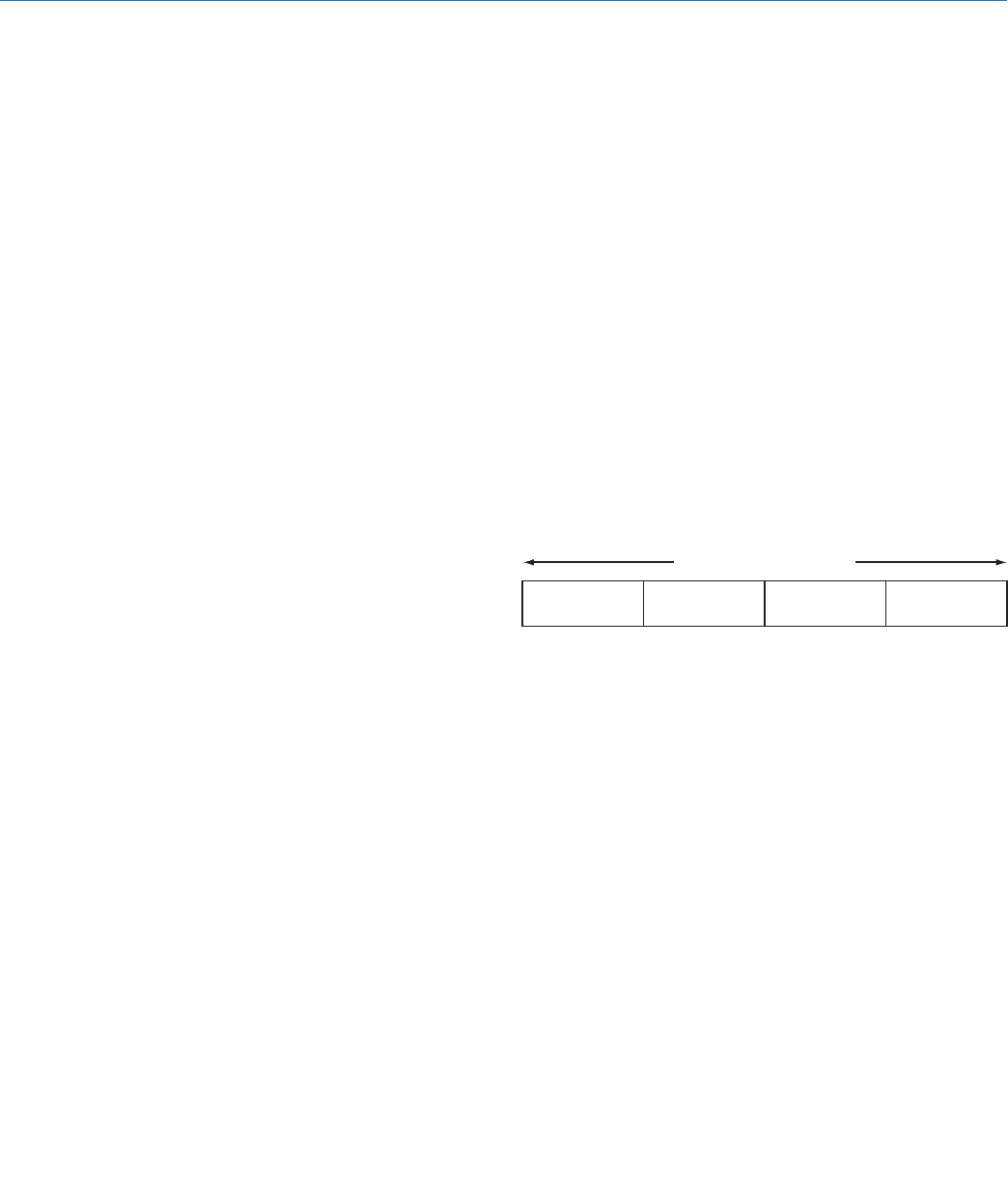
In the 4-channel mode, the D4 system operates on
one of four 4.2 MHz channels in the 902 to 928 MHz
band. Each channel carries four separate audio sig-
nals, digitally multiplexed within a common carrier. D4
systems can be run simultaneously on all four chan-
nels across the 902 to 928 MHz band to provide a total
of16channels.
907.776 912.384 916.992 921.600
902 to 928 MHz Band
Center frequencies of the RF channels
A “spreading” technique is used in the design to in-
crease immunity to noise and interference. The sam-
pled audio signals are delivered to the FPGA where
the spreading algorithm and encoding are applied.
The audio quality is suitable for any professional appli-
cation in film, television and live sound. 48 kHz sam-
pling and 24-bit A-D conversion assure excellent audio
quality across a 20Hz to 20kHz audio bandwidth with
only 0.05% distortion.
The LCD interface on the front panels make setup
simple and straightforward. Power is provided by exter-
nalsourcesfrom6to16VDC.
Rugged machined aluminum housings are finished
in a Teflon impregnated nickle alloy plating with laser
etched nomenclature for durability and legibility.
Table of Contents
Introduction .............................................................................3
General Technical Description ..............................................4
D4T Transmitter .....................................................................4
D4R Receiver ........................................................................5
Front and Rear Panels ............................................................6
Transmitter Input Modes ........................................................7
Receiver Output Modes .........................................................7
Mixed Modes ...........................................................................7
Navigating the LCD ................................................................7
System Setup Steps ...............................................................8
System Setup ..........................................................................8
D4T Transmitter Audio Level Setup ......................................9
D4R Receiver Audio Level Setup ..........................................9
Antenna Placement and Orientation ...................................10
Frequency Selection ............................................................10
Replacement Parts and Accessories ..................................11
Specifications .......................................................................12
Service and Repair ...............................................................14
Returning Units for Repair ..................................................14
D4T/D4R
LECTROSONICS, INC.
4
General Technical Description
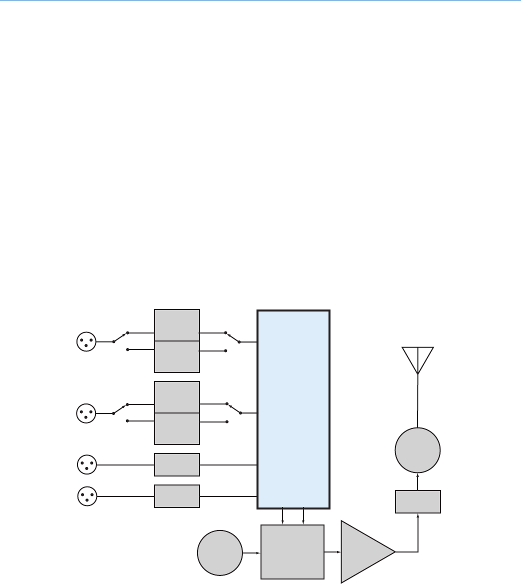
D4T Transmitter
The transmitter can accept up to four inputs from digi-
taloranalogsources.Inputs1and2areselectablebe-
tweentwodigitalchannelseachor1balancedanalog
channel each and inputs 3 and 4 can each accept a
single balanced analog signal.
The inputs can be configured as follows:
• Fourbalancedanaloginputsusingallfourjacks
• Twodigitalchannelsusingjack1andtwobal-
ancedanaloginputsusingjacks3and4
• Fourdigitalchannelsusingjacks1and2
The input connectors are TA3 “mini XLR” types with
the same pin numbering and configuration as standard
XLR connectors for AES-EBU and balanced line level
analog signals.
Input preamp circuits use a special balanced amplifier
withveryhighcommonmoderejectiontominimize
hum and noise.
Analog input signals are sampled at 48kHz and con-
verted to 24-bit digital audio and fed into the FPGA
for further processing. The FPGA applies a spreading
algorithm to expand the bandwidth of each channel
to 4,2 MHz to improve immunity to interference and
noise. The baseband signal is then delivered to the
D-A to generate the I and Q signals for final output.
The modulated signal is filtered before and after the
RF amp to suppress out of band noise and spurious
signals. A circulator/isolator is used in the final RF
output to minimize IM that can occur when external
signals enter the output stage through the antenna.
The isolator passes the transmitter output signal to the
antenna but shunts returning signals to ground.
A USB port is provided to simplify firmware updates.
POWER
AMP
OSC
900 MHz
RF
DEMOD
DIGITAL
BASEBAND
ENCODER
24-bit D/A
(analog)
AES/EBU
OUT
(digital)
24-bit D/A
(analog)
AES/EBU
OUT
(digital)
24-bit D/A
(analog)
24-bit D/A
(analog)
TA3F
INPUTS
CIRCULATOR
ISOLATOR
FILTER
1
2
3
4
4-channel Digital Wireless System
Rio Rancho, NM, USA 5
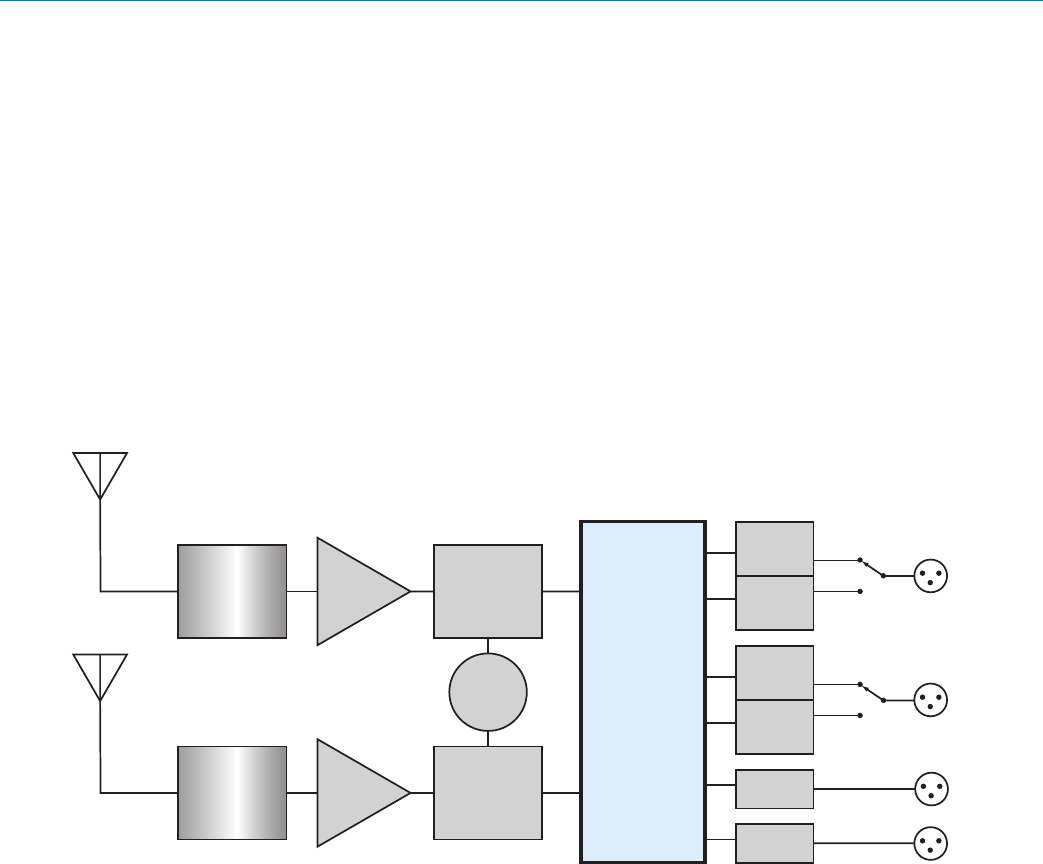
D4R Receiver
The receiver is essentially a mirror image of the trans-
mitter. The incoming RF signal is converted back into
the baseband signal that was generated in the trans-
mitter, and the FPGA decodes the signal to generate
the four audio channels in digital and analog formats
as they appeared at the transmitter inputs.
Diversity reception is employed to suppress multipath
dropouts, followed by SAW filters in the front-end to
attenuate signals above and below the passband. The
FPGAmonitorsandadjuststheleveloftheincoming
RF signal to increase the dynamic range capabilities of
the receiver.
From the IQ demodulator through the filters, amplifier
and baseband ADC, the signal path and processing
is the reverse of that in the transmitter. Decoding in
the FPGA regenerates the original digital and analog
audio signals and delivers them to the output stages.
The FPGA also delivers a signal to a DAC and amplifer
for monitoring with headphones. The headphone out-
put follows the receiver selected on the front panel.
FILTER
FILTER
LOW
NOISE
AMP
LOW
NOISE
AMP
OSC
900 MHz
RF
DEMOD
RF
DEMOD
DIGITAL
BASEBAND
DECODER
and
DIVERSITY
SYSTEM
24-bit D/A
(analog)
AES/EBU
OUT
(digital)
24-bit D/A
(analog)
AES/EBU
OUT
(digital)
24-bit D/A
(analog)
24-bit D/A
(analog)
TA3F
OUTPUTS
1
2
3
4
D4T/D4R
LECTROSONICS, INC.
6
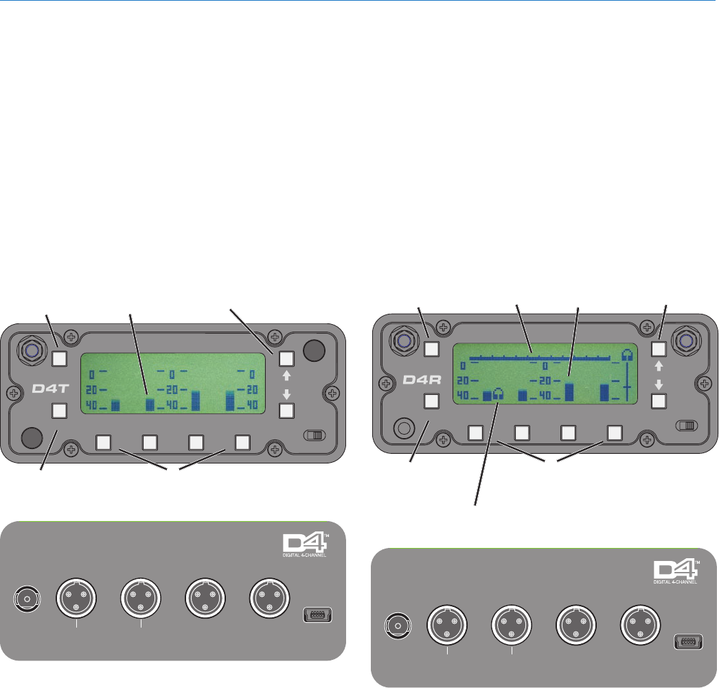
Front and Rear Panels
Setup and operation of the transmitter and receiver is
a straightforward process using an LCD and push but-
ton interface on the front panels. The Main Window dis-
plays audio levels during operation, with a setup menu
and screens to select operating modes and levels.
The rear panels provide the audio inputs and outputs,
powerreceptacleandUSBport.Channels1and2
provide balanced analog signals and AES-EBU digital
signals as selected from the LCD setup screens.
Channels 3 and 4 are balanced analog audio only. The
connectors are standard TA3M type.
D4T Transmitter
FUNC
BACK
OFF ON
1234
DIGITAL 4 CHANNEL TRANSMITTER
Channel Select 1-4
Menu Item &
Parameter Select
Return to
Previous
Menu
Press to Enter
Setup Menus
Audio
Level
USBAES 3/4
1234
9-16 VDC
500 mA
AES 1/2
D4T 4-CHANNEL DIGITAL TRANSMITTER
The units are powered with an external source of 9 to
16VDC,withpowerconsumptionof500mAforthe
transmitter and 250 mA for the receiver.
The USB port is used for firmware updates.
D4R Receiver
FUNC
BACK
OFF ON
1234
PHONES
DIGITAL 4 CHANNEL RECEIVER
Channel
Select 1-4
Menu Item/Parameter
Select Buttons
Press to Enter
Setup Menus
Return to
Previous
Menu
Channel selected
for headphone
monitoring
Incoming
RF level
Menu Item &
Parameter Select
Audio
Level
USBAES 3/4
1234
9-16 VDC
300 mA
AES 1/2
D4R 4-CHANNEL DIGITAL RECEIVER
4-channel Digital Wireless System
Rio Rancho, NM, USA 7
Transmitter Input Modes
The transmitter can be set up in three different con-
figurations with the AES3 mode menu for 4-channel
operation:
CH 1
CH 2
CH 3
CH 4
ANALOG
ANALOG
ANALOG
ANALOG
CH 1
CH 2
CH 3
CH 4
DIGITAL
DIGITAL
ANALOG
ANALOG
NOT USED
CH 1
CH 2
CH 3
CH 4
DIGITAL
DIGITAL
NOT USED
NOT USED
DIGITAL
DIGITAL
Two different configurations are available for 2-channel
operation:
CH 1
CH 2
CH 3
CH 4
ANALOG
ANALOG
CH 1
CH 2
CH 3
CH 4
DIGITAL
DIGITAL
NOT USED
NOT USED
NOT USED
NOT USED
NOT USED
Receiver Output Modes
The receiver audio outputs can be configured in the
same manner as the transmitter for 4-channel opera-
tion:
CH 1
CH 2
CH 3
CH 4
ANALOG
ANALOG
ANALOG
ANALOG
CH 1
CH 2
CH 3
CH 4
DIGITAL
DIGITAL
ANALOG
ANALOG
NOT USED
CH 1
CH 2
CH 3
CH 4
DIGITAL
DIGITAL
NOT USED
NOT USED
DIGITAL
DIGITAL
Two different configurations are available for 2-channel
operation:
CH 1
CH 2
CH 3
CH 4
DIGITAL
DIGITAL
NOT USED
CH 1
CH 2
CH 3
CH 4
NOT USED
NOT USED
ANALOG
ANALOG
NOT USED
NOT USED
Mixed Modes
The selected AES3 modes on the transmitter and re-
ceiver do not have to be identical. For example, analog
signals can be fed into the transmitter from a mixer or
wireless mic receivers, transmitted to the D4 receiver,
which can be configured for four digital outputs to feed
a digital recorder.
The sampling rate of the audio at the receiver digital
outputs will always be at 48 kHz, regardless of the
sampling rate of the signal fed into the transmitter.
NOTE: Transmitter and receiver must both be set
to either the 2-channel or 4-channel mode.
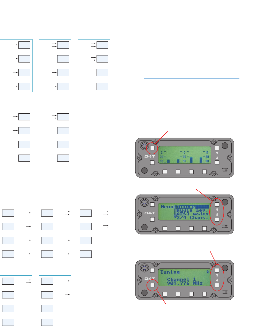
Navigating the LCD
Navigation through setup screens is the same on
transmitter and receiver. The Main Window will display
audio levels for all active channels while the system is
operating. Press the FUNC button to enter the setup
menu.
FUNC
BACK
OFF ON
1234
DIGITAL 4 CHANNEL TRANSMITTER
Then press the UP and DOWN arrow buttons to select
a menu item.
FUNC
BACK
OFF ON
1234
DIGITAL 4 CHANNEL TRANSMITTER
Press the FUNC button to enter the setup screen for
the selected item. Then use the UP and DOWN arrow
buttons to select a value or mode.
FUNC
BACK
OFF ON
1234
DIGITAL 4 CHANNEL TRANSMITTER
Press BACK once to return to the Menu or twice to
return to the Main Wiindow.
D4T/D4R
LECTROSONICS, INC.
8
System Setup Steps
The following steps are necessary to set up and oper-
ate the D4 system. Details for each step are on the
next pages.
1) Attachantennasandpowersuppliestothetrans-
mitter and receiver.
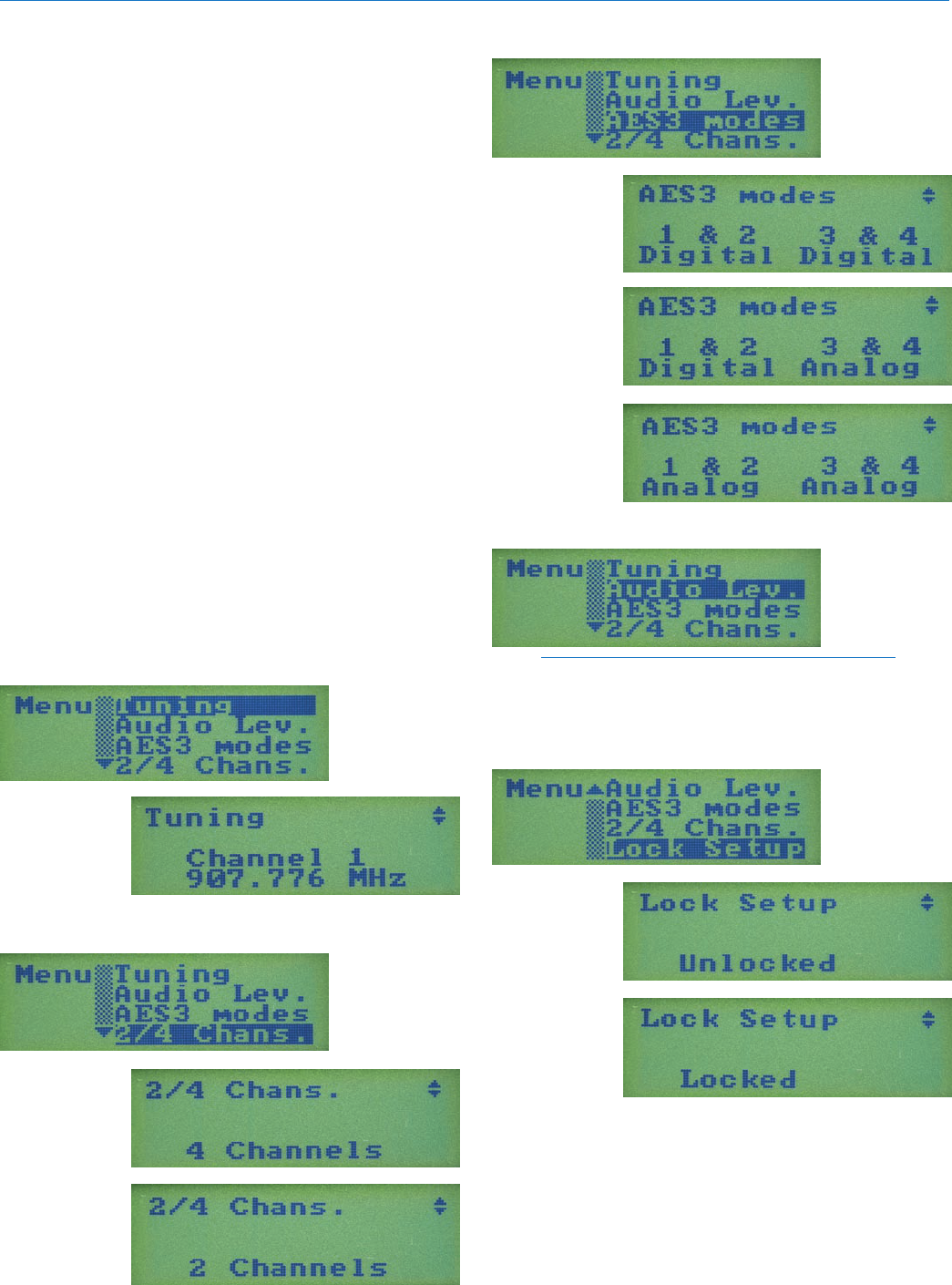
2) TuningMenu-selectthesameoperatingfrequen-
cy on the transmitter and receiver.
3) 2/4ChannelMode-set2-channelor4-channel
modes the same on transmitter and receiver.
4) SelecttheAES3modesontransmitterandreceiv-
er as needed for the connected equipment, mixer,
recorder,etc.(seeAES3Modes)
5) Adjustaudioinputlevelsonthetransmitter.(see
TransmitterAudioLevelSetup)
6) Adjustaudiooutputlevelsofanalogoutputsonthe
receiver.(seeReceiverAudioLevelSetup)
7) Walktestthesystemtocheckforadequateop-
erating range. If dropouts occur within the range
needed, select a different operating frequency.
System Setup
Tuning Menu
Use UP/DOWN
arrows to select
menu item and
press FUNC to
enter setup
Use UP/DOWN
arrows to select
channel, then
press FUNC to
return to menu
2/4 Channel Modes
Use UP/DOWN
arrows to select
menu item and
press FUNC to
enter setup
Use UP/DOWN
buttons to select
desired mode
AES3 Modes
Use UP/DOWN
arrows to select
menu item and
press FUNC to
enter setup
Use UP/DOWN
buttons to select
desired mode
Audio Level
Use UP/DOWN
arrows to select
menu item and
press FUNC to
enter setup
NOTE: The setup screens for Audio Level on the
transmitter and receiver will be slightly different.
See the next page for details.
Locked/Unlocked Modes
Use UP/DOWN
arrows to select
menu item and
press FUNC to
enter setup
Use UP/DOWN
buttons to select
desired mode
4-channel Digital Wireless System
Rio Rancho, NM, USA 9
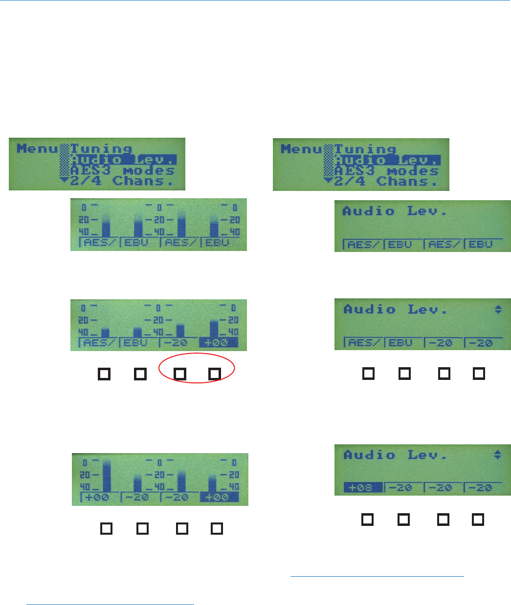
D4T Transmitter
Audio Level Setup
Press FUNC and then select the menu item “Audio
Lev. “ and press FUNC again. The setup screen for
audio level will vary slightly depending upon which
AES3 mode has been selected. If the 2-channel mode
has been selected, channels 3 and 4 will appear blank
on the setup screen.
Use UP/DOWN
arrows to select
menu item and
press FUNC to
enter setup
When configured for four AES/EBU
outputs, the channel levels will be preset
to the AES standard.
12 3 4
When configured for two digital and two
analog inputs, press the button under the
analog channel to be adjusted and then
use the UP and DOWN buttons to set the
desired level.
12 3 4
In this example, the transmitter is
configured for four analog channels. Select
each channel with the button below it and
use the UP and DOWN arrow buttons to
set the desired level.
NOTE: The transmitter is designed for line
level signals. There is no gain stage in the input
section. Attenuation up to 20 dB can be applied to
the input signal to reduce very high level signals
to the optimal range for the transmitter.
D4R Receiver
Audio Level Setup
Press FUNC and then select the menu item “Audio
Lev. “ and press FUNC again. The setup screen for
audio level will vary slightly depending upon which
AES3 mode has been selected. If the 2-channel mode
has been selected, channels 3 and 4 will appear blank
on the setup screen.
Use UP/DOWN
arrows to select
menu item and
press FUNC to
enter setup
When configured for four AES/EBU
outputs, the channel levels will be preset
to the AES standard.
12 3 4
When configured for two digital and two
analog inputs, press the button under the
analog channel to be adjusted and then
use the UP and DOWN buttons to set the
desired level.
12 3 4
When configured for four analog outputs,
press the button under the channel to be
adjusted and then use the UP and DOWN
buttons to set the desired level.
NOTE: The value shown in the setup screen
on the receiver is the level of an analog signal
in dBu at the output when the RF signal is fully
modulated. AES/EBU outputs are preset to the
industrystandardvalue,sonoadjustmentis
needed.
D4T/D4R
LECTROSONICS, INC.
10
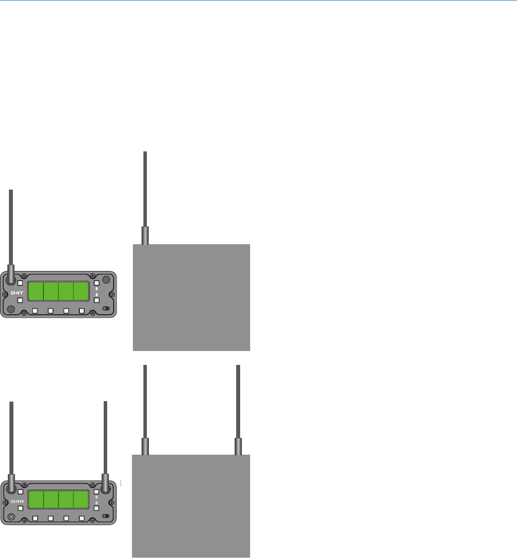
Antenna Placement and
Orientation
The supplied antenna is a center fed half-wave type
with a right angle elbow and rotating mount. For most
applications, the whip antennas should be vertically
oriented to provide a circular coverage pattern. In other
orientations, the transmitter antenna should be paral-
lel with and not directly above or below the receiver
antennas.
FUNC
BACK
12
34
DIGITAL 4 CHANNEL TRANSMITTER
OFF ON
D4T Transmitter
FUNC
BACK
OFFON
1234
PHONES
DIGITAL 4 CHANNEL RECEIVER
D4R Receiver
Frequency Selection
For a single system, any of the four frequencies can be
used for normal operation. With multiple systems oper-
ating in the same location, select a different frequency
for each system.
Walk test each system through the area where it will
be operating and listen for dropouts while observing
the RF level indicator on the receiver LCD. It is best to
have all equipment in the location turned on to check
for interference and short operating range.
If the RF level on the receiver LCD indicates a weak
overall level, try re-positioning the antennas. Re-ori-
enting the antennas or moving them even a few inches
away from nearby surfaces can also make a difference.
If dropouts are experienced during the walk test, but
the RF level at the receiver remains strong, there could
be interference on that frequency band. Switch the
system to another frequency and walk test the system
again to check for adequate operating range.

4-channel Digital Wireless System
Rio Rancho, NM, USA 11
Replacement Parts and
Accessories
Power Supply
Lectrosonics PS70 (non-locking)
ACpowersupplywith60320universalsocketonhous-
ing,100-240VAC,50/60Hz,1.6A(max)input;13.8
VDC,2.8A,40W(max)output.SpecifytheACpower
cord needed for your country or application.
Power Input Plug and Cables
• ShogyoMP121CRlockingplug(nocable)
• Lectrosonics21425straight,non-lockingplugwith
6ft.cable
• Lectrosonics21472rightangle,non-lockingplug
with6ft.cable

D4T/D4R
LECTROSONICS, INC.
12
Specifications
Overall System
Operating Spectrum: 902 - 928 MHz
Center frequencies (MHz): 907.776, 912.387, 916.992, 921.600
Four systems can operate simultaneously for a
total of 16 audio channels.
Modulation Type: QPSK with spreading to 4.2 MHz
Sampling Rate: 48 kHz
Latency (overall system):
Digital In/Digital Out: Less than 1 mS
Analog In/Analog Out: 2.2 mS
Selectable Audio Channels: • 4 digital
• 2 digital, 2 analog
• 4 analog
Audio Performance (overall system):
Frequency Response: 20 Hz - 20 kHz
THD: 0.05 %
D4T Transmitter
Power output: 200 mW; spreading algorithm across
4.2 MHz bandwidth
Power requirements: 9 - 16 VDC
Power consumption: 500 mA
Dimensions: 4 x 4 x 1.5 inches
Weight:
D4R Receiver
D4R Receiver
Power requirements: 9 - 16 VDC
Power consumption: 250 mA
Dimensions: 4 x 4 x 1.5 inches
Weight: 346 grams; 12.2 ozs.

4-channel Digital Wireless System
Rio Rancho, NM, USA 13
Industry Canada Notices:
Operationofthisdeviceissubjecttothefollowingtwo
conditions:(1)thisdevicemaynotcauseinterference,
and(2)thisdevicemustacceptinterference,including
interference that may cause undesired operation of the
device.
This device has been designed to operate with the
antennalistedbelow,andhavingamaximumgainof6
dB. Antennas not included in this list or having a gain
greaterthan6dBarestrictlyprohibitedforusewith
this device. The required antenna impedance is 50
ohms.
Linx Technologies model: ANT-916-CW-HWR-RPS
To reduce potential radio interference to other users,
the antenna type and its gain should be so chosen that
theequivalentisotropicallyradiatedpower(e.i.r.p.)is
not more than that permitted for successful communi-
cation
FCC Notice
NOTE: This equipment has been tested and found
to comply with the limits for a Class B digital device,
pursuanttoPart15oftheFCCRules.Theselimits
are designed to provide reasonable protection against
harmful interference in a residential installation. The
equipment generates, uses and can radiate radio
frequency energy and, if not installed and used in
accordance with the instructions, may cause harmful
interference to radio communications. However, there
is no guarantee that interference will not occur in a
particular installation. If this equipment does cause
harmful interference to radio or television reception,
which can be determined by turning the equipment
off and on, the user is encouraged to try to correct the
interference by one or more of the following measures:
• Reorientorrelocatethereceivingantenna
• Increasetheseparationbetweentheequipment
and receiver
• Connecttheequipmentintoanoutletonacircuit
different from that which the receiver is connected
• Consultthedealeroranexperiencedradio/TV
technician for help
Changes or modifications to this equipment not ex-
pressly approved by Lectrosonics, Inc. could void the
user’s authority to operate it.

D4T/D4R
LECTROSONICS, INC.
14
Service and Repair
If your system malfunctions, you should attempt to correct or isolate the trouble before concluding that the equip-
ment needs repair. Make sure you have followed the setup procedure and operating instructions. Check the inter-
connecting cables and then go through the Troubleshooting section in this manual.
We strongly recommend that you do not try to repair the equipment yourself and do not have the local repair shop
attempt anything other than the simplest repair. If the repair is more complicated than a broken wire or loose con-
nection,sendtheunittothefactoryforrepairandservice.Don’tattempttoadjustanycontrolsinsidetheunits.
Once set at the factory, the various controls and trimmers do not drift with age or vibration and never require read-
justment.There are no adjustments inside that will make a malfunctioning unit start working.
Lectrosonics’ Service Department is equipped and staffed to quickly repair your equipment. In warranty repairs are
made at no charge in accordance with the terms of the warranty. Out-of-warranty repairs are charged at a mod-
est flat rate plus parts and shipping. Since it takes almost as much time and effort to determine what is wrong as it
does to make the repair, there is a charge for an exact quotation. We will be happy to quote approximate charges by
phone for out-of-warranty repairs.
Returning Units for Repair
For timely service, please follow the steps below:
A. DO NOT return equipment to the factory for repair without first contacting us by email or by phone. We need
to know the nature of the problem, the model number and the serial number of the equipment. We also need a
phonenumberwhereyoucanbereached8A.M.to4P.M.(U.S.MountainStandardTime).
B. Afterreceivingyourrequest,wewillissueyouareturnauthorizationnumber(R.A.).Thisnumberwillhelp
speed your repair through our receiving and repair departments. The return authorization number must be
clearly shown on the outside of the shipping container.
C. Pack the equipment carefully and ship to us, shipping costs prepaid. If necessary, we can provide you with the
proper packing materials. UPS is usually the best way to ship the units. Heavy units should be “double-boxed”
for safe transport.
D. We also strongly recommend that you insure the equipment, since we cannot be responsible for loss of or dam-
age to equipment that you ship. Of course, we insure the equipment when we ship it back to you.
Lectrosonics USA:
Mailing address: Shipping address: Telephone:
Lectrosonics,Inc. Lectrosonics,Inc. (505)892-4501
POBox15900 581LaserRd. (800)821-1121Toll-free
RioRancho,NM87174 RioRancho,NM87124 (505)892-6243Fax
USA USA
Web: E-mail:
www.lectrosonics.com sales@lectrosonics.com
Lectrosonics Canada:
Mailing Address: Telephone: E-mail:
49SpadinaAvenue, (416)596-2202 Sales: colinb@lectrosonics.com
Suite303A (877)753-2876Toll-free Service:joeb@lectrosonics.com
Toronto,OntarioM5V2J1 (877-7LECTRO)
(416)596-6648Fax

27 February 2009
581 Laser Road NE • Rio Rancho, NM 87124 USA • www.lectrosonics.com
(505) 892-4501 • (800) 821-1121 • fax (505) 892-6243 • sales@lectrosonics.com
LIMITED ONE YEAR WARRANTY
The equipment is warranted for one year from date of purchase against defects in
materials or workmanship provided it was purchased from an authorized dealer. This
warranty does not cover equipment which has been abused or damaged by careless
handling or shipping. This warranty does not apply to used or demonstrator equipment.
Should any defect develop, Lectrosonics, Inc. will, at our option, repair or replace any
defective parts without charge for either parts or labor. If Lectrosonics, Inc. cannot
correct the defect in your equipment, it will be replaced at no charge with a similar new
item. Lectrosonics, Inc. will pay for the cost of returning your equipment to you.
This warranty applies only to items returned to Lectrosonics, Inc. or an authorized
dealer, shipping costs prepaid, within one year from the date of purchase.
This Limited Warranty is governed by the laws of the State of New Mexico. It states the
entire liablility of Lectrosonics Inc. and the entire remedy of the purchaser for any
breach of warranty as outlined above. NEITHER LECTROSONICS, INC. NOR
ANYONE INVOLVED IN THE PRODUCTION OR DELIVERY OF THE EQUIPMENT
SHALL BE LIABLE FOR ANY INDIRECT, SPECIAL, PUNITIVE, CONSEQUENTIAL,
OR INCIDENTAL DAMAGES ARISING OUT OF THE USE OR INABILITY TO USE
THIS EQUIPMENT EVEN IF LECTROSONICS, INC. HAS BEEN ADVISED OF THE
POSSIBILITY OF SUCH DAMAGES. IN NO EVENT SHALL THE LIABILITY OF
LECTROSONICS, INC. EXCEED THE PURCHASE PRICE OF ANY DEFECTIVE
EQUIPMENT.
This warranty gives you specific legal rights. You may have additional legal rights which
vary from state to state.