Lectrosonics HHAA1 Wireless Microphone Transmitter User Manual HHa man indd
Lectrosonics Inc Wireless Microphone Transmitter HHa man indd
User Manual
Rio Rancho, NM, USA
www.lectrosonics.com
INSTRUCTION MANUAL
HHa
Handheld Transmitter
Digital Hybrid Wireless®
US Patent 7,225,135

HHa
LECTROSONICS, INC.
2

Wideband Hand Held Transmitter
Rio Rancho, NM 3
Consumer Alert for US Users - FCC Order DA 10-92
Most users do not need a license to operate this wireless microphone system. Nevertheless, operating this microphone
system without a license is subject to certain restrictions: the system may not cause harmful interference; it must operate at
a low power level (not in excess of 50 milliwatts); and it has no protection from interference received from any other device.
Purchasers should also be aware that the FCC is currently evaluating use of wireless microphone systems, and these rules
are subject to change. For more information, call the FCC at 1-888- CALL-FCC (TTY: 1-888-TELL-FCC) or visit the FCC’s
wireless microphone website at www.fcc.gov/cgb/wirelessmicrophones. To operate wireless microphone systems at power
greater than 50mW, you must qualify as a Part 74 user and be licensed. If you qualify and wish to apply for a license go to:
http://www.fcc.gov/Forms/Form601/601.html
Table of Contents
General Technical Description ............................................. 4
Microphone Capsules: .......................................................... 6
Mechanical Assembly ........................................................... 6
Battery Installation ................................................................ 7
IR Sync ................................................................................... 7
Control Panel ......................................................................... 7
Setup and Adjustments ........................................................ 7
Powering On ........................................................................ 7
Powering Off ........................................................................ 8
Standby Mode ...................................................................... 8
Power Menu ......................................................................... 8
Battery Condition ................................................................. 8
Navigating Menus and Screens ........................................... 8
Input Gain Adjustment ........................................................ 10
Side Button Functions ........................................................ 11
Mic Capsule Adjustments ................................................... 12
(EXPERT LEVEL ADJUSTMENT) ..................................... 12
Firmware Updates ............................................................... 13
Parts and Accessories ........................................................ 14
Troubleshooting ................................................................... 15
Specifications ...................................................................... 16
Service and Repair .............................................................. 17
Returning Units for Repair ................................................. 17
HHa
LECTROSONICS, INC.
4
General Technical Description
Introduction
The HHa handheld transmitter uses state-of-the-art
Digital Hybrid Wireless® wireless technology, select-
able output power and a versatile microphone capsule
mounting system to meet the needs of audio profes-
sionals and vocalists.
The compandor-free Digital Hybrid audio chain pre-
serves the quality of the selected microphone capsule
and delivers it to the sound and recording system
without coloration. This superb audio performance and
highly reliable RF transmission makes it ideally suited
for high end stage and studio production.
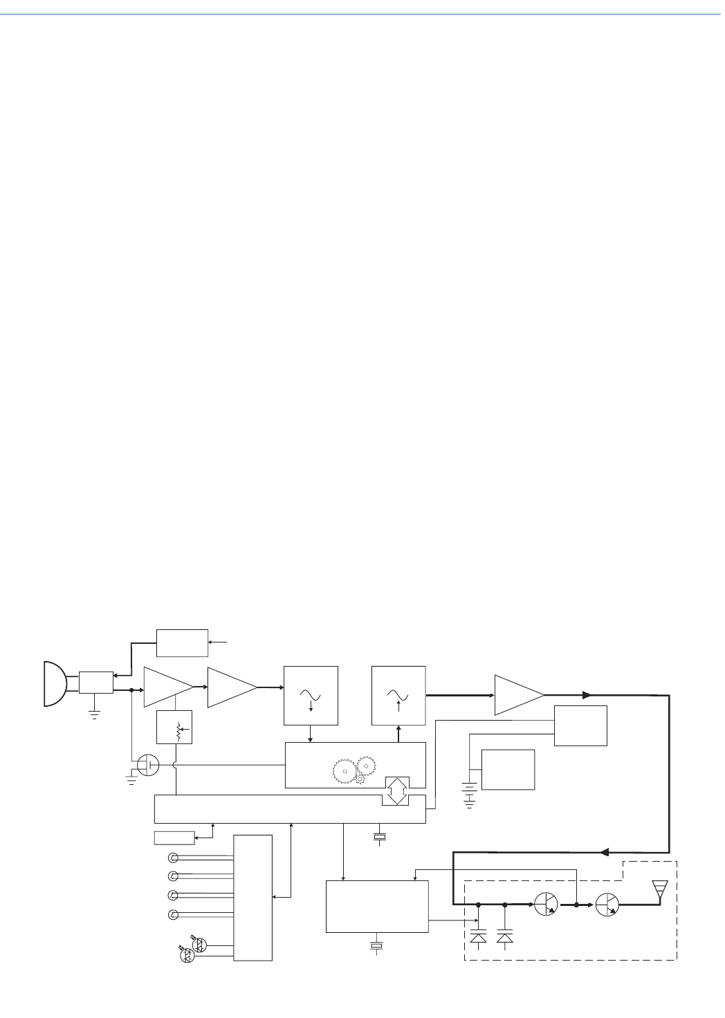
Digital Signal Processor
The DSP encodes the digitized audio from the A-D
converter and adds an ultrasonic pilot tone to control
the receiver’s squelch in systems that use pilot tone. It
also controls the input limiter and audio metering.
Compatibility Modes
The transmitter was designed to operate with Lec-
trosonics Digital Hybrid Wireless® receivers and will
yield the best performance when doing so. Due to
the flexibility of digital signal processing, however, the
transmitter is also able to operate with Lectrosonics
200 Series, Lectrosonics 100 Series, IFB and certain
non-Lectrosonics analog receivers in special compat-
ibility modes. (Contact the Lectrosonics Sales Depart-
ment for a complete list of compatible receivers.)
Digital Hybrid Wireless® Technology
All wireless links suffer from channel noise to some
degree and all wireless microphone systems seek to
minimize the impact of that noise on the desired signal.
Conventional analog systems use compandors to
increase the signal to noise ratio, at the cost of distor-
tion artifacts. Wholly digital systems defeat the noise
by sending the audio information in digital form, at
the cost of some combination of power, bandwidth or
channel count.
The Lectrosonics Digital Hybrid Wireless® system over-
comes channel noise by digitally encoding the audio
in the transmitter and decoding it in the receiver, yet
still sending the encoded information via an analog FM
wireless link. This proprietary algorithm is not a digital
implementation of an analog compandor. Instead, it
is a technique that can be accomplished only in the
digital domain, even though the inputs and outputs are
analog signals.
Because it uses an analog FM link, the system enjoys
all the benefits of conventional FM wireless systems,
such as excellent range, efficient use of RF spectrum,
and long battery life. However, unlike conventional FM
systems, the design has eliminated the analog com-
pandor and its artifacts.
Wide Deviation
±75 kHz deviation is used in the Digital Hybrid and 200
Series compatibility modes to dramatically improve
the capture ratio, signal to noise ratio and dynamic
range of the wireless system. This, in conjunction with
accurate input gain adjustment, produces outstanding
audio quality that rivals a hard wired connection.
Mic
capsule
Bias 5V +7V
Input
Amp
Interface
Shunt
Limiter
MENU/SEL
BACK
MUTE
POWER
Reference
Crystal
Reference
Crystal
3 V
Battery
Variable
Switching
Power
Supply
Hi.Lo
Pass
Filter
Digital
PotAudio
Level
Phantom
Power
Audio A-D
Converter
11001001
D-A
Converter
11001001
Control Panel
Microprocessor
Voltage
Controlled
Oscillator
Final
Amplifier
Filter
Amp
Encoded Audio
and Pilot Tone
Bicolor
Modulation
LEDs
Switching
Power
Supply
Digital Signal Processor
Phase Locked Loop
LCD

Wideband Hand Held Transmitter
Rio Rancho, NM 5
Pilot Tone Squelch
The benefit of the pilot tone squelch system is that the
associated receiver will remain muted until it receives
the pilot tone from the matching transmitter, even if a
strong RF signal is present on the carrier frequency
of the system. All Digital Hybrid Wireless® transmitters
use one of 256 different ultrasonic tones between 25
and 32 kHz in each standard frequency block to oper-
ate the receiver squelch.
The HHa is a wideband design that tunes across
three standard blocks (up to 76 MHz). The pilot tone
frequency is determined by the selected operating
frequency in 100 kHz steps. In other words, the same
pilot tone is used for all four frequencies within each
100 kHz step of the tuning range. This preserves com-
patibility with earlier Digital Hybrid products that tune
across a single frequency block (25.6 MHz).
Input Gain Range and Limiter
45 dB range of input gain adjustment allows gain
settings to accurately match the user’s voice and the
varying sensitivity of different microphone capsules. A
DSP-controlled analog audio limiter is employed be-
fore the A-D converter. The limiter has a range of more
than 30 dB for excellent overload protection. A dual re-
lease envelope makes the limiter acoustically transpar-
ent while maintaining low distortion. It can be thought
of as two limiters in series, a fast attack and release
limiter followed by a slow attack and release limiter.
The limiter recovers quickly from brief transients, with
no audible side effects, and also recovers slowly from
sustained high levels to keep audio distortion low while
preserving short term dynamics.
Long Battery Life
Switching power supplies throughout the design allow
over 5 hours of operation using two alkaline AA bat-
teries. Lithium batteries will provide over 8 hours of
operation. The battery compartment and contacts are
designed to prevent “rattle” as the unit is handled.
Menu-Driven Control
A high-resolution LCD and control panel with mem-
brane switches provide access to the menu-driven
setup. Transmitter RF power, high-pass filter, frequency
selection, backlight timeout, mute or talkback functions
and tuning modes are easily accessed.
Wideband Tuning Range
The transmitter can tune across band of up to 76 MHz
in either 100 kHz or 25 kHz steps.
Frequency Selection
Operating frequency is normally selected using a
receiver or analyzer to assess signals in the local en-
vironment to avoid interference. Once an interference-
free frequency is identified, the transmitter frequency is
set to match the receiver.
The LCD on the transmitter displays frequency in MHz
and with a two character hex code that is used on
most Lectrosonics receivers.
Antenna
A newly designed helical antenna allows the transmit-
ter to be held in any position, since the user’s hands
have little or no effect on the RF output power.
Microphone Capsules
The transmitter is available from Lectrosonics with
the HHC and HHVMC cardioid condenser capsules.
Capsules from several other manufacturers are also
available for use with the HH: those with a 1.25” x 28
thread pitch and three contact rings. Condenser or
dynamic microphone heads can be used with the HH,
depending on the user’s preference or the application.
IR (infrared) Sync
An IR Sync Port is used for quick setup with receivers
that offer this feature. Settings for frequency, step size
and compatibility mode are transferred from receiver to
transmitter via the IR ports.
Side Button Functions
A programmable switch on the side of the housing can
be configured as a mute/cough switch, to provide a
talkback function, a power switch, or be disabled.
The talkback function provides a communication
channel when used with a receiver equipped with this
feature, such as a Venue Wideband receiver with ap-
propriate firmware. When pressed and held in, the side
switch re-directs the audio output to a different audio
channel on the receiver. As soon as the switch is re-
leased, audio is returned to the program channel.
The talkback function works only in the Digital Hybrid
compatibility mode.
USB Port for Firmware Updates
Firmware updates are enabled by simply downloading
a file and utility program from the Lectrosonics web
site, connecting the transmitter to a computer via the
USB port and running the program.
HHa
LECTROSONICS, INC.
6
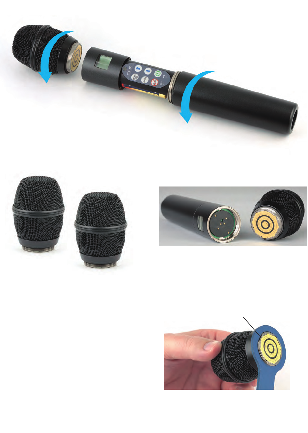
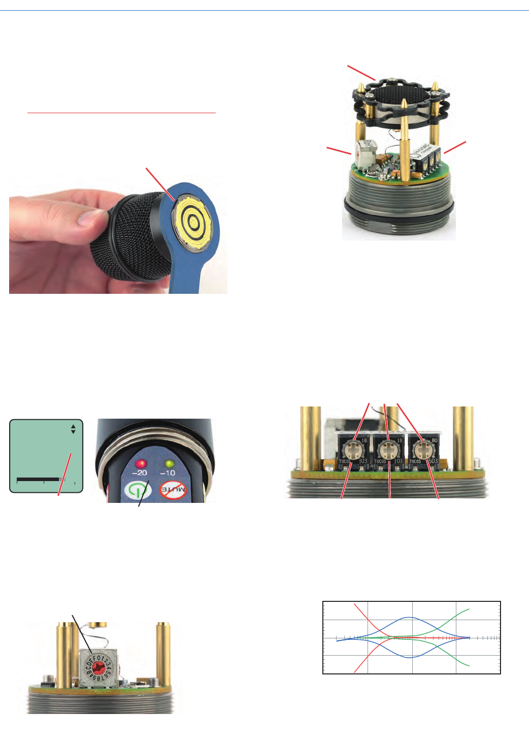
A mic capsule is
threaded onto the body
of the transmitter in the
direction shown.
Do not overtighten it.
The lower housing opens by rotating
it in the direction shown. After the
threads are disengaged, pull the
housing downward until it engages
the detent that holds it open.
The threaded interface is a 1.25”
diameter opening with 28 threads
per inch and three contact rings
Mechanical Assembly
Microphone Capsules:
Lectrosonics offers two types of capsules. The HHC is
the standard capsule and the HHVMC is the Variable
Mic Capsule which includes adjustments for Bass,
Midrange and Treble.
HHC Lectrosonics
cardioid electret
HHVMC Lectrosonics cardioid
electret with VariMic preamp
Along with these two models from Lectrosonics, a
variety of different capsules with a common thread
and electrical interface are available from the major
microphone manufacturers.
A list of compatible capsules is on the website at www.
lectrosonics.com listed on the HH transmitter page.
Do not touch the contacts between the mic capsule
and transmitter body. When necessary, the contacts
can be cleaned with a cotton swab and alcohol.
*All product names are trademarks of their respective
owners, which are in no way affiliated with Lectrosonics.
Capsule Installation
Capsules are attached with a right-hand thread.
To remove the windscreen from the mic capsule,
line up the blue wrench (included with the capsule
head) with the flat notches on the lower threaded area
of the mic capsule.
Align flats on the wrench with flats on the capsule.
Wideband Hand Held Transmitter
Rio Rancho, NM 7
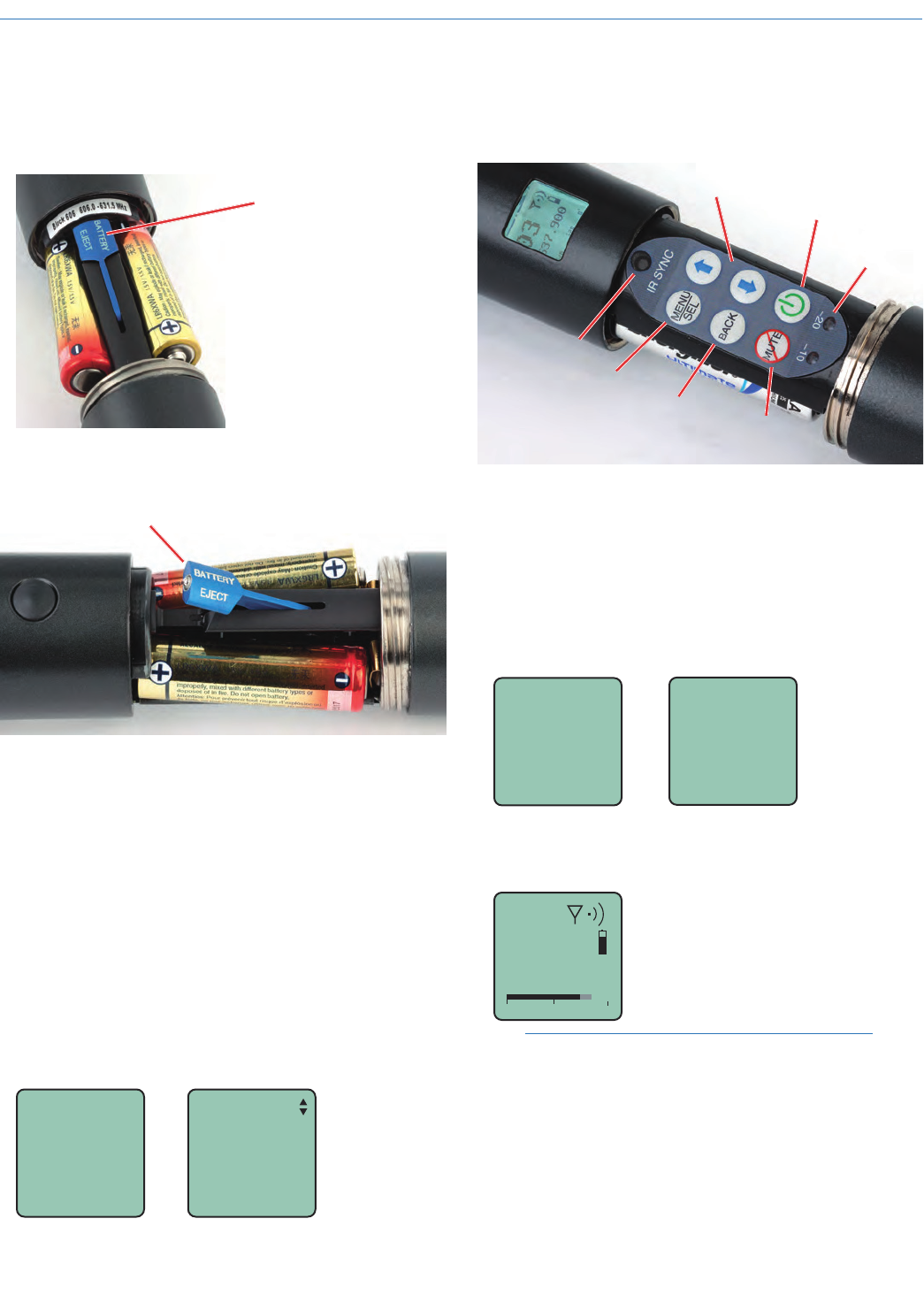
Battery Installation
To insert batteries, close the eject lever and insert the
upper contacts first (closest to the mic capsule). Polar-
ity is marked on the label in the bottom of the battery
compartment.
Close
eject lever
to install
batteries
To remove the batteries, pull the eject lever outward.
The battery tips will move outward, making them
easier to grasp.
Pull eject lever outward to release batteries from contacts
The contacts are very tight to prevent the batteries
from “rattling” as the transmitter is being handled.
IR Sync
The IR SYNC (infrared sync) port is used with receiv-
ers that offer this feature. Settings stored in the receiv-
er for frequency, step size and compatibility mode are
transferred to the transmitter via the infrared ports. To
use this feature, open the housing on the transmitter
to expose the control panel. Hold the transmitter near
the receiver (less than 3 feet away) so the IR ports
face each other. The transfer is triggered by a switch
on the receiver. The LCD on the transmitter will display
a message confirming that the settings were success-
fully transferred, or an error message that identifies the
problem that occurred.
Button
Cough
IR Sync
OK
Control Panel
Six membrane switches on the control panel are used
to set up the transmitter by navigating the menus on
the LCD and selecting the desired values.
Power Button
Side Button
Setup Switch
Modulation
LEDs
Previous
Screen
UP/DOWN Buttons for
Menu Item Selection
Enter Menu and
Select Item
IR Sync Port
Setup and Adjustments
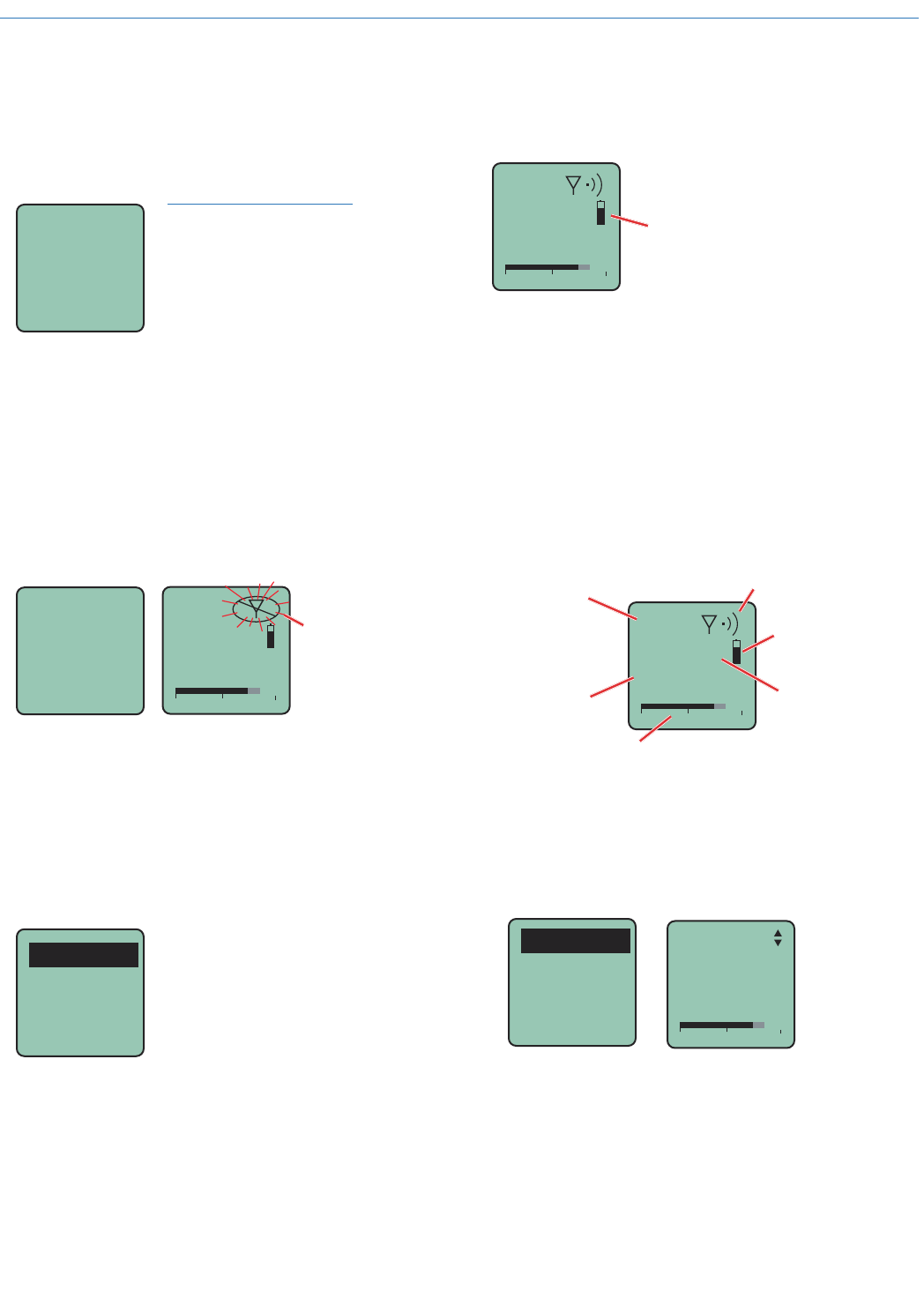
Powering On
Press and hold the Power Button for several seconds
until a countdown on the LCD is completed. The
countdown from 1 through 3 will appear on the LCD,
followed by a display of the model, firmware version,
frequency block and compatibility mode.
Hold
for
Rf On
...3
HH
V1.00
Blk 24
Hybrid
When you release the button, the unit will be opera-
tional with the RF output turned on and the Main
Window displayed.
5
623.400
-40 -20 0
AThe Main Window
NOTE: If the Power Button is released before the
countdown is completed, the unit will boot up in
the “standby” mode with the RF output turned off.
HHa
LECTROSONICS, INC.
8
Battery Condition
An icon on the Main Window indicates the remaining
power of the transmitter batteries. This battery gauge
is most accurate with the typical voltage drop across
the life of alkaline and dry cell lithium batteries.
5
623.400
-40 -20 0
A
Battery Gauge
Rechargeable batteries give little or no warning when
nearing depletion. If you use rechargeable batteries in
the HH, we recommend trying fully charged batteries
first, noting the length of time that the batteries will run
the unit, and in the future using somewhat less than
that time to determine when the battery needs to be
replaced. The Venue and other receivers from Lectro-
sonics offer a timer function to assist in this process.
Navigating Menus and Screens
The Main Window displays the following information:
5
623.400
-40 -20 0
ATB
Hex Code for
Operating frequency
Icon indicates
whether RF output
is turned on or off
Battery condition
Operating
frequency in MHz
Audio level
Function of the
rear panel switch
(talkback button)
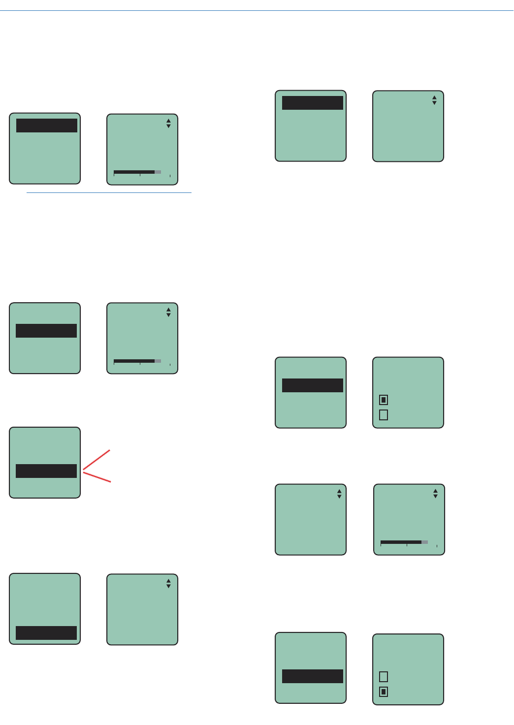
1) Press the MENU/SEL button to enter the setup
menu. Use the UP/DOWN buttons to highlight the
menu item.
2) Press the MENU/SEL button to enter the setup
screen for that item. Use the UP/DOWN buttons
to select the desired value or mode.
Gain
Freq.
Button
Rolloff
-40 -20 0
Gain
25
3) Press the MENU/SEL button to save this setting
and return to the previous screen.
4) Press the BACK button to return to the Main Win-
dow.
Powering Off
Press and hold the Power Button (or the side button
if it is configured for turning the power on and off) for
several seconds and observe the countdown on the
LCD. The countdown on the LCD will progress from 3
to 1 and the power will then be turned off. This can be
done from any menu or screen.
Powering
O . . .
1
NOTE: If the Power Button
is released before the
countdown is completed, the
unit will remain turned on
and the LCD will return to the
same screen or menu that
was displayed previously.
Standby Mode
A brief push of the Power Button turns the unit on and
places it into a “standby” mode (not transmitting). This
allows the transmitter to be set up without the risk of
creating interference for other wireless systems that
are operating in the vicinity.
A notice will appear briefly confirming that the RF out-
put of the transmitter is turned off, followed by the Main
Window. The antenna symbol will blink as a reminder
that the RF output is turned off.
5
623.400
-40 -20 0
AMUTE Symbol blinks
when RF output
is turned OFF
Rf
Off
Power Menu
When the transmitter is turned on, a brief push of
the Power Button will reveal a menu allowing you to
choose between Resume, Rf On?, and Pwr Off?.
Use the UP/DOWN buttons to select one of the menu
items, then press the MENU/SEL button to confirm this
action. The Rf On? selection will enter another screen
prompting a Yes or No answer.
Resume
Rf On?
Pwr Off?
• Resume: Continue operating in the same condi-
tion as before.
• Rf On?: Begin transmitting the RF signal.
• Pwr Off?: Turns off the transmitter.
The unit can also be turned off from any menu or
screen on the LCD by holding the power button in for
the duration of the countdown.
Wideband Hand Held Transmitter
Rio Rancho, NM 9
Gain
This setting is very important since it will determine the
audio signal to noise ratio and dynamic range that the
wireless system will deliver. Gain must be set accord-
ing to the individual voice, the mic capsule in use and
the handling technique of the user. LEDs in the control
panel facilitate accurate gain adjustment.
Gain
Freq.
Button
Rolloff
-40 -20 0
Gain
25
IMPORTANT: See the section Input Gain
Adjustment on page 10 for details.
Freq.
The operating frequency is normally determined using
the scanning function in the receiver or with coordina-
tion software. The frequency is shown on the transmit-
ter LCD display in MHz and with a hexadecimal code
that is used on most Lectrosonics receivers.
Gain
Freq.
Button
Rolloff
-40 -20 0
Freq
8A
628.200
Button
The Side Button on the housing can be set to provide
several functions, or it can be bypassed.
Functions:
TalkBack
Power
Cough
Mute
(none)
See page 11
for details
Gain
Freq.
Button
Rolloff
Rolloff
A low frequency roll-off filter can be set for a -3dB
point at 35, 50, 70, 100 or 125 Hz. Roll-off slopes are
12.2 dB/octave at 35 Hz and 10.1 dB/octave at 70 Hz
through 125 Hz.
Gain
Freq.
Button
Rolloff
Rolloff
70 Hz
The roll-off frequency is normally adjusted by ear to
suit personal preferences.
Compat
The HH can be used with earlier Lectrosonics wireless
and IFB systems and systems from other manufactur-
ers by selecting the correct Compatibility Mode. The
receiver must be set to the same mode.
Compat
Tuning
TxPower
Phase
Compat
Hybrid
The available modes are as follows:
• Hybrid Digital Hybrid receivers
• Mode 3 (other brand contact the factory)
• 200 Mode Earlier Lectrosonics receivers
• 100 Mode 100 Series Lectrosonics receivers
• Mode 6 (other brand contact the factory)
• IFB Mode Lectrosonics IFB receivers
Tuning
The frequency can be adjusted in 100 kHz or 25 kHz
steps to match the receiver. 100 kHz is the standard
increment for Lectrosonics wireless systems, but 25
kHz increments may be needed for use with systems
from other manufacturers or when frequency coordina-
tion requires it.
Compat
Tuning
TxPower
Phase
Tuning
100 kHz
25 kHz
The Hex Code on the Main Screen will be smaller in
the 25 kHz mode and a fraction will appear next to the
characters if a frequency in between even 100 kHz
steps is selected.
Button
Cough
-40 -20 0
Gain
25
TxPower
Output power can be set to 100 mW to extend operat-
ing range (which can also suppress noise and drop-
outs to some extent) or set to 50 mW to slightly extend
the operating life of the batteries.
Compat
Tuning
TxPower
Phase
TxPower
50 mW
100 mW
HHa
LECTROSONICS, INC.
10
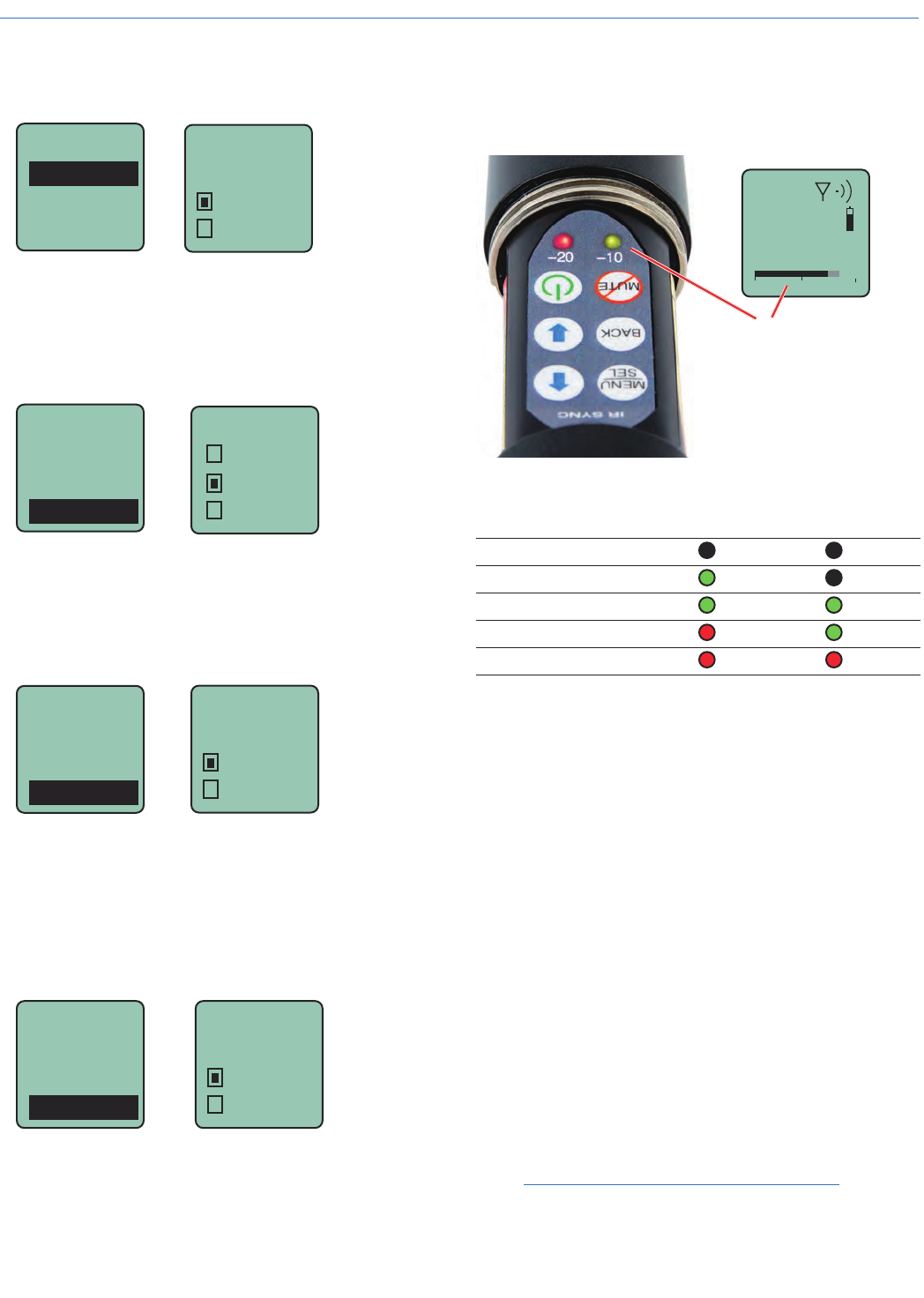
Input Gain Adjustment
The two bicolor Modulation LEDs (located at the bot-
tom of the control panel) provide a visual indication of
the audio signal level entering the transmitter.
5
623.400
-40 -20 0
A
The audio level is shown by
LEDs and in the LCD screen.
The gain should be set so that
the -20 LED just turns red on
the loudest peak (the onset of
limiting).
The LEDs will glow either red or green to indicate
modulation levels as shown in the following table.
Signal Level -20 LED -10 LED
Less than -20 dB Off Off
-20 dB to -10 dB Green Off
-10 dB to +0 dB Green Green
+0 dB to +10 dB Red Green
Greater than +10 dB Red Red
It is best to go through the following procedure with the
transmitter in the “standby” mode so that no audio will
enter the sound system, which could cause feedback.
1) With fresh batteries in the transmitter, power the
unit on into “standby” (no transmission) mode.
2) Press the MENU/SEL button once to enter the
setup menu. Use the UP/DOWN buttons to select
Gain. Press the MENU/SEL button again to enter
the setup screen.
3) Hold the microphone the way it will be used in
actual operation.
4) Speak or sing at the same voice level that will
actually be used during the program, while ob-
serving the modulation LEDs. Use the UP/DOWN
buttons to adjust the gain until the –20 dB LED
starts to flicker red and the –10 dB glows green.
5) Once the audio gain has been set, the signal can
be sent through the sound system for overall level
adjustments, monitor settings, etc. To do this, the
unit must be set to transmit (see Powering On
and Off, and the Standby Mode on page 7).
NOTE: Full modulation is achieved when the
-20 LED first turns red. 30 dB of clean limiting is
available above this point.
Phase
The phase (polarity) of the audio can be inverted to
match other microphone capsules as needed.
TxPower
Phase
Backlgt
Rf On?
Phase
Pos
Neg
Backlgt
The LCD includes a backlight that illuminates the
display for easier viewing in dim lighting conditions. It
is set to come on when any button on the control panel
is pressed, then stay on for either 30 seconds or 5
minutes, or to stay on all the time.
Compat
Tuning
TxPower
Backlgt
Backlgt
On
30 sec
5 min
Rf On?
The transmitter output can be switched on or off with
this menu item. This is useful, for example, when the
transmitter is in the “standby” mode during setup, al-
lowing it to be turned on for normal operation without
having to cycle the power.
Tuning
TxPower
Backlgt
Rf On?
Rf On?
No
Ye s
This menu item can also be used to change the trans-
mitter to the “standby” mode with the RF output turned
off for additional setup.
Default
The default setting simple returns the transmitter back
to the factory settings and any of the menu items can
be readjusted from that default point.
Default
settings
No
Ye s
TxPower
Backlgt
Rf On?
Default
Wideband Hand Held Transmitter
Rio Rancho, NM 11
Side Button Functions
NOTE: The Power and Cough functions were
added starting with serial number 1001.
A special button (the Side Button) on the outside of
the housing can be configured to provide a several dif-
ferent functions, or to be inoperative.
Side Button Functions:
• TalkBack
• Power
• Cough
• Mute
• (none)
The Side Button Setup Switch on the control panel
opens a setup screen to set the Side Button function.
Enter this setup screen and then use the UP/DOWN
arrows to select the desired function, then press the
MENU/SEL button to return to the Main Window.
Press the Side Button
Setup Switch or select
Button on the main
menu.
Side Button
Setup Switch
Gain
Freq.
Button
Rolloff
The button menu provides a scrollable list of the avail-
able functions. Us the UP/DOWN arrows to highlight
the desired function and press BACK or MENU/SEL to
select it and return to the main menu.
Button
TalkBk
Talkback is a “push to talk” function
that is active only while the button is
pressed. The talkback function
provides a communication channel
when used with a receiver equipped
with this function, such as a Venue
Wideband receiver with firmware
Ver. 5.2 or higher. When pressed and held in, the side
button re-directs the audio output to a different audio
channel on the receiver. As soon as the switch is
released, audio is returned to the program channel.
NOTE: The Talkback function is only available
in the Digital Hybrid compatibility mode. An error
message will appear if Talkback is selected while
in another mode.
Button
Power
Power turns the power on and off.
Hold the button in until the count-
down sequence from 3 to 1 is
completed. The power will then be
turned off.
(additional information on page 7)
Button
Cough
Cough is a momentary mute switch.
Audio is muted while the button is
held in.
Button
Mute
Mute is a “push on/push” off function
that toggles on and off each time
the Side Button is pressed. The
mute function defeats the audio in
the transmitter, so it works in all
compatibility modes and with all
receivers.
Button
(none)
(none) disables the switch.
For detailed information on setting up the Talkback
function and the Venue receiver, refer to the Installa-
tion Guide for the Venue Wideband Receiver.
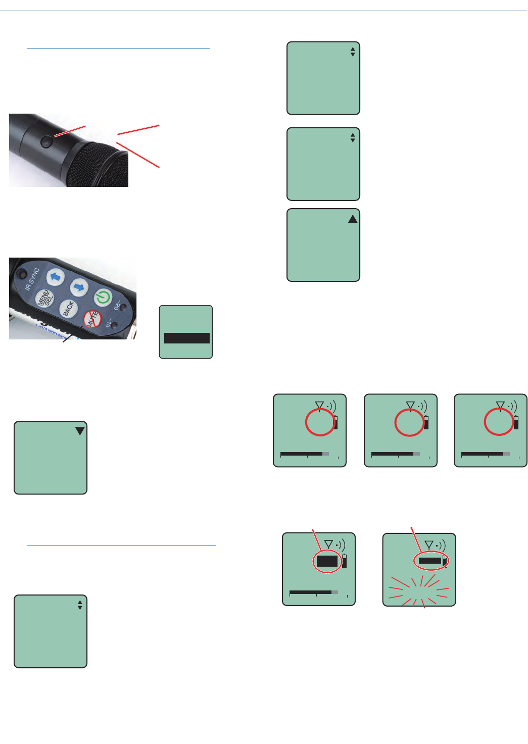
Main Window Displays for Mute and
Talkback Functions
The function of the Side Button is displayed in the
LCD Main Window.
5
623.400
-40 -20 0
A5
623.400
-40 -20 0
ATB 5
623.400
-40 -20 0
AMUTE
None/Power Talkback Mute/Cough
When the Side Button is pressed, the function will be
active and the LCD will display an indication.
5
623.400
-40 -20 0
ATB
Talkback active
Reverse video
5
623.400
AMUTE
<–MUTE–>
Mute active
(MUTE blinks)
Reverse video
HHa
LECTROSONICS, INC.
12
IMPORTANT: Be sure to set the attenuator control back
to its original setting (“F”) for normal operation. or a
subsequent user may think the unit is malfunctioning or
has a poor signal to noise ratio.
LO/MID/HI (bass/mid/treble) - HHVMC only
The HHVMC head includes VariMicTM equalization
adjustments to boost or cut the frequency response in
LOW, MID and HIGH ranges. The LOW and HIGH con-
trols will boost/cut by up to 8 dB while the MID control
will boost/cut up to 6 dB.
LOW MID HIGH
The pointer is between the
darkened dots.
The controls are set to “zero”
(no boost or cut) in this photo
These controls operate as standard tone controls in
that a counterclockwise adjustment cuts the response
in that band and a clockwise adjustment boosts the
response.
+10
0dB
-10 10Hz 100Hz 1KHz 10KHz
+5
-5
VariMic Tone Control Range
Treble
Bass Midrange
Boost
Cut Treble
Midrange
Bass
Mic Capsule Adjustments
(EXPERT LEVEL ADJUSTMENT)
These adjustments significantly alter the gain and
tonal quality of the microphone, and are to be used
only in special circumstances.
Caution: Always make the final decision about
sound quality with the windscreen in place.
Remove the windscreen using the supplied wrench.
Align flats on the wrench with flats on the capsule.
Attenuator Adjustment
The HHC & HHVMC heads include an attenuator in
the preamp circuitry to provide an additional 15 dB of
headroom when needed for extremely loud voices.
The attenuator should ONLY be used when the gain
control is already turned all the way down and the
audio is still driving the preamp into significant limiting
where both -20 and -10 dB LEDs stay lit all or most of
the time during peaks in the audio.
-40 -20 0
Gain
0
Gain set to
minimum (0) on
the LCD.
LEDs on control panel
The attenuator control is a 16 position switch that
attenuates the audio in 1 dB steps. It is marked 0
through F where F is minimum attenuation and 0 is
maximum attenuation. Rotating it clockwise increases
the loudness, and counter clockwise decreases the
loudness.
Attenuator switch set at F for normal operation.
EQ controls
(HHVMC only)
Attenuator
control
Resonance tuned
suspension HHVMC capsule
Wideband Hand Held Transmitter
Rio Rancho, NM 13
Firmware Updates
As of the date of this writing, the firmware update pro-
gram runs only on a Windows operating system.
Updating the firmware is simply a matter of download-
ing a utility program and file from the web site and
running the program with the receiver connected to a
computer via the USB port.
Go to www.lectrosonics.com/US. Click on SUPPORT
in the top bar, then click on the link to the HHa trans-
mitter in the CATEGORIES pane on the right side of
the page. Click on the link labeled Firmware Updates
at the bottom of the page. Download the Firmware
Updater program zip file and extract it to a temporary
folder on your computer. Then download and extract
the firmware zip file (e.g. xxxx_16.zip) and extract it to
a temporary folder on your computer.
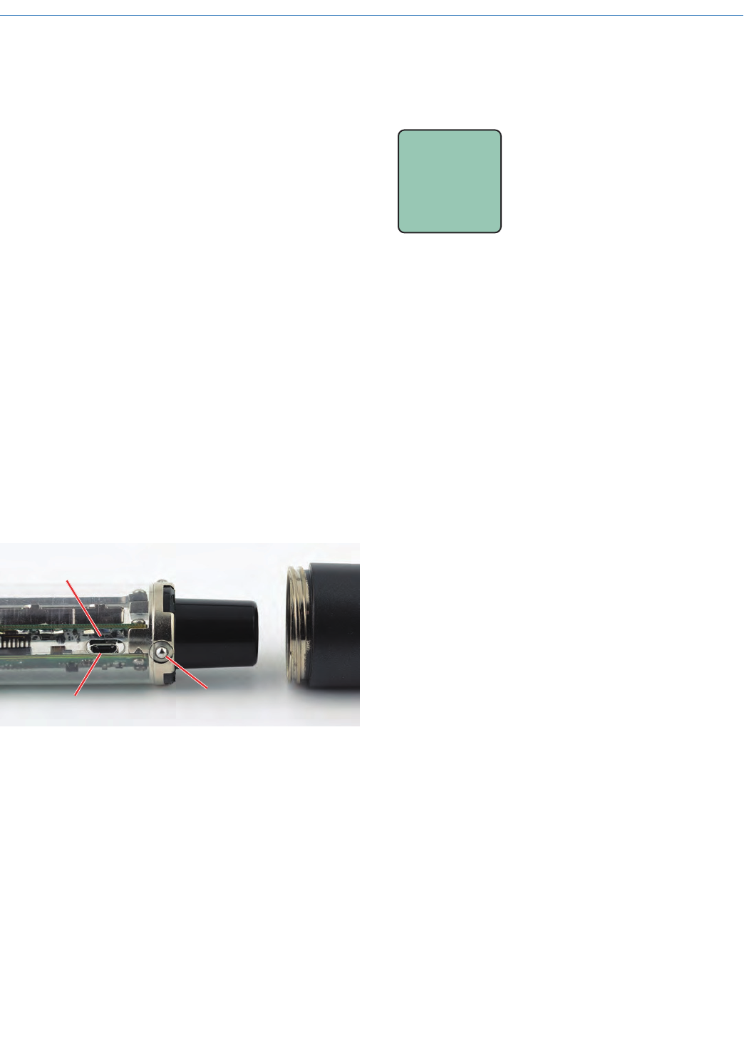
Remove the lower housing of the transmitter by un-
screwing it from the housing attached to the capsule
and pulling it straight off the body of the transmitter to
expose the circuitry. Spring-loaded ball detents provide
a “stop” with only the control panel exposed. Continue
to pull the lower housing farther to remove it. Simply
push the lower housing back onto the transmitter body
to re-install it.
The USB port on the transmitter requires a micro-B
male plug on the connecting cable. The other end of
the cable would normally be a USB A-Type male con-
nector to fit the most common type of USB jack used
on computers.
USB Port
Opening in clear
plastic sleeve
Spring-loaded balls
engage detents in housing
Hold down the BACK and UP arrow buttons on the
transmitter control panel while powering it up. The LCD
will display UPDATE to confirm it is in this mode.
UPDAT E
Connect the USB cable and run the utility program.
The program will automatically detect the transmitter
and prompt for the location of the firmware file. Point
at the file and click on Start. The process takes about
90 seconds. A message on the computer screen will
confirm the update is complete. Turn the transmitter
off and disconnect the USB cable. Turn the transmitter
back on again in the normal mode to verify it is work-
ing correctly.
HHa
LECTROSONICS, INC.
14
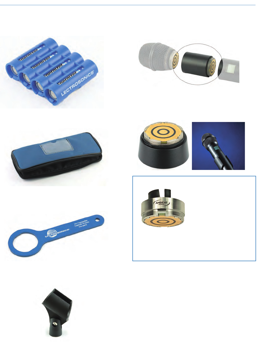
Parts and Accessories
#55008 - Blue Battery Caddy
#CCHH - Zippered Pouch
Padded zipper pouch for handheld transmitter
#26872 Mic Capsule Wrench
Custom wrench for removing windscreen from mic
capsule
#13585 Mic Clip
Screw on mic clip for standard mic stands with 5/8”-27
thread
HHXTND
Extender to for use with microphone flags commonly
used in ENG for network or station ID to keep the flag
from covering the side switch and LCD
HH2SEN Adapter
Adapts Sennheiser G2, G3 and 2000 Series micro-
phone capsule heads to the HH transmitter.
Transmitter interface Capsule interface
HHA Adapter by Ambient Recording
Adapts Neumann KK104 and
KK105 and Sennheiser cap-
sules for the 5000 Series wire-
less with Shure style threads
to the HH transmitter
HHA is available from
Ambient Recording dealers
Visit: www.ambient.de

Wideband Hand Held Transmitter
Rio Rancho, NM 15
Troubleshooting
SYMPTOM POSSIBLE CAUSE
TRANSMITTER WILL NOT POWER ON 1) Batteries are inserted backwards.
2) Batteries are dead, or too low to be used.
HH MODULATION LEDs OFF 1) Audio Gain set too low.
2) Battery is inserted backwards. Check LCD for power indication.
3) Mic capsule is damaged or malfunctioning. Contact the factory
for repair.
HH MODULATION LEDs GOOD BUT NO SOUND
1) Talkback function is engaged (release multi-function button).
See p. 11.
2) Receiver on wrong frequency or wrong block.
3) Receiver connected incorrectly to sound system.
4) Transmitter in standby mode.
RECEIVER RF INDICATOR OFF 1) Transmitter not turned on.
2) Transmitter is in “standby” (non-transmitting) mode. Check the
LCD for the antenna/transmission icon status.
3) Batteries are dead or installed backwards.
4) Receiver antenna missing, defective or improperly positioned.
5) Transmitter and receiver not on same frequency block.
Check labels on transmitter and receiver to be sure they are
operating on the same frequency block.
6) Make sure the transmitter and receiver frequency settings are in
agreement.
7) Operating range is too great.
8) Receiver antenna missing, incorrect frequency or disconnected.
NO SOUND BUT RECEIVER AUDIO LEVEL METER INDICATES SOUND
1) Receiver audio is muted. (Unmute receiver.)
2) Receiver audio output levels set too low.
3) Receiver audio output is disconnected or cable defective
or mis-wired.
4) Sound system or recorder input level is turned down.
DISTORTED SOUND 1) Transmitter Audio Gain set too high. Speak or sing into the
transmitter and check the Audio Level LEDs, Audio Level bar
graph in the transmitter
LCD and corresponding indicators on the receiver.
2) Receiver output level may be too high for the sound system or
recorder input.
3) Excessive wind noise or “breath pops.” Microphone may require
an additional wind screen.
4) Transmitter frequency setting is not correct (when used with
non-Digital Hybrid receiver).
5) Compatibility Mode mismatch between transmitter and receiver.
6) Mic capsule damaged or defective
HISS AND NOISE -- AUDIBLE DROPOUTS 1) Transmitter Audio Gain set too low. See page 10 for proper audio
gain setting.
2) Receiver antenna missing, defective or obstructed.
3) Operating range too great.
4) Interference may be present. Turn transmitter off and observe the
RF level indicator on the receiver. Change frequency if necessary.
5) Return attenuator control back to default setting of “F”, then
readjust audio gain per instructions on page 10
EXCESSIVE FEEDBACK 1) Transmitter Audio Gain set too high. Check level adjustment,
reduce receiver output level, or both.
2) Microphone too close to speaker system.
3) Move microphone closer to the user’s mouth and lower the
sound system volume.

HHa
LECTROSONICS, INC.
16
Specifications
Operating frequencies: †
Band A1: 470.100 - 537.575
Band B1: 537.600 - 614.375
Band C1: 614.400 - 691.175
Band D1: 691.200 - 767.975 (export only)
Channel Step Size:
Normal Tuning mode: 100 kHz
Fine Tuning mode: 25 kHz
RF Power output: Selectable at 50 or 100 mW
Pilot tone: 25 to 32 kHz frequency; 5 kHz deviation
(Hybrid, IFB, 200 Series, Mode 6)
Frequency stability: ± 0.002%
Deviation: ± 75 kHz max. (Digital Hybrid mode)
Spurious radiation: 90 dB below carrier
Operating temperature range: -20° C to +50° C
Input compressor: Dual envelope compressor, >30 dB range
Audio Gain range: 0 to 45 dB; menu selectable
Modulation indicators: Dual bicolor LEDs indicate modulation
of -20, -10, 0 and +10 dB referenced to full
modulation, LCD bar-graph indicator
Frequency response 40 Hz to 20 kHz (+/- 1dB)
Low frequency roll-off: -3 dB selectable @35, 50, 70, 100, 125 Hz,
36 dB/octave (varies slightly w/ selection)
Controls:
External: Programmable mute/talkback button
Internal control panel: Power, Side Button Setup, MENU/SEL, BACK
and Up/Down arrow buttons for menu item
selection and settings.
Battery: (2) AA with polarity protection and
battery ejection lever
Battery Life: 5.5 hours (alkaline); 8-10 hours (lithium)
Battery Status Indication: Transmitted to Lectrosonics Digital Hybrid and
200 Series receivers
Capsule Interface: 1.25 in. diameter x 28 thread pitch
Capsule Power available: 5V, 25 mA max
Input impedance: 1000 Ohms
Weight: 11.4 oz. with lithium batteries and HHC
capsule
Dimensions: 9.5” long x 1.97” diameter at largest point with
HHC capsule attached
Emission Designator: 180KF3E
Specifications subject to change without notice.
† Not all frequency blocks are available in all countries. Consult your local
representative or contact Lectrosonics for more information.

Wideband Hand Held Transmitter
Rio Rancho, NM 17
FCC Compliance:
This device complies with FCC radiation exposure limits as set forth for an un-
controlled environment. This device should be installed and operated so that its
antenna(s) are not co-located or operating in conjunction with any other antenna
or transmitter.
Notice to the End User:
The normal condition of using this device is to keep the hand at least 20mm away
from the base of the microphone.
Industry Canada Compliance:
This device operates on a no-protection no-interference basis. Should the user
seek to obtain protection from other radio services operating in the same TV
bands, a radio license is required. Please consult Industry Canada’s document
CPC-2-1-28, Optional Licensing for Low-Power Radio Apparatus in the TV Bands,
for details.
This device complies with Industry Canada license-exempt RSS standard(s). Op-
eration is subject to the following two conditions:
1. This device may not cause harmful interference;
2. This device must accept any interference received, including interference that
may cause undesired operation of the device.
Cet appareil est conforme à Industrie Canada une licence standard RSS exonérés
(s). Son fonctionnement est soumis aux deux conditions suivantes:
1. Cet appareil ne doit pas provoquer d’interférences
2. Cet appareil doit accepter toute interférence reçue, y compris les interférences
pouvant provoquer un fonctionnement indésirable de l’appareil

HHa
LECTROSONICS, INC.
18
Service and Repair
If your system malfunctions, you should attempt to correct or isolate the trouble before concluding that the equip-
ment needs repair. Make sure you have followed the setup procedure and operating instructions. Check the inter-
connecting cables and then go through the Troubleshooting section in this manual.
We strongly recommend that you do not try to repair the equipment yourself and do not have the local repair shop
attempt anything other than the simplest repair. If the repair is more complicated than a broken wire or loose con-
nection, send the unit to the factory for repair and service. Don’t attempt to adjust any controls inside the units.
Once set at the factory, the various controls and trimmers do not drift with age or vibration and never require read-
justment. There are no adjustments inside that will make a malfunctioning unit start working.
LECTROSONICS’ Service Department is equipped and staffed to quickly repair your equipment. In-warranty repairs
are made at no charge in accordance with the terms of the warranty. Out-of-warranty repairs are charged at a mod-
est flat rate plus parts and shipping. Since it takes almost as much time and effort to determine what is wrong as it
does to make the repair, there is a charge for an exact quotation. We will be happy to quote approximate charges by
phone for out-of-warranty repairs.
Returning Units for Repair
For timely service, please follow the steps below:
A. DO NOT return equipment to the factory for repair without first contacting us by letter or by phone. We need to
know the nature of the problem, the model number and the serial number of the equipment. We also need a
phone number where you can be reached 8 A.M. to 4 P.M. (U.S. Mountain Standard Time).
B. After receiving your request, we will issue you a return authorization number (R.A.). This number will help
speed your repair through our receiving and repair departments. The return authorization number must be
clearly shown on the outside of the shipping container.
C. Pack the equipment carefully and ship to us, shipping costs prepaid. If necessary, we can provide you with the
proper packing materials. UPS is usually the best way to ship the units. Heavy units should be “double-boxed”
for safe transport.
D. We also strongly recommend that you insure the equipment, since we cannot be responsible for loss of or
damage to equipment that you ship. Of course, we insure the equipment when we ship it back to you.
Mailing address: Shipping address: Telephone:
Lectrosonics, Inc. Lectrosonics, Inc. (505) 892-4501
PO Box 15900 581 Laser Rd. (800) 821-1121 Toll-free
Rio Rancho, NM 87174 Rio Rancho, NM 87124 (505) 892-6243 Fax
USA USA
Web: E-mail:
www.lectrosonics.com sales@lectrosonics.com
Lectrosonics Canada:
Mailing Address: Telephone: E-mail:
720 Spadina Avenue, (416) 596-2202 Sales: colinb@lectrosonics.com
Suite 600 (877) 753-2876 Toll-free Service: joeb@lectrosonics.com
Toronto, Ontario M5S 2T9 (877-7LECTRO)
(416) 596-6648 Fax

Wideband Hand Held Transmitter
Rio Rancho, NM 19

20
23 October 2015
581 Laser Road NE • Rio Rancho, NM 87124 USA • www.lectrosonics.com
(505) 892-4501 • (800) 821-1121 • fax (505) 892-6243 • sales@lectrosonics.co
m
LIMITED ONE YEAR WARRANTY
The equipment is warranted for one year from date of purchase against defects in
materials or workmanship provided it was purchased from an authorized dealer. This
warranty does not cover equipment which has been abused or damaged by careless
handling or shipping. This warranty does not apply to used or demonstrator equipment.
Should any defect develop, Lectrosonics, Inc. will, at our option, repair or replace any
defective parts without charge for either parts or labor. If Lectrosonics, Inc. cannot
correct the defect in your equipment, it will be replaced at no charge with a similar new
item. Lectrosonics, Inc. will pay for the cost of returning your equipment to you.
This warranty applies only to items returned to Lectrosonics, Inc. or an authorized
dealer, shipping costs prepaid, within one year from the date of purchase.
This Limited Warranty is governed by the laws of the State of New Mexico. It states the
entire liablility of Lectrosonics Inc. and the entire remedy of the purchaser for any
breach of warranty as outlined above. NEITHER LECTROSONICS, INC. NOR
ANYONE INVOLVED IN THE PRODUCTION OR DELIVERY OF THE EQUIPMENT
SHALL BE LIABLE FOR ANY INDIRECT, SPECIAL, PUNITIVE, CONSEQUENTIAL,
OR INCIDENTAL DAMAGES ARISING OUT OF THE USE OR INABILITY TO USE
THIS EQUIPMENT EVEN IF LECTROSONICS, INC. HAS BEEN ADVISED OF THE
POSSIBILITY OF SUCH DAMAGES. IN NO EVENT SHALL THE LIABILITY OF
LECTROSONICS, INC. EXCEED THE PURCHASE PRICE OF ANY DEFECTIVE
EQUIPMENT.
This warranty gives you specific legal rights. You may have additional legal rights which
vary from state to state.