Lectrosonics HMM WIRELESS MICROPHONE TRANSMITTER User Manual
Lectrosonics Inc WIRELESS MICROPHONE TRANSMITTER Users Manual
Users Manual
HM
Plug-On Transmitter
With Digital Hybrid Wireless™ Technology
INSTRUCTION MANUAL
Rio Rancho, NM, USA
www.lectrosonics.com
Fill in for your records:
Serial Number:
Purchase Date:
Digital Hybrid Wireless
US Patent 7,225,135

HM
LECTROSONICS, INC.
2

Digital Hybrid™ Plug-On Transmitter
Rio Rancho, NM 3
Table of Contents
General Technical Description .............................................. 4
Wideband Design .................................................................. 4
Digital Hybrid Wireless™ Technology ..................................... 4
No Pre-Emphasis/De-Emphasis ........................................... 4
Low Frequency Roll-Off ........................................................ 4
Input Limiter .......................................................................... 5
Signal Encoding and Pilot Tone ............................................ 5
Microprocessor, PLL and VCO Circuits................................. 5
Compatibility Modes .............................................................. 5
Control Panel ........................................................................ 5
Wide-Band Deviation ............................................................ 5
Battery Options and Operating Time .................................... 5
Frequency Blocks .................................................................. 5
Circulator/Isolator .................................................................. 5
Controls and Functions ......................................................... 6
LCD Screen .......................................................................... 6
Power LED ............................................................................ 6
Audio Input Jack .................................................................... 6
Battery Compartment............................................................ 6
Modulation LEDs ................................................................... 6
Audio Button ......................................................................... 6
Freq Button ........................................................................... 6
Up/Down Arrows ................................................................... 6
Antenna ................................................................................. 6
Setup with the LCD ................................................................. 7
Audio Screen ........................................................................ 7
Frequency Screen ................................................................. 7
Compatibility Mode Screen ................................................... 7
Turning the Power On ........................................................... 7
Turning the Power Off ........................................................... 7
Entering the Standby Mode .................................................. 7
Lock/Unlock Screen .............................................................. 7
Battery Installation ................................................................. 8
Operating Instructions ........................................................... 9
Power Up and Boot Sequence .............................................. 9
Power Down .......................................................................... 9
Standby Mode ....................................................................... 9
Selecting the Compatibility Mode .......................................... 9
Setting Transmitter Operating Frequency ............................ 10
Adjusting the Low Frequency Roll-off ................................. 10
Attaching a Microphone and Adjusting Gain ....................... 10
Locking or Unlocking the Control Panel .............................. 11
Attaching/Removing a Microphone ..................................... 11
Accessories .......................................................................... 13
Troubleshooting .................................................................... 14
Specifications and Features ................................................ 16
Service and Repair ............................................................... 17
Returning Units for Repair .................................................. 17
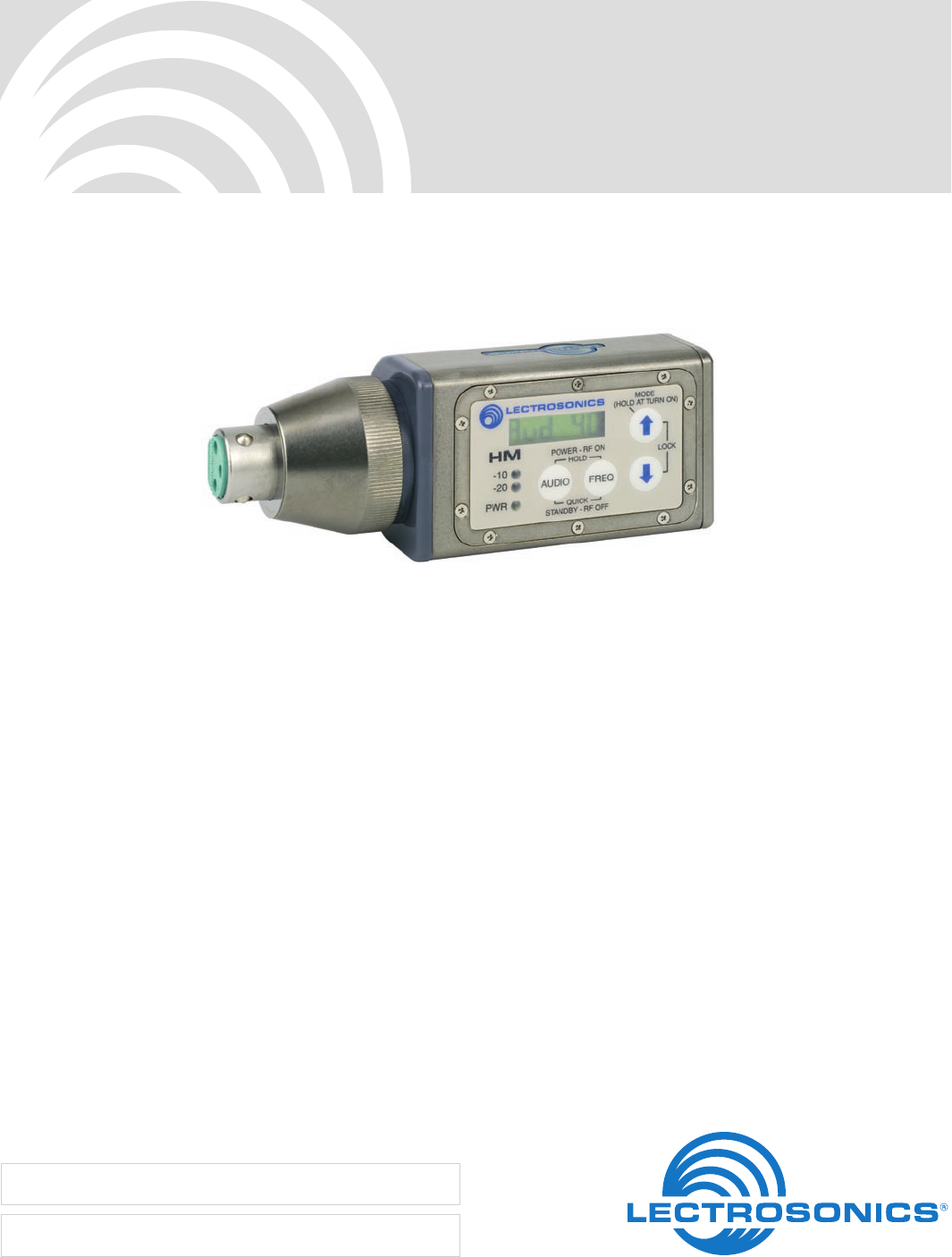
Thank you for selecting a Lectrosonics HM Plug-On
transmitter. The unique design provides several distinct
features for professional applications:
• OutstandingRFoperatingrange
• Superbaudioquality
• Corrosion-resistanthousing
• Programmablecompatibilitymodesforusewitha
wide variety of different receivers
The Digital Hybrid Wireless™ design (US Patent
7,225,135) combines 24-bit digital audio with analog
FM resulting in a system that has the same operating
range as analog systems, the same spectral efficiency
as analog systems, the same long battery life as analog
systems, plus the excellent audio fidelity typical of pure
digital systems.
The HM transmitter uses a standard XLR input jack
for use with most brands of handheld mics. An LCD,
membrane switches and multi-color LEDs on the control
panel make input gain adjustments and frequency and
compatibility mode selection quick and accurate, with-
out having to view the receiver. The battery compart-
ment accepts AA lithium or rechargeable batteries. The
HM is machined from a solid aluminum block to provide
a lightweight and rugged package. A special non-corro-
sive finish resists salt water exposure and perspiration
in extreme environments.
The DSP-based design works with all Digital Hybrid
recievers, and is backward compatible for use with
Lectrosonics 200 and 100 Series and IFB receivers and
some other brands of analog wireless receivers. Com-
panion receivers are covered in separate manuals.
HM
LECTROSONICS, INC.
4
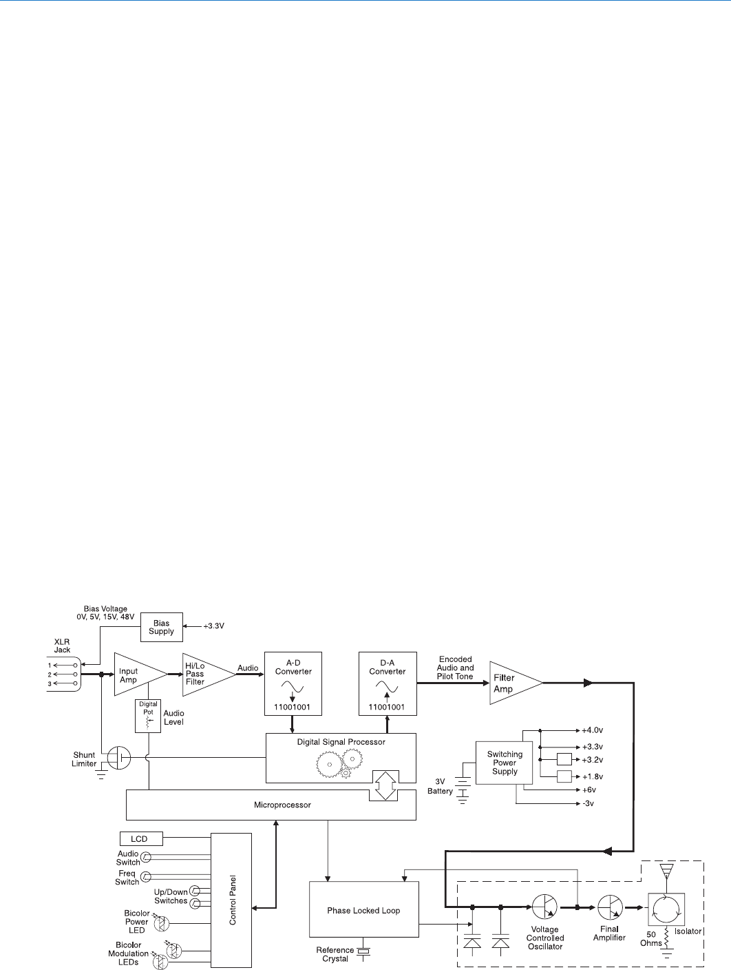
Wideband Design
The HM transmitter uses ±75 kHz wide deviation for an
excellent signal to noise ratio and wide dynamic range.
The DSP controlled input limiter features a wide range
dual envelope design which cleanly limits input signal
peaks over 30 dB above full modulation. Switching power
supplies to provide constant voltages to the transmitter
circuits from the beginning (3 Volts) to the end (1.7 Volts)
of battery life, and an ultra low noise input amplifier for
quiet operation.
Digital Hybrid Wireless™ Technology
All wireless links suffer from channel noise to some de-
gree, and all wireless microphone systems seek to mini-
mize the impact of that noise on the desired signal. Con-
ventional analog systems use compandors for enhanced
dynamic range, at the cost of subtle artifacts (known as
“pumping” and “breathing”). Wholly digital systems defeat
the noise by sending the audio information in digital form,
at the cost of some combination of power, bandwidth and
resistance to interference.
Lectrosonics Digital Hybrid Wireless™ systems over-
come channel noise in a dramatically new way, digitally
encoding the audio in the transmitter and decoding it
in the receiver, yet still sending the encoded informa-
tion via an analog FM wireless link. This proprietary
algorithm is not a digital implementation of an analog
compandor but a technique that can be accomplished
only in the digital domain, even though the inputs and
outputs are analog.
Channel noise still impacts received signal quality and
will eventually overwhelm a receiver. Digital Hybrid
Wireless™ simply encodes the signal to use a noisy
General Technical Description
channel as efficiently and robustly as possible, yield-
ing audio performance that rivals that of wholly digital
systems, without the power and bandwidth problems
inherent in digital transmission.
Because it uses an analog FM link, Digital Hybrid Wire-
less™ enjoys all the benefits of conventional FM wire-
less systems, such as excellent range, efficient use of
RF spectrum, and resistance to interference. However,
unlike conventional FM systems, it does away with the
analog compandor and its artifacts.
No Pre-Emphasis/De-Emphasis
The Digital Hybrid Wireless™ design results in a signal-to-
noise ratio high enough to preclude the need for conven-
tional pre-emphasis (HF boost) in the transmitter and de-
emphasis (HF roll off) in the receiver. This eliminates the
potential for extreme distortion on signals with abundant
high-frequency information.
Low Frequency Roll-Off
The low frequency roll-off can be set for a 3 dB down
point at 35, 50 or 70 Hz to control subsonic and very
low frequency audio content in the audio. The actual roll-
off frequency will vary slightly depending upon the low
frequency response of the microphone.
Excessive low frequency content can drive the transmit-
ter into limiting, or in the case of high level sound sys-
tems, can even cause damage to loudspeaker systems.
The roll-off is normally adjusted by ear while listening
as the system is operating.

Digital Hybrid™ Plug-On Transmitter
Rio Rancho, NM 5
Input Limiter
A DSP-controlled analog audio limiter is employed before
the analog-to-digital (A-D) converter. The limiter has a range
of more than 30 dB for excellent overload protection. A dual
release envelope makes the limiter acoustically transparent
while maintaining low distortion. It can be thought of as two
limiters in series, a fast attack and release limiter followed by
a slow attack and release limiter. The limiter recovers quickly
from brief transients, with no audible side effects, and also
recovers slowly from sustained high levels, to keep audio
distortion low and while preserving short term dynamics.
Signal Encoding and Pilot Tone
In addition to controlling the limiter, the DSP also en-
codes the digitized audio from the A-D converter and
adds an ultrasonic pilot tone to control the receiver’s
squelch. A pilot tone squelch system provides a reliable
method of keeping a receiver output muted (squelched)
even in the presence of significant interference. When
the system is operating in the hybrid mode, a differ-
ent pilot tone frequency is generated for each carrier
frequency to prevent inadvertent squelch problems and
simplify multi-channel coordination.
Microprocessor and DSP
A microprocessor monitors user command inputs from
the control panel buttons and numerous other internal
signals. It works intimately with the DSP to ensure the
audio is encoded according to the selected Compatibil-
ity Mode and that the correct pilot tone is added to the
encoded signal.
Compatibility Modes
The HM transmitter was designed to operate with
Lectrosonics Digital Hybrid receivers and will yield the
best performance when doing so. However, due to the
flexibility of digital signal processing, the transmitters
can also operate in various compatibility modes for use
with Lectrosonics 200 Series, Lectrosonics 100 Series,
IFB and certain non-Lectrosonics receivers. Contact
the Lectrosonics sales department for a complete list of
compatible non-Lectrosonics receivers.
Control Panel
The control panel includes four membrane switches and
an LCD screen to adjust the operational settings. Multi-
color LEDs are used to indicate audio signal levels for
accurate gain adjustment and for battery status.
Wide-Band Deviation
±75 kHz deviation improves the signal to noise ratio and
audio dynamic range of a wireless system dramatically,
compared to other designs that use ±30 kHz to 40 kHz
deviation. Wide deviation combined with a high powered
transmitters makes a significant improvement in signal
to noise ratio and operating range.
Battery Options and Operating Time
Switching power supplies convert battery voltages to
operate various circuit stages with maximum efficiency.
With the variety of alkaline, lithium and rechargeable
NiMH batteries available today in the AA format, there
are many choices to maximize operating time or mini-
mize cost as needed for any application.
Frequency Blocks
Lectrosonics established a “block” numbering system
years ago to organize the range of frequencies avail-
able from the low 500 MHz band to the upper 700
MHz band. Each block includes 256 frequencies in 100
kHz increments. The block number is part of a simple
formula to derive the frequency. The block number is
multiplied by 25.6 to produce the lowest frequency in
the block. For example, block 27 x 25.6 = 691.200.
Circulator/Isolator
The RF output circuit includes a one way circulator/isolator
using a magnetically polarized ferrite. This device greatly
reduces the RF intermodulation produced when multiple
transmitters are used in close proximity to one another
(several feet apart). The isolator also provides additional
RF output stage protection.
HM
LECTROSONICS, INC.
6
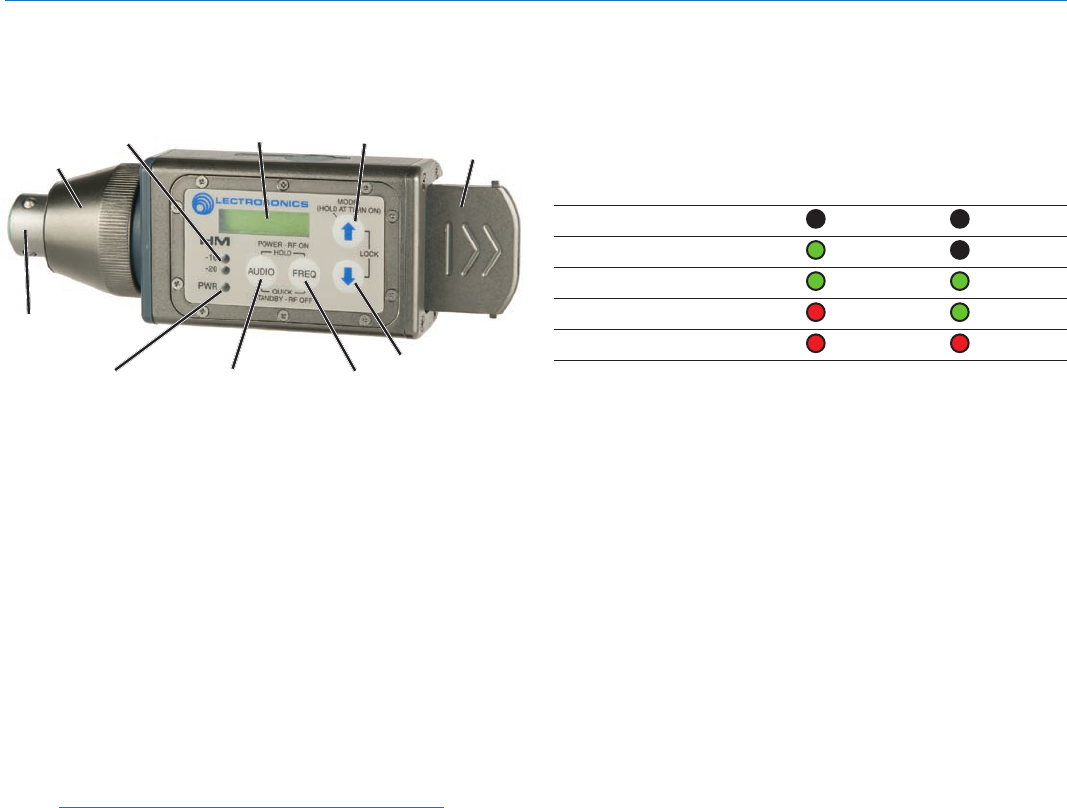
Controls and Functions
LCD Screen
The LCD is a numeric-type Liquid Crystal Display with
several screens that allow settings to be made with the
AUDIO, FREQ, UP and DOWN to configure the trans-
mitter. Turn on and turn off countdowns appear in the
LCD allowing the transmitter to be turned on for adjust-
ments without the output stage enabled, and to prevent
accidental turn off.
Power LED
The PWR LED glows green when the batteries are
good. The color changes to red when there is about 30
minutes of operation left with the recommended lithium
batteries. Alkaline batteries will have about 20 minutes
of life left. When the LED begins to blink red, there are
only a few minutes of life.
Note: NiMH batteries will give little or no warning
when depleted. If you wish to use NiMH batteries
in the HM, we recommend trying fully charged
batteries in the unit, noting the length of time that
the batteries will run the unit and then using the
battery timer feature available on most Digital
Hybrid receivers.
A weak battery will sometimes cause the PWR LED to
glow green immediately after being put in the unit, but
will soon discharge to the point where the LED will go
red or shut off completely.
Audio Input Jack
The XLR input jack on the HM Series transmitters ac-
commodates most hand-held microphones.
Battery Compartment
The Battery Compartment Cover Plate slides open,
allowing access to the battery compartment.
Modulation LEDs
The Modulation LEDs provide a visual indication of the
input audio signal level from the microphone. These two
bicolor LEDs can glow either red or green to indicate
modulation levels. 0 dB in the table below indicates full
modulation.
Signal Level -20 LED -10 LED
Less than -20 dB Off Off
-20 dB to -10 dB Green Off
-10 dB to +0 dB Green Green
+0 dB to +10 dB Red Green
Greater than +10 db Red Red
Audio Button
The AUDIO button is used to display the audio level set-
ting, low frequency roll-off and phantom power mode.
Repeated pressings cycle through the settings and the
UP and DOWN arrows adjust the values.
The AUDIO button is also used with the FREQ button to
enter standby mode and to power the transmitter on or off.
Freq Button
The FREQ Button displays the selected operating
frequency and also toggles the LCD between displaying
the actual operating frequency in MHz and a two-digit
hexadecimal number that corresponds to the equivalent
Lectrosonics Frequency Switch Setting.
The FREQ button is also used with the AUDIO button to
enter standby mode and to power the transmitter on or off.
Up/Down Arrows
The Up and Down arrow buttons are used to select the
operating frequency, adjust the audio level, or set the
Compatibility Mode.
Pressing both arrows simultaneously enters the lock
countdown. Holding the two arrow buttons until the
countdown completes locks the control panel buttons so
they can only be used to display current settings. “Loc”
is displayed to indicate the controls are locked.
Once locked, the buttons can be unlocked only by re-
moving the battery, or via the RM remote control (if this
function was enabled in the transmitter setup).
Antenna
An antenna is formed between the housing and the at-
tached microphone, operating much like a dipole type.
At UHF frequencies the length of the housing is similar
to 1/4 wavelength of the operating frequency, so the
antenna is surprisingly efficient, which helps extend the
operating range and suppress noise and interference.
Battery
Compartment
Cover
XLR Input
Jack
AUDIO Button
LCD
Input
Coupler
FREQ Button
Modulation
LEDs
PWR LED
UP Arrow
DOWN Arrow
Digital Hybrid™ Plug-On Transmitter
Rio Rancho, NM 7
Setup with the LCD
LCD screens and membrane switches are used to set
the operating frequency, adjust the audio input level,
select the Compatibility Mode, turn power on and off
and to lock out the control panel.
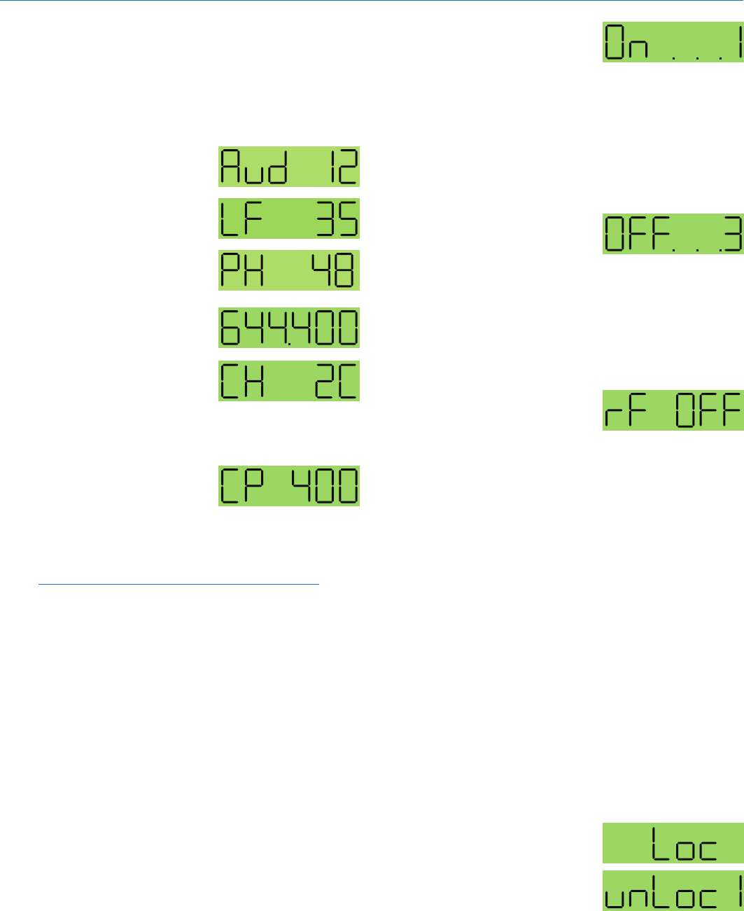
Audio Screen
The Audio screen is used
to adjust input gain and low
frequency roll-off, and to turn
phantom power on and off. Re-
peatedly pressing the AUDIO
button selects the setting. Press
and hold the AUDIO button and
use the Up and Down arrows to
adjust the value.
Frequency Screen
The Frequency Screen dis-
plays the operating frequency
in MHz or as a two-digit
hexadecimal number that cor-
responds to the equivalent
Lectrosonics Frequency Switch
Setting. Pressing the FREQ button toggles between the
two displays.
Compatibility Mode
Screen
Holding down the Up arrow button while powering up
the SM opens the Compatibility Mode screen. By using
the Up or Down arrow buttons, the user can select one
of six compatibility modes:
Note: RF transmission is prevented while selecting
Compatibility Modes. Also, the HM exits the
Compatibility Mode screen to Standby Mode.
• 400-Thisisthefactorydefaultsettingandworkswith
all Lectrosonics 400 Series Digital Hybrid Wireless™
receivers, including the Venue. This mode offers the
best audio quality.
• 200-ThismodeworkswithallLectrosonics200
Series compatible receivers.
• 100-ThismodeworkswithallLectrosonics100
Series compatible receivers.
• 3-(Mode3)Thismodeworkswithanumberof
non-Lectrosonics analog receivers. Contact the
company for a list of compatible receivers.
• IFB-ThismodeworkswithallLectrosonicsIFB
compatible receivers.
• 6-(Mode6)Thismodeworkswithanumberof
non-Lectrosonics analog receivers. Contact the
company for a list of compatible receivers.
While in the compatibility mode screen, pressing either
the AUDIO or FREQ button exits to standby mode. To
power off from the compatibility mode screen, press
and hold AUDIO and FREQ together.
Turning the Power On
With the power turned off,
simultaneously pressing and
holding the AUDIO and FREQ
buttons displays a timer with
numerals on the right. The numerals count up from one
and the boot sequence begins when the count reaches
three. “LECtro” is displayed as the boot sequence be-
gins. If either button is release prior to the screen reach-
ing numeral three, the unit will enter the Standby Mode
with no RF output (see Standby Mode below).
Turning the Power Off
With the unit turned on, simul-
taneously holding the AUDIO
and FREQ buttons starts a
countdown timer with numerals
on the right. The screen counts down from three and
the transmitter turns off when it reaches zero. Releas-
ing either button prior to the Power Off Timer screen
indicating zero returns the unit to normal operation and
displays the previous screen.
Entering the
Standby Mode
With the power turned off,
pressing the AUDIO and FREQ
buttons for about one second places the unit in Standby
Mode. In this mode the RF output is turned off so all
setup adjustments can be made without interfering
with other systems operating in the same location. The
screen displays “rf OFF” to remind the user that the unit
is not transmitting.
Holding the FREQ button in Standby Mode displays the
current operating frequency of the transmitter. The op-
erating frequency can be changed by holding the FREQ
button and pressing either the Up or Down button.
Release the FREQ button, then press and hold it again
to toggle the display between frequency in MHz and the
hex code corresponding to the equivalent Lectrosonics
Frequency Switch Setting.
Holding the AUDIO button in Standby Mode displays
the current audio input level setting. This level can be
changed by holding the AUDIO button and pressing
either the Up or Down button.
Quickly pressing both the FREQ and AUDIO buttons
simultaneiously when the unit is in Standby Mode pow-
ers off the transmitter.
Lock/Unlock Screen
Simultaneously pressing and
holding both the Up and Down
arrow buttons during normal
operation starts the Lock timer.
The timer starts at three and
counts down to zero. When the timer reaches zero, the
transmitter’s controls are locked.
Initial Power On
Timer Screen
Initial Power Off
imer Screen
Standby Screen
HM
LECTROSONICS, INC.
8
The LCD will display the locked condition as long as the
arrow buttons are held, then revert back to the previous
screen when either button is released.
With the controls locked, the AUDIO and FREQ buttons
can still be used to display current settings. Any attempt
to change a setting by pressing either the Up or Down
arrow button will result in an on-screen “Loc” reminder
that the controls are locked. Remove the batteries to
unlock the control panel.
Important: Once the transmitter is locked,
it cannot be unlocked or powered off using
the buttons. The only way to unlock a locked
transmitter is to remove the batteries.
The HM transmitter is powered by two AA batteries.
We recommend using lithium batteries for longest life.
Lithium batteries provide over X hours of operation at
room temperature.
Note: Standard zinc-carbon batteries marked
“heavy-duty” or “long-lasting” are not adequate.
The battery status circuitry is designed for the voltage
drop over the life of lithium batteries.
To install new batteries:
1. Slide open the Battery Cover and remove any old
batteries.
2. Insert the new batteries into the housing. One bat-
tery goes in positive (+) end first, the other negative
(-) end first. Look into the battery compartment to
determine which end goes in which side. The side
with the plastic ring is the side which accepts the
positive end of the battery.
Note: It is possible to install the batteries backward
and close the battery door, but the batteries will
not make contact and the unit will not work.
3. Slide the Battery Cover until it snaps securely shut.
Battery Installation
Battery
Compartment
Battery
Cover
Digital Hybrid™ Plug-On Transmitter
Rio Rancho, NM 9
Standby Mode
Standby Mode allows the user to verify or change the
transmitter’s operating frequency or audio input level
without transmitting any signals. Standby Mode can
only be invoked from a power off condition.
Quickly press and release both the AUDIO and FREQ
buttons simultaneously to enter and exit this mode.
Selecting the
Compatibility Mode
All Digital Hybrid Wireless™
receivers are capable of work-
ing with the Lectrosonics HM
transmitter. By selecting the proper compatibility mode,
the SM will also work with 200 Series, 100 Series and
IFB analog receivers, plus some other analog wire-
less receivers (contact the factory for details). Setting
the Compatibility Mode of the transmitter to match the
receiver is easily done via the Control Panel.
Note: RF transmission is prevented while selecting
Compatibility Modes. Also, the HM exits the
Compatibility Mode screen to Standby Mode. (See
Standby Mode, this section.)
Note: The unit comes from the factory configured
as a 400 Series transmitter.
1) Set the receiver’s audio controls to minimum.
2) Power up the HM and observe the Boot Sequence.
If the Compatibility Mode for the HM does not
match the corresponding receiver, then power off
the HM transmitter.
3) From a power off condition, hold down the Up
arrow, then simultaneously press the AUDIO and
FREQ buttons.
4) The LCD will display the current Compatibility
Mode. Use the Up or Down arrow buttons to set
the Compatibility Mode to match the corresponding
receiver.
The following Compatibility Modes are available:
•100Seriesmode: CP100
•200Seriesmode: CP200
•Mode3(Contactdealerfordetails): CP3
•400Seriesmode: CP400
•IFBSeriesmode: CPIFB
•Mode6(Contactdealerfordetails): CP6
5) The Compatibility Mode selected in Step 4 will be
the current Compatibility Mode until reset using this
procedure. Pressing the AUDIO or FREQ exits into
Standby Mode. To power off from the compatibility
mode screen, press AUDIO and FREQ together.
Power Up and Boot Sequence
1) Ensure that good batteries are installed in the unit.
(See Battery Installation.)
2) Simultaneously press and hold the AUDIO and
FREQ buttons until the Power On Boot Sequence is
initiated. (See Power On Timer.) As the unit turns
on, the Modulation LEDs and PWR LED all glow red,
then green, and then they revert to normal opera-
tion, i.e., the Modulation LEDs glow according to the
audio level present at the Audio Input Jack and the
PWR LED glows green (with good batteries).
AUDIO
Button
FREQ
Button
Modulation
LEDs
PWR LED
UP Arrow
DOWN Arrow
The LCD displays a bootup sequence which con-
sists of four screens:
Company Name: Lectro
Frequency Block (bXX) and
Firmware Version (rX.X): b21r1.1 (typ)
Compatibility Mode: CP 400 (typ)
Audio: Aud 12 (typ)
Power Down
1) Simultaneously press
and hold the AUDIO
and FREQ buttons while
observing that the word
“Off” appears in the LCD
along with a counter.
2) When the counter reaches “0”, the unit turns off.
Note: If the AUDIO and FREQ buttons are
released before the LCD goes blank at the end of
the countdown, the unit will not turn off. Instead, it
will stay energized and the display will return to the
previous screen.
3) If batteries are removed from the unit while it is
turned on, the unit will be turned on when the bat-
teries are replaced.
Operating Instructions
Initial Power Off
Timer Screen
400 Series or Digital
Hybrid Wireless™
Compatibility Mode
HM
LECTROSONICS, INC.
10
Setting Transmitter
Operating Frequency
The Operating Frequency of the
HM can be displayed either in
MHz or as a two-digit hexadeci-
mal number. (See Controls and
Functions, FREQ Button.) The
HM’s operating frequency can
be set with the unit in Standby
Mode or powered up for normal
operation. Use the following procedure to change the
Operating Frequency of the HM transmitter:
1) If the LCD is displaying something other than the
Frequency Screen, press the FREQ button on the
HM Control Panel to enter this screen.
Note: The default display is in MHz. Pressing
the FREQ button again displays the operating
frequency as a two-digit hexadecimal number
that corresponds the equivalent Lectrosonics
Frequency Switch Setting.
2) While holding the FREQ button, use the Up or
Down arrow buttons to move the operating fre-
quency up or down in 100 kHz increments from the
current setting.
Note: The operating frequency displayed on the
LCD wraps as it reaches the upper or lower end of
its range. Thus, if you intend to move the operating
frequency from the lower end of the range to the
upper end, it may be faster to do this by using the
Down arrow until the frequency wraps to the upper
end.
Most Lectrosonics receivers indicate the operating
frequency both in MHz and as a two digit hexa-
decimal number. This conforms to the Lectrosonics
tradition of setting the operating frequency using
two 16-position rotary switches. The HM offers the
ability to set the operating frequency in a similar
manner. Pressing the FREQ button while the LCD
displays the operating frequency in MHz will change
the display to show the equivalent two-digit hexa-
decimal frequency select switch setting. Simply use
the UP or DOWN arrow to increase or decrease the
operating frequency.
Adjusting the Low Frequency Roll-off
Repeatedly press the AUDIO button until the LF roll-
off adjustment screen appears. Then press and hold
the AUDIO button while selecting the desired roll-off
frequency with the UP and DOWN arrows.
The roll-off frequency can be set to 35, 50 or 70 Hz.
Attaching a Microphone and Adjusting Gain
The control panel Modulation LEDs indicate the modu-
lation level and limiter activity. Once set, the transmit-
ter’s audio level setting should not be used to control
the volume of your sound system or recorder levels.
This gain adjustment matches the transmitter gain with
the microphone’s output level, the user’s voice level and
the position of the microphone. The audio input level
can be set with the unit in Standby Mode or while pow-
ered up in normal operation.
Signal Level -20 LED -10 LED
Less than -20 dB Off Off
-20 dB to -10 dB Green Off
-10 dB to +0 dB Green Green
+0 dB to +10 dB Red Green
Greater than +10 db Red Red
Note: Different voices will usually require
different settings of the AUDIO control, so check
this adjustment as each new person uses the
system. If several different people will be using
the transmitter and there is not time to make the
adjustment for each individual, adjust it for the
loudest voice.
1) With the HM powered off, insert the microphone
plug into the Audio Input Jack, aligning the pins and
ensuring that the connector locks.
See the following page for suggestions on using
the microphone connector and sleeve
2) Place the transmitter in Standby Mode, or if the unit
is to be powered up and adjusted, mute the main
sound system prior to powering up the transmitter.
3) Position the microphone in the location where it will
be used in actual operation.
4) Observe the audio level LEDs while speaking or
singing into the microphone at the same voice level
that will be used during the program. While holding
the AUDIO button, press the UP or DOWN arrow
buttons until the both the -20 and -10 LEDs glow
green, with the -20 LED occasionally flickering red.
This will maximize the signal to noise ratio of the
system with full modulation and provide subtle limit-
ing to prevent overload and audible compression of
signal peaks.
Note: Setting the audio level too high reduces the
dynamic range of the audio signal. Setting the
audio level too low may cause hiss and noise in
the audio.
5) If the unit was set up in Standby Mode, it will be
necessary to turn the transmitter off, then power it
up again in normal operation so the RF output will
be on. Then the other components in the sound or
recording system can be adjusted.
Frequency displayed as
two-digit hexadecimal
number
Frequency displayed
in MHz
Digital Hybrid™ Plug-On Transmitter
Rio Rancho, NM 11
Locking or Unlocking the
Control Panel
The Lock mode protects the
transmitter from accidental changes to its settings.
1) Ensure the HM setup is complete (operating fre-
quency, audio level, Compatibility Mode, sensitivity
to remote control).
2) Simultaneously press both the Up and Down ar-
row buttons to start the Lock timer. When the timer
reaches zero, “Loc” is displayed and the controls
are locked.
Important: Once the transmitter is locked, it cannot
be unlocked or powered off using the buttons.
The only ways to unlock a locked transmitter
are to remove the battery or unlock it via the
remote control. The remote control will work only
if the transmitter was previously configured to
respond to the remote control. The unit will
always power up in “unlocked” mode.
Attaching/Removing a Microphone
Three phantom voltages are selectable from the control
panel. The voltages are:
• 5Voltsforlavalieremicrophones,
• 15Voltsforsomeprofessionalmicsrequiringhigh
current and for many common stage mics that will
operate over a wide phantom Voltage range of 12 to
48 Volts. With the proper adapter, this position can
also be used with T power microphones. See our
web site for details on finding or making the proper
adapter.
• 48Voltsformicrophonesthatdoinfactrequirea
supply greater than 18 Volts. (See below for a dis-
cussion of why 42 and not a “true” 48 Volts.)
For longest battery life use the minimum phantom volt-
age necessary for the microphone. Many stage micro-
phones regulate the 48 Volts down to 10 Volts internally
anyway, so you might as well use the 15 Volt setting and
save some battery power. If you are not using a micro-
phone for the input device, or are using a microphone
that does not require phantom power, turn the phantom
power off.
Control Panel Locked
Phantom power should only be used with a fully float-
ing, balanced device such as most microphones with
a 3-pin XLR connector. If you use the phantom power
with an unbalanced device or if pins 2 or 3 are DC con-
nected to ground, then you will draw maximum current
from the power supply. The HM is fully protected against
such shorts but the batteries will be drained at twice the
normal rate.
The transmitter can supply 4 mA at 42 Volts, 8 mA at 15
Volts, and 8 mA at 5 Volts. The 42 Volts setting actually
supplies the same voltage to a 48 Volt microphone as
the DIN standard arrangement due to a dynamic bias-
ing scheme that does not have as much voltage drop
as the DIN standard. The 48 Volt DIN standard arrange-
ment protects against shorts and high fault current
with high resistance in the power supply feeds to pins
2 and 3. This protects the supply if the supply current
is accidentally shorted to ground and also keeps the
microphone from being attenuated by the power supply.
The HM improves on those functions and is able to use
less power from the battery by using constant current
sources and current limiters. With this dynamic ar-
rangement the HM can also supply more than twice the
current of competing 48 Volt plug on units and provide
four times the current for some very high end 15 Volt
microphones.
The 5 Volt setting is provided for lavaliere microphones
made by us and others. Do not power lavalieres from
the 15 or 48 Volt setting as the microphone will most
likely be destroyed. Lectrosonics makes an adapter,
MCA5X, that will adapt our standard TA5F 5 pin micro-
phones to the HM. This adapter also provides protection
against excessive phantom voltage. If voltages higher
than 5 Volts are applied to the adapter, a Zener diode
will shunt excess voltage to ground. The microphone
won’t work until the voltage is correctly reduced to 5
Volts. If you have an older lavaliere mic that was wired
directly to an XLR for use with the earlier UH200’s, we
strongly recommend building our protection circuit into
the XLR to prevent accidental destruction of the lava-
liere.
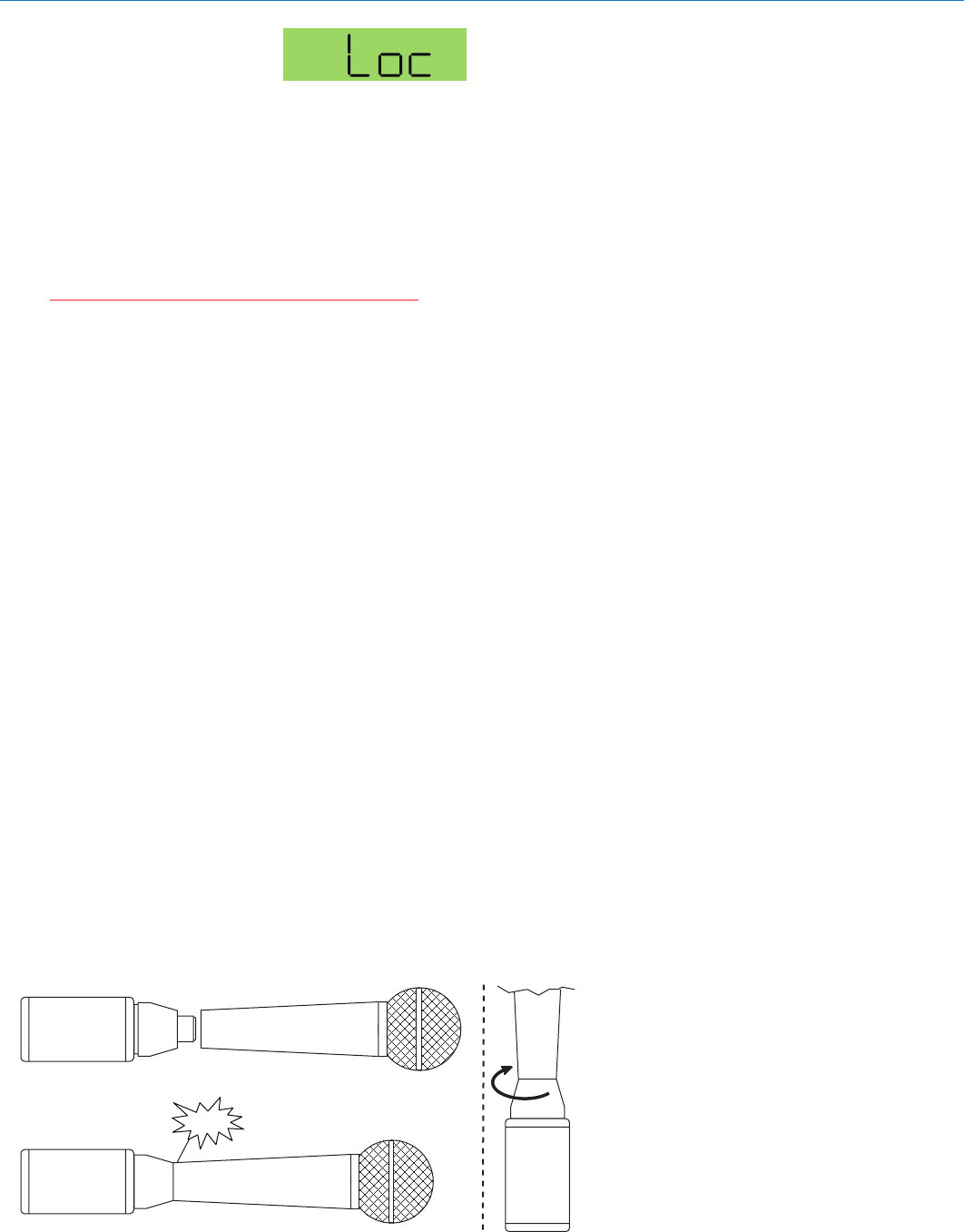
TO AT TACH
TO REMOVE
Hold the
transmitter
case with the
microphone
pointed
upward.
Rotate the
collar in the
direction
shown.
Pull on mic to ensure it is locked.
Press firmly, listen for click.
Depress collar fully.
Click!

HM
LECTROSONICS, INC.
12
Digital Hybrid™ Plug-On Transmitter
Rio Rancho, NM 13
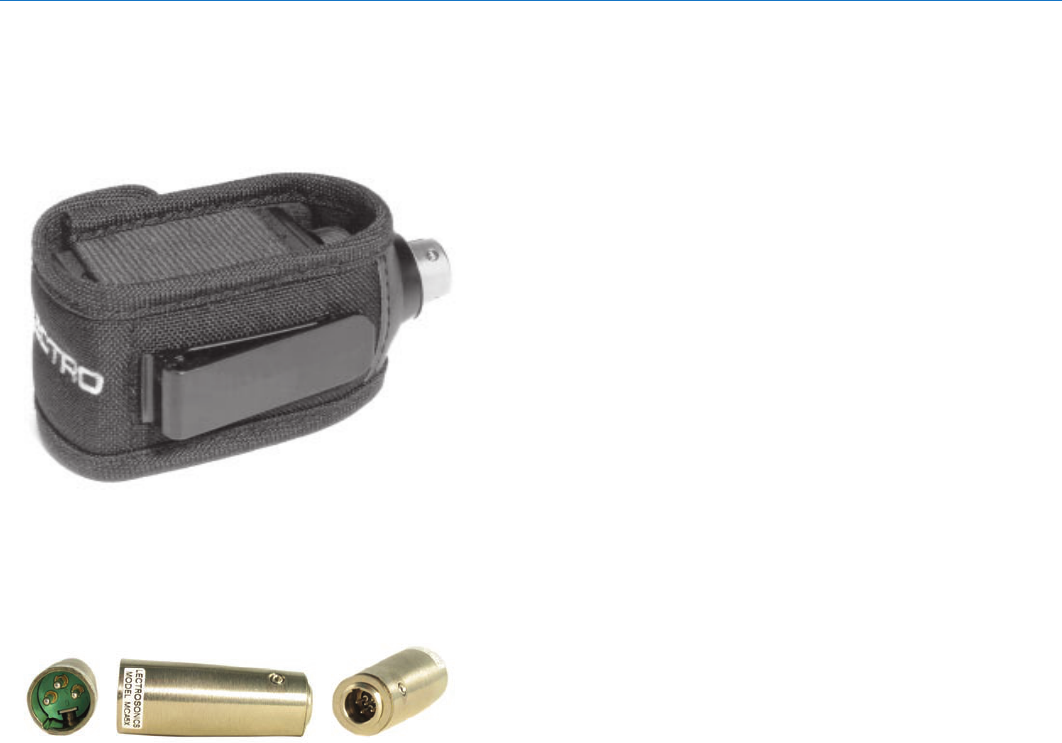
Accessories
PHTRAN2
Cordura Pouch with belt clip and velcro flap.
(Included with TX)
MC5AX
TA5 to XLR adapter for connecting a lavaliere
microphone to the HM.

HM
LECTROSONICS, INC.
14
Before going through the following chart, be sure that you have good batteries in the transmitter. It is important that you
follow these steps in the sequence listed.
SYMPTOM POSSIBLE CAUSE
TRANSMITTER PWR LED OFF 1) Battery is inserted backwards or dead.
2) Transmitter not powered up. (See Operating Instructions,
Power UP and Boot Sequence.)
AUDIO LEVEL LEDs NOT LIGHTING 1) Gain control set to minimum.
2) Battery is dead or installed backwards. Check PWR LED.
3) Mic capsule is damaged or malfunctioning.
4) Mic cable damaged or mis-wired.
RECEIVER RF INDICATOR OFF 1) Transmitter not turned on, or is in Standby Mode.
2) Transmitter battery is dead.
3) Receiver antenna missing or improperly positioned.
4) Transmitter and receiver not on same frequency.
Check switches/display on transmitter and receiver.
5) Transmitter and receiver not on same frequency block.
6) Operating range is too great.
7) Defective transmitter antenna - unit needs repair.
NO SOUND (OR LOW SOUND LEVEL), RECEIVER INDICATES PROPER AUDIO MODULATION
1) Receiver output level set too low.
2) Receiver output disconnected, or cable defective or mis-wired.
3) Sound system or recorder input is turned down.
DISTORTED SOUND 1) Transmitter gain (audio level) is far too high. Check HM
LEDs and receiver audio levels as HM is being used.
2) Receiver output may be mismatched with the sound system or
recorder input. Adjust output level on receiver to the correct level
for the recorder, mixer or sound system. (Use the receiver’s Tone
function to check level.)
3) Excessive wind noise or breath “pops.” Reposition microphone
and/or use a larger windscreen.
4) Transmitter is not set to same frequency as receiver. Check that
operating frequency on receiver and transmitter match.
5) Receiver/Transmitter Compatibility Mode mismatched.
EXCESSIVE FEEDBACK 1) Transmitter gain (audio level) too high. Check gain adjustment
and/or reduce receiver output level.
2) Talent standing too close to speaker system.
3) Mic is too far from user’s mouth.
Troubleshooting

Digital Hybrid™ Plug-On Transmitter
Rio Rancho, NM 15
SYMPTOM POSSIBLE CAUSE
HISS AND NOISE -- AUDIBLE DROPOUTS 1) Transmitter gain (audio level) far too low.
2) Receiver antenna missing or obstructed.
3) Transmitter antenna broken or missing.
4) Operating range too great.
5) Signal interference. Turn off transmitter. If receiver’s signal
strength indicator does not drop to nearly zero, this indicates an
interfering signal may be the problem.
Try a different operating frequency.
“Loc” APPEARS IN DISPLAY WHEN ANY BUTTON IS PRESSED
1) Control Panel is locked. (See Operating Instructions, Locking
and Unlocking the Control Panel.)
“Hold” APPEARS IN DISPLAY WHEN ARROW BUTTONS ARE PRESSED
1) Reminder that it is necessary to hold down the AUDIO or FREQ
button to make adjustments to the audio gain or frequency settings.
“PLL” APPEARS IN DISPLAY 1) Indication that the PLL is not locked. This is a serious condition
that requires factory repair. It may be possible to operate on
another frequency far removed from the one that was selected
when the unlocked condition was indicated.

HM
LECTROSONICS, INC.
16
Modulation indicators: Dual bicolor LEDs indicate modulation of
–20, -10, 0, +10 dB referenced to
full modulation.
Controls: Control panel with LCD and four membrane
switches.
Low frequency roll-off: Selectable; -3dB at 35, 50 or 70 Hz.
Audio Frequency Response: 35 Hz to 20 kHz, +/-1 dB (The low frequency
roll-off is adjustable)
Signal to Noise Ratio (dB):
(overall system, 400 Series mode)
(Note: the dual envelope “soft”
limiter provides exceptionally
good handling of transients
using variable attack and release
time constants. The gradual onset of limiting in the design begins below full
modulation, which reduces the measured figure for SNR without limiting by 4.5 dB)
SmartNR No Limiting w/Limiting
OFF 103.5 108.0
NORMAL 107.0 111.5
FULL 108.5 113.0
Total Harmonic Distortion: 0.2% typical (400 Series mode)
Audio Input Jack: 3-pin Female XLR
Batteries: Two 1.5 Volt AA lithium or rechargeable
NiMH recommended
Battery Life: 3 hours (alkaline); 10 hours (lithium),
8 hours with 2500mAh NiMH
Weight: 2.3 oz.. (65.8 grams) with lithium battery
Overall Dimensions:
2.3 x 1.8 x 0.64 inches
Emission Designator: 180KF3E
Specifications subject to change without notice.
Operating frequencies:
Block 470 470.100 - 495.600
Block 19 486.400 - 511.900
Block 20 512.000 - 537.500
Block 21 537.600 - 563.100
Block 22 563.200 - 588.700
Block 23 588.800 - 607.900 and 614.100 - 614.300
Block 24 614.400 - 639.900
Block 25 640.000 - 665.500
Block 26 665.600 - 691.100
Block 27 691.200 - 716.700
Block 28 716.800 - 742.300
Block 29 742.400 - 767.900
Block 944 944.100 - 951.900
(Frequency usage varies by country)
Frequency range: 256 frequencies in 100 kHz steps
for one 25.5 MHz wide block
Channel Spacing: 100 kHz
Frequency selection: Control panel mounted membrane switches
RF Power output: 100 mW (nominal)
Compatibility Modes (6) Digital Hybrid Wireless™ (400 Series),
200 Series, 100 Series, Mode 3
(other analog), Mode 6, and IFB
Pilot tone: 25 to 32 kHz; 5 kHz deviation
(in 400 Series Mode)
Frequency stability: ± 0.002%
Deviation: ± 75 kHz max. (in 400 Series Mode)
Spurious radiation: 60 dB below carrier
Equivalent input noise: –125 dBV, A-weighted
Input level:
If set for dynamic mic: 0.5 mV to 50 mV before limiting.
Greater than 1 V with limiting.
If set for electret lavaliere mic: 1.7 uA to 170 uA before limiting.
Greater than 5000 uA (5 mA) with limiting.
Line level input: 17 mV to 1.7 V before limiting.
Greater than 50 V with limiting.
Input impedance: 300 Ohms
Input limiter: Soft limiter, 30 dB range
Bias voltages: Selectable; 0, 5, 15. 48 Volts
Gain control range: 44 dB; panel mounted membrane switches
Specifications and Features

Digital Hybrid™ Plug-On Transmitter
Rio Rancho, NM 17
Service and Repair
If your system malfunctions, you should attempt to correct or isolate the trouble before concluding that the equipment
needs repair. Make sure you have followed the setup procedure and operating instructions. Check the interconnecting
cables and then go through the Troubleshooting section in this manual.
We strongly recommend that you do not try to repair the equipment yourself and do not have the local repair shop at-
tempt anything other than the simplest repair. If the repair is more complicated than a broken wire or loose connection,
send the unit to the factory for repair and service. Don’t attempt to adjust any controls inside the units. Once set at the
factory, the various controls and trimmers do not drift with age or vibration and never require readjustment. There are
no adjustments inside that will make a malfunctioning unit start working.
LECTROSONICS’ Service Department is equipped and staffed to quickly repair your equipment. In warranty repairs
are made at no charge in accordance with the terms of the warranty. Out-of-warranty repairs are charged at a modest
flat rate plus parts and shipping. Since it takes almost as much time and effort to determine what is wrong as it does
to make the repair, there is a charge for an exact quotation. We will be happy to quote approximate charges by phone
for out-of-warranty repairs.
Returning Units for Repair
For timely service, please follow the steps below:
A. DO NOT return equipment to the factory for repair without first contacting us by email or by phone. We need
to know the nature of the problem, the model number and the serial number of the equipment. We also need a
phone number where you can be reached 8 A.M. to 4 P.M. (U.S. Mountain Standard Time).
B. After receiving your request, we will issue you a return authorization number (R.A.). This number will help speed
your repair through our receiving and repair departments. The return authorization number must be clearly shown
on the outside of the shipping container.
C. Pack the equipment carefully and ship to us, shipping costs prepaid. If necessary, we can provide you with the
proper packing materials. UPS is usually the best way to ship the units. Heavy units should be “double-boxed” for
safe transport.
D. We also strongly recommend that you insure the equipment, since we cannot be responsible for loss of or dam-
age to equipment that you ship. Of course, we insure the equipment when we ship it back to you.
Lectrosonics USA:
Mailing address: Shipping address: Telephone:
Lectrosonics, Inc. Lectrosonics, Inc. (505) 892-4501
PO Box 15900 581 Laser Rd. (800) 821-1121 Toll-free
Rio Rancho, NM 87174 Rio Rancho, NM 87124 (505) 892-6243 Fax
USA USA
Web: E-mail:
www.lectrosonics.com sales@lectrosonics.com
Lectrosonics Canada:
Mailing Address: Telephone: E-mail:
49 Spadina Avenue, (416) 596-2202 Sales: colinb@lectrosonics.com
Suite 303A (877) 753-2876 Toll-free Service: joeb@lectrosonics.com
Toronto, Ontario M5V 2J1 (877-7LECTRO)
(416) 596-6648 Fax

HM
LECTROSONICS, INC.
18
The FCC requires that the following statements be
included in this manual for SM Series transmitters:
For body worn operation, this HM Transmitter has been tested
and meets the FCC RF exposure guidelines when used with
the Lectrosonics accessories supplied or designated for this
product. Use of other accessories may not ensure compliance
with FCC RF exposure guidelines. Contact Lectrosonics if
you have any questions or need more information about RF
exposure using this product..
This device complies with FCC radiation exposure limits as
set forth for an uncontrolled environment. This device should
be installed and operated so that its antenna(s) are not co-
located or operating in conjunction with any other antenna or
transmitter.

Digital Hybrid™ Plug-On Transmitter
Rio Rancho, NM 19

HM_man.indd
24 September 2008
581 Laser Road NE • Rio Rancho, NM 87124 USA • www.lectrosonics.com
(505) 892-4501 • (800) 821-1121 • fax (505) 892-6243 • sales@lectrosonics.com
LIMITED ONE YEAR WARRANTY
The equipment is warranted for one year from date of purchase against defects in
materials or workmanship provided it was purchased from an authorized dealer. This
warranty does not cover equipment which has been abused or damaged by careless
handling or shipping. This warranty does not apply to used or demonstrator equipment.
Should any defect develop, Lectrosonics, Inc. will, at our option, repair or replace any
defective parts without charge for either parts or labor. If Lectrosonics, Inc. cannot
correct the defect in your equipment, it will be replaced at no charge with a similar new
item. Lectrosonics, Inc. will pay for the cost of returning your equipment to you.
This warranty applies only to items returned to Lectrosonics, Inc. or an authorized
dealer, shipping costs prepaid, within one year from the date of purchase.
This Limited Warranty is governed by the laws of the State of New Mexico. It states the
entire liablility of Lectrosonics Inc. and the entire remedy of the purchaser for any
breach of warranty as outlined above. NEITHER LECTROSONICS, INC. NOR
ANYONE INVOLVED IN THE PRODUCTION OR DELIVERY OF THE EQUIPMENT
SHALL BE LIABLE FOR ANY INDIRECT, SPECIAL, PUNITIVE, CONSEQUENTIAL,
OR INCIDENTAL DAMAGES ARISING OUT OF THE USE OR INABILITY TO USE
THIS EQUIPMENT EVEN IF LECTROSONICS, INC. HAS BEEN ADVISED OF THE
POSSIBILITY OF SUCH DAMAGES. IN NO EVENT SHALL THE LIABILITY OF
LECTROSONICS, INC. EXCEED THE PURCHASE PRICE OF ANY DEFECTIVE
EQUIPMENT.
This warranty gives you specific legal rights. You may have additional legal rights which
vary from state to state.