Lectrosonics IFBT4VHF Wireless Microphone Transmitter User Manual
Lectrosonics Inc Wireless Microphone Transmitter
User Manual
IFBT4-VHF
Synthesized VHF IFB Transmitter
INSTRUCTION MANUAL
Rio Rancho, NM, USA
www.lectrosonics.com
Fill in for your records:
Serial Number:
Purchase Date:
Featuring Digital Hybrid Wireless® Technology
U.S. Patent 7,225,135

IFBT4-VHF
LECTROSONICS, INC.
2

Synthesized VHF IFB Transmitter
Rio Rancho, NM 3
Table of Contents
General Technical Description ............................................4
Introduction .........................................................................4
Audio Input Interface ........................................................... 4
Digital Hybrid Wireless® Technology ...................................5
Audio Signal Processing .....................................................5
Pilot Tone Squelch System .................................................5
Frequency Agility.................................................................5
Power Delay ........................................................................ 5
Microcontroller ....................................................................5
Transmitter ..........................................................................5
Antenna Port .......................................................................5
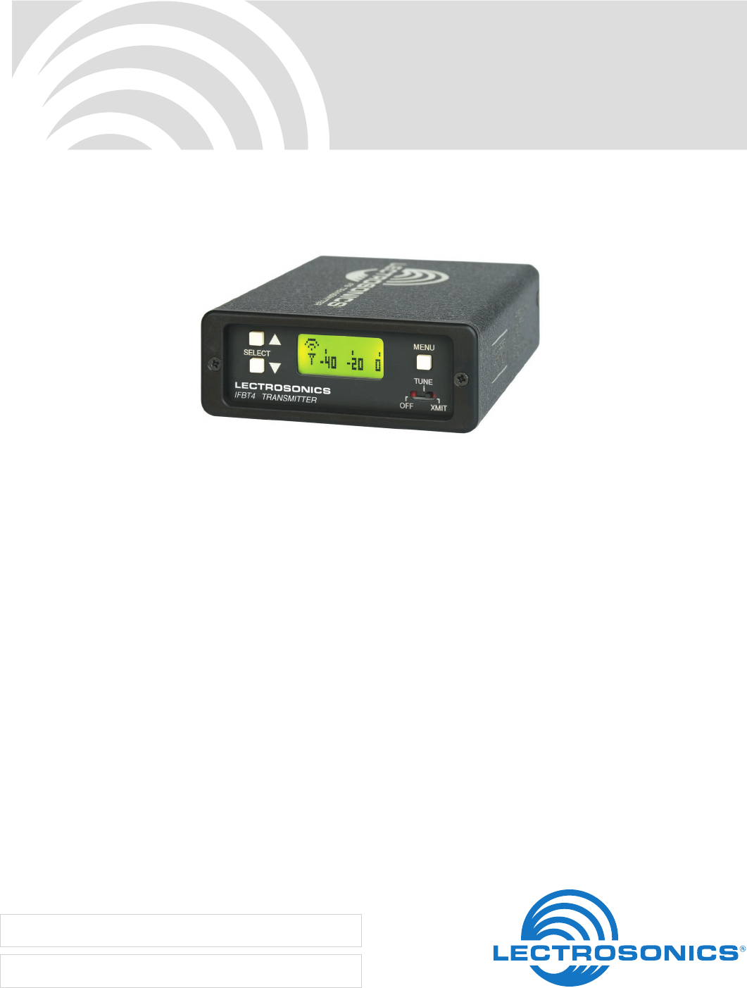
Front Panel Controls and Functions ...................................6
IFBT4 Front Panel ............................................................... 6
OFF/TUNE/XMIT Switch ..................................................... 6
Power Up Sequence ...........................................................6
Main Window .......................................................................6
Frequency Window..............................................................6
Audio Input Gain Window ....................................................6
Setup Window .....................................................................6
COMPAT Setup Screen .......................................................7
Lock/Unlock Panel Buttons .................................................7
IFBT4 Menu Diagram ..........................................................7
Rear Panel
Controls and Functions ................................................8
IFBT4 Rear Panel ...............................................................8
XLR Jack .............................................................................8
Power Input Connector .......................................................8
Antenna ...............................................................................8
Input Configuration (Mode Switches) .................................. 8
Frequency Selection ............................................................9
Installation and Operation .................................................10
Adjust Audio Input Level ...................................................10
Accessories ........................................................................11
Troubleshooting ..................................................................12
Specifications .....................................................................13
Service and Repair .............................................................14
Returning Units for Repair ................................................14
Consumer Alert for US Users - FCC Order DA 10-92
Most users do not need a license to operate this wireless microphone system. Nevertheless,
operating this microphone system without a license is subject to certain restrictions: the system
may not cause harmful interference; it must operate at a low power level (not in excess of 50
milliwatts); and it has no protection from interference received from any other device.
Purchasers should also be aware that the FCC is currently evaluating use of wireless micro-
phone systems, and these rules are subject to change. For more information, call the FCC at
1-888- CALL-FCC (TTY: 1-888-TELL-FCC) or visit the FCC’s wireless microphone website
at www.fcc.gov/cgb/wirelessmicrophones. To operate wireless microphone systems at power
greater than 50mW, you must qualify as a Part 74 user and be licensed. If you qualify and wish
to apply for a license go to: http://www.fcc.gov/Forms/Form601/601.html
IFBT4-VHF
LECTROSONICS, INC.
4
Introduction
This version of the IFB “base station” transmitter oper-
ates in the television broadcast band from 174 to 216
MHz (US TV channels 7 through 13). It will tune across
the entire band, so clear frequencies can be found
almost anywhere.
The VHF spectrum has not been impacted by the
spectrum auctions and re-packing as much as the
UHF spectrum, so the idea behind this product design
is to operate an IFB system in the VHF band and free
up space for wireless microphones in the UHF band.
The IFBT4 features a graphics type backlit LCD
display with a menu system similar to those provided
on other Lectrosonics receivers. The interface can be
Locked to prevent a user from changing any settings
but still allow browsing of the current settings.
The unit can be powered from any external DC source
of 6 to 18 Volts at 200 mA or from the provided 12 Volt
power supply with a locking power connector. The pow-
er inlet has an internal self-resetting fuse and reverse
polarity protection.
The housing is contructed of machined aluminum
extrusion with a durable electrostatic powder coating.
The front and rear panels are machined aluminum with
an anodized finish and laser etched engraving. The
included antenna is a right angle, ¼ wavelength whip
with a BNC connector.
Audio Input Interface
The standard 3 pin XLR connector on the rear panel
handles all audio inputs. The four DIP switches allow
setting the input sensitivity for low levels, such as mi-
crophone inputs, or for high level line inputs, balanced
or unbalanced. The switches also offer special settings
to provide the proper input configurations to match to
Clear Com, RTS1, and RTS2 intercom systems. Pin 1
of the XLR input connector is normally connected to
ground but an internal jumper can be moved if a float-
ing input is desired. Phantom supplied microphones
may be connected without the need for DC isolation at
the input of the transmitter.
A user-selectable low frequency roll-off can be set for
35 Hz or 50 Hz as needed to suppress low frequency
acoustic noise or to extend the frequency response.
DSP-controlled Input Limiter
The transmitter employs a digitally-controlled analog
audio limiter prior to the analog-to-digital converter.
The limiter has a range greater than 30 dB for excel-
lent overload protection. A dual release envelope
makes the limiter acoustically transparent while main-
taining low distortion. It can be thought of as two limit-
ers in series, connected as a fast attack and release
limiter followed by a slow attack and release limiter.
The limiter recovers quickly from brief transients, so
that its action is hidden from the listener, but recovers
slowly from sustained high levels to keep audio distor-
tion low and preserve short term dynamic changes in
the audio.
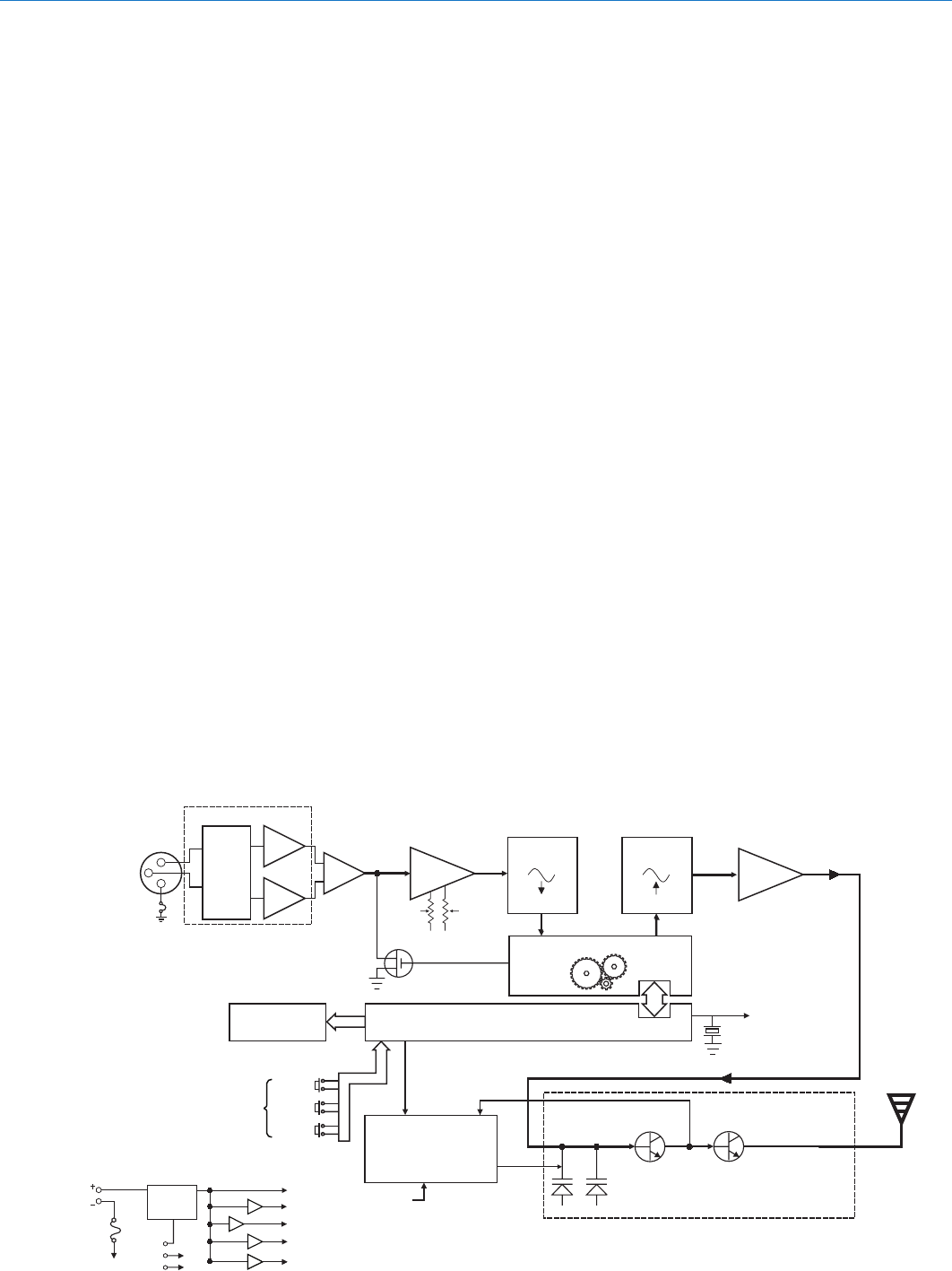
General Technical Description
Filter
Amp
11.3 MHz
Reference
11.3 MHz
Reference
Po
wer
Input
6-18VDC
200mA
Power
OFF
TUNE
XMIT
Polyfuse
Voltage
Regulator
+5 V
+3.3 V
+1.8 V
+15 V
-15 V
Voltage
Controlled
Oscillator
Phase Locked Loop
IFBT4-VHF Transmitter
Block Diagram
Final
Amplifier
Microprocessor
Digital Signal Processor
A-D
Converter
11001001 11001001
D-A
Converter
1
2
3Input
Amplifier
Shunt
Limiter
Graphic LCD Display
UP
Front
Panel
Controls
Input
Amp
LF
Roll-Off
Audio
Level
Audio
XLR
Input
Connector
Audio Input Interface
Mode
Set
Switches
(Rear
Panel)
DOWN
MENU

Synthesized VHF IFB Transmitter
Rio Rancho, NM 5
Digital Hybrid Wireless® Technology
The design is based upon the patented Lectrosonics
Digital Hybrid Wireless® system.* While at the time of
the first release of the product, there is only a compan-
ion analog receiver, the Digital Hybrid Wireless system
is included for compatibility with future products.
Audio Signal Processing
Lectrosonics IFB systems use a single band compan-
dor and pre-emphasis/de-emphasis to reduce noise.
This signal processing is generated and applied by the
DSP for accuracy and clean handling of signal dynam-
ics.
The DSP also provides the ability to employ compat-
ibility modes for use with other wireless equipment in
the VHF spectrum that may come along in the future.
Pilot Tone Squelch System
Lectrosonics IFB systems use a supersonic “pilot
tone” to control the squelch activity in the receiver. A
valid RF signal will include the pilot to signal the audio
output to open. Even strong interference on the same
frequency cannot open the audio output if the pilot
tone is not present.
During normal operation, an IFB receiver will listen for
the distinctive pilot tone, remaining silent (squelched)
until the pilot tone is detected. The pilot tone is located
well above audio frequencies and is never passed
through to the receiver’s audio output.
Frequency Agility
The IFBT4 transmitter uses a synthesized, frequency
selectable main oscillator. The frequency is extremely
stable over a wide temperature range and over time.
The transmitter’s standard tuning range covers 239
frequencies from 174 to 216 MHz in 175 kHz steps. to
alleviate interference problems in mobile applications.
Power Delay
When powering the transmitter on and off, and when
switching between the XMIT and TUNE modes, intel-
ligent circuitry adds brief delays in order to allow time
for circuits to stabilize, both locally and in the match-
ing receiver. These delays prevent clicks, thumps and
other noise in the audio.
Microcontroller
The microcontroller oversees most system operations,
including RF frequency and output, DSP audio func-
tions, buttons and display, and more. User settings are
stored in non-volatile memory, so they are retained
even when the power is turned off.
Transmitter
The transmitter operates at the maximum allowed RF
power level to ensure a clean signal free of dropouts
and noise. All transmitter circuits are buffered and
filtered for excellent spectral purity. The clean trans-
mitted signal reduces the chances for interference in
multiple transmitter installations.
Antenna Port
The 50 Ohm BNC output connector will work with stan-
dard coaxial cabling and remote antennas.
IFBT4-VHF
LECTROSONICS, INC.
6
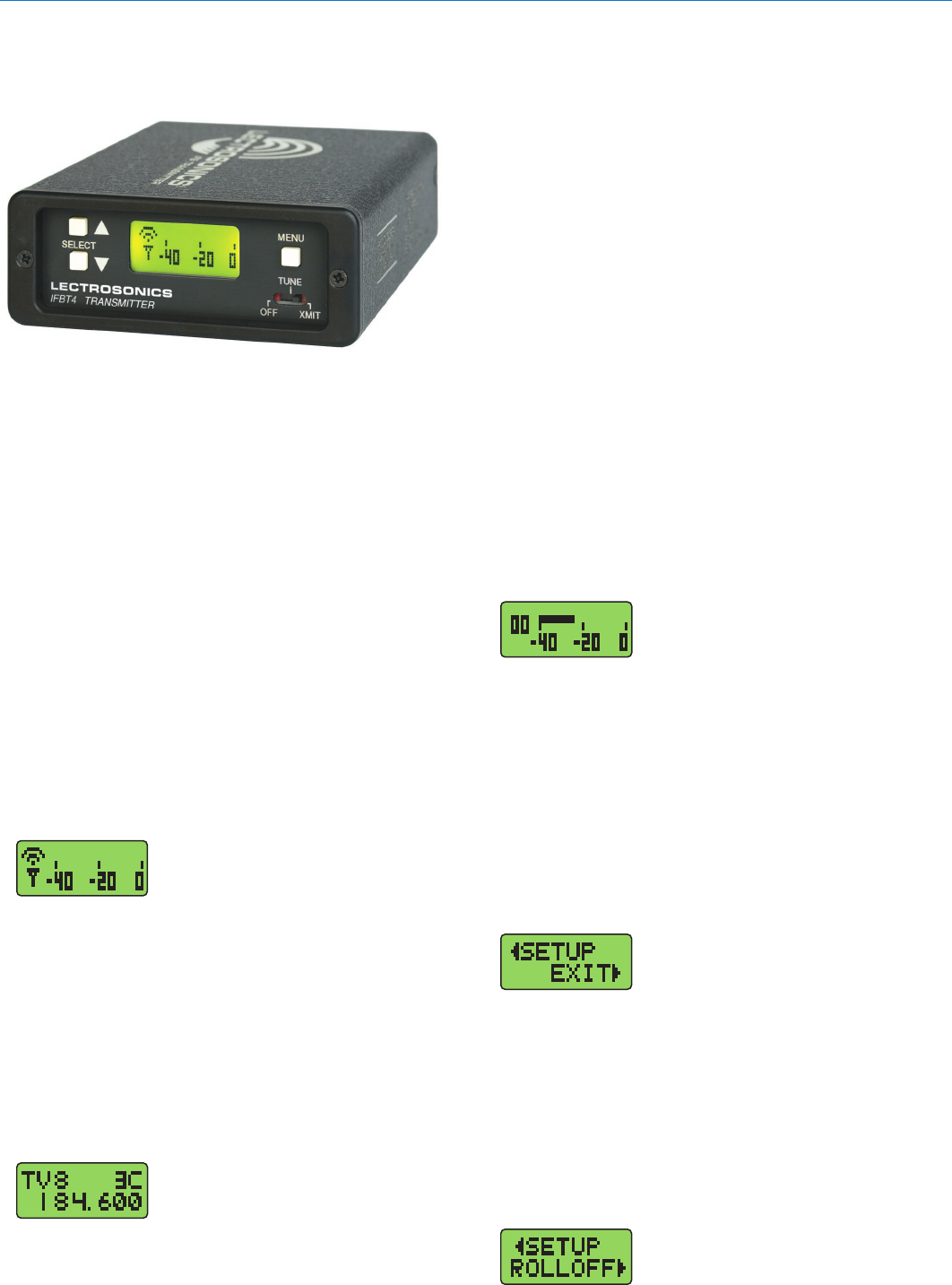
the Main window navigates to the Frequency window.
The Frequency window displays the current operating
frequency in MHz, as well as the standard Lectrosonics
hex code. Also displayed is the UHF television channel to
which the selected frequency belongs.
In XMIT mode, it is not possible to change the operating
frequency.
In TUNE mode, the Up and Down buttons may be used
to select a new frequency.
The UP and DOWN buttons navigate in 175 kHz incre-
ments. Holding the MENU butto+Up and MENU+Down
move 2.8 MHz at a time. In any of the various group tun-
ing modes, the currently selected group identifier is dis-
played to the left of the hex code, and the Up and Down
buttons navigate among the frequencies in the group.
In factory group tuning modes A thru D, MENU+Up and
MENU+Down jump to the highest and lowest frequen-
cies in the group. In user group tuning modes U and V,
MENU+Up and MENU+Down permit access to frequen-
cies not currently in the group.
Pressing and holding the Up or Down button invokes an
autorepeat function, for faster tuning.
Audio Input Gain Window
Pressing the MENU button once from
the Frequency window navigates to
the Audio Input Gain window. This
window greatly resembles the Main
window, with the exception that the current audio input
gain setting is displayed in the upper left corner. The Up
and Down buttons may be used to alter the setting while
reading the realtime audio meter to determine what
setting works best.
The gain range is -18 dB to +24 dB with 0 dB nominal
center. The reference for this control can be changed with
the rear panel MODE switches. See the Installation and
Operation section for more information on the MODE
switches.
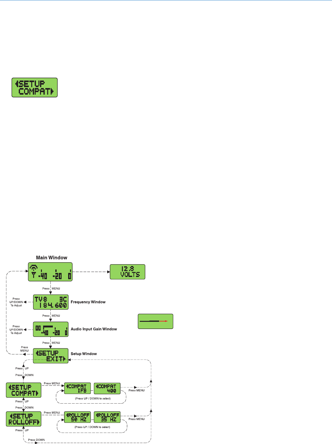
Setup Window
Pressing the MENU button once
from the Audio Input Gain window
navigates to the Setup window. This
window provides access to a menu
for various setup screens.
Initially the active menu item is EXIT. Pressing the Up
and Down keys permits navigation to the menu items:
COMPAT and ROLLOFF.
Pressing the MENU button selects the current menu
item. Selecting EXIT navigates back to the Main window.
Selecting any other item navigates to the associated setup
screen.
ROLLOFF Setup Screen
The ROLLOFF setup screen controls
the low frequency audio response of
the IFBT4 by moving the 3 dB corner
IFBT4 Front Panel
OFF/TUNE/XMIT Switch
OFF Turns the unit off.
TUNE Allows all functions of the transmitter to be set
up, without transmitting. The operating frequen-
cy may only be selected in this mode.
XMIT Normal operating position. The operating
frequency may not be changed in this mode,
though other settings may be changed, so long
as the unit isn’t “Locked.”
Power Up Sequence
When power is first turned on, the front panel LCD
display steps through the following sequence.
1. Displays Model and the firmware verson
(e.g. IFBT4VHF and V1.0).
2. Displays the current compatibility mode setting
(e.g. COMPAT IFB).
3. Displays the Main Window.
Main Window
The Main window is dominated by an
audio level meter, which displays the
current audio modulation level in real
time. In TUNE mode, a blinking
capital “T” is displayed in the lower left corner to
remind the user that the unit is not yet transmitting. In
XMIT mode, the blinking “T” is replaced by an antenna
icon.
Audio limiting is indicated when the audio bargraph
extends all the way to the right and widens somewhat.
Clipping is indicated when the zero in the lower right
corner changes to a capital “C”.
The Up and Down buttons are disabled in this Window.
Frequency Window
Pressing the MENU button once from
Front Panel Controls and Functions
Synthesized VHF IFB Transmitter
Rio Rancho, NM 7
IFBT4 Menu Diagram
of a 4 pole lowpass digital filter. The 50 Hz setting is
the default, and should be used whenever wind noise,
HVAC rumble, traffic noise or other low frequency
sounds may degrade the quality of the audio. The 35
Hz setting may be used in the absence of adverse
conditions, for a fuller bass response.
Press MENU to return to the Setup window.
COMPAT Setup Screen
The COMPAT setup screen selects
the current compatibility mode, for
interoperation with various types of
receivers. The available modes are:
IFB - Lectrosonics IFB compatibility mode. This is the
default setting and is the appropriate setting to
use with the Lectrosonics IFBR1A or a compat-
ible IFB receiver.
400 - Lectrosonics 400 Series. This mode offers the
best audio quality and is recommended if your
receiver supports it.
Press MENU to return to the Setup window.
Lock/Unlock Panel Buttons
To enable or disable the control panel buttons, navi-
gate to the Main Window and press and hold the
MENU button for about 4 seconds. Continue holding
the button as a progress bar extends across the LCD.
When the bar reaches the right side of the screen,
the unit will toggle to the opposite locked or unlocked
mode.
Press UP or DOWN arrow Display External Power Voltage
(added feature with firmware Ver. 1.4)
From the Main Window, press and hold the MENU
button until a progress bar appears (about 4 seconds).
Lock/Unlock Panel Buttons
Continue holding the button until the bar reaches the
right side of the LCD. The selected mode will flash briefly.
IFBT4-VHF
LECTROSONICS, INC.
8
Rear Panel
Controls and Functions
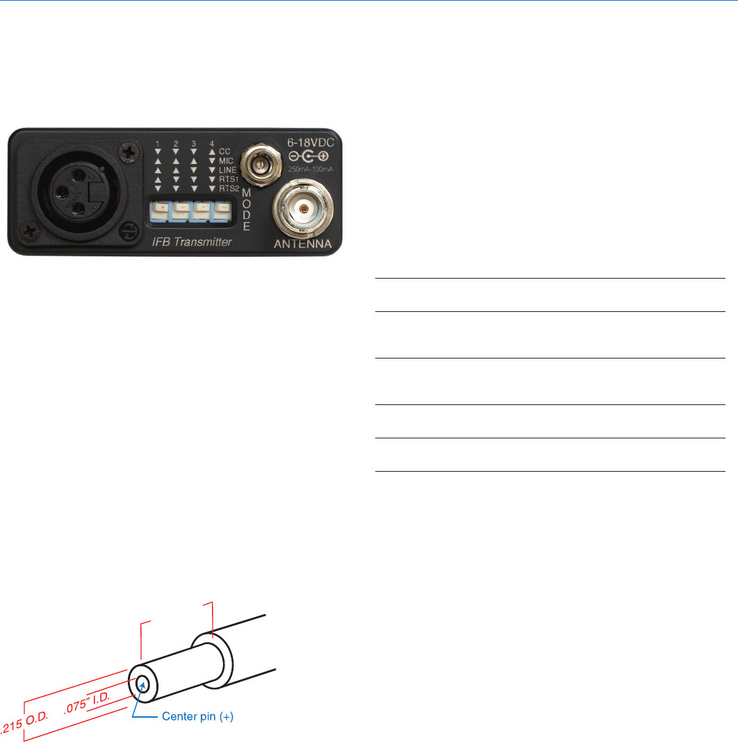
IFBT4 Rear Panel
XLR Jack
A standard XLR female jack accepts a variety of input
sources depending on the setting of the rear panel
MODE switches. XLR pin functions can be changed to
suit the source depending on the positions of the indi-
vidual switches. For detailed information on the setting
of these switches see the Installation and Operation
section.
Power Input Connector
The IFBT4 is designed to be used with the CH20
external (or equivalent) power source. The nominal
voltage to operate the unit is 12 VDC, although it will
operate at voltages as low as 6 VDC and as high as 18
VDC. External power sources must be able to supply
200 mA continuously.
The connector dimensions are shown below. Lectro-
sonics P/N 21425 has a straight back shell. P/N 21586
has a locking collar.
.375” to
.475” typ.
Straight or with
locking collar
Antenna
The ANTENNA connector is a standard 50 ohm BNC
type for use with standard coaxial cabling and remote
antennas.
Input Configuration (Mode Switches)
The MODE switches allow the IFBT4 to accommodate
a variety of input source levels by changing the input
sensitivity and the pin functions of the input XLR jack.
Marked on the rear panel are the most common set-
tings. Each setting is detailed below. Switches 1 and
2 adjust the XLR pin functions while switches 3 and 4
adjust the input sensitivity.
Switch
Positions Input
Name 1 2 3 4 XLR Pins Balanced Sensitivity
CC qqqp 3 = Audio No -10 dBu
1 = Common
MIC pppq 2 = Hi Yes -42 dBu
3 = Lo
1 = Common
LINE ppqq 2 = Hi Yes 0 dBu
3 = Lo
1 = Common
RTS1 pqqq 2 = Hi No 0 dBu
1 = Common
RTS2 qqqq 3 = Hi No 0 dBu
1 = Common
Synthesized VHF IFB Transmitter
Rio Rancho, NM 9
Frequency Selection
The R1A-VHF receiver provides two 16-position rotary
switches to select the frequency, adjusted with a small
screwdriver inserted in the slot in the middle of the
switches. The left-hand switch makes 2.8 MHz steps
and the right-hand switch in 175 kHz steps, with the
switch positions marked in hexadecimal numerals 0
through F.
Frequencies are designated by two characters, such
as B5, where first character is the left-and switch posi-
tion and the second character the right-hand switch
position. Thus, in this example, B5 would indicate
205.775 MHz, as shown in the table below.
175K SWITCH (RIGHT)
0
1
2
3
2.8M
4
SWITCH
5
(LEFT)
6
7
8
196 500
196 675
196 850
197 025
197 200
197 375
197 550
197 725
8
196
.
196
.
675
196
.
850
197
.
025
.
200
197
.
375
197
.
550
197
.
725
9
A
B
C
D
E
F
175K SWITCH (RIGHT)
0
1
2
3
2.8M 4
SWITCH 5
(LEFT) 6
7
8
197 900
198 075
198 250
198 425
198 600
198 775
198 950
199 125
8
197
.
900
198
.
075
198
.
250
198
.
425
198
.
600
198
.
775
198
.
950
199
.
125
9
A
B
C
D
E
F
The front panel LCD on the IFBT4-VHF transmitter
displays frequency in MHz and in the two character
hexadecimal method.
012
3
4
5
6
7
8
9
A
B
C
D
EF012
3
4
5
6
7
8
9
A
B
C
D
EF
Frequency select switches on the
IFBR1A-VHF receiver
2.8 MHz
steps
175 kHz
steps
Frequency in hex
Frequency in MHz
IFBT4-VHF transmitter LCD
IFBT4-VHF
LECTROSONICS, INC.
10
Installation and Operation
1) The IFBT4 transmitter is shipped with pin 1 of the
XLR input connector tied directly to ground. If a
floating input is desired, a Ground Lift Jumper is
provided. This jumper is located inside the unit on
the PC board near the rear panel XLR jack. For
floating input, open the unit and move the Ground
Lift Jumper to the outermost contacts.
Location of Ground Lift Jumper:
Jumper placed toward PCB as shown connects
pin 1 to ground. Move jumper to outside
contacts to lift ground.
2) Set the MODE switches on the rear panel to match
the specific input source to be used. See Inpout
Configuration (Mode Switches).
3) Insert the power supply plug into the 6-18 VDC
jack on the rear panel.
4) Insert the microphone or other audio source XLR
plug into the input jack. Ensure that the pins are
aligned and that the connector locks into place.
5) Attach the antenna (or antenna cable) to the BNC
connector on the rear panel.
6) Set the OFF/TUNE/XMIT switch to TUNE.
7) Press the MENU button to display the Frequency
Window and adjust the transmitter to the desired
frequency with the front panel Up and Down but-
tons.
8) Position the microphone. The microphone should
be placed where it will be located during actual
use.
9) Use the MENU button to navigate to the Audio
Input Gain Window. While speaking at the same
voice level that will be present during actual use,
observe the audio meter display. Use the Up and
Down buttons to adjust the audio input gain so
that the meter reads close to 0 dB, but only rarely
exceeds 0 dB (limiting).
10) Once the transmitter audio gain has been set, the
receiver and other components of the system can
be turned on and their audio levels adjusted. Set
the power switch on the IFBT4 transmitter to XMIT
and adjust the associated receiver and sound
system level as required.
Note: There will be a delay between the moment
the transmitter is energized and the actual
appearance of audio at the receiver output. This
intentional delay eliminates turn-on thumps, and
is controlled by the pilot tone squelch system.
Adjust Audio Input Level
The AUDIO LEVEL control adjusts the gain applied
to the incoming audio signal. This gain adjustment is
used to match the input level to the incoming signal
from the sound source to provide full modulation and
the maximum signal to noise ratio, not to set the vol-
ume of the associated receiver.
If the audio level is too high, compression or distor-
tion may occur. The audio level meter will reach the 0
dB level (full scale) frequently or remain indicating full
scale. Input limiting begins when a vertical line ap-
pears at the right end of the level indicator.
Input limiting indicator
If the audio level is too low, the audio level meter will
continuously indicate a low level. This condition may
cause hiss and noise in the audio, or pumping and
breathing in the background noise.
Low input level
The input limiter will handle peaks up to 30 dB above
full modulation, regardless of the gain control setting.
Occasional limiting is often deemed desirable, indicat-
ing that the gain is correctly set and the transmitter is
fully modulated for optimum signal to noise ratio. Differ-
ent voices will usually require different audio input gain
settings, so check this adjustment as each new person
uses the system. If several different people will be
using the transmitter and there is not time to make the
adjustment for each individual, adjust it for the loudest
voice
Synthesized VHF IFB Transmitter
Rio Rancho, NM 11
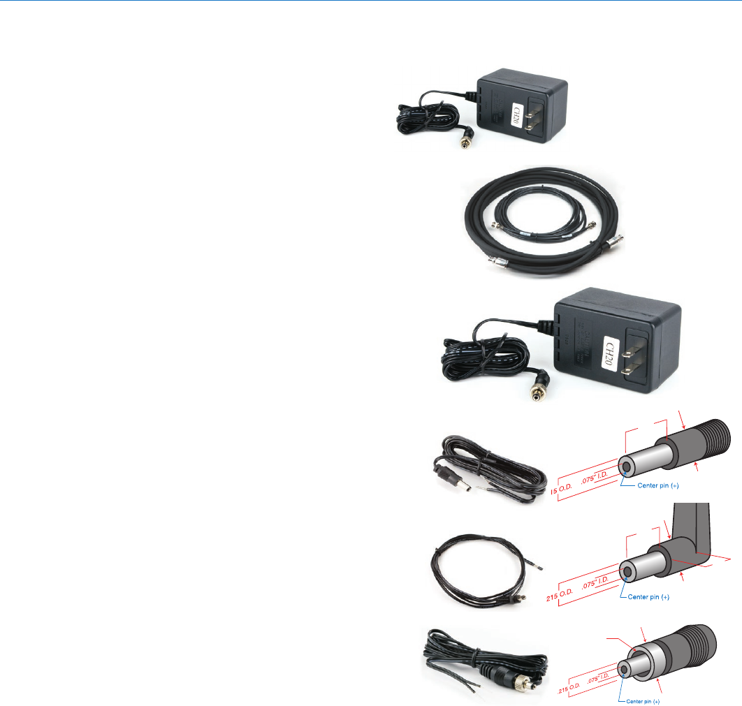
Accessories
CH20
Power supply for IFB base transmitters with lock-
ing LZR power jacks; 110 VAC input, 12 VDC
regulated output; 400 mA max.
A170AC
VHF straight whip antenna; right angle BNC con-
nector
ARG15
A 15 foot antenna cable of standard RG-58 coax
cable with BNC connectors at each end. Loss of 1
to 2 dB with 0.25” diameter.
ARG25/ARG50/ARG100
An antenna cable of Belden 9913F low-loss coax
cable with BNC connectors at each end. Double
shielded, flexible, 50 Ohms, with a foamed poly-
ethylene dielectric. Lower loss (1.6 to 2.3 dB) with
somewhat less weight than standard RG-8 with
the same 0.400” diameter. Available in 25, 50 and
100 foot lengths.
RMP195
4 channel rack mount for up to four IFBT4
transmitters. Rocker switch included to work as a
master power switch if desired.
21425
6 ft. long power cord; coaxial to stripped & tinned
leads. Coaxial plug: ID-.080”; OD-.218”; Depth- .5”.
Fits all compact receiver models that use CH12
power supply.
21472
6 ft. long power cord; coaxial to stripped & tinned
leads. Right angle coaxial plug: ID-.075”; OD-
.218”; Depth- .375”. Fits all compact receiver
models that use CH12 power supply.
21586
DC16A Pigtail power cable, LZR stripped & tinned.
CH20
ARG15
ARG25
ARG50
ARG100
.475”
.375” O.D.
.375”
.35”
.375” O.D.
.475” O.
D.
Locking collar with
5/16”-32 thread
21425
21472
21586
CH20 power supply

IFBT4-VHF
LECTROSONICS, INC.
12
Troubleshooting
NOTE: Always ensure that the COMPAT (compatibility) setting is the same on both transmitter and receiver. A variety
of different symptoms will occur if the settings do not match.
Symptom: Possible Cause:
Display Dead 1) External power supply disconnected or inadequate.
2) The External DC power input is protected by an auto-reset
polyfuse. Disconnect power and wait about 1 minute for the
fuse to reset.
No Transmitter Modulation 1) Audio input gain setting turned all the way down.
2) Sound source off or malfunctioning.
3) Input cable damaged or mis-wired.
No Received Signal 1) Transmitter not turned on.
2) Receiver antenna missing or improperly positioned.
(The IFBR1/IFBR1a headset cable is the antenna.)
3) Transmitter and receiver not on same frequency.
Check on transmitter and receiver.
4) Operating range is too great.
5) Transmitter antenna not connected.
6) Transmitter switch in the TUNE position. Switch to XMIT mode.
No Sound (or Low Sound Level), and Receiver is powered on.
1) Receiver output level set too low.
2) Receiver earphone cable is defective or mis-wired.
3) Sound system or transmitter input is turned down.
Distorted Sound 1) Transmitter gain (audio level) is far too high. Check audio level
meter on transmitter as it is being used. (Refer to Installation &
Operation section for details on gain adjustment.)
2) Receiver output may be mismatched with the headset or
earphone.
Adjust output level on receiver to the correct level for the headset
or earphone.
3) Excessive wind noise or breath “pops.” Reposition microphone
and/or use a larger windscreen.
Hiss, Noise, or Audible Dropouts 1) Transmitter gain (audio level) far too low.
2) Receiver antenna missing or obstructed.
(The IFBR1/IFBR1a headset cable is the antenna.)
3) Transmitter antenna missing or mismatched.
Check that the correct antenna is being used.
4) Operating range too great.
5) Defective remote antenna or cable.
Antenna Icon (in Main Window) or Hex Code (in Frequency Window ) Blinking
1) PLL is unlocked. Retune transmitter. Factory service may be
required if problem persists.

Synthesized VHF IFB Transmitter
Rio Rancho, NM 13
Specifications
Operating Frequencies (MHz): 174.100 to 215.750 MHz
Available Frequencies: 239
Channel Spacing: 175 kHz
RF Power Output: 50 mW
Frequency Stability: ±.001% (10 ppm) @ 25° C
Temperature Stability: ±.001% (10 ppm) from -30° C to +50° C
Channel Selection: Momentary pushbutton switches, tune Up and Down
Compatibility Modes (2) IFB and Digital Hybrid Wireless® (400 Series)
Pilot Tone: 29.997 kHz IFB & 400 MODE; each frequency has a
unique pilot tone
Modulation: • IFB Mode: FM, ±20 kHz deviation
• Digital Hybrid Mode: ±75kHz
Audio Frequency Response: • IFB Mode: 100 Hz to 8 kHz, ±1 dB
• Digital Hybrid Mode: 30Hz to 20kHz ±1dB response
(see Rolloff)
Rolloff: Low frequency audio rolloff is menu selectable for
3 dB down at 35 Hz or 50 Hz.
Audio Compressor: 2 to 1 (IFB mode)
Input Limiter Range: 30 dB
Output Impedance: 50 ohms
Audio Input Levels: • 0 dBu for Line, RTS1 & RTS2
• -10 dBu for Clear Com
• -42 dBu for mic dry inputs (no phantom power)
• +/-50Vdc max
Audio Input Config: Balanced and Unbalanced, rear panel selectable for
Line, Mic. RTS 1, RTS 2, and Clear Comm
Audio Input Impedance: Greater than 2 K balanced, greater
than 1 K unbalanced at any gain setting
Gain Control Range: -18 dB to +24 dB (0 dB nominal center),
Menu selectable
Audio Input Jack: Standard XLR female connector
Power Requirements: 12 to 14 VDC typical, 200 ma. max.;
Max. Input Range 6 to 18 VDC
Power Input Jack: Coax type, locking LZR RL26AE
Indicators: Backlit Liquid Crystal Display. Displays modulation
meter, frequencies, modes, roll-off and audio level
Front panel controls: • MENU momentary pushbutton switch
• Power OFF-TUNE-XMIT, 3 position slide switch
• Select Up momentary pushbutton switch
• Select down momentary pushbutton switch
Rear panel controls: Input Mode Select, 4 section DIP switch
Weight: 9 ozs.
Size: 5.25” L (including connectors) x 3.25” W x 1.25” H
Emission designator: 180KF3E
Specifications subject to change without notice.
FCC Notices:
This device complies with part 15 of the FCC rules. Operation is subject to
the following two conditions: (1) this device may not cause harmful interfer-
ence, and (2) this device must accept any interference received, including
interference that may cause undesired operation.
This equipment complies with the FCC RF radiation exposure limits set
forth for an uncontrolled environment. This equipment should be installed
and operated with a minimum distance of 20cm between the radiator and
any part of your body.
This device complies with Industry Canada’s license-exempt RSSs. Operation is subject to
the following two conditions:
(1) This device may not cause interference; and
(2) This device must accept any interference, including interference that may cause unde-
sired operation of the device.
Le présent appareil est conforme aux CNR d’Industrie Canada applicables aux appareils
radio exempts de licence. L’exploitation est autorisée aux deux conditions suivantes:
(1) l’appareil ne doit pas produire de brouillage, et
(2) l’utilisateur de l’appareil doit accepter tout brouillage radioélectrique subi, même si le
brouillage est susceptible d’en compromettre le fonctionnement.
This equipment complies with the IC RF radiation exposure limits set forth for an uncon-
trolled environment. This equipment should be installed and operated with a minimum
distance of 20 cm between the radiator and any part of your body.

IFBT4-VHF
LECTROSONICS, INC.
14
Service and Repair
If your system malfunctions, you should attempt to correct or isolate the trouble before concluding that the equip-
ment needs repair. Make sure you have followed the setup procedure and operating instructions. Check the inter-
connecting cables and then go through the Troubleshooting section in this manual.
We strongly recommend that you do not try to repair the equipment yourself and do not have the local repair shop
attempt anything other than the simplest repair. If the repair is more complicated than a broken wire or loose con-
nection, send the unit to the factory for repair and service. Don’t attempt to adjust any controls inside the units. Once
set at the factory, the various controls and trimmers do not drift with age or vibration and never require readjustment.
There are no adjustments inside that will make a malfunctioning unit start working.
LECTROSONICS’ Service Department is equipped and staffed to quickly repair your equipment. In warranty repairs
are made at no charge in accordance with the terms of the warranty. Out-of-warranty repairs are charged at a mod-
est flat rate plus parts and shipping. Since it takes almost as much time and effort to determine what is wrong as it
does to make the repair, there is a charge for an exact quotation. We will be happy to quote approximate charges by
phone for out-of-warranty repairs.
Returning Units for Repair
For timely service, please follow the steps below:
A. DO NOT return equipment to the factory for repair without first contacting us by email or by phone. We need
to know the nature of the problem, the model number and the serial number of the equipment. We also need a
phone number where you can be reached 8 A.M. to 4 P.M. (U.S. Mountain Standard Time).
B. After receiving your request, we will issue you a return authorization number (R.A.). This number will help speed
your repair through our receiving and repair departments. The return authorization number must be clearly
shown on the outside of the shipping container.
C. Pack the equipment carefully and ship to us, shipping costs prepaid. If necessary, we can provide you with the
proper packing materials. UPS is usually the best way to ship the units. Heavy units should be “double-boxed”
for safe transport.
D. We also strongly recommend that you insure the equipment, since we cannot be responsible for loss of or dam-
age to equipment that you ship. Of course, we insure the equipment when we ship it back to you.
Lectrosonics USA:
Mailing address: Shipping address: Telephone:
Lectrosonics, Inc. Lectrosonics, Inc. (505) 892-4501
PO Box 15900 581 Laser Rd. (800) 821-1121 Toll-free
Rio Rancho, NM 87174 Rio Rancho, NM 87124 (505) 892-6243 Fax
USA USA
Web: E-mail:
www.lectrosonics.com sales@lectrosonics.com
Lectrosonics Canada:
Mailing Address: Telephone: E-mail:
49 Spadina Avenue, (416) 596-2202 Sales: colinb@lectrosonics.com
Suite 303A (877) 753-2876 Toll-free Service: joeb@lectrosonics.com
Toronto, Ontario M5V 2J1 (877-7LECTRO)
(416) 596-6648 Fax

Synthesized VHF IFB Transmitter
Rio Rancho, NM 15

20 October 2015
581 Laser Road NE • Rio Rancho, NM 87124 USA • www.lectrosonics.com
+1(505) 892-4501 • fax +1(505) 892-6243 • (800) 821-1121 US and Canada • sales@lectrosonics.com
LIMITED ONE YEAR WARRANTY
The equipment is warranted for one year from date of purchase against defects in
materials or workmanship provided it was purchased from an authorized dealer. This
warranty does not cover equipment which has been abused or damaged by careless
handling or shipping. This warranty does not apply to used or demonstrator equipment.
Should any defect develop, Lectrosonics, Inc. will, at our option, repair or replace any
defective parts without charge for either parts or labor. If Lectrosonics, Inc. cannot
correct the defect in your equipment, it will be replaced at no charge with a similar new
item. Lectrosonics, Inc. will pay for the cost of returning your equipment to you.
This warranty applies only to items returned to Lectrosonics, Inc. or an authorized
dealer, shipping costs prepaid, within one year from the date of purchase.
This Limited Warranty is governed by the laws of the State of New Mexico. It states the
entire liablility of Lectrosonics Inc. and the entire remedy of the purchaser for any
breach of warranty as outlined above. NEITHER LECTROSONICS, INC. NOR
ANYONE INVOLVED IN THE PRODUCTION OR DELIVERY OF THE EQUIPMENT
SHALL BE LIABLE FOR ANY INDIRECT, SPECIAL, PUNITIVE, CONSEQUENTIAL,
OR INCIDENTAL DAMAGES ARISING OUT OF THE USE OR INABILITY TO USE
THIS EQUIPMENT EVEN IF LECTROSONICS, INC. HAS BEEN ADVISED OF THE
POSSIBILITY OF SUCH DAMAGES. IN NO EVENT SHALL THE LIABILITY OF
LECTROSONICS, INC. EXCEED THE PURCHASE PRICE OF ANY DEFECTIVE
EQUIPMENT.
This warranty gives you specific legal rights. You may have additional legal rights which
vary from state to state.