Lectrosonics M4T Digital Modulation Transmission System User Manual
Lectrosonics Inc Digital Modulation Transmission System
User Manual
Digital IEM System
INSTRUCTION MANUAL
Rio Rancho, NM, USA
www.lectrosonics.com
Fill in for your records:
Serial Number:
Purchase Date:

QUADRA
LECTROSONICS, INC.
2
Table of Contents
Safety Notes .......................................................................... 3
System Overview .................................................................. 4
Receiver Operation ............................................................... 5
Receiver Menus .................................................................... 6
Selecting 2-channel or 4-channel Operation ..................... 6
2-channel Operation ............................................................. 7
4-channel operation ............................................................. 8
Split 4-channel operation ..................................................... 9
Receiver: Body Placement ................................................ 12
Receiver Accessories ........................................................ 12
Transmitter Front Panel ..................................................... 14
Transmitter Rear Panel ....................................................... 14
Initial Setup ......................................................................... 15
Powering the Unit ON and OFF ......................................... 15
LCD ...................................................................................... 15
Audio Signal Monitoring .................................................... 15
Transmitter Menus .............................................................. 16
Selecting 2-channel or 4-channel Operation ..................... 16
Tuning ............................................................................... 16
Input Type .......................................................................... 16
Audio Trim ......................................................................... 16
Lock Setup ........................................................................ 17
Factory Default Reset ....................................................... 17
Rack Mount Hardware ........................................................ 18
Dual Rack-Mount Instructions ........................................... 18
Single Rack-Mount InstructionsFirmware Updates ........ 21
Transmitter Accessories .................................................... 22
Specifications ..................................................................... 22

Digital IEM System
Rio Rancho, NM 3
Excessive sound levels can cause permanent hearing
damage.
1. Always adjust the volume to the lowest level be-
fore listening to unknown transmissions.
2. Use the lowest reasonable level consistent with
hearing safety.
3. Don’t use high sound levels in the earphone to
overcome high ambient sound levels. That is ab-
solutely foolish! Demand and use high isolation
earphones.
4. Don’t expose your ears to sound levels that cause
them to ring. If your ears do ring after exposure,
think of it as a warning bell telling you not to do
that again.
OSHA (Occupational Safety Health Administration)
guidelines on the maximum allowable time exposure
to sound pressure levels that will cause hearing dam-
age are as follows:
8 hours at 90 dB SPL
4 hours at 95 dB SPL
2 hours at 100 db SPL
1 hour at 105 dB SPL
30 mins at 110 dB SPL
15 mins at 115 dB SPL
NEVER expose your ears to 120 dB SPL or higher!
Damage will occur.
Safety Notes
FCC Notice
NOTE: This equipment has been tested and found to
comply with the limits for a Class B digital device, pur-
suant to Part 15 of the FCC Rules. These limits are de-
signed to provide reasonable protection against harmful
interference in a residential installation. The equipment
generates, uses and can radiate radio frequency energy
and, if not installed and used in accordance with the
instructions, may cause harmful interference to radio
communications. However, there is no guarantee that
interference will not occur in a particular installation.
If this equipment does cause harmful interference to
radio or television reception, which can be determined
by turning the equipment off and on, the user is encour-
aged to try to correct the interference by one or more of
the following measures:
• Reorientorrelocatethereceivingantenna
• Increasetheseparationbetweentheequipment
and receiver
• Connecttheequipmentintoanoutletonacircuit
different from that which the receiver is connected
• Consultthedealeroranexperiencedradio/TVtech-
nician for help
Changes or modifications to this equipment not ex-
pressly approved by Lectrosonics, Inc. could void the
user’s authority to operate it.
Industry Canada Notices
Operation of this device is subject to the following two
conditions: (1) this device may not cause interference,
and (2) this device must accept interference, including
interference that may cause undesired operation of the
device.
This device has been designed to operate with the
antenna listed below, and having a maximum gain of 6
dB. Antennas not included in this list or having a gain
greater than 6 dB are strictly prohibited for use with this
device. The required antenna impedance is 50 ohms.
• LectrosonicsM4TAntenna;P/N21422
• LinxTechnologiesmodelANT-916-CW-HWR-RPS
To reduce potential radio interference to other users,
the antenna type and its gain should be so chosen that
the equivalent isotropically radiated power (e.i.r.p.) is
not more than that permitted for successful communica-
tion.
QUADRA
LECTROSONICS, INC.
4
System Overview
The Quadra system provides an entirely new level
of audio and RF performance in a wireless monitor
system. The combination of analog or digital input
capability, ultra-low latency 24 bit, 48 kHz audio, digital
RF modulation and discrete four channel mixing capa-
bility make the Quadra a truly unique IEM product for
mission-critical, professional applications.
The system is designed for line level analog audio
signalsandAES/EBUdigitalaudioinputsignals.
48kHz/24-bitaudio,ruler-at20Hzto20kHzfrequency
response, ultra-low distortion and high dynamic range
assure excellent audio quality. Housings and panels
are machined aluminum with electrostatic powder
coated and anodized finishes and laser etched mark-
ing for durability. An intuitive mixing interface and
comprehensive LCD on the belt pack receiver provides
performing artists and monitor engineers alike with a
comfortable and confident user experience.
M4 Transmitter
The half-rack transmitter can accept up to four inputs
from digital or analog sources. The inputs can be con-
figured as follows:
• Fouranaloginputsusingallfourjacks
• Twodigitalinputsusingjack1andtwobalanced
analog inputs using jacks 3 and 4
• Fourdigitalchannelsusingjacks1and2
The input connectors are full-size balanced XLR types
forAES/EBUandbalancedlinelevelanalogsignals.
Input preamp circuits use a special balanced amplifier
with very high common mode rejection to minimize
hum and noise.
EitheranalogorAES/EBUdigitalinputsignalsare
converted to an internal 24-bit digital format which is
then encoded, organized into packets, and passed to
an RF modulator using spread spectrum techniques
and error correction for robust reception. The modu-
lated RF signal is filtered before and after amplification
to suppress out-of-band noise and spurious signals,
andacirculator/isolatorguardsagainstintermodulation
interference (IM).
The transmitter can be free-standing or rack-mounted
in single units (via an optional rack mounting kit) or in
a dual configuration using supplied hardware.
A USB port is provided for firmware updates.
M4 Receiver
The receiver employs advanced antenna switching
diversity reception, switching between the antennas
during packet headers in order to maintain a seamless
audio signal. A configurable four-channel mixer on the
top of the receiver housing allows the user to mix from
four discrete audio channels according to the needs
of the performance. The headphone jack is fed from a
high-qualitystereoamplierwithgreaterthan100mW
available to drive headphones or earbuds to sufficient
levels for stage performance or other environments
with significant background noise. A high-density,
backlit LCD allows the user to make setup changes via
the available menu options.
A USB port is provided for firmware updates.
Frequency Range
Using the license free 902 - 928 MHz ISM band, this
system is outside the normal broadcast frequencies
thus providing both technical and operational advan-
tages over standard analog systems.
OR
Freq 1 Freq 2 Freq 3 Freq 4
4 CHANNEL MODE
2 CHANNEL MODE
Freq
1A
Freq
2A
Freq
2B
Freq
3A
Freq
3B
Freq
4A
Freq
4B
OR OR OR
Freq
1B
In four-channel mode, the system occupies 4 MHz and
is selectable between four available center frequen-
cies: 907.776, 912.384, 916.992 and 923.904 MHz.
In two-channel mode, Quadra occupies 2 MHz and
is selectable between eight available center frequen-
cies: 906.624, 908.928, 911.232, 913.536, 915.840,
918.144, 922.752 or 925.056 MHz.
Multi-Channel Capability
Quadra can be configured to provide either 2 or 4
audio channels. In the 2-channel mode, eight different
frequencies are available, each with two audio chan-
nels. In the 4-channel mode, four different frequency
bands are available, each with four audio channels.
Multiple Quadra systems can be operated in the same
location to provide up to 16 audio channels.
The performer can then use the on-board mixer to tai-
lor the audio output to his or her tastes or the require-
ments of the performance at hand.
Digital IEM System
Rio Rancho, NM 5
Receiver Operation
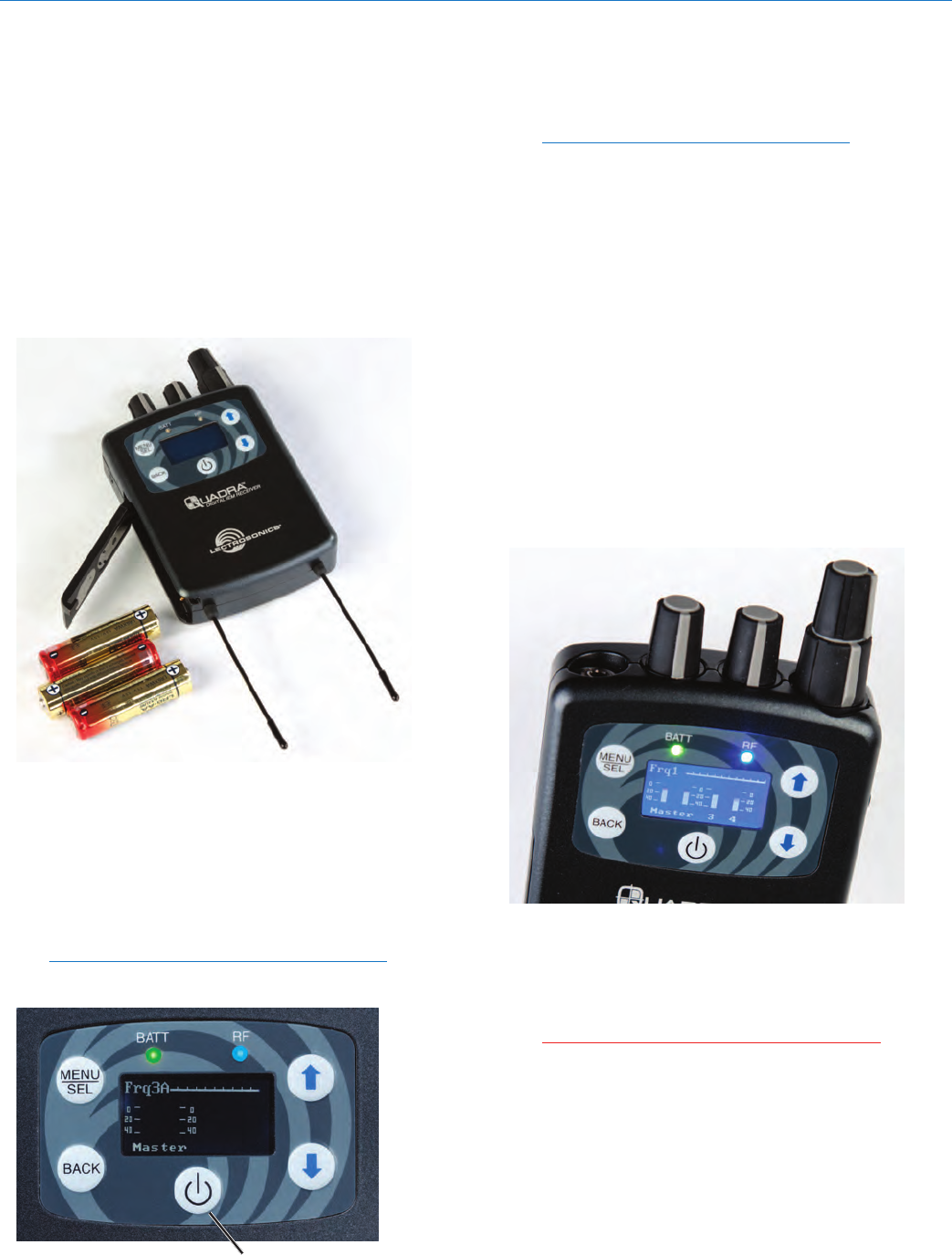
Battery Insertion
The receiver is powered by three AA batteries, either
alkaline, lithium, or rechargeable types. Do not use
“heavy duty” batteries from a drug store - they will not
last long in the M4 receiver.
Open the battery door by pressing on it while sliding it
downward.Itshouldthenipopenallowingfullaccess
to the battery compartment. Carefully note the battery
orientation as indicated by the diagrams inside. The
outer two batteries are positive (+) facing in, while the
middle battery is positive (+) facing out.
Once the three batteries are in place, close the door
by swinging it shut then sliding it upwards while apply-
ing slight pressure. It should snap shut and line up with
the case.
Powering the Unit ON and OFF
Press the power button once to turn on the unit. Check
to see that the LCD displays the single-screen Power
Up Sequence:
Lectrosonics M4R vX.XX (the current firmware
version)
Power Button
AfterthePowerUpSequenceisdisplayedbriey,the
MainWindowappearsandtheM4Risreadyforopera-
tion.
Note also that the BATT LED should be lit.
Green indicates good power. Red indicates your
batteriesare2/3depleted.Flashingredindicates
that you should replace your batteries as soon as
possible.
To turn the receiver off, press and hold the power but-
ton for three seconds. A countdown will be displayed
until the power is turned off.
Control Panel/Knobs
The four knobs on the top edge of the M4 receiver
(two are in a dual concentric arrangement and two are
separate) allow for a number of mixer configurations
by using the Chan. Setup in the LCD menu. The first
knob (the tall, skinny one) is usually set as a Master
Volume, while the other three can be set up differently
depending on the artist’s needs and preferences. See
Selecting 2-channel or 4-channel Operation below
for details.
Theheadphonejackisastandard1/8”stereoTRS(tip,
ring, sleeve) jack with standard headphone wiring (tip
is left, ring is right, sleeve is ground). The headphone
ampcandelivermorethan100mWintoa32Ohmload
so it is important to always start with the volume low
before plugging in your headphones or earbuds.
CAUTION: Hearing damage can result from
listening too loudly with this receiver!
QUADRA
LECTROSONICS, INC.
6
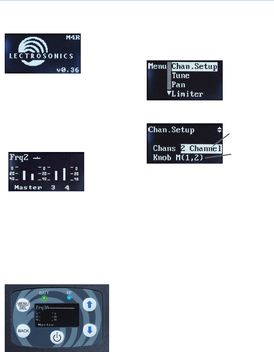
LCD
Thebootsequencewillbrieydisplaythecompany
logo, model number and firmware revision.
Following the boot-up sequence, the receiver will re-
verttotheMainWindow,showingthefollowing:
• Operatingfrequencyattheupperleft(Frq1,Frq2,
etc. for 4-ch or Split 4-ch operation, Frq1a, Frq1b,
Frq2a for 2-ch operation)
• RFlevelmeter(alongthetopedgeoftheLCD)
• Audiolevelmetersinthemiddleofthedisplay
(either two or four, depending on operating mode)
• Knobsetupalongthebottom(Mstr(1,2)+3,4;
Mstr (1) + 2, 3, 4, etc.)
Receiver Menus
Toaccessthesetupmenus,pressthe“MENU/SEL”
button at the upper left of the membrane panel. To
back up one level or return to the “home screen”, press
the“BACK”button.TheUPandDOWNarrowbuttons
along the right side of the control panel allow you to
navigate between menu options and to adjust specific
parameters within the setup screens.
Battery status is indicated by a GREEN LED. The
LED turns REDtoindicatethatyourbatteriesare2/3
depleted. FLASHING RED indicates that you should
replace your batteries as soon as possible.
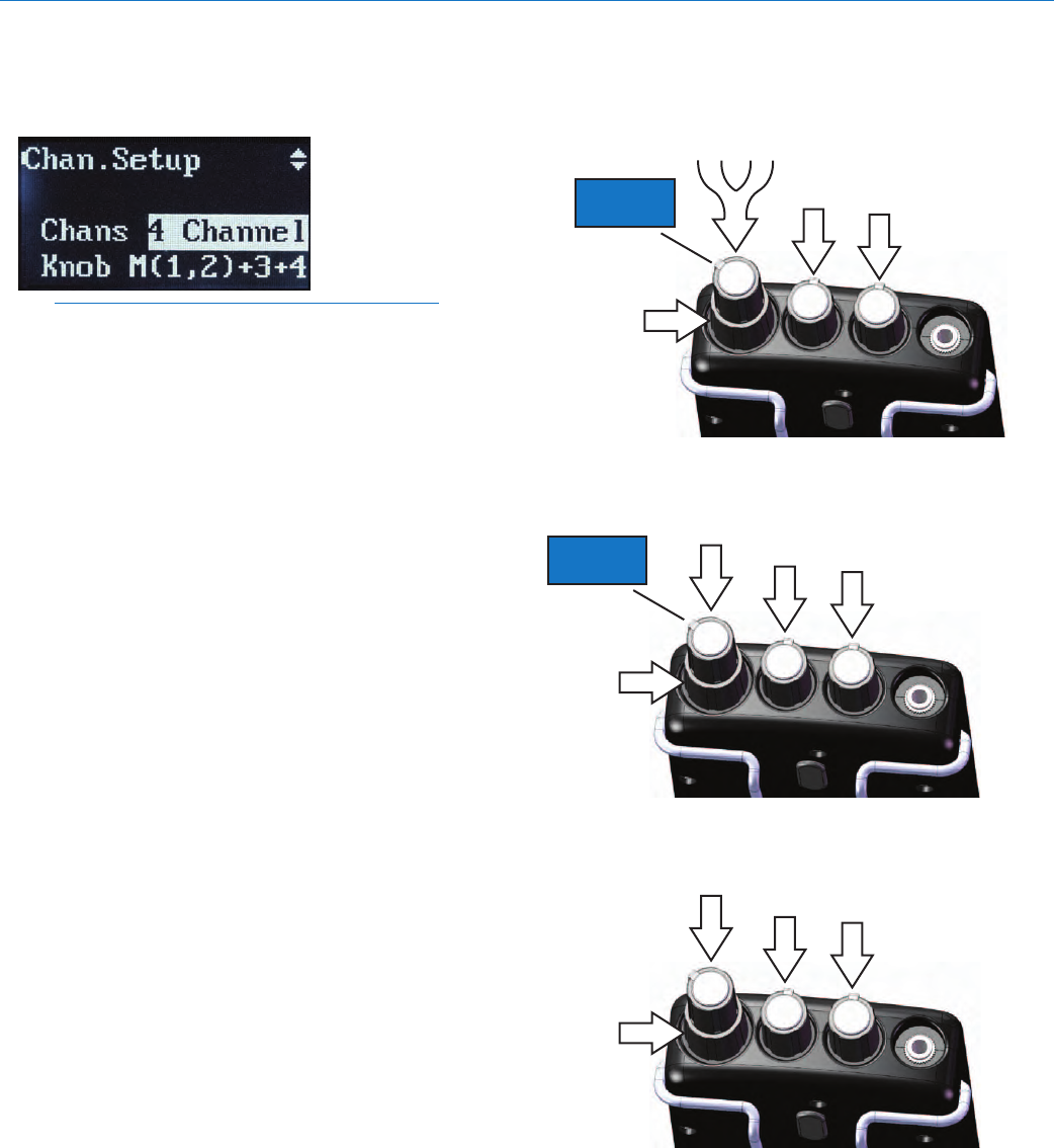
Selecting 2-channel or
4-channel Operation
The Chan. Setup screen allows you to select whether
the receiver operates in 2 ch., 4-ch. or split 4-ch.
modes, and then how the knobs on the top of the
receiver are configured as a mixer.
Each Chan. Setup screen allows setting of 2-channel
and 4-channel modes, plus a second line for selection
of the knob configurations.
2/4 channel
selection
knob
configuration
Press MENU/SEL to toggle the highlight between the
Chans and KnoblinesandusetheUPandDOWN
arrow keys to make selections.
Digital IEM System
Rio Rancho, NM 7
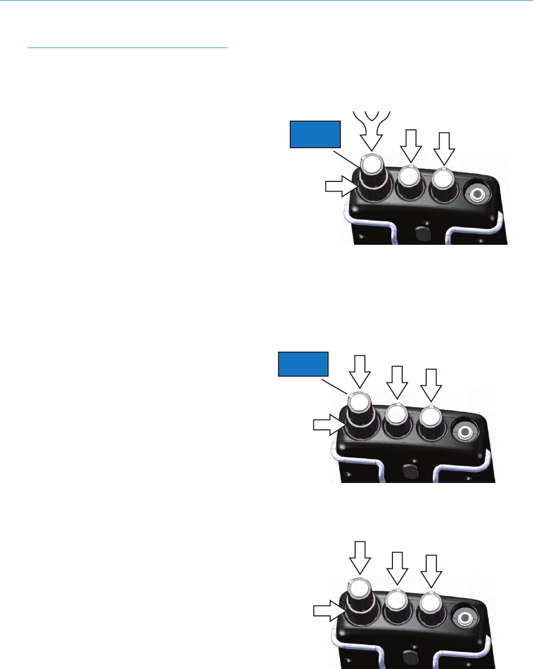
2-channel Operation
NOTE: the transmitter must be also in 2 ch. mode
for the receiver to operate in this manner.
2-ch. mode allows for three different knob setups:
• Master(1,2)
This is the factory default and is equivalent to
standard IEM systems where only a stereo signal
is used. The tall, thin knob is the stereo master
volume.
• Master(1)+2
Feeds audio channel 1 to the master volume (tall,
thin knob) and audio channel 2 to the middle knob
for independent control.
• 1+2
Gives you individual control over both audio
channels. Audio channel 1 is fed to the tall thin
knob, and audio channel two is fed to the middle
individual knob. In this setup, there is no master
volume knob. You can develop a stereo mix by
panning each channel in the stereo field (see pan-
ning, below).
MASTER
VOLUME
AUDIO CH.
12
NO
FUNCTION
NO
FUNCTION
2 CHANNEL - Master (1,2) mode
(factory default)
MASTER
VOLUME
2 CHANNEL - Master (1) + 2 mode
AUDIO
CH. 1
AUDIO
CH. 2
MASTER
VOLUME
NO
FUNCTION
AUDIO
CH. 1
AUDIO
CH. 2
2 CHANNEL - 1 + 2 mode
NO
FUNCTION
QUADRA
LECTROSONICS, INC.
8
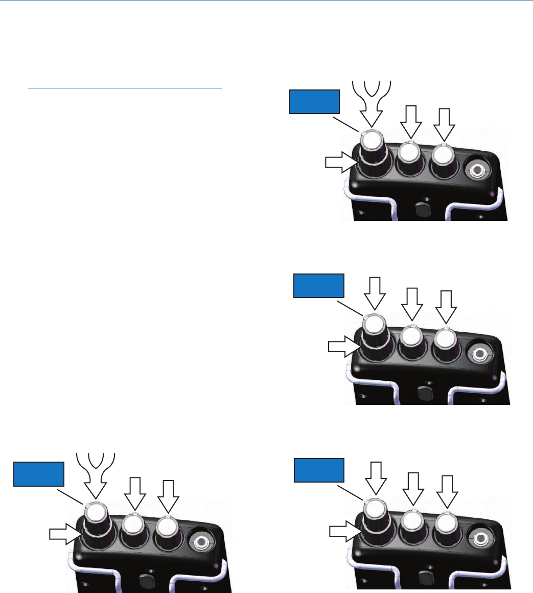
4-channel operation
In this mode, all four audio channels fed to the trans-
mitter are available at the receiver.
NOTE: the transmitter must be in 4 ch. mode for
the receiver to work in this manner.
Audio can be routed to the four audio control knobs in
the following ways:
• Master(1,2)+3,4
Feeds channels 1 & 2 to the master volume knob
in a fixed stereo relationship, while audio chan-
nels 3 & 4 are on the two smaller separate knobs.
This gives you individual control over two of the
channels in their relationship to the stereo mix.
For instance, you may want to have drums and
bass (in stereo) on 1 & 2, your guitar in ch. 3 (first
small knob, in the middle) and your vocals in ch.
4 (second small knob, closest to the headphone
jack). After choosing this mode, you would use
the master knob to control your overall volume,
and the other two knobs to change how those two
individual channels are mixed into the master.
• Master(1) +2, 3, 4
Places ch. 1 on the master knob, and then gives
you individual control over channels 2, 3 and 4.
Use this mode if you plan to have a mono mix as a
starting point, and then add three additional chan-
nels that you would like to adjust during perfor-
mance. An example would be drums and bass (in
mono) on 1, backing vocals on 2, your guitar on 3,
and your vocals on 4.
• 1+2+3+4
Gives you individual control over all four audio
channels. In this setup, there is no master vol-
ume knob. You can develop a stereo mix by pan-
ning each channel in the stereo field (see panning,
below).
MASTER
VOLUME
AUDIO CH.
12
NO
FUNCTION
AUDIO
CH. 3 AUDIO
CH. 4
4 CHANNEL - Master (1,2) + 3,4 mode
MASTER
VOLUME
AUDIO
CH. 1
4 CHANNEL - Master (1) + 2,3,4 mode
AUDIO
CH. 2
AUDIO
CH. 3 AUDIO
CH. 4
AUDIO
CH. 1 AUDIO
CH. 3
4 CHANNEL - 1+2+3+4 mode
AUDIO
CH. 2
AUDIO
CH. 4
Digital IEM System
Rio Rancho, NM 9
Split 4-channel operation
Split 4-ch. mode allows you to use a single M4T
transmitter to send two different stereo mixes to two
different receivers or groups of receivers using a single
radio frequency.
NOTE: the transmitter must be in 4 ch. mode for
the receiver to work in this manner.
Split 4-ch. mode allows for four different knob setups:
• Master(1,2)
Equivalent to standard IEM systems where only
stereo signal is used. The tall, thin knob is the ste-
reo master volume and is fed from audio channels
1 & 2. Here, although there is audio on channels 3
& 4 in the transmission itself, they are muted and
thus the two individual knobs do not function.
• Master(3,4)
Also equivalent to standard IEM systems where
only stereo signal is used. The tall, thin knob is
the stereo master volume and is fed from audio
channels 3 & 4. Here, although there is audio on
channels 1 & 2 in the transmission itself, they are
muted and thus the two individual knobs do not
function.
• Master(1)+2
Feeds audio channel 1 to the master volume (tall,
thin knob) and audio channel 2 to the middle knob
for independent control.
• Master(3)+4
Feeds audio channel 3 to the master volume (tall,
thin knob) and audio channel 4 to the middle knob
for independent control.
SPLIT 4 CHANNEL - Master (1,2) mode
AUDIO CH.
12
NO
FUNCTION
NO
FUNCTION
MASTER
VOLUME
SPLIT 4 CHANNEL - Master (3,4) mode
AUDIO CH.
34
NO
FUNCTION
NO
FUNCTION
MASTER
VOLUME
MASTER
VOLUME
AUDIO
CH. 1 AUDIO
CH. 2
SPLIT 4 CHANNEL - Master (1) + 2 mode
NO
FUNCTION
NO
FUNCTION
MASTER
VOLUME
AUDIO
CH. 3 AUDIO
CH. 4
SPLIT 4 CHANNEL - Master (3) + 4 mode
NO
FUNCTION
NO
FUNCTION
QUADRA
LECTROSONICS, INC.
10
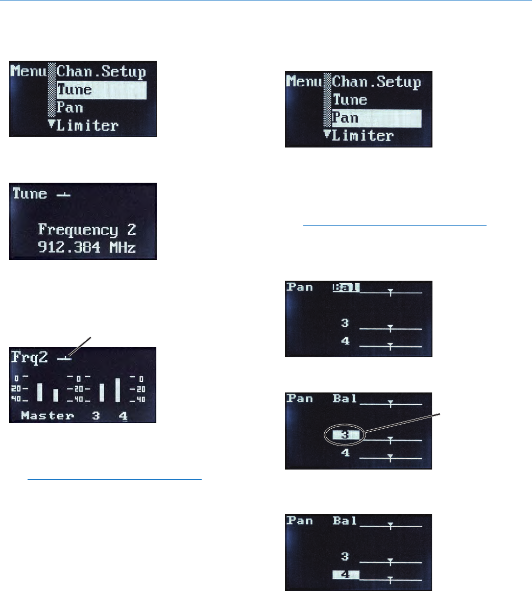
Tune
To select your operating frequency, choose Tune in the
menu list, and press the MENU/SEL button.
Here, you can choose between four operating frequen-
cies in the 4-ch mode or Split 4-ch mode, or eight
operating frequencies the in 2-ch mode.
You should first test your proposed frequency by first
ensuring that your transmitter is turned off and then
observing the RF level in the LCD on your receiver in
the main window.
RF signal strength is indicated
by this status bar.
If you see a large RF signal at the receiver and your
transmitter is off, you may want to choose a different
operating frequency to attain as much operating range
as possible.
Note: Frequency 1a at 906.624 MHz is the
factory default setting.
Once you have selected an operating frequency, press
the BACK button to return to the main menu list. As
soon as you turn on your transmitter (see transmit-
ter section), place it in the correct mode (2 ch. vs. 4
ch.) and then tune it to the same frequency as your
receiver/s,youshouldseetheblue“RF”LEDlighton
yourreceiver/s.Thisindicatesyouhaveasignallock.
Pan
To select your overall stereo balance and stereo pan-
ning for individual audio channels, use the arrow but-
tons to highlight Pan in the menu list.
Press the MENU/SEL button to enter the setup screen.
The setup screen that appears will be determined
by the 2 channel or 4 channel mode and the knob
configuration you have selected. Continue pressing
MENU/SEL to select the channel, then use the UP and
DOWNarrowsbuttonstoadjustthebalance.
Note: All channels panned center and stereo
balance centered is the factory default setting.
In a mode that defines a Master knob, the uppermost
channel line is labled BAL.
Use the MENU/SEL button to move between master
balance and the available audio channels.
Press MENU/SEL
to select channel
(highlight)
For stereo balance (when available), use either the
arrow keys or the lower concentric knob to adjust the
desired L-R balance.
Use UP and DOWN
buttons or lower
concentric knob to
pan the highlighted
channel
For individual channels (when available), use either
the arrow keys or the lower concentric knob to pan the
channel to the desired position in the stereo field.
Once you have completed the necessary adjustments,
pressthe“BACK”buttontoexitthisscreenandreturn
to the main menu.
Digital IEM System
Rio Rancho, NM 11
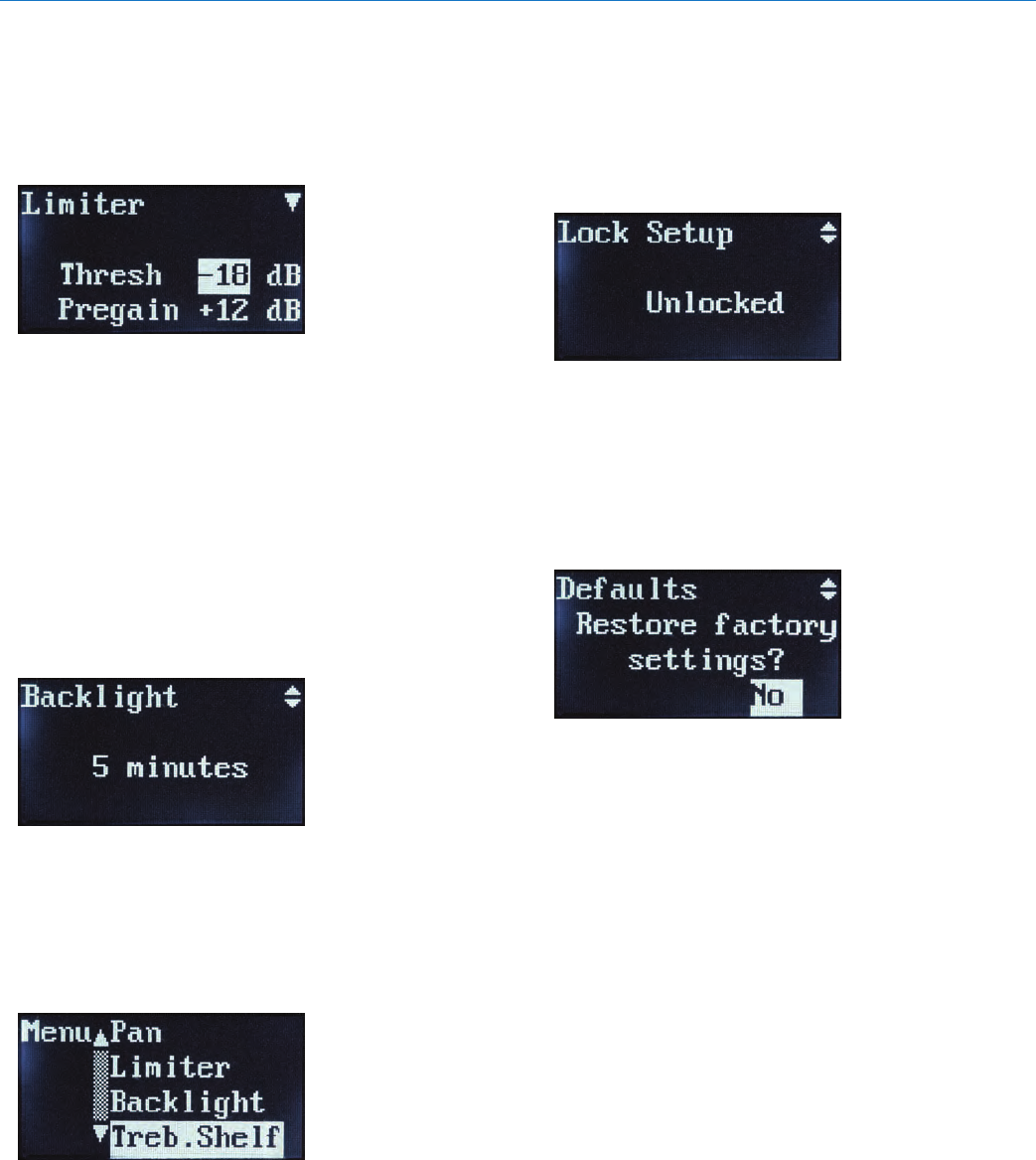
Limiter
This feature can be used in order to provide audio lim-
iting at the receiver in order to prevent excessive levels
at the headphones or earbuds. To set the amount of
limiting, highlight “Limiter” in the menu list using the ar-
rowkeys.Press“MENU/SEL”tochoosethisfunction.
Use the arrow keys to select the limiter threshold in
3dB increments. Test it with a known signal to deter-
mine the maximum sound level you are comfortable
with. The pre-gain setting can then be used to boost
the audio level before the limiter. Use this feature if you
need to make up for a weaker signal at the transmitter.
UsetheMENU/SELbuttontochoose“Pre-Gain”,then
use the arrow buttons to adjust in 3 dB increments.
Backlight
The backlight control page allows you to select the
length of time before the backlight turns off on the re-
ceiver. The factory default setting is 5 minutes, but you
can also select 30 seconds or “Always on.”
Treble Shelf
In this screen, you can choose a treble boost with a
corner either at 5kHz or 7kHz, and a boost of up to
9dB in 3dB increments. This feature can be used to
overcome a stereo mix without enough high frequency
information, or earbuds that “roll off” too early in the
high frequency area.
This high-frequency boost should be used sparingly
due to the fact that it can accelerate hearing loss with
high volumes in the earphones or headphones. Note:
the factory default setting is 5 kHz corner with 0dB
boost.
Lock Setup
This feature is used to lock the control panel so that
no further changes can be made. Once “Locked” is se-
lected, note that a small lock icon is at the upper right
ofeachsetupmenuscreen.Withthereceiverlocked,
you can view each menu screen but you are unable to
make changes and the power can not be turned off.
To return to the unlocked status, go back to the “Lock
Setup” screen via the main menu, and select “Un-
locked”. Also, note that the “Locked” status is main-
tained even if the batteries are changed.
Factory Default
This is used if you intend to reset the receiver to all the
factory default settings.

QUADRA
LECTROSONICS, INC.
12
Receiver: Body Placement
Position the receiver on a belt, guitar strap, wardrobe,
etc. so that the antennas are oriented vertically and not
touching a metallic surface. Make sure the antennas
are on the outside of thick or metallic costuming so the
antenna whips will be out in the open. It is also good
practice to keep the antenna whips from contacting a
person’s body directly for maximum receive sensitivity.
Receiver Accessories
• Replacementwirebeltclip.
• CCM4RFoamlinedcarryingcase

Digital IEM System
Rio Rancho, NM 13
QUADRA
LECTROSONICS, INC.
14
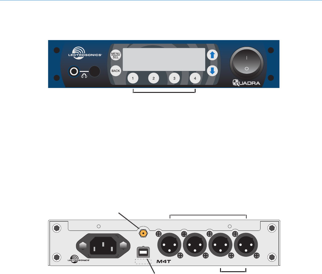
Transmitter Front Panel
TM
DIGITAL IEM
Headphone
Monitor Power
Switch
Channel Select Buttons
Transmitter Rear Panel
DIGITAL IEM TRANSMITTER AES IN
CH1/CH2
1
23
4
AES IN
CH3/CH4
USB
ANT
100-240 VAC, 50/60 Hz, 5W S/N
USB Port for
Firmware Updates
Antenna Output Analog Audio Inputs
Power Inlet
100-240 VAC,
50/60 Hz, 5 W
Digital Audio
Inputs
Digital IEM System
Rio Rancho, NM 15
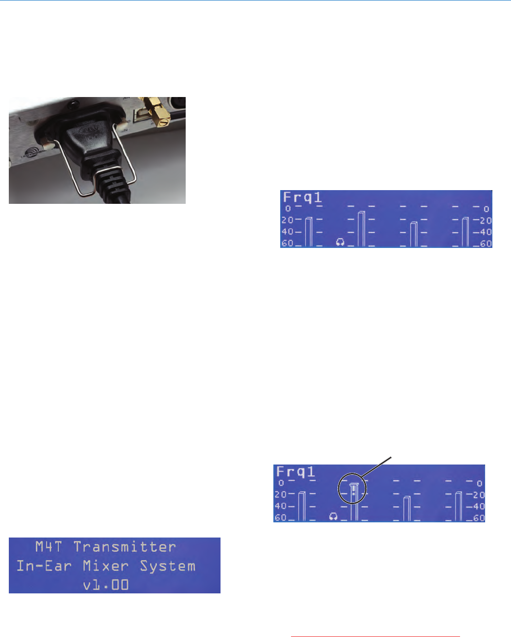
Initial Setup
Connect AC power to the M4T transmitter using the
provided power cable. To ensure that the power cable
can not come loose, use the provided wire retainer. By
placing the retainer above the cable and then pressing
down, the retainer can not come loose.
Attach the supplied antenna to the antenna port on the
back of the M4T, and position it pointing upright while
tightening the knurled nut at the base of the antenna.
If you are rack-mounting one or more M4T transmit-
ters, please see the section on installing rack mounting
hardware (below).
Connect your audio inputs via the XLR connectors.
Note that like a mixing console, the inputs are oriented
right to left, inputs 1-4. If you are feeding the transmit-
ter with analog audio signals, connect your channel 1
to input 1, channel 2 to input 2 and so on.
IfyouaresendingdigitalAES/EBUsignalstotheM4T
transmitter,notethatAES/EBUlinescarrytwochan-
nels on a single XLR connection. Therefore, channels
1 & 2 would be connected to input 1, and channels 3
& 4 are connected to input 2. Note also that in order
to change between analog and digital inputs, use the
front panel menus (see below).
Powering the Unit
ON and OFF
Once you have connected AC power, the antenna,
and your audio lines, apply power to the M4T using
the switch on the front panel. The LCD displays a brief
logo and graphic, followed by the model number, de-
scription and firmware version:
AfterthePowerUpSequence,theMainWindowap-
pears and the M4T is ready for operation.
To turn the transmitter off, simply return the front panel
power switch to the “off” position.
LCD
TheMainWindowshowsthefollowing:
• Operating frequency
(Frq1, Frq2, etc. for 4-ch or Split 4-ch operation
(Frq1a, Frq1b, Frq2a, etc. for 2-ch operation - see
Channel Setup below)
• Audio level meters for either two or four channels
(depending on how the M4T is set up - see Chan-
nel Setup below)
• Headphone monitoring channels as indicated by
the small headphone icons next to the level meters
for those channels.
Audio Signal Monitoring
The signals at the inputs can be monitored in two
ways: using the LCD bar-graph meters for levels and
with headphones for listening to the actual signals. The
LCD bar-graph meters show the audio level range from
-60to0dB.Whenthesignalexceedstheavailable
input headroom, the bar graph indicates this with a
bright “!” at the top of the bar on that channel. Because
this is a digital system, overloads should be carefully
avoided as to prevent signal distortion at the convert-
ers.
NOTE: Do not “drive” this transmitter as you might
be tempted to do with an analog IEM system. Gener-
ally, it is best to leave 3 dB of headroom above your
strongest peaks to ensure that you are not clipping the
signals. Clipping Indicator
Tomonitortheaudiosignal/s,plugintotheheadphone
jack with headphones or earbuds. Push the volume
knob so that it “pops out” for level adjustment. To
selectthechannel/sforlistening,pressthenumbered
button/s1-4belowthosechannels.Eitheroneortwo
channelsatatimecanbemonitored.Whenonechan-
nel is chosen, it is panned center in the headphone
stereoeld.Whentwochannelsarechosenbypress-
ing both buttons at the same time, they are panned
hard left & right in the headphones.
CAUTION: Start with the monitor volume
at a low setting before plugging in your
headphones or earbuds - excessive volume
can damage your hearing.
QUADRA
LECTROSONICS, INC.
16
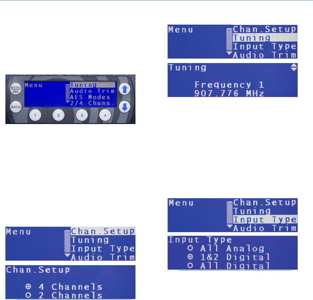
Transmitter Menus
Toaccessthesetupmenus,pressthe“MENU/SEL”
button at the upper left of the membrane panel. To
back up one level or return to the “home screen”, press
the“BACK”button.Thearrowkeysalongtherightside
of the control panel allow you to navigate between
menu options and to adjust specific parameters within
the menu windows.
Whenthedesiredmenuitemishighlighted,pressthe
MENU/SELbuttontoenterthesetupscreen.
Selecting 2-channel or 4-channel
Operation
The Chan. Setup screen allows you to select whether
the transmitter operates in 2-channel or 4-channel
mode. This determines the width of the RF carrier, and
thus how many frequencies can be used in one place
at one time. In 2-channel mode, the RF carrier is 2
MHz wide, thus yielding 8 available operating frequen-
cies. In 4-channel mode, the RF carrier is 4 MHz wide,
thus yielding 4 operating frequencies.
NOTE: for the system to operate, the transmitter
and receiver must be in the same channel setup
(2 ch. vs. 4 ch.) Furthermore, note that for the
receiver to work in Split Mode (see p. 8), the
transmitter must be in 4-channel mode.
Tuning
Once you have selected a Channel Setup, you can
choose an RF operating frequency. Generally, it is best
to use your receiver to determine the best operating
frequency with the tuning method described on p. 9. To
then select the matching operating frequency on your
M4Ttransmitter,usetheup/downarrowstohighlight
“Tuning”onthemenulist,thenpress“MENU/SEL”.
Here, you can select from four operating frequencies
(in 4-ch) or eight operating frequencies (in 2-ch mode).
Once you have selected a matching operating fre-
quency, the blue LED on the front of your IEM receiver
should light up, indicating an RF signal lock.
Input Type
This allows you to choose between analog and digital
inputs, depending on your source from the mixing
console.Fromthemainmenu,usetheup/downarrow
buttonstohighlight“InputType”.PresstheMENU/SEL
to enter this page. Here, you have three choices: All
Analog, 1&2 Digital, and All Digital. Because XLR
inputs1and2alsodoubleasdual-channelAES/EBU
digital inputs, only these three choices are possible.
NOTE: the M4T inputs are set to “All Analog” as
a factory default. If you send digital signals to the
input without changing the Input Type, the system
will transmit a very loud white-noise signal to the
receiver. Also, if the receiver inputs are set to
“Digital”, and you are sending analog signals to
the inputs, there will be no audio present.
Audio Trim
Whenusinganaloginputs,thisfeaturegivesyouthe
opportunity to adjust the transmitter input gain in 1
dB increments, on a per-channel basis. For very “hot”
analog signals from the console, you may need to
attenuate the input gain to compensate, thus avoiding
clipping and the resulting signal distortion.
Toselectaudioinputtrimlevels,usetheup/down
arrow buttons to highlight “Audio Trim”, then use the
MENU/SELbuttontoenterthispage.Usethenum-
bered buttons 1 through 4 to select the channel, then
usetheup/downarrowstoincreaseorreducethe
amount of attenuation on that channel.
Digital IEM System
Rio Rancho, NM 17
NOTE: input channels that have been selected
asAES/EBUdigitalinputsdonotallowinputlevel
trim.
In the case where the resulting volume at the receiver
headphones or earphones is deemed insufficient, the
receiver provides makeup gain (see receiver Dynamic
Boost on p. 9)
NOTE: Do not “drive” this transmitter as you might
be tempted to do with an analog IEM system. Gener-
ally, it is best to leave 3 dB of headroom above your
strongest peaks to ensure that you are not clipping the
signals.
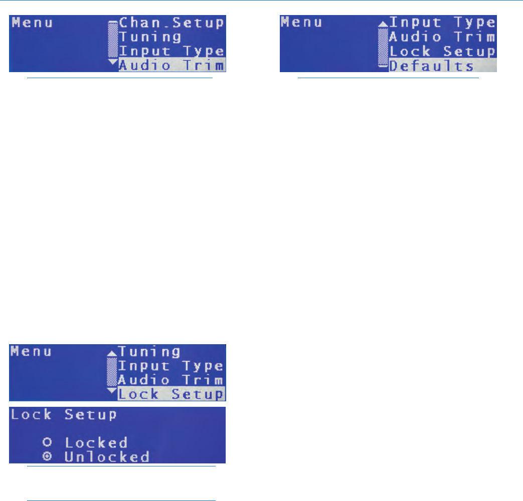
Lock Setup
So that the front panel buttons can be locked to pre-
vent further changes, the Lock Setup feature is provid-
ed.Usetheup/downarrowstohighlight“LockSetup”
andpresstheMENU/SELbuttontoenterthatscreen.
Usetheup/downarrowstoselecteitherLockedorUn-
locked. Once Locked is selected, no further changes
can be made to the transmitter settings until this same
screen is entered and Unlocked is selected.
NOTE: Features not affected by the Lock Setup
include channel monitoring selection and
headphone volume.
NOTE: Features not affected by the Lock Setup
include channel monitoring selection and
headphone volume.
Factory Default Reset
Torestorefactorydefaultsettings,usetheup/down
arrow buttons in the main menu to highlight “Defaults”,
thenpresstheMENU/SELbutton.Usetheup/down
arrows to select “Yes”. To activate the factory default
reset,nowpresstheMENU/SELbutton.Thescreen
will show “Defaults Restored” thus indicating that the
process is complete.
NOTE: DO NOT restore factory defaults while
someone is listening to the receiver with
headphones or earbuds - the resulting change
in levels or input type may cause a VERY LOUD
signal to be transmitted to the receiver.
QUADRA
LECTROSONICS, INC.
18
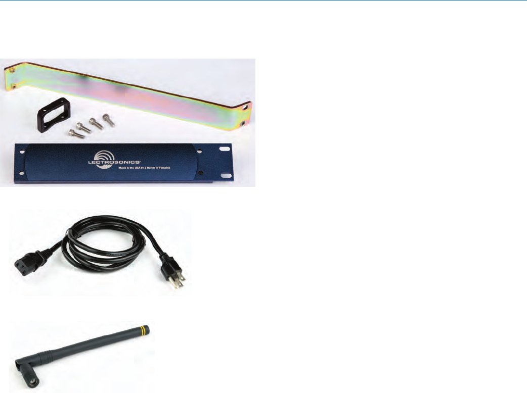
Rack Mount Hardware
The M4T is delivered with a partial set of rack mount
hardware,includingbolts,arackear,connectingang-
es,antennacableandfront-panelhandles.Withtwo
M4T units, there is enough hardware supplied in the
delivery to connect the two units together, front-mount
the antennas, and prepare the units as a complete as-
sembly ready for mounting in a rack enclosure.
If you need to rack-mount a single M4T transmitter,
you will need to purchase the optional RMPM4T-1
rack kit. The kit provides a blank half-rack panel, a rear
mounting brace and the additional hardware required
for this setup.
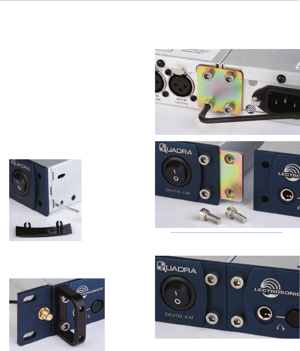
Dual Rack-Mount
Instructions
1. Remove the plastic end-caps from the front of the
M4T and pry out the metal inserts on each side of
the transmitters with a small screwdriver.
Plastic guards snap out
from corners. Pry out the
aluminum inserts on the
side panel with a small
screwdriver.
2. Attach the antenna cables to the rack ears with
the supplied nuts and lock washers. Tighten with
a small wrench - do not over-tighten the nuts but
make sure they are snug enough not to work
loose.
3. Insert the rack ear and attach the handle to the
front of the panel using the supplied hex-head
bolts and hex wrench. The screws should go
through the handle, through the front panel, and
into the rack ear nuts. Tighten these bolts firmly.
4. Remove the hex head bolts from the rear of both
units right where they contact each other. Attach
thetwounitsusingthetwometalanges,thenon-
threaded one for the rear and the threaded one for
the front. Secure them with the supplied hex head
bolts. Tighten these bolts firmly.
NOTE: The threads in the front adapter plate are
a self-locking type. Tighten the screws until the
headisushwiththefrontpanel.
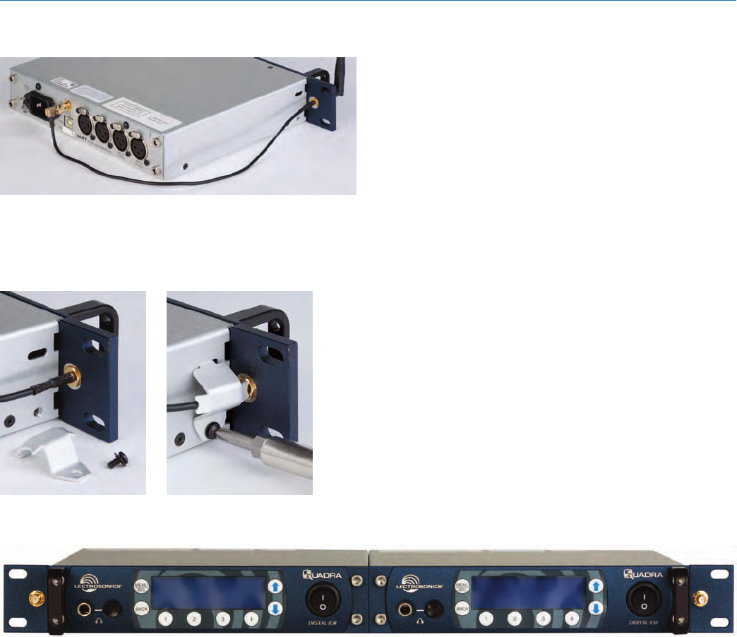
Digital IEM System
Rio Rancho, NM 19
8. Attach the antenna wires to the antenna ports on
the back of the transmitters.
9. Attach the supplied antenna connector protectors
to the sides of the transmitters right behind the
rack ears. Secure them with the supplied screws.
Note that this item will fit tightly and is meant to
deform slightly during installation.
The dual set of M4T transmitters is now ready for rack
mounting.
QUADRA
LECTROSONICS, INC.
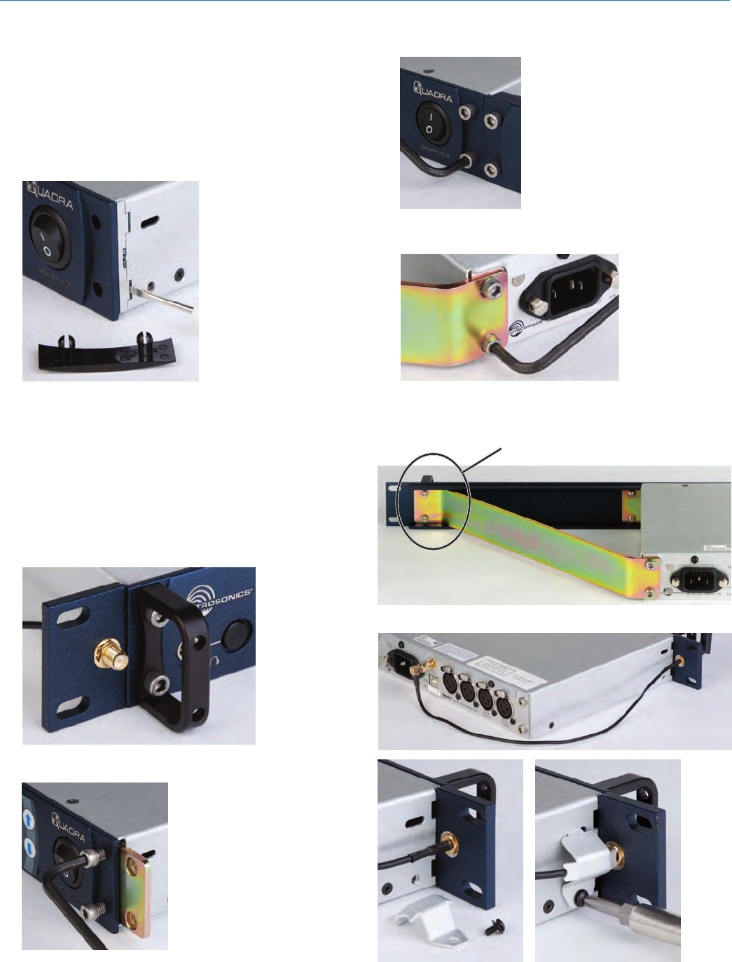
20
Single Rack-Mount
Instructions (using
optional RMPM4T-1 kit)
1. Remove the plastic end-caps from the front of the
M4T transmitter. Pry out the metal inserts on each
side of the transmitter with a small screwdriver
Plastic guards snap out
from corners. Pry out the
aluminum inserts on the
side panel with a small
screwdriver.
2. Attach the antenna cable to the rack ear with the
supplied nut and lock washer. Tighten with a small
wrench - do not over-tighten the nuts but make
sure they are snug enough not to work loose. In-
sert the rack ear into the left side of the transmitter
front panel.
3. Insert the rack ear and attach the handle to the
front of the panel using the supplied hex-head
bolts and hex wrench. The screws should go
through the handle, through the front panel, and
into the rack ear nuts. Tighten these bolts firmly.
4. Attach front bracket plate to right side of panel.
Insert the screws
partially, but do not
tighten them yet.
5. Attach the blank panel to the bracket and tighten
all four screws.
The threads in the front
adapter plate are a self-
locking type. Tighten the
screws until the heads are
flush with the front panel.
6. Mount the steel brace with the supplied screws. Do
not tighten the screws yet.
7. Attach the steel brace to the blank panel using the
supplied screws. Tighten all four screws that retain
the brace. Install handle and bracket
with supplied screws
8. Attach the supplied antenna and antenna guard.
Digital IEM System
Rio Rancho, NM 21
Firmware Updates
As new versions of the firmware become available,
updates are accomplished with a software utility and
simple procedure. In many cases, updates must be
made to both transmitter and receiver to ensure com-
patibility and provide the latest feature set.
ThesoftwareinterfaceoperateswithWindows2000,
XP and Vista operating systems.
Configuring the USB Port
1) Remove any previous LecNet2 installation from
your computer.
2) Install LecNet2 software. Use the CD supplied
with the Quadra system or download the LecNet2
Software Installer or the CD contents from the web
site:
http://www.lectrosonics.com/lecnet2/lecnet2.htm
3) On the same web page, scroll down to LecNet2
Firmware Updates. Download the latest firmware
files and store them in a convenient directory on
your local hard drive. The files are stored on the
web site as .zip files. After they are extracted the
filename extension is .rpd. There are separate files
for the receiver and the transmitter.
4) Install batteries or connect power to the unit.
5) Plug the USB cable into the unit. If this is the first
time this unit has been connected to this computer,
Windowswillaskforadriverlocation.Thedefault
directory used by the LecNet2 installer is:
c:\Program Files\Lectrosonics\drivers
Oncethedriverislocated,Windowswillcomplete
the installation and display a message stating that
the USB device is now ready to be used.
NOTE: If a message appears during installation
stating that the driver is not signed by Microsoft,
click on Continue to finish the installation.
Installing the Firmware
Make certain that the USB port is configured to com-
municate with the unit. If not, follow the procedure
outlined above to install the USB driver.
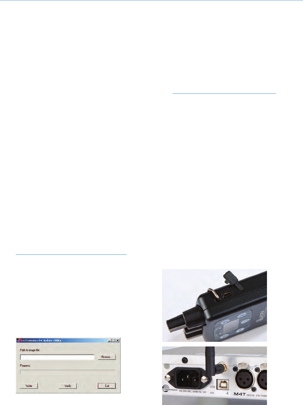
Launch the utility:
Start>All Programs>LecNet2>Tools>D4/M4 Update
Utility
The Browse button is used to select the file to be
loaded into the unit.
The Write button initiates the installation process.
The Verify button on the Utility program control panel
is used to compare the version of the selected file with
that of the firmware installed in the unit. Clicking the
button will start the process. After a few seconds, an
OK screen will appear if the versions are the same,
or a mismatch screen will appear if the versions are
different.
NOTE: Verification takes place automatically
during the installation process launched by
clicking the Write button.
Thermwareversionintheunitisdisplayedbrieyon
the LCD during the turn-on cycle. The version of the
downloaded firmware file is indicated by its filename.
1) Click on the Browse button and select the folder
where the downloaded firmware files are stored.
Select the correct file for either the receiver or
transmitter, whichever is connected.
2) Click the Write button to copy the new firmware
into the unit. The progress bar will indicate as the
firmware is being updated.
3) After about 30 seconds an OK message will ap-
pear if the installation was successful.
4) Click the Exit button to close the software panel.
If the wrong firmware is installed into a unit (such as
the M4R receiver firmware being loaded into the M4T
transmitter) the installation process will appear to work
but the LCD on the unit will likely be blank and the
unit will not operate. Installing the correct firmware will
restore the unit to normal operation.
The USB port is on the side panel of the receiver and
on the rear panel of the transmitter.
QUADRA
LECTROSONICS, INC.
22
Transmitter Accessories
RMPM4T-1SingleUnitRackMountKit
P/N21499PowerCord,6ft.long,NEMA3-pinplug
LectrosonicsM4TAntenna;P/N21422
Specifications
Overall System
Operating Spectrum: 902 - 928 MHz
Center Frequencies (MHz):
4-channel Mode: 907.776, 912.384, 916.992, 923.904
Four 4-channel systems can operate simultaneously
for a total of 16 audio channels.
Center Frequencies: (MHz):
2-channel Mode: 906.624, 908.928, 911.232, 913.536, 915.840,
918.144, 922.752, 925.056
Eight 2-channel systems can operate simultaneously
for a total of 16 audio channels
Modulation Type: Differential QPSK with Forward Error Correction,
spread spectrum
Occupied Bandwidth: 4 MHz (4-channel mode), 2 MHz (2-channel mode)
Audio Sampling: 48 kHz, 24-bit
Latency (overall system):
Digital: Less than 0.5 mS
Analog: Less than 1.0 mS
Selectable Audio Channels: • 4 digital
• 2 digital, 2 analog
• 4 analog
Audio Performance (overall system):
Frequency Response: 20 Hz - 20 kHz, +/– 0.5 dB
THD+N: < 0.05% (1 kHz @ –10 dBFS)
Dynamic Range: > 104 dB A-weighted
Adjacent Channel Isolation: > 93 dB
M4T Transmitter
Power output: 200 mW
Audio Input: Simulated transformer balanced inputs,
clip level adjustable +0 to +20 dBu
(or AES/EBU digital standard)
Power requirements: 100 - 240 VAC
Power consumption: 5 Watts
Dimensions: Height: 1.750 in. / 44.45 mm.
Width: 8.375 in. / 212.7 mm.
Depth: 7.750 in. / 196.8 mm.
Weight: 2.36 lbs.; 1068 grams
M4R Receiver
Diversity Type: Switched antenna
Audio Output: Earphone: 100 mW at 32 Ohms
–20 to +0 dBu
Power requirements: 3 x AA batteries (4.5V)
Power consumption: 230 mA
Dimensions: Height:
4.725 in. / 120 mm. (with knobs)
3.735 in. / 94.87 mm. (housing)
Width: 2.75 in. / 69.85 mm.
Depth: .960 in. / 24.38 mm.
Weight: 9.14 ounces / 259 grams (with alkaline batteries)
Specifications subject to change without notice.

Digital IEM System
Rio Rancho, NM 23

13 December 2010
581 Laser Road NE • Rio Rancho, NM 87124 USA • www.lectrosonics.com
(505) 892-4501 • (800) 821-1121 • fax (505) 892-6243 • sales@lectrosonics.com
LIMITED ONE YEAR WARRANTY
The equipment is warranted for one year from date of purchase against defects in
materials or workmanship provided it was purchased from an authorized dealer. This
warranty does not cover equipment which has been abused or damaged by careless
handling or shipping. This warranty does not apply to used or demonstrator equipment.
Should any defect develop, Lectrosonics, Inc. will, at our option, repair or replace any
defective parts without charge for either parts or labor. If Lectrosonics, Inc. cannot
correct the defect in your equipment, it will be replaced at no charge with a similar new
item. Lectrosonics, Inc. will pay for the cost of returning your equipment to you.
This warranty applies only to items returned to Lectrosonics, Inc. or an authorized
dealer, shipping costs prepaid, within one year from the date of purchase.
This Limited Warranty is governed by the laws of the State of New Mexico. It states the
entire liablility of Lectrosonics Inc. and the entire remedy of the purchaser for any
breach of warranty as outlined above. NEITHER LECTROSONICS, INC. NOR
ANYONE INVOLVED IN THE PRODUCTION OR DELIVERY OF THE EQUIPMENT
SHALL BE LIABLE FOR ANY INDIRECT, SPECIAL, PUNITIVE, CONSEQUENTIAL,
OR INCIDENTAL DAMAGES ARISING OUT OF THE USE OR INABILITY TO USE
THIS EQUIPMENT EVEN IF LECTROSONICS, INC. HAS BEEN ADVISED OF THE
POSSIBILITY OF SUCH DAMAGES. IN NO EVENT SHALL THE LIABILITY OF
LECTROSONICS, INC. EXCEED THE PURCHASE PRICE OF ANY DEFECTIVE
EQUIPMENT.
This warranty gives you specific legal rights. You may have additional legal rights which
vary from state to state.