Lectrosonics MM400E WIRELESS MICROPHONE TRANSMITTER User Manual USERS MANUAL
Lectrosonics Inc WIRELESS MICROPHONE TRANSMITTER USERS MANUAL
USERS MANUAL
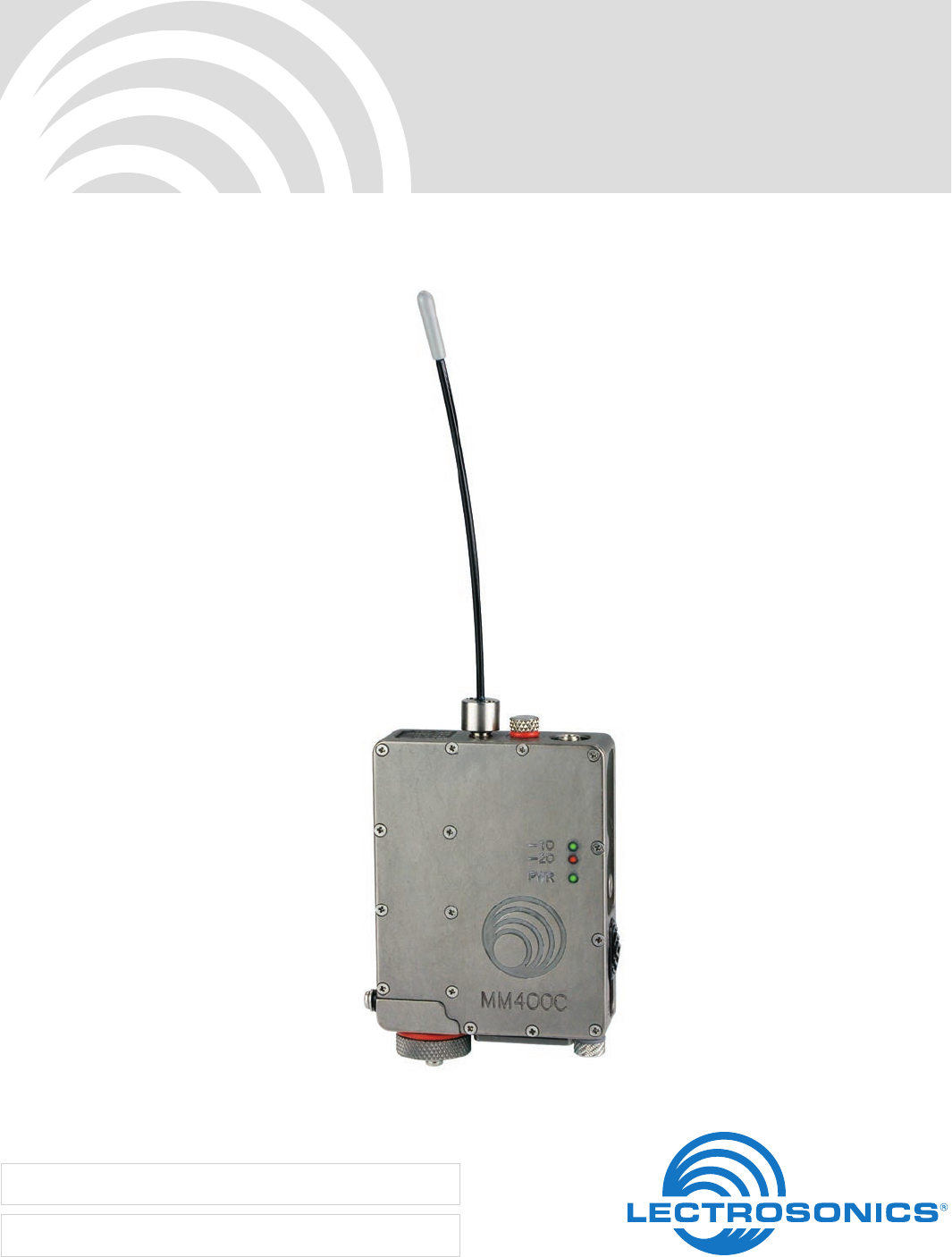
MM400C
Watertight Miniature UHF Belt-Pack Transmitter
Featuring Digital Hybrid Wireless® Technology
INSTRUCTION MANUAL
Rio Rancho, NM, USA
www.lectrosonics.com
Fill in for your records:
Serial Number:
Purchase Date:

MM400C
LECTROSONICS, INC.
2

Watertight Miniature UHF Belt-Pack Transmitter
Rio Rancho, NM 3
Thank you for selecting the Lectrosonics MM400C
watertight miniature transmitter. The unique design
provides several distinct features for professional ap-
plications:
• OutstandingRFoperatingrange
• Superbaudioquality
• Ultra-lightweight,corrosionresistanthousing
• Watertightsealsforuseinwetenvironments
• Programmableemulationmodesformaximum
versatility
ThepatentedDigitalHybridWireless® design combines
24-bit digital audio with analog FM techniques to pro-
vide the operating range of the finest analog wireless
systems and the audio quality of a pure digital system.
The100mWRFoutputpowerextendsoperatingrange,
and the DSP controlled, dual-envelope limiter cleanly
handles input peaks to allow higher gain settings. This
combinationmaximizesoperatingrangeandthesignal
to noise ratio of the system.
The input provides 6 VDC bias voltage for use with
modern electret lavaliere microphones. Multi-color
LEDs are provided to make input gain adjustments
quick and accurate, without having to view the receiver.
The battery compartment accepts AA alkaline, lithium
or NiMH batteries, and a detachable antenna ¼ wave-
lengthexiblecableconnectstoawatertight50Ohm
SMA port on the transmitter.
The MM400C is machined from a solid aluminum block
to provide the lightweight, rugged package needed in
extremeenvironmentswithoutcompromisingfunctional-
ity.InputjacksandcontrolsareO-ringsealedforwater-
tight protection in wet environments. A special noncor-
rosivenishresistssaltwaterexposureandperspiration
inextremeenvironments.
The DSP-based design offers backward compatibility
with a handful of earlier analog designs, such as the
Lectrosonics 100 and 200 Series receivers, and some
other brands of analog wireless receivers. Compat-
ibility Modes are easily selected with a sequence of
frequency switch settings and cycling the unit’s power.
OnlytheMM400Ctransmitteriscoveredinthismanual.
Companion receivers are covered in separate manuals.

MM400C
LECTROSONICS, INC.
4

Watertight Miniature UHF Belt-Pack Transmitter
Rio Rancho, NM 5
Table of Contents
General Technical Description ..............................................................................................................................................................6
General .................................................................................................................................................................................................6
DigitalHybridWireless® Technology* ....................................................................................................................................................6
LowFrequencyRoll-Off ........................................................................................................................................................................6
Input Limiter ..........................................................................................................................................................................................7
Digital Signal Processor ........................................................................................................................................................................7
Microprocessor,PLLandVCOCircuits.................................................................................................................................................7
Compatibility Modes ..............................................................................................................................................................................7
Pilot Tone Squelch ................................................................................................................................................................................7
Wide-BandDeviation ............................................................................................................................................................................7
MagneticPowerON/OFFSwitch ..........................................................................................................................................................7
BatteryLife ............................................................................................................................................................................................7
Frequency Agility...................................................................................................................................................................................7
Circulator/Isolator ..................................................................................................................................................................................7
Controls and Functions .........................................................................................................................................................................8
Preventing Internal Corrosion ...............................................................................................................................................................8
PowerON/OFFSwitch ..........................................................................................................................................................................8
Power LED ............................................................................................................................................................................................8
Mic Jack ................................................................................................................................................................................................9
Audio Level ...........................................................................................................................................................................................9
Modulation LEDs ...................................................................................................................................................................................9
Frequency Select Switches ...................................................................................................................................................................9
Antenna .................................................................................................................................................................................................9
BeltClip .................................................................................................................................................................................................9
BatteryInstallation ..............................................................................................................................................................................10
OperatingInstructions .........................................................................................................................................................................11
Selecting the Compatibility Mode ........................................................................................................................................................11
Adjusting Transmitter Frequency .........................................................................................................................................................11
Attaching a Microphone and Adjusting Audio Levels ..........................................................................................................................12
Power Switch Function Selection ........................................................................................................................................................13
Determine Power Switch Function Mode ........................................................................................................................................13
Changing Power Switch Function ....................................................................................................................................................13
Replacing the Power Switch Magnet Housing Assembly .................................................................................................................14
Microphone RF Bypassing ..................................................................................................................................................................15
Replacement Parts and Accessories ..................................................................................................................................................16
UHF Transmitter Antenna Specifications ............................................................................................................................................16
Troubleshooting ....................................................................................................................................................................................17
Specifications and Features ................................................................................................................................................................18
Service and Repair ...............................................................................................................................................................................19
Returning Units for Repair ..................................................................................................................................................................19
MM400C
LECTROSONICS, INC.
6
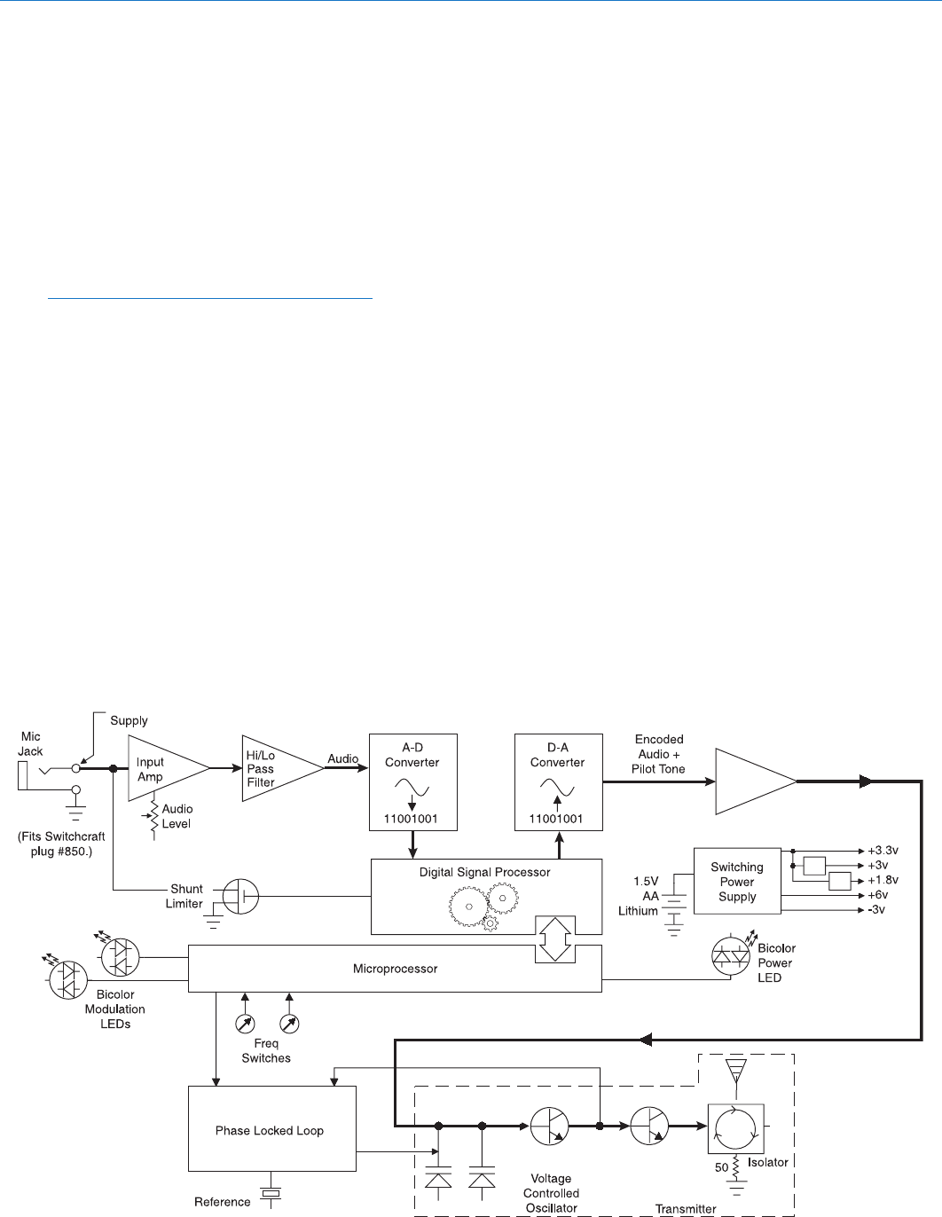
General
The400Series(orDigitalHybridWireless®) system
uses75kHzwidedeviationforanextremelyhighsignal
to noise ratio. The switching power supplies provide
constant voltages to the transmitter circuits from the be-
ginning(1.5Volts)totheend(0.85Volts)ofbatterylife.
The input amplifier uses an ultra low noise op amp for
quiet operation. It is gain controlled with a wide range
dual envelope input compressor which cleanly limits
inputsignalpeaksover30dBabovefullmodulation.
Note: The terms 400 Series and Digital Hybrid
Wireless® describe the same product line are
interchangeable.
Digital Hybrid Wireless® Technology
All wireless links suffer from channel noise to some
degree, and all wireless microphone systems seek to
minimizetheimpactofthatnoiseonthedesiredsignal.
Conventional analog systems use compandors for
enhanced dynamic range, at the cost of subtle artifacts
(knownas“pumping”and“breathing”).Whollydigital
systems defeat the noise by sending the audio informa-
tion in digital form, at the cost of some combination of
power, bandwidth and resistance to interference.
TheLectrosonicsDigitalHybridWireless® system over-
comes channel noise in a dramatically new way, digitally
encoding the audio in the transmitter and decoding it
in the receiver, yet still sending the encoded informa-
General Technical Description
tion via an analog FM wireless link. This proprietary
algorithm is not a digital implementation of an analog
compandor but a technique which can be accomplished
only in the digital domain, even though the inputs and
outputs are analog signals.
BecauseitusesananalogFMlink,DigitalHybridWire-
less® enjoys all the benefits of conventional FM wireless
systems,suchasexcellentrange,efcientuseofRF
spectrum, and resistance to interference. However,
unlike conventional FM systems, the Digital Hybrid has
done away with the analog compandor and its artifacts.
Low Frequency Roll-Off
A12dBperoctavelowfrequencyroll-offisprovidedin
theaudiosection,withthe-3dBpointat70Hz.The
actual roll-off frequency will vary somewhat according
to the low frequency response of the mic capsule being
used.
The low frequency roll-off is used to remove subsonic
(or very low frequency) audio, such as that produced by
air conditioning systems or automobile traffic from the
audiosignal.Excessivelowfrequencycontentinthe
audio input can cause a variety of audio problems in-
cludingdrivingthetransmitterintolimiting.Forexam-
ple, in sound reinforcement systems, as one instance,
excessivelowfrequencycontentcancauseexcessive
power amplifier drain or even damage to loudspeaker
systems.
+5V Bias
11.3 MHz

Watertight Miniature UHF Belt-Pack Transmitter
Rio Rancho, NM 7
Input Limiter
The MM400C transmitters employ a DSP-controlled an-
alog audio limiter just before the analog-to-digital con-
verter.Thelimiterhasarangeofmorethan30dBfor
excellentoverloadprotection.Adualreleaseenvelope
makes the limiter acoustically transparent while main-
taining low distortion. It can be thought of as two limit-
ers in series, connected as a fast attack and release
limiter followed by a slow attack and release limiter. The
limiter recovers quickly from brief transients, so that its
action is hidden from the listener, but recovers slowly
from sustained high levels, to both keep audio distortion
low and preserve short term dynamic changes.
Two bicolor LEDs indicate limiter activity. (See Operat-
ing Instructions, Adjusting Audio Levels.) Generally
speaking, some limiting is desirable in normal operation
to improve the signal to noise ratio of the system. The
limiting action is not audible and does not create distor-
tion.
Digital Signal Processor
TheDSPconstructstheoriginaldigitizedaudiofromthe
A-D Converter, adds an ultrasonic Pilot Tone to con-
trol the receiver’s squelch (only in 400 Series and 200
Series Compatibility Mode with the Pilot Tone enabled
– see Pilot Tone Squelch), and implements the user
defined Compatibility Mode.
Microprocessor, PLL and VCO Circuits
An 8-bit microprocessor monitors user command inputs
and numerous other internal signals. It also drives the
Modulation LEDs, controls the Pilot Tone and operates
thePLL/VCOcircuits.
Compatibility Modes
The MM400C transmitter was designed to compatible
with Lectrosonics 400 Series receivers and will yield the
best performance when doing so. However, due to the
exibilityofdigitalsignalprocessing,theMM400Cis
also able to operate with Lectrosonics 200 Series, Lec-
trosonics100Series,IFBandcertainnon-Lectrosonics
analog receivers in special compatibility modes. (Con-
tact the Lectrosonics Sales Department for a complete
list of compatible transmitters.)
Pilot Tone Squelch
The 400 Series wireless system uses an ultrasonic tone
between25and32kHztooperatethereceiversquelch.
The pilot tone squelch system keeps the receiver muted
until it receives the pilot tone from the matching trans-
mitter, even if a strong RF signal is present on the car-
rier frequency of the system. The “pilot tone” frequency
isdifferentforeachofthe256availablecarrierfrequen-
cies to prevent the pilot tone from being transferred to
the wrong receiver via an intermodulation product.
Wide-Band Deviation
A±75kHzdeviationimprovesthecaptureratio,signal
to noise ratio and AM rejection of a wireless system
dramatically, compared to other designs that use 30
kHzto40kHzdeviation.Thiscombinedwithafull100
mWofpoweroutputmakesasignicantimprovementin
signaltonoiseratioandmaximumoperatingrange.
Magnetic Power/Mute Switch
A magnetic switch is used to control the application of
power to the MM400C circuits and as an audio mute
switch. The function of this switch can be set by the
user. (See Controls and Functions, Magnetic Power
ON/OFF Switch.)
Battery Life
Switching power supplies throughout the design allow
over 6 hours of operation using a single AA lithium
battery.(AnalkalineAAbatterywillprovideabout1.75
hours and a 2200 mAh NiMH AA battery will provide
about 4 hours of operating time.) The battery contacts
are spring loaded in order to prevent “rattle” as the unit
is handled.
Frequency Agility
Thetransmittersectionusesasynthesized,frequency
selectablemainoscillator.Thefrequencyisextremely
stable over a wide temperature range and over time.
Two 16-position rotary switches, located on the under a
waterproofcoveronthebottomoftheunit,provide256
frequenciesin100kHzstepsovera25.5MHzrange.
This alleviates carrier interference problems, a definite
problem in mobile or traveling applications.
Circulator/Isolator
TheRFoutputcircuitincludesaonewaycirculator/iso-
latorusingamagneticallypolarizedferrite.Thisdevice
greatly reduces RF intermodulation produced when
multiple transmitters are used within a few feet of each
other by blocking RF from returning back into the output
stage. It also provides additional RF output stage
protection but is rarely seen in a wireless microphone
transmitter due to its high cost.
MM400C
LECTROSONICS, INC.
8
Controls and Functions
Preventing Internal Corrosion
It is very important that you properly dry the transmitter
when it becomes wet due to immersion or high levels of
perspiration BEFORE opening any covers or connec-
tors. Follow the procedure below for best results:
1. Carefully blot the transmitter dry with a clean paper
towel or cloth. Remove all moisture. After open-
ing any connector or cover, carefully blot up any
remaining moisture that may have remained around
the seal.
IMPORTANT!DONOTCLOSEANYCOVER
ORCONNECTORBEFOREMAKINGCERTAIN
THEREISNOMOISTUREINORNEARTHE
OPENING.
2. After use, it is important to store the transmitter
in a dry place with all access compartments and
connectors opened to allow any internal humidity to
evaporate.Specically,opentheBatteryCompart-
ment, the Frequency Switch Cover Plate and fully
unscrew and remove the microphone connector
before storing. Do not store wet and do not store
sealed. If moisture is sealed inside the unit it has
nowhere to go other than to chemically react with
and destroy components and the printed circuit
board.
3. LubricateallrubberO-ringswithpetroleumjelly
(such as Vaseline) after each use (included with
transmitterandO-ringreplacementkits).DO NOT
USE ANYTHING OTHER THAN PURE PETRO-
LEUM JELLY. Silicone-based lubricants will dis-
solvetherubber.FailingtolubricatetheO-rings
after each use will significantly shorten their life.
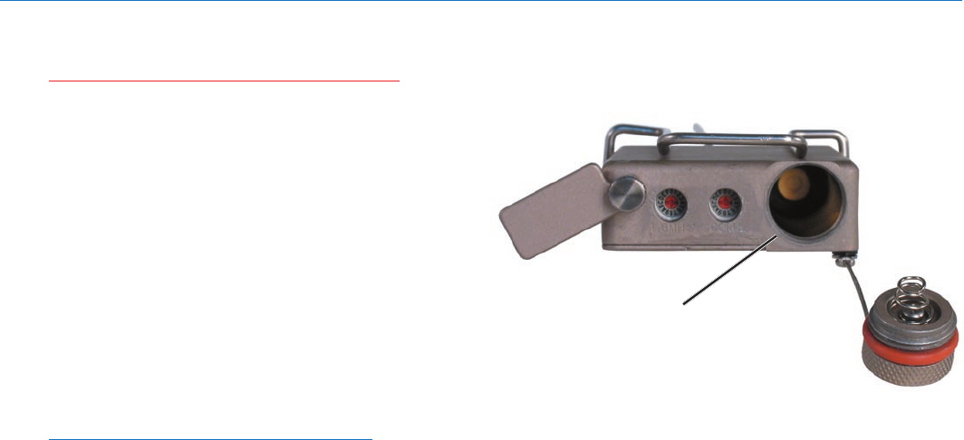
Power ON/OFF Switch
Awaterproof,magneticPowerON/OFFswitchis
located on the unit’s side panel. The switch actually
consists of two components. A magnetically actuated
internal component and a magnet housing assembly.
The switch is designed so that the unit will still operate
if the Switch Magnet Housing Assembly is missing or
removed.
ThefunctionofthePowerON/OFFSwitchcanalsobe
changed so it operates as an audio mute switch. (See
Operating Instructions, Power Switch Function Selec-
tion.) These functions are illustrated in the chart below:
Power Switch Position
Function ON OFF
Normal,or AppliesPower TurnsUnitOff
Power Mode to Unit
AudioMute TurnsOnAudio MutesAudio
Mode
IftheMM400CPowerON/OFFSwitchhasbeencon-
figured for Audio Mute Mode, it is still possible to turn
off the transmitter without removing the battery. This
isdonebyplacingtheswitchintheONposition,then
togglingtheswitchbetweentheONandOFFposition
threetimesinlessthanveseconds,i.e.,ON(Starting
Position)-OFF-ON-OFF-ON-OFF.
Theuser-selectedcongurationofthePowerON/OFF
switch is stored in memory and persists until reconfig-
ured by the user.
Power LED
ThePWRLEDprovidesanindicationofthebattery’s
condition.ThePWRLEDglowsgreenwhenthebattery
is good. The color changes to red when there is about
30 minutes of operation left with the recommended
lithium battery. (An alkaline battery will have about 20
minutesoflifeleft.)WhentheLEDbeginstoblinkred,
there are only a few minutes of life left in the battery.
ThePWRLEDblinksredforashortperiodwhenthe
transmitter is configured for Normal Mode and the
PowerON/OFFswitchissettoOFF.Attheendofthe
poweroffsequence,thenPWRLEDextinguishes.
Note: A NiMH battery gives little or no warning
when it is depleted. If you use NiMH batteries in
the MM400C, we recommend trying fully charged
batteries first, noting the length of time that the
batteries will run the unit , then plan for somewhat
less time to determine when the battery needs to
be replaced. Some Lectrosonics receivers have
timers for use with these batteries.
AweakbatterywillsometimescausethePWRLEDto
glow green immediately after being put in the unit, but
will soon discharge to the point where the LED will blink
red or shut off completely.
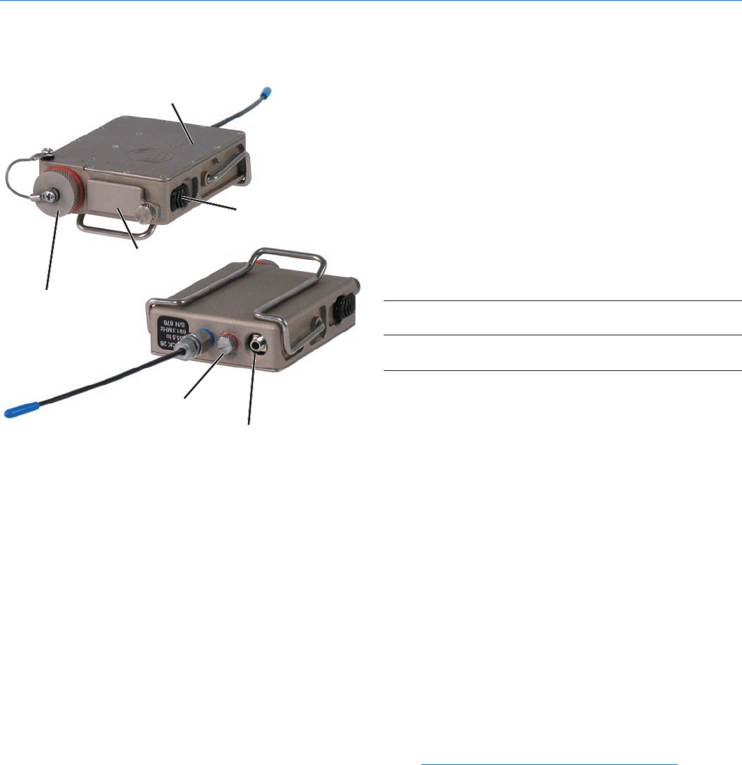
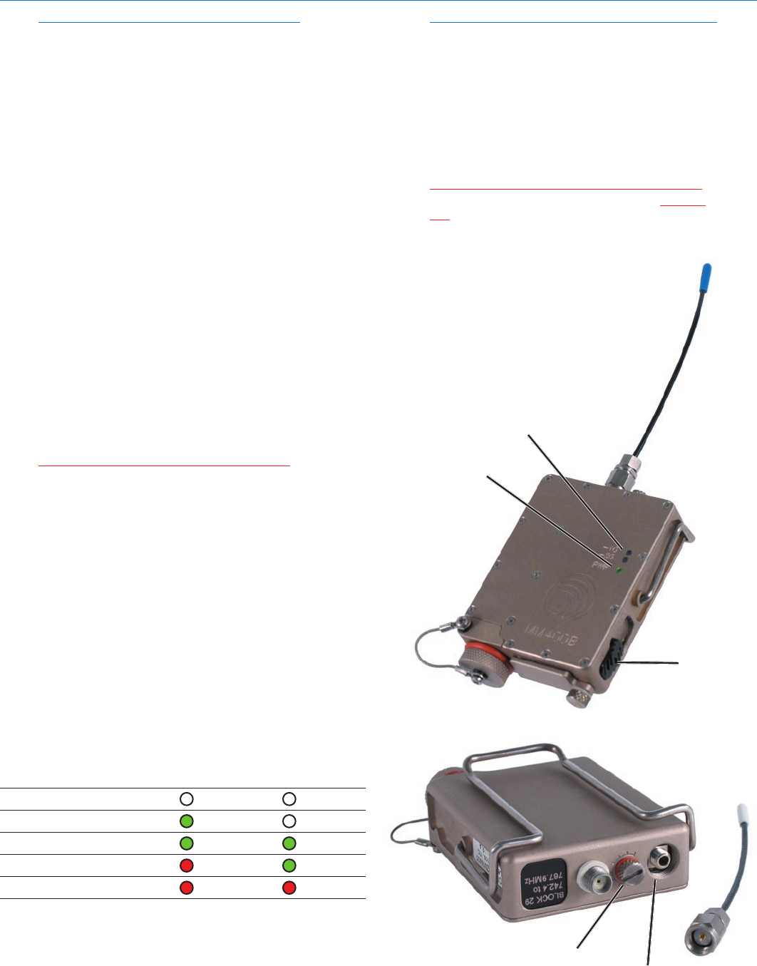
Microphone Jack
Frequency Select
SwitchThumbscrew
and Cover Plate
Modulation and
Power LEDs
Audio Level Control
Antenna
Battery
Compartment
Cap
Power ON/OFF Switch
(ExternalSwitchMagnet
Housing Assembly Shown.)
Watertight Miniature UHF Belt-Pack Transmitter
Rio Rancho, NM 9
Mic Jack
TheMicJackisa2.5mmmicroplugthatiswiredtoac-
commodatetwo-wirepositivebiaslavalieres.Whilethe
M152-WP(waterproof)isspecicallydesignedforthe
MM400C, other two-wire lavaliere microphones can be
adaptedtotheMM440CusingtheWPMC-3orWPMC-
10kits.ASwitchcraft850connector(LectrosonicsP/N
21357)canbeusedinanemergencythoughitisnot
waterproof. (See Replacement Parts and Accessories.)
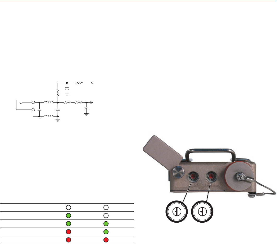
The equivalent input circuit wiring for the Mic Jack is
shown below:
Audio Level
The Audio Level Control is used to adjust the audio
input level from the microphone for proper modulation of
the output signal from the transmitter.
Modulation LEDs
The two bicolor Modulation LEDs provide a visual
indication of the audio signal level input from the mi-
crophone. These LEDs can glow either red or green
to indicate modulation levels as shown in the following
chart.
Signal Level -20 LED -10 LED
Lessthan-20dB Off Off
-20dBto-10dB Green Off
-10dBto+0dB Green Green
+0dBto+10dB Red Green
Greaterthan+10db Red Red
WhenthePowerON/OFFSwitchisconguredforAudio
Mute Mode, the -10 Modulat ion LED is also used to
indicate if the transmitter is in an audio muted, or an
unmuted condition. In Audio Mute Mode, if the Power
ON/OFFswitchissettoOFF,thetransmitterremains
powered up; however, the audio is muted and the -10
Modulation LED blinks green.
IfthePowerON/OFFswitchissettoONandtheswitch
is configured for Audio Mute Mode, -10 and -20 LEDs
operate normally to indicate audio level.
Mic
Jack
330pF 330pF
FB
FB
100
2k
2k
30uF
6V Mic Bias
To Mic Amp
2k
2.2nF
Frequency Select Switches
1.6M 100K
012
3
4
5
6
7
8
9
A
B
C
D
EF012
3
4
5
6
7
8
9
A
B
C
D
EF
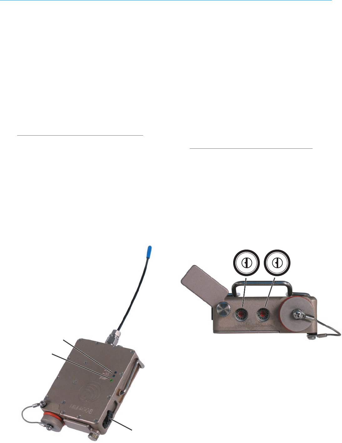
Frequency Select Switches
Two 16-position rotary Frequency Select Switches are
used to select the operating frequency, for setting Com-
patiblityModesandforconguringthePowerON/OFF
switch.
The switches are accessed by loosening the retaining
screw holding the cover plate, lifting the cover away
fromthehousingandrotatingittoexposetheswitches.
For setting the operating frequency, the left switch
(1.6MHz)adjuststheoperatingfrequencyupordownin
1.6MHzincrements.Therightswitch(100kHz)ad-
juststhefrequencyupordownin100kHzincrements.
(See Operating Instructions, Adjusting the Transmitter
Frequency.)
A sequence of Frequency Select Switch settings and
PowerON/OFFtogglesareusedtosetCompatibility
ModesandforconguringthePowerON/OFFswitch.
(See Operating Instructions, Setting Compatibility
Modes and Power Switch Function Selection.)
Antenna
Thepermanently-mounted,exiblesteelcableantenna
iscutto1/4wavelengthofthecenterofthefrequency
block (the frequency range) of the transmitter.
Belt Clip
The belt clip may be removed for special applications
by gently spreading the spring wire clip and pulling
the ends out of the holes in the case. The clip can be
installed in either the up or down position so that when
the transmitter is worn, the antenna can be pointing up
or down. Replacement belt clips are available. (See
Replacement Parts and Accessories.)
MM400C
LECTROSONICS, INC.
10
WARNING: Do not open battery compartment
if unit is wet. Read “Preventing Internal
Corrosion” on page 8 before proceeding.
The transmitter is powered by a standard lithium, NiMH
oralkalineAA1.5voltbattery.Thebatterystatus
circuitry is designed for the voltage drop over the life of
lithiumbatteries.WhileNiMHrechargeablebatteries
willwork,theyrundownquiteabruptly.Becauseofthis,
usingthePWRLEDtoverifybatterystatusnotreliable
with NiMH batteries. It is possible to track battery status
usingtheBatteryTimerfunctionavailableinanum-
ber of Lectrosonics receivers. (Refer to your receiver
manual to determine if this function is available.
Alkalinebatteriesprovideabout1.75hoursofoperation
with some warning. Lithium batteries can be used to
provide over 6 hours of operation and provide about 30
minutes of warning as the LED turns red.
Note:Standardzinc-carbonbatteriesmarked
“heavy-duty” or “long-lasting” are not adequate.
To access the battery compartment, unscrew and
removetheBatteryCompartmentCover.Takenoteof
the polarity marked on the battery case showing the
locationofthepositive(+)andnegative(-)terminals.
Thepositive(+)batteryterminalgoesintothetransmit-
terrst.ScrewtheBatteryCompartmentCoverback
into the transmitter body. If the battery is inserted incor-
rectly, the cover will not screw in easily and the unit will
not work.
Battery Installation
Battery Compartment
Watertight Miniature UHF Belt-Pack Transmitter
Rio Rancho, NM 11
Modulation LEDs
POWER LED
Power ON/OFF
Switch
thetransmitterOff.
6) Change the Frequency Select Switch settings to
one of the following positions:
• 100Seriesmode: 1,1
•200Seriesmode: 2,2
•Mode3: 3,3
•400Seriesmode: 4,4
•IFBSeriesmode: 5,5
7) Power up the unit briefly – just long enough to
watch the LED’s glow and then turn the transmitter
Off.
8) Set the Frequency Select Switches to 0,0.
9) Turn on the transmitter and observe the Modulation
LEDs to verify the compatibility mode for the unit
has changed.
NOTE:Eachtimethetransmitteristurnedon,the
Modulation LEDs will confirm the current operating
mode with the number of blinks listed in Step 2.
The mode setting will not change until reset with
the procedure listed above.
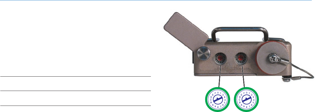
Adjusting Transmitter Frequency
Ifyouareexperiencinginterferencefromanothersignal
on your operating frequency, you may need to change
the operating frequency of your system. This is done
through two Frequency Select Switches located under
the Frequency Switch Cover Plate on the bottom of the
transmitter case.
012
3
4
5
6
7
8
9
A
B
C
D
EF012
3
4
5
6
7
8
9
A
B
C
D
EF
Frequency Select Switches
1.6M 100K
The left switch is for coarse frequency adjustment, and
itincrementstheoperatingfrequencyin1.6MHzsteps.
The right switch is for fine frequency adjustment and it
incrementstheoperatingfrequencyin100kHzsteps.
If you are using a 200 Series or 400 Series receiver,
it is suggested to use the built in frequency spectrum
scanning function on the associated receiver to find a
clear channel. Turn the transmitter off and leave the
receiver turned on. Scan across the frequency band to
find a frequency where little or no RF activity is dis-
played. Set both the transmitter and the receiver to this
new frequency. Turn on the transmitter to ensure the
RF signal is strongly indicated at the receiver.
Selecting the Compatibility Mode
All Digital Hybrid receivers are capable of working with
Lectrosonics MM400C transmitter, and by setting the
proper Compatibility Mode, the unit will also work with
200 Series and 100 Series analog receivers, plus some
other brands (contact the factory for details). In order
to operate properly, the transmitter must be set to the
operating mode of the matching receiver, which is easily
done using a small screwdriver and a battery.
The following procedure assumes that the Power
ON/OFFswitchisconguredforNormalMode.Ifit
has been configured for Audio Mute Mode, see Power
Switch Function Selection to change the configuration
to Normal Mode.
Note: The unit comes from the factory in the Digital
Hybrid mode.
1) Set the audio controls for the corresponding re-
ceiver to minimum.
2) Install a good battery in the transmitter. Move the
PowerSwitchtoONandobservetheModulation
LEDs to determine the current Compatibility Mode.
The –20 and –10 LEDs will blink simultaneously:
•Oncefor100Seriesmode
•Twotimesfor200Seriesmode
•Threetimesfor“Other”receivers
• Fourtimesfor400Seriesmode
•FivetimesforIFBSeriesmode
3) MovethePowerSwitchtotheOFFposition.
4) Loosen the Frequency Switch Cover Plate
Retaining Screen and rotate the cover to
exposetheFrequencySelectSwitches.
Withasmallscrewdriver(included
with your unit), set the Frequency
Select Switches to CC. (for
Change, Change).
5) Power up the unit briefly – just
long enough to watch the
LED’s glow and then turn
Operating Instructions
MM400C
LECTROSONICS, INC.
12
POWER
LED
Modulation
LEDs
Power On/Off
Switch
NOTE:All400Series(andanumberofearlier
receivers) offer a front panel LCDs that indicate the
correct transmitter switch settings when locating
clear channels. Use the scanning functions on
these receivers to find a clear channel, then switch
both the receiver and transmitter to the Frequency
Select Switch settings indicated in the receiver’s
display.
If you are using a 100 Series receiver, turn off the trans-
mitter and observe the RF LED on the front panel of the
UCR100 receiver. If it flickers, or glows red, then adjust
the UCR100’s Frequency Select Switches up or down in
100kHzincrementsuntiltheRFLEDextinguishes.Set
the MM400C transmitter’s Frequency Select Switches
to the same settings. Turn on the transmitter and ob-
serve that the RF LED on the receiver glows brightly.
Attaching a Microphone and
Adjusting Audio Levels
The front panel Modulation LEDs indicate limiter activity.
(See chart.) Since the distortion introduced by the lim-
iter is minimal and full modulation is assured, occasional
forays into the red by the -10 LED is acceptable.
1) Install a fresh battery.
2) Insert the watertight microphone plug into the Mic
Jack and screw it in snugly.
WARNING: Do not overtighten as this will
distort the “O-ring” and allow moisture to enter
the unit.
3) Mute the main sound system and rotate the Audio
LevelControlontheMM400Ctomaximumcounter-
clockwise(Off).
4) SetthePowerON/OFFswitchtotheONposition.
5) Position the microphone in the location where it will
be used during in actual operation.
6) ObservetheMM400CModulationLEDSwhile
speaking or singing into the microphone at
the same voice level that will be used during
the program. Gradually rotate the Audio Level
Control control clockwise until both LEDs glow
greenwiththe-20dBoccasionalblinking
red. This indicates full modulation and is the
optimum setting for the transmitter’s gain.
Signal Level -20 LED -10 LED
Lessthan-20dB Off Off
-20dBto-10dB Green Off
-10dBto+0dB Green Green
+0dBto+10dB Red Green
Greaterthan+10db Red Red
NOTE:Differentvoiceswillusuallyrequiredifferent
settings of the Audio Level Control, so check
this adjustment as each new person uses the
system. If several different people will be using
the transmitter and there is not time to make the
adjustment for each individual, adjust it for the
loudest voice.
7) OncetheMM400C’saudiogainhasbeenset,the
remaining components of the audio system can be
energizedandadjusted.
WARNING: The AUDIO LEVEL control should
not be used to control the volume of your
sound system or recorder levels. This gain
adjustment matches the transmitter gain
with the user’s voice level and microphone
positioning.
Microphone Jack
Audio
Level
Control
Watertight Miniature UHF Belt-Pack Transmitter
Rio Rancho, NM 13
Power Switch Function Selection
ThePowerON/OFFSwitchcanalsobeusedasanau-
diomuteswitch.Whenusedasanaudiomuteswitch,
the power switch causes the transmitter’s audio to be
mutedwhenthePowerON/OFFswitchisplacedinthe
OFFposition.The-10ModulationLEDblinksgreento
indicate that the transmitter is in Audio Mute Mode.
Power Switch Position
Function ON OFF
Normal,or AppliesPower TurnsUnitOff
Power Mode to Unit
AudioMute TurnsOnAudio MutesAudio
Mode
In Audio Mute Mode, the transmitter can still be turned
offbytogglingthePowerON/OFFswitchrapidly.Turn
thePowerSwitchONthenOFFthreetimes(ending
intheOFFposition)withinvesecondstoinitiatethe
poweroffsequence.ThesequenceisON-OFF-ON-
OFF-ON-OFF.
Whenthetransmitterispoweredupagain,AudioMute
Mode will persist until the power switch function is
changed.
Determine Power Switch Function Mode
1) If the transmitter is turned off, set the Power Switch
ONandobservetheModulationLEDs.
2) After the power up sequence completes, place the
POWERON/OFFswitchintheOFFpositionand
observe the -10 Modulation LED.
3) IfthePWRLEDglowsandthe-10ModulationLED
blinks green, the Power Switch is in Audio Mute
Mode.IftheLEDsextinguish,thePowerSwitchis
in Normal or Power Mode.
Changing Power Switch Function
1) EnsurethePowerON/OFFswitchisintheOFF
position.
2) Loosen the Frequency Switch Cover Plate Retain-
ing Screw, pull it away from the transmitter body,
thenrotateittoexposetheFrequencySelect
Switches.
3) Withasmallscrewdriver(includedwithyourunit),
set the Frequency Select Switches to F,F.
4) RapidlytogglethePowerON/OFFswitchtoON
thenbacktoOFF.
5) Change the Frequency Select Switch settings to the
following position:
Normal Mode: 1,1
Audio Mute Mode: 2,2.
5) RapidlytogglethePowerON/OFFswitchtoON
thenbacktoOFF.
6) Set the Frequency Select Switches to 0,0.
7) RapidlytogglethePowerON/OFFswitchtoON
thenbacktoOFF.
8) Turn on the transmitter. After the powerup se-
quencehascompleted,setthePowerON/OFF
SwitchtoOFFandobservethe-10ModulationLED
andthePWRLED.
IfthePowerON/OFFswitchisconguredforNor-
mal Mode, the -10 Modulation LED will go out and
thePWRLEDwillblinkredforashortperiodthen
go out indicating the transmitter has shut down.
IfthePowerON/OFFswitchisconguredfor
AudioMuteMode,thePWRLEDcontinues
to monitor battery condition while the -10
Modulation LED blinks green.
Frequency Select Switches
1.6M 100K
MM400C
LECTROSONICS, INC.
14
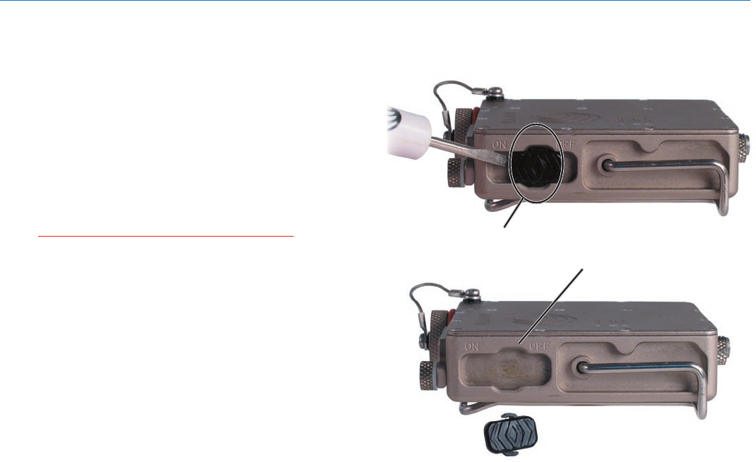
Although the Power Switch’s Magnet Housing Assembly
is designed to provide years of rugged use it may be-
come inadvertently damaged or lost. Use the following
procedure to install a new Magnet Housing Assembly.
1) If necessary, use a nonmetallic tool such as an
“orange stick” to remove the damaged Magnet
Housing Assembly and clean any debris from the
Magnet Housing Assembly slot. Apply a small
amount of petroleum jelly or white lithium grease to
the area before inserting the new magnet assembly.
Warning: If you use something metallic, as
illustrated in the example, use extreme caution
not to scratch the finish. Breaching the finish
may cause corrosion of the metal housing.
2) Notice that the Magnet Housing Assembly Slot has
a wide spot in the middle. Place the new Magnet
Housing Assembly in the slot so that one tab is in a
small groove in one side of the slot.
3) Use a nonmetallic implement to snap the other side
of the Magnet Housing Assembly into the slot.
4) Ensure a good battery is installed, then slide the
newPowerON/OFFSwitchtoONtoverifythatitis
working properly.
Replacing the Power Switch Magnet Housing Assembly
Magnet Housing
Assembly
First, center the switch in the slot in the
housing so that the tabs will release
through the wider openings.

Watertight Miniature UHF Belt-Pack Transmitter
Rio Rancho, NM 15
Some mics require RF protection to keep the radio sig-
nal from affecting the capsule, even though the trans-
mitter input circuitry is already RF bypassed.
If the mic is wired as directed, and you are having diffi-
culty with level, high noise, or poor frequency response;
RF is likely to be the cause.
The best RF protection is accomplished by installing RF
bypass capacitors at the mic capsule. If this is not pos-
sible, or if you are still having problems, capacitors can
beinstalledonthemicwiresinsidetheTA5Fconnector
housing.
Install the capacitors as follows: Use 330 pF capaci-
tors. Capacitors are available from Lectrosonics. Please
specify the part number for the desired lead style.
Microphone RF Bypassing
Leaded capacitors: P/N 15117
Leadless capacitors: P/N SCC330P
All Lectrosonics lavaliere mics are already bypassed
and do not need any additional capacitors installed for
proper operation.
2 WIRE MIC
CAPSULE
SHIELD
AUDIO
Alternate location for bypass capacitors
MICROPHONE
CONNECTOR
Preferred location for bypass capacitors
MM400C
LECTROSONICS, INC.
16
Part/Model # Description
26486 Replacement wire belt clip
21357 Non-watertight audio input plug
WPMC-3 Watertightplugkit-3pieces
WMPC-10 Watertightplugkit-10pieces
P1201-1 Switch Magnet Housing Assembly
Replacement Parts and Accessories
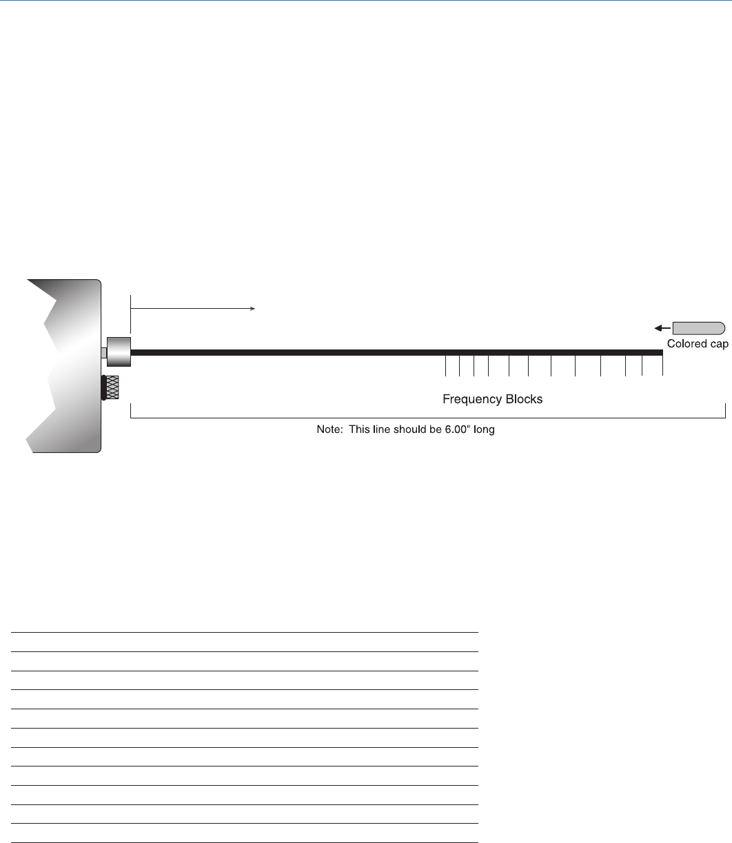
UHF Transmitter Antenna Specifications
All Lectrosonic UHF transmitter antennas follow the
color code specifications in the chart below to identify
operating frequency block range. The frequency block
range is labeled on the ouside housing for each indi-
vidual transmitter.
FREQUENCY CAP ANTENNA
BLOCK RANGE COLOR WHIP LENGTH
470 470.100-495.600 Black 5.37”
19 486.400-511.900 Black 5.16”
20 512.000-537.500 Black 4.98”
21 537.600-563.100 Brown 4.74”
22 563.200-588.700 Red 4.48”
23 588.800-614.300 Orange 4.24”
24 614.400-639.900 Yellow 4.01”
25 640.000-665.500 Green 3.81”
26 665.600-691.100 Blue 3.62”
27 691.200 - 716.700 Violet (Pink) 3.46”
28 716.800 - 742.300 Grey 3.31”
29 742.400-767.900 White 3.18”
470
19
20
21
22
23
24
25
26
27
28
29
Lay the transmitter on this template to determine the frequency block
of the antenna. Remove the colored cap for accurate measurement.

Watertight Miniature UHF Belt-Pack Transmitter
Rio Rancho, NM 17
Beforegoingthroughthefollowingchart,besurethatyouhaveagoodbatteryinthetransmitter.Itisimportantthat
you follow these steps in the sequence listed.
SYMPTOM POSSIBLE CAUSE
1) Batteryisinsertedbackwards.
2) Batteryisdead.
3) PowerON/OFFswitchconguredtoNormalModeandis
settoOFF.
1) VerifyTransmitterPWRLEDisglowing.
2) Gain control turned all the way down.
3) Mic capsule is damaged or malfunctioning.
4) Mic cable damaged or mis-wired.
1) PowerON/OFFSwitchisconguredforAudioMuteModeand
theswitchisintheOFF,ormuteposition.(SeeControls and
Functions.)
1) Transmitter not turned on.
2) Transmitter battery is dead.
3) Receiver antenna missing or improperly positioned.
4) Transmitter and receiver not on same frequency.
Checkswitches/displayontransmitterandreceiver.
5) Operatingrangeistoogreat.
1) Receiver output level set too low.
2) Receiver output is disconnected; cable is defective or connectors
not wired correctly.
3) Sound system or recorder input is turned down.
4) Receiver/Transmittercompatibilitymodemismatched.
5) Transmitteraudiomuted.
1) Transmitter gain (audio level) is far too high. Check Modulation
LEDs on transmitter and receiver as it is being used. (See
Operating Instructions, Attaching a Microphone and Adjusting
Audio Levels.)
2) Receiver output may be mismatched with the sound system or
recorder input. Adjust output level on receiver to the correct level
fortherecorder,mixerorsoundsystem.
3) Excessivewindnoiseorbreath“pops.”Repositionmicrophone
and/orusealargerwindscreen.
4) Transmitter is not set to same frequency as receiver. Check that
frequency select switches on receiver and transmitter match.
5) Receiver/Transmittercompatibilitymodemismatched.
1) Transmitter gain (audio level) far too low.
2) Receiver antenna missing or obstructed.
3) Operatingrangetoogreat.CheckRFlevelonreceiverindicator.
1) Transmitter gain (audio level) too high. Check gain adjustment
and/orreducereceiveroutputlevel.
2) Transmitter too close to speaker system.
3) Mic is too far from user’s mouth.
Troubleshooting
TRANSMITTER PWR LED OFF
NO TRANSMITTER MODULATION LEDs
-10 MODULATION LED IS BLINKING
GREEN AND RECEIVER HAS NO AUDIO
RECEIVER INDICATES NO RF
NO SOUND (OR LOW SOUND LEVEL),
RECEIVER INDICATES PROPER AUDIO
MODULATION
DISTORTED SOUND
HISS AND NOISE -- AUDIBLE DROPOUTS
EXCESSIVE FEEDBACK

MM400C
LECTROSONICS, INC.
18
Operating frequencies:
Block 470 470.100 - 495.600
Block 19 486.400 - 511.900
Block 20 512.000 - 537.500
Block 21 537.600 - 563.100
Block 22 563.200 - 588.700
Block 23 588.800 - 607.900 and 614.100 - 614.300
Block 24 614.400 - 639.900
Block 25 640.000 - 665.500
Block 26 665.600 - 691.100
Block 27 691.200 - 716.700
Block 28 716.800 - 742.300
Block 29 742.400 - 767.900
Frequency selection: 256 frequencies in 100 kHz steps
RF Power output: 100 mW (nominal)
Pilot tone: 25 to 32 kHz; 5 kHz deviation
(in 400 Series Mode)
Frequency stability: ± 0.002%
Deviation: ± 75 kHz max. (in 400 Series Mode)
Spurious radiation: 60 dB below carrier
Equivalent input noise: –118 dBV, A-weighted
Input level: Nominal 2 mV to 300 mV, before limiting.
Greater than 1.5V maximum, with limiting.
Input impedance: 2 kOhm
Input limiter: Soft limiter, >30 dB range
Gain control range: 43 dB; semi-log rotary control
Modulation indicators: Dual bicolor LEDs indicate modulation of
–20, -10, 0, +10 dB referenced to full
modulation.
Low frequency roll-off: –12 dB/octave; 70 Hz
Specifications and Features
The FCC requires that the following statement be included in this manual:
ThisdevicecomplieswithFCCradiationexposurelimitsassetforthforanuncontrolled
environment. This device should be installed and operated so that its antenna(s) are
not co-located or operating in conjunction with any other antenna or transmitter.
Emission Designator: 180KF3E
Specifications subject to change without notice.
Controls: Front panel knob adjusts audio gain.
Rotary switches on bottom panel adjust
transmitter frequency.
Audio Frequency Response: 80 Hz to 20 kHz, +/-1dB, -3 dB @ 70 Hz
(The audio is deliberately rolled off at 70 Hz
using a 12 dB/octave filter. This filter cannot
be disabled.)
Signal to Noise Ratio (dB):
(overall system, 400 Series mode)
Total Harmonic Distortion: 0.2% typical (400 Series mode)
Audio Input Jack: 2.5 mm Microjack (matches Switchcraft 850
Microplug)
Antenna: Detachable, flexible galvanized steel
with SMA connector. (50 Ohm antenna port
also allows connection to test equipment.)
Battery: 1.5 Volt AA lithium recommended
Battery Life: 1.75 hours (alkaline); over 6 hours (lithium);
3.5 hours (2200 mAhr) NiMH
Weight: 3.6 ozs. (102 grams) with lithium battery,
no antenna
Overall Dimensions: 3.03 x 2 x 0.69 inches (not including
microphone or antenna)
(Note: the dual envelope “soft”
limiterprovidesexceptionally
good handling of transients
using variable attack and release
time constants. The gradual onset of limiting in the design begins below full
modulation, which reduces the measured figure for SNR without limitingby4.5dB)
SmartNR No Limiting w/Limiting
OFF 103.5 108.0
NORMAL 107.0 111.5
FULL 108.5 113.0

Watertight Miniature UHF Belt-Pack Transmitter
Rio Rancho, NM 19
Service and Repair
If your system malfunctions, you should attempt to correct or isolate the trouble before concluding that the equipment
needs repair. Make sure you have followed the setup procedure and operating instructions. Check the interconnect-
ing cables and then go through the Troubleshooting section in this manual.
Westronglyrecommendthatyoudo not try to repair the equipment yourself and do not have the local repair shop
attempt anything other than the simplest repair. If the repair is more complicated than a broken wire or loose connec-
tion,sendtheunittothefactoryforrepairandservice.Don’tattempttoadjustanycontrolsinsidetheunits.Once
set at the factory, the various controls and trimmers do not drift with age or vibration and never require readjustment.
There are no adjustments inside that will make a malfunctioning unit start working.
LECTROSONICS’ServiceDepartmentisequippedandstaffedtoquicklyrepairyourequipment.Inwarrantyrepairs
aremadeatnochargeinaccordancewiththetermsofthewarranty.Out-of-warrantyrepairsarechargedatamodest
flat rate plus parts and shipping. Since it takes almost as much time and effort to determine what is wrong as it does
tomaketherepair,thereisachargeforanexactquotation.Wewillbehappytoquoteapproximatechargesbyphone
for out-of-warranty repairs.
Returning Units for Repair
For timely service, please follow the steps below:
A. DONOTreturnequipmenttothefactoryforrepairwithoutrstcontactingusbyemailorbyphone.Weneed
toknowthenatureoftheproblem,themodelnumberandtheserialnumberoftheequipment.Wealsoneeda
phone number where you can be reached 8 A.M. to 4 P.M. (U.S. Mountain Standard Time).
B. Afterreceivingyourrequest,wewillissueyouareturnauthorizationnumber(R.A.).Thisnumberwillhelpspeed
yourrepairthroughourreceivingandrepairdepartments.Thereturnauthorizationnumbermustbeclearlyshown
on the outside of the shipping container.
C. Pack the equipment carefully and ship to us, shipping costs prepaid. If necessary, we can provide you with the
properpackingmaterials.UPSisusuallythebestwaytoshiptheunits.Heavyunitsshouldbe“double-boxed”for
safe transport.
D. Wealsostronglyrecommendthatyouinsuretheequipment,sincewecannotberesponsibleforlossofordam-
agetoequipmentthatyouship.Ofcourse,weinsuretheequipmentwhenweshipitbacktoyou.
Lectrosonics USA:
Mailing address: Shipping address: Telephone:
Lectrosonics,Inc. Lectrosonics,Inc. (505)892-4501
POBox15900 581LaserRd. (800)821-1121Toll-free
RioRancho,NM87174 RioRancho,NM87124 (505)892-6243Fax
USA USA
Web: E-mail:
www.lectrosonics.com sales@lectrosonics.com
Lectrosonics Canada:
Mailing Address: Telephone: E-mail:
49SpadinaAvenue, (416)596-2202 Sales: colinb@lectrosonics.com
Suite303A (877)753-2876Toll-free Service:joeb@lectrosonics.com
Toronto,OntarioM5V2J1 (877-7LECTRO)
(416)596-6648Fax

8 April 2008
581 Laser Road NE • Rio Rancho, NM 87124 USA • www.lectrosonics.com
(505) 892-4501 • (800) 821-1121 • fax (505) 892-6243 • sales@lectrosonics.com
LIMITED ONE YEAR WARRANTY
The equipment is warranted for one year from date of purchase against defects in
materials or workmanship provided it was purchased from an authorized dealer. This
warranty does not cover equipment which has been abused or damaged by careless
handling or shipping. This warranty does not apply to used or demonstrator equipment.
Should any defect develop, Lectrosonics, Inc. will, at our option, repair or replace any
defective parts without charge for either parts or labor. If Lectrosonics, Inc. cannot
correct the defect in your equipment, it will be replaced at no charge with a similar new
item. Lectrosonics, Inc. will pay for the cost of returning your equipment to you.
This warranty applies only to items returned to Lectrosonics, Inc. or an authorized
dealer, shipping costs prepaid, within one year from the date of purchase.
This Limited Warranty is governed by the laws of the State of New Mexico. It states the
entire liablility of Lectrosonics Inc. and the entire remedy of the purchaser for any
breach of warranty as outlined above. NEITHER LECTROSONICS, INC. NOR
ANYONE INVOLVED IN THE PRODUCTION OR DELIVERY OF THE EQUIPMENT
SHALL BE LIABLE FOR ANY INDIRECT, SPECIAL, PUNITIVE, CONSEQUENTIAL,
OR INCIDENTAL DAMAGES ARISING OUT OF THE USE OR INABILITY TO USE
THIS EQUIPMENT EVEN IF LECTROSONICS, INC. HAS BEEN ADVISED OF THE
POSSIBILITY OF SUCH DAMAGES. IN NO EVENT SHALL THE LIABILITY OF
LECTROSONICS, INC. EXCEED THE PURCHASE PRICE OF ANY DEFECTIVE
EQUIPMENT.
This warranty gives you specific legal rights. You may have additional legal rights which
vary from state to state.