Lectrosonics SMWBB1 Wireless Microphone Transmitter User Manual SMWB man indd
Lectrosonics Inc Wireless Microphone Transmitter SMWB man indd
UserManual.wiki
>
Lectrosonics
>
SMWBB1 User Manual
User Manual
Navigation menu
Upload a User Manual
Namespaces
Wiki Guide
HTML
PDF
Info
Views
User Manual
Discussion / Help
Navigation
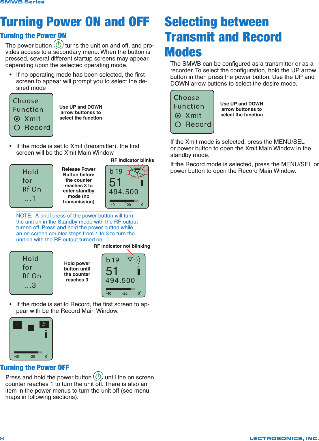
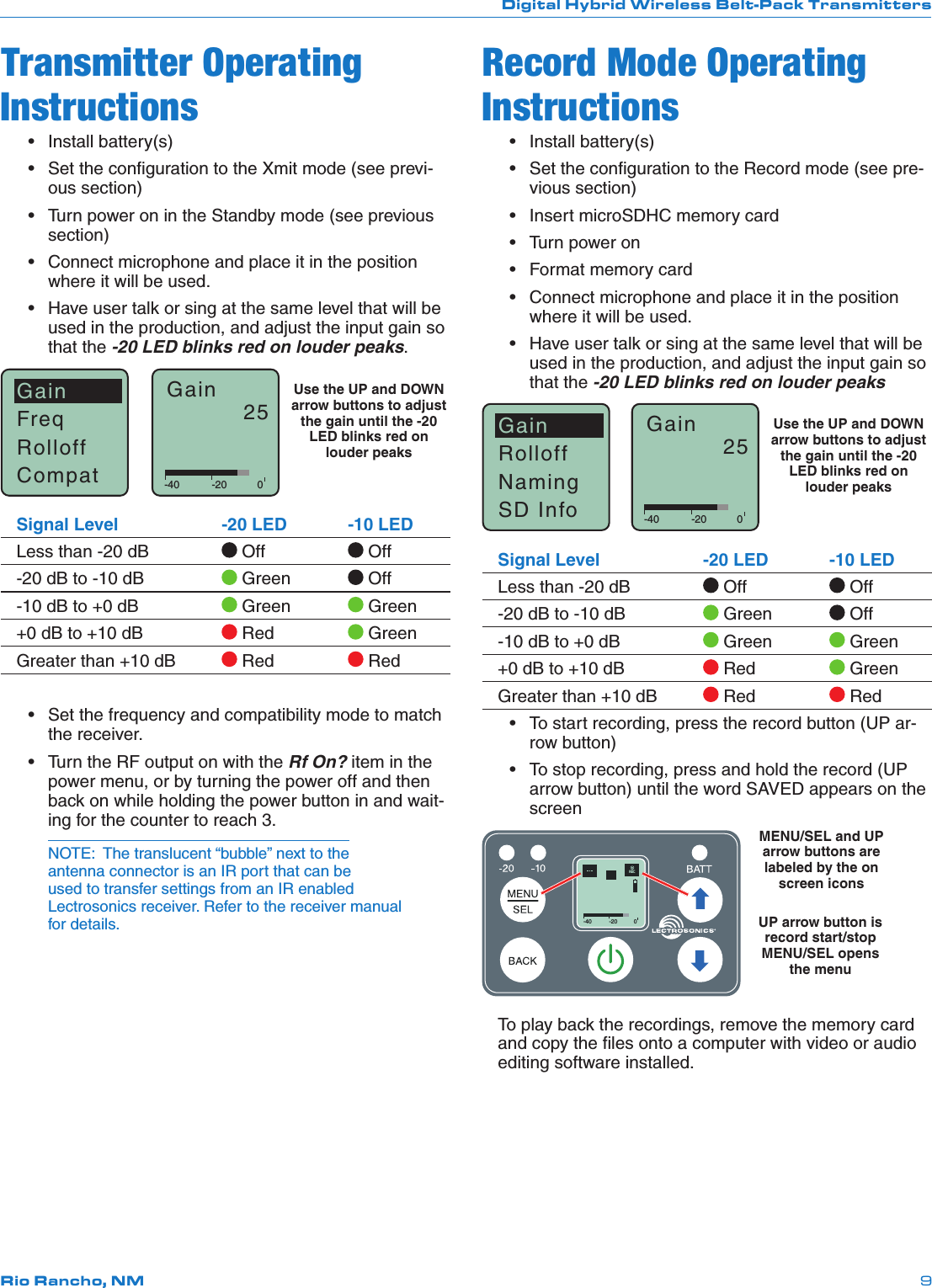
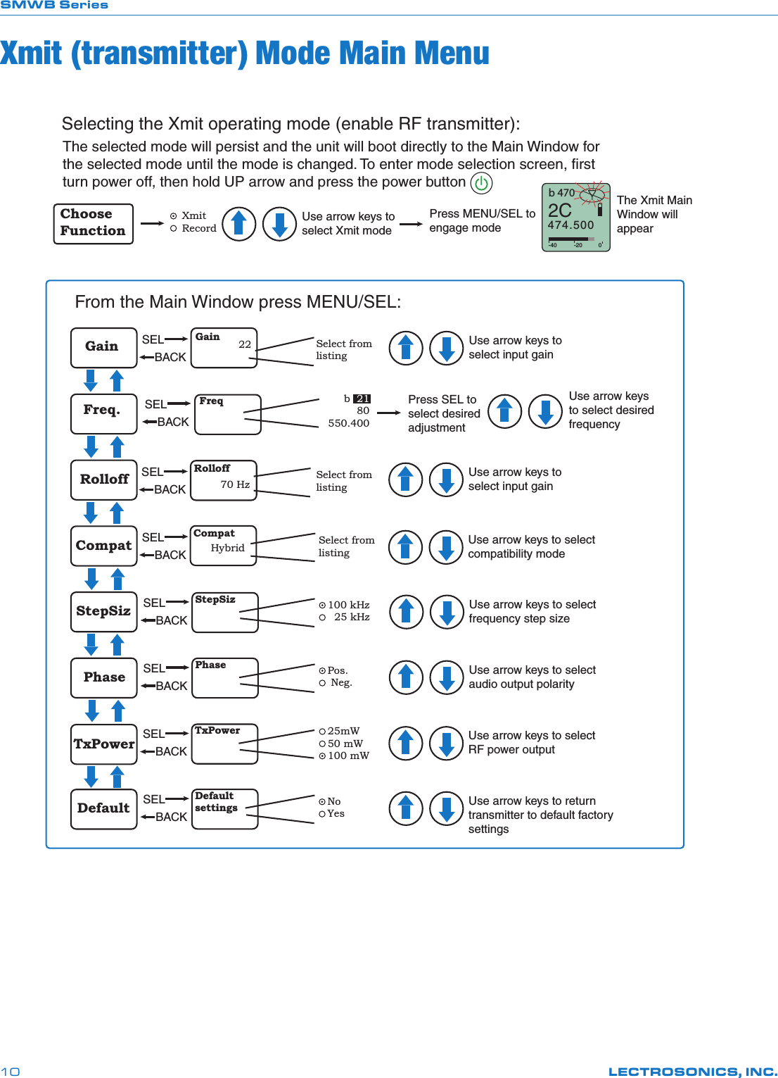
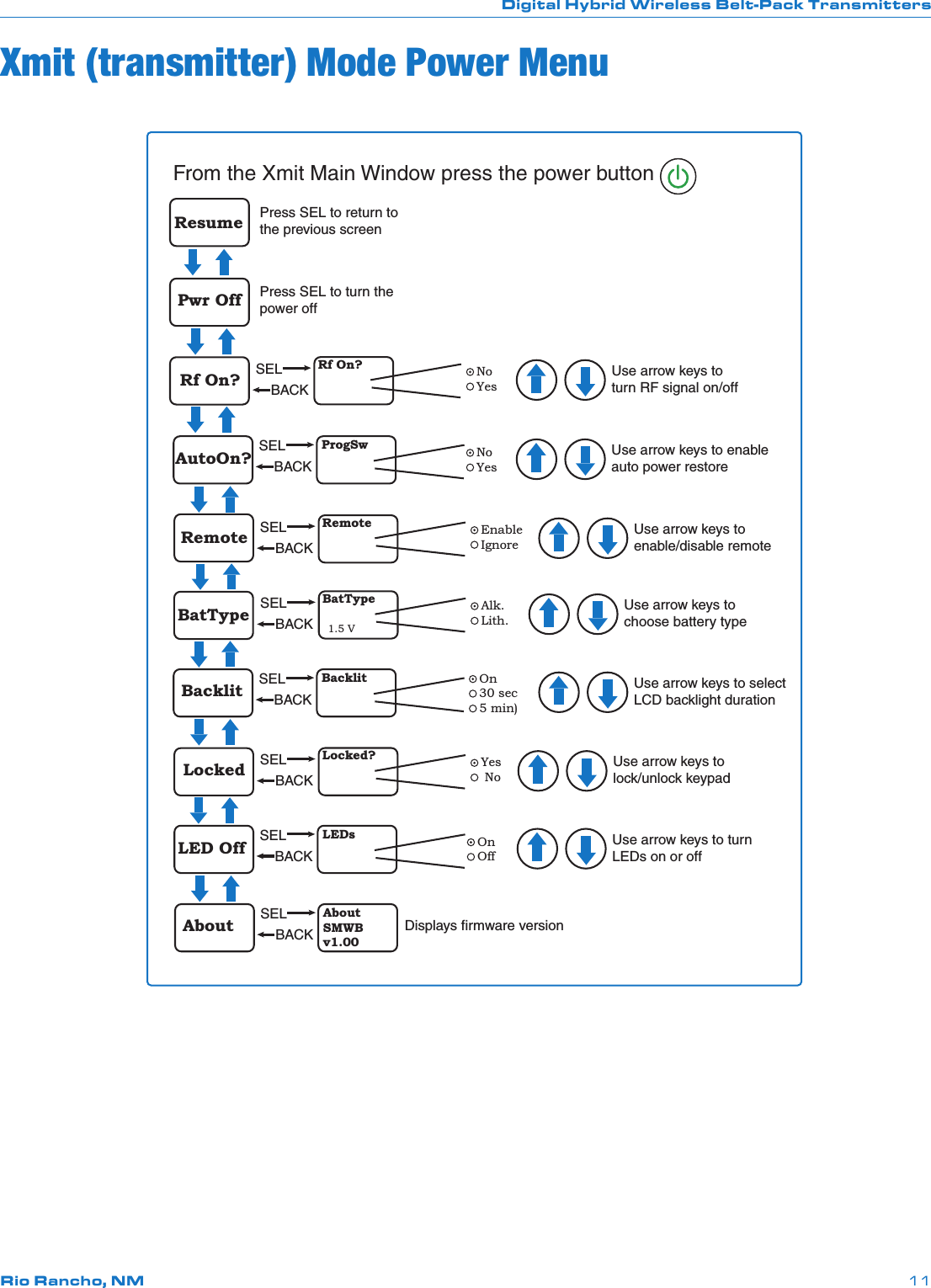
![SMWB SeriesLECTROSONICS, INC.12Record Mode Main MenuFiles SELBACKFiles 0014A0000013A000Use arrow keys to select file in listDefault SELBACKUse arrow keys to return recorder to default factory settingsNoYesDefaultsettingsSelect fromlistingUse arrow keys to select Xmit modeChoose FunctionPress MENU/SEL to engage mode Xmit RecordThe Recorder Main Window will appearSelecting the Record operating mode:The selected mode will persist and the unit will boot directly to the Main Window for the selected mode until the mode is changed. To enter mode selection screen, first turn power off, then hold UP arrow and press the power button-40 -20 0RECFormat SELBACKUse arrow keys to initiate formatting the memory cardNoYesFormat?(erases)Gain SELBACKGain 22 Use arrow keys to select input gainSelect value in dBRolloff SELBACKRolloff70 HzUse arrow keys to select low frequency rolloffSelect fromlistingNaming SELBACKUse arrow keys to select file naming method Seq # ClockNamingSD Info SELBACK[SMWB ]Max RecE.........................F0/ 14GFuel gaugeStorage usedStorage capacityAvailable recording time (H : M : S)From the Main Window press MENU/SEL:](https://usermanual.wiki/Lectrosonics/SMWBB1/User-Guide-3499785-Page-12.png)