Lectrosonics UM450L Body Worn Wireless Microphone Transmitter User Manual um450man
Lectrosonics Inc Body Worn Wireless Microphone Transmitter um450man
user manual
UM450
Frequency-Agile UHF Belt-Pack Transmitter
INSTRUCTION MANUAL
Rio Rancho, NM, USA
www.lectrosonics.com
Fill in for your records:
Serial Number:
Purchase Date:
Featuring
Digital Hybrid Wireless™ Technology
(US Patent Pending)

UM450
LECTROSONICS, INC.2

Frequency-Agile UHF Belt-Pack Transmitter
Rio Rancho, NM 3
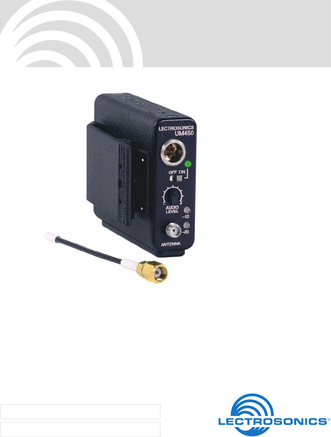
Thank you for selecting the Lectrosonics UM450 frequency agile, belt-pack transmitter. The UM450 combines over 80
years of engineering experience with the very latest components, in a design that addresses the most demanding
professional applications.
The design of the UM450 was the direct result of numerous conversations with users, staging and touring companies
and dealers across the US. The specific concerns and needs brought up in these conversations led directly to the
development of the operational features offered on the UM450. Two hundred fifty six frequencies are user selectable in
100kHz steps to alleviate interference problems in traveling venues, and the low frequency roll-off is user adjustable to
adapt to varying acoustic environments and preferences.
The UM450 is a rugged, machined aluminum package with a removable, spring loaded belt clip. The input section
provides a correct input tap for virtually any microphone or line level audio source. Five volts of bias voltage is avail-
able to power electret mics with either positive or negative bias. Level indicating LEDs are provided on the control
panel to make level settings quick and accurate, without having to view the receiver. The battery compartment ac-
cepts any 9 Volt alkaline battery and makes a positive connection via self-adjusting contacts. The antenna is a detach-
able, locking 1/4 wavelength flexible galvanized steel cable that connects to a 50 Ohm SMA port on the transmitter.
Only the UM450 transmitter is covered in this manual. Companion receivers are covered in separate manuals. The
UM450 will operate with any 400 Series Lectrosonics receiver and a variety of analog receivers in the same frequency
group.

UM450
LECTROSONICS, INC.4

Frequency-Agile UHF Belt-Pack Transmitter
Rio Rancho, NM 5
Table of Contents
General Technical Description ..............................................................................................................................................................6
Introduction ...........................................................................................................................................................................................6
Digital Hybrid Technology ..................................................................................................................................................................... 6
UM450 Block Diagram ..........................................................................................................................................................................6
No Pre-Emphasis/De-Emphasis ...........................................................................................................................................................7
Pilot Tone Squelch ................................................................................................................................................................................7
Input Limiter ..........................................................................................................................................................................................7
Wide-Band Deviation ............................................................................................................................................................................ 7
Long Battery life ...................................................................................................................................................................................7
Frequency Agility ..................................................................................................................................................................................7
Antenna ................................................................................................................................................................................................7
Controls and Functions ......................................................................................................................................................................... 8
Input Jack ............................................................................................................................................................................................. 8
Power ON/OFF Switch .........................................................................................................................................................................8
Power On LED ......................................................................................................................................................................................8
Audio Level Control .............................................................................................................................................................................. 8
Audio Level ........................................................................................................................................................................................... 8
Modulation LEDs ..................................................................................................................................................................................9
Antenna ................................................................................................................................................................................................9
Frequency Select Switches ..................................................................................................................................................................9
Adjustable Low Frequency Roll-Off ......................................................................................................................................................9
Belt Clip ................................................................................................................................................................................................9
Battery Installation ............................................................................................................................................................................... 10
Operating Instructions ........................................................................................................................................................................ 10
Selecting the Compatibility Mode ....................................................................................................................................................... 10
Attaching a Microphone and Adjusting Gain ......................................................................................................................................11
Operating Notes ................................................................................................................................................................................. 11
Adjusting the Transmitter Frequency .................................................................................................................................................. 11
Microphone Cord Termination ............................................................................................................................................................ 12
TA5F Connector Assembly ................................................................................................................................................................. 12
Mic Cord Stripping Instructions .......................................................................................................................................................... 12
5-Pin Input Jack Wiring ........................................................................................................................................................................ 13
Input Jack Wiring Diagram.................................................................................................................................................................. 13
RF Bypassing ..................................................................................................................................................................................... 13
Line Level Signals .............................................................................................................................................................................. 14
Wiring Hookups for Different Sources ............................................................................................................................................... 15
Replacement Parts and Accessories ................................................................................................................................................. 16
UHF Transmitter Antenna Specifications ............................................................................................................................................16
Troubleshooting ................................................................................................................................................................................... 17
Specifications and Features ............................................................................................................................................................... 18
Service and Repair ............................................................................................................................................................................... 19
Returning Units for Repair .................................................................................................................................................................. 19
UM450
LECTROSONICS, INC.6
<--See
5-Pin Input Jack Wiring
for details.
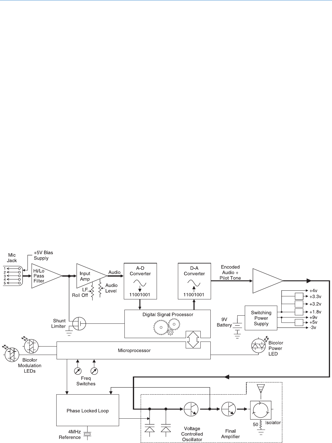
Introduction
The 400 system uses 75 kHz wide deviation for an
extremely high signal to noise ratio. The switching
power supplies provide constant voltages to the trans-
mitter circuits from the beginning (9.3 Volts) to the end
(5.5 Volts) of battery life. The input amplifier uses an
ultra low noise op amp for quiet operation. It is gain
controlled with a wide range dual envelope input
compressor which cleanly limits input signal peaks over
30 dB above full modulation.
Digital Hybrid Technology
All wireless links suffer from channel noise to some
degree, and all wireless microphone systems seek to
minimize the impact of that noise on the desired signal.
Conventional analog systems use compandors to
improve the signal to noise ratio, at the cost of subtle
artifacts (known as “pumping” and “breathing”). Wholly
digital systems defeat the noise by sending the audio
information in digital form, at the cost of some combina-
tion of power, bandwidth and resistance to interference.
The Lectrosonics Digital Hybrid system overcomes
channel noise in a dramatically new way, digitally
encoding the audio in the transmitter and decoding it in
the receiver, yet still sending the encoded information
via an analog FM wireless link. This proprietary algo-
rithm is not a digital implementation of an analog
UM450 Block Diagram
General Technical Description
compandor but a technique which can be accomplished
only in the digital domain, even though the inputs and
outputs are analog signals. (As of this writing, the
patent is still pending, so we cannot reveal detailed
information about the algorithm at this time.)
Channel noise still has an impact on received signal
quality and will eventually overwhelm the receiver. The
Digital Hybrid simply encodes the signal to use a noisy
channel as efficiently and robustly as possible, yielding
audio performance that rivals that of wholly digital
systems, without the power and bandwidth problems
inherent in digital transmission. As always, these
advantages come at a cost. The Digital Hybrid system
requires fairly intensive digital processing in both the
transmitter and the receiver. These processors cost
money, take up space and consume power. The Digital
Hybrid system also requires that the underlying RF link
be of excellent quality, with better frequency response
and distortion characteristics than that required by
conventional systems.
Because it uses an analog FM link, the Digital Hybrid
enjoys all the benefits of conventional FM wireless
systems, such as excellent range, efficient use of RF
spectrum, and long battery life. However, unlike con-
ventional FM systems, the Digital Hybrid has done away
with the analog compandor and its artifacts.

Frequency-Agile UHF Belt-Pack Transmitter
Rio Rancho, NM 7
No Pre-Emphasis/De-Emphasis
The signal to noise ratio of the 400 system is high
enough to preclude the need for conventional pre-
emphasis (HF boost) in the transmitter and de-empha-
sis (HF roll off) in the receiver. Pre-emphasis and de-
emphasis in an FM radio system usually provides about
a 10 dB improvement in the signal to noise ratio of the
system, but the high frequency boost in the transmitter
must be removed in a purely complementary manner or
else the frequency response of the original audio signal
will be altered.
Pre-emphasis can also cause distortion in the receiver.
As this signal is passed through the IF filters in the
receiver, distortion can be produced, most noticeably at
full modulation. De-emphasis cannot be applied until
the signal is converted into audio, so there is no way
around this problem short of eliminating pre-emphasis
altogether. Neither of these problems occur in the 400
system
Pilot Tone Squelch
The 400 system uses one of 256 different ultrasonic
tones between 25 and 32 kHz, that modulate the
carrier to operate the receiver squelch. The pilot tone
frequency is chosen according to which of the 256
channels has been selected by the frequency switch
setting. The basic benefit of the pilot tone squelch
system is that the receiver will remain muted until it
receives the pilot tone from the matching transmitter,
even if a strong RF signal is present on the carrier
frequency of the system. The UM450 extends this
concept even further by insuring that all transmitters in
a system have different pilot tone frequencies so that
even spurious RF from the wrong transmitters can’t
open the receiver squelch.
Input Limiter
The 400 series transmitters employ a digitally-controlled
analog audio limiter just before the analog-to-digital
converter. The limiter has a range of more than 30 dB
for excellent overload protection. A dual release
envelope makes the limiter acoustically transparent
while maintaining low distortion. It can be thought of as
two limiters in series, connected as a fast attack and
release limiter followed by a slow attack and release
limiter. The limiter recovers quickly from brief tran-
sients, so that its action is hidden from the listener, but
recovers slowly from sustained high levels, to both keep
audio distortion low and preserve short term dynamic
changes.
The audio level LEDs indicate limiter activity. The first
red LED indicates that the limiter is active and that the
transmitter is fully modulated (audio level is between +0
and +10 dB). The second red LED indicates that the
level is 10 dB or more into limiting. Occasional forays
into the red are desirable for most applications, since
the distortion introduced by the limiter is so minimal,
and full modulation is thus assured. We strongly
recommend setting the gain of the transmitter high
enough so that the first red LED occasionally lights.
Generally speaking, some limiting is desirable in
normal operation to improve the signal to noise ratio of
the system. The limiting action is not audible and does
not create distortion. A highly trained ear would hear
only the compression of the peaks in the audio signal,
which is desirable with most recorders and many sound
reinforcement systems.
Wide-Band Deviation
± 75 kHz deviation improves the capture ratio, signal to
noise ratio and AM rejection of a wireless system
dramatically, compared to the more commonly used
±15 kHz deviation.
Long Battery life
Switching power supplies throughout the design allow
over ninety minutes of operation using a single 9 VDC
alkaline battery. (A 9 V lithium battery will provide over
4.5 hours of continuous operation.) The battery con-
tacts are spring loaded to prevent “rattle” as the unit is
handled.
Frequency Agility
The transmitter section uses a synthesized, frequency
selectable main oscillator. The frequency is extremely
stable over a wide temperature range and over time.
Two rotary switches, located on the side panel of the
unit, provide 256 frequencies in 100 kHz steps over a
25.5 MHz range. This alleviates carrier interference
problems in mobile or traveling applications.
Antenna
The antenna on the UM450 consists of a flexible 1/4
wavelength galvanized steel cable, detachable via an
SMA connector. The impedance of this connector is 50
Ohms.
UM450
LECTROSONICS, INC.8
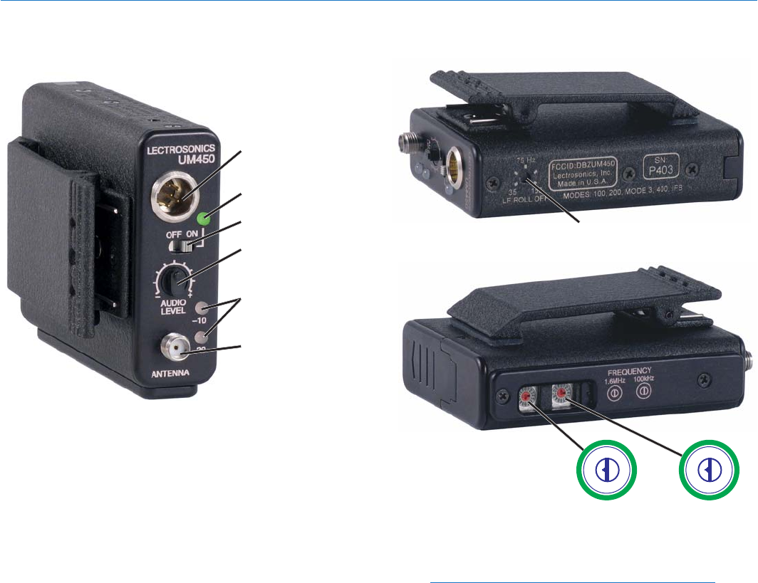
Input Jack
The input on the UM450 accommodates virtually every
lavaliere, hand-held or shotgun microphone available.
Different line level signals can also be accommodated.
(See Line Level Signals and Transmitter 5-Pin Input
Jack Wiring.)
Power ON/OFF Switch
Turns the transmitter on and off. Even when the switch
is turned off or on abruptly, the pilot tone muting system
prevents “thumps” or transients from occurring.
Power On LED
The Power LED glows green when the battery is good
and the transmitter is turned on. The LED will glow
yellow/orange as the battery voltage drops and finally
glows red when there are about 30 minutes of operation
left (when using the recommended alkaline battery).
The LED blinks red when there are only a few minutes
of life left.
Input Jack
Power ON/OFF Switch
AUDIO LEVEL Control
Modulation LEDs
ANTENNA Jack
Power LED
1.6M 100K
Frequency Select Switches
012
3
4
5
6
7
8
9
A
B
C
D
EF012
3
4
5
6
7
8
9
A
B
C
D
EF
Low Frequency Roll Off
Control
Controls and Functions
NOTE: A NiMH battery will give little or no warning
when it is depleted. If you wish to use NiMH
batteries in the UM450, we recommend trying fully
charged batteries in the unit, noting the length of
time that the batteries will run the unit and in the
future use somewhat less than that time to
determine when the battery needs to be replaced.
A weak battery will sometimes light the Power LED to
the “good” green indication immediately after being put
in the unit, but will quickly discharge to the point where
the LED will go red or shut down (just like a flashlight
with “dead” batteries). If the lamp fails to light, the
battery should be replaced.
Audio Level Control
The front panel AUDIO LEVEL Control is used to adjust
the incoming audio input level for proper modulation.
Audio Level
Used to adjust the audio input level for the proper
modulation.
Frequency-Agile UHF Belt-Pack Transmitter
Rio Rancho, NM 9
Belt Clip
Belt Clip
Retaining Screw
Location
Modulation LEDs
The Modulation LEDs provide a visual indication of the
input audio signal level from the microphone. These
two bicolor LEDs can glow either red or green to
indicate modulation levels.
Signal Level -20 LED -10 LED
Less than -20 dB Off Off
-20 dB to -10 dB Green Off
-10 dB to +0 dB Green Green
+0 dB to +10 dB Red Green
Greater than +10 dB Red Red
The Modulation LEDs are also used to indicate the
Compatibility Mode when the transmitter is initially
turned on. The Modulation LEDs will blink simulta-
neously:
• Once for 100 Series mode
• Two times for 200 Series mode
• Three times for mode 3
• Four times for Digital Hybrid Wireless™ or
400 Series mode
• Five times for IFB mode*
• Six times for mode 6
Modes 3 and 6 provide compatibility with other
manufacturer’s receivers - contact the factory for
details.
Antenna
The flexible galvanized steel cable antenna supplied
with the transmitter is cut to 1/4 wavelength of the
center of the frequency block (the frequency range) of
the transmitter. It is removable via an SMA connector.
The SMA connector is a 50 Ohm RF port which can
also be connected directly to test equipment. Replace-
ment antennas are available in pre-cut lengths for
specific frequency blocks, or as a kit with instructions to
cut the antenna for any frequency block.
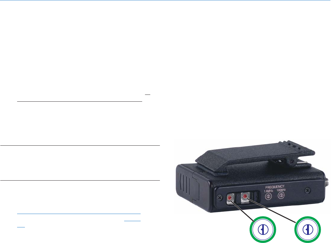
Frequency Select Switches
Two 16-position rotary switches adjust the center
frequency of the carrier. The 1.6M is a coarse adjust-
ment and the 100K is the fine adjustment.
Adjustable Low Frequency Roll-Off
A 18dB per octave low frequency roll-off is provided in
the audio section, with the -3dB point adjustable from
35Hz to 150Hz. The actual roll-off frequency will vary
somewhat according to the low frequency response of
the mic capsule being used.
The low frequency roll-off control is used to remove
subsonic (or very low frequency) audio, often produced
by air conditioning systems, automobile traffic and other
sources from the audio signal. Excessive low frequency
content in the audio input can cause a variety of audio
problems including driving the transmitter into limiting.
In sound reinforcement systems, as one instance,
*Not available on earlier units.
excessive low frequency content can cause excessive
power amplifier drain or even damage to loudspeaker
systems. By rotating the control clockwise, the hinge
point of the roll-off is increased to reduce the level of
low frequencies. In controlled situations, such as a
motion picture production set indoors where environ-
mental noise is minimal, the control can be rotated
counter-clockwise to permit low frequency audio to be
captured.
Belt Clip
The belt clip may be removed for special applications by
removing one screw.
WARNING: Use ONLY the screw that is
supplied
The circuitry is tightly packed into this unit. A longer
screw will permanently damage the transmitter! Use
only Lectrosonics PN:28528 which is a Phillips head,
4-40 x 3/16", FL100 screw.
UM450
LECTROSONICS, INC.10
The transmitter is powered by a standard alkaline or
lithium 9 Volt battery. It is important that you use ONLY
an ALKALINE or LITHIUM battery for longest life. Stan-
dard zinc-carbon batteries marked “heavy-duty” or
“long-lasting” and Ni-Cad batteries are not adequate.
Alkaline batteries provide approximately 1.5 hours of
operation. Lithium batteries can be used to provide up to
4.5 hours. Care should be taken not to leave a fully
discharged lithium battery in the transmitter, as swelling
of the battery can make it difficult to remove from the
compartment. The battery status circuitry is designed for
the voltage drop over the life of alkaline batteries.
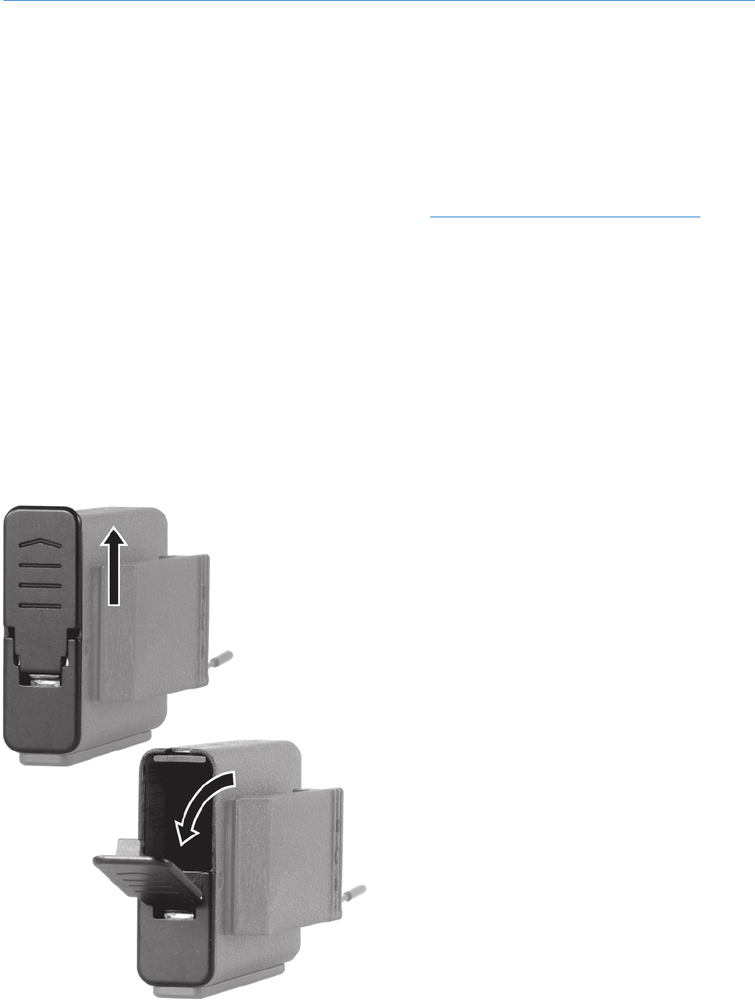
To open the battery compartment, press outward on the
cover door in the direction of the arrow as shown in the
drawing. Only firm, sliding pressure is needed to open
and close the battery door. Swing the door open and
take note of the polarity marked inside showing the
location of the positive (+) and negative (-) terminals.
You can see the large and small contact holes inside the
battery compartment with the door open.
Insert the battery correctly and close the cover by
pressing the door closed and across, reversing the
opening procedure illustrated above. If the battery is
inserted incorrectly, the door will not close. Do not force
the door closed.
*Not available on earlier units.
Battery Installation
Selecting the Compatibility Mode
All units with serial number 601 and up are capable of
working with Lectrosonics 400 Series Digital Hybrid
Wireless™, 200 Series analog, 100 Sseries analog and
some non-Lectrosonics analog wireless receivers
(contact the factory for details). The transmitter must be
set to the operating mode of the matching receiver,
which is easily done using only the supplied screwdriver
and a battery.
NOTE: The unit is supplied from the factory as a
400 series transmitter.
1) Ensure the battery is good.
2) Turn off the transmitter.
3) With a small screwdriver (one is included with your
unit), set the Frequency Select Switches to CC. (for
Change, Change).
4) Power up the unit briefly – just long enough for the
LED’s to light up and then turn it off.
5) Change the Frequency Select Switches to one of
the following settings:
• To set Lectrosonics 100 Series mode:
set switches to 1,1
• To set Lectrosonics 200 Series mode:
set switches to 2,2
• To set mode 3: set switches to 3,3
(contact the factory for details)
• To set Lectro 400 Series mode:
set switches to 4,4
• To set IFB mode: set switches to 5,5*
• To set Mode 6: set switches to 6,6
6) Turn the unit on, wait a couple of seconds and turn
off again.
7) Change the Frequency Select Switches to 0,0.
8) Turn on the transmitter to complete the operation.
The LEDS will blink to indicate the selected com-
patibility mode. Immediately after power up, all
LEDS will blink together red, then green, followed
by the audio level LEDs (-20 and -10) blinking to
indicate the mode.
The –20 and –10 LEDs will blink:
• Once for 100 Series mode
• Two times for 200 Series mode
• Three times for some other receivers
• Four times for 400 Series mode
• Five times for IFB mode*
• Six times for Mode 6
At powerup the transmitter will confirm the current
compatibility mode with the number of blinks listed
here. This setting will remain the same until you
reset it with the procedure listed above.
Operating Instructions
Frequency-Agile UHF Belt-Pack Transmitter
Rio Rancho, NM 11
012
3
4
5
6
7
8
9
A
B
C
D
EF012
3
4
5
6
7
8
9
A
B
C
D
EF
1.6M 100K
Attaching a Microphone and Adjusting Gain
1) Ensure the battery is in good condition.
2) Insert the microphone plug into the input jack,
aligning the pins; be sure that the connector locks.
3) Attach the antenna to the SMA connector on the
top of the transmitter.
4) Mute the associated receiver’s audio output.
5) Turn on the transmitter.
6) Position the microphone in the location you will use
in actual operation. While speaking or singing at
the same voice level that will actually be used,
observe the Modulation LEDs. Adjust the AUDIO
LEVEL control until the –20 dB LED glows green
with occasional red flickers and -10 dB glows green.
This will set the gain of your transmitter to between
+0 dB and +10 dB modulation. (See chart below.)
Signal Level -20 LED -10 LED
Less than -20 dB Off Off
-20 dB to -10 dB Green Off
-10 dB to +0 dB Green Green
+0 dB to +10 dB Red Green
Greater than +10 dB Red Red
7) Once the gain has been adjusted, the audio system
audio can be turned on to make level adjustments
in the main audio system.
NOTE: The transmitter Audio Level Control should
not be used to control the volume of your sound
system or recorder levels. This gain adjustment
matches the transmitter gain with the user’s voice
level and microphone positioning.
Operating Notes
If the audio level is too high — both LEDs will blink red
frequently or glow a steady red. This condition may
reduce the dynamic range of the audio signal.
If the audio level is too low — neither LED will glow, or
only the -20 LED will glow green. This condition may
cause hiss and noise in the audio.
Different voices will usually require different settings of
the AUDIO LEVEL control, so check this adjustment as
each new person uses the system. If several different
people will be using the transmitter and there is not time
to make the adjustment for each individual, adjust it for
the loudest voice.
Adjusting the Transmitter Frequency
If you are experiencing interference from another signal
on your frequency, you may want to change the operat-
ing frequency of your system. The left switch changes
the operating frequency by 1.6 MHz per step and the
right switch changes it 100 kHz per step. Start by
changing the operating frequency in 100 kHz incre-
ments to find a clear channel. If it is not possible to find
a clear channel using the 100 kHz switch, return it to its
original position and change the 1.6 MHz switch by one
click then try the 100 kHz switch again.
To gain access to these switches, slide the access door
sideways with a fingernail.
With the 400 Series receivers, a front panel LCD
character display will indicate the correct transmitter
switch settings.
UM450
LECTROSONICS, INC.12
1
23
4
5
Caution: When wiring the connector, do not
use the connector body for any electrical
connections. A common mistake is to use the
connector body as an audio ground. The
connector body is already used as an RF
ground on VHF models and no other use is
permitted.
NOTE: This termination is required on VHF
transmitters and will still work fine on UHF
transmitters.
Microphone Cord Termination
TA5F Connector Assembly
Mic Cord Stripping Instructions
Frequency-Agile UHF Belt-Pack Transmitter
Rio Rancho, NM 13
43
2
1
5
LECTROSONICS
TRANSMITTER
INPUT JACK
FB
40k
4k
5
100
4
3
2
1
+
5V Mic Bias
To Mic Amp
POS BIAS (OR GND)
MIC
SOURCE LOAD
LINE IN
NEG GND (OR BIAS)
+
1k
10uF
330pF
330pF
330pF
330pF
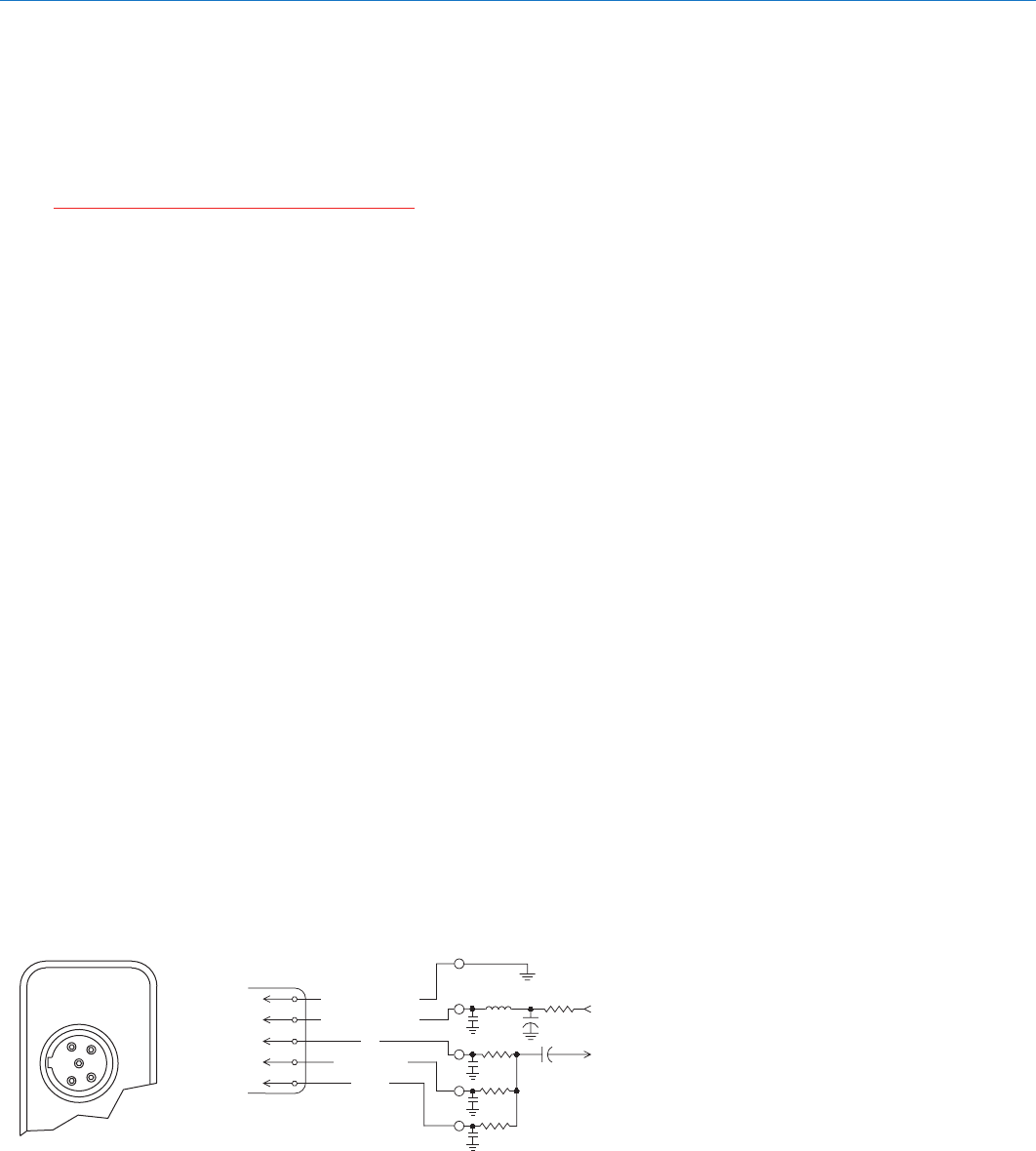
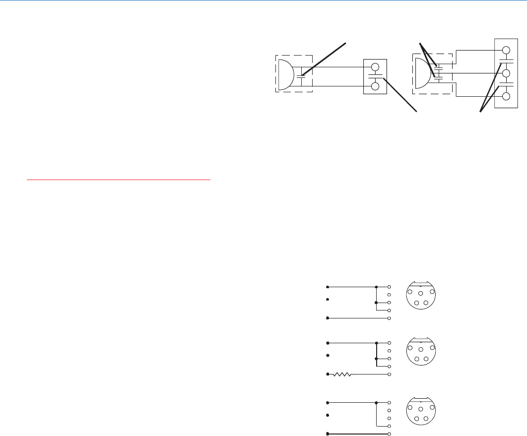
Input Jack Wiring Diagram
The wiring diagrams shown on the next page represent
the basic wiring necessary for the most common types
of microphones and other audio inputs. Some micro-
phones may require extra jumpers or a slight variation
on the diagrams shown.
Caution: When wiring the connector, do not
use the connector body for any electrical
connections. A common mistake is to use the
connector body as an audio ground. The
connector body is already used as an RF
ground on VHF models and no other use is
permitted.
It’s virtually impossible to keep completely up to date on
changes that other manufacturers make to their prod-
ucts. It is possible that you may encounter a micro-
phone that differs from these instructions. If this occurs
please call our toll-free number listed on page 15 of this
instruction manual. Our service department can
answer your questions regarding microphone compat-
ibility.
When used on a wireless transmitter, the microphone
element is in the proximity of the RF coming from the
transmitter. The nature of electret microphones makes
them sensitive to RF, which can cause problems with
the microphone/transmitter compatibility. If the electret
microphone is not designed properly for use with
wireless transmitters, it may be necessary to install a
chip capacitor in the mic capsule or connector to block
the RF from entering the electret capsule. This modifi-
cation is shown on the next page.
VHF transmitters use the shield of the microphone cord
as the antenna. This transmitter uses a 1/4 wave
flexible wire to radiate the RF signal. There is really not
much difference between these two approaches, with
5-Pin Input Jack Wiring
respect to the effect of the RF on the microphone
capsule. Even in transmitters that utilize a “dangling
wire,” the microphone is still part of the “ground plane”
and is therefore still in the antenna circuit.
PIN 1 Shield (ground) for positive biased electret
lavaliere microphones. Bias voltage source for
negative biased electret lavaliere microphones.
Shield (ground) for dynamic microphones and
line level inputs.
PIN 2 Shield (ground) for negative biased electret
lavaliere microphones. Bias voltage source for
positive biased electret lavaliere microphones.
PIN 3 Low impedance microphone level input for
dynamic microphones. Also accepts hand-held
electret microphones provided the microphone
has its own built-in battery.
PIN 4 4K Ohm source load for non-Lectrosonics
electret microphones. Use in conjunction with
other pins to provide attenuation of high level
input signals.
PIN 5 High impedance, line level input for tape decks,
mixer outputs, musical instruments, etc.
RF BYPASSING
Some mics require RF protection to keep the radio
signal from affecting the capsule, even though the
transmitter input circuitry is already RF bypassed (see
schematic diagram).
If the mic is wired as directed, and you are having
difficulty with squealing, high noise, or poor frequency
response; RF is likely to be the cause.
UM450
LECTROSONICS, INC.14
The best RF protection is accomplished by installing RF
bypass capacitors at the mic capsule. If this is not
possible, or if you are still having problems, capacitors
can be installed on the mic pins inside the TA5F con-
nector housing.
Install the capacitors as follows: Use 330 pF capacitors.
Capacitors are available from Lectrosonics. Please
specify the part number for the desired lead style.
Leaded capacitors: P/N 15117
Leadless capacitors: P/N SCC330P
All Lectrosonics lavaliere mics are already bypassed
and do not need any additional capacitors installed for
proper operation.
Caution: When wiring the connector, do not
use the connector body for any electrical
connections. A common mistake is to use the
connector body as an audio ground. The
connector body is already used as an RF
ground on VHF models and no other uses
permitted.
Line Level Signals
The normal hookup for line level signals is: Signal Hot
to pin 5, Signal Gnd to pin 1, pin 4 jumped to pin 1, and
pin 3 jumped to pin 1. This gives a 40dB attenuator that
allows signal levels much higher than 3V to be applied
without limiting.
If more headroom is needed, insert a 100k resistor in
series with pin 5. Put this resistor inside the TA5F
connector to minimize noise pickup.
If lower than normal line levels (less than 1V) are
expected, use this hookup: Signal Hot to pin 5, Signal
Gnd to pin 1, and pin 4 jumpered to pin 1. This pro-
vides a 20dB attenuator allowing signals as high as 3V
to be applied without limiting.
3 WIRE MIC2 WIRE MIC
CAPSULE CAPSULE
SHIELD
AUDIO
SHIELD
AUDIO
BIAS
Alternate locations for bypass capacitors
TA5F
CONNECTOR
TA 5 F
CONNECTOR
Preferred locations for bypass capacitors
PIN
5
4
3
2
1
SHIELD (GND)
AUDIO
Normal Hookup1
2
3
45
TA5F
PLUG
PIN
5
4
3
2
1
AUDIO
More Headroom 1
2
3
45
TA5F
PLUG
PIN
5
4
3
2
1
AUDIO
Lower Line Level
Hookup
1
2
3
45
TA5F
PLUG
100k
SHIELD (GND)
SHIELD (GND)
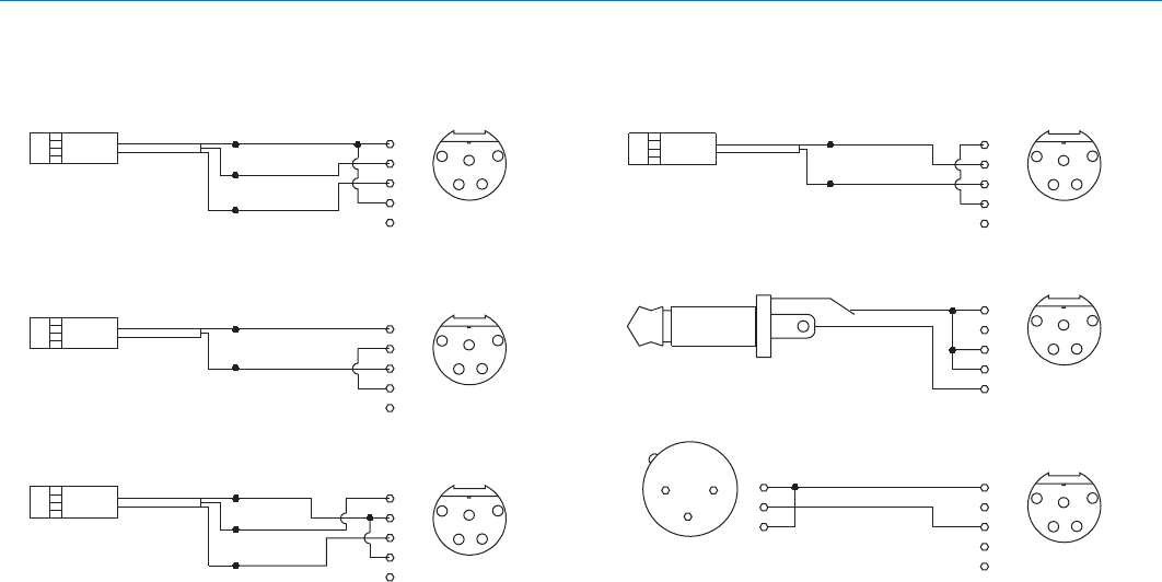
Frequency-Agile UHF Belt-Pack Transmitter
Rio Rancho, NM 15
3
1
2
DYNAMIC
MIC LEVEL
1
2
3
4
5
3
2
1
PIN PIN
SHIELD
SHIELD
TIP
PIN
5
4
3
2
1
SLEEVE
LINE LEVEL
RCA or 1/4 " PLUG
1
2
3
4
5
PIN
PIN
5
4
3
2
1
SHIELD
AUDIO
SHIELD
AUDIO
BIAS
1
2
3
4
5
PIN
3 WIRE ELECTRET MIC
POSITIVE BIAS
1
2
3
4
5
PIN
SHIELD
AUDIO
SHIELD
BIAS
AUDIO
1
2
3
45
TA5F
PLUG
2 WIRE ELECTRET MIC
POSITIVE BIAS
3 WIRE ELECTRET MIC
NEGATIVE BIAS
2 WIRE ELECTRET MIC
NEGATIVE BIAS
AUDIO
Dynamic LO Z mic or electret with
manufacturer’s power supply.
1
2
3
45
TA5F
PLUG
1
2
3
45
TA5F
PLUG
1
2
3
45
TA 5 F
PLUG
1
2
3
45
TA 5 F
PLUG
1
2
3
45
TA 5 F
PLUG
(See notes on “LINE LEVEL SIGNALS” on p.14)
Wiring Hookups for Different Sources
UM450
LECTROSONICS, INC.16
Item
Replacement wire belt clip
Replacment whip antenna
Replacement Parts and Accessories
UHF Transmitter Antenna Specifications
All Lectrosonic UHF transmitter antennas follow the
color code specifications in the chart below to identify
operating frequency block range. (The frequency block
range is engraved on the ouside housing for each
individual transmitter.)
If a situation exists whereby the antenna is defective
and the antenna cap is missing, refer to the following
chart to determine the correct replacement antenna.
FREQUENCY CAP ANTENNA
BLOCK RANGE COLOR WHIP LENGTH
20 512.000 - 537.500 Black 4.98"
21 537.600 - 563.100 Brown 4.74"
22 563.200 - 588.700 Red 4.48"
23 588.800 - 614.300 Orange 4.24”
24 614.400 - 639.900 Yellow 4.01"
25 640.000 - 665.500 Green 3.81"
26 665.600 - 691.100 Blue 3.62"
27 691.200 - 716.700 Violet (Pink) 3.46"
28 716.800 - 742.300 Grey 3.31"
29 742.400 - 767.900 White 3.18"
30 768.000 - 793.500 Black-w/Label 3.08"
31 793.600 - 819.100 Black-w/Label 2.99”
32 819.200 - 844.700 Black-w/Label 2.92”
33 844.800 - 865.000 Black-w/Label 2.87”
NOTE: Blocks 30 through 33 are labeled
with the frequency block number.
Model/Part Number
Lectrosonics #BCWire
Lectrosonics AMM (xx) -
specify frequency block
(xx)
Measure the length of the whip that protrudes outside
of the SMA connector to find the operating Frequency Block

Frequency-Agile UHF Belt-Pack Transmitter
Rio Rancho, NM 17
Before going through the following chart, be sure that you have a good battery in the transmitter. It is important that
you follow these steps in the sequence listed.
Symptom Possible Cause
TRANSMITTER BATTERY LED OFF 1) Battery is inserted backwards.
2) Battery is dead.
NO TRANSMITTER MODULATION LEDs 1) Gain control turned all the way down.
2) Battery is in backwards. Check power LED.
3) Mic capsule is damaged or malfunctioning.
4) Mic cable damaged or mis-wired.
RECEIVER RF LAMP OFF 1) Transmitter not turned on.
2) Transmitter battery is dead.
3) Receiver antenna missing or improperly positioned.
4) Transmitter and receiver not on same frequency. Check
switches/display on transmitter and receiver.
5) Operating range is too great.
6) Transmitter antenna not connected
NO SOUND (OR LOW SOUND LEVEL), 1) Receiver output level set too low.
RECEIVER INDICATES PROPER AUDIO 2) Receiver output is disconnected; cable is defective
MODULATION or mis-wired.
3) Sound system or recorder input is turned down.
DISTORTED SOUND 1) Transmitter gain (audio level) is far too high. Check mod level
lamps on transmitter and receiver as it is being used.
(refer to pages 8/9 for details on gain adjustment)
2) Receiver output may be mis-matched with the sound system or
recorder input. Adjust output level on receiver to the correct
level for the recorder, mixer or sound system.
3) Excessive wind noise or breath “pops.” Reposition microphone
and/or use a larger windscreen.
4) Transmitter is not set to same frequency as receiver. Check that
frequency select switches on receiver and transmitter match.
HISS AND NOISE -- AUDIBLE DROPOUTS 1) Transmitter gain (audio level) far too low.
2) Receiver antenna missing or obstructed.
3) Transmitter antenna missing.
4) Operating range too great.
EXCESSIVE FEEDBACK 1) Transmitter gain (audio level) too high. Check gain adjustment
and/or reduce receiver output level.
2) Transmitter too close to speaker system.
3) Mic is too far from user’s mouth.
Troubleshooting

UM450
LECTROSONICS, INC.18
Operating frequencies: Block 21: 537.600 - 563.100
Block 22: 563.200 - 588.700
Block 23: 588.800 - 607.900 and 614.100 - 614.300
Block 24: 614.400 - 639.900
Block 25: 640.000 - 665.500
Block 26: 665.600 - 691.100
Block 27: 691.200 - 716.700
Block 28: 716.800 - 742.300
Block 29: 742.400 - 767.900
Block 30: 768.000 - 793.500 (Export)
Block 31: 793.600 - 805.600 (Export)
Frequency selection: 256 frequencies in 100kHz steps
RF Power output: 250 mW (nominal)
Pilot tone: 25 to 32 kHz frequency; 5kHz deviation
Frequency stability: ± 0.002%
Deviation: ± 75 kHz (max)
Spurious radiation: 90 dB below carrier
Equivalent input noise: –120 dBV, A-weighted
Input level: Nominal 2 mV to 300 mV, before limiting.
Greater than 1V maximum, with limiting.
Input impedance: Taps provided for 200, 4k, 40k Ohm
Input compressor: Dual envelope compressor, >30 dB range
Gain control range: 43 dB; semi-log rotary control
Modulation indicators: Dual bicolor LEDs indicate modulation of -20, -10, 0, +10 dB
referenced to full modulation.
Low frequency roll-off: –18 dB/octave; 35Hz to 150Hz
Audio frequency response (overall system): 32 Hz to 20 kHz (+/- 1dB)
Controls: 2 position “OFF-ON” slide switch for noiseless turn on/turn off operation.
Front panel knob adjusts audio gain. Recessed control on side panel adjusts low
frequency rolloff. Rotary switches on side panel adjust transmitter frequency.
Audio Input Jack: Switchcraft 5 pin locking (TA5F)
Antenna: Detachable, flexible wire supplied. 50 Ohm port allows
connection to test equipment.
Power Consumption: 120mA @ 9V
Battery: Precision compartment auto-adjusts to accept any known alkaline 9 Volt battery.
Battery Life: 1.5 hours (alkaline); 4.5 hours (lithium)
Weight: 6.3 ozs. including battery
Dimensions: 3.1 x 2.4 x .75 inches
Emission Designator: 180KF3E
Specifications subject to change without notice.
The FCC requires that the following statement be included in this manual:
This device complies with FCC radiation exposure limits as set forth for an uncontrolled environment.
This device should be installed and operated so that its antenna(s) are not co-located or operating in
conjunction with any other antenna or transmitter.
Specifications and Features

Frequency-Agile UHF Belt-Pack Transmitter
Rio Rancho, NM 19
Service and Repair
If your system malfunctions, you should attempt to correct or isolate the trouble before concluding that the equipment
needs repair. Make sure you have followed the setup procedure and operating instructions. Check the interconnect-
ing cables and then go through the TROUBLESHOOTING section in this manual.
We strongly recommend that you do not try to repair the equipment yourself and do not have the local repair shop
attempt anything other than the simplest repair. If the repair is more complicated than a broken wire or loose connec-
tion, send the unit to the factory for repair and service. Don’t attempt to adjust any controls inside the units. Once set
at the factory, the various controls and trimmers do not drift with age or vibration and never require readjustment.
There are no adjustments inside that will make a malfunctioning unit start working.
LECTROSONICS’ Service Department is equipped and staffed to quickly repair your equipment. In warranty repairs
are made at no charge in accordance with the terms of the warranty. Out-of-warranty repairs are charged at a modest
flat rate plus parts and shipping. Since it takes almost as much time and effort to determine what is wrong as it does
to make the repair, there is a charge for an exact quotation. We will be happy to quote approximate charges by phone
for out-of-warranty repairs.
Returning Units for Repair
For timely service, please follow the steps below:
A. DO NOT return equipment to the factory for repair without first contacting us by letter or by phone. We need to
know the nature of the problem, the model number and the serial number of the equipment. We also need a
phone number where you can be reached 8 A.M. to 4 P.M. (U.S. Mountain Standard Time).
B. After receiving your request, we will issue you a return authorization number (R.A.). This number will help speed
your repair through our receiving and repair departments. The return authorization number must be clearly shown
on the outside of the shipping container.
C. Pack the equipment carefully and ship to us, shipping costs prepaid. If necessary, we can provide you with the
proper packing materials. UPS is usually the best way to ship the units. Heavy units should be “double-boxed” for
safe transport.
D. We also strongly recommend that you insure the equipment, since we cannot be responsible for loss of or dam-
age to equipment that you ship. Of course, we insure the equipment when we ship it back to you.
Mailing address: Shipping address: Telephone:
Lectrosonics, Inc. Lectrosonics, Inc. (505) 892-4501
PO Box 15900 581 Laser Rd. (800) 821-1121 Toll-free
Rio Rancho, NM 87174 Rio Rancho, NM 87124 (505) 892-6243 Fax
USA USA
Web: E-mail:
www.lectrosonics.com sales@lectrosonics.com

February 23, 2006
581 Laser Road NE • Rio Rancho, NM 87124 USA • www.lectrosonics.com
(505) 892-4501 • (800) 821-1121 • fax (505) 892-6243 • sales@lectrosonics.com
LIMITED ONE YEAR WARRANTY
The equipment is warranted for one year from date of purchase against defects in
materials or workmanship provided it was purchased from an authorized dealer. This
warranty does not cover equipment which has been abused or damaged by careless
handling or shipping. This warranty does not apply to used or demonstrator equipment.
Should any defect develop, Lectrosonics, Inc. will, at our option, repair or replace any
defective parts without charge for either parts or labor. If Lectrosonics, Inc. cannot
correct the defect in your equipment, it will be replaced at no charge with a similar new
item. Lectrosonics, Inc. will pay for the cost of returning your equipment to you.
This warranty applies only to items returned to Lectrosonics, Inc. or an authorized
dealer, shipping costs prepaid, within one year from the date of purchase.
This Limited Warranty is governed by the laws of the State of New Mexico. It states the
entire liablility of Lectrosonics Inc. and the entire remedy of the purchaser for any
breach of warranty as outlined above. NEITHER LECTROSONICS, INC. NOR
ANYONE INVOLVED IN THE PRODUCTION OR DELIVERY OF THE EQUIPMENT
SHALL BE LIABLE FOR ANY INDIRECT, SPECIAL, PUNITIVE, CONSEQUENTIAL,
OR INCIDENTAL DAMAGES ARISING OUT OF THE USE OR INABILITY TO USE
THIS EQUIPMENT EVEN IF LECTROSONICS, INC. HAS BEEN ADVISED OF THE
POSSIBILITY OF SUCH DAMAGES. IN NO EVENT SHALL THE LIABILITY OF
LECTROSONICS, INC. EXCEED THE PURCHASE PRICE OF ANY DEFECTIVE
EQUIPMENT.
This warranty gives you specific legal rights. You may have additional legal rights which
vary from state to state.