Lectrosonics UT400 WIRELESS MICROPHONE TRANSMITTER User Manual ut400man pmd
Lectrosonics Inc WIRELESS MICROPHONE TRANSMITTER ut400man pmd
MANUAL

UT400
DIGITAL-HYBRID
FREQUENCY-AGILE
HAND-HELD TRANSMITTER
OPERATING INSTRUCTIONS
and trouble-shooting guide
LECTROSONICS, INC.
Rio Rancho, NM
www.lectrosonics.com

2
UT400
LECTROSONICS, INC.
TABLE OF CONTENTS
INTRODUCTION ..................................................................................................... 3
GENERAL TECHNICAL DESCRIPTION ................................................................. 4
CONTROLS AND FUNCTIONS .............................................................................. 6
VARIMIC CONTROLS ............................................................................................. 7
BATTERY INSTALLATION ....................................................................................... 9
OPERATING INSTRUCTIONS ............................................................................... 10
OPERATING NOTES .............................................................................................11
ADJUSTING THE TRANSMITTER FREQUENCY ................................................. 11
TROUBLESHOOTING ............................................................................................ 12
SPECIFICATIONS ................................................................................................. 13
SERVICE AND REPAIR .........................................................................................14
RETURNING UNITS FOR REPAIR ........................................................................ 14
WARRANTY ............................................................................................ Back cover

3
Rio Rancho, NM - USA
Digital-hybrid, Frequency Agile Handheld Transmitter
INTRODUCTION
Thank you for selecting the Lectrosonics UT400 hand-held wireless transmitter. The
UT combines over 80 years of engineering experience with the very latest components
in a design that addresses the most demanding professional applications.
The design of the UT400 was the direct result of numerous conversations with users,
staging and touring companies and dealers across the US. The specific concerns and
needs brought up in these conversations led directly to the development of the opera-
tional features offered on the UT400. Two hundred fifty six frequencies are user
selectable in 100kHz steps to alleviate interference problems in travelling venues
The UT400 is an integral microphone/transmitter with an internal antenna. The antenna
is a dipole type utilizing the two printed circuit boards as the elements. The housing is
composed of durable PVC, machined to a natural, comfortable shape. Internal me-
chanical parts are machined aluminum and brass.
Only the UT400 transmitters are covered in this manual. Companion receivers are
covered in separate manuals. The UT400 will operate with any 100 Series, 200 Series
and 400 Series Lectrosonics receiver in the same frequency group.
4
UT400
LECTROSONICS, INC.
GENERAL TECHNICAL DESCRIPTION
GENERAL
The 400 system uses 75kHz wide deviation for an extremely high signal to noise ratio. The switching power supplies
provide constant voltages to the transmitter circuits from the beginning (9.3 Volts) to the end (5.5 Volts) of battery life.
The input amplifier uses an ultra low noise op amp for quiet operation. It is gain controlled with a wide range dual
envelope input compressor which cleanly limits input signal peaks over 30dB above full modulation.
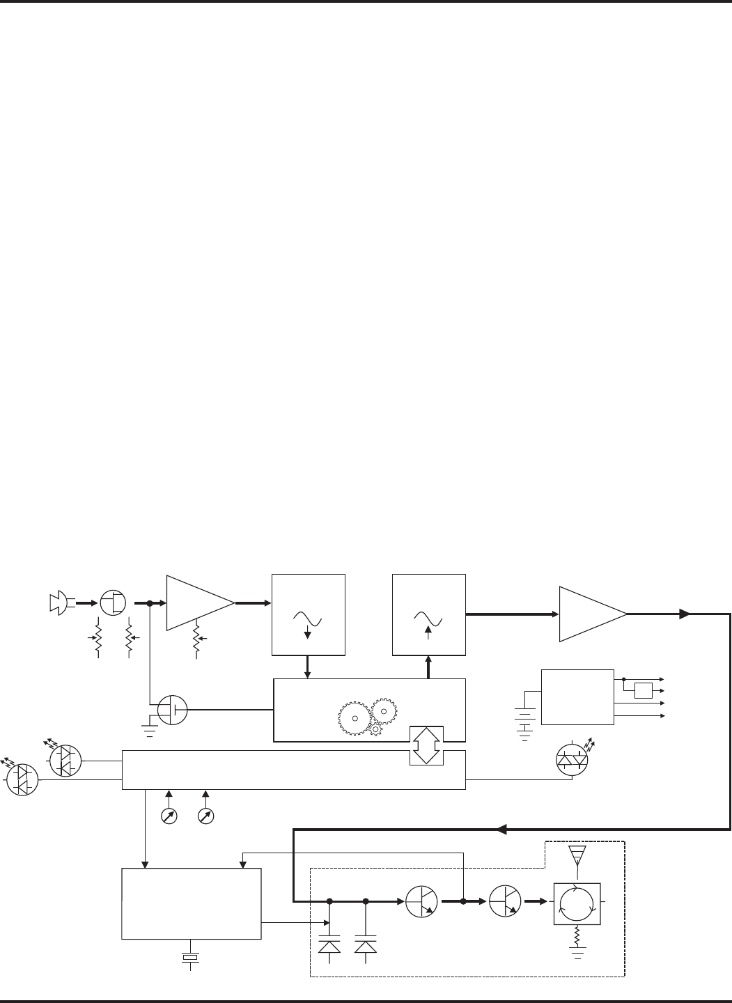
DIGITAL HYBRID TECHNOLOGY
All wireless links suffer from channel noise to some degree, and all wireless microphone systems seek to minimize the
impact of that noise on the desired signal. Conventional analog systems use compandors for enhanced dynamic range,
at the cost of subtle artifacts (known as “pumping” and “breathing”). Wholly digital systems defeat the noise by sending
the audio information in digital form, at the cost of some combination of power, bandwidth and resistance to interfer-
ence.
The Lectrosonics Digital Hybrid system overcomes channel noise in a dramatically new way, digitally encoding the
audio in the transmitter and decoding it in the receiver, yet still sending the encoded information via an analog FM
wireless link. This proprietary algorithm is not a digital implementation of an analog compandor but a technique which
can be accomplished only in the digital domain, even though the inputs and outputs are analog signals. (As of this
writing, the patent is still pending, so we cannot reveal detailed information about the algorithm at this time.)
Channel noise still has an impact on received signal quality and will eventually overwhelm the receiver. The Digital
Hybrid simply encodes the signal to use a noisy channel as efficiently and robustly as possible, yielding audio perfor-
mance that rivals that of wholly digital systems, without the power and bandwidth problems inherent in digital transmis-
sion. As always, these advantages come at a cost. The Digital Hybrid system requires fairly intensive digital
processing in both the transmitter and the receiver. These processors cost money, take up space and consume power.
The Digital Hybrid system also requires that the underlying RF link be of excellent quality, with better frequency re-
sponse and distortion characteristics than that required by conventional systems.
Because it uses an analog FM link, the Digital Hybrid enjoys all the benefits of conventional FM wireless systems,
such as excellent range, efficient use of RF spectrum, and long battery life. However, unlike conventional FM sys-
tems, the Digital Hybrid has done away with the analog compandor and its artifacts.
Phase Locked Loop
Voltage
Controlled
Oscillator
Freq
Switches
11001001
A-D
Converter
Digital Signal Processor
11001001
D-A
Converter
Shunt
Limiter
Bicolor
Modulation
LEDs
Microprocessor
9V
Battery
Switching
Power
Supply
+3.3v
+1.8v
+9v
-3v
Audio
Encoded
Audio +
Pilot Tone
11.3 MHz
Reference
Bicolor
Power
LED
Audio
Level
Input
Amp
Final
Amplifier
50 Isolator
Preamp
Mic
Element
Preamp
Level
Tone

5
Rio Rancho, NM - USA
Digital-hybrid, Frequency Agile Handheld Transmitter
NO PRE-EMPHASIS/DE-EMPHASIS
The signal to noise ratio of the 400 system is high enough to preclude the need for conventional pre-emphasis (HF
boost) in the transmitter and de-emphasis (HF roll off) in the receiver. Pre-emphasis and de-emphasis in an FM radio
system usually provides about a 10dB improvement in the signal to noise ratio of the system, but the high frequency
boost in the transmitter must be removed in a purely complementary manner or else the frequency response of the
original audio signal will be altered.
Pre-emphasis can also cause distortion in the receiver. As this signal is passed through the IF filters in the receiver,
distortion can be produced, most noticeably at full modulation. De-emphasis cannot be applied until the signal is
converted into audio, so there is no way around this problem short of eliminating pre-emphasis altogether. Neither of
these problems occur in the 400 system
PILOT TONE SQUELCH
The 400 system utilizes one of 256 different ultrasonic tones between 25 and 32 kHz, that modulate the carrier to
operate the receiver squelch. The pilot tone frequency is chosen according to which of the 256 channels has been
selected by the frequency switch setting. The basic benefit of the pilot tone squelch system is that the receiver will
remain muted until it receives the pilot tone from the matching transmitter, even if a strong RF signal is present on the
carrier frequency of the system. The UM400 extends this concept even further by insuring that all transmitters in a
system have different pilot tone frequencies so that even spurious RF from the wrong transmitters can’t open the
receiver squelch.
WIDE-BAND DEVIATION
±75kHz deviation improves the capture ratio, signal to noise ratio and AM rejection of a wireless system dramatically,
compared to the more commonly used ±15kHz deviation.
LONG BATTERY LIFE
Switching power supplies throughout the design allow over 5 hours of operation using a single 9 Volt alkaline battery. (A
9V lithium battery will provide over 14 hours of operation.) The battery contacts are spring loaded to prevent “rattle” as
the unit is handled.
FREQUENCY AGILITY
The transmitter section uses a synthesized, frequency selectable main oscillator. The frequency is extremely stable
over a wide temperature range and over time.
Two rotary switches, located under the battery door, provide 256 frequencies in 100kHz steps over a 25.5MHz range.
This alleviates carrier interference problems in mobile or traveling applications.
ANTENNA
The high output antenna utilizes the lower half of the printed circuit boards as one radiating element, with the upper half
of the PC boards and the mic capsule as the other half of the dipole configuration. This allows the mic to be held in any
position, since the user’s hands have little or no effect on the radiated power.
MICROPHONE ELEMENT
The UT400 includes the Lectrosonics VariMic mic element. The VariMic is an cardioid condenser back electret micro-
phone that is adapted for the unique circumstances of wireless microphones. The problems it solves are dynamic
range, handling noise and low frequency noise (rumble or wind).
In the VariMic, an unusual pumped source FET circuit increases the usable dynamic range 12dB and greatly reduces
distortion, just as if the FET were being supplied with 48 Volts. In addition, a unique 16 position sensitivity control at the
element itself can adjust the sensitivity in 15 steps over a 15 dB range. This is in addition to the normal gain control in
the wireless microphone. The result is the widest dynamic range of any condenser mic in a wireless microphone.
The VariMic has a three point damped rubber suspension to reduce high frequency handling noise and a generous sized
windscreen to keep wind noise and breath pops away from the microphone.
6
UT400
LECTROSONICS, INC.
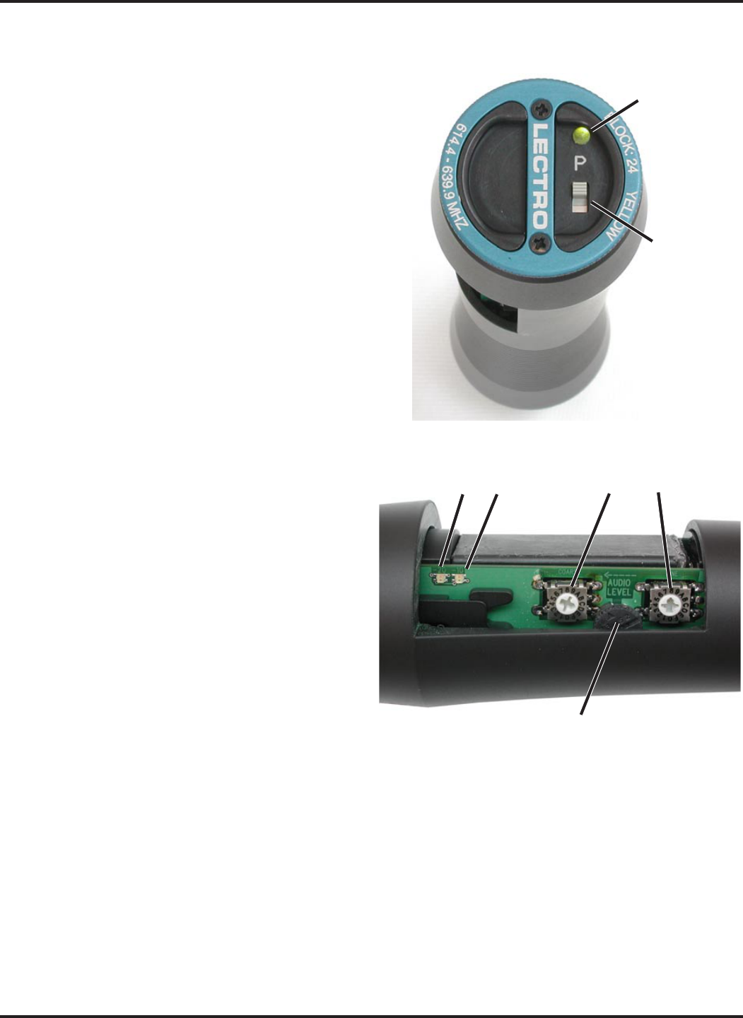
Power
LED
Po w er
Switch
Audio Level LEDs
-20 -10
Frequency Switches
Coarse Fine
Audio Level
CONTROLS AND FUNCTIONS
“P” SWITCH – POWER ON/OFF
A slide switch (located on the outside bottom of the unit)
which turns battery power on and off. The pilot tone
muting system prevents “thumps” or transients from
occurring even when the switch is turned off or on
abruptly,
The Power LED glows green when the battery is good and
the ON/OFF switch is ON. The lamp will glow red as the
battery voltage drops and finally flashes when there is
about 30 minutes of operation left with the recommended
alkaline battery. The lamp will flash red when there are
only a few minutes of life left. A NiMh battery will give
little or no warning when it is depleted. If you wish to use
NiMh batteries in the UM400, we recommend trying fully
charged batteries in the unit, noting the length of time that
the batteries will run the unit and in the future use some-
what less than that time to determine when the battery
needs to be replaced. A weak battery will sometimes light
the POWER LED to the “good” green indication immedi-
ately after being put in the unit, but will soon discharge to
the point where the LED will go red or shut down, just like
a flashlight with “dead” batteries. If the lamp fails to light,
the battery should be replaced.
FREQUENCY ADJUST
Two rotary switches (located under the battery door) adjust
the center frequency of the carrier. The Coarse adjust-
ment adjusts the frequency in 1.6 MHz steps and the fine
in 100 kHz steps. Each transmitter is factory aligned at
the center of its operating range for uniform operation
across the entire band. The default position of the fre-
quency select switches is in the center of the transmitter
range.
MOD LEVEL LEDs
These LEDs (located under the battery door) indicate the
proper setting of the MIC LEVEL control. There are two
bicolor modulation LEDs that can light either red or green.
“-20dB level” One modulation LED glows green and the transmitter is 20 dB below full modulation.
“-10 dB level” Both modulation LEDs glow green and the transmitter is close to full modulation.
“+0 dB level” The -20 LED glows red and the -10 LED glows green. The transmitter is in slight limiting and is fully
modulated. This is probably desirable. See the discussion below under Input Limiter.
“+10 dB level” Both LEDs are red. The transmitter is in limiting and you may want to reduce the transmitter audio
gain. See the discussion below under Input Limiter.
7
Rio Rancho, NM - USA
Digital-hybrid, Frequency Agile Handheld Transmitter
INPUT LIMITER
The 400 series transmitters employ a digitally-controlled analog audio limiter just before the analog-to-digital converter.
The limiter has a range of more than 30dB for excellent overload protection. A dual release envelope makes the limiter
acoustically transparent while maintaining low distortion. It can be thought of as two limiters in series, connected as a
fast attack and release limiter followed by a slow attack and release limiter. The limiter recovers quickly from brief
transients, so that its action is hidden from the listener, but recovers slowly from sustained high levels, to both keep
audio distortion low and preserve short term dynamic changes.
The audio level LEDs indicate limiter activity. The first red LED indicates that the limiter is active and that the transmit-
ter is fully modulated (audio level is between +0 and +10 dB). The second red LED indicates that the level is 10dB or
more into limiting. Occasional forays into the red are desirable for most applications, since the distortion introduced by
the limiter is so minimal, and full modulation is thus assured. We strongly recommend setting the gain of the transmit-
ter high enough so that the first red LED occasionally lights.
Generally speaking, some limiting is desirable in normal operation to improve the signal to noise ratio of the system.
The limiting action is not audible and does not create distortion. A highly trained ear would hear only the compression
of the peaks in the audio signal, which is desirable with most recorders and many sound reinforcement systems.
AUDIO LEVEL
This knob (located under the battery door) is operated while speaking or singing into the transmitter to adjust the audio
gain of the transmitter for the correct amount of modulation. The LEDs located next to it indicate the modulation level
as the gain is adjusted. See the Operating Instructions section for details on this very important adjustment.
VARIMIC CONTROLS
Caution - Due to the high RF levels surrounding the transmitter, the sound of the Varimic capsule may be temporarily
affected if the metal windscreen is not in place. Always make the final decision about sound balance and quality with
the windscreen in place.
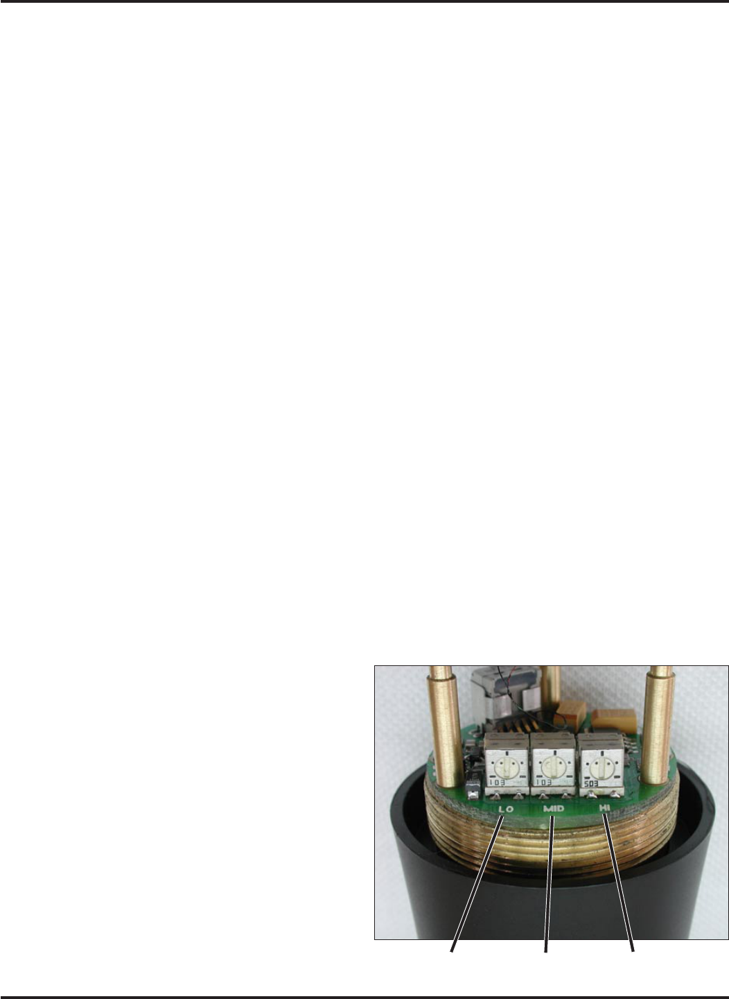
The VariMic head includes adjustments for Bass, Midrange and Treble response. There is also an attenuation adjust-
ment to provide up to 15dB of additional headroom if needed.
BASS / MID / TREBLE (LO / MID / HI)
The bass and treble controls will boost/cut by up to ap-
proximately 8dB while the Mid control will boost/cut up to
about 6dB. These controls operate as standard tone
controls. Counter-clockwise will reduce the response in that
band and clockwise will provide a true boost. These
controls can be accessed by removing the windscreen. To
remove the windscreen, grasp the body of the transmitter in
one hand and the windscreen in the other hand. Carefully
unscrew the wind-screen counter-clockwise until it comes
off then carefully slide the windscreen past the mic ele-
ment.
• Set flat, the mic capsule is very wide range and sounds a
lot like a large competitor’s top line condenser mic.
• Bass cut gives a dry but highly intelligible sound. Crisp.
• Bass boost “fattens” the sound but is very listenable.
Does not get midbass boomy.
Bass (LO) Mid (MID) Treble (HI)
8
UT400
LECTROSONICS, INC.
+10
0
dB
-10 10Hz 100Hz 1KHz 10KHz
+5
-5
UT200 Bass/Midrange/Treble Boost/Cut
• Midrange cut sounds very smooth. Almost a “crooner”
quality. A sweet sound.
• Midrange boost is likely to be useful in a system that is
midrange shy.
• Treble cut has a “mellow” sound. The capsule has a solid
high end so a little cut does not ruin the response.
• Treble boost might be fine on some sound systems. The
sound doesn’t get harsh (showing that the response was
smooth) but sibilants are a little too much. Should be
used in moderation.
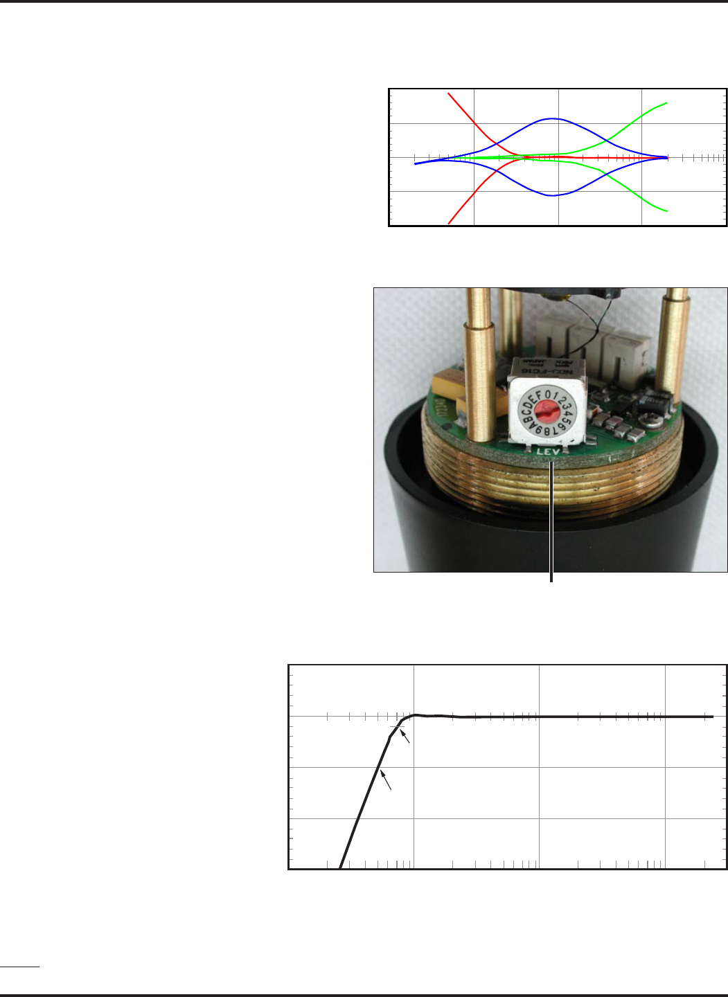
PREAMP LEVEL CONTROL
The VariMic head includes an attenuator to provide an
additional 15dB of headroom when needed. The attenuator
should only be used when the normal Mic Level pot is
already turned down as far as it will go and the signal
through the mic is still too hot. The attenuator control is a
16-position switch marked 0 through F. “F” is minimum
attenuation or the highest signal level. “0” is maximum
attenuation or the lowest signal level. For the maximum
amount of headroom, set the switch to “0.”
Note: The attenuator should not be used as a level
control. The Audio Level control inside the battery
compartment is the main level control. Adjust the
attenuator only when the Audio Level control is
turned completely down and more headroom is still
needed. Be sure to set the attenuator back to its
original setting for normal operation.
BASS FILTER
In addition to the tone controls, the
UT400 also has a built in bass filter. This
filter is fixed and cannot be adjusted or
defeated. Low frequency noise is much
more of a problem with wireless micro-
phones than with conventional micro-
phones. With a regular mic, low fre-
quency wind noise, breath thumps or
handling rumble can be filtered out at the
control board before the noise causes
problems with the following electronics or
speaker systems. But with a wireless
microphone, the electronics that will be
overdriven are right in the wireless
microphone. Filtering at the control board
is much too late. To solve this problem,
the VariMic has a low frequency filter that
is so sharp that it can remove low frequency noise without affecting any wanted vocals. It consists of a 36 dB per
octave filter circuit to sharply remove low frequency noise below 75 Hz without affecting vocal fundamentals. The
lowest operatic bass voice fundamental is 82 Hz.
20
0dB
-20
-40
-60
10Hz 100Hz 1KHz 10KHz
VariMic Low Frequency Roll-off Filter
-3dB @ 71Hz
-20dB @ 50Hz
Preamp Level Control
9
Rio Rancho, NM - USA
Digital-hybrid, Frequency Agile Handheld Transmitter
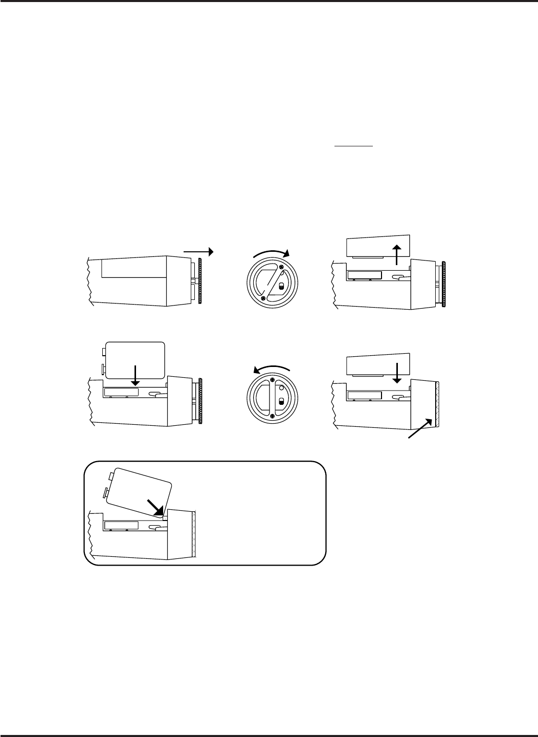
STEP 1STEP 3
Remove
Cover
STEP 4STEP 6
STEP 5
Rotate Ring To
Lock Closed
PA
STEP 2
Rotate Ring
1/8 Turn
PA
+
–
Insert
Battery Replace
Cover
+
–
Alternate Method
Depress the plunger with the
corner of the battery and slide the
battery into the compartment. Note
that the locking ring is in the closed
position for this procedure.
Ring will sit flush in the
closed position.
Pull Ring
Outward
BATTERY INSTALLATION
The transmitter is powered by a standard alkaline or lithium 9 Volt battery. It is important that you use ONLY ALKA-
LINE or LITHIUM batteries for reliable operation. Alkaline batteries will provide about 4 hours of operation while the
lithium batteries will operate the transmitter for over 14 hours. The battery status lamp will function normally only with
alkaline or lithium batteries. Standard zinc-carbon batteries marked “heavy duty” or “long-lasting” are not adequate.
They will provide only about 30 minutes of operation. Similarly, nicad rechargeable batteries only provide about 1 hour
of operation, and will run down quite abruptly.
The battery compartment is located in the lower section of the transmitter, between the two printed circuit boards. To
install a fresh battery, follow the steps illustrated below.
Look inside the battery compartment when the cover is off and take note of the two differently sized holes in the
battery contact pad. Insert the battery so that the large hole in the battery contact pad will line up with the large
contact on the battery when it is installed. The spring-loaded plunger in the bottom of the compartment (opposite the
contact pad) secures the battery in place.
The battery status is indicated by an LED on the bottom panel. The LED will glow brightly when the battery is good and
will dim as the battery condition deteriorates. The LED is green with a new battery. The battery status is also displayed
on the Information Display on the front panel of the receiver. See the receiver manual for further details.
Note: It is possible to insert the battery backwards and still be able to close the battery door. No damage will occur but
the transmitter will not operate in this condition.

10
UT400
LECTROSONICS, INC.
OPERATING INSTRUCTIONS
SELECTING THE OPERATING MODE
All units with serial number 601 and up are capable of working with Lectrosonics 100 series analog , 200 series analog,
400 series digital hybrid or some other analog wireless receivers (contact the factory for details). The transmitter must
be set to the operating mode of the matching receiver, which is easily done using only the supplied screwdriver and a
battery.
NOTE: the unit is supplied from the factory as a 400 series transmitter
1) Make certain a good battery is installed.
2) Power down the transmitter.
3) With a small screwdriver (included with your unit), set the frequency change switches to CC. (for Change, Change).
4) Power up the unit briefly – just a couple of seconds (just watch for the LED’s to light up) and then turn it off.
5) Change the switches to one of the following settings:
• To set Lectrosonics 100 mode: set switches to 1,1
• To set Lectrosonics 200 mode: set switches to 2,2
• To set mode 3: set switches to 3,3* (contact the factory for details)
• To set Lectro digital hybrid (400) mode: set switches to 4,4
6) Turn the unit on, wait just a couple of seconds and turn off again.
7) Change the switches to 0,0.
8) Power up the unit – you have now changed the operation mode for the unit.
The LEDS will blink at powerup to indicate the selected operating mode. Immediately after powering up, all LEDS
will blink together red, then green, followed by the audio level LEDs (-20 and -10) blinking to indicate the mode.
The –20 and –10 LEDs will blink:
• Once for 100 mode
• Two times for 200 mode
• Three times for some other receivers
• Four times for 400 mode
At powerup the transmitter will confirm the current operating mode with the number of blinks listed here. The setting
will remain the same until you reset it with the procedure listed above.
ADJUSTING THE GAIN
1) Install a fresh battery. Leave the battery cover off for further adjustment.
2) On the bottom panel, move the “A” (audio) switch to “OFF” (away from the LED) and the “P” (power) switch to ON
(toward the LED) in that order. Observe that the battery status LED is brightly lit. If the LED is dim, replace the
battery.
3) Hold the microphone in the same position that it will be used in actual operation.
4) While speaking or singing at the same voice level that will actually be used, observe the MODULATION LEDs.
Adjust the AUDIO LEVEL control knob until the LEDs begin to light. At too low a setting neither LED will light as
you speak. Gradually, turn the gain up until the –20 dB LED lights green and then the -10 dB lights green. We
strongly recommend setting the gain of the transmitter even higher so that the first red LED occasionally lights.
If you find that the AUDIO LEVEL control is set to minimum and the LIMIT LED is still on often, then adjust the
attenuator. This control is located under the windscreen. Unscrew the windscreen and carefully lift it off the top of
the unit. See the VERIMIC CONTROLS section for these adjustments. If you need to change these controls, be
sure to repeat the gain adjustment procedure beginning at step 3.
5) Once the gain has been adjusted, the audio system audio can be turned on to make level adjustments in the main
audio system.

11
Rio Rancho, NM - USA
Digital-hybrid, Frequency Agile Handheld Transmitter
OPERATING NOTES
The AUDIO LEVEL control knob should not be used to control the volume of your sound system or recorder levels.
This gain adjustment matches the transmitter gain with the user’s voice level and microphone positioning.
If the audio level is too high — both red LEDs will light frequently or stay lit. This condition may reduce the dynamic
range of the audio signal.
If the audio level is too low — neither LED will light, or only the -20 LED will light green. This condition may cause hiss
and noise in the audio.
Different voices will usually require different settings of the AUDIO LEVEL control, so check this adjustment as each
new person uses the system. If several different people will be using the transmitter and there is not time to make the
adjustment for each individual, adjust it for the loudest voice.
ADJUSTING THE TRANSMITTER FREQUENCY
If you are experiencing interference from another signal on your frequency, you
may want to change the operating frequency of your system. The switch nearest
to the mic element changes the operating frequency by 100 kHz per step (Fine)
and the switch furthest from the mic element changes it 1.6 MHz per step
(Coarse). If you are experiencing interference, change the operating frequency of
the receiver to find a clear channel, then set the transmitter to match.
Some receiver models will indicate the correct transmitter switch settings on the
receiver control panel.
8
9
A
B
C
D
E
F
0
1
2
3
4
5
6
7
8
9
A
B
C
D
E
F
0
1
2
3
4
5
6
7
Coarse Fine

12
UT400
LECTROSONICS, INC.
TROUBLESHOOTING
Before going through the following chart, be sure that you have a good battery in the transmitter. It is important that
you follow these steps in the sequence listed.
SYMPTOM POSSIBLE CAUSE
TRANSMITTER BATTERY LED OFF 1) Battery is inserted backwards.
2) Battery is dead, or too low to be used.
NO TRANSMITTER MOD LEVEL LEDs 1) Gain control turned all the way down.
2) Battery is in backwards. Check power LED.
3) Mic capsule is damaged or malfunctioning. Contact the
factory for repair.
RECEIVER RF LAMP OFF 1) Transmitter not turned on.
2) Transmitter battery is dead.
3) Receiver antenna missing or improperly positioned.
4) Transmitter and receiver not on same frequency. Check labels
on transmitter and receiver and the frequency switch settings.
5) Operating range is too great.
NO SOUND BUT RECEIVER AUDIO LEVEL
METER INDICATES 1) Receiver audio is muted or set too low.
2) Receiver audio output is disconnected or cable
defective or mis-wired.
3) Sound system or recorder input is turned down.
DISTORTED SOUND AND/OR
MOTORBOATING 1) Transmitter gain (audio level) is too high. Speak or sing into the
transmitter and check mod level lamps on transmitter and
receiver.
2) Receiver output level may be too high for the sound
system or recorder input.
3) Excessive wind noise or breath “pops.” Microphone
may require an additional wind screen.
4) Transmitter frequency switches mis-set.
5) RF feedback getting into VariMic mic capsule. Ensure that the
windscreen is present and screwed down snugly.
HISS AND NOISE -- AUDIBLE DROPOUTS 1) Transmitter gain (audio level) too low.
2) Receiver antenna missing or obstructed.
3) Operating range too great.
4) Transmitter frequency switches mis-set.
EXCESSIVE FEEDBACK 1) Transmitter gain (audio level) too high. Check gain adjustment
and/or reduce receiver output level.
2) Microphone too close to speaker system.
3) Move microphone closer to the user’s mouth, and lower the
sound system volume.

13
Rio Rancho, NM - USA
Digital-hybrid, Frequency Agile Handheld Transmitter
SPECIFICATIONS
Operating frequencies: 537.600 to 607.900 MHz
614.100 to 793.500 MHz
Frequency selection: 256 frequencies in 100kHz steps
RF Power output: 100 mW (nominal)
Pilot tone: 25 to 32 kHz frequency; 5kHz deviation
Frequency stability: ± 0.002%
Deviation: ± 75 kHz (max)
Spurious radiation: 90 dB below carrier
Equivalent input noise: –120 dBV, A-weighted
Input level: Nominal 2 mV to 300 mV, before limiting.
Greater than 1V maximum, with limiting.
Input compressor: Dual envelope compressor, >30 dB range
Gain control range: 43 dB; semi-log rotary control
Modulation indicators: Dual bicolor LEDs indicate modulation of -20, -10, 0, +10 dB
referenced to full modulation.
Low frequency roll-off: –18dB/octave; 35Hz to 150Hz
Audio frequency response (overall system): 32 Hz to 20 kHz (+/- 1dB)
Controls: 2 position “OFF-ON” slide switch for noiseless turn on/turn off operation.
Battery compartment knob adjusts audio gain. Rotary switches adjust
transmitter frequency.
Battery: Precision compartment auto-adjusts to accept any known alkaline 9 Volt
battery. (We’ve tried 243 different ones!)
Battery Life: 5 hours (alkaline); 16 hours (lithium)
Weight: 12.4 ozs. with VeriMic capsule and lithium battery
Dimensions: 9” long x 2.05” diameter at largest point with VeriMic capsule
Emission Designator: 180KF3E
Specifications subject to change without notice.
The FCC requires that the following statement be included in this manual:
This device complies with FCC radiation exposure limits as set forth for an uncon-
trolled environment. This device should be installed and operated so that its antenna(s)
are not co-located or operating in conjunction with any other antenna or transmitter.

14
UT400
LECTROSONICS, INC.
SERVICE AND REPAIR
If your system malfunctions, you should attempt to correct or isolate the trouble before concluding that the equipment
needs repair. Make sure you have followed the setup procedure and operating instructions. Check out the intercon-
necting cords and then go through the TROUBLE SHOOTING section in the manual
We strongly recommend that you do not try to repair the equipment yourself and do not have the local repair shop
attempt anything other than the simplest repair. If the repair is more complicated than a broken wire or loose connec-
tion, send the unit to the factory for repair and service. Don’t attempt to adjust any controls inside the units. Once set
at the factory, the various controls and trimmers do not drift with age or vibration and never require readjustment.
There are no adjustments inside that will make a malfunctioning unit start working.
LECTROSONICS service department is equipped and staffed to quickly repair your equipment. In-warranty repairs
are made at no charge in accordance with the terms of the warranty. Out of warranty repairs are charged at a modest
flat rate plus parts and shipping. Since it takes almost as much time and effort to determine what is wrong as it does
to make the repair, there is a charge for an exact quotation. We will be happy to quote approximate charges by phone
for out of warranty repairs.
RETURNING UNITS FOR REPAIR
You will save yourself time and trouble if you will follow the steps below:
A. DO NOT return equipment to the factory for repair without first contacting us by letter or by phone. We need to
know the nature of the problem, the model number and the serial number of the equipment. We also need a phone
number where you can be reached 8 am to 4 pm (Mountain Standard Time).
B. After receiving your request, we will issue you a return authorization number (R.A.). This number will help speed
your repair through our receiving and repair departments. The return authorization number must be clearly shown on
the outside of the shipping container.
C. Pack the equipment carefully and ship to us, shipping costs prepaid. If necessary, we can provide you with the
proper packing materials. UPS is usually the best way to ship the units. Heavy units should be “double-boxed” for
safe transport.
D. We also strongly recommend that you insure the equipment, since we cannot be responsible for loss of or damage
to equipment that you ship. Of course, we insure the equipment when we ship it back to you.
Mailing address: Shipping address: Telephones:
Lectrosonics, Inc. Lectrosonics, Inc. Regular: (505) 892-4501
PO Box 15900 581 Laser Rd. Toll Free (800) 821-1121
Rio Rancho, NM 87174 Rio Rancho, NM 87124 FAX: (505) 892-6243
USA USA
World Wide Web: http://www.lectrosonics.com Email: sales@lectrosonics.com

LECTROSONICS, INC.
581 LASER ROAD
RIO RANCHO, NM 87124 USA
www.lectrosonics.com
August 25, 2003
LIMITED ONE YEAR WARRANTY
The equipment is warranted for one year from date of purchase against defects in
materials or workmanship provided it was purchased from an authorized dealer. This
warranty does not cover equipment which has been abused or damaged by careless
handling or shipping. This warranty does not apply to used or demonstrator equipment.
Should any defect develop, Lectrosonics, Inc. will, at our option, repair or replace any
defective parts without charge for either parts or labor. If Lectrosonics, Inc. cannot
correct the defect in your equipment, it will be replaced at no charge with a similar new
item. Lectrosonics, Inc. will pay for the cost of returning your equipment to you.
This warranty applies only to items returned to Lectrosonics, Inc. or an authorized
dealer, shipping costs prepaid, within one year from the date of purchase.
This Limited Warranty is governed by the laws of the State of New Mexico. It states the
entire liablility of Lectrosonics Inc. and the entire remedy of the purchaser for any
breach of warranty as outlined above. NEITHER LECTROSONICS, INC. NOR
ANYONE INVOLVED IN THE PRODUCTION OR DELIVERY OF THE EQUIPMENT
SHALL BE LIABLE FOR ANY INDIRECT, SPECIAL, PUNITIVE, CONSEQUENTIAL,
OR INCIDENTAL DAMAGES ARISING OUT OF THE USE OR INABILITY TO USE
THIS EQUIPMENT EVEN IF LECTROSONICS, INC. HAS BEEN ADVISED OF THE
POSSIBILITY OF SUCH DAMAGES. IN NO EVENT SHALL THE LIABILITY OF
LECTROSONICS, INC. EXCEED THE PURCHASE PRICE OF ANY DEFECTIVE
EQUIPMENT.
This warranty gives you specific legal rights. You may have additional legal rights which
vary from state to state.
LIMITED ONE YEAR WARRANTY