Lee s High Tech Enterprise Co 9311F2212 Industrial Radio Control Transmitter User Manual 260e 300 313F22 12D manual
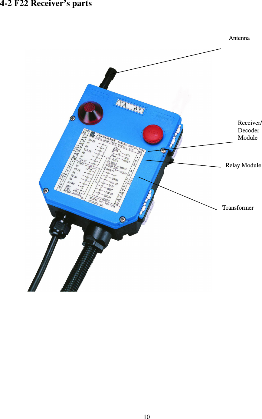
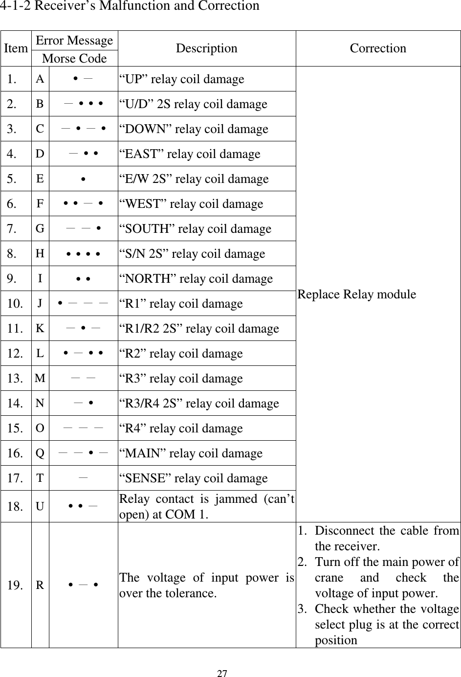
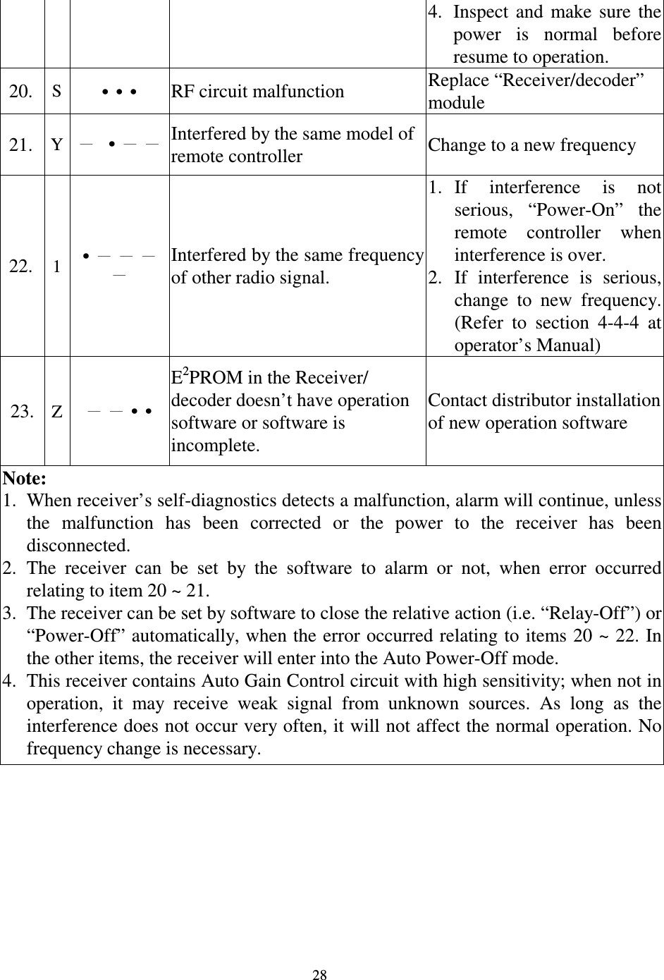
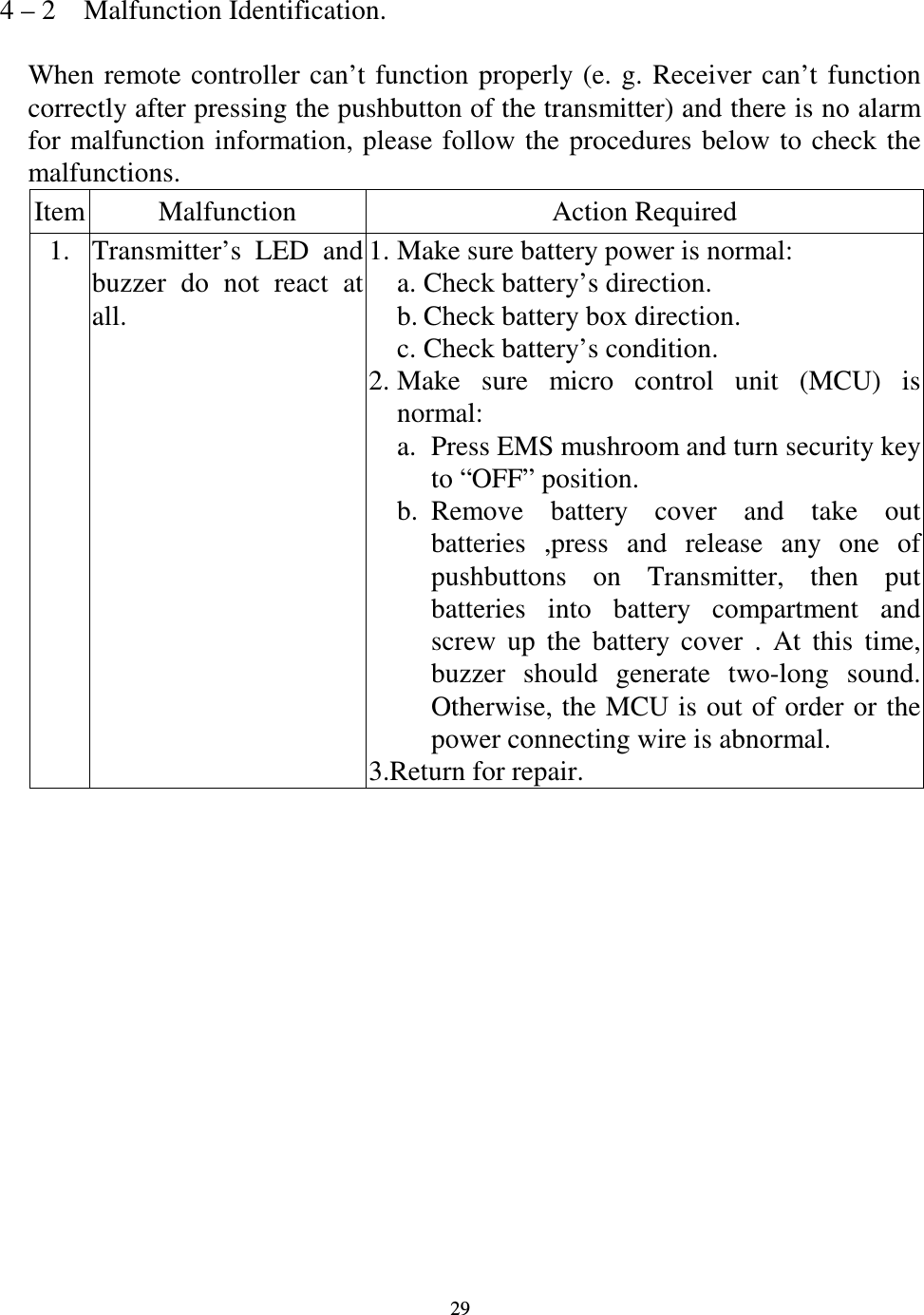
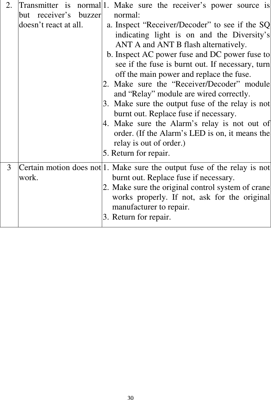
Lee's High-Tech Enterprise Co Ltd Industrial Radio Control Transmitter 260e 300 313F22 12D manual
UserManual.wiki
>
Lee s High Tech Enterprise Co
>
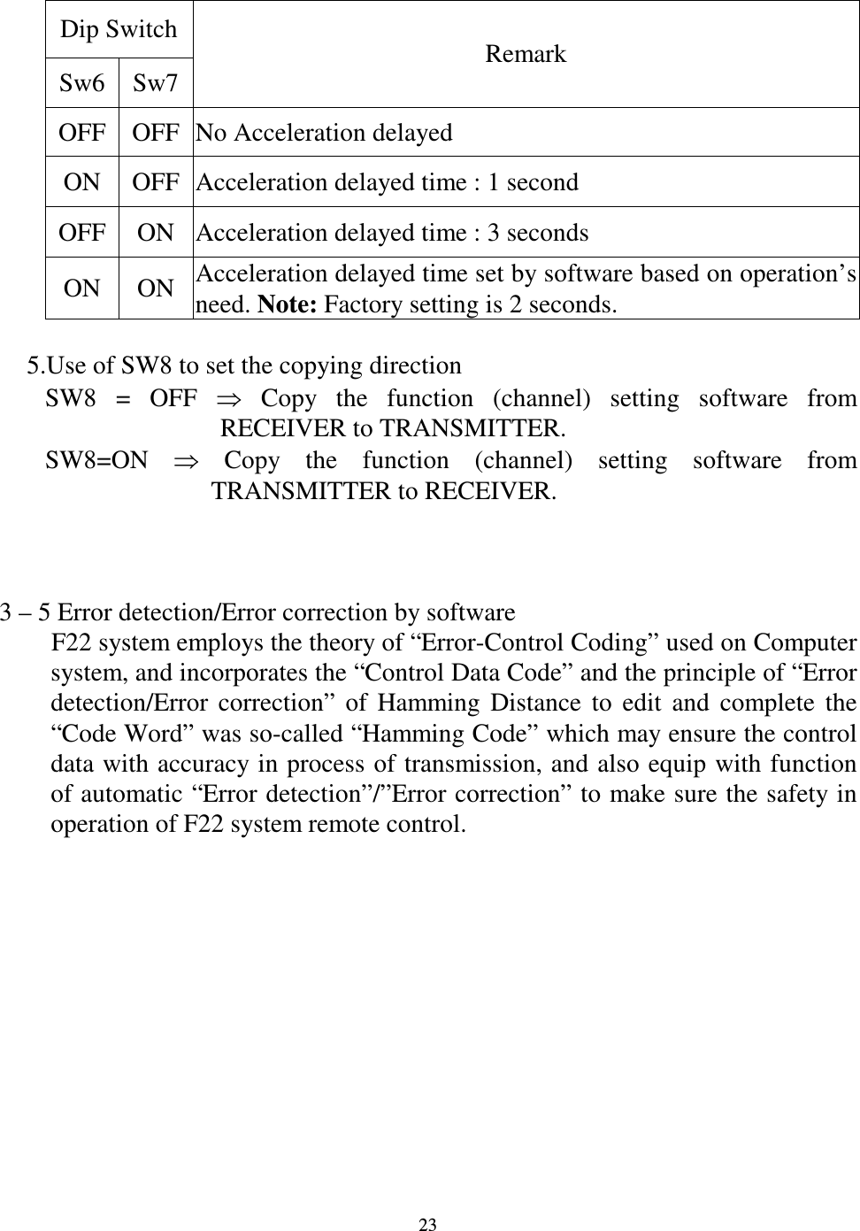
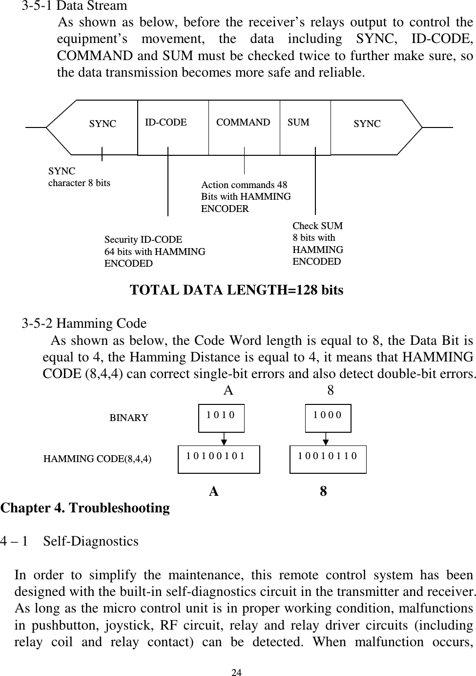
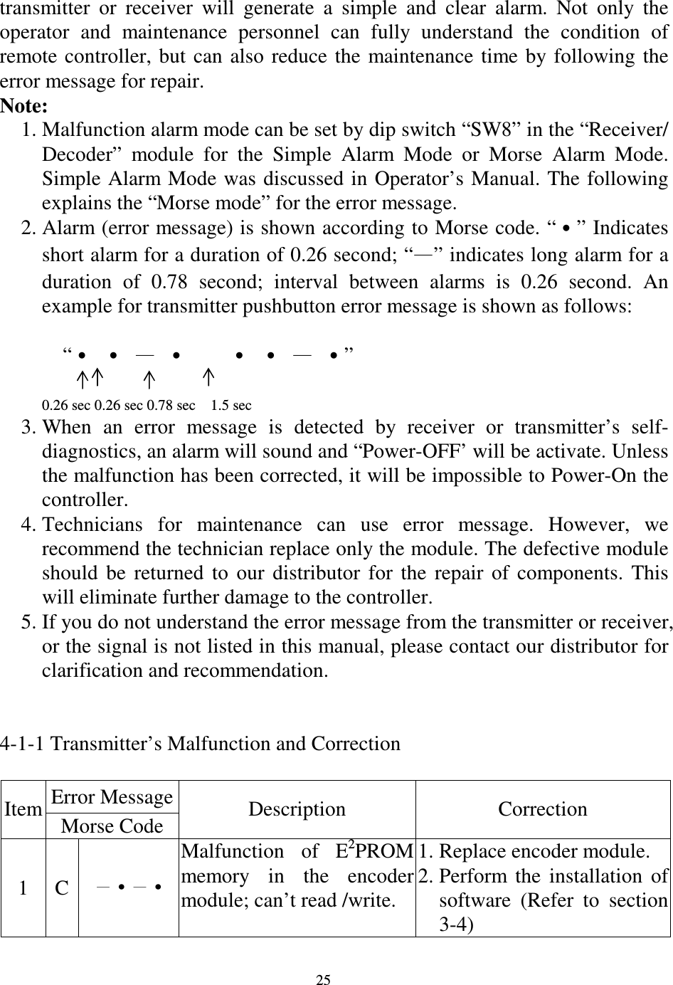
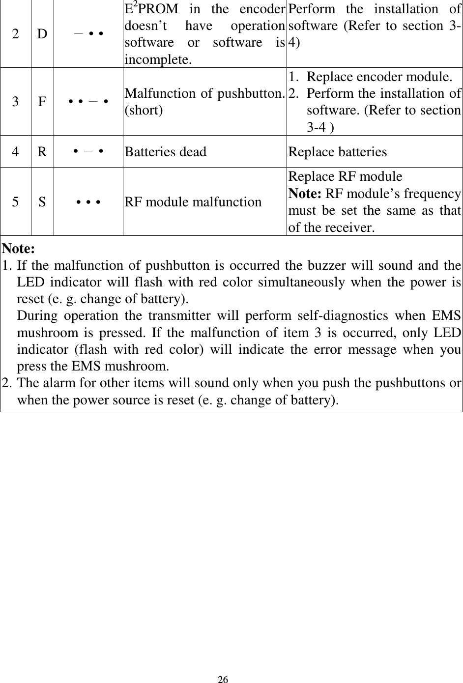
9311F2212 User Manual
User Manual
Navigation menu
Upload a User Manual
Namespaces
Wiki Guide
HTML
PDF
Info
Views
User Manual
Discussion / Help
Navigation