Lee s High Tech Enterprise Co 9312F24 Industrial Radio Remote Controller User Manual F24
Lee's High-Tech Enterprise Co Ltd Industrial Radio Remote Controller F24
UserManual.wiki
>
Lee s High Tech Enterprise Co
>
9312F24 User Manual
Users Manual
Navigation menu
Upload a User Manual
Namespaces
Wiki Guide
HTML
PDF
Info
Views
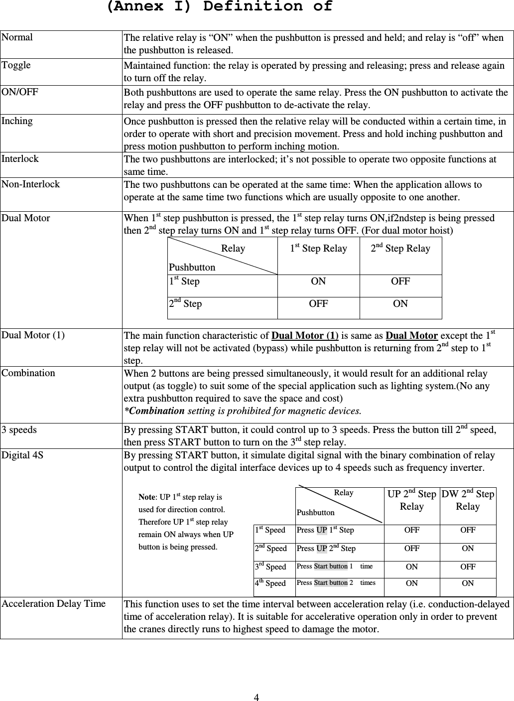
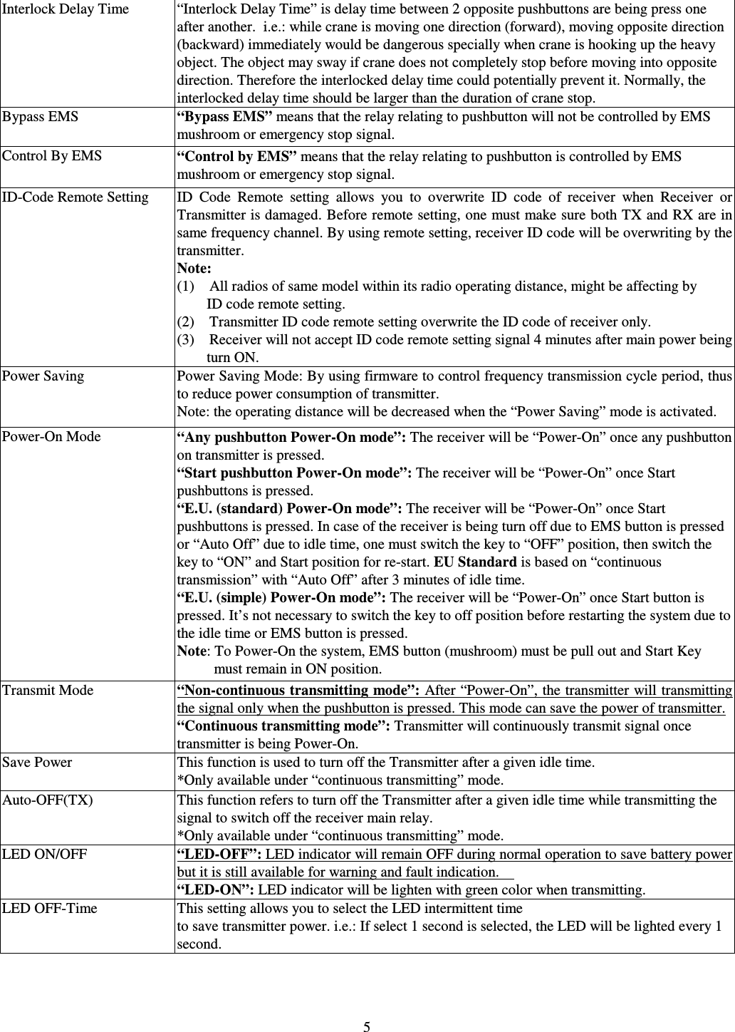
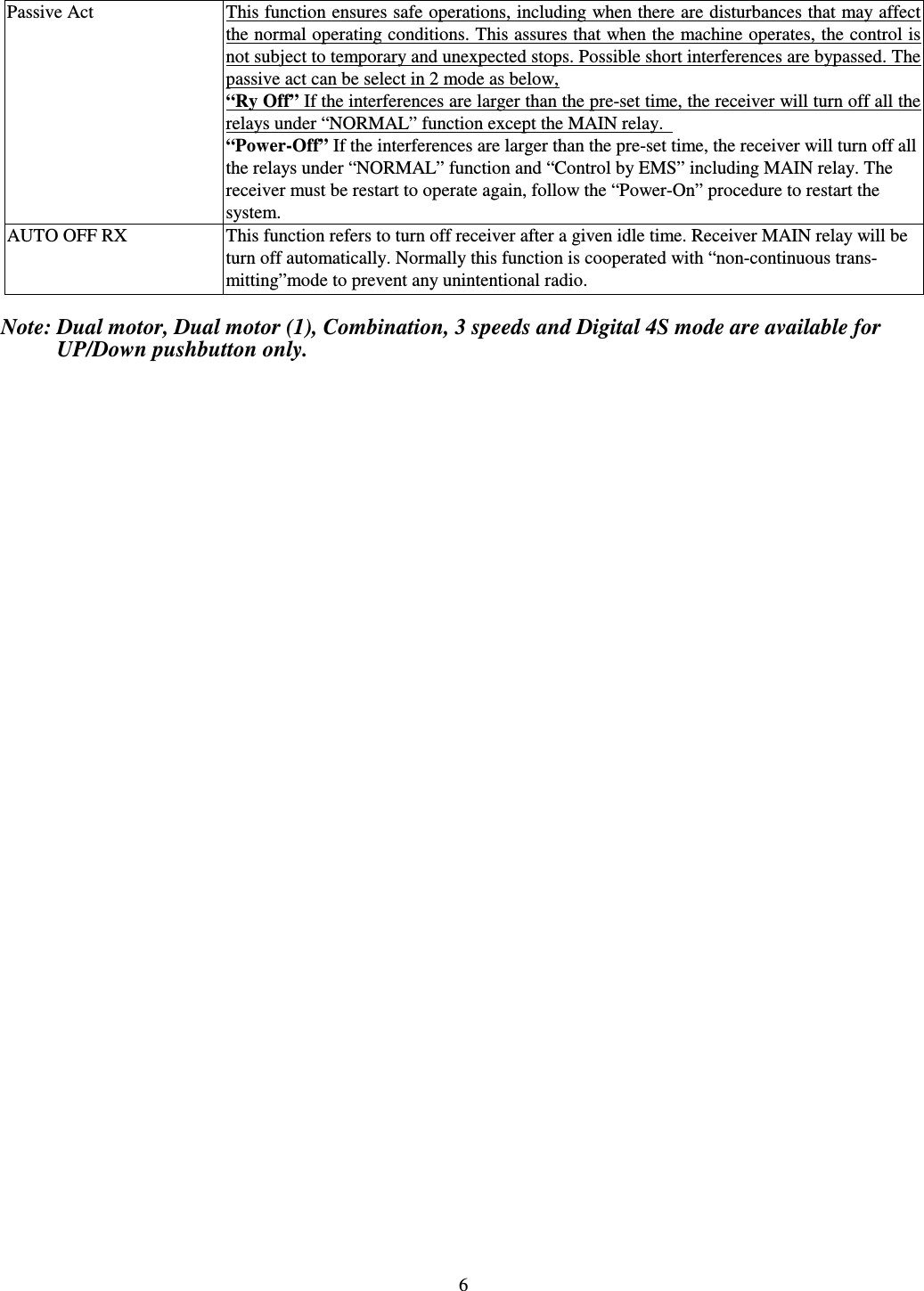
User Manual
Discussion / Help
Navigation