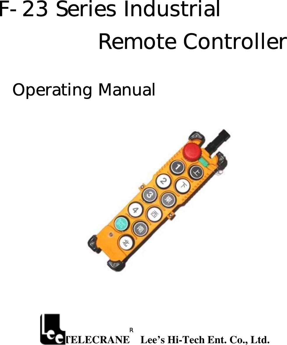
Lee s High Tech Enterprise Co F-23 IND. RADIO REMOTE CONTROLLER User Manual USERS MANUAL

Lee's High-Tech Enterprise Co Ltd IND. RADIO REMOTE CONTROLLER USERS MANUAL

USERS MANUAL

F-23 Series Industrial  Remote Controller  Operating Manual                             TELECRANE    Lee’s Hi-Tech Ent. Co., Ltd.   R
 1   Warranty Lee’s Hi-Tech Enterprises Co., Ltd. guarantees that this product meets its published specifications at the time of shipment from the factory. Under proper installation it should work as expected.  Warranty Period   This equipment is warranted against defects in material and manufacturing for a period of one year from the date of shipment. During the warranty period, TELECRANE is responsible for necessary repairs as long as the product can be proved to be defective. For warranty service or repair this product must be returned to a service facility designated by TELECRANE. Buyer will pay shipping charges to TELECRANE while TELECRANE will pay return shipping charges.    Excluded Items   This warranty does not include consumptive parts such as batteries, fuses, buttons, relays. Also this warranty does not cover defects caused by improper installation, improper or insufficient maintenance, unauthorized modification, improper operation, ignorance of environmental specifications, or improper software or interfacing. Remarks No other warranty is expressed or implied, except for the above mentioned.◎ The remedies provided her◎ein are the buyer’s sole and exclusive remedies. TELECRANE shall not be liable for any direct, indirect, special, incidental or consequential damages.   Attention  ◎  Never dismantle the equipment by any unauthorized personnel, or equipment may be damaged. ◎  After finishing operation of TELECRANE radio controller shut off main power to the crane, power to receiver, and remove transmitter key. If transmitter’s power is controlled by “rotary key switch”, then need turn the key to “OFF” position and remove it. ◎  The crane should be equipped with main power relay, limit switch and other safety devices.   Precautions ( I )   To avoid any interference, the receiver must be placed as far as possible from frequency inverter and   power cable as possible.  Precaution ( II ) The receiver should be installed on the top of the electrical control box. Do not mount the receiver inside the electrical control box.  Emergency In case of Emergency, please follow the procedure below and contact the distributor for service immediately.  1.  Press EMS button of transmitter. 2.  Remove the key from transmitter. 3.  Switch off the main power of crane. 4.  Contact distributor nearest you immediately.    F-23 Operation Instruction
 2   F-23 Standard Accessories  When you get a standard and full set of F-23 system, it includes the following item.:               Remarks: (1). Hamming Distance-------------≧4 (2).  I.D. Code--------------------------More than 42 billion ID Code(32bit) (3). Channel Spacing----------------267.5KHz (1)Transmitter, one unit. (2)Receiver, one unit. F-23 Operation
 3F-23Transmitter’sparts                      Remarks: (1).  Power----------------------Two 1.5Volt Alkaline Batteries(AA Size) (2). Dimensions----------------218×60×60mm (3). Weight---------------------about 365g(W/batteries)   Emergency stop LED indicator Pushbuttons
 4F-23 Receiver’s parts                         Remarks: (1). Input Voltage------------------------------110VAC(50/60Hz)±10% (2). Output Relays-----------------------------10A/250VAC. (3). Dimensions---------------------------------290×230×70mm(L×W×H) (4). Weight--------------------------------------about 1900g(W/O wire cable)       How to use 1.  Insert 2 AA-size alkaline batteries into battery compartment.   2.  Insert magnetic key or rotary key and switch to ON position. 3.  Follow the Power-On procedure to energize the main relay inside receiver.   4.  Operate normally according to the function settings have been done. Output cable
 55.  After operation, please proceed as following: (1) Press EMS pushbutton /mushroom, (2) remove the key and keep it in safe place, (3) Switch off the equipment’s main power (e.g. Crane)    How to change quartz from transmitter/ receiver & identify frequency quartz It’s simple to change frequency of the new F23 series. The system’s frequency can be changed simply by replacing correspondent frequency quartz in both the TX and RX.    Note: For replacing the new crystal, there are 2 types of frequency are available (VHF & UHF). Do not replace the VHF crystal unit into UHF PC Board. The indication of frequency type (VHF or UHF) is shown on the PC Board with a check mark “v”  Instructions: (1). Pry up the crystal unit with a flat screwdriver   (2). Remove the crystal unit from the system.   (3). Use a needle nose pliers to straighten both pins of the new crystal unit.   (4). Insert the new crystal unit vertically into the PC board.   (5). Press the new crystal down into the socket.           Note: the frequency will be different when plugging the same crystal into the TX or RX, for example,      ID Code Remote Setting ID Code Remote setting allows you to overwrite the receiver ID code if Receiver or Transmitter is damaged. Before remote setting, one must make sure both TX and RX are in same frequency channel. By using remote setting, receiver ID code will be overwriting by the transmitter.  Prior to remote setting, please follow the instruction below,   (a)  Make sure both TX and RX are same model and in the same frequency channel. (b)  To avoid interference during remote setting, place the transmitter to RX as close as possible. (c)  Turn off RX power completely (MAIN SWITCH) for 20 seconds and turn it on again. (d)  Complete the remote setting within 4 minutes after turning on the RX. The RX will NOT accept the remote setting signal after 4 minutes.  Instructions: (1)  Depress the TX Emergency Stop (For those systems without a Mushroom style stop button that stays depressed, please hold down the “STOP” pushbutton) (2)  Press UP pushbutton and hold it. (3)  Press DOWN pushbutton 4 times and release “STOP & UP” pushbuttons when red LED flash. (4)  Start the system as usual. Note: (1) By follow the procedures above, all the radios of same model within its radio operating distance, might be affecting by ID code remote setting.           (2) ID code remote setting only transmits data of ID code only.             (3) The position of magnetic key or Rotary key will not affect to the ID code remote setting.  1  2 3 4  5 T : 321.00 MHz R : 331.70 MHz  Frequency for    TX is 321.00 MHz  Frequency for    RX is 331.70 MHz
 6Transmitter Batteries 2 AA size alkaline batteries are required for the transmitter. DO NOT use rechargeable batteries. During operation, the LED flash green when battery power is full and flash red intermittent every 2 seconds when battery power is low. When battery power is low, the operating distance will become shorter. For safety reason, replace new batteries immediately when battery power is low.  Power Supply F-23 provide 3 different AC transformers and the power supplied to the F-23 Receiver as below (1)  48/110/220 VAC (2) 110/220/380 VAC (3)  48/220/380 VAC Each AC transformer provides 3 different voltages to meet different application’s need. Please follow   the procedures below to select the voltage.                                                      (Fig. A)                                        (Fig. B) 1.  Disconnect the power of receiver. 2.  Remove connector plug of the transformer from its original position (Fig A) 3  Then insert connector plug into the new position (Fig B)  Transmitter LED Malfunction Alert (A) Red LED flashing quickly (every 0.2 sec) when any pushbutton is pressed. The problem could be: (1) One of the pushbuttons is jammed. (2) The EMS mushroom has not been released.   (3) The transmitter is not properly Power-On according to the instructions. Note: Please contact the distributor nearest you for further assistant if need. (B) TX LED flashes slowly (every 0.5 sec intermittent). The problem could be: The memory of the TX is defective. Contact the distributor for repair.  Troubleshooting (A) TX LED remains ON with red light. Solution: Please remove the batteries and insert again.   (B) The RX does not respond at all. Solution: Turn the main power off for 20 seconds and turn it on again.  110V 48V 48V 220V 110V 220V 380V 220V 380V Connector Plug
 7 FEDERAL COMMUNICATIONS COMMISSION This device complies with Part 15 of the FCC Rules. Operation is subject to the following two conditions:(1) this device may not cause harmful interference, and (2) this device must accept any interference received, including interference that may cause undesired operation.  NOTE This equipment has been tested and found to comply with the limits for a Class B digital device, pursuant to Part 15 of the FCC Rules. These limits are designed to provide reasonable protection against harmful interference in a residential installation. This equipment generates, uses and can radiated radio frequency energy and, if not installed and used in accordance with the instructions, may cause harmful interference to radio communications. However, there is no guarantee that interference will not occur in a particular installation If this equipment does cause harmful interference to radio or television reception, which can be determined by turning the equipment off and on, the user is encouraged to try to correct the interference by one or more of the following measures:  -Reorient or relocate the receiving antenna. -Increase the separation between the equipment and receiver. -Connect the equipment into an outlet on a circuit different from that to which the receiver is connected. -Consult the dealer or an experienced radio/TV technician for help.  Changes or modifications not expressly approved by the party responsible for compliance could void the user‘s authority to operate the equipment.  The antenna(s) used for this transmitter must not be co-located or operating in conjunction with any other antenna or transmitter

Navigation menu