Leedarson Lighting 6AB-SS-AG-C0 Arrival Sensor User Manual
LEEDARSON LIGHTING CO., LTD. Arrival Sensor
Users Manual
Leedarson Lighting
Leedarson Arrival Sensor
Quick User Guide
Draft
Ver.
Description
Time
Fu
V1.0
2016.10.10
V1.1
2017.06.02
Leedarson Lighting
1 Product Introduction
1.1 Basic Information
Arrival sensor integrated Z-Wave communication module to connect with Z-Wave gateway. By
real-time communication to verify if the device in the communication range of gateway, system can
automatically trigger some relative scenarios and send out messages to especial person.
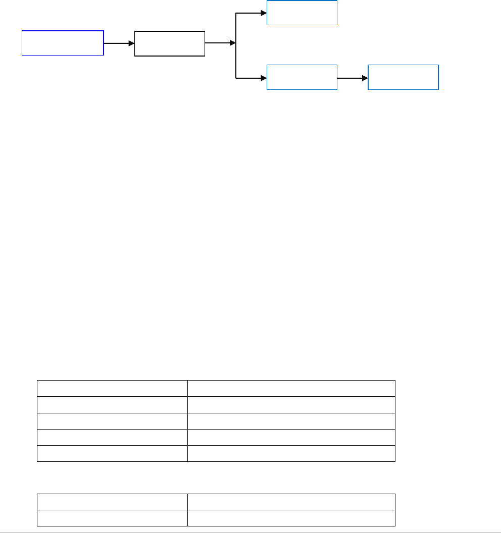
1.2 System Diagram
*MID: Mobile Internet Device
1.3 Functions
a) Particular design for low power consumption, battery charging cycle up to
45 days
b) High performance RF design, visual communication distance up to 30m
c) Follow standard Z-Wave plus protocol
d) Build-in an acceleration sensor to control device sleeping and awaking for
power saving
e)Conveniently operations to connect and reset by a button inside back cover
f) LED indicator to show different status
1.4 Technical Parameter
1.4.1 Communication
Module name
6aB-SS-AG-C0
Protocol
Z-Wave
Frequency
908.42~916 MHz
Communication Distance
About 40m indoors (LOS)
Modulation Mode
FSK(BFSK/GFSK)
1.4.2 Power Supply
Operation Voltage
3.3Vdc
Current
37mA/3s
Arrival Sensor
Gateway
Scenarios
Router
MID*
Leedarson Lighting
Max. Power Consumption
About 120mW
Standby Power
22uA in Average
1.4.3 Battery
Battery Type
150mAh Li-Poly
Charging Cycle
≤45 days
1.4.4 Condition
Storage environment:
-5-45℃, <90%, non-condensing
Operational temperature:
0-40℃
2 Hardware Specification
2.1 Structure
Dimensions: 43mm(H)*34mm(W)*16mm(D)
Weight: 30g
Material: PC
2.2 Functional Description
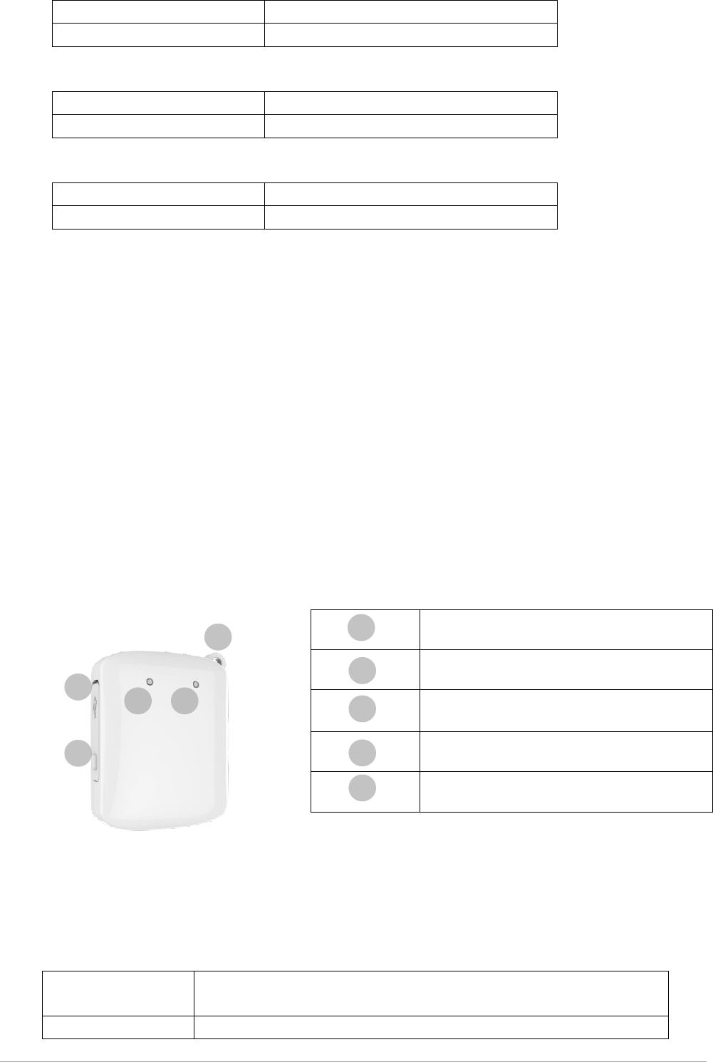
2.2.1 Total Introduction
2.2.2 Reset Button
Reset and Connection button built-in back cover and used for connecting and removing with gateway.
Operation mode as following:
Connection
Turn on researching function in APP, short press button to add in
Z-Wave system.
Reset
Hold on pressing button for 5 seconds, device reset to factory
Hanger
Charging Interface (Micro USB)
Reset Button
Charging Indicator
Connection Status Indicator
1
1
2
3
4
2
3
4
5
5

Leedarson Lighting
mode.
2.2.3 LED Indicator
LED indicator embedded in internal PCBA and support red/yellow colors to display different status
of devices.
Connecting
Red indicator quickly flash for 3 times, if successfully connected, red
indicator hold on for 3 seconds.
Connected
Red indicator keep on for 3s.
Resetting
Red indicator slowly flash for 2 times.
Charging
Blue indicator quickly flash until full charged.
Low Power
Blue indicator slowly flash, about 2 minutes once
2.3 Product Operation
2.3.1 Product Charging
Open the soft cover inside product and plug in Micro USB interface and connect to power supply. If
blue indicator quickly flash, the product turned into charging mode.
2.3.2 Connecting
Use APP or special button in gateway to turn on searching function. While gateway waiting for
connection, short press Reset button to connect. Check the status of LED indicator as the sheet
above.
2.3.3 Reset
Hold on pressing Reset button for 5 seconds and check the status of LED indicator as the sheet above.
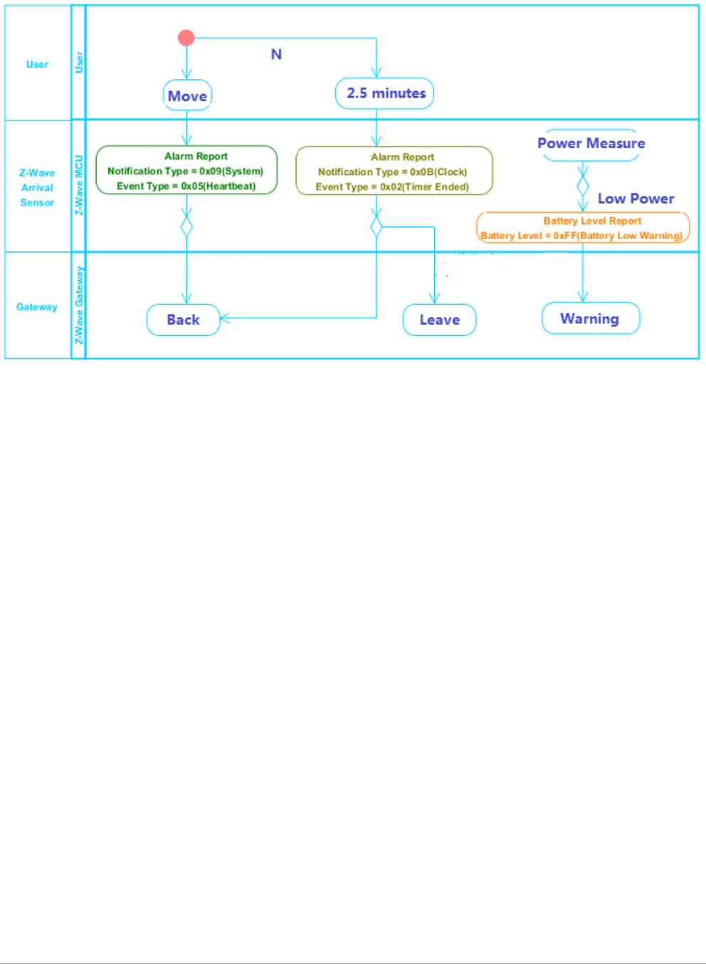
2.3.4 Working Mechanism
1. Sleeping and awaking of arrival sensor is based on integrated acceleration detector. If acceleration
detector had not triggered for 2.5 minutes, arrival sensor send out a package to gateway and go to
sleep mode. While acceleration sensor triggered, arrival sensor wake up and communication with
gateway immediately.
2. If arrival sensor send out a Heartbeat package and not get reply from gateway, system judge arrival
sensor as user left to trigger relative scenarios and send out message.
3. If arrival sensor send out a Heartbeat package and get reply at once from gateway, system judge
arrival sensor as user back to trigger relative scenarios and send out message.
Leedarson Lighting
2.3.5 Connection Logic
Caution:
This device complies with Part 15 of the FCC Rules. Operation is subject to the following two
conditions: (1) this device may not cause harmful interference, and (2) this device must accept any
interference received, including interference that may cause undesired operation.
FCC Caution:
Changes or modifications not expressly approved by the part responsible for compliance could void
the user's authority to operate the equipment.
FCC Statement:
"This equipment has been tested and found to comply with the limits for a Class B digital device,
pursuant to part 15 of the FCC Rules. These limits are designed to provide reasonable protection
against harmful interference in a residential installation. This equipment generates, uses and can
radiate radio frequency energy and, if not installed and used in accordance with the instructions, may
cause harmful interference to radio communications. However, there is no guarantee that
interference will not occur in a particular installation. If this equipment does cause harmful
interference to radio or television reception, which can be determined by turning the equipment off
and on, the user is encouraged to try to correct the interference by one or more of the following
measures:
—Reorient or relocate the receiving antenna.
—Increase the separation between the equipment and receiver.
—Connect the equipment into an outlet on a circuit different from that to which the receiver is
connected.
—Consult the dealer or an experienced radio/TV technician for help."