Leedarson Lighting 7ASSVEH0 Door/Window Sensor User Manual
LEEDARSON LIGHTING CO., LTD. Door/Window Sensor Users Manual
Users Manual

LEEDARSON Z-Wave Door/Window Sensor
Content:
Contact Sensor ................................................................................................................................................... 2
1. Product Introduction ............................................................................................................................ 2
2. Product Appearance ............................................................................................................................ 2
3. Specification ......................................................................................................................................... 3
4. Features/Capabilities: .......................................................................................................................... 3
5. Installation Position and Notes ............................................................................................................ 4
6. Product Installation .............................................................................................................................. 4
7. Product Usage ...................................................................................................................................... 5
8. Attention .............................................................................................................................................. 6
9. Z-Wave Command ................................................................................................................................ 7
7A-SS-VE-H0
2
Contact Sensor
Quick Start Guide
1. Product Introduction
The LEEDARSON Door/Window Sensor is a wireless sensor that is powered by a CR2 battery. The
door/window sensor lets you know when a door or window is opened, or closed, and can trigger different
actions in response to that open action or close action. This sensor uses the Z-Wave communication
module to connect with Z-Wave Gateway. This device can be adapted to use in the EU(868.42Mhz),
US(908.42MHz) or AU(921.42MHz). The door/window sensor supports the Over The Air (OTA) feature for
the product’s firmware upgrade. If you want your Door/Window Sensor to be a security device that uses
secure/encrypted messages to communicate in a Z-Wave network, then a security enabled Z-Wave
controller/gateway is needed.
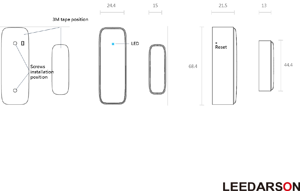
2. Product Appearance
Product main components and function overview.
① Reset: Hold the key for 5s to reset the sensor. After reset, Door/Window Sensor will send
“Device_Reset_Locally” to the main controller and exclude it from the Z-Wave network when the button
is released. This procedure will reset the sensor to factory default.
② LED indicator: If sensor has not been added to controller, the LED will blink for than 5 seconds. Once
the device is joined to the network successfully, the LED will stay on for 3 seconds.

3
3. Specification
Detection Technology
Magnetic switch
Detective Range
20mm
Communication Protocol
Z-Wave
Radio Frequency
908.42MHz (US)
868.42MHz (EU)
921.42MHz (AU)
Wireless Range
More than 100m outdoors
Approximately 30m indoors (depending
on building materials)
Power Source
3V, CR2 *1
Battery Life
2 years
Mounting
Screws or 3M Tape
Operating Temperature
-10°C to 45°C
Operating Humidity
Up to 85% non-condensing
Certifications
CE/FCC, Z-Wave Plus
Dimensions (mm):
68.4.(L)*24.4(W)*21.5(H) for Main Body
44.4(L)*15(W)*13(H) for Magnetic Part
4. Features/Capabilities:
1. The LEEDARSON Door/Window Sensor contains a sensor body and a magnet.
2. The LEEDARSON Door/Window Sensor detects through the separation and combination of the main
body and the magnet.
3. Recommend installation distance between the sensor body and the magnet is 10MM.
4. The Sensor also anti-tamper functionality. Once the sensor is moved, it will notify the gateway.
5. The LEEDARSON Door/Window Sensor is powered by CR2 battery with 2 years battery life.
6. The LEEDARSON Door/Window Sensor is designed to be mounted on the door or windows.
7. The LEEDARSON Door/Window Sensor supports low battery alarm function.
8. The LEEDARSON Door/Window Sensor supports firmware OTA.
4
5. Installation Position and Notes
1. The sensor should be used indoors and away from sources of moisture.
2. The magnet and the main sensor must be less than 2cm apart. Main sensor must be affixed to the
door or window and the magnet must be affixed to the frame. The magnet and the main sensor
must separate when the door or window is opened.
3. The sensor should not be mounted on a metal frame.
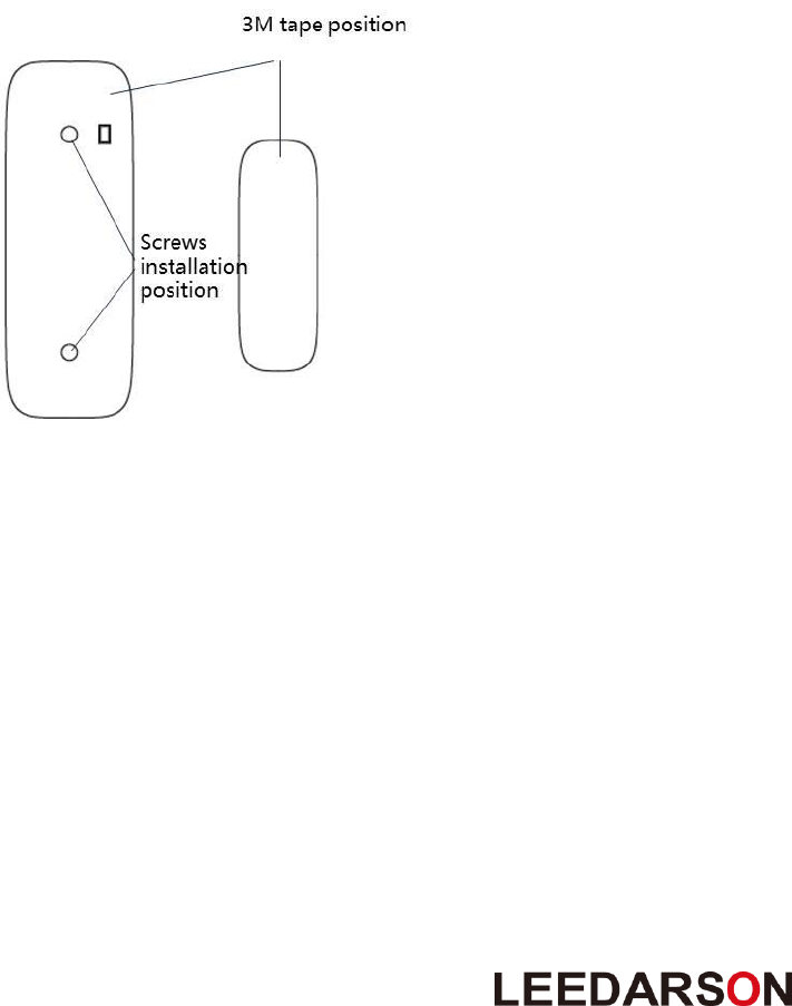
6. Product Installation
This product can be mounted by screws or 3M adhesive tape. Install it according to the diagram below:
① Push the bracket upwards to separate it from the body, then fix the bracket on the door/window by
screw or 3M tape.
② Take off the bracket on the back, install battery into the body. The LED will slowly flash 3 times.
③ Be careful when installing the bracket back onto the body. The best approach is from the side.
④ Stick the magnet onto the moving part of the door/window, no further than 20mm from the sensor.

5
7. Product Usage
7.1 How to add (include) the Door/Window Sensor to a Controller/Gateway
Door/Window Sensor Inclusion Procedure:
Make sure the sensor is powered.
1. Set the Z-Wave network main controller into learning mode.
2. Short press the button one time. (within 1 second)
3. If the inclusion is successful, the LED will blink for less than 5 seconds and then stay on for 3 seconds.
Otherwise, the LED will blink 8 seconds and then turn off, in which case, you will need to repeat the
process from step 2.
7.2 How to exclude a Door/Window Sensor from Controller/Gateway
Door/Window Sensor Exclusion Procedure:
1. Make sure the sensor is powered.
2. Set the Z-Wave network main controller into learning mode.
3. Short press the button one time. (within 1 second)
4. If the exclusion is successful, the LED will blink 3 times. Otherwise, the LED will blink for 3 seconds
and then turn off, in which case, you will need to repeat the process from step 2.
7.3 How to reset a Door / Window Sensor
Reset procedure deletes memory, including all information on the Z-Wave network and the hub.
Contact Sensor’s Reset Procedure:
1. Make sure the sensor is powered.
2. Press and hold the button for 5 seconds.
3. Release the button.
4. Door/Window Sensor will send “Device_Reset_Locally” to the main controller and exclude it from the
Z-Wave network and reset the sensor to the factory default.
Caution:
This device complies with Part 15 of the FCC Rules. Operation is subject to the following two conditions:
(1) this device may not cause harmful interference, and (2) this device must accept any interference
received, including interference that may cause undesired operation.
Changes or modifications not expressly approved by the party responsible for compliance could void the
user's authority to operate the equipment.

6
7.4 Low voltage alarm to remind changing battery.
This product has low voltage detection reminder, When the battery voltage is in low status, the
detector will give out low battery signal to controller.
8. Attention
1. If the sensor needs to be cleaned, remove power and use a soft cloth with a little alcohol and wipe down
the device.
2. This product is just for indoor use only.
3. Replace the battery immediately when the low battery warning is indicated.

7
9. Z-Wave Command
9.1 Z-Wave Plus Device Type
Device Type
Basic Device Attribute
Specific Device Attribute
Role Type
Sensor - Notification
GENERIC_TYPE_SENSO
R_NOTIFICATION
SPECIFIC_TYPE_NOTIFICATI
ON_SENSOR
Reporting Sleeping
Slave
(RSS)
9.2 Command list
Non-security device:
The node info frame supports:
COMMAND_CLASS_ZWAVEPLUS_INFO
V2
COMMAND_CLASS_VERSION
V2
COMMAND_CLASS_MANUFACTURER_SPECIF IC
V2
COMMAND_CLASS_NOTIFICATION
V5
COMMAND_CLASS_ASSOCIATION_GRP_INFO
V1
COMMAND_CLASS_ASSOCIATION
V2
COMMAND_CLASS_BATTERY
V1
COMMAND_CLASS_WAKE_UP
V2
COMMAND_CLASS_POWERLEVEL
V1
COMMAND_CLASS_CONFIGURATION
V1
COMMAND_CLASS_FIRMWARE_UPDATE_MD
V2
COMMAND_CLASS_SECURITY
V1
COMMAND_CLASS_DEVICE_RESET_LOCALLY
V1
Security device
The node info frame supports:
COMMAND_CLASS_ZWAVEPLUS_INFO
V2
COMMAND_CLASS_VERSION
V2
COMMAND_CLASS_MANUFACTURER_SPECIF IC
V2
COMMAND_CLASS_SECURITY
V1
COMMAND_CLASS_DEVICE_RESET_LOCALLY
V1
COMMAND_CLASS_POWERLEVEL
V1
Security Command Supported Report Frame:
COMMAND_CLASS_NOTIFICATION
V5
COMMAND_CLASS_ASSOCIATION_GRP_INFO
V1
COMMAND_CLASS_ASSOCIATION
V2
COMMAND_CLASS_BATTERY
V1
COMMAND_CLASS_WAKE_UP
V2
COMMAND_CLASS_CONFIGURATION
V1
COMMAND_CLASS_FIRMWARE_UPDATE_MD
V2
8
9.3 Command Explain
9.3.1 Z-Wave Plus Info Command Report
Parameter
Value
Z-Wave Plus
Version
V1
Role Type
6(ZWAVEPLUS_INFO_REPORT_ROLE_TYPE_SLAVE_SLEEPING_REPORTING)
Node Type
0 (ZWAVEPLUS_INFO_REPORT_NODE_TYPE_ZWAVEPLUS_NODE)
Installer Icon Type
0x0C06 (ICON_TYPE_SPECIFIC_SENSOR_NOTIFICATION_ACCESS_CONTROL)
User Icon Type
0x0C06 (ICON_TYPE_SPECIFIC_SENSOR_NOTIFICATION_ACCESS_CONTROL)
9.3.2 Association Command
Door/Window Sensor supports only one association group.
Grouping Identifier
Max Nodes
Transmit Content
Group 1
0x05
1. Notification Report.
Sensor will send Notification Report when the
sensor body and magnet removed or
combined.
2. Battery Report.
Sensor will send Battery Report when the
battery level is low and the battery report’s
value is 0xFF.
9.3.3 Association Group Info Command
A) Association Group Name Command Report
Team No.
Value
1 St
The ASSIC of Lifeline: 4C 69 66 65 6C 69 6E 65
B) Association Group Info Command Report
Parameter
Team No.
Value
Profile
1 St
General: Lifeline, Profile MSB=0x00,Profile LSB=0x01
C) Association Group Command List Command Report
Team No.
Command List Support
1 St
COMMAND_CLASS_NOTIFICATION(0x71)
NOTIFICATION_REPORT(0x05)
COMMAND_CLASS_BATTERY(0x80)
BATTERY_REPORT(0x03)
COMMAND_CLASS_DEVICE_RESET_LOCA
LLY(0x5A)
DEVICE_RESET_LOCALLY_NOTIFICATION
(0x01)

9
9.3.4 Wake Up Command
A) Press the study key three times for the Door/Window sensor to send a Wake Up Notification to the
Gateway. Please make sure the Door/Window Sensor is added to the Z-wave network.
B) How to use Wake Up Interval Set Command to set the Door/Window Sensor to automatic Wake Up.
1. When the configured value is set 0~59 then the configuration is not available and the Wake Up
time cannot be changed.
2. If the configured value is 60~119 then the Wake Up Interval time is 60 seconds.
3. If the configured value is 120~179 then the Wake Up Interval time is 120 seconds.
Note: You can set additional configured values for longer Wake Up Interval times.
C) Wake Up Interval Capabilities Report CC
• Minimum Wake Up Interval Seconds = 60 seconds
• Maximum Wake Up Interval Seconds = 2678400 seconds=31 days
• Default Wake Up Interval Seconds = 600 seconds
• Wake Up Interval Step Seconds = 60 seconds
9.3.5 Battery Command
A) If the Controller or Gateway sends the Battery Get command to the Door/Window Sensor then
Door/Window Sensor will report the Battery Power Level to the Controller or Gateway.
• If the Battery Voltage >3.0V the Battery Power Level is 100%.
• If the Battery Voltage<2.3V the Battery Power Level is 0%.
B) If the Battery has a low voltage of 10%, or less, the Configuration 0x0A setting threshold values for the
Door/Window Sensor will report Battery Report 0xFF to Association Group 1.
9.3.6 Notification Commands
A) Notification Supported Report : Access Control (0x06)、Home Security (0x07)
B) Event Supported Report Command
Notification Type
Notification Event
Access Control (0x06)
Window/Door is open (0x16), Window/Door is closed (0x17)
Home Security (0x07)
Tampering, Product covering removed (0x03), Previous Events cleared
(0x00)
9.3.7 Manufacturer Specific Report Commands
Parameter
Value
Manufacturer ID 1
0x03
Manufacturer ID 2
0x00
Product Type ID 1
0x00
Product Type ID 2
0x02
Product ID 1
0x00
Product ID 2
0x08

10
9.3.8 Version Report Commands
Parameter
Value (HEX)
Z-Wave Protocol Library Type
0x03
Z-Wave Protocol Version
0x04
Z-Wave Protocol Sub Version
0x34
Firmware 0 Version
Firmware Version Upper 8 bits
Firmware 0 Sub Version
Firmware Version Lower 8 bits
Hardware Version
0x01
Number of firmware targets
0x00
9.3.9 Basic Commands
There is no relevant commands are available for mapping. Sensor will send “Basic Set” via the lifeline group.
9.3.10 Configuration Command Parameters
Door/Window Sensor offers a wide variety of advanced configuration settings. Below parameters can be
accessed from the main controller’s configuration interface.
Parameter
Number of
Bytes
Default
Value
Function Description
10 (0x0A)
1
10
Low Battery Power Level of alarm
threshold values: the value range
are 10~50 for percentage, so the
Battery Low Power level can
setting 10%~50%.
254 (0xFE)
1
0
Configuration Lock function: when
it was lock then the other
parameters value cannot change
unless this parameter.
0= unlock
1= lock
255*
(0xFF)
4
NA
Value=0x8888888, Default=1,
Size=4
Reset to factory configuration and
removed the Z-wave network.
4
NA
Value=0x88000000, Default=1,
Size=4
Reset Configuration parameter to
default value.
Note: Parameter 0xFF is a set-only parameter.

.
FCC Statement
15.19
1. This device complies with Part 15 of the FCC Rules. Operation is subject to the following two
conditions:
(1) This device may not cause harmful interference.
(2) This device must accept any interference received, including interference that may cause
undesired operation.
15.21
Note: The grantee is not responsible for any changes or modifications not expressly approved by the party responsible for
compliance. Such modifications could void the user’s authority to operate the equipment.
15.105(b)
NOTE: This equipment has been tested and found to comply with the limits for a Class B digital device, pursuant to part 15 of
the FCC Rules. These limits are designed to provide reasonable protection against harmful interference in a residential
installation.
This equipment generates uses and can radiate radio frequency energy and, if not installed and used in accordance with the
instructions, may cause harmful interference to radio communications. However, there is no guarantee that interference will
not occur in a particular installation. If this equipment does cause harmful interference to radio or television reception, which
can be determined by turning the equipment off and on, the user is encouraged to try to correct the interference by one or
more of the following measures:
- Reorient or relocate the receiving antenna.
- Increase the separation between the equipment and receiver.
-Connect the equipment into an outlet on a circuit different from that to which the receiver is connected.
-Consult the dealer or an experienced radio/TV technician for help
IC Statement
This device complies with Industry Canada licence-exempt RSS standard(s). Operation is subject to the following two
conditions: (1) this device may not cause harmful interference, and (2) this device must accept any interference received,
including interference that may cause undesired operation.
Le présent appareil est conforme aux CNR d'Industrie Canada applicables aux appareils radio exempts de licence.
L'exploitation est autorisée aux deux conditions suivantes :
(1) l'appareil ne doit pas produire de brouillage, et
(2) l'utilisateur de l'appareil doit accepter tout brouillage radioélectrique subi, même si le brouillage est susceptible d'en
compromettre le fonctionnement.