Leica Gps1200 Users Manual _GPS12_User
GPS1200 to the manual 01703eb8-7175-4fb9-954e-9c0f91dda59b
2015-02-02
: Leica Leica-Gps1200-Users-Manual-435613 leica-gps1200-users-manual-435613 leica pdf
Open the PDF directly: View PDF ![]() .
.
Page Count: 146 [warning: Documents this large are best viewed by clicking the View PDF Link!]
Leica GPS1200
User Manual
Version 3.0
English

2GPS1200
Introduction
Introduction
Purchase Congratulations on the purchase of a GPS1200 series instrument.
This manual contains important safety directions as well as instructions for setting
up the product and operating it. Refer to "7 Safety Directions" for further information.
Read carefully through the User Manual before you switch on the product.
Product
identification
The type and the serial number of your product are indicated on the type plate.
Enter the type and serial number in your manual and always refer to this information
when you need to contact your agency or Leica Geosystems authorized service
workshop.
Type: _______________
Serial No.: _______________

Introduction GPS1200 3
Symbols The symbols used in this manual have the following meanings:
Trademarks • Windows and Windows CE are a registered trademark of Microsoft Corporation
• CompactFlash and CF are trademarks of SanDisk Corporation
• Bluetooth is a registered trademark of Bluetooth SIG, Inc
All other trademarks are the property of their respective owners.
Type Description
Danger Indicates an imminently hazardous situation which, if not
avoided, will result in death or serious injury.
Warning Indicates a potentially hazardous situation or an unintended
use which, if not avoided, could result in death or serious
injury.
Caution Indicates a potentially hazardous situation or an unintended
use which, if not avoided, may result in minor or moderate
injury and/or appreciable material, financial and environmental
damage.
)Important paragraphs which must be adhered to in practice as
they enable the product to be used in a technically correct and
efficient manner.

4GPS1200
Table of Contents
Table of Contents
In this manual Chapter Page
1 How to Use this Manual 8
2 Description of the System 12
2.1 System Components 12
2.2 System Concept 16
2.2.1 Software Concept 16
2.2.2 Data Storage and Data Conversion Concept 18
2.2.3 Power Concept 20
2.3 Container Contents 22
2.4 Receiver Components 24
3 User Interface 26
3.1 Operating Principles 26
3.2 Icons 33
4 Operation 38
4.1 Equipment Setup 38
4.2 Battery 40
4.3 Working with the CompactFlash Card 43

Table of Contents GPS1200 5
4.4 Working with the Clip-On-Housings for Devices 46
4.5 Accessing Survey Application Program 55
4.6 Guidelines for Correct Results 58
4.7 Operation with a Typical Configuration Set 59
5 Reference Station 64
5.1 Overview 64
5.2 Equipment Setup 67
5.3 Getting Started with the GRX1200 Series 72
6 Care and Transport 80
6.1 Transport 80
6.2 Storage 81
6.3 Cleaning and Drying 82
7 Safety Directions 84
7.1 General Introduction 84
7.2 Intended Use 85
7.3 Limits of Use 87
7.4 Responsibilities 88
7.5 International Warranty, Software Licence Agreement 89
7.6 Hazards of Use 91
7.7 Electromagnetic Compatibility EMC 100
7.8 FCC Statement, Applicable in U.S. 103

6GPS1200
Table of Contents
8 Technical Data 110
8.1 Receiver Technical Data 110
8.1.1 Tracking Characteristics of the Receiver 110
8.1.2 Accuracy 113
8.1.3 Technical Data 115
8.2 Antennas Technical Data 121
8.3 RX1200 Technical Data 126
8.4 Conformity to National Regulations 130
8.4.1 RX1250 130
8.4.2 GFU16, Bluetooth communication 132
8.4.3 GFU17, Siemens MC45 133
8.4.4 GFU19, US CDMA MultiTech MTMMC-C 135
Index 138

Table of Contents GPS1200 7

8GPS1200
How to Use this Manual
1 How to Use this Manual
)It is recommended to set-up the product while reading through this manual.
Path Main Menu: Manage...\Data stands for this working sequence:
From the Main Menu select Manage... and then select Data.
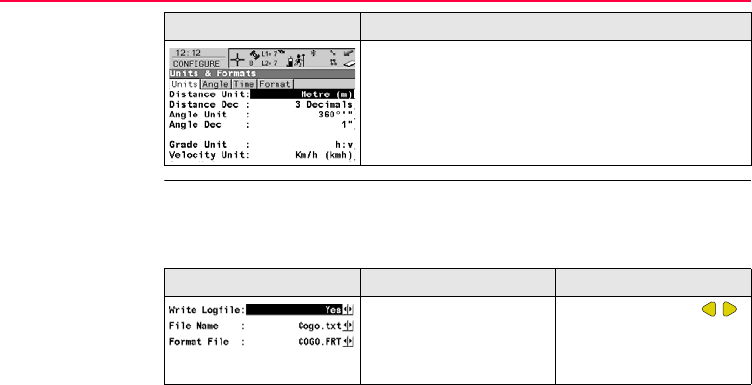
Screen CONFIGURE General Menu describes the name of the screen.
Page Screens can have more than one page. Units page describes a specific page of a
screen. For example: ’...in CONFIGURE Units & Formats, Units page...’.
Fields and options Fields displayed on the screen are described as <Coord System:> or <Coord
System: Swiss>, if ’Swiss’ is the selected coordinate system.
Index The index is at the back of the manual.
)Keys, fields and options on the screens which are considered as self-explanatory are
not explained.
Validity of this
manual
• This manual applies to all GPS1200 instruments. Differences between the
various models are marked and described.

How to Use this Manual GPS1200 9
• The RX1200 is available as RX1210 or with touch screen functionality as
RX1210T, RX1220T or RX1250 X. The names RX1210 and RX1220 are used
throughout the manual and may also represent the touch screen models. Only
use the supplied stylus on the screens of the touch screen models.
Illustrations For the purpose of the illustrations, a GX1230 model has been selected which is
representative for all models.
Available
documentation
General description
Name of
documentation
Description
User Manual All instructions required in order to operate the product to
a basic level are contained in the User Manual. Provides
an overview of the product together with technical data
and safety directions.

10GPS1200
How to Use this Manual
Available documentation depending on use case
Name of
documentation
Description
System Field Manual Describes the general working of the product in standard
use. Intended as a quick reference field guide.
Applications Field
Manual
Describes specific onboard application programs in
standard use. Intended as a quick reference field guide.
The RoadRunner application program is described in a
separate manual.
Technical Reference
Manual
Overall comprehensive guide to the product and program
functions. Included are detailed descriptions of special
software/hardware settings and software/hardware func-
tions intended for technical specialists.
Use case User Manual System Field
Manual
Application
Programs
Field Manual
Technical
Reference
Manual
for for for for
TPS TPS1200 TPS1200 TPS1200 TPS1200

How to Use this Manual GPS1200 11
Format of the
documentation
The GPS1200 CD contains the entire documentation in electronic format. All
manuals are also available in printed form except for the GPS1200 Technical Refer-
ence Manual.
TPS RCS RX1200 TPS1200 TPS1200 TPS1200
GPS GPS1200 GPS1200 GPS1200 GPS1200
GPS
SmartRover
RX1200 GPS1200 GPS1200 GPS1200
Use case User Manual System Field
Manual
Application
Programs
Field Manual
Technical
Reference
Manual
for for for for

12GPS1200
Description of the System
2 Description of the System
2.1 System Components
Main components Component Description
Receiver To calculate a range to all visible satellites.
RX1200 To operate the user interface either by the keyboard or by
the touch screen with supplied stylus.
Antenna To receive the satellite signals from the NAVSTAR satel-
lites.
LEICA Geo Office The office software including a series of help programs
which support working with GPS1200.
LEICA GPS Spider The reference station software required to operate the
reference station receivers of GPS1200.

Description of the System GPS1200 13
Receivers
)The GX1230, GX1220, GX1200 with PPS/Event option and GRX1200 Series
receivers use the GPS P-code signal, which by U.S. policy is liable to be switched
Receiver Description
GX1230 Twelve L1, twelve L2 channels, code and phase, real-time
capable
GX1220 Twelve L1, twelve L2 channels, code and phase
GX1210 Twelve L1 channels, code and phase
GX1200 with
PPS/Event option
Twelve L1, twelve L2 channels, code and phase, real-time
capable, with event and PPS ports
GRX1200 Classic Twelve L1, twelve L2 channels, code and phase, real-time
capable, for reference station applications
GRX1200 Lite Twelve L1, twelve L2 channels, code and phase, real-time
capable, for reference station applications, no ring buffer
logging, no download of internally logged data and upload
of files to receiver by remote control
GRX1200 Pro Twelve L1, twelve L2 channels, code and phase, real-time
capable, with event, PPS, oscillator and NET port, for refer-
ence station applications
14GPS1200
Description of the System
off without notice. Phase measurements on L2 are ensured as these receivers auto-
matically switch to patented tracking techniques.
Antennas used
with receivers
LEICA Geo Office • LGO supports the GPS1200 and TPS1200 instruments. It also supports all other
Leica TPS instruments.
• LGO is based on a graphical user interface with standard Windows® operating
procedures.
• LGO provides the following functionality:
Receiver Antenna
GX1230/GX1220 Typically: AX1202, otherwise: AT504
GX1210 AX1201
GRX1200 Series Typically: AT504, otherwise: AX1202
Functionality Description
Standard Func-
tionality
Includes data exchange between computer and receiver, data
management including viewing and editing, reporting, creation
and management of codelists, creation and use of format files for
data conversion, uploading and deleting of system software and
application programs.

Description of the System GPS1200 15
• Supported operating systems: Windows® XP, Windows® 2000, Windows® ME.
Refer to the online help of LGO for additional information.
LEICA GPS Spider The reference station software is known as LEICA GPS Spider. It is required to
operate the GRX1200 Series receivers.
Use
Operating systems
Refer to the online help of LEICA GPS Spider for additional information.
Extended Func-
tionality
Includes coordinate transformations, GPS post processing, level
data processing, network adjustment, GIS and CAD Export.
Functionality Description
• to connect from a PC to a GPS1200
receiver locally or remotely.
• to automatically convert data to
RINEX format.
• to configure receiver operation. • to automatically archive data files.
• to monitor receiver operation. • to automatically distribute to FTP
locations.
• to automatically download raw data.
• Windows® XP • Windows® 2000

16GPS1200
Description of the System
2.2 System Concept
2.2.1 Software Concept
Description All receivers use the same software concept.
Software type Software type Description
System
software
This important software covers the basic functions of the instru-
ment. System software is also referred to as firmware.
The programs Survey and Setup are integrated into the firmware
and cannot be deleted.
The English language is integrated into the firmware and cannot
be deleted.
Language
software
Numerous languages are available for the receivers. Language
software is also referred to as system language.
The system software enables a maximum of three languages
which can be stored at any one time - the English language and
two other languages. The English language is the default
language and cannot be deleted. One language is chosen as the
active language.

Description of the System GPS1200 17
Software upload All instrument software is stored in the System RAM of the receiver. The software
can be uploaded onto the receiver using the following methods:
• Using LGO the software is transferred via the serial interface to the Compact-
Flash card in the receiver, which is then stored to the System RAM.
• By connecting the CompactFlash card directly to the computer either via an
internal card slot housing or an external OMNI drive, the software is trans-
ferred to the card, which is then stored to the System RAM.
Application
programs
A suite of optional survey-specific application programs are
available for the instrument.
Some of these programs are freely available and can be loaded
and are immediately activated. The other programs must be
purchased and are only activated with a licence key.
Customised
application
programs
Custom software specific to user requirements can be developed
using the GeoC++ development kit.
Information on the GeoC++ development environment is avail-
able on request from a Leica Geosystems representative.
RX1200
software
For RX1210 and RX1220T. This software covers display, sound
and communication settings of the RX1210 and RX1220T.
Software type Description

18GPS1200
Description of the System
2.2.2 Data Storage and Data Conversion Concept
Description Data is stored within a job in a database on a memory device. This is either a
CompactFlash card or an internal memory.
Memory device
)Unplugging connecting cables or removing the CompactFlash card during the meas-
urement may cause loss of data. Always return to GPS1200 Main Menu before
removing the CompactFlash card and switch off the instrument before removing
cables.
CompactFlash card: A CompactFlash card slot is standard. A CompactFlash
card can be inserted and removed. Various capacities are
available.
)Whilst other CompactFlash cards may be used,
Leica recommends to only use Leica Compact-
Flash cards and is not responsible for data loss
or any other error that may occur whilst using a
non-Leica card.
Internal memory: An internal memory is optional. It resides inside the
receiver. Available capacity: 32 MB and 256 MB

Description of the System GPS1200 19
)For GRX1200 Series receivers:
While in remote operation mode, stop point occupation and ring buffer logging before
removing the CompactFlash card.
Data conversion Export
Data can be exported from a job in a wide range of ASCII formats. The export format
is defined in Format Manager which is a PC tool in LEICA Geo Office. Refer to the
online help of LGO for information on creating format files.
Import
Data can be imported from ASCII, GSI8 or GSI16 format.
Transfer raw data
to LGO
Raw data can be transferred between the database on the CompactFlash card or
the internal memory of the receiver and LGO in two ways:
• From the CompactFlash card or the internal memory directly through a serial
interface to a project in LGO on a PC.
• From the CompactFlash card using for example an OMNI drive as supplied by
Leica Geosystems to a project in LGO on a PC.
)CompactFlash cards can directly be used in an OMNI drive as supplied by Leica
Geosystems. Other PC card drives may require an adaptor.

20GPS1200
Description of the System
2.2.3 Power Concept
General Use the Leica Geosystems batteries, chargers and accessories or accessories
recommended by Leica Geosystems to ensure the correct functionality of the instru-
ment.
Power options Receiver
Power for the receiver can be supplied either internally or externally. Up to two
external power supplies can be connected using a Y-cable. For the GRX1200 Series
one of the two external power supplies can be configured to be the primary which is
always used when available.
Internal power supply: Two GEB221 batteries fit into the receiver.
External power supply: GEB171 battery connected via a cable.
OR
Car battery connected via a converter cable supplied by
Leica Geosystems.
OR
10.5-28 V DC power supply via a converter cable
supplied by Leica Geosystems.
OR
110/240 V AC to 12 V DC power supply unit, supplied
by Leica Geosystems.

Description of the System GPS1200 21
)For permanent operations use Uninterruptible Power Supply units as a back-up in
case of a main power failure.
22GPS1200
Description of the System
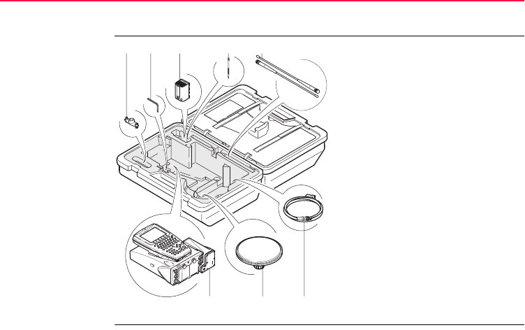
2.3 Container Contents
Container for
GX1200 receivers
and delivered
accessories
part 1 of 2
a) Double arm for antennas of
devices
b) Adjusting pin
c) Spare battery
d) Supplied stylus
e) Antennas of device
f) GX1200 with RX1210 and
device such as radio
g) Antenna
h) Cables
GPS12_135
a b
fgh
cde
Description of the System GPS1200 23
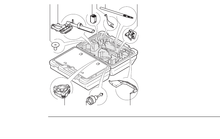
Container for
GX1200 receivers
and delivered
accessories
part 2 of 2
a) Base for telescopic rod
b) Holder for RX1210 on pole
with grip for pole
c) Spare battery
d) Arm 15 cm long for antenna of
device
e) Telescopic rod
f) Holder for GX1200 on pole
g) Tribrach
h) Carrier
i) Height hook
GPS12_136
ab c
def
gh i
24GPS1200
Description of the System
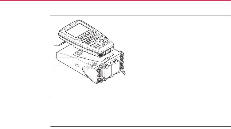
2.4 Receiver Components
Receiver compo-
nents
ON/OFF button The receiver can be preprogrammed in the office and used in the field without the
RX1200 attached. In this case, the receiver is turned on by holding down the
ON/OFF button for 2 s or off by holding down the ON/OFF button for 4 s. A green
steady light at the power LED indicates that the receiver is turned on.
a) RX1200
b) Supplied stylus
c) Clip-on-contacts for connecting
RX1200 without cable
d) Recess for RX1200
e) Guide rail for clip-on-housing of a
device
f) ON/OFF button
g) LED indicators
h) Battery compartment 2 or port NET
i) Battery compartment 1
j) CompactFlash card compartment
GPS12_134
a
g
h
i
j
b
c
d
e
f

Description of the System GPS1200 25

26GPS1200
User Interface
3 User Interface
3.1 Operating Principles
Keyboard and
touch screen
The user interface is operated either by the keyboard or by the touch screen with
supplied stylus. The workflow is the same for keyboard and touch screen. The differ-
ence is the way information is selected and entered.
Turn instrument on Press PROG.
Turn instrument off The instrument can only be turned off in the GPS1200 Main Menu screen.
Press both USER and PROG simultaneously.
OR
Hold ESC for 2 s.
Lock/Unlock
keyboard Option Description
Lock To lock the keyboard press and hold SHIFT for 3 s. The message
’Keyboard locked’ is momentariliy displayed on the Message Line.
User Interface GPS1200 27
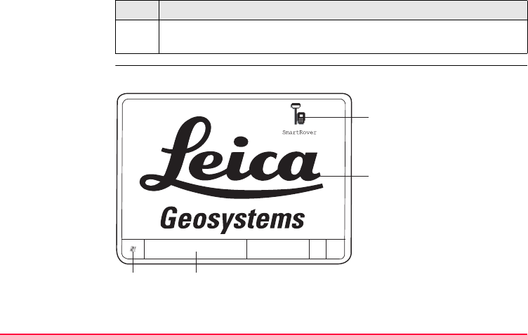
Switching between
Leica software and
Windows CE
desktop
This is valid for RX1250.
Unlock To unlock the keyboard press and hold SHIFT for 3 s. The message
’Keyboard unlocked’ is momentariliy displayed on the Message Line.
Option Description
a) Icon to start Leica
software
b) Windows CE desktop
c) Task bar
d) Start button
RX12_33
a
b
dc
28GPS1200
User Interface
Access Leica software
Access Windows CE desktop
IF THEN
RX1250 is started the Leica software comes up automatically.
Windows CE
desktop is active
double click to display the Leica software.
OR
SHIFT PROG ( ) to display the Leica software.
Leica software is
minimised
double click to maximise it.
OR
select SmartRover in the task bar to maximise it.
IF THEN
Leica software is to
be minimised
SHIFT MINIM (F5) in Main Menu.
Leica software is to
be closed
SHIFT EXIT (F6) in Main Menu.
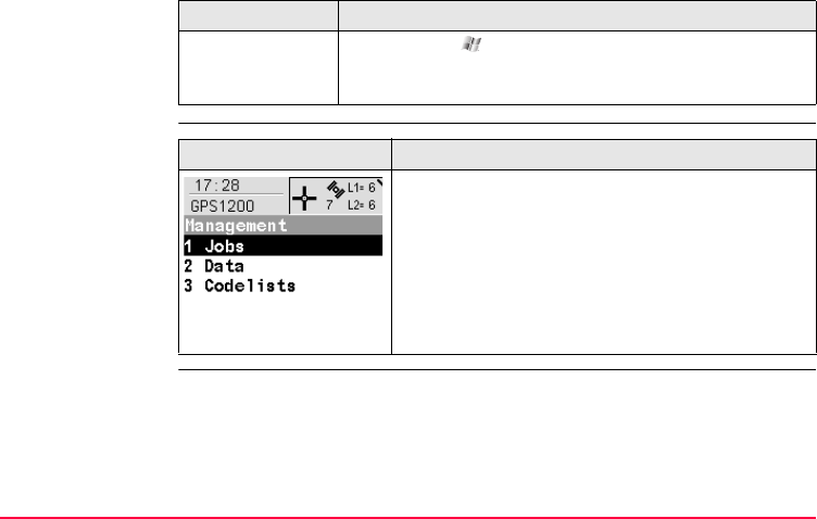
User Interface GPS1200 29
Selecting from a
menu
.
Windows CE task
bar is to be
displayed
SHIFT PROG ().
IF THEN
Appearance Description
To select an item from a menu, do one of the following:
Move the focus to the item. ENTER or CONT (F1)
OR
Type the complete selection number in front of the
item. ENTER or CONT (F1) are not required.
OR
Tap on the item.
30GPS1200
User Interface
Selecting a page
Appearance and
selection from a
choicelist
Choicelists have various appearances.
Closed choicelist
.
ENTER or tap on the field to access the choicelist. Opening a choicelist reveals
either a simple listbox or a comprehensive listbox dialogue.
Appearance Description
To select a page in a screen, do one of the following:
PAGE (F6).
OR
Tap on the page tab.
Appearance Description Selection
Triangles on the right indi-
cate further available
choices.
Use the arrow keys
to toggle through the list or
tap the triangles on the
screen.

User Interface GPS1200 31
Simple listbox
.
Appearance Description Selection
• Choicelist shows
items to select.
• A search field is
shown if necessary
• A scroll bar is shown if
necessary.
• Highlight an item and
ENTER.
• To exit without
changes ESC or tap
outside the simple
listbox.
32GPS1200
User Interface
Listbox dialogue
.Appearance Description Selection
• Choicelist fills the
whole screen.
• A search field is
shown.
• A scroll bar is shown if
necessary.
• The functionality
comprises adding,
editing and deleting of
items.
• Highlight an item and
CONT (F1) or ENTER.
• To exit without
changes press ESC or
tap .
• Listbox dialogues are
explained in detail at
appropriate places in
the manuals.
User Interface GPS1200 33
3.2 Icons
Description Icons show the current status information of the receiver.
)The icons provide information related to basic receiver functions. The icons that
appear depend upon which GPS1200 receiver is used and the current receiver
configuration.
Position of the
icons on the screen
a) Position status
b) Number of visible satellites
c) Contributing satellites
d) Real-time device and real-time
status, Internet online status
e) Position mode
f) Bluetooth
g) Line/area
h) CompactFlash card/internal memory
i) Battery
j) SHIFT
k) Quick coding
j
a
GPS12_130
bc d ef ghi
k

34GPS1200
User Interface
Icons Icon Description
Position status Displays the status of the current position. As soon as this
icon becomes visible the receiver is in a stage where practical
operation can commence.
Number of visible
satellites
Displays the number of theoretically visible satellites above
the configured cut off angle according to the current almanac.
Contributing
satellites
Displays the number of satellites on L1 and L2 that are
contributing to the currently computed position solution.
)The number of contributing satellites can differ from
the number of visible satellites. This may be either
because satellites cannot be viewed or the observa-
tions to these satellites are considered to be too
noisy to be used in the position solution.
Real-time device
and real-time
status
Displays the real-time device configured to be used and its
status.
Internet online
status
Receiver is online in the Internet.
Position mode Displays the current position mode depending on the config-
uration defined.

User Interface GPS1200 35
Symbols are added to the basic position mode icon when raw
data logging or logging of auto points is configured.
Bluetooth The status of each Bluetooth port and any Bluetooth connec-
tion is displayed.
Line/area The number of lines and areas currently open in the active job
is displayed.
CompactFlash
card/internal
memory
The status of the CompactFlash card and internal memory are
displayed.
• For the CompactFlash card, the capacity of used space is
shown in seven levels.
• For the internal memory, the capacity of used memory is
shown in nine levels.
Battery The status and source of the battery is displayed. The
remaining power in the battery is indicated by six levels.
For GPS1200 receivers:
• If two internal batteries are inserted, the battery with the
lower voltage is used.
Icon Description

36GPS1200
User Interface
• If an external power supply is connected and one or two
internal batteries are inserted, then the external power is
used.
• If two external power supplies are attached, then the
system uses the one which is configured as the preferred
power supply.
For RX1250:
• If an external power supply is connected and one internal
battery is inserted, then the external power is used.
SHIFT The status of the SHIFT key is displayed.
Quick coding Shows the quick coding configuration. Can be used with touch
screen to turn quick coding on and off.
Icon Description

User Interface GPS1200 37

38GPS1200
Operation
4 Operation
4.1 Equipment Setup
)The example given is for static operations.
Equipment setup
step-by-step Step Description
1. Set up the tripod.
2. Mount and level the tribrach on the tripod.
3. Ensure that the tribrach is over the marker.
4. Place and lock the carrier in the tribrach.
5. Screw the GPS antenna onto the carrier.
6. Check that the tribrach is still level.
7. Insert the batteries into the receiver.
)Alternatively or in addition, to power the receiver externally, connect a
GEB171 battery to the port PWR on the receiver.
8. If no internal memory is fitted, insert a CompactFlash card into the
receiver.

Operation GPS1200 39
)A memory device must be available otherwise a survey cannot be carried
out.
)Close the lid carefully after insertion of the CompactFlash card in order to
prevent water and dust from getting inside the receiver.
9. Attach the RX1200 to the receiver, if required, either directly or via a
connection cable by plugging it into the port RX on the receiver.
10. Connect the receiver to the GPS antenna using the antenna cable and
port ANT on the receiver.
11. To hang the receiver on the tripod leg, use the hook on the rear of the unit.
)Alternatively place the receiver in the transport container.
12. Insert the height hook into the carrier.
13. Measure the antenna height using the height hook.
14. Press the ON/OFF button on the receiver for at least 2 s or PROG on the
RX1200 to switch the receiver on.
15. The receiver is now ready for operation.
Step Description

40GPS1200
Operation
4.2 Battery
)Primary use/charging
• The battery must be charged prior to using it for the first time because it is deliv-
ered with an energy content as low as possible.
• For new batteries or batteries that have been stored for a long time (> three
months), it is effectual to make only one charge/discharge cycle.
• For Li-Ion batteries, a single discharging and charging cycle is sufficient. We
recommend carrying out the process when the battery capacity indicated on the
charger or on a Leica Geosystems product deviates significantly from the actual
battery capacity available.
• The permissible temperature range for charging is between 0°C to +40°C/ +32°F
to +104°F. For optimal charging we recommend charging the batteries at a low
ambient temperature of +10°C to +20°C/+50°F to +68°F if possible.
• It is normal for the battery to become warm during charging. Using the chargers
recommended by Leica Geosystems, it is not possible to charge the battery if
the temperature is too high.
Operation/Discharging
• The batteries can be operated from -20°C to +55°C/-4°F to +131°F.
Operation GPS1200 41
• Low operating temperatures reduce the capacity that can be drawn; very high
operating temperatures reduce the service life of the battery.
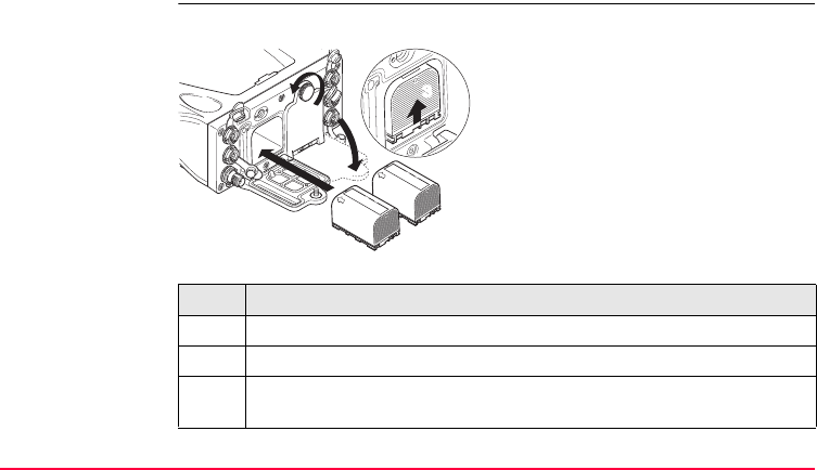
Change battery
step-by-step
The batteries are inserted in the front of the receiver.
Step Description
1. Loosen the screw of one of the battery compartments.
2. Open the cover of the battery compartment.
3. With the Leica logo facing upwards, slide the battery into the battery
compartment and push upwards so that it locks into position.
GPS12_085
1
2
3
3

42GPS1200
Operation
4. Close the cover of the battery compartment and tighten the screw.
5. Repeat steps 2. to 4. for the second battery compartment.
6. To remove a battery, loosen the screw to open the cover of the battery
compartment.
7. Push the battery slightly in and at the same time downwards. This releases
the battery from its fixed position.
8. Pull out the battery.
9. Close the cover of the battery compartment and tighten the screw.
10. Repeat steps 6. to 9. for the second battery compartment.
Step Description
Operation GPS1200 43
4.3 Working with the CompactFlash Card
)• Keep the card dry.
• Use it only within the specified temperature range.
• Do not bend the card.
• Protect the card from direct impacts.
)Failure to follow these instructions could result in data loss and/or permanent
damage to the card.
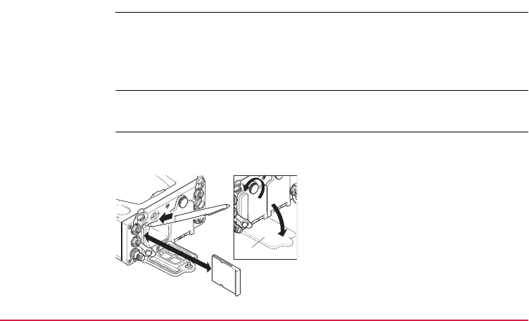
Insert and remove
a CompactFlash
card step-by-step
The CompactFlash card is inserted into a slot inside of battery compartment A on the
front of the receiver.
A Battery compartment A
GPS12_086
1
2
47
8A

44GPS1200
Operation
Format a Compact-
Flash card step-by-
step
Formatting the CompactFlash card before logging data is started is required if a
completely new CompactFlash card is used or if all existing data needs to be
deleted.
Step Description
1. Loosen the screw of the battery compartment A.
2. Open the cover of battery compartment A.
3. The card should be held with the lable for the care instructions towards the
right-hand side of the receiver.
4. Slide the card firmly into the slot until it clicks into position.
5. Close the compartment cover.
6. To remove the card, open the cover of battery compartment A.
7. Press the eject button above the card slot.
8. Pull out the CompactFlash card.
9. Close the compartment cover.
Step Description
1. Select Main Menu: Tools...\Format Memory Device.

Operation GPS1200 45
2. TOOLS Format Memory Device
<Memory Device: CF Card>
<Format Method: Format Quick>
Select the memory device to be formatted.
)By activating the format command all data will be lost. Make sure that all
important data on the CompactFlash card has been backed up before
formatting the card. Before formatting the internal memory make sure that
all important data is first transferred to the PC.
)To exit the screen without formatting the memory device, press ESC. This
returns to the previous screen.
3. CONT (F1)
4. YES (F4) to continue with the formatting of the selected device.
)NO (F6) to not continue with the formatting of the selected device and to
return to TOOLS Format Memory Device.
5. Once the formatting of the card is completed the system returns to
GPS1200 Main Menu.
Step Description

46GPS1200
Operation
4.4 Working with the Clip-On-Housings for Devices
Devices fitting into
a clip-on-housing
Digital cellular phones fitting into a clip-on-housing
Radios fitting into a clip-on-housing
Attach a clip-on-
housing step-by-
step
The clip-on-housing for devices fits on either of the small sides of the receiver.
Digital cellular phone Clip-on-housing
Siemens MC45 GFU17
US CDMA MultiTech MTMMC-C GFU19
Radio Clip-on-housing
Pacific Crest PDL, receive GFU15
Satelline 3AS, transceive GFU14
Step Description
1. Place the clip-on-housing into position such that the guide rails for the clip-
on-housing on the receiver and the guide rails on the clip-on-housing are
aligned.

Operation GPS1200 47
Detach a clip-on-
housing step-by-
step
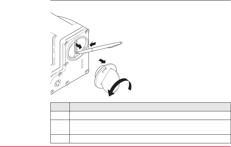
Insert a SIM card
step-by-step
For those digital cellular phones that require SIM cards.
2. Ensure that the connector on the clip-on-housing fits to port P1 or port P3
on the receiver front panel.
3. Slide the clip-on-housing towards the receiver front panel until the
connector is completely plugged into port P1 or port P3.
4. On the top side of the clip-on-housing, turn the screw clockwise, as shown
by the symbols on the screw, to lock the clip-on-housing to the receiver.
Step Description
Step Description
1. On the top side of the clip-on-housing, turn the screw anticlockwise, as
shown by the symbols on the screw, to unlock the clip-on-housing from the
receiver.
2. Slide the clip-on-housing away from the receiver front panel until the
connector is completely unplugged from port P1 or port P3.
Step Description
1. Take the SIM card, a coin and a pen.

48GPS1200
Operation
2. Locate the SIM card screw, that covers the SIM card slot, on the bottom
of the clip-on-housing.
3. Insert the coin into the groove of the SIM card screw.
4. Turn the coin anticlockwise to loosen the SIM card screw.
5. Remove the SIM card screw from the housing.
6. Using the pen, press the small button of the SIM card slot to eject the SIM
card holder.
7. Take the SIM card holder out off the housing.
8. Put the SIM card into the SIM card holder, the chip facing up.
9. Insert the SIM card holder into the SIM card slot, the chip facing the
connectors inside the slot.
10. Place the SIM card screw back on the housing.
11. Insert the coin into the groove of the SIM card screw.
12. Turn the coin clockwise to tighten the SIM card screw.
Step Description
Operation GPS1200 49
Remove a SIM card
step-by-step
For those digital cellular phones that require SIM cards.
Step Description
1. Take a coin and a pen.
2. Locate the SIM card screw, that covers the SIM card slot, on the bottom
of the clip-on-housing.
3. Insert the coin into the groove of the SIM card screw.
GPS12_088
4
5
6
7

50GPS1200
Operation
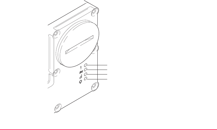
LED indicators Description
Each clip-on-housing for a radio, digital cellular phones or bluetooth communication
has Light Emitting Diode indicators on the bottom side. They indicate the basic
device status.
4. Turn the coin anticlockwise to loosen the SIM card screw.
5. Remove the SIM card screw from the housing.
6. Using the pen, press the small button of the SIM card slot to eject the SIM
card holder.
7. Take the SIM card holder out off the SIM card slot.
8. Take the SIM card out of the SIM card holder.
9. Put the SIM card holder back into the SIM card slot, the even side not
facing the contacts inside the slot.
10. Place the SIM card screw back on the housing.
11. Turn the coin clockwise to tighten the SIM card screw.
Step Description
Operation GPS1200 51
Diagram
a) Warning LED, available for Satelline
3AS
b) Data transfer LED
c) Signal strength LED or Status LED
for Bluetooth communication
d) Power LED
a
b
c
d
GPS12_089

52GPS1200
Operation
Description of the LED’s
IF the on is THEN
Warning
LED
GFU14 with
Satelline 3AS
red the device is in the configuration
mode controlled from the PC via
cable.
Data
transfer
LED
any device off data is not being transferred.
green or flashing
green
data is being transferred.

Operation GPS1200 53
Signal
strength
LED
GFU19 with
US CDMA
MultiTech
MTMMC-C
red device is on, not registered on
the network.
flashing red device is on, registered on the
network.
off download mode or device is off.
GFU17 with
Siemens MC45
red call is in progress.
red: long flash,
short break
no SIM card inserted, no PIN
entered or network search, user
authentication or network login in
progress.
red: short flash,
long break
logged onto network, no call in
progress.
off device is off.
IF the on is THEN

54GPS1200
Operation
GFU15 with
Pacific Crest
PDL
red or flashing red the communication link, Data
Carrier Detection, is okay on the
roving receiver.
off the DCD is not okay.
GFU14 with
Satelline 3AS
red or flashing red the communication link, Data
Carrier Detection, is okay on the
roving receiver.
off the DCD is not okay.
Status
LED
Bluetooth
communication
green bluetooth is in stand-by mode.
orange bluetooth is in configuration
mode.
purple bluetooth is connecting.
blue bluetooth has connected.
Power
LED
any device off power is off.
green power is okay.
IF the on is THEN
Operation GPS1200 55
4.5 Accessing Survey Application Program
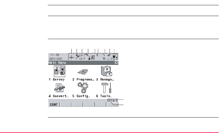
Access Select Main Menu: Survey.
OR
Press PROG. Highlight Survey. CONT (F1).
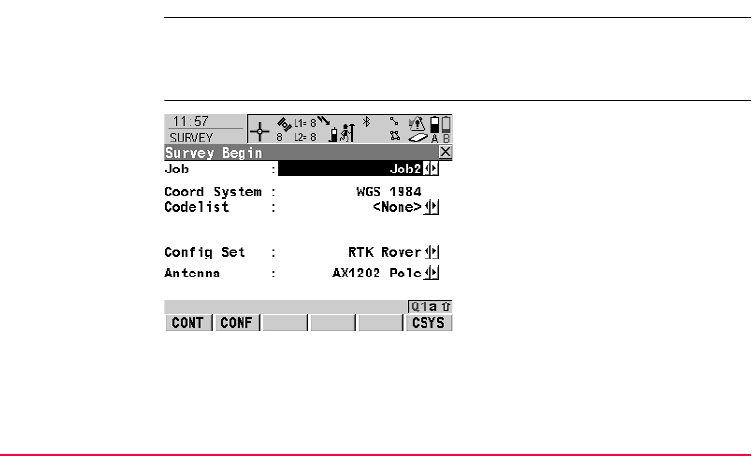
SURVEY
Survey Begin
CONT (F1)
To accept changes and access the
subsequent screen. The chosen
settings become active.
CONF (F2)
Available for <R-Time Mode: None>
and <R-Time Mode: Rover>. To
configure auto points and hidden
point measurements.
CSYS (F6)
To select a different coordinate
system.

56GPS1200
Operation
Description of fields
Field Option Description
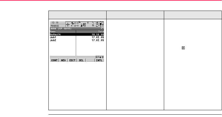
<Job:> Choicelist The active job. All jobs from Main Menu:
Manage...\Jobs can be selected.
<Coord
System:>
Output The coordinate system currently attached to the
selected <Job:>.
<Codelist:> Choicelist No codes are stored in the selected <Job:>. All
codelists from Main Menu:
Manage...\Codelists can be selected.
Output Codes have already been stored in the selected
<Job:>. If codes had been copied from a
System RAM codelist, then the name of the
codelist is displayed. If codes have not been
copied from a System RAM codelist but typed in
manually, then the name of the active job is
displayed.
<Config
Set:>
Choicelist The active configuration set. All configuration
sets from Main Menu: Manage...\Configura-
tion Sets can be selected.

Operation GPS1200 57
Next step
CONT (F1) accepts the changes and accesses, depending on the selected <Config
Set:>, SURVEY Survey: Job Name or SURVEY Survey Set Up Reference
Station. Measurements can be performed with OCUPY (F1), STOP (F1) and
STORE (F1).
The receiver has numerous user configurable
parameters and functions. This allows a variety
of preferences to be addressed. The configura-
tion of the parameters and functions for an indi-
vidual measuring technique are combined in a
configuration set.
<Antenna:> Choicelist The antenna currently defined to be used in the
selected configuration set. All antennas from
Main Menu: Manage...\Antennas can be
selected.
Field Option Description

58GPS1200
Operation
4.6 Guidelines for Correct Results
Undisturbed satel-
lite signal recep-
tion
Successful GPS surveys require undisturbed satellite signal reception, especially at
the receiver which serves as a reference. Set up the receivers in locations which are
free of obstructions such as trees, buildings or mountains.
Steady antenna for
static surveys
For static surveys, the antenna must be kept perfectly steady throughout the whole
occupation of a point. Put the antenna on a tripod or pillar.
Centred and
levelled antenna
Centre and level the antenna precisely over the marker.

Operation GPS1200 59
4.7 Operation with a Typical Configuration Set
)The example given is for static operations.
Static operations
step-by-step Step Description
1. Set up the equipment.
)Always fill out a field record sheet for each point.
)It is vital that the antenna height is measured correctly. Measure the height
at the beginning and at the end of the occupation.
2. Start the Survey application program.
3. SURVEY Survey Begin
<Job: Default>
<Coord System: WGS 1984>
<Codelist: <None>>
<Config Set:> Select a configuration set for static operations.
<Antenna: AX1202>
4. CONT (F1)

60GPS1200
Operation
5. SURVEY Survey: Job Name
Type in the point ID and the antenna height.
)The position mode icon is the moving icon. This indicates that the antenna
can be moved around and that no static observations are being recorded.
6. OCUPY (F1) starts logging of static observations.
)The position mode icon changes to the static icon indicating that the
receiver should remain stationary. For a static survey, the GPS antenna
has to be kept totally still.
7. If required, check information, for example on the satellites, the memory
or the battery.
)SHIFT QUIT (F6) always terminates the survey operation, even during a
site occupation. In this case all data collected since pressing OCUPY (F1)
is lost.
8. STOP (F1) when enough data is collected.
9. STORE (F1) to store the point information.
10. Check that the tribrach is still level and note it down in the field record
sheet.
Step Description

Operation GPS1200 61
11. Measure the antenna height and note it down in the field record sheet.
)If the tribrach is not level or the antenna height has changed, the collected
data is not reliable.
12. SHIFT QUIT (F6) to return to from where SURVEY Survey: Job Name
was accessed.
13. ESC until in GPS1200 Main Menu.
14. GPS1200 Main Menu
PROG plus USER to turn off the receiver.
15. Take down the equipment and put it back into the transport container.
16. Are more points to be surveyed?
•If yes, continue with step 17.
•If no, continue with step 19.
17. Move to the next point.
18. Repeat steps 1. to 16.
19. Post-process the data in the office.
Step Description

62GPS1200
Operation
)The antenna must not be moved while data is logged, otherwise the quality of post-
processed coordinates is impaired.
)The CompactFlash card must be removed in GPS1200 Main Menu. If the card is
removed when in any other screen all stored data might get corrupted, preventing
LGO from successfully reading the data on the card.

Operation GPS1200 63

64GPS1200
Reference Station
5 Reference Station
5.1 Overview
Description The GRX1200 Series
• are designed to operate for specific reference station applications using remote
control software, for example LEICA GPS Spider reference station software.
• support internal logging of raw observations which can be downloaded using an
external remote control software package such as LEICA GPS Spider.
• support streaming output of GPS raw observations and status information.
• can log or stream out data from specific external devices approved by Leica
Geosystems, such as meteo and tilt, which can be directly output to an external
remote control software package.
• can be used - with a suitable radio, digital cellular phone or modem attached - to
transmit data for real-time operations using proprietary as well as standard
RTCM, CMR and CMR+ formats. The GRX1200 Series cannot receive refer-
ence station broadcasts and therefore cannot be used as a real-time rover
receiver.

Reference Station GPS1200 65
• operate in the same manner as the other GPS1200 receivers.
• have the same receiver and measurement performance as the other GPS1200
receivers. Refer to "8 Technical Data" for information on technical data.
Special features To operate for specific reference station applications, the GRX1200 Series is,
compared with the other GPS1200 receivers, equipped with some special features.
Specific to the GRX1200 Series: • Controllable dual external power
supply
• Support of external devices such as
meteo and tilt
Additional features for GRX1200 Classic
and GRX1200 Pro:
• Ring buffer logging
Additional features for GRX1200 Pro: • One Ethernet port including three
logical NET ports
• One port to output PPS
• One port to input event messages
• One port for input from an external
oscillator

66GPS1200
Reference Station
Data storage All CompactFlash cards recommended by Leica Geosystems are supported. Storing
data on a CompactFlash card enables subsequent data download and post-
processing. Refer to "2.2.2 Data Storage and Data Conversion Concept" for infor-
mation on available memory. Refer to "4.3 Working with the CompactFlash Card" for
information on inserting and removing a CompactFlash card.
Data streaming The receiver can be set to stream the raw observations out of one or more commu-
nication ports instead of or in addition to storing data on the CompactFlash card.
Power supply Refer to "2.2.3 Power Concept".
Commands for
remote control
Special commands from Outside World Interface or Leica Binary 2 format can be
used to control the receiver through the configured port. Documentation for OWI and
LB2 is available on request from the Leica Geosystems representative.

Reference Station GPS1200 67
5.2 Equipment Setup
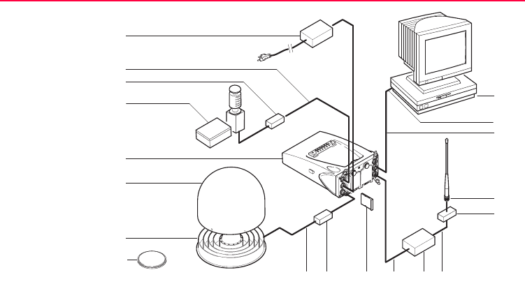
Equipment setup An example for an equipment setup for a reference station is shown in the following
diagram. It is a basic serial setup with LEICA GPS Spider, including a meteo/tilt
device and a local radio to broadcast real-time data.
68GPS1200
Reference Station
i j k l m n
a
o
q
p
r
s
b
c
d
e
f
g
h
GPS12_027

Reference Station GPS1200 69
)Normally, the data transfer cable GX RX to RS232 is used to connect the GRX1200
Series to a PC. Connect the cable to port 2 on the receiver and to the COM port on
the PC.
a) Power supply unit 100/240 V AC to
12 V DC
k) CompactFlash card
b) Interface cable l) Radio interface cable
c) DB9 surge arrester with 12 V DC
pass through
m) Radio
d) Meteo/tilt device with interface cable n) Cable to connect radio antenna
e) Receiver GRX1200 Series o) PC with, for example, LEICA GPS
Spider
f) Weather protection radome for
AT504
p) Serial port
g) AT504 q) Data transfer cable for receiver
communication
h) AX1202 r) Radio antenna
i) TNC to TNC antenna cable s) Radio surge arrester
j) Surge arrester

70GPS1200
Reference Station
)Connect the device to transmit real-time data to port P1, P2 or P3 of the receiver.
Some devices fit into a clip-on-housing that plugs directly into these ports. Other
devices require an interface cable.
)Unauthorised radio units should not be connected to the GRX1200 Series.
Cable connection Cable connections are identical to other GPS1200 receivers. Additional cables are
available from Leica Geosystems for the specific oscillator and Ethernet ports on the
GRX1200 Pro.
Switch on Hold down the ON/OFF button on the receiver for at least 2 s.
OR
Press PROG on the RX1200, if used.
OR
Send a pulse/data to one of the serial ports. Port P1, P2 and P3 can be config-
ured not to allow receiver switch on upon pulse reception.
Switch off Press the ON/OFF button on the receiver for at least 4 s.
OR
Press PROG and USER simultaneously on the RX1200, if used.

Reference Station GPS1200 71
Behaviour when
turning off and on
Turning the GRX1200 Series off and on again resets the receiver. The conse-
quences are:
• If the configuration of the output is stored in the configuration set, standard
NMEA messages are still output.
• All data/message outputs scheduled via OWI or LB 2 commands are no longer
output.
• Data logging parameters and interface configuration options, that have been set
by OWI or LB 2 commands and have not been saved to a configuration set using
the corresponding OWI or LB 2 command, are reset.
Behaviour after
power failure
After temporary power failure, the GRX1200 Series will automatically power itself up
and resume the previously set operations. Two power fail recovery options are avail-
able - Sudden Loss Only and Always. To access the configuration select Main
Menu: Config...\General Settings...\Start Up & Power Down.

72GPS1200
Reference Station
5.3 Getting Started with the GRX1200 Series
Ways of operating The GRX1200 Series can either be operated with the RX1200 like the other
GPS1200 receivers or by remote control.
Operation Description
With RX1200 The receiver can be fully configured. In order to start and stop
a point occupation, an external application software such as
LEICA GPS Spider must send appropriate OWI or LB2
commands through a remote interface port to the receiver.
Available with full functionality
• Job management
• Data management
• Configuration of ports
• Configuration of operation parameters
• Status information
• Transfer capabilities including the upload of new
firmware
Unavailable

Reference Station GPS1200 73
Any application program available on GPS1200 such as
Survey or Stakeout
)Refer to the relevant chapters in this manual or to
the GPS1200 Technical Reference Manual for infor-
mation on configuring and using the receiver.
By remote control • Special commands from OWI or LB2 can be used to
control the GRX1200 Series through a remote interface.
• For the majority of applications, the GRX1200 Series has
to be operated using a suitable application software that
supports the OWI or LB 2 commands, such as LEICA
GPS Spider.
• For the GRX1200 Classic/GRX1200 Pro, remote control
also supports the download of internally logged data and
upload of files to the receiver.
Operation Description

74GPS1200
Reference Station
Configure a remote
interface connec-
tion
Remote interface to be configured Configure using
Standard default RS232 • Each port is by default a remote port.
No specific receiver configurations
must be done.
• The default settings allow immediate
communication using the following
port communication parameters:
Baud rate: 115200
Data bits: 8
Parity: None
Stop bit: 1
Flow control: None
Specific devices such as modems for a
particular port
Must be configured using the RX1200.
Refer to "Configure a modem interface
step-by-step" for an example.
GRX1200 Pro built-in ethernet device for
communicating with the receiver
Must be configured using the RX1200.
Refer to "Configure a NET port step-by-
step" for an example.

Reference Station GPS1200 75
Configure a
modem interface
step-by-step
In order to use a modem for the remote interface connection, the corresponding
device has to be created on the receiver and attached to the receiver serial port. As
an example, the following step-by-step description shows how to configure a U.S.
Robotics 56k modem for port P1 on the receiver. Refer to the GPS1200 Technical
Reference Manual for more information. Refer to the manual of the modem for infor-
mation on the modem configuration.
Any other interface and operation config-
uration required
Can be done using LEICA GPS Spider.
Remote interface to be configured Configure using
Step Description
1. Main Menu: Config...\Interfaces...
2. CONFIGURE Interfaces
Highlight Remote.
3. EDIT (F3) to access CONFIGURE Interfaces.
4. Highlight 1.
)Remote must be displayed in column Interface. USE (F6) to display
Remote.

76GPS1200
Reference Station
5. DEVCE (F5) to access CONFIGURE Devices.
6. PAGE (F6) changes to the Modem/GSM page.
7. CONFIGURE Devices, Modem/GSM page
Highlight Modem.
8. NEW (F2) to create a new modem.
9. CONFIGURE Device
Type in a name and the port parameters for the modem.
)ATCMD (F4) to configure the communication commands for the modem.
10. STORE (F1) to return to CONFIGURE Devices, Modem/GSM page.
)The receiver is ready to accept an incoming call from a remote application.
11. Connect the modem to port P1 of the receiver using a modem cable.
12. Connect the modem cable to the phone line and to a suitable power
supply.
Step Description

Reference Station GPS1200 77
Configure a NET
port step-by-step
In order to use a NET port for the remote interface connection, the RJ45 connector
of the GRX1200 Pro must be connected to a network hub, router or PC Ethernet port
which requires a special crossed cable. A static IP address must be available. Talk
to the network administrator in order to obtain a static network IP address. The
following step-by-step description shows how to create a NET port and assign the
remote interface to it. Refer to the GPS1200 Technical Reference Manual for more
information.
Step Description
1. Main Menu: Config...\Instrument Settings...\Set NET Parameters
2. CONFIGURE Set NET Parameters
Enter the Internet Protocol address, the network mask and the gateway.
3. CONT (F1) returns to GPS1200 Main Menu.
4. Main Menu: Config...\Interfaces...
5. CONFIGURE Interfaces
Highlight Remote.
6. EDIT (F3) to access CONFIGURE Interfaces.
7. Highlight a NET port.

78GPS1200
Reference Station
8. CTRL (F4) to access CONFIGURE Set NET Port.
9. CONFIGURE Set NET Port
<User: Server>
Configure the NET port numbers and access control.
10. CONT (F1) to return to CONFIGURE Remote Interfaces.
11. Is Remote displayed in the column Interface for the selected NET port?
•If yes, continue with step 13.
•If no, continue with step 12.
12. USE (F6) to use the port NET by remote.
13. Press CONT (F1) twice to return to GPS1200 Main Menu.
)The receiver is ready to accept an incoming call from a remote application.
14. Connect the receiver port NET to a LAN using a suitable network cable.
Step Description

Reference Station GPS1200 79

80GPS1200
Care and Transport
6 Care and Transport
6.1 Transport
Transport in the
field
When transporting the equipment in the field, always make sure that you
• either carry the product in its original transport container,
• or carry the tripod with its legs splayed across your shoulder, keeping the
attached product upright.
Transport in a road
vehicle
Never carry the product loose in a road vehicle, as it can be affected by shock and
vibration. Always carry the product in its transport container and secure it.
Shipping When transporting the product by rail, air or sea, always use the complete original
Leica Geosystems packaging, transport container and cardboard box, or its equiva-
lent, to protect against shock and vibration.
Shipping, transport
of batteries
When transporting or shipping batteries, the person in charge of the product must
ensure that the applicable national and international rules and regulations are
observed. Before transportation or shipping, contact your local passenger or freight
transport company.

Care and Transport GPS1200 81
6.2 Storage
Product Respect the temperature limits when storing the equipment, particularly in summer
if the equipment is inside a vehicle. Refer to "8 Technical Data" for information about
temperature limits.
Li-Ion batteries • Refer to "8.1.3 Technical Data" for information about storage temperature range.
• A storage temperature range of -20 to +30°C/-4 to 68°F in a dry environment is
recommended to minimise self-discharging of the battery.
• At the recommended storage temperature range, batteries containing a 10% to
50% charge can be stored for up to one year. After this storage period the
batteries must be recharged.
• Remove batteries from the product and the charger before storing.
• After storage recharge batteries before using.
• Protect batteries from damp and wetness. Wet or damp batteries must be dried
before storing or use.

82GPS1200
Care and Transport
6.3 Cleaning and Drying
Product Use only a clean, soft, lint-free cloth for cleaning. If necessary, moisten the cloth with
water or pure alcohol.
Do not use other liquids; these may attack the polymer components.
Damp products Dry the product, the transport container, the foam inserts and the accessories at a
temperature not greater than 40°C/108°F and clean them. Do not repack until every-
thing is completely dry.
Cables and plugs Keep plugs clean and dry. Blow away any dirt lodged in the plugs of the connecting
cables.
Connectors with
dust caps
Wet connectors must be completely dry before attaching the dust cap.

Care and Transport GPS1200 83

84GPS1200
Safety Directions
7 Safety Directions
7.1 General Introduction
Description The following directions should enable the person responsible for the product, and
the person who actually uses the equipment, to anticipate and avoid operational
hazards.
The person responsible for the product must ensure that all users understand these
directions and adhere to them.

Safety Directions GPS1200 85
7.2 Intended Use
Permitted use • Measuring and computing coordinates using P-code and/or C/A-code signals
from NAVSTAR GPS satellites.
• Carrying out measurement tasks using various GPS measuring techniques.
• Recording GPS and point related data.
• Computation and evaluation by means of software.
• Data transfer via radio or digital cellular phone for real-time kinematic surveys.
Adverse use • Use of the product without instruction.
• Use outside of the intended limits.
• Disabling safety systems.
• Removal of hazard notices.
• Opening the product using tools, for example screwdriver, unless this is specifi-
cally permitted for certain functions.
• Modification or conversion of the product.
• Use after misappropriation.
• Use of products with obviously recognizable damages or defects.
• Use with accessories from other manufacturers without the prior explicit
approval of Leica Geosystems.

86GPS1200
Safety Directions
• Inadequate safeguards at the surveying site, for example when measuring on
roads.
• Controlling of machines, moving objects or similar monitoring application without
additional control- and safety installations.
Warning Adverse use can lead to injury, malfunction and damage.
It is the task of the person responsible for the equipment to inform the user about
hazards and how to counteract them. The product is not to be operated until the user
has been instructed on how to work with it.

Safety Directions GPS1200 87
7.3 Limits of Use
Environment Suitable for use in an atmosphere appropriate for permanent human habitation: not
suitable for use in aggressive or explosive environments.
Danger Local safety authorities and safety experts must be contacted before working in
hazardous areas, or in close proximity to electrical installations or similar situations
by the person in charge of the product.

88GPS1200
Safety Directions
7.4 Responsibilities
Manufacturer of the
product
Leica Geosystems AG, CH-9435 Heerbrugg, hereinafter referred to as Leica
Geosystems, is responsible for supplying the product, including the user manual and
original accessories, in a completely safe condition.
Manufacturers of
non Leica Geosys-
tems accessories
The manufacturers of non Leica Geosystems accessories for the product are
responsible for developing, implementing and communicating safety concepts for
their products, and are also responsible for the effectiveness of those safety
concepts in combination with the Leica Geosystems product.
Person in charge of
the product
The person in charge of the product has the following duties:
• To understand the safety instructions on the product and the instructions in the
user manual.
• To be familiar with local regulations relating to safety and accident prevention.
• To inform Leica Geosystems immediately if the product and the application
becomes unsafe.
Warning The person responsible for the product must ensure that it is used in accordance
with the instructions. This person is also accountable for the training and the deploy-
ment of personnel who use the product and for the safety of the equipment in use.

Safety Directions GPS1200 89
7.5 International Warranty, Software Licence Agreement
International
Warranty
The International Warranty can be downloaded from the Leica Geosystems home
page at http://www.leica-geosystems.com/internationalwarranty or received from
your Leica Geosystems dealer.
Software Licence
Agreement
This product contains software that is preinstalled on the product, or that is supplied
to you on a data carrier medium, or that can be downloaded by you online pursuant
to prior authorization from Leica Geosystems. Such software is protected by copy-
right and other laws and its use is defined and regulated by the Leica Geosystems
Software Licence Agreement, which covers aspects such as, but not limited to,
Scope of the Licence, Warranty, Intellectual Property Rights, Limitation of Liability,
Exclusion of other Assurances, Governing Law and Place of Jurisdiction. Please
make sure, that at any time you fully comply with the terms and conditions of the
Leica Geosystems Software Licence Agreement.
Such agreement is provided together with all products and can also be found at the
Leica Geosystems home page at http://www.leica-geosystems.com/swlicense
or your Leica Geosystems dealer.
You must not install or use the software unless you have read and accepted the
terms and conditions of the Leica Geosystems Software Licence Agreement. Instal-

90GPS1200
Safety Directions
lation or use of the software or any part thereof, is deemed to be an acceptance of
all the terms and conditions of such licence agreement. If you do not agree to all or
some of the terms of such licence agreement, you may not download, install or use
the software and you must return the unused software together with its accompa-
nying documentation and the purchase receipt to the dealer from whom you
purchased the product within ten (10) days of purchase to obtain a full refund of the
purchase price.

Safety Directions GPS1200 91
7.6 Hazards of Use
Warning The absence of instruction, or the inadequate imparting of instruction, can lead to
incorrect or adverse use, and can give rise to accidents with far-reaching human,
material, financial and environmental consequences.
Precautions:
All users must follow the safety directions given by the manufacturer and the direc-
tions of the person responsible for the product.
Caution Watch out for erroneous measurement results if the product has been dropped or
has been misused, modified, stored for long periods or transported.
Precautions:
Periodically carry out test measurements and perform the field adjustments indi-
cated in the user manual, particularly after the product has been subjected to
abnormal use and before and after important measurements.
92GPS1200
Safety Directions
Danger Because of the risk of electrocution, it is very dangerous to use poles and extensions
in the vicinity of electrical installations such as power cables or electrical railways.
Precautions:
Keep at a safe distance from electrical installations. If it is essential to work in this
environment, first contact the safety authorities responsible for the electrical instal-
lations and follow their instructions.
Warning By surveying during a thunderstorm you are at risk from lightning.
Precautions:
Do not carry out field surveys during thunderstorms.
Warning During dynamic applications, for example stakeout procedures there is a danger of
accidents occurring if the user does not pay attention to the environmental conditions
around, for example obstacles, excavations or traffic.
Precautions:
The person responsible for the product must make all users fully aware of the
existing dangers.

Safety Directions GPS1200 93
Warning Inadequate securing of the surveying site can lead to dangerous situations, for
example in traffic, on building sites, and at industrial installations.
Precautions:
Always ensure that the survey site is adequately secured. Adhere to the regulations
governing safety and accident prevention and road traffic.
Warning Only Leica Geosystems authorised service workshops are entitled to repair these
products.
Warning If computers intended for use indoors are used in the field there is a danger of elec-
tric shock.
Precautions:
Adhere to the instructions given by the computer manufacturer with regard to field
use in conjunction with Leica Geosystems products.
Caution If the accessories used with the product are not properly secured and the product is
subjected to mechanical shock, for example blows or falling, the product may be
damaged or people may sustain injury.
Precautions:
When setting-up the product, make sure that the accessories, for example tripod,
tribrach, connecting cables, are correctly adapted, fitted, secured, and locked in
position.

94GPS1200
Safety Directions
Avoid subjecting the product to mechanical stress.
Caution The product uses the GPS P-Code signal which by U.S. policy may be switched off
without notice.
Caution During the transport, shipping or disposal of batteries it is possible for inappropriate
mechanical influences to constitute a fire hazard.
Precautions:
Before shipping the product or disposing of it, discharge the batteries by running the
product until they are flat.
When transporting or shipping batteries, the person in charge of the product must
ensure that the applicable national and international rules and regulations are
observed. Before transportation or shipping contact your local passenger or freight
transport company.
Warning Using a battery charger not recommended by Leica Geosystems can destroy the
batteries. This can cause fire or explosions.
Precautions:
Only use chargers recommended by Leica Geosystems to charge the batteries.

Safety Directions GPS1200 95
Warning High mechanical stress, high ambient temperatures or immersion into fluids can
cause leackage, fire or explosions of the batteries.
Precautions:
Protect the batteries from mechanical influences and high ambient temperatures. Do
not drop or immerse batteries into fluids.
Warning Short circuited battery terminals can overheat and cause injury or fire, for example
by storing or transporting in pockets if battery terminals come in contact with jewel-
lery, keys, metallized paper or other metals.
Precautions:
Make sure that the battery terminals do not come into contact with metallic objects.
Warning If an external antenna is not properly fitted to vehicles or any other means of trans-
portation it can be torn off by mechanical shock, vibration or wind, possibly causing
accident and injury.
Precautions:
Attach the external antenna professionally. The external antenna must be secured
additionally, for example by use of a safety cord. Ensure that the mounting device is
correctly mounted and able to safely carry the weight of the external antenna
(>1 kg).

96GPS1200
Safety Directions
Warning If the product is improperly disposed of, the following can happen:
• If polymer parts are burnt, poisonous gas are produced which may impair health.
• If batteries are damaged or are heated strongly, they can explode and cause
poisoning, burning, corrosion or environmental contamination.
• By disposing of the product irresponsibly you may enable unauthorized persons
to use it in contravention of the regulations, exposing themselves and third
parties to the risk of severe injury and rendering the environment liable to
contamination.
Precautions:
Dispose of the product appropriately in accordance with the regulations in force in
your country.
Always prevent access to the product by unauthorized personnel.
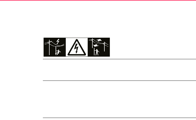
Danger If the product is used in exposed locations, for example on masts, mountains or
buildings, it is at risk from lightning. Danger from high voltages also exists near
power lines. Lightning, voltage peaks, or the touching of power lines can cause
damage, injury and death.
Precautions:
• Do not use the product in a thunderstorm as you may increase the risk of being
struck by lightning.
• Be sure to remain at a safe distance from electrical installations. Do not use the
product directly under or in close proximity to power lines. If it is essential to work

Safety Directions GPS1200 97
in such an environment contact the safety authorities responsible for electrical
installations and follow their instructions.
• If the product has to be permanently mounted in an exposed location, it is advis-
able to provide a lightning conductor system. A suggestion on how to design a
lightning conductor for the product is given below. Always follow the regulations
in force in your country with regard to grounding antennas and masts. These
installations must be carried out by an authorised specialist.
• To prevent damages due to indirect lightning strikes (voltage spikes) cables, for
example for antenna, power source or modem should be protected with appro-
priate protection elements, like a lightning arrester. These installations must be
carried out by an authorized specialist.
• If there is a risk of a thunderstorm, or if the equipment is to remain unused and
unattended for a long period, protect your product additionally by unplugging all
systems components and disconnecting all connecting cables and supply
cables, for example, receiver - antenna.
Lightning conduc-
tors
Suggestion for design of a lightning conductor for a GPS system:
1. On non-metallic structures
Protection by air terminals is recommended. An air terminal is a pointed solid or
tubular rod of conducting material with proper mounting and connection to a
conductor. The position of four air terminals should be uniformly distributed
around the antenna at a distance equal to the height of the air terminal.
98GPS1200
Safety Directions
The air terminal diameter should be 12 mm for copper or 15 mm for aluminium.
The height of the air terminals should be 25 cm to 50 cm. All air terminals should
be connected to the down conductors. The diameter of the air terminal should
be kept to a minimum to reduce GPS signal shading.
2. On metallic structures
Protection is as described for non-metallic structures, but the air terminals can
be connected directly to the conducting structure without the need for down
conductors.
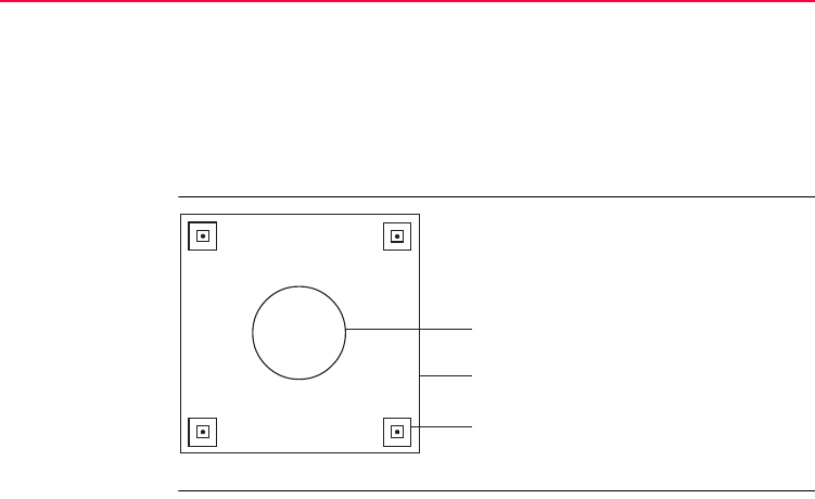
Air terminal
arrangement, plan
view
a) GPS antenna
b) Support structure
c) Air terminal
a
GPS12_059
b
c
Safety Directions GPS1200 99
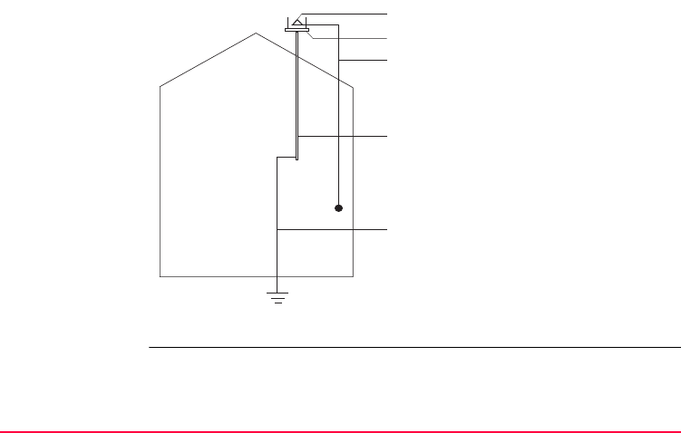
Grounding the
receiver/antenna
a) GPS antenna
b) Lightning conductor array
c) Antenna/receiver connection
d) Metallic mast
e) Connection to earth
e
GPS12_060
d
c
a
b

100GPS1200
Safety Directions
7.7 Electromagnetic Compatibility EMC
Description The term Electromagnetic Compatibility is taken to mean the capability of the
product to function smoothly in an environment where electromagnetic radiation and
electrostatic discharges are present, and without causing electromagnetic distur-
bances to other equipment.
Warning Electromagnetic radiation can cause disturbances in other equipment.
Although the product meets the strict regulations and standards which are in force
in this respect, Leica Geosystems cannot completely exclude the possibility that
other equipment may be disturbed.
Caution There is a risk that disturbances may be caused in other equipment if the product is
used in conjunction with accessories from other manufacturers, for example field
computers, personal computers, two-way radios, non-standard cables or external
batteries.
Precautions:
Use only the equipment and accessories recommended by Leica Geosystems.
When combined with the product, they meet the strict requirements stipulated by the
guidelines and standards. When using computers and two-way radios, pay attention
to the information about electromagnetic compatibility provided by the manufacturer.

Safety Directions GPS1200 101
Caution Disturbances caused by electromagnetic radiation can result in erroneous measure-
ments.
Although the product meets the strict regulations and standards which are in force
in this respect, Leica Geosystems cannot completely exclude the possibility that the
product may be disturbed by very intense electromagnetic radiation, for example,
near radio transmitters, two-way radios or diesel generators.
Precautions:
Check the plausibility of results obtained under these conditions.
Warning If the product is operated with connecting cables attached at only one of their two
ends, for example external supply cables, interface cables, the permitted level of
electromagnetic radiation may be exceeded and the correct functioning of other
products may be impaired.
Precautions:
While the product is in use, connecting cables, for example product to external
battery, product to computer, must be connected at both ends.

102GPS1200
Safety Directions
Radios, digital
cellular phones or
ATX1230 with Blue-
tooth
Use of product with radio, digital cellular phone devices or ATX1230 with Bluetooth:
Warning Electromagnetic radiation can cause disturbances in other equipment, in installa-
tions, in medical devices, for example pacemakers or hearing aids and in aircraft. It
can also affect humans and animals.
Precautions:
Although the product meets in combination with radio or digital cellular phone
devices recommended by Leica Geosystems the strict regulations and standards
which are in force in this respect, Leica Geosystems cannot completely exclude the
possibility that other equipment may be disturbed or that humans or animals may be
affected.
• Do not operate the product with radio or digital cellular phone devices in the
vicinity of filling stations or chemical installations, or in other areas where an
explosion hazard exists.
• Do not operate the product with radio or digital cellular phone devices near to
medical equipment.
• Do not operate the product with radio or digital cellular phone devices in aircraft.
• Do not operate the product with radio or digital cellular phone devices for long
periods immediately next to your body.

Safety Directions GPS1200 103
7.8 FCC Statement, Applicable in U.S.
Applicability The grayed paragraph below is only applicable for products of the GPS1200 System
without radio, digital cellular phone devices or Bluetooth.
Warning This equipment has been tested and found to comply with the limits for a Class B
digital device, pursuant to part 15 of the FCC rules.
These limits are designed to provide reasonable protection against harmful interfer-
ence in a residential installation.
This equipment generates, uses and can radiate radio frequency energy and, if not
installed and used in accordance with the instructions, may cause harmful interfer-
ence to radio communications. However, there is no guarantee that interference will
not occur in a particular installation.
If this equipment does cause harmful interference to radio or television reception,
which can be determined by turning the equipment off and on, the user is encour-
aged to try to correct the interference by one or more of the following measures:
• Reorient or relocate the receiving antenna.
• Increase the separation between the equipment and the receiver.
• Connect the equipment into an outlet on a circuit different from that to which the
receiver is connected.
• Consult the dealer or an experienced radio/TV technician for help.
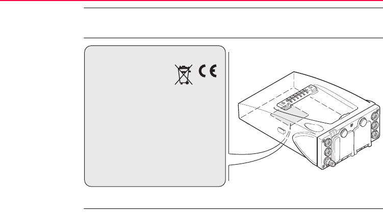
104GPS1200
Safety Directions
Warning Changes or modifications not expressly approved by Leica Geosystems for compli-
ance could void the user's authority to operate the equipment.
Labelling GPS1200
GPS12_101
Type: GX... ..............
. . . . . . . . . . . . . . . . . . . . .
. . . . . . . . . . . . . . . . . . . . .
. . . . . . . . . . . . . . . . . . . . . .
. . . . . . . . . . . . . . . . . . . . . . . . .
. . . . . . . . . . . . . . . . . . . . . . . . . . . . . .
. . . . . . . . . . . . . . . . . . . . . . . . . . . . . .
. . . . . . . . . . . . . . . . . . . . . . . . . . . . . .
This device complies with part 15 of
the FCC Rules. Operation is subject
to the following two conditions:
(1) This device may not cause harmful
interference, and (2) this device must
accept any interference received,
including interference that may cause
undesired operation.
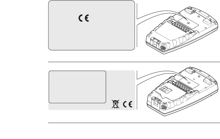
Safety Directions GPS1200 105
Labelling
RX1210
Labelling
RX1250 X
RX12_023
Type: RX1210 .......
. . . . . . . . . . . . . . . . .
. . . . . . . . . . . .
. . . . . . . . . . . .
. . . . . . . . . . . .
. . . . . . . . . . . . . . . . .
. . . . . . . . . . . . . . . . .
. . . . . . . . . . . . . . . . .
. . . . . . . . . . . . . . . . .
. . . . . . . . . . . . . . . . .
This device complies with
part 15 of the FCC Rules.
Operation is subject to the
following two conditions:
(1) This device may not
cause harmful interference,
and (2) this device must
accept any interference
received, including i
nterference that may cause
undesired operation.
RX12_025
This device complies with part
15 of the FCC Rules. Operation is
subject to the following two
conditions: (1) This device may
not cause harmful interference,
and (2) this device must accept
any interference received,
including interference that may
cause undesired operation.
Typ e : RX1250
. . . . . . . . . . .
. . . . . . . . . . .
. . . . . . . . . . . . . . . . . . .
. . . . . . . . . . . . . . . . .
. . . . . . . . . . . . . . . . .
. . . . . . . . . . . . . . . . .
. . . . . . . . . . . . . . . . .
. . . . . . . . . . . . . . . . .
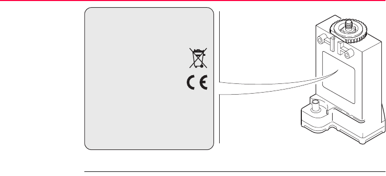
106GPS1200
Safety Directions
Labelling GFU16,
GFU17
GPS12_103
This device complies with part 15 of the FCC
Rules. Operation is subject to the following two
conditions: (1) This device may not cause
harmful interference, and (2) this device must
accept any interference received, including
interference that may cause undesired
Type: GFUXX . . . . . . . . .
. . . . . . . . . . . . . . . . .
. . . . . . . . . . . . . . . . . . .
. . . . . . . . . . . . . . . . . . .
. . . . . . . . . . . . . . . . . . .
. . . . . . . . . . . . . . . . . . .
. . . . . . . . . . . . . . . . . . .
. . . . . . . . . . . . . . . . . . .
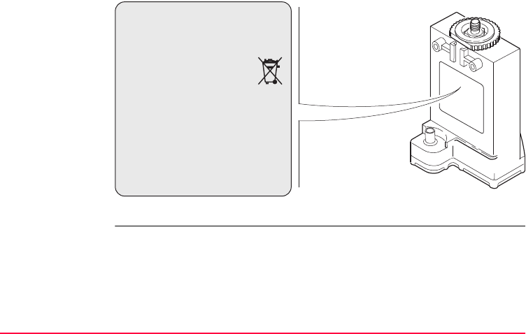
Safety Directions GPS1200 107
Labelling GFU19
TPS12_218
This device complies with part 15 of the FCC
Rules. Operation is subject to the following two
conditions: (1) This device may not cause
harmful interference, and (2) this device must
accept any interference received, including
interference that may cause undesired
operation.
Type: GFUXX . . . . . . . . .
. . . . . . . . . . . . . . . . .
. . . . . . . . . . . . . . . . . . .
. . . . . . . . . . . . . . . . . . .
. . . . . . . . . . . . . . . . . . .
. . . . . . . . . . . . . . . . . . .
. . . . . . . . . . . . . . . . . . .
. . . . . . . . . . . . . . . . . . .
108GPS1200
Safety Directions
Labelling internal
battery GEB211,
GEB221
TPS12_082
.................. ...............
.......................
......................
................................ .................... ......................
.... ..........
.................................................................................
This device complies with part 15 of the FCC Rules. Operation
is subject to the following two conditions: (1) This device
may not cause harmful interference, and (2) this device
must accept any interference received, including
interference that may cause undesired operation.

Safety Directions GPS1200 109

110GPS1200
Technical Data
8 Technical Data
8.1 Receiver Technical Data
8.1.1 Tracking Characteristics of the Receiver
GPS technology SmartTrack
Satellite reception
Receiver channels
Supported codes
GX1230/GX1220/GRX1200 Series: Dual frequency
GX1210: Single frequency
GX1230/GX1220/GRX1200 Series: Twelve channels continuous tracking on L1
and L2
GX1210: Twelve channels continuous tracking on L1
Type L1 L2
GX1230/GX1220/
GRX1200 Series
Carrier phase, C/A code Carrier phase, P2 code
GX1210 Carrier phase, C/A code -

Technical Data GPS1200 111
Carrier tracking
Code measure-
ments
Condition GX1230/GX1220/
GRX1200 Series
GX1210
L1, AS off or on Reconstructed carrier phase
via C/A code
Reconstructed carrier phase
via C/A code
L2, AS off Reconstructed carrier phase
via P2 code
-
L2, AS on Switches automatically to
patented P code-aided tech-
nique providing full L2 recon-
structed carrier phase
-
Condition GX1230/GX1220/
GRX1200 Series
GX1210
L1, AS off
L1, AS on
Carrier phase smoothed code
measurements: C/A code
Carrier phase smoothed C/A
code measurements
L2, AS off Carrier phase smoothed code
measurements: P2 code
-

112GPS1200
Technical Data
)Carrier phase and code measurements on L1 and L2 are fully independent with AS
on or off.
Satellites tracked
L2, AS on Carrier phase smoothed code
measurements: Patented P
code-aided code
-
Condition GX1230/GX1220/
GRX1200 Series
GX1210
GX1230/GX1220/GRX1200 Series: Up to twelve simultaneously on L1 and L2
GX1210: Up to twelve simultaneously on L1

Technical Data GPS1200 113
8.1.2 Accuracy
)Accuracy is dependent upon various factors including the number of satellites
tracked, constellation geometry, observation time, ephemeris accuracy, ionospheric
disturbance, multipath and resolved ambiguities.
The following accuracies, given as root mean square, are based on measurements
processed using LGO and on real-time measurements.
Differential code For all receivers, the baseline precision of a differential code solution for static and
kinematic surveys is 25 cm.
Differential phase
in post-processing
Normal baselines with GX1230/GX1220/GRX1200 Series plus AX1202
Static Kinematic
Horizontal Vertical Horizontal Vertical
5 mm + 0.5 ppm 10 mm + 0.5 ppm 10 mm + 1 ppm 20 mm + 1 ppm
114GPS1200
Technical Data
Long baselines with GX1230/GX1220/GRX1200 Series plus AT504
Short baselines with GX1210 plus AX1201
Differential phase
in real-time
GX1230/GX1220/GRX1200 Series plus AX1202
Static
Horizontal Vertical
3 mm + 0.5 ppm 6 mm + 1 ppm
Static Kinematic
Horizontal Vertical
10 mm + 1 ppm 20 mm + 2 ppm 20 mm + 2 ppm
Static Kinematic
Horizontal Vertical Horizontal Vertical
5 mm + 0.5 ppm 10 mm + 0.5 ppm 10 mm + 1 ppm 20 mm + 1 ppm

Technical Data GPS1200 115
8.1.3 Technical Data
Dimensions The dimensions are given for the housing without the sockets.
Weight Receiver weights without battery and radio:
Recording Data can be recorded on the CompactFlash card or in the internal memory, if fitted.
Type Length [m] Width [m] Thickness [m]
All receivers 0.212 0.166 0.079
Type Weight [kg]
GX1230/GX1220/GX1210/GRX1200 Classic 1.2
GRX1200 Pro 1.3
Type Capacity [MB] Data capacity
CompactFlash
card
•32
• 256
32 MB is sufficient for about
• 550 h L1 + L2 data logging at 15 s rate
• 2200 h L1 + L2 data logging at 60 s rate
• 45000 real-time point with codes
Internal memory • 32
• 256

116GPS1200
Technical Data
Power
Battery internal
Battery external
Operating times The given operating times are valid for
• all receiver types except GRX1200 Pro.
• receiver plus antenna plus RX1200 without keyboard illumination and without
screen heating.
• two fully charged GEB221 batteries.
• room temperature. Operating times will be shorter when working in cold weather.
Power consumption: GX1230/GX1220/GX1210, radio and RX1200 excluded:
3.8 W typically, 320 mA
External supply voltage: Nominal 12 V DC ( , GEV71 car battery cable to a
12 V car battery), voltage range 10.5-28 V DC
Type: Li-Ion
Voltage: 7.4 V
Capacity: GEB221: 3.8 Ah
Type: NiMH
Voltage: 12 V
Capacity: GEB171: 8.0 Ah

Technical Data GPS1200 117
Environmental
specifications
Temperature
Equipment Operating time
Type Radio Digital cellular
phone
Static - - 15 h continuously
Rover Pacific Crest PDL,
receive
- 10 h continuously
Rover - Siemens MC45 10 h continuously
Type Operating temperature [°C] Storage temperature [°C]
All receivers -40 to +65 -40 to +80
Leica CompactFlash
cards, all sizes
-40 to +80 -40 to +80
Battery internal -20 to +55 -40 to +70

118GPS1200
Technical Data
Protection against water, dust and sand
Humidity
PPS output For GX1200 with PPS/Event option and GRX1200 Pro
PPS output characteristics:
Type Protection
All receivers IP67 (IEC 60529)
Dusttight
Waterproof to 1 m temporary immersion
Type Protection
All receivers Up to 100 %
The effects of condensation are to be effectively counter-
acted by periodically drying out the receiver.
Peak: 3.3 V = High
Impedance: 50 Ω

Technical Data GPS1200 119
Cable connectivity:
Event input For GX1200 with PPS/Event option and GRX1200 Pro
Pulse length: 1 ms
Leading edge: Coinciding with the beginning of each epoch.
Positive/negative edge: Selectable via RX1200.
Matched with an appropriate impedance of: 50 Ω
Socket: LEMO ERN.0S.250.CTL
Peak: 3.3 V = High
Pulse type: TTL, positive or negative going pulse
Pulse length: 125 ns at minimum
Voltage: TTL level, ~ 5 V, min. 3.3 V
Pin definition: Centre = signal, Case = ground
Socket: LEMO HGP.00.250.CTL

120GPS1200
Technical Data
External oscillator
input
For GRX1200 Pro
External clock input:
Frequency: 5 MHz or 10 MHz
Input impedance: 50 Ω nominal
Input VSWR: 2:1 maximum
Signal level: 0 dBm minimum to +13.0 dBm maximum
Frequency stability: ±0.5 ppm maximum
Wave shape: Sinusoidal
Connector: MMCX female

Technical Data GPS1200 121
8.2 Antennas Technical Data
Description and
use
The GPS antenna is selected for use based upon the application. The table gives a
description and the intended use of the individual antennas.
Dimensions
Type Description Use
AX1201 L1 SmartTrack antenna with built
in groundplane.
With GX1210 receiver.
AX1202 L1/L2 SmartTrack antenna with
built in groundplane.
With GX1220 or GX1230 receiver.
AT504 Dorne & Margolin L1/L2 antenna
element with gold anodized choke
ring groundplane. Complies with
IGS type 'T' antenna, JPL design.
Optional protective radome.
With GX1220, GX1230 or
GRX1200 Series where higher
precision is required.
For example static surveys of long
baselines, tectonic plate moni-
toring and reference stations.
Type AX1201 AX1202 AT504
Height 6.2 cm 6.2 cm 14.0 cm
Diameter 17.0 cm 17.0 cm 38.0 cm

122GPS1200
Technical Data
Connector
Mounting
Weight
Electrical data
AX1201/AX1202: TNC female
AT504: N female
All antennas: 5/8" Whitworth
AX1201/AX1202: 0.4 kg
AT504 4.3 kg, radome 1.1 kg
Type AX1201 AX1202 AT504
Voltage 4.75 to 15 V DC 4.75 to 15 V DC 4.75 to 15 V DC
Current 50 mA max 50 mA max 50 mA max
Frequency GPS L1
1575.46 MHz
GPS L1
1575.46 MHz
GPS L1
1575.46 MHz
GPS L2
1227.60 MHz
GPS L2
1227.60 MHz
GPS L2
1227.60 MHz
Gain Typically 27 dBi Typically 27 dBi Typically 27 dBi
Noise Figure Typically < 2 dBi Typically < 2 dBi 3 dBi max
BW, -3 dBiW - - 40 MHz min

Technical Data GPS1200 123
Environmental
specifications
Temperature
Protection against water, dust and sand
BW, -30 dBi - - 200 MHz max
Type AX1201 AX1202 AT504
Type Operating temperature [°C] Storage temperature [°C]
All antennas -40 to +70 -40 to +70
Type Protection
AX1201/AX1202 IP67 (IEC 60529)
Dusttight
Protected against water jets
Waterproof to 1 m temporary immersion
AT504 IP57 (IEC 60529)
Dustprotected
Waterproof to 1 m temporary immersion

124GPS1200
Technical Data
Humidity
Cable length
Type Protection
AX1201/AX1202 Up to 100 %
The effects of condensation are to be effectively counter-
acted by periodically drying out the antenna.
AT504 Up to 92 %
The effects of condensation are to be effectively counter-
acted by periodically drying out the antenna.
Separation distance
from receiver ...
to antenna Supplied
cable lengths
[m]
Optional
cable lengths
[m]
GX1230/GX1220/
GX1210
AX1202/AX1201 1.2
2.8
30
50
70
GRX1200
Classic/GRX1200 Lite
AX1202 1.2 30

Technical Data GPS1200 125
2.8 50
10 70
GRX1200 Pro AT504/AX1202 1.2 30
2.8 50
10 70
Separation distance
from receiver ...
to antenna Supplied
cable lengths
[m]
Optional
cable lengths
[m]
126GPS1200
Technical Data
8.3 RX1200 Technical Data
Control unit
Dimensions
Weight
Display: 1/4 VGA (320 x 240 pixels), monochrome, graphics
capable LCD, illumination, optional touch screen
Keyboard: 62 keys including 12 function keys, illumination
Angle Display: 360°’", 360° decimal, 400 gon, 6400 mil, V %
Distance Display: m, ft int, ft us, ft int inch, ft us inch
Touch screen if fitted: Toughened film on glass
Type Length [m] Width [m] Thickness [m]
RX1210 0.218 0.123 0.037
RX1250 X 0.218 0.123 0.047
Type Weight [kg]/[lbs]
RX1210 0.507/1.118
RX1250 X with GEB211 0.741/1.634

Technical Data GPS1200 127
Recording For RX1250 X, data can be recorded on the CompactFlash card.
Power
Type Capacity [MB] Data capacity
CompactFlash
card
•32
• 256
32 MB is sufficient for about
• 550 h L1 + L2 data logging at 15 s rate
• 2200 h L1 + L2 data logging at 60 s rate
• 45000 real-time point with codes
Type Consumption [W] External supply voltage
RX1210 1 Nominal voltage 12 V DC ( )
Voltage range 11.5 V-28 V
RX1250 X 1.1
Bluetooth to SmartAntenna,
digital cellular phone powered
from GHT56
Nominal voltage 12 V DC ( )
Voltage range 11.5 V-28 V

128GPS1200
Technical Data
Internal battery
Environmental
specifications
Temperature
Protection against water, dust and sand
Type Battery Voltage Capacity Operating time,
typical
RX1250 X Li-Ion 7.4 V GEB211: 1.9 Ah 11 h
Bluetooth to SmartAn-
tenna
Type Operating temperature [°C] Storage temperature [°C]
RX1210/RX1250 X -30 to +65 -40 to +80
Type Protection
RX1210/RX1250 X IP67 (IEC 60529)
Dusttight
Waterproof to 1 m temporary immersion

Technical Data GPS1200 129
Humidity
Ports
Type Protection
RX1210/RX1250 X Up to 100 %
The effects of condensation are to be effectively counter-
acted by periodically drying out the RX1210.
Type 8 pin LEMO-1 Special clip-on interface
RX1210 For power and/or communication For power and communication to
GPS1200
RX1250 X For power and/or communication For communication to GHT56
and GPS1200

130GPS1200
Technical Data
8.4 Conformity to National Regulations
8.4.1 RX1250
Conformity to
national regula-
tions
For RX1250
• FCC part 15, applicable in US
• European directive 1999/5/EC on radio equipment and telecommunication
RX1200 equipment. Refer to "CE Conformity Declaration".
• The conformity for countries with other national regulations not covered by the
FCC part 15 or european directive 1999/5/EC has to be approved prior to use
and operation
Frequency band
Ouput power
Type Frequency band [MHz]
RX1250, Bluetooth Limited to 2409 - 2435
Type Output power [mW]
RX1250, Bluetooth < 10 (e. i. r. p.)

Technical Data GPS1200 131
Antenna Type Antenna Gain
[dBi]
Connector Frequency
band [MHz]
RX1250,
Bluetooth
Integrated antenna - - -

132GPS1200
Technical Data
8.4.2 GFU16, Bluetooth communication
Conformity to
national regula-
tions
• FCC Part 15 (applicable in US)
• European Directive 1999/5/EC on radio equipment and telecommunication
terminal equipment (see CE Conformity Declaration)
• The conformity for countries with other national regulations not covered by the
FCC part 15 or European directive 1999/5/EC has to be approved prior to use
and operation.
Frequency band 2402 - 2480 MHz
Output power
Antenna
Bluetooth Class 2 type: 2.5 mW
Type Internal patch antenna
Gain 2.7 dBi

Technical Data GPS1200 133
8.4.3 GFU17, Siemens MC45
Conformity to
national regula-
tions
• FCC Part 15 and 24 (applicable in US)
• European Directive 1999/5/EC on radio equipment and telecommunication
terminal equipment (see CE Conformity Declaration)
• The conformity for countries with other national regulations not covered by the
FCC part 15 and 24 or European directive 1999/5/EC has to be approved prior
to use and operation.
Frequency band Tri-Band EGSM900 / GSM1800 / GSM1900 MHz
Output power
Antennas
EGSM900: 2 W
GSM1800: 1 W
GSM1900: 1 W
Type GAT 3 GAT 5
Frequency band 900 or 1800 MHz 850 or 1900 MHz
Type Detachable λ/2 antenna Detachable λ/2 antenna
Gain 0 dBi 0 dBi
Connector TNC TNC

134GPS1200
Technical Data
Specific Absorp-
tion Rate (SAR)
The product meets the limits for the maximum permissible exposure of the guide-
lines and standards which are force in this respect. The product must be used with
the recommended antenna. A separation distance of at least 20 centimeters should
be kept between the antenna and the body of the user or nearby person within the
intended application.

Technical Data GPS1200 135
8.4.4 GFU19, US CDMA MultiTech MTMMC-C
Conformity to
national regula-
tions
• FCC Part 15, 22 and 24 (applicable in US)
• European Directive 1999/5/EC on radio equipment and telecommunication
terminal equipment (see CE Conformity Declaration)
• The conformity for countries with other national regulations not covered by the
FCC part 15, 22 and 24 or European directive 1999/5/EC has to be approved
prior to use and operation.
Frequency band Dual-Band CDMA850/CDMA1900 MHz
Output power
Antenna
CDMA850: 2 W
CDMA1900: 0.4 W
Type GAT 5
Frequency band 850 or 1900 MHz
Type Detachable λ/2 antenna
Gain 0 dBi
Connector TNC

136GPS1200
Technical Data
Specific Absorp-
tion Rate (SAR)
The product meets the limits for the maximum permissible exposure of the guide-
lines and standards which are force in this respect. The product must be used with
the recommended antenna. A separation distance of at least 20 centimeters should
be kept between the antenna and the body of the user or nearby person within the
intended application.

Technical Data GPS1200 137

138GPS1200
Index
Index
A
AC, power supply unit ......................................... 20
In Diagram ...................................................... 69
Accuracy ............................................................ 113
Antennas ........................................................... 121
GFU16 Bluetooth communication ................132
GFU17, Siemens MC45 ............................... 133
GFU19, MultiTech MTMMC-C ..................... 135
Type ............................................................. 121
Used with receivers ........................................ 14
Application program software .............................. 14
Area, icon ............................................................ 35
Attach, clip-on-housing ........................................ 46
B
Battery
Change in receiver ......................................... 41
External, receiver ......................................... 116
For internal power supply .............................. 20
Icon ................................................................ 35
Internal, receiver .......................................... 116
RX1200 ........................................................ 128
Baud rate ............................................................ 74
Bluetooth communication .................................. 132
Bluetooth, icon .................................................... 35

Index GPS1200 139
C
Capacity, memory
Receiver ....................................................... 115
RX1200 ........................................................ 127
Choicelist ............................................................. 30
Clip-on-housing
Attach ............................................................. 46
Detach ............................................................ 47
Commands, remote control ................................. 66
Communication parameters
Remote interface ............................................ 74
CompactFlash card ............................................. 43
Format ............................................................ 44
Icon ................................................................ 35
Insert .............................................................. 43
Memory device ............................................... 18
Remove .......................................................... 43
Safety instructions .......................................... 43
Connector, antennas ......................................... 122
Container contents .............................................. 22
Conversion of data .............................................. 19
D
Data bits .............................................................. 74
Data conversion .................................................. 19
Data exchange
Between receiver and PC .............................. 14
Data storage ....................................................... 18
Reference station ........................................... 66
Data streaming, reference station ....................... 66
Detach, clip-on-housing ...................................... 47
Device
Clip-on-housing .............................................. 46
Status ............................................................. 50
Dimensions
Antennas ...................................................... 121
Receivers ..................................................... 115
RX1200 ........................................................ 126
Documentation ...................................................... 9
Drive
OMNI ............................................................. 19
PC card, on office computer .......................... 19

140GPS1200
Index
E
Electrical data, antennas ................................... 122
Environmental specifications
Antenna ........................................................ 123
Receiver ....................................................... 117
RX1200 ........................................................ 128
Equipment setup ........................................... 38, 67
Event input ........................................................ 119
Exchange data
Between receiver and PC .............................. 14
External power supply ......................................... 20
F
Fields ..................................................................... 8
Flashing LED on clip-on-housing ........................ 53
Flow control ......................................................... 74
Format CompactFlash card ................................. 44
Frequency band
GFU16 Bluetooth communication ................ 132
GFU17, Siemens MC45 ............................... 133
GFU19, MultiTech MTMMC-C ..................... 135
G
GAT 3, antenna ................................................. 133
GeoC++ .............................................................. 17
GFU16 .............................................................. 132
GFU17 .............................................................. 133
GFU19 .............................................................. 135
GPS Spider ................................................... 12, 15
H
Housing for devices ............................................ 46
I
Icons ................................................................... 34
Indicators, LED for clip-on-housing ..................... 50
Insert
CompactFlash card ........................................ 43
SIM card ........................................................ 47
Interface
Remote .......................................................... 74
User ............................................................... 26
Internal memory .................................................. 18
Icon ................................................................ 35

Index GPS1200 141
Internal power supply .......................................... 20
Internet online status, icon .................................. 34
K
Keyboard ............................................................. 26
Keyboard, lock and unlock .................................. 26
L
Labelling
RX1210 ........................................................ 105
RX1250 X ..................................................... 105
LED
Clip-on-housing, description ........................... 52
Housing .......................................................... 50
LEICA
Geo Office ................................................ 12, 14
GPS Spider .............................................. 12, 15
Leica software on RX1250
Access ............................................................ 28
Activate .......................................................... 27
Exit ................................................................. 28
Minimise ......................................................... 28
LGO .................................................................... 14
Light Emitting Diode, clip-on-housing ................. 50
Li-Ion battery ..................................................... 116
Storage .......................................................... 81
Line, icon ............................................................. 35
Lock, keyboard .................................................... 26
M
Manual, How to use this ........................................ 8
Memory device, available ................................... 18
Menu, select from ............................................... 29
Mount, antennas ............................................... 122
MultiTech MTMMC-C
GFU19, technical data ................................. 135
N
NiCd battery ...................................................... 116

142GPS1200
Index
O
OFF button .................................................... 24, 39
OMNI drive .......................................................... 19
ON button ...................................................... 24, 39
Operating times ................................................. 116
Operation
GRX1200/GRX1200 Pro ................................ 72
GX1200 .......................................................... 59
Options .................................................................. 8
Output power
GFU16, Bluetooth communication ............... 132
GFU17, Siemens MC45 ............................... 133
GFU19, MultiTech MTMMC-C ..................... 135
P
Page ...................................................................... 8
Parameters, remote interface .............................. 74
Parity ................................................................... 74
Path ....................................................................... 8
PC card drive on office computer ........................ 19
Ports on RX1200 ............................................... 129
Position mode, icon ............................................. 34
Position status, icon ............................................ 34
Power .................................................................. 20
RX1200 ........................................................ 127
Power supply unit
AC, reference station setup ........................... 69
Power, receivers ............................................... 116
PPS output ........................................................ 118
Q
Quick coding, icon ............................................... 36
R
Raw data transfer to LGO ................................... 19
Real-time device, icon ......................................... 34
Real-time status, icon ......................................... 34
Receiver components ......................................... 24
Receivers ............................................................ 13
Recording .......................................................... 115
RX1200 ........................................................ 127

Index GPS1200 143
Remote control
Commands ..................................................... 66
Reference station ........................................... 73
Remote interface ................................................. 74
Remove
CompactFlash card ........................................ 43
SIM card ......................................................... 49
RX1200
Functionality for GRX1200/GRX1200 Pro ...... 72
With/without touch screen ................................ 9
RX1200 technical data ...................................... 126
S
Satellites
Icon, contributing ............................................ 34
Icon, visible .................................................... 34
Screen ................................................................... 8
Select from menu ................................................ 29
Setup ................................................................... 38
Reference station ........................................... 67
SHIFT .................................................................. 36
Icon ................................................................ 36
Siemens MC45
GFU17, technical data ................................. 133
SIM card
Insert .............................................................. 47
Remove ......................................................... 49
Software
Application programs ..................................... 17
Customised application programs ................. 17
Language ....................................................... 16
RX1200 .......................................................... 17
System ........................................................... 16
Type ............................................................... 16
Upload ........................................................... 17
Specifications, environmental ........................... 110
Antennas ...................................................... 123
Receiver ....................................................... 117
RX1200 ........................................................ 128
Spider ............................................................ 12, 15
Status, device ..................................................... 50

144GPS1200
Index
Stop bit ................................................................ 74
Survey application program ................................. 55
Switching, Leica software and Windows CE ....... 27
System software .................................................. 14
T
Technical data ................................................... 110
Receiver ....................................................... 115
Temperature
Antenna
Operating ................................................ 123
Storage ................................................... 123
Battery internal
Charging .................................................... 40
Operating ................................................ 117
Storage ................................................... 117
CompactFlash card
Operating ................................................ 117
Storage ................................................... 117
Receiver
Operating ................................................ 117
Storage ................................................... 117
RX1200
Operating ................................................ 128
Storage ................................................... 128
Temperature range
Receiver, drying ............................................. 82
Time, operating ................................................. 116
Touch screen ...................................................... 26
Tracking characteristics .................................... 110
Transfer raw data to LGO ................................... 19
U
Uninterruptible Power Supply ............................. 21
Unlock, keyboard ................................................ 26
Upload software .................................................. 17
UPS ..................................................................... 21
User interface ...................................................... 26

Index GPS1200 145
W
Weight
Antennas ...................................................... 122
Receiver ....................................................... 115
RX1200 ........................................................ 126
Windows CE desktop, access ............................. 28
Windows CE, activate ......................................... 27
Windows key symbol ..................................... 28, 29

Total Quality Management - Our commitment to total customer satisfaction.
Leica Geosystems AG, Heerbrugg, Switzerland, has been
certified as being equipped with a quality system which
meets the International Standards of Quality Management
and Quality Systems (ISO standard 9001) and Environmental
Management Systems (ISO standard 14001).
Ask your local Leica Geosystems dealer for more information about our TQM
program.
733483-3.0.0en Original text
Printed in Switzerland © 2005 Leica Geosystems AG, Heerbrugg, Switzerland
Leica Geosystems AG
Heinrich-Wild-Strasse
CH-9435 Heerbrugg
Switzerland
Phone +41 71 727 31 31
www.leica-geosystems.com
