Leidos RTR-4I Remote Control Transmitter User Manual RTR4revD
Science Application International Corporation Remote Control Transmitter RTR4revD
UserManual.wiki
>
Leidos
>
RTR 4I User Manual
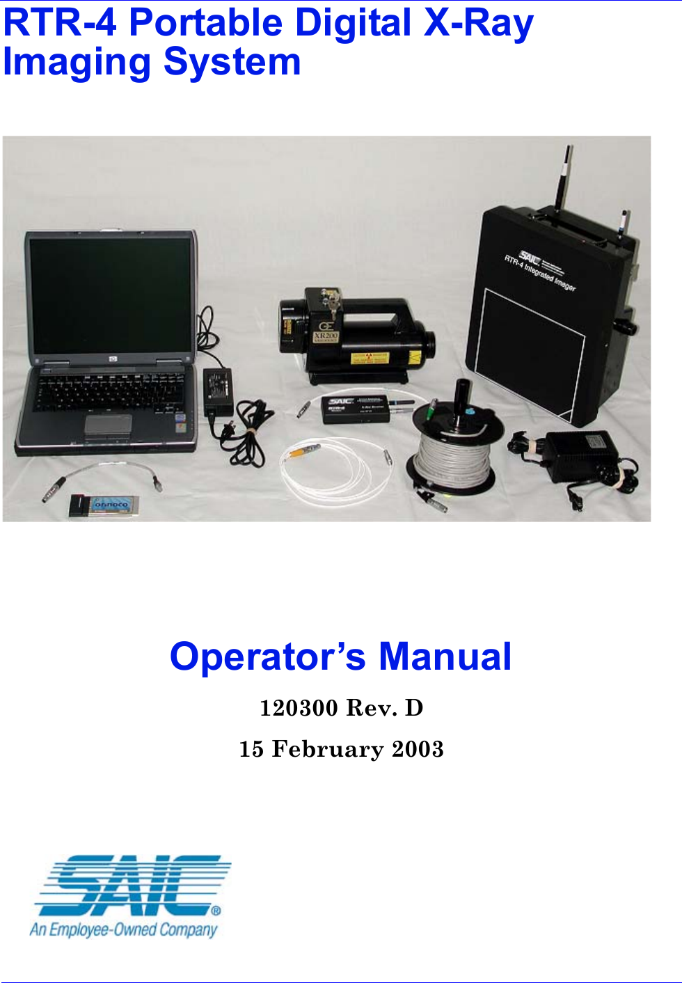
Users Manual
Navigation menu
Upload a User Manual
Namespaces
Wiki Guide
HTML
PDF
Info
Views
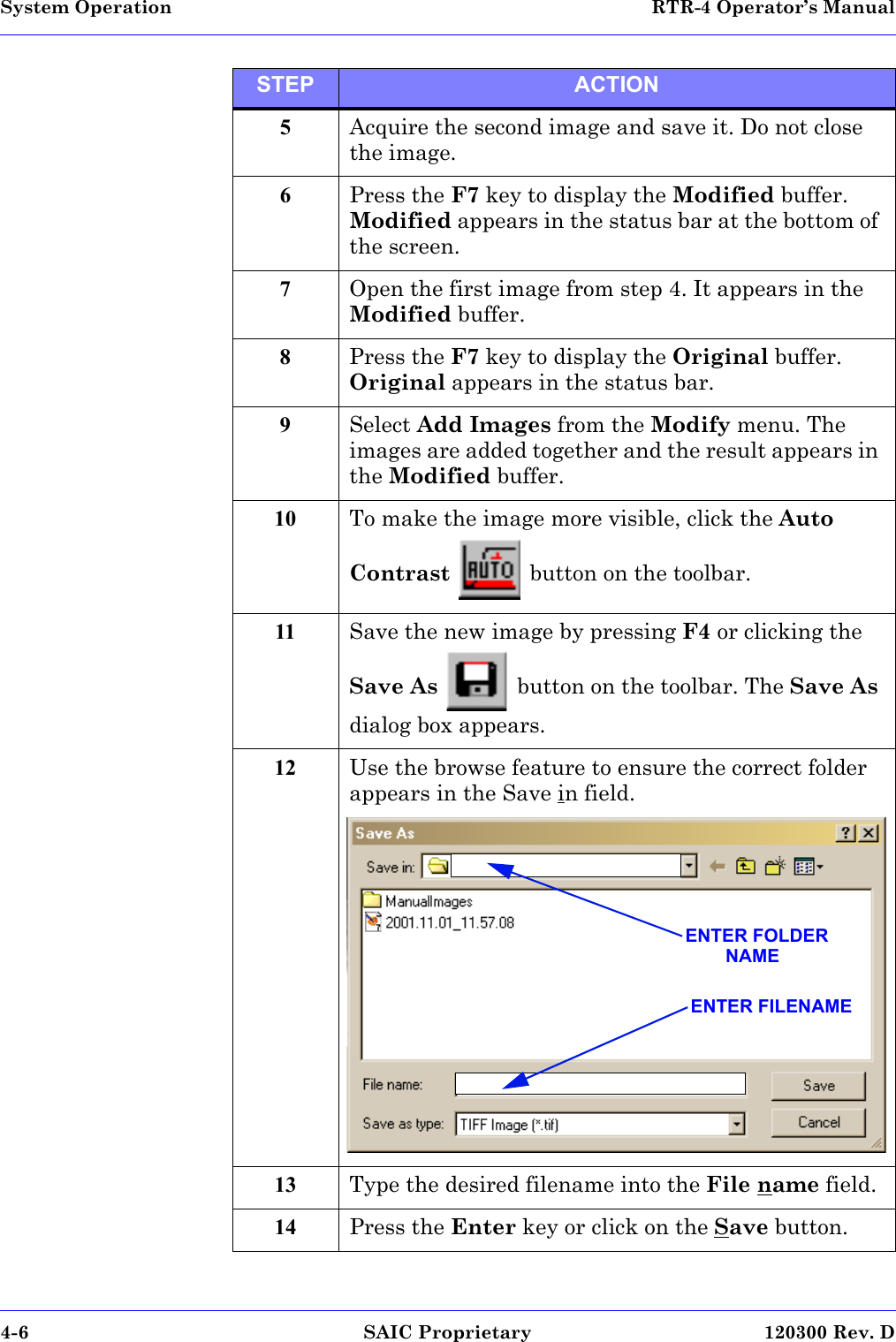
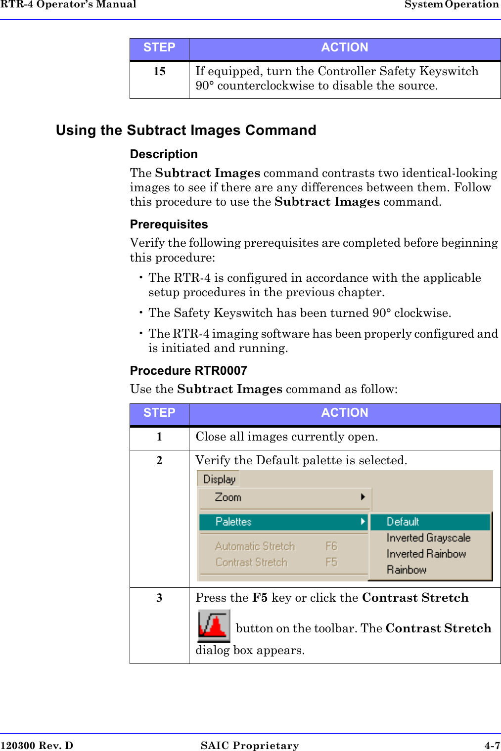
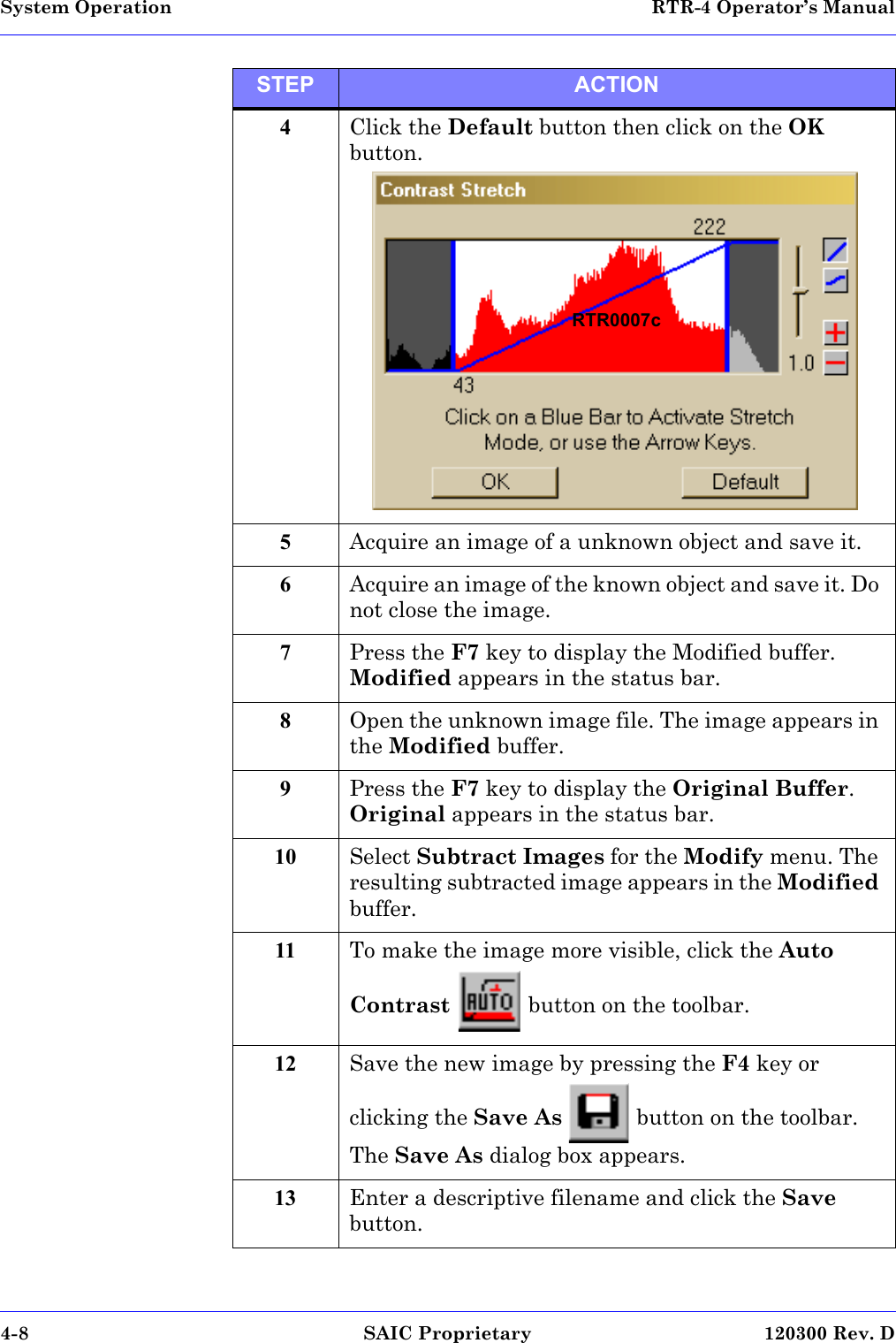
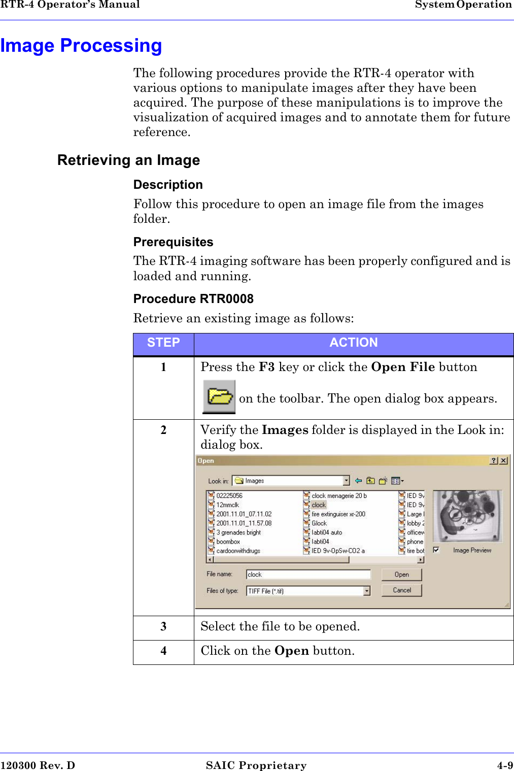
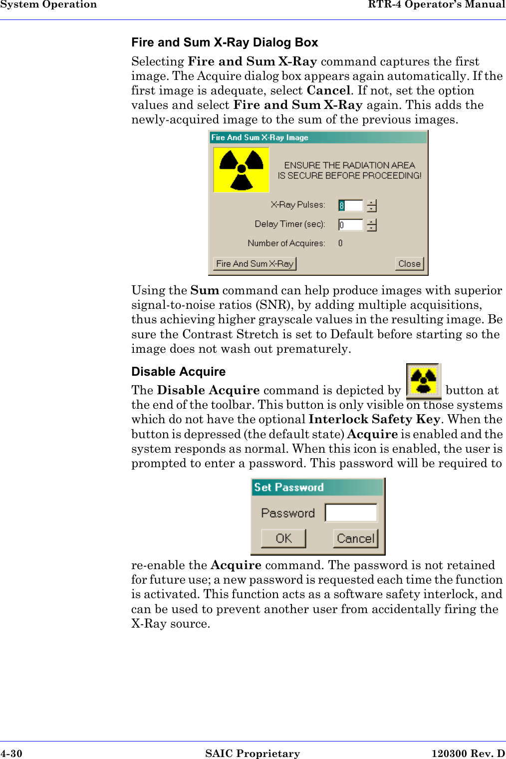
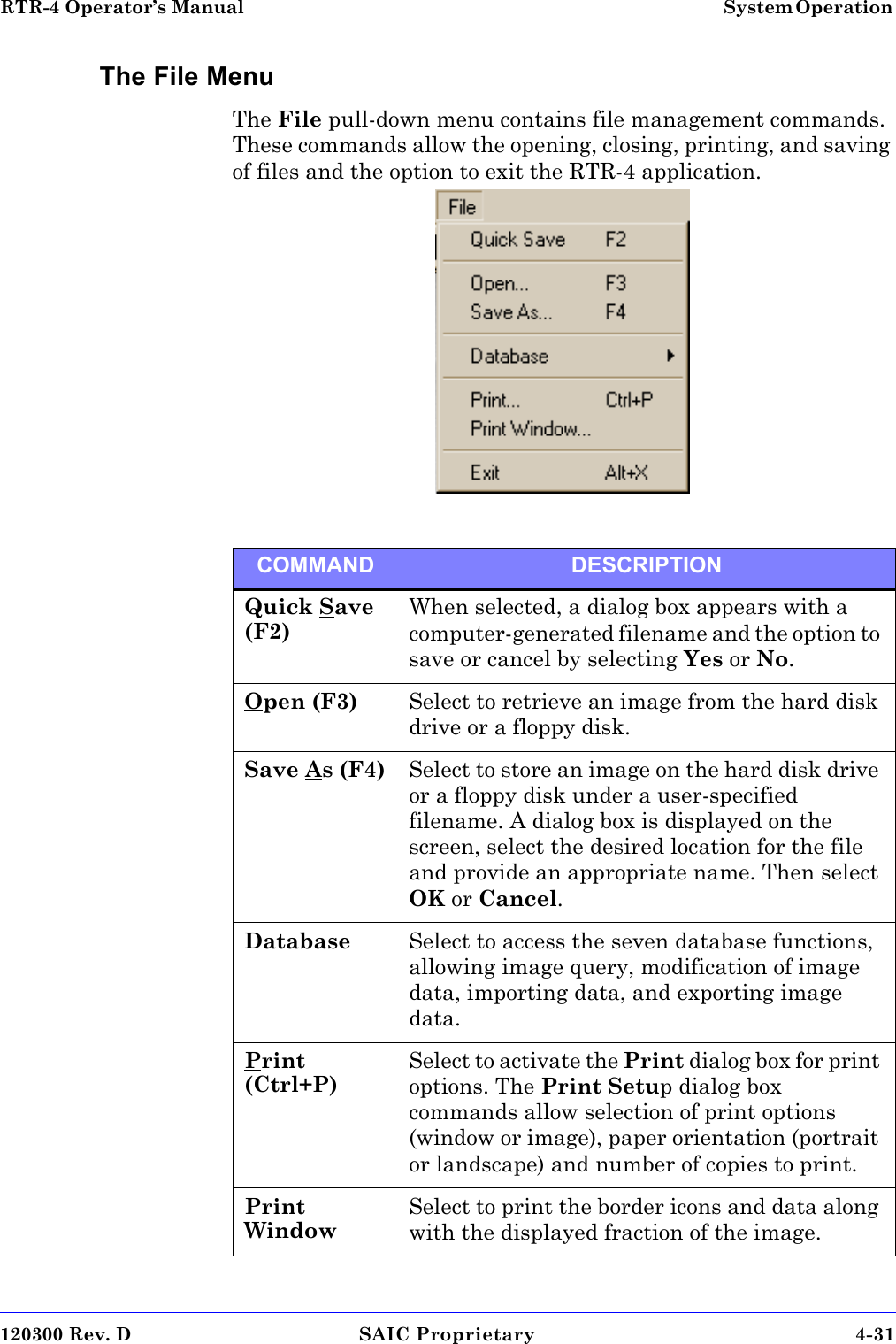
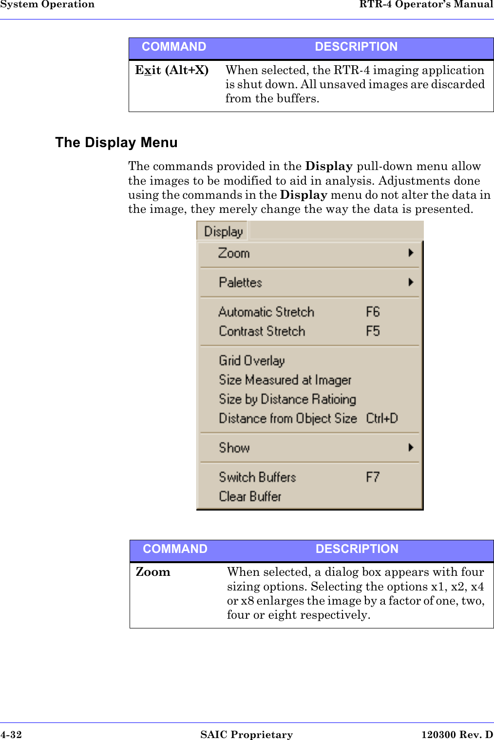
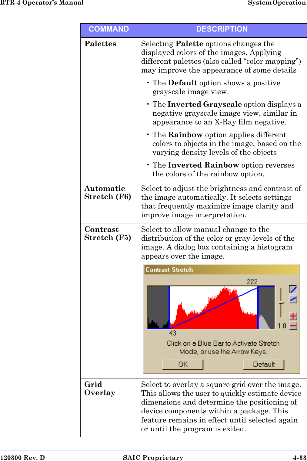
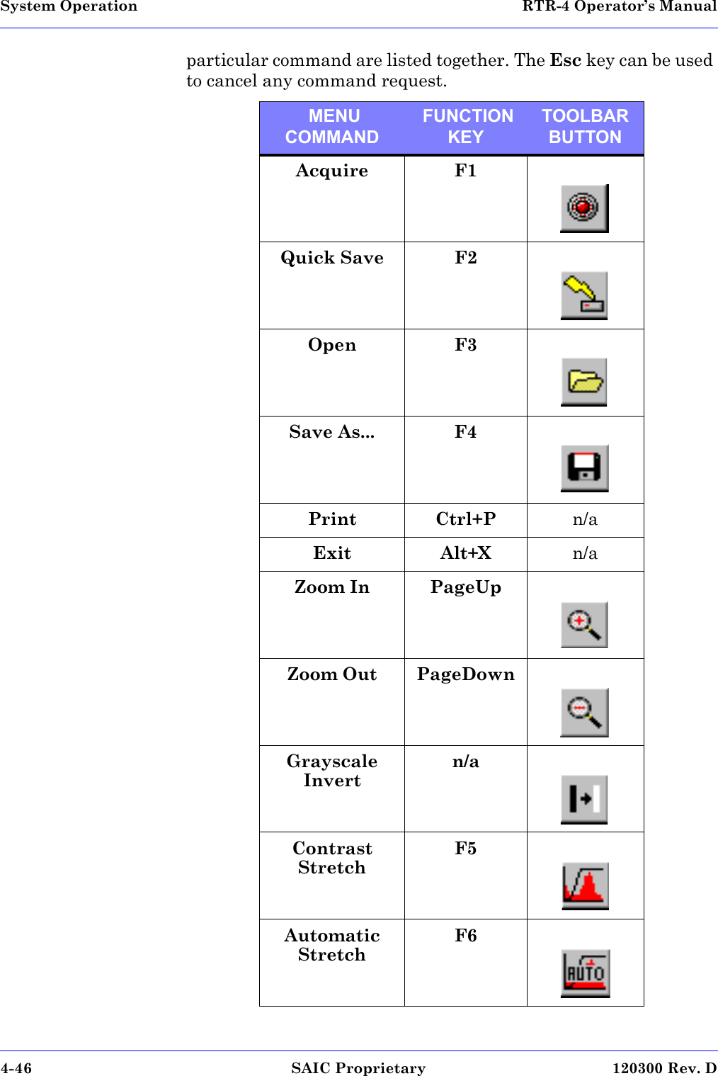
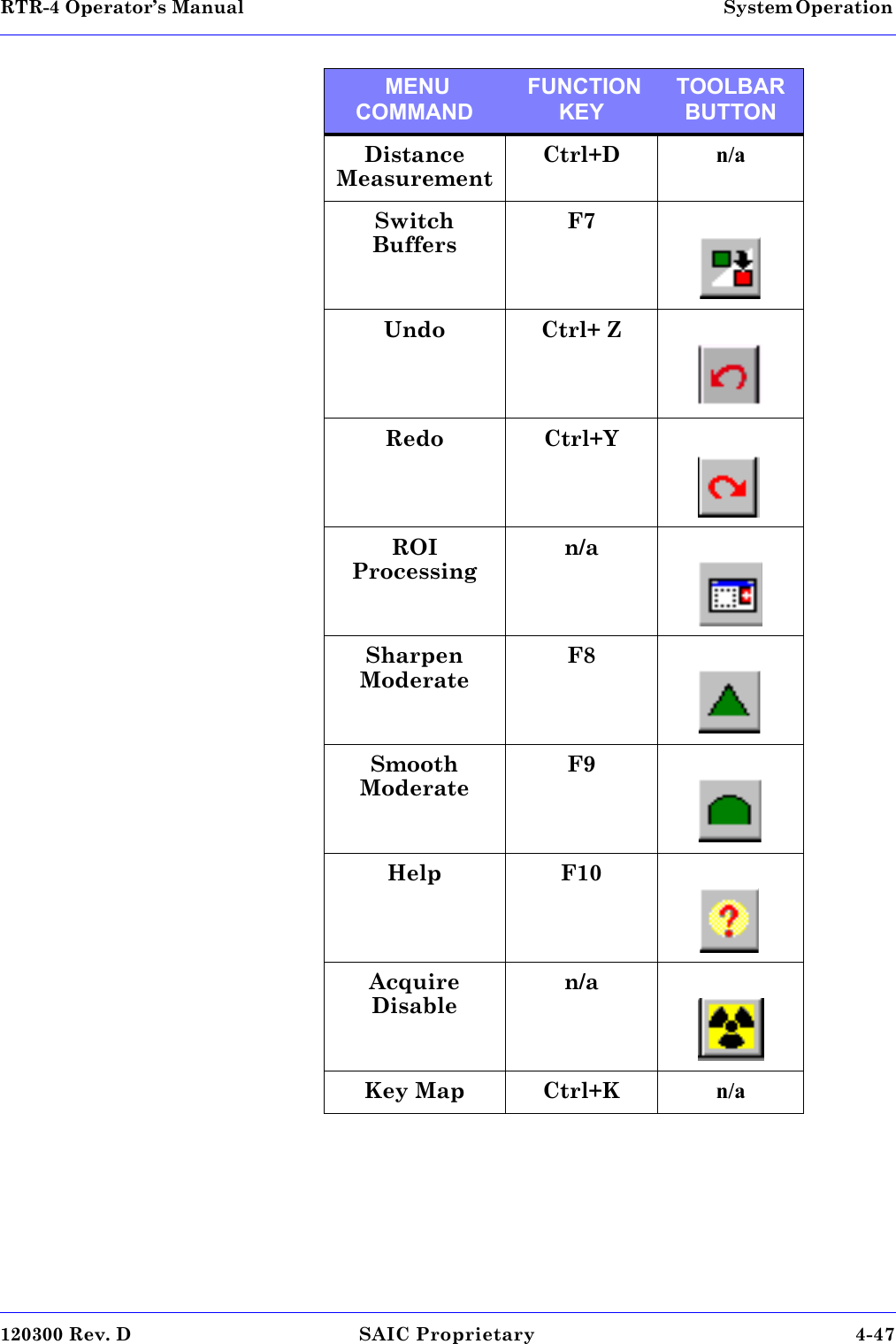
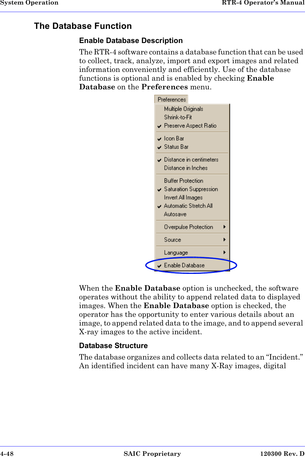
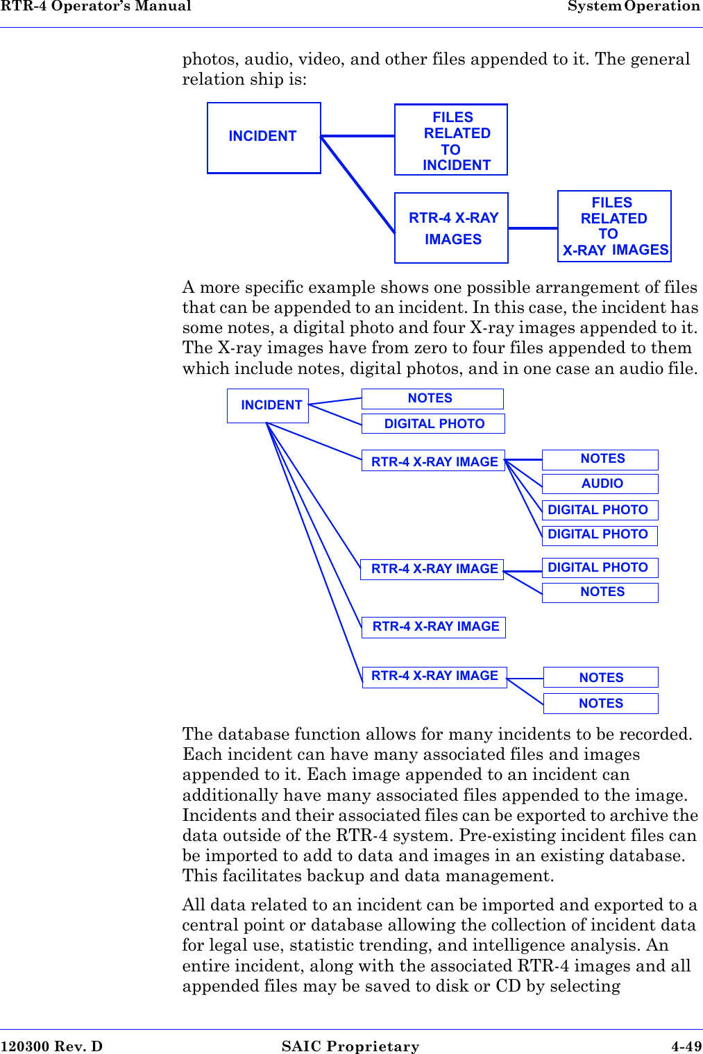
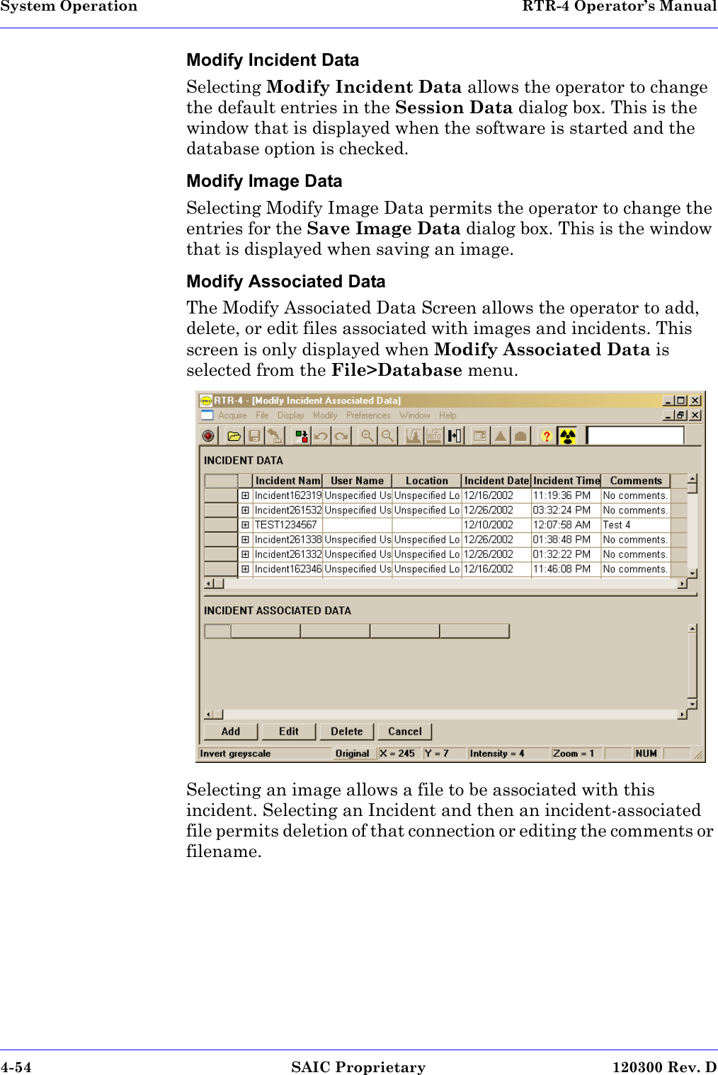
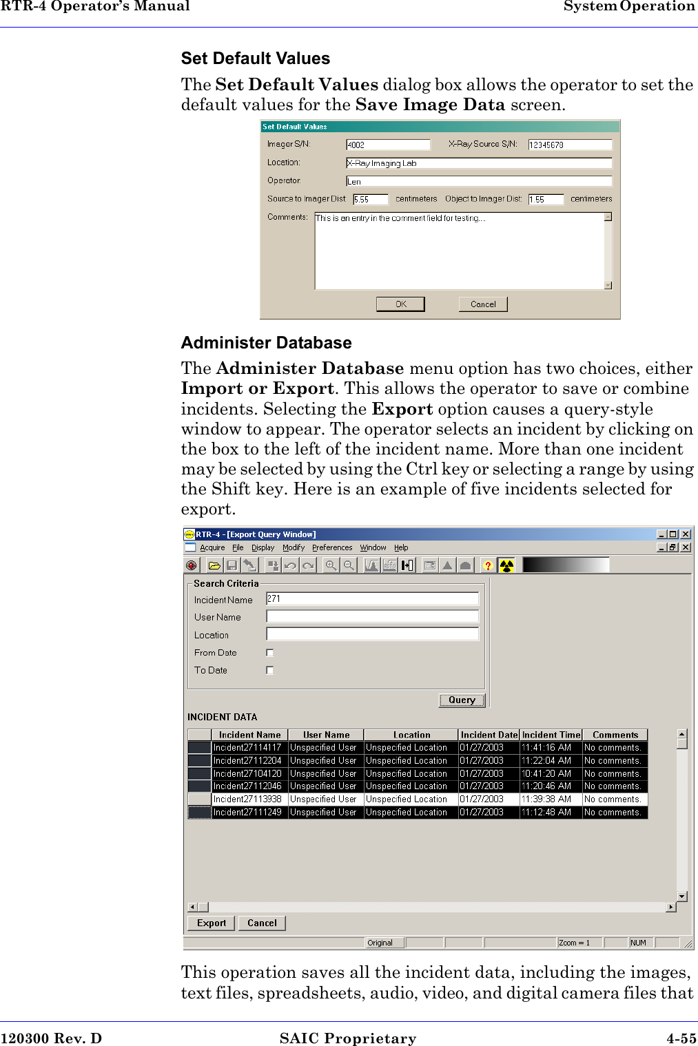
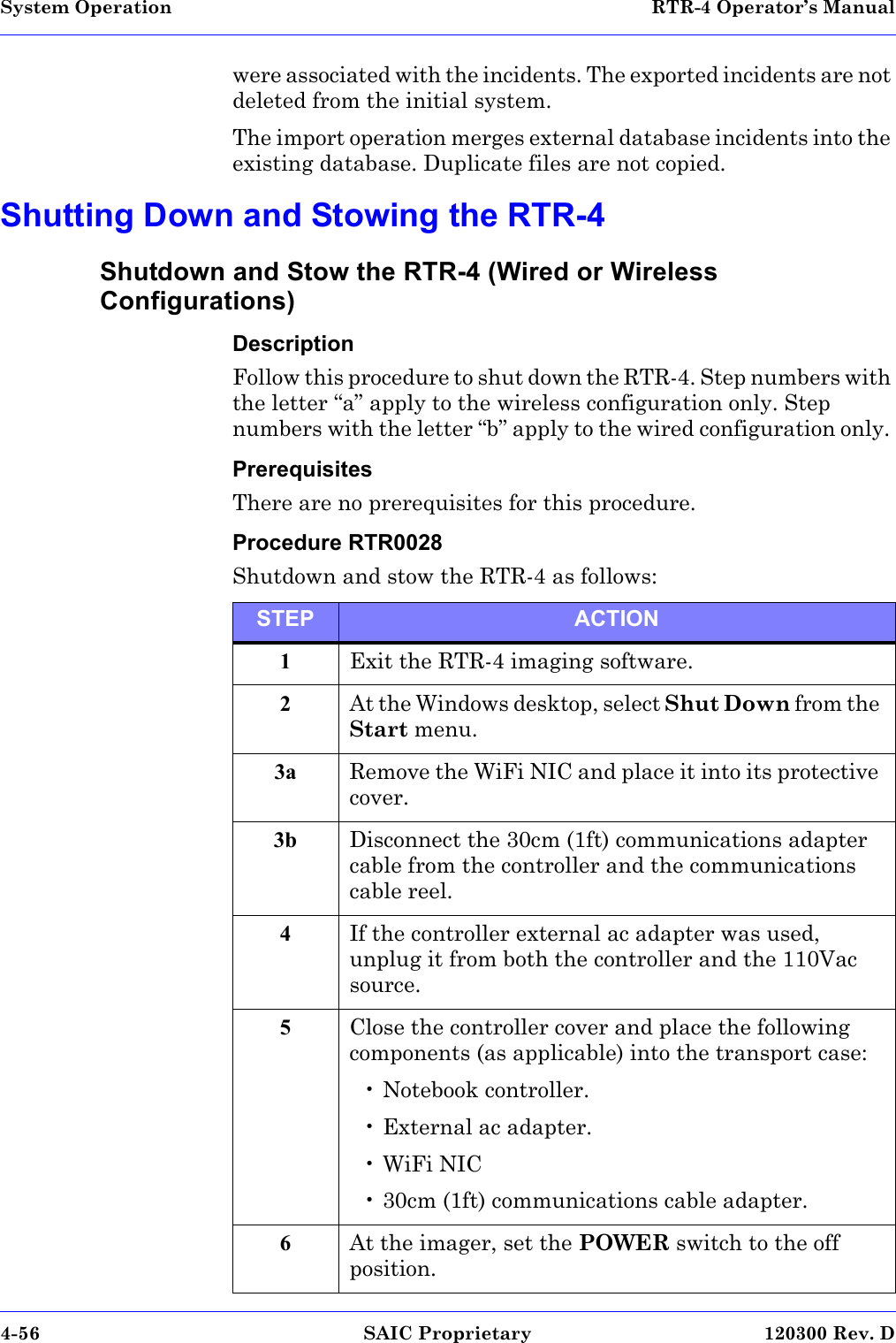
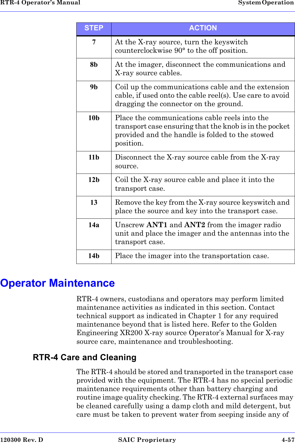
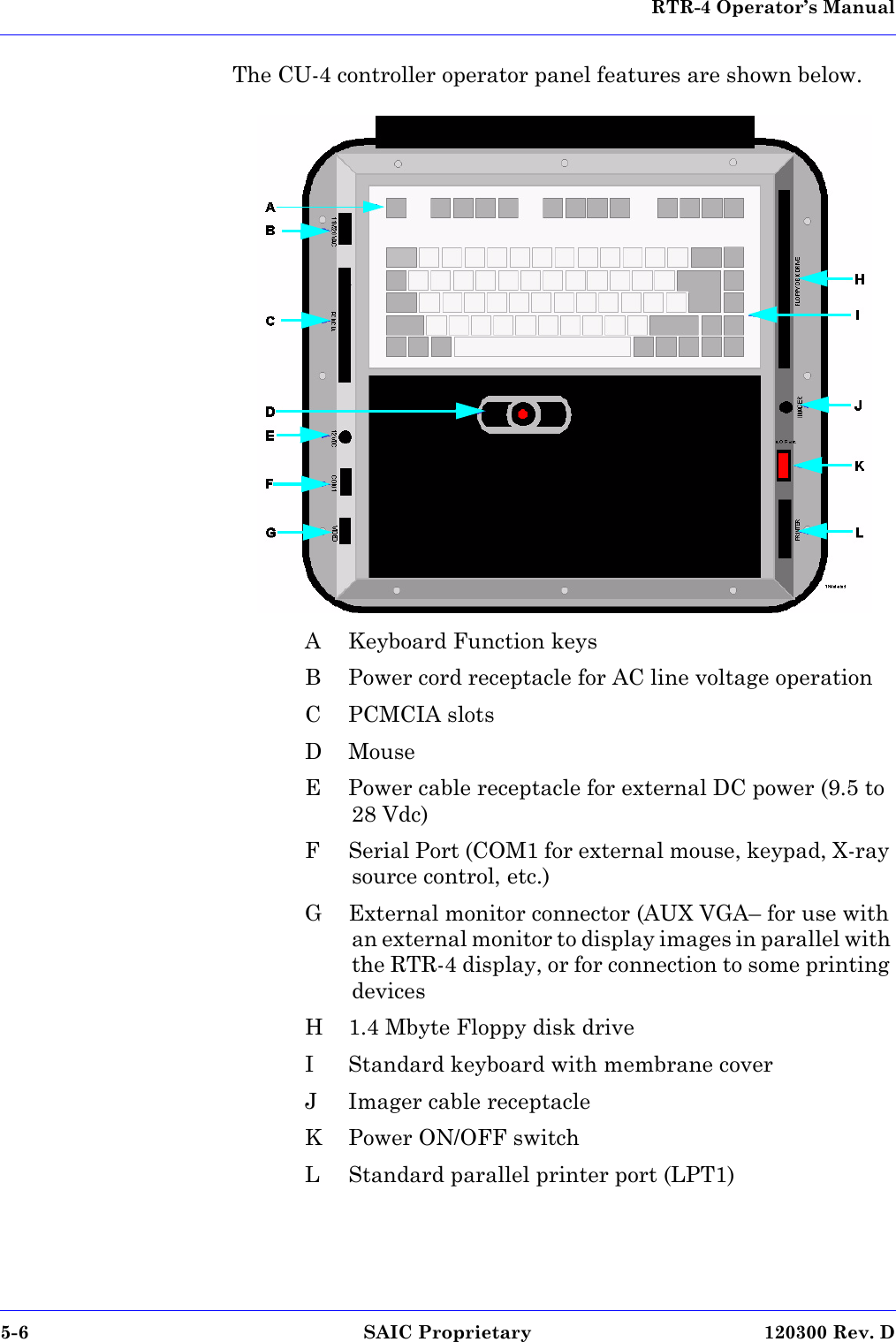
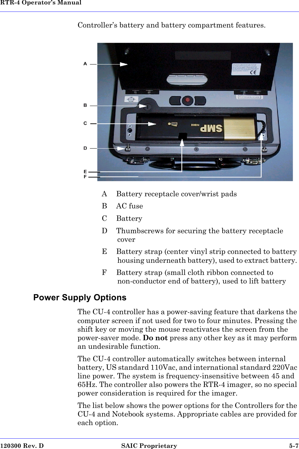
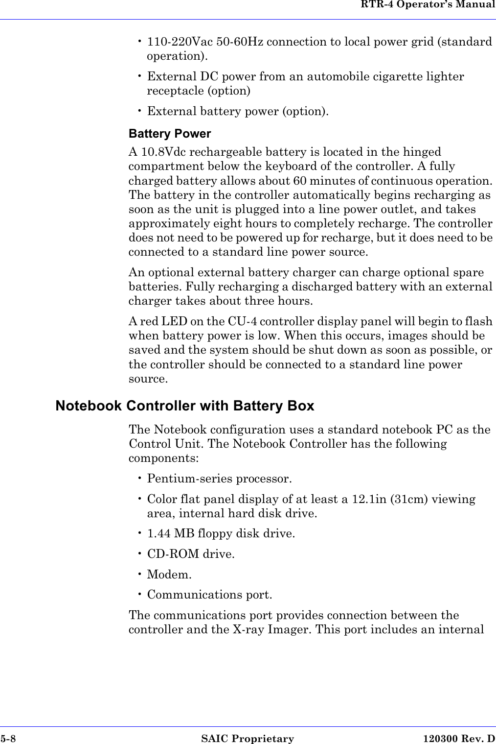
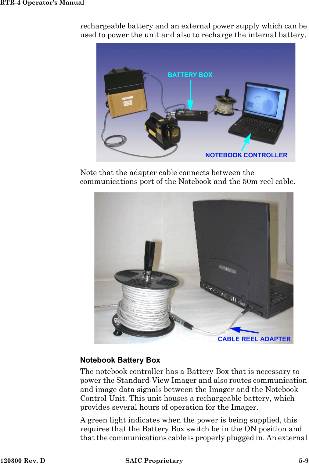
User Manual
Discussion / Help
Navigation