Leidos RTR-RI Remote Control Transmitter User Manual RTR4revD
Science Application International Corporation Remote Control Transmitter RTR4revD
Leidos >
Users Manual
RTR-4 Portable Digital X-Ray
Imaging System
Operator’s Manual
120300 Rev. D
15 February 2003

RTR-4 Operator’s Manual
ii SAIC Proprietary 120300 Rev. D
SAIC
16701 W. Bernardo Dr.
San Diego, CA 92127-1903
U.S.A.
Copyright © 2001-2003 SAIC
All rights reserved. Printed in the United States of America.
All data and information contained in or disclosed by this document are confidential
and proprietary information of SAIC and its affiliates and all rights herein are
expressly reserved. By accepting this material, the recipient agrees that this material
and the information contained herein are held in confidence and in trust and will not
be used, copied, or reproduced in whole or in part, nor its contents revealed in any
manner to others without the express written permission of SAIC. The recipient also
agrees not to allow the use of this document by others without the express written
consent of SAIC. This technology is controlled by the U.S. Government. Diversion
contrary to U.S. law is prohibited. SAIC reserves the right to change or revise this
information without notice. Reasonable effort has been made to ensure that the
information in this manual is accurate; however, SAIC assumes no responsibility for
inaccuracies or omissions of any kind. SAIC makes no warranty for the use of its
product.
SAIC is a registered trademark of Science Applications International Corporation.
RTR-4™ is a trademark of SAIC
RTR-4 Portable Digital X-Ray Imaging System Operator’s Manual
120300 Rev. D

RTR-4 Operator’s Manual
120300 Rev. D SAIC Proprietary iii
FCC Declaration of Conformity
We SAIC
16701 W. Bernardo Dr.
San Diego, CA 92127-1903 U.S.A.
declare under our sole responsibility that the product
RTR-4 Portable Digital X-Ray Imaging System
complies with Part 15 of FCC Rules. Operation is subject to the following of two
conditions:
• This device may not cause harmful interference.
• This device must accept any interference received, including
interference that may cause undesired operation.
NOTE: This equipment has been tested and found to comply with the limits for a
Class A digital device, pursuant to Part 15 of the FCC Rules. These limits are
designed to provide reasonable protection against harmful interference when the
equipment is operated in a commercial environment. This equipment generates, uses,
and can radiate radio frequency energy and, if not installed and used in accordance
with this instruction manual, may cause harmful interference to radio
communications. Operation of this equipment in a residential area is likely to cause
harmful interference, in which case the user will be required to correct the
interference at his own expense. Changes or modifications not expressly approved by
Science Applications International Corporation could void the user’s authority to
operate the equipment.

RTR-4 Operator’s Manual
iv SAIC Proprietary 120300 Rev. D
Declaration Of CE Conformity
We SAIC
16701 W. Bernardo Dr.
San Diego, CA 92127-1903 U.S.A.
declare under our sole responsibility that the product
RTR-4 Portable Digital X-Ray Imaging System
to which this declaration relates is in conformance with the applicable provisions of
the following directives:
• 73/23;EEC governing product safety.
• 89/336/EEC governing electromagnetic compatibility.
• 99/5/EC governing radio and telecommunication terminal
equipment.
Using the following standards:
• EN61010-1
• EN 61326:1997 +A1:1998 +A2:2001
• EN300 220-3:2000
• EN 301 489-3:2001
15 February 2003
San Diego, CA
Richard Amiton
Director of Engineering

RTR-4 Operator’s Manual
120300 Rev. D SAIC Proprietary v
Revision History
VERSION COPY FREEZE DATE NOTES
— 15 June 1999 Initial release.
A 16 April 1999 Minor revision.
B 28 February 2001 Wireless Option removed from Operator’s Guide
and transformed into a separate supplemental
document.Battery Charger chapter and CU-4
Modem chapter deleted.
C 20 October 2001 Minor text changes.
D 15 February 2003 Incorporate information for Wireless operation
and optional equipment; document new database
software. Word count is 19,926.

RTR-4 Operator’s Manual
vi SAIC Proprietary 120300 Rev. D
Table of Contents
Introduction................................................................................................... 1-1
About this Manual..................................................................................................... 1-1
Purpose and Scope .................................................................................................... 1-1
Document Revisions ................................................................................................. 1-1
RTR-4 Technical Support......................................................................................... 1-1
Component Returns ............................................................................................ 1-2
Acronyms and Abbreviations ................................................................................... 1-2
Safety Summary ........................................................................................... 2-1
Introduction............................................................................................................... 2-1
Follow all warnings and instructions.................................................................. 2-1
Qualified and Trained personnel only ................................................................ 2-1
Symbols .............................................................................................................. 2-1
Safety Procedures...................................................................................................... 2-2
General Safety Procedures.................................................................................. 2-3
Safe Operating Environment ............................................................................... 2-4
Outdoor Use........................................................................................................ 2-4
System Description, Setup, and Quick Start ......................................... 3-1
Introduction................................................................................................................ 3-1
Hardware Description ............................................................................................... 3-1
RTR-4 System Standard Wired Configuration Components.............................. 3-1
Portable Notebook Controller............................................................................. 3-2
Integrated Imager................................................................................................ 3-3
XR200 X-Ray Source......................................................................................... 3-8
Interconnecting Cables ....................................................................................... 3-8
Transport Case.................................................................................................... 3-9
RTR-4 Standard Wireless Configuration.......................................................... 3-10
Setting up the RTR-4 .............................................................................................. 3-12
Distance Adjustments ....................................................................................... 3-12
Position Adjustments........................................................................................ 3-12
Standard Wired Configuration.......................................................................... 3-13
Setting Up the Wired Configuration................................................................. 3-13
Standard Wireless Configuration...................................................................... 3-15
Setting Up the Wireless Configuration............................................................. 3-15
Quick Start .............................................................................................................. 3-18
System Initialization......................................................................................... 3-18
Acquiring an X-Ray Image............................................................................... 3-18
System Operation ........................................................................................ 4-1
Introduction................................................................................................................ 4-1
Operating the RTR-4................................................................................................. 4-1
Acquiring an X-Ray Image................................................................................. 4-1
Using the Sum Command................................................................................... 4-3
Using the Add Images Feature ........................................................................... 4-4
Using the Subtract Images Command ................................................................ 4-7
Image Processing ...................................................................................................... 4-9

RTR-4 Operator’s Manual
120300 Rev. D SAIC Proprietary vii
Retrieving an Image............................................................................................ 4-9
Showing Image Information............................................................................. 4-10
Using Multiple Image Display.......................................................................... 4-10
Using the Grid Overlay..................................................................................... 4-11
Measuring Distance in an Image ...................................................................... 4-12
Adding Lines and Text ..................................................................................... 4-13
Using Contrast Stretch...................................................................................... 4-14
Using Automatic Stretch................................................................................... 4-16
Using the Color Palettes ................................................................................... 4-16
Using Saturation Suppression........................................................................... 4-17
Sharpening an Image ........................................................................................ 4-18
Smoothing an Image......................................................................................... 4-19
Reducing Image Noise...................................................................................... 4-20
Using Edge Detection....................................................................................... 4-21
Embossing an Image......................................................................................... 4-22
Using Histogram Equalization.......................................................................... 4-23
Image Preservation.................................................................................................. 4-23
QuickSaving an Image...................................................................................... 4-24
Saving an Image ............................................................................................... 4-25
Print an Image................................................................................................... 4-25
Software Description .............................................................................................. 4-26
RTR-4 Functions .............................................................................................. 4-26
The Acquire Menu............................................................................................. 4-27
The File Menu ................................................................................................... 4-31
The Display Menu ............................................................................................ 4-32
The Modify Menu............................................................................................. 4-35
The Preferences Menu ...................................................................................... 4-39
The Window Menu........................................................................................... 4-43
The Help Menu................................................................................................. 4-44
The Icon Toolbar ............................................................................................... 4-45
The Database Function ..................................................................................... 4-48
Shutting Down and Stowing the RTR-4 ................................................................. 4-56
Shutdown and Stow the RTR-4 (Wired or Wireless Configurations) .............. 4-56
Operator Maintenance............................................................................................. 4-57
RTR-4 Care and Cleaning ................................................................................ 4-57
Disk Space ........................................................................................................ 4-58
Charging Batteries ............................................................................................ 4-58
Imager Battery Replacement ............................................................................ 4-59
Optional External X-Ray Receiver Battery Replacement ................................. 4-60
Wireless Signal Strength Test Utility ............................................................... 4-61
Ancillary Equipment................................................................................... 5-1
Introduction............................................................................................................... 5-1
Previous Model Wireless Option.............................................................................. 5-1
Previous Model Controllers ...................................................................................... 5-4
Introduction......................................................................................................... 5-4
Standard CU-4 Components............................................................................... 5-4

RTR-4 Operator’s Manual
viii SAIC Proprietary 120300 Rev. D
Power Supply Options ........................................................................................ 5-7
Notebook Controller with Battery Box............................................................... 5-8
Previous Model Imagers ......................................................................................... 5-10
Introduction....................................................................................................... 5-10
Standard-View Imager...................................................................................... 5-10
Alternate X-Ray Sources ........................................................................................ 5-12
Introduction........................................................................................................ 5-12
Miscellaneous Accessories ..................................................................................... 5-13
Introduction....................................................................................................... 5-13
Wireless Option Backpack ............................................................................... 5-13
Notebook PC Configuration Accessories ......................................................... 5-14
Index .................................................................................................................I-1
List of Figures
Figure 4-1 Main Menu Screen.............................................................................. 4-27
Figure 4-2 Attach Associated Data Window........................................................ 4-52

120300 Rev. D SAIC Proprietary 1-1
1 Introduction
About this Manual
This manual provides information on the setup and use of the
various options and configurations of the Real Time Radioscopy
(RTR-4) Imaging System and is comprised of the following
chapters:
Chapter 1 - Introduction
Chapter 2 - Safety Summary
Chapter 3 - System Description, Setup, and Quick Start
Chapter 4 - System Operation
Chapter 5 - Ancillary Equipment
Purpose and Scope
This manual describes the RTR-4 hardware and software and
provides instructions on its use, including setup of the equipment,
acquisition and processing of X-ray images, and some
troubleshooting. The information in this document is to be used
only by technicians and operators who have been trained to use
the RTR-4 system.
Document Revisions
This manual is revised periodically, based on the amount and
substance of equipment changes and resulting changes to the
manual. When changes to this manual are required, a new
manual incorporating the changes is released.
RTR-4 Technical Support
Technical support is available using the following methods:
• By phone: 800-962-1632 (in the US) or 858-826-9831 (outside
of the US) from 0730 to 1630 PDT.
• By fax: 858-826-9009.
• By e-mail: SecurityProducts@saic.com.
More information may be found on our website at
http://www.saic.com.

Introduction RTR-4 Operator’s Manual
1-2 SAIC Proprietary 120300 Rev. D
Component Returns
Contact us at the above numbers or e-mail to receive a Return
Material Authorization (RMA) number. Return damaged, failed,
or defective systems or components to the address below. When
shipping components, include a description of the problem and
the RMA number.
SAIC
Attn: RTR-4 Manufacturing Mgr.
16701 W. Bernardo Dr.
San Diego, CA 92127-1903 USA
The Golden Engineering X-ray sources may be handled
separately for customer convenience. Follow the instructions in
the Golden operator’s manual for repair of the Golden
Engineering XR200 X-ray source or visit their website at
http://www.goldenengineering.com.
Acronyms and Abbreviations
The acronyms and abbreviations listed in the table below are used
throughout this manual.
TERM DEFINITION
ALARA As Low As Reasonably Achievable
CU-4 Control Unit 4 (original controller)
ESD Electrostatic Discharge
GUI Graphical User Interface
HERO Hazards of Electromagnetic Radiation to
Ordnance
LED Light Emitting Diode
MB Megabyte (one million bytes)
NCU Notebook Control Unit
NIC Network Interface Card
PC Personal Computer
PCMCIA Personal Computer Memory Card
International Association
PIC Pocket Ionization Chamber

RTR-4 Operator’s Manual Introduction
120300 Rev. D SAIC Proprietary 1-3
RF Radio Frequency
RMA Return Material Authorization
ROI Region Of Interest
RTR Real Time Radiography
SNR Signal-to-Noise Ratio
.tif Tagged Image Format (a filename extension)
TLD Thermoluminescent Dosimeters
Vac Volts alternating current
Vdc Volts direct current
WiFi Wireless Fidelity, a wireless ethernet
communications standard.
TERM DEFINITION

Introduction RTR-4 Operator’s Manual
1-4 SAIC Proprietary 120300 Rev. D

120300 Rev. D SAIC Proprietary 2-1
2 Safety Summary
Introduction
This chapter lists and describes the safety issues applicable to the
standard configurations of the RTR-4. The summaries listed here
apply at all times and shall be strictly followed by all operators,
technicians, and observers.
Follow all warnings and instructions
The equipment and the procedures in this manual have warning
and caution labels and their relevant hazard type symbols.
Observe all warnings, cautions, and instructions marked on the
equipment and included in this manual and in all supporting
manufacturer documentation at all times.
Qualified and Trained personnel only
The RTR-4 should only be operated by technically qualified and
trained personnel. It is the responsibility of the RTR-4 user to
ensure only trained personnel are permitted to configure, operate,
and maintain RTR-4 equipment. It is the responsibility of the user
to verify that all regulations have been met before operating this
equipment.
Symbols
In procedural steps, specific warnings and cautions are placed
immediately prior to the step(s) to which they apply. Specific
warnings and cautions have three parts:
• The specific hazard is stated.
• The correct action to be followed or performed is given.
• The consequences if the correct action is not followed are
stated.
The following warning symbols and the caution symbol are used
in this manual when warnings and cautions are placed into
procedural steps.
Safety Summary RTR-4 Operator’s Manual
2-2 SAIC Proprietary 120300 Rev. D
Safety Procedures
The X-ray source used with the RTR-4 system generates x-rays
that can be harmful to personnel. It is the responsibility of the
operator to ensure that the RTR-4 is properly used by trained
personnel who follow recommended operating procedures and
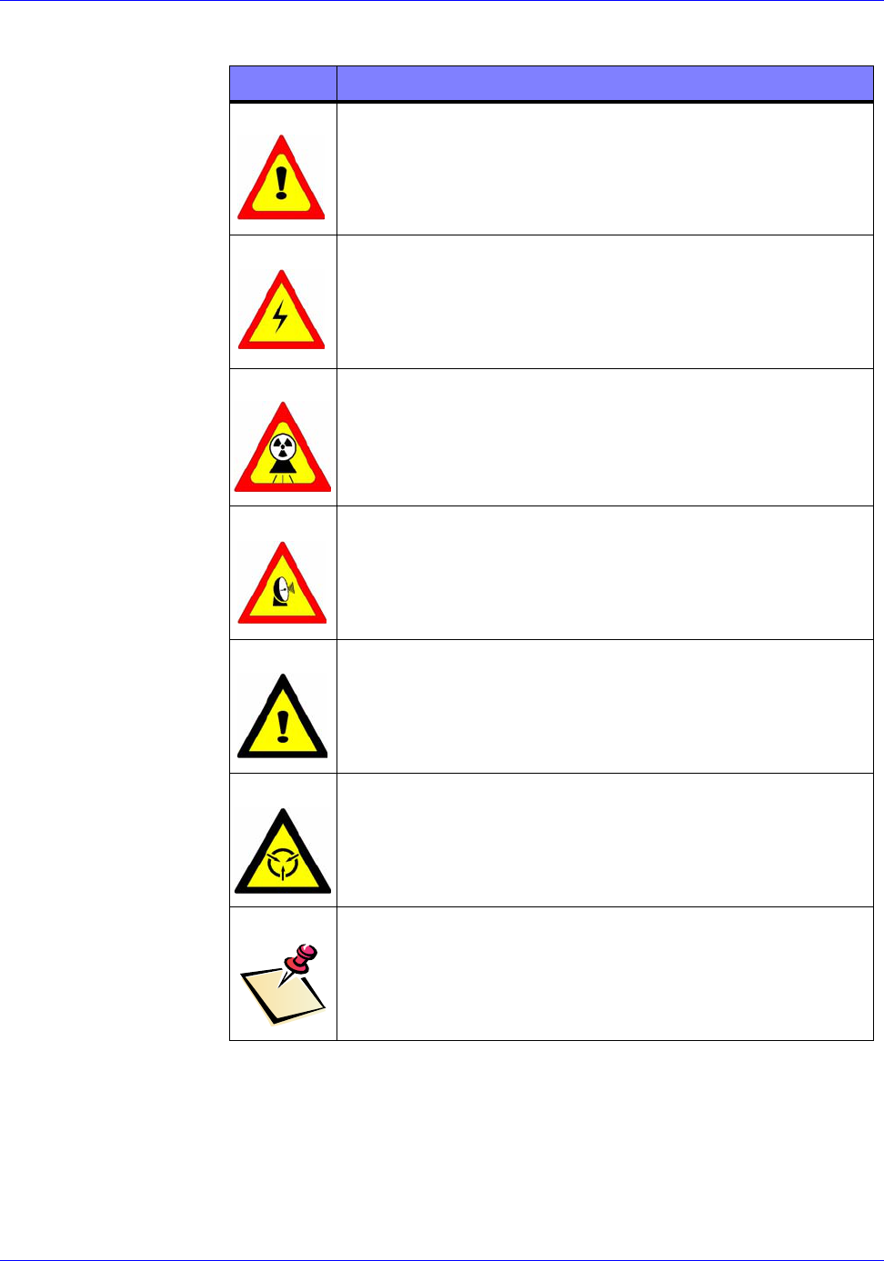
SYMBOL DEFINITION OF USE
The generic Warning symbol precedes a procedural
step or process which could lead to personnel injury
if not followed correctly. This symbol is used when
multiple hazard conditions may be present or one of
the symbols below does not specifically apply.
The Electrical, High Voltage, or High Current
hazard warning symbol is used where the potential
for electrical shock may exist while performing a
specific task.
The X-Ray Radiation hazard warning symbol is
used whenever emitted x-ray radiation may exceed
background levels during a specific procedure or
process.
The Microwave Radiation hazard warning
symbol is used whenever emitted microwave/rf
radiation is present during a specific procedure or
process.
The generic Caution symbol precedes a procedural
step or process which could lead to equipment
damage if not followed correctly.
The ESD caution symbol precedes a procedural
step or process requiring use of standard approved
ESD damage control procedures to avoid harming
electronic components and circuit card assemblies.
The Note symbol indicates where additional or
clarifying information, commentary, sidelights, or
points of interest have been added to a procedure
either before or after the step to which it applies.

RTR-4 Operator’s Manual Safety Summary
120300 Rev. D SAIC Proprietary 2-3
applicable regulations, and the X-ray Source supplier guidelines,
such as the Golden Engineering XR200 X-Ray Source Operator’s
Manual.
General Safety Procedures
The following are general safety precautions for using X-ray
generating devices:
• As Low As Reasonably Achievable (ALARA) principles of
radiation exposure are applicable whenever the RTR-4 system
is being used. Personnel exposure to X-rays shall be kept to the
absolute minimum possible.
• Users shall establish appropriate exclusion zones to limit
access to the radiation field. This information can be found in
the Users’s Manual for the applicable X-ray source or on the
manufacturer’s webpage. When two or more exclusion zones
apply, such as using the RTR-4 in the presence (or suspected
presence) of explosives, the larger exclusion zone perimeter
shall apply.
• Operating personnel shall review and follow applicable
regulations.
• In order to meet the FCC RF safety regulations when using the
wireless configuration, personnel shall maintain a distance of
at least 20cm (8in) from the WiFi antennas when the system
is operational.
• Personnel in the vicinity when the RTR-4 system is being
operated may be required to wear an approved X-ray radiation
monitoring device in accordance with local regulations or
administrative procedures.
• Personnel shall remain at a safe distance from the X-ray
source, and always remain outside the direct beam during
image acquisition if possible.
• Personnel shall remain at a distance of at least 20cm (7.9in)
from the antennas whenever the RTR-4 wireless option is
being used.
• When using the optional Notebook Safety Lock, the controller
key shall be turned to the OFF position when not acquiring
images. The X-ray source cannot fire when its controller key is
in the OFF position.
• The power key for the X-ray source should be turned to the
OFF position when the system is not acquiring images. The
X-ray Source cannot fire when its key is in the OFF position.

Safety Summary RTR-4 Operator’s Manual
2-4 SAIC Proprietary 120300 Rev. D
• The system operator shall remove the controller key and X-ray
Source keys when not operating the system, to ensure that the
system is not accidentally or improperly operated.
• All reasonable efforts shall be made to reduce doses to ALARA
levels.
Safe Operating Environment
The following environmental conditions affect the safe operating
conditions of the RTR-4:
• Maximum external voltage fluctuation of ± 10%.
• Maximum altitude 2000m (6562ft).
• Operating temperature range 5°C (41°F) to 40°C (104°F).
• Maximum relative humidity of 80%.
Outdoor Use
All parts of the RTR-4 system are intended for the outdoor use
except for the external ac power adapters. If external power
adapters must be used outdoors, ensure they are protected from
adverse weather conditions such as rain or moisture. Failure to
use adequate precautions may result in equipment damage or
personnel hazard.

120300 Rev. D SAIC Proprietary 3-1
3 System Description, Setup, and Quick
Start
Introduction
This chapter describes the standard configuration of the RTR-4
system and contains the following sections:
• Hardware Description.
• Setting up the RTR-4
•Quick Start
The basic system design of the RTR-4 consists of an imager unit,
a controller unit, an X-ray source unit, and the interconnecting
cables or optional wireless components. This chapter covers the
standard wired configuration and the standard wireless
configuration only. Alternate components are covered in later
chapters.
Hardware Description
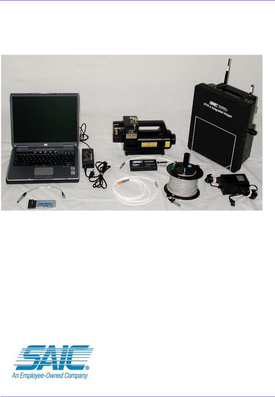
RTR-4 System Standard Wired Configuration Components
The standard wired RTR-4 configuration includes the following
components:
• Portable Notebook Controller.
• Notebook ac power adapter.
• 30cm (1ft) Notebook to cable reel adapter.
• 50m (164ft) cable reel.
• Integrated Imager.
• Imager ac power adapter and spare battery.
• Imager battery external battery charger.
• RTR-4 Operating Software
• Golden Engineering XR200 X-Ray Source with operator’s
manual.
• 3m (10ft) imager to source cable.
• Source battery charger and spare battery.
System Description, Setup, and Quick Start RTR-4 Operator’s Manual
3-2 SAIC Proprietary 120300 Rev. D
• RTR-4 Portable Digital X-Ray Imaging Set Operator’s
Manual, SAIC document 120300 (this document).
• Transport case.
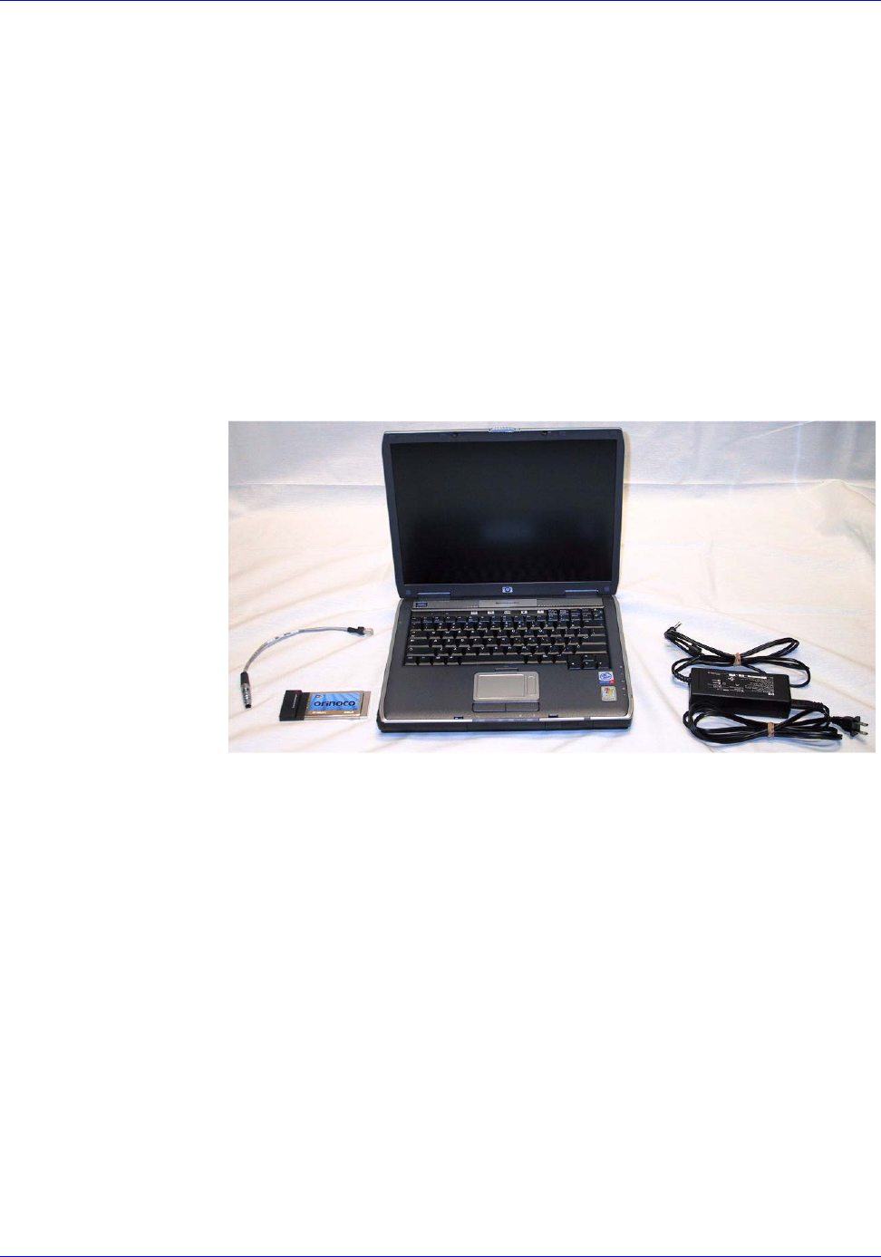
Portable Notebook Controller
The standard configuration of the RTR-4 system uses a standard
commercial notebook Personal Computer (PC). Functioning as
the controller, the notebook PC contains specific SAIC software
that provides for operator interface with the RTR-4 system and
displays images as they are captured. A special adapter cable is
provided to connect the PC modem RJ45 connector to the RTR-4
system cable reel when the system is setup in the wired
configuration. A WiFi Network Interface Card (NIC) is provided
for connecting in the wireless configuration.
The notebook PC has the following current features:
• A Pentium- series processor.
• A 12.1 in (30.7cm) or larger active matrix color flat panel
display.
•Custom SAIC software.
• A 30 GB or greater internal hard drive.
• A 1.44 MB floppy disk drive.
• DVD/CD-RW drive.
• Two CardBus slots.
• 56 kbaud internal modem.
• Internal rechargeable Lithium Ion battery with an external
100-240Vac power adapter and battery charger.
• Current Dimensions: 36.6cm x 25.9cm x 2.55cm (14.1in W x
10.2in D x 1.46in H).
NOTEBOOK PC
AC POWER
ADAPTER
RJ45 CABLE
ADAPTER
WiFi NIC

RTR-4 Operator’s Manual System Description, Setup, and Quick Start
120300 Rev. D SAIC Proprietary 3-3
• Weight: 2.9 kg (6.39lbs).
Storage Medium
Images are stored on disk in an industry-standard format, and
may be manipulated and annotated with third-party software.
The following list shows the RTR-4 Notebook options for storage,
and their capacities. Some differences between notebook
manufacturers will occur.
RJ45 Cable Adapter
This adapter is provided to connect the modem connection on the
controller PC to the 50m cable reel when the RTR-4 is setup in the
wired configuration.
Controller AC Power Adapter
This adapter connects the notebook PC to ac power and provides
19Vdc to the PC for operation or internal battery charging.
Integrated Imager
The Integrated Imager uses a compact solid-state camera with a
20cm x 27cm (8.0in x 10.7in) field-of-view. An electro-optical
system records images formed on the imager's X-ray conversion
screen and transmits the images to the controller PC for display.
Imager features include:
• Dimensions: 30cm x 34cm x 18cm (11.75in W x 13.25in H x
7.0in D).
• Weight: 4.5kg (10.0lbs).
• DR35S NiMH 10.8Vdc battery and an optimal ac power
adapter.
STORAGE MEDIUM MAXIMUM CAPACITY
Internal hard disk
drive.
Over 80,000 images,
depending on size of disk
drive.
1.44 MB floppy disk. Four images per disk.
Optional CardBus
disk drive.
System-defined; up to
thousands of images.
Optional USB flash
disk.
Up to thousands of images.
CD-ROM Up to thousands of images.
System Description, Setup, and Quick Start RTR-4 Operator’s Manual
3-4 SAIC Proprietary 120300 Rev. D
• The imager may use other external power sources between
12Vdc and 24Vdc such as vehicle power.
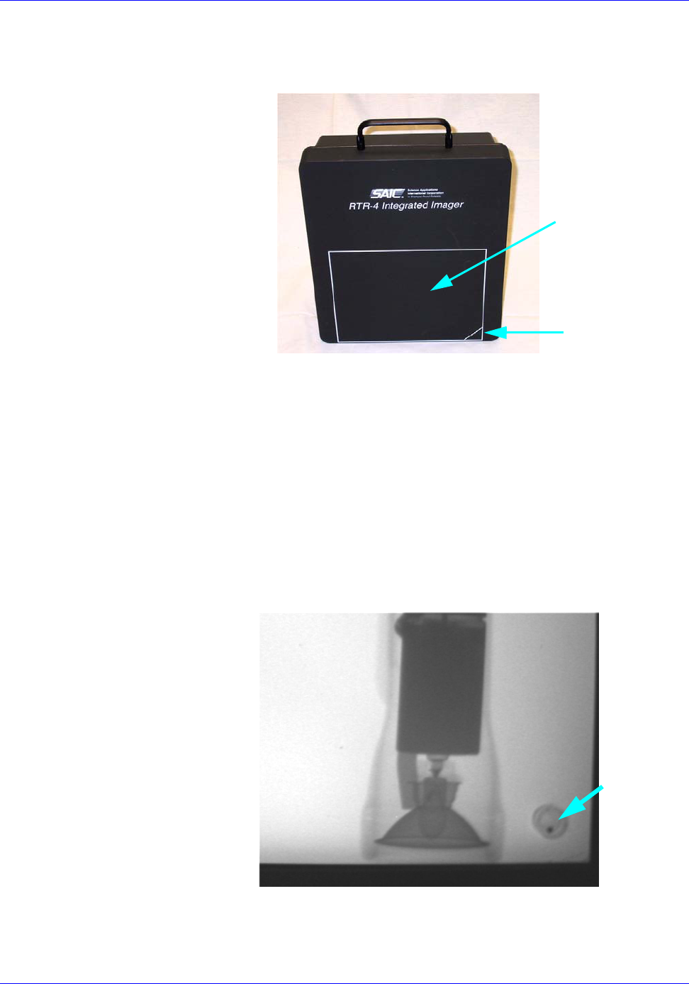
Image Target Area
The active image area is indicated on the face of the imager. This
is the area that will be displayed on the controller PC.
Orientation Indicator
A triangle in one corner of the image target area is shown as a ball
in a circle on the controller PC image and indicates the lower edge
of the image. This ball is free floating and will always indicate the
downward edge of the image as the imager is positioned on its
sides or other orientations. Rubber feet and standard threaded
tripod mounting holes are provided on three sides to permit
placement of the imager in different orientations.
RTR010 TARGET AREA
ORIENTATION
INDICATOR
IMAGE
ORIENTATION
INDICATOR

RTR-4 Operator’s Manual System Description, Setup, and Quick Start
120300 Rev. D SAIC Proprietary 3-5
Power-on Delay Timer
The imager is equipped with a rotary switch that allows setting a
0 to 3 minute delay between turning on the imager power switch
and the application of power to the imager. The switch positions
provide 20 second interval settings up to the 3 minute limit. Use
of this switch permits operating personnel to leave the immediate
area before electromagnetic energy is applied near a suspect
package.
Integrated Imager External Power Adapter
This adapter provides 18Vdc power to the imager when
connected. If a battery is present, the adapter will charge the
battery. The Power On LED will indicate when the adapter is
connected and the Battery Charge LED will indicate battery
charge status.
Integrated Imager External Battery Charger.
This unit provide for charging the DR35S NiMH 10.8Vdc battery
while it is outside of the imager. It is connected to the local utility
power and the battery to be charged is inserted. The charger is
equipped with LEDs that indicate as follows:
LED INDICATION
Red
IDLE, unit plugged in, no battery inserted.
flashes once.
Green flashes briefly, long dark pause.
Red
CHARGE, battery inserted.
off.
Green on steady, normal charging of smart battery.
Red
MAINTENANCE
off.
Green steady flashing, battery is fully charged.
Red
WAKEUP-CHARGE heavily discharged smart
battery or not a smart battery.
flashes on-off in equal amounts.
Green flashes on-off in equal amounts.
System Description, Setup, and Quick Start RTR-4 Operator’s Manual
3-6 SAIC Proprietary 120300 Rev. D
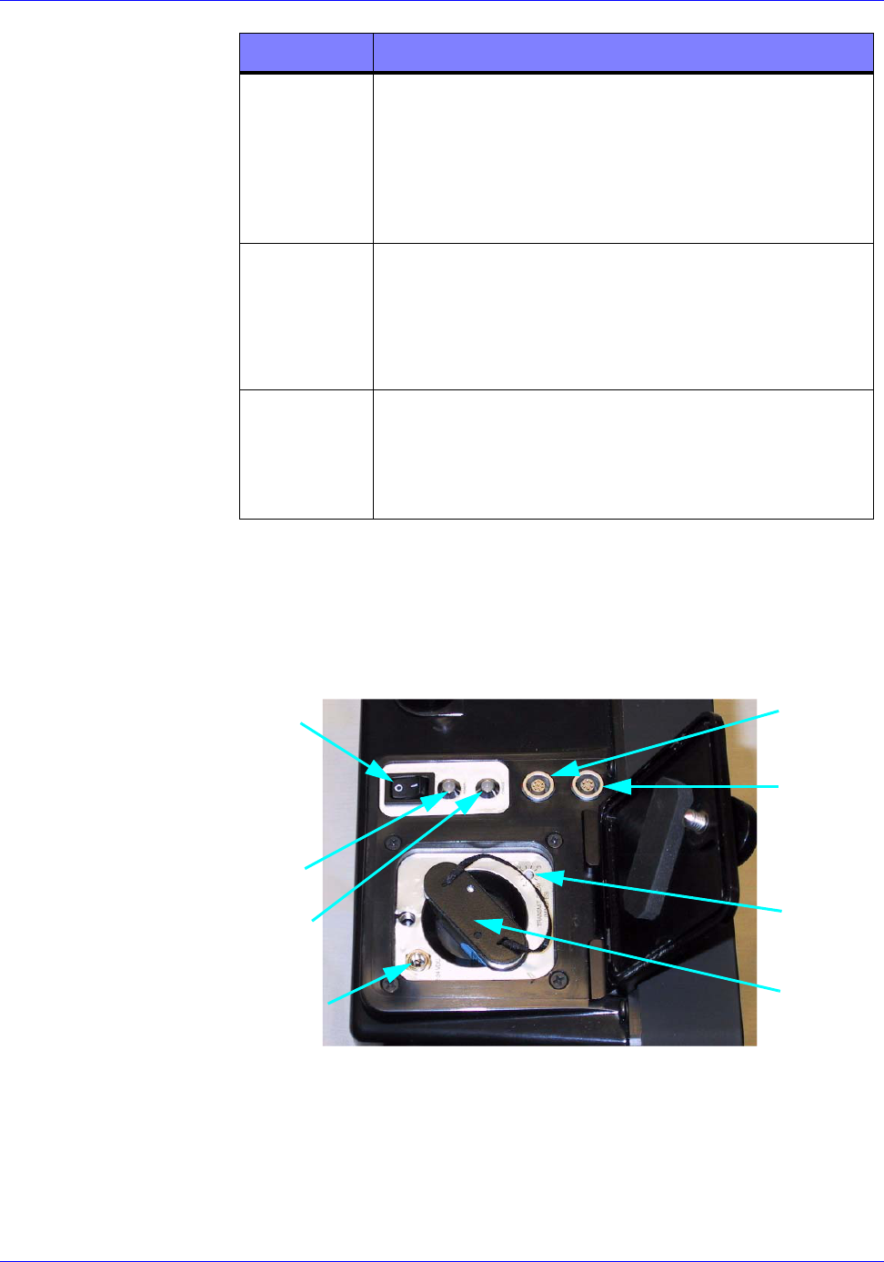
Imager Control Panel
Operation and interconnection of the imager with the rest of the
RTR-4 system in the wired configuration is accomplished through
a control panel at the side of the imager.
Red
TEMPERATURE FAILURE, battery is too
hot or too cold for safe charging. The battery
should be brought to operating temperature.
On steady.
Green Off.
Red
FAILURE, battery is physically damaged, do
not use, discard battery.
On.
Green On.
Red FAILURE DURING INITIATION
If the red LED light up when the charger is
plugged in, the charger is not ready for use.
Contact your nearest dealer.
LED INDICATION
POWER
SWITCH
POWER
ON LED
BATTERY
CHARGE
LED
DATA
CONNECTOR
X-RAY
CONNECTOR
POWER ON
DELAY
TIMER
EXT. PWR
CONNECTOR
BATTERY
TRIGGER

RTR-4 Operator’s Manual System Description, Setup, and Quick Start
120300 Rev. D SAIC Proprietary 3-7
The functions located on the Imager control panel are as follows:
CONTROL OR
INDICATOR FUNCTION
Power On-Off Switch Turns on the imager power for both
internal battery and external power
operation.
Power On LED • Green and on steady when
powered by battery.
• Amber and on steady when
powered by an external source.
• Flashing green when power-up
delay is selected, with last five
seconds before power on rapid
flashing green.
• Flashing Amber when battery
power is low.
Battery Charger LED • Amber and flashing when testing
battery.
• Amber and on steady during
battery charging.
• Green and on steady when battery
charging is complete.
Data Connector Receptacle for the Extension Data
Cable Spool. Color coded green to
match the cable connector.
X-Ray Trigger
Connector
Receptacle for the X-Ray Trigger
Cable. Color coded yellow to match
cable connector.
External Power
Connector
Receptacle for an external 12Vdc to
24Vdc power source.
Battery
Compartment
Receptacle for the NiMH 10.8Vdc
battery. Insert battery with the “This
side up” label towards the external
power connector.
Power On Delay
Timer
Provides for setting power-on delays
from 0 to 3 minutes in 20 second
intervals.

System Description, Setup, and Quick Start RTR-4 Operator’s Manual
3-8 SAIC Proprietary 120300 Rev. D
XR200 X-Ray Source
The RTR-4 system uses the Golden Engineering XR200 X-ray
source. This is a pulsed 150kV unit with a 40° beam angle. This
unit produces extremely short bursts of X-rays capable of
penetrating several centimeters of most materials. The source is
equipped with a keyed power switch to prevent the uncontrolled
emission of X-rays. The source is battery powered using a
rechargeable battery. The manufacturer states that 4000 pulses
may be obtained with a fully charged battery. However, this will
vary with temperature, battery age, and source condition.
Standard features include:
• Tube life: 100,000 pulses.
• X-ray Source Power Key and spare.
• 14.4Vdc removable, rechargeable nickel-cadmium (NiCd)
battery pack and spare.
• Battery charger.
• Dimensions: 11.5cm x 19cm x 32cm (4.5in W x 7.5in H x 12.5in
D). The front half is a canister with a diameter of 4.0cm (1.6in).
• Weight: 5.5kg (12.0lbs) including battery.
Additional information is available in the provided Golden
Engineering Operator’s Manual.
Interconnecting Cables
The RTR-4 system when setup in the wired configuration requires
the following cables:
• 30cm (1ft) adapter cable that allows connection between the
controller communications port and the 50m (164ft) signal
cable.
RTR-4 Operator’s Manual System Description, Setup, and Quick Start
120300 Rev. D SAIC Proprietary 3-9
• 50m (164ft) cable on a reel, passes communications and image
data signals between the controller and the imager.
• 3m (10ft) X-ray source control cable connects the X-ray source
to the imager.
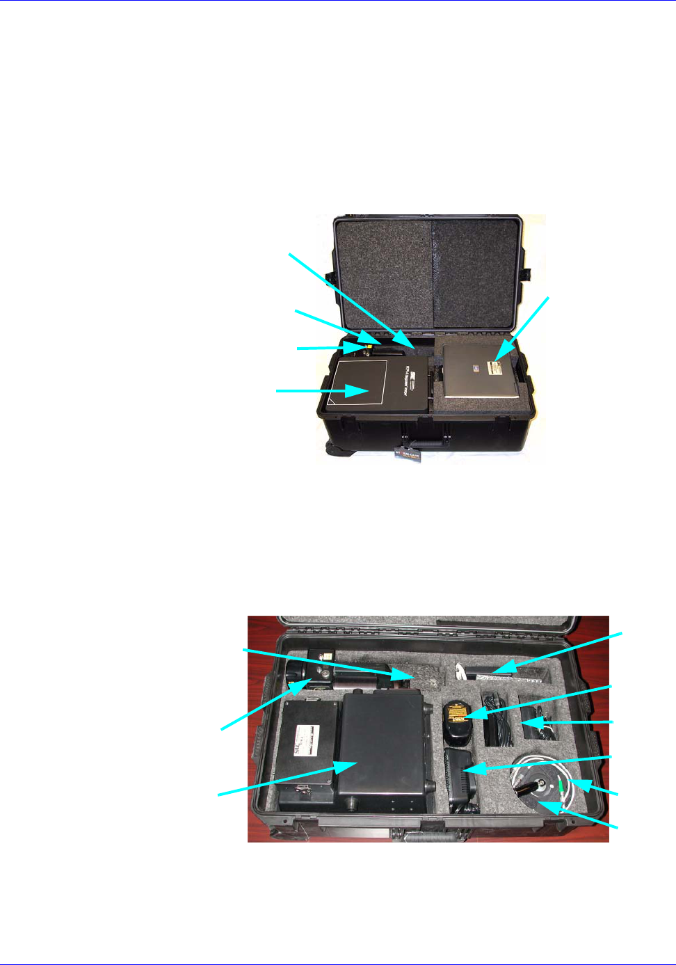
Transport Case
The RTR-4 is protected during transport and storage by a rugged
impact-resistant plastic transport case with fitted foam inserts.
Key features are:
• A single watertight, crushproof, foam-lined case.
• Dimensions: 67.3cm x 27.9cm x 44.4cm (26.5in W x 11.0in H x
17.5in D)
• Weight: 11.8kg (26.0lb)
XR200 SOURCE
SOURCE KEY
IMAGER
NOTEBOOK
CONTROLLER
SPARE IMAGER BATTERY
(UNDER SOURCE)
IMAGER
ANTENNAS
CABLE REEL
AC
BATTERY
CHARGER
SPARE
XR200
SOURCE KEY
CABLE
SOURCE
BATTERY
ADAPTER
ADAPTERS
AND
SOURCE
SOURCE
SOURCE
CABLE
System Description, Setup, and Quick Start RTR-4 Operator’s Manual
3-10 SAIC Proprietary 120300 Rev. D
RTR-4 Standard Wireless Configuration
Wireless Option
The RTR-4 Wireless Option is an alternative to connecting the
controller, X-Ray imager, and XR200 X-ray source with cables.
Wireless operation simplifies system setup and use by
eliminating the signal cables and provides greater controller to
target distances. The Wireless systems adhere to the frequencies
and protocols of the WiFi, IEEE-802.11b standard.
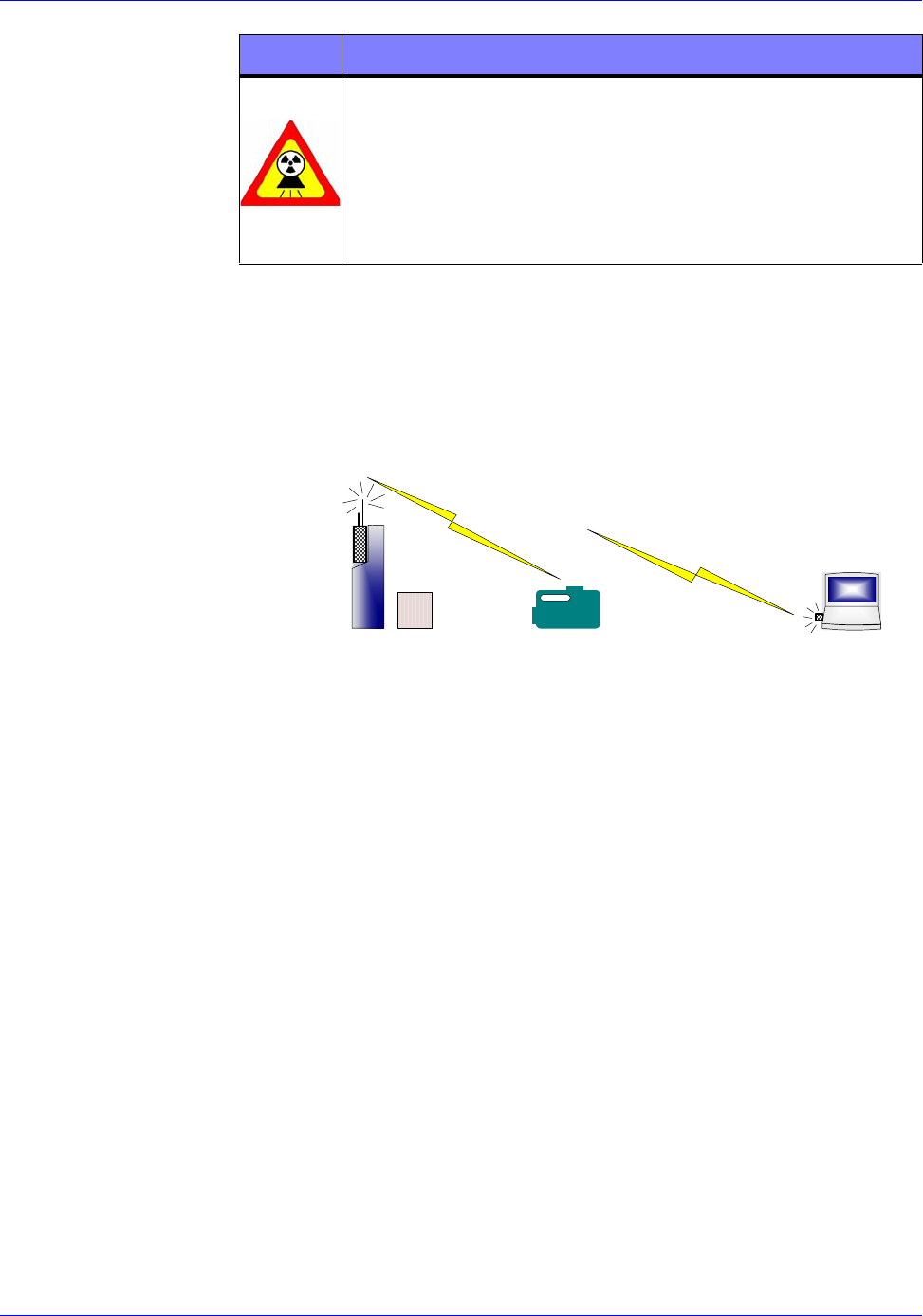
Radio-frequency energy between the imager and the controller
combined with the radio-frequency energy to the X-ray receiver is
at a very low intensity. When the Integrated Imager is more than
50cm (1.5ft) away from a target device, the RTR-4 Wireless
operation complies with the Hazards of Electromagnetic
Radiation to Ordnance (HERO) specifications. This consideration
is only relevant if the RTR-4 is being used with potentially
explosive devices.
The data transmission frequency of the Imager radio module and
the controller is between 2.4000 and 2.4835GHz, and is
spread-spectrum and frequency-hopping, according to the
IEEE-802.11b-1999 standard, and is further encrypted to
minimize snooping or spoofing. The frequency used when
transmitting to the X-ray source receiver is about 418MHz for US
usage and about 433MHz for European usage, which is very low
power. The frequency is coded with a sequencing 64-bit security
code to minimize the possibility of unintended source firing.
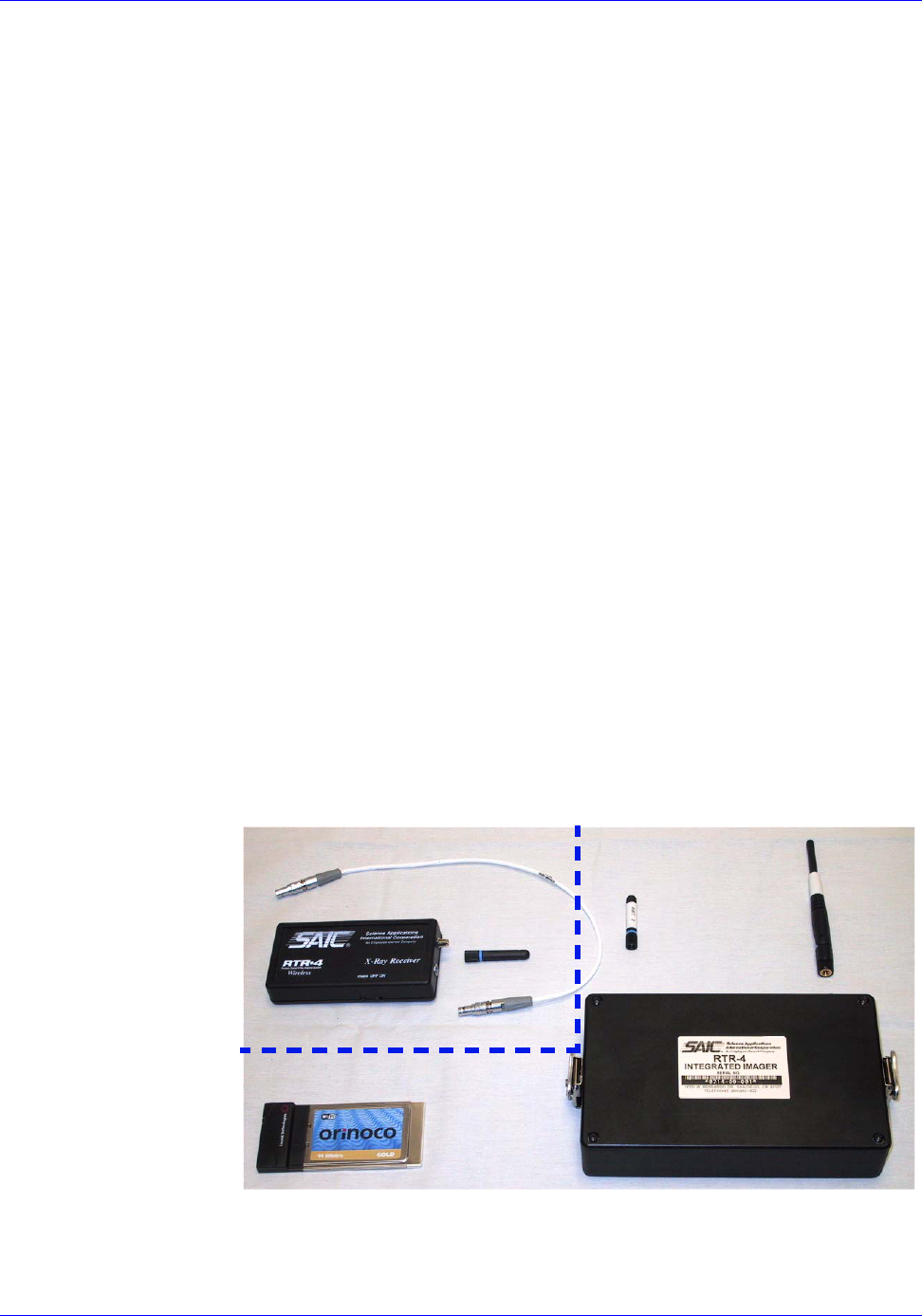
The wireless option adds the following components to the RTR-4
standard configuration:
• WiFi NIC.
• Imager transceiver.
SOURCE CONNECTOR
ANT 1
ANT 2
SOURCE RECEIVER
SOURCE
WiFi NIC
IMAGER TRANSCEIVER
ANT
OPTION

RTR-4 Operator’s Manual System Description, Setup, and Quick Start
120300 Rev. D SAIC Proprietary 3-11
• 2.4GHz screw-on transceiver antenna (ANT 1) for the imager
transceiver provides signals for communication with the
controller.
• 418MHz or 433MHz screw-on transmitter antenna (ANT 2)
for the imager transceiver provides signals to the X-ray
Receiver.
• Optional source transceiver with short antenna and connector
cable for alternate X-Ray sources.
WiFi NIC
The Wifi NIC is a PC interface transceiver card that fits into the
notebook Personal Computer Memory Card International
Association (PCMCIA) slot. This card transmits and receives data
to the Imager Transceiver radio module attached to the RTR-4
Imager.
Imager Transceiver Radio Module
The Image Transceiver radio module is affixed to the RTR-4
Imager with quarter turn clamps.This module transmits and
receives data to the controller PC and transmits a trigger signal
to the X-Ray receiver unit. A 3m (10ft) cable is available to permit
placement of the Imager Transceiver radio module remotely from
the imager to remove radio frequency energy from the immediate
area of the suspect package. This cable connects from the radio
module connector to the Imager at the receptacle located to the
left of the radio module bulkhead connector.
Internal Source Receiver
A receiver within the X-ray source receives the trigger signal from
the Imager radio module to fire the X-ray pulses. A label on the
XR200 source indicates that the source is equipped with an
internal receiver. All other sources use the externally mounted
source receiver.
Optional Source Receiver (Externally Mounted)
An optional source receiver is affixed to the X-ray source by a
velcro strip and connected to the source by a short cable. The
externally mounted source receiver is not used on the current
model XR200 source equipped with the internal receiver. All other
sources require the external receiver to be used in the wireless
configuration. The X-ray receiver unit receives a signal from the
Image Transceiver radio module and fires the X-ray source. It has
three components, the body, antenna, and connecting cable.
Cables are available that can accommodate any of the four X-ray
sources manufactured by Golden Engineering. The externally
mounted X-ray receiver unit is powered by a standard 9-volt
alkaline battery and has a power switch with an indicating LED.

System Description, Setup, and Quick Start RTR-4 Operator’s Manual
3-12 SAIC Proprietary 120300 Rev. D
Setting up the RTR-4
There are two setup configurations for the standard RTR-4, the
wired configuration and the wireless configuration. There are
some positioning related issues that apply to all setups that the
operator must be aware of during the setup process.
Distance Adjustments
The distance between the source and the imager determines the
target X-ray illumination. Although a distance of approximately
50-100cm (20in-40in) between the X-ray source and imager is
recommended to provide a flat field image without sacrificing
penetrating power. This separation distance can be decreased to
penetrate thicker or denser materials, or increased to provide a
flatter field for very thin objects. Regardless of the distance
between the X-ray source and imager, it is usually better to place
the suspect object as close to the center of the imager as possible
to make the edges of objects sharper.
The further the suspect object is away from the imager and the
closer to the source, the larger its projected image, and the larger
its features appear in the acquired image. This can be used to
magnify small features, but will result in fuzzier edges. Objects
that are closer to the imager more closely reflect their true
dimensions.
Position Adjustments
The imager’s active area, denoted by the white rectangular
outline on the flat side of the imager (the face), should be
positioned as close as possible to the target object. The X-ray
source should be positioned approximately 50cm-100cm
(20in-40in) from the imager with its beam centered on and
perpendicular to the imager face. The imager is oriented so that it
is located as close to the ground as possible. The X-ray source is
set on the ground or in a slightly elevated position so the source’s
beam is centered on the imager’s face.
If needed, the imager can be used in an inverted position, such as
suspended from a rope or wire, placed on a tripod, or on its side
for imaging tall, narrow objects. An Image Orientation Indicator
in the marked corner of the image shows the orientation of the
object when the image was acquired. Regardless of the
orientation, the image appears on the controller screen as though
the imager was positioned with the handle on top. The image can
be rotated to the actual orientation using the RTR-4 software.
RTR-4 Operator’s Manual System Description, Setup, and Quick Start
120300 Rev. D SAIC Proprietary 3-13
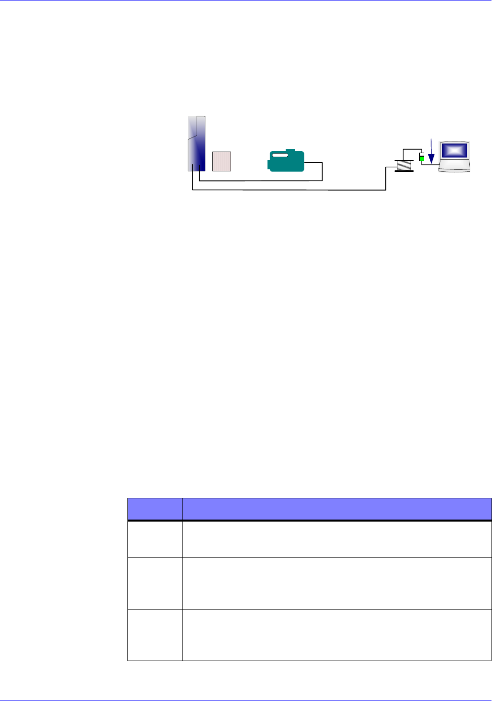
Standard Wired Configuration
In the wired configuration of the RTR-4 Imaging System, cabling
is used to interconnect the various components. The basic wired
configuration is shown here.
Setting Up the Wired Configuration
Description
Use this procedure to setup the standard RTR-4 Imaging System
in the wired configuration.
Prerequisites
Verify the following prerequisites are completed before beginning
this procedure:
• The RTR-4 components have been removed from their
transport cases.
• All needed batteries have sufficient charge or have been
recharged or replaced with new ones.
• A cleared, level workplace is available for setup and an
appropriate exclusion zone has been established.
Procedure RTR0001
Setup the wired configuration of the RTR-4 system as follows:
X-RAY
SOURCE
IMAGER
SUSPECT
PACKAGE
CABLE
REEL
CONTROLLER
X-RAY SOURCE CABLE
COMMUNICATIONS CABLE
ADAPTER
CABLE
STEP ACTION
1Place the imager screen as close to the object to be
imaged as possible.
2Place the X-ray source approximately 1m in front of
the imager, perpendicular to and level with the
imager screen.
3Connect the yellow connector of the 3m (10ft) X-ray
Source cable to the imager and connect the other end
to the X-ray source.
System Description, Setup, and Quick Start RTR-4 Operator’s Manual
3-14 SAIC Proprietary 120300 Rev. D
4Place the controller notebook in the selected area as
far from the imaging area as is appropriate to adhere
to exclusion zone requirements and other safety
regulations.
CAUTION
When unreeling the cable, be sure to grasp the cable
rather than the connector and unreel the cable rather
than let the Imager pull the cable off the reel. This
will extend cable life and reduce the likelihood of
moving the suspect object. Failure to comply may
damage equipment.
5Connect the green connector of the 50m (164ft)
communications cable to the appropriate connection
on the Imager then unreel and extend the cable to the
controller setup location. Use optional extension
cabling if needed and available.
6Connect the 30cm (1ft) adapter cable between the
controller and the 50m (164ft) cable reel.
7If 110/220Vac power is to be used for imager power,
connect the supplied external power adapter directly
to a 110/220Vac outlet and connect the adapter
output to the external power connector on the Imager
control panel.
8If a power-on time delay is desired, use a small
screwdriver to set the desired delay at the time delay
rotary switch in the Imager battery compartment.
9Turn on the Imager power switch.
10 Using the key, turn on the X-ray source. Verify that
the X-ray source’s Exposure Selector (display at the
back of the X-ray source handle) is set to 99 pulses.
Do not change this setting during operation of the
RTR-4.
11 If 110/220Vac power is to be used for the controller,
connect the supplied external power adapter directly
to a 110/220Vac outlet and connect the adapter
output to the controller.
12 Turn on the controller.
STEP ACTION
RTR-4 Operator’s Manual System Description, Setup, and Quick Start
120300 Rev. D SAIC Proprietary 3-15
Standard Wireless Configuration
In the Wireless configuration of the RTR-4 Imaging System, radio
components are used to interconnect the various components. The
basic wireless configuration is shown here.
Setting Up the Wireless Configuration
Description
Verify the following prerequisites are completed before doing this
procedure:
Use this procedure to setup the standard RTR-4 Imaging System
in the wireless configuration.
Prerequisites
Verify the following prerequisites are completed before beginning
this procedure:
• The RTR-4 components have been removed from their
transport cases.
• All needed batteries have sufficient charge or have been
recharged or replaced with new ones.
• A cleared, level workplace is available for setup and applicable
exclusion zone has been established.
WARNING
When the RTR-4 has been set up and is standing by
for imaging, ensure all personnel follow applicable
X-ray radiation safety distance recommendations for
field operation. Failure to comply may result in
personnel injury.
STEP ACTION
IMAGER WITH
RADIO MODULE
SUSPECT
PACKAGE
RADIO
RECEIVER CONTROLLER
WiFi
NIC
X-RAY
SOURCE WITH
System Description, Setup, and Quick Start RTR-4 Operator’s Manual
3-16 SAIC Proprietary 120300 Rev. D
Procedure RTR0002
Set up the wireless configuration of the RTR-4 system as follows:
STEP ACTION
1If not already mounted to the Imager, place the
Imager radio module in the imager mounting bracket
ensuring that the bulkhead connector is aligned and
secure the module with the quarter-turn clamps.
2If the Imager radio module is to be used remotely
from the Imager, do the following:
• Connect the 3m (10ft) cable to the female
connector on the rear of the Imager.
• Place the Imager radio module in desired location.
• Connect other end of the 3m (10ft) cable to the
Imager radio module.
CAUTION
Antenna connectors are not keyed. Ensure antennas
are mated to the proper connector and correctly
aligned before tightening. Do not force antennas onto
connectors. Failure to comply may damage
equipment.
3Attach ANT 1 and ANT 2 to their respective
connectors on the imager radio module.
4Place the imager screen as close to the object to be
imaged as possible.
5Place the X-ray source approximately 1m in front of
the imager, perpendicular to and level with the
imager screen.
NOTE
If it is desired to reduce the radio energy in the
vicinity of the object being X-Rayed, the X-Ray Source
Cable can be connected between the imager and the
source. This overrides the Imager radio module
control of the source by permitting the source to be
fired by signals sent through the cable.
6Place the controller notebook in the selected area as
far from the imaging area as is appropriate to adhere
to exclusion zone requirements and other safety
regulations.
RTR-4 Operator’s Manual System Description, Setup, and Quick Start
120300 Rev. D SAIC Proprietary 3-17
7Insert the WiFi NIC into the PCMCIA slot on the
controller notebook.
8If 110/220Vac power is to be used for the imager,
connect the supplied Imager external power adapter
directly to a 110/220Vac outlet and connect the
adapter output to the external power connector on the
Imager control panel.
9If a power-on time delay is desired, use a small
screwdriver to set the desired delay at the time delay
rotary switch on the Imager control panel.
10 Turn on the Imager power switch.
11 Using the key, turn on the X-ray source. Verify that
the X-ray source’s Exposure Selector (display at the
back of the X-ray source handle) is set to 99 pulses.
Do not change this setting during operation of the
RTR-4.
12 If 110/220Vac power is to be used for the controller,
connect the supplied controller external power
adapter directly to a 110/220Vac outlet and connect
the adapter output to the controller.
13 Turn on the controller.
WARNING
When the RTR-4 has been set up and is standing by
for imaging, ensure all personnel follow applicable
X-Ray radiation and RF safety distance
recommendations for field operation. Failure to
comply may result in personnel injury.
STEP ACTION

System Description, Setup, and Quick Start RTR-4 Operator’s Manual
3-18 SAIC Proprietary 120300 Rev. D
Quick Start
System Initialization
Description
Use this procedure to prepare the RTR-4 for X-raying an object.
Prerequisites
Verify the following prerequisites are completed before beginning
this procedure:
• The appropriate setup procedure has been completed.
• The source and imager are correctly positioned by the object to
be X-rayed and the source, imager, and controller have been
turned on.
Procedure RTR0003
Initialize the RTR-4 as follows:
Acquiring an X-Ray Image
Description
Follow this procedure to X-ray an object.
Prerequisites
Verify the following prerequisites are completed before beginning
this procedure:
• The RTR-4 is fully configured in accordance with the
applicable setup procedure.
• The Source and Imager units are correctly positioned around
the item to be X-rayed and the source Safety Keyswitch has
been turned 90° clockwise.
• The RTR-4 imaging software has been properly initiated and
is running.
STEP ACTION
1At the controller screen, select either Wired or
Wireless mode.
2 The controller will then load Windows. The splash
screen will appear followed by the main menu screen.
3To use the software database function, verify that
Enable Database is checked on the Preferences
menu.

RTR-4 Operator’s Manual System Description, Setup, and Quick Start
120300 Rev. D SAIC Proprietary 3-19
Procedure RTR0004
X-Ray an object as follows:
STEP ACTION
WARNING
Excessive exposure to X-ray radiation is harmful.
Verify the exclusion zone is clear of all personnel.
Failure to comply may result in personnel injury.
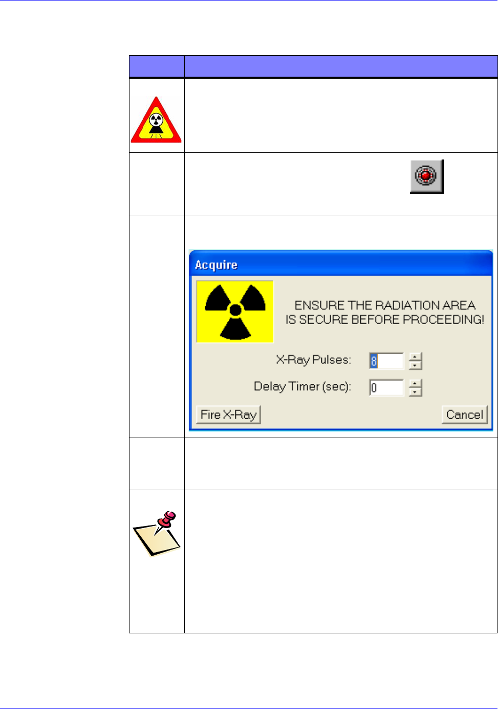
1
Press the F1 key or click the Acquire button
on the toolbar. The Acquire dialog box appears.
2Enter the number of pulses desired and the desired
time delay.
3Press the Enter key or click on the Fire X-Ray
button. The source fires and an image appears on the
screen.
NOTE
The X-ray source fires and an image is produced.
Examine image to determine if the image shall be
saved or discarded. Press F2 to QuickSave or F4 to
Save As or if the image is too dark, discard it and
take another image, either with a higher pulse
settings or use the Sum feature. If the image is too
light, discard it and take another image with a lower
pulse setting. Proceed to the appropriate procedure in
the operations chapter.
RTR0004a
RTR23
RTR0004b

System Description, Setup, and Quick Start RTR-4 Operator’s Manual
3-20 SAIC Proprietary 120300 Rev. D

120300 Rev. D March 3, 2003 12:01 pm 4-1
4 System Operation
Introduction
This chapter describes how to operate the Standard RTR-4
system in both wired and wireless modes and contains the
following sections:
• Operating the RTR-4.
• Image Processing.
• Image Preservation.
• Software Description.
• Shutting Down and Stowing the RTR-4.
• Operator Maintenance.
Operating the RTR-4
Acquiring an X-Ray Image
Description
Follow this procedure to X-Ray an object.
Prerequisites
Verify the following prerequisites are completed before beginning
this procedure:
• The RTR-4 is configured in accordance with the applicable
setup procedure in the previous chapter.
• The Source and Imager units are correctly positioned around
the item to be X-Rayed and the source Safety Keyswitch has
been turned 90° clockwise.
• The RTR-4 imaging software has been properly configured and
is initiated and running.
System Operation RTR-4 Operator’s Manual
4-2 SAIC Proprietary 120300 Rev. D
Procedure RTR0004
X-Ray an object as follows:
STEP ACTION
WARNING
Excessive exposure to X-Ray radiation is harmful.
Verify the exclusion zone is clear of all personnel.
Failure to comply may result in personnel injury.
1‘
Press the F1 key or click the Acquire button
on the toolbar. The Acquire dialog box appears.
2Enter the number of pulses desired and the desired
time delay.
3Press the Enter key or click on the Fire X-Ray
button. The source fires and an image appears on the
screen in the Original buffer.
NOTE
The X-Ray source fires and an image is produced.
Examine image to determine if the image shall be
saved or discarded. Press F2 to QuickSave or F4 to
Save As or if the image is too dark, discard it and
take another image, either with a higher pulse
settings or use the Sum feature. If the image is too
light, discard it and take another image with a lower
pulse setting. Proceed to the appropriate procedure.
RTR0004a
RTR0004b
RTR-4 Operator’s Manual System Operation
120300 Rev. D SAIC Proprietary 4-3
Using the Sum Command
Description
If an image appears too dark after using 99 pulses to acquire it,
you can use the Sum command to accumulate more that 99 pulses
per image. The Sum command allows the operator to acquire an
initial image then acquire subsequent images that are
automatically added (summed) to the initial image. Follow this
procedure to obtain an X-Ray using the Sum command.
Prerequisites
Verify the following prerequisites are completed before beginning
this procedure:
• The RTR-4 is configured in accordance with the applicable
setup procedure in the previous chapter.
• The source and imager units are correctly positioned by the
object to be X-rayed and the source Safety Keyswitch has been
turned 90° clockwise.
• The RTR-4 imaging software has been properly configured and
is initiated and running.
Procedure RTR0005
Obtain a summed X-Ray image as follows:
STEP ACTION
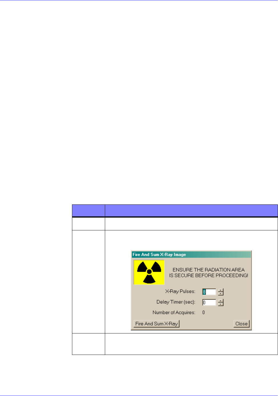
1Close all images currently open.
2Select Sum from the Acquire menu. The Fire and
Sum X-Ray Image dialog box appears.
3Enter the number of pulses desired up to 99 and
enter the desired time delay up to 300 seconds.
RTR0005a
System Operation RTR-4 Operator’s Manual
4-4 SAIC Proprietary 120300 Rev. D
Using the Add Images Feature
Description
The Add Images feature allows the operator to accumulate more
than 99 pulses per image by adding the pixels from a second
image. The images can either be newly acquired or retrieved from
the image file folder. Follow this procedure to obtain an X-Ray
using the Add Images feature.
Prerequisites
Verify the following prerequisites are completed before beginning
this procedure:
• The RTR-4 is configured in accordance with the applicable
setup procedures in the previous chapter.
• The Safety Keyswitch has been turned 90° clockwise.
WARNING
Excessive exposure to X-Ray radiation is harmful.
Verify the exclusion zone is clear of all personnel.
Failure to comply may result in personnel injury.
4Click the Fire and Sum X-Ray button. After the
source fires, an image appears on the screen along
with the Fire and Sum X-Ray dialog box.
5If the image is satisfactory, click the Close button in
the dialog box and proceed to step 8. If the image is
unsatisfactory, continue to next step.
CAUTION
If the source is set to fire more than 99 pulses, wait
five minutes before firing the source again. This
permits the source to cool down properly. Failure to
comply may damage the source.
6Enter the number of pulses desired up to 99 and
enter the desired time delay up to 300 seconds.
7Click the Fire and Sum X-Ray button. The newly
acquired image is added to the previous image.
Repeat steps 5 through 7 until a satisfactory image is
obtained.
8When a satisfactory image is obtained, save the
image using QuickSave or Save As.
STEP ACTION
RTR-4 Operator’s Manual System Operation
120300 Rev. D SAIC Proprietary 4-5
• The RTR-4 imaging software has been properly configured and
is initiated and running.
Procedure RTR0006
Obtain a Added image as follows:
STEP ACTION
1Close all images currently open.
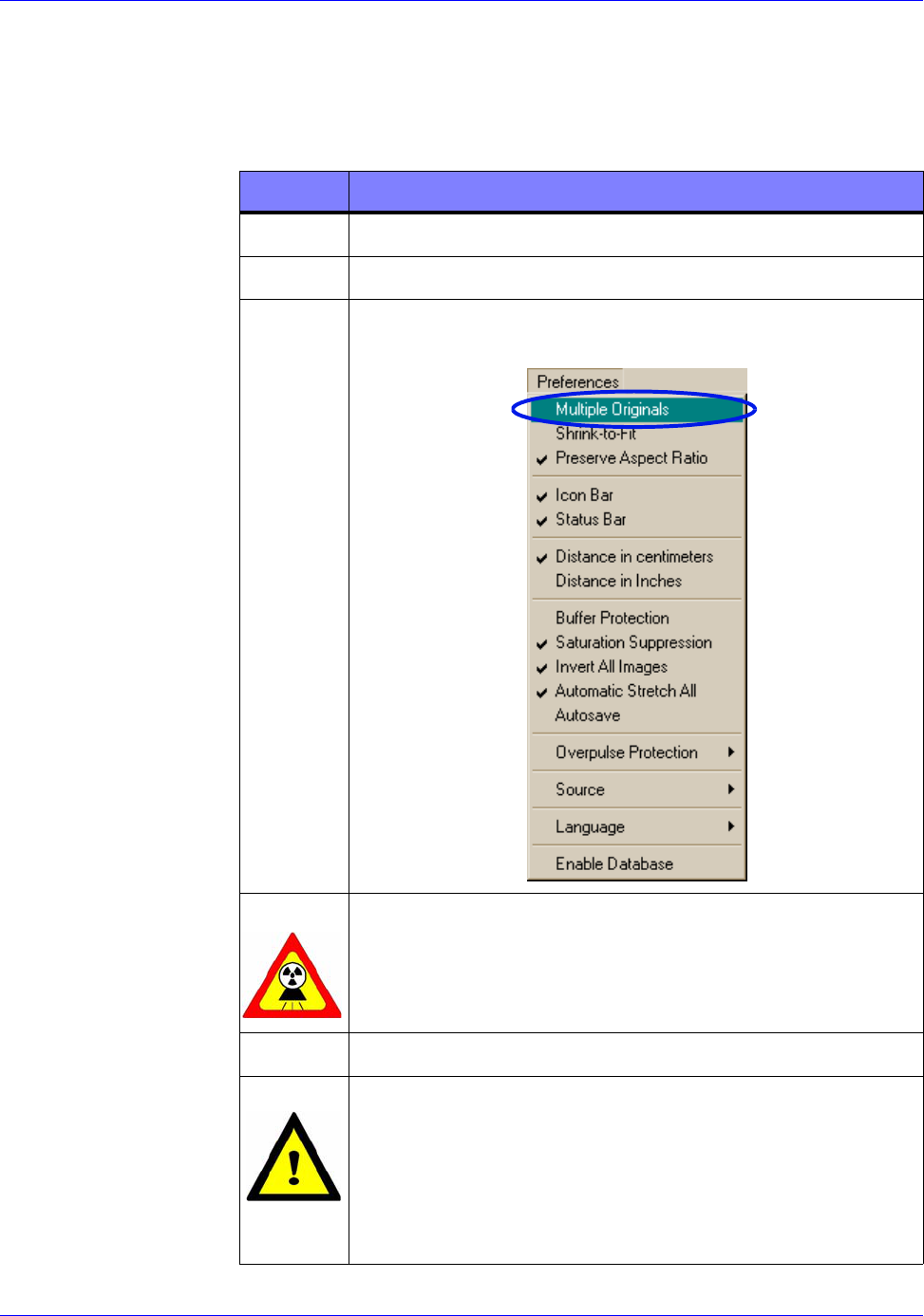
2Click on the Preferences pull-down menu.
3Verify the Multiple Originals command is disabled
(unchecked.)
WARNING
Excessive exposure to X-Ray radiation is harmful.
Verify the exclusion zone is clear of all personnel.
Failure to comply may result in personnel injury.
4Acquire the first image and save it.
CAUTION
If the source is set to fire more than 99 pulses, wait
five minutes before firing the source again. This
permits the source to cool properly and allow the
battery to recover. Failure to comply may damage
the source unit.
RTR0006a
System Operation RTR-4 Operator’s Manual
4-6 SAIC Proprietary 120300 Rev. D
5Acquire the second image and save it. Do not close
the image.
6Press the F7 key to display the Modified buffer.
Modified appears in the status bar at the bottom of
the screen.
7Open the first image from step 4. It appears in the
Modified buffer.
8Press the F7 key to display the Original buffer.
Original appears in the status bar.
9Select Add Images from the Modify menu. The
images are added together and the result appears in
the Modified buffer.
10 To make the image more visible, click the Auto
Contrast button on the toolbar.
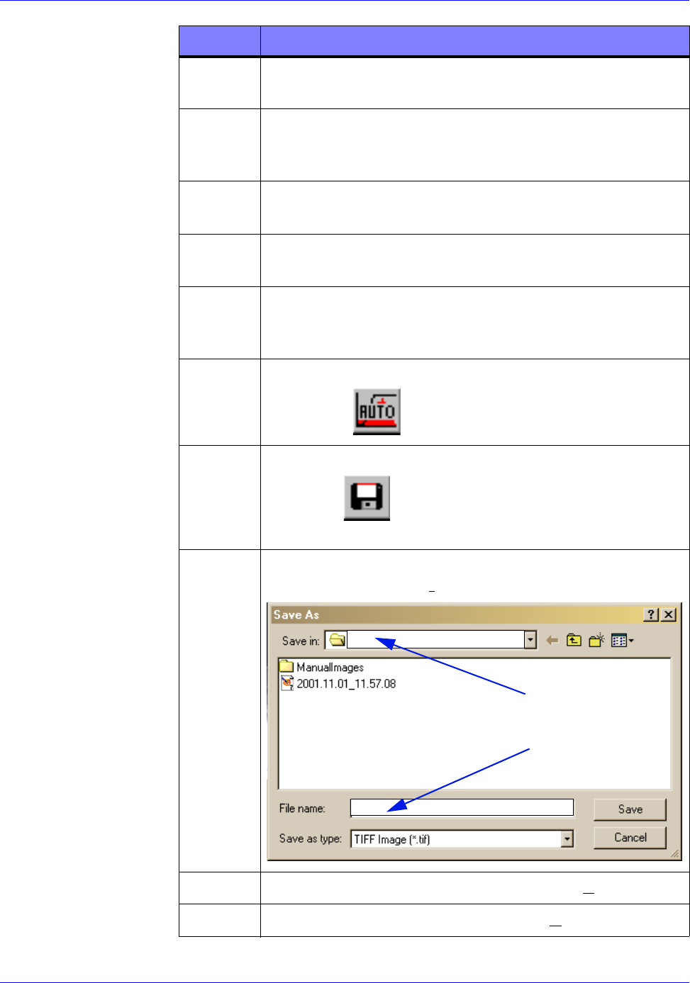
11 Save the new image by pressing F4 or clicking the
Save As button on the toolbar. The Save As
dialog box appears.
12 Use the browse feature to ensure the correct folder
appears in the Save in field.
13 Type the desired filename into the File name field.
14 Press the Enter key or click on the Save button.
STEP ACTION
RTR0006b
RTR0006c
RTR006d
RTR25
ENTER FOLDER
ENTER FILENAME
NAME
RTR-4 Operator’s Manual System Operation
120300 Rev. D SAIC Proprietary 4-7
Using the Subtract Images Command
Description
The Subtract Images command contrasts two identical-looking
images to see if there are any differences between them. Follow
this procedure to use the Subtract Images command.
Prerequisites
Verify the following prerequisites are completed before beginning
this procedure:
• The RTR-4 is configured in accordance with the applicable
setup procedures in the previous chapter.
• The Safety Keyswitch has been turned 90° clockwise.
• The RTR-4 imaging software has been properly configured and
is initiated and running.
Procedure RTR0007
Use the Subtract Images command as follow:
15 If equipped, turn the Controller Safety Keyswitch
90° counterclockwise to disable the source.
STEP ACTION
STEP ACTION
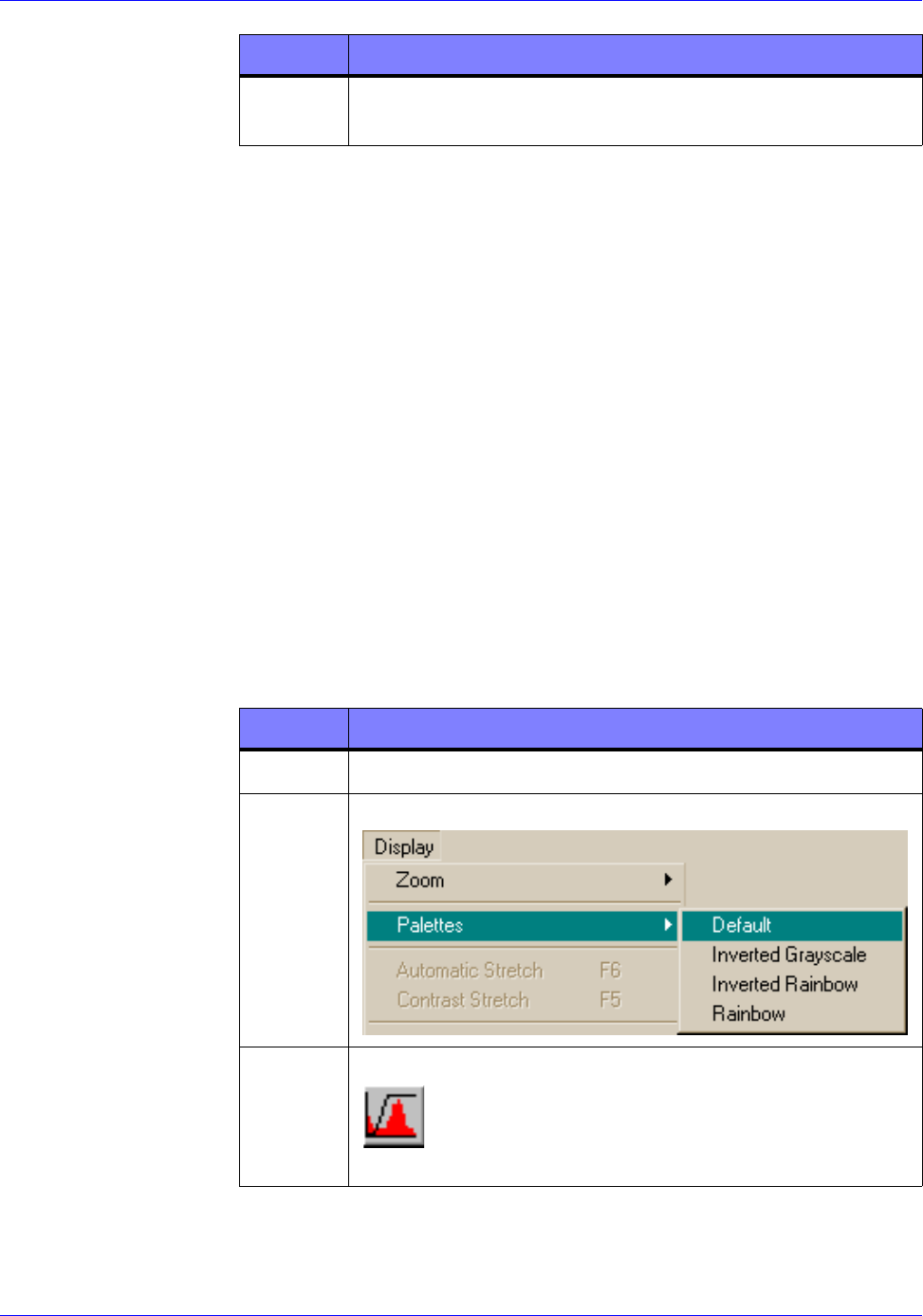
1Close all images currently open.
2Verify the Default palette is selected.
3Press the F5 key or click the Contrast Stretch
button on the toolbar. The Contrast Stretch
dialog box appears.
RTR0007a
RTR0007b
System Operation RTR-4 Operator’s Manual
4-8 SAIC Proprietary 120300 Rev. D
4Click the Default button then click on the OK
button.
5Acquire an image of a unknown object and save it.
6Acquire an image of the known object and save it. Do
not close the image.
7Press the F7 key to display the Modified buffer.
Modified appears in the status bar.
8Open the unknown image file. The image appears in
the Modified buffer.
9Press the F7 key to display the Original Buffer.
Original appears in the status bar.
10 Select Subtract Images for the Modify menu. The
resulting subtracted image appears in the Modified
buffer.
11 To make the image more visible, click the Auto
Contrast button on the toolbar.
12 Save the new image by pressing the F4 key or
clicking the Save As button on the toolbar.
The Save As dialog box appears.
13 Enter a descriptive filename and click the Save
button.
STEP ACTION
RTR0007c
RTR0006b
RTR0006c
RTR-4 Operator’s Manual System Operation
120300 Rev. D SAIC Proprietary 4-9
Image Processing
The following procedures provide the RTR-4 operator with
various options to manipulate images after they have been
acquired. The purpose of these manipulations is to improve the
visualization of acquired images and to annotate them for future
reference.
Retrieving an Image
Description
Follow this procedure to open an image file from the images
folder.
Prerequisites
The RTR-4 imaging software has been properly configured and is
loaded and running.
Procedure RTR0008
Retrieve an existing image as follows:
STEP ACTION
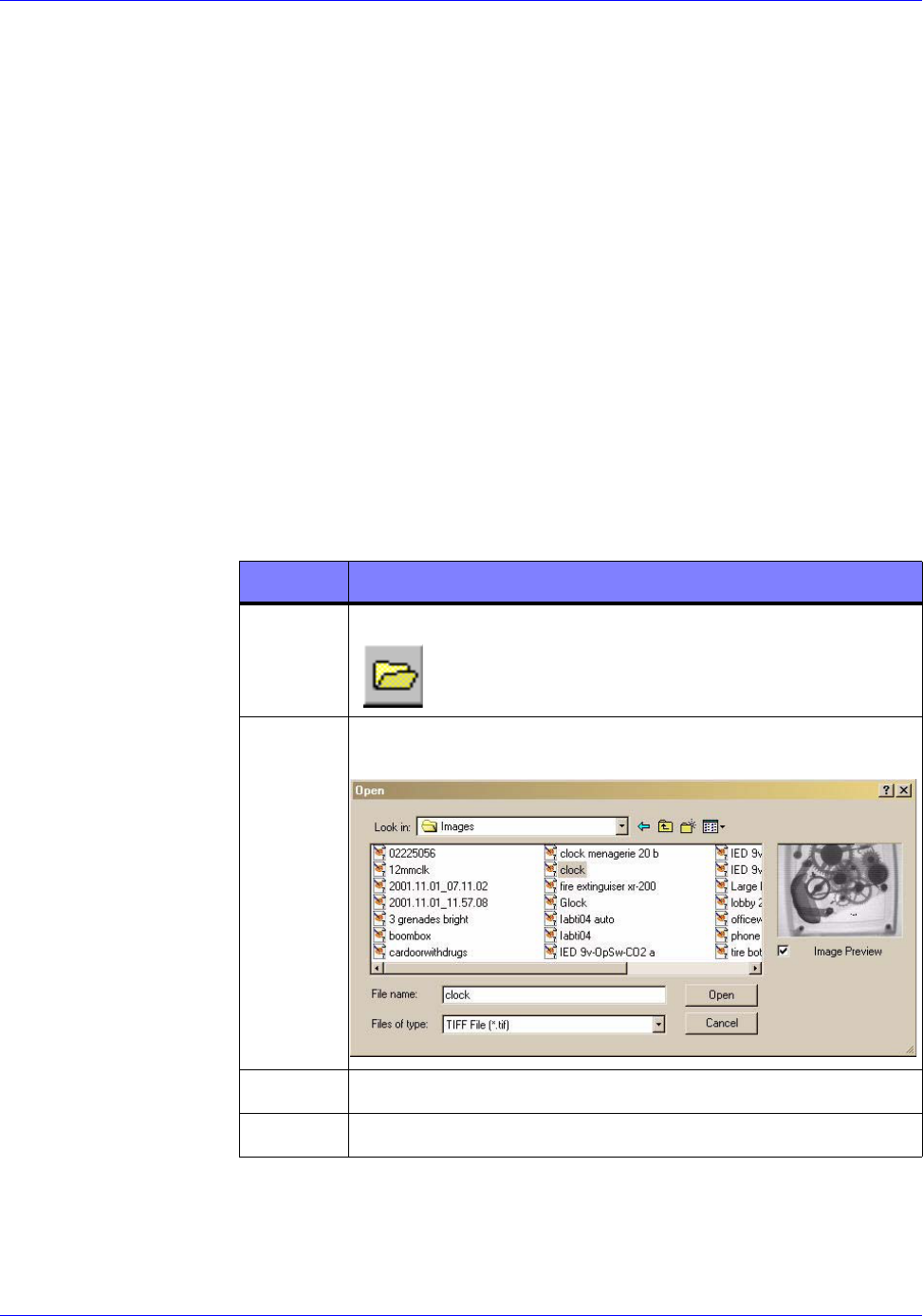
1Press the F3 key or click the Open File button
on the toolbar. The open dialog box appears.
2Verify the Images folder is displayed in the Look in:
dialog box.
3Select the file to be opened.
4Click on the Open button.
RTRooo8a
RTR0008b
System Operation RTR-4 Operator’s Manual
4-10 SAIC Proprietary 120300 Rev. D
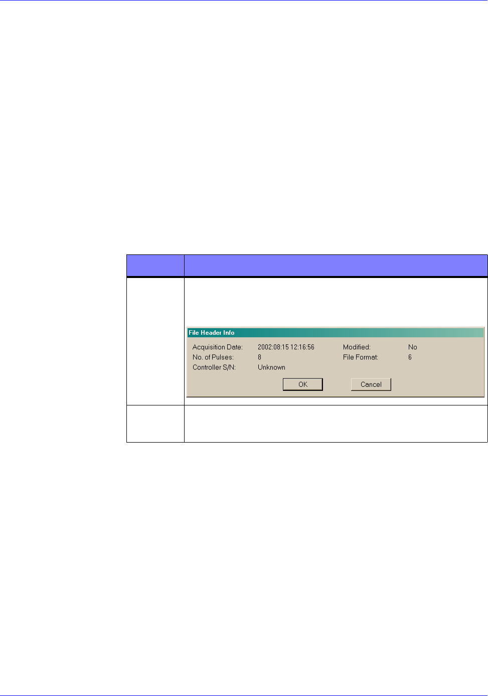
Showing Image Information
Description
Follow this procedure to obtain information such as the date and
time the image was acquired and the number of pulses used to
acquire the image.
Prerequisites
Verify the following prerequisites are completed before beginning
this procedure:
• The RTR-4 imaging software has been properly configured and
is loaded and running.
• An image is displayed in the Original buffer.
Procedure RTR0009
Obtain image information as follows:
Using Multiple Image Display
Description
It is often useful to present images next to each other for
comparison purposes. Follow this procedure to set the display to
show multiple images.
Prerequisites
Verify the following prerequisites are completed before beginning
this procedure:
• The RTR-4 imaging software has been properly configured and
is loaded and running.
• An image is displayed in the Original Buffer and one is
displayed in the Modified Buffer.
STEP ACTION
1Select Image Header from the Display > Show
pull-down menu. The File Header Info dialog box
appears.
2Click the OK or Cancel button to close the dialog
box.
RTR0009a

RTR-4 Operator’s Manual System Operation
120300 Rev. D SAIC Proprietary 4-11
Procedure RTR0010
Display multiple images as follows:
Using the Grid Overlay
Description
The RTR-4 imaging software has a Grid Overlay feature to
assist the operator in determining the position and dimension of
components in an image. Follow this procedure to enable and
disable the Grid Overlay feature.
Prerequisites
Verify the following prerequisites are completed before beginning
this procedure:
• The RTR-4 imaging software has been properly configured and
is loaded and running.
• An image is displayed in the Original Buffer.
Procedure RTR 0011
Use the Grid Overlay feature as follows:
STEP ACTION
1Select Multiple Original from the Preferences
pull-down menu.
NOTE
Once selected, Multiple Original will remain in
effect until cleared or the software program is closed.
2At the Window pull down menu, select either:
• Tile Horizontal
• Tile Vertical
Depending upon selection, images will be displayed
one above the other or side by side.
STEP ACTION
1Select Grid Overlay from the Display menu. A grid
appears over the displayed image.
2Select Distance in Centimeters or Distance in
Inches from the Preferences pull-down menu.
System Operation RTR-4 Operator’s Manual
4-12 SAIC Proprietary 120300 Rev. D
Measuring Distance in an Image
Description
Follow this procedure to measure the distance between two points
in an image, either in centimeters or inches, depending upon the
Preferences setting.
Prerequisites
Verify the following prerequisites are completed before beginning
this procedure:
• The RTR-4 imaging software has been properly configured and
is loaded and running.
• An image is displayed in the Original buffer.
Procedure RTR0012
Measure distance as follows:
NOTE
Once selected, the Grid Overlay remains in place
until cleared. Complete step 3 to clear the Grid
Overlay.
3Select Grid Overlay from the Display menu. The
grid disappears.
STEP ACTION
STEP ACTION
1Select Distance Measurement from the Display
pull-down menu or press Ctrl+d on the keyboard.
The cursor symbol changes to crosshair.
2Move the crosshair cursor to the initial measuring
point and click.
3Move the crosshair cursor to the final measuring
point and click. A dialog box appears with the
distance indicated in centimeters or inches
depending upon Preferences setting.
4Click on the OK button to close the dialog box.
RTR-4 Operator’s Manual System Operation
120300 Rev. D SAIC Proprietary 4-13
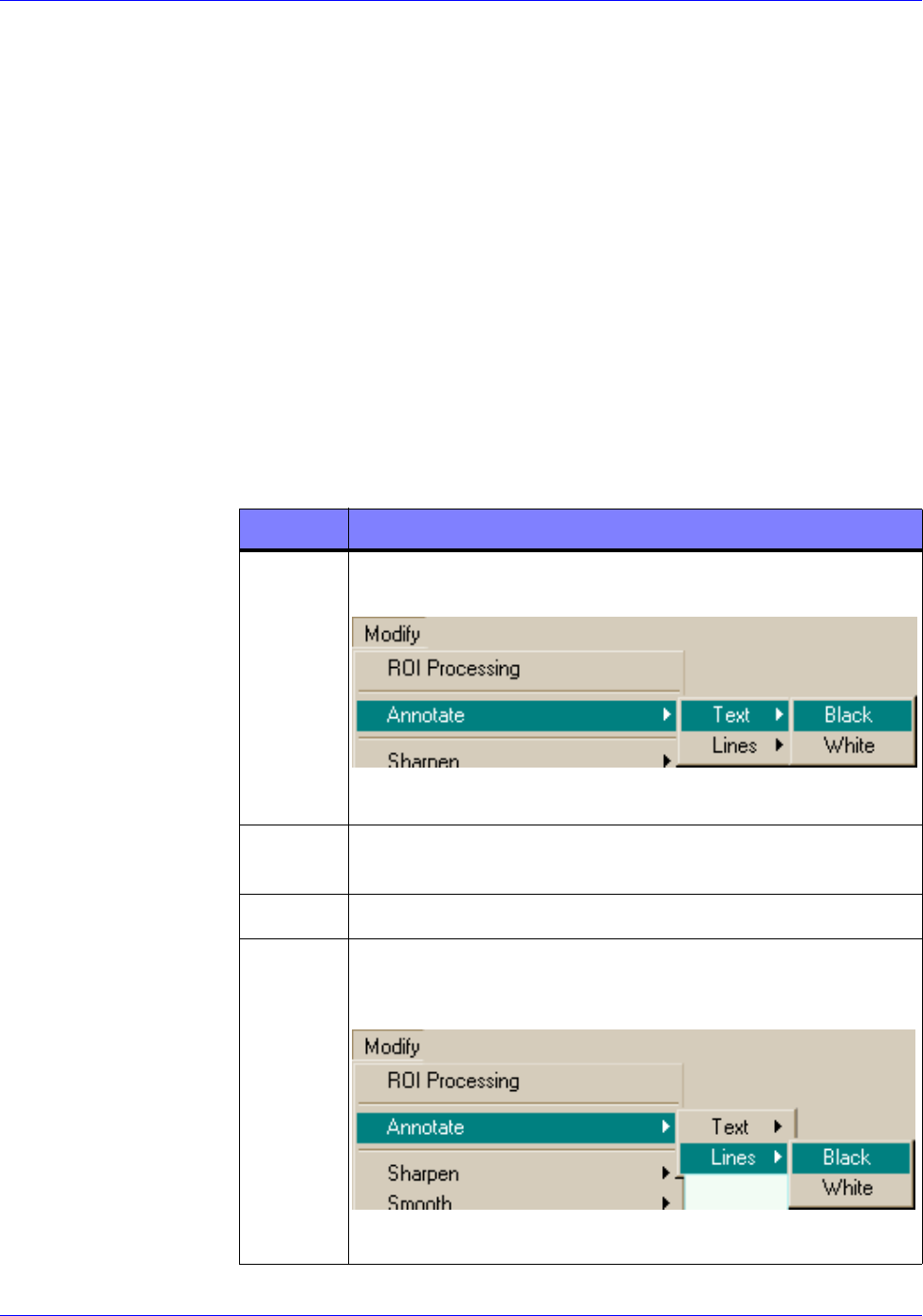
Adding Lines and Text
Description
The RTR-4 imaging software has provisions to allow the operator
to place lines and text on an image to highlight or point out
certain areas. Follow this procedure to add lines and text to an
image.
Prerequisites
Verify the following prerequisites are completed before beginning
this procedure:
• The RTR-4 imaging software has been properly configured and
is loaded and running.
• An image is displayed in the Original buffer.
Procedure RTR0013
Add lines and text to an image as follows:
STEP ACTION
1To add text, select Annotate>Text>Black (or
White) from the Modify pull-down menu.
The cursor changes to the text I-beam.
2Move the cursor to where the text is to be added and
click. A text box appears.
3Type in the desired text and then press Enter.
4To add a line to the image, select
Annotate>Lines>Black (or White) from the
Modify pull-down menu.
The cursor changes to the crosshair symbol.
RTR0013a
RTR0013b
System Operation RTR-4 Operator’s Manual
4-14 SAIC Proprietary 120300 Rev. D
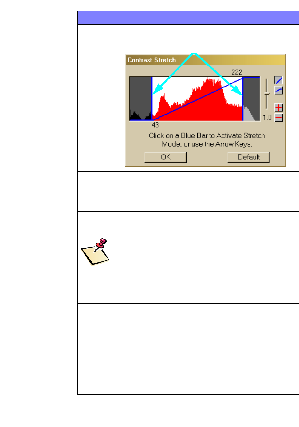
Using Contrast Stretch
Description
Contrast Stretch provides the operator with the most useful tool
to analyze images. This function allows the operator to make
graduated changes in the brightness and contrast of an image.
Doing this often reveals objects of very slight differences in
density from their surroundings.
Follow this procedure to adjust the brightness, darkness, and
contrast of an image.
Prerequisites
Verify the following prerequisites are completed before beginning
this procedure:
• The RTR-4 imaging software has been properly configured and
is loaded and running.
• An image is displayed in the Original buffer.
Procedure RTR0014
Use Contrast Stretch as follows:
5Move cursor to the beginning point of the line and
click the mouse button.
6Move the cursor to the end point of the line and click
the mouse button.
STEP ACTION
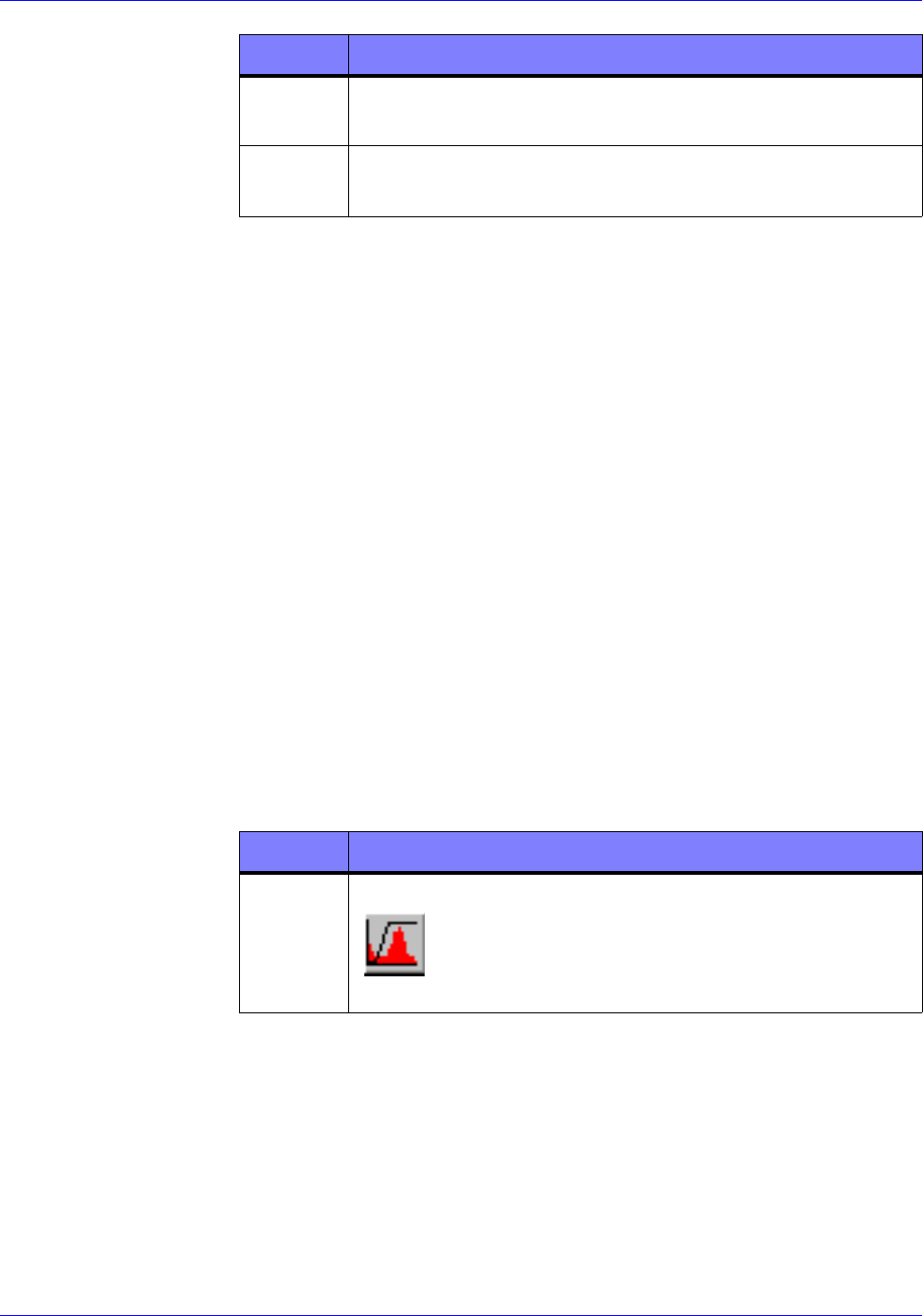
STEP ACTION
1Press the F5 key or click the Contrast Stretch
button on the toolbar. The Contrast Stretch
dialog box appears.
RTR0007b
RTR-4 Operator’s Manual System Operation
120300 Rev. D SAIC Proprietary 4-15
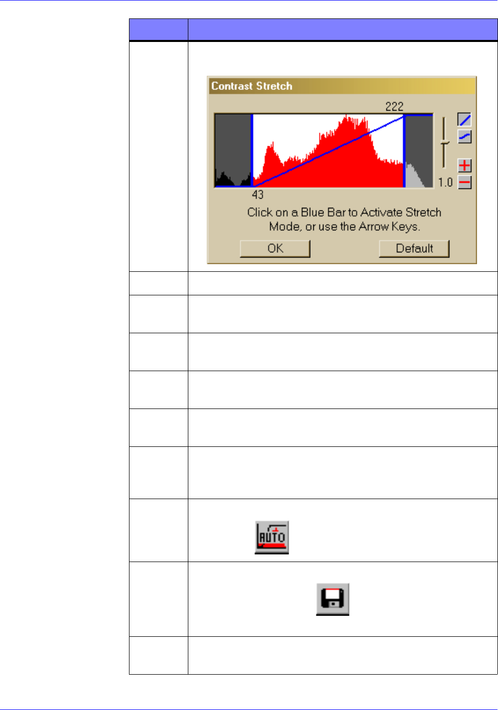
2Click on a vertical blue bar to change the image
brightness. The bar will flash a different color when
properly selected.
3Move the cursor to the left or right to vary the
brightness of the image. Notice the selected blue bar
moves as the cursor moves, adjusting the brightness
of the image in the active buffer.
4Click the blue bar again to stop the bar from moving.
NOTE
Selecting and moving either the left or right vertical
blue bar will vary the brightness of the image.
Depending on the distribution of the density graph,
one may have more affect than the other. The
operator should try both until satisfied with the
image display. To change the contrast of the image,
continue this procedure.
5Place the cursor in the space between the vertical
bars and click. Both bars will flash.
6Move the cursor left or right to adjust the contrast.
7When satisfied with the contrast setting, click
between the vertical bars again.
8To close the dialog box either click the OK button to
keep the changed settings or click the Default
button to return to the original settings.
STEP ACTION
RTRooo7c
System Operation RTR-4 Operator’s Manual
4-16 SAIC Proprietary 120300 Rev. D
Using Automatic Stretch
Description
Follow this procedure to automatically adjust the brightness and
contrast of an image.
Prerequisites
Verify the following prerequisites are completed before beginning
this procedure:
• The RTR-4 imaging software has been properly configured and
is loaded and running.
• An image is displayed in the Original Buffer.
Procedure RTR0015
Use Automatic Stretch as follows:
Using the Color Palettes
Description
The default palette is grayscale. Some images are easier to
interpret if color is used to show density differences. Follow this
procedure to select the color palette or an inverted palette.
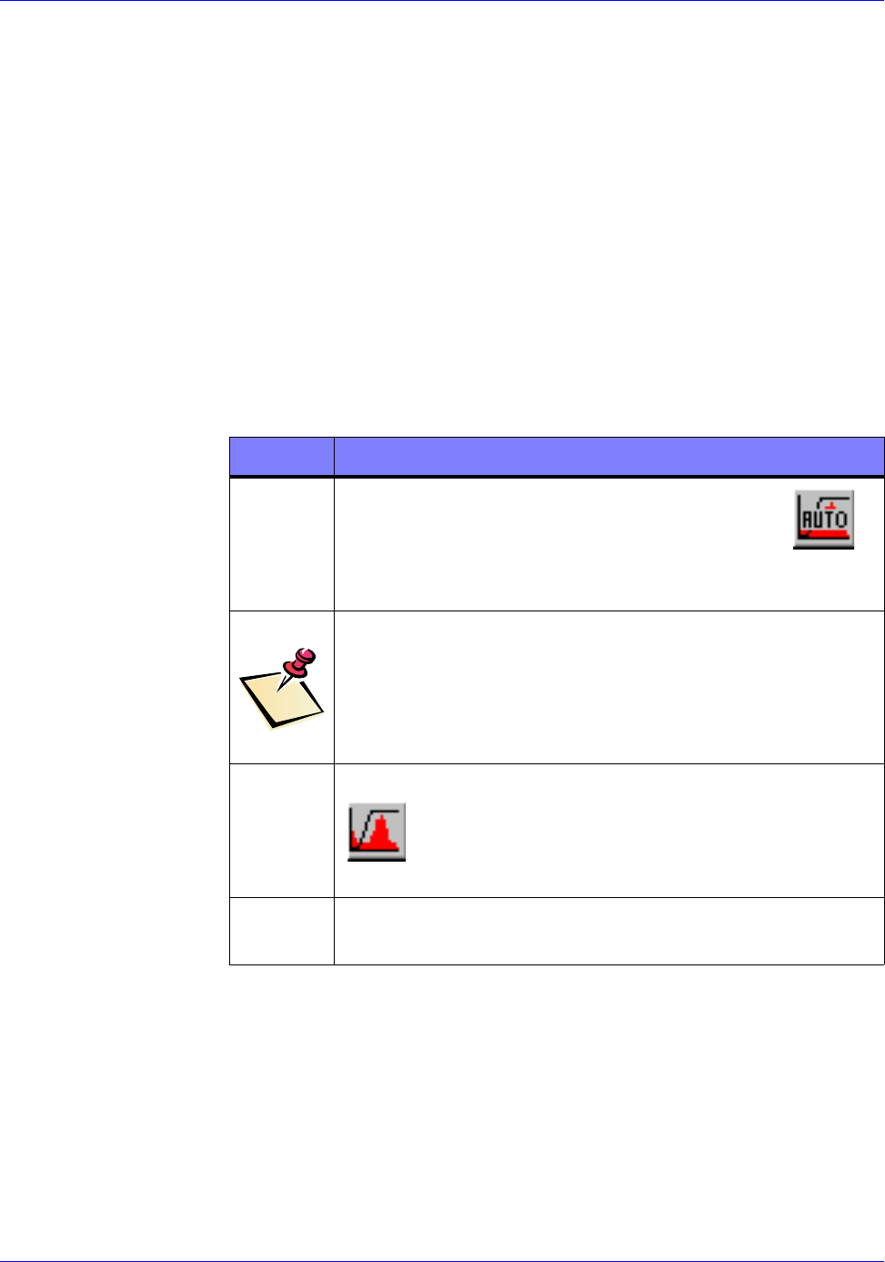
STEP ACTION
1
Press the F6 key or click the Auto Stretch
button on the toolbar. The image contrast and
brightness adjust to optimum levels.
NOTE
If not satisfied with the auto-adjusted image, follow
the Contrast Stretch procedure. To return the
image to the original settings, continue this
procedure.
2Press the F5 key or press the Contrast Stretch
button on the toolbar. The Contrast Stretch
dialog box appears.
3Click the Default button to return to the original
settings.
RTR0006b
RTR0007b

RTR-4 Operator’s Manual System Operation
120300 Rev. D SAIC Proprietary 4-17
Prerequisites
Verify the following prerequisites are completed before beginning
this procedure:
• The RTR-4 imaging software has been properly configured and
is loaded and running.
• An image is displayed in the Original buffer.
Procedure RTR0016
Change the image palette as follows:
Using Saturation Suppression
Description
Image saturation occurs when a dense object surrounded by less
dense material is X-rayed using a high number of pulses. The
image will have bright white areas surrounding the denser object.
These bright areas make it difficult to see the contents of the
denser area. Saturation Suppression changes the white pixels
to black allowing better interpretation of detail in the denser area.
Follow this procedure to enable the saturation suppression
feature.
Prerequisites
Verify the following prerequisites are completed before beginning
this procedure:
• The RTR-4 imaging software has been properly configured and
is loaded and running.
• An image is displayed in the Original buffer.
STEP ACTION
1Select Palettes from the Display menu.
2Select one of the following commands from the
Palettes pull-down menu.
• Default
• Inverted Grayscale
• Inverted Rainbow
• Rainbow
3To return to default settings, select Default from the
Palettes drop menu.
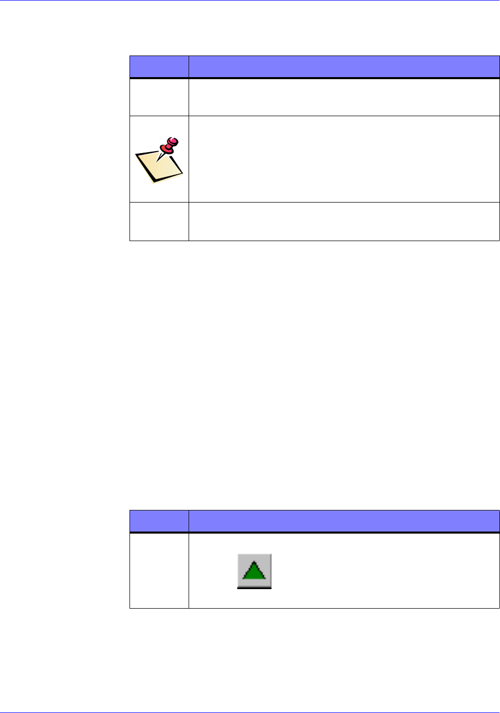
System Operation RTR-4 Operator’s Manual
4-18 SAIC Proprietary 120300 Rev. D
Procedure RTR0017
Use Saturation Suppression as follows:
Sharpening an Image
Description
Image sharpening defines the lines and edges in an image and
improve an image’s resolution. Follow this procedure to sharpen
an image.
Prerequisites
Verify the following prerequisites are completed before beginning
this procedure:
• The RTR-4 imaging software has been properly configured and
is loaded and running.
• An image is displayed in the Original buffer.
Procedure RTR0018
Sharpen an image as follows:
STEP ACTION
1Select Saturation Suppression from the Display
pull-down menu.
NOTE
Once enabled, Saturation Suppression will remain in
effect until disabled. The Saturation Suppression
will be applied on all subsequent images. Complete
step 2 to disable the Saturation Suppression feature.
2Select Saturation Suppression from the Display
menu.
STEP ACTION
1Press the F8 key or click on the Sharpen Image
button on the toolbar. The sharpened image
appears in the Modified buffer.
RTR0018a
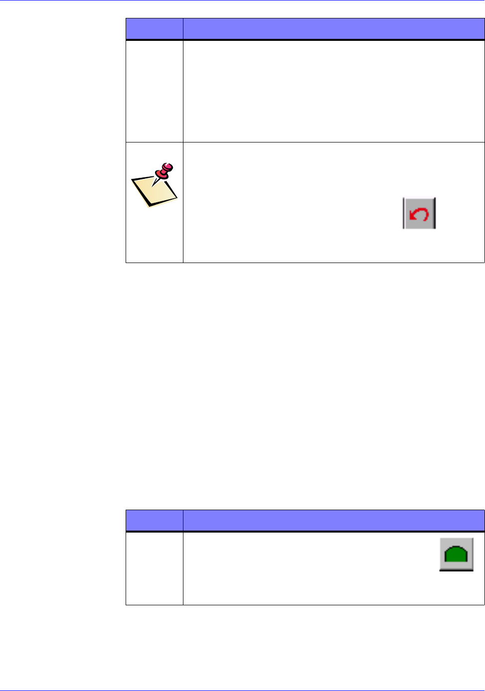
RTR-4 Operator’s Manual System Operation
120300 Rev. D SAIC Proprietary 4-19
Smoothing an Image
Description
Image smoothing softens edges, softens image, and reduces image
resolution. Follow this procedure to soften an image.
Prerequisites
Verify the following prerequisites are completed before beginning
this procedure:
• The RTR-4 imaging software has been properly configured and
is loaded and running.
• An image is displayed in the Original buffer.
Procedure RTR0019
Smooth an image as follows:
2Or select:
• Sharpen>Fine
• Sharpen>Moderate
• Sharpen>Extreme
from the Modify pull-down menu.
NOTE
An image may be sharpened several times before
distortion become severe. Use the Ctrl+Z key
combination or click the Undo button on the
toolbar to undo a sharpen. Also, you may return to
the Original buffer.
STEP ACTION
RTR0018b
STEP ACTION
1
Press the F9 key or click the Smooth button
on the toolbar. A smoothed image appears in the
Modified buffer.
RTR0019a
System Operation RTR-4 Operator’s Manual
4-20 SAIC Proprietary 120300 Rev. D
Reducing Image Noise
Description
Noise is randomly colored and scattered pixels within an image
that give the image a cluttered and unclear appearance. Follow
this procedure to reduce noise in an image.
Prerequisites
Verify the following prerequisites are completed before beginning
this procedure:
• The RTR-4 imaging software has been properly configured and
is loaded and running.
• An image is displayed in the Original buffer.
Procedure RTR0020
Reduce image noise as follows:
2Select one of the following commands:
• Smooth>Fine
• Smooth>Moderate
• Smooth>Extreme
from the Modify pull-down menu.
NOTE
An image may be smoothed several times before
distortion become severe. Use Ctrl+Z key
combination or click the Undo button on the
toolbar to undo a smooth. Also, you may return to the
Original buffer.
STEP ACTION
RTR0018b
STEP ACTION
1Select one of the following commands from the
Modify pull-down menu.
• Noise Reduction>Average
• Noise Reduction>Median
• Noise Reduction>Despeckle
2The noise reduced image appears in the Modified
buffer.
RTR-4 Operator’s Manual System Operation
120300 Rev. D SAIC Proprietary 4-21
Using Edge Detection
Description
Edge detection displays white lines on a dark background where
the edge of objects appear. Invert Grayscale can be used to show
a reverse image-black lines on a white background. Follow this
procedure to edge detect an image.
Prerequisites
Verify the following prerequisites are completed before beginning
this procedure:
• The RTR-4 imaging software has been properly configured and
is loaded and running.
• An image is displayed in the Original buffer.
Procedure RTR0021
Edge detect an image as follows:
NOTE
Noise reduction may be used several times before
distortion become severe. Use Ctrl+Z key
combination or click the Undo button on the
toolbar to undo. Also, you may return to the
Original buffer.
STEP ACTION
RTR0018b
STEP ACTION
1Select one of the following commands:
• Edge Detect>Horizontal
• Edge Detect>Vertical
• Edge Detect>General
from the Modify pull-down menu.
2The Edge Detected image appears in the Modified
buffer.
System Operation RTR-4 Operator’s Manual
4-22 SAIC Proprietary 120300 Rev. D
Embossing an Image
Description
Embossing suppresses color and makes an image appear raised or
stamped in a “high relief” pattern. This is useful if the pattern or
density appears uniform throughout the image making it difficult
to pick out specific objects. Follow this procedure to emboss an
image.
Prerequisites
Verify the following prerequisites are completed before beginning
this procedure:
• The RTR-4 imaging software has been properly configured and
is loaded and running.
• An image is displayed in the Original buffer.
Procedure RTR0022
Emboss an image as follows:
NOTE
Edge Detect may only be used a few times before
distortion become severe. Use Ctrl+Z key
combination or click the Undo button on the
toolbar to undo. Also, you may return to the
Original buffer.
STEP ACTION
RTR0018b
STEP ACTION
1Select Emboss from the Modify menu.
2The embossed image appears in the Modified
buffer.
NOTE
Emboss may only be used a few times before
distortion become severe. Use Ctrl+Z key
combination or click the Undo button on the
toolbar to undo. Also, you may return to the
Original buffer.
RTR0018b
RTR-4 Operator’s Manual System Operation
120300 Rev. D SAIC Proprietary 4-23
Using Histogram Equalization
Description
The Histogram Equalize command moves the density scale of
an image slightly causing the lighter areas to darken slightly and
the darker areas to lighten slightly. Follow this procedure to
perform a Histogram Equalize.
Prerequisites
Verify the following prerequisites are completed before beginning
this procedure:
• The RTR-4 imaging software is on and software preferences
have been set.
• An image is displayed in the Original buffer.
Procedure RTR0023
Use Histogram Equalize as follows:
Image Preservation
The operator must be aware of the following regarding image
preservation:
• A newly acquired image is displayed in the Original buffer.
• A newly acquired image remains unchanged in the Original
buffer until another image is acquired or a saved image is
opened with the File Open command while the Original
buffer is active.
STEP ACTION
1Select Histogram Equalize from the Modify
pull-down menu.
2The equalized image appears in the Modified
buffer.
NOTE
Histogram Equalize only slightly affects an image.
More than one use is unlikely to produce any useful
results.
Use the Ctrl+Z key combination or click the Undo
button on the toolbar to undo. Also, you may
return to the Original buffer.
RTR0018b
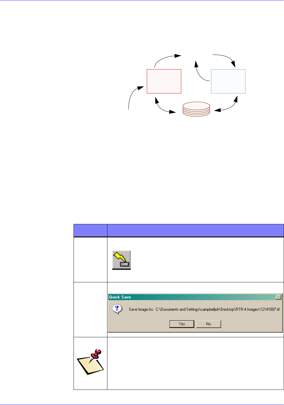
System Operation RTR-4 Operator’s Manual
4-24 SAIC Proprietary 120300 Rev. D
• Modifications made to an image in the Original or the
Modified buffers will overwrite the image in the Modified
buffer.
• Immediately save a newly acquired image to prevent its loss.
QuickSaving an Image
Description
Follow this procedure to “quick save” an image to the default
C:\Images folder with a default file name.
Prerequisites
Verify an unsaved image is present in the active buffer.
Procedure RTR0024
QuickSave an image as follows:
ORIGINAL
BUFFER BUFFER
ACQUIRE
MODIFY
DISKDRIVE
MODIFIED
STEP ACTION
1Press the F2 key or click the QuickSave! button
on the toolbar. The QuickSave! dialog box
appears.
2Click on the Yes button.
NOTE
The displayed image is saved to the C:\Images
folder with a default file name. DD.HH.MM.SS.tif
The day date, hour, minutes, and seconds and the
image file type.
RTR0024a
RTR0024b
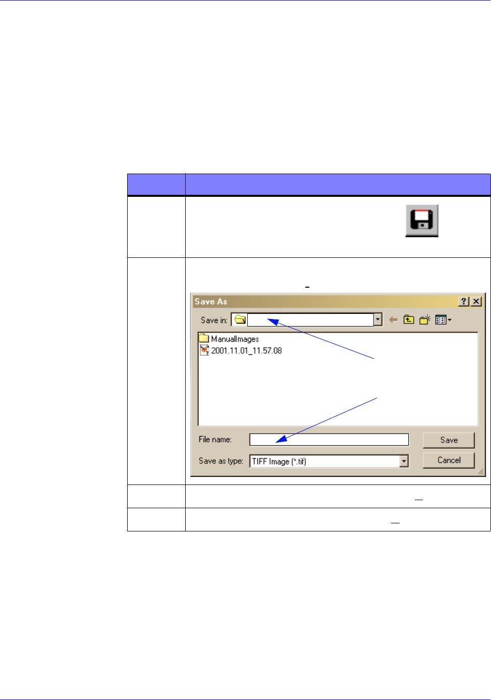
RTR-4 Operator’s Manual System Operation
120300 Rev. D SAIC Proprietary 4-25
Saving an Image
Description
Follow this procedure to save an image with a specific filename to
a location other than the default folder.
Prerequisites
Verify an unsaved image is present in the active buffer.
Procedure RTR0025
QuickSave an image as follows:
Print an Image
Description
Follow this procedure to print an image.
Prerequisites
Verify the following prerequisites are completed before beginning
this procedure:
STEP ACTION
1
Press the F4 key or click the Save As button
on the toolbar. The Save As dialog box appears.
2Use the browse feature to ensure the correct folder
appears in the Save in field.
3Type the desired filename into the File name field.
4Press the Enter key or click on the Save button.
RTR0006c
RTR0006d
ENTER FOLDER
ENTER FILENAME
NAME

System Operation RTR-4 Operator’s Manual
4-26 SAIC Proprietary 120300 Rev. D
• The RTR-4 imaging software has been properly configured and
is loaded and running.
• An image is displayed in the Original buffer.
• Verify a printer is connected to the printer port, is loaded with
paper, and is powered up.
Procedure RTR0026
Print an image as follows:
Software Description
The RTR-4 imaging software has many unique operating features
differing from the MS Windows® OS installed on the controller
notebooks. RTR-4 operators must be familiar with the Windows®
OS. This manual does not cover Windows® operation.
Information and training on Windows® may be located at
http://www.microsoft.com. RTR-4 application-specific features
and commands are listed and described in the following
paragraphs.
RTR-4 Functions
In most cases the RTR-4 commands can be accessed by:
• The pull-down menus listed in the Main Menu bar at the top
of the screen.
• A button on the toolbar displayed under the Main Menu bar.
• The Function Keys (F1-F12) located at the top row of the
keyboard.
• Various keys or key combinations (refer to the Key Map
selection under the Help pull-down menu for more
information).
• The RTR-4 application may be operated using the keyboard in
the advent of a mouse or pointing device failure.
Once the RTR-4 is set up and configured, the operator shall
launch the imaging software and verify that it is running
normally and properly configured.
STEP ACTION
1Select Print from the File pull-down menu to print
the image in the active buffer.
2Select Print Window from the File pull-down menu
to print the entire Main Menu screen.
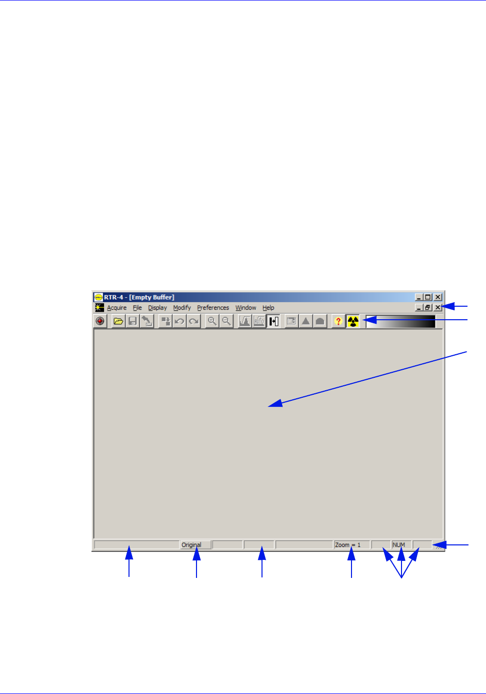
RTR-4 Operator’s Manual System Operation
120300 Rev. D SAIC Proprietary 4-27
Images are acquired with the RTR-4 using an imaging and
modification software program installed on the RTR-4 system.
The RTR-4 Main Menu screen is a standard Windows-based
Graphical User Interface (GUI) activated through onscreen
pull-down menus and toolbar buttons as well as keyboard
commands.
The RTR-4 software includes a database feature that lets the user
record information about an image such as operator name, date of
acquisition, location, project, type of image, X-Ray source and
serial number, and any comments about the image. This
information can then be retrieved, viewed, sorted by category, and
changed as needed to provide an accurate record of acquisitions
and modifications, and assist the user in locating and organizing
images. The database function is enabled in the Preferences
menu, and accessed through the File menu.
The operator must be familiar with the RTR-4 software pull-down
menus, dialog boxes, and toolbar buttons. The figure below shows
the Main Menu screen as it appears at startup.
Figure 4-1: Main Menu Screen
The Acquire Menu
The Acquire menu contains the Acquire..., Sum, and Enable
Acquire commands.
1
2
3
4
56
7
8
1 Menu bar
2 Icon Toolbar
3 Image display
area
4 Status bar
5 Caps lock,
numlock, and
Scroll lock
6 Zoom level
7 Cursor local
and pixel
density.
8 Buffer name
9 Icon bar
definition
9
indicator
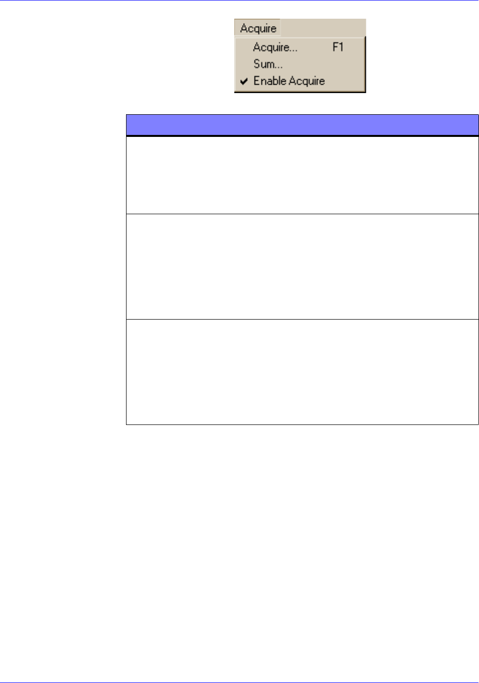
System Operation RTR-4 Operator’s Manual
4-28 SAIC Proprietary 120300 Rev. D
During image acquisition, a progress bar is displayed, showing
progress as the image is transferred the Original buffer. When
finished, the system returns to the main screen and the image is
displayed.
An Acquire request can be canceled at any point by selecting
Cancel or pressing Esc twice. The Cancel or Esc commands
return the user to the Main Menu.
COMMAND DESCRIPTION
Acquire... (F1) When selected, the system waits the
number of seconds specified in the Delay
Timer field, then the X-Ray source fires
for the specified number of pulses and an
image is acquired.
Sum... Used to collect an initial image, then
subsequent acquired images are added
to the existing image. This operation
may be repeated as often as the operator
desires. This command is useful when
the target object is thick or made of a
dense material.
Enable Acquire When enabled (checkmark present), the
Acquire command is enabled and the
source can fire. When disabled (no
checkmark), the Acquire command is
disabled and the source will not fire. A
password will be required to re-enable
this function.
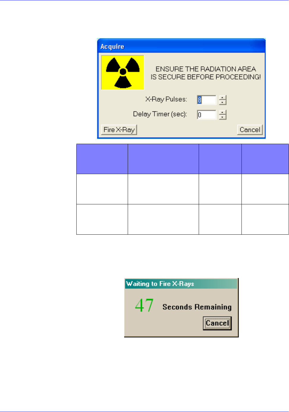
RTR-4 Operator’s Manual System Operation
120300 Rev. D SAIC Proprietary 4-29
Acquire Dialog Box
The two Acquire dialog box settings and their respective ranges
are:
Delay Dialog Box
When a Delay Timer value other than zero seconds has been set,
a message box appears on the display with a counter that counts
down the preset number of seconds.Cancel may be selected to
abort image acquisition at any point during the countdown.
Once the Delay Timer value has been changed, it remains at the
changed setting until the program is shut down. The Delay
Timer value automatically resets to zero when the application is
restarted.
COMMAND DESCRIPTION
TYPICAL
INPUT
RANGE
DEFAULT
X-Ray
pulses
Sets the number of
times the source
pulses on firing
5-99
pulses
Eight
pulses
Delay
Timer
Sets the time delay
before the source
fires
0-300
seconds
Zero
seconds
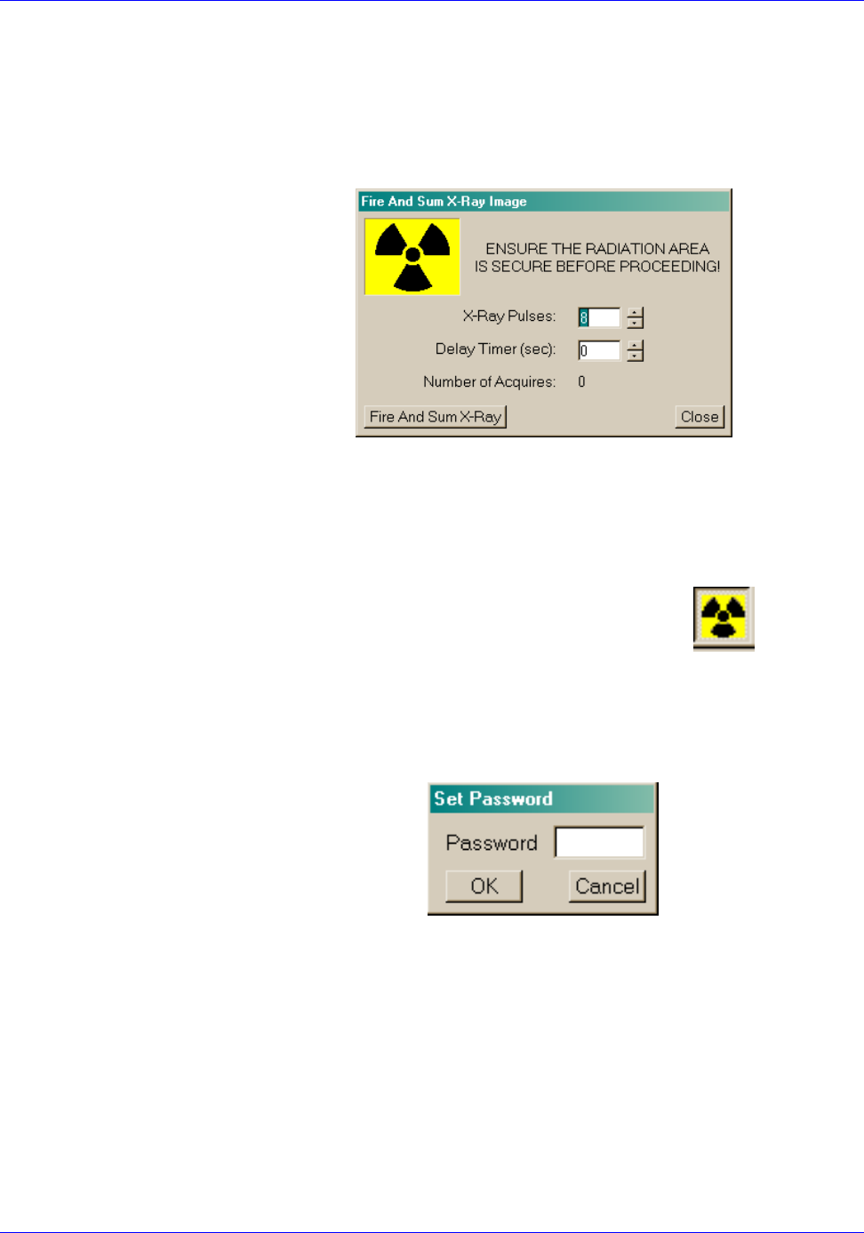
System Operation RTR-4 Operator’s Manual
4-30 SAIC Proprietary 120300 Rev. D
Fire and Sum X-Ray Dialog Box
Selecting Fire and Sum X-Ray command captures the first
image. The Acquire dialog box appears again automatically. If the
first image is adequate, select Cancel. If not, set the option
values and select Fire and Sum X-Ray again. This adds the
newly-acquired image to the sum of the previous images.
Using the Sum command can help produce images with superior
signal-to-noise ratios (SNR), by adding multiple acquisitions,
thus achieving higher grayscale values in the resulting image. Be
sure the Contrast Stretch is set to Default before starting so the
image does not wash out prematurely.
Disable Acquire
The Disable Acquire command is depicted by button at
the end of the toolbar. This button is only visible on those systems
which do not have the optional Interlock Safety Key. When the
button is depressed (the default state) Acquire is enabled and the
system responds as normal. When this icon is enabled, the user is
prompted to enter a password. This password will be required to
re-enable the Acquire command. The password is not retained
for future use; a new password is requested each time the function
is activated. This function acts as a software safety interlock, and
can be used to prevent another user from accidentally firing the
X-Ray source.
RTR-4 Operator’s Manual System Operation
120300 Rev. D SAIC Proprietary 4-31
The File Menu
The File pull-down menu contains file management commands.
These commands allow the opening, closing, printing, and saving
of files and the option to exit the RTR-4 application.
COMMAND DESCRIPTION
Quick Save
(F2)
When selected, a dialog box appears with a
computer-generated filename and the option to
save or cancel by selecting Yes or No.
Open (F3) Select to retrieve an image from the hard disk
drive or a floppy disk.
Save As (F4) Select to store an image on the hard disk drive
or a floppy disk under a user-specified
filename. A dialog box is displayed on the
screen, select the desired location for the file
and provide an appropriate name. Then select
OK or Cancel.
Database Select to access the seven database functions,
allowing image query, modification of image
data, importing data, and exporting image
data.
Print
(Ctrl+P)
Select to activate the Print dialog box for print
options. The Print Setup dialog box
commands allow selection of print options
(window or image), paper orientation (portrait
or landscape) and number of copies to print.
Print
Window
Select to print the border icons and data along
with the displayed fraction of the image.
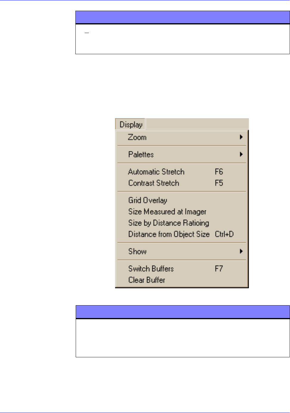
System Operation RTR-4 Operator’s Manual
4-32 SAIC Proprietary 120300 Rev. D
The Display Menu
The commands provided in the Display pull-down menu allow
the images to be modified to aid in analysis. Adjustments done
using the commands in the Display menu do not alter the data in
the image, they merely change the way the data is presented.
Exit (Alt+X) When selected, the RTR-4 imaging application
is shut down. All unsaved images are discarded
from the buffers.
COMMAND DESCRIPTION
COMMAND DESCRIPTION
Zoom When selected, a dialog box appears with four
sizing options. Selecting the options x1, x2, x4
or x8 enlarges the image by a factor of one, two,
four or eight respectively.
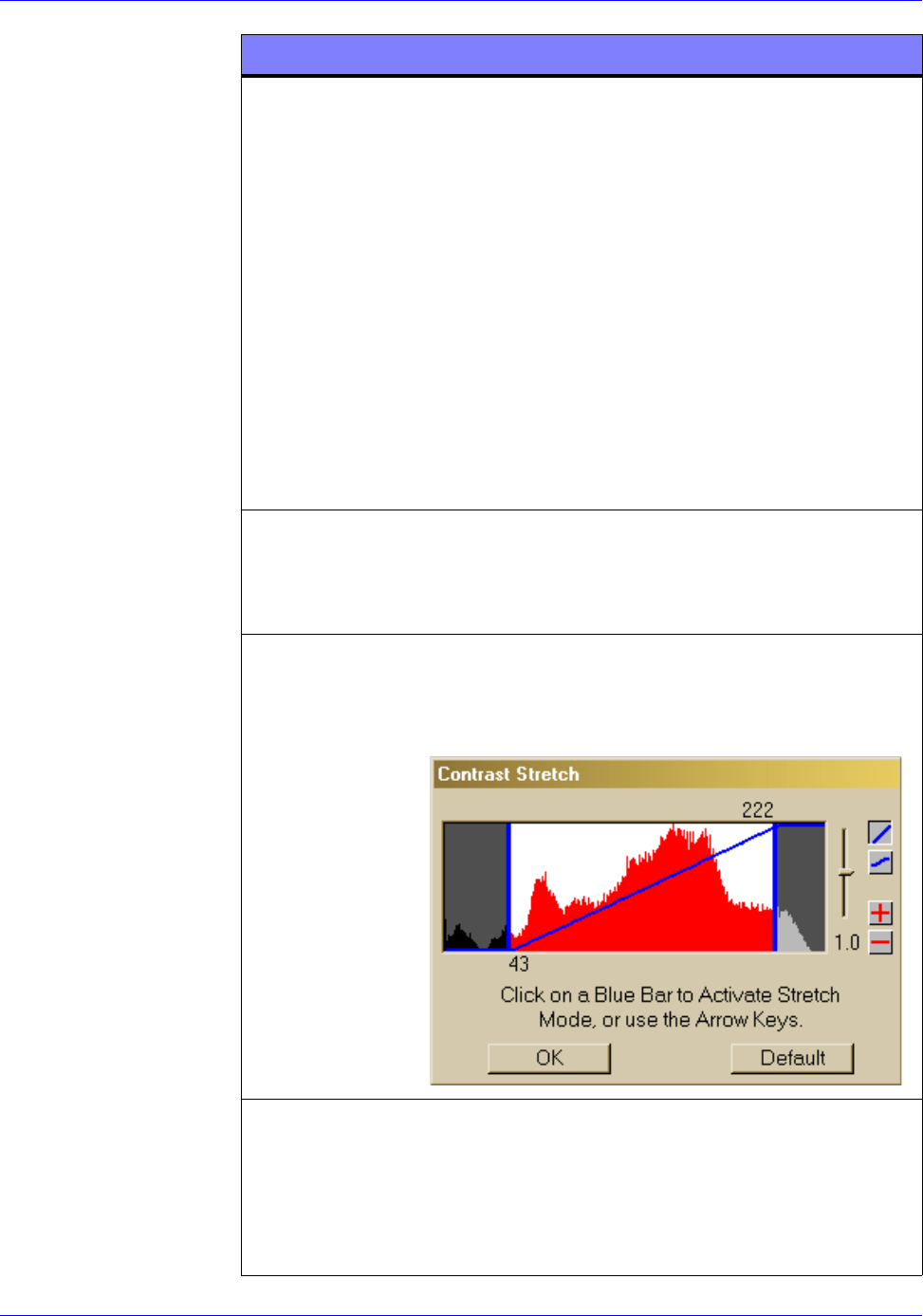
RTR-4 Operator’s Manual System Operation
120300 Rev. D SAIC Proprietary 4-33
Palettes Selecting Palette options changes the
displayed colors of the images. Applying
different palettes (also called “color mapping”)
may improve the appearance of some details
•The Default option shows a positive
grayscale image view.
•The Inverted Grayscale option displays a
negative grayscale image view, similar in
appearance to an X-Ray film negative.
•The Rainbow option applies different
colors to objects in the image, based on the
varying density levels of the objects
•The Inverted Rainbow option reverses
the colors of the rainbow option.
Automatic
Stretch (F6)
Select to adjust the brightness and contrast of
the image automatically. It selects settings
that frequently maximize image clarity and
improve image interpretation.
Contrast
Stretch (F5)
Select to allow manual change to the
distribution of the color or gray-levels of the
image. A dialog box containing a histogram
appears over the image.
Grid
Overlay
Select to overlay a square grid over the image.
This allows the user to quickly estimate device
dimensions and determine the positioning of
device components within a package. This
feature remains in effect until selected again
or until the program is exited.
COMMAND DESCRIPTION
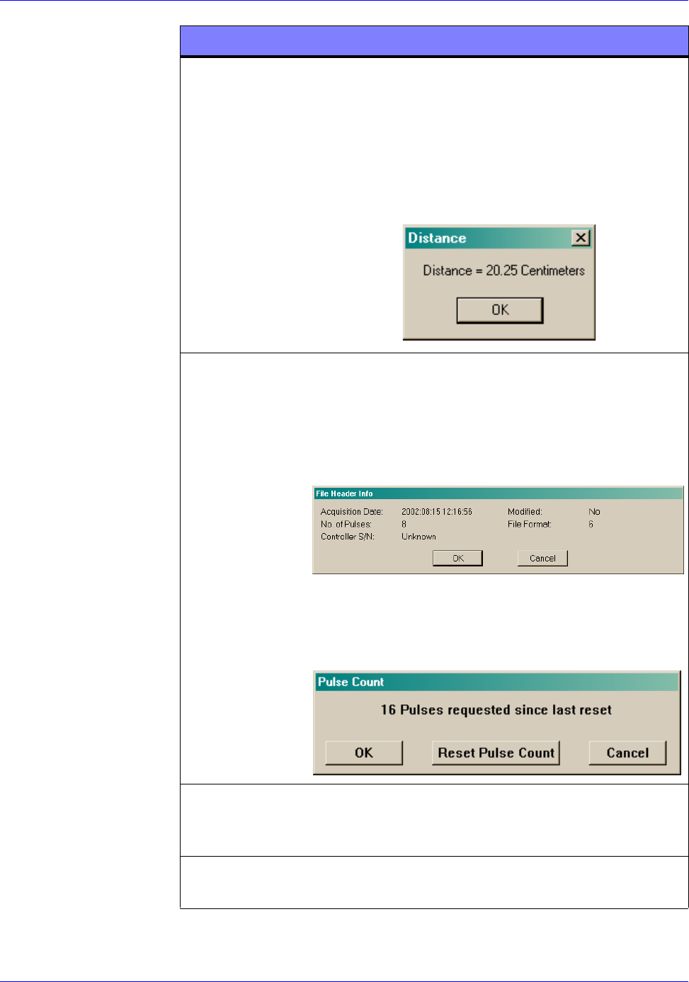
System Operation RTR-4 Operator’s Manual
4-34 SAIC Proprietary 120300 Rev. D
Distance
Measurement
(Ctrl+D)
Select to place a measuring crosshair cursor on
the image. Move the cursor to the desired first
location, then click to set the base position.
Move to the second location, a mobile line is
displayed with another crosshair at the new
end. Click to set the endpoint and the distance
between the two set points is displayed in a
dialog box.
Show Select to show a dialog box displaying the date
and time that the selected image was acquired.
Also shows the serial number of the Control
Unit used to capture the image, the number of
pulses used to acquire the image, and whether
the image has been modified.
Selecting the Show > Cumulative Pulse
Count command displays the total number of
pulses requested of the X-Ray source since the
last reset.
Switch
Buffers (F7)
Select to switch between the Original Buffer
and the Modified Buffer. The current buffer on
the display is highlighted in the Status Bar.
Clear Buffer Select to erase the image located in the
displayed buffer, clearing the display.
COMMAND DESCRIPTION
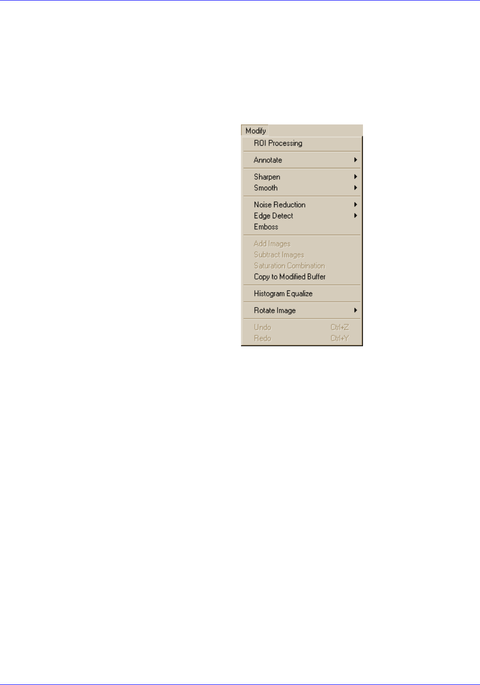
RTR-4 Operator’s Manual System Operation
120300 Rev. D SAIC Proprietary 4-35
The Modify Menu
The commands in the Modify pull-down menu alter the displayed
image to produce a modified image in the Modified buffer. If the
modifications are not satisfactory, press the F7 key to switch back
to the Original buffer, where the unmodified image may be
changed in a different way. If the displayed buffer was the
Modified buffer, then this reversal is not available.
Save the original image before any modifications are made. When
making modifications to an image, RTR-4 displays only the most
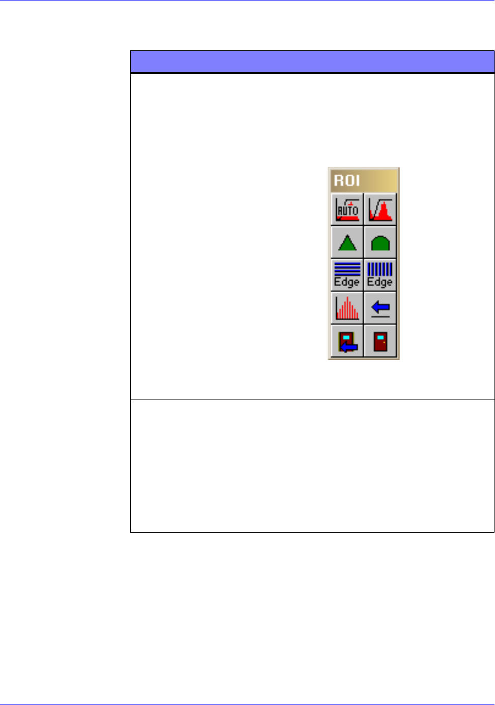
System Operation RTR-4 Operator’s Manual
4-36 SAIC Proprietary 120300 Rev. D
recently saved modifications unless Multiple Originals is
enabled.
COMMAND DESCRIPTION
ROI Processing Select this command to modify a specific
area of an image. When selected, the
cursor changes to a crosshair. Click at
one corner of the area to be modified and
drag to the opposite corner and click
again. The ROI toolbar then appears.
Click on the desired toolbar button to
modify the selected area.
Annotate Select this command to place lines or
text on an image. Select any of the
following:
• Text>Black
• Text>White
• Line>Black
• Line>White
SHARPEN
HORIZ. EDGE
DETECT
HISTOGRAM
EQUALIZE
ABORT ROI
MODE
CONTRAST
STRETCH
SMOOTH
VERT. EDGE
DETECT
RESTORE
ORIGINAL
EXIT ROI MODE
AUTO
STRETCH

RTR-4 Operator’s Manual System Operation
120300 Rev. D SAIC Proprietary 4-37
Sharpen Select this command to sharpen an
image.
•Fine slightly sharpens the image,
use for subtle adjustments.
•Moderate improves image clarity
without significantly increasing the
image noise level.
•Extreme dramatically increase the
sharpness of the image, but increases
the noise, producing a “grainy” effect.
Smooth Select this command to soften the lines,
edges, and noise in an image. Using this
function will slightly reduce the image
resolution.
•Fine slightly smooths noise, edges
and lines and is used for subtle
adjustment.
•Moderate smooths the image to a
higher degree.
•Extreme causes more smoothing, for
noisier images or more subtly
changing areas of interest.
Noise Reduction Select this command to filter out pixels
with randomly distributed brightness or
color levels.
•Average replaces the center pixel of
a three-by-three array with the
average of those nine pixels.
•Median replaces the center pixel of
the three-by-three array with the
median value of those nine pixels
•Despeckle removes one-pixel
speckles (white dots) from the image
and shrinks some larger speckles.
COMMAND DESCRIPTION

System Operation RTR-4 Operator’s Manual
4-38 SAIC Proprietary 120300 Rev. D
Edge Detect Select this command to highlight edges
in the image as white lines on a black
background. This may aid in locating
specific shapes in a cluttered image.
•Horizontal highlights the horizontal
lines.
•Vertical highlights the vertical lines.
•General highlights both horizontal
and vertical lines.
Emboss Select this command to make an image
appear raised or stamped by replacing
shading with a uniform gray. This may
aid in locating specific shapes in a
cluttered image.
Add Images Select this command to add images
together to discern objects within dense
containers or housings. This feature is
useful when the highest pulse rate
setting (99) provides a dim image. This
feature allows the user to add several
99-pulse images together.
Subtract Images Select this command to subtract images
from one another. This feature can be
used to remove objects in images by
taking a background image and
subtracting the image of the object.
Saturation
Combination
Select this command to compare a
low-pulse image and a high-pulse image
of the same object, taken in the same
position. The combined image shows the
details of both the low- and high-pulse
images.
Copy to Modified
Buffer
Select this command to copy the image in
the original buffer into the modified
buffer.
COMMAND DESCRIPTION

RTR-4 Operator’s Manual System Operation
120300 Rev. D SAIC Proprietary 4-39
The Preferences Menu
Description
The Preferences pull-down menu commands allow operators to
customize the various operating interfaces. A checkmark next to
a pull-down menu item indicates that the command is enabled.
Except for default settings and unless otherwise noted, preference
commands do not remain enabled after the RTR-4 imaging
application is exited. Preferences should usually be checked and
set before acquiring images.
Prerequisites
Ensure the RTR-4 imaging application is loaded and running.
Histogram
Equalize
Select this command to make a
nonlinear change to enhance subtle
details in a different way than Auto
Contrast. It automatically adjusts the
brightness of pixels to balance the
number of pixels across the range of
possible brightness values. This can
improve visual interpretation
Rotate Image Select this command to rotate the image
as follows:
• +180 Degrees.
• Flip Left-Right.
•Flip Top-Bottom.
Undo Select this command to step backwards
through previously created images. If a
modification is performed which does not
provide the desired effect the user can
step backward one image by selecting
the Undo item.
Redo Select this command to step forward
through previously generated images. If
the user decides that a previously
“undone” modification is desirable after
all, they may return to this image by
selecting the Redo item.
COMMAND DESCRIPTION
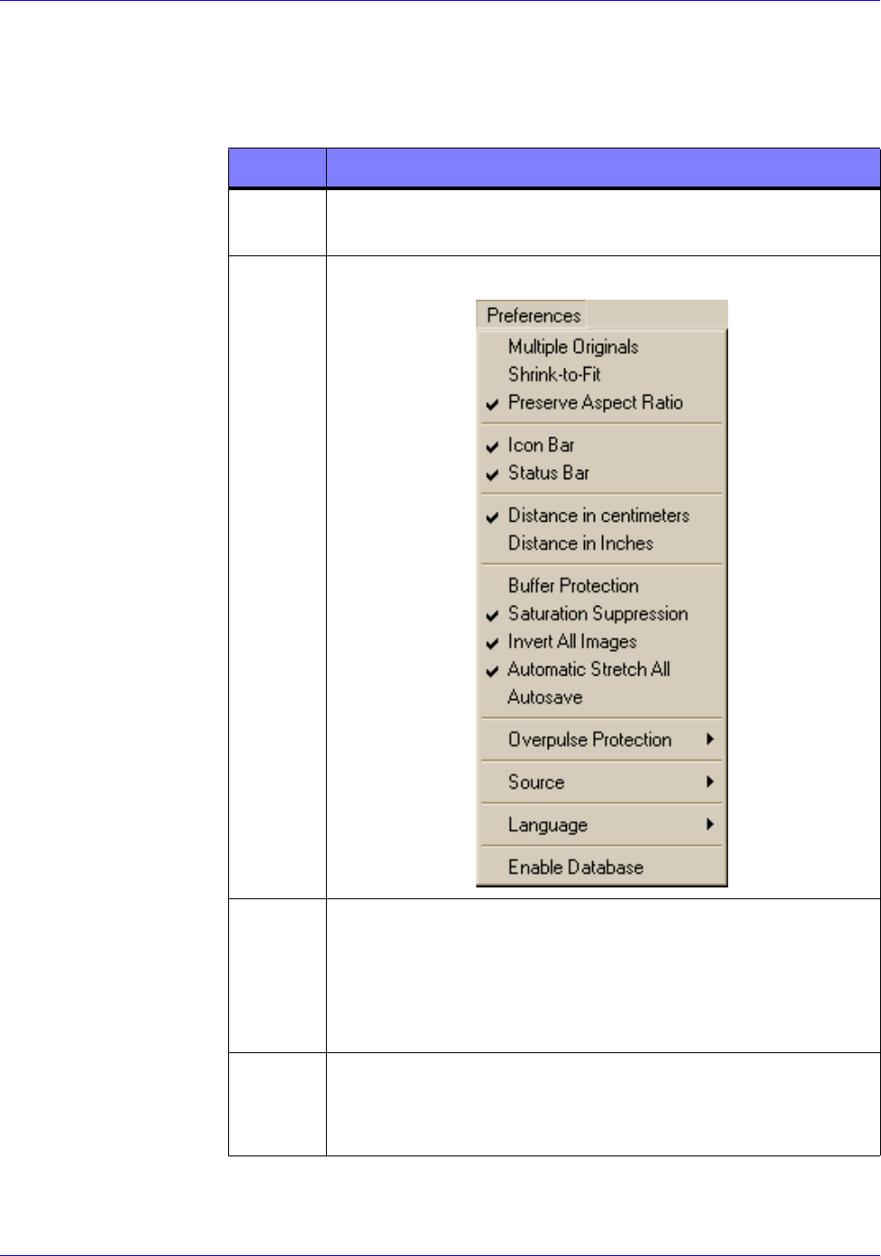
System Operation RTR-4 Operator’s Manual
4-40 SAIC Proprietary 120300 Rev. D
Set Preferences Procedure RTR0027
The items listed and described below are available in the
Preferences pull-down menu. Set each item for the desired RTR-4
operation.
STEP ACTION
1Select the Preferences pull-down menu located at
the top of the Main Screen.
2 The Preferences pull-down menu appears.
3Multiple Originals
Select this command to utilize more buffers than the
system default of two (Original and Modified).
Enabling multiple buffers allows the operator to
open, display, and modify several images.
4Shrink-To-Fit
Select this command to shrink the image to fit within
the viewable area of the window.
RTR0027a

RTR-4 Operator’s Manual System Operation
120300 Rev. D SAIC Proprietary 4-41
5Preserve Aspect Ratio
Select this command to retain the width to height
ratio of an image on the display screen when the
Shrink-to-Fit command is used.
6Iconbar
Select this command to show the Toolbar at the top of
the screen, just below the Main Menu bar. This
selection remains enabled after the RTR-4 imaging
application is exited.
7Status Bar
Select this command to show the status information
across the bottom of the screen. This selection
remains enabled after the RTR-4 imaging application
is exited.
8Distance in Centimeters
Select this command to display units in centimeters.
This selection remains enabled after the RTR-4
imaging application is exited.
9Distance in Inches
Select this command to display units in inches. This
selection remains enabled after the RTR-4 imaging
application is exited.
10 Buffer Protection
Select this command to turn buffer protection on.
When on, the system warns the system operator when
a buffer’s contents are about to be discarded, unless
the image in the buffer has already been saved. When
off, no warnings are given. This selection remains
enabled after the RTR-4 imaging application is
exited.
11 Saturation Suppression
Select this command to reduce glare that may be
created in images containing large areas of bright
white pixels. When enabled, pure white pixels are
changed to black, allowing subtle details to be more
easily seen. When activated this function remains in
affect until it is disabled.
STEP ACTION

System Operation RTR-4 Operator’s Manual
4-42 SAIC Proprietary 120300 Rev. D
12 Invert All Images
Select this command to view the display as a negative
(a positive image is normally displayed). This setting
disables itself when the RTR-4 imaging application is
exited.
13 Automatic Stretch All
Select this command to automatically optimize the
contrast of images that are opened or captured.
14 Autosave
Select this command to be prompted immediately
after each acquired image to save the image. The
Save As dialog box will appear.
15 Overpulse Protection
Use this command to select one of the following:
• No overpulse protection. (Ignores the duty cycle
constraint.)
• Warn about overpulsing. (Warns the operator
prior to firing the source.)
• Delay to prevent overpulsing.(Add an appropriate
delay to prevent overpulsing.)
NOTE: Overpulse protection is required to prevent
overheating of the source and stressing the source
battery.
16 Source
Use this command to select one of the four RTR-4
radiation sources:
• XR-200
• XR-150
•XRS-3
•Inspector
STEP ACTION
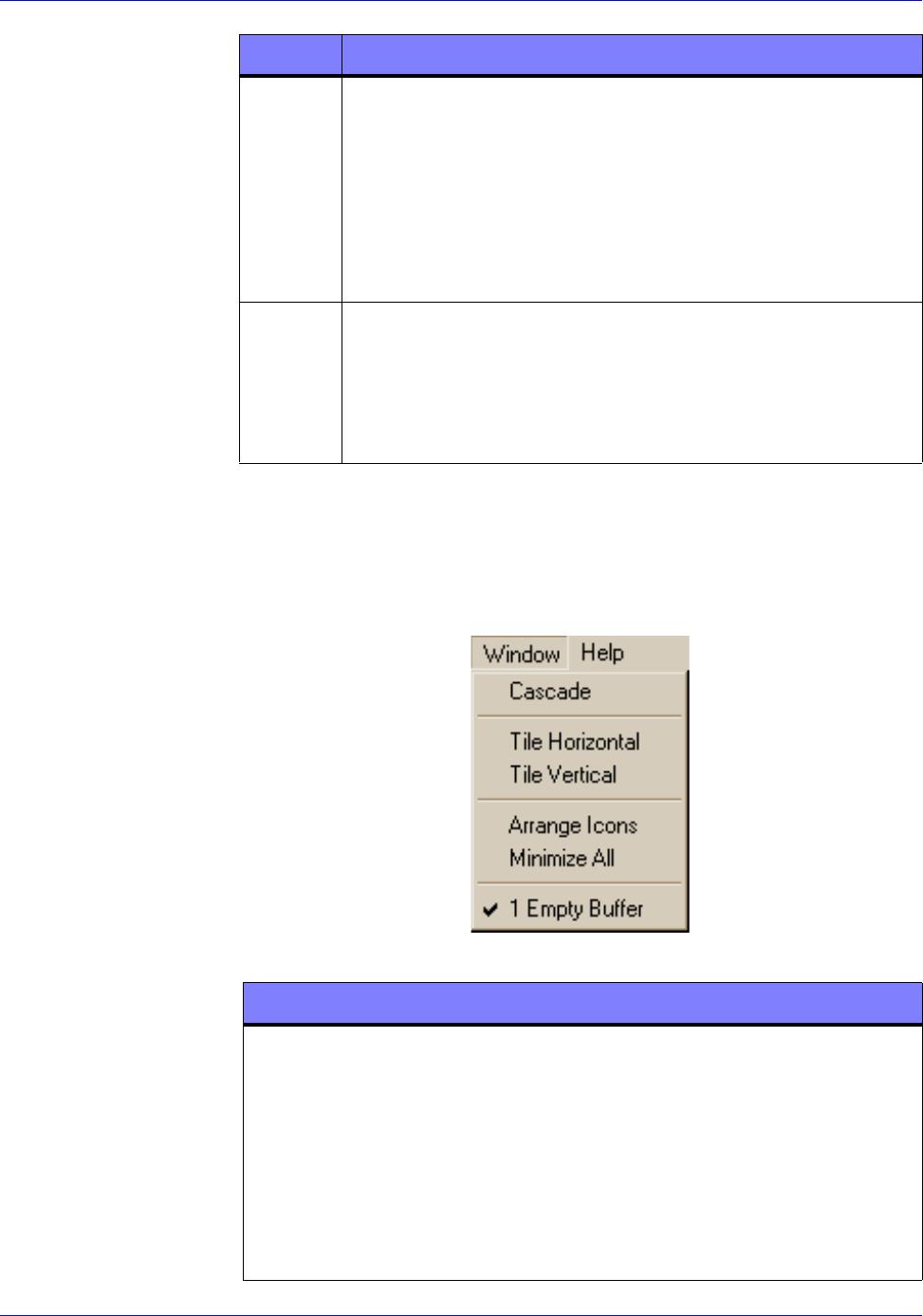
RTR-4 Operator’s Manual System Operation
120300 Rev. D SAIC Proprietary 4-43
The Window Menu
The Window pull-down menu commands allow the user to
arrange or select image windows. This option is not available if
the Multiple Originals command is disabled.
17 Language
Use this command to select the desired display
language.
This item changes only the menu items, not the OS.
The name of the language is always displayed in that
language. Available foreign languages may vary,
depending on the particular controller’s OS.
18 Enable Database
Select this command to enable the database function
and allow recording of ancillary data. This option
remains enabled after the RTR-4 imaging application
is exited.
STEP ACTION
COMMAND DESCRIPTION
Cascade If Multiple Originals is enabled in the
Preferences pull-down menu, selecting
this command rearranges the displayed
images on the screen in a cascade
pattern. Clicking on any image brings
that image to the front of the screen. If
Multiple Originals is not selected, only
the images from the Original and
Modified buffers may be cascaded.

System Operation RTR-4 Operator’s Manual
4-44 SAIC Proprietary 120300 Rev. D
The Help Menu
The Help pull-down menu offers information and assistance on
RTR-4 operation.
Tile Horizontal Selecting this command displays images
in a horizontal layout pattern. The
Multiple Originals function under the
Preferences menu must be selected in
order for more than two images to be
displayed.
Tile Vertical Selecting this command displays images
in a vertical layout pattern. The Multiple
Originals option under the Preferences
menu must be enabled in order for more
than two images to be displayed.
Arrange Icons Selecting this command reorganizes
icons for each of the minimized open files
neatly on the display screen above the
Status Line.
Minimize All Selecting this command collapses all
open display to icons arranged at the
bottom of the screen just above the
status bar. Double clicking the image
header of the icon expands the image to
full size.
Empty Buffer The words Empty Buffer are replaced
by the file name of the image once an
image is opened and read into the buffer.
COMMAND DESCRIPTION
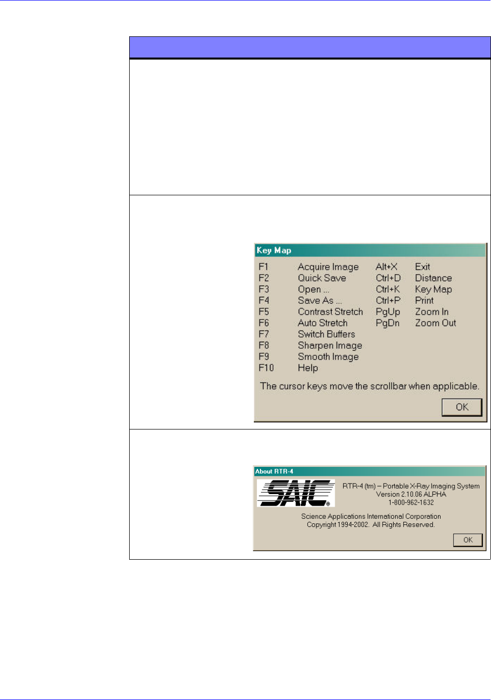
RTR-4 Operator’s Manual System Operation
120300 Rev. D SAIC Proprietary 4-45
The Icon Toolbar
The icon toolbar is located directly under the main menu bar at
the top of the screen. Many of the Menu Bar and pull-down menu
commands have corresponding buttons located in the toolbar. The
commands and their corresponding options for accessing that
COMMAND DESCRIPTION
Help (F10) When selected, a help window
containing the RTR-4 Operator Manual
appears. The first image is the index to
chapters, with hypertext links where the
text is underlined. Clicking on the links
retrieves and displays the indicated
chapter. Clicking on the Index button
returns to the index. Close exits this
display.
Key Map (Crtl+K) Selecting this commands provides a list
of the various keyboard commands and
their corresponding functions.
About Selecting this command provides release
data on the RTR-4 imaging software.
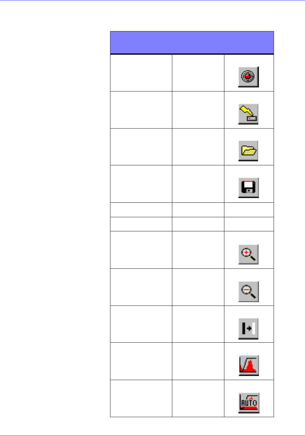
System Operation RTR-4 Operator’s Manual
4-46 SAIC Proprietary 120300 Rev. D
particular command are listed together. The Esc key can be used
to cancel any command request.
MENU
COMMAND
FUNCTION
KEY
TOOLBAR
BUTTON
Acquire F1
Quick Save F2
Open F3
Save As... F4
Print Ctrl+P n/a
Exit Alt+X n/a
Zoom In PageUp
Zoom Out PageDown
Grayscale
Invert
n/a
Contrast
Stretch
F5
Automatic
Stretch
F6
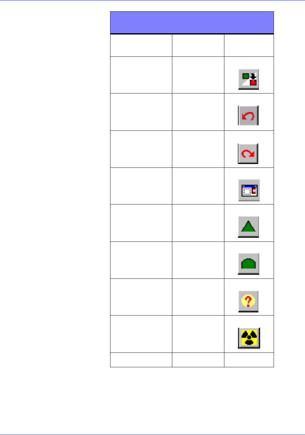
RTR-4 Operator’s Manual System Operation
120300 Rev. D SAIC Proprietary 4-47
Distance
Measurement
Ctrl+D n/a
Switch
Buffers
F7
Undo Ctrl+ Z
Redo Ctrl+Y
ROI
Processing
n/a
Sharpen
Moderate
F8
Smooth
Moderate
F9
Help F10
Acquire
Disable
n/a
Key Map Ctrl+K n/a
MENU
COMMAND
FUNCTION
KEY
TOOLBAR
BUTTON
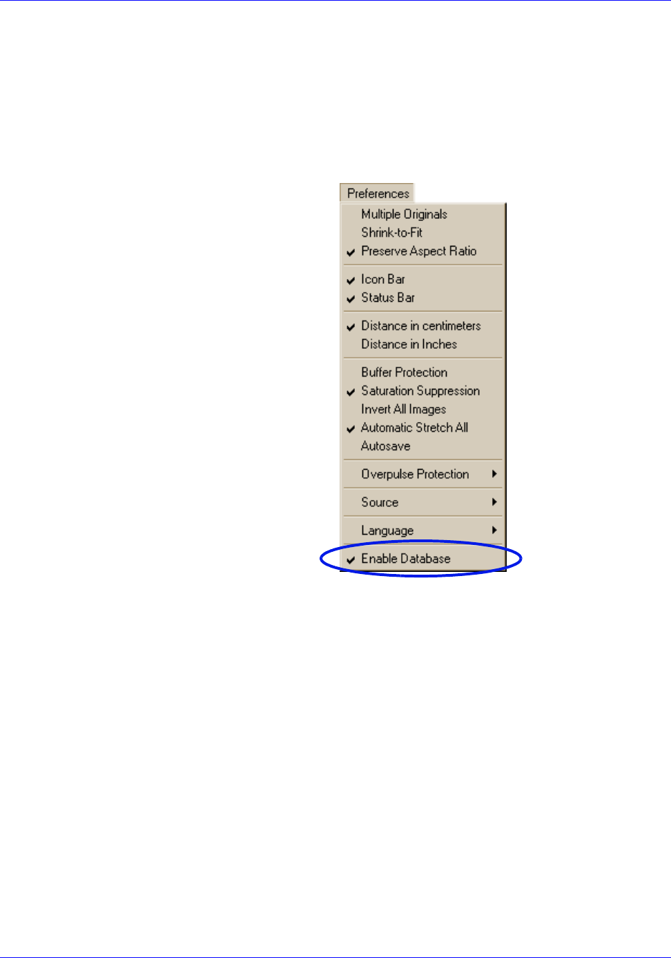
System Operation RTR-4 Operator’s Manual
4-48 SAIC Proprietary 120300 Rev. D
The Database Function
Enable Database Description
The RTR-4 software contains a database function that can be used
to collect, track, analyze, import and export images and related
information conveniently and efficiently. Use of the database
functions is optional and is enabled by checking Enable
Database on the Preferences menu.
When the Enable Database option is unchecked, the software
operates without the ability to append related data to displayed
images. When the Enable Database option is checked, the
operator has the opportunity to enter various details about an
image, to append related data to the image, and to append several
X-ray images to the active incident.
Database Structure
The database organizes and collects data related to an “Incident.”
An identified incident can have many X-Ray images, digital
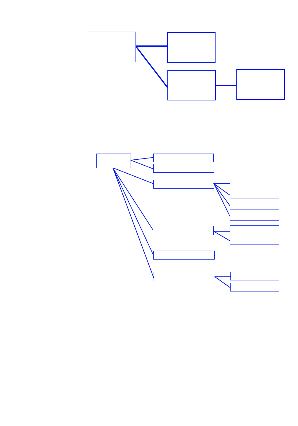
RTR-4 Operator’s Manual System Operation
120300 Rev. D SAIC Proprietary 4-49
photos, audio, video, and other files appended to it. The general
relation ship is:
A more specific example shows one possible arrangement of files
that can be appended to an incident. In this case, the incident has
some notes, a digital photo and four X-ray images appended to it.
The X-ray images have from zero to four files appended to them
which include notes, digital photos, and in one case an audio file.
The database function allows for many incidents to be recorded.
Each incident can have many associated files and images
appended to it. Each image appended to an incident can
additionally have many associated files appended to the image.
Incidents and their associated files can be exported to archive the
data outside of the RTR-4 system. Pre-existing incident files can
be imported to add to data and images in an existing database.
This facilitates backup and data management.
All data related to an incident can be imported and exported to a
central point or database allowing the collection of incident data
for legal use, statistic trending, and intelligence analysis. An
entire incident, along with the associated RTR-4 images and all
appended files may be saved to disk or CD by selecting
INCIDENT
INCIDENT
RELATED
FILES
RTR-4 X-RAY
IMAGES X-RAY
RELATED
TO
TO
FILES
IMAGES
INCIDENT
RTR-4 X-RAY IMAGE
NOTES
DIGITAL PHOTO
RTR-4 X-RAY IMAGE
RTR-4 X-RAY IMAGE
RTR-4 X-RAY IMAGE NOTES
NOTES
NOTES
NOTES
DIGITAL PHOTO
DIGITAL PHOTO
DIGITAL PHOTO
AUDIO
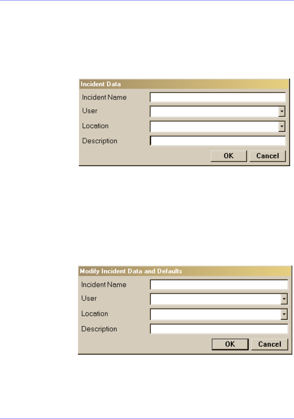
System Operation RTR-4 Operator’s Manual
4-50 SAIC Proprietary 120300 Rev. D
File>Database> Administer Database>Export when the
database function is enabled. Saved incidents may be combined
by selecting File> Database>Administer Database>Import
when the database function is enabled.
Entering Incident Identification
When Enable Database is checked, the Incident Data dialog
box is displayed when the RTR-4 program is started.
This dialog box shows the active Incident Name and the default
User, Location, and Description. Changing any of the entries
will create a new incident. The incident name and description
fields accept typed input from the operator. The user and location
fields will accept typed in data or the operator can select from the
drop down lists. The Incident Data fields may be entered before
arriving at an incident or input by the RTR-4 user at the scene.
Once incident data has been entered, it can only be changed by
using the Modify Incident Data and Defaults dialog box which
is accessed by selecting File>Database>Modify Incident Data
and Defaults.
Saving Image Data
When an image is acquired and saved, after entering the
filename, the Save Image Data dialog box is displayed. The
operator enters the appropriate data into the fields provided and
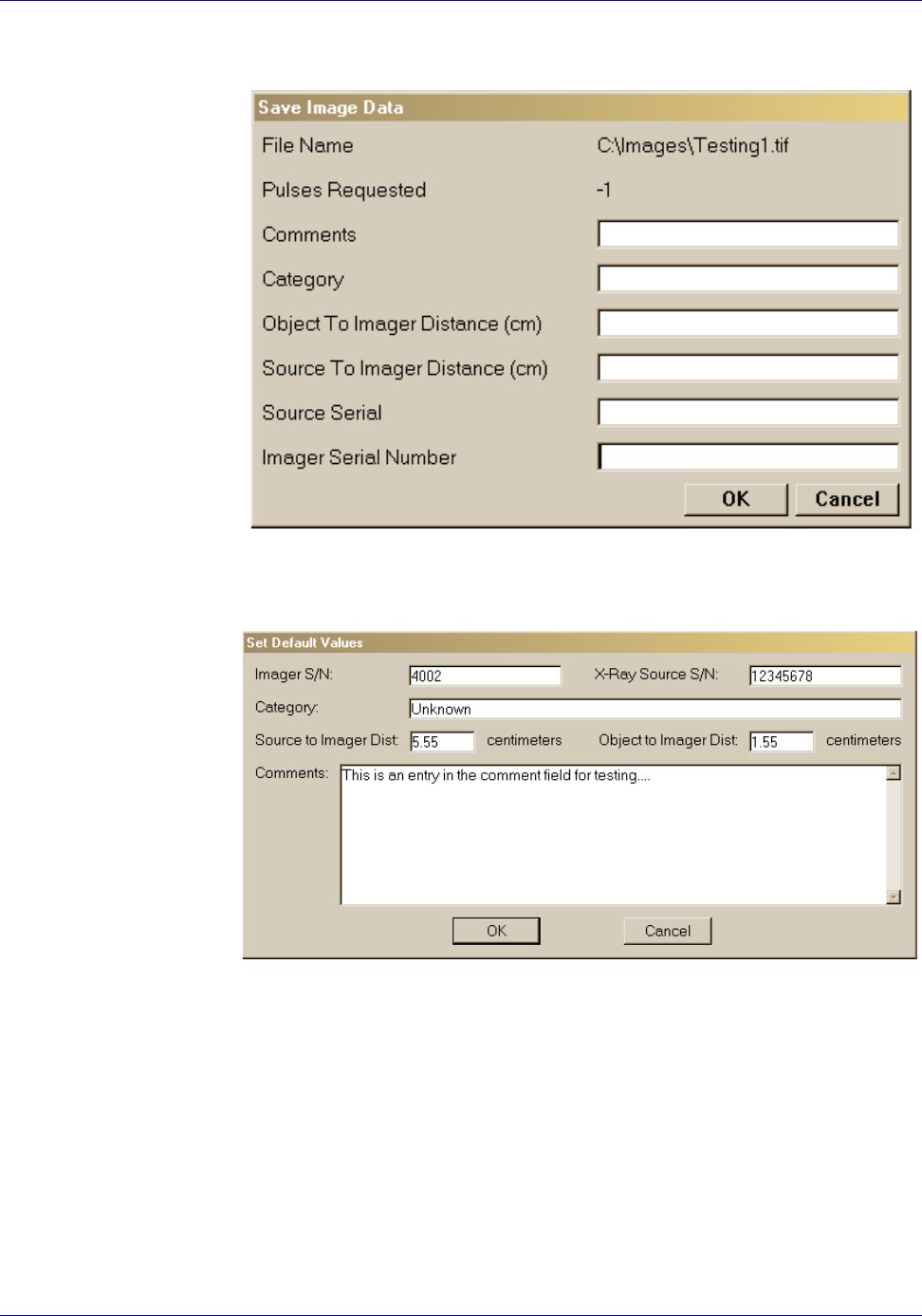
RTR-4 Operator’s Manual System Operation
120300 Rev. D SAIC Proprietary 4-51
clicks on OK to save the image. These values are provided by the
system or the user-specified defaults.
The user can specify the defaults for the Save Image Data dialog
box by using the Set Default Values option from the
Files>Database menu.
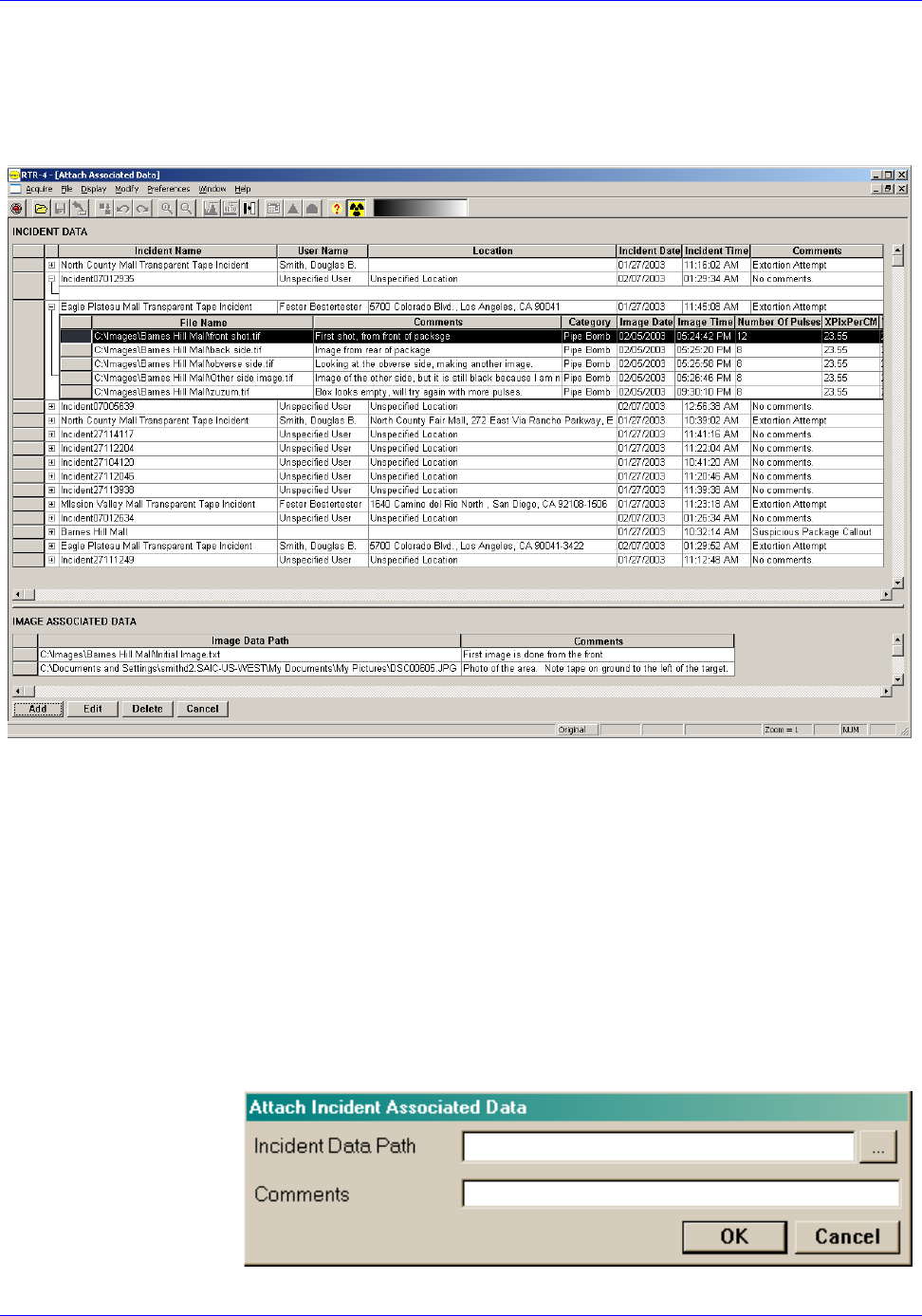
System Operation RTR-4 Operator’s Manual
4-52 SAIC Proprietary 120300 Rev. D
Attaching Associated Data
Select File>Database>Attach Associated Data to link a file on
the computer with the active image. The Attach Associated
Data window displays (figure 4-2).
Figure 4-2: Attach Associated Data Window
This window displays a list of the incidents contained in the
database with a + sign by each incident name. Clicking on this +
sign expands the entry showing the RTR-4 X-ray images
appended to that incident. The appended files are displayed in a
smaller window below the selected incident. The operator
appends files (images) to an incident by selecting the incident and
clicking the Add button. A dialog box appears where the operator
can enter the file location and a descriptive comment. After
appending the desired files, the operator returns to the main
menu screen by closing the Attach Associated Data window.
RTR04attImg
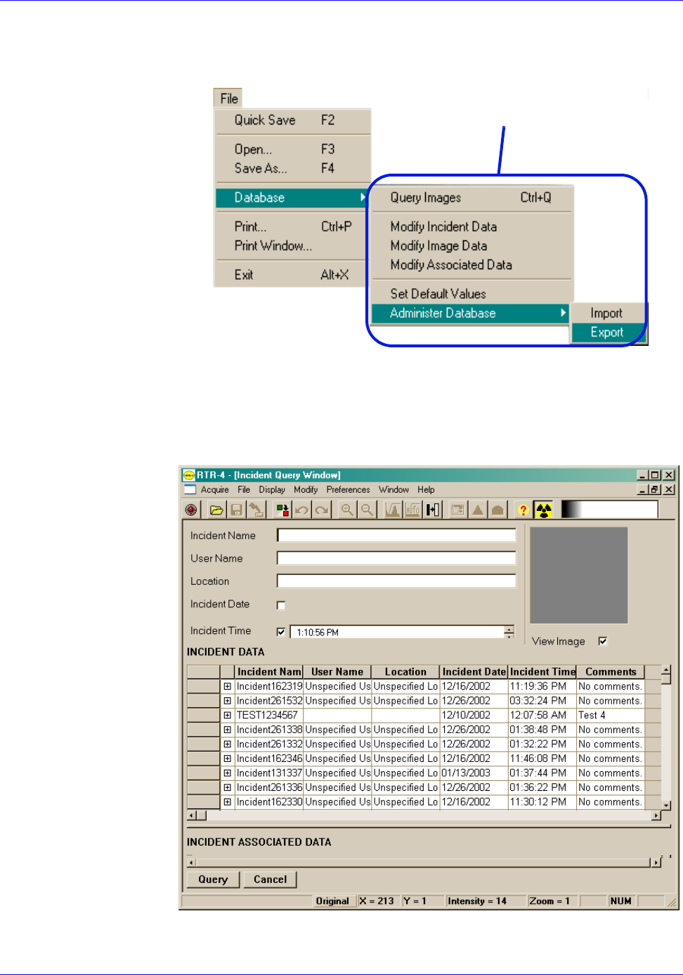
RTR-4 Operator’s Manual System Operation
120300 Rev. D SAIC Proprietary 4-53
Query Image
Selecting this function displays a window where the operator can
enter search data for specific incidents and related data.
The query window provides the operator with several methods to
locate specific incident information. The operator can search on
Incident Name, User Name, Category, Location, or a date range.
The first four search methods use the key word search method to
locate data.
DATABASE ACTIVITIES
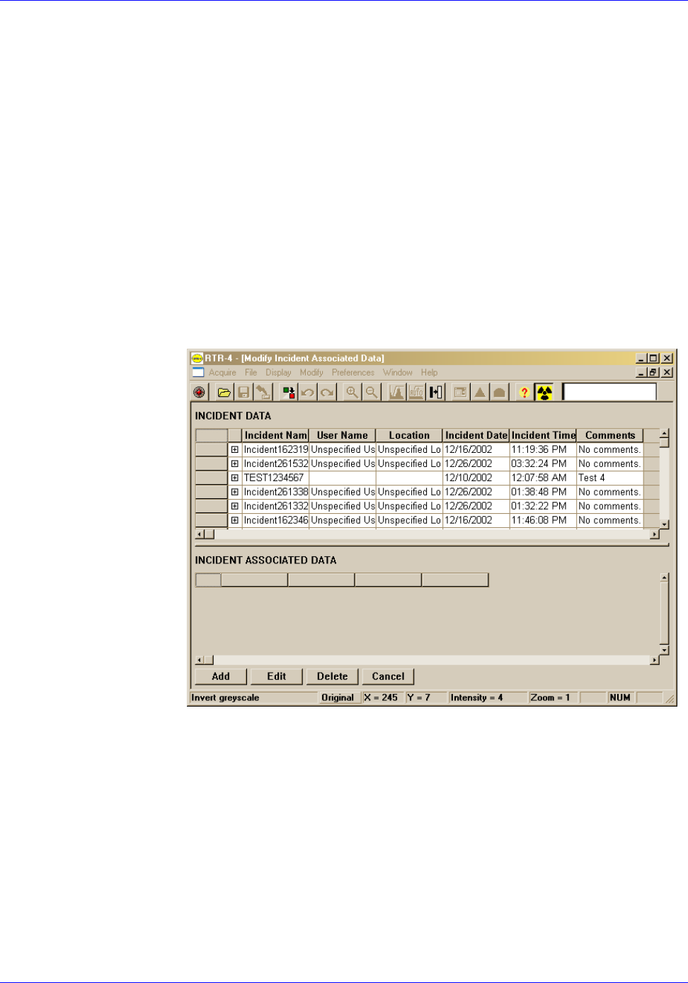
System Operation RTR-4 Operator’s Manual
4-54 SAIC Proprietary 120300 Rev. D
Modify Incident Data
Selecting Modify Incident Data allows the operator to change
the default entries in the Session Data dialog box. This is the
window that is displayed when the software is started and the
database option is checked.
Modify Image Data
Selecting Modify Image Data permits the operator to change the
entries for the Save Image Data dialog box. This is the window
that is displayed when saving an image.
Modify Associated Data
The Modify Associated Data Screen allows the operator to add,
delete, or edit files associated with images and incidents. This
screen is only displayed when Modify Associated Data is
selected from the File>Database menu.
Selecting an image allows a file to be associated with this
incident. Selecting an Incident and then an incident-associated
file permits deletion of that connection or editing the comments or
filename.
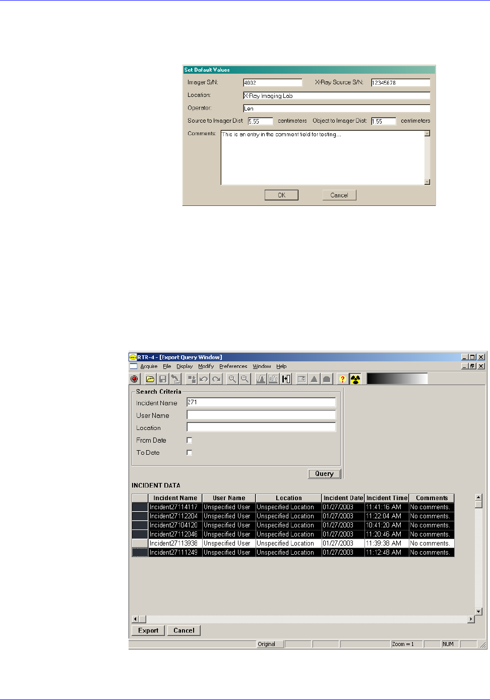
RTR-4 Operator’s Manual System Operation
120300 Rev. D SAIC Proprietary 4-55
Set Default Values
The Set Default Values dialog box allows the operator to set the
default values for the Save Image Data screen.
Administer Database
The Administer Database menu option has two choices, either
Import or Export. This allows the operator to save or combine
incidents. Selecting the Export option causes a query-style
window to appear. The operator selects an incident by clicking on
the box to the left of the incident name. More than one incident
may be selected by using the Ctrl key or selecting a range by using
the Shift key. Here is an example of five incidents selected for
export.
This operation saves all the incident data, including the images,
text files, spreadsheets, audio, video, and digital camera files that

System Operation RTR-4 Operator’s Manual
4-56 SAIC Proprietary 120300 Rev. D
were associated with the incidents. The exported incidents are not
deleted from the initial system.
The import operation merges external database incidents into the
existing database. Duplicate files are not copied.
Shutting Down and Stowing the RTR-4
Shutdown and Stow the RTR-4 (Wired or Wireless
Configurations)
Description
Follow this procedure to shut down the RTR-4. Step numbers with
the letter “a” apply to the wireless configuration only. Step
numbers with the letter “b” apply to the wired configuration only.
Prerequisites
There are no prerequisites for this procedure.
Procedure RTR0028
Shutdown and stow the RTR-4 as follows:
STEP ACTION
1Exit the RTR-4 imaging software.
2At the Windows desktop, select Shut Down from the
Start menu.
3a Remove the WiFi NIC and place it into its protective
cover.
3b Disconnect the 30cm (1ft) communications adapter
cable from the controller and the communications
cable reel.
4If the controller external ac adapter was used,
unplug it from both the controller and the 110Vac
source.
5Close the controller cover and place the following
components (as applicable) into the transport case:
• Notebook controller.
• External ac adapter.
• WiFi NIC
• 30cm (1ft) communications cable adapter.
6At the imager, set the POWER switch to the off
position.

RTR-4 Operator’s Manual System Operation
120300 Rev. D SAIC Proprietary 4-57
Operator Maintenance
RTR-4 owners, custodians and operators may perform limited
maintenance activities as indicated in this section. Contact
technical support as indicated in Chapter 1 for any required
maintenance beyond that is listed here. Refer to the Golden
Engineering XR200 X-ray source Operator’s Manual for X-ray
source care, maintenance and troubleshooting.
RTR-4 Care and Cleaning
The RTR-4 should be stored and transported in the transport case
provided with the equipment. The RTR-4 has no special periodic
maintenance requirements other than battery charging and
routine image quality checking. The RTR-4 external surfaces may
be cleaned carefully using a damp cloth and mild detergent, but
care must be taken to prevent water from seeping inside any of
7At the X-ray source, turn the keyswitch
counterclockwise 90° to the off position.
8b At the imager, disconnect the communications and
X-ray source cables.
9b Coil up the communications cable and the extension
cable, if used onto the cable reel(s). Use care to avoid
dragging the connector on the ground.
10b Place the communications cable reels into the
transport case ensuring that the knob is in the pocket
provided and the handle is folded to the stowed
position.
11b Disconnect the X-ray source cable from the X-ray
source.
12b Coil the X-ray source cable and place it into the
transport case.
13 Remove the key from the X-ray source keyswitch and
place the source and key into the transport case.
14a Unscrew ANT1 and ANT2 from the imager radio
unit and place the imager and the antennas into the
transport case.
14b Place the imager into the transportation case.
STEP ACTION

System Operation RTR-4 Operator’s Manual
4-58 SAIC Proprietary 120300 Rev. D
the units and damaging any electronic components. The flat panel
display may be wiped off using a damp, lint-free cloth while the
power is off.
Disk Space
Hard disk drive and floppy disk file space can be recovered by
deleting old images that are no longer needed, or those that have
been backed up to an external hard drive, ZIP disk or CD-R. Use
the Delete option in Windows Explorer for this purpose.
Charging Batteries
It is recommended that unused and spare batteries be recharged
every month while in storage. The Imager and controller batteries
can be recharged by connecting the external power adapters when
they are not in use. There are two different battery chargers for
the DeWalt XR200 battery. One will only work on 110 Vac, 60 Hz,
and the other will only work on 220 Vac/50 Hz. Attempting to use
the battery charger with the wrong AC supply is very likely to
damage the battery charger and possibly the battery. Please
verify compatibility before connecting the charger to a power
source. Batteries should be disconnected from the charging once
they are fully charged.
Charging the Source Battery
The source battery is charged on an external battery charger.
Remove the battery from the source and plug it into the charger
to charge. A fully discharged battery can be charged in
approximately one hour. However, observe the LED indicator on
the charger to monitor battery charging progress. Be sure to
remove the battery when it is fully charged.
Charging the Imager Battery
The battery in the imager can be charged while it is in the imager
unit. Connecting the external power adapter to the Imager,
whether in use or not, will charge the battery. Observe the LED
indicator to monitor battery charging progress.
Imager batteries may also be charged using the external
imager-battery charger provided. The red and green LEDs on the
charger unit will indicate the condition and charge of the battery.
Replacement Integrated Imager batteries must meet or exceed
the specifications for a DR-35S 10.8Vdc 3800 mA/hr battery.
Nickel metal-hydrate (NiMH) is the only acceptable battery type.
Charging the Notebook Controller Battery
The RTR-4 Controller internal battery must remain charged to
ensure that the set is always ready for deployment. Connecting
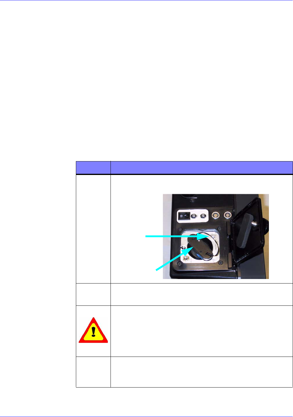
RTR-4 Operator’s Manual System Operation
120300 Rev. D SAIC Proprietary 4-59
the supplied external power adapter to the notebook while it is not
in use will recharge a discharged battery. Using the external
power adapter while the notebook is in use will also charge a
discharged battery, but at a slower rate. Check with appropriate
notebook manufacturer documentation for recharge times.
Imager Battery Replacement
Description
Follow this procedure to replace the DR-35S battery in the
Integrated Imager unit.
Prerequisites
Verify all power is off and the Imager is not connected to other
RTR-4 components or to external power.
Procedure RTR0029
Replace the battery as follows:
STEP ACTION
1Unscrew the cover screw and open the battery
compartment cover.
2Pulling on the string loop in the battery end, remove
the discharged battery.
WARNING
Substituting batteries is dangerous. Use only the
10.8Vdc, 9 cell NiMH provided. Use of any other
battery may cause explosion or fire. Failure to
comply may result in personnel injury.
3Position replacement battery so that the “This side
Up” label is facing the rear of the Imager, and insert
into battery compartment.
RTR0029a
LOOP
BATTERY
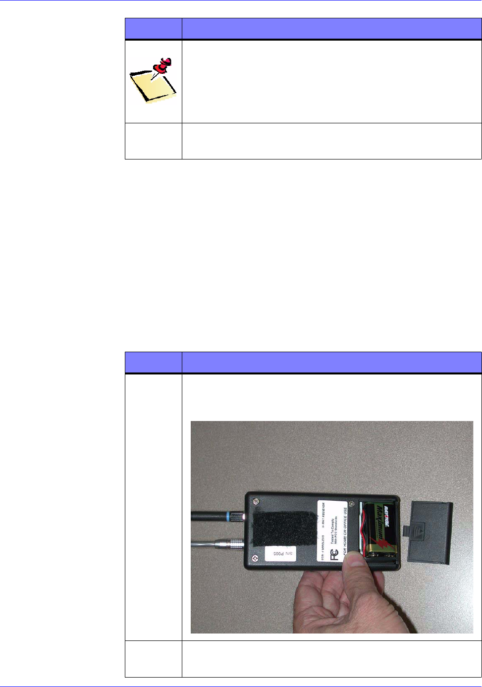
System Operation RTR-4 Operator’s Manual
4-60 SAIC Proprietary 120300 Rev. D
Optional External X-Ray Receiver Battery Replacement
Description
Follow this procedure to replace the standard 9V transistor radio
battery only if your system is equipped with the optional
externally-mounted X-Ray Receiver unit.
Prerequisites
Verify the external X-Ray Receiver is turned off.
Procedure RTR0030
Replace the 9V battery as follows:
NOTE
The battery compartment cover will not close
properly if the battery was replaced facing the wrong
way. If cover doesn’t close, repeat step 3 to place the
battery correctly.
4Close battery compartment cover and finger tighten
cover screw.
STEP ACTION
STEP ACTION
1Using the thumb, press and slide the battery cover
off the opposite end of the X-Ray Receiver from the
Velcro strip.
2Remove the discharged battery from the battery
connector.
RTR0030a

RTR-4 Operator’s Manual System Operation
120300 Rev. D SAIC Proprietary 4-61
Wireless Signal Strength Test Utility
Description
The RTR-4 Wireless Option features a signal strength test utility
called “WaveManager Client” which is launched by clicking on an
icon on the Windows desktop. This utility shows the signal
strength in the connection between the WiFi NIC and Integrated
Imager radio module. Follow this procedure to determine the set’s
signal-to-noise ratio (SNR) when deployed in the field.
Prerequisites
• Ensure the RTR-4 Wireless configuration properly set up,
connected, and powered up.
• The controller must be booted up and running Windows.
Procedure RTR0031
3Connect the replacement battery and position in the
battery compartment.
4Position and slide the battery cover inward until it
snaps into place.
STEP ACTION
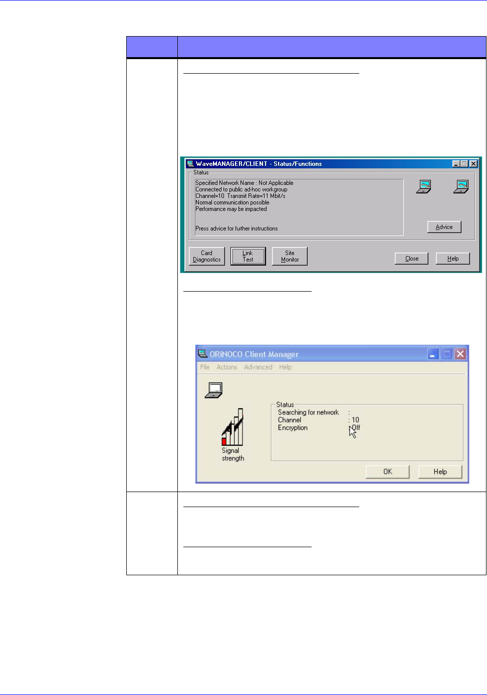
System Operation RTR-4 Operator’s Manual
4-62 SAIC Proprietary 120300 Rev. D
Run the Wireless Signal Strength Test Utility as follows:
STEP ACTION
1For Windows 98 or 98SE OS:
Double-check on the WaveManager Client icon on the
Windows desktop, or select
Programs>Orinoco>WaveMANAGER CLIENT
from the Start menu. A dialog box entitled
WaveManager/Client - Status/Functions appears.
For Windows XP OS:
Select Programs>Orinoco>Client Manager from
the Start menu. A dialog box entitled Orinoco Client
Manager appears.
2For Windows 98 or 98SE OS:
Click on the “Link Test” button.
For Windows XP OS:
Select Link Test from the Advanced menu.
RTR0031a
RTR0031b
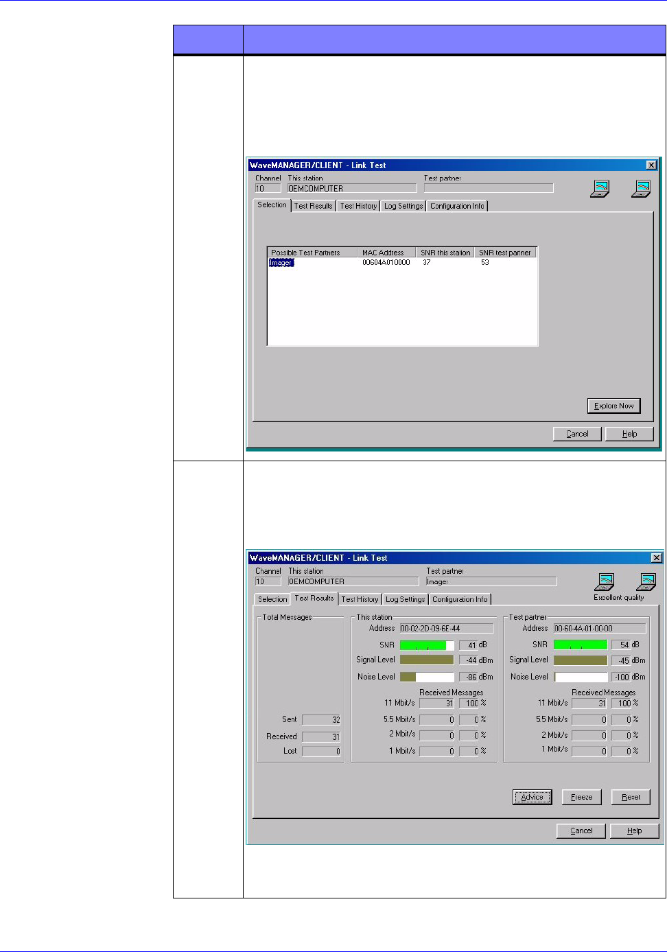
RTR-4 Operator’s Manual System Operation
120300 Rev. D SAIC Proprietary 4-63
3A dialog box entitled WaveManager/Client-Link
Test appears. From the tabs at the top, select the
Test Results tab. (The Windows 98 and Windows XP
Operating System dialog boxes are slightly different,
but their functionality is identical.)
3Select the Test Results tab to display a horizontal
real-time connectivity bar graph. The
WaveMANAGER/CLIENT Link Test dialog box
appears.
The presence of a high SNR (high signal value, low
noise value) verifies a good quality connection.
STEP ACTION
RTR0031c
RTR0031d
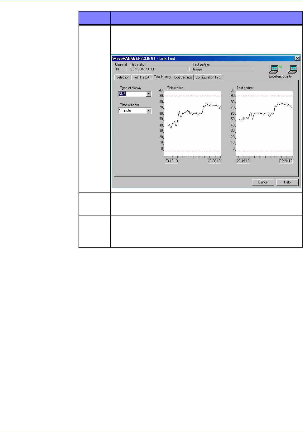
System Operation RTR-4 Operator’s Manual
4-64 SAIC Proprietary 120300 Rev. D
4Select the Test History tab to display a real-time
signal-to-noise ratio (SNR) figure and corresponding
line graphs.
5Click the Cancel button on either the Test Results or
Test History dialog boxes to exit the tests.
6Click the Close button on the WaveManager/Client -
Status/Functions dialog box to exit the WaveManager
Test Utility.
STEP ACTION
RTR0031e
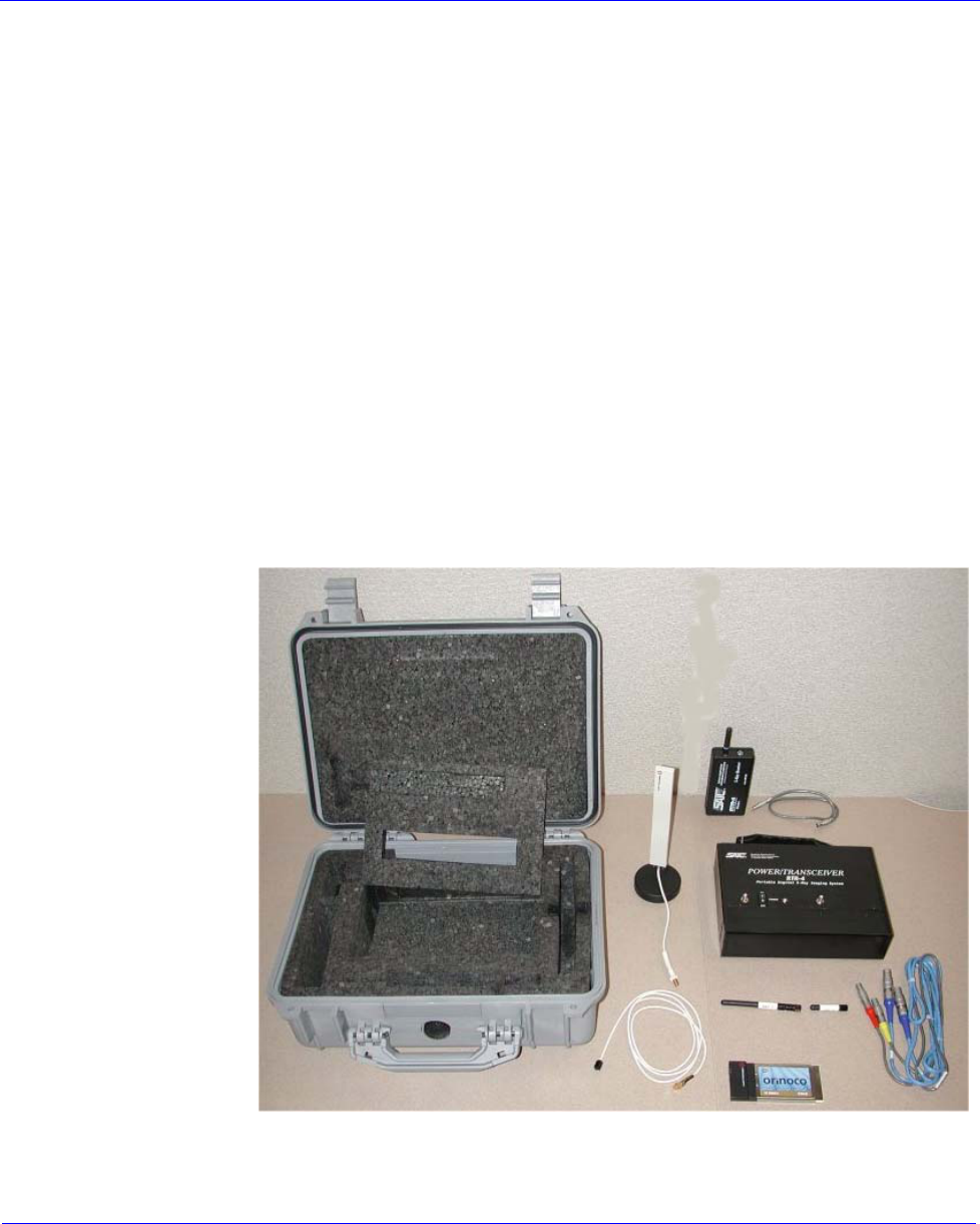
120300 Rev. D SAIC Proprietary 5-1
5 Ancillary Equipment
Introduction
This chapter describes various ancillary equipment that has been
used with or may be with the RTR-4 in place of or in addition to
the equipment described earlier in this manual. This chapter
consists of the following sections:
• Previous Model Wireless Option.
• Previous Model Controllers.
• Previous Model Imagers.
• Alternate X-ray Sources.
• Miscellaneous Accessories.
Previous Model Wireless Option
Prior to the current Wireless configuration a typical RTR-4
Wireless Option consisted of the hardware items shown below.
1. Carrying case with removable foam lining.
2. Optional medium-range antenna unit.
1
23
4
5
67
8
9
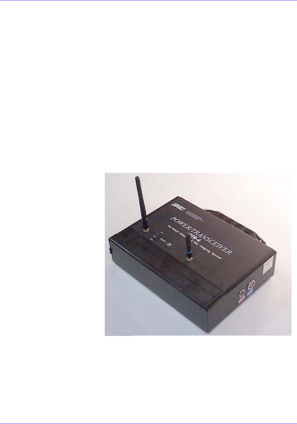
RTR-4 Operator’s Manual
5-2 SAIC Proprietary 120300 Rev. D
3. X-ray Receiver unit and Receiver-to-Source cable.
4. Power Transceiver unit.
5. Adapter cable for optional medium-range antenna unit.
6. Tall screw-on transceiver antenna.
7. Short screw-on transmitter antenna.
8. Two Power Transceiver-to-Imager cables.
9. Orinoco WiFi NIC PCMCIA card.
Power Transceiver
The Power Transceiver unit has three functions:
• Provides power to the imager previously supplied by the
controller (in the CU-4 case) or the external power supply (in
the notebook case).
• Facilitates wireless communication between the controller
and the imager.
• Sends the wireless signal from the imager to the x-ray source
for firing x-rays.
The Power Transceiver unit has five assemblies:
• The black chassis
• Antenna 1 (tall, transceiver antenna)
• Antenna 2 (short, transmitting antenna)
• The blue Power Transceiver-to-Imager cable for
controller-and-imager communications

RTR-4 Operator’s Manual
120300 Rev. D SAIC Proprietary 5-3
• The gray Power Transceiver-to-Imager cable for
imager-to-x-ray-source communications
The chassis houses all the active components, the battery, the
imager-to-controller transceiver, and the x-ray transmitter.
Antenna 1 provides signals for communication with the
controller; Antenna 2 provides signals to the X-ray Source
Receiver. The blue cable provides communication to the imager,
and the gray cable (with one red strain relief and one yellow)
provides communication from the imager for x-ray firing
purposes.
The Power Transceiver has a convenient briefcase-style handle
and contains a 10.8-Volt smart battery that is the same type as
provided with the CU-4 controllers. This battery can be recharged
using either the single-slot or the dual-slot charger sometimes
provided with the RTR-4 controllers, or in the RTR-4 CU-4
controller's battery compartment. The Power Transceiver also
has a power switch and a power-indication LED as shown in
Figure 5-2. The battery is in use whenever the power switch is on
and the LED is illuminated. (Early versions have a red LED; later
versions have a green LED.)
Radio-frequency communications between the Imager and the
Controller combined with the radio-frequency communications
with the X-ray Source Receiver are very low intensity. When the
Power Transceiver is more than 50cm (1.5 feet) away from a
target device, then the RTR-4 Wireless Option complies with
HERO specifications. (If the RTR-4 is not being used with
potentially-explosive devices, then this specification is
irrelevant.)
The transmission frequency of the Power Transceiver when
communicating with the imager is near 2.4GHz. This
communication is done between 2.4000 and 2.4835GHz, is
spread-spectrum and frequency-hopping, according to the
IEEE-802.11b-1999 standard, and is further encrypted to
minimize snooping or spoofing. The frequency used when
transmitting to the X-ray Receiver is about 418MHz, is very low
power and is coded with a sequencing 64-bit security code to
minimize the possibility of unintended source firing.
Externally Mounted X-ray Source Receiver Unit
The X-ray Source Receiver unit receives a signal from the Power
Transceiver and fires the x-ray source. A detachable cable can
connect to any of the four x-ray sources manufactured by Golden
Engineering. A strip of velcro is used to attach the receiver unit to
the X-ray source unit.

RTR-4 Operator’s Manual
5-4 SAIC Proprietary 120300 Rev. D
The Externally Mounted X-ray-Source Receiver unit is powered
by a standard 9-volt alkaline battery and has a power switch with
an indicating LED.
Previous Model Controllers
Introduction
This section describes various controllers available for use with
the RTR-4. These are:
• CU-4 Controller
• Notebook Controller with Battery Box.
Standard CU-4 Components
The standard CU-4 controller unit is a fully integrated computer
comprised of the following components:
• Pentium-series processor
• Flat panel display with power-save feature
• Internal hard disk drive
• 1.44MB floppy disk drive
• Modem
The cable spool supplied with the CU-4 controller contains 50 m
of combined power and digital data delivery capability. Imager
power is supplied directly from the CU-4 controller; the Notebook
battery box component is not used in this configuration.
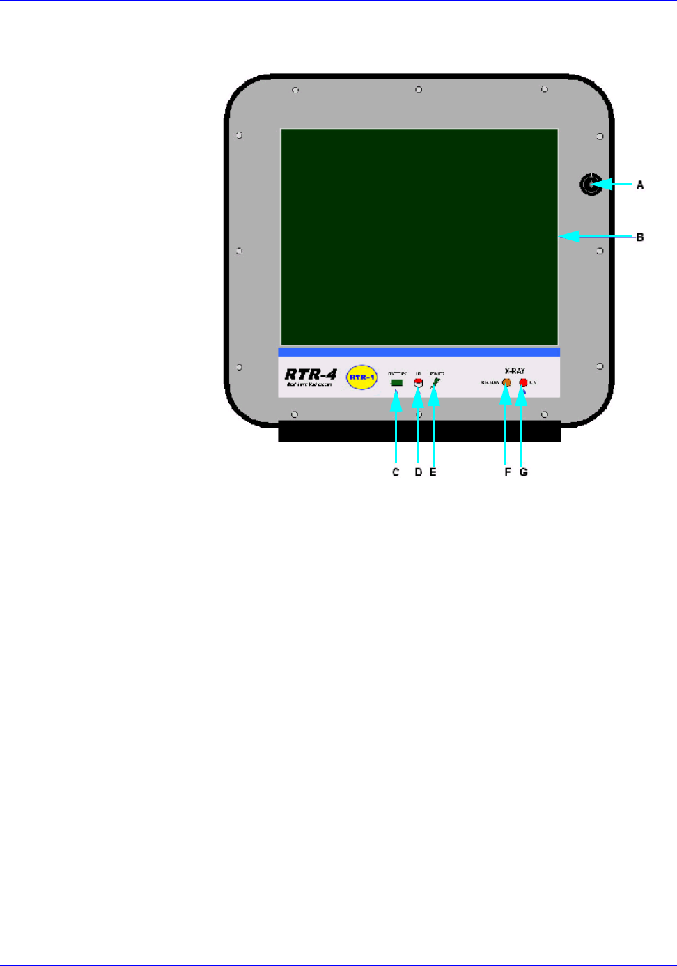
RTR-4 Operator’s Manual
120300 Rev. D SAIC Proprietary 5-5
The CU-4 controller internal display panel features are shown
below.
A Safety key switch
B Color display
C Battery charge indicator light
D Hard drive LED– indicates that the hard disk drive is
in use
E Power LED – indicates that controller power is on
F Standby LED – indicates that the controller’s safety
key is in the “Standby” position
G Source LED – indicates that power is being supplied
to the imager by the controller
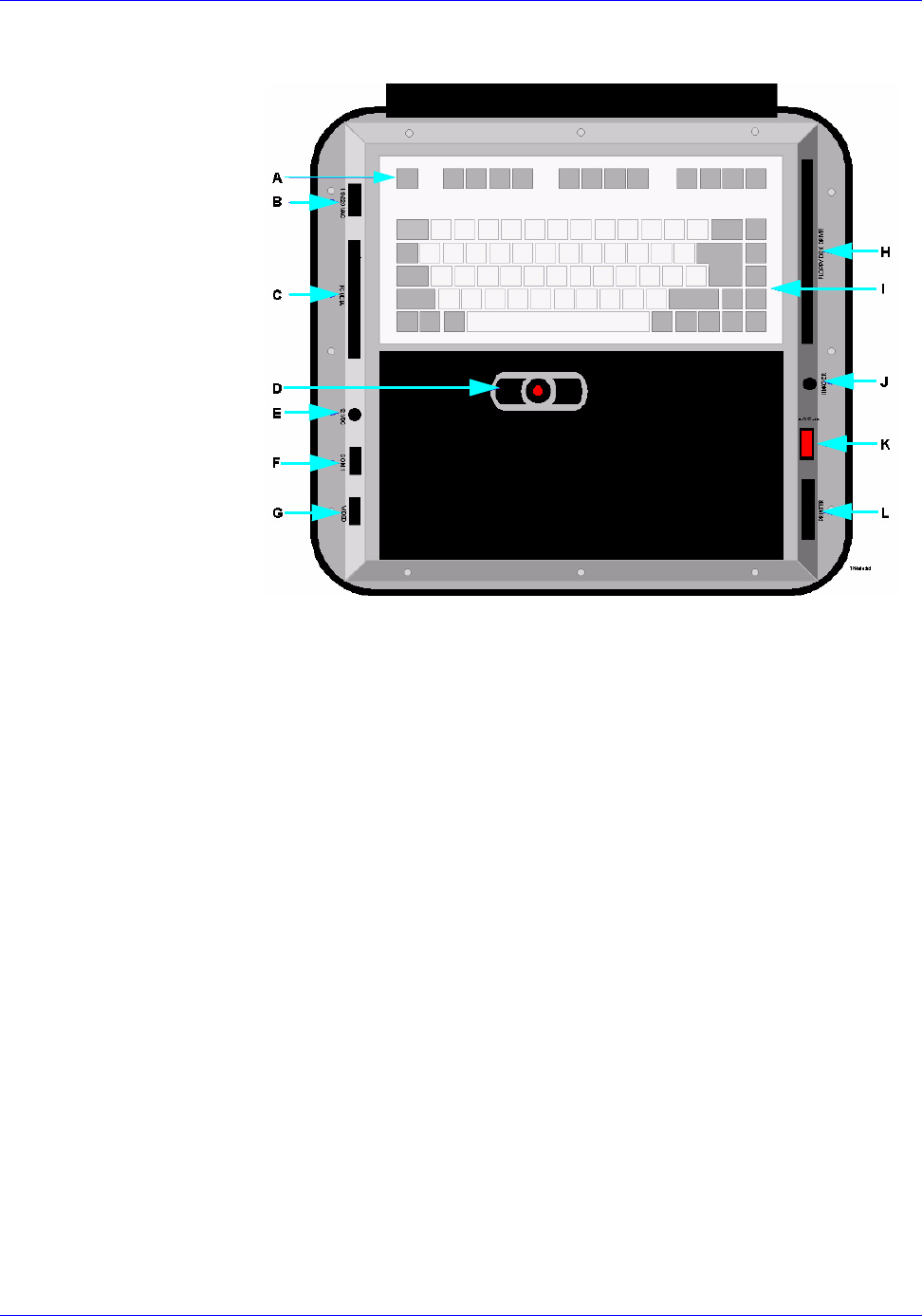
RTR-4 Operator’s Manual
5-6 SAIC Proprietary 120300 Rev. D
The CU-4 controller operator panel features are shown below.
A Keyboard Function keys
B Power cord receptacle for AC line voltage operation
C PCMCIA slots
DMouse
E Power cable receptacle for external DC power (9.5 to
28 Vdc)
F Serial Port (COM1 for external mouse, keypad, X-ray
source control, etc.)
G External monitor connector (AUX VGA– for use with
an external monitor to display images in parallel with
the RTR-4 display, or for connection to some printing
devices
H 1.4 Mbyte Floppy disk drive
I Standard keyboard with membrane cover
J Imager cable receptacle
K Power ON/OFF switch
L Standard parallel printer port (LPT1)
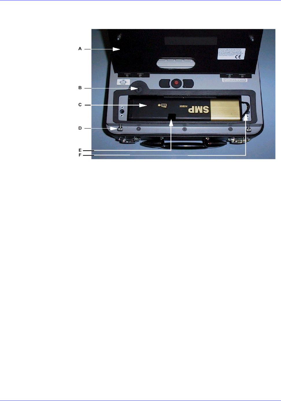
RTR-4 Operator’s Manual
120300 Rev. D SAIC Proprietary 5-7
Controller’s battery and battery compartment features.
A Battery receptacle cover/wrist pads
BAC fuse
CBattery
D Thumbscrews for securing the battery receptacle
cover
E Battery strap (center vinyl strip connected to battery
housing underneath battery), used to extract battery.
F Battery strap (small cloth ribbon connected to
non-conductor end of battery), used to lift battery
Power Supply Options
The CU-4 controller has a power-saving feature that darkens the
computer screen if not used for two to four minutes. Pressing the
shift key or moving the mouse reactivates the screen from the
power-saver mode. Do not press any other key as it may perform
an undesirable function.
The CU-4 controller automatically switches between internal
battery, US standard 110Vac, and international standard 220Vac
line power. The system is frequency-insensitive between 45 and
65Hz. The controller also powers the RTR-4 imager, so no special
power consideration is required for the imager.
The list below shows the power options for the Controllers for the
CU-4 and Notebook systems. Appropriate cables are provided for
each option.

RTR-4 Operator’s Manual
5-8 SAIC Proprietary 120300 Rev. D
• 110-220Vac 50-60Hz connection to local power grid (standard
operation).
• External DC power from an automobile cigarette lighter
receptacle (option)
• External battery power (option).
Battery Power
A 10.8Vdc rechargeable battery is located in the hinged
compartment below the keyboard of the controller. A fully
charged battery allows about 60 minutes of continuous operation.
The battery in the controller automatically begins recharging as
soon as the unit is plugged into a line power outlet, and takes
approximately eight hours to completely recharge. The controller
does not need to be powered up for recharge, but it does need to be
connected to a standard line power source.
An optional external battery charger can charge optional spare
batteries. Fully recharging a discharged battery with an external
charger takes about three hours.
A red LED on the CU-4 controller display panel will begin to flash
when battery power is low. When this occurs, images should be
saved and the system should be shut down as soon as possible, or
the controller should be connected to a standard line power
source.
Notebook Controller with Battery Box
The Notebook configuration uses a standard notebook PC as the
Control Unit. The Notebook Controller has the following
components:
• Pentium-series processor.
• Color flat panel display of at least a 12.1in (31cm) viewing
area, internal hard disk drive.
• 1.44 MB floppy disk drive.
• CD-ROM drive.
• Modem.
• Communications port.
The communications port provides connection between the
controller and the X-ray Imager. This port includes an internal
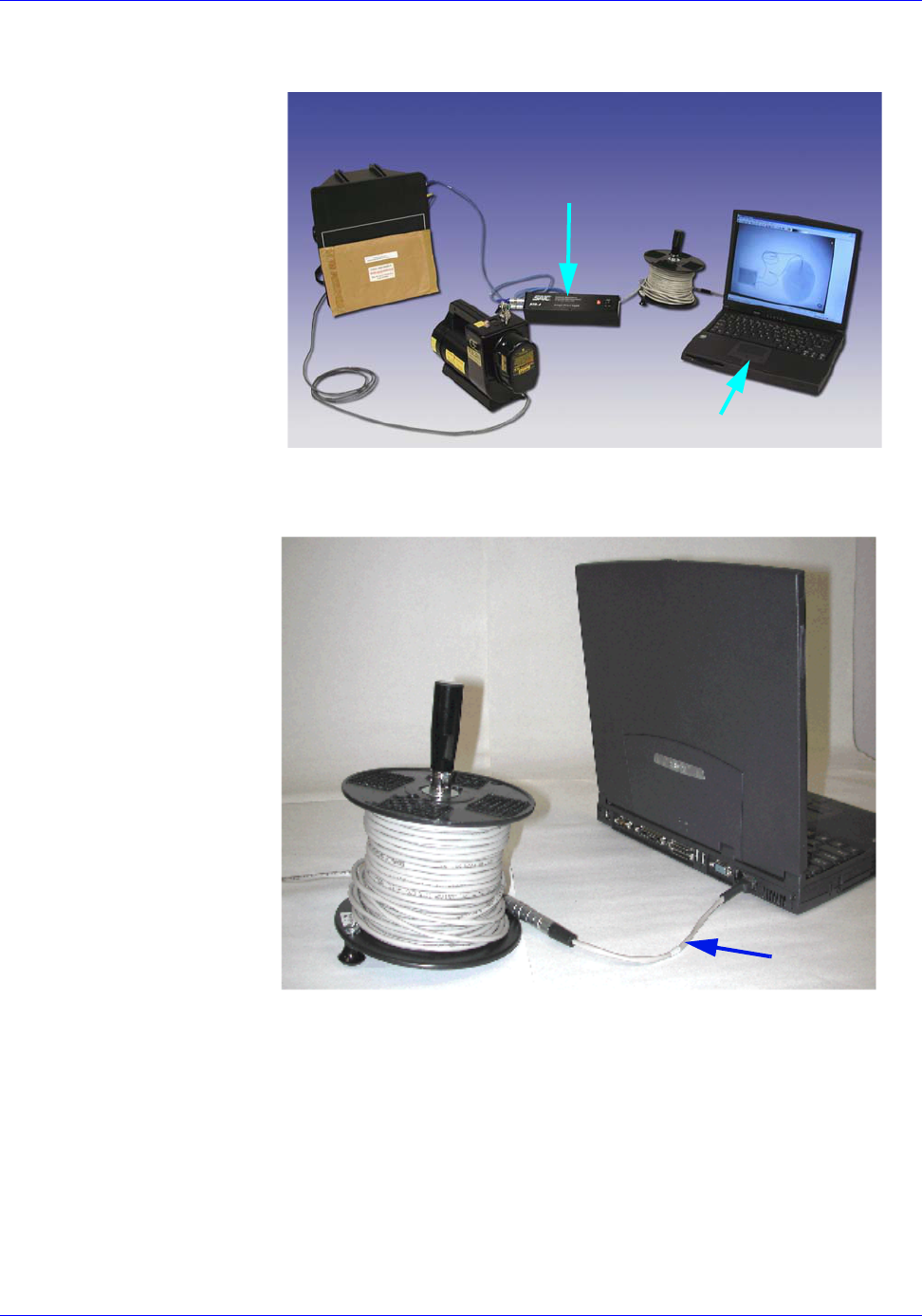
RTR-4 Operator’s Manual
120300 Rev. D SAIC Proprietary 5-9
rechargeable battery and an external power supply which can be
used to power the unit and also to recharge the internal battery.
Note that the adapter cable connects between the
communications port of the Notebook and the 50m reel cable.
Notebook Battery Box
The notebook controller has a Battery Box that is necessary to
power the Standard-View Imager and also routes communication
and image data signals between the Imager and the Notebook
Control Unit. This unit houses a rechargeable battery, which
provides several hours of operation for the Imager.
A green light indicates when the power is being supplied, this
requires that the Battery Box switch be in the ON position and
that the communications cable is properly plugged in. An external
BATTERY BOX
NOTEBOOK CONTROLLER
CABLE REEL ADAPTER

RTR-4 Operator’s Manual
5-10 SAIC Proprietary 120300 Rev. D
battery-charging unit is provided, and the battery is easily
removed and replaced in the unit.
Optional Safety Interlock Key Box
The RTR-4 Notebook system offers an optional Interlock Key Box
which enhances the operators control of x-ray firing. This safety
feature is connected between the Control Unit pigtail cable and
the main 50-m signal wire, and makes use of the existing
connectors on these cables.
A serial communications cable is also required for this
configuration. This extra cable is a standard RS-232 cable
terminated with 9-pin plugs on either end. One side connects to
the Interlock Key Box, and the other is plugged into the COM port
on the rear panel of the Notebook Controller. This connection is
required so that the RTR-4 software can detect the orientation of
the key.
Previous Model Imagers
Introduction
This chapter describes the Standard-View Imager available for
use with the RTR-4 system.
Standard-View Imager
Description
The standard-view imager uses a compact solid-state camera.
Electro-optical signal processing circuitry records images
captured by the Imager unit's X-ray signal acquisition screen and
transmits the acquired images to the Controller (CU-4 or
Notebook.)
• Dimensions: 30cm x 34cm x 18cm (11.75in W x 13.25in H x
7.0in D)
• Field of View: 20 x 27cm (8in x 10.7in)
• Weight: 4.5kg (10lb)
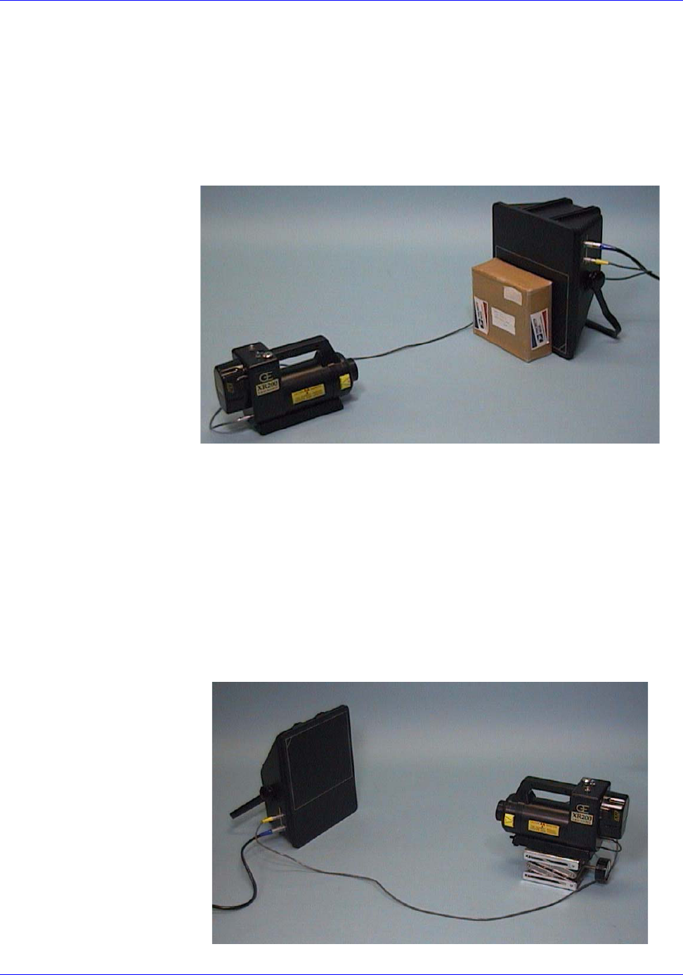
RTR-4 Operator’s Manual
120300 Rev. D SAIC Proprietary 5-11
• Power: 12Vdc (supplied by CU-4 Controller’s Control Unit or
the Notebook Controller’s Battery Box.)
X-Ray Source & Imager Relationship
When acquiring an image, the target object must be positioned so
that it is as close as possible to the Imager’s signal acquisition
screen (face) which is denoted by the white rectangular outline on
the flat side of the Imager unit.
The X-ray source unit should be positioned approximately
60-90cm (24-35in) from the Imager with its beam centered on and
perpendicular to the Imager face.
The two large knobs on the side of the Imager unit must be
loosened prior to adjusting the imager’s handle. If the knobs are
not sufficiently loosened before adjusting or moving the handle,
the Imager may be damaged.
When scanning objects on the ground that cannot or shouldn’t be
moved, the Imager is oriented so that its face is as close to the
ground or working surface as possible.
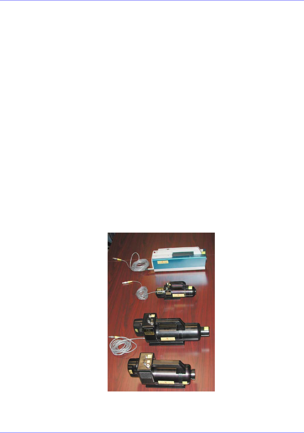
RTR-4 Operator’s Manual
5-12 SAIC Proprietary 120300 Rev. D
The Imager handle is used to support the Imager so that its face
is nearly vertical. The X-ray Source is level with the Imager (or
slightly elevated) so that the X-ray Source’s beam is centered on
the Imager’s signal acquisition screen. The object being imaged
may need to be elevated and the X-ray source must be elevated for
the X-ray Source unit’s beam to be properly centered on the screen
Imager Unit with Elevated Source
Alternate X-Ray Sources
Introduction
The RTR-4 can currently be used with the following Golden
Engineering X-Ray sources:
• Inspector 200
• XR150
•XRS3
• XR200
Although the Inspector 200 has been discontinued, it still can be
used with the RTR-4. For more information on setup and
operation of these sources, see the respective Golden Engineering
user’s manual. These manuals are in Adobe PDF format and can
be downloaded from www.goldenengineering.com.
INSPECTOR 200
XR150
XRS3
XR200
(WITHOUT INTERNAL
RECEIVER)
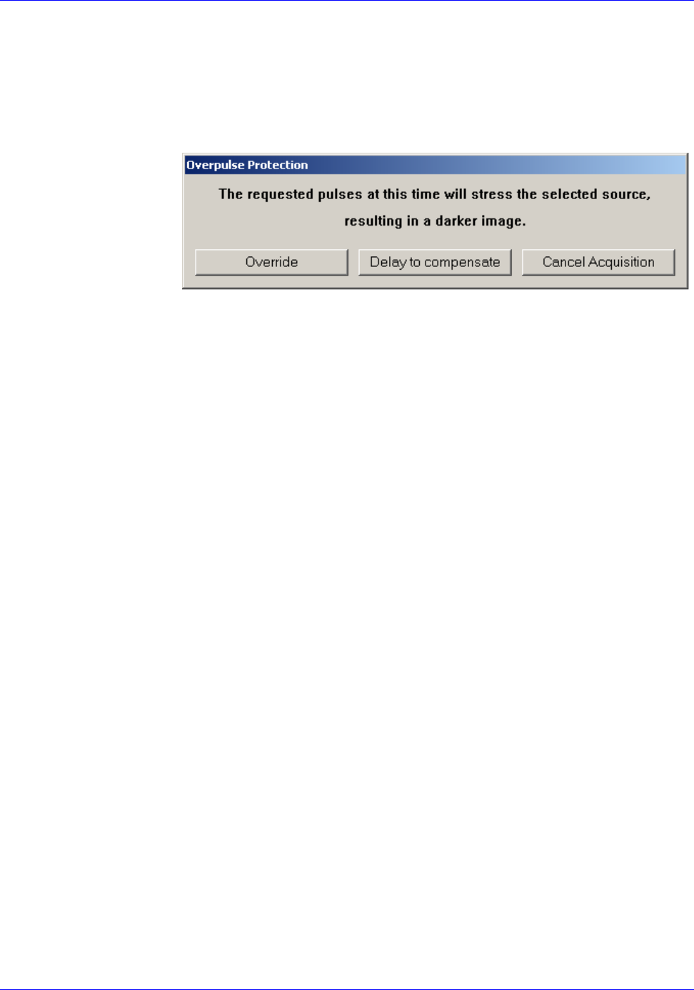
RTR-4 Operator’s Manual
120300 Rev. D SAIC Proprietary 5-13
Over Pulse Protection
Each Golden Engineering source has a duty cycle that sets the
maximum number of pulses that can be produced in a given time.
This is to prevent overheating in the source and stressing the
battery. The RTR-4 software will prompt the operator should a
selection be made that would overpulse the selected X-ray source.
Miscellaneous Accessories
Introduction
Miscellaneous accessories currently available for use with the
RTR-4 are the:
• Wireless Option Backpack.
• Notebook PC Configuration Accessories
Wireless Option Backpack
The RTR-4 wireless option backpack provides a compact,
convenient way of moving and operating the RTR-4 Wireless
Option configuration.
The backpack holds the following items:
• the imager unit
• the X-ray source unit
• the controller unit
• the wireless option equipment (including the
power/transceiver unit)
The backpack accessory uses the same imaging procedure as
would be used in a standard work space. The case with the
components inside can be worn as a backpack to carry the system
to another location.
The RTR-4 backpack is used in conjunction with the normal
transport cases. The items above are removed from their
transport case and put into the RTR-4 backpack. The equipment
is placed in the backpack for easy removal of the PC controller and
X-ray source, while the imager is left in the backpack connected
RTR0550

RTR-4 Operator’s Manual
5-14 SAIC Proprietary 120300 Rev. D
and ready to power on. The backpack can be placed near the
target object for imaging through the pack without removal of the
imager or the need for further setup.
Notebook PC Configuration Accessories
The following table lists and describes the optional accessories for
the standard RTR-4 Notebook configuration.
ITEM DESCRIPTION
Notebook Safety Lock An optional safety lock in a
small box can be connected
between the pigtail cable from
the Notebook PC and the end of
the 50m cable. A connection is
also made to a serial port of the
controller. When the key is in
the OFF position, the X-ray
source cannot be fired.
Extension Cable 50m (164ft) cable extension to
connect to the 50m cable reel.

INDEX
120300 Rev. D SAIC Proprietary I-1
A
Abbreviations ..................................1-2
Acquire an image .................. 3-18, 4-1
Acquire menu ................................4-27
Acronyms .........................................1-2
Active image area ...........................3-4
Adapter cable .......................... 3-2, 3-8
Add Images .....................................4-4
Adding Lines and Text .................4-13
Administer Database ....................4-55
Ancillary equipment .......................5-1
Antenna 1 ........................................5-3
Antenna 2 ........................................5-3
Attach Data ...................................4-52
Automatic Stretch .........................4-16
B
Backpack option ............................5-13
Battery Box .....................................5-9
C
Cable Adapter .................................3-3
Caution symbol ...............................2-1
Charging Batteries .......................4-58
Color palette ..................................4-16
Component Returns ........................1-2
Contrast Stretch ...........................4-14
Copy Freeze Date .............................i-v
CU-4 controller ...............................5-4
D
Database function .........................4-48
Delay Timer .......................... 3-5, 4-29
Disable Acquire .............................4-30
Disk space .....................................4-58
Display menu ................................4-32
Distance Adjustments ..................3-12
Document Revisions .......................1-1
E
Edge detection ...............................4-21
Embossing an image .....................4-22
Enable Database ...........................4-48
F
File menu ......................................4-31
Fire and Sum ................................4-30
G
General Safety ................................2-3
Grid Overlay .................................4-11
H
Help menu .....................................4-44
Histogram Equalize ......................4-23
I
Icon toolbar ...................................4-45
Image Data ....................................4-50
Image information ........................4-10
Image preservation .......................4-23
Image Processing ............................4-9
Image saturation ..........................4-17
Image sharpening .........................4-18
Image smoothing ...........................4-19
Image Transceiver ........................3-11
Imager battery ..............................4-58
Imager Battery Replacement .......4-59
Imager control panel .......................3-7
Imager handle ...............................5-12
Incident data .................................4-50
Incident name ...............................4-50
Initialize the RTR-4 ......................3-18
Inspector 200 .................................5-12
Integrated Imager ...........................3-3
Interlock Key .................................5-10
Internal Source Receiver ..............3-11
M
Main Menu screen ........................4-27
Maintenance
disk space ...................................4-58
system care and cleaning ...........4-57
Measuring Distance ......................4-12
Menus
acquire menu ..............................4-27
display menu ..............................4-32
file menu .....................................4-31
help menu ...................................4-44
modify menu ...............................4-35
preferences menu .......................4-39
window menu .............................4-43
Miscellaneous accessories ............5-13
Modified buffer .................... 4-24, 4-35
Modify Associated Data ................4-54
Modify Incident Data ....................4-54
Modify menu .................................4-35
Multiple Image Display ................4-10
N
Notebook battery ..........................4-58
Notebook PC ....................................3-2
O
Open an image ................................4-9
Operating Environment .................2-4

INDEX
I-2 SAIC Proprietary 120300 Rev. D
Orientation Indicator .....................3-4
Original buffer ........... 4-23, 4-26, 4-35
Outdoor Use ....................................2-4
Overpulse protection ....................5-13
P
Palette options
default ..........................................4-33
inverted greyscale........................4-33
inverted rainbow..........................4-33
rainbow.........................................4-33
Place lines and text ......................4-13
Position Adjustments ...................3-12
Power considerations ......................5-7
Power Transceiver ..........................5-2
Preferences menu .........................4-39
Print an image ..............................4-25
Purpose and Scope ..........................1-1
Q
Query Image .................................4-53
Quick save .....................................4-24
Quick start ....................................3-18
QuickSaving an Image .................4-24
R
Receiver Battery Replacement .....4-60
Reduce noise .................................4-20
Retrieving an Image .......................4-9
Revision History ..............................i-v
RTR-4
description ....................................1-1
power considerations ...................5-7
system components ....................5-14
RTR-4 commands ..........................4-26
S
Safety procedures ...........................2-2
Safety Summary .............................2-1
Saturation Suppression ................4-17
Save an image ...............................4-25
Save Image Data ...........................4-54
Save the image ..............................4-51
Search data ...................................4-53
Set Default Values .............. 4-51, 4-55
Setup, wired configuration ...........3-13
Setup, wireless configuration .......3-15
Sharpen an image .........................4-18
Show multiple images ..................4-10
Showing Image Information .........4-10
Shutdown and Stow the RTR-4 ....4-56
Signal acquisition screen ..............5-11
Signal strength test utility ...........4-61
Soften an image ............................4-19
Source and Imager relationship ...5-11
Source battery ...............................4-58
Source receiver ..............................3-11
Standard View Imager .................5-10
Storage Medium ..............................3-3
Subtract Images ..............................4-7
Sum command ....................... 4-3, 4-30
Symbols ...........................................2-1
System care and cleaning .............4-57
System component
descriptions ................................5-14
T
Technical support ...........................1-1
Trained personnel only ...................2-1
Transport and storage ....................3-9
W
Warning symbol ..............................2-1
Warnings and instructions .............2-1
Wifi NIC ........................................3-11
Window menu ...............................4-43
Wired configuration ............ 3-12, 3-13
Wireless configuration ........ 3-12, 3-15
Wireless Option .............................3-10
X
XR150 ............................................5-12
XR200 .................................... 3-8, 5-12
X-ray Source Receiver ....................5-3
X-ray source ....................................3-8
X-Ray sources ................................5-12
XRS3 ..............................................5-12