Lennox International Inc G50Uh 24A 045 Users Manual
LENNOX Furnace/Heater, Gas Manual L0806179 LENNOX Furnace/Heater, Gas Owner's Manual, LENNOX Furnace/Heater, Gas installation guides
G50UH-48C-110 to the manual 74bf3324-cf3b-4d2b-aaf5-4cd643369a3c
2015-02-09
: Lennox-International-Inc Lennox-International-Inc-G50Uh-24A-045-Users-Manual-570922 lennox-international-inc-g50uh-24a-045-users-manual-570922 lennox-international-inc pdf
Open the PDF directly: View PDF ![]() .
.
Page Count: 35
,1_2006 Lennox industries Inc.
Dallas, Texas, USA
INSTALLATION
INSTRUCTIONS
G50UH(X) Series
GAS FURNACE
505,254M _ Technical
8/2006 .L_._L Publications
Supersedes 504,957M Lithe U.S.A.
RETAIN THESE INSTRUCTIONS
FOR FUTURE REFERENCE
Unit Dimensions ................................ 2
G50UH(X) Parts Arrangement .................... 3
G50UH(X) Gas Furnace .......................... 4
Shipping and Packing List ........................ 4
Safety Information ............................... 4
General ........................................ 5
Combustion, Dilution & Ventilation Air .............. 6
Setting Equipment ............................... 8
Filters .......................................... 12
Duct System .................................... 12
Venting ........................................ 12
Gas Piping ..................................... 20
Electrical ....................................... 21
Unit Start-Up ................................... 25
Gas Pressure Adjustment ........................ 26
High Altitude Information ......................... 27
Other Unit Adjustments .......................... 27
Service ........................................ 28
Repair Parts List ................................ 30
Ignition Control Board Diagnostic Codes ........... 30
Troubleshooting ................................. 31
Start-Up & Performance Check List ................ 35
&WARNING
Do not store or use gasoline or other
flammable vapors and liquids in the
vicinity of this or any other ap-
pliance.
Installation and service must be
performed by a qualified installer,
service agency or the gas supplier.
WHAT TO DO IF YOU SMELL GAS:
•Do not try to light any appliance.
•Do not touch any electrical switch; do not
use any phone in your building.
•Leave the building immediately.
•Immediately call your gas supplier from a
neighbor's phone. Follow the gas supplier's
instructions.
•If you cannot reach your gas supplier, call
the fire department.
08/06
IIIHIININIIIIIIIIIIIIIIIIIIIIIIIIIIII Page1
505,254M
IIIHIIIIIIIIIIIIIIIIIIINIIIIIIIIIIIIIIIIIIIIIII
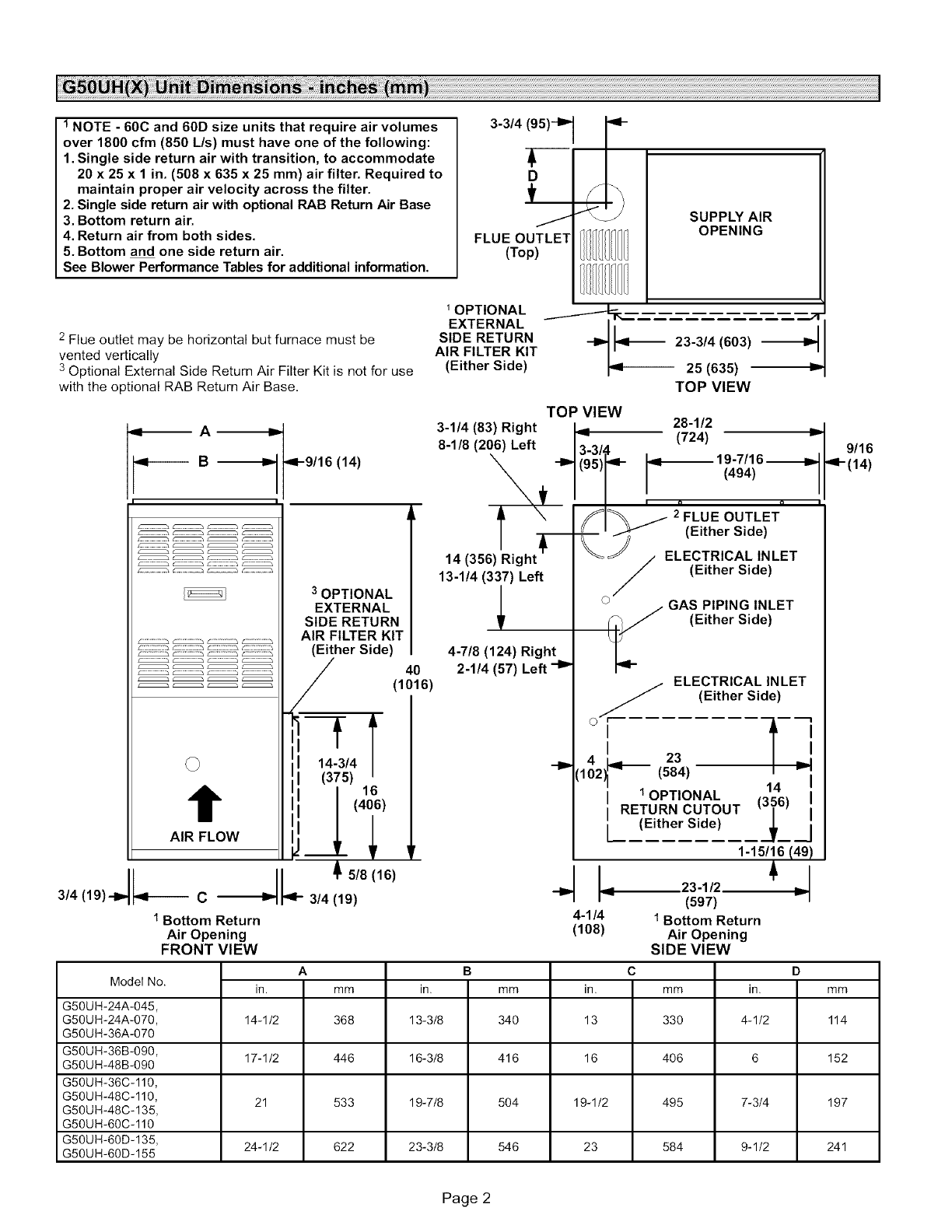
1 NOTE -60C and 60D size units that require air volumes
over 1800 cfm (850 L/s) must have one of the following:
1. Single side return air with transition, to accommodate
20 x 25 x 1 in. (508 x 635 x 25 mm) air filter. Required to
maintain proper air velocity across the filter.
2. Single side return air with optional RAB Return Air Base
3. Bottom return air.
4. Return air from both sides.
5. Bottom and one side return air.
See Blower Performance Tables for additional information.
3-3/4 (95)-I_ 1
FLUE OUTLET
(Top)
SUPPLY AIR
OPENING
2 Flue outlet may be horizontal but furnace must be
vented vertically
3 Optional External Side Return Air Filter Kit is not for use
with the optional RAB Return Air Base.
1OPTIONAL
EXTERNAL
SIDE RETURN
AIR FILTER KIT
(Either Side)
23-3/4 (603)
I_1 25 (635) =
TOP VIEW
I I
/" ........... h r........... h::::::::h f..............
,_ A -_
B_ 4-9/16 (14)
3 OPTIONAL
EXTERNAL
SIDE RETURN
AIR FILTER KIT
__ (Either Side)
__ 40
.... (1016)
,, i
AiR FLOW !1
5/8 (16)
1Bottom Return
Air Opening
FRONT VIEW
3-1/4 (83) Right
8-1/8 (206) Left
13-1/4 (337) Left
4-7/8 (124) Right
2-1/4 (57) Left -I_
TOP VIEW 28-1/2
(724)
r--
4-1/4
(108)
iE OUTLET
(Either Side)
ELECTRICAL INLET
(Either Side)
oGAS PIPING INLET
(Either Side)
ELECTRICAL INLET
OW (Either Side)
'
I
4 23
[102 (584) 14
1OPTIONAL
RETURN CUTOUT (3_6)
L(Either Side)
1-15/16 (49)
23-1/2 v
(597)
1 Bottom Return
Air Opening
SIDE VIEW
ABCD
Model No. in. mm in. mm in. mm in. mm
G50UH-24A-045,
G50UH-24A-070, 14-1/2 368 13-3/8 340 13 330 4-1/2 114
G50UH-36A-070
G50UH-36B-090, 17-1/2 446 16-3/8 416 16 406 6 152
G50UH-48B-090
G50UH-36C-110,
G50UH-48C-110, 21 533 19-7/8 504 19-1/2 495 7-3/4 197
G50UH-48C-135,
G50UH-60C-110
G50UH-60D-135, 24-1/2 622 23-3/8 546 23 584 9-1/2 241
G50UH-60D-155
9/16
Page 2

Gasket
FlueBoxGasket
HeatExchanger
FlueCollectorBox
AirDeflector
G50UH-48C-135,
G50UH-60C-110&
G50UH-60D-155
UnitsOnly
FlueTransition
%
Flame Sensor _
Flame Rollout Switches*
Flame Rollout Bracket
Gas Valve
Gas Orifices
Ignitor Bracket Ig'_itor
Combustion Air
Orifice
Combustion Air
Pressure Switch
Air Inducer
Limit Shield
Primary Limit
NOx Insert
(NO x Units Only)
\
Secondary Limit
Burner Bottom Shield
Control Transformer
_ _'_ X Blower Assembly
SureLight ¢ Control Board _'_ " Capacitor
"135 and 155 kBtuh units only --
Flame rollout switches are located
on brackets on the inner sides (one _ Door Interlock Switch
on the left and one on the right) of
the burner box.
FIGURE 1
Page 3
TheG50UH(X)gasfurnaceisshippedreadyforinstalla-
tionintheupfioworhorizontalposition(leftorright).The
furnaceisshippedwiththebottompanelinplace.Thebot-
tompanelmustberemovediftheunitistobeinstalledina
horizontalapplication.Thepanelmayalsoberemovedin
upfiowapplications.
Package 1 of 1 contains
1 - Assembled G50UH(X) unit
1 - Bag assembly containing the following:
2 - Screws
3 -Wire nuts
1 - Snap bushing
1 - Snap plug
1 - Wire tie
1 -Vent warning label
1 - Owner's manual and warranty card
The following items may be ordered separately:
1- Thermostat
1 - Hanging bracket (for horizontal installations)
1 - Propane/LP changeover kit
1 - High altitude kit
1 - Return air base
1 - Side filter kit
Check equipment for shipping damage, If you find any
damage, immediately contact the last carrier.
A,WARNING
A,CAUTION
G50UH(X) units are CSA International certified to ANSI
Z21.47 and CSA 2.3 standard.
In the USA, installation of gas furnaces must conform with
local building codes. In the absence of local codes, units
must be installed according to the current National Fuel
Gas Code (ANSI-Z223.1/NFPA 54). The National Fuel Gas
Code is available from the following address:
American National Standards Institute, Inc.
11 West 42nd Street
New York, NY 10036
In Canada, installation must conform with current National
Standard of Canada CSA B149 Natural Gas and Propane
Installation Codes," local plumbing or waste water codes
and other applicable local codes.
Adequate clearance must be made around the air open-
ings into the vestibule area. In order to ensure proper unit
operation, combustion and ventilation air supply must be
provided according to the current National Fuel Gas Code
or CSA B149 standards.
Vent installations must be consistent with the venting
tables (in this instruction) and applicable provisions of local
building codes.
This furnace is CSA Intemational certified for installation
clearances to combustible material as listed on the unit
nameplate and in the tables in figures 6 and 11. Accessibility
and service clearances must take precedence over fire
protection clearances.
NOTE- For installation on combustible floors, the furnace
shaft not be installed directly on carpeting, tile, or other
combustible material other than wood flooring.
For installation in a residential garage, the furnace must
be installed so that the burner(s) and the ignition source
are located no less than 18 inches (457 mm) above the
floor. The furnace must be located or protected to avoid
physical damage by vehicles. When a furnace is installed
in a public garage, hangar, or other building that has a haz-
ardous atmosphere, the furnace must be installed accord-
ing to recommended good practice requirements and cur-
rent National Fuel Gas Code or CSA B149 standards.
NOTE -Furnace must be adjusted to obtain a temperature
rise within the range specified on the unit nameplate. Failure
to do so may cause erratic limit operation.
This G50UH(X) furnace must be installed so that its electri-
cal components are protected from water.
When this furnace is used with cooling units, it shall be
installed in parallel with, or on the upstream side of, cooling
units to avoid condensation in the heating compartment.
With a parallel flow arrangement, a damper (or other
means to control the flow of air) must adequately prevent
chilled air from entering the furnace. If the damper is manu-
ally operated, it must be equipped to prevent operation of
either the heating or the cooling unit, unless it is in the full
HEAT or COOL setting.
Page 4
Wheninstalled,thisfurnacemustbeelectricallygrounded
accordingtolocalcodes.Inaddition,intheUnitedStates,
installationmustconformwiththecurrentNationalElec-
tricCode,ANSI/NFPANo.70.TheNationalElectricCode
(ANSI/NFPANo.70)isavailablefromthefollowingad-
dress:
NationalFireProtectionAssociation
1BatteryMarchPark
Quincy,MA02269
InCanada,allelectricalwiringandgroundingfortheunit
mustbeinstalledaccordingtothecurrentregulationsofthe
CanadianElectricalCodePartI (CSAStandardC22.1)
and/orlocalcodes.
NOTE -This furnace is designed for a minimum continu-
ous return air temperature of 60°F (16°C) or an intermit-
tent operation down to 55°F (13°C) dry bulb for cases
where a night setback thermostat is used. Return air tem-
perature must not exceed 85°F (29 °C) dry bulb.
The G50UH(X) furnace may be installed in alcoves, clos-
ets, attics, basements, garages, and utility rooms in the up-
flow or horizontal position.
This furnace design has not been CSA International certi-
fied for installation in mobile homes, recreational vehicles,
or outdoors.
Lennox does not recommend the use of G50UH units as a
construction heater during any phase of construction. Very
low return air temperatures, harmful vapors and operation
of the unit with clogged or misplaced filters will damage the
unit.
G50UH units may be used for heating of buildings or struc-
tures under construction, if the following conditions are
met:
•The vent system must be permanently installed per
these installation instructions.
• A room thermostat must control the furnace. The use of
fixed jumpers that will provide continuous heating is not
allowed.
• The return air duct must be provided and sealed to the
furnace.
• Return air temperature range between 60°F (16°C) and
80°F (27°C) must be maintained.
• Air filters must be installed in the system and must be
maintained during construction.
• Air filters must be replaced upon construction comple-
tion.
• The input rate and temperature rise must be set per the
furnace rating plate.
• One hundred percent (100%) outdoor air must be pro-
vided for combustion air requirements during construc-
tion. Temporary ducting may supply outdoor air to the
furnace. Do not connect duct directly to the furnace.
Size the temporary duct following these instructions in
section for Combustion, Dilution and Ventilation Air in a
confined space with air from outside.
• The furnace heat exchanger, components, duct system,
air filters and evaporator coils must be thoroughly
cleaned following final construction clean-up.
• All furnace operating conditions (including ignition, in-
put rate, temperature rise and venting) must be verified
according to these installation instructions.
NOTE -The Commonwealth of Massachusetts stipu-
lates these additional requirements:
• Gas furnaces shall be installed by aticensedptumb-
er or gas fitter only.
• The gas cock must be "T handle" type.
• When afurnace is installed in an attic, the passage-
way to and service area surrounding the equipment
shall be floored.
These instructions are intended as a general guide and do
not supersede local codes in any way. Consult authorities
having jurisdiction before installation.
In addition to the requirements outlined previously, the fol-
lowing general recommendations must be considered
when installing a G50UH(X) furnace:
•Place the furnace as close to the center of the air dis-
tribution system as possible. The furnace should also be
located close to the chimney or vent termination point.
•Do not install the furnace where drafts might blow direct-
ly into it. This could cause improper combustion and un-
safe operation.
•Do not block the furnace combustion air openings with
clothing, boxes, doors, etc. Air is needed for proper
combustion and safe unit operation.
•When the furnace is installed in an attic or other insu-
lated space, keep insulation away from the furnace.
WARNING
Page 5
Inthepast,therewasnoprobleminbringinginsufficientout-
doorairforcombustion.Infiltrationprovidedalltheairthat
wasneeded.Intoday'shomes,tightconstructionpractices
makeit necessaryto bringinairfromoutsideforcombus-
tion.Takeintoaccountthatexhaustfans,appliancevents,
chimneys,andfireplacesforceadditionalairthatcouldbe
usedforcombustionoutofthehouse.Unlessoutsideairis
broughtintothehousefor combustion,negativepressure
(outsidepressureisgreaterthaninsidepressure)willbuild
tothepointthatadowndraftcanoccurinthefurnacevent
pipeorchimney.Asaresult,combustiongasesentertheliv-
ingspacecreatinga potentiallydangeroussituation.
Intheabsenceoflocalcodesconcerningairforcombus-
tionandventilation,usetheguidelinesandproceduresin
thissectiontoinstallG50UH(X)furnacestoensureefficient
andsafeoperation.Youmustconsidercombustionair
needsandrequirementsforexhaustventsandgaspiping.
A portionof thisinformationhasbeenreprintedwithper-
missionfromtheNationalFuelGasCode(ANSI-Z223.1).
Thisreprintedmaterialisnotthecompleteandofficialposi-
tionoftheANSIonthereferencedsubject,whichisrepre-
sentedonlybythestandardinitsentirety.
In Canada,referto the standardCSAB149installation
codes.
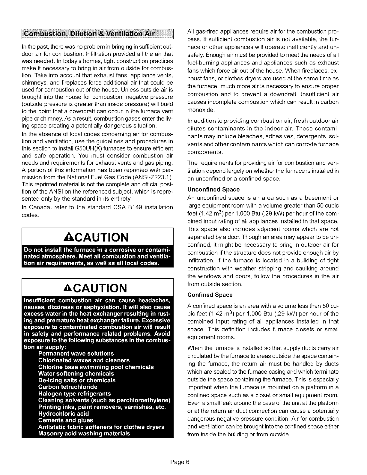
ACAUTION
ACAUTION
All gas-fired appliances require air for the combustion pro-
cess. If sufficient combustion air is not available, the fur-
nace or other appliances will operate inefficiently and un-
safely. Enough air must be provided to meet the needs of all
fuel-burning appliances and appliances such as exhaust
fans which force air out of the house. When fireplaces, ex-
haust fans, or clothes dryers are used at the same time as
the furnace, much more air is necessary to ensure proper
combustion and to prevent a downdraft. Insufficient air
causes incomplete combustion which can result in carbon
monoxide,
In addition to providing combustion air, fresh outdoor air
dilutes contaminants in the indoor air. These contami-
nants may include bleaches, adhesives, detergents, sol-
vents and other contaminants which can corrode furnace
components,
The requirements for providing air for combustion and ven-
tilation depend largely on whether the furnace is installed in
an unconfined or a confined space,
Unconfined Space
An unconfined space is an area such as a basement or
large equipment room with a volume greater than 50 cubic
feet (1.42 m3) per 1,000 Btu (.29 kW) per hour of the com-
bined input rating of all appliances installed in that space.
This space also includes adjacent rooms which are not
separated by a door. Though an area may appear to be un-
confined, it might be necessary to bring in outdoor air for
combustion if the structure does not provide enough air by
infiltration. If the furnace is located in a building of tight
construction with weather stripping and caulking around
the windows and doors, follow the procedures in the air
from outside section.
Confined Space
A confined space is an area with a volume less than 50 cu-
bic feet (1.42 m3) per 1,000 Btu (.29 kW) per hour of the
combined input rating of all appliances installed in that
space. This definition includes furnace closets or small
equipment rooms.
When the furnace is installed so that supply ducts carry air
circulated by the furnace to areas outside the space contain-
ing the furnace, the return air must be handled by ducts
which are sealed to the furnace casing and which terminate
outside the space containing the furnace, This is especially
important when the furnace is mounted on a platform in a
confined space such as a closet or small equipment room.
Even a small leak around the base of the unit at the platform
or at the return air duct connection can cause a potentially
dangerous negative pressure condition, Air for combustion
and ventilation can be brought into the confined space either
from inside the building or from outside,
Page 6

CHIMNEY
VENT
EQUIPMENT IN CONFINED
SPACE ALL AIR FROM INSIDE
WiTER/
HEATER
FURNACE 1_
OPENINGS
(To Adjacent
Room)
I I I I
NOTE -Each opening shall have afree area of at least one square
inch (645 mm 2) per 1,000 Btu (.29 kW) per hour of the total input rat-
ing of all equipment in the enclosure, but not less than 100 square
inches (64516 mm2).
FIGURE 2
Air from Inside
If the confined space that houses the furnace adjoins a
space categorized as unconfined, air can be brought in by
providing two permanent openings between the two
spaces. Each opening must have a minimum free area of 1
square inch (645 mm2) per 1,000 Btu (.29 kW) per hour of
total input rating of all gas-fired equipment in the confined
space. Each opening must be at least 100 square inches
(64516 mm2). One opening shall be within 12 inches (305
mm) of the top of the enclosure and one opening within 12
inches (305 mm) of the bottom. See figure 2.
Air from Outside
If air from outside is brought in for combustion and ventila-
tion, the confined space must have two permanent open-
ings. One opening shall be within 12 inches (305 mm) of the
top of the enclosure and one opening within 12 inches (305
mm) of the bottom. These openings must communicate di-
rectly or by ducts with the outdoors or spaces (crawl or at-
tic) that freely communicate with the outdoors or indirectly
through vertical ducts. Each opening shall have a minimum
free area of 1 square inch (645 mm2) per 4,000 Btu (1.17
kW) per hour of total input rating of all equipment in the en-
closure. See figures 3 and 4. When communicating with
the outdoors through horizontal ducts, each opening shall
have a minimum free area of 1 square inch (645 mm 2) per
2,000 Btu (.56 kW) per total input rating of all equipment in
the enclosure. See figure 5.
When ducts are used, they shall be of the same cross-sec-
tional area as the free area of the openings to which they
connect. The minimum dimension of rectangular air ducts
shall be no less than 3 inches (75 mm). In calculating free
area, the blocking effect of louvers, grilles, or screens must
be considered. Ifthe design and free area of protective cov-
ering is not known for calculating the size opening required,
it may be assumed that wood louvers will have 20 to 25 per-
cent free area and metal louvers and grilles will have 60 to
75 percent free area. Louvers and grilles must be fixed in the
open position or interlocked with the equipment so that they
are opened automatically during equipment operation.
CHIMNEY OR
GAS VENT
EQUIPMENT IN CONFINED SPACE
ALL AIR FROM OUTSIDE
(Inlet Air from Crawlspace and Outlet Air
to Ventilated Attic)
VENTILATION LOUVERS
(Each end of attic)
I ...... I
OUTLET
FURNACE AIR WATER
HEATER
VENTILATION INLET
LOUVERS AIR
(For unheated crawl !
NO TE- The inlet and outlet air openings shall each have a free area of at least one square inch (645
mm 2) per 4, 000 Btu (1.17 kW) per hour of the total input rating of all equipment in the enclosure.
FIGURE 3
Page 7
CHIMNEY
OR GAS
VENT_
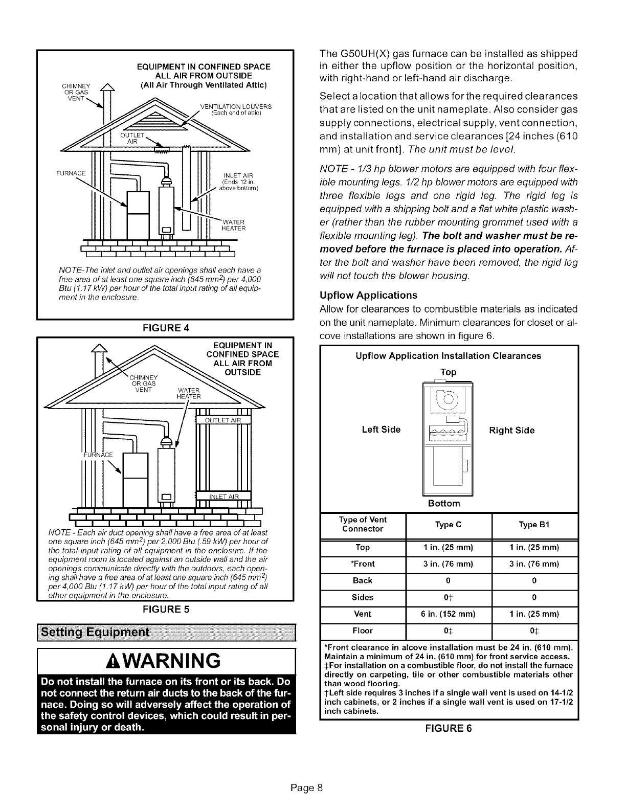
EQUIPMENT IN CONFINED SPACE
ALL AIR FROM OUTSIDE
(All Air Through Ventilated Attic)
VENTILATION LOUVERS
(Each end of attic)
FURNACE INLET AIR
(Ends 12 in.
above bottom)
HEATER
NO TE- The inlet and outlet air openings shall each have a
free area of at least one square inch (645 mm 2)per 4,000
Btu (1.17 kW) per hour of the total input rating of all equip-
ment in the enclosure.
FIGURE 4
A _ EQUIPMENT IN
TT'_. JJ_ CONFINED SPACE
I I "_'Y _ ALLAIRFROM
I 1 OUTLET AIR
FURNACE
I1"- ,,
I ii I I I I I I I I I I I
NOTE -Each air duct opening shall have a free area of at least
o 2
ne square inch (645 mm Jper 2, 000 Btu (.59 kW) per hour of
the total input rating of all equipment in the enclosure. If the
equipment room is located against an outside wall and the air
openings communicate directly with the outdoors, each open-
ing shall have a free area of at least one square inch (645 mm 2)
per4,000 Btu (1.17 kW) per hour of the total input rating of all
other equipment in the enclosure.
FIGURE 5
-&WARNING
The G50UH(X) gas furnace can be installed as shipped
in either the upfiow position or the horizontal position,
with right-hand or left-hand air discharge.
Select a location that allows for the required clearances
that are listed on the unit nameplate. Also consider gas
supply connections, electrical supply, vent connection,
and installation and service clearances [24 inches (610
mm) at unit front]. The unit must be level.
NOTE -1/3 hp blower motors are equipped with four flex-
ible mounting legs. 1/2 hp blower motors are equipped with
three flexible legs and one rigid leg. The rigid leg is
equipped with a shipping bolt and a flat white plastic wash-
er (rather than the rubber mounting grommet used with a
flexible mounting leg). The bolt and washer must be re-
moved before the furnace is placed into operation. Af-
ter the bolt and washer have been removed, the rigid leg
will not touch the blower housing.
Upflow Applications
Allow for clearances to combustible materials as indicated
on the unit nameplate. Minimum clearances for closet or al-
cove installations are shown in figure 6.
Upflow Application Installation Clearances
Top
Left Side Right Side
Type of Vent
Connector
Top
*Front
Back
Sides
Vent
Floor
Bottom
Type C
1 in, (25 ram)
3in, (76 ram)
0
Ot
6 in. (152 ram)
05
Type B1
1in, (25 ram)
3in, (76 ram)
0
0
1in. (25 ram)
0J;
*Front clearance in alcove installation must be 24 in. (610 ram).
Maintain a minimum of 24 in. (610 ram) for front service access.
SFor installation on a combustible floor, do not install the furnace
directly on carpeting, tile or other combustible materials other
than wood flooring.
l-Left side requires 3 inches ifa single wall vent is used on 14-1/2
inch cabinets, or 2 inches if a single wall vent is used on 17-1/2
inch cabinets.
FIGURE 6
Page 8
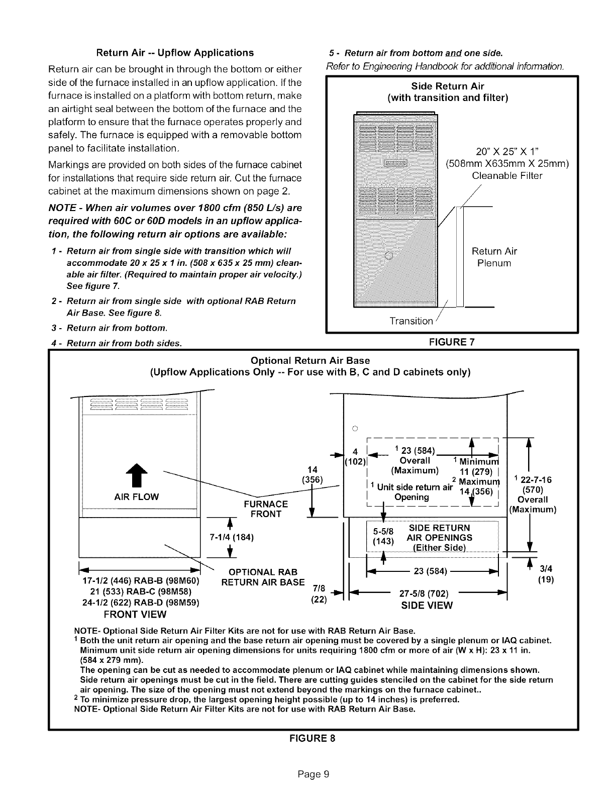
Return Air -- Upflow Applications
Return air can be brought in through the bottom or either
side of the furnace installed in an upflow application. If the
furnace is installed on a platform with bottom return, make
an airtight seal between the bottom of the furnace and the
platform to ensure that the furnace operates properly and
safely. The furnace is equipped with a removable bottom
panel to facilitate installation,
Markings are provided on both sides of the furnace cabinet
for installations that require side return air. Cut the furnace
cabinet at the maximum dimensions shown on page 2.
NOTE -When air volumes over 1800 cfm (850 L/s) are
required with 60C or 60D models in an upflow applica-
tion, the following return air options are available:
1-Return air from single side with transition which will
accommodate 20 x 25 x 1 in. (508 x 635 x 25 mm) clean-
able air filter. (Required to maintain proper air velocity.)
See figure 7.
2 - Return air from single side with optional RAB Return
Air Base. See figure 8.
3-Return air from bottom.
4-Return air from both sides.
5-Return air from bottom and one side.
Refer to Engineering Handbook for additional information.
Side Return Air
(with transition and filter)
Transition
FIGURE 7
Optional Return Air Base
(Upflow Applications Only -- For use with B, Cand D cabinets only)
20" X 25" X 1"
(508mm X635mm X 25mm)
Cleanable Filter
_/
Return Air
Plenum
J
AIR FLOW
14
L
7-1/4 (184)
17-1/2 (446) RAB-B (98M60)
21 (533) RAB-C (98M58)
24-1/2 (622) RAB-D (98M59)
FRONT VIEW
OPTIONAL RAB
RETURN AIR BASE 7/8
(22)
I
©
r
41
(102)1"9_- 123(584) fL_-
Overall 1 MinimuV_
(Maximum) 11 (279)
2 Maximurr
1 Unit side return airOpening 11_5.6) j_ __
5-5/8
(143)
....................._ 23 (584)........................................................................_!
_1-- 27-5/8 (702)
SIDE VIEW
122-7-16
(570)
Overall
Maximum)
_2
_-- 3/4
(19)
NOTE- Optional Side Return Air Filter Kits are not for use with RAB Return Air Base.
1 Both the unit return air opening and the base return air opening must be covered by a single plenum or IAQ cabinet.
Minimum unit side return air opening dimensions for units requiring 1800 cfm or more of air (W x H): 23 x 11 in.
(584 x 279 mm).
The opening can be cut as needed to accommodate plenum or IAQ cabinet while maintaining dimensions shown.
Side return air openings must be cut in the field. There are cutting guides stenciled on the cabinet for the side return
air opening. The size of the opening must not extend beyond the markings on the furnace cabinet..
2 To minimize pressure drop, the largest opening height possible (up to 14 inches) is preferred.
NOTE- Optional Side Return Air Filter Kits are not for use with RAB Return Air Base.
FIGURE 8
Page 9
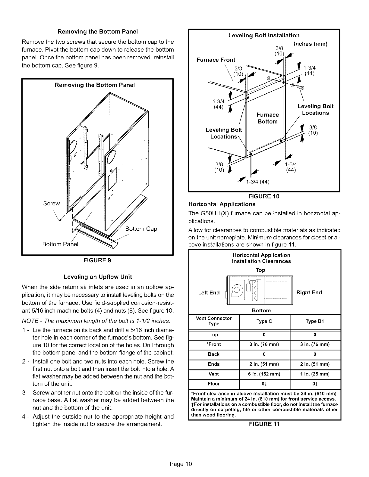
Removingthe Bottom Panel
Remove the two screws that secure the bottom cap to the
furnace. Pivot the bottom cap down to release the bottom
panel. Once the bottom panel has been removed, reinstall
the bottom cap, See figure 9.
Removing the Bottom Panel
Screw
\/
Bottom Cap
Bottom
FIGURE 9
Leveling an Upflow Unit
When the side return air inlets are used in an upflow ap-
plication, it may be necessary to install leveling bolts on the
bottom of the furnace. Use field-supplied corrosion-resist-
ant 5/16 inch machine bolts (4) and nuts (8), See figure 10.
NOTE -The maximum length of the bolt is 1-1/2 inches.
1 - Lie the furnace on its back and drill a 5/16 inch diame-
ter hole in each corner of the furnace's bottom. See fig-
ure 10 for the correct location of the holes, Drill through
the bottom panel and the bottom flange of the cabinet,
2 - Install one bolt and two nuts into each hole. Screw the
first nut onto a bolt and then insert the bolt into a hole, A
fiat washer may be added between the nut and the bot-
tom of the unit,
3 - Screw another nut onto the bolt on the inside of the fur-
nace base. A flat washer may be added between the
nut and the bottom of the unit,
4 - Adjust the outside nut to the appropriate height and
tighten the inside nut to secure the arrangement,
Leveling Bolt Installation
Inches (mm)
3/8
(10)_r
Furnace Front _'1 [
3/8 1-3/4
(44)
1-3/4
(44)
Leveling Bolt
Locati_
3/8
(10)
I-3/4 (44)
Furnace
Bottom
Leveling Bolt
Locations
3/8
(10)
1-3/4
(44)
FIGURE 10
Horizontal Applications
The G50UH(X) furnace can be installed in horizontal ap-
plications,
Allow for clearances to combustible materials as indicated
on the unit nameplate, Minimum clearances for closet or al-
cove installations are shown in figure 11,
Horizontal Application
Installation Clearances
Top
Left End Right End
Vent Connector
Type
Top
*Front
Back
Ends
Vent
Floor
Bottom
Type C
0
3in. (76 ram)
0
2in. (51 ram)
6in. (152 ram)
o:_
Type B1
0
3in. (76 ram)
0
2in. (51 ram)
1in. (25 ram)
o:_
*Front clearance in alcove installation must be 24 in. (610 ram).
Maintain a minimum of 24 in. (610 ram) for front service access.
_:For installations on a combustible floor, do not install the furnace
directly on carpeting, tile or other combustible materials other
than wood flooring.
FIGURE 11
Page 10
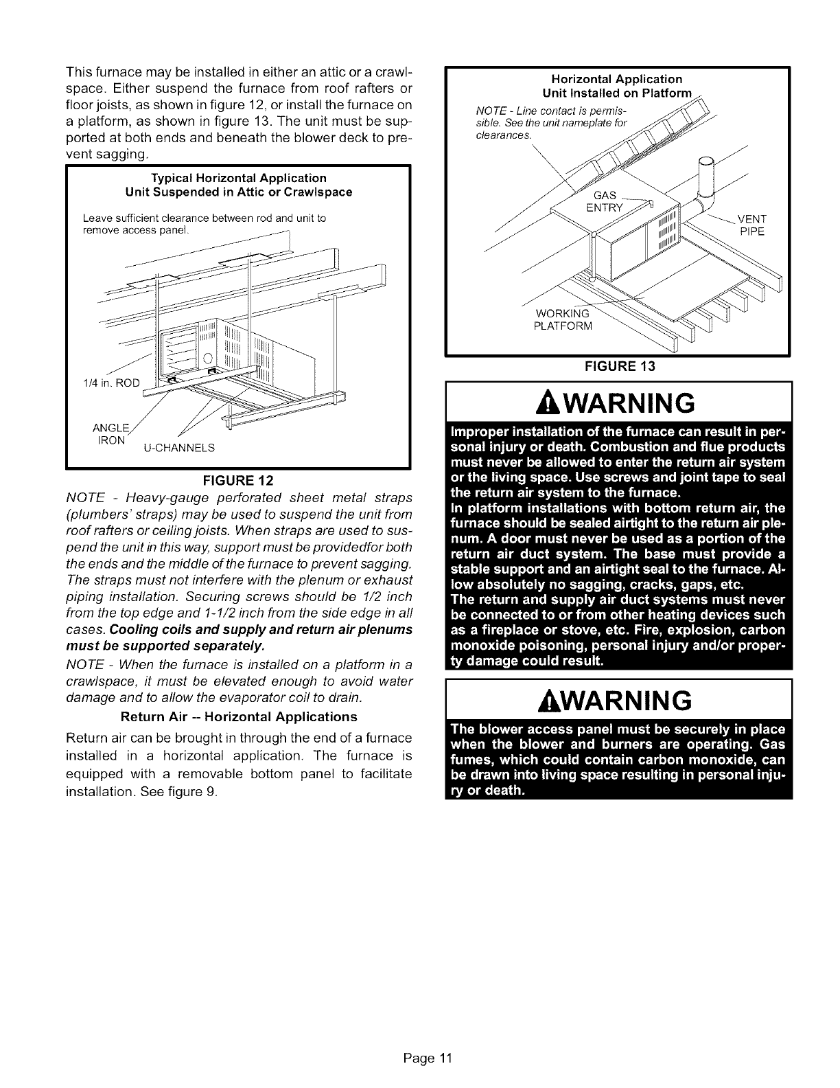
Thisfurnacemaybeinstalledineitheranatticoracrawl-
space.Eithersuspendthefurnacefromroofraftersor
floorjoists,asshowninfigure12,orinstallthefurnaceon
a platform,asshownin figure13.Theunitmustbesup-
portedat bothendsandbeneaththeblowerdecktopre-
ventsagging.
Typical Horizontal Application
Unit Suspended in Attic or Crawlspace
Leave sufficient clearance between rod and unit to
remove access panel.
1/4 i
ANGLE
IRON U-CHANNELS
FIGURE 12
NOTE -Heavy-gauge perforated sheet metal straps
(plumbers' straps) may be used to suspend the unit from
roof rafters or ceiling joists. When straps are used to sus-
pend the unit in this way, support must be providedfor both
the ends and the middle of the furnace to prevent sagging.
The straps must not interfere with the plenum or exhaust
piping instaflation. Securing screws should be 1/2 inch
from the top edge and 1-1/2 inch from the side edge in aft
cases. Cooling coils and supply and return air plenums
must be supported separately.
NOTE -When the furnace is installed on a platform in a
crawlspace, it must be elevated enough to avoid water
damage and to allow the evaporator coil to drain.
Return Air -- Horizontal Applications
Return air can be brought in through the end of a furnace
installed in a horizontal application, The furnace is
equipped with a removable bottom panel to facilitate
installation, See figure 9,
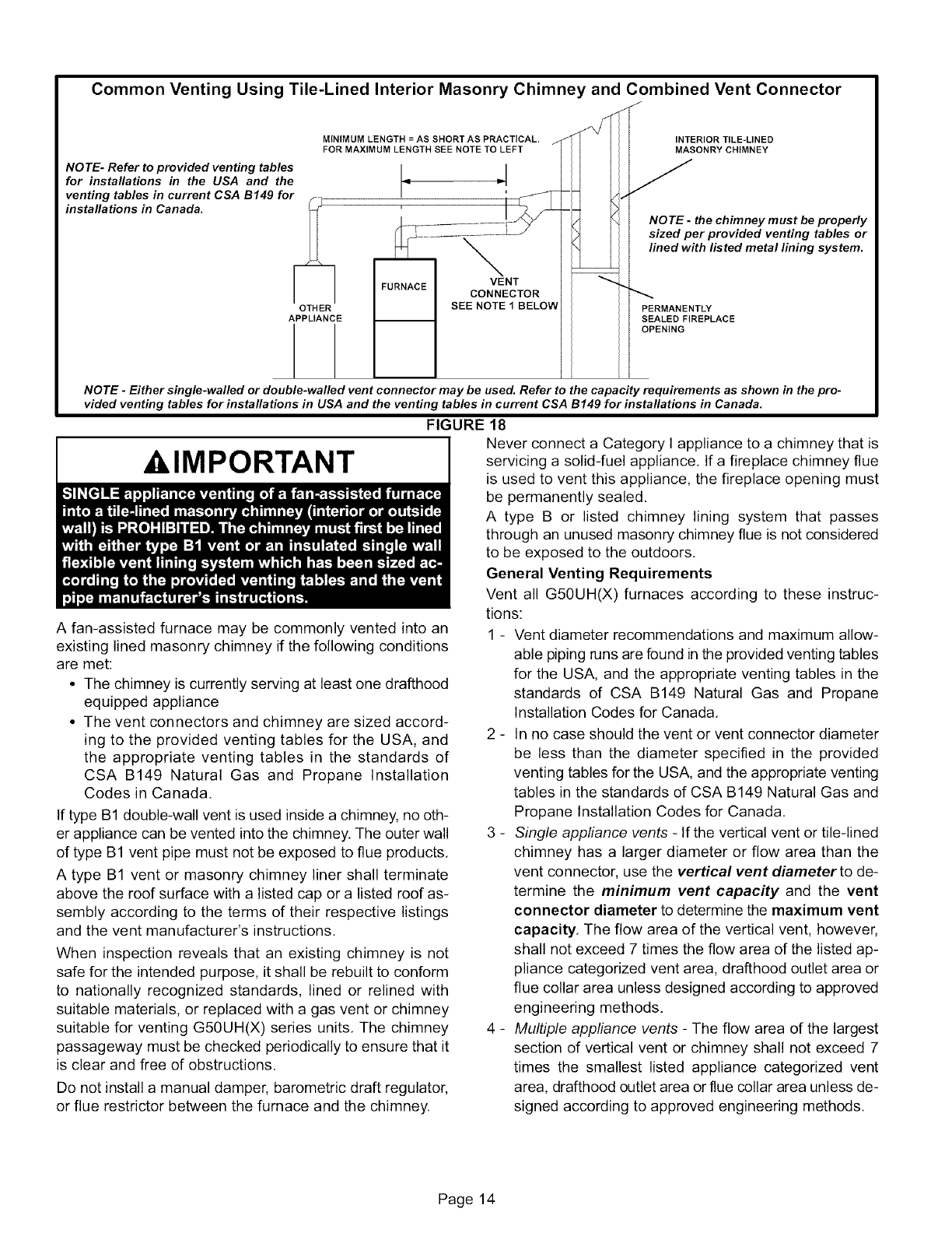
Horizontal Application
Unit Installed on Platform
NOTE -Line contact is permis-
sible. See the unit nameplate for
clearances.
\\\
GAS
ENTRY
__VENT
PIPE
WORKING
PLATFORM
FIGURE 13
-&WARNING
&WARNING
Page 11

Thisunitisnotequippedwithafilteror rack.A field-pro-
videdhigh-velocityfilterisrequiredfortheunittooperate
properly.Table1listsrecommendedfiltersizes.
Afiltermustbein placeanytimetheunitisoperating.
Furnace
Cabinet Size
14-1/2"
17-112"
21"
24-1/2"
TABLE 1
Filter Size
Side Return
16X25X 1 (1)
16X25X 1 (1)
16X25X 1 (1)
16 X 25 X 1 (2)
Bottom Return
14X25X1 (1)
16X25X1 (1)
20X25X 1 (1)
24X25X 1 (1)
Use industry-approved standards to size and install the
supply and return air duct system. This will result in a quiet
and low-static system that has uniform air distribution.
NOTE -Do not operate the furnace with an external static
pressure that exceeds 0,5 inches w,c, Higher external stat-
ic pressures may cause erratic limit operation,
Supply Air Plenum
If the furnace is installed without a cooling coil, a removable
access panel must be installed in the supply air duct, The
access panel should be large enough to permit inspection
(either by smoke or reflected light) of the heat exchanger
for leaks after the furnace is installed, The furnace access
panel must always be in place when the furnace is operat-
ing and it must not allow leaks into the supply air duct sys-
tem,
Return Air Plenum
Return air must not be drawn from aroom where this
furnace, or any other gas appliance (ie., a water heat-
er), is installed. When return air is drawn from a room, a
negative pressure is created in the room, If a gas ap-
pliance is operating in a room with negative pressure, the
flue products can be pulled back down the vent pipe and
into the room, This reverse flow of the flue gas may result
in incomplete combustion and the formation of carbon
monoxide gas. This toxic gas might then be distributed
throughout the house by the furnace duct system,
In upflow applications, the return air can be brought in
through the bottom or either side of the furnace. If a fur-
nace with bottom return air is installed on a platform, make
an airtight seal between the bottom of the furnace and the
platform to ensure that the unit operates properly and
safely, Use fiberglass sealing strips, caulking, or equiva-
lent sealing method between the plenum and the furnace
cabinet to ensure a tight seal, Ifa filter is installed, size the
return air duct to fit the filter frame.
A 4-inch diameter flue transition is factory-installed on the
combustion air inducer outlet of all models. Modifying or
removing the flue transition will cause the unit to oper-
ate unsafely and will void the unit certification. The
vent connector does not require insulation.
The combustion air inducer may be rotated clockwise or
counterclockwise by 90° to allow for top or side vent dis-
charge in all applications. When the unit is installed, the flue
transition must be in the 9 o'clock, 12 o'clock or 3 o'clock
position. The unit will not vent properly with the flue
transition pointed down in the 6 o'clock position. Re-
move the four mounting screws, rotate the assembly (in-
cluding the gasket), then reinstall the mounting screws.
See figure 14. Use the provided wire tie to bundle the pres-
sure switch wires with the inducer motor power leads.
Route the wires away from moving parts and the heat
of the inducer motor to prevent damage to the wires.
Combustion Air Inducer
Flue Transition
(Do not remove)
Mounting Screws
(Remove)
FIGURE 14
Power Leads
Optional Flue Outlet
(Horizontal Installation)
Top View of Furnace
Top Cap ----__ _
Flue Outlet _<_J
Hole /
(Reattach II 111
Cutout Here)
Supply Air
Opening
Optional
Flue Outlet
FIGURE 15
Page 12

Usesheetmetalshearstoremovethecutoutfromtheside
ofthecabinet.Usethetwoprovidedsheetmetalscrewsto
installthecutoutonthetopcaptocovertheoriginalflue
outletopening.Seefigure15.
TheG50UH(X)seriesunitsareclassifiedasfan-assisted
CategoryIfurnaceswhenverticallyventedaccordingto
thelatesteditionof NationalFuelGasCode(NFPA54/
ANSI Z223.1 ) in the USA and the current standards of CSA
B149 Natural Gas and Propane Installation Codes in Can-
ada. A fan-assisted Category I furnace is an appliance
equipped with an integral mechanical means to either draw
or force combustion products through the combustion
chamber and/or heat exchanger.
NOTE -Use these instructions as a guide. They do not su-
persede local codes. This furnace must be vented accord-
ing to all local codes these installation instructions, and the
provided venting tables in these instructions
The venting tables in this manual were extracted from the
National Fuel Gas Code (NFPA 54 /ANSI Z223.1 ) and are
provided as a guide for proper vent installation. Proper ap-
plication, termination, construction and location of vents
must conform to local codes having jurisdiction. In the ab-
sence dlocal codes, the NFGC serves as the defining doc-
ument.
Refer to the tables and the venting information contained in
these instructions to properly size and install the venting
system.
klMPORTANT
kWARNING
VENT CONNECTION
VENT
PIPE
FURNACE
FLUE TRANSITIOF
COLLAR
FIGURE 16
Use self-drilling sheet metal screws or a mechanical fas-
tener to firmly secure the vent pipe to the round collar of the
flue transition. If self-drilling screws are used to attach the
vent pipe, it is recommended that three be used. Drive one
self-drilling screw through the front and one through each
side of the vent pipe and collar. See figure 16.
Install the first vent connector elbow at a minimum of six
inches (152 mm) from the furnace vent outlet.
Venting Using a Masonry Chimney
The following additional requirements apply when a lined
masonry chimney is used to vent this furnace.
Masonry chimneys used to vent Category I central fur-
naces must be either tile-lined or lined with a listed metal
lining system or dedicated gas vent. Unlined masonry
chimneys are prohibited. See figures 17 and 18 for com-
mon venting.
A chimney with one or more sides exposed to the outside of
the structure is considered to be an exterior chimney.
An exterior masonry chimney that is not tile-lined must be
lined with B1 vent or a listed insulated flexible metal vent.
An exterior tileqined chimney that is sealed and capped
may be lined with a listed uninsulated flexible metal vent.
If the existing chimney will not accommodate a B1 vent or
an insulated flexible vent pipe liner, either the chimney
must be rebuilt to accommodate one of these liners or an
alternate approved venting method must be found.
Insulation for the flexible vent pipe must be an encapsu-
lated fiberglass sleeve recommended by the flexible vent
pipe manufacturer. See figure 17.
G50UH units installed in upflow applications may be
vented into a tile-lined masonry chimney without using a
listed metal liner, provided that the optional masonry chim-
ney vent adapter kit (18M79) is used. Instructions provided
with the kit must be followed exactly.
DO NOT insulate the space between the liner and the
chimney wall with puffed mica or any other loose gran-
ular insulating material
CommonVenting Using Metal-Lined Masonry Chimney
T MAX. LENGTH
-- SEE NOTE 1
BELOW.
VE%OO.o%OTOR "
SEALED
/
II
II EXTERIOR
CHIMNEY WITH
II METAL
II LINER
'1
__ .,J
PERMANENTLY
SEALED FIREPLACE
OPENING
NOTE 1 -Refer to the provided venting tables for installations in the USA
and the venting tables in CSA B149 for installations Canada.
NOTE 2 -Either single-walled or double-walled vent connector may be
used. Refer to the capacity requirements shown in the provided venting
tables for installations in USA and the venting tames in current CSA
B149 for installations in Canada.
FIGURE 17
Page 13
Common Venting Using Tile-Lined Interior Masonry Chimne
MINIMUM LENGTH = AS SHORT AS PRACTICAL.
FOR MAXIMUM LENGTH SEE NOTE TO LEFT
NOTE- Refer to provided venting tables
for installations in the USA and the
venting tables in current CSA B149 for
installations in Canada. _
OTHER
APPLIANCE
m
FU
J
_Row
'and Combined Vent Connector
J
INTERIOR TILE=LINED
MASONRY CHIMNEY
NOTE -the chimney must be properly
sized per provided venting tables or
lined with listed metal lining system.
PERMANENTLY
SEALED FIREPLACE
OPENING
NOTE -Either single-walled or double-walled vent connector may be used. Refer to the capacity requirements as shown in the pro-
vided venting tables for installations in USA and the venting tables in current CSA B149 for installations in Canada.
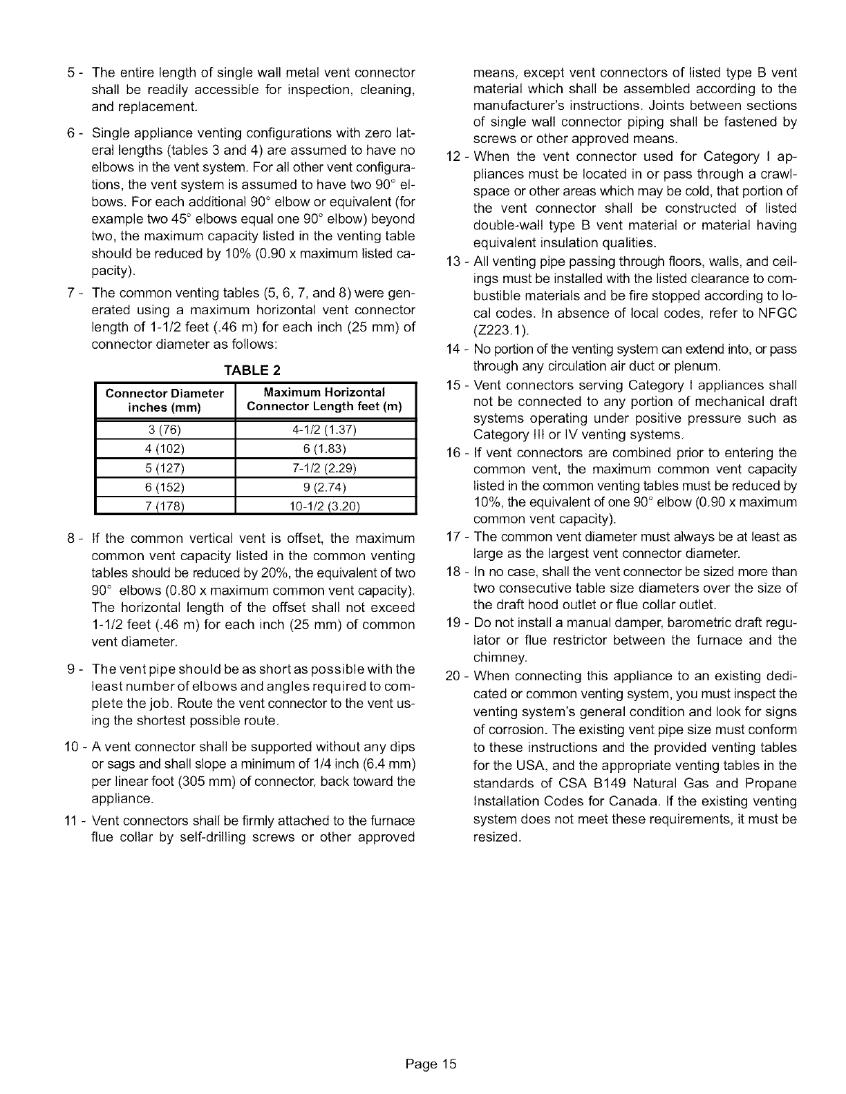
,IMPORTANT
A fan-assisted furnace may be commonly vented into an
existing lined masonry chimney if the following conditions
are met:
• The chimney is currently serving at least one drafthood
equipped appliance
• The vent connectors and chimney are sized accord-
ing to the provided venting tables for the USA, and
the appropriate venting tables in the standards of
CSA B149 Natural Gas and Propane Installation
Codes in Canada.
If type B1 double-wall vent is used inside a chimney, no oth-
er appliance can be vented into the chimney. The outer wall
of type B1 vent pipe must not be exposed to flue products.
A type B1 vent or masonry chimney liner shall terminate
above the roof surface with a listed cap or a listed roof as-
sembly according to the terms of their respective listings
and the vent manufacturer's instructions.
When inspection reveals that an existing chimney is not
safe for the intended purpose, it shall be rebuilt to conform
to nationally recognized standards, lined or relined with
suitable materials, or replaced with a gas vent or chimney
suitable for venting G50UH(X) series units. The chimney
passageway must be checked periodically to ensure that it
is clear and free of obstructions.
Do not install a manual damper, barometric draft regulator,
or flue restrictor between the furnace and the chimney.
FIGURE 18
Never connect a Category I appliance to a chimney that is
servicing a solid-fuel appliance. If a fireplace chimney flue
is used to vent this appliance, the fireplace opening must
be permanently sealed.
A type B or listed chimney lining system that passes
through an unused masonry chimney flue is not considered
to be exposed to the outdoors.
General Venting Requirements
Vent all G50UH(X) furnaces according to these instruc-
tions:
1 - Vent diameter recommendations and maximum allow-
able piping runs are found in the provided venting tables
for the USA, and the appropriate venting tables in the
standards of CSA B149 Natural Gas and Propane
Installation Codes for Canada.
2 - In no case should the vent or vent connector diameter
be less than the diameter specified in the provided
venting tables for the USA, and the appropriate venting
tables in the standards of CSA B149 Natural Gas and
Propane Installation Codes for Canada.
3 - Single appliance vents -If the vertical vent or tile-lined
chimney has a larger diameter or flow area than the
vent connector, use the vertical vent diameter to de-
termine the minimum vent capacity and the vent
connector diameter to determine the maximum vent
capacity, The flow area of the vertical vent, however,
shall not exceed 7 times the flow area of the listed ap-
pliance categorized vent area, drafthood outlet area or
flue collar area unless designed according to approved
engineering methods.
4 - Multiple appliance vents - The flow area of the largest
section of vertical vent or chimney shall not exceed 7
times the smallest listed appliance categorized vent
area, drafthood outlet area orflue collar area unless de-
signed according to approved engineering methods.
Page 14
5 - Theentirelengthofsinglewallmetalventconnector
shallbe readilyaccessiblefor inspection,cleaning,
andreplacement.
6 - Singleapplianceventingconfigurationswithzerolat-
erallengths(tables3and4)areassumedto haveno
elbowsintheventsystem.Forallotherventconfigura-
tions,theventsystemisassumedtohavetwo90° el-
bows.Foreachadditional90°elboworequivalent(for
exampletwo45°elbowsequalone90°elbow)beyond
two,themaximumcapacitylistedintheventingtable
shouldbereducedby10%(0.90x maximumlistedca-
pacity).
7 - Thecommonventingtables(5,6,7,and8)weregen-
eratedusinga maximumhorizontalventconnector
lengthof 1-1/2feet(.46m)foreachinch(25mm)of
connectordiameterasfollows:
TABLE 2
Connector Diameter Maximum Horizontal
inches (mm) Connector Length feet (m)
3 (76) 4-1/2 (1.37)
4 (102) 6 (1.83)
5 (127) 7-1/2 (2.29)
6 (152) 9 (2.74)
7 (178) 10-1/2 (3.20)
_If the common vertical vent is offset, the maximum
common vent capacity listed in the common venting
tables should be reduced by 20%, the equivalent of two
90° elbows (0.80 x maximum common vent capacity).
The horizontal length of the offset shall not exceed
1-1/2 feet (.46 m) for each inch (25 mm) of common
vent diameter.
9 - The vent pipe should be as short as possible with the
least number of elbows and angles required to com-
plete the job. Route the vent connector to the vent us-
ing the shortest possible route.
10 - A vent connector shall be supported without any dips
or sags and shall slope a minimum of 1/4 inch (6.4 mm)
per linear foot (305 mm) of connector, back toward the
appliance.
11 - Vent connectors shall be firmly attached to the furnace
flue collar by self-drilling screws or other approved
means, except vent connectors of listed type B vent
material which shall be assembled according to the
manufacturer's instructions. Joints between sections
of single wall connector piping shall be fastened by
screws or other approved means.
12- When the vent connector used for Category I ap-
pliances must be located in or pass through a crawl-
space or other areas which may be cold, that portion of
the vent connector shall be constructed of listed
double-wall type B vent material or material having
equivalent insulation qualities.
13 - All venting pipe passing through floors, walls, and ceil-
ings must be installed with the listed clearance to com-
bustible materials and be fire stopped according to lo-
cal codes. In absence of local codes, refer to NFGC
(Z223.1).
14 - No portion of the venting system can extend into, or pass
through any circulation air duct or plenum.
15 - Vent connectors serving Category I appliances shall
not be connected to any portion of mechanical draft
systems operating under positive pressure such as
Category III or IV venting systems.
16 - If vent connectors are combined prior to entering the
common vent, the maximum common vent capacity
listed in the common venting tables must be reduced by
10%, the equivalent of one 90° elbow (0.90 x maximum
common vent capacity).
17 - The common vent diameter must always be at least as
large as the largest vent connector diameter.
18 - In no case, shall the vent connector be sized more than
two consecutive table size diameters over the size of
the draft hood outlet or flue collar outlet.
19 - Do not install a manual damper, barometric draft regu-
lator or flue restrictor between the furnace and the
chimney.
20 - When connecting this appliance to an existing dedi-
cated or common venting system, you must inspect the
venting system's general condition and look for signs
of corrosion. The existing vent pipe size must conform
to these instructions and the provided venting tables
for the USA, and the appropriate venting tables in the
standards of CSA B149 Natural Gas and Propane
Installation Codes for Canada. If the existing venting
system does not meet these requirements, it must be
resized.
Page 15
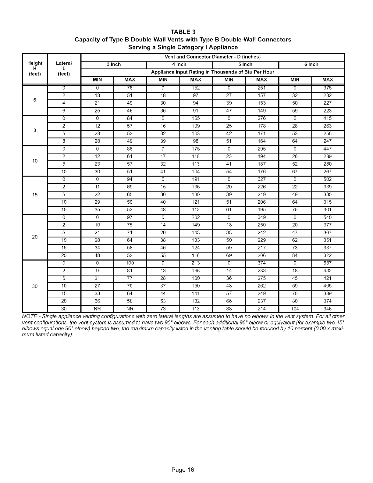
TABLE 3
Capacity of Type B Double-Wall Vents with Type B Double-Wall Connectors
Serving a Single Category I Appliance
Vent and Connector Diameter - D (inches)
Height Lateral 3 Inch 4 Inch 5 Inch 6 Inch
H L
(feet) (feet) Appliance Input Rating in Thousands of Btu Per Hour
MIN MAX MIN MAX MIN MAX MIN MAX
0 0 78 0 152 0 251 0 375
2 13 51 18 97 27 157 32 232
64 21 49 30 94 39 153 50 227
6 25 46 36 91 47 149 59 223
0 0 84 0 165 0 276 0 415
2 12 57 16 109 25 178 28 263
85 23 53 32 103 42 171 53 255
8 28 49 39 98 51 164 64 247
0 0 88 0 175 0 295 0 447
2 12 61 17 118 23 194 26 289
10 5 23 57 32 113 41 187 52 280
10 30 51 41 104 54 176 67 267
0 0 94 0 191 0 327 0 502
2 11 69 15 136 20 226 22 339
15 5 22 65 30 130 39 219 49 330
10 29 59 40 121 51 206 64 315
15 35 53 48 112 61 195 76 301
0 0 97 0 202 0 349 0 540
2 10 75 14 149 18 250 20 377
5 21 71 29 143 38 242 47 367
20 10 28 64 38 133 50 229 62 351
15 34 58 46 124 59 217 73 337
20 48 52 55 116 69 206 84 322
0 0 100 0 213 0 374 0 587
2 9 81 13 166 14 283 18 432
5 21 77 28 160 36 275 45 421
30 10 27 70 37 150 48 262 59 405
15 33 64 44 141 57 249 70 389
20 56 58 53 132 66 237 80 374
30 NR NR 73 113 88 214 104 346
NOTE -Single appliance venting configurations withzero lateral lengths are assumed to have no elbows in the vent system. For all other
vent configurations, the vent system is assumed to have two 90°elbows. For each additional 90°elbow or equivalent (for example two 45 °
elbows equal one 90 ° elbow) beyond two, the maximum capacity listed in the venting table should be reduced by 10 percent (0.90 x maxi-
mum listed capacity).
Page 16
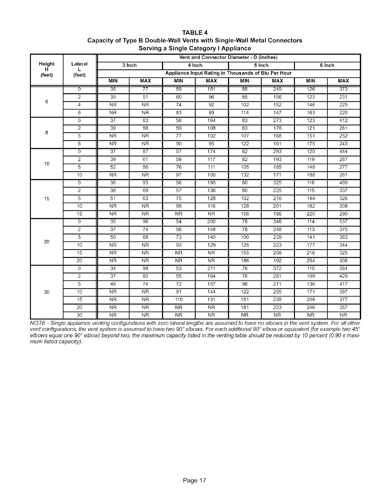
TABLE 4
Capacity of Type B Double-Wall Vents with Single-Wall Metal Connectors
Serving a Single Category I Appliance
Vent and Connector Diameter -D (inches)
Height Lateral 3 Inch 4 Inch 5 Inch 6 Inch
H L
(feet) (feet) Appliance Input Rating in Thousands of Btu Per Hour
MIN MAX MIN MAX MIN MAX MIN MAX
0 38 77 59 151 85 249 126 373
2 39 51 60 96 85 156 123 231
64 NR NR 74 92 102 152 146 225
6 NR NR 83 89 114 147 163 220
0 37 83 58 164 83 273 123 412
2 39 56 59 108 83 176 121 261
85 NR NR 77 102 107 168 151 252
8 NR NR 90 95 122 161 175 243
0 37 87 57 174 82 293 120 444
2 39 61 59 117 82 193 119 287
10 5 52 56 76 111 105 185 148 277
10 NR NR 97 100 132 171 188 261
0 36 93 56 190 80 325 116 499
2 38 69 57 136 80 225 115 337
15 5 51 63 75 128 102 216 144 326
10 NR NR 95 116 128 201 182 308
15 NR NR NR NR 158 186 220 290
0 35 96 54 200 78 346 114 537
2 37 74 56 148 78 248 113 375
5 50 68 73 140 100 239 141 363
20 10 NR NR 93 129 125 223 177 344
15 NR NR NR NR 155 208 216 325
20 NR NR NR NR 186 192 254 306
0 34 99 53 211 76 372 110 584
2 37 80 55 164 76 281 109 429
5 49 74 72 157 98 271 136 417
30 10 NR NR 91 144 122 255 171 397
15 NR NR 115 131 151 239 208 377
20 NR NR NR NR 181 223 246 357
30 NR NR NR NR NR NR NR NR
NOTE -Single appliance venting configurations with zero lateral lengths are assumed to have no elbows in the vent system. For all other
vent configurations, the vent system is assumed to have two 90°elbows. For each additional 90°elbow or equivalent (for example two 45°
elbows equal one 90°elbow) beyond two, the maximum capacity listed in the venting table should be reduced by 10percent (0.90 x maxi-
mum listed capacity).
Page 17
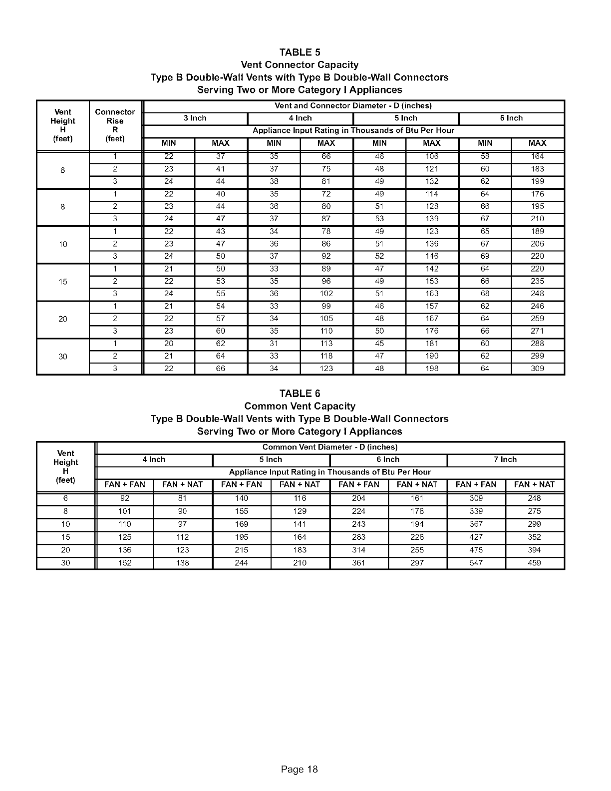
TABLE 5
Vent Connector Capacity
Type B Double-Wall Vents with Type B Double-Wall Connectors
Serving Two or More Category I Appliances
Vent and Connector Diameter - D (inches)
Vent Connector
Height Rise 3 Inch 4 Inch 5 Inch 6 Inch
H R Appliance Input Rating in Thousands of Btu Per Hour
(feet) (feet) MIN MAX MIN MAX MIN MAX MIN MAX
1 22 37 35 66 46 106 58 164
6 2 23 41 37 75 48 121 60 183
3 24 44 38 81 49 132 62 199
1 22 40 35 72 49 114 64 176
8 2 23 44 36 80 51 128 66 195
3 24 47 37 87 53 139 67 210
1 22 43 34 78 49 123 65 189
10 2 23 47 36 86 51 136 67 206
3 24 50 37 92 52 146 69 220
1 21 50 33 89 47 142 64 220
15 2 22 53 35 96 49 153 66 235
3 24 55 36 102 51 163 68 248
1 21 54 33 99 46 157 62 246
20 2 22 57 34 105 48 167 64 259
3 23 60 35 110 50 176 66 271
1 20 62 31 113 45 181 60 288
30 2 21 64 33 118 47 190 62 299
3 22 66 34 123 48 198 64 309
TABLE 6
Common Vent Capacity
Type B Double-Wall Vents with Type B Double-Wall Connectors
Serving Two or More Category I Appliances
Common Vent Diameter -D (inches)
Vent
Height 4 Inch 5 Inch 6 Inch 7 Inch
H Appliance Input Rating in Thousands of Btu Per Hour
(feet) FAN + FAN FAN + NAT FAN + FAN FAN + NAT FAN + FAN FAN + NAT FAN + FAN FAN + NAT
6 92 81 140 116 204 161 309 248
8 101 90 155 129 224 178 339 275
10 110 97 169 141 243 194 367 299
15 125 112 195 164 283 228 427 352
20 136 123 215 183 314 255 475 394
30 152 138 244 210 361 297 547 459
Page 18
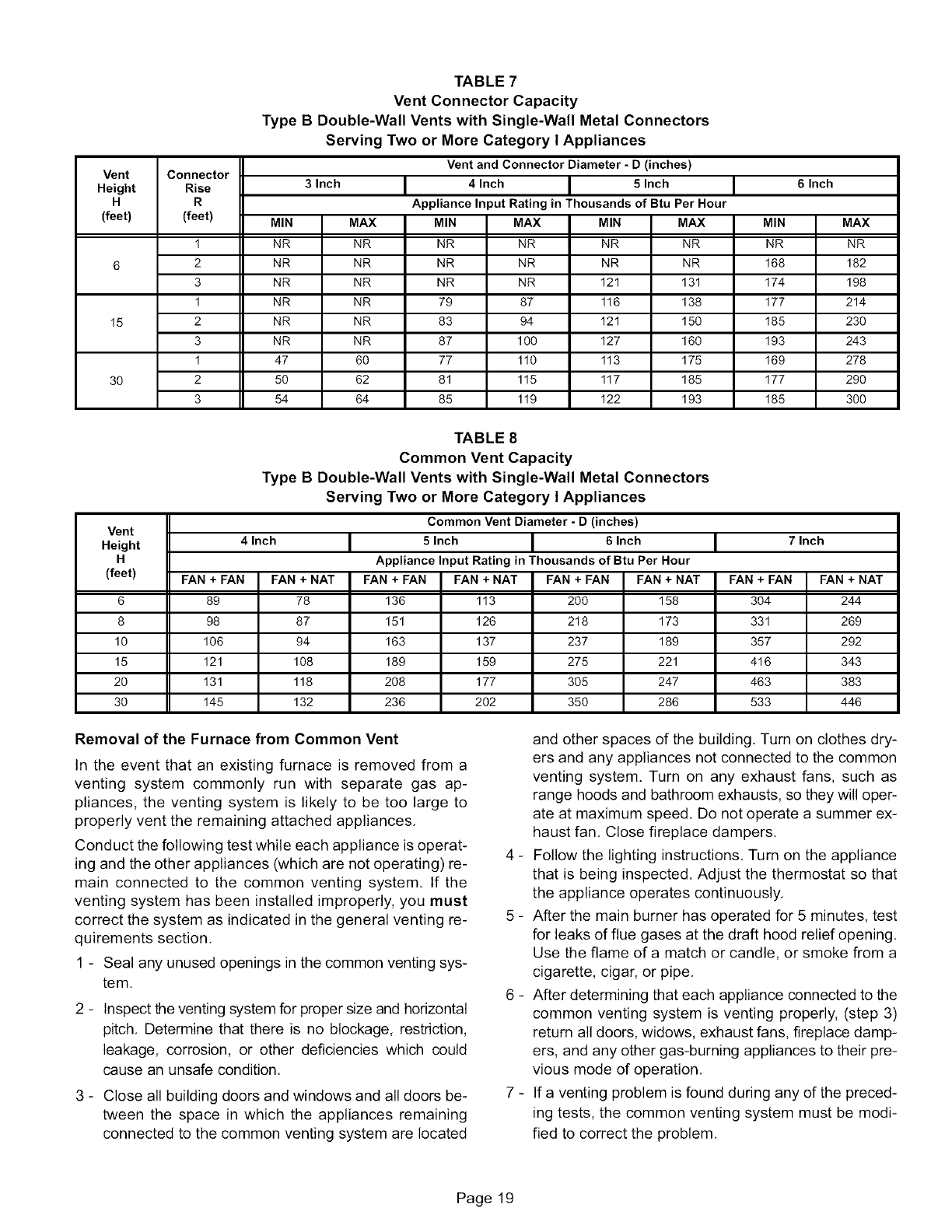
TABLE 7
Vent Connector Capacity
Type B Double-Wall Vents with Single-Wall Metal Connectors
Serving Two or More Category I Appliances
Vent and Connector Diameter - D (inches)
Vent Connector
Height Rise 3 Inch 4 Inch 5 Inch 6 Inch
H R Appliance Input Rating in Thousands of Btu Per Hour
(feet) (feet) MIN MAX MIN MAX MIN MAX MIN MAX
INR NR NR NR NR NR NR NR
6 2 NR NR NR NR NR NR 168 182
3 NR NR NR NR 121 131 174 198
1 NR NR 79 87 116 138 177 214
15 2 NR NR 83 94 121 150 185 230
3 NR NR 87 100 127 160 193 243
1 47 60 77 110 113 175 169 278
30 2 50 62 81 115 117 185 177 290
3 54 64 85 119 122 193 185 300
TABLE 8
Common Vent Capacity
Type B Double-Wall Vents with Single-Wall Metal Connectors
Serving Two or More Category I Appliances
Common Vent Diameter - D (inches)
Vent
Height 4 Inch 5 Inch 6 Inch 7 Inch
H Appliance Input Rating in Thousands of Btu Per Hour
(feet) FAN + FAN FAN + NAT FAN + FAN FAN + NAT FAN + FAN FAN + NAT FAN + FAN FAN + NAT
6 89 78 136 113 200 158 304 244
8 98 87 151 126 218 173 331 269
10 106 94 163 137 237 189 357 292
15 121 108 189 159 275 221 416 343
20 131 118 208 177 305 247 463 383
30 145 132 236 202 350 286 533 446
Removal of the Furnace from Common Vent
In the event that an existing furnace is removed from a
venting system commonly run with separate gas ap-
pliances, the venting system is likely to be too large to
properly vent the remaining attached appliances,
Conduct the following test while each appliance is operat-
ing and the other appliances (which are not operating) re-
main connected to the common venting system. If the
venting system has been installed improperly, you must
correct the system as indicated in the general venting re-
quirements section,
1 - Seal any unused openings in the common venting sys-
tem.
_Inspect the venting system for proper size and horizontal
pitch, Determine that there is no blockage, restriction,
leakage, corrosion, or other deficiencies which could
cause an unsafe condition,
3 - Close all building doors and windows and all doors be-
tween the space in which the appliances remaining
connected to the common venting system are located
and other spaces of the building. Turn on clothes dry-
ers and any appliances not connected to the common
venting system. Turn on any exhaust fans, such as
range hoods and bathroom exhausts, so they will oper-
ate at maximum speed. Do not operate a summer ex-
haust fan. Close fireplace dampers,
4 - Follow the lighting instructions, Turn on the appliance
that is being inspected. Adjust the thermostat so that
the appliance operates continuously,
5 - After the main burner has operated for 5 minutes, test
for leaks of flue gases at the draft hood relief opening,
Use the flame of a match or candle, or smoke from a
cigarette, cigar, or pipe,
6 - After determining that each appliance connected to the
common venting system is venting properly, (step 3)
return all doors, widows, exhaust fans, fireplace damp-
ers, and any other gas-burning appliances to their pre-
vious mode of operation,
7 - If a venting problem is found during any of the preced-
ing tests, the common venting system must be modi-
fied to correct the problem,
Page 19
Resizethecommonventingsystemto theminimum
ventpipesizedeterminedbyusingtheappropriate
tablesinappendixG.(Thesearein thecurrentstan-
dardsoftheNationalFuelGasCodeANSIZ223.1in
theUSA,andtheappropriateCategory1NaturalGas
andPropaneappliancesventingsizingtablesinthe
currentstandardsof theCSAB149NaturalGasand
PropaneInstallationCodesinCanada.)
A,CAUTION
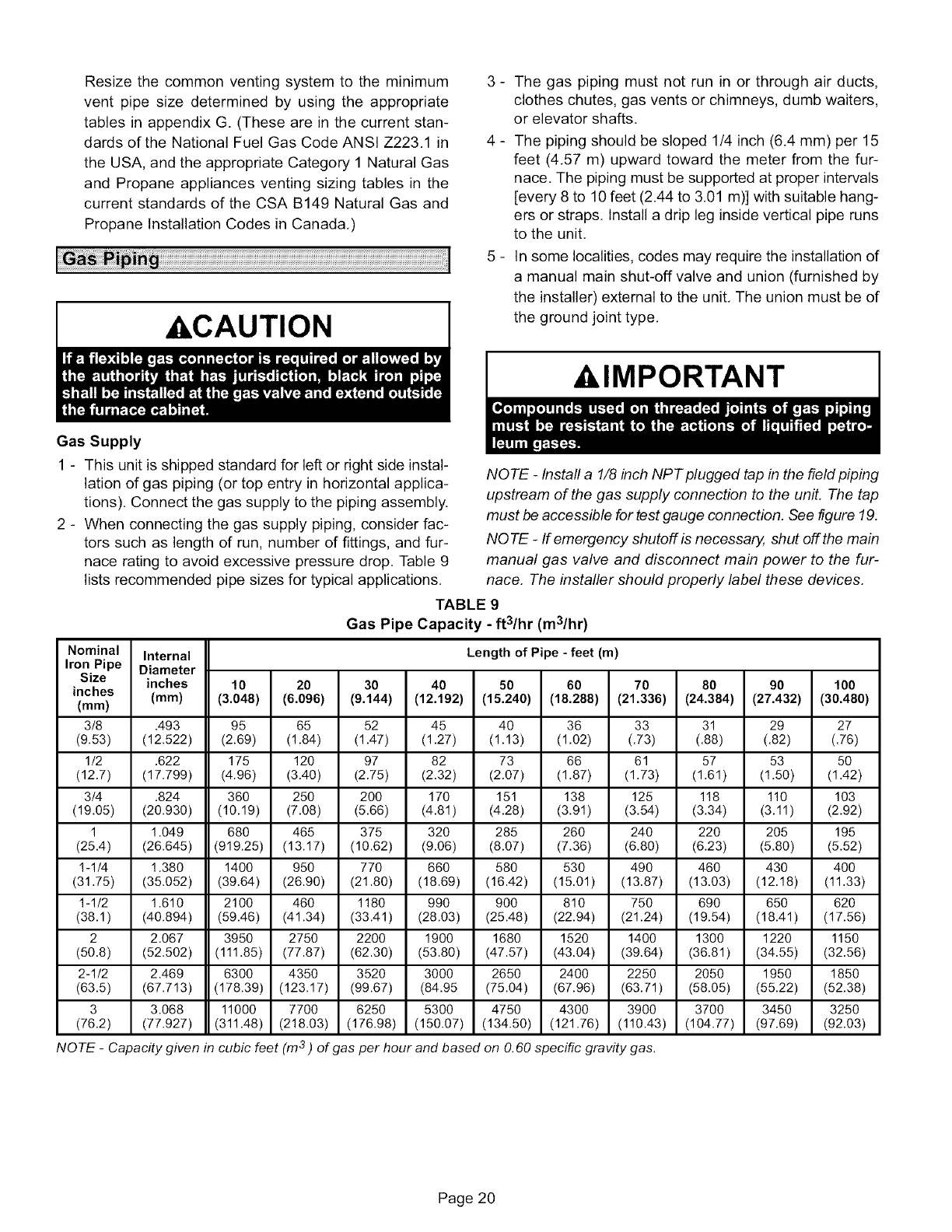
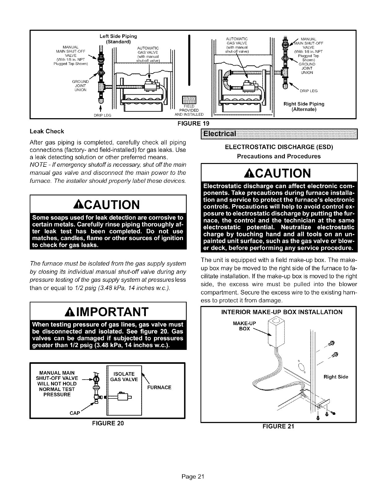
3 - The gas piping must not run in or through air ducts,
clothes chutes, gas vents or chimneys, dumb waiters,
or elevator shafts.
4 - The piping should be sloped 1/4 inch (6.4 mm) per 15
feet (4,57 m) upward toward the meter from the fur-
nace. The piping must be supported at proper intervals
[every 8 to 10 feet (2.44 to 3.01 m)] with suitable hang-
ers or straps, Install a drip leg inside vertical pipe runs
to the unit,
5- In some localities, codes may require the installation of
a manual main shut-off valve and union (furnished by
the installer) external to the unit, The union must be of
the ground joint type,
A, IMPORTANT
Gas Supply
1 - This unit is shipped standard for left or right side instal-
lation of gas piping (or top entry in horizontal applica-
tions). Connect the gas supply to the piping assembly.
2 - When connecting the gas supply piping, consider fac-
tors such as length of run, number of fittings, and fur-
nace rating to avoid excessive pressure drop. Table 9
lists recommended pipe sizes for typical applications.
NOTE -Install a 1/8 inch NPT plugged tap in the field piping
upstream of the gas supply connection to the unit. The tap
must be accessible for test gauge connection. See figure 19.
NQ TE -If emergency shutoff is necessarj4 shut off the main
manual gas valve and disconnect main power to the fur-
nace. The installer should properly label these devices.
Nominal
IronPipe
Size
inches
(ram)
3/8
(9.53)
1/2
(12.7)
3/4
(19.05)
1
(25.4)
1-1/4
(31.75)
1-1/2
(38.1)
2
(50.8)
2 -1/2
(63.5)
3
(76.2)
TABLE 9
Gas Pipe Capacity -ft3/hr (m3/hr)
Internal Length of Pipe -feet(m)
Diameter
inches 10 20 30 40 50 60 70 80 90 100
(mm) (3.048) (6.096) (9.144) (12.192) (15.240) (18.288) (21.336) (24.384) (27.432) (30.480)
.493 95 65
(12.522) (2.69) (1.84)
.622 175 120
(17.799) (4.96) (3.40)
.824 360 250
(20.930) (10.19) (7.08)
1.049 680 465
(26.645) (919.25) (13.17)
1.380 1400 950
(35.052) (39.64) (26.90)
1.610 2100 460
(40.894) (59.46) (41.34)
2.067 3950 2750
(52.502) (111.85) (77.87)
2.469 6300 4350
(67.713) (178.39) (123.17)
3.068 11000 7700
(77.927) (311.48) (218.03)
52
(1.47)
97
(2.75)
2OO
(5.66)
375
(10.62)
77O
(21.80)
1180
(33.41)
2200
(62.30)
3520
(99.67)
6250
(176.98)
45
(1.27)
82
(2.32)
170
(4.81)
32O
(9.06)
66O
(18.69)
990
(28.03)
1900
(53.80)
3000
(84.95
5300
(150.07)
NOTE -Capacity given in cubic feet (In 3) of gas per hour and based
40
(1.13)
73
(2.07)
151
(4.28)
285
(8.07)
580
(16.42)
9OO
(25.48)
1680
(47.57)
2650
(75.04)
4750
(134.50)
36
(1.02)
66
(1.87)
138
(3.91)
26O
(7.36)
53O
(15.Ol)
81o
(22.94)
1520
(43.04)
2400
(67.96)
4300
(121.76)
33
(.73)
61
(1.73)
125
(3.54)
24O
(6.80)
490
(13.87)
75O
(21.24)
1400
(39.64)
2250
(63.71)
3900
(110.43)
31
(.88)
57
(1.61)
118
(3.34)
22O
(6.23)
46O
(13.03)
690
(19.54)
1300
(36.81)
2050
(58.05)
3700
(104.77)
29
(.82)
53
(1.50)
11o
(3.11)
2O5
(5.80)
430
(12.18)
65O
(18.41)
1220
(34.55)
1950
(55.22)
3450
(97.69)
on O.60 specific gravity gas.
27
(.76)
5O
(1.42)
103
(2.92)
195
(5.52)
400
(11.33)
62O
(17.56)
1150
(32.56)
1850
(52.38)
3250
(92.03)
Page 20
MANUAL
MAIN SHUT-OFF
VALVE
(With 1/8 in. NPT
Plugged Tap Shown)
GROUND
JOINT
UNION
Left Side Piping
(Standard)
AUTOMATIC
GAS VALVE
(with manual
shut-off valve /
AUTOMATIC MANUAL
GAS VALVE
(with manual VALVE
shut-off valve) (With 1/8 in. NPT
Shown)
JOINT
UNION
DRIP LEG
DRIP LEG
FIELD
PROVIDED
AND INSTALLED
FIGURE 19
Leak Check
After gas piping is completed, carefully check all piping
connections (factory- and field-installed) for gas leaks, Use
a leak detecting solution or other preferred means.
NOTE -If emergency shutoff is necessa04 shut off the main
manual gas valve and disconnect the main power to the
furnace. The installer should properly label these devices.
Right Side Piping
(Alternate)
ELECTROSTATIC DISCHARGE (ESD)
Precautions and Procedures
&CAUTION
&CAUTION
The furnace must be isolated from the gas supply system
by closing its individual manual shut-off valve during any
pressure testing of the gas supply system at pressures less
than or equal to 1/2 psig (3.48 kPa, 14 inches w.c.).
&IMPORTANT
MANUAL MAIN
SHUT-OFF VALVE
WILLNOTHOLD ._.
NORMALTEST _i _
PRESSURE _1]!
CAP /
ISOLATE
GAS VALVE
FIGURE 20
\FURNACE
The unit is equipped with a field make-up box, The make-
up box may be moved to the right side of the furnace to fa-
cilitate installation, If the make-up box is moved to the right
side, the excess wire must be pulled into the blower
compartment. Secure the excess wire to the existing harn-
ess to protect it from damage.
INTERIOR MAKE-UP BOX INSTALLATION
MAKE-UP
BOX
Right Side
FIGURE 21
Page 21

INTERIORMAKE-UP BOX INSTALLATION
MAKE-UP
Left side /BOX
_ °
FIGURE 22
Refer to figure 24 for field wiring and figure 26 for schematic
wiring diagram and troubleshooting.
1 - Select circuit protection and wire size according to the
unit nameplate. The power supply wiring must meet
Class I restrictions,
2 - Holes are on both sides of the furnace cabinet to facili-
tate wiring,
3 - Install a separate disconnect switch (protected by ei-
ther fuse or circuit breaker) near the furnace so that
power can be turned off for servicing,
4 - Before connecting the thermostat or the power wiring,
check to make sure the wires will be long enough for
servicing at a later date, Remove the blower access
panel to check the length of the wire,
5- Complete the wiring connections to the equipment.
Use the provided unit wiring diagram and the field wir-
ing diagram shown in figure 24, Use 18-gauge wire or
larger that is suitable for Class II rating for thermostat
connections,
6 - Electrically ground the unit according to local codes or,
in the absence of local codes, according to the current
National Electric Code (ANSI/NFPA No, 70) for the
USA and current Canadian Electric Code part 1 (CSA
standard C22.1) for Canada. A green ground wire is
provided in the field make-up box,
NOTE -The G5OUH(X) furnace contains electronic
components that are polarity sensitive. Make sure
that the furnace is wired correctly and is properly
grounded.
7 - One line voltage "EAC" terminal is provided on the fur-
nace control board. Any electronic air cleaner rated up
to one amp can be connected to this terminal with the
neutral leg of the circuit being connected to any of the
"NEUTRAL" terminals. See figure 25 for control board
configuration. This terminal is energized when the
blower is operating,
8 - One line voltage "HUM" terminal is provided on the fur-
nace control board, A humidifier rated up to one amp
can be connected to this terminal with the neutral leg
of the circuit being connected to any of the "NEUTRAL"
terminals. See figure 25 for control board configura-
tion. This terminal is energized in the heating mode
whenever the combustion air inducer is operating.
9 - One 24 volt terminal "24V HUM" is provided on the fur-
nace control board. A humidifier rated up to 0.5 amp
can be connected to this terminal with the common leg
of the circuit being connected to the "C" terminal dthe
thermostat terminal block located on the control board.
10-Install the room thermostat according to the instruc-
tions provided with the thermostat. See figure 23 for
thermostat designations. If the furnace is being
matched with a heat pump, refer to the FM21 installa-
tion instruction.
G50UH(X) and CONDENSING UNIT
THERMOSTAT DESIGNATIONS
(Refer to specific thermostat and outdoor unit.)
Thermostat G50UH(X) Condensing
Furnace Unit
PowER
@1 HsuN,T
FIGURE 23
Indoor Blower Speeds
1 - When the thermostat is set to "FAN ON," the indoor
blower will run continuously on the low speed when
there is no cooling or heating demand,
2 - When the G50UH(X)is running in the heating mode,
the indoor blower will run on the heating speed.
3 - When there is a cooling demand, the indoor blower will
run on the cooling speed,
Page 22
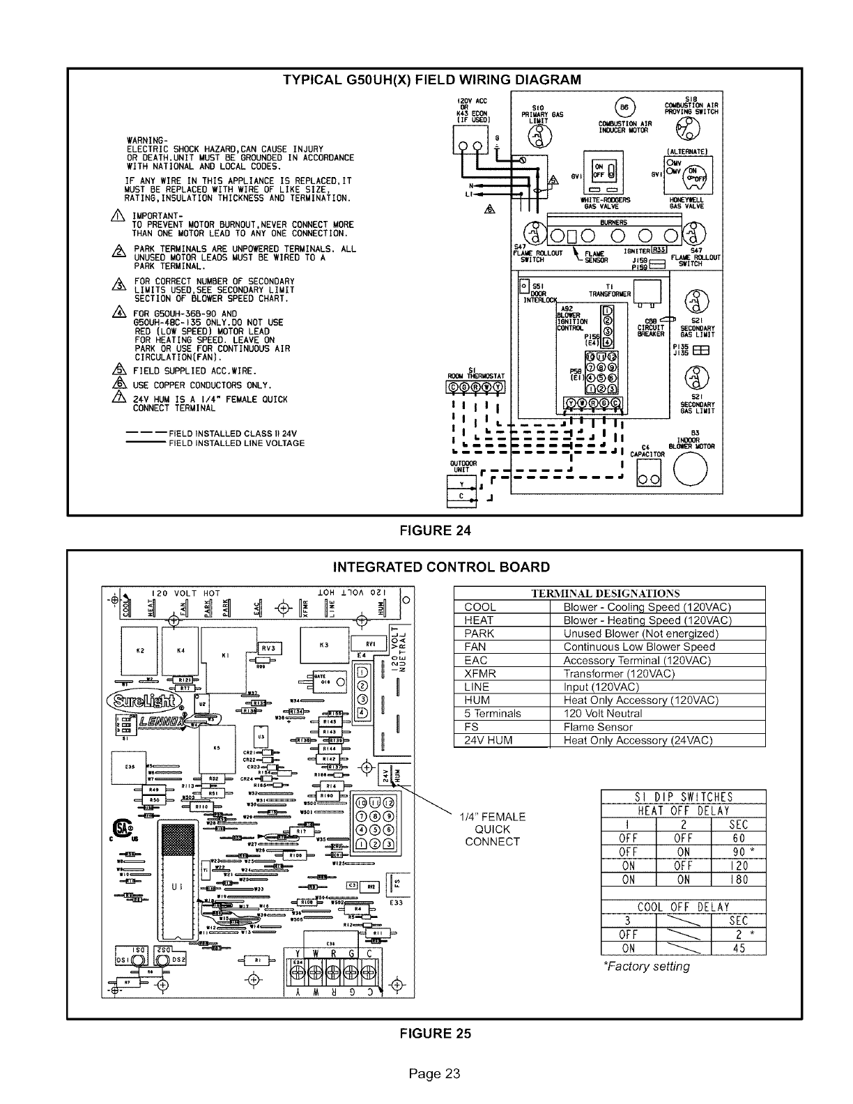
TYPICAL G50UH(X) FIELD WIRING DIAGRAM
WARNING-
ELECTRIC SHOCK HAZARD,CAN CAUSE INJURY
OR DEATH.UNIT MUST BE GROUNDED IN ACCORDANCE
WITH NATIONAL AND LOCAL CODES,
IF ANY WIRE IN THIS APPLIANCE IS REPLACED, IT
MUST BE REPLACED WITH WIRE OF LIKE SIZE,
RATING,INSULATION THICKNESS AND TERMINATION.
_ IMPORTANT-
TO PREVENT MOTOR BURNOUT,NEVER CONNECT MORE
THAN ONE MOTOR LEAD TO ANY ONE CONNECTION.
PARK TERMINALS ARE UNPOWERED TERMINALS. ALL
UNUSED MOTOR LEADS MUST BE WIRED TO A
PARK TERMINAL.
/:Zk FOR CORRECT NUMBER OF SECONDARY
LIMITS USED,SEE SECONDARY LIMIT
SECTION OF BLOWER SPEED CHART.
FOR 650UH-56B-90 AND
G5OUH-4BC-135 ONLY.DO NOT USE
RED (LOW SPEED) MOTOR LEAD
FOR HEATING SPEED. LEAVE ON
PARK OR USE FOR CONTINUOUS AIR
CIRCULATION(FAN).
FIELD SUPPLIED ACC.IIRE.
./6'kUSE COPPER CONDUCTORS ONLY.
/Z_X 24V HUM IS A I/4" FEMALE OUICK
CONNECT TERMINAL
---- FIELD INSTALLED CLASS II24V
-- FIELD INSTALLED LINE VOLTAGE
{_V ACC
K43 EC(_
(IF USEO)
L I-_=======_
GS{g
S{O COIlBIJ_ITION AIR
_IIIARYGAS PROVIi_ SWITCH
LIMIT C(_WBIJSTI(_NAIR
(_) INN.ICERI_T_
{ALEImNATE}
-'e
-- V_lTE-R(X)GERS HONEYWELL
6A5 VALVE 6AS VALVE
,, orlo 000
FLAMEROLLOUT _ FLAI_ I_NITERIR3$1 S47
SWITCH SENS_ J,_ _A_ _LLOm
m_=l _r_
TRANSFORMER
A_ _
I_ITI(_W _ CB8_ _ S2I
:O_TROL _, CIRCUIT SECONE)ARY
PIS_ _" BREAKER 6AS LIIIIT
(_4: P135
J,3_F::F::I
ROOM THIZRMOSTAT [E{) _)@_)
I I I I I _SECONDARY
6AS LIMIT
'1 _1,._.... .,1'Ill, _
I I i'---- "-------la J III INOOOe
C4 BLOWERMOTO_
_' _ _ JICAPACITOR
OUTB:_ al l(9
U.,T r--- ....
|
FIGURE 24
INTEGRATED CONTROL BOARD
COOL
HEAT
PARK
FAN
EAC
XFMR
LINE
HUM
5 Terminals
FS
24V HUM
TEll\ IINAL DESIGNATIONS
Blower- Cooling Speed (120MAC)
Blower - Heating Speed (120VAC)
Unused Blower (Not energized)
Continuous Low Blower Speed
Accessory Terminal (120VAC)
Transformer (120VAC)
Input (120VAC)
Heat Only Accessory (120VAC)
120 Volt Neutral
Flame Sensor
Heat Only Accessory (24VAC)
1/4" FEMALE
QUICK
CONNECT
SI DIP SWITCHES
HEAT OFF DELAY
l 2 SEC
OFF OFF 60
OFF ON 90 *
ON OFF 120
ON ON 180
COOL OFF DELAY
3 _ SEC
OFF _ 2 *
ON _ 45
*Factory setting
FIGURE 25
Page 23
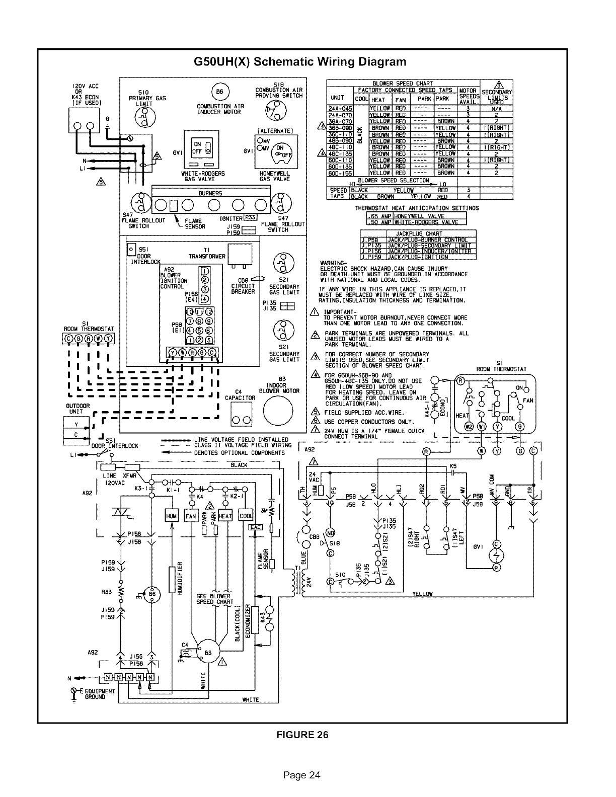
G5OUH(X) Schematic Wiring Diagram
120V ADO /_ SIS BLOWER SPEED CHART L_
OR SlO COMBUSTION AIR FACTORY CONNECTED SPEED TAPS MOTOR SECONDARY
PROVING SWITCH SREE_
K43 ECON PRIMARY GAS UNIT COOL HEAT FAN PARK PARK AVAIL, L_DTS
(IF USED) LIMIT COMBUSTION AIR _24A-045 fELLOW RED ........ 3 N/A
INDUCER MOTOR 2¢A-070 fELLOW RED 32
"-L£P./ 36A-070 fELLOW RED .... BROWN 4 2
36B-090 _ BROWN RED .... YELLOt 4{(RIGHT)
(ALTERNATE) _<BROWN RED .... YELLO_ €I(RISHT)
o o° o....,ELLo,,
GVf6V I4BC- 135 BROWN RED .... t'ELLO£t 4- _
60C-t JO fELLOW RED .... BROWN 4I(R=eHT}
60D- 135 fELLOW RED .... BROWN 4- 2
WHITE-RODGER9 HONEYWELL 6DO° 155 fELLOW RED .... BROWN 42
/_ GAS VALVE GAS VALVE HX BLOWER_ - SPEED SELECTION LO
0 _ SPEED BLACK Y_LI.QW RED 3
BURNERS TAPS BLACK BROWN YELLOW RED 4-
0[] 0 0 0 T.ERMOOTAT.EATANTICIPATIONSETTINES
PLANENOLLDUT\FLAMEI_NITER"_L_SAT
SWITCH SENSOR JI59 FLAME ROLLOU'[
JACKPLU6 CHART
P159 E_ SWITCH IJ.P5B IJACK/PLUG-GURNER CONTROL
DOOR TRANSFORMER IJ.PIB9 IJACK/PLUD-IONITION
INTERLOCI WARN INO-
OR DEATH.UNIT MUST BE GROUNDED IN ACCORDANCE
A92 _ ELECTRIC SHOCK HAZARD,CAN CAUSE INJURY
BLO_R
IGNITION COB c $21 WITH NATIONAL AND LOCAL CODES.
CONTROLpIs6 CIROOI SECONDARY IF ANY WIRE IN THIS APPLIANCE IS RSPLACED,IT
6REANEf GAS LIMIT MUST 6E REPLACED WITH WIRE OF LIKE SIZE,
(EA-) RATING,INSULATION THICKNESS AND TERMINATION,
PIJS
JI35_ _ IMPORTANT-
TO PREVENT MOTOR DURMDUT,REVER CONNECT MORE
SI P50 THAN ONE MOTOR LEAD TO ANY ONE CONNECTION.
ROOM THERMOSTAT (El) Z_ PARK TERMINALS ARE UNPOWEREDTERMINALS. ALL
i®®.o®ol UNOREDMOTORLEAOOMUST6EWIREDTOA
"" " 9ZI PARK TERMINAL.
IIIIIl_(_I SECONDARY i:& FOR CORRECT NUM6ER OF SECONDARY
I•--If-" " • "'_k GAS LIMIT _LIMITS USED,SEE SECONDARY LIMIT SI
IIiIL .... j I II I II A SECTION OF BLOWER SPEED CHART. ROOM THERMOSTAT
li ,- .-, ,,I , "= .. /Ax FOR G5DUH-3OO-90 AND ._ _ _ _..
=I. ..... "1 .I I I iDo OODUH-4-BC-135 ONLY,DO NOT USE LJ'-c>P_R \
l IL ...... i= = ,,I IINDOOR RED (LOW SPEED) MOTOR LEAD -T- I Iv.L _nN.-L,I
[........ II I J I C4- 6LO_R MOTOR FOR HEATING SPEED. LEAVE ON ,_ I I _') N _ ,_-"%'tI
........... = .... ' CAPACITOR _PARK OR USE FOR OONTINOOUS AIR _o'l I I /"_-_]C ..I.I'-_FANI
OUTDO(._ I IF-------I /\CIRCULATION(FAN), T_'II _0 C) r(3 I )-,'"1
UNI<"r...... "'I I (;_FIELOSH_LIEOAOO.WIRE._?_&ll..do-t_E___.YI
F-T-l, r........... " _ _ ,_ USECOPPERCONDUCTORSONLY. Y '1I"°_L_ _oo%L /
....... A zAv,uMISA,,4-"FEMALEOOICKL I\ _ Lp L_ J
JCONNECT TERMINAL
$51 _LINE VOLTAGE FIELD INSTALLED
- 0O0R,NTERL K_---CLASSiiVOLTAREFIELD,IRINO....
L, _-0_ _ DENOTES OPTIONAL COMPONENTS .u. _ _._ _ _
I-@ .... -_CK I,Z_ II ,KS II
x_ . 24-_T I 1 Ilk- = I
IZOVAC ' VAC o-- N -- _ I
K,€ -_K; I ._I/---_V P98 "-./ "4/ "-./_ _ "_L...--",P96 S_. _I/
_L I /'z, 9 _ ,_" J962 _ 4- "y" _ _'JSD '_"'_" '_-
._-JISS r- r- r_
I"''T II ,o;,. 0v,
PI59_/ I I I / _,_ O=_
R35 _SPE_FEDCHART YELLOW
JI59, sot
PI59_
A9Z J I
EQUIPMENT
WHITE
FIGURE 26
Page 24
FOR YOUR SAFETY READ BEFORE LIGHTING
AWARNING
AWARNING
ACAUTION
BEFORE LIGHTING smell all around the appliance area for
gas, Be sure to smell next to the floor because some gas is
heavier than air and will settle on the floor.
The gas valve on the G50UH(X) unit may be equipped with
either a gas control knob or gas control lever. Use only your
hand to push the lever or to tum the gas control knob. Never
use tools, If the knob will not turn or if the lever will not move
by hand, do not try to repair it. Call a qualified service tech-
nician, Force or attempted repair may result in a fire or ex-
plosion,
Placing the furnace into operation:
G50UH(X) units are equipped with a SureLight ® ignition
system. Do not attempt to manually light burners on these
furnaces, Each time the thermostat calls for heat, the
burners will automatically light. The ignitor does not get
hot when there is no call for heat on units with SureLight ®
ignition system,
AWARNING
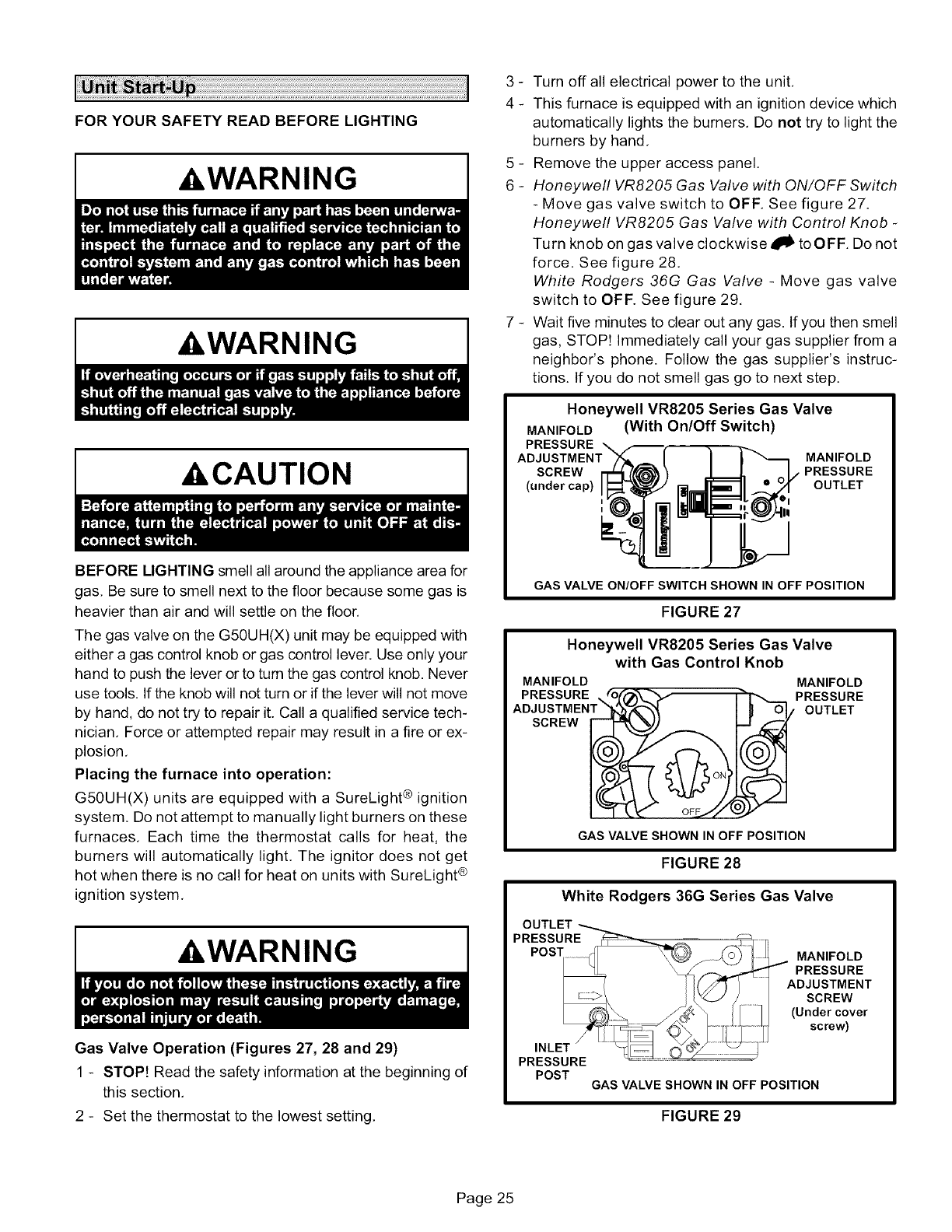
Gas Valve Operation (Figures 27, 28 and 29)
1 - STOP! Read the safety information at the beginning of
this section,
2 - Set the thermostat to the lowest setting,
3 - Turn off all electrical power to the unit,
4-This furnace is equipped with an ignition device which
automatically lights the burners, Do not try to light the
burners by hand,
5- Remove the upper access panel,
6 - Honeywell VR8205 Gas Valve with ON/OFF Switch
- Move gas valve switch to OFF, See figure 27.
Honeywell VR8205 Gas Valve with Control Knob -
Turn knob on gas valve clockwise 41_ to OFF. Do not
force, See figure 28,
White Rodgers 36G Gas Valve - Move gas valve
switch to OFF. See figure 29,
7 - Wait five minutes to clear out any gas. If you then smell
gas, STOP! Immediately call your gas supplier from a
neighbor's phone. Follow the gas supplier's instruc-
tions. If you do not smell gas go to next step.
Honeywell VR8205 Series Gas Valve
MANIFOLD (With On/Off Switch)
PRESSURE MANIFOLD
SCREW PRESSURE
(under cap) OUTLET
DI
GAS VALVE ON/OFF SWITCH SHOWN IN OFF POSITION
FIGURE 27
Honeywell VR8205 Series Gas Valve
with Gas Control Knob
MANIFOLD MANIFOLD
PRESSURE ._ _ PRESSURE
ADJUSTMENT"'_'___,_, r I h _'_'l_, OUTLET
SCREW _
GAS VALVE SHOWN IN OFF POSITION
FIGURE 28
White Rodgers 36G Series Gas Valve
PRESSURE
POST
MANIFOLD
PRESSURE
ADJUSTMENT
SCREW
(Undercover
SCOW)
GAS VALVE SHOWN IN OFF POSITION
FIGURE 29
Page 25
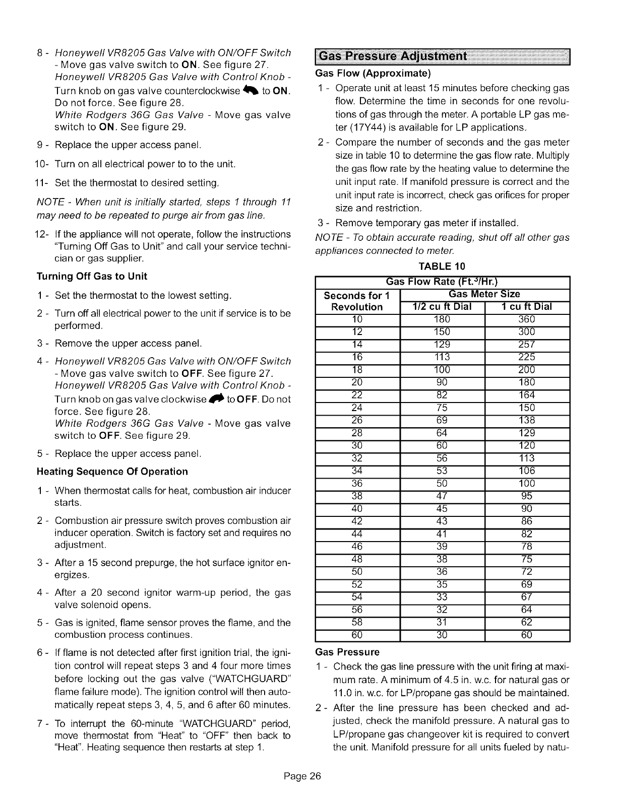
8- Honeywell VR8205 Gas Valve with ON/OFF Switch
- Move gas valve switch to ON. See figure 27.
Honeywell VR8205 Gas Valve with Control Knob -
Turn knob on gas valve counterclockwise _ to ON,
Do not force. See figure 28,
White Rodgers 36G Gas Valve - Move gas valve
switch to ON, See figure 29,
9 - Replace the upper access panel,
10- Turn on all electrical power to to the unit,
11- Set the thermostat to desired setting,
NOTE -When unit is initially started, steps 1 through 11
may need to be repeated to purge air from gas line,
12- If the appliance will not operate, follow the instructions
"Turning Off Gas to Unit" and call your service techni-
cian or gas supplier,
Turning Off Gas to Unit
1 - Set the thermostat to the lowest setting,
2 - Turn off all electrical power to the unit if service is to be
performed,
3 - Remove the upper access panel,
4 - Honeywell VR8205 Gas Valve with ON/OFF Switch
- Move gas valve switch to OFF, See figure 27.
Honeywell VR8205 Gas Valve with Control Knob -
Turn knob on gas valve clockwise clio to OFF, Do not
force, See figure 28,
White Rodgers 36G Gas Valve - Move gas valve
switch to OFF, See figure 29,
5 - Replace the upper access panel.
Heating Sequence Of Operation
1-When thermostat calls for heat, combustion air inducer
starts,
2 - Combustion air pressure switch proves combustion air
inducer operation. Switch is factory set and requires no
adjustment,
3 - After a 15 second prepurge, the hot surface ignitor en-
ergizes,
4- After a 20 second ignitor warm-up period, the gas
valve solenoid opens,
5 - Gas is ignited, flame sensor proves the flame, and the
combustion process continues,
6 - If flame is not detected after first ignition trial, the igni-
tion control will repeat steps 3 and 4 four more times
before locking out the gas valve ("WATCHGUARD"
flame failure mode), The ignition control will then auto-
matically repeat steps 3, 4, 5, and 6 after 60 minutes,
7- To interrupt the 60-minute "WATCHGUARD" period,
move thermostat from "Heat" to "OFF" then back to
"Heat", Heating sequence then restarts at step 1.
Gas Flow (Approximate)
1 - Operate unit at least 15 minutes before checking gas
flow. Determine the time in seconds for one revolu-
tions of gas through the meter, A portable LP gas me-
ter (17Y44) is available for LP applications,
2 - Compare the number of seconds and the gas meter
size in table 10 to determine the gas flow rate. Multiply
the gas flow rate by the heating value to determine the
unit input rate, If manifold pressure is correct and the
unit input rate is incorrect, check gas orifices for proper
size and restriction,
3 - Remove temporary gas meter if installed,
NOTE -To obtain accurate reading, shut off all other gas
appliances connected to meter,
TABLE 10
Gas Flow Rate (Ft.'_/Hr.)
Seconds for 1
Revolution
10
12
14
16
18
2O
22
24
26
28
3O
32
34
36
38
4O
42
44
46
48
5O
52
54
56
58
6O
Gas Pressure
Gas Meter Size
1/2 cu ft Dial 1 cu ft Dial
180 360
150 300
129 257
113 225
100 200
90 180
82 164
75 150
69 138
64 129
60 120
56 113
53 106
50 100
47 95
45 90
43 86
41 82
39 78
38 75
36 72
35 69
33 67
32 64
31 62
30 60
1 - Check the gas line pressure with the unit firing at maxi-
mum rate. A minimum of 4.5 in, w.c. for natural gas or
11,0 in, w,c, for LP/propane gas should be maintained,
2- After the line pressure has been checked and ad-
justed, check the manifold pressure. A natural gas to
LP/propane gas changeover kit is required to convert
the unit, Manifold pressure for all units fueled by natu-
Page 26
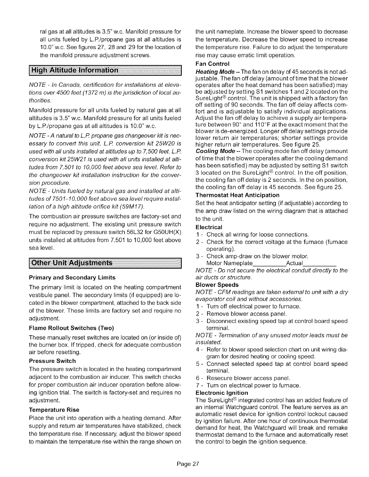
ralgasatallaltitudesis3.5"w.c.Manifoldpressurefor
allunitsfueledbyL.R/propanegasat allaltitudesis
10.0"w,c.Seefigures27,28and29forthelocationof
themanifoldpressureadjustmentscrews,
NOTE -In Canada, certification for installations at eleva-
tions over 4500 feet (1372 m) is the jurisdiction of local au-
thorities.
Manifold pressure for all units fueled by natural gas at all
altitudes is 3.5" w,c, Manifold pressure for all units fueled
by L,R/propane gas at all altitudes is 10,0" w,c,
NOTE -A natural to L.R propane gas changeover kit is nec-
essary to convert this un#. L.R conversion kit 25W20 is
used with all units installed at altitudes up to 7,500 feet. L.P.
conversion kit 25W21 is used with all units installed at alti-
tudes from 7,501 to 10,000 feet above sea level. Refer to
the changeover kit installation instruction for the conver-
sion procedure.
NOTE -Units fueled by natural gas and installed at alti-
tudes of 7501-10,000 feet above sea level require instal-
lation of a high altitude orifice kit (59M17).
The combustion air pressure switches are factory-set and
require no adjustment, The existing unit pressure switch
must be replaced by pressure switch 56L32 for G50UH(X)
units installed at altitudes from 7,501 to 10,000 feet above
sea level,
Primary and Secondary Limits
The primary limit is located on the heating compartment
vestibule panel. The secondary limits (if equipped) are lo-
cated in the blower compartment, attached to the back side
of the blower. These limits are factory set and require no
adjustment.
Flame Rollout Switches (Two)
These manually reset switches are located on (or inside of)
the burner box, If tripped, check for adequate combustion
air before resetting,
Pressure Switch
The pressure switch is located in the heating compartment
adjacent to the combustion air inducer. This switch checks
for proper combustion air inducer operation before allow-
ing ignition trial, The switch is factory-set and requires no
adjustment.
Temperature Rise
Place the unit into operation with a heating demand, After
supply and return air temperatures have stabilized, check
the temperature rise, If necessary, adjust the blower speed
to maintain the temperature rise within the range shown on
the unit nameplate, Increase the blower speed to decrease
the temperature, Decrease the blower speed to increase
the temperature rise, Failure to do adjust the temperature
rise may cause erratic limit operation,
Fan Control
Heating Mode -- The fan on delay of 45 seconds is not ad-
justable. The fan offdelay (amount of time that the blower
operates after the heat demand has been satisfied) may
be adjusted by setting $1 switches 1and 2 located on the
SureLight ® control. The unit is shipped with a factory fan
off setting of 90 seconds, The fan off delay affects com-
fort and is adjustable to satisfy individual applications.
Adjust the fan off delay to achieve a supply air tempera-
ture between 90 ° and 110° F at the exact moment that the
blower is de-energized. Longer offdelay settings provide
lower return air temperatures; shorter settings provide
higher return air temperatures. See figure 25.
Cooling Mode --The cooling mode fan off delay (amount
of time that the blower operates after the cooling demand
has been satisfied) may be adjusted by setting $1 switch
3 located on the SureLight ® control, In the off position,
the cooling fan off delay is 2 seconds. In the on position,
the cooling fan off delay is 45 seconds, See figure 25,
Thermostat Heat Anticipation
Set the heat anticipator setting (if adjustable) according to
the amp draw listed on the wiring diagram that is attached
to the unit.
Electrical
1 - Check all wiring for loose connections,
2 - Check for the correct voltage at the furnace (furnace
operating).
3 - Check amp-draw on the blower motor.
Motor Nameplate Actual
NOTE -Do not secure the electrical conduit directly to the
air ducts or structure.
Blower Speeds
NOTE - CFM readings are taken external to unit with a dry
evaporator coil and without accessories.
1 - Turn off electrical power to furnace,
2 - Remove blower access panel.
3 - Disconnect existing speed tap at control board speed
terminal.
NOTE -Termination of any unused motor leads must be
insulated.
4 - Refer to blower speed selection chart on unit wiring dia-
gram for desired heating or cooling speed.
5- Connect selected speed tap at control board speed
terminal.
6 - Resecure blower access panel.
7 - Turn on electrical power to furnace,
Electronic Ignition
The SureLight @integrated control has an added feature of
an internal Watchguard control, The feature serves as an
automatic reset device for ignition control lockout caused
by ignition failure, After one hour of continuous thermostat
demand for heat, the Watchguard will break and remake
thermostat demand to the furnace and automatically reset
the control to begin the ignition sequence,
Page 27
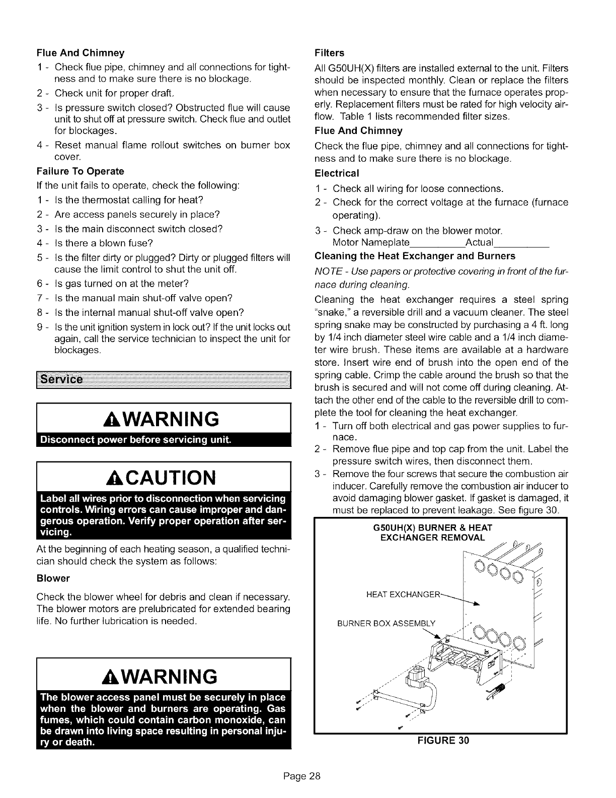
FlueAndChimney
1- Checkfluepipe,chimneyandallconnectionsfortight-
nessandtomakesurethereisnoblockage,
2 - Checkunitforproperdraft,
3- Ispressureswitchclosed?Obstructedfluewillcause
unittoshutoffatpressureswitch,Checkflueandoutlet
forblockages.
4- Resetmanualflamerolloutswitcheson burnerbox
cover.
FailureToOperate
Iftheunitfailstooperate,checkthefollowing:
1- Isthethermostatcallingforheat?
2 - Areaccesspanelssecurelyinplace?
3- Isthemaindisconnectswitchclosed?
4 - Istherea blownfuse?
5- Isthefilterdirtyorplugged?Dirtyorpluggedfilterswill
causethelimitcontroltoshuttheunitoff.
6 - Isgasturnedonatthemeter?
7- Isthemanualmainshut-offvalveopen?
8- Istheinternalmanualshut-offvalveopen?
9- Istheunitignitionsysteminlockout?Iftheunitlocksout
again,calltheservicetechniciantoinspecttheunitfor
blockages.
,AWARNING
A,CAUTION
At the beginning of each heating season, a qualified techni-
cian should check the system as follows:
Blower
Check the blower wheel for debris and clean if necessary.
The blower motors are prelubricated for extended bearing
life. No further lubrication is needed.
,&WARNING
Filters
All G50UH(X) filters are installed external to the unit. Filters
should be inspected monthly. Clean or replace the filters
when necessary to ensure that the furnace operates prop-
erly. Replacement filters must be rated for high velocity air-
flow. Table 1 lists recommended filter sizes.
Flue And Chimney
Check the flue pipe, chimney and all connections for tight-
ness and to make sure there is no blockage,
Electrical
1 - Check all wiring for loose connections.
2 - Check for the correct voltage at the furnace (furnace
operating),
3 - Check amp-draw on the blower motor.
Motor Nameplate Actual
Cleaning the Heat Exchanger and Burners
NOTE -Use papers or protective covering in front of the fur-
nace during cleaning.
Cleaning the heat exchanger requires a steel spring
"snake," a reversible drill and a vacuum cleaner, The steel
spring snake may be constructed by purchasing a 4 ft. long
by 1/4 inch diameter steel wire cable and a 1/4 inch diame-
ter wire brush, These items are available at a hardware
store. Insert wire end of brush into the open end of the
spring cable. Crimp the cable around the brush so that the
brush is secured and will not come off during cleaning, At-
tach the other end of the cable to the reversible drill to com-
plete the tool for cleaning the heat exchanger.
1 - Turn off both electrical and gas power supplies to fur-
nace.
2 - Remove flue pipe and top cap from the unit. Label the
pressure switch wires, then disconnect them.
3 - Remove the four screws that secure the combustion air
inducer. Carefully remove the combustion air inducer to
avoid damaging blower gasket. If gasket is damaged, it
must be replaced to prevent leakage. See figure 30.
G50UH(X) BURNER & HEAT
EXCHANGER REMOVAL
HEAT
BURNER BOX ASSEMBLY
FIGURE 30
Page 28
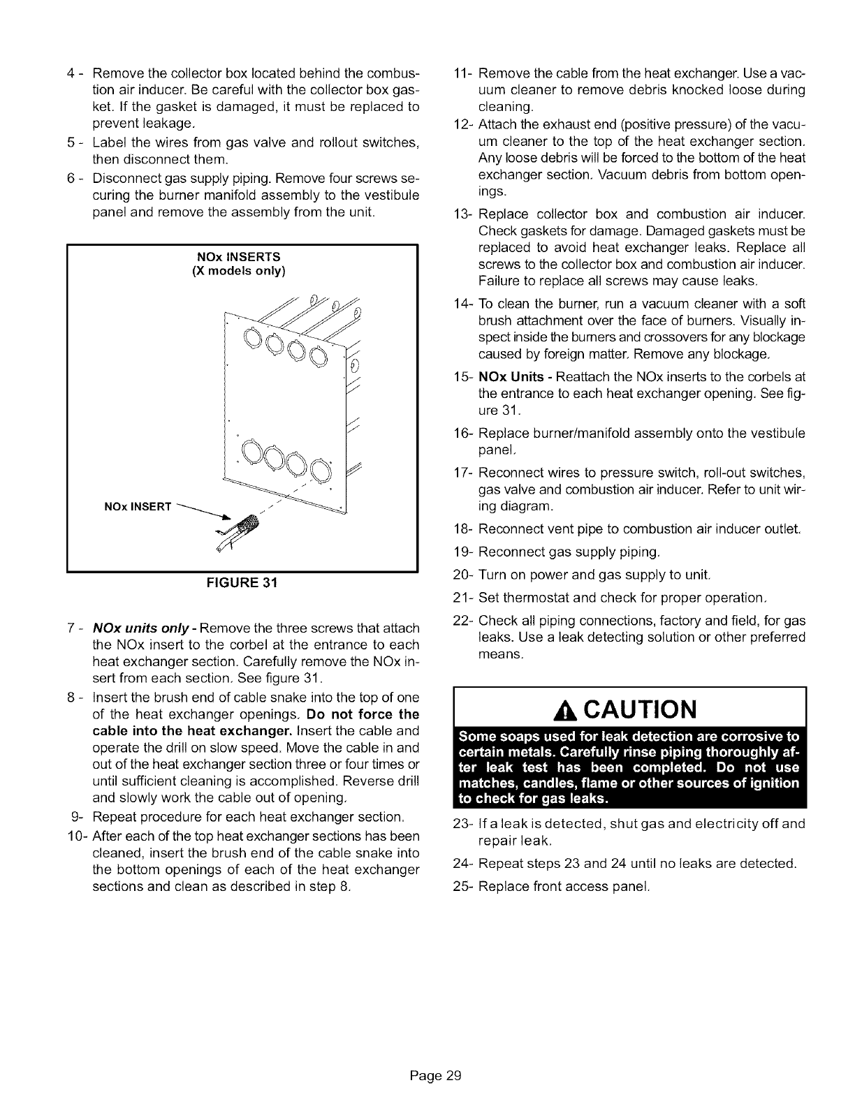
4- Removethecollectorboxlocatedbehindthecombus-
tionairinducer.Becarefulwiththecollectorboxgas-
ket.Ifthegasketisdamaged,it mustbereplacedto
preventleakage,
5- Labelthewiresfromgasvalveandrolloutswitches,
thendisconnectthem.
6- Disconnectgassupplypiping.Removefourscrewsse-
curingtheburnermanifoldassemblytothevestibule
panelandremovetheassemblyfromtheunit,
NOx INSERTS
(X models only)
/
FIGURE 31
7 - NOx units only- Remove the three screws that attach
the NOx insert to the corbel at the entrance to each
heat exchanger section, Carefully remove the NOx in-
sert from each section, See figure 31.
8 - Insert the brush end of cable snake into the top of one
of the heat exchanger openings, Do not force the
cable into the heat exchanger. Insert the cable and
operate the drill on slow speed. Move the cable in and
out of the heat exchanger section three or four times or
until sufficient cleaning is accomplished. Reverse drill
and slowly work the cable out of opening,
9- Repeat procedure for each heat exchanger section.
10- After each of the top heat exchanger sections has been
cleaned, insert the brush end of the cable snake into
the bottom openings of each of the heat exchanger
sections and clean as described in step 8,
11- Remove the cable from the heat exchanger. Use a vac-
uum cleaner to remove debris knocked loose during
cleaning.
12- Attach the exhaust end (positive pressure) of the vacu-
um cleaner to the top of the heat exchanger section,
Any loose debris will be forced to the bottom of the heat
exchanger section, Vacuum debris from bottom open-
ings.
13- Replace collector box and combustion air inducer.
Check gaskets for damage. Damaged gaskets must be
replaced to avoid heat exchanger leaks. Replace all
screws to the collector box and combustion air inducer.
Failure to replace all screws may cause leaks,
14- To clean the burner, run a vacuum cleaner with a soft
brush attachment over the face of burners. Visually in-
spect inside the burners and crossovers for any blockage
caused by foreign matter. Remove any blockage,
15- NOx Units -Reattach the NOx inserts to the corbels at
the entrance to each heat exchanger opening, See fig-
ure 31,
16- Replace burner/manifold assembly onto the vestibule
panel,
17- Reconnect wires to pressure switch, roll-out switches,
gas valve and combustion air inducer. Refer to unit wir-
ing diagram,
18- Reconnect vent pipe to combustion air inducer outlet,
19- Reconnect gas supply piping,
20- Turn on power and gas supply to unit,
21- Set thermostat and check for proper operation,
22- Check all piping connections, factory and field, for gas
leaks. Use a leak detecting solution or other preferred
means,
AkCAUTION
23- Ira leak is detected, shut gas and electricity offand
repair leak,
24- Repeat steps 23 and 24 until no leaks are detected.
25- Replace front access panel.
Page 29
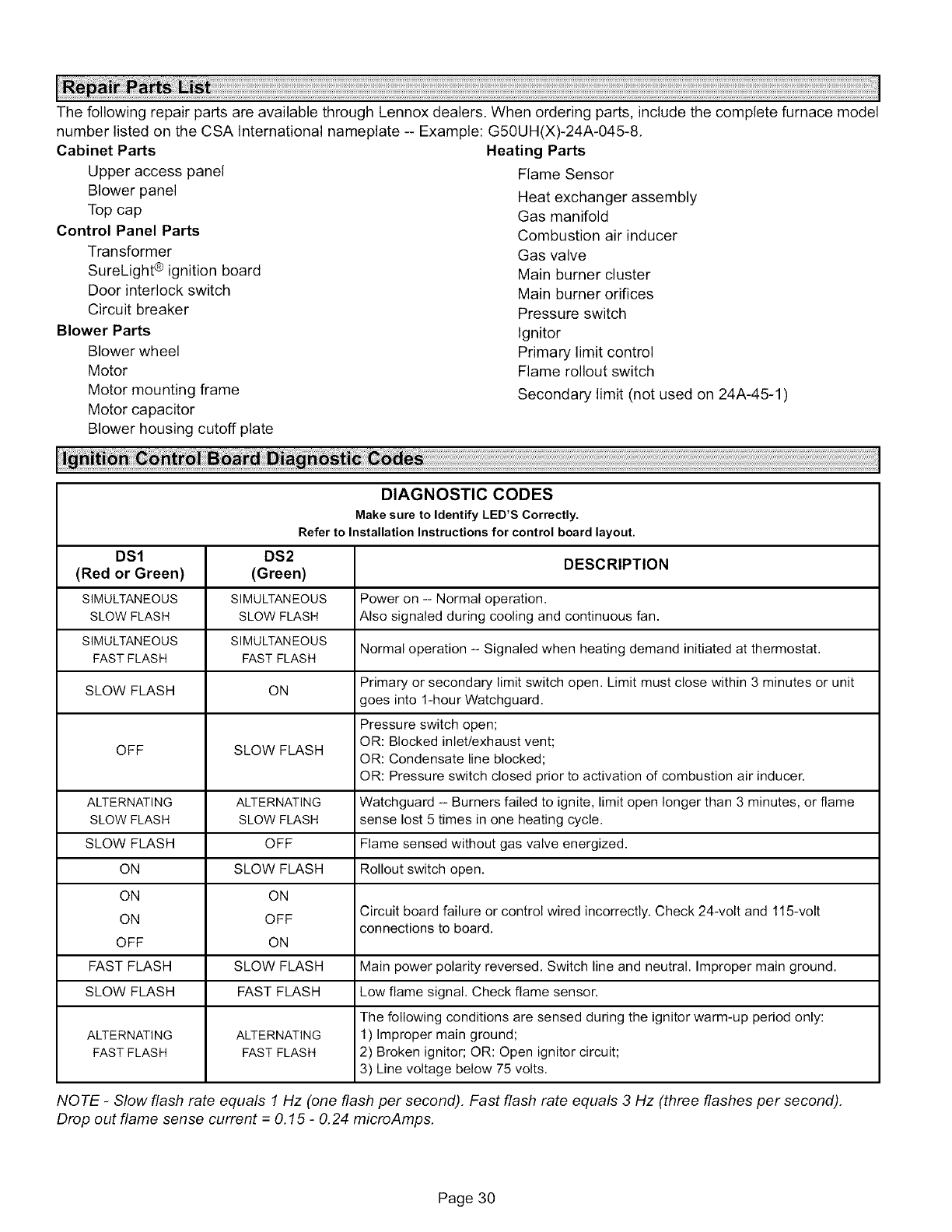
ThefollowingrepairpartsareavailablethroughLennoxdealers.Whenorderingparts,includethecompletefurnacemodel
numberlistedontheCSAInternationalnameplate--Example:G50UH(X)-24A-045-8,
CabinetParts
Upperaccesspanel
Blowerpanel
Topcap
ControlPanelParts
Transformer
SureLight®ignitionboard
Doorinterlockswitch
Circuitbreaker
BlowerParts
Blowerwheel
Motor
Motormountingframe
Motorcapacitor
Blowerhousingcutoffplate
HeatingParts
FlameSensor
Heatexchangerassembly
Gasmanifold
Combustionairinducer
Gasvalve
Mainburnercluster
Mainburnerorifices
Pressureswitch
Ignitor
Primarylimitcontrol
Flamerolloutswitch
Secondarylimit(notusedon24A-45-1)
DIAGNOSTIC CODES
Make sure to Identify LED'S Correctly.
Refer to Installation Instructions for control board layout,
DSl DS2 DESCRIPTION
(Red or Green) (Green)
SIMULTANEOUS SIMULTANEOUS Power on -- Normal operation.
SLOW FLASH SLOW FLASH Also signaled during cooling and continuous fan.
SIMULTANEOUS SIMULTANEOUS Normal operation -- Signaled when heating demand initiated at thermostat.
FAST FLASH FAST FLASH
SLOW FLASH ON Primary or secondary limit switch open. Limit must close within 3 minutes or unit
goes into 1-hour Watchguard.
Pressure switch open;
OR: Blocked inlet/exhaust vent;
OFF SLOW FLASH OR: Condensate line blocked;
OR: Pressure switch closed prior to activation of combustion air inducer.
ALTERNATING ALTERNATING Watchguard -- Burners failed to ignite, limit open longer than 3 minutes, or flame
SLOW FLASH SLOW FLASH sense lost 5 times in one heating cycle.
SLOW FLASH OFF Flame sensed without gas valve energized.
ON SLOW FLASH Rollout switch open.
ON ON
Circuit board failure or control wired incorrectly. Check 24-volt and 115-volt
ON OFF connections to board.
OFF ON
FAST FLASH SLOW FLASH Main power polarity reversed. Switch line and neutral. Improper main ground.
SLOW FLASH FAST FLASH Low flame signal. Check flame sensor.
The following conditions are sensed during the ignitor warm-up period only:
ALTERNATING ALTERNATING 1) Improper main ground;
FAST FLASH FAST FLASH 2) Broken ignitor; OR: Open ignitor circuit;
3) Line voltage below 75 volts.
NOTE -Slow flash rate equals 1 Hz (one flash per second). Fast flash rate equals 3 Hz (three flashes per second).
Drop out flame sense current =0.15 -0.24 microAmps.
Page 30
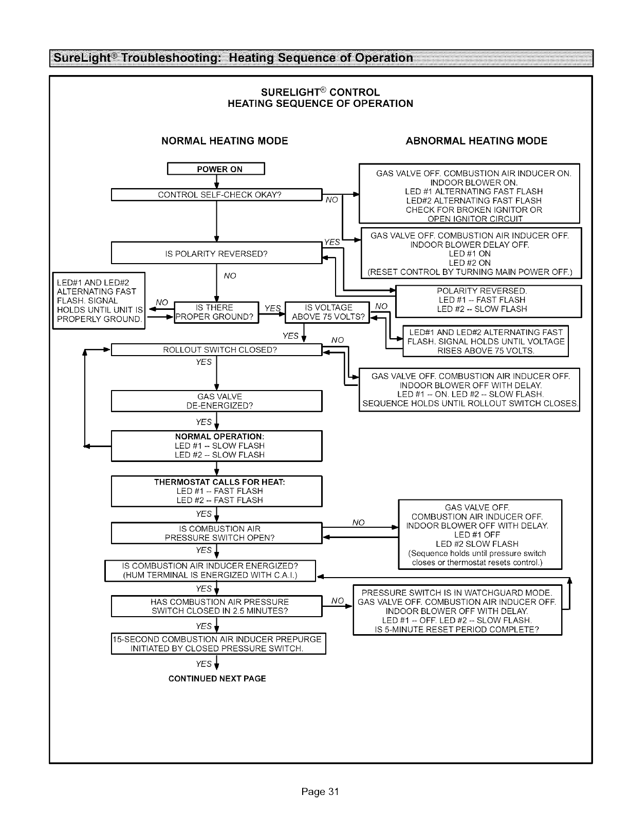
SURELIGHT®CONTROL
HEATING SEQUENCE OF OPERATION
NORMAL HEATING MODE ABNORMAL HEATING MODE
IPOWER ON ]I GAS VALVE OFF. COMBUSTION AIR INDUCER ON.
_' I INDOOR BLOWER ON.
CONTROL SELF-CHECK OKAY'_ I,_ _ LED #1 ALTERNATING FAST FLASH
I";NO | LED#2 ALTERNATING FAST FLASH
I | CHECK FOR BROKEN IGNITOR OR
-I GAS VALVE OFF. COMBUSTION AIR INDUCER OFF.
vaYES _ INDOOR BLOWER DELAY OFF.
,sPOLARITYREVERSED? _1 I LED#1ON
I i- I I I LED #2 ON
IINO /I I (R__ TURNING MAIN POWER OFF)
LED#1 AND LED#2 /
ALTERNATING FAST J_ 1' _ POLARITY REVERSED.
FLASH, SIGNAL NO • I LED #1 -- FAST FLASH
HOLDS UNTIL UNIT IS| ._--I ISTHERE IYESI ISVOLTAGE INO ILED #2 -- SLOW FLASH
PROPERLY GROUNDi_I PROPER GROUND? _ ABOVE 75 VOLTS? I_-----I'
-- ' YES/ II _I LED#1ANDLED#2ALTERNATINGFASTI
•NO I'--ml FLASH. SIGNAL HOLDS UNTIL VOLTAGE I
_I ROLLOUT SWITCH CLOSED? _ I_ I RISES ABOVE 75 VOLTS. I
YESi in,--
| I1"I"1 GAS VALVE OFF. COMBUSTION AIR INDUCER OFF.
'_ _1 INDOOR BLOWER OFF WITH DELAY.
GAS VALVE I I LED #1 -- ON. LED #2 -- SLOW FLASH,
I DE-ENERGIZED? I ISEQUENCE HOLDS UNTIL ROLLOUT SWITCH CLOSES.
I
i
YEs_
NORMAL OPERATION: I
LED #1 -- SLOW FLASH
LED #2 -- SLOW FLASH
THERMOSTAT CALLS FOR HEAT: I
LED #1 -- FAST FLASH ILED #2 -- FAST FLASH
YES NO
IS COMBUSTION AIR I
PRESSURE SWITCH OPEN? 14
YES _1
I IS COMBUSTION AIR INDUCER ENERGIZED?
(HUM TERMINAL IS ENERGIZED WITH C.A.I.) 4
1_
HAS COMBUSTION AIR PRESSURESWITCH CLOSED IN 2.5 MINUTES?
YES
15-SECOND COMBUSTION AIR INDUCER PREPURGE I
| N T ATED BY CLOSED PRESSURE SW TCH. I
m
YES
CONTINUED NEXT PAGE
GAS VALVE OFF.
COMBUSTION AIR INDUCER OFF.
INDOOR BLOWER OFF WITH DELAY.
LED #1 OFF
LED #2 SLOW FLASH
(Sequence holds until pressure switch
closes or thermostat resets control,)
PRESSURE SWITCH IS IN WATCHGUARD MODE.
GAS VALVE OFF. COMBUSTION AIR INDUCER OFF.
INDOOR BLOWER OFF WITH DELAY,
LED #1 -- OFF. LED #2 -- SLOW FLASH,
IS 5-MINUTE RESET PERIOD COMPLETE?
Page 31
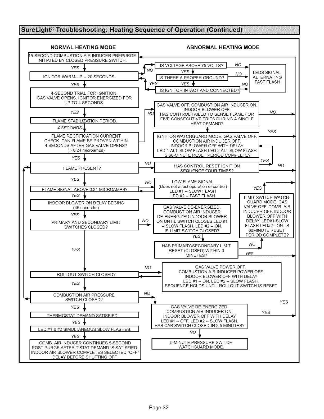
NORMAL HEATING MODE
15-SECOND COMBUSTION AIR INDUCER PREPURGE 9
N T ATED BY CLOSED PRESSURE SW TCH.
YES _
I IGNITOR WARM-UP -- 20 SECONDS.
YES
I 4-SECOND TRIAL FOR IGNITION.
GAS VALVE OPENS, IGNITOR ENERGIZED FOR
UP TO 4 SECONDS,
YES
I FLAME STABILIZATION PERIOD.
4 SECONDS
FLAME RECTIFICATION CURRENT
CHECK. CAN FLAME BE PROVEN WITHIN
4 SECONDS AFTER GAS VALVE OPENS?
( > 0.24 microamps)
YES _
ABNORMAL HEATING MODE
FLAME PRESENT?
YES _
I FLAME SIGNAL ABOVE 0.31 MICROAMPS?
YES _
I INDOOR BLOWER ON DELAY BEGINS
(45 seconds,)
YES _1
PRIMARY AND SECONDARY LIMITSWITCHES CLOSED?
YES
÷1
I
I
I ROLLOUT SWITCH CLOSED?
q
YES _
COMBUSTION AIR PRESSURE
SWITCH CLOSED?
YES _
THERMOSTAT DEMAND SATISFIED.
YES
LED #1 & #2 SIMULTANEOUS SLOW FLASHES.
YES _
COMB. AIR INDUCER CONTINUES 5-SECOND
POST PURGE AFTER T'STAT DEMAND IS SATISFIED,
INDOOR AIR BLOWER COMPLETES SELECTED "OFF"
DELAY BEFORE SHUTTING OFF.
-_O S VOLTAGE ABOVE 75 VOLTS?
YES_ . NO I
_IIW ISTHERE A PROPER GROUND? I--=-_l
YES_t INOI
ISIGNITOR INTACT AND CONNECTED?I_"I
LEDS SIGNAL
ALTERNATING
FAST FLASH
I GAS VALVE OFF. COMBUSTION AIR INDUCER ON.
INDOOR BLOWER OFF. I
HAS CONTROL FA LED TO SENSE FLAME FOR NO
FIVE CONSECUTIVE TRIES DURING A SINGLE
I HEAT DEMAND?
t
I_ IGNITION WATCHGUARD MODE. GAS VALVE OFF. I YES
COMBUSTION AIR INDUCER OFF. |
INDOOR BLOWER OFF WITH DELAY
LED 1 ALT. SLOW FLASH LED 2 ALT SLOW FLASH I I
IS 60-MINUTE RESET PERIOD COMPLETE? I,.__ I
_,Z_._I
HASCONTROLRESET,GN,T,ON
I I SEQUENCE FOUR TIMES? /
NO
- I
I
F-
LOW FLAME SIGNAL
(Does not affect operation of control)
LED #1 -- SLOW FLASH
LED #2 -- FAST FLASH
GAS VALVE DE-ENERGIZED
COMBUSTION AIR INDUCER
DE-ENERGIZED.INDOOR BLOWER
ON UNTIL SWITCH CLOSES.LED #1
-- SLOW FLASH, LED #2 -- ON.
IS LIMIT SWITCH CLOSED?
YES
HAS PRIMARY/SECONDARY LIMIT
RESET (CLOSED) WITHIN 3
MINUTES?
YESl
LIMIT SWITCH WATCH-
GUARD MODE. GAS
VALVE OFF. COMB. AIR
INDUCER OFF. INDOOR
BLOWER OFF WITH
DELAY, LED#I-SLOW
FLASH LED#2 - ON. IS
60MINUTE RESET
PERIOD COMPLETE?
YES
NO
I
I
GAS VALVE POWER OFR
COMBUSTION AIR INDUCER POWER OFF.
INDOOR BLOWER OFF WITH DELAY
LED #1 -- ON. LED #2 -- SLOW FLASH,
SEQUENCE HOLDS UNTIL ROLLOUT SWITCH IS RESET
I GAS VALVE DE-ENERGIZED
COMBUSTION AIR INDUCER ON.
INDOOR BLOWER OFF WITH DELAY
LED #1 -- OFF. LED #2 -- SLOW FLASH,
HAS CAB SWITCH CLOSED IN 2.5 MINUTES?
NO_
I 5-MINUTE PRESSURE SWITCH
WATCHGUARD MODE,
YES
YES
]
Ii
Page 32
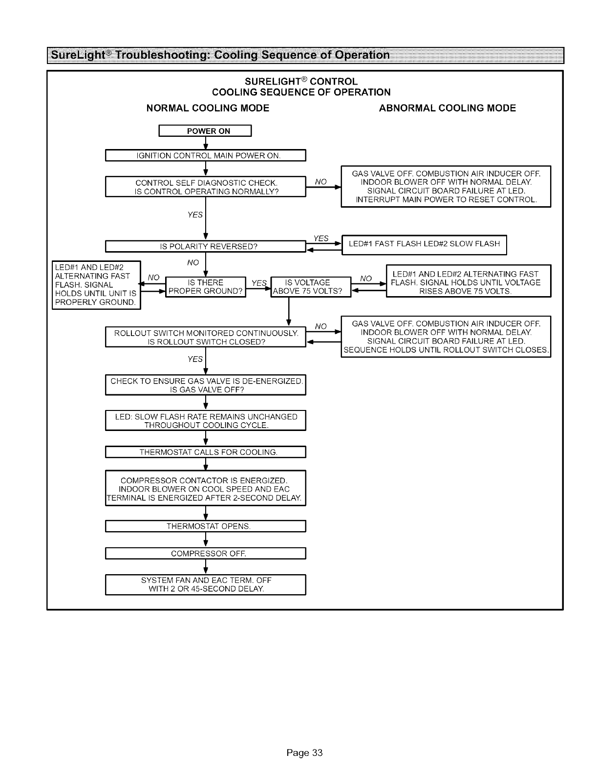
SURELIGHT®CONTROL
COOLINGSEQUENCEOF OPERATION
NORMALCOOLING MODE ABNORMALCOOLING MODE
I POWER ON l
I IGNITIONCONTROLMA,NPOWERON I
I CO.T O S O,A .OS ,OO. OKIS CONTROL OPERATING NORMALLY?
GAS VALVE OFF, COMBUSTION AIR INDUCER OFR
INDOOR BLOWER OFF WITH NORMAL DELAY.
SIGNAL CIRCUIT BOARD FAILURE AT LED.
INTERRUPT MAIN POWER TO RESET CONTROL,
Y sJ
I ,sPOLARITYREVERSED?_ LED_IFASTFLASHLED_2SLOWFLASHI
/
LED#1 AND LED#2 NO |
ALTERNATING FAST I NO _ __ _ LED#1 AND LED#2 ALTERNATING FAST
FLASH. SIGNAL _ IS THERE I YESJ Is VOLTAGE FLASH. SIGNAL HOLDS UNTIL VOLTAGE
I HOLDS UNTIL UNIT IS I_1 PROPER GROUND? I_IABOVE 75 VOLTS? I_' RISES ABOVE 75 VOLTS.
[PROPERLY GROUND. I I
•NO I GAS VALVE OFF COMBUSTION AIR INDUCER OFF
I ROLLOUT SWITCH MONITORED CONTINUOUSLY. _ INDOOR BLOWER OFF WITH NORMAL DELAY.
IS ROLLOUT SWITCH CLOSED? I_--I SIGNAL CIRCUIT BOARD FAILURE AT LED,
YESl - ISEQUENCEHOLDS UNTIL ROLLOUT SWITCH CLOSES.
t
I CHECK TO ENSURE GAS VALVE IS DE-ENERGIZED.
S GAS VALVE OFF?
I LED:SLOW FLASHRATEREMAINSUNCHANGED ITHROUGHOUT COOLING CYCLE.
ITHERMOSTAT CALLS FOR COOLING. I
COMPRESSOR CONTACTOR IS ENERGIZED,
INDOOR BLOWER ON COOL SPEED AND EAC
TERM NAL S ENERG ZED AFTER 2-SECOND DELAY,
THERMOSTAT OPENS. I
COMPRESSOR OFF. I
SYSTEM FAN AND EAC TERM, OFF I
WITH 2 OR 45-SECOND DELAY, I
I
I
I
Page 33

I
SURELIGHT ® CONTROL
CONTINUOUS FAN SEQUENCE OF OPERATION
I!
LED: SLOW FLASH RATE REMAINS I
I
UNCHANGED THROUGHOUT SEQUENCE.
MANUAL FAN SELECTION MADE AT THERMOSTAT.
CONTROL (G) ENERGIZES INDOOR BLOWER AT
FAN SPEED. EAC TERM. IS ENERGIZED.
/
THERMOSTAT CALLS FOR HEAT (W). I--l't
/
NO
THERMOSTAT CALLS FOR COOLING.
_YES
INDOOR BLOWER SWITCHES TO COOL SPEED.
THERMOSTAT OPENS.
1
t
YEs I
AFTER NORMAL DELAY.
I THERMOSTAT OPENS. COMBUSTION AIR INDUCER I
AND HUM TERMINAL ARE DE-ENERGIZED.
JINDOOR BLOWER SELECTED TIME OFF DELAY BEGINS. I
I
I
AFTER DELAY HEAT SPEED DE-ENERGIZED.
(bower rema ns energ zed dur ng cont nuous fan mode).
INDOOR BLOWER SWITCHES TO FAN "4
J
SPEED, EAC TERM, REMAINS ENERGIZED,
HUM TERM. ENERGIZES
WITH COMB. AIR INDUCER.
Page 34

JobName
JobLocation
JobNo.
City
Date
State
Installer
UnitModelNo.
SerialNo.
HeatingSection
ElectricalConnectionsTight?
SupplyVoltage
BlowerMotorAmps []
FuelType:NaturalGas?
FurnaceBtuInput
City
Technician
State
[]
[]
Blower Motor H.P.
Gas Piping Connections
Tight & Leak-Tested?
LP/Propane Gas? []
D
Line Pressure
Regulator Pressure
Flue Connections Tight?
Combustion Gas Tested?
Fan Control Setting
(45 Seconds Fixed On)
Fan Control Off Setting
Filter Clean & Secure?
Thermostat
w.c. _Nat,: w.c. - LP/Propane
[] Proper Draft? []
[] 002 [] co
Temperature Rise
Calibrated? []
[] Vent Clear? []
Heat Anticipator Properly Set? [] Level? []
Page 35
