Lenovo 53Y6319 Hardware Maintenance Manual User A58 Desktop (Think Centre) Type 7705
2011-01-04
User Manual: Lenovo 53Y6319 Hardware Maintenance Manual A58 Desktop (ThinkCentre) - Type 7705 7705
Open the PDF directly: View PDF ![]() .
.
Page Count: 292 [warning: Documents this large are best viewed by clicking the View PDF Link!]
- Contents
- Chapter 1. About this manual
- Chapter 2. Safety information
- Chapter 3. General information
- Chapter 4. General checkout
- Chapter 5. Diagnostics
- Chapter 6. Using the Setup Utility program
- Chapter 7. Symptom-to-FRU index
- Chapter 8. Replacing FRUs (Machine types: 7515, 7523, 7569, and 7611.)
- Locating connectors on the front of your computer
- Locating connectors on the rear of your computer
- Removing the computer cover
- Locating components
- Locating parts on the system board
- Removing and reinstalling the front bezel
- Installing or replacing a memory module
- Installing or replacing a PCI card
- Replacing the battery
- Replacing the power supply assembly
- Replacing the heat sink and fan assembly
- Replacing the microprocessor
- Replacing the system board
- Replacing the primary hard disk drive
- Replacing the secondary hard disk drive
- Replacing the optical drive
- Replacing the diskette drive or card reader
- Replacing the front fan assembly
- Replacing the rear fan assembly
- Replacing the internal speaker
- Replacing the front audio and USB assembly
- Completing the FRU replacement
- Chapter 9. Replacing FRUs (Machine types: 7522, 7560, 7610, and 7705.)
- Locating connectors on the front of your computer
- Locating connectors on the rear of your computer
- Opening the computer cover
- Accessing the system board components and drives
- Locating components
- Locating parts on the system board
- Installing or replacing a memory module
- Installing or replacing an adapter card
- Replacing the battery
- Replacing the hard disk drive
- Replacing the optical drive
- Replacing the power supply assembly
- Replacing the heat sink and fan assembly
- Replacing the microprocessor
- Replacing the system board
- Replacing the card reader
- Replacing the front audio and USB assembly
- Replacing the internal speaker
- Completing the FRU replacement
- Chapter 10. FRU lists
- Chapter 11. Additional service information
- Appendix. Notices
- Index

Machine Types: 7515, 7522, 7523, 7560, 7569, 7610, 7611, and 7705
ThinkCentre
Hardware Maintenance Manual

ThinkCentre
Hardware Maintenance Manual

Note
Before using this information and the product it supports, be sure to read and understand the Chapter 2, “Safety
information,” on page 3 and “Notices,” on page 281.
Fifth Edition (December 2009)
© Copyright Lenovo 2009.
LENOVO products, data, computer software, and services have been developed exclusively at private expense and
are sold to governmental entities as commercial items as defined by 48 C.F.R. 2.101 with limited and restricted
rights to use, reproduction and disclosure.
LIMITED AND RESTRICTED RIGHTS NOTICE: If products, data, computer software, or services are delivered
pursuant a General Services Administration ″GSA″contract, use, reproduction, or disclosure is subject to restrictions
set forth in Contract No. GS-35F-05925.

Contents
Chapter 1. About this manual .....1
Important safety information .........1
Important information about replacing the RoHS
compliant FRUs .............2
Chapter 2. Safety information .....3
General safety ..............3
Electrical safety .............3
Voltage-selection switch...........5
Safety inspection guide ...........5
Handling electrostatic discharge-sensitive devices . . 6
Grounding requirements ..........7
Safety notices (multi-lingual translations) .....7
Chapter 3. General information ....39
Lenovo ThinkVantage Tools .........39
Lenovo Care ..............39
Access Help ..............39
Additional information resources .......40
Specifications ..............41
For machine types: 7515, 7523, 7569, and 7611.. . 41
For machine types: 7522, 7560, 7610, and 7705.. . 41
For all machine types ..........41
Chapter 4. General checkout .....43
Problem determination tips .........43
Chapter 5. Diagnostics ........45
Lenovo ThinkVantage Toolbox ........45
Lenovo System Toolbox ..........45
PC-Doctor for Rescue and Recovery ......46
PC-Doctor for DOS ............46
Creating a diagnostic disc ........46
Running the diagnostic program from the
diagnostic disc ............47
Navigating through the diagnostics programs . . 47
Running tests.............47
Viewing the test log ..........49
Chapter 6. Using the Setup Utility
program ..............51
Starting the Setup Utility program.......51
Viewing and changing settings ........51
Using passwords ............51
Password considerations .........52
Set Power-On Password .........52
Set Administrator Password ........52
Setting, changing, or deleting a password . . . 52
Enabling or disabling a device ........53
Selecting a startup device..........53
Selecting a temporary startup device .....53
Viewing or changing the startup device sequence 54
Exiting the Setup Utility program .......54
Chapter 7. Symptom-to-FRU index . . . 55
Hard disk drive boot error .........55
Power supply problems ..........55
Diagnostic error codes...........56
Beep symptoms .............77
POST error codes ............78
Miscellaneous error messages ........80
Undetermined problems ..........81
Chapter 8. Replacing FRUs (Machine
types: 7515, 7523, 7569, and 7611.) . . 83
Locating connectors on the front of your computer 84
Locating connectors on the rear of your computer 85
Removing the computer cover ........86
Locating components ...........88
Locating parts on the system board ......89
Removing and reinstalling the front bezel ....89
Installing or replacing a memory module ....90
Installing or replacing a PCI card .......92
Replacing the battery ...........95
Replacing the power supply assembly.....96
Replacing the heat sink and fan assembly ....98
Replacing the microprocessor ........100
Replacing the system board ........103
Replacing the primary hard disk drive .....105
Replacing the secondary hard disk drive ....107
Replacing the optical drive .........110
Replacing the diskette drive or card reader . . . 112
Replacing the front fan assembly .......113
Replacing the rear fan assembly .......115
Replacing the internal speaker........117
Replacing the front audio and USB assembly . . . 119
Completing the FRU replacement ......120
Chapter 9. Replacing FRUs (Machine
types: 7522, 7560, 7610, and 7705.) . . 123
Locating connectors on the front of your computer 124
Locating connectors on the rear of your computer 125
Opening the computer cover ........126
Accessing the system board components and
drives ................127
Locating components ...........128
Locating parts on the system board ......129
Installing or replacing a memory module ....130
Installing or replacing an adapter card .....132
Replacing the battery ...........134
Replacing the hard disk drive ........136
Replacing the optical drive .........137
Replacing the power supply assembly .....140
Replacing the heat sink and fan assembly ....142
Replacing the microprocessor ........144
Replacing the system board ........147
Replacing the card reader .........149
Replacing the front audio and USB assembly . . . 150
Replacing the internal speaker........151
© Copyright Lenovo 2009 iii
Completing the FRU replacement ......155
Chapter 10. FRU lists ........157
Machine type 7515 ...........157
Machine type 7522 ...........175
Machine type 7523 ...........193
Machine type 7560 ...........206
Machine type 7569 ...........220
Machine type 7610 ...........233
Machine type 7611............247
Machine type 7705 ...........262
Chapter 11. Additional service
information ............277
Security features ............277
Hardware controlled Passwords ......277
Operating system password .......277
Vital product data ...........277
BIOS levels ..............277
Updating (flashing) BIOS from a disc .....278
Updating (flashing) BIOS from your operating
system ...............278
Recovering from a POST/BIOS update failure . . 278
Power management ...........279
Automatic configuration and power interface
(ACPI)BIOS.............279
Automatic Power-On features .......279
Appendix. Notices .........281
Television output notice ..........282
Trademarks ..............282
Index ...............283
iv Hardware Maintenance Manual

Chapter 1. About this manual
This manual contains service and reference information for ThinkCentre®computer
machine types listed on the front cover. All the information in this manual is
intended only for trained Service Providers who are familiar with Lenovo®
computer products. Before using this information and the product it supports, be
sure to read and understand the Chapter 2, “Safety information,” on page 3 and
“Notices,” on page 281.
The “Symptom-to-FRU Index” chapter and the “Additional service information”
chapter apply to all ThinkCentre computers.
This manual includes a complete field replaceable unit (FRU) part number list for
each machine type listed on the front cover. If you have Internet access, the FRU
part number lists are also available at:
http://www.lenovo.com/support
Important safety information
Be sure to read and understand all caution and danger statements in this manual
before performing any of the instructions.
Veuillez lire toutes les consignes de type DANGER et ATTENTION du présent
document avant d’exécuter les instructions.
Lesen Sie unbedingt alle Hinweise vom Typ ″ACHTUNG″oder ″VORSICHT″in
dieser Dokumentation, bevor Sie irgendwelche Vorgänge durchführen
Leggere le istruzioni introdotte da ATTENZIONE e PERICOLO presenti nel
manuale prima di eseguire una qualsiasi delle istruzioni
Certifique-se de ler todas as instruções de cuidado e perigo neste manual antes de
executar qualquer uma das instruções
Es importante que lea todas las declaraciones de precaución y de peligro de este
manual antes de seguir las instrucciones.
© Copyright Lenovo 2009 1
Important information about replacing the RoHS compliant FRUs
RoHS, the Restriction of Hazardous Substances in Electrical and Electronic
Equipment Directive (2002/95/EC) is a European Union legal requirement
affecting the global electronics industry. RoHS requirements must be
implemented on Lenovo products placed on the market and sold in the
European Union after June 2006. Products on the market before June 2006 are
not required to have RoHS compliant parts. If the parts are not compliant
originally, replacement parts can also be noncompliant, but in all cases, if the
parts are compliant, the replacement parts must also be compliant.
Note: RoHS and non-RoHS FRU parts with the same fit and function are identified
with unique FRU part numbers.
Lenovo plans to transition to RoHS compliance well before the implementation
date and expects its suppliers to be ready to support the requirements and
schedule of Lenovo in the European Union. Products sold in 2005 will contain
some RoHS compliant FRUs. The following statement pertains to these products
and any product Lenovo produces containing RoHS compliant parts.
RoHS compliant ThinkCentre parts have unique FRU part numbers. Before or after
June 2006, failed RoHS compliant parts must always be replaced using RoHS
compliant FRUs, so only the FRUs identified as compliant in the Hardware
Maintenance Manual (HMM) or direct substitutions for those FRUs can be used.
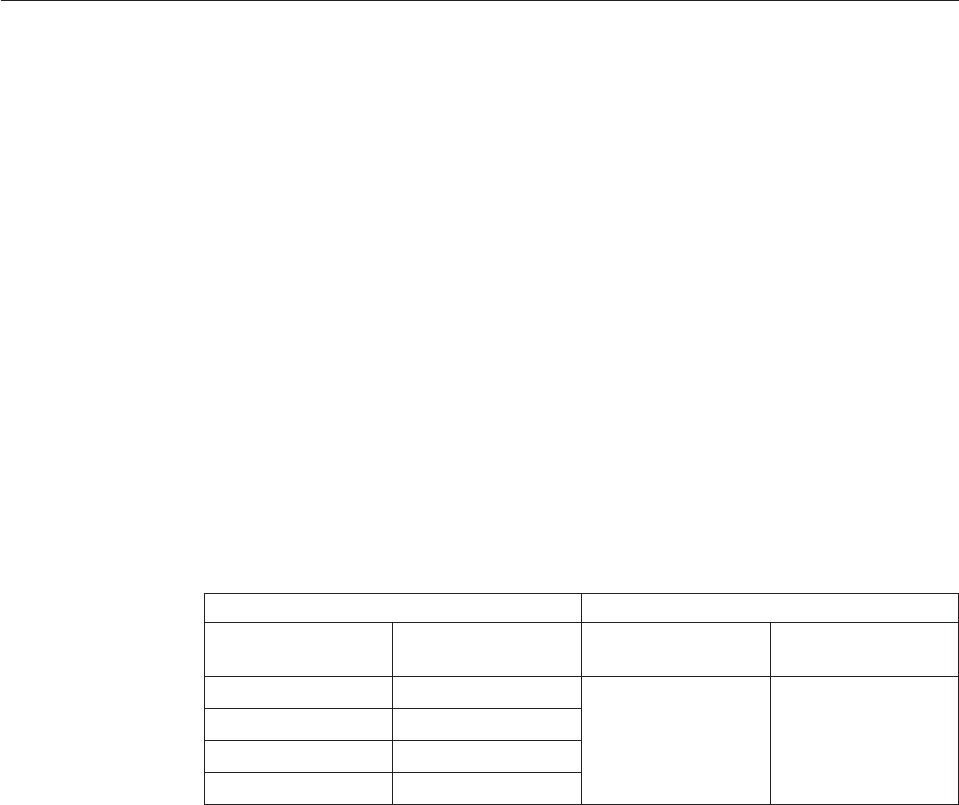
Products marketed before June 2006 Products marketed after June 2006
Current or original
part
Replacement FRU Current or original
part
Replacement FRU
Non-RoHS Can be Non-RoHS Must be RoHS Must be RoHS
Non-RoHS Can be RoHS
Non-RoHS Can sub to RoHS
RoHS Must be RoHS
Note: A direct substitution is a part with a different FRU part number that is
automatically shipped by the distribution center at the time of order.
2Hardware Maintenance Manual

Chapter 2. Safety information
This chapter contains the safety information that you need to read and understand
before servicing a computer.
General safety
Follow these rules to ensure general safety:
vObserve good housekeeping in the area of the machines during and after
maintenance.
vWhen lifting any heavy object:
1. Ensure you can stand safely without slipping.
2. Distribute the weight of the object equally between your feet.
3. Use a slow lifting force. Never move suddenly or twist when you attempt to
lift.
4. Lift by standing or by pushing up with your leg muscles; this action removes
the strain from the muscles in your back. Do not attempt to lift any objects that
weigh more than 16 kg (35 lb) or objects that you think are too heavy for you.
vDo not perform any action that causes hazards to the customer, or that makes
the equipment unsafe.
vBefore you start the machine, ensure that other service representatives and the
customer’s personnel are not in a hazardous position.
vPlace removed covers and other parts in a safe place, away from all personnel,
while you are servicing the machine.
vKeep your tool case away from walk areas so that other people will not trip over
it.
vDo not wear loose clothing that can be trapped in the moving parts of a
machine. Ensure that your sleeves are fastened or rolled up above your elbows.
If your hair is long, fasten it.
vInsert the ends of your necktie or scarf inside clothing or fasten it with a
nonconductive clip, approximately 8 centimeters (3 inches) from the end.
vDo not wear jewelry, chains, metal-frame eyeglasses, or metal fasteners for your
clothing.
Remember: Metal objects are good electrical conductors.
vWear safety glasses when you are: hammering, drilling, soldering, cutting wire,
attaching springs, using solvents, or working in any other conditions that might
be hazardous to your eyes.
vAfter service, reinstall all safety shields, guards, labels, and ground wires.
Replace any safety device that is worn or defective.
vReinstall all covers correctly before returning the machine to the customer.
Electrical safety
© Copyright Lenovo 2009 3
CAUTION:
Electrical current from power, telephone, and communication cables can be
hazardous. To avoid personal injury or equipment damage, disconnect the
attached power cords, telecommunication systems, networks, and modems before
you open the server/workstation covers, unless instructed otherwise in the
installation and configuration procedures.
Observe the following rules when working on electrical equipment.
Important: Use only approved tools and test equipment. Some hand tools have
handles covered with a soft material that does not insulate you when
working with live electrical currents.
Many customers have, near their equipment, rubber floor mats that
contain small conductive fibers to decrease electrostatic discharges. Do
not use this type of mat to protect yourself from electrical shock.
vFind the room emergency power-off (EPO) switch, disconnecting switch, or
electrical outlet. If an electrical accident occurs, you can then operate the switch
or unplug the power cord quickly.
vDo not work alone under hazardous conditions or near equipment that has
hazardous voltages.
vDisconnect all power before:
– Performing a mechanical inspection
– Working near power supplies
– Removing or installing Field Replaceable Units
vBefore you start to work on the machine, unplug the power cord. If you cannot
unplug it, ask the customer to power-off the wall box that supplies power to the
machine and to lock the wall box in the off position.
vIf you need to work on a machine that has exposed electrical circuits, observe
the following precautions:
– Ensure that another person, familiar with the power-off controls, is near you.
Remember: Another person must be there to switch off the power, if
necessary.
– Use only one hand when working with powered-on electrical equipment;
keep the other hand in your pocket or behind your back.
Remember: There must be a complete circuit to cause electrical shock. By
observing the above rule, you may prevent a current from passing through
your body.
– When using testers, set the controls correctly and use the approved probe
leads and accessories for that tester.
– Stand on suitable rubber mats (obtained locally, if necessary) to insulate you
from grounds such as metal floor strips and machine frames.
Observe the special safety precautions when you work with very high voltages;
these instructions are in the safety sections of maintenance information. Use
extreme care when measuring high voltages.
vRegularly inspect and maintain your electrical hand tools for safe operational
condition.
vDo not use worn or broken tools and testers.
vNever assume that power has been disconnected from a circuit. First, check that it
has been powered-off.
4Hardware Maintenance Manual

vAlways look carefully for possible hazards in your work area. Examples of these
hazards are moist floors, nongrounded power extension cables, power surges,
and missing safety grounds.
vDo not touch live electrical circuits with the reflective surface of a plastic dental
mirror. The surface is conductive; such touching can cause personal injury and
machine damage.
vDo not service the following parts with the power on when they are removed
from their normal operating places in a machine:
– Power supply units
– Pumps
– Blowers and fans
– Motor generators
and similar units. (This practice ensures correct grounding of the units.)
vIf an electrical accident occurs:
– Use caution; do not become a victim yourself.
– Switch off power.
– Send another person to get medical aid.
Voltage-selection switch
Some computers are equipped with a voltage-selection switch located near the
power-cord connection point on the computer. If your computer has a
voltage-selection switch, ensure that you set the switch to match the voltage
available at your electrical outlet. Setting the voltage-selection switch incorrectly
can cause permanent damage to the computer.
If your computer does not have a voltage-selection switch, your computer is
designed to operate only at the voltage provided in the country or region where
the computer was originally purchased.
If you relocate your computer to another country, be aware of the following:
vIf your computer does not have a voltage-selection switch, do not connect the
computer to an electrical outlet until you have verified that the voltage provided
is the same as it was in the country or region where the computer was originally
purchased.
vIf your computer has a voltage-selection switch, do not connect the computer to
an electrical outlet until you have verified that the voltage-selection switch is set
to match the voltage provided in that country or region.
If you are not sure of the voltage provided at your electrical outlet, contact your
local electric company or refer to official Web sites or other literature for travelers
to the country or region where you are located.
Safety inspection guide
The intent of this inspection guide is to assist you in identifying potentially unsafe
conditions on these products. Each machine, as it was designed and built, had
required safety items installed to protect users and service personnel from injury.
This guide addresses only those items. However, good judgment should be used to
identify potential safety hazards due to attachment of features or options not
covered by this inspection guide.
Chapter 2. Safety information 5

If any unsafe conditions are present, you must determine how serious the apparent
hazard could be and whether you can continue without first correcting the
problem.
Consider these conditions and the safety hazards they present:
vElectrical hazards, especially primary power (primary voltage on the frame can
cause serious or fatal electrical shock).
vExplosive hazards, such as a damaged CRT face or bulging capacitor
vMechanical hazards, such as loose or missing hardware
The guide consists of a series of steps presented in a checklist. Begin the checks
with the power off, and the power cord disconnected.
Checklist:
1. Check exterior covers for damage (loose, broken, or sharp edges).
2. Power-off the computer. Disconnect the power cord.
3. Check the power cord for:
a. A third-wire ground connector in good condition. Use a meter to measure
third-wire ground continuity for 0.1 ohm or less between the external
ground pin and frame ground.
b. The power cord should be the appropriate type as specified in the parts
listings.
c. Insulation must not be frayed or worn.
4. Remove the cover.
5. Check for any obvious alterations. Use good judgment as to the safety of any
alterations.
6. Check inside the unit for any obvious unsafe conditions, such as metal filings,
contamination, water or other liquids, or signs of fire or smoke damage.
7. Check for worn, frayed, or pinched cables.
8. Check that the power-supply cover fasteners (screws or rivets) have not been
removed or tampered with.
Handling electrostatic discharge-sensitive devices
Any computer part containing transistors or integrated circuits (ICs) should be
considered sensitive to electrostatic discharge (ESD). ESD damage can occur when
there is a difference in charge between objects. Protect against ESD damage by
equalizing the charge so that the machine, the part, the work mat, and the person
handling the part are all at the same charge.
Notes:
1. Use product-specific ESD procedures when they exceed the requirements noted
here.
2. Make sure that the ESD protective devices you use have been certified (ISO
9000) as fully effective.
When handling ESD-sensitive parts:
vKeep the parts in protective packages until they are inserted into the product.
vAvoid contact with other people while handling the part.
vWear a grounded wrist strap against your skin to eliminate static on your body.
6Hardware Maintenance Manual
vPrevent the part from touching your clothing. Most clothing is insulative and
retains a charge even when you are wearing a wrist strap.
vUse the black side of a grounded work mat to provide a static-free work surface.
The mat is especially useful when handling ESD-sensitive devices.
vSelect a grounding system, such as those listed below, to provide protection that
meets the specific service requirement.
Note: The use of a grounding system is desirable but not required to protect
against ESD damage.
– Attach the ESD ground clip to any frame ground, ground braid, or green-wire
ground.
– Use an ESD common ground or reference point when working on a
double-insulated or battery-operated system. You can use coax or
connector-outside shells on these systems.
– Use the round ground-prong of the ac plug on ac-operated computers.
Grounding requirements
Electrical grounding of the computer is required for operator safety and correct
system function. Proper grounding of the electrical outlet can be verified by a
certified electrician.
Safety notices (multi-lingual translations)
The caution and danger safety notices in this section are provided in the following
languages:
vEnglish
vArabic
vBrazilian Portuguese
vSimplified Chinese
vTraditional Chinese
vFrench
vGerman
vHebrew
vItalian
vKorean
vSpanish
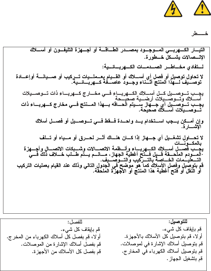
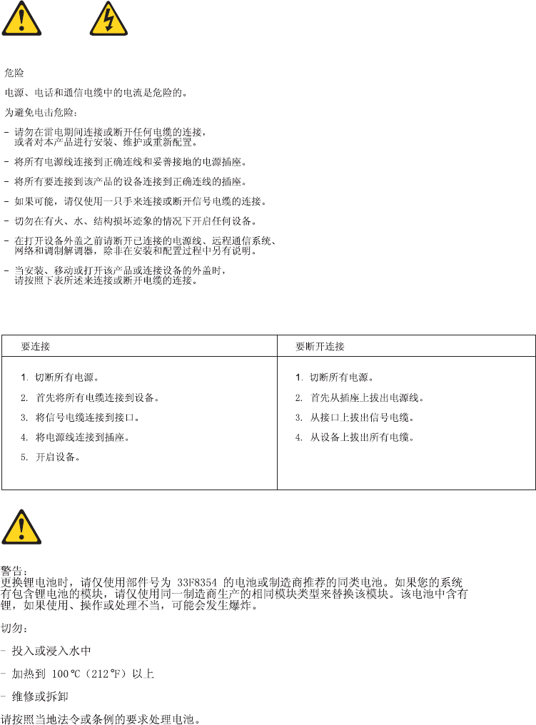
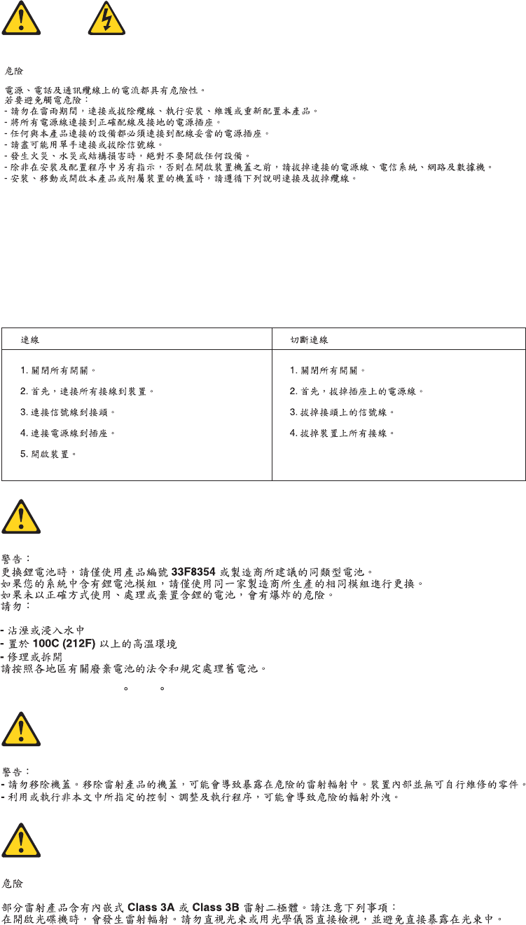
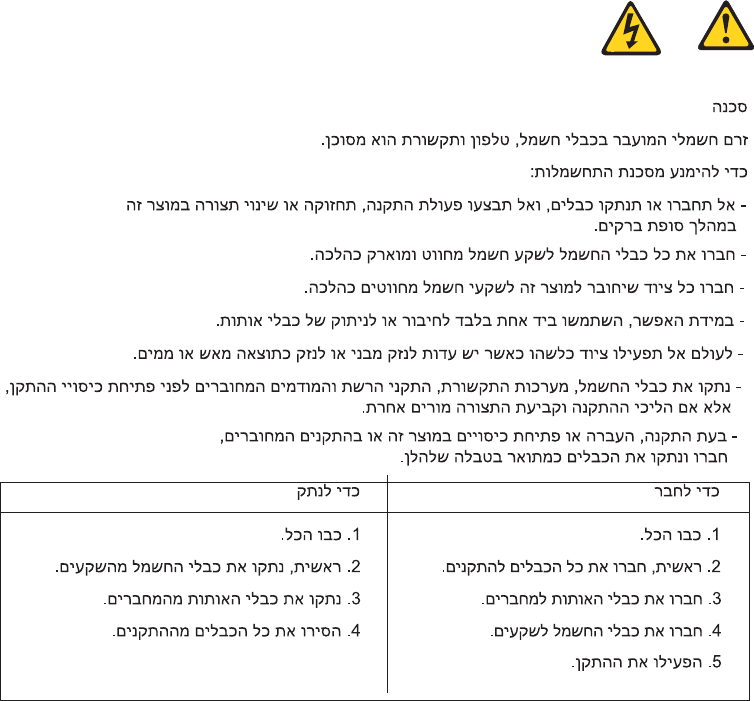
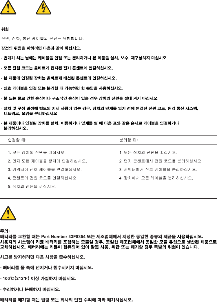
DANGER
Electrical current from power, telephone and communication cables is hazardous.
To avoid a shock hazard:
vDo not connect or disconnect any cables or perform installation, maintenance,
or reconfiguration of this product during an electrical storm.
vConnect all power cords to a properly wired and grounded electrical outlet.
Chapter 2. Safety information 7

vConnect to properly wired outlets any equipment that will be attached to this
product.
vWhen possible, use one hand only to connect or disconnect signal cables.
vNever turn on any equipment when there is evidence of fire, water, or
structural damage.
vDisconnect the attached power cords, telecommunications systems, networks,
and modems before you open the device covers, unless instructed otherwise
in the installation and configuration procedures.
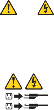
vConnect and disconnect cables as described in the following tables when
installing, moving, or opening covers on this product or attached devices.
To Connect To Disconnect
1. Turn everything OFF.
2. First, attach all cables to devices.
3. Attach signal cables to connectors.
4. Attach power cords to outlet.
5. Turn device ON.
1. Turn everything OFF.
2. First, remove power cords from outlet.
3. Remove signal cables from connectors.
4. Remove all cables from devices.
8Hardware Maintenance Manual
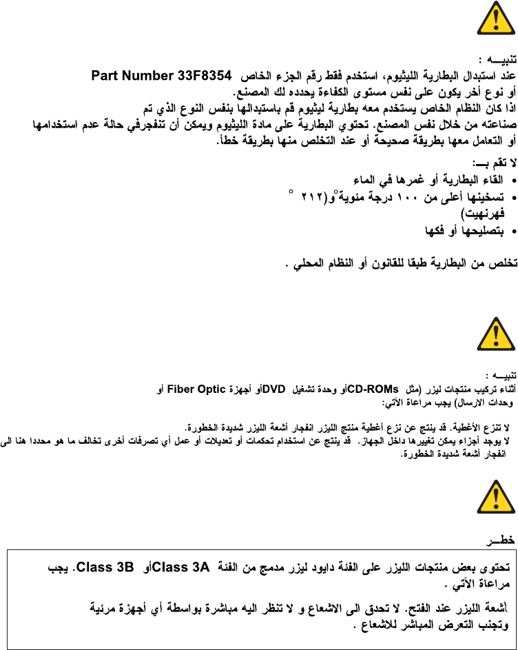
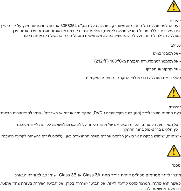
CAUTION:
When replacing the lithium battery, use only Part Number 33F8354 or an
equivalent type battery recommended by the manufacturer. If your system has a
module containing a lithium battery, replace it only with the same module type
made by the same manufacturer. The battery contains lithium and can explode if
not properly used, handled, or disposed of.
Do not:
vThrow or immerse into water
vHeat to more than 100°C (212°F)
vRepair or disassemble
Dispose of the battery as required by local ordinances or regulations.
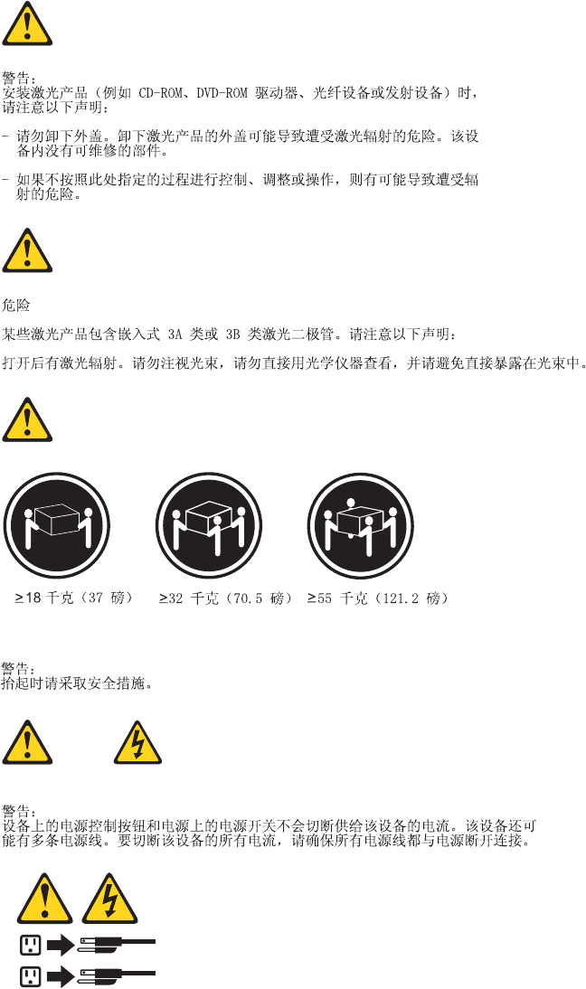
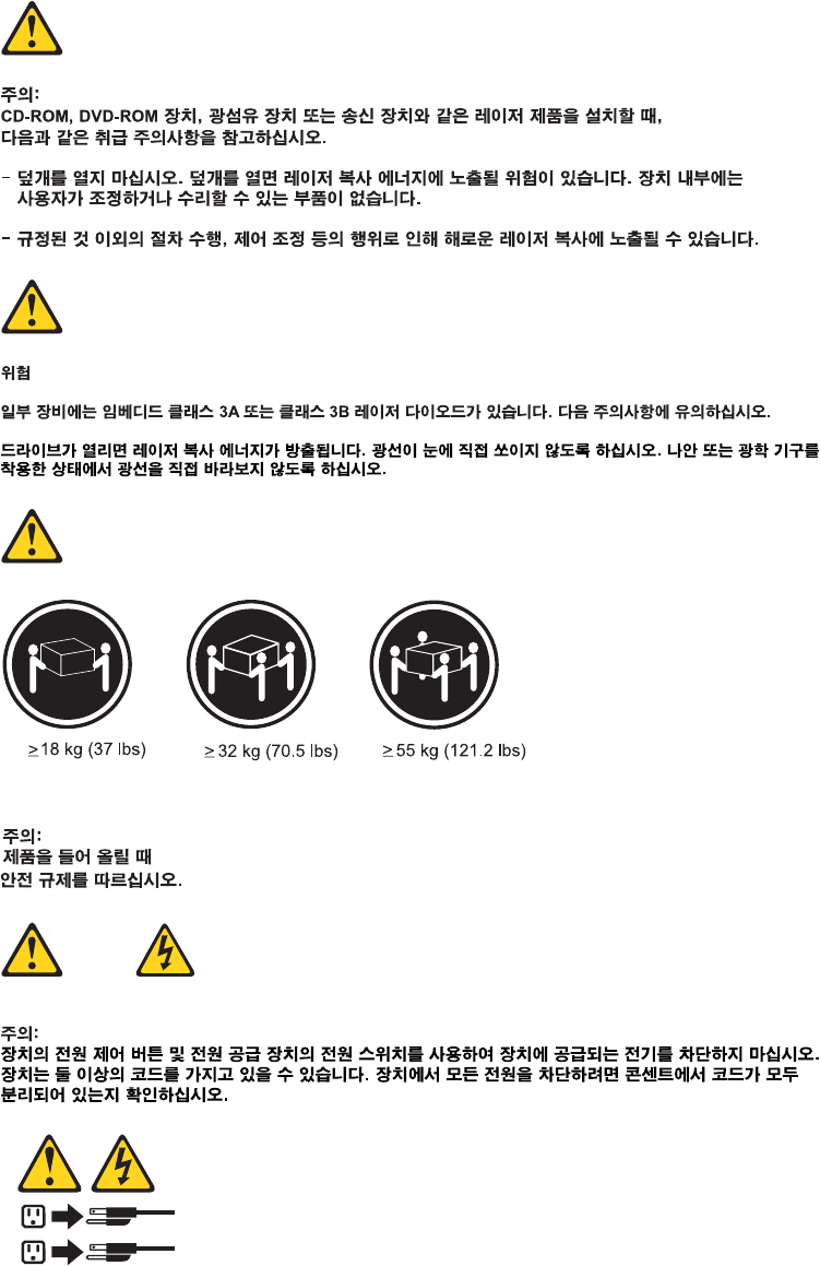
CAUTION:
When laser products (such as CD-ROMs, DVD-ROM drives, fiber optic devices,
or transmitters) are installed, note the following:
vDo not remove the covers. Removing the covers of the laser product could
result in exposure to hazardous laser radiation. There are no serviceable parts
inside the device.
vUse of controls or adjustments or performance of procedures other than those
specified herein might result in hazardous radiation exposure.
DANGER: Some laser products contain an embedded Class 3A or Class 3B laser
diode. Note the following:
Laser radiation when open. Do not stare into the beam, do not view
directly with optical instruments, and avoid direct exposure to the
beam.
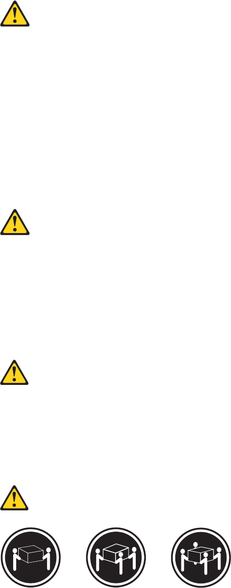
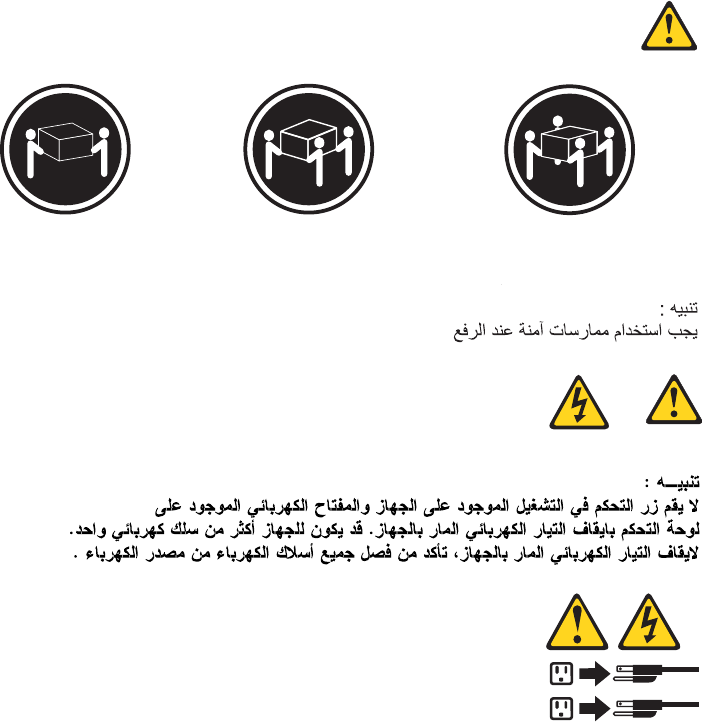
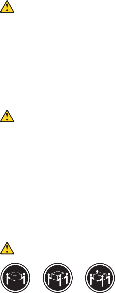
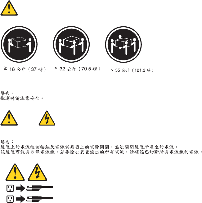
≥18 kg (37 lbs) ≥32 kg (70.5 lbs) ≥55 kg (121.2 lbs)
CAUTION:
Use safe practices when lifting.
Chapter 2. Safety information 9
CAUTION:
The power control button on the device and the power switch on the power
supply do not turn off the electrical current supplied to the device. The device
also might have more than one power cord. To remove all electrical current from
the device, ensure that all power cords are disconnected from the power source.
1
2
10 Hardware Maintenance Manual
Chapter 2. Safety information 11
12 Hardware Maintenance Manual
≥18 kg (37 lbs) ≥32 kg (70.5 lbs) ≥55 kg (121.2 lbs)
1
2
Chapter 2. Safety information 13

PERIGO
A corrente elétrica proveniente de cabos de alimentação, de telefone e de
comunicações é perigosa.
Para evitar risco de choque elétrico:
vNão conecte nem desconecte nenhum cabo ou execute instalação, manutenção
ou reconfiguração deste produto durante uma tempestade com raios.
vConecte todos os cabos de alimentação a tomadas elétricas corretamente
instaladas e aterradas.
vTodo equipamento que for conectado a este produto deve ser conectado a
tomadas corretamente instaladas.
vQuando possível, utilize apenas uma das mãos para conectar ou desconectar
cabos de sinal.
vNunca ligue nenhum equipamento quando houver evidência de fogo, água ou
danos estruturais.
vAntes de abrir tampas de dispositivos, desconecte cabos de alimentação,
sistemas de telecomunicação, redes e modems conectados, a menos que
especificado de maneira diferente nos procedimentos de instalação e
configuração.
vConecte e desconecte os cabos conforme descrito na tabela apresentada a seguir
ao instalar, mover ou abrir tampas deste produto ou de dispositivos conectados.
Para Conectar: Para Desconectar:
1. DESLIGUE Tudo.
2. Primeiramente, conecte todos os cabos
aos dispositivos.
3. Conecte os cabos de sinal aos
conectores.
4. Conecte os cabos de alimentação às
tomadas.
5. LIGUE os dispositivos.
1. DESLIGUE Tudo.
2. Primeiramente, remova os cabos de
alimentação das tomadas.
3. Remova os cabos de sinal dos conectores.
4. Remova todos os cabos dos dispositivos.
14 Hardware Maintenance Manual
CUIDADO:
Ao substituir a bateria de lítio, utilize apenas uma bateria com Número de Peça
33F8354 ou um tipo de bateria equivalente recomendado pelo Se o seu sistema
possui um módulo com uma bateria de lítio, substitua-o apenas por um módulo
do mesmo tipo e do mesmo fabricante. A bateria contém lítio e pode explodir se
não for utilizada, manuseada ou descartada de maneira correta.
Não:
vJogue ou coloque na água
vAqueça a mais de 100°C (212°F)
vConserte nem desmonte
Descarte a bateria conforme requerido pelas leis ou regulamentos locais.
PRECAUCIÓN:
Quando produtos a laser (como unidades de CD-ROMs, unidades de DVD-ROM,
dispositivos de fibra ótica ou transmissores) estiverem instalados, observe o
seguinte:
vNão remova as tampas. A remoção das tampas de um produto a laser pode
resultar em exposição prejudicial à radiação de laser. Não existem peças que
podem ser consertadas no interior do dispositivo.
vA utilização de controles ou ajustes ou a execução de procedimentos diferentes
dos especificados aqui pode resultar em exposição prejudicial à radiação.
PERIGO
Alguns produtos a laser contêm diodo de laser integrado da Classe 3A ou da
Classe 3B. Observe o seguinte:
Radiação a laser quando aberto. Não olhe diretamente para o feixe a olho nu ou
com instrumentos ópticos e evite exposição direta ao feixe.
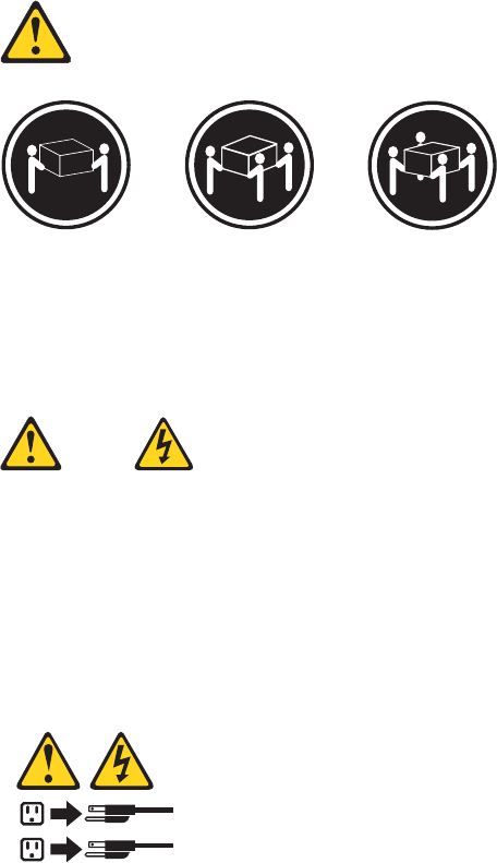
≥18 kg (37 lbs) ≥32 kg (70.5 lbs) ≥55 kg (121.2 lbs)
CUIDADO:
Utilize procedimentos de segurança para levantar equipamentos.
Chapter 2. Safety information 15
CUIDADO:
O botão de controle de alimentação do dispositivo e o botão para ligar/desligar da
fonte de alimentação não desligam a corrente elétrica fornecida ao dispositivo. O
dispositivo também pode ter mais de um cabo de alimentação. Para remover toda
a corrente elétrica do dispositivo, assegure que todos os cabos de alimentação
estejam desconectados da fonte de alimentação.
1
2
16 Hardware Maintenance Manual
Chapter 2. Safety information 17
1
2
18 Hardware Maintenance Manual
Chapter 2. Safety information 19
1
2
20 Hardware Maintenance Manual

DANGER
Le courant électrique provenant de l’alimentation, du téléphone et des câbles de
transmission peut présenter un danger.
Pour éviter tout risque de choc électrique :
vNe manipulez aucun câble et n’effectuez aucune opération d’installation,
d’entretien ou de reconfiguration de ce produit au cours d’un orage.
vBranchez tous les cordons d’alimentation sur un socle de prise de courant
correctement câblé et mis à la terre.
vBranchez sur des socles de prise de courant correctement câblés tout équipement
connecté à ce produit.
vLorsque cela est possible, n’utilisez qu’une seule main pour connecter ou
déconnecter les câbles d’interface.
vNe mettez jamais un équipement sous tension en cas d’incendie ou d’inondation,
ou en présence de dommages matériels.
vAvant de retirer les carters de l’unité, mettez celle-ci hors tension et déconnectez
ses cordons d’alimentation, ainsi que les câbles qui la relient aux réseaux, aux
systèmes de télécommunication et aux modems (sauf instruction contraire
mentionnée dans les procédures d’installation et de configuration).
vLorsque vous installez, que vous déplacez, ou que vous manipulez le présent
produit ou des périphériques qui lui sont raccordés, reportez-vous aux
instructions ci-dessous pour connecter et déconnecter les différents cordons.
Connexion Déconnexion
1. Mettez les unités HORS TENSION.
2. Commencez par brancher tous les
cordons sur les unités.
3. Branchez les câbles d’interface sur des
connecteurs.
4. Branchez les cordons d’alimentation sur
des prises.
5. Mettez les unités SOUS TENSION.
1. Mettez les unités HORS TENSION.
2. Débranchez les cordons d’alimentation
des prises.
3. Débranchez les câbles d’interface des
connecteurs.
4. Débranchez tous les câbles des unités.
Chapter 2. Safety information 21

ATTENTION:
Remplacer la pile au lithium usagée par une pile de référence identique
exclusivement, (référence 33F8354), ou suivre les instructions du fabricant qui en
définit les équivalences. Si votre système est doté d’un module contenant une
pile au lithium, vous devez le remplacer uniquement par un module identique,
produit par le même fabricant. La pile contient du lithium et peut exploser en
cas de mauvaise utilisation, de mauvaise manipulation ou de mise au rebut
inappropriée.
Ne pas :
vla jeter à l’eau,
vl’exposer à des températures supérieures à 100°C,
vchercher à la réparer ou à la démonter.
Ne pas mettre la pile à la poubelle. Pour la mise au rebut, se reporter à la
réglementation en vigueur.
ATTENTION:
Si des produits à laser (tels que des unités de CD-ROM, de DVD-ROM, des
unités à fibres optiques, ou des émetteurs) sont installés, prenez connaissance
des informations suivantes :
vNe retirez pas le carter. En ouvrant l’unité de CD-ROM ou de DVD-ROM,
vous vous exposez au rayonnement dangereux du laser. Aucune pièce de
l’unité n’est réparable.
vPour éviter tout risque d’exposition au rayon laser, respectez les consignes de
réglage et d’utilisation des commandes, ainsi que les procédures décrites dans
le présent manuel.
DANGER
Certains produits à laser contiennent une diode à laser intégrée de classe 3A ou
3B. Prenez connaissance des informations suivantes:
Rayonnement laser lorsque le carter est ouvert. Evitez toute expositiondirecte au
rayon laser. Evitez de regarder fixement le faisceau ou del’observer à l’aide
d’instruments optiques.
22 Hardware Maintenance Manual
≥18 kg (37 lbs) ≥32 kg (70.5 lbs) ≥55 kg (121.2 lbs)
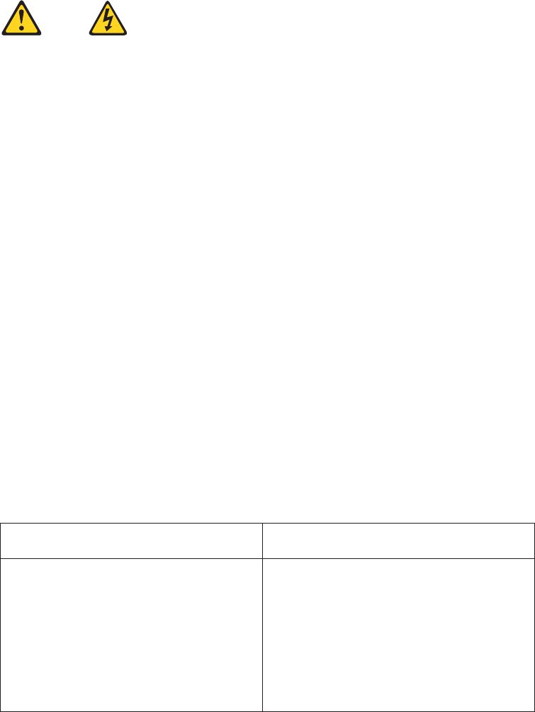
ATTENTION:
Soulevez la machine avec précaution.
ATTENTION:
L’interrupteur de contrôle d’alimentation de l’unité et l’interrupteur dubloc
d’alimentation ne coupent pas le courant électrique alimentantl’unité. En outre,
le système peut être équipé de plusieurs cordonsd’alimentation. Pour mettre
l’unité hors tension, vous devez déconnectertous les cordons de la source
d’alimentation.
1
2
Chapter 2. Safety information 23
VORSICHT
An Netz-, Telefon- und Datenleitungen können gefährliche Spannungen anliegen.
Aus Sicherheitsgründen:
vBei Gewitter an diesem Gerät keine Kabel anschließen oder lösen. Ferner
keine Installations-, Wartungs- oder Rekonfigurationsarbeiten durchführen.
vGerät nur an eine Schutzkontaktsteckdose mit ordnungsgemäß geerdetem
Schutzkontakt anschließen.
vAlle angeschlossenen Geräte ebenfalls an Schutzkontaktsteckdosen mit
ordnungsgemäß geerdetem Schutzkontakt anschließen.
vDie Signalkabel nach Möglichkeit einhändig anschließen oder lösen, um
einen Stromschlag durch Berühren von Oberflächen mit unterschiedlichem
elektrischem Potenzial zu vermeiden.
vGeräte niemals einschalten, wenn Hinweise auf Feuer, Wasser oder
Gebäudeschäden vorliegen.
vDie Verbindung zu den angeschlossenen Netzkabeln,
Telekommunikationssystemen, Netzwerken und Modems ist vor dem Öffnen
des Gehäuses zu unterbrechen, sofern in den Installations- und
Konfigurationsprozeduren keine anders lautenden Anweisungen enthalten
sind.
vZum Installieren, Transportieren und Öffnen der Abdeckungen des
Computers oder der angeschlossenen Einheiten die Kabel gemäß der
folgenden Tabelle anschließen und abziehen.
Zum Anschließen der Kabel gehen Sie
wie folgt vor
Zum Abziehen der Kabel gehen Sie wie
folgt vor
1. Schalten Sie alle Einheiten AUS.
2. Schließen Sie erst alle Kabel an die
Einheiten an.
3. Schließen Sie die Signalkabel an die
Buchsen an.
4. Schließen Sie die Netzkabel an die
Steckdose an.
5. Schalten Sie die Einheit EIN.
1. Schalten Sie alle Einheiten AUS.
2. Ziehen Sie zuerst alle Netzkabel aus den
Netzsteckdosen.
3. Ziehen Sie die Signalkabel aus den
Buchsen.
4. Ziehen Sie alle Kabel von den Einheiten
ab.
24 Hardware Maintenance Manual

CAUTION:
Eine verbrauchte Lithiumbatterie nur durch eine Batterie mit der Teilenummer
33F8354 oder eine gleichwertige, vom Hersteller empfohlene Batterie ersetzen.
Enthält das System ein Modul mit einer Lithiumbatterie, dieses nur durch ein
Modul desselben Typs und von demselben Hersteller ersetzen. Die Batterie enthält
Lithium und kann bei unsachgemäßer Verwendung, Handhabung oder Entsorgung
explodieren.
Die Batterie nicht:
vmit Wasser in Berührung bringen.
vüber 100 C erhitzen.
vreparieren oder zerlegen.
Die örtlichen Bestimmungen für die Entsorgung von Sondermüll beachten.
ACHTUNG:
Bei der Installation von Lasergeräten (wie CD-ROM-Laufwerken, DVD-
aufwerken, Einheiten mit Lichtwellenleitertechnik oder Sendern) Folgendes
beachten:
vDie Abdeckungen nicht entfernen. Durch Entfernen der Abdeckungen des
Lasergeräts können gefährliche Laserstrahlungen freigesetzt werden. Das
Gerät enthält keine zu wartenden Teile.
vWerden Steuerelemente, Einstellungen oder Durchführungen von Prozeduren
anders als hier angegeben verwendet, kann gefährliche Laserstrahlung
auftreten.
VORSICHT
Einige Lasergeräte enthalten eine Laserdiode der Klasse 3A oder 3B. Beachten
Sie Folgendes:
Laserstrahlung bei geöffneter Verkleidung. Nicht in den Strahl blicken. Keine
Lupen oder Spiegel verwenden. Strahlungsbereich meiden.
Chapter 2. Safety information 25
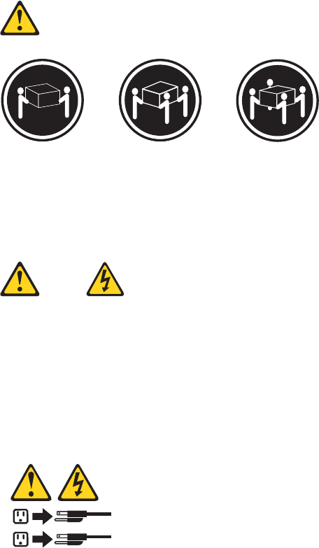
≥18 kg (37 lbs) ≥32 kg (70.5 lbs) ≥55 kg (121.2 lbs)
ACHTUNG:
Arbeitsschutzrichtlinien beim Anheben der Maschine beachten.
ACHTUNG:
Mit dem Netzschalter an der Einheit und am Netzteil wird die Stromversorgung
für die Einheit nicht unterbrochen. Die Einheit kann auch mit mehreren
Netzkabeln ausgestattet sein. Um die Stromversorgung für die Einheit
vollständig zu unterbrechen, müssen alle zum Gerät führenden Netzkabel vom
Netz getrennt werden.
1
2
26 Hardware Maintenance Manual
Chapter 2. Safety information 27
28 Hardware Maintenance Manual

1
2
Chapter 2. Safety information 29
PERICOLO
La corrente elettrica proveniente dai cavi di alimentazione, del telefono e di
comunicazione può essere pericolosa.
Per evitare il rischio di scosse elettriche:
vNon collegare o scollegare qualsiasi cavo oppure effettuare l’installazione, la
manutenzione o la riconfigurazione del prodotto durante un temporale.
vCollegare tutti i fili elettrici a una presa di alimentazione correttamente
cablata e dotata di messa a terra.
vCollegare alle prese elettriche appropriate tutte le apparecchiature che
verranno utilizzate per questo prodotto.
vSe possibile, utilizzare solo una mano per collegare o scollegare i cavi di
segnale.
vNon accendere assolutamente apparecchiature in presenza di incendi, perdite
d’acqua o danno strutturale.
vScollegare i cavi di alimentazione, i sistemi di telecomunicazione, le reti e il
modem prima di aprire i coperchi del dispositivo, salvo istruzioni contrarie
relative alle procedure di installazione e configurazione.
vCollegare e scollegare i cavi come descritto nella seguente tabella quando
vengono effettuate operazioni di installazione, spostamento o apertura dei
coperchi di questo prodotto o delle unità collegate.
Per collegarsi Per scollegarsi
1. SPEGNERE le apparecchiature.
2. Innanzitutto, collegare tutti i cavi alle
unità.
3. Collegare i cavi di segnale ai connettori.
4. Collegare i cavi di alimentazione alla
presa.
5. Accendere l’unità.
1. SPEGNERE le apparecchiature.
2. Innanzitutto, rimuovere i cavi di
alimentazione dalla presa.
3. Rimuovere i cavi di segnale dai
connettori.
4. Rimuovere tutti i cavi dalle unità.
30 Hardware Maintenance Manual

ATTENZIONE:
Quando si sostituisce la batteria al litio, utilizzare solo il Numero parte 33F8354
o un tipo di batteria equivalente consigliato dal produttore. Se sul sistema è
presente un modulo che contiene una batteria al litio, sostituirlo solo con un
tipo di modulo dello stesso tipo della stessa casa di produzione. La batteria
contiene litio e può esplodere se usata, maneggiata o smaltita in modo non
corretto.
Non:
vGettare o immergere la batteria nell’acqua
vRiscaldarla ad una temperatura superiore ai 100 gradi C (212 gradi F)
vSmontarla, ricaricarla o tentare di ripararla
Le batterie usate vanno smaltite in accordo alla normativa in vigore (DPR 915/82
e successive disposizioni e disposizioni locali).
ATTENZIONE:
Quando vengono installati prodotti laser (quali CD-ROM, unità DVD-ROM,
unità a fibre ottiche o trasmittenti), tener presente quanto segue:
vNon rimuovere gli sportelli. L’apertura di un’unità laser può determinare
l’esposizione a radiazioni laser pericolose. All’interno dell’unità non vi sono
parti su cui effettuare l’assistenza tecnica.
vL’utilizzo di controlli, regolazioni o l’esecuzione di procedure non descritti nel
presente manuale possono provocare l’esposizione a radiazioni pericolose.
PERICOLO
Alcune unità laser contengono un diodo laser di Classe 3A o Classe 3B. Tener
presente quanto segue:
Aprendo l’unità vengono emesse radiazioni laser. Non fissare il fascio, non
guardarlo direttamente con strumenti ottici ed evitare l’esposizione al fascio.
Chapter 2. Safety information 31

≥18 kg (37 lbs) ≥32 kg (70.5 lbs) ≥55 kg (121.2 lbs)
ATTENZIONE:
Prestare attenzione nel sollevare l’apparecchiatura.
ATTENZIONE:
Il pulsante di controllo dell’alimentazione presente sull’unità e l’interruttore
dell’alimentatore non disattivano l’alimentazione corrente fornita all’unità. E’
possibile che l’unità disponga di più cavi di alimentazione. Per disattivare
l’alimentazione dall’unità, accertarsi che tutti i cavi di alimentazione siano
scollegati dalla fonte di alimentazione.
1
2
32 Hardware Maintenance Manual
Chapter 2. Safety information 33
1
2
34 Hardware Maintenance Manual

PELIGRO
La corriente eléctrica procedente de cables de alimentación, teléfonos y cables de
comunicación puede ser peligrosa.
Para evitar el riesgo de descarga eléctrica:
vNo conecte ni desconecte los cables ni realice ninguna tarea de instalación,
mantenimiento o reconfiguración de este producto durante una tormenta
eléctrica.
vConecte todos los cables de alimentación a tomas de corriente debidamente
cableadas y conectadas a tierra.
vCualquier equipo que se conecte a este producto también debe conectarse a
tomas de corriente debidamente cableadas.
vSiempre que sea posible, utilice una sola mano para conectar o desconectar los
cables de señal.
vNo encienda nunca un equipo cuando hay señales de fuego, agua o daños
estructurales.
vDesconecte los cables de alimentación, los sistemas de telecomunicaciones, las
redes y los módems conectados antes de abrir las cubiertas de los dispositivos,
a menos que se indique lo contrario en los procedimientos de instalación y
configuración.
vConecte y desconecte los cables, como se describe en la tabla siguiente,
cuando instale, mueva o abra las cubiertas de este producto o de los
dispositivos conectados.
Para conectar Para desconectar
1. APÁGUELO todo.
2. En primer lugar, conecte todos los
cables a los dispositivos.
3. Conecte los cables de señal a los
conectores.
4. Enchufe los cables de alimentación a las
tomas de corriente.
5. Encienda el dispositivo.
1. APÁGUELO todo.
2. En primer lugar, desenchufe los cables de
alimentación de las tomas de corriente.
3. Desconecte los cables de señal de los
conectores.
4. Desconecte todos los cables de los
dispositivos.
Chapter 2. Safety information 35

PRECAUCIÓN:
Cuando sustituya una batería de litio, utilice solamente una batería número de
pieza 33F8354 u otra de tipo equivalente recomendada por el fabricante. Si su
sistema dispone de un módulo que contiene una batería de litio, reemplácelo
sólo con el mismo tipo de módulo, del mismo fabricante. La batería contiene
litio y puede explotar si no se utiliza, manipula o desecha correctamente.
No debe:
vArrojarla al agua o sumergirla en ella
vExponerla a temperaturas superiores a 100°C (212°F)
vRepararla o desmontarla
Deshágase de la batería según especifiquen las leyes o normas locales.
PRECAUCIÓN:
Cuando haya productos láser (como unidades de CD-ROM, unidades de DVD,
dispositivos de fibra óptica o transmisores) instalados, tenga en cuenta lo
siguiente:
vNo quite las cubiertas. Si quita las cubiertas del producto láser, podría quedar
expuesto a radiación láser peligrosa. Dentro del dispositivo no existe ninguna
pieza que requiera servicio técnico.
vSi usa controles o ajustes o realiza procedimientos que no sean los
especificados aquí, podría exponerse a radiaciones peligrosas.
PELIGRO
Algunos productos láser tienen incorporado un diodo láser de clase 3A o clase
3B. Tenga en cuenta lo siguiente:
Cuando se abre, queda expuesto a radiación láser. No mire directamente al rayo
láser, ni siquiera con instrumentos ópticos, y evite exponerse directamente al
rayo láser.
36 Hardware Maintenance Manual
≥18 kg (37 lbs) ≥32 kg (70.5 lbs) ≥55 kg (121.2 lbs)
PRECAUCIÓN:
Adopte procedimientos seguros al levantar el equipo.
PRECAUCIÓN:
El botón de control de alimentación del dispositivo y el interruptor de
alimentación de la fuente de alimentación no desconectan la corriente eléctrica
suministrada al dispositivo. Además, el dispositivo podría tener más de un cable
de alimentación. Para suprimir toda la corriente eléctrica del dispositivo,
asegúrese de que todos los cables de alimentación estén desconectados de la
toma de corriente.
1
2
Chapter 2. Safety information 37
38 Hardware Maintenance Manual

Chapter 3. General information
This chapter provides general information that applies to all the machine types
supported by this manual.
Lenovo ThinkVantage Tools
Note: The Lenovo ThinkVantage®Tools program is only available on computers
with the Microsoft®Windows®7 operating system from Lenovo.
The Lenovo ThinkVantage Tools program helps you work more easily and securely
by providing easy access to various tools, such as:
vLenovo ThinkVantage Toolbox
vPassword Manager
vPower Manager
vProduct Recovery
vRescue and Recovery®
vThinkVantage System Update
To access the Lenovo ThinkVantage Tools program, click Start →All Programs →
Lenovo ThinkVantage Tools.
Lenovo Care
Note: The Lenovo CareSM program is only available on computers preinstalled
with the Microsoft Windows Vista®operating system or the Microsoft
Windows XP operating system from Lenovo.
The Lenovo Care program contains information sources and tools designed to
make computing easy and secure. It provides easy access to various technologies,
such as:
vPassword Manager
vPower Manager
vProduct Recovery
vRescue and Recovery
vThinkVantage System Update
To access the Lenovo Care program, click Start →All Programs →ThinkVantage →
Lenovo Care.
Access Help
The Access Help information system provides information about getting started,
doing basic tasks, customizing settings for your personal preference, protecting
data, expanding and upgrading, and troubleshooting.
vTo open the Access Help information system on the Windows 7 operating
system, click Start →Help and Support →Lenovo Access Help.
© Copyright Lenovo 2009 39

vTo open the Access Help information system on the Windows Vista operating
system or the Windows XP operating system, click Start →All Programs →
ThinkVantage →Access Help.
After you have opened the Access Help information system, use the left panel to
make a selection from the Contents tab or the Index tab, or use the Search tab to
find a particular word or phrase.
Additional information resources
If you have Internet access, the most up-to-date information for your computer is
available at:
http://www.lenovo.com/support
You can find the following information:
vCRU installation or replacement instructions
vDownloads and drivers
vPublications
vParts information
vTroubleshooting information
vLinks to other useful sources of information
40 Hardware Maintenance Manual

Specifications
This section lists the physical specifications for your computer.
For machine types: 7515, 7523, 7569, and 7611.
Dimensions
Width: 175 mm (6.9 inches)
Height: 412 mm (16.2 inches)
Depth: 442 mm (17.4 inches)
Weight
Maximum configuration as shipped: 11.2 kg (24.7 lbs)
For machine types: 7522, 7560, 7610, and 7705.
Dimensions
Width: 317 mm (12.48 inches)
Height: 99 mm (3.90 inches)
Depth: 355 mm (13.98 inches)
Weight
Maximum configuration as shipped: 7.5 kg (16.53 lbs)
For all machine types
Environment
Air temperature:
Operating: 10° to 35°C (50° to 95°F)
Non-operating: -40° to 60°C (-40° to 140°F) (with package)
Non-operating: -10° to 60°C (14° to 140°F) (without package)
Humidity:
Operating: 10% to 80% (10% per hour, non condensing)
Non-operating: 10% to 90% (10% per hour, non condensing)
Altitude:
Operating: -50 to 10 000 ft (-15.2 to 3 048 m)
Non-operating: -50 to 35 000 ft (-15.2 to 10 668 m)
Electrical input
Input voltage:
Low range:
Minimum: 100 V ac
Maximum: 127 V ac
Input frequency range: 50 to 60 Hz
Voltage-selection switch setting: 115 V ac
High range:
Minimum: 200 V ac
Maximum: 240 V ac
Input frequency range: 50 to 60 Hz
Voltage-selection switch setting: 230 V ac
Chapter 3. General information 41
42 Hardware Maintenance Manual

Chapter 4. General checkout
Attention
The drives in the computer you are servicing might have been rearranged or
the drive startup sequence changed. Be extremely careful during write
operations such as copying, saving, or formatting. Data or programs can be
overwritten if you select an incorrect drive.
General error messages appear if a problem or conflict is found by an application
program, the operating system, or both. For an explanation of these messages, refer
to the information supplied with that software package.
Before replacing any FRUs, ensure that the latest level of BIOS is installed on the
system. A down-level BIOS might cause false errors and unnecessary replacement
of the system board. For more information on how to determine and obtain the
latest level BIOS, see “BIOS levels” on page 277.
Use the following procedure to help determine the cause of the problem:
1. Power-off the computer and all external devices.
2. Check all cables and power cords.
3. Set all display controls to the middle position.
4. Power-on all external devices.
5. Power-on the computer.
vLook for displayed error codes
vListen for beep codes
vLook for readable instructions or a main menu on the display.
If you did not receive the correct response, proceed to step 6.
If you do receive the correct response, proceed to step 7.
6. Look at the following conditions and follow the instructions:
vIf you hear beep codes during POST, go to “Beep symptoms” on page 77.
vIf the computer displays a POST error, go to “POST error codes” on page 78.
vIf the computer hangs and no error is displayed, continue at step 7.
7. Run the Diagnostic programs. See Chapter 5, “Diagnostics,” on page 45.
vIf you receive an error, replace the part that the diagnostic program calls out
or go to “Diagnostic error codes” on page 56.
vIf the test stops and you cannot continue, replace the last device tested.
Problem determination tips
Due to the variety of hardware and software combinations that can be
encountered, use the following information to assist you in problem determination.
If possible, have this information available when requesting assistance from Service
Support and Engineering functions.
vMachine type and model
vProcessor or hard disk upgrades
vFailure symptom
– Do diagnostics indicate a failure?
© Copyright Lenovo 2009 43
– What, when, where, single, or multiple systems?
– Is the failure repeatable?
– Has this configuration ever worked?
– If it has been working, what changes were made prior to it failing?
– Is this the original reported failure?
vDiagnostics version
– Type and version level
vHardware configuration
– Print (print screen) configuration currently in use
– BIOS level
vOperating system software
– Type and version level
Note: To eliminate confusion, identical systems are considered identical only if
they:
1. Are the exact machine type and models
2. Have the same BIOS level
3. Have the same adapters/attachments in the same locations
4. Have the same address jumpers/terminators/cabling
5. Have the same software versions and levels
6. Have the same Diagnostic Diskettes (version)
7. Have the same configuration options set in the system
8. Have the same setup for the operating system control files
Comparing the configuration and software setup between “working and
non-working” systems will often lead to problem resolution.
44 Hardware Maintenance Manual

Chapter 5. Diagnostics
Diagnostic programs are used to test hardware components of your computer and
report operating-system-controlled settings that can cause hardware failures. There
are two programs preinstalled on your computer to help you diagnose computer
problems:
vLenovo ThinkVantage Toolbox or Lenovo System Toolbox, depending on your
operating system (used when you are running the Windows operating system)
vPC-Doctor for Rescue and Recovery (used when you cannot start the Windows
operating system)
Notes:
1. You can also download the PC-Doctor for DOS diagnostic program from
http://www.lenovo.com/support. See “PC-Doctor for DOS” on page 46 for
detailed information.
2. If you are unable to isolate and repair the problem yourself after running the
programs, save and print the log files created by the programs. You will need
the log files when you turn to a Lenovo technical support representative for
help.
Lenovo ThinkVantage Toolbox
Note: The Lenovo ThinkVantage Toolbox program is only available on computers
preinstalled with the Windows 7 operating system from Lenovo.
The Lenovo ThinkVantage Toolbox program helps you maintain your computer,
improve computing security, diagnose computer problems, get familiar with the
innovative technologies provided by Lenovo, and get more information about your
computer. You can use the Diagnostics feature of the Lenovo ThinkVantage Toolbox
program to test devices, diagnose computer problems, create bootable diagnostic
media, update system drivers, and view system information.
To run the Lenovo ThinkVantage Toolbox program, click Start →All Programs →
Lenovo ThinkVantage Tools →System Health and Diagnostics. Follow the
instructions on the screen.
For additional information about running the Lenovo ThinkVantage Toolbox
program, refer to the Lenovo ThinkVantage Toolbox help system.
Lenovo System Toolbox
Note: The Lenovo System Toolbox program is only available on computers
preinstalled with the Windows Vista operating system or the Windows XP
operating system from Lenovo.
The Lenovo System Toolbox diagnostic program works through the Windows
operating system to enable you to view symptoms and solutions for computer
problems, access the Lenovo troubleshooting center, update system drivers, and
view system information.
© Copyright Lenovo 2009 45

To run the Lenovo System Toolbox program, click Start →All Programs →Lenovo
Services →Lenovo System Toolbox. Follow the instructions on the screen.
For additional information about running the Lenovo System Toolbox program,
refer to the Lenovo System Toolbox help system.
PC-Doctor for Rescue and Recovery
The PC-Doctor for Rescue and Recovery diagnostic program is part of the Rescue
and Recovery workspace on your Lenovo computer. Use the PC-Doctor for Rescue
and Recovery program if you are unable to start the Windows operating system.
To run the PC-Doctor for Rescue and Recovery program from the Rescue and
Recovery workspace, do the following:
1. Turn off the computer.
2. Repeatedly press and release the F11 key when turning on the computer. When
you hear beeps or see a logo screen, release the F11 key. The Rescue and
Recovery workspace opens after a short delay.
3. From the Rescue and Recovery workspace, select Launch advanced Rescue and
Recovery →Diagnose hardware. The PC-Doctor for Rescue and Recovery
program opens.
4. Select the diagnostic test of your choice. Then, follow the instructions on the
screen.
For additional information about running the PC-Doctor for Rescue and Recovery
program, refer to the PC-Doctor for Rescue and Recovery help system.
Note: If you encounter failures that prevent you from gaining access to the Rescue
and Recovery workspace, you can run the PC-Doctor for Rescue and
Recovery diagnostic program after using a rescue medium to recover the
computer from failures and gaining access to the Rescue and Recovery
workspace. Refer to “Creating and using rescue media” in your ThinkCentre
User Guide.
PC-Doctor for DOS
You can also download the latest version of the PC-Doctor for DOS diagnostic
program from http://www.lenovo.com/support. The PC-Doctor for DOS
diagnostic program runs independently of the Windows operating system. Use the
PC-Doctor for DOS diagnostic program if you are unable to start the Windows
operating system. You can run the PC-Doctor for DOS diagnostic program from a
diagnostic disc that you created.
Creating a diagnostic disc
This section provides instructions on how to create a diagnostic disc.
To create a diagnostic disc, do the following:
1. Download a self-starting bootable CD/DVD image (known as an ISO image) of
the diagnostic program from:
http://www.lenovo.com/support
2. Use any CD/DVD burning software to create a diagnostic disc with the ISO
image.
46 Hardware Maintenance Manual
Running the diagnostic program from the diagnostic disc
This section provides instructions on how to run the diagnostic program from the
diagnostic disc that you created.
To run the diagnostic program from the diagnostic disc that you created, do the
following:
1. Repeatedly press and release the F12 key when turning on the computer. When
the Startup Device Menu opens, release the F12 key.
2. Insert the diagnostic disc into the optical drive.
3. Select the optical drive with the diagnostic disc as the startup device and press
Enter. The diagnostic program opens.
4. Follow the instructions on the screen to select the diagnostic test of your choice.
For additional help, press the F1 key.
5. Remove the diagnostic disc from the optical drive when you complete the
diagnostic process.
Navigating through the diagnostics programs
Use the cursor movement keys to navigate within the menus.
vThe Enter key is used to select a menu item.
vThe Esc key is used to back up to the previous menu.
vFor online help select F1.
Running tests
There are four ways to run the diagnostic tests.
vUsing the cursor movement keys, highlight Run Normal Test or Run Quick Test
from the Diagnostics menu and then press Enter.
This automatically runs a pre-defined group of tests from each test category.
Run Normal Test runs a more extensive set of tests than does Run Quick Test
and takes longer to complete.
vPress F5 to automatically run all selected tests in all categories.
vFrom within a test category, press Ctrl-Enter to automatically run only the
selected tests in that category.
vUsing the cursor movement keys, highlight a single test within a test category,
and then press Enter. This runs only that test.
Press Esc at any time to stop the testing process.
Test results (N/A, PASSED, FAILED, ABORTED) are displayed in the field beside
the test description and in the test log. See “Viewing the test log” on page 49.
To select one or more tests, use the following procedure.
1. Open the corresponding test category.
2. Using the cursor movement keys, highlight the desired test.
3. Press the space bar.
A selected test is marked by >>. Pressing the space bar again de-selects a test
and removes the >>.
4. Repeat steps 2 and 3 above to select all desired tests.
Chapter 5. Diagnostics 47

Test results
Diagnostics test results produce the following error code format:
Function
Code
Failure Type DeviceID Date ChkDigits Text
vFunction Code:
Represents the feature or function within the PC.
vFailure Type:
Represents the type of error encountered.
vDeviceID:
Contains the component’s unit-ID which corresponds to either a fixed disk
drive, removable media drive, serial or parallel port, processor, specific RIMM,
or a device on the PCI bus.
vDate:
Contains the date when the diagnostic test was run. The date is retrieved from
CMOS and displayed using the YYYYMMDD format.
vChkDigits:
Contains a 2-digit check-digit value to ensure the following:
– Diagnostics were run on the specified date.
– Diagnostics were run on the specified computer.
– The diagnostic error code is recorded correctly.
vText:
Description of the error.
Note: See “Diagnostic error codes” on page 56 for error code listings.
Quick and Full erase - hard drive
The diagnostics program offers two hard drive format utilities:
vQuick Erase Hard Drive
vFull Erase Hard Drive
The Quick Erase Hard Drive provides a DOS utility that performs the following:
vDestroys the Master Boot Record (MBR) on the hard drive.
vDestroys all copies of the FAT Table on all partitions (both the master and
backup).
vDestroys the partition table.
vProvides messages that warn the user that this is a non-recoverable process.
The Full Erase Hard Drive provides a DOS utility that performs the following:
vPerforms all the steps in Quick Erase.
vProvides a DOS utility that writes random data to all sectors of the hard drive.
vProvides an estimate of time to completion along with a visual representation of
completion status.
vProvides messages that warn the user about non-recoverable process.
Important: Make sure that all data is backed up before using the Quick or Full Erase
functions.
48 Hardware Maintenance Manual
To select the Quick Erase or Full Erase Hard Drive utility, use the following
procedure:
1. Select the UTILITY option on the toolbar and press Enter.
2. Select either the QUICK ERASE or FULL ERASE HARD DISK option and
follow the instructions.
Viewing the test log
Errors reported by the diagnostic test will be displayed by the program as a failed
test.
To view details of a failure or to view a list of test results, use the following
procedure from any test category screen:
1. Press F3 to activate the log file.
2. Press F3 again to save the file to diskette or press F2 to print the file.
Chapter 5. Diagnostics 49
50 Hardware Maintenance Manual

Chapter 6. Using the Setup Utility program
You can use the Setup Utility program to view and change the configuration
settings of your computer, regardless of which operating system you are using.
However, the operating system settings might override any similar settings in the
Setup Utility program.
Starting the Setup Utility program
To start the Setup Utility program, do the following:
1. Make sure your computer is turned off.
2. Repeatedly press and release the F1 key when turning on the computer. When
you hear multiple beeps or see a logo screen, release the F1 key.
Note: If a password has been set, the Setup Utility program menu will not be
displayed until you type the correct password. For more information, see
“Using passwords.”
The Setup Utility program might start automatically when the POST detects that
hardware has been removed or new hardware has been installed in your computer.
Viewing and changing settings
The Setup Utility program menu lists various items about the system configuration
settings. To view or change the settings, start the Setup Utility program. See
“Starting the Setup Utility program.” Then, follow the instructions on the screen.
When working with the Setup Utility program, you must use the keyboard. The
keys used to perform various tasks are displayed at the bottom of each screen.
Using passwords
By using the Setup Utility program, you can set a password to prevent
unauthorized access to your computer and data. The following options are
available to help you set a power-on password or an administrator password:
vSet Power-On Password
vSet Administrator Password
You do not have to set a password to use your computer. However, using a
password improves computing security. If you decide to set a password, read the
following sections.
© Copyright Lenovo 2009 51
Password considerations
A password can be any combination of up to 16 (1 to 16) alphabetic and numeric
characters. For security reasons, it is recommended to use a strong password that
cannot be easily compromised. To set a strong password, use the following
guidelines:
vHave at least eight characters in length and contain at least one alphabetic
character and one numeric character
vSetup Utility program passwords are not case sensitive
vNot be your name or your user name
vNot be a common word or a common name
vBe significantly different from your previous passwords
Set Power-On Password
After you have set a power-on password using the Set Power-On Password
option, the user is prompted to type a valid password each time the computer is
turned on. The computer cannot be used until a valid password is typed in. For
more information on how to set a password, see “Setting, changing, or deleting a
password.”
Set Administrator Password
The Set Administrator Password option enables you to set an administrator
password, which deters unauthorized users from changing configuration settings.
If you are responsible for maintaining the settings of several computers, you might
want to set an administrator password. For more information on how to set a
password, see “Setting, changing, or deleting a password.”
After you have set an administrator password, a password prompt is displayed
each time you try to access the Setup Utility program. You cannot access the Setup
Utility program until a valid password is typed in.
If you have set both power-on password and administrator password, you can
type either password to use your computer. However, to change any configuration
settings, you must use your administrator password.
Setting, changing, or deleting a password
To set, change, or delete a password, do the following:
1. Start the Setup Utility program. See “Starting the Setup Utility program” on
page 51.
2. From the Setup Utility program main menu, select Security →Set Power-On
Password or Set Administrator Password.
3. Follow the instructions on the screen to set, change, or delete a password.
Note: A password can be any combination of up to 16 (1 to 16) alphabetic and
numeric characters. For more information, see “Password
considerations.”
52 Hardware Maintenance Manual

Enabling or disabling a device
This section provides information on how to enable or disable user access to the
following devices:
SATA Controller When this feature is set to Disabled, all devices connected to the
SATA connectors (such as hard disk drives or the optical drive)
are disabled and will not be displayed in the system
configuration.
Floppy A When this feature is set to Disabled, the diskette drive cannot be
accessed.
To set the SATA Controller, do the following:
1. Start the Setup Utility program. See “Starting the Setup Utility program” on
page 51.
2. From the Setup Utility program menu, select Devices →ATA Drives Setup →
SATA Controller.
3. Select the desired settings and press Enter.
4. Return to the Setup Utility program menu and select Exit →Save Changes and
Exit.
Note: If you do not want to save the settings, select Discard Changes and Exit.
To set the Floppy A, do the following:
1. Start the Setup Utility program. See “Starting the Setup Utility program” on
page 51.
2. From the Setup Utility program menu, select Devices →Floppy Drive Setup →
Floppy A.
3. Select the desired settings and press Enter.
4. Return to the Setup Utility program menu and select Exit →Save Changes and
Exit.
Note: If you do not want to save the settings, select Discard Changes and Exit.
Selecting a startup device
If your computer does not start up from a device such as a hard disk drive or the
disc in an optical drive as expected, do one of the following to select the startup
device of your choice.
Selecting a temporary startup device
This section provides instructions on how to select a temporary startup device. Use
the instructions in this section to start up from any startup device.
Note: Not all discs and hard disk drives are bootable.
To select a temporary startup device, do the following:
1. Turn off your computer.
2. Repeatedly press and release the F12 key when turning on the computer. When
the Startup Device Menu opens, release the F12 key.
3. Select the desired startup device on the Startup Device Menu and press Enter
to begin.
Chapter 6. Using the Setup Utility program 53

Note: Selecting a startup device on the Startup Device Menu does not
permanently change the startup device sequence.
Viewing or changing the startup device sequence
This section provides instructions on how to view or permanently change the
configured startup device sequence.
To view or permanently change the configured startup device sequence, do the
following:
1. Start the Setup Utility program. See “Starting the Setup Utility program” on
page 51.
2. Select Startup →Primary Boot Sequence. Read the information displayed on
the right side of the screen.
3. Select the first boot device, second boot device, and so on.
4. Press Esc to return to the Startup menu. Then, select the devices for the
Automatic Boot Sequence and Error Boot Sequence.
5. Press Esc to return to the Setup Utility program main menu. You might have to
press Esc several times.
6. Press F10 to save and exit the Setup Utility program.
Notes:
a. If you do not want to save the settings, select Exit →Discard Changes and
Exit.
b. If you want to return to the default settings, press F9 or select Exit →Load
Optimal Defaults.
Exiting the Setup Utility program
After you finish viewing or changing settings, press Esc to return to the Setup
Utility program main menu. You might have to press Esc several times. Then, you
can do one of the following:
vIf you want to save the new settings, press F10 to save and exit the Setup Utility
program. Otherwise, your changes will not be saved.
vIf you do not want to save the settings, select Exit →Discard Changes and Exit.
vIf you want to return to the default settings, press F9 or select Exit →Load
Optimal Defaults.
54 Hardware Maintenance Manual

Chapter 7. Symptom-to-FRU index
The Symptom-to-FRU index lists error symptoms and possible causes. The most
likely cause is listed first. Always begin with Chapter 4, “General checkout,” on
page 43. This index can also be used to help you decide which FRUs to have
available when servicing a computer. If you are unable to correct the problem
using this index, go to “Undetermined problems” on page 81.
Notes:
1. If you have both an error message and an incorrect audio response, diagnose the error
message first.
2. If you cannot run the diagnostic tests or you get a diagnostic error code when running
a test, but did receive a POST error message, diagnose the POST error message first.
3. If you did not receive any error message, look for a description of your error symptoms
in the first part of this index.
Hard disk drive boot error
A hard disk drive boot error can have the following causes.
Error FRU/Action
The start-up drive is not in the boot
sequence in configuration.
Check the configuration and ensure the
start-up drive is in the boot sequence.
No operating system installed on the boot
drive.
Install an operating system on the boot
drive.
The boot sector on the start-up drive is
corrupted.
The drive must be formatted, do the
following:
1. Attempt to back-up the data on the
failing hard disk drive.
2. Using the operating systems programs,
format the hard disk drive.
The drive is defective. Replace the hard disk drive.
Power supply problems
If you suspect a power problem, use the following procedures.
Check/Verify FRU/Action
Check the following for proper installation.
vPower Cord
vOn/Off Switch connector
vOn/Off Switch Power Supply connector
vSystem Board Power Supply connectors
vMicroprocessor(s) connection
Reseat connectors
Check the power cord for continuity. Power Cord
Check the power-on switch for continuity. Power-on Switch
© Copyright Lenovo 2009 55

Diagnostic error codes
Refer to the following diagnostic error codes when using the diagnostic tests. See
“Running tests” on page 47 for the specific type for information about the
Diagnostic programs.
In the following index, Xcan represent any number.
Diagnostic error code FRU/Action
000-000-XXX
BIOS Test Passed
No action
000-002-XXX
BIOS Timeout 1. Flash the system. See “Updating
(flashing) BIOS from a disc” on page
278
2. System board
000-024-XXX
BIOS Addressing test failure 1. Flash the system. See “Updating
(flashing) BIOS from a disc” on page
278
2. System board
000-025-XXX
BIOS Checksum Value error 1. Flash the system. See “Updating
(flashing) BIOS from a disc” on page
278
2. System board
000-026-XXX
FLASH data error 1. Flash the system. See “Updating
(flashing) BIOS from a disc” on page
278
2. System board
000-027-XXX
BIOS Configuration/Setup error 1. Run Setup
2. Flash the system. See “Updating
(flashing) BIOS from a disc” on page 278
3. System board
000-034-XXX
BIOS Buffer Allocation failure 1. Reboot the system
2. Flash the system. See “Updating
(flashing) BIOS from a disc” on page 278
3. Run memory test
4. System board
000-035-XXX
BIOS Reset Condition detected 1. Flash the system. See “Updating
(flashing) BIOS from a disc” on page
278
2. System board
000-036-XXX
BIOS Register error 1. Flash the system. See “Updating
(flashing) BIOS from a disc” on page
278
2. System board
000-038-XXX
BIOS Extension failure 1. Flash the system. See “Updating
(flashing) BIOS from a disc” on page
278
2. Adapter card
3. System board
56 Hardware Maintenance Manual

Diagnostic error code FRU/Action
000-039-XXX
BIOS DMI data error 1. Flash the system. See “Updating
(flashing) BIOS from a disc” on page
278
2. System board
000-195-XXX
BIOS Test aborted by user
Information only
Re-start the test, if necessary
000-196-XXX
BIOS test halt, error threshold exceeded 1. Press F3 to review the log file
2. Re-start the test to reset the log file
000-197-XXX
BIOS test warning 1. Make sure the component that is called
out is connected and/or enabled. See
Chapter 6, “Using the Setup Utility
program,” on page 51
2. Re-run test
3. Replace the component that is called out
in warning statement
4. Replace the component under test
000-198-XXX
BIOS test aborted 1. Make sure the component that is called
out is connected and/or enabled. See
Chapter 6, “Using the Setup Utility
program,” on page 51
2. Flash the system and retest. See
“Updating (flashing) BIOS from a disc”
on page 278
3. Go to “Undetermined problems” on page
81
000-199-XXX
BIOS test failed, cause unknown 1. Go to “Undetermined problems” on page
81
2. Flash the system and re-test
3. Replace component under function test
000-250-XXX
BIOS APM failure 1. Flash the system. See “Updating
(flashing) BIOS from a disc” on page
278
2. System board
000-270-XXX
BIOS ACPI failure 1. Flash the system. See “Updating
(flashing) BIOS from a disc” on page
278
2. System board
001-000-XXX
System Test Passed
No action
001-00X-XXX
System Error
System board
001-01X-XXX
System Error
System board
001-024-XXX
System Addressing test failure
System board
Chapter 7. Symptom-to-FRU index 57

Diagnostic error code FRU/Action
001-025-XXX
System Checksum Value error 1. Flash the system. See “Updating
(flashing) BIOS from a disc” on page
278
2. System board
001-026-XXX
System FLASH data error 1. Flash the system. See “Updating
(flashing) BIOS from a disc” on page
278
2. System board
001-027-XXX
System Configuration/Setup error 1. Run Setup
2. Flash the system. See “Updating
(flashing) BIOS from a disc” on page 278
3. System board
001-032-XXX
System Device Controller failure
System board
001-034-XXX
System Device Buffer Allocation failure 1. Reboot the system
2. Flash the system. See “Updating
(flashing) BIOS from a disc” on page 278
3. Run memory test
4. System board
001-035-XXX
System Device Reset condition detected
System board
001-036-XXX
System Register error
System board
001-038-XXX
System Extension failure 1. Adapter card
2. System board
001-039-XXX
System DMI data structure error 1. Flash the system. See “Updating
(flashing) BIOS from a disc” on page
278
2. System board
001-040-XXX
System IRQ failure 1. Power-off/on system and re-test
2. System board
001-041-XXX
System DMA failure 1. Power-off/on system and re-test
2. System board
001-195-XXX
System Test aborted by user
Information only
Re-start the test, if necessary
001-196-XXX
System test halt, error threshold exceeded 1. Press F3 to review the log file
2. Re-start the test to reset the log file
001-197-XXX
System test warning 1. Make sure the component that is called
out is connected and/or enabled. See
Chapter 6, “Using the Setup Utility
program,” on page 51
2. Re-run test
3. Replace the component that is called out
in warning statement
4. Replace the component under test
58 Hardware Maintenance Manual

Diagnostic error code FRU/Action
001-198-XXX
System test aborted 1. If a component is called out, make sure
it is connected and/or enabled. See
Chapter 6, “Using the Setup Utility
program,” on page 51
2. Flash the system and retest. See
“Updating (flashing) BIOS from a disc”
on page 278
3. Go to “Undetermined problems” on page
81
001-199-XXX
System test failed, cause unknown 1. Go to “Undetermined problems” on page
81
2. Flash the system and re-test
3. Replace component under function test
001-250-XXX
System ECC error
System board
001-254-XXX
001-255-XXX
001-256-XXX
001-257-XXX
System DMA error
System board
001-260-XXX
001-264-XXX
System IRQ error
System board
001-268-XXX
System IRQ1 failure 1. Device on IRQ1
2. System board
001-269-XXX
System IRQ2 failure 1. Device on IRQ2
2. System board
001-270-XXX
System IRQ3 failure 1. Device on IRQ3
2. System board
001-271-XXX
System IRQ4 failure 1. Device on IRQ4
2. System board
001-272-XXX
System IRQ5 failure 1. Device on IRQ5
2. System board
001-273-XXX
System IRQ6
(diskette drive) failure
1. Diskette Cable
2. Diskette drive
3. System board
001-274-XXX
System IRQ7 failure 1. Device on IRQ7
2. System board
001-275-XXX
System IRQ8 failure 1. Device on IRQ8
2. System board
001-276-XXX
System IRQ9 failure 1. Device on IRQ9
2. System board
001-277-XXX
System IRQ10 failure 1. Device on IRQ10
2. System board
Chapter 7. Symptom-to-FRU index 59

Diagnostic error code FRU/Action
001-278-XXX
System IRQ11 failure 1. Device on IRQ11
2. System board
001-279-XXX
System IRQ12 failure 1. Device on IRQ12
2. System board
001-280-XXX
System IRQ13 failure 1. Device on IRQ13
2. System board
001-281-XXX
System IRQ14
(hard disk drive) failure
1. Hard disk drive cable
2. Hard disk drive
3. System board
001-282-XXX
System IRQ15 failure 1. Device on IRQ15
2. System board
001-286-XXX
001-287-XXX
001-288-XXX
System Timer failure
System board
001-292-XXX
System CMOS
RAM error
1. Run Setup and re-test
2. System board
001-293-XXX
System CMOS Battery 1. CMOS Battery
2. System board
001-298-XXX
System RTC date/time update failure 1. Flash the system. See “Updating
(flashing) BIOS from a disc” on page
278
2. System board
001-299-XXX
System RTC periodic interrupt failure
System board
001-300-XXX
System RTC Alarm failure
System board
001-301-XXX
System RTC Century byte error 1. Flash the system. See “Updating
(flashing) BIOS from a disc” on page
278
2. System board
005-000-XXX
Video Test Passed
No action
005-00X-XXX
Video error 1. Video card, if installed
2. System board
005-010-XXX
005-011-XXX
005-012-XXX
005-013-XXX
Video Signal failure
1. Video card, if installed
2. System board
005-016-XXX
Video Simple Pattern
test failure
1. Video Ram
2. Video card, if installed
3. System board
60 Hardware Maintenance Manual

Diagnostic error code FRU/Action
005-024-XXX
Video Addressing test failure 1. Video card, if installed
2. System board
005-025-XXX
Video Checksum Value error 1. Video card, if installed
2. System board
005-027-XXX
Video Configuration/Setup error 1. Run Setup
2. Video drivers update
3. Video card, if installed
4. System board
005-031-XXX
Video Device Cable failure 1. Video cable
2. Monitor
3. Video card, if installed
4. System board
005-032-XXX
Video Device Controller failure 1. Video card, if installed
2. System board
005-036-XXX
Video Register error 1. Video card, if installed
2. System board
005-038-XXX
System BIOS extension failure 1. Video card, if installed
2. System board
005-040-XXX
Video IRQ failure 1. Video card, if installed
2. System board
005-195-XXX
Video Test aborted by user
Information only
Re-start the test, if necessary
005-196-XXX
Video test halt, error threshold exceeded 1. Press F3 to review the log file
2. Re-start the test to reset the log file
005-197-XXX
Video test warning 1. Make sure the component that is called
out is connected and/or enabled. See
Chapter 6, “Using the Setup Utility
program,” on page 51
2. Re-run test
3. Replace the component called out in
warning statement
4. Replace the component under test
005-198-XXX
Video test aborted 1. If a component is called out, make sure
it is connected and/or enabled. See
Chapter 6, “Using the Setup Utility
program,” on page 51
2. Flash the system and re-test. See
“Updating (flashing) BIOS from a disc”
on page 278
3. Go to “Undetermined problems” on page
81
Chapter 7. Symptom-to-FRU index 61

Diagnostic error code FRU/Action
005-199-XXX
Video test failed, cause unknown 1. Go to “Undetermined problems” on page
81
2. Flash the system and re-test. See
“Updating (flashing) BIOS from a disc”
on page 278
3. Replace component under function test
005-2XX-XXX
005-3XX-XXX
Video subsystem error
1. Video card, if installed
2. System board
006-000-XXX
Diskette interface Test Passed
No action
006-0XX-XXX
Diskette interface error 1. Diskette drive Cable
2. Diskette drive
3. System board
006-195-XXX
Diskette interface Test aborted by user
Information only
Re-start the test, if necessary
006-196-XXX
Diskette interface test halt, error threshold
exceeded
1. Press F3 to review the log file
2. Re-start the test to reset the log file
006-197-XXX
Diskette interface test warning 1. If a component is called out, make sure
it is connected and/or enabled
2. Re-run test
3. Replace the component that is called out
in warning statement
4. Replace the component under test
006-198-XXX
Diskette interface test aborted 1. If a component is called out, make sure
it is connected and/or enabled
2. Flash the system and re-test. See
“Updating (flashing) BIOS from a disc”
on page 278
3. Go to “Undetermined problems” on page
81
006-199-XXX
Diskette interface test failed, cause unknown 1. Go to “Undetermined problems” on page
81
2. Flash the system and re-test
3. Replace component under function test
006-25X-XXX
Diskette interface Error 1. Diskette drive cable
2. Diskette drive
3. System board
011-000-XXX
Serial port Interface Test Passed
No action
011-001-XXX
Serial port Presence 1. Remove external serial device, if
present
2. Run setup, enable port
3. System board
62 Hardware Maintenance Manual

Diagnostic error code FRU/Action
011-002-XXX
011-003-XXX
Serial port Timeout/Parity error
System board
011-013-XXX
011-014-XXX
Serial port Control Signal/Loopback test
failure
System board
011-015-XXX
Serial port External Loopback failure 1. Wrap plug
2. System board
011-027-XXX
Serial port Configuration/Setup error 1. Run Setup, enable port
2. Flash the system. See “Updating
(flashing) BIOS from a disc” on page 278
3. System board
011-03X-XXX
011-04X-XXX
Serial port failure
System board
011-195-XXX
Serial port Test aborted by user
Information only
Re-start the test, if necessary
011-196-XXX
Serial port test halt, error threshold exceeded 1. Press F3 to review the log file
2. Re-start the test to reset the log file
011-197-XXX
Serial port test warning 1. Make sure the component that is called
out is connected and/or enabled. See
Chapter 6, “Using the Setup Utility
program,” on page 51
2. Re-run test
3. Replace the component that is called out
in warning statement
4. Replace the component under test
011-198-XXX
Serial port test aborted 1. If a component is called out, make sure
it is connected and/or enabled. See
Chapter 6, “Using the Setup Utility
program,” on page 51
2. Flash the system and re-test. See
“Updating (flashing) BIOS from a disc”
on page 278
3. Go to “Undetermined problems” on page
81
011-199-XXX
Serial port test failed, cause unknown 1. Go to “Undetermined problems” on page
81
2. Flash the system and re-test. See
“Updating (flashing) BIOS from a disc”
on page 278
3. Replace component under function test
011-2XX-XXX
Serial port signal failure 1. External serial device
2. System board
014-000-XXX
Parallel port Interface Test Passed
No action
Chapter 7. Symptom-to-FRU index 63

Diagnostic error code FRU/Action
014-001-XXX
Parallel port Presence 1. Remove external parallel device, if
present
2. Run setup, enable port
3. System board
014-002-XXX
014-003-XXX
Parallel port Timeout/Parity error
System board
014-013-XXX
014-014-XXX
Parallel port Control Signal/Loopback test
failure
System board
014-015-XXX
Parallel port External Loopback failure 1. Wrap plug
2. System board
014-027-XXX
Parallel port Configuration/Setup error 1. Run Setup, enable port
2. Flash the system. See “Updating
(flashing) BIOS from a disc” on page 278
3. System board
014-03X-XXX
014-04X-XXX
Parallel port failure
System board
014-195-XXX
Parallel port Test aborted by user
Information only
Re-start the test, if necessary
014-196-XXX
Parallel port test halt, error threshold
exceeded
1. Press F3 to review the log file
2. Re-start the test to reset the log file
014-197-XXX
Parallel port test warning 1. Make sure the component that is called
out is connected and/or enabled. See
Chapter 6, “Using the Setup Utility
program,” on page 51
2. Re-run test
3. Replace the component that is called out
in warning statement
4. Replace the component under test
014-198-XXX
Parallel port test aborted 1. If a component is called out, make sure
it is connected and/or enabled
2. Flash the system and re-test. See
“Updating (flashing) BIOS from a disc”
on page 278
3. Go to “Undetermined problems” on page
81
014-199-XXX
Parallel port test failed, cause unknown 1. Go to “Undetermined problems” on page
81
2. Flash the system and re-test. See
“Updating (flashing) BIOS from a disc”
on page 278
3. Replace component under function test
014-2XX-XXX
014-3XX-XXX
Parallel port failure
1. External parallel device
2. System board
64 Hardware Maintenance Manual

Diagnostic error code FRU/Action
015-000-XXX
USB (Universal Serial Bus) port Interface
Test Passed
No action
015-001-XXX
USB port Presence 1. Remove USB device(s) and re-test
2. System board
015-002-XXX
USB port Timeout 1. Remove USB device(s) and re-test
2. System board
015-015-XXX
USB port External Loopback failure 1. Remove USB device(s) and re-test
2. System board
015-027-XXX
USB port Configuration/Setup error 1. Flash the system. See “Updating
(flashing) BIOS from a disc” on page
278
2. System board
015-032-XXX
USB port Device Controller failure
System board
015-034-XXX
USB port buffer
allocation failure
1. Reboot the system
2. Flash the system and re-test. See
“Updating (flashing) BIOS from a disc”
on page 278
3. Run memory test
4. System board
015-035-XXX
USB port Reset condition detected 1. Remove USB device(s) and re-test
2. System board
015-036-XXX
USB port Register error
System board
015-040-XXX
USB port IRQ failure 1. Run setup and check for conflicts
2. Flash the system. See “Updating
(flashing) BIOS from a disc” on page 278
3. System board
015-195-XXX
USB port Test aborted by user
Information only
Re-start the test, if necessary
015-196-XXX
USB port test halt, error threshold exceeded 1. Press F3 to review the log file
2. Re-start the test to reset the log file
015-197-XXX
USB port test warning 1. Make sure the component that is called
out is connected and/or enabled. See
Chapter 6, “Using the Setup Utility
program,” on page 51
2. Re-run test
3. Replace the component that is called out
in warning statement
4. Replace the component under test
Chapter 7. Symptom-to-FRU index 65

Diagnostic error code FRU/Action
015-198-XXX
USB port test aborted 1. If a component is called out, make sure
it is connected and/or enabled. See
Chapter 6, “Using the Setup Utility
program,” on page 51
2. Flash the system and re-test. See
“Updating (flashing) BIOS from a disc”
on page 278
3. Go to “Undetermined problems” on page
81
015-199-XXX
USB port test failed, cause unknown 1. Go to “Undetermined problems” on page
81
2. Flash the system and re-test. See
“Updating (flashing) BIOS from a disc”
on page 278
3. Replace component under function test
018-000-XXX
PCI (Peripheral Component Interconnect)
Card Test Passed
No action
018-0XX-XXX
PCI Card Failure 1. Riser card, if installed
2. System board
018-195-XXX
PCI Card Test aborted by user 1. PCI card
2. Information only
Re-start the test, if necessary
018-196-XXX
PCI Card test halt, error threshold exceeded 1. Press F3 to review the log file
2. Re-start the test to reset the log file
018-197-XXX
PCI Card test warning 1. Make sure the component that is called
out is connected and/or enabled. See
Chapter 6, “Using the Setup Utility
program,” on page 51
2. Re-run test
3. Replace the component that is called out
in warning statement
4. Replace the component under test
018-198-XXX
PCI Card test aborted 1. If a component is called out, make sure
it is connected and/or enabled. See
Chapter 6, “Using the Setup Utility
program,” on page 51
2. Flash the system and re-test. See
“Updating (flashing) BIOS from a disc”
on page 278
3. Go to “Undetermined problems” on page
81
018-199-XXX
PCI Card test failed, cause unknown 1. Go to “Undetermined problems” on page
81
2. Flash the system and re-test. See
“Updating (flashing) BIOS from a disc”
on page 278
3. Replace component under function test
66 Hardware Maintenance Manual

Diagnostic error code FRU/Action
018-250-XXX
PCI Card Services error 1. PCI card
2. Riser card, if installed
3. System board
020-000-XXX
PCI Interface Test Passed
No action
020-0XX-XXX
PCI Interface error 1. PCI card
2. Riser card, if installed
3. System board
020-195-XXX
PCI Test aborted by user
Information only
Re-start the test, if necessary
020-196-XXX
PCI test halt, error threshold exceeded 1. Press F3 to review the log file
2. Re-start the test to reset the log file
020-197-XXX
PCI test warning 1. Make sure the component that is called
out is connected and/or enabled. See
Chapter 6, “Using the Setup Utility
program,” on page 51
2. Re-run test
3. Replace the component that is called out
in warning statement
4. Replace the component under test
020-198-XXX
PCI test aborted 1. If a component is called out, make sure
it is connected and/or enabled. See
Chapter 6, “Using the Setup Utility
program,” on page 51
2. Flash the system and re-test. See
“Updating (flashing) BIOS from a disc”
on page 278
3. Go to “Undetermined problems” on page
81
020-199-XXX
PCI test failed, cause unknown 1. Go to “Undetermined problems” on page
81
2. Flash the system and re-test. See
“Updating (flashing) BIOS from a disc”
on page 278
3. Replace component under function test
020-262-XXX
PCI system error 1. PCI card
2. Riser card, if installed
3. System board
025-000-XXX
IDE interface Test Passed
No action
025-00X-XXX
025-01X-XXX
IDE interface failure
1. IDE signal cable
2. Check power supply voltages
3. Reseat IDE signal cable
4. IDE device
5. System board
Chapter 7. Symptom-to-FRU index 67

Diagnostic error code FRU/Action
025-027-XXX
IDE interface Configuration/Setup error 1. IDE signal cable
2. Flash the system. See “Updating
(flashing) BIOS from a disc” on page 278
3. Reseat IDE signal cable
4. IDE device
5. System board
025-02X-XXX
025-03X-XXX
025-04X-XXX
IDE Interface failure
1. IDE signal cable
2. Check power supply
3. Reseat IDE signal cable
4. IDE device
5. System board
025-195-XXX
IDE interface Test aborted by user
Information only
Re-start the test, if necessary
025-196-XXX
IDE interface test halt, error threshold
exceeded
1. Press F3 to review the log file
2. Re-start the test to reset the log file
025-197-XXX
IDE interface test warning 1. Make sure the component that is called
out is connected and/or enabled. See
Chapter 6, “Using the Setup Utility
program,” on page 51
2. Re-run test
3. Replace the component that is called out
in warning statement
4. Replace the component under test
025-198-XXX
IDE interface test aborted 1. If a component is called out, make sure
it is connected and/or enabled. See
Chapter 6, “Using the Setup Utility
program,” on page 51
2. Flash the system and re-test. See
“Updating (flashing) BIOS from a disc”
on page 278
3. Go to “Undetermined problems” on page
81
025-199-XXX
IDE interface test failed, cause unknown 1. Go to “Undetermined problems” on page
81
2. Flash the system and re-test. See
“Updating (flashing) BIOS from a disc”
on page 278
3. Replace component under function test
030-000-XXX
SCSI interface Test Passed
No action
030-00X-XXX
030-01X-XXX
SCSI interface failure
1. SCSI signal cable
2. Check power supply
3. SCSI device
4. SCSI adapter card, if installed
5. System board
68 Hardware Maintenance Manual

Diagnostic error code FRU/Action
030-027-XXX
SCSI interface Configuration/Setup error 1. SCSI signal cable
2. Flash the system. See “Updating
(flashing) BIOS from a disc” on page 278
3. SCSI device
4. SCSI adapter card, if installed
5. System board
030-03X-XXX
030-04X-XXX
SCSI interface error
1. SCSI signal cable
2. Check power supply
3. SCSI device
4. SCSI adapter card, if installed
5. System board
030-195-XXX
SCSI interface Test aborted by user
Information only
Re-start the test, if necessary
030-196-XXX
SCSI interface test halt, error threshold
exceeded
1. Press F3 to review the log file
2. Re-start the test to reset the log file
030-197-XXX
SCSI interface test warning 1. Make sure the component that is called
out is connected and/or enabled. See
Chapter 6, “Using the Setup Utility
program,” on page 51
2. Re-run test
3. Replace the component that is called out
in warning statement
4. Replace the component under test
030-198-XXX
SCSI interface test aborted 1. If a component is called out, make sure
it is connected and/or enabled. See
Chapter 6, “Using the Setup Utility
program,” on page 51
2. Flash the system and re-test. See
“Updating (flashing) BIOS from a disc”
on page 278
3. Go to “Undetermined problems” on page
81
030-199-XXX
SCSI interface test failed, cause unknown 1. Go to “Undetermined problems” on page
81
2. Flash the system and re-test. See
“Updating (flashing) BIOS from a disc”
on page 278
3. Replace component under function test
035-000-XXX
RAID interface Test Passed
No action
035-0XX-XXX
RAID interface Failure 1. RAID signal cable
2. RAID device
3. RAID adapter card, if installed
4. System board
035-195-XXX
RAID interface Test aborted by user
Information only
Re-start the test, if necessary
Chapter 7. Symptom-to-FRU index 69

Diagnostic error code FRU/Action
035-196-XXX
RAID interface test halt, error threshold
exceeded
1. Press F3 to review the log file
2. Re-start the test to reset the log file
035-197-XXX
RAID interface test warning 1. Make sure the component that is called
out is connected and/or enabled. See
Chapter 6, “Using the Setup Utility
program,” on page 51
2. Re-run test
3. Replace the component that is called out
in warning statement
4. Replace the component under test
035-198-XXX
RAID interface test aborted 1. If a component is called out, make sure
it is connected and/or enabled. See
Chapter 6, “Using the Setup Utility
program,” on page 51
2. Flash the system and re-test. See
“Updating (flashing) BIOS from a disc”
on page 278
3. Go to “Undetermined problems” on page
81
035-199-XXX
RAID interface test failed, cause unknown 1. See “Undetermined problems” on page
81
2. Flash the system and re-test. See
“Updating (flashing) BIOS from a disc”
on page 278
3. Replace component under function test
071-000-XXX
Audio port Interface Test Passed
No action
071-00X-XXX
071-01X-XXX
071-02X-XXX
Audio port error
1. Run Setup
2. Flash the system. See “Updating
(flashing) BIOS from a disc” on page 278
3. System board
071-03X-XXX
Audio port failure 1. Speakers
2. Microphone
3. Audio card, if installed
4. System board
071-04X-XXX
Audio port failure 1. Run Setup
2. Audio card, if installed
3. System board
071-195-XXX
Audio port Test aborted by user
Information only
Re-start the test, if necessary
071-196-XXX
Audio port test halt, error threshold
exceeded
1. Press F3 to review the log file
2. Re-start the test to reset the log file
70 Hardware Maintenance Manual

Diagnostic error code FRU/Action
071-197-XXX
Audio port test warning 1. Make sure the component that is called
out is connected and/or enabled. See
Chapter 6, “Using the Setup Utility
program,” on page 51
2. Re-run test
3. Replace the component that is called out
in warning statement
4. Replace the component under test
071-198-XXX
Audio port test aborted 1. If a component is called out, make sure
it is connected and/or enabled. See
Chapter 6, “Using the Setup Utility
program,” on page 51
2. Flash the system and re-test. See
“Updating (flashing) BIOS from a disc”
on page 278
3. Go to “Undetermined problems” on page
81
071-199-XXX
Audio port test failed, cause unknown 1. See “Undetermined problems” on page
81
2. Flash the system and re-test. See
“Updating (flashing) BIOS from a disc”
on page 278
3. Replace component under function test
071-25X-XXX
Audio port failure 1. Speakers
2. Audio card, if installed
3. System board
080-000-XXX
Game Port interface Test Passed
No action
080-XXX-XXX
Game Port interface Error 1. Remove the game port device and
re-test the system
080-195-XXX
Game Port interface Test aborted by user
Information only
Re-start the test, if necessary
080-196-XXX
Game Port interface test halt, error threshold
exceeded
1. Press F3 to review the log file
2. Re-start the test to reset the log file
080-197-XXX
Game Port interface test warning 1. Make sure the component that is called
out is connected and/or enabled. See
Chapter 6, “Using the Setup Utility
program,” on page 51
2. Re-run test
3. Replace the component that is called out
in warning statement
4. Replace the component under test
Chapter 7. Symptom-to-FRU index 71

Diagnostic error code FRU/Action
080-198-XXX
Game Port interface test aborted 1. If a component is called out, make sure
it is connected and/or enabled. See
Chapter 6, “Using the Setup Utility
program,” on page 51
2. Flash the system and re-test. See
“Updating (flashing) BIOS from a disc”
on page 278
3. Go to “Undetermined problems” on page
81
080-199-XXX
Game Port interface test failed, cause
unknown
1. See “Undetermined problems” on page
81
2. Flash the system and re-test. See
“Updating (flashing) BIOS from a disc”
on page 278
3. Replace component under function test
086-000-XXX
Mouse Port interface Test Passed
No action
086-001-XXX
Mouse Port interface Presence 1. Mouse
2. System board
086-032-XXX
Mouse Port interface Device controller
failure
1. Mouse
2. System board
086-035-XXX
Mouse Port interface Reset 1. Mouse
2. System board
086-040-XXX
Mouse Port interface IRQ failure 1. Run Setup
2. Mouse
3. System board
086-195-XXX
Mouse Port interface Test aborted by user
Information only
Re-start the test, if necessary
086-196-XXX
Mouse Port interface test halt, error
threshold exceeded
1. Press F3 to review the log file
2. Re-start the test to reset the log file
086-197-XXX
Mouse Port interface test warning 1. Make sure the component that is called
out is connected and/or enabled. See
Chapter 6, “Using the Setup Utility
program,” on page 51
2. Re-run test
3. Replace the component that is called out
in warning statement
4. Replace the component under test
086-198-XXX
Mouse Port interface test aborted 1. If a component is called out, make sure
it is connected and/or enabled. See
Chapter 6, “Using the Setup Utility
program,” on page 51
2. Flash the system and re-test. See
“Updating (flashing) BIOS from a disc”
on page 278
3. Go to “Undetermined problems” on page
81
72 Hardware Maintenance Manual

Diagnostic error code FRU/Action
086-199-XXX
Mouse Port interface test failed, cause
unknown
1. See “Undetermined problems” on page
81
2. Flash the system and re-test. See
“Updating (flashing) BIOS from a disc”
on page 278
3. Replace component under function test
089-000-XXX
Microprocessor Test Passed
No action
089-XXX-XXX
Microprocessor failure 1. Microprocessor(s)
2. System board
089-195-XXX
Microprocessor Test aborted by user
Information only
Re-start the test, if necessary
089-196-XXX
Microprocessor test halt, error threshold
exceeded
1. Press F3 to review the log file
2. Re-start the test to reset the log file
089-197-XXX
Microprocessor test warning 1. Make sure the component that is called
out is connected and/or enabled. See
Chapter 6, “Using the Setup Utility
program,” on page 51
2. Re-run test
3. Replace the component that is called out
in warning statement
4. Replace the component under test
089-198-XXX
Microprocessor test aborted 1. Flash the system. See “Updating
(flashing) BIOS from a disc” on page
278
2. Go to “Undetermined problems” on page
81
089-199-XXX
Microprocessor test failed, cause unknown 1. See “Undetermined problems” on page
81
2. Flash the system and re-test. See
“Updating (flashing) BIOS from a disc”
on page 278
3. Replace component under function test
170-000-XXX
Voltage Sensor(s) Test Passed
No action
170-0XX-XXX
Voltage Sensor(s) failure 1. Flash system
2. System board
170-195-XXX
Voltage Sensor(s) Test aborted by user
Information only
Re-start the test, if necessary
170-196-XXX
Voltage Sensor(s) test halt, error threshold
exceeded
1. Press F3 to review the log file
2. Re-start the test to reset the log file
Chapter 7. Symptom-to-FRU index 73

Diagnostic error code FRU/Action
170-197-XXX
Voltage Sensor(s) test warning 1. Make sure the component that is called
out is connected and/or enabled. See
Chapter 6, “Using the Setup Utility
program,” on page 51
2. Re-run test
3. Replace the component that is called out
in warning statement
4. Replace the component under test
170-198-XXX
Voltage Sensor(s) test aborted 1. If a component is called out, make sure
it is connected and/or enabled. See
Chapter 6, “Using the Setup Utility
program,” on page 51
2. Flash the system and re-test. See
“Updating (flashing) BIOS from a disc”
on page 278
3. Go to “Undetermined problems” on page
81
170-199-XXX
Voltage Sensor(s) test failed, cause unknown 1. See “Undetermined problems” on page
81
2. Flash the system and re-test. See
“Updating (flashing) BIOS from a disc”
on page 278
3. Replace component under function test
170-250-XXX
170-251-XXX
Voltage Sensor(s) Voltage limit error
1. Power supply
2. System board
170-254-XXX
Voltage Sensor(s) Voltage Regulator Module
error
1. Voltage Regulator Module (VRM)
2. Microprocessor
3. System board
175-000-XXX
Thermal Sensor(s) Test Passed
No action
175-0XX-XXX
Thermal Sensor(s) failure 1. Flash system
2. System board
175-195-XXX
Thermal Sensor(s) Test aborted by user
Information only
Re-start the test, if necessary
175-196-XXX
Thermal Sensor(s) test halt, error threshold
exceeded
1. Press F3 to review the log file
2. Re-start the test to reset the log file
175-197-XXX
Thermal Sensor(s) test warning 1. Make sure the component that is called
out is connected and/or enabled. See
Chapter 6, “Using the Setup Utility
program,” on page 51
2. Re-run test
3. Replace the component that is called out
in warning statement
4. Replace the component under test
74 Hardware Maintenance Manual

Diagnostic error code FRU/Action
175-198-XXX
Thermal Sensor(s) test aborted 1. If a component is called out, make sure
it is connected and/or enabled
2. Flash the system and re-test. See
“Updating (flashing) BIOS from a disc”
on page 278
3. Go to “Undetermined problems” on page
81
175-199-XXX
Thermal Sensor(s) test failed, cause
unknown
1. See “Undetermined problems” on page
81
2. Flash the system and re-test. See
“Updating (flashing) BIOS from a disc”
on page 278
3. Replace component under function test
175-250-XXX
175-251-XXX
Thermal Sensor(s) limit error
1. Check fans
2. Check Power supply voltages
3. Microprocessor
4. System board
185-000-XXX
Asset Security Test Passed
No action
185-XXX-XXX
Asset Security failure 1. Flash system
2. System board
185-278-XXX
Asset Security Chassis Intrusion 1. Assure Asset Security Enabled
2. C2 Cover Switch
3. System board
201-000-XXX
System Memory Test Passed
No action
201-XXX-XXX
System Memory error 1. Replace the memory module called out
by the test
2. System board
202-000-XXX
System Cache Test Passed
No action
202-XXX-XXX
System Cache error 1. Cache, if removable
2. System board
3. Microprocessor
206-000-XXX
Diskette Drive Test Passed
No action
206-XXX-XXX
Diskette Drive error 1. Diskette Drive Cable
2. Check power supply voltages
3. Diskette drive
4. System board
215-000-XXX
CD-ROM Drive Test Passed
No action
Chapter 7. Symptom-to-FRU index 75

Diagnostic error code FRU/Action
215-XXX-XXX
CD-ROM Drive error 1. CD-ROM Drive Cable
2. Check power supply voltages
3. CD-ROM drive
4. System board
217-000-XXX
Hard Disk Drive Test Passed
No action
217-25X-XXX
217-26X-XXX
Hard Disk Drive (IDE) error
1. Hard Disk Drive Cable
2. Check power supply voltages
3. Reseat the hard disk drive cable
4. Hard Disk drive (IDE)
5. System board
217-28X-XXX
217-29X-XXX
Hard Disk Drive (SCSI) error
1. Hard Disk Drive Cable
2. Check power supply voltages
3. Reseat the hard disk drive cable
4. Hard Disk drive (SCSI)
5. SCSI adapter card
6. System board
220-000-XXX
Hi-Capacity Cartridge Drive Test Passed
No action
220-XXX-XXX
Hi-Capacity Cartridge Drive error 1. Remove the Hi-Capacity Cartridge
Drive and re-test the system
301-XXX-XXX
Keyboard error 1. Keyboard
2. Check and test mouse
3. System board
301-000-XXX
Keyboard Test Passed
No action
302-000-XXX
Mouse Test Passed
No action
302-XXX-XXX
Mouse error 1. Mouse
2. Check and test Keyboard
3. System board
303-000-XXX
Joystick Test Passed
No action
303-XXX-XXX
Joystick error
Remove the Joystick and re-test the system
305-000-XXX
Monitor DDC Test Passed
No action
305-250-XXX
Monitor DDC self test failure 1. Run Setup to enable DDC
2. Cable
3. Monitor
4. Video card
5. System board
415-000-XXX
Modem Test Passed
No action
76 Hardware Maintenance Manual

Diagnostic error code FRU/Action
415-XXX-XXX
Modem error
Remove the Modem and re-test the system
Beep symptoms
Beep symptoms are tones or a series of tones separated by pauses (intervals
without sound) during POST.
The following tables describes beep symptoms.
Beep symptom FRU/Action
2 short beeps
CMOS setting error
Perform the following actions in order.
1. Start the Setup Utility program and press
F10 to Save and exit. See Chapter 6,
“Using the Setup Utility program,” on
page 51.
2. Start the Setup Utility program and press
F7 to load defaults and then press F10 to
Save and exit.
3. Perform a Boot-block recovery. See
“Recovering from a POST/BIOS update
failure” on page 278.
1 long and 2 short beeps
Monitor or video adapter card error
Perform the following actions in order.
1. Make sure the monitor is properly
connected to the computer.
2. Replace the video adapter card (if
present).
3. Replace the system board.
1 long and 3 short beeps
Keyboard error
Perform the following actions in order.
1. Make sure the keyboard is properly
connected to the keyboard connector.
2. Replace the keyboard.
3. Replace the system board.
1 long and 9 short beeps BIOS ROM error Perform the following actions in order.
1. Start the Setup Utility program and press
F7 to load defaults and then press F10 to
Save and exit. See Chapter 6, “Using the
Setup Utility program,” on page 51.
2. Perform a Boot-block recovery. See
“Recovering from a POST/BIOS update
failure” on page 278.
3. Replace the system board.
Continuos long beeps
DRAM memory error
Perform the following actions in order.
1. Make sure the memory module(s) are
properly seated in the connector(s).
2. Replace the memory module(s).
3. Replace the system board.
Chapter 7. Symptom-to-FRU index 77
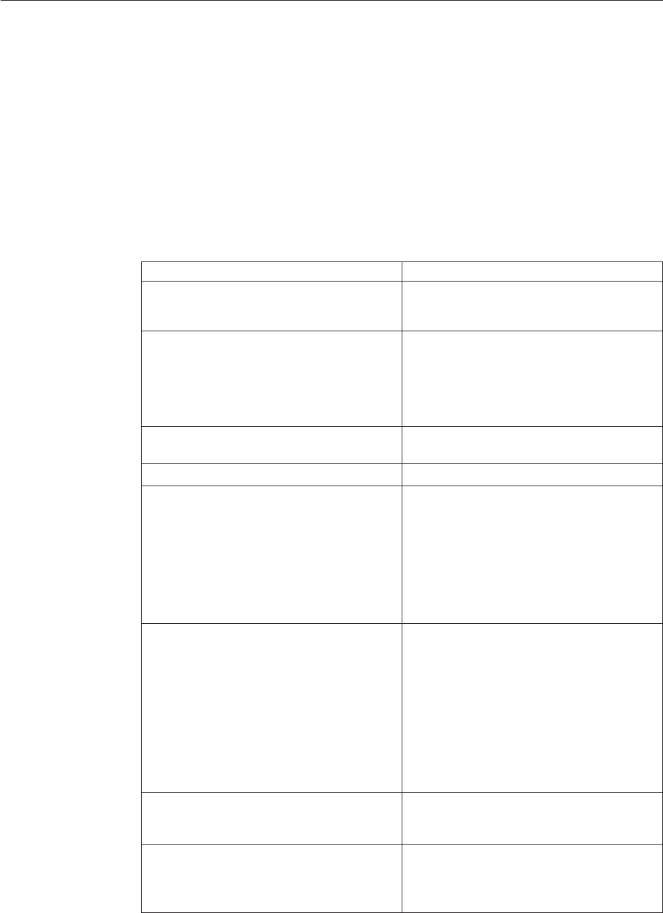
POST error codes
Each time you power-on the system, it performs a series of tests that check the
operation of the system and some options. This series of tests is called the
Power-On Self-Test,orPOST. POST does the following operations.
vChecks some basic system-board operations
vChecks the memory operation
vStarts the video operation
vVerifies that the boot drive is working
If the POST detects a problem, an error message appears on the screen. A single
problem can cause several error messages to appear. When you correct the cause of
the first error message, the other error messages probably will not appear on the
screen the next time you turn on the system.
POST error message Description/Action
CMOS battery failed The CMOS battery is no longer functional.
Replace the battery.
CMOS checksum error - defaults loaded Checksum of CMOS is incorrect.
The computer loads the default
configuration settings. This error might
indicate that CMOS has become corrupt due
to a weak CMOS battery.
CPU at nnnn nnnn is the running speed of the
microprocessor.
Press Esc to skip memory test Pressing Esc skips the full memory test
HARD DISK INSTALL FAILURE Cannot find or initialize the hard disk drive
controller or the drive.
Make sure the hard disk drive is correctly
installed.
If no hard disk drives are installed, make
sure the hard disk drive selection in Setup is
set to NONE.
Keyboard error or no keyboard present Cannot initialize the keyboard.
Make sure the keyboard is properly
connected to the computer and that no keys
are held pressed during POST.
To purposely configure the computer
without a keyboard, set the error halt
condition in Setup to HALT ON ALL, BUT
KEYBOARD. The BIOS then ignores the
missing keyboard during POST.
Memory Test: This message displays during a full memory
test, counting down the memory areas being
tested.
Memory test fail If POST detects an error during memory
testing, additional information appears. This
information gives specifics about the type
and location of the memory error.
78 Hardware Maintenance Manual

POST error message Description/Action
Press TAB to show POST screen Pressing the TAB key permits the user to
toggle between the default POST display
screen and a custom POST display screen.
Error: Non-System disk or disk error
Replace and press any key when ready
The BIOS was unable to find a suitable boot
device.
Make sure the boot drive is properly
connected to the computer.
Make sure you have bootable media.
Chapter 7. Symptom-to-FRU index 79

Miscellaneous error messages
Message/Symptom FRU/Action
Changing display colors Display/Monitor
Computer will not power-off. See “Power
supply problems” on page 55. 1. Power Switch
2. System Board
3. Riser card, if installed
Computer will not RPL from server 1. Ensure that network is in startup
sequence as first device or first device
after diskette
2. Ensure that network adapter is enabled
for RPL
3. Network adapter (Advise network
administrator of new MAC address)
Computer will not perform a Wake on LAN
(if applicable) 1. Check power supply and signal cable
connections to network adapter
2. Ensure that the operating system settings
are set to enable Wake on LAN
3. Ensure Wake on LAN feature is enabled
in Setup/Configuration (see “Starting the
Setup Utility program” on page 51)
4. Ensure network administrator is using
correct MAC address
5. Ensure no interrupt or I/O address
conflicts
6. Network adapter (advise network
administrator of new MAC address)
Dead computer. See “Power supply
problems” on page 55. 1. Power Supply
2. System Board
Diskette drive in-use light remains on or
does not light when drive is active. 1. Diskette Drive
2. System Board
3. Diskette Drive Cable
Flashing cursor with an otherwise blank
display. 1. System Board
2. Primary Hard Disk Drive
3. Hard Disk Drive Cable
Incorrect memory size during POST 1. Run the Memory tests
2. Memory Module
3. System Board
″Insert a Diskette″icon appears with a
known-good diagnostics diskette in the first
3.5-inch diskette drive.
1. System Board
2. Diskette Drive Cable
3. Network Adapter
Intensity or color varies from left to right of
characters and color bars 1. Display
2. Video adapter (if present)
3. System Board
No power or fan not running 1. See “Power supply problems” on page
55.
80 Hardware Maintenance Manual

Message/Symptom FRU/Action
Non-system disk or disk error-type message
with a known-good diagnostic diskette. 1. Diskette Drive
2. System Board
3. Diskette Drive Cable
Other display symptoms not listed above
(including blank or illegible display) 1. Display
2. System Board
Power-on indicator or hard disk drive in-use
light not on, but computer works correctly 1. Power switch/LED assembly
2. System Board
Printer problems 1. Printer
2. System Board
Program loads from the hard disk with a
known-good diagnostics diskette in the first
3.5-inch diskette drive
1. Run Setup and check Startup sequence.
2. Diskette Drive
3. Diskette Drive Cable
4. System Board
5. Power Supply
RPL computer cannot access programs from
its own hard disk. 1. If network administrator is using
LCCM Hybrid RPL, check startup
sequence:
a. First device - network
b. Second device - hard disk
2. Hard disk drive
RPL computer does not RPL from server 1. Check startup sequence
2. Check the network adapter LED status
Serial or parallel port device failure (system
board port) 1. External Device Self-Test OK?
2. External Device
3. Cable
4. System Board
Serial or parallel port device failure (adapter
port) 1. External Device Self-Test OK?
2. External Device
3. Cable
4. Alternate Adapter
5. System Board
Some or all keys on the keyboard do not
work 1. Keyboard
2. Keyboard Cable
3. System Board
Undetermined problems
If this computer has a parallel ATA hard disk drive, make sure that the hard disk
drive is jumpered as a master and the optical drive is jumpered as a slave.
1. Power-off the computer.
2. Remove or disconnect the following components (if installed) one at a time.
a. External devices (modem, printer, or mouse)
b. Any adapters
Chapter 7. Symptom-to-FRU index 81
c. Memory modules
d. Extended video memory
e. External Cache
f. External Cache RAM
g. Hard disk drive
h. Diskette drive
3. Power-on the computer to re-test the system.
4. Repeat steps 1 through 3 until you find the failing device or adapter.
If all devices and adapters have been removed, and the problem continues, replace
the system board.
82 Hardware Maintenance Manual

Chapter 8. Replacing FRUs (Machine types: 7515, 7523, 7569,
and 7611.)
Important
Be sure to read and understand the Chapter 2, “Safety information,” on page
3 before replacing any FRU. These precautions and guidelines will help you
work safely.
FRU replacements are to be done only by trained service technicians.
This chapter does not contain the install, remove or replace procedure for all FRUs.
Only the major FRUs are documented.
© Copyright Lenovo 2009 83

Locating connectors on the front of your computer
Figure 1 shows the locations of the connectors on the front of your computer.
Note: Not all computer models have the following connectors.
1 USB connector 3 Microphone connector
2 Headphone connector 4 USB connector
Figure 1. Front connector locations
84 Hardware Maintenance Manual
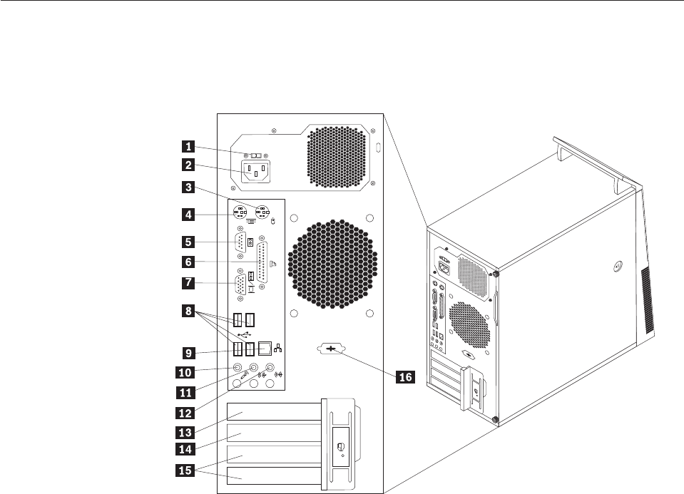
Locating connectors on the rear of your computer
Figure 2 shows the locations of the connectors on the rear of your computer. Some
connectors on the rear of your computer are color-coded to help you determine
where to connect the cables on your computer.
1 Voltage-selection switch (some models) 9 Ethernet connector
2 Power cord connector 10 Microphone connector
3 Standard mouse connector 11 Audio line-out connector
4 Standard keyboard connector 12 Audio line-in connector
5 Serial port 13 PCI Express x16 graphics card slot
6 Parallel port 14 PCI Express x1 card slot
7 Video Graphics Array (VGA) monitor
connector
15 PCI card slots (2)
8 USB connectors (4) 16 Serial port (some models)
Figure 2. Rear connector locations
Chapter 8. Replacing FRUs - Tamdhu 85
Removing the computer cover
This section provides instructions on how to remove the computer cover.
Attention
Do not open your computer or attempt any repair before reading and understanding the
“Important safety information” in the ThinkCentre Safety and Warranty Guide that came with
your computer. To obtain a copy of the ThinkCentre Safety and Warranty Guide,goto:
http://www.lenovo.com/support
CAUTION:
Turn off the computer and wait three to five minutes to let the computer cool
before removing the computer cover.
To remove the computer cover, do the following:
1. Remove any media from the drives, shut down your operating system, and
turn off all attached devices and the computer.
2. Unplug all power cords from electrical outlets.
3. Disconnect the cables attached to the computer. This includes power cords,
input/output (I/O) cables, and any other cables that are connected to the
computer. See “Locating connectors on the front of your computer” on page 84
and “Locating connectors on the rear of your computer” on page 85.
4. Remove any locking devices, such as a cable lock that secures the computer
cover.
5. If there are thumbscrews that secure the computer cover, remove them.
86 Hardware Maintenance Manual
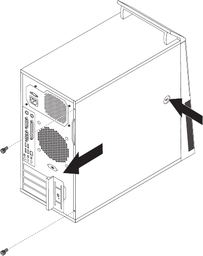
6. Press the cover-release button on the side of the computer cover and slide the
computer cover to the rear to remove.
Figure 3. Removing the computer cover
Chapter 8. Replacing FRUs - Tamdhu 87

Locating components
To remove the computer cover, see “Removing the computer cover” on page 86.
Figure 4 shows the locations of the various components in your computer.
1 Heat sink and fan assembly 6 PCI card slot
2 Memory modules 7 PCI Express x1 card slot
3 Battery 8 Cover presence switch (Intrusion
switch) (some models)
4 PCI Express x16 graphics card slot 9 Rear fan assembly
5 PCI card 10 Power supply assembly
Figure 4. Component locations
88 Hardware Maintenance Manual
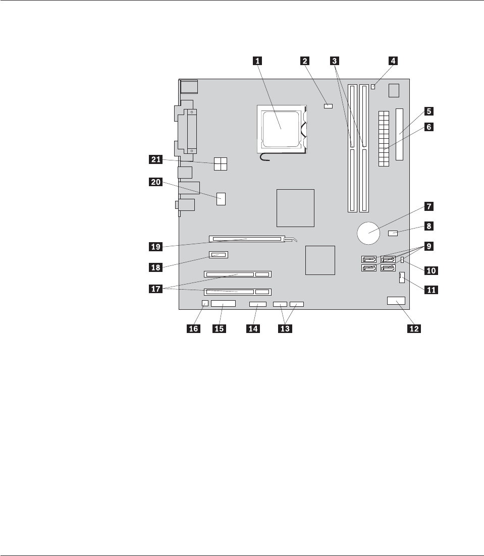
Locating parts on the system board
Figure 5 shows the locations of the parts on the system board.
1 Microprocessor 12 Front panel connector
2 Microprocessor fan connector 13 Front USB connectors (2)
3 Memory slots (2) 14 Serial (COM 2) connector
4 Thermal sensor connector 15 Front audio connector
5 Diskette drive connector 16 Internal speaker connector
6 24-pin power connector 17 PCI card slots (2)
7 Battery 18 PCI Express x1 card slot
8 Cover presence (Intrusion) switch
connector
19 PCI Express x16 graphics card slot
9 SATA connectors (4) 20 System fan connector
10 Clear CMOS (Complementary
Metal Oxide Semiconductor)/Recovery
jumper
21 4-pin power connector
11 Power fan connector
Removing and reinstalling the front bezel
This section provides instructions on how to remove and reinstall the front bezel.
To remove and reinstall the front bezel, do the following:
1. Remove the computer cover. See “Removing the computer cover” on page 86.
Figure 5. System board parts locations
Chapter 8. Replacing FRUs - Tamdhu 89
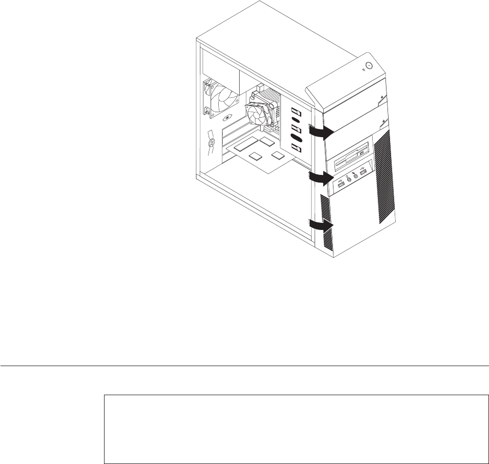
2. Release the three plastic tabs on the left side and pivot the front bezel outward
to remove it.
3. To reinstall the front bezel, align the plastic tabs on the right side of the front
bezel with the corresponding holes in the chassis, then pivot the front bezel
inward until it snaps into position on the left side.
4. To complete the installation, go to “Completing the FRU replacement” on page
120.
Installing or replacing a memory module
Attention
Do not open your computer or attempt any repair before reading and understanding the
“Important safety information” in the ThinkCentre Safety and Warranty Guide that came with
your computer. To obtain a copy of the ThinkCentre Safety and Warranty Guide,goto:
http://www.lenovo.com/support
This section provides instructions on how to install or replace a memory module.
Your computer has two slots for installing or replacing DDR2 DIMMs (double data
rate 2 dual inline memory modules) that provide up to a maximum of 4 GB
system memory.
When installing or replacing a memory module, use the following guidelines:
vUse 1.8 V, 240-pin, DDR2 DIMMs (double data rate 2 dual inline memory
modules).
vUse 512 MB, 1 GB, or 2 GB memory modules in any combination up to a
maximum of 4 GB.
Figure 6. Removing the front bezel
90 Hardware Maintenance Manual
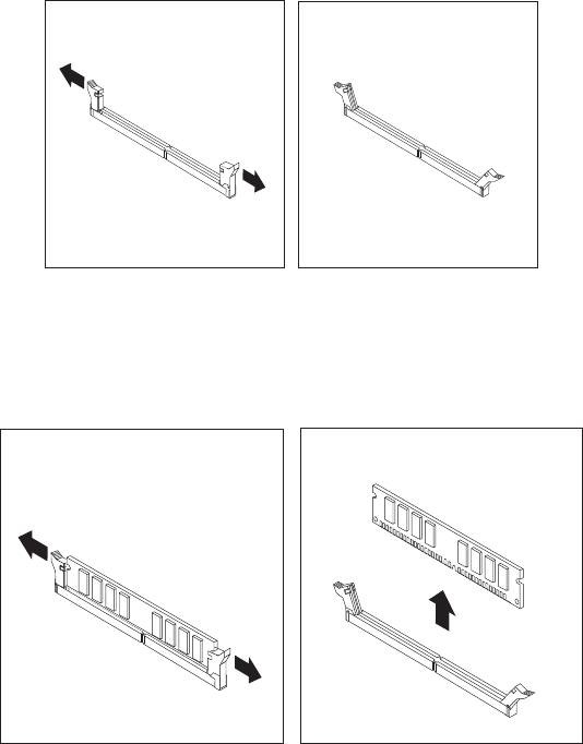
Note: Only DDR2 SDRAM DIMMs can be used.
To install or replace a memory module, do the following:
1. Remove the computer cover. See “Removing the computer cover” on page 86.
2. Remove any parts that might prevent access to the memory slots.
3. Locate the memory slots. See “Locating parts on the system board” on page 89.
4. Open the retaining clips.
If you are replacing an old memory module, open the retaining clips and
remove the memory module being replaced as shown.
Figure 7. Opening the retaining clips
Figure 8. Removing the memory module
Chapter 8. Replacing FRUs - Tamdhu 91
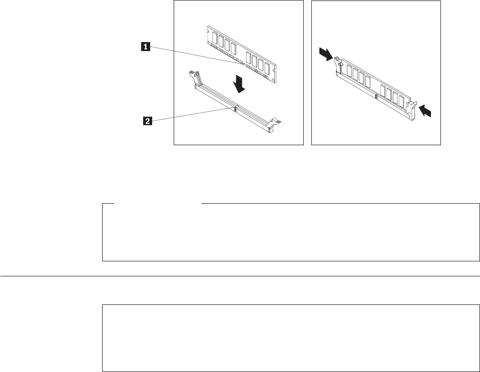
5. Position the memory module over the memory slot. Make sure that the notch
1 on the memory module aligns correctly with the slot key 2 on the system
board. Push the memory module straight down into the slot until the retaining
clips close.
What to do next:
vTo work with another piece of hardware, go to the appropriate section.
vTo complete the installation or replacement, go to “Completing the FRU
replacement” on page 120.
Installing or replacing a PCI card
Attention
Do not open your computer or attempt any repair before reading and understanding the
“Important safety information” in the ThinkCentre Safety and Warranty Guide that came with
your computer. To obtain a copy of the ThinkCentre Safety and Warranty Guide,goto:
http://www.lenovo.com/support
This section provides instructions on how to install or replace a PCI card.
Your computer has two standard PCI card slots, one PCI Express x1 card slot, and
one PCI Express x16 graphics card slot.
Figure 9. Installing the memory module
92 Hardware Maintenance Manual
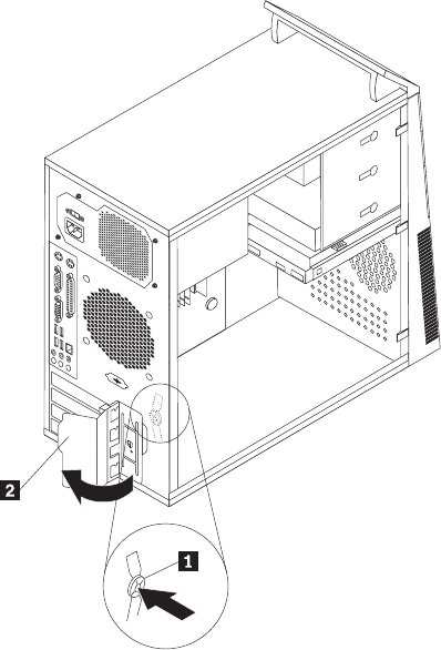
To install or replace a PCI card, do the following:
1. Remove the computer cover. See “Removing the computer cover” on page 86.
2. At the rear of the computer, press the release button 1 to open the PCI card
latch 2 and remove the PCI card slot cover.
3. If you are replacing a PCI card, locate the appropriate PCI card slot on the
system board and remove the old PCI card that is currently installed. See
“Locating parts on the system board” on page 89. If you are installing a PCI
card, go to step 4.
Notes:
a. The PCI card fits tightly into the PCI card slot. If necessary, alternate
moving each side of the PCI card a small and equal amount until it is
completely removed from the PCI card slot.
Figure 10. Opening the PCI card latch
Chapter 8. Replacing FRUs - Tamdhu 93
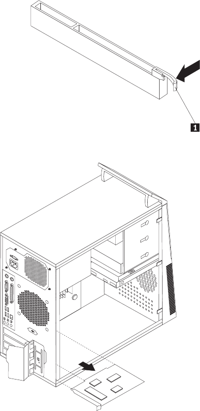
b. If the PCI card is secured in place by a retaining latch 1, press the
retaining latch downwards to release the PCI card from the latch. Then,
grasp the PCI card and gently pull it out of the slot.
4. Remove the new PCI card from its static-protective package.
Figure 11. Removing the PCI card
94 Hardware Maintenance Manual
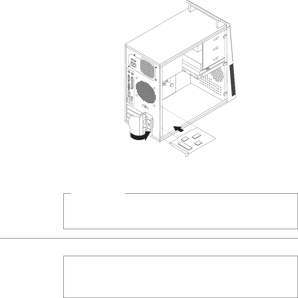
5. Install the new PCI card into the appropriate slot on the system board. See
“Locating parts on the system board” on page 89. Then, pivot the PCI card
latch to the closed position to secure the PCI cards.
What to do next:
vTo work with another piece of hardware, go to the appropriate section.
vTo complete the installation or replacement, go to “Completing the FRU
replacement” on page 120.
Replacing the battery
Attention
Do not open your computer or attempt any repair before reading and understanding the
“Important safety information” in the ThinkCentre Safety and Warranty Guide that came with
your computer. To obtain a copy of the ThinkCentre Safety and Warranty Guide,goto:
http://www.lenovo.com/support
Your computer has a special type of memory that maintains the date, time, and
settings for built-in features, such as parallel-port assignments (configuration). A
battery keeps this information active when you turn off the computer.
The battery normally requires no charging or maintenance throughout its life;
however, no battery lasts forever. If the battery fails, the date, time, and
configuration information (including passwords) are lost. An error message is
displayed when you turn on the computer.
Figure 12. Installing the PCI card
Chapter 8. Replacing FRUs - Tamdhu 95
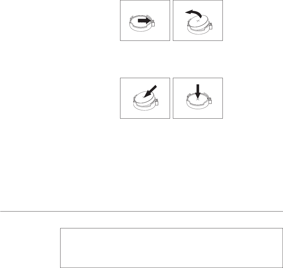
Refer to the “Lithium battery notice” in the ThinkCentre Safety and Warranty Guide
for information about replacing and disposing of the battery.
To replace the battery, do the following:
1. Remove the computer cover. See “Removing the computer cover” on page 86.
2. Locate the battery. See “Locating parts on the system board” on page 89.
3. Remove the old battery.
4. Install a new battery.
5. Reinstall the computer cover and connect the cables. See “Completing the FRU
replacement” on page 120.
Note: When the computer is turned on for the first time after replacing the
battery, an error message might be displayed. This is normal after
replacing the battery.
6. Turn on the computer and all attached devices.
7. Use the Setup Utility program to set the date, time, and any passwords. See
Chapter 6, “Using the Setup Utility program,” on page 51.
Replacing the power supply assembly
Attention
Do not open your computer or attempt any repair before reading and understanding the
“Important safety information” in the ThinkCentre Safety and Warranty Guide that came with
your computer. To obtain a copy of the ThinkCentre Safety and Warranty Guide,goto:
http://www.lenovo.com/support
This section provides instructions on how to replace the power supply assembly.
To replace the power supply assembly, do the following:
1. Remove the computer cover. See “Removing the computer cover” on page 86.
2. Disconnect the power supply assembly cables from the system board and all
drives. See “Locating parts on the system board” on page 89.
Figure 13. Removing the old battery
Figure 14. Installing a new battery
96 Hardware Maintenance Manual
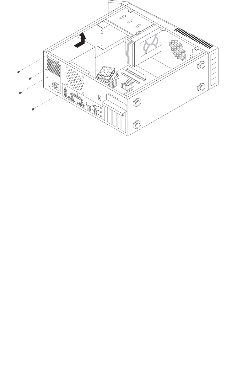
3. Lay the computer on its side and remove the four screws at the rear of the
chassis that secure the power supply assembly.
4. Remove the old power supply assembly from the chassis.
5. Ensure that the power supply assembly is the correct replacement. Some power
supply assemblies automatically sense the voltage, some power supply
assemblies are voltage specific, and some power supply assemblies have a
voltage-selection switch. If your computer has a voltage-selection switch, ensure
that you set the voltage-selection switch of the new power supply assembly to
match the voltage available at your electrical outlet. If necessary, use a ballpoint
pen to slide the voltage-selection switch to a different position.
vIf the voltage supply range in your local country or region is 100–127 V AC,
set the switch to 115 V.
vIf the voltage supply range in your local country or region is 200–240 V AC,
set the switch to 230 V.
6. Install the new power supply assembly into the chassis so that the screw holes
in the power supply assembly align with those in the chassis.
7. Install the four screws to secure the power supply assembly.
Note: Use only screws provided by Lenovo.
8. Reconnect the power supply assembly connectors to the system board.
9. Reconnect a power supply assembly connector to each of the drives.
What to do next:
vTo work with another piece of hardware, go to the appropriate section.
vTo complete the replacement, go to “Completing the FRU replacement” on
page 120.
Figure 15. Removing the retaining screws for the power supply assembly
Chapter 8. Replacing FRUs - Tamdhu 97
Replacing the heat sink and fan assembly
Attention
Do not open your computer or attempt any repair before reading and understanding the
“Important safety information” in the ThinkCentre Safety and Warranty Guide that came with
your computer. To obtain a copy of the ThinkCentre Safety and Warranty Guide,goto:
http://www.lenovo.com/support
This section provides instructions on how to replace the heat sink and fan
assembly.
CAUTION:
The heat sink and fan assembly might be very hot. Turn off the computer and
wait three to five minutes to let the computer cool before removing the
computer cover.
To replace the heat sink and fan assembly, do the following:
1. Remove the computer cover. See “Removing the computer cover” on page 86.
2. Lay the computer on its side for easier access to the system board.
3. Locate the heat sink and fan assembly. See “Locating parts on the system
board” on page 89.
4. Disconnect the heat sink and fan assembly cable from the microprocessor fan
connector on the system board. See “Locating parts on the system board” on
page 89.
98 Hardware Maintenance Manual
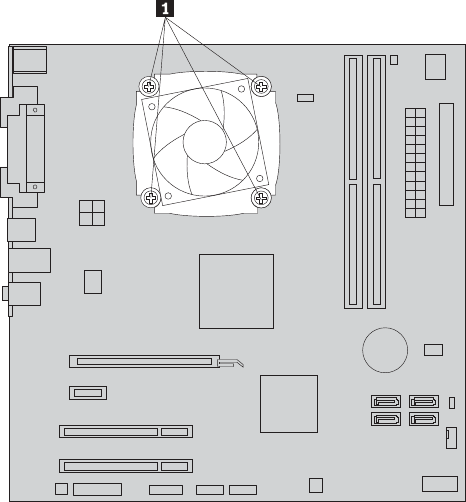
5. Remove the four screws 1 that secure the heat sink and fan assembly to the
system board.
Note: Carefully remove the four screws from the system board to avoid any
possible damage. The four screws cannot be removed from the heat sink
and fan assembly.
6. Lift the failing heat sink and fan assembly off the system board.
Notes:
a. You might have to gently twist the heat sink and fan assembly to free it
from the microprocessor.
b. Do not touch the thermal grease while handling the heat sink and fan
assembly.
7. Position the new heat sink and fan assembly on the system board so that the
four screws are aligned with the holes on the system board.
Note: Position the new heat sink and fan assembly so that the heat sink and
fan assembly cable is toward the microprocessor fan connector on the
system board.
Figure 16. Removing the heat sink and fan assembly
Chapter 8. Replacing FRUs - Tamdhu 99
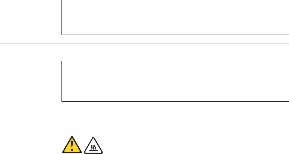
8. Alternate tightening each screw a small and equal amount until the heat sink
and fan assembly is secured to the system board. Do not over-tighten the
screws.
9. Connect the new heat sink and fan assembly cable to the microprocessor fan
connector on the system board.
What to do next:
vTo work with another piece of hardware, go to the appropriate section.
vTo complete the replacement, go to “Completing the FRU replacement” on
page 120.
Replacing the microprocessor
Attention
Do not open your computer or attempt any repair before reading and understanding the
“Important safety information” in the ThinkCentre Safety and Warranty Guide that came with
your computer. To obtain a copy of the ThinkCentre Safety and Warranty Guide,goto:
http://www.lenovo.com/support
This section provides instructions on how to replace the microprocessor.
CAUTION:
The heat sink and microprocessor might be very hot. Turn off the computer and
wait three to five minutes to let the computer cool before removing the
computer cover.
To replace the microprocessor, do the following:
1. Remove the computer cover. See “Removing the computer cover” on page 86.
2. Lay the computer on its side for easier access to the system board.
3. Remove any parts or cables that may prevent your access to the system board.
4. Disconnect the heat sink and fan assembly cable from the microprocessor fan
connector on the system board. See “Locating parts on the system board” on
page 89.
5. Remove the heat sink and fan assembly. See “Replacing the heat sink and fan
assembly” on page 98.
6. Place the heat sink and fan assembly on its side so that the thermal grease
does not come in contact with anything.
100 Hardware Maintenance Manual
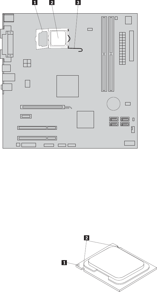
7. Lift the small handle 3 and open the retainer 1 to access the
microprocessor 2.
8. Lift the microprocessor straight up and out of the socket.
Notes:
a. Your microprocessor and socket might look different from the one
illustrated.
b. Note the orientation of the microprocessor in the socket. You can either
look for the small triangle 1 on one corner of the microprocessor or note
the orientation of the notches 2 on the microprocessor. This is important
when reinstalling the microprocessor on the system board.
Figure 17. Accessing the microprocessor
Chapter 8. Replacing FRUs - Tamdhu 101
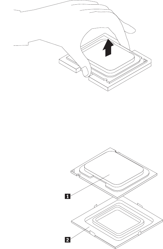
c. Touch only the sides of the microprocessor. Do not touch the gold contacts
on the bottom.
d. Do not drop anything onto the microprocessor socket while it is exposed.
The socket pins must be kept as clean as possible.
9. Make sure that the small handle is in the raised position and the
microprocessor retainer is fully open.
10. Remove the protective cover 2 that protects the gold contacts on the new
microprocessor 1.
11. Hold the new microprocessor and align the notches on it with the tabs in the
microprocessor socket, or align the small triangle on one corner with the
corresponding beveled corner of the microprocessor socket.
12. Lower the new microprocessor straight down into the microprocessor socket
on the system board.
13. Close the microprocessor retainer and lock it into position with the small
handle to secure the new microprocessor in the socket.
14. Reinstall the heat sink and fan assembly. See “Replacing the heat sink and fan
assembly” on page 98.
15. Reconnect the heat sink and fan assembly cable to the microprocessor fan
connector on the system board.
16. Reinstall any other parts or reconnect any other cables you removed.
Figure 18. Removing the microprocessor
102 Hardware Maintenance Manual
What to do next:
vTo work with another piece of hardware, go to the appropriate section.
vTo complete the replacement, go to “Completing the FRU replacement” on
page 120.
Replacing the system board
Attention
Do not open your computer or attempt any repair before reading and understanding the
“Important safety information” in the ThinkCentre Safety and Warranty Guide that came with
your computer. To obtain a copy of the ThinkCentre Safety and Warranty Guide,goto:
http://www.lenovo.com/support
This section provides instructions on how to replace the system board.
CAUTION:
The heat sink and microprocessor might be very hot. Turn off the computer and
wait three to five minutes to let the computer cool before removing the
computer cover.
Note: When replacing the system board, you must order a new retention module
for the new system board. Make sure you have a retention module for the
new system board before continuing this procedure.
To replace the system board, do the following:
1. Remove the computer cover. See “Removing the computer cover” on page 86.
2. Remove the primary hard disk drive with the hard disk drive cage. See
“Replacing the primary hard disk drive” on page 105.
3. Lay the computer on its side to make the system board more accessible.
4. Remove all memory modules and adapter cards that are currently installed.
See “Installing or replacing a memory module” on page 90 and “Installing or
replacing a PCI card” on page 92.
5. Carefully take note of the location of all cable connectors on the system board
and disconnect all the cables. See “Locating parts on the system board” on
page 89.
6. Remove the heat sink and fan assembly from the failing system board. See
“Replacing the heat sink and fan assembly” on page 98.
7. Remove the screws that secure the system board to the chassis.
8. Carefully move the system board out of the chassis.
9. Remove the microprocessor socket cover from the new system board.
10. Remove the microprocessor from the failing system board and install it on the
new system board. See “Replacing the microprocessor” on page 100.
11. The failing system board must be returned with a microprocessor socket cover
to protect the pins during shipping and handling. Install the microprocessor
socket cover removed from the new system board on the failing system board.
Chapter 8. Replacing FRUs - Tamdhu 103
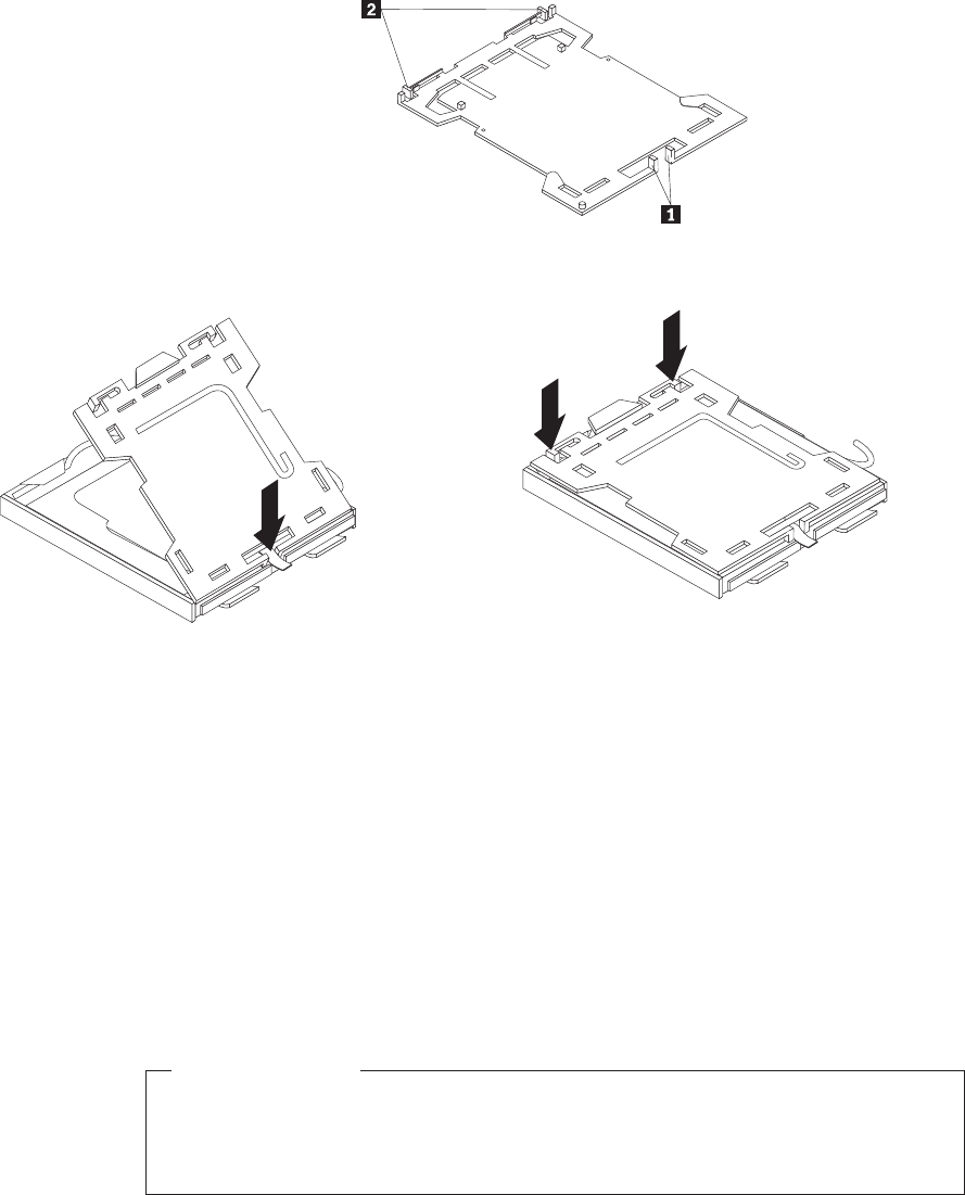
To install the microprocessor socket cover:
a. Make sure the microprocessor has been removed from the microprocessor
socket, and then close the microprocessor retainer and lock it into position
with the small handle.
b. Insert the tabs 1 of the socket cover into the hinged side of the socket,
and then press the other side of the socket cover downward until the tabs
2 snap into position.
12. Install the new retention module on the new system board.
13. Install the heat sink and fan assembly and connect the heat sink and fan
assembly cable to the microprocessor fan connector on the new system board.
14. Install the new system board into the chassis and align the screw holes with
those in the chassis. Insert and tighten the screws to secure the new system
board in place.
15. Install all memory modules and adapter cards removed from the failing
system board on the new system board.
16. Reinstall the primary hard disk drive with the hard disk drive cage.
17. Reconnect all remaining cables to the system board. See “Locating parts on the
system board” on page 89.
What to do next:
vTo work with another piece of hardware, go to the appropriate section.
vTo complete the replacement, go to “Completing the FRU replacement” on
page 120.
Figure 19. Tabs on the microprocessor socket cover (bottom view)
Figure 20. Installing the microprocessor socket cover
104 Hardware Maintenance Manual
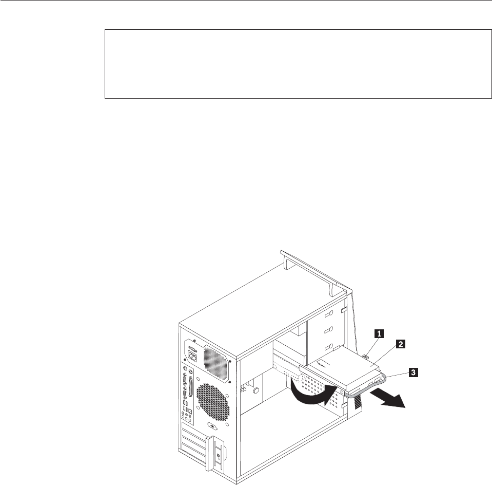
Replacing the primary hard disk drive
Attention
Do not open your computer or attempt any repair before reading and understanding the
“Important safety information” in the ThinkCentre Safety and Warranty Guide that came with
your computer. To obtain a copy of the ThinkCentre Safety and Warranty Guide,goto:
http://www.lenovo.com/support
This section provides instructions on how to replace the primary hard disk drive.
To replace the primary hard disk drive, do the following:
1. Remove the computer cover. See “Removing the computer cover” on page 86.
2. Locate the primary hard disk drive.
3. Disconnect the signal cable and the power cable from the hard disk drive.
4. Press the blue release tab 1 down, slide the hard disk drive cage 2 back,
and pivot it outward.
5. Remove the hard disk drive cage from the chassis by simply sliding it
outward.
6. Pull on the blue handle 3 to release and remove the hard disk drive from
the drive cage.
7. Remove the hard disk drive from the blue bracket by flexing the sides of the
bracket enough to slide it free from the hard disk drive.
Figure 21. Removing the primary hard disk drive
Chapter 8. Replacing FRUs - Tamdhu 105
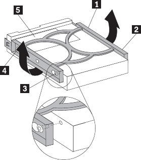
8. To install a new hard disk drive into the blue bracket, flex the bracket and
align pin 1, pin 2, pin 3, and pin 4 on the bracket with the holes in
the hard disk drive. Do not touch the circuit board 5 on the bottom of the
hard disk drive.
9. Slide the new hard disk drive into the drive cage until it snaps into position.
Figure 22. Installing the primary hard disk drive into the bracket
106 Hardware Maintenance Manual
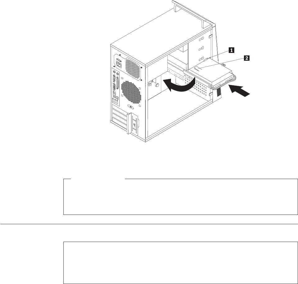
10. Align the drive cage pivot pin with the slot 1 in the upper drive cage and
slide the hard disk drive cage into the chassis.
11. Connect the signal cable and the power cable to the rear of the new hard disk
drive.
12. Press down on the metal latch 2 and pivot the drive cage into place, and
then slide it forward until it snaps into position.
Note: There are two arrows, one on the upper drive cage and one on the hard
disk drive cage. The arrows are aligned when the hard disk drive is in
the proper position.
What to do next:
vTo work with another piece of hardware, go to the appropriate section.
vTo complete the replacement, go to “Completing the FRU replacement” on
page 120.
Replacing the secondary hard disk drive
Attention
Do not open your computer or attempt any repair before reading and understanding the
“Important safety information” in the ThinkCentre Safety and Warranty Guide that came with
your computer. To obtain a copy of the ThinkCentre Safety and Warranty Guide,goto:
http://www.lenovo.com/support
This section provides instructions on how to replace the secondary hard disk drive.
Figure 23. Installing the primary hard disk drive with the hard disk drive cage
Chapter 8. Replacing FRUs - Tamdhu 107
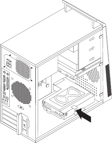
Note: Depending on your model type, your computer might come with a
secondary hard disk drive bay for installing or replacing a secondary hard
disk drive.
To replace the secondary hard disk drive, do the following:
1. Remove the computer cover. See “Removing the computer cover” on page 86.
2. Locate the secondary hard disk drive.
3. Disconnect the signal cable and the power cable from the hard disk drive.
4. Press the blue release button to release the hard disk drive cage from the
chassis.
5. Remove the hard disk drive cage from the chassis by simply sliding it
outward.
6. Pull on the blue handle to release and remove the hard disk drive from the
hard disk drive cage.
7. Remove the hard disk drive from the blue plastic bracket by flexing the sides
of the bracket enough to slide it free from the hard disk drive.
Figure 24. Removing the secondary hard disk drive
108 Hardware Maintenance Manual
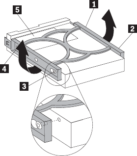
8. To install a new hard disk drive into the blue bracket, flex the bracket and
align pin 1, pin 2, pin 3, and pin 4 on the bracket with the holes in
the hard disk drive. Do not touch the circuit board 5 on the bottom of the
hard disk drive.
9. Slide the new hard disk drive into the hard disk drive cage until it snaps into
position.
Figure 25. Installing the secondary hard disk drive into the bracket
Chapter 8. Replacing FRUs - Tamdhu 109
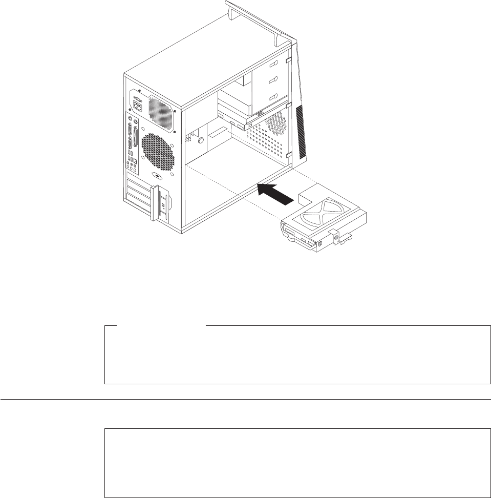
10. Install the hard disk drive cage into the chassis until it snaps into position
underneath the metal tab. Make sure that the hard disk drive cage is secured
in the chassis.
11. Connect the signal and power cables to the rear of the new hard disk drive.
What to do next:
vTo work with another piece of hardware, go to the appropriate section.
vTo complete the replacement, go to “Completing the FRU replacement” on
page 120.
Replacing the optical drive
Attention
Do not open your computer or attempt any repair before reading and understanding the
“Important safety information” in the ThinkCentre Safety and Warranty Guide that came with
your computer. To obtain a copy of the ThinkCentre Safety and Warranty Guide,goto:
http://www.lenovo.com/support
This section provides instructions on how to replace the optical drive.
To replace the optical drive, do the following:
1. Remove the computer cover. See “Removing the computer cover” on page 86.
2. Remove the front bezel. See “Removing and reinstalling the front bezel” on
page 89.
3. Disconnect the signal cable and the power cable from the rear of the optical
drive.
Figure 26. Installing the secondary hard disk drive and drive cage
110 Hardware Maintenance Manual

4. Press the blue release button and remove the optical drive out of the front of
the computer.
5. Remove the retaining bracket from the optical drive being replaced and install
it on the new optical drive.
6. Slide the new optical drive into the bay from the front until it snaps into
position.
7. Connect the signal cable and the power cable to the optical drive.
What to do next:
vTo work with another piece of hardware, go to the appropriate section.
vTo complete the replacement, go to “Completing the FRU replacement” on
page 120.
Figure 27. Removing the optical drive
Figure 28. Retaining bracket for optical drive
Chapter 8. Replacing FRUs - Tamdhu 111
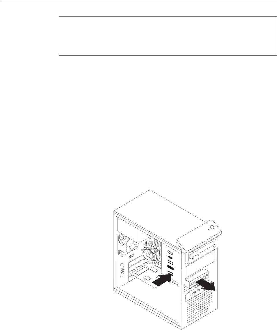
Replacing the diskette drive or card reader
Attention
Do not open your computer or attempt any repair before reading and understanding the
“Important safety information” in the ThinkCentre Safety and Warranty Guide that came with
your computer. To obtain a copy of the ThinkCentre Safety and Warranty Guide,goto:
http://www.lenovo.com/support
Depending on your model type, your computer might have a diskette drive or a
card reader installed. This section provides instructions on how to replace the
diskette drive or card reader.
The artwork in this section shows how to replace the diskette drive. To replace the
card reader, the procedure is the same as replacing the diskette drive.
To replace the diskette drive or card reader, do the following:
1. Remove the computer cover. See “Removing the computer cover” on page 86.
2. Remove the front bezel. See “Removing and reinstalling the front bezel” on
page 89.
3. Disconnect the signal cable and the power cable from the rear of the diskette
drive or card reader.
4. Press the release button and slide the diskette drive or card reader out of the
front of the computer.
Figure 29. Removing the diskette drive or card reader
112 Hardware Maintenance Manual
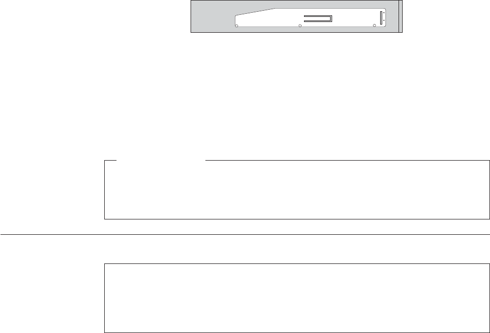
5. Remove the retaining bracket from the failing diskette drive or card reader and
install it on a new diskette drive or card reader.
6. Slide the new diskette drive or card reader into the drive bay until it snaps into
position.
7. Connect the signal cable and the power cable to the new diskette drive or card
reader.
8. Reinstall the front bezel.
What to do next:
vTo work with another piece of hardware, go to the appropriate section.
vTo complete the replacement, go to “Completing the FRU replacement” on
page 120.
Replacing the front fan assembly
Attention
Do not open your computer or attempt any repair before reading and understanding the
“Important safety information” in the ThinkCentre Safety and Warranty Guide that came with
your computer. To obtain a copy of the ThinkCentre Safety and Warranty Guide,goto:
http://www.lenovo.com/support
This section provides instructions on how to replace the front fan assembly.
Note: Depending on model type, your computer might have a front fan assembly
installed.
To replace the front fan assembly, do the following:
1. Remove the computer cover. See “Removing the computer cover” on page 86.
2. Remove the front bezel. See “Removing and reinstalling the front bezel” on
page 89.
3. Disconnect the front fan assembly cable from the power fan connector on the
system board. See “Locating parts on the system board” on page 89.
Figure 30. Retaining bracket for diskette drive or card reader
Chapter 8. Replacing FRUs - Tamdhu 113

4. The front fan assembly is attached to the chassis by four rubber mounts.
Remove the front fan assembly by breaking or cutting the rubber mounts and
gently pulling the front fan assembly out of the chassis.
5. Install the new front fan assembly by aligning the new rubber mounts of the
new front fan assembly with the holes on the chassis and push the rubber
mounts through the holes.
Note: The new front fan assembly you received will have four new rubber
mounts attached.
Figure 31. Removing the front fan assembly
114 Hardware Maintenance Manual
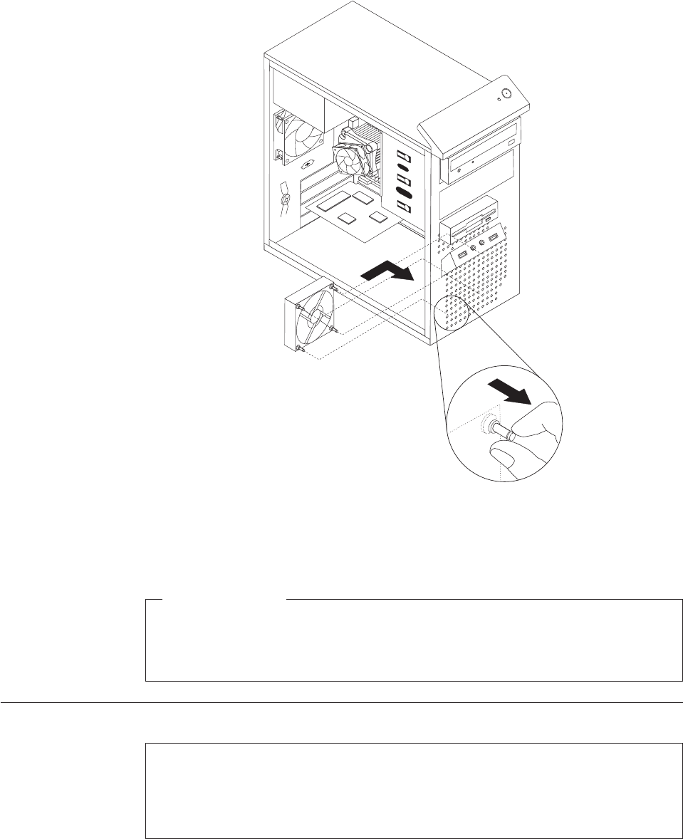
6. Pull on the tips of the rubber mounts until the front fan assembly is in place.
7. Connect the front fan assembly cable to the power fan connector on the system
board.
What to do next:
vTo work with another piece of hardware, go to the appropriate section.
vTo complete the replacement, go to “Completing the FRU replacement” on
page 120.
Replacing the rear fan assembly
Attention
Do not open your computer or attempt any repair before reading and understanding the
“Important safety information” in the ThinkCentre Safety and Warranty Guide that came with
your computer. To obtain a copy of the ThinkCentre Safety and Warranty Guide,goto:
http://www.lenovo.com/support
This section provides instructions on how to replace the rear fan assembly.
Figure 32. Installing the front fan assembly
Chapter 8. Replacing FRUs - Tamdhu 115
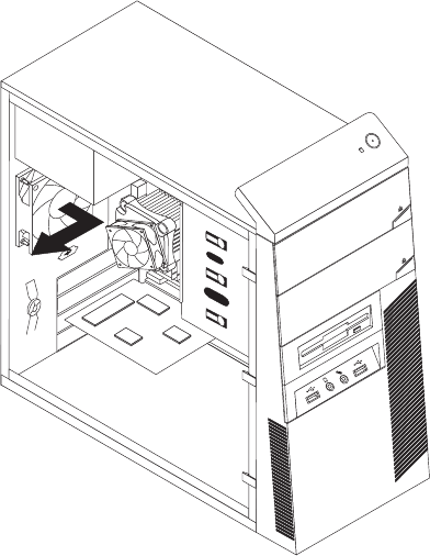
To replace the rear fan assembly, do the following:
1. Remove the computer cover. See “Removing the computer cover” on page 86.
2. Locate the rear fan assembly. See “Locating components” on page 88.
3. Disconnect the rear fan assembly cable from the system fan connector on the
system board. See “Locating parts on the system board” on page 89.
4. The rear fan assembly is attached to the chassis by four rubber mounts.
Remove the rear fan assembly by breaking or cutting the rubber mounts and
gently pulling the rear fan assembly out of the chassis.
5. Install the new rear fan assembly by aligning the new rubber mounts of the
new rear fan assembly with the holes on the chassis and push the rubber
mounts through the holes.
Note: The new rear fan assembly you received will have four new rubber
mounts attached.
Figure 33. Removing the rear fan assembly
116 Hardware Maintenance Manual
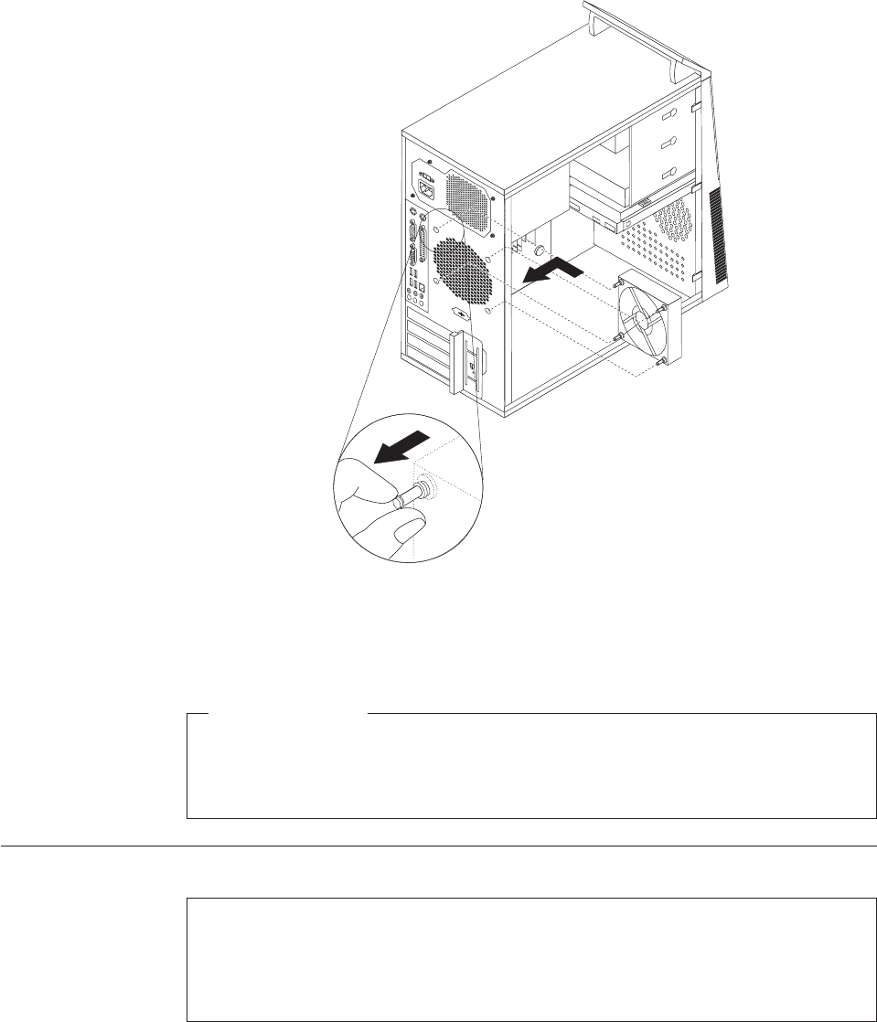
6. Pull on the tips of the rubber mounts until the rear fan assembly is in place.
7. Connect the rear fan assembly cable to the system fan connector on the system
board.
What to do next:
vTo work with another piece of hardware, go to the appropriate section.
vTo complete the replacement, go to “Completing the FRU replacement” on
page 120.
Replacing the internal speaker
Attention
Do not open your computer or attempt any repair before reading and understanding the
“Important safety information” in the ThinkCentre Safety and Warranty Guide that came with
your computer. To obtain a copy of the ThinkCentre Safety and Warranty Guide,goto:
http://www.lenovo.com/support
This section provides instructions on how to replace the internal speaker.
To replace the internal speaker, do the following:
1. Remove the computer cover. See “Removing the computer cover” on page 86.
Figure 34. Installing the rear fan assembly
Chapter 8. Replacing FRUs - Tamdhu 117
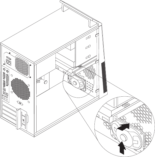
2. Locate the internal speaker connector on the system board. See “Locating parts
on the system board” on page 89.
3. Disconnect the internal speaker cable from the system board.
4. Push the metal tab on the top of the internal speaker outward and slide the
internal speaker upward to completely remove it from the chassis.
Figure 35. Removing the old internal speaker
118 Hardware Maintenance Manual
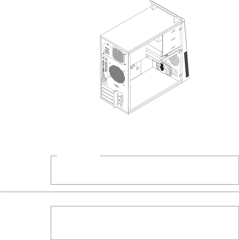
5. Position a new internal speaker into the metal clips and push downward on the
internal speaker until it snaps into position.
6. Connect the speaker cable to the system board. See “Locating parts on the
system board” on page 89.
What to do next:
vTo work with another piece of hardware, go to the appropriate section.
vTo complete the replacement, go to “Completing the FRU replacement” on
page 120.
Replacing the front audio and USB assembly
Attention
Do not open your computer or attempt any repair before reading and understanding the
“Important safety information” in the ThinkCentre Safety and Warranty Guide that came with
your computer. To obtain a copy of the ThinkCentre Safety and Warranty Guide,goto:
http://www.lenovo.com/support
This section provides instructions on how to replace the front audio and USB
assembly.
To replace the front audio and USB assembly, do the following:
1. Remove the computer cover. See “Removing the computer cover” on page 86.
2. Remove the front bezel. See “Removing and reinstalling the front bezel” on
page 89.
3. Disconnect the front audio and USB assembly cables from the system board.
See “Locating parts on the system board” on page 89.
Figure 36. Installing a new internal speaker
Chapter 8. Replacing FRUs - Tamdhu 119
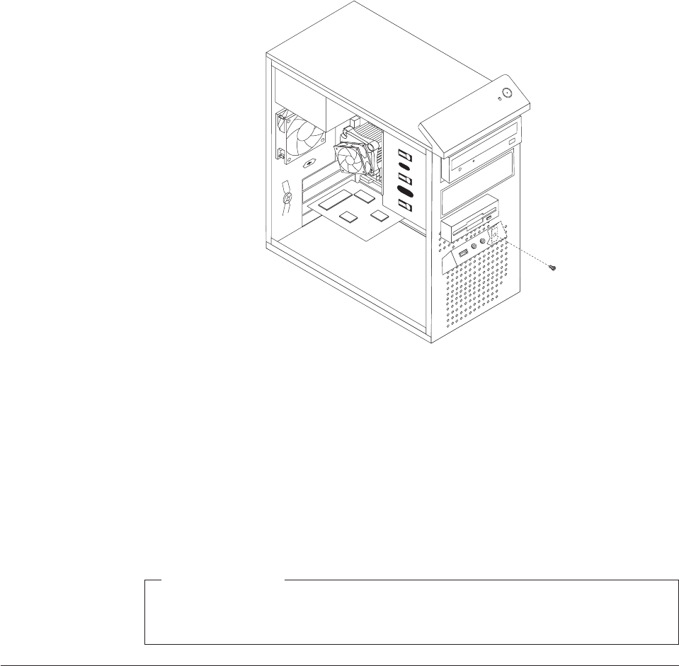
4. Note the front audio and USB assembly cables routing and remove the screw
that secures the front audio and USB assembly to the chassis.
5. Remove the front audio and USB assembly.
6. Route the cables for the new front audio and USB assembly through the hole in
the chassis to the system board.
7. Install the new front audio and USB assembly into the chassis and secure it
with the screw.
8. Connect the new front audio and USB assembly cables to the system board. See
“Locating parts on the system board” on page 89.
9. Reinstall the front bezel.
What to do next:
vTo work with another piece of hardware, go to the appropriate section.
vTo complete the replacement, go to “Completing the FRU replacement.”
Completing the FRU replacement
After replacing the FRUs, you need to reinstall any removed parts, reconnect and
route any internal cables, reinstall the computer cover, and reconnect any external
cables, including telephone lines and power cords. Depending on the FRUs
replaced, you might need to confirm the updated information in the Setup Utility
program, see Chapter 6, “Using the Setup Utility program,” on page 51.
Note: When the power cord is first plugged in, the computer might appear to turn
on for a few seconds and then turn off. This is a normal sequence to enable
the computer to initialize.
To reinstall the computer cover and reconnect cables to your computer:
Figure 37. Removing the front audio and USB assembly
120 Hardware Maintenance Manual

1. Ensure that all components have been reassembled correctly and that no tools
or loose screws are left inside your computer. See “Locating components” on
page 88 for the location of the various components.
2. Reconnect any internal cables.
3. Position the computer cover on the chassis so that the rail guides on the bottom
of the computer cover engage the rails. Then, push the computer cover closed
until it snaps into position.
4. If the computer cover is secured with thumbscrews, install them.
5. If a cover lock is installed, lock the cover.
6. Reconnect the external cables and power cords to the computer. See “Locating
connectors on the rear of your computer” on page 85.
7. If you have replaced the system board, you must update (flash) the BIOS. See
“Updating (flashing) BIOS from a disc” on page 278.
8. Some FRU replacements require the configuration to be updated. To update
your configuration, see Chapter 6, “Using the Setup Utility program,” on page
51.
Figure 38. Reinstalling the computer cover
Chapter 8. Replacing FRUs - Tamdhu 121
122 Hardware Maintenance Manual

Chapter 9. Replacing FRUs (Machine types: 7522, 7560, 7610,
and 7705.)
Important
Be sure to read and understand the Chapter 2, “Safety information,” on page
3 before replacing any FRU. These precautions and guidelines will help you
work safely.
FRU replacements are to be done only by trained service technicians.
This chapter does not contain the install, remove or replace procedure for all FRUs.
Only the major FRUs are documented.
© Copyright Lenovo 2009 123
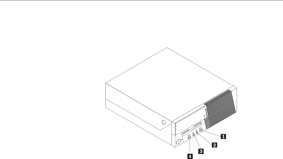
Locating connectors on the front of your computer
Figure 39 shows the locations of the connectors on the front of the computer.
Note: Not all computer models have the following connectors.
1 USB connector 3 Microphone connector
2 Headphone connector 4 USB connector
Figure 39. Front connector locations
124 Hardware Maintenance Manual
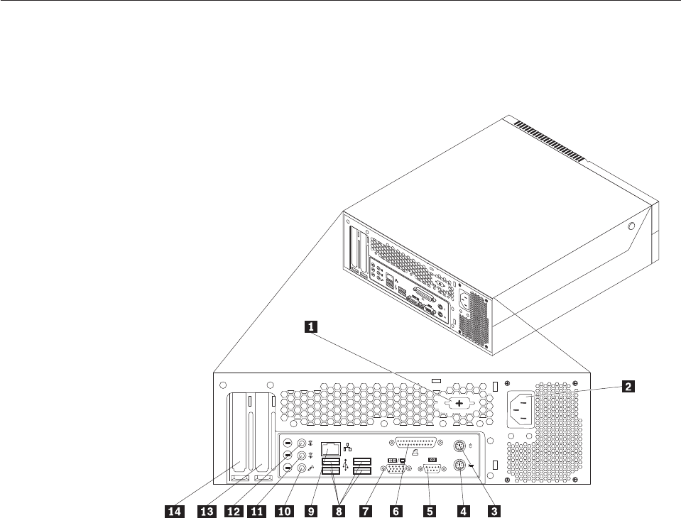
Locating connectors on the rear of your computer
Figure 40 shows the locations of the connectors on the rear of the computer. Some
connectors on the rear of your computer are color-coded to help you determine
where to connect the cables on your computer.
1 Serial port (some models) 8 USB connectors (4)
2 Power cord connector 9 Ethernet connector
3 Standard mouse connector 10 Microphone connector
4 Standard keyboard connector 11 Audio line-out connector
5 Serial port 12 Audio line-in connector
6 Parallel port 13 PCI Express x16 graphics card slot
7 VGA monitor connector 14 PCI card slot
Figure 40. Rear connector locations
Chapter 9. Replacing FRUs - 607 125
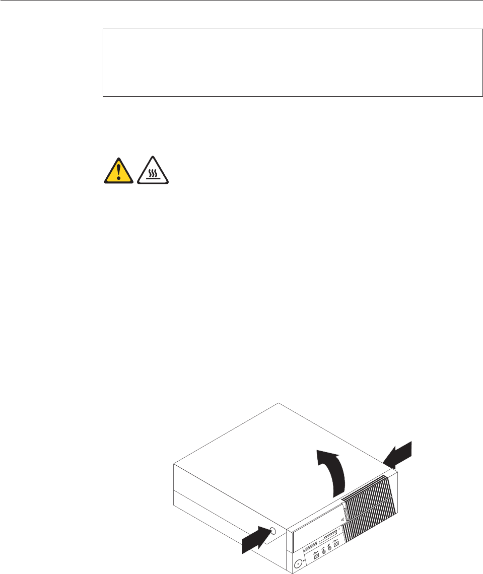
Opening the computer cover
Attention
Do not open your computer or attempt any repair before reading and understanding the
“Important safety information” in the ThinkCentre Safety and Warranty Guide that came with
your computer. To obtain a copy of the ThinkCentre Safety and Warranty Guide,goto:
http://www.lenovo.com/support
This section provides instructions on how to open the computer cover.
CAUTION:
Turn off the computer and wait three to five minutes to let the computer cool
before opening the computer cover.
To open the computer cover, do the following:
1. Remove any media from the drives, shut down your operating system, and
turn off all attached devices and the computer.
2. Unplug all power cords from electrical outlets.
3. Disconnect the cables attached to the computer. This includes power cords,
input/output (I/O) cables, and any other cables that are connected to the
computer. See “Locating connectors on the front of your computer” on page
124 and “Locating connectors on the rear of your computer” on page 125.
4. Remove any locking devices, such as a cable lock that secures the computer
cover.
5. Press the buttons on the sides of the computer and pivot the computer cover
upward to open.
Figure 41. Opening the computer cover
126 Hardware Maintenance Manual
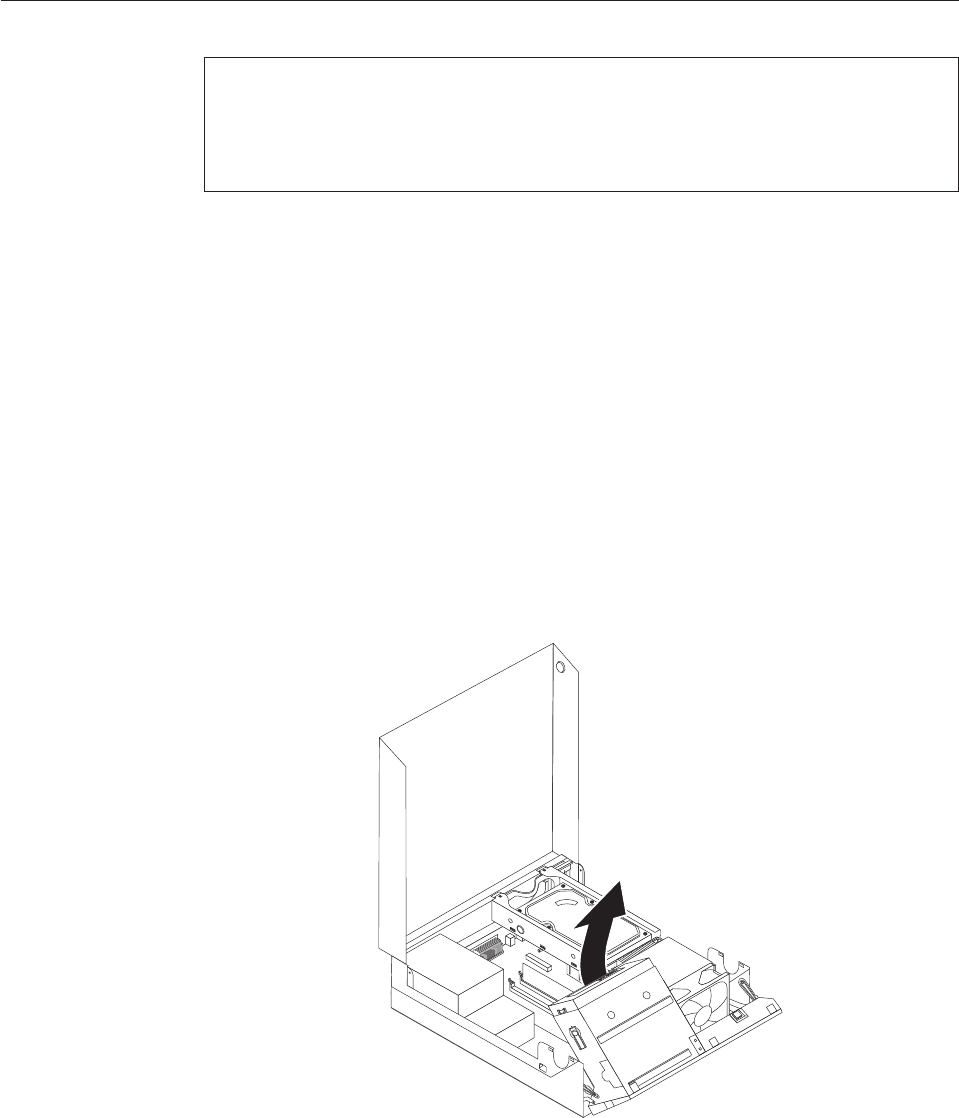
Accessing the system board components and drives
Attention
Do not open your computer or attempt any repair before reading and understanding the
“Important safety information” in the ThinkCentre Safety and Warranty Guide that came with
your computer. To obtain a copy of the ThinkCentre Safety and Warranty Guide,goto:
http://www.lenovo.com/support
This section provides instructions on how to access the system board components
and drives.
To access the system board components and drives:
1. Open the computer cover. See “Opening the computer cover” on page 126.
2. On some models, you might need to pivot the drive bay assembly upward and
remove the hard disk drive to access the internal components. See “Replacing
the hard disk drive” on page 136.
Note: Make sure you note the location of any cables that you disconnect from
the drives or the system board.
Attention: Make sure the hard disk drive assembly is in the latched down
position before closing the computer cover to prevent damage to the hard disk
drive assembly.
Figure 42. Pivoting the drive bay assembly
Chapter 9. Replacing FRUs - 607 127
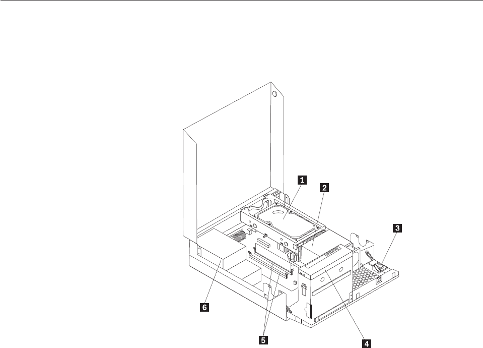
Locating components
To open the computer cover, see “Opening the computer cover” on page 126.
Figure 43 shows the location of the various components in your computer.
1 Hard disk drive 4 Optical drive
2 Heat sink and fan assembly 5 Memory slots
3 Internal speaker 6 Power supply assembly
Figure 43. Component locations
128 Hardware Maintenance Manual

Locating parts on the system board
Figure 44 shows the location of the parts on the system board.
1 PCI card slot 11 Memory slots (2)
2 PCI Express x16 graphics card slot 12 Front USB connectors (2)
3 Internal speaker connector 13 Serial (COM 2) connector
4 Battery 14 Power fan connector
5 Microprocessor fan connector 15 24-pin power connector
6 Thermal sensor connector 16 SATA connectors (2)
7 Cover presence (Intrusion) switch
connector
17 Clear CMOS (Complementary Metal Oxide
Semiconductor)/Recovery jumper
8 Microprocessor 18 Front audio connector
9 4-pin power connector 19 System fan connector
10 Front panel connector
Figure 44. System board parts locations
Chapter 9. Replacing FRUs - 607 129
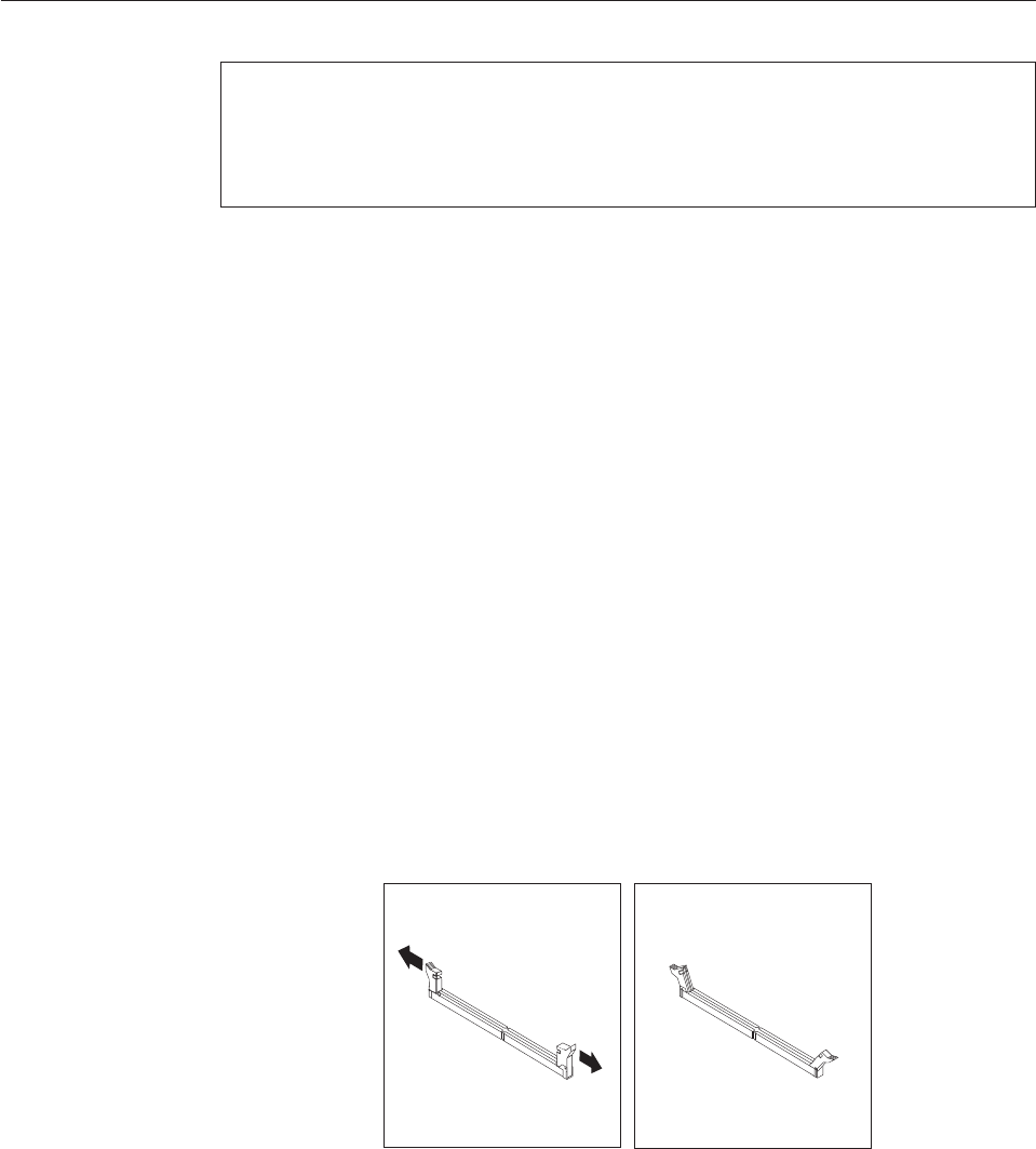
Installing or replacing a memory module
Attention
Do not open your computer or attempt any repair before reading and understanding the
“Important safety information” in the ThinkCentre Safety and Warranty Guide that came with
your computer. To obtain a copy of the ThinkCentre Safety and Warranty Guide,goto:
http://www.lenovo.com/support
This section provides instructions on how to install or replace a memory module.
Your computer has two slots for installing or replacing DDR2 DIMMs (double data
rate 2 dual inline memory modules) that provide up to a maximum of 4 GB
system memory.
When installing or replacing a memory module, use the following guidelines:
vUse 1.8 V, 240-pin, DDR2 DIMMs (double data rate 2 dual inline memory
modules).
vUse 512 MB, 1 GB, or 2 GB memory modules in any combination up to a
maximum of 4 GB.
Note: Only DDR2 SDRAM DIMMs can be used.
To install or replace a memory module:
1. Open the computer cover. See “Opening the computer cover” on page 126.
2. Pivot the drive bay assembly upward to access the memory slots. See
“Accessing the system board components and drives” on page 127.
3. Remove any parts that might prevent your access to the memory slots.
4. Locate the memory slots.
5. Open the retaining clips.
Figure 45. Opening the retaining clips
130 Hardware Maintenance Manual
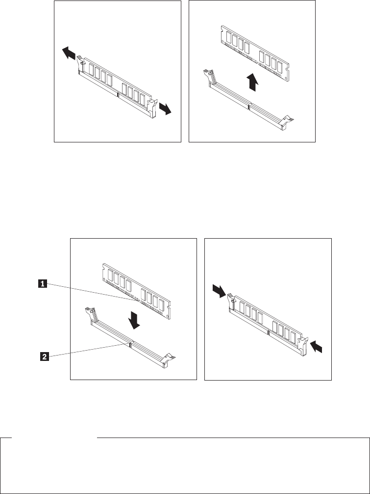
If you are replacing an old memory module, open the retaining clips and
remove the memory module being replaced as shown.
6. Position the memory module over the memory slot. Make sure that the notch
1 on the memory module aligns correctly with the slot key 2 on the system
board. Push the memory module straight down into the slot until the retaining
clips close.
What to do next:
vTo work with another option, go to the appropriate section.
vTo complete the installation, go to “Completing the FRU replacement” on
page 155.
Figure 46. Removing the old memory module
Figure 47. Installing the memory module
Chapter 9. Replacing FRUs - 607 131

Installing or replacing an adapter card
Attention
Do not open your computer or attempt any repair before reading and understanding the
“Important safety information” in the ThinkCentre Safety and Warranty Guide that came with
your computer. To obtain a copy of the ThinkCentre Safety and Warranty Guide,goto:
http://www.lenovo.com/support
This section provides instructions on how to install or replace an adapter card.
Your computer has one standard adapter card slot and one PCI Express x16
graphics adapter card slot.
To install or replace an adapter card:
1. Open the computer cover. See “Opening the computer cover” on page 126.
2. Rotate the adapter card retainer to the open position.
3. Remove the adapter card from its static-protective package.
132 Hardware Maintenance Manual
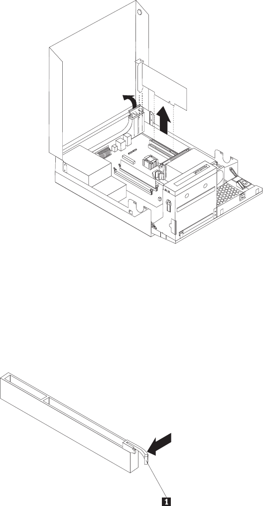
4. Install the adapter card into the appropriate adapter card slot on the system
board, see “Locating parts on the system board” on page 129. If you are
replacing an old adapter card, remove the adapter card being replaced before
installing the new one.
Notes:
a. The adapter card fits tightly into the adapter card slot. If necessary, alternate
moving each side of the adapter card a small amount until it is removed
from the adapter card slot.
b. If the adapter card is held in place by a retaining latch, press the adapter
card retaining latch 1 as shown to disengage the latch. Grasp the adapter
card and then gently pull the adapter card out of the slot.
Figure 48. Removing the adapter card
Chapter 9. Replacing FRUs - 607 133
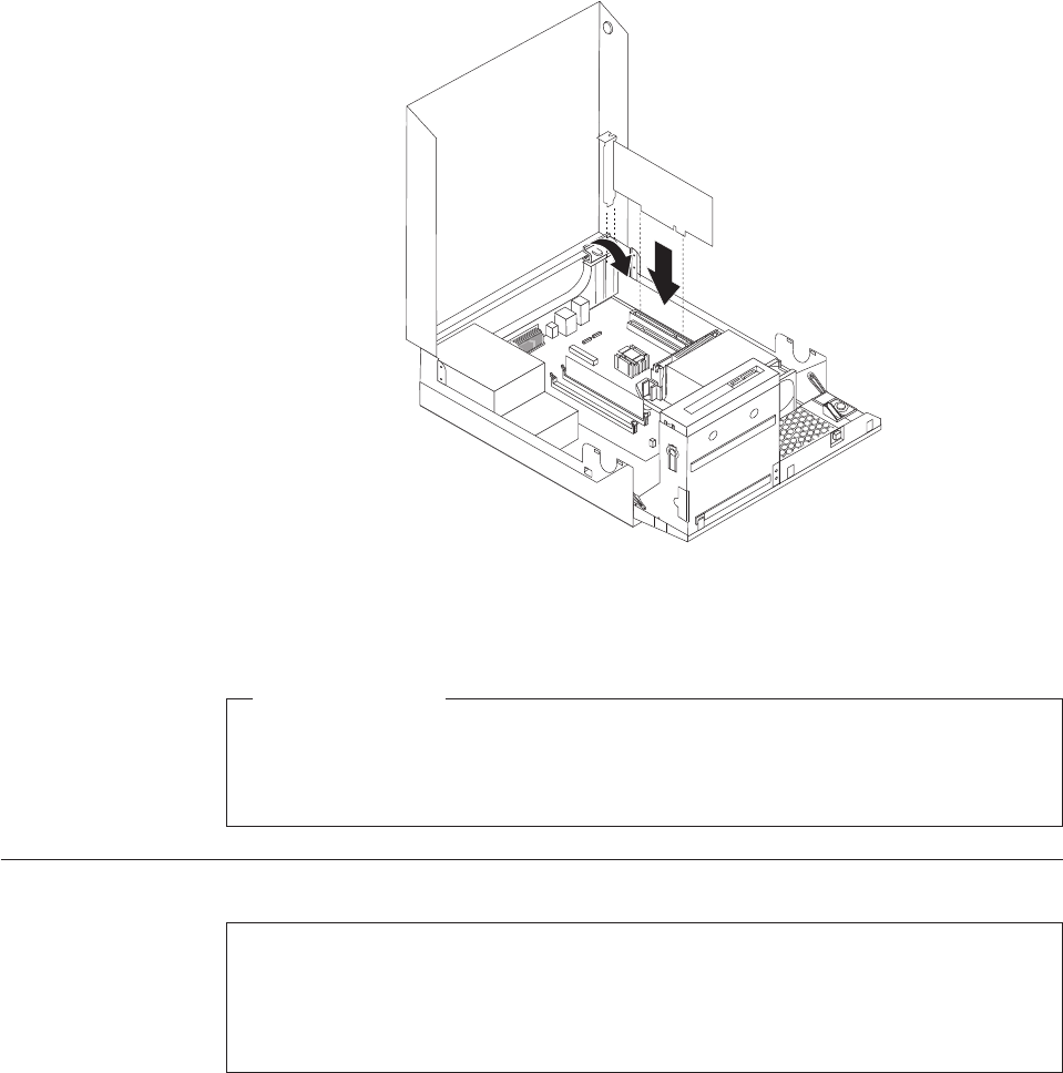
5. Rotate the adapter retainer to the closed position.
What to do next:
vTo work with another option, go to the appropriate section.
vTo complete the installation, go to “Completing the FRU replacement” on
page 155.
Replacing the battery
Attention
Do not open your computer or attempt any repair before reading and understanding the
“Important safety information” in the ThinkCentre Safety and Warranty Guide that came with
your computer. To obtain a copy of the ThinkCentre Safety and Warranty Guide,goto:
http://www.lenovo.com/support
This section provides instructions on how to replace the battery.
Your computer has a special type of memory that maintains the date, time, and
settings for built-in features, such as parallel-port assignments (configuration). A
battery keeps this information active when you turn off the computer.
The battery normally requires no charging or maintenance throughout its life;
however, no battery lasts forever. If the battery fails, the date, time, and
configuration information (including passwords) are lost. An error message is
displayed when you turn on the computer.
Refer to the “Lithium battery notice” in the ThinkCentre Safety and Warranty Guide
for information about replacing and disposing of the battery.
Figure 49. Installing the adapter card
134 Hardware Maintenance Manual
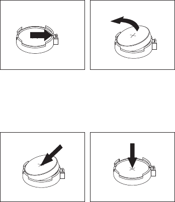
To replace the battery:
1. Open the computer cover. See “Opening the computer cover” on page 126.
2. Locate the battery. See “Locating parts on the system board” on page 129.
3. Remove the old battery.
4. Install a new battery.
5. Reinstall the computer cover and connect the cables. See “Completing the FRU
replacement” on page 155.
Note: When the computer is turned on for the first time after replacing the
battery, an error message might be displayed. This is normal after
replacing the battery.
6. Turn on the computer and all attached devices.
7. Use the Setup Utility program to set the date, time, and any passwords. See
Chapter 6, “Using the Setup Utility program,” on page 51.
Figure 50. Removing the old battery
Figure 51. Installing a new battery
Chapter 9. Replacing FRUs - 607 135
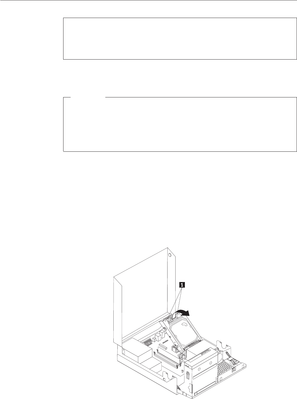
Replacing the hard disk drive
Attention
Do not open your computer or attempt any repair before reading and understanding the
“Important safety information” in the ThinkCentre Safety and Warranty Guide that came with
your computer. To obtain a copy of the ThinkCentre Safety and Warranty Guide,goto:
http://www.lenovo.com/support
This section provides instructions on how to replace the hard disk drive.
Important
When you receive a new hard disk drive, you also receive a set of Product
Recovery discs. The set of Product Recovery discs will enable you to restore the
contents of the hard disk drive to the same state as when your computer was
originally shipped from the factory. For more information on recovering
factory-installed software, refer to “Recovering software” in your ThinkCentre
User Guide.
To replace the hard disk drive:
1. Open the computer cover. See “Opening the computer cover” on page 126.
2. You might need to pivot the drive bay assembly upward to gain easy access
to the hard disk drive. See “Accessing the system board components and
drives” on page 127.
3. Locate the hard disk drive.
4. Push the blue handle of the hard disk drive bracket inwards to release the two
clips 1 that secure the hard disk drive to the chassis, and then rotate the
hard disk drive upwards and lift it up to remove it from the computer.
Figure 52. Removing the hard disk drive
136 Hardware Maintenance Manual
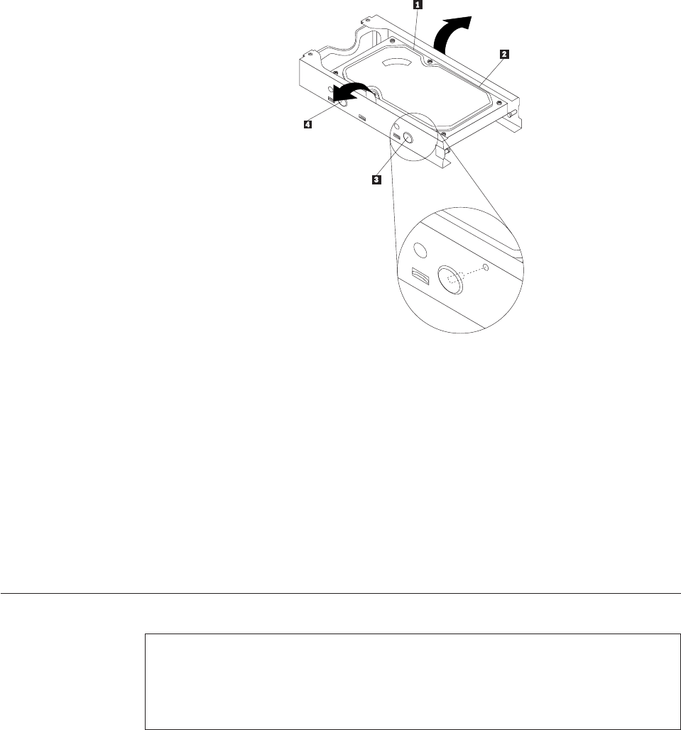
5. Disconnect the signal cable and the power cable from the hard disk drive.
6. Remove the old hard disk drive from the bracket by flexing the sides of the
bracket enough to slide it free from the hard disk drive.
7. To install a new hard disk drive into the bracket, flex the bracket and align
pin 1, pin 2, pin 3, and pin 4 on the bracket with the holes in the
hard disk drive.
Important: Do not touch the circuit board on the bottom of the hard disk
drive.
8. Connect the signal cable and the power cable to the new hard disk drive.
9. Install the new hard disk drive and bracket into the rear retainer and rotate
down until the two clips on the blue handle of the hard disk drive bracket
snap into position.
10. Go to “Completing the FRU replacement” on page 155.
Replacing the optical drive
Attention
Do not open your computer or attempt any repair before reading and understanding the
“Important safety information” in the ThinkCentre Safety and Warranty Guide that came with
your computer. To obtain a copy of the ThinkCentre Safety and Warranty Guide,goto:
http://www.lenovo.com/support
This section provides instructions on how to replace the optical drive.
To replace the optical drive:
1. Open the computer cover. See “Opening the computer cover” on page 126.
2. Pivot the drive bay assembly upward to gain access to the optical drive. See
“Accessing the system board components and drives” on page 127.
Figure 53. Removing the hard disk drive from the bracket
Chapter 9. Replacing FRUs - 607 137
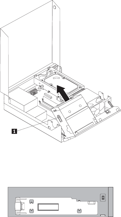
3. Disconnect the signal cable and the power cable from the rear of the optical
drive.
4. Press the optical drive lock 1 and slide the optical drive out the rear of the
drive bay assembly.
5. Remove the optical drive retainer from the old optical drive and then install it
on the left side of the new optical drive.
Figure 54. Removing the old optical drive
Figure 55. Installing the retainer
138 Hardware Maintenance Manual

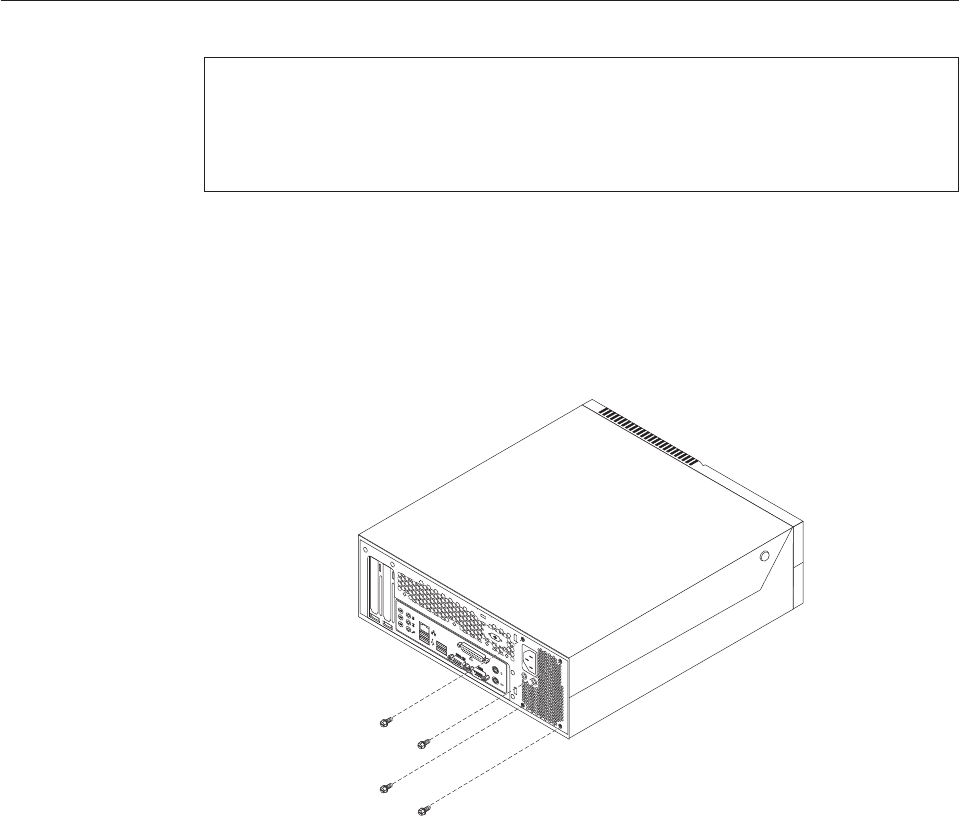
Replacing the power supply assembly
Attention
Do not open your computer or attempt any repair before reading and understanding the
“Important safety information” in the ThinkCentre Safety and Warranty Guide that came with
your computer. To obtain a copy of the ThinkCentre Safety and Warranty Guide,goto:
http://www.lenovo.com/support
This section provides instructions on how to replace the power supply assembly.
To replace the power supply assembly:
1. Remove the four screws at the rear of the chassis that secure the power
supply assembly.
2. Open the computer cover. See “Opening the computer cover” on page 126.
3. Pivot the drive bay assembly upward to gain access to the power supply
assembly.
4. Locate the power supply assembly. See “Locating components” on page 128.
Figure 57. Removing the retaining screws for the power supply assembly
140 Hardware Maintenance Manual
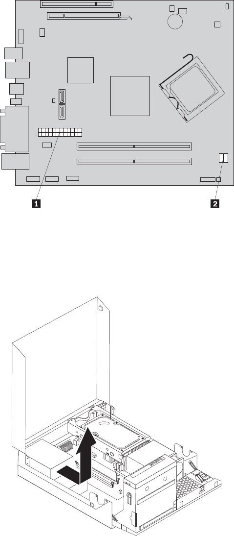
5. Disconnect the power supply assembly cables from all drives and from the
power connectors 1 and 2.
Note: You might need to remove the hard disk drive to gain easy access to
the power connector 1. See “Replacing the hard disk drive” on page
136.
6. Remove the power supply assembly cables from the cable clips and ties.
7. Slide the power supply assembly away from the chassis and remove it from
the computer.
Figure 58. Power connectors on the system board
Figure 59. Removing the power supply assembly
Chapter 9. Replacing FRUs - 607 141

8. Install the new power supply assembly into the chassis so that the screw holes
in the new power supply assembly align with those in the chassis.
9. Install and tighten the four screws at the rear of the chassis to secure the
power supply assembly.
Note: Use only the screws provided by Lenovo.
10. Reconnect all the power supply assembly cables to the drives and the system
board.
11. Go to “Completing the FRU replacement” on page 155.
Replacing the heat sink and fan assembly
Attention
Do not open your computer or attempt any repair before reading and understanding the
“Important safety information” in the ThinkCentre Safety and Warranty Guide that came with
your computer. To obtain a copy of the ThinkCentre Safety and Warranty Guide,goto:
http://www.lenovo.com/support
This section provides instructions on how to replace the heat sink and fan
assembly.
CAUTION:
The heat sink and fan assembly might be very hot. Turn off the computer and
wait three to five minutes to let the computer cool before opening the computer
cover.
This section provides instructions on how to replace the heat sink and fan
assembly.
To replace the heat sink and fan assembly:
1. Open the computer cover. See “Opening the computer cover” on page 126.
2. Pivot the drive bay assembly upward to gain access to the heat sink and fan
assembly. See “Accessing the system board components and drives” on page
127.
3. Locate the heat sink and fan assembly and disconnect the heat sink and fan
assembly cable from the microprocessor fan connector on the system board. See
“Locating parts on the system board” on page 129.
142 Hardware Maintenance Manual
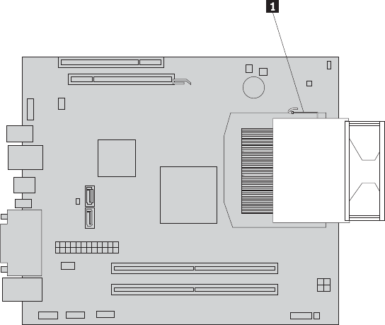
4. Remove the heat sink and fan assembly from the system board by pivoting the
lever 1 that secures the heat sink and fan assembly until it is fully in the up
position. Carefully lift the heat sink and fan assembly off the system board.
Notes:
a. You might have to gently twist the heat sink and fan assembly to free it
from the microprocessor.
b. Do not touch the thermal grease while handling the heat sink and fan
assembly.
5. Place the new heat sink and fan assembly into position and lower the lever to
secure the new heat sink and fan assembly.
6. Connect the new heat sink and fan assembly cable to the microprocessor fan
connector on the system board.
7. Go to “Completing the FRU replacement” on page 155.
Figure 60. Removing the heat sink and fan assembly
Chapter 9. Replacing FRUs - 607 143
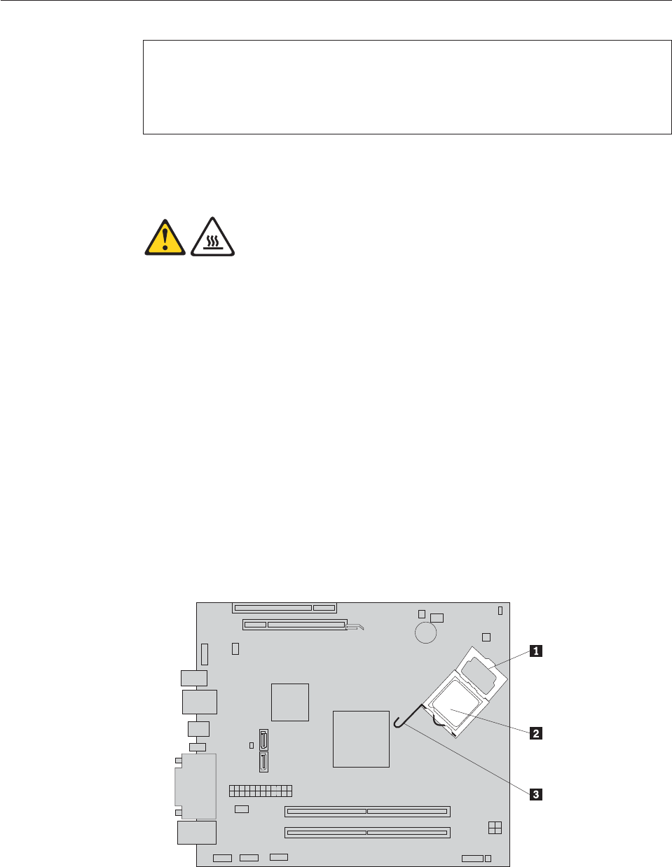
Replacing the microprocessor
Attention
Do not open your computer or attempt any repair before reading and understanding the
“Important safety information” in the ThinkCentre Safety and Warranty Guide that came with
your computer. To obtain a copy of the ThinkCentre Safety and Warranty Guide,goto:
http://www.lenovo.com/support
This section provides instructions on how to replace the microprocessor.
CAUTION:
The heat sink and microprocessor might be very hot. Turn off the computer and
wait three to five minutes to let the computer cool before opening the computer
cover.
To replace the microprocessor:
1. Open the computer cover. See “Opening the computer cover” on page 126.
2. Pivot the drive bay assembly upward to gain access to the system board. See
“Accessing the system board components and drives” on page 127.
3. Locate the heat sink and fan assembly and disconnect the heat sink and fan
assembly cable from the microprocessor fan connector on the system board.
See “Locating parts on the system board” on page 129.
4. Remove the heat sink and fan assembly. See “Replacing the heat sink and fan
assembly” on page 142.
5. Place the heat sink and fan assembly on its side so that the thermal grease
does not come in contact with anything.
6. Remove the hard disk drive. See “Replacing the hard disk drive” on page 136.
7. Lift the small handle 3 and open the retainer 1 to access the
microprocessor 2.
144 Hardware Maintenance Manual
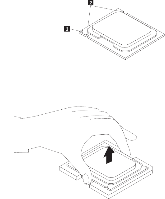
8. Lift the microprocessor straight up and out of the socket.
Notes:
a. Your microprocessor and socket might look different from the one
illustrated.
b. Note the orientation of the microprocessor in the socket. You can either
look for the small triangle 1 on one corner of the microprocessor or note
the orientation of the notches 2 on the microprocessor. This is important
when installing the new microprocessor on the system board.
c. Touch only the sides of the microprocessor. Do not touch the gold contacts
on the bottom.
d. Do not drop anything onto the microprocessor socket while it is exposed.
The socket pins must be kept as clean as possible.
9. Make sure that the small handle is in the raised position.
Chapter 9. Replacing FRUs - 607 145
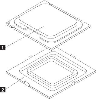
10. Remove the protective cover 2 that protects the gold contacts on the new
microprocessor 1.
11. Hold the new microprocessor and align the notches on it with the tabs in the
microprocessor socket, or align the small triangle on one corner with the
corresponding beveled corner of the microprocessor socket.
12. Lower the new microprocessor straight down into the microprocessor socket
on the system board.
13. Close the microprocessor retainer and lock it into position with the small
handle to secure the new microprocessor in the socket.
14. Reinstall the hard disk drive. See “Replacing the hard disk drive” on page
136.
15. Reinstall the heat sink and fan assembly. See “Replacing the heat sink and fan
assembly” on page 142.
16. Reconnect the heat sink and fan assembly cable to the microprocessor fan
connector on the system board.
17. Go to “Completing the FRU replacement” on page 155.
146 Hardware Maintenance Manual
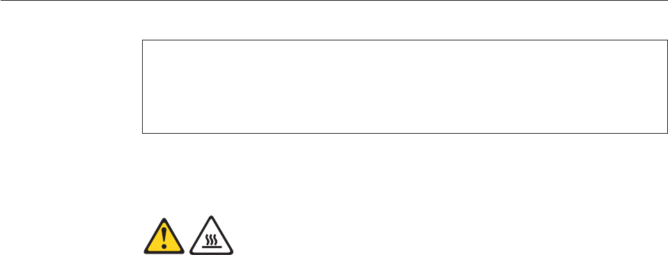
Replacing the system board
Attention
Do not open your computer or attempt any repair before reading and understanding the
“Important safety information” in the ThinkCentre Safety and Warranty Guide that came with
your computer. To obtain a copy of the ThinkCentre Safety and Warranty Guide,goto:
http://www.lenovo.com/support
This section provides instructions on how to replace the system board.
CAUTION:
The heat sink and microprocessor might be very hot. Turn off the computer and
wait three to five minutes to let the computer cool before opening the computer
cover.
To replace the system board:
1. Open the computer cover. See “Opening the computer cover” on page 126.
2. Pivot the drive bay assembly upward to gain access to the system board. See
“Accessing the system board components and drives” on page 127.
3. Remove the hard disk drive. See “Replacing the hard disk drive” on page 136.
4. Remove all memory modules and adapter cards that are currently installed.
See “Installing or replacing a memory module” on page 130 and “Installing or
replacing an adapter card” on page 132.
5. Carefully take note of the cable routing and the location of all cable
connectors on the system board, and then disconnect all the cables. See
“Locating parts on the system board” on page 129.
6. Remove the heat sink and fan assembly from the failing system board. See
“Replacing the heat sink and fan assembly” on page 142.
7. Remove the heat sink and fan assembly retainer by releasing the four screws
that secure the retainer on the system board, and then lifting the retainer off
the system board.
8. Carefully slide the system board toward the front of the chassis so that it can
be released from the four mounting studs that secure the system board in
place, and then lift the system board out of the chassis.
9. Remove the microprocessor socket cover from the new system board.
10. Remove the microprocessor from the failing system board and install it on the
new system board. See “Replacing the microprocessor” on page 144.
11. The failing system board must be returned with a microprocessor socket cover
to protect the pins during shipping and handling. Install the microprocessor
socket cover removed from the new system board on the failing system board.
To install the microprocessor socket cover:
a. Make sure the microprocessor has been removed from the microprocessor
socket, and then close the microprocessor retainer and lock it into position
with the small handle.
Chapter 9. Replacing FRUs - 607 147
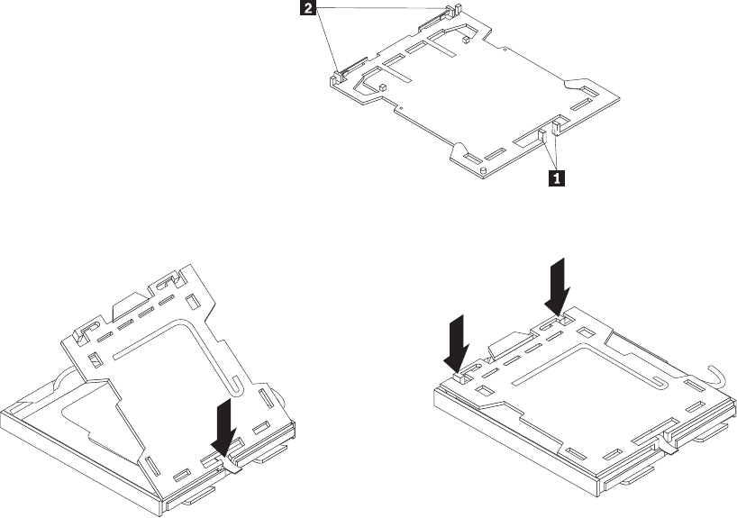
b. Insert the tabs 1 of the socket cover into the hinged side of the socket,
and then press the other side of the socket cover downward until the tabs
2 snap into position.
12. Install the new system board into the chassis by aligning the four mounting
studs in the chassis with the corresponding holes on the new system board,
and then carefully slide the new system board in to the chassis until it is
secured in place by the four mounting studs.
13. Install the heat sink and fan assembly retainer by aligning the four screw
holes on the retainer with the corresponding holes on the new system board,
and then tighten the screws to secure the retainer on the new system board.
14. Install the heat sink and fan assembly on the new system board. See
“Replacing the heat sink and fan assembly” on page 142. And connect the
heat sink and fan assembly cable to the new system board. See “Locating
parts on the system board” on page 129.
15. Install all memory modules and adapter cards removed from the failing
system board on the new system board.
16. Reinstall the hard disk drive. See “Replacing the hard disk drive” on page
136.
17. Reconnect the power and signal cables to the hard disk drive.
18. Reconnect all remaining cables to the new system board. See “Locating parts
on the system board” on page 129.
19. Go to “Completing the FRU replacement” on page 155.
Figure 61. Tabs on the microprocessor socket cover (bottom view)
Figure 62. Installing the microprocessor socket cover
148 Hardware Maintenance Manual
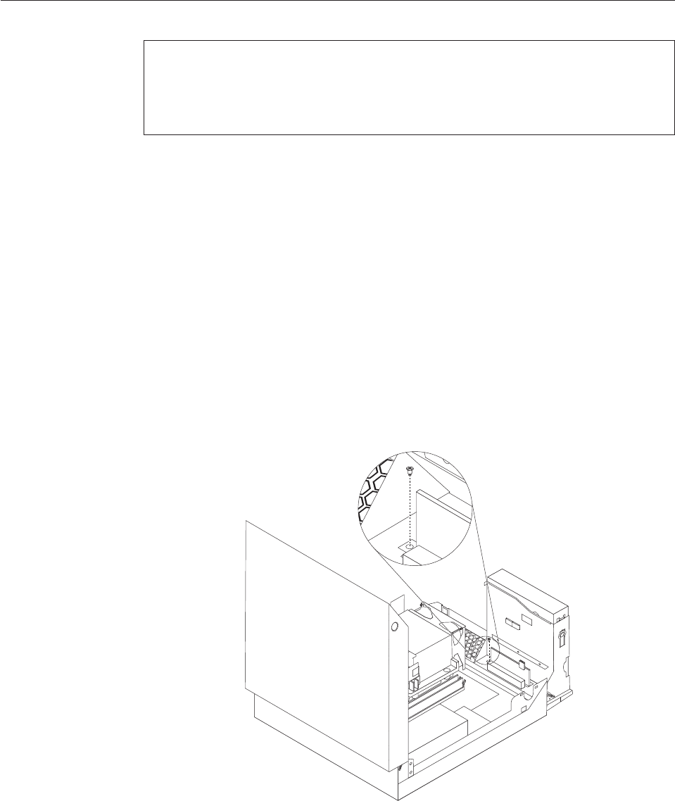
Replacing the card reader
Attention
Do not open your computer or attempt any repair before reading and understanding the
“Important safety information” in the ThinkCentre Safety and Warranty Guide that came with
your computer. To obtain a copy of the ThinkCentre Safety and Warranty Guide,goto:
http://www.lenovo.com/support
This section provides instructions on how to replace the card reader.
To replace the card reader, do the following:
1. Open the computer cover. See “Opening the computer cover” on page 126.
2. Pivot the drive bay assembly upward to gain access to the card reader. See
“Accessing the system board components and drives” on page 127.
3. Locate the card reader.
4. Disconnect the card reader cable from the front USB connector on the system
board. See “Locating parts on the system board” on page 129.
Note: Make sure you note the location and routing of the cable when you
disconnect the cable from the connector on the system board.
5. Remove the screw that secures the card reader to the chassis.
6. Remove the card reader from the chassis.
7. Install a new card reader into the chassis and align the screw hole in the new
card reader with the hole in the chassis.
8. Install the screw to secure the new card reader to the chassis.
9. Reconnect the card reader cable to the system board.
Figure 63. Removing the securing screw of the card reader
Chapter 9. Replacing FRUs - 607 149

10. Go to “Completing the FRU replacement” on page 155.
Replacing the front audio and USB assembly
Attention
Do not open your computer or attempt any repair before reading and understanding the
“Important safety information” in the ThinkCentre Safety and Warranty Guide that came with
your computer. To obtain a copy of the ThinkCentre Safety and Warranty Guide,goto:
http://www.lenovo.com/support
This section provides instructions on how to replace the front audio and USB
assembly.
To replace the front audio and USB assembly, do the following:
1. Open the computer cover. See “Opening the computer cover” on page 126.
2. Pivot the drive bay assembly upward to gain access to the front audio and
USB assembly. See “Accessing the system board components and drives” on
page 127.
3. Locate the front audio and USB assembly.
4. Remove the hard disk drive to gain access to the front audio connector on the
system board. See “Replacing the hard disk drive” on page 136.
5. Disconnect the front audio and USB assembly cables from the front audio
connector and the front USB connector on the system board. See “Locating
parts on the system board” on page 129.
Note: Make sure you note the location and routing of the cables when you
disconnect the cables from the connectors on the system board.
150 Hardware Maintenance Manual
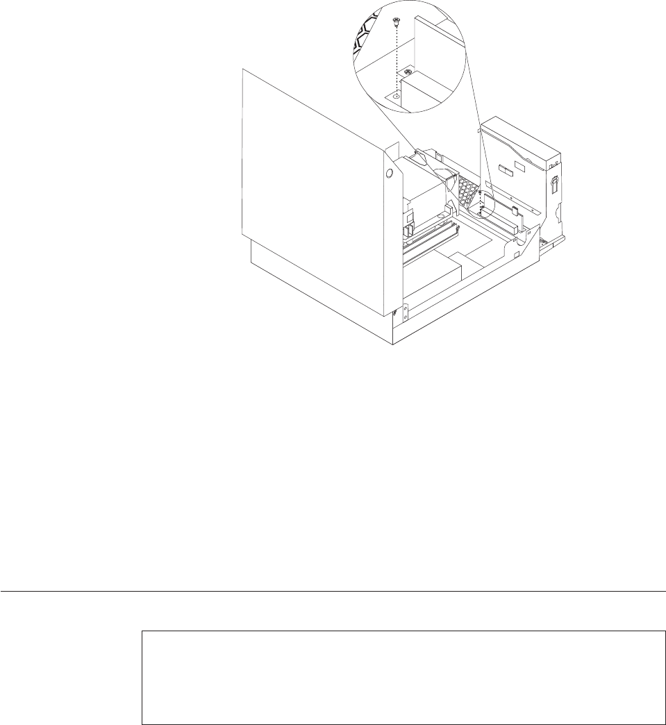
6. Remove the screw that secures the front audio and USB assembly to the
chassis.
7. Remove the front audio and USB assembly from the chassis.
8. Install a new front audio and USB assembly into the chassis and align the
screw hole in the new front audio and USB assembly with the hole in the
chassis.
9. Install the screw to secure the new front audio and USB assembly to the
chassis.
10. Reconnect the front audio and USB assembly cables to the front audio
connector and the front USB connector on the system board.
11. Reinstall the hard disk drive. See “Replacing the hard disk drive” on page 136.
12. Go to “Completing the FRU replacement” on page 155.
Replacing the internal speaker
Attention
Do not open your computer or attempt any repair before reading and understanding the
“Important safety information” in the ThinkCentre Safety and Warranty Guide that came with
your computer. To obtain a copy of the ThinkCentre Safety and Warranty Guide,goto:
http://www.lenovo.com/support
This section provides instructions on how to replace the internal speaker.
To replace the internal speaker:
1. Open the computer cover. See “Opening the computer cover” on page 126.
Figure 64. Removing the securing screw of the front audio and USB assembly
Chapter 9. Replacing FRUs - 607 151
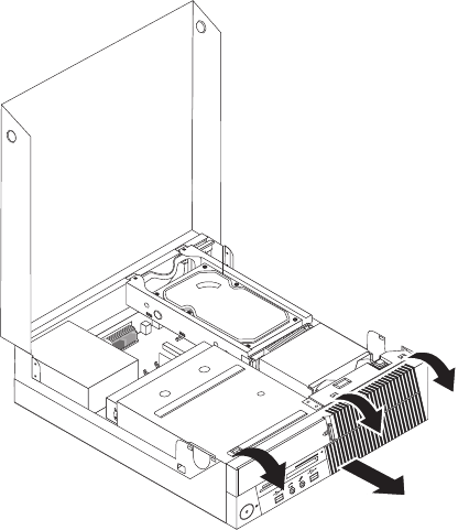
2. Remove the front bezel by releasing the three tabs, pivoting the front bezel
outward from the top, and pulling the front bezel off the chassis.
3. Pivot the drive bay assembly upward to gain access to the internal speaker.
See “Accessing the system board components and drives” on page 127.
4. Locate the internal speaker. See “Locating components” on page 128.
5. Disconnect the internal speaker cable and the thermal sensor cable from the
internal speaker connector and the thermal sensor connector on the system
board. See “Locating parts on the system board” on page 129.
Figure 65. Removing the front bezel
152 Hardware Maintenance Manual
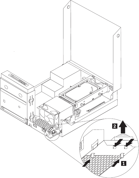
6. Push the four tabs on the bottom of the internal speaker one by one as shown
to release the internal speaker, and then lift the internal speaker straight up to
completely remove it from the chassis.
7. Remove the thermal sensor cable latched on the bottom of the old internal
speaker and install it on the new internal speaker.
Figure 66. Removing the internal speaker
Chapter 9. Replacing FRUs - 607 153

8. Align the four tabs on the bottom of the new internal speaker with the
corresponding holes in the chassis, and push the new internal speaker straight
down until it snaps into position.
Note: Carefully place the thermal sensor cable so that it will not impede the
installation of the new internal speaker.
9. Reconnect the internal speaker cable and the thermal sensor cable to the
system board.
10. Go to “Completing the FRU replacement” on page 155.
Figure 67. Installing the new internal speaker
154 Hardware Maintenance Manual
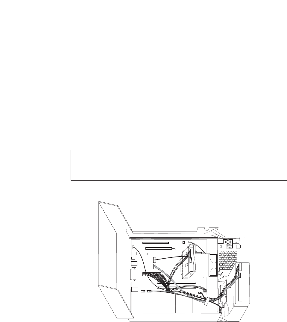
Completing the FRU replacement
After replacing the FRUs, you need to reinstall any removed parts, reconnect and
route any internal cables, close the computer cover, and reconnect any external
cables, including telephone lines and power cords. Depending on the FRUs
replaced, you might need to confirm the updated information in the Setup Utility
program, see Chapter 6, “Using the Setup Utility program,” on page 51.
Note: When the power cord is first plugged in, the computer might appear to turn
on for a few seconds and then turn off. This is a normal sequence to enable
the computer to initialize.
To close the computer cover and reconnect external cables to your computer:
1. Ensure that all components have been reassembled correctly and that no tools
or loose screws are left inside your computer. See “Locating components” on
page 128 for the location of the various components.
2. Ensure that the internal cables are routed correctly before lowering the drive
bay assembly.
Important
Correctly route all power supply cables to avoid interference with the
drive bay assembly. Keep cables clear of the hinges and sides of the
computer chassis.
3. Lower the drive bay assembly and place the drive locks to the locked position.
Otherwise, you cannot close the computer cover.
4. If you removed the front bezel, reinstall it by aligning the three tabs on the
front bezel with the corresponding holes on the chassis and pivoting the front
bezel inward until it snaps into position.
5. Close the computer cover.
6. If a computer cover lock is installed, lock the computer cover.
Figure 68. Cable routing
Chapter 9. Replacing FRUs - 607 155
7. Reconnect the external cables and power cords to the computer. See “Locating
connectors on the rear of your computer” on page 125.
8. If you have replaced the system board, you must update (flash) the BIOS. See
“Updating (flashing) BIOS from a disc” on page 278.
9. Some FRU replacements require the configuration to be updated. To update
your configuration, see Chapter 6, “Using the Setup Utility program,” on page
51.
156 Hardware Maintenance Manual
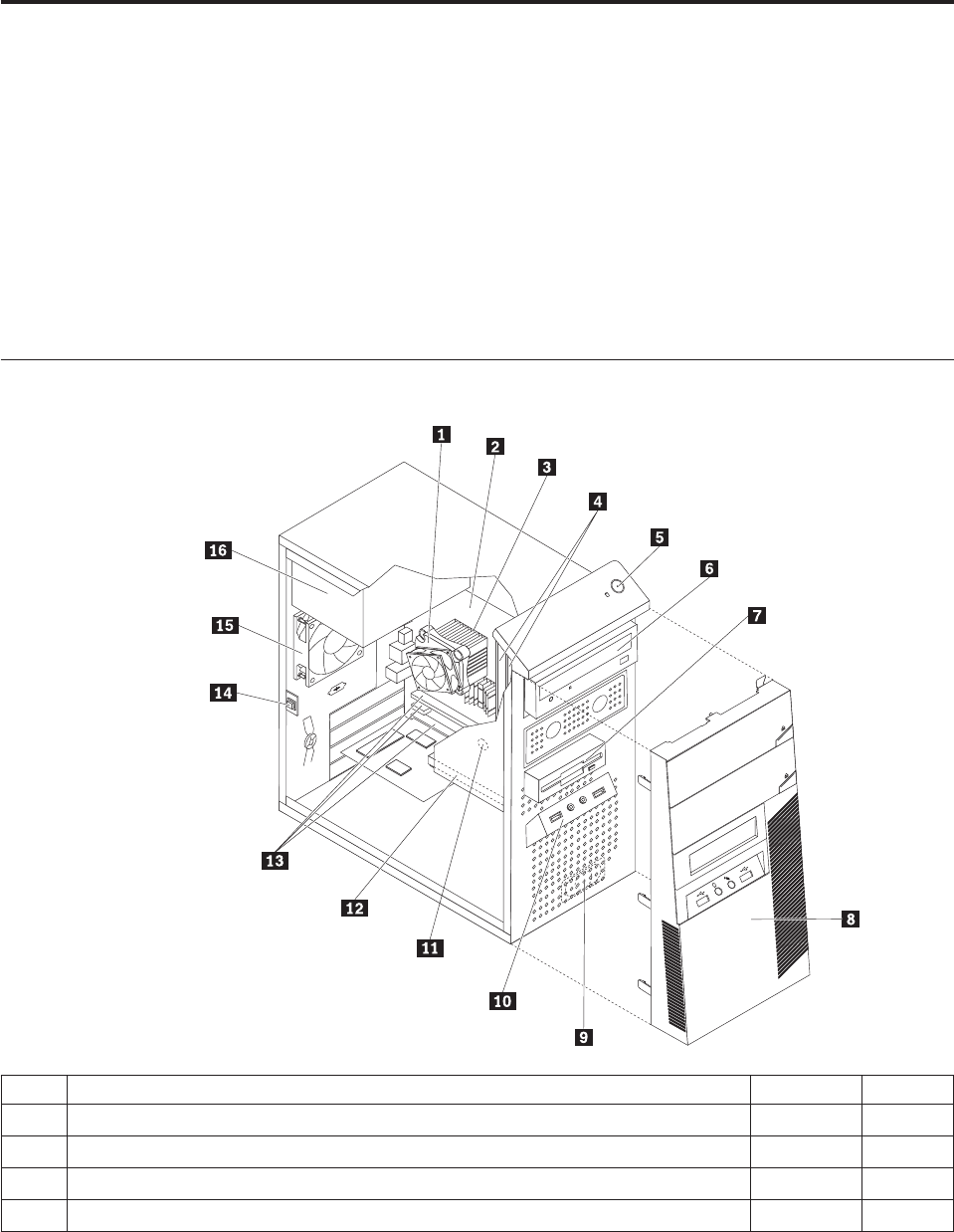
Chapter 10. FRU lists
This chapter lists the information about the FRUs for the computers.
Attention: Be sure to read and understand all the safety information before
replacing any FRUs.
Note: In the following tables, a customer replaceable unit (CRU) is identified as
either ″1″,″2″,or″N″in the CRU column. ″N″means that the part is not a
CRU, ″1″means that the part is a Self-service CRU, and ″2″means that the
part is an Optional-service CRU.
Machine type 7515
Item# 7515 FRUs FRU# CRU
1 Intel 95W / 65W heat sink (all models) 43N9409 2
1 Intel 65W heat sink (all models) 43N9708 2
1 Intel 65W heat sink (all models) 45K6227 2
1 Intel 95W / 65W heat sink (all models) 43N9897 2
© Copyright Lenovo 2009 157

Item# 7515 FRUs FRU# CRU
2 System board, Intel G41 MATX(GA) non-AMT (models H6A H6Q H6T H7M H7A
H7T A8M B1M B1Q B2Q B2T B3A B5M B5Q B6Q B7Q B8M B8Q D2M D2Q D3M
E6M E6A E6Q E7M E7A E7Q E8M E8A E8Q E8K E9A E9Q F1A F1Q F2M F2A F2Q
F3M F3A F4M F4A F4Q F4K F5M F5A F5Q F6M F6A F6Q F6K F7M F7A F8A F8Q
F9M F9A H1M H1A H2M H2A H3A H3Q 73G 73M 73A 73H 72G 74G 75G 76G
77G 78G 79G 7AG A1S A1P A1Y A4U A4F A4S A4P A4Y A5P A6S A6Y E2S E2P
E2D E2Y E4S E4P E4D E4Y E5S E5P E5D E5Y D9U D9F H4U H4F H5U H5F H5M
H5A H5T 7CG 7DG H8S H8Y H9S H9Y J1S J1Y J2U J2F J3U J3F J4U J4F J5U J6T
J7A 7FG J8U J8F J9U J9F K1U K1F 7JG 7KG 7LG 7RG 7SG 7MG 7NG 7PG 7QG
K2M K3M K4M K7J K8J K9J L1J L2U L2F K5U K5F K5S K5D K5Y K6U K6F L3Q
L4S L4D L4Y L5S L5D L5Y L6S L6D L6Y L7S L7D L7Y L8S L8D L8Y L9J M1S M1Y
M2S M2Y M3S M3Y)
46R8891 N
2 System board, Intel G41 MATX(GA) -NB upgrade (models H6A H6Q H6T H7M
H7A H7T A8M B1M B1Q B2Q B2T B3A B5M B5Q B6Q B7Q B8M B8Q D2M D2Q
D3M E6M E6A E6Q E7M E7A E7Q E8M E8A E8Q E8K E9A E9Q F1A F1Q F2M
F2A F2Q F3M F3A F4M F4A F4Q F4K F5M F5A F5Q F6M F6A F6Q F6K F7M F7A
F8A F8Q F9M F9A H1M H1A H2M H2A H3A H3Q 73G 73M 73A 73H 72G 74G
75G 76G 77G 78G 79G 7AG A1S A1P A1Y A4U A4F A4S A4P A4Y A5P A6S A6Y
E2S E2P E2D E2Y E4S E4P E4D E4Y E5S E5P E5D E5Y D9U D9F H4U H4F H5U
H5F H5M H5A H5T 7CG 7DG H8S H8Y H9S H9Y J1S J1Y J2U J2F J3U J3F J4U J4F
J5U J6T J7A 7FG J8U J8F J9U J9F K1U K1F 7JG 7KG 7LG 7RG 7SG 7MG 7NG 7PG
7QG K2M K3M K4M K7J K8J K9J L1J L2U L2F K5U K5F K5S K5D K5Y K6U K6F
L3Q L4S L4D L4Y L5S L5D L5Y L6S L6D L6Y L7S L7D L7Y L8S L8D L8Y L9J M1S
M1Y M2S M2Y M3S M3Y)
64Y9197 N
2 System board, Intel G41 MATX -- EuP and No TCM header (models H6A H6Q
H6T H7M H7A H7T A8M B1M B1Q B2Q B2T B3A B5M B5Q B6Q B7Q B8M B8Q
D2M D2Q D3M E6M E6A E6Q E7M E7A E7Q E8M E8A E8Q E8K E9A E9Q F1A
F1Q F2M F2A F2Q F3M F3A F4M F4A F4Q F4K F5M F5A F5Q F6M F6A F6Q F6K
F7M F7A F8A F8Q F9M F9A H1M H1A H2M H2A H3A H3Q 73G 73M 73A 73H
72G 74G 75G 76G 77G 78G 79G 7AG A1S A1P A1Y A4U A4F A4S A4P A4Y A5P
A6S A6Y E2S E2P E2D E2Y E4S E4P E4D E4Y E5S E5P E5D E5Y D9U D9F H4U
H4F H5U H5F H5M H5A H5T 7CG 7DG H8S H8Y H9S H9Y J1S J1Y J2U J2F J3U
J3F J4U J4F J5U J6T J7A 7FG J8U J8F J9U J9F K1U K1F 7JG 7KG 7LG 7RG 7SG
7MG 7NG 7PG 7QG K2M K3M K4M K7J K8J K9J L1J L2U L2F K5U K5F K5S K5D
K5Y K6U K6F L3Q L4S L4D L4Y L5S L5D L5Y L6S L6D L6Y L7S L7D L7Y L8S
L8D L8Y L9J M1S M1Y M2S M2Y M3S M3Y)
71Y6838 N
3 Microprocessor, E7400 2.8GHZ 1066M 3M R0 (ViiV, EIST, EM64T, EDB) 65W
(models F4M F4A F4Q F4K F5M F5A F5Q F6M F6A F6Q F6K F7M F7A F8A F8Q
72G 74G E5S E5P E5D E5Y 7CG 7DG)
53Y6653 N
3 Microprocessor, E7500 2.93GHZ 1066M 3M R0 (ViiV, EIST, EM64T, EDB) 65W
(models F9M F9A H1M H1A H2M H2A H3A H3Q K1U K1F 7JG 7KG 7QG L5S
L5D L5Y L6S L6D L6Y L9J M3S M3Y)
53Y6654 N
3 Microprocessor, E5300 2.6GHz 800MHz 2MB R0 (EIST, EM64T, EDB) 65W (models
E8M E8A E8Q E8K E9A E9Q F2M F2A F2Q F3M F3A J8U J8F J9U J9F 7RG 7SG
7MG 7NG 7PG L3Q M1S M1Y M2S M2Y)
53Y9049 N
3 Microprocessor, E1500 2.2GHz 800MHz 512KB (EIST, EM64T, EDB) M0 65W
(models)
53Y9051 N
3 Microprocessor, Q8300 Yorkfield 2.5GHZ, 1333MHz, 4M R-0 (ViiV, EIST, EM64T,
EDB) 95W (models)
53Y6656 N
3 Microprocessor, E8600 3.33GHZ/1333MHZ/6M E0 65W (models) 46R8640 N
3 Microprocessor, E8500 3.16GHz 1333MHz FSB 6M C-0 65W (models D2M D2Q) 45C7735 N
3 Microprocessor, E8400 3.0GHz 1333MHz FSB 6M C-0 65W (models 91C 91J B7Q
B8M B8Q 73G 73M 73A 73H 77G 78G A5P A6S A6Y E2S E2P E2D E2Y)
45C7736 N
3 Microprocessor, E8300 2.83GHz 1333MHz FSB 6M C-0 65W (models) 45C7737 N
158 Hardware Maintenance Manual

Item# 7515 FRUs FRU# CRU
3 Microprocessor, E7200 2.53GHz 1066MHz FSB 3M M-0 65W (models) 45R8337 N
3 Microprocessor, E7300 2.66GHz 1066MHz FSB 3M M-0 65W (models B3A B5M
B5Q B6Q E6M E6A E6Q E7M E7A E7Q F1A F1Q A4U A4F A4S A4P A4Y)
46R1622 N
3 Microprocessor, E2200 Conroe-L 2.2GHz 800MHz FSB 1M (models) 45C5349 N
3 Microprocessor, E2220 Conroe-L 2.4GHz 800MHz FSB 1M (models) 45C1774 N
3 Microprocessor, E5200 2.5G 800MHz 2M M-0 65W, 45nm (models H6A H6Q H6T
H7M H7A H7T B1M B1Q B2Q B2T 79G 7AG E4S E4P E4D E4Y D9U D9F H4U
H4F H5U H5F H5M H5A H5T J2U J2F J4U J4F J5U 7FG 7LG)
46R9512 N
3 Microprocessor, E1600 2.4GHZ/800MHZ/512K - NPI M-0 65W (models) 46R1655 N
3 Microprocessor, E1400 2.0GHz 800MHz FSB 512K - NPI M-0 65W (models 75G
76G J3U J3F)
45R8339 N
3 Microprocessor, Cel-440 Conroe-L 2.0GHz 800MHz FSB 512K (models) 43C1965 N
3 Microprocessor, Cel-450 2.2GHz 800MHz FSB 512K 35W (models) 46R9514 N
3 Microprocessor, Q9650 3.0GHZ 1333FSB 12MB VT, TXT E-0 95W (models) 46R8642 N
3 Microprocessor, Q9400 2.66GHZ 1333FSB 6MB VT, TXT R-0 95W (models) 46R8644 N
3 Microprocessor, Q8200 2.33GHz 1333FSB 4M M-1 95W (models D3M H8S H8Y
H9S H9Y J1S J1Y)
46R9516 N
3 Microprocessor, Q9550 2.83GHZ 1333FSB 12M C-1 95W (models) 45C7739 N
3 Microprocessor, Q9450 Yorkfield 2.66GHZ 1333FSB 12M C-1 95W (models) 45C7740 N
3 Microprocessor, Q9300 Yorkfield 2.50GHZ 1333FSB 6M M-1 95W (models) 45C7741 N
3 Microprocessor, E5400 2.7G 800MHz 2MB 65W Non-vPro SKU (models J6T J7A) 64Y1075 N
3 Microprocessor, E7600 3.06GHZ 1066M 3M 65W (models) 71Y3486 N
3 Microprocessor, Q8400 2.66GHZ,1333MHz,4M 95W (models K2M K7J K8J L7S L7D
L7Y L8S L8D L8Y)
71Y3488 N
3 Microprocessor, E6300 2.8G 1066MHz-2MB 65W (models K5U K5F K5S K5D K5Y
K6U K6F L4S L4D L4Y)
71Y3484 N
3 Microprocessor, E6500 2.93GHZ 1066 MHz-2MB 65W R0 (models) 71Y6250 N
3 Microprocessor, E3300 2.5GHZ 800 MHz-1MB 65W R0 (models) 71Y6252 N
3 Microprocessor, E3200 2.4GHZ 800 MHz-1MB 65W R0 (models) 71Y6251 N
4 Memory module, 512MB PC2-5300 (667MHz) DDR2 SDRAM (models) 41X4255 1
4 Memory module, 1GB PC2-5300 (667MHz) DDR2 SDRAM (models) 41X4256 1
4 Memory module, 2GB PC2-5300 (667MHz) DDR2 SDRAM (models) 41X4257 1
4 Memory module, 512MB PC2-6400 (800MHz) DDR2 SDRAM (models H4U H4F) 41X1079 1
4 Memory module, 1GB PC2-6400 (667MHz) DDR2 SDRAM (models H6A H6Q H6T
H7M H7A H7T A8M B1M B1Q B2Q B2T B3A B5M B5Q B6Q B7Q E6M E6A E6Q
E7M E7A E7Q E8M E8A E8Q E8K E9A E9Q F1A F1Q F2M F2A F2Q F4M F4A F4Q
F4K F5M F5A F5Q F6M F6A F6Q F6K F8A F8Q F9M F9A H1M H1A H3A H3Q
A1S A1P A1Y E4S E4P E4D E4Y H5U H5F H5M H5A H5T H8S H8Y H9S H9Y J3U
J3F J6T J7A 7FG 7LG 7MG 7NG 7PG L1J L2U L2F L4S L4D L4Y L6S L6D L6Y L7S
L7D L7Y M1S M1Y)
41X1080 1
4 Memory module, 2GB PC2-6400 (667MHz) DDR2 SDRAM (models B8M B8Q D2M
D2Q D3M F3M F3A F7M F7A H2M H2A 73G 73M 73A 73H 72G 74G 75G 76G 77G
78G 79G 7AG A4U A4F A4S A4P A4Y A5P A6S A6Y E2S E2P E2D E2Y E5S E5P
E5D E5Y D9U D9F 7CG 7DG J1S J1Y J2U J2F J4U J4F J5U J8U J8F J9U J9F K1U
K1F 7JG 7KG 7RG 7SG 7QG K2M K3M K4M K7J K8J K9J K5U K5F K5S K5D K5Y
K6U K6F L3Q L5S L5D L5Y L8S L8D L8Y L9J M2S M2Y M3S M3Y)
41X1081 1
Chapter 10. FRU lists 159

Item# 7515 FRUs FRU# CRU
6 Optical drive, DVD-ROM Drive - 16x/48x - SATA - for Windows 7 (models 91C
91J A8M B3A B6Q H4U H4F J2U J2F 7FG 7LG L3Q)
71Y5543 1
6 Optical drive, DVD Recordable Rambo8-SATA12XRAM Write - for Windows 7
(models H6A H6Q H6T H7M H7A H7T B1M B1Q B2Q B2T B5M B5Q B7Q B8M
B8Q D2M D2Q D3M E6M E6A E6Q E7M E7A E7Q E8M E8A E8Q E8K E9A E9Q
F1A F1Q F2M F2A F2Q F3M F3A F4M F4A F4Q F4K F5M F5A F5Q F6M F6A F6Q
F6K F7M F7A F8A F8Q F9M F9A H1M H1A H2M H2A H3A H3Q 73G 73M 73A
73H 72G 74G 75G 76G 77G 78G 79G 7AG A4U A4F A4S A4P A4Y A5P A6S A6Y
E2S E2P E2D E2Y E4S E4P E4D E4Y E5S E5P E5D E5Y D9U D9F H5U H5F H5M
H5A H5T 7CG 7DG H8S H8Y H9S H9Y J1S J1Y J3U J3F J4U J4F J5U J6T J7A J8U
J8F J9U J9F K1U K1F 7JG 7KG 7RG 7SG 7QG K2M K3M K4M K7J K8J K9J L1J
L2U L2F K5U K5F K5S K5D K5Y K6U K6F L4S L4D L4Y L5S L5D L5Y L6S L6D
L6Y L7S L7D L7Y L8S L8D L8Y L9J M1S M1Y M2S M2Y M3S M3Y)
71Y5545 1
6 Optical drive, Blu-ray Recordable / DVD Super Multi - for Windows 7 (models) 71Y5547 1
7 Diskette drive, 3.5″1.44MB 2 Mode FDD with Bezel and cable (models) 40Y9107 1
7 Diskette drive, 3.5″1.44MB 2 Mode FDD with Bezel and cable (models) 40Y9105 1
8 Front bezel assembly (all models) 43N9662 1
8 Front bezel with ODD door assembly (all models) 43N9694 2
9 Internal speaker 400mm -- Optional (all models) 43N9091 2
11 Battery 3V - Lithium (models H6A H6Q H6T H7M H7A H7T A8M B1M B1Q B2Q
B2T B3A B5M B5Q B6Q B7Q B8M B8Q D2M D2Q D3M E6M E6A E6Q E7M E7A
E7Q E8M E8A E8Q E8K E9A E9Q F1A F1Q F2M F2A F2Q F3M F3A F4M F4A F4Q
F4K F5M F5A F5Q F6M F6A F6Q F6K F7M F7A F8A F8Q F9M F9A H1M H1A
H2M H2A H3A H3Q 73G 73M 73A 73H 72G 74G 75G 76G 77G 78G 79G 7AG A1S
A1P A1Y A4U A4F A4S A4P A4Y A5P A6S A6Y E2S E2P E2D E2Y E4S E4P E4D
E4Y E5S E5P E5D E5Y D9U D9F H4U H4F H5U H5F H5M H5A H5T 7CG 7DG
H8S H8Y H9S H9Y J1S J1Y J2U J2F J3U J3F J4U J4F J5U J6T J7A 7FG J8U J8F J9U
J9F K1U K1F 7JG 7KG 7LG 7RG 7SG 7MG 7NG 7PG 7QG K2M K3M K4M K7J K8J
K9J L1J L2U L2F K5U K5F K5S K5D K5Y K6U K6F L3Q L4S L4D L4Y L5S L5D
L5Y L6S L6D L6Y L7S L7D L7Y L8S L8D L8Y L9J M1S M1Y M2S M2Y M3S M3Y)
45C1566 1
12 Hard disk drive, SATA 160GB 7200RPM/3Gb/8MB (models 91C 91J H6A H6Q
H6T A8M B3A E6M E6A E6Q E7M E7A E7Q E8M E8A E8Q E8K E9A E9Q F1A
F1Q F2M F2A F2Q F4M F4A F4Q F4K F5M F5A F5Q F8A F8Q F9M F9A H3A H3Q
73G 73M 73A 73H 75G 76G A1S A1P A1Y A4U A4F A4S A4P A4Y A5P E2S E2P
E2D E2Y E4S E4P E4D E4Y E5S E5P E5D E5Y D9U D9F H4U H4F H5U H5F H5M
H5A H5T H8S H8Y J2U J2F J3U J3F J4U J4F J8U J8F)
40Y9035 1
12 Hard disk drive, SATA 250GB 7200RPM/3Gb/8MB (models H7M H7A H7T B1M
B1Q B2Q B2T B5M B5Q B6Q B7Q B8M B8Q F3M F3A F6M F6A F6Q F6K F7M F7A
H1M H1A H2M H2A A6S A6Y H9S H9Y J1S J1Y J5U J6T J7A 7FG J9U J9F K1U
K1F 7LG 7MG 7NG 7PG L1J L2U L2F K5U K5F K5S K5D K5Y L4S L4D L4Y L5S
L5D L5Y L6S L6D L6Y L7S L7D L7Y L8S L8D L8Y)
40Y9036 1
12 Hard disk drive, SATA 320GB 7200rpm SATA/8MB (models D2M D2Q D3M 72G
74G 77G 78G 79G 7AG 7CG 7DG 7JG 7KG 7RG 7SG 7QG K7J K8J K9J K6U K6F
L3Q L9J M1S M1Y M2S M2Y M3S M3Y)
87H4891 1
12 Hard disk drive, SATA 500GB 7200RPM/3Gb/s/8MB (models) 41X5582 1
12 Hard disk drive, 1TB 7200rpm SATA (models) 45C5973 1
12 Hard disk drive, SATA 160GB 7200RPM/3Gb/8MB - optional (models H6A H6Q
H6T A8M B3A E6M E6A E6Q E7M E7A E7Q E8M E8A E8Q E8K E9A E9Q F1A
F1Q F2M F2A F2Q F4M F4A F4Q F4K F5M F5A F5Q F8A F8Q F9M F9A H3A H3Q
73G 73M 73A 73H 75G 76G A1S A1P A1Y A4U A4F A4S A4P A4Y A5P E2S E2P
E2D E2Y E4S E4P E4D E4Y E5S E5P E5D E5Y D9U D9F H4U H4F H5U H5F H5M
H5A H5T H8S H8Y J2U J2F J3U J3F J4U J4F J8U J8F)
53Y6837 1
160 Hardware Maintenance Manual

Item# 7515 FRUs FRU# CRU
12 Hard disk drive, SATA 250GB 7200RPM/3Gb/8MB - optional (models H7M H7A
H7T B1M B1Q B2Q B2T B5M B5Q B6Q B7Q B8M B8Q F3M F3A F6M F6A F6Q
F6K F7M F7A H1M H1A H2M H2A A6S A6Y H9S H9Y J1S J1Y J5U J6T J7A 7FG
J9U J9F K1U K1F 7LG 7MG 7NG 7PG L1J L2U L2F K5U K5F K5S K5D K5Y L4S
L4D L4Y L5S L5D L5Y L6S L6D L6Y L7S L7D L7Y L8S L8D L8Y)
45K0408 1
12 Hard disk drive, SATA 320GB 7200RPM SATA/8MB - optional (models D2M D2Q
D3M 72G 74G 77G 78G 79G 7AG 7CG 7DG 7JG 7KG 7RG 7SG 7QG K7J K8J K9J
K6U K6F L3Q L9J M1S M1Y M2S M2Y M3S M3Y)
45K0409 1
12 Hard disk drive, SATA 500GB 7200RPM/3Gb/s/8MB - optional (models K2M
K3M K4M)
45K0410 1
12 Hard disk drive, 1TB 7200RPM SATA - optional (models) 45K0412 1
12 Hard disk drive, 150G 10K RPM, SATA (models) 46R6400 1
14 Intrusion Switch Asm 475mm --Optional (all models) 39K5022 2
14 Intrusion Switch Asm (all models) 41R6116 2
15 System fan, rear (all models) 41R6269 2
16 Power supply, ATX 450W 80% power supply, Robust, WW, JP (models H6A H6Q
H6T H7M H7A H7T A8M B1M B1Q B2Q B2T B3A B5M B5Q B6Q B7Q B8M B8Q
D2M D2Q D3M E6M E6A E6Q E7M E7A E7Q E8M E8A E8Q E8K E9A E9Q F1A
F1Q F2M F2A F2Q F3M F3A F4M F4A F4Q F4K F5M F5A F5Q F6M F6A F6Q F6K
F7M F7A F8A F8Q F9M F9A H1M H1A H2M H2A H3A H3Q 73G 73M 73A 73H
72G 74G 75G 76G 77G 78G 79G 7AG A1S A1P A1Y A4U A4F A4S A4P A4Y A5P
A6S A6Y E2S E2P E2D E2Y E4S E4P E4D E4Y E5S E5P E5D E5Y D9U D9F H4U
H4F H5U H5F H5M H5A H5T 7CG 7DG H8S H8Y H9S H9Y J1S J1Y J2U J2F J3U
J3F J4U J4F J5U J6T J7A 7FG J8U J8F J9U J9F K1U K1F 7JG 7KG 7LG 7RG 7SG
7MG 7NG 7PG 7QG K2M K3M K4M K7J K8J K9J L1J L2U L2F K5U K5F K5S K5D
K5Y K6U K6F L3Q L4S L4D L4Y L5S L5D L5Y L6S L6D L6Y L7S L7D L7Y L8S
L8D L8Y L9J M1S M1Y M2S M2Y M3S M3Y)
41A9721 2
16 Power supply, ATX 280W power supply, Robust, WW (models H6A H6Q H6T
H7M H7A H7T A8M B1M B1Q B2Q B2T B3A B5M B5Q B6Q B7Q B8M B8Q D2M
D2Q D3M E6M E6A E6Q E7M E7A E7Q E8M E8A E8Q E8K E9A E9Q F1A F1Q
F2M F2A F2Q F3M F3A F4M F4A F4Q F4K F5M F5A F5Q F6M F6A F6Q F6K F7M
F7A F8A F8Q F9M F9A H1M H1A H2M H2A H3A H3Q 73G 73M 73A 73H 72G
74G 75G 76G 77G 78G 79G 7AG A1S A1P A1Y A4U A4F A4S A4P A4Y A5P A6S
A6Y E2S E2P E2D E2Y E4S E4P E4D E4Y E5S E5P E5D E5Y D9U D9F H4U H4F
H5U H5F H5M H5A H5T 7CG 7DG H8S H8Y H9S H9Y J1S J1Y J2U J2F J3U J3F
J4U J4F J5U J6T J7A 7FG J8U J8F J9U J9F K1U K1F 7JG 7KG 7LG 7RG 7SG 7MG
7NG 7PG 7QG K2M K3M K4M L2U L2F K5U K5F K5S K5D K5Y K6U K6F L3Q
L4S L4D L4Y L5S L5D L5Y L6S L6D L6Y L7S L7D L7Y L8S L8D L8Y M1S M1Y
M2S M2Y M3S M3Y)
41A9684 2
16 Power supply, ATX 280W 80% power supply, Robust, WW, JP (models H6A H6Q
H6T H7M H7A H7T A8M B1M B1Q B2Q B2T B3A B5M B5Q B6Q B7Q B8M B8Q
D2M D2Q D3M E6M E6A E6Q E7M E7A E7Q E8M E8A E8Q E8K E9A E9Q F1A
F1Q F2M F2A F2Q F3M F3A F4M F4A F4Q F4K F5M F5A F5Q F6M F6A F6Q F6K
F7M F7A F8A F8Q F9M F9A H1M H1A H2M H2A H3A H3Q 73G 73M 73A 73H
72G 74G 75G 76G 77G 78G 79G 7AG A1S A1P A1Y A4U A4F A4S A4P A4Y A5P
A6S A6Y E2S E2P E2D E2Y E4S E4P E4D E4Y E5S E5P E5D E5Y D9U D9F H4U
H4F H5U H5F H5M H5A H5T 7CG 7DG H8S H8Y H9S H9Y J1S J1Y J2U J2F J3U
J3F J4U J4F J5U J6T J7A 7FG J8U J8F J9U J9F K1U K1F 7JG 7KG 7LG 7RG 7SG
7MG 7NG 7PG 7QG K2M K3M K4M K7J K8J K9J L1J L2U L2F K5U K5F K5S K5D
K5Y K6U K6F L3Q L4S L4D L4Y L5S L5D L5Y L6S L6D L6Y L7S L7D L7Y L8S
L8D L8Y L9J M1S M1Y M2S M2Y M3S M3Y)
41A9665 2
Chapter 10. FRU lists 161

Item# 7515 FRUs FRU# CRU
16 Power supply, 280-watt ATX, (85plus)-WW, Robust, JP (models H6A H6Q H6T
H7M H7A H7T A8M B1M B1Q B2Q B2T B3A B5M B5Q B6Q B7Q B8M B8Q D2M
D2Q D3M E6M E6A E6Q E7M E7A E7Q E8M E8A E8Q E8K E9A E9Q F1A F1Q
F2M F2A F2Q F3M F3A F4M F4A F4Q F4K F5M F5A F5Q F6M F6A F6Q F6K F7M
F7A F8A F8Q F9M F9A H1M H1A H2M H2A H3A H3Q 73G 73M 73A 73H 72G
74G 75G 76G 77G 78G 79G 7AG A1S A1P A1Y A4U A4F A4S A4P A4Y A5P A6S
A6Y E2S E2P E2D E2Y E4S E4P E4D E4Y E5S E5P E5D E5Y D9U D9F H4U H4F
H5U H5F H5M H5A H5T 7CG 7DG H8S H8Y H9S H9Y J1S J1Y J2U J2F J3U J3F
J4U J4F J5U J6T J7A 7FG J8U J8F J9U J9F K1U K1F 7JG 7KG 7LG 7RG 7SG 7MG
7NG 7PG 7QG K2M K3M K4M K7J K8J K9J L1J L2U L2F K5U K5F K5S K5D K5Y
K6U K6F L3Q L4S L4D L4Y L5S L5D L5Y L6S L6D L6Y L7S L7D L7Y L8S L8D
L8Y L9J M1S M1Y M2S M2Y M3S M3Y)
45J9431 2
16 Power supply, ATX 280W Robust; WW for EUP (models H6Q B1Q B2Q B5Q B6Q
B7Q B8Q D2Q E6Q E7Q E8Q E9Q F1Q F2Q F4Q F5Q F6Q F8Q H3Q 73H K7J K8J
K9J L1J L3Q L9J)
45J9436 2
The FRUs listed in the following tables are not illustrated.
7515 FRUs FRU# CRU
Chassis (all models) 45K6346 2
System fan, front fan used for 2X500G (all models) 43N9599 2
Shield, 5.25 EMC FOR 1st ODD Bay (all models) 41N8080 1
Cable - SATA 457 mm (RoHS) for ODD (all models) 43N9013 2
Cable - SATA, Second HDD, 120 mm, 1 latching for Device, RoHS (all models) 41R3328 2
Cable - SATA 250 mm (RoHS) for 1st HDD (all models) 43N9012 2
Second HDD Bracket Asm (all models) 41R6106 1
Temp Sense Cable (6pin 460 mm) (all models) 45J9495 2
FDD Cable (all models) 41A7182 2
FDD Cable, 310 mm (all models) 41A7147 2
I/O Shield (all models) 41N8053 2
Rear I/O Shield, ATX, 946, FOF (all models) 45K6266 2
HDD Tray (all models) 41R6291 1
ODD/FDD/Cardreader Retainers (all models) 43N9351 1
Cable Clip, FW-6D (all models) 43N9462 2
Power switch cable, 760 mm (all models) 45J9512 2
Front I_O cable_R (all models) 45J9506 2
Front I_O cable_R (all models) 45J9592 2
ODD door assembly (all models) 43N9663 1
No FDD cover assembly (all models) 43N9664 1
FDD/Cardreader cover (all models) 43N9665 1
Chassis primary HDD cage (all models) 45K6272 2
USB cover (all models) 43N9666 1
Top handle assembly (all models) 43N9667 1
3.5’’ Convert 2.5’’ for 150GB 10K rpm HDD (1st HDD bay) (all models) 43N9593 2
Thermal Grease (all models) 91P8835 N
162 Hardware Maintenance Manual

7515 FRUs FRU# CRU
Rubber foot (For acoustic improvement) (all models) 45K6278 2
7515 Keyboards (Lenovo Preferred Pro USB -- without hub) FRU# CRU
USB FULL--US English (models H6A H6Q H7M H7A A8M B1M B1Q B2Q B3A B5M B5Q
B6Q B7Q B8M B8Q D2M D2Q D3M E6M E6A E6Q E7M E7A E7Q E8M E8A E8Q E9A
E9Q F1A F1Q F2M F2A F2Q F3M F3A F4M F4A F4Q F5M F5A F5Q F6M F6A F6Q F7M
F7A F8A F8Q F9M F9A H1M H1A H2M H2A H3A H3Q 73G 73M 73A 73H 72G 74G 75G
76G 77G 78G 79G 7AG A4U D9U H4U H5U H5M H5A 7CG 7DG J2U J3U J4U J5U J7A
7FG J8U J9U K1U 7JG 7KG 7LG L3Q)
41A5289 1
USB FULL--Arabic (models 73G 72G 74G 75G 76G 77G 78G 79G 7AG 7CG 7DG 7FG 7JG
7KG 7LG)
41A5290 1
USB FULL--Arabic/French (models 73G 72G 74G 75G 76G 77G 78G 79G 7AG 7CG 7DG
7FG 7JG 7KG 7LG)
41A5291 1
USB FULL--Belgium French (models 73G 72G 74G 75G 76G 77G 78G 79G 7AG 7CG 7DG
7FG 7JG 7KG 7LG)
41A5292 1
USB FULL--Belgium English (models 73G 72G 74G 75G 76G 77G 78G 79G 7AG 7CG 7DG
7FG 7JG 7KG 7LG)
41A5293 1
USB FULL--Brazilian Portuguese (models A1P A4P A5P E2P E4P E5P) 41A5294 1
USB FULL--Bulgarian (models 73G 72G 74G 75G 76G 77G 78G 79G 7AG 7CG 7DG 7FG
7JG 7KG 7LG)
41A5295 1
USB FULL--Chinese/US (models) 41A5296 1
USB FULL--Czech (ABB) (models 73G 72G 74G 75G 76G 77G 78G 79G 7AG 7CG 7DG
7FG 7JG 7KG 7LG)
41A5297 1
USB FULL--Danish (models 73G 72G 74G 75G 76G 77G 78G 79G 7AG 7CG 7DG 7FG 7JG
7KG 7LG)
41A5298 1
USB FULL--Dutch (models 73G 72G 74G 75G 76G 77G 78G 79G 7AG 7CG 7DG 7FG 7JG
7KG 7LG)
41A5299 1
USB FULL--French (models 73G 72G 74G 75G 76G 77G 78G 79G 7AG 7CG 7DG 7FG 7JG
7KG 7LG)
41A5300 1
USB FULL--French Canadian (models 73G 72G 74G 75G 76G 77G 78G 79G 7AG A4F D9F
H4F H5F 7CG 7DG J2F J3F J4F 7FG J8F J9F K1F 7JG 7KG 7LG 7RG 7SG 7MG 7NG 7PG
7QG L2F K5F K6F)
41A5301 1
USB FULL--French Canadian (models 73G 72G 74G 75G 76G 77G 78G 79G 7AG A4F D9F
H4F H5F 7CG 7DG J2F J3F J4F 7FG J8F J9F K1F 7JG 7KG 7LG 7RG 7SG 7MG 7NG 7PG
7QG L2F K5F K6F)
41A5302 1
USB FULL--German (models 73G 72G 74G 75G 76G 77G 78G 79G 7AG 7CG 7DG 7FG 7JG
7KG 7LG)
41A5303 1
USB FULL--Greek (models 73G 72G 74G 75G 76G 77G 78G 79G 7AG 7CG 7DG 7FG 7JG
7KG 7LG)
41A5304 1
USB FULL--Greek/US (models 73G 72G 74G 75G 76G 77G 78G 79G 7AG 7CG 7DG 7FG
7JG 7KG 7LG)
41A5305 1
USB FULL--Hebrew (models 73G 72G 74G 75G 76G 77G 78G 79G 7AG 7CG 7DG 7FG 7JG
7KG 7LG)
41A5306 1
USB FULL--Hungarian (models 73G 72G 74G 75G 76G 77G 78G 79G 7AG 7CG 7DG 7FG
7JG 7KG 7LG)
41A5307 1
USB FULL--Iceland (models 73G 72G 74G 75G 76G 77G 78G 79G 7AG 7CG 7DG 7FG 7JG
7KG 7LG)
41A5308 1
Chapter 10. FRU lists 163

7515 Keyboards (Lenovo Preferred Pro USB -- without hub) FRU# CRU
USB FULL--Italy (models 73G 72G 74G 75G 76G 77G 78G 79G 7AG 7CG 7DG 7FG 7JG
7KG 7LG)
41A5309 1
USB FULL--Japanese (models K7J K8J K9J L1J L9J) 41A5310 1
USB FULL--Korean (models E8K F4K F6K) 41A5311 1
USB FULL--LA Spanish (models A1S A1Y A4S A4Y A6S A6Y E2S E2D E2Y E4S E4D E4Y
E5S E5D E5Y H8S H8Y H9S H9Y J1S J1Y K5S K5D K5Y L4S L4D L4Y L5S L5D L5Y L6S
L6D L6Y L7S L7D L7Y L8S L8D L8Y M1S M1Y M2S M2Y M3S M3Y)
41A5312 1
USB FULL--Norwegian (models 73G 72G 74G 75G 76G 77G 78G 79G 7AG 7CG 7DG 7FG
7JG 7KG 7LG)
41A5313 1
USB FULL--Polish (models 73G 72G 74G 75G 76G 77G 78G 79G 7AG 7CG 7DG 7FG 7JG
7KG 7LG)
41A5314 1
USB FULL--Portuguese (models 73G 72G 74G 75G 76G 77G 78G 79G 7AG 7CG 7DG 7FG
7JG 7KG 7LG)
41A5315 1
USB FULL--Romanian (models 73G 72G 74G 75G 76G 77G 78G 79G 7AG 7CG 7DG 7FG
7JG 7KG 7LG)
41A5317 1
USB FULL--Romanian (models 73G 72G 74G 75G 76G 77G 78G 79G 7AG 7CG 7DG 7FG
7JG 7KG 7LG)
41A5316 1
USB FULL--Russian/Cyrillic (models 73G 72G 74G 75G 76G 77G 78G 79G 7AG 7CG 7DG
7FG 7JG 7KG 7LG)
41A5318 1
USB FULL--Serbian/Cyrillic (models 73G 72G 74G 75G 76G 77G 78G 79G 7AG 7CG 7DG
7FG 7JG 7KG 7LG)
41A5319 1
USB FULL--Slovak (models 73G 72G 74G 75G 76G 77G 78G 79G 7AG 7CG 7DG 7FG 7JG
7KG 7LG)
41A5320 1
USB FULL--Spanish (models 73G 72G 74G 75G 76G 77G 78G 79G 7AG 7CG 7DG 7FG 7JG
7KG 7LG)
41A5321 1
USB FULL--Swedish/Finnish (models 73G 72G 74G 75G 76G 77G 78G 79G 7AG 7CG 7DG
7FG 7JG 7KG 7LG)
41A5322 1
USB FULL--Swiss French/German (models 73G 72G 74G 75G 76G 77G 78G 79G 7AG 7CG
7DG 7FG 7JG 7KG 7LG)
41A5323 1
USB FULL--Thailand (models H6T H7T B2T H5T J6T) 41A5324 1
USB FULL--Turkish (models 73G 72G 74G 75G 76G 77G 78G 79G 7AG 7CG 7DG 7FG 7JG
7KG 7LG)
41A5325 1
USB FULL--Turkish (models 73G 72G 74G 75G 76G 77G 78G 79G 7AG 7CG 7DG 7FG 7JG
7KG 7LG)
41A5326 1
USB FULL --UK English (models 73G 72G 74G 75G 76G 77G 78G 79G 7AG 7CG 7DG 7FG
7JG 7KG 7LG)
41A5327 1
USB FULL--US Euro (models 73G 72G 74G 75G 76G 77G 78G 79G 7AG 7CG 7DG 7FG
7JG 7KG 7LG)
41A5328 1
USB FULL--Slovenian (models 73G 72G 74G 75G 76G 77G 78G 79G 7AG 7CG 7DG 7FG
7JG 7KG 7LG)
41A5329 1
USB FULL--Lithuanian (models 73G 72G 74G 75G 76G 77G 78G 79G 7AG 7CG 7DG 7FG
7JG 7KG 7LG)
45J4896 1
USB FULL--Estonia (models CTO) 51J0059 1
7515 Keyboards (Lenovo Fingerprint Reader USB) FRU# CRU
US English (models) 41R0038 1
Arabic (models) 41R0039 1
164 Hardware Maintenance Manual

7515 Keyboards (Lenovo Fingerprint Reader USB) FRU# CRU
Arabic/French (models) 41R0040 1
Belgium French (models) 41R0041 1
Belgium English (models) 41R0042 1
Brazilian Portuguese (models) 41R0043 1
Bulgarian (models) 41R0044 1
Chinese/US (models) 41R0045 1
Czech (ABB) (models) 41R0046 1
Danish (models) 41R0047 1
Dutch (models) 41R0048 1
French (models) 41R0049 1
French Canadian (models) 41R0050 1
French Canadian (models) 41R0051 1
German (models) 41R0052 1
Greek (models) 41R0053 1
Greek/US (models) 41R0054 1
Hebrew (models) 41R0055 1
Hungarian (models) 41R0056 1
Iceland (models) 41R0057 1
Italian (models) 41R0058 1
Japanese (models) 41R0059 1
Korean (models) 41R0060 1
LA Spanish (models) 41R0061 1
Norwegian (models) 41R0062 1
Polish (models) 41R0063 1
Portuguese (models) 41R0064 1
Romanian (models) 41R0065 1
Romanian (models) 41R0066 1
Russian/Cyrillic (models) 41R0067 1
Serbian/Cyrillic (models) 41R0068 1
Slovak (models) 41R0069 1
Spanish (models) 41R0070 1
Swedish/Finnish (models) 41R0071 1
Swiss French/German (models) 41R0072 1
Thailand (models) 41R0073 1
Turkish (models) 41R0074 1
Turkish (models) 41R0075 1
UK English (models) 41R0076 1
US Euro (models) 41R0077 1
Slovenian (models) 41R0078 1
Chapter 10. FRU lists 165

7515 Mice FRU# CRU
Optical Wheel Mouse OPT (400DPI, USB) (models H6A H6Q H6T H7M H7A H7T A8M
B1M B1Q B2Q B2T B3A B5M B5Q B6Q B7Q B8M B8Q D2M D2Q D3M E6M E6A E6Q E7M
E7A E7Q E8M E8A E8Q E8K E9A E9Q F1A F1Q F2M F2A F2Q F3M F3A F4M F4A F4Q
F4K F5M F5A F5Q F6M F6A F6Q F6K F7M F7A F8A F8Q F9M F9A H1M H1A H2M H2A
H3A H3Q 73G 73M 73A 73H 72G 74G 75G 76G 77G 78G 79G 7AG A1S A1P A1Y A4U A4F
A4S A4P A4Y A5P A6S A6Y E2S E2P E2D E2Y E4S E4P E4D E4Y E5S E5P E5D E5Y D9U
D9F H4U H4F H5U H5F H5M H5A H5T 7CG 7DG H8S H8Y H9S H9Y J1S J1Y J2U J2F
J3U J3F J4U J4F J5U J6T J7A 7FG J8U J8F J9U J9F K1U K1F 7JG 7KG 7LG 7RG 7SG 7MG
7NG 7PG 7QG K2M K3M K4M K7J K8J K9J L1J L2U L2F K5U K5F K5S K5D K5Y K6U
K6F L3Q L4S L4D L4Y L5S L5D L5Y L6S L6D L6Y L7S L7D L7Y L8S L8D L8Y L9J M1S
M1Y M2S M2Y M3S M3Y)
41U3013 1
Optical Wheel Mouse OPT (400DPI, USB) (models H6A H6Q H6T H7M H7A H7T A8M
B1M B1Q B2Q B2T B3A B5M B5Q B6Q B7Q B8M B8Q D2M D2Q D3M E6M E6A E6Q E7M
E7A E7Q E8M E8A E8Q E8K E9A E9Q F1A F1Q F2M F2A F2Q F3M F3A F4M F4A F4Q
F4K F5M F5A F5Q F6M F6A F6Q F6K F7M F7A F8A F8Q F9M F9A H1M H1A H2M H2A
H3A H3Q 73G 73M 73A 73H 72G 74G 75G 76G 77G 78G 79G 7AG A1S A1P A1Y A4U A4F
A4S A4P A4Y A5P A6S A6Y E2S E2P E2D E2Y E4S E4P E4D E4Y E5S E5P E5D E5Y D9U
D9F H4U H4F H5U H5F H5M H5A H5T 7CG 7DG H8S H8Y H9S H9Y J1S J1Y J2U J2F
J3U J3F J4U J4F J5U J6T J7A 7FG J8U J8F J9U J9F K1U K1F 7JG 7KG 7LG 7RG 7SG 7MG
7NG 7PG 7QG K2M K3M K4M K7J K8J K9J L1J L2U L2F K5U K5F K5S K5D K5Y K6U
K6F L3Q L4S L4D L4Y L5S L5D L5Y L6S L6D L6Y L7S L7D L7Y L8S L8D L8Y L9J M1S
M1Y M2S M2Y M3S M3Y)
41U3030 1
7515 Adapters and miscellaneous FRUs FRU# CRU
Internal 25 in 1 USB Memory Card Reader (models) 45R8139 1
IEEE 1394 Firewire Adapter ATX (models) 41D2781 1
Speaker power brick - US, Canada, LA low voltage, ASEAN (models A4U D9U H4U H5U
J2U J3U J4U J5U J8U J9U K1U)
89P8571 1
Speaker power brick - LA high voltage (non-APU) (models) 89P8575 1
Speaker power brick - Simplified Chinese, Thailand EMEA (models 91C 73G 72G 74G 75G
76G 77G 78G 79G 7AG 7CG 7DG 7FG 7JG 7KG 7LG)
89P8581 1
Speaker power brick - Japanese (models K7J K8J K9J L1J L9J) 89P8577 1
Speaker power brick - Brazil (models) 89P8583 1
Speaker power brick - Argentina (models) 41A4901 1
Speaker power brick - ANZ (models H7M A8M B1M B5M B8M D2M D3M E6M E7M E8M
F2M F3M F4M F5M F6M F7M F9M H1M H2M 73M H5M)
89P8579 1
Speaker power brick - Korea (models) 41A4903 1
Speaker power brick - Hong Kong, EMEA, Ireland (models 73G 72G 74G 75G 76G 77G
78G 79G 7AG 7CG 7DG 7FG 7JG 7KG 7LG)
89P8573 1
Speaker power brick -Taiwan-Traditional Chinese (models) 41A4905 1
Speaker power brick - India, South Africa (models H6Q B1Q B2Q B5Q B6Q B7Q B8Q D2Q
E6Q E7Q E8Q E9Q F1Q F2Q F4Q F5Q F6Q F8Q H3Q L3Q)
89P8585 1
2-pc external speaker--primary (models) 41A5331 1
2-pc external speaker-secondary (models) 41A5334 1
DVI-I(M)-VGA(F) cord (models) 41R3342 1
Geforce 9500GT GDDR3 512MB - DVI+HDMI+DP (models) 46R1524 1
ATI HD3470 GDDR3 256MB - VGA+DP (models) 46R1521 1
ADD2 DVI-D Adapter, (HDCP) DVD-D connection Adapter Low Profile (Silicon Image)
(models 91U 77G 78G)
43C0258 1
166 Hardware Maintenance Manual

7515 Adapters and miscellaneous FRUs FRU# CRU
DisplayPort to DVI-D Dongle (models) 43N9160 1
DisplayPort to VGA Dongle (models) 45J9524 1
Modem phone cable (models) 39K5120 1
LI300mm Rear USB 2Ports II HP®(models) 42Y8005 2
LI350mm Rear Com2 cable II mini®(models) 41R8548 2
NVIDIA G100 DDR2 256MB ATX - DVI-I+VGA (models 91U CTO) 53Y9249 1
Soft Modem V.90/V.44 ATX (models) 46R4220 1
7515 Power Cords (Primary) FRU # CRU
Power cord - US (models H6A H6T H7A H7T B2T B3A E6A E7A E8A E9A F1A F2A F3A
F4A F5A F6A F7A F8A F9A H1A H2A H3A 73A A1S A1Y A4U A4F A4S A4Y A6S A6Y E2S
E2Y E4S E4Y E5S E5Y D9U D9F H4U H4F H5U H5F H5A H5T H8S H8Y H9S H9Y J1S J1Y
J2U J2F J3U J3F J4U J4F J5U J6T J7A J8U J8F J9U J9F K1U K1F L2U L2F K5U K5F K5S K5Y
K6U K6F L4S L4Y L5S L5Y L6S L6Y L7S L7Y L8S L8Y M1S M1Y M2S M2Y M3S M3Y)
41R3184 1
Power cord - China (models 91C) 41R3256 1
Power Cord - Japanese and Japanese English (models K7J K8J K9J L1J L9J) 41R3248 1
Power cord - Brazil (models) 41R3270 1
Power cord - Brazil - optional (models) 45J9595 1
Power cord - LA High Volt (APU) (models) 41R3176 1
Power cord - Australia / New Zealand (models) 41R3196 1
Power cord - Korea (models) 41R3260 1
Power cord - UK, Ireland, Singapore, Malaysia, Brunei, Hong Kong (models 73H) 41R3224 1
Power cord - Taiwan (models) 41R3278 1
Power cord - Italy (models) 41R3232 1
Power cord - Indonesia, Laos, Cambodia, Vietnam, Austria, Belgium, Croatia,
Czechoslovakia, Finland, France, Germany, Hungary, Netherlands, Norway, Poland,
Portugal, Romania, Spain, Sweden (models H6A H6T H7A H7T B2T B3A E6A E7A E8A
E9A F1A F2A F3A F4A F5A F6A F7A F8A F9A H1A H2A H3A 73A A1S A1Y A4U A4F A4S
A4Y A6S A6Y E2S E2Y E4S E4Y E5S E5Y D9U D9F H4U H4F H5U H5F H5A H5T H8S
H8Y H9S H9Y J1S J1Y J2U J2F J3U J3F J4U J4F J5U J6T J7A J8U J8F J9U J9F K1U K1F L2U
L2F K5U K5F K5S K5Y K6U K6F L4S L4Y L5S L5Y L6S L6Y L7S L7Y L8S L8Y M1S M1Y
M2S M2Y M3S M3Y)
41R3208 1
Power cord - Denmark (models 73G 72G 74G 75G 76G 77G 78G 79G 7AG 7CG 7DG 7FG
7JG 7KG 7LG)
41R3212 1
Power cord - Switzerland (models 73G 72G 74G 75G 76G 77G 78G 79G 7AG 7CG 7DG
7FG 7JG 7KG 7LG)
41R3228 1
Power cord - Israel (models 73G 72G 74G 75G 76G 77G 78G 79G 7AG 7CG 7DG 7FG 7JG
7KG 7LG)
41R3236 1
Power cord - South Africa (models H6A H7M H7A A8M B1M B3A B5M B8M D2M D3M
E6M E6A E7M E7A E8M E8A E9A F1A F2M F2A F3M F3A F4M F4A F5M F5A F6M F6A
F7M F7A F8A F9M F9A H1M H1A H2M H2A H3A 73G 73M 73A 72G 74G 75G 76G 77G
78G 79G 7AG H5M H5A 7CG 7DG J7A 7FG 7JG 7KG)
41R3220 1
Power cord - India (models H6Q B1Q B2Q B5Q B6Q B7Q B8Q D2Q E6Q E7Q E8Q E9Q
F1Q F2Q F4Q F5Q F6Q F8Q H3Q L3Q)
41R3341 1
Power cord - Thailand (models H6T H7T B2T H5T J6T) 43N9029 1
Chapter 10. FRU lists 167

7515 Power Cords (Secondary) FRU# CRU
Power cord - US (models H6A H6T H7A H7T B2T B3A E6A E7A E8A E9A F1A F2A F3A
F4A F5A F6A F7A F8A F9A H1A H2A H3A 73A A1S A1Y A4U A4F A4S A4Y A6S A6Y E2S
E2Y E4S E4Y E5S E5Y D9U D9F H4U H4F H5U H5F H5A H5T H8S H8Y H9S H9Y J1S J1Y
J2U J2F J3U J3F J4U J4F J5U J6T J7A J8U J8F J9U J9F K1U K1F L2U L2F K5U K5F K5S K5Y
K6U K6F L4S L4Y L5S L5Y L6S L6Y L7S L7Y L8S L8Y M1S M1Y M2S M2Y M3S M3Y)
41R3185 1
Power cord - China (models 91C) 41R3257 1
Power Cord - Japanese and Japanese English (models K7J K8J K9J L1J L9J) 41R3249 1
Power cord - Brazil (models) 41R3271 1
Power cord - LA High Volt (APU) (models) 41R3177 1
Power cord - Australia / New Zealand (models) 41R3197 1
Power cord - Korea (models) 41R3261 1
Power cord - UK, Ireland, Singapore, Malaysia, Brunei, Hong Kong (models 73H) 41R3225 1
Power cord - Taiwan (models) 41R3279 1
Power cord - Italy (models) 41R3233 1
Power cord - Indonesia, Laos, Cambodia, Vietnam, Austria, Belgium, Croatia,
Czechoslovakia, Finland, France, Germany, Hungary, Netherlands, Norway, Poland,
Portugal, Romania, Spain, Sweden (models H6A H6T H7A H7T B2T B3A E6A E7A E8A
E9A F1A F2A F3A F4A F5A F6A F7A F8A F9A H1A H2A H3A 73A A1S A1Y A4U A4F A4S
A4Y A6S A6Y E2S E2Y E4S E4Y E5S E5Y D9U D9F H4U H4F H5U H5F H5A H5T H8S
H8Y H9S H9Y J1S J1Y J2U J2F J3U J3F J4U J4F J5U J6T J7A J8U J8F J9U J9F K1U K1F L2U
L2F K5U K5F K5S K5Y K6U K6F L4S L4Y L5S L5Y L6S L6Y L7S L7Y L8S L8Y M1S M1Y
M2S M2Y M3S M3Y)
41R3209 1
Power cord - Denmark (models 73G 72G 74G 75G 76G 77G 78G 79G 7AG 7CG 7DG 7FG
7JG 7KG 7LG)
41R3213 1
Power cord - Switzerland (models 73G 72G 74G 75G 76G 77G 78G 79G 7AG 7CG 7DG
7FG 7JG 7KG 7LG)
41R3229 1
Power cord - Israel (models 73G 72G 74G 75G 76G 77G 78G 79G 7AG 7CG 7DG 7FG 7JG
7KG 7LG)
41R3237 1
Power cord - South Africa (models H6A H7M H7A A8M B1M B3A B5M B8M D2M D3M
E6M E6A E7M E7A E8M E8A E9A F1A F2M F2A F3M F3A F4M F4A F5M F5A F6M F6A
F7M F7A F8A F9M F9A H1M H1A H2M H2A H3A 73G 73M 73A 72G 74G 75G 76G 77G
78G 79G 7AG H5M H5A 7CG 7DG J7A 7FG 7JG 7KG)
41R3221 1
Power cord - India (models H6Q B1Q B2Q B5Q B6Q B7Q B8Q D2Q E6Q E7Q E8Q E9Q
F1Q F2Q F4Q F5Q F6Q F8Q H3Q L3Q)
41R3175 1
Power cord - Thailand (models H6T H7T B2T H5T J6T) 43N9030 1
Power cord - Y cable for Brazil (models) 43N9044 1
7515 Windows XP Home Recovery CDs FRU# CRU
US English/UK/Asia Pacific (models) TBD 1
French/French Canadian (models) TBD 1
Greek (models) TBD 1
Italy (models) TBD 1
Brazilian (models) TBD 1
Spanish/LA (models) TBD 1
Danish (models) TBD 1
Dutch (models) TBD 1
168 Hardware Maintenance Manual

7515 Windows XP Home Recovery CDs FRU# CRU
Arabic (models) TBD 1
Swedish (models) TBD 1
Hebrew (models) TBD 1
Finnish (models) TBD 1
Norwegian (models) TBD 1
Polish (models) TBD 1
Portuguese (models) TBD 1
Russian (models) TBD 1
Russian English (models) TBD 1
Hungarian (models) TBD 1
Czech (models) TBD 1
Turkish native (models) TBD 1
Greek (models) TBD 1
Japanese (models) TBD 1
Simplified Chinese (models) TBD 1
Taiwan-TC (models) TBD 1
Hong Kong-TC (models) TBD 1
Korean (models) TBD 1
7515 Windows XP Pro Recovery CDs FRU# CRU
Hebrew (models 72G 75G 77G 7AG 7CG 7JG 7LG 7SG 7PG 7QG) 71Y7506 1
Portuguese (models 72G 75G 77G 7AG 7CG 7JG 7LG 7SG 7PG 7QG) 71Y7514 1
Russian English (models 72G 75G 77G 7AG 7CG 7JG 7LG 7SG 7PG 7QG) 71Y7510 1
Hungarian (models 72G 75G 77G 7AG 7CG 7JG 7LG 7SG 7PG 7QG) 71Y7512 1
Slovenian (models 72G 75G 77G 7AG 7CG 7JG 7LG 7SG 7PG 7QG) 71Y7515 1
Korea (models) 71Y7519 1
US English (models E6M E6A E6Q E8M E8A E8Q F3M F3A F5M F5A F5Q F7M F7A H2M
H2A 72G 75G 77G 7AG 7CG J2U J4U 7JG 7LG 7SG 7PG 7QG K2M K3M K4M)
71Y7493 1
French (models 72G 75G 77G 7AG 7CG J2F J4F 7JG 7LG 7SG 7PG 7QG) 71Y7494 1
German (models 72G 75G 77G 7AG 7CG 7JG 7LG 7SG 7PG 7QG) 71Y7495 1
Italian (models) 71Y7498 1
Brazilian Portuguese (models 72G 75G 77G 7AG 7CG 7JG 7LG 7SG 7PG 7QG) 71Y7497 1
Spanish (models 72G 75G 77G 7AG 7CG 7JG 7LG 7SG 7PG 7QG) 71Y7496 1
Danish (models 72G 75G 77G 7AG 7CG 7JG 7LG 7SG 7PG 7QG) 71Y7502 1
Dutch (models 72G 75G 77G 7AG 7CG 7JG 7LG 7SG 7PG 7QG) 71Y7503 1
Arabic (models 72G 75G 77G 7AG 7CG 7JG 7LG 7SG 7PG 7QG) 71Y7508 1
Swedish (models 72G 75G 77G 7AG 7CG 7JG 7LG 7SG 7PG 7QG) 71Y7501 1
Finnish (models 72G 75G 77G 7AG 7CG 7JG 7LG 7SG 7PG 7QG) 71Y7505 1
Norwegian (models 72G 75G 77G 7AG 7CG 7JG 7LG 7SG 7PG 7QG) 71Y7500 1
Polish (models 72G 75G 77G 7AG 7CG 7JG 7LG 7SG 7PG 7QG) 71Y7507 1
Russian (models 72G 75G 77G 7AG 7CG 7JG 7LG 7SG 7PG 7QG) 71Y7509 1
Chapter 10. FRU lists 169

7515 Windows XP Pro Recovery CDs FRU# CRU
Czech (models 72G 75G 77G 7AG 7CG 7JG 7LG 7SG 7PG 7QG) 71Y7504 1
Turkish (models 72G 75G 77G 7AG 7CG 7JG 7LG 7SG 7PG 7QG) 71Y7511 1
Greek (models 72G 75G 77G 7AG 7CG 7JG 7LG 7SG 7PG 7QG) 71Y7513 1
Japanese (models) 71Y7499 1
Simplified Chinese (models) 71Y7516 1
Traditional Chinese (models) 71Y7517 1
Hong Kong (models) 71Y7518 1
MUI Nordics (EN-DK-FI-NO-SV) (models 72G 75G 77G 7AG 7CG 7JG 7LG 7SG 7PG 7QG) 71Y7520 1
MUI Switz (US EN-FR -GR-IT) (models E6M E6A E6Q E8M E8A E8Q F3M F3A F5M F5A
F5Q F7M F7A H2M H2A 72G 72G 75G 75G 77G 77G 7AG 7AG 7CG 7CG J2U J2F J4U J4F
7JG 7JG 7LG 7LG 7SG 7SG 7PG 7PG 7QG 7QG K2M K3M K4M)
71Y7521 1
MUI Bel-Lux (EN-FR-GR-NL) (models E6M E6A E6Q E8M E8A E8Q F3M F3A F5M F5A
F5Q F7M F7A H2M H2A 72G 72G 75G 75G 77G 77G 7AG 7AG 7CG 7CG J2U J2F J4U J4F
7JG 7JG 7LG 7LG 7SG 7SG 7PG 7PG 7QG 7QG K2M K3M K4M)
71Y7522 1
7515 Vista Home Basic 32 Recovery DVDs FRU# CRU
US English (models) 64Y8594 1
French (models) 64Y8596 1
German (models) 64Y8597 1
Spanish (models) 64Y8598 1
Brazilian (models) 64Y8599 1
Italian (models) 64Y8600 1
Dutch (models) 64Y8614 1
Czech (models) 64Y8601 1
Polish (models) 64Y8602 1
Russian (models) 64Y8603 1
Turkish (models) 64Y8604 1
Hungarian (models) 64Y8605 1
Greek (models) 64Y8606 1
Portuguese (models) 64Y8617 1
Simplified Chinese (models) 64Y8608 1
Hong Kong (models) 64Y8610 1
Traditional Chinese (models) 64Y8609 1
Korean (models) 64Y8611 1
Slovenian (models) 64Y8612 1
Russian English (models) 64Y8595 1
Hebrew (models) 64Y8615 1
Arabic Localized (models) 64Y8613 1
Slovakian (models) 64Y8619 1
Romanian (models) 64Y8616 1
Serbian-Latin (models) 64Y8618 1
C&L 1 Nordics (EN DK FI NO SV) (models) 64Y8620 1
170 Hardware Maintenance Manual

7515 Vista Home Basic 32 Recovery DVDs FRU# CRU
C&L 2 Switzerland (EN FR GR IT) (models) 64Y8621 1
C&L 3 Bel Lux (EN FR GR NL) (models) 64Y8622 1
Japanese (models) 64Y8607 1
7515 Vista Business 32 Recovery DVDs FRU# CRU
US English (models B5M B5Q B8M B8Q D2M D2Q D3M E6M E6A E6Q E8M E8A E8Q
F3M F3A F5M F5A F5Q F7M F7A H2M H2A 73G 73M 73A 73H 72G 75G 77G 7AG 7CG
J2U J3U J4U J5U 7JG)
64Y8565 1
French (models 73G 72G 75G 77G 7AG 7CG 7JG 7LG) 64Y8567 1
German (models 73G 72G 75G 77G 7AG 7CG 7JG 7LG) 64Y8568 1
Spanish (models 73G 72G 75G 77G 7AG 7CG 7JG 7LG) 64Y8569 1
Brazilian Portuguese (models) 64Y8570 1
Italian (models 73G 72G 75G 77G 7AG 7CG 7JG 7LG) 64Y8571 1
Japanese (models) 64Y8578 1
Dutch (models 73G 72G 75G 77G 7AG 7CG 7JG 7LG) 64Y8585 1
Czech (models) 64Y8572 1
Polish (models 73G 72G 75G 77G 7AG 7CG 7JG 7LG) 64Y8573 1
Russian (models 73G 72G 75G 77G 7AG 7CG 7JG 7LG) 64Y8574 1
Turkish (models 73G 72G 75G 77G 7AG 7CG 7JG 7LG) 64Y8575 1
Hungarian (models 73G 72G 75G 77G 7AG 7CG 7JG 7LG) 64Y8576 1
Greek (models 73G 72G 75G 77G 7AG 7CG 7JG 7LG) 64Y8577 1
Portuguese (models) 64Y8588 1
Simplified Chinese (models) 64Y8579 1
Traditional Chinese (models) 64Y8580 1
Hong Kong (models) 64Y8581 1
Korean (models E8K) 64Y8582 1
Slovenian (models 73G 72G 75G 77G 7AG 7CG 7JG 7LG) 64Y8583 1
Russian English (models 73G 72G 75G 77G 7AG 7CG 7JG 7LG) 64Y8566 1
Romanian (models 73G 72G 75G 77G 7AG 7CG 7JG 7LG) 64Y8587 1
Serbian-Latin (models 73G 72G 75G 77G 7AG 7CG 7JG 7LG) 64Y8589 1
Slovakian (models 73G 72G 75G 77G 7AG 7CG 7JG 7LG) 64Y8590 1
Arabic Localized (models 73G 72G 75G 77G 7AG 7CG 7JG 7LG) 64Y8584 1
Hebrew (models 73G 72G 75G 77G 7AG 7CG 7JG 7LG) 64Y8586 1
C&L 1 Nordics (EN DK FI NO SV) (models) 64Y8591 1
C&L 2 Switzerland (EN FR GR IT) (models) 64Y8592 1
C&L 3 Bel Lux (EN FR GR NL) (models) 64Y8593 1
7515 Vista Home Premium 32 Recovery DVDs FRU# CRU
US English (models) 64Y8623 1
French (models) 64Y8624 1
German (models) 64Y8625 1
Chapter 10. FRU lists 171

7515 Vista Home Premium 32 Recovery DVDs FRU# CRU
Spanish (models) 64Y8626 1
Italian (models) 64Y8628 1
Japanese (models) 64Y8629 1
Hong Kong (models) 64Y8630 1
Korean (models) 64Y8627 1
C&L 1 Nordics (EN DK FI NO SV) (models) 64Y8631 1
C&L 2 Switzerland (EN FR GR IT) (models) 64Y8632 1
C&L 3 Bel Lux (EN FR GR NL) (models) 64Y8633 1
7515 Vista Business 64 Recovery DVDs FRU# CRU
US English (models) 64Y8643 1
French (models) 64Y8644 1
German (models) 64Y8645 1
Japanese (models) 64Y8646 1
Simplified Chinese (models) 64Y8647 1
7515 Vista Ultimate 32 Recovery DVDs FRU# CRU
US English (models) 64Y8634 1
Japanese (models) 64Y8635 1
French (models) 64Y8636 1
German (models) 64Y8637 1
Spanish (models) 64Y8638 1
Italian (models) 64Y8639 1
Hong Kong - Traditional Chinese (models) 64Y8640 1
Arabic localized (models) 64Y8641 1
C&L 1 Nordics (EN DK FI NO SV) (models) 64Y8642 1
7515 Vista Starter 32 Recovery DVDs FRU# CRU
English (models) TBD 1
7515 Windows 7 Home Basic 32 Recovery DVDs FRU# CRU
Arabic (models) 71Y7549 1
India English (models) 71Y8655 1
Russian English (models) 71Y7550 1
Russian (models) 71Y7551 1
Spanish (models) 71Y7552 1
Serbian-Latin (models) 71Y7553 1
Turkish (models) 71Y7554 1
English (models) 71Y7555 1
172 Hardware Maintenance Manual

7515 Windows 7 Home Premium 32 Recovery DVDs FRU# CRU
Traditional Chinese (models) 71Y7556 1
India English (models) 71Y8656 1
French (models) 71Y7557 1
Hong Kong (models) 71Y7558 1
Italian (models) 71Y7559 1
Japan (models) 71Y7560 1
Korean (models) 71Y7561 1
Spanish (models) 71Y7562 1
English (models) 71Y7563 1
C&L Bel Lux (EN FR GR NL) (models) 71Y7564 1
C&L Nordics (EN DK FI NO SV) (models) 71Y7565 1
C&L Switzerland (EN FR GR IT) (models) 71Y7566 1
7515 Windows 7 Professional 32 Recovery DVDs FRU# CRU
Arabic (models) 71Y7523 1
Traditional Chinese (models) 71Y7524 1
Czech (models) 71Y7525 1
India English (models) 71Y8654 1
French (models L2F K5F) 71Y7526 1
Greek (models) 71Y7527 1
German (models) 71Y7528 1
Hebrew (models) 71Y7529 1
Hong Kong (models) 71Y7530 1
Hungarian (models) 71Y7531 1
Italian (models) 71Y7532 1
Japan (models K7J K8J K9J L1J L9J) 71Y7533 1
Korean (models) 71Y7534 1
Polish (models) 71Y7535 1
Portuguese (models) 71Y7536 1
Russian English (models) 71Y7537 1
Romanian (models) 71Y7538 1
Russian (models) 71Y7539 1
Slovakia (models) 71Y7540 1
Slovenian (models) 71Y7541 1
Spanish (models K5S K5D K5Y L4S L4D L4Y L5S L5D L5Y L6S L6D L6Y L7S L7D L7Y L8S
L8D L8Y L9J M1S M1Y M2S M2Y M3S M3Y)
71Y7542 1
Serbian-Latin (models) 71Y7543 1
Turkish (models) 71Y7544 1
English (models L2U K5U) 71Y7545 1
C&L Bel Lux (EN FR GR NL) (models) 71Y7546 1
C&L Nordics (EN DK FI NO SV) (models) 71Y7547 1
Chapter 10. FRU lists 173

7515 Windows 7 Professional 32 Recovery DVDs FRU# CRU
C&L Switzerland (EN FR GR IT) (models) 71Y7548 1
7515 Windows 7 Professional 64 Recovery DVDs FRU# CRU
Traditional Chinese (models) 71Y7574 1
India English (models) 71Y8658 1
French (models) 71Y7575 1
German (models) 71Y7576 1
Hong Kong (models) 71Y7577 1
Italian (models) 71Y7578 1
Japan (models) 71Y7579 1
Spanish (models) 71Y7580 1
English (models) 71Y7581 1
C&L Bel Lux (EN FR GR NL) (models) 71Y7582 1
C&L Nordics (EN DK FI NO SV) (models) 71Y7583 1
C&L Switzerland (EN FR GR IT) (models) 71Y7584 1
7515 Windows 7 Starter Recovery DVDs FRU# CRU
Arabic (models) 71Y7567 1
India English (models) 71Y8657 1
Russian English (models) 71Y7568 1
Russian (models) 71Y7569 1
Spanish (models) 71Y7570 1
Serbian-Latin (models) 71Y7571 1
Turkish (models) 71Y7572 1
English (models) 71Y7573 1
174 Hardware Maintenance Manual
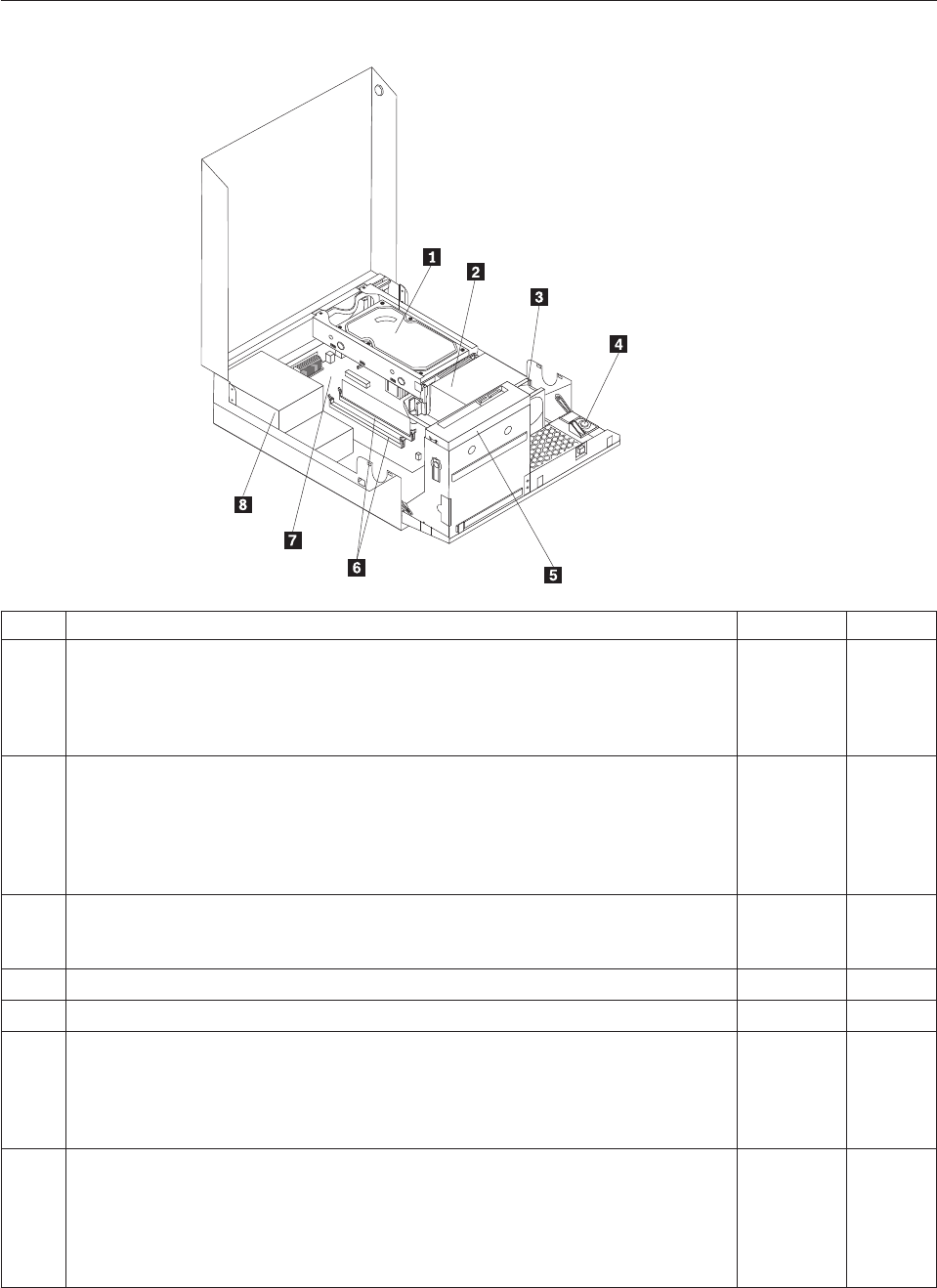
Machine type 7522
Item# 7522 FRUs FRU# CRU
1 Hard disk drive, SATA 160GB 7200RPM/3Gb/8MB (models H3M H3A B1M E3M
E3A E3K E4M E4A E4K F1M F1A F1K F2M F2A F5M F5A 74G 74M 74A 74V 79G
7BG A1S A1Y A2Q A4S A4P A4Y A4M A4A A4K D8S D8D D8Y E1S E1D E1Y E2S
E2D E2Y F9U F9F H1U H1F H1M H1A H1J H2U H2F D6U D6F H6U H6F H7U
H7F J4U J4F)
40Y9035 1
1 Hard disk drive, SATA 250 GB 7200RPM/3GB/8MB (models H4A H4T H5M H5A
B2A B2Q B2T B6M B8M B8A B9M E5M E5A E5K E7M E7A E8M E8A E8K F3M
F3A F6M F6A F6K F7M F7A H8U H9A J1T J2T J3T J5U J5F J6U J6F J7M L6J L7J
L8J L9J M1J M2J M3J M4J M5J M7J M8U M8F M8S M8D M8Y K6U K6F K6S K6D
K6Y M9U M9F P1U P1F P4S P4D P4Y P5S P5D P5Y P6S P6D P6Y P7S P7D P7Y
P8J)
40Y9036 1
1 Hard disk drive, SATA 320 GB 7200RPM SATA/8MB (models D1M 76G 77G 78G
7CG 73G 75G 7KG 7FG 7HG 7JG 7LG 7MG 7NG J8M J9M K1M K2M K3M K4M
K5M K8J K9J L1J L2J L3J L4J L5J K7U K7F P2U P2F P3Q P9J Q1J Q2J Q3J)
87H4891 1
1 Hard disk drive, SATA 500GB 7200RPM/3Gb/s/8MB (models) 41X5582 1
1 Hard disk drive, 1TB 7200rpm SATA (models) 45C5973 1
1 Hard disk drive, SATA 160 GB 7200RPM/3GB/8MB - optional (models 91C 91J
H3M H3A B1M E3M E3A E3K E4M E4A E4K F1M F1A F1K F2M F2A F5M F5A
74G 74M 74A 74V 79G 7BG A1S A1Y A2Q A4S A4P A4Y A4M A4A A4K D8S D8D
D8Y E1S E1D E1Y E2S E2D E2Y F9U F9F H1U H1F H1M H1A H1J H2U H2F D6U
D6F H6U H6F H7U H7F J4U J4F)
53Y6837 1
1 Hard disk drive, SATA 250 GB 7200RPM/3GB/8MB - optional (models H4A H4T
H5M H5A B2A B2Q B2T B6M B8M B8A B9M E5M E5A E5K E7M E7A E8M E8A
E8K F3M F3A F6M F6A F6K F7M F7A H8U H9A J1T J2T J3T J5U J5F J6U J6F J7M
L6J L7J L8J L9J M1J M2J M3J M4J M5J M7J M8U M8F M8S M8D M8Y K6U K6F
K6S K6D K6Y M9U M9F P1U P1F P4S P4D P4Y P5S P5D P5Y P6S P6D P6Y P7S
P7D P7Y P8J)
45K0408 1
Chapter 10. FRU lists 175

Item# 7522 FRUs FRU# CRU
1 Hard disk drive, SATA 320 GB 7200RPM SATA/8MB - optional (models D1M 76G
77G 78G 7CG 73G 75G 7KG 7FG 7HG 7JG 7LG 7MG 7NG J8M J9M K1M K2M
K3M K4M K5M K8J K9J L1J L2J L3J L4J L5J K7U K7F P2U P2F P3Q P9J Q1J Q2J
Q3J)
45K0409 1
1 Hard disk drive, SATA 500 GB 7200RPM/3GB/s/8MB - optional (models) 45K0410 1
1 Hard disk drive, 1 TB 7200RPM SATA - optional (models) 45K0412 1
1 Hard disk drive, 150 GB 10K RPM, SATA (models) 46R6400 1
2 Microprocessor, E7400 2.8GHZ 1066M 3M R0 (ViiV, EIST, EM64T, EDB) 65W
(models F1M F1A F1K F2M F2A F3M F3A 73G 75G E2S E2D E2Y J1T)
53Y6653 N
2 Microprocessor, E7500 2.93GHZ 1066M 3M R0 (ViiV, EIST, EM64T, EDB) 65W
(models F5M F5A F6M F6A F6K F7M F7A H9A J2T J3T J6U J6F 7KG 7FG 7MG
P5S P5D P5Y P6S P6D P6Y P9J Q1J Q2J Q3J)
53Y6654 N
2 Microprocessor, E5300 2.6GHz 800MHz 2MB R0 (EIST, EM64T, EDB) 65W (models
E3M E3A E3K E4M E4A E4K E5M E5A E5K J4U J4F J5U J5F 7HG 7JG)
53Y9049 N
2 Microprocessor, E1500 2.2GHz 800MHz 512KB (EIST, EM64T, EDB) M0 65W
(models)
53Y9051 N
2 Microprocessor, Q8300 Yorkfield 2.5GHZ, 1333MHz, 4M R-0 (ViiV, EIST, EM64T,
EDB) 95W (models)
53Y6656 N
2 Microprocessor, E8600 3.33GHZ/1333MHZ/6M E0 65W (models) 46R8640 N
2 Microprocessor, E8500 3.16GHz 1333MHz FSB 6M C-0 65W (models B9M) 45C7735 N
2 Microprocessor, E8400 3.0GHz 1333MHz FSB 6M C-0 65W (models 91C 91J B8M
B8A 74G 74M 74A 74V 77G 78G D8S D8D D8Y)
45C7736 N
2 Microprocessor, E8300 2.83GHz 1333MHz FSB 6M C-0 65W (models) 45C7737 N
2 Microprocessor, E7200 2.53GHz 1066MHz FSB 3M M-0 65W (models) 45R8337 N
2 Microprocessor, E7300 2.66GHz 1066MHz FSB 3M M-0 65W (models B6M E7M
E7A E8M E8A E8K A4S A4P A4Y A4M A4A A4K H2U H2F)
46R1622 N
2 Microprocessor, E2200 Conroe-L 2.2GHz 800MHz FSB 1M (models) 45C5349 N
2 Microprocessor, E2220 Conroe-L 2.4GHz 800MHz FSB 1M (models) 45C1774 N
2 Microprocessor, E5200 2.5G 800MHz 2M M-0 65W, 45nm (models H3M H3A H4A
H4T H5M H5A B1M B2A B2Q B2T 76G 7CG E1S E1D E1Y F9U F9F H1U H1F
H1M H1A H1J D6U D6F H7U H7F H8U)
46R9512 N
2 Microprocessor, E1600 2.4GHZ/800MHZ/512K - NPI M-0 65W (models) 46R1655 N
2 Microprocessor, E1400 2.0GHz 800MHz FSB 512K - NPI M-0 65W (models 79G
7BG H6U H6F)
45R8339 N
2 Microprocessor, Cel-440 Conroe-L 2.0GHz 800MHz FSB 512K (models) 43C1965 N
2 Microprocessor, Cel-450 2.2GHz 800MHz FSB 512K 35W (models L8J L9J M1J M2J
M3J M4J M5J M7J P8J)
46R9514 N
2 Microprocessor, Q9650 3.0GHZ 1333FSB 12MB VT, TXT E-0 95W (models) 46R8642 N
2 Microprocessor, Q9400 2.66GHZ 1333FSB 6MB VT, TXT R-0 95W (models) 46R8644 N
2 Microprocessor, Q8200 2.33GHz 1333FSB 4M M-1 95W (models D1M) 46R9516 N
2 Microprocessor, Q9550 2.83GHZ 1333FSB 12M C-1 95W (models) 45C7739 N
2 Microprocessor, Q9450 Yorkfield 2.66GHZ 1333FSB 12M C-1 95W (models) 45C7740 N
2 Microprocessor, Q9300 Yorkfield 2.50GHZ 1333FSB 6M M-1 95W (models) 45C7741 N
2 Microprocessor, E5400 2.7G 800MHz-2MB 65W Non-vPro SKU (models) 64Y1075 N
2 Microprocessor, E7600 3.06GHZ 1066M 3M 65W (models) 71Y3486 N
176 Hardware Maintenance Manual

Item# 7522 FRUs FRU# CRU
2 Microprocessor, Q8400 2.66GHZ,1333MHz,4M 95W (models) 71Y3488 N
2 Microprocessor, E6300 2.8G 1066MHz-2MB 65W (models J8M J9M K6U K6F K6S
K6D K6Y K7U K7F P4S P4D P4Y)
71Y3484 N
2 Microprocessor, E6500 2.93GHZ 1066 MHz-2MB 65W R0 (models) 71Y6250 N
2 Microprocessor, E3300 2.5GHZ 800 MHz-1MB 65W R0 (models) 71Y6252 N
2 Microprocessor, E3200 2.4GHZ 800 MHz-1MB 65W R0 (models J7M M8U M8F
M8S M8D M8Y M9U M9F P7S P7D P7Y)
71Y6251 N
3 95W heat sink kit with RM (all models) 41R6454 2
3 65W heat sink kit with RM (all models) 43N9349 2
3 95W heat sink kit with RM (all models) 43N9874 2
3 65W heat sink kit with RM (all models) 43N9877 2
4 Internal speaker 254 mm - optional (all models) 39K5012 2
5 Optical drive, DVD-ROM Drive - 16x/48x - SATA for Windows 7 (models 91C 91J
F9U F9F L1J L5J L7J M1J M3J M5J M7J P3Q P8J Q3J)
71Y5543 1
5 Optical drive, DVD Recordable Rambo8-SATA12XRAM Write - for Windows 7
(models H3M H3A H4A H4T H5M H5A B1M B2A B2Q B2T B6M B8M B8A B9M
D1M E3M E3A E3K E4M E4A E4K E5M E5A E5K E7M E7A E8M E8A E8K F1M
F1A F1K F2M F2A F3M F3A F5M F5A F6M F6A F6K F7M F7A 74G 74M 74A 74V
76G 77G 78G 79G 7BG 7CG 73G 75G A1S A1Y A2Q A4S A4P A4Y A4M A4A A4K
D8S D8D D8Y E1S E1D E1Y E2S E2D E2Y H1U H1F H1M H1A H1J H2U H2F
D6U D6F H6U H6F H7U H7F H8U H9A J1T J2T J3T J4U J4F J5U J5F J6U J6F 7KG
7FG 7HG 7JG 7LG 7MG 7NG J7M J8M J9M K1M K2M K3M K4M K5M K8J K9J
L2J L3J L4J L6J L8J L9J M2J M4J M8U M8F M8S M8D M8Y K6U K6F K6S K6D
K6Y K7U K7F M9U M9F P1U P1F P2U P2F P4S P4D P4Y P5S P5D P5Y P6S P6D
P6Y P7S P7D P7Y P9J Q1J Q2J)
71Y5545 1
6 Memory module, 512MB PC2-5300 (667MHz) DDR2 SDRAM (models) 41X4255 1
6 Memory module, 1GB PC2-5300 (667MHz) DDR2 SDRAM (models) 41X4256 1
6 Memory module, 2GB PC2-5300 (667MHz) DDR2 SDRAM (models) 41X4257 1
6 Memory module, 512MB PC2-6400 (800MHz) DDR2 SDRAM (models F9U F9F) 41X1079 1
6 Memory module, 1GB PC2-6400 (667MHz) DDR2 SDRAM (models 91C 91J H3M
H3A H4A H4T H5M H5A B1M B2A B2Q B2T B6M B8M B8A B9M E3M E3A E3K
E4M E4A E4K E5M E5A E5K F1M F1A F1K F2M F2A F5M F5A A1S A1Y A2Q A4S
A4P A4Y A4M A4A A4K E1S E1D E1Y H1U H1F H1M H1A H1J H6U H6F H9A
J1T J2T J3T L6J L7J M4J M5J M7J M8U M8F M8S M8D M8Y M9U M9F P4S P4D
P4Y P6S P6D P6Y P8J)
41X1080 1
6 Memory module, 2GB PC2-6400 (667MHz) DDR2 SDRAM (models D1M E7M E7A
E8M E8A E8K F3M F3A F6M F6A F6K F7M F7A 74G 74M 74A 74V 76G 77G 78G
79G 7BG 7CG 73G 75G D8S D8D D8Y E2S E2D E2Y H2U H2F D6U D6F H7U H7F
H8U J4U J4F J5U J5F J6U J6F 7KG 7FG 7HG 7JG 7LG 7MG 7NG J7M J8M J9M
K1M K2M K3M K4M K5M K8J K9J L1J L2J L3J L4J L5J L8J L9J M1J M2J M3J K6U
K6F K6S K6D K6Y K7U K7F P1U P1F P2U P2F P3Q P5S P5D P5Y P7S P7D P7Y
P9J Q1J Q2J Q3J)
41X1081 1
Chapter 10. FRU lists 177

Item# 7522 FRUs FRU# CRU
7 System board, Intel G41 BTX(GA) non-AMT (models 91C 91J H3M H3A H4A H4T
H5M H5A B1M B2A B2Q B2T B6M B8M B8A B9M D1M E3M E3A E3K E4M E4A
E4K E5M E5A E5K E7M E7A E8M E8A E8K F1M F1A F1K F2M F2A F3M F3A
F5M F5A F6M F6A F6K F7M F7A 74G 74M 74A 74V 76G 77G 78G 79G 7BG 7CG
73G 75G A1S A1Y A2Q A4S A4P A4Y A4M A4A A4K D8S D8D D8Y E1S E1D E1Y
E2S E2D E2Y F9U F9F H1U H1F H1M H1A H1J H2U H2F D6U D6F H6U H6F
H7U H7F H8U H9A J1T J2T J3T J4U J4F J5U J5F J6U J6F 7KG 7FG 7HG 7JG 7LG
7MG 7NG J7M J8M J9M K1M K2M K3M K4M K5M K8J K9J L1J L2J L3J L4J L5J
L6J L7J L8J L9J M1J M2J M3J M4J M5J M7J M8U M8F M8S M8D M8Y K6U K6F
K6S K6D K6Y K7U K7F M9U M9F P1U P1F P2U P2F P3Q P4S P4D P4Y P5S P5D
P5Y P6S P6D P6Y P7S P7D P7Y P8J P9J Q1J Q2J Q3J)
46R8892 N
7 System board, Intel G41 BTX (GA) - NB upgrade (models 91C 91J H3M H3A H4A
H4T H5M H5A B1M B2A B2Q B2T B6M B8M B8A B9M D1M E3M E3A E3K E4M
E4A E4K E5M E5A E5K E7M E7A E8M E8A E8K F1M F1A F1K F2M F2A F3M F3A
F5M F5A F6M F6A F6K F7M F7A 74G 74M 74A 74V 76G 77G 78G 79G 7BG 7CG
73G 75G A1S A1Y A2Q A4S A4P A4Y A4M A4A A4K D8S D8D D8Y E1S E1D E1Y
E2S E2D E2Y F9U F9F H1U H1F H1M H1A H1J H2U H2F D6U D6F H6U H6F
H7U H7F H8U H9A J1T J2T J3T J4U J4F J5U J5F J6U J6F 7KG 7FG 7HG 7JG 7LG
7MG 7NG J7M J8M J9M K1M K2M K3M K4M K5M K8J K9J L1J L2J L3J L4J L5J
L6J L7J L8J L9J M1J M2J M3J M4J M5J M7J M8U M8F M8S M8D M8Y K6U K6F
K6S K6D K6Y K7U K7F M9U M9F P1U P1F P2U P2F P3Q P4S P4D P4Y P5S P5D
P5Y P6S P6D P6Y P7S P7D P7Y P8J P9J Q1J Q2J Q3J)
64Y9198 N
7 System board, Intel G41 BTX - EuP and TCM header (models 91C 91J H3M H3A
H4A H4T H5M H5A B1M B2A B2Q B2T B6M B8M B8A B9M D1M E3M E3A E3K
E4M E4A E4K E5M E5A E5K E7M E7A E8M E8A E8K F1M F1A F1K F2M F2A
F3M F3A F5M F5A F6M F6A F6K F7M F7A 74G 74M 74A 74V 76G 77G 78G 79G
7BG 7CG 73G 75G A1S A1Y A2Q A4S A4P A4Y A4M A4A A4K D8S D8D D8Y E1S
E1D E1Y E2S E2D E2Y F9U F9F H1U H1F H1M H1A H1J H2U H2F D6U D6F
H6U H6F H7U H7F H8U H9A J1T J2T J3T J4U J4F J5U J5F J6U J6F 7KG 7FG 7HG
7JG 7LG 7MG 7NG J7M J8M J9M K1M K2M K3M K4M K5M K8J K9J L1J L2J L3J
L4J L5J L6J L7J L8J L9J M1J M2J M3J M4J M5J M7J M8U M8F M8S M8D M8Y K6U
K6F K6S K6D K6Y K7U K7F M9U M9F P1U P1F P2U P2F P3Q P4S P4D P4Y P5S
P5D P5Y P6S P6D P6Y P7S P7D P7Y P8J P9J Q1J Q2J Q3J)
71Y6839 N
8 Power supply, 280 watt, Active PFC power supply, auto-sensing, Robust, WW, JP
(models 91C 91J H3M H3A H4A H4T H5M H5A B1M B2A B2Q B2T B6M B8M
B8A B9M D1M E3M E3A E3K E4M E4A E4K E5M E5A E5K E7M E7A E8M E8A
E8K F1M F1A F1K F2M F2A F3M F3A F5M F5A F6M F6A F6K F7M F7A 74G 74M
74A 74V 76G 77G 78G 79G 7BG 7CG 73G 75G A1S A1Y A2Q A4S A4P A4Y A4M
A4A A4K D8S D8D D8Y E1S E1D E1Y E2S E2D E2Y F9U F9F H1U H1F H1M H1A
H1J H2U H2F D6U D6F H6U H6F H7U H7F H8U H9A J1T J2T J3T J4U J4F J5U
J5F J6U J6F 7KG 7FG 7HG 7JG 7LG 7MG 7NG J7M J8M J9M K1M K2M K3M K4M
K5M K8J K9J L1J L2J L3J L4J L5J L6J L7J L8J L9J M1J M2J M3J M4J M5J M7J M8U
M8F M8S M8D M8Y K6U K6F K6S K6D K6Y K7U K7F M9U M9F P1U P1F P2U
P2F P3Q P4S P4D P4Y P5S P5D P5Y P6S P6D P6Y P7S P7D P7Y P8J P9J Q1J Q2J
Q3J)
41A9701 N
8 Power supply, 280 watt, 85+ power supply for 10L, Robust, WW, JP (models 91C
91J H3M H3A H4A H4T H5M H5A B1M B2A B2Q B2T B6M B8M B8A B9M D1M
E3M E3A E3K E4M E4A E4K E5M E5A E5K E7M E7A E8M E8A E8K F1M F1A
F1K F2M F2A F3M F3A F5M F5A F6M F6A F6K F7M F7A 74G 74M 74A 74V 76G
77G 78G 79G 7BG 7CG 73G 75G A1S A1Y A2Q A4S A4P A4Y A4M A4A A4K D8S
D8D D8Y E1S E1D E1Y E2S E2D E2Y F9U F9F H1U H1F H1M H1A H1J H2U H2F
D6U D6F H6U H6F H7U H7F H8U H9A J1T J2T J3T J4U J4F J5U J5F J6U J6F 7KG
7FG 7HG 7JG 7LG 7MG 7NG J7M J8M J9M K1M K2M K3M K4M K5M K8J K9J
L1J L2J L3J L4J L5J L6J L7J L8J L9J M1J M2J M3J M4J M5J M7J M8U M8F M8S
M8D M8Y K6U K6F K6S K6D K6Y K7U K7F M9U M9F P1U P1F P2U P2F P3Q
P4S P4D P4Y P5S P5D P5Y P6S P6D P6Y P7S P7D P7Y P8J P9J Q1J Q2J Q3J)
41A9742 N
178 Hardware Maintenance Manual

Item# 7522 FRUs FRU# CRU
8 Power supply, 280 watt, Active PFC power supply (auto-sensing) - all countries
(models 91C 91J H3M H3A H4A H4T H5M H5A B1M B2A B2Q B2T B6M B8M
B8A B9M D1M E3M E3A E3K E4M E4A E4K E5M E5A E5K E7M E7A E8M E8A
E8K F1M F1A F1K F2M F2A F3M F3A F5M F5A F6M F6A F6K F7M F7A 74G 74M
74A 74V 76G 77G 78G 79G 7BG 7CG 73G 75G A1S A1Y A2Q A4S A4P A4Y A4M
A4A A4K D8S D8D D8Y E1S E1D E1Y E2S E2D E2Y F9U F9F H1U H1F H1M H1A
H1J H2U H2F D6U D6F H6U H6F H7U H7F H8U H9A J1T J2T J3T J4U J4F J5U
J5F J6U J6F 7KG 7FG 7HG 7JG 7LG 7MG 7NG J7M J8M J9M K1M K2M K3M K4M
K5M K8J K9J L1J L2J L3J L4J L5J L6J L7J L8J L9J M1J M2J M3J M4J M5J M7J M8U
M8F M8S M8D M8Y K6U K6F K6S K6D K6Y K7U K7F M9U M9F P1U P1F P2U
P2F P3Q P4S P4D P4Y P5S P5D P5Y P6S P6D P6Y P7S P7D P7Y P8J P9J Q1J Q2J
Q3J)
45J9418 N
8 Power supply, 280 watt, 85+ power supply - all countries (models) 45J9423 N
8 Power supply, 280 watt Active PFC power supply, auto-sensing, Robust, WW, JP,
for Eup (models 91C 91J H3M H3A H4A H4T H5M H5A B1M B2A B2Q B2T B6M
B8M B8A B9M D1M E3M E3A E3K E4M E4A E4K E5M E5A E5K E7M E7A E8M
E8A E8K F1M F1A F1K F2M F2A F3M F3A F5M F5A F6M F6A F6K F7M F7A 74G
74M 74A 74V 76G 77G 78G 79G 7BG 7CG 73G 75G A1S A1Y A2Q A4S A4P A4Y
A4M A4A A4K D8S D8D D8Y E1S E1D E1Y E2S E2D E2Y F9U F9F H1U H1F H1M
H1A H1J H2U H2F D6U D6F H6U H6F H7U H7F H8U H9A J1T J2T J3T J4U J4F
J5U J5F J6U J6F 7KG 7FG 7HG 7JG 7LG 7MG 7NG J7M J8M J9M K1M K2M K3M
K4M K5M K8J K9J L1J L2J L3J L4J L5J L6J L7J L8J L9J M1J M2J M3J M4J M5J M7J
M8U M8F M8S M8D M8Y K6U K6F K6S K6D K6Y K7U K7F M9U M9F P1U P1F
P2U P2F P3Q P4S P4D P4Y P5S P5D P5Y P6S P6D P6Y P7S P7D P7Y P8J P9J Q1J
Q2J Q3J)
54Y8804 N
The FRUs listed in the following tables are not illustrated.
7522 FRUs FRU# CRU
Battery 3V - Lithium (models 91C 91J H3M H3A H4A H4T H5M H5A B1M B2A B2Q B2T
B6M B8M B8A B9M D1M E3M E3A E3K E4M E4A E4K E5M E5A E5K E7M E7A E8M E8A
E8K F1M F1A F1K F2M F2A F3M F3A F5M F5A F6M F6A F6K F7M F7A 74G 74M 74A
74V 76G 77G 78G 79G 7BG 7CG 73G 75G A1S A1Y A2Q A4S A4P A4Y A4M A4A A4K
D8S D8D D8Y E1S E1D E1Y E2S E2D E2Y F9U F9F H1U H1F H1M H1A H1J H2U H2F
D6U D6F H6U H6F H7U H7F H8U H9A J1T J2T J3T J4U J4F J5U J5F J6U J6F 7KG 7FG
7HG 7JG 7LG 7MG 7NG J7M J8M J9M K1M K2M K3M K4M K5M K8J K9J L1J L2J L3J L4J
L5J L6J L7J L8J L9J M1J M2J M3J M4J M5J M7J M8U M8F M8S M8D M8Y K6U K6F K6S
K6D K6Y K7U K7F M9U M9F P1U P1F P2U P2F P3Q P4S P4D P4Y P5S P5D P5Y P6S P6D
P6Y P7S P7D P7Y P8J P9J Q1J Q2J Q3J)
45C1566 1
Cable - SATA 250 mm (RoHS) for 1st hard disk drive (all models) 43N9012 2
Cable - SATA 600 mm (RoHS) (all models) 45J9579 2
Cable - SATA 700 mm (RoHS) for optical drive / Second hard disk drive (all models) 43N9011 2
C2 intrusion switch 260 mm (all models) 43N9080 2
Rear I/O shield BTX (all models) 41R6381 N
Temp sense cable (165 mm) (all models) 43N9079 2
Air deflector, recycle resin (all models) 43N9610 2
Hard disk drive tray assembly (all models) 43N9595 1
Front cage assembly (all models) 43N9596 N
Front cage assembly (all models) 43N9647 N
Cable, Front I/O cable_R (10L_U380_A550)_ESD (all models) 45J9509 2
Chapter 10. FRU lists 179

7522 FRUs FRU# CRU
Models with 3.5’’ convert 2.5’’ for 150 GB 10 K rpm hard disk drive (first HDD bay) (all
models)
43N9645 2
3.5’’ convert 2.5’’ for 150 GB 10 K rpm hard disk drive (first HDD bay) (all models) 43N9593 2
Universal Adapter Bracket 5.25 to 3.5 (all models) 43N9676 2
Top cover assembly (all models) 43N9594 1
Cable, LED/Switch cable_R (10L_220 mm_PCBA) (all models) 45J9515 2
NO ODD, EMI shielding (all models) 43N9641 1
Card reader bezel (all models) 43N9642 1
Non-card reader bezel (all models) 43N9643 1
Card reader (all models) 45K6081 1
Vertical stand (all models) 43N9644 1
Front bezel assembly (all models) 43N9677 1
Chassis (all models) 43N9649 N
Rubber foot for vertical (all models) 43N9727 1
Rubber foot for horizontal (all models) 43N9728 1
Thermal grease (all models) 91P8835 N
Optical retainer (all models) 45K6364 1
7522 Keyboards (Lenovo Preferred Pro USB -- without hub) FRU# CRU
USB FULL--US English (models H3M H3A H4A H5M H5A B1M B2A B2Q B6M B8M B8A
B9M D1M E3M E3A E4M E4A E5M E5A E7M E7A E8M E8A F1M F1A F2M F2A F3M F3A
F5M F5A F6M F6A F7M F7A 74G 74M 74A 76G 77G 78G 79G 7BG 7CG 73G 75G A2Q
A4M A4A F9U H1U H1M H1A H2U D6U H6U H7U H8U H9A J4U J5U J6U 7KG 7FG
7HG 7JG)
41A5289 1
USB FULL--Arabic (models 74G 76G 77G 78G 79G 7BG 7CG 73G 75G 7KG 7FG 7HG 7JG) 41A5290 1
USB FULL--Arabic/French (models 74G 76G 77G 78G 79G 7BG 7CG 73G 75G 7KG 7FG
7HG 7JG)
41A5291 1
USB FULL--Belgium French (models 74G 76G 77G 78G 79G 7BG 7CG 73G 75G 7KG 7FG
7HG 7JG)
41A5292 1
USB FULL--Belgium English (models 74G 76G 77G 78G 79G 7BG 7CG 73G 75G 7KG 7FG
7HG 7JG)
41A5293 1
USB FULL--Brazilian Portuguese (models A4P) 41A5294 1
USB FULL--Bulgarian (models 74G 76G 77G 78G 79G 7BG 7CG 73G 75G 7KG 7FG 7HG
7JG)
41A5295 1
USB FULL--Chinese/US (models 74V) 41A5296 1
USB FULL--Czech (ABB) (models 74G 76G 77G 78G 79G 7BG 7CG 73G 75G 7KG 7FG
7HG 7JG)
41A5297 1
USB FULL--Danish (models 74G 76G 77G 78G 79G 7BG 7CG 73G 75G 7KG 7FG 7HG 7JG) 41A5298 1
USB FULL--Dutch (models 74G 76G 77G 78G 79G 7BG 7CG 73G 75G 7KG 7FG 7HG 7JG) 41A5299 1
USB FULL--French (models 74G 76G 77G 78G 79G 7BG 7CG 73G 75G 7KG 7FG 7HG 7JG) 41A5300 1
USB FULL--French Canadian (models 74G 76G 77G 78G 79G 7BG 7CG 73G 75G F9F H1F
H2F D6F H6F H7F J4F J5F J6F 7KG 7FG 7HG 7JG)
41A5301 1
USB FULL--French Canadian (models 74G 76G 77G 78G 79G 7BG 7CG 73G 75G F9F H1F
H2F D6F H6F H7F J4F J5F J6F 7KG 7FG 7HG 7JG)
41A5302 1
180 Hardware Maintenance Manual

7522 Keyboards (Lenovo Preferred Pro USB -- without hub) FRU# CRU
USB FULL--German (models 74G 76G 77G 78G 79G 7BG 7CG 73G 75G 7KG 7FG 7HG
7JG)
41A5303 1
USB FULL--Greek (models 74G 76G 77G 78G 79G 7BG 7CG 73G 75G 7KG 7FG 7HG 7JG) 41A5304 1
USB FULL--Greek/US (models 74G 76G 77G 78G 79G 7BG 7CG 73G 75G 7KG 7FG 7HG
7JG)
41A5305 1
USB FULL--Hebrew (models 74G 76G 77G 78G 79G 7BG 7CG 73G 75G 7KG 7FG 7HG
7JG)
41A5306 1
USB FULL--Hungarian (models 74G 76G 77G 78G 79G 7BG 7CG 73G 75G 7KG 7FG 7HG
7JG)
41A5307 1
USB FULL--Iceland (models 74G 76G 77G 78G 79G 7BG 7CG 73G 75G 7KG 7FG 7HG
7JG)
41A5308 1
USB FULL--Italy (models 74G 76G 77G 78G 79G 7BG 7CG 73G 75G 7KG 7FG 7HG 7JG) 41A5309 1
USB FULL--Japanese (models 91J H1J K8J K9J L1J L2J L3J L4J L5J L6J L7J L8J L9J M1J M2J
M3J M4J M5J M7J P8J P9J Q1J Q2J Q3J)
41A5310 1
USB FULL--Korean (models E3K E4K E5K E8K F1K F6K A4K) 41A5311 1
USB FULL--LA Spanish (models A1S A1Y A4S A4Y D8S D8D D8Y E1S E1D E1Y E2S E2D
E2Y M8S M8D M8Y K6S K6D K6Y P4S P4D P4Y P5S P5D P5Y P6S P6D P6Y P7S P7D
P7Y)
41A5312 1
USB FULL--Norwegian (models 74G 76G 77G 78G 79G 7BG 7CG 73G 75G 7KG 7FG 7HG
7JG)
41A5313 1
USB FULL--Polish (models 74G 76G 77G 78G 79G 7BG 7CG 73G 75G 7KG 7FG 7HG 7JG) 41A5314 1
USB FULL--Portuguese (models 74G 76G 77G 78G 79G 7BG 7CG 73G 75G 7KG 7FG 7HG
7JG)
41A5315 1
USB FULL--Romanian (models 74G 76G 77G 78G 79G 7BG 7CG 73G 75G 7KG 7FG 7HG
7JG)
41A5317 1
USB FULL--Romanian (models 74G 76G 77G 78G 79G 7BG 7CG 73G 75G 7KG 7FG 7HG
7JG)
41A5316 1
USB FULL--Russian/Cyrillic (models 74G 76G 77G 78G 79G 7BG 7CG 73G 75G 7KG 7FG
7HG 7JG)
41A5318 1
USB FULL--Serbian/Cyrillic (models 74G 76G 77G 78G 79G 7BG 7CG 73G 75G 7KG 7FG
7HG 7JG)
41A5319 1
USB FULL--Slovak (models 74G 76G 77G 78G 79G 7BG 7CG 73G 75G 7KG 7FG 7HG 7JG) 41A5320 1
USB FULL--Spanish (models 74G 76G 77G 78G 79G 7BG 7CG 73G 75G 7KG 7FG 7HG
7JG)
41A5321 1
USB FULL--Swedish/Finnish (models 74G 76G 77G 78G 79G 7BG 7CG 73G 75G 7KG 7FG
7HG 7JG)
41A5322 1
USB FULL--Swiss French/German (models 74G 76G 77G 78G 79G 7BG 7CG 73G 75G 7KG
7FG 7HG 7JG)
41A5323 1
USB FULL--Thailand (models H4T B2T J1T J2T J3T) 41A5324 1
USB FULL--Turkish (models 74G 76G 77G 78G 79G 7BG 7CG 73G 75G 7KG 7FG 7HG
7JG)
41A5325 1
USB FULL--Turkish (models 74G 76G 77G 78G 79G 7BG 7CG 73G 75G 7KG 7FG 7HG
7JG)
41A5326 1
USB FULL --UK English (models 74G 76G 77G 78G 79G 7BG 7CG 73G 75G 7KG 7FG 7HG
7JG)
41A5327 1
USB FULL--US Euro (models 74G 76G 77G 78G 79G 7BG 7CG 73G 75G 7KG 7FG 7HG
7JG)
41A5328 1
Chapter 10. FRU lists 181

7522 Keyboards (Lenovo Preferred Pro USB -- without hub) FRU# CRU
USB FULL--Slovenian (models 74G 76G 77G 78G 79G 7BG 7CG 73G 75G 7KG 7FG 7HG
7JG)
41A5329 1
USB FULL--Arabic (New) (models 74G 76G 77G 78G 79G 7BG 7CG 73G 75G 7KG 7FG
7HG 7JG)
45J4880 1
USB FULL--Lithuanian (models 74G 76G 77G 78G 79G 7BG 7CG 73G 75G 7KG 7FG 7HG
7JG)
45J4896 1
USB FULL--Estonia (models) 51J0059 1
7522 Keyboards (Lenovo Fingerprint Reader USB) FRU# CRU
US English (models) 41R0038 1
Arabic (models) 41R0039 1
Arabic/French (models) 41R0040 1
Belgium French (models) 41R0041 1
Belgium English (models) 41R0042 1
Brazilian Portuguese (models) 41R0043 1
Bulgarian (models) 41R0044 1
Chinese/US (models) 41R0045 1
Czech (ABB) (models) 41R0046 1
Danish (models) 41R0047 1
Dutch (models) 41R0048 1
French (models) 41R0049 1
French Canadian (models) 41R0050 1
French Canadian (models) 41R0051 1
German (models) 41R0052 1
Greek (models) 41R0053 1
Greek/US (models) 41R0054 1
Hebrew (models) 41R0055 1
Hungarian (models) 41R0056 1
Iceland (models) 41R0057 1
Italian (models) 41R0058 1
Japanese (models) 41R0059 1
Korean (models) 41R0060 1
LA Spanish (models) 41R0061 1
Norwegian (models) 41R0062 1
Polish (models) 41R0063 1
Portuguese (models) 41R0064 1
Romanian (models) 41R0065 1
Romanian (models) 41R0066 1
Russian/Cyrillic (models) 41R0067 1
Serbian/Cyrillic (models) 41R0068 1
Slovak (models) 41R0069 1
Spanish (models) 41R0070 1
182 Hardware Maintenance Manual

7522 Keyboards (Lenovo Fingerprint Reader USB) FRU# CRU
Swedish/Finnish (models) 41R0071 1
Swiss French/German (models) 41R0072 1
Thailand (models) 41R0073 1
Turkish (models) 41R0074 1
Turkish (models) 41R0075 1
UK English (models) 41R0076 1
US Euro (models) 41R0077 1
Slovenian (models) 41R0078 1
7522 Keyboards (Lenovo preferred Pro PS/2 Full Size) FRU# CRU
US English (models) 41A5039 1
Arabic (models) 41A5040 1
Arabic (New) (models) 45J4880 1
Arabic French (models) 41A5041 1
Belgium French (models) 41A5042 1
Belgium English (models) 41A5043 1
Brazilian Portuguese (models) 41A5044 1
Bulgarian (models) 41A5045 1
Chinese/US (models) 41A5046 1
Czech (ABB) (models) 41A5047 1
Danish (models) 41A5048 1
Dutch (models) 41A5049 1
French (models) 41A5050 1
French Canadian (models) 41A5051 1
French Canadian (models) 41A5052 1
German (models) 41A5053 1
Greek (models) 41A5054 1
Greek/US (models) 41A5080 1
Hebrew (models) 41A5055 1
Hungarian (models) 41A5056 1
Iceland (models) 41A5057 1
Italian (models) 41A5058 1
Japanese (models) 41A5059 1
Korean (models) 41A5060 1
LA Spanish (models) 41A5061 1
Norwegian (models) 41A5062 1
Polish (models) 41A5063 1
Portuguese (models) 41A5064 1
Romanian (models) 41A5065 1
Russian/Cyrillic (models) 41A5066 1
Serbian/Cyrillic (models) 41A5067 1
Chapter 10. FRU lists 183

7522 Keyboards (Lenovo preferred Pro PS/2 Full Size) FRU# CRU
Slovak (models) 41A5068 1
Spanish (models) 41A5069 1
Swedish/Finnish (models) 41A5070 1
Swiss French/German (models) 41A5071 1
Thailand (models) 41A5072 1
Turkish (models) 41A5073 1
Turkish (models) 41A5074 1
UK English (models) 41A5075 1
US Euro (models) 41A5076 1
Slovenian (models) 41A5077 1
7522 Mice FRU# CRU
Optical Wheel Mouse OPT (400DPI, USB) (models 91C 91J H3M H3A H4A H4T H5M H5A
B1M B2A B2Q B2T B6M B8M B8A B9M D1M E3M E3A E3K E4M E4A E4K E5M E5A E5K
E7M E7A E8M E8A E8K F1M F1A F1K F2M F2A F3M F3A F5M F5A F6M F6A F6K F7M
F7A 74G 74M 74A 74V 76G 77G 78G 79G 7BG 7CG 73G 75G A1S A1Y A2Q A4S A4P A4Y
A4M A4A A4K D8S D8D D8Y E1S E1D E1Y E2S E2D E2Y F9U F9F H1U H1F H1M H1A
H1J H2U H2F D6U D6F H6U H6F H7U H7F H8U H9A J1T J2T J3T J4U J4F J5U J5F J6U
J6F 7KG 7FG 7HG 7JG 7LG 7MG 7NG J7M J8M J9M K1M K2M K3M K4M K5M K8J K9J
L1J L2J L3J L4J L5J L6J L7J L8J L9J M1J M2J M3J M4J M5J M7J M8U M8F M8S M8D M8Y
K6U K6F K6S K6D K6Y K7U K7F M9U M9F P1U P1F P2U P2F P3Q P4S P4D P4Y P5S P5D
P5Y P6S P6D P6Y P7S P7D P7Y P8J P9J Q1J Q2J Q3J)
41U3013 1
Optical Wheel Mouse OPT (400DPI, USB) (models 91C 91J H3M H3A H4A H4T H5M H5A
B1M B2A B2Q B2T B6M B8M B8A B9M D1M E3M E3A E3K E4M E4A E4K E5M E5A E5K
E7M E7A E8M E8A E8K F1M F1A F1K F2M F2A F3M F3A F5M F5A F6M F6A F6K F7M
F7A 74G 74M 74A 74V 76G 77G 78G 79G 7BG 7CG 73G 75G A1S A1Y A2Q A4S A4P A4Y
A4M A4A A4K D8S D8D D8Y E1S E1D E1Y E2S E2D E2Y F9U F9F H1U H1F H1M H1A
H1J H2U H2F D6U D6F H6U H6F H7U H7F H8U H9A J1T J2T J3T J4U J4F J5U J5F J6U
J6F 7KG 7FG 7HG 7JG 7LG 7MG 7NG J7M J8M J9M K1M K2M K3M K4M K5M K8J K9J
L1J L2J L3J L4J L5J L6J L7J L8J L9J M1J M2J M3J M4J M5J M7J M8U M8F M8S M8D M8Y
K6U K6F K6S K6D K6Y K7U K7F M9U M9F P1U P1F P2U P2F P3Q P4S P4D P4Y P5S P5D
P5Y P6S P6D P6Y P7S P7D P7Y P8J P9J Q1J Q2J Q3J)
41U3030 1
7522 Adapters and miscellaneous FRUs FRU# CRU
Internal 25 in 1 USB Memory Card Reader Slim (models) 46R1529 1
IEEE 1394 Firewire Adapter (models) 41D2781 1
Soft Modem V.90/V.44 (models) 46R4220 1
Speaker power brick - US, Canada, LA low voltage, ASEAN (models F9U H1U H2U D6U
H6U H7U H8U J4U J5U J6U)
89P8571 1
Speaker power brick - LA high voltage (non-APU) (models) 89P8575 1
Speaker power brick - Simplified Chinese, Thailand EMEA (models 74G 76G 77G 78G 79G
7BG 7CG 73G 75G 7KG 7FG 7HG 7JG)
89P8581 1
Speaker power brick - Japanese (models 91J H1J K8J K9J L1J L2J L3J L4J L5J L6J L7J L8J
L9J M1J M2J M3J M4J M5J M7J P8J P9J Q1J Q2J Q3J)
89P8577 1
Speaker power brick - Brazil (models) 89P8583 1
Speaker power brick - Argentina (models) 41A4901 1
184 Hardware Maintenance Manual

7522 Adapters and miscellaneous FRUs FRU# CRU
Speaker power brick - ANZ (models H3M H5M B1M B6M B8M B9M D1M E3M E4M E5M
E7M E8M F1M F2M F3M F5M F6M F7M 74M A4M H1M)
89P8579 1
Speaker power brick - Korea (models) 41A4903 1
Speaker power brick - Hong Kong, EMEA, Ireland (models 74G 76G 77G 78G 79G 7BG
7CG 73G 75G 7KG 7FG 7HG 7JG)
89P8573 1
Speaker power brick -Taiwan-Traditional Chinese (models 74V) 41A4905 1
Speaker power brick - India, South Africa (models B2Q A2Q) 89P8585 1
2-pc external speaker--primary (models) 41A5331 1
2-pc external speaker-secondary (models) 41A5334 1
DVI-I(M)-VGA(F) cord (models) 41R3342 1
ATI HD3470 GDDR3 256MB - VGA+DP (models) 46R1521 1
ADD2 DVI-D Adapter, (HDCP) DVD-D connection Adapter Low Profile (Silicon Image)
(models 73G 75G)
43C0258 1
DisplayPort to DVI-D Dongle (models) 43N9160 1
DisplayPort to VGA Dongle (models) 45J9524 1
Modem phone cable (models) 39K5120 1
LI140mm Rear Com2 cable II mini®(models) 43N9062 2
Rear USB 2 Ports II LP®350 mm (models) 43N9124 2
NVIDIA G100 DDR2 256MB LP - DVI-I (With DVI-I to VGA Dongle) (models CTO) 53Y9341 1
7522 Power Cords (Primary) FRU# CRU
Power cord - US (models H3A H4A H4T H5A B2A B2T B8A E3A E4A E5A E7A E8A F1A
F2A F3A F5A F6A F7A 74A A1S A1Y A4S A4Y A4A D8S D8Y E1S E1Y E2S E2Y F9U F9F
H1U H1F H1A H2U H2F D6U D6F H6U H6F H7U H7F H8U H9A J1T J2T J3T J4U J4F J5U
J5F J6U J6F M8U M8F M8S M8Y K6U K6F K6S K6Y K7U K7F M9U M9F P1U P1F P2U
P2F P4S P4Y P5S P5Y P6S P6Y P7S P7Y)
41R3184 1
Power cord - China (models 91C) 41R3256 1
Power cord - Japanese and Japanese English (models 91J H1J K8J K9J L1J L2J L3J L4J L5J
L6J L7J L8J L9J M1J M2J M3J M4J M5J M7J P8J P9J Q1J Q2J Q3J)
41R3248 1
Power cord - Brazil (models) 41R3270 1
Power cord - Brazil - optional (models) 45J9595 1
Power cord - LA High Volt (APU) (models) 41R3176 1
Power cord - Australia / New Zealand (models) 41R3196 1
Power cord - Korea (models) 41R3260 1
Power cord - UK, Ireland, Singapore, Malaysia, Brunei, Hong Kong (models) 41R3224 1
Power cord - Taiwan (models 74V) 41R3278 1
Power cord - Italy (models) 41R3232 1
Power cord - Indonesia, Laos, Cambodia, Vietnam, Austria, Belgium, Croatia,
Czechoslovakia, Finland, France, Germany, Hungary, Netherlands, Norway, Poland,
Portugal, Romania, Spain, Sweden (models H3A H4A H4T H5A B2A B2T B8A E3A E4A
E5A E7A E8A F1A F2A F3A F5A F6A F7A 74A A1S A1Y A4S A4Y A4A D8S D8Y E1S E1Y
E2S E2Y F9U F9F H1U H1F H1A H2U H2F D6U D6F H6U H6F H7U H7F H8U H9A J1T
J2T J3T J4U J4F J5U J5F J6U J6F M8U M8F M8S M8Y K6U K6F K6S K6Y K7U K7F M9U
M9F P1U P1F P2U P2F P4S P4Y P5S P5Y P6S P6Y P7S P7Y)
41R3208 1
Chapter 10. FRU lists 185

7522 Power Cords (Primary) FRU# CRU
Power cord - Denmark (models 74G 76G 77G 78G 79G 7BG 7CG 73G 75G 7KG 7FG 7HG
7JG)
41R3212 1
Power cord - Switzerland (models 74G 76G 77G 78G 79G 7BG 7CG 73G 75G 7KG 7FG
7HG 7JG)
41R3228 1
Power cord - Israel (models 74G 76G 77G 78G 79G 7BG 7CG 73G 75G 7KG 7FG 7HG 7JG) 41R3236 1
Power cord - South Africa (models H3M H3A H4A H5M H5A B1M B2A B6M B8M B8A
B9M D1M E3M E3A E4M E4A E5M E5A E7M E7A E8M E8A F1M F1A F2M F2A F3M F3A
F5M F5A F6M F6A F7M F7A 74G 74M 74A 76G 77G 78G 79G 7BG 7CG 73G 75G A4M
A4A H1M H1A H9A 7KG 7FG 7HG 7JG)
41R3220 1
Power cord - India (models B2Q A2Q) 41R3341 1
Power cord - Thailand (models H4T B2T J1T J2T J3T) 43N9029 1
7522 Power Cords (Secondary) FRU# CRU
Power cord - US (models H3A H4A H4T H5A B2A B2T B8A E3A E4A E5A E7A E8A F1A
F2A F3A F5A F6A F7A 74A A1S A1Y A4S A4Y A4A D8S D8Y E1S E1Y E2S E2Y F9U F9F
H1U H1F H1A H2U H2F D6U D6F H6U H6F H7U H7F H8U H9A J1T J2T J3T J4U J4F J5U
J5F J6U J6F M8U M8F M8S M8Y K6U K6F K6S K6Y K7U K7F M9U M9F P1U P1F P2U
P2F P4S P4Y P5S P5Y P6S P6Y P7S P7Y)
41R3185 1
Power cord - China (models 91C) 41R3257 1
Power Cord - Japanese and Japanese English (models 91J H1J K8J K9J L1J L2J L3J L4J L5J
L6J L7J L8J L9J M1J M2J M3J M4J M5J M7J P8J P9J Q1J Q2J Q3J)
41R3249 1
Power cord - Brazil (models) 41R3271 1
Power cord - LA High Volt (APU) (models) 41R3177 1
Power cord - Australia / New Zealand (models) 41R3197 1
Power cord - Korea (models) 41R3261 1
Power cord - UK, Ireland, Singapore, Malaysia, Brunei, Hong Kong (models) 41R3225 1
Power cord - Taiwan (models 74V) 41R3279 1
Power cord - Italy (models) 41R3233 1
Power cord - Indonesia, Laos, Cambodia, Vietnam, Austria, Belgium, Croatia,
Czechoslovakia, Finland, France, Germany, Hungary, Netherlands, Norway, Poland,
Portugal, Romania, Spain, Sweden (models H3A H4A H4T H5A B2A B2T B8A E3A E4A
E5A E7A E8A F1A F2A F3A F5A F6A F7A 74A A1S A1Y A4S A4Y A4A D8S D8Y E1S E1Y
E2S E2Y F9U F9F H1U H1F H1A H2U H2F D6U D6F H6U H6F H7U H7F H8U H9A J1T
J2T J3T J4U J4F J5U J5F J6U J6F)
41R3209 1
Power cord - Denmark (models H3A H4A H4T H5A B2A B2T B8A E3A E4A E5A E7A E8A
F1A F2A F3A F5A F6A F7A 74A A1S A1Y A4S A4Y A4A D8S D8Y E1S E1Y E2S E2Y F9U
F9F H1U H1F H1A H2U H2F D6U D6F H6U H6F H7U H7F H8U H9A J1T J2T J3T J4U J4F
J5U J5F J6U J6F M8U M8F M8S M8Y K6U K6F K6S K6Y K7U K7F M9U M9F P1U P1F P2U
P2F P4S P4Y P5S P5Y P6S P6Y P7S P7Y)
41R3213 1
Power cord - Switzerland (models 74G 76G 77G 78G 79G 7BG 7CG 73G 75G 7KG 7FG
7HG 7JG)
41R3229 1
Power cord - Israel (models 74G 76G 77G 78G 79G 7BG 7CG 73G 75G 7KG 7FG 7HG 7JG) 41R3237 1
Power cord - South Africa (models H3M H3A H4A H5M H5A B1M B2A B6M B8M B8A
B9M D1M E3M E3A E4M E4A E5M E5A E7M E7A E8M E8A F1M F1A F2M F2A F3M F3A
F5M F5A F6M F6A F7M F7A 74G 74M 74A 76G 77G 78G 79G 7BG 7CG 73G 75G A4M
A4A H1M H1A H9A 7KG 7FG 7HG 7JG)
41R3221 1
Power cord - India (models B2Q A2Q) 41R3175 1
Power cord - Thailand (models H4T B2T J1T J2T J3T) 43N9030 1
186 Hardware Maintenance Manual

7522 Power Cords (Secondary) FRU# CRU
Power cord - Y cable for Brazil (models) 43N9044 1
7522 Windows XP Home Recovery CDs FRU# CRU
US English/UK/Asia Pacific (models) TBD 1
French/French Canadian (models) TBD 1
Greek (models) TBD 1
Italy (models) TBD 1
Brazilian (models) TBD 1
Spanish/LA (models) TBD 1
Danish (models) TBD 1
Dutch (models) TBD 1
Arabic (models) TBD 1
Swedish (models) TBD 1
Hebrew (models) TBD 1
Finnish (models) TBD 1
Norwegian (models) TBD 1
Polish (models) TBD 1
Portuguese (models) TBD 1
Russian (models) TBD 1
Russian English (models) TBD 1
Hungarian (models) TBD 1
Czech (models) TBD 1
Turkish native (models) TBD 1
Greek (models) TBD 1
Japanese (models) TBD 1
Simplified Chinese (models) TBD 1
Taiwan-TC (models) TBD 1
Hong Kong-TC (models) TBD 1
Korean (models) TBD 1
7522 Windows XP Pro Recovery Discs FRU# CRU
Hebrew (models 76G 78G 7BG 75G 7FG 7JG) 71Y7506 1
Portuguese (models 76G 78G 7BG 75G 7FG 7JG) 71Y7514 1
Russian English (models 76G 78G 7BG 75G 7FG 7JG) 71Y7510 1
Hungarian (models 76G 78G 7BG 75G 7FG 7JG) 71Y7512 1
Slovenian (models 76G 78G 7BG 75G 7FG 7JG) 71Y7515 1
Korea (models) 71Y7519 1
US English (models E7M E7A F1M F1A F5M F5A F6M F6A 76G 78G 7BG 75G A4M A4A
F9U H1U H1M H1A H2U D6U H6U H8U H9A J4U J5U J6U 7FG 7JG)
71Y7493 1
French (models 76G 78G 7BG 75G F9F H1F H2F D6F H6F J4F J5F J6F 7FG 7JG) 71Y7494 1
German (models 76G 78G 7BG 75G 7FG 7JG) 71Y7495 1
Chapter 10. FRU lists 187

7522 Windows XP Pro Recovery Discs FRU# CRU
Italian (models) 71Y7498 1
Brazilian Portuguese (models 76G 78G 7BG 75G 7FG 7JG) 71Y7497 1
Spanish (models 76G 78G 7BG 75G 7FG 7JG) 71Y7496 1
Danish (models 76G 78G 7BG 75G 7FG 7JG) 71Y7502 1
Dutch (models 76G 78G 7BG 75G 7FG 7JG) 71Y7503 1
Arabic (models 76G 78G 7BG 75G 7FG 7JG) 71Y7508 1
Swedish (models 76G 78G 7BG 75G 7FG 7JG) 71Y7501 1
Finnish (models 76G 78G 7BG 75G 7FG 7JG) 71Y7505 1
Norwegian (models 76G 78G 7BG 75G 7FG 7JG) 71Y7500 1
Polish (models 76G 78G 7BG 75G 7FG 7JG) 71Y7507 1
Russian (models 76G 78G 7BG 75G 7FG 7JG) 71Y7509 1
Czech (models 76G 78G 7BG 75G 7FG 7JG) 71Y7504 1
Turkish (models 76G 78G 7BG 75G 7FG 7JG) 71Y7511 1
Greek (models 76G 78G 7BG 75G 7FG 7JG) 71Y7513 1
Japanese (models H1J) 71Y7499 1
Simplified Chinese (models) 71Y7516 1
Traditional Chinese (models) 71Y7517 1
Hong Kong (models) 71Y7518 1
MUI Nordics (EN-DK-FI-NO-SV) (models) 71Y7520 1
MUI Switz (US EN-FR -GR-IT) (models E7M E7A F1M F1A F5M F5A F6M F6A 76G 76G
78G 78G 7BG 7BG 75G 75G A4M A4A F9U F9F H1U H1F H1M H1A H2U H2F D6U D6F
H6U H6F H8U H9A J4U J4F J5U J5F J6U J6F 7FG 7FG 7JG 7JG)
71Y7521 1
MUI Bel-Lux (EN-FR-GR-NL) (models E7M E7A F1M F1A F5M F5A F6M F6A 76G 76G
78G 78G 7BG 7BG 75G 75G A4M A4A F9U F9F H1U H1F H1M H1A H2U H2F D6U D6F
H6U H6F H8U H9A J4U J4F J5U J5F J6U J6F 7FG 7FG 7JG 7JG)
71Y7522 1
7522 Vista Home Basic 32 Recovery DVDs FRU# CRU
US English (models) 64Y8594 1
French (models) 64Y8596 1
German (models) 64Y8597 1
Spanish (models) 64Y8598 1
Brazilian (models) 64Y8599 1
Italian (models) 64Y8600 1
Dutch (models) 64Y8614 1
Czech (models) 64Y8601 1
Polish (models) 64Y8602 1
Russian (models) 64Y8603 1
Turkish (models) 64Y8604 1
Hungarian (models) 64Y8605 1
Greek (models) 64Y8606 1
Portuguese (models) 64Y8617 1
Simplified Chinese (models) 64Y8608 1
188 Hardware Maintenance Manual

7522 Vista Home Basic 32 Recovery DVDs FRU# CRU
Hong Kong (models) 64Y8610 1
Traditional Chinese (models) 64Y8609 1
Korean (models) 64Y8611 1
Slovenian (models) 64Y8612 1
Russian English (models) 64Y8595 1
Hebrew (models) 64Y8615 1
Arabic Localized (models) 64Y8613 1
Slovakian (models) 64Y8619 1
Romanian (models) 64Y8616 1
Serbian-Latin (models) 64Y8618 1
C&L 1 Nordics (EN DK FI NO SV) (models) 64Y8620 1
C&L 2 Switzerland (EN FR GR IT) (models) 64Y8621 1
C&L 3 Bel Lux (EN FR GR NL) (models) 64Y8622 1
Japanese (models) 64Y8607 1
7522 Vista Business 32 Recovery DVDs FRU# CRU
US English (models H3M H3A H5M H5A B1M B2A B2Q B6M B8M B8A B9M D1M E3M
E3A E4M E4A E5M E5A E8M E8A F2M F2A F3M F3A F7M F7A 74G 74M 74A 77G 79G
7CG 73G H7U 7KG 7HG)
64Y8565 1
French (models 74G 77G 79G 7CG 73G H7F 7KG 7HG) 64Y8567 1
German (models 74G 77G 79G 7CG 73G 7KG 7HG) 64Y8568 1
Spanish (models 74G 77G 79G 7CG 73G 7KG 7HG) 64Y8569 1
Brazilian Portuguese (models) 64Y8570 1
Italian (models 74G 77G 79G 7CG 73G 7KG 7HG) 64Y8571 1
Japanese (models) 64Y8578 1
Dutch (models 74G 77G 79G 7CG 73G 7KG 7HG) 64Y8585 1
Czech (models) 64Y8572 1
Polish (models 74G 77G 79G 7CG 73G 7KG 7HG) 64Y8573 1
Russian (models 74G 77G 79G 7CG 73G 7KG 7HG) 64Y8574 1
Turkish (models 74G 77G 79G 7CG 73G 7KG 7HG) 64Y8575 1
Hungarian (models 74G 77G 79G 7CG 73G 7KG 7HG) 64Y8576 1
Greek (models 74G 77G 79G 7CG 73G 7KG 7HG) 64Y8577 1
Portuguese (models) 64Y8588 1
Simplified Chinese (models) 64Y8579 1
Traditional Chinese (models) 64Y8580 1
Hong Kong (models) 64Y8581 1
Korean (models E3K E4K E5K E8K) 64Y8582 1
Slovenian (models 74G 77G 79G 7CG 73G 7KG 7HG) 64Y8583 1
Russian English (models 74G 77G 79G 7CG 73G 7KG 7HG) 64Y8566 1
Romanian (models 74G 77G 79G 7CG 73G 7KG 7HG) 64Y8587 1
Serbian-Latin (models 74G 77G 79G 7CG 73G 7KG 7HG) 64Y8589 1
Chapter 10. FRU lists 189

7522 Vista Business 32 Recovery DVDs FRU# CRU
Slovakian (models 74G 77G 79G 7CG 73G 7KG 7HG) 64Y8590 1
Arabic Localized (models 74G 77G 79G 7CG 73G 7KG 7HG) 64Y8584 1
Hebrew (models 74G 77G 79G 7CG 73G 7KG 7HG) 64Y8586 1
C&L 1 Nordics (EN DK FI NO SV) (models) 64Y8591 1
C&L 2 Switzerland (EN FR GR IT) (models) 64Y8592 1
C&L 3 Bel Lux (EN FR GR NL) (models) 64Y8593 1
7522 Vista Home Premium 32 Recovery DVDs FRU# CRU
US English (models) 64Y8623 1
French (models) 64Y8624 1
German (models) 64Y8625 1
Spanish (models) 64Y8626 1
Italian (models) 64Y8628 1
Japanese (models) 64Y8629 1
Hong Kong (models) 64Y8630 1
Korean (models) 64Y8627 1
C&L 1 Nordics (EN DK FI NO SV) (models) 64Y8631 1
C&L 2 Switzerland (EN FR GR IT) (models) 64Y8632 1
C&L 3 Bel Lux (EN FR GR NL) (models) 64Y8633 1
7522 Vista Business 64 Recovery DVDs FRU# CRU
US English (models) 64Y8643 1
French (models) 64Y8644 1
German (models) 64Y8645 1
Japanese (models) 64Y8646 1
Simplified Chinese (models) 64Y8647 1
7522 Vista Ultimate 32 Recovery DVDs FRU# CRU
US English (models) 64Y8634 1
Japanese (models) 64Y8635 1
French (models) 64Y8636 1
German (models) 64Y8637 1
Spanish (models) 64Y8638 1
Italian (models) 64Y8639 1
Hong Kong - Traditional Chinese (models) 64Y8640 1
Arabic localized (models) 64Y8641 1
C&L 1 Nordics (EN DK FI NO SV) (models) 64Y8642 1
7522 Vista Starter 32 Recovery DVDs FRU# CRU
English (models) TBD 1
190 Hardware Maintenance Manual

7522 Windows 7 Home Basic 32 Recovery DVDs FRU# CRU
Arabic (models) 71Y7549 1
India English (models) 71Y8655 1
Russian English (models) 71Y7550 1
Russian (models) 71Y7551 1
Spanish (models) 71Y7552 1
Serbian-Latin (models) 71Y7553 1
Turkish (models) 71Y7554 1
English (models) 71Y7555 1
7522 Windows 7 Home Premium 32 Recovery DVDs FRU# CRU
Traditional Chinese (models) 71Y7556 1
India English (models) 71Y8656 1
French (models) 71Y7557 1
Hong Kong (models) 71Y7558 1
Italian (models) 71Y7559 1
Japan (models) 71Y7560 1
Korean (models) 71Y7561 1
Spanish (models) 71Y7562 1
English (models) 71Y7563 1
C&L Bel Lux (EN FR GR NL) (models) 71Y7564 1
C&L Nordics (EN DK FI NO SV) (models) 71Y7565 1
C&L Switzerland (EN FR GR IT) (models) 71Y7566 1
7522 Windows 7 Professional 32 Recovery DVDs FRU# CRU
Arabic (models) 71Y7523 1
Traditional Chinese (models) 71Y7524 1
Czech (models) 71Y7525 1
India English (models) 71Y8654 1
French (models) 71Y7526 1
Greek (models) 71Y7527 1
German (models) 71Y7528 1
Hebrew (models) 71Y7529 1
Hong Kong (models) 71Y7530 1
Hungarian (models) 71Y7531 1
Italian (models) 71Y7532 1
Japan (models P8J P9J Q1J Q2J Q3J) 71Y7533 1
Korean (models) 71Y7534 1
Polish (models) 71Y7535 1
Portuguese (models) 71Y7536 1
Russian English (models) 71Y7537 1
Romanian (models) 71Y7538 1
Chapter 10. FRU lists 191

7522 Windows 7 Professional 32 Recovery DVDs FRU# CRU
Russian (models) 71Y7539 1
Slovakia (models) 71Y7540 1
Slovenian (models) 71Y7541 1
Spanish (models M8S M8D M8Y K6S K6D K6Y P4S P4D P4Y P5S P5D P5Y P6S P6D P6
P7S P7D P7Y)
71Y7542 1
Serbian-Latin (models) 71Y7543 1
Turkish (models) 71Y7544 1
English (models) 71Y7545 1
C&L Bel Lux (EN FR GR NL) (models) 71Y7546 1
C&L Nordics (EN DK FI NO SV) (models) 71Y7547 1
C&L Switzerland (EN FR GR IT) (models) 71Y7548 1
7522 Windows 7 Professional 64 Recovery DVDs FRU# CRU
Traditional Chinese (models) 71Y7574 1
India English (models) 71Y8658 1
French (models) 71Y7575 1
German (models) 71Y7576 1
Hong Kong (models) 71Y7577 1
Italian (models) 71Y7578 1
Japan (models) 71Y7579 1
Spanish (models) 71Y7580 1
English (models) 71Y7581 1
C&L Bel Lux (EN FR GR NL) (models) 71Y7582 1
C&L Nordics (EN DK FI NO SV) (models) 71Y7583 1
C&L Switzerland (EN FR GR IT) (models) 71Y7584 1
7522 Windows 7 Starter Recovery DVDs FRU# CRU
Arabic (models) 71Y7567 1
India English (models) 71Y8657 1
Russian English (models) 71Y7568 1
Russian (models) 71Y7569 1
Spanish (models) 71Y7570 1
Serbian-Latin (models) 71Y7571 1
Turkish (models) 71Y7572 1
English (models) 71Y7573 1
192 Hardware Maintenance Manual

Machine type 7523
Item# 7523 FRUs FRU# CRU
1 Intel 95W / 65W heat sink (all models) 43N9409 2
1 Intel 65W heat sink (all models) 43N9708 2
1 Intel 65W heat sink (all models) 45K6227 2
1 Intel 95W / 65W heat sink (all models) 43N9897 2
2 System board, Intel G41 MATX(GA) non-AMT (models 91G 91J 71G 72G) 46R8891 N
2 System board, Intel G41 MATX(GA) -NB upgrade (models 91G 91J 71G 72G) 64Y9197 N
2 System board, Intel G41 MATX -- EuP and No TCM header (models) 71Y6838 N
3 Microprocessor, E7400 2.8GHZ 1066M 3M R0 (ViiV, EIST, EM64T, EDB) 65W
(models 71G)
53Y6653 N
3 Microprocessor, E7500 2.93GHZ 1066M 3M R0 (ViiV, EIST, EM64T, EDB) 65W
(models)
53Y6654 N
3 Microprocessor, E5300 2.6GHz 800MHz 2MB R0 (EIST, EM64T, EDB) 65W (models) 53Y9049 N
3 Microprocessor, E1500 2.2GHz 800MHz 512KB (EIST, EM64T, EDB) M0 65W
(models)
53Y9051 N
3 Microprocessor, Q8300 Yorkfield 2.5GHZ, 1333MHz, 4M R-0 (ViiV, EIST, EM64T,
EDB) 95W (models)
53Y6656 N
3 Microprocessor, E8600 3.33GHZ/1333MHZ/6M E0 65W (models) 46R8640 N
3 Microprocessor, E8500 3.16GHz 1333MHz FSB 6M C-0 65W (models) 45C7735 N
3 Microprocessor, E8400 3.0GHz 1333MHz FSB 6M C-0 65W (models) 45C7736 N
Chapter 10. FRU lists 193

Item# 7523 FRUs FRU# CRU
3 Microprocessor, E8300 2.83GHz 1333MHz FSB 6M C-0 65W (models) 45C7737 N
3 Microprocessor, E7200 2.53GHz 1066MHz FSB 3M M-0 65W (models) 45R8337 N
3 Microprocessor, E7300 2.66GHz 1066MHz FSB 3M M-0 65W (models) 46R1622 N
3 Microprocessor, E2200 Conroe-L 2.2GHz 800MHz FSB 1M (models) 45C5349 N
3 Microprocessor, E2220 Conroe-L 2.4GHz 800MHz FSB 1M (models) 45C1774 N
3 Microprocessor, E5200 2.5G 800MHz 2M M-0 65W, 45nm (models 91G 91J 72G) 46R9512 N
3 Microprocessor, E1600 2.4GHZ/800MHZ/512K - NPI M-0 65W (models) 46R1655 N
3 Microprocessor, E1400 2.0GHz 800MHz FSB 512K - NPI M-0 65W (models) 45R8339 N
3 Microprocessor, Cel-440 Conroe-L 2.0GHz 800MHz FSB 512K (models) 43C1965 N
3 Microprocessor, Cel-450 2.2GHz 800MHz FSB 512K 35W (models) 46R9514 N
3 Microprocessor, Q9650 3.0GHZ 1333FSB 12MB VT, TXT E-0 95W (models) 46R8642 N
3 Microprocessor, Q9400 2.66GHZ 1333FSB 6MB VT, TXT R-0 95W (models) 46R8644 N
3 Microprocessor, Q8200 2.33GHz 1333FSB 4M M-1 95W (models) 46R9516 N
3 Microprocessor, Q9550 2.83GHZ 1333FSB 12M C-1 95W (models) 45C7739 N
3 Microprocessor, Q9450 Yorkfield 2.66GHZ 1333FSB 12M C-1 95W (models) 45C7740 N
3 Microprocessor, Q9300 Yorkfield 2.50GHZ 1333FSB 6M M-1 95W (models) 45C7741 N
3 Microprocessor, E5400 2.7G 800MHz 2MB 65W Non-vPro SKU (models) 64Y1075 N
3 Microprocessor, E7600 3.06GHZ 1066M 3M 65W (models) 71Y3486 N
3 Microprocessor, Q8400 2.66GHZ,1333MHz,4M 95W (models) 71Y3488 N
3 Microprocessor, E6300 2.8G 1066MHz-2MB 65W (models) 71Y3484 N
3 Microprocessor, E6500 2.93GHZ 1066 MHz-2MB 65W R0 (models) 71Y6250 N
3 Microprocessor, E3300 2.5GHZ 800 MHz-1MB 65W R0 (models) 71Y6252 N
3 Microprocessor, E3200 2.4GHZ 800 MHz-1MB 65W R0 (models) 71Y6251 N
4 Memory module, 512MB PC2-5300 (667MHz) DDR2 SDRAM (models) 41X4255 1
4 Memory module, 1GB PC2-5300 (667MHz) DDR2 SDRAM (models) 41X4256 1
4 Memory module, 2GB PC2-5300 (667MHz) DDR2 SDRAM (models) 41X4257 1
4 Memory module, 512MB PC2-6400 (800MHz) DDR2 SDRAM (models) 41X1079 1
4 Memory module, 1GB PC2-6400 (667MHz) DDR2 SDRAM (models 91G 91J 72G) 41X1080 1
4 Memory module, 2GB PC2-6400 (667MHz) DDR2 SDRAM (models 71G) 41X1081 1
6 Optical drive, DVD-ROM Drive - 16x/48x - SATA - for Windows 7 (models) 71Y5543 1
6 Optical drive, DVD Recordable Rambo8-SATA12XRAM Write - for Windows 7
(models 91G 91J 71G 72G)
71Y5545 1
6 Optical drive, Blu-ray Recordable / DVD Super Multi - for Windows 7 (models) 71Y5547 1
7 Diskette drive, 3.5″1.44MB 2 Mode FDD with Bezel and cable (models) 40Y9107 1
7 Diskette drive, 3.5″1.44MB 2 Mode FDD with Bezel and cable (models) 40Y9105 1
8 Front bezel assembly (all models) 43N9662 1
8 Front bezel with ODD door assembly (all models) 43N9694 2
9 Internal speaker 400mm -- Optional (all models) 43N9091 2
11 Battery 3V - Lithium (models 91G 91J 71G 72G) 45C1566 1
12 Hard disk drive, SATA 160GB 7200RPM/3Gb/8MB (models) 40Y9035 1
12 Hard disk drive, SATA 250GB 7200RPM/3Gb/8MB (models 91G 91J 71G 72G) 40Y9036 1
194 Hardware Maintenance Manual

Item# 7523 FRUs FRU# CRU
12 Hard disk drive, SATA 320GB 7200rpm SATA/8MB (models) 87H4891 1
12 Hard disk drive, SATA 500GB 7200RPM/3Gb/s/8MB (models) 41X5582 1
12 Hard disk drive, 1TB 7200rpm SATA (models) 45C5973 1
12 Hard disk drive, SATA 160GB 7200RPM/3Gb/8MB - optional (models) 53Y6837 1
12 Hard disk drive, SATA 250GB 7200RPM/3Gb/8MB - optional (models) 45K0408 1
12 Hard disk drive, SATA 320GB 7200RPM SATA/8MB - optional (models) 45K0409 1
12 Hard disk drive, SATA 500GB 7200RPM/3Gb/s/8MB - optional (models) 45K0410 1
12 Hard disk drive, 1TB 7200RPM SATA - optional (models) 45K0412 1
12 Hard disk drive, 150G 10K RPM, SATA (models) 46R6400 1
14 Intrusion Switch Asm 475mm --Optional (all models) 39K5022 2
14 Intrusion Switch Asm (all models) 41R6116 2
15 System fan, rear (all models) 41R6269 2
16 Power supply, ATX 450W 80% power supply, Robust, WW, JP (models 91G 91J
71G 72G)
41A9721 2
16 Power supply, ATX 280W power supply, Robust, WW (models 91G 71G 72G) 41A9684 2
16 Power supply, ATX 280W 80% power supply, Robust, WW, JP (models 91G 91J
71G 72G)
41A9665 2
16 Power supply, 280-watt ATX, (85plus)-WW, Robust, JP (models 91G 91J 71G 72G) 45J9431 2
16 Power supply, ATX 280W, Robust; WW for EUP (models 91G 71G 72G) 45J9436 2
The FRUs listed in the following tables are not illustrated.
7523 FRUs FRU# CRU
Chassis (all models) 45K6346 2
System fan, front fan used for 2X500G (all models) 43N9599 2
Shield, 5.25 EMC FOR 1st ODD Bay (all models) 41N8080 1
Cable - SATA 457 mm (RoHS) for ODD (all models) 43N9013 2
Cable - SATA, Second HDD, 120 mm, 1 latching for Device, RoHS (all models) 41R3328 2
Cable - SATA 250 mm (RoHS) for 1st HDD (all models) 43N9012 2
Second HDD Bracket Asm (all models) 41R6106 1
Temp Sense Cable (6pin 460 mm) (all models) 45J9495 2
FDD Cable (all models) 41A7182 2
FDD Cable, 310 mm (all models) 41A7147 2
I/O Shield (all models) 41N8053 2
Rear I/O Shield, ATX, 946, FOF (all models) 45K6266 2
HDD Tray (all models) 41R6291 1
ODD/FDD/Cardreader Retainers (all models) 43N9351 1
Cable Clip, FW-6D (all models) 43N9462 2
Power switch cable, 760 mm (all models) 45J9512 2
Front I_O cable_R (all models) 45J9506 2
Front I_O cable_R (all models) 45J9592 2
ODD door assembly (all models) 43N9663 1
Chapter 10. FRU lists 195

7523 FRUs FRU# CRU
No FDD cover assembly (all models) 43N9664 1
FDD/Card reader cover (all models) 43N9665 1
Chassis primary HDD cage (all models) 45K6272 2
USB cover (all models) 43N9666 1
Top handle assembly (all models) 43N9667 1
3.5’’ Convert 2.5’’ for 150GB 10K rpm HDD (1st HDD bay) (all models) 43N9593 2
Thermal Grease (all models) 91P8835 N
Rubber foot (For acoustic improvement) (all models) 45K6278 2
7523 Keyboards (Lenovo Preferred Pro USB -- without hub) FRU# CRU
USB FULL--US English (models 91G 71G 72G) 41A5289 1
USB FULL--Arabic (models 91G 71G 72G) 41A5290 1
USB FULL--Arabic/French (models 91G 71G 72G) 41A5291 1
USB FULL--Belgium French (models 91G 71G 72G) 41A5292 1
USB FULL--Belgium English (models 91G 71G 72G) 41A5293 1
USB FULL--Brazilian Portuguese (models) 41A5294 1
USB FULL--Bulgarian (models 91G 71G 72G) 41A5295 1
USB FULL--Chinese/US (models) 41A5296 1
USB FULL--Czech (ABB) (models 91G 71G 72G) 41A5297 1
USB FULL--Danish (models 91G 71G 72G) 41A5298 1
USB FULL--Dutch (models 91G 71G 72G) 41A5299 1
USB FULL--French (models 91G 71G 72G) 41A5300 1
USB FULL--French Canadian (models 91G 71G 72G) 41A5301 1
USB FULL--French Canadian (models 91G 71G 72G) 41A5302 1
USB FULL--German (models 91G 71G 72G) 41A5303 1
USB FULL--Greek (models 91G 71G 72G) 41A5304 1
USB FULL--Greek/US (models 91G 71G 72G) 41A5305 1
USB FULL--Hebrew (models 91G 71G 72G) 41A5306 1
USB FULL--Hungarian (models 91G 71G 72G) 41A5307 1
USB FULL--Iceland (models 91G 71G 72G) 41A5308 1
USB FULL--Italy (models 91G 71G 72G) 41A5309 1
USB FULL--Japanese (models 91J) 41A5310 1
USB FULL--Korean (models) 41A5311 1
USB FULL--LA Spanish (models) 41A5312 1
USB FULL--Norwegian (models 91G 71G 72G) 41A5313 1
USB FULL--Polish (models 91G 71G 72G) 41A5314 1
USB FULL--Portuguese (models 91G 71G 72G) 41A5315 1
USB FULL--Romanian (models 91G 71G 72G) 41A5317 1
USB FULL--Romanian (models 91G 71G 72G) 41A5316 1
USB FULL--Russian/Cyrillic (models 91G 71G 72G) 41A5318 1
USB FULL--Serbian/Cyrillic (models 91G 71G 72G) 41A5319 1
196 Hardware Maintenance Manual

7523 Keyboards (Lenovo Preferred Pro USB -- without hub) FRU# CRU
USB FULL--Slovak (models 91G 71G 72G) 41A5320 1
USB FULL--Spanish (models 91G 71G 72G) 41A5321 1
USB FULL--Swedish/Finnish (models 91G 71G 72G) 41A5322 1
USB FULL--Swiss French/German (models 91G 71G 72G) 41A5323 1
USB FULL--Thailand (models) 41A5324 1
USB FULL--Turkish (models 91G 71G 72G) 41A5325 1
USB FULL--Turkish (models 91G 71G 72G) 41A5326 1
USB FULL --UK English (models 91G 71G 72G) 41A5327 1
USB FULL--US Euro (models 91G 71G 72G) 41A5328 1
USB FULL--Slovenian (models 91G 71G 72G) 41A5329 1
USB FULL--Lithuanian (models 91G 71G 72G) 45J4896 1
USB FULL--Estonia (models CTO) 51J0059 1
7523 Keyboards (Lenovo Fingerprint Reader USB) FRU# CRU
US English (models) 41R0038 1
Arabic (models) 41R0039 1
Arabic/French (models) 41R0040 1
Belgium French (models) 41R0041 1
Belgium English (models) 41R0042 1
Brazilian Portuguese (models) 41R0043 1
Bulgarian (models) 41R0044 1
Chinese/US (models) 41R0045 1
Czech (ABB) (models) 41R0046 1
Danish (models) 41R0047 1
Dutch (models) 41R0048 1
French (models) 41R0049 1
French Canadian (models) 41R0050 1
French Canadian (models) 41R0051 1
German (models) 41R0052 1
Greek (models) 41R0053 1
Greek/US (models) 41R0054 1
Hebrew (models) 41R0055 1
Hungarian (models) 41R0056 1
Iceland (models) 41R0057 1
Italian (models) 41R0058 1
Japanese (models) 41R0059 1
Korean (models) 41R0060 1
LA Spanish (models) 41R0061 1
Norwegian (models) 41R0062 1
Polish (models) 41R0063 1
Portuguese (models) 41R0064 1
Chapter 10. FRU lists 197

7523 Keyboards (Lenovo Fingerprint Reader USB) FRU# CRU
Romanian (models) 41R0065 1
Romanian (models) 41R0066 1
Russian/Cyrillic (models) 41R0067 1
Serbian/Cyrillic (models) 41R0068 1
Slovak (models) 41R0069 1
Spanish (models) 41R0070 1
Swedish/Finnish (models) 41R0071 1
Swiss French/German (models) 41R0072 1
Thailand (models) 41R0073 1
Turkish (models) 41R0074 1
Turkish (models) 41R0075 1
UK English (models) 41R0076 1
US Euro (models) 41R0077 1
Slovenian (models) 41R0078 1
7523 Mice FRU# CRU
Optical Wheel Mouse OPT (400DPI, USB) (models 91G 91J 71G 72G) 41U3013 1
Optical Wheel Mouse OPT (400DPI, USB) (models 91G 91J 71G 72G) 41U3030 1
7523 Adapters and miscellaneous FRUs FRU# CRU
Internal 25 in 1 USB Memory Card Reader (models) 45R8139 1
IEEE 1394 Firewire Adapter ATX (models) 41D2781 1
Speaker power brick - US, Canada, LA low voltage, ASEAN (models) 89P8571 1
Speaker power brick - LA high voltage (non-APU) (models) 89P8575 1
Speaker power brick - Simplified Chinese, Thailand EMEA (models 91G) 89P8581 1
Speaker power brick - Japanese (models 91J) 89P8577 1
Speaker power brick - Brazil (models) 89P8583 1
Speaker power brick - Argentina (models) 41A4901 1
Speaker power brick - ANZ (models) 89P8579 1
Speaker power brick - Korea (models) 41A4903 1
Speaker power brick - Hong Kong, EMEA, Ireland (models 91G) 89P8573 1
Speaker power brick -Taiwan-Traditional Chinese (models) 41A4905 1
Speaker power brick - India, South Africa (models) 89P8585 1
2-pc external speaker--primary (models) 41A5331 1
2-pc external speaker-secondary (models) 41A5334 1
DVI-I(M)-VGA(F) cord (models) 41R3342 1
Geforce 9500GT GDDR3 512MB - DVI+HDMI+DP (models) 46R1524 1
ATI HD3470 GDDR3 256MB - VGA+DP (models) 46R1521 1
ADD2 DVI-D Adapter, (HDCP) DVD-D connection Adapter Low Profile (Silicon Image)
(models)
43C0258 1
DisplayPort to DVI-D Dongle (models) 43N9160 1
198 Hardware Maintenance Manual

7523 Adapters and miscellaneous FRUs FRU# CRU
DisplayPort to VGA Dongle (models) 45J9524 1
Modem phone cable (models) 39K5120 1
LI300mm Rear USB 2Ports II HP®(models) 42Y8005 2
LI350mm Rear Com2 cable II mini®(models) 41R8548 2
NVIDIA G100 DDR2 256MB ATX - DVI-I+VGA (models) 53Y9249 1
Soft Modem V.90/V.44 ATX (models) 46R4220 1
7523 Power Cords (Primary) FRU # CRU
Power cord - US (models) 41R3184 1
Power cord - China (models) 41R3256 1
Power cord - Japanese and Japanese English (models 91J) 41R3248 1
Power cord - Brazil (models) 41R3270 1
Power cord - Brazil - optional (models) 45J9595 1
Power cord - LA High Volt (APU) (models) 41R3176 1
Power cord - Australia / New Zealand (models) 41R3196 1
Power cord - Korea (models) 41R3260 1
Power cord - UK, Ireland, Singapore, Malaysia, Brunei, Hong Kong (models) 41R3224 1
Power cord - Taiwan (models) 41R3278 1
Power cord - Italy (models) 41R3232 1
Power cord - Indonesia, Laos, Cambodia, Vietnam, Austria, Belgium, Croatia,
Czechoslovakia, Finland, France, Germany, Hungary, Netherlands, Norway, Poland,
Portugal, Romania, Spain, Sweden (models)
41R3208 1
Power cord - Denmark (models 91G 71G 72G) 41R3212 1
Power cord - Switzerland (models 91G 71G 72G) 41R3228 1
Power cord - Israel (models 91G 71G 72G) 41R3236 1
Power cord - South Africa (models 91G 71G 72G) 41R3220 1
Power cord - India (models) 41R3341 1
Power cord - Thailand (models) 43N9029 1
7523 Power Cords (Secondary) FRU# CRU
Power cord - US (models) 41R3185 1
Power cord - China (models) 41R3257 1
Power Cord - Japanese and Japanese English (models 91J) 41R3249 1
Power cord - Brazil (models) 41R3271 1
Power cord - LA High Volt (APU) (models) 41R3177 1
Power cord - Australia / New Zealand (models) 41R3197 1
Power cord - Korea (models) 41R3261 1
Power cord - UK, Ireland, Singapore, Malaysia, Brunei, Hong Kong (models) 41R3225 1
Power cord - Taiwan (models) 41R3279 1
Power cord - Italy (models) 41R3233 1
Chapter 10. FRU lists 199

7523 Power Cords (Secondary) FRU# CRU
Power cord - Indonesia, Laos, Cambodia, Vietnam, Austria, Belgium, Croatia,
Czechoslovakia, Finland, France, Germany, Hungary, Netherlands, Norway, Poland,
Portugal, Romania, Spain, Sweden (models)
41R3209 1
Power cord - Denmark (models 91G 71G 72G) 41R3213 1
Power cord - Switzerland (models 91G 71G 72G) 41R3229 1
Power cord - Israel (models 91G 71G 72G) 41R3237 1
Power cord - South Africa (models 91G 71G 72G) 41R3221 1
Power cord - India (models) 41R3175 1
Power cord - Thailand (models) 43N9030 1
Power cord - Y cable for Brazil (models) 43N9044 1
7523 Windows XP Home Recovery CDs FRU# CRU
US English/UK/Asia Pacific (models) TBD 1
French/French Canadian (models) TBD 1
Greek (models) TBD 1
Italy (models) TBD 1
Brazilian (models) TBD 1
Spanish/LA (models) TBD 1
Danish (models) TBD 1
Dutch (models) TBD 1
Arabic (models) TBD 1
Swedish (models) TBD 1
Hebrew (models) TBD 1
Finnish (models) TBD 1
Norwegian (models) TBD 1
Polish (models) TBD 1
Portuguese (models) TBD 1
Russian (models) TBD 1
Russian English (models) TBD 1
Hungarian (models) TBD 1
Czech (models) TBD 1
Turkish native (models) TBD 1
Greek (models) TBD 1
Japanese (models) TBD 1
Simplified Chinese (models) TBD 1
Taiwan-TC (models) TBD 1
Hong Kong-TC (models) TBD 1
Korean (models) TBD 1
7523 Windows XP Pro Recovery CDs FRU# CRU
Hebrew (models) 71Y7506 1
200 Hardware Maintenance Manual

7523 Windows XP Pro Recovery CDs FRU# CRU
Portuguese (models) 71Y7514 1
Russian English (models) 71Y7510 1
Hungarian (models) 71Y7512 1
Slovenian (models) 71Y7515 1
Korea (models) 71Y7519 1
US English (models) 71Y7493 1
French (models) 71Y7494 1
German (models) 71Y7495 1
Italian (models) 71Y7498 1
Brazilian Portuguese (models) 71Y7497 1
Spanish (models) 71Y7496 1
Danish (models) 71Y7502 1
Dutch (models) 71Y7503 1
Arabic (models) 71Y7508 1
Swedish (models) 71Y7501 1
Finnish (models) 71Y7505 1
Norwegian (models) 71Y7500 1
Polish (models) 71Y7507 1
Russian (models) 71Y7509 1
Czech (models) 71Y7504 1
Turkish (models) 71Y7511 1
Greek (models) 71Y7513 1
Japanese (models) 71Y7499 1
Simplified Chinese (models) 71Y7516 1
Traditional Chinese (models) 71Y7517 1
Hong Kong (models) 71Y7518 1
MUI Nordics (EN-DK-FI-NO-SV) (models) 71Y7520 1
MUI Switz (US EN-FR -GR-IT) (models) 71Y7521 1
MUI Bel-Lux (EN-FR-GR-NL) (models) 71Y7522 1
7523 Vista Home Basic 32 Recovery DVDs FRU# CRU
US English (models) 64Y8594 1
French (models) 64Y8596 1
German (models) 64Y8597 1
Spanish (models) 64Y8598 1
Brazilian (models) 64Y8599 1
Italian (models) 64Y8600 1
Dutch (models) 64Y8614 1
Czech (models) 64Y8601 1
Polish (models) 64Y8602 1
Russian (models) 64Y8603 1
Chapter 10. FRU lists 201

7523 Vista Home Basic 32 Recovery DVDs FRU# CRU
Turkish (models) 64Y8604 1
Hungarian (models) 64Y8605 1
Greek (models) 64Y8606 1
Portuguese (models) 64Y8617 1
Simplified Chinese (models) 64Y8608 1
Hong Kong (models) 64Y8610 1
Traditional Chinese (models) 64Y8609 1
Korean (models) 64Y8611 1
Slovenian (models) 64Y8612 1
Russian English (models) 64Y8595 1
Hebrew (models) 64Y8615 1
Arabic Localized (models) 64Y8613 1
Slovakian (models) 64Y8619 1
Romanian (models) 64Y8616 1
Serbian-Latin (models) 64Y8618 1
C&L 1 Nordics (EN DK FI NO SV) (models) 64Y8620 1
C&L 2 Switzerland (EN FR GR IT) (models) 64Y8621 1
C&L 3 Bel Lux (EN FR GR NL) (models) 64Y8622 1
Japanese (models) 64Y8607 1
7523 Vista Business 32 Recovery DVDs FRU# CRU
US English (models) 64Y8565 1
French (models) 64Y8567 1
German (models) 64Y8568 1
Spanish (models) 64Y8569 1
Brazilian Portuguese (models) 64Y8570 1
Italian (models) 64Y8571 1
Japanese (models) 64Y8578 1
Dutch (models) 64Y8585 1
Czech (models) 64Y8572 1
Polish (models) 64Y8573 1
Russian (models) 64Y8574 1
Turkish (models) 64Y8575 1
Hungarian (models) 64Y8576 1
Greek (models) 64Y8577 1
Portuguese (models) 64Y8588 1
Simplified Chinese (models) 64Y8579 1
Traditional Chinese (models) 64Y8580 1
Hong Kong (models) 64Y8581 1
Korean (models) 64Y8582 1
Slovenian (models) 64Y8583 1
202 Hardware Maintenance Manual

7523 Vista Business 32 Recovery DVDs FRU# CRU
Russian English (models) 64Y8566 1
Romanian (models) 64Y8587 1
Serbian-Latin (models) 64Y8589 1
Slovakian (models) 64Y8590 1
Arabic Localized (models) 64Y8584 1
Hebrew (models) 64Y8586 1
C&L 1 Nordics (EN DK FI NO SV) (models) 64Y8591 1
C&L 2 Switzerland (EN FR GR IT) (models) 64Y8592 1
C&L 3 Bel Lux (EN FR GR NL) (models) 64Y8593 1
7523 Vista Home Premium 32 Recovery DVDs FRU# CRU
US English (models) 64Y8623 1
French (models) 64Y8624 1
German (models) 64Y8625 1
Spanish (models) 64Y8626 1
Italian (models) 64Y8628 1
Japanese (models) 64Y8629 1
Hong Kong (models) 64Y8630 1
Korean (models) 64Y8627 1
C&L 1 Nordics (EN DK FI NO SV) (models) 64Y8631 1
C&L 2 Switzerland (EN FR GR IT) (models) 64Y8632 1
C&L 3 Bel Lux (EN FR GR NL) (models) 64Y8633 1
7523 Vista Business 64 Recovery DVDs FRU# CRU
US English (models) 64Y8643 1
French (models) 64Y8644 1
German (models) 64Y8645 1
Japanese (models) 64Y8646 1
Simplified Chinese (models) 64Y8647 1
7523 Vista Ultimate 32 Recovery DVDs FRU# CRU
US English (models) 64Y8634 1
Japanese (models) 64Y8635 1
French (models) 64Y8636 1
German (models) 64Y8637 1
Spanish (models) 64Y8638 1
Italian (models) 64Y8639 1
Hong Kong - Traditional Chinese (models) 64Y8640 1
Arabic localized (models) 64Y8641 1
C&L 1 Nordics (EN DK FI NO SV) (models) 64Y8642 1
Chapter 10. FRU lists 203

7523 Vista Starter 32 Recovery DVDs FRU# CRU
English (models) TBD 1
7523 Windows 7 Home Basic 32 Recovery DVDs FRU# CRU
Arabic (models) 71Y7549 1
India English (models) 71Y8655 1
Russian English (models) 71Y7550 1
Russian (models) 71Y7551 1
Spanish (models) 71Y7552 1
Serbian-Latin (models) 71Y7553 1
Turkish (models) 71Y7554 1
English (models) 71Y7555 1
7523 Windows 7 Home Premium 32 Recovery DVDs FRU# CRU
Traditional Chinese (models) 71Y7556 1
India English (models) 71Y8656 1
French (models) 71Y7557 1
Hong Kong (models) 71Y7558 1
Italian (models) 71Y7559 1
Japan (models) 71Y7560 1
Korean (models) 71Y7561 1
Spanish (models) 71Y7562 1
English (models) 71Y7563 1
C&L Bel Lux (EN FR GR NL) (models) 71Y7564 1
C&L Nordics (EN DK FI NO SV) (models) 71Y7565 1
C&L Switzerland (EN FR GR IT) (models) 71Y7566 1
7523 Windows 7 Professional 32 Recovery DVDs FRU# CRU
Arabic (models) 71Y7523 1
Traditional Chinese (models) 71Y7524 1
Czech (models) 71Y7525 1
India English (models) 71Y8654 1
French (models) 71Y7526 1
Greek (models) 71Y7527 1
German (models) 71Y7528 1
Hebrew (models) 71Y7529 1
Hong Kong (models) 71Y7530 1
Hungarian (models) 71Y7531 1
Italian (models) 71Y7532 1
Japan (models) 71Y7533 1
Korean (models) 71Y7534 1
Polish (models) 71Y7535 1
204 Hardware Maintenance Manual

7523 Windows 7 Professional 32 Recovery DVDs FRU# CRU
Portuguese (models) 71Y7536 1
Russian English (models) 71Y7537 1
Romanian (models) 71Y7538 1
Russian (models) 71Y7539 1
Slovakia (models) 71Y7540 1
Slovenian (models) 71Y7541 1
Spanish (models) 71Y7542 1
Serbian-Latin (models) 71Y7543 1
Turkish (models) 71Y7544 1
English (models) 71Y7545 1
C&L Bel Lux (EN FR GR NL) (models) 71Y7546 1
C&L Nordics (EN DK FI NO SV) (models) 71Y7547 1
C&L Switzerland (EN FR GR IT) (models) 71Y7548 1
7523 Windows 7 Professional 64 Recovery DVDs FRU# CRU
Traditional Chinese (models) 71Y7574 1
India English (models) 71Y8658 1
French (models) 71Y7575 1
German (models) 71Y7576 1
Hong Kong (models) 71Y7577 1
Italian (models) 71Y7578 1
Japan (models) 71Y7579 1
Spanish (models) 71Y7580 1
English (models) 71Y7581 1
C&L Bel Lux (EN FR GR NL) (models) 71Y7582 1
C&L Nordics (EN DK FI NO SV) (models) 71Y7583 1
C&L Switzerland (EN FR GR IT) (models) 71Y7584 1
7523 Windows 7 Starter Recovery DVDs FRU# CRU
Arabic (models) 71Y7567 1
India English (models) 71Y8657 1
Russian English (models) 71Y7568 1
Russian (models) 71Y7569 1
Spanish (models) 71Y7570 1
Serbian-Latin (models) 71Y7571 1
Turkish (models) 71Y7572 1
English (models) 71Y7573 1
Chapter 10. FRU lists 205
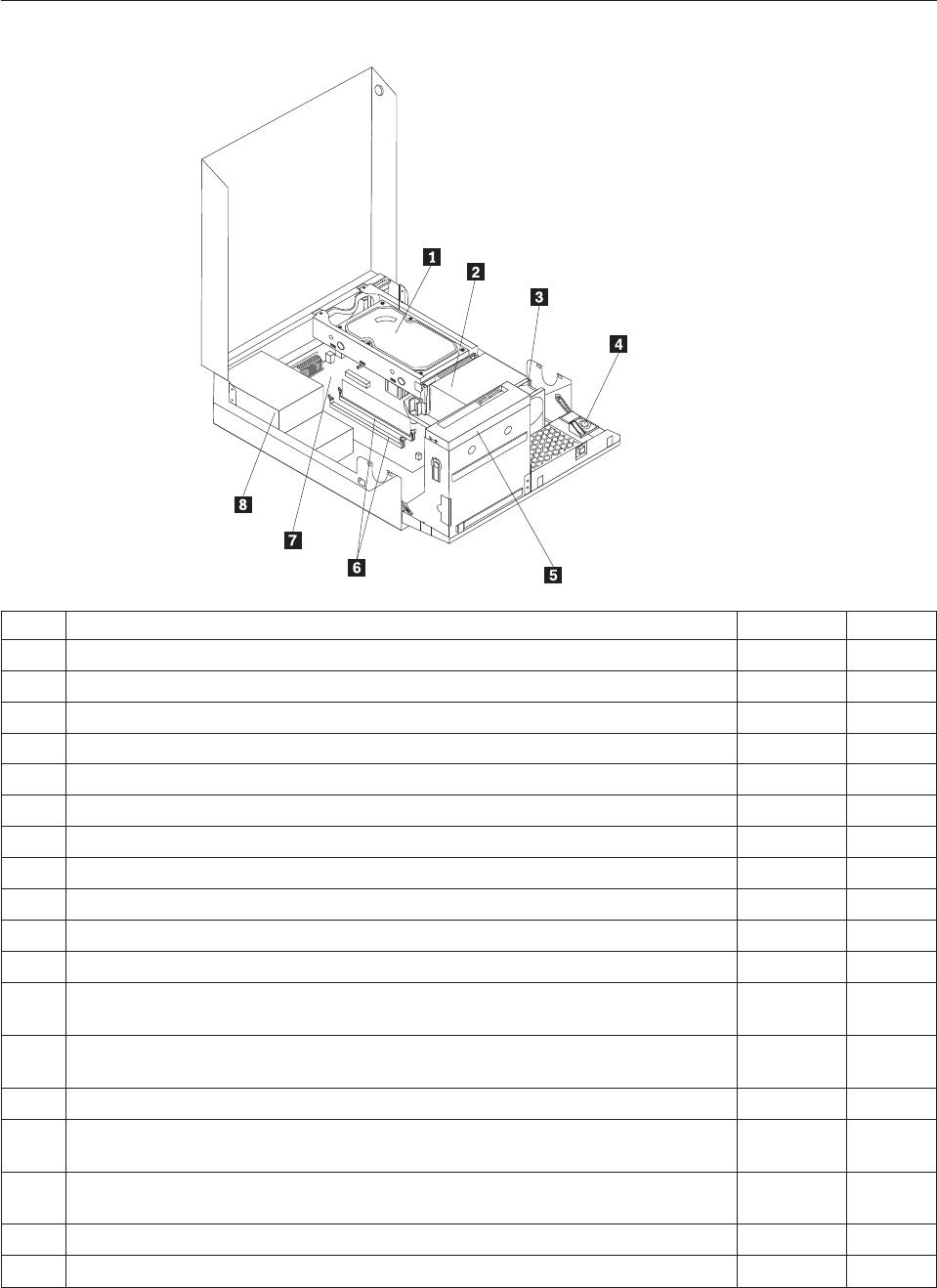
Machine type 7560
Item# 7560 FRUs FRU# CRU
1 Hard disk drive, SATA 160GB 7200RPM/3Gb/8MB (models) 40Y9035 1
1 Hard disk drive, SATA 250GB 7200RPM/3Gb/8MB (models) 40Y9036 1
1 Hard disk drive, SATA 320GB 7200rpm SATA/8MB (models) 87H4891 1
1 Hard disk drive, SATA 500GB 7200RPM/3Gb/s/8MB (models) 41X5582 1
1 Hard disk drive, 1TB 7200rpm SATA (models) 45C5973 1
1 Hard disk drive, SATA 160 GB 7200RPM/3GB/8MB - optional (models) 53Y6837 1
1 Hard disk drive, SATA 250 GB 7200RPM/3GB/8MB - optional (models) 45K0408 1
1 Hard disk drive, SATA 320 GB 7200RPM SATA/8MB - optional (models) 45K0409 1
1 Hard disk drive, SATA 500 GB 7200RPM/3GB/s/8MB - optional (models) 45K0410 1
1 Hard disk drive, 1 TB 7200RPM SATA - optional (models) 45K0412 1
1 Hard disk drive, 150 GB 10K RPM, SATA (models) 46R6400 1
2 Microprocessor, E7400 2.8GHZ 1066M 3M R0 (ViiV, EIST, EM64T, EDB) 65W
(models)
53Y6653 N
2 Microprocessor, E7500 2.93GHZ 1066M 3M R0 (ViiV, EIST, EM64T, EDB) 65W
(models)
53Y6654 N
2 Microprocessor, E5300 2.6GHz 800MHz 2MB R0 (EIST, EM64T, EDB) 65W (models) 53Y9049 N
2 Microprocessor, E1500 2.2GHz 800MHz 512KB (EIST, EM64T, EDB) M0 65W
(models)
53Y9051 N
2 Microprocessor, Q8300 Yorkfield 2.5GHZ, 1333MHz, 4M R-0 (ViiV, EIST, EM64T,
EDB) 95W (models)
53Y6656 N
2 Microprocessor, E8600 3.33GHZ/1333MHZ/6M E0 65W (models) 46R8640 N
2 Microprocessor, E8500 3.16GHz 1333MHz FSB 6M C-0 65W (models) 45C7735 N
206 Hardware Maintenance Manual

Item# 7560 FRUs FRU# CRU
2 Microprocessor, E8400 3.0GHz 1333MHz FSB 6M C-0 65W (models) 45C7736 N
2 Microprocessor, E8300 2.83GHz 1333MHz FSB 6M C-0 65W (models) 45C7737 N
2 Microprocessor, E7200 2.53GHz 1066MHz FSB 3M M-0 65W (models) 45R8337 N
2 Microprocessor, E7300 2.66GHz 1066MHz FSB 3M M-0 65W (models) 46R1622 N
2 Microprocessor, E2200 Conroe-L 2.2GHz 800MHz FSB 1M (models) 45C5349 N
2 Microprocessor, E2220 Conroe-L 2.4GHz 800MHz FSB 1M (models) 45C1774 N
2 Microprocessor, E5200 2.5G 800MHz 2M M-0 65W, 45nm (models) 46R9512 N
2 Microprocessor, E1600 2.4GHZ/800MHZ/512K - NPI M-0 65W (models) 46R1655 N
2 Microprocessor, E1400 2.0GHz 800MHz FSB 512K - NPI M-0 65W (models) 45R8339 N
2 Microprocessor, Cel-440 Conroe-L 2.0GHz 800MHz FSB 512K (models) 43C1965 N
2 Microprocessor, Cel-450 2.2GHz 800MHz FSB 512K 35W (models) 46R9514 N
2 Microprocessor, Q9650 3.0GHZ 1333FSB 12MB VT, TXT E-0 95W (models) 46R8642 N
2 Microprocessor, Q9400 2.66GHZ 1333FSB 6MB VT, TXT R-0 95W (models) 46R8644 N
2 Microprocessor, Q8200 2.33GHz 1333FSB 4M M-1 95W (models) 46R9516 N
2 Microprocessor, Q9550 2.83GHZ 1333FSB 12M C-1 95W (models) 45C7739 N
2 Microprocessor, Q9450 Yorkfield 2.66GHZ 1333FSB 12M C-1 95W (models) 45C7740 N
2 Microprocessor, Q9300 Yorkfield 2.50GHZ 1333FSB 6M M-1 95W (models) 45C7741 N
2 Microprocessor, E5400 2.7G 800MHz-2MB 65W Non-vPro SKU (models) 64Y1075 N
2 Microprocessor, E7600 3.06GHZ 1066M 3M 65W (models) 71Y3486 N
2 Microprocessor, Q8400 2.66GHZ,1333MHz,4M 95W (models) 71Y3488 N
2 Microprocessor, E6300 2.8G 1066MHz-2MB 65W (models) 71Y3484 N
2 Microprocessor, E6500 2.93GHZ 1066 MHz-2MB 65W R0 (models) 71Y6250 N
2 Microprocessor, E3300 2.5GHZ 800 MHz-1MB 65W R0 (models) 71Y6252 N
2 Microprocessor, E3200 2.4GHZ 800 MHz-1MB 65W R0 (models) 71Y6251 N
3 95W heat sink kit with RM (all models) 41R6454 2
3 65W heat sink kit with RM (all models) 43N9349 2
3 95W heat sink kit with RM (all models) 43N9874 2
3 65W heat sink kit with RM (all models) 43N9877 2
4 Internal speaker 254 mm - optional (all models) 39K5012 2
5 Optical drive, DVD-ROM Drive - 16x/48x - SATA - for Windows 7 (models) 71Y5543 1
5 Optical drive, DVD Recordable Rambo8-SATA12XRAM Write - for Windows 7
(models)
71Y5545 1
6 Memory module, 512MB PC2-5300 (667MHz) DDR2 SDRAM (models) 41X4255 1
6 Memory module, 1GB PC2-5300 (667MHz) DDR2 SDRAM (models) 41X4256 1
6 Memory module, 2GB PC2-5300 (667MHz) DDR2 SDRAM (models) 41X4257 1
6 Memory module, 512MB PC2-6400 (800MHz) DDR2 SDRAM (models) 41X1079 1
6 Memory module, 1GB PC2-6400 (667MHz) DDR2 SDRAM (models) 41X1080 1
6 Memory module, 2GB PC2-6400 (667MHz) DDR2 SDRAM (models) 41X1081 1
7 System board, Intel G41 BTX(GA) non-AMT (models) 46R8892 N
7 System board, Intel G41 BTX (GA) - NB upgrade (models) 64Y9198 N
7 System board, Intel G41 BTX - EuP and TCM header (models) 71Y6839 N
Chapter 10. FRU lists 207

Item# 7560 FRUs FRU# CRU
8 Power supply, 280W Active PFC power supply (Auto sensing) for 10L---Robust,
ww, JP (models)
41A9701 N
8 Power supply, 280W 85+ power supply for 10L---Robust, ww, JP (models) 41A9742 N
8 Power supply, 280W Active PFC power supply (auto-sensing) - all countries
(models)
45J9418 N
8 Power supply, 280W 85+ power supply - all countries (models) 45J9423 N
8 Power supply, 280 watt, Active PFC power supply, auto-sensing for 10L - Robust,
WW, JP, for Eup (models)
54Y8804 N
The FRUs listed in the following tables are not illustrated.
7560 FRUs FRU# CRU
Battery 3V - Lithium (models) 45C1566 1
Cable - SATA 250 mm (RoHS) for 1st hard disk drive (all models) 43N9012 2
Cable - SATA 600 mm (RoHS) (all models) 45J9579 2
Cable - SATA 700 mm (RoHS) for optical drive / Second hard disk drive (all models) 43N9011 2
C2 intrusion switch 260 mm (all models) 43N9080 2
Rear I/O shield BTX (all models) 41R6381 N
Temp sense cable (165 mm) (all models) 43N9079 2
Air deflector, recycle resin (all models) 43N9610 2
Hard disk drive tray assembly (all models) 43N9595 1
Front cage assembly (all models) 43N9596 N
Front cage assembly (all models) 43N9647 N
Cable, Front I/O cable_R (10L_U380_A550)_ESD (all models) 45J9509 2
Models with 3.5’’ convert 2.5’’ for 150 GB 10 K rpm hard disk drive (first HDD bay) (all
models)
43N9645 2
3.5’’ convert 2.5’’ for 150 GB 10 K rpm hard disk drive (first HDD bay) (all models) 43N9593 2
Universal Adapter Bracket 5.25 to 3.5 (all models) 43N9676 2
Top cover assembly (all models) 43N9594 1
Cable, LED/Switch cable_R (10L_220 mm_PCBA) (all models) 45J9515 2
NO ODD, EMI shielding (all models) 43N9641 1
Card reader bezel (all models) 43N9642 1
Non-card reader bezel (all models) 43N9643 1
Card reader (all models) 45K6081 1
Vertical stand (all models) 43N9644 1
Front bezel assembly (all models) 43N9677 1
Chassis (all models) 43N9649 N
Rubber foot for vertical (all models) 43N9727 1
Rubber foot for horizontal (all models) 43N9728 1
Thermal grease (all models) 91P8835 N
Optical retainer (all models) 45K6364 1
208 Hardware Maintenance Manual

7560 Keyboards (Lenovo Preferred Pro USB -- without hub) FRU# CRU
USB FULL--US English (models) 41A5289 1
USB FULL--Arabic (models) 41A5290 1
USB FULL--Arabic/French (models) 41A5291 1
USB FULL--Belgium French (models) 41A5292 1
USB FULL--Belgium English (models) 41A5293 1
USB FULL--Brazilian Portuguese (models) 41A5294 1
USB FULL--Bulgarian (models) 41A5295 1
USB FULL--Chinese/US (models) 41A5296 1
USB FULL--Czech (ABB) (models) 41A5297 1
USB FULL--Danish (models) 41A5298 1
USB FULL--Dutch (models) 41A5299 1
USB FULL--French (models) 41A5300 1
USB FULL--French Canadian (models) 41A5301 1
USB FULL--French Canadian (models) 41A5302 1
USB FULL--German (models) 41A5303 1
USB FULL--Greek (models) 41A5304 1
USB FULL--Greek/US (models) 41A5305 1
USB FULL--Hebrew (models) 41A5306 1
USB FULL--Hungarian (models) 41A5307 1
USB FULL--Iceland (models) 41A5308 1
USB FULL--Italy (models) 41A5309 1
USB FULL--Japanese (models) 41A5310 1
USB FULL--Korean (models) 41A5311 1
USB FULL--LA Spanish (models) 41A5312 1
USB FULL--Norwegian (models) 41A5313 1
USB FULL--Polish (models) 41A5314 1
USB FULL--Portuguese (models) 41A5315 1
USB FULL--Romanian (models) 41A5317 1
USB FULL--Romanian (models) 41A5316 1
USB FULL--Russian/Cyrillic (models) 41A5318 1
USB FULL--Serbian/Cyrillic (models) 41A5319 1
USB FULL--Slovak (models) 41A5320 1
USB FULL--Spanish (models) 41A5321 1
USB FULL--Swedish/Finnish (models) 41A5322 1
USB FULL--Swiss French/German (models) 41A5323 1
USB FULL--Thailand (models) 41A5324 1
USB FULL--Turkish (models) 41A5325 1
USB FULL--Turkish (models) 41A5326 1
USB FULL --UK English (models) 41A5327 1
USB FULL--US Euro (models) 41A5328 1
USB FULL--Slovenian (models) 41A5329 1
Chapter 10. FRU lists 209

7560 Keyboards (Lenovo Preferred Pro USB -- without hub) FRU# CRU
USB FULL--Arabic (New) (models) 45J4880 1
USB FULL--Lithuanian (models) 45J4896 1
USB FULL--Estonia (models) 51J0059 1
7560 Keyboards (Lenovo Fingerprint Reader USB) FRU# CRU
US English (models) 41R0038 1
Arabic (models) 41R0039 1
Arabic/French (models) 41R0040 1
Belgium French (models) 41R0041 1
Belgium English (models) 41R0042 1
Brazilian Portuguese (models) 41R0043 1
Bulgarian (models) 41R0044 1
Chinese/US (models) 41R0045 1
Czech (ABB) (models) 41R0046 1
Danish (models) 41R0047 1
Dutch (models) 41R0048 1
French (models) 41R0049 1
French Canadian (models) 41R0050 1
French Canadian (models) 41R0051 1
German (models) 41R0052 1
Greek (models) 41R0053 1
Greek/US (models) 41R0054 1
Hebrew (models) 41R0055 1
Hungarian (models) 41R0056 1
Iceland (models) 41R0057 1
Italian (models) 41R0058 1
Japanese (models) 41R0059 1
Korean (models) 41R0060 1
LA Spanish (models) 41R0061 1
Norwegian (models) 41R0062 1
Polish (models) 41R0063 1
Portuguese (models) 41R0064 1
Romanian (models) 41R0065 1
Romanian (models) 41R0066 1
Russian/Cyrillic (models) 41R0067 1
Serbian/Cyrillic (models) 41R0068 1
Slovak (models) 41R0069 1
Spanish (models) 41R0070 1
Swedish/Finnish (models) 41R0071 1
Swiss French/German (models) 41R0072 1
Thailand (models) 41R0073 1
210 Hardware Maintenance Manual

7560 Keyboards (Lenovo Fingerprint Reader USB) FRU# CRU
Turkish (models) 41R0074 1
Turkish (models) 41R0075 1
UK English (models) 41R0076 1
US Euro (models) 41R0077 1
Slovenian (models) 41R0078 1
7560 Keyboards (Lenovo preferred Pro PS/2 Full Size) FRU# CRU
US English (models) 41A5039 1
Arabic (models) 41A5040 1
Arabic (New) (models) 45J4880 1
Arabic French (models) 41A5041 1
Belgium French (models) 41A5042 1
Belgium English (models) 41A5043 1
Brazilian Portuguese (models) 41A5044 1
Bulgarian (models) 41A5045 1
Chinese/US (models) 41A5046 1
Czech (ABB) (models) 41A5047 1
Danish (models) 41A5048 1
Dutch (models) 41A5049 1
French (models) 41A5050 1
French Canadian (models) 41A5051 1
French Canadian (models) 41A5052 1
German (models) 41A5053 1
Greek (models) 41A5054 1
Greek/US (models) 41A5080 1
Hebrew (models) 41A5055 1
Hungarian (models) 41A5056 1
Iceland (models) 41A5057 1
Italian (models) 41A5058 1
Japanese (models) 41A5059 1
Korean (models) 41A5060 1
LA Spanish (models) 41A5061 1
Norwegian (models) 41A5062 1
Polish (models) 41A5063 1
Portuguese (models) 41A5064 1
Romanian (models) 41A5065 1
Russian/Cyrillic (models) 41A5066 1
Serbian/Cyrillic (models) 41A5067 1
Slovak (models) 41A5068 1
Spanish (models) 41A5069 1
Swedish/Finnish (models) 41A5070 1
Chapter 10. FRU lists 211

7560 Keyboards (Lenovo preferred Pro PS/2 Full Size) FRU# CRU
Swiss French/German (models) 41A5071 1
Thailand (models) 41A5072 1
Turkish (models) 41A5073 1
Turkish (models) 41A5074 1
UK English (models) 41A5075 1
US Euro (models) 41A5076 1
Slovenian (models) 41A5077 1
7560 mice FRU# CRU
Optical Wheel Mouse OPT (400DPI, USB) (models) 41U3013 1
Optical Wheel Mouse OPT (400DPI, USB) (models) 41U3030 1
7560 adapters and miscellaneous FRUs FRU# CRU
Internal 25 in 1 USB Memory Card Reader Slim (models) 46R1529 1
IEEE 1394 Firewire Adapter (models) 41D2781 1
Soft Modem V.90/V.44 (models) 46R4220 1
Speaker power brick - US, Canada, LA low voltage, ASEAN (models) 89P8571 1
Speaker power brick - LA high voltage (non-APU) (models) 89P8575 1
Speaker power brick - Simplified Chinese, Thailand EMEA (models) 89P8581 1
Speaker power brick - Japanese (models) 89P8577 1
Speaker power brick - Brazil (models) 89P8583 1
Speaker power brick - Argentina (models) 41A4901 1
Speaker power brick - ANZ (models) 89P8579 1
Speaker power brick - Korea (models) 41A4903 1
Speaker power brick - Hong Kong, EMEA, Ireland (models) 89P8573 1
Speaker power brick -Taiwan-Traditional Chinese (models) 41A4905 1
Speaker power brick - India, South Africa (models) 89P8585 1
2-pc external speaker--primary (models) 41A5331 1
2-pc external speaker-secondary (models) 41A5334 1
DVI-I(M)-VGA(F) cord (models) 41R3342 1
ATI HD3470 GDDR3 256MB - VGA+DP (models) 46R1521 1
ADD2 DVI-D Adapter, (HDCP) DVD-D connection Adapter Low Profile (Silicon Image)
(models)
43C0258 1
DisplayPort to DVI-D Dongle (models) 43N9160 1
DisplayPort to VGA Dongle (models) 45J9524 1
Modem phone cable (models) 39K5120 1
LI140mm Rear Com2 cable II mini®(models) 43N9062 2
Rear USB 2 Ports II LP®350 mm (models) 43N9124 2
NVIDIA G100 DDR2 256MB LP - DVI-I (With DVI-I to VGA Dongle) (models) 53Y9341 1
212 Hardware Maintenance Manual

7560 Power Cords (Primary) FRU# CRU
Power cord - US (models) 41R3184 1
Power cord - China (models) 41R3256 1
Power cord - Japanese and Japanese English (models) 41R3248 1
Power cord - Brazil (models) 41R3270 1
Power cord - Brazil - optional (models) 45J9595 1
Power cord - LA High Volt (APU) (models) 41R3176 1
Power cord - Australia / New Zealand (models) 41R3196 1
Power cord - Korea (models) 41R3260 1
Power cord - UK, Ireland, Singapore, Malaysia, Brunei, Hong Kong (models) 41R3224 1
Power cord - Taiwan (models) 41R3278 1
Power cord - Italy (models) 41R3232 1
Power cord - Indonesia, Laos, Cambodia, Vietnam, Austria, Belgium, Croatia,
Czechoslovakia, Finland, France, Germany, Hungary, Netherlands, Norway, Poland,
Portugal, Romania, Spain, Sweden (models)
41R3208 1
Power cord - Denmark (models) 41R3212 1
Power cord - Switzerland (models) 41R3228 1
Power cord - Israel (models) 41R3236 1
Power cord - South Africa (models) 41R3220 1
Power cord - India (models) 41R3341 1
Power cord - Thailand (models) 43N9029 1
7560 Power Cords (Secondary) FRU# CRU
Power cord - US (models) 41R3185 1
Power cord - China (models) 41R3257 1
Power Cord - Japanese and Japanese English (models) 41R3249 1
Power cord - Brazil (models) 41R3271 1
Power cord - LA High Volt (APU) (models) 41R3177 1
Power cord - Australia / New Zealand (models) 41R3197 1
Power cord - Korea (models) 41R3261 1
Power cord - UK, Ireland, Singapore, Malaysia, Brunei, Hong Kong (models) 41R3225 1
Power cord - Taiwan (models) 41R3279 1
Power cord - Italy (models) 41R3233 1
Power cord - Indonesia, Laos, Cambodia, Vietnam, Austria, Belgium, Croatia,
Czechoslovakia, Finland, France, Germany, Hungary, Netherlands, Norway, Poland,
Portugal, Romania, Spain, Sweden (models)
41R3209 1
Power cord - Denmark (models) 41R3213 1
Power cord - Switzerland (models) 41R3229 1
Power cord - Israel (models) 41R3237 1
Power cord - South Africa (models) 41R3221 1
Power cord - India (models) 41R3175 1
Power cord - Thailand (models) 43N9030 1
Power cord - Y cable for Brazil (models) 43N9044 1
Chapter 10. FRU lists 213

7560 Windows XP Home Recovery CDs FRU# CRU
US English/UK/Asia Pacific (models) TBD 1
French/French Canadian (models) TBD 1
Greek (models) TBD 1
Italy (models) TBD 1
Brazilian (models) TBD 1
Spanish/LA (models) TBD 1
Danish (models) TBD 1
Dutch (models) TBD 1
Arabic (models) TBD 1
Swedish (models) TBD 1
Hebrew (models) TBD 1
Finnish (models) TBD 1
Norwegian (models) TBD 1
Polish (models) TBD 1
Portuguese (models) TBD 1
Russian (models) TBD 1
Russian English (models) TBD 1
Hungarian (models) TBD 1
Czech (models) TBD 1
Turkish native (models) TBD 1
Greek (models) TBD 1
Japanese (models) TBD 1
Simplified Chinese (models) TBD 1
Taiwan-TC (models) TBD 1
Hong Kong-TC (models) TBD 1
Korean (models) TBD 1
7560 Windows XP Pro Recovery CDs FRU# CRU
Hebrew (models) 71Y7506 1
Portuguese (models) 71Y7514 1
Russian English (models) 71Y7510 1
Hungarian (models) 71Y7512 1
Slovenian (models) 71Y7515 1
Korea (models) 71Y7519 1
US English (models) 71Y7493 1
French (models) 71Y7494 1
German (models) 71Y7495 1
Italian (models) 71Y7498 1
Brazilian Portuguese (models) 71Y7497 1
Spanish (models) 71Y7496 1
214 Hardware Maintenance Manual

7560 Windows XP Pro Recovery CDs FRU# CRU
Danish (models) 71Y7502 1
Dutch (models) 71Y7503 1
Arabic (models) 71Y7508 1
Swedish (models) 71Y7501 1
Finnish (models) 71Y7505 1
Norwegian (models) 71Y7500 1
Polish (models) 71Y7507 1
Russian (models) 71Y7509 1
Czech (models) 71Y7504 1
Turkish (models) 71Y7511 1
Greek (models) 71Y7513 1
Japanese (models) 71Y7499 1
Simplified Chinese (models) 71Y7516 1
Traditional Chinese (models) 71Y7517 1
Hong Kong (models) 71Y7518 1
MUI Nordics (EN-DK-FI-NO-SV) (models) 71Y7520 1
MUI Switz (US EN-FR -GR-IT) (models) 71Y7521 1
MUI Bel-Lux (EN-FR-GR-NL) (models) 71Y7522 1
7560 Vista Home Basic 32 Recovery DVDs FRU# CRU
US English (models) 64Y8594 1
French (models) 64Y8596 1
German (models) 64Y8597 1
Spanish (models) 64Y8598 1
Brazilian (models) 64Y8599 1
Italian (models) 64Y8600 1
Dutch (models) 64Y8614 1
Czech (models) 64Y8601 1
Polish (models) 64Y8602 1
Russian (models) 64Y8603 1
Turkish (models) 64Y8604 1
Hungarian (models) 64Y8605 1
Greek (models) 64Y8606 1
Portuguese (models) 64Y8617 1
Simplified Chinese (models) 64Y8608 1
Hong Kong (models) 64Y8610 1
Traditional Chinese (models) 64Y8609 1
Korean (models) 64Y8611 1
Slovenian (models) 64Y8612 1
Russian English (models) 64Y8595 1
Hebrew (models) 64Y8615 1
Chapter 10. FRU lists 215

7560 Vista Home Basic 32 Recovery DVDs FRU# CRU
Arabic Localized (models) 64Y8613 1
Slovakian (models) 64Y8619 1
Romanian (models) 64Y8616 1
Serbian-Latin (models) 64Y8618 1
C&L 1 Nordics (EN DK FI NO SV) (models) 64Y8620 1
C&L 2 Switzerland (EN FR GR IT) (models) 64Y8621 1
C&L 3 Bel Lux (EN FR GR NL) (models) 64Y8622 1
Japanese (models) 64Y8607 1
7560 Vista Business 32 Recovery DVDs FRU# CRU
US English (models) 64Y8565 1
French (models) 64Y8567 1
German (models) 64Y8568 1
Spanish (models) 64Y8569 1
Brazilian Portuguese (models) 64Y8570 1
Italian (models) 64Y8571 1
Japanese (models) 64Y8578 1
Dutch (models) 64Y8585 1
Czech (models) 64Y8572 1
Polish (models) 64Y8573 1
Russian (models) 64Y8574 1
Turkish (models) 64Y8575 1
Hungarian (models) 64Y8576 1
Greek (models) 64Y8577 1
Portuguese (models) 64Y8588 1
Simplified Chinese (models) 64Y8579 1
Traditional Chinese (models) 64Y8580 1
Hong Kong (models) 64Y8581 1
Korean (models) 64Y8582 1
Slovenian (models) 64Y8583 1
Russian English (models) 64Y8566 1
Romanian (models) 64Y8587 1
Serbian-Latin (models) 64Y8589 1
Slovakian (models) 64Y8590 1
Arabic Localized (models) 64Y8584 1
Hebrew (models) 64Y8586 1
C&L 1 Nordics (EN DK FI NO SV) (models) 64Y8591 1
C&L 2 Switzerland (EN FR GR IT) (models) 64Y8592 1
C&L 3 Bel Lux (EN FR GR NL) (models) 64Y8593 1
216 Hardware Maintenance Manual

7560 Vista Home Premium 32 Recovery DVDs FRU# CRU
US English (models) 64Y8623 1
French (models) 64Y8624 1
German (models) 64Y8625 1
Spanish (models) 64Y8626 1
Italian (models) 64Y8628 1
Japanese (models) 64Y8629 1
Hong Kong (models) 64Y8630 1
Korean (models) 64Y8627 1
C&L 1 Nordics (EN DK FI NO SV) (models) 64Y8631 1
C&L 2 Switzerland (EN FR GR IT) (models) 64Y8632 1
C&L 3 Bel Lux (EN FR GR NL) (models) 64Y8633 1
7560 Vista Business 64 Recovery DVDs FRU# CRU
US English (models) 64Y8643 1
French (models) 64Y8644 1
German (models) 64Y8645 1
Japanese (models) 64Y8646 1
Simplified Chinese (models) 64Y8647 1
7560 Vista Ultimate 32 Recovery DVDs FRU# CRU
US English (models) 64Y8634 1
Japanese (models) 64Y8635 1
French (models) 64Y8636 1
German (models) 64Y8637 1
Spanish (models) 64Y8638 1
Italian (models) 64Y8639 1
Hong Kong - Traditional Chinese (models) 64Y8640 1
Arabic localized (models) 64Y8641 1
C&L 1 Nordics (EN DK FI NO SV) (models) 64Y8642 1
7560 Vista Starter 32 Recovery DVDs FRU# CRU
English (models) TBD 1
7560 Windows 7 Home Basic 32 Recovery DVDs FRU# CRU
Arabic (models) 71Y7549 1
India English (models) 71Y8655 1
Russian English (models) 71Y7550 1
Russian (models) 71Y7551 1
Spanish (models) 71Y7552 1
Serbian-Latin (models) 71Y7553 1
Turkish (models) 71Y7554 1
Chapter 10. FRU lists 217

7560 Windows 7 Home Basic 32 Recovery DVDs FRU# CRU
English (models) 71Y7555 1
7560 Windows 7 Home Premium 32 Recovery DVDs FRU# CRU
Traditional Chinese (models) 71Y7556 1
India English (models) 71Y8656 1
French (models) 71Y7557 1
Hong Kong (models) 71Y7558 1
Italian (models) 71Y7559 1
Japan (models) 71Y7560 1
Korean (models) 71Y7561 1
Spanish (models) 71Y7562 1
English (models) 71Y7563 1
C&L Bel Lux (EN FR GR NL) (models) 71Y7564 1
C&L Nordics (EN DK FI NO SV) (models) 71Y7565 1
C&L Switzerland (EN FR GR IT) (models) 71Y7566 1
7560 Windows 7 Professional 32 Recovery DVDs FRU# CRU
Arabic (models) 71Y7523 1
Traditional Chinese (models) 71Y7524 1
Czech (models) 71Y7525 1
India English (models) 71Y8654 1
French (models) 71Y7526 1
Greek (models) 71Y7527 1
German (models) 71Y7528 1
Hebrew (models) 71Y7529 1
Hong Kong (models) 71Y7530 1
Hungarian (models) 71Y7531 1
Italian (models) 71Y7532 1
Japan (models) 71Y7533 1
Korean (models) 71Y7534 1
Polish (models) 71Y7535 1
Portuguese (models) 71Y7536 1
Russian English (models) 71Y7537 1
Romanian (models) 71Y7538 1
Russian (models) 71Y7539 1
Slovakia (models) 71Y7540 1
Slovenian (models) 71Y7541 1
Spanish (models) 71Y7542 1
Serbian-Latin (models) 71Y7543 1
Turkish (models) 71Y7544 1
English (models) 71Y7545 1
218 Hardware Maintenance Manual

7560 Windows 7 Professional 32 Recovery DVDs FRU# CRU
C&L Bel Lux (EN FR GR NL) (models) 71Y7546 1
C&L Nordics (EN DK FI NO SV) (models) 71Y7547 1
C&L Switzerland (EN FR GR IT) (models) 71Y7548 1
7560 Windows 7 Professional 64 Recovery DVDs FRU# CRU
Traditional Chinese (models) 71Y7574 1
India English (models) 71Y8658 1
French (models) 71Y7575 1
German (models) 71Y7576 1
Hong Kong (models) 71Y7577 1
Italian (models) 71Y7578 1
Japan (models) 71Y7579 1
Spanish (models) 71Y7580 1
English (models) 71Y7581 1
C&L Bel Lux (EN FR GR NL) (models) 71Y7582 1
C&L Nordics (EN DK FI NO SV) (models) 71Y7583 1
C&L Switzerland (EN FR GR IT) (models) 71Y7584 1
7560 Windows 7 Starter Recovery DVDs FRU# CRU
Arabic (models) 71Y7567 1
India English (models) 71Y8657 1
Russian English (models) 71Y7568 1
Russian (models) 71Y7569 1
Spanish (models) 71Y7570 1
Serbian-Latin (models) 71Y7571 1
Turkish (models) 71Y7572 1
English (models) 71Y7573 1
Chapter 10. FRU lists 219

Machine type 7569
Item# 7569 FRUs FRU# CRU
1 Intel 95W / 65W Heatsink (all models) 43N9409 2
1 Intel 65W heat sink (all models) 43N9708 2
1 Intel 65W heat sink (all models) 45K6227 2
1 Intel 95W / 65W heat sink (all models) 43N9897 2
2 System board, Intel G41 MATX(GA) non-AMT (models) 46R8891 N
2 System board, Intel G41 MATX(GA) -NB upgrade (models) 64Y9197 N
2 System board, Intel G41 MATX -- EuP and No TCM header (models) 71Y6838 N
3 Microprocessor, E7400 2.8GHZ 1066M 3M R0 (ViiV, EIST, EM64T, EDB) 65W
(models)
53Y6653 N
3 Microprocessor, E7500 2.93GHZ 1066M 3M R0 (ViiV, EIST, EM64T, EDB) 65W
(models)
53Y6654 N
3 Microprocessor, E5300 2.6GHz 800MHz 2MB R0 (EIST, EM64T, EDB) 65W (models) 53Y9049 N
3 Microprocessor, E1500 2.2GHz 800MHz 512KB (EIST, EM64T, EDB) M0 65W
(models)
53Y9051 N
3 Microprocessor, Q8300 Yorkfield 2.5GHZ, 1333MHz, 4M R-0 (ViiV, EIST, EM64T,
EDB) 95W (models)
53Y6656 N
3 Microprocessor, E8600 3.33GHZ/1333MHZ/6M E0 65W (models) 46R8640 N
3 Microprocessor, E8500 3.16GHz 1333MHz FSB 6M C-0 65W (models) 45C7735 N
3 Microprocessor, E8400 3.0GHz 1333MHz FSB 6M C-0 65W (models) 45C7736 N
220 Hardware Maintenance Manual

Item# 7569 FRUs FRU# CRU
3 Microprocessor, E8300 2.83GHz 1333MHz FSB 6M C-0 65W (models) 45C7737 N
3 Microprocessor, E7200 2.53GHz 1066MHz FSB 3M M-0 65W (models) 45R8337 N
3 Microprocessor, E7300 2.66GHz 1066MHz FSB 3M M-0 65W (models) 46R1622 N
3 Microprocessor, E2200 Conroe-L 2.2GHz 800MHz FSB 1M (models) 45C5349 N
3 Microprocessor, E2220 Conroe-L 2.4GHz 800MHz FSB 1M (models) 45C1774 N
3 Microprocessor, E5200 2.5G 800MHz 2M M-0 65W, 45nm (models) 46R9512 N
3 Microprocessor, E1600 2.4GHZ/800MHZ/512K - NPI M-0 65W (models) 46R1655 N
3 Microprocessor, E1400 2.0GHz 800MHz FSB 512K - NPI M-0 65W (models) 45R8339 N
3 Microprocessor, Cel-440 Conroe-L 2.0GHz 800MHz FSB 512K (models) 43C1965 N
3 Microprocessor, Cel-450 2.2GHz 800MHz FSB 512K 35W (models) 46R9514 N
3 Microprocessor, Q9650 3.0GHZ 1333FSB 12MB VT, TXT E-0 95W (models) 46R8642 N
3 Microprocessor, Q9400 2.66GHZ 1333FSB 6MB VT, TXT R-0 95W (models) 46R8644 N
3 Microprocessor, Q8200 2.33GHz 1333FSB 4M M-1 95W (models) 46R9516 N
3 Microprocessor, Q9550 2.83GHZ 1333FSB 12M C-1 95W (models) 45C7739 N
3 Microprocessor, Q9450 Yorkfield 2.66GHZ 1333FSB 12M C-1 95W (models) 45C7740 N
3 Microprocessor, Q9300 Yorkfield 2.50GHZ 1333FSB 6M M-1 95W (models) 45C7741 N
3 Microprocessor, E5400 2.7G 800MHz 2MB 65W Non-vPro SKU (models) 64Y1075 N
3 Microprocessor, E7600 3.06GHZ 1066M 3M 65W (models) 71Y3486 N
3 Microprocessor, Q8400 2.66GHZ,1333MHz,4M 95W (models) 71Y3488 N
3 Microprocessor, E6300 2.8G 1066MHz-2MB 65W (models) 71Y3484 N
3 Microprocessor, E6500 2.93GHZ 1066 MHz-2MB 65W R0 (models) 71Y6250 N
3 Microprocessor, E3300 2.5GHZ 800 MHz-1MB 65W R0 (models) 71Y6252 N
3 Microprocessor, E3200 2.4GHZ 800 MHz-1MB 65W R0 (models) 71Y6251 N
4 Memory module, 512MB PC2-5300 (667MHz) DDR2 SDRAM (models) 41X4255 1
4 Memory module, 1GB PC2-5300 (667MHz) DDR2 SDRAM (models) 41X4256 1
4 Memory module, 2GB PC2-5300 (667MHz) DDR2 SDRAM (models) 41X4257 1
4 Memory module, 512MB PC2-6400 (800MHz) DDR2 SDRAM (models) 41X1079 1
4 Memory module, 1GB PC2-6400 (667MHz) DDR2 SDRAM (models) 41X1080 1
4 Memory module, 2GB PC2-6400 (667MHz) DDR2 SDRAM (models) 41X1081 1
6 Optical drive, DVD-ROM Drive - 16x/48x - SATA - for Windows 7 (models) 71Y5543 1
6 Optical drive, DVD Recordable Rambo8-SATA12XRAM Write - for Windows 7
(models)
71Y5545 1
6 Optical drive, Blu-ray Recordable / DVD Super Multi - for Windows 7 (models) 71Y5547 1
7 Diskette drive, 3.5″1.44MB 2 Mode FDD with Bezel and cable (models) 40Y9107 1
7 Diskette drive, 3.5″1.44MB 2 Mode FDD with Bezel and cable (models) 40Y9105 1
8 Front bezel assembly (all models) 43N9662 1
8 Front bezel with ODD door assembly (all models) 43N9694 2
9 Internal speaker 400mm -- Optional (all models) 43N9091 2
11 Battery 3V - Lithium (models) 45C1566 1
12 Hard disk drive, SATA 160GB 7200RPM/3Gb/8MB (models) 40Y9035 1
12 Hard disk drive, SATA 250GB 7200RPM/3Gb/8MB (models) 40Y9036 1
Chapter 10. FRU lists 221

Item# 7569 FRUs FRU# CRU
12 Hard disk drive, SATA 320GB 7200rpm SATA/8MB (models) 87H4891 1
12 Hard disk drive, SATA 500GB 7200RPM/3Gb/s/8MB (models) 41X5582 1
12 Hard disk drive, 1TB 7200rpm SATA (models) 45C5973 1
12 Hard disk drive, SATA 160GB 7200RPM/3Gb/8MB - optional (models) 53Y6837 1
12 Hard disk drive, SATA 250GB 7200RPM/3Gb/8MB - optional (models) 45K0408 1
12 Hard disk drive, SATA 320GB 7200RPM SATA/8MB - optional (models) 45K0409 1
12 Hard disk drive, SATA 500GB 7200RPM/3Gb/s/8MB - optional (models) 45K0410 1
12 Hard disk drive, 1TB 7200RPM SATA - optional (models) 45K0412 1
12 Hard disk drive, 150G 10K RPM, SATA (models) 46R6400 1
14 Intrusion Switch Asm 475mm --Optional (all models) 39K5022 2
14 Intrusion Switch Asm (all models) 41R6116 2
15 System fan, rear (all models) 41R6269 2
16 Power supply, ATX 450W 80% power supply, Robust, WW, JP (models) 41A9721 2
16 Power supply, ATX 280W power supply, Robust, WW (models) 41A9684 2
16 Power supply, ATX 280W 80% power supply, Robust, WW, JP (models) 41A9665 2
16 Power supply, 280-watt ATX, (85plus)-WW, Robust, JP (models) 45J9431 2
16 Power supply, ATX 280 watt, Robust; WW for EUP (models) 45J9436 2
The FRUs listed in the following tables are not illustrated.
7569 FRUs FRU# CRU
Chassis (all models) 45K6346 2
System fan, front fan used for 2X500G (all models) 43N9599 2
Shield, 5.25 EMC FOR 1st ODD Bay (all models) 41N8080 1
Cable - SATA 457 mm (RoHS) for ODD (all models) 43N9013 2
Cable - SATA, Second HDD, 120 mm, 1 latching for Device, RoHS (all models) 41R3328 2
Cable - SATA 250 mm (RoHS) for 1st HDD (all models) 43N9012 2
Second HDD Bracket Asm (all models) 41R6106 1
Temp Sense Cable (6pin 460 mm) (all models) 45J9495 2
FDD Cable (all models) 41A7182 2
FDD Cable, 310 mm (all models) 41A7147 2
I/O Shield (all models) 41N8053 2
Rear I/O Shield, ATX, 946, FOF (all models) 45K6266 2
HDD Tray (all models) 41R6291 1
ODD/FDD/Cardreader Retainers (all models) 43N9351 1
Cable Clip, FW-6D (all models) 43N9462 2
Power switch cable, 760 mm (all models) 45J9512 2
Front I_O cable_R (all models) 45J9506 2
Front I_O cable_R (all models) 45J9592 2
ODD door assembly (all models) 43N9663 1
No FDD cover assembly (all models) 43N9664 1
222 Hardware Maintenance Manual

7569 FRUs FRU# CRU
FDD/Card reader cover (all models) 43N9665 1
Chassis primary HDD cage (all models) 45K6272 2
USB cover (all models) 43N9666 1
Top handle assembly (all models) 43N9667 1
3.5’’ Convert 2.5’’ for 150GB 10K rpm HDD (1st HDD bay) (all models) 43N9593 2
Thermal Grease (all models) 91P8835 N
Rubber foot (For acoustic improvement) (all models) 45K6278 2
7569 Keyboards (Lenovo Preferred Pro USB -- without hub) FRU# CRU
USB FULL--US English (models) 41A5289 1
USB FULL--Arabic (models) 41A5290 1
USB FULL--Arabic/French (models) 41A5291 1
USB FULL--Belgium French (models) 41A5292 1
USB FULL--Belgium English (models) 41A5293 1
USB FULL--Brazilian Portuguese (models) 41A5294 1
USB FULL--Bulgarian (models) 41A5295 1
USB FULL--Chinese/US (models) 41A5296 1
USB FULL--Czech (ABB) (models) 41A5297 1
USB FULL--Danish (models) 41A5298 1
USB FULL--Dutch (models) 41A5299 1
USB FULL--French (models) 41A5300 1
USB FULL--French Canadian (models) 41A5301 1
USB FULL--French Canadian (models) 41A5302 1
USB FULL--German (models) 41A5303 1
USB FULL--Greek (models) 41A5304 1
USB FULL--Greek/US (models) 41A5305 1
USB FULL--Hebrew (models) 41A5306 1
USB FULL--Hungarian (models) 41A5307 1
USB FULL--Iceland (models) 41A5308 1
USB FULL--Italy (models) 41A5309 1
USB FULL--Japanese (models) 41A5310 1
USB FULL--Korean (models) 41A5311 1
USB FULL--LA Spanish (models) 41A5312 1
USB FULL--Norwegian (models) 41A5313 1
USB FULL--Polish (models) 41A5314 1
USB FULL--Portuguese (models) 41A5315 1
USB FULL--Romanian (models) 41A5317 1
USB FULL--Romanian (models) 41A5316 1
USB FULL--Russian/Cyrillic (models) 41A5318 1
USB FULL--Serbian/Cyrillic (models) 41A5319 1
USB FULL--Slovak (models) 41A5320 1
Chapter 10. FRU lists 223

7569 Keyboards (Lenovo Preferred Pro USB -- without hub) FRU# CRU
USB FULL--Spanish (models) 41A5321 1
USB FULL--Swedish/Finnish (models) 41A5322 1
USB FULL--Swiss French/German (models) 41A5323 1
USB FULL--Thailand (models) 41A5324 1
USB FULL--Turkish (models) 41A5325 1
USB FULL--Turkish (models) 41A5326 1
USB FULL --UK English (models) 41A5327 1
USB FULL--US Euro (models) 41A5328 1
USB FULL--Slovenian (models) 41A5329 1
USB FULL--Lithuanian (models) 45J4896 1
USB FULL--Estonia (models) 51J0059 1
7569 Keyboards (Lenovo Fingerprint Reader USB) FRU# CRU
US English (models) 41R0038 1
Arabic (models) 41R0039 1
Arabic/French (models) 41R0040 1
Belgium French (models) 41R0041 1
Belgium English (models) 41R0042 1
Brazilian Portuguese (models) 41R0043 1
Bulgarian (models) 41R0044 1
Chinese/US (models) 41R0045 1
Czech (ABB) (models) 41R0046 1
Danish (models) 41R0047 1
Dutch (models) 41R0048 1
French (models) 41R0049 1
French Canadian (models) 41R0050 1
French Canadian (models) 41R0051 1
German (models) 41R0052 1
Greek (models) 41R0053 1
Greek/US (models) 41R0054 1
Hebrew (models) 41R0055 1
Hungarian (models) 41R0056 1
Iceland (models) 41R0057 1
Italian (models) 41R0058 1
Japanese (models) 41R0059 1
Korean (models) 41R0060 1
LA Spanish (models) 41R0061 1
Norwegian (models) 41R0062 1
Polish (models) 41R0063 1
Portuguese (models) 41R0064 1
Romanian (models) 41R0065 1
224 Hardware Maintenance Manual

7569 Keyboards (Lenovo Fingerprint Reader USB) FRU# CRU
Romanian (models) 41R0066 1
Russian/Cyrillic (models) 41R0067 1
Serbian/Cyrillic (models) 41R0068 1
Slovak (models) 41R0069 1
Spanish (models) 41R0070 1
Swedish/Finnish (models) 41R0071 1
Swiss French/German (models) 41R0072 1
Thailand (models) 41R0073 1
Turkish (models) 41R0074 1
Turkish (models) 41R0075 1
UK English (models) 41R0076 1
US Euro (models) 41R0077 1
Slovenian (models) 41R0078 1
7569 Mice FRU# CRU
Optical Wheel Mouse OPT (400DPI, USB) (models) 41U3013 1
Optical Wheel Mouse OPT (400DPI, USB) (models) 41U3030 1
7569 Adapters and miscellaneous FRUs FRU# CRU
Internal 25 in 1 USB Memory Card Reader (models) 45R8139 1
IEEE 1394 Firewire Adapter ATX (models) 41D2781 1
Speaker power brick - US, Canada, LA low voltage, ASEAN (models) 89P8571 1
Speaker power brick - LA high voltage (non-APU) (models) 89P8575 1
Speaker power brick - Simplified Chinese, Thailand EMEA (models) 89P8581 1
Speaker power brick - Japanese (models) 89P8577 1
Speaker power brick - Brazil (models) 89P8583 1
Speaker power brick - Argentina (models) 41A4901 1
Speaker power brick - ANZ (models) 89P8579 1
Speaker power brick - Korea (models) 41A4903 1
Speaker power brick - Hong Kong, EMEA, Ireland (models) 89P8573 1
Speaker power brick -Taiwan-Traditional Chinese (models) 41A4905 1
Speaker power brick - India, South Africa (models) 89P8585 1
2-pc external speaker--primary (models) 41A5331 1
2-pc external speaker-secondary (models) 41A5334 1
DVI-I(M)-VGA(F) cord (models) 41R3342 1
Geforce 9500GT GDDR3 512MB - DVI+HDMI+DP (models) 46R1524 1
ATI HD3470 GDDR3 256MB - VGA+DP (models) 46R1521 1
ADD2 DVI-D Adapter, (HDCP) DVD-D connection Adapter Low Profile (Silicon Image)
(models)
43C0258 1
DisplayPort to DVI-D Dongle (models) 43N9160 1
DisplayPort to VGA Dongle (models) 45J9524 1
Chapter 10. FRU lists 225

7569 Adapters and miscellaneous FRUs FRU# CRU
Modem phone cable (models) 39K5120 1
LI300mm Rear USB 2Ports II HP®(models) 42Y8005 2
LI350mm Rear Com2 cable II mini®(models) 41R8548 2
NVIDIA G100 DDR2 256MB ATX - DVI-I+VGA (models) 53Y9249 1
Soft Modem V.90/V.44 ATX (models) 46R4220 1
7569 Power Cords (Primary) FRU # CRU
Power cord - US (models) 41R3184 1
Power cord - China (models) 41R3256 1
Power Cord - Japanese and Japanese English (models) 41R3248 1
Power cord - Brazil (models) 41R3270 1
Power cord - Brazil - optional (models) 45J9595 1
Power cord - LA High Volt (APU) (models) 41R3176 1
Power cord - Australia / New Zealand (models) 41R3196 1
Power cord - Korea (models) 41R3260 1
Power cord - UK, Ireland, Singapore, Malaysia, Brunei, Hong Kong (models) 41R3224 1
Power cord - Taiwan (models) 41R3278 1
Power cord - Italy (models) 41R3232 1
Power cord - Indonesia, Laos, Cambodia, Vietnam, Austria, Belgium, Croatia,
Czechoslovakia, Finland, France, Germany, Hungary, Netherlands, Norway, Poland,
Portugal, Romania, Spain, Sweden (models)
41R3208 1
Power cord - Denmark (models) 41R3212 1
Power cord - Switzerland (models) 41R3228 1
Power cord - Israel (models) 41R3236 1
Power cord - South Africa (models) 41R3220 1
Power cord - India (models) 41R3341 1
Power cord - Thailand (models) 43N9029 1
7569 Power Cords (Secondary) FRU# CRU
Power cord - US (models) 41R3185 1
Power cord - China (models) 41R3257 1
Power Cord - Japanese and Japanese English (models) 41R3249 1
Power cord - Brazil (models) 41R3271 1
Power cord - LA High Volt (APU) (models) 41R3177 1
Power cord - Australia / New Zealand (models) 41R3197 1
Power cord - Korea (models) 41R3261 1
Power cord - UK, Ireland, Singapore, Malaysia, Brunei, Hong Kong (models) 41R3225 1
Power cord - Taiwan (models) 41R3279 1
Power cord - Italy (models) 41R3233 1
Power cord - Indonesia, Laos, Cambodia, Vietnam, Austria, Belgium, Croatia,
Czechoslovakia, Finland, France, Germany, Hungary, Netherlands, Norway, Poland,
Portugal, Romania, Spain, Sweden (models)
41R3209 1
226 Hardware Maintenance Manual

7569 Power Cords (Secondary) FRU# CRU
Power cord - Denmark (models) 41R3213 1
Power cord - Switzerland (models) 41R3229 1
Power cord - Israel (models) 41R3237 1
Power cord - South Africa (models) 41R3221 1
Power cord - India (models) 41R3175 1
Power cord - Thailand (models) 43N9030 1
Power cord - Y cable for Brazil (models) 43N9044 1
7569 Windows XP Home Recovery CDs FRU# CRU
US English/UK/Asia Pacific (models) TBD 1
French/French Canadian (models) TBD 1
Greek (models) TBD 1
Italy (models) TBD 1
Brazilian (models) TBD 1
Spanish/LA (models) TBD 1
Danish (models) TBD 1
Dutch (models) TBD 1
Arabic (models) TBD 1
Swedish (models) TBD 1
Hebrew (models) TBD 1
Finnish (models) TBD 1
Norwegian (models) TBD 1
Polish (models) TBD 1
Portuguese (models) TBD 1
Russian (models) TBD 1
Russian English (models) TBD 1
Hungarian (models) TBD 1
Czech (models) TBD 1
Turkish native (models) TBD 1
Greek (models) TBD 1
Japanese (models) TBD 1
Simplified Chinese (models) TBD 1
Taiwan-TC (models) TBD 1
Hong Kong-TC (models) TBD 1
Korean (models) TBD 1
7569 Windows XP Pro Recovery CDs FRU# CRU
Hebrew (models) 71Y7506 1
Portuguese (models) 71Y7514 1
Russian English (models) 71Y7510 1
Hungarian (models) 71Y7512 1
Chapter 10. FRU lists 227

7569 Windows XP Pro Recovery CDs FRU# CRU
Slovenian (models) 71Y7515 1
Korea (models) 71Y7519 1
US English (models) 71Y7493 1
French (models) 71Y7494 1
German (models) 71Y7495 1
Italian (models) 71Y7498 1
Brazilian Portuguese (models) 71Y7497 1
Spanish (models) 71Y7496 1
Danish (models) 71Y7502 1
Dutch (models) 71Y7503 1
Arabic (models) 71Y7508 1
Swedish (models) 71Y7501 1
Finnish (models) 71Y7505 1
Norwegian (models) 71Y7500 1
Polish (models) 71Y7507 1
Russian (models) 71Y7509 1
Czech (models) 71Y7504 1
Turkish (models) 71Y7511 1
Greek (models) 71Y7513 1
Japanese (models) 71Y7499 1
Simplified Chinese (models) 71Y7516 1
Traditional Chinese (models) 71Y7517 1
Hong Kong (models) 71Y7518 1
MUI Nordics (EN-DK-FI-NO-SV) (models) 71Y7520 1
MUI Switz (US EN-FR -GR-IT) (models) 71Y7521 1
MUI Bel-Lux (EN-FR-GR-NL) (models) 71Y7522 1
7569 Vista Home Basic 32 Recovery DVDs FRU# CRU
US English (models) 64Y8594 1
French (models) 64Y8596 1
German (models) 64Y8597 1
Spanish (models) 64Y8598 1
Brazilian (models) 64Y8599 1
Italian (models) 64Y8600 1
Dutch (models) 64Y8614 1
Czech (models) 64Y8601 1
Polish (models) 64Y8602 1
Russian (models) 64Y8603 1
Turkish (models) 64Y8604 1
Hungarian (models) 64Y8605 1
Greek (models) 64Y8606 1
228 Hardware Maintenance Manual

7569 Vista Home Basic 32 Recovery DVDs FRU# CRU
Portuguese (models) 64Y8617 1
Simplified Chinese (models) 64Y8608 1
Hong Kong (models) 64Y8610 1
Traditional Chinese (models) 64Y8609 1
Korean (models) 64Y8611 1
Slovenian (models) 64Y8612 1
Russian English (models) 64Y8595 1
Hebrew (models) 64Y8615 1
Arabic Localized (models) 64Y8613 1
Slovakian (models) 64Y8619 1
Romanian (models) 64Y8616 1
Serbian-Latin (models) 64Y8618 1
C&L 1 Nordics (EN DK FI NO SV) (models) 64Y8620 1
C&L 2 Switzerland (EN FR GR IT) (models) 64Y8621 1
C&L 3 Bel Lux (EN FR GR NL) (models) 64Y8622 1
Japanese (models) 64Y8607 1
7569 Vista Business 32 Recovery DVDs FRU# CRU
US English (models) 64Y8565 1
French (models) 64Y8567 1
German (models) 64Y8568 1
Spanish (models) 64Y8569 1
Brazilian Portuguese (models) 64Y8570 1
Italian (models) 64Y8571 1
Japanese (models) 64Y8578 1
Dutch (models) 64Y8585 1
Czech (models) 64Y8572 1
Polish (models) 64Y8573 1
Russian (models) 64Y8574 1
Turkish (models) 64Y8575 1
Hungarian (models) 64Y8576 1
Greek (models) 64Y8577 1
Portuguese (models) 64Y8588 1
Simplified Chinese (models) 64Y8579 1
Traditional Chinese (models) 64Y8580 1
Hong Kong (models) 64Y8581 1
Korean (models) 64Y8582 1
Slovenian (models) 64Y8583 1
Russian English (models) 64Y8566 1
Romanian (models) 64Y8587 1
Serbian-Latin (models) 64Y8589 1
Chapter 10. FRU lists 229

7569 Vista Business 32 Recovery DVDs FRU# CRU
Slovakian (models) 64Y8590 1
Arabic Localized (models) 64Y8584 1
Hebrew (models) 64Y8586 1
C&L 1 Nordics (EN DK FI NO SV) (models) 64Y8591 1
C&L 2 Switzerland (EN FR GR IT) (models) 64Y8592 1
C&L 3 Bel Lux (EN FR GR NL) (models) 64Y8593 1
7569 Vista Home Premium 32 Recovery DVDs FRU# CRU
US English (models) 64Y8623 1
French (models) 64Y8624 1
German (models) 64Y8625 1
Spanish (models) 64Y8626 1
Italian (models) 64Y8628 1
Japanese (models) 64Y8629 1
Hong Kong (models) 64Y8630 1
Korean (models) 64Y8627 1
C&L 1 Nordics (EN DK FI NO SV) (models) 64Y8631 1
C&L 2 Switzerland (EN FR GR IT) (models) 64Y8632 1
C&L 3 Bel Lux (EN FR GR NL) (models) 64Y8633 1
7569 Vista Business 64 Recovery DVDs FRU# CRU
US English (models) 64Y8643 1
French (models) 64Y8644 1
German (models) 64Y8645 1
Japanese (models) 64Y8646 1
Simplified Chinese (models) 64Y8647 1
7569 Vista Ultimate 32 Recovery DVDs FRU# CRU
US English (models) 64Y8634 1
Japanese (models) 64Y8635 1
French (models) 64Y8636 1
German (models) 64Y8637 1
Spanish (models) 64Y8638 1
Italian (models) 64Y8639 1
Hong Kong - Traditional Chinese (models) 64Y8640 1
Arabic localized (models) 64Y8641 1
C&L 1 Nordics (EN DK FI NO SV) (models) 64Y8642 1
7569 Vista Starter 32 Recovery DVDs FRU# CRU
English (models) TBD 1
230 Hardware Maintenance Manual

7569 Windows 7 Home Basic 32 Recovery DVDs FRU# CRU
Arabic (models) 71Y7549 1
India English (models) 71Y8655 1
Russian English (models) 71Y7550 1
Russian (models) 71Y7551 1
Spanish (models) 71Y7552 1
Serbian-Latin (models) 71Y7553 1
Turkish (models) 71Y7554 1
English (models) 71Y7555 1
7569 Windows 7 Home Premium 32 Recovery DVDs FRU# CRU
Traditional Chinese (models) 71Y7556 1
India English (models) 71Y8656 1
French (models) 71Y7557 1
Hong Kong (models) 71Y7558 1
Italian (models) 71Y7559 1
Japan (models) 71Y7560 1
Korean (models) 71Y7561 1
Spanish (models) 71Y7562 1
English (models) 71Y7563 1
C&L Bel Lux (EN FR GR NL) (models) 71Y7564 1
C&L Nordics (EN DK FI NO SV) (models) 71Y7565 1
C&L Switzerland (EN FR GR IT) (models) 71Y7566 1
7569 Windows 7 Professional 32 Recovery DVDs FRU# CRU
Arabic (models) 71Y7523 1
Traditional Chinese (models) 71Y7524 1
Czech (models) 71Y7525 1
India English (models) 71Y8654 1
French (models) 71Y7526 1
Greek (models) 71Y7527 1
German (models) 71Y7528 1
Hebrew (models) 71Y7529 1
Hong Kong (models) 71Y7530 1
Hungarian (models) 71Y7531 1
Italian (models) 71Y7532 1
Japan (models) 71Y7533 1
Korean (models) 71Y7534 1
Polish (models) 71Y7535 1
Portuguese (models) 71Y7536 1
Russian English (models) 71Y7537 1
Romanian (models) 71Y7538 1
Chapter 10. FRU lists 231

7569 Windows 7 Professional 32 Recovery DVDs FRU# CRU
Russian (models) 71Y7539 1
Slovakia (models) 71Y7540 1
Slovenian (models) 71Y7541 1
Spanish (models) 71Y7542 1
Serbian-Latin (models) 71Y7543 1
Turkish (models) 71Y7544 1
English (models) 71Y7545 1
C&L Bel Lux (EN FR GR NL) (models) 71Y7546 1
C&L Nordics (EN DK FI NO SV) (models) 71Y7547 1
C&L Switzerland (EN FR GR IT) (models) 71Y7548 1
7569 Windows 7 Professional 64 Recovery DVDs FRU# CRU
Traditional Chinese (models) 71Y7574 1
India English (models) 71Y8658 1
French (models) 71Y7575 1
German (models) 71Y7576 1
Hong Kong (models) 71Y7577 1
Italian (models) 71Y7578 1
Japan (models) 71Y7579 1
Spanish (models) 71Y7580 1
English (models) 71Y7581 1
C&L Bel Lux (EN FR GR NL) (models) 71Y7582 1
C&L Nordics (EN DK FI NO SV) (models) 71Y7583 1
C&L Switzerland (EN FR GR IT) (models) 71Y7584 1
7569 Windows 7 Starter Recovery DVDs FRU# CRU
Arabic (models) 71Y7567 1
India English (models) 71Y8657 1
Russian English (models) 71Y7568 1
Russian (models) 71Y7569 1
Spanish (models) 71Y7570 1
Serbian-Latin (models) 71Y7571 1
Turkish (models) 71Y7572 1
English (models) 71Y7573 1
232 Hardware Maintenance Manual

Machine type 7610
Item# 7610 FRUs FRU# CRU
1 Hard disk drive, SATA 160GB 7200RPM/3Gb/8MB (models) 40Y9035 1
1 Hard disk drive, SATA 250GB 7200RPM/3Gb/8MB (models) 40Y9036 1
1 Hard disk drive, SATA 320GB 7200rpm SATA/8MB (models) 87H4891 1
1 Hard disk drive, SATA 500GB 7200RPM/3Gb/s/8MB (models) 41X5582 1
1 Hard disk drive, 1TB 7200rpm SATA (models) 45C5973 1
1 Hard disk drive, SATA 160 GB 7200RPM/3GB/8MB - optional (models) 53Y6837 1
1 Hard disk drive, SATA 250 GB 7200RPM/3GB/8MB - optional (models) 45K0408 1
1 Hard disk drive, SATA 320 GB 7200RPM SATA/8MB - optional (models) 45K0409 1
1 Hard disk drive, SATA 500 GB 7200RPM/3GB/s/8MB - optional (models) 45K0410 1
1 Hard disk drive, 1 TB 7200RPM SATA - optional (models) 45K0412 1
1 Hard disk drive, 150 GB 10K RPM, SATA (models) 46R6400 1
2 Microprocessor, E7400 2.8GHZ 1066M 3M R0 (ViiV, EIST, EM64T, EDB) 65W
(models)
53Y6653 N
2 Microprocessor, E7500 2.93GHZ 1066M 3M R0 (ViiV, EIST, EM64T, EDB) 65W
(models)
53Y6654 N
2 Microprocessor, E5300 2.6GHz 800MHz 2MB R0 (EIST, EM64T, EDB) 65W (models) 53Y9049 N
2 Microprocessor, E1500 2.2GHz 800MHz 512KB (EIST, EM64T, EDB) M0 65W
(models)
53Y9051 N
2 Microprocessor, Q8300 Yorkfield 2.5GHZ, 1333MHz, 4M R-0 (ViiV, EIST, EM64T,
EDB) 95W (models)
53Y6656 N
2 Microprocessor, E8600 3.33GHZ/1333MHZ/6M E0 65W (models) 46R8640 N
2 Microprocessor, E8500 3.16GHz 1333MHz FSB 6M C-0 65W (models) 45C7735 N
Chapter 10. FRU lists 233

Item# 7610 FRUs FRU# CRU
2 Microprocessor, E8400 3.0GHz 1333MHz FSB 6M C-0 65W (models) 45C7736 N
2 Microprocessor, E8300 2.83GHz 1333MHz FSB 6M C-0 65W (models) 45C7737 N
2 Microprocessor, E7200 2.53GHz 1066MHz FSB 3M M-0 65W (models) 45R8337 N
2 Microprocessor, E7300 2.66GHz 1066MHz FSB 3M M-0 65W (models) 46R1622 N
2 Microprocessor, E2200 Conroe-L 2.2GHz 800MHz FSB 1M (models) 45C5349 N
2 Microprocessor, E2220 Conroe-L 2.4GHz 800MHz FSB 1M (models) 45C1774 N
2 Microprocessor, E5200 2.5G 800MHz 2M M-0 65W, 45nm (models) 46R9512 N
2 Microprocessor, E1600 2.4GHZ/800MHZ/512K - NPI M-0 65W (models) 46R1655 N
2 Microprocessor, E1400 2.0GHz 800MHz FSB 512K - NPI M-0 65W (models) 45R8339 N
2 Microprocessor, Cel-440 Conroe-L 2.0GHz 800MHz FSB 512K (models) 43C1965 N
2 Microprocessor, Cel-450 2.2GHz 800MHz FSB 512K 35W (models) 46R9514 N
2 Microprocessor, Q9650 3.0GHZ 1333FSB 12MB VT, TXT E-0 95W (models) 46R8642 N
2 Microprocessor, Q9400 2.66GHZ 1333FSB 6MB VT, TXT R-0 95W (models) 46R8644 N
2 Microprocessor, Q8200 2.33GHz 1333FSB 4M M-1 95W (models) 46R9516 N
2 Microprocessor, Q9550 2.83GHZ 1333FSB 12M C-1 95W (models) 45C7739 N
2 Microprocessor, Q9450 Yorkfield 2.66GHZ 1333FSB 12M C-1 95W (models) 45C7740 N
2 Microprocessor, Q9300 Yorkfield 2.50GHZ 1333FSB 6M M-1 95W (models) 45C7741 N
2 Microprocessor, E5400 2.7G 800MHz-2MB 65W Non-vPro SKU (models 91G 91M
91A 91Q 91K)
64Y1075 N
2 Microprocessor, E7600 3.06GHZ 1066M 3M 65W (models) 71Y3486 N
2 Microprocessor, Q8400 2.66GHZ,1333MHz,4M 95W (models) 71Y3488 N
2 Microprocessor, E6300 2.8G 1066MHz-2MB 65W (models) 71Y3484 N
2 Microprocessor, E6500 2.93GHZ 1066 MHz-2MB 65W R0 (models) 71Y6250 N
2 Microprocessor, E3300 2.5GHZ 800 MHz-1MB 65W R0 (models) 71Y6252 N
2 Microprocessor, E3200 2.4GHZ 800 MHz-1MB 65W R0 (models) 71Y6251 N
3 95W heat sink kit with RM (all models) 41R6454 2
3 65W heat sink kit with RM (all models) 43N9349 2
3 95W heat sink kit with RM (all models) 43N9874 2
3 65W heat sink kit with RM (all models) 43N9877 2
4 Internal speaker 254 mm - optional (all models) 39K5012 2
5 Optical drive, DVD-ROM Drive - 16x/48x - SATA - for Windows 7 (models) 71Y5543 1
5 Optical drive, DVD Recordable Rambo8-SATA12XRAM Write - for Windows 7
(models)
71Y5545 1
6 Memory module, 512MB PC2-5300 (667MHz) DDR2 SDRAM (models) 41X4255 1
6 Memory module, 1GB PC2-5300 (667MHz) DDR2 SDRAM (models) 41X4256 1
6 Memory module, 2GB PC2-5300 (667MHz) DDR2 SDRAM (models) 41X4257 1
6 Memory module, 512MB PC2-6400 (800MHz) DDR2 SDRAM (models) 41X1079 1
6 Memory module, 1GB PC2-6400 (667MHz) DDR2 SDRAM (models) 41X1080 1
6 Memory module, 2GB PC2-6400 (667MHz) DDR2 SDRAM (models) 41X1081 1
7 System board, Intel G41 BTX(GA) non-AMT (models) 46R8892 N
7 System board, Intel G41 BTX (GA) - NB upgrade (models) 64Y9198 N
234 Hardware Maintenance Manual

Item# 7610 FRUs FRU# CRU
7 System board, Intel G41 BTX - EuP and TCM header (models) 71Y6839 N
8 Power supply, 280W Active PFC power supply (Auto sensing) for 10L---Robust,
ww, JP (models)
41A9701 N
8 Power supply, 280W 85+ power supply for 10L---Robust, ww, JP (models) 41A9742 N
8 Power supply, 280W Active PFC power supply (auto-sensing) - all countries
(models)
45J9418 N
8 Power supply, 280W 85+ power supply - all countries (models) 45J9423 N
8 Power supply, 280 watt Active PFC power supply, auto-sensing for 10L - Robust,
WW, JP, for Eup (models)
54Y8804 N
The FRUs listed in the following tables are not illustrated.
7610 FRUs FRU# CRU
Battery 3V - Lithium (models) 45C1566 1
Cable - SATA 250 mm (RoHS) for 1st hard disk drive (all models) 43N9012 2
Cable - SATA 600 mm (RoHS) (all models) 45J9579 2
Cable - SATA 700 mm (RoHS) for optical drive / Second hard disk drive (all models) 43N9011 2
C2 intrusion switch 260 mm (all models) 43N9080 2
Rear I/O shield BTX (all models) 41R6381 N
Temp sense cable (165 mm) (all models) 43N9079 2
Air deflector, recycle resin (all models) 43N9610 2
Hard disk drive tray assembly (all models) 43N9595 1
Front cage assembly (all models) 43N9596 N
Front cage assembly (all models) 43N9647 N
Cable, Front I/O cable_R (10L_U380_A550)_ESD (all models) 45J9509 2
Models with 3.5’’ convert 2.5’’ for 150 GB 10 K rpm hard disk drive (first HDD bay) (all
models)
43N9645 2
3.5’’ convert 2.5’’ for 150 GB 10 K rpm hard disk drive (first HDD bay) (all models) 43N9593 2
Universal Adapter Bracket 5.25 to 3.5 (all models) 43N9676 2
Top cover assembly (all models) 43N9594 1
Cable, LED/Switch cable_R (10L_220 mm_PCBA) (all models) 45J9515 2
NO ODD, EMI shielding (all models) 43N9641 1
Card reader bezel (all models) 43N9642 1
Non-card reader bezel (all models) 43N9643 1
Card reader (all models) 45K6081 1
Vertical stand (all models) 43N9644 1
Front bezel assembly (all models) 43N9677 1
Chassis (all models) 43N9649 N
Rubber foot for vertical (all models) 43N9727 1
Rubber foot for horizontal (all models) 43N9728 1
Thermal grease (all models) 91P8835 N
Optical retainer (all models) 45K6364 1
Chapter 10. FRU lists 235

7610 Keyboards (Lenovo Preferred Pro USB -- without hub) FRU# CRU
USB FULL--US English (models) 41A5289 1
USB FULL--Arabic (models) 41A5290 1
USB FULL--Arabic/French (models) 41A5291 1
USB FULL--Belgium French (models) 41A5292 1
USB FULL--Belgium English (models) 41A5293 1
USB FULL--Brazilian Portuguese (models) 41A5294 1
USB FULL--Bulgarian (models) 41A5295 1
USB FULL--Chinese/US (models) 41A5296 1
USB FULL--Czech (ABB) (models) 41A5297 1
USB FULL--Danish (models) 41A5298 1
USB FULL--Dutch (models) 41A5299 1
USB FULL--French (models) 41A5300 1
USB FULL--French Canadian (models) 41A5301 1
USB FULL--French Canadian (models) 41A5302 1
USB FULL--German (models) 41A5303 1
USB FULL--Greek (models) 41A5304 1
USB FULL--Greek/US (models) 41A5305 1
USB FULL--Hebrew (models) 41A5306 1
USB FULL--Hungarian (models) 41A5307 1
USB FULL--Iceland (models) 41A5308 1
USB FULL--Italy (models) 41A5309 1
USB FULL--Japanese (models) 41A5310 1
USB FULL--Korean (models) 41A5311 1
USB FULL--LA Spanish (models) 41A5312 1
USB FULL--Norwegian (models) 41A5313 1
USB FULL--Polish (models) 41A5314 1
USB FULL--Portuguese (models) 41A5315 1
USB FULL--Romanian (models) 41A5317 1
USB FULL--Romanian (models) 41A5316 1
USB FULL--Russian/Cyrillic (models) 41A5318 1
USB FULL--Serbian/Cyrillic (models) 41A5319 1
USB FULL--Slovak (models) 41A5320 1
USB FULL--Spanish (models) 41A5321 1
USB FULL--Swedish/Finnish (models) 41A5322 1
USB FULL--Swiss French/German (models) 41A5323 1
USB FULL--Thailand (models) 41A5324 1
USB FULL--Turkish (models) 41A5325 1
USB FULL--Turkish (models) 41A5326 1
USB FULL --UK English (models) 41A5327 1
USB FULL--US Euro (models) 41A5328 1
USB FULL--Slovenian (models) 41A5329 1
236 Hardware Maintenance Manual

7610 Keyboards (Lenovo Preferred Pro USB -- without hub) FRU# CRU
USB FULL--Arabic (New) (models) 45J4880 1
USB FULL--Lithuanian (models) 45J4896 1
USB FULL--Estonia (models) 51J0059 1
7610 Keyboards (Lenovo Fingerprint Reader USB) FRU# CRU
US English (models) 41R0038 1
Arabic (models) 41R0039 1
Arabic/French (models) 41R0040 1
Belgium French (models) 41R0041 1
Belgium English (models) 41R0042 1
Brazilian Portuguese (models) 41R0043 1
Bulgarian (models) 41R0044 1
Chinese/US (models) 41R0045 1
Czech (ABB) (models) 41R0046 1
Danish (models) 41R0047 1
Dutch (models) 41R0048 1
French (models) 41R0049 1
French Canadian (models) 41R0050 1
French Canadian (models) 41R0051 1
German (models) 41R0052 1
Greek (models) 41R0053 1
Greek/US (models) 41R0054 1
Hebrew (models) 41R0055 1
Hungarian (models) 41R0056 1
Iceland (models) 41R0057 1
Italian (models) 41R0058 1
Japanese (models) 41R0059 1
Korean (models) 41R0060 1
LA Spanish (models) 41R0061 1
Norwegian (models) 41R0062 1
Polish (models) 41R0063 1
Portuguese (models) 41R0064 1
Romanian (models) 41R0065 1
Romanian (models) 41R0066 1
Russian/Cyrillic (models) 41R0067 1
Serbian/Cyrillic (models) 41R0068 1
Slovak (models) 41R0069 1
Spanish (models) 41R0070 1
Swedish/Finnish (models) 41R0071 1
Swiss French/German (models) 41R0072 1
Thailand (models) 41R0073 1
Chapter 10. FRU lists 237

7610 Keyboards (Lenovo Fingerprint Reader USB) FRU# CRU
Turkish (models) 41R0074 1
Turkish (models) 41R0075 1
UK English (models) 41R0076 1
US Euro (models) 41R0077 1
Slovenian (models) 41R0078 1
7610 keyboards (Lenovo preferred Pro PS/2 Full Size) FRU# CRU
US English (models) 41A5039 1
Arabic (models) 41A5040 1
Arabic (New) (models) 45J4880 1
Arabic French (models) 41A5041 1
Belgium French (models) 41A5042 1
Belgium English (models) 41A5043 1
Brazilian Portuguese (models) 41A5044 1
Bulgarian (models) 41A5045 1
Chinese/US (models) 41A5046 1
Czech (ABB) (models) 41A5047 1
Danish (models) 41A5048 1
Dutch (models) 41A5049 1
French (models) 41A5050 1
French Canadian (models) 41A5051 1
French Canadian (models) 41A5052 1
German (models) 41A5053 1
Greek (models) 41A5054 1
Greek/US (models) 41A5080 1
Hebrew (models) 41A5055 1
Hungarian (models) 41A5056 1
Iceland (models) 41A5057 1
Italian (models) 41A5058 1
Japanese (models) 41A5059 1
Korean (models) 41A5060 1
LA Spanish (models) 41A5061 1
Norwegian (models) 41A5062 1
Polish (models) 41A5063 1
Portuguese (models) 41A5064 1
Romanian (models) 41A5065 1
Russian/Cyrillic (models) 41A5066 1
Serbian/Cyrillic (models) 41A5067 1
Slovak (models) 41A5068 1
Spanish (models) 41A5069 1
Swedish/Finnish (models) 41A5070 1
238 Hardware Maintenance Manual

7610 keyboards (Lenovo preferred Pro PS/2 Full Size) FRU# CRU
Swiss French/German (models) 41A5071 1
Thailand (models) 41A5072 1
Turkish (models) 41A5073 1
Turkish (models) 41A5074 1
UK English (models) 41A5075 1
US Euro (models) 41A5076 1
Slovenian (models) 41A5077 1
7610 mice FRU# CRU
Optical Wheel Mouse OPT (400DPI, USB) (models) 41U3013 1
Optical Wheel Mouse OPT (400DPI, USB) (models) 41U3030 1
7610 adapters and miscellaneous FRUs FRU# CRU
Internal 25 in 1 USB Memory Card Reader Slim (models) 46R1529 1
IEEE 1394 Firewire Adapter (models) 41D2781 1
Soft Modem V.90/V.44 (models) 46R4220 1
Speaker power brick - US, Canada, LA low voltage, ASEAN (models) 89P8571 1
Speaker power brick - LA high voltage (non-APU) (models) 89P8575 1
Speaker power brick - Simplified Chinese, Thailand EMEA (models) 89P8581 1
Speaker power brick - Japanese (models) 89P8577 1
Speaker power brick - Brazil (models) 89P8583 1
Speaker power brick - Argentina (models) 41A4901 1
Speaker power brick - ANZ (models) 89P8579 1
Speaker power brick - Korea (models) 41A4903 1
Speaker power brick - Hong Kong, EMEA, Ireland (models) 89P8573 1
Speaker power brick -Taiwan-Traditional Chinese (models) 41A4905 1
Speaker power brick - India, South Africa (models) 89P8585 1
2-pc external speaker--primary (models) 41A5331 1
2-pc external speaker-secondary (models) 41A5334 1
DVI-I(M)-VGA(F) cord (models) 41R3342 1
ATI HD3470 GDDR3 256MB - VGA+DP (models) 46R1521 1
ADD2 DVI-D Adapter, (HDCP) DVD-D connection Adapter Low Profile (Silicon Image)
(models)
43C0258 1
DisplayPort to DVI-D Dongle (models) 43N9160 1
DisplayPort to VGA Dongle (models) 45J9524 1
Modem phone cable (models) 39K5120 1
LI140mm Rear Com2 cable II mini®(models) 43N9062 2
Rear USB 2 Ports II LP®350 mm (models) 43N9124 2
NVIDIA G100 DDR2 256MB LP - DVI-I (With DVI-I to VGA Dongle) (models) 53Y9341 1
Chapter 10. FRU lists 239

7610 Power Cords (Primary) FRU# CRU
Power cord - US (models) 41R3184 1
Power cord - China (models) 41R3256 1
Power cord - Japanese and Japanese English (models) 41R3248 1
Power cord - Brazil (models) 41R3270 1
Power cord - Brazil - optional (models) 45J9595 1
Power cord - LA High Volt (APU) (models) 41R3176 1
Power cord - Australia / New Zealand (models) 41R3196 1
Power cord - Korea (models) 41R3260 1
Power cord - UK, Ireland, Singapore, Malaysia, Brunei, Hong Kong (models) 41R3224 1
Power cord - Taiwan (models) 41R3278 1
Power cord - Italy (models) 41R3232 1
Power cord - Indonesia, Laos, Cambodia, Vietnam, Austria, Belgium, Croatia,
Czechoslovakia, Finland, France, Germany, Hungary, Netherlands, Norway, Poland,
Portugal, Romania, Spain, Sweden (models)
41R3208 1
Power cord - Denmark (models) 41R3212 1
Power cord - Switzerland (models) 41R3228 1
Power cord - Israel (models) 41R3236 1
Power cord - South Africa (models) 41R3220 1
Power cord - India (models) 41R3341 1
Power cord - Thailand (models) 43N9029 1
7610 Power Cords (Secondary) FRU# CRU
Power cord - US (models) 41R3185 1
Power cord - China (models) 41R3257 1
Power Cord - Japanese and Japanese English (models) 41R3249 1
Power cord - Brazil (models) 41R3271 1
Power cord - LA High Volt (APU) (models) 41R3177 1
Power cord - Australia / New Zealand (models) 41R3197 1
Power cord - Korea (models) 41R3261 1
Power cord - UK, Ireland, Singapore, Malaysia, Brunei, Hong Kong (models) 41R3225 1
Power cord - Taiwan (models) 41R3279 1
Power cord - Italy (models) 41R3233 1
Power cord - Indonesia, Laos, Cambodia, Vietnam, Austria, Belgium, Croatia,
Czechoslovakia, Finland, France, Germany, Hungary, Netherlands, Norway, Poland,
Portugal, Romania, Spain, Sweden (models)
41R3209 1
Power cord - Denmark (models) 41R3213 1
Power cord - Switzerland (models) 41R3229 1
Power cord - Israel (models) 41R3237 1
Power cord - South Africa (models) 41R3221 1
Power cord - India (models) 41R3175 1
Power cord - Thailand (models) 43N9030 1
Power cord - Y cable for Brazil (models) 43N9044 1
240 Hardware Maintenance Manual

7610 Windows XP Home Recovery CDs FRU# CRU
US English/UK/Asia Pacific (models) TBD 1
French/French Canadian (models) TBD 1
Greek (models) TBD 1
Italy (models) TBD 1
Brazilian (models) TBD 1
Spanish/LA (models) TBD 1
Danish (models) TBD 1
Dutch (models) TBD 1
Arabic (models) TBD 1
Swedish (models) TBD 1
Hebrew (models) TBD 1
Finnish (models) TBD 1
Norwegian (models) TBD 1
Polish (models) TBD 1
Portuguese (models) TBD 1
Russian (models) TBD 1
Russian English (models) TBD 1
Hungarian (models) TBD 1
Czech (models) TBD 1
Turkish native (models) TBD 1
Greek (models) TBD 1
Japanese (models) TBD 1
Simplified Chinese (models) TBD 1
Taiwan-TC (models) TBD 1
Hong Kong-TC (models) TBD 1
Korean (models) TBD 1
7610 Windows XP Pro Recovery CDs FRU# CRU
Hebrew (models) 71Y7506 1
Portuguese (models) 71Y7514 1
Russian English (models) 71Y7510 1
Hungarian (models) 71Y7512 1
Slovenian (models) 71Y7515 1
Korea (models) 71Y7519 1
US English (models) 71Y7493 1
French (models) 71Y7494 1
German (models) 71Y7495 1
Italian (models) 71Y7498 1
Brazilian Portuguese (models) 71Y7497 1
Spanish (models) 71Y7496 1
Chapter 10. FRU lists 241

7610 Windows XP Pro Recovery CDs FRU# CRU
Danish (models) 71Y7502 1
Dutch (models) 71Y7503 1
Arabic (models) 71Y7508 1
Swedish (models) 71Y7501 1
Finnish (models) 71Y7505 1
Norwegian (models) 71Y7500 1
Polish (models) 71Y7507 1
Russian (models) 71Y7509 1
Czech (models) 71Y7504 1
Turkish (models) 71Y7511 1
Greek (models) 71Y7513 1
Japanese (models) 71Y7499 1
Simplified Chinese (models) 71Y7516 1
Traditional Chinese (models) 71Y7517 1
Hong Kong (models) 71Y7518 1
MUI Nordics (EN-DK-FI-NO-SV) (models) 71Y7520 1
MUI Switz (US EN-FR -GR-IT) (models) 71Y7521 1
MUI Bel-Lux (EN-FR-GR-NL) (models) 71Y7522 1
7610 Vista Home Basic 32 Recovery DVDs FRU# CRU
US English (models) 64Y8594 1
French (models) 64Y8596 1
German (models) 64Y8597 1
Spanish (models) 64Y8598 1
Brazilian (models) 64Y8599 1
Italian (models) 64Y8600 1
Dutch (models) 64Y8614 1
Czech (models) 64Y8601 1
Polish (models) 64Y8602 1
Russian (models) 64Y8603 1
Turkish (models) 64Y8604 1
Hungarian (models) 64Y8605 1
Greek (models) 64Y8606 1
Portuguese (models) 64Y8617 1
Simplified Chinese (models) 64Y8608 1
Hong Kong (models) 64Y8610 1
Traditional Chinese (models) 64Y8609 1
Korean (models) 64Y8611 1
Slovenian (models) 64Y8612 1
Russian English (models) 64Y8595 1
Hebrew (models) 64Y8615 1
242 Hardware Maintenance Manual

7610 Vista Home Basic 32 Recovery DVDs FRU# CRU
Arabic Localized (models) 64Y8613 1
Slovakian (models) 64Y8619 1
Romanian (models) 64Y8616 1
Serbian-Latin (models) 64Y8618 1
C&L 1 Nordics (EN DK FI NO SV) (models) 64Y8620 1
C&L 2 Switzerland (EN FR GR IT) (models) 64Y8621 1
C&L 3 Bel Lux (EN FR GR NL) (models) 64Y8622 1
Japanese (models) 64Y8607 1
7610 Vista Business 32 Recovery DVDs FRU# CRU
US English (models) 64Y8565 1
French (models) 64Y8567 1
German (models) 64Y8568 1
Spanish (models) 64Y8569 1
Brazilian Portuguese (models) 64Y8570 1
Italian (models) 64Y8571 1
Japanese (models) 64Y8578 1
Dutch (models) 64Y8585 1
Czech (models) 64Y8572 1
Polish (models) 64Y8573 1
Russian (models) 64Y8574 1
Turkish (models) 64Y8575 1
Hungarian (models) 64Y8576 1
Greek (models) 64Y8577 1
Portuguese (models) 64Y8588 1
Simplified Chinese (models) 64Y8579 1
Traditional Chinese (models) 64Y8580 1
Hong Kong (models) 64Y8581 1
Korean (models) 64Y8582 1
Slovenian (models) 64Y8583 1
Russian English (models) 64Y8566 1
Romanian (models) 64Y8587 1
Serbian-Latin (models) 64Y8589 1
Slovakian (models) 64Y8590 1
Arabic Localized (models) 64Y8584 1
Hebrew (models) 64Y8586 1
C&L 1 Nordics (EN DK FI NO SV) (models) 64Y8591 1
C&L 2 Switzerland (EN FR GR IT) (models) 64Y8592 1
C&L 3 Bel Lux (EN FR GR NL) (models) 64Y8593 1
Chapter 10. FRU lists 243

7610 Vista Home Premium 32 Recovery DVDs FRU# CRU
US English (models) 64Y8623 1
French (models) 64Y8624 1
German (models) 64Y8625 1
Spanish (models) 64Y8626 1
Italian (models) 64Y8628 1
Japanese (models) 64Y8629 1
Hong Kong (models) 64Y8630 1
Korean (models) 64Y8627 1
C&L 1 Nordics (EN DK FI NO SV) (models) 64Y8631 1
C&L 2 Switzerland (EN FR GR IT) (models) 64Y8632 1
C&L 3 Bel Lux (EN FR GR NL) (models) 64Y8633 1
7610 Vista Business 64 Recovery DVDs FRU# CRU
US English (models) 64Y8643 1
French (models) 64Y8644 1
German (models) 64Y8645 1
Japanese (models) 64Y8646 1
Simplified Chinese (models) 64Y8647 1
7610 Vista Ultimate 32 Recovery DVDs FRU# CRU
US English (models) 64Y8634 1
Japanese (models) 64Y8635 1
French (models) 64Y8636 1
German (models) 64Y8637 1
Spanish (models) 64Y8638 1
Italian (models) 64Y8639 1
Hong Kong - Traditional Chinese (models) 64Y8640 1
Arabic localized (models) 64Y8641 1
C&L 1 Nordics (EN DK FI NO SV) (models) 64Y8642 1
7610 Vista Starter 32 Recovery DVDs FRU# CRU
English (models) TBD 1
7610 Windows 7 Home Basic 32 Recovery DVDs FRU# CRU
Arabic (models) 71Y7549 1
India English (models) 71Y8655 1
Russian English (models) 71Y7550 1
Russian (models) 71Y7551 1
Spanish (models) 71Y7552 1
Serbian-Latin (models) 71Y7553 1
Turkish (models) 71Y7554 1
244 Hardware Maintenance Manual

7610 Windows 7 Home Basic 32 Recovery DVDs FRU# CRU
English (models) 71Y7555 1
7610 Windows 7 Home Premium 32 Recovery DVDs FRU# CRU
Traditional Chinese (models) 71Y7556 1
India English (models) 71Y8656 1
French (models) 71Y7557 1
Hong Kong (models) 71Y7558 1
Italian (models) 71Y7559 1
Japan (models) 71Y7560 1
Korean (models) 71Y7561 1
Spanish (models) 71Y7562 1
English (models) 71Y7563 1
C&L Bel Lux (EN FR GR NL) (models) 71Y7564 1
C&L Nordics (EN DK FI NO SV) (models) 71Y7565 1
C&L Switzerland (EN FR GR IT) (models) 71Y7566 1
7610 Windows 7 Professional 32 Recovery DVDs FRU# CRU
Arabic (models) 71Y7523 1
Traditional Chinese (models) 71Y7524 1
Czech (models) 71Y7525 1
India English (models) 71Y8654 1
French (models) 71Y7526 1
Greek (models) 71Y7527 1
German (models) 71Y7528 1
Hebrew (models) 71Y7529 1
Hong Kong (models) 71Y7530 1
Hungarian (models) 71Y7531 1
Italian (models) 71Y7532 1
Japan (models) 71Y7533 1
Korean (models) 71Y7534 1
Polish (models) 71Y7535 1
Portuguese (models) 71Y7536 1
Russian English (models) 71Y7537 1
Romanian (models) 71Y7538 1
Russian (models) 71Y7539 1
Slovakia (models) 71Y7540 1
Slovenian (models) 71Y7541 1
Spanish (models) 71Y7542 1
Serbian-Latin (models) 71Y7543 1
Turkish (models) 71Y7544 1
English (models) 71Y7545 1
Chapter 10. FRU lists 245

7610 Windows 7 Professional 32 Recovery DVDs FRU# CRU
C&L Bel Lux (EN FR GR NL) (models) 71Y7546 1
C&L Nordics (EN DK FI NO SV) (models) 71Y7547 1
C&L Switzerland (EN FR GR IT) (models) 71Y7548 1
7610 Windows 7 Professional 64 Recovery DVDs FRU# CRU
Traditional Chinese (models) 71Y7574 1
India English (models) 71Y8658 1
French (models) 71Y7575 1
German (models) 71Y7576 1
Hong Kong (models) 71Y7577 1
Italian (models) 71Y7578 1
Japan (models) 71Y7579 1
Spanish (models) 71Y7580 1
English (models) 71Y7581 1
C&L Bel Lux (EN FR GR NL) (models) 71Y7582 1
C&L Nordics (EN DK FI NO SV) (models) 71Y7583 1
C&L Switzerland (EN FR GR IT) (models) 71Y7584 1
7610 Windows 7 Starter Recovery DVDs FRU# CRU
Arabic (models) 71Y7567 1
India English (models) 71Y8657 1
Russian English (models) 71Y7568 1
Russian (models) 71Y7569 1
Spanish (models) 71Y7570 1
Serbian-Latin (models) 71Y7571 1
Turkish (models) 71Y7572 1
English (models) 71Y7573 1
246 Hardware Maintenance Manual
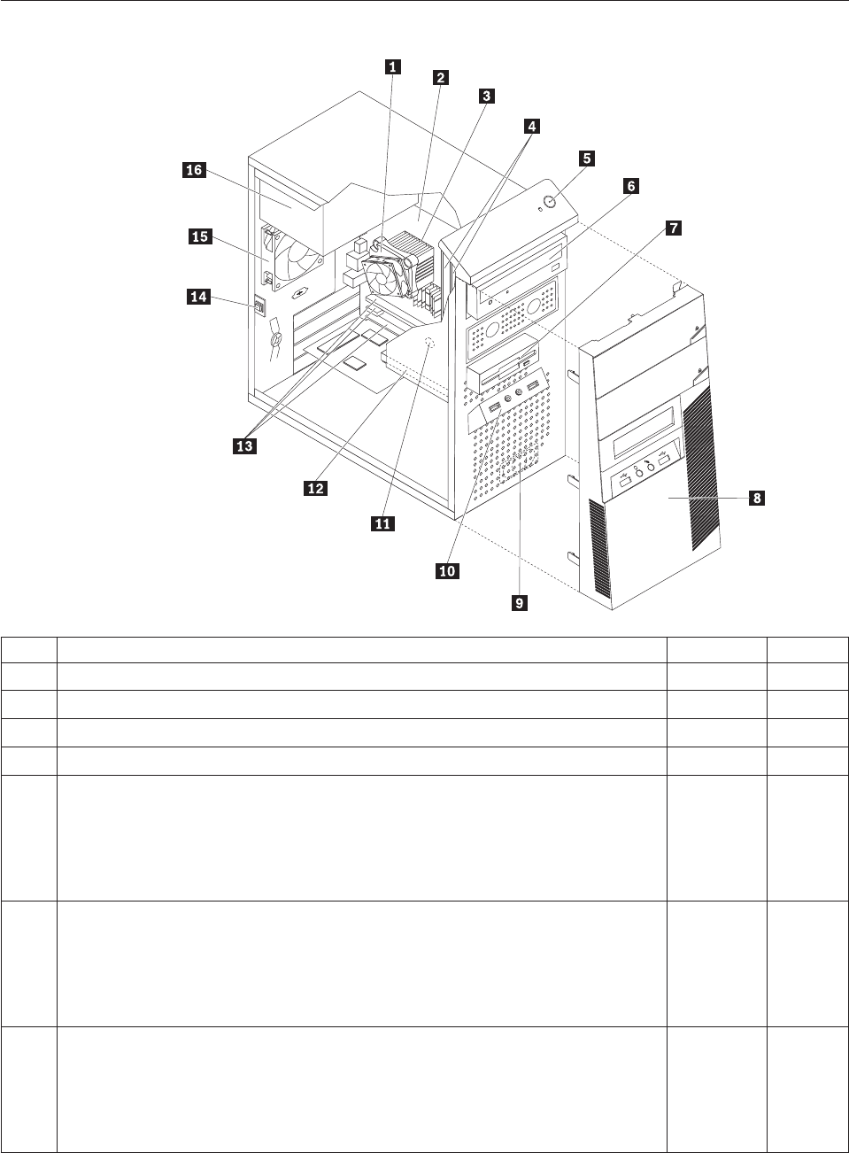
Machine type 7611
Item# 7611 FRUs FRU# CRU
1 Intel 95W / 65W heat sink (all models) 43N9409 2
1 Intel 65W heat sink (all models) 43N9708 2
1 Intel 65W heat sink (all models) 45K6227 2
1 Intel 95W / 65W heat sink (all models) 43N9897 2
2 System board, Intel G41 MATX(GA) non-AMT (models 91U 91F 91M 91Q 91C 91K
A1H A2H A3H A4H A5H A6H A7H A8H B6H B5S B5P B5Y A9V B1A B2A B3A
B4A 71G 72G 73G 74G 75G 76G 77G 78G 79G 7AG B7S B7Y B8S B8Y B9S B9Y
D3H D1A D2A 7BG 7CG D4U D4F D5U D5F 7DG 7FG 7GG 7HG 7JG D6S D6D
D6Y D7S D7D D7Y D8S D8D D8Y D9S D9D D9Y E1S E1D E1Y E2S E2D E2Y E3S
E3D E3Y)
46R8891 N
2 System board, Intel G41 MATX(GA) -NB upgrade (models 91U 91F 91M 91Q 91C
91K A1H A2H A3H A4H A5H A6H A7H A8H B6H B5S B5P B5Y A9V B1A B2A
B3A B4A 71G 72G 73G 74G 75G 76G 77G 78G 79G 7AG B7S B7Y B8S B8Y B9S B9Y
D3H D1A D2A 7BG 7CG D4U D4F D5U D5F 7DG 7FG 7GG 7HG 7JG D6S D6D
D6Y D7S D7D D7Y D8S D8D D8Y D9S D9D D9Y E1S E1D E1Y E2S E2D E2Y E3S
E3D E3Y)
64Y9197 N
2 System board, Intel G41 MATX -- EuP and No TCM header (models 91U 91F 91M
91Q 91C 91K A1H A2H A3H A4H A5H A6H A7H A8H B6H B5S B5P B5Y A9V
B1A B2A B3A B4A 71G 72G 73G 74G 75G 76G 77G 78G 79G 7AG B7S B7Y B8S
B8Y B9S B9Y D3H D1A D2A 7BG 7CG D4U D4F D5U D5F 7DG 7FG 7GG 7HG
7JG D6S D6D D6Y D7S D7D D7Y D8S D8D D8Y D9S D9D D9Y E1S E1D E1Y E2S
E2D E2Y E3S E3D E3Y)
71Y6838 N
Chapter 10. FRU lists 247

Item# 7611 FRUs FRU# CRU
3 Microprocessor, E7400 2.8GHZ 1066M 3M R0 (ViiV, EIST, EM64T, EDB) 65W
(models 91U 91F 91M 91Q 91C 91K B3A B4A 73G 74G 79G 7AG)
53Y6653 N
3 Microprocessor, E7500 2.93GHZ 1066M 3M R0 (ViiV, EIST, EM64T, EDB) 65W
(models A7H B2A D3H D2A 7BG 7CG D4U D4F 7HG D8S D8D D8Y D9S D9D
D9Y)
53Y6654 N
3 Microprocessor, E5300 2.6GHz 800MHz 2MB R0 (EIST, EM64T, EDB) 65W (models
A8H D5U D5F)
53Y9049 N
3 Microprocessor, E1500 2.2GHz 800MHz 512KB (EIST, EM64T, EDB) M0 65W
(models)
53Y9051 N
3 Microprocessor, Q8300 Yorkfield 2.5GHZ, 1333MHz, 4M R-0 (ViiV, EIST, EM64T,
EDB) 95W (models)
53Y6656 N
3 Microprocessor, E8600 3.33GHZ/1333MHZ/6M E0 65W (models) 46R8640 N
3 Microprocessor, E8500 3.16GHz 1333MHz FSB 6M C-0 65W (models A5H) 45C7735 N
3 Microprocessor, E8400 3.0GHz 1333MHz FSB 6M C-0 65W (models A1H A9V 75G
76G)
45C7736 N
3 Microprocessor, E8300 2.83GHz 1333MHz FSB 6M C-0 65W (models) 45C7737 N
3 Microprocessor, E7200 2.53GHz 1066MHz FSB 3M M-0 65W (models) 45R8337 N
3 Microprocessor, E7300 2.66GHz 1066MHz FSB 3M M-0 65W (models A2H A3H
B1A)
46R1622 N
3 Microprocessor, E2200 Conroe-L 2.2GHz 800MHz FSB 1M (models) 45C5349 N
3 Microprocessor, E2220 Conroe-L 2.4GHz 800MHz FSB 1M (models) 45C1774 N
3 Microprocessor, E5200 2.5G 800MHz 2M M-0 65W, 45nm (models B6H B5S B5P
B5Y 77G 78G)
46R9512 N
3 Microprocessor, E1600 2.4GHZ/800MHZ/512K - NPI M-0 65W (models) 46R1655 N
3 Microprocessor, E1400 2.0GHz 800MHz FSB 512K - NPI M-0 65W (models 71G
72G)
45R8339 N
3 Microprocessor, Cel-440 Conroe-L 2.0GHz 800MHz FSB 512K (models) 43C1965 N
3 Microprocessor, Cel-450 2.2GHz 800MHz FSB 512K 35W (models) 46R9514 N
3 Microprocessor, Q9650 3.0GHZ 1333FSB 12MB VT, TXT E-0 95W (models) 46R8642 N
3 Microprocessor, Q9400 2.66GHZ 1333FSB 6MB VT, TXT R-0 95W (models A6H) 46R8644 N
3 Microprocessor, Q8200 2.33GHz 1333FSB 4M M-1 95W (models A4H B7S B7Y B8S
B8Y B9S B9Y)
46R9516 N
3 Microprocessor, Q9550 2.83GHZ 1333FSB 12M C-1 95W (models) 45C7739 N
3 Microprocessor, Q9450 Yorkfield 2.66GHZ 1333FSB 12M C-1 95W (models) 45C7740 N
3 Microprocessor, Q9300 Yorkfield 2.50GHZ 1333FSB 6M M-1 95W (models) 45C7741 N
3 Microprocessor, E5400 2.7G 800MHz 2MB 65W Non-vPro SKU (models D1A) 64Y1075 N
3 Microprocessor, E7600 3.06GHZ 1066M 3M 65W (models) 71Y3486 N
3 Microprocessor, Q8400 2.66GHZ,1333MHz,4M 95W (models D6S D6D D6Y D7S
D7D D7Y)
71Y3488 N
3 Microprocessor, E6300 2.8G 1066MHz-2MB 65W (models E1S E1D E1Y E2S E2D
E2Y)
71Y3484 N
3 Microprocessor, E6500 2.93GHZ 1066 MHz-2MB 65W R0 (models) 71Y6250 N
3 Microprocessor, E3300 2.5GHZ 800 MHz-1MB 65W R0 (models) 71Y6252 N
3 Microprocessor, E3200 2.4GHZ 800 MHz-1MB 65W R0 (models E3S E3D E3Y) 71Y6251 N
4 Memory module, 512MB PC2-5300 (667MHz) DDR2 SDRAM (models) 41X4255 1
248 Hardware Maintenance Manual

Item# 7611 FRUs FRU# CRU
4 Memory module, 1GB PC2-5300 (667MHz) DDR2 SDRAM (models) 41X4256 1
4 Memory module, 2GB PC2-5300 (667MHz) DDR2 SDRAM (models) 41X4257 1
4 Memory module, 512MB PC2-6400 (800MHz) DDR2 SDRAM (models) 41X1079 1
4 Memory module, 1GB PC2-6400 (667MHz) DDR2 SDRAM (models A2H A3H A4H
A5H A6H A8H B6H B5S B5P B5Y A9V B1A B3A B4A B8S B8Y B9S B9Y D1A D2A
7DG 7GG D7S D7D D7Y D8S D8D D8Y E2S E2D E2Y E3S E3D E3Y)
41X1080 1
4 Memory module, 2GB PC2-6400 (667MHz) DDR2 SDRAM (models 91U 91F 91M
91Q 91C 91K A1H A7H B2A 71G 72G 73G 74G 75G 76G 77G 78G 79G 7AG B7S
B7Y D3H 7BG 7CG D4U D4F D5U D5F 7FG 7HG 7JG D6S D6D D6Y D9S D9D
D9Y E1S E1D E1Y)
41X1081 1
6 Optical drive, DVD-ROM Drive - 16x/48x - SATA - for Windows 7 (models A2H
A8H A9V)
71Y5543 1
6 Optical drive, DVD Recordable Rambo8-SATA12XRAM Write - for Windows 7
(models 91U 91F 91M 91Q 91C 91K A1H A3H A4H A5H A6H A7H B6H B5S B5P
B5Y B1A B2A B3A B4A 71G 72G 73G 74G 75G 76G 77G 78G 79G 7AG B7S B7Y
B8S B8Y B9S B9Y D3H D1A D2A 7BG 7CG D4U D4F D5U D5F 7FG 7HG 7JG D6S
D6D D6Y D7S D7D D7Y D8S D8D D8Y D9S D9D D9Y E1S E1D E1Y E2S E2D E2Y
E3S E3D E3Y)
71Y5545 1
6 Optical drive, Blu-ray Recordable / DVD Super Multi - for Windows 7 (models) 71Y5547 1
7 Diskette drive, 3.5″1.44MB 2 Mode FDD with Bezel and cable (models) 40Y9107 1
7 Diskette drive, 3.5″1.44MB 2 Mode FDD with Bezel and cable (models) 40Y9105 1
8 Front bezel assembly (all models) 43N9662 1
8 Front bezel with ODD door assembly (all models) 43N9694 2
9 Internal speaker 400mm -- Optional (all models) 43N9091 2
11 Battery 3V - Lithium (models 91U 91F 91M 91Q 91C 91K A1H A2H A3H A4H
A5H A6H A7H A8H B6H B5S B5P B5Y A9V B1A B2A B3A B4A 71G 72G 73G 74G
75G 76G 77G 78G 79G 7AG B7S B7Y B8S B8Y B9S B9Y D3H D1A D2A 7BG 7CG
D4U D4F D5U D5F 7DG 7FG 7GG 7HG 7JG D6S D6D D6Y D7S D7D D7Y D8S
D8D D8Y D9S D9D D9Y E1S E1D E1Y E2S E2D E2Y E3S E3D E3Y)
45C1566 1
12 Hard disk drive, SATA 160GB 7200RPM/3Gb/8MB (models A1H A2H B5S B5P
B5Y A9V B1A 71G 72G B9S B9Y D5U D5F)
40Y9035 1
12 Hard disk drive, SATA 250GB 7200RPM/3Gb/8MB (models A3H A4H A5H B6H
B2A B3A B4A B7S B7Y B8S B8Y D3H D1A D2A D4U D4F 7DG 7GG D6S D6D D6Y
D7S D7D D7Y D8S D8D D8Y D9S D9D D9Y E1S E1D E1Y E2S E2D E2Y E3S E3D
E3Y)
40Y9036 1
12 Hard disk drive, SATA 320GB 7200rpm SATA/8MB (models A6H A7H A8H 73G
74G 75G 76G 77G 78G 79G 7AG 7BG 7CG)
87H4891 1
12 Hard disk drive, SATA 500GB 7200RPM/3Gb/s/8MB (models) 41X5582 1
12 Hard disk drive, 1TB 7200rpm SATA (models) 45C5973 1
12 Hard disk drive, SATA 160GB 7200RPM/3Gb/8MB - optional (models A1H A2H
B5S B5P B5Y A9V B1A 71G 72G B9S B9Y D5U D5F)
53Y6837 1
12 Hard disk drive, SATA 250GB 7200RPM/3Gb/8MB - optional (models A3H A4H
A5H B6H B2A B3A B4A B7S B7Y B8S B8Y D3H D1A D2A D4U D4F 7DG 7GG D6S
D6D D6Y D7S D7D D7Y D8S D8D D8Y D9S D9D D9Y E1S E1D E1Y E2S E2D E2Y
E3S E3D E3Y)
45K0408 1
12 Hard disk drive, SATA 320GB 7200RPM SATA/8MB - optional (models 91U 91F
91M 91Q 91C 91K A6H A7H A8H 73G 74G 75G 76G 77G 78G 79G 7AG 7BG 7CG
7FG 7HG 7JG)
45K0409 1
12 Hard disk drive, SATA 500GB 7200RPM/3Gb/s/8MB - optional (models) 45K0410 1
Chapter 10. FRU lists 249

Item# 7611 FRUs FRU# CRU
12 Hard disk drive, 1TB 7200RPM SATA - optional (models) 45K0412 1
12 Hard disk drive, 150G 10K RPM, SATA (models) 46R6400 1
14 Intrusion Switch Asm 475mm --Optional (all models) 39K5022 2
14 Intrusion Switch Asm (all models) 41R6116 2
15 System fan, rear (all models) 41R6269 2
16 Power supply, ATX 450W 80% power supply, Robust, WW, JP (models 91U 91F
91M 91Q 91C 91K A1H A2H A3H A4H A5H A6H A7H A8H B6H B5S B5P B5Y
A9V B1A B2A B3A B4A 71G 72G 73G 74G 75G 76G 77G 78G 79G 7AG B7S B7Y
B8S B8Y B9S B9Y D3H D1A D2A 7BG 7CG D4U D4F D5U D5F 7DG 7FG 7GG
7HG 7JG D6S D6D D6Y D7S D7D D7Y D8S D8D D8Y D9S D9D D9Y E1S E1D E1Y
E2S E2D E2Y E3S E3D E3Y)
41A9721 2
16 Power supply, ATX 280W power supply, Robust, WW (models 91U 91F 91M 91Q
91C 91K A1H A2H A3H A4H A5H A6H A7H A8H B6H B5S B5P B5Y A9V B1A
B2A B3A B4A 71G 72G 73G 74G 75G 76G 77G 78G 79G 7AG B7S B7Y B8S B8Y B9S
B9Y D3H D1A D2A 7BG 7CG D4U D4F D5U D5F 7DG 7FG 7GG 7HG 7JG D6S
D6D D6Y D7S D7D D7Y D8S D8D D8Y D9S D9D D9Y E1S E1D E1Y E2S E2D E2Y
E3S E3D E3Y)
41A9684 2
16 Power supply, ATX 280W 80% power supply, Robust, WW, JP (models 91U 91F
91M 91Q 91C 91K A1H A2H A3H A4H A5H A6H A7H A8H B6H B5S B5P B5Y
A9V B1A B2A B3A B4A 71G 72G 73G 74G 75G 76G 77G 78G 79G 7AG B7S B7Y
B8S B8Y B9S B9Y D3H D1A D2A 7BG 7CG D4U D4F D5U D5F 7DG 7FG 7GG
7HG 7JG D6S D6D D6Y D7S D7D D7Y D8S D8D D8Y D9S D9D D9Y E1S E1D E1Y
E2S E2D E2Y E3S E3D E3Y)
41A9665 2
16 Power supply, 280-watt ATX, (85plus)-WW, Robust, JP (models 91U 91F 91M 91Q
91C 91K A1H A2H A3H A4H A5H A6H A7H A8H B6H B5S B5P B5Y A9V B1A
B2A B3A B4A 71G 72G 73G 74G 75G 76G 77G 78G 79G 7AG B7S B7Y B8S B8Y B9S
B9Y D3H D1A D2A 7BG 7CG D4U D4F D5U D5F 7DG 7FG 7GG 7HG 7JG D6S
D6D D6Y D7S D7D D7Y D8S D8D D8Y D9S D9D D9Y E1S E1D E1Y E2S E2D E2Y
E3S E3D E3Y)
45J9431 2
16 Power supply, ATX 280 watt, Robust; WW for EUP (models 91U 91F 91M 91Q 91C
91K A1H A2H A3H A4H A5H A6H A7H A8H B6H B5S B5P B5Y A9V B1A B2A
B3A B4A 71G 72G 73G 74G 75G 76G 77G 78G 79G 7AG B7S B7Y B8S B8Y B9S B9Y
D3H D1A D2A 7BG 7CG D4U D4F D5U D5F 7DG 7FG 7GG 7HG 7JG D6S D6D
D6Y D7S D7D D7Y D8S D8D D8Y D9S D9D D9Y E1S E1D E1Y E2S E2D E2Y E3S
E3D E3Y)
45J9436 2
The FRUs listed in the following tables are not illustrated.
7611 FRUs FRU# CRU
Chassis (all models) 45K6346 2
System fan, front fan used for 2X500G (all models) 43N9599 2
Shield, 5.25 EMC FOR 1st ODD Bay (all models) 41N8080 1
Cable - SATA 457 mm (RoHS) for ODD (all models) 43N9013 2
Cable - SATA, Second HDD, 120 mm, 1 latching for Device, RoHS (all models) 41R3328 2
Cable - SATA 250 mm (RoHS) for 1st HDD (all models) 43N9012 2
Second HDD Bracket Asm (all models) 41R6106 1
Temp Sense Cable (6pin 460 mm) (all models) 45J9495 2
FDD Cable (all models) 41A7182 2
FDD Cable, 310 mm (all models) 41A7147 2
250 Hardware Maintenance Manual

7611 FRUs FRU# CRU
I/O Shield (all models) 41N8053 2
Rear I/O Shield, ATX, 946, FOF (all models) 45K6266 2
HDD Tray (all models) 41R6291 1
ODD/FDD/Cardreader Retainers (all models) 43N9351 1
Cable Clip, FW-6D (all models) 43N9462 2
Power switch cable, 760 mm (all models) 45J9512 2
Front I_O cable_R (all models) 45J9506 2
Front I_O cable_R (all models) 45J9592 2
ODD door assembly (all models) 43N9663 1
No FDD cover assembly (all models) 43N9664 1
FDD/Card reader cover (all models) 43N9665 1
Chassis primary hard disk drive cage (all models) 45K6272 2
USB cover (all models) 43N9666 1
Top handle assembly (all models) 43N9667 1
3.5’’ Convert 2.5’’ for 150GB 10K rpm HDD (1st HDD bay) (all models) 43N9593 2
Thermal Grease (all models) 91P8835 N
Rubber foot (For acoustic improvement) (all models) 45K6278 2
7611 Keyboards (Lenovo Preferred Pro USB -- without hub) FRU# CRU
USB FULL--US English (models A1H A2H A3H A4H A5H A6H A7H A8H B6H B1A B2A
B3A B4A 71G 72G 73G 74G 75G 76G 77G 78G 79G 7AG D3H D1A D2A 7BG 7CG D4U
D5U)
41A5289 1
USB FULL--Arabic (models 71G 72G 73G 74G 75G 76G 77G 78G 79G 7AG 7BG 7CG) 41A5290 1
USB FULL--Arabic/French (models 71G 72G 73G 74G 75G 76G 77G 78G 79G 7AG 7BG
7CG)
41A5291 1
USB FULL--Belgium French (models 71G 72G 73G 74G 75G 76G 77G 78G 79G 7AG 7BG
7CG)
41A5292 1
USB FULL--Belgium English (models 71G 72G 73G 74G 75G 76G 77G 78G 79G 7AG 7BG
7CG)
41A5293 1
USB FULL--Brazilian Portuguese (models B5P) 41A5294 1
USB FULL--Bulgarian (models 71G 72G 73G 74G 75G 76G 77G 78G 79G 7AG 7BG 7CG) 41A5295 1
USB FULL--Chinese/US (models A9V) 41A5296 1
USB FULL--Czech (ABB) (models 71G 72G 73G 74G 75G 76G 77G 78G 79G 7AG 7BG
7CG)
41A5297 1
USB FULL--Danish (models 71G 72G 73G 74G 75G 76G 77G 78G 79G 7AG 7BG 7CG) 41A5298 1
USB FULL--Dutch (models 71G 72G 73G 74G 75G 76G 77G 78G 79G 7AG 7BG 7CG) 41A5299 1
USB FULL--French (models 71G 72G 73G 74G 75G 76G 77G 78G 79G 7AG 7BG 7CG) 41A5300 1
USB FULL--French Canadian (models 71G 72G 73G 74G 75G 76G 77G 78G 79G 7AG 7BG
7CG D4F D5F)
41A5301 1
USB FULL--French Canadian (models 71G 72G 73G 74G 75G 76G 77G 78G 79G 7AG 7BG
7CG D4F D5F)
41A5302 1
USB FULL--German (models 71G 72G 73G 74G 75G 76G 77G 78G 79G 7AG 7BG 7CG) 41A5303 1
USB FULL--Greek (models 71G 72G 73G 74G 75G 76G 77G 78G 79G 7AG 7BG 7CG) 41A5304 1
Chapter 10. FRU lists 251

7611 Keyboards (Lenovo Preferred Pro USB -- without hub) FRU# CRU
USB FULL--Greek/US (models 71G 72G 73G 74G 75G 76G 77G 78G 79G 7AG 7BG 7CG) 41A5305 1
USB FULL--Hebrew (models 71G 72G 73G 74G 75G 76G 77G 78G 79G 7AG 7BG 7CG) 41A5306 1
USB FULL--Hungarian (models 71G 72G 73G 74G 75G 76G 77G 78G 79G 7AG 7BG 7CG) 41A5307 1
USB FULL--Iceland (models 71G 72G 73G 74G 75G 76G 77G 78G 79G 7AG 7BG 7CG) 41A5308 1
USB FULL--Italy (models 71G 72G 73G 74G 75G 76G 77G 78G 79G 7AG 7BG 7CG) 41A5309 1
USB FULL--Japanese (models) 41A5310 1
USB FULL--Korean (models) 41A5311 1
USB FULL--LA Spanish (models B5S B5Y B7S B7Y B8S B8Y B9S B9Y D6S D6D D6Y D7S
D7D D7Y D8S D8D D8Y D9S D9D D9Y E1S E1D E1Y E2S E2D E2Y E3S E3D E3Y)
41A5312 1
USB FULL--Norwegian (models 71G 72G 73G 74G 75G 76G 77G 78G 79G 7AG 7BG 7CG) 41A5313 1
USB FULL--Polish (models 71G 72G 73G 74G 75G 76G 77G 78G 79G 7AG 7BG 7CG) 41A5314 1
USB FULL--Portuguese (models 71G 72G 73G 74G 75G 76G 77G 78G 79G 7AG 7BG 7CG) 41A5315 1
USB FULL--Romanian (models 71G 72G 73G 74G 75G 76G 77G 78G 79G 7AG 7BG 7CG) 41A5317 1
USB FULL--Romanian (models 71G 72G 73G 74G 75G 76G 77G 78G 79G 7AG 7BG 7CG) 41A5316 1
USB FULL--Russian/Cyrillic (models 71G 72G 73G 74G 75G 76G 77G 78G 79G 7AG 7BG
7CG)
41A5318 1
USB FULL--Serbian/Cyrillic (models 71G 72G 73G 74G 75G 76G 77G 78G 79G 7AG 7BG
7CG)
41A5319 1
USB FULL--Slovak (models 71G 72G 73G 74G 75G 76G 77G 78G 79G 7AG 7BG 7CG) 41A5320 1
USB FULL--Spanish (models 71G 72G 73G 74G 75G 76G 77G 78G 79G 7AG 7BG 7CG) 41A5321 1
USB FULL--Swedish/Finnish (models 71G 72G 73G 74G 75G 76G 77G 78G 79G 7AG 7BG
7CG)
41A5322 1
USB FULL--Swiss French/German (models 71G 72G 73G 74G 75G 76G 77G 78G 79G 7AG
7BG 7CG)
41A5323 1
USB FULL--Thailand (models) 41A5324 1
USB FULL--Turkish (models 71G 72G 73G 74G 75G 76G 77G 78G 79G 7AG 7BG 7CG) 41A5325 1
USB FULL--Turkish (models 71G 72G 73G 74G 75G 76G 77G 78G 79G 7AG 7BG 7CG) 41A5326 1
USB FULL --UK English (models 71G 72G 73G 74G 75G 76G 77G 78G 79G 7AG 7BG 7CG) 41A5327 1
USB FULL--US Euro (models 71G 72G 73G 74G 75G 76G 77G 78G 79G 7AG 7BG 7CG) 41A5328 1
USB FULL--Slovenian (models 71G 72G 73G 74G 75G 76G 77G 78G 79G 7AG 7BG 7CG) 41A5329 1
USB FULL--Lithuanian (models 71G 72G 73G 74G 75G 76G 77G 78G 79G 7AG 7BG 7CG) 45J4896 1
USB FULL--Estonia (models) 51J0059 1
7611 Keyboards (Lenovo Fingerprint Reader USB) FRU# CRU
US English (models) 41R0038 1
Arabic (models) 41R0039 1
Arabic/French (models) 41R0040 1
Belgium French (models) 41R0041 1
Belgium English (models) 41R0042 1
Brazilian Portuguese (models) 41R0043 1
Bulgarian (models) 41R0044 1
Chinese/US (models) 41R0045 1
252 Hardware Maintenance Manual

7611 Keyboards (Lenovo Fingerprint Reader USB) FRU# CRU
Czech (ABB) (models) 41R0046 1
Danish (models) 41R0047 1
Dutch (models) 41R0048 1
French (models) 41R0049 1
French Canadian (models) 41R0050 1
French Canadian (models) 41R0051 1
German (models) 41R0052 1
Greek (models) 41R0053 1
Greek/US (models) 41R0054 1
Hebrew (models) 41R0055 1
Hungarian (models) 41R0056 1
Iceland (models) 41R0057 1
Italian (models) 41R0058 1
Japanese (models) 41R0059 1
Korean (models) 41R0060 1
LA Spanish (models) 41R0061 1
Norwegian (models) 41R0062 1
Polish (models) 41R0063 1
Portuguese (models) 41R0064 1
Romanian (models) 41R0065 1
Romanian (models) 41R0066 1
Russian/Cyrillic (models) 41R0067 1
Serbian/Cyrillic (models) 41R0068 1
Slovak (models) 41R0069 1
Spanish (models) 41R0070 1
Swedish/Finnish (models) 41R0071 1
Swiss French/German (models) 41R0072 1
Thailand (models) 41R0073 1
Turkish (models) 41R0074 1
Turkish (models) 41R0075 1
UK English (models) 41R0076 1
US Euro (models) 41R0077 1
Slovenian (models) 41R0078 1
7611 Mice FRU# CRU
Optical Wheel Mouse OPT (400DPI, USB) (models 91U 91F 91M 91Q 91C 91K A1H A2H
A3H A4H A5H A6H A7H A8H B6H B5S B5P B5Y A9V B1A B2A B3A B4A 71G 72G 73G
74G 75G 76G 77G 78G 79G 7AG B7S B7Y B8S B8Y B9S B9Y D3H D1A D2A 7BG 7CG D4U
D4F D5U D5F 7DG 7FG 7GG 7HG 7JG D6S D6D D6Y D7S D7D D7Y D8S D8D D8Y D9S
D9D D9Y E1S E1D E1Y E2S E2D E2Y E3S E3D E3Y)
41U3013 1
Chapter 10. FRU lists 253

7611 Mice FRU# CRU
Optical Wheel Mouse OPT (400DPI, USB) (models 91U 91F 91M 91Q 91C 91K A1H A2H
A3H A4H A5H A6H A7H A8H B6H B5S B5P B5Y A9V B1A B2A B3A B4A 71G 72G 73G
74G 75G 76G 77G 78G 79G 7AG B7S B7Y B8S B8Y B9S B9Y D3H D1A D2A 7BG 7CG D4U
D4F D5U D5F 7DG 7FG 7GG 7HG 7JG D6S D6D D6Y D7S D7D D7Y D8S D8D D8Y D9S
D9D D9Y E1S E1D E1Y E2S E2D E2Y E3S E3D E3Y)
41U3030 1
7611 Adapters and miscellaneous FRUs FRU# CRU
Internal 25 in 1 USB Memory Card Reader (models) 45R8139 1
IEEE 1394 Firewire Adapter ATX (models) 41D2781 1
Speaker power brick - US, Canada, LA low voltage, ASEAN (models D4U D5U) 89P8571 1
Speaker power brick - LA high voltage (non-APU) (models) 89P8575 1
Speaker power brick - Simplified Chinese, Thailand EMEA (models 71G 72G 73G 74G 75G
76G 77G 78G 79G 7AG 7BG 7CG)
89P8581 1
Speaker power brick - Japanese (models) 89P8577 1
Speaker power brick - Brazil (models) 89P8583 1
Speaker power brick - Argentina (models) 41A4901 1
Speaker power brick - ANZ (models 91M) 89P8579 1
Speaker power brick - Korea (models) 41A4903 1
Speaker power brick - Hong Kong, EMEA, Ireland (models 71G 72G 73G 74G 75G 76G
77G 78G 79G 7AG 7BG 7CG)
89P8573 1
Speaker power brick -Taiwan-Traditional Chinese (models A9V) 41A4905 1
Speaker power brick - India, South Africa (models 91Q) 89P8585 1
2-pc external speaker--primary (models) 41A5331 1
2-pc external speaker-secondary (models) 41A5334 1
DVI-I(M)-VGA(F) cord (models) 41R3342 1
Geforce 9500GT GDDR3 512MB - DVI+HDMI+DP (models) 46R1524 1
ATI HD3470 GDDR3 256MB - VGA+DP (models) 46R1521 1
ADD2 DVI-D Adapter, (HDCP) DVD-D connection Adapter Low Profile (Silicon Image)
(models 75G 76G)
43C0258 1
DisplayPort to DVI-D Dongle (models) 43N9160 1
DisplayPort to VGA Dongle (models) 45J9524 1
Modem phone cable (models) 39K5120 1
LI300mm Rear USB 2Ports II HP®(models) 42Y8005 2
LI350mm Rear Com2 cable II mini®(models) 41R8548 2
NVIDIA G100 DDR2 256MB ATX - DVI-I+VGA (models CTO) 53Y9249 1
Soft Modem V.90/V.44 ATX (models) 46R4220 1
7611 Power Cords (Primary) FRU # CRU
Power cord - US (models 91U 91F B5S B5Y B1A B2A B3A B4A B7S B7Y B8S B8Y B9S B9Y
D1A D2A D4U D4F D5U D5F D6S D6Y D7S D7Y D8S D8Y D9S D9Y E1S E1Y E2S E2Y E3S
E3Y)
41R3184 1
Power cord - China (models 91C) 41R3256 1
Power cord - Japanese and Japanese English (models) 41R3248 1
254 Hardware Maintenance Manual

7611 Power Cords (Primary) FRU # CRU
Power cord - Brazil (models) 41R3270 1
Power cord - Brazil - optional (models) 45J9595 1
Power cord - LA High Volt (APU) (models) 41R3176 1
Power cord - Australia / New Zealand (models) 41R3196 1
Power cord - Korea (models) 41R3260 1
Power cord - UK, Ireland, Singapore, Malaysia, Brunei, Hong Kong (models A1H A2H
A3H A4H A5H A6H A7H A8H B6H D3H)
41R3224 1
Power cord - Taiwan (models A9V) 41R3278 1
Power cord - Italy (models) 41R3232 1
Power cord - Indonesia, Laos, Cambodia, Vietnam, Austria, Belgium, Croatia,
Czechoslovakia, Finland, France, Germany, Hungary, Netherlands, Norway, Poland,
Portugal, Romania, Spain, Sweden (models 91U 91F B5S B5Y B1A B2A B3A B4A B7S B7Y
B8S B8Y B9S B9Y D1A D2A D4U D4F D5U D5F D6S D6Y D7S D7Y D8S D8Y D9S D9Y E1S
E1Y E2S E2Y E3S E3Y)
41R3208 1
Power cord - Denmark (models 71G 72G 73G 74G 75G 76G 77G 78G 79G 7AG 7BG 7CG) 41R3212 1
Power cord - Switzerland (models 71G 72G 73G 74G 75G 76G 77G 78G 79G 7AG 7BG
7CG)
41R3228 1
Power cord - Israel (models 71G 72G 73G 74G 75G 76G 77G 78G 79G 7AG 7BG 7CG) 41R3236 1
Power cord - South Africa (models B1A B2A B3A B4A 71G 72G 73G 74G 75G 76G 77G 78G
79G 7AG D1A D2A 7BG 7CG)
41R3220 1
Power cord - India (models 91Q) 41R3341 1
Power cord - Thailand (models) 43N9029 1
7611 Power Cords (Secondary) FRU# CRU
Power cord - US (models 91U 91F B5S B5Y B1A B2A B3A B4A B7S B7Y B8S B8Y B9S B9Y
D1A D2A D4U D4F D5U D5F D6S D6Y D7S D7Y D8S D8Y D9S D9Y E1S E1Y E2S E2Y E3S
E3Y)
41R3185 1
Power cord - China (models 91C) 41R3257 1
Power Cord - Japanese and Japanese English (models) 41R3249 1
Power cord - Brazil (models) 41R3271 1
Power cord - LA High Volt (APU) (models) 41R3177 1
Power cord - Australia / New Zealand (models) 41R3197 1
Power cord - Korea (models) 41R3261 1
Power cord - UK, Ireland, Singapore, Malaysia, Brunei, Hong Kong (models A1H A2H
A3H A4H A5H A6H A7H A8H B6H D3H)
41R3225 1
Power cord - Taiwan (models A9V) 41R3279 1
Power cord - Italy (models) 41R3233 1
Power cord - Indonesia, Laos, Cambodia, Vietnam, Austria, Belgium, Croatia,
Czechoslovakia, Finland, France, Germany, Hungary, Netherlands, Norway, Poland,
Portugal, Romania, Spain, Sweden (models 91U 91F B5S B5Y B1A B2A B3A B4A B7S B7Y
B8S B8Y B9S B9Y D1A D2A D4U D4F D5U D5F D6S D6Y D7S D7Y D8S D8Y D9S D9Y E1S
E1Y E2S E2Y E3S E3Y)
41R3209 1
Power cord - Denmark (models 71G 72G 73G 74G 75G 76G 77G 78G 79G 7AG 7BG 7CG) 41R3213 1
Power cord - Switzerland (models 71G 72G 73G 74G 75G 76G 77G 78G 79G 7AG 7BG
7CG)
41R3229 1
Chapter 10. FRU lists 255

7611 Power Cords (Secondary) FRU# CRU
Power cord - Israel (models 71G 72G 73G 74G 75G 76G 77G 78G 79G 7AG 7BG 7CG) 41R3237 1
Power cord - South Africa (models B1A B2A B3A B4A 71G 72G 73G 74G 75G 76G 77G 78G
79G 7AG D1A D2A 7BG 7CG)
41R3221 1
Power cord - India (models 91Q) 41R3175 1
Power cord - Thailand (models) 43N9030 1
Power cord - Y cable for Brazil (models) 43N9044 1
7611 Windows XP Home Recovery CDs FRU# CRU
US English/UK/Asia Pacific (models) TBD 1
French/French Canadian (models) TBD 1
Greek (models) TBD 1
Italy (models) TBD 1
Brazilian (models) TBD 1
Spanish/LA (models) TBD 1
Danish (models) TBD 1
Dutch (models) TBD 1
Arabic (models) TBD 1
Swedish (models) TBD 1
Hebrew (models) TBD 1
Finnish (models) TBD 1
Norwegian (models) TBD 1
Polish (models) TBD 1
Portuguese (models) TBD 1
Russian (models) TBD 1
Russian English (models) TBD 1
Hungarian (models) TBD 1
Czech (models) TBD 1
Turkish native (models) TBD 1
Greek (models) TBD 1
Japanese (models) TBD 1
Simplified Chinese (models) TBD 1
Taiwan-TC (models) TBD 1
Hong Kong-TC (models) TBD 1
Korean (models) TBD 1
7611 Windows XP Pro Recovery CDs FRU# CRU
Hebrew (models 71G 73G 75G 78G 79G 7BG 7GG 7HG 7JG) 71Y7506 1
Portuguese (models 71G 73G 75G 78G 79G 7BG 7GG 7HG 7JG) 71Y7514 1
Russian English (models 71G 73G 75G 78G 79G 7BG 7GG 7HG 7JG) 71Y7510 1
Hungarian (models 71G 73G 75G 78G 79G 7BG 7GG 7HG 7JG) 71Y7512 1
Slovenian (models 71G 73G 75G 78G 79G 7BG 7GG 7HG 7JG) 71Y7515 1
256 Hardware Maintenance Manual

7611 Windows XP Pro Recovery CDs FRU# CRU
Korea (models) 71Y7519 1
US English (models 91U 91M 91Q B1A B2A B3A 71G 73G 75G 78G 79G 7BG 7GG 7HG
7JG)
71Y7493 1
French (models 91F 71G 73G 75G 78G 79G 7BG 7GG 7HG 7JG) 71Y7494 1
German (models 71G 73G 75G 78G 79G 7BG 7GG 7HG 7JG) 71Y7495 1
Italian (models) 71Y7498 1
Brazilian Portuguese (models 71G 73G 75G 78G 79G 7BG 7GG 7HG 7JG) 71Y7497 1
Spanish (models 71G 73G 75G 78G 79G 7BG 7GG 7HG 7JG) 71Y7496 1
Danish (models 71G 73G 75G 78G 79G 7BG 7GG 7HG 7JG) 71Y7502 1
Dutch (models 71G 73G 75G 78G 79G 7BG 7GG 7HG 7JG) 71Y7503 1
Arabic (models 71G 73G 75G 78G 79G 7BG 7GG 7HG 7JG) 71Y7508 1
Swedish (models 71G 73G 75G 78G 79G 7BG 7GG 7HG 7JG) 71Y7501 1
Finnish (models 71G 73G 75G 78G 79G 7BG 7GG 7HG 7JG) 71Y7505 1
Norwegian (models 71G 73G 75G 78G 79G 7BG 7GG 7HG 7JG) 71Y7500 1
Polish (models 71G 73G 75G 78G 79G 7BG 7GG 7HG 7JG) 71Y7507 1
Russian (models 71G 73G 75G 78G 79G 7BG 7GG 7HG 7JG) 71Y7509 1
Czech (models 71G 73G 75G 78G 79G 7BG 7GG 7HG 7JG) 71Y7504 1
Turkish (models 71G 73G 75G 78G 79G 7BG 7GG 7HG 7JG) 71Y7511 1
Greek (models 71G 73G 75G 78G 79G 7BG 7GG 7HG 7JG) 71Y7513 1
Japanese (models) 71Y7499 1
Simplified Chinese (models 91C) 71Y7516 1
Traditional Chinese (models) 71Y7517 1
Hong Kong (models) 71Y7518 1
MUI Nordics (EN-DK-FI-NO-SV) (models 71G 73G 75G 78G 79G 7BG 7GG 7HG 7JG) 71Y7520 1
MUI Switz (US EN-FR -GR-IT) (models 91U 91F 91M 91Q B1A B2A B3A 71G 71G 73G 73G
75G 75G 78G 78G 79G 79G 7BG 7BG 7GG 7GG 7HG 7HG 7JG 7JG)
71Y7521 1
MUI Bel-Lux (EN-FR-GR-NL) (models 91U 91F 91M 91Q B1A B2A B3A 71G 71G 73G 73G
75G 75G 78G 78G 79G 79G 7BG 7BG 7GG 7GG 7HG 7HG 7JG 7JG)
71Y7522 1
7611 Vista Home Basic 32 Recovery DVDs FRU# CRU
US English (models) 64Y8594 1
French (models) 64Y8596 1
German (models) 64Y8597 1
Spanish (models) 64Y8598 1
Brazilian (models) 64Y8599 1
Italian (models) 64Y8600 1
Dutch (models) 64Y8614 1
Czech (models) 64Y8601 1
Polish (models) 64Y8602 1
Russian (models) 64Y8603 1
Turkish (models) 64Y8604 1
Hungarian (models) 64Y8605 1
Chapter 10. FRU lists 257

7611 Vista Home Basic 32 Recovery DVDs FRU# CRU
Greek (models) 64Y8606 1
Portuguese (models) 64Y8617 1
Simplified Chinese (models) 64Y8608 1
Hong Kong (models) 64Y8610 1
Traditional Chinese (models) 64Y8609 1
Korean (models) 64Y8611 1
Slovenian (models) 64Y8612 1
Russian English (models) 64Y8595 1
Hebrew (models) 64Y8615 1
Arabic Localized (models) 64Y8613 1
Slovakian (models) 64Y8619 1
Romanian (models) 64Y8616 1
Serbian-Latin (models) 64Y8618 1
C&L 1 Nordics (EN DK FI NO SV) (models) 64Y8620 1
C&L 2 Switzerland (EN FR GR IT) (models) 64Y8621 1
C&L 3 Bel Lux (EN FR GR NL) (models) 64Y8622 1
Japanese (models) 64Y8607 1
7611 Vista Business 32 Recovery DVDs FRU# CRU
US English (models A1H A2H A3H A4H A5H A6H A7H A8H B6H B1A B2A B3A 71G 73G
75G 78G 79G D3H 7BG)
64Y8565 1
French (models 71G 73G 75G 78G 79G 7BG) 64Y8567 1
German (models 71G 73G 75G 78G 79G 7BG) 64Y8568 1
Spanish (models 71G 73G 75G 78G 79G 7BG) 64Y8569 1
Brazilian Portuguese (models) 64Y8570 1
Italian (models 71G 73G 75G 78G 79G 7BG) 64Y8571 1
Japanese (models) 64Y8578 1
Dutch (models 71G 73G 75G 78G 79G 7BG) 64Y8585 1
Czech (models) 64Y8572 1
Polish (models 71G 73G 75G 78G 79G 7BG) 64Y8573 1
Russian (models 71G 73G 75G 78G 79G 7BG) 64Y8574 1
Turkish (models 71G 73G 75G 78G 79G 7BG) 64Y8575 1
Hungarian (models 71G 73G 75G 78G 79G 7BG) 64Y8576 1
Greek (models 71G 73G 75G 78G 79G 7BG) 64Y8577 1
Portuguese (models) 64Y8588 1
Simplified Chinese (models) 64Y8579 1
Traditional Chinese (models) 64Y8580 1
Hong Kong (models) 64Y8581 1
Korean (models) 64Y8582 1
Slovenian (models 71G 73G 75G 78G 79G 7BG) 64Y8583 1
Russian English (models 71G 73G 75G 78G 79G 7BG) 64Y8566 1
258 Hardware Maintenance Manual

7611 Vista Business 32 Recovery DVDs FRU# CRU
Romanian (models 71G 73G 75G 78G 79G 7BG) 64Y8587 1
Serbian-Latin (models 71G 73G 75G 78G 79G 7BG) 64Y8589 1
Slovakian (models 71G 73G 75G 78G 79G 7BG) 64Y8590 1
Arabic Localized (models 71G 73G 75G 78G 79G 7BG) 64Y8584 1
Hebrew (models 71G 73G 75G 78G 79G 7BG) 64Y8586 1
C&L 1 Nordics (EN DK FI NO SV) (models) 64Y8591 1
C&L 2 Switzerland (EN FR GR IT) (models) 64Y8592 1
C&L 3 Bel Lux (EN FR GR NL) (models) 64Y8593 1
7611 Vista Home Premium 32 Recovery DVDs FRU# CRU
US English (models) 64Y8623 1
French (models) 64Y8624 1
German (models) 64Y8625 1
Spanish (models) 64Y8626 1
Italian (models) 64Y8628 1
Japanese (models) 64Y8629 1
Hong Kong (models) 64Y8630 1
Korean (models) 64Y8627 1
C&L 1 Nordics (EN DK FI NO SV) (models) 64Y8631 1
C&L 2 Switzerland (EN FR GR IT) (models) 64Y8632 1
C&L 3 Bel Lux (EN FR GR NL) (models) 64Y8633 1
7611 Vista Business 64 Recovery DVDs FRU# CRU
US English (models) 64Y8643 1
French (models) 64Y8644 1
German (models) 64Y8645 1
Japanese (models) 64Y8646 1
Simplified Chinese (models) 64Y8647 1
7611 Vista Ultimate 32 Recovery DVDs FRU# CRU
US English (models) 64Y8634 1
Japanese (models) 64Y8635 1
French (models) 64Y8636 1
German (models) 64Y8637 1
Spanish (models) 64Y8638 1
Italian (models) 64Y8639 1
Hong Kong - Traditional Chinese (models) 64Y8640 1
Arabic localized (models) 64Y8641 1
C&L 1 Nordics (EN DK FI NO SV) (models) 64Y8642 1
Chapter 10. FRU lists 259

7611 Vista Starter 32 Recovery DVDs FRU# CRU
English (models) TBD 1
7611 Windows 7 Home Basic 32 Recovery DVDs FRU# CRU
Arabic (models) 71Y7549 1
India English (models) 71Y8655 1
Russian English (models) 71Y7550 1
Russian (models) 71Y7551 1
Spanish (models) 71Y7552 1
Serbian-Latin (models) 71Y7553 1
Turkish (models) 71Y7554 1
English (models) 71Y7555 1
7611 Windows 7 Home Premium 32 Recovery DVDs FRU# CRU
Traditional Chinese (models) 71Y7556 1
India English (models) 71Y8656 1
French (models) 71Y7557 1
Hong Kong (models) 71Y7558 1
Italian (models) 71Y7559 1
Japan (models) 71Y7560 1
Korean (models) 71Y7561 1
Spanish (models) 71Y7562 1
English (models) 71Y7563 1
C&L Bel Lux (EN FR GR NL) (models) 71Y7564 1
C&L Nordics (EN DK FI NO SV) (models) 71Y7565 1
C&L Switzerland (EN FR GR IT) (models) 71Y7566 1
7611 Windows 7 Professional 32 Recovery DVDs FRU# CRU
Arabic (models) 71Y7523 1
Traditional Chinese (models) 71Y7524 1
Czech (models) 71Y7525 1
India English (models) 71Y8654 1
French (models L2F K5F) 71Y7526 1
Greek (models) 71Y7527 1
German (models) 71Y7528 1
Hebrew (models) 71Y7529 1
Hong Kong (models) 71Y7530 1
Hungarian (models) 71Y7531 1
Italian (models) 71Y7532 1
Japan (models) 71Y7533 1
Korean (models) 71Y7534 1
Polish (models) 71Y7535 1
260 Hardware Maintenance Manual

7611 Windows 7 Professional 32 Recovery DVDs FRU# CRU
Portuguese (models) 71Y7536 1
Russian English (models) 71Y7537 1
Romanian (models) 71Y7538 1
Russian (models) 71Y7539 1
Slovakia (models) 71Y7540 1
Slovenian (models) 71Y7541 1
Spanish (models D6S D6D D6Y D7S D7D D7Y D8S D8D D8Y D9S D9D D9Y E1S E1D E1Y
E2S E2D E2Y E3S E3D E3Y)
71Y7542 1
Serbian-Latin (models) 71Y7543 1
Turkish (models) 71Y7544 1
English (models) 71Y7545 1
C&L Bel Lux (EN FR GR NL) (models) 71Y7546 1
C&L Nordics (EN DK FI NO SV) (models) 71Y7547 1
C&L Switzerland (EN FR GR IT) (models) 71Y7548 1
7611 Windows 7 Professional 64 Recovery DVDs FRU# CRU
Traditional Chinese (models) 71Y7574 1
India English (models) 71Y8658 1
French (models) 71Y7575 1
German (models) 71Y7576 1
Hong Kong (models) 71Y7577 1
Italian (models) 71Y7578 1
Japan (models) 71Y7579 1
Spanish (models) 71Y7580 1
English (models) 71Y7581 1
C&L Bel Lux (EN FR GR NL) (models) 71Y7582 1
C&L Nordics (EN DK FI NO SV) (models) 71Y7583 1
C&L Switzerland (EN FR GR IT) (models) 71Y7584 1
7611 Windows 7 Starter Recovery DVDs FRU# CRU
Arabic (models) 71Y7567 1
India English (models) 71Y8657 1
Russian English (models) 71Y7568 1
Russian (models) 71Y7569 1
Spanish (models) 71Y7570 1
Serbian-Latin (models) 71Y7571 1
Turkish (models) 71Y7572 1
English (models) 71Y7573 1
Chapter 10. FRU lists 261
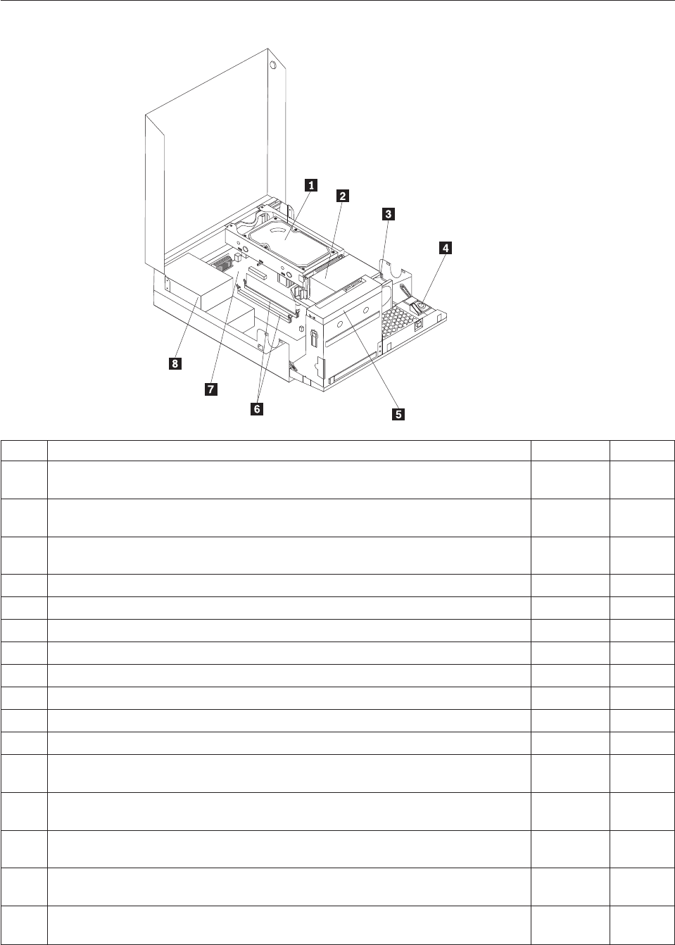
Machine type 7705
Item# 7705 FRUs FRU# CRU
1 Hard disk drive, SATA 160GB 7200RPM/3Gb/8MB (models A4S A4Y 77G 78G
A7U A7F A8U A8F A9U A9F B4U B4F)
40Y9035 1
1 Hard disk drive, SATA 250GB 7200RPM/3Gb/8MB (models A5H A6H B2H B1A
B3U B3F)
40Y9036 1
1 Hard disk drive, SATA 320GB 7200rpm SATA/8MB (models A1H A2H 71G 73G
74G 75G 76G 79G 7AG 7BG 7CG 7DG)
87H4891 1
1 Hard disk drive, SATA 500GB 7200RPM/3Gb/s/8MB (models) 41X5582 1
1 Hard disk drive, 1TB 7200rpm SATA (models) 45C5973 1
1 Hard disk drive, SATA 160 GB 7200RPM/3GB/8MB - optional (models) 53Y6837 1
1 Hard disk drive, SATA 250 GB 7200RPM/3GB/8MB - optional (models) 45K0408 1
1 Hard disk drive, SATA 320 GB 7200RPM SATA/8MB - optional (models) 45K0409 1
1 Hard disk drive, SATA 500 GB 7200RPM/3GB/s/8MB - optional (models) 45K0410 1
1 Hard disk drive, 1 TB 7200RPM SATA - optional (models) 45K0412 1
1 Hard disk drive, 150 GB 10K RPM, SATA (models) 46R6400 1
2 Microprocessor, E7400 2.8GHZ 1066M 3M R0 (ViiV, EIST, EM64T, EDB) 65W
(models 71G 73G A8U A8F)
53Y6653 N
2 Microprocessor, E7500 2.93GHZ 1066M 3M R0 (ViiV, EIST, EM64T, EDB) 65W
(models A1H B2H B1A 7AG 7BG B3U B3F)
53Y6654 N
2 Microprocessor, E5300 2.6GHz 800MHz 2MB R0 (EIST, EM64T, EDB) 65W (models
A2H 7CG 7DG B4U B4F)
53Y9049 N
2 Microprocessor, E1500 2.2GHz 800MHz 512KB (EIST, EM64T, EDB) M0 65W
(models)
53Y9051 N
2 Microprocessor, Q8300 Yorkfield 2.5GHZ, 1333MHz, 4M R-0 (ViiV, EIST, EM64T,
EDB) 95W (models)
53Y6656 N
262 Hardware Maintenance Manual

Item# 7705 FRUs FRU# CRU
2 Microprocessor, E8600 3.33GHZ/1333MHZ/6M E0 65W (models) 46R8640 N
2 Microprocessor, E8500 3.16GHz 1333MHz FSB 6M C-0 65W (models) 45C7735 N
2 Microprocessor, E8400 3.0GHz 1333MHz FSB 6M C-0 65W (models 75G 76G A9U
A9F)
45C7736 N
2 Microprocessor, E8300 2.83GHz 1333MHz FSB 6M C-0 65W (models) 45C7737 N
2 Microprocessor, E7200 2.53GHz 1066MHz FSB 3M M-0 65W (models) 45R8337 N
2 Microprocessor, E7300 2.66GHz 1066MHz FSB 3M M-0 65W (models) 46R1622 N
2 Microprocessor, E2200 Conroe-L 2.2GHz 800MHz FSB 1M (models) 45C5349 N
2 Microprocessor, E2220 Conroe-L 2.4GHz 800MHz FSB 1M (models) 45C1774 N
2 Microprocessor, E5200 2.5G 800MHz 2M M-0 65W, 45nm (models A5H A6H A4S
A4Y 74G 79G A7U A7F)
46R9512 N
2 Microprocessor, E1600 2.4GHZ/800MHZ/512K - NPI M-0 65W (models) 46R1655 N
2 Microprocessor, E1400 2.0GHz 800MHz FSB 512K - NPI M-0 65W (models 77G
78G)
45R8339 N
2 Microprocessor, Cel-440 Conroe-L 2.0GHz 800MHz FSB 512K (models) 43C1965 N
2 Microprocessor, Cel-450 2.2GHz 800MHz FSB 512K 35W (models) 46R9514 N
2 Microprocessor, Q9650 3.0GHZ 1333FSB 12MB VT, TXT E-0 95W (models) 46R8642 N
2 Microprocessor, Q9400 2.66GHZ 1333FSB 6MB VT, TXT R-0 95W (models) 46R8644 N
2 Microprocessor, Q8200 2.33GHz 1333FSB 4M M-1 95W (models) 46R9516 N
2 Microprocessor, Q9550 2.83GHZ 1333FSB 12M C-1 95W (models) 45C7739 N
2 Microprocessor, Q9450 Yorkfield 2.66GHZ 1333FSB 12M C-1 95W (models) 45C7740 N
2 Microprocessor, Q9300 Yorkfield 2.50GHZ 1333FSB 6M M-1 95W (models) 45C7741 N
2 Microprocessor, E5400 2.7G 800MHz-2MB 65W Non-vPro SKU (models) 64Y1075 N
2 Microprocessor, E7600 3.06GHZ 1066M 3M 65W (models) 71Y3486 N
2 Microprocessor, Q8400 2.66GHZ,1333MHz,4M 95W (models) 71Y3488 N
2 Microprocessor, E6300 2.8G 1066MHz-2MB 65W (models) 71Y3484 N
2 Microprocessor, E6500 2.93GHZ 1066 MHz-2MB 65W R0 (models) 71Y6250 N
2 Microprocessor, E3300 2.5GHZ 800 MHz-1MB 65W R0 (models) 71Y6252 N
2 Microprocessor, E3200 2.4GHZ 800 MHz-1MB 65W R0 (models) 71Y6251 N
3 95W heat sink kit with RM (all models) 41R6454 2
3 65W heat sink kit with RM (all models) 43N9349 2
3 95W heat sink kit with RM (all models) 43N9874 2
3 65W heat sink kit with RM (all models) 43N9877 2
4 Internal speaker 254 mm - optional (all models) 39K5012 2
5 Optical drive, DVD-ROM Drive - 16x/48x - SATA - for Windows 7 (models A2H
A7U A7F)
71Y5543 1
5 Optical drive, DVD Recordable Rambo8-SATA12XRAM Write - for Windows 7
(models A1H A5H A6H A4S A4Y 71G 73G 74G 75G 76G 77G 78G 79G A8U A8F
A9U A9F B2H B1A 7AG 7BG 7CG 7DG B3U B3F B4U B4F)
71Y5545 1
6 Memory module, 512MB PC2-5300 (667MHz) DDR2 SDRAM (models) 41X4255 1
6 Memory module, 1GB PC2-5300 (667MHz) DDR2 SDRAM (models) 41X4256 1
6 Memory module, 2GB PC2-5300 (667MHz) DDR2 SDRAM (models) 41X4257 1
Chapter 10. FRU lists 263

Item# 7705 FRUs FRU# CRU
6 Memory module, 512MB PC2-6400 (800MHz) DDR2 SDRAM (models) 41X1079 1
6 Memory module, 1GB PC2-6400 (667MHz) DDR2 SDRAM (models A2H A5H A4S
A4Y B1A)
41X1080 1
6 Memory module, 2GB PC2-6400 (667MHz) DDR2 SDRAM (models A1H A6H 71G
73G 74G 75G 76G 77G 78G 79G A7U A7F A8U A8F A9U A9F B2H 7AG 7BG 7CG
7DG B3U B3F B4U B4F)
41X1081 1
7 System board, Intel G41 BTX(GA) non-AMT (models A1H A2H A5H A6H A4S
A4Y 71G 73G 74G 75G 76G 77G 78G 79G A7U A7F A8U A8F A9U A9F B2H B1A
7AG 7BG 7CG 7DG B3U B3F B4U B4F)
46R8892 N
7 System board, Intel G41 BTX (GA) - NB upgrade (models A1H A2H A5H A6H
A4S A4Y 71G 73G 74G 75G 76G 77G 78G 79G A7U A7F A8U A8F A9U A9F B2H
B1A 7AG 7BG 7CG 7DG B3U B3F B4U B4F)
64Y9198 N
7 System board, Intel G41 BTX - EuP and TCM header (models) 71Y6839 N
8 Power supply, 280W Active PFC power supply (Auto sensing) for 10L---Robust,
ww, JP (models A1H A2H A5H A6H A4S A4Y 71G 73G 74G 75G 76G 77G 78G
79G A7U A7F A8U A8F A9U A9F B2H B1A 7AG 7BG 7CG 7DG B3U B3F B4U
B4F)
41A9701 N
8 Power supply, 280W 85+ power supply for 10L---Robust, ww, JP (models A1H
A2H A5H A6H A4S A4Y 71G 73G 74G 75G 76G 77G 78G 79G A7U A7F A8U A8F
A9U A9F B2H B1A 7AG 7BG 7CG 7DG B3U B3F B4U B4F)
41A9742 N
8 Power supply, 280W Active PFC power supply (auto-sensing) - all countries
(models A1H A2H A5H A6H A4S A4Y 71G 73G 74G 75G 76G 77G 78G 79G A7U
A7F A8U A8F A9U A9F B2H B1A 7AG 7BG 7CG 7DG B3U B3F B4U B4F)
45J9418 N
8 Power supply, 280W 85+ power supply - all countries (models A1H A2H A5H
A6H A4S A4Y 71G 73G 74G 75G 76G 77G 78G 79G A7U A7F A8U A8F A9U A9F
B2H B1A 7AG 7BG 7CG 7DG B3U B3F B4U B4F)
45J9423 N
8 Power supply, 280 watt Active PFC power supply, auto-sensing for 10L - Robust,
WW, JP, for Eup (models A1H A2H A5H A6H A4S A4Y 71G 73G 74G 75G 76G
77G 78G 79G A7U A7F A8U A8F A9U A9F B2H B1A 7AG 7BG 7CG 7DG B3U B3F
B4U B4F)
54Y8804 N
The FRUs listed in the following tables are not illustrated.
7705 FRUs FRU# CRU
Battery 3V - Lithium (models A1H A2H A5H A6H A4S A4Y 71G 73G 74G 75G 76G 77G
78G 79G A7U A7F A8U A8F A9U A9F B2H B1A 7AG 7BG 7CG 7DG B3U B3F B4U B4F)
45C1566 1
Cable - SATA 250 mm (RoHS) for 1st hard disk drive (all models) 43N9012 2
Cable - SATA 600 mm (RoHS) (all models) 45J9579 2
Cable - SATA 700 mm (RoHS) for optical drive / Second hard disk drive (all models) 43N9011 2
C2 intrusion switch 260 mm (all models) 43N9080 2
Rear I/O shield BTX (all models) 41R6381 N
Temp sense cable (165 mm) (all models) 43N9079 2
Air deflector, recycle resin (all models) 43N9610 2
Hard disk drive tray assembly (all models) 43N9595 1
Front cage assembly (all models) 43N9596 N
Front cage assembly (all models) 43N9647 N
Cable, Front I/O cable_R (10L_U380_A550)_ESD (all models) 45J9509 2
264 Hardware Maintenance Manual

7705 FRUs FRU# CRU
Models with 3.5’’ convert 2.5’’ for 150 GB 10 K rpm hard disk drive (first HDD bay) (all
models)
43N9645 2
3.5’’ convert 2.5’’ for 150 GB 10 K rpm hard disk drive (first HDD bay) (all models) 43N9593 2
Universal Adapter Bracket 5.25 to 3.5 (all models) 43N9676 2
Top cover assembly (all models) 43N9594 1
Cable, LED/Switch cable_R (10L_220 mm_PCBA) (all models) 45J9515 2
NO ODD, EMI shielding (all models) 43N9641 1
Card reader bezel (all models) 43N9642 1
Non-card reader bezel (all models) 43N9643 1
Card reader (all models) 45K6081 1
Vertical stand (all models) 43N9644 1
Front bezel assembly (all models) 43N9677 1
Chassis (all models) 43N9649 N
Rubber foot for vertical (all models) 43N9727 1
Rubber foot for horizontal (all models) 43N9728 1
Thermal grease (all models) 91P8835 N
Optical retainer (all models) 45K6364 1
7705 keyboards (Lenovo preferred Pro USB - without hub) FRU# CRU
USB FULL--US English (models A1H A2H A5H A6H 71G 73G 74G 75G 76G 77G 78G 79G
A7U A8U A9U B2H B1A 7AG 7BG 7CG 7DG B3U B4U)
41A5289 1
USB FULL--Arabic (models 71G 73G 74G 75G 76G 77G 78G 79G 7AG 7BG 7CG 7DG) 41A5290 1
USB FULL--Arabic/French (models 71G 73G 74G 75G 76G 77G 78G 79G 7AG 7BG 7CG
7DG)
41A5291 1
USB FULL--Belgium French (models 71G 73G 74G 75G 76G 77G 78G 79G 7AG 7BG 7CG
7DG)
41A5292 1
USB FULL--Belgium English (models 71G 73G 74G 75G 76G 77G 78G 79G 7AG 7BG 7CG
7DG)
41A5293 1
USB FULL--Brazilian Portuguese (models) 41A5294 1
USB FULL--Bulgarian (models 71G 73G 74G 75G 76G 77G 78G 79G 7AG 7BG 7CG 7DG) 41A5295 1
USB FULL--Chinese/US (models) 41A5296 1
USB FULL--Czech (ABB) (models 71G 73G 74G 75G 76G 77G 78G 79G 7AG 7BG 7CG
7DG)
41A5297 1
USB FULL--Danish (models 71G 73G 74G 75G 76G 77G 78G 79G 7AG 7BG 7CG 7DG) 41A5298 1
USB FULL--Dutch (models 71G 73G 74G 75G 76G 77G 78G 79G 7AG 7BG 7CG 7DG) 41A5299 1
USB FULL--French (models 71G 73G 74G 75G 76G 77G 78G 79G 7AG 7BG 7CG 7DG) 41A5300 1
USB FULL--French Canadian (models 71G 73G 74G 75G 76G 77G 78G 79G A7F A8F A9F
7AG 7BG 7CG 7DG B3F B4F)
41A5301 1
USB FULL--French Canadian (models 71G 73G 74G 75G 76G 77G 78G 79G A7F A8F A9F
7AG 7BG 7CG 7DG B3F B4F)
41A5302 1
USB FULL--German (models 71G 73G 74G 75G 76G 77G 78G 79G 7AG 7BG 7CG 7DG) 41A5303 1
USB FULL--Greek (models 71G 73G 74G 75G 76G 77G 78G 79G 7AG 7BG 7CG 7DG) 41A5304 1
USB FULL--Greek/US (models 71G 73G 74G 75G 76G 77G 78G 79G 7AG 7BG 7CG 7DG) 41A5305 1
Chapter 10. FRU lists 265

7705 keyboards (Lenovo preferred Pro USB - without hub) FRU# CRU
USB FULL--Hebrew (models 71G 73G 74G 75G 76G 77G 78G 79G 7AG 7BG 7CG 7DG) 41A5306 1
USB FULL--Hungarian (models 71G 73G 74G 75G 76G 77G 78G 79G 7AG 7BG 7CG 7DG) 41A5307 1
USB FULL--Iceland (models 71G 73G 74G 75G 76G 77G 78G 79G 7AG 7BG 7CG 7DG) 41A5308 1
USB FULL--Italy (models 71G 73G 74G 75G 76G 77G 78G 79G 7AG 7BG 7CG 7DG) 41A5309 1
USB FULL--Japanese (models) 41A5310 1
USB FULL--Korean (models) 41A5311 1
USB FULL--LA Spanish (models A4S A4Y) 41A5312 1
USB FULL--Norwegian (models 71G 73G 74G 75G 76G 77G 78G 79G 7AG 7BG 7CG 7DG) 41A5313 1
USB FULL--Polish (models 71G 73G 74G 75G 76G 77G 78G 79G 7AG 7BG 7CG 7DG) 41A5314 1
USB FULL--Portuguese (models 71G 73G 74G 75G 76G 77G 78G 79G 7AG 7BG 7CG 7DG) 41A5315 1
USB FULL--Romanian (models 71G 73G 74G 75G 76G 77G 78G 79G 7AG 7BG 7CG 7DG) 41A5317 1
USB FULL--Romanian (models 71G 73G 74G 75G 76G 77G 78G 79G 7AG 7BG 7CG 7DG) 41A5316 1
USB FULL--Russian/Cyrillic (models 71G 73G 74G 75G 76G 77G 78G 79G 7AG 7BG 7CG
7DG)
41A5318 1
USB FULL--Serbian/Cyrillic (models 71G 73G 74G 75G 76G 77G 78G 79G 7AG 7BG 7CG
7DG)
41A5319 1
USB FULL--Slovak (models 71G 73G 74G 75G 76G 77G 78G 79G 7AG 7BG 7CG 7DG) 41A5320 1
USB FULL--Spanish (models 71G 73G 74G 75G 76G 77G 78G 79G 7AG 7BG 7CG 7DG) 41A5321 1
USB FULL--Swedish/Finnish (models 71G 73G 74G 75G 76G 77G 78G 79G 7AG 7BG 7CG
7DG)
41A5322 1
USB FULL--Swiss French/German (models 71G 73G 74G 75G 76G 77G 78G 79G 7AG 7BG
7CG 7DG)
41A5323 1
USB FULL--Thailand (models) 41A5324 1
USB FULL--Turkish (models 71G 73G 74G 75G 76G 77G 78G 79G 7AG 7BG 7CG 7DG) 41A5325 1
USB FULL--Turkish (models 71G 73G 74G 75G 76G 77G 78G 79G 7AG 7BG 7CG 7DG) 41A5326 1
USB FULL --UK English (models 71G 73G 74G 75G 76G 77G 78G 79G 7AG 7BG 7CG
7DG)
41A5327 1
USB FULL--US Euro (models 71G 73G 74G 75G 76G 77G 78G 79G 7AG 7BG 7CG 7DG) 41A5328 1
USB FULL--Slovenian (models 71G 73G 74G 75G 76G 77G 78G 79G 7AG 7BG 7CG 7DG) 41A5329 1
USB FULL--Arabic (New) (models 71G 73G 74G 75G 76G 77G 78G 79G 7AG 7BG 7CG
7DG)
45J4880 1
USB FULL--Lithuanian (models 71G 73G 74G 75G 76G 77G 78G 79G 7AG 7BG 7CG 7DG) 45J4896 1
USB FULL--Estonia (models) 51J0059 1
7705 keyboards (Lenovo fingerprint reader USB) FRU# CRU
US English (models) 41R0038 1
Arabic (models) 41R0039 1
Arabic/French (models) 41R0040 1
Belgium French (models) 41R0041 1
Belgium English (models) 41R0042 1
Brazilian Portuguese (models) 41R0043 1
Bulgarian (models) 41R0044 1
266 Hardware Maintenance Manual

7705 keyboards (Lenovo fingerprint reader USB) FRU# CRU
Chinese/US (models) 41R0045 1
Czech (ABB) (models) 41R0046 1
Danish (models) 41R0047 1
Dutch (models) 41R0048 1
French (models) 41R0049 1
French Canadian (models) 41R0050 1
French Canadian (models) 41R0051 1
German (models) 41R0052 1
Greek (models) 41R0053 1
Greek/US (models) 41R0054 1
Hebrew (models) 41R0055 1
Hungarian (models) 41R0056 1
Iceland (models) 41R0057 1
Italian (models) 41R0058 1
Japanese (models) 41R0059 1
Korean (models) 41R0060 1
LA Spanish (models) 41R0061 1
Norwegian (models) 41R0062 1
Polish (models) 41R0063 1
Portuguese (models) 41R0064 1
Romanian (models) 41R0065 1
Romanian (models) 41R0066 1
Russian/Cyrillic (models) 41R0067 1
Serbian/Cyrillic (models) 41R0068 1
Slovak (models) 41R0069 1
Spanish (models) 41R0070 1
Swedish/Finnish (models) 41R0071 1
Swiss French/German (models) 41R0072 1
Thailand (models) 41R0073 1
Turkish (models) 41R0074 1
Turkish (models) 41R0075 1
UK English (models) 41R0076 1
US Euro (models) 41R0077 1
Slovenian (models) 41R0078 1
7705 keyboards (Lenovo preferred Pro PS/2 Full Size) FRU# CRU
US English (models) 41A5039 1
Arabic (models) 41A5040 1
Arabic (New) (models) 45J4880 1
Arabic French (models) 41A5041 1
Belgium French (models) 41A5042 1
Chapter 10. FRU lists 267

7705 keyboards (Lenovo preferred Pro PS/2 Full Size) FRU# CRU
Belgium English (models) 41A5043 1
Brazilian Portuguese (models) 41A5044 1
Bulgarian (models) 41A5045 1
Chinese/US (models) 41A5046 1
Czech (ABB) (models) 41A5047 1
Danish (models) 41A5048 1
Dutch (models) 41A5049 1
French (models) 41A5050 1
French Canadian (models) 41A5051 1
French Canadian (models) 41A5052 1
German (models) 41A5053 1
Greek (models) 41A5054 1
Greek/US (models) 41A5080 1
Hebrew (models) 41A5055 1
Hungarian (models) 41A5056 1
Iceland (models) 41A5057 1
Italian (models) 41A5058 1
Japanese (models) 41A5059 1
Korean (models) 41A5060 1
LA Spanish (models) 41A5061 1
Norwegian (models) 41A5062 1
Polish (models) 41A5063 1
Portuguese (models) 41A5064 1
Romanian (models) 41A5065 1
Russian/Cyrillic (models) 41A5066 1
Serbian/Cyrillic (models) 41A5067 1
Slovak (models) 41A5068 1
Spanish (models) 41A5069 1
Swedish/Finnish (models) 41A5070 1
Swiss French/German (models) 41A5071 1
Thailand (models) 41A5072 1
Turkish (models) 41A5073 1
Turkish (models) 41A5074 1
UK English (models) 41A5075 1
US Euro (models) 41A5076 1
Slovenian (models) 41A5077 1
7705 mice FRU# CRU
Optical Wheel Mouse OPT (400DPI, USB) (models A1H A2H A5H A6H A4S A4Y 71G 73G
74G 75G 76G 77G 78G 79G A7U A7F A8U A8F A9U A9F B2H B1A 7AG 7BG 7CG 7DG
B3U B3F B4U B4F)
41U3013 1
268 Hardware Maintenance Manual

7705 mice FRU# CRU
Optical Wheel Mouse OPT (400DPI, USB) (models A1H A2H A5H A6H A4S A4Y 71G 73G
74G 75G 76G 77G 78G 79G A7U A7F A8U A8F A9U A9F B2H B1A 7AG 7BG 7CG 7DG
B3U B3F B4U B4F)
41U3030 1
7705 adapters and miscellaneous FRUs FRU# CRU
Internal 25 in 1 USB Memory Card Reader Slim (models) 46R1529 1
IEEE 1394 Firewire Adapter (models) 41D2781 1
Soft Modem V.90/V.44 (models) 46R4220 1
Speaker power brick - US, Canada, LA low voltage, ASEAN (models A7U A8U A9U B3U
B4U)
89P8571 1
Speaker power brick - LA high voltage (non-APU) (models) 89P8575 1
Speaker power brick - Simplified Chinese, Thailand EMEA (models 71G 73G 74G 75G 76G
77G 78G 79G 7AG 7BG 7CG 7DG)
89P8581 1
Speaker power brick - Japanese (models) 89P8577 1
Speaker power brick - Brazil (models) 89P8583 1
Speaker power brick - Argentina (models) 41A4901 1
Speaker power brick - ANZ (models 91M) 89P8579 1
Speaker power brick - Korea (models) 41A4903 1
Speaker power brick - Hong Kong, EMEA, Ireland (models 71G 73G 74G 75G 76G 77G
78G 79G 7AG 7BG 7CG 7DG)
89P8573 1
Speaker power brick -Taiwan-Traditional Chinese (models 91V) 41A4905 1
Speaker power brick - India, South Africa (models 91Q) 89P8585 1
2-pc external speaker--primary (models) 41A5331 1
2-pc external speaker-secondary (models) 41A5334 1
DVI-I(M)-VGA(F) cord (models) 41R3342 1
ATI HD3470 GDDR3 256MB - VGA+DP (models) 46R1521 1
ADD2 DVI-D Adapter, (HDCP) DVD-D connection Adapter Low Profile (Silicon Image)
(models 71G 73G)
43C0258 1
DisplayPort to DVI-D Dongle (models) 43N9160 1
DisplayPort to VGA Dongle (models) 45J9524 1
Modem phone cable (models) 39K5120 1
LI140mm Rear Com2 cable II mini®(models) 43N9062 2
Rear USB 2 Ports II LP®350 mm (models) 43N9124 2
NVIDIA G100 DDR2 256MB LP - DVI-I (With DVI-I to VGA Dongle) (models CTO) 53Y9341 1
7705 Power Cords (Primary) FRU# CRU
Power cord - US (models A4S A4Y A7U A7F A8U A8F A9U A9F B1A B3U B3F B4U B4F) 41R3184 1
Power cord - China (models 91C) 41R3256 1
Power cord - Japanese and Japanese English (models) 41R3248 1
Power cord - Brazil (models) 41R3270 1
Power cord - Brazil - optional (models) 45J9595 1
Power cord - LA High Volt (APU) (models) 41R3176 1
Chapter 10. FRU lists 269

7705 Power Cords (Primary) FRU# CRU
Power cord - Australia / New Zealand (models) 41R3196 1
Power cord - Korea (models) 41R3260 1
Power cord - UK, Ireland, Singapore, Malaysia, Brunei, Hong Kong (models A1H A2H
A5H A6H B2H)
41R3224 1
Power cord - Taiwan (models 91V) 41R3278 1
Power cord - Italy (models) 41R3232 1
Power cord - Indonesia, Laos, Cambodia, Vietnam, Austria, Belgium, Croatia,
Czechoslovakia, Finland, France, Germany, Hungary, Netherlands, Norway, Poland,
Portugal, Romania, Spain, Sweden (models A4S A4Y A7U A7F A8U A8F A9U A9F B1A
B3U B3F B4U B4F)
41R3208 1
Power cord - Denmark (models 71G 73G 74G 75G 76G 77G 78G 79G 7AG 7BG 7CG 7DG) 41R3212 1
Power cord - Switzerland (models 71G 73G 74G 75G 76G 77G 78G 79G 7AG 7BG 7CG
7DG)
41R3228 1
Power cord - Israel (models 71G 73G 74G 75G 76G 77G 78G 79G 7AG 7BG 7CG 7DG) 41R3236 1
Power cord - South Africa (models 91M 91A 71G 73G 74G 75G 76G 77G 78G 79G B1A
7AG 7BG 7CG 7DG)
41R3220 1
Power cord - India (models) 41R3341 1
Power cord - Thailand (models) 43N9029 1
7705 Power Cords (Secondary) FRU# CRU
Power cord - US (models A4S A4Y A7U A7F A8U A8F A9U A9F B1A B3U B3F B4U B4F) 41R3185 1
Power cord - China (models 91C) 41R3257 1
Power Cord - Japanese and Japanese English (models) 41R3249 1
Power cord - Brazil (models) 41R3271 1
Power cord - LA High Volt (APU) (models) 41R3177 1
Power cord - Australia / New Zealand (models) 41R3197 1
Power cord - Korea (models) 41R3261 1
Power cord - UK, Ireland, Singapore, Malaysia, Brunei, Hong Kong (models A1H A2H
A5H A6H B2H)
41R3225 1
Power cord - Taiwan (models 91V) 41R3279 1
Power cord - Italy (models) 41R3233 1
Power cord - Indonesia, Laos, Cambodia, Vietnam, Austria, Belgium, Croatia,
Czechoslovakia, Finland, France, Germany, Hungary, Netherlands, Norway, Poland,
Portugal, Romania, Spain, Sweden (models A4S A4Y A7U A7F A8U A8F A9U A9F B1A
B3U B3F B4U B4F)
41R3209 1
Power cord - Denmark (models 71G 73G 74G 75G 76G 77G 78G 79G 7AG 7BG 7CG 7DG) 41R3213 1
Power cord - Switzerland (models 71G 73G 74G 75G 76G 77G 78G 79G 7AG 7BG 7CG
7DG)
41R3229 1
Power cord - Israel (models 71G 73G 74G 75G 76G 77G 78G 79G 7AG 7BG 7CG 7DG) 41R3237 1
Power cord - South Africa (models 91M 91A 71G 73G 74G 75G 76G 77G 78G 79G B1A
7AG 7BG 7CG 7DG)
41R3221 1
Power cord - India (models) 41R3175 1
Power cord - Thailand (models) 43N9030 1
Power cord - Y cable for Brazil (models) 43N9044 1
270 Hardware Maintenance Manual

7705 Windows XP Home Recovery CDs FRU# CRU
US English/UK/Asia Pacific (models) TBD 1
French/French Canadian (models) TBD 1
Greek (models) TBD 1
Italy (models) TBD 1
Brazilian (models) TBD 1
Spanish/LA (models) TBD 1
Danish (models) TBD 1
Dutch (models) TBD 1
Arabic (models) TBD 1
Swedish (models) TBD 1
Hebrew (models) TBD 1
Finnish (models) TBD 1
Norwegian (models) TBD 1
Polish (models) TBD 1
Portuguese (models) TBD 1
Russian (models) TBD 1
Russian English (models) TBD 1
Hungarian (models) TBD 1
Czech (models) TBD 1
Turkish native (models) TBD 1
Greek (models) TBD 1
Japanese (models) TBD 1
Simplified Chinese (models) TBD 1
Taiwan-TC (models) TBD 1
Hong Kong-TC (models) TBD 1
Korean (models) TBD 1
7705 Windows XP Pro Recovery Discs FRU# CRU
Hebrew (models 73G 74G 76G 78G 7BG 7DG) 71Y7506 1
Portuguese (models 73G 74G 76G 78G 7BG 7DG) 71Y7514 1
Russian English (models 73G 74G 76G 78G 7BG 7DG) 71Y7510 1
Hungarian (models 73G 74G 76G 78G 7BG 7DG) 71Y7512 1
Slovenian (models 73G 74G 76G 78G 7BG 7DG) 71Y7515 1
Korea (models) 71Y7519 1
US English (models 73G 74G 76G 78G B1A 7BG 7DG B3U B4U) 71Y7493 1
French (models 73G 74G 76G 78G 7BG 7DG B3F B4F) 71Y7494 1
German (models 73G 74G 76G 78G 7BG 7DG) 71Y7495 1
Italian (models) 71Y7498 1
Brazilian Portuguese (models 73G 74G 76G 78G 7BG 7DG) 71Y7497 1
Spanish (models 73G 74G 76G 78G 7BG 7DG) 71Y7496 1
Danish (models 73G 74G 76G 78G 7BG 7DG) 71Y7502 1
Chapter 10. FRU lists 271

7705 Windows XP Pro Recovery Discs FRU# CRU
Dutch (models 73G 74G 76G 78G 7BG 7DG) 71Y7503 1
Arabic (models 73G 74G 76G 78G 7BG 7DG) 71Y7508 1
Swedish (models 73G 74G 76G 78G 7BG 7DG) 71Y7501 1
Finnish (models 73G 74G 76G 78G 7BG 7DG) 71Y7505 1
Norwegian (models 73G 74G 76G 78G 7BG 7DG) 71Y7500 1
Polish (models 73G 74G 76G 78G 7BG 7DG) 71Y7507 1
Russian (models 73G 74G 76G 78G 7BG 7DG) 71Y7509 1
Czech (models 73G 74G 76G 78G 7BG 7DG) 71Y7504 1
Turkish (models 73G 74G 76G 78G 7BG 7DG) 71Y7511 1
Greek (models 73G 74G 76G 78G 7BG 7DG) 71Y7513 1
Japanese (models) 71Y7499 1
Simplified Chinese (models) 71Y7516 1
Traditional Chinese (models) 71Y7517 1
Hong Kong (models) 71Y7518 1
MUI Nordics (EN-DK-FI-NO-SV) (models 73G 74G 76G 78G 7BG 7DG) 71Y7520 1
MUI Switz (US EN-FR -GR-IT) (models 73G 73G 74G 74G 76G 76G 78G 78G B1A 7BG 7BG
7DG 7DG B3U B3F B4U B4F)
71Y7521 1
MUI Bel-Lux (EN-FR-GR-NL) (models 73G 73G 74G 74G 76G 76G 78G 78G B1A 7BG 7BG
7DG 7DG B3U B3F B4U B4F)
71Y7522 1
7705 Vista Home Basic 32 Recovery DVDs FRU# CRU
US English (models) 64Y8594 1
French (models) 64Y8596 1
German (models) 64Y8597 1
Spanish (models) 64Y8598 1
Brazilian (models) 64Y8599 1
Italian (models) 64Y8600 1
Dutch (models) 64Y8614 1
Czech (models) 64Y8601 1
Polish (models) 64Y8602 1
Russian (models) 64Y8603 1
Turkish (models) 64Y8604 1
Hungarian (models) 64Y8605 1
Greek (models) 64Y8606 1
Portuguese (models) 64Y8617 1
Simplified Chinese (models) 64Y8608 1
Hong Kong (models) 64Y8610 1
Traditional Chinese (models) 64Y8609 1
Korean (models) 64Y8611 1
Slovenian (models) 64Y8612 1
Russian English (models) 64Y8595 1
272 Hardware Maintenance Manual

7705 Vista Home Basic 32 Recovery DVDs FRU# CRU
Hebrew (models) 64Y8615 1
Arabic Localized (models) 64Y8613 1
Slovakian (models) 64Y8619 1
Romanian (models) 64Y8616 1
Serbian-Latin (models) 64Y8618 1
C&L 1 Nordics (EN DK FI NO SV) (models) 64Y8620 1
C&L 2 Switzerland (EN FR GR IT) (models) 64Y8621 1
C&L 3 Bel Lux (EN FR GR NL) (models) 64Y8622 1
Japanese (models) 64Y8607 1
7705 Vista Business 32 Recovery DVDs FRU# CRU
US English (models A1H A2H A5H A6H 71G 75G 77G 79G A7U A8U A9U B2H 7AG
7CG)
64Y8565 1
French (models 71G 75G 77G 79G A7F A8F A9F 7AG 7CG) 64Y8567 1
German (models 71G 75G 77G 79G 7AG 7CG) 64Y8568 1
Spanish (models 71G 75G 77G 79G 7AG 7CG) 64Y8569 1
Brazilian Portuguese (models) 64Y8570 1
Italian (models 71G 75G 77G 79G 7AG 7CG) 64Y8571 1
Japanese (models) 64Y8578 1
Dutch (models 71G 75G 77G 79G 7AG 7CG) 64Y8585 1
Czech (models) 64Y8572 1
Polish (models 71G 75G 77G 79G 7AG 7CG) 64Y8573 1
Russian (models 71G 75G 77G 79G 7AG 7CG) 64Y8574 1
Turkish (models 71G 75G 77G 79G 7AG 7CG) 64Y8575 1
Hungarian (models 71G 75G 77G 79G 7AG 7CG) 64Y8576 1
Greek (models 71G 75G 77G 79G 7AG 7CG) 64Y8577 1
Portuguese (models) 64Y8588 1
Simplified Chinese (models) 64Y8579 1
Traditional Chinese (models) 64Y8580 1
Hong Kong (models) 64Y8581 1
Korean (models) 64Y8582 1
Slovenian (models 71G 75G 77G 79G 7AG 7CG) 64Y8583 1
Russian English (models 71G 75G 77G 79G 7AG 7CG) 64Y8566 1
Romanian (models 71G 75G 77G 79G 7AG 7CG) 64Y8587 1
Serbian-Latin (models 71G 75G 77G 79G 7AG 7CG) 64Y8589 1
Slovakian (models 71G 75G 77G 79G 7AG 7CG) 64Y8590 1
Arabic Localized (models 71G 75G 77G 79G 7AG 7CG) 64Y8584 1
Hebrew (models 71G 75G 77G 79G 7AG 7CG) 64Y8586 1
C&L 1 Nordics (EN DK FI NO SV) (models) 64Y8591 1
C&L 2 Switzerland (EN FR GR IT) (models) 64Y8592 1
C&L 3 Bel Lux (EN FR GR NL) (models) 64Y8593 1
Chapter 10. FRU lists 273

7705 Vista Home Premium 32 Recovery DVDs FRU# CRU
US English (models) 64Y8623 1
French (models) 64Y8624 1
German (models) 64Y8625 1
Spanish (models) 64Y8626 1
Italian (models) 64Y8628 1
Japanese (models) 64Y8629 1
Hong Kong (models) 64Y8630 1
Korean (models) 64Y8627 1
C&L 1 Nordics (EN DK FI NO SV) (models) 64Y8631 1
C&L 2 Switzerland (EN FR GR IT) (models) 64Y8632 1
C&L 3 Bel Lux (EN FR GR NL) (models) 64Y8633 1
7705 Vista Business 64 Recovery DVDs FRU# CRU
US English (models) 64Y8643 1
French (models) 64Y8644 1
German (models) 64Y8645 1
Japanese (models) 64Y8646 1
Simplified Chinese (models) 64Y8647 1
7705 Vista Ultimate 32 Recovery DVDs FRU# CRU
US English (models) 64Y8634 1
Japanese (models) 64Y8635 1
French (models) 64Y8636 1
German (models) 64Y8637 1
Spanish (models) 64Y8638 1
Italian (models) 64Y8639 1
Hong Kong - Traditional Chinese (models) 64Y8640 1
Arabic localized (models) 64Y8641 1
C&L 1 Nordics (EN DK FI NO SV) (models) 64Y8642 1
7705 Vista Starter 32 Recovery DVDs FRU# CRU
English (models) TBD 1
7705 Windows 7 Home Basic 32 Recovery DVDs FRU# CRU
Arabic (models) 71Y7549 1
India English (models) 71Y8655 1
Russian English (models) 71Y7550 1
Russian (models) 71Y7551 1
Spanish (models) 71Y7552 1
Serbian-Latin (models) 71Y7553 1
Turkish (models) 71Y7554 1
274 Hardware Maintenance Manual

7705 Windows 7 Home Basic 32 Recovery DVDs FRU# CRU
English (models) 71Y7555 1
7705 Windows 7 Home Premium 32 Recovery DVDs FRU# CRU
Traditional Chinese (models) 71Y7556 1
India English (models) 71Y8656 1
French (models) 71Y7557 1
Hong Kong (models) 71Y7558 1
Italian (models) 71Y7559 1
Japan (models) 71Y7560 1
Korean (models) 71Y7561 1
Spanish (models) 71Y7562 1
English (models) 71Y7563 1
C&L Bel Lux (EN FR GR NL) (models) 71Y7564 1
C&L Nordics (EN DK FI NO SV) (models) 71Y7565 1
C&L Switzerland (EN FR GR IT) (models) 71Y7566 1
7705 Windows 7 Professional 32 Recovery DVDs FRU# CRU
Arabic (models) 71Y7523 1
Traditional Chinese (models) 71Y7524 1
Czech (models) 71Y7525 1
India English (models) 71Y8654 1
French (models) 71Y7526 1
Greek (models) 71Y7527 1
German (models) 71Y7528 1
Hebrew (models) 71Y7529 1
Hong Kong (models) 71Y7530 1
Hungarian (models) 71Y7531 1
Italian (models) 71Y7532 1
Japan (models) 71Y7533 1
Korean (models) 71Y7534 1
Polish (models) 71Y7535 1
Portuguese (models) 71Y7536 1
Russian English (models) 71Y7537 1
Romanian (models) 71Y7538 1
Russian (models) 71Y7539 1
Slovakia (models) 71Y7540 1
Slovenian (models) 71Y7541 1
Spanish (models) 71Y7542 1
Serbian-Latin (models) 71Y7543 1
Turkish (models) 71Y7544 1
English (models) 71Y7545 1
Chapter 10. FRU lists 275

7705 Windows 7 Professional 32 Recovery DVDs FRU# CRU
C&L Bel Lux (EN FR GR NL) (models) 71Y7546 1
C&L Nordics (EN DK FI NO SV) (models) 71Y7547 1
C&L Switzerland (EN FR GR IT) (models) 71Y7548 1
7705 Windows 7 Professional 64 Recovery DVDs FRU# CRU
Traditional Chinese (models) 71Y7574 1
India English (models) 71Y8658 1
French (models) 71Y7575 1
German (models) 71Y7576 1
Hong Kong (models) 71Y7577 1
Italian (models) 71Y7578 1
Japan (models) 71Y7579 1
Spanish (models) 71Y7580 1
English (models) 71Y7581 1
C&L Bel Lux (EN FR GR NL) (models) 71Y7582 1
C&L Nordics (EN DK FI NO SV) (models) 71Y7583 1
C&L Switzerland (EN FR GR IT) (models) 71Y7584 1
7705 Windows 7 Starter Recovery DVDs FRU# CRU
Arabic (models) 71Y7567 1
India English (models) 71Y8657 1
Russian English (models) 71Y7568 1
Russian (models) 71Y7569 1
Spanish (models) 71Y7570 1
Serbian-Latin (models) 71Y7571 1
Turkish (models) 71Y7572 1
English (models) 71Y7573 1
276 Hardware Maintenance Manual

Chapter 11. Additional service information
This chapter provides additional information that the service representative might
find helpful.
Security features
Security features in this section include the following:
vPasswords
vVital Product Data
vManagement Information Format (MIF)
Hardware controlled Passwords
Hardware controlled passwords are set using the Setup Utility program. For more
information about passwords, see “Using passwords” on page 51.
Operating system password
An operating system password is very similar to a power-on password and denies
access to the computer by an unauthorized user when the password is activated.
The computer is unusable until the password is entered and recognized by the
computer.
Vital product data
Each computer has a unique Vital Product Data (VPD) code stored in the
nonvolatile memory on the system board. After you replace the system board, the
VPD must be updated. To update the VPD, see “Updating (flashing) BIOS from a
disc” on page 278.
BIOS levels
An incorrect level of BIOS can cause false errors and unnecessary FRU
replacement. Use the following information to determine the current level of BIOS
installed in the computer, the latest BIOS available for the computer, and where to
obtain the latest level of BIOS.
vTo determine the current Level of BIOS:
– Start the Setup Utility.
– Select System Information on the Main setup screen.
vSources for obtaining the latest level BIOS available
1. Lenovo support web site:
http://www.lenovo.com/support/
2. Lenovo Customer Support Center
3. Levels 1 and 2 Support
To update (flash) the BIOS, see “Updating (flashing) BIOS from a disc” on page
278.
© Copyright Lenovo 2009 277

Updating (flashing) BIOS from a disc
This section provides instructions on how to update (flash) BIOS from a disc.
System program updates are available at:
http://www.lenovo.com/support
To update (flash) BIOS from a disc, do the following:
1. Turn off your computer.
2. Repeatedly press and release the F12 key when turning on the computer. When
the Startup Device Menu opens, release the F12 key.
3. On the Startup Device Menu, select the optical drive of your choice as the first
boot device.
4. Insert the disc into the optical drive and press Enter. The update begins.
5. When prompted to change the serial number, press N. If you want to change
the serial number, press Y when prompted. Type in the serial number and press
Enter.
6. When prompted to change the machine type/model, press N. If you want to
change the machine type/model, press Y when prompted. Type in the machine
type/model and press Enter.
7. Follow the instructions on the screen to complete the update. After the update
is completed, remove the disc from the optical drive.
Updating (flashing) BIOS from your operating system
Note: Because Lenovo makes constant improvements to the Web site, the Web
page contents are subject to change without notice, including the contents
referenced in the following procedure.
To update (flash) BIOS from your operating system, do the following:
1. Go to http://www.lenovo.com/support.
2. Do the following to locate the downloadable files for your machine type:
a. In the Enter a product number field, type your machine type and click Go.
b. Click Downloads and drivers.
c. Select BIOS in the Refine results field to easily locate all the BIOS related
links.
d. Click the BIOS update link.
3. Click the TXT file that contains the instructions for updating (flashing) BIOS
from your operating system.
4. Print these instructions. This is very important because these instructions are
not on the screen after the download begins.
5. Follow the printed instructions to download, extract, and install the update.
Recovering from a POST/BIOS update failure
If the power to your computer is interrupted while POST/BIOS is being updated
(flash update), your computer might not restart correctly. If this happens, perform
the following procedure that is commonly called Boot-block Recovery.
1. Remove all media from the drives and turn off all attached devices and the
computer. Then, disconnect all power cords from electrical outlets and
disconnect all cables that are connected to the computer.
278 Hardware Maintenance Manual

2. Remove or open the computer cover. See “Removing the computer cover” on
page 86 or “Opening the computer cover” on page 126.
3. Depending on your machine type, you might need to lay the computer on its
side for easier access to the system board or you might need to pivot the
optical drive bay assembly upward and or remove the hard disk drive to
access the system board, see “Accessing the system board components and
drives” on page 127.
4. Locate the Clear CMOS/Recovery jumper on the system board. See “Locating
parts on the system board” on page 89 or “Locating parts on the system
board” on page 129.
5. Remove any cables that impede access to the Clear CMOS/Recovery jumper.
6. Move the jumper from the standard position (pin 1 and pin 2) to pin 2 and
pin 3.
7. Reconnect any cables that were disconnected.
8. Reinstall or close the computer cover and reconnect the power cords for the
computer and monitor to electrical outlets. See “Completing the FRU
replacement” on page 120 or “Completing the FRU replacement” on page 155.
9. Turn on the computer and the monitor, and then insert the POST/BIOS
update (flash update) disc into the optical drive.
10. Turn the computer off and back on again.
11. The recovery session will take two to three minutes. During this time you will
hear a series of beeps. After the update session is completed, there will be no
video, the series of beeps will end, and the system will automatically turn off.
Remove the disc from the optical drive before the system completely turns off.
12. Repeat steps 2 through 5.
13. Move the jumper back to the standard position (pin 1 and pin 2).
14. Reconnect any cables that were disconnected.
15. Reinstall or close the computer cover and reconnect the power cords for the
computer and monitor to electrical outlets. See “Completing the FRU
replacement” on page 120 or “Completing the FRU replacement” on page 155.
16. Turn on the computer to restart the operating system.
Power management
Power management reduces the power consumption of certain components of the
computer such as the system power supply, processor, hard disk drives, and some
monitors.
Automatic configuration and power interface (ACPI) BIOS
Being an ACPI BIOS system, the operating system is allowed to control the power
management features of the computer and the setting for Advanced Power
Management (APM) BIOS mode is ignored. Not all operating systems support
ACPI BIOS mode.
Automatic Power-On features
The Automatic Power-On features within the Power Management menu allow you
to enable and disable features that turn on the computer automatically.
vRTC resume: You can specify a date and time at which the computer will be
turned on automatically. This can be either a single event or a daily event.
vWake on LAN: If the computer has a properly configured token-ring or Ethernet
LAN adapter card that is Wake on LAN-enabled and there is remote network
Chapter 11. Additional service information 279
management software, you can use the Wake on LAN feature. When you set
Wake on LAN to Enabled, the computer will turn on when it receives a specific
signal from another computer on the local area network (LAN).
280 Hardware Maintenance Manual

Appendix. Notices
Lenovo may not offer the products, services, or features discussed in this
document in all countries. Consult your local Lenovo representative for
information on the products and services currently available in your area. Any
reference to a Lenovo product, program, or service is not intended to state or
imply that only that Lenovo product, program, or service may be used. Any
functionally equivalent product, program, or service that does not infringe any
Lenovo intellectual property right may be used instead. However, it is the user’s
responsibility to evaluate and verify the operation of any other product, program,
or service.
Lenovo may have patents or pending patent applications covering subject matter
described in this document. The furnishing of this document does not give you
any license to these patents. You can send license inquiries, in writing, to:
Lenovo (United States), Inc.
1009 Think Place - Building One
Morrisville, NC 27560
U.S.A.
Attention: Lenovo Director of Licensing
LENOVO PROVIDES THIS PUBLICATION “AS IS” WITHOUT WARRANTY OF
ANY KIND, EITHER EXPRESS OR IMPLIED, INCLUDING, BUT NOT LIMITED
TO, THE IMPLIED WARRANTIES OF NON-INFRINGEMENT,
MERCHANTABILITY OR FITNESS FOR A PARTICULAR PURPOSE. Some
jurisdictions do not allow disclaimer of express or implied warranties in certain
transactions, therefore, this statement may not apply to you.
This information could include technical inaccuracies or typographical errors.
Changes are periodically made to the information herein; these changes will be
incorporated in new editions of the publication. Lenovo may make improvements
and/or changes in the product(s) and/or the program(s) described in this
publication at any time without notice.
The products described in this document are not intended for use in implantation
or other life support applications where malfunction may result in injury or death
to persons. The information contained in this document does not affect or change
Lenovo product specifications or warranties. Nothing in this document shall
operate as an express or implied license or indemnity under the intellectual
property rights of Lenovo or third parties. All information contained in this
document was obtained in specific environments and is presented as an
illustration. The result obtained in other operating environments may vary.
Lenovo may use or distribute any of the information you supply in any way it
believes appropriate without incurring any obligation to you.
Any references in this publication to non-Lenovo Web sites are provided for
convenience only and do not in any manner serve as an endorsement of those Web
sites. The materials at those Web sites are not part of the materials for this Lenovo
product, and use of those Web sites is at your own risk.
Any performance data contained herein was determined in a controlled
environment. Therefore, the result obtained in other operating environments may
© Copyright Lenovo 2009 281

vary significantly. Some measurements may have been made on development-level
systems and there is no guarantee that these measurements will be the same on
generally available systems. Furthermore, some measurements may have been
estimated through extrapolation. Actual results may vary. Users of this document
should verify the applicable data for their specific environment.
Television output notice
The following notice applies to models that have the factory-installed
television-output feature.
This product incorporates copyright protection technology that is protected by
method claims of certain U.S. patents and other intellectual property rights owned
by Macrovision Corporation and other rights owners. Use of this copyright
protection technology must be authorized by Macrovision Corporation, and is
intended for home and other limited viewing uses only unless otherwise
authorized by Macrovision Corporation. Reverse engineering or disassembly is
prohibited.
Trademarks
The following terms are trademarks or service marks of Lenovo in the United
States, other countries, or both:
Lenovo
Lenovo Care
Rescue and Recovery
The Lenovo logo
ThinkCentre
ThinkVantage
Celeron, Intel, and Intel Core are trademarks of Intel Corporation in the United
States, other countries, or both.
Microsoft, Windows, and Windows Vista are trademarks of the Microsoft group of
companies.
Other company, product, or service names may be trademarks or service marks of
others.
282 Hardware Maintenance Manual

Index
A
Access Help 39
adapter card 132
installing, replacing 132
B
battery, replacing 95, 134
beep symptoms 77
BIOS, updating (flashing) 278
boot error, hard disk drive 55
Boot-block Recovery 278
C
cables, routing 155
card reader, replacing 112, 149
changing
startup device sequence 54
components, accessing system board 127
components, internal 88, 128
computer cover
opening 126
removing 86
computer cover, reinstalling 120
connectors
front 84, 124
rear 85, 125
considerations, password 52
D
diagnostics 45
diskette drive, replacing 112
E
electrical safety 3
electrostatic discharge-sensitive devices 6
environment, operating 41
error codes, diagnostic 56
error codes, POST 78
exiting, Setup Utility program 54
F
failure, recovering from POST/BIOS 278
flashing BIOS 278
front audio and USB assembly, replacing 119, 150
front bezel
front bezel, removing 89
front bezel, reinstalling 89
front connectors 84, 124
front fan assembly, replacing 113
FRU
completing the installation 120, 155
FRU replacement, completing 120, 155
G
general checkout 43
grounding requirements 7
H
hard disk drive, replacing 105, 136
heat sink and fan assembly, replacing 98, 142
help
Access Help 39
I
important safety information 1
installing
PCI card 92
installing options
adapter card 132
memory module 90, 130
internal speaker, replacing 117, 151
L
Lenovo Care 39
Lenovo System Toolbox 45
Lenovo ThinkVantage Toolbox 45
Lenovo ThinkVantage Tools 39
locating components 88, 128
M
memory module
installing 130
installing, replacing 90
system board 90, 130
microprocessor, replacing 100, 144
miscellaneous error messages 80
O
opening computer cover 126
optical drive, replacing 110, 137
P
password
considerations 52
setting, changing, deleting 52
PC-Doctor for DOS 46
PC-Doctor for Rescue and Recovery 46
PCI card
installing, replacing 92
physical specifications 41
power supply assembly, replacing 96, 140
power supply problems 55
© Copyright Lenovo 2009 283
R
rear connectors 85, 125
rear fan assembly, replacing 115
recovering
from a POST/BIOS update failure 278
recovery
Boot-block Recovery 278
removing computer cover 86
replacing
battery 95, 134
card reader 112, 149
diskette drive 112
front audio and USB assembly 119, 150
front fan assembly 113
hard disk drive 105, 136
heat sink and fan assembly 98, 142
internal speaker 117, 151
microprocessor 100, 144
optical drive 110, 137
PCI card 92
power supply assembly 96, 140
rear fan assembly 115
system board 103, 147
RoHS 2
S
safety information 3
safety inspection guide 5
safety notices 7
security
enabling or disabling 53
selecting
startup device 53
temporary startup device 53
Set Administrator Password 52
Set Power-On Password 52
settings
changing 51
viewing 51
Setup Utility program 51
Setup Utility program, exiting 54
Setup Utility program, starting 51
starting the Setup Utility program 51
startup device 53
sequence, changing 54
temporary, selecting 53
Symptom-to-FRU index 55
system board
components, accessing 127
connectors 89, 129
locating parts 89, 129
location 89, 129
memory module 90, 130
system board, replacing 103, 147
T
temporary startup device 53
test results 48
tips, problem determination 43
U
undetermined problems 81
updating
(flashing) BIOS 278
updating (flashing) BIOS 278
using
passwords 51
Setup Utility program 51
V
viewing and changing settings 51
voltage-selection switch 5
284 Hardware Maintenance Manual

Part Number: 53Y6319
Printed in USA
(1P) P/N: 53Y6319
