Lenovo E4325 Hmm En User Manual Hardware Maintenance Laptop (Lenovo)
2013-12-02
User Manual: Lenovo E4325 Hmm En Hardware Maintenance Manual - Lenovo E4325 E4325 Laptop (Lenovo) Lenovo E4325 Notebook
Open the PDF directly: View PDF ![]() .
.
Page Count: 88
- About this manual
- Chapter 1. Safety information
- Chapter 2. General checkout
- Chapter 3. Related service information
- Chapter 4. Status indicators
- Chapter 5. Fn key combinations
- Chapter 6. Locations
- Chapter 7. FRU replacement notices
- Chapter 8. Removing and replacing a FRU
- General guidelines
- 1010 Battery pack
- 1020 Bottom slot cover
- 1030 Optical drive
- 1040 Memory module
- 1050 Hard disk drive assembly
- 1060 PCI Express Mini Card for wireless LAN
- 1080 Backup battery
- 1090 Keyboard
- 1100 Keyboard bezel
- 1110 LED board
- 1120 Power board
- 1140 Input/output (I/O) board
- 1150 System board assembly and USB board
- 1160 Thermal module
- 1170 Microprocessor
- 1180 LCD unit
- 1190 Speaker assembly
- 1200 DC-in connector and base cover
- 2010 LCD front bezel
- 2020 Camera
- 2030 LCD panel, LCD cable, and hinges
- 2040 Antenna assembly and LCD rear cover
- Appendix A. Notices

HardwareMaintenanceManual
LenovoE4325

Note:Beforeusingthisinformationandtheproductitsupports,besuretoreadthegeneralinformation
underAppendixA“Notices”onpage79.
FirstEdition(May2013)
©CopyrightLenovo2013.
LIMITEDANDRESTRICTEDRIGHTSNOTICE:IfdataorsoftwareisdeliveredpursuantaGeneralServicesAdministration
“GSA”contract,use,reproduction,ordisclosureissubjecttorestrictionssetforthinContractNo.GS-35F-05925.

Contents
Aboutthismanual...........iii
Chapter1.Safetyinformation.....1
Generalsafety...............1
Electricalsafety..............2
Safetyinspectionguide...........3
Handlingdevicesthataresensitivetoelectrostatic
discharge.................3
Groundingrequirements...........4
Safetynotices(multilingualtranslations).....4
Lasercompliancestatement(multilingual
translations)................19
Chapter2.Generalcheckout.....27
Whattodorst..............27
Powersystemcheckout...........28
Checkingtheacpoweradapter......28
Checkingoperationalcharging......29
Checkingthebatterypack........29
Chapter3.Relatedservice
information..............31
Recoveringthecomputersettings.......31
Usingpasswords..............31
Powermanagement............31
Screenblankmode...........32
Sleepmode..............32
Hibernationmode...........32
Chapter4.Statusindicators.....35
Chapter5.Fnkeycombinations...37
Chapter6.Locations.........39
Locatingcomputercontrols,connectors,and
indicators.................39
Frontview...............39
Right-sideview.............40
Bottomandleft-sideview........40
LocatingFRUsandCRUs..........40
MajorFRUsandCRUs..........42
LCDFRUs..............43
Miscellaneousparts...........45
LookingupFRUinformation.........45
Chapter7.FRUreplacement
notices................47
ImportantnoticeforreplacingFRUs......47
Screwnotices...............48
Chapter8.Removingandreplacinga
FRU..................49
Generalguidelines.............49
1010Batterypack.............50
1020Bottomslotcover...........50
1030Opticaldrive.............51
1040Memorymodule............52
1050Harddiskdriveassembly........53
1060PCIExpressMiniCardforwirelessLAN..55
1080Backupbattery............56
1090Keyboard..............56
1100Keyboardbezel............59
1110LEDboard..............61
1120Powerboard.............62
1140Input/output(I/O)board.........62
1150SystemboardassemblyandUSBboard..64
1160Thermalmodule............67
1170Microprocessor............69
1180LCDunit...............70
1190Speakerassembly...........72
1200DC-inconnectorandbasecover.....73
2010LCDfrontbezel............74
2020Camera...............75
2030LCDpanel,LCDcable,andhinges....76
2040AntennaassemblyandLCDrearcover...78
AppendixA.Notices..........79
Trademarks................80
©CopyrightLenovo2013i

iiHardwareMaintenanceManual

Aboutthismanual
ThismanualprovidesserviceandreferenceinformationforthefollowingLenovo®products.
MachineMachineType(MT)
LenovoE432580BH
Thismanualprovidesinformationaboutthecomputerfeatures,specications,componentlocations,
hardwarereplacementprocedures,andpartslisting.Thismanualalsoincludessafetyguidelinesand
importantnoticesforservicingthecomputer.
Important:
•ThismanualisintendedonlyfortrainedservicetechnicianswhoarefamiliarwithLenovoproducts.Use
thismanualtotroubleshootproblemseffectively.
•BeforeservicingaLenovoproduct,besuretoreadalltheinformationunderChapter1“Safety
information”onpage1andChapter3“Relatedserviceinformation”onpage31.
©CopyrightLenovo2013iii

ivHardwareMaintenanceManual

Chapter1.Safetyinformation
Thischapterpresentsfollowingsafetyinformationthatyouneedtobefamiliarwithbeforeyouservicea
LenovoNotebook.
•“Generalsafety”onpage1
•“Electricalsafety”onpage2
•“Safetyinspectionguide”onpage3
•“Handlingdevicesthataresensitivetoelectrostaticdischarge”onpage3
•“Groundingrequirements”onpage4
•“Safetynotices(multilingualtranslations)”onpage4
•“Lasercompliancestatement(multilingualtranslations)”onpage19
Generalsafety
Followtheserulestoensuregeneralsafety:
•Observegoodhousekeepingintheareaofthemachinesduringandaftermaintenance.
•Whenliftinganyheavyobject:
1.Makesurethatyoucanstandsafelywithoutslipping.
2.Distributetheweightoftheobjectequallybetweenyourfeet.
3.Useaslowliftingforce.Nevermovesuddenlyortwistwhenyouattempttolift.
4.Liftbystandingorbypushingupwithyourlegmuscles;thisactionremovesthestrainfromthe
musclesinyourback.Donotattempttoliftanyobjectthatweighsmorethan16kg(35lb)orthatyou
thinkistooheavyforyou.
•Donotperformanyactionthatcauseshazardstothecustomer,orthatmakestheequipmentunsafe.
•Beforeyoustartthemachine,makesurethatotherservicetechniciansandthecustomer'spersonnelare
notinahazardousposition.
•Placeremovedcoversandotherpartsinasafeplace,awayfromallpersonnel,whileyouareservicing
themachine.
•Keepyourtoolcaseawayfromwalkareassothatotherpeoplewillnottripoverit.
•Donotwearlooseclothingthatcanbetrappedinthemovingpartsofamachine.Makesurethatyour
sleevesarefastenedorrolledupaboveyourelbows.Ifyourhairislong,fastenit.
•Inserttheendsofyournecktieorscarfinsideclothingorfastenitwithanonconductiveclip,about8
centimeters(3inches)fromtheend.
•Donotwearjewelry,chains,metal-frameeyeglasses,ormetalfastenersforyourclothing,becausemetal
objectsaregoodelectricalconductors.
•Wearsafetyglasseswhenyouarehammering,drilling,soldering,cuttingwire,attachingsprings,using
solvents,orworkinginanyotherconditionsthatmightbehazardoustoyoureyes.
•Afterservice,reinstallallsafetyshields,guards,labels,andgroundwires.Replaceanysafetydevice
thatiswornordefective.
•Reinstallallcoverscorrectlybeforereturningthemachinetothecustomer.
•Fanlouversonthemachinehelptopreventoverheatingofinternalcomponents.Donotobstructfan
louversorcoverthemwithlabelsorstickers.
©CopyrightLenovo20131

Electricalsafety
Observethefollowingruleswhenworkingonelectricalequipment.
Important:
Useonlyapprovedtoolsandtestequipment.Somehandtoolshavehandlescoveredwithasoftmaterial
thatdoesnotinsulateyouwhenworkingwithliveelectricalcurrents.
Manycustomershave,neartheirequipment,rubberoormatsthatcontainsmallconductivebersto
decreaseelectrostaticdischarges.Donotusethistypeofmattoprotectyourselffromelectricalshock.
•Findtheroomemergencypower-off(EPO)switch,disconnectingswitch,orelectricaloutlet.Ifanelectrical
accidentoccurs,youcanthenoperatetheswitchorunplugthepowercordquickly.
•Donotworkaloneunderhazardousconditionsornearequipmentthathashazardousvoltages.
•Disconnectallpowerbefore:
–Performingamechanicalinspection
–Workingnearpowersupplies
–Removingorinstallingmainunits
•Beforeyoustarttoworkonthemachine,unplugthepowercord.Ifyoucannotunplugit,askthecustomer
topower-offthewallboxthatsuppliespowertothemachine,andtolockthewallboxintheoffposition.
•Ifyouneedtoworkonamachinethathasexposedelectricalcircuits,observethefollowingprecautions:
–Ensurethatanotherperson,familiarwiththepower-offcontrols,isnearyou.
Attention:Anotherpersonmustbetheretoswitchoffthepower,ifnecessary.
–Useonlyonehandwhenworkingwithpowered-onelectricalequipment;keeptheotherhandinyour
pocketorbehindyourback.
Attention:Anelectricalshockcanoccuronlywhenthereisacompletecircuit.Byobservingtheabove
rule,youmaypreventacurrentfrompassingthroughyourbody.
–Whenusingtesters,setthecontrolscorrectlyandusetheapprovedprobeleadsandaccessoriesfor
thattester.
–Standonsuitablerubbermats(obtainedlocally,ifnecessary)toinsulateyoufromgroundssuchas
metaloorstripsandmachineframes.
Observethespecialsafetyprecautionswhenyouworkwithveryhighvoltages;Instructionsforthese
precautionsareinthesafetysectionsofmaintenanceinformation.Useextremecarewhenmeasuring
highvoltages.
•Regularlyinspectandmaintainyourelectricalhandtoolsforsafeoperationalcondition.
•Donotusewornorbrokentoolsandtesters.
•Neverassumethatpowerhasbeendisconnectedfromacircuit.First,checkthatithasbeenpoweredoff.
•Alwayslookcarefullyforpossiblehazardsinyourworkarea.Examplesofthesehazardsaremoistoors,
nongroundedpowerextensioncables,powersurges,andmissingsafetygrounds.
•Donottouchliveelectricalcircuitswiththereectivesurfaceofaplasticdentalmirror.Thesurfaceis
conductive;suchtouchingcancausepersonalinjuryandmachinedamage.
•Donotservicethefollowingpartswiththepoweronwhentheyareremovedfromtheirnormaloperating
placesinamachine:
–Powersupplyunits
–Pumps
–Blowersandfans
–Motorgenerators
–Similarunitstolistedabove
Thispracticeensurescorrectgroundingoftheunits.
•Ifanelectricalaccidentoccurs:
2HardwareMaintenanceManual

–Usecaution;donotbecomeavictimyourself.
–Switchoffpower.
–Sendanotherpersontogetmedicalaid.
Safetyinspectionguide
Thepurposeofthisinspectionguideistoassistyouinidentifyingpotentiallyunsafeconditions.Aseach
machinewasdesignedandbuilt,requiredsafetyitemswereinstalledtoprotectusersandservicetechnicians
frominjury.Thisguideaddressesonlythoseitems.Y oushouldusegoodjudgmenttoidentifypotential
safetyhazardsduetoattachmentofnon-Lenovofeaturesoroptionsnotcoveredbythisinspectionguide.
Ifanyunsafeconditionsarepresent,youmustdeterminehowserioustheapparenthazardcouldbeand
whetheryoucancontinuewithoutrstcorrectingtheproblem.
Considertheseconditionsandthesafetyhazardstheypresent:
•Electricalhazards,especiallyprimarypower(primaryvoltageontheframecancauseseriousorfatal
electricalshock)
•Explosivehazards,suchasadamagedCRTfaceorabulgingcapacitor
•Mechanicalhazards,suchaslooseormissinghardware
Todeterminewhetherthereareanypotentiallyunsafeconditions,usethefollowingchecklistatthebeginning
ofeveryservicetask.Beginthecheckswiththepoweroff,andthepowercorddisconnected.
Checklist:
1.Checkexteriorcoversfordamage(loose,broken,orsharpedges).
2.Poweroffthecomputer.Disconnectthepowercord.
3.Checkthepowercordfor:
a.Athird-wiregroundconnectoringoodcondition.Useametertomeasurethird-wireground
continuityfor0.1ohmorlessbetweentheexternalgroundpinandtheframeground.
b.Thepowercordshouldbethetypespeciedinthepartslist.
c.Insulationmustnotbefrayedorworn.
4.Checkforcrackedorbulgingbatteries.
5.Removethecover.
6.Checkforanyobviousnon-Lenovoalterations.Usegoodjudgmentastothesafetyofanynon-Lenovo
alterations.
7.Checkinsidetheunitforanyobviousunsafeconditions,suchasmetallings,contamination,wateror
otherliquids,orsignsofreorsmokedamage.
8.Checkforworn,frayed,orpinchedcables.
9.Checkthatthepower-supplycoverfasteners(screwsorrivets)havenotbeenremovedortamperedwith.
Handlingdevicesthataresensitivetoelectrostaticdischarge
Anycomputerpartcontainingtransistorsorintegratedcircuits(ICs)shouldbeconsideredsensitiveto
electrostaticdischarge(ESD.)ESDdamagecanoccurwhenthereisadifferenceinchargebetweenobjects.
ProtectagainstESDdamagebyequalizingthechargesothatthemachine,thepart,theworkmat,andthe
personhandlingthepartareallatthesamecharge.
Notes:
1.Useproduct-specicESDprocedureswhentheyexceedtherequirementsnotedhere.
Chapter1.Safetyinformation3
2.MakesurethattheESDprotectivedevicesyouusehavebeencertied(ISO9000)asfullyeffective.
WhenhandlingESD-sensitiveparts:
•Keepthepartsinprotectivepackagesuntiltheyareinsertedintotheproduct.
•Avoidcontactwithotherpeople.
•Wearagroundedwriststrapagainstyourskintoeliminatestaticonyourbody.
•Preventthepartfromtouchingyourclothing.Mostclothingisinsulativeandretainsachargeevenwhen
youarewearingawriststrap.
•Useagroundedworkmattoprovideastatic-freeworksurface.Thematisespeciallyusefulwhen
handlingESD-sensitivedevices.
•Selectagroundingsystem,suchasthoselistedbelow,toprovideprotectionthatmeetsthespecic
servicerequirement.
Note:TheuseofagroundingsystemtoguardagainstESDdamageisdesirablebutnotnecessary.
–AttachtheESDgroundcliptoanyframeground,groundbraid,orgreen-wireground.
–Whenworkingonadouble-insulatedorbattery-operatedsystem,useanESDcommongroundor
referencepoint.Y oucanusecoaxorconnector-outsideshellsonthesesystems.
–Usetheroundgroundprongoftheacplugonac-operatedcomputers.
Groundingrequirements
Electricalgroundingofthecomputerisrequiredforoperatorsafetyandcorrectsystemfunction.Proper
groundingoftheelectricaloutletcanbeveriedbyacertiedelectrician.
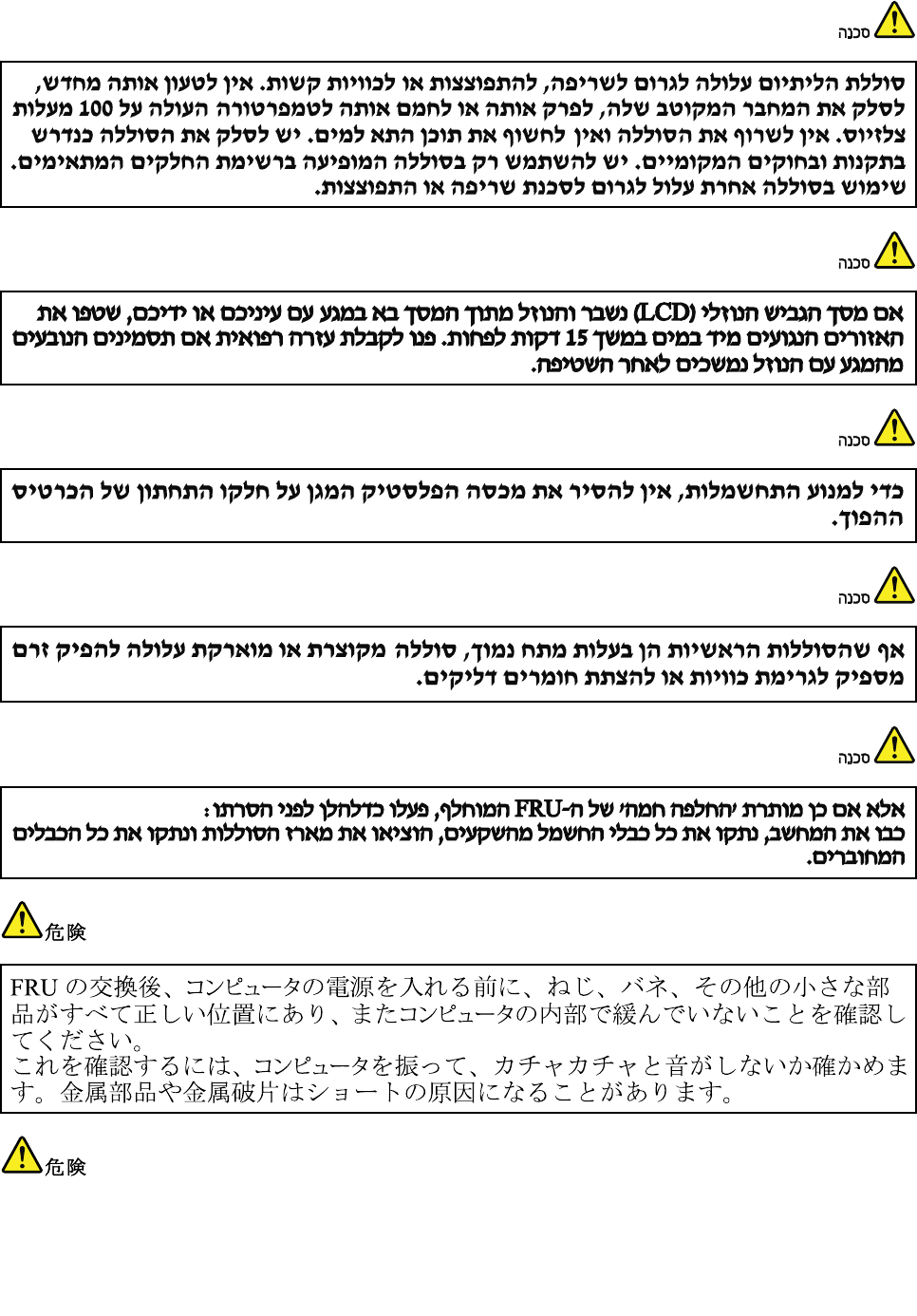
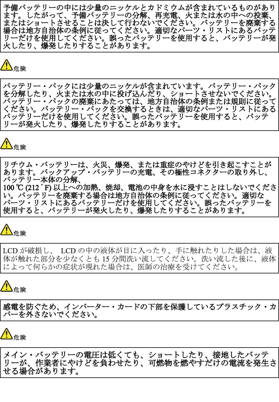
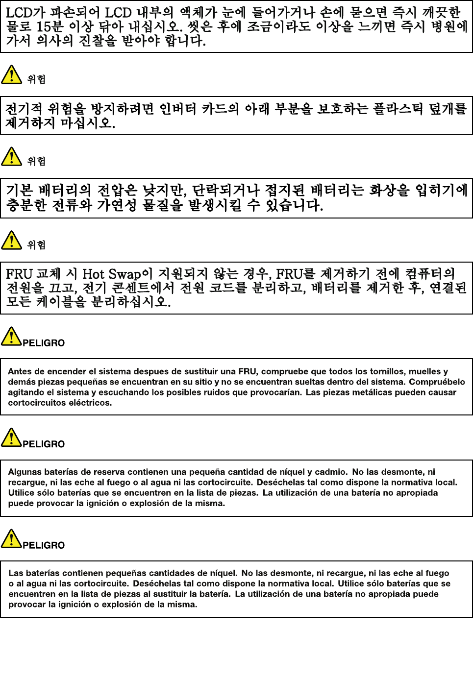
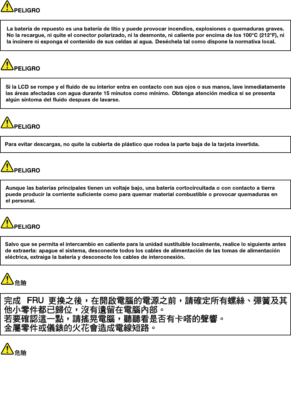
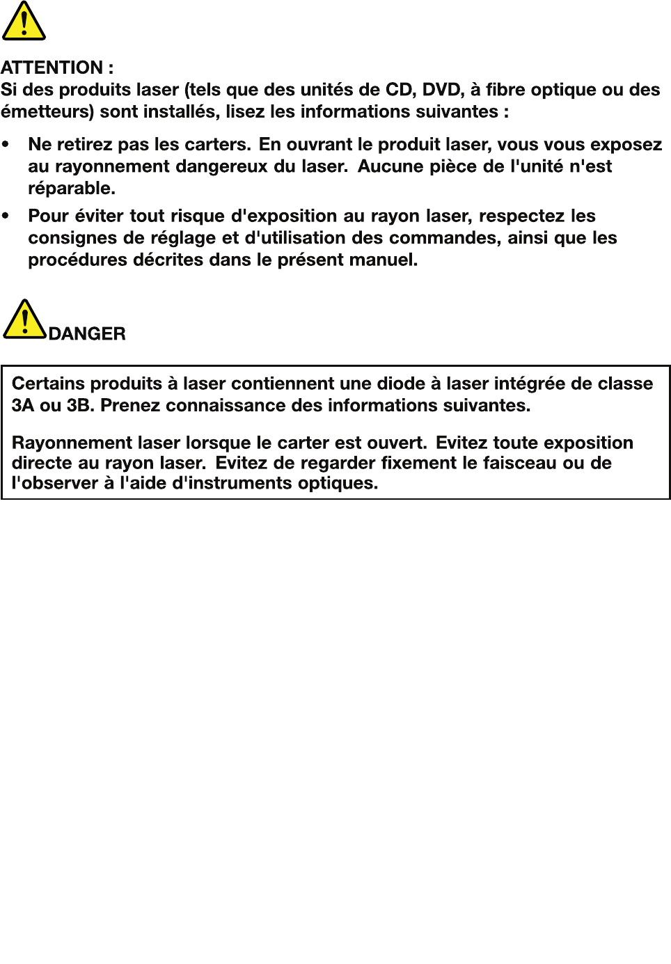
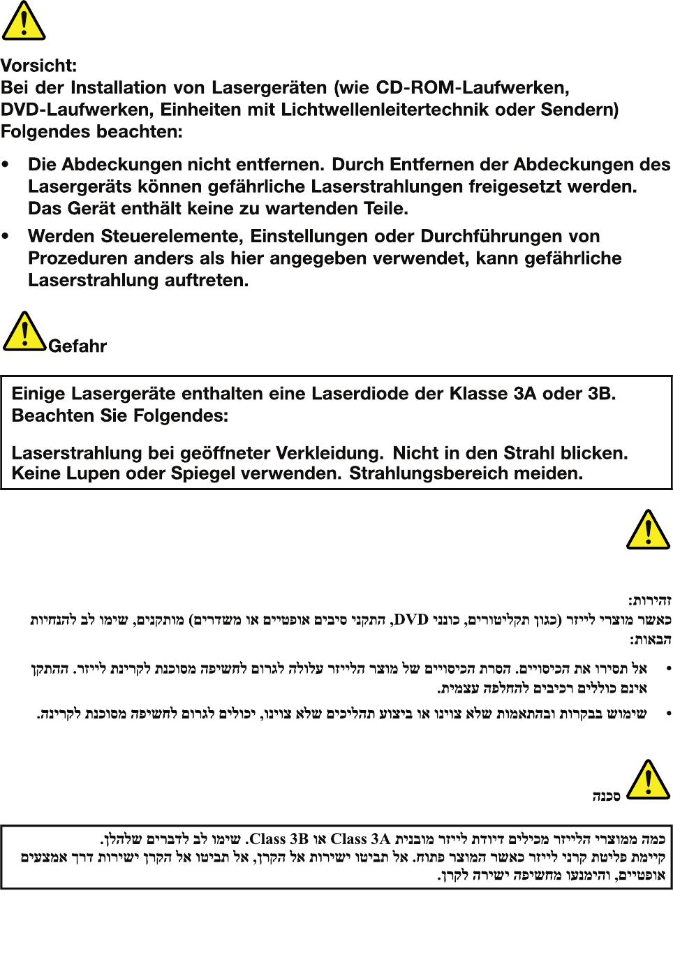
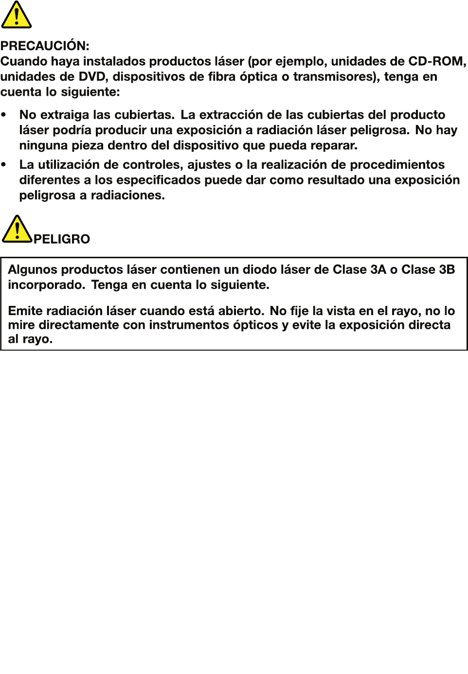
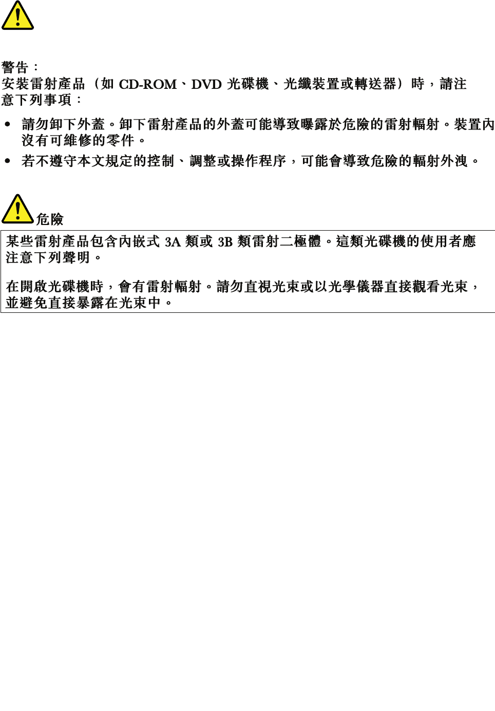
Safetynotices(multilingualtranslations)
Thesafetynoticesinthissectionareprovidedinthefollowinglanguages:
•English
•Arabic
•BrazilianPortuguese
•French
•German
•Hebrew
•Japanese
•Korean
•Spanish
•TraditionalChinese
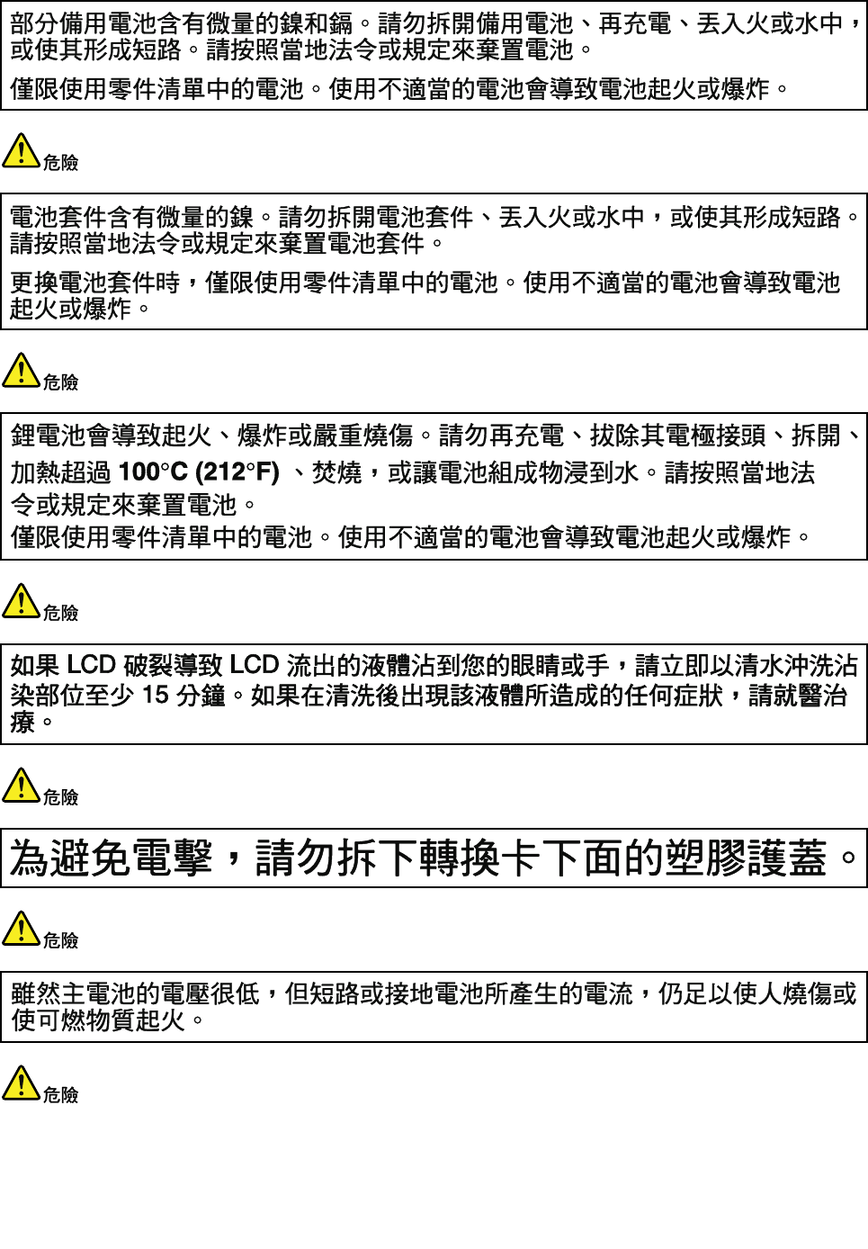
DANGER
DANGER
4HardwareMaintenanceManual
DANGER
DANGER
DANGER
DANGER
DANGER
Chapter1.Safetyinformation5
DANGER
6HardwareMaintenanceManual

Chapter1.Safetyinformation7
PERIGO
PERIGO
PERIGO
PERIGO
PERIGO
PERIGO
8HardwareMaintenanceManual
PERIGO
PERIGO
DANGER
DANGER
DANGER
Chapter1.Safetyinformation9
DANGER
DANGER
DANGER
DANGER
DANGER
VORSICHT
10HardwareMaintenanceManual
VORSICHT
VORSICHT
VORSICHT
VORSICHT
Chapter1.Safetyinformation11
VORSICHT
VORSICHT
VORSICHT
12HardwareMaintenanceManual
Chapter1.Safetyinformation13
14HardwareMaintenanceManual

Chapter1.Safetyinformation15
16HardwareMaintenanceManual
Chapter1.Safetyinformation17
18HardwareMaintenanceManual
20HardwareMaintenanceManual
Chapter1.Safetyinformation21
22HardwareMaintenanceManual
Chapter1.Safetyinformation23

24HardwareMaintenanceManual
Chapter1.Safetyinformation25
26HardwareMaintenanceManual

Chapter2.Generalcheckout
Thischapterpresentsfollowinginformation:
•“Whattodorst”onpage27
•“Powersystemcheckout”onpage28
Beforeyougotothecheckoutguide,besuretoreadthefollowingimportantnotes.
Importantnotes:
•Onlycertiedtrainedpersonnelshouldservicethecomputer.
•BeforereplacinganyFRU,readtheentirepageonremovingandreplacingFRUs.
•WhenyoureplaceFRUs,itisrecommendedtousenewnylon-coatedscrews.
•Beextremelycarefulduringsuchwriteoperationsascopying,saving,orformatting.Drivesinthecomputer
thatyouareservicingsequencemighthavebeenaltered.Ifyouselectanincorrectdrive,dataorprograms
mightbeoverwritten.
•ReplaceaFRUonlywithanotherFRUofthecorrectmodel.WhenyoureplaceaFRU,makesurethatthemodel
ofthemachineandtheFRUpartnumberarecorrectbyreferringtotheFRUpartslist.
•AFRUshouldnotbereplacedbecauseofasingle,unreproduciblefailure.Singlefailurescanoccurfora
varietyofreasonsthathavenothingtodowithahardwaredefect,suchascosmicradiation,electrostaticdischarge,
orsoftwareerrors.ConsiderreplacingaFRUonlywhenaproblemrecurs.IfyoususpectthataFRUisdefective,
cleartheerrorlogandrunthetestagain.Iftheerrordoesnotrecur,donotreplacetheFRU.
•BecarefulnottoreplaceanondefectiveFRU.
Whattodorst
WhenyoudoreturnaFRU,youmustincludethefollowinginformationinthepartsexchangeformor
partsreturnformthatyouattachtoit:
•Nameandphonenumberofservicetechnician
•Dateofservice
•Dateonwhichthemachinefailed
•Dateofpurchase
•ProcedureindexandpagenumberinwhichthefailingFRUwasdetected
•FailingFRUnameandpartnumber
•Machinetype,modelnumber,andserialnumber
•Customer'snameandaddress
Note:Duringthewarrantyperiod,thecustomermayberesponsibleforrepaircostsifthecomputerdamage
wascausedbymisuse,accident,modication,unsuitablephysicaloroperatingenvironment,orimproper
maintenancebythecustomer.Followingisalistofsomecommonitemsthatarenotcoveredunderwarranty
andsomesymptomsthatmightindicatethatthesystemwassubjectedtostressbeyondnormaluse.
Beforecheckingproblemswiththecomputer,determinewhetherthedamageiscoveredunderthewarranty
byreferringtothefollowinglist:
Thefollowingarenotcoveredunderwarranty:
•LCDpanelcrackedfromtheapplicationofexcessiveforceorfrombeingdropped
•Scratched(cosmetic)parts
•Distortion,deformation,ordiscolorationofthecosmeticparts
•Plasticparts,latches,pins,orconnectorsthathavebeencrackedorbrokenbyexcessiveforce
•Damagecausedbyliquidspilledintothesystem
•DamagecausedbytheimproperinsertionofaPCCardortheinstallationofanincompatiblecard
©CopyrightLenovo201327
•Improperdiscinsertionoruseofanopticaldrive
•Diskettedrivedamagecausedbypressureonthediskettedrivecover,foreignmaterialinthedrive,
ortheinsertionofadiskettewithmultiplelabels
•Damagedorbentdisketteejectbutton
•Fusesblownbyattachmentofanonsupporteddevice
•Forgottencomputerpassword(makingthecomputerunusable)
•Stickykeyscausedbyspillingaliquidontothekeyboard
•Useofanincorrectacpoweradapteronlaptopproducts
Thefollowingsymptomsmightindicatedamagecausedbynonwarrantedactivities:
•Missingpartsmightbeasymptomofunauthorizedserviceormodication.
•Ifthespindleofaharddiskdrivebecomesnoisy,itmayhavebeensubjectedtoexcessiveforce,
ordropped.
Powersystemcheckout
Toverifyapowersymptom,dothefollowing:
1.Turnoffthecomputer.
2.Removethebatterypack.
3.Connecttheacpoweradapter.
4.Checkthatpowerissuppliedwhenyouturnonthecomputer.
5.Turnoffthecomputer.
6.Disconnecttheacpoweradapterandinstallthechargedbatterypack.
7.Checkthatthebatterypacksuppliespowerwhenyouturnonthecomputer.
Ifyoususpectapowerproblem,seetheappropriateoneofthefollowingpowersupplycheckouts:
•“Checkingtheacpoweradapter”onpage28
•“Checkingoperationalcharging”onpage29
•“Checkingthebatterypack”onpage29
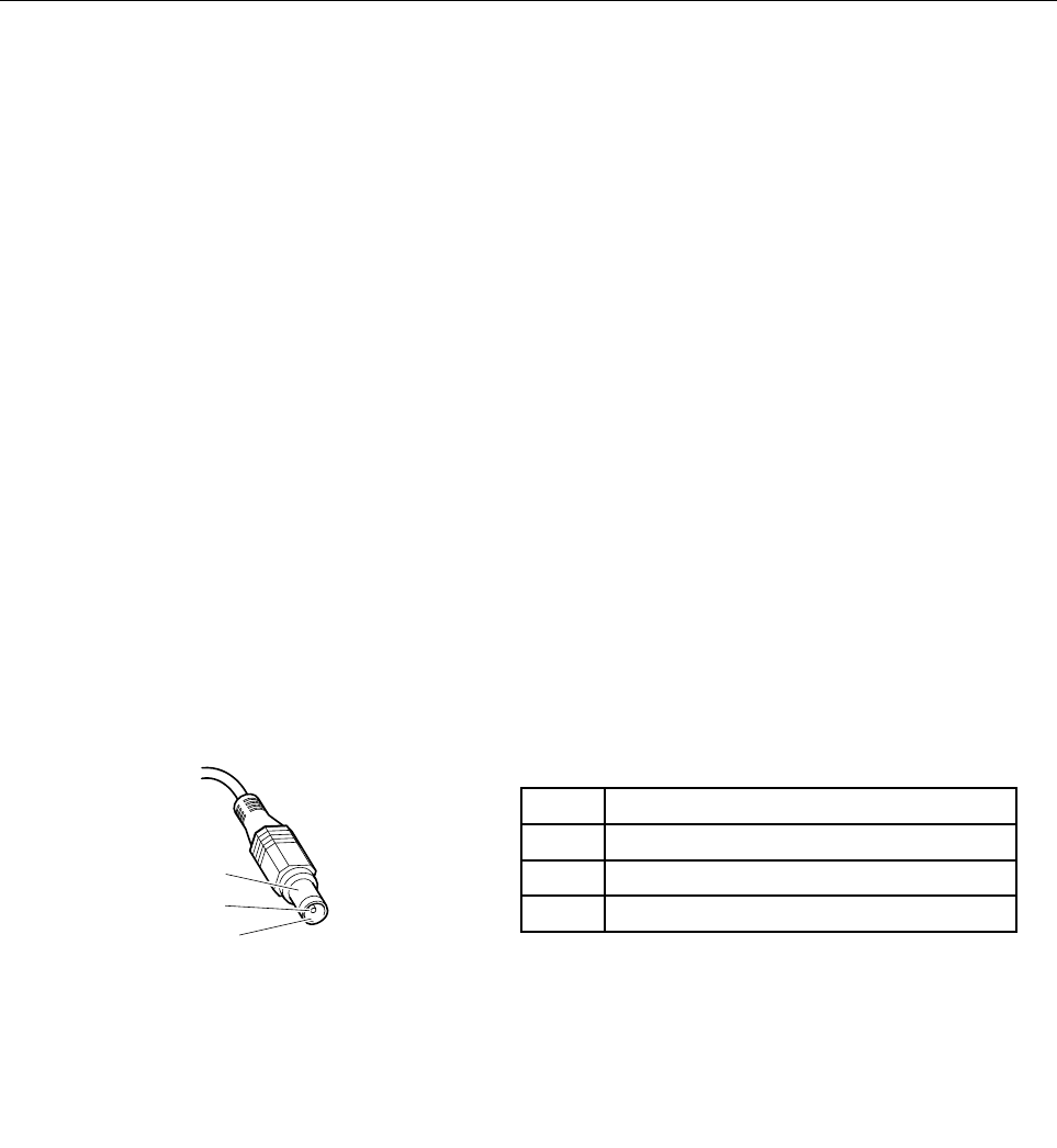
Checkingtheacpoweradapter
Ifthecomputerfailsonlywhentheacpoweradapterisused,refertotheinformationinthistopictocheck
theacpoweradapter.
•Ifthepower-onindicatordoesnotturnon,checkthepowercordoftheacpoweradapterforcorrect
continuityandinstallation.
•Ifthecomputerdoesnotchargeduringoperation,goto“Checkingoperationalcharging”onpage29.
Tochecktheacpoweradapter,dothefollowing:
1.Unplugtheacpoweradaptercablefromthecomputer.
2.Measuretheoutputvoltageacrosstheplugoftheacpoweradaptercable.Thecorrectvoltagesare
showninthefollowingtable.
PinVoltage(Vdc)
1+20
20
3Ground
1
2
3
(20V)
Note:Theoutputvoltageacrosspin2mightdifferfromthevoltagethatyoumeasure.
3.Dependingonthevoltagethatyoumeasure,dooneofthefollowing:
28HardwareMaintenanceManual
•Ifthevoltageisnotcorrect,replacetheacpoweradapter.
•Ifthevoltageisacceptable,dothefollowing:
a.Replacethesystemboard.
b.Iftheproblempersists,calltheCustomerSupportCenter.
Note:Noisefromtheacpoweradapterdoesnotalwaysindicateadefect.
Checkingoperationalcharging
Tocheckwhetherthebatterypackchargesproperlyduringoperation,dothefollowing:
Note:Beforeyoubegin,installadischargedbatterypackorabatterypackthathaslessthan50%ofthe
totalpowerremaininginthecomputer.
1.Ifthebatterystatusindicatordoesnotturnon,removethebatterypackandletitreturntoroom
temperature.
2.Reinstallthebatterypack.
3.Iftheindicatorstilldoesnotturnon,replacethebatterypack.
4.Iftheindicatorstilldoesnotturnon,replacethesystemboard.Otherwise,referto“Checkingthebattery
pack”onpage29tochecktheoriginalbatterypack.
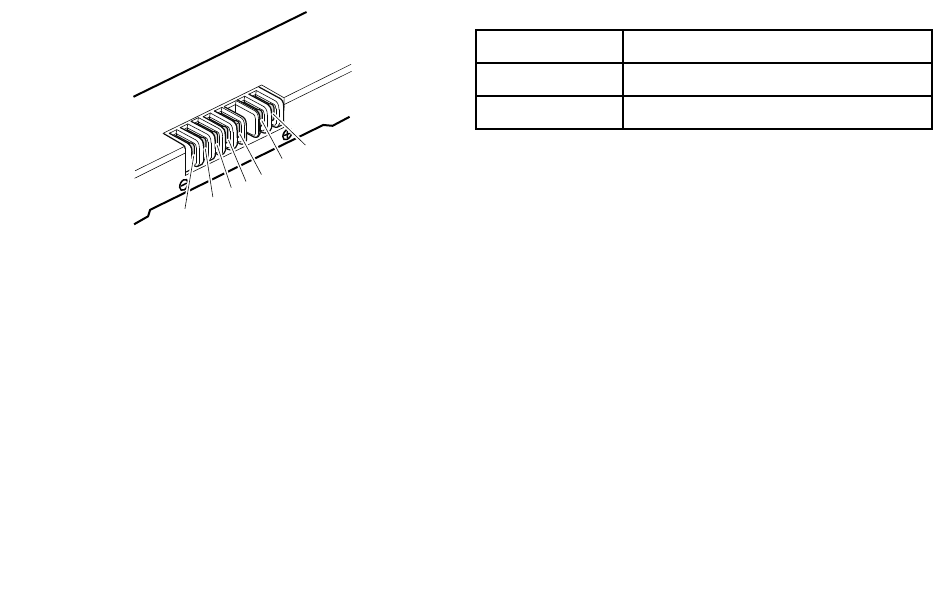
Checkingthebatterypack
ThebatterystatusiconintheMicrosoft®Windows®noticationareadisplaysthepercentageofbattery
powerremaining.
TocheckdetailedbatterystatusinformationontheWindowsoperatingsystems,launchthePowerManager
programandclicktheBatterytab.
Tocheckthebatterypack,dothefollowing:
1.Turnoffthecomputeranddisconnecttheacpoweradapter.
2.Removethebatterypackandmeasurethevoltagebetweenbatteryterminals1(+)and7(-).The
correctvoltagesareshowninthefollowingtable.
TerminalVoltage(Vdc)
1+0to+14
7Ground(-)
1(+)
2(+)
543
6(-)
7(-)
3.Measuretheresistancebetweenbatteryterminals5and7.Theresistanceshouldbe4to30KΩ.Ifthe
resistanceisnotcorrect,replacethebatterypack.
4.Dependingonthevoltagethatyoumeasure,dooneofthefollowing:
•Ifthevoltageislessthan+12.0Vdc,rechargethebatterypack.Ifthevoltagestillislessthan+12.0V
dcafterrecharging,replacethebatterypack.
•Ifthevoltageismorethan+12.0Vdc,dischargethebatterypackuntilthevoltagebecomesless
than+12.0Vdcandthenrechargethebatterypack.Ifthevoltagestillislessthan+12.0Vdcafter
recharging,replacethebatterypack.
Note:Rechargingwilltakeatleastthreehours,evenifthebatterystatusindicatordoesnotturnon.
5.Replacethesystemboardifthenewbatterypackisnotcharged.
Chapter2.Generalcheckout29

30HardwareMaintenanceManual

Chapter3.Relatedserviceinformation
Thischapterpresentsthefollowinginformation:
•“Recoveringthecomputersettings”onpage31
•“Usingpasswords”onpage31
•“Powermanagement”onpage31
Recoveringthecomputersettings
Thistopicprovidesinformationabouttherecoveryprogramsthatareavailableforyoutorecoverthe
computersettings.
OneKey®RecoveryPro
TheOneKeyRecoveryProprogramenablesyoutobackupallyourharddiskdrivecontents,includingthe
operatingsystem,datales,softwareprograms,andpersonalsettings.Youcandesignatewherethe
OneKeyRecoveryProprogramstoresthebackup.Afteryouhavebackedupthecontentsontheharddisk
drive,youcanrestorethecompletecontentsoftheharddiskdrive,restoreonlythedesiredles,orrestore
onlytheWindowsoperatingsystemandapplications.
ProductRecovery
TheProductRecoveryprogramenablesyoutorestorethecomputersettingstothefactorydefaultsettings
throughrecoverymedia.
Attention:WhenyouusetheProductRecoveryprogramtorestorethecomputersettings,allthedatayou
havestoredontheharddiskdrivewillbedeletedandthecomputersettingswillberestoredtothefactory
defaultsettings.Duringtherestoringprocess,youwillbegiventheoptiontosaveoneormorelescurrently
ontheharddiskdrivetoothermediabeforethedataisdeleted.
Formoreinformationabouttherecoverysolutions,refertothehelpinformationsystemoftheprograms.
Usingpasswords
Youcansetthefollowingtypesofpasswordstoprotectunauthorizedaccesstoyourcomputer.
Attention:Ifyouforgetthepassword,thereisnoserviceproceduretoresetthepassword.Thesystem
boardmustbereplacedforascheduledfee.
•Power-onpassword:Apower-onpasswordprotectsthecomputerfrombeingturnedonbyan
unauthorizedperson.Ifapower-onpasswordhasbeenset,theusermustenterthepasswordbefore
startingtheoperatingsystem.
•Supervisorpassword:AsupervisorpasswordprotectsthesysteminformationstoredintheBIOS
program.TheusermustenterthesupervisorpasswordtogetaccesstotheBIOSprogramandchange
systemcongurations.
Ifyouhavesetapassword,youwillbepromptedtoenterthepasswordwheneveryouturnonthecomputer.
Powermanagement
Therearethreepowermanagementmodestoreducepowerconsumption:screenblank,sleep,and
hibernation.
©CopyrightLenovo201331

Screenblankmode
Inthefollowingcircumstances,thecomputerentersscreenblankmode:
•Thetimesetonthe“T urnoffmonitor”timerontheWindows7operatingsystemexpires.
Toendscreenblankmodeandresumenormaloperation,pressanykey.
•Y ouhavepressedFn+F2.
Toendscreenblankmodeandresumenormaloperation,pressFn+F2.
Sleepmode
Whenthecomputerenterssleepmode,thefollowingeventsoccurinadditiontowhatoccursinscreen
blankmode:
•TheLCDispoweredoff.
•Theharddiskdriveispoweredoff.
•Themicroprocessorstops.
Toentersleepmode,pressFn+F1.
Incertaincircumstances,thecomputerautomaticallyenterssleepmode:
•A“suspendtime”hasbeensetonthetimer,andtheuserdoesnotdoanyoperationwiththekeyboard,
theharddiskdrive,theparallelconnector,orthediskettedrivewithinthattime.
•Thebatterystatusindicatorblinksorange,indicatingthatthebatterypowerislow.
Tocausethecomputertoreturnfromsleepmodeandresumetheoperation,dooneofthefollowing:
•PresstheFnkey.
•OpentheLCDcover.
•Pressthepowerbutton.
Also,whenthetimesetontheresumetimerelapses,thecomputerautomaticallyreturnsfromsleepmode
andresumesoperation.
Note:Thecomputerdoesnotacceptanyinputimmediatelyafteritenterssleepmode.Waitafewseconds
beforetakinganyactionstoreenteroperationmode.
Hibernationmode
Inhibernationmode,thefollowingoccurs:
•Thesystemstatus,RAM,VRAM,andsetupdataarestoredontheharddiskdrive.
•Thesystemispoweredoff.
Ifyouhavedenedoneofthefollowingactionsastheeventthatcausesthecomputertoenterhibernation
mode,performthataction.
•Closingthelid
•Pressingthepowerbutton
Also,thecomputerautomaticallyentershibernationmodeineitherofthefollowingcircumstances:
•A“hibernationtime”hasbeensetonthetimer,andtheuserdoesnotdoanyoperationwiththekeyboard,
theharddiskdrive,theparallelconnector,orthediskettedrivewithinthattime.
•Thetimerconditionsaresatisedinsuspendmode.
32HardwareMaintenanceManual

Whenthepoweristurnedon,thecomputerreturnsfromhibernationmodeandresumesoperation.The
hibernationleinthebootrecordontheharddiskdriveisread,andthesystemstatusisrestoredfromthe
harddiskdrive.
Chapter3.Relatedserviceinformation33

34HardwareMaintenanceManual
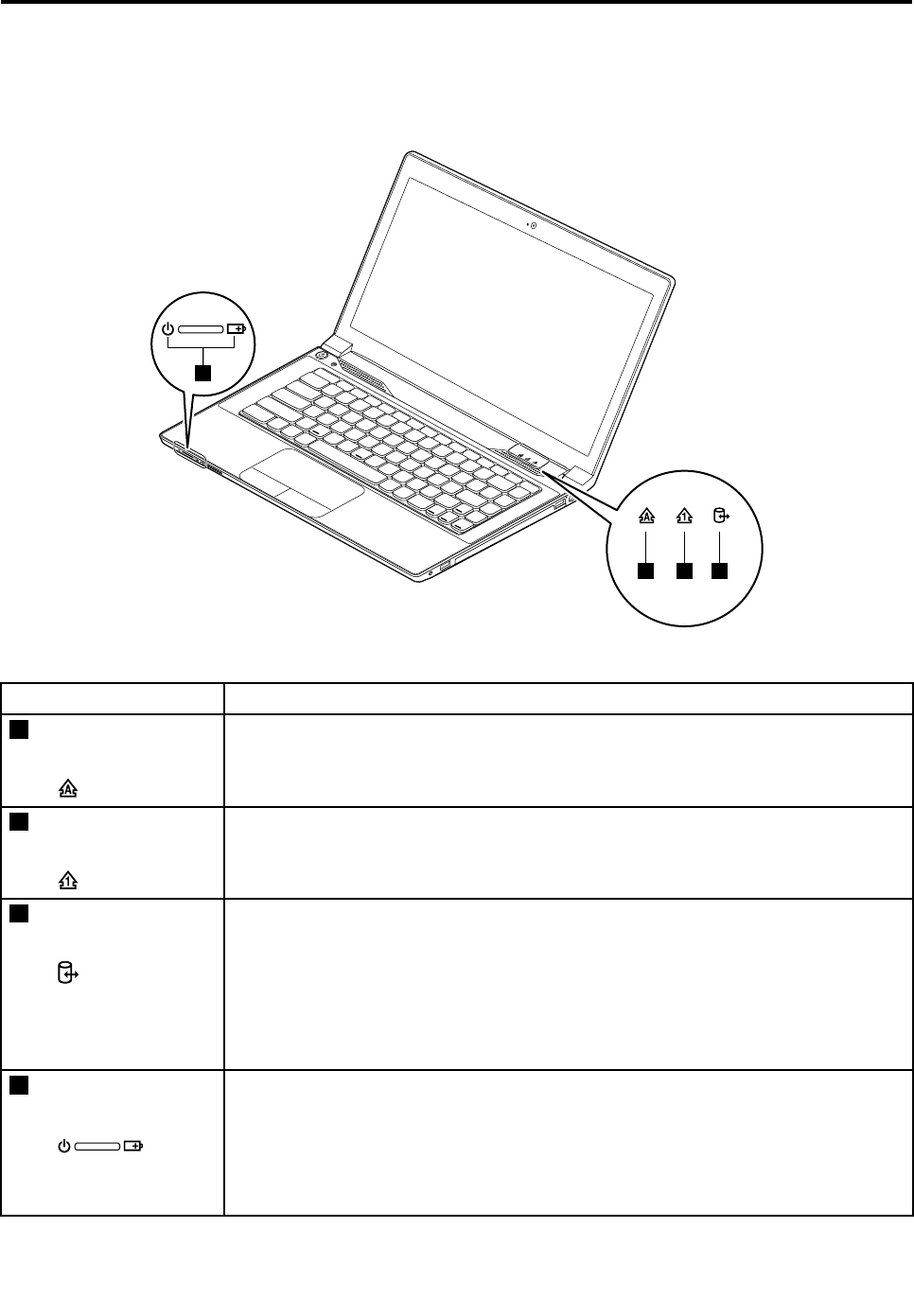
Chapter4.Statusindicators
Thischapterpresentsthesystemstatusindicatorsthatshowthestatusofthecomputer.
4
123
Table1.Statusindicators
IndicatorMeaning
1Capslockstatus
indicator
White:CapsLockmodeisenabled.Youcantypeallalphabeticcharacters(A-Z)in
uppercasedirectly.ToenableordisableCapsLockmode,presstheCapsLockkey.
2Numericlockstatus
indicator
White:Theseparatenumerickeypadonthekeyboardisenabled.Toenableordisable
thenumerickeypad,presstheNumericLockkey.
3Deviceaccess
statusindicator
On:Theharddiskdriveoropticaldriveisreadingorwritingdata.
Attention:
•Whentheindicatorison,donotputthecomputerintosleepmodeorturnoffthe
computer.
•Whentheindicatorison,donotmovethecomputer.Suddenphysicalshockmight
causedriveerrors.
4Powerandbattery
statusindicator
•Solidgreen:Thebatterychargelevelisbetween80%and100%,orthebattery
dischargelevelisbetween20%and100%.
•Slow-blinkinggreen:Thebatterychargelevelisbetween20%and80%,and
chargingiscontinuing.Whenthebatterychargelevelreaches80%,thebatterystatus
indicatorstopsblinking,butthechargingmightcontinueuntilthebatteryis100%
charged.
©CopyrightLenovo201335

Table1.Statusindicators(continued)
IndicatorMeaning
•Slow-blinkingorange:Thebatterychargelevelisbetween5%and20%,and
chargingiscontinuing.Whenthebatterychargelevelreaches20%,theblinking
colorchangestogreen.
•Solidorange:Thebatterydischargelevelisbetween5%and20%.
•Fast-blinkingorange:Thebatterychargeordischargelevelis5%orless.
•Off:Thebatteryisdetachedorthecomputerispoweredoff.
36HardwareMaintenanceManual

Chapter5.Fnkeycombinations
ThefollowingtabledescribesthefunctionsofFnkeycombinations.
Table2.Functionkeycombinations
KeycombinationDescription
Fn+EscChangesthecameraandaudiosettings.
Fn+F1Putsthecomputerintosleepmode.Toresumenormaloperation,press
theFnkeyonly.
Fn+F2Enablesordisablesthebacklightfeatureofthecomputerscreen.
Fn+F3Switchesbetweenthecomputerdisplayandanexternalmonitor.
Note:Y oualsocanusetheWindows+Pcombinationtoswitchbetweenthe
computerdisplayandanexternalmonitor.
Fn+F5Enablesordisablesthebuilt-inwirelessnetworkingfeatures.
Fn+F6Enablesordisablesthetouchpad.
Fn+F8Enablesordisablesthenumerickeypad.
Fn+F9Multimediacontrol:Play/Pause
Fn+F10Multimediacontrol:Stop
Fn+F11Multimediacontrol:Skiptotheprevioustrack
Fn+F12Multimediacontrol:Skiptothenexttrack
Fn+PgUpHasthesamefunctionastheScrLkkeyonaconventionalkeyboard.
Fn+PrtScHasthesamefunctionastheSysRqkeyonaconventionalkeyboard.
Fn+HomeHasthesamefunctionasthePausekeyonaconventionalkeyboard.
Fn+EndHasthesamefunctionastheBreakkeyonaconventionalkeyboard.
Fn+PgDnHasthesamefunctionastheInsertkeyonaconventionalkeyboard.
Fn+up/downarrowIncreasesordecreasesthedisplaybrightnesslevel.
Fn+left/rightarrowDecreasesorincreasesthesoundvolume.
©CopyrightLenovo201337

38HardwareMaintenanceManual
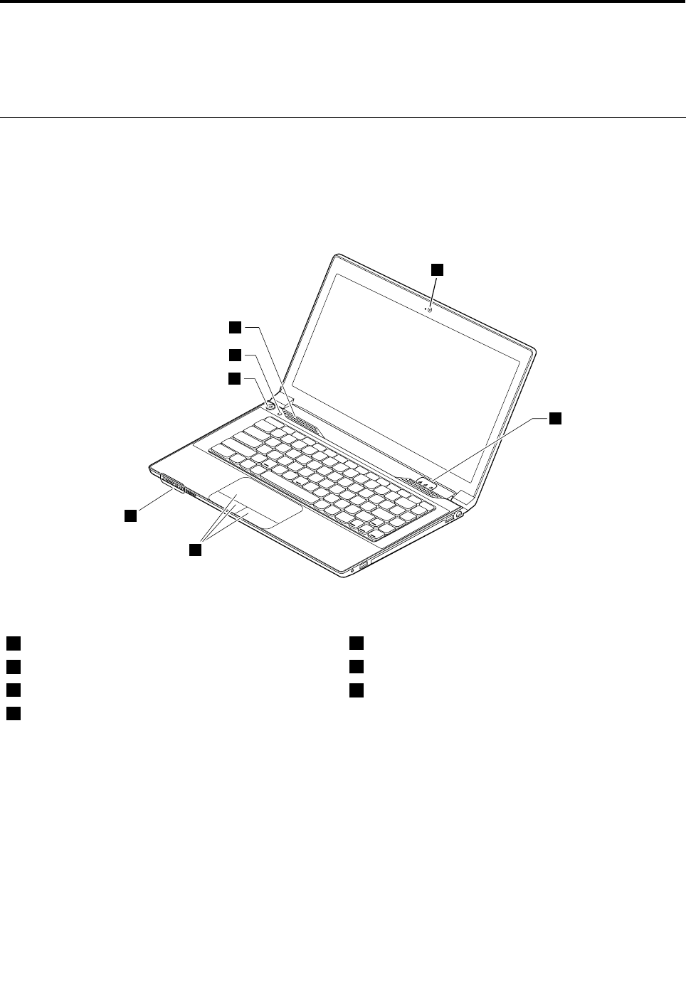
Chapter6.Locations
Thischapterprovidesinformationaboutcomponentlocations.
Locatingcomputercontrols,connectors,andindicators
Thistopicintroducesthelocationsofthecomputercontrols,connectors,andindicators.
Frontview
1
6
5
7
2
4
3
Figure1.Frontview
1Camera5Powerbutton
2Statusindicators16Recoverybutton
3Touchpadandtouchpadbuttons7Speaker
4Batterystatusindicator1
1Forthedescriptionoftheindicators,seeChapter4“Statusindicators”onpage35.
©CopyrightLenovo201339
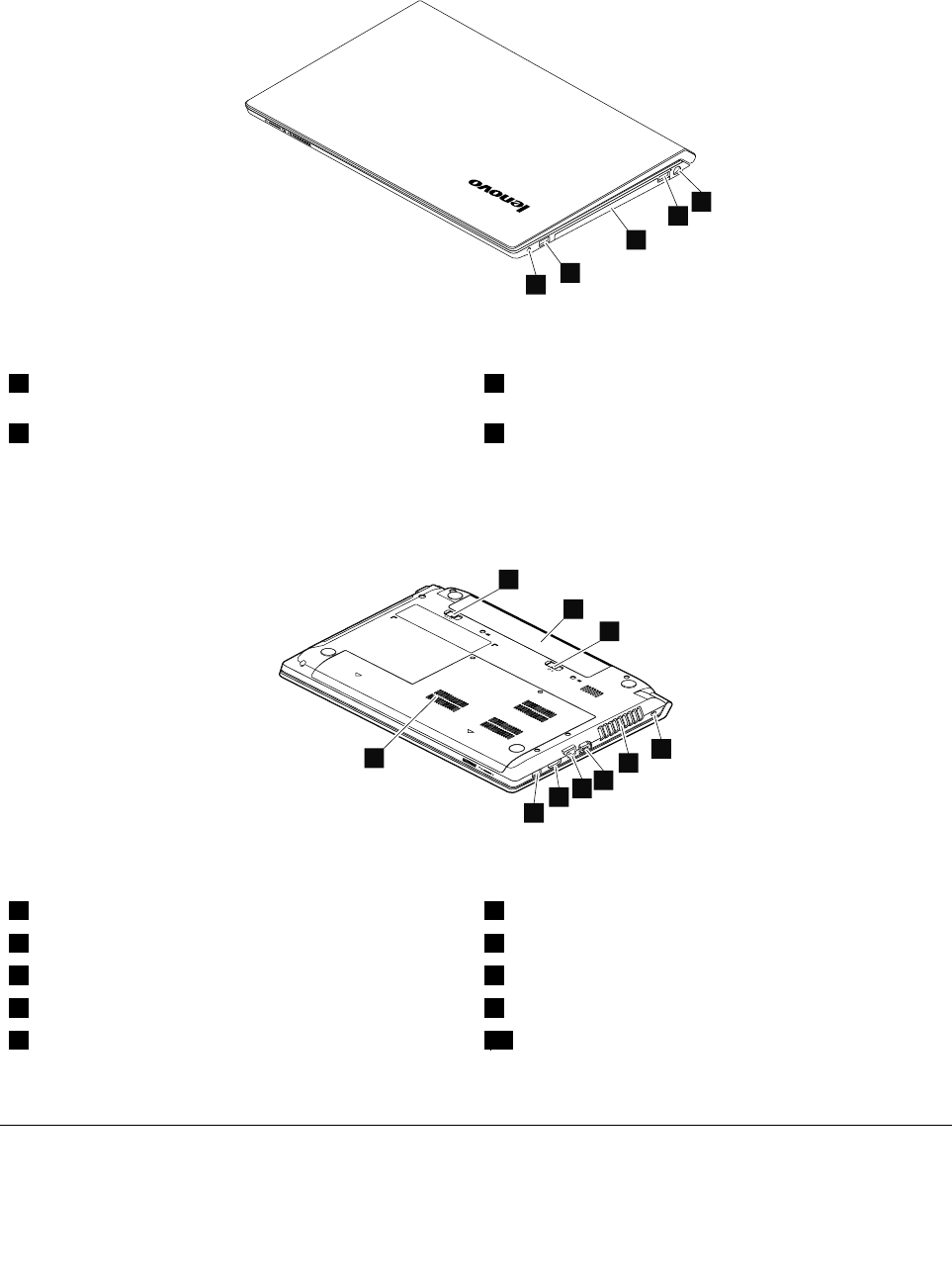
Right-sideview
1
2
3
2
4
Figure2.Right-sideview
1Comboaudiojack3Opticaldrive(onsomemodels)
2USBconnector4acpoweradapter
Bottomandleft-sideview
4
5
6
7
8
9
1
2
3
10
Figure3.Bottomandleft-sideview
1Batterylock6Monitorconnector
2Batterypack7Ethernetconnector
3Batterylatch8HDMIport
4Security-lockslot9UniversalSerialBus(USB)connector
5Fanlouvers10Bottomslotcover1
1Thememorymodule,harddiskdrive,andwirelesscardarelocatedunderneaththebottomslotcover.
LocatingFRUsandCRUs
Thischaptercontainsfollowinglistsoftheserviceparts.
•“MajorFRUsandCRUs”onpage42
40HardwareMaintenanceManual

•“LCDFRUs”onpage43
•“Miscellaneousparts”onpage45
Notes:
•EachFRUisavailableforalltypesormodels,unlessotherwisespecied.
•ACRUisidentiedbyasingleasterisk(*)ortwoasterisks(**)intheCRUIDcolumn.AnNintheCRUIDcolumn
meansthatthepartisnotaCRU.Asingleasterisk(*)meansthatthepartisaself-serviceCRU;twoasterisks
(**)meansthatthepartisanoptional-serviceCRU.
CRUstatementforcustomers:
Youcanresolvesomeproblemswithyourproductwithareplacementpartyoucaninstallyourself,calleda
“CustomerReplaceableUnit”or“CRU”.SomeCRUsaredesignatedasself-serviceCRUsandothersare
designatedasoptional-serviceCRUs.Installationofself-serviceCRUsisyourresponsibility.Foroptional-service
CRUs,youcaneitherinstalltheCRUyourselforyoucanrequestthataServiceProviderinstalltheCRUaccording
tothewarrantyserviceforyourproduct.IfyouintendoninstallingtheCRU,LenovowillshiptheCRUtoyou.CRU
informationandreplacementinstructionsareshippedwithyourproductandareavailablefromLenovoatanytime
uponrequest.YoucanndalistofCRUsforyourproductinthisHardwareMaintenanceManual.Anelectronic
versionofthismanualcanbefoundathttp://www.lenovo.com/UserManuals.Followtheon-screeninstructionsto
ndthemanualforyourproduct.YoumightberequiredtoreturnthedefectiveCRU.Whenreturnisrequired:(1)
returninstructions,aprepaidshippinglabel,andacontainerwillbeincludedwiththereplacementCRU;and(2)you
mightbechargedforthereplacementCRUifLenovodoesnotreceivethedefectiveCRUwithinthirty(30)daysof
yourreceiptofthereplacementCRU.SeeyourLenovoLimitedWarrantydocumentationforfulldetails.
LenovocomputerscontainthefollowingtypesofCRUs:
–Self-serviceCRUs:TheseCRUsunplugorareheldbynomorethantwoscrews.Examplesofthesetypes
ofCRUsincludetheacpoweradapter,powercord,battery,andharddiskdrive.Otherself-serviceCRUs
dependingonproductdesignmightincludethememorymodule,wirelesscard,keyboard,andpalmrest
withngerprintreaderandtouchpad.
–Optional-serviceCRUs:TheseCRUsareisolatedpartswithinthecomputerthatareconcealedbyanaccess
panelthatistypicallysecuredbymorethantwoscrews.Oncetheaccesspanelisremoved,thespecic
CRUisvisible.
Chapter6.Locations41
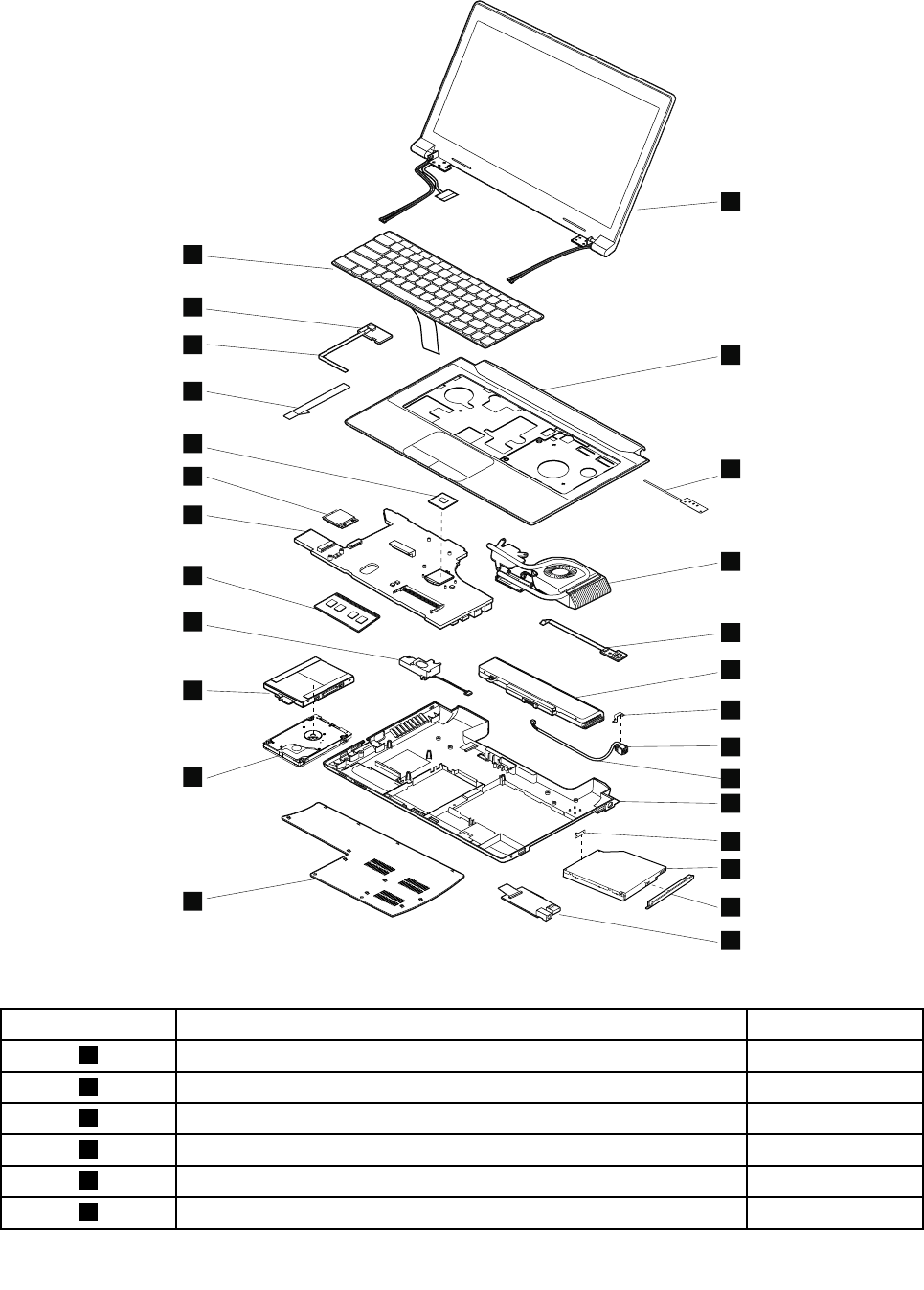
MajorFRUsandCRUs
1
3
5
6
7
d
c
8
11
e
14
15
f
17
18
21
g
h
23
b
20
16
1
2
3
4
5
6
7
c
e
f
g
d
a
b
8
9
10
11
12
13
14
15
20
16
17
18
19
Table3.MajorFRUsandCRUs
No.FRUdescriptionCRUID
1LCDunitN
2KeyboardbezelwithtouchpadN
3LEDboardwithcableN
4ThermalmoduleassemblyN
5USBboardN
6Batterypack*
42HardwareMaintenanceManual

Table3.MajorFRUsandCRUs(continued)
No.FRUdescriptionCRUID
7DC-inconnectorN
8BasecoverN
9Opticaldrive*
10Input/output(I/O)boardN
11BasecoverN
12Harddiskdrive**
13SpeakerN
14Memorymodule*
15SystemboardN
16WirelessLANcard*
17MicroprocessorN
18PowerboardwithcableN
19KeyboardN
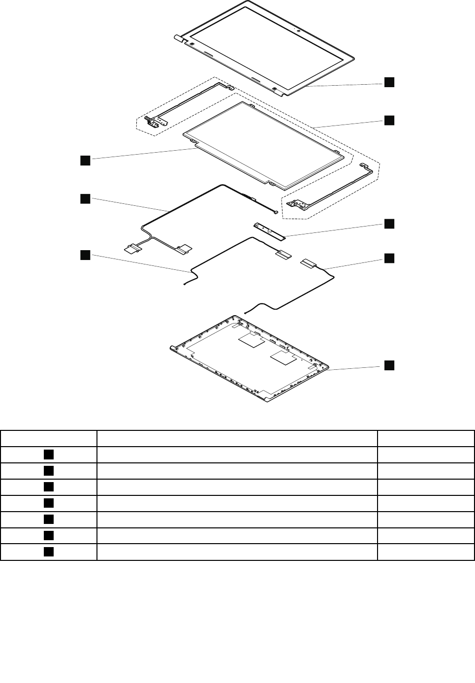
LCDFRUs
LenovoE4325usesa355.6-mm(14-inch)highdenition(HD)LCD.
Chapter6.Locations43
h
7
1
2
3
4
5
6
h
7
Table4.LCDFRUs
No.FRUdescriptionCRUID
1LCDBezelN
2HingesN
3CameraN
4RightantennaN
5LCDcoverN
6LeftantennaN
7LCDpanelN
44HardwareMaintenanceManual

Miscellaneousparts
Table5.Miscellaneousparts
No.FRUdescriptionCRUID
aDC-inconnectorbracketN
bDC-incableN
cOpticaldrivebracketN
dOpticaldrivebezelN
eHarddiskdrivebracketN
fTouchpadcableN
gPowerboardcableN
hLCDcableN
LookingupFRUinformation
FordetailedFRUinformation,includingpartnumbers,descriptions,andsubstitutionpartnumbers,goto
http://www.lenovo.com/serviceparts-lookup.
Chapter6.Locations45

46HardwareMaintenanceManual

Chapter7.FRUreplacementnotices
Thischapterpresentsnoticesrelatedtoremovingandreplacingparts.Readthischaptercarefullybefore
replacinganyFRU.
CRUstatementforcustomers:
Youcanresolvesomeproblemswithyourproductwithareplacementpartyoucaninstallyourself,called
a“CustomerReplaceableUnit”or“CRU”.SomeCRUsaredesignatedasself-serviceCRUsandothers
aredesignatedasoptional-serviceCRUs.Installationofself-serviceCRUsisyourresponsibility.For
optional-serviceCRUs,youcaneitherinstalltheCRUyourselforyoucanrequestthataServiceProvider
installtheCRUaccordingtothewarrantyserviceforyourproduct.IfyouintendoninstallingtheCRU,
LenovowillshiptheCRUtoyou.CRUinformationandreplacementinstructionsareshippedwithyour
productandareavailablefromLenovoatanytimeuponrequest.YoucanndalistofCRUsforyour
productinthisHardwareMaintenanceManual.Anelectronicversionofthismanualcanbefoundat
http://www.lenovo.com/UserManuals.Followtheon-screeninstructionstondthemanualforyourproduct.
YoumightberequiredtoreturnthedefectiveCRU.Whenreturnisrequired:(1)returninstructions,aprepaid
shippinglabel,andacontainerwillbeincludedwiththereplacementCRU;and(2)youmightbechargedfor
thereplacementCRUifLenovodoesnotreceivethedefectiveCRUwithinthirty(30)daysofyourreceiptof
thereplacementCRU.SeeyourLenovoLimitedWarrantydocumentationforfulldetails.
ImportantnoticeforreplacingFRUs
EnsurethatthecomputerhasthelatestBIOSversionanddevicedriversinstalledbeforereplacinganyFRUs.
Afteryoureplaceasystemboard,ensurethatyouinstallthelatestBIOSversiononthenewsystemboard.
Note:BIOSanddevicedriversarecustomer-installable.TheBIOSanddevicedriversareavailableat
http://www.lenovo.com/support.
TodownloadthelatestBIOS,devicedrivers,andothersoftwareprograms,dothefollowing:
1.Gotohttp://www.lenovo.com/support.
2.ClickDownloadDrivers&Software.TheWebsiteoffersthreeoptionstobeginyoursearch:
•Searchbyproductnumber
•Searchthroughtheproductauto-detectfunction
•Searchbyproductcategory
3.Followtheinstructionsonthescreenandinstallthenecessarysoftware.
4.Restartthecomputer.
Notes:YoualsocanimprovethecomputerperformancebyupdatingtheBIOSutilitytothelatestversion
fromtheLenovoSupportWebsitehttp://www.lenovo.com/support.
•Beforeinstallingthelatestutility,makesurethatthebatteryisfullychargedandanacpoweradapteris
connected.
•DonottrytoupdatetheBIOSsettingsforanycomputerunlessyouhavebeentrainedandcertied.An
untrainedpersonrunstheriskofdamagingthecomputer.
•Donotturnofforputyourcomputerintosleeporhibernationuntiltheupdatehasbeencompleted.
Otherwise,thesystemboardmightbedamaged.
WhenyouarereplacingandservicingFRUs,refertothefollowinginstructionstoavoidunnecessaryexpense:
©CopyrightLenovo201347
•IfyouareinstructedtoreplaceaFRUbutthereplacementdoesnotsolvetheproblem,reinstallthe
originalFRUbeforeyoucontinue.
•Somecomputershavebothaprocessorboardandasystemboard.Ifyouareinstructedtoreplaceeither
theprocessorboardorthesystemboard,butthereplacementdoesnotsolvetheproblem,reinstallthe
originalboard,andthenreplacetheotherone.
•IfanadapteroradeviceconsistsofmorethanoneFRU,anyoftheFRUsmightbethecauseoftheerror.
Beforereplacingtheadapterordevice,removetheFRUsonebyonetoseeifthesymptomschange.Find
andreplaceonlytheFRUthatchangedthesymptoms.
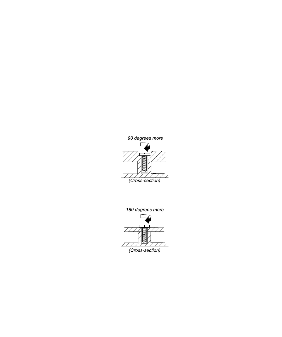
Screwnotices
TheLenovonotebookcomputerusesspecialnylon-coatedscrewsthathavethefollowingcharacteristics:
•Theymaintaintightconnections.
•Theydonoteasilycomeloose,evenwithshockorvibration.
•Theyarehardertotighten.
Dothefollowingwhenyouareservicingthecomputer:
•Keepthescrewkitinyourtoolbag.
•Itisrecommendedthatyouusenewscrews.
•Itisrecommendedthatyouuseeachscrewonlyonce.
•Useatorquescrewdriverifyouhaveone.
Tightenscrewsasfollows:
•Plastictoplastic
Turnanadditionalangleof90degreesafterthescrewheadtouchesthesurfaceoftheplasticpart.
•Logiccardtoplastic
Turnanadditionalangleof180degreesafterthescrewheadtouchesthesurfaceofthelogiccard.
Notes:
•Ensurethatyouusethecorrectscrew.Itisrecommendedthatyouusenewscrewsforreplacements.If
youhaveatorquescrewdriver,rmlytightenallscrewstothetorquespeciedinthescrewinformation
tableforeachstep.
•Ensurethattorquescrewdriversarecalibratedcorrectlyfollowingcountryspecications.
48HardwareMaintenanceManual

Chapter8.RemovingandreplacingaFRU
ThischapterprovidesinstructionsonhowtoremoveorreplaceaFRU.
CRUstatementforcustomers:
Youcanresolvesomeproblemswithyourproductwithareplacementpartyoucaninstallyourself,called
a“CustomerReplaceableUnit”or“CRU”.SomeCRUsaredesignatedasself-serviceCRUsandothers
aredesignatedasoptional-serviceCRUs.Installationofself-serviceCRUsisyourresponsibility.For
optional-serviceCRUs,youcaneitherinstalltheCRUyourselforyoucanrequestthataServiceProvider
installtheCRUaccordingtothewarrantyserviceforyourproduct.IfyouintendoninstallingtheCRU,
LenovowillshiptheCRUtoyou.CRUinformationandreplacementinstructionsareshippedwithyour
productandareavailablefromLenovoatanytimeuponrequest.YoucanndalistofCRUsforyour
productinthisHardwareMaintenanceManual.Anelectronicversionofthismanualcanbefoundat
http://www.lenovo.com/UserManuals.Followtheon-screeninstructionstondthemanualforyourproduct.
YoumightberequiredtoreturnthedefectiveCRU.Whenreturnisrequired:(1)returninstructions,aprepaid
shippinglabel,andacontainerwillbeincludedwiththereplacementCRU;and(2)youmightbechargedfor
thereplacementCRUifLenovodoesnotreceivethedefectiveCRUwithinthirty(30)daysofyourreceiptof
thereplacementCRU.SeeyourLenovoLimitedWarrantydocumentationforfulldetails.
Generalguidelines
ThischapterpresentsdirectionsanddrawingsforuseinremovingandreplacingaFRU.Besuretoobserve
thefollowinggeneralrules:
1.Donottrytoserviceanycomputerunlessyouhavebeentrainedandcertied.Anuntrainedpersonruns
theriskofdamagingparts.
2.BeforereplacinganyFRU,reviewChapter7“FRUreplacementnotices”onpage47.
3.BeginbyremovinganyFRUsthathavetoberemovedbeforereplacingthefailingFRU.SuchFRUsare
listedineachFRUreplacementsection.Removethemintheorderinwhichtheyarelisted.
4.FollowthecorrectsequenceinthestepsforremovingaFRU,asgiveninthedrawingsbythenumbers
insquarecallouts.
5.Whenturningascrew,turnitinthedirectionasgivenbythearrowinthedrawing.
6.WhenremovingaFRU,moveitinthedirectionasgivenbythearrowinthedrawing.
7.ToputthenewFRUinplace,reversetheremovalprocedureandfollowanynotesthatpertainto
replacement.
8.WhenreplacingaFRU,usethecorrectscrew(s)asshownintheprocedures.
9.Yourcomputermightlookdifferentlyfromtheillustrationsinthelaterpartofthischapter.
DANGER
BeforeremovinganyFRU,turnoffthecomputer,unplugallpowercordsfromelectricaloutlets,
removethebatterypack,andthendisconnectanyinterconnectingcables.
Attention:AfterreplacingaFRU,donotturnonthecomputeruntilyouhavemadesurethatallscrews,
springs,andothersmallpartsareinplaceandnonearelooseinsidethecomputer.Verifythisbyshaking
thecomputergentlyandlisteningforrattlingsounds.Metallicpartsormetalakescancauseelectrical
shortcircuits.
Attention:Thesystemboardissensitiveto,andcanbedamagedby,electrostaticdischarge.Before
touchingit,establishpersonalgroundingbytouchingagroundpointwithonehandorbyusingan
electrostaticdischarge(ESD)strap(P/N6405959).
©CopyrightLenovo201349
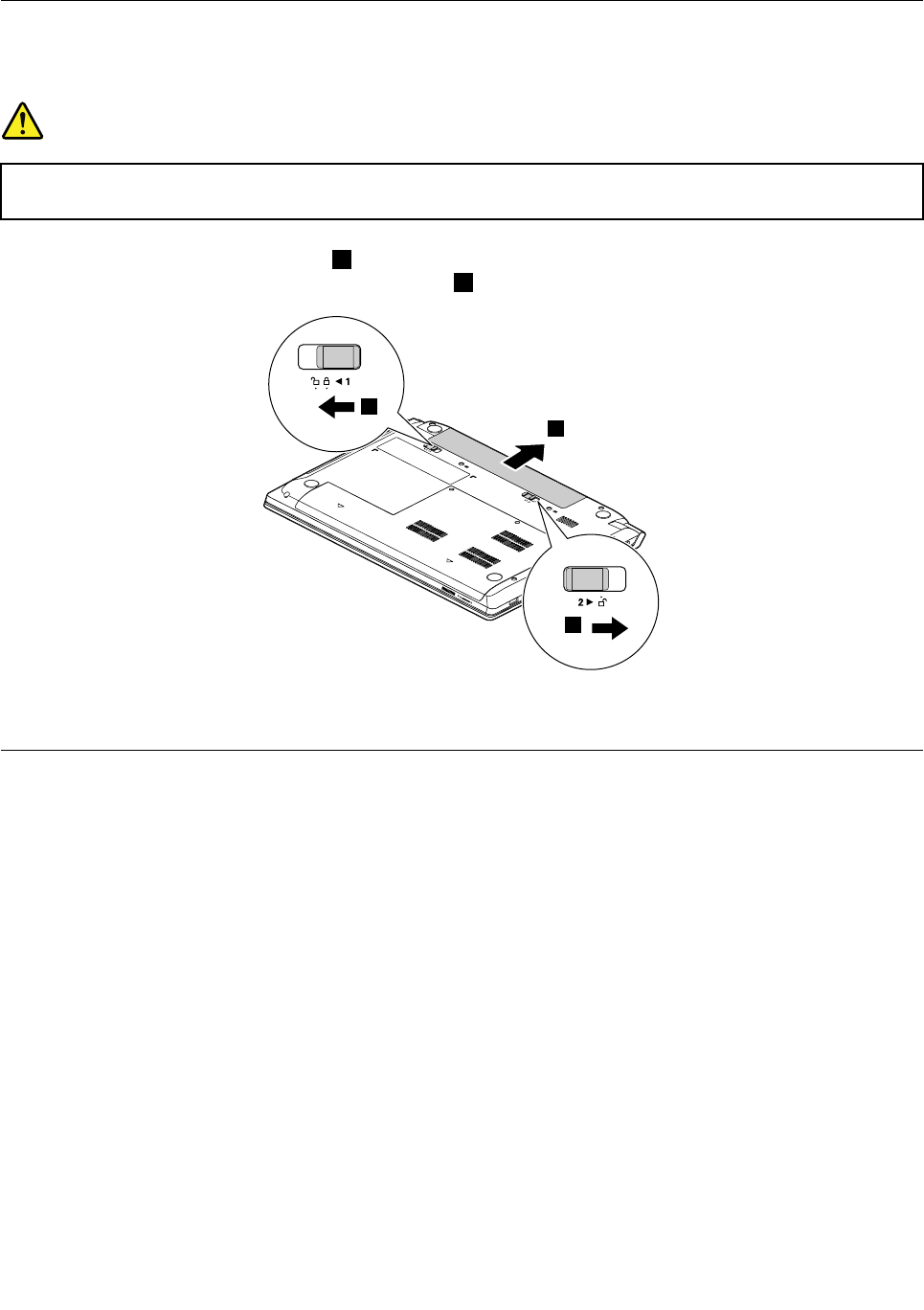
1010Batterypack
Removalstepsofbatterypack
DANGER
Useonlythebatteryspeciedinthepartslistforyourcomputer.Anyotherbatterycouldignite
orexplode.
Unlockthespring-loadedbatterylatch1.Holdingthemanualbatterylatchintheunlockedposition,remove
thebatterypackinthedirectionshownbythearrow2.
1
2
1
2
Wheninstalling:Installthebatterypackintheslot.Ensurethatthebatterylatchesareinthelockedposition.
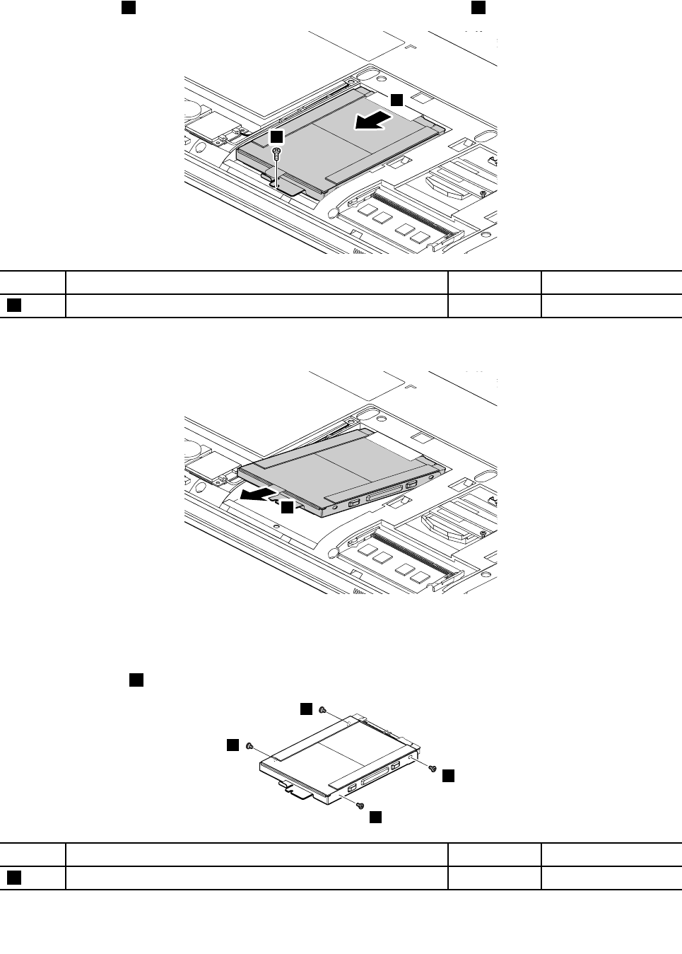
1020Bottomslotcover
Foraccess,removethisFRU:
•“1010Batterypack”onpage50
50HardwareMaintenanceManual
Removalstepsofbottomslotcover
Removethescrews1,andthenremovethecover.
1
1
2
2
StepScrew(quantity)ColorTorque
1M2×3mm,at-head,nylon-coated(2)Black1.85kgf-cm
1030Opticaldrive
Foraccess,removetheseFRUsinorder:
•“1010Batterypack”onpage50
•“1020Bottomslotcover”onpage50
Removalstepsofopticaldrive
Removethescrew1.
1
StepScrew(quantity)ColorTorque
1M2×3mm,at-head,nylon-coated(1)Black1.85kgf-cm
Chapter8.RemovingandreplacingaFRU51
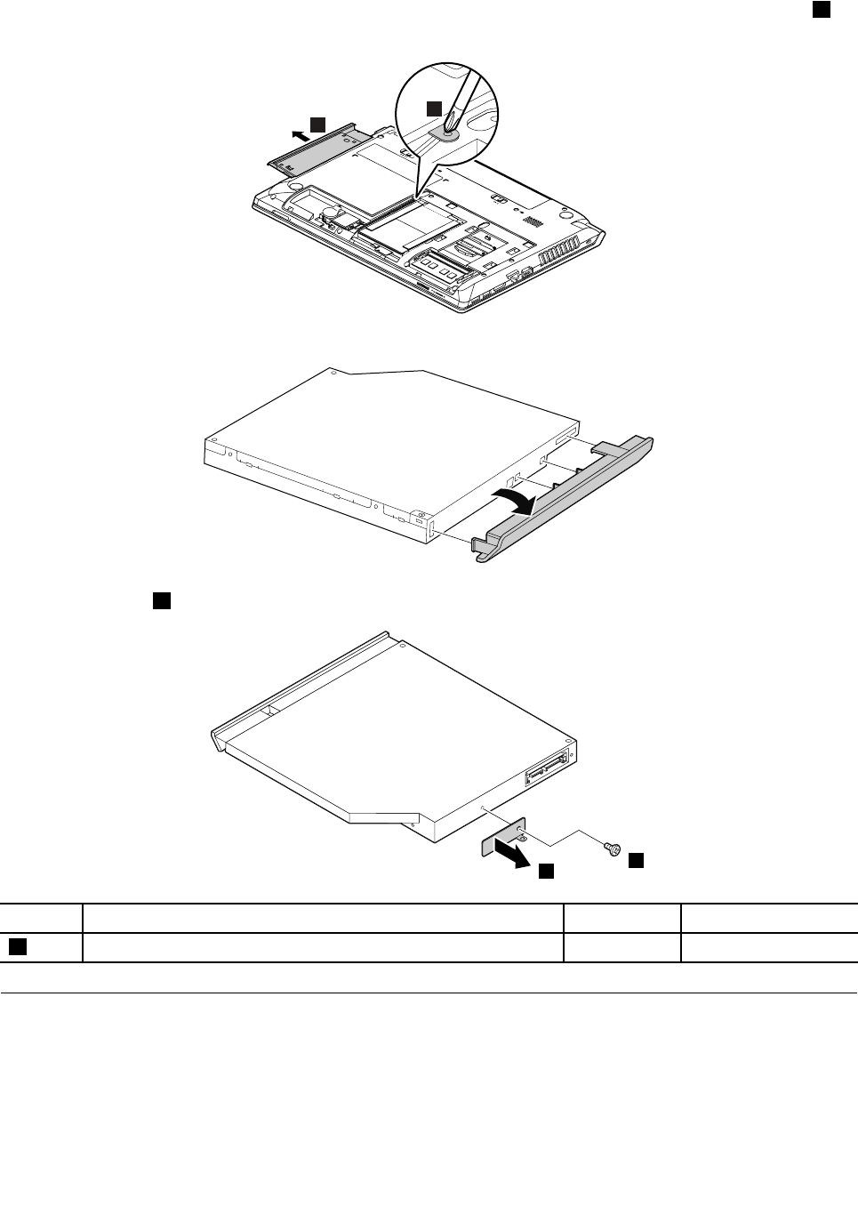
Insertascrewdriverintothescrewholeandpushtheopticaldriveinthedirectionshownbythearrow2.
Thenremovetheopticaldrive.
3
2
Removalstepsofopticaldrivebezelandopticaldrivebracket
Removethescrew1andthenremovetheopticaldrivebracket.
1
2
StepScrew(quantity)ColorTorque
1M2×3mm,at-head,nylon-coated(1)Black1.85kgf-cm
1040Memorymodule
Foraccess,removetheseFRUsinorder:
•“1010Batterypack”onpage50
•“1020Bottomslotcover”onpage50
52HardwareMaintenanceManual
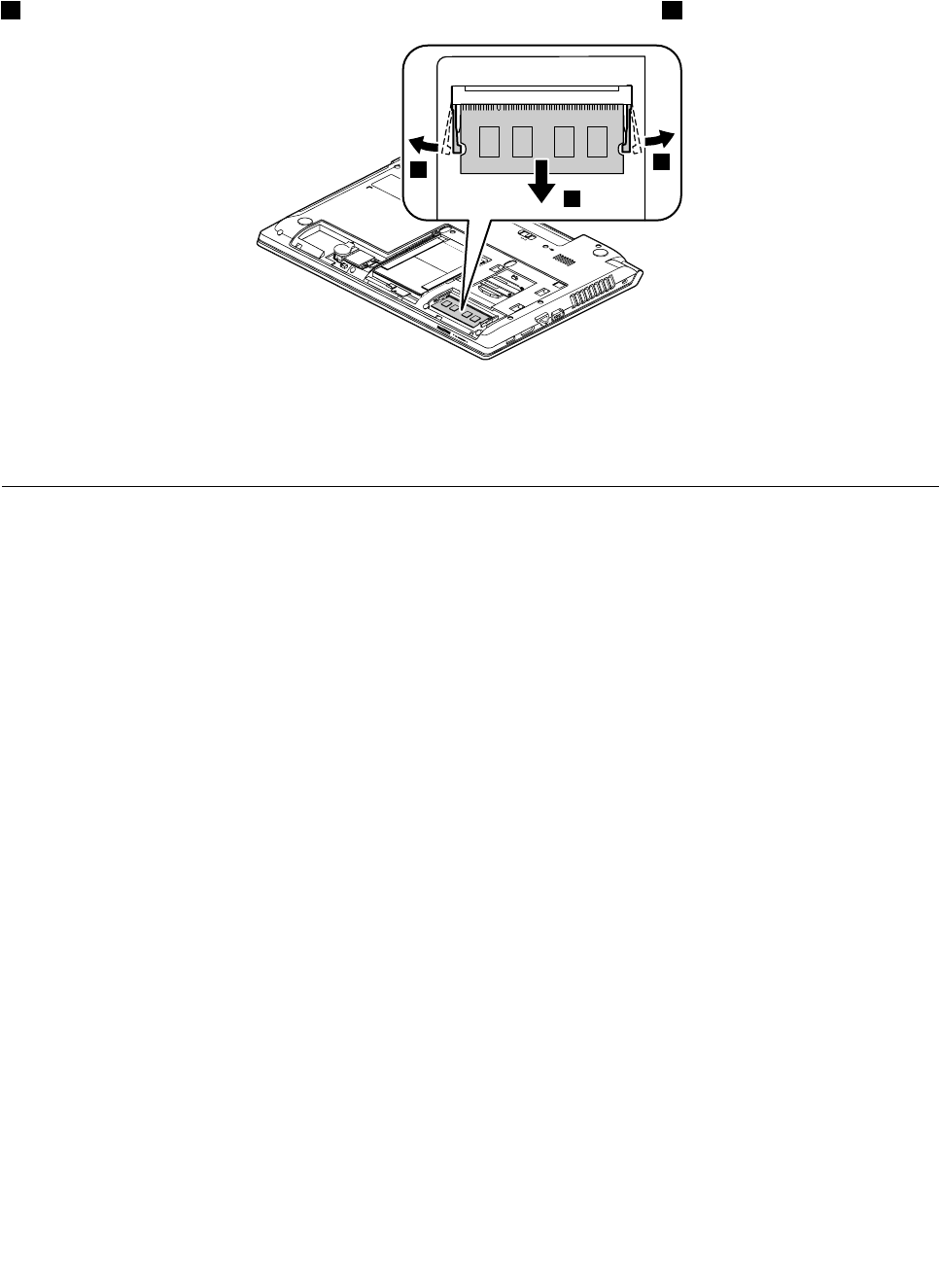
Removalstepsofmemorymodule
Releasethetwolatchesonbothedgesofthesocketatthesametimeinthedirectionshownbythearrows
1,andthenunplugthememorymoduleinthedirectionshownbythearrow2.
1
1
2
Wheninstalling:Insertthenotchedendofthememorymoduleintothememoryslotatanangleofabout20
degrees.Pressthememorymodulermly,andpivotitdownwarduntilitsnapsintoplace.Ensurethatthe
memorymoduleisrmlyinstalledintheslotanddoesnotmoveeasily.
1050Harddiskdriveassembly
Foraccess,removetheseFRUsinorder:
•“1010Batterypack”onpage50
•“1020Bottomslotcover”onpage50
Importantnoticeforreplacingaharddiskdrive
Alwaystrytorunalow-levelformatbeforereplacingaharddiskdrive.Thiswillcauseallcustomerdataonthe
harddiskdrivetobelost.Ensurethatthecustomerhasacurrentbackupofthedatabeforedoingthistask.
Attention:
•Donotdropthedriveorapplyanyphysicalshocktoit.Thedriveissensitivetophysicalshock.Improper
handlingcancausedamageandpermanentlossofdata.
•Beforeremovingthedrive,havetheusermakeabackupcopyofalltheinformationonitifpossible.
•Neverremovethedrivewhilethecomputerisoperatingorinsuspendmode.
•Thedrivestartupsequenceinthecomputeryouareservicingmighthavebeenchanged.Beextremely
carefulduringwriteoperationssuchascopying,saving,orformatting.Ifyouselectanincorrectdrive,
dataorprogramscanbeoverwritten.
Chapter8.RemovingandreplacingaFRU53
Removalstepsofharddiskdriveassembly
Removethescrew1,thenpullthetabinthedirectionshownbythearrow2.
1
2
StepScrew(quantity)ColorTorque
1M2×3mm,at-head,nylon-coated(1)Black1.85kgf-cm
Removetheharddiskdriveassembly.
3
Wheninstalling:Ensurethattheharddiskdriveconnectorisattachedrmly.
Removalstepsofharddiskdrivebracket
Removethescrews1.
1
1
1
1
StepScrew(quantity)ColorTorque
1M3×4mm,at-head,nylon-coated(4)Silver4kgf-cm
54HardwareMaintenanceManual
Removetheharddiskdrivebracket.
2
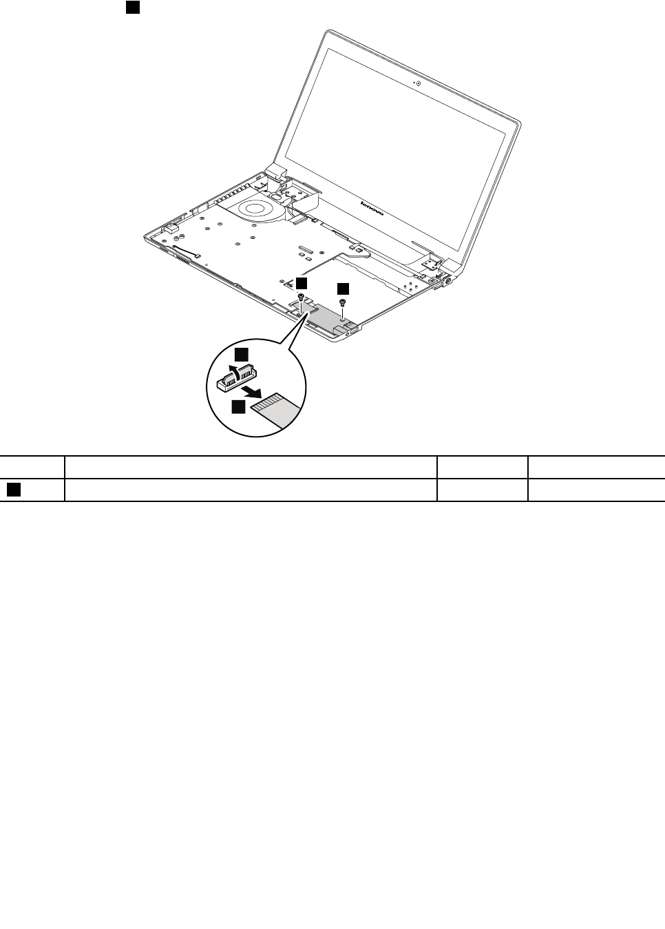
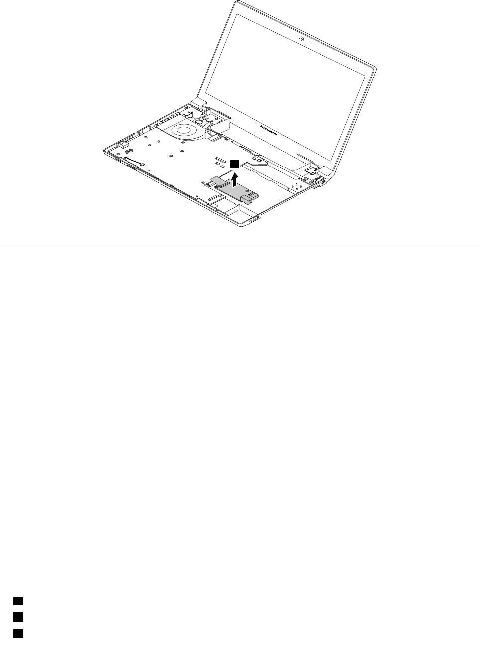
1060PCIExpressMiniCardforwirelessLAN
Foraccess,removetheseFRUsinorder:
•“1010Batterypack”onpage50
•“1020Bottomslotcover”onpage50
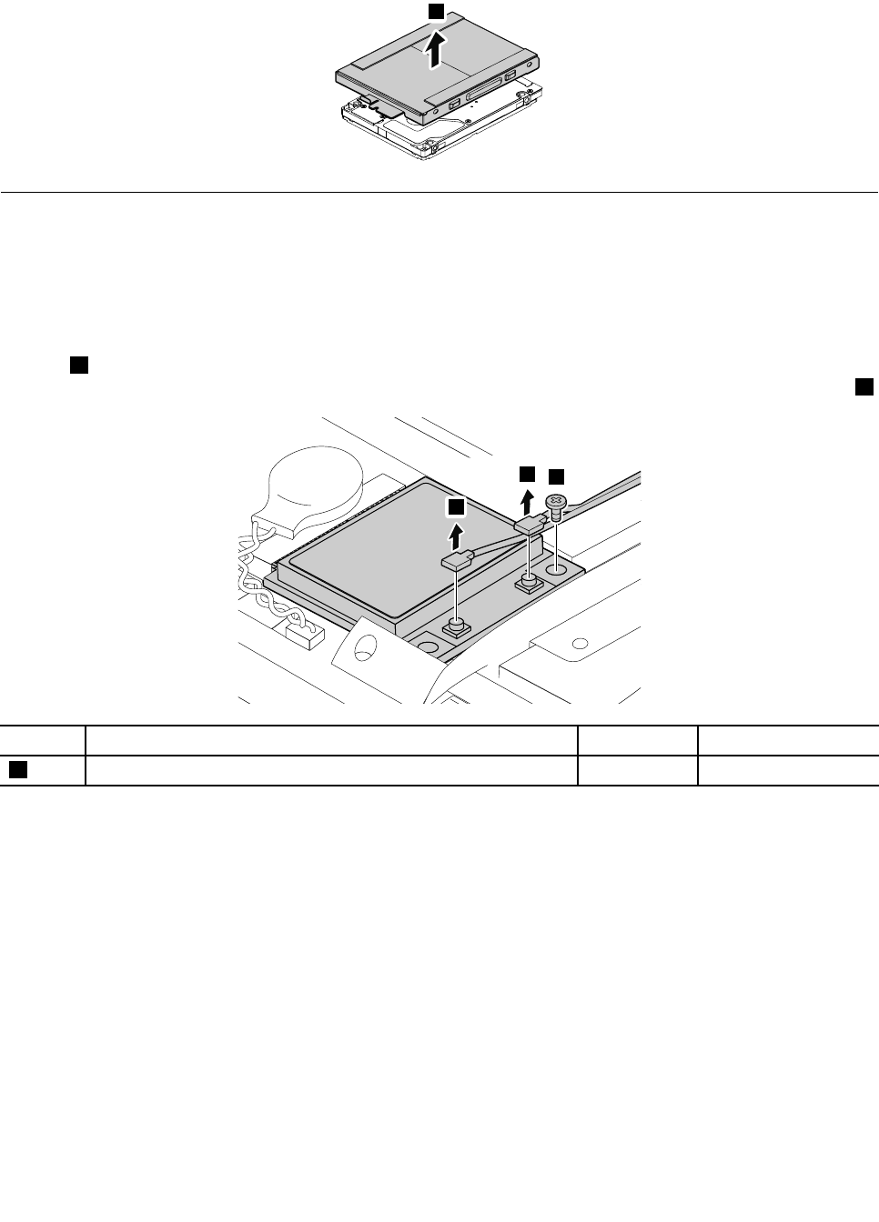
RemovalstepsofPCIExpressMiniCardforwirelessLAN
Insteps1,disconnectthecablesfromthecardusingtheremovaltoolfortheantennaconnectors(P/N:
08K7159)orpickupthecableswithyourngersandthengentlydisconnectthem.Thenremovethescrew2.
2
1
1
StepScrew(quantity)ColorTorque
2M2×3mm,at-head,nylon-coated(1)Black1.85kgf-cm
Chapter8.RemovingandreplacingaFRU55
RemovethePCIExpressMiniCardforwirelessLAN.
3
Wheninstalling:Plugtheblackcableintothemainconnector,andthewhitecableintotheauxiliary
connector.
1080Backupbattery
Foraccess,removetheseFRUsinorder:
•“1010Batterypack”onpage50
•“1020Bottomslotcover”onpage50
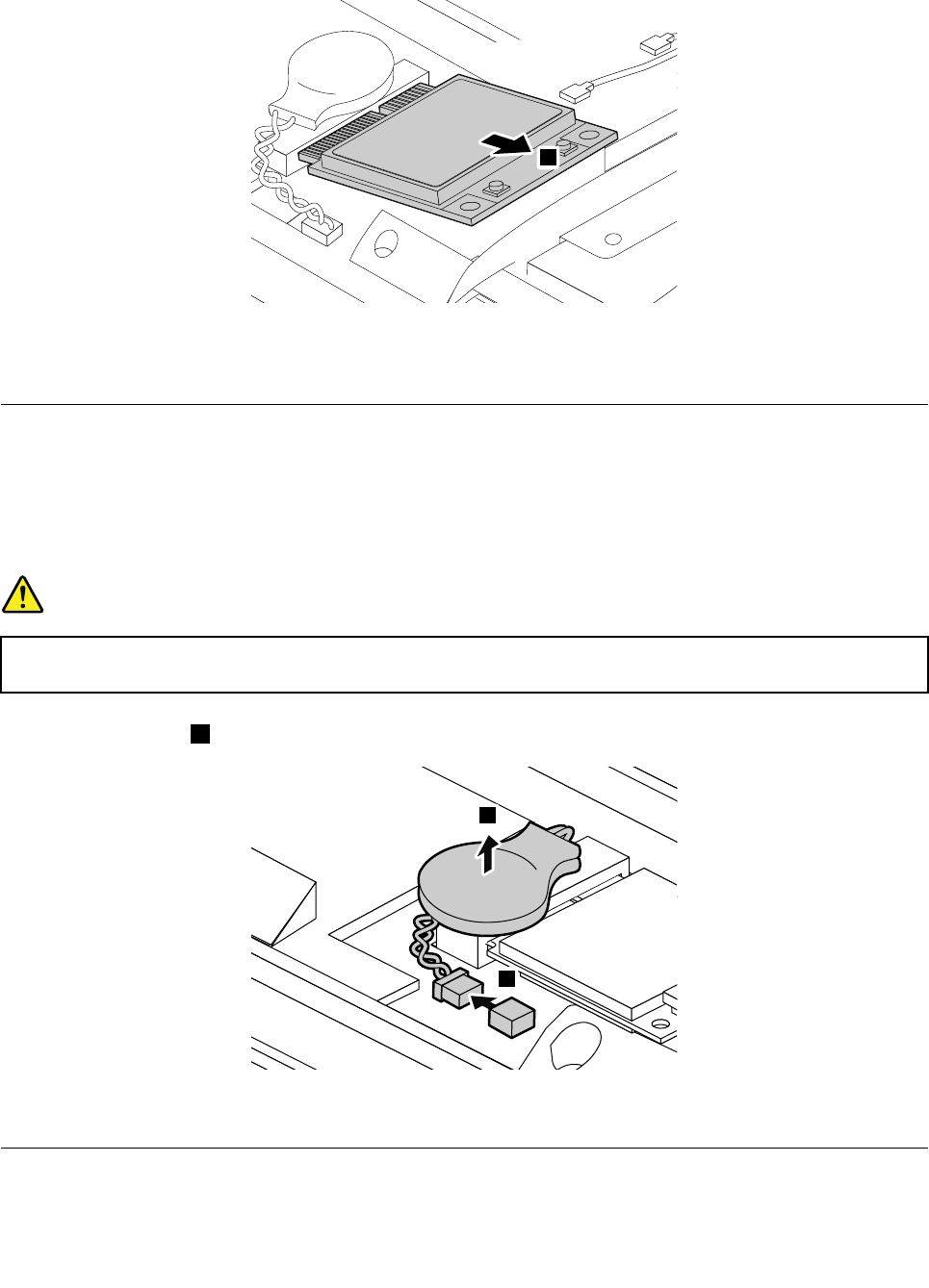
Removalstepsofbackupbattery
DANGER
Useonlythebatteryspeciedinthepartslistforyourcomputer.Anyotherbatterycouldignite
orexplode.
Detachtheconnector1,andthenremovethebatterypackinthedirectionshownbythearrow.
1
2
Wheninstalling:Ensurethattheconnectorisattachedrmly.
1090Keyboard
Foraccess,removetheseFRUsinorder:
56HardwareMaintenanceManual
•“1010Batterypack”onpage50
•“1020Bottomslotcover”onpage50
Removalstepsofkeyboard
Removethescrews1.
1
1
1
Wheninstalling:Ensurethatthescrewshavebeenrmlyinstalledtosecurethekeyboard.
StepScrew(quantity)ColorTorque
1M2.5×8mm,at-head,nylon-coated(3)Black4.0kgf-cm
Pushhardtounlatchthefrontsideofthekeyboard.
2
Wheninstalling:Ensurethatthekeyboardconnectorisrmlyattached.
Chapter8.RemovingandreplacingaFRU57
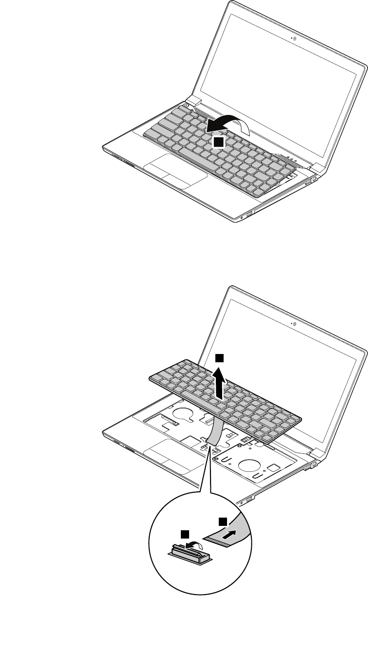
Carefullydetachthekeyboardandthenliftitupuntilyoucanseehowitisconnected.
3
Detachthekeyboardconnector,andthenremovethekeyboard.
5
6
4
Wheninstalling:Ensurethattheconnectorisrmlyattached.
58HardwareMaintenanceManual
1100Keyboardbezel
Foraccess,removetheseFRUsinorder:
•“1010Batterypack”onpage50
•“1020Bottomslotcover”onpage50
•“1030Opticaldrive”onpage51
•“1090Keyboard”onpage56
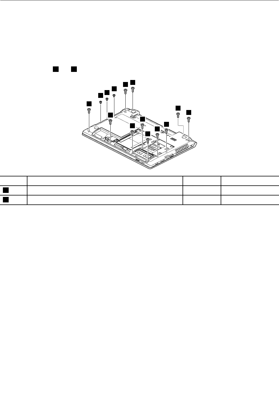
Removalstepsofkeyboardbezel
Removethescrews1and2thatsecurethekeyboardbezel.
2
2
2
1
11
1
1
1
1
1
1
1
1
StepScrew(quantity)ColorTorque
1M2.5×8mm,at-head,nylon-coated(11)Black4.0kgf-cm
2M2×3mm,at-head,nylon-coated(3)Black1.85kgf-cm
Chapter8.RemovingandreplacingaFRU59
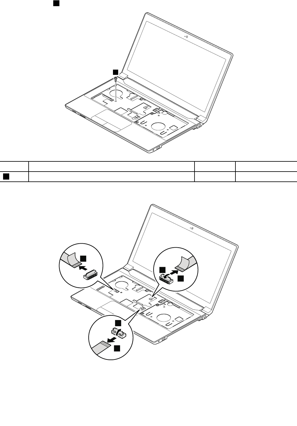
Removethescrew3.
3
StepScrew(quantity)ColorTorque
3M2×6mm,at-head,nylon-coated(1)Black1.85kgf-cm
Detachtheconnectors.
7
6
9
4
5
Wheninstalling:Ensurethatalltheconnectorsarermlyattached.
60HardwareMaintenanceManual
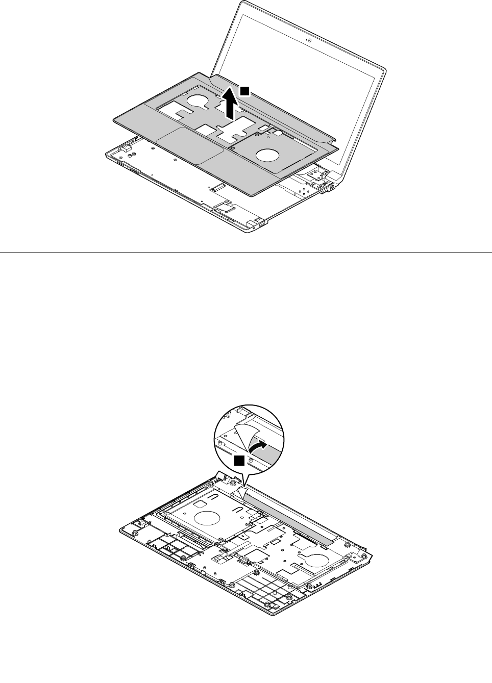
RemovetheLEDboard.
2
1120Powerboard
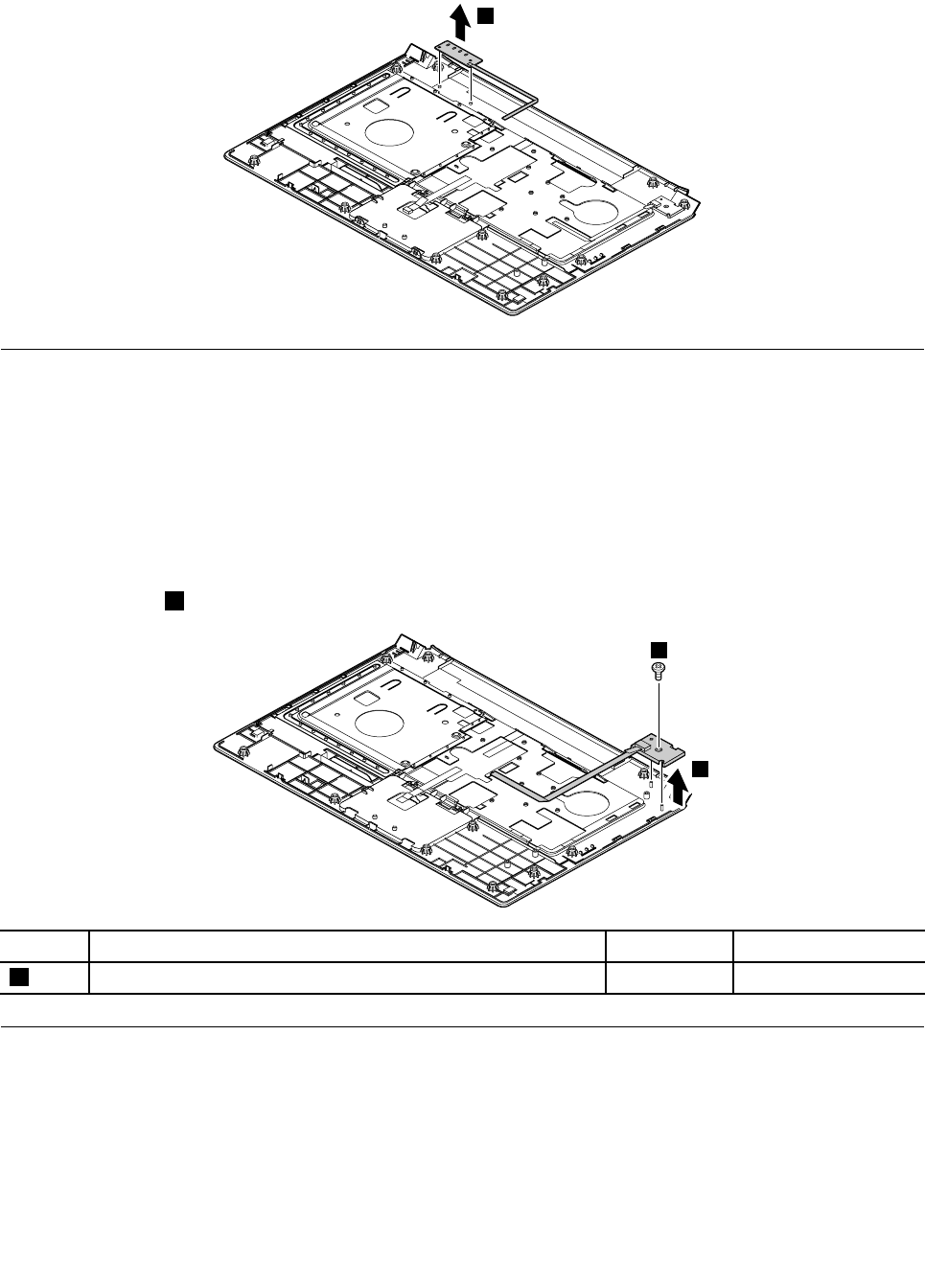
Foraccess,removetheseFRUsinorder:
•“1010Batterypack”onpage50
•“1020Bottomslotcover”onpage50
•“1030Opticaldrive”onpage51
•“1090Keyboard”onpage56
•“1100Keyboardbezel”onpage59
Removalstepsofpowerboard
Removethescrew1andthenremovethepowerboard.
2
1
StepScrew(quantity)ColorTorque
1M2×3mm,at-head,nylon-coated(1)Black1.85kgf-cm
1140Input/output(I/O)board
Foraccess,removetheseFRUsinorder:
•“1010Batterypack”onpage50
•“1020Bottomslotcover”onpage50
•“1030Opticaldrive”onpage51
•“1090Keyboard”onpage56
•“1100Keyboardbezel”onpage59
62HardwareMaintenanceManual
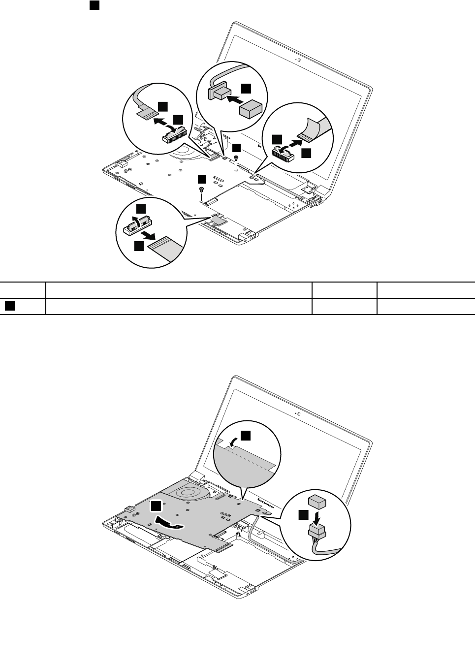
Removalstepsoftheinput/output(I/O)board
Removethescrews1,andthendisconnectthecable.
1
1
3
2
StepScrew(quantity)ColorTorque
1M2×6mm,at-head,nylon-coated(2)Black1.85kgf-cm
Wheninstalling:Ensurethatthecableisrmlyattached.
Chapter8.RemovingandreplacingaFRU63
Removetheinput/output(I/O)board.
4
1150SystemboardassemblyandUSBboard
Foraccess,removetheseFRUsinorder:
•“1010Batterypack”onpage50
•“1020Bottomslotcover”onpage50
•“1030Opticaldrive”onpage51
•“1040Memorymodule”onpage52
•“1050Harddiskdriveassembly”onpage53
•“1060PCIExpressMiniCardforwirelessLAN”onpage55
•“1080Backupbattery”onpage56
•“1090Keyboard”onpage56
•“1100Keyboardbezel”onpage59
Importantnoticeforreplacingthesystemboard
Whenreplacingthesystemboard,observethefollowingguidelines:
•Donotdropasystemboardonabenchtopthathasahardsurface,suchasmetal,wood,orcomposite.
•Donotapplyanyexcessiveforcetoasystemboard.
•Avoidroughhandlingofanykind.
•AvoidbendingasystemboardorhardpushingtopreventcrackingateachBallGridArray(BGA)chipset.
•Whenyouputasystemboarddown,besuretoputitonlyonapaddedsurfacesuchasanESDmat
oracorrugatedconductivesurface.
Locatingmajorsensitivecomponentsonthesystemboard
Attention:Thefollowingcomponentsmountedonasystemboardareextremelysensitive.Improper
handlingofasystemboardcancausedamagetothefollowingcomponents,andmightcauseasystem
malfunction.Whenyouservicethesystemboard,avoidanykindofroughhandling.
aGraphicschip(fordiscretegraphicsmodels)
bMicroprocessor
cPlatformControllerHub(PCH)
64HardwareMaintenanceManual
Formodelswithanintegratedthermalmoduleassembly
a
b
Formodelswithadiscretethermalmoduleassembly
a
b
c
Chapter8.RemovingandreplacingaFRU65
RemovalstepsofsystemboardassemblyandUSBboard
Removethescrews1,andthendetachtheconnectors.
1
1
3
4
2
7
8
6
5
StepScrew(quantity)ColorTorque
1M2×6mm,at-head,nylon-coated(2)Black1.85kgf-cm
Wheninstalling:Ensurethatalltheconnectorsarermlyattached.
Removethesystemboard.ThendisconnecttheDC-incable.
11
9
10
66HardwareMaintenanceManual
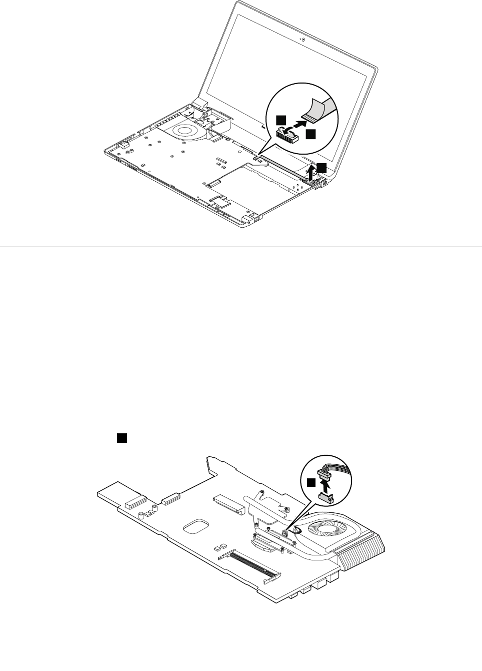
Disconnecttheconnector,andthenremovetheUSBboard.
1
3
2
1160Thermalmodule
Foraccess,removetheseFRUsinorder:
•“1010Batterypack”onpage50
•“1020Bottomslotcover”onpage50
•“1030Opticaldrive”onpage51
•“1040Memorymodule”onpage52
•“1050Harddiskdriveassembly”onpage53
•“1060PCIExpressMiniCardforwirelessLAN”onpage55
•“1080Backupbattery”onpage56
•“1090Keyboard”onpage56
•“1100Keyboardbezel”onpage59
•“1150SystemboardassemblyandUSBboard”onpage64
Removalstepsofthermalmodule
Detachthefanconnector1.
1
Wheninstalling:Ensurethattheconnectorisrmlyattached.
Chapter8.RemovingandreplacingaFRU67
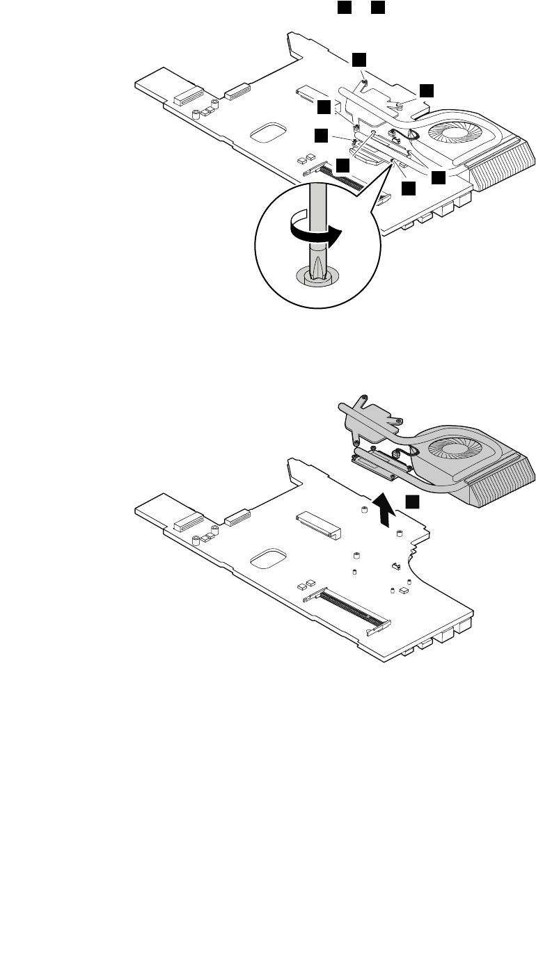
Loosenthescrewsfollowingthenumericalorderfrom2to6.
3
4
5
2
6
6
6
Carefullyremovethefanassembly.
Note:Becarefulnottodamagetheconnector.
7
68HardwareMaintenanceManual
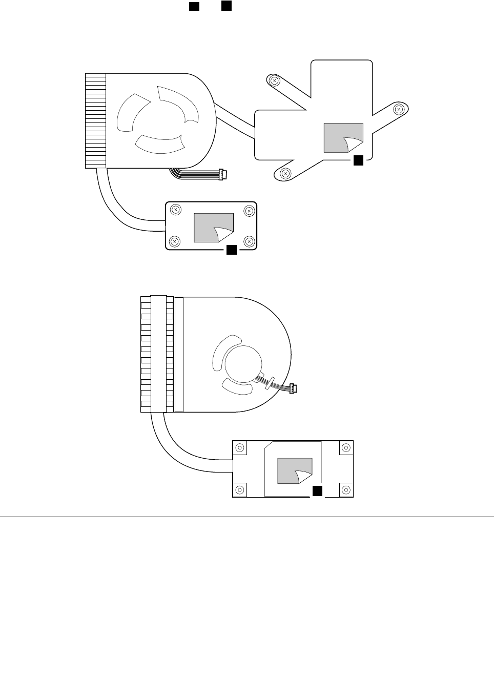
Wheninstalling:Beforeyouattachthethermalmoduletothesystemboard,applythermalgrease,atan
amountof0.2grams,onthepartmarkedaandbasshowninthefollowingillustrations.Eithertoomuchor
toolessapplicationofgreasecancauseathermalproblemduetoimperfectcontactwithacomponent.
Formodelswithanintegratedthermalmodule
a
b
Formodelswithadiscretethermalmodule
a
1170Microprocessor
Foraccess,removetheseFRUsinorder:
•“1010Batterypack”onpage50
•“1020Bottomslotcover”onpage50
•“1030Opticaldrive”onpage51
•“1040Memorymodule”onpage52
•“1050Harddiskdriveassembly”onpage53
•“1060PCIExpressMiniCardforwirelessLAN”onpage55
•“1080Backupbattery”onpage56
•“1090Keyboard”onpage56
•“1100Keyboardbezel”onpage59
Chapter8.RemovingandreplacingaFRU69
•“1150SystemboardassemblyandUSBboard”onpage64
•“1160Thermalmodule”onpage67
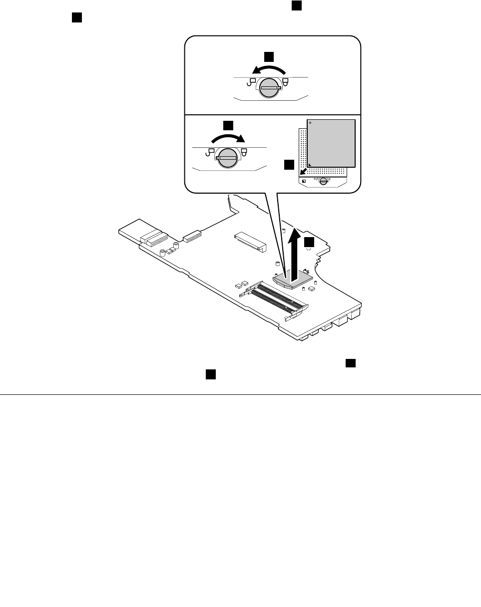
Attention:Themicroprocessorisextremelysensitive.Whenyouservicethemicroprocessor,avoidany
kindofroughhandling.
Removalstepsofmicroprocessor
Rotatetheheadofthescrewinthedirectionshownbythearrow1toreleasethelock,thenremovethe
microprocessor2.
22
a
b
1
Wheninstalling:Placethemicroprocessorabovethemicroprocessorsocketa,andthenrotatetheheadof
thescrewinthedirectionshownbythearrowbtosecurethemicroprocessor.
1180LCDunit
Foraccess,removetheseFRUsinorder:
•“1010Batterypack”onpage50
•“1020Bottomslotcover”onpage50
•“1030Opticaldrive”onpage51
•“1040Memorymodule”onpage52
•“1050Harddiskdriveassembly”onpage53
•“1060PCIExpressMiniCardforwirelessLAN”onpage55
•“1080Backupbattery”onpage56
•“1090Keyboard”onpage56
•“1100Keyboardbezel”onpage59
•“1140Input/output(I/O)board”onpage62
•“1150SystemboardassemblyandUSBboard”onpage64
70HardwareMaintenanceManual

RemovalstepsofLCDunit
Releasetheantennacablesfromthecableguides.Thenremovethescrews1.
1
11
1
StepScrew(quantity)ColorTorque
1M2.5×6mm,at-head,nylon-coated(4)Silver4.0kgf-cm
Wheninstalling:
•Routetheantennacablesalongthecableguides.Asyouroutethecables,makesurethattheyare
notsubjectedtoanytension.Tensioncouldcausethecablestobedamagedbythecableguides,
orawiretobebroken.
•EnsurethattheLCDconnectorisattachedrmlyandmakesurethatyoudonotpinchtheantennacables
whenyouattachtheLCDassembly.RoutetheLCDcablealongthecableguides.
Chapter8.RemovingandreplacingaFRU71
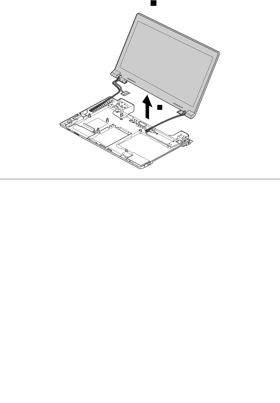
RemovetheLCDunitinthedirectionshownbythearrow2.
2
1190Speakerassembly
Foraccess,removetheseFRUsinorder:
•“1010Batterypack”onpage50
•“1020Bottomslotcover”onpage50
•“1030Opticaldrive”onpage51
•“1040Memorymodule”onpage52
•“1050Harddiskdriveassembly”onpage53
•“1060PCIExpressMiniCardforwirelessLAN”onpage55
•“1080Backupbattery”onpage56
•“1090Keyboard”onpage56
•“1100Keyboardbezel”onpage59
•“1140Input/output(I/O)board”onpage62
•“1150SystemboardassemblyandUSBboard”onpage64
•“1180LCDunit”onpage70
72HardwareMaintenanceManual
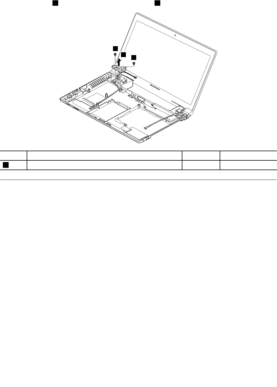
Removalstepsofspeakerassembly
Removethescrews1.Thenremovethespeakerassembly2.
2
1
1
StepScrew(quantity)ColorTorque
1M2.5×5.7mm,at-head,nylon-coated(2)Black4.0kgf-cm
1200DC-inconnectorandbasecover
Foraccess,removetheseFRUsinorder:
•“1010Batterypack”onpage50
•“1020Bottomslotcover”onpage50
•“1030Opticaldrive”onpage51
•“1040Memorymodule”onpage52
•“1050Harddiskdriveassembly”onpage53
•“1060PCIExpressMiniCardforwirelessLAN”onpage55
•“1080Backupbattery”onpage56
•“1090Keyboard”onpage56
•“1100Keyboardbezel”onpage59
•“1140Input/output(I/O)board”onpage62
•“1150SystemboardassemblyandUSBboard”onpage64
•“1180LCDunit”onpage70
•“1190Speakerassembly”onpage72
Chapter8.RemovingandreplacingaFRU73
RemovalstepsofDC-inconnectorandbasecover
Removethescrews1,andthenremovetheDC-inconnectorinthedirectionshownbythearrow2.
2
1
1
StepScrew(quantity)ColorTorque
1M2×3mm,at-head,nylon-coated(2)Black1.85kgf-cm
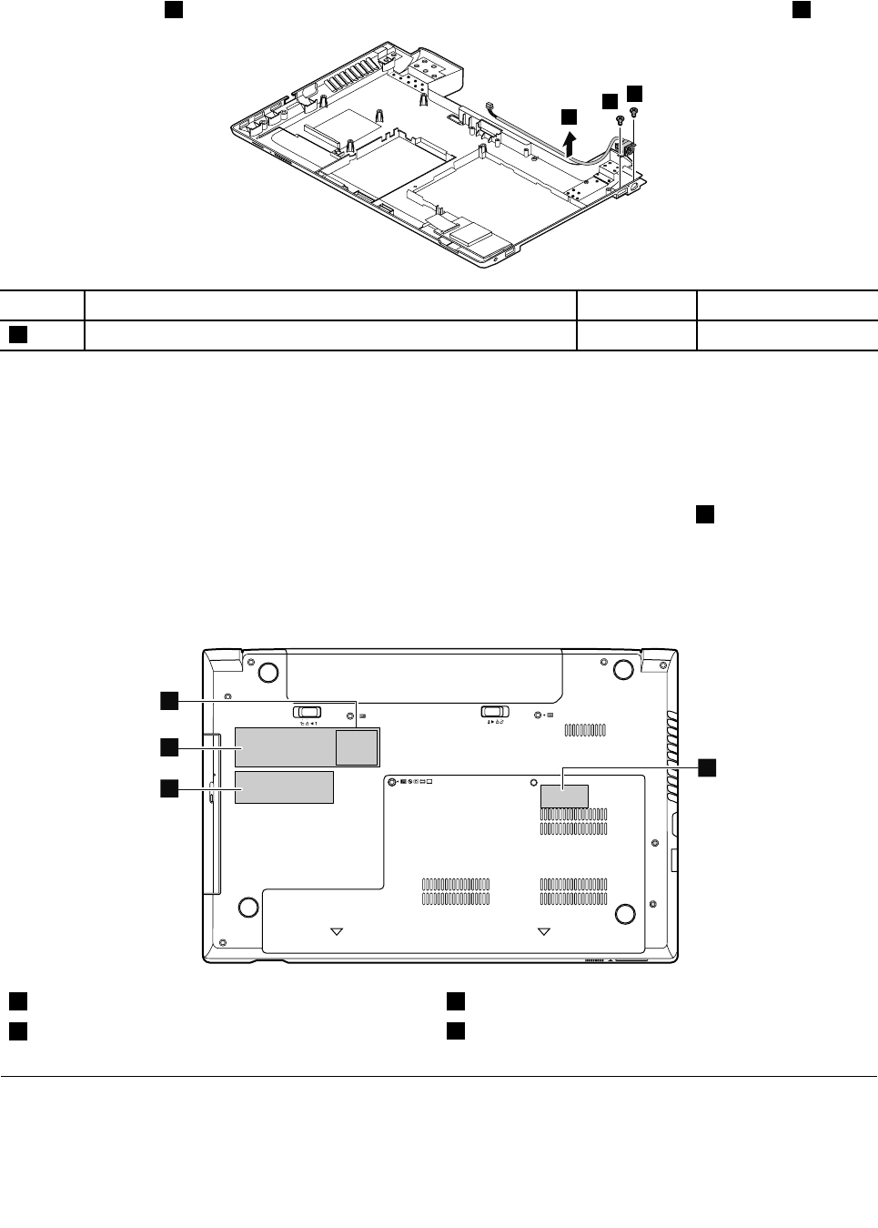
Applyinglabelstothebasecover
Thenewbasecoverisshippedwithakitcontaininglabelsofseveralkinds.Applythoselabelslistedwhen
youreplacethebasecover.Forthelabelswhicharenotshippedwiththenewbasecover,peelthemoff
fromtheoldbasecover,andadherethemtothenewone.
Note:IfyoureplaceapartwiththeWindowsCerticateofAuthentication(COA)label2,returntheoldpart
withthelabelattachedtothecustomer.Otherwise,youcanprovidethecustomerwithaletter,statingthe
originallocationofthelabelonthecomputerandtheinformationonthelabel,suchasthepartnumber,
serialnumber,andproductkey.
Thefollowingillustrationshowsthecorrectlocationofeachlabel.
2
1
3
4
1WirelessWANIMEIbarcodelabel3Ratinglabel
2WindowsCerticateofAuthentication(COA)label4Ratinglabel
2010LCDfrontbezel
Foraccess,removetheseFRUsinorder:
•“1010Batterypack”onpage50
74HardwareMaintenanceManual
•“1180LCDunit”onpage70
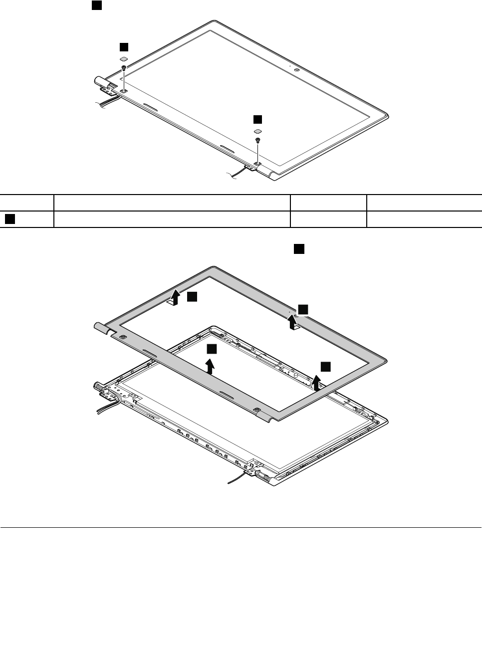
RemovalstepsofLCDfrontbezel
Removethescrews1.
1
1
StepScrew(quantity)ColorTorque
1M2×3.5mm,at-head,nylon-coated(2)Black1.85kgf-cm
RemovetheLCDfrontbezelinthedirectionshownbythearrows2.
2
2
2
2
Wheninstalling:Ensurethatallthelatchesareattachedrmly.Thensecurethebezelwiththescrews.
2020Camera
Foraccess,removetheseFRUsinorder:
•“1010Batterypack”onpage50
•“1180LCDunit”onpage70
•“2010LCDfrontbezel”onpage74
Chapter8.RemovingandreplacingaFRU75
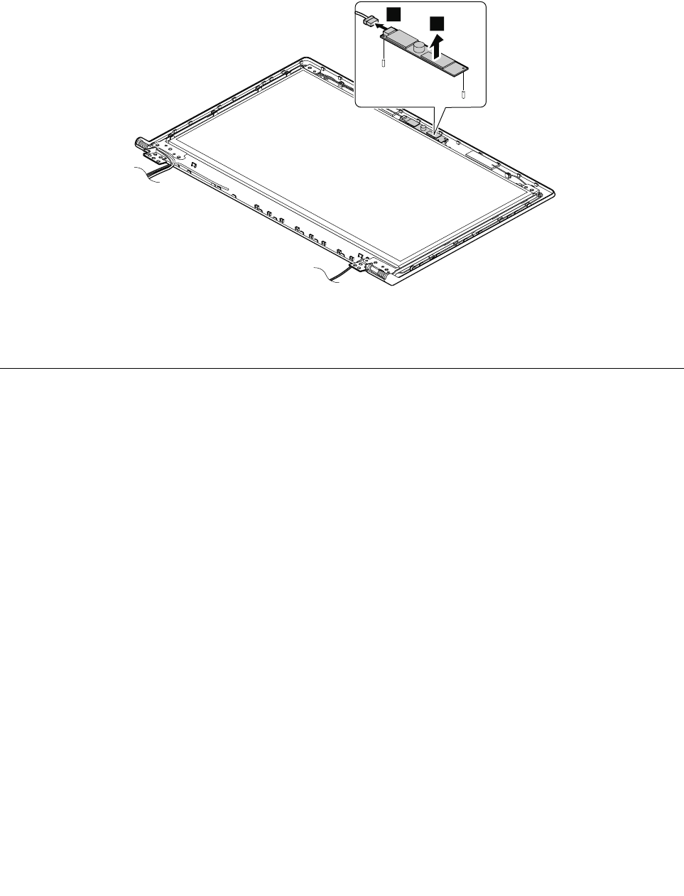
Removalstepsofcamera
RemovethecamerafromtheLCDcoverasshowninthefollowingillustration.
Note:ThecameraisstuckonthetopcenteroftheLCDcover.
1
2
Wheninstalling:StickthecameratothetopcenteroftheLCDcoverandadjusttheplacementtomakesure
thattheconnectorisattachedrmly.
2030LCDpanel,LCDcable,andhinges
Foraccess,removetheseFRUsinorder:
•“1010Batterypack”onpage50
•“1180LCDunit”onpage70
•“2010LCDfrontbezel”onpage74
76HardwareMaintenanceManual

RemovalstepsofLCDpanelandLCDcable
Removethescrews1.ThenremovetheLCDpanelwithhingesinthedirectionshownbythearrow.
1
1
1
1
2
1
1
StepScrew(quantity)ColorTorque
1M2×4mm,at-head,nylon-coated(6)White1.85kgf-cm
Removethescrews3.Thenremovethehinges.
4
3
3
3
3
4
StepScrew(quantity)ColorTorque
3M2×2.5mm,at-head,nylon-coated(4)White1.85kgf-cm
Chapter8.RemovingandreplacingaFRU77

RemovetheLCDcable.
1
2
Wheninstalling:Ensurethatthecableisattachedrmly.
2040AntennaassemblyandLCDrearcover
Foraccess,removetheseFRUsinorder:
•“1010Batterypack”onpage50
•“1180LCDunit”onpage70
•“2010LCDfrontbezel”onpage74
•“2020Camera”onpage75
•“2030LCDpanel,LCDcable,andhinges”onpage76
RemovalstepsofantennaassemblyandLCDrearcover
ReleasetheantennacablesfromthecableguidesoftheLCDrearcoverassemblyandfromthehingesin
thedirectionshownbythearrows1.
1
1
Cablerouting:Routetheantennacablesalongthecableguidesandsecuretheantennaboardswith
adhesivetapes.Asyouroutethecables,makesurethattheyarenotsubjectedtoanytension.Tension
couldcausethecablestobedamagedbythecableguides,orawiretobebroken.
78HardwareMaintenanceManual

AppendixA.Notices
Lenovomaynotoffertheproducts,services,orfeaturesdiscussedinthisdocumentinallcountries.Consult
yourlocalLenovorepresentativeforinformationontheproductsandservicescurrentlyavailableinyour
area.AnyreferencetoaLenovoproduct,program,orserviceisnotintendedtostateorimplythatonlythat
Lenovoproduct,program,orservicemaybeused.Anyfunctionallyequivalentproduct,program,orservice
thatdoesnotinfringeanyLenovointellectualpropertyrightmaybeusedinstead.However,itistheuser's
responsibilitytoevaluateandverifytheoperationofanyotherproduct,program,orservice.
Lenovomayhavepatentsorpendingpatentapplicationscoveringsubjectmatterdescribedinthis
document.Thefurnishingofthisdocumentdoesnotgiveyouanylicensetothesepatents.Y oucansend
licenseinquiries,inwriting,to:
Lenovo(UnitedStates),Inc.
1009ThinkPlace-BuildingOne
Morrisville,NC27560
U.S.A.
Attention:LenovoDirectorofLicensing
LENOVOPROVIDESTHISPUBLICATION“ASIS”WITHOUTWARRANTYOFANYKIND,EITHEREXPRESS
ORIMPLIED,INCLUDING,BUTNOTLIMITEDTO,THEIMPLIEDWARRANTIESOFNON-INFRINGEMENT,
MERCHANTABILITYORFITNESSFORAPARTICULARPURPOSE.Somejurisdictionsdonotallow
disclaimerofexpressorimpliedwarrantiesincertaintransactions,therefore,thisstatementmaynotapply
toyou.
Thisinformationcouldincludetechnicalinaccuraciesortypographicalerrors.Changesareperiodically
madetotheinformationherein;thesechangeswillbeincorporatedinneweditionsofthepublication.
Lenovomaymakeimprovementsand/orchangesintheproduct(s)and/ortheprogram(s)describedinthis
publicationatanytimewithoutnotice.
Theproductsdescribedinthisdocumentarenotintendedforuseinimplantationorotherlifesupport
applicationswheremalfunctionmayresultininjuryordeathtopersons.Theinformationcontainedinthis
documentdoesnotaffectorchangeLenovoproductspecicationsorwarranties.Nothinginthisdocument
shalloperateasanexpressorimpliedlicenseorindemnityundertheintellectualpropertyrightsofLenovo
orthirdparties.Allinformationcontainedinthisdocumentwasobtainedinspecicenvironmentsandis
presentedasanillustration.Theresultobtainedinotheroperatingenvironmentsmayvary.
Lenovomayuseordistributeanyoftheinformationyousupplyinanywayitbelievesappropriatewithout
incurringanyobligationtoyou.
Anyreferencesinthispublicationtonon-LenovoWebsitesareprovidedforconvenienceonlyanddonotin
anymannerserveasanendorsementofthoseWebsites.ThematerialsatthoseWebsitesarenotpartof
thematerialsforthisLenovoproduct,anduseofthoseWebsitesisatyourownrisk.
Anyperformancedatacontainedhereinwasdeterminedinacontrolledenvironment.Therefore,theresult
obtainedinotheroperatingenvironmentsmayvarysignicantly.Somemeasurementsmayhavebeen
madeondevelopment-levelsystemsandthereisnoguaranteethatthesemeasurementswillbethesame
ongenerallyavailablesystems.Furthermore,somemeasurementsmayhavebeenestimatedthrough
extrapolation.Actualresultsmayvary.Usersofthisdocumentshouldverifytheapplicabledatafortheir
specicenvironment.
©CopyrightLenovo201379

Trademarks
ThefollowingtermsaretrademarksofLenovointheUnitedStates,othercountriesorboth:
Lenovo
OneKey
TheLenovologo
MicrosoftandWindowsaretrademarksoftheMicrosoftgroupofcompanies.
Othercompany,product,orservicenamesmaybethetrademarksorservicemarksofothers.
80HardwareMaintenanceManual

PartNumber:
PrintedinChina
(1P)P/N:
*1P*
