Lenovo Ic Y700 900 Hmm 20151006 User Manual Hardware Maintenance 34ISH Desktop (ideacentre) Type 90DF
2015-10-06
User Manual: Lenovo Ic Y700-900 Hmm 20151006 Hardware Maintenance Manual Y700-34ISH Desktop (ideacentre) - Type 90DF 90DF
Open the PDF directly: View PDF ![]() .
.
Page Count: 57
- Chapter 1. About this manual
- Chapter 2. Safety information
- Chapter 3. General information
- Chapter 4. General Checkout
- Chapter 5. Using the Setup Utility
- Chapter 6. Symptom-to-FRU Index
- Chapter 7. Locations
- Chapter 8. Replacing hardware
- General information
- Cleaning rear dust screen
- Replacing the keyboard and mouse
- Removing the computer cover
- Removing the computer cover ii
- Removing the front bezel
- Cleaning front dust screen
- Replacing a memory module
- Replacing a hard disk drive
- Replacing an optical drive
- Replacing the microprocessor fan assembly
- Replacing the rear system fan
- Replacing a front fan
- Replacing the Power supply
- Replacing the Wi-Fi card
- Removing the top cover
- Replacing a graphics card
- Replacing the CPU
- Replacing the motherboard
- FRU lists
- Chapter 9. General information

ideacentreY700–900HardwareMaintenance
Manual
MachineTypes:90DD[Y900-34ISZEnergyStar]/90DF[Y700-34ISH
EnergyStar]/90DG[Y700-34ISHNon-EnergyStar]

ideacentreY700–900
HardwareMaintenanceManual
MachineTypes:90DD[Y900-34ISZEnergyStar]/90DF[Y700-34ISH
EnergyStar]/90DG[Y700-34ISHNon-EnergyStar]

FirstEdition(Sept.2015)15th
©CopyrightLenovo2015.
LIMITEDANDRESTRICTEDRIGHTSNOTICE:IfdataorsoftwarearedeliveredpursuantaGeneralServices
Administration“GSA”contract,use,reproduction,ordisclosureissubjecttorestrictionssetforthinContractNo.
GS-35F-05925

Contents
Chapter1.Aboutthismanual.....1
ImportantSafetyInformation.........1
Chapter2.Safetyinformation.....3
Generalsafety...............3
Electricalsafety..............3
Safetyinspectionguide...........5
Handlingelectrostaticdischarge-sensitive
devices.................5
Groundingrequirements...........6
Safetynotices...............6
Chapter3.Generalinformation....9
Specifications...............9
Chapter4.GeneralCheckout.....11
Chapter5.UsingtheSetupUtility...13
StartingtheLenovoBIOSSetupUtilityprogram.13
Viewingandchangingsettings........13
Usingpasswords..............13
Enablingordisablingadevice........15
Selectingastartupdevice..........16
ExitingtheLenovoBIOSSetupUtilityprogram..17
Chapter6.Symptom-to-FRUIndex..19
Harddiskdrivebooterror..........19
PowerSupplyProblems...........19
AdditionalServiceInformation........19
POSTerrorcodes.............20
Undeterminedproblems...........20
Chapter7.Locations.........23
Identifyinginternalcomponents........23
Identifyingpartsonthesystemboard......23
Chapter8.Replacinghardware....25
Generalinformation.............25
Cleaningreardustscreen..........26
Replacingthekeyboardandmouse......26
Removingthecomputercover........27
Removingthecomputercoverii........28
Removingthefrontbezel..........28
Cleaningfrontdustscreen..........29
Replacingamemorymodule.........30
Replacingaharddiskdrive..........31
Replacinganopticaldrive..........32
Replacingthemicroprocessorfanassembly...32
Replacingtherearsystemfan.........33
Replacingafrontfan............34
ReplacingthePowersupply.........36
ReplacingtheWi-Ficard...........36
Removingthetopcover...........37
Replacingagraphicscard..........39
ReplacingtheCPU.............41
Replacingthemotherboard..........43
FRUlists.................45
Chapter9.Generalinformation....51
AdditionalServiceInformation........51
©CopyrightLenovo2015iii

ivideacentreY700–900HardwareMaintenanceManual

Chapter1.Aboutthismanual
ThismanualcontainsserviceandreferenceinformationforideacntreY700–900desktopcomputerslistedon
thecover.ItisintendedonlyfortrainedservicerswhoarefamiliarwithLenovocomputerproducts.
BeforeservicingaLenovoproduct,besuretoreadtheSafetyInformation.
ThedescriptionoftheTVcardinthismanualisonlyusedforthemachineswhichhavetheTVcard.Itis
invalidforthosemachineswhichdonothaveTVcard.
ImportantSafetyInformation
Important:SystemrequirementwarningtermsforY900
YourthermalequipmentMUSTbeconsistentwithyourownclockfrequencyand/orvoltagesettings.
Important:Lenovo’swarrantywarningtermsforY900
Alteringthedefaultsettingofanyiteminthissub-menumay:(i)reducesystemstabilityandusefullifeofthe
system,processor,andothersystemcomponents;(ii)causetheprocessorandothersystemcomponents
tofail;(iii)causereductionsinsystemperformance;(iv)causeadditionalheatorotherdamage;and(v)
affectsystemdataintegrity.
LenovoandIntelhavenottested,anddonotwarranty,theoperationoftheprocessorbeyondits
specifications.LenovoandIntelhavenottested,anddonotwarranty,theoperationofothersystem
componentsbeyondtheirindustrystandardspecifications.
LenovoandIntelassumenoresponsibilitythattheprocessorandothersystemcomponents,includingif
usedwithalteredclockfrequencies,voltages,and/oranyotheroperationparameterswillbefitforany
particularpurpose.
Besuretoreadallcautionanddangerstatementsinthisbookbeforeperforminganyoftheinstructions.
VeuillezliretouteslesconsignesdetypeDANGERetATTENTIONduprésentdocumentavantd’exécuter
lesinstructions.
LesenSieunbedingtalleHinweisevomTyp“ACHTUNG”oder“VORSICHT”indieserDokumentation,bevor
SieirgendwelcheVorgängedurchführen
LeggereleistruzioniintrodottedaATTENZIONEePERICOLOpresentinelmanualeprimadieseguireuna
qualsiasidelleistruzioni
Certifique-sedelertodasasinstruçõesdecuidadoeperigonestemanualantesdeexecutarqualquer
umadasinstruções
Esimportantequeleatodaslasdeclaracionesdeprecauciónydepeligrodeestemanualantesdeseguir
lasinstrucciones.
©CopyrightLenovo20151

2ideacentreY700–900HardwareMaintenanceManual

Chapter2.Safetyinformation
Thischaptercontainsthesafetyinformationthatyouneedtobefamiliarwithbeforeservicingacomputer.
Generalsafety
Followtheserulestoensuregeneralsafety:
•Observegoodhousekeepingintheareaofthemachinesduringandaftermaintenance.
•Whenliftinganyheavyobject:
1.Ensureyoucanstandsafelywithoutslipping.
2.Distributetheweightoftheobjectequallybetweenyourfeet.
3.Useaslowliftingforce.Nevermovesuddenlyortwistwhenyouattempttolift.
4.Liftbystandingorbypushingupwithyourlegmuscles;thisactionremovesthestrainfromthe
musclesinyourback.
Donotattempttoliftanyobjectsthatweighmorethan16kg(35lb)orobjectsthatyouthinkare
tooheavyforyou.
•Donotperformanyactionthatcauseshazardstothecustomer,orthatmakestheequipmentunsafe.
•Beforeyoustartthemachine,ensurethatotherservicerepresentativesandthecustomer’spersonnelare
notinahazardousposition.
•Placeremovedcoversandotherpartsinasafeplace,awayfromallpersonnel,whileyouareservicing
themachine.
•Keepyourtoolcaseawayfromwalkareassothatotherpeoplewillnottripoverit.
•Donotwearlooseclothingthatcanbetrappedinthemovingpartsofamachine.Ensurethatyoursleeves
arefastenedorrolledupaboveyourelbows.Ifyourhairislong,fastenit.
•Inserttheendsofyournecktieorscarfinsideclothingorfastenitwithanonconductiveclip,approximately
8centimeters(3inches)fromtheend.
•Donotwearjewelry,chains,metal-frameeyeglasses,ormetalfastenersforyourclothing.
Remember:Metalobjectsaregoodelectricalconductors.
•Wearsafetyglasseswhenyouare:hammering,drillingsoldering,cuttingwire,attachingsprings,using
solvents,orworkinginanyotherconditionsthatmightbehazardoustoyoureyes.
•Afterservice,reinstallallsafetyshields,guards,labels,andgroundwires.Replaceanysafetydevice
thatiswornordefective.
•Reinstallallcoverscorrectlybeforereturningthemachinetothecustomer.
Electricalsafety
CAUTION:
Electricalcurrentfrompower,telephone,andcommunicationcablescanbehazardous.T oavoid
personalinjuryorequipmentdamage,disconnecttheattachedpowercords,telecommunication
systems,networks,andmodemsbeforeyouopenthecomputercovers,unlessinstructedotherwise
intheinstallationandconfigurationprocedures.
©CopyrightLenovo20153

Observethefollowingruleswhenworkingonelectricalequipment.
Important:Useonlyapprovedtoolsandtestequipment.Somehandtoolshavehandlescoveredwithasoft
materialthatdoesnotinsulateyouwhenworkingwithliveelectricalcurrents.Manycustomershave,near
theirequipment,rubberfloormatsthatcontainsmallconductivefiberstodecreaseelectrostaticdischarges.
Donotusethistypeofmattoprotectyourselffromelectricalshock.
•Findtheroomemergencypower-off(EPO)switch,disconnectingswitch,orelectricaloutlet.Ifanelectrical
accidentoccurs,youcanthenoperatetheswitchorunplugthepowercordquickly.
•Donotworkaloneunderhazardousconditionsornearequipmentthathashazardousvoltages.
•Disconnectallpowerbefore:
–Performingamechanicalinspection
–Workingnearpowersupplies
–RemovingorinstallingFieldReplaceableUnits(FRUs)
•Beforeyoustarttoworkonthemachine,unplugthepowercord.Ifyoucannotunplugit,askthecustomer
topower-offthewallboxthatsuppliespowertothemachineandtolockthewallboxintheoffposition.
•Ifyouneedtoworkonamachinethathasexposedelectricalcircuits,observethefollowingprecautions:
–Ensurethatanotherperson,familiarwiththepower-offcontrols,isnearyou.
Remember:Anotherpersonmustbetheretoswitchoffthepower,ifnecessary.
–Useonlyonehandwhenworkingwithpowered-onelectricalequipment;keeptheotherhandinyour
pocketorbehindyourback.
Remember:Theremustbeacompletecircuittocauseelectricalshock.Byobservingtheaboverule,
youmaypreventacurrentfrompassingthroughyourbody.
–Whenusingatester,setthecontrolscorrectlyandusetheapprovedprobeleadsandaccessoriesfor
thattester.
–Standonsuitablerubbermats(obtainedlocally,ifnecessary)toinsulateyoufromgroundssuchas
metalfloorstripsandmachineframes.
Observethespecialsafetyprecautionswhenyouworkwithveryhighvoltages;theseinstructionsarein
thesafetysectionsofmaintenanceinformation.Useextremecarewhenmeasuringhighvoltages.
•Regularlyinspectandmaintainyourelectricalhandtoolsforsafeoperationalcondition.
•Donotusewornorbrokentoolsandtesters.
•Neverassumethatpowerhasbeendisconnectedfromacircuit.First,checkthatithasbeenpowered-off.
•Alwayslookcarefullyforpossiblehazardsinyourworkarea.Examplesofthesehazardsaremoistfloors,
nongroundedpowerextensioncables,powersurges,andmissingsafetygrounds.
•Donottouchliveelectricalcircuitswiththereflectivesurfaceofaplasticdentalmirror.Thesurfaceis
conductive;suchtouchingcancausepersonalinjuryandmachinedamage.
•Donotservicethefollowingpartswiththepoweronwhentheyareremovedfromtheirnormaloperating
placesinamachine:
–Powersupplyunits
–Pumps
–Blowersandfans
–Motorgenerators
andsimilarunits.(Thispracticeensurescorrectgroundingoftheunits.)
•Ifanelectricalaccidentoccurs:
–Usecaution;donotbecomeavictimyourself.
–Switchoffpower.
4ideacentreY700–900HardwareMaintenanceManual

–Sendanotherpersontogetmedicalaid.
Safetyinspectionguide
Theintentofthisinspectionguideistoassistyouinidentifyingpotentiallyunsafeconditionsonthese
products.Eachmachine,asitwasdesignedandbuilt,hadrequiredsafetyitemsinstalledtoprotectusers
andservicepersonnelfrominjury.Thisguideaddressesonlythoseitems.However,goodjudgmentshould
beusedtoidentifypotentialsafetyhazardsduetoattachmentoffeaturesoroptionsnotcoveredbythis
inspectionguide.
Ifanyunsafeconditionsarepresent,youmustdeterminehowserioustheapparenthazardcouldbeand
whetheryoucancontinuewithoutfirstcorrectingtheproblem.
Considertheseconditionsandthesafetyhazardstheypresent:
•Electricalhazards,especiallyprimarypower(primaryvoltageontheframecancauseseriousorfatal
electricalshock).
•Explosivehazards,suchasadamagedCRTfaceorbulgingcapacitor
•Mechanicalhazards,suchaslooseormissinghardware
Theguideconsistsofaseriesofstepspresentedinachecklist.Beginthecheckswiththepoweroff,and
thepowercorddisconnected.
Checklist:
1.Checkexteriorcoversfordamage(loose,broken,orsharpedges).
2.Power-offthecomputer.Disconnectthepowercord.
3.Checkthepowercordfor:
a.Athird-wiregroundconnectoringoodcondition.Useametertomeasurethird-wireground
continuityfor0.1ohmorlessbetweentheexternalgroundpinandframeground.
b.Thepowercordshouldbetheappropriatetypeasspecifiedinthepartslistings.
c.Insulationmustnotbefrayedorworn.
4.Removethecover.
5.Checkforanyobviousalterations.Usegoodjudgmentastothesafetyofanyalterations.
6.Checkinsidetheunitforanyobviousunsafeconditions,suchasmetalfilings,contamination,wateror
otherliquids,orsignsoffireorsmokedamage.
7.Checkforworn,frayed,orpinchedcables.
8.Checkthatthepower-supplycoverfasteners(screwsorrivets)havenotbeenremovedortamperedwith.
Handlingelectrostaticdischarge-sensitivedevices
Anycomputerpartcontainingtransistorsorintegratedcircuits(ICs)shouldbeconsideredsensitiveto
electrostaticdischarge(ESD).ESDdamagecanoccurwhenthereisadifferenceinchargebetweenobjects.
ProtectagainstESDdamagebyequalizingthechargesothatthemachine,thepart,theworkmat,andthe
personhandlingthepartareallatthesamecharge.
Notes:
1.Useproduct-specificESDprocedureswhentheyexceedtherequirementsnotedhere.
2.MakesurethattheESDprotectivedevicesyouusehavebeencertified(ISO9000)asfullyeffective.
WhenhandlingESD-sensitiveparts:
•Keepthepartsinprotectivepackagesuntiltheyareinsertedintotheproduct.
Chapter2.Safetyinformation5
•Avoidcontactwithotherpeoplewhilehandlingthepart.
•Wearagroundedwriststrapagainstyourskintoeliminatestaticonyourbody.
•Preventthepartfromtouchingyourclothing.Mostclothingisinsulativeandretainsachargeeven
whenyouarewearingawriststrap.
•Usetheblacksideofagroundedworkmattoprovideastatic-freeworksurface.Thematisespecially
usefulwhenhandlingESD-sensitivedevices.
•Selectagroundingsystem,suchasthoselistedbelow,toprovideprotectionthatmeetsthespecific
servicerequirement.
Note:TheuseofagroundingsystemisdesirablebutnotrequiredtoprotectagainstESDdamage.
–AttachtheESDgroundcliptoanyframeground,groundbraid,orgreen-wireground.
–UseanESDcommongroundorreferencepointwhenworkingonadouble-insulatedor
battery-operatedsystem.Youcanusecoaxorconnector-outsideshellsonthesesystems.
–Usetheroundground-prongoftheacplugonac-operatedcomputers.
Groundingrequirements
Electricalgroundingofthecomputerisrequiredforoperatorsafetyandcorrectsystemfunction.Proper
groundingoftheelectricaloutletcanbeverifiedbyacertifiedelectrician.
Safetynotices
ThecautionanddangersafetynoticesinthissectionareprovidedinthethelanguageofEnglish.
DANGER
Electricalcurrentfrompower,telephoneandcommunicationcablesishazardous.
Toavoidashockhazard:
•Donotconnectordisconnectanycablesorperforminstallation,maintenance,orreconfiguration
ofthisproductduringanelectricalstorm.
•Connectallpowercordstoaproperlywiredandgroundedelectricaloutlet.
•Connecttoproperlywiredoutletsanyequipmentthatwillbeattachedtothisproduct.
•Whenpossible,useonehandonlytoconnectordisconnectsignalcables.
•Neverturnonanyequipmentwhenthereisevidenceoffire,water,orstructuraldamage.
•Disconnecttheattachedpowercords,telecommunicationssystems,networks,andmodems
beforeyouopenthedevicecovers,unlessinstructedotherwiseintheinstallationandconfiguration
procedures.
•Connectanddisconnectcablesasdescribedinthefollowingtablewheninstalling,moving,or
openingcoversonthisproductorattacheddevices.
6ideacentreY700–900HardwareMaintenanceManual
ToConnectToDisconnect
1.TurneverythingOFF.
2.First,attachallcablestodevices.
3.Attachsignalcablestoconnectors.
4.Attachpowercordstooutlet.
5.TurndeviceON.
1.TurneverythingOFF.
2.First,removepowercordsfromoutlet.
3.Removesignalcablesfromconnectors.
4.Removeallcablesfromdevices.
CAUTION:
Whenreplacingthelithiumbattery,useonlyPartNumber45C1566oranequivalenttypebattery
recommendedbythemanufacturer.Ifyoursystemhasamodulecontainingalithiumbattery,replace
itonlywiththesamemoduletypemadebythesamemanufacturer.Thebatterycontainslithiumand
canexplodeifnotproperlyused,handled,ordisposedof.
Donot:
•Throworimmerseintowater
•Heattomorethan100°C(212°F)
•Repairordisassemble
Disposeofthebatteryasrequiredbylocalordinancesorregulations.
CAUTION:
Whenlaserproducts(suchasCD-ROMs,DVD-ROMdrives,fiberopticdevices,ortransmitters)are
installed,notethefollowing:
•Donotremovethecovers.Removingthecoversofthelaserproductcouldresultinexposureto
hazardouslaserradiation.Therearenoserviceablepartsinsidethedevice.
•Useofcontrolsoradjustmentsorperformanceofproceduresotherthanthosespecifiedherein
mightresultinhazardousradiationexposure.
DANGER
SomelaserproductscontainanembeddedClass3AorClass3Blaserdiode.Notethefollowing:
Laserradiationwhenopen.Donotstareintothebeam,donotviewdirectlywithoptical
instruments,andavoiddirectexposuretothebeam.
Chapter2.Safetyinformation7
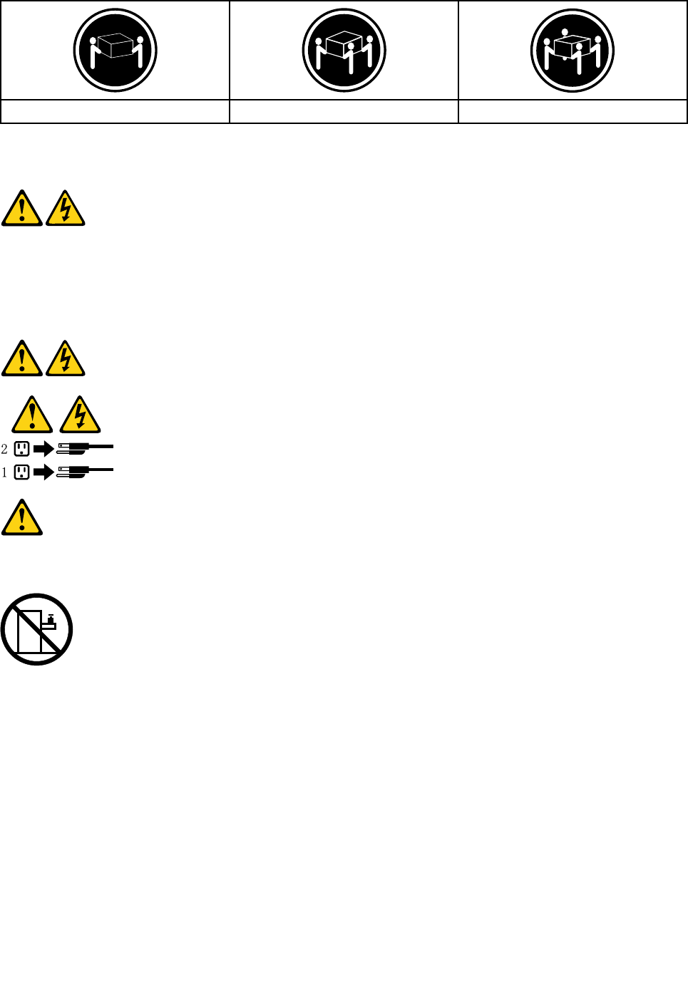
≥18kg(37lbs)≥32kg(70.5lbs)≥55kg(121.2lbs)
CAUTION:
Usesafepracticeswhenlifting.
CAUTION:
Thepowercontrolbuttononthedeviceandthepowerswitchonthepowersupplydonotturnoff
theelectricalcurrentsuppliedtothedevice.Thedevicealsomighthavemorethanonepower
cord.Toremoveallelectricalcurrentfromthedevice,ensurethatallpowercordsaredisconnected
fromthepowersource.
CAUTION:
Donotplaceanyobjectweighingmorethan82kg(180lbs.)ontopofrack-mounteddevices.
8ideacentreY700–900HardwareMaintenanceManual

Chapter3.Generalinformation
Thischapterprovidesgeneralinformationthatappliestoallmachinetypessupportedbythispublication.
Specifications
Thissectionliststhephysicalspecificationsforyourcomputer.
Thissectionliststhephysicalspecificationsforyourcomputer.
TypeideacentreY700–900
Thissectionliststhephysicalspecifications.
Environment
Airtemperature:
Operating:10°to35°C
Transit:-20°to55°C
Humidity:
Operating:35%to80%
Transit:20%to90%(40°C)
Altitude:86KPato106KPa
Electricalinput:
Inputvoltage:90V-264V(AC)
Inputfrequency:47Hz-63Hz
©CopyrightLenovo20159

10ideacentreY700–900HardwareMaintenanceManual

Chapter4.GeneralCheckout
Attention:Thedrivesinthecomputeryouareservicingmighthavebeenrearrangedorthedrivestartup
sequencechanged.Beextremelycarefulduringwriteoperationssuchascopying,saving,orformatting.
Dataorprogramscanbeoverwrittenifyouselectanincorrectdrive.
Generalerrormessagesappearifaproblemorconflictisfoundbyanapplicationprogram,theoperating
system,orboth.Foranexplanationofthesemessages,refertotheinformationsuppliedwiththatsoftware
package.
Usethefollowingproceduretohelpdeterminethecauseoftheproblem:
1.Power-offthecomputerandallexternaldevices.
2.Checkallcablesandpowercords.
3.Setalldisplaycontrolstothemiddleposition.
4.Power-onallexternaldevices.
5.Power-onthecomputer.
•Lookfordisplayederrorcodes
•Lookforreadableinstructionsoramainmenuonthedisplay.
Ifyoudidnotreceivethecorrectresponse,proceedtostep6.
Ifyoudoreceivethecorrectresponse,proceedtostep7.
6.Lookatthefollowingconditionsandfollowtheinstructions:
•IfthecomputerdisplaysaPOSTerror,goto“POSTerrorcodes” .
•Ifthecomputerhangsandnoerrorisdisplayed,continueatstep7.
7.Iftheteststopsandyoucannotcontinue,replacethelastdevicetested.
©CopyrightLenovo201511

12ideacentreY700–900HardwareMaintenanceManual

Chapter5.UsingtheSetupUtility
TheSetupUtilityprogramisusedtoviewandchangetheconfigurationsettingsofyourcomputer,regardless
ofwhichoperatingsystemyouareusing.However,theoperating-systemsettingsmightoverrideanysimilar
settingsintheSetupUtilityprogram.
StartingtheLenovoBIOSSetupUtilityprogram
TostarttheLenovoBIOSSetupUtilityprogram,dothefollowing:
1.Ifyourcomputerisalreadyonwhenyoustartthisprocedure,shutdowntheoperatingsystemand
turnoffthecomputer.
2.PressandholdtheF1keythenturnonthecomputer.WhentheLenovoBIOSSetupUtilityprogramis
displayed,releasetheF1key.
Note:IfaPower-OnPasswordoranAdministratorPasswordhasbeenset,theSetupUtilityprogrammenu
isnotdisplayeduntilyoutypeyourpassword.Formoreinformation,see“Usingpasswords.”
Viewingandchangingsettings
SystemconfigurationoptionsarelistedintheLenovoBIOSSetupUtilityprogrammenu.Tovieworchange
settings,see“StartingtheSetupUtilityprogram.”
YoumustusethekeyboardwhenusingtheLenovoBIOSSetupUtilitymenu.Thekeysusedtoperform
varioustasksaredisplayedonthebottomofeachscreen.
Usingpasswords
YoucanusetheLenovoBIOSSetupUtilityprogramtosetpasswordstopreventunauthorizedpersons
fromgainingaccesstoyourcomputeranddata.See“StartingtheSetupUtilityprogram.”Thefollowing
typesofpasswordsareavailable:
•SetAdministratorPassword
•SetPower-OnPassword
Youdonothavetosetanypasswordstouseyourcomputer.However,ifyoudecidetosetpasswords,read
thefollowingsections.
Passwordconsiderations
Apasswordcanbeanycombinationoflettersandnumbersupto16character(a-z,and0-9).Forsecurity
reasons,itisagoodideatouseastrongpasswordthatcannotbeeasilycompromised.Wesuggestthat
passwordsshouldfollowtheserules:
•Strongpasswordscontain7-16characters,combinelettersandnumbers.
•Donotuseyournameoryourusername.
•Donotuseacommonwordoracommonname.
•Besignificantlydifferentfromyourpreviouspassword.
Attention:AdministratorandPower-Onpasswordsarenotcasesensitive
©CopyrightLenovo201513

AdministratorPassword
SettinganAdministratorPassworddetersunauthorizedpersonsfromchangingconfigurationsettings.You
mightwanttosetanAdministratorPasswordifyouareresponsibleformaintainingthesettingsofseveral
computers.
AfteryousetanAdministratorPassword,apasswordpromptisdisplayedeverytimeyouaccesstheLenovo
BIOSSetupUtilityprogram.
IfboththeAdministratorandPower-OnPasswordareset,youcantypeeitherpassword.However,youmust
useyourAdministratorPasswordtochangeanyconfigurationsettings.
Setting,changing,ordeletinganAdministratorpassword
TosetanAdministratorPassword,dothefollowing:
Note:Apasswordcanbeanycombinationoflettersandnumbersupto16character(a-z,and0-9).For
moreinformation,see“Passwordconsiderations”onpage13.
1.StarttheLenovoBIOSSetupUtilityprogram(see“StartingtheLenovoBIOSSetupUtilityprogram”on
page13).
2.FromtheSecuritymenu,selectSetAdministratorPasswordandpresstheEnterkey.
3.Thepassworddialogboxwillbedisplayed.TypethepasswordthenpresstheEnterkey.
4.Re-typethepasswordtoconfirm,thenpresstheEnterkey.Ifyoutypethepasswordcorrectly,the
passwordwillbeinstalled.
TochangeanAdministratorPassword,dothefollowing:
1.StarttheLenovoBIOSSetupUtilityprogram(see“StartingtheLenovoBIOSSetupUtilityprogram”on
page13).
2.FromtheSecuritymenu,selectSetAdministratorPasswordandpresstheEnterkey.
3.Thepassworddialogboxwillbedisplayed.TypethecurrentpasswordthenpressEnterkey.
4.T ypethenewpassword,thenpressEnterkey.Re-typethepasswordtoconfirmthenewpassword,if
youtypethenewpasswordcorrectly,thenewpasswordwillbeinstalled.ASetupNoticewilldisplay
thatchangeshavebeensaved.
TodeleteapreviouslysetAdministratorPassword,dothefollowing:
1.FromtheSecuritymenu,selectSetAdministratorPasswordandpresstheEnterkey.
2.Thepassworddialogboxwillbedisplayed.TypethecurrentpasswordandpresstheEnterkey.
3.T odeleteanAdministratorPassword,Enterblankfieldsforeachnewpasswordlineitem.Asetup
noticewilldisplaythatchangeshavebeensaved.
4.ReturntotheLenovoBIOSSetupUtilityprogrammenuandselecttheExitoption.
5.SelectSavechangesandExitfromthemenu.
Power-OnPassword
WhenaPower-OnPasswordisset,youcannotstarttheLenovoBIOSSetupUtilityprogramuntilavalid
passwordistypedfromthekeyboard.
Setting,changing,ordeletingaPower-OnPassword
Note:Apasswordcanbeanycombinationoflettersandnumbersupto16character(a-z,and0-9).
14ideacentreY700–900HardwareMaintenanceManual

TosetaPower-OnPassword,dothefollowing:
1.StarttheLenovoBIOSSetupUtilityprogram(See”StartingtheLenovoBIOSSetupUtilityprogram”on
page13.)
2.FromtheSecuritymenu,selectSetPower-OnPasswordandpresstheEnterkey.
3.Thepassworddialogboxwillbedisplayed.Typethepassword,andpresstheEnterkey.
4.Re-typethepasswordtoconfirm,ifyoutypethepasswordcorrectly,thepasswordwillbeinstalled.
TochangeaPower-OnPassword,dothefollowing:
1.StarttheLenovoBIOSSetupUtilityprogram(See”StartingtheLenovoBIOSSetupUtilityprogram”on
page13.)
2.FromtheSecuritymenu,selectSetPower-OnPasswordandpresstheEnterkey.
3.Thepassworddialogboxwillbedisplayed.TypethecurrentpasswordthenpresstheEnterkey.
4.T ypethenewpassword,thenpresstheEnterkey.Re-typethepasswordtoconfirmthenewpassword,
ifyoutypethenewpasswordcorrectly,thenewpasswordwillbeinstalled.Asetupnoticewilldisplay
thatchangeshavebeensaved.
TodeleteapreviouslysetPower-OnPassword,dothefollowing:
1.FromtheSecuritymenu,selectSetPower-OnPasswordandpresstheEnterkey.
2.Thepassworddialogboxwillbedisplayed.TypethecurrentpasswordandpresstheEnterkey.
3.T odeletethePower-OnPassword,Enterblankfieldsforeachnewpasswordlineitem.Asetup
noticewilldisplaythatchangeshavebeensaved.
4.ReturntotheLenovoBIOSSetupUtilityprogrammenuandselecttheExitoption.
5.SelectSavechangesandExitfromthemenu.
Enablingordisablingadevice
TheDevicesoptionsisusedtoenableordisableuseraccesstothefollowingdevices:
USBFunctionsSelectwhethertoenableordisableUSB(UniversalSerial
Bus)functions.Ifthefunctionsaredisabled,noUSB
devicescanbeused.
ATADriveSetupSelectIDEorACHImode.Devicedriversupportis
requiredforACHImode.Dependingonhowtheharddisk
imagewasinstalled,changingthissettingmayprevent
thesystemfrombooting.
OnboardAudioControllerSelectwhethertoenableordisabletheOnboardAudio
Controller,whenfeatureissettoDisabledalldevices
connectedtotheaudioconnectors(e.g.aheadphoneor
amicrophone)aredisabledandcan’tbeused.
OnboardEthernetControllerorBootAgentSelectwhethertoenableordisableOnboardEthernet
Controller,orselectwhethertoenableordisableload
onboardPXE(PrebootExecutionEnvironment),or
SMC(SecureManagedClient).Thisfeaturewillallow
thecomputertobootfromaserverimage.
Toenableordisableadevice,dothefollowing:
1.StarttheSetupUtilityprogram(see“StartingtheSetupUtilityprogram”onpage13).
2.FromtheSetupUtilityprogrammenu,selectDevices.
3.Select:
Chapter5.UsingtheSetupUtility15

USBSetuppresstheEnterkey,andthenselectUSBFunctions.
ATADeviceSetuppresstheEnterkey.SelectConfigureSATAas,presstheEnterkeyandthen
selectSATAmode.
AudioSetuppresstheEnterkey,andthenselectOnboardAudioController.
NetworkSetuppresstheEnterkey,thenselectOnboardEthernetSupportorBootAgent.
4.SelectDisabledorEnabledandpresstheEnterkey.
5.ReturntotheLenovoBIOSSetupUtilityprogrammenuandselecttheExitoption.
6.SelectSavechangesandExitfromthemenu.
Note:Ifyoudonotwanttosavethesettings,selectDiscardchangesandExitfromthemenu.
Selectingastartupdevice
IfyourcomputerdoesnotbootfromadevicesuchastheCD/DVD-ROMdrivediskorharddiskasexpected,
followoneoftheproceduresbelow.
Selectingatemporarystartupdevice
Usethisproceduretostartupfromanybootdevice.
Note:NotallCDs,DVDsorharddiskdrivesarebootable.
1.T urnoffyourcomputer.
2.PressandholdtheF12keythenturnonthecomputer.WhentheStartupDeviceMenuappears,
releasetheF12key.
Note:IftheStartupDeviceMenudoesnotdisplayusingthesesteps,repeatedlypressandreleasethe
F12keyratherthankeepingitpressedwhenturningonthecomputer.
3.Use↑and↓arrowstoselectthedesiredstartupdevicefromtheStartupDeviceMenuandpress
theEnterkeytobegin.
Note:SelectingastartupdevicefromtheStartupDeviceMenudoesnotpermanentlychangethe
startupsequence.
Selectingorchangingthestartupdevicesequence
Tovieworpermanentlychangetheconfiguredstartupdevicesequence,dothefollowing:
1.StarttheLenovoBIOSSetupUtilityprogram(see“StartingtheLenovoBIOSSetupUtilityprogram”on
page13).
2.FromtheLenovoBIOSSetupUtilityprogrammainmenu,selecttheStartupoption.
3.PresstheEnterkey,andselectthedevicesforthePrimaryBootSequence.Readtheinformation
displayedontherightsideofthescreen.
4.Use↑and↓arrowstoselectadevice.Usethe<+>or<->keystomoveadeviceupordown.Usethe
<×>keytoexcludethedevicefromorincludethedeviceinthebootsequence.
5.ReturntotheLenovoBIOSSetupUtilityprogrammenuandselecttheExitoption.
6.SelectSavechangesandExitfromthemenu.
Notes:
a.Ifyoudonotwanttosavethesettings,selectDiscardchangesandExitfromthemenu.
16ideacentreY700–900HardwareMaintenanceManual

b.Ifyouhavechangedthesesettingsandwanttoreturntothedefaultsettings,selectLoadOptimal
Defaultsfromthemenu.
ExitingtheLenovoBIOSSetupUtilityprogram
Afteryoufinishviewingorchangingsettings,presstheEsckeytoreturntotheLenovoBIOSSetupUtility
programmainmenu.YoumighthavetopresstheEsckeyseveraltimes.Dooneofthefollowing:
•Ifyouwanttosavethenewsettings,selectSavechangesandExitfromthemenu.WhentheSave&
resetwindowshows,selecttheYesbutton,andthenpresstheEnterkeytoexittheLenovoBIOS
SetupUtilityprogram.
•Ifyoudonotwanttosavethesettings,selectDiscardchangesandExitfromthemenu.Whenthe
ResetWithoutSavingwindowshows,selecttheYesbutton,andthenpresstheEnterkeytoexitthe
SetupUtilityprogram.
Chapter5.UsingtheSetupUtility17

18ideacentreY700–900HardwareMaintenanceManual
Chapter6.Symptom-to-FRUIndex
TheSymptom-to-FRUindexlistserrorsymptomsandpossiblecauses.Themostlikelycauseislistedfirst.
AlwaysbeginwithChapter4,“GeneralCheckout,”onpage11.Thisindexcanalsobeusedtohelpyou
decidewhichFRUstohaveavailablewhenservicingacomputer.Ifyouareunabletocorrecttheproblem
usingthisindex,goto“Undeterminedproblems”onpage20.
Notes:
•Ifyouhavebothanerrormessageandanincorrectaudioresponse,diagnosetheerrormessagefirst.
•Ifyoucannotrunthediagnostictestsoryougetadiagnosticerrorcodewhenrunningatestbutdid
receiveaPOSTerrormessage,diagnosethePOSTerrormessagefirst.
•Ifyoudidnotreceiveanyerrormessagelookforadescriptionofyourerrorsymptomsinthefirstpartof
thisindex.
Harddiskdrivebooterror
Aharddiskdrivebooterrorcanhavethefollowingcauses.
ErrorFRU/Action
Thestartupdriveisnotincludedinthebootsequence
inconfiguration.
Checktheconfigurationandensurethestartupdriveis
inthebootsequence.
Nooperatingsysteminstalledonthebootdrive.Installanoperatingsystemonthebootdrive.
Thebootsectoronthestartupdriveiscorrupted.Thedrivemustbeformatted.Dothefollowing:
1.Attempttoback-upthedataonthefailingharddisk
drive.
2.Usetheoperatingsystemtoformattheharddisk
drive.
Thedriveisdefective.Replacetheharddiskdrive.
PowerSupplyProblems
Followtheseproceduresifyoususpectthereisapowersupplyproblem.
Check/VerifyFRU/Action
Checkthatthefollowingareproperlyinstalled:
•PowerCord
•On/OffSwitchconnector
•SystemBoardPowerSupplyconnectors
•Microprocessor(s)connection
Reseatconnectors
Checkthepowercord.PowerCord
Checkthepower-onswitch.Power-onSwitch
AdditionalServiceInformation
Thischapterprovidesadditionalinformationthattheservicerepresentativemightfindhelpful.
©CopyrightLenovo201519

Powermanagement
Powermanagementreducesthepowerconsumptionofcertaincomponentsofthecomputersuchasthe
systempowersupply,processor,harddiskdrives,andsomemonitors.
Advancedconfigurationandpowerinterface(ACPI)BIOS
AsthiscomputerhasanACPIBIOSsystem,theoperatingsystemisallowedtocontrolthepower
managementfeaturesofthecomputerandthesettingsforAdvancedPowerManagement(APM)BIOSmode
isignored.NotalloperatingsystemssupportACPIBIOSmode.
AutomaticPower-Onfeatures
TheAutomaticPower-OnfeatureswithinthePowerManagementmenuallowyoutoenableanddisable
featuresthatturnonthecomputerautomatically.
•WakeUponAlarm:Y oucanspecifyadateandtimeatwhichthecomputerwillbeturnedonautomatically.
Thiscanbeeitherasingleevent,adailyeventoraweeklyevent.
•WakeUponLAN:ThisfeatureallowsLANadaptercardtowaketheSystem.
POSTerrorcodes
Eachtimeyouturnthecomputeron,itperformsaseriesofteststocheckthatthesystemisoperating
correctlyandthatcertainoptionsareset.ThisseriesoftestsiscalledthePower-OnSelf-Test,orPOST.
POSTdoesthefollowing:
•Checkssomebasicsystem-boardoperations
•Checksthatthememoryisworkingcorrectly
•Startsvideooperations
•Verifiesthatthebootdriveisworking
POSTErrorMessageDescription/Action
KeyboarderrorCannotinitializethekeyboard.Makesurethekeyboard
isproperlyconnectedtothecomputerandthatnokeys
areheldpressedduringPOST.Topurposelyconfigure
thecomputerwithoutakeyboard,selectKeyboardless
operationinStartupoptiontoEnabled.TheBIOSthen
ignoresthemissingkeyboardduringPOST.
RebootandSelectproperBootdeviceorInsertBoot
MediainselectedBootdevice
TheBIOSwasunabletofindasuitablebootdevice.Make
surethebootdriveisproperlyconnectedtothecomputer.
Makesureyouhavebootablemediainthebootdevice.
Undeterminedproblems
1.Power-offthecomputer.
2.Removeordisconnectthefollowingcomponents(ifconnectedorinstalled)oneatatime.
a.Externaldevices(modem,printer,ormouse)
b.Extendedvideomemory
c.ExternalCache
d.ExternalCacheRAM
e.Harddiskdrive
f.Diskdrive
20ideacentreY700–900HardwareMaintenanceManual


22ideacentreY700–900HardwareMaintenanceManual
Chapter7.Locations
Thissectionprovidesillustrationstohelplocatethevariousconnectors,controlsandcomponentsofthe
computer.
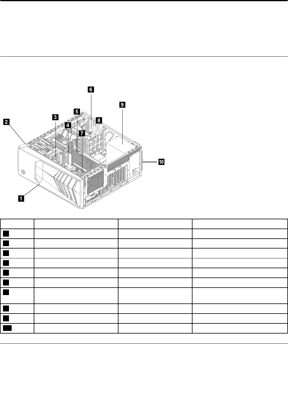
Identifyinginternalcomponents
Thefollowingillustrationshowsthecomponentsinsideyourcomputer.
5
6
9
7
8
3
4
1
2
10
No.DescriptionSelf-serviceCRUOptional-serviceCRU
1TopcoverNoNo
2FrontbezelYesNo
3OpticaldiskdriveYesNo
4MemorymoduleYesNo
5GraphicscardNoYes
6HarddiskdriveYesNo
7Microprocessor,fanand
heat-sink
NoNo
8Wi-FiCardNoNo
9PowersupplyNoYes
10ReardustscreenYesNo
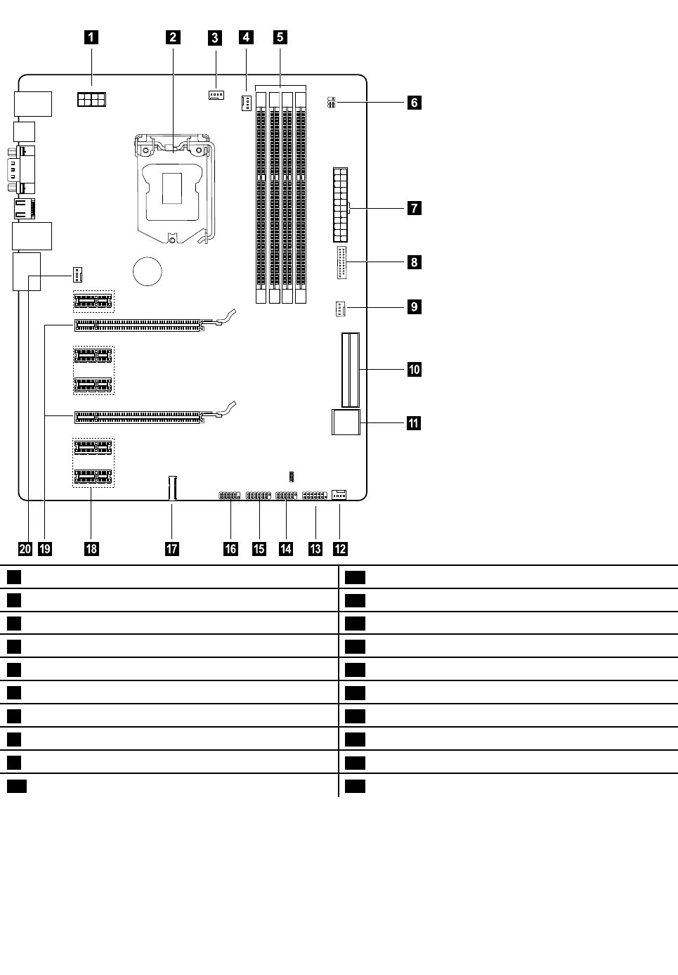
Identifyingpartsonthesystemboard
Thesystemboard(alsoknownasthe“mainboard”or“motherboard”)isthemaincircuitboardinyour
computer.Itprovidesbasiccomputerfunctionsandsupportsavarietyofdevicesthatarefactory-installed
orthatyoucaninstalllater.
Thefollowingillustrationsshowthelocationsofthedifferentpartsonthesystemboard.
©CopyrightLenovo201523
Y700–900
10
1214131617151819
20
1 2
3
4 5
6
7
8
9
11
112Vpowerconnector11FrontUSB3.0connector
2Microprocessor12Auxfan2
3Microprocessorfanheader113Frontpanelconnector
4Microprocessorfanheader214FrontUSB2.0connectorPowerfanheader
5Memoryslots(4)15FrontUSB,cardreaderconnector
6FrontLEDheader16LPCdebug
7Powerconnector17MiniPCI-Eslot
8FrontUSB3.0slot18PCIexpressX1adapterslots(5)
9Auxfan119PCIexpressX16adapterslot
10SATAconnectors(4)20Systemfanheader
24ideacentreY700–900HardwareMaintenanceManual

Chapter8.Replacinghardware
Attention:Donotremovethecomputercoverorattemptanyrepairbeforereadingthe“Importantsafety
information”intheSafetyandWarrantyGuidethatwasincludedwithyourcomputer.Toobtaincopiesofthe
SafetyandWarrantyGuide,gototheSupportWebsiteat:
http://consumersupport.lenovo.com
Generalinformation
Pre-disassemblyinstructions
Beforeproceedingwiththedisassemblyprocedure,makesurethatyoudothefollowing:
1.T urnoffthepowertothesystemandallperipherals.
2.Unplugallpowerandsignalcablesfromthecomputer.
3.Placethesystemonaflat,stablesurface.
Generalinformation
Pre-disassemblyinstructions
Beforeproceedingwiththedisassemblyprocedure,makesurethatyoudothefollowing:
1.T urnoffthepowertothesystemandallperipherals.
2.Unplugallpowerandsignalcablesfromthecomputer.
3.Placethesystemonaflat,stablesurface.
©CopyrightLenovo201525
Cleaningreardustscreen
Toreplacethesystemfan:
Step1.Removeanymedia(disks,CDs,DVDs,ormemorycards)fromthedrives,shutdowntheoperating
system,andturnoffthecomputerandallattacheddevices.
Step2.Unplugallpowercordsfromelectricaloutlets.
Step3.Disconnectallcablesattachedtothecomputer.Thisincludespowercords,input/output(I/O)
cables,andanyothercablesthatareconnectedtothecomputer.Referto“Leftandrightview”
and“Rearview”forhelpwithlocatingthevariousconnectors.
Step4.Removethecomputercover.Referto“Removingthecomputercover”.
Step5.Pressthenpulltheoutthereardustscreenasshown.
Step6.Cleaningtips:
a.Usabrushgentlybrushthroughthedustscreentoremovethedust.
b.Ifcleaningthedustscreenwithcleanwater,makesureyoudrythedustscreencompletely
beforeputitback.
Step7.Toinstallthereardustscreen:
a.Lineupthenewdustscreenwiththechassisandpushthescreenintoposition.
Replacingthekeyboardandmouse
Note:YourkeyboardwillbeconnectedtoaUSBconnectorateitherfrontorattherearofthecomputer.
Toreplacethekeyboard:
Step1.Removeanymedia(disks,CDs,ormemorycards)fromthedrives,shutdownthecomputer,and
turnoffallattacheddevices.
Step2.Unplugallpowercordsfromelectricaloutlets.
26ideacentreY700–900HardwareMaintenanceManual
Step3.Locatetheconnectorforthekeyboard.Referto“Frontviewofthechassis”and“Rearviewofthe
chassis”.
Step4.Disconnectthedefectivekeyboardcablefromthecomputerandconnectthenewkeyboardcable
tothesameconnector.
Step5.Themousecanbereplacedusingthesamemethod.
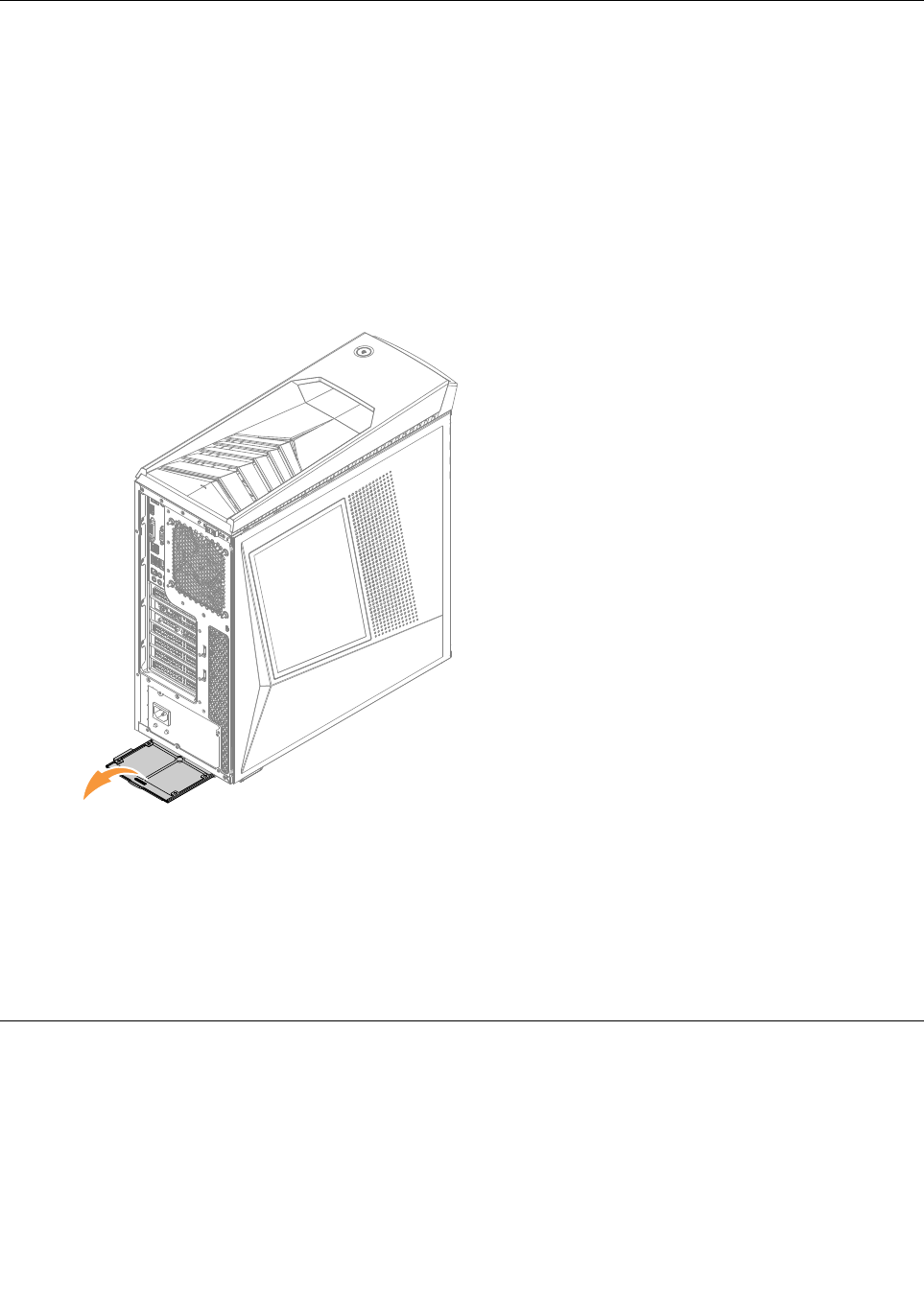
Removingthecomputercover
Attention:
•T urnoffthecomputerandwait3to5minutestoletitcooldownbeforeremovingthecover.
•Forthisprocedure,ithelpstolaythecomputeronaflat,stablesurface.
Toremovethecomputercover:
Step1.Removeanymedia(disks,CDs,ormemorycards)fromthedrives,shutdownthecomputer,and
turnoffallattacheddevices.
Step2.Unplugallpowercordsfromelectricaloutlets.
Step3.Disconnectallcablesattachedtothecomputer.Thisincludespowercords,input/output(I/O)
cables,andanyothercablesthatareconnectedtothecomputer.Referto“Locatingconnectors
ontherearofthecomputer”.
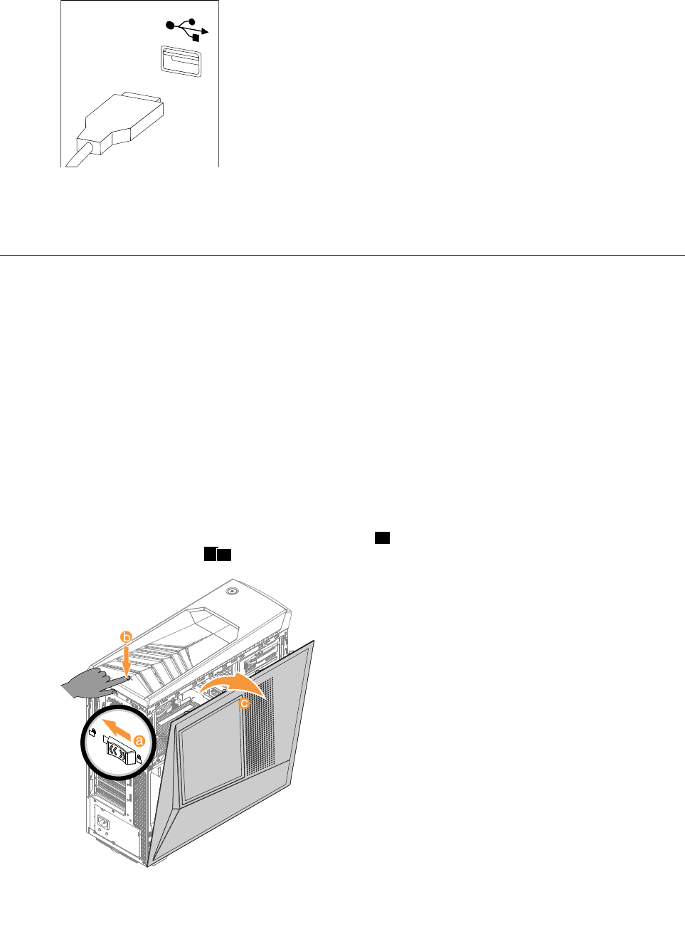
Step4.Slidethecomputercoverlocktounlockposition,athenpressthecoveropenbutton,computer
coverwillspringopen.bc.
Step5.Reinstallthecomputercover:
Chapter8.Replacinghardware27
a.Alignthecoverwiththeguidetrackonthecomputercase,thenslidethecoverin.
b.Pushthecovertillit’slockposition.
c.Pushthecoverlocktolockposition.
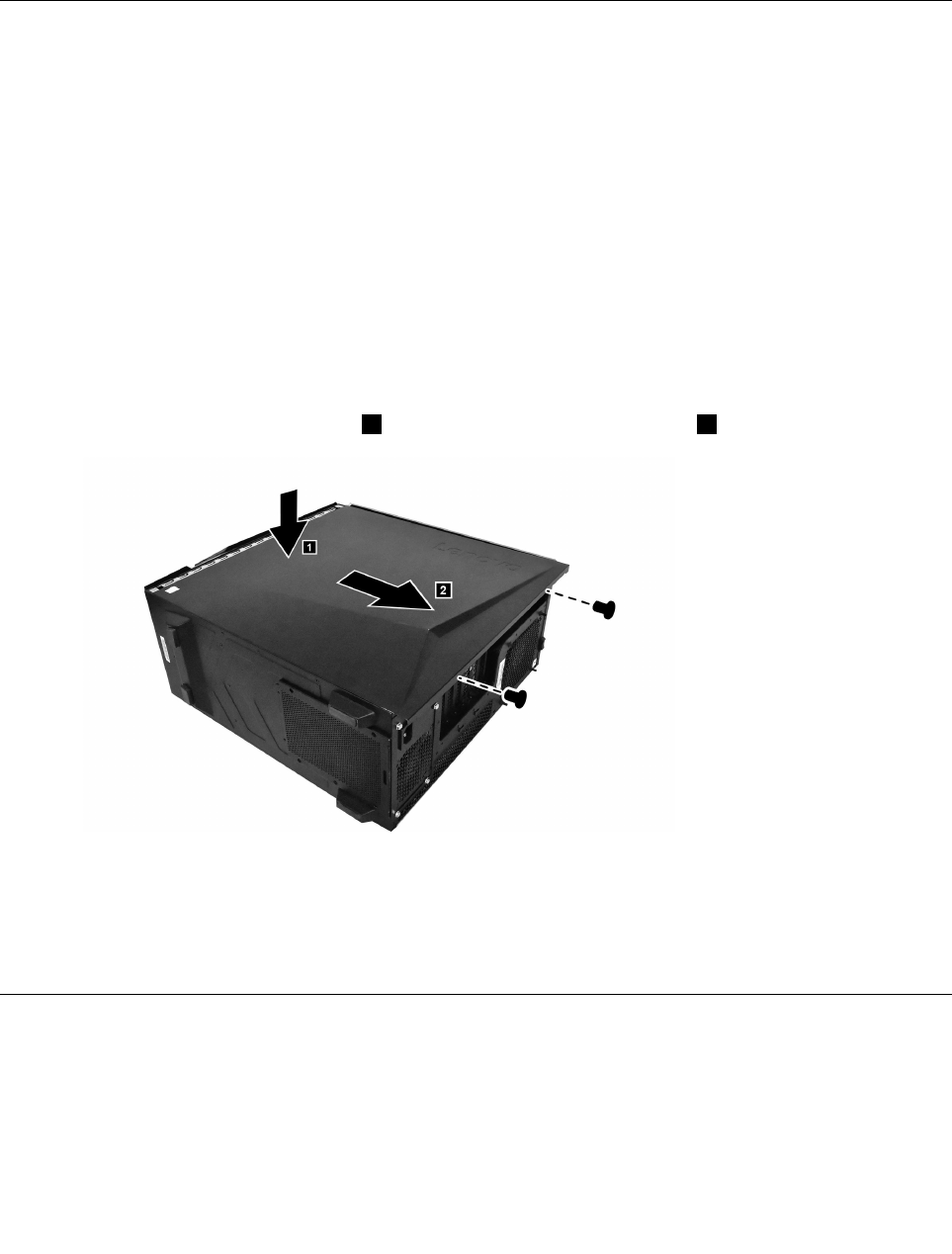
Removingthecomputercoverii
Attention:
•T urnoffthecomputerandwait3to5minutestoletitcooldownbeforeremovingthecover.
•Forthisprocedure,ithelpstolaythecomputeronaflat,stablesurface.
Toremovethecomputercoverii:
Step1.Removeanymedia(disks,CDs,ormemorycards)fromthedrives,shutdownthecomputer,and
turnoffallattacheddevices.
Step2.Unplugallpowercordsfromelectricaloutlets.
Step3.Disconnectallcablesattachedtothecomputer.Thisincludespowercords,input/output(I/O)
cables,andanyothercablesthatareconnectedtothecomputer.Referto“Locatingconnectors
ontherearofthecomputer”.
Step4.Removethe2screwsthatsecurethecomputercovertothechassis.
Step5.Presstheleftsideofthecover,1thenslidethecomputercoverout.2
Step6.Reinstallthecomputercoverii:
a.Alignthecoverwiththeguidetrackonthecomputercase,thenslidethecoverin.
b.Presstheleftsidethecover,thenpushitintillthecoverlockedproperly.
c.Securethecomputercoverwithtwoscrews.
Removingthefrontbezel
Note:Forthisprocedure,ithelpstolaythecomputerflat.
Toremovethefrontbezel:
Step1.Removethecomputercover.Referto“Removingthecomputercover”.
28ideacentreY700–900HardwareMaintenanceManual
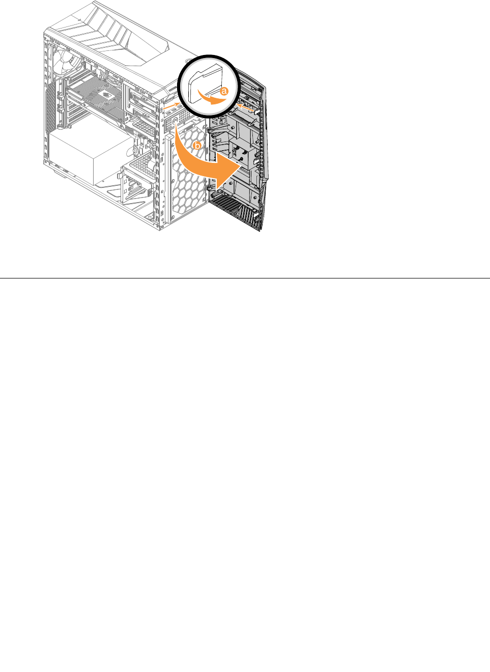
Step2.Removethefrontbezelbyreleasingthethreeplastictabsinsidethechassisandpullingthebezel
outasshown.
Step3.Toreattachthebezel,aligntheplastictabsonthebottomofthebezelwiththecorrespondingholes
inthechassis,andthensnapitintoposition.
Cleaningfrontdustscreen
Toreplacethesystemfan:
Step1.Removeanymedia(disks,CDs,DVDs,ormemorycards)fromthedrives,shutdowntheoperating
system,andturnoffthecomputerandallattacheddevices.
Step2.Unplugallpowercordsfromelectricaloutlets.
Step3.Disconnectallcablesattachedtothecomputer.Thisincludespowercords,input/output(I/O)
cables,andanyothercablesthatareconnectedtothecomputer.Referto“Leftandrightview”
and“Rearview”forhelpwithlocatingthevariousconnectors.
Step4.Removethecomputercover.Referto“Removingthecomputercover”.
Step5.Removethecomputercover.Referto“Removingcomputercover”.
Step6.Removethefrontbezel.Referto“Removingthefrontbezel”.
Chapter8.Replacinghardware29
Step7.Pulltheoutthefrontdustscreenasshown.
Step8.Cleaningtips:
a.Usabrushgentlybrushthroughthedustscreentoremovethedust.
b.Ifcleaningthedustscreenwithcleanwater,makesureyoudrythedustscreencompletely
beforeputitback.
Step9.Toinstallthefrontdustscreen:
a.Lineupthenewdustscreenwiththechassisandpushthescreenintoposition.
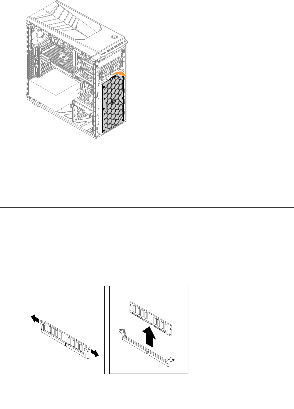
Replacingamemorymodule
Note:Forthisprocedure,ithelpstolaythecomputerflat.
Toreplaceamemorymodule:
Step1.Removethecomputercover.Referto“Removingthecomputercover”.
Step2.Locatethememorymoduleconnectors.Referto“Locatingcomponents”.
Step3.Removethememorymoduletobereplacedbyopeningtheretainingclipsasshown.
30ideacentreY700–900HardwareMaintenanceManual
Step4.Positionthenewmemorymoduleoverthememoryconnector.Makesurethatthenotch1onthe
memorymodulealignscorrectlywiththeconnectorkey2onthesystemboard.Pushthememory
modulestraightdownintotheconnectoruntiltheretainingclipsclose.
Step5.Reattachthecomputercover.
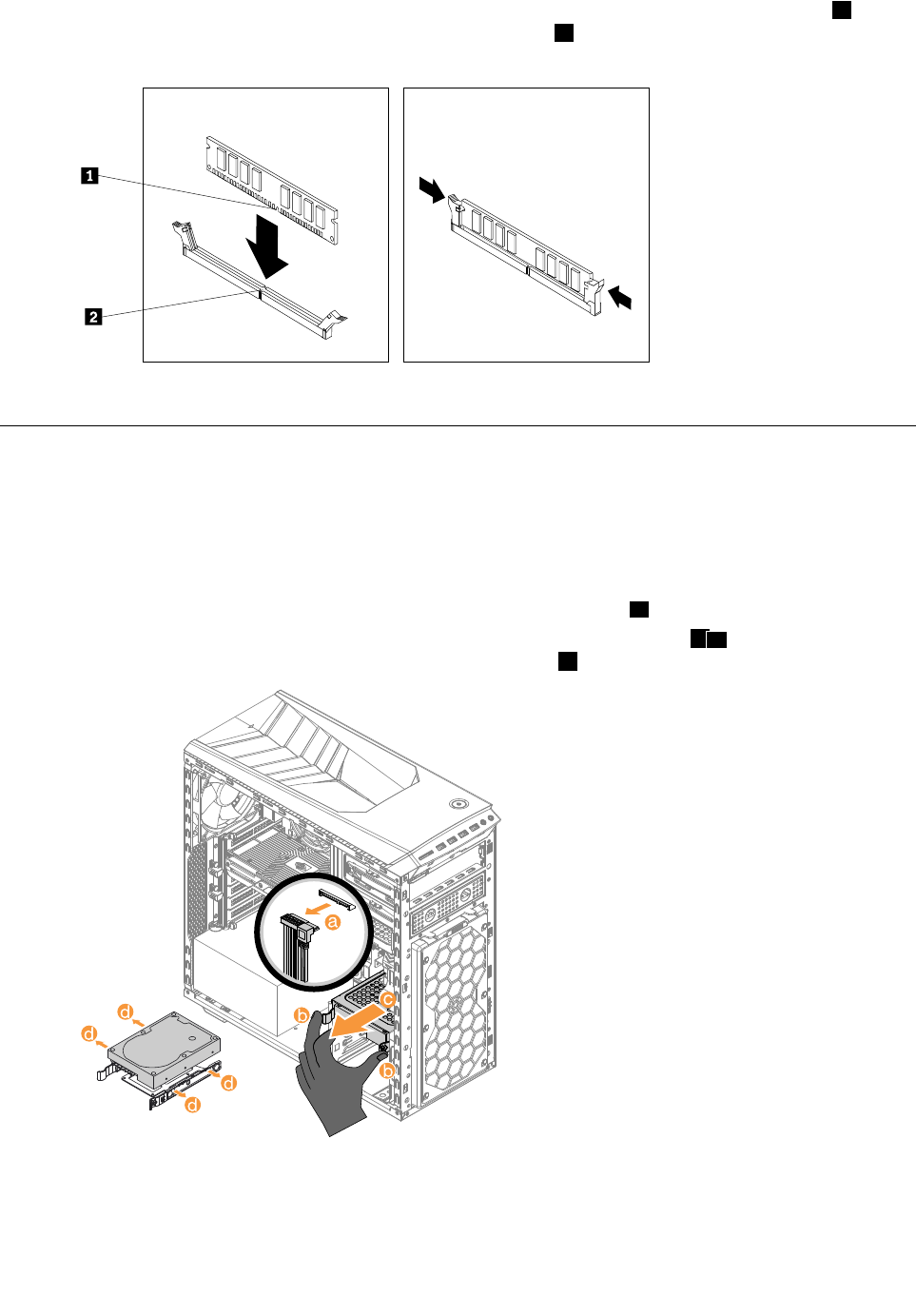
Replacingaharddiskdrive
Note:Forthisprocedure,ithelpstolaythecomputerflat.
Toreplaceaharddiskdrive:
Step1.Removethecomputercover.Referto“Removingthecomputercover”.
Step2.Disconnectthedataandpowercablesfromtheharddiskdrive.a
Step3.Pulltheplastichandleandslidetheharddiskdriveoutofthedrivebay.bc
Releasetheharddiskdrivefromthebracketasshown.d
Step4.Lineupthenewharddiskdrivewiththeplasticbracketandsnapitintoposition.
Step5.Slidethenewharddiskdriveintothedrivebayandslidethedrivebayintoplace.
Step6.Connectthepowerandsignalcablestothenewharddiskdrive.
Chapter8.Replacinghardware31
Step7.Reattachthecomputercover.
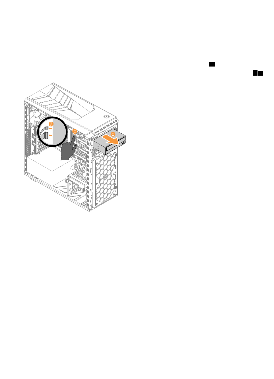
Replacinganopticaldrive
Note:Forthisprocedure,ithelpstolaythecomputerflat,stablesurface.
Toreplaceanopticaldrive:
Step1.Removethecomputercover.Referto“Removingthecomputercover”.
Step2.Removethefrontbezel.Referto“Removingthefrontbezel”.
Step3.Disconnectthedataandpowercablesfromtherearoftheopticaldrive.a
Step4.Pressthereleasebuttonandpushtheopticaldrivestraightoutofthefrontofthechassis.bc
Step5.Slidethenewopticaldriveintothebayfromthefrontuntilitsnapsintoposition.
Step6.Connectthedataandpowercablestothenewdiskdrive.
Step7.Reattachthefrontbezelandcomputercover.
Replacingthemicroprocessorfanassembly
Toreplacethemicroprocessorfanassembly:
Step1.Removeanymedia(disks,CDs,DVDs,ormemorycards)fromthedrives,shutdowntheoperating
system,andturnoffthecomputerandallattacheddevices.
Step2.Unplugallpowercordsfromelectricaloutlets.
Step3.Disconnectallcablesattachedtothecomputer.Thisincludespowercords,input/output(I/O)
cables,andanyothercablesthatareconnectedtothecomputer.Referto“Leftandrightview”
and“Rearview”forhelpwithlocatingthevariousconnectors.
Step4.Removethecomputercover.Referto“Removingthecomputercover”.
Step5.Disconnectthefanpowercablefromtheconnectoronthemotherboard.
32ideacentreY700–900HardwareMaintenanceManual
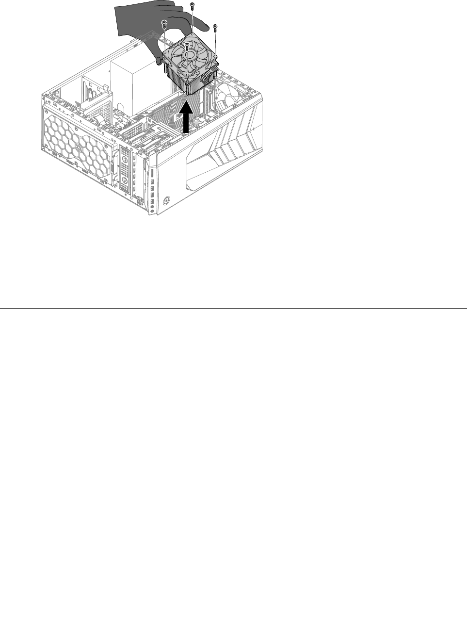
Step6.Removethe4screwsthatsecurethemicroprocessorfantotheheat-sinkandliftupthe
microprocessorfantoremoveit.
Step7.Toinstallthenewmicroprocessorfanassembly:
a.Lineupthenewmicroprocessorfanassemblywiththeheat-sinkandsecureittotheheat-sink
with4screws.
b.Connectthemicroprocessorfanpowercabletotheconnectorontheboard.
Step8.Reattachthecomputercover.
Replacingtherearsystemfan
Toreplacethesystemfan:
Step1.Removeanymedia(disks,CDs,DVDs,ormemorycards)fromthedrives,shutdowntheoperating
system,andturnoffthecomputerandallattacheddevices.
Step2.Unplugallpowercordsfromelectricaloutlets.
Step3.Disconnectallcablesattachedtothecomputer.Thisincludespowercords,input/output(I/O)
cables,andanyothercablesthatareconnectedtothecomputer.Referto“Leftandrightview”
and“Rearview”forhelpwithlocatingthevariousconnectors.
Step4.Removethecomputercover.Referto“Removingthecomputercover”.
Step5.Disconnectthefanpowercablefromtheconnectoronthemotherboard.
Chapter8.Replacinghardware33
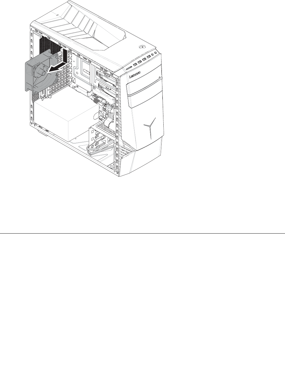
Step6.Thesystemfanislockedtothecomputercaseviaplasticscrew,useaknifecutofftheplastic
lockingscrews,thenpulltherearsystemfanassemblyoutofcomputercase.
Step7.Toinstallthenewsystemfan:
a.Lineupthenewsystemfanwiththecomputercaseandsecureittothecomputercasewith
lockingscrewsbypullingtheplasticscrewsthroughthelockinghole.
b.Connectthesystemfanpowercabletotheconnectorontheboard.
Step8.Reattachthecomputercover.
Replacingafrontfan
Toreplaceafrontfan:
Step1.Removeanymedia(disks,CDs,DVDs,ormemorycards)fromthedrives,shutdowntheoperating
system,andturnoffthecomputerandallattacheddevices.
Step2.Unplugallpowercordsfromelectricaloutlets.
Step3.Disconnectallcablesattachedtothecomputer.Thisincludespowercords,input/output(I/O)
cables,andanyothercablesthatareconnectedtothecomputer.Referto“Leftandrightview”
and“Rearview”forhelpwithlocatingthevariousconnectors.
Step4.Removethecomputercover.Referto“Removingthecomputercover”.
Step5.Removethecomputercoverii.Referto“Removingthecomputercoverii”.
Step6.Removethefrontbezel.Referto“Removingthefrontbezel”.
34ideacentreY700–900HardwareMaintenanceManual
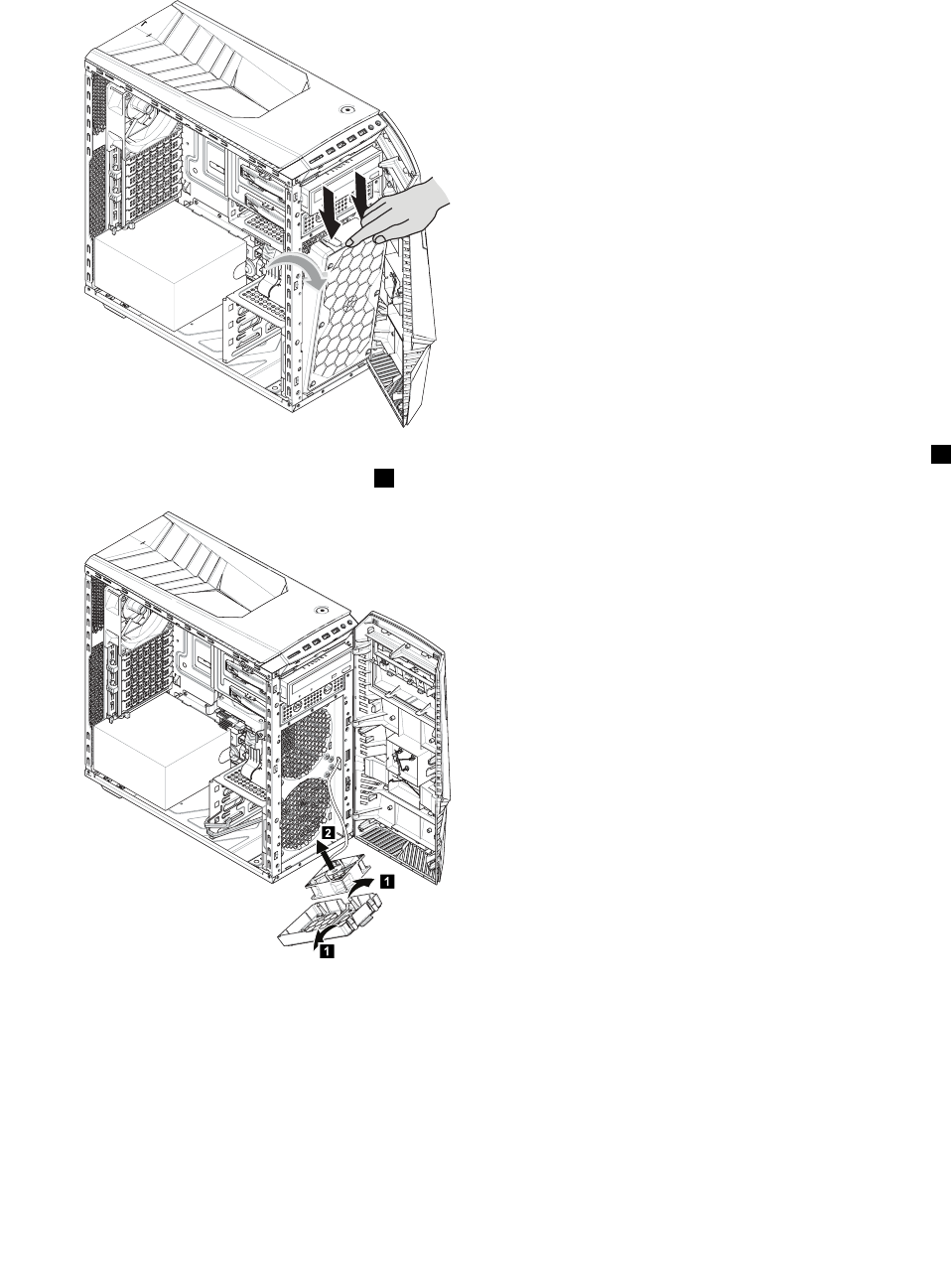
Step7.Disconnectthefanfromtheconnectoronthemotherboard.
Step8.Thefrontfanandthebracketaremountedtothechassiswithtwopins.Pressdownthetwopins
asillustrated,thenslideoutthefrontfanandthebracketslowly.
Step9.Thefrontfanispinedtothebrackets,pushthepinsoutwardtoreleasethefanfromthebracket1,
thenliftupthefantoremoveit.2
1
1
2
Step10.Toinstallanewfan:
a.Placethenewfanwithintothebracket,thensecurethefanwiththetwolockingpins.
b.Alignthetwolockingpinsatthebottomofthebracketwithmountingholesonthechassis,
thensnapthefanandbracketintoposition.
c.Connectthenewfancabletotheconnectoronthemotherboard.
Step11.Reattachthefrontbezelandthecomputercovers.
Chapter8.Replacinghardware35
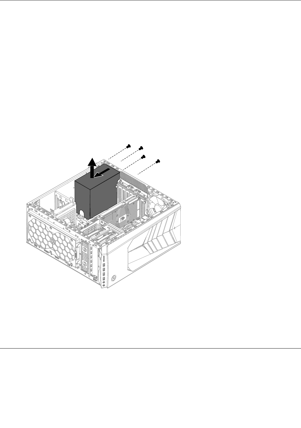
ReplacingthePowersupply
Note:Forthisprocedure,ithelpstolaythecomputerflat.
ToreplacethePowersupply:
Step1.Removeanymedia(disks,CDs,DVDs,ormemorycards)fromthedrives,shutdowntheoperating
system,andturnoffthecomputerandallattacheddevices.
Step2.Unplugallpowercordsfromelectricaloutlets.
Step3.Disconnectallcablesattachedtothecomputer.Thisincludespowercords,input/output(I/O)
cables,andanyothercablesthatareconnectedtothecomputer.Referto“Leftandrightview”
and“Rearview”forhelpwithlocatingthevariousconnectors.
Step4.Removethecomputercover.Referto“Removingthecomputercover”.
Step5.Disconnectthepowercablesfromtheconnectorsonmotherboard.
Step6.Removethe4screwsthatsecurethePowersupplytothechassis.
Step7.SlidethenliftthePowersupplyoutofchassis.
Step8.Installthenewpowersupply:
a.Lineuptheholesonthenewpowersupplywithmountingholesontherearofthechassisand
secureittothechassiswiththe4screws.
b.Connectthepowercablestotheconnectorsonthemotherboard.
Step9.Reattachthecomputercover.
ReplacingtheWi-Ficard
Note:Forthisprocedure,ithelpstolaythecomputerflat.
ToreplacetheWi-Ficard:
Step1.Removeanymedia(disks,CDs,DVDs,ormemorycards)fromthedrives,shutdowntheoperating
system,andturnoffthecomputerandallattacheddevices.
36ideacentreY700–900HardwareMaintenanceManual
Step2.Unplugallpowercordsfromelectricaloutlets.
Step3.Disconnectallcablesattachedtothecomputer.Thisincludespowercords,input/output(I/O)
cables,andanyothercablesthatareconnectedtothecomputer.Referto“Leftandrightview”
and“Rearview”forhelpwithlocatingthevariousconnectors.
Step4.Removethecomputercover.Referto“Removingthecomputercover”.
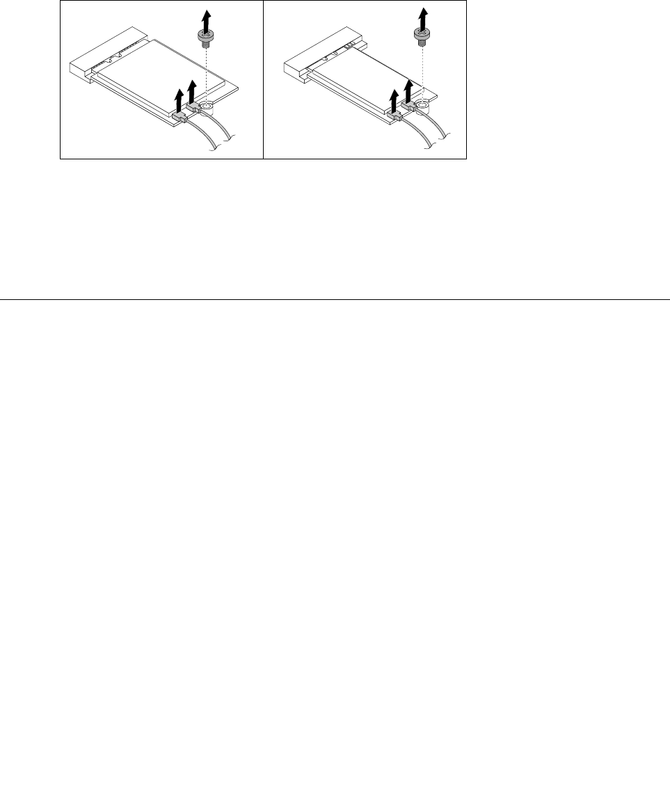
Step5.Disconnectthe2antennacablesfromtheWi-Ficard.
Step6.Removethe2screwsthatsecuretheWi-Ficardtothemotherboard.
Step7.PulltheWi-Ficardupwardtoremoveitfromthecardport.
Step8.InstallthenewWi-Ficard:
a.LineupthenewWi-Ficard,theninsertitintothesamecardport.
b.SecuretheWi-Ficardtothemotherboardwiththescrew.
c.Connectthe2antennacablestothenewWi-Ficard.
Step9.Reattachthecomputercover.
Removingthetopcover
Attention:
•T urnoffthecomputerandwait3to5minutestoletitcooldownbeforeremovingthecover.
•Forthisprocedure,ithelpstolaythecomputeronaflat,stablesurface.
Toremovethetopcover:
Step1.Removeanymedia(disks,CDs,ormemorycards)fromthedrives,shutdownthecomputer,and
turnoffallattacheddevices.
Step2.Unplugallpowercordsfromelectricaloutlets.
Step3.Disconnectallcablesattachedtothecomputer.Thisincludespowercords,input/output(I/O)
cables,andanyothercablesthatareconnectedtothecomputer.Referto“Locatingconnectors
ontherearofthecomputer”.
Step4.Removethecomputercover.Referto“Removingthecomputercover”.
Chapter8.Replacinghardware37
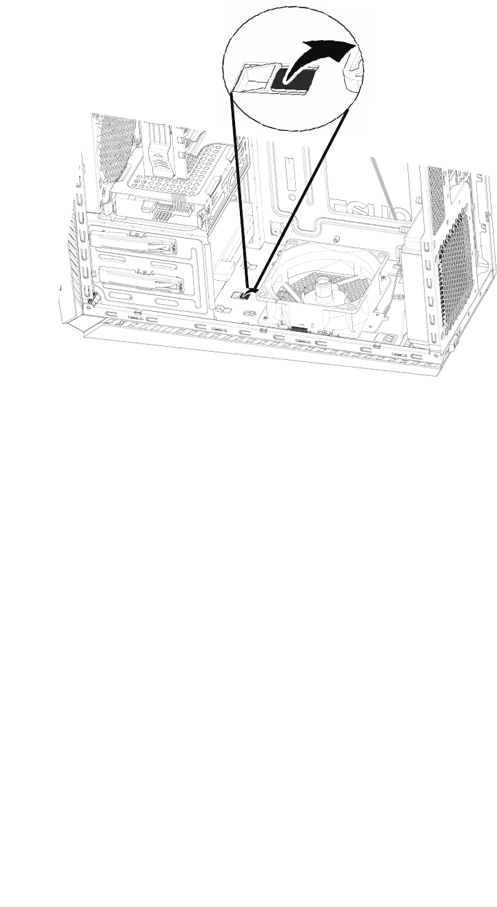
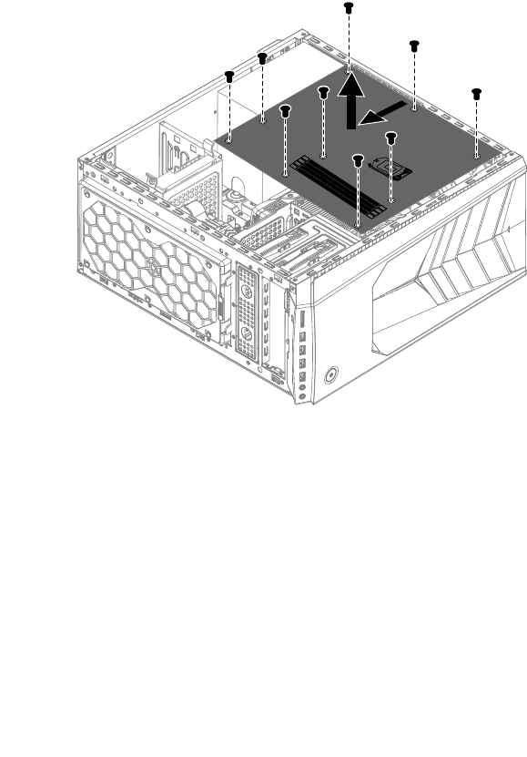
Step5.Putthecomputerupsidedown,locatethetopcoverlockingfinasshown.Useaflatheadscrew
driverstopryupthelockingfintoreleasethetopcover.
Step6.Slidethetopcoveroutwardtoremovethetopcoverasshown.
38ideacentreY700–900HardwareMaintenanceManual
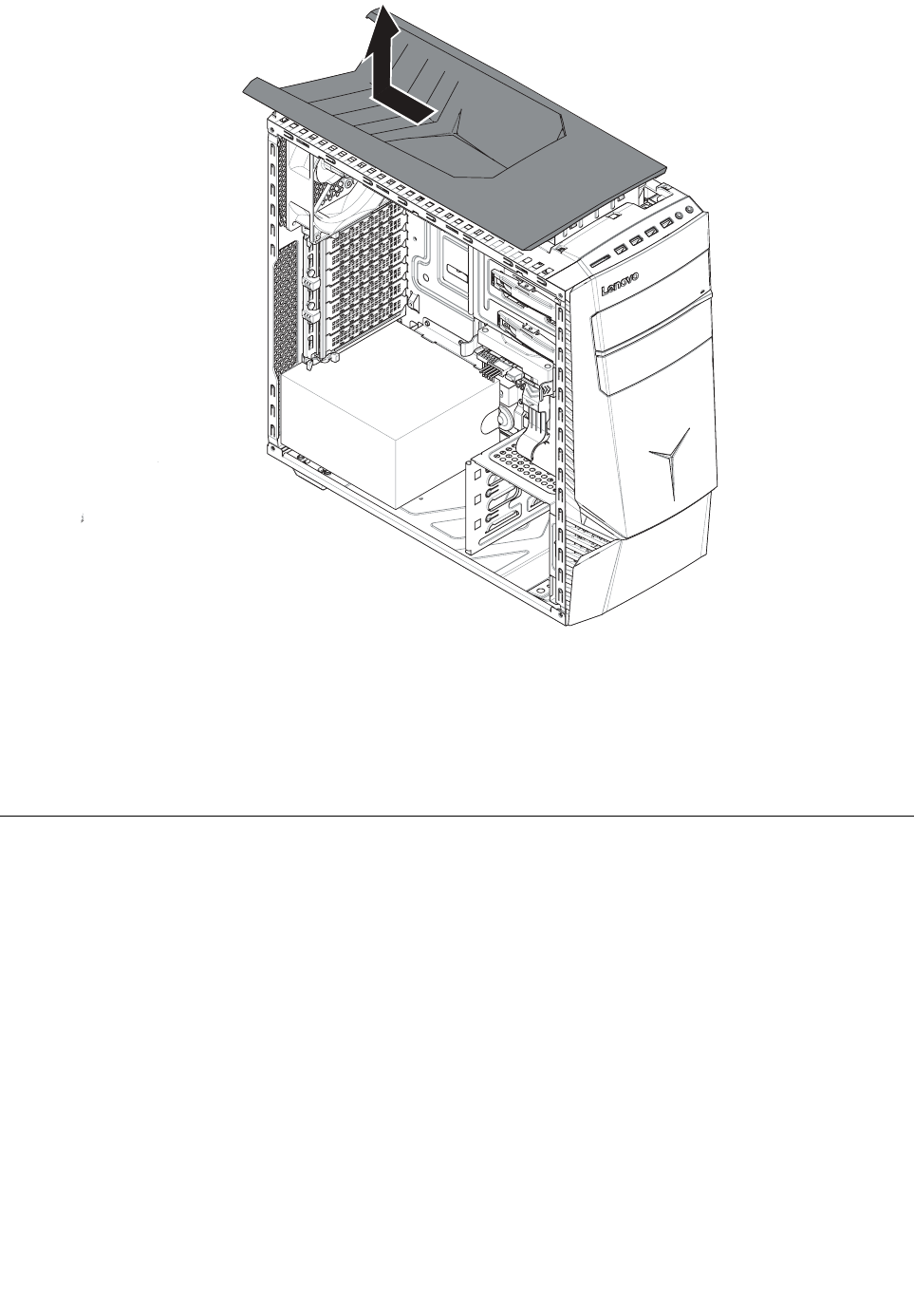
Step7.Reinstallthecomputercover:
a.Alignthecoverwiththeguidetrackonthecomputercase,thenslidethecoverin.
b.Pushthecovertillit’slockingposition.
c.Pressdownthelockingfintosecurethetopcover.
Step8.Reattachthecomputercover.
Replacingagraphicscard
Note:Forthisprocedure,ithelpstolaythecomputeronaflat,stablesurface.
Toreplaceagraphicscard:
Step1.Removethecomputercover.Referto“Removingthecomputercover”.
Step2.Pushthegraphiccardtounlockpositionasshown.
Chapter8.Replacinghardware39
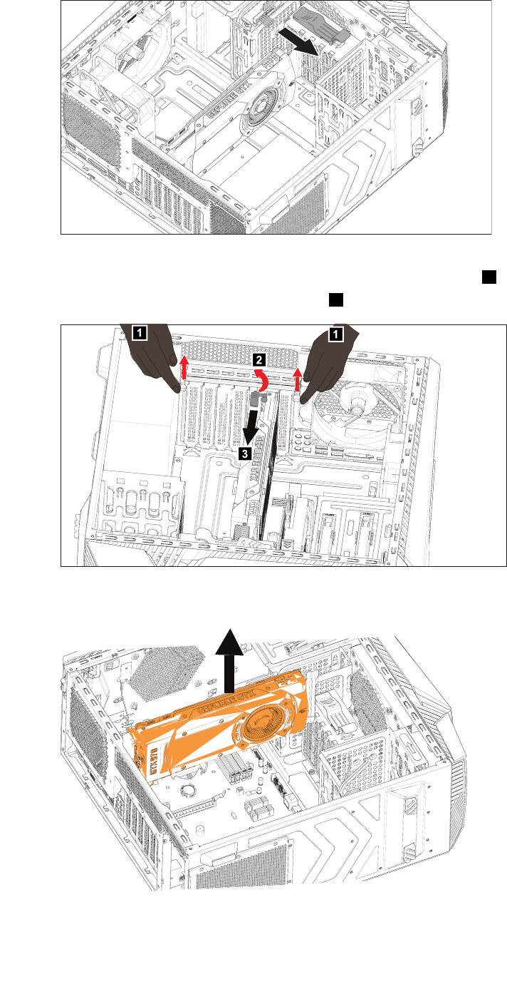
Step3.Disconnectthepowercablesfromthegraphicscard.
Step4.Turnthelockingpincounterclockwise90°,thenslowlytakeitout.2
Step5.Openthegraphiccardlatchesasshown.1
11
2
3
Step6.Pushthelockingpinthatlocksthegraphiccardtothemotherboard,thenliftthecardstraight
uptoremoveit.
Step7.Toinstallthenewgraphicscard:
a.Attachthenewgraphicscardtothesameadapterconnector.
40ideacentreY700–900HardwareMaintenanceManual

b.Connectthepowercablestothenewgraphicscard.
c.Turnthegraphicscardlatchtotheclosedpositionandsecureitwiththelockingpin.
Step8.Reattachthecomputercover.
ReplacingtheCPU
Note:Forthisprocedure,ithelpstolaythecomputerflat.
ToreplacetheCPU:
Step1.Removeanymedia(disks,CDs,DVDs,ormemorycards)fromthedrives,shutdowntheoperating
system,andturnoffthecomputerandallattacheddevices.
Step2.Unplugallpowercordsfromelectricaloutlets.
Step3.Disconnectallcablesattachedtothecomputer.Thisincludespowercords,input/output(I/O)
cables,andanyothercablesthatareconnectedtothecomputer.Referto“Leftandrightview”
and“Rearview”forhelpwithlocatingthevariousconnectors.
Step4.Removethecomputercover.Referto“Removingthecomputercover”.
Step5.Removethemicroprocessorfan.Referto“Replacingthemicroprocessorfan”.
Step6.RemovetheCPUfanassembly.Referto“ReplacingtheCPUfanassembly”.
Chapter8.Replacinghardware41
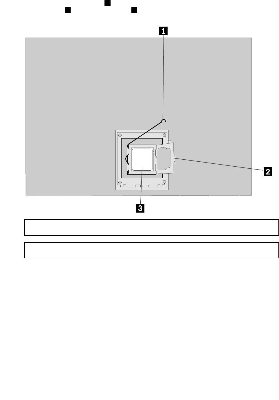
Step7.Toremovethemicroprocessor3fromthesystemboard,pressthenslidethesmallhandleout
tospringitup.1andopentheretainer.2
Attention:Donottouchthegoldcontactsonthebottomofthemicroprocessor.Whenhandingthe
microprocessor,touchonlythesides.
Note:Donotdropanythingontothemicroprocessorsocketwhileitisexposed.Thesocketpinsmust
bekeptascleanaspossible.
42ideacentreY700–900HardwareMaintenanceManual
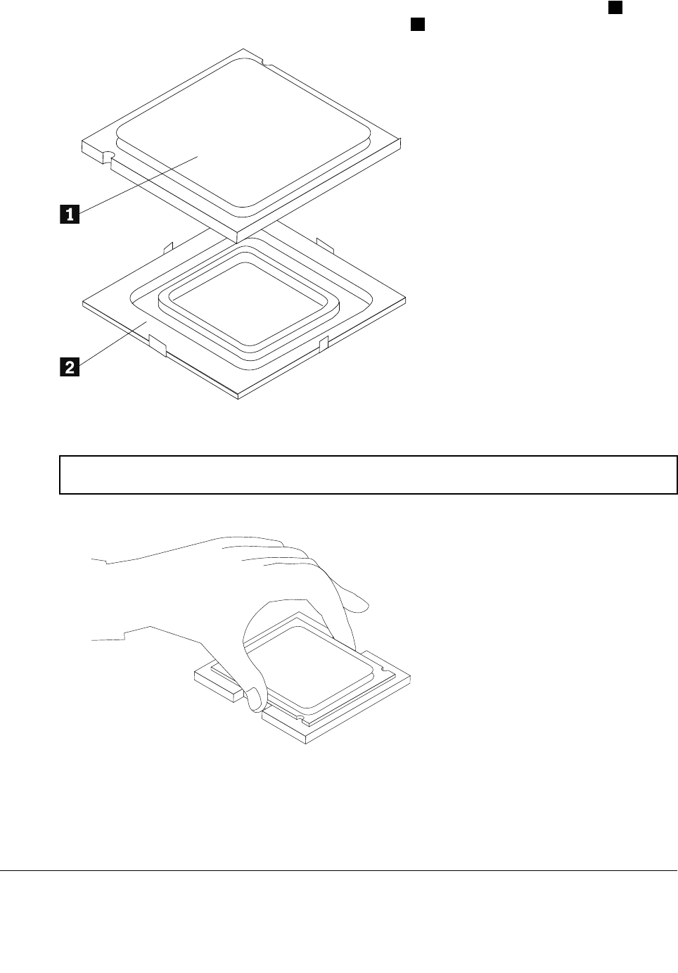
Step8.Holdingthesidesofthemicroprocessorwithyourfingers,removetheprotectivecover1that
protectsthegoldcontactsonthenewmicroprocessor.2
Step9.Holdingthesidesofthemicroprocessorwithyourfingers,positionthemicroprocessorsothatthe
notchesonthemicroprocessorarealignedwiththetabsinthemicroprocessorsocket.
Important:Toavoiddamagingthemicroprocessorcontacts,keepthemicroprocessorcompletelylevel
whileinstallingitintothesocket.
Step10.Lowerthemicroprocessorstraightdownintoitssocketonthemotherboard.
Step11.Tosecurethemicroprocessorinthesocket,closethemicroprocessorretainerandlockitinto
positionwiththesmallhandle.
Step12.Useathermalgreasesyringetoplace5dropsofgreaseonthetopofthemicroprocessor.Each
dropofgreaseshouldbe0.03ml(3tickmarksonthegreasesyringe).
Step13.ReattachtheCPUfanassembly,microprocessorfan,computercover.
Replacingthemotherboard
Note:Forthisprocedure,ithelpstolaythecomputerflat.
Chapter8.Replacinghardware43
Toreplacethemotherboard:
Step1.Removeanymedia(disks,CDs,DVDs,ormemorycards)fromthedrives,shutdowntheoperating
system,andturnoffthecomputerandallattacheddevices.
Step2.Unplugallpowercordsfromelectricaloutlets.
Step3.Disconnectallcablesattachedtothecomputer.Thisincludespowercords,input/output(I/O)
cables,andanyothercablesthatareconnectedtothecomputer.Referto“Leftandrightview”
and“Rearview”forhelpwithlocatingthevariousconnectors.
Step4.Removethecomputercover.Referto“Removingthecomputercover”.
Step5.Removethememorymodule.Referto“Replacingamemorymodule”.
Step6.Removethemicroprocessorfan.Referto“Replacingthemicroprocessorfan”.
Step7.Removetheheat-sink.Referto“Replacingtheheat-sink”.
Step8.Removethegraphiccard.Referto“Replacingagraphiccard”.
Step9.RemovetheWi-Ficard.Referto“ReplacingtheWi-Ficard”.
Step10.RemovetheCPU.Referto“ReplacingtheCPU”.
Step11.Disconnecttheallcablesfromtheconnectorsonmotherboard.
Step12.Removethe11screwsthatsecurethemotherboardtothechassis.
Step13.Slidethenliftthemotherboardoutofthechassistoremoveit.
Step14.Installthenewmotherboard:
a.Lineuptheholesonthenewmotherboardwithmountingholesonthechassisandsecure
itwithscrews.
b.Reattachthememorymodule,Wi-Ficard,CPU,andtheheat-sinktothenewmotherboard.
c.Connecttheallcablestothenewmotherboard.
d.Attachthegraphiccardtothenewmotherboard.
Step15.Reattachthecomputercover.
44ideacentreY700–900HardwareMaintenanceManual

FRUlists
Thischapterliststheinformationonthefieldreplaceableunits(FRUs).
Attention:BesuretoreadandunderstandallthesafetyinformationbeforereplacinganyFRUs.
FruP/NDescriptionBasicName
01AJ152MBZ170DDR4DIMMx4NODPKBDPLANAR
01AJ153MBZ170DDR4DIMMx4WINDPKBDPLANAR
01AJ154MBH170DDR4DIMMx4NODPKBDPLANAR
01AJ155MBH170DDR4DIMMx4WINDPKBDPLANAR
31026146VLBLK1.8mBSMIPowerCord(R)CABLE
31026357LWBLK1.8mULCSAPowerCord(R)CABLE
31049509Volex1.8MC13SApowercordCABLE
31026082VLBLK1.8mBSPowerCord(R)CABLE
31043148GS457mmSATAcable2latchCABLE
31026140VLBLK1.8mANEPowerCord(R)CABLE
31026143VLBLK1.8mKTLPowerCord(R)CABLE
31049512Volex1.8MC13ITYpowercordCABLE
31049516Volex1.8MC13SWIpowercordCABLE
31503249LS460mmSATAcable2latch,right
angle
CABLE
04X2778Fru,GamingPCantennacable_GrayCABLE
31043147LX457mmSATAcable2latchCABLE
31039728Longwell1.8MIsraelC13power
cord(R)
CABLE
04X2777Fru,GamingPCantennacable_BlackCABLE
31039732Longwell1.8MSEVC13power
cord(R)
CABLE
31049521LX(ASAP)1.8MC13ULpowercordCABLE
31049523LX(ASAP)1.8MC13JPNpowercordCABLE
31026355LWBLK1.8mVDEPowerCord(R)CABLE
31026096LWBLK1.8mBSPowerCord(R)CABLE
31026351LWBLK1.8mKTLPowerCord(R)CABLE
31049524LX(ASAP)1.8MC13ANZpowercordCABLE
31049522LX(ASAP)1.8MC13EUpowercordCABLE
31031394LWBLK1.8mSABSPowerCord(R)CABLE
31033216LWBLK1.8mIndiapowercord(R)CABLE
31028776GSBLK1T11.8mCCCPowercord(R)CABLE
31049511Volex1.8MC13DENpowercordCABLE
31026145VLBLK1.8mULCSAPowerCord(R)CABLE
Chapter8.Replacinghardware45

31039730Longwell1.8MPSEC13power
cord(R)
CABLE
31036980LWBLACK1.8mC13IRAMpower
cord(R)
CABLE
31026350LWBLK1.8mANEPowerCord(R)CABLE
31049515Volex1.8MC13LApowercordCABLE
31038784LWBLACK1.8mBrazilpowercord(R)CABLE
31026349LWBLK1.8mBSMIPowerCord(R)CABLE
31049513Volex1.8MC13BRpowercordCABLE
31024556LX130mmDVI-to-VGAcord(R)CABLE
31039726Longwell1.8MItalyC13power
cord(R)
CABLE
31039729Longwell1.8MDenmarkC13power
cord(R)
CABLE
31049514Volex1.8MC13JPNpowercordCABLE
31049510Volex1.8MC13ISIpowercordCABLE
04X2791Fru460mmSATAcableR_angleCABLE
31026144VLBLK1.8mVDEPowerCord(R)CABLE
31040179LX(ASAP)1.8MCCCC13power
cord(R)
CABLE
31503250GS460mmSATAcable2latch,right
angle
CABLE
31034561LIXUN460MMTHERMAL
SENSOR6PIN(R)
CABLE
04X2774Fru,GamingPCFRONT_I/OcableCABLE
04X2776Fru,500mmLEDcableCABLE
04X2775Fru,600mmpowerswitchcableCABLE
00KT354NVGTX750Ti2GVGA+DVI+HDMICARDPOP
00PC201DT_KYB,DOK5321(US)B-Silk
USB,US
DT_KYB
00UW411NewmenKB-760USBKBBLK-USDT_KYB
00PC711PrimaxK800USBgamingKB
BLK-US
DT_KYB
00XD157FrontSystemFanFAN
31045550TSLCEL3102836A6Intel65/95W
Cooler
FAN
31045549AVCZ8UL06S012Intel65/95W
Cooler
FAN
31045548FoxconnPKP734G01K12Zintel65
Coolerkit
FAN
00XD648FrontFanW/OLEDFAN
00KT236RearSystemFanFAN
00PC554SSHS,1TB,7200,DT3,SATA3,STDHDD_ASM
00PC555SSHS,2TB,7200,DT3,SATA3,STDHDD_ASM
46ideacentreY700–900HardwareMaintenanceManual

00XD15695WCPUCoolerWithLEDHEATSINK
25209130SunrexEKB-10YA(FR)B-SilkUSB
KB-LVT8
KYB_MOUSE
25209139SunrexEKB-10YA(US-EU)B-SUSB
KB-LVT8
KYB_MOUSE
25209137SunrexEKB-10YA(PT)B-SilkUSB
KB-LVT8
KYB_MOUSE
25209116SunrexEKB-10YA(CZ-SL)B-SUSB
KB-LVT8
KYB_MOUSE
25209138SunrexEKB-10YA(BE-EN)B-SUSB
KB-LVT8
KYB_MOUSE
25209131SunrexEKB-10YA(GK)B-SilkUSB
KB-LVT8
KYB_MOUSE
25209112PrimaxKB4721(US)B-SilkUSB
KB-LVT8
KYB_MOUSE
25209122SunrexEKB-10YA(AR)B-SilkUSB
KB-LVT8
KYB_MOUSE
25209125SunrexEKB-10YA(TR)B-SilkUSB
KB-LVT8
KYB_MOUSE
25209111SunrexEKB-10YA(US)B-SilkUSB
KB-LVT8
KYB_MOUSE
25209115SunrexEKB-10YA(TH)B-SilkUSB
KB-LVT8
KYB_MOUSE
25209128SunrexEKB-10YA(IT)B-SilkUSB
KB-LVT8
KYB_MOUSE
25209119SunrexEKB-10YA(UK)B-SilkUSB
KB-LVT8
KYB_MOUSE
25209117SunrexEKB-10YA(IN)B-SilkUSB
KB-LVT8
KYB_MOUSE
25209118SunrexEKB-10YA(RU)B-SilkUSB
KB-LVT8
KYB_MOUSE
25209129SunrexEKB-10YA(HB)B-SilkUSB
KB-LVT8
KYB_MOUSE
25209134SunrexEKB-10YA(KR)B-SilkUSB
KB-LVT8
KYB_MOUSE
25209136SunrexEKB-10YA(EN-FR)B-SUSB
KB-LVT8
KYB_MOUSE
25209126SunrexEKB-10YA(SP)B-SilkUSB
KB-LVT8
KYB_MOUSE
25209114SunrexEKB-10YA(TW)B-SilkUSB
KB-LVT8
KYB_MOUSE
25209124SunrexEKB-10YA(GE)B-SilkUSB
KB-LVT8
KYB_MOUSE
25209123SunrexEKB-10YA(SW)B-SilkUSB
KB-LVT8
KYB_MOUSE
25209135SunrexEKB-10YA(JP)B-SilkUSB
KB-LVT8
KYB_MOUSE
Chapter8.Replacinghardware47

25209121SunrexEKB-10YA(LA)B-SilkUSB
KB-LVT8
KYB_MOUSE
25209132SunrexEKB-10YA(HG)B-SilkUSB
KB-LVT8
KYB_MOUSE
25209127SunrexEKB-10YA(SL)B-SilkUSB
KB-LVT8
KYB_MOUSE
25209120SunrexEKB-10YA(Nordic)B-SUSB
KB-LVT8
KYB_MOUSE
25209133SunrexEKB-10YA(BG)B-SilkUSB
KB-LVT8
KYB_MOUSE
31502863LX(ASAP)1.8MC13DANMARK
powercord
LINECORD
31502869LX(ASAP)1.8MC13ARGENTINA
powercord
LINECORD
5L60J34355Thailand,1.8M,3P ,LUX(ASAP)LINECORD
31502866LX(ASAP)1.8MC13ISRAELpower
cord
LINECORD
31502867LX(ASAP)1.8MC13BSMIpowercordLINECORD
31502862LX(ASAP)1.8MC13BRAZILpower
cord
LINECORD
31502864LX(ASAP)1.8MC13ITALYpower
cord
LINECORD
31502871LX(ASAP)1.8MC13INDIApower
cord
LINECORD
31502861LX(ASAP)1.8MC13UKpowercordLINECORD
31502865LX(ASAP)1.8MC13SABSpower
cord
LINECORD
31502870LX(ASAP)1.8MC13KOREApower
cord
LINECORD
31502868LX(ASAP)1.8MC13Switzerland
powercord
LINECORD
00XD41834L,412ATAChassisassy,FoxconnMECH_ASM
00XD41934L,412ATBChassisassy,FoxconnMECH_ASM
00XD53734L,TopBezelCover,DestinyMECH_ASM
00XD53834L,TopBezelBase,DestinyMECH_ASM
00XD552Rear-IOShield,H170,FoxconnMECH_ASM
00XD55134L,Chassis,Destiny-Y700MECH_ASM
00XD54234L,BottomDustfilter,DestinyMECH_ASM
00XD54734L,Chassis,Destiny-Y900MECH_ASM
00XD54634L,FrontIO,DestinyMECH_ASM
00XD548Rear-IOShield,Z170,FoxconnMECH_ASM
00XD53634L,FrontBezel,DestinyMECH_ASM
00XD53934L,TopHandle,DestinyMECH_ASM
00XD55034L,Rcover,Y700MECH_ASM
48ideacentreY700–900HardwareMaintenanceManual

00XD54134L,FrontDustfilter,DestinyMECH_ASM
00XD54034L,FrontFanBkt,DestinyMECH_ASM
00XD54434L,Rcover,Y900MECH_ASM
00XD54534L,HDDTry,DestinyMECH_ASM
00XD54934L,Lcover,Y700MECH_ASM
00XD54334L,Lcoverass'y,Y900MECH_ASM
31049016JTDVIplasticcoverMECHANICAL
31049017JTHDMIrubbercoverMECHANICAL
31501076JTM2X3DedicatedScrewMECHANICAL
00XD417Y700H170ATXMBRearIOMECHANICAL
00XD414Y900GTX980/970GFXbracketMECHANICAL
00XD415Y700GTX980/970GFXbracketMECHANICAL
00XD416Y900Z170ATXMBRearIOMECHANICAL
31505052AVCVGAentrancerubbercoverMECHANICAL
03T7465UDIMM,4G,DDR4,2133MEMORY
03T7467UDIMM,8G,DDR4,2133MEMORY
00PC592DokingM680BB-SilkUSBMCBLKMOUSE
00UW413NewmenMS-312USBMCBlackMOUSE
00PC712PrimaxM800USBgamingMCblackMOUSE
25210651HLDSBH40NBlu-ray
Recorder-LH(BE)
OPT_DRIVE
71Y5545SMD,DT,SATA,H/H,x16OPT_DRIVE
54Y8957100-240Vac,TOWER280WPSUPWR_SUPPLY
54Y8930PWR_SUPPLY,100-240Vac,450WPWR_SUPPLY
54Y8931PWR_SUPPLY,100-240Vac,625WPWR_SUPPLY
03T7444IntelCorei5-65003.2G4CSP
03T7445IntelCorei5-64002.7G4CSP
03T7443IntelCorei5-66003.3G4CSP
01AG000IntelCoreI7-6700K4.0GHz95WSP
01AG001IntelCoreI5-6600K3.5GHz95WSP
03T7446IntelCorei7-67003.4G4CSP
00KT030120G,2.5",7mm,SATA6G,SAMSG,STDSSD_ASM
00KT023256G,2.5",7mm,SATA6G,LTON,STDSSD_ASM
00KT011256G,2.5",7mm,SATA6G,SAMSG,STDSSD_ASM
00KT018256G,2.5",7mm,SATA6G,SDISK,STDSSD_ASM
00KT031192G,2.5",7mm,SATA6G,SAMSG,STDSSD_ASM
00PC570NVGTX9704GDVI/HDMI/3DPVIDEO_CARD
00PC571NVGTX9804GDVI/HDMI/3DPVIDEO_CARD
00PC569NVGTX9602G2DVI/HDMI/DPVIDEO_CARD
00JT471Wireless,CMB,LTN,NFA344V2WIRELESS
Chapter8.Replacinghardware49

50ideacentreY700–900HardwareMaintenanceManual

Chapter9.Generalinformation
Thischapterprovidesgeneralinformationthatappliestoallmachinetypessupportedbythispublication.
AdditionalServiceInformation
Thischapterprovidesadditionalinformationthattheservicerepresentativemightfindhelpful.
Powermanagement
Powermanagementreducesthepowerconsumptionofcertaincomponentsofthecomputersuchasthe
systempowersupply,processor,harddiskdrives,andsomemonitors.
Advancedconfigurationandpowerinterface(ACPI)BIOS
AsthiscomputerhasanACPIBIOSsystem,theoperatingsystemisallowedtocontrolthepower
managementfeaturesofthecomputerandthesettingsforAdvancedPowerManagement(APM)BIOSmode
isignored.NotalloperatingsystemssupportACPIBIOSmode.
AutomaticPower-Onfeatures
TheAutomaticPower-OnfeatureswithinthePowerManagementmenuallowyoutoenableanddisable
featuresthatturnonthecomputerautomatically.
•WakeUponAlarm:Y oucanspecifyadateandtimeatwhichthecomputerwillbeturnedonautomatically.
Thiscanbeeitherasingleevent,adailyeventoraweeklyevent.
•WakeUponLAN:ThisfeatureallowsLANadaptercardtowaketheSystem.
©CopyrightLenovo201551
