Lenovo Ideacentre A730 Hmm 20130607 User Manual Idea Centre Hardware Maintenance All In One (ideacentre) Type F0A0
2013-06-06
User Manual: Lenovo Ideacentre A730 Hmm 20130607 IdeaCentre A730 Hardware Maintenance Manual A730 All-in-One (ideacentre) - Type F0A0
Open the PDF directly: View PDF ![]() .
.
Page Count: 75
- Chapter 1. About this manual
- Chapter 2. Safety information
- Chapter 3. General information
- Chapter 4. General Checkout
- Chapter 5. Using the Setup Utility
- Chapter 6. Symptom-to-FRU Index
- Chapter 7. Locating connectors, controls and components
- Chapter 8. Replacing hardware
- General information
- Replacing the keyboard and mouse
- Replacing the power cord or power adapter
- Removing the base cover
- Replacing the hard disk drive
- Replacing a memory module
- Replacing the system fan
- Replacing the heat-sink
- Replacing the CPU
- Replacing the optical drive
- Replacing the solid state disk
- Replacing the optical drive eject board
- Replacing the motherboard
- Replacing the speaker system
- Replacing the TV tuner card
- Replacing the battery
- Removing the hinge from the chassis
- Removing the rear cover
- Replacing the scalar board
- Replacing the touch control board
- Replacing the converter board
- Replacing the power switch board
- Replacing the Bluetooth module
- Replacing the WLAN card
- Replacing the camera
- Replacing the front function board
- Replacing the LED panel
- FRU lists
- Chapter 9. General information

IdeaCentreA730
HardwareMaintenanceManual
ideaideaideaCentreidea
MachineTypes:10123/F0A0[A730]

IdeaCentreA730
HardwareMaintenanceManual
MachineTypes:10123/F0A0[A730]

SecondEdition(June2013)6th
©CopyrightLenovo2013.
LIMITEDANDRESTRICTEDRIGHTSNOTICE:IfdataorsoftwarearedeliveredpursuantaGeneralServices
Administration“GSA”contract,use,reproduction,ordisclosureissubjecttorestrictionssetforthinContractNo.
GS-35F-05925

Contents
Chapter1.Aboutthismanual......1
ImportantSafetyInformation..........1
Chapter2.Safetyinformation......3
Generalsafety................3
Electricalsafety...............3
Safetyinspectionguide............5
Handlingelectrostaticdischarge-sensitive
devices..................5
Groundingrequirements............6
Safetynotices................6
Chapter3.Generalinformation.....9
Specications................9
Chapter4.GeneralCheckout.....11
Chapter5.UsingtheSetupUtility...13
StartingtheLenovoBIOSSetupUtilityprogram.13
Viewingandchangingsettings........13
Usingpasswords..............13
Enablingordisablingadevice........15
Selectingastartupdevice..........16
ExitingtheLenovoBIOSSetupUtilityprogram..17
Chapter6.Symptom-to-FRUIndex..19
Harddiskdrivebooterror..........19
PowerSupplyProblems...........19
POSTerrorcodes.............20
Undeterminedproblems...........20
Chapter7.Locatingconnectors,
controlsandcomponents......21
Chapter8.Replacinghardware....29
Generalinformation.............29
Replacingthekeyboardandmouse......30
Replacingthepowercordorpoweradapter...30
Removingthebasecover..........31
Replacingtheharddiskdrive.........32
Replacingamemorymodule.........34
Replacingthesystemfan..........34
Replacingtheheat-sink...........35
ReplacingtheCPU.............36
Replacingtheopticaldrive..........38
Replacingthesolidstatedisk.........40
Replacingtheopticaldriveejectboard.....40
Replacingthemotherboard..........41
Replacingthespeakersystem........43
ReplacingtheTVtunercard.........45
Replacingthebattery............46
Removingthehingefromthechassis......47
Removingtherearcover...........49
Replacingthescalarboard..........50
Replacingthetouchcontrolboard.......52
Replacingtheconverterboard........53
Replacingthepowerswitchboard.......54
ReplacingtheBluetoothmodule........55
ReplacingtheWLANcard..........56
Replacingthecamera............57
Replacingthefrontfunctionboard.......58
ReplacingtheLEDpanel...........59
FRUlists.................61
Chapter9.Generalinformation....69
AdditionalServiceInformation........69
©CopyrightLenovo2013iii

ivIdeaCentreA730HardwareMaintenanceManual
Chapter1.Aboutthismanual
ThismanualcontainsserviceandreferenceinformationforIdeaCentreA730computerslistedonthecover.
ItisintendedonlyfortrainedservicerswhoarefamiliarwithLenovocomputerproducts.
BeforeservicingaLenovoproduct,besuretoreadtheSafetyInformation.
ThedescriptionoftheTV-tunercardinthismanualappliesonlytocomputerswithaTV-tunercardinstalled.
ItdoesnotapplytocomputerswithoutaTV-tunercard.
ImportantSafetyInformation
BesuretoreadallCAUTIONandDANGERsectionsinthismanualbeforefollowinganyoftheinstructions.
VeuillezliretouteslesconsignesdetypeDANGERetATTENTIONduprésentdocumentavantd’exécuter
lesinstructions.
LesenSieunbedingtalleHinweisevomTyp“ACHTUNG”oder“VORSICHT”indieserDokumentation,bevor
SieirgendwelcheVorgängedurchführen
LeggereleistruzioniintrodottedaATTENZIONEePERICOLOpresentinelmanualeprimadieseguireuna
qualsiasidelleistruzioni
Certique-sedelertodasasinstruçõesdecuidadoeperigonestemanualantesdeexecutarqualquer
umadasinstruções
Esimportantequeleatodaslasdeclaracionesdeprecauciónydepeligrodeestemanualantesdeseguir
lasinstrucciones.
©CopyrightLenovo20131

2IdeaCentreA730HardwareMaintenanceManual

Chapter2.Safetyinformation
Thischaptercontainsthesafetyinformationthatyouneedtobefamiliarwithbeforeservicingacomputer.
Generalsafety
Followtheserulestoensuregeneralsafety:
•Keeptheareasaroundthecomputerclearandcleanduringandaftermaintenance.
•Whenliftinganyheavyobject:
1.Ensureyoucanstandsafelywithoutslipping.
2.Distributetheweightoftheobjectequallyacrossbothfeet.
3.Liftslowly.Nevermovesuddenlyortwistwhenyouattempttolift.
4.Liftbystandingorbypushingupwithyourlegmuscles;thisactionremovesthestrainfromthe
musclesinyourback.
Donotattempttoliftanyobjectsthatweighmorethan16kg(35lb)orobjectsthatyouthinkare
tooheavyforyou.
•Donotperformanyactionthatwouldcreateahazardforthecustomer,orwouldmakethecomputer
unsafe.
•Beforeyoustartthecomputer,ensurethatotherservicerepresentativesandcustomerpersonnelarenot
inapositionthatwouldcreateahazardforthem.
•Placeremovedcoversandotherpartsinasafeplace,awayfromallpersonnel,whileyouareservicingthe
computer.
•Keepyourtoolcaseawayfromareasthatpeoplemaywalkthroughtoensureno-onetripsoverit.
•Donotwearlooseclothingthatcanbetrappedinthemovingpartsofamachine.Ensurethatyoursleeves
arefastenedorrolledupaboveyourelbows.Ifyourhairislong,tieorfastenitback.
•Inserttheendsofyournecktieorscarfinsideclothingorfastenitwithanonconductiveclip,approximately
8centimeters(3inches)fromtheend.
•Donotwearjewelry,chains,metal-frameeyeglasses,ormetalfastenersforyourclothing.
Remember:Metalobjectsaregoodelectricalconductors.
•Wearsafetyglasseswhenyouare:hammering,drillingsoldering,cuttingwire,attachingsprings,using
solvents,orworkinginanyotherconditionsthatmightbehazardoustoyoureyes.
•Afterservice,reinstallallsafetyshields,guards,labels,andgroundwires.Replaceanysafetydevice
thatiswornordefective.
•Reattachallcoverscorrectlybeforereturningthecomputertothecustomer.
Electricalsafety
CAUTION:
Electricalcurrentfrompower,telephone,andcommunicationcablescanbehazardous.Toavoid
personalinjuryorequipmentdamage,disconnectanyattachedpowercords,telecommunication
cables,networkcables,andmodemcablesbeforeyouopenthecomputercovers,unlessinstructed
otherwiseintheinstallationandcongurationprocedures.
©CopyrightLenovo20133

Observethefollowingruleswhenworkingonelectricalequipment.
Important:Useonlyapprovedtoolsandtestequipment.Somehandtoolshavehandlescoveredwithasoft
materialthatdoesnotinsulateyouwhenworkingwithliveelectricalcurrents.Manycustomershaverubber
oormatsneartheirequipmentthatcontainsmallconductiveberstodecreaseelectrostaticdischarge.
•Findtheroomemergencypower-off(EPO)switch,disconnectingswitch,orelectricaloutlet.Ifanelectrical
accidentoccurs,youcanthenoperatetheswitchorunplugthepowercordquickly.
•Donotworkaloneunderhazardousconditionsornearequipmentthathashazardousvoltages.
•Disconnectallpowerbefore:
–Performingamechanicalinspection
–Workingnearpowersupplies
–RemovingorinstallingFieldReplaceableUnits(FRUs)
•Beforeyoustarttoworkonthecomputer,unplugthepowercord.Ifyoucannotunplugit,askthe
customertopower-offtheelectricaloutletthatsuppliespowertothemachineandtolocktheelectrical
outletintheoffposition.
•Ifyouneedtoworkonacomputerthathasexposedelectricalcircuits,observethefollowingprecautions:
–Ensurethatanotherperson,familiarwiththepower-offcontrols,isnearyou.
Remember:Anotherpersonmustbetheretoswitchoffthepower,ifnecessary.
–Useonlyonehandwhenworkingwithpowered-onelectricalequipment;keeptheotherhandinyour
pocketorbehindyourback.
Remember:Theremustbeacompletecircuittocauseelectricalshock.Byobservingtheaboverule,
youmaypreventacurrentfrompassingthroughyourbody.
–Whenusingatester,setthecontrolscorrectlyandusetheapprovedprobeleadsandaccessoriesfor
thattester.
–Standonsuitablerubbermats(obtainedlocally,ifnecessary)toinsulateyoufromgroundssuchas
metaloorstripsandmachineframes.
Observethespecialsafetyprecautionswhenyouworkwithveryhighvoltages;theseinstructionsarein
thesafetysectionsofthemaintenanceinformation.Useextremecarewhenmeasuringhighvoltages.
•Regularlyinspectandmaintainyourelectricalhandtoolstoensuretheyaresafetouse.
•Donotusewornorbrokentoolsandtesters.
•Neverassumethatpowerhasbeendisconnectedfromacircuit.First,checkthatithasbeenpoweredoff.
•Alwayslookcarefullyforpossiblehazardsinyourworkarea.Examplesofthesehazardsarewetoors,
non-groundedpowerextensioncables,conditionsthatmaycauseorallowpowersurges,andmissing
safetygrounds.
•Donottouchliveelectricalcircuitswiththereectivesurfaceofaplasticdentalmirror.Thissurfaceis
conductive,andtouchingalivecircuitcancausepersonalinjuryanddamagetothecomputer.
•Donotservicethefollowingpartswiththepoweronwhentheyareremovedfromtheirnormaloperating
positionsinacomputer:
–Powersupplyunits
–Pumps
–Blowersandfans
–Motorgenerators
andsimilarunits.(Thispracticeensurescorrectgroundingoftheunits.)
•Ifanelectricalaccidentoccurs:
–Usecaution;donotbecomeavictimyourself.
4IdeaCentreA730HardwareMaintenanceManual

–Switchoffpower.
–Sendanotherpersontogetmedicalaid.
Safetyinspectionguide
Theintentofthisinspectionguideistoassistyouinidentifyingpotentialhazardsposedbytheseproducts.
Eachcomputer,asitwasdesignedandbuilt,hadrequiredsafetyitemsinstalledtoprotectusersand
servicepersonnelfrominjury.Thisguideaddressesonlythoseitems.However,goodjudgmentshouldbe
usedtoidentifypotentialsafetyhazardsduetoattachmentoffeaturesoroptionsnotcoveredbythis
inspectionguide.
Ifanyhazardsarepresent,youmustdeterminehowserioustheapparenthazardcouldbeandwhetheryou
cancontinuewithoutrstresolvingtheproblem.
Considerthefollowingitemsandthesafetyhazardstheypresent:
•Electricalhazards,especiallyprimarypower(primaryvoltageontheframecancauseseriousorfatal
electricalshock).
•Explosivehazards,suchasadamagedCRTfaceorbulgingcapacitor
•Mechanicalhazards,suchaslooseormissinghardware
Theguideconsistsofaseriesofstepspresentedasachecklist.Beginthecheckswiththepoweroff,and
thepowercorddisconnected.
Checklist:
1.Checkexteriorcoversfordamage(loose,broken,orsharpedges).
2.Power-offthecomputer.Disconnectthepowercord.
3.Checkthepowercordfor:
a.Athird-wiregroundconnectoringoodcondition.Useametertomeasurethird-wireground
continuityfor0.1ohmorlessbetweentheexternalgroundpinandframeground.
b.Thepowercordshouldbetheappropriatetypeasspeciedinthepartslistings.
c.Insulationmustnotbefrayedorworn.
4.Removethecover.
5.Checkforanyobviousalterations.Usegoodjudgmentastothesafetyofanyalterations.
6.Checkinsidetheunitforanyobvioushazards,suchasmetallings,contamination,waterorother
liquids,orsignsofreorsmokedamage.
7.Checkforworn,frayed,orpinchedcables.
8.Checkthatthepower-supplycoverfasteners(screwsorrivets)havenotbeenremovedortamperedwith.
Handlingelectrostaticdischarge-sensitivedevices
Anycomputerpartcontainingtransistorsorintegratedcircuits(ICs)shouldbeconsideredsensitiveto
electrostaticdischarge(ESD).ESDdamagecanoccurwhenthereisadifferenceinchargebetweenobjects.
ProtectagainstESDdamagebyequalizingthechargesothatthecomputer,thepart,theworkmat,andthe
personhandlingthepartareallatthesamecharge.
Notes:
1.Useproduct-specicESDprocedureswhentheyexceedtherequirementsnotedhere.
2.MakesurethattheESDprotectivedevicesyouusehavebeencertied(ISO9000)asfullyeffective.
WhenhandlingESD-sensitiveparts:
Chapter2.Safetyinformation5

•Keepthepartsinprotectivepackagesuntiltheyareinsertedintotheproduct.
•Avoidcontactwithotherpeoplewhilehandlingthepart.
•Wearagroundedwriststrapagainstyourskintoeliminatestaticonyourbody.
•Preventthepartfromtouchingyourclothing.Mostclothingisinsulativeandretainsachargeevenwhen
youarewearingawriststrap.
•Usetheblacksideofagroundedworkmattoprovideastatic-freeworksurface.Thematisespecially
usefulwhenhandlingESD-sensitivedevices.
•Selectagroundingsystem,suchasthoselistedbelow,toprovideprotectionthatmeetsthespecic
servicerequirement.
Note:TheuseofagroundingsystemisdesirablebutnotrequiredtoprotectagainstESDdamage.
–AttachtheESDgroundcliptoanyframeground,groundbraid,orgreen-wireground.
–UseanESDcommongroundorreferencepointwhenworkingonadouble-insulatedor
battery-operatedsystem.Youcanusecoaxorconnector-outsideshellsonthesesystems.
–Usetheroundground-prongoftheACplugonAC-operatedcomputers.
Groundingrequirements
Electricalgroundingofthecomputerisrequiredforoperatorsafetyandcorrectsystemfunction.Proper
groundingoftheelectricaloutletcanbeveriedbyacertiedelectrician.
Safetynotices
TheCAUTIONandDANGERsafetynoticesinthissectionareprovidedinthethelanguageofEnglish.
DANGER
Electricalcurrentfrompower,telephoneandcommunicationcablesishazardous.
Toavoidashockhazard:
•Donotconnectordisconnectanycablesorperforminstallation,maintenance,orreconguration
ofthisproductduringanelectricalstorm.
•Connectallpowercordstoaproperlywiredandgroundedelectricaloutlet.
•Connectanyequipmentthatwillbeattachedtothisproducttoaproperlywiredoutlet.
•Whenpossible,useonehandonlytoconnectordisconnectsignalcables.
•Neverturnonanyequipmentwhenthereisevidenceofre,water,orstructuraldamage.
•Disconnecttheattachedpowercords,telecommunicationscables,networkcables,andmodem
cablesbeforeyouopenthedevicecovers,unlessinstructedotherwiseintheinstallationand
congurationprocedures.
•Connectanddisconnectcablesasdescribedinthefollowingtablewheninstalling,moving,or
openingcoversonthisproductorattacheddevices.
6IdeaCentreA730HardwareMaintenanceManual
ToConnectToDisconnect
1.TurneverythingOFF .
2.First,attachallcablestodevices.
3.Attachsignalcablestoconnectors.
4.Attachpowercordstooutlet.
5.TurndeviceON.
1.TurneverythingOFF .
2.First,removepowercordsfromoutlets.
3.Removesignalcablesfromconnectors.
4.Removeallcablesfromdevices.
CAUTION:
Whenreplacingthelithiumbattery,useonlyPartNumber45C1566oranequivalenttypebattery
recommendedbythemanufacturer.Ifyoursystemhasamodulecontainingalithiumbattery,replace
itonlywiththesamemoduletypemadebythesamemanufacturer.Thebatterycontainslithiumand
canexplodeifnotproperlyused,handled,ordisposedof.
Donot:
•Throwintoorimmerseinwater
•Heattomorethan100°C(212°F)
•Repairordisassemble
Disposeofthebatteryasrequiredbylocalordinancesorregulations.
CAUTION:
Whenlaserproducts(suchasCD-ROMs,DVD-ROMdrives,beropticdevices,ortransmitters)are
installed,notethefollowing:
•Donotremovethecovers.Removingthecoversofthelaserproductcouldresultinexposureto
hazardouslaserradiation.Therearenoserviceablepartsinsidethedevice.
•Useofcontrolsoradjustmentsorperformanceofproceduresotherthanthosespeciedherein
mightresultinhazardousradiationexposure.
DANGER
SomelaserproductscontainanembeddedClass3AorClass3Blaserdiode.Notethefollowing:
Thesediodesemitradiationwhenopen.Donotstareintothebeam,donotviewdirectlywith
opticalinstruments,andavoiddirectexposuretothebeam.
Chapter2.Safetyinformation7
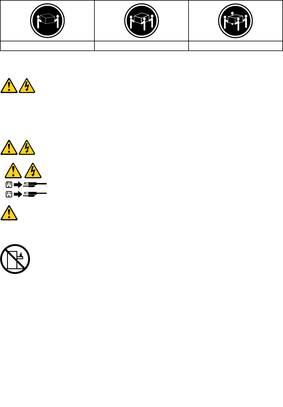
≥18kg(37lbs)≥32kg(70.5lbs)≥55kg(121.2lbs)
CAUTION:
Usesafepracticeswhenlifting.
CAUTION:
Thepowercontrolbuttononthedeviceandthepowerswitchonthepowersupplydonotturnoff
theelectricalcurrentsuppliedtothedevice.Thedevicealsomighthavemorethanonepower
cord.Toremoveallelectricalcurrentfromthedevice,ensurethatallpowercordsaredisconnected
fromthepowersource.
1
2
CAUTION:
Donotplaceanyobjectweighingmorethan82kg(180lbs.)ontopofrack-mounteddevices.
8IdeaCentreA730HardwareMaintenanceManual

Chapter3.Generalinformation
Thischapterprovidesgeneralinformationthatappliestoallcomputermodelscoveredbythismanual.
Specications
Thissectionliststhephysicalspecicationsforyourcomputer.
Thissectionliststhephysicalspecicationsforyourcomputer.
TypeIdeaCentreA730
Thissectionliststhephysicalspecications.
Environment
Airtemperature:
Operating:10°to35°C
Transit:-20°to55°C
Humidity:
Operating:35%to80%
Transit:20%to90%(40°C)
Altitude:86KPato106KPa
Electricalinput:
Inputvoltage:90V-264V(AC)
Inputfrequency:47Hz-63Hz
©CopyrightLenovo20139

10IdeaCentreA730HardwareMaintenanceManual

Chapter4.GeneralCheckout
Attention:Thedrivesinthecomputeryouareservicingmighthavebeenrearrangedorthedrivestartup
sequencemayhavebeenchanged.Beextremelycarefulduringwriteoperationssuchascopying,saving,or
formatting.Dataorprogramscanbeoverwrittenifyouselectanincorrectdrive.
Generalerrormessagesappearifaproblemorconictisfoundbyanapplication,theoperatingsystem,or
both.Foranexplanationofthesemessages,refertotheinformationsuppliedwiththatsoftwarepackage.
Usethefollowingproceduretohelpdeterminethecauseoftheproblem:
1.Power-offthecomputerandallexternaldevices.
2.Checkallcablesandpowercords.
3.Setalldisplaycontrolstothemiddleposition.
4.Power-onallexternaldevices.
5.Power-onthecomputer.
•Lookfordisplayederrorcodes.
•Lookforreadableinstructionsoramainmenuonthedisplay.
Ifyoudidnotreceivethecorrectresponse,proceedtostep6.
Ifyoudidreceivethecorrectresponse,proceedtostep7.
6.Ifoneofthefollowinghappens,followtheinstructiongiven:
•IfthecomputerdisplaysaPOSTerror,goto“POSTerrorcodes” .
•Ifthecomputerhangsandnoerrorisdisplayed,continueatstep7.
7.Iftheteststopsandyoucannotcontinue,replacethelastdevicetested.
©CopyrightLenovo201311

12IdeaCentreA730HardwareMaintenanceManual

Chapter5.UsingtheSetupUtility
TheSetupUtilityprogramisusedtoviewandchangethecongurationsettingsofyourcomputer,regardless
ofwhichoperatingsystemyouareusing.However,theoperatingsystemsettingsmightoverrideanysimilar
settingsintheSetupUtilityprogram.
StartingtheLenovoBIOSSetupUtilityprogram
TostarttheLenovoBIOSSetupUtilityprogram,dothefollowing:
1.Ifyourcomputerisalreadyonwhenyoustartthisprocedure,shutdowntheoperatingsystemand
turnoffthecomputer.
2.PressandholdtheF1keythenturnonthecomputer.WhentheLenovoBIOSSetupUtilityprogramis
displayed,releasetheF1key.
Note:IfaPower-OnPasswordoranAdministratorPasswordhasbeenset,theSetupUtilityprogrammenu
willnotbedisplayeduntilyoutypeyourpassword.Formoreinformation,see“Usingpasswords.”
Viewingandchangingsettings
SystemcongurationoptionsarelistedintheLenovoBIOSSetupUtilityprogrammenu.Tovieworchange
settings,see“StartingtheSetupUtilityprogram.”
YoumustusethekeyboardwhenusingtheLenovoBIOSSetupUtilitymenu.Thekeysusedtoperform
varioustasksaredisplayedonthebottomofeachscreen.
Usingpasswords
YoucanusetheLenovoBIOSSetupUtilityprogramtosetpasswordstopreventunauthorizedpersons
fromgainingaccesstoyourcomputeranddata.See“StartingtheSetupUtilityprogram.”Thefollowing
typesofpasswordsareavailable:
•AdministratorPassword
•Power-OnPassword
Youdonothavetosetanypasswordstouseyourcomputer.However,ifyoudecidetosetpasswords,read
thefollowingsections.
Passwordconsiderations
Apasswordcanbeanycombinationoflettersandnumbersupto16characters(a-zand0-9).Forsecurity
reasons,itisagoodideatouseastrongpasswordthatcannotbeeasilycompromised.Wesuggestthat
passwordsshouldfollowtheserules:
•Forastrongpassword,use7-16charactersandamixoflettersandnumbers.
•Donotuseyournameoryourusername.
•Donotuseacommonwordoracommonname.
•Usesomethingsignicantlydifferentfromyourpreviouspassword.
Attention:AdministratorandPower-Onpasswordsarenotcasesensitive.
©CopyrightLenovo201313

AdministratorPassword
SettinganAdministratorPassworddetersunauthorizedpersonsfromchangingcongurationsettings.You
mightwanttosetanAdministratorPasswordifyouareresponsibleformaintainingthesettingsofseveral
computers.
AfteryousetanAdministratorPassword,apasswordpromptisdisplayedeverytimeyouaccesstheLenovo
BIOSSetupUtilityprogram.
IfboththeAdministratorandPower-OnPasswordareset,youcantypeeitherpassword.However,youmust
useyourAdministratorPasswordtochangeanycongurationsettings.
Setting,changing,ordeletinganAdministratorpassword
TosetanAdministratorPassword,dothefollowing:
Note:Apasswordcanbeanycombinationoflettersandnumbersupto16characters(a-zand0-9).For
moreinformation,see“Passwordconsiderations”onpage13.
1.StarttheLenovoBIOSSetupUtilityprogram(see“StartingtheLenovoBIOSSetupUtilityprogram”on
page13).
2.FromtheSecuritymenu,selectSetAdministratorPasswordandpresstheEnterkey.
3.Thepassworddialogboxwillbedisplayed.TypethepasswordthenpresstheEnterkey.
4.Re-typethepasswordtoconrm,thenpresstheEnterkey.Ifyoutypedthepasswordcorrectly,
thepasswordwillbeinstalled.
TochangeanAdministratorPassword,dothefollowing:
1.StarttheLenovoBIOSSetupUtilityprogram(see“StartingtheLenovoBIOSSetupUtilityprogram”on
page13).
2.FromtheSecuritymenu,selectSetAdministratorPasswordandpresstheEnterkey.
3.Thepassworddialogboxwillbedisplayed.TypethecurrentpasswordthenpresstheEnterkey.
4.Typethenewpassword,thenpresstheEnterkey.Re-typethepasswordtoconrmthenewpassword.
Ifyoutypedthenewpasswordcorrectly,thenewpasswordwillbeinstalled.ASetupNoticedconrming
thatchangeshavebeensavedwillbedisplayed.
TodeleteapreviouslysetAdministratorPassword,dothefollowing:
1.FromtheSecuritymenu,selectSetAdministratorPasswordandpresstheEnterkey.
2.Thepassworddialogboxwillbedisplayed.TypethecurrentpasswordandpresstheEnterkey.
3.TodeleteanAdministratorPassword,leaveeachnewpasswordlineitemblank,thenpresstheEnter
key.ASetupNoticeconrmingthatchangeshavebeensavedwillbedisplayed.
4.ReturntotheLenovoBIOSSetupUtilityprogrammenuandselecttheExitoption.
5.SelectSavechangesandExitfromthemenu.
Power-OnPassword
WhenaPower-OnPasswordisset,youcannotstarttheLenovoBIOSSetupUtilityprogramuntilavalid
passwordistypedfromthekeyboard.
Setting,changing,ordeletingaPower-OnPassword
Note:Apasswordcanbeanycombinationoflettersandnumbersupto16characters(a-zand0-9).
14IdeaCentreA730HardwareMaintenanceManual

TosetaPower-OnPassword,dothefollowing:
1.StarttheLenovoBIOSSetupUtilityprogram(See”StartingtheLenovoBIOSSetupUtilityprogram”on
page13.)
2.FromtheSecuritymenu,selectSetPower-OnPasswordandpresstheEnterkey.
3.Thepassworddialogboxwillbedisplayed.Typethepassword,thenpresstheEnterkey.
4.Re-typethepasswordtoconrm.Ifyoutypedthepasswordcorrectly,thepasswordwillbeinstalled.
TochangeaPower-OnPassword,dothefollowing:
1.StarttheLenovoBIOSSetupUtilityprogram(See”StartingtheLenovoBIOSSetupUtilityprogram”on
page13.)
2.FromtheSecuritymenu,selectSetPower-OnPasswordandpresstheEnterkey.
3.Thepassworddialogboxwillbedisplayed.TypethecurrentpasswordthenpresstheEnterkey.
4.Typethenewpassword,thenpresstheEnterkey.Re-typethepasswordtoconrmthenewpassword.
Ifyoutypedthenewpasswordcorrectly,thenewpasswordwillbeinstalled.ASetupNoticedconrming
thatchangeshavebeensavedwillbedisplayed.
TodeleteapreviouslysetPower-OnPassword,dothefollowing:
1.FromtheSecuritymenu,selectSetPower-OnPasswordandpresstheEnterkey.
2.Thepassworddialogboxwillbedisplayed.TypethecurrentpasswordandpresstheEnterkey.
3.TodeletethePower-OnPassword,leaveeachnewpasswordlineitemblank,thenpressEnter.ASetup
Noticeconrmingthatchangeshavebeensavedwillbedisplayed.
4.ReturntotheLenovoBIOSSetupUtilityprogrammenuandselecttheExitoption.
5.SelectSavechangesandExitfromthemenu.
Enablingordisablingadevice
TheDevicesoptionsisusedtoenableordisableuseraccesstothefollowingdevices:
USBFunctionsSelectwhethertoenableordisableUSB(UniversalSerial
Bus)functions.Ifthefunctionsaredisabled,noUSB
devicescanbeused.
SATAModeWhenthisfeatureissettoDisabled,alldevices
connectedtotheSATAconnectors(e.g.harddiskdrives
ortheopticaldiskdrive)aredisabledandcannotbe
accessed.
OnboardAudioControllerSelectwhethertoenableordisabletheOnboard
AudioController.WhenthisfeatureissettoDisabled
alldevicesconnectedtotheaudioconnectors(e.g.
headphonesoramicrophone)aredisabledandcannot
beused.
OnboardEthernetControllerorLANBootAgentSelectwhethertoenableordisabletheOnboardEthernet
Controller,orselectwhethertoenableordisableload
onboardPXE(PrebootExecutionEnvironment).
Toenableordisableadevice,dothefollowing:
1.StarttheSetupUtilityprogram(see“StartingtheSetupUtilityprogram”onpage13).
2.FromtheSetupUtilityprogrammenu,selectDevices.
3.Selectanoptionasfollows:
SelectUSBSetup,presstheEnterkey,thenselectUSBFunctions.
Chapter5.UsingtheSetupUtility15

SelectATADeviceSetup,presstheEnterkey,thenselectSATAMode.
SelectAudioSetup,presstheEnterkey,thenselectOnboardAudioController.
SelectNetworkSetup,presstheEnterkey,thenselectOnboardEthernetSupportorLANBoot
Agent.
4.SelectDisabledorEnabledandpresstheEnterkey.
5.ReturntotheLenovoBIOSSetupUtilityprogrammenuandselecttheExitoption.
6.SelectSavechangesandExitfromthemenu.
Notes:
a.Ifyoudonotwanttosavethesettings,selectDiscardchangesandExitfromthemenu.
b.SelectIDE/AHCIMode:DevicedriversupportisrequiredforACHI.Dependingonhowtheharddisk
imagewasinstalled,changingthissettingmaypreventthesystemfrombooting.
Selectingastartupdevice
IfyourcomputerdoesnotbootfromadevicesuchastheCD/DVD-ROMdrivediskorharddiskasexpected,
followoneoftheproceduresbelow.
Selectingatemporarystartupdevice
Usethisproceduretostartupfromanybootdevice.
Note:NotallCDs,DVDsorharddiskdrivesarebootable.
1.Turnoffyourcomputer.
2.PressandholdtheF12keythenturnonthecomputer.WhentheStartupDeviceMenuappears,
releasetheF12key.
Note:IftheStartupDeviceMenudoesnotdisplayusingthesesteps,repeatedlypressandreleasethe
F12keyratherthankeepingitpressedwhenturningonthecomputer.
3.Use↑and↓arrowstoselectthedesiredstartupdevicefromtheStartupDeviceMenuandpress
theEnterkeytobegin.
Note:SelectingastartupdevicefromtheStartupDeviceMenudoesnotpermanentlychangethe
startupsequence.
Selectingorchangingthestartupdevicesequence
Tovieworpermanentlychangetheconguredstartupdevicesequence,dothefollowing:
1.StarttheLenovoBIOSSetupUtilityprogram(see“StartingtheLenovoBIOSSetupUtilityprogram”on
page13).
2.FromtheLenovoBIOSSetupUtilityprogrammainmenu,selecttheStartupoption.
3.PresstheEnterkey,andselectthedevicesforthePrimaryBootSequence.Readtheinformation
displayedontherightsideofthescreen.
4.Use↑and↓arrowstoselectadevice.Usethe<+>or<->keystomoveadeviceupordown.Usethe
<×>keytoexcludethedevicefromorincludethedeviceinthebootsequence.
5.ReturntotheLenovoBIOSSetupUtilityprogrammenuandselecttheExitoption.
6.SelectSavechangesandExitfromthemenu.
Notes:
16IdeaCentreA730HardwareMaintenanceManual

a.Ifyoudonotwanttosavethesettings,selectDiscardchangesandExitfromthemenu.
b.Ifyouhavechangedthesesettingsandwanttoreturntothedefaultsettings,selectLoadOptimal
Defaultsfromthemenu.
ExitingtheLenovoBIOSSetupUtilityprogram
Afteryounishviewingorchangingsettings,presstheEsckeytoreturntotheLenovoBIOSSetupUtility
programmainmenu.YoumighthavetopresstheEsckeyseveraltimes.Dooneofthefollowing:
•Ifyouwanttosavethenewsettings,selectSavechangesandExitfromthemenu.WhentheSave&
resetwindowshows,selecttheYesbutton,andthenpresstheEnterkeytoexittheLenovoBIOS
SetupUtilityprogram.
•Ifyoudonotwanttosavethesettings,selectDiscardchangesandExitfromthemenu.Whenthe
ResetWithoutSavingwindowshows,selecttheYesbutton,andthenpresstheEnterkeytoexitthe
LenovoBIOSSetupUtilityprogram.
Chapter5.UsingtheSetupUtility17

18IdeaCentreA730HardwareMaintenanceManual

Chapter6.Symptom-to-FRUIndex
TheSymptom-to-FRUindexlistserrorsymptomsandpossiblecauses.Themostlikelycauseislistedrst.
AlwaysbeginwithChapter4,“GeneralCheckout,”onpage11.Thisindexcanalsobeusedtohelpyou
decidewhichFRUstohaveavailablewhenservicingacomputer.Ifyouareunabletocorrecttheproblem
usingthisindex,goto“Undeterminedproblems”onpage20.
Notes:
•Ifyouhavebothanerrormessageandanincorrectaudioresponse,diagnosetheerrormessagerst.
•Ifyoucannotrunthediagnostictestsoryougetadiagnosticerrorcodewhenrunningatestbutdid
receiveaPOSTerrormessage,diagnosethePOSTerrormessagerst.
•Ifyoudidnotreceiveanyerrormessagelookforadescriptionofyourerrorsymptomsintherstpartof
thisindex.
Harddiskdrivebooterror
Aharddiskdrivebooterrorcanbecausedbythefollowing.
ErrorFRU/Action
Thestartupdriveisnotincludedinthebootsequence
conguration.
Checkthecongurationandensurethestartupdriveis
inthebootsequence.
Nooperatingsystemisinstalledonthebootdrive.Installanoperatingsystemonthebootdrive.
Thebootsectoronthestartupdriveiscorrupted.Thedrivemustbeformatted.Dothefollowing:
1.Attempttobackupthedataonthefailingharddisk
drive.
2.Usetheoperatingsystemtoformattheharddisk
drive.
Thedriveisdefective.Replacetheharddiskdrive.
PowerSupplyProblems
Followtheseproceduresifyoususpectthereisapowersupplyproblem.
Check/VerifyFRU/Action
Checkthatthefollowingareproperlyinstalled:
•PowerCord
•On/OffSwitchconnector
•SystemBoardPowerSupplyconnectors
•Microprocessorconnections
Reseatconnectors
Checkthepowercord.PowerCord
Checkthepower-onswitch.Power-onSwitch
©CopyrightLenovo201319
POSTerrorcodes
Eachtimeyouturnthecomputeron,itperformsaseriesofteststocheckthatthesystemisoperating
correctlyandthatcertainoptionsareset.ThisseriesoftestsiscalledthePower-OnSelf-Test,orPOST.
POSTdoesthefollowing:
•Checkssomebasicmotherboardoperations
•Checksthatthememoryisworkingcorrectly
•Startsvideooperations
•Veriesthatthebootdriveisworking
POSTErrorMessageDescription/Action
KeyboarderrorCannotinitializethekeyboard.Makesurethekeyboard
isproperlyconnectedtothecomputerandthatnokeys
areheldpressedduringPOST.Topurposelycongure
thecomputerwithoutakeyboard,selectKeyboardless
operationinStartupandsettheoptiontoEnabled.The
BIOSthenignoresthemissingkeyboardduringPOST.
RebootandSelectproperBootdeviceorInsertBoot
MediainselectedBootdevice
TheBIOSwasunabletondasuitablebootdevice.Make
surethebootdriveisproperlyconnectedtothecomputer.
Makesureyouhavebootablemediainthebootdevice.
Undeterminedproblems
1.Power-offthecomputer.
2.Removeordisconnectthefollowingcomponents(ifconnectedorinstalled)oneatatime.
a.Externaldevices(modem,printer,ormouse)
b.Extendedvideomemory
c.ExternalCache
d.ExternalCacheRAM
e.Harddiskdrive
f.Diskdrive
3.Power-onthecomputertore-testthesystem.
4.Repeatsteps1through3untilyoundthefailingdeviceorcomponent.
Ifalldevicesandcomponentshavebeenremovedandtheproblemcontinues,replacethesystemboard.
20IdeaCentreA730HardwareMaintenanceManual
Chapter7.Locatingconnectors,controlsandcomponents
Thissectionprovidesillustrationstohelplocatethevariousconnectors,controlsandcomponentsofthe
computer.
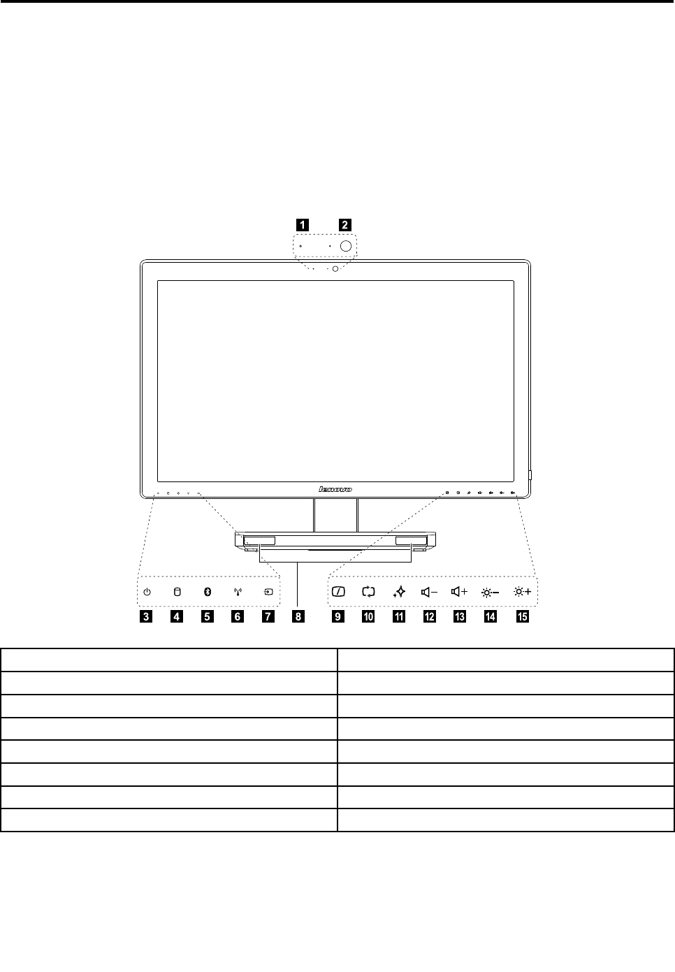
Fontview
Thefollowingillustrationshowsthelocationofcontrolsandcomponentsonthefrontofthecomputer.
Attention:Becarefulnottoblockanyairventsonthecomputer.Blockedairventscancauseoverheating.
12
3765489
101112131415
1.Built-inmicrophone9.MonitorOn/Off
2.Built-incamera10.PCmode/HDMI-in/AV-inswitch
3.Powerindicator11.NovoVisionbutton
4.Harddiskdriveindicator12.Volumedown
5.Bluetoothstatusindicator13.Volumeup
6.WIFIstatusindicator14.Brightnessdown
7.HDMI-inindicator15.Brightnessup
8.Built-inspeakers
©CopyrightLenovo201321
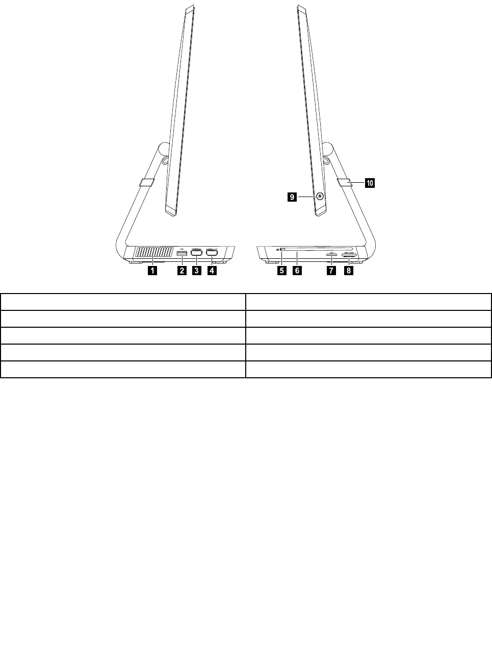
Leftandrightview
Thefollowingillustrationshowsthelocationofconnectors,controlsandcomponentsontheleftandright
sideofthecomputer.
234685
9
10
71
1.Airvents6.Opticaldrive
2.USB3.0connector7.B-CAScardslot(Japanmodelsonly)
3.HDMI-inconnector(selectedmodelsonly)8.Memorycardreader
4.HDMI-outconnector9.Powerbutton
5.Ejectbutton10.Anti-scratchprotector
Attention:Donotinsert3-inchdiscsintotheopticaldrive.
22IdeaCentreA730HardwareMaintenanceManual
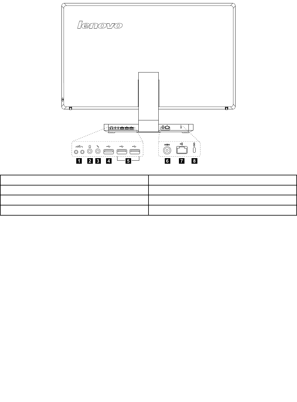
Rearview
Thefollowingillustrationshowsthelocationofconnectorsandcomponentsontherearofthecomputer.
12387645
1.TVtunerconnector(selectedmodelsonly)5.USB2.0connectors(2)
2.Headphoneconnector6.Powerconnector
3.Microphoneconnector7.Ethernetconnector(RJ45)
4.USB3.0connector8.Securitycableslot
Chapter7.Locatingconnectors,controlsandcomponents23
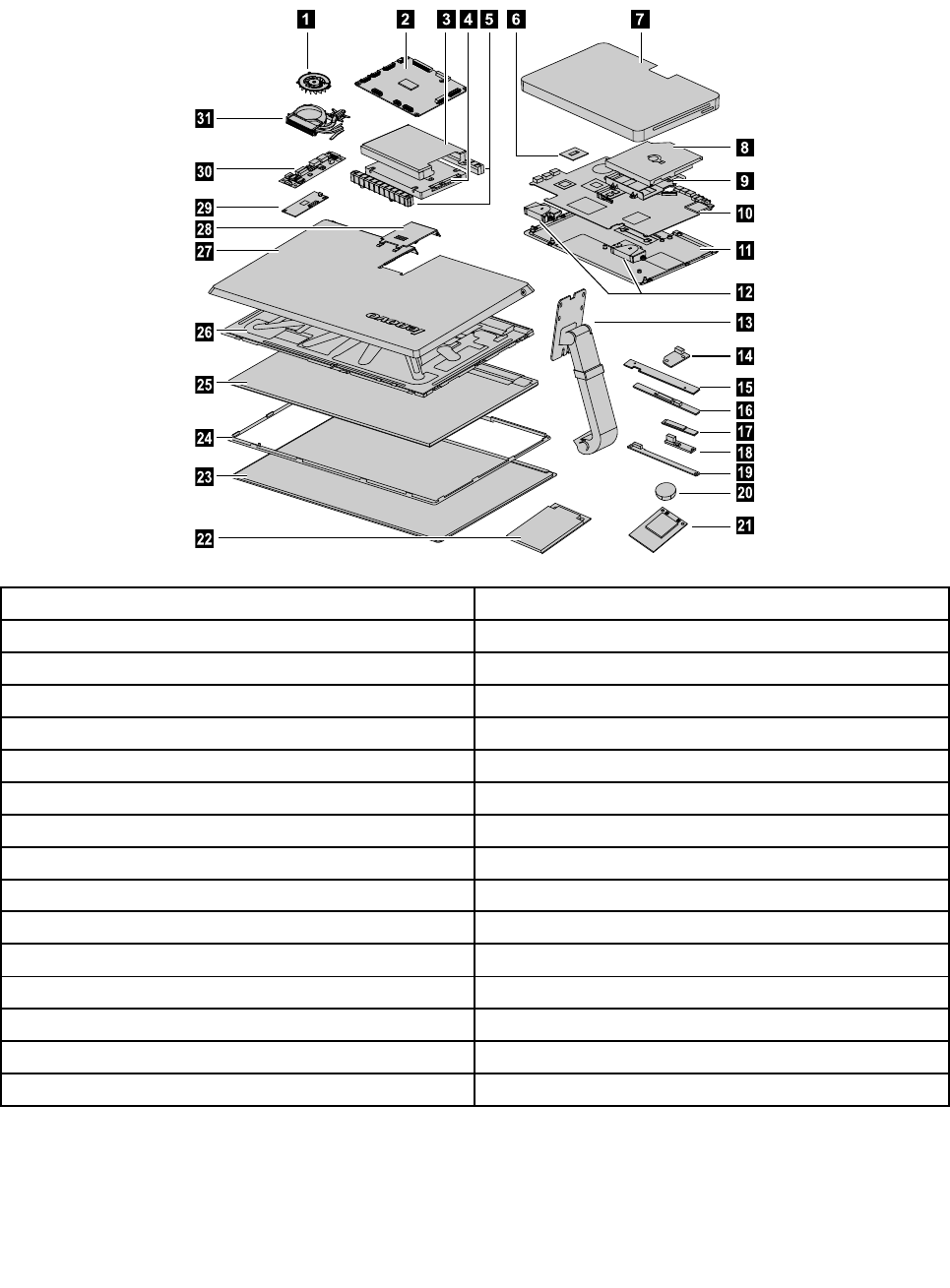
Hardwarecomponents
Thefollowingillustrationshowsthecomponentsthatmakeupyourcomputer.
4567
9
10
11
12
13
14
15
16
17
18
19
20
21
8
23
24
25
26
27
28
29
30
31
22
1.Systemfan17.Bluetoothmodule
2.Scalarboard18.Powerswitchboard
3.Harddiskdrivebracket19.Frontfunctionboard
4.Harddiskdrive20.Battery
5.Harddiskdriverubbers21.Solidstatedisk
6.CPU22.TV-tunercard
7.Basecover23.Glass
8.Opticaldrive24.Panelframe
9.Opticaldrivebracket25.LEDpanel
10.Motherboard26.Middleframe
11.Chassis27.Rearcover
12.Speakers28.Rearcoverdeco
13.Hinge29.Touchcontrolboard
14.Opticaldriveejectboard30.Converter
15.Camera31.Heat-sink
16.WLANcard
24IdeaCentreA730HardwareMaintenanceManual
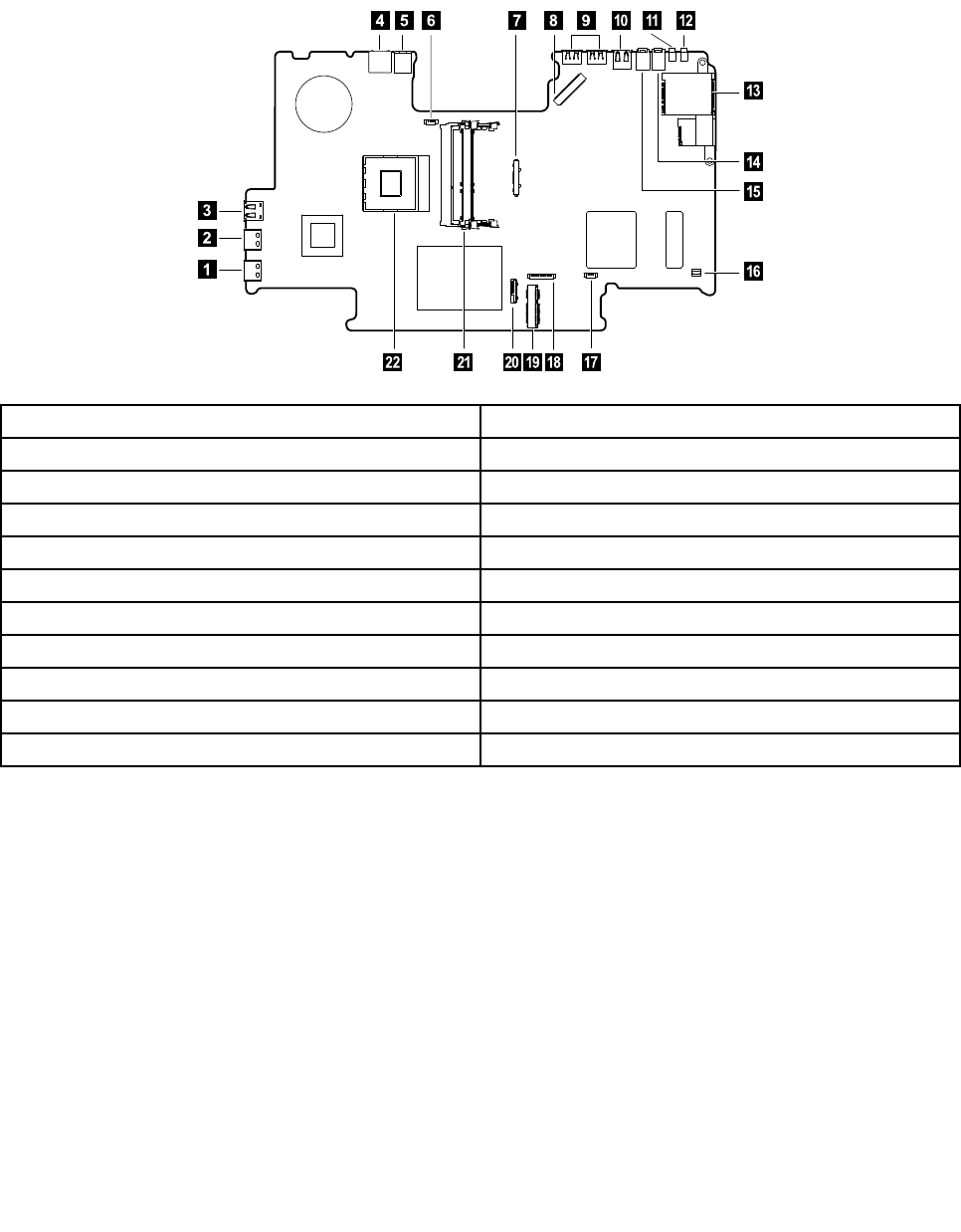
Identifyingpartsonthemotherboard
Themotherboard(sometimescalledtheplanarorsystemboard)isthemaincircuitboardinyourcomputer.
Itprovidesbasiccomputingfunctionsandsupportsavarietyofdevicesthatarefactory-installedorthat
youcaninstalllater.Thefollowingillustrationshowsthelocationofconnectorsandcomponentsonthe
frontofthemotherboard.
1.HDMI-outconnector12.TVjack2(Japanonly)
2.HDMI-inconnector13.Cardreader
3.USB3.0connector14.Microphoneconnector
4.Ethernetconnector(RJ45)15.Headphoneconnector
5.Powerconnector16.Opticaldriveejectbuttonconnector
6.Systemfanconnector17.Speakerconnector
7.Scalarcableconnector18.Opticaldriveconnector
8.Scalarcableconnector19.Solidstatediskconnector
9.USB2.0connectors(2)20.Harddiskdriveconnector
10.USB3.0connector21.Memoryslot
11.TVjack122.CPUsocket
Chapter7.Locatingconnectors,controlsandcomponents25
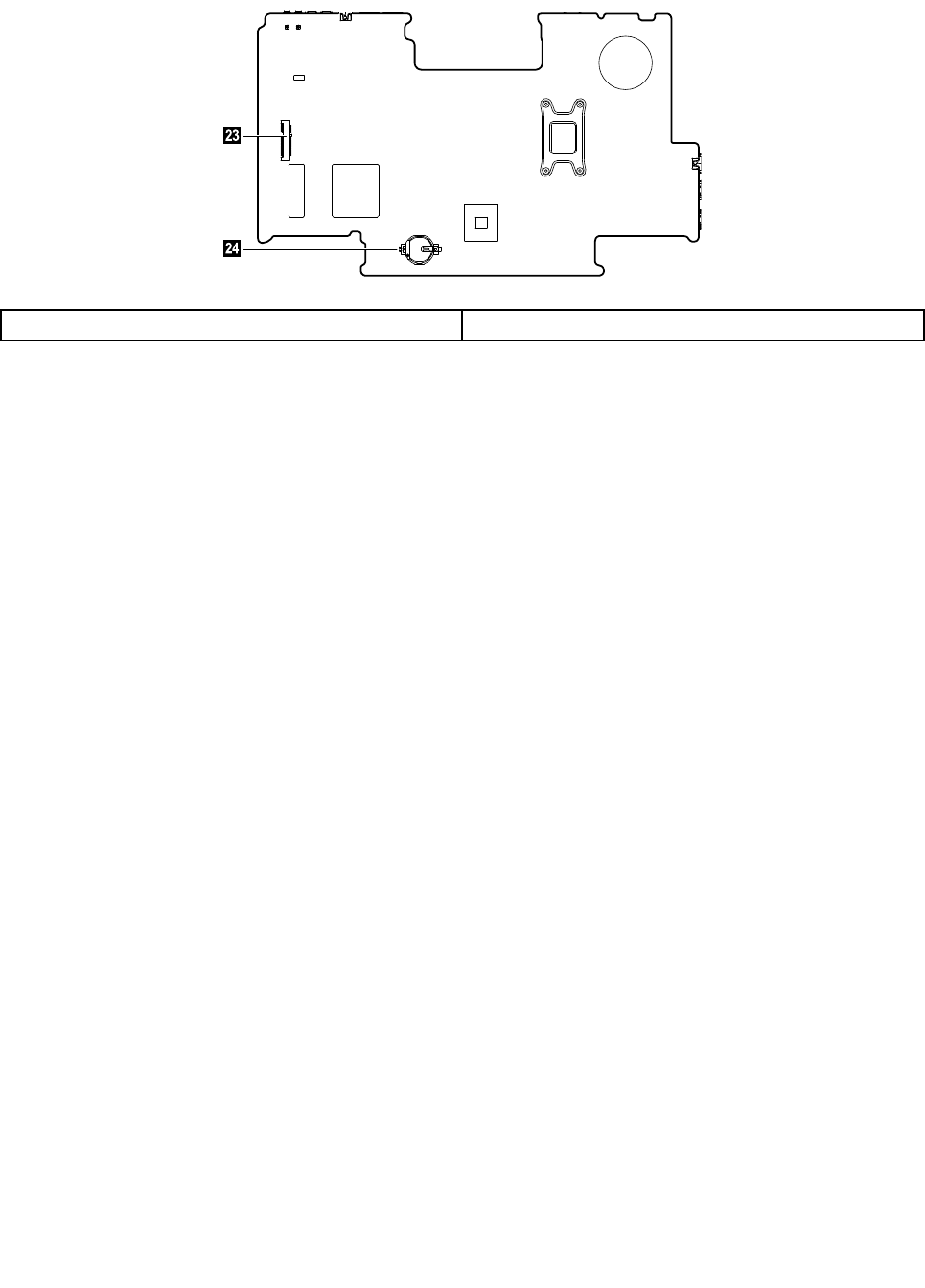
Thefollowingillustrationshowsthelocationofconnectorsandcomponentsonthebackofthemotherboard.
23.TV-Tunercardconnector24.Battery
26IdeaCentreA730HardwareMaintenanceManual
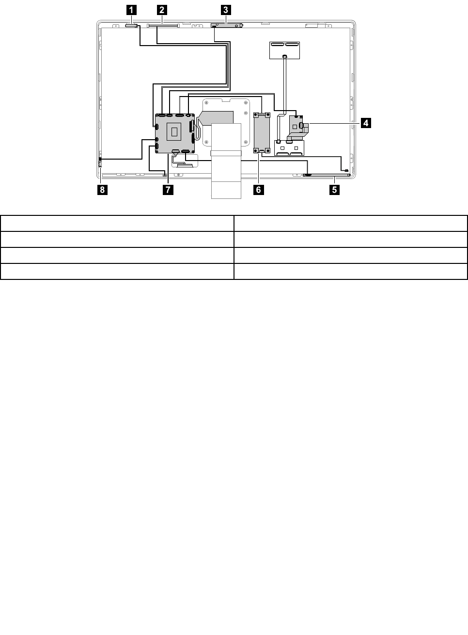
IdentifyingpartsonthebackoftheLEDpanel
ThefollowingillustrationshowsthecomponentsandcontrolsonthebackofLEDpanel.
123
4
5678
1.Bluetoothmodule5.Frontfunctionboard
2.WLANcard6.Converterboard
3.Camera7.Scalarboard
4.Touchcontrolboard8.Powerswitchboard
Chapter7.Locatingconnectors,controlsandcomponents27

28IdeaCentreA730HardwareMaintenanceManual

Chapter8.Replacinghardware
Attention:Donotremovethecomputercoverorattemptanyrepairbeforereadingthe“Importantsafetyinformation”
intheSafetyandWarrantyGuidethatwasincludedwithyourcomputer.T oobtaincopiesoftheSafetyandWarranty
Guide,gototheSupportWebsiteat:http://consumersupport.lenovo.com.
Note:UseonlypartsprovidedbyLenovo.
Generalinformation
Pre-disassemblyinstructions
Beforestartingthedisassemblyprocedure,makesurethatyoudothefollowing:
1.Turnoffthepowertothesystemandallperipherals.
2.Unplugallpowerandsignalcablesfromthecomputer.
3.Placethesystemonaat,stablesurface.
©CopyrightLenovo201329
Replacingthekeyboardandmouse
Attention:Turnoffthecomputerandwait3to5minutestoletitcooldownbeforeremovingthecover.
Toreplacethekeyboardandmouse
Step1.Removeanymedia(disks,CDs,DVDsormemorycards)fromthedrives,shutdowntheoperating
system,andturnoffthecomputerandallattacheddevices.
Step2.Unplugallpowercordsfromelectricaloutlets.
Step3.Disconnectallcablesattachedtothecomputer.Thisincludespowercords,input/output(I/O)
cables,andanyothercablesthatareconnectedtothecomputer.Referto“Leftandrightview”
and“Rearview”forhelpwithlocatingthevariousconnectors.
Note:YourkeyboardwillbeconnectedtoaUSBconnectorononesideorattherearofthe
computer.
Step4.Disconnectthedefectivekeyboardcablefromthecomputerandconnectthenewkeyboardcable
tothesameconnector.
Note:Themousecanbereplacedusingthesamemethod.
Replacingthepowercordorpoweradapter
Attention:Turnoffthecomputerandwait3to5minutestoletitcooldownbeforeremovingthecover.
Toreplacethepowercordandpoweradapter:
Step1.Removeanymedia(disks,CDs,DVDs,ormemorycards)fromthedrives,shutdowntheoperating
system,andturnoffthecomputerandallattacheddevices.
30IdeaCentreA730HardwareMaintenanceManual
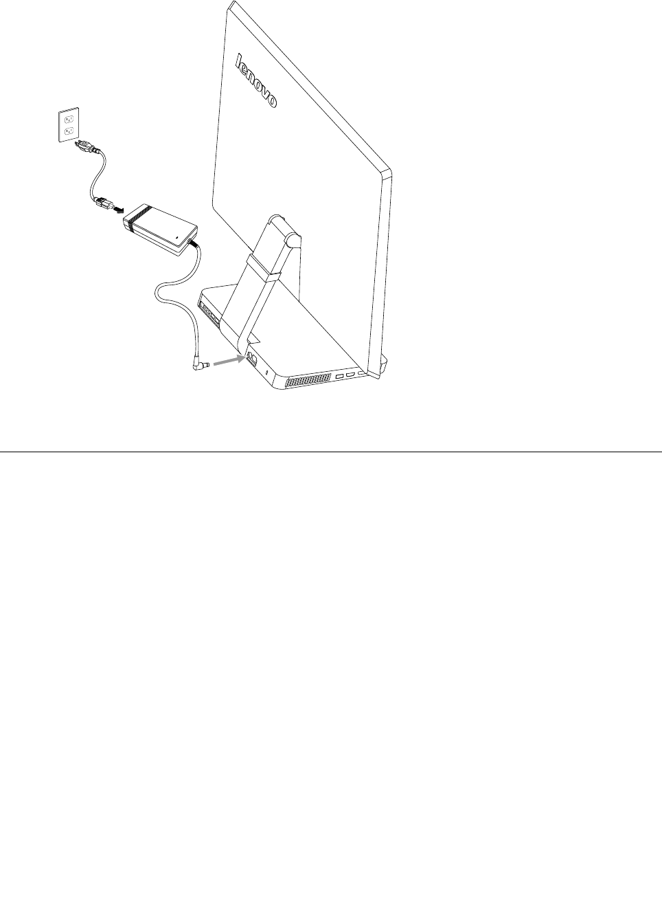
Step2.Locatetheconnectorforthepowercord.Referto“Rearview” .
Step3.Disconnectthefailingpowercordandadapterfromthecomputerandconnectthenewpowercord
andadaptertothesameconnector.
Removingthebasecover
Note:Turnoffthecomputerandwait3to5minutestoletitcooldownbeforeremovingthecover.
Note:Itmaybehelpfultoplacethecomputerface-downonasoftatsurfaceforthisprocedure.Lenovo
recommendsthatyouuseablanket,towel,orothersoftclothtoprotectthecomputerscreenfromscratches
orotherdamage.
Toremovethebasecover
Step1.Removeanymedia(disks,CDs,DVDs,ormemorycards)fromthedrives,shutdowntheoperating
system,andturnoffthecomputerandallattacheddevices.
Step2.Unplugallpowercordsfromelectricaloutlets.
Step3.Disconnectallcablesattachedtothecomputer.Thisincludespowercords,input/output(I/O)
cables,andanyothercablesthatareconnectedtothecomputer.Referto“Leftandrightview”
and“Rearview”forhelpwithlocatingthevariousconnectors.
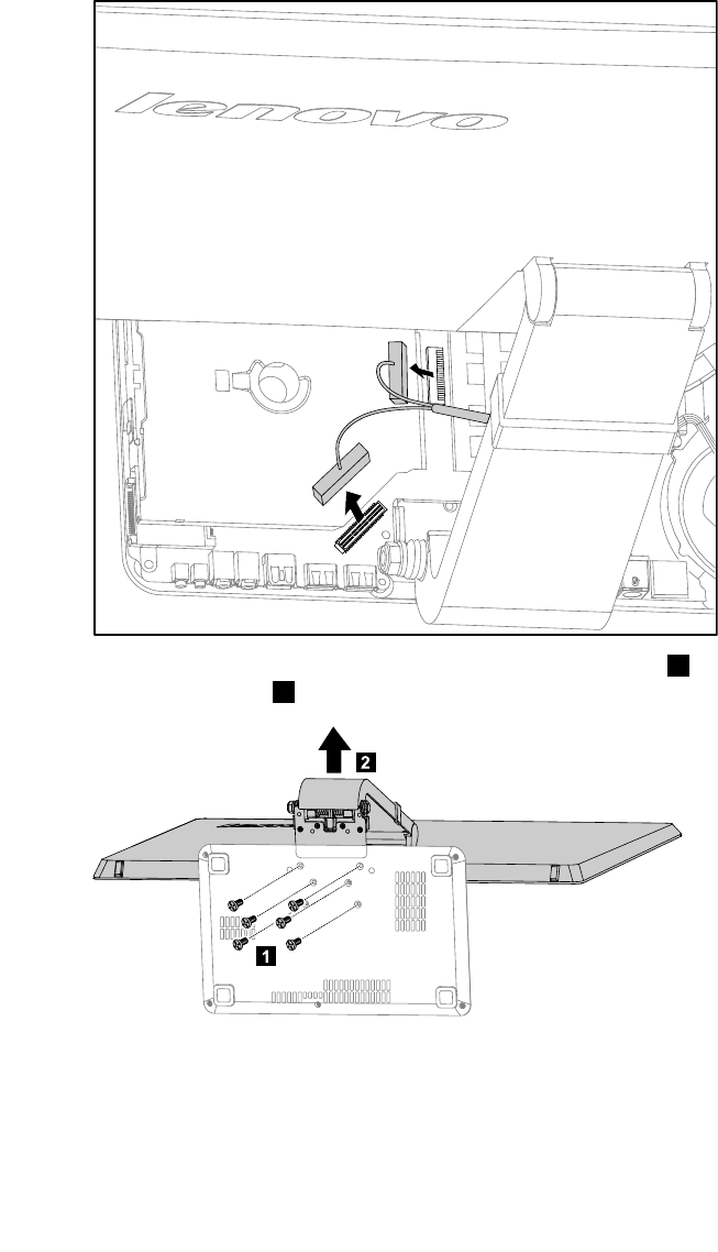
Step4.Placethecomputerface-downonasoftatsurface,thenremovethe7screwsthatsecurethe
basecovertothebase.
Chapter8.Replacinghardware31
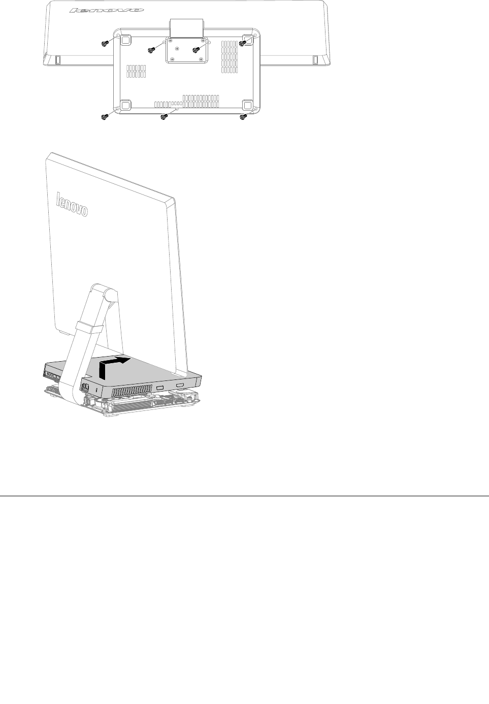
Step5.Returnthecomputertoanuprightposition,thenliftthebasecoverupandslideitoutasshown.
Step6.Toreattachthebasecover:
a.Lineupthebasecoverwiththebase,slideitbackandsnapitintoposition.
b.Placethecomputerface-downonasoftatsurface,thensecurethebasecovertothebase
withthe7screws.
Replacingtheharddiskdrive
Attention:Turnoffthecomputerandwait3to5minutestoletitcooldownbeforeremovingthecover.
Toreplacetheharddiskdrive
Step1.Removeanymedia(disks,CDs,DVDsormemorycards)fromthedrives,shutdowntheoperating
system,andturnoffthecomputerandallattacheddevices.
Step2.Unplugallpowercordsfromelectricaloutlets.
Step3.Disconnectallcablesattachedtothecomputer.Thisincludespowercords,input/output(I/O)
cables,andanyothercablesthatareconnectedtothecomputer.Referto“Leftandrightview”
and“Rearview”forhelpwithlocatingthevariousconnectors.
Step4.Removethebasecover.Referto“Removingthebasecover” .
32IdeaCentreA730HardwareMaintenanceManual
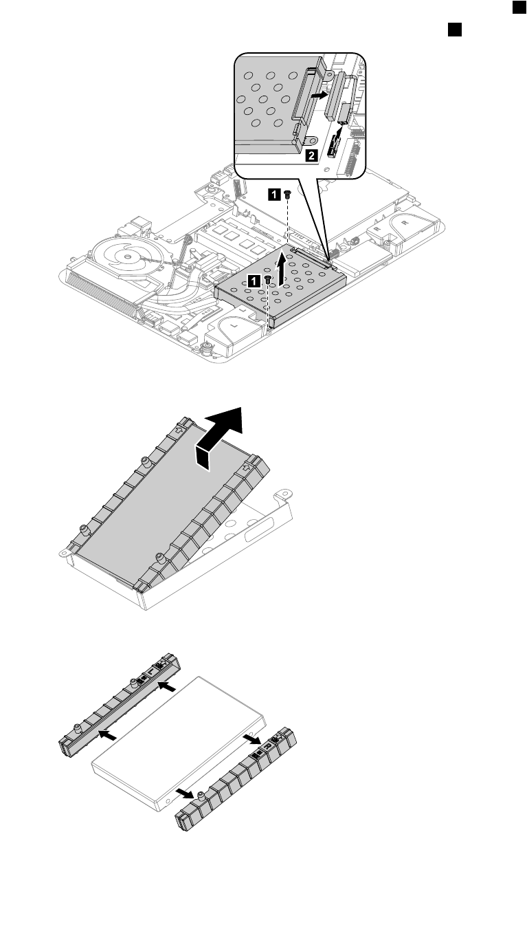
Step5.Removethe2screwsthatsecuretheharddiskdrivetothemotherboard.1
Step6.Disconnectthedataandpowercablefromtheharddiskdrive.2
1
1
2
Step7.Slidetheharddiskdriveandrubberoutofthebayasshown.
Step8.Detachtherubbersfromtheharddiskdriveasshown.
Step9.Installthenewharddiskdriveasfollows:
a.Attachtherubberstothenewharddiskdrive.
b.Lineupthenewharddiskdriveandslideitbackintotheharddiskdrivebay.
Chapter8.Replacinghardware33
c.Securethenewharddiskdrivetomotherboardwiththe2screws.
d.Connectthedataandpowercabletothenewharddiskdriveandmotherboard.
Step10.Reattachthebasecoverandsecureitwiththescrews.
Replacingamemorymodule
Attention:Turnoffthecomputerandwait3to5minutestoletitcooldownbeforeremovingthecover.
Toreplaceamemorymodule
Step1.Removeanymedia(disks,CDs,DVDs,ormemorycards)fromthedrives,shutdowntheoperating
system,andturnoffthecomputerandallattacheddevices.
Step2.Unplugallpowercordsfromelectricaloutlets.
Step3.Disconnectallcablesattachedtothecomputer.Thisincludespowercords,input/output(I/O)
cables,andanyothercablesthatareconnectedtothecomputer.Referto“Leftandrightview”
and“Rearview”forhelpwithlocatingthevariousconnectors.
Step4.Removethebasecover.Referto“Removingthebasecover” .
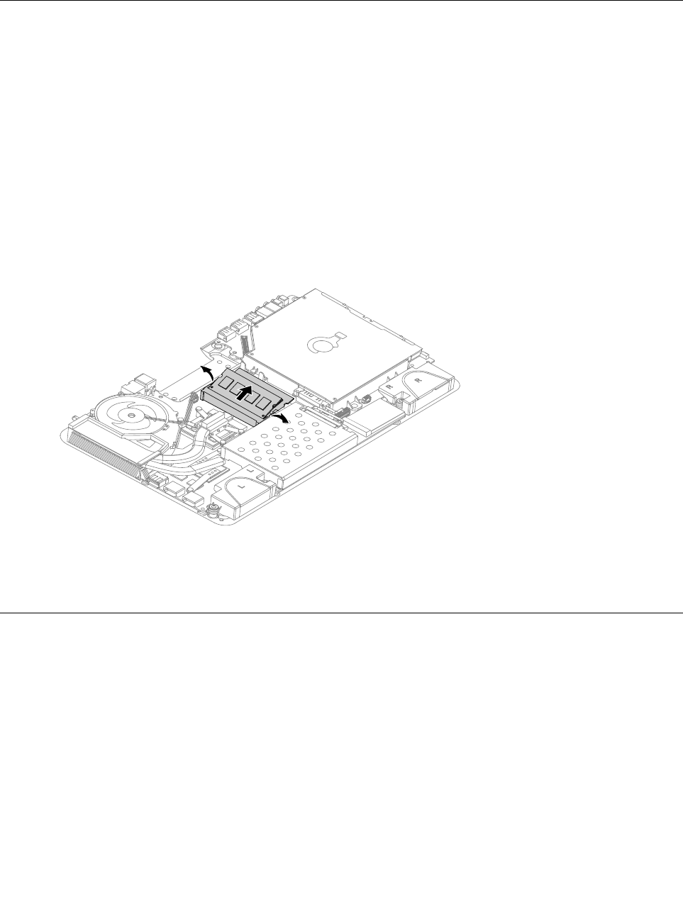
Step5.Pushoutthelatchesonbothsidesofthememorysockettoreleasethememorymodule.Gently
pullthememorymoduleupwardtoremoveitfromitssocket.
Step6.Alignthenewmemorymodulewiththememorysocket,theninsertitandpushdownonthetop
edge.Makesurethelatcheslockthememorymoduleinplace.
Step7.Reattachthebasecoverandsecureitwiththescrews.
Replacingthesystemfan
Note:Turnoffthecomputerandwait3to5minutestoletitcooldownbeforeremovingthecover.
Toreplacethesystemfan
Step1.Removeanymedia(disks,CDs,DVDsormemorycards)fromthedrives,shutdowntheoperating
system,andturnoffthecomputerandallattacheddevices.
Step2.Unplugallpowercordsfromelectricaloutlets.
Step3.Disconnectallcablesattachedtothecomputer.Thisincludespowercords,input/output(I/O)
cables,andanyothercablesthatareconnectedtothecomputer.Referto“Leftandrightview”
and“Rearview”forhelpwithlocatingthevariousconnectors.
Step4.Removethebasecover.Referto“Removingthebasecover” .
34IdeaCentreA730HardwareMaintenanceManual
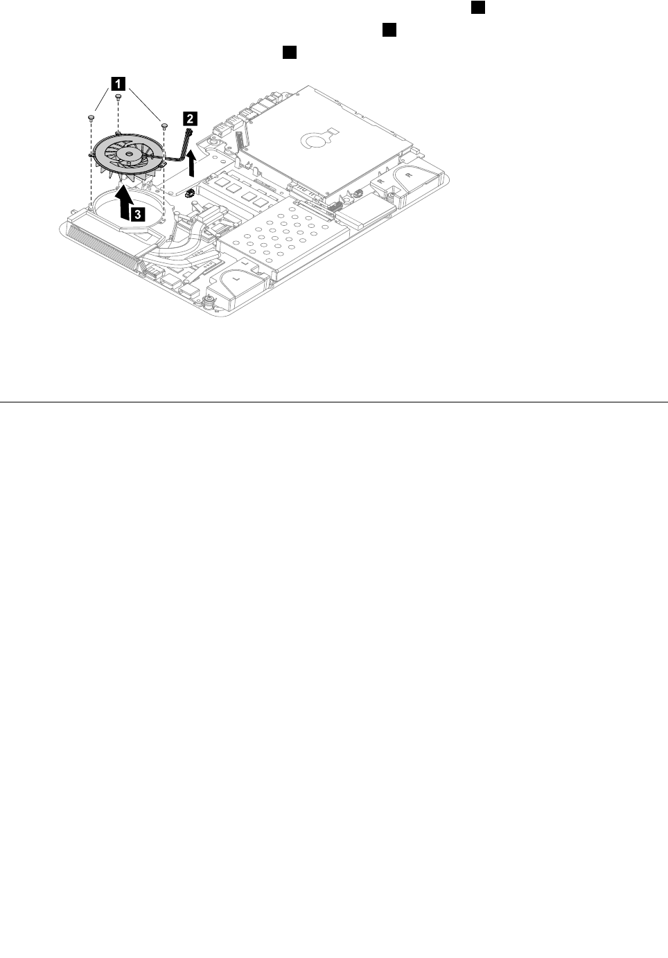
Step5.Removethe3screwsthatsecurethesystemfantotheheat-sink.1
Step6.Disconnectthepowercablefromthemotherboard.2
Step7.Liftthesystemfanuptoremoveit.3
1
2
3
Step8.Lineupthenewsystemfan,thensecureittotheheat-sinkandconnectthenewpowercable
tothemotherboard.
Step9.Reattachthebasecoverandsecureitwiththescrews.
Replacingtheheat-sink
Note:Turnoffthecomputerandwait3to5minutestoletitcooldownbeforeremovingthecover.
Toreplacetheheat-sink:
Step1.Removeanymedia(disks,CDs,DVDsormemorycards)fromthedrives,shutdowntheoperating
system,andturnoffthecomputerandallattacheddevices.
Step2.Unplugallpowercordsfromelectricaloutlets.
Step3.Disconnectallcablesattachedtothecomputer.Thisincludespowercords,input/output(I/O)
cables,andanyothercablesthatareconnectedtothecomputer.Referto“Leftandrightview”
and“Rearview”forhelpwithlocatingthevariousconnectors.
Step4.Removethebasecover.Referto“Removingthebasecover” .
Step5.Removethesystemfan.Referto“Replacingthesystemfan” .
Step6.Removethe9screwsthatsecuretheheat-sinktothemotherboard.
Chapter8.Replacinghardware35
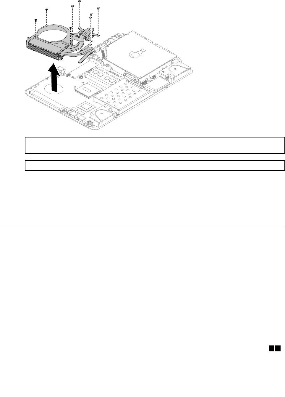
Step7.Removetheheat-sinkbyliftingitup.
Attention:Placetheheat-sinkupsidedownonaatsurfacetopreventthermalgreasefromcontaminating
othercomponents.
Attention:Useanalcoholpadtowipethethermalgreaseofftheheat-sinkandCPU.
Step8.Useathermalgreasesyringetoplace5dropsofgreaseonthetopofthemicroprocessor.Each
dropofgreaseshouldbe0.03ml(3tickmarksonthegreasesyringe).
Step9.Lineupthenewheat-sinkthensecureittothemotherboardwiththe9screws.
Step10.Attachthesystemfantothenewheat-sinkandsecureitwiththescrews.
Step11.Reattachthebasecoverandsecureitwiththescrews.
ReplacingtheCPU
Note:Turnoffthecomputerandwait3to5minutestoletitcooldownbeforeremovingthecover.
ToreplacetheCPU
Step1.Removeanymedia(disks,CDs,DVDs,ormemorycards)fromthedrives,shutdowntheoperating
system,andturnoffthecomputerandallattacheddevices.
Step2.Unplugallpowercordsfromelectricaloutlets.
Step3.Disconnectallcablesattachedtothecomputer.Thisincludespowercords,input/output(I/O)
cables,andanyothercablesthatareconnectedtothecomputer.Referto“Leftandrightview”
and“Rearview”forhelpwithlocatingthevariousconnectors.
Step4.Removethebasecover.Referto“Removingthebasecover” .
Step5.Removethesystemfan.Referto“Replacingthesystemfan” .
Step6.Removetheheat-sink.Referto“Replacingtheheat-sink” .
Step7.UseaatheadscrewdrivertoturntheCPUlockscrewcounterclockwisetounlocktheCPU.12
36IdeaCentreA730HardwareMaintenanceManual
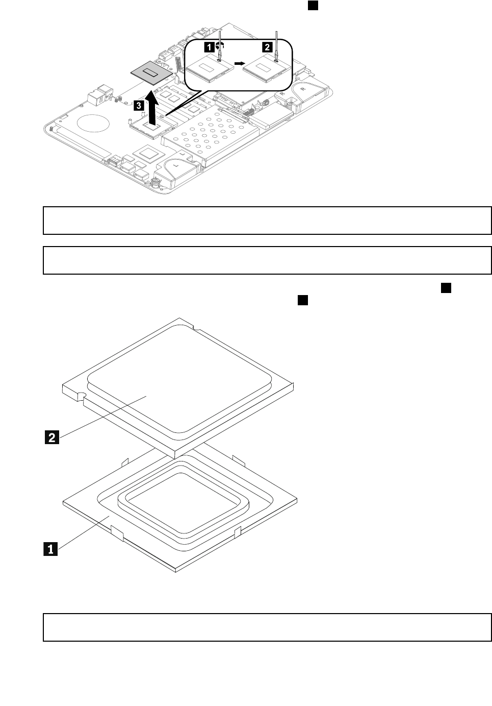
Step8.Liftthemicroprocessorstraightupandoutofthesocket.3
12
3
Attention:Donottouchthegoldcontactsonthebottomofthemicroprocessor.Whenhandlingthe
microprocessor,touchonlythesides.
Note:Donotdropanythingontothemicroprocessorsocketwhileitisexposed.Thesocketpinsmust
bekeptascleanaspossible.
Step9.Holdingthesidesofthemicroprocessorwithyourngers,removetheprotectivecover1that
protectsthegoldcontactsonthenewmicroprocessor.2
Step10.Holdingthesidesofthemicroprocessorwithyourngers,positionthemicroprocessorsothatthe
notchesonthemicroprocessorarealignedwiththetabsinthemicroprocessorsocket.
Important:Toavoiddamagingthemicroprocessorcontacts,keepthemicroprocessorcompletelylevel
whileinstallingitintothesocket.
Chapter8.Replacinghardware37

Step11.Lowerthemicroprocessorstraightdownintoitssocketonthemotherboard.
Step12.Tosecurethemicroprocessorinthesocket,closethemicroprocessorretainerandlockitinto
positionwiththesmallhandle.
Step13.Useathermalgreasesyringetoplace5dropsofgreaseonthetopofthemicroprocessor.Each
dropofgreaseshouldbe0.03ml(3tickmarksonthegreasesyringe).
Step14.Reattachthesystemfan,heat-sink,andbasecover,thensecurethemwiththescrews.
Replacingtheopticaldrive
Attention:Turnoffthecomputerandwait3to5minutestoletitcooldownbeforeremovingthecover.
Toreplacetheopticaldrive
Step1.Removeanymedia(disks,CDs,DVDs,ormemorycards)fromthedrives,shutdowntheoperating
system,andturnoffthecomputerandallattacheddevices.
Step2.Unplugallpowercordsfromelectricaloutlets.
Step3.Disconnectallcablesattachedtothecomputer.Thisincludespowercords,input/output(I/O)
cables,andanyothercablesthatareconnectedtothecomputer.Referto“Leftandrightview”
and“Rearview”forhelpwithlocatingthevariousconnectors.
Step4.Removethebasecover.Referto“Removingthebasecover” .
Step5.Disconnecttheopticaldrivedatacablefromthemotherboard.
38IdeaCentreA730HardwareMaintenanceManual
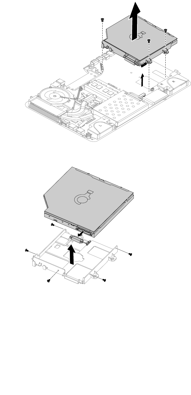
Step6.Removethe3screwsthatsecuretheopticaldrivetothemotherboardandliftituptoremoveit.
Step7.Removethe5screwsthatsecuretheopticaldrivetothebracketanddisconnectthedatacable
fromtheopticaldrive.
Step8.Installthenewopticaldriveasfollows:
a.Connectthedatacabletothenewopticaldrive.
b.Alignthenewopticaldrivewiththebracket,pushitintopositionandsecureitwiththe5screws.
c.Lineuptheopticaldrivebracketholeswiththemountingholesinthemotherboardandsecure
itwiththe3screws.
d.Connectthedatacabletothemotherboard.
Step9.Reattachthebasecoverandsecureitwiththescrews.
Chapter8.Replacinghardware39
Replacingthesolidstatedisk
Note:Turnoffthecomputerandwait3to5minutestoletitcooldownbeforeremovingthecover.
Toreplacethesolidstatedisk
Step1.Removeanymedia(disks,CDs,DVDs,ormemorycards)fromthedrives,shutdowntheoperating
system,andturnoffthecomputerandallattacheddevices.
Step2.Unplugallpowercordsfromelectricaloutlets.
Step3.Disconnectallcablesattachedtothecomputer.Thisincludespowercords,input/output(I/O)
cables,andanyothercablesthatareconnectedtothecomputer.Referto“Leftandrightview”
and“Rearview”forhelpwithlocatingthevariousconnectors.
Step4.Removethebasecover.Referto“Removingthebasecover” .
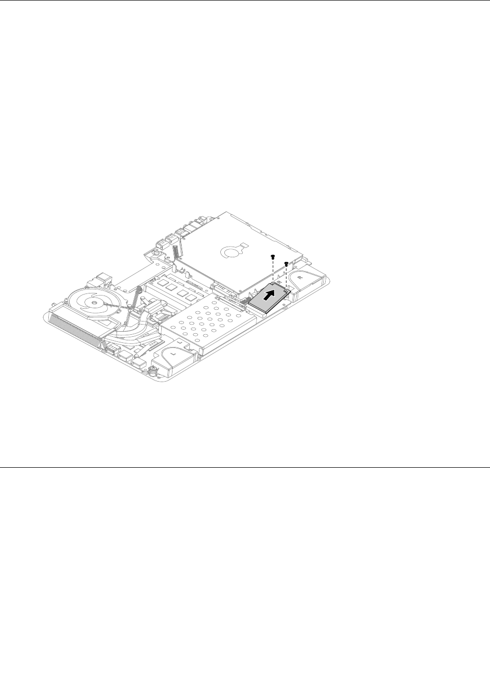
Step5.Removethe2screwsthatsecurethesolidstatedisktothemotherboard.
Step6.Pullthesolidstatediskupwardtoremoveitfromthecardport.
Step7.Toinstallthenewsolidstatedisk:
a.Insertthenotchedendofthenewsolidstatediskintothecardportonthemotherboard.
b.Securethenewsolidstatedisktothemotherboardusingthe2screws.
Step8.Reattachthebasecoverandsecureitwiththescrews.
Replacingtheopticaldriveejectboard
Note:Turnoffthecomputerandwait3to5minutestoletitcooldownbeforeremovingthecover.
Toreplacetheopticaldriveejectboard
Step1.Removeanymedia(disks,CDs,DVDs,ormemorycards)fromthedrives,shutdowntheoperating
system,andturnoffthecomputerandallattacheddevices.
Step2.Unplugallpowercordsfromelectricaloutlets.
Step3.Disconnectallcablesattachedtothecomputer.Thisincludespowercords,input/output(I/O)
cables,andanyothercablesthatareconnectedtothecomputer.Referto“Leftandrightview”
and“Rearview”forhelpwithlocatingthevariousconnectors.
Step4.Removethebasecover.Referto“Removingthebasecover” .
Step5.Removethe2screwsthatsecuretheopticaldriveejectboardtothemotherboard.
40IdeaCentreA730HardwareMaintenanceManual
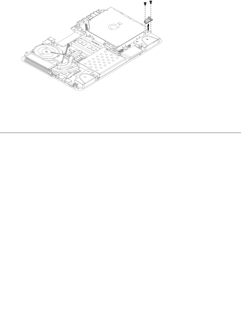
Step6.Liftuptheopticaldriveejectboardtoremoveit.
Step7.Toinstallthenewopticaldriveejectboard:
a.Connectthenewopticaldriveejectboardtothemotherboard.
b.Securethenewopticaldriveejectboardtothemotherboardwiththe2screws.
Step8.Reattachthebasecoverandsecureitwiththescrews.
Replacingthemotherboard
Note:Turnoffthecomputerandwait3to5minutestoletitcooldownbeforeremovingthecover.
Toreplacethemotherboard:
Step1.Removeanymedia(disks,CDs,DVDs,ormemorycards)fromthedrives,shutdowntheoperating
system,andturnoffthecomputerandallattacheddevices.
Step2.Unplugallpowercordsfromelectricaloutlets.
Step3.Disconnectallcablesattachedtothecomputer.Thisincludespowercords,input/output(I/O)
cables,andanyothercablesthatareconnectedtothecomputer.Referto“Leftandrightview”
and“Rearview”forhelpwithlocatingthevariousconnectors.
Step4.Removethebasecover.Referto“Removingthebasecover” .
Step5.Removetheharddiskdrive.Referto“Replacingtheharddiskdrive” .
Step6.Removeamemorymodule.Referto“Replacingamemorymodule” .
Step7.Removethesystemfan.Referto“Replacingthesystemfan” .
Step8.Removetheheat-sink.Referto“Replacingtheheat-sink” .
Step9.RemovetheCPU.Referto“ReplacingtheCPU” .
Step10.Removetheopticaldrive.Referto“Replacingtheopticaldrive” .
Step11.Removethesolidstatedisk.Referto“Replacingthesolidstatedisk” .
Step12.Removetheopticaldriveejectboard.Referto“Replacingtheopticaldriveejectboard” .
Step13.Removeallthecablesconnectedtothemotherboard.
Chapter8.Replacinghardware41
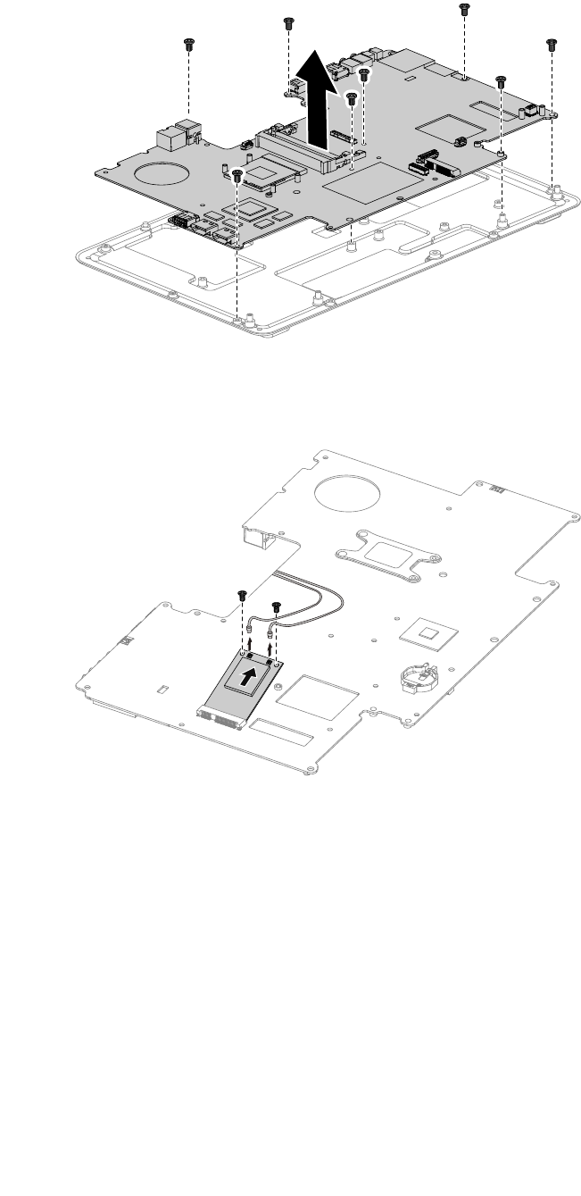
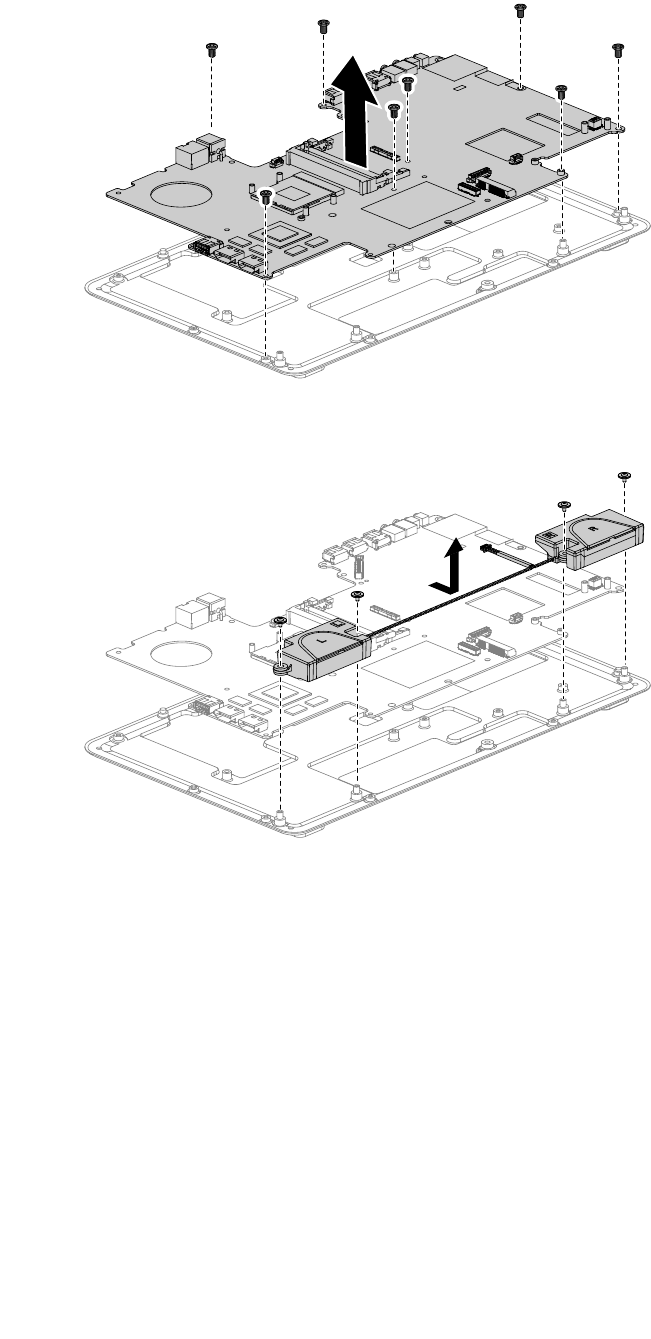
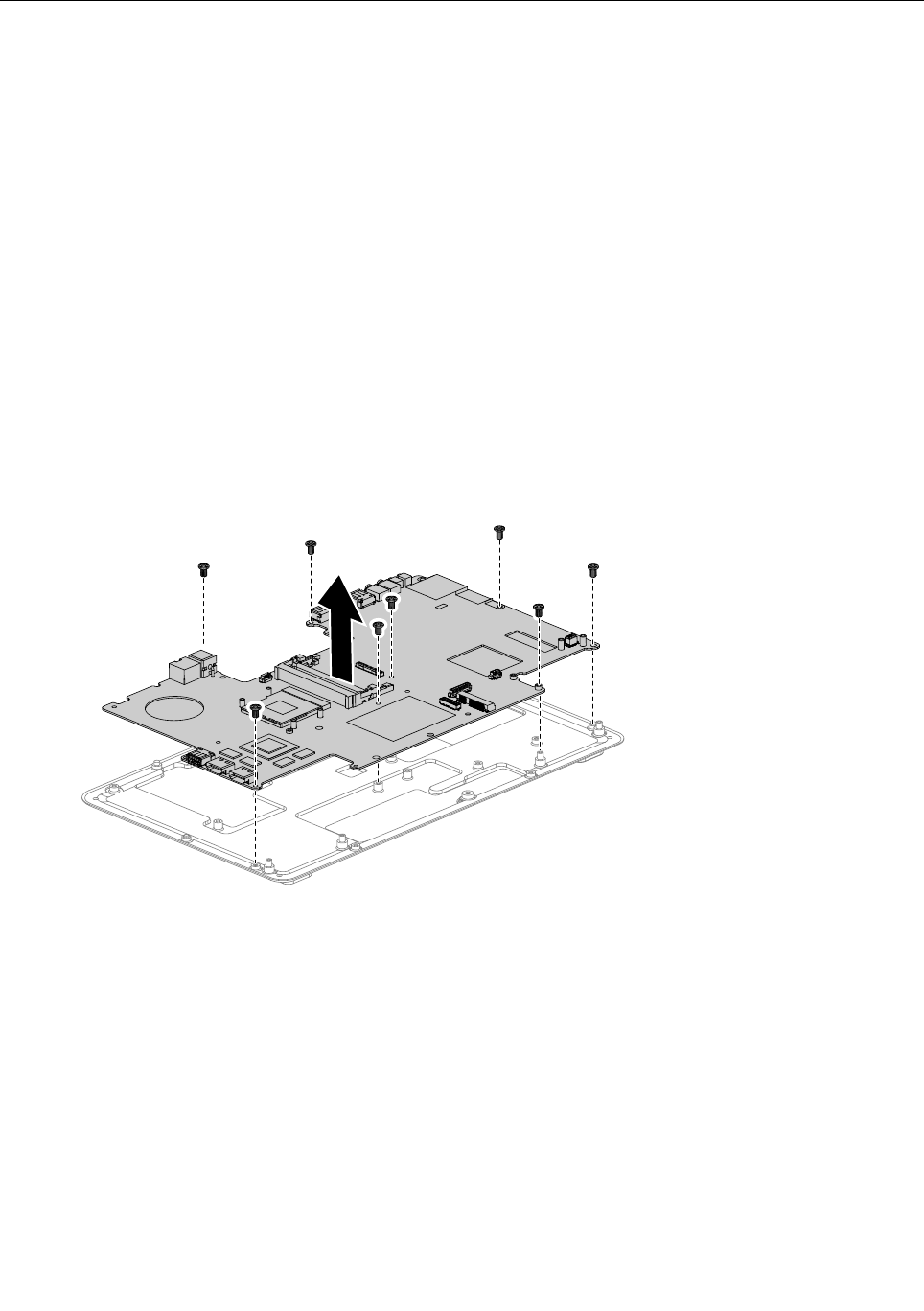
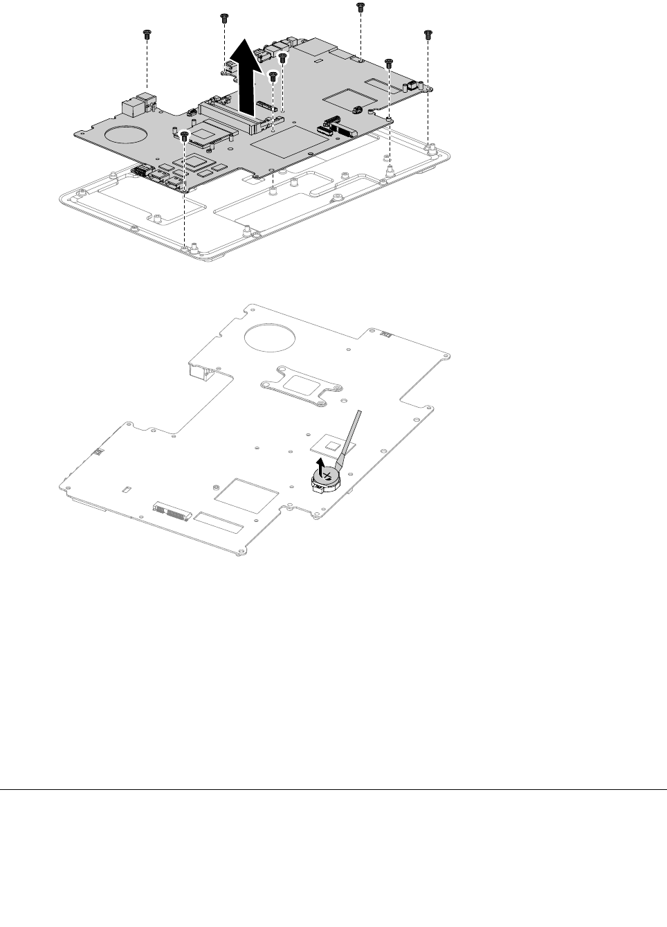
Step14.Removethe8screwsthatsecurethemotherboardtothechassisandslideitoutasshown.
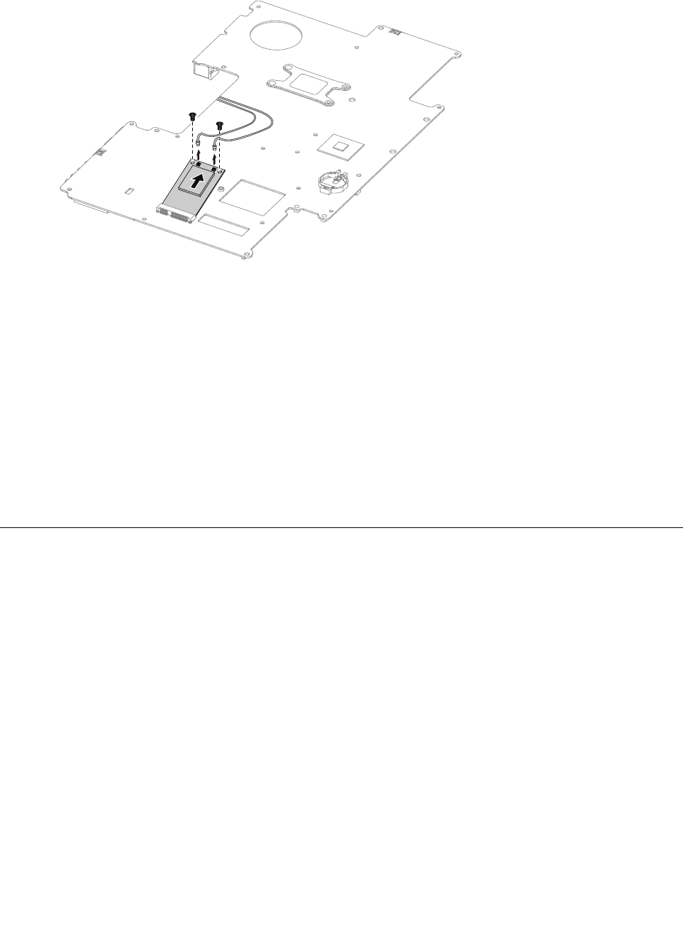
Step15.Removethe2screwsthatsecuretheTV-Tunercardtothemotherboard.
Step16.Disconnecttheantennacable(s)fromtheTV-Tunercard.
Step17.PulltheTV-Tunercardupwardtoremoveitfromthecardport.
42IdeaCentreA730HardwareMaintenanceManual
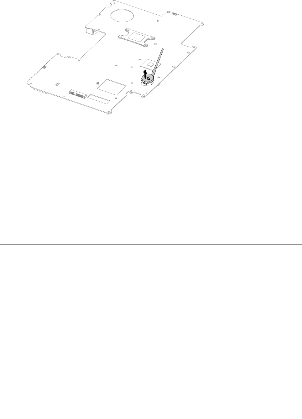
Step18.Useaatheadscrewdriverasalevertopriseoutthebatteryasshown.
Step19.Toinstallthenewmotherboard:
a.Insertthebattery(CR2032)intothesocketwiththesidelabeled“+”facingup,andpress
thebatteryintoplace.
b.InsertthenotchedendoftheTV-Tunercardintothecardportonthenewmotherboardand
secureitwiththe2screws.
c.Connecttheantennacable(s)totheTV-Tunercard.
d.Lineupthenewmotherboardwiththechassisandslideitintoposition.Aligntheholeson
thenewmotherboardwiththemountingholesonthechassisandsecureittothechassis
withthescrews.
e.Attachtheopticaldriveejectboard,solidstatedisk,opticaldrive,CPU,heat-sink,systemfan,
memorymodule,harddiskdrivetothenewmotherboard.
f.Connectallthecablestothenewmotherboard.
Step20.Reattachthebasecoverandsecureitwiththescrews.
Replacingthespeakersystem
Note:Turnoffthecomputerandwait3to5minutestoletitcooldownbeforeremovingthecover.
Toreplacethespeakersystem:
Step1.Removeanymedia(disks,CDs,DVDs,ormemorycards)fromthedrives,shutdowntheoperating
system,andturnoffthecomputerandallattacheddevices.
Step2.Unplugallpowercordsfromelectricaloutlets.
Step3.Disconnectallcablesattachedtothecomputer.Thisincludespowercords,input/output(I/O)
cables,andanyothercablesthatareconnectedtothecomputer.Referto“Leftandrightview”
and“Rearview”forhelpwithlocatingthevariousconnectors.
Step4.Removethebasecover.Referto“Removingthebasecover” .
Step5.Removetheharddiskdrive.Referto“Replacingtheharddiskdrive” .
Step6.Removetheheat-sink.Referto“Replacingtheheat-sink” .
Step7.Removetheopticaldrive.Referto“Replacingtheopticaldrive” .
Step8.Removethehingefromthechassis.Referto“Removingthehingefromthechassis” .
Step9.Disconnectthespeakercablefromtheconnectorsonthemotherboard.
Chapter8.Replacinghardware43
Step10.Removethe8screwsthatsecurethemotherboardtothechassisandslideitoutasshown.
Step11.Removethe4screwsthatsecurethespeakersystemtothemotherboard.
Step12.Detachthespeakerfromthechassis.
Step13.Toinstallthenewspeakersystem:
a.Attachthenewspeakercabletothechassis.
b.Lineupthemotherboardwiththechassisandslideitintoposition.Aligntheholesonthe
motherboardwiththemountingholesonthechassisandsecureittothechassiswiththe
8screws.
c.Lineupthenewspeakersystemwiththemotherboardandsecureitwiththe4screws.
d.Connectthenewspeakercabletothemotherboard.
Step14.Reattachtheopticaldrive,heat-sink,andharddiskdrivetothemotherboard.
Step15.Reattachthehingetothechassis,andreconnectthetouchandLEDpanelcablestothe
motherboard.
Step16.Reattachthebasecoverandsecureitwiththescrews.
44IdeaCentreA730HardwareMaintenanceManual
ReplacingtheTVtunercard
Note:Turnoffthecomputerandwait3to5minutestoletitcooldownbeforeremovingthecover.
ToreplacetheTVtunercard
Step1.Removeanymedia(disks,CDs,DVDs,ormemorycards)fromthedrives,shutdowntheoperating
system,andturnoffthecomputerandallattacheddevices.
Step2.Unplugallpowercordsfromelectricaloutlets.
Step3.Disconnectallcablesattachedtothecomputer.Thisincludespowercords,input/output(I/O)
cables,andanyothercablesthatareconnectedtothecomputer.Referto“Leftandrightview”
and“Rearview”forhelpwithlocatingthevariousconnectors.
Step4.Removethebasecover.Referto“Removingthebasecover” .
Step5.Removetheharddiskdrive.Referto“Replacingtheharddiskdrive” .
Step6.Removetheheat-sink.Referto“Replacingtheheat-sink” .
Step7.Removetheopticaldrive.Referto“Replacingtheopticaldrive” .
Step8.Removethehingefromthechassis.Referto“Removingthehingefromthechassis” .
Step9.Removeallthecablesconnectedtothemotherboard.
Step10.Removethe8screwsthatsecurethemotherboardtothechassisandslideitoutasshown.
Step11.Removethe2screwsthatsecuretheTV-Tunercardtothemotherboard.
Step12.Disconnecttheantennacable(s)fromtheTV-Tunercard.
Chapter8.Replacinghardware45
Step13.PulltheTV-Tunercardupwardtoremoveitfromthecardportonthemotherboard.
Step14.ToinstallthenewTV-Tunercard:
a.InsertthenotchedendoftheTV-Tunercardintothecardportonthemotherboard.
b.SecurenewtheTV-Tunercardtothemotherboardwiththe2screws.
c.Connecttheantennacable(s)tothenewTV-Tunercard.
Step15.Lineupmotherboardwiththechassisandslideitintoposition.Aligntheholesonthemotherboard
withthemountingholesonthechassisandsecureittothechassiswiththescrews.
Step16.Reattachtheopticaldrive,heat-sink,andharddiskdrivetothemotherboard.
Step17.Reattachthehingetothechassis,andreconnectthetouchandLEDpanelcablestothe
motherboard.
Step18.Reconnectallthecablesbacktothemotherboard.
Step19.Reattachthebasecoverandsecureitwiththescrews.
Replacingthebattery
Note:Turnoffthecomputerandwait3to5minutestoletitcooldownbeforeremovingthecover.
Toreplacethebattery
Step1.Removeanymedia(disks,CDs,DVDs,ormemorycards)fromthedrives,shutdowntheoperating
system,andturnoffthecomputerandallattacheddevices.
Step2.Unplugallpowercordsfromelectricaloutlets.
Step3.Disconnectallcablesattachedtothecomputer.Thisincludespowercords,input/output(I/O)
cables,andanyothercablesthatareconnectedtothecomputer.Referto“Leftandrightview”
and“Rearview”forhelpwithlocatingthevariousconnectors.
Step4.Removethebasecover.Referto“Removingthebasecover” .
Step5.Removetheharddiskdrive.Referto“Replacingtheharddiskdrive” .
Step6.Removetheheat-sink.Referto“Replacingtheheat-sink” .
Step7.Removetheopticaldrive.Referto“Replacingtheopticaldrive” .
Step8.Removethehingefromthechassis.Referto“Removingthehingefromthechassis” .
Step9.Removeallthecablesconnectedtothemotherboard.
46IdeaCentreA730HardwareMaintenanceManual
Step10.Removethe8screwsthatsecurethemotherboardtothechassisandslideitoutasshown.
Step11.Useaatheadscrewdriverasalevertopriseoutthebatteryasshown.
Step12.Toinstallthenewbattery:
a.Insertthenewbattery(CR2032)intothesocketwiththesidelabeled“+”facingup,andpress
thebatteryintoplace.
Step13.Lineupthemotherboardwiththechassisandslideitintoposition.Aligntheholesonthe
motherboardwiththemountingholesonthechassisandsecureittothechassiswiththescrews.
Step14.Reattachtheopticaldrive,heat-sink,andharddiskdrivetothemotherboard.
Step15.Reattachthehingetothechassis,andreconnectthetouchandLEDpanelcablestothe
motherboard.
Step16.Reconnectallthecablesbacktothemotherboard.
Step17.Reattachthebasecoverandsecureitwiththescrews.
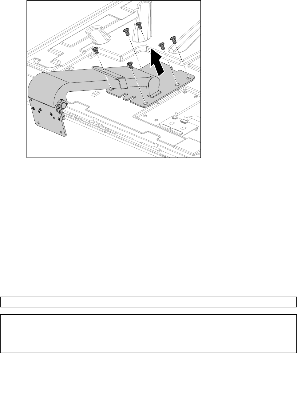
Removingthehingefromthechassis
Note:Turnoffthecomputerandwait3to5minutestoletitcooldownbeforeremovingthecover.
Toremovethehingefromthechassis
Chapter8.Replacinghardware47
Step1.Removeanymedia(disks,CDs,DVDs,ormemorycards)fromthedrives,shutdowntheoperating
system,andturnoffthecomputerandallattacheddevices.
Step2.Unplugallpowercordsfromelectricaloutlets.
Step3.Disconnectallcablesattachedtothecomputer.Thisincludespowercords,input/output(I/O)
cables,andanyothercablesthatareconnectedtothecomputer.Referto“Leftandrightview”
and“Rearview”forhelpwithlocatingthevariousconnectors.
Step4.Removethebasecover.Referto“Removingthebasecover” .
Step5.DisconnectthetouchandLEDpanelcablesfromtheconnectorsonthemotherboard.
Step6.Removethe6screwsthatsecurethehingetothechassis1,thenraisethehingetoremoveit
fromthechassis.2
1
2
Step7.Toreattachthehingetothechassis:
a.Lineupthehingewiththechassisandslidethehingeintoposition.
b.Securethehingetothechassiswiththe6screws.
c.ReconnectthetouchandLEDpanelcablestothemotherboard.
48IdeaCentreA730HardwareMaintenanceManual
Step8.Reattachthebasecoverandsecureitwiththescrews.
Removingtherearcover
Note:Turnoffthecomputerandwait3to5minutestoletitcooldownbeforeremovingthecover.
Toremovetherearcover
Step1.Removeanymedia(disks,CDs,DVDs,ormemorycards)fromthedrives,shutdowntheoperating
system,andturnoffthecomputerandallattacheddevices.
Step2.Unplugallpowercordsfromelectricaloutlets.
Step3.Disconnectallcablesattachedtothecomputer.Thisincludespowercords,input/output(I/O)
cables,andanyothercablesthatareconnectedtothecomputer.Referto“Leftandrightview”
and“Rearview”forhelpwithlocatingthevariousconnectors.
Step4.Removethebasecover.Referto“Removingthebasecover” .
Step5.Removethehingefromthechassis.Referto“Removingthehingefromthechassis” .
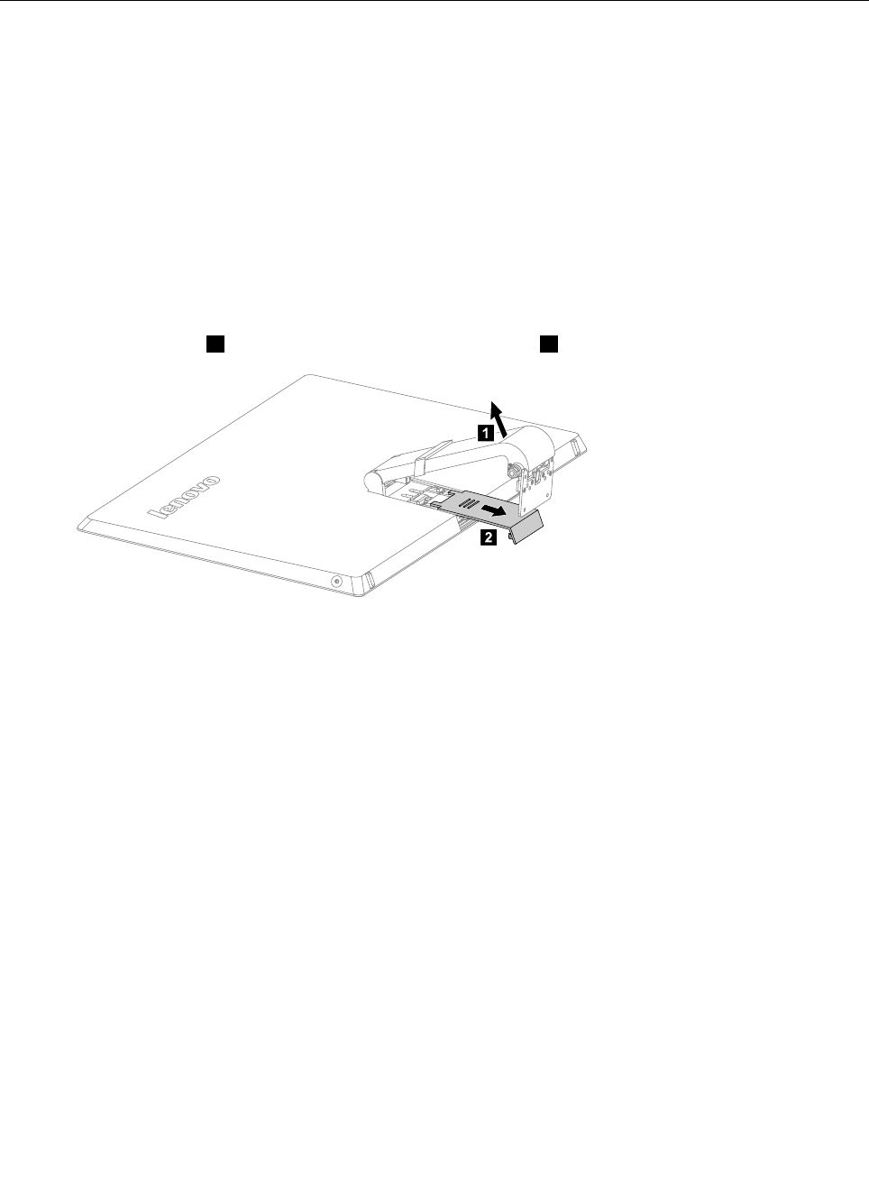
Step6.Raisethehinge1andslidethereardecooutasshown.2
1
2
Chapter8.Replacinghardware49
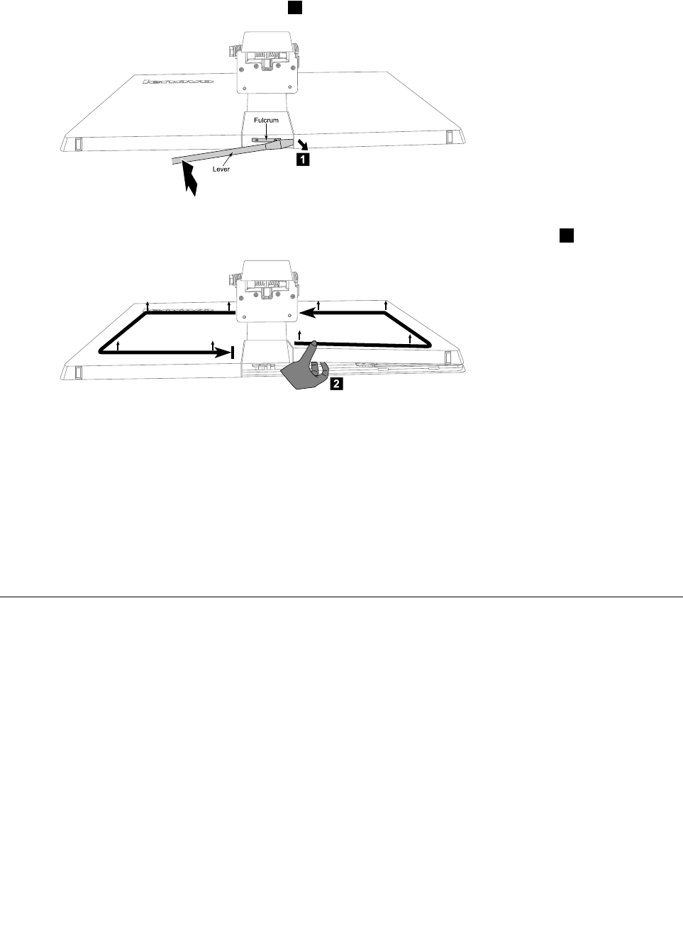
Step7.Puttheheadofaatheadscrewdriverbetweenthemiddleframeandtherearcoverasshown.
Thenusingthescrewdriverasaleverandthemiddleframemetalbarasthefulcrum,prisetherear
coverawayfromthemiddleframe.1
Fulcru m
Le ve r
1
Step8.Workingaroundtheedgeinananti-clockwisedirection,useyourngerstopriseuptherearcover.
Therearcoverispinnedintoplace,useshort,sharpmovementstopriseitup.2
2
Step9.Pressdownthehingeandslideouttherearcover.
Step10.Toreattachtherearcover:
a.Raisethehinge,lineuptherearcoverwiththeLEDpanelandslideitbackintoposition.
b.PresstheedgeofrearcovertolockthecovertotheLEDpanelwiththepins.
c.Slidethereardecobackintoposition.
Step11.Reattachthehingetothechassis,andreconnectthetouchandLEDpanelcablesbacktothe
motherboard.
Step12.Reattachthebasecoverandsecureitwiththescrews.
Replacingthescalarboard
Note:Turnoffthecomputerandwait3to5minutestoletitcooldownbeforeremovingthecover.
Toreplacethescalarboard
Step1.Removeanymedia(disks,CDs,DVDs,ormemorycards)fromthedrives,shutdowntheoperating
system,andturnoffthecomputerandallattacheddevices.
Step2.Unplugallpowercordsfromelectricaloutlets.
Step3.Disconnectallcablesattachedtothecomputer.Thisincludespowercords,input/output(I/O)
cables,andanyothercablesthatareconnectedtothecomputer.Referto“Leftandrightview”
and“Rearview”forhelpwithlocatingthevariousconnectors.
Step4.Removethebasecover.Referto“Removingthebasecover” .
Step5.Removethehingefromthechassis.Referto“Removingthehingefromthechassis” .
Step6.Removetherearcover.Referto“Removingtherearcover” .
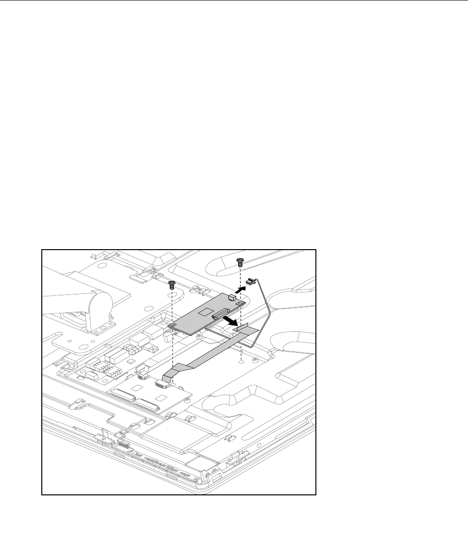
Step7.Removethe3screwsthatsecurethescalarshieldingtothemiddleframe.
50IdeaCentreA730HardwareMaintenanceManual
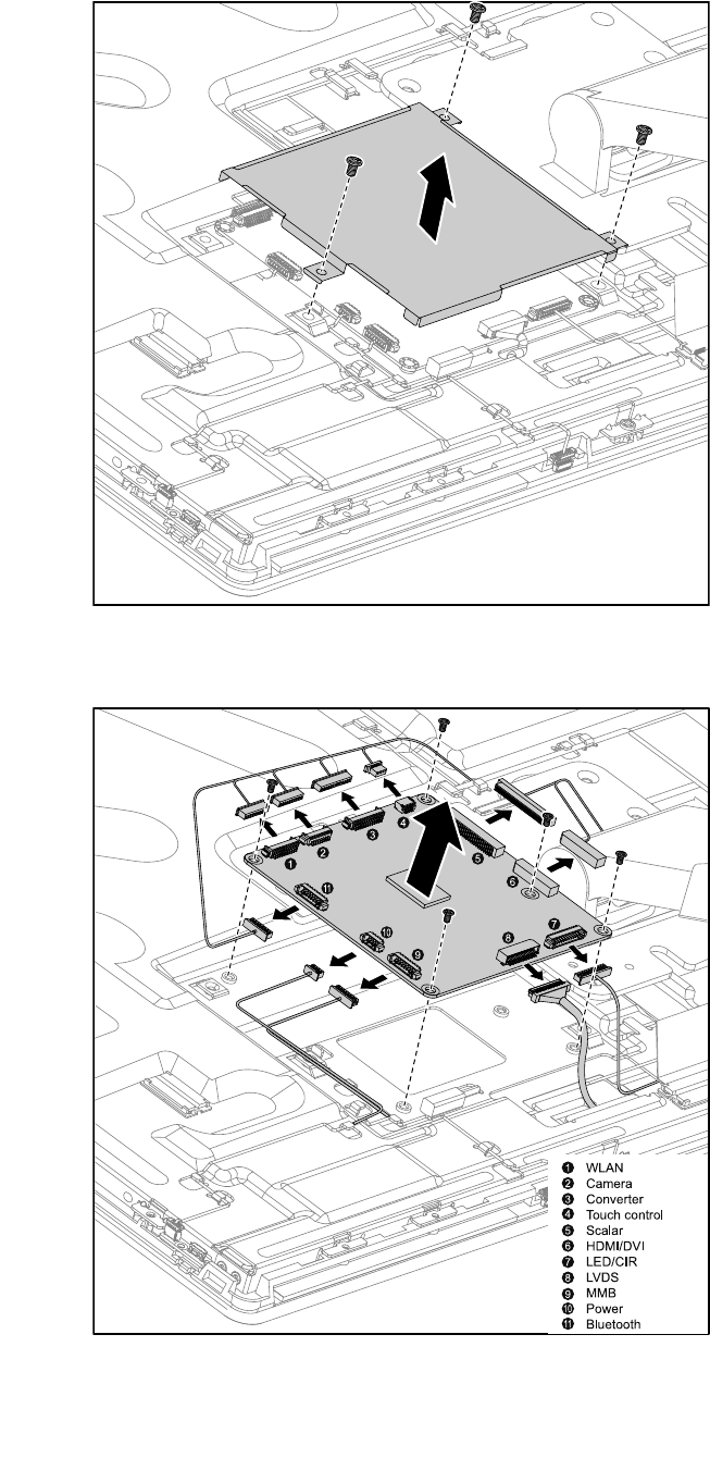
Step8.Removethescalarshieldingandsetitaside.
Step9.Disconnectallthecablesfromthescalarboard.
Step10.Removethe5screwsthatsecurethescalarboardtothemiddleframeandliftituptoremoveit.
WLAN
Ca me ra
Conve rte r
Touch contro l
S ca la r
HDMI/DVI
LED/CIR
LVDS
MMB
P owe r
Blue tooth
Step11.Toinstallthenewscalarboard:
Chapter8.Replacinghardware51
a.Lineuptheholesonthenewscalarboardwiththemountingholesonthemiddleframeand
secureitwiththe5screws.
b.Connectallthecablestothenewscalarboard.
c.Reattachthescalarshieldingtothemiddleframewiththe3screws.
Step12.ReattachtherearcovertotheLEDpanel.
Step13.Reattachthehingetothechassis,andreconnectthetouchandLEDpanelcablesbacktothe
motherboard.
Step14.Reattachthebasecoverandsecureitwiththescrews.
Replacingthetouchcontrolboard
Note:Turnoffthecomputerandwait3to5minutestoletitcooldownbeforeremovingthecover.
Toreplacethetouchcontrolboard:
Step1.Removeanymedia(disks,CDs,DVDs,ormemorycards)fromthedrives,shutdowntheoperating
system,andturnoffthecomputerandallattacheddevices.
Step2.Unplugallpowercordsfromelectricaloutlets.
Step3.Disconnectallcablesattachedtothecomputer.Thisincludespowercords,input/output(I/O)
cables,andanyothercablesthatareconnectedtothecomputer.Referto“Leftandrightview”
and“Rearview”forhelpwithlocatingthevariousconnectors.
Step4.Removethebasecover.Referto“Removingthebasecover” .
Step5.Removethehingefromthechassis.Referto“Removingthehingefromthechassis” .
Step6.Removetherearcover.Referto“Removingtherearcover” .
Step7.Disconnectallthetouchcablesfromthetouchcontrolboard.
Step8.Removethe2screwsthatsecurethetouchcontrolboardtothemiddleframe.
Step9.Liftupthetouchcontrolboardtoremoveit.
Step10.Toinstallthenewtouchcontrolboard:
52IdeaCentreA730HardwareMaintenanceManual
a.Lineuptheholesonthenewtouchcontrolboardwiththemountingholesonthemiddleframe
andsecureitwiththe2screws.
b.Connectallthecablestothenewtouchcontrolboard.
Step11.ReattachtherearcovertotheLEDpanel.
Step12.Reattachthehingetothechassis,andreconnectthetouchandLEDpanelcablestothe
motherboard.
Step13.Reattachthebasecoverandsecureitwiththescrews.
Replacingtheconverterboard
Note:Turnoffthecomputerandwait3to5minutestoletitcooldownbeforeremovingthecover.
Toreplacetheconverterboard:
Step1.Removeanymedia(disks,CDs,DVDs,ormemorycards)fromthedrives,shutdowntheoperating
system,andturnoffthecomputerandallattacheddevices.
Step2.Unplugallpowercordsfromelectricaloutlets.
Step3.Disconnectallcablesattachedtothecomputer.Thisincludespowercords,input/output(I/O)
cables,andanyothercablesthatareconnectedtothecomputer.Referto“Leftandrightview”
and“Rearview”forhelpwithlocatingthevariousconnectors.
Step4.Removethebasecover.Referto“Removingthebasecover” .
Step5.Removethehingefromthechassis.Referto“Removingthehingefromthechassis” .
Step6.Removetherearcover.Referto“Removingtherearcover” .
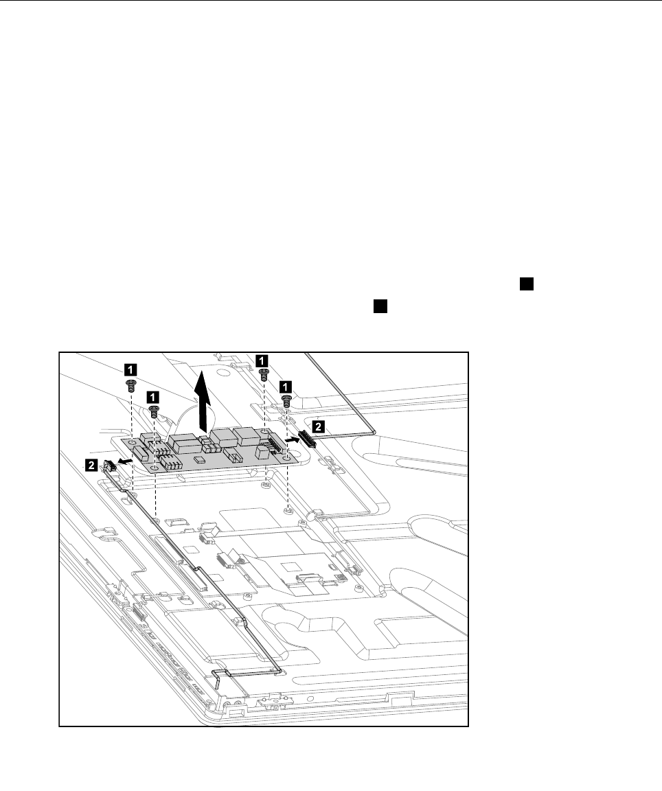
Step7.Removethe4screwsthatsecuretheconverterboardtothemiddleframe.1
Step8.Disconnectthe2cablesfromtheconverterboard.2
Step9.Liftuptheconverterboardtoremoveit.
1
1
1
1
2
2
Chapter8.Replacinghardware53

Step10.Toinstallthenewconverterboard:
a.Lineuptheholesonthenewconverterboardwiththemountingholesonthemiddleframe
andsecureitwiththe4screws.
b.Connectthe2cablestothenewconverterboard.
Step11.ReattachtherearcovertotheLEDpanel.
Step12.Reattachthehingetothechassis,andreconnectthetouchandLEDpanelcablestothe
motherboard.
Step13.Reattachthebasecoverandsecureitwiththescrews.
Replacingthepowerswitchboard
Note:Turnoffthecomputerandwait3to5minutestoletitcooldownbeforeremovingthecover.
Toreplacethepowerswitchboard
Step1.Removeanymedia(disks,CDs,DVDs,ormemorycards)fromthedrives,shutdowntheoperating
system,andturnoffthecomputerandallattacheddevices.
Step2.Unplugallpowercordsfromelectricaloutlets.
Step3.Disconnectallcablesattachedtothecomputer.Thisincludespowercords,input/output(I/O)
cables,andanyothercablesthatareconnectedtothecomputer.Referto“Leftandrightview”
and“Rearview”forhelpwithlocatingthevariousconnectors.
Step4.Removethebasecover.Referto“Removingthebasecover” .
Step5.Removethehingefromthechassis.Referto“Removingthehingefromthechassis” .
Step6.Removetherearcover.Referto“Removingtherearcover” .
Step7.Disconnectthepowercablefromthepowerswitchboard.
54IdeaCentreA730HardwareMaintenanceManual
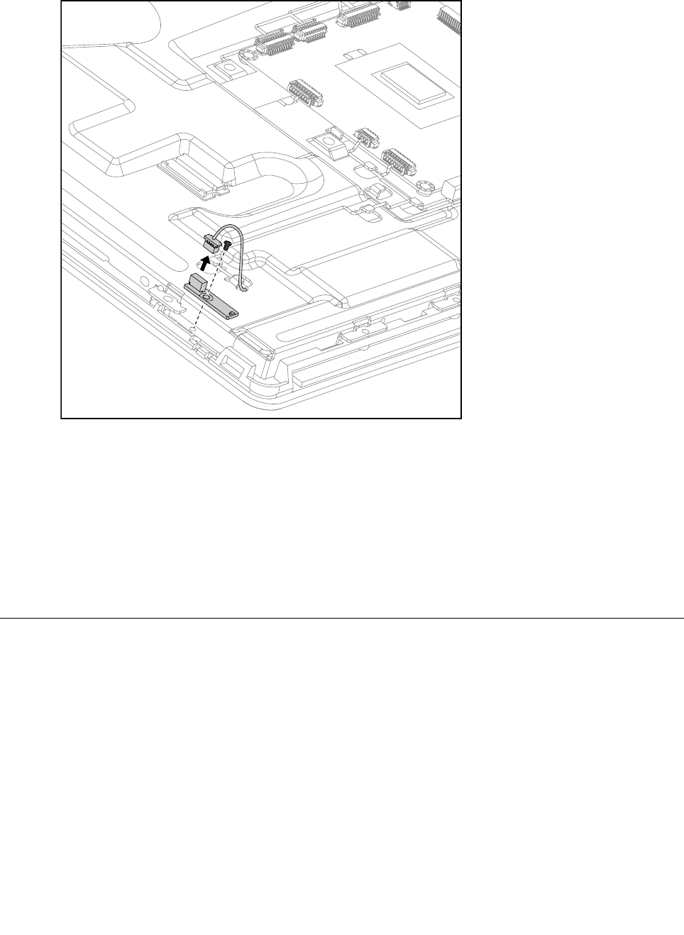
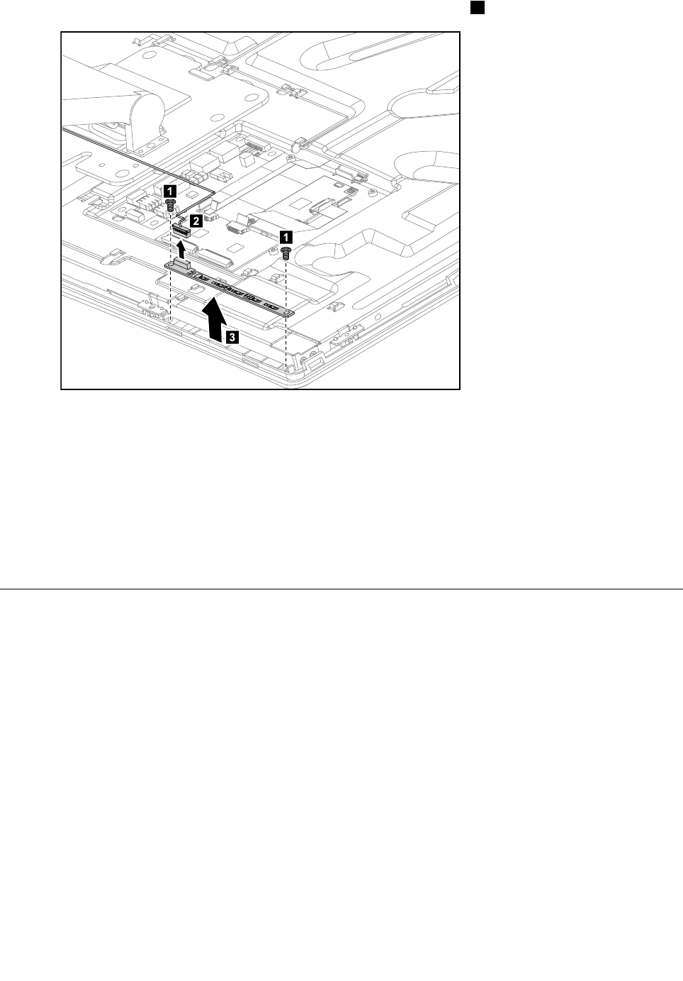
Step8.RemovethescrewthatsecuresthepowerswitchboardtotheLEDpanelandliftupthepower
switchboardtoremoveit.
Step9.Toinstallthepowerswitchboard:
a.LineuptheholeonthenewpowerswitchboardwiththemountingholeontheLEDpaneland
secureitwiththescrew.
b.Connectthepowercabletothenewconverterboard.
Step10.ReattachtherearcovertotheLEDpanel.
Step11.Reattachthehingetothechassis,andreconnectthetouchandLEDpanelcablestothe
motherboard.
Step12.Reattachthebasecoverandsecureitwiththescrews.
ReplacingtheBluetoothmodule
Attention:Turnoffthecomputerandwait3to5minutestoletitcooldownbeforeremovingthecover.
ToreplacetheBluetoothmodule:
Step1.Removeanymedia(disks,CDs,DVDs,ormemorycards)fromthedrives,shutdowntheoperating
system,andturnoffthecomputerandallattacheddevices.
Step2.Unplugallpowercordsfromelectricaloutlets.
Step3.Disconnectallcablesattachedtothecomputer.Thisincludespowercords,input/output(I/O)
cables,andanyothercablesthatareconnectedtothecomputer.Referto“Leftandrightview”
and“Rearview”forhelpwithlocatingthevariousconnectors.
Step4.Removethebasecover.Referto“Removingthebasecover” .
Step5.Removethehingefromthechassis.Referto“Removingthehingefromthechassis” .
Chapter8.Replacinghardware55
Step6.Removetherearcover.Referto“Removingtherearcover” .
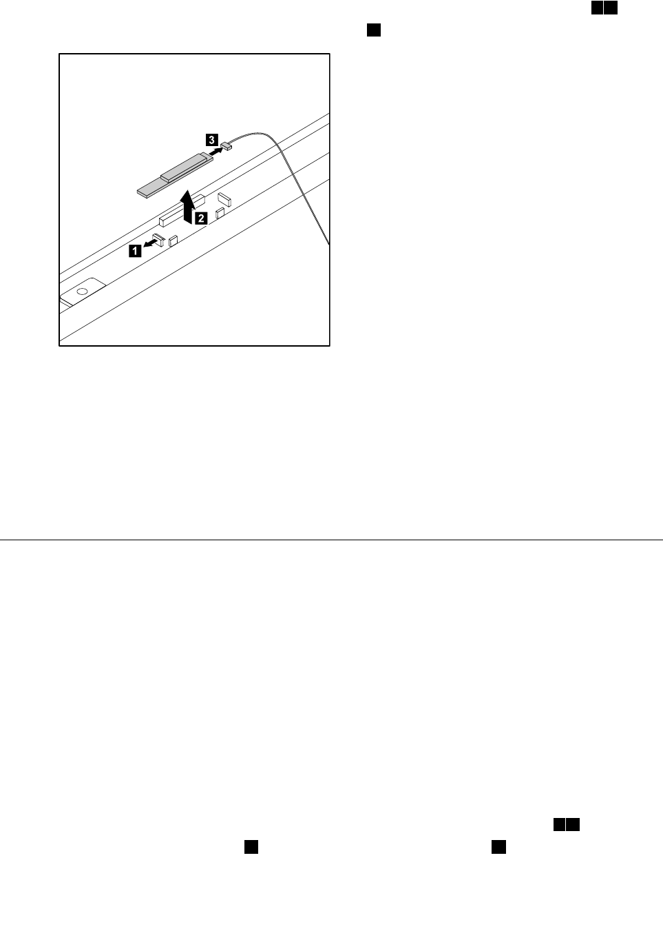
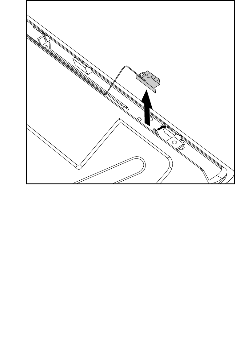
Step7.UseasmallatheadscrewdrivertoprisetheBluetoothmoduleawayfromthesocket.12
Step8.DisconnectthecablefromtheBluetoothmodule.3
1
2
3
Step9.ToinstallthenewBluetoothmodule:
a.ConnectthecabletothenewBluetoothmodule.
b.LineupthenewBluetoothmodulewiththesocket,snapitintopositionandsecureitwith
thepins.
Step10.ReattachtherearcovertotheLEDpanel.
Step11.Reattachthehingetothechassis,andreconnectthetouchandLEDpanelcablestothe
motherboard.
Step12.Reattachthebasecoverandsecureitwiththescrews.
ReplacingtheWLANcard
Note:Turnoffthecomputerandwait3to5minutestoletitcooldownbeforeremovingthecover.
ToreplacetheWLANcard:
Step1.Removeanymedia(disks,CDs,DVDs,ormemorycards)fromthedrives,shutdowntheoperating
system,andturnoffthecomputerandallattacheddevices.
Step2.Unplugallpowercordsfromelectricaloutlets.
Step3.Disconnectallcablesattachedtothecomputer.Thisincludespowercords,input/output(I/O)
cables,andanyothercablesthatareconnectedtothecomputer.Referto“Leftandrightview”
and“Rearview”forhelpwithlocatingthevariousconnectors.
Step4.Removethebasecover.Referto“Removingthebasecover” .
Step5.Removethehingefromthechassis.Referto“Removingthehingefromthechassis” .
Step6.Removetherearcover.Referto“Removingtherearcover” .
Step7.UseasmallatheadscrewdrivertoprisetheWLANcardawayfromthesocket.12
Step8.Disconnecttheantennacable3anddatacablefromtheWLANcard.4
56IdeaCentreA730HardwareMaintenanceManual
Step9.LiftuptheWLANcardtoremoveitfromthesocket.
1
1
1
1
2
4
3
Step10.ToinstallthenewWLANcard:
a.ConnectthedatacabletothenewWLANcard.
b.LineupthenewWLANcardwiththesocket,snapitintopositionandsecureitwiththepins.
c.ConnecttheantennacabletothenewWLANcard.
Step11.ReattachtherearcovertotheLEDpanel.
Step12.Reattachthehingetothechassis,andreconnectthetouchandLEDpanelcablestothe
motherboard.
Step13.Reattachthebasecoverandsecureitwiththescrews.
Replacingthecamera
Note:Turnoffthecomputerandwait3to5minutestoletitcooldownbeforeremovingthecover.
Toreplacethecamera:
Step1.Removeanymedia(disks,CDs,DVDs,ormemorycards)fromthedrives,shutdowntheoperating
system,andturnoffthecomputerandallattacheddevices.
Step2.Unplugallpowercordsfromelectricaloutlets.
Step3.Disconnectallcablesattachedtothecomputer.Thisincludespowercords,input/output(I/O)
cables,andanyothercablesthatareconnectedtothecomputer.Referto“Leftandrightview”
and“Rearview”forhelpwithlocatingthevariousconnectors.
Step4.Removethebasecover.Referto“Removingthebasecover” .
Step5.Removethehingefromthechassis.Referto“Removingthehingefromthechassis” .
Step6.Removetherearcover.Referto“Removingtherearcover” .
Step7.Removethe2screwsthatsecurethecameratothefrontbezel.1
Chapter8.Replacinghardware57
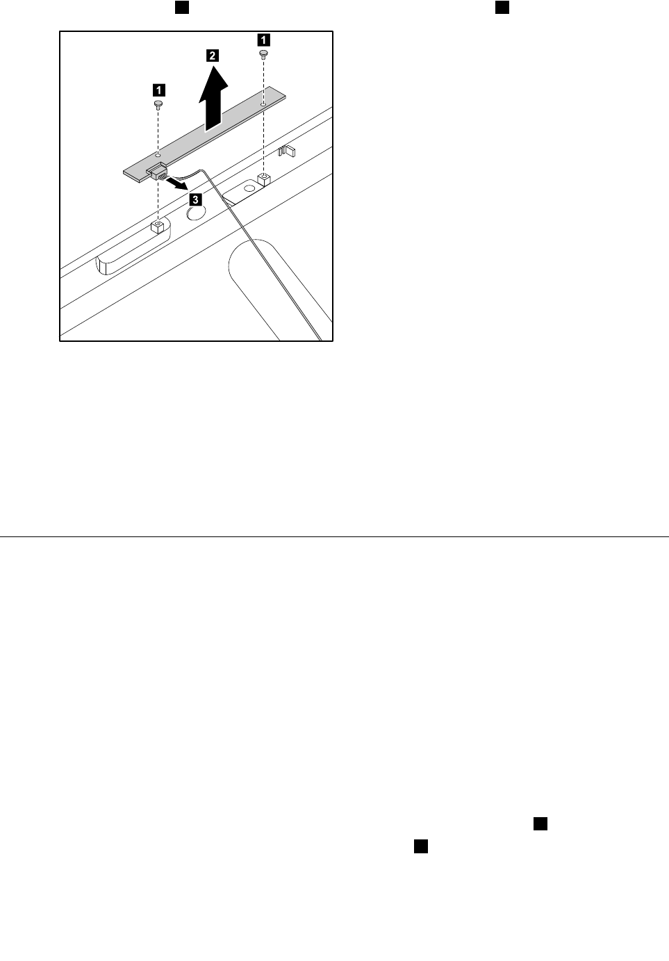
Step8.Liftupthecamera2anddisconnectthedatacablefromthecamera.3
1
2
3
1
Step9.Toinstallthenewcamera:
a.Connectthedatacabletothenewcamera.
b.Lineuptheholesinthenewcamerawiththemountingholesonthefrontbezelandsecure
itwiththe2screws.
Step10.ReattachtherearcovertotheLEDpanel.
Step11.Reattachthehingetothechassis,andreconnectthetouchandLEDpanelcablestothe
motherboard.
Step12.Reattachthebasecoverandsecureitwiththescrews.
Replacingthefrontfunctionboard
Note:Turnoffthecomputerandwait3to5minutestoletitcooldownbeforeremovingthecover.
Toreplacethefrontfunctionboard:
Step1.Removeanymedia(disks,CDs,DVDs,ormemorycards)fromthedrives,shutdowntheoperating
system,andturnoffthecomputerandallattacheddevices.
Step2.Unplugallpowercordsfromelectricaloutlets.
Step3.Disconnectallcablesattachedtothecomputer.Thisincludespowercords,input/output(I/O)
cables,andanyothercablesthatareconnectedtothecomputer.Referto“Leftandrightview”
and“Rearview”forhelpwithlocatingthevariousconnectors.
Step4.Removethebasecover.Referto“Removingthebasecover” .
Step5.Removethehingefromthechassis.Referto“Removingthehingefromthechassis” .
Step6.Removetherearcover.Referto“Removingtherearcover” .
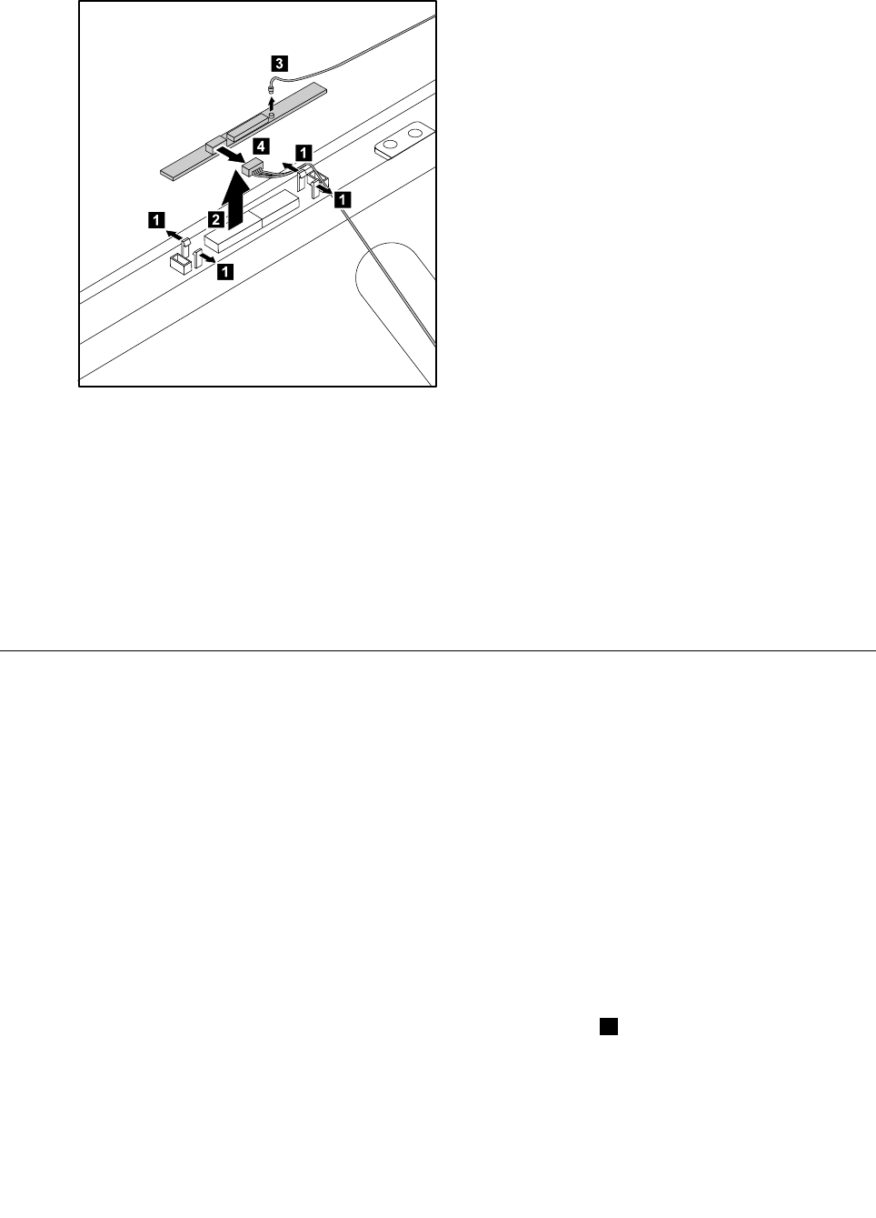
Step7.Removethe2screwsthatsecurethefrontfunctionboardtothefrontbezel.1
Step8.Disconnectthedatacablefromthefrontfunctionboard.2
58IdeaCentreA730HardwareMaintenanceManual
Step9.Liftupthefrontfunctionboardtoremoveitfromthefrontbezel.3
3
1
2
1
Step10.Toinstallthenewfrontfunctionboard:
a.Connectthedatacabletothenewfrontfunctionboard.
b.Lineuptheholesinthenewfrontfunctionboardwiththemountingholesonthefrontbezel
andsecureitwiththe2screws.
Step11.ReattachtherearcovertotheLEDpanel.
Step12.Reattachthehingetothechassis,andreconnectthetouchandLEDpanelcablestothe
motherboard.
Step13.Reattachthebasecoverandsecureitwiththescrews.
ReplacingtheLEDpanel
Note:Turnoffthecomputerandwait3to5minutestoletitcooldownbeforeremovingthecover.
Note:Itmaybehelpfultoplacethecomputerface-downonasoftatsurfaceforthisprocedure.Lenovo
recommendsthatyouuseablanket,towel,orothersoftclothtoprotectthecomputerscreenfromscratches
orotherdamage.
ToreplacetheLEDpanel:
Step1.Removeanymedia(disks,CDs,DVDs,ormemorycards)fromthedrives,shutdowntheoperating
system,andturnoffthecomputerandallattacheddevices.
Step2.Unplugallpowercordsfromelectricaloutlets.
Step3.Disconnectallcablesattachedtothecomputer.Thisincludespowercords,input/output(I/O)
cables,andanyothercablesthatareconnectedtothecomputer.Referto“Leftandrightview”
and“Rearview”forhelpwithlocatingthevariousconnectors.
Step4.Removethebasecover.Referto“Removingthebasecover” .
Step5.Removethehingefromthechassis.Referto“Removingthehingefromthechassis” .
Step6.Removetherearcover.Referto“Removingtherearcover” .
Chapter8.Replacinghardware59
Step7.Removethescalarboard.Referto“Replacingthescalarboard” .
Step8.Removethetouchcontrolboard.Referto“Replacingthetouchcontrolboard” .
Step9.Removetheconverterboard.Referto“Replacingtheconverterboard” .
Step10.Removethepowerswitchboard.Referto“Replacingthepowerswitchboard” .
Step11.RemovetheBluetoothmodule.Referto“ReplacingtheBluetoothmodule” .
Step12.RemovetheWLANcard.Referto“ReplacingtheWLANcard” .
Step13.RemovetheWLANantennacablefromthefrontbezel.
Step14.Removethecamera.Referto“Replacingthecamera” .
Step15.Removethefrontfunctionboard.Referto“Replacingthefrontfunctionboard” .
Step16.Removeallthecablesattachedtothemiddleframeandthefrontbezel.
60IdeaCentreA730HardwareMaintenanceManual
Step17.Removethe6screwsthatsecurethehingetothemiddleframeandsetthehingeaside.
Step18.ToinstallthenewtheLEDpanel:
a.Lineuptheholesonthehingewiththemountingholesonthenewmiddleframeandsecureit
with6screws.
b.AttachallthecablestothenewLEDpanelmiddleframeandfrontbezel.
c.AttachtheWLANcard,Bluetoothmodule,powerswitchboard,converterboard,touchcontrol
board,scalarboardandfrontfunctionboardtothenewLEDpanelmiddleframeandconnect
allthecablestothenewLEDpanel.
Step19.ReattachtherearcovertotheLEDpanel.
Step20.Reattachthehingetothechassis,andreconnectthetouchandLEDpanelcablestothe
motherboard.
Step21.Reattachthebasecoverandsecureitwiththescrews.
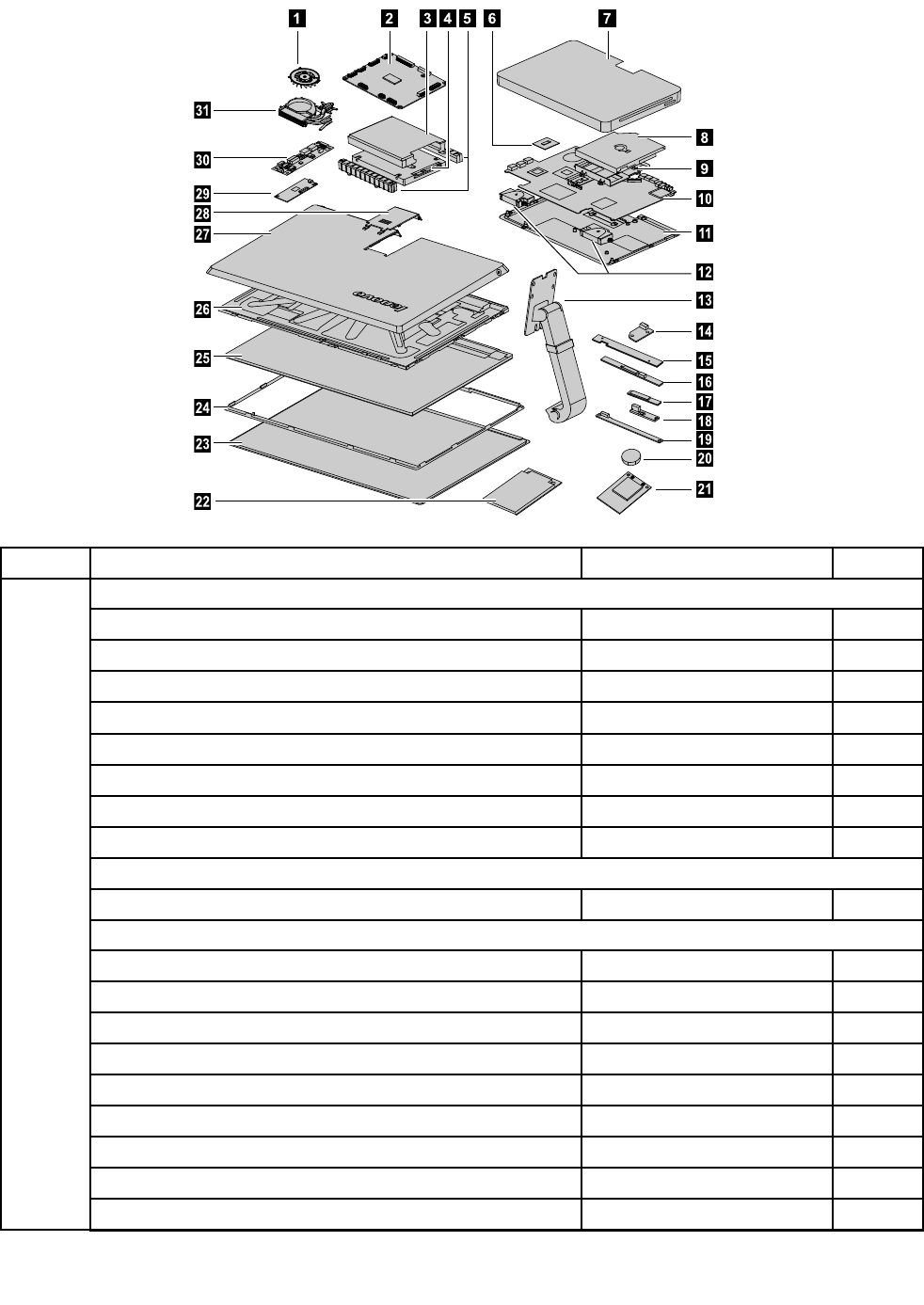
FRUlists
Thischapterliststheinformationontheeldreplaceableunits(FRUs).
Attention:BesuretoreadandunderstandallthesafetyinformationbeforereplacinganyFRUs.
Notes:FRUsthathavea1or2intheCRUcolumnareCustomerReplaceableUnits(CRUs).
•1–identiespartsthatarefairlysimpletoreplace,requiringfewornotools.
•2–identiespartsthatareslightlymoredifculttoreplace.
•N-identiespartsthatarenottobereplacedbythecustomer.
Chapter8.Replacinghardware61
4567
9
10
11
12
13
14
15
16
17
18
19
20
21
8
23
24
25
26
27
28
29
30
31
22
Item#FRUsServicePartNumber(FRU#)CRUID
Motherboard
A7302G_PGS_GPUW/HDMI_IN/TV2MB90002643N
A7302G_PGV2_GPUW/HDMI_IN/TV2MB90002644N
A7302G_PGS_GPUW/HDMI_IN/TVMB90003043N
A7302G_PGV2_GPUW/HDMI_IN/TVMB90003044N
A7302G_PGS_GPUW/HDMI_INW/OTVMB90003045N
A7302G_PGV2_GPUW/HDMI_INW/OTVMB90003046N
A7302G_PGS_GPUW/OHDMI_INW/OTVMB90003047N
A7302G_PGV2_GPUW/OHDMI_INW/OTVMB90003048N
CPU
IntelI7-4700MQ2.4G4cPGACPU102500540N
Memory
M471B5773DH0-YK01100642N
HMT425S6AFR6A-PB1100643N
MT8KTF25664HZ-1G6M11100228N
Elp_RJ2108EDBG-GN-F2GBD3L-1600SMemory1100750N
Mic_SD9PF J2GBD3L-1600SMemory1100683N
M471B5273DH0-YK01100637N
HMT451S6AFR8A-PB1100638N
MT8KTF51264HZ-1G6J11100639N
Elp_RJ4208EBBG-GN-F4GBD3L-1600SMemory1100640N
10
62IdeaCentreA730HardwareMaintenanceManual

Mic_SD9QVG4GBD3L-1600SMemory1100672N
M471B1G73BH0-YK01100633N
HMT41GS6AFR8A-PB1100634N
MT16KTF1G64HZ-1G6E11100635N
Elp_RJ4208EBBG-GN-F8GBD3L-1600SMemory1100636N
Harddiskdrive
HGSTHTS545050A7E3805400PRM7mm500GHDD16200067N
ST500L T0125.4K7mm500GHDD16200211N
WD5000LPVT-08G33T17mm5.4Krpm500GHDD16200264N
HTS541010A9E6809.55.4K1THDD16200193N
WDWD10JPVT-24A1YT05400PRM9.5mm1THDD16200071N
A720HDDCable90200731N
4
A720HDDBracket90200753N
Solidstatedisk
SGTKahunaV500GST500LM000SSHD-LH16200420N
21
SGTKahunaV1TBST1000LM014SSHD-LH16200421N
Opticaldiskdrive
HLDSCA40NSlimSlotBDCombo25205779N
PanasonicUJ265SlotBDCombo光驱-LH25209300N
HLDSGA31NSlimSATASlotDVDRW25009580N
8
A720ODDCable90200732N
14A720ODDEJECTBOARD90000217N
9A720ODDBracket90200752N
PowerSupply
FSP150-RAB150Wadapter®360018761
LietonPA-1151-11VA150wadapter(R)360018751
DELTAADP-170CBBB170Wadapter®362003901
Heat-sink
A730CMR47WDISHEATSINK90202529N
31
A730AVC47WDISHEATSINK90202530N
Systemfan
A720DeltaDIS45WFan90200584N
1
A720AVCDIS45WFan90201256N
WLANcard
A720WlanCardW/CABLE90000171N
A720WLANDataCable90201832N
16
A720WlanAnntena90200739N
Chapter8.Replacinghardware63

TV- Tunercard
AvermediaH334DVB-TMiniTVCard11201071N
AvermediaH339BBDVB-TMiniTVCard11200290N
AvermediaH334ATSCMiniTVCard11201072N
AvermediaH339BAATSCMiniTVCard11200291N
A720TVTunnerCableForNTSL90201142N
22
A720TVT unnerCableForPAL90201143N
Remotecontrol
PhilipsWin8Controller(R)8889000071
PhilipsWin7IRReveiver(R)8880106621
Bluetoothmodule
FcnBCM92070BT2.1EDRFlashDTCard®11200978N
USIBCM92070BT2.1EDRFlashDTCard®11200979N
17
A720BluetoothCardCable90200741N
Camera
CCYM720PVCOV97122DMICRSpongeCAM20200436N
15
A730WebcamCable90202752N
Speakers
12A720Speaker(L+R)90200743N
Converter
A730ConverterBoard90002900N
30
A720ConverterCable90200737N
LCDT ouchModule
A730LCDT ouchModuleForFHD90400125N
A730LCDT ouchModuleForQHD90400126N
A730TouchControlBoard90002903N
A730StandW/CableForQHDPanel90202762N
A730StandW/CableForFHDPanel90202763N
ScalarBoard
A730ScalarBoardForFHDPanel90002901N
A730ScalarBoardForQHDPanel90002902N
29
A720TOUCHCable90200733N
64IdeaCentreA730HardwareMaintenanceManual

WirelessKB/MS
2.4G_SILVER_FN_ENGLISH252092042
2.4G_SILVER_FN_EN_MALAYSIA252092052
2.4G_SILVER_FN_TC_TAIWAN252092062
2.4G_SILVER_FN_THAI252092072
2.4G_SILVER_FN_CZ_SI252092082
2.4G_SILVER_FN_EN_INDIA252092092
2.4G_SILVER_FN_RU_RUSSIA252092102
2.4G_SILVER_FN_EN_UK252092112
2.4G_SILVER_FN_NORDIC252092122
2.4G_SILVER_FN_LASPANISH252092132
2.4G_SILVER_FN_LASP_ARGENTINA252092142
2.4G_SILVER_FN_ARABIC252092152
2.4G_SILVER_FN_SWISS252092162
2.4G_SILVER_FN_GERMAN252092172
2.4G_SILVER_FN_TURKISH252092182
2.4G_SILVER_FN_SPANISH252092192
2.4G_SILVER_FN_SLOVENIAN252092202
2.4G_SILVER_FN_ITALIAN252092212
2.4G_SILVER_FN_HEBREW252092222
2.4G_SILVER_FN_FRENCH252092232
2.4G_SILVER_FN_GREEK252092242
2.4G_SILVER_FN_HUNGARIAN252092252
2.4G_SILVER_FN_BULGARIAN252092262
2.4G_SILVER_FN_KOREAN252092272
2.4G_SILVER_FN_JAPANESE252092282
2.4G_SILVER_FN_EN_FR_CANADA252092292
2.4G_SILVER_FN_PORTUGUESE252092302
2.4G_SILVER_FN_BELGIAN252092312
2.4G_SILVER_FN_DUTCH252092322
LiteonSM-8861(WW)MouseSilver252036062
LiteonSM-8861Mouse(MY)Silver252036082
LiteonSM-8861Mouse(NoBattery)Silver252036072
LiteonSM-8861(JP)Mouse-Silver252057742
LiteonSK-8861(GB)2.4GKBonly-Silver8252092942
LiteonSK-8861(FR)2.4GKBonly-Silver8252092952
LiteonSK-8861(DE)2.4GKBonly-Silver8252092962
LiteonSK-8861(US)2.4GKBonly-Silver8252098122
LiteonSK-8861(EN-FR)2.4GKBOnly-S8252101932
LiteonSK-8861(TH)2.4GKBOnly-Silver8252101952
Chapter8.Replacinghardware65

LiteonSK-8861(BE-EN)2.4GKBOnly-S8252101972
LiteonSK-8861(US-EU)2.4GKBOnly-S8252101982
LiteonSK-8861(RU)2.4GKB-Silver8252101992
LiteonSK-8861(CS-SK)2.4GKB-Silver8252102002
LiteonSK-8861(JP)2.4GKBOnly-Silver8252102012
LiteonSK-8861(Nordic)2.4GKBOnly-S8252106522
LiteonSK-8861(IT)2.4GKBOnly-Silver8252106532
LiteonSK-8861(CH)2.4GKBOnly-Silver8252107522
LiteonSK-8861(ES)2.4GKBOnly-Silver8252106542
LiteonSK-8861(TW)2.4GKBOnly-Silver8252101902
LiteonSK-8861(KR)2.4GKBOnly-Silver8252101912
LiteonSK-8861(LA-AR)2.4GKBOnly-S8252101922
LiteonSK-8861(LA)2.4GKBOnly-Silver8252101942
LiteonSK-8861(US-IN)2.4GKBOnly-S8252101962
LiteonSK-8861(SA)2.4GKBOnly-Silver8252107442
LiteonN702.4Gmouse+DforSilverSilk252092972
LiteonN702.4Gmouse+DforSSilkJP252102022
PowerCord
longwellBlackSingle-end1.0m3wireULCSAPowerCable310338571
Volex1mC5USPowerCable310338581
Luxshare1.0mC5USPowerCable310495171
longwellBlackSingle-end1.0mSAAPowerCable310353971
Volex1mC5AustraliaPowerCable310495001
Luxshare1.0mC5AustraliaPowerCable310495201
Longwell1.0MC52pinJapanpowercord315034231
Volex1.0MC52pinJapanpowercord315034241
Luxshare1.0MC52pinJapanpowercord315034251
GrandsunBlackSingle-end1.0m3wireCCCPowerCable(R)310329531
Luxshare1.0MC5CCCPowerCable310451471
longwellBlackSingle-end1.0mASTAPowerCable310353961
Volex1mC5UKPowerCable310494961
Luxshare1.0mC5UKPowerCable315033521
longwellBlackSingle-end1.0mVDEPowerCable310353321
Volex1mC5EuropePowerCable310494971
Luxshare1.0mC5EuropePowerCable310495181
longwellBlackSingle-end1.0mIndiaPowerCable310353951
Luxshare1.0mC5IndiaPowerCable315033531
LongwellBlackSingle-end1.0mItalyC5PowerCable®310391041
Volex1mC5ItalyPowerCable310495041
Luxshare1.0mC5ItalyPowerCable315033591
66IdeaCentreA730HardwareMaintenanceManual

LongwellBlackSingle-end1.0mBrazilPowerCable®310358281
Volex1mC5BrazilPowerCable310495051
Luxshare1.0mC5BrazilPowerCable315033571
LongwellBlackSingle-end1.0mArgentinaC5PowerCable®310391001
Volex1mC5LAUSPowerCable310495071
Luxshare1.0mC5LAUSPowerCable315033561
LongwellBlackSingle-end1.0mDenmarkC5PowerCable®310391011
Volex1mC5DenmarlPowerCable310495031
Luxshare1.0mC5DenmarlPowerCable315033601
LongwellBlackSingle-end1.0mSwitzerlandC5PowerCable
®
310391031
Volex1mC5SwitzerlandPowerCable310495081
Luxshare1.0mC5SwitzerlandPowerCable315033611
LongwellBlackSingle-end1.0mIsraelC5PowerCable®310391071
Volex1mC5IsraelPowerCable310495021
Luxshare1.0mC5IserealPowerCable315033621
LongwellBlackSingle-end1.0mTaiwanC5PowerCable®310388851
Volex1mC5TaiwanPowerCable310494991
Luxshare1.0mC5TaiwanPowerCable315033541
LongwellBlackSingle-end1.0mKoreaC5PowerCable®310391061
Volex1mC5KoreaPowerCable310494981
Luxshare1.0mC5KoreaPowerCable315033581
LongwellBlackSingle-end1.0mSAC5PowerCable®310391051
Volex1mC5SAPowerCable310495011
Luxshare1.0mC5SAPowerCable315033551
Mechanical
A730BaseCoverW/BCASW/TV2W/HDMI90202757N
A730BaseCoverW/OBCASW/TVW/HDMI90202758N
A730BaseCoverW/OBCASWTVW/OHDMI90202759N
A730BaseCoverW/OBCASW/OTVW/HDMI90202760N
7
A730BaseCoverW/OBCASW/OTVW/OHDMI90202761N
18A720PowerBoard90000214N
19A720LEDIndicatorBoard90000216N
2A720ScalarBoard90000218N
A720PANELBACKLIGHTCABLE90200734N
A720PowerSwitchCable90200735N
A720LVDSCable90200736N
A720LEDFunctionBoardCable90200738N
A720MMBCable90200742N
27A720BackCover90200751N
Chapter8.Replacinghardware67

28A720RearDeco90200754N
A730ScalarEMIShielding90202764N
A720BaseBottomAssy90201155N
A730LVDSCableForQHDPanel(30pin)90202753N
A730LVDSCableForQHDPanel(40pin)90202754N
A730LVDSCableForFHDPanel90202765N
A730TVANTENNA90202766N
A730ScalarCableForFHDPanel90202767N
A730ScalarCableForQHDPanel90202768N
A730T ouchFunctionBoardCable90202755N
A730LEDIndicatorBoardCable90202756N
A720PowerSwitchCable90200735N
68IdeaCentreA730HardwareMaintenanceManual

Chapter9.Generalinformation
Thischapterprovidesgeneralinformationthatappliestoallcomputermodelscoveredbythismanual.
AdditionalServiceInformation
Thischapterprovidesadditionalinformationthattheservicerepresentativemightndhelpful.
Powermanagement
Powermanagementreducesthepowerconsumptionofcertaincomponentsofthecomputersuchasthe
systempowersupply,processor,harddiskdrives,andsomemonitors.
Advancedcongurationandpowerinterface(ACPI)BIOS
AsthiscomputerhasanACPIBIOSsystem,theoperatingsystemisallowedtocontrolthepower
managementfeaturesofthecomputerandthesettingsforAdvancedPowerManagement(APM)BIOSmode
isignored.NotalloperatingsystemssupportACPIBIOSmode.
AutomaticPower-Onfeatures
TheAutomaticPower-OnfeatureswithinthePowerManagementmenuallowyoutoenableanddisable
featuresthatturnonthecomputerautomatically.
•WakeUponAlarm:Youcanspecifyadateandtimeatwhichthecomputerwillbeturnedonautomatically.
Thiscanbeeitherasingleevent,adailyeventoraweeklyevent.
•WakeUponLAN:ThisfeatureallowsLANadaptercardtowaketheSystem.
©CopyrightLenovo201369
