Lenovo Ideacentre B5 Series Hardware Replacement Guide V3.0 (English) User Manual Idea Centre B520 All In One (ideacentre)
2011-04-19
User Manual: Lenovo Ideacentre B5 Series Hardware Replacement Guide V3.0 (English) Lenovo IdeaCentre B5 Series Hardware Replacement Guide V3.0 B520 All-in-One (ideacentre) B520 All-in-One (ideacentre)
Open the PDF directly: View PDF ![]() .
.
Page Count: 29

Version 3.0 2011.01
Machine type: 10064/7745
Lenovo
IdeaCentre B5 Series
Hardware Replacement Guide
31047244
Hardware Replacement Guide
© Copyright Lenovo 2011. All rights reserved.
LENOVO products, data, computer software, and services have been developed
exclusively at private expense and are sold to governmental entities as commercial
items as defined by 48 C.F.R. 2.101 with limited and restricted rights to use,
reproduction and disclosure.
LIMITED AND RESTRICTED RIGHTS NOTICE: If products, data, computer
software, or services are delivered pursuant a General Services Administration
“GSA” contract, use, reproduction, or disclosure is subject to restrictions set forth
in Contract No. GS-35F-05925.
© 2011. Lenovo
Contents
Overview ...................................................................................... 1
Chapter 1 Locations ................................................................. 5
Locating components and connectors ...........................................5
Chapter 2 Replacing hardware ................................................ 9
General information ........................................................................9
Removing the computer cover .......................................................9
Mounting the computer onto a wall ..............................................11
Replacing a memory module .......................................................13
Replacing the optical drive ...........................................................15
Replacing the hard disk drive .......................................................17
Replacing the keyboard ...............................................................19
Replacing the mouse ...................................................................20
Replacing the power cord ............................................................21
Chapter 3 Appendix ............................................................... 23

1
Hardware Replacement Guide
Overview
This guide is intended to be used by customers who are replacing Customer
Replaceable Units (CRUs) as well as trained service personnel who are replacing
Field Replaceable Units (FRUs). In this guide, CRUs and FRUs will often be referred
to as parts.
Note: Trained service personnel should refer to the Hardware Maintenance
Manual (HMM) for parts ordering information.
This guide does not include procedures for all parts. It is expected that cables,
switches, and certain mechanical parts can be replaced by trained service
personnel without the need for step-by-step procedures.
Note: Use only parts provided by Lenovo®.
The description of the TV-Tuner card in this manual applies only to those computer
models that have the TV-Tuner card installed. It does not apply to those computer
models that do not have the TV-Tuner card installed.
This guide contains procedures for replacing the following parts:
• Memorymodules
• Harddiskdrive
• Opticaldrive
• Keyboard,Mouse(wired)
• Powercord
Safety information for replacing CRUs
Do not open your computer or attempt any repairs before reading the “Important
safety information” in the Safety and Warranty Guide that was included with your
computer. If you no longer have this copy of the Safety and Warranty Guide, you
can obtain one online from the Support Web site at
http://consumersupport.lenovo.com.
Additional information resources
If you have Internet access, the most up-to-date information for your computer is
available from the World Wide Web.

2Hardware Replacement Guide
You can find the following information:
• CRUremovalandinstallationinformation
• Publications
• Troubleshootinginformation
• Partsinformation
• Linkstootherusefulsourcesofinformation
To access this information, go to: http://consumersupport.lenovo.com
Tools required
To disassemble the computer, you need the following tools:
• Wristgroundingstrapandconductivematforpreventingelectrostatic
discharge
• Flatscrewdriver
• Phillipsscrewdriver
• Hexscrewdriver
• Plasticatscrewdriver
• Plastictweezers
Note: Thescrewsforthedifferentcomponentsvaryinsize.Duringthe
disassembly procedure, group the screws with their corresponding
components to avoid a mismatch when replacing the components.
Handling static-sensitive devices
Static electricity, although harmless to you, can seriously damage computer
components.
When you are replacing a part, do not open the static-protective package
containing the new part until the defective part has been removed from the
computer and you are ready to install the new part.
When you handle parts and other computer components, take these precautions
to avoid static-electricity damage:
• Limityourmovement.Movementcancausestatic-electricitytobuilduparound
you.
3
Hardware Replacement Guide
• Alwayshandlepartsandothercomputercomponentscarefully.Handle
adapters, memory modules, system boards, and microprocessors by the
edges. Never touch any exposed circuitry.
• Preventothersfromtouchingthepartsandothercomputercomponents.
• Beforeyoureplaceanewpart,touchthestatic-protectivepackagecontaining
the part to a metal expansion-slot cover or other unpainted metal surface on
the computer for at least two seconds. This reduces static electricity in the
package and your body.
• Whenpossible,removethenewpartfromthestatic-protectivepackaging,
and install it directly in the computer without setting the part down. When this
is not possible, place the static-protective package that the part came in on a
smooth, level surface and place the part on it.
• Donotplacethepartonthecomputercoverorothermetalsurface.
4Hardware Replacement Guide
5
Hardware Replacement Guide
Locations
Chapter
This chapter provides illustrations to help locate the various connectors, controls
and components of the computer.
Locating components and connectors
The following illustrations will help you to locate the various components and
connectors in your computer.
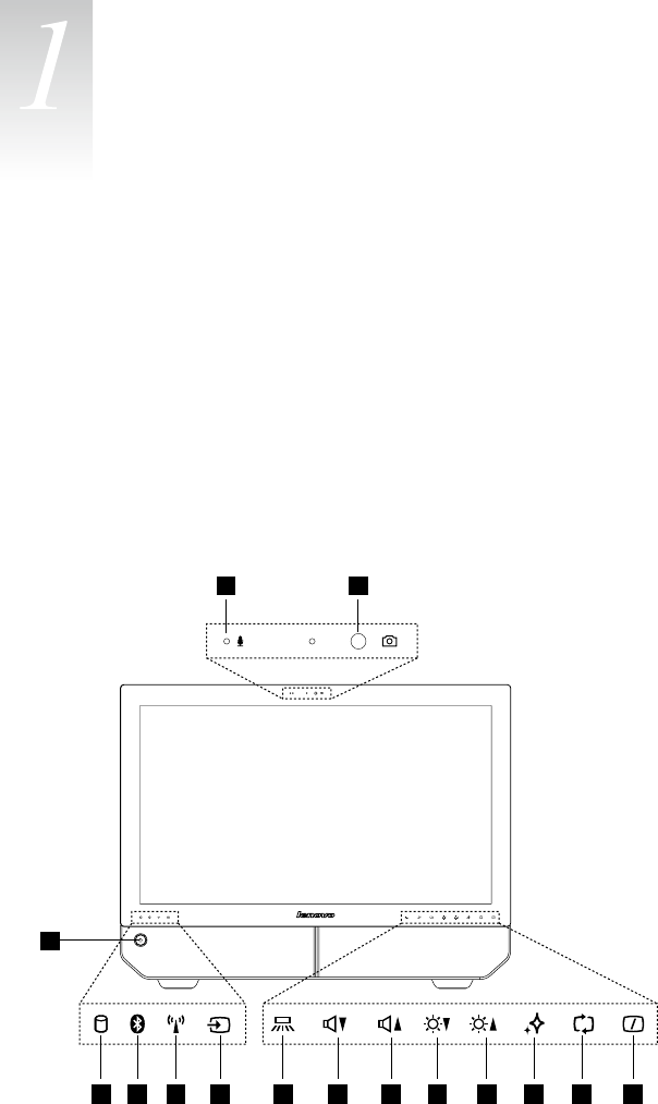
Font view
The following illustrations show the location of connectors on the front of the
computer.
1 2
4
3
5 6 7 8 9 10 11 12 13 14 15

6Hardware Replacement Guide
Built-inmicrophone Volume down
Camera Volume up
Powerbutton Brightnessdown
Hard Disk Drive Indicator Brightnessup
Bluetoothstatusindicator Novo Vision button
WIFI status indicator PCmode/HDMI-in/AV-inswitch
AV-in / HDMI-in indicator Monitor On/Off
Indicator lights ON/OFF button
Note: The quality of video output will be affected accordingly due to the
restriction of the actual bandwidth used by users and the limitation of data
transmission speed of the video communication software.
Left and right view
The following illustrations show the location of connectors on the left and right side
of the computer.
Attention: Besurenottoblockanyairventsonthecomputer.Blockedair
vents may cause thermal problems.
Memory card reader Microphone connector
USBconnector Optical drive
Headphone connector
7
Hardware Replacement Guide
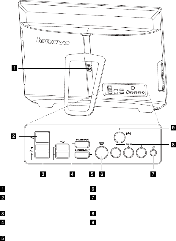
Rear view
The following illustration shows the location of connectors on the rear of the
computer.
Powersocket PS/2keyboardport
Ethernet port Bluetoothresetbutton(Onlysome
models are functional)
USBports(4) AV-IN ports (Selected models only)
HDMI in port (Selected models
only)
TV tuner connector (Selected models
only)
HDMI out port
8Hardware Replacement Guide
9
Hardware Replacement Guide
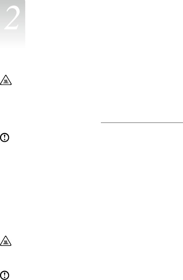
Attention:
Do not remove the computer cover or attempt any repairs before reading
the “Important safety information” in the Safety and Warranty Guide that was
included with your computer or in the Hardware Maintenance Manual (HMM)
for the computer. To obtain copies of the Safety and Warranty Guide or
HMM, go to the Support Web site at: http://consumersupport.lenovo.com
Note: Use only parts provided by Lenovo.
General information
Pre-disassembly instructions
Beforeproceedingwiththedisassemblyprocedure,makesurethatyoudothe
following:
1. Turn off the power to the system and all peripherals.
2. Unplug all power and signal cables from the computer.
3. Placethesystemonaat,stablesurface.
Removing the computer cover
Attention:
Turn off the computer and wait 3 to 5 minutes to let the computer cool
down before removing the computer cover.
Note: Itmaybehelpfultoplacethecomputerface-downonasoftatsurface
for this procedure. Lenovo recommends that you use a blanket, towel, or
other soft cloth to protect the computer screen from scratching or other
damage.
Replacing hardware
Chapter
10 Hardware Replacement Guide
To remove the computer cover
1. Remove any media (disks, CDs, or memory cards) from the drives, shut down
the operating system, and turn off the computer and all attached devices.
2. Unplug all power cords from electrical outlets.
3. Disconnect all cables attached to the computer. This includes power cords,
input/output (I/O) cables, and any other cables that are connected to the
computer. Refer to “Left and right view” and “Rear view” for help with locating
the various connectors.
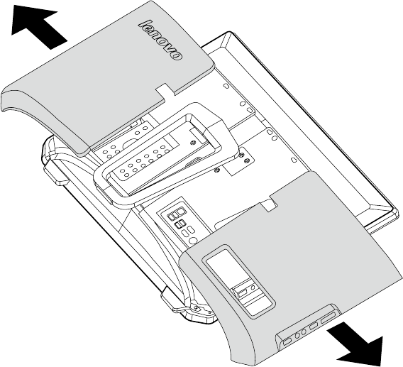
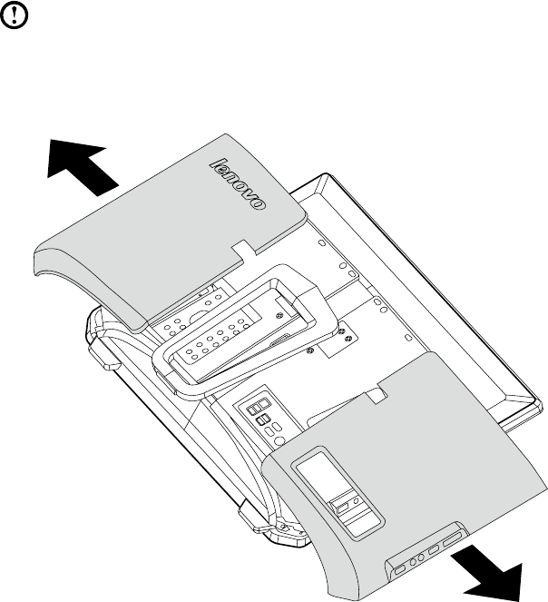
4. Remove the 2 cover pieces by sliding them in opposite directions as shown.
11
Hardware Replacement Guide
Mounting the computer onto a wall
Thecomputercanbemountedontoawall.Beforedoingthis,youwillrstneedto
install a wall mount VESA bracket adapter* (some models are shipped with this
part) onto the back of the computer. The bracket adapter can then be used with a
UL listed standard wall mount (to be purchased separately) to mount the computer
onto a wall.
To install a wall mount bracket adapter
Note: Itmaybehelpfultoplacethecomputerface-downonasoftatsurface
for this procedure. Lenovo recommends that you use a blanket, towel, or
other soft cloth to protect the touch screen from scratching or other damage.
1. Remove the 2 cover pieces by sliding them in opposite directions as shown.
* VESA bracket adapter spec: VESA100, 100mm x 100mm, M4 bolts.
12 Hardware Replacement Guide
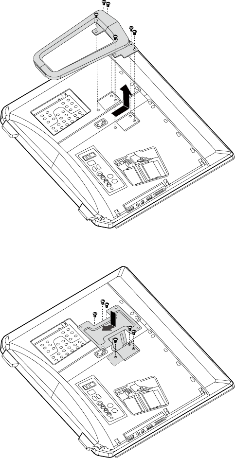
2. Remove the 6 screws that secure the stand to the computer, and then slide
the stand out.
3. Align the wall mount bracket adapter and slide into place as shown, and then
secure the adapter to the computer with the 6 screws.
13
Hardware Replacement Guide
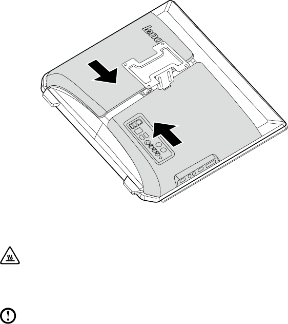
4. Slide both cover pieces back into position.
Replacing a memory module
Attention:
Turn off the computer and wait 3 to 5 minutes to let the computer cool
down before removing the computer cover.
Note: Itmaybehelpfultoplacethecomputerface-downonasoftatsurface
for this procedure. Lenovo recommends that you use a blanket, towel, or
other soft cloth to protect the touch screen from scratching or other damage.
1. Remove any media (disks, CDs, or memory cards) from the drives, shut down
the operating system, and turn off the computer and all attached devices.
2. Unplug all power cords from electrical outlets.
3. Disconnect all cables attached to the computer. This includes power cords,
input/output (I/O) cables, and any other cables that are connected to the
computer. Refer to “Left and right view” and “Rear view” for help with locating
the various connectors.
4. Remove the computer cover. Refer to “Removing the computer cover”.
14 Hardware Replacement Guide
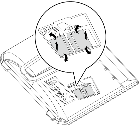
5. Pushoutthelatchesonbothsidesofthememorysockettoreleasethe
memory module and gently pull the memory module upward to remove it from
its socket. All of the memory modules can be removed by using the same
procedure.
6. Align then insert the new memory module into the socket and push down on
the top edge of the memory module. Make sure the latches lock the memory
module in place.
7. Align then slide the computer cover back into position.
15
Hardware Replacement Guide
Replacing the optical drive
Attention:
Turn off the computer and wait 3 to 5 minutes to let the computer cool
down before replacing the optical drive.
To remove the optical drive:
Note: Itmaybehelpfultoplacethecomputerface-downonasoftatsurface
for this procedure. Lenovo recommends that you use a blanket, towel, or
other soft cloth to protect the screen from scratching or other damage.
1. Remove any media (disks, CDs, or memory cards) from the drives, shut down
the operating system, and turn off the computer and all attached devices.
2. Unplug all power cords from electrical outlets.
3. Disconnect all cables attached to the computer. This includes power cords,
input/output (I/O) cables, and any other cables that are connected to the
computer. Refer to “Left and right view” and “Rear view” for help with locating
the various connectors.
4. Remove the computer cover. Refer to “Removing the computer cover”.
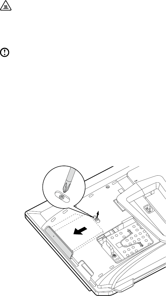
5. Loosen the screw that secures the optical drive to the chassis.
6. Pushtheopticaldrivesothatitslidesoutofthedrivebay.
16 Hardware Replacement Guide
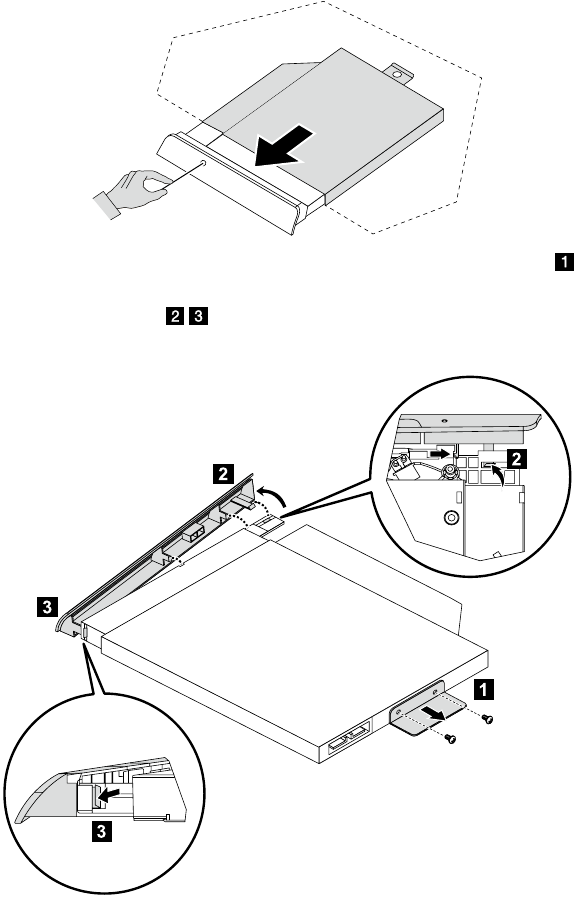
7. Pushasmallironstick(paperclip)intothesmallholeontheopticaldrivecover
so that the disk springs out as shown.
8. Remove the 2 screws that secure the optical drive to the metal bracket.
9. Useasmallatheadscrewdrivertopressandpushoutthepinsthatsecure
the cover to the disk.
10. Separate the cover from the defective optical drive.

17
Hardware Replacement Guide
11. Install the new optical drive as follows:
(1) Align the new optical drive with the cover, and then push the cover back into
position.
(2) Screw the metal bracket back onto the new optical drive.
(3) Slide the new optical drive into the drive bay.
12. Screw the new optical drive back onto the chassis.
13. Slide the computer cover back into position.
Replacing the hard disk drive
Attention:
Turn off the computer and wait 3 to 5 minutes to let the computer cool
down before replacing the hard disk drive.
To replace the hard disk drive:
Note: Itmaybehelpfultoplacethecomputerface-downonasoftatsurface
for this procedure. Lenovo recommends that you use a blanket, towel, or
other soft cloth to protect the screen from scratching or other damage.
1. Remove the computer cover. Refer to “Removing the computer cover”.
2. Loosen the screw that secures the hard disk drive bay to the chassis.
18 Hardware Replacement Guide
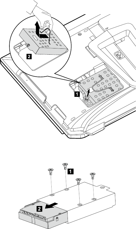
3. Spring up the handle on the hard disk drive bay, and then slide the hard disk
drive bay out of the chassis as shown.
4. Remove the 4 screws that secure the hard disk drive to the disk bay and slide
the defective hard disk drive out of the bay.
5. Install the new hard disk drive as follows:
(1) Slide the new hard disk drive into the drive bay.
(2) Screw the 4 screws back onto the drive bay.
6. Slide the hard disk drive bay back into position.
19
Hardware Replacement Guide
7. Secure the hard disk drive bay to the chassis with the remaining screw.
8. Install the computer cover back into position.
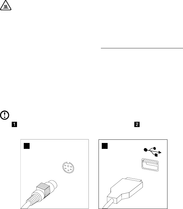
Replacing the keyboard
Attention:
Do not remove the computer cover or attempt any repairs before reading
the “Important safety information” in the Safety and Warranty Guide that was
included with your computer or in the Hardware Maintenance Manual (HMM)
for the computer. To obtain copies of the Safety and Warranty Guide or
HMM, go to the Support Web site at: http://consumersupport.lenovo.com
To replace the keyboard:
1. Remove any media (disks, CDs, or memory cards) from the drives, shut down
the operating system, and turn off the computer and all attached devices.
2. Unplug all power cords from electrical outlets.
3. Locate the connector for the keyboard. Refer to “Left and right view” and “Rear
view”.
Note: Your keyboard may be connected to the standard keyboard connector
attherearofthecomputer,ortoaUSBconnector at either side or at
the rear of the computer.
1 2
4. Disconnect the defective keyboard cable from the computer and connect the
new keyboard cable to the same connector.
20 Hardware Replacement Guide
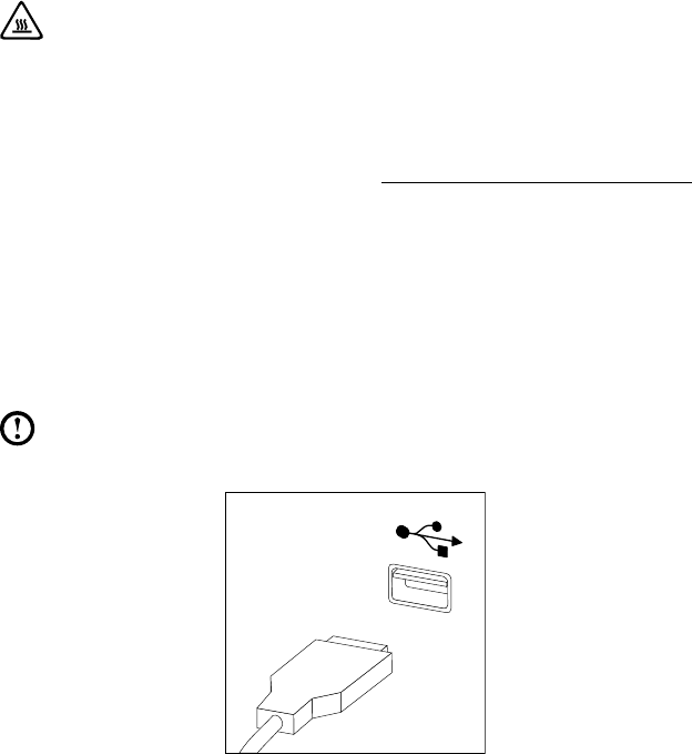
Replacing the mouse
Attention:
Do not remove the computer cover or attempt any repairs before reading
the “Important safety information” in the Safety and Warranty Guide that was
included with your computer or in the Hardware Maintenance Manual (HMM)
for the computer. To obtain copies of the Safety and Warranty Guide or
HMM, go to the Support Web site at: http://consumersupport.lenovo.com
To replace the mouse:
1. Remove any media (disks, CDs, or memory cards) from the drives, shut down
the operating system, and turn off the computer and all attached devices.
2. Unplug all power cords from electrical outlets.
3. Locate the connector for the mouse. Refer to “Left and right view” and “Rear
view”.
Note: YourmousewillbeconnectedtotheUSBconnectorateithersideorat
the rear of the computer.
4. Disconnect the defective mouse cable from the computer and connect the
new mouse cable to the same connector.
21
Hardware Replacement Guide
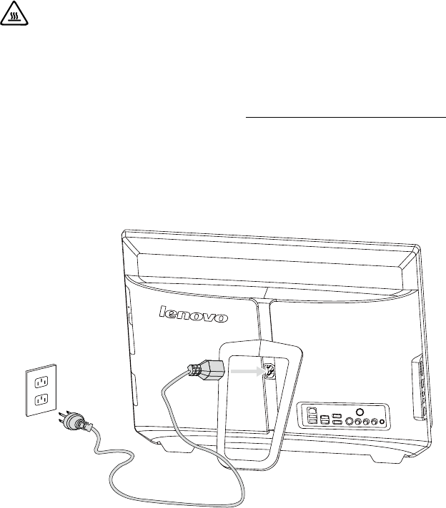
Replacing the power cord
Attention:
Do not remove the computer cover or attempt any repairs before reading
the “Important safety information” in the Safety and Warranty Guide that was
included with your computer or in the Hardware Maintenance Manual (HMM)
for the computer. To obtain copies of the Safety and Warranty Guide or
HMM, go to the Support Web site at: http://consumersupport.lenovo.com
To replace the power cord
1. Remove any media (disks, CDs, or memory cards) from the drives, shut down
the operating system, and turn off the computer and all attached devices.
2. Locate the connector for the power cord. Refer to “Rear view”.
3. Disconnect the defective power cord from the computer and connect the new
power cord to the same connector.
22 Hardware Replacement Guide

23
Hardware Replacement Guide
Declaration
Thank you for using Lenovo products.
Carefully read all documents shipped with your computer before you install and
use the product for the first time. Lenovo is not responsible for any loss except
when caused by installation and operations performed by Lenovo professional
service personnel. You are responsible if you fail to operate the product according
to instructions and requirements in the manuals included with your computer, or
operate the product inappropriately.
This manual could include technical inaccuracies or typographical errors. Changes
are made periodically to the information herein; these changes will be incorporated
in new editions of the publication.To provide better service, Lenovo reserves the
right to improve and/or modify the products and software programs described in
the manuals included with your computer, and the content of the manual, at any
time without additional notice.
The manuals included with your computer are provided to help you use Lenovo’s
products appropriately. For the configuration of the product, refer to the related
contract (if any) or product packing list, or consult the distributor for the product
sales.
The content of the manuals included with your computer is protected by copyright
laws and rules. None of the manuals included with your computer may be
reproduced or transcribed by any means or translated into any language without
prior written permission of Lenovo.
The software interface and function and hardware configuration described in
the manuals included with your computer might not match exactly the actual
configuration of the computer that you purchase.You are welcome to contact us
about the manuals included with your computer. For the latest information or any
questions or comments, contact or visit the Lenovo Web site:
Service Web site: http://consumersupport.lenovo.com
Appendix
Chapter
24 Hardware Replacement Guide
Trademarks
Lenovo and the Lenovo logo, IdeaCentre and IdeaCentre logo are trademarks of
Lenovo in the United States, other countries, or both.
Microsoft, Windows, and Windows Vista are trademarks of the Microsoft group of
companies.
Intel Inside is a trademark of Intel Corporation in the U.S. and/or other countries.
AMD, the AMD Arrow logo, ATI, AMD Athlon, AMD LIVE!, AMD Opteron, AMD
Phenom,AMDSempron,Catalyst,Cool‘n’Quiet,CrossFire,PowerPlay,Radeon,
and The Ultimate Visual Experience are trademarks of Advanced Micro Devices,
Inc.
Other company, product, or service names referred to herein or in other Lenovo
publications may be trademarks or service marks of others.
All rights reserved.
Names or marks of certain companies mentioned in the manuals included with
your computer or this document do not necessarily indicate that related software
or hardware is included. The actual configuration of the product depends on the
packing list description.
