Lenovo 387 Users Manual
389 to the manual 2f42d55f-42b4-4739-8362-0249425ab7ae
2015-01-24
: Lenovo Lenovo-387-Users-Manual-330530 lenovo-387-users-manual-330530 lenovo pdf
Open the PDF directly: View PDF ![]() .
.
Page Count: 248 [warning: Documents this large are best viewed by clicking the View PDF Link!]
- Safety information
- Chapter 1. General information
- Chapter 2. Server setup road map
- Chapter 3. Product overview
- Chapter 4. Turning on and turning off the server
- Chapter 5. Configuring the server
- Chapter 6. Installing, removing, or replacing hardware
- Guidelines
- Removing the server cover
- Removing and reinstalling the front bezel
- Installing, removing, or replacing hardware
- Installing or removing a memory module
- Installing or removing a PCI card
- Installing or removing the Ethernet card
- Installing or removing the RAID card
- Installing or removing the ThinkServer 9240-8i RAID 5 Upgrade Key
- Installing or removing the ThinkServer SATA Software RAID 5 Key
- Installing or removing the ThinkServer iKVM Remote Management Module
- Installing or removing the TPM module
- Installing or removing the DIT module
- Installing or replacing an optical drive
- Installing or replacing a hot-swap hard disk drive
- Removing or installing a non-hot-swap hard disk drive
- Replacing the hot-swap hard disk drive backplane
- Replacing the non-hot-swap power supply assembly
- Replacing a hot-swap redundant power supply module
- Replacing the power distribution board and cage assembly
- Replacing the front panel board assembly
- Replacing the front system fan
- Replacing the rear system fan
- Replacing the heat sink and fan assembly
- Replacing the microprocessor
- Replacing the system board battery
- Replacing the system board
- Completing the parts replacement
- Chapter 7. Troubleshooting and diagnostics
- Chapter 8. FRU lists
- Chapter 9. Getting information, help, and service
- Appendix A. Notices
- Index

ThinkServer
HardwareMaintenanceManual
MachineTypes:0387,0388,0389,0390,0391,0392,0393,and0441

Note:
Beforeusingtheinformationandtheproductitsupports,besuretoreadandunderstandthefollowing:
•TheReadMeFirstthatcomeswithyourproduct
•“Safetyinformation”onpageiii
•AppendixA“Notices”onpage217
SecondEdition(August2011)
©CopyrightLenovo2011.
LIMITEDANDRESTRICTEDRIGHTSNOTICE:IfdataorsoftwareisdeliveredpursuantaGeneralServicesAdministration
“GSA”contract,use,reproduction,ordisclosureissubjecttorestrictionssetforthinContractNo.GS-35F-05925.

Contents
Safetyinformation..........iii
Chapter1.Generalinformation.....1
Introduction.................1
Serverdocumentation.............1
Chapter2.Serversetuproadmap...5
Chapter3.Productoverview......7
Serverpackage...............7
Features..................7
Specications...............12
Software.................12
ThinkServerEasyStartup.........12
ThinkServerEasyUpdateFirmwareUpdater.13
BIOSandBMCrmwareupdateutility...13
RAIDcongurationutilities........13
PC-DoctorforDOS...........13
Locations.................13
Machinetype,model,andserialnumber
label.................13
Frontviewoftheserver.........15
Frontpanel..............17
DITmodule..............18
Rearviewoftheserver.........19
Serverlocks..............22
Servercomponents...........25
Hot-swapharddiskdrivestatusLEDs...32
RAIDcard...............33
Hot-swapharddiskdrivebackplane....34
Systemboardcomponents........42
Systemboardjumpers..........46
SystemboardLEDs...........50
Chapter4.Turningonandturningoff
theserver...............53
Turningontheserver............53
Turningofftheserver............53
Chapter5.Conguringtheserver..55
UsingtheSetupUtilityprogram........55
StartingtheSetupUtilityprogram.....55
ViewinginformationintheSetupUtility
program...............55
SetupUtilityprograminterface......56
Settingthesystemdateandtime.....64
Usingpasswords............65
ConguringtheTPMfunction.......66
Selectingastartupdevice........66
ExitingtheSetupUtilityprogram......67
UpdatingorrecoveringtheBIOS......67
UsingtheThinkServerEasyStartupprogram...69
FeaturesoftheThinkServerEasyStartup
program...............70
StartingtheThinkServerEasyStartup
program...............70
ConguringRAID..............71
AboutRAID..............72
RAIDforyourserver...........73
ConguringRAIDusingtheThinkServer
EasyStartupprogram..........74
ConguringtheonboardSATAsoftware
RAID.................74
ConguringtheadvancedSATAorSAS
hardwareRAID.............79
ConguringtheEthernetcontrollers......80
Updatingthermware............80
UsingtheFirmwareUpdaterprogram....81
Chapter6.Installing,removing,or
replacinghardware..........83
Guidelines................83
Precautions..............83
Handlingstatic-sensitivedevices.....84
Systemreliabilityguidelines........84
Workinginsidetheserverwiththepoweron.85
Removingtheservercover..........85
Removingandreinstallingthefrontbezel....87
Installing,removing,orreplacinghardware...89
Installingorremovingamemorymodule...89
InstallingorremovingaPCIcard......93
InstallingorremovingtheEthernetcard...96
InstallingorremovingtheRAIDcard....98
InstallingorremovingtheThinkServer9240-8i
RAID5UpgradeKey..........100
InstallingorremovingtheThinkServerSATA
SoftwareRAID5Key..........102
InstallingorremovingtheThinkServeriKVM
RemoteManagementModule.......105
InstallingorremovingtheTPMmodule...109
InstallingorremovingtheDITmodule....111
Installingorreplacinganopticaldrive....115
Installingorreplacingahot-swapharddisk
drive.................119
Removingorinstallinganon-hot-swaphard
diskdrive...............123
©CopyrightLenovo2011i

Replacingthehot-swapharddiskdrive
backplane...............133
Replacingthenon-hot-swappowersupply
assembly...............137
Replacingahot-swapredundantpower
supplymodule.............140
Replacingthepowerdistributionboardand
cageassembly.............143
Replacingthefrontpanelboardassembly..147
Replacingthefrontsystemfan......149
Replacingtherearsystemfan.......152
Replacingtheheatsinkandfanassembly..154
Replacingthemicroprocessor.......157
Replacingthesystemboardbattery....161
Replacingthesystemboard.......162
Completingthepartsreplacement.......168
Reinstallingtheservercoverandreconnecting
cables................168
Updatingtheserverconguration.....170
Chapter7.Troubleshootingand
diagnostics.............171
Troubleshootingprocedure..........171
ViewingthestatusanddiagnosticLEDs.....171
Usingthediagnosticprogram.........172
Viewingthesystemeventlog.........172
Basictroubleshootingtables.........172
ThinkServerEasyStartupprogram
problems...............172
Opticaldriveproblems..........173
Harddiskdriveproblems.........174
Memorymoduleproblems........176
Keyboard,mouse,orUSBdeviceproblems..176
POSTerrorcodes............177
Chapter8.FRUlists.........179
MajorFRUs................179
MechanicalFRUs.............189
AdaptersandmiscellaneousFRUs.......194
Powercords...............196
Shipgroup................204
Chapter9.Gettinginformation,help,
andservice.............213
Informationresources............213
Usingthedocumentation.........213
ThinkServerWebsite
(http://www.lenovo.com/thinkserver)....213
LenovoSupportWebsite.........213
Helpandservice..............214
Beforeyoucall.............214
Callingforservice............214
Usingotherservices..........215
Purchasingadditionalservices......215
AppendixA.Notices.........217
Trademarks................218
Importantnotes..............218
PolyvinylChloride(PVC)cableandcordnotice..218
Recyclinginformation............218
Batteryreturnprogram..........219
Requirementforbatteriescontaining
perchlorate..............220
Particulatecontamination..........220
ImportantinformationfortheEuropeanDirective
2002/96/EC................221
RestrictionofHazardousSubstancesDirective
(RoHS)..................224
ChinaRoHS..............225
Turkishstatementofcompliance......225
GermanOrdinanceforWorkglossstatement...226
Electronicemissionnotices..........226
FederalCommunicationsCommission(FCC)
Statement...............226
Index.................229
iiThinkServerHardwareMaintenanceManual
Safetyinformation
Note:Beforeusingtheproduct,besuretoreadandunderstandthemultilingualsafetyinstructionsonthe
documentationDVDthatcomeswiththeproduct.
Antesdeusaroproduto,leiaeentendaasinstruçõesdesegurançamultilínguesnoDVDdedocumentação
queoacompanha.
Предидаизползватетозипродукт,задължителнопрочететеивникнетевмногоезичнитеинструкции
забезопасноствDVDдискасдокументация,койтосепредоставяспродукта.
PrijeupotrebeovogproizvodaobaveznopročitajtevišejezičnesigurnosneuputekojesenalazenaDVD-us
dokumentacijomkojidobivateuzproizvod.
PředpoužitímproduktujetřebasipřečístaporozumětbezpečnostnímpokynůmuvedenýmnadiskuDVDs
dokumentací,kterýjedodávánsproduktem.
Førdubrugerproduktet,skaldusørgeforatlæseogforstådesikkerhedsforskrifter,derndespåere
sprog,pådendokumentations-dvd,derfølgermedproduktet.
LuetuotteenmukanatoimitetullaDVD-tietolevylläolevatmonikielisetturvaohjeetennentämäntuotteen
käyttöä.
Avantd'utiliserleproduit,veillezàbienlireetcomprendrelesinstructionsdesécuritémultilinguesgurant
surleDVDdedocumentationfourniavecleproduit.
Πρινχρησιμοποιήσετετοπροϊόν,βεβαιωθείτεότιέχετεδιαβάσεικαικατανοήσειτιςοδηγίεςασφάλειας,οι
οποίεςείναιδιαθέσιμεςσεδιάφορεςγλώσσεςστοDVDτεκμηρίωσηςπουσυνοδεύειτοπροϊόν.
VorVerwendungdesProduktssolltenSieunbedingtdiemehrsprachigenSicherheitsanweisungenaufder
Dokumentations-DVDlesen,dieimLieferumfangdesProduktsenthaltenist.
AtermékhasználataelőttmindenképpenolvassaelésértelmezzeatermékhezkapottdokumentációsDVD
lemezentalálható,többnyelvenelolvashatóbiztonságielőírásokat.
Primadiutilizzareilprodotto,accertarsidileggereecomprendereleinformazionisullasicurezzamultilingue
disponibilisulDVDdidocumentazionefornitoconilprodotto.
製品をご使用になる前に、製品に付属のDocumentationDVDに収録されているマルチリンガルの「安
全に正しくご使用いただくために」を読んで理解してください。
제품을사용하기전에제품과함께제공되는문서DVD의다국어안전지침을주의깊게읽어보십시오.
Voordatuhetproductgebruikt,moetuervoorzorgendatudemeertaligeveiligheidsinstructiesopde
documentatie-dvdvanhetproducthebtgelezenenbegrijpt.
©CopyrightLenovo2011iii

Przedskorzystaniemzproduktunależyzapoznaćsięzwielojęzycznymiinstrukcjamibezpieczeństwa
znajdującymisięnapłycieDVDzdokumentacjądostarczonąwrazzproduktem.
Antesdeutilizaroproduto,leiaatentamenteasinstruçõesdesegurançamultilinguesqueconstamno
DVDdedocumentaçãofornecidocomoproduto.
Înaintedeautilizaprodusul,asiguraţi-văcăaţicititşiînţelesinstrucţiuniledesiguranţăînmaimultelimbide
peDVD-ulcudocumentaţiecareînsoţeşteprodusul.
Førdubrukerproduktet,måduleseogforstådenerspråkligesikkerhetsinformasjonenpåDVDenmed
dokumentasjonsomfølgermedproduktet.
Преждечемиспользоватьэтотпродукт,внимательноознакомьтесьсинструкциямипотехнике
безопасностинаразныхязыках,которыеможнонайтинаDVD-дискесдокументациейвкомплектес
продуктом.
在使用本产品之前,请务必先阅读和了解产品附带的文档DVD中的多语言安全说明。
Prenegotoupotrebiteproizvodobaveznopaljivoproitajteiprouiteviejezikouputstvozabezbednostna
dokumentacionomDVD-ukojistedobiliuzproizvod.
PredpouvanmproduktusipretajteviacjazynbezpenostnpokynynadiskuDVDsdokumentcioudodanoms
produktom.
Predenzačneteuporabljatiizdelek,jepomembno,daprebereteinrazumetevečjezičnavarnostnanavodila
naDVD-juzdokumentacijo,kistegaprejeliskupajzizdelkom.
Antesdeutilizarelproducto,asegúresedeleerycomprenderlasinstruccionesdeseguridadmultilingüesdel
DVDdedocumentaciónqueseproporcionaconelproducto.
Varnogamedattläsasäkerhetsinstruktionernapådokumentations-DVD-skivansomföljermedprodukten
innandubörjaranvändaprodukten.
使用本產品之前,請務必閱讀並瞭解產品隨附的文件DVD上的多國語言版本安全資訊。
Buürünükullanmadanönce,ürünlebirliktegönderilenbelgeDVD'siüzerindekiçokdiliçerengüvenlik
yönergeleriniokuyupanladýðýnýzdaneminolun.
Передвикористаннямцьогопродуктууважноознайомтесязінструкціямизтехнікибезпекинарізних
мовах,щоможназнайтинаDVD-дискуздокументацієювкомплектізпродуктом.
Important:Thecautionanddangerstatementsinthisdocumentarelabeledwithnumbers.Eachnumber
identiesanEnglish-languagecautionordangerstatementthatreferstotranslatedversionsofthecaution
ordangerstatementintheSafetyInformationdocument.Forexample,ifadangerstatementislabeled
“Statement1,”translationsforthisdangerstatementareintheSafetyInformationdocumentunder
“Statement1.”
Ensurethatyoureadandunderstandallcautionanddangerstatementsinthisdocumentbeforeyouperform
theprocedures.Readandunderstandanyadditionalsafetyinformationthatisincludedwiththeserveror
optionaldevicebeforeyouinstall,remove,orreplacethedevice.
ivThinkServerHardwareMaintenanceManual
Statement1
DANGER
Electricalcurrentfrompower,telephone,andcommunicationcablesishazardous.
Toavoidashockhazard:
•Donotconnectordisconnectanycablesorperforminstallation,maintenance,orrecongurationofthis
productduringanelectricalstorm.
•Connectallpowercordstoaproperlywiredandgroundedelectricaloutlet.
•Connecttoproperlywiredoutletsanyequipmentthatwillbeattachedtothisproduct.
•Whenpossible,useonehandonlytoconnectordisconnectsignalcables.
•Neverturnonanyequipmentwhenthereisevidenceofre,water,orstructuraldamage.
•Disconnecttheattachedpowercords,telecommunicationssystems,networks,andmodemsbeforeyou
openthedevicecovers,unlessinstructedotherwiseintheinstallationandcongurationprocedures.
•Connectanddisconnectcablesasdescribedinthefollowingtablewheninstalling,moving,oropening
coversonthisproductorattacheddevices.
Toconnect:Todisconnect:
1.TurneverythingOFF.
2.First,attachallcablestodevices.
3.Attachsignalcablestoconnectors.
4.Attachpowercordstooutlet.
5.TurndevicesON.
1.TurneverythingOFF.
2.First,removepowercordsfromoutlet.
3.Removesignalcablesfromconnectors.
4.Removeallcablesfromdevices.
Statement2
DANGER
Dangerofexplosionifbatteryisincorrectlyreplaced.
Whenreplacingthelithiumcoincellbattery,useonlythesameoranequivalenttypethatis
recommendedbythemanufacturer.Thebatterycontainslithiumandcanexplodeifnotproperly
used,handled,ordisposedof.
Donot:
•Throworimmerseintowater
•Heattomorethan100°C(212°F)
•Repairordisassemble
Disposeofthebatteryasrequiredbylocalordinancesorregulations.
©CopyrightLenovo2011v
Statement3
CAUTION:
Whenlaserproducts(suchasCD-ROMs,DVDdrives,beropticdevices,ortransmitters)are
installed,notethefollowing:
•Donotremovethecovers.Removingthecoversofthelaserproductcouldresultinexposureto
hazardouslaserradiation.Therearenoserviceablepartsinsidethedevice.
•Useofcontrolsoradjustmentsorperformanceofproceduresotherthanthosespeciedherein
mightresultinhazardousradiationexposure.
DANGER
SomelaserproductscontainanembeddedClass3AorClass3Blaserdiode.Notethefollowing.
Laserradiationwhenopen.Donotstareintothebeam,donotviewdirectlywithoptical
instruments,andavoiddirectexposuretothebeam.
Statement4
≥18kg(39.7lb)≥32kg(70.5lb)≥55kg(121.2lb)
<32kg(70.5lb)<55kg(121.2lb)<100kg(220.5lb)
CAUTION:
Usesafepracticeswhenlifting.
Statement5
CAUTION:
Thepowercontrolbuttononthedeviceandthepowerswitchonthepowersupplydonotturnoff
theelectricalcurrentsuppliedtothedevice.Thedevicealsomighthavemorethanonepower
cord.Toremoveallelectricalcurrentfromthedevice,ensurethatallpowercordsaredisconnected
fromthepowersource.
viThinkServerHardwareMaintenanceManual
Statement6
CAUTION:
Ifyouinstallastrain-reliefbracketoptionovertheendofthepowercordthatisconnectedtothe
device,youmustconnecttheotherendofthepowercordtoapowersourcethatiseasilyaccessible
incaseitneedstobedisconnected.
Statement7
CAUTION:
Ifthedevicehasdoors,ensurethatyouremoveorsecurethedoorsbeforemovingorliftingthe
devicetoprotectagainstpersonalinjury.Thedoorswillnotsupporttheweightofthedevice.
Statement8
CAUTION:
Neverremovethecoveronapowersupplyoranypartthathasthefollowinglabelattached.
Hazardousvoltage,current,andenergylevelsarepresentinsideanycomponentthathasthislabel
attached.Therearenoserviceablepartsinsidethesecomponents.Ifyoususpectaproblemwith
oneoftheseparts,contactaservicetechnician.
Statement9
CAUTION:
Disconnectthehot-swapfancablesbeforeremovingthefanfromthedevicetoprotectagainst
personalinjury.
Statement10
CAUTION:
Thefollowinglabelindicatesasharp-edgehazard.
©CopyrightLenovo2011vii
Statement11
CAUTION:
Thefollowinglabelindicatesapotentialheathazard.
Statement12
DANGER
Overloadingabranchcircuitisapotentialrehazardandashockhazardundercertainconditions.To
avoidthesehazards,ensurethatyoursystemelectricalrequirementsdonotexceedbranchcurrentratings
attheinstallationsite.
Statement13
CAUTION:
Ensurethattherackissecuredproperlytoavoidtippingwhentheserverunitisextendedontherails.
Statement14
CAUTION:
SomeaccessoryoroptionboardoutputsexceedClass2orlimitedpowersourcelimits.You
mustinstalltheappropriateinterconnectingcablinginaccordancewithyourlocalelectricalcode
requirements.
Statement15
CAUTION:
Thepower-controlbuttononthedevicemayputthedeviceinstandbymodeinsteadofturningoff
thedevice.Inaddition,thedevicemighthavemultipleconnectionstodcpower.Toremoveall
electricalcurrentfromthedevice,ensurethatallconnectionstodcpoweraredisconnectedat
thedcpowerinputterminals.
viiiThinkServerHardwareMaintenanceManual
Statement16
CAUTION:
Toreducetheriskofelectricshockorenergyhazards:
•Thisequipmentmustbeinstalledbytrainedservicepersonnelinarestricted-accesslocation,as
denedbyyourlocalelectricalcodeandthelatesteditionofIEC60950.
•Connecttheequipmenttoareliablyearthedsafetyextralowvoltage(SELV)source.AnSELV
sourceisasecondarycircuitthatisdesignedsothatnormalandsinglefaultconditionsdonot
causethevoltagestoexceedasafelevel(60Vdirectcurrent).
•Thebranchcircuitovercurrentprotectionmustberatedinaccordancewithlocalelectricalcode
requirements.
•Use1.3mm2or16AmericanWireGauge(AWG)copperconductoronly,notexceeding3meters
inlength.
•Torquethewiring-terminalscrewsto1.4newton-metersor12inch-pounds.
•Provideareadilyavailable,approvedandrateddisconnectdeviceintheeldwiring.
Statement17
CAUTION:
ThisproductcontainsaClass1Mlaser.Donotviewdirectlywithopticalinstruments.
Statement18
CAUTION:
Donotplaceanyobjectontopofrack-mountedproducts.
Statement19
CAUTION:
Hazardousmovingparts.Keepngersandotherbodypartsaway.
©CopyrightLenovo2011ix

Statement20
CAUTION:
Alithiumionbatteryisprovided.T oavoidpossibleexplosion,donotburnthebattery.Replacethe
batteryonlywiththeLenovo-approvedpart.Recycleordiscardthebatteryasinstructedbylocal
regulations.
xThinkServerHardwareMaintenanceManual

Chapter1.Generalinformation
Thischapterprovidessomegeneralinformationaboutyourproduct.
Thischaptercontainsthefollowingitems:
•“Introduction”onpage1
•“Serverdocumentation”onpage1
Introduction
ThisHardwareMaintenanceManualforyourLenovo®ThinkServer®productcontainsinformationaboutthe
serverfeatures,specications,componentlocations,congurationinstructions,hardwarereplacement
procedures,partslisting,andtroubleshootinganddiagnostics.
Note:TheHardwareMaintenanceManualisintendedonlyfortrainedservicepersonnelofLenovo.The
HardwareMaintenanceManualisupdatedfrequently,andthemostup-to-dateversionisalwaysavailablein
EnglishontheLenovoWebsiteat:
http://www.lenovo.com/ThinkServerUserGuides
Thisdocumentcontainsinstructionsonhowtoinstall,remove,orreplaceCustomerReplaceableUnits
(CRUs)andFieldReplaceableUnits(FRUs).
Replaceablecomponentsareofthreetypes:
•Self-serviceCRUs:Self-serviceCRUsareeasytoinstallandcustomersareresponsibleforreplacingall
Self-serviceCRUs.IfaLenovoservicetechnicianinstallsaSelf-serviceCRUatyourrequest,youwillbe
chargedfortheinstallation.
•Optional-serviceCRUs:AlthoughdealingwithOptional-serviceCRUsrequiressometechnicalskills,
Optional-serviceCRUsaresafeforcustomerstoreplace.YoumayinstallanOptional-serviceCRU
yourselforrequestLenovotoinstallit,atnoadditionalcharge,underthetypeofwarrantyservicethat
isdesignatedfortheserver.
•FRUs:FRUsmustbereplacedonlybytrainedservicetechnicians.
Notes:
1.BeforeservicingaLenovoproduct,besuretoreadandunderstandthe“Safetyinformation”onpageiii.
2.Forinformationaboutthetermsofwarranty,refertotheWarrantyandSupportInformationonthe
documentationDVDthatcomeswiththeserver.TheWarrantyandSupportInformationisalsoavailable
ontheLenovoWebsiteat:
http://www.lenovo.com/ThinkServerUserGuides
Toobtainthemostup-to-dateinformationabouttheserver,goto:
http://www.lenovo.com/thinkserver
LenovomaintainspagesontheWorldWideWeb,whereyoucangetthelatesttechnicalinformationand
downloaddocumentationordevicedriversandupdates.ToaccesstheLenovoSupportWebsite,goto:
http://support.lenovo.com
Serverdocumentation
Thistopicprovidesgeneraldescriptionsofthevariousdocumentationforyourserverandinstructionson
howtoobtainallthedocumentation.
©CopyrightLenovo20111

Printeddocuments
Thefollowingdocumentsareprintedoutandcontainedinyourserverpackage.
•ReadMeFirst
Thisisamultilingualdocumentyoushouldreadrst.Thisdocumentguidesyoutoreadthecomplete
warranty,support,andsafetyinformationonthedocumentationDVDthatcomeswithyourserverbefore
usingtheproduct.Thisdocumentalsoprovidesinformationabouthowtondthemostup-to-date
informationontheLenovoSupportWebsite.
•ImportantNotices
Thisdocumentincludessafetyandlegalnoticesthatyoushouldreadandunderstandbeforeusing
theserver.
DocumentationDVD
ThedocumentationDVD,whichcomeswithyourserver,containsvariousdocumentsforyourserverin
PortableDocumentFormat(PDF).Toviewthedocumentation,youneedtohavetheAdobeReaderprogram
installed.YoucandownloadthedesiredlanguageversionofthelatestAdobeReaderprogramfromthe
AdobeWebsiteat:
http://www.adobe.com
Note:LenovomaintainspagesontheWorldWideWebwhereyoucangetthelatesttechnicalinformation
anddownloaddocumentationordevicedriversandupdates.Someinformationinthedocumentsonthe
documentationDVDmightchangewithoutnoticeaftertherstreleaseoftheDVD.Youcanalwaysobtainall
themostup-to-datedocumentationforyourserverfromtheLenovoWebsiteat:
http://www.lenovo.com/ThinkServerUserGuides
ThefollowingdocumentsareonthedocumentationDVDthatcomeswithyourserver:
•SafetyInformation
Thisisamultilingualdocumentthatincludesallthesafetystatementsforyourproductinmorethan30
languages.Besuretoreadandunderstandallthesafetystatementsbeforeusingtheproduct.
•WarrantyandSupportInformation
ThisdocumentincludestheLenovowarrantystatement,CRUsinformation,andinformationabouthow
tocontactLenovoSupport.
•UserGuide
Thisdocumentprovidesdetailedinformationtohelpyougetfamiliarwithyourserverandhelpyouuse,
congure,andmaintainyourserver.
•RemoteManagementModuleUserGuide
ThisdocumentprovidesinformationtohelpyouusetheintegratedKeyboard,Video,andMouse(iKVM)
functionforserverremotemanagement.ThisdocumentisinEnglishonly.
Note:AThinkServeriKVMRemoteManagementModule(hereinafterreferredtoastheiKVMkey)is
requiredandthisoptionshouldbeinstalledontheiKVMkeyconnectoronthesystemboardtoenable
theiKVMfunction.
2ThinkServerHardwareMaintenanceManual

•MegaRAIDSASSoftwareUserGuide
ThisdocumentprovidesinformationaboutRedundantArrayofIndependentDisks(RAID)andhowto
usetheutilityprogramstocongure,monitor,andmaintainyourserverRAIDandrelateddevices.This
documentisinEnglishonly.
Note:RefertothisdocumentforhardwareRAIDinformationifyouhavearequiredRAIDcardinstalledin
theserver.See“InstallingorremovingtheRAIDcard”onpage98.Forinformationabouttheonboard
SATAsoftwareRAID,see“ConguringtheonboardSATAsoftwareRAID”onpage74.
Documentfortrainedservicepersonnelonly
ThefollowingdocumentisintendedfortrainedservicepersonnelofLenovoandisonlyavailableinEnglish
ontheLenovoWebsiteat:
http://www.lenovo.com/ThinkServerUserGuides
HardwareMaintenanceManual
Thisdocumentprovidesdiagnosticinformation,partslisting,andreplacementproceduresforalleld
replaceableunits(FRUs,partsreplacedbytrainedservicepersonnel)aswellasallCRUs.
Chapter1.Generalinformation3

4ThinkServerHardwareMaintenanceManual

Chapter2.Serversetuproadmap
Thischapterprovidesageneralroadmaptoguideyouthroughsettingupyourserver.
Theserversetupprocedurevariesdependingonthecongurationoftheserverwhenitwasdelivered.In
somecases,theserverisfullyconguredandyoujustneedtoconnecttheservertothenetworkandan
acpowersource,andthenyoucanturnontheserver.Inothercases,theserverneedstohavehardware
featuresinstalled,requireshardwareandrmwareconguration,andrequiresanoperatingsystemto
beinstalled.
Thegeneralprocedureforsettingupyourserveris:
1.Unpacktheserverpackage.See“Serverpackage”onpage7.
2.Installanyrequiredhardwareorserveroption.SeetherelatedtopicinChapter6“Installing,removing,
orreplacinghardware”onpage83.
3.ConnecttheEthernetcableandpowercord(s)totheserver.See“Rearviewoftheserver”onpage
19tolocatetheconnectors.
4.Turnontheservertoverifyoperation.See“Turningontheserver”onpage53.
5.ReviewtheUniedExtensibleFirmwareInterface(UEFI)settingsandcustomizeasneeded.See“Using
theSetupUtilityprogram”onpage55.
6.CongureRAIDandinstalltheoperatingsystemandbasicdrivers.See“UsingtheThinkServer
EasyStartupprogram”onpage69and“ConguringRAID”onpage71.
7.Installanyadditionaldriversneededforaddedfeatures.Refertotheinstructionsthatcomewiththe
hardwareoption.
8.CongureEthernetsettingsintheoperatingsystembyreferringtotheoperatingsystemhelp.Thisstep
isnotrequirediftheoperatingsystemwasinstalledusingtheThinkServerEasyStartupprogram.
9.Checkforrmwareanddriverupdates.See“Updatingthermware”onpage80.
10.Installotherapplications.Refertothedocumentationthatcomeswiththeapplicationsthatyouwantto
install.
©CopyrightLenovo20115

6ThinkServerHardwareMaintenanceManual
Chapter3.Productoverview
Thischapterprovidesinformationabouttheserverpackage,features,specications,softwareprograms,
andcomponentlocations.
Thischaptercontainsthefollowingitems:
•“Serverpackage”onpage7
•“Features”onpage7
•“Specications”onpage12
•“Software”onpage12
•“Locations”onpage13
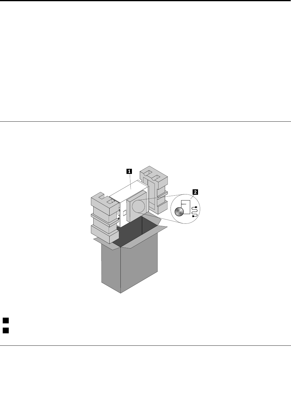
Serverpackage
Theserverpackageincludestheserver,powercord(s),printeddocumentation,documentationDVD,and
softwaremedia.
Figure1.Serverpackage
1Server
2Materialbox,includingpowercord(s),printeddocumentation,documentationDVD,andsoftwaremedia
Features
Thistopicprovidesgeneralinformationabouttheserverfeaturesforavarietyofmodels.Dependingonyour
specicmodel,somefeaturesmightvaryornotbeavailable.Forinformationaboutyourspecicmodel,use
theSetupUtilityprogram.See“ViewinginformationintheSetupUtilityprogram”onpage55.
©CopyrightLenovo20117

Microprocessor
Yourservercomeswithoneofthefollowingmicroprocessors(internalcachesizevariesbymodel):
•Intel®Xeon®quad-coremicroprocessor
•IntelXeondual-coremicroprocessor
•IntelCore™i3microprocessor
ForalistoftheThinkServermicroprocessoroptions,gotohttp://www.lenovo.com/thinkserver.Clickthe
ProductstabandthenclickOptions➙ThinkServerProcessorstoviewtheinformation.
Memory
Yourserversupportsuptofourdoubledatarate3unbuffereddualinlinememorymodules(DDR3UDIMMs)
withErrorCheckingandCorrecting(ECC)technology.
•Supports2GBand4GB1333MHzDDR3UDIMMs
•Single-rankordual-rank
•Minimumsystemmemory:2GB(onlyone2GBmemorymoduleinstalledintheDIMMA2slot)
•Maximumsystemmemory:16GB(one4GBmemorymoduleinstalledineachofthefourmemoryslots)
Formoreinformation,see“Systemboardcomponents”onpage42and“Memorymoduleinstallation
rules”onpage90.
Powersupply
Yourservercomeswithoneofthefollowingpowersupplycongurations:
•Onescrew-secured,non-hot-swap400-wattpowersupply(80PlusBronzeCompliantanduniversalinput)
•Oneortwohot-swap450-wattredundantpowersupplymodules(80PlusGoldCompliantanduniversal
input)
Fans
Youservercomeswiththefollowingfanstoprovidepropersystemcoolingandairow:
•Oneheatsinkandfanassembly
•Oneortwofrontsystemfansdependingonthemodel
•Onerearsystemfan
8ThinkServerHardwareMaintenanceManual

Internaldrives
Internaldrivesaredevicesthatyourserverusestoreadandstoredata.Theinternaldrivessupported
byyourservervarybymodel.
•Harddiskdrive
–Fivetoeight3.5-inchhot-swapSerialAdvancedTechnologyAttachment(SATA)orSerialAttached
SCSI(SAS)harddiskdrives(SCSIistheacronymforSmallComputerSystemInterface)
–Uptoeight2.5-inchhot-swapSASharddiskdrives
–Uptofour3.5-inchhot-swapSATAorSASharddiskdrives
–Uptofour3.5-inchnon-hot-swapSATAharddiskdrives
Note:ForservermodelswithmorethanfourharddiskdrivesormodelsthatuseSASharddiskdrives,
theremustbearequiredRAIDcardinstalled.See“RAIDcard”onpage33.
•Opticaldrive
–Uptotwo5.25-inchSATAopticaldrives(DVD-ROMorDVDBurner/CD-RWRambo8)
–Theloweropticaldrivebayisinstalledwitha5.25-inchSATAopticaldrive(DVD-ROMorDVDBurner/
CD-RWRambo8).TheupperopticaldrivebayisforaRemovableDiskTechnology(RDX)Universal
SerialBus(USB)drivebundle.
Forthelocationinformationabouttheinternaldrivesordrivebays,see“Servercomponents”onpage
25.ForinformationabouttheRDXUSBdrivebundleandinstructionsonhowtoinstallit,refertothe
documentationthatcomeswiththeRDXUSBdrivebundle.Inyourserver,theP6powerconnectorofthe
powersupplyisfortheRDXUSBdrivebundle.YoucanpurchasethisoptiondirectlyfromLenovo.The
optionnameisLenovoRemovableDiskTechnology(RDX)USBDriveBundle.TheRDXtechnologycombines
thecharacteristicsoftapebackupwithdiskstoragetohelpyouprotectandarchivedata.
Expansionslots
Theserverhasfourexpansionslotsonthesystemboard.Fordetailedinformation,see“Systemboard
components”onpage42.
Input/Output(I/O)features
•OneVideoGraphicsArray(VGA)DB-15connectorontherearpanel
•SixUSB2.0connectors(twoonthefrontpanelandfourontherearpanel)
•TwoRJ-45Ethernetconnectorsontherearpanel
•Twoserialconnectors(onefully-functionalserialconnectorontherearpanelandoneinternalserial
connectoronthesystemboardforoptionaluse)
Forthelocationinformationabouttheconnectors,refertotherelatedtopicin“Locations”onpage13.
Videosubsystem
AnintegratedgraphicscontrollerintheBaseboardManagementController(BMC)chiponthesystemboard
tosupportaVGADB-15connectorontherearpanelforconnectingvideodevices
Ethernetconnectivity
TheservercomeswithanintegratedIntelGigabitEthernetcontrolleraswellasanEthernetphysicallayer
(PHY)oftheOpenSystemsInterconnectionmodel(OSImodel).Theyprovidetheserverwiththeability
tosupporttwoEthernetconnectorsontherearpanelwith10Mbps,100Mbps,or1000Mbpsnetwork
connectivity.Formoreinformation,see“Rearviewoftheserver”onpage19.
Chapter3.Productoverview9

Reliability,availability,andserviceability
Reliability,availability,andserviceability(hereinafterreferredtoasRAS)arethreeimportantserverdesign
features.TheRASfeatureshelpyoutoensuretheintegrityofthedatastoredontheserver,theavailabilityof
theserverwhenyouneedit,andtheeasewithwhichyoucandiagnoseandcorrectproblems.
YourserverhasthefollowingRASfeatures:
•Securityfeatures
–Serverlocks(see“Serverlocks”onpage22)
–Administratorpasswordanduserpasswordtohelpprotectunauthorizedaccesstotheserver(see
“Usingpasswords”onpage65)
–TrustedPlatformModule(TPM)connectoronthesystemboardforaTPMmodule,whichisasecurity
chip,tohelpprotectyourserverandstrengthenserversecurity
Note:TheTPMmoduleisonlyavailableinsomemodels.
–Remotemonitoringorcontrolbyanadministratortoprovideprotectionorhelp
–Hot-swapredundantpowersupplymodulestohelpyouavoidsignicantinterruptiontotheoperation
ofthesystemwhenapowersupplymodulefails(availableinsomemodels)
•Basicsystemmanagementfeatures
–Abilitytostorethepower-onself-test(POST)hardwaretestresults
–BIOSSetupUtilityprogram
TheBIOSSetupUtilityprogramhelpsyouviewtheserverinformationandconguretheserverinthe
pre-operatingsystemenvironment.See“UsingtheSetupUtilityprogram”onpage55.
–BMCandIntelligentPlatformManagementInterface(IPMI)2.0
ThesystemboardplatformmanagementsubsystemisbasedontheintegratedBMCfeatures.The
BMCisamanagementchipthatisintegratedonthesystemboardofyourserver.WiththeBMCchip,
nomatterwhatconditiontheserveroperatingsystemisinandnomatteriftheserverisonoroff,aslong
astheserverisconnectedtonetworkandanacpowersource,theinteractionwiththeBMCcontrolled
serverscanbeachievedthroughsystemnetwork.Theusercanobtaintheserverhardwarehealth
informationandsystemeventlog(SEL),andisabletoconducttheoperationsincludingturningonor
offtheserver,restartingtheserver,lockingthepowerswitchonthefrontpanel,andsoon.Thispartof
theservermanagementisindependentoftheoperatingsystemandiscalledout-of-bandmanagement.
ThesystemboardplatformmanagementsubsystemconsistsoftheintegratedBMC,communication
buses,sensors,BasicInputOutputSystem(BIOS),andservermanagementrmware.Itisresponsible
forerrormanagementandreporting,systempowercontrol,thermalmonitoring,systemfancontrol,
andothermanagementfeatures.TheBMCprovidessystemmanagementandmonitoringfeatures
basedontheIPMI2.0specication.IPMIhelpslowertheoverallcostsofservermanagement.Youcan
ndmoreinformationaboutIPMI2.0fromtheWebsiteofIntel.TheBMCalsosupportssomenon-IPMI
features,suchastheDynamicHostCongurationProtocol(DHCP)andthePlatformEnvironment
ControlInterface(PECI),toprovidemoresystemmanagementfunctions.
RefertotheRemoteManagementModuleUserGuideonthedocumentationDVDthatcomeswithyour
serverformoreinformation.
–Hot-swapfeature
Somemodelssupporthot-swapharddiskdrivesandorhot-swapredundantpowersupplymodules.
Withthehot-swapfeature,youcaninstall,remove,orreplaceharddiskdrivesorafailingpowersupply
modulewithoutturningofftheserver.
10ThinkServerHardwareMaintenanceManual

–PrebootExecutionEnvironment(PXE)
TheIntelPXEtechnologyenablesyoutobootyourcomputers,loadanoperatingsystem,ordeploy
executableimagesfromaremoteserverbyusinganetworkinterface.Theoperationcanbedone
independentlyoflocaldatastoragedevices(suchasharddiskdrives)orinstalledoperatingsystems.
–RedundantArrayofIndependentDisks(RAID)
YourserversupportsonboardSATAsoftwareRAIDandadvancedSATA/SAShardwareRAID
congurationsifyouhavearequiredRAIDcardinstalled.Fordetailedinformation,see“Conguring
RAID”onpage71.
–Statuslight-emittingdiodes(LEDs)anddiagnosticLEDs
FormoreinformationabouttheLEDsforyourserver,refertotherelatedtopicsin“Locations”on
page13.
–ThinkServerEasyStartupprogramandThinkServerEasyUpdateFirmwareUpdaterprogram
Formoreinformationaboutthesoftwareprograms,see“Software”onpage12.
–WakeonLAN
WhentheWakeonLANfeatureisenabledonacomputerthatisconnectedtoalocalareanetwork
(LAN),anetworkadministratorcanremotelyturnonorwakeupthecomputerfromamanagement
consoleusingremotenetworkmanagementsoftware.Besides,manyotherfunctions,suchasdata
transferandsoftwareupdates,canbeperformedremotelywithoutremoteattendanceandcanbedone
afternormalworkinghoursandonweekendstosavetimeandincreaseproductivity.
•Advancedsystemmanagementfeatures
TheBMCrmwaresupportsthefollowingadvancedsystemmanagementfeatures:
Note:TheadvancedsystemmanagementfeaturesareonlyavailablewhentheBMCdetectsthepresence
ofanintegratedkeyboard,video,andmouse(iKVM)key.TheiKVMkeyisaremotemanagementmodule.
YoucanpurchaseaniKVMkeyfromLenovoandinstallitontheiKVMkeyconnectoronthesystemboard
ofyourservertoenabletheiKVMfunctionandactivatetheadvancedsystemmanagementfeatures.
–iKVMredirection
TheBMCrmwaresupportsiKVMredirectionoverLAN.Thisfeatureisavailableremotelyfromthe
embeddedWebserver.Theremotemanagementmodulecandigitizeandcompressthecollected
keyboard,video,andmousesignalsfromthehostsystemandthensendthemtotheremoteconsole.
Meanwhile,itiseasilyaccessiblebyremoteKVMandcontrollablethroughLANorInternet.Fordetailed
information,refertotheRemoteManagementModuleUserGuideonthedocumentationDVDthat
comeswithyourserver.
–Mediaredirection
TheembeddedWebserverprovidesaJavaJNLPtoenabletheremotemediaredirection.Thisisused
inconjunctionwiththeremoteKVMfeatureorasastandaloneapplet.
Themediaredirectionfeatureisintendedtoenablesystemadministratorsoruserstomountaremote
opticaldrive,oppydrive,orUSBashdiskasaUSBdevicetotheserver.Oncemounted,theremote
devicefunctionsasalocaldevicetotheserver,enablingsystemadministratorsoruserstobootthe
serverandinstallsoftware(includingoperatingsystems),copyles,updatetheBIOSfromthisdevice.
–WebServicesforManagement(WS-MAN)
TheBMCrmwaresupportstheWS-MANspecication.
–LocalDirectoryAuthenticationProtocol(LDAP)
TheBMCrmwaresupportstheLDAPforuserauthentication.
Note:TheIPMIusers,passwords,andsessionsarenotsupportedoverLDAP.
Chapter3.Productoverview11

–EmbeddedWebserver
TheBMCprovidesanembeddedWebserverforout-of-bandmanagement.Theuserauthenticationis
handledbyIPMIusernamesandpasswords.Formoreinformation,refertotheRemoteManagement
ModuleUserGuideonthedocumentationDVDthatcomeswithyourserver.
Specications
Thistopicliststhephysicalspecicationsforyourserver.
Dimensions
Width:195mm(7.68inches)
Height:430mm(16.93inches)withoutfootstands;445mm(17.52inches)withfootstands
Depth:595mm(23.43inches)includingthefrontbezel
Weight
Theproductweightvariesdependingondifferentsystemcongurations.
Rangeofproductweightwithoutpackage:19kg(41.89lb)to28kg(61.73lb)
Rangeofproductpackageweight:2.8kg(6.17lb)to3.5kg(7.72lb)
Environment
•Airtemperature:
Operating:10°Cto35°C(50°Fto95°F)
Storage:-40°Cto70°C(-40°Fto158°F)inoriginalshippingpackage
•Altitude:0to3048m(0to10000ft)
•Humidity:
Operating:8%to80%(non-condensing)
Storage:8%to90%(non-condensing)
Electricalinput
Universalinput:
Minimum:90Vac
Maximum:264Vac
Inputfrequencyrange:47to63Hz
Software
Thistopicprovidesinformationaboutthesoftwareprogramsthatyoucanusetohelpyousetup,use,
andmaintaintheserver.
ThinkServerEasyStartup
TheThinkServerEasyStartupprogramsimpliestheprocessofconguringRAIDandinstallingsupported
Microsoft®Windows®andLinux®operatingsystemsanddevicedriversonyourserver.Thisprogramis
providedwithyourserveronaself-starting(bootable)ThinkServerEasyStartupDVD.Theuserguidefor
theprogramisalsoontheDVDandcanbeaccesseddirectlyfromtheprograminterface.Fordetailed
information,see“UsingtheThinkServerEasyStartupprogram”onpage69.
12ThinkServerHardwareMaintenanceManual

ThinkServerEasyUpdateFirmwareUpdater
TheThinkServerEasyUpdateFirmwareUpdaterprogram(hereinafterreferredtoastheFirmwareUpdater
program)enablesyoutomaintainyourserverrmwareup-to-dateandhelpsyouavoidunnecessaryserver
outages.TheFirmwareUpdaterprogramisprovidedontheLenovoSupportWebsite.Formoreinformation
aboutdownloadingandusingtheFirmwareUpdaterprogram,see“Updatingthermware”onpage80.
BIOSandBMCrmwareupdateutility
TheBIOSandBMCrmwarekeepsupdatingaftertheshipmentoftheserver.Lenovomaintainspages
ontheSupportWebsiteandprovidestheBIOSandBMCrmwareupdateutilitywithinstructionsfor
downloadtohelpyouupdatetheBIOSandBMCrmwareifneeded.Formoreinformation,see“Updatingor
recoveringtheBIOS”onpage67andor“Updatingthermware”onpage80.
RAIDcongurationutilities
YourserversupportsonboardSATAsoftwareRAIDandadvancedSATA/SAShardwareRAIDcongurations
ifyouhavearequiredRAIDcardinstalled.Fordetailedinformation,see“ConguringRAID”onpage71.
PC-DoctorforDOS
ThePC-DoctorforDOSisadiagnostictoolthatyoucanusetotestandgatherinformationaboutyoursystem
inordertoensureyoursystemisworkingcorrectlyandresolveanyhardwareissues.Youcandownload
thelatestversionofthisdiagnosticprogramfromhttp://support.lenovo.comandcreateaself-starting
DOS-baseddiagnosticutilitythatyoucanusetodetectfailinghardwarecomponentsindependentlyofthe
operatingsystem.Formoreinformation,see“Usingthediagnosticprogram”onpage172.
Locations
Thistopicprovidesinformationtohelpyoulocateyourservercomponents.
Machinetype,model,andserialnumberlabel
Thistopichelpsyoulocatethetwolabelsthatcontainthemachinetype,model,andserialnumber
informationforyourserver.Thetwolabelsarethesame.Oneisonthefrontbezelandtheotherison
thechassis.
Themachinetype,model,andserialnumberidentifyyourserver.WhenyoucontactLenovoforhelp,the
informationhelpssupporttechnicianstoidentifyyourserverandprovidefasterservice.
Chapter3.Productoverview13
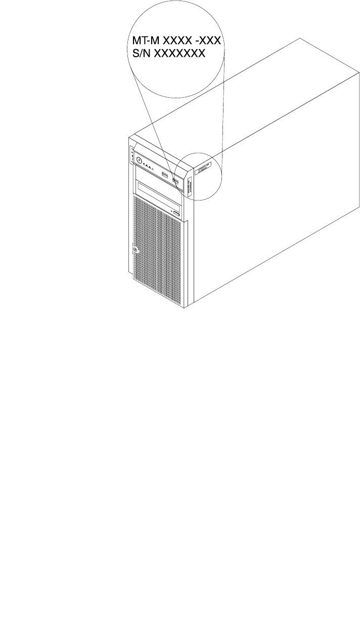
Thefollowingillustrationisasampleofthemachinetype,model,andserialnumberlabelsontheserver.
Note:Dependingonthemodeltype,yourservermightlookslightlydifferentfromtheillustrationinthistopic.
Figure2.Machinetype,model,andserialnumberlabels
14ThinkServerHardwareMaintenanceManual
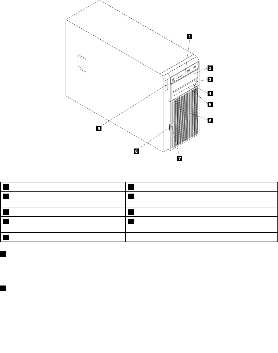
Frontviewoftheserver
Thistopicprovidesinformationtohelpyoulocatethepartsonthefrontoftheserver.
Thefollowingillustrationshowsthefrontviewoftheserver.
CPU
MEM
PSU
12
Figure3.Frontviewoftheserver
1Frontpanel6Frontdoor
2Opticaldrivebay2(withanopticaldriveinstalled
insomemodels)
7Frontdoorlock
3Opticaldrivebay1(withanopticaldriveinstalled)8Frontdoorhandle
4Opticaldriveeject/closebutton9DoctorInsideTechnology(DIT)panel(availableinsome
models)
5OpticaldrivestatusLED
1Frontpanel
Fordetailedinformationaboutthecontrol,connectors,andstatusLEDsonthefrontpanel,see“Front
panel”onpage17.
2Opticaldrivebay2
The5.25-inchopticaldrivebay2isforasecondaryopticaldriveoraRDXUSBdrivebundle(serveroption).
Somemodelshaveasecondaryopticaldriveinstalled.
Chapter3.Productoverview15

3Opticaldrivebay1
Yourservercomeswithanopticaldriveinstalledinthe5.25-inchopticaldrivebay1.
4Opticaldriveeject/closebutton
Pressthisbuttontoejectorclosetheopticaldrivewhentheserverpowerison.
5OpticaldrivestatusLED
TheopticaldrivestatusLEDisblinkingingreenwhentheopticaldriveisworkingorinthePOSTprocess.
6Frontdoor
7Frontdoorlock
Youcanlockthefrontdoortoprotecttheharddiskdrivecagesfromunauthorizedaccess.
8Frontdoorhandle
Thefrontdoorhandlehelpsyoutoopenthefrontdoor.
9DITpanel
TheDITpanelisonlyavailableinmodelsthatcomewithaDITmodule.Formoreinformation,see“DIT
module”onpage18.
16ThinkServerHardwareMaintenanceManual
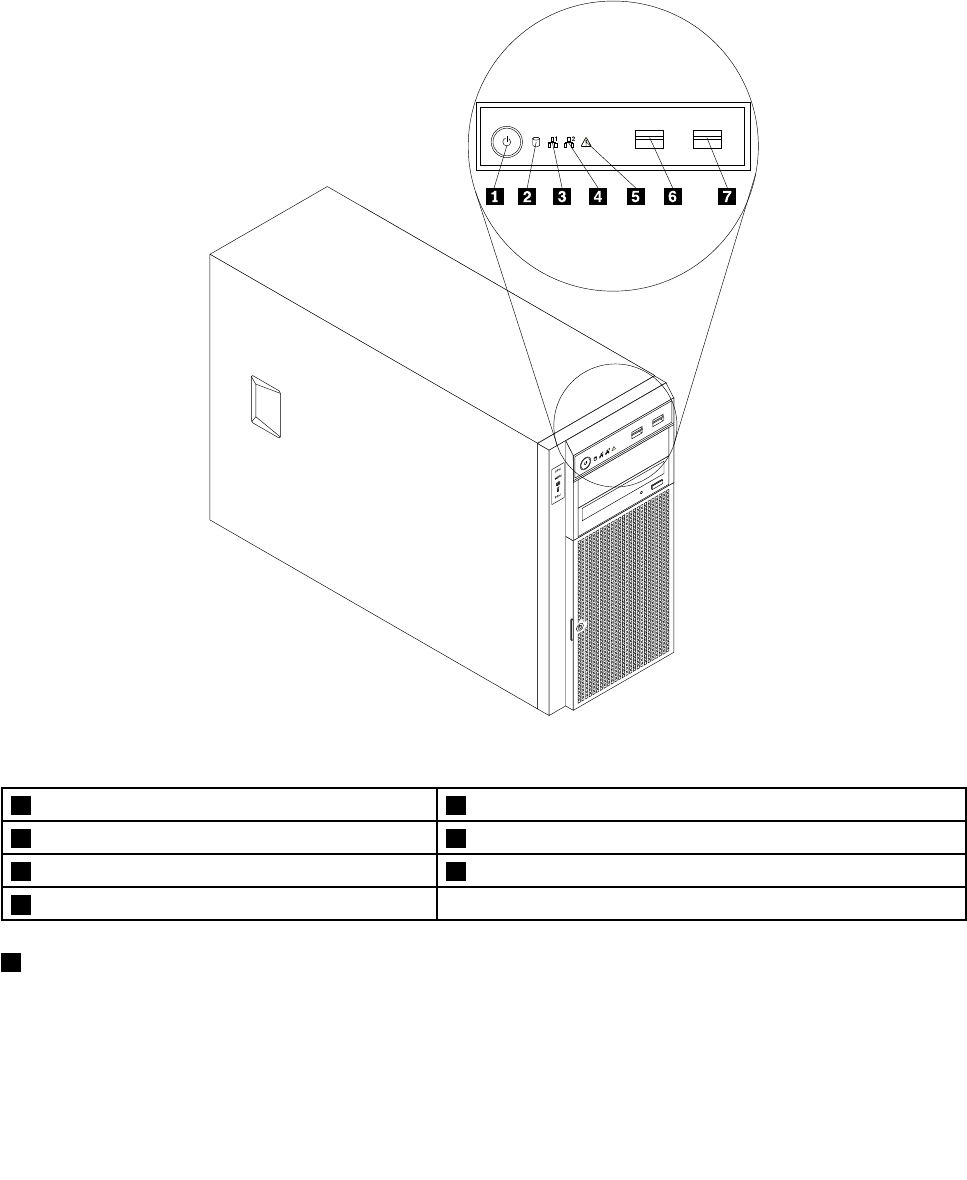
Frontpanel
Thistopicprovidesinformationtohelpyoulocatethecontrol,connectors,andLEDsonthefrontpanelof
theserver.
Thefollowingillustrationshowsthecontrol,connectors,andLEDsonthefrontpaneloftheserver.
Dependingonthemodel,yourservermightlookslightlydifferentfromthefollowingillustration.
Figure4.Frontpanel
1PowerswitchwithpowerstatusLED5SystemstatusLED
2HarddiskdrivestatusLED6FrontUSBconnector1
3NetworkInterfaceController(NIC)1statusLED7FrontUSBconnector2
4NIC2statusLED
1PowerswitchwithpowerstatusLED
Youcanpressthepowerswitchtoturnontheserverwhenyounishsettinguptheserver.Youcanalso
holdthepowerswitchforseveralsecondstoturnofftheserverifyoucannotturnofftheserverfromthe
operatingsystem.SeeChapter4“Turningonandturningofftheserver”onpage53.ThepowerstatusLED
helpsyoutodeterminethecurrentpowerstatus.
Chapter3.Productoverview17

PowerstatusLEDColorDescription
OnGreenTheserverison.
OffNoneTheserverisoff.
BlinkingGreenTheserverisinACPIS1mode,whichisalsoknown
asPowerOnSuspend(POS)mode.Inthismode,the
microprocessorisnotworkingwhileotherhardware
devicesarestillworking.
2HarddiskdrivestatusLED
TheharddiskdrivestatusLEDhelpsyoutodeterminethestatusoftheharddiskdriveactivity.
HarddiskdrivestatusLEDColorDescription
OffNoneTheharddiskdriveisnotinuse.
BlinkingGreenTheharddiskdriveisactiveanddataisbeing
transferred.
3NIC1statusLED
4NIC2statusLED
ThetwoNICstatusLEDsindicatetheLANstatusfortheEthernetconnector1andEthernetconnector2
ontherearpaneloftheserver.
NICstatusLEDColorDescription
OnGreenTheserverisconnectedtoaLAN.
OffNoneTheserverisdisconnectedfromaLAN.
BlinkingGreenTheLANisconnectedandactive.
5SystemstatusLED
ThesystemstatusLEDhelpsyoutodetermineifthereareanysystemerrors.
SystemstatusLEDColorDescription
OnAmberAsystemerrorhasoccurred.
OffNoneTheserverisoffortheserverisonandisworking
correctly.
6FrontUSBconnector1
7FrontUSBconnector2
UsedtoattachadevicethatrequiresaUSBconnector,suchasaUSBkeyboard,aUSBmouse,aUSB
scanner,oraUSBprinter.IfyouhavemorethansixUSBdevices,youcanpurchaseaUSBhub,which
youcanusetoconnectadditionalUSBdevices.
DITmodule
ThistopicprovidesinformationabouttheDITmoduleandthediagnosticLEDsonthepaneloftheDIT
module.
18ThinkServerHardwareMaintenanceManual
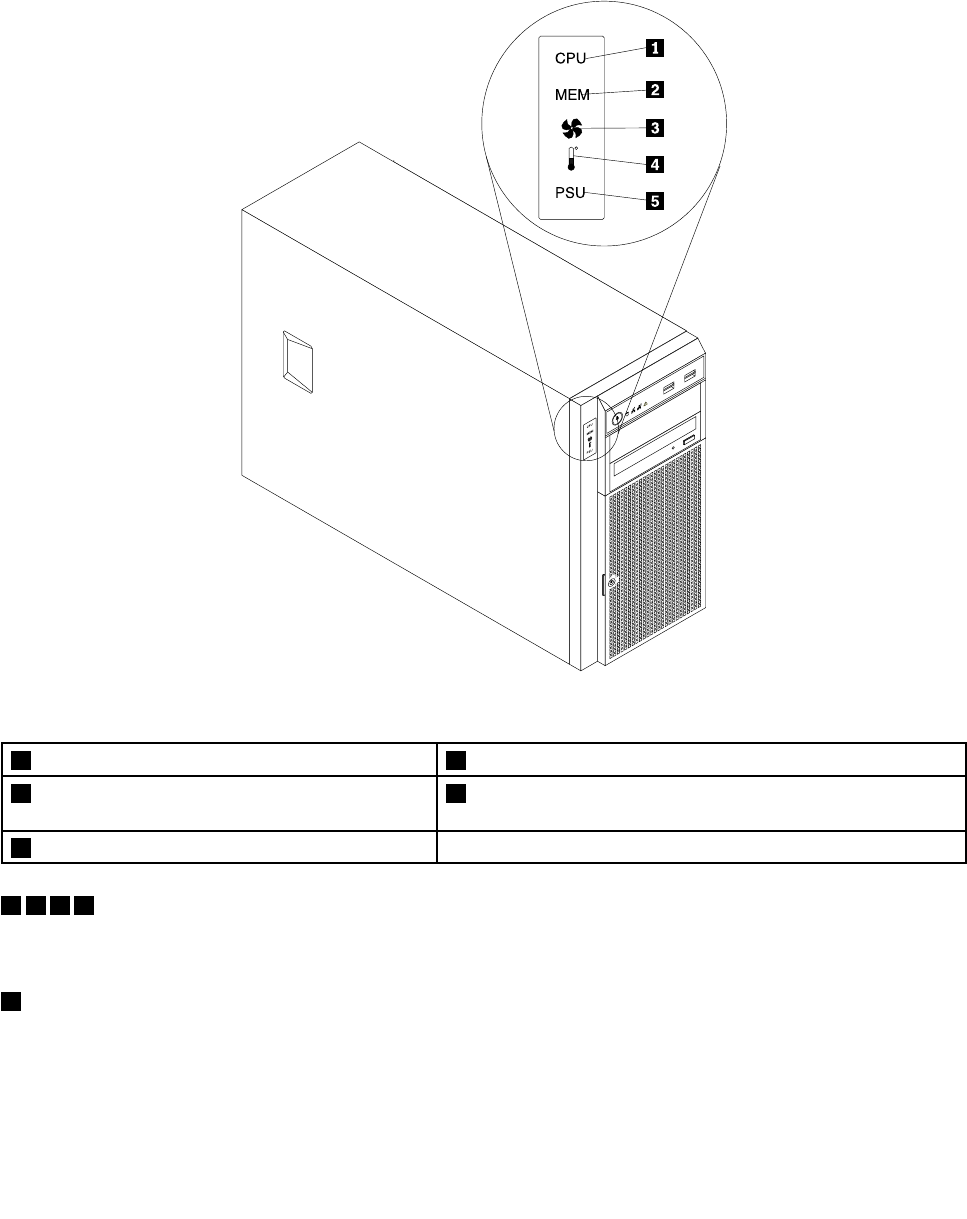
Note:TheDITmoduleisonlyavailableinsomemodels.
ThefollowingillustrationshowsthelocationoftheDITmoduleandthediagnosticLEDsontheDITpanelin
thefrontoftheserver.Dependingonthemodel,yourservermightlookslightlydifferentfromthefollowing
illustration.
Figure5.DITpanel
1MicroprocessorerrorLED4AmbienttemperatureoverlimitLED
2MemorymoduleerrorLED5PowersupplyerrorLED(onlyavailableonmodelswith
redundantpowersupplymodules)
3FanerrorLED
1235ErrorLEDs
WhenoneoftheseerrorLEDsislit(orange),itindicatesthattheassociatedcomponenthasfailed.
4AmbienttemperatureoverlimitLED
WhenthisLEDislit(orange),itindicatesthattheambienttemperatureisover38°C(100.4°F).
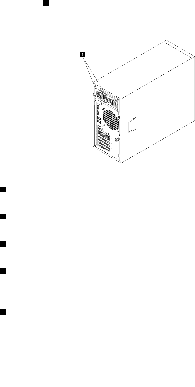
Rearviewoftheserver
Thistopicprovidesinformationtohelpyoulocatetheconnectorsandcomponentsontherearofyourserver.
Chapter3.Productoverview19
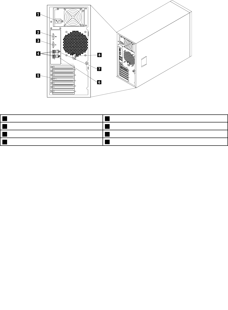
Thefollowingillustrationshowstherearviewoftheserverwithascrew-secured,non-hot-swappowersupply.
Figure6.Rearviewoftheserverwithanon-hot-swappowersupply
1Powercordconnector5Expansioncardarea
2Serialport6Ethernetconnector1(RJ-45)
3VGADB-15connector7Ethernetconnector2(RJ-45)(forsystemmanagement)
4FourUSBconnectors8Frontdoorkey
20ThinkServerHardwareMaintenanceManual
Forservermodelsthathavehot-swapredundantpowersupplymodule(s),theremightbeoneortwopower
cordconnectors1ontherearoftheserver.Foreachhot-swapredundantpowersupplymodule,there
mightbeoneortwostatusLEDsonthepowersupplymodulenearthepowercordconnector.Whenthe
greenLEDislit,itindicatesthatthehot-swapredundantpowersupplymoduleisworkingproperly.When
theredLEDislit,itindicatesthatthehot-swapredundantpowersupplymodulehasfailed.
Figure7.Rearviewoftheserverwithhot-swapredundantpowersupplymodules
1Powercordconnector(s)
Usedtoconnectthepowercord(s).
2Serialport
Usedtoattachadevicethatusesa9-pinserialport.
3VGADB-15connector
Usedtoattachavideodevice,suchasaVGAmonitororotherdevicesthatuseaVGADB-15connector.
4USBconnectors
UsedtoattachadevicethatrequiresaUSBconnector,suchasaUSBkeyboard,aUSBmouse,aUSB
scanner,oraUSBprinter.IfyouhavemorethansixUSBdevices,youcanpurchaseaUSBhub,which
youcanusetoconnectadditionalUSBdevices.
5Expansioncardarea
YouserverhasfourexpansionslotsonthesystemboardforyoutoinstallappropriatePCIcards.For
detailedinformation,see“Systemboardcomponents”onpage42.
Chapter3.Productoverview21
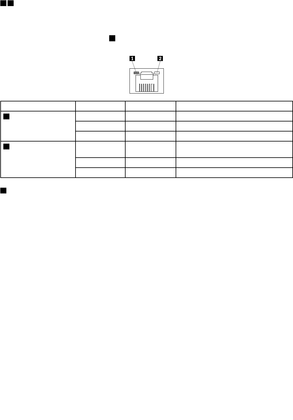
67Ethernetconnectors
UsedtoattachanEthernetcableforaLAN.EachEthernetconnectorhastwostatusLEDstohelpyou
identifytheEthernetconnectivity,activity,andconnectionspeed.
Note:TheEthernetconnector2(callout7)markedwith“MGMT”isforsystemmanagement.Ifyouwantto
useremotemanagementfunctions,youneedtoconnectanEthernetcabletotheEthernetconnector2.
EthernetstatusLEDColorStatusDescription
GreenOnTheserverisconnectedtoaLAN.
NoneOffTheserverisdisconnectedfromaLAN.
1Left
GreenBlinkingTheLANisconnectedandactive.
AmberOnTheconnectionspeedis1000Mbps
(megabitspersecond).
GreenOnTheconnectionspeedis100Mbps.
2Right
NoneOffTheconnectionspeedis10Mbps.
8Frontdoorkey
Usedtoopenorlockthefrontdoor.
Note:Carefullysavethefrontdoorkeytoavoidloss.
Serverlocks
Lockingtheservercoverhelpspreventunauthorizedaccesstotheinsideofyourserverandlockingthefront
doorhelpspreventunauthorizedaccesstotheinstalledharddiskdrives.
Note:Dependingonthemodel,yourservermightlookslightlydifferentfromtheillustrationsinthistopic.
22ThinkServerHardwareMaintenanceManual
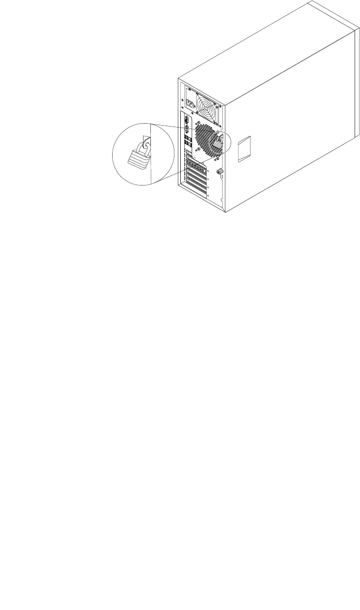
Padlock
Yourservercomeswithapadlockloopsothattheservercovercannotberemovedwhenapadlock
isinstalled.
Figure8.Padlock
Chapter3.Productoverview23
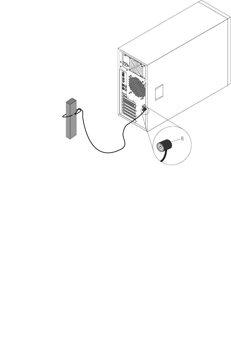
Integratedcablelock
Anintegratedcablelock,sometimesreferredtoastheKensingtonlock,canbeusedtosecureyourserverto
anon-permanentxture.Thecablelockattachestotheintegratedcablelockslotattherearofyourserver
andisoperatedwithakey.Thecablelockalsolockstheservercover.Thisisthesametypeoflockused
withmanynotebookcomputers.YoucanorderanintegratedcablelockdirectlyfromLenovobysearching
forKensingtonat:
http://support.lenovo.com
Figure9.Integratedcablelock
24ThinkServerHardwareMaintenanceManual
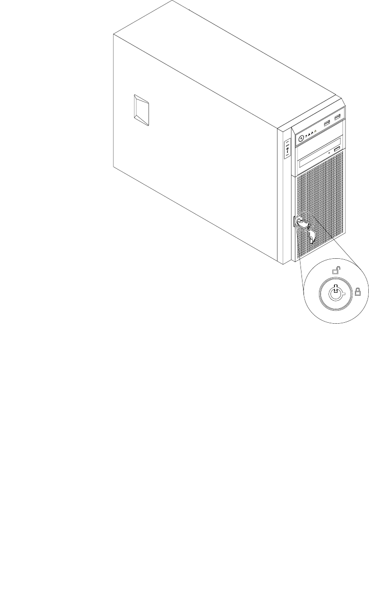
Frontdoorlock
Youcanremovethekeyattachedontheserveranduseittoopenorlockthefrontdooroftheserver.
Thefrontdoorhelpsprotecttheharddiskdrivecagestopreventunauthorizedaccesstotheinstalled
harddiskdrives.
Figure10.Frontdoorlock
Servercomponents
Thistopicprovidesinformationtohelpyoulocatethecomponentsofyourserver.
Toremovetheservercoverandgainaccesstotheinsideoftheserver,see“Removingtheservercover”
onpage85.
Thechassiscongurationvariesbymodel.Thefollowingillustrationsshowthefourmainchassis
congurationsbasedonthesupportedharddiskdrives.
Chapter3.Productoverview25
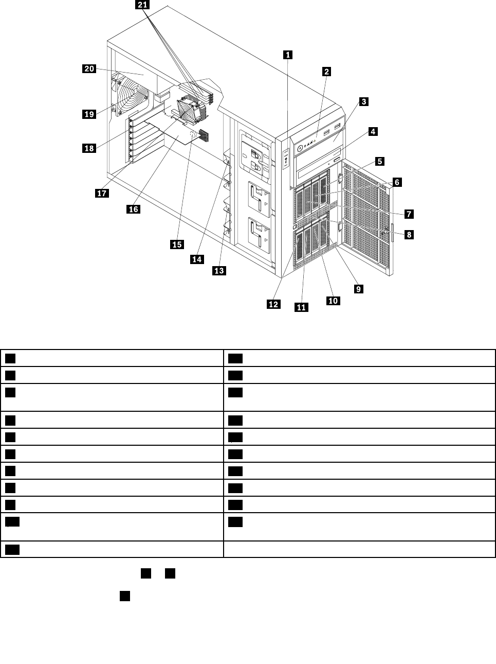
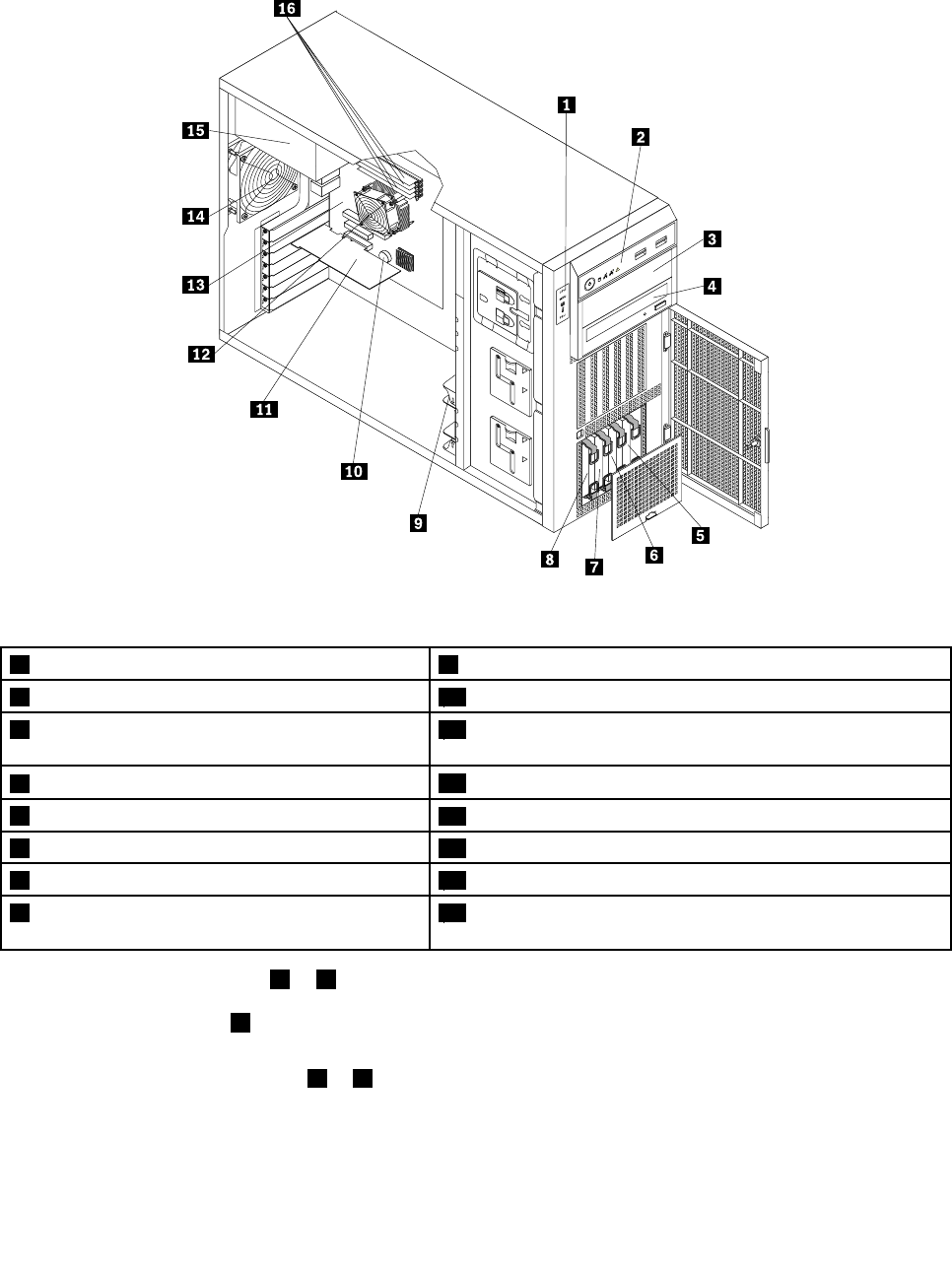
Thefollowingillustrationshowsthecomponentsoftheserverwithvetoeight3.5-inchhot-swaphard
diskdrives.
Figure11.Componentsoftheserverwithvetoeight3.5-inchhot-swapharddiskdrives
1DITmodule(availableinsomemodels)12Harddiskdrivebay0
2Frontpanel13Frontsystemfan1
3Opticaldrivebay2(withanopticaldriveinstalled
insomemodels)
14Frontsystemfan2
4Opticaldrivebay1(withanopticaldriveinstalled)15Systemboardbattery
5Harddiskdrivebay716Expansioncard
6Harddiskdrivebay617Heatsinkandfanassembly
7Harddiskdrivebay518Systemboard
8Harddiskdrivebay419Rearsystemfan
9Harddiskdrivebay320Powersupply
10Harddiskdrivebay221Fourmemoryslots(installedmemorymodulesvaryby
model)
11Harddiskdrivebay1
•Formoreinformationabout1to4,see“Frontviewoftheserver”onpage15.
Note:TheDITmodule1isonlyavailableinsomemodelsandtheDITpanelalsovariesbymodel.
See“DITmodule”onpage18.
26ThinkServerHardwareMaintenanceManual

•Thereisa3.5-inchhot-swapharddiskdriveoradummyharddiskdrivetrayinstalledineachhard
diskdrivebay(5to12).
Note:Thenumberoftheinstalledharddiskdrivesvariesbymodel.Forthevacantdrivebay,thereisa
dummyharddiskdrivetraytocovertheplace.
•Forinformationaboutthesupportedexpansioncard,see“Systemboardcomponents”onpage42.
•Dependingonthemodel,yourservermightcomewithascrew-secured,non-hot-swappowersupply
orhot-swapredundantpowersupplymodule(s).
•Formoreinformationaboutthememorymodules,see“Memorymoduleinstallationrules”onpage90.
Chapter3.Productoverview27
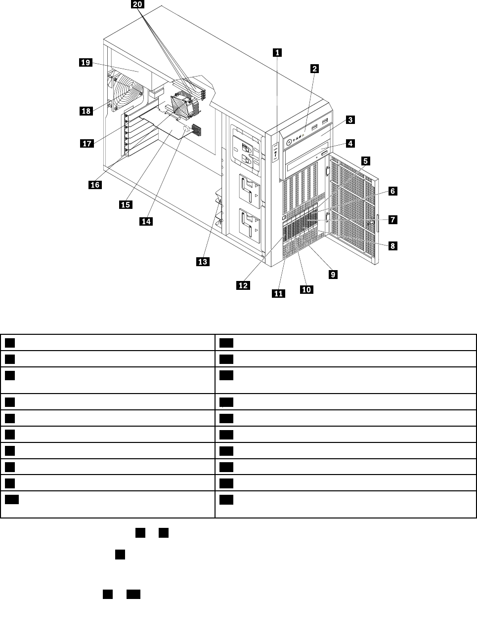
Thefollowingillustrationshowsthecomponentsoftheserverwithuptoeight2.5-inchhot-swapSAS
harddiskdrives.
Figure12.Componentsoftheserverwithuptoeight2.5-inchhot-swapSASharddiskdrives
1DITmodule(availableinsomemodels)11Harddiskdrivebay1
2Frontpanel12Harddiskdrivebay0
3Opticaldrivebay2(withanopticaldriveinstalled
insomemodels)
13Frontsystemfan1
4Opticaldrivebay1(withanopticaldriveinstalled)14Systemboardbattery
5Harddiskdrivebay715Expansioncard
6Harddiskdrivebay616Heatsinkandfanassembly
7Harddiskdrivebay517Systemboard
8Harddiskdrivebay418Rearsystemfan
9Harddiskdrivebay319Powersupply
10Harddiskdrivebay220Fourmemoryslots(installedmemorymodulesvaryby
model)
•Formoreinformationabout1to4,see“Frontviewoftheserver”onpage15.
Note:TheDITmodule1isonlyavailableinsomemodelsandtheDITpanelalsovariesbymodel.
See“DITmodule”onpage18.
•Thereisa2.5-inchhot-swapSASharddiskdriveoradummyharddiskdrivetrayinstalledineach
harddiskdrivebay(5to12).
28ThinkServerHardwareMaintenanceManual
Note:Thenumberoftheinstalledharddiskdrivesvariesbymodel.Forthevacantdrivebay,thereisa
dummyharddiskdrivetraytocovertheplace.
•Forinformationaboutthesupportedexpansioncard,see“Systemboardcomponents”onpage42.
•Dependingonthemodel,yourservermightcomewithascrew-secured,non-hot-swappowersupply
orhot-swapredundantpowersupplymodule(s).
•Formoreinformationaboutthememorymodules,see“Memorymoduleinstallationrules”onpage90.
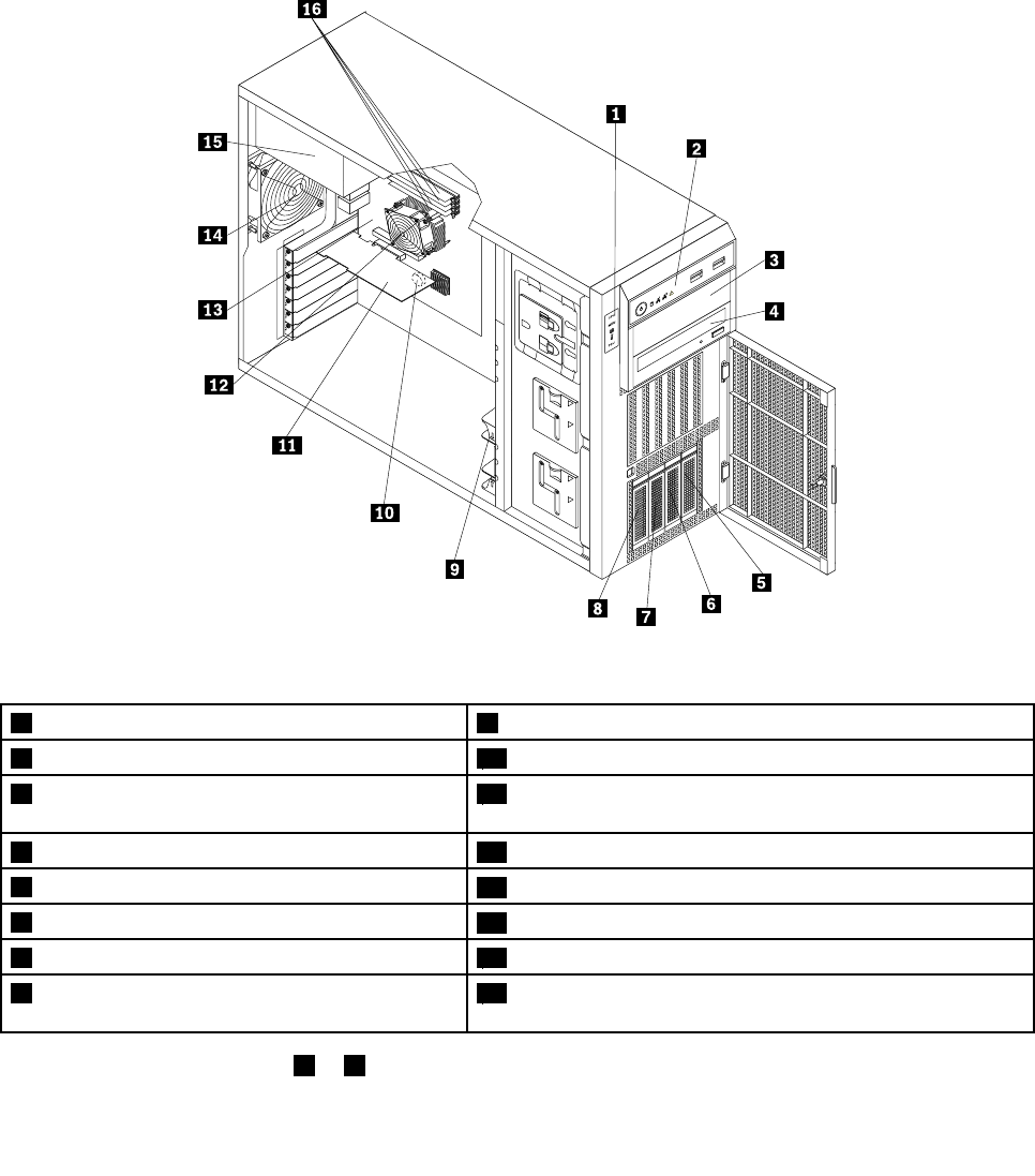
Thefollowingillustrationshowsthecomponentsoftheserverwithuptofour3.5-inchhot-swapharddisk
drives.
Figure13.Componentsoftheserverwithuptofour3.5-inchhot-swapharddiskdrives
1DITmodule(availableinsomemodels)9Frontsystemfan1
2Frontpanel10Systemboardbattery
3Opticaldrivebay2(withanopticaldriveinstalled
insomemodels)
11Expansioncard(variesbymodel)
4Opticaldrivebay1(withanopticaldriveinstalled)12Heatsinkandfanassembly
5Harddiskdrivebay313Systemboard
6Harddiskdrivebay214Rearsystemfan
7Harddiskdrivebay115Powersupply
8Harddiskdrivebay016Fourmemoryslots(installedmemorymodulesvaryby
model)
•Formoreinformationabout1to4,see“Frontviewoftheserver”onpage15.
Chapter3.Productoverview29

Note:TheDITmodule1isonlyavailableinsomemodelsandtheDITpanelalsovariesbymodel.
See“DITmodule”onpage18.
•Thereisa3.5-inchhot-swapharddiskdriveoradummyharddiskdrivetrayinstalledineachhard
diskdrivebay(5to8).
Note:Thenumberoftheinstalledharddiskdrivesvariesbymodel.Forthevacantdrivebay,thereisa
dummyharddiskdrivetraytocovertheplace.
•Forinformationaboutthesupportedexpansioncard,see“Systemboardcomponents”onpage42.
•Dependingonthemodel,yourservermightcomewithascrew-secured,non-hot-swappowersupply
orhot-swapredundantpowersupplymodule(s).
•Formoreinformationaboutthememorymodules,see“Memorymoduleinstallationrules”onpage90.
30ThinkServerHardwareMaintenanceManual
Thefollowingillustrationshowsthecomponentsoftheserverwithuptofour3.5-inchnon-hot-swaphard
diskdrives.
Figure14.Componentsoftheserverwithuptofour3.5-inchnon-hot-swapharddiskdrives
1DITmodule(availableinsomemodels)9Frontsystemfan1
2Frontpanel10Systemboardbattery
3Opticaldrivebay2(withanopticaldriveinstalled
insomemodels)
11Expansioncard(variesbymodel)
4Opticaldrivebay1(withanopticaldriveinstalled)12Heatsinkandfanassembly
5Harddiskdrivebay313Systemboard
6Harddiskdrivebay214Rearsystemfan
7Harddiskdrivebay115Powersupply
8Harddiskdrivebay016Fourmemoryslots(installedmemorymodulesvaryby
model)
•Formoreinformationabout1to4,see“Frontviewoftheserver”onpage15.
Note:TheDITmodule1isonlyavailableinsomemodelsandtheDITpanelalsovariesbymodel.
See“DITmodule”onpage18.
•Eachoftheharddiskdrivebay(5to8)isusedforinstallinga3.5-inchnon-hot-swapharddiskdrives.
Note:Thenumberoftheinstalledharddiskdrivesvariesbymodel.
•Forinformationaboutthesupportedexpansioncard,see“Systemboardcomponents”onpage42.
Chapter3.Productoverview31
•Dependingonthemodel,yourservermightcomewithascrew-secured,non-hot-swappowersupply
orhot-swapredundantpowersupplymodule(s).
•Formoreinformationaboutthememorymodules,see“Memorymoduleinstallationrules”onpage90.
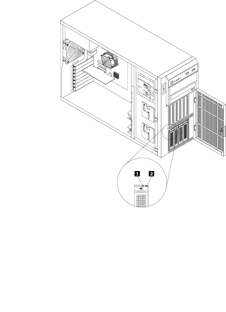
Hot-swapharddiskdrivestatusLEDs
Thistopicappliesonlytoservermodelswithhot-swapharddiskdrives.
Note:Dependingonthemodel,yourservermightlookslightlydifferentfromtheillustrationsinthistopic.
Eachhot-swapharddiskdrivehastwostatusLEDsonthefront.Unlockandopenthefrontdoortogain
accesstotheharddiskdrivesandviewthestatusLEDs.
Figure15.3.5-inchhot-swapharddiskdrivestatusLEDs
32ThinkServerHardwareMaintenanceManual
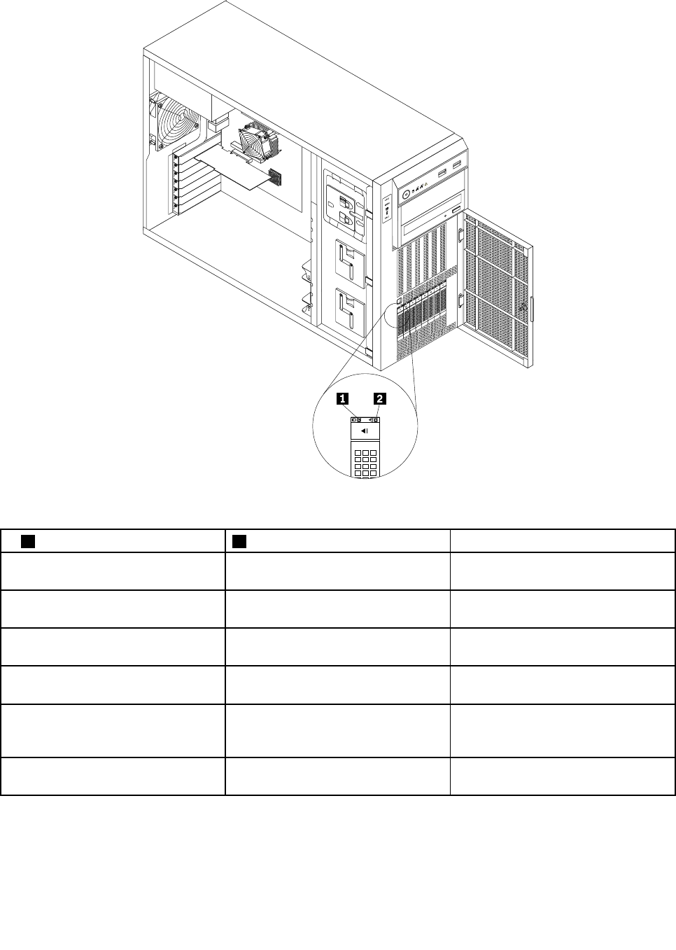
Figure16.2.5-inchhot-swapharddiskdrivestatusLEDs
1HarddiskdriveactivityLED2HarddiskdriveRAIDstatusLEDDescription
OffOffTheharddiskdrivehasfailedoris
notpresent.
On,greenOffTheharddiskdriveispresentbutnot
inuse.
Blinking,greenOffTheharddiskdriveisactiveanddata
isbeingtransferred.
On,greenBlinkingrapidly(aboutfourashes
persecond),amber
TheRAIDcontrollerisidentifyingthe
harddiskdrive.
On,greenOn,amberTheRAIDarrayhasfailedandcannot
recover.Youneedtorecreateanew
array.
Blinking,greenBlinkingslowly(aboutoneashper
second),amber
Theharddiskdriveisbeingrebuilt.
RAIDcard
ThistopicprovidesinformationtohelpyoulocatetheconnectorsonaRAIDcardifyouhaveoneinstalledin
thePCI-Eslot3onthesystemboard.See“Systemboardcomponents”onpage42.
Chapter3.Productoverview33
SomeservermodelscomewitharequiredRAIDcardtoprovideadvancedSATA/SAShardwareRAID
functionstotheserver.YoucanalsopurchasetheRAIDcardfromLenovoandinstallitintomodelsthat
supporttheRAIDcardtogetadvancedSATA/SAShardwareRAIDfunctions.See“Installingorremoving
theRAIDcard”onpage98.
Note:ForservermodelswithmorethanfourharddiskdrivesormodelsthatuseSASharddiskdrives,there
mustbeaRAIDcardinstalled.
Optionname:ThinkServer9240-8iRAID0/1Adapter(hereinafterreferredtoastheRAIDcard)
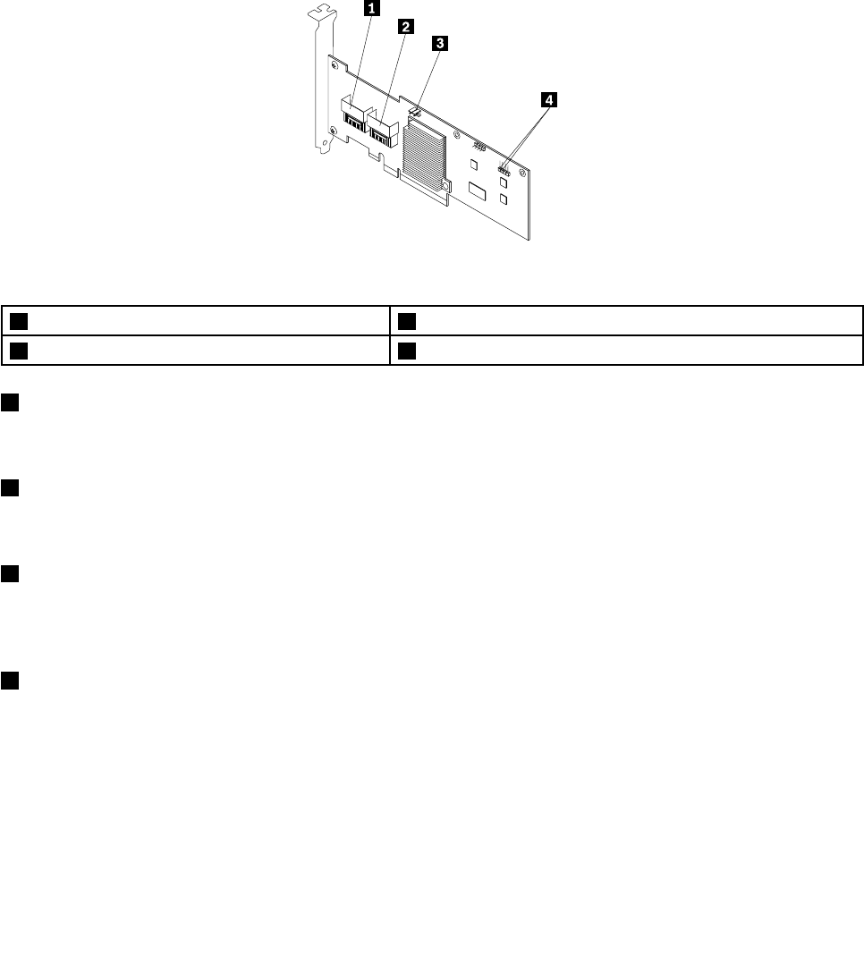
ThefollowingillustrationshowstheconnectorsontheRAIDcard.
Figure17.ThinkServer9240-8iRAID0/1Adapter
1Port03RAID5keyconnector
2Port14Externalconnector
1Port0
Usedtoconnectamini-SASsignalcable.See“Connectingcables”onpage38.
2Port1
Usedtoconnectamini-SASsignalcable.See“Connectingcables”onpage38.
3RAID5keyconnector
UsedtoconnectaThinkServer9240-8iRAID5UpgradeKey.See“InstallingorremovingtheThinkServer
9240-8iRAID5UpgradeKey”onpage100.
4Externalconnector
Usedtoconnecta2-pin200mm(7.87inches)RAIDcardtosystemboardharddiskdriveLEDcable.
See“Connectingcables”onpage38.
Hot-swapharddiskdrivebackplane
Yourserversupportsthefollowinghot-swapharddiskdriveandbackplanecongurations:
•Fivetoeight3.5-inchhot-swapSATAorSASharddiskdriveswithtwobackplanes
•Uptofour3.5-inchhot-swapSATAorSASharddiskdriveswithonebackplane
34ThinkServerHardwareMaintenanceManual
•Uptoeight2.5-inchhot-swapSASharddiskdriveswithonebackplane
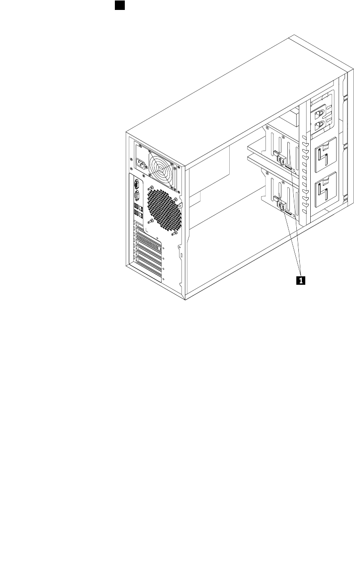
Thefollowingillustrationshowsthelocationsofthehot-swapharddiskdrivebackplanes.Youneedtoopen
theservercoverandremovethefrontsystemfanstoaccessthebackplanes.See“Removingtheserver
cover”onpage85and“Replacingthefrontsystemfan”onpage149.
Notes:
1.Dependingonthemodel,yourservermightlookslightlydifferentfromtheillustrationinthistopic.
2.Thefollowingillustrationisbasedonvetoeight3.5-inchhot-swapSATAorSASharddiskdrives
withtwobackplanes1.
Figure18.Hot-swapharddiskdrivebackplanelocations
Backplanefor3.5-inchhot-swapharddiskdrives
Thistopicprovidesinformationtohelpyoulocatetheconnectorsona3.5-inchhot-swapharddiskdrive
backplane.
Chapter3.Productoverview35
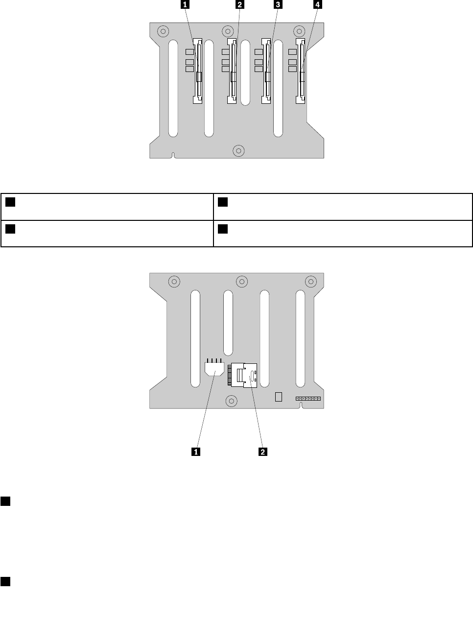
Thefollowingillustrationsshowtheconnectorsona3.5-inchhot-swapharddiskdrivebackplane.
Figure19.Frontviewofthe3.5-inchhot-swapharddiskdrivebackplane
1Slot0fora3.5-inchSATAorSAShot-swaphard
diskdrive
3Slot2fora3.5-inchSATAorSAShot-swapharddiskdrive
2Slot1fora3.5-inchSATAorSAShot-swaphard
diskdrive
4Slot3fora3.5-inchSATAorSAShot-swapharddiskdrive
Figure20.Rearviewofthe3.5-inchhot-swapharddiskdrivebackplane
18-pinpowerconnector
•For3.5-inchhot-swapharddiskdrivebackplaneonthelowerharddiskdrivecage,connecttheP5power
connectorofthepowersupplytothe8-pinpowerconnectoronthebackplane.
•For3.5-inchhot-swapharddiskdrivebackplaneontheupperharddiskdrivecage,connecttheP4power
connectorofthepowersupplytothe8-pinpowerconnectoronthebackplane.
2Mini-SASsignalcableconnector
Usedtoconnectthemini-SASconnectorononeendofthemini-SASsignalcable.
36ThinkServerHardwareMaintenanceManual
Backplanefor2.5-inchhot-swapharddiskdrives
Thistopicprovidesinformationtohelpyoulocatetheconnectorsonthe2.5-inchhot-swapharddisk
drivebackplane.
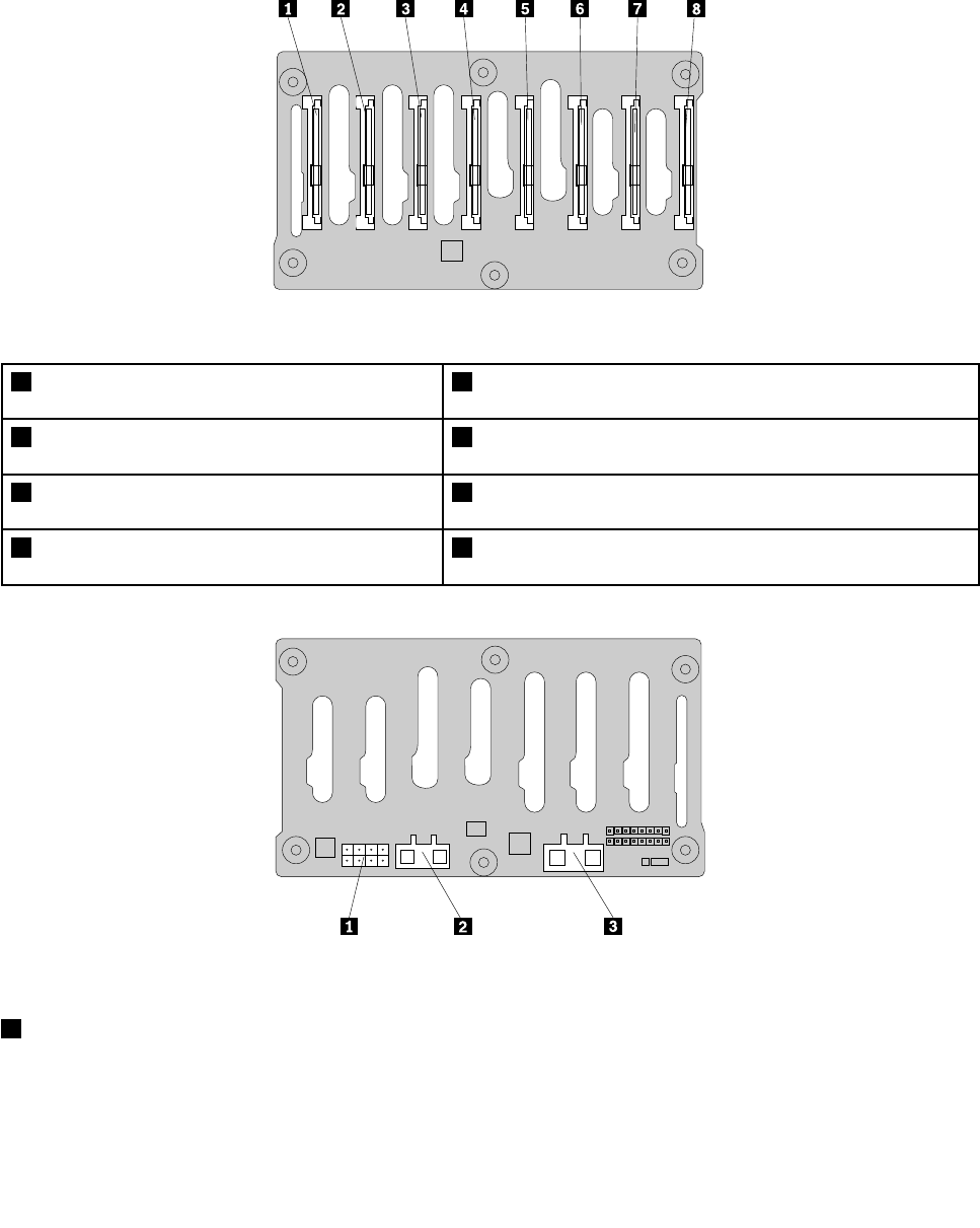
Thefollowingillustrationsshowtheconnectorsonthe2.5-inchhot-swapharddiskdrivebackplane.
Figure21.Frontviewofthe2.5-inchhot-swapharddiskdrivebackplane
1Slot0fora2.5-inchSAShot-swapharddisk
drive
5Slot4fora2.5-inchSAShot-swapharddiskdrive
2Slot1fora2.5-inchSAShot-swapharddisk
drive
6Slot5fora2.5-inchSAShot-swapharddiskdrive
3Slot2fora2.5-inchSAShot-swapharddisk
drive
7Slot6fora2.5-inchSAShot-swapharddiskdrive
4Slot3fora2.5-inchSAShot-swapharddisk
drive
8Slot7fora2.5-inchSAShot-swapharddiskdrive
Figure22.Rearviewofthe2.5-inchhot-swapharddiskdrivebackplane
18-pinpowerconnector
UsedtoconnecttheP5powerconnectorofthepowersupply.
Chapter3.Productoverview37

2Mini-SASsignalcableconnector2
Usedtoconnectthemini-SASconnectorononeendofthemini-SASsignalcable.
3Mini-SASsignalcableconnector1
Usedtoconnectthemini-SASconnectorononeendofthemini-SASsignalcable.
Connectingcables
Thistopicprovidesinstructionsonhowtoconnectthemini-SASsignalcable(s)tothehot-swapharddisk
drivebackplane(s)andthesystemboardortherequiredRAIDcardifyouhaveoneinstalled.
Thistopicappliesonlytoservermodelsthathavehot-swapharddiskdrive(s)installedandthecable
connectionsaredifferentdependingonthefollowingcongurations:
•Servermodelswithvetoeight3.5-inchhot-swapharddiskdrivesandtwobackplanes
•Servermodelswithuptoeight2.5-inchSAShot-swapharddiskdrivesandonebackplane
•Servermodelswithuptofour3.5-inchhot-swapharddiskdrivesandonebackplane
Servermodelswithvetoeight3.5-inchhot-swapharddiskdrivesandtwobackplanes
ForservermodelswithvetoeightSASorSATAII3.5-inchhot-swapharddiskdrivesandtwobackplanes,a
requiredRAIDcardmustbeinstalledintheserver.
ThefollowingcablesthatcomewiththeRAIDcardarerequired:
Note:TheoptionpackagefortheRAIDcardisdesignedfordifferenttypesofserversandmightcontain
additionalcablesthatarenotrequiredtobeinstalledintoyourserver.
•Two700mm(27.56inches)mini-SAStomini-SASsignalcables
•One2-pin200mm(7.87inches)RAIDcardtosystemboardharddiskdriveLEDcable
38ThinkServerHardwareMaintenanceManual
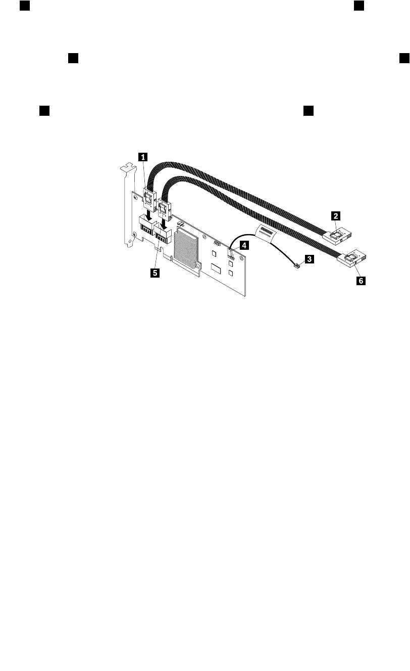
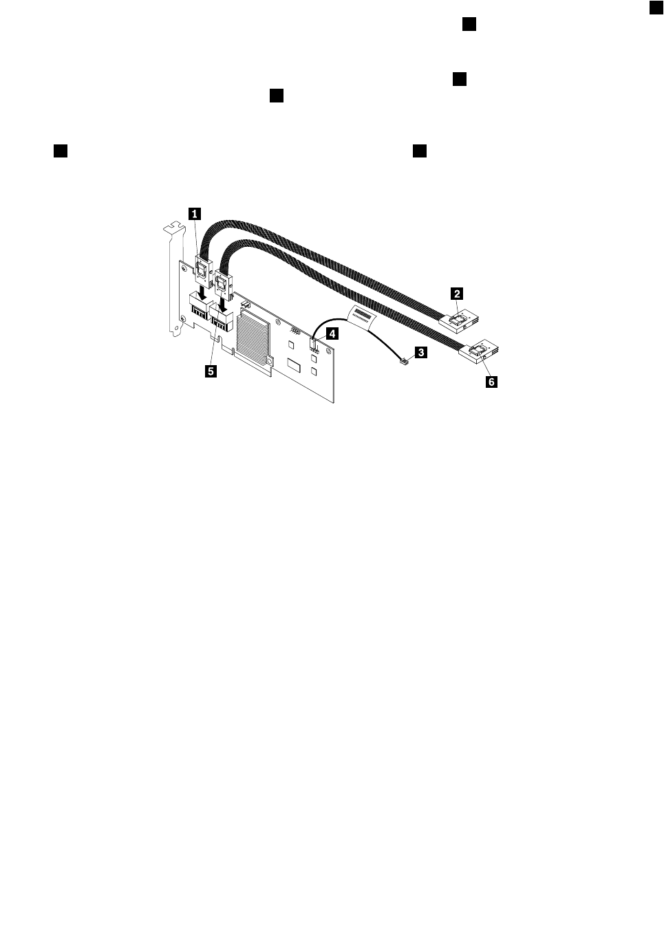
Usethefollowinginstructionstoconnectthecables:
1.Useone700mm(27.56inches)mini-SAStomini-SASsignalcable.Connectthemini-SASconnector
1totheport0ontheRAIDcard.Then,connectthemini-SASconnector2tothemini-SASsignal
cableconnectoronthe3.5-inchhot-swapharddiskdrivebackplaneinstalledonthelowerharddisk
drivecage.
2.Usetheother700mm(27.56inches)mini-SAStomini-SASsignalcable.Connectthemini-SAS
connector5totheport1ontheRAIDcard.Then,connectthemini-SASconnector6tothemini-SAS
signalcableconnectoronthe3.5-inchhot-swapharddiskdrivebackplaneinstalledontheupper
harddiskdrivecage.
3.Usethe2-pin200mm(7.87inches)RAIDcardtosystemboardharddiskdriveLEDcable.Connectthe
end4totheexternalconnectorontheRAIDcardandtheend3totheharddiskdriveLEDconnector
onthesystemboard.
Figure23.ConnectingcablesforservermodelswithtwobackplanesandaRAIDcard
ForconnectorlocationinformationabouttheRAIDcard,hot-swapharddiskdrivebackplane,andthe
systemboard,refertotherelatedtopicsin“Locations”onpage13.
Forinformationaboutconnectingtheappropriatepowerconnectorofthepowersupplytothebackplane,
see“Hot-swapharddiskdrivebackplane”onpage34.
Servermodelswithuptoeight2.5-inchSAShot-swapharddiskdrivesandonebackplane
Forservermodelswithuptoeight2.5-inchSAShot-swapharddiskdrivesandonebackplane,arequired
RAIDcardmustbeinstalledintheserver.
ThefollowingcablesthatcomewiththeRAIDcardarerequired:
Note:TheoptionpackagefortheRAIDcardisdesignedfordifferenttypesofserversandmightcontain
additionalcablesthatarenotrequiredtobeinstalledintoyourserver.
•Oneortwo700mm(27.56inches)mini-SAStomini-SASsignalcablesdependingonthenumberof
theharddiskdrivesinstalled
•One2-pin200mm(7.87inches)RAIDcardtosystemboardharddiskdriveLEDcable
Chapter3.Productoverview39
Usethefollowinginstructionstoconnectthecables:
1.Useone700mm(27.56inches)mini-SAStomini-SASsignalcable.Connectthemini-SASconnector1
totheport0ontheRAIDcard.Then,connectthemini-SASconnector2tothemini-SASsignalcable
connector1onthe2.5-inchhot-swapharddiskdrivebackplane.
2.Ifyouhavemorethanfour2.5-inchharddiskdrivesinstalled,usetheother700mm(27.56inches)
mini-SAStomini-SASsignalcable.Connectthemini-SASconnector5totheport1ontheRAIDcard.
Then,connectthemini-SASconnector6tothemini-SASsignalcableconnector2onthe2.5-inch
hot-swapharddiskdrivebackplane.
3.Usethe2-pin200mm(7.87inches)RAIDcardtosystemboardharddiskdriveLEDcable.Connectthe
end4totheexternalconnectorontheRAIDcardandtheend3totheharddiskdriveLEDconnector
onthesystemboard.
Figure24.Connectingcablesforservermodelswithone2.5-inchhot-swapharddiskdrivebackplaneandaRAIDcard
ForconnectorlocationinformationabouttheRAIDcard,hot-swapharddiskdrivebackplane,andthe
systemboard,refertotherelatedtopicsin“Locations”onpage13.
Forinformationaboutconnectingtheappropriatepowerconnectorofthepowersupplytothebackplane,
see“Hot-swapharddiskdrivebackplane”onpage34.
Servermodelswithuptofour3.5-inchhot-swapharddiskdrivesandonebackplane
Forservermodelswithuptofour3.5-inchSATAhot-swapharddiskdrivesandonebackplane,youcaneither
connecttheSATAharddiskdrive(s)totheSATAconnectorsonthesystemboardorarequiredRAIDcardif
youhaveoneinstalledintheserver.Forservermodelswithuptofour3.5-inchSAShot-swapharddisk
drivesandonebackplane,connecttheSASharddiskdrive(s)totherequiredRAIDcardinstalledintheserver.
Note:SATAIIistheonlytypeofSATAsupportedbytheRAIDcard.
Usethefollowinginstructionstoconnectthecables:
40ThinkServerHardwareMaintenanceManual
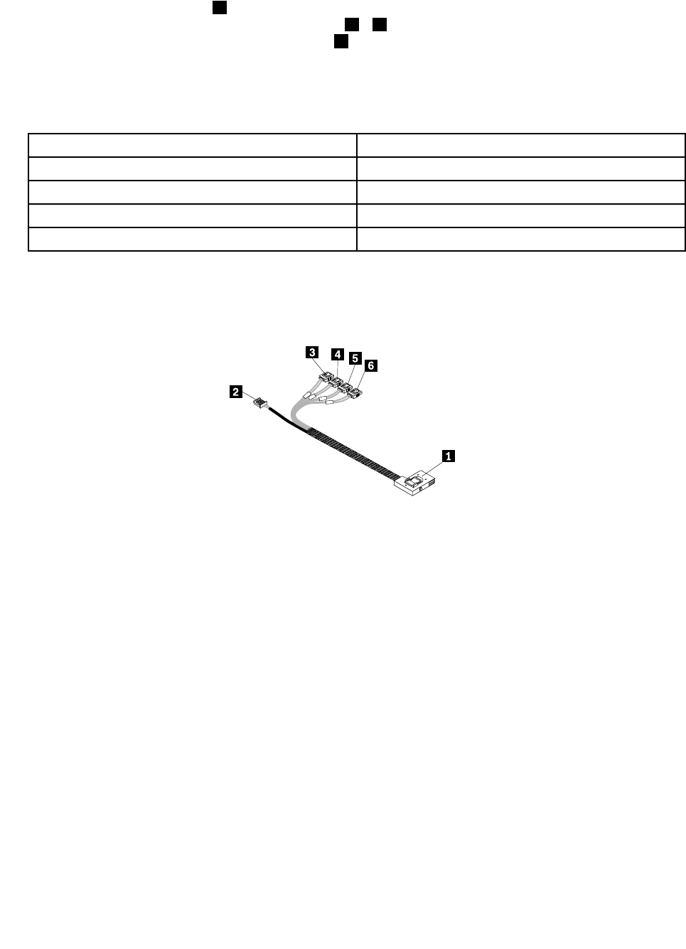
IfyouareconnectingtheSATAharddiskdrivestothesystemboard,usethe450mm(17.72inches)
mini-SASsignalcablewithfourSATAportsandoneSerialGeneralPurposeInput/Output(SGPIO)port.
Connectthemini-SASconnector1tothemini-SASsignalcableconnectoronthe3.5-inchhot-swaphard
diskdrivebackplaneandconnectthefourSATAports3–6totheSATAconnector0toSATAconnector3
onthesystemboard.Then,connecttheSGPIOport2totheSATASGPIOconnectoronthesystemboard.
Notes:
1.ThenumberonthelabelforeachofthefourSATAsignalcablesindicatesthesequencewhenyouare
connectingthecablestothecorrespondingSATAconnectors(0-3)onthesystemboard.
SATAsignalcablelabelSystemboardSATAconnector
P0SATAconnector0
P1SATAconnector1
P2SATAconnector2
P3SATAconnector3
2.IfyouconnecttheSATAharddiskdrivestothesystemboard,youcancongureRAIDusingthe
congurationutilityfortheonboardSATAsoftwareRAID.See“ConguringtheonboardSATAsoftware
RAID”onpage74.
Figure25.Mini-SASsignalcablewithfourSATAportsandoneSGPIOport
TheRAIDcardprovidesadvancedSATA/SASRAIDcongurations.IfyouareusingSAShot-swapharddisk
drives,youmusthavetheRAIDcardforconnectingtheSASharddiskdrives.Toconnecttheharddisk
drivestotheinstalledRAIDcard,thefollowingcablesthatcomewiththeRAIDcardarerequired:
Note:TheoptionpackagefortheRAIDcardisdesignedfordifferenttypesofserversandmightcontain
additionalcablesthatarenotrequiredtobeinstalledintoyourserver.
•One700mm(27.56inches)mini-SAStomini-SASsignalcable
•One2-pin200mm(7.87inches)RAIDcardtosystemboardharddiskdriveLEDcable
Chapter3.Productoverview41
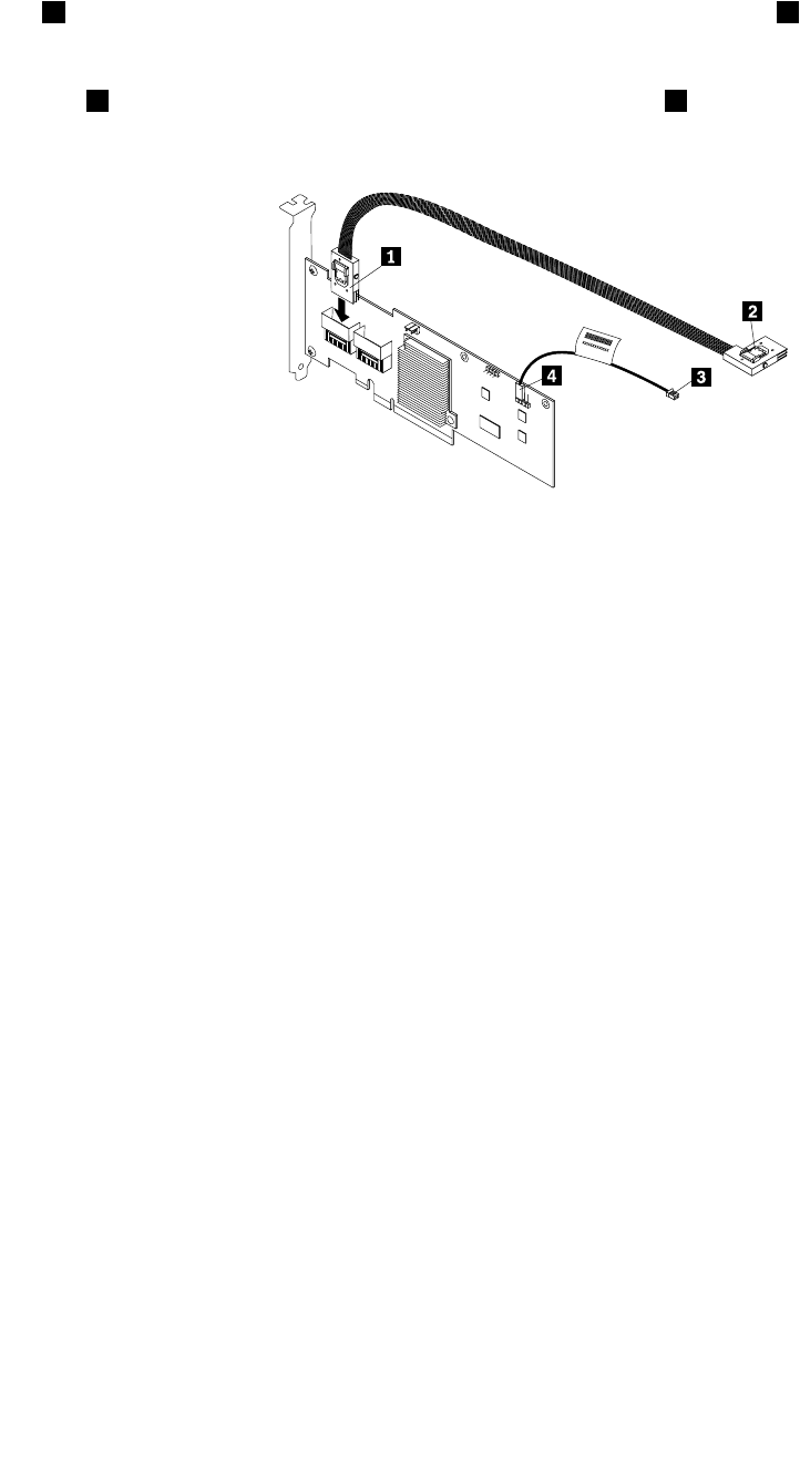
Toconnectthecables,dothefollowing:
1.Usethe700mm(27.56inches)mini-SAStomini-SASsignalcable.Connectthemini-SASconnector
1totheport0ontheRAIDcard.Then,connectthemini-SASconnector2tothemini-SASsignal
cableconnectoronthe3.5-inchhot-swapharddiskdrivebackplane.
2.Usethe2-pin200mm(7.87inches)RAIDcardtosystemboardharddiskdriveLEDcable.Connectthe
end4totheexternalconnectorontheRAIDcardandtheend3totheharddiskdriveLEDconnector
onthesystemboard.
Figure26.Connectingcablesforservermodelswithone3.5-inchhot-swapharddiskdrivebackplaneandaRAIDcard
ForconnectorlocationinformationabouttheRAIDcard,hot-swapharddiskdrivebackplane,andthe
systemboard,refertotherelatedtopicsin“Locations”onpage13.
Forinformationaboutconnectingtheappropriatepowerconnectorofthepowersupplytothebackplane,
see“Hot-swapharddiskdrivebackplane”onpage34.
Systemboardcomponents
Yourserversystemboardisasix-layermicro-ATXboardbasedontheIntelBromolowplatform.The
followingillustrationshowsthecomponentlocationsonthesystemboard.
42ThinkServerHardwareMaintenanceManual
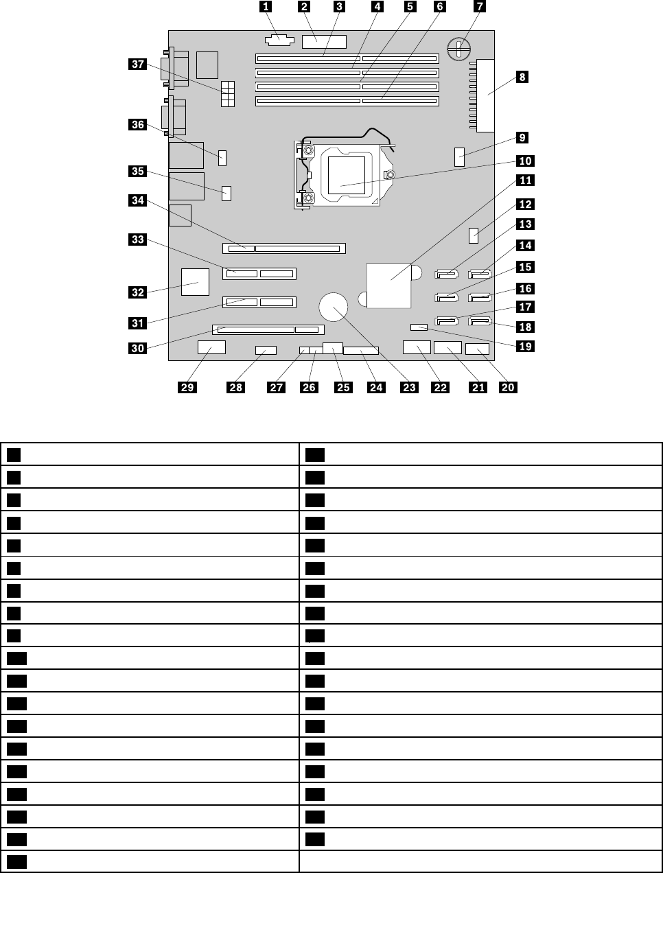
Figure27.Systemboardcomponents
1PowerManagementBus(PMBus)connector20InternalUSB2.0TypeAconnector
2TPMconnector21Internaldual-portUSB2.0connector2
3Memoryslot4(DIMMB2)22Internaldual-portUSB2.0connector1
4Memoryslot3(DIMMB1)23Systemboardbattery
5Memoryslot2(DIMMA2)24Frontpanelconnector
6Memoryslot1(DIMMA1)25Systemboardjumperblocks
7iButtonsocket26SATASGPIOconnector
8Mainpowerconnector27HarddiskdriveLEDconnector
95-pinsystemfan2connector28DITmoduleconnector
10Microprocessor29Internalserialconnector
11IntelC202chip30PCIcardslot(PCIslot1)
124-pinsystemfan1connector31PCIExpressx4cardslot(PCI-Eslot2)
13SATAconnector132BMCchip
14SATAconnector033PCIExpressx8cardslot(PCI-Eslot3)
15SATAconnector334PCIExpressx8cardslot(PCI-Eslot4)
16SATAconnector235Microprocessorfanconnector
17SATAconnector536Systemfan3connector
18SATAconnector437Microprocessorpowerconnector
19iKVMkeyconnector
Chapter3.Productoverview43

1PMBusconnector
TheBMCcanreadthepowersupplystatusregisteredthroughPMBus.Youdonotneedtoconnect
anydevicetothePMBusconnector.Thisconnectoriskeptforpowermanagementinmodelswith
redundantpowersupplymodules.ThefunctionofthePMBusconnectorisnotavailableformodelswitha
screw-securednon-hot-swappowersupply.
2TPMconnector
UsedtoconnectaTPMmodule,whichisasecuritychip,toprotectyourserverandstrengthenserver
security.See“InstallingorremovingtheTPMmodule”onpage109.
3–6Memoryslots
Yourserversystemboardprovidesfourmemoryslotstosupportuptofourmemorymodules.Formore
information,see“Memorymoduleinstallationrules”onpage90.
7iButtonsocket
YourserversupportsonboardSATAsoftwareRAIDlevels0,1,and10.However,youcanactivateonboard
SATAsoftwareRAID5byinstallingaThinkServerSATASoftwareRAID5activationkeyintheiButtonsocket.
Formoreinformation,see“InstallingorremovingtheThinkServerSATASoftwareRAID5Key”onpage102.
8Mainpowerconnector
Usedtoconnectthe24-pinP1powerconnectorofthepowersupplytoprovidemainpowertoyourserver.
95-pinsystemfan2connector
Usedtoconnectthecableoftheupperfrontsystemfan(frontsystemfan2)ifyourservermodelhas
twofrontsystemfans.
10Microprocessor
Amicroprocessorincorporatesmostorallofthefunctionsofacomputer'scentralprocessingunit(CPU)on
asingleintegratedcircuit.Themicroprocessorforyourserverissecuredinthemicroprocessorsocketon
thesystemboardandaheatsinkandfanassemblyisinstalledabovethemicroprocessortoprovidecooling.
Formoreinformationaboutyourmicroprocessortype,see“Features”onpage7.
11IntelC202chip
TheIntelC202chiponthesystemboardservesasaplatformcontrollerhub(PCH),whichprovidesthedata
bufferingandinterfacearbitrationrequiredtoensurethatsysteminterfacesoperateefcientlyandprovides
thebandwidthnecessarytoenablethesystemtoobtainpeakperformance.Thechipsupportsandprovides
manyfeatures,includingtheonboardSATAsoftwareRAID.
124-pinsystemfan1connector
Usedtoconnectthecableofthelowerfrontsystemfan(frontsystemfan1).
13–18SATAconnectors
UsedtoconnectSATAsignalcablesfortheSATAharddiskdrivesorSATAopticaldrives.
44ThinkServerHardwareMaintenanceManual

19iKVMkeyconnector
UsedtoconnectaniKVMkeyoption,whichisakindofremotemanagementmodule,toenabletheiKVM
functiononyourserver.See“InstallingorremovingtheThinkServeriKVMRemoteManagementModule”on
page105.
20InternalUSB2.0TypeAconnector
UsedtoconnectadevicethatusesaUSB2.0TypeAconnector.
21Internaldual-portUSB2.0connector2
UsedtoconnecttheUSBcableoftheRDXUSBdrivebundle(serveroption).
22Internaldual-portUSB2.0connector1
UsedtoconnectthefrontpanelUSBcable.
23Systemboardbattery
Yourserverhasaspecialtypeofmemorythatmaintainsthedate,time,andcongurationinformationfor
built-infeatures.Thesystemboardbatterykeepstheinformationactivewhenyouturnofftheserver.
24Frontpanelconnector
Usedtoconnectthefrontpanelcable.
25Systemboardjumperblocks
Usedtocongurethesystemboardandyourserver.See“Systemboardjumpers”onpage46.
26SATASGPIOconnector
UsedtoconnecttheSGPIOportofthemini-SASsignalcablewithfourSATAportsandoneSGPIOportto
enabletheRAIDstatusLEDsforhot-swapharddiskdrives.
27HarddiskdriveLEDconnector
Usedtoconnecta2-pin200mm(7.87inches)RAIDcardtosystemboardharddiskdriveLEDcable.
See“Connectingcables”onpage38.
28DITmoduleconnector
UsedtoconnectthecableoftheDITmoduleifyourserverhasoneinstalled.
29Internalserialconnector
Usedtoprovideanoptionalserialconnectorsolutionwitharequiredcable.
30PCIcardslot(PCIslot1)
Usedtoinstallastandard32-bit33MHzPCIcardwith167mm(6.57inches)inlength.
Chapter3.Productoverview45

31PCIExpressx4cardslot(PCI-Eslot2)
ThisisaPCIExpressx4laneinphysicalPCI2.0x8slotthatsupportsaPCIExpressx4cardwith167mm
(6.57inches)inlength,suchasanEthernetcard.
32BMCchip
WiththeintegratedBMCchip,nomatterwhatconditiontheserveroperatingsystemisinandnomatterif
theserverisonoroff,aslongastheserverisconnectedtonetworkandanacpowersource,theinteraction
withtheBMCcontrolledserverscanbeachievedthroughsystemnetwork.Theusercanobtaintheserver
hardwarehealthinformationandSEL,andisabletoconducttheoperationsincludingturningonorofthe
server,restartingtheserver,lockingthepowerswitchonthefrontpanelandsoon.Thispartoftheserver
managementisindependentoftheoperatingsystemandiscalledout-of-bandmanagement.
33PCIExpressx8cardslot(PCI-Eslot3)
ThisisaPCIExpressx8laneinphysicalPCI2.0x8slotthatsupportsaPCIExpressx8cardwith167mm
(6.57inches)inlength,suchasanEthernetcardoraRAIDcard.
34PCIExpressx8cardslot(PCI-Eslot4)
ThisisaPCIExpressx8laneinphysicalPCI2.0x16slotthatsupportsaPCIExpressx8cardwith312mm
(12.28inches)inlength,suchasagraphicscard.
35Microprocessorfanconnector
Usedtoconnecttheheatsinkandfanassemblycable.
36Systemfan3connector
Usedtoconnecttherearsystemfancable.
37Microprocessorpowerconnector
Usedtoconnectthe8-pinP2powerconnectorofthepowersupplytoprovidepowertoyourmicroprocessor.
Systemboardjumpers
Thistopicprovidesinformationaboutthejumpersonthesystemboard.
Ajumperisashortlengthofconductorusedtosetuporadjustprintedcircuitboards,suchasthesystem
boardofacomputer.Ajumperisusuallyencasedinanon-conductiveblockofplasticforconvenientuse
andavoidinganypossibledamagetoalivecircuit.Jumperpinsarrangedingroupsonthesystemboardare
calledjumperblocks.Whentwoormorejumperpinsarecappedwithajumper,anelectricalconnectionis
madebetweenthemandtheequipmentisthusinstructedtoactivatecertainsettingsaccordingly.
46ThinkServerHardwareMaintenanceManual
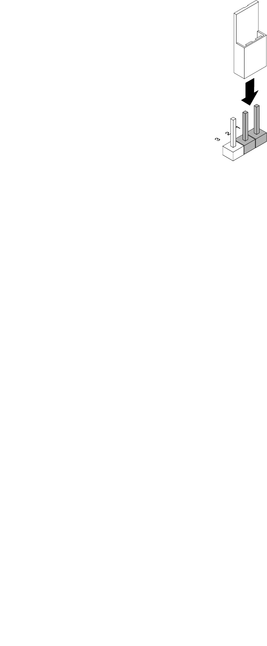
Thefollowingillustrationshowsajumperinthedefaultsettingposition(pin1andpin2).Thisisthecorrect
positionfornormaloperation.
Figure28.Defaultjumpersetting
Chapter3.Productoverview47
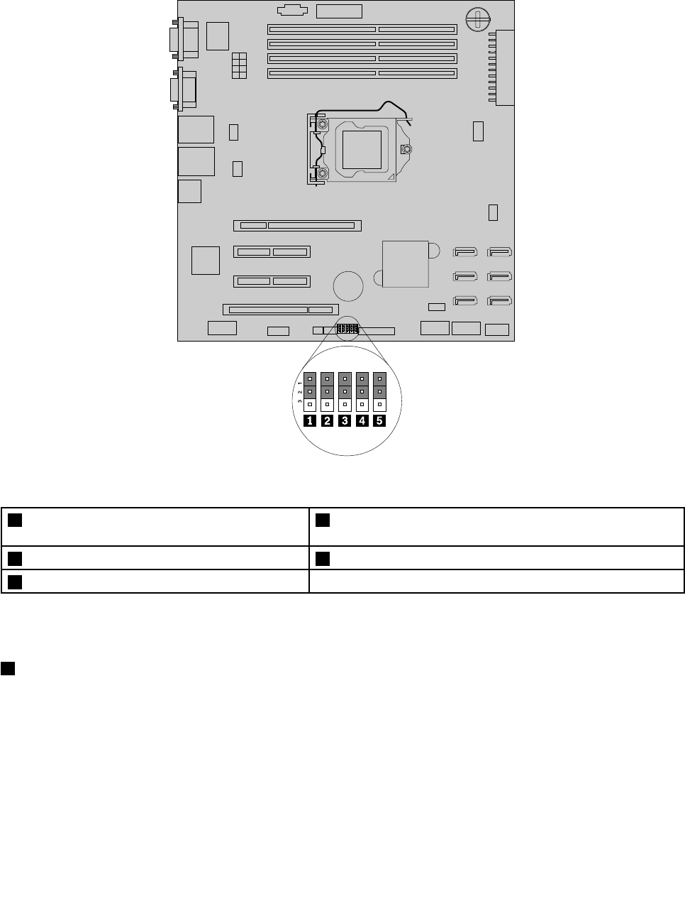
Thefollowingillustrationshowsthestatusofthejumpersonthesystemboardofyourserver.Youcan
congure,recover,enable,ordisablesomespecicfeaturesofthesystemboardbysettingthejumpers.
Figure29.Systemboardjumpers
1ClearCMOS(ComplementaryMetalOxide
Semiconductor)/Recoveryjumper
4Clearpasswordjumper
2BMCsettingjumper5Manufacturingjumper(reservedforthemanufacturer)
3BIOSrecoveryjumper
Attention:Tosetthejumpers,youneedtoopentheservercover.Donotopenyourserverorattemptany
repairbeforereadingandunderstandingthe“Safetyinformation”onpageiiiand“Guidelines”onpage83.
1ClearCMOS/Recoveryjumper
UsedtoclearCMOSandrecoveryourservertothefactorydefaultsettings.
Note:AfterclearingCMOS,allyourBIOSpasswordsareerasedandtheBIOSrecoverstothefactory
defaultsettings.
ToclearCMOS,dothefollowing:
1.Removeallmediafromthedrivesandturnoffallattacheddevicesandtheserver.Then,disconnectall
powercordsfromelectricaloutletsanddisconnectallcablesthatareconnectedtotheserver.
2.Removetheservercover.See“Removingtheservercover”onpage85.
48ThinkServerHardwareMaintenanceManual

3.Laytheserveronitssideforeasieroperation.
4.LocatetheClearCMOS/Recoveryjumperonthesystemboardandthenmovethejumperfromthe
defaultnormalposition(pin1andpin2)totheshort-circuitedposition(pin2andpin3).
5.Waitmorethan10secondsandthenmovetheClearCMOS/Recoveryjumperbacktothenormal
position(pin1andpin2).
6.Reinstalltheservercoverandconnectthepowercord(s).See“Completingthepartsreplacement”on
page168.
7.Waitabout30seconds.Then,turnontheserver.TheBIOSpasswordsareerasedandtheBIOS
recoverstothefactorydefaultsettings.
2BMCsettingjumper
WhentheBMCsettingjumperisinthedefaultnormalposition(pin1andpin2),theserverneedsabout30
secondsfortheBMCtoinitializewheneveryouconnecttheservertoanacpowersource.Ifyoupressthe
powerswitchonthefrontpanelduringthisperiod,theserverwillnotstartimmediately;itwillstartafter
theBMCinitializationnishes.
IfyoumovetheBMCsettingjumpertopin2andpin3,theserverwillbedirectlyturnedonwhenyoupressthe
powerswitchwithoutwaitingfortheBMCready.TheBMCfunctionmightnotbeavailableinthissituation.
3BIOSrecoveryjumper
SetthejumperandboottheserverfromaBIOSrecoveryimageinordertorecoveryourBIOSsettings.
TorecovertheBIOS,see“RecoveringfromaBIOSupdatefailure”onpage68.
4Clearpasswordjumper
Usedtoeraseforgottenpasswords,suchasanadministratorpasswordandauserpassword.
Toclearpasswords,dothefollowing:
1.Removeallmediafromthedrivesandturnoffallattacheddevicesandtheserver.Then,disconnectall
powercordsfromelectricaloutletsanddisconnectallcablesthatareconnectedtotheserver.
2.Removetheservercover.See“Removingtheservercover”onpage85.
3.Laytheserveronitssideforeasieroperation.
4.LocatetheClearpasswordjumperonthesystemboardandthenmovethejumperfromthedefault
normalposition(pin1andpin2)totheshort-circuitedposition(pin2andpin3).
5.Waitmorethan10secondsandthenmovetheClearpasswordjumperbacktothenormalposition
(pin1andpin2).
6.Reinstalltheservercoverandconnectthepowercord(s).See“Completingthepartsreplacement”on
page168.
7.Waitabout30seconds.Then,turnontheserver.TheBIOSpasswordsareerased,includingthe
administratorpasswordanduserpassword.
8.Tosetnewpasswords,see“Usingpasswords”onpage65.
5Manufacturingjumper
Reservedforthemanufacturer.
Chapter3.Productoverview49
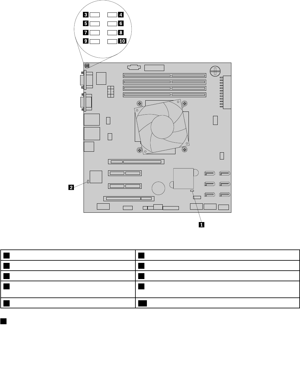
SystemboardLEDs
ThistopichelpsyoulocatetheLEDsonthesystemboard.
ThefollowingillustrationshowstheBMCstatusLED,systemboardhardwarefaultLED,andthePOSTcode
diagnosticLEDsonthesystemboard.
Figure30.SystemboardLEDs
1SystemboardhardwarefaultLED6POSTcodediagnosticLED#1
2BMCstatusLED7POSTcodediagnosticLED#6
3POSTcodediagnosticLED#48POSTcodediagnosticLED#2
4POSTcodediagnosticLED#0-LeastSignicant
Bit(LSB)
9POSTcodediagnosticLED#7-MostSignicantBit(MSB)
5POSTcodediagnosticLED#510POSTcodediagnosticLED#3
1SystemboardhardwarefaultLED
WhenthisLEDislit,itindicatesthatthesystemboardhardwarehasfailed.
50ThinkServerHardwareMaintenanceManual
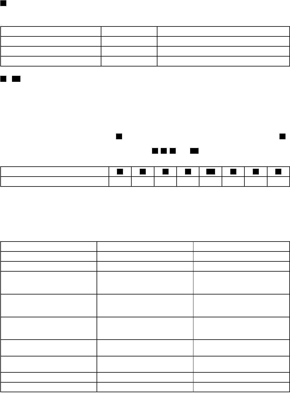
2BMCstatusLED
ThisLEDindicatestheBMCstatusofyourserver.
BMCstatusLEDColorDescription
OnGreenTheBMCisnotready.
OffNoneTheBMChasnopowerorfails.
BlinkingGreenTheBMCisworking.
3-10POSTcodediagnosticLEDs
Duringthesystembootprocess,theBIOSexecutesseveralplatformcongurationprocesses,eachof
whichisassignedaspecichexPOSTcodenumber.Wheneachcongurationroutineisstarted,theBIOS
displaysthePOSTcodenumberthroughthePOSTcodediagnosticLEDsonthesystemboard.Toassistin
troubleshootingasystemhangduringthePOSTprocess,thediagnosticLEDscanbeusedtoidentifythe
lastPOSTprocessexecuted.
ThePOSTcodediagnosticLED#0(callout4)istheLSBandthePOSTcodediagnosticLED#7(callout9)
istheMSB.IfaPOSTcodediagnosticLEDislit,itindicates1inthebinarynumeralsystem;otherwise,it
indicates0.Forexample,ifPOSTcodediagnosticLEDs5,6,9,and10arelit,youcanreadthenumber
asthefollowing:
POSTcodediagnosticLED975310864
Binarysymbol10101010
The“10101010”indicatesacorrespondingPOSTcode.
Note:ThePOSTcodediagnosticLEDsandPOSTerrorcodeinformationareintendedfortrainedservice
personnelofLenovo.
ThefollowingtablelistsinformationaboutthePOSTerrorcodes.
POSTcodediagnosticLEDsPOSTerrorcodeDescription
000011100x0EMicrocodenotfound.
000011110x0FMicrocodenotloaded.
010100000x50Memoryinitializationerror.The
memorytypeisinvalidorthememory
speedisincompatible.
010100010x51Memoryinitializationerror.TheSerial
PresenceDetect(SPD)datareading
hasfailed.
010100100x52Memoryinitializationerror.The
memorysizeisinvalidorthememory
modulesdonotmatch.
010100110x53Memoryinitializationerror.Nousable
memorydetected.
010101000x54Unspeciedmemoryinitialization
error.
010101010x55Memorynotinstalled.
010101100x56Invalidmicroprocessortypeorspeed.
Chapter3.Productoverview51

POSTcodediagnosticLEDsPOSTerrorcodeDescription
010101110x57Microprocessormismatch.
010110000x58Microprocessorself-testfailedor
microprocessorcacheerroroccurred.
010110010x59Microprocessormicrocodenotfound
ormicrocodeupdatingfailed.
010110100x5AInternalmicroprocessorerror.
010110110x5BResetPPInotavailable.
111010000xE8S3resumeoperationfailed.
111010010xE9S3resumePPInotfound.
111010100xEAS3resumebootscripterror.
111010110xEBS3operatingsystemwakeerror.
111110000xF8RecoveryPPInotavailable.
111110010xF9Recoverycapsulenotfound.
111110100xFAInvalidrecoverycapsule.
110100000xD0Microprocessorinitializationerror.
110100010xD1Northbridgeinitializationerror.
110100100xD2Southbridgeinitializationerror.
110100110xD3Somearchitecturalprotocolsnot
available.
110101000xD4PCIresourceallocationerror.Outof
resources.
110101010xD5NospaceforthelegacyoptionROM.
110101100xD6Consoleoutputdevicesnotfound.
110101110xD7Consoleinputdevicesnotfound.
110110000xD8Invalidpassword.
110110010xD9ErrorloadingBootOption(LoadImage
returnederror).
110110100xDABootOptionfailed(StartImage
returnederror).
110110110xDBFlashupdatingfailed.
110111000xDCResetprotocolnotavailable.
52ThinkServerHardwareMaintenanceManual
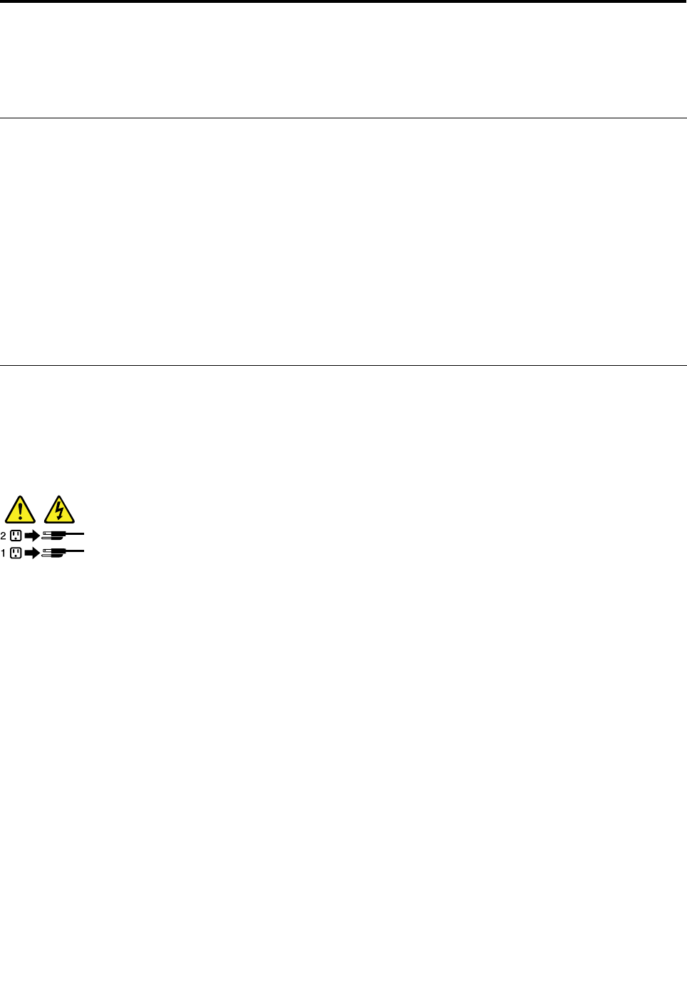
Chapter4.Turningonandturningofftheserver
Thischapterprovidesinformationaboutturningonandturningofftheserver.
Turningontheserver
Theservercanbeturnedoninoneofthefollowingways:
•Afteryounishunpackingandsettinguptheserver,connectittoanacpowersource.Pressthepower
switchonthefrontpaneltoturnontheserver.See“Frontpanel”onpage17.Theserverneedsabout
30secondsfortheBMCtoinitializewheneveryouconnecttheservertoanacpowersource.Ifyou
pressthepowerswitchonthefrontpanelduringthisperiod,theserverwillnotstartimmediately;itwill
startaftertheBMCinitializationnishes.
•WhentheWakeonLANfeatureisenabledontheserverthatisconnectedtoanacpowersourceanda
LAN,anetworkadministratorcanremotelyturnonorwakeuptheserverfromamanagementconsole
usingremotenetworkmanagementsoftware.
•YoucanalsousetherelatedBMCfeaturetoremotelyturnontheserverthroughthemanagementLAN.
Turningofftheserver
CAUTION:
Thepowercontrolbuttononthedeviceandthepowerswitchonthepowersupplydonotturnoff
theelectricalcurrentsuppliedtothedevice.Thedevicealsomighthavemorethanonepower
cord.Toremoveallelectricalcurrentfromthedevice,ensurethatallpowercordsaredisconnected
fromthepowersource.
Theservercanbeturnedoffinoneofthefollowingways:
•Turnofftheserverfromtheoperatingsystemifyouroperatingsystemsupportsthisfeature.Afteran
orderlyshutdownoftheoperatingsystem,theserverwillturnoffautomatically.Forinstructionsonhow
toshutdownyourspecicoperatingsystem,refertotherelateddocumentationorhelpsystemfor
theoperatingsystem.
•Pressthepowerswitchonthefrontpaneltostartanorderlyshutdownoftheoperatingsystemandturn
offtheserver,ifyouroperatingsystemsupportsthisfeature.
•Ifyourserverstopsrespondingandyoucannotturnitoff,pressandholdthepowerswitchonthe
frontpanelforfoursecondsormore.Ifyoustillcannotturnofftheserver,disconnectallpowercords
fromtheserver.
•IftheserverisconnectedtoaLAN,anetworkadministratorcanremotelyturnofftheserverfroma
managementconsoleusingremotenetworkmanagementsoftware.
•YoucanalsousetherelatedBMCfeaturetoremotelyturnofftheserverthroughthemanagementLAN.
•Theservermightbeturnedoffasanautomaticresponsetoacriticalsystemfailure.
Notes:
1.Whenyouturnofftheserverandleaveitconnectedtoanacpowersource,theservercanalsorespond
toaremoterequesttoturnontheserver.Toremoveallpowerfromtheserver,youmustdisconnect
theserverfromtheacpowersource.
©CopyrightLenovo201153

2.Forinformationaboutyourspecicoperatingsystem,refertotherelateddocumentationorhelpsystem
fortheoperatingsystem.
54ThinkServerHardwareMaintenanceManual

Chapter5.Conguringtheserver
Thischapterprovidesthefollowinginformationtohelpyouconguretheserver:
•“UsingtheSetupUtilityprogram”onpage55
•“UsingtheThinkServerEasyStartupprogram”onpage69
•“ConguringRAID”onpage71
•“ConguringtheEthernetcontrollers”onpage80
•“Updatingthermware”onpage80
UsingtheSetupUtilityprogram
ThistopicprovidesinformationaboutusingtheSetupUtilityprogram.
TheSetupUtilityprogramispartoftheserverrmware.YoucanusetheSetupUtilityprogramtoviewand
changethecongurationsettingsofyourserver,regardlessofwhichoperatingsystemyouareusing.
However,theoperatingsystemsettingsmightoverrideanysimilarsettingsintheSetupUtilityprogram.
StartingtheSetupUtilityprogram
ThistopicprovidesinstructionsonhowtostarttheSetupUtilityprogram.
TostarttheSetupUtilityprogram,dothefollowing:
1.Connecttheservertoanacpowersourceandpressthepowerswitchonthefrontpaneltoturnonthe
server.See“Turningontheserver”onpage53.
2.PresstheF1keyassoonasyouseethelogoscreen.Then,waitforseveralseconds,andtheSetup
Utilityprogramopens.Ifyouhavesetapassword,youneedtotypethecorrectpasswordtoenterthe
SetupUtilityprogram.Forpasswordinformation,see“Usingpasswords”onpage65.
ViewinginformationintheSetupUtilityprogram
TheSetupUtilityprogrammenulistsvariousitemsaboutthesystemconguration.Selectadesireditem
toviewinformationorchangesettings.
WhenworkingwiththeSetupUtilityprogram,youmustusethekeyboard.Thekeysusedtoperformvarious
tasksaredisplayedontherightbottompaneofeachscreen.YoucanalsopresstheF1keyforgeneralhelp
aboutthekeys.Formostitems,thecorrespondinghelpmessageisdisplayedontherighttoppaneofthe
screenwhentheitemisselected.Iftheitemhassubmenus,youcandisplaythesubmenusbypressingEnter.
YoucanviewthefollowinginformationaboutyourspecicservermodelfromtheSetupUtilityprogram:
•TheMainmenulistsinformationabouttheBIOSversion,microprocessortypeandcorefrequency,
memorysize,andsystemdateandtime.
•OntheAdvancedmenu:
–SelectProcessorCongurationtoviewtheinformationabouttheinstalledmicroprocessorand
itssupportedtechnologies.
–SelectMemoryCongurationtoviewtheinformationabouttheinstalledmemorymodules.
–SelectSATAConguration.Then,selectthedesiredSATAportfromSATAPort0toSATAPort5toview
theinformationabouttheinstalledSATAdevices,suchasaSATAharddiskdriveoranopticaldrive.
©CopyrightLenovo201155

•OntheServerManagementmenu,selectSystemInformationtoviewtheinformationaboutyour
system,includingtheBMCinformation.
SetupUtilityprograminterface
ThistopicprovidesinformationaboutthemenusanditemsintheSetupUtilityprogram.
DependingontheversionofyoursystemBIOS,somemenuoriteminformationmightdifferslightlyfromthe
informationinthistopic.Theinformationinthistopicisbasedonthe0.9bversionoftheBIOS.
Notes:
1.Thedefaultsettingsarealreadyoptimizedforyou.Usethedefaultvalueforanyitemyouarenotfamiliar
with.Donotchangethevalueofunfamiliaritemsoritemsthatarenotmentionedinthistopictoavoid
unexpectedproblems.Ifyouconsiderchangingtheserverconguration,proceedwithextremecaution.
Settingthecongurationincorrectlymightcauseunexpectedresults.Ifyoucannotturnontheserver
becauseofincorrectBIOSsettings,usetheClearCMOS/RecoveryjumpertorecovertheBIOStothe
factorydefaultsettingsorusetheBIOSrecoveryjumpertoboottheserverfromaBIOSrecoveryimage
andrecovertheBIOStotheversionintheimage.See“Systemboardjumpers”onpage46.
2.LenovoprovidestheBIOSupdateutilityontheLenovoSupportWebsite.YoucandownloadtheBIOS
imageandfollowtheinstructionsontheWebsitetoupdatetheBIOS.See“Updatingorrecoveringthe
BIOS”onpage67.AfterupdatingtheBIOS,alltheBIOSsettingsbecomethedefaultsettingsofthe
updatedBIOSversion.YouneedtocheckandreconguretheBIOSsettingsforyourspecicneeds.
3.Ifyouhavechangedanyhardwareintheserver,youmightneedtoreashtheBIOS,theBMCrmware,
andtheFRU/SDR.
ThefollowingmenusarelistedontheBIOSSetupUtilityscreen:
•Main:See“Mainmenu”onpage56.
•Advanced:See“Advancedmenu”onpage57.
•Security:See“Securitymenu”onpage60.
•ServerManagement:See“ServerManagementmenu”onpage61.
•BootOptions:See“BootOptionsmenu”onpage62.
•BootManager:See“BootManagermenu”onpage64.
•Exit:“Exitmenu”onpage64.
Mainmenu
AfterenteringtheSetupUtilityprogram,youcanseetheMainmenu,whichlistssomebasicinformation
aboutthesystemBIOSversionandbuilddate,themicroprocessor,memory,andthesystemdateandtime.
56ThinkServerHardwareMaintenanceManual
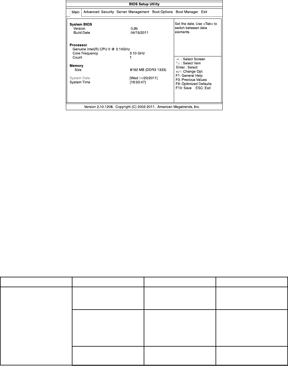
ThefollowingillustrationshowsanexampleoftheMainmenuintheSetupUtilityprogram.
Figure31.AnexampleoftheMainmenuintheSetupUtilityprogram
TosetthesystemdateandtimeontheMainmenu,see“Settingthesystemdateandtime”onpage64.
Advancedmenu
ThistopicprovidesinformationaboutthevariouscongurationmenusanditemsontheAdvancedmenu
intheSetupUtilityprogram.
YoucanvieworchangevariousservercomponentsettingsontheAdvancedmenu.Thefollowingtable
showsthecontentsoftheAdvancedmenu.Oneachsubmenu,presstheEnterkeytoshowselectable
optionsandselectadesiredoptionbyusingupanddownarrowkeysortypedesiredvaluesfromthe
keyboarddirectly.Someitemsaredisplayedonthemenuonlyiftheserversupportsthecorresponding
features.
Notes:
•Enabledmeansthatthefunctioniscongured.
•Disabledmeansthatthefunctionisnotcongured.
•DefaultvaluesareinboldfaceintheSelectionscolumn.
Advancedmenuitems
MenuitemSubmenuitemSelectionsComments
IntelHyper-Threading
Technology
•Disabled
•Enabled
Enableordisablethe
IntelHyper-Threading
Technology.
ActiveProcessorCores•All
•1
•2
•3
Settheactive
microprocessorcores.
IntelVirtualization
Technology
•Disabled
•Enabled
EnableordisabletheIntel
VirtualizationTechnology.
ProcessorConguration
(setthemicroprocessor
congurationparameters)
Chapter5.Conguringtheserver57

MenuitemSubmenuitemSelectionsComments
IntelEISTTechnology•Disabled
•Enabled
EnableordisabletheIntel
EISTTechnology.
P-StateCoordination•HW_ALL
•SW_ALL
•SW_ANY
ChangetheP-State
Coordinationtype.
IntelTurboBoost
Technology
•Disabled
•Enabled
EnableordisabletheIntel
TurboBoostTechnology.
C1ESupport•Disabled
•Enabled
EnableordisabletheC1E
Support.
CPUC3Report•Disabled
•ACPIC2
•ACPIC3
EnableordisabletheCPU
C3report.
CPUC6Report•Disabled
•Enabled
EnableordisabletheCPU
C6report.
PackageCStateLimit•C0
•C1
•C6
•C7
•NoLimit
SetthePackageCstate
limit.
HardwarePrefetcher•Disabled
•Enabled
Enableordisablethe
hardwareprefetcher
function.
AdjacentCacheLine
Prefetch
•Disabled
•Enabled
Enableordisablethe
adjacentcacheline
prefetcherfunction.
MemoryConguration
(setmemoryconguration
parametersandview
informationaboutthe
installedmemorymodules)
MemoryReset•No
•Yes
Setthememorymodule
resetoptions.Ifamemory
moduleencountersany
errors,setthisoptionto
Yestotrytore-initializethe
memorymodule.
IntelVT-dTechnology•Disabled
•Enabled
EnableordisabletheIntel
VT-dtechnology.
IntelTXTTechnology•Disabled
•Enabled
Enableordisablethe
IntelTrustedExecution
Technology(TXT).
SerialPort1•Disabled
•Enabled
Enableordisabletheserial
port1(COM1).
SerialPort2•Disabled
•Enabled
Enableordisabletheserial
port2(COM2).
PoweronbyRTCAlarm•Disabled
•Enabled
Enableordisablepowering
onbyRTCalarm.
ChipsetConguration
(setchipsetconguration
parameters)
RestoreonACPowerLoss•Stayoff
•LastState
Selectthesystemresume
statusafteracpowerloss.
58ThinkServerHardwareMaintenanceManual

MenuitemSubmenuitemSelectionsComments
•PoweronIfthepowerisinterrupted
whentheserverison,after
thepowerresumes:
•IfyouhaveselectedStay
off,theserverwillstayin
theoffstate.
•IfyouhaveselectedLast
State,theserverwill
resumetothelaststate.
•Ifyouhaveselected
Poweron,theserverwill
restartautomatically.
SATAMode•IDEMode
•AHCIMode
•RAIDMode
SelectSATAcontroller
operationmode.Ifyou
wanttocongureRAID,
chooseRAIDModeforthe
SATAcontroller.
SATAPort0Viewtheinformationabout
theSATAdeviceconnected
totheSATAconnector0on
thesystemboard.
SATAPort1Viewtheinformationabout
theSATAdeviceconnected
totheSATAconnector1on
thesystemboard.
SATAPort2Viewtheinformationabout
theSATAdeviceconnected
totheSATAconnector2on
thesystemboard.
SATAPort3Viewtheinformationabout
theSATAdeviceconnected
totheSATAconnector3on
thesystemboard.
SATAPort4Viewtheinformationabout
theSATAdeviceconnected
totheSATAconnector4on
thesystemboard.
SATAConguration
(setSATAconguration
parameters)
SATAPort5Viewtheinformationabout
theSATAdeviceconnected
totheSATAconnector5on
thesystemboard.
OnboardGraphics
Controller
•Disabled
•Enabled
Enableordisable
theonboardgraphics
controller.
PrimaryGraphics•Onboard
•Add-On
Chooseamodeforprimary
graphics.TheAdd-On
optionrequiresagraphics
cardinstalled.
OnboardLAN1I/OROM•Disabled
•Enabled
Enableordisablethe
onboardLAN1I/OROM.
PCIConguration(setPCI
congurationparameters)
Chapter5.Conguringtheserver59

MenuitemSubmenuitemSelectionsComments
OnboardLAN2I/OROM•Disabled
•Enabled
Enableordisablethe
onboardLAN2I/OROM.
PCIROMPriority•LegacyROM
•EFICompatibleROM
Chooseamodeforthe
PCIROMpriority.Incase
ofmultipleOptionROMs
(LegacyROMandEFI
CompatibleROM),the
selectionspecieswhich
PCIOptionROMtolaunch.
USBController•Disabled
•Enabled
EnableordisabletheUSB
controller.
LegacyUSBSupport•Enabled
•Disabled
•Auto
Enableordisablethe
supportonlegacyUSB
devices.
Port60/64Emulation•Disabled
•Enabled
Enableordisablethe
port60h/64hemulation.
Thisfunctionisforthe
operatingsystemthatdoes
notsupportlegacyUSB
devices.
USBConguration
(setUSBconguration
parameters)
TANDBERGRDX3040•Auto
•Floppy
•ForcedFDD
•HardDisk
•CD-ROM
Massstoragedevice
emulationtype.Auto
meanstoenumerate
devicesaccordingtotheir
mediaformat.Optical
devicesareemulatedas
“CD-ROM”;driveswith
nomediaareemulated
accordingtothedrivetype.
ConsoleRedirection
Conguration(setconsole
redirectionconguration
parameters)
ConsoleRedirection•Disabled
•SerialPort1
•SerialPort2
Thesettingspecieshow
thehostcomputerandthe
remotecomputer(whichthe
userisusing)willexchange
data.Bothcomputers
shouldhavethesameor
compatiblesettings.
Securitymenu
ThistopicprovidesinformationaboutthesecurityrelatedsettingsontheSecuritymenuintheSetup
Utilityprogram.
Youcansetpasswords,theTPMfeature,andothersecurityfeaturesontheSecuritymenu.Thefollowing
tableshowsthecontentsoftheSecuritymenu.Foreachmenuitem,presstheEnterkeytoshowselectable
optionsandselectadesiredoptionbyusingupanddownarrowkeysortypedesiredvaluesfromthe
keyboarddirectly.Someitemsaredisplayedonthemenuonlyiftheserversupportsthecorresponding
features.
Notes:
•Enabledmeansthatthefunctioniscongured.
•Disabledmeansthatthefunctionisnotcongured.
•DefaultvaluesareinboldfaceintheSelectionscolumn.
60ThinkServerHardwareMaintenanceManual

Securitymenuitems
MenuitemSelectionsComments
SetAdministratorPasswordSetanadministratorpassword
toprotectagainstunauthorized
accesstoyourserver.See“Using
passwords”onpage65.
SetUserPasswordSetauserpasswordtoprotect
againstunauthorizedaccesstoyour
server.See“Usingpasswords”on
page65.Thisitemisonlyavailable
afteryouhavesetanadministrator
password.
Power/ResetButtonLockout•Disabled
•Enabled
IfthisitemissettoEnabled,the
powerswitchonthefrontpanelwill
belockedandtheservercanonlybe
turnedonremotely.
BIOSWriteProtect•Disabled
•Enabled
Ifyouwanttoupdateorashthe
BIOS,makesurethatthisitemis
settoDisabled.Ifthisitemissetto
Enabled,theBIOSwillbeprotected
fromupdatingorashing.
TPMSupport•Disabled
•Enabled
EnableordisabletheTPMsupport.
TousetheTPMfeature,youneedto
haveaTPMmoduleinstalledinthe
TPMconnectoronthesystemboard.
TPMState•Disabled
•Enabled
ThisitemisdisplayedwhentheTPM
SupportissettoEnabled.Setthe
TPMStatetoenableordisablethe
TPMfunction.Theserverwillrestart
inordertochangethestateofTPM.
ServerManagementmenu
ThistopicprovidesinformationaboutthefeaturesavailableontheServerManagementmenuinthe
SetupUtilityprogram.
YoucanviewsysteminformationandvieworchangeeventlogsettingsontheServerManagementmenu.
ThefollowingtableshowsthecontentsoftheServerManagementmenu.Oneachsubmenu,pressthe
Enterkeytoviewtheinformationorshowselectableoptionsandselectadesiredoptionbyusingupand
downarrowkeys.Someitemsaredisplayedonthemenuonlyiftheserversupportsthecorresponding
features.
Note:DefaultvaluesareinboldfaceintheSelectionscolumn.
Chapter5.Conguringtheserver61

ServerManagementmenuitems
MenuitemSubmenuitemSelectionsComments
SystemInformationViewtheinformationabout
yoursystem,includingthe
BMCversioninformation.
ClearallEventLogs•Enabled
•Disabled
IfthisitemissettoEnabled,
theSELwillbecleared.
BMCLANConguration
CongurationSource•Static
•Dynamic
•DoNothing
SelecttocongureLAN
channel1parameters
staticallyordynamically
(DHCP).TheDoNothing
optionmeansthatBMC
networkparameterswill
notbemodiedduringthe
BIOSphase.
BootOptionsmenu
ThistopicprovidesinformationaboutthemenusanditemsontheBootOptionsmenuintheSetupUtility
program.
TheBootOptionsmenuprovidesaninterfacetohelpyouvieworchangetheserverstartupoptions,
includingthestartupsequenceandbootpriorityforvariousdevices.Changesinthestartupoptionstake
effectwhenyoustarttheserver.
Thestartupsequencespeciestheorderinwhichtheserverchecksdevicestondabootrecord.The
serverstartsfromtherstbootrecordthatitnds.Forexample,youcandeneastartupsequencethat
checksforadiscintheopticaldrive,thencheckstheharddiskdrive,andthenchecksanetworkdevice.
Forinformationaboutsettingthestartupsequenceorselectingastartupdevice,see“Selectingastartup
device”onpage66.
Thefollowinglist,showingtheorderinwhichdeviceswillbestartedup,isalwaysdisplayed.Evendevices
thatarenotattachedtoorinstalledinyourserverarelisted.Foreachdevicethatisattachedtoorinstalledin
theserver,informationaboutitispresentedonthescreenafterthecolon.
1.UEFIDevice:
2.HardDiskDrive:
3.OpticalDiskDrive:
4.RemovableDevice:
5.NetworkDevice:
ThefollowingtableshowsthecontentsoftheBootOptionsmenu.Oneachsubmenu,presstheEnterkey
toshowselectableoptionsandselectadesiredoptionbyusingupanddownarrowkeys.Someitemsare
displayedonthemenuonlyiftheserversupportsthecorrespondingfeatures.
Notes:
•Enabledmeansthatthefunctioniscongured.
•Disabledmeansthatthefunctionisnotcongured.
•DefaultvaluesareinboldfaceintheSelectionscolumn.
BootOptionsmenuitems
62ThinkServerHardwareMaintenanceManual

MenuitemSelectionsComments
BootOption#1•UEFIDevice
•HardDiskDrive
•OpticalDiskDrive
•RemovableDevice
•NetworkDevice
Settherststartupdevice.
BootOption#2•UEFIDevice
•HardDiskDrive
•OpticalDiskDrive
•RemovableDevice
•NetworkDevice
Setthesecondstartupdevice.
BootOption#3•UEFIDevice
•HardDiskDrive
•OpticalDiskDrive
•RemovableDevice
•NetworkDevice
Setthethirdstartupdevice.
BootOption#4•UEFIDevice
•HardDiskDrive
•OpticalDiskDrive
•RemovableDevice
•NetworkDevice
Setthefourthstartupdevice.
BootOption#5•UEFIDevice
•HardDiskDrive
•OpticalDiskDrive
•RemovableDevice
•NetworkDevice
Setthefthstartupdevice.
UEFIBootDevicePriorityVariesdependingontheavailable
UEFIdevices.Specifythestartuppriorityforallthe
availableUEFIdevices.
HardDiskDrivePriorityVariesdependingontheavailable
harddiskdrives.Specifythestartuppriorityforallthe
availableharddiskdrives.
OpticalDiskDrivePriorityVariesdependingontheavailable
opticaldrives.Specifythestartuppriorityforallthe
availableopticaldrives.
RemovableDevicePriorityVariesdependingontheavailable
removabledevices.Specifythestartuppriorityforallthe
availableremovabledevices.
NetworkDevicePriorityVariesdependingontheavailable
networkdevices.Specifythestartuppriorityforallthe
availablenetworkdevices.
QuietBoot•Disabled
•Enabled
Enableordisablethequietboot
featuretodeterminewhetherthelogo
screenwillbedisplayedornotwhen
startingtheserver.
Chapter5.Conguringtheserver63
MenuitemSelectionsComments
BootupNum-Lock•On
•Off
TurntheNum-Lockkeyonoroff.
POSTErrorPause•Disabled
•Enabled
EnableordisablethePOSTerror
pausefeature.Whenthisfeature
issettoEnabled,thesystemwill
stoponthePOSTscreenifanyerror
occursduringthePOST.
BootManagermenu
ThistopicprovidesinformationabouttheBootManagermenuintheSetupUtilityprogram.
TheBootManagermenulistsallthebootabledevicesinstalledonyourserversystemboardandtheitems
listedvarydependingonyourservercongurationandinstalledoptiondevices.Ifyouselectadesired
devicelistedonthismenu,theserverwillstartfromthedeviceyouselect.
YoucanpressF12whenturningontheserverandselectatemporarystartupdevicedirectlyfromtheboot
deviceselectionwindow.See“Selectingastartupdevice”onpage66.
Exitmenu
ThistopicprovidesinformationabouttheExitmenuintheSetupUtilityprogram.
AfteryounishviewingorchangingsettingsintheSetupUtilityprogram,youcanchooseonedesiredaction
fromtheExitmenutosavechanges,discardchanges,loaddefaultvalues,andexittheprogram.The
followingtablelistseachitemontheExitmenuwithdescriptions.PressEntertoselecttheitemandthen
selectYeswhenpromptedtoconrmtheaction.ForinformationaboutexitingtheSetupUtilityprogram,
see“ExitingtheSetupUtilityprogram”onpage67.
Exitmenuitems
ItemComments
SaveChangesandExitSaveyoursettingsandexittheSetupUtilityprogram.
DiscardChangesandExitDiscardyoursettingsandexittheSetupUtilityprogram.
SaveChangesSaveyoursettings.
DiscardChangesDiscardyoursettingsandloadpreviousvalues.
LoadDefaultValuesReturntotheoptimizeddefaultsettings.
SaveasUserDefaultValuesSavethechangessofarasuserdefaultvalues.
LoadUserDefaultValuesRestoretheuserdefaultvaluesforalltheitems.
Settingthesystemdateandtime
ThistopicprovidesinstructionsonhowtosetthesystemdateandtimeintheSetupUtilityprogram.
TosetthesystemdateandtimeintheSetupUtilityprogram,dothefollowing:
1.StarttheSetupUtilityprogram.See“StartingtheSetupUtilityprogram”onpage55.
2.OntheMainmenu,selectSystemDateorSystemTime.
3.UsetheTabkeytoswitchbetweendataelementsandtypethenumbersfromthekeyboardtosetthe
systemdateandtime.
4.PressF10tosavesettingsandexittheSetupUtilityprogram.
64ThinkServerHardwareMaintenanceManual

Usingpasswords
ByusingtheSetupUtilityprogram,youcansetapasswordtopreventunauthorizedaccesstoyourserver.
Youdonothavetosetapasswordtouseyourserver.However,usingapasswordimprovescomputing
security.Ifyoudecidetosetapassword,readthefollowingtopics.
SetupUtilityprogrampasswordtype
ThefollowingtypesofpasswordsareavailableintheSetupUtilityprogram:
•Administratorpassword
Settinganadministratorpassworddetersunauthorizedusersfromchangingcongurationsettings.Ifyou
areresponsibleformaintainingthecongurationsettingsofseveralcomputers,youmightwanttoset
anadministratorpassword.Whenanadministratorpasswordisset,youarepromptedtotypeavalid
passwordeachtimeyoutrytoaccesstheSetupUtilityprogram.TheSetupUtilityprogramcannot
beaccesseduntilavalidpasswordistypedin.
•Userpassword(onlyavailablewhenyouhavesetanadministratorpassword)
Whenauserpasswordisset,theservercannotbeuseduntilavalidpasswordistypedin.
Note:Ifboththeadministratorpasswordanduserpasswordareset,youcantypeeitherpassword.
However,youmustuseyouradministratorpasswordtochangeanycongurationsettings.
Passwordconsiderations
Forsecurityreasons,itisrecommendedtouseastrongpasswordthatcannotbeeasilycompromised.
Notes:
1.TheSetupUtilityprogrampasswordsarenotcasesensitive.
2.TheserversupportsSetupUtilityprogrampasswordsthatconsistofupto20characters.
Tosetastrongpassword,usethefollowingguidelines:
•Haveatleasteightcharactersinlength
•Containatleastonealphabeticcharacterandonenumericcharacter
•Notbeyournameoryourusername
•Notbeacommonwordoracommonname
•Besignicantlydifferentfromyourpreviouspasswords
Besidesthealphabeticcharacters(a-z)andnumericcharacters(0-9),theserveralsosupportscharacters
typedusingspecialkeysonthekeyboardforapassword.Refertothehelpmessageonthescreenwhen
settingapasswordtodeterminethevalidspecialcharacters.
Setting,changing,ordeletingapassword
Thistopicprovidesinstructionsonhowtoset,change,ordeleteapasswordintheSetupUtilityprogram.
Toset,change,ordeleteapasswordintheSetupUtilityprogram,dothefollowing:
1.StarttheSetupUtilityprogram.See“StartingtheSetupUtilityprogram”onpage55.
2.OntheSecuritymenu,selectSetAdministratorPasswordtosetanadministratorpasswordorselect
SetUserPasswordtosetauserpassword.
Note:TheSetUserPasswordoptionisonlyavailablewhenyouhavealreadysetanadministrator
password.
Chapter5.Conguringtheserver65

3.See“Passwordconsiderations”onpage65.Then,followtheinstructionsonthescreentosetor
changeapassword.
4.Ifyouwanttodeleteapassword,typeyourcurrentpassword.PressEnterwhenyouareprompted
totypeanewpassword.Then,pressEntertoconrmthenewpassword.Thepreviouspassword
willbecleared.
Note:Ifyoudeleteanadministratorpassword,theuserpasswordwillalsobedeleted.Forsecurity
reasons,itisrecommendedthatyoualwayssetapasswordforyourserver.
5.PressF10tosavesettingsandexittheSetupUtilityprogram.
Ifyouhaveforgottenthepassword,youcanusetheClearpasswordjumperonthesystemboardtoerase
thepassword.See“Systemboardjumpers”onpage46.Then,setanewpasswordfortheserver.
ConguringtheTPMfunction
TheTPMfunctionprovidesahardwaresecuritysolutiontoencryptdataandprotecttheserver.TheTPM
functionisonlyavailablewhenthereisaTPMmoduleinstalledinyourserver.See“InstallingtheTPM
module”onpage109.YoucanpurchaseaTPMmodulefromLenovo.
AfterinstallingaTPMmodule,youneedtocheckiftheTPMfunctionisenabledintheSetupUtilityprogram.
ToenabletheTPMfunctionintheSetupUtilityprogram,dothefollowing:
1.StarttheSetupUtilityprogram.See“StartingtheSetupUtilityprogram”onpage55.
2.OntheSecuritymenu,selectTPMSupport.MakesurethattheTPMSupportissettoEnabled.
3.WhentheTPMSupportissettoEnabled,theTPMStateitemisdisplayed.SettheTPMStateto
Enabled.
4.PressF10tosavesettingsandexittheSetupUtilityprogram.Theserverwillrestartinordertoenable
theTPMfunction.
Selectingastartupdevice
Ifyourserverdoesnotstartupfromadesireddevicesuchasthediscorharddiskdriveasexpected,doone
ofthefollowingtoselectthestartupdeviceyouwant:
Note:Notalldiscs,harddiskdrives,orotherremovabledevicesarebootable.
•Toselectatemporarystartupdevice,dothefollowing:
Note:Selectingastartupdeviceusingthefollowingmethoddoesnotpermanentlychangethestartup
sequence.
1.Turnonorrestartyourserver.
2.Whenyouseethelogoscreen,pressF12todisplaythebootmenu.Thebootdeviceselection
windowopens.Ifyourserverisconnectedtoanetworkandyouwanttostartuptheserverfromthe
network,pressF10.
3.Inthebootdeviceselectionwindow,usetheupanddownarrowkeysonthekeyboardtoswitch
betweentheselections.PressEntertoselectthedeviceofyourchoice.Then,theserverwillstart
upfromtheselecteddevice.
•Tovieworpermanentlychangetheconguredstartupdevicesequence,dothefollowing:
1.StarttheSetupUtilityprogram.See“StartingtheSetupUtilityprogram”onpage55.
2.OntheBootOptionsmenu,followtheinstructionsonthescreentosetthestartupdeviceforBoot
Option#1toBootOption#5dependingonyourneeds.Youcanalsosetthebootpriorityforvarious
devices.See“BootOptionsmenu”onpage62.
66ThinkServerHardwareMaintenanceManual

3.PressF10tosavesettingsandexittheSetupUtilityprogram.Theserverwillfollowthestartupdevice
sequenceyouhaveseteachtimeyouturnontheserver.
ExitingtheSetupUtilityprogram
Afteryounishviewingorchangingsettings,pressEsctoreturntotheSetupUtilityprogrammaininterface.
Ifyouareonanestedsubmenu,pressEscrepeatedlyuntilyoureachthemaininterface.Then,youcan
dooneofthefollowing:
•IfyouwanttosavethenewsettingsandexittheSetupUtilityprogram,pressF10.Otherwise,your
changeswillnotbesaved.
•Ifyoudonotwanttosavethenewsettings,selectExit➙DiscardChangesandExit.
•Ifyouwanttoreturntothedefaultsettings,pressF9orselectExit➙LoadDefaultValues.
FormoreinformationabouttheExitmenuintheSetupUtilityprogram,see“Exitmenu”onpage64.
UpdatingorrecoveringtheBIOS
ThistopicprovidesinstructionsonhowtoupdatetheBIOSandhowtorecoverfromaPOSTandBIOS
updatefailure.
Systemprogramsarethebasiclayerofsoftwarebuiltintoyourserver.SystemprogramsincludethePOST,
theUEFIBIOS,theSetupUtilityprogram,andtheBMCrmware.ThePOSTisasetoftestsandprocedures
thatareperformedeachtimeyouturnonyourserver.TheUEFIBIOSisalayerofsoftwarethattranslates
instructionsfromotherlayersofsoftwareintoelectricalsignalsthattheserverhardwarecanexecute.You
canusetheSetupUtilityprogramtovieworchangethecongurationsettingsofyourserver.See“Using
theSetupUtilityprogram”onpage55.TheBMCrmwareworkstogetherwithaniKVMkeytoprovide
advancedservermanagementfeatures.
Yourserversystemboardhasamodulecalledelectricallyerasableprogrammableread-onlymemory
(EEPROM,alsoreferredtoasashmemory).YoucaneasilyupdatethePOST,theBIOSandBMC
rmware,andtheSetupUtilityprogrambystartingyourserverwithasystem-program-updatediscora
bootableUSBkey.
LenovomightmakechangesandenhancementstotheBIOSandBMCrmware.Whenupdatesare
released,theyareavailablefordownloadontheLenovoSupportWebsiteathttp://support.lenovo.com.
InstructionsforusingtheupdatesalsoareavailableinaTXTleonthesameWebpagewiththeupdates.
Youcandownloadaself-startingdiscimage(knownasanISOimage)fortheupdateprogramandcreatea
system-program-updatedisc;ordownloadaBIOSupdatepackageandcopyalllesinthepackagetoa
bootableUSBkeyandstarttheserverfromtheUSBkey.
YoucanalsousetheFirmwareUpdaterprogramtohelpyoukeeptheserverrmwareup-to-date.See
“Updatingthermware”onpage80.
DownloadingtheBIOSupdateutilityprogram
BeforeupdatingorrecoveringyourBIOS,youneedtodownloadaBIOSupdateutilityprogramfromthe
LenovoSupportWebsite.
TodownloadtheBIOSupdateutilityprogram,dothefollowing:
Note:LenovomaintainstheSupportWebsitebymakingchangesandimprovementsperiodically.The
actualproceduremightvaryslightlyfromwhatisdescribedinthistopic.
1.GototheLenovoSupportWebsiteat:
http://support.lenovo.com
Chapter5.Conguringtheserver67

2.ClickDownloadDrivers&SoftwareandfollowtheinstructionsontheWebpagetolocatetheBIOS
updateutilityprogram.
3.DownloadtheISOimageorupdatepackageandtheinstallationinstructionsinaTXTle.
4.IfyouwilluseanISOimagetoupdatetheBIOS,useanyCDorDVDburningsoftwaretocreatea
bootablediscwiththeISOimage.IfyouwilluseanupdatepackagetoupdatetheBIOS,extractthe
packagetoalocaldriveandcopyallthelestoabootableUSBkey.
5.PrinttheTXTlethatcontainstheinstallationinstructions.Youwillneedtheinstructionswhen
performingtheBIOSupdateorrecoveryprocedure.
Updating(ashing)theBIOS
Thistopicprovidesinstructionsonhowtoupdate(ash)theBIOS.
Notes:
1.UpdatetheBIOSonyourserveronlyifthenewerBIOSversionspecicallysolvesaproblemyou
have.WedonotrecommendBIOSupdatesforserversthatdonotneedit.Youcanviewtheupdated
informationforthenewBIOSversionintheinstallationinstructionsfortheBIOSupdateutilityprogram.
See“DownloadingtheBIOSupdateutilityprogram”onpage67.
2.DowngradingtheBIOStoanearlierversionisnotrecommendedandmightnotbesupported.Anearlier
BIOSversionmightnotcontainthesupportforthelatestsystemcongurations.
3.IfthepowertoyourserverisinterruptedwhilethePOSTandBIOSisbeingupdated,yourserver
mightnotrestartcorrectly.MakesurethatyouperformtheBIOSupdateprocedureinanenvironment
withasteadypowersupply.Besides,makesurethatyourservercanrestartsuccessfullywithout
encounteringhardwareproblems.
4.IfyouhaveupdatedtheBIOSrmware,alltheBIOSsettingsbecomethedefaultsettingsoftheupdated
BIOSversion.YouneedtocheckandreconguretheBIOSsettingsforyourspecicneeds.You
cannotedownyourspecicBIOSsettingsbeforeupdatingtheBIOSforaneasierrecongurationin
thenewBIOSversion.
Toupdate(ash)theBIOS,dothefollowing:
1.DownloadaBIOSupdateutilityprogramanditsinstallationinstructionsfromtheLenovoSupport
Website.Then,makeabootablediscorabootableUSBkeyandprinttheTXTlethatcontainsthe
installationinstructions.See“DownloadingtheBIOSupdateutilityprogram”onpage67.
2.TurnontheserverandpresstheF1keyassoonasyouseethelogoscreentostarttheSetupUtility
program.See“StartingtheSetupUtilityprogram”onpage55.
3.OntheSecuritymenu,checktheBIOSWriteProtectsetting.Toupdate(ash)theBIOS,theBIOS
WriteProtectitemmustbesettoDisabled.
4.PressF10tosavesettingsandexittheSetupUtilityprogram.Then,followtheinstallationinstructionsto
update(ash)theBIOSusingadiscorUSBkey.
5.Thesystemwillrestartautomaticallyaftertheupdateprocessiscompleted.Checkandrecongure
theBIOSsettingsforyourspecicneedsbasedonyournoteorreferto“UsingtheSetupUtility
program”onpage55.
RecoveringfromaBIOSupdatefailure
IfthepowertoyourserverisinterruptedwhiletheBIOSisbeingupdated,yourservermightnotrestart
correctly.Ifthishappens,performthefollowingproceduretorecoverfromtheBIOSupdatefailure.
TorecoverfromaBIOSupdatefailure,dothefollowing:
1.DownloadaBIOSupdateutilityprogramanditsinstallationinstructionsfromtheLenovoSupport
Website.Then,makeabootablediscorabootableUSBkeyandprinttheTXTlethatcontainsthe
installationinstructions.See“DownloadingtheBIOSupdateutilityprogram”onpage67.
68ThinkServerHardwareMaintenanceManual

2.Removeallmediafromthedrivesandturnoffallattacheddevicesandtheserver.Then,disconnectall
powercordsfromelectricaloutletsanddisconnectallcablesthatareconnectedtotheserver.
3.Removetheservercover.See“Removingtheservercover”onpage85.
4.LocatetheBIOSrecoveryjumperonthesystemboard.See“Systemboardjumpers”onpage46.
5.RemoveanypartsordisconnectanycablesthatmightimpedeyouraccesstotheBIOSrecoveryjumper.
6.MovetheBIOSrecoveryjumperfromthenormalposition(pin1andpin2)totherecoveryposition
(pin2andpin3).
7.Reinstallanypartsorreconnectanycablesandreinstalltheservercover.See“Completingtheparts
replacement”onpage168.
8.ConnecttheservertoanacpowersourceandthenfollowtheinstallationinstructionsfortheBIOS
updateutilityprogramtostarttheserverfromtherecoveryimage.Therecoverywindowopens.
9.PressEntertostarttherecoveryprocess.Aftertherecoveryprocessiscompleted,yourserverwill
automaticallyturnoff.
10.Repeatstep2throughstep5.
11.MovetheBIOSrecoveryjumperbacktothenormalposition(pin1andpin2).
12.Reinstallanypartsorreconnectanycablesandreinstalltheservercover.See“Completingtheparts
replacement”onpage168.
13.Connecttheservertoanacpowersourceandturnontheserver.TheBIOSsettingsbecomethedefault
settingsoftheupdatedBIOSversion.YouneedtocheckandconguretheBIOSsettingsforyour
specicneeds.See“UsingtheSetupUtilityprogram”onpage55.
UsingtheThinkServerEasyStartupprogram
ThistopicguidesyoutousetheThinkServerEasyStartupprogramtosetupandcongureyourserver.
TheThinkServerEasyStartupprogramsimpliestheprocessofconguringRAIDandinstallingsupported
WindowsandLinuxoperatingsystemsanddevicedriversonyourserver.Theprogramworksinconjunction
withyourWindowsorLinuxoperatingsysteminstallationdisctoautomatetheprocessofinstallingthe
operatingsystemandassociateddevicedrivers.Thisprogramisprovidedwithyourserveronaself-starting
(bootable)ThinkServerEasyStartupDVD.TheuserguidefortheprogramisalsoontheDVDandcanbe
accesseddirectlyfromtheprograminterface.
IfyoudonothaveaThinkServerEasyStartupDVDavailable,youcanalsodownloadanISOimagefromthe
LenovoSupportWebsiteandmakeadiscbyyourself.
TodownloadtheThinkServerEasyStartupprogramimageandburnitintoadisc,dothefollowing:
Note:LenovomaintainstheSupportWebsitebymakingchangesandimprovementsperiodically.The
actualproceduremightvaryslightlyfromwhatisdescribedinthistopic.
1.GototheLenovoSupportWebsiteat:
http://support.lenovo.com
2.ClickDownloadDrivers&SoftwareandfollowtheinstructionsontheWebpagetolocatethe
ThinkServerEasyStartupprogram.
3.DownloadtheISOimagefortheThinkServerEasyStartupprogramandtheinstallationinstructionsin
aTXTle.
4.UseanyDVDburningsoftwaretocreateabootablediscwiththeISOimage.
5.PrinttheTXTlethatcontainstheinstallationinstructionsandfollowtheinstructionstostartthe
ThinkServerEasyStartupprogram.
Chapter5.Conguringtheserver69

FeaturesoftheThinkServerEasyStartupprogram
ThistopicliststhefeaturesoftheThinkServerEasyStartupprogram.
TheThinkServerEasyStartupprogramhasthefollowingfeatures:
•Containedinaself-starting(bootable)DVD
•Easy-to-use,language-selectableinterface
•Integratedhelpsystemanduserguide
•Automatichardwaredetection
•RAIDcongurationutility
•Devicedriversprovidedbasedontheservermodelanddetecteddevices
•Selectablepartitionsizeandlesystemtype
•Supportformultipleoperatingsystems
•Abilitytoinstalltheoperatingsystemanddevicedriversinanunattendedmodetosavetime
•AbilitytocreateareuseableresponselethatcanbeusedwithsimilarlyconguredLenovoserversto
makefutureinstallationsevenfaster
StartingtheThinkServerEasyStartupprogram
ThistopicprovidesinstructionsonhowtostarttheThinkServerEasyStartupprogram.Afteryoustartthe
programandenterthemaininterface,clickUserGuidefordetailedinformationabouthowtousethis
programtohelpyouconguretheserverandinstallanoperatingsystem.
TostarttheThinkServerEasyStartupprogram,dothefollowing:
1.InserttheThinkServerEasyStartupDVDintotheopticaldrive,settheopticaldriveastherststartup
device,andstartyourserverfromtheDVDintheopticaldrive.See“Selectingastartupdevice”on
page66.
2.Waitfortheprogramtoload.Then,youwillbepromptedforthefollowingselections:
•Thelanguageinwhichyouwanttoviewtheprogram
•Thelanguageofthekeyboardlayoutyouwillbeusingwiththeprogram
Note:ThesupportedlanguagesandkeyboardlayoutsfortheThinkServerEasyStartupprogramare
German,English,Spanish,French,Italian,Dutch,Turkish,andJapanese.YourThinkServerEasyStartup
DVDmightbeEnglishonly.Inthiscase,thekeyboardlayoutshouldbeEnglish.
3.Afterselectingthelanguageandkeyboardlayout,clickOK.Then,youwillseeoneormorereminders
ormessagesaboutconguringstoragedevices.ClickNextuntilyouarepresentedwiththeLenovo
LicenseAgreement.ReadtheLenovoLicenseAgreementcarefully.Inordertocontinue,youmustagree
withtermsbyclickingAgree.Then,theDateandtimewindowopens.
4.SetthecurrentdateandtimeandclickOK.TheStartoptionwindowopens.
5.TheStartoptionwindowprovidesthefollowingselections:
•Continuetothemaininterface.
•Installtheoperatingsystemusingapre-existingresponsele.
•CongureRAIDusingapre-existingresponsele.
Readtheexplanationsonthescreenandselectadesiredoption.Then,followtheinstructionsonthe
screen.IfthisisthersttimeyouareusingtheThinkServerEasyStartupprogram,selecttheoptionto
continuetothemaininterfaceandviewthecompatibilitynotesanduserguide.
Notes:
70ThinkServerHardwareMaintenanceManual

1.FunctionalityandsupportedoperatingsystemsvarydependingontheversionoftheThinkServer
EasyStartupprogram.Fromthemaininterfaceoftheprogram,clickCompatibilitynotestoview
theinformationabouttheRAIDcontrollers,operatingsystems,andservercongurationssupported
bythespecicversionoftheprogramandclickUserGuidetoviewthevariousfunctionsandlearn
howtousetheprogram.
2.BeforeusingtheThinkServerEasyStartupprogramtoinstallanoperatingsystem,makesureany
externalstoragedevicesandberchannelsareconguredcorrectly.
TheThinkServerEasyStartupprogrammaininterfaceprovidesthefollowingmenusontheleftpaneof
thescreen:
•Home
Thismenuisthewelcomepagethatcontainssomegeneraldescriptionsabouttheprogramandthe
Lenovocopyrightandtrademarkstatements.
•Compatibilitynotes
ThismenuprovidesinformationabouttheRAIDcontrollers,operatingsystems,andservercongurations
supportedbytheversionoftheprogramyouareusing.
•UserGuide
Thismenuprovidesinformationaboutthefeaturesoftheprogramandinstructionsonhowtousethe
program.
•Hardwarelist
Thismenudisplaysalistofhardwaredevicesdetectedbytheprogram.
•CongureRAID
ThismenuguidesyoutocongureRAIDorviewthecurrentRAIDcongurationandmakechanges
ifneeded.
•Installoperatingsystem
Thismenudisplaysaseriesofchoicesandpromptstocollectinformationrequiredforoperatingsystem
installation,preparestheharddiskdriveforinstallation,andtheninitiatestheinstallationprocessusing
youroperatingsysteminstallationdisc.
•About
Thismenuprovidestheversioninformationandlegalnotices.
ConguringRAID
ThistopicprovidesinformationaboutRAIDandtheutilityprogramsthatareavailableforyoutocongure
RAID.
Thistopiccontainsthefollowingitems:
•“AboutRAID”onpage72
•“RAIDforyourserver”onpage73
•“ConguringRAIDusingtheThinkServerEasyStartupprogram”onpage74
•“ConguringtheonboardSATAsoftwareRAID”onpage74
•“ConguringtheadvancedSATAorSAShardwareRAID”onpage79
Chapter5.Conguringtheserver71

AboutRAID
RAID,anacronymforRedundantArrayofIndependentDisks,isatechnologythatprovidesincreased
storagefunctionsandreliabilitythroughredundancy.Thisisachievedbycombiningmultipleharddiskdrives
intoalogicalunit,wheredataisdistributedacrossthedrivesinoneofseveralwayscalledRAIDlevels.
WhenagroupofindependentphysicalharddiskdrivesaresetuptouseRAIDtechnology,theyareina
RAIDarray.Thisarraydistributesdataacrossmultipleharddiskdrives,butthearrayappearstothehost
serverasonesinglestorageunit.CreatingandusingRAIDarraysprovideshighperformance,suchasthe
expeditedI/Operformance,becauseseveraldrivescanbeaccessedsimultaneously.
RAIDdrivegroupsalsoimprovedatastoragereliabilityandfaulttolerancecomparedtosingle-drivestorage
systems.Datalossresultingfromadrivefailurecanbepreventedbyreconstructingmissingdatafromthe
remainingdrives.
ThefollowinglistdescribessomeofthemostcommonlyusedRAIDlevels:
•RAID0:block-levelstripingwithoutparityormirroring
SimplestripesetsarenormallyreferredtoasRAID0.RAID0usesstripingtoprovidehighdata
throughput,especiallyforlargelesinanenvironmentthatdoesnotrequirefaulttolerance.RAID0hasno
redundancyanditprovidesimprovedperformanceandadditionalstoragewithoutfaulttolerance.Any
drivefailuredestroysthearrayandthelikelihoodoffailureincreaseswithmoredrivesinthearray.RAID
0doesnotimplementerrorchecking,soanyerrorisuncorrectable.Moredrivesinthearraymeans
higherbandwidth,butgreaterriskofdataloss.
RAID0requiresaminimumnumberoftwoharddiskdrives.
•RAID1:mirroringwithoutparityorstriping
RAID1usesmirroringsothatdatawrittentoonedriveissimultaneouslywrittentoanotherdrive.Thisis
goodforsmalldatabasesorotherapplicationsthatrequiresmallcapacitybutcompletedataredundancy.
RAID1providesfaulttolerancefromdiskerrorsorfailuresandcontinuestooperateaslongasatleast
onedriveinthemirroredsetisfunctioning.Withappropriateoperatingsystemsupport,therecanbe
increasedreadperformanceandonlyaminimalwriteperformancereduction.
RAID1requiresaminimumnumberoftwoharddiskdrives.
•RAID5:block-levelstripingwithdistributedparity
RAID5usesdiskstripingandparitydataacrossalldrives(distributedparity)toprovidehighdata
throughput,especiallyforsmallrandomaccess.RAID5distributesparityalongwiththedataandrequires
alldrivesbutonetobepresenttooperate;drivefailurerequiresreplacement,butthearrayisnot
destroyedbyasingledrivefailure.Upondrivefailure,anysubsequentreadoperationscanbecalculated
fromthedistributedparitysothatthedrivefailureismaskedfromtheenduser.Thearraywillhavedata
lossintheeventofaseconddrivefailureandisvulnerableuntilthedatathatwasonthefailingdriveis
rebuiltontoareplacementdrive.Asingledrivefailureinthesetwillresultinreducedperformanceof
theentiresetuntilthefailingdrivehasbeenreplacedandrebuilt.
RAID5requiresaminimumnumberofthreeharddiskdrives.
•RAID10:acombinationofRAID0andRAID1
RAID10consistsofstripeddataacrossmirroredspans.ARAID10drivegroupisaspanneddrive
groupthatcreatesastripedsetfromaseriesofmirroreddrives.RAID10allowsamaximumofeight
spans.YoumustuseanevennumberofdrivesineachRAIDvirtualdriveinthespan.TheRAID1
virtualdrivesmusthavethesamestripesize.RAID10provideshighdatathroughputandcompletedata
redundancybutusesalargernumberofspans.
RAID10requiresaminimumnumberoffourharddiskdrivesandalsorequiresanevennumberofdrives,
forexample,sixharddiskdrivesoreightharddiskdrives.
72ThinkServerHardwareMaintenanceManual

•RAID50:acombinationofRAID0andRAID5
RAID50usesdistributedparityanddiskstriping.ARAID50drivegroupisaspanneddrivegroupin
whichdataisstripedacrossmultipleRAID5drivegroups.RAID50worksbestwithdatathatrequires
highreliability,highrequestrates,highdatatransfers,andmedium-to-largecapacity.
Note:HavingvirtualdrivesofdifferentRAIDlevels,suchasRAID0andRAID5,inthesamedrivegroupis
notallowed.Forexample,ifanexistingRAID5virtualdriveiscreatedoutofpartialspaceinanarray,the
nextvirtualdriveinthearrayhastobeRAID5only.
RAID50requiresaminimumnumberofsixharddiskdrives.
FordetailedinformationaboutRAID,referto“IntroductiontoRAID”intheMegaRAIDSASSoftwareUser
GuideonthedocumentationDVDthatcomeswithyourserver.
RAIDforyourserver
ThistopicprovidesinformationabouttheRAIDsupportedbyyourserver.
YourserversupportsthefollowingtwotypesofRAIDcongurations:
•OnboardSATAsoftwareRAIDcongurationusingtheLSISoftwareRAIDCongurationUtility
program;andRAIDmanagementusingtheMegaRAIDStorageManagerprogram
TheonboardSATAsoftwareRAIDcontrollerisintegratedintheIntelC202chiponthesystemboard.Ifyour
serverhasSATAharddiskdrivesthatareconnectedtothesystemboard,youcanusetheLSISoftware
RAIDCongurationUtilityprogramtocongureRAID.YourserversupportsonboardSATAsoftwareRAID
levels0,1,and10.YoucanalsoactivateRAIDlevel5byinstallingaThinkServerSATASoftwareRAID5
activationkey.See“InstallingorremovingtheThinkServerSATASoftwareRAID5Key”onpage102.
YoucaninstallandusetheMegaRAIDStorageManagerprogramtomanagetheRAIDarrayandRAID
controllerinanoperatingsystemenvironment.
Fordetailedinformation,see“ConguringtheonboardSATAsoftwareRAID”onpage74.
•AdvancedSATA/SAShardwareRAIDcongurationusingtheWebBIOSCongurationUtility
program;andRAIDmanagementusingtheMegaRAIDStorageManagerprogramandtheMegaCLI
CongurationUtilityprogram(requiresaRAIDcard)
SomeservermodelscomewitharequiredRAIDcardtoprovideadvancedSATA/SAShardwareRAID
functionstotheserver.YoucanalsopurchasetheRAIDcardfromLenovoandinstallitintoservermodels
thatsupporttheRAIDcardtogetadvancedSATA/SAShardwareRAIDfunctions.See“RAIDcard”on
page33and“InstallingorremovingtheRAIDcard”onpage98formoreinformation.
Note:ForservermodelswithmorethanfourharddiskdrivesormodelsthatuseSASharddiskdrives,
theremustbeaRAIDcardinstalled.
TheRAIDcardprovidestheWebBIOSCongurationUtilityprogramtohelpyoucongureRAID
independentlyoftheoperatingsystem.YoucanalsoinstalltheMegaRAIDStorageManagerprogramand
theMegaCLICongurationUtilityprogramtohelpyoumanagetheRAIDarrayandRAIDcontrollerin
anoperatingsystemenvironment.ThesupportedRAIDlevelsareRAID0,1,and10.ToactivateRAID
5and50levels,youneedtoinstallaRAID5keyontheRAIDcard.See“Installingorremovingthe
ThinkServer9240-8iRAID5UpgradeKey”onpage100.
Fordetailedinformation,see“ConguringtheadvancedSATAorSAShardwareRAID”onpage79.
Note:TheThinkServerEasyStartupprogramsimpliestheprocessofconguringsupportedRAIDand
installingsupportedoperatingsystemsanddevicedrivers.
Chapter5.Conguringtheserver73

BeforeconguringRAIDforyourserver,observethefollowingprecautions:
1.UseharddiskdrivesthathavethesamecapacitywithinasingleRAIDarray.
2.Useharddiskdrivesthatareofthesametype(SATAorSAS)withinasingleRAIDarray.
3.Dependingontheoperatingsystem,theprimaryRAIDmightbelimitedto2TBtotaldrivecapacity.
ConguringRAIDusingtheThinkServerEasyStartupprogram
TheThinkServerEasyStartupprogramsimpliestheprocessofconguringsupportedRAIDandinstalling
supportedWindowsandLinuxoperatingsystemsanddevicedriversonyourserver.Theuserguideforthe
programcanbeaccesseddirectlyfromtheprograminterface.
TheThinkServerEasyStartupprogramhasthefollowingfeaturesforRAIDconguration:
•ForusewithallsupportedRAIDcontrollers
•AutomaticallydetectshardwareandlistsallsupportedRAIDcongurations
•Conguresoneormorediskarrayspercontrollerdependingonthenumberofdrivesattachedtothe
controllerandtheRAIDlevelselected
•Supportshot-sparedrives
•CreatesaRAIDresponselethatcanbeusedtocongureRAIDcontrollersonsimilarlycongured
Lenovoservers
See“UsingtheThinkServerEasyStartupprogram”onpage69andviewtheuserguidefromthemain
interfaceoftheprogram.
SomeRAIDmanagementsoftwareisalsoprovidedontheThinkServerEasyStartupDVDtohelpyoumanage
RAIDarraysandRAIDcontrollersinanoperatingsystemenvironment.Afteryouentertheoperatingsystem,
inserttheThinkServerEasyStartupDVDintotheopticaldrive.Theinstallationpackagesfortheprogramsare
locatedintheUtilitiesandOthersfolderintherootdirectoryoftheDVD.TheThinkServerEasyStartupDVDis
designedfordifferenttypesofserversandtheUtilitiesandOthersfoldermightcontainadditionalinstallation
packagesthatarenotrequiredtobeinstalledintoyourserver.Formoreinformation,see“Installingand
usingtheMegaRAIDStorageManagerprogram”onpage79and“ConguringtheadvancedSATAorSAS
hardwareRAID”onpage79.
ConguringtheonboardSATAsoftwareRAID
TheonboardSATAsoftwareRAIDcontrollerisintegratedintheIntelC202chiponthesystemboard.Ifyour
serverhasSATAharddiskdrivesthatareconnectedtothesystemboard,youcanusetheLSISoftware
RAIDCongurationUtilityprogramtocongureRAIDindependentlyoftheoperatingsystem.Yourserver
supportsonboardSATAsoftwareRAIDlevels0,1,and10.YoucanalsoactivateRAID5byinstalling
aThinkServerSATASoftwareRAID5activationkey.See“InstallingorremovingtheThinkServerSATA
SoftwareRAID5Key”onpage102.
YoucaninstallandusetheMegaRAIDStorageManagerprogramtomanagetheRAIDarrayandRAID
controllerinanoperatingsystemenvironment.
StartingtheLSISoftwareRAIDCongurationUtilityprogram
ThistopicprovidesinstructionsonhowtostarttheLSISoftwareRAIDCongurationUtilityprogram.
TostarttheLSISoftwareRAIDCongurationUtilityprogram,dothefollowing:
1.StarttheSetupUtilityprogram.See“StartingtheSetupUtilityprogram”onpage55.
2.OntheAdvancedmenu,selectSATAConguration➙SATAMode.
3.SelectRAIDMode.Then,pressF10tosavesettingsandexittheSetupUtilityprogram.
74ThinkServerHardwareMaintenanceManual

4.Whenyouseethemessage“PressCtrl-MorEntertorunLSISoftwareRAIDSetupUtility,”immediately
pressCtrl+MorEntertostarttheLSISoftwareRAIDCongurationUtilityprogram.
LSISoftwareRAIDCongurationUtilityprograminterface
ThistopicprovidesinformationaboutthemenusanditemsintheLSISoftwareRAIDCongurationUtility
program.Dependingontheversionoftheprogram,somemenuoriteminformationmightdifferslightlyfrom
theinformationinthistopic.
WhenworkingwiththeLSISoftwareRAIDCongurationUtilityprogram,youmustusethekeyboard.
Thekeysusedtoperformvarioustasksaredisplayedonthebottomofeachscreen.Useupanddown
arrowkeystonavigatebetweenitems.Formostitems,thecorrespondinghelpmessageisdisplayed
onthebottomofthescreenwhentheitemisselected.Iftheitemhassubmenus,youcandisplaythe
submenusbypressingEnter.
AfterenteringtheLSISoftwareRAIDCongurationUtilityprogram,youcanseetheManagementMenuon
thescreen.TheManagementMenucontainsthefollowingmenuitems:
•Congure
ThismenucontainsitemstohelpyoucreateaRAIDarray,viewthecurrentRAIDconguration,addanew
array,deleteanexistingarray,orselectabootvirtualdrive.
•Initialize
Thismenuhelpsyouinitializevirtualdrive(s).
Note:Initializingavirtualdriveerasesalldataonthevirtualdrive.Backupanydatayouwanttokeepand
ensuretheoperatingsystemisnotinstalledonthevirtualdrivebeforetheinitialization.
•Objects
ThismenuhelpsyoucongureparametersfortheRAIDadapterorcontroller,thevirtualdrive(s),andthe
physicaldrive(s).
•Rebuild
Thismenuhelpsyourebuildaphysicaldriveinanarrayintheeventofaphysicaldrivefailure.Youcan
choosetorebuildthedataonthefailingdriveifthedriveisstilloperational.Ifthedriveisnotoperational,
itmustbereplacedandthedataonthefailingdrivemustberebuiltonanewdrivetorestorethesystem
tofaulttolerance.Ifhot-sparedrivesareavailable,thefailingdrivemightberebuiltautomaticallywithout
anyuserintervention.
•CheckConsistency
Thismenuhelpsyoudoconsistencycheckforthevirtualdrive(s).Theconsistencycheckveriesthe
correctnessofthedataonvirtualdrive(s)thatuseRAID1,5,and10.
ThefollowingtableshowsthevariousmenusanditemsintheLSISoftwareRAIDCongurationUtility
program.Oneachmenu,presstheEnterkeytoshowselectableoptionsandselectadesiredoptionby
usingupanddownarrowkeysortypedesiredvaluesfromthekeyboarddirectly.
Chapter5.Conguringtheserver75
MenuitemSubmenuitemComments
EasyCongurationCreatephysicalarrays.Anarraywill
automaticallybecomeavirtualdrive.
NewCongurationCleartheexistingcongurationand
startanewconguration.
View/AddCongurationViewtheexistingcongurationoradda
newconguration.
ClearCongurationCleartheexistingconguration.
Congure
SelectBootDriveSelectabootvirtualdrive.
InitializeVariesbyconguration.Initializevirtualdrives.
AdapterSetadapterrelatedparameters,such
asrebuildrate,consistencycheckrate,
auto-rebuild,andsoon.
VirtualDriveSetvirtualdriveparameters.
Objects
PhysicalDriveSetphysicaldriveparameters,suchas
creatingahot-sparedriveforthevirtual
drive,makingafailingdriveasonline,
changingadrivestate,andviewingthe
specicationsofaphysicaldrive.
RebuildVariesbyconguration.Rebuildphysicaldrive(s).
CheckConsistencyVariesbyconguration.Checkconsistencyofvirtualdrive(s).
Creating,adding,ordeletingaRAIDarray
Thistopicprovidesinstructionsonhowtocreate,add,ordeleteaRAIDarrayusingtheLSISoftwareRAID
CongurationUtilityprogram.
Note:BeforeyoucreateaRAIDarrayusingtheLSISoftwareRAIDCongurationUtilityprogram,makesure
thattheservermeetstherequiredhardwareconguration.Forexample,theserverneedstohavethe
requirednumberofSATAharddiskdrivesinstalledandconnectedtothesystemboard.See“AboutRAID”
onpage72forinformationabouttherequirednumberofharddiskdrivesforeachRAIDlevel.Ifyouwantto
createaRAID5arrayusingtheLSISoftwareRAIDCongurationUtilityprogram,theserveralsoneedsto
haveaThinkServerSATASoftwareRAID5Keyinstalledonthesystemboard.See“Installingorremovingthe
ThinkServerSATASoftwareRAID5Key”onpage102.
Tocreate,add,ordeleteaRAIDarrayusingtheLSISoftwareRAIDCongurationUtilityprogram,dothe
following:
1.StarttheLSISoftwareRAIDCongurationUtilityprogram.See“StartingtheLSISoftwareRAID
CongurationUtilityprogram”onpage74.
2.Onthemaininterfaceoftheprogram,dooneofthefollowingdependingonyourneeds:
•IfyouwanttocreateaRAIDarray,selectEasyCongurationandthenfollowtheinstructionson
thescreen.
•IfyouwanttoaddasecondaryRAIDconguration,selectView/AddCongurationandthenfollow
theinstructionsonthescreentoviewthecurrentcongurationandaddanewconguration.
•IfyouwanttodeletetheexistingRAIDconguration,exittheprogramandbackupallyourdataon
theharddiskdrives.Afterbackingupallyourdata,entertheprogrammaininterfaceandselectClear
Conguration.SelectYeswhenpromptedandfollowtheinstructionsonthescreen.
76ThinkServerHardwareMaintenanceManual

Attention:DeletingtheexistingRAIDcongurationerasesalldataonthevirtualdrive.Makesurethat
youbackupalldatabeforedeletingtheRAIDarray.Iftheoperatingsystemisinstalledonthevirtual
driveyouwanttodelete,youneedtoreinstalltheoperatingsystemaftercompletingtheoperation.
•IfyouwanttodeletetheexistingRAIDcongurationandmakeanewconguration,exittheprogram
andbackupallyourdataontheharddiskdrives.Afterbackingupallyourdata,entertheprogram
maininterfaceandselectNewConguration.SelectYeswhenpromptedtoproceedandthen
followtheinstructionsonthescreen.
Attention:DeletingtheexistingRAIDcongurationerasesalldataonthevirtualdrive.Makesurethat
youbackupalldatabeforedeletingtheRAIDarray.Iftheoperatingsystemisinstalledonthevirtual
driveyouwanttodelete,youneedtoreinstalltheoperatingsystemaftercompletingtheoperation.
Initializingavirtualdrive
ThistopicprovidesinstructionsonhowtoinitializeavirtualdriveusingtheLSISoftwareRAIDConguration
Utilityprogramaftercompletingthecongurationprocess.
Virtualdriveinitializationistheprocessofwritingzerostothedataeldsofavirtualdriveand,infault-tolerant
RAIDlevels,generatingthecorrespondingparitytoputthevirtualdriveinareadystate.Initializationerases
alldataonthevirtualdrive.Drivegroupswillworkwithoutbeinginitialized,buttheycanfailaconsistency
checkbecausetheparityeldshavenotbeengenerated.
Notes:
1.Makesurethatyoubackupanydatayouwanttokeepbeforeinitializingavirtualdrive.
2.Makesurethattheoperatingsystemisnotinstalledonthevirtualdriveyouareinitializing.Otherwise,
youneedtoreinstalltheoperatingsystemaftercompletingtheoperation.
ToinitializeavirtualdriveusingtheLSISoftwareRAIDCongurationUtilityprogram,dothefollowing:
1.StarttheLSISoftwareRAIDCongurationUtilityprogram.See“StartingtheLSISoftwareRAID
CongurationUtilityprogram”onpage74.
2.Onthemaininterfaceoftheprogram,selectInitializeandfollowtheinstructionsonthescreen.
Settingahot-sparedrive
Thistopicprovidesinstructionsonhowtosetaphysicaldriveasahot-sparedriveusingtheLSISoftware
RAIDCongurationUtilityprogram.
Ahot-sparedriveisanextra,unuseddrivethatispartofthedisksubsystem.Itisusuallyinstandby
modeandreadyforserviceifadrivefails.Settinghot-sparedrivesenablesyoutoreplacefailingdrives
withoutperformingasystemshutdownoperation.Foradetailedintroductiontohot-sparedrives,referto
“IntroductiontoRAID”intheMegaRAIDSASSoftwareUserGuideonthedocumentationDVDthatcomes
withyourserver.
Tosetaphysicaldriveasahot-sparedriveusingtheLSISoftwareRAIDCongurationUtilityprogram,
dothefollowing:
1.StarttheLSISoftwareRAIDCongurationUtilityprogram.See“StartingtheLSISoftwareRAID
CongurationUtilityprogram”onpage74.
2.Dooneofthefollowing:
•IfyouwanttocreateoraddanewRAIDarray,youcansetahot-sparedriveduringtheconguration
processbyfollowingtheinstructionsonthescreen.
•Ifyouwanttosetahot-sparedriverightaftertheconguration,selectObjects➙PhysicalDrive
fromtheprogrammaininterface.Then,selectthephysicaldrivethatyouwanttosetasahot-spare
Chapter5.Conguringtheserver77

driveandpressEnter.Asubmenuisdisplayed.SelectMakeHotSparefromthesubmenuandthen
selectYeswhenpromptedtosetthephysicaldriveasahot-sparedrive.
Rebuildingaphysicaldrive
ThistopicprovidesinstructionsonhowtorebuildaphysicaldriveusingtheLSISoftwareRAIDConguration
Utilityprogramwhenaphysicaldriveinanarrayfails.
WhenadriveinaRAIDdrivegroupfails,youcanrebuildthedrivebyrecreatingthedatathatwasstoredon
thedrivebeforeitfails.Ifthedriveisnotoperational,itmustbereplacedandthedataonthefailingdrive
mustberebuiltonanewdrivetorestorethesystemtofaulttolerance.Ifhot-sparedrivesareavailable,the
failingdrivemightberebuiltautomaticallywithoutanyuserintervention.
TheRAIDcontrollerrecreatesthedatausingthedatastoredonotherdrivesinthedrivegroup.Rebuilding
canbedoneonlyindrivegroupswithdataredundancy,suchasRAID1,5,and10drivegroups.Fora
detailedintroductiontodiskrebuild,referto“IntroductiontoRAID”intheMegaRAIDSASSoftwareUser
GuideonthedocumentationDVDthatcomeswithyourserver.
TorebuildaphysicaldriveusingtheLSISoftwareRAIDCongurationUtilityprogramwhenaphysical
driveinanarrayfails,dothefollowing:
1.StarttheLSISoftwareRAIDCongurationUtilityprogram.See“StartingtheLSISoftwareRAID
CongurationUtilityprogram”onpage74.
2.Onthemaininterfaceoftheprogram,selectRebuildandfollowtheinstructionsonthescreen.
Note:Runningaconsistencycheckimmediatelyaftertherebuildcompletestoensuredataintegrityforthe
virtualdrives.See“Runningaconsistencycheck”onpage78.
Therebuildrateisthepercentageofthecomputingcyclesdedicatedtorebuildingfailingdrives.Arebuild
rateof100percentmeansthatthesystemgivesprioritytorebuildingthefailingdrives.Therebuildratecan
beconguredbetween0percentand100percent.At0percent,therebuildisdoneonlyifthesystemisnot
doinganythingelse.At100percent,therebuildhasahigherprioritythananyothersystemactivity.
ToconguretherebuildrateusingtheLSISoftwareRAIDCongurationUtilityprogram,dothefollowing:
Note:Usingarebuildrateof0or100percentisnotrecommended.Thedefaultvalueis30percent.
1.StarttheLSISoftwareRAIDCongurationUtilityprogram.See“StartingtheLSISoftwareRAID
CongurationUtilityprogram”onpage74.
2.Onthemaininterfaceoftheprogram,selectObjects➙Adapter➙RebuildRate.
Note:UseupanddownarrowkeystonavigatebetweenitemsandpressEntertoselectanoption.
3.Settherebuildratebytypingadesiredvaluefromthekeyboarddirectly.
Runningaconsistencycheck
ThistopicprovidesinstructionsonhowtorunaconsistencycheckforvirtualdrivesusingtheLSISoftware
RAIDCongurationUtilityprogram.
AconsistencycheckisanoperationthatveriesthatallstripesonavirtualdrivewitharedundantRAID
levelareconsistent.Theconsistencycheckoperationveriescorrectnessofthedataonvirtualdrivesthat
useRAID1,5,and10(RAID0doesnotprovidedataredundancy).Forexample,inasystemwithparity,
checkingconsistencymeanscomputingthedataononedriveandcomparingtheresultstothecontentsof
theparitydrive.
Youshouldrunaconsistencycheckonfault-tolerantvirtualdrivesperiodically.Itisrecommendedthatyou
runaconsistencycheckatleastonceamonth.Youmustrunaconsistencycheckifyoususpectthatthe
78ThinkServerHardwareMaintenanceManual

virtualdrivedatamightbecorrupted.Besuretobackupthedatabeforerunningaconsistencycheckifyou
suspectthedatamightbecorrupted.
TorunaconsistencycheckusingtheLSISoftwareRAIDCongurationUtilityprogram,dothefollowing:
1.StarttheLSISoftwareRAIDCongurationUtilityprogram.See“StartingtheLSISoftwareRAID
CongurationUtilityprogram”onpage74.
2.Onthemaininterfaceoftheprogram,selectCheckConsistencyandfollowtheinstructionsonthe
screen.
Theconsistencycheckrateistherateatwhichconsistencycheckoperationsarerunonasystem.The
consistencycheckratecanbeconguredbetween0percentand100percent.At0percent,theconsistency
checkisdoneonlyifthesystemisnotdoinganythingelse.At100percent,theconsistencycheckhasa
higherprioritythananyothersystemactivity.
ToconguretheconsistencycheckrateusingtheLSISoftwareRAIDCongurationUtilityprogram,do
thefollowing:
Note:Usingaconsistencycheckrateof0or100percentisnotrecommended.Thedefaultvalueis30
percent.
1.StarttheLSISoftwareRAIDCongurationUtilityprogram.See“StartingtheLSISoftwareRAID
CongurationUtilityprogram”onpage74.
2.Onthemaininterfaceoftheprogram,selectObjects➙Adapter➙ChkConstRate.
Note:UseupanddownarrowkeystonavigatebetweenitemsandpressEntertoselectanoption.
3.Settheconsistencycheckratebytypingadesiredvaluefromthekeyboarddirectly.
InstallingandusingtheMegaRAIDStorageManagerprogram
YoucaninstallandusetheMegaRAIDStorageManagerprogramtomanagetheRAIDarrayandRAID
controllerinanoperatingsystemenvironmentafterconguringRAID.
TheinstallationpackagefortheMegaRAIDStorageManagerprogramisontheThinkServerEasyStartup
DVD.Afteryouentertheoperatingsystem,inserttheThinkServerEasyStartupDVDintotheopticaldrive.
TheinstallationpackagefortheMegaRAIDStorageManagerprogramislocatedintheUtilitiesandOthers
folderintherootdirectoryoftheDVD.
ToinstallandusetheMegaRAIDStorageManagerprogram,refertothefollowingchaptersintheMegaRAID
SASSoftwareUserGuideonthedocumentationDVDthatcomeswithyourserver:
Note:SomeinformationinthesechaptersmightbeintendedfortheadvancedSATA/SAShardwareRAID
congurationsandmightnotapplytotheonboardSATAsoftwarecongurations.
•“MegaRAIDStorageManagerOverviewandInstallation”
•“MegaRAIDStorageManagerWindowandMenus”
•“MonitoringSystemEventsandStorageDevices”
•“MaintainingandManagingStorageCongurations”
TheMegaRAIDSASSoftwareUserGuideisalsoavailableontheLenovoWebsiteat:
http://www.lenovo.com/ThinkServerUserGuides
ConguringtheadvancedSATAorSAShardwareRAID
SomeservermodelscomewitharequiredRAIDcardtoprovideadvancedSATA/SAShardwareRAID
functionstotheserver.YoucanalsopurchasetheRAIDcardfromLenovoandinstallitintoservermodels
Chapter5.Conguringtheserver79

thatsupporttheRAIDcardtogetadvancedSATA/SAShardwareRAIDfunctions.See“RAIDcard”onpage
33and“InstallingorremovingtheRAIDcard”onpage98formoreinformation.
Note:ForservermodelswithmorethanfourharddiskdrivesormodelsthatuseSASharddiskdrives,there
mustbeaRAIDcardinstalled.
TheRAIDcardprovidestheWebBIOSCongurationUtilityprogramtohelpyoucongureRAID
independentlyoftheoperatingsystem.YoucanalsoinstalltheMegaRAIDStorageManagerprogramand
theMegaCLICongurationUtilityprogramtohelpyoumanagetheRAIDarrayandRAIDcontrollerinan
operatingsystemenvironment.ThesupportedRAIDlevelsareRAID0,1,and10.ToactivateRAID5and
50levels,youneedtoinstallaRAID5keyontheRAIDcard.See“InstallingorremovingtheThinkServer
9240-8iRAID5UpgradeKey”onpage100.
TheinstallationpackagesfortheMegaRAIDStorageManagerprogramandtheMegaCLIConguration
UtilityprogramareontheThinkServerEasyStartupDVD.Afteryouentertheoperatingsystem,insertthe
ThinkServerEasyStartupDVDintotheopticaldrive.Theinstallationpackagesfortheprogramsarelocatedin
theUtilitiesandOthersfolderintherootdirectoryoftheDVD.
Note:TheThinkServerEasyStartupDVDisdesignedfordifferenttypesofserversandtheUtilitiesandOthers
foldermightcontainadditionalinstallationpackagesthatarenotrequiredtobeinstalledintoyourserver.
ForinstructionsonhowtocongureandmanagetheadvancedSATAorSAShardwareRAID,referto
theMegaRAIDSASSoftwareUserGuideonthedocumentationDVDthatcomeswithyourserver.This
documentisalsoavailableontheLenovoWebsiteat:
http://www.lenovo.com/ThinkServerUserGuides
ConguringtheEthernetcontrollers
TheEthernetcontrollersareintegratedonthesystemboard.Theyprovideaninterfaceforconnectingto
a10Mbps,100Mbps,or1000Mbpsnetworkandprovidefull-duplex(FDX)capability,whichenables
simultaneoustransmissionandreceptionofdataonthenetwork.
YoudonothavetosetanyjumpersorconguretheEthernetcontrollers.However,youmustinstalladevice
drivertoenabletheoperatingsystemtoaddressthecontrollers.
TheThinkServerEasyStartupprogramsimpliestheprocessofconguringRAIDandinstallingsupported
operatingsystemsanddevicedriversonyourserver.See“UsingtheThinkServerEasyStartupprogram”
onpage69.
ThedevicedriversforonboardEthernetcontrollersarealsoavailablefordownloadat
http://support.lenovo.com.Todownloadthedrivers,clickDownloadDrivers&Softwareandthenfollow
theinstructionsontheWebpage.
Updatingthermware
ThermwareintheserverisperiodicallyupdatedandisavailablefordownloadontheLenovoSupport
Website.
Gotohttp://support.lenovo.com,clickDownloadDrivers&Software,andthenfollowtheinstructionsonthe
Webpagetocheckforthelatestlevelofrmware,suchastheBIOSandBMCupdatesanddevicedrivers.
Whenyoureplaceadeviceintheserver,youmighthavetoeitherupdatetheserverwiththelatestversion
ofthermwarethatisstoredinmemoryonthedeviceorreashtheBIOS,theBMCrmware,andthe
FRU/SDRfromadiscimage.
80ThinkServerHardwareMaintenanceManual

UsingtheFirmwareUpdaterprogram
TheFirmwareUpdaterprogramenablesyoutomaintainyoursystemrmwareup-to-dateandhelpsyou
avoidunnecessaryoutages.
ToupdateyoursystemrmwareusingtheFirmwareUpdaterprogram,dothefollowing:
Note:LenovomaintainstheSupportWebsitebymakingchangesandimprovementsperiodically.The
actualproceduremightvaryslightlyfromwhatisdescribedinthistopic.
1.GototheLenovoSupportWebsiteat:
http://support.lenovo.com
2.ClickDownloadDrivers&SoftwareandfollowtheinstructionsontheWebpagetolocatethe
FirmwareUpdaterprogram.
3.DownloadtheISOimagefortheFirmwareUpdaterprogramandtheinstallationinstructionsinaTXTle.
4.UseanyCDorDVDburningsoftwaretocreateabootablediscwiththeISOimage.
5.PrinttheTXTlethatcontainstheinstallationinstructionsandfollowtheinstructionstousetheFirmware
Updaterprogramtoupdateyoursystemrmware.
Notes:
1.Beforedistributingthermwareupdatestoaserver,ensurethatyourservercanrestartsuccessfully
withoutencounteringhardwareproblems.
2.IfyouhaveupdatedtheBIOSrmware,alltheBIOSsettingsbecomethedefaultsettingsoftheupdated
BIOSversion.YouneedtocheckandreconguretheBIOSsettingsforyourspecicneeds.
Chapter5.Conguringtheserver81

82ThinkServerHardwareMaintenanceManual

Chapter6.Installing,removing,orreplacinghardware
Thischapterprovidesinstructionsonhowtoinstall,remove,orreplacehardwareforyourserver.
Thischaptercontainsthefollowingitems:
•“Guidelines”onpage83
•“Removingtheservercover”onpage85
•“Removingandreinstallingthefrontbezel”onpage87
•“Installing,removing,orreplacinghardware”onpage89
•“Completingthepartsreplacement”onpage168
ForalistoftheThinkServeroptions,gotohttp://www.lenovo.com/thinkserver.ClicktheProductstaband
thenclickOptionstoviewthesupportedserveroptioninformation.
Guidelines
Thistopicprovidessomeguidelinesthatyoushouldreadandunderstandbeforeusingyourserver.
Precautions
Beforeyouusetheserver,besuretoreadandunderstandthefollowingprecautions:
•Beforeusingtheproduct,besuretoreadandunderstandthemultilingualsafetyinstructionsandthe
LenovoLimitedWarranty(LLW)onthedocumentationDVDthatcomeswiththeproduct.Readingand
understandingthesafetyinstructionsreducestheriskofpersonalinjuryanddamagetoyourproduct.
•Whenyouinstallyournewserver,taketheopportunitytodownloadandapplythemostrecentrmware
updates.Thisstepwillhelptoensurethatanyknownissuesareaddressedandthatyourserveris
readytofunctionatmaximumlevelsofperformance.Todownloadrmwareupdatesforyourserver,
dothefollowing:
1.Gotohttp://support.lenovo.com.
2.ClickDownloadDrivers&SoftwareandfollowtheinstructionsontheWebpagetodownload
rmwareupdatesforyourserver.
See“Updatingthermware”onpage80formoreinformation.
•Beforeyouinstalloptionalhardwaredevices,makesurethattheserverisworkingcorrectly.Ifthe
serverisnotworkingcorrectly,seeChapter7“Troubleshootinganddiagnostics”onpage171todo
basictroubleshooting.Iftheproblemcannotbesolved,seeChapter9“Gettinginformation,help,and
service”onpage213.
•Observegoodhousekeepingintheareawhereyouareworking.Putremovedcoversandotherparts
inasafeplace.
•Ifyoumustturnontheserverwhiletheservercoverisremoved,makesurethatnooneisneartheserver
andthatnotoolsorotherobjectshavebeenleftinsidetheserver.
•Donotattempttoliftanobjectthatyouthinkistooheavyforyou.Ifyouhavetoliftaheavyobject,
observethefollowingprecautions:
–Makesurethatyoucanstandsafelywithoutslipping.
–Distributetheweightoftheobjectequallybetweenyourfeet.
–Useaslowliftingforce.Nevermovesuddenlyortwistwhenyouliftaheavyobject.
–Toavoidstrainingthemusclesinyourback,liftbystandingorbypushingupwithyourlegmuscles.
©CopyrightLenovo201183

•Makesurethatyouhaveanadequatenumberofproperlygroundedelectricaloutletsfortheserver,
monitor,andotherdevices.
•Backupallimportantdatabeforeyoumakechangestodrives.
•Haveasmallat-bladescrewdriveravailable.
•Youdonothavetoturnofftheservertoinstallorreplaceahot-swapredundantpowersupplymodule,
hot-swapharddiskdrives,orhot-plugUSBdevices.However,youmustturnofftheserverbefore
performinganystepsthatinvolveinstalling,removing,orreplacingadaptercablesornon-hot-swap
devicesorcomponents.
•ToviewtheLEDsonthesystemboardandinternalcomponents,leavetheserverconnectedtopower.
•Whenyouarenishedworkingontheserver,reinstallallsafetyshields,guards,labels,andgroundwires.
•Whenworkinginsidetheserver,youmightndsometaskseasierifyoulaytheserveronitsside.
Handlingstatic-sensitivedevices
Attention:Donotopenthestatic-protectivepackagethatcontainsthenewpartuntilthedefectiveparthasbeen
removedfromtheserverandyouarereadytoinstallthenewpart.Staticelectricity,althoughharmlesstoyou,
canseriouslydamageservercomponentsandparts.
Whenyouhandleserverpartsandcomponents,taketheseprecautionstoavoidstatic-electricitydamage:
•Limityourmovement.Movementcancausestaticelectricitytobuilduparoundyou.
•Theuseofagroundingsystemisrecommended.Forexample,wearanelectrostaticdischarge(ESD)
wriststrap,ifoneisavailable.MakesurethatyouworkinanESD-safearea.
•Alwayscarefullyhandlethepartsandothercomponents(suchasPCIcards,memorymodules,system
boards,andmicroprocessors)byitsedgesoritsframe.Donottouchsolderjoints,pins,orexposed
circuitry.
•Donotleavethedevicewhereotherscanhandleanddamageit.
•Beforeyoureplaceanewpart,touchthestatic-protectivepackagecontainingthenewparttoan
unpaintedmetalpartoftheserverforatleasttwoseconds.Thisreducesstaticelectricityfromthe
packageandyourbody.
•Removethenewpartfromthestatic-protectivepackageanddirectlyinstallitintheserverwithout
placingitonanyothersurface.Ifitishardforyoutodothisinyourspecicsituation,placethe
static-protectivepackageofthenewpartonasmooth,levelsurface,andthenplacethenewparton
thestatic-protectivepackage.
•Donotplacethepartontheservercoverorothermetalsurface.
•Takeadditionalcarewhenhandlingdevicesduringcoldweather.Heatingreducesindoorhumidity
andincreasesstaticelectricity.
Systemreliabilityguidelines
Tohelpensurepropercoolingandsystemreliability,makesurethatyoufollowtheseguidelines:
•Eachofthedrivebayshasadriveoradummytrayinstalled;orthereisanelectromagneticinterface(EMI)
protectivepanelorEMIshieldinstalledtoprotectthedrivecage.
•Iftheserverhasredundantpower,eachofthepowersupplymodulebayhasaredundantpowersupply
moduleinstalled,oronebayhasamodulewhiletheotherbayiscoveredbyashield.
•Leaveadequatespacearoundtheservertomakesurethattheservercoolingsystemworkswell.Leave
approximately50mm(2inches)ofopenspacearoundthefrontandrearoftheserver.Donotplace
objectsinfrontofthefans.Forpropercoolingandairow,installtheservercoverbeforeyouturnon
theserver.Operatingtheserverforextendedperiodsoftime(morethan30minutes)withtheserver
coverremovedmightdamageservercomponents.
84ThinkServerHardwareMaintenanceManual

•Properlyroutethecables.Forsomeoptions,suchasPCIcards,followthecablinginstructionsthatcome
withtheoptionsinadditiontotheinstructionsinthismanual.
•Makesurethatyoureplaceafailingfanwithin48hours.
•Whenreplacingahot-swapdrive,installthenewhot-swapdrivewithintwominutesofremoval.
Workinginsidetheserverwiththepoweron
Attention:Staticelectricitythatisreleasedtointernalservercomponentswhentheserveristurnedonmightcause
theservertohalt,whichmightresultinthelossofdata.Toavoidthispotentialproblem,alwaysuseanESDwriststrap
orothergroundingsystemwhenyouworkinsidetheserverwiththepoweron.
Theserversupportshot-swapdevicesandisdesignedtooperatesafelywhileitisturnedonandthecoveris
removed.Followtheseguidelineswhenyouworkinsidetheserverwiththepoweron:
•Avoidwearingloose-ttingclothingonyourforearms.Buttonlong-sleevedshirtsbeforeworkinginside
theserver;donotwearcufflinkswhileyouareworkinginsidetheserver.
•Donotallowyournecktieorscarftohanginsidetheserver.
•Removejewelry,suchasbracelets,necklaces,rings,andloose-ttingwristwatches.
•Removeitemsfromyourshirtpocket,suchaspensandpencils.Theseitemsmightfallintotheserveras
youleanoverit.
•Avoiddroppinganymetallicobjectsintotheserver,suchaspaperclips,hairpins,andscrews.
Removingtheservercover
Attention:Donotopenyourserverorattemptanyrepairbeforereadingandunderstandingthe“Safetyinformation”
onpageiiiand“Guidelines”onpage83.
Thistopicprovidesinstructionsonhowtoremovetheservercover.
Beforeyoubegin,printalltherelatedinstructionsorensurethatyoucanviewthePDFversiononanother
computerforreference.
Note:Dependingonthemodel,yourservermightlookslightlydifferentfromtheillustrationsinthistopic.
Toremovetheservercover,dothefollowing:
1.Removeallmediafromthedrives.Then,turnoffallattacheddevicesandtheserver.
2.Disconnectallpowercordsfromelectricaloutlets.
3.Disconnectthepowercord(s),Input/Output(I/O)cables,andallothercablesthatareconnectedto
theserver.
4.Removeanylockingdevicethatsecurestheservercover,suchasapadlockoranintegratedcable
lock.See“Serverlocks”onpage22.
Chapter6.Installing,removing,orreplacinghardware85
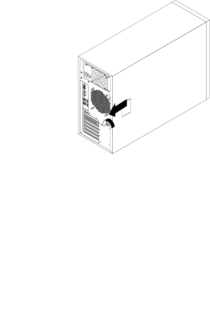
5.Loosenthethumbscrewthatsecurestheservercoverandthenslidetheservercovertotherearuntilit
isstopped.
Notes:
a.Theservercoverissecurelyinstalledandyouneedtouseatool,suchasascrewdriver,toloosen
thethumbscrewthatsecurestheservercover.Thethumbscrewisanintegratedpartoftheserver
coveranddonottrytoremovethethumbscrewfromtheservercover.
b.Itisrecommendedthatyouwaitthreetoveminutestolettheservercoolbeforeremovingthe
servercover.
Figure32.Slidingtheservercovertotherear
86ThinkServerHardwareMaintenanceManual
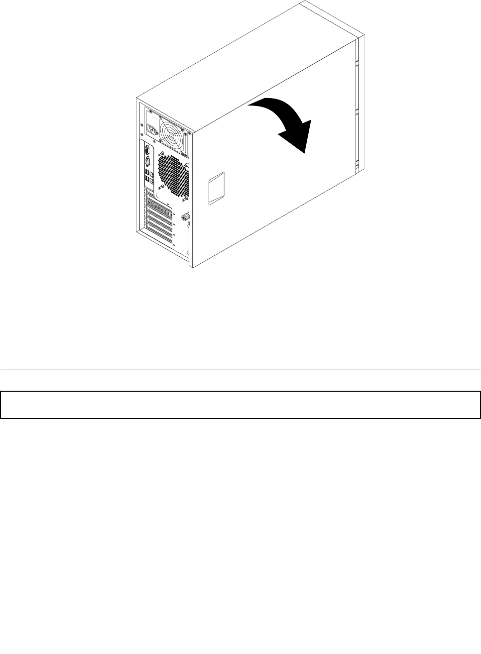
6.Pivottheservercoveroutwardtocompletelyremoveit.
Figure33.Removingtheservercover
Attention:Forpropercoolingandairow,installtheservercoverbeforeturningontheserver.Operatingthe
serverformorethan30minuteswiththeservercoverremovedmightdamageservercomponents.
Toreinstalltheservercover,see“Reinstallingtheservercoverandreconnectingcables”onpage168.
Removingandreinstallingthefrontbezel
Attention:Donotopenyourserverorattemptanyrepairbeforereadingandunderstandingthe“Safetyinformation”
onpageiiiand“Guidelines”onpage83.
Thistopicprovidesinstructionsonhowtoremoveandreinstallthefrontbezel.
Beforeyoubegin,printalltherelatedinstructionsorensurethatyoucanviewthePDFversiononanother
computerforreference.
Note:Dependingonthemodel,yourservermightlookslightlydifferentfromtheillustrationsinthistopic.
Toremoveandreinstallthefrontbezel,dothefollowing:
1.Removeallmediafromthedrivesandturnoffallattacheddevicesandtheserver.Then,disconnectall
powercordsfromelectricaloutletsanddisconnectallcablesthatareconnectedtotheserver.
2.Removetheservercover.See“Removingtheservercover”onpage85.
Chapter6.Installing,removing,orreplacinghardware87
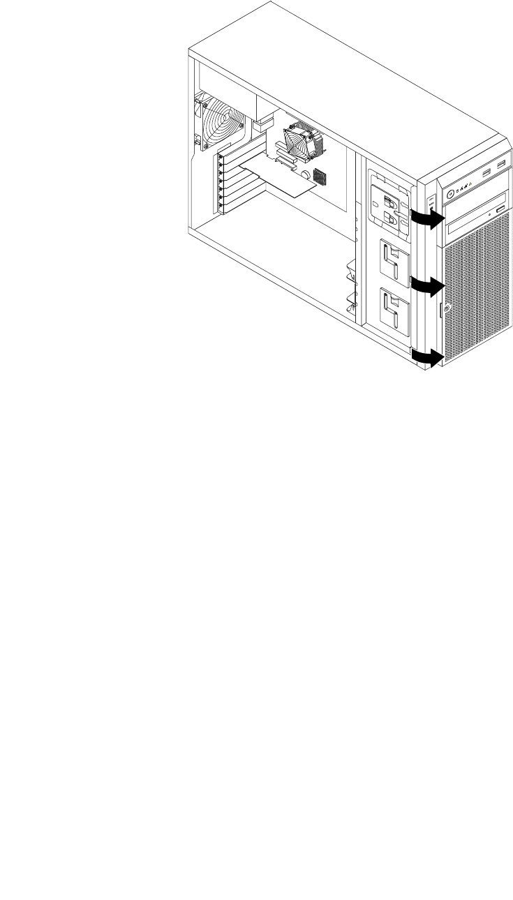
3.Removethefrontbezelbyreleasingthethreeplastictabsontheleftsideandpivotingthefrontbezel
outward.
Figure34.Removingthefrontbezel
88ThinkServerHardwareMaintenanceManual
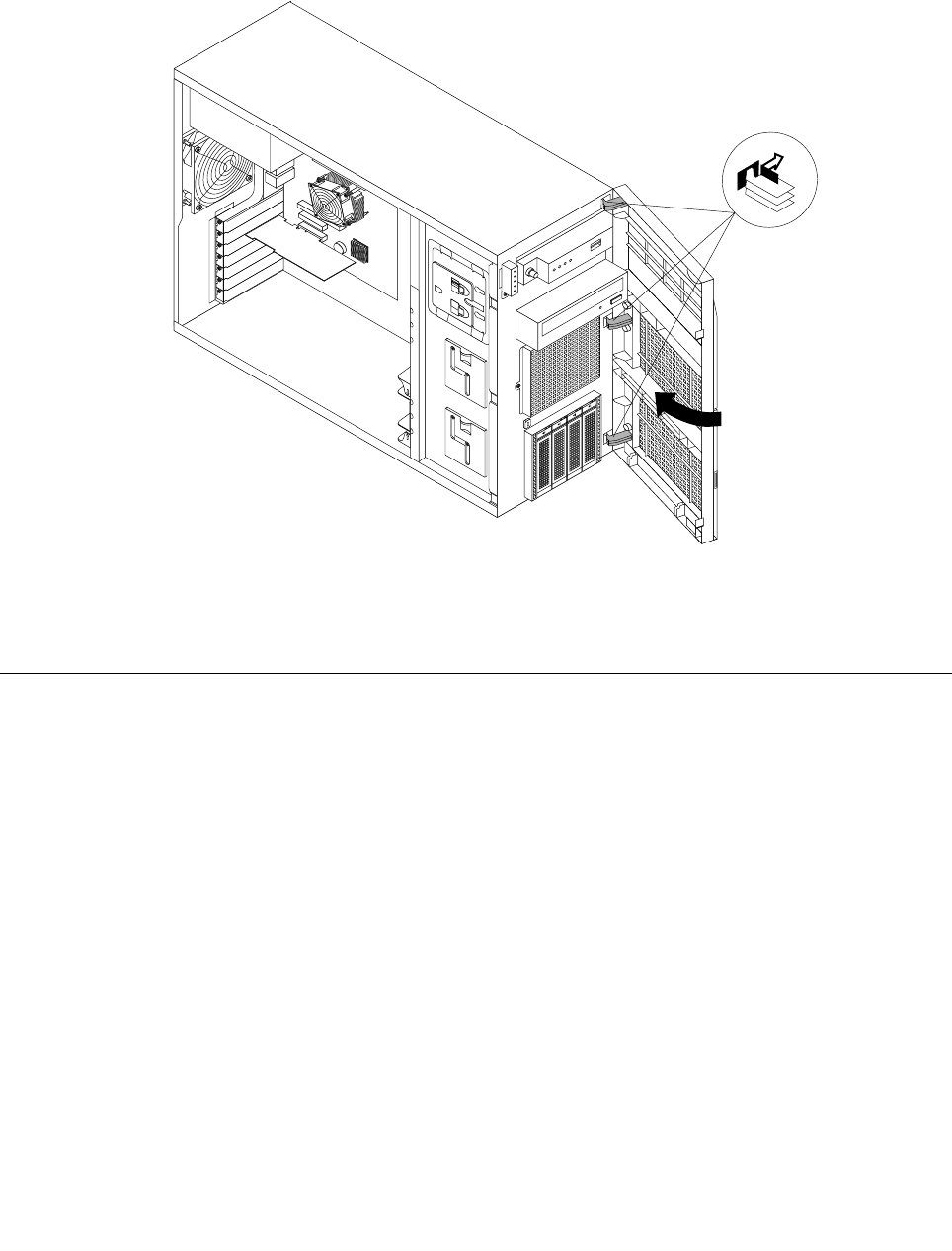
4.Toreinstallthefrontbezel,aligntheotherthreeplastictabsontherightsideofthefrontbezelwith
thecorrespondingholesinthechassis,thenpivotthefrontbezelinwarduntilitsnapsintoposition
ontheleftside.
Figure35.Installingthefrontbezel
5.Goto“Completingthepartsreplacement”onpage168.
Installing,removing,orreplacinghardware
Thistopicprovidesinstructionsonhowtoinstall,remove,orreplacehardwareforyourserver.Youcan
expandthecapabilitiesofyourserverbyaddingnewhardwaredevices,suchasmemorymodules,PCI
cards,orotherserveroptions,andmaintainyourserverbyreplacingthefailinghardwaredevices.
Ifyouarehandlingaserveroption,refertotheappropriateinstallationandorremovalinstructionsinthis
topicalongwiththeinstructionsthatcomewiththeoption.
Notes:
1.UseonlypartsprovidedbyLenovo.
2.Dependingonthemodel,yourservermightlookslightlydifferentfromtheillustrationsinthistopic.
Installingorremovingamemorymodule
Thistopicprovidesinstructionsonhowtoinstallorremoveamemorymodule.
ForalistoftheThinkServermemorymoduleoptions,gotohttp://www.lenovo.com/thinkserver.Clickthe
ProductstabandthenclickOptions➙ThinkServerMemorytoviewtheinformation.
Note:ThememorymodulesareextremelysensitivetoESD.Makesurethatyoureadandunderstand
“Handlingstatic-sensitivedevices”onpage84rstandcarefullyperformtheoperation.
Chapter6.Installing,removing,orreplacinghardware89
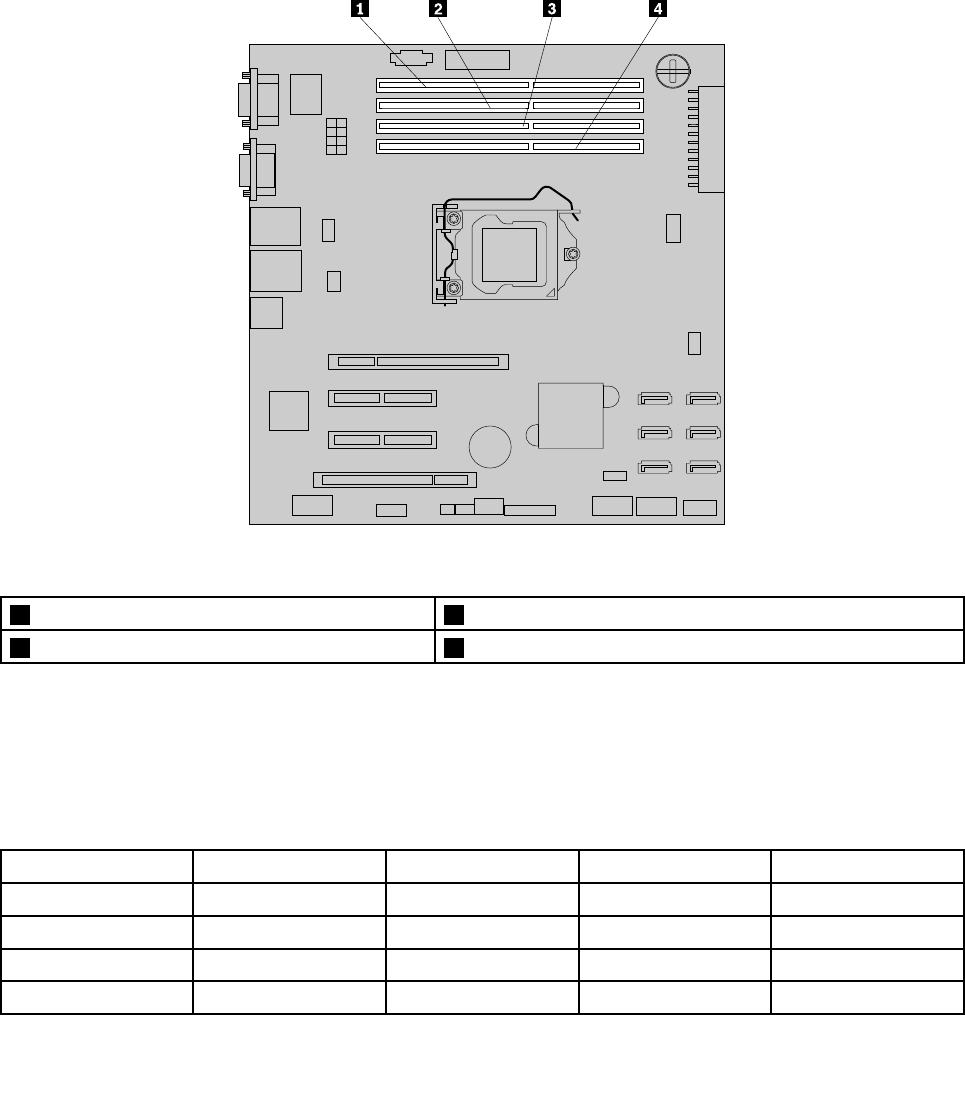
Memorymoduleinstallationrules
YourserverhasfourmemoryslotsforinstallingorreplacingDDR3UDIMMswithECCtechnology.
•Supports2GBand4GB1333MHzDDR3UDIMMs
•Single-rankordual-rank
•Minimumsystemmemory:2GB(onlyone2GBmemorymoduleinstalledintheDIMMA2slot)
•Maximumsystemmemory:16GB(one4GBmemorymoduleinstalledineachofthefourmemoryslots)
Thefollowingillustrationhelpsyoutolocatethememoryslotsonthesystemboard.
Figure36.Memoryslotsonthesystemboard
1Memoryslot4(DIMMB2)3Memoryslot2(DIMMA2)
2Memoryslot3(DIMMB1)4Memoryslot1(DIMMA1)
Thefollowingtableprovidesinformationaboutthememorymoduleinstallationrulesthatyoushould
considerwheninstallingorremovingamemorymodule.The“X”markindicatesthememoryslot(s)into
whichthememorymodule(s)shouldbeinstalledindifferentsituations.Thenumbers1,2,3,and4indicate
theinstallationsequence.
Note:Theinstalledmemorymodulesmustbethesametypewiththesamevoltageandfrequency.
UDIMMDIMMA1DIMMA2DIMMB1DIMMB2
OneUDIMMX
TwoUDIMMsX,1X,2
ThreeUDIMMsX,3X,1X,2
FourUDIMMsX,3X,1X,4X,2
90ThinkServerHardwareMaintenanceManual
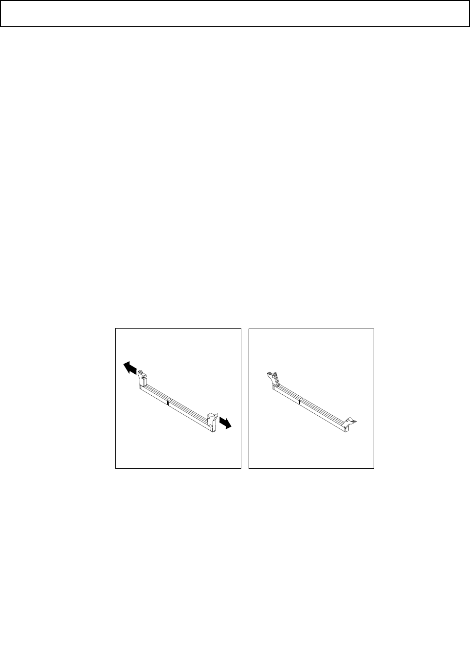
Installingamemorymodule
Attention:Donotopenyourserverorattemptanyrepairbeforereadingandunderstandingthe“Safetyinformation”
onpageiiiand“Guidelines”onpage83.
Thistopicprovidesinstructionsonhowtoinstallamemorymodule.
Beforeyoubegin,printalltherelatedinstructionsorensurethatyoucanviewthePDFversiononanother
computerforreference.
Notes:
1.Tooptimizesystemperformance,makesurethatyouconsiderandfollowthememorymodule
installationruleswhenperformingtheoperation.See“Memorymoduleinstallationrules”onpage90.
2.Useanydocumentationthatcomeswiththememorymoduleandfollowthoseinstructionsinadditionto
theinstructionsinthistopic.
Toinstallamemorymodule,dothefollowing:
1.Removeallmediafromthedrivesandturnoffallattacheddevicesandtheserver.Then,disconnectall
powercordsfromelectricaloutletsanddisconnectallcablesthatareconnectedtotheserver.
2.Removetheservercover.See“Removingtheservercover”onpage85.
3.Laytheserveronitssideforeasieroperation.
4.Locatethememoryslotsonthesystemboard.See“Systemboardcomponents”onpage42.
5.Removeanypartsordisconnectanycablesthatmightpreventyouraccesstothememoryslots.
6.Opentheretainingclipsoftheappropriatememoryslot.See“Memorymoduleinstallationrules”on
page90fortheinstallationsequenceinformation.
Figure37.Openingtheretainingclipsofthememoryslots
7.Touchthestatic-protectivepackagethatcontainsthenewmemorymoduletoanyunpaintedsurfaceon
theoutsideoftheserver.Then,takethenewmemorymoduleoutofthepackage.
Note:Carefullyhandlethememorymodulebyitsedges.
Chapter6.Installing,removing,orreplacinghardware91
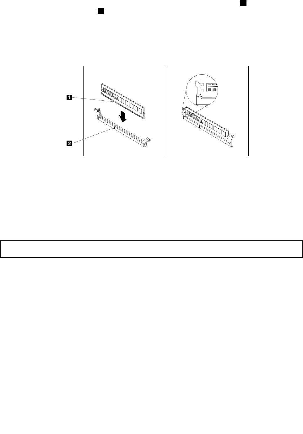
8.Positionthenewmemorymoduleoverthememoryslot.Makesurethatthenotch1onthenewmemory
moduleisalignedwiththekey2inthememoryslot.Then,pressthenewmemorymodulestraightdown
intothememoryslotuntiltheretainingclipscloseandthenewmemorymodulesnapsintoposition.
Note:Ifthereisagapbetweenthememorymoduleandtheretainingclips,thememorymodulehas
notbeencorrectlyinstalled.Opentheretainingclips,removethememorymodule,andthenreinstallit
intothememoryslotuntiltheretainingclipsarecompletelyclosed.
Figure38.Installingamemorymodule
9.Reinstallanypartsorreconnectanycablesyouhaveremoved.
Whattodonext:
•Toworkwithanotherpieceofhardware,gototheappropriatesection.
•Tocompletetheinstallation,goto“Completingthepartsreplacement”onpage168.
Removingamemorymodule
Attention:Donotopenyourserverorattemptanyrepairbeforereadingandunderstandingthe“Safetyinformation”
onpageiiiand“Guidelines”onpage83.
Thistopicprovidesinstructionsonhowtoremoveamemorymodule.
Beforeyoubegin,printalltherelatedinstructionsorensurethatyoucanviewthePDFversiononanother
computerforreference.
Note:Tooptimizesystemperformance,makesurethatyouconsiderandfollowthememorymodule
installationruleswhenperformingtheoperation.See“Memorymoduleinstallationrules”onpage90.
Toremoveamemorymodule,dothefollowing:
1.Removeallmediafromthedrivesandturnoffallattacheddevicesandtheserver.Then,disconnectall
powercordsfromelectricaloutletsanddisconnectallcablesthatareconnectedtotheserver.
2.Removetheservercover.See“Removingtheservercover”onpage85.
3.Laytheserveronitssideforeasieroperation.
4.Locatethememoryslotsonthesystemboard.See“Systemboardcomponents”onpage42.
5.Removeanypartsordisconnectanycablesthatmightpreventyouraccesstothememoryslots.
92ThinkServerHardwareMaintenanceManual
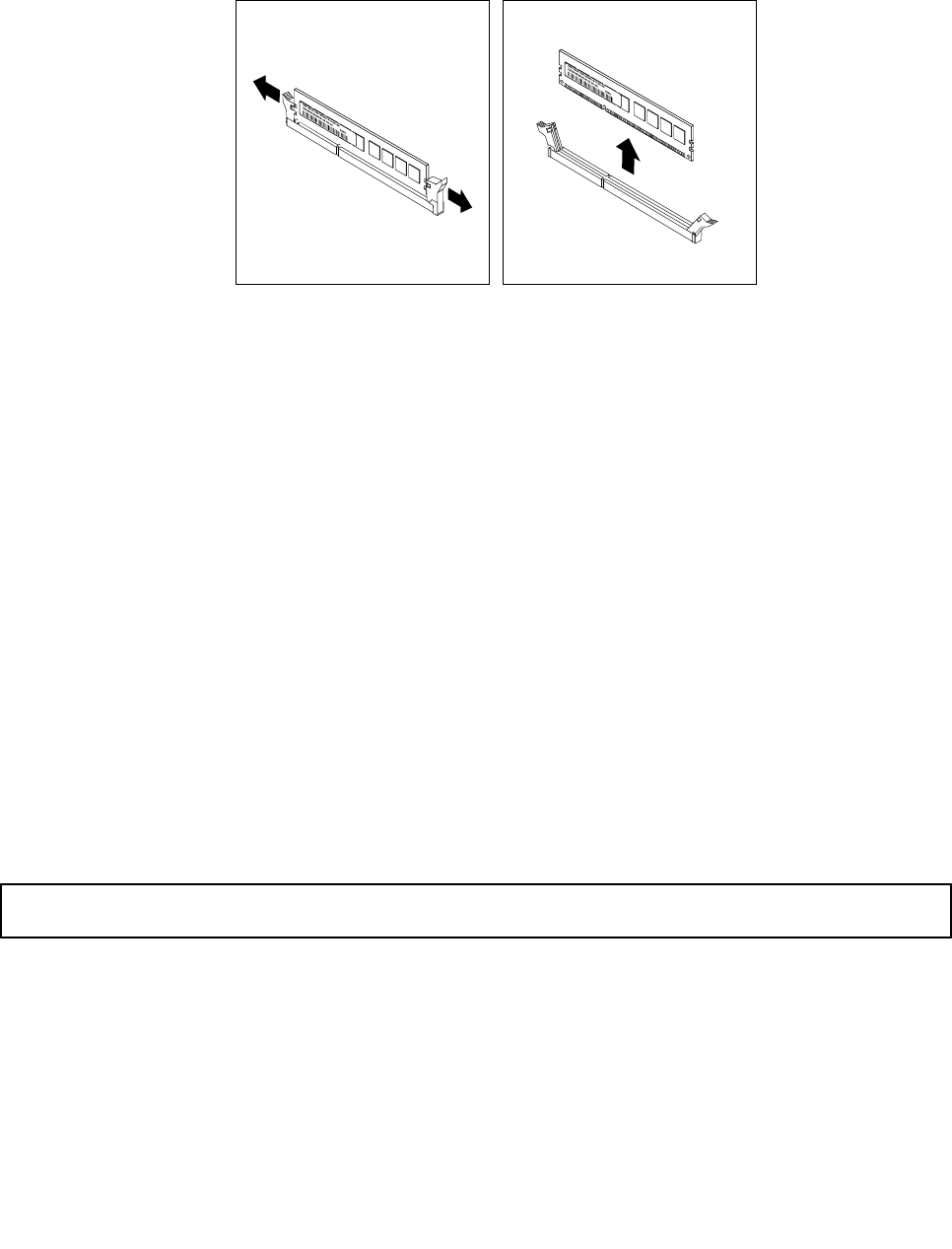
6.Locatetheappropriatememorymodulethatyouwanttoremoveandopentheretainingclipsonboth
endsofthememoryslot.Then,graspthememorymodulebyitsedgesandcarefullypullitstraight
uptoremoveitfromthememoryslot.
Figure39.Removingamemorymodule
7.Ifyouareinstructedtoreturntheoldmemorymodule,followallpackaginginstructionsanduseany
packagingmaterialsthataresuppliedtoyouforshipping.
Whattodonext:
•Toworkwithanotherpieceofhardware,gototheappropriatesection.
•Tocompletetheremovalprocedure,goto“Completingthepartsreplacement”onpage168.
InstallingorremovingaPCIcard
ThistopicprovidesinstructionsonhowtoinstallorremoveaPCIcard.
TheEMIintegrityandcoolingoftheserverareprotectedbyhavingalldrivebaysandPCIcardslotscovered
oroccupied.WhenyouinstallaninternaldriveorPCIcard,savetheEMIshieldordrivebayllerfromthe
drivebayorsavethePCIcardslotbracketintheeventthatyoulaterremovethedevice.
Attention:AnunoccupieddrivebayorPCIcardslotwithoutcover,shield,ller,oranyotherprotectionmight
impacttheEMIintegrityandcoolingoftheserver,whichmightresultinoverheatingorcomponentdamage.
Note:ThePCIcardsareextremelysensitivetoESD.Makesurethatyoureadandunderstand“Handling
static-sensitivedevices”onpage84rstandcarefullyperformtheoperation.
InstallingaPCIcard
Attention:Donotopenyourserverorattemptanyrepairbeforereadingandunderstandingthe“Safetyinformation”
onpageiiiand“Guidelines”onpage83.
ThistopicprovidesinstructionsonhowtoinstallaPCIcard.
Beforeyoubegin,printalltherelatedinstructionsorensurethatyoucanviewthePDFversiononanother
computerforreference.
Note:UseanydocumentationthatcomeswiththePCIcardandfollowthoseinstructionsinadditionto
theinstructionsinthistopic.
ToinstallaPCIcard,dothefollowing:
Chapter6.Installing,removing,orreplacinghardware93
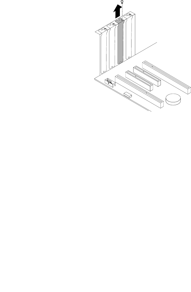
1.Removeallmediafromthedrivesandturnoffallattacheddevicesandtheserver.Then,disconnectall
powercordsfromelectricaloutletsanddisconnectallcablesthatareconnectedtotheserver.
2.Removetheservercover.See“Removingtheservercover”onpage85.
3.Laytheserveronitssideforeasieroperation.
4.LocateanappropriatePCIcardslotonthesystemboard.See“Systemboardcomponents”onpage
42toidentifythedifferenttypesofPCIcardslotsinyourserver.
5.RemovethePCIcardslotbracketbyremovingthescrewthatsecuresthemetalbracketandthenlifting
thebracketoutofthechassis.StorethePCIcardslotbracketintheeventthatyoulaterremovethePCI
cardandneedthebrackettocovertheplace.
Note:Carefullyplacetheremovedscrewaside.YouwillneedthescrewlatertosecurethePCIcardin
place.
Figure40.RemovingaPCIcardslotbracket
6.Touchthestatic-protectivepackagethatcontainsthenewPCIcardtoanyunpaintedsurfaceonthe
outsideoftheserver.Then,takethenewPCIcardoutofthepackage.
Note:CarefullyhandlethePCIcardbyitsedges.
94ThinkServerHardwareMaintenanceManual
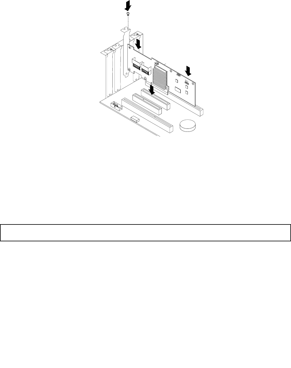
7.PositionthenewPCIcardonthePCIcardslotforwhichyouhaveremovedtheslotbracketandthen
carefullypressthePCIcardstraightdownuntilitissecurelyseatedintheslot.Installthescrewto
securethePCIcardinplace.
Note:YourPCIcardmightlookdifferentfromthefollowingillustrationdependingonthespecictype.
Figure41.InstallingaPCIcard
8.DependingonthetypeofthePCIcard,youmightneedtoconnectanyrequiredcables.Refertothe
documentationthatcomeswiththePCIcardforspecicinformation.
Whattodonext:
•Toworkwithanotherpieceofhardware,gototheappropriatesection.
•Tocompletetheinstallation,goto“Completingthepartsreplacement”onpage168.
RemovingaPCIcard
Attention:Donotopenyourserverorattemptanyrepairbeforereadingandunderstandingthe“Safetyinformation”
onpageiiiand“Guidelines”onpage83.
ThistopicprovidesinstructionsonhowtoremoveaPCIcard.
Beforeyoubegin,printalltherelatedinstructionsorensurethatyoucanviewthePDFversiononanother
computerforreference.
Note:UseanydocumentationthatcomeswiththePCIcardandfollowthoseinstructionsinadditionto
theinstructionsinthistopic.
ToremoveaPCIcard,dothefollowing:
1.Removeallmediafromthedrivesandturnoffallattacheddevicesandtheserver.Then,disconnectall
powercordsfromelectricaloutletsanddisconnectallcablesthatareconnectedtotheserver.
2.Removetheservercover.See“Removingtheservercover”onpage85.
3.Laytheserveronitssideforeasieroperation.
Chapter6.Installing,removing,orreplacinghardware95
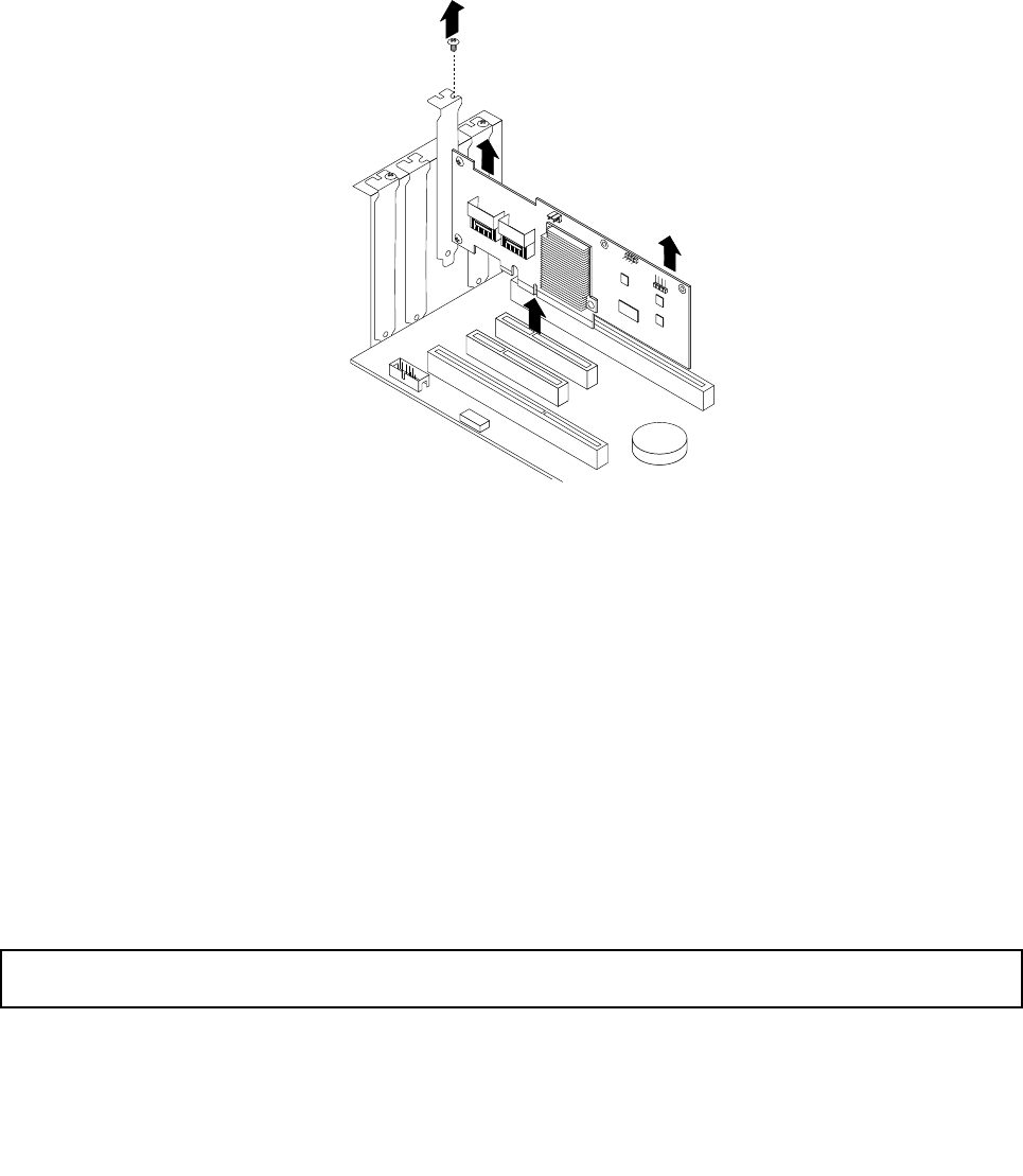
4.LocatethePCIcardyouwanttoremove.See“Systemboardcomponents”onpage42.
5.Ifnecessary,removeanypartsordisconnectanycablesthatmightimpedeyouraccesstothePCIcard.
DependingonthetypeofthePCIcard,youmightalsoneedtodisconnectanycablesfromthePCI
card,thesystemboard,andorthehot-swapharddiskdrivebackplane.
6.RemovethescrewthatsecuresthePCIcard.Then,graspthePCIcardbyitsedgesandcarefully
pullitoutofthePCIcardslot.
Note:ThePCIcardtstightlyintothePCIcardslot.Ifnecessary,alternatemovingeachsideofthePCI
cardasmallandequalamountuntilitiscompletelyremovedfromtheslot.
Figure42.RemovingaPCIcard
7.InstallanewPCIcardtoreplacetheoldoneorinstallaPCIcardslotbrackettocovertheplace.
See“InstallingaPCIcard”onpage93.
8.IfyouareinstructedtoreturntheoldPCIcard,followallpackaginginstructionsanduseanypackaging
materialsthataresuppliedtoyouforshipping.
Whattodonext:
•Toworkwithanotherpieceofhardware,gototheappropriatesection.
•Tocompletetheremovalprocedure,goto“Completingthepartsreplacement”onpage168.
InstallingorremovingtheEthernetcard
ThistopicprovidesinstructionsonhowtoinstallorremovetheEthernetcard.
InstallingtheEthernetcard
Attention:Donotopenyourserverorattemptanyrepairbeforereadingandunderstandingthe“Safetyinformation”
onpageiiiand“Guidelines”onpage83.
ThistopicprovidesinstructionsonhowtoinstalltheEthernetcardandhowtoinstalltheEthernetcard
driveronWindowsoperatingsystems.
96ThinkServerHardwareMaintenanceManual
Beforeyoubegin,printalltherelatedinstructionsorensurethatyoucanviewthePDFversiononanother
computerforreference.
Note:UseanydocumentationthatcomeswiththeEthernetcardandfollowthoseinstructionsinadditionto
theinstructionsinthistopic.
ToinstalltheEthernetcard,dothefollowing:
1.Removeallmediafromthedrivesandturnoffallattacheddevicesandtheserver.Then,disconnectall
powercordsfromelectricaloutletsanddisconnectallcablesthatareconnectedtotheserver.
2.Removetheservercover.See“Removingtheservercover”onpage85.
3.Laytheserveronitssideforeasieroperation.
4.LocateanappropriatePCIcardslotonthesystemboardforinstallingtheEthernetcard.Youcan
installtheEthernetcardtothePCI-Eslot2orPCI-Eslot3thatsupportsacardwith167mm(6.57
inches)inlength.See“Systemboardcomponents”onpage42toidentifythedifferenttypesofPCI
cardslotsinyourserver.
5.Removeanypartsordisconnectanycablesthatmightimpedeyouroperation.
6.Touchthestatic-protectivepackagethatcontainstheEthernetcardtoanyunpaintedsurfaceonthe
outsideoftheserver.Then,taketheEthernetcardoutofthepackage.
Note:CarefullyhandletheEthernetcardbyitsedges.
7.TheEthernetcardisakindofPCIcard.See“InstallingaPCIcard”onpage93andfollowthose
instructionstoinstalltheEthernetcard.
Whattodonext:
•Toworkwithanotherpieceofhardware,gototheappropriatesection.
•Tocompletetheinstallation,goto“Completingthepartsreplacement”onpage168.Then,continuewith
thefollowingproceduretoinstalltheEthernetcarddriverifyouareusingaWindowsoperatingsystem.
OnLinuxoperatingsystems,youdonotneedtoinstallanydevicedriverfortheEthernetcard.
OnWindowsoperatingsystems,dothefollowingtoinstallthedevicedriverfortheEthernetcard:
1.Saveanyopendocumentsandexitallapplications.
2.ClickStart.Rright-clickMyComputerandselectProperties.TheSystemPropertieswindowopens.
3.ClicktheDeviceManagerbuttonontheHardwaretab.TheDeviceManagerwindowopens.
4.ExpandtheNetworkadapters.
5.Right-clickoneoftheEthernetcards(PRO/1000PTortheyellowquestionmark).
6.SelectUpdateDriver.TheHardwareUpdateWizardwindowopens.Youwillbeaskedifyoupermit
WindowstoconnecttoWindowsUpdatetosearchforsoftware.
7.MakeaselectiondependingonyourneedsandclickNext.
8.InserttheThinkServerEasyStartupDVDthatcomeswithyourserverintotheopticaldrive.
Note:YoudonotneedtousethedriverdiscthatcomeswiththeEthernetcard.
9.SelectInstallthesoftwareautomatically(Recommended)andclickNexttocontinue.
10.Followtheinstructionsonthescreentocompletetheinstallation.
RemovingtheEthernetcard
Attention:Donotopenyourserverorattemptanyrepairbeforereadingandunderstandingthe“Safetyinformation”
onpageiiiand“Guidelines”onpage83.
Chapter6.Installing,removing,orreplacinghardware97

ThistopicprovidesinstructionsonhowtoremovetheEthernetcard.
Beforeyoubegin,printalltherelatedinstructionsorensurethatyoucanviewthePDFversiononanother
computerforreference.
Note:UseanydocumentationthatcomeswiththeEthernetcardandfollowthoseinstructionsinadditionto
theinstructionsinthistopic.
ToremovetheEthernetcard,dothefollowing:
1.Removeallmediafromthedrivesandturnoffallattacheddevicesandtheserver.Then,disconnectall
powercordsfromelectricaloutletsanddisconnectallcablesthatareconnectedtotheserver.
2.Removetheservercover.See“Removingtheservercover”onpage85.
3.Laytheserveronitssideforeasieroperation.
4.LocatetheEthernetcard.TheEthernetcardcanbeinthePCI-Eslot2orthePCI-Eslot3thatsupports
acardwith167mm(6.57inches)inlength.See“Systemboardcomponents”onpage42.
5.TheEthernetcardisakindofPCIcard.See“RemovingaPCIcard”onpage95andfollowthose
instructionstoremovetheEthernetcard.
6.IfyouareinstructedtoreturntheoldEthernetcard,followallpackaginginstructionsanduseany
packagingmaterialsthataresuppliedtoyouforshipping.
Whattodonext:
•Toworkwithanotherpieceofhardware,gototheappropriatesection.
•Tocompletetheremovalprocedure,goto“Completingthepartsreplacement”onpage168.
InstallingorremovingtheRAIDcard
ThistopicprovidesinstructionsonhowtoinstallorremovetheRAIDcard.
AspecicRAIDcardisrequiredforservermodelswithmorethanfourharddiskdrivesormodelsthatuse
SASharddiskdrives.YoucanalsoinstalltheRAIDcardforadvancedSATA/SAShardwareRAIDfunctions.
Formoreinformation,see“RAIDcard”onpage33and“ConguringRAID”onpage71.
Note:ThistopicappliesonlytomodelsthatsupporttheRAIDcard.
InstallingtheRAIDcard
Attention:Donotopenyourserverorattemptanyrepairbeforereadingandunderstandingthe“Safetyinformation”
onpageiiiand“Guidelines”onpage83.
ThistopicprovidesinstructionsonhowtoinstalltheRAIDcard.
Attention:MakesurethatyoubackupyourdatabeforeinstallingtheRAIDcardbecauseyoumightneedto
recongureRAIDandreinstalltheoperatingsystemafterinstallingtheRAIDcard.
Beforeyoubegin,printalltherelatedinstructionsorensurethatyoucanviewthePDFversiononanother
computerforreference.
Note:UseanydocumentationthatcomeswiththeRAIDcardandfollowthoseinstructionsinadditionto
theinstructionsinthistopic.
ToinstalltheRAIDcard,dothefollowing:
1.Removeallmediafromthedrivesandturnoffallattacheddevicesandtheserver.Then,disconnectall
powercordsfromelectricaloutletsanddisconnectallcablesthatareconnectedtotheserver.
98ThinkServerHardwareMaintenanceManual

2.Removetheservercover.See“Removingtheservercover”onpage85.
3.Laytheserveronitssideforeasieroperation.
4.LocatethePCI-Eslot3onthesystemboard.See“Systemboardcomponents”onpage42.
5.Removeanypartsordisconnectanycablesthatmightimpedeyouroperation.
6.Touchthestatic-protectivepackagethatcontainstheRAIDcardtoanyunpaintedsurfaceonthe
outsideoftheserver.Then,taketheRAIDcardoutofthepackage.
Note:CarefullyhandletheRAIDcardbyitsedges.
7.TheRAIDcardisakindofPCIcard.See“InstallingaPCIcard”onpage93andfollowthoseinstructions
toinstalltheRAIDcard.
8.Connectcablesdependingonyourspecicserverconguration.See“Connectingcables”onpage38.
Whattodonext:
•Toworkwithanotherpieceofhardware,gototheappropriatesection.
•Tocompletetheinstallation,goto“Completingthepartsreplacement”onpage168.Then,congure
RAIDforyourserver.See“ConguringRAID”onpage71.
RemovingtheRAIDcard
Attention:Donotopenyourserverorattemptanyrepairbeforereadingandunderstandingthe“Safetyinformation”
onpageiiiand“Guidelines”onpage83.
ThistopicprovidesinstructionsonhowtoremovetheRAIDcard.
Attention:MakesurethatyoubackupyourdatabeforeremovingtheRAIDcardbecauseyoumightneedto
recongureRAIDandreinstalltheoperatingsystemafterremovingtheRAIDcard.IfyouremovetheRAID
card,youwilllosetheadvancedSATA/SAShardwareRAIDfunctions.Also,aspecicRAIDcardisrequired
forservermodelswithmorethanfourharddiskdrivesormodelsthatuseSASharddiskdrives.
Beforeyoubegin,printalltherelatedinstructionsorensurethatyoucanviewthePDFversiononanother
computerforreference.
Note:UseanydocumentationthatcomeswiththeRAIDcardandfollowthoseinstructionsinadditionto
theinstructionsinthistopic.
ToremovetheRAIDcard,dothefollowing:
1.Removeallmediafromthedrivesandturnoffallattacheddevicesandtheserver.Then,disconnectall
powercordsfromelectricaloutletsanddisconnectallcablesthatareconnectedtotheserver.
2.Removetheservercover.See“Removingtheservercover”onpage85.
3.Laytheserveronitssideforeasieroperation.
4.LocatetheRAIDcard,whichisinstalledinthePCI-Eslot3onthesystemboard.See“Systemboard
components”onpage42.
5.Removeanypartsordisconnectanycablesthatmightimpedeyouroperation.
6.DisconnectallcablesfromtheRAIDcardandanyotherrelatedparts.
Note:IfyouwanttoinstallanewRAIDcardafterremovingtheoldone,notedownthecable
connectionsbeforedisconnectingthecables.
7.TheRAIDcardisakindofPCIcard.See“RemovingaPCIcard”onpage95andfollowthose
instructionstoremovetheRAIDcard.
Note:CarefullyhandletheRAIDcardbyitsedges.
Chapter6.Installing,removing,orreplacinghardware99

8.Dependingonyourspecicserverconguration,youmightneedtoconnecttheSATAharddiskdrives
totheSATAconnectorsonthesystemboardifnoRAIDcardisinstalled.See“Connectingcables”
onpage38.
9.IfyouareinstructedtoreturntheoldRAIDcard,followallpackaginginstructionsanduseanypackaging
materialsthataresuppliedtoyouforshipping.
Whattodonext:
•Toworkwithanotherpieceofhardware,gototheappropriatesection.
•Tocompletetheremovalprocedure,goto“Completingthepartsreplacement”onpage168.Then,you
needtorecongureRAIDforyourserver.See“ConguringRAID”onpage71.
InstallingorremovingtheThinkServer9240-8iRAID5UpgradeKey
ThistopicprovidesinstructionsonhowtoinstallorremovetheThinkServer9240-8iRAID5UpgradeKey
(hereinafterreferredtoastheRAID5key).
TheRAID5keyexpandsthecapabilityoftheinstalledRAIDcard(ThinkServer9240-8iRAID0/1Adapter)
byactivatingRAID5and50levelsforadvancedSATA/SAShardwareRAID.YoucanpurchaseaRAID5
keydirectlyfromLenovo.
InstallingtheRAID5keyontheRAIDcard
Attention:Donotopenyourserverorattemptanyrepairbeforereadingandunderstandingthe“Safetyinformation”
onpageiiiand“Guidelines”onpage83.
ThistopicprovidesinstructionsonhowtoinstalltheRAID5keyontheRAIDcard.
Note:ThistopicappliesonlytomodelsthathaveaRAIDcardinstalled.
Beforeyoubegin,printalltherelatedinstructionsorensurethatyoucanviewthePDFversiononanother
computerforreference.
Note:UseanydocumentationthatcomeswiththeRAID5keyandfollowthoseinstructionsinadditionto
theinstructionsinthistopic.
ToinstalltheRAID5keyontheRAIDcard,dothefollowing:
1.Removeallmediafromthedrivesandturnoffallattacheddevicesandtheserver.Then,disconnectall
powercordsfromelectricaloutletsanddisconnectallcablesthatareconnectedtotheserver.
2.Removetheservercover.See“Removingtheservercover”onpage85.
3.Laytheserveronitssideforeasieroperation.
4.LocatetheRAIDcard,whichisinstalledinthePCI-Eslot3onthesystemboard.See“Systemboard
components”onpage42.
5.Removeanypartsordisconnectanycablesthatmightimpedeyouroperation.
6.Touchthestatic-protectivepackagethatcontainstheRAID5keytoanyunpaintedsurfaceonthe
outsideoftheserver.Then,taketheRAID5keyoutofthepackage.
Note:CarefullyhandletheRAID5keybyitsedges.
100ThinkServerHardwareMaintenanceManual
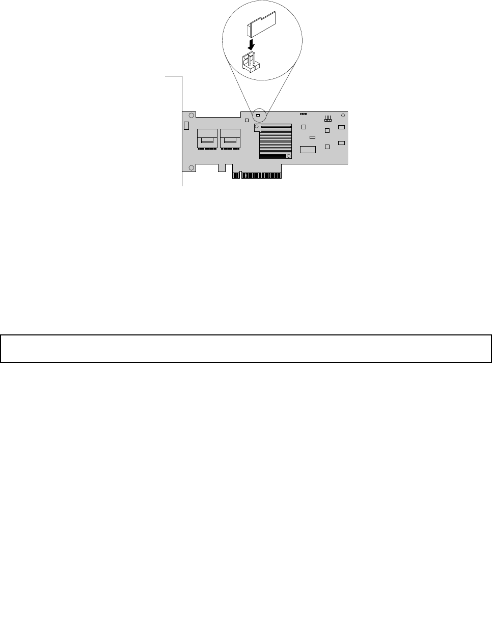
7.LocatetheRAID5keyconnectorontheRAIDcardandtheninserttheRAID5keyintotheconnector.
YoumightwanttoremovetheRAIDcardrst,installtheRAID5keyontheRAIDcard,andthenreinstall
theRAIDcard.See“InstallingorremovingtheRAIDcard”onpage98.
Note:MakesurethattheRAID5keyissecurelyseatedontheRAIDcard.
Figure43.InstallingtheRAID5keyontheRAIDcard
Whattodonext:
•Toworkwithanotherpieceofhardware,gototheappropriatesection.
•Tocompletetheinstallation,goto“Completingthepartsreplacement”onpage168.Then,thehardware
RAID5and50levelsareavailableforyourserverifyourserverhastherequirednumberofharddisk
drivesinstalled.RefertotheMegaRAIDSASSoftwareUserGuideonthedocumentationDVDthatcomes
withyourserverforinformationabouthowtocongurethehardwareRAID.
RemovingtheRAID5keyfromtheRAIDcard
Attention:Donotopenyourserverorattemptanyrepairbeforereadingandunderstandingthe“Safetyinformation”
onpageiiiand“Guidelines”onpage83.
ThistopicprovidesinstructionsonhowtoremovetheRAID5keyfromtheRAIDcard.
Notes:
1.ThistopicappliesonlytoservermodelsthathaveaRAIDcardwiththeRAID5keyoptioninstalled.
2.IfyouremovetheRAID5keyfromtheRAIDcard,thehardwareRAID5and50levelsarenotavailable.
Beforeyoubegin,printalltherelatedinstructionsorensurethatyoucanviewthePDFversiononanother
computerforreference.
Note:UseanydocumentationthatcomeswiththeRAID5keyandfollowthoseinstructionsinadditionto
theinstructionsinthistopic.
ToremovetheRAID5keyfromtheRAIDcard,dothefollowing:
1.Removeallmediafromthedrivesandturnoffallattacheddevicesandtheserver.Then,disconnectall
powercordsfromelectricaloutletsanddisconnectallcablesthatareconnectedtotheserver.
2.Removetheservercover.See“Removingtheservercover”onpage85.
Chapter6.Installing,removing,orreplacinghardware101
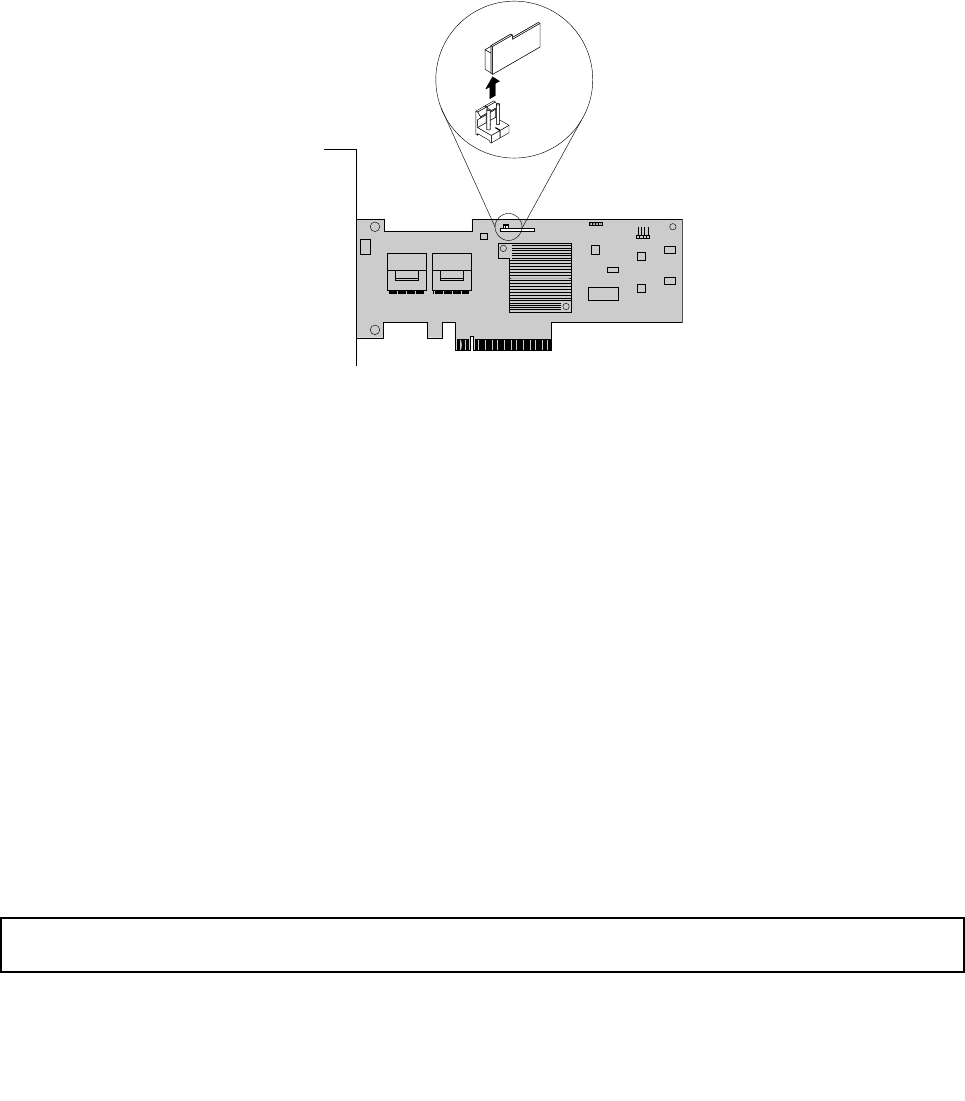
3.Laytheserveronitssideforeasieroperation.
4.LocatetheRAIDcard,whichisinstalledinthePCI-Eslot3onthesystemboard.See“Systemboard
components”onpage42.
5.Removeanypartsordisconnectanycablesthatmightimpedeyouroperation.
6.LocatetheRAID5keyontheRAIDcardandthenremoveitfromtheRAIDcard.Youmightneedto
removetheRAIDcardrst,removetheRAID5keyfromtheRAIDcard,andthenreinstalltheRAIDcard.
See“InstallingorremovingtheRAIDcard”onpage98.
Note:CarefullyhandletheRAID5keybyitsedges.
Figure44.RemovingtheRAID5keyfromtheRAIDcard
7.IfyouareinstructedtoreturntheoldRAID5key,followallpackaginginstructionsanduseany
packagingmaterialsthataresuppliedtoyouforshipping.
Whattodonext:
•Toworkwithanotherpieceofhardware,gototheappropriatesection.
•Tocompletetheremovalprocedure,goto“Completingthepartsreplacement”onpage168.Asthe
hardwareRAID5and50levelsarenotavailablewithouttheRAID5key,youmightneedtorecongure
RAIDforyourserver.RefertotheMegaRAIDSASSoftwareUserGuideonthedocumentationDVDthat
comeswithyourserverforinformationabouthowtocongurethehardwareRAID.
InstallingorremovingtheThinkServerSATASoftwareRAID5Key
ThistopicprovidesinstructionsonhowtoinstallorremovetheThinkServerSATASoftwareRAID5Key
(hereinafterreferredtoasthesystemboardRAID5key).
ThesystemboardRAID5keyexpandsthecapabilityofthesystemboardbyactivatingRAID5forthe
onboardSATAsoftwareRAID.YoucanpurchaseasystemboardRAID5keydirectlyfromLenovo.
InstallingthesystemboardRAID5key
Attention:Donotopenyourserverorattemptanyrepairbeforereadingandunderstandingthe“Safetyinformation”
onpageiiiand“Guidelines”onpage83.
ThistopicprovidesinstructionsonhowtoinstallthesystemboardRAID5key.
102ThinkServerHardwareMaintenanceManual
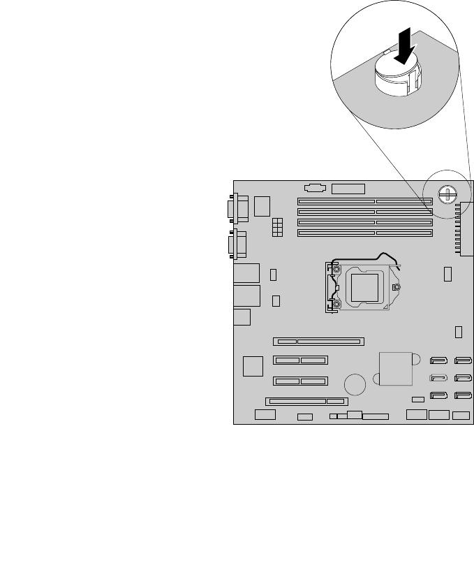
Beforeyoubegin,printalltherelatedinstructionsorensurethatyoucanviewthePDFversiononanother
computerforreference.
Note:UseanydocumentationthatcomeswiththesystemboardRAID5keyandfollowthoseinstructionsin
additiontotheinstructionsinthistopic.
ToinstallthesystemboardRAID5key,dothefollowing:
1.Removeallmediafromthedrivesandturnoffallattacheddevicesandtheserver.Then,disconnectall
powercordsfromelectricaloutletsanddisconnectallcablesthatareconnectedtotheserver.
2.Removetheservercover.See“Removingtheservercover”onpage85.
3.Laytheserveronitssideforeasieroperation.
4.Touchthestatic-protectivepackagethatcontainsthesystemboardRAID5keytoanyunpainted
surfaceontheoutsideoftheserver.Then,takethesystemboardRAID5keyoutofthepackage.
5.LocatetheiButtonsocketonthesystemboard.InsertonesideofthesystemboardRAID5keyunder
oneoftheretainingclipsontheiButtonsocket.Then,carefullypresstheothersideofthesystem
boardRAID5keystraightdownuntilthekeysnapsintopositionandissecuredbythetworetaining
clipsontheiButtonsocket.
Note:Ifnecessary,removeanypartsordisconnectanycablesthatmightimpedeyouroperation.
Figure45.InstallingthesystemboardRAID5key
Whattodonext:
•Toworkwithanotherpieceofhardware,gototheappropriatesection.
Chapter6.Installing,removing,orreplacinghardware103

•Tocompletetheinstallation,goto“Completingthepartsreplacement”onpage168.Then,theonboard
SATAsoftwareRAID5isavailableforyourserverifyourserverhastherequirednumberofharddisk
drivesinstalled.TocongureRAID,see“ConguringRAID”onpage71.
RemovingthesystemboardRAID5key
Attention:Donotopenyourserverorattemptanyrepairbeforereadingandunderstandingthe“Safetyinformation”
onpageiiiand“Guidelines”onpage83.
ThistopicprovidesinstructionsonhowtoremovethesystemboardRAID5key.
Notes:
1.ThistopicappliesonlytoserversthathaveasystemboardRAID5keyoptioninstalled.
2.IfyouremovethesystemboardRAID5key,theonboardSATAsoftwareRAID5willbedisabled.
Beforeyoubegin,printalltherelatedinstructionsorensurethatyoucanviewthePDFversiononanother
computerforreference.
Note:UseanydocumentationthatcomeswiththesystemboardRAID5keyandfollowthoseinstructionsin
additiontotheinstructionsinthistopic.
ToremovethesystemboardRAID5key,dothefollowing:
1.Removeallmediafromthedrivesandturnoffallattacheddevicesandtheserver.Then,disconnectall
powercordsfromelectricaloutletsanddisconnectallcablesthatareconnectedtotheserver.
2.Removetheservercover.See“Removingtheservercover”onpage85.
3.Laytheserveronitssideforeasieroperation.
104ThinkServerHardwareMaintenanceManual
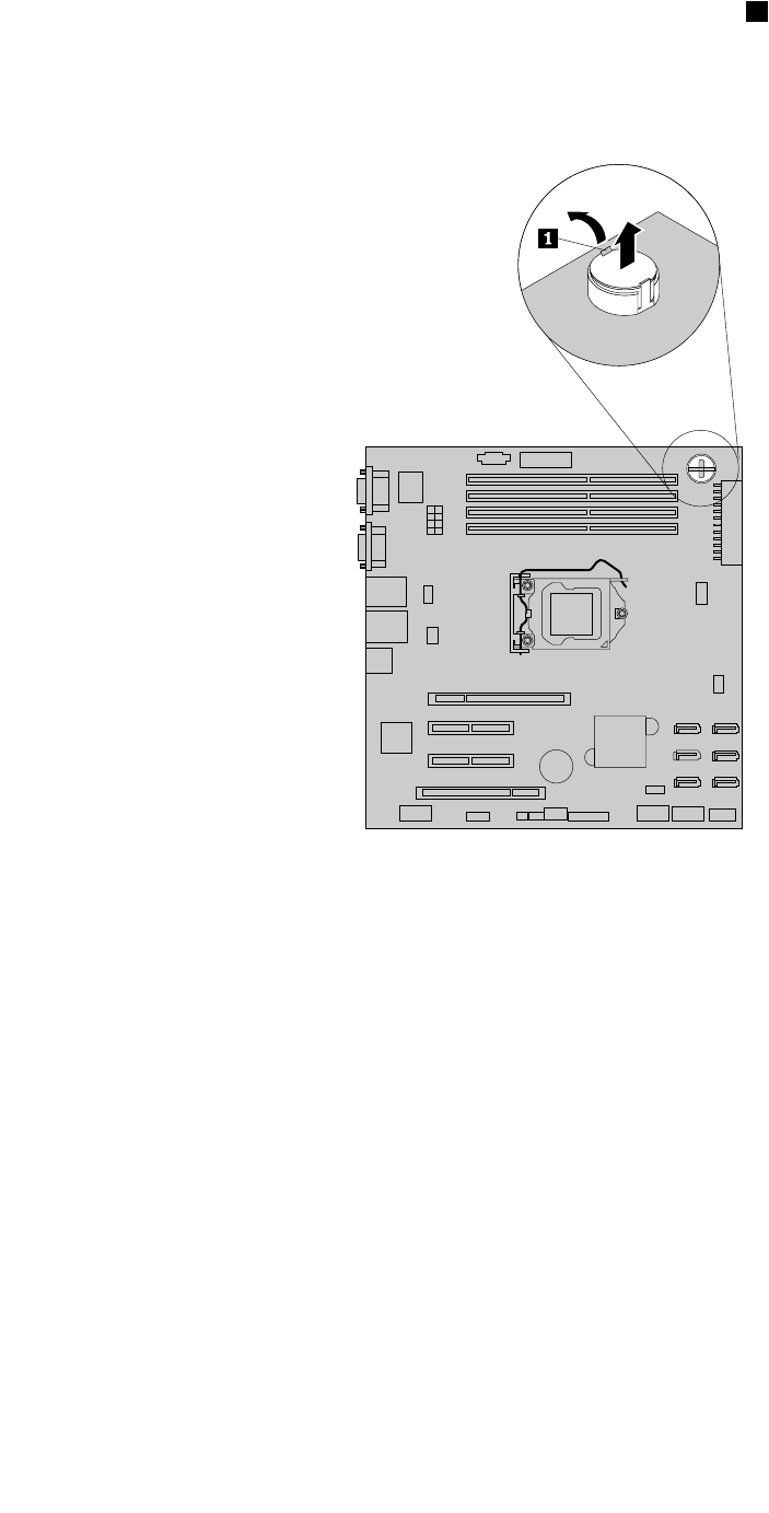
4.LocatetheiButtonsocketonthesystemboard.Opentheretainingclip1ontheiButtonsocketto
releasethesystemboardRAID5keyandthencompletelyremovethekeyfromtheiButtonsocket.
Note:Ifnecessary,removeanypartsordisconnectanycablesthatmightimpedeyouroperation.
Figure46.RemovingthesystemboardRAID5key
5.IfyouareinstructedtoreturntheoldsystemboardRAID5key,followallpackaginginstructionsand
useanypackagingmaterialsthataresuppliedtoyouforshipping.
Whattodonext:
•Toworkwithanotherpieceofhardware,gototheappropriatesection.
•Tocompletetheremovalprocedure,goto“Completingthepartsreplacement”onpage168.Asthe
onboardSATAsoftwareRAID5isnotavailablewithoutthesystemboardRAID5key,youmightneedto
recongureRAIDforyourserver.See“ConguringRAID”onpage71.
InstallingorremovingtheThinkServeriKVMRemoteManagement
Module
ThistopicprovidesinstructionsonhowtoinstallorremovetheThinkServeriKVMRemoteManagement
Module(hereinafterreferredtoastheiKVMkey).
TheiKVMkeyoffersconvenient,remoteKVMaccessandcontrolthroughtheLANorInternet.Youcanuse
theiKVMkeytogainlocation-independentremoteaccesstorespondtocriticalincidentsandtoundertake
necessarymaintenance.Therefore,workingasanintegratedsolutioninyourserver,theiKVMkeyprovides
Chapter6.Installing,removing,orreplacinghardware105

anincreasedlevelofmanageabilityoverthebasicservermanagementavailabletothesystemboard.You
canpurchaseaniKVMkeydirectlyfromLenovo.
InstallingtheiKVMkey
Attention:Donotopenyourserverorattemptanyrepairbeforereadingandunderstandingthe“Safetyinformation”
onpageiiiand“Guidelines”onpage83.
ThistopicprovidesinstructionsonhowtoinstalltheiKVMkey.
Beforeyoubegin,printalltherelatedinstructionsorensurethatyoucanviewthePDFversiononanother
computerforreference.
Note:UseanydocumentationthatcomeswiththeiKVMkeyandfollowthoseinstructionsinadditionto
theinstructionsinthistopic.
ToinstalltheiKVMkey,dothefollowing:
1.Removeallmediafromthedrivesandturnoffallattacheddevicesandtheserver.Then,disconnectall
powercordsfromelectricaloutletsanddisconnectallcablesthatareconnectedtotheserver.
2.Removetheservercover.See“Removingtheservercover”onpage85.
3.Laytheserveronitssideforeasieroperation.
4.Touchthestatic-protectivepackagethatcontainstheiKVMkeytoanyunpaintedsurfaceontheoutside
oftheserver.Then,taketheiKVMkeyoutofthepackage.
106ThinkServerHardwareMaintenanceManual
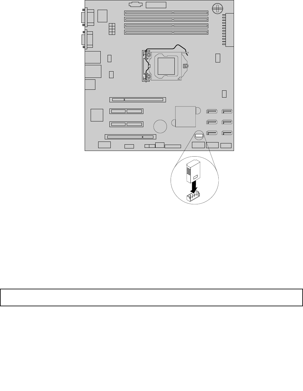
5.LocatetheiKVMkeyconnectoronthesystemboardandtheninserttheiKVMkeyintotheiKVMkey
connector.
Note:MakesurethattheiKVMkeyissecurelyseatedonthesystemboard.
Figure47.InstallingtheiKVMkey
Whattodonext:
•Toworkwithanotherpieceofhardware,gototheappropriatesection.
•Tocompletetheinstallation,goto“Completingthepartsreplacement”onpage168.Then,youcanrefer
totheRemoteManagementModuleUserGuideonthedocumentationDVDthatcomeswithyourserver
formoreinformationabouttheiKVMfunctionandserverremotemanagement.
RemovingtheiKVMkey
Attention:Donotopenyourserverorattemptanyrepairbeforereadingandunderstandingthe“Safetyinformation”
onpageiiiand“Guidelines”onpage83.
ThistopicprovidesinstructionsonhowtoremovetheiKVMkeyiftheserverhasoneinstalled.
Beforeyoubegin,printalltherelatedinstructionsorensurethatyoucanviewthePDFversiononanother
computerforreference.
Chapter6.Installing,removing,orreplacinghardware107
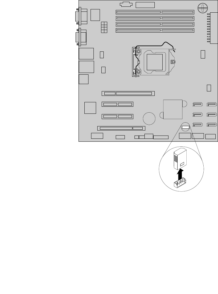
Notes:
1.UseanydocumentationthatcomeswiththeiKVMkeyandfollowthoseinstructionsinadditionto
theinstructionsinthistopic.
2.IfyouremovetheiKVMkey,theiKVMfunctionforserverremotemanagementisunavailable.
ToremovetheiKVMkey,dothefollowing:
1.Removeallmediafromthedrivesandturnoffallattacheddevicesandtheserver.Then,disconnectall
powercordsfromelectricaloutletsanddisconnectallcablesthatareconnectedtotheserver.
2.Removetheservercover.See“Removingtheservercover”onpage85.
3.Laytheserveronitssideforeasieroperation.
4.LocatetheiKVMkeyonthesystemboardandthenlifttheiKVMkeystraightuptoremoveitfromthe
iKVMkeyconnector.
Figure48.RemovingtheiKVMkey
5.IfyouareinstructedtoreturntheoldiKVMkey,followallpackaginginstructionsanduseanypackaging
materialsthataresuppliedtoyouforshipping.
Whattodonext:
•Toworkwithanotherpieceofhardware,gototheappropriatesection.
•Tocompletetheremovalprocedure,goto“Completingthepartsreplacement”onpage168.
108ThinkServerHardwareMaintenanceManual

InstallingorremovingtheTPMmodule
ThistopicprovidesinstructionsonhowtoinstallorremovetheTPMmodule.
TheTPMmoduleisasecuritychipdesignedbytheTrustedComputingGroup(TCG)toprovideahardware
methodofdataencryption.Itstorespasswords,encryptionkeys,anddigitalcerticatestohelpprovide
securitysolutionsandprotectthecomputer.
InstallingtheTPMmodule
Attention:Donotopenyourserverorattemptanyrepairbeforereadingandunderstandingthe“Safetyinformation”
onpageiiiand“Guidelines”onpage83.
ThistopicprovidesinstructionsonhowtoinstalltheTPMmodule.
Beforeyoubegin,printalltherelatedinstructionsorensurethatyoucanviewthePDFversiononanother
computerforreference.
Note:UseanydocumentationthatcomeswiththeTPMmoduleandfollowthoseinstructionsinadditionto
theinstructionsinthistopic.
ToinstalltheTPMmodule,dothefollowing:
1.Removeallmediafromthedrivesandturnoffallattacheddevicesandtheserver.Then,disconnectall
powercordsfromelectricaloutletsanddisconnectallcablesthatareconnectedtotheserver.
2.Removetheservercover.See“Removingtheservercover”onpage85.
3.Laytheserveronitssideforeasieroperation.
4.Touchthestatic-protectivepackagethatcontainstheTPMmoduletoanyunpaintedsurfaceonthe
outsideoftheserver.Then,taketheTPMmoduleoutofthepackage.
Note:CarefullyhandletheTPMmodulebyitsedges.
Chapter6.Installing,removing,orreplacinghardware109
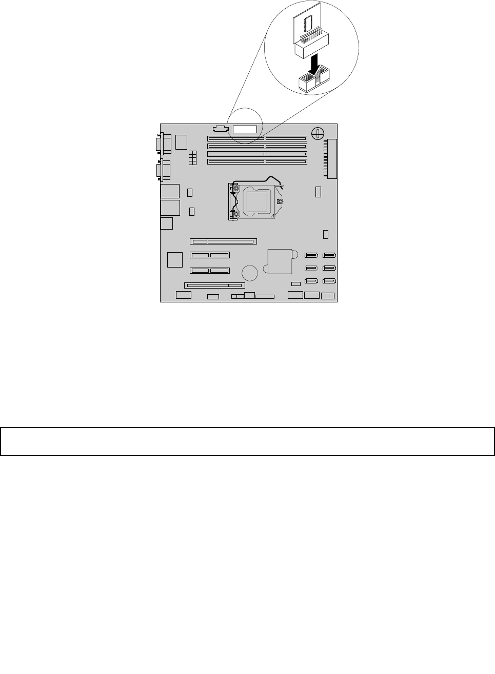
5.LocatetheTPMconnectoronthesystemboardandtheninserttheTPMmoduleintotheTPMconnector.
Figure49.InstallingtheTPMmodule
Whattodonext:
•Toworkwithanotherpieceofhardware,gototheappropriatesection.
•Tocompletetheinstallation,goto“Completingthepartsreplacement”onpage168.Then,youcan
conguretheTPMfunctionintheSetupUtilityprogram.See“ConguringtheTPMfunction”onpage66.
RemovingtheTPMmodule
Attention:Donotopenyourserverorattemptanyrepairbeforereadingandunderstandingthe“Safetyinformation”
onpageiiiand“Guidelines”onpage83.
ThistopicprovidesinstructionsonhowtoremovetheTPMmoduleiftheserverhasoneinstalled.
Beforeyoubegin,printalltherelatedinstructionsorensurethatyoucanviewthePDFversiononanother
computerforreference.
Notes:
1.UseanydocumentationthatcomeswiththeTPMmoduleandfollowthoseinstructionsinadditionto
theinstructionsinthistopic.
2.IfyouremovetheTPMmodule,theTPMfunctionisunavailable.
ToremovetheTPMmodule,dothefollowing:
1.Removeallmediafromthedrivesandturnoffallattacheddevicesandtheserver.Then,disconnectall
powercordsfromelectricaloutletsanddisconnectallcablesthatareconnectedtotheserver.
110ThinkServerHardwareMaintenanceManual
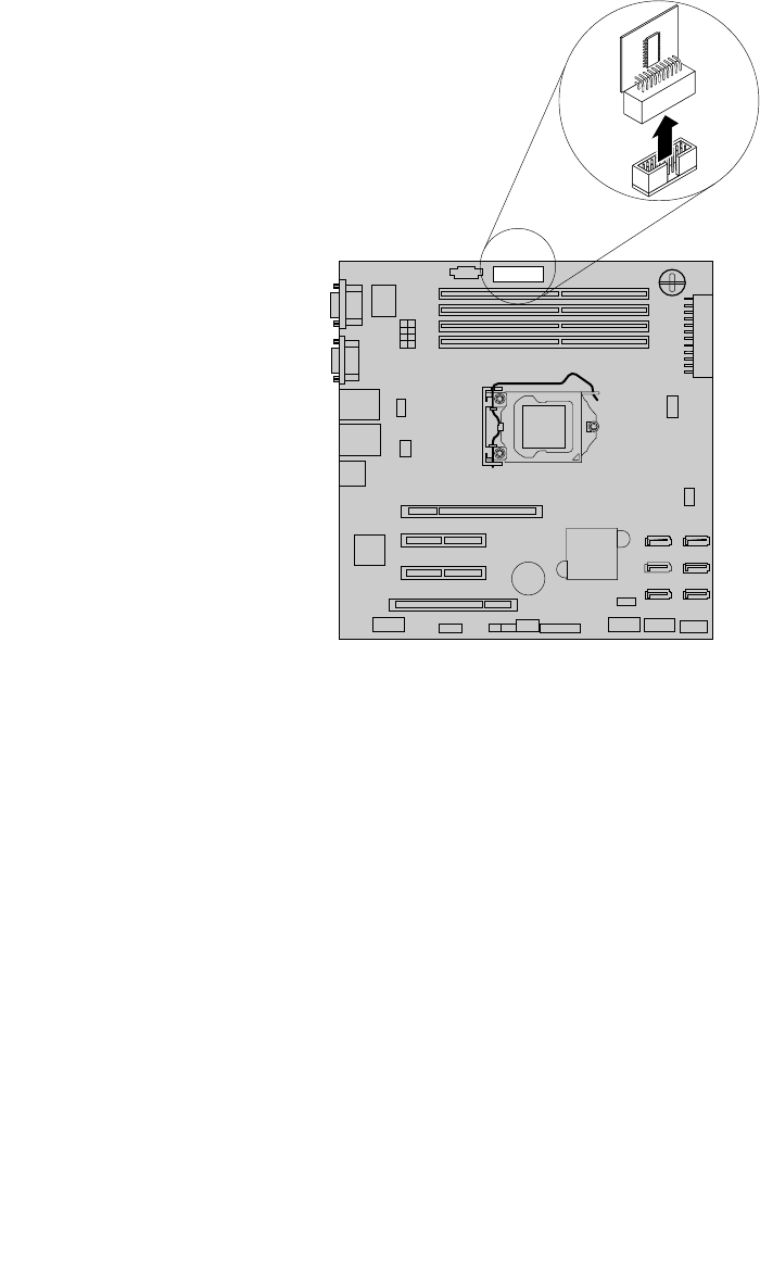
2.Removetheservercover.See“Removingtheservercover”onpage85.
3.Laytheserveronitssideforeasieroperation.
4.LocatetheTPMconnectoronthesystemboardandthenremovetheTPMmoduleinstalledonthe
TPMconnectorbyliftingitstraightup.
Note:CarefullyhandletheTPMmodulebyitsedges.
Figure50.RemovingtheTPMmodule
5.IfyouareinstructedtoreturntheoldTPMmodule,followallpackaginginstructionsanduseany
packagingmaterialsthataresuppliedtoyouforshipping.
Whattodonext:
•Toworkwithanotherpieceofhardware,gototheappropriatesection.
•Tocompletetheremovalprocedure,goto“Completingthepartsreplacement”onpage168.
InstallingorremovingtheDITmodule
ThistopicprovidesinstructionsonhowtoinstallorremovetheDITmodule.
TheDITmodule,whichisonlyavailableinsomemodels,providesdiagnosticLEDsthroughtheDITpanel
tohelpyoueasilyidentifyaproblem.ThediagnosticLEDsontheDITpanelalsovarydependingonthe
installedpowersupply.Formoreinformation,see“DITmodule”onpage18.
Chapter6.Installing,removing,orreplacinghardware111
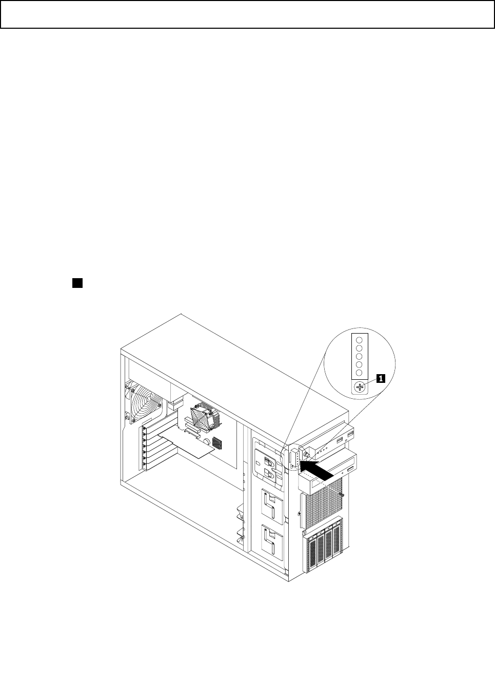
InstallingtheDITmodule
Attention:Donotopenyourserverorattemptanyrepairbeforereadingandunderstandingthe“Safetyinformation”
onpageiiiand“Guidelines”onpage83.
ThistopicprovidesinstructionsonhowtoinstalltheDITmodule.
Beforeyoubegin,printalltherelatedinstructionsorensurethatyoucanviewthePDFversiononanother
computerforreference.
Note:Dependingonthemodel,yourservermightlookslightlydifferentfromtheillustrationsinthistopic.
ToinstalltheDITmodule,dothefollowing:
1.Removeallmediafromthedrivesandturnoffallattacheddevicesandtheserver.Then,disconnectall
powercordsfromelectricaloutletsanddisconnectallcablesthatareconnectedtotheserver.
2.Removetheservercover.See“Removingtheservercover”onpage85.
3.Removethefrontbezel.See“Removingandreinstallingthefrontbezel”onpage87.
4.Touchthestatic-protectivepackagethatcontainstheDITmoduletoanyunpaintedsurfaceonthe
outsideoftheserver.Then,taketheDITmoduleoutofthepackage.
5.ConnectthesignalcabletotherearoftheDITmodule.
6.RoutethesignalcableoftheDITmodulethroughthecorrespondingholeinthechassisandpositionthe
DITmoduleonthechassissothatthescrewholeintheDITmoduleisalignedwiththecorresponding
screwhole1inthechassis.Then,installthescrewtosecuretheDITmoduleinplace.
Figure51.InstallingtheDITmodule
7.Removethefrontsystemfan(s).See“Replacingthefrontsystemfan”onpage149.
112ThinkServerHardwareMaintenanceManual
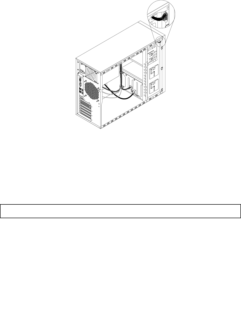
8.ConnecttheotherendofthesignalcabletotheDITmoduleconnectoronthesystemboard.See
“Systemboardcomponents”onpage42.Then,properlyroutethesignalcableoftheDITmodule.You
mightneedtosecurethesignalcablewithcableclipsortiesinthechassis.
Figure52.Cablerouting
9.Reinstallthefrontsystemfan(s).See“Replacingthefrontsystemfan”onpage149.
10.Reinstallthefrontbezel.See“Removingandreinstallingthefrontbezel”onpage87.
Whattodonext:
•Toworkwithanotherpieceofhardware,gototheappropriatesection.
•Tocompletetheinstallation,goto“Completingthepartsreplacement”onpage168.
RemovingtheDITmodule
Attention:Donotopenyourserverorattemptanyrepairbeforereadingandunderstandingthe“Safetyinformation”
onpageiiiand“Guidelines”onpage83.
ThistopicprovidesinstructionsonhowtoremovetheDITmodule.
ThistopicappliesonlytoservermodelsthatcomewiththeDITmodule.
Beforeyoubegin,printalltherelatedinstructionsorensurethatyoucanviewthePDFversiononanother
computerforreference.
Notes:
1.Dependingonthemodel,yourservermightlookslightlydifferentfromtheillustrationinthistopic.
2.IfyouremovetheDITmodule,theserverwilllosethediagnosticLEDsontheDITpanel.
ToremovetheDITmodule,dothefollowing:
Chapter6.Installing,removing,orreplacinghardware113
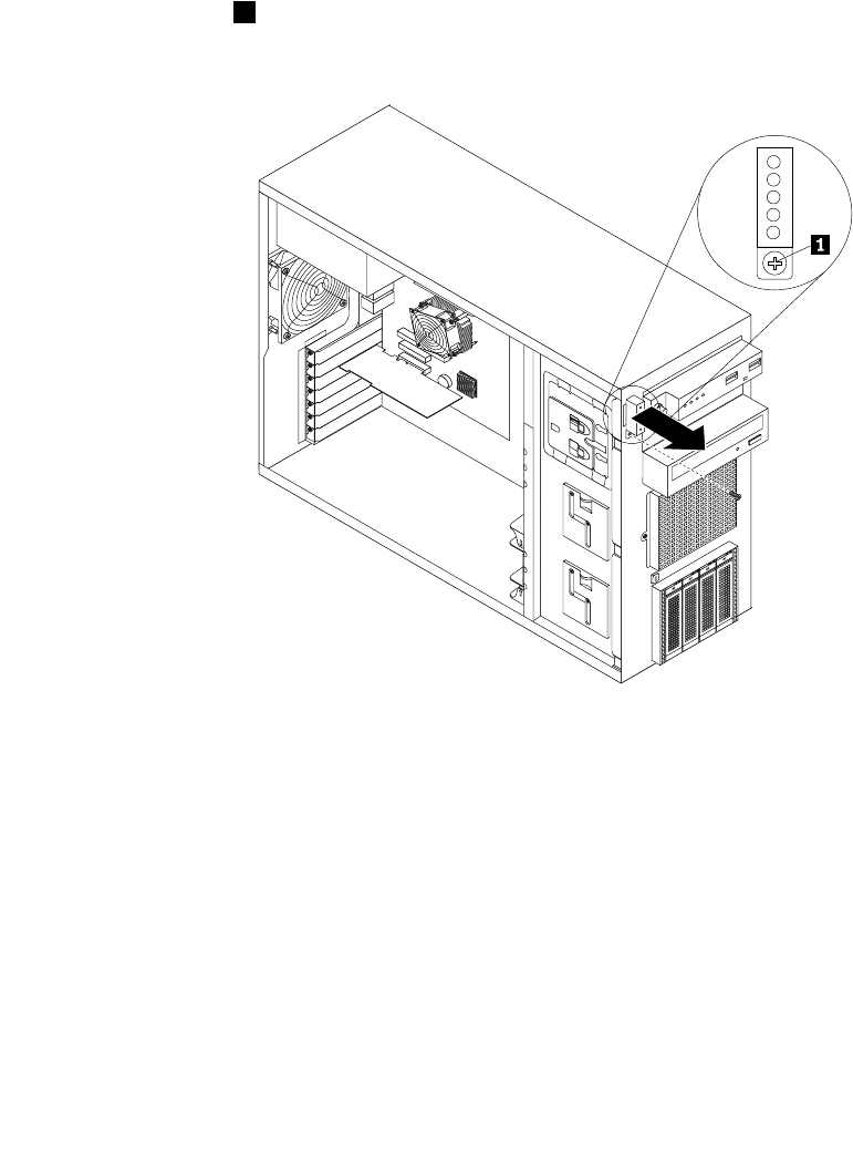
1.Removeallmediafromthedrivesandturnoffallattacheddevicesandtheserver.Then,disconnectall
powercordsfromelectricaloutletsanddisconnectallcablesthatareconnectedtotheserver.
2.Removetheservercover.See“Removingtheservercover”onpage85.
3.Removethefrontbezel.See“Removingandreinstallingthefrontbezel”onpage87.
4.LocatetheDITmodule.See“DITmodule”onpage18.
5.Removethefrontsystemfan(s).See“Replacingthefrontsystemfan”onpage149.
6.DisconnectthesignalcableoftheDITmodulefromtheDITmoduleconnectoronthesystemboard.
See“Systemboardcomponents”onpage42.
7.Ifnecessary,removeanypartsordisconnectanycablesthatmightimpedeyouraccesstothesignal
cableoftheDITmodule.NotethecableroutingandthenreleasethesignalcableoftheDITmodule
fromanycableclipsortiesinthechassis.
8.Removethescrew1onthechassisthatsecurestheDITmodule.Then,carefullyremovetheDIT
modulefromthechassisandpullthesignalcableoftheDITmoduleoutoftheholeinthechassis.
Figure53.RemovingtheDITmodule
9.DisconnectthesignalcablefromtherearoftheDITmodule.
10.Reinstallthefrontsystemfan(s).See“Replacingthefrontsystemfan”onpage149.
11.Reinstallthefrontbezel.See“Removingandreinstallingthefrontbezel”onpage87.
12.IfyouareinstructedtoreturntheoldDITmodule,followallpackaginginstructionsanduseany
packagingmaterialsthataresuppliedtoyouforshipping.
Whattodonext:
•Toworkwithanotherpieceofhardware,gototheappropriatesection.
•Tocompletetheremovalprocedure,goto“Completingthepartsreplacement”onpage168.
114ThinkServerHardwareMaintenanceManual
Installingorreplacinganopticaldrive
Attention:Donotopenyourserverorattemptanyrepairbeforereadingandunderstandingthe“Safetyinformation”
onpageiiiand“Guidelines”onpage83.
Thistopicprovidesinstructionsonhowtoinstallorreplaceanopticaldrive.
TheEMIintegrityandcoolingoftheserverareprotectedbyhavingalldrivebayscoveredoroccupied.Your
serverhastwoopticaldrivebays.Ifonlyoneopticaldriveisinstalledinthelowerbay,theupperbayis
coveredbyametalEMIshieldonthechassisandalsoaplasticshieldonthefrontbezel.Whenyouinstall
asecondaryopticaldriveoraRDXUSBdrivebundle,savetheremovedEMIshieldfromthechassisand
plasticshieldfromthefrontbezelintheeventthatyoulaterremovethedriveandneedtheshieldsto
coverthedrivebay.
Attention:AnunoccupieddrivebaywithoutanyotherprotectionmightimpacttheEMIintegrityandcooling
oftheserver,whichmightresultinoverheatingorcomponentdamage.TomaintaintheEMIintegrityand
coolingoftheserver,installanewopticaldriveassoonasyouremovethefailingoneortheprotectiveshields.
CAUTION:
Whenlaserproducts(suchasCD-ROMs,DVDdrives,beropticdevices,ortransmitters)are
installed,notethefollowing:
•Donotremovethecovers.Removingthecoversofthelaserproductcouldresultinexposureto
hazardouslaserradiation.Therearenoserviceablepartsinsidethedevice.
•Useofcontrolsoradjustmentsorperformanceofproceduresotherthanthosespeciedherein
mightresultinhazardousradiationexposure.
DANGER
SomelaserproductscontainanembeddedClass3AorClass3Blaserdiode.Notethefollowing.
Laserradiationwhenopen.Donotstareintothebeam,donotviewdirectlywithoptical
instruments,andavoiddirectexposuretothebeam.
Beforeyoubegin,considerthefollowingopticaldriveinstallationrules:
•Theserverhastwoopticaldrivebays.Iftheserverhasonlyoneopticaldriveinstalled,makesurethatthe
opticaldriveisinstalledinthelowerbay(opticaldrivebay1).Theupperbayisforasecondaryoptical
driveoraRDXUSBdrivebundle(serveroption).
•Thefollowingtableprovidesinformationabouttherecommendedpowerconnectorandconnectoron
thesystemboardfortheinstalledopticaldriveorRDXUSBdrivebundle.See“Servercomponents”on
page25forthelocationsoftheopticaldrivebaysand“Systemboardcomponents”onpage42forthe
locationsoftheconnectorsonthesystemboard.
DrivebayDrivePowerconnectorConnectoronthesystemboard
Opticaldrivebay1(lower
bay)
AnopticaldriveinstalledP11SATA5connector
Anopticaldriveinstalledin
somemodels
P12SATA4connector Opticaldrivebay2(upper
bay)
ARDXUSBdrivebundle
(serveroption)
P6Internaldual-portUSB2.0
connector2
Chapter6.Installing,removing,orreplacinghardware115
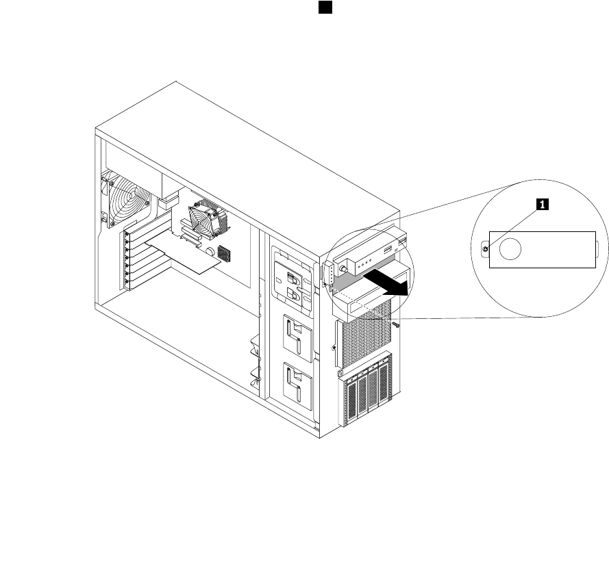
Note:ForinformationabouttheRDXUSBdrivebundleandinstructionsonhowtoinstallit,refertothe
documentationthatcomeswiththeRDXUSBdrivebundle.Youcanpurchasethisoptiondirectlyfrom
Lenovo.TheoptionnameisLenovoRemovableDiskTechnology(RDX)USBDriveBundle.
Beforeyoubegin,printalltherelatedinstructionsorensurethatyoucanviewthePDFversiononanother
computerforreference.
Notes:
1.Dependingonthemodel,yourservermightlookslightlydifferentfromtheillustrationsinthistopic.
2.Useanydocumentationthatcomeswiththeopticaldriveandfollowthoseinstructionsinadditionto
theinstructionsinthistopic.
Toinstallorreplaceanopticaldrive,dothefollowing:
1.Removeallmediafromthedrivesandturnoffallattacheddevicesandtheserver.Then,disconnectall
powercordsfromelectricaloutletsanddisconnectallcablesthatareconnectedtotheserver.
2.Removetheservercover.See“Removingtheservercover”onpage85.
3.Locatetheopticaldrivebays.See“Servercomponents”onpage25.
4.Dependingonwhetheryouareinstallingorreplacinganopticaldrive,dooneofthefollowing:
•Ifyouareinstallingasecondaryopticaldriveintheupperopticaldrivebay,removethefrontbezel.
See“Removingandreinstallingthefrontbezel”onpage87.Then,removetheplasticshieldforthe
bayfromthefrontpanel.Removethescrew1thatsecuresthemetalEMIshieldcoveredonthe
upperopticaldrivebay.InsertangerintotheholeintheEMIshieldandcarefullypulltheEMI
shieldoutofthefrontofthechassis.
Figure54.RemovingtheEMIshieldfortheupperopticaldrivebay
116ThinkServerHardwareMaintenanceManual
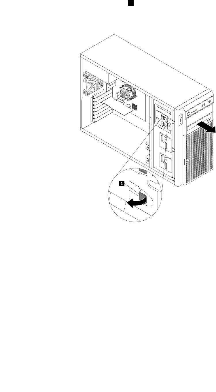
•Ifyouarereplacinganopticaldrive,disconnectthesignalcableandthepowercablefromtherearof
theopticaldrive.Pressthereleasebutton1inthedirectionasshownandpushtheopticaldrive
fromtherearuntilitisprojectedfromthefrontofthechassis.Then,holdtheopticaldrivefromthe
frontandcompletelyslideitoutofthechassis.
Figure55.Removingtheopticaldrive
5.Touchthestatic-protectivepackagethatcontainsthenewopticaldrivetoanyunpaintedsurfaceonthe
outsideoftheserver.Then,takethenewopticaldriveandthesignalcableoutofthepackage.
Chapter6.Installing,removing,orreplacinghardware117
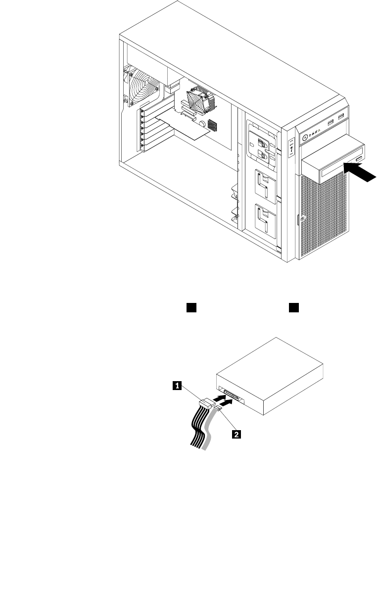
6.Slidethenewopticaldriveintothedrivebayfromthefrontuntilitsnapsintoposition.
Note:Youdonotneedtoremovethefrontbezelwhenreplacinganopticaldrive.However,ifyouare
addingasecondaryopticaldriveintheupperopticaldrivebay,youneedtoremovethefrontbezelrst
andthengainaccesstotheprotectiveshieldstoremovethem.Thefollowingillustrationshowsonlythe
situationinwhichthefrontbezelhasnotbeenremoved.
Figure56.Installingtheopticaldrive
7.Connecttheappropriatepowercable1andthesignalcable2totherearofthenewopticaldrive.
Figure57.Connectingcablestotherearoftheopticaldrive
8.Ifnecessary,connecttheotherendofthesignalcabletotheappropriateSATAconnectoronthesystem
board.See“Systemboardcomponents”onpage42.
9.Reinstallthefrontbezelifyouhaveremovedit.See“Removingandreinstallingthefrontbezel”on
page87.
10.Dooneofthefollowing:
118ThinkServerHardwareMaintenanceManual

•Ifyouareinstallinganopticaldrive,savetheremovedEMI-protectiveshieldfromthechassisand
plasticshieldfromthefrontbezelintheeventthatyoulaterremovethedriveandneedtheshieldsto
coverthedrivebay.
•Ifyouarereplacinganopticaldriveandareinstructedtoreturntheoldopticaldrive,followall
packaginginstructionsanduseanypackagingmaterialsthataresuppliedtoyouforshipping.
Whattodonext:
•Toworkwithanotherpieceofhardware,gototheappropriatesection.
•Tocompletetheinstallationorreplacement,goto“Completingthepartsreplacement”onpage168.
Installingorreplacingahot-swapharddiskdrive
Attention:Donotopenyourserverorattemptanyrepairbeforereadingandunderstandingthe“Safetyinformation”
onpageiiiand“Guidelines”onpage83.
Thistopicprovidesinstructionsonhowtoinstallorreplaceahot-swapharddiskdrive.
Thistopicappliesonlytoservermodelsthathavehot-swapharddiskdrive(s)installed.See“Features”on
page7formoreinformationaboutthesupportedhot-swapharddiskdrives.
ForalistoftheThinkServerharddiskdriveoptions,gotohttp://www.lenovo.com/thinkserver.Clickthe
ProductstabandthenclickOptions➙ThinkServerHardDrivestoviewtheinformation.
Youcaninstallorreplaceahot-swapharddiskdrivewithoutturningofftheserver,whichhelpsyouavoid
signicantinterruptiontotheoperationofthesystem.
TheEMIintegrityandcoolingoftheserverareprotectedbyhavingalldrivebayscoveredoroccupied.The
numberoftheinstalledharddiskdrivesinyourservervariesdependingontheservermodel.Thevacant
baysareeithercoveredbyanEMI-protectivepaneloroccupiedbydummyharddiskdrivetrays.Whenyou
installahot-swapharddiskdrive,savetheremoveddummyharddiskdrivetrayfromthedrivebayinthe
eventthatyoulaterremovethehot-swapharddiskdriveandneedthedummytraytocovertheplace.
Attention:AnunoccupieddrivebaywithoutanyotherprotectionmightimpacttheEMIintegrityandcooling
oftheserver,whichmightresultinoverheatingorcomponentdamage.TomaintaintheEMIintegrityand
coolingoftheserver,installanewhot-swapharddiskdriveassoonasyouremovethefailingoneor
thedummytray.
Beforeyoubegin,considerthefollowingharddiskdriveinstallationrules:
•Followtheorderoftheharddiskdrivebayswheninstallingaharddiskdrive.See“Servercomponents”
onpage25tolocatetheharddiskdrivebaysinyourserver.
•ForRAIDconguration,theharddiskdrivesmustbethesametypewiththesamecapacityiftheyare
withinasingleRAIDarray.Formoreinformation,see“ConguringRAID”onpage71.
•Forharddiskdriveswithdifferentcapacities,installtheharddiskdrivewiththelowestcapacityrst.
Beforeyoubegin,printalltherelatedinstructionsorensurethatyoucanviewthePDFversiononanother
computerforreference.
Notes:
1.Dependingonthemodel,yourservermightcomewith3.5-inchhot-swapharddiskdrive(s)or2.5-inch
hot-swapharddiskdrive(s).Theillustrationsinthistopicarebasedonservermodelswithfour3.5-inch
hot-swapSATAorSASharddiskdrives.Forothermodels,thereplacementprocedureisthesame.
2.Dependingonthemodel,yourservermightlookslightlydifferentfromtheillustrationsinthistopic.
Chapter6.Installing,removing,orreplacinghardware119
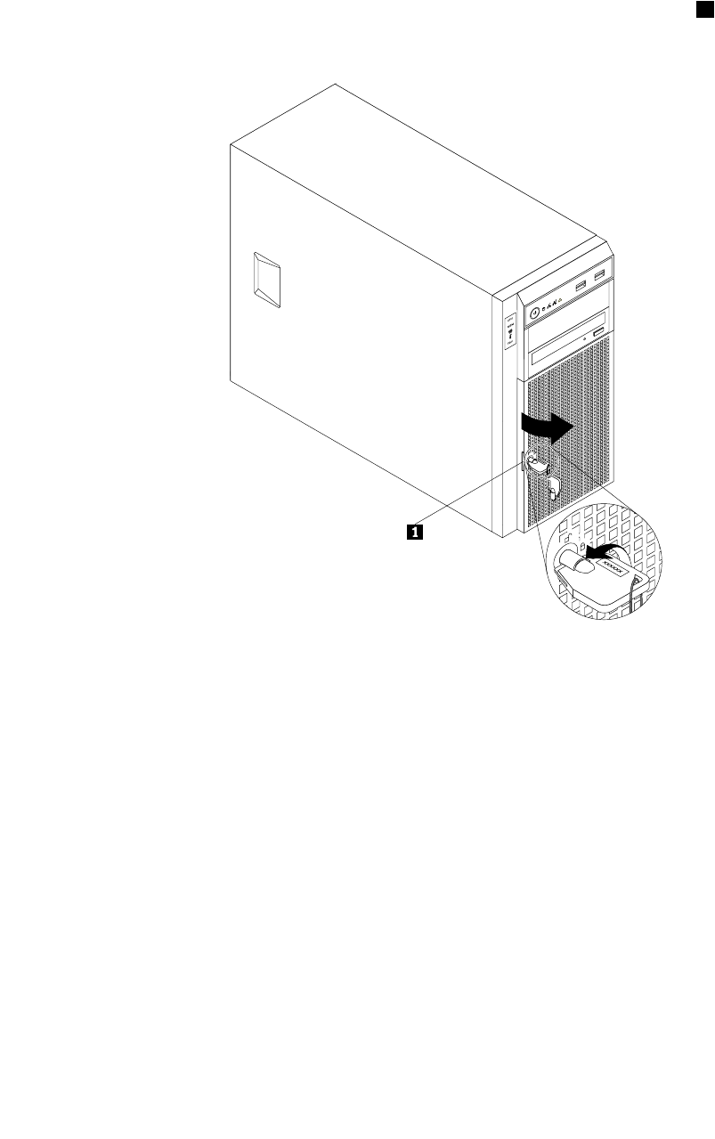
3.Useanydocumentationthatcomeswiththehot-swapharddiskdriveandfollowthoseinstructionsin
additiontotheinstructionsinthistopic.
Toinstallorreplaceahot-swapharddiskdrive,dothefollowing:
1.Usethefrontdoorkeytounlockthefrontdoorandthenusethefrontdoorhandle1topivotthe
frontdoortotheopenposition.
Figure58.Openingthefrontdooroftheserver
2.Locatetheappropriateharddiskdrivebay.See“Servercomponents”onpage25.
120ThinkServerHardwareMaintenanceManual
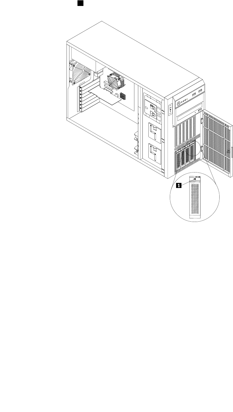
3.Pressthereleasebutton1toopenthehandleofthehot-swapharddiskdriveorthedummytray.
Figure59.Openingthehandleofthehot-swapharddiskdriveorthedummytray
Chapter6.Installing,removing,orreplacinghardware121
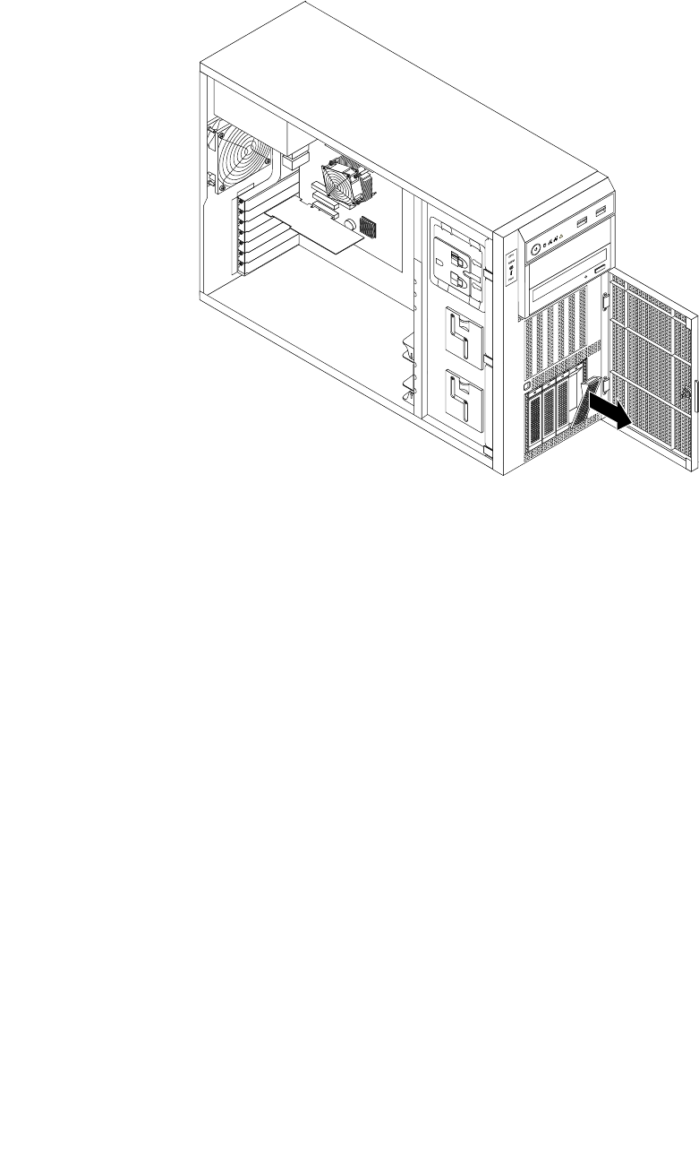
4.Pullthehandleandcarefullyslidethehot-swapharddiskdriveorthedummytrayoutofthefrontof
thechassis.
Figure60.Removingthehot-swapharddiskdriveorthedummytray
5.Touchthestatic-protectivepackagethatcontainsthenewhot-swapharddiskdrivetoanyunpainted
surfaceontheoutsideoftheserver.Then,takethenewhot-swapharddiskdriveoutofthepackage.
Note:Donottouchthecircuitboardontheharddiskdrive.
122ThinkServerHardwareMaintenanceManual
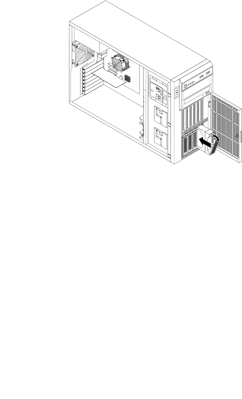
6.Slidethenewhot-swapharddiskdriveintothedrivebayfromthefrontuntilitsnapsintoposition
andthencompletelyclosethehandle.
Figure61.Installingthehot-swapharddiskdrive
7.Checkthehot-swapharddiskdrivestatusLEDstomakesurethattheharddiskdriveisoperating
correctly.Youmighthavetorestarttheserverforthenewlyinstalleddrivetoberecognized.See
“Hot-swapharddiskdrivestatusLEDs”onpage32.Iftheharddiskdriveisfaulty,youneedtoreinstall
orreplaceituntilitisoperatingcorrectly.
8.Closeandlockthefrontdoor.
9.Dooneofthefollowing:
•Ifyouareinstallingahot-swapharddiskdrive,savetheremovedharddiskdrivedummytrayin
theeventthatyoulaterremovethehot-swapharddiskdriveandneedadummytraytocoverthe
drivebay.
•Ifyouarereplacingahot-swapharddiskdriveandareinstructedtoreturntheoldhot-swaphard
diskdrive,followallpackaginginstructionsanduseanypackagingmaterialsthataresuppliedto
youforshipping.
Whattodonext:
•Toworkwithanotherpieceofhardware,gototheappropriatesection.
•TocongureRAID,goto“ConguringRAID”onpage71.
Removingorinstallinganon-hot-swapharddiskdrive
Thistopicprovidesinstructionsonhowtoremoveorinstallanon-hot-swapharddiskdrive.
Thistopicappliesonlytoservermodelsthathavenon-hot-swapharddiskdrive(s)installed.See“Features”
onpage7formoreinformationaboutthesupportednon-hot-swapharddiskdrives.
Chapter6.Installing,removing,orreplacinghardware123

ForalistoftheThinkServerharddiskdriveoptions,gotohttp://www.lenovo.com/thinkserver.Clickthe
ProductstabandthenclickOptions➙ThinkServerHardDrivestoviewtheinformation.
Removinganon-hot-swapharddiskdrive
Attention:Donotopenyourserverorattemptanyrepairbeforereadingandunderstandingthe“Safetyinformation”
onpageiiiand“Guidelines”onpage83.
Thistopicprovidesinstructionsonhowtoremoveanon-hot-swapharddiskdrive.
Beforeyoubegin,considerthefollowingharddiskdriveinstallationrules:
•Followtheorderoftheharddiskdrivebayswheninstallingaharddiskdrive.See“Servercomponents”
onpage25tolocatetheharddiskdrivebaysinyourserver.
•ForRAIDconguration,theharddiskdrivesmustbethesametypewiththesamecapacityiftheyare
withinasingleRAIDarray.Formoreinformation,see“ConguringRAID”onpage71.
•Forharddiskdriveswithdifferentcapacities,installtheharddiskdrivewiththelowestcapacityrst.
Beforeyoubegin,printalltherelatedinstructionsorensurethatyoucanviewthePDFversiononanother
computerforreference.
Note:Dependingonthemodel,yourservermightlookslightlydifferentfromtheillustrationsinthistopic.
Toremoveanon-hot-swapharddiskdrive,dothefollowing:
1.Removeallmediafromthedrivesandturnoffallattacheddevicesandtheserver.Then,disconnectall
powercordsfromelectricaloutletsanddisconnectallcablesthatareconnectedtotheserver.
124ThinkServerHardwareMaintenanceManual
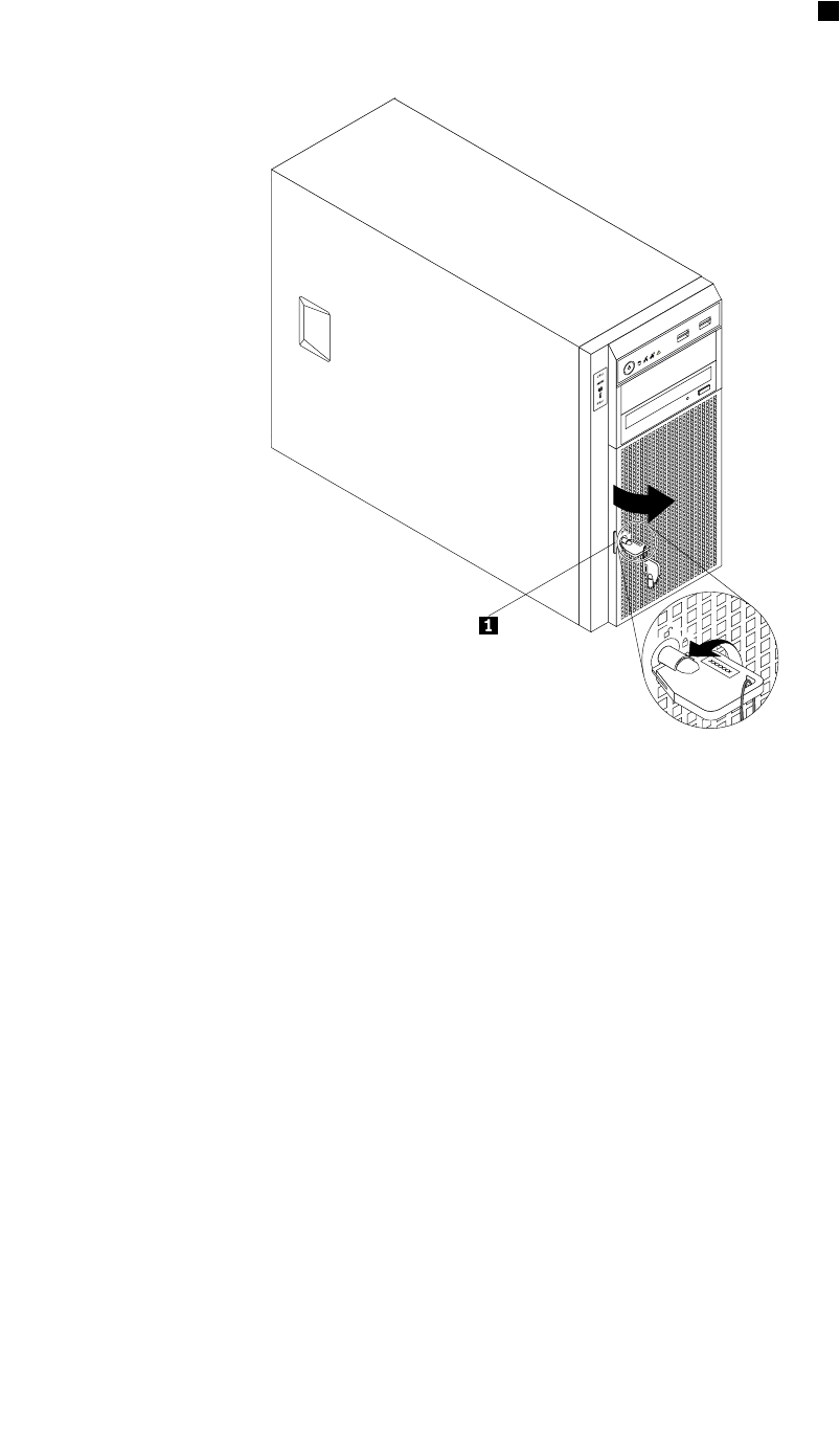
2.Usethefrontdoorkeytounlockthefrontdoorandthenusethefrontdoorhandle1topivotthe
frontdoortotheopenposition.
Figure62.Openingthefrontdooroftheserver
Chapter6.Installing,removing,orreplacinghardware125

3.Thenon-hot-swapharddiskdrive(s)areinstalledinthelowerharddiskdrivecageandareprotected
byanEMI-protectivepanel.Pressthesmalltab1ontheEMI-protectivepanelfromthebottomand
thenpivottheEMI-protectivepanelupwardtoremoveitfromthechassisandgainaccesstothe
non-hot-swapharddiskdrive(s).
CPU
MEM
PSU
CPU
MEM
PSU
12
Figure63.RemovingtheEMI-protectivepanel
4.Removetheservercover.See“Removingtheservercover”onpage85.
5.Removethefrontsystemfan1.See“Replacingthefrontsystemfan”onpage149.
6.Locatetheappropriatenon-hot-swapharddiskdrive.See“Servercomponents”onpage25.Then,
disconnecttheSATAsignalcableandthepowercablefromtherearofthenon-hot-swapharddiskdrive.
126ThinkServerHardwareMaintenanceManual
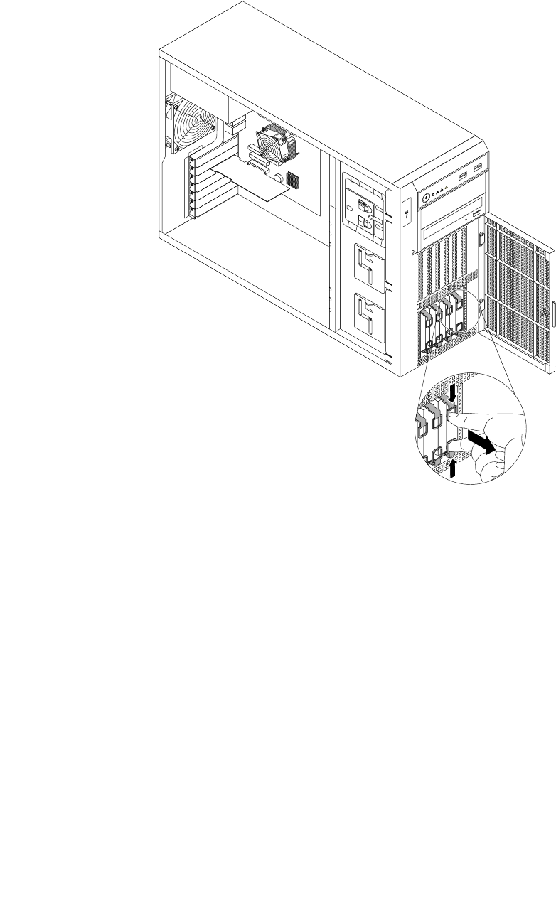
7.Inserttwongersintotheholesinthetwotabsonthefrontofthebluebracket.Then,pressthetabs
towardseachotherandcarefullyslidethenon-hot-swapharddiskdriveoutofthefrontofthechassis.
CPU
MEM
PSU
CPU
MEM
PSU
12
Figure64.Slidingthenon-hot-swapharddiskdriveoutofthebay
8.Flexthesidesofthebluebrackettoremovethenon-hot-swapharddiskdrivefromthebracket.Save
thebracketforfutureuse.
Note:Donottouchthecircuitboardontheharddiskdrive.
9.Reinstallthefrontsystemfan1.See“Replacingthefrontsystemfan”onpage149.
Chapter6.Installing,removing,orreplacinghardware127
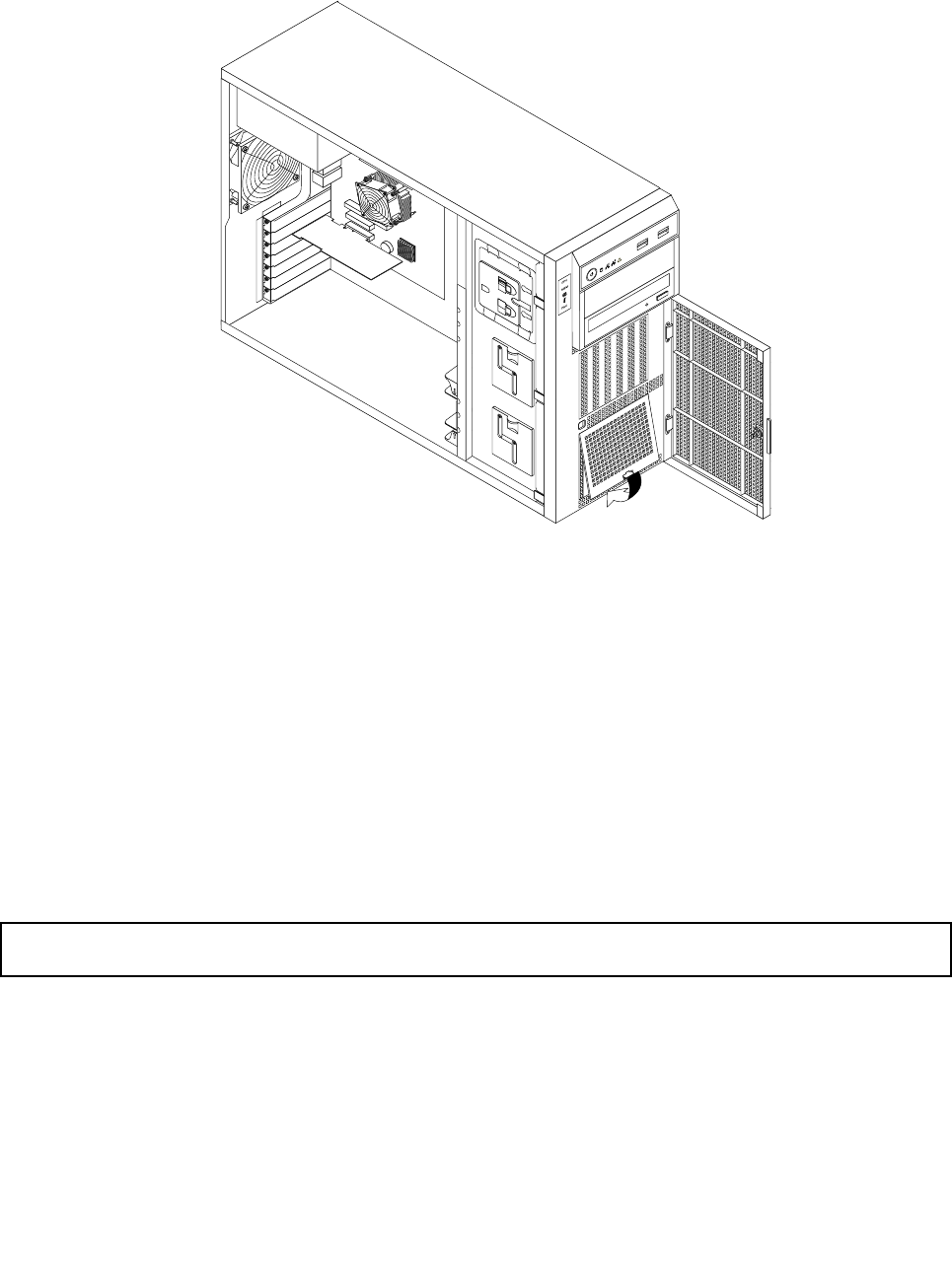
10.AlignthetopedgeoftheEMI-protectivepanelwiththetopsideoftheharddiskdrivecageandthen
pivottheEMI-protectivepaneldownuntilitsnapsintoposition.
Figure65.InstallingtheEMI-protectivepanel
11.DisconnecttheSATAcablefortheremovednon-hot-swapharddiskdrivefromthesystemboardand
savethecableforfutureuse.
12.Closeandlockthefrontdoor.
13.Ifyouareinstructedtoreturntheoldnon-hot-swapharddiskdrive,followallpackaginginstructionsand
useanypackagingmaterialsthataresuppliedtoyouforshipping.
Whattodonext:
•Toworkwithanotherpieceofhardware,gototheappropriatesection.
•Tocompletetheremovalprocedure,goto“Completingthepartsreplacement”onpage168.Then,you
mightneedtorecongureRAIDforyourserver.See“ConguringRAID”onpage71.
Installinganon-hot-swapharddiskdrive
Attention:Donotopenyourserverorattemptanyrepairbeforereadingandunderstandingthe“Safetyinformation”
onpageiiiand“Guidelines”onpage83.
Thistopicprovidesinstructionsonhowtoinstallanon-hot-swapharddiskdrive.
Beforeyoubegin,considerthefollowingharddiskdriveinstallationrules:
•Followtheorderoftheharddiskdrivebayswheninstallingaharddiskdrive.See“Servercomponents”
onpage25tolocatetheharddiskdrivebaysinyourserver.
•ForRAIDconguration,theharddiskdrivesmustbethesametypewiththesamecapacityiftheyare
withinasingleRAIDarray.Formoreinformation,see“ConguringRAID”onpage71.
128ThinkServerHardwareMaintenanceManual
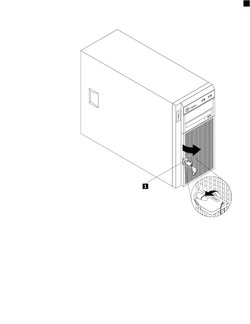
•Forharddiskdriveswithdifferentcapacities,installtheharddiskdrivewiththelowestcapacityrst.
Beforeyoubegin,printalltherelatedinstructionsorensurethatyoucanviewthePDFversiononanother
computerforreference.
Notes:
•Dependingonthemodel,yourservermightlookslightlydifferentfromtheillustrationsinthistopic.
•Useanydocumentationthatcomeswiththeharddiskdriveandfollowthoseinstructionsinadditionto
theinstructionsinthistopic.
Toinstallanon-hot-swapharddiskdrive,dothefollowing:
1.Removeallmediafromthedrivesandturnoffallattacheddevicesandtheserver.Then,disconnectall
powercordsfromelectricaloutletsanddisconnectallcablesthatareconnectedtotheserver.
2.Usethefrontdoorkeytounlockthefrontdoorandthenusethefrontdoorhandle1topivotthe
frontdoortotheopenposition.
Figure66.Openingthefrontdooroftheserver
Chapter6.Installing,removing,orreplacinghardware129
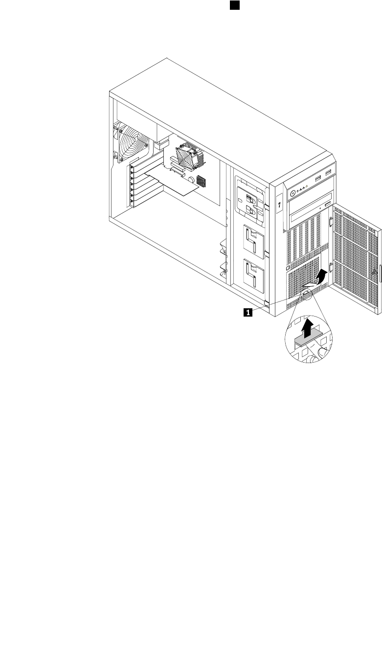
3.Thenon-hot-swapharddiskdrive(s)areinstalledinthelowerharddiskdrivecageandareprotected
byanEMI-protectivepanel.Pressthesmalltab1ontheEMI-protectivepanelfromthebottomand
thenpivottheEMI-protectivepanelupwardtoremoveitfromthechassisandgainaccesstothe
non-hot-swapharddiskdrivebays.
CPU
MEM
PSU
CPU
MEM
PSU
12
Figure67.RemovingtheEMI-protectivepanel
4.Removetheservercover.See“Removingtheservercover”onpage85.
5.Removethefrontsystemfan1.See“Replacingthefrontsystemfan”onpage149.
6.Locatetheappropriatenon-hot-swapharddiskdrivebay.See“Servercomponents”onpage25.
7.Touchthestatic-protectivepackagethatcontainsthenewnon-hot-swapharddiskdrivetoany
unpaintedsurfaceontheoutsideoftheserver.Then,takethenewnon-hot-swapharddiskdriveand
thesignalcableoutofthepackage.
Note:Donottouchthecircuitboardontheharddiskdrive.
130ThinkServerHardwareMaintenanceManual
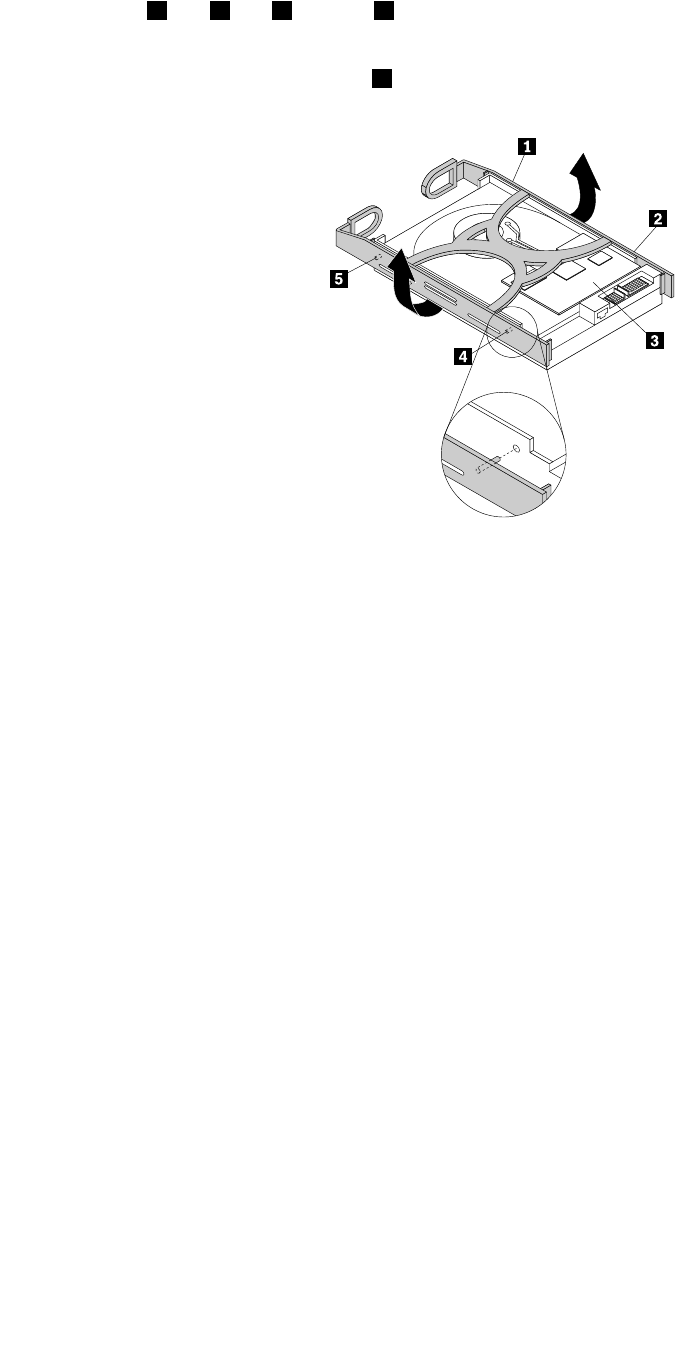
8.Installthenewnon-hot-swapharddiskdriveintoabluebracketbyexingthesidesofthebracketand
aligningpin1,pin2,pin4,andpin5onthebracketwiththecorrespondingholesintheharddisk
drivesothattheharddiskdrivecanbeseatedinthebracket.
Note:Donottouchthecircuitboard3onthebottomoftheharddiskdrive.
Figure68.Installingthenon-hot-swapharddiskdriveintothebracket
9.Slidethenewnon-hot-swapharddiskdrivewithbracketintothedrivebayuntilitsnapsintoposition.
Chapter6.Installing,removing,orreplacinghardware131
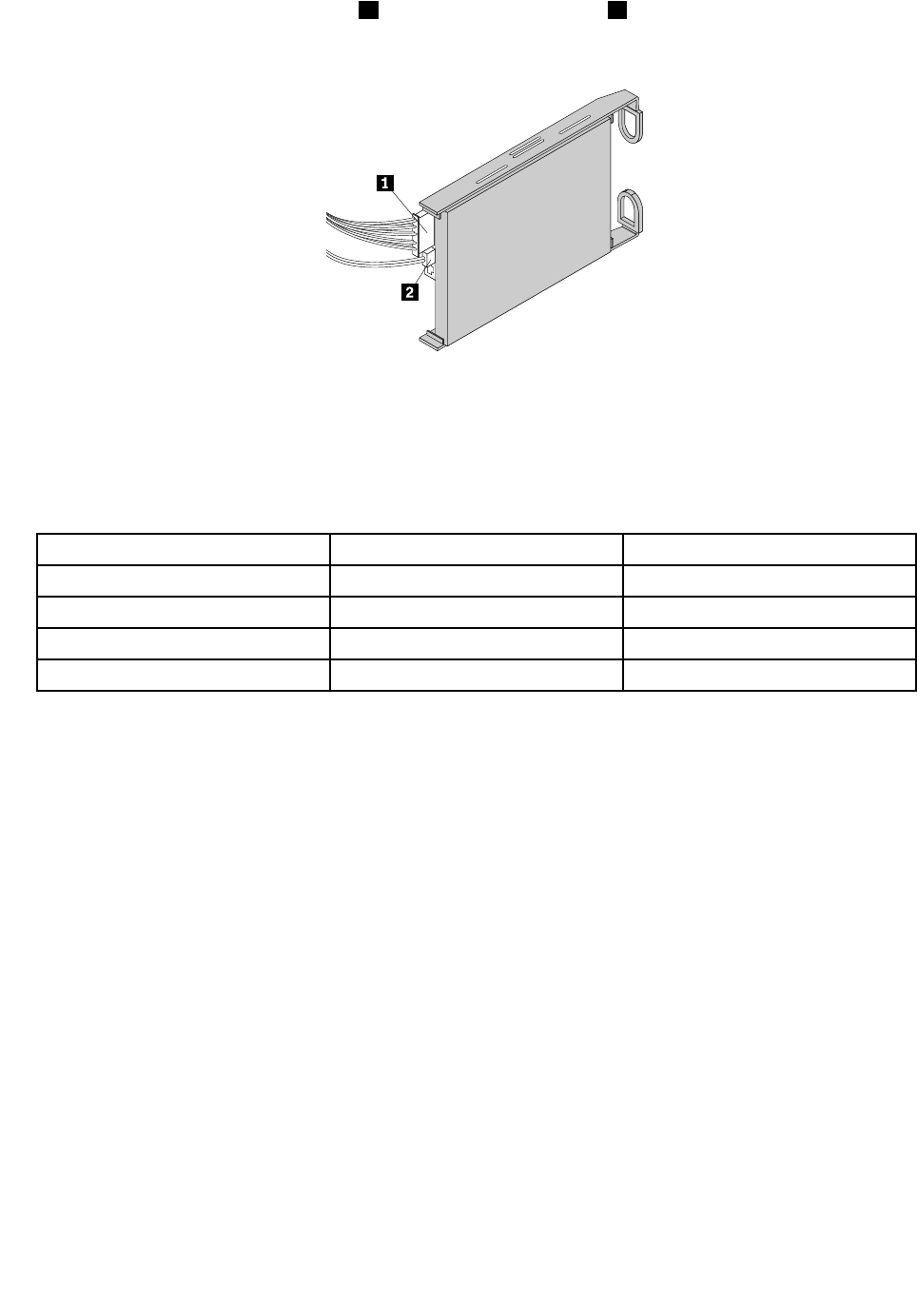
10.Connecttheappropriatepowercable1andtheSATAsignalcable2totherearofthenon-hot-swap
harddiskdrive.
Figure69.Connectingcablestotherearofthenon-hot-swapharddiskdrive
Thefollowingtableprovidesinformationabouttherecommendedpowerconnectorandsystem
boardSATAconnectorforthenon-hot-swapharddiskdriveinstalledineachdrivebay.See“Server
components”onpage25and“Systemboardcomponents”onpage42forthelocationinformation
abouttheharddiskdrivebaysandSATAconnectorsonthesystemboard.
Non-hot-swapharddiskdrivePowerconnectorSystemboardSATAconnector
Installedinbay0P9powerconnectorSATAconnector0
Installedinbay1P10powerconnectorSATAconnector1
Installedinbay2P7powerconnectorSATAconnector2
Installedinbay3P8powerconnectorSATAconnector3
11.ConnecttheotherendoftheSATAsignalcabletotheappropriateSATAconnectoronthesystemboard.
See“Systemboardcomponents”onpage42.
12.Reinstallthefrontsystemfan1.See“Replacingthefrontsystemfan”onpage149.
132ThinkServerHardwareMaintenanceManual
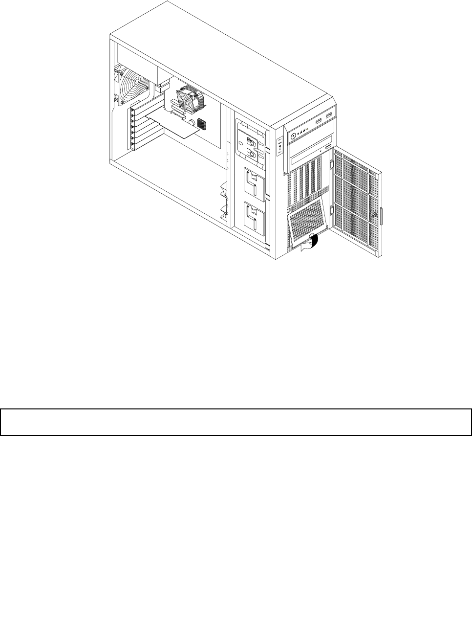
13.AlignthetopedgeoftheEMI-protectivepanelwiththetopsideoftheharddiskdrivecageandthen
pivottheEMI-protectivepaneldownuntilitsnapsintoposition.
Figure70.InstallingtheEMI-protectivepanel
14.Closeandlockthefrontdoor.
Whattodonext:
•Toworkwithanotherpieceofhardware,gototheappropriatesection.
•Tocompletetheinstallation,goto“Completingthepartsreplacement”onpage168.Then,youmight
needtorecongureRAIDforyourserver.See“ConguringRAID”onpage71.
Replacingthehot-swapharddiskdrivebackplane
Attention:Donotopenyourserverorattemptanyrepairbeforereadingandunderstandingthe“Safetyinformation”
onpageiiiand“Guidelines”onpage83.
Thistopicprovidesinstructionsonhowtoreplacethehot-swapharddiskdrivebackplane.
Thistopicappliesonlytoservermodelsthathavehot-swapharddiskdrive(s)installed.
Beforeyoubegin,printalltherelatedinstructionsorensurethatyoucanviewthePDFversiononanother
computerforreference.
Note:Dependingonthemodel,yourservermightlookslightlydifferentfromtheillustrationsinthistopic.
Toreplacethehot-swapharddiskdrivebackplane,dothefollowing:
1.Removeallmediafromthedrivesandturnoffallattacheddevicesandtheserver.Then,disconnectall
powercordsfromelectricaloutletsanddisconnectallcablesthatareconnectedtotheserver.
Chapter6.Installing,removing,orreplacinghardware133
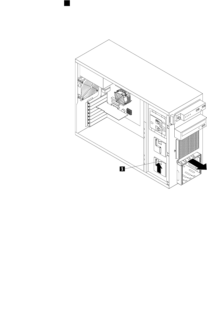
2.Removetheservercover.See“Removingtheservercover”onpage85.
3.Removethefrontbezel.See“Removingandreinstallingthefrontbezel”onpage87.
4.Locatethehot-swapharddiskdrivebackplane(s).See“Hot-swapharddiskdrivebackplane”on
page34.
5.Removethefrontsystemfan.See“Replacingthefrontsystemfan”onpage149.
6.Removealltheinstalledhot-swapharddiskdrivesanddummytrays(ifany)fromtheharddiskdrive
cage.See“Installingorreplacingahot-swapharddiskdrive”onpage119.
7.Notedownthecableconnectionsonthebackplaneandthendisconnectallthecablesfromthe
backplane.
8.Liftthereleaselatch1andslidetheharddiskdrivecageoutofthefrontofthechassis.
Note:Thefollowingillustrationshowsthe3.5-inchharddiskdrivecage.Forthe2.5-inchharddisk
drivecage,theremovalprocedureisthesame.
Figure71.Removingtheharddiskdrivecage
9.Dependingonwhetheryourserverhasa2.5-inchhot-swapharddiskdrivecagewithbackplaneor
3.5-inchhot-swapharddiskdrivecage(s)withbackplane(s),dooneofthefollowing:
134ThinkServerHardwareMaintenanceManual
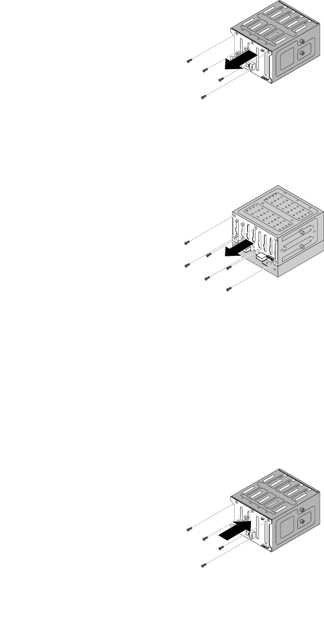
•Forthe3.5-inchhot-swapharddiskdrivebackplane,removethefourscrewsthatsecurethe
backplaneandthenremovethebackplanefromtheharddiskdrivecage.
Figure72.Removingthe3.5-inchhot-swapharddiskdrivebackplane
•Forthe2.5-inchhot-swapharddiskdrivebackplane,removethesixscrewsthatsecurethe
backplaneandthenremovethebackplanefromtheharddiskdrivecage.
Figure73.Removingthe2.5-inchhot-swapharddiskdrivebackplane
10.Touchthestatic-protectivepackagethatcontainsthenewhot-swapharddiskdrivebackplanetoany
unpaintedsurfaceontheoutsideoftheserver.Then,removethenewbackplanefromthepackage.
Note:Carefullyhandlethebackplanebyitsedges.
11.Positionthenewbackplaneontheharddiskdrivecagesothatthescrewholesinthenewbackplane
arealignedwiththecorrespondingholesintheharddiskdrivecage.Then,dooneofthefollowing
dependingontheharddiskdrivecage:
•Forthe3.5-inchhot-swapharddiskdrivecage,installthefourscrewstosecurethebackplaneon
thecage.
Figure74.Installingthe3.5-inchhot-swapharddiskdrivebackplane
Chapter6.Installing,removing,orreplacinghardware135
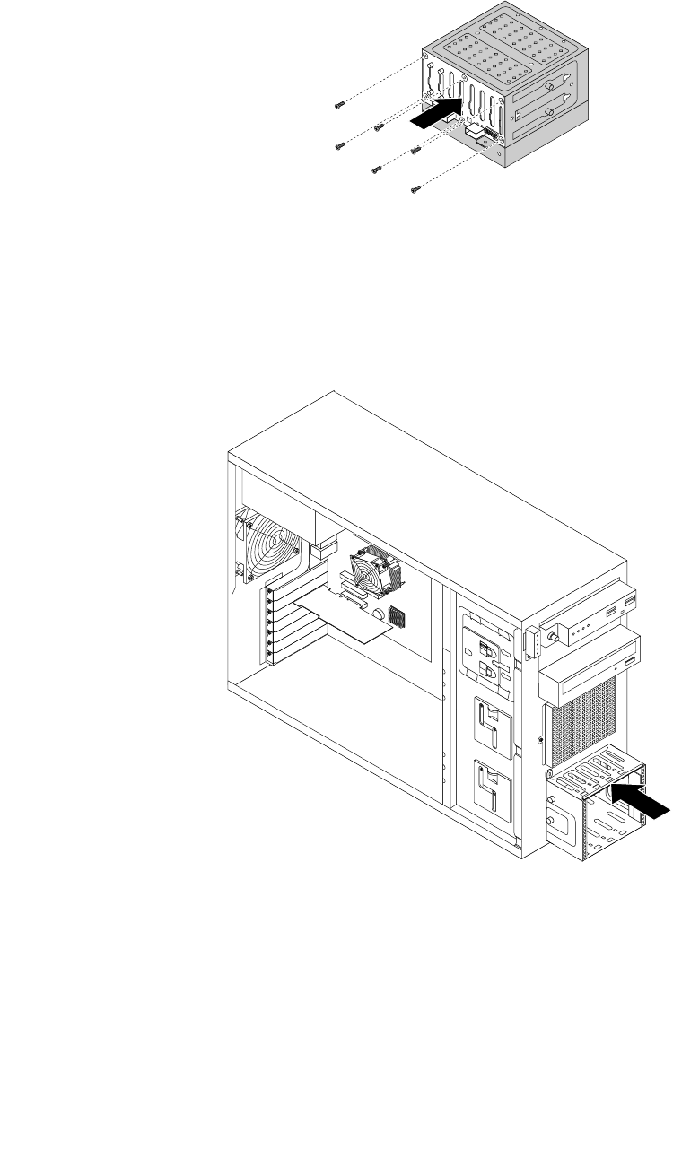
•Forthe2.5-inchhot-swapharddiskdrivecage,installthesixscrewstosecurethebackplaneon
thecage.
Figure75.Installingthe2.5-inchhot-swapharddiskdrivebackplane
12.Slidetheharddiskdrivecageintothechassisfromthefrontuntilitsnapsintoposition.
Note:Thefollowingillustrationshowsthe3.5-inchharddiskdrivecage.Forthe2.5-inchharddisk
drivecage,theinstallationprocedureisthesame.
Figure76.Installingtheharddiskdrivecage
13.Reinstallallthehot-swapharddiskdrivesanddummytrays(ifany)intheharddiskdrivecage.See
“Installingorreplacingahot-swapharddiskdrive”onpage119.
14.Refertoyournoteandreconnectthecablestothebackplane.
15.Reinstallthefrontsystemfan.See“Replacingthefrontsystemfan”onpage149.
16.Reinstallthefrontbezel.See“Removingandreinstallingthefrontbezel”onpage87.
136ThinkServerHardwareMaintenanceManual
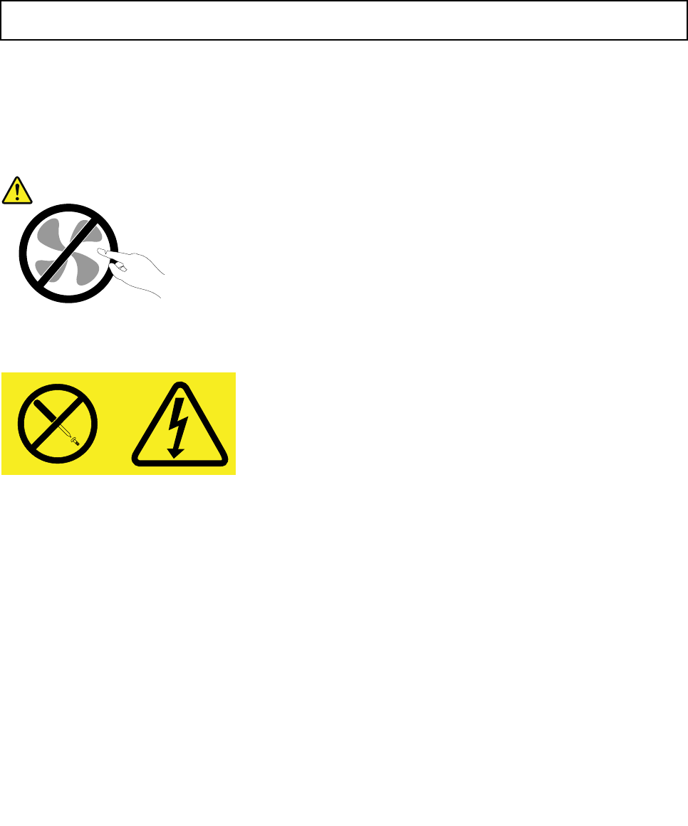
17.Ifyouareinstructedtoreturntheoldhot-swapharddiskdrivebackplane,followallpackaging
instructionsanduseanypackagingmaterialsthataresuppliedtoyouforshipping.
Whattodonext:
•Toworkwithanotherpieceofhardware,gototheappropriatesection.
•Tocompletethereplacement,goto“Completingthepartsreplacement”onpage168.
Replacingthenon-hot-swappowersupplyassembly
Attention:Donotopenyourserverorattemptanyrepairbeforereadingandunderstandingthe“Safetyinformation”
onpageiiiand“Guidelines”onpage83.
Thistopicprovidesinstructionsonhowtoreplacethenon-hot-swappowersupplyassembly.
Thistopicappliesonlytoservermodelsthatcomewithanon-hot-swappowersupplyassembly.
CAUTION:
Hazardousmovingparts.Keepngersandotherbodypartsaway.
CAUTION:
Neverremovethecoveronapowersupplyoranypartthathasthefollowinglabelattached.
Hazardousvoltage,current,andenergylevelsarepresentinsideanycomponentthathasthislabel
attached.Therearenoserviceablepartsinsidethesecomponents.Ifyoususpectaproblemwith
oneoftheseparts,contactaservicetechnician.
Beforeyoubegin,printalltherelatedinstructionsorensurethatyoucanviewthePDFversiononanother
computerforreference.
Note:Dependingonthemodel,yourservermightlookslightlydifferentfromtheillustrationsinthistopic.
Toreplacethenon-hot-swappowersupplyassembly,dothefollowing:
1.Removeallmediafromthedrivesandturnoffallattacheddevicesandtheserver.Then,disconnectall
powercordsfromelectricaloutletsanddisconnectallcablesthatareconnectedtotheserver.
2.Removetheservercover.See“Removingtheservercover”onpage85.
3.Laytheserveronitssideforeasieroperation.
4.Removethefrontsystemfan(s).See“Replacingthefrontsystemfan”onpage149.
Chapter6.Installing,removing,orreplacinghardware137
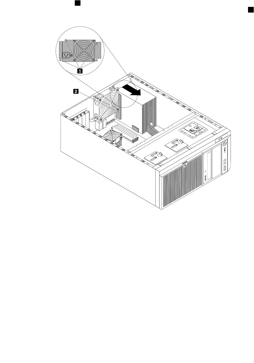
5.Notedownthecableroutingandconnection.Then,disconnectthepowersupplyassemblycablesfrom
thesystemboardandalldrives.Forservermodelswithhot-swapharddiskdrives,youalsoneedto
disconnectthepowercable(s)fromthehot-swapharddiskdrivebackplane(s).
6.Releasethepowersupplyassemblycablesfromthecableclipsandtiesinthechassis.
7.Removethefourscrews1attherearofthechassisthatsecurethepowersupplyassembly.Then,
pushthepowersupplyassemblyfromtherearuntilitisreleasedfromthemetalretainingtab2.
CPU
MEM
Figure77.Releasingthenon-hot-swappowersupplyassembly
138ThinkServerHardwareMaintenanceManual
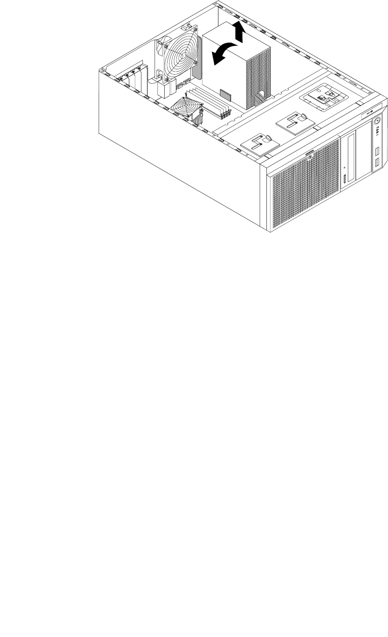
8.Pivotthepowersupplyassemblyalittlebitinthedirectionasshownandthenliftitoutofthechassis.
CPU
MEM
Figure78.Removingthenon-hot-swappowersupplyassembly
9.Touchthestatic-protectivepackagethatcontainsthenewpowersupplyassemblytoanyunpainted
surfaceontheoutsideoftheserver.Then,removethenewpowersupplyassemblyfromthepackage
andensurethatthenewpowersupplyassemblyisthecorrectreplacement.See“Features”onpage
7forinformationaboutthesupportedpowersupplyassemblies.
Chapter6.Installing,removing,orreplacinghardware139
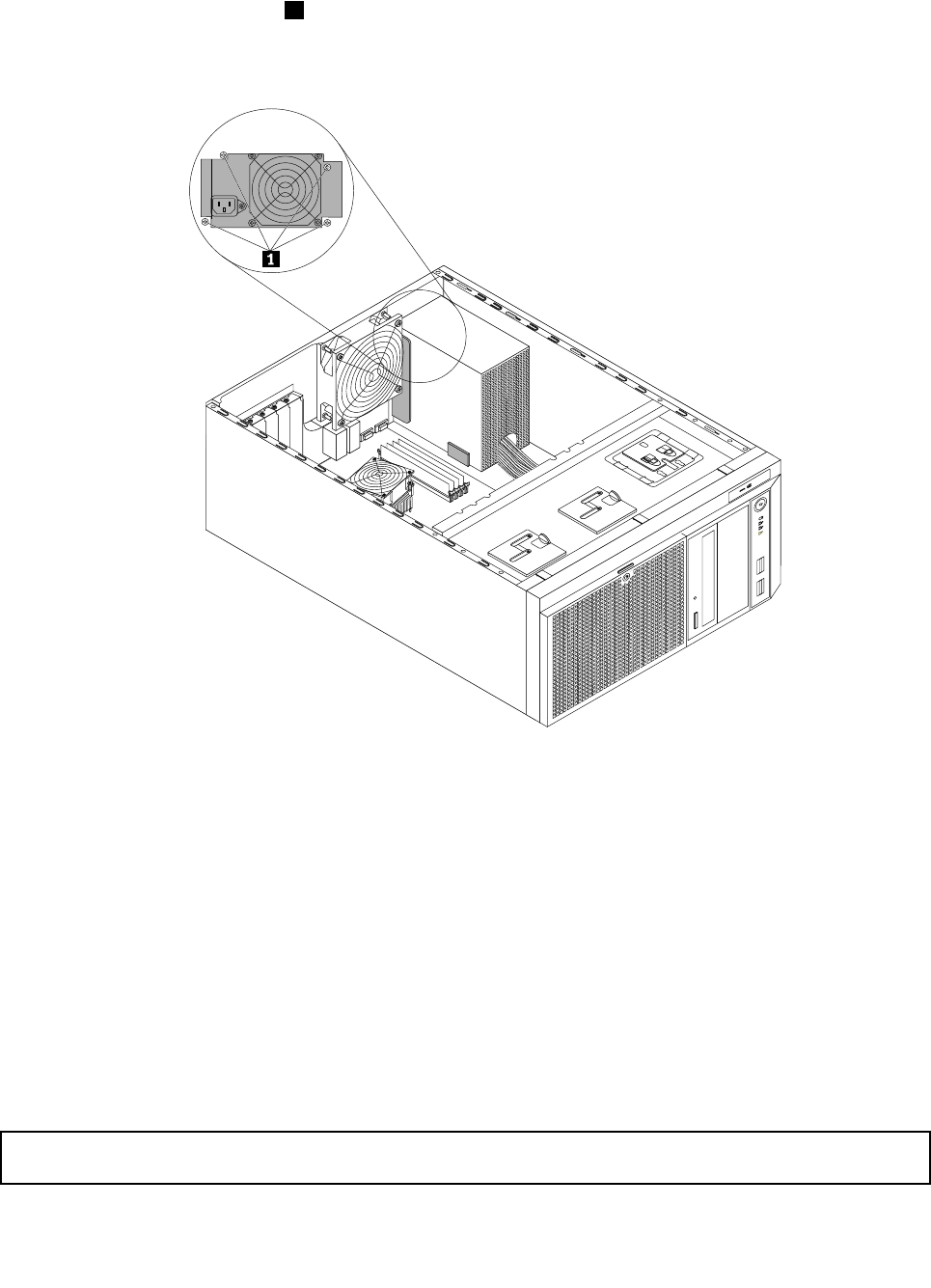
10.Installthenewpowersupplyassemblyintothechassissothatthefourscrewholesinthenewpower
supplyassemblyarealignedwiththecorrespondingholesmarkedwithAintherearofthechassis.
Then,installthefourscrews1tosecurethenewpowersupplyassemblyinplace.
Note:UseonlyscrewsprovidedbyLenovo.
CPU
MEM
Figure79.Installingthenon-hot-swappowersupplyassembly
11.Refertoyournoteandconnectthenewpowersupplyassemblycablestothesystemboard,alldrives,
andorhot-swapharddiskdrivebackplane(s),dependingonthemodel.Then,properlyroutethecables
andsecurethecableswiththecableclipsandtiesinthechassis.
12.Reinstallthefrontsystemfan(s).See“Replacingthefrontsystemfan”onpage149.
13.Ifyouareinstructedtoreturntheoldnon-hot-swappowersupplyassembly,followallpackaging
instructionsanduseanypackagingmaterialsthataresuppliedtoyouforshipping.
Whattodonext:
•Toworkwithanotherpieceofhardware,gototheappropriatesection.
•Tocompletethereplacement,goto“Completingthepartsreplacement”onpage168.
Replacingahot-swapredundantpowersupplymodule
Attention:Donotopenyourserverorattemptanyrepairbeforereadingandunderstandingthe“Safetyinformation”
onpageiiiand“Guidelines”onpage83.
140ThinkServerHardwareMaintenanceManual
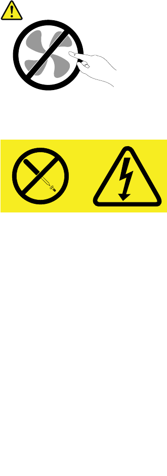
Thistopicprovidesinstructionsonhowtoreplaceahot-swapredundantpowersupplymodule.
Thistopicappliesonlytoservermodelsthatcomewithhot-swapredundantpowersupplymodule(s).For
eachhot-swapredundantpowersupplymodule,theremightbeoneortwostatusLEDsonthepower
supplymodulenearthepowercordconnector.WhenthegreenLEDislit,itindicatesthatthehot-swap
redundantpowersupplymoduleisworkingproperly.WhentheredLEDislit,itindicatesthatthehot-swap
redundantpowersupplymodulehasfailed.
Thehot-swapredundantpowersupplymoduleshelpyouavoidsignicantinterruptiontotheoperationof
thesystemwhenapowersupplymodulefailsandyoucanreplaceahot-swapredundantpowersupply
modulewithoutturningofftheserver.
Note:TomaintaintheEMIintegrityandcoolingoftheserver,installanewhot-swapredundantpower
supplymoduleassoonasyouremovethefailingoneorcovertheotherbaywithashieldifyoujustuse
onemoduletoprovidepower.
CAUTION:
Hazardousmovingparts.Keepngersandotherbodypartsaway.
CAUTION:
Neverremovethecoveronapowersupplyoranypartthathasthefollowinglabelattached.
Hazardousvoltage,current,andenergylevelsarepresentinsideanycomponentthathasthislabel
attached.Therearenoserviceablepartsinsidethesecomponents.Ifyoususpectaproblemwith
oneoftheseparts,contactaservicetechnician.
Beforeyoubegin,printalltherelatedinstructionsorensurethatyoucanviewthePDFversiononanother
computerforreference.
Notes:
1.Yourhot-swapredundantpowersupplymodulemightlookslightlydifferentfromtheillustrationsin
thistopic.
2.Useanydocumentationthatcomeswiththenewhot-swapredundantpowersupplymoduleandfollow
thoseinstructionsinadditiontotheinstructionsinthistopic.
Toreplaceahot-swapredundantpowersupplymodule,dothefollowing:
Chapter6.Installing,removing,orreplacinghardware141
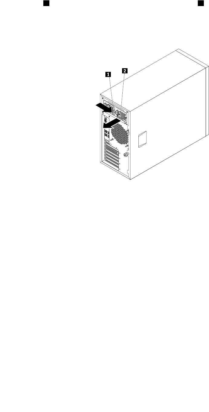
1.Locatethefailinghot-swapredundantpowersupplymoduleontherearofyourserver.Then,pressthe
releasetab1inthedirectionasshownandcarefullypullthehandle2atthesametimetoslidethe
redundantpowersupplymoduleoutofthechassis.
Note:Donotusetoomuchstrength.Youcanrstcarefullyslidetheredundantpowersupplymodulea
littlebitouttoreleaseitfromthesecuredposition.Then,completelyslideitoutofthechassis.
Figure80.Removingahot-swapredundantpowersupplymodule
2.Touchthestatic-protectivepackagethatcontainsthenewhot-swapredundantpowersupplymodule
toanyunpaintedsurfaceontheoutsideoftheserver.Then,removethenewhot-swapredundant
powersupplymodulefromthepackage.
142ThinkServerHardwareMaintenanceManual
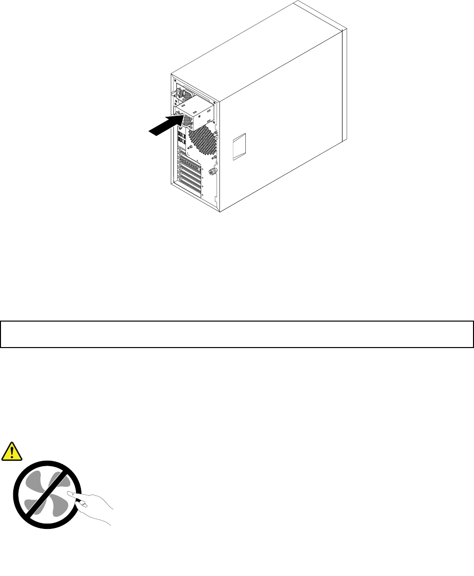
3.Notetheorientationofthehot-swapredundantpowersupplymoduleandthenslidethenewhot-swap
redundantpowersupplymoduleintothechassisuntilitsnapsintoposition.
Note:Ifyourservercomeswithonehot-swapredundantpowersupplymoduleinstalledinthe
redundantpowersupplymodulebay1(thebaynumberismarkedontherearofthechassis)andyou
areinstallingasecondaryhot-swapredundantpowersupplymoduletoprovideredundantpower,you
needtoremovetheshieldthatprotectsthebay2rst.Savetheshieldforfutureuse.
Figure81.Installingahot-swapredundantpowersupplymodule
4.Ifyouareinstructedtoreturntheoldhot-swapredundantpowersupplymodule,followallpackaging
instructionsanduseanypackagingmaterialsthataresuppliedtoyouforshipping.
5.Toworkwithanotherpieceofhardware,gototheappropriatesection.
Replacingthepowerdistributionboardandcageassembly
Attention:Donotopenyourserverorattemptanyrepairbeforereadingandunderstandingthe“Safetyinformation”
onpageiiiand“Guidelines”onpage83.
Thistopicprovidesinstructionsonhowtoreplacethepowerdistributionboardandcageassembly.
Thistopicappliesonlytoservermodelsthatcomewithhot-swapredundantpowersupplymodules.
CAUTION:
Hazardousmovingparts.Keepngersandotherbodypartsaway.
Chapter6.Installing,removing,orreplacinghardware143

CAUTION:
Neverremovethecoveronapowersupplyoranypartthathasthefollowinglabelattached.
Hazardousvoltage,current,andenergylevelsarepresentinsideanycomponentthathasthislabel
attached.Therearenoserviceablepartsinsidethesecomponents.Ifyoususpectaproblemwith
oneoftheseparts,contactaservicetechnician.
Beforeyoubegin,printalltherelatedinstructionsorensurethatyoucanviewthePDFversiononanother
computerforreference.
Note:Dependingonthemodel,yourservermightlookslightlydifferentfromtheillustrationsinthistopic.
Toreplacethepowerdistributionboardandcageassembly,dothefollowing:
1.Removeallmediafromthedrivesandturnoffallattacheddevicesandtheserver.Then,disconnectall
powercordsfromelectricaloutletsanddisconnectallcablesthatareconnectedtotheserver.
2.Removethehot-swapredundantpowersupplymodule(s).See“Replacingahot-swapredundant
powersupplymodule”onpage140.
Note:Ifyourservercomeswithonehot-swapredundantpowersupplymoduleinstalledinthe
redundantpowersupplymodulebay1(thebaynumberismarkedontherearofthechassis),thereisa
shiedinstalledonbay2toprotecttheemptybay.Removetheshieldandsaveitforfutureuse.
3.Removetheservercover.See“Removingtheservercover”onpage85.
4.Laytheserveronitssideforeasieroperation.
5.Removethefrontsystemfan(s).See“Replacingthefrontsystemfan”onpage149.
6.Notedownthecableroutingandconnection.Then,disconnectthepowercablesofthepower
distributionboardandcageassemblyfromthesystemboardandalldrives.Forservermodelswith
hot-swapharddiskdrives,youalsoneedtodisconnectthepowercable(s)fromthehot-swaphard
diskdrivebackplane(s).
7.Releasethepowercablesofthepowerdistributionboardandcageassemblyfromthecableclips
andtiesinthechassis.
144ThinkServerHardwareMaintenanceManual
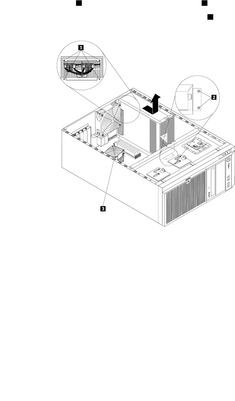
8.Removethefourscrews1attherearofthechassisandthetwoscrews2onthemetalclipatthe
frontofthepowerdistributionboardandcageassembly.Then,pushthepowerdistributionboardand
cageassemblyfromtherearuntilitisreleasedfromthemetalretainingtab3andthencarefullylift
itoutofthechassis.
Figure82.Removingthepowerdistributionboardandcageassembly
9.Touchthestatic-protectivepackagethatcontainsthenewpowerdistributionboardandcageassembly
toanyunpaintedsurfaceontheoutsideoftheserver.Then,removethenewpowerdistributionboard
andcageassemblyfromthepackage.
Chapter6.Installing,removing,orreplacinghardware145
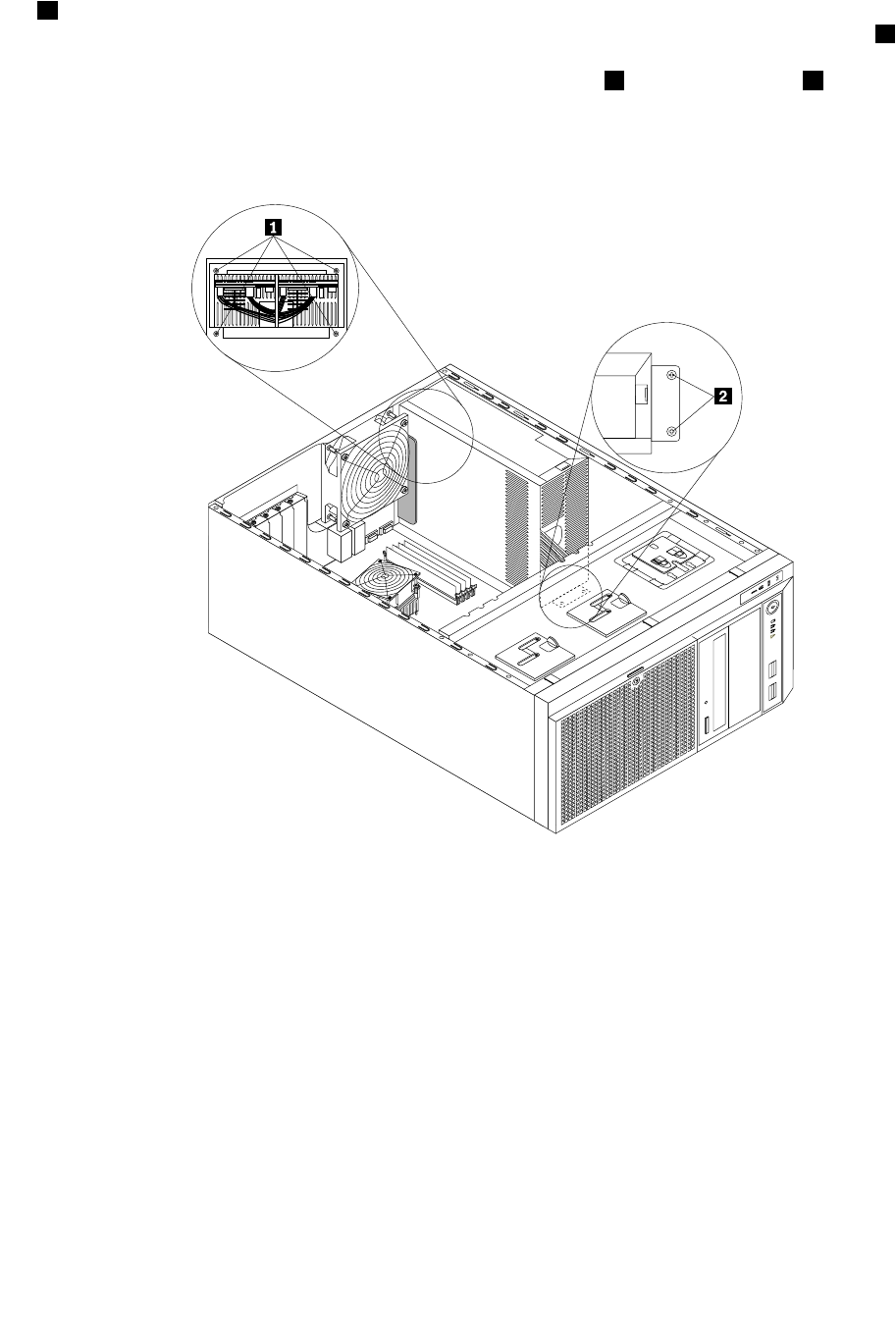
10.Installthenewpowerdistributionboardandcageassemblyintothechassissothatthefourscrewholes
1intherearofthenewpowerdistributionboardandcageassemblyarealignedwiththecorresponding
holesmarkedwithRintherearofthechassis.Meanwhile,makesurethatthetwoscrewholes2in
themetalclipatthefrontofthenewpowerdistributionboardandcageassemblyarealignedwiththe
correspondingholesinthechassis.Then,installthefourscrews1andthetwoscrews2tosecurethe
newpowerdistributionboardandcageassemblyinplace.
Note:UseonlyscrewsprovidedbyLenovo.
Figure83.Installingthepowerdistributionboardandcageassembly
11.Refertoyournoteandconnectthepowercablesofthenewpowerdistributionboardandcageassembly
tothesystemboard,alldrives,andorhot-swapharddiskdrivebackplane(s),dependingonthemodel.
Then,properlyroutethecablesandsecurethecableswiththecableclipsandtiesinthechassis.
12.Reinstallthefrontsystemfan(s).See“Replacingthefrontsystemfan”onpage149.
13.Reinstallthehot-swapredundantpowersupplymodule(s)andortheprotectiveshieldfortheredundant
powersupplymodulebay2.See“Replacingahot-swapredundantpowersupplymodule”onpage140.
14.Ifyouareinstructedtoreturntheoldpowerdistributionboardandcageassembly,followallpackaging
instructionsanduseanypackagingmaterialsthataresuppliedtoyouforshipping.
Whattodonext:
•Toworkwithanotherpieceofhardware,gototheappropriatesection.
•Tocompletethereplacement,goto“Completingthepartsreplacement”onpage168.
146ThinkServerHardwareMaintenanceManual

Replacingthefrontpanelboardassembly
Attention:Donotopenyourserverorattemptanyrepairbeforereadingandunderstandingthe“Safetyinformation”
onpageiiiand“Guidelines”onpage83.
Thistopicprovidesinstructionsonhowtoreplacethefrontpanelboardassembly.
Beforeyoubegin,printalltherelatedinstructionsorensurethatyoucanviewthePDFversiononanother
computerforreference.
Note:Dependingonthemodel,yourservermightlookslightlydifferentfromtheillustrationsinthistopic.
Toreplacethefrontpanelboardassembly,dothefollowing:
1.Removeallmediafromthedrivesandturnoffallattacheddevicesandtheserver.Then,disconnectall
powercordsfromelectricaloutletsanddisconnectallcablesthatareconnectedtotheserver.
2.Removetheservercover.See“Removingtheservercover”onpage85.
3.Removethefrontbezel.See“Removingandreinstallingthefrontbezel”onpage87.
4.Locatethefrontpanel.See“Frontpanel”onpage17.
5.Removethefrontsystemfan(s).See“Replacingthefrontsystemfan”onpage149.
6.Disconnectthesignalcablesofthefrontpanelboardassemblyfromtheinternaldual-portUSB2.0
connector1andthefrontpanelconnectoronthesystemboard.See“Systemboardcomponents”
onpage42.
7.Ifnecessary,removeanypartsordisconnectanycablesthatmightimpedeyouraccesstothesignal
cablesofthefrontpanelboardassembly.Notedownthecableroutingandthenreleasethesignal
cablesofthefrontpanelboardassemblyfromanycableclipsortiesinthechassis.
Chapter6.Installing,removing,orreplacinghardware147
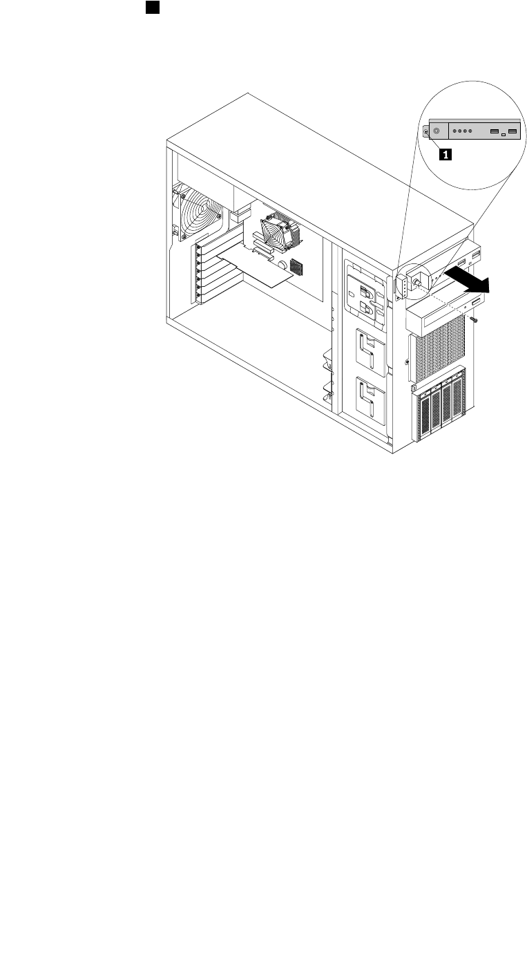
8.Removethescrew1onthechassisthatsecuresthefrontpanelboardassembly.Then,carefully
removethefrontpanelboardassemblyfromthechassisandpullthesignalcablesofthefrontpanel
boardassemblyoutofthechassis.
Figure84.Removingthefrontpanelboardassembly
9.Touchthestatic-protectivepackagethatcontainsthenewfrontpanelboardassemblytoanyunpainted
surfaceontheoutsideoftheserver.Then,takethenewfrontpanelboardassemblyoutofthepackage.
10.Notethecableconnection.Then,disconnectthesignalcablesfromtherearoftheoldfrontpanelboard
assemblyandconnectthemtotherearofthenewone.
148ThinkServerHardwareMaintenanceManual
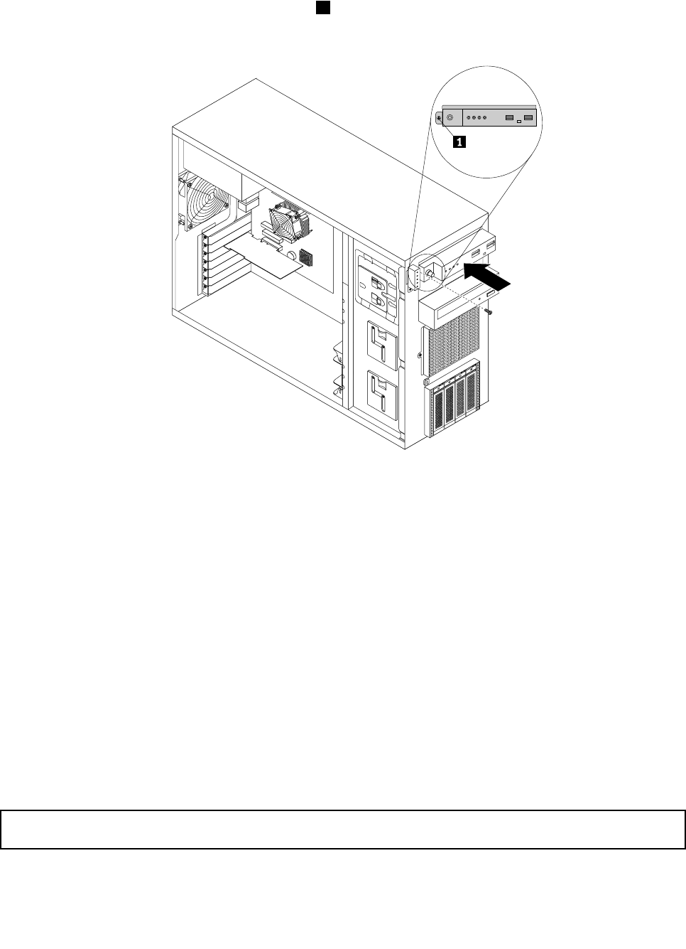
11.Routethesignalcablesofthenewfrontpanelboardassemblythroughthecorrespondingholeinthe
chassisandpositionthenewfrontpanelboardassemblyonthechassissothatthescrewholeinit
isalignedwiththecorrespondingscrewhole1inthechassis.Then,installthescrewtosecurethe
frontpanelboardassemblyinplace.
Figure85.Installingthefrontpanelboardassembly
12.ConnectthefrontpanelUSBcabletotheinternaldual-portUSB2.0connector1onthesystemboard.
Then,connectthefrontpanelcabletothefrontpanelconnectoronthesystemboard.See“System
boardcomponents”onpage42.
13.Properlyroutethesignalcablesofthenewfrontpanelboardassemblyaccordingtoyournote.You
mightneedtosecurethesignalcableswithcableclipsortiesinthechassis.
14.Reinstallthefrontsystemfan(s).See“Replacingthefrontsystemfan”onpage149.
15.Reinstallthefrontbezel.See“Removingandreinstallingthefrontbezel”onpage87.
16.Ifyouareinstructedtoreturntheoldfrontpanelboardassembly,followallpackaginginstructionsand
useanypackagingmaterialsthataresuppliedtoyouforshipping.
Whattodonext:
•Toworkwithanotherpieceofhardware,gototheappropriatesection.
•Tocompletethereplacement,goto“Completingthepartsreplacement”onpage168.
Replacingthefrontsystemfan
Attention:Donotopenyourserverorattemptanyrepairbeforereadingandunderstandingthe“Safetyinformation”
onpageiiiand“Guidelines”onpage83.
Thistopicprovidesinstructionsonhowtoreplacethefrontsystemfan.
Chapter6.Installing,removing,orreplacinghardware149
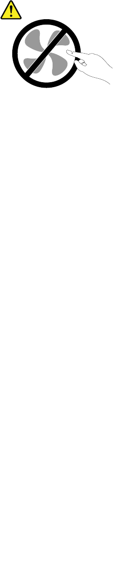
Dependingonthemodel,yourservermightcomewithoneortwofrontsystemfans.See“Server
components”onpage25tolocatethefrontsystemfan(s)installedinyourservermodel.
Note:Thefrontsystemfan2isonlyavailableinservermodelswithvetoeight3.5-inchhot-swapharddisk
drivesinstalled.Thefrontsystemfan2shouldonlybefactory-installed.Lenovodoesnotsupportusers
andservicerstoinstallasecondaryfrontsystemfanbythemselves.
CAUTION:
Hazardousmovingparts.Keepngersandotherbodypartsaway.
Beforeyoubegin,printalltherelatedinstructionsorensurethatyoucanviewthePDFversiononanother
computerforreference.
Note:Dependingonthemodel,yourservermightlookslightlydifferentfromtheillustrationsinthistopic.
Toreplacethefrontsystemfan,dothefollowing:
1.Removeallmediafromthedrivesandturnoffallattacheddevicesandtheserver.Then,disconnectall
powercordsfromelectricaloutletsanddisconnectallcablesthatareconnectedtotheserver.
2.Removetheservercover.See“Removingtheservercover”onpage85.
3.Locatethefrontsystemfan1.See“Servercomponents”onpage25.
4.Disconnectthefrontsystemfan1cablefromthe4-pinsystemfan1connectoronthesystemboard.
See“Systemboardcomponents”onpage42.
150ThinkServerHardwareMaintenanceManual
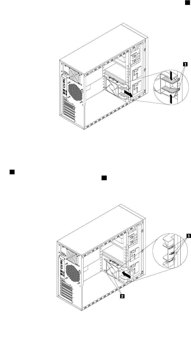
5.Pressthetwotabsofthefrontsystemfantowardseachotheruntilthetwotips1arealignedwiththe
correspondingholesinthechassis.Then,carefullyslidethefrontsystemfanoutofthechassis.
Figure86.Removingthefrontsystemfan
6.Touchthestatic-protectivepackagethatcontainsthenewfrontsystemfantoanyunpaintedsurfaceon
theoutsideoftheserver.Then,removethenewfrontsystemfanfromthepackage.
7.Positionthenewfrontsystemfanonthesystemfan1mountingareaofthechassissothatthethreetips
1onthebottomofthefrontsystemfanarealignedwiththecorrespondingholesinthemountingarea.
Meanwhile,makesurethatthetwoposts2ofthefrontsystemfanarealignedwiththecorresponding
holesintheinnersideofthechassis.Then,carefullyslidethefrontsystemfanintothechassisuntil
itsnapsintoposition.
Figure87.Installingthefrontsystemfan
Chapter6.Installing,removing,orreplacinghardware151
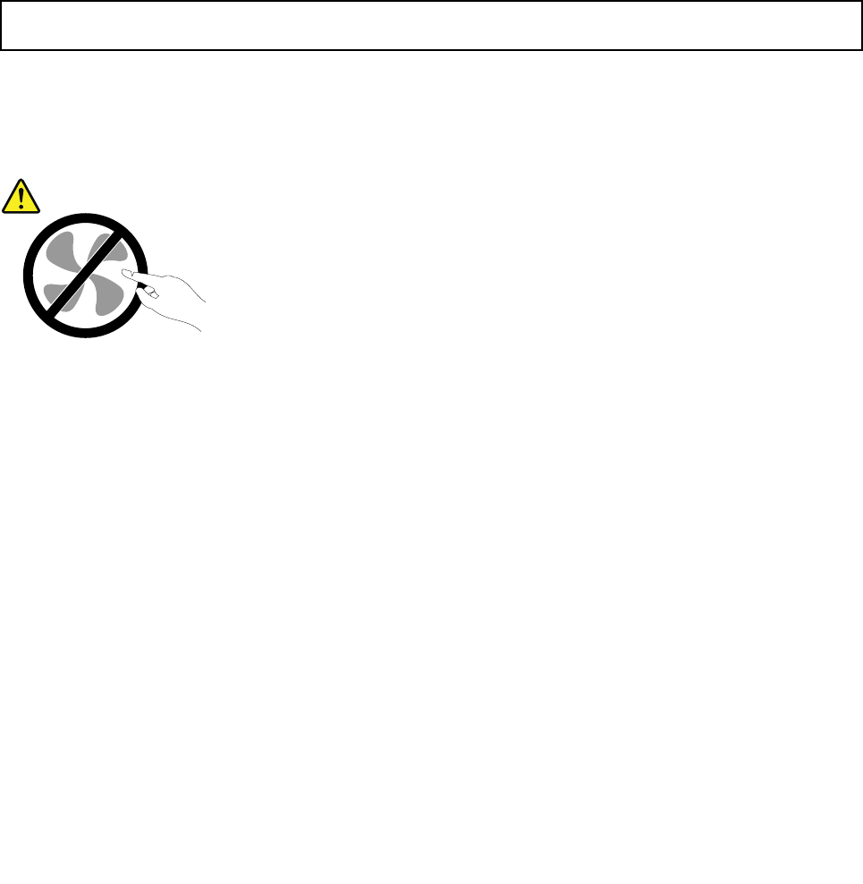
8.Connectthenewfrontsystemfancabletothe4-pinsystemfan1connectoronthesystemboard.
See“Systemboardcomponents”onpage42.
Note:Forservermodelswithvetoeight3.5-inchhot-swapharddiskdrives,thereisasecondaryfront
systemfaninstalledinthefrontsystemfan2mountingarea(abovethefrontsystemfan1mounting
area).Thecableofthesecondaryfrontsystemfanisconnectedtothe5-pinsystemfan2connectoron
thesystemboard.See“Systemboardcomponents”onpage42.
9.Ifyouareinstructedtoreturntheoldfrontsystemfan,followallpackaginginstructionsanduseany
packagingmaterialsthataresuppliedtoyouforshipping.
Whattodonext:
•Toworkwithanotherpieceofhardware,gototheappropriatesection.
•Tocompletethereplacement,goto“Completingthepartsreplacement”onpage168.
Replacingtherearsystemfan
Attention:Donotopenyourserverorattemptanyrepairbeforereadingandunderstandingthe“Safetyinformation”
onpageiiiand“Guidelines”onpage83.
Thistopicprovidesinstructionsonhowtoreplacetherearsystemfan.
CAUTION:
Hazardousmovingparts.Keepngersandotherbodypartsaway.
Beforeyoubegin,printalltherelatedinstructionsorensurethatyoucanviewthePDFversiononanother
computerforreference.
Note:Dependingonthemodel,yourservermightlookslightlydifferentfromtheillustrationsinthistopic.
Toreplacetherearsystemfan,dothefollowing:
1.Removeallmediafromthedrivesandturnoffallattacheddevicesandtheserver.Then,disconnectall
powercordsfromelectricaloutletsanddisconnectallcablesthatareconnectedtotheserver.
2.Removetheservercover.See“Removingtheservercover”onpage85.
3.Locatetherearsystemfan.See“Servercomponents”onpage25.
4.Disconnecttherearsystemfancablefromthesystemfan3connectoronthesystemboard.See
“Systemboardcomponents”onpage42.
152ThinkServerHardwareMaintenanceManual
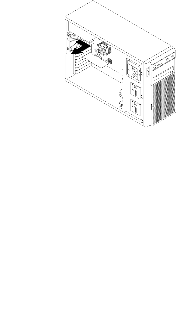
5.Therearsystemfanisattachedtothechassisbyfourrubbermounts.Removetherearsystemfanby
cuttingtherubbermountsandpullingtherearsystemfanoutofthechassis.
Figure88.Removingtherearsystemfan
6.Touchthestatic-protectivepackagethatcontainsthenewrearsystemfantoanyunpaintedsurfaceon
theoutsideoftheserver.Then,removethenewrearsystemfanfromthepackage.
Chapter6.Installing,removing,orreplacinghardware153
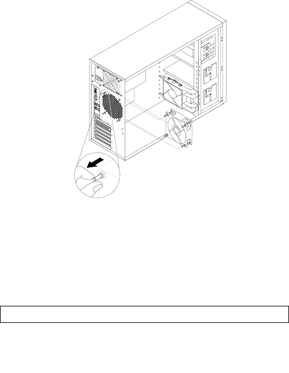
7.Positionthenewrearsystemfan,whichhasfournewrubbermountsattached,onthechassissothat
thefournewrubbermountsarealignedwiththecorrespondingholesinthechassis.Pushtherubber
mountsthroughtheholesandthenpullonthetipsoftherubbermountsfromtheothersideofthe
chassisuntiltherearsystemfanissecuredinplace.
Figure89.Installingtherearsystemfan
8.Connectthenewrearsystemfancabletothesystemfan3connectoronthesystemboard.See
“Systemboardcomponents”onpage42.
9.Ifyouareinstructedtoreturntheoldrearsystemfan,followallpackaginginstructionsanduseany
packagingmaterialsthataresuppliedtoyouforshipping.
Whattodonext:
•Toworkwithanotherpieceofhardware,gototheappropriatesection.
•Tocompletethereplacement,goto“Completingthepartsreplacement”onpage168.
Replacingtheheatsinkandfanassembly
Attention:Donotopenyourserverorattemptanyrepairbeforereadingandunderstandingthe“Safetyinformation”
onpageiiiand“Guidelines”onpage83.
Thistopicprovidesinstructionsonhowtoreplacetheheatsinkandfanassembly.
154ThinkServerHardwareMaintenanceManual
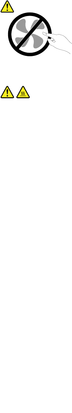
CAUTION:
Hazardousmovingparts.Keepngersandotherbodypartsaway.
CAUTION:
Theheatsinkandfanassemblymightbeveryhot.Turnofftheserverandwaitthreetoveminutesto
lettheservercoolbeforeremovingtheservercover.
Beforeyoubegin,printalltherelatedinstructionsorensurethatyoucanviewthePDFversiononanother
computerforreference.
Toreplacetheheatsinkandfanassembly,dothefollowing:
1.Removeallmediafromthedrivesandturnoffallattacheddevicesandtheserver.Then,disconnectall
powercordsfromelectricaloutletsanddisconnectallcablesthatareconnectedtotheserver.
2.Removetheservercover.See“Removingtheservercover”onpage85.
3.Locatetheheatsinkandfanassembly.See“Servercomponents”onpage25.
4.Laytheserveronitssideforeasieroperation.Ifnecessary,removeanyinstalledPCIcardthatmight
impedeyouraccesstotheheatsinkandfanassembly.See“RemovingaPCIcard”onpage95.
5.Disconnecttheheatsinkandfanassemblycablefromthemicroprocessorfanconnectoronthesystem
board.See“Systemboardcomponents”onpage42.
Chapter6.Installing,removing,orreplacinghardware155
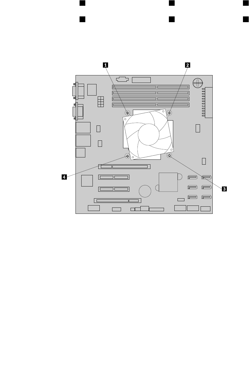
6.Removethefourscrewsthatsecuretheheatsinkandfanassemblytothesystemboard.Itis
recommendedthatyoucarefullyremovethefourscrewsfromthesystemboardusingthefollowing
methodtoavoidanypossibledamagetothesystemboard.
a.Partiallyremovescrew1,thencompletelyremovescrew3,andthenreturntoscrew1and
completelyremoveit.
b.Partiallyremovescrew2,thencompletelyremovescrew4,andthenreturntoscrew2and
completelyremoveit.
Note:Thefourscrewsareintegratedpartsoftheheatsinkandfanassembly.Donottrytoremovethe
fourscrewsfromtheheatsinkandfanassembly.
Figure90.Removingthescrewsthatsecuretheheatsinkandfanassembly
7.Gentlytwisttheheatsinkandfanassemblytofreeitfromthemicroprocessorandthenlifttheheatsink
andfanassemblyoffthesystemboard.
8.Layasidetheoldheatsinkandfanassembly.Touchthestatic-protectivepackagethatcontainsthenew
heatsinkandfanassemblytoanyunpaintedsurfaceontheoutsideoftheserver.Then,removethenew
heatsinkandfanassemblyfromthepackage.
Note:Whenhandlingtheheatsinkandfanassembly,donottouchthethermalgreaseonthebottomof
it.
9.Placethenewheatsinkandfanassemblyonthesystemboardsothatthefourscrewsonthenewheat
sinkandfanassemblyarealignedwiththecorrespondingmountingstudsonthesystemboard.Note
theorientationofthenewheatsinkandfanassemblyandmakesurethatyouproperlyplaceitsothat
youcaneasilyconnecttheheatsinkandfanassemblycabletothemicroprocessorfanconnectoron
thesystemboard.See“Systemboardcomponents”onpage42.
156ThinkServerHardwareMaintenanceManual
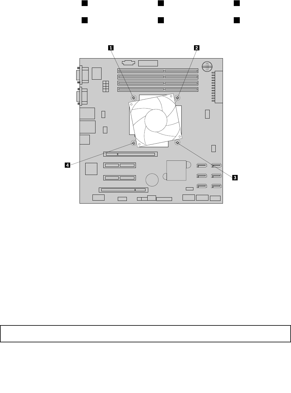
10.Installthefourscrewstosecurethenewheatsinkandfanassemblyonthesystemboard.Itis
recommendedthatyoucarefullyinstallthefourscrewsusingthefollowingmethodtoavoidanypossible
damagetothesystemboard.
a.Partiallytightenscrew1,thenrmlytightenscrew3,andthenreturntoscrew1andrmlytighten
it.Donotover-tightenthescrews.
b.Partiallytightenscrew2,thenrmlytightenscrew4,andthenreturntoscrew2andrmlytighten
it.Donotover-tightenthescrews.
Figure91.Installingthescrewstosecuretheheatsinkandfanassembly
11.Connecttheheatsinkandfanassemblycabletothemicroprocessorfanconnectoronthesystem
board.See“Systemboardcomponents”onpage42.
Note:Iftheheatsinkandfanassemblycableistoolong,looselyknotthecableforpropercablerouting.
12.Ifyouareinstructedtoreturntheoldheatsinkandfanassembly,followallpackaginginstructionsand
useanypackagingmaterialsthataresuppliedtoyouforshipping.
Whattodonext:
•Toworkwithanotherpieceofhardware,gototheappropriatesection.
•Tocompletethereplacement,goto“Completingthepartsreplacement”onpage168.
Replacingthemicroprocessor
Attention:Donotopenyourserverorattemptanyrepairbeforereadingandunderstandingthe“Safetyinformation”
onpageiiiand“Guidelines”onpage83.
Thistopicprovidesinstructionsonhowtoreplacethemicroprocessor.
Chapter6.Installing,removing,orreplacinghardware157
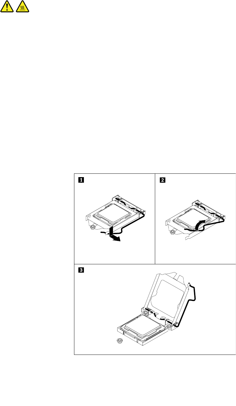
CAUTION:
Theheatsinkandfanassemblyandthemicroprocessormightbeveryhot.Turnofftheserverand
waitthreetoveminutestolettheservercoolbeforeremovingtheservercover.
Beforeyoubegin,printalltherelatedinstructionsorensurethatyoucanviewthePDFversiononanother
computerforreference.
Toreplacethemicroprocessor,dothefollowing:
1.Removeallmediafromthedrivesandturnoffallattacheddevicesandtheserver.Then,disconnectall
powercordsfromelectricaloutletsanddisconnectallcablesthatareconnectedtotheserver.
2.Removetheservercover.See“Removingtheservercover”onpage85.
3.Laytheserveronitssideforeasieroperation.
4.Removetheheatsinkandfanassembly.See“Replacingtheheatsinkandfanassembly”onpage154.
5.Gentlypressdownthesmallhandleonthemicroprocessorsocketandthenpullthehandlealittlebit
outwardtoreleaseitfromthesecuredposition.Then,pivotthehandleupwarduntilthehandleandthe
microprocessorretainerareinthefullyopenposition.
Note:Yourmicroprocessorandsocketmightlookdifferentfromtheoneillustrated.
Figure92.Liftingthehandletoopenthemicroprocessorretainer
158ThinkServerHardwareMaintenanceManual
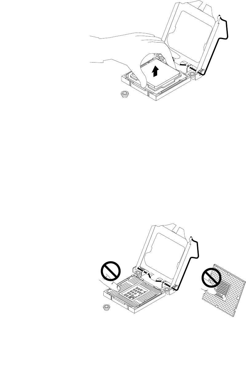
6.Touchonlytheedgesofthemicroprocessorandcarefullyliftitstraightupandoutofthemicroprocessor
socket.Placetheoldmicroprocessoronastatic-protectivesurface.
Note:Donottouchthegoldcontactsonthebottomofthemicroprocessor.
Figure93.Removingthemicroprocessor
7.Makesurethatthesmallhandleandthemicroprocessorretainerareinthefullyopenposition.
Note:Donotdropanythingontothemicroprocessorsocketwhileitisexposed.Thesocketpinsmust
bekeptascleanaspossible.
8.Touchthestatic-protectivepackagethatcontainsthenewmicroprocessortoanyunpaintedsurfaceon
theoutsideoftheserver.Then,removethenewmicroprocessorfromthepackage.
9.Removethenewmicroprocessorfromtheprotectivecoverthatprotectsthegoldcontactsonthe
bottomofthenewmicroprocessor.
Note:Donottouchthepinsonthemicroprocessorsocketandthegoldcontactsonthebottomofthe
newmicroprocessor.
Figure94.Donottouchthepins
Chapter6.Installing,removing,orreplacinghardware159
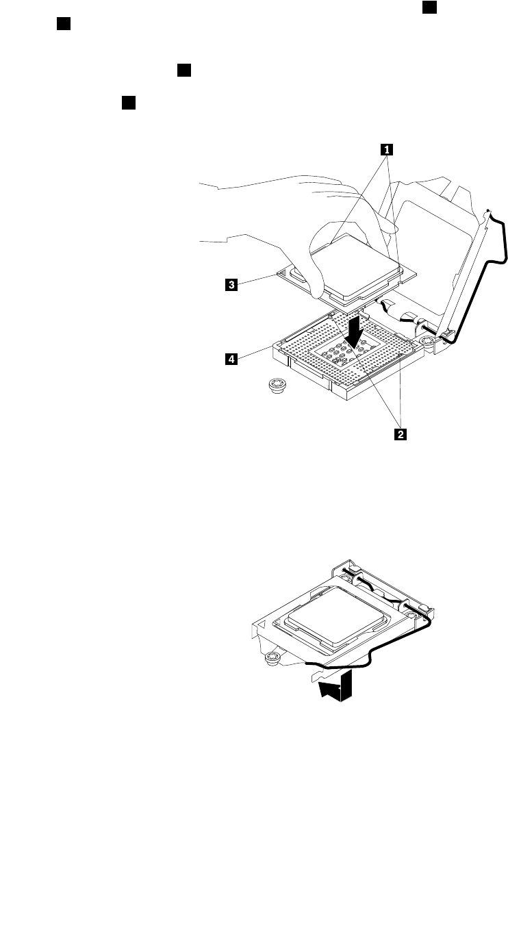
10.Holdthenewmicroprocessorbyitsedgesandalignthenotches1onthenewmicroprocessorwiththe
tabs2inthemicroprocessorsocket.Then,carefullylowerthenewmicroprocessorstraightdowninto
themicroprocessorsocket.
Note:Thesmalltriangle3ononecornerofthenewmicroprocessoristhemicroprocessororientation
indicator.Thenewmicroprocessorisinthecorrectorientationwhenthisindicatorfacestowardthe
beveledcorner4ofthemicroprocessorsocket.
Figure95.Installingthemicroprocessor
11.Closethemicroprocessorretainer.Gentlypressdownthesmallhandleandthenpushthehandleinward
tolocktheretainerintopositionandsecurethenewmicroprocessorinthesocket.
Figure96.Securingthemicroprocessorinthesocket
12.Reinstalltheheatsinkandfanassembly.See“Replacingtheheatsinkandfanassembly”onpage154.
13.Ifyouareinstructedtoreturntheoldmicroprocessor,followallpackaginginstructionsanduseany
packagingmaterialsthataresuppliedtoyouforshipping.
Whattodonext:
•Toworkwithanotherpieceofhardware,gototheappropriatesection.
•Tocompletethereplacement,goto“Completingthepartsreplacement”onpage168.
160ThinkServerHardwareMaintenanceManual
Replacingthesystemboardbattery
Attention:Donotopenyourserverorattemptanyrepairbeforereadingandunderstandingthe“Safetyinformation”
onpageiiiand“Guidelines”onpage83.
Thistopicprovidesinstructionsonhowtoreplacethesystemboardbattery.
Yourserverhasaspecialtypeofmemorythatmaintainsthedate,time,andcongurationinformationfor
built-infeatures.Thesystemboardbatterykeepstheinformationactivewhenyouturnofftheserver.The
systemboardbatterynormallyrequiresnochargingormaintenancethroughoutitslife;however,nobattery
lastsforever.Ifthesystemboardbatteryfails,thedate,time,andcongurationinformation,including
passwords,arelostandanerrormessageisdisplayedwhenyouturnontheserver.
DANGER
Dangerofexplosionifbatteryisincorrectlyreplaced.
Whenreplacingthelithiumcoincellbattery,useonlythesameoranequivalenttypethatis
recommendedbythemanufacturer.Thebatterycontainslithiumandcanexplodeifnotproperly
used,handled,ordisposedof.
Donot:
•Throworimmerseintowater
•Heattomorethan100°C(212°F)
•Repairordisassemble
Disposeofthebatteryasrequiredbylocalordinancesorregulations.
ThefollowingstatementappliestousersinthestateofCalifornia,U.S.A.
CaliforniaPerchlorateInformation:
ProductscontainingCR(manganesedioxide)lithiumcoincellbatteriesmaycontainperchlorate.
PerchlorateMaterial-specialhandlingmayapply,See
http://www.dtsc.ca.gov/hazardouswaste/perchlorate
Beforeyoubegin,printalltherelatedinstructionsorensurethatyoucanviewthePDFversiononanother
computerforreference.
Toreplacethesystemboardbattery,dothefollowing:
Note:Afteryoureplacethesystemboardbattery,youmustresetpasswords,resetsystemdateandtime,
andreconguretheserver.
1.Removeallmediafromthedrivesandturnoffallattacheddevicesandtheserver.Then,disconnectall
powercordsfromelectricaloutletsanddisconnectallcablesthatareconnectedtotheserver.
2.Removetheservercover.See“Removingtheservercover”onpage85.
3.Laytheserveronitssideforeasieroperation.
4.Locatethesystemboardbattery.See“Servercomponents”onpage25.
5.RemoveanyinstalledPCIcardthatimpedesyouraccesstothesystemboardbattery.See“Removinga
PCIcard”onpage95.
Chapter6.Installing,removing,orreplacinghardware161
6.Removetheoldsystemboardbattery.
Figure97.Removingthesystemboardbattery
7.Installanewsystemboardbattery.
Figure98.Installingthesystemboardbattery
8.ReinstallthePCIcardthathasbeenremoved.See“InstallingaPCIcard”onpage93.
9.Disposeoftheoldsystemboardbatteryasrequiredbylocalordinancesorregulations.
Whattodonext:
•Toworkwithanotherpieceofhardware,gototheappropriatesection.
•Tocompletethereplacement,goto“Completingthepartsreplacement”onpage168.Afteryoureplace
thesystemboardbattery,youmustresetpasswords,resetsystemdateandtime,andrecongurethe
server.SeeChapter5“Conguringtheserver”onpage55.
Replacingthesystemboard
Attention:Donotopenyourserverorattemptanyrepairbeforereadingandunderstandingthe“Safetyinformation”
onpageiiiand“Guidelines”onpage83.
Thistopicprovidesinstructionsonhowtoreplacethesystemboard.
CAUTION:
Hazardousmovingparts.Keepngersandotherbodypartsaway.
162ThinkServerHardwareMaintenanceManual

CAUTION:
Theheatsinkandmicroprocessormightbeveryhot.Turnofftheserverandwaitthreetoveminutes
tolettheservercoolbeforeremovingtheservercover.
Beforeyoubegin,printalltherelatedinstructionsorensurethatyoucanviewthePDFversiononanother
computerforreference.
Toreplacethesystemboard,dothefollowing:
1.Removeallmediafromthedrivesandturnoffallattacheddevicesandtheserver.Then,disconnectall
powercordsfromelectricaloutletsanddisconnectallcablesthatareconnectedtotheserver.
2.Removetheservercover.See“Removingtheservercover”onpage85.
3.Laytheserveronitssideforeasieroperation.
4.Notedownthecomponentlocations,cableconnections,andcableroutingintheserver.
5.RemoveallmemorymodulesandPCIcards(includingtheRAIDcardandEthernetcard)thatarecurrently
installed.See“Removingamemorymodule”onpage92and“RemovingaPCIcard”onpage95.
6.Removetheheatsinkandfanassembly.See“Replacingtheheatsinkandfanassembly”onpage154.
7.RemovetheTPMmoduleifoneisinstalled.See“RemovingtheTPMmodule”onpage110.
8.RemovetheThinkServerSATASoftwareRAID5keyifoneisinstalled.See“Removingthesystem
boardRAID5key”onpage104.
9.RemovetheThinkServeriKVMRemoteManagementModuleifoneisinstalled.See“Removingthe
iKVMkey”onpage107.
10.Removethesystemboardbattery.See“Replacingthesystemboardbattery”onpage161.
11.Removeanyotherpartsanddisconnectallcablesfromthesystemboard.
Chapter6.Installing,removing,orreplacinghardware163
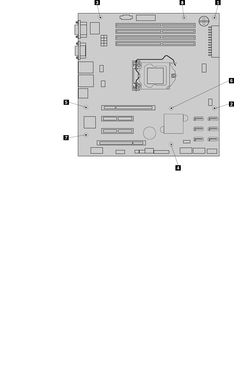
12.Removetheeightscrewsthatsecurethesystemboardfollowingtherecommendednumericalsequence
asshown.Then,carefullyremovethesystemboardoutofthechassis.
Figure99.Removingthescrewsthatsecurethesystemboard
13.Placeboththeoldsystemboardandthenewsystemboardonaclean,at,andESD-safesurface.
164ThinkServerHardwareMaintenanceManual
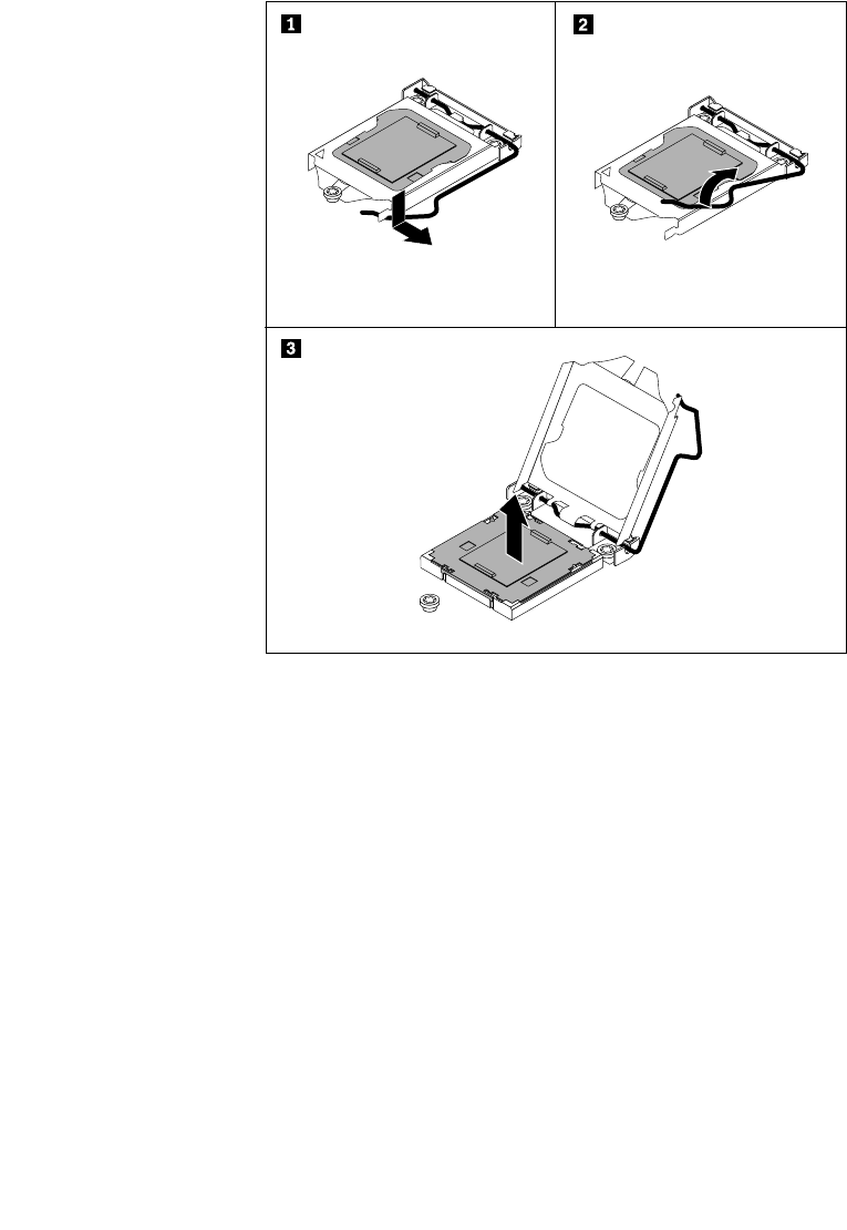
14.Forthenewsystemboard,gentlypressdownthesmallhandleonthemicroprocessorsocketand
thenpullthehandlealittlebitoutwardtoreleaseitfromthesecuredposition.Then,pivotthehandle
upwarduntilthehandleandthemicroprocessorretainerareinthefullyopenposition.Removethe
microprocessorsocketcoverfromthenewsystemboard.
Notes:
a.Yourmicroprocessorsocketandcovermightlookslightlydifferentfromtheillustration.
b.Donotdropanythingontothemicroprocessorsocketwhileitisexposed.Thesocketpinsmustbe
keptascleanaspossible.
Figure100.Removingthemicroprocessorsocketcover
15.Removethemicroprocessorfromtheoldsystemboardandinstallitdirectlyonthenewsystemboard.
See“Replacingthemicroprocessor”onpage157.
16.Theoldsystemboardmustbereturnedwithamicroprocessorsocketcovertoprotectthepinsonthe
socketduringshippingandhandling.Usethemicroprocessorsocketcoverremovedfromthenew
systemboard.Toinstallitontheoldsystemboard,dothefollowing:
a.Makesurethatthesmallhandleandthemicroprocessorretainerareinthefullyopenposition.
Chapter6.Installing,removing,orreplacinghardware165
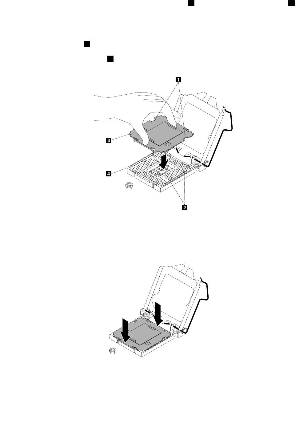
b.Holdthemicroprocessorsocketcoverandalignthenotches1onthesocketcoverwiththetabs2
inthemicroprocessorsocket.Then,carefullylowerthesocketcoverstraightdownintothesocket.
Notes:
1)Yourmicroprocessorsocketandcovermightlookslightlydifferentfromtheillustration.
2)Thesmalltriangle3ononecornerofthemicroprocessorsocketcoveristheorientation
indicator.Themicroprocessorsocketcoverisinthecorrectorientationwhenthisindicatorfaces
towardthebeveledcorner4ofthemicroprocessorsocket.
Figure101.Installingthemicroprocessorsocketcover
c.Makesurethatthemicroprocessorsocketcoverisproperlyseatedandthengentlypressitdown
untilitissecurelyseatedinthesocket.
Figure102.Seatingthemicroprocessorsocketcoverinthesocket
166ThinkServerHardwareMaintenanceManual
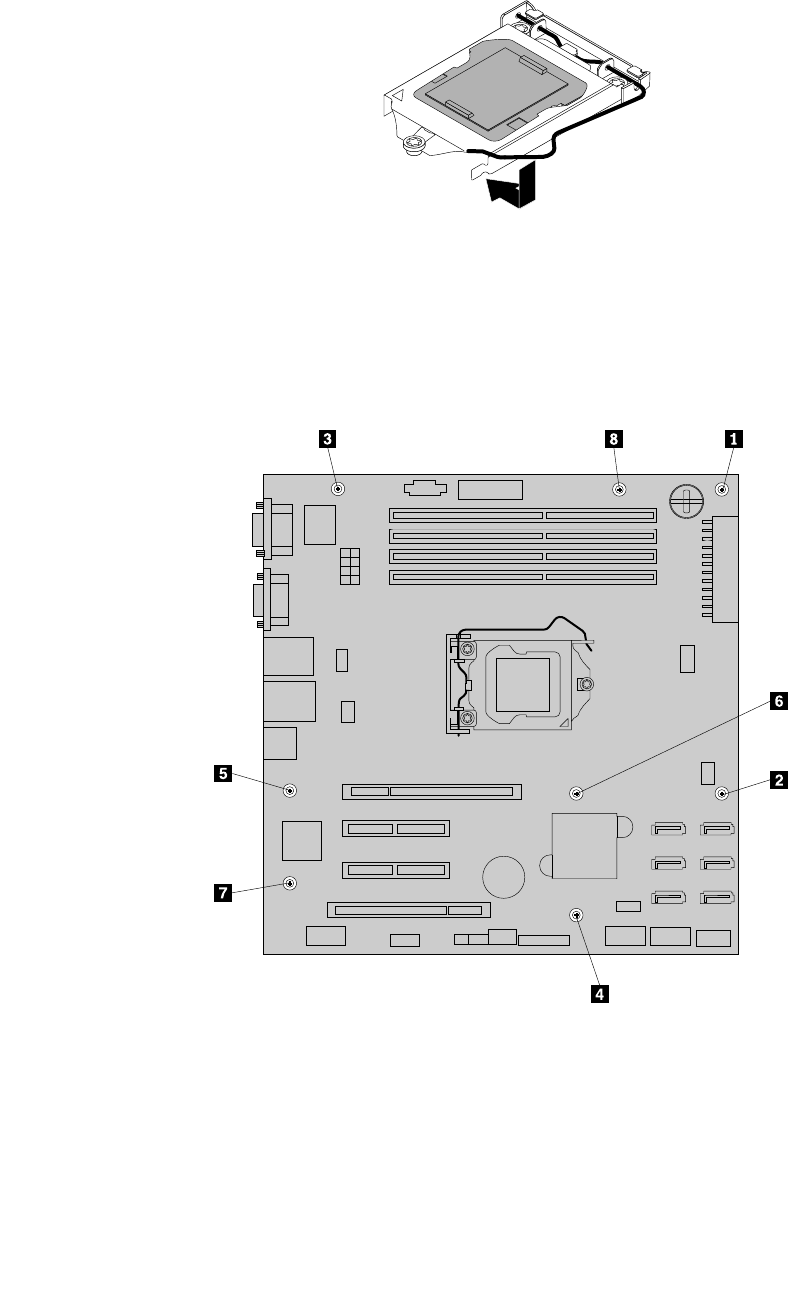
d.Closethemicroprocessorretainer.Gentlypressdownthesmallhandleandthenpushthehandle
inwardtolocktheretainerintopositionandsecurethemicroprocessorsocketcoverinthesocket.
Figure103.Securingthemicroprocessorsocketcover
17.Notetheorientationofthenewsystemboardandcarefullyplaceitintothechassissothattherear
connectorsareinsertedintothecorrespondingholesintherearpanelandtheeightscrewholesinthe
newsystemboardarealignedwiththoseinthechassis.Then,installtheeightscrewsfollowingthe
numericalsequenceasshowntosecurethenewsystemboardinthechassis.
Figure104.Installingthescrewstosecurethesystemboard
18.Installallpartsandconnectallcablesthatyouremovedfromtheoldsystemboardtothenewsystem
board.Refertotheinformationthatyouhavenoteddownandtherelatedtopicsin“Installing,removing,
orreplacinghardware”onpage89.
19.Ifyouareinstructedtoreturntheoldsystemboard,followallpackaginginstructionsanduseany
packagingmaterialsthataresuppliedtoyouforshipping.
Chapter6.Installing,removing,orreplacinghardware167
Whattodonext:
•Toworkwithanotherpieceofhardware,gototheappropriatesection.
•Tocompletethereplacement,goto“Completingthepartsreplacement”onpage168.
Completingthepartsreplacement
Thistopicprovidesinstructionstohelpyoucompletethepartsreplacementandturnonyourserver.
Tocompletethepartsreplacement,youmustproperlyroutethecablesinsidetheserver,reinstalltheserver
cover,reconnectalltheexternalcablesand,forsomedevices,updatethermwareandruntheSetupUtility
programtodofurthersetup.
Reinstallingtheservercoverandreconnectingcables
Attention:Donotopenyourserverorattemptanyrepairbeforereadingandunderstandingthe“Safetyinformation”
onpageiiiand“Guidelines”onpage83.
Thistopicprovidesinstructionsonhowtoreinstalltheservercoverandreconnectcablestoyourserver.
Attention:Forpropercoolingandairow,reinstalltheservercoverbeforeturningontheserver.Operating
theserverforextendedperiodsoftime(morethan30minutes)withtheservercoverremovedmight
damageservercomponents.
Beforeyoubegin,printalltherelatedinstructionsorensurethatyoucanviewthePDFversiononanother
computerforreference.
Note:Dependingonthemodel,yourservermightlookslightlydifferentfromtheillustrationsinthistopic.
Toreinstalltheservercoverandreconnectcablestoyourserver,dothefollowing:
1.Makesurethatallcomponentshavebeenreassembledcorrectlyandthatnotoolsorloosescrewsare
leftinsideyourserver.
2.Makesurethatallinternalcablesareroutedcorrectlyandsecuredbyanycableclipsortiesinthe
server.Keepcablesclearofthehingesandsidesoftheserverchassistoavoidinterferencewith
reinstallingtheservercover.
3.Ifyouhaveremovedthefrontbezel,reinstallit.See“Removingandreinstallingthefrontbezel”on
page87.
168ThinkServerHardwareMaintenanceManual
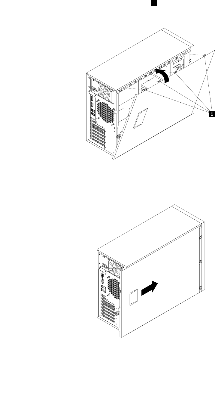
4.Positiontheservercoveronthechassissothattherailonthebottomoftheservercoverengagesthe
bottomrailonthechassis.Then,alignthefourtabs1ontheservercoverwiththecorrespondingholes
inthetopedgeofthechassis.Pivottheservercovertocloseit.
Figure105.Closingtheservercover
5.Slidetheservercovertothefrontofthechassisuntilitsnapsintoposition.
Figure106.Installingtheservercover
6.Tightenthethumbscrewontheservercovertosecuretheservercoverinplace.
Chapter6.Installing,removing,orreplacinghardware169

Note:Forsafetyconsideration,besuretouseatool,forexampleascrewdriver,totightenthe
thumbscrewandalwaysmakesurethatthethumbscrewissecurelyinstalled.Also,donotover-tighten
thethumbscrew.
7.Locktheservercoverandserverfrontdoortoensurethesecurity.See“Serverlocks”onpage22.
8.Reconnectexternalcablesandpowercord(s)totheserver.See“Rearviewoftheserver”onpage19to
identifytheconnectorsontherearpaneloftheserver.
Attention:Toavoidcomponentdamage,connectthepowercord(s)last.
Note:Inmostareasoftheworld,LenovorequiresthereturnofthedefectiveCRU.Informationaboutthiswill
comewiththeCRUorwillcomeafewdaysaftertheCRUarrives.
Updatingtheserverconguration
Whenyouturnontheserverforthersttimeafteryouinstall,remove,orreplaceadevice,youmight
needtoupdatetheserverconguration.
Someoptionaldeviceshavedevicedriversthatyoumustinstall.Forinformationaboutinstallingdevice
drivers,usethedocumentationthatcomeswitheachoptionaldevice.Toobtainthesupporteddevicedrivers
foryourserverfromtheLenovoSupportWebsite,gotohttp://support.lenovo.com.ClickDownloadDrivers
&SoftwareandfollowtheinstructionsontheWebpagetondthedevicedriversyouwanttodownload.
Refertothefollowinginformationresourcestoupdatetheserverconguration:
•ToupdatetheBIOSconguration,see“UsingtheSetupUtilityprogram”onpage55.
•ToupdatetheRAIDconguration,see“ConguringRAID”onpage71.
•TousetheThinkServerEasyStartupprogram,see“UsingtheThinkServerEasyStartupprogram”on
page69.
•Toupdateyoursystemrmware,see“Updatingthermware”onpage80.
170ThinkServerHardwareMaintenanceManual

Chapter7.Troubleshootinganddiagnostics
Thischapterprovidesinformationaboutbasictroubleshootinganddiagnosticmethodstohelpyousolve
problemsthatmightoccurintheserver.
Ifyoucannotdiagnoseandcorrectaproblembyusingtheinformationinthischapter,seeChapter9
“Gettinginformation,help,andservice”onpage213foradditionaltroubleshootingresources.
Troubleshootingprocedure
Usethefollowinginformationasageneralprocedurefordiagnosingandtroubleshootingproblemsyou
experiencewithyourserver:
1.Verifythatthepowercordsandthecablesforallattacheddevicesareconnectedcorrectlyandsecurely.
2.Verifythattheserverandallattacheddevicesthatrequireacpowerareconnectedtoproperlygrounded,
functioningelectricaloutlets.
3.VerifythatallinstalledhardwareandattacheddevicesareenabledintheBIOSsettingsofyourserver.
FormoreinformationaboutaccessingandchangingtheBIOSsettings,see“UsingtheSetupUtility
program”onpage55.
4.ViewthestatusanddiagnosticLEDstoidentifythesystemanddevicestatusanddiagnoseproblems.
See“ViewingthestatusanddiagnosticLEDs”onpage171.
5.Iftheserverisnotworkingafteryouhaveaddednewsoftware,installedanewoptionaldevice,or
replacedapieceofhardware,removeorreinstallthesoftwareordevicetoseeiftheproblemcould
besolved.
6.ViewtheSELtodiagnoseproblems.See“Viewingthesystemeventlog”onpage172.
7.TurnontheserverandpressEscassoonasyouseethelogoscreentoviewanydiagnosticmessages.
8.DownloadandusethePC-DoctorforDOSdiagnosticprogramtodiagnoseproblems.See“Using
thediagnosticprogram”onpage172.
9.Referto“Basictroubleshootingtables”onpage172andfollowtheinstructionsforthetypeofproblem
youareexperiencing.Ifthebasictroubleshootinginformationdoesnothelpyouresolveaproblem,
continuewiththenextstep.
10.Tryusingapreviouslyservercongurationtoseeifarecentchangetohardwareorsoftwaresettingshas
causedaproblem.Beforerestoringyourpreviousconguration,captureyourcurrentcongurationin
casetheoldercongurationsettingsdonotsolvetheproblemorhaveadverseeffect.
11.Useanantivirusprogramtoseeifyourserverhasbeeninfectedbyavirus.Iftheprogramdetectsa
virus,removethevirus.
12.Ifnoneoftheseactionssolvetheproblem,seektechnicalassistance.SeeChapter9“Getting
information,help,andservice”onpage213.
ViewingthestatusanddiagnosticLEDs
YourserverhasstatusanddiagnosticLEDsonthefrontpanel,theDITpanel(variesbymodel),therear
panel(EthernetstatusLEDs),thesystemboard,thehot-swapharddiskdrives(ifsupported),andtheoptical
drive(s).ThevariousLEDshelpyoueasilyidentifythesystemanddevicestatusanddiagnoseproblems.For
informationabouttheLEDs,refertotherelatedtopicsin“Locations”onpage13.
©CopyrightLenovo2011171

Usingthediagnosticprogram
ThePC-DoctorforDOSdiagnosticprogramrunsindependentlyoftheoperatingsystem.Usethisdiagnostic
programtotestandgatherinformationaboutyoursysteminordertoensureyoursystemisworkingcorrectly
andresolveanyhardwareissues.Youcanrunthediagnosticprogramfromadiagnosticdiscthatyoucreated.
Tousethediagnosticprogram,dothefollowing:
Note:LenovomaintainstheSupportWebsitebymakingchangesandimprovementsperiodically.The
actualproceduremightvaryslightlyfromwhatisdescribedinthistopic.
1.GototheLenovoSupportWebsiteat:
http://support.lenovo.com
2.ClickDownloadDrivers&SoftwareandfollowtheinstructionsontheWebpagetolocatethe
diagnosticprogram.
3.DownloadtheISOimageforthediagnosticprogramandthereadmeleinTXT.
4.UseanydiscburningsoftwaretocreateabootablediscwiththeISOimage.
5.Printthereadmelethatcontainstheinstructionsonhowtousethediagnosticprogramandfollow
theinstructionstostarttheprogramfromthedisc.Then,followtheinstructionsonthescreento
startthediagnostictest.
6.Removethediagnosticdiscfromtheopticaldrivewhenyoucompletethediagnosticprocess.
Viewingthesystemeventlog
Thesystemeventlog(SEL)containsinformationaboutallthePOSTandsystemmanagementinterrupt(SMI)
events.YoucanviewtheSELtodiagnosesystemproblems.
TheBMCimplementstheSELasspeciedintheIPMI2.0specication.TheSELisaccessibleregardlessof
thesystempowerstatethroughtheBMCin-bandandout-of-bandinterfaces.
FormoreinformationaboutviewingtheSEL,refertotheRemoteManagementModuleUserGuideonthe
documentationDVDthatcomeswithyourserver.
Basictroubleshootingtables
Usethebasictroubleshootinginformationtondsolutionstoproblemsthathavedenitesymptoms.
ThinkServerEasyStartupprogramproblems
Followthesuggestedactionsforthecorrespondingsymptomintheorderinwhichtheyarelisteduntilthe
problemissolved.Ifnoneoftheseactionssolvetheproblem,see“Troubleshootingprocedure”onpage
171forthesubsequentstepsyoushouldcheckafterusingtheinformationinthistopic.Iftheproblem
cannotbesolvedbyyourself,seektechnicalassistance.SeeChapter9“Gettinginformation,help,and
service”onpage213.
Note:Ifyouareinstructedtoremove,install,orreplaceanyCRUs,refertotherelatedprocedureinChapter
6“Installing,removing,orreplacinghardware”onpage83.
172ThinkServerHardwareMaintenanceManual

SymptomAction
TheThinkServerEasyStartupDVDdoesnotstart.1.MakesurethattheserversupportstheThinkServer
EasyStartupprogramandhasabootableDVDdrive.
2.Makesurethatyouhavesettheopticaldrivewith
theThinkServerEasyStartupDVDastherststartup
device.
3.Verifyiftheopticaldriveorthedischasproblems.
See“Opticaldriveproblems”onpage173.
Theoperatingsysteminstallationprogramcontinuously
loops.
Makemorespaceavailableontheharddiskdrive.
TheThinkServerEasyStartupprogramcannotstartthe
operatingsystemmedia.
1.Makesurethattheoperatingsystemmediais
supportedbytheThinkServerEasyStartupprogram
versionyourareusing.Foralistofthesupported
operatingsystems,refertotheuserguideand
compatibilitynotesfortheThinkServerEasyStartup
programthroughtheprogrammaininterface.See
“StartingtheThinkServerEasyStartupprogram”on
page70.
2.Verifyiftheopticaldriveorthedischasproblems.
See“Opticaldriveproblems”onpage173.
Opticaldriveproblems
Followthesuggestedactionsforthecorrespondingsymptomintheorderinwhichtheyarelisteduntilthe
problemissolved.Ifnoneoftheseactionssolvetheproblem,see“Troubleshootingprocedure”onpage
171forthesubsequentstepsyoushouldcheckafterusingtheinformationinthistopic.Iftheproblem
cannotbesolvedbyyourself,seektechnicalassistance.SeeChapter9“Gettinginformation,help,and
service”onpage213.
Notes:
1.Ifyouareinstructedtoremove,install,orreplaceanyCRUs,refertotherelatedprocedureinChapter6
“Installing,removing,orreplacinghardware”onpage83.
2.Ifanactionstepisprecededby“(Trainedservicetechnicianonly),”thisactionstepisreservedfora
trainedservicetechnicianandmustbeperformedonlybyatrainedservicetechnician.
SymptomAction
Theopticaldriveisnotrecognized.1.Makesurethat:
•Thesignalcableandconnectorarenotdamaged
andtheconnectorpinsarenotbent.
•Theopticaldriveissecurelyconnectedtothe
correctSATAconnectoronthesystemboardand
theSATAconnectorisenabledintheSetupUtility
program.See“UsingtheSetupUtilityprogram”
onpage55.
•Allcablesandjumpers(ifany)areinstalled
correctly.
•Thecorrectdevicedriverisinstalledfortheoptical
drive.
2.Runanyopticaldrivediagnosticprogramsifyou
have.
3.Reinstalltheopticaldriveandreconnectcables.
4.Replacethesignalcablefortheopticaldrive.
Chapter7.Troubleshootinganddiagnostics173

SymptomAction
5.Replacetheopticaldrive.
6.(Trainedservicetechnicianonly)Replacethesystem
board.
Adiscisnotworkingcorrectly.1.Makesurethatthediscisintheopticaldrivewiththe
shinysidefacingdown.
2.Makesurethatthediscsurfaceiscleanandnot
scratched.
3.Checkthediscorpackageforregionalcoding.You
mightneedtopurchaseadiscwithcodingforthe
regionwhereyouareusingtheproduct.
4.Restartthediscplayerprogram.
5.Restarttheserver.
6.Runanyopticaldrivediagnosticprogramsifyou
have.
7.Reinstalltheopticaldriveandreconnectcables.
8.Replacethesignalcablefortheopticaldrive.
9.Replacetheopticaldrive.
Harddiskdriveproblems
Followthesuggestedactionsforthecorrespondingsymptomintheorderinwhichtheyarelisteduntilthe
problemissolved.Ifnoneoftheseactionssolvetheproblem,see“Troubleshootingprocedure”onpage
171forthesubsequentstepsyoushouldcheckafterusingtheinformationinthistopic.Iftheproblem
cannotbesolvedbyyourself,seektechnicalassistance.SeeChapter9“Gettinginformation,help,and
service”onpage213.
Notes:
1.Ifyouareinstructedtoremove,install,orreplaceanyCRUs,refertotherelatedprocedureinChapter6
“Installing,removing,orreplacinghardware”onpage83.
2.Iftheservermodelcomeswithhot-swapharddiskdrives,thestatusLEDsoneachhot-swapharddisk
drivehelpyoueasilyidentifyaproblem.See“Hot-swapharddiskdrivestatusLEDs”onpage32.
SymptomAction
Anewlyinstallednon-hot-swapharddiskdriveisnot
recognized.
1.Makesurethat:
•Thesignalcableandconnectorarenotdamaged.
•Thenon-hot-swapharddiskdriveissecurely
connectedtothecorrectSATAconnectoronthe
systemboardandtheSATAconnectorisenabled
intheSetupUtilityprogram.See“UsingtheSetup
Utilityprogram”onpage55.
•Allcablesandjumpers(ifany)areinstalled
correctly.
2.Runanydiagnosticprogramstotesttheharddisk
drive.
3.Reinstallthenon-hot-swapharddiskdriveand
reconnectcables.
4.Replacethesignalcableforthenon-hot-swaphard
diskdrive.
174ThinkServerHardwareMaintenanceManual

SymptomAction
5.Replacethenon-hot-swapharddiskdrive.
Anewlyinstalledhot-swapharddiskdriveisnot
recognized.
1.Makesurethatthedriveisinstalledintothecorrect
drivebay.
2.Restarttheserver.
3.Removethedrivefromthebay,wait45seconds,
andreinsertthedriveintothebay,makingsurethat
thedriveconnectstothehot-swapharddiskdrive
backplane.
4.Runanydiagnosticprogramstotesttheharddisk
drive.
5.Makesurethatthehot-swapharddiskdrive
backplaneiscorrectlyseated.Whenitiscorrectly
seated,thedriveassembliescorrectlyconnecttothe
backplanewithoutbowingorcausingmovementof
thebackplane.
6.Makesurethatthecableconnectioniscorrect.See
“Connectingcables”onpage38.
7.Reconnectthebackplanepowercableandrepeat
step1throughstep4.
8.Reconnectthebackplanesignalcableandrepeat
step1throughstep4.
9.Ifyoususpectaproblemwiththebackplanesignal
cableorthebackplane:
a.Replacetheaffectedbackplanesignalcable.
b.Replacetheaffectedbackplane.
Multipleharddiskdrivesfail.1.Runanydiagnosticprogramstotesttheharddisk
drives.
2.Makesurethatthecableconnectioniscorrect.See
“Connectingcables”onpage38.
3.Reconnectthepowercable.
4.Reconnectthesignalcable.
5.Replacetheaffectedsignalcable.
6.Forhot-swapharddiskdrives,ifyoususpecta
problemwiththebackplane,replacetheaffected
backplane.
Notalldrivesarerecognizedbytheharddiskdrive
diagnostictest.Removethedrive(s)thatarenotrecognizedbythe
diagnostictest.Then,runtheharddiskdrivediagnostic
testagain.Iftheremainingdrivesarerecognized,replace
thedrive(s)thatyouremoved.
Theserverstopsrespondingduringtheharddiskdrive
diagnostictest.
Removetheharddiskdrivethatwasbeingtestedwhen
theserverstoppedrespondingandrunthediagnostic
testagain.Iftheharddiskdrivediagnostictestruns
successfully,replacethedrivethatyouremovedwitha
newone.
Aharddiskdrivewasnotdetectedwhiletheoperating
systemwasbeingstarted.
Reinstallallharddiskdrivesandreconnectcables.Then,
runtheharddiskdrivediagnostictest.
Chapter7.Troubleshootinganddiagnostics175

Memorymoduleproblems
Followthesuggestedactionsforthecorrespondingsymptomintheorderinwhichtheyarelisteduntilthe
problemissolved.Ifnoneoftheseactionssolvetheproblem,see“Troubleshootingprocedure”onpage
171forthesubsequentstepsyoushouldcheckafterusingtheinformationinthistopic.Iftheproblem
cannotbesolvedbyyourself,seektechnicalassistance.SeeChapter9“Gettinginformation,help,and
service”onpage213.
Notes:
1.Ifyouareinstructedtoremove,install,orreplaceanyCRUs,refertotherelatedprocedureinChapter6
“Installing,removing,orreplacinghardware”onpage83.
2.Ifanactionstepisprecededby“(Trainedservicetechnicianonly),”thisactionstepisreservedfora
trainedservicetechnicianandmustbeperformedonlybyatrainedservicetechnician.
SymptomAction
Theamountofsystemmemorythatisdisplayedisless
thanthetotalcapacityoftheinstalledphysicalmemory
modulesandyoususpectamemorymoduleproblem.
1.Makesurethat:
•Allmemorymodulesarethecorrecttype
supportedbytheserver.See“Features”onpage
7.
•Youfollowthememorymoduleinstallationrules.
See“Memorymoduleinstallationrules”onpage
90.
•Allmemorymodulesareseatedcorrectlyand
securely.
•Thesystemrmwareisup-to-date.
2.Runanydiagnosticprogramstotestthememory
modules.
3.Reinstallthememorymodules.
4.Replacethesuspectmemorymodules.
5.(Trainedservicetechnicianonly)Replacethesystem
board.
Keyboard,mouse,orUSBdeviceproblems
Followthesuggestedactionsforthecorrespondingsymptomintheorderinwhichtheyarelisteduntilthe
problemissolved.Ifnoneoftheseactionssolvetheproblem,see“Troubleshootingprocedure”onpage171
forthesubsequentstepsyoushouldcheckafterusingtheinformationinthistopic.
SymptomAction
Allorsomekeysonthekeyboarddonotwork.1.Makesurethat:
•TheUSBkeyboardcableissecurelyconnected
toaUSBconnectorontheserver.IftheUSB
keyboardisconnectedtoaUSBhub,disconnect
thekeyboardfromthehubandconnectitdirectly
totheserver.
•Nokeysarestuck.
•TheUSBcontrollerisenabledintheSetupUtility
program.See“UsingtheSetupUtilityprogram”
onpage55.
2.Restarttheserver.
176ThinkServerHardwareMaintenanceManual

SymptomAction
3.Replacethekeyboard.
Themouseorpointingdevicedoesnotwork.1.Makesurethat:
•Themouseorpointingdevicecableissecurely
connectedtotheserver.IftheUSBmouseor
pointingdeviceisconnectedtoaUSBhub,
disconnectthemouseorpointingdevicefromthe
hubandconnectitdirectlytotheserver.
•Themouseorpointingdeviceiscleanandnodust
accumulates.
•Thedevicedriversareinstalledcorrectly.
•TheUSBcontrollerisenabledintheSetupUtility
program.See“UsingtheSetupUtilityprogram”
onpage55.
2.Restarttheserver.
3.Replacethemouseorpointingdevice.
AUSBdevicedoesnotwork.1.Makesurethat:
•TheUSBcableissecurelyconnectedtotheserver.
IftheUSBdeviceisconnectedtoaUSBhub,
disconnectthedevicefromthehubandconnect
itdirectlytotheserver.
•Thedevicedriversareinstalledcorrectly.
•TheUSBcontrollerisenabledintheSetupUtility
program.See“UsingtheSetupUtilityprogram”
onpage55.
2.Restarttheserver.
3.ReplacetheUSBdevice.
POSTerrorcodes
Eachtimeyouturnonthesystem,itperformsaseriesofteststhatcheckstheoperationofthesystemand
options.Thisseriesoftestsiscalledthepower-onself-test(POST).Toassistintroubleshootingasystem
hangduringthePOSTprocess,thePOSTcodediagnosticLEDsonthesystemboardcanbeusedto
identifythelastPOSTprocessexecuted.
Note:ThePOSTcodediagnosticLEDsandPOSTerrorcodeinformationareintendedonlyfortrained
servicepersonnelofLenovo.
Referto“SystemboardLEDs”onpage50fordetailedinformationaboutthePOSTcodediagnosticLEDs
andPOSTerrorcodes.
Chapter7.Troubleshootinganddiagnostics177

178ThinkServerHardwareMaintenanceManual
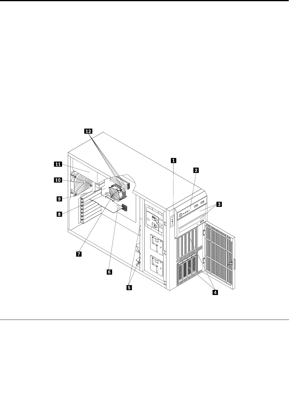
Chapter8.FRUlists
ThischapterlistsinformationabouttheFRUs.
Attention:Besuretoreadandunderstandthe“Safetyinformation”onpageiiibeforereplacinganyFRUs.
Inthefollowingtables,aCRUisidentiedas“1,”“2,”or“N”intheCRUcolumn.“N”meansthatthepartis
notaCRU,“1”meansthatthepartisaSelf-serviceCRU,and“2”meansthatthepartisanOptional-service
CRU.
Note:Theservercongurationvariesbymodel.Thefollowingillustrationshowsonlyonetypeofserver
conguration(servermodelswithuptofour3.5-inchhot-swapharddiskdrives)toprovideageneralview
ofthecomponentlocations.Formoreinformationaboutthemajorservercongurations,see“Server
components”onpage25.
Figure107.Componentlocations
MajorFRUs
Thefollowingreplaceablecomponentsareavailableformachinetypes(MTs)0387,0388,0389,0390,
0391,0392,0393,and0441.
©CopyrightLenovo2011179

ItemFRUFRU
numberCRU
1
DITkitwithoutlabel
•MT0387:CTO
•MT0388:CTO
•MT0389:CTO
•MT0390:CTO
•MT0391:CTO
•MT0392:CTO
•MT0393:CTO
•MT0441:CTO
03X36682
2
5UfrontpanelkitforLX-KT2v1.1
•MT0387:CTO,allmodels
•MT0388:CTO,allmodels
•MT0389:CTO,allmodels
•MT0390:CTO,allmodels
•MT0391:CTO,allmodels
•MT0392:CTO,allmodels
•MT0393:CTO,allmodels
•MT0441:CTO,allmodels
03X35732
3
Opticaldrive,DVD-ROMdrive-16x/48x(SATA)
•MT0387:CTO11U11G12U12G
•MT0388:CTO11U12U12G13U13G14U
•MT0389:CTO11U
•MT0390:CTO
•MT0391:CTO11U
•MT0392:CTO11U12U13U14U15U
•MT0393:CTO
•MT0441:CTO
71Y55431
3
Opticaldrive,DVDBurner/CD-RWRambo8(SATA)
•MT0387:CTO
•MT0388:CTO
•MT0389:CTO
•MT0390:CTO11U11G12U12G13U13G
•MT0391:CTO
•MT0392:CTO
•MT0393:CTO11U11G12U12G
•MT0441:CTO11U11G12U12G13U13G14U14G15U15G16U16G
71Y55451
180ThinkServerHardwareMaintenanceManual

ItemFRUFRU
numberCRU
3
LenovoRDXUSBdrivebundlebay
•MT0387:CTO
•MT0388:CTO
•MT0389:CTO
•MT0390:CTO
•MT0391:CTO
•MT0392:CTO
•MT0393:CTO
•MT0441:CTO
67Y14241
3
Lenovo160GBRDXUSBdrivebundlecartridge
•MT0387:CTO
•MT0388:CTO
•MT0389:CTO
•MT0390:CTO
•MT0391:CTO
•MT0392:CTO
•MT0393:CTO
•MT0441:CTO
67Y14211
3
Lenovo320GBRDXUSBdrivebundlecartridge
•MT0387:CTO
•MT0388:CTO
•MT0389:CTO
•MT0390:CTO
•MT0391:CTO
•MT0392:CTO
•MT0393:CTO
•MT0441:CTO
67Y14221
3
Lenovo500GBRDXUSBdrivebundlecartridge
•MT0387:CTO
•MT0388:CTO
•MT0389:CTO
•MT0390:CTO
•MT0391:CTO
•MT0392:CTO
•MT0393:CTO
•MT0441:CTO
67Y14231
Chapter8.FRUlists181

ItemFRUFRU
numberCRU
4
Harddiskdrive,hot-swap,250GBSATA-enterprise7200rpm,3Gb/s,
3.5-inchdriveassembly
•MT0387:CTO
•MT0388:CTO
•MT0389:CTO
•MT0390:CTO
•MT0391:CTO
•MT0392:CTO
•MT0393:CTO
•MT0441:CTO
03X36741
4
Harddiskdrive,hot-swap,500GBSATA-enterprise7200rpm,3Gb/s,
3.5-inchdriveassembly
•MT0387:CTO
•MT0388:CTO
•MT0389:CTO
•MT0390:CTO
•MT0391:CTO
•MT0392:CTO
•MT0393:CTO
•MT0441:CTO
03X39101
4
Harddiskdrive,hot-swap,1TBSATA-enterprise7200rpm,3Gb/s,
3.5-inchdriveassembly
•MT0387:CTO
•MT0388:CTO
•MT0389:CTO
•MT0390:CTO
•MT0391:CTO
•MT0392:CTO
•MT0393:CTO
•MT0441:CTO
03X39111
4
Harddiskdrive,hot-swap,2TBSATA-enterprise7200rpm,3Gb/s,
3.5-inchdriveassembly
•MT0387:CTO
•MT0388:CTO
•MT0389:CTO
•MT0390:CTO
•MT0391:CTO
•MT0392:CTO
•MT0393:CTO
•MT0441:CTO
03X39121
182ThinkServerHardwareMaintenanceManual

ItemFRUFRU
numberCRU
4
Harddiskdrive,non-hot-swap,250GBSATA-enterprise7200rpm,3Gb/s,
3.5-inchdriveassembly
•MT0387:CTO
•MT0388:CTO
•MT0389:CTO
•MT0390:CTO
•MT0391:CTO
•MT0392:CTO
•MT0393:CTO
•MT0441:CTO
03X36781
4
Harddiskdrive,non-hot-swap,500GBSATA-enterprise7200rpm,3Gb/s,
3.5-inchdriveassembly
•MT0387:CTO
•MT0388:CTO
•MT0389:CTO
•MT0390:CTO
•MT0391:CTO
•MT0392:CTO
•MT0393:CTO
•MT0441:CTO
03X39131
4
Harddiskdrive,non-hot-swap,1TBSATA-enterprise7200rpm,3Gb/s,
3.5-inchdriveassembly
•MT0387:CTO
•MT0388:CTO
•MT0389:CTO
•MT0390:CTO
•MT0391:CTO
•MT0392:CTO
•MT0393:CTO
•MT0441:CTO
03X39141
4
Harddiskdrive,non-hot-swap,2TBSATA-enterprise7200rpm,3Gb/s,
3.5-inchdriveassembly
•MT0387:CTO
•MT0388:CTO
•MT0389:CTO
•MT0390:CTO
•MT0391:CTO
•MT0392:CTO
•MT0393:CTO
•MT0441:CTO
03X39151
Chapter8.FRUlists183

ItemFRUFRU
numberCRU
4
Harddiskdrive,hot-swap,300GBSAS-enterprise,6Gb/s,xxMBcache,
3.5-inchdriveassembly
•MT0387:CTO
•MT0388:CTO
•MT0389:CTO
•MT0390:CTO
•MT0391:CTO
•MT0392:CTO
•MT0393:CTO
•MT0441:CTO
03X39161
4
Harddiskdrive,hot-swap,450GBSAS-enterprise,6Gb/s,xxMBcache,
3.5-inchdriveassembly
•MT0387:CTO
•MT0388:CTO
•MT0389:CTO
•MT0390:CTO
•MT0391:CTO
•MT0392:CTO
•MT0393:CTO
•MT0441:CTO
03X39171
4
Harddiskdrive,hot-swap,600GBSAS-enterprise,6Gb/s,xxMBcache,
3.5-inchdriveassembly
•MT0387:CTO
•MT0388:CTO
•MT0389:CTO
•MT0390:CTO
•MT0391:CTO
•MT0392:CTO
•MT0393:CTO
•MT0441:CTO
03X39181
4
Harddiskdrive,hot-swap,300GBSAS-enterprise,6Gb/s,xxMBcache,
2.5-inchdriveassembly
•MT0387:CTO
•MT0388:CTO
•MT0389:CTO
•MT0390:CTO
•MT0391:CTO
•MT0392:CTO
•MT0393:CTO
•MT0441:CTO
03X39191
184ThinkServerHardwareMaintenanceManual

ItemFRUFRU
numberCRU
4
Harddiskdrive,hot-swap,450GBSAS-enterprise,6Gb/s,xxMBcache,
2.5-inchdriveassembly
•MT0387:CTO
•MT0388:CTO
•MT0389:CTO
•MT0390:CTO
•MT0391:CTO
•MT0392:CTO
•MT0393:CTO
•MT0441:CTO
03X39201
4
Harddiskdrive,hot-swap,600GBSAS-enterprise,6Gb/s,xxMBcache,
2.5-inchdriveassembly
•MT0387:CTO
•MT0388:CTO
•MT0389:CTO
•MT0390:CTO
•MT0391:CTO
•MT0392:CTO
•MT0393:CTO
•MT0441:CTO
03X39211
5
Frontsystemfan,secondcage9225fan
•MT0387:CTO,allmodels
•MT0388:CTO,allmodels
•MT0389:CTO,allmodels
•MT0390:CTO,allmodels
•MT0391:CTO,allmodels
•MT0392:CTO,allmodels
•MT0393:CTO,allmodels
•MT0441:CTO,allmodels
03X37071
6
SystemboardCMOSbattery
•MT0387:CTO11U11G12U12G
•MT0388:CTO11U12U12G13U13G14U
•MT0389:CTO11U11F
•MT0390:CTO11U11G12U12G13U13G
•MT0391:CTO11U
•MT0392:CTO11U12U13U14U15U
•MT0393:CTO11U11G12U12G
•MT0441:CTO11U11G12U12G13U13G14U14G15U15G16U16G
03X37211
Chapter8.FRUlists185

ItemFRUFRU
numberCRU
7
Heatsink
•MT0387:CTO
•MT0388:CTO
•MT0389:CTO
•MT0390:CTO
•MT0391:CTO
•MT0392:CTO
•MT0393:CTO
•MT0441:CTO
03X37101
8
Microprocessor,Xeon,quad-core,E31280,8MB,3.5GHz,95W
•MT0387:CTO
•MT0388:CTO
•MT0389:CTO
•MT0390:CTO
•MT0391:CTO
•MT0392:CTO
•MT0393:CTO
•MT0441:CTO
03X36242
8
Microprocessor,Xeon,quad-core,E31220,8MB,3.1GHz,80W
•MT0387:CTO
•MT0388:CTO
•MT0389:CTO
•MT0390:CTO11U11G12U12G
•MT0391:CTO
•MT0392:CTO
•MT0393:CTO12U12G
•MT0441:CTO11U11G
03X36252
8
Microprocessor,Xeon,quad-core,E31230,8MB,3.2GHz,80W
•MT0387:CTO
•MT0388:CTO
•MT0389:CTO
•MT0390:CTO
•MT0391:CTO
•MT0392:CTO
•MT0393:CTO
•MT0441:CTO14U14G
03X36262
186ThinkServerHardwareMaintenanceManual

ItemFRUFRU
numberCRU
8
Microprocessor,Xeon,quad-core,E31240,8MB,3.3GHz,80W
•MT0387:CTO
•MT0388:CTO
•MT0389:CTO
•MT0390:CTO
•MT0391:CTO
•MT0392:CTO
•MT0393:CTO
•MT0441:CTO12U12G16U16G
03X36272
8
Microprocessor,Xeon,quad-core,E31270,8MB,3.4GHz,80W
•MT0387:CTO
•MT0388:CTO
•MT0389:CTO11U
•MT0390:CTO
•MT0391:CTO
•MT0392:CTO
•MT0393:CTO
•MT0441:CTO15U15G
03X36282
8
Microprocessor,Corei3-2100(3.1GHz/dual-core/3M/65W/1GT/1333)
•MT0387:CTO11U11G12U12G
•MT0388:CTO11U12U12G13U13G14U
•MT0389:CTO11U
•MT0390:CTO13U13G
•MT0391:CTO11U
•MT0392:CTO11U12U13U14U15U
•MT0393:CTO11U11G
•MT0441:CTO13U13G
03T80112
8
Microprocessor,Corei3-2120(3.3GHz/dual-core/3M/65W/1GT/1333)
•MT0387:CTO
•MT0388:CTO
•MT0389:CTO
•MT0390:CTO
•MT0391:CTO
•MT0392:CTO
•MT0393:CTO
•MT0441:CTO
03T80102
Chapter8.FRUlists187

ItemFRUFRU
numberCRU
9
Systemboard,CPESX31000systemboard
•MT0387:CTO11U11G12U12G
•MT0388:CTO11U12U12G13U13G14U
•MT0389:CTO11U
•MT0390:CTO11U11G12U12G13U13G
•MT0391:CTO11U
•MT0392:CTO11U12U13U14U15U
•MT0393:CTO11U11G12U12G
•MT0441:CTO11U11G12U12G13U13G14U14G15U15G16U16G
03X3665N
10
Systemfanassembly
•MT0387:CTO,allmodels
•MT0388:CTO,allmodels
•MT0389:CTO,allmodels
•MT0390:CTO,allmodels
•MT0391:CTO,allmodels
•MT0392:CTO,allmodels
•MT0393:CTO,allmodels
•MT0441:CTO,allmodels
46U31971
10
Systemfanassembly
•MT0387:CTO,allmodels
•MT0388:CTO,allmodels
•MT0389:CTO,allmodels
•MT0390:CTO,allmodels
•MT0391:CTO,allmodels
•MT0392:CTO,allmodels
•MT0393:CTO,allmodels
•MT0441:CTO,allmodels
03X39481
11
Powersupply,GPS-400CBB400WATXpowersupply,REV:00F
•MT0387:CTO11U11G12U12G
•MT0388:CTO11U12U12G13U13G14U
•MT0389:CTO11U
•MT0390:CTO11U11G12U12G13U13G
•MT0391:CTO
•MT0392:CTO
•MT0393:CTO
•MT0441:CTO
03X38002
188ThinkServerHardwareMaintenanceManual

ItemFRUFRU
numberCRU
11
PowerdistributionboardandcageassemblyREV:00forredundantpower
supplies
•MT0387:CTO
•MT0388:CTO
•MT0389:CTO
•MT0390:CTO
•MT0391:CTO11U
•MT0392:CTO11U12U13U14U15U
•MT0393:CTO11U11G12U12G
•MT0441:CTO11U11G12U12G13U13G14U14G15U15G16U16G
03X37992
11
Powersupply,redundant450WpowersupplymoduleREV:00
•MT0387:CTO
•MT0388:CTO
•MT0389:CTO
•MT0390:CTO
•MT0391:CTO11U
•MT0392:CTO11U12U13U14U15U
•MT0393:CTO11U11G12U12G
•MT0441:CTO11U11G12U12G13U13G14U14G15U15G16U16G
03X38011
12
Memorymodule,2GB1RX8PC3-10600E,ECC-UDIMMDDR3-1333,2Gbit
•MT0387:CTO11U11G12U12G
•MT0388:CTO11U12U12G13U13G14U
•MT0389:CTO11U
•MT0390:CTO11U11G12U12G13U13G
•MT0391:CTO11U
•MT0392:CTO11U12U13U14U15U
•MT0393:CTO11U11G
•MT0441:CTO13U13G
03X36601
12
Memorymodule,4GB2RX8PC3-10600E,ECC-UDIMMDDR3-1333,2Gbit
•MT0387:CTO
•MT0388:CTO
•MT0389:CTO
•MT0390:CTO
•MT0391:CTO
•MT0392:CTO
•MT0393:CTO12U12G
•MT0441:CTO11U11G12U12G14U14G15U15G16U16G
03X36611
MechanicalFRUs
TheFRUslistedinthefollowingtablearenotillustrated.
Chapter8.FRUlists189

FRUFRUnumberCRU
3.5-inchhot-swapharddiskdrivetrayV2.0
•MT0387:CTO,allmodels
•MT0388:CTO,allmodels
•MT0389:CTO,allmodels
•MT0390:CTO,allmodels
•MT0391:CTO,allmodels
•MT0392:CTO,allmodels
•MT0393:CTO,allmodels
•MT0441:CTO,allmodels
03X38352
3.5-inchnon-hot-swapharddiskdrivetrayV2.0
•MT0387:CTO,allmodels
•MT0388:CTO,allmodels
•MT0389:CTO,allmodels
•MT0390:CTO,allmodels
•MT0391:CTO,allmodels
•MT0392:CTO,allmodels
•MT0393:CTO,allmodels
•MT0441:CTO,allmodels
03X38422
2.5-inchharddiskdrivetrayV2.0
•MT0387:CTO,allmodels
•MT0388:CTO,allmodels
•MT0389:CTO,allmodels
•MT0390:CTO,allmodels
•MT0391:CTO,allmodels
•MT0392:CTO,allmodels
•MT0393:CTO,allmodels
•MT0441:CTO,allmodels
03X38362
3.5-inchharddiskdrivedummytrayV2.0
•MT0387:CTO,allmodels
•MT0388:CTO,allmodels
•MT0389:CTO,allmodels
•MT0390:CTO,allmodels
•MT0391:CTO,allmodels
•MT0392:CTO,allmodels
•MT0393:CTO,allmodels
•MT0441:CTO,allmodels
03X38371
190ThinkServerHardwareMaintenanceManual

FRUFRUnumberCRU
2.5-inchharddiskdrivedummytrayV2.0
•MT0387:CTO,allmodels
•MT0388:CTO,allmodels
•MT0389:CTO,allmodels
•MT0390:CTO,allmodels
•MT0391:CTO,allmodels
•MT0392:CTO,allmodels
•MT0393:CTO,allmodels
•MT0441:CTO,allmodels
03X38381
3.5-inchharddiskdrivecage
•MT0387:CTO,allmodels
•MT0388:CTO,allmodels
•MT0389:CTO,allmodels
•MT0390:CTO,allmodels
•MT0391:CTO,allmodels
•MT0392:CTO,allmodels
•MT0393:CTO,allmodels
•MT0441:CTO,allmodels
03X37032
2.5-inchharddiskdrivecage
•MT0387:CTO,allmodels
•MT0388:CTO,allmodels
•MT0389:CTO,allmodels
•MT0390:CTO,allmodels
•MT0391:CTO,allmodels
•MT0392:CTO,allmodels
•MT0393:CTO,allmodels
•MT0441:CTO,allmodels
03X37042
Non-hot-swapharddiskdrivecageshield
•MT0387:CTO,allmodels
•MT0388:CTO,allmodels
•MT0389:CTO,allmodels
•MT0390:CTO,allmodels
•MT0391:CTO,allmodels
•MT0392:CTO,allmodels
•MT0393:CTO,allmodels
•MT0441:CTO,allmodels
03X37222
Chapter8.FRUlists191

FRUFRUnumberCRU
Harddiskdrivecage,blank,metal,LX-KT2A
•MT0387:CTO,allmodels
•MT0388:CTO,allmodels
•MT0389:CTO,allmodels
•MT0390:CTO,allmodels
•MT0391:CTO,allmodels
•MT0392:CTO,allmodels
•MT0393:CTO,allmodels
•MT0441:CTO,allmodels
03X37232
Hot-swap3.5"x4SAS/SATAbackplane
•MT0387:CTO,allmodels
•MT0388:CTO,allmodels
•MT0389:CTO,allmodels
•MT0390:CTO,allmodels
•MT0391:CTO,allmodels
•MT0392:CTO,allmodels
•MT0393:CTO,allmodels
•MT0441:CTO,allmodels
03X59992
Hot-swap2.5"x8SAS/SATAbackplane
•MT0387:CTO,allmodels
•MT0388:CTO,allmodels
•MT0389:CTO,allmodels
•MT0390:CTO,allmodels
•MT0391:CTO,allmodels
•MT0392:CTO,allmodels
•MT0393:CTO,allmodels
•MT0441:CTO,allmodels
03X60002
KT2Abezelassemblywithlabel
•MT0387:CTO,allmodels
•MT0388:CTO,allmodels
•MT0389:CTO,allmodels
•MT0390:CTO,allmodels
•MT0391:CTO,allmodels
•MT0392:CTO,allmodels
•MT0393:CTO,allmodels
•MT0441:CTO,allmodels
03X37122
192ThinkServerHardwareMaintenanceManual

FRUFRUnumberCRU
KT2Asidecoverassembly
•MT0387:CTO,allmodels
•MT0388:CTO,allmodels
•MT0389:CTO,allmodels
•MT0390:CTO,allmodels
•MT0391:CTO,allmodels
•MT0392:CTO,allmodels
•MT0393:CTO,allmodels
•MT0441:CTO,allmodels
03X37131
KT2Achassisbaseassembly
•MT0387:CTO,allmodels
•MT0388:CTO,allmodels
•MT0389:CTO,allmodels
•MT0390:CTO,allmodels
•MT0391:CTO,allmodels
•MT0392:CTO,allmodels
•MT0393:CTO,allmodels
•MT0441:CTO,allmodels
03X37142
KT2A9225(38)fanholder
•MT0387:CTO,allmodels
•MT0388:CTO,allmodels
•MT0389:CTO,allmodels
•MT0390:CTO,allmodels
•MT0391:CTO,allmodels
•MT0392:CTO,allmodels
•MT0393:CTO,allmodels
•MT0441:CTO,allmodels
03X37172
450mm(17.72inches)singletomini-SAScable4-1withoneSGPIOport(mini-SAS
signalcablewithfourSATAportsandoneSGPIOport)
•MT0387:CTO,allmodels
•MT0388:CTO,allmodels
•MT0389:CTO,allmodels
•MT0390:CTO,allmodels
•MT0391:CTO,allmodels
•MT0392:CTO,allmodels
•MT0393:CTO,allmodels
•MT0441:CTO,allmodels
03X37051
Chapter8.FRUlists193

FRUFRUnumberCRU
700mm(27.56inches)mini-SAStomini-SASsignalcable
•MT0387:CTO,allmodels
•MT0388:CTO,allmodels
•MT0389:CTO,allmodels
•MT0390:CTO,allmodels
•MT0391:CTO,allmodels
•MT0392:CTO,allmodels
•MT0393:CTO,allmodels
•MT0441:CTO,allmodels
03X37061
15u750mm(29.53inches)singleSATAcableV1.0
•MT0387:CTO,allmodels
•MT0388:CTO,allmodels
•MT0389:CTO,allmodels
•MT0390:CTO,allmodels
•MT0391:CTO,allmodels
•MT0392:CTO,allmodels
•MT0393:CTO,allmodels
•MT0441:CTO,allmodels
03X36961
LenovoRDXUSBdrivebundlecables
•MT0387:CTO
•MT0388:CTO
•MT0389:CTO
•MT0390:CTO
•MT0391:CTO
•MT0392:CTO
•MT0393:CTO
•MT0441:CTO
67Y14251
AdaptersandmiscellaneousFRUs
ThefollowingtablelistsinformationaboutadaptersandmiscellaneousFRUs.
FRUFRUnumberCRU
Pro/1000PTdualportEthernetcard
•MT0387:CTO
•MT0388:CTO
•MT0389:CTO
•MT0390:CTO
•MT0391:CTO
•MT0392:CTO
•MT0393:CTO
67Y14301
194ThinkServerHardwareMaintenanceManual

FRUFRUnumberCRU
•MT0441:CTO
ThinkServer9240-8iRAID0/1Adapter,eightportswithoutRAID5UpgradeKeyB2
•MT0387:CTO
•MT0388:CTO
•MT0389:CTO
•MT0390:CTO
•MT0391:CTO
•MT0392:CTO
•MT0393:CTO
•MT0441:CTO
03X36341
ThinkServer9240-8iRAID5UpgradeKey
•MT0387:CTO
•MT0388:CTO
•MT0389:CTO
•MT0390:CTO
•MT0391:CTO
•MT0392:CTO
•MT0393:CTO
•MT0441:CTO
03X36041
RemoteManagementModuleV1.0
•MT0387:CTO
•MT0388:CTO
•MT0389:CTO
•MT0390:CTO
•MT0391:CTO
•MT0392:CTO
•MT0393:CTO
•MT0441:CTO
03X36661
OnboardSATASoftwareRAID5Key
•MT0387:CTO
•MT0388:CTO
•MT0389:CTO
•MT0390:CTO
•MT0391:CTO
•MT0392:CTO
•MT0393:CTO
•MT0441:CTO
03X36671
Chapter8.FRUlists195
FRUFRUnumberCRU
TPMModuleV1.1
•MT0387:CTO11U11G12U12G
•MT0388:CTO11U12U12G13U13G14U
•MT0389:CTO11U
•MT0390:CTO11U11G12U12G13U13G
•MT0391:CTO11U
•MT0392:CTO11U12U13U14U15U
•MT0393:CTO11U11G12U12G
•MT0441:CTO11U11G12U12G13U13G14U14G15U15G16U16G
03X37091
2-pin200mm(7.87inches)RAIDcardtosystemboardharddiskdriveLEDcable
•MT0387:CTO
•MT0388:CTO
•MT0389:CTO
•MT0390:CTO
•MT0391:CTO
•MT0392:CTO
•MT0393:CTO
•MT0441:CTO
03X37571
Powercords
Foryoursafety,LenovoprovidesapowercordwithagroundedattachmentplugtousewiththisLenovo
product.Toavoidelectricalshock,alwaysusethepowercordandplugwithaproperlygroundedoutlet.
LenovopowercordsusedintheUnitedStatesandCanadaarelistedbyUnderwriter'sLaboratories(UL)and
certiedbytheCanadianStandardsAssociation(CSA).
Forunitsintendedtobeoperatedat115volts:UseaUL-listedandCSA-certiedcordsetconsistingofa
minimum18AWG,TypeSVTorSJT,three-conductorcord,amaximumof15feetinlengthandaparallel
blade,grounding-typeattachmentplugrated15amperes,125volts.
Forunitsintendedtobeoperatedat230volts(U.S.use):UseaUL-listedandCSA-certiedcordset
consistingofaminimum18AWG,TypeSVTorSJT,three-conductorcord,amaximumof15feetinlength
andatandemblade,grounding-typeattachmentplugrated15amperes,250volts.
Forunitsintendedtobeoperatedat230volts(outsidetheU.S.):Useacordsetwithagrounding-type
attachmentplug.Thecordsetshouldhavetheappropriatesafetyapprovalsforthecountryinwhichthe
equipmentwillbeinstalled.
Lenovopowercordsforaspeciccountryorregionareusuallyavailableonlyinthatcountryorregion.
196ThinkServerHardwareMaintenanceManual

PrimarypowercordFRU
numberCRU
Powercord-UnitedStates
•MT0387:CTO11U12U
•MT0388:CTO11U12U13U14U
•MT0389:CTO11U
•MT0390:CTO11U12U13U
•MT0391:CTO11U
•MT0392:CTO11U12U13U14U15U
•MT0393:CTO11U12U
•MT0441:CTO11U12U13U14U15U16U
41R31841
Powercord-China
•MT0387:CTO
•MT0388:CTO
•MT0389:CTO
•MT0390:CTO
•MT0391:CTO
•MT0392:CTO
•MT0393:CTO
•MT0441:CTO
41R32561
Powercord-Japan
•MT0387:CTO
•MT0388:CTO
•MT0389:CTO
•MT0390:CTO
•MT0391:CTO
•MT0392:CTO
•MT0393:CTO
•MT0441:CTO
24R26331
Powercord-Brazil
•MT0387:CTO
•MT0388:CTO
•MT0389:CTO
•MT0390:CTO
•MT0391:CTO
•MT0392:CTO
•MT0393:CTO
•MT0441:CTO
45J95951
Chapter8.FRUlists197

PrimarypowercordFRU
numberCRU
Powercord-LA(HighVoltage)Argentina,Paraguay,Uruguay
•MT0387:CTO
•MT0388:CTO
•MT0389:CTO
•MT0390:CTO
•MT0391:CTO
•MT0392:CTO
•MT0393:CTO
•MT0441:CTO
41R31761
Powercord-AustraliaandNewZealand
•MT0387:CTO
•MT0388:CTO
•MT0389:CTO
•MT0390:CTO
•MT0391:CTO
•MT0392:CTO
•MT0393:CTO
•MT0441:CTO
41R31961
Powercord-Korea
•MT0387:CTO
•MT0388:CTO
•MT0389:CTO
•MT0390:CTO
•MT0391:CTO
•MT0392:CTO
•MT0393:CTO
•MT0441:CTO
41R32601
Powercord-HongKong,Singapore,Malaysia,Brunei,UnitedKingdom,Ireland
•MT0387:CTO11G12G
•MT0388:CTO12G13G
•MT0389:CTO11G
•MT0390:CTO11G12G13G
•MT0391:CTO
•MT0392:CTO
•MT0393:CTO11G12G
•MT0441:CTO11G12G13G14G15G16G
41R32241
198ThinkServerHardwareMaintenanceManual

PrimarypowercordFRU
numberCRU
Powercord-Taiwan
•MT0387:CTO
•MT0388:CTO
•MT0389:CTO
•MT0390:CTO
•MT0391:CTO
•MT0392:CTO
•MT0393:CTO
•MT0441:CTO
41R32781
Powercord-Italy
•MT0387:CTO11G12G
•MT0388:CTO12G13G
•MT0389:CTO11G
•MT0390:CTO11G12G13G
•MT0391:CTO
•MT0392:CTO
•MT0393:CTO11G12G
•MT0441:CTO11G12G13G14G15G16G
41R32321
Powercord-Indonesia,Laos,Cambodia,Vietnam,Austria,Belgium,Croatia,
Czechoslovakia,Finland,France,Germany,Hungary,Netherlands,Norway,Poland,
Portugal,Romania,Spain,Sweden
•MT0387:CTO
•MT0388:CTO
•MT0389:CTO
•MT0390:CTO
•MT0391:CTO
•MT0392:CTO
•MT0393:CTO
•MT0441:CTO
41R32081
Powercord-Denmark
•MT0387:CTO11G12G
•MT0388:CTO12G13G
•MT0389:CTO11G
•MT0390:CTO11G12G13G
•MT0391:CTO
•MT0392:CTO
•MT0393:CTO11G12G
•MT0441:CTO11G12G13G14G15G16G
41R32121
Chapter8.FRUlists199

PrimarypowercordFRU
numberCRU
Powercord-Switzerland
•MT0387:CTO11G12G
•MT0388:CTO12G13G
•MT0389:CTO11G
•MT0390:CTO11G12G13G
•MT0391:CTO
•MT0392:CTO
•MT0393:CTO11G12G
•MT0441:CTO11G12G13G14G15G16G
41R32281
Powercord-Israel
•MT0387:CTO11G12G
•MT0388:CTO12G13G
•MT0389:CTO11G
•MT0390:CTO11G12G13G
•MT0391:CTO
•MT0392:CTO
•MT0393:CTO11G12G
•MT0441:CTO11G12G13G14G15G16G
41R32361
Powercord-SouthAfrica
•MT0387:CTO11G12G
•MT0388:CTO12G13G
•MT0389:CTO11G
•MT0390:CTO11G12G13G
•MT0391:CTO
•MT0392:CTO
•MT0393:CTO11G12G
•MT0441:CTO11G12G13G14G15G16G
41R32201
Powercord-India
•MT0387:CTO
•MT0388:CTO
•MT0389:CTO
•MT0390:CTO
•MT0391:CTO
•MT0392:CTO
•MT0393:CTO
•MT0441:CTO
41R33411
200ThinkServerHardwareMaintenanceManual

SecondarypowercordFRU
numberCRU
Powercord-UnitedStates
•MT0387:CTO11U12U
•MT0388:CTO11U12U13U14U
•MT0389:CTO11U
•MT0390:CTO11U12U13U
•MT0391:CTO11U
•MT0392:CTO11U12U13U14U15U
•MT0393:CTO11U12U
•MT0441:CTO11U12U13U14U15U16U
41R31841
Powercord-China
•MT0387:CTO
•MT0388:CTO
•MT0389:CTO
•MT0390:CTO
•MT0391:CTO
•MT0392:CTO
•MT0393:CTO
•MT0441:CTO
41R32561
Powercord-Japan
•MT0387:CTO
•MT0388:CTO
•MT0389:CTO
•MT0390:CTO
•MT0391:CTO
•MT0392:CTO
•MT0393:CTO
•MT0441:CTO
24R26331
Powercord-Brazil
•MT0387:CTO
•MT0388:CTO
•MT0389:CTO
•MT0390:CTO
•MT0391:CTO
•MT0392:CTO
•MT0393:CTO
•MT0441:CTO
45J95951
Chapter8.FRUlists201

SecondarypowercordFRU
numberCRU
Powercord-LA(HighVoltage)Argentina,Paraguay,Uruguay
•MT0387:CTO
•MT0388:CTO
•MT0389:CTO
•MT0390:CTO
•MT0391:CTO
•MT0392:CTO
•MT0393:CTO
•MT0441:CTO
41R31761
Powercord-AustraliaandNewZealand
•MT0387:CTO
•MT0388:CTO
•MT0389:CTO
•MT0390:CTO
•MT0391:CTO
•MT0392:CTO
•MT0393:CTO
•MT0441:CTO
41R31961
Powercord-Korea
•MT0387:CTO
•MT0388:CTO
•MT0389:CTO
•MT0390:CTO
•MT0391:CTO
•MT0392:CTO
•MT0393:CTO
•MT0441:CTO
41R32601
Powercord-HongKong,Singapore,Malaysia,Brunei,UnitedKingdom,Ireland
•MT0387:CTO11G12G
•MT0388:CTO12G13G
•MT0389:CTO11G
•MT0390:CTO11G12G13G
•MT0391:CTO
•MT0392:CTO
•MT0393:CTO11G12G
•MT0441:CTO11G12G13G14G15G16G
41R32241
202ThinkServerHardwareMaintenanceManual

SecondarypowercordFRU
numberCRU
Powercord-Taiwan
•MT0387:CTO
•MT0388:CTO
•MT0389:CTO
•MT0390:CTO
•MT0391:CTO
•MT0392:CTO
•MT0393:CTO
•MT0441:CTO
41R32781
Powercord-Italy
•MT0387:CTO11G12G
•MT0388:CTO12G13G
•MT0389:CTO11G
•MT0390:CTO11G12G13G
•MT0391:CTO
•MT0392:CTO
•MT0393:CTO11G12G
•MT0441:CTO11G12G13G14G15G16G
41R32321
Powercord-Indonesia,Laos,Cambodia,Vietnam,Austria,Belgium,Croatia,
Czechoslovakia,Finland,France,Germany,Hungary,Netherlands,Norway,Poland,
Portugal,Romania,Spain,Sweden
•MT0387:CTO
•MT0388:CTO
•MT0389:CTO
•MT0390:CTO
•MT0391:CTO
•MT0392:CTO
•MT0393:CTO
•MT0441:CTO
41R32081
Powercord-Denmark
•MT0387:CTO11G12G
•MT0388:CTO12G13G
•MT0389:CTO11G
•MT0390:CTO11G12G13G
•MT0391:CTO
•MT0392:CTO
•MT0393:CTO11G12G
•MT0441:CTO11G12G13G14G15G16G
41R32121
Chapter8.FRUlists203

SecondarypowercordFRU
numberCRU
Powercord-Switzerland
•MT0387:CTO11G12G
•MT0388:CTO12G13G
•MT0389:CTO11G
•MT0390:CTO11G12G13G
•MT0391:CTO
•MT0392:CTO
•MT0393:CTO11G12G
•MT0441:CTO11G12G13G14G15G16G
41R32281
Powercord-Israel
•MT0387:CTO11G12G
•MT0388:CTO12G13G
•MT0389:CTO11G
•MT0390:CTO11G12G13G
•MT0391:CTO
•MT0392:CTO
•MT0393:CTO11G12G
•MT0441:CTO11G12G13G14G15G16G
41R32361
Powercord-SouthAfrica
•MT0387:CTO11G12G
•MT0388:CTO12G13G
•MT0389:CTO11G
•MT0390:CTO11G12G13G
•MT0391:CTO
•MT0392:CTO
•MT0393:CTO11G12G
•MT0441:CTO11G12G13G14G15G16G
41R32201
Powercord-India
•MT0387:CTO
•MT0388:CTO
•MT0389:CTO
•MT0390:CTO
•MT0391:CTO
•MT0392:CTO
•MT0393:CTO
•MT0441:CTO
41R33411
Shipgroup
TheLenovoshipgroupforaspeciccountryorregionisusuallyavailableonlyinthatcountryorregion.
204ThinkServerHardwareMaintenanceManual

ShipgroupFRUnumberCRU
DocumentationDVD(English)
•MT0387:CTO
•MT0388:CTO
•MT0389:CTO
•MT0390:CTO
•MT0391:CTO
•MT0392:CTO
•MT0393:CTO
•MT0441:CTO
03X36561
DocumentationDVD(multilingual)
•MT0387:CTO
•MT0388:CTO
•MT0389:CTO
•MT0390:CTO
•MT0391:CTO
•MT0392:CTO
•MT0393:CTO
•MT0441:CTO
03X36581
EasyStartupDVD(multilingual)
•MT0387:CTO
•MT0388:CTO
•MT0389:CTO
•MT0390:CTO
•MT0391:CTO
•MT0392:CTO
•MT0393:CTO
•MT0441:CTO
03X39461
MicrosoftWindowsServer®2008R2(64-bit)shipgroupUS
•MT0387:CTO
•MT0388:CTO
•MT0389:CTO
•MT0390:CTO
•MT0391:CTO
•MT0392:CTO
•MT0393:CTO
•MT0441:CTO
90Y11831
Chapter8.FRUlists205

ShipgroupFRUnumberCRU
MicrosoftWindowsSmallBusinessServer2011StandardEdition(English)
•MT0387:CTO
•MT0388:CTO
•MT0389:CTO
•MT0390:CTO
•MT0391:CTO
•MT0392:CTO
•MT0393:CTO
•MT0441:CTO
03X37771
MicrosoftWindowsSmallBusinessServer2011StandardEdition(French)
•MT0387:CTO
•MT0388:CTO
•MT0389:CTO
•MT0390:CTO
•MT0391:CTO
•MT0392:CTO
•MT0393:CTO
•MT0441:CTO
03X37781
MicrosoftWindowsSmallBusinessServer2011StandardEdition(German)
•MT0387:CTO
•MT0388:CTO
•MT0389:CTO
•MT0390:CTO
•MT0391:CTO
•MT0392:CTO
•MT0393:CTO
•MT0441:CTO
03X37791
MicrosoftWindowsSmallBusinessServer2011StandardEdition(Japanese)
•MT0387:CTO
•MT0388:CTO
•MT0389:CTO
•MT0390:CTO
•MT0391:CTO
•MT0392:CTO
•MT0393:CTO
•MT0441:CTO
03X37801
206ThinkServerHardwareMaintenanceManual

ShipgroupFRUnumberCRU
MicrosoftWindowsSmallBusinessServer2011PremiumAdd-on(English)
•MT0387:CTO
•MT0388:CTO
•MT0389:CTO
•MT0390:CTO
•MT0391:CTO
•MT0392:CTO
•MT0393:CTO
•MT0441:CTO
03X37811
MicrosoftWindowsSmallBusinessServer2011PremiumAdd-on(French)
•MT0387:CTO
•MT0388:CTO
•MT0389:CTO
•MT0390:CTO
•MT0391:CTO
•MT0392:CTO
•MT0393:CTO
•MT0441:CTO
03X37821
MicrosoftWindowsSmallBusinessServer2011PremiumAdd-on(German)
•MT0387:CTO
•MT0388:CTO
•MT0389:CTO
•MT0390:CTO
•MT0391:CTO
•MT0392:CTO
•MT0393:CTO
•MT0441:CTO
03X37831
MicrosoftWindowsSmallBusinessServer2011PremiumAdd-on(Japanese)
•MT0387:CTO
•MT0388:CTO
•MT0389:CTO
•MT0390:CTO
•MT0391:CTO
•MT0392:CTO
•MT0393:CTO
•MT0441:CTO
03X37841
Chapter8.FRUlists207

ShipgroupFRUnumberCRU
MicrosoftWindowsSmallBusinessServer2011Essentials(English)
•MT0387:CTO
•MT0388:CTO
•MT0389:CTO
•MT0390:CTO
•MT0391:CTO
•MT0392:CTO
•MT0393:CTO
•MT0441:CTO
03X37851
MicrosoftWindowsSmallBusinessServer2011Essentials(French)
•MT0387:CTO
•MT0388:CTO
•MT0389:CTO
•MT0390:CTO
•MT0391:CTO
•MT0392:CTO
•MT0393:CTO
•MT0441:CTO
03X37861
MicrosoftWindowsSmallBusinessServer2011Essentials(German)
•MT0387:CTO
•MT0388:CTO
•MT0389:CTO
•MT0390:CTO
•MT0391:CTO
•MT0392:CTO
•MT0393:CTO
•MT0441:CTO
03X37871
MicrosoftWindowsSmallBusinessServer2011Essentials(Japanese)
•MT0387:CTO
•MT0388:CTO
•MT0389:CTO
•MT0390:CTO
•MT0391:CTO
•MT0392:CTO
•MT0393:CTO
•MT0441:CTO
03X37881
208ThinkServerHardwareMaintenanceManual

ShipgroupFRUnumberCRU
MicrosoftWindowsServer2008R2StandardEdition(64-bit)(French)
•MT0387:CTO
•MT0388:CTO
•MT0389:CTO
•MT0390:CTO
•MT0391:CTO
•MT0392:CTO
•MT0393:CTO
•MT0441:CTO
90Y11841
MicrosoftWindowsServer2008R2StandardEdition(64-bit)(German)
•MT0387:CTO
•MT0388:CTO
•MT0389:CTO
•MT0390:CTO
•MT0391:CTO
•MT0392:CTO
•MT0393:CTO
•MT0441:CTO
90Y11851
MicrosoftWindowsServer2008R2StandardEdition(64-bit)(Spanish)
•MT0387:CTO
•MT0388:CTO
•MT0389:CTO
•MT0390:CTO
•MT0391:CTO
•MT0392:CTO
•MT0393:CTO
•MT0441:CTO
90Y11871
MicrosoftWindowsServer2008R2StandardEdition(64-bit)(Italian)
•MT0387:CTO
•MT0388:CTO
•MT0389:CTO
•MT0390:CTO
•MT0391:CTO
•MT0392:CTO
•MT0393:CTO
•MT0441:CTO
90Y11881
Chapter8.FRUlists209

ShipgroupFRUnumberCRU
MicrosoftWindowsServer2008R2StandardEdition(64-bit)(Turkish)
•MT0387:CTO
•MT0388:CTO
•MT0389:CTO
•MT0390:CTO
•MT0391:CTO
•MT0392:CTO
•MT0393:CTO
•MT0441:CTO
90Y11891
MicrosoftWindowsServer2008R2StandardEdition(64-bit)(Dutch)
•MT0387:CTO
•MT0388:CTO
•MT0389:CTO
•MT0390:CTO
•MT0391:CTO
•MT0392:CTO
•MT0393:CTO
•MT0441:CTO
90Y11901
MicrosoftWindowsServer2008R2EnterpriseEdition(64-bit)(English)
•MT0387:CTO
•MT0388:CTO
•MT0389:CTO
•MT0390:CTO
•MT0391:CTO
•MT0392:CTO
•MT0393:CTO
•MT0441:CTO
90Y11911
MicrosoftWindowsServer2008R2EnterpriseEdition(64-bit)(Dutch)
•MT0387:CTO
•MT0388:CTO
•MT0389:CTO
•MT0390:CTO
•MT0391:CTO
•MT0392:CTO
•MT0393:CTO
•MT0441:CTO
90Y11921
210ThinkServerHardwareMaintenanceManual

ShipgroupFRUnumberCRU
MicrosoftWindowsServer2008R2EnterpriseEdition(64-bit)(French)
•MT0387:CTO
•MT0388:CTO
•MT0389:CTO
•MT0390:CTO
•MT0391:CTO
•MT0392:CTO
•MT0393:CTO
•MT0441:CTO
90Y11931
MicrosoftWindowsServer2008R2EnterpriseEdition(64-bit)(German)
•MT0387:CTO
•MT0388:CTO
•MT0389:CTO
•MT0390:CTO
•MT0391:CTO
•MT0392:CTO
•MT0393:CTO
•MT0441:CTO
90Y11941
MicrosoftWindowsServer2008R2EnterpriseEdition(64-bit)(Italian)
•MT0387:CTO
•MT0388:CTO
•MT0389:CTO
•MT0390:CTO
•MT0391:CTO
•MT0392:CTO
•MT0393:CTO
•MT0441:CTO
90Y11951
MicrosoftWindowsServer2008R2EnterpriseEdition(64-bit)(Spanish)
•MT0387:CTO
•MT0388:CTO
•MT0389:CTO
•MT0390:CTO
•MT0391:CTO
•MT0392:CTO
•MT0393:CTO
•MT0441:CTO
90Y11971
Chapter8.FRUlists211

ShipgroupFRUnumberCRU
MicrosoftWindowsServer2008R2EnterpriseEdition(64-bit)(Turkish)
•MT0387:CTO
•MT0388:CTO
•MT0389:CTO
•MT0390:CTO
•MT0391:CTO
•MT0392:CTO
•MT0393:CTO
•MT0441:CTO
90Y11981
ResellerOptionKit(ROK)-MicrosoftWindowsServer2008Foundations(64-bit)
(multilingual:English,Japanese)
•MT0387:CTO
•MT0388:CTO
•MT0389:CTO
•MT0390:CTO
•MT0391:CTO
•MT0392:CTO
•MT0393:CTO
•MT0441:CTO
90Y11991
ROK-MicrosoftWindowsServer2008Foundations(64-bit)(multilingual:English,
French,German,Italian,Spanish)
•MT0387:CTO
•MT0388:CTO
•MT0389:CTO
•MT0390:CTO
•MT0391:CTO
•MT0392:CTO
•MT0393:CTO
•MT0441:CTO
90Y12001
212ThinkServerHardwareMaintenanceManual

Chapter9.Gettinginformation,help,andservice
Thischaptercontainsinformationabouthelp,service,andtechnicalassistanceforproductsmanufactured
byLenovoandwheretogoforadditionalinformationaboutLenovoandLenovoproducts.
Informationresources
Youcanusetheinformationinthistopictoaccessusefulresourcesrelatingtoyourneedswhenusing
theproduct.
Usingthedocumentation
InformationaboutyourLenovosystemandinstalledsoftware,ifany,oroptionaldeviceisavailableinthe
documentationthatcomeswiththeproduct.Thedocumentationcanincludeprinteddocuments,online
documents,readmeles,andhelples.Mostofthedocumentationforyourserverisonthedocumentation
DVDprovidedwithyourserver.
TheHardwareMaintenanceManualiskeptupdatingandthemostup-to-dateversionisalwaysavailablein
EnglishontheLenovoWebsiteat:
http://www.lenovo.com/ThinkServerUserGuides
LenovomaintainspagesontheWorldWideWebwhereyoucangetthelatesttechnicalinformationand
downloaddocumentationordevicedriversandupdates.ToaccesstheLenovoSupportWebsite,goto:
http://support.lenovo.com
Formoreinformationaboutyourserverdocumentation,see“Serverdocumentation”onpage1.
Ifyoususpectasoftwareproblem,refertothedocumentation,includingreadmelesandonlinehelp,that
comeswiththeoperatingsystemorsoftwareprogram.
ThinkServerWebsite(http://www.lenovo.com/thinkserver)
TheThinkServerWebsiteprovidesup-to-dateinformationandservicestohelpyoubuy,use,upgrade,and
maintainyourserver.Youcanalsodothefollowing:
•Shopforserversaswellasupgradesandaccessoriesforyourserver.
•Purchaseadditionalservicesandsoftware.
•Purchaseupgradesandextendedhardwarerepairservices.
•AccesstheLenovoLimitedWarranty(LLW).
•Accesstheonlinemanualsforyourproducts.
•Accesstroubleshootingandsupportinformationforyourservermodelandothersupportedproducts.
•Downloadthelatestdevicedriversandsoftwareupdatesforyourservermodel.
•Findtheserviceandsupportphonenumbersforyourcountryorregion.
•FindaServiceProviderlocatednearyou.
LenovoSupportWebsite
TechnicalsupportinformationisavailableontheLenovoSupportWebsiteat:
http://support.lenovo.com
©CopyrightLenovo2011213

Thisportalisupdatedwiththelatestinformationaboutthefollowingsubjects:
DownloadDrivers&SoftwareDownloaddrivers,ashtheBIOS,andupdateyour
software.
Diagnose&FixUseself-diagnostictoolstodiagnosetheproblem
yourself,searchcommunityboards,orworkwithour
VirtualAgenttoanswerquestions.
Product&ServiceWarrantyCheckyourwarrantystatusandupgradeyourwarranty.
Product&PartsDetailFindpartnumbersforreplacementparts,learnhowto
replaceparts,andviewotherpartsinformationrelated
toyourproduct.
UserGuides&ManualsReadordownloadthedocumentationrelatedtoyour
product.
Research&LearnSearchthecommunityknowledgebaseforyourcomputer
toshareanddiscoverinformationwithotherusers.
Helpandservice
Thistopiccontainsinformationaboutobtaininghelpandservice.
Beforeyoucall
Beforeyoucall,dothefollowingtotrytosolvetheproblembyyourself:
•Checkallcablestomakesurethattheyareconnected.
•Checkthepowerswitchestomakesurethatthesystemandoptionaldevicesareturnedon.
•UsethetroubleshootinginformationinyoursystemdocumentationonthedocumentationDVDthat
comeswithyourproduct.
•Checkfortheupdatedinformation,newdevicedrivers,andhintsandtipsontheLenovoSupportWeb
siteat:
http://support.lenovo.com
Ifpossible,beatyourproductwhenyoucall.Havethefollowinginformationavailable:
•Machinetypeandmodel
•SerialnumbersofyourLenovohardwareproducts
•Descriptionoftheproblem
•Exactwordingofanyerrormessages
•Hardwareandsoftwarecongurationinformation
Callingforservice
Duringthewarrantyperiod,youcangethelpandinformationbytelephonethroughtheCustomerSupport
Center.
Thefollowingservicesareavailableduringthewarrantyperiod:
•Problemdetermination-Trainedservicepersonnelareavailabletoassistyouwithdetermininga
hardwareproblemanddecidingwhatactionisnecessarytoxtheproblem.
•Hardwarerepair-Iftheproblemiscausedbyhardwareunderwarranty,trainedservicepersonnelare
availabletoprovidetheapplicablelevelofservice.
214ThinkServerHardwareMaintenanceManual

•EngineeringChangemanagement-Theremightbechangesthatarerequiredafteraproducthas
beensold.LenovooryourresellerwillmakeselectedEngineeringChanges(ECs)thatapplytoyour
hardwareavailable.
Thewarrantydoesnotcoverthefollowing:
•ReplacementoruseofpartsnotmanufacturedfororbyLenovoornon-warrantedLenovoparts
•Identicationofsoftwareproblemsources
•CongurationoftheUniedExtensibleFirmwareInterface(UEFI)aspartofaninstallationorupgrade
•Changes,modications,orupgradestodevicedrivers
•Installationandmaintenanceofnetworkoperatingsystems(NOS)
•Installationandmaintenanceofapplicationprograms
Forthewarrantytypeanddurationforyourproduct,refertotheWarrantyandSupportInformationon
thedocumentationDVDthatcomeswithyouserver.Youmustretainyourproofofpurchasetoobtain
warrantyservice.
Forwarrantyservice,consulttheworldwideLenovoSupporttelephonelist.Telephonenumbersaresubject
tochangewithoutnotice.Themostup-to-datetelephonelistforLenovoSupportisalwaysavailableonthe
Websiteathttp://www.lenovo.com/support/phone.Ifthetelephonenumberforyourcountryorregionisnot
listed,contactyourLenovoresellerorLenovomarketingrepresentative.
Usingotherservices
IfyoutravelwithaLenovonotebookcomputerorrelocateyourcomputertoacountrywhereyourdesktop,
notebook,orservermachinetypeissold,yourcomputermightbeeligibleforInternationalWarrantyService,
whichautomaticallyentitlesyoutoobtainwarrantyservicethroughoutthewarrantyperiod.Servicewillbe
performedbyserviceprovidersauthorizedtoperformwarrantyservice.
Servicemethodsandproceduresvarybycountry,andsomeservicesmightnotbeavailableinallcountries.
InternationalWarrantyServiceisdeliveredthroughthemethodofservice(suchasdepot,carry-in,or
on-siteservice)thatisprovidedintheservicingcountry.Servicecentersincertaincountriesmightnotbe
abletoserviceallmodelsofaparticularmachinetype.Insomecountries,feesandrestrictionsmight
applyatthetimeofservice.
TodeterminewhetheryourcomputeriseligibleforInternationalWarrantyServiceandtoviewalistofthe
countrieswhereserviceisavailable,gotohttp://support.lenovo.com,clickProduct&ServiceWarranty,
andfollowtheinstructionsontheWebpage.
FortechnicalassistancewiththeinstallationoforquestionsrelatedtoServicePacksfor
yourinstalledWindowsproduct,refertotheMicrosoftProductSupportServicesWebsiteat
http://support.microsoft.com/directoryoryoucancontacttheCustomerSupportCenter.Somefeesmight
apply.
Purchasingadditionalservices
Duringandafterthewarrantyperiod,youcanpurchaseadditionalservices,suchassupportforhardware,
operatingsystems,andapplicationprograms;networksetupandcongurationservices;upgradedor
extendedhardwarerepairservices;andcustominstallationservices.Serviceavailabilityandservicename
mightvarybycountryorregion.Formoreinformationabouttheseservices,gototheLenovoWebsiteat:
http://www.lenovo.com
Chapter9.Gettinginformation,help,andservice215

216ThinkServerHardwareMaintenanceManual

AppendixA.Notices
Lenovomaynotoffertheproducts,services,orfeaturesdiscussedinthisdocumentinallcountries.Consult
yourlocalLenovorepresentativeforinformationontheproductsandservicescurrentlyavailableinyour
area.AnyreferencetoaLenovoproduct,program,orserviceisnotintendedtostateorimplythatonlythat
Lenovoproduct,program,orservicemaybeused.Anyfunctionallyequivalentproduct,program,orservice
thatdoesnotinfringeanyLenovointellectualpropertyrightmaybeusedinstead.However,itistheuser's
responsibilitytoevaluateandverifytheoperationofanyotherproduct,program,orservice.
Lenovomayhavepatentsorpendingpatentapplicationscoveringsubjectmatterdescribedinthis
document.Thefurnishingofthisdocumentdoesnotgiveyouanylicensetothesepatents.Youcansend
licenseinquiries,inwriting,to:
Lenovo(UnitedStates),Inc.
1009ThinkPlace-BuildingOne
Morrisville,NC27560
U.S.A.
Attention:LenovoDirectorofLicensing
LENOVOPROVIDESTHISPUBLICATION“ASIS”WITHOUTWARRANTYOFANYKIND,EITHEREXPRESS
ORIMPLIED,INCLUDING,BUTNOTLIMITEDTO,THEIMPLIEDWARRANTIESOFNON-INFRINGEMENT,
MERCHANTABILITYORFITNESSFORAPARTICULARPURPOSE.Somejurisdictionsdonotallow
disclaimerofexpressorimpliedwarrantiesincertaintransactions,therefore,thisstatementmaynotapply
toyou.
Thisinformationcouldincludetechnicalinaccuraciesortypographicalerrors.Changesareperiodically
madetotheinformationherein;thesechangeswillbeincorporatedinneweditionsofthepublication.
Lenovomaymakeimprovementsand/orchangesintheproduct(s)and/ortheprogram(s)describedinthis
publicationatanytimewithoutnotice.
Theproductsdescribedinthisdocumentarenotintendedforuseinimplantationorotherlifesupport
applicationswheremalfunctionmayresultininjuryordeathtopersons.Theinformationcontainedinthis
documentdoesnotaffectorchangeLenovoproductspecicationsorwarranties.Nothinginthisdocument
shalloperateasanexpressorimpliedlicenseorindemnityundertheintellectualpropertyrightsofLenovo
orthirdparties.Allinformationcontainedinthisdocumentwasobtainedinspecicenvironmentsandis
presentedasanillustration.Theresultobtainedinotheroperatingenvironmentsmayvary.
Lenovomayuseordistributeanyoftheinformationyousupplyinanywayitbelievesappropriatewithout
incurringanyobligationtoyou.
Anyreferencesinthispublicationtonon-LenovoWebsitesareprovidedforconvenienceonlyanddonotin
anymannerserveasanendorsementofthoseWebsites.ThematerialsatthoseWebsitesarenotpartof
thematerialsforthisLenovoproduct,anduseofthoseWebsitesisatyourownrisk.
Anyperformancedatacontainedhereinwasdeterminedinacontrolledenvironment.Therefore,theresult
obtainedinotheroperatingenvironmentsmayvarysignicantly.Somemeasurementsmayhavebeen
madeondevelopment-levelsystemsandthereisnoguaranteethatthesemeasurementswillbethesame
ongenerallyavailablesystems.Furthermore,somemeasurementsmayhavebeenestimatedthrough
extrapolation.Actualresultsmayvary.Usersofthisdocumentshouldverifytheapplicabledatafortheir
specicenvironment.
©CopyrightLenovo2011217

Trademarks
Lenovo,theLenovologo,ThinkServer,andThinkVantagearetrademarksofLenovointheUnitedStates,
othercountries,orboth.
Intel,IntelCore,andIntelXeonaretrademarksofIntelCorporationintheUnitedStates,othercountries,or
both.
Microsoft,Windows,andWindowsServeraretrademarksoftheMicrosoftgroupofcompanies.
LinuxisaregisteredtrademarkofLinusTorvaldsintheUnitedStates,othercountries,orboth.
Othercompany,product,orservicenamesmaybetrademarksorservicemarksofothers.
Importantnotes
Processorspeedindicatestheinternalclockspeedofthemicroprocessor;otherfactorsalsoaffect
applicationperformance.
CDorDVDdrivespeedisthevariablereadrate.Actualspeedsvaryandareoftenlessthanthepossible
maximum.
Whenreferringtoprocessorstorage,realandvirtualstorage,orchannelvolume,KBstandsfor1024bytes,
MBstandsfor1048576bytes,andGBstandsfor1073741824bytes.
Whenreferringtoharddiskdrivecapacityorcommunicationsvolume,MBstandsfor1000000bytes,
andGBstandsfor1000000000bytes.Totaluser-accessiblecapacitycanvarydependingonoperating
environments.
Maximuminternalharddiskdrivecapacitiesassumethereplacementofanystandardharddiskdrives
andpopulationofallharddiskdrivebayswiththelargestcurrentlysupporteddrivesthatareavailable
fromLenovo.
Maximummemorymightrequirereplacementofthestandardmemorywithanoptionalmemorymodule.
Lenovomakesnorepresentationsorwarrantieswithrespecttonon-Lenovoproducts.Support(ifany)for
thenon-Lenovoproductsisprovidedbythethirdparty,notLenovo.
Somesoftwaremightdifferfromitsretailversion(ifavailable)andmightnotincludeusermanualsorall
programfunctionality.
PolyvinylChloride(PVC)cableandcordnotice
WARNING:Handlingthecordonthisproductorcordsassociatedwithaccessoriessoldwiththisproduct
willexposeyoutolead,achemicalknowntotheStateofCaliforniatocausecancer,andbirthdefectsor
otherreproductiveharm.Washhandsafterhandling.
Recyclinginformation
Lenovoencouragesownersofinformationtechnology(IT)equipmenttoresponsiblyrecycletheirequipment
whenitisnolongerneeded.Lenovooffersavarietyofprogramsandservicestoassistequipmentownersin
recyclingtheirITproducts.ForinformationonrecyclingLenovoproducts,goto:
http://www.lenovo.com/recycling
218ThinkServerHardwareMaintenanceManual
CollectingandrecyclingadisusedLenovocomputerormonitor
IfyouareacompanyemployeeandneedtodisposeofaLenovocomputerormonitorthatistheproperty
ofthecompany,youmustdosoinaccordancewiththeLawforPromotionofEffectiveUtilizationof
Resources.Computersandmonitorsarecategorizedasindustrialwasteandshouldbeproperlydisposed
ofbyanindustrialwastedisposalcontractorcertiedbyalocalgovernment.InaccordancewiththeLaw
forPromotionofEffectiveUtilizationofResources,LenovoJapanprovides,throughitsPCCollecting
andRecyclingServices,forthecollecting,reuse,andrecyclingofdisusedcomputersandmonitors.For
details,visittheLenovoWebsiteathttp://www.lenovo.com/recycling/japan.PursuanttotheLawfor
PromotionofEffectiveUtilizationofResources,thecollectingandrecyclingofhome-usedcomputers
andmonitorsbythemanufacturerwasbegunonOctober1,2003.Thisserviceisprovidedfreeof
chargeforhome-usedcomputerssoldafterOctober1,2003.Fordetails,visittheLenovoWebsiteat
http://www.lenovo.com/recycling/japan.
DisposingofLenovocomputercomponents
SomeLenovocomputerproductssoldinJapanmayhavecomponentsthatcontainheavymetalsorother
environmentalsensitivesubstances.Toproperlydisposeofdisusedcomponents,suchasaprintedcircuit
boardordrive,usethemethodsdescribedaboveforcollectingandrecyclingadisusedcomputerormonitor.
Batteryreturnprogram
Thisproductmaycontainalithiumorlithiumionbattery.Consultyourusermanualorservicemanualfor
specicbatteryinformation.Thebatterymustberecycledordisposedofproperly.Recyclingfacilitiesmay
notbeavailableinyourarea.ForinformationondisposalorbatteriesoutsidetheUnitedStates,goto
http://www.lenovo.com/recyclingorcontactyourlocalwastedisposalfacility.
BatteryrecyclinginformationforTaiwan
AppendixA.Notices219
BatteryrecyclinginformationfortheEuropeanUnion
Notice:ThismarkappliesonlytocountrieswithintheEuropeanUnion(EU).
BatteriesorpackagingforbatteriesarelabeledinaccordancewithEuropeanDirective2006/66/EC
concerningbatteriesandaccumulatorsandwastebatteriesandaccumulators.TheDirectivedeterminesthe
frameworkforthereturnandrecyclingofusedbatteriesandaccumulatorsasapplicablethroughoutthe
EuropeanUnion.Thislabelisappliedtovariousbatteriestoindicatethatthebatteryisnottobethrown
away,butratherreclaimeduponendoflifeperthisDirective.
InaccordancewiththeEuropeanDirective2006/66/EC,batteriesandaccumulatorsarelabeledtoindicate
thattheyaretobecollectedseparatelyandrecycledatendoflife.Thelabelonthebatterymayalso
includeachemicalsymbolforthemetalconcernedinthebattery(Pbforlead,Hgformercury,andCdfor
cadmium).Usersofbatteriesandaccumulatorsmustnotdisposeofbatteriesandaccumulatorsasunsorted
municipalwaste,butusethecollectionframeworkavailabletocustomersforthereturn,recycling,and
treatmentofbatteriesandaccumulators.Customerparticipationisimportanttominimizeanypotential
effectsofbatteriesandaccumulatorsontheenvironmentandhumanhealthduetothepotentialpresenceof
hazardoussubstances.Forpropercollectionandtreatment,goto:
http://www.lenovo.com/lenovo/environment
Requirementforbatteriescontainingperchlorate
ThefollowingstatementappliestousersinthestateofCalifornia,U.S.A.
CaliforniaPerchlorateInformation:
ProductscontainingCR(manganesedioxide)lithiumcoincellbatteriesmaycontainperchlorate.
PerchlorateMaterial-specialhandlingmayapply,Seehttp://www.dtsc.ca.gov/hazardouswaste/perchlorate
TheforegoingnoticeisprovidedinaccordancewithCaliforniaCodeofRegulationsTitle22,Division4.5
Chapter33.BestManagementPracticesforPerchlorateMaterials.Thisproduct/partmayincludealithium
manganesedioxidebatterywhichcontainsaperchloratesubstance.
Particulatecontamination
Attention:Airborneparticulates(includingmetalakesorparticles)andreactivegasesactingaloneorin
combinationwithotherenvironmentalfactorssuchashumidityortemperaturemightposearisktothe
serverthatisdescribedinthisdocument.Risksthatareposedbythepresenceofexcessiveparticulate
levelsorconcentrationsofharmfulgasesincludedamagethatmightcausetheservertomalfunctionor
ceasefunctioningaltogether.Thisspecicationsetsforthlimitsforparticulatesandgasesthatareintended
toavoidsuchdamage.Thelimitsmustnotbeviewedorusedasdenitivelimits,becausenumerous
otherfactors,suchastemperatureormoisturecontentoftheair,caninuencetheimpactofparticulates
orenvironmentalcorrosivesandgaseouscontaminanttransfer.Intheabsenceofspeciclimitsthatare
setforthinthisdocument,youmustimplementpracticesthatmaintainparticulateandgaslevelsthatare
consistentwiththeprotectionofhumanhealthandsafety.IfLenovodeterminesthatthelevelsofparticulates
220ThinkServerHardwareMaintenanceManual
orgasesinyourenvironmenthavecauseddamagetotheserver,Lenovomayconditionprovisionofrepair
orreplacementofserversorpartsonimplementationofappropriateremedialmeasurestomitigatesuch
environmentalcontamination.Implementationofsuchremedialmeasuresisacustomerresponsibility.
Table1.Limitsforparticulatesandgases
ContaminantLimits
Particulate•Theroomairmustbecontinuouslylteredwith40%atmosphericdustspotefciency
(MERV9)accordingtoASHRAEStandard52.21.
•Airthatentersadatacentermustbelteredto99.97%efciencyorgreater,using
high-efciencyparticulateair(HEPA)ltersthatmeetMIL-STD-282.
•Thedeliquescentrelativehumidityoftheparticulatecontaminationmustbemorethan60%2.
•Theroommustbefreeofconductivecontaminationsuchaszincwhiskers.
Gaseous•Copper:ClassG1asperANSI/ISA71.04-19853
•Silver:Corrosionrateoflessthan300Åin30days
1ASHRAE52.2-2008-MethodofTestingGeneralVentilationAir-CleaningDevicesforRemovalEfciencybyParticle
Size.Atlanta:AmericanSocietyofHeating,RefrigeratingandAir-ConditioningEngineers,Inc.
2Thedeliquescentrelativehumidityofparticulatecontaminationistherelativehumidityatwhichthedustabsorbs
enoughwatertobecomewetandpromoteionicconduction.
3ANSI/ISA-71.04-1985.Environmentalconditionsforprocessmeasurementandcontrolsystems:Airborne
contaminants.InstrumentSocietyofAmerica,ResearchTrianglePark,NorthCarolina,U.S.A.
ImportantinformationfortheEuropeanDirective2002/96/EC
EU Only
TheWasteElectricalandElectronicEquipment(WEEE)markappliesonlytocountrieswithintheEuropean
Union(EU)andNorway.AppliancesarelabeledinaccordancewithEuropeanDirective2002/96/EC
concerningwasteelectricalandelectronicequipment(WEEE).TheDirectivedeterminestheframeworkfor
thereturnandrecyclingofusedappliancesasapplicablethroughouttheEuropeanUnion.Thislabelis
appliedtovariousproductstoindicatethattheproductisnottobethrownaway,butratherreclaimedupon
endoflifeperthisDirective.Usersofelectricalandelectronicequipment(EEE)withtheWEEEmarkingper
AnnexIVoftheWEEEDirectivemustnotdisposeofendoflifeEEEasunsortedmunicipalwaste,butusethe
collectionframeworkavailabletothemforthereturn,recycle,recoveryofWEEEandminimizeanypotential
effectsofEEEontheenvironmentandhumanhealthduetothepresenceofhazardoussubstances.For
additionalWEEEinformationgoto:
http://www.lenovo.com/lenovo/environment
Lemarquagedesdéchetsd'équipementsélectriquesetélectroniques(DEEE)s'appliqueuniquementaux
paysdel'Unioneuropéenne(EU)etàlaNorvège.LesappareilssontmarquésconformémentàlaDirective
2002/96/CEduConseilEuropéenrelativeauxdéchetsd'équipementsélectriquesetélectroniques(DEEE).
Cettedirective,applicableàl'ensembledespaysdel'Unioneuropéenne,concernelacollecteetlerecyclage
desappareilsusagés.Cemarquageestapposésurdifférentsproduitspourindiquerquecesderniers
nedoiventpasêtrejetés,maisrécupérésenndevie,conformémentàcettedirective.Lesutilisateurs
AppendixA.Notices221

d'équipementsélectriquesetélectroniquesportantlemarquageDEEE,conformémentàl'AnnexeIVdela
DirectiveDEEE,nedoiventpasmettreaurebutceséquipementscommedesdéchetsmunicipauxnontriés,
maisilsdoiventutiliserlastructuredecollectemiseàdispositiondesclientspourleretour,lerecyclageetla
récupérationdesdéchetsd'équipementsélectriquesetélectroniques,anderéduiretouteffetpotentiel
deséquipementsélectriquesetélectroniquessurl'environnementetlasantéenraisondelaprésence
possibledesubstancesdangereusesdansceséquipements.Pourplusd'informationssurleséquipements
électriquesetélectroniques,consultezlesitehttp://www.lenovo.com/lenovo/environment.
DieWEEE-KennzeichnunggiltnurinLändernderEuropäischenUnionundinNorwegen.Gerätewerden
gemäßderRichtlinie2002/96/ECderEuropäischenUnionüberElektro-undElektronikaltgeräte(WEEE)
gekennzeichnet.DieRichtlinieregeltdieRückgabeundWiederverwertungvonAltgeräteninnerhalbder
EuropäischenUnion.MitdieserKennzeichnungverseheneAltgerätedürfengemäßdieserRichtlinie
nichtweggeworfenwerden,sondernmüssenzurückgegebenwerden.AnwendervonElektro-und
ElektronikgerätenmitderWEEE-KennzeichnungdürfendiesegemäßAnnexIVderWEEE-Richtlinienach
ihremGebrauchnichtalsallgemeinenHausmüllentsorgen.StattdessenmüssendieseGeräteimverfügbaren
SammelsystemzurückgegebenwerdenunddamiteinemRecycling-oderWiederherstellungsprozess
zugeführtwerden,beidemmöglicheAuswirkungenderGeräteaufdieUmweltunddenmenschlichen
OrganismusaufgrundgefährlicherSubstanzenminimiertwerden.WeitereInformationenzurEntsorgungvon
Elektro-undElektronikaltgerätenndenSieunterderAdresse:http://www.lenovo.com/lenovo/environment.
LamarcadeResiduosdeequiposeléctricosyelectrónicos(WEEE)seaplicasóloalospaísespertenecientes
alaUniónEuropea(UE)yaNoruega.LosaparatosseetiquetanconformealaDirectivaEuropea2002/96/EC
relativaalosresiduosdeequiposeléctricosyelectrónicos(WEEE).Ladirectivadeterminaelmarcopara
devolveryreciclarlosaparatosusadossegúnseaaplicableentodalaUniónEuropea.Estaetiquetase
aplicaavariosproductosparaindicarqueelproductonosevaadesechar,sinoquevaserreclamadopor
estaDirectiva,unavezterminesuciclodevida.Losusuariosdelosequiposeléctricosyelectrónicos(EEE)
conlamarcaWEEEporelAnexoIVdelaDirectivaWEEEnodebentratarlosEEEcomodesperdicios
municipalesnoclasicados,unavezterminadosuciclodevida,sinoquedebenutilizarelmarcoderecogida
disponibleparadevolver,reciclaryrecuperarlosWEEEyminimizarlosposiblesefectosdelosEEEenel
medioambienteyenlasaluddebidosalapresenciadesubstanciaspeligrosas.Paraobtenerinformación
adicionalacercadeWEEEconsulteelsitio:http://www.lenovo.com/lenovo/environment.
IlmarchioWEEE(WasteElectricalandElectronicEquipment)vieneapplicatosoltantoaipaesiall'interno
dell'unioneeuropea(EU)enorvegia.Leapparecchiaturevengonoetichettateinaccordoconladirettiva
europea2002/96/ECriguardandelosmaltimentodiapparecchiaturaelettricaedalettronica(WEEE).Le
direttivedeterminanolaproceduradirestituzioneediriciclaggiodelleapparecchiatureusateinconformità
conlenormativedell'unioneeuropea.Questaclassicazionevieneapplicataavariprodottiperindicareche
ilprodottostessonondeveesseregettatomariscattatoalterminedell'utilizzoperquastadirettiva.Gliutenti
diapparecchiatureelettricheoelettroniche(EEE)marchiateWEEEsecondoAnnexIVdelladirettivaWEEE
nondevonodisporredineutilizzoEEEcomeriuto,municipalenonclassicato,madeveessereutilizzata
laproceduradiclassicazionedisponibileperilriscatto,riciclo,recuperodelWEEEeminimizzarequalsiasi
potenzialeeffettodellaEEEsull'ambienteesullasaluteumanadovutoallapresenzadisostanzepericolose.
PerulterioriinformazionisullaWEEEvisitareilsito:http://www.lenovo.com/lenovo/environment.
AmarcaREEE(ResíduosdeEquipamentosEléctricoseElectrónicos)aplica-seapenasaosEstados
MembrosdaUniãoEuropeiaeàNoruega.Osaparelhoseléctricosdeverãoseridenticadosem
conformidadecomaDirectivaEuropeia2002/96/CErelativaaREEE(ResíduosdeEquipamentosEléctricos
eElectrónicos).ADirectivadeterminaoenquadramentonormativorelativamenteàdevoluçãoereciclagem
deaparelhoseléctricosutilizados,conformeaplicávelnoespaçodaUniãoEuropeia.Estaetiqueta
deveráserapostaemdiversosprodutosparaindicarqueosmesmosnãopoderãoserdeitadosfora,
massimrecuperadosnonaldarespectivavidaútil,deacordocomareferidaDirectiva.Osutilizadores
deequipamentoseléctricoseelectrónicos(EEE)comamarcaREEEemconformidadecomoAnexoIVda
DirectivaREEEnãopoderãodeitarforaosEEEnonaldarespectivavidaútilcomolixomunicipalnão
separado,devendosimutilizaraestruturaderecolhaquelhestenhasidodisponibilizadaparaefeitosde
devolução,reciclagemerecuperaçãodeREEE,porformaaminimizarpotenciaisefeitosdosEEEsobre
222ThinkServerHardwareMaintenanceManual

oambienteesaúdepúblicaresultantesdapresençadesubstânciasperigosas.Paraobterinformações
adicionaisacercadaREEEconsulteosítiodaweb:http://www.lenovo.com/lenovo/environment.
HetWEEE-merkteken(WasteElectricalandElectronicEquipment)geldtalleenvoorlandenbinnende
EuropeseUnie(EU)enNoorwegen.Apparatenwordenvaneenmerktekenvoorzienovereenkomstig
EuropeseRichtlijn2002/96/ECinzakeafgedankteelektrischeenelektronischeapparatuur(wasteelectrical
andelectronicequipment,WEEE).Dezerichtlijnbepaalthetraamwerkvoorhetretournerenenrecyclenvan
gebruikteapparatuur,zoalsvantoepassingbinnendeEuropeseUnie.Ditmerktekenwordtaangebrachtop
diverseproductenomaantegevendathetproductinkwestienietdienttewordenweggegooid,maardat
hetaanheteindvandelevenscycluskrachtensdezeRichtlijndienttewordengeretourneerd.Gebruikersvan
elektrischeenelektronischeapparaten(EEE)welkezijnvoorzienvanhetWEEE-merktekenzijngehouden
aanAnnexIVvandeWEEERichtlijnenmogengebruikteEEEnietweggooienalsongesorteerdafval,maar
dienengebruiktemakenvanhetinzamelprocesvoorhetteruggeven,recyclenenterugwinnenvanWEEE
datvoorhenbeschikbaaris,endienendemogelijkeeffectendieEEEtengevolgevandeaanwezigheidvan
schadelijkestoffenkunnenhebbenophetmilieuendevolksgezondheid,toteenminimumtebeperken.Voor
meerinformatieoverWEEEgaatunaar:http://www.lenovo.com/lenovo/environment.
WEEE-mærkningen(WasteElectricalandElectronicEquipment)gælderkunforlandeiEUsamtNorge.
UdstyrmærkesihenholdtilEU'sdirektiv2002/96/EFomaffaldafelektriskogelektroniskudstyr(WEEE).
Direktivetfastlæggerderammer,dergælderforreturneringoggenbrugafbrugtudstyriEU.Mærkaten
påsættesforskelligeprodukterforatangive,atproduktetikkemåsmidesvæk,nårdeterudtjent,menskal
genvindesihenholdtildettedirektiv.Brugereafelektriskogelektroniskudstyr(EEE),derermærketmed
WEEE-mærketsomangivetiBilagIVtilWEEE-direktivet,måikkebortskaffebrugtEEEsomusorteret
husholdningsaffald,menskalbrugedenindsamlingsordning,dereretableret,såWEEEkanreturneres,
genbrugesellergenvindes.Formåleteratminimeredeneventuellepåvirkningafmiljøetogmenneskers
sundhedsomfølgeaftilstedeværelsenafskadeligestoffer.Dererereoplysningeromaffaldafelektriskog
elektroniskudstyrpåadressenhttp://www.lenovo.com/lenovo/environment.
Sähkö-jaelektroniikkalaiteromu(Wasteelectricalandelectronicequipment,WEEE)-merkintäkoskeevain
Euroopanunionin(EU)jäsenmaitajaNorjaa.Sähkö-jaelektroniikkalaitteetmerkitäänEuroopanparlamentin
janeuvostondirektiivin2002/96/EYmukaisesti.KyseinendirektiivimäärittääEuroopanUnioninalueella
käytössäolevatpalautus-jakierrätyskäytännöt.WEEE-merkintälaitteessaosoittaa,ettädirektiivinohjeiden
mukaantuotettaeitulisihävittääsenelinkaarenpäässä,vaansetuleetoimittaauusiokäyttöön.Käyttäjien,
joidensähkö-jaelektroniikkalaitteissaontämäsähkö-jaelektroniikkalaiteromundirektiivinliitteenIV
mukainenmerkintä,tuleekierrättääkyseisetlaitteetkäytettävissäolevienresurssienmukaanjavarmistaa,
ettäniistätainiissäkäytetyistämateriaaleistaeiaiheuduhaittaaympäristölletaiihmistenterveydelle.Sähkö-
jaelektroniikkalaitteitaeisaahävittääsekajätteenmukana.Lisätietojasähkö-jaelektroniikkalaiteromun
uusiokäytöstäonWWW-sivustossahttp://www.lenovo.com/lenovo/environment.
WEEE-merket(WasteElectricalandElectronicEquipment)gjelderbareforlandiDeneuropeiskeunion
(EU)ogNorge.UtstyrmerkesihenholdtilEU-direktiv2002/96/EFomavfallfraelektriskogelektronisk
utstyr(WEEE).DirektivetfastsetterrammeneforreturogresirkuleringavbruktutstyrinnenforEU.Dette
merketbenyttespåforskjelligeprodukterforåangiatproduktetikkemåkastes,menmåbehandlesi
henholdtildettedirektivetvedsluttenavproduktetslevetid.Brukereavelektriskogelektroniskutstyr
(EEE)somermerketmedWEEE-merketifølgevedleggIViWEEE-direktivet,måikkekasteutstyretsom
usorterthusholdningsavfall,menmåbrukedetilgjengeligeinnsamlingssystemeneforretur,resirkuleringog
gjenvinningavkassertelektriskogelektroniskutstyrforåredusereeneventuellskadeligvirkningavelektrisk
ogelektroniskutstyrpåmiljøoghelse,somskyldesskadeligestoffer.DunnermerinformasjonomWEEE
pådenneadressen:http://www.lenovo.com/lenovo/environment.
AppendixA.Notices223
RestrictionofHazardousSubstancesDirective(RoHS)
ThistopicprovidesstatementsabouttheRestrictionofHazardousSubstancesDirective(RoHS).
224ThinkServerHardwareMaintenanceManual
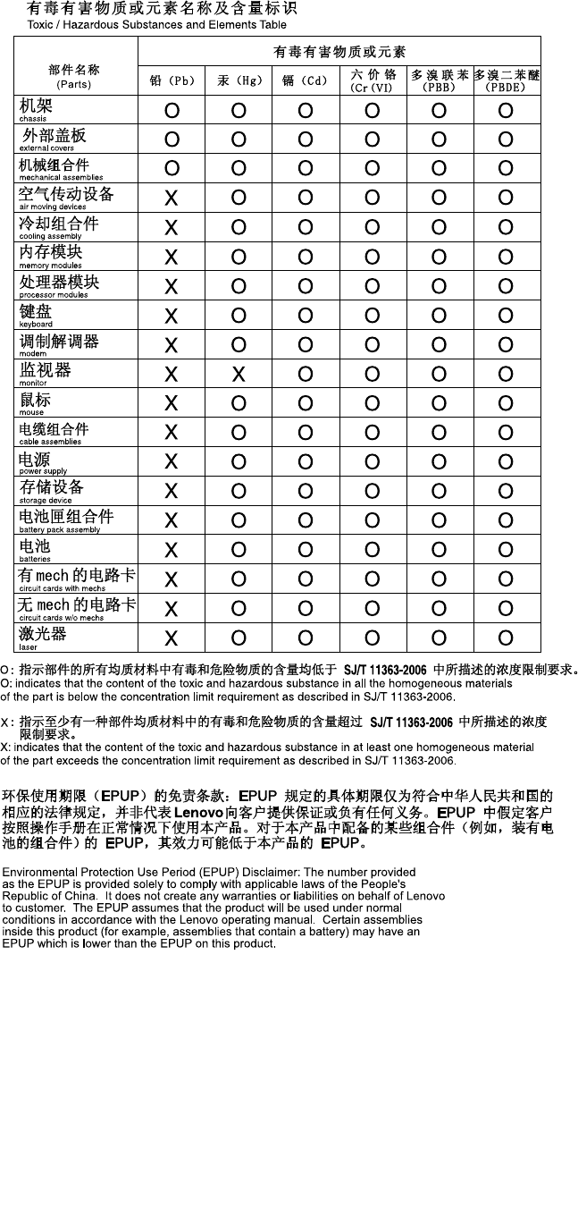
ChinaRoHS
Turkishstatementofcompliance
TheLenovoproductmeetstherequirementsoftheRepublicofTurkeyDirectiveontheRestrictionoftheUse
ofCertainHazardousSubstancesinElectricalandElectronicEquipment(EEE).
AppendixA.Notices225
GermanOrdinanceforWorkglossstatement
Theproductisnotsuitableforusewithvisualdisplayworkplacedevicesaccordingtoclause2ofthe
GermanOrdinanceforWorkwithVisualDisplayUnits.
DasProduktistnichtfürdenEinsatzanBildschirmarbeitsplätzenimSinne§2der
Bildschirmarbeitsverordnunggeeignet.
Electronicemissionnotices
ThefollowinginformationreferstotheLenovoThinkServermachinetypes0387,0388,0389,0390,0391,
0392,0393,and0441.
FederalCommunicationsCommission(FCC)Statement
ThisequipmenthasbeentestedandfoundtocomplywiththelimitsforaClassAdigitaldevice,pursuant
toPart15oftheFCCRules.Theselimitsaredesignedtoprovidereasonableprotectionagainstharmful
interferencewhentheequipmentisoperatedinacommercialenvironment.Thisequipmentgenerates,uses,
andcanradiateradiofrequencyenergyand,ifnotinstalledandusedinaccordancewiththeinstruction
manual,maycauseharmfulinterferencetoradiocommunications.Operationofthisequipmentina
residentialareaislikelytocauseharmfulinterferenceinwhichcasetheuserwillberequiredtocorrectthe
interferenceathisownexpense.
ProperlyshieldedandgroundedcablesandconnectorsmustbeusedinordertomeetFCCemissionlimits.
Lenovoisnotresponsibleforanyradioortelevisioninterferencecausedbyusingotherthanspeciedor
recommendedcablesandconnectorsorbyunauthorizedchangesormodicationstothisequipment.
Unauthorizedchangesormodicationscouldvoidtheuser'sauthoritytooperatetheequipment.
ThisdevicecomplieswithPart15oftheFCCRules.Operationissubjecttothefollowingtwoconditions:(1)
thisdevicemaynotcauseharmfulinterference,and(2)thisdevicemustacceptanyinterferencereceived,
includinginterferencethatmaycauseundesiredoperation.
IndustryCanadaClassAemissioncompliancestatement
ThisClassAdigitalapparatuscomplieswithCanadianICES-003.
CetappareilnumériquedelaclasseAestconformeàlanormeNMB-003duCanada.
UnitedKingdomtelecommunicationssafetyrequirement
NoticetoCustomers
ThisapparatusisapprovedunderapprovalnumberNS/G/1234/J/100003forindirectconnectiontopublic
telecommunicationsystemsintheUnitedKingdom.
226ThinkServerHardwareMaintenanceManual

EuropeanUnion-CompliancetotheElectromagneticCompatibilityDirective
ThisproductisinconformitywiththeprotectionrequirementsofEUCouncilDirective2004/108/EConthe
approximationofthelawsoftheMemberStatesrelatingtoelectromagneticcompatibility.Lenovocannot
acceptresponsibilityforanyfailuretosatisfytheprotectionrequirementsresultingfromanon-recommended
modicationoftheproduct,includingtheinstallationofoptioncardsfromothermanufacturers.
ThisproducthasbeentestedandfoundtocomplywiththelimitsforClassAInformationTechnology
EquipmentaccordingtoEuropeanStandardEN55022.ThelimitsforClassAequipmentwerederivedfor
commercialandindustrialenvironmentstoprovidereasonableprotectionagainstinterferencewithlicensed
communicationequipment.
Warning:ThisisaClassAproduct.Inadomesticenvironmentthisproductmaycauseradiointerference
inwhichcasetheusermayberequiredtotakeadequatemeasures.
GermanClassAcompliancestatement
DeutschsprachigerEUHinweis:
HinweisfürGerätederKlasseAEU-RichtliniezurElektromagnetischenVerträglichkeit
DiesesProduktentsprichtdenSchutzanforderungenderEU-Richtlinie2004/108/EG(früher89/336/EWG)zur
AngleichungderRechtsvorschriftenüberdieelektromagnetischeVerträglichkeitindenEU-Mitgliedsstaaten
undhältdieGrenzwertederEN55022KlasseAein.
Umdiesessicherzustellen,sinddieGerätewieindenHandbüchernbeschriebenzuinstallierenundzu
betreiben.DesWeiterendürfenauchnurvonderLenovoempfohleneKabelangeschlossenwerden.
LenovoübernimmtkeineVerantwortungfürdieEinhaltungderSchutzanforderungen,wenndasProdukt
ohneZustimmungderLenovoverändertbzw.wennErweiterungskomponentenvonFremdherstellernohne
EmpfehlungderLenovogesteckt/eingebautwerden.
Deutschland:
EinhaltungdesGesetzesüberdieelektromagnetischeVerträglichkeitvonBetriebsmittein
DiesesProduktentsprichtdem„GesetzüberdieelektromagnetischeVerträglichkeitvonBetriebsmitteln“
EMVG(früher„GesetzüberdieelektromagnetischeVerträglichkeitvonGeräten“).DiesistdieUmsetzungder
EU-Richtlinie2004/108/EG(früher89/336/EWG)inderBundesrepublikDeutschland.
ZulassungsbescheinigunglautdemDeutschenGesetzüberdieelektromagnetischeVerträglichkeit
vonBetriebsmitteln,EMVGvom20.Juli2007(früherGesetzüberdieelektromagnetische
VerträglichkeitvonGeräten),bzw.derEMVEGRichtlinie2004/108/EC(früher89/336/EWG),für
GerätederKlasseA.
DiesesGerätistberechtigt,inÜbereinstimmungmitdemDeutschenEMVGdasEG-Konformitätszeichen
-CE-zuführen.VerantwortlichfürdieKonformitätserklärungnachParagraf5desEMVGistdieLenovo
(Deutschland)GmbH,Gropiusplatz10,D-70563Stuttgart.
InformationeninHinsichtEMVGParagraf4Abs.(1)4:
DasGeräterfülltdieSchutzanforderungennachEN55024undEN55022KlasseA.
NachderEN55022:„DiesisteineEinrichtungderKlasseA.DieseEinrichtungkannimWohnbereich
Funkstörungenverursachen;indiesemFallkannvomBetreiberverlangtwerden,angemesseneMaßnahmen
durchzuführenunddafüraufzukommen.“
AppendixA.Notices227
NachdemEMVG:„GerätedürfenanOrten,fürdiesienichtausreichendentstörtsind,nurmitbesonderer
GenehmigungdesBundesministersfürPostundTelekommunikationoderdesBundesamtesfürPostund
Telekommunikationbetriebenwerden.DieGenehmigungwirderteilt,wennkeineelektromagnetischen
Störungenzuerwartensind.“(AuszugausdemEMVG,Paragraph3,Abs.4).DiesesGenehmigungsverfahren
istnachParagraph9EMVGinVerbindungmitderentsprechendenKostenverordnung(Amtsblatt14/93)
kostenpichtig.
Anmerkung:UmdieEinhaltungdesEMVGsicherzustellensinddieGeräte,wieindenHandbüchern
angegeben,zuinstallierenundzubetreiben.
AustraliaandNewZealandClassAstatement
Attention:ThisisaClassAproduct.Inadomesticenvironmentthisproductmaycauseradiointerference
inwhichcasetheusermayberequiredtotakeadequatemeasures.
KoreaClassAcompliancestatement
JapanVCCIClassAcompliancestatement
Japancompliancestatementforproductswhichconnecttothepowermainswithratedcurrent
lessthanorequalto20Aperphase
ChinaClassAcompliancestatement
TaiwanClassAcompliancestatement
LenovoproductserviceinformationforT aiwan
228ThinkServerHardwareMaintenanceManual

Index
2.5-inchhot-swapharddiskdrivebackplane
locations37
3.5-inchhot-swapharddiskdrivebackplane
locations35
A
aboutRAID72
Advancedmenu
SetupUtilityprogram57
advancedSATAorSAShardwareRAID
conguring79
ambienttemperatureoverlimitLED
LED19
B
BIOSandBMCrmwareupdate
software13
BMCstatus
LED51
BootManagermenu
SetupUtilityprogram64
BootOptionsmenu
SetupUtilityprogram62
C
cables
connecting38
conguring
Ethernetcontrollers80
server55
conguringRAID
advancedSATAorSAShardwareRAID79
onboardSATAsoftwareRAID74
usingtheThinkServerEasyStartupprogram74
conguringtheserver55
connecting
cables38
considerations,password65
consistencycheck
running78
contamination,particulateandgaseous220
creating,adding,ordeleting
RAIDarray76
CRU
completingthereplacement168
D
devices,handlingstatic-sensitive84
DIMM
installationrules90
installing91
removing92
DITmodule
installing112
locations18
removing113
DITpanel
LED18
locations18
documentation
using213
downloading
theBIOSupdateutilityprogram67
E
EasyUpdateFirmwareUpdaterprogram
using81
error
LED19
Ethernetcard
installing96
removing97
Ethernetconnectivity
features9
Ethernetcontrollers
conguring80
Ethernetstatus
LED22
Exitmenu
SetupUtilityprogram64
exiting
SetupUtilityprogram67
expansionslots
features9
F
fans
features8
features7
ThinkServerEasyStartupprogram70
rmware
updating80
ashing
theBIOS68
frontbezel
reinstalling87
removing87
frontpanel
LED17
locations17
frontpanelboardassembly
replacing147
frontsystemfan
replacing149
©CopyrightLenovo2011229

frontviewoftheserver
locations15
FRUlists179
G
gaseouscontamination220
Germanglossstatement226
gettinghelp213
gettinginformation213
gettingservice213
guidelines83
H
harddiskdrivestatus
LED18
hardware
installing83
removing83
replacing83
heatsinkandfanassembly
replacing154
help,getting213
hot-sparedrive
setting77
hot-swapharddiskdrive
installing119
replacing119
hot-swapharddiskdrivebackplane
locations34
replacing133
hot-swapharddiskdrivestatus
LED32
hot-swapharddiskdrivestatusLEDs
locations32
hot-swapredundantpowersupplymodule
replacing140
hot-swapredundantpowersupplymodulestatus
LED21
I
iKVMkey
installing106
removing107
information,getting213
initializing
virtualdrive77
Input/Output(I/O)
features9
installationrules
DIMM90
memorymodule90
installing
DIMM91
DITmodule112
Ethernetcard96
hardware83
hot-swapharddiskdrive119
iKVMkey106
memorymodule91
non-hot-swapharddiskdrive128
opticaldrive115
PCIcard93
RAID5keyontheRAIDcard100
RAIDcard98
servercover168
systemboardRAID5key102
TPMmodule109
installingandusing
MegaRAIDStorageManagerprogram79
interface
LSISoftwareRAIDCongurationUtilityprogram75
SetupUtilityprogram56
internaldrives
features9
L
LED
ambienttemperatureoverlimitLED19
BMCstatus51
DITpanel18
error19
Ethernetstatus22
frontpanel17
harddiskdrivestatus18
hot-swapharddiskdrivestatus32
hot-swapredundantpowersupplymodulestatus21
NICstatus18
opticaldrivestatus16
POSTcodediagnostic51
powerstatus17
systemboard50
systemboardhardwarefault50
systemstatus18
locations13
LSISoftwareRAIDCongurationUtilityprogram
interface75
starting74
M
machinetypeandmodellabel
locations13
Mainmenu
SetupUtilityprogram56
MegaRAIDStorageManagerprogram
installingandusing79
memory
features8
memorymodule
installationrules90
installing91
removing92
memorymoduleinstallation
guidelines90
microprocessor
features8
230ThinkServerHardwareMaintenanceManual

replacing157
N
NICstatus
LED18
non-hot-swapharddiskdrive
installing128
removing124
non-hot-swappowersupplyassembly
replacing137
O
onboardSATAsoftwareRAID
conguring74
opticaldrive
installing115
replacing115
opticaldrivestatus
LED16
option
completingthereplacement168
P
particulatecontamination220
partsreplacement,completing168
password
considerations65
setting,changing,deleting65
SetupUtilityprogram65
PC-DoctorforDOS
software13
troubleshootinganddiagnostics172
PCIcard
installing93
removing95
physicaldrive
rebuilding78
POSTcodediagnostic
LED51
powerdistributionboardandcageassembly
replacing143
powerstatus
LED17
powersupply
features8
precautions
guidelines83
R
RAID
conguring71
foryourserver73
introduction72
RAID5keyontheRAIDcard
installing100
removing101
RAIDarray
creating,adding,ordeleting76
RAIDcard
installing98
locations33
removing99
RAIDcongurationutilities
software13
rearsystemfan
replacing152
rearviewoftheserver
locations19
rebuilding
physicaldrive78
recovering
theBIOS68
reinstalling
frontbezel87
reliability,availability,andserviceability
features10
removing
DIMM92
DITmodule113
Ethernetcard97
frontbezel87
hardware83
iKVMkey107
memorymodule92
non-hot-swapharddiskdrive124
PCIcard95
RAID5keyontheRAIDcard101
RAIDcard99
servercover85
systemboardRAID5key104
TPMmodule110
replacing
frontpanelboardassembly147
frontsystemfan149
hardware83
heatsinkandfanassembly154
hot-swapharddiskdrive119
hot-swapharddiskdrivebackplane133
hot-swapredundantpowersupplymodule140
microprocessor157
non-hot-swappowersupplyassembly137
opticaldrive115
powerdistributionboardandcageassembly143
rearsystemfan152
systemboard162
systemboardbattery161
roadmap
serversetup5
running
consistencycheck78
S
security
frontdoorlock25
integratedcablelock24
©CopyrightLenovo2011231

padlock23
Securitymenu
SetupUtilityprogram60
serialnumberlabel
locations13
servercomponents
locations25
serverconguration
updating170
servercover
installing168
removing85
serverdocumentation1
serverlocks
locations22
ServerManagementmenu
SetupUtilityprogram61
serverpackage7
serversetup
roadmap5
service,getting213
setting
hot-sparedrive77
setting,changing,deleting
password65
SetupUtilityprogram
exiting67
interface56
password65
starting55
TPM66
using55
software12
specications12
starting
LSISoftwareRAIDCongurationUtilityprogram74
SetupUtilityprogram55
ThinkServerEasyStartupprogram70
startupdevice
selecting66
SetupUtilityprogram66
static-sensitivedevices
guidelines84
static-sensitivedevices,handling84
systemboard42
LED50
replacing162
systemboardbattery
replacing161
systemboardcomponents
locations42
systemboardhardwarefault
LED50
systemboardjumpers
locations46
systemboardLEDs
locations50
systemboardRAID5key
installing102
removing104
systemdate
setting64
systemeventlog
troubleshootinganddiagnostics172
systemreliability
guidelines84
systemstatus
LED18
systemtime
setting64
T
theBIOS
ashing68
recovering68
updating68
updatingorrecovering67
theBIOSupdateutilityprogram
downloading67
ThinkServerEasyStartup
software12
ThinkServerEasyStartupprogram
features70
starting70
using69
ThinkServerEasyUpdateFirmwareUpdater
software13
ThinkServerWebaddress1
TPM
SetupUtilityprogram66
TPMmodule
installing109
removing110
troubleshootinganddiagnostics
harddiskdriveproblems174
keyboard,mouse,orUSBdeviceproblems176
memorymoduleproblems176
opticaldriveproblems173
PC-DoctorforDOS172
POSTerrorcodes177
statusanddiagnosticLEDs171
systemeventlog172
ThinkServerEasyStartupprogramproblems172
troubleshootingprocedure171
turningofftheserver53
turningontheserver53
TÜVglossstatement226
U
updating
rmware80
serverconguration170
theBIOS68
updatingorrecovering
theBIOS67
using
documentation213
232ThinkServerHardwareMaintenanceManual


234ThinkServerHardwareMaintenanceManual