Lenovo B40 30 Hmm 20140929 User Manual B40–30 All In One Hardware Maintenance (Lenovo) Type 10178
2014-09-29
User Manual: Lenovo Lenovo B40-30 Hmm 20140929 Lenovo B40–30 All-In-One Hardware Maintenance Manual B40-30 All-in-One (Lenovo) - Type 10178
Open the PDF directly: View PDF ![]() .
.
Page Count: 65
- Chapter 1. About this manual
- Chapter 2. Safety information
- Chapter 3. General information
- Chapter 4. General Checkout
- Chapter 5. Using the Setup Utility
- Chapter 6. Symptom-to-FRU Index
- Chapter 7. Replacing hardware
- General information
- Replacing the keyboard and mouse
- Replacing the adapter
- Removing the stand base
- Removing the foot cover
- Replacing the memory module
- Replacing the hard disk drive
- Replacing the optical drive
- Removing the stand holder
- Removing the middle cover
- Replacing the converter board
- Removing the EMI cover
- Replacing the Wi-Fi card
- Replacing the TV tuner card
- Replacing the heat-sink
- Replacing the CPU
- Replacing the system fan
- Replacing the speaker system
- Replacing the power switch board
- Replacing the motherboard
- Removing the rear deco
- Replacing the camera
- Replacing the LED panel module
- Chapter 8. FRU lists
- Chapter 9. General information

LenovoB40–30All-In-OneComputer
HardwareMaintenanceManual
MachineTypes:F0AW[B40-30]

LenovoB40–30All-In-OneComputer
HardwareMaintenanceManual
MachineTypes:F0AW[B40-30]

SecondEdition(September2014)12th
©CopyrightLenovo2014.
LIMITEDANDRESTRICTEDRIGHTSNOTICE:IfdataorsoftwarearedeliveredpursuantaGeneralServices
Administration“GSA”contract,use,reproduction,ordisclosureissubjecttorestrictionssetforthinContractNo.
GS-35F-05925

Contents
Chapter1.Aboutthismanual.....1
ImportantSafetyInformation.........1
Chapter2.Safetyinformation.....3
Generalsafety...............3
Electricalsafety..............3
Safetyinspectionguide...........5
Handlingelectrostaticdischarge-sensitive
devices.................5
Groundingrequirements...........6
Safetynotices...............6
Chapter3.Generalinformation....9
Specifications...............9
Chapter4.GeneralCheckout.....11
Chapter5.UsingtheSetupUtility...13
StartingtheLenovoBIOSSetupUtilityprogram.13
Viewingandchangingsettings........13
Usingpasswords..............13
Enablingordisablingadevice........15
Selectingastartupdevice..........16
ExitingtheLenovoBIOSSetupUtilityprogram..17
Chapter6.Symptom-to-FRUIndex..19
Harddiskdrivebooterror..........19
PowerSupplyProblems...........19
POSTerrorcodes.............20
Undeterminedproblems...........20
Chapter7.Replacinghardware....21
Generalinformation.............21
Replacingthekeyboardandmouse......22
Replacingtheadapter............22
Removingthestandbase..........23
Removingthefootcover...........24
Replacingthememorymodule........25
Replacingtheharddiskdrive.........26
Replacingtheopticaldrive..........27
Removingthestandholder..........28
Removingthemiddlecover.........29
Replacingtheconverterboard........31
RemovingtheEMIcover...........31
ReplacingtheWi-Ficard...........32
ReplacingtheTVtunercard.........33
Replacingtheheat-sink...........34
ReplacingtheCPU.............35
Replacingthesystemfan..........37
Replacingthespeakersystem........38
Replacingthepowerswitchboard.......39
Replacingthemotherboard..........40
Removingthereardeco...........42
Replacingthecamera............43
ReplacingtheLEDpanelmodule.......44
Chapter8.FRUlists..........49
Chapter9.Generalinformation....59
AdditionalServiceInformation........59
©CopyrightLenovo2014iii

ivLenovoB40–30All-In-OneComputerHardwareMaintenanceManual
Chapter1.Aboutthismanual
ThismanualcontainsserviceandreferenceinformationforLenovoB40–30All-In-Onecomputerslistedon
thecover.ItisintendedonlyfortrainedservicerswhoarefamiliarwithLenovocomputerproducts.
BeforeservicingaLenovoproduct,besuretoreadtheSafetyInformation.
ThedescriptionoftheTV-tunercardinthismanualappliesonlytocomputerswithaTV-tunercardinstalled.
ItdoesnotapplytocomputerswithoutaTV-tunercard.
ImportantSafetyInformation
BesuretoreadallCAUTIONandDANGERsectionsinthismanualbeforefollowinganyoftheinstructions.
VeuillezliretouteslesconsignesdetypeDANGERetATTENTIONduprésentdocumentavantd’exécuter
lesinstructions.
LesenSieunbedingtalleHinweisevomTyp“ACHTUNG”oder“VORSICHT”indieserDokumentation,bevor
SieirgendwelcheVorgängedurchführen
LeggereleistruzioniintrodottedaATTENZIONEePERICOLOpresentinelmanualeprimadieseguireuna
qualsiasidelleistruzioni
Certifique-sedelertodasasinstruçõesdecuidadoeperigonestemanualantesdeexecutarqualquer
umadasinstruções
Esimportantequeleatodaslasdeclaracionesdeprecauciónydepeligrodeestemanualantesdeseguir
lasinstrucciones.
©CopyrightLenovo20141

2LenovoB40–30All-In-OneComputerHardwareMaintenanceManual

Chapter2.Safetyinformation
Thischaptercontainsthesafetyinformationthatyouneedtobefamiliarwithbeforeservicingacomputer.
Generalsafety
Followtheserulestoensuregeneralsafety:
•Keeptheareasaroundthecomputerclearandcleanduringandaftermaintenance.
•Whenliftinganyheavyobject:
1.Ensureyoucanstandsafelywithoutslipping.
2.Distributetheweightoftheobjectequallyacrossbothfeet.
3.Liftslowly.Nevermovesuddenlyortwistwhenyouattempttolift.
4.Liftbystandingorbypushingupwithyourlegmuscles;thisactionremovesthestrainfromthe
musclesinyourback.
Donotattempttoliftanyobjectsthatweighmorethan16kg(35lb)orobjectsthatyouthinkare
tooheavyforyou.
•Donotperformanyactionthatwouldcreateahazardforthecustomer,orwouldmakethecomputer
unsafe.
•Beforeyoustartthecomputer,ensurethatotherservicerepresentativesandcustomerpersonnelarenot
inapositionthatwouldcreateahazardforthem.
•Placeremovedcoversandotherpartsinasafeplace,awayfromallpersonnel,whileyouareservicingthe
computer.
•Keepyourtoolcaseawayfromareasthatpeoplemaywalkthroughtoensureno-onetripsoverit.
•Donotwearlooseclothingthatcanbetrappedinthemovingpartsofamachine.Ensurethatyoursleeves
arefastenedorrolledupaboveyourelbows.Ifyourhairislong,tieorfastenitback.
•Inserttheendsofyournecktieorscarfinsideclothingorfastenitwithanon-conductiveclip,
approximately8centimeters(3inches)fromtheend.
•Donotwearjewelry,chains,metal-frameeyeglasses,ormetalfastenersforyourclothing.
Remember:Metalobjectsaregoodelectricalconductors.
•Wearsafetyglasseswhenyouare:hammering,drillingsoldering,cuttingwire,attachingsprings,using
solvents,orworkinginanyotherconditionsthatmightbehazardoustoyoureyes.
•Afterservice,reinstallallsafetyshields,guards,labels,andgroundwires.Replaceanysafetydevice
thatiswornordefective.
•Reattachallcoverscorrectlybeforereturningthecomputertothecustomer.
Electricalsafety
CAUTION:
Electricalcurrentfrompower,telephone,andcommunicationcablescanbehazardous.T oavoid
personalinjuryorequipmentdamage,disconnectanyattachedpowercords,telecommunication
cables,networkcables,andmodemcablesbeforeyouopenthecomputercovers,unlessinstructed
otherwiseintheinstallationandconfigurationprocedures.
©CopyrightLenovo20143

Observethefollowingruleswhenworkingonelectricalequipment.
Important:Useonlyapprovedtoolsandtestequipment.Somehandtoolshavehandlescoveredwithasoft
materialthatdoesnotinsulateyouwhenworkingwithliveelectricalcurrents.Manycustomershaverubber
floormatsneartheirequipmentthatcontainsmallconductivefiberstodecreaseelectrostaticdischarge.
•Findtheroomemergencypower-off(EPO)switch,disconnectingswitch,orelectricaloutlet.Ifanelectrical
accidentoccurs,youcanthenoperatetheswitchorunplugthepowercordquickly.
•Donotworkaloneunderhazardousconditionsornearequipmentthathashazardousvoltages.
•Disconnectallpowerbefore:
–Performingamechanicalinspection
–Workingnearpowersupplies
–RemovingorinstallingFieldReplaceableUnits(FRUs)
•Beforeyoustarttoworkonthecomputer,unplugthepowercord.Ifyoucannotunplugit,askthe
customertopower-offtheelectricaloutletthatsuppliespowertothemachineandtolocktheelectrical
outletintheoffposition.
•Ifyouneedtoworkonacomputerthathasexposedelectricalcircuits,observethefollowingprecautions:
–Ensurethatanotherperson,familiarwiththepower-offcontrols,isnearyou.
Remember:Anotherpersonmustbetheretoswitchoffthepower,ifnecessary.
–Useonlyonehandwhenworkingwithpowered-onelectricalequipment;keeptheotherhandinyour
pocketorbehindyourback.
Remember:Theremustbeacompletecircuittocauseelectricalshock.Byobservingtheaboverule,
youmaypreventacurrentfrompassingthroughyourbody.
–Whenusingatester,setthecontrolscorrectlyandusetheapprovedprobeleadsandaccessoriesfor
thattester.
–Standonsuitablerubbermats(obtainedlocally,ifnecessary)toinsulateyoufromgroundssuchas
metalfloorstripsandmachineframes.
Observethespecialsafetyprecautionswhenyouworkwithveryhighvoltages;theseinstructionsarein
thesafetysectionsofthemaintenanceinformation.Useextremecarewhenmeasuringhighvoltages.
•Regularlyinspectandmaintainyourelectricalhandtoolstoensuretheyaresafetouse.
•Donotusewornorbrokentoolsandtesters.
•Neverassumethatpowerhasbeendisconnectedfromacircuit.First,checkthatithasbeenpoweredoff.
•Alwayslookcarefullyforpossiblehazardsinyourworkarea.Examplesofthesehazardsarewetfloors,
non-groundedpowerextensioncables,conditionsthatmaycauseorallowpowersurges,andmissing
safetygrounds.
•Donottouchliveelectricalcircuitswiththereflectivesurfaceofaplasticdentalmirror.Thissurfaceis
conductive,andtouchingalivecircuitcancausepersonalinjuryanddamagetothecomputer.
•Donotservicethefollowingpartswiththepoweronwhentheyareremovedfromtheirnormaloperating
positionsinacomputer:
–Powersupplyunits
–Pumps
–Blowersandfans
–Motorgenerators
andsimilarunits.(Thispracticeensurescorrectgroundingoftheunits.)
•Ifanelectricalaccidentoccurs:
–Usecaution;donotbecomeavictimyourself.
4LenovoB40–30All-In-OneComputerHardwareMaintenanceManual

–Switchoffpower.
–Sendanotherpersontogetmedicalaid.
Safetyinspectionguide
Theintentofthisinspectionguideistoassistyouinidentifyingpotentialhazardsposedbytheseproducts.
Eachcomputer,asitwasdesignedandbuilt,hadrequiredsafetyitemsinstalledtoprotectusersand
servicepersonnelfrominjury.Thisguideaddressesonlythoseitems.However,goodjudgmentshouldbe
usedtoidentifypotentialsafetyhazardsduetoattachmentoffeaturesoroptionsnotcoveredbythis
inspectionguide.
Ifanyhazardsarepresent,youmustdeterminehowserioustheapparenthazardcouldbeandwhetheryou
cancontinuewithoutfirstresolvingtheproblem.
Considerthefollowingitemsandthesafetyhazardstheypresent:
•Electricalhazards,especiallyprimarypower(primaryvoltageontheframecancauseseriousorfatal
electricalshock).
•Explosivehazards,suchasadamagedCRTfaceorbulgingcapacitor
•Mechanicalhazards,suchaslooseormissinghardware
Theguideconsistsofaseriesofstepspresentedasachecklist.Beginthecheckswiththepoweroff,and
thepowercorddisconnected.
Checklist:
1.Checkexteriorcoversfordamage(loose,broken,orsharpedges).
2.Power-offthecomputer.Disconnectthepowercord.
3.Checkthepowercordfor:
a.Athird-wiregroundconnectoringoodcondition.Useametertomeasurethird-wireground
continuityfor0.1ohmorlessbetweentheexternalgroundpinandframeground.
b.Thepowercordshouldbetheappropriatetypeasspecifiedinthepartslistings.
c.Insulationmustnotbefrayedorworn.
4.Removethecover.
5.Checkforanyobviousalterations.Usegoodjudgmentastothesafetyofanyalterations.
6.Checkinsidetheunitforanyobvioushazards,suchasmetalfilings,contamination,waterorother
liquids,orsignsoffireorsmokedamage.
7.Checkforworn,frayed,orpinchedcables.
8.Checkthatthepower-supplycoverfasteners(screwsorrivets)havenotbeenremovedortamperedwith.
Handlingelectrostaticdischarge-sensitivedevices
Anycomputerpartcontainingtransistorsorintegratedcircuits(ICs)shouldbeconsideredsensitiveto
electrostaticdischarge(ESD).ESDdamagecanoccurwhenthereisadifferenceinchargebetweenobjects.
ProtectagainstESDdamagebyequalizingthechargesothatthecomputer,thepart,theworkmat,andthe
personhandlingthepartareallatthesamecharge.
Notes:
1.Useproduct-specificESDprocedureswhentheyexceedtherequirementsnotedhere.
2.MakesurethattheESDprotectivedevicesyouusehavebeencertified(ISO9000)asfullyeffective.
WhenhandlingESD-sensitiveparts:
Chapter2.Safetyinformation5

•Keepthepartsinprotectivepackagesuntiltheyareinsertedintotheproduct.
•Avoidcontactwithotherpeoplewhilehandlingthepart.
•Wearagroundedwriststrapagainstyourskintoeliminatestaticonyourbody.
•Preventthepartfromtouchingyourclothing.Mostclothingisinsulativeandretainsachargeeven
whenyouarewearingawriststrap.
•Usetheblacksideofagroundedworkmattoprovideastatic-freeworksurface.Thematisespecially
usefulwhenhandlingESD-sensitivedevices.
•Selectagroundingsystem,suchasthoselistedbelow,toprovideprotectionthatmeetsthespecific
servicerequirement.
Note:TheuseofagroundingsystemisdesirablebutnotrequiredtoprotectagainstESDdamage.
–AttachtheESDgroundcliptoanyframeground,groundbraid,orgreen-wireground.
–UseanESDcommongroundorreferencepointwhenworkingonadouble-insulatedor
battery-operatedsystem.Y oucanusecoaxorconnector-outsideshellsonthesesystems.
–Usetheroundground-prongoftheACplugonAC-operatedcomputers.
Groundingrequirements
Electricalgroundingofthecomputerisrequiredforoperatorsafetyandcorrectsystemfunction.Proper
groundingoftheelectricaloutletcanbeverifiedbyacertifiedelectrician.
Safetynotices
TheCAUTIONandDANGERsafetynoticesinthissectionareprovidedinthelanguageofEnglish.
DANGER
Electricalcurrentfrompower,telephoneandcommunicationcablesishazardous.
Toavoidashockhazard:
•Donotconnectordisconnectanycablesorperforminstallation,maintenance,orreconfiguration
ofthisproductduringanelectricalstorm.
•Connectallpowercordstoaproperlywiredandgroundedelectricaloutlet.
•Connectanyequipmentthatwillbeattachedtothisproducttoaproperlywiredoutlet.
•Whenpossible,useonehandonlytoconnectordisconnectsignalcables.
•Neverturnonanyequipmentwhenthereisevidenceoffire,water,orstructuraldamage.
•Disconnecttheattachedpowercords,telecommunicationscables,networkcables,andmodem
cablesbeforeyouopenthedevicecovers,unlessinstructedotherwiseintheinstallationand
configurationprocedures.
•Connectanddisconnectcablesasdescribedinthefollowingtablewheninstalling,moving,or
openingcoversonthisproductorattacheddevices.
6LenovoB40–30All-In-OneComputerHardwareMaintenanceManual
ToConnectToDisconnect
1.TurneverythingOFF .
2.First,attachallcablestodevices.
3.Attachsignalcablestoconnectors.
4.Attachpowercordstooutlet.
5.TurndeviceON.
1.TurneverythingOFF .
2.First,removepowercordsfromoutlets.
3.Removesignalcablesfromconnectors.
4.Removeallcablesfromdevices.
CAUTION:
Whenreplacingthelithiumbattery,useonlyPartNumber45C1566oranequivalenttypebattery
recommendedbythemanufacturer.Ifyoursystemhasamodulecontainingalithiumbattery,replace
itonlywiththesamemoduletypemadebythesamemanufacturer.Thebatterycontainslithiumand
canexplodeifnotproperlyused,handled,ordisposedof.
Donot:
•Throwintoorimmerseinwater
•Heattomorethan100°C(212°F)
•Repairordisassemble
Disposeofthebatteryasrequiredbylocalordinancesorregulations.
CAUTION:
Whenlaserproducts(suchasCD-ROMs,DVD-ROMdrives,fiberopticdevices,ortransmitters)are
installed,notethefollowing:
•Donotremovethecovers.Removingthecoversofthelaserproductcouldresultinexposureto
hazardouslaserradiation.Therearenoserviceablepartsinsidethedevice.
•Useofcontrolsoradjustmentsorperformanceofproceduresotherthanthosespecifiedherein
mightresultinhazardousradiationexposure.
DANGER
SomelaserproductscontainanembeddedClass3AorClass3Blaserdiode.Notethefollowing:
Thesediodesemitradiationwhenopen.Donotstareintothebeam,donotviewdirectlywith
opticalinstruments,andavoiddirectexposuretothebeam.
Chapter2.Safetyinformation7
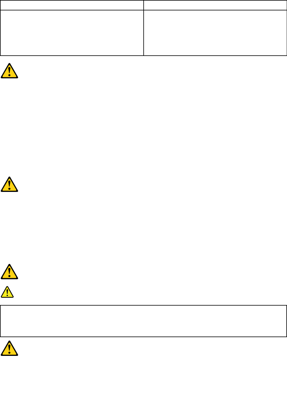
≥18kg(37lbs)≥32kg(70.5lbs)≥55kg(121.2lbs)
CAUTION:
Usesafepracticeswhenlifting.
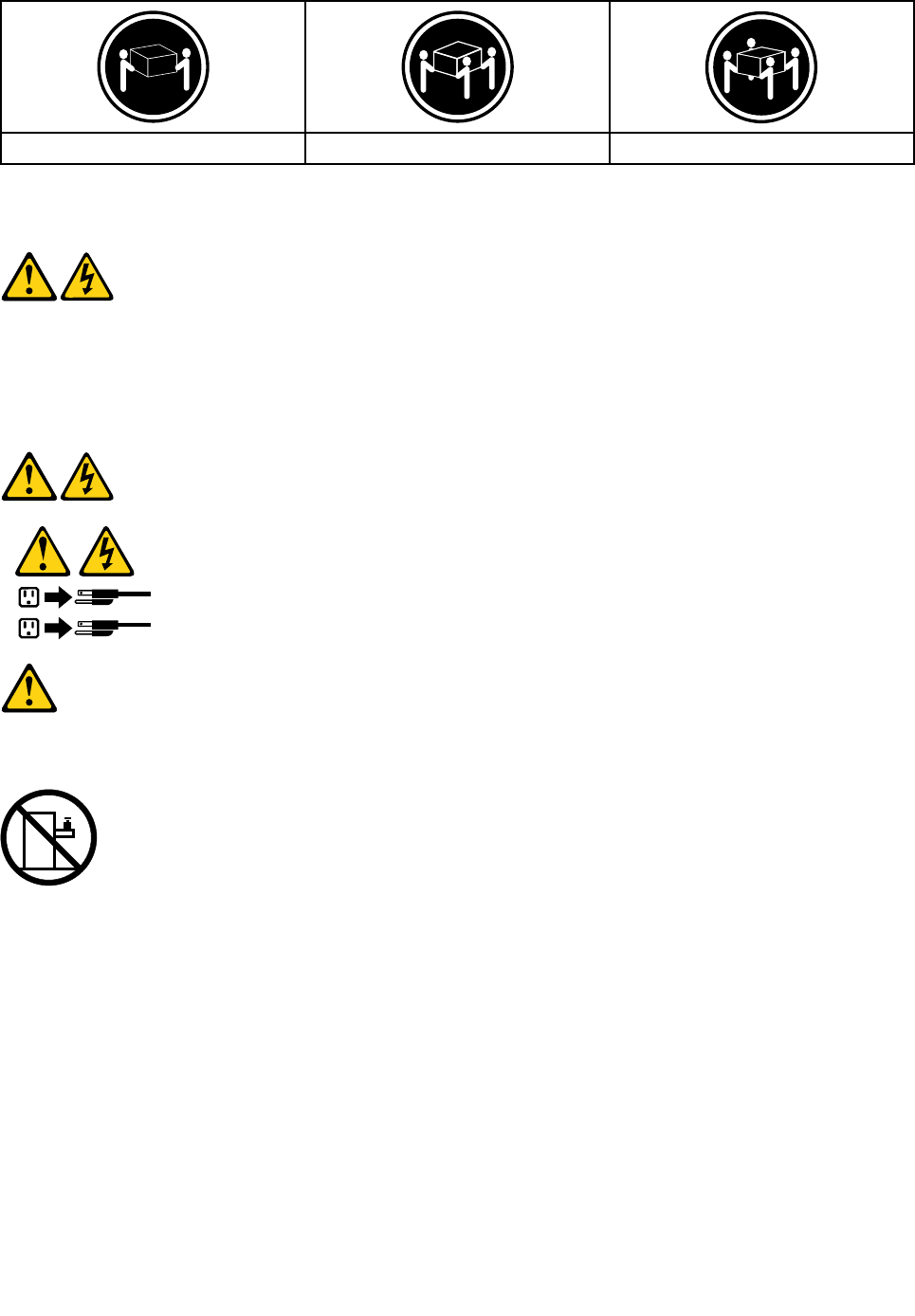
CAUTION:
Thepowercontrolbuttononthedeviceandthepowerswitchonthepowersupplydonotturnoff
theelectricalcurrentsuppliedtothedevice.Thedevicealsomighthavemorethanonepower
cord.Toremoveallelectricalcurrentfromthedevice,ensurethatallpowercordsaredisconnected
fromthepowersource.
1
2
CAUTION:
Donotplaceanyobjectweighingmorethan82kg(180lbs.)ontopofrack-mounteddevices.
8LenovoB40–30All-In-OneComputerHardwareMaintenanceManual

Chapter3.Generalinformation
Thischapterprovidesgeneralinformationthatappliestoallcomputermodelscoveredbythismanual.
Specifications
Thissectionliststhephysicalspecificationsforyourcomputer.
Thissectionliststhephysicalspecificationsforyourcomputer.
TypeLenovoB40–30
Thissectionliststhephysicalspecifications.
Environment
Airtemperature:
Operating:10°to35°C
Transit:-20°to55°C
Humidity:
Operating:35%to80%
Transit:20%to90%(40°C)
Altitude:86KPato106KPa
Electricalinput:
Inputvoltage:90V-264V(AC)
Inputfrequency:47Hz-63Hz
©CopyrightLenovo20149

10LenovoB40–30All-In-OneComputerHardwareMaintenanceManual

Chapter4.GeneralCheckout
Attention:Thedrivesinthecomputeryouareservicingmighthavebeenrearrangedorthedrivestartup
sequencemayhavebeenchanged.Beextremelycarefulduringwriteoperationssuchascopying,saving,or
formatting.Dataorprogramscanbeoverwrittenifyouselectanincorrectdrive.
Generalerrormessagesappearifaproblemorconflictisfoundbyanapplication,theoperatingsystem,or
both.Foranexplanationofthesemessages,refertotheinformationsuppliedwiththatsoftwarepackage.
Usethefollowingproceduretohelpdeterminethecauseoftheproblem:
1.Power-offthecomputerandallexternaldevices.
2.Checkallcablesandpowercords.
3.Setalldisplaycontrolstothemiddleposition.
4.Power-onallexternaldevices.
5.Power-onthecomputer.
•Lookfordisplayederrorcodes.
•Lookforreadableinstructionsoramainmenuonthedisplay.
Ifyoudidnotreceivethecorrectresponse,proceedtostep6.
Ifyoudidreceivethecorrectresponse,proceedtostep7.
6.Ifoneofthefollowinghappens,followtheinstructiongiven:
•IfthecomputerdisplaysaPOSTerror,goto“POSTerrorcodes” .
•Ifthecomputerhangsandnoerrorisdisplayed,continueatstep7.
7.Iftheteststopsandyoucannotcontinue,replacethelastdevicetested.
©CopyrightLenovo201411

12LenovoB40–30All-In-OneComputerHardwareMaintenanceManual

Chapter5.UsingtheSetupUtility
TheSetupUtilityprogramisusedtoviewandchangetheconfigurationsettingsofyourcomputer,regardless
ofwhichoperatingsystemyouareusing.However,theoperatingsystemsettingsmightoverrideanysimilar
settingsintheSetupUtilityprogram.
StartingtheLenovoBIOSSetupUtilityprogram
TostarttheLenovoBIOSSetupUtilityprogram,dothefollowing:
1.Ifyourcomputerisalreadyonwhenyoustartthisprocedure,shutdowntheoperatingsystemand
turnoffthecomputer.
2.PressandholdtheF1keythenturnonthecomputer.WhentheLenovoBIOSSetupUtilityprogramis
displayed,releasetheF1key.
Note:IfaPower-OnPasswordoranAdministratorPasswordhasbeenset,theSetupUtilityprogrammenu
willnotbedisplayeduntilyoutypeyourpassword.Formoreinformation,see“Usingpasswords.”
Viewingandchangingsettings
SystemconfigurationoptionsarelistedintheLenovoBIOSSetupUtilityprogrammenu.Tovieworchange
settings,see“StartingtheSetupUtilityprogram.”
YoumustusethekeyboardwhenusingtheLenovoBIOSSetupUtilitymenu.Thekeysusedtoperform
varioustasksaredisplayedonthebottomofeachscreen.
Usingpasswords
YoucanusetheLenovoBIOSSetupUtilityprogramtosetpasswordstopreventunauthorizedpersons
fromgainingaccesstoyourcomputeranddata.See“StartingtheSetupUtilityprogram.”Thefollowing
typesofpasswordsareavailable:
•AdministratorPassword
•Power-OnPassword
Youdonothavetosetanypasswordstouseyourcomputer.However,ifyoudecidetosetpasswords,read
thefollowingsections.
Passwordconsiderations
Apasswordcanbeanycombinationoflettersandnumbersupto16characters(a-zand0-9).Forsecurity
reasons,itisagoodideatouseastrongpasswordthatcannotbeeasilycompromised.Wesuggestthat
passwordsshouldfollowtheserules:
•Forastrongpassword,use7-16charactersandamixoflettersandnumbers.
•Donotuseyournameoryourusername.
•Donotuseacommonwordoracommonname.
•Usesomethingsignificantlydifferentfromyourpreviouspassword.
Attention:AdministratorandPower-Onpasswordsarenotcasesensitive.
©CopyrightLenovo201413

AdministratorPassword
SettinganAdministratorPassworddetersunauthorizedpersonsfromchangingconfigurationsettings.You
mightwanttosetanAdministratorPasswordifyouareresponsibleformaintainingthesettingsofseveral
computers.
AfteryousetanAdministratorPassword,apasswordpromptisdisplayedeverytimeyouaccesstheLenovo
BIOSSetupUtilityprogram.
IfboththeAdministratorandPower-OnPasswordareset,youcantypeeitherpassword.However,youmust
useyourAdministratorPasswordtochangeanyconfigurationsettings.
Setting,changing,ordeletinganAdministratorpassword
TosetanAdministratorPassword,dothefollowing:
Note:Apasswordcanbeanycombinationoflettersandnumbersupto16characters(a-zand0-9).For
moreinformation,see“Passwordconsiderations”onpage13.
1.StarttheLenovoBIOSSetupUtilityprogram(see“StartingtheLenovoBIOSSetupUtilityprogram”on
page13).
2.FromtheSecuritymenu,selectSetAdministratorPasswordandpresstheEnterkey.
3.Thepassworddialogboxwillbedisplayed.TypethepasswordthenpresstheEnterkey.
4.Re-typethepasswordtoconfirm,thenpresstheEnterkey.Ifyoutypedthepasswordcorrectly,
thepasswordwillbeinstalled.
TochangeanAdministratorPassword,dothefollowing:
1.StarttheLenovoBIOSSetupUtilityprogram(see“StartingtheLenovoBIOSSetupUtilityprogram”on
page13).
2.FromtheSecuritymenu,selectSetAdministratorPasswordandpresstheEnterkey.
3.Thepassworddialogboxwillbedisplayed.TypethecurrentpasswordthenpresstheEnterkey.
4.Typethenewpassword,thenpresstheEnterkey.Re-typethepasswordtoconfirmthenewpassword.
Ifyoutypedthenewpasswordcorrectly,thenewpasswordwillbeinstalled.ASetupNoticedconfirming
thatchangeshavebeensavedwillbedisplayed.
TodeleteapreviouslysetAdministratorPassword,dothefollowing:
1.FromtheSecuritymenu,selectSetAdministratorPasswordandpresstheEnterkey.
2.Thepassworddialogboxwillbedisplayed.TypethecurrentpasswordandpresstheEnterkey.
3.TodeleteanAdministratorPassword,leaveeachnewpasswordlineitemblank,thenpresstheEnter
key.ASetupNoticeconfirmingthatchangeshavebeensavedwillbedisplayed.
4.ReturntotheLenovoBIOSSetupUtilityprogrammenuandselecttheExitoption.
5.SelectSavechangesandExitfromthemenu.
Power-OnPassword
WhenaPower-OnPasswordisset,youcannotstarttheLenovoBIOSSetupUtilityprogramuntilavalid
passwordistypedfromthekeyboard.
Setting,changing,ordeletingaPower-OnPassword
Note:Apasswordcanbeanycombinationoflettersandnumbersupto16characters(a-zand0-9).
14LenovoB40–30All-In-OneComputerHardwareMaintenanceManual

TosetaPower-OnPassword,dothefollowing:
1.StarttheLenovoBIOSSetupUtilityprogram(See”StartingtheLenovoBIOSSetupUtilityprogram”on
page13.)
2.FromtheSecuritymenu,selectSetPower-OnPasswordandpresstheEnterkey.
3.Thepassworddialogboxwillbedisplayed.Typethepassword,thenpresstheEnterkey.
4.Re-typethepasswordtoconfirm.Ifyoutypedthepasswordcorrectly,thepasswordwillbeinstalled.
TochangeaPower-OnPassword,dothefollowing:
1.StarttheLenovoBIOSSetupUtilityprogram(See”StartingtheLenovoBIOSSetupUtilityprogram”on
page13.)
2.FromtheSecuritymenu,selectSetPower-OnPasswordandpresstheEnterkey.
3.Thepassworddialogboxwillbedisplayed.TypethecurrentpasswordthenpresstheEnterkey.
4.Typethenewpassword,thenpresstheEnterkey.Re-typethepasswordtoconfirmthenewpassword.
Ifyoutypedthenewpasswordcorrectly,thenewpasswordwillbeinstalled.ASetupNoticedconfirming
thatchangeshavebeensavedwillbedisplayed.
TodeleteapreviouslysetPower-OnPassword,dothefollowing:
1.FromtheSecuritymenu,selectSetPower-OnPasswordandpresstheEnterkey.
2.Thepassworddialogboxwillbedisplayed.TypethecurrentpasswordandpresstheEnterkey.
3.TodeletethePower-OnPassword,leaveeachnewpasswordlineitemblank,thenpressEnter.ASetup
Noticeconfirmingthatchangeshavebeensavedwillbedisplayed.
4.ReturntotheLenovoBIOSSetupUtilityprogrammenuandselecttheExitoption.
5.SelectSavechangesandExitfromthemenu.
Enablingordisablingadevice
TheDevicesoptionsisusedtoenableordisableuseraccesstothefollowingdevices:
USBFunctionsSelectwhethertoenableordisableUSB(UniversalSerial
Bus)functions.Ifthefunctionsaredisabled,noUSB
devicescanbeused.
SATAModeWhenthisfeatureissettoDisabled,alldevices
connectedtotheSATAconnectors(e.g.harddiskdrives
ortheopticaldiskdrive)aredisabledandcannotbe
accessed.
OnboardAudioControllerSelectwhethertoenableordisabletheOnboard
AudioController.WhenthisfeatureissettoDisabled
alldevicesconnectedtotheaudioconnectors(e.g.
headphonesoramicrophone)aredisabledandcannot
beused.
OnboardEthernetControllerorLANBootAgentSelectwhethertoenableordisabletheOnboardEthernet
Controller,orselectwhethertoenableordisableload
onboardPXE(PrebootExecutionEnvironment).
Toenableordisableadevice,dothefollowing:
1.StarttheSetupUtilityprogram(see“StartingtheSetupUtilityprogram”onpage13).
2.FromtheSetupUtilityprogrammenu,selectDevices.
3.Selectanoptionasfollows:
SelectUSBSetup,presstheEnterkey,thenselectUSBFunctions.
Chapter5.UsingtheSetupUtility15

SelectATADeviceSetup,presstheEnterkey,thenselectSATAMode.
SelectAudioSetup,presstheEnterkey,thenselectOnboardAudioController.
SelectNetworkSetup,presstheEnterkey,thenselectOnboardEthernetSupportorLANBoot
Agent.
4.SelectDisabledorEnabledandpresstheEnterkey.
5.ReturntotheLenovoBIOSSetupUtilityprogrammenuandselecttheExitoption.
6.SelectSavechangesandExitfromthemenu.
Notes:
a.Ifyoudonotwanttosavethesettings,selectDiscardchangesandExitfromthemenu.
b.SelectIDE/AHCIMode:DevicedriversupportisrequiredforACHI.Dependingonhowtheharddisk
imagewasinstalled,changingthissettingmaypreventthesystemfrombooting.
Selectingastartupdevice
IfyourcomputerdoesnotbootfromadevicesuchastheCD/DVD-ROMdrivediskorharddiskasexpected,
followoneoftheproceduresbelow.
Selectingatemporarystartupdevice
Usethisproceduretostartupfromanybootdevice.
Note:NotallCDs,DVDsorharddiskdrivesarebootable.
1.Turnoffyourcomputer.
2.PressandholdtheF12keythenturnonthecomputer.WhentheStartupDeviceMenuappears,
releasetheF12key.
Note:IftheStartupDeviceMenudoesnotdisplayusingthesesteps,repeatedlypressandreleasethe
F12keyratherthankeepingitpressedwhenturningonthecomputer.
3.Use↑and↓arrowstoselectthedesiredstartupdevicefromtheStartupDeviceMenuandpress
theEnterkeytobegin.
Note:SelectingastartupdevicefromtheStartupDeviceMenudoesnotpermanentlychangethe
startupsequence.
Selectingorchangingthestartupdevicesequence
Tovieworpermanentlychangetheconfiguredstartupdevicesequence,dothefollowing:
1.StarttheLenovoBIOSSetupUtilityprogram(see“StartingtheLenovoBIOSSetupUtilityprogram”on
page13).
2.FromtheLenovoBIOSSetupUtilityprogrammainmenu,selecttheStartupoption.
3.PresstheEnterkey,andselectthedevicesforthePrimaryBootSequence.Readtheinformation
displayedontherightsideofthescreen.
4.Use↑and↓arrowstoselectadevice.Usethe<+>or<->keystomoveadeviceupordown.Usethe
<×>keytoexcludethedevicefromorincludethedeviceinthebootsequence.
5.ReturntotheLenovoBIOSSetupUtilityprogrammenuandselecttheExitoption.
6.SelectSavechangesandExitfromthemenu.
Notes:
16LenovoB40–30All-In-OneComputerHardwareMaintenanceManual

a.Ifyoudonotwanttosavethesettings,selectDiscardchangesandExitfromthemenu.
b.Ifyouhavechangedthesesettingsandwanttoreturntothedefaultsettings,selectLoadOptimal
Defaultsfromthemenu.
ExitingtheLenovoBIOSSetupUtilityprogram
Afteryoufinishviewingorchangingsettings,presstheEsckeytoreturntotheLenovoBIOSSetupUtility
programmainmenu.Y oumighthavetopresstheEsckeyseveraltimes.Dooneofthefollowing:
•Ifyouwanttosavethenewsettings,selectSavechangesandExitfromthemenu.WhentheSave&
resetwindowshows,selecttheYesbutton,andthenpresstheEnterkeytoexittheLenovoBIOS
SetupUtilityprogram.
•Ifyoudonotwanttosavethesettings,selectDiscardchangesandExitfromthemenu.Whenthe
ResetWithoutSavingwindowshows,selecttheY esbutton,andthenpresstheEnterkeytoexitthe
LenovoBIOSSetupUtilityprogram.
Chapter5.UsingtheSetupUtility17

18LenovoB40–30All-In-OneComputerHardwareMaintenanceManual

Chapter6.Symptom-to-FRUIndex
TheSymptom-to-FRUindexlistserrorsymptomsandpossiblecauses.Themostlikelycauseislistedfirst.
AlwaysbeginwithChapter4,“GeneralCheckout,”onpage11.Thisindexcanalsobeusedtohelpyou
decidewhichFRUstohaveavailablewhenservicingacomputer.Ifyouareunabletocorrecttheproblem
usingthisindex,goto“Undeterminedproblems”onpage20.
Notes:
•Ifyouhavebothanerrormessageandanincorrectaudioresponse,diagnosetheerrormessagefirst.
•Ifyoucannotrunthediagnostictestsoryougetadiagnosticerrorcodewhenrunningatestbutdid
receiveaPOSTerrormessage,diagnosethePOSTerrormessagefirst.
•Ifyoudidnotreceiveanyerrormessagelookforadescriptionofyourerrorsymptomsinthefirstpartof
thisindex.
Harddiskdrivebooterror
Aharddiskdrivebooterrorcanbecausedbythefollowing.
ErrorFRU/Action
Thestartupdriveisnotincludedinthebootsequence
configuration.
Checktheconfigurationandensurethestartupdriveis
inthebootsequence.
Nooperatingsystemisinstalledonthebootdrive.Installanoperatingsystemonthebootdrive.
Thebootsectoronthestartupdriveiscorrupted.Thedrivemustbeformatted.Dothefollowing:
1.Attempttobackupthedataonthefailingharddisk
drive.
2.Usetheoperatingsystemtoformattheharddisk
drive.
Thedriveisdefective.Replacetheharddiskdrive.
PowerSupplyProblems
Followtheseproceduresifyoususpectthereisapowersupplyproblem.
Check/VerifyFRU/Action
Checkthatthefollowingareproperlyinstalled:
•PowerCord
•On/OffSwitchconnector
•SystemBoardPowerSupplyconnectors
•Microprocessorconnections
Reseatconnectors
Checkthepowercord.PowerCord
Checkthepower-onswitch.Power-onSwitch
©CopyrightLenovo201419

POSTerrorcodes
Eachtimeyouturnthecomputeron,itperformsaseriesofteststocheckthatthesystemisoperating
correctlyandthatcertainoptionsareset.ThisseriesoftestsiscalledthePower-OnSelf-Test,orPOST.
POSTdoesthefollowing:
•Checkssomebasicmotherboardoperations
•Checksthatthememoryisworkingcorrectly
•Startsvideooperations
•Verifiesthatthebootdriveisworking
POSTErrorMessageDescription/Action
KeyboarderrorCannotinitializethekeyboard.Makesurethekeyboard
isproperlyconnectedtothecomputerandthatnokeys
areheldpressedduringPOST.Topurposelyconfigure
thecomputerwithoutakeyboard,selectKeyboardless
operationinStartupandsettheoptiontoEnabled.The
BIOSthenignoresthemissingkeyboardduringPOST.
RebootandSelectproperBootdeviceorInsertBoot
MediainselectedBootdevice
TheBIOSwasunabletofindasuitablebootdevice.Make
surethebootdriveisproperlyconnectedtothecomputer.
Makesureyouhavebootablemediainthebootdevice.
Undeterminedproblems
1.Power-offthecomputer.
2.Removeordisconnectthefollowingcomponents(ifconnectedorinstalled)oneatatime.
a.Externaldevices(modem,printer,ormouse)
b.Extendedvideomemory
c.ExternalCache
d.ExternalCacheRAM
e.Harddiskdrive
f.Diskdrive
3.Power-onthecomputertore-testthesystem.
4.Repeatsteps1through3untilyoufindthefailingdeviceorcomponent.
Ifalldevicesandcomponentshavebeenremovedandtheproblemcontinues,replacethesystemboard.
20LenovoB40–30All-In-OneComputerHardwareMaintenanceManual

Chapter7.Replacinghardware
Attention:Donotremovethecomputercoverorattemptanyrepairbeforereadingthe“Importantsafetyinformation”
intheSafetyandWarrantyGuidethatwasincludedwithyourcomputer.ToobtaincopiesoftheSafetyandWarranty
Guide,gototheSupportWebsiteat:http://consumersupport.lenovo.com.
Note:UseonlypartsprovidedbyLenovo.
Generalinformation
Pre-disassemblyinstructions
Beforestartingthedisassemblyprocedure,makesurethatyoudothefollowing:
1.Turnoffthepowertothesystemandallperipherals.
2.Unplugallpowerandsignalcablesfromthecomputer.
3.Placethesystemonaflat,stablesurface.
©CopyrightLenovo201421
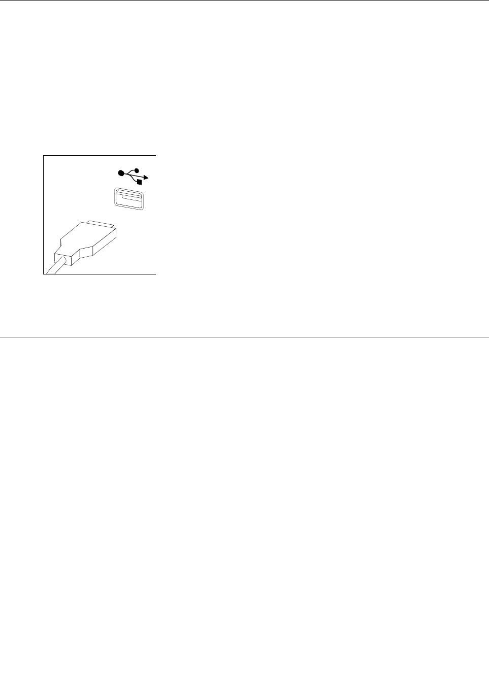
Replacingthekeyboardandmouse
Note:YourkeyboardwillbeconnectedtoaUSBconnectorateithersideorattherearofthecomputer.
Toreplacethekeyboard:
Step1.Removeanymedia(disks,CDs,ormemorycards)fromthedrives,shutdownthecomputer,and
turnoffallattacheddevices.
Step2.Unplugallpowercordsfromelectricaloutlets.
Step3.Locatetheconnectorforthekeyboard.Referto“Sideviewofthecomputer”and“Rearviewof
thecomputer”.
Step4.Disconnectthedefectivekeyboardcablefromthecomputerandconnectthenewkeyboardcable
tothesameconnector.
Step5.Themousecanbereplacedusingthesamemethod.
Replacingtheadapter
Attention:Turnoffthecomputerandwait3to5minutestoletitcooldownbeforeremovingthecover.
Step1.Removeanymedia(disks,CDs,ormemorycards)fromthedrives,shutdowntheoperating
system,andturnoffthecomputerandallattacheddevices.
22LenovoB40–30All-In-OneComputerHardwareMaintenanceManual
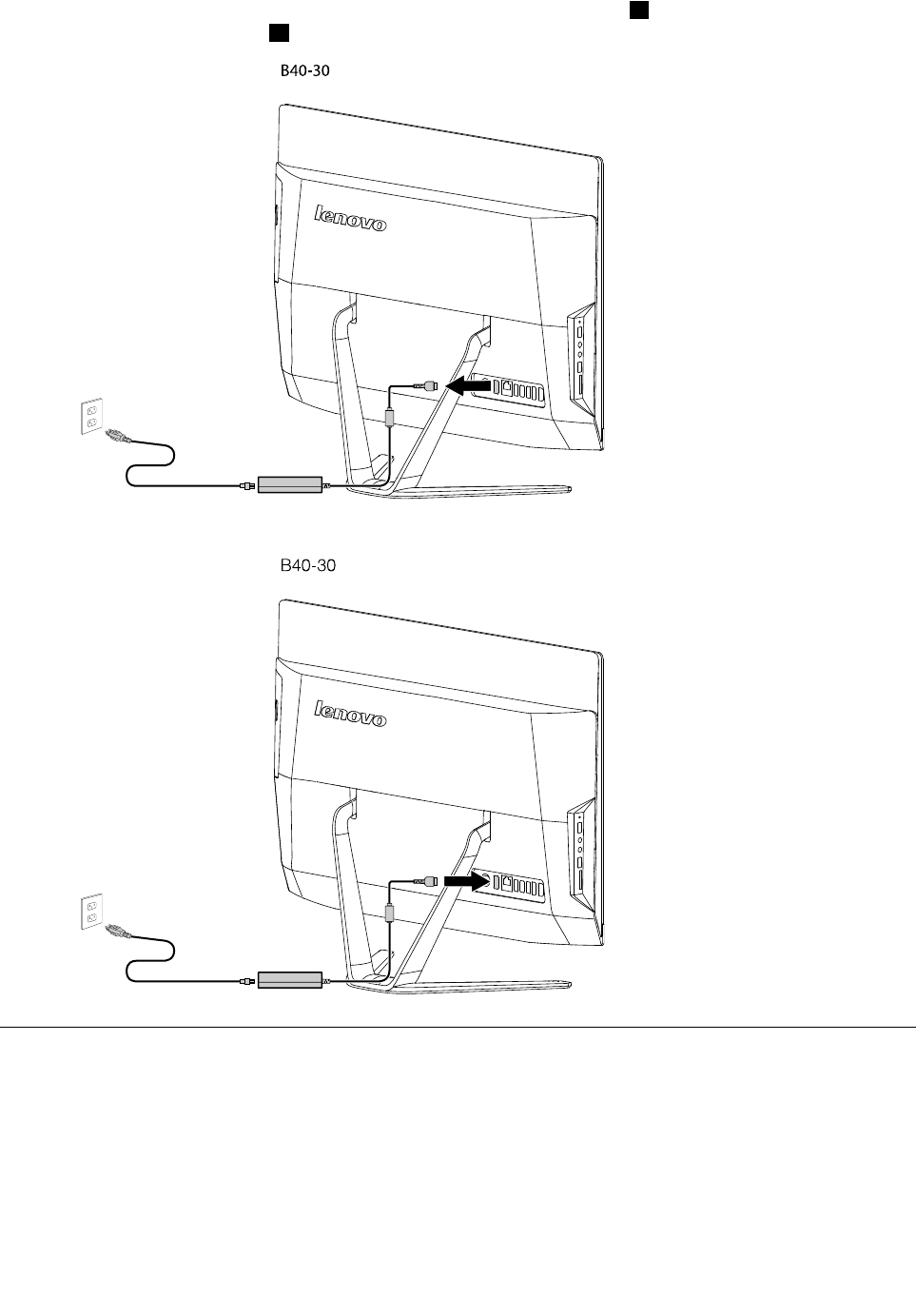
Step2.Disconnectthepowercordfromtheconnectoronthecomputer1,thenunplugthepowercord
fromelectricaloutlet.2
B40-30
Step3.Connectthenewadaptercordasshown.
B40-30
Removingthestandbase
Attention:Turnoffthecomputerandwait3to5minutestoletitcooldownbeforeremovingthecover.
Note:Itmaybehelpfultoplacethecomputerface-downonasoftflatsurfaceforthisprocedure.Lenovo
recommendsthatyouuseablanket,towel,orothersoftclothtoprotectthetouchscreenfromscratches
orotherdamage.
Step1.Removeanymedia(disks,CDs,ormemorycards)fromthedrives,shutdowntheoperating
system,andturnoffthecomputerandallattacheddevices.
Chapter7.Replacinghardware23

Step2.Unplugallpowercordsfromelectricaloutlets.
Step3.Disconnectallcablesattachedtothecomputer.Thisincludespowercords,input/output(I/O)
cables,andanyothercablesthatareconnectedtothecomputer.Referto“Leftandrightviews”
and“Rearview”forhelpwithlocatingthevariousconnectors.
Step4.Twistthehandscrewringcounter-clockwiseuntilthebasecomesloosetoreleasethestandbase
fromthestandholder.12
Step5.Slidethestandbaseoutfromtheholderthenputitaside.3
1
2
3
Step6.Referto“Installingthecomputerstand”toreinstallthestandbase.
Removingthefootcover
Attention:Turnoffthecomputerandwait3to5minutestoletitcooldownbeforeremovingthecover.
Note:Itmaybehelpfultoplacethecomputerface-downonasoftflatsurfaceforthisprocedure.Lenovo
recommendsthatyouuseablanket,towel,orothersoftclothtoprotectthetouchscreenfromscratches
orotherdamage.
Step1.Removeanymedia(disks,CDs,ormemorycards)fromthedrives,shutdowntheoperating
system,andturnoffthecomputerandallattacheddevices.
Step2.Unplugallpowercordsfromelectricaloutlets.
Step3.Disconnectallcablesattachedtothecomputer.Thisincludespowercords,input/output(I/O)
cables,andanyothercablesthatareconnectedtothecomputer.Referto“Leftandrightviews”
and“Rearview”forhelpwithlocatingthevariousconnectors.
Step4.Removethefootbase.Referto“Removingthefootbase” .
24LenovoB40–30All-In-OneComputerHardwareMaintenanceManual
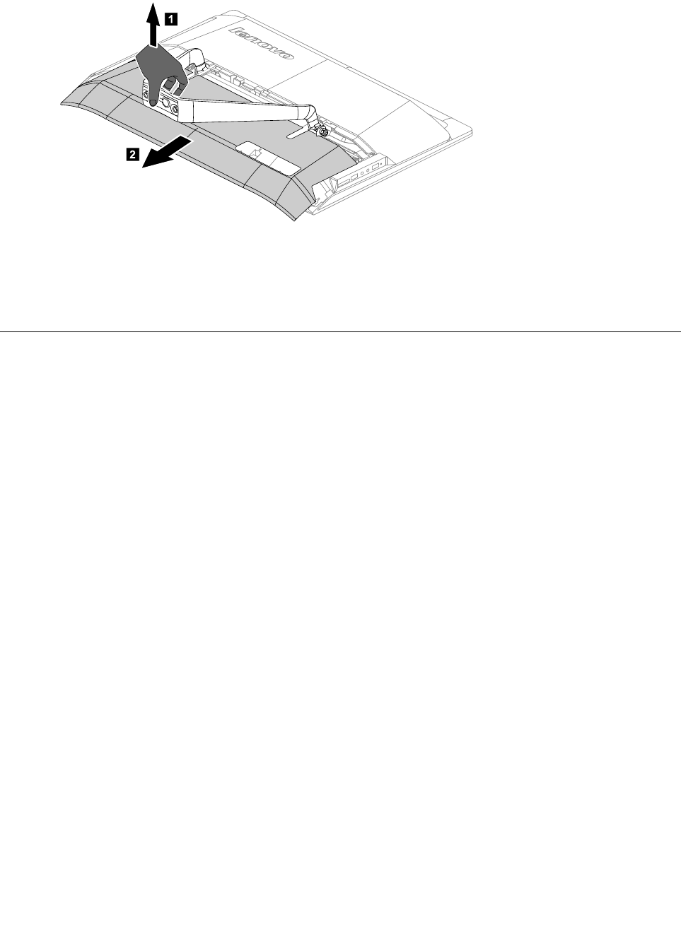
Step5.Liftupthestandholderthenslideoutthefootcoverasshown.
1
2
Step6.Toreattachthefootcover:
a.Liftupthestandholder.
b.Lineupthefootcoverwithmountingholesonthebackofthecomputer,thenslideitbackinto
position.
Replacingthememorymodule
Attention:Turnoffthecomputerandwait3to5minutestoletitcooldownbeforeremovingthecover.
Note:Itmaybehelpfultoplacethecomputerface-downonasoftflatsurfaceforthisprocedure.Lenovo
recommendsthatyouuseablanket,towel,orothersoftclothtoprotectthetouchscreenfromscratches
orotherdamage.
Step1.Removeanymedia(disks,CDs,ormemorycards)fromthedrives,shutdowntheoperating
system,andturnoffthecomputerandallattacheddevices.
Step2.Unplugallpowercordsfromelectricaloutlets.
Step3.Disconnectallcablesattachedtothecomputer.Thisincludespowercords,input/output(I/O)
cables,andanyothercablesthatareconnectedtothecomputer.Referto“Leftandrightviews”
and“Rearview”forhelpwithlocatingthevariousconnectors.
Step4.Removethestandbase.Referto“Removingthestandbase” .
Step5.Removethefootcover.Referto“Removingthefootcover” .
Chapter7.Replacinghardware25
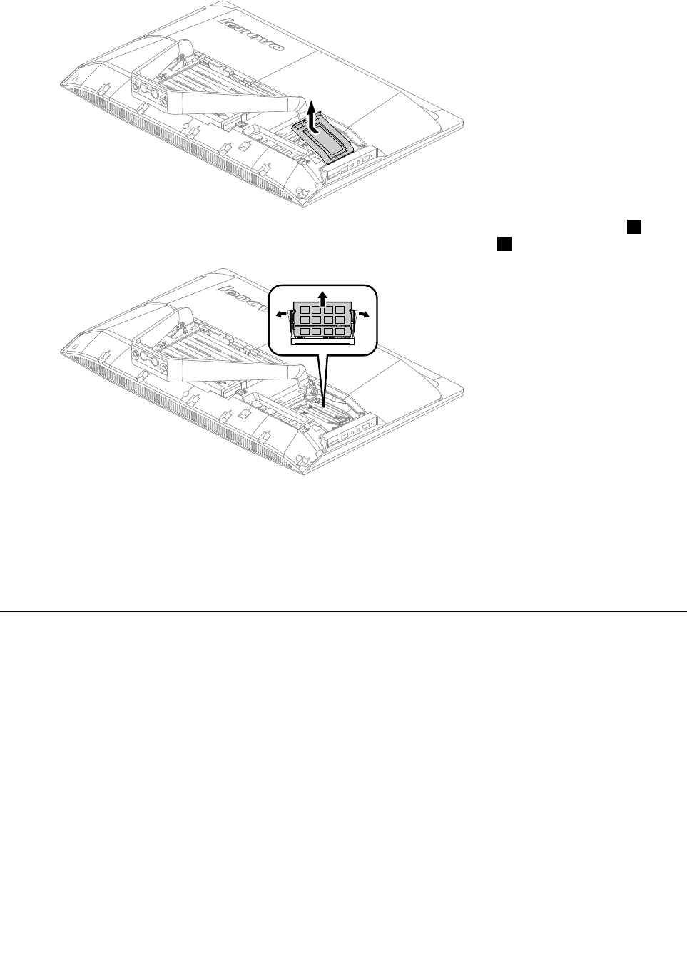
Step6.Removethememoryshieldingasshown.
Step7.Pushoutthelatchesonbothsidesofthememorysockettoreleasethememorymodule1and
gentlypullthememorymoduleupwardtoremoveitfromitssocket.2
Step8.Toinstallthenewmemorymodule:
a.Alignthenewmemorymodulewiththememorysocket,theninsertitandpushdownonthe
topedge.Makesurethelatcheslockthememorymoduleinplace.
b.Reattachthememoryshielding.
Step9.Reattachthefootcoverandstandbase.
Replacingtheharddiskdrive
Attention:Turnoffthecomputerandwait3to5minutestoletitcooldownbeforeremovingthecover.
Note:Itmaybehelpfultoplacethecomputerface-downonasoftflatsurfaceforthisprocedure.Lenovo
recommendsthatyouuseablanket,towel,orothersoftclothtoprotectthetouchscreenfromscratches
orotherdamage.
Step1.Removeanymedia(disks,CDs,ormemorycards)fromthedrives,shutdowntheoperating
system,andturnoffthecomputerandallattacheddevices.
Step2.Unplugallpowercordsfromelectricaloutlets.
Step3.Disconnectallcablesattachedtothecomputer.Thisincludespowercords,input/output(I/O)
cables,andanyothercablesthatareconnectedtothecomputer.Referto“Leftandrightviews”
and“Rearview”forhelpwithlocatingthevariousconnectors.
Step4.Removethestandbase.Referto“Removingthestandbase” .
Step5.Removethefootcover.Referto“Removingthefootcover” .
26LenovoB40–30All-In-OneComputerHardwareMaintenanceManual
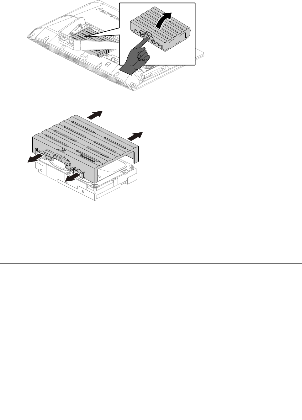
Step6.Liftouttheharddiskdriveandbracketasshown.
Step7.Pushthelockpinsoutwardtoreleasetheharddiskdrivefromthebracket.
Step8.Toinstallthenewharddiskdrive:
a.Lineupthenewharddiskdrivewiththebracketandsecureitwiththepins.
b.Connectthedataandpowercablestothenewharddiskdrive.
c.Slidetheharddiskdriveandbracketbackintoposition.
Step9.Reattachthefootcoverandstandbase.
Replacingtheopticaldrive
Attention:Turnoffthecomputerandwait3to5minutestoletitcooldownbeforeremovingthecover.
Note:Itmaybehelpfultoplacethecomputerface-downonasoftflatsurfaceforthisprocedure.Lenovo
recommendsthatyouuseablanket,towel,orothersoftclothtoprotectthetouchscreenfromscratches
orotherdamage.
Step1.Removeanymedia(disks,CDs,ormemorycards)fromthedrives,shutdowntheoperating
system,andturnoffthecomputerandallattacheddevices.
Step2.Unplugallpowercordsfromelectricaloutlets.
Step3.Disconnectallcablesattachedtothecomputer.Thisincludespowercords,input/output(I/O)
cables,andanyothercablesthatareconnectedtothecomputer.Referto“Leftandrightviews”
and“Rearview”forhelpwithlocatingthevariousconnectors.
Step4.Removethestandbase.Referto“Removingthestandbase” .
Step5.Removethefootcover.Referto“Removingthefootcover” .
Chapter7.Replacinghardware27
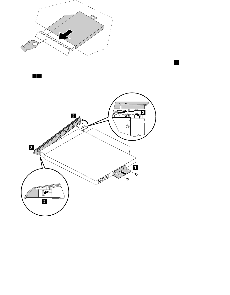
Step6.Locatetheopticalremovalnotch,andthenuseascrewdriverpushtheopticaldriveout.
Step7.Pushasmallironstick(paperclip)intothesmallholeontheopticaldrivecoversothatthedisk
springsoutasshown.
Step8.Removethe2screwsthatsecuretheopticaldrivetothemetalbracket.1
Step9.Useasmallflatheadscrewdrivertopressandpushoutthepinsthatsecurethecovertothe
disk.23
Step10.Separatethecoverfromthedefectiveopticaldrive.
Step11.Toinstallthenewopticaldrive:
a.Alignthenewopticaldrivewiththecover,andthenpushthecoverbackintoposition.
b.Slidethenewopticaldriveintothedrivebay.
Step12.Reattachthefootcoverandstandbase.
Removingthestandholder
Note:Turnoffthecomputerandwait3to5minutestoletitcooldownbeforeremovingthecover.
28LenovoB40–30All-In-OneComputerHardwareMaintenanceManual
Note:Itmaybehelpfultoplacethecomputerface-downonasoftflatsurfaceforthisprocedure.Lenovo
recommendsthatyouuseablanket,towel,orothersoftclothtoprotectthecomputerscreenfromscratches
orotherdamage.
Toremovethestandholder:
Step1.Removeanymedia(disks,CDs,DVDs,ormemorycards)fromthedrives,shutdowntheoperating
system,andturnoffthecomputerandallattacheddevices.
Step2.Unplugallpowercordsfromelectricaloutlets.
Step3.Disconnectallcablesattachedtothecomputer.Thisincludespowercords,input/output(I/O)
cables,andanyothercablesthatareconnectedtothecomputer.Referto“Leftandrightview”
and“Rearview”forhelpwithlocatingthevariousconnectors.
Step4.Removethestandbase.Referto“Removingthestandbase” .
Step5.Removethefootcover.Referto“Removingthefootcover” .
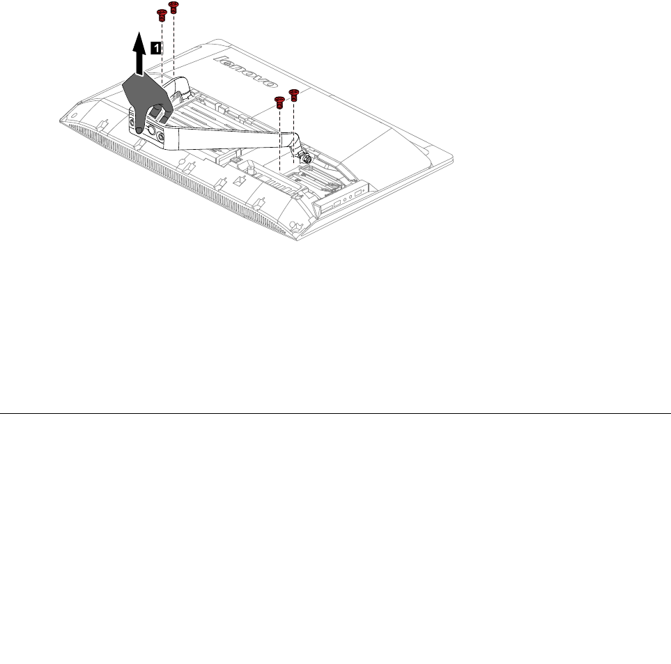
Step6.Removethefourscrewsthatsecurethestandholdertothechassis,thenliftupthestandholderto
removeit.
1
Step7.Toreattachthestandholder:
a.Aligntheholesonthestandholderwithmountingholesonthechassis,placethestand
holderbackintoposition.
b.Securethestandholdertothechassiswiththefourscrews.
Step8.Lineupthefootcoverwithmountingholesonthebackofthecomputer,thenslideitbackinto
position.
Step9.Reattachthestandbase.
Removingthemiddlecover
Note:Turnoffthecomputerandwait3to5minutestoletitcooldownbeforeremovingthecover.
Note:Itmaybehelpfultoplacethecomputerface-downonasoftflatsurfaceforthisprocedure.Lenovo
recommendsthatyouuseablanket,towel,orothersoftclothtoprotectthecomputerscreenfromscratches
orotherdamage.
Toremovethemiddlecover:
Step1.Removeanymedia(disks,CDs,DVDs,ormemorycards)fromthedrives,shutdowntheoperating
system,andturnoffthecomputerandallattacheddevices.
Chapter7.Replacinghardware29
Step2.Unplugallpowercordsfromelectricaloutlets.
Step3.Disconnectallcablesattachedtothecomputer.Thisincludespowercords,input/output(I/O)
cables,andanyothercablesthatareconnectedtothecomputer.Referto“Leftandrightview”
and“Rearview”forhelpwithlocatingthevariousconnectors.
Step4.Removethestandbase.Referto“Removingthestandbase” .
Step5.Removethefootcover.Referto“Removingthefootcover” .
Step6.Removethestandholder.Referto“Removingthestandholder” .
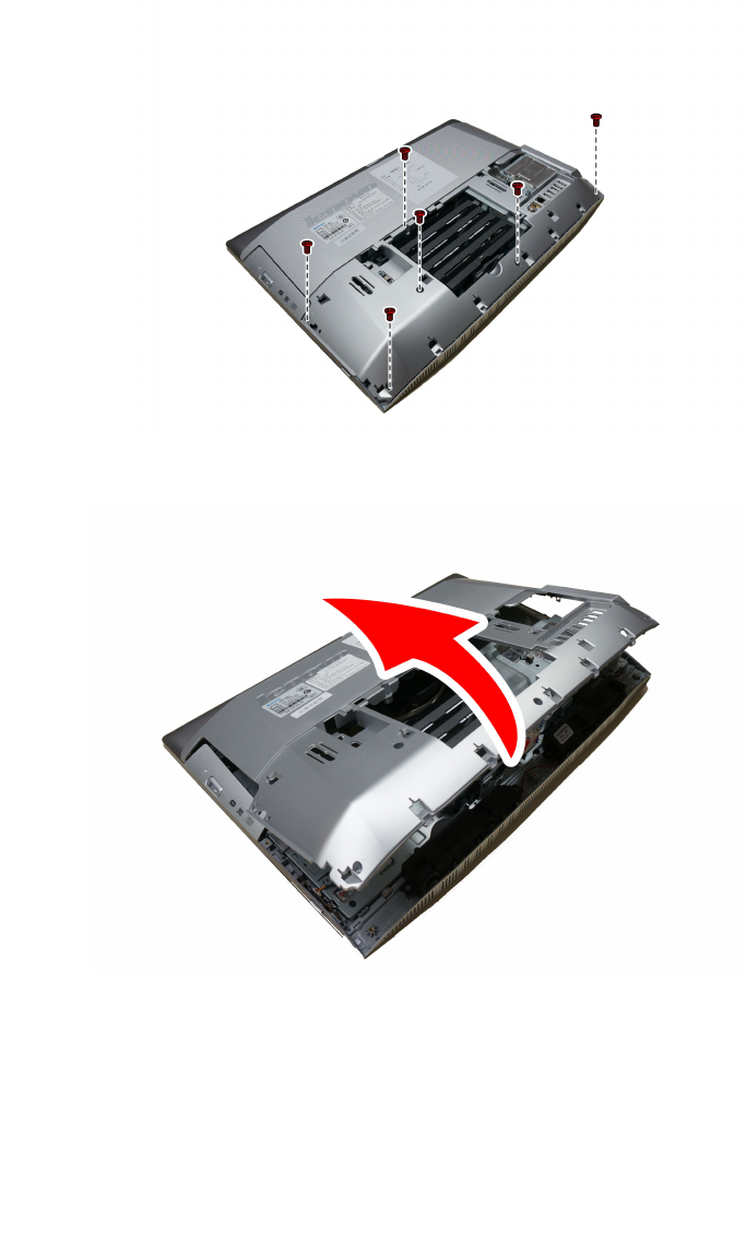
Step7.Removethesixscrewsthatsecurethemiddlecovertothechassis,then
Step8.Liftupthemiddlecoverasshowntoremoveit.
Step9.Toreattachthemiddlecover:
a.Lineupthemiddlecoverwithchassis,thenplacethemiddlecoverback.
b.Securethemiddlecovertothechassiswiththesixscrews.
Step10.Reattachthestandholder,footcoverandstandbase.
30LenovoB40–30All-In-OneComputerHardwareMaintenanceManual
Replacingtheconverterboard
Note:Turnoffthecomputerandwait3to5minutestoletitcooldownbeforeremovingthecover.
Note:Itmaybehelpfultoplacethecomputerface-downonasoftflatsurfaceforthisprocedure.Lenovo
recommendsthatyouuseablanket,towel,orothersoftclothtoprotectthecomputerscreenfromscratches
orotherdamage.
Toreplacetheconverterboard:
Step1.Removeanymedia(disks,CDs,DVDs,ormemorycards)fromthedrives,shutdowntheoperating
system,andturnoffthecomputerandallattacheddevices.
Step2.Unplugallpowercordsfromelectricaloutlets.
Step3.Disconnectallcablesattachedtothecomputer.Thisincludespowercords,input/output(I/O)
cables,andanyothercablesthatareconnectedtothecomputer.Referto“Leftandrightview”
and“Rearview”forhelpwithlocatingthevariousconnectors.
Step4.Removethestandbase.Referto“Removingthestandbase” .
Step5.Removethefootcover.Referto“Removingthefootcover” .
Step6.Removethestandholder.Referto“Removingthestandholder” .
Step7.Removethemiddlecover.Referto“Removingthemiddlecover” .
Step8.Disconnectthetwocablesfromtheconverter,andthenremovethetwoscrewsthatsecurethe
converterboardtothechassis.
Step9.Liftuptheconverterboardouttoremoveit.
Step10.Toinstallthenewconverterboard:
a.Connectthetwocablestothenewconverterboard.
b.Alignthenplacethenewconverterboardintoposition.
c.Securethenewconverterboardwiththescrews.
Step11.Reattachthemiddlecover,standholder,footcoverandstandbase.
RemovingtheEMIcover
Note:Turnoffthecomputerandwait3to5minutestoletitcooldownbeforeremovingthecover.
Chapter7.Replacinghardware31
Note:Itmaybehelpfultoplacethecomputerface-downonasoftflatsurfaceforthisprocedure.Lenovo
recommendsthatyouuseablanket,towel,orothersoftclothtoprotectthecomputerscreenfromscratches
orotherdamage.
ToreplacetheEMIcover
Step1.Removeanymedia(disks,CDs,DVDs,ormemorycards)fromthedrives,shutdowntheoperating
system,andturnoffthecomputerandallattacheddevices.
Step2.Unplugallpowercordsfromelectricaloutlets.
Step3.Disconnectallcablesattachedtothecomputer.Thisincludespowercords,input/output(I/O)
cables,andanyothercablesthatareconnectedtothecomputer.Referto“Leftandrightview”
and“Rearview”forhelpwithlocatingthevariousconnectors.
Step4.Removethestandbase.Referto“Removingthestandbase” .
Step5.Removethefootcover.Referto“Removingthefootcover” .
Step6.Removethestandholder.Referto“Removingthestandholder” .
Step7.Removethemiddlecover.Referto“Removingthemiddlecover” .
Step8.RemovetheeightscrewsthatsecuretheEMIcovertothechassis,andthenliftitup.
Step9.ToreattachtheEMIcover:
a.LineuptheholesontheEMIcoverwithmountingholesonthechassis,thenplaceEMIcover
backintoposition.
b.SecuretheEMIcovertothechassiswitheightscrews.
Step10.Reattachthemiddlecover,standholder,footcoverandstandbase.
ReplacingtheWi-Ficard
Note:Turnoffthecomputerandwait3to5minutestoletitcooldownbeforeremovingthecover.
Note:Itmaybehelpfultoplacethecomputerface-downonasoftflatsurfaceforthisprocedure.Lenovo
recommendsthatyouuseablanket,towel,orothersoftclothtoprotectthecomputerscreenfromscratches
orotherdamage.
ToreplacetheWi-Ficard:
32LenovoB40–30All-In-OneComputerHardwareMaintenanceManual
Step1.Removeanymedia(disks,CDs,DVDs,ormemorycards)fromthedrives,shutdowntheoperating
system,andturnoffthecomputerandallattacheddevices.
Step2.Unplugallpowercordsfromelectricaloutlets.
Step3.Disconnectallcablesattachedtothecomputer.Thisincludespowercords,input/output(I/O)
cables,andanyothercablesthatareconnectedtothecomputer.Referto“Leftandrightview”
and“Rearview”forhelpwithlocatingthevariousconnectors.
Step4.Removethestandbase.Referto“Removingthestandbase” .
Step5.Removethefootcover.Referto“Removingthefootcover” .
Step6.Removethestandholder.Referto“Removingthestandholder” .
Step7.Removethemiddlecover.Referto“Removingthemiddlecover” .
Step8.RemovetheEMIcover.Referto“RemovingtheEMIcover” .
Step9.DisconnecttheantennacablesfromtheWi-Ficard.
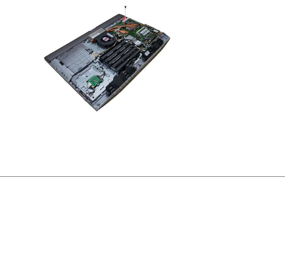
Step10.RemovethescrewthatsecurestheWi-Ficardtothemotherboard.
Step11.LiftuptheWi-Ficardtoremoveitfromthesocket.
Step12.ToinstallthenewWi-Ficard:
a.InsertthenotchedendoftheWi-Ficardintothecardportonthemotherboard.
b.SecurenewtheWi-Ficardtothemotherboardwiththescrew.
c.ConnecttheantennacablestothenewWi-Ficard.
Step13.ReattachtheEMIcover,middlecover,standholder,footcoverandstandbase.
ReplacingtheTVtunercard
Note:Turnoffthecomputerandwait3to5minutestoletitcooldownbeforeremovingthecover.
Note:Itmaybehelpfultoplacethecomputerface-downonasoftflatsurfaceforthisprocedure.Lenovo
recommendsthatyouuseablanket,towel,orothersoftclothtoprotectthecomputerscreenfromscratches
orotherdamage.
ToreplacetheTVtunercard
Step1.Removeanymedia(disks,CDs,DVDs,ormemorycards)fromthedrives,shutdowntheoperating
system,andturnoffthecomputerandallattacheddevices.
Chapter7.Replacinghardware33

Step2.Unplugallpowercordsfromelectricaloutlets.
Step3.Disconnectallcablesattachedtothecomputer.Thisincludespowercords,input/output(I/O)
cables,andanyothercablesthatareconnectedtothecomputer.Referto“Leftandrightview”
and“Rearview”forhelpwithlocatingthevariousconnectors.
Step4.Removethestandbase.Referto“Removingthestandbase” .
Step5.Removethefootcover.Referto“Removingthefootcover” .
Step6.Removethestandholder.Referto“Removingthestandholder” .
Step7.Removethemiddlecover.Referto“Removingthemiddlecover” .
Step8.RemovetheEMIcover.Referto“RemovingtheEMIcover” .
Step9.DisconnecttheantennacablefromtheTV-Tunercard.
Step10.RemovethescrewthatsecurestheTV-Tunercardtothemotherboard.
Step11.PulltheTV-Tunercardupwardtoremoveitfromthecardportonthemotherboard.
Step12.ToinstallthenewTV-Tunercard:
a.InsertthenotchedendoftheTV-Tunercardintothecardportonthemotherboard.
b.SecurenewtheTV-Tunercardtothemotherboardwiththescrew.
c.ConnecttheantennacabletothenewTV-Tunercard.
Step13.ReattachtheEMIcover,middlecover,standholder,footcoverandstandbase.
Replacingtheheat-sink
Note:Turnoffthecomputerandwait3to5minutestoletitcooldownbeforeremovingthecover.
Note:Itmaybehelpfultoplacethecomputerface-downonasoftflatsurfaceforthisprocedure.Lenovo
recommendsthatyouuseablanket,towel,orothersoftclothtoprotectthecomputerscreenfromscratches
orotherdamage.
Toreplacetheheat-sink:
Step1.Removeanymedia(disks,CDs,DVDs,ormemorycards)fromthedrives,shutdowntheoperating
system,andturnoffthecomputerandallattacheddevices.
Step2.Unplugallpowercordsfromelectricaloutlets.
34LenovoB40–30All-In-OneComputerHardwareMaintenanceManual
Step3.Disconnectallcablesattachedtothecomputer.Thisincludespowercords,input/output(I/O)
cables,andanyothercablesthatareconnectedtothecomputer.Referto“Leftandrightview”
and“Rearview”forhelpwithlocatingthevariousconnectors.
Step4.Removethestandbase.Referto“Removingthestandbase” .
Step5.Removethefootcover.Referto“Removingthefootcover” .
Step6.Removethestandholder.Referto“Removingthestandholder” .
Step7.Removethemiddlecover.Referto“Removingthemiddlecover” .
Step8.RemovetheEMIcover.Referto“RemovingtheEMIcover” .
Step9.Removethesealingtapebetweenthesystemfanandheat-sink.
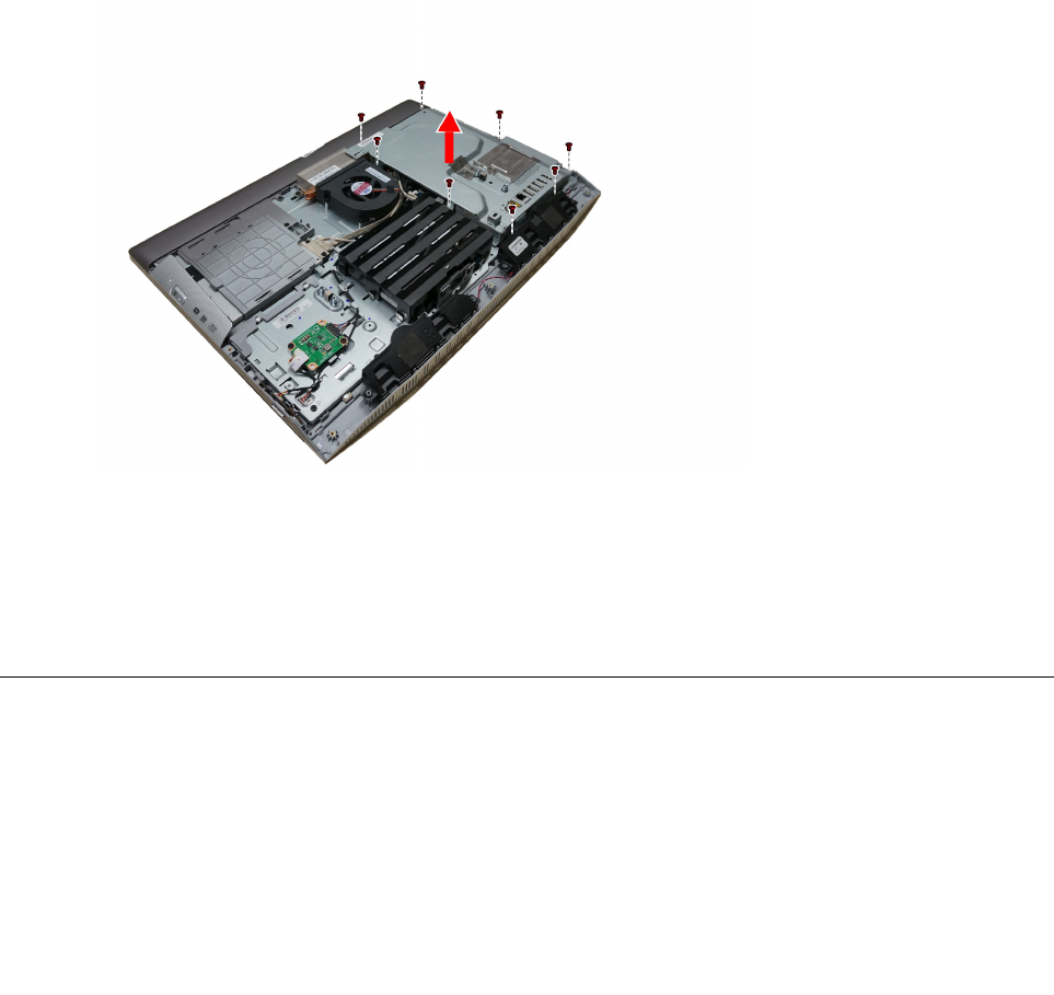
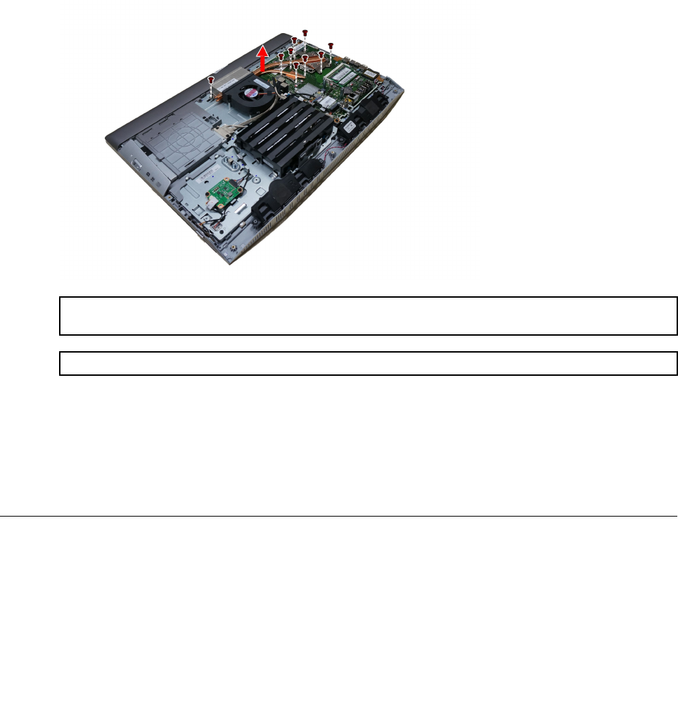
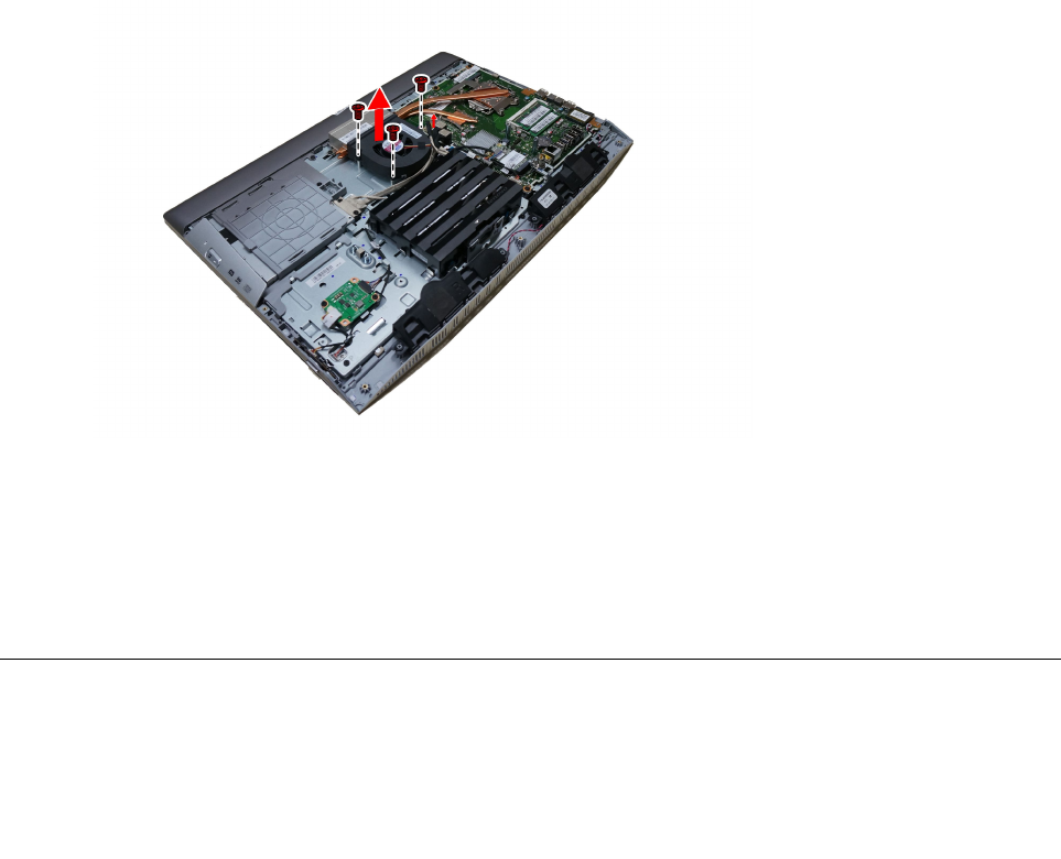
Step10.Removetheninescrewsthatsecuretheheat-sinktothemotherboardandchassis.
Step11.Liftuptheheat-sinktoremoveit.
Attention:Placetheheat-sinkupsidedownonaflatsurfacetopreventthermalgreasefromcontaminating
othercomponents.
Attention:UseanalcoholpadtowipethethermalgreaseofftheCPU.
Step12.Toinstallthenewheat-sink:
a.Lineupthenewheat-sinkwithmountingholesonthemotherboard,thenplaceitintoposition.
b.Followthenumbersprintedonthenewheat-sinktosecureitinorderusingthescrews.
c.Usethesealingtapetosealthegapin-betweenthesystemfanandheat-sink.
Step13.ReattachtheEMIcover,middlecover,standholder,footcoverandstandbase.
ReplacingtheCPU
Note:Turnoffthecomputerandwait3to5minutestoletitcooldownbeforeremovingthecover.
Note:Itmaybehelpfultoplacethecomputerface-downonasoftflatsurfaceforthisprocedure.Lenovo
recommendsthatyouuseablanket,towel,orothersoftclothtoprotectthecomputerscreenfromscratches
orotherdamage.
ToreplacetheCPU
Chapter7.Replacinghardware35
Step1.Removeanymedia(disks,CDs,DVDs,ormemorycards)fromthedrives,shutdowntheoperating
system,andturnoffthecomputerandallattacheddevices.
Step2.Unplugallpowercordsfromelectricaloutlets.
Step3.Disconnectallcablesattachedtothecomputer.Thisincludespowercords,input/output(I/O)
cables,andanyothercablesthatareconnectedtothecomputer.Referto“Leftandrightview”
and“Rearview”forhelpwithlocatingthevariousconnectors.
Step4.Removethestandbase.Referto“Removingthestandbase” .
Step5.Removethefootcover.Referto“Removingthefootcover” .
Step6.Removethestandholder.Referto“Removingthestandholder” .
Step7.Removethemiddlecover.Referto“Removingthemiddlecover” .
Step8.RemovetheEMIcover.Referto“RemovingtheEMIcover” .
Step9.Removetheheat-sink.Referto“Replacingtheheatsink” .
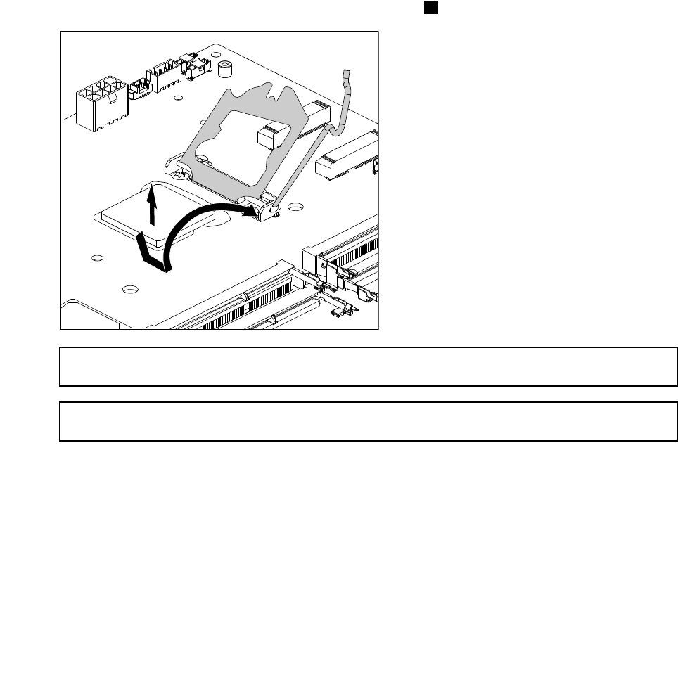
Step10.Liftthesmallhandleandopentheretainer.
Step11.Liftthemicroprocessorstraightupandoutofthesocket.3
Attention:Donottouchthegoldcontactsonthebottomofthemicroprocessor.Whenhandlingthe
microprocessor,touchonlythesides.
Note:Donotdropanythingontothemicroprocessorsocketwhileitisexposed.Thesocketpinsmust
bekeptascleanaspossible.
36LenovoB40–30All-In-OneComputerHardwareMaintenanceManual
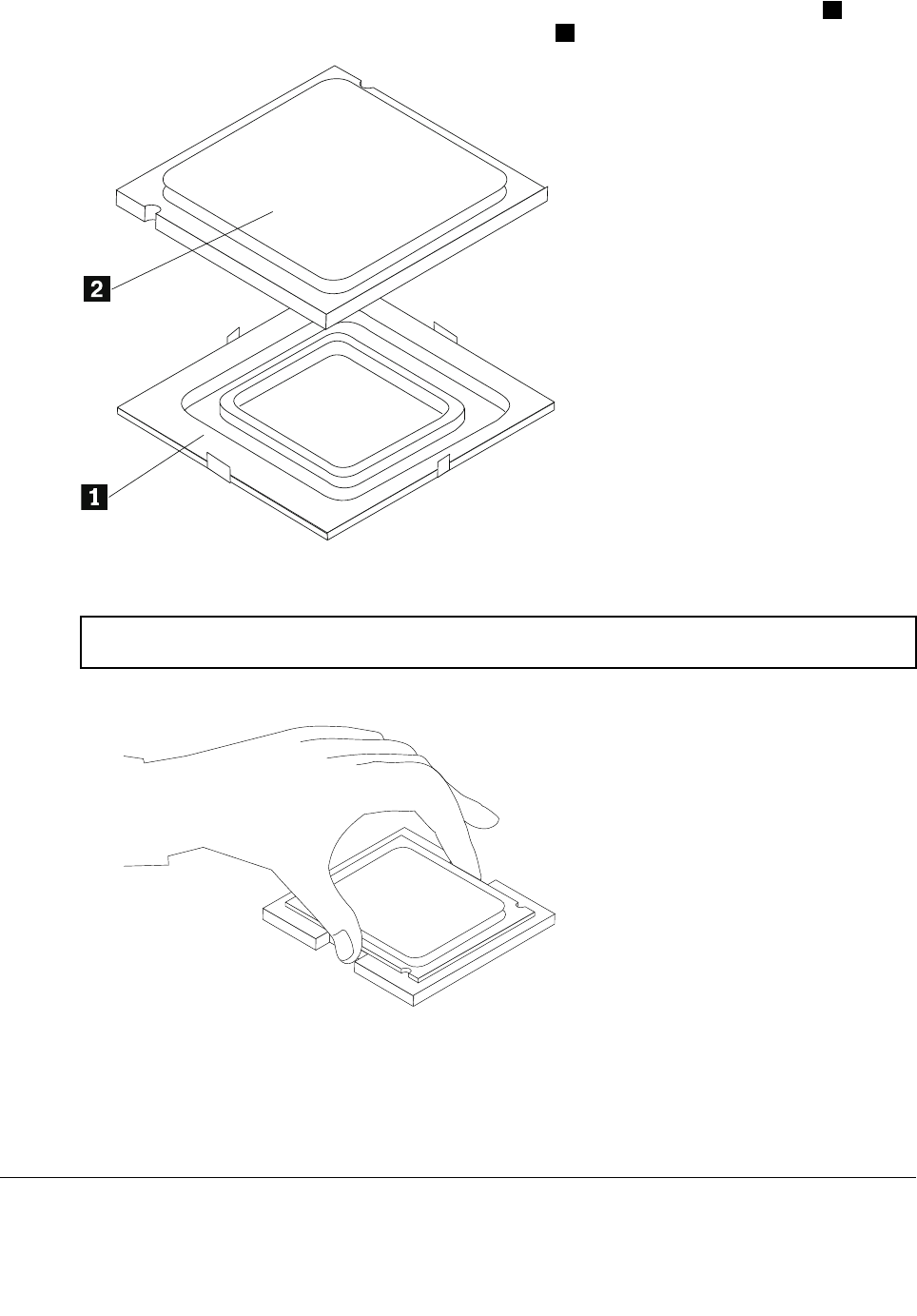
Step12.Holdingthesidesofthemicroprocessorwithyourfingers,removetheprotectivecover1that
protectsthegoldcontactsonthenewmicroprocessor.2
Step13.Holdingthesidesofthemicroprocessorwithyourfingers,positionthemicroprocessorsothatthe
notchesonthemicroprocessorarealignedwiththetabsinthemicroprocessorsocket.
Important:Toavoiddamagingthemicroprocessorcontacts,keepthemicroprocessorcompletelylevel
whileinstallingitintothesocket.
Step14.Lowerthemicroprocessorstraightdownintoitssocketonthemotherboard.
Step15.Tosecurethemicroprocessorinthesocket,closethemicroprocessorretainerandlockitinto
positionwiththesmallhandle.
Step16.Useathermalgreasesyringetoplace5dropsofgreaseonthetopofthemicroprocessor.Each
dropofgreaseshouldbe0.03ml(3tickmarksonthegreasesyringe).
Step17.Reattachtheheat-sink,EMIcover,middlecover,standholder,footcoverandstandbase.
Replacingthesystemfan
Note:Turnoffthecomputerandwait3to5minutestoletitcooldownbeforeremovingthecover.
Chapter7.Replacinghardware37
Note:Itmaybehelpfultoplacethecomputerface-downonasoftflatsurfaceforthisprocedure.Lenovo
recommendsthatyouuseablanket,towel,orothersoftclothtoprotectthecomputerscreenfromscratches
orotherdamage.
Toreplacethesystemfan
Step1.Removeanymedia(disks,CDs,DVDs,ormemorycards)fromthedrives,shutdowntheoperating
system,andturnoffthecomputerandallattacheddevices.
Step2.Unplugallpowercordsfromelectricaloutlets.
Step3.Disconnectallcablesattachedtothecomputer.Thisincludespowercords,input/output(I/O)
cables,andanyothercablesthatareconnectedtothecomputer.Referto“Leftandrightview”
and“Rearview”forhelpwithlocatingthevariousconnectors.
Step4.Removethestandbase.Referto“Removingthestandbase” .
Step5.Removethefootcover.Referto“Removingthefootcover” .
Step6.Removethestandholder.Referto“Removingthestandholder” .
Step7.Removethemiddlecover.Referto“Removingthemiddlecover” .
Step8.RemovetheEMIcover.Referto“RemovingtheEMIcover” .
Step9.Removethesealingtapebetweenthesystemfanandheat-sink.
Step10.Removethethreescrewsthatsecurethesystemfantothechassis.
Step11.Disconnectthepowercablefromthemotherboard.
Step12.Liftupthesystemfantoremoveit.
Step13.Toinstallthenewsystemfan:
a.Placethenewsystemfanintoposition,andthensecureittothechassiswiththreescrews.
b.Connectthesystemfanpowercabletotheconnectoronthemotherboard.
c.Usethesealingtapetosealthegapin-betweenthesystemfanandheat-sink.
Step14.ReattachtheEMIcover,middlecover,standholder,footcoverandstandbase.
Replacingthespeakersystem
Note:Turnoffthecomputerandwait3to5minutestoletitcooldownbeforeremovingthecover.
38LenovoB40–30All-In-OneComputerHardwareMaintenanceManual
Note:Itmaybehelpfultoplacethecomputerface-downonasoftflatsurfaceforthisprocedure.Lenovo
recommendsthatyouuseablanket,towel,orothersoftclothtoprotectthecomputerscreenfromscratches
orotherdamage.
Toreplacethespeakersystem:
Step1.Removeanymedia(disks,CDs,DVDs,ormemorycards)fromthedrives,shutdowntheoperating
system,andturnoffthecomputerandallattacheddevices.
Step2.Unplugallpowercordsfromelectricaloutlets.
Step3.Disconnectallcablesattachedtothecomputer.Thisincludespowercords,input/output(I/O)
cables,andanyothercablesthatareconnectedtothecomputer.Referto“Leftandrightview”
and“Rearview”forhelpwithlocatingthevariousconnectors.
Step4.Removethestandbase.Referto“Removingthestandbase” .
Step5.Removethefootcover.Referto“Removingthefootcover” .
Step6.Removethestandholder.Referto“Removingthestandholder” .
Step7.Removethemiddlecover.Referto“Removingthemiddlecover” .
Step8.RemovetheEMIcover.Referto“RemovingtheEMIcover” .
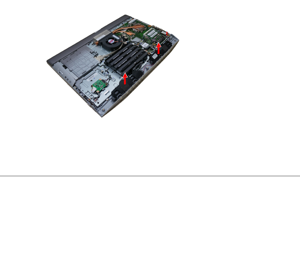
Step9.Disconnectthespeakercablesfromtheconnectoronthemotherboard.
Step10.Liftupthespeakersystemtoremoveit.
Step11.Toinstallthenewspeakersystem:
a.Placethenewspeakersystemintoposition,thensecureitwithfourscrews.
b.Connectthenewspeakercablestotheconnectoronthemotherboard.
Step12.ReattachtheEMIcover,middlecover,standholder,footcoverandstandbase.
Replacingthepowerswitchboard
Note:Turnoffthecomputerandwait3to5minutestoletitcooldownbeforeremovingthecover.
Note:Itmaybehelpfultoplacethecomputerface-downonasoftflatsurfaceforthisprocedure.Lenovo
recommendsthatyouuseablanket,towel,orothersoftclothtoprotectthecomputerscreenfromscratches
orotherdamage.
Toreplacethepowerswitchboard
Chapter7.Replacinghardware39
Step1.Removeanymedia(disks,CDs,DVDs,ormemorycards)fromthedrives,shutdowntheoperating
system,andturnoffthecomputerandallattacheddevices.
Step2.Unplugallpowercordsfromelectricaloutlets.
Step3.Disconnectallcablesattachedtothecomputer.Thisincludespowercords,input/output(I/O)
cables,andanyothercablesthatareconnectedtothecomputer.Referto“Leftandrightview”
and“Rearview”forhelpwithlocatingthevariousconnectors.
Step4.Removethestandbase.Referto“Removingthestandbase” .
Step5.Removethefootcover.Referto“Removingthefootcover” .
Step6.Removethestandholder.Referto“Removingthestandholder” .
Step7.Removethemiddlecover.Referto“Removingthemiddlecover” .
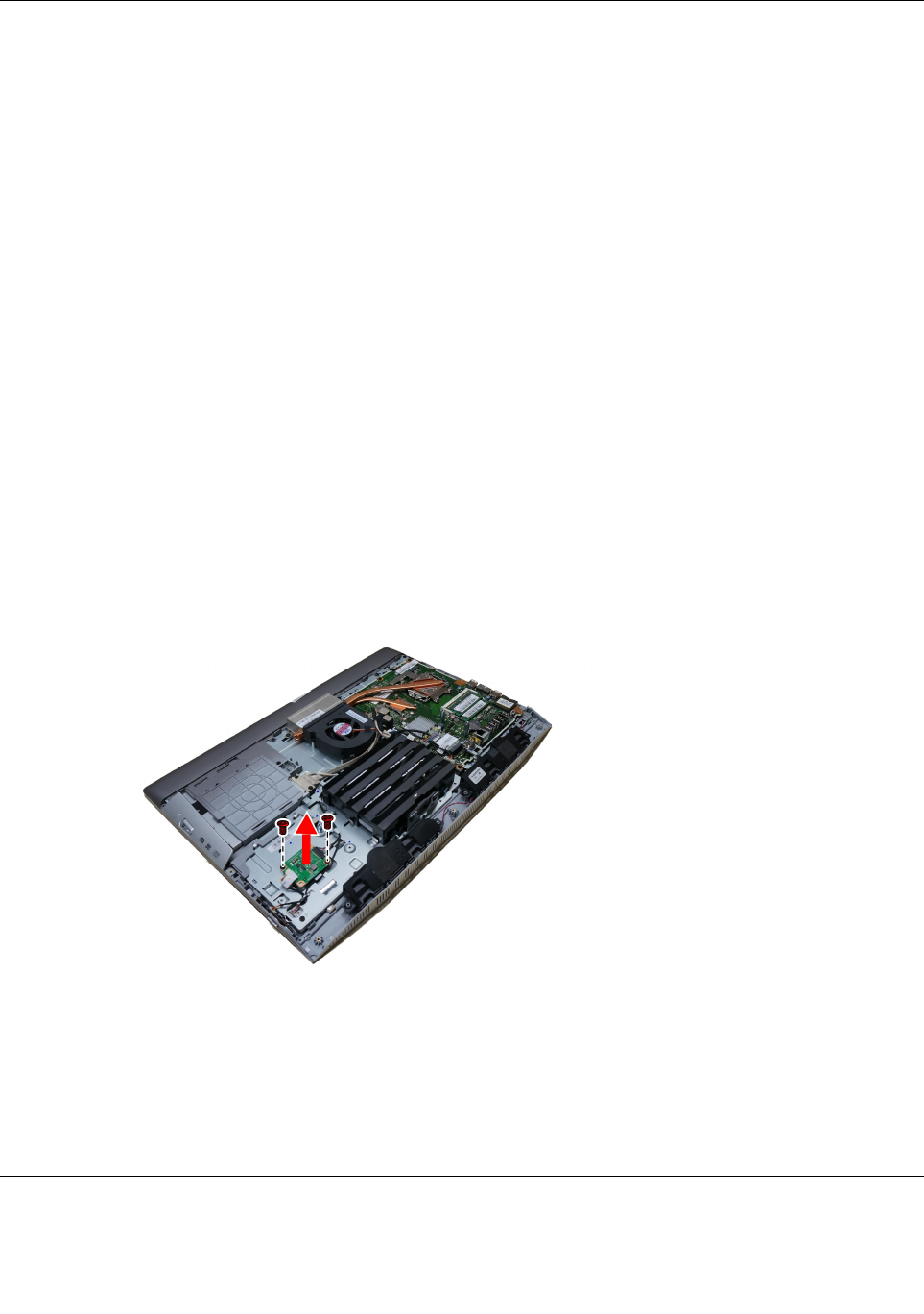
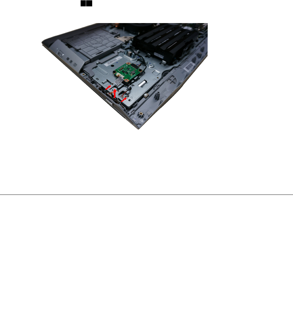
Step8.Pushthelockingpinoutwardtoreleasethepowerswitchboard,thenliftupthepowerswitch
boardtoremoveit.12
Step9.Disconnectthedatacablefromthepowerswitchboard.
Step10.Toinstallthepowerswitchboard:
a.Lineupthenotchesonthenewpowerswitchboardwiththekeysintheslot.
b.Securethepowerswitchboardwiththelockingpin.
Step11.Reattachthemiddlecover,standholder,footcoverandstandbase.
Replacingthemotherboard
Note:Turnoffthecomputerandwait3to5minutestoletitcooldownbeforeremovingthecover.
Note:Itmaybehelpfultoplacethecomputerface-downonasoftflatsurfaceforthisprocedure.Lenovo
recommendsthatyouuseablanket,towel,orothersoftclothtoprotectthecomputerscreenfromscratches
orotherdamage.
Toreplacethemotherboard:
Step1.Removeanymedia(disks,CDs,DVDs,ormemorycards)fromthedrives,shutdowntheoperating
system,andturnoffthecomputerandallattacheddevices.
Step2.Unplugallpowercordsfromelectricaloutlets.
40LenovoB40–30All-In-OneComputerHardwareMaintenanceManual
Step3.Disconnectallcablesattachedtothecomputer.Thisincludespowercords,input/output(I/O)
cables,andanyothercablesthatareconnectedtothecomputer.Referto“Leftandrightview”
and“Rearview”forhelpwithlocatingthevariousconnectors.
Step4.Removethestandbase.Referto“Removingthestandbase” .
Step5.Removethefootcover.Referto“Removingthefootcover” .
Step6.Removethememorymodules.Referto“Replacingamemorymodule” .
Step7.Removetheopticaldrive.Referto“Replacingtheopticaldrive” .
Step8.Removethestandholder.Referto“Removingthestandholder” .
Step9.Removethemiddlecover.Referto“Removingthemiddlecover” .
Step10.RemovetheEMIcover.Referto“RemovingtheEMIcover” .
Step11.Removetheheat-sink.Referto“Replacingtheheat-sink” .
Step12.RemovetheCPU.Referto“ReplacingtheCPU”.
Step13.RemovetheTV-Tunercard.Referto“ReplacingtheTVtunercard” .
Step14.RemovetheWLANcard.Referto“ReplacingtheWLANcard” .
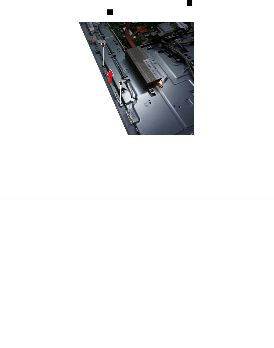
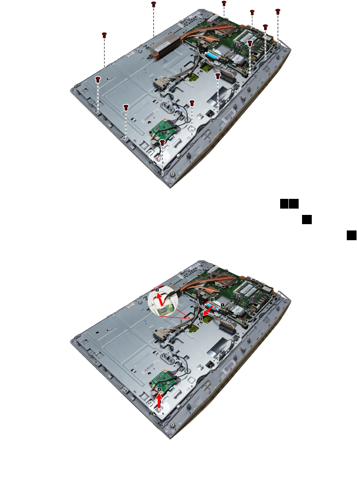
Step15.RemovetheTV-Tunerantennajackasshown.
Step16.Unplugthefollowingcablesfromconnectorsonthemotherboard:
•Convertercable
•Systemfanpowercable
•Touchcontrolboardcable
•OpticaldriveSATAcable(Red)
•HarddiskdriveSATAcable(Black)
•Powersupplycable
•Harddiskdrivepowercable
•Powerswitchboardcable
•Speakersystemcable
•Cameracable
•LVDScable
Chapter7.Replacinghardware41
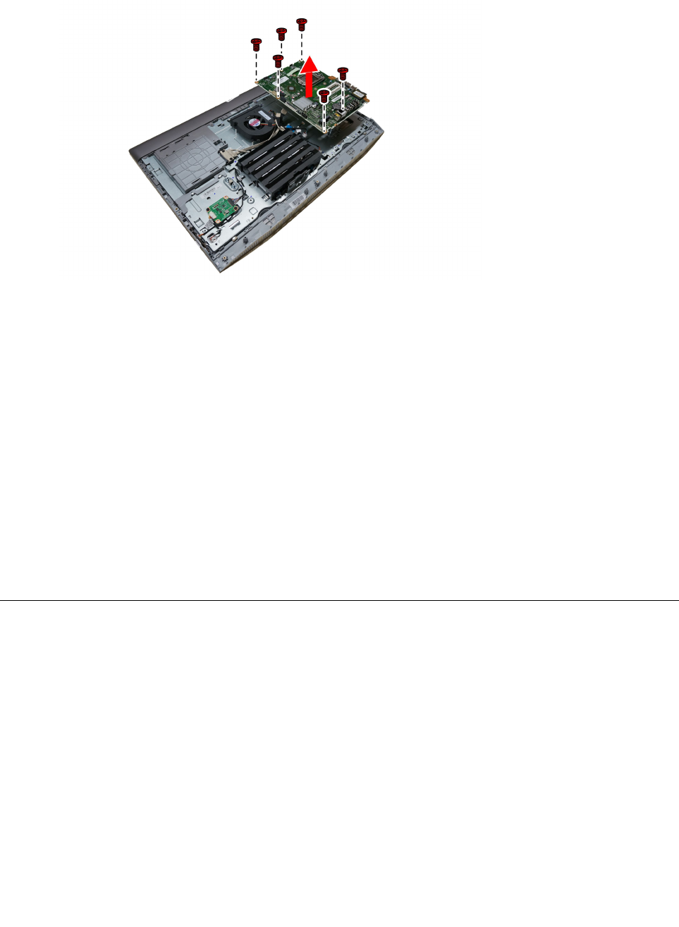
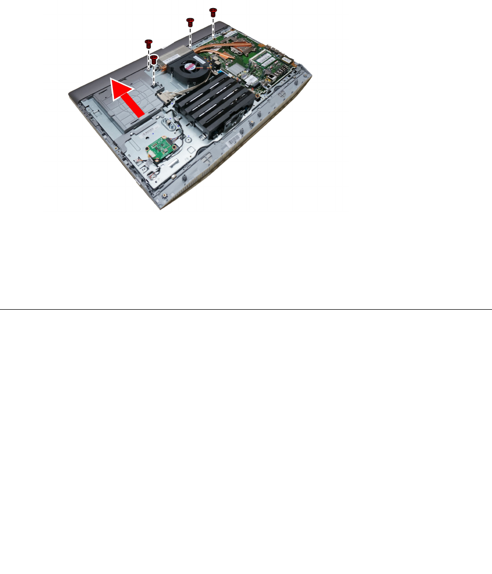
Step17.Removethesevenscrewsthatsecurethemotherboardtothechassisandliftthemotherboard
uptoremoveit.
Step18.Toinstallthenewmotherboard:
a.Lineuptheholesonthenewmotherboardwiththemountingholeschassisandplacethenew
motherboardintoposition.
b.Usethescrewstosecurethenewmotherboardtothechassis.
c.Connectallthecablestothenewmotherboard.
Step19.Installthefollowingpartstothenewmotherboard:
•Wi-Ficard
•TV-Tunercard
•CPU
•Heat-sink
•Memorymodule
•TV-Tunerantennajack
Step20.ReattachtheEMIcover,middlecover,opticaldrive,standholder,footcoverandstandbase.
Removingthereardeco
Note:Turnoffthecomputerandwait3to5minutestoletitcooldownbeforeremovingthecover.
Note:Itmaybehelpfultoplacethecomputerface-downonasoftflatsurfaceforthisprocedure.Lenovo
recommendsthatyouuseablanket,towel,orothersoftclothtoprotectthecomputerscreenfromscratches
orotherdamage.
Toremovethereardeco:
Step1.Removeanymedia(disks,CDs,DVDs,ormemorycards)fromthedrives,shutdowntheoperating
system,andturnoffthecomputerandallattacheddevices.
Step2.Unplugallpowercordsfromelectricaloutlets.
Step3.Disconnectallcablesattachedtothecomputer.Thisincludespowercords,input/output(I/O)
cables,andanyothercablesthatareconnectedtothecomputer.Referto“Leftandrightview”
and“Rearview”forhelpwithlocatingthevariousconnectors.
42LenovoB40–30All-In-OneComputerHardwareMaintenanceManual
Step4.Removethestandbase.Referto“Removingthestandbase” .
Step5.Removethefootcover.Referto“Removingthefootcover” .
Step6.Removetheopticaldrive.Referto“Replacingtheopticaldrive” .
Step7.Removethestandholder.Referto“Removingthestandholder” .
Step8.Removethemiddlecover.Referto“Removingthemiddlecover” .
Step9.Removethepowerswitchboard.Referto“Replacingthepowerswitchboard” .
Step10.Removethefourscrewsthatsecurethereardecotothechassis,thenslidethereardecoupward
toremoveit.
Step11.Toreattachthereardeco:
a.Lineupthereardecowiththeguidetrackonthechassis.
b.Securethereardecotothechassiswiththetwoscrews.
Step12.Reattachthepowerswitchboard,middlecover,standholder,opticaldrive,footcoverandstand
base.
Replacingthecamera
Note:Turnoffthecomputerandwait3to5minutestoletitcooldownbeforeremovingthecover.
Note:Itmaybehelpfultoplacethecomputerface-downonasoftflatsurfaceforthisprocedure.Lenovo
recommendsthatyouuseablanket,towel,orothersoftclothtoprotectthecomputerscreenfromscratches
orotherdamage.
Toreplacethecamera:
Step1.Removeanymedia(disks,CDs,DVDs,ormemorycards)fromthedrives,shutdowntheoperating
system,andturnoffthecomputerandallattacheddevices.
Step2.Unplugallpowercordsfromelectricaloutlets.
Step3.Disconnectallcablesattachedtothecomputer.Thisincludespowercords,input/output(I/O)
cables,andanyothercablesthatareconnectedtothecomputer.Referto“Leftandrightview”
and“Rearview”forhelpwithlocatingthevariousconnectors.
Step4.Removethestandbase.Referto“Removingthestandbase” .
Step5.Removethefootcover.Referto“Removingthefootcover” .
Chapter7.Replacinghardware43
Step6.Removetheharddiskdrive.Referto“Replacingtheharddiskdrive” .
Step7.Removetheopticaldrive.Referto“Replacingtheopticaldrive” .
Step8.Removethestandholder.Referto“Removingthestandholder” .
Step9.Removethemiddlecover.Referto“Removingthemiddlecover” .
Step10.Removethereardeco.Referto“Replacingthereardeco” .
Step11.Pushingthecameralockingpinoutwardtoreleasethecamera.1
Step12.Slideoutthecameraasshown.2
Step13.Disconnectthecameradatacablefromtheconnectoronthecamera.
Step14.Toinstallthenewcamera:
a.Connectthedatacabletothenewcamera.
b.Placethenewcameraintoposition,securethecameratothefrontbezelwiththelockingpins.
Step15.Reattachthereardeco,middlecover,opticaldrive,standholder,harddiskdrive,footcover
andstandbase.
ReplacingtheLEDpanelmodule
Note:Turnoffthecomputerandwait3to5minutestoletitcooldownbeforeremovingthecover.
Note:Itmaybehelpfultoplacethecomputerface-downonasoftflatsurfaceforthisprocedure.Lenovo
recommendsthatyouuseablanket,towel,orothersoftclothtoprotectthecomputerscreenfromscratches
orotherdamage.
ToreplacetheLEDpanelmodule:
Step1.Removeanymedia(disks,CDs,DVDs,ormemorycards)fromthedrives,shutdowntheoperating
system,andturnoffthecomputerandallattacheddevices.
Step2.Unplugallpowercordsfromelectricaloutlets.
Step3.Disconnectallcablesattachedtothecomputer.Thisincludespowercords,input/output(I/O)
cables,andanyothercablesthatareconnectedtothecomputer.Referto“Leftandrightview”
and“Rearview”forhelpwithlocatingthevariousconnectors.
Step4.Removethestandbase.Referto“Removingthestandbase” .
Step5.Removethefootcover.Referto“Removingthefootcover” .
44LenovoB40–30All-In-OneComputerHardwareMaintenanceManual
Step6.Removetheharddiskdrive.Referto“Replacingtheharddiskdrive” .
Step7.Removetheopticaldrive.Referto“Replacingtheopticaldrive” .
Step8.Removethestandholder.Referto“Removingthestandholder” .
Step9.Removethemiddlecover.Referto“Removingthemiddlecover” .
Step10.RemovetheEMIcover.Referto“RemovingtheEMIcover” .
Step11.Removethesystemfan.Referto“Replacingthesystemfan”.
Step12.Removethespeakersystem.Referto“Replacingthespeakersystem” .
Step13.Removethepowerswitchboard.Referto“Replacingthepowerswitchboard” .
Step14.Removethereardeco.Referto“Removingthereardeco”.
Step15.Removethecamera.Referto“Replacingthecamera” .
Step16.RemovethetwelvescrewsthatsecurethechassistotheLEDpanelmodule.
Step17.DisconnecttheLVDScablefromconnectorasshown.12
Step18.Disconnectthetouchcontrolboardcablesfromconnector.3
Step19.DisconnecttheconvertercablefromtheconnectorontheLEDpanel.4
Chapter7.Replacinghardware45
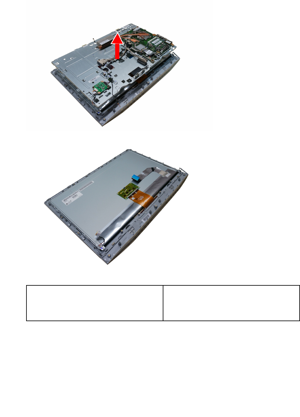
Step20.LiftupthechassistoseparatethechassisfromtheLEDpanelmodule.
Step21.ToinstallthenewtheLEDpanelmodule:
ThenewLEDpanelmoduleincluding:1.LEDpanel
2.LVDScable
3.Touchcontrolboardandtouchcable.(Touch
modelonly)
a.LineupthechassiswithnewLEDpanelmodule,placethechassisintoposition.
b.ConnecttheconvertercabletotheconnectorontheLEDpanel.
c.ConnecttheLVDScabletotheconnectoronthemotherboard.
d.Connectthetouchcontrolboardcablestotheconnectoronthetouchcontrolboard.
e.SecuretheLEDpaneltothechassiswiththetwelvescrews.
f.AttachthecameratothenewLEDmodule.
46LenovoB40–30All-In-OneComputerHardwareMaintenanceManual

g.LineupthereardecowiththeguidetrackontheLEDmodule,thenslidethereardecointo
position.
h.SecurethereardecotothenewLEDmodulewiththetwoscrews.
i.Reattachthepowerswitchboardtothereardeco.
j.AttachthespeakermoduletothenewLEDmodule.
Step22.Reattachthesystemfan,EMIcover,middlecover,opticaldrive,harddiskdrive,computerstand,
footcoverandstandbase.
Chapter7.Replacinghardware47

48LenovoB40–30All-In-OneComputerHardwareMaintenanceManual

Chapter8.FRUlists
Thischapterliststheinformationonthefieldreplaceableunits(FRUs)forLenovoB40–30All-In-Onedesktop
computer.
Attention:BesuretoreadandunderstandallthesafetyinformationbeforereplacinganyFRUs.
Notes:FRUsthathavea1or2intheCRUcolumnareCustomerReplaceableUnits(CRUs).
•1–identifiespartsthatarefairlysimpletoreplace,requiringfewornotools.
•2–identifiespartsthatareslightlymoredifficulttoreplace.
•N-identifiespartsthatarenottobereplacedbythecustomer.
Item
#
DescriptionLenovoPNCRU
ID
CPU
II7-4785T2.2/1600/4C/8M/115035WCPU1101090
II5-4460T1.9/1600/4C/6M/115035WCPU1101092
II3-4150T3.0/1600/2C/3M/115035WCPU1101093
IG3240T2.7/1333/2C/3M/115035WCPU1101094
IG1840T2.5/1333/2C/2M/115035WCPU1101096
IG1820T2.4/1333/2C/2M/115035CPU1101030
N
BDPLANAR
TB4030NOKUMAMB5B20G53342
TB4030W8SUMAMB5B20G53309
TB4030W8PUMAMB5B20G53340
TB4030NOKW/HDMIUMAMB5B20G54840
TB4030NOKW/HDMI_INUMAMB5B20G54838
TB4030NOK1GW/HDMIMB5B20G54863
TB4030NOK2GW/HDMIMB5B20G54859
TB4030NOK1GW/HDMI_INMB5B20G54856
TB4030NOK2GW/HDMI_INMB5B20G54853
TB4030W8SW/HDMIUMAMB5B20G54849
TB4030W8SW/HDMI_INUMAMB5B20G54847
TB4030W8S1GW/HDMIMB5B20G54844
TB4030W8S2GW/HDMIMB5B20G54860
TB4030W8S1GW/HDMI_INMB5B20G54857
TB4030W8S2GW/HDMI_INMB5B20G54858
TB4030W8PW/HDMIUMAMB5B20G54850
TB4030W8PW/HDMI_INUMAMB5B20G54848
TB4030W8P1GW/HDMIMB5B20G54843
TB4030W8P2GW/HDMIMB5B20G54842
N
©CopyrightLenovo201449

TB4030W8P1GW/HDMI_INMB5B20G54841
TB4030W8P2GW/HDMI_INMB5B20G54839
RAM
M471B5674QH0-YK02GBD3L-1600SMemory-HF1100983
HMT425S6AFR6A-PB2GBD3L-1600SMemory-HF1100643
MT4KTF25664HZ-1G6E12GBD3L-1600SMemory1100956
Mic_RD9PSH2GBD3L-1600SMemory-HF1100965
M471B5173DB0-YK04GBD3L-1600SMemory-HF1100942
HMT451S6BFR8A-PB4GBD3L-1600SMemory-HF1100985
MT8KTF51264HZ-1G6E14GBD3L-1600SMemory-HF1100957
Mic_RD9QBJ4GBD3L-1600SMemory-HF1100967
M471B5173DB0-YK04GBD3L-1600SMemory-HF1100942
HMT451S6BFR8A-PB4GBD3L-1600SMemory-HF1100985
MT8KTF51264HZ-1G6E14GBD3L-1600SMemory-HF1100957
Mic_RD9QBJ4GBD3L-1600SMemory-HF1100967
M471B1G73DB0-YK08GBD3L-1600SMemory-HF1100943
HMT41GS6BFR8A-PB8GBD3L-1600SMemory-HF1100986
MT16KTF1G64HZ-1G6E11100635
Mic_RD9QBJ8GBD3L-1600SMemory-HF1101012
M471B5674QH0-YK02GBD3L-1600SMemory-HF1100983
M471B5173DB0-YK04GBD3L-1600SMemory-HF1100942
HMT425S6AFR6A-PB2GBD3L-1600SMemory-HF1100643
HMT451S6BFR8A-PB4GBD3L-1600SMemory-HF1100985
Mic_RD9PSH2GBD3L-1600SMemory-HF1100965
Mic_RD9QBJ4GBD3L-1600SMemory-HF1100967
M471B5173DB0-YK04GBD3L-1600SMemory-HF1100942
M471B1G73DB0-YK08GBD3L-1600SMemory-HF1100943
HMT451S6BFR8A-PB4GBD3L-1600SMemory-HF1100985
HMT41GS6BFR8A-PB8GBD3L-1600SMemory-HF1100986
Mic_RD9QBJ4GBD3L-1600SMemory-HF1100967
Mic_RD9QBJ8GBD3L-1600SMemory-HF1101012
M471B1G73DB0-YK08GBD3L-1600SMemory-HF1100943
HMT41GS6BFR8A-PB8GBD3L-1600SMemory-HF1100986
MT16KTF1G64HZ-1G6E11100635
Mic_RD9QBJ8GBD3L-1600SMemory-HF1101012
2
50LenovoB40–30All-In-OneComputerHardwareMaintenanceManual

HDD
TSBMars4K500GDT01ACA050-LH16200512
WDXL500AWD5000AAKX-08U6AA0500GHDD-LH16200544
STPharaoh4KNon-MCST500DM002500GHDD16200674
3.5inchSATA6G7.2KGrenadaBP1.51TB16200528
TSBMars4K1TBDT01ACA100-LH16200513
3.5inchSATA6G7.2KWDXL1000B1TB16200613
3.5inchSATA6G7.2KGrenadaBP1.52TB16200529
TSBMars4K2TBDT01ACA200-LH16200514
2
SSHD
SGTGrenada1TBST1000DX001SSHD-LH16200534
SGTGrenada2TBST2000DX001SSHD-LH16200535
2
ODD
PSNUJ8FB9.5mmTrayRambow/obezel25215310
PLDSDU-8A5SH-L T rayRambow/obezelLSOPU25214499
HLDSGU90NSlimTrayRambow/obezel25214073
2
Cable
SATADateB4030Cable5C10F78951
CableCameraTB40305C10G53327
CableSATAODD+HDDTB40305C10G53315
CablePowerBoardTB40305C10G53328
CableConvertertoMBTB40305C10G53317
SATAPowerB4030Cable5C10F78950
WebCamB4030cable5C10F78943
WebCamB4030cable5C10F78943
WebCamB4030cable5C10F78943
AntennaB4030cable5A30F78952
N
LCDModule
LCDModuleTB4030TSBLK5D10G53346
LCDModuleTB4030NTBLK5D10G53336
LCDModuleTB4030TSSilver5D10G53326
LCDModuleTB4030NTSilver5D10G53313
N
POWER
DELTAADP-120ZBBBHTcommon120Wadapter36200439
LiteonPA-1121-04LB120wcommonadapter36200440
1
WifiCombo
LiteonWB3351x1BGN+BT4.0HMCWLAN20200437
LTNRTL8723BE1x1bgn+BTHMCWLAN20200439
LTNRTL8821AE1x1ac+BT4.0ComboHMC11202485
CbtRTL8821AE1x1AC+BT4.0PCIEM.2WLAN20200571
N
Chapter8.FRUlists51

TVtuner
AvermediaH334DVB-TMiniTVCard11201071
B360PFcabelNTSC31507278
B360PFcabelPAL31507277
T&ITVtunerbracketB40-30®31507268
Philips43keyIRremoterblack888900018
PhilipsIRreceiver888900019
2
Camera
AVC1080P58302724WB1DMSCam20200633
T&I2DcameraholderB40-30®31507267
Bison1080P58302724WB1DMSCam20200634
LT1080P58302724WB1DMSCam20200664
N
SPEAKER
B36X3WAWSpeaker25216359
B36X3WSXSpeaker25216360
N
FAN
FANSystemTB40-30DIS/UMAAvc5F10F77361
FANSystemTB40-30DIS/UMADelta5F10F77359
N
HEATSINK
HEATSINKTB40-30DISCM5H40F77358
HEATSINKTB40-30DISAvc5H40F77360
HEATSINKTB40-30UMACM5H40F77362
HEATSINKTB40-30UMAAvc5H40F77363
N
CARDPOP
PowerBoardTB40305C50G53305
PowerBoardTB4030W/HDMI5C50G53301
ConverterBoardTB40305C50G53291
N
Accessory
MiddleCoverTB4030W/HDMIBLK5CB0G53304
MiddleCoverTB4030BLK5CB0G53295
MiddleCoverTB4030W/HDMISilver5CB0G53287
MiddleCoverTB4030Silver5CB0G53338
MBEMIShieldTB40305M20G53331
MBEMIShieldTB4030W/TV5M20G53318
MBEMIShieldTB4030W/HDMI5M20G53320
MBEMIShieldB4030W/TV_HDMI5M20G53310
RearCoverTB4030BLK5CB0G53306
RearCoverTB4030W/TVBLK5CB0G53296
RearCoverTB4030W/HDMIBLK5CB0G53290
RearCoverTB4030W/TV_HDMIBLK5CB0G53341
N
52LenovoB40–30All-In-OneComputerHardwareMaintenanceManual

RearCoverTB4030Silver5CB0G53330
RearCoverTB4030W/TVSilver5CB0G53316
RearCoverTB4030W/HDMISilver5CB0G53307
RearCoverTB4030W/TV_HDMISilver5CB0G53298
SlideCoverTB4030BLK5CB0G53289
SlideCoverTB4030W/TVBLK5CB0G53339
SlideCoverTB4030W/HDMIBLK5CB0G53344
SlideCoverTB4030W/TV_HDMIBLK5CB0G53334
SlideCoverTB4030Silver5CB0G53322
SlideCoverTB4030W/TVSilver5CB0G53311
SlideCoverTB4030W/HDMISilver5CB0G53299
SlideCoverB4030W/TVHDMISilver5CB0G53293
SpeakerTB40303W5SB0G53345
StandTopTB4030BLK5SE0G53335
StandBaseTB4030BLK5SE0G53325
StandTopTB4030Silver5SE0G53312
StandBaseTB4030Silver5SE0G53300
BracketCameraTB40305B40G53292
HousingHDDTB40305B40G53343
BezelODDTB4030BLK5CB0G53332
BezelODDTB4030Silver5CB0G53321
AntennaTB40305A30G53337
BracketTVTunerTB40305B40G53308
ShieldingHDDTB40305M20G53303
CoverDDRTB40305M20G53323
B540ODDLockingBracket90200895
C360TVT unerCableForPType90204663
KB&MS
25209111
BlackSilkUSBKB-LVT8(US)Black
25209112
BlackSilkUSBKB-LVT8(TW)Black25209114
BlackSilkUSBKB-LVT8(TH)Black25209115
BlackSilkUSBKB-LVT8(CZ-SL)Black25209116
BlackSilkUSBKB-LVT8(IN)Black25209117
BlackSilkUSBKB-LVT8(RU)Black25209118
BlackSilkUSBKB-LVT8(UK)Black25209119
BlackSilkUSBKB-LVT8(Nordic)Black25209120
BlackSilkUSBKB-LVT8(LA)Black25209121
BlackSilkUSBKB-LVT8(AR)Black25209122
BlackSilkUSBKB-LVT8(SW)Black25209123
1
Chapter8.FRUlists53

BlackSilkUSBKB-LVT8(GE)Black25209124
BlackSilkUSBKB-LVT8(TR)Black25209125
BlackSilkUSBKB-LVT8(SP)Black25209126
BlackSilkUSBKB-LVT8(SL)Black25209127
BlackSilkUSBKB-LVT8(IT)Black25209128
BlackSilkUSBKB-LVT8(HB)Black25209129
BlackSilkUSBKB-LVT8(FR)Black25209130
BlackSilkUSBKB-LVT8(GK)Black25209131
BlackSilkUSBKB-LVT8(HG)Black25209132
BlackSilkUSBKB-LVT8(BG)Black25209133
BlackSilkUSBKB-LVT8(HR)Black25209134
BlackSilkUSBKB-LVT8(JP)Black25209135
BlackSilkUSBKB-LVT8(EN-FR)Black25209136
BlackSilkUSBKB-LVT8(PT)Black25209137
BlackSilkUSBKB-LVT8(BE-EN)Black25209138
BlackSilkUSBKB-LVT8(DU)Black25209139
25200528
BlackSilkMouseBlack
25200530
PrimaxM300USBgesturemouseBLK25213876
SilverSilk2.4GKB-LVT(US)Black825209175
SilverSilk2.4GKB-LVT(US-MY)Black825209176
SilverSilk2.4GKB-LVT(TW)Black825209177
SilverSilk2.4GKB-LVT(TH)Black825209178
SilverSilk2.4GKB-LVT(CS-SK)Black825209179
SilverSilk2.4GKB-LVT(US-IN)Black825209180
SilverSilk2.4GKB-LVT(RU)Black825209181
SilverSilk2.4GKB-LVT(GB)Black825209182
SilverSilk2.4GKB-LVT(Nordic)Black825209183
SilverSilk2.4GKB-LVT(LA)Black825209184
SilverSilk2.4GKB-LVT(LA-AR)Black825209185
SilverSilk2.4GKB-LVT(SA)Black825209186
SilverSilk2.4GKB-LVT(CH)Black825209187
SilverSilk2.4GKB-LVT(DE)Black825209188
SilverSilk2.4GKB-LVT(TR)Black825209189
SilverSilk2.4GKB-LVT(ES)Black825209190
SilverSilk2.4GKB-LVT(SL)Black825209191
SilverSilk2.4GKB-LVT(IT)Black825209192
SilverSilk2.4GKB-LVT(IL)Black825209193
SilverSilk2.4GKB-LVT(FR)Black825209194
SilverSilk2.4GKB-LVT(GR)Black825209195
54LenovoB40–30All-In-OneComputerHardwareMaintenanceManual

SilverSilk2.4GKB-LVT(HU)Black825209196
SilverSilk2.4GKB-LVT(BG)Black825209197
SilverSilk2.4GKB-LVT(KR)Black825209198
SilverSilk2.4GKB-LVT(JP)Black825209199
SilverSilk2.4GKB-LVT(EN-FR)Black825209200
SilverSilk2.4GKB-LVT(PT)Black825209201
SilverSilk2.4GKB-LVT(BE-EN)Black825209202
SilverSilk2.4GKB-LVT(DU)Black825209203
SilverSilkMouse(WW)Black25203464
SilverSilkMouseBlack(NoBattery)25203465
SilverSilkMouse(MY)Black25203466
SilverSilkMouse(JP)Black25205773
SilverSilk2.4GKB-LVT(US)Silver825209204
SilverSilk2.4GKB-LVT(US-MY)Silver825209205
SilverSilk2.4GKB-LVT(TW)Silver825209206
SilverSilk2.4GKB-LVT(TH)Silver825209207
SilverSilk2.4GKB-LVT(CS-SK)Silver825209208
SilverSilk2.4GKB-LVT(US-IN)Silver825209209
SilverSilk2.4GKB-LVT(RU)Silver825209210
SilverSilk2.4GKB-LVT(GB)Silver825209211
SilverSilk2.4GKB-LVT(Nordic)Silver825209212
SilverSilk2.4GKB-LVT(LA)Silver825209213
SilverSilk2.4GKB-LVT(LA-AR)Silver825209214
SilverSilk2.4GKB-LVT(SA)Silver825209215
SilverSilk2.4GKB-LVT(CH)Silver825209216
SilverSilk2.4GKB-LVT(DE)Silver825209217
SilverSilk2.4GKB-LVT(TR)Silver825209218
SilverSilk2.4GKB-LVT(ES)Silver825209219
SilverSilk2.4GKB-LVT(SL)Silver825209220
SilverSilk2.4GKB-LVT(IT)Silver825209221
SilverSilk2.4GKB-LVT(IL)Silver825209222
SilverSilk2.4GKB-LVT(FR)Silver825209223
SilverSilk2.4GKB-LVT(GR)Silver825209224
SilverSilk2.4GKB-LVT(HU)Silver825209225
SilverSilk2.4GKB-LVT(BG)Silver825209226
SilverSilk2.4GKB-LVT(KR)Silver825209227
SilverSilk2.4GKB-LVT(JP)Silver825209228
SilverSilk2.4GKB-LVT(EN-FR)Silver825209229
SilverSilk2.4GKB-LVT(PT)Silver825209230
SilverSilk2.4GKB-LVT(BE-EN)Silver825209231
Chapter8.FRUlists55

SilverSilk2.4GKB-LVT(DU)Silver825209232
SilverSilkMouse(WW)Silver25203606
SilverSilkMouseSilver(NoBattery)25203607
SilverSilkMouse(MY)Silver25203608
SilverSilkMouse(JP)Silver25205774
Powercord
longwellBlacksinglehead1.0m3wireULCSAPowercord31033857
HLS1MC5USPowercord31033858
LX(BS)1.0MC5USPowercord31049517
longwellBlacksinglehead1.0mSAAPowercord31035397
HLS1MC5AUPowercord31049500
LX(BS)1.0MC5AUPowercord31049520
LW1.0MC52pinJapanpowercord31503423
HLS1.0MC52pinJapanpowercord31503424
LX1.0MC52pinJapanpowercord31503425
GrandsunBlacksinglehead1.0m3wireCCCPowercord(R)31032953
LX(BS)1.0MC5CCCPowercord31045147
longwellBlacksinglehead1.0mASTAPowercord31035396
HLS1MC5UKPowercord31049496
LX(BS)1.0MC5UKPowercord31503352
longwellBlacksinglehead1.0mVDEPowercord31035332
HLS1MC5ENPowercord31049497
LX(BS)1.0MC5ENPowercord31049518
longwellBlacksinglehead1.0mIndiaPowercord31035395
LX(BS)1.0MC5IndiaPowercord31503353
LWBlacksinglehead1.0mItalyC5Powercord®31039104
HLS1MC5ItalyPowercord31049504
LX(BS)1.0MC5ItalyPowercord31503359
LWBlacksinglehead1.0mBrazilPowercord®31035828
HLS1MC5BrazilPowercord31049505
LX(BS)1.0MC5BrazilPowercord31503357
LWBlacksinglehead1.0mArgentinaC5Powercord®31039100
HLS1MC5LAPowercord31049507
LX(BS)1.0MC5LAPowercord31503356
LWBlacksinglehead1.0mDenmarkC5Powercord®31039101
HLS1MC5DenmarkPowercord31049503
LX(BS)1.0MC5DenmarkPowercord31503360
LWBlacksinglehead1.0mSwitzerlandC5Powercord®31039103
HLS1MC5SwitzerlandPowercord31049508
LX(BS)1.0MC5SwitzerlandPowercord31503361
1
56LenovoB40–30All-In-OneComputerHardwareMaintenanceManual

LWBlacksinglehead1.0mIsraelC5Powercord®31039107
HLS1MC5IsraelPowercord31049502
LX(BS)1.0MC5IsraelPowercord31503362
LWBlacksinglehead1.0mTaiwanC5Powercord®31038885
HLS1MC5TWPowercord31049499
LX(BS)1.0MC5TWPowercord31503354
LWBlacksinglehead1.0mKoreaC5Powercord®31039106
HLS1MC5KoreaPowercord31049498
LX(BS)1.0MC5KoreaPowercord31503358
LWBlacksinglehead1.0mSAC5Powercord®31039105
HLS1MC5FAPowercord31049501
LX(BS)1.0MC5FAPowercord31503355
Chapter8.FRUlists57

58LenovoB40–30All-In-OneComputerHardwareMaintenanceManual

Chapter9.Generalinformation
Thischapterprovidesgeneralinformationthatappliestoallcomputermodelscoveredbythismanual.
AdditionalServiceInformation
Thischapterprovidesadditionalinformationthattheservicerepresentativemightfindhelpful.
Powermanagement
Powermanagementreducesthepowerconsumptionofcertaincomponentsofthecomputersuchasthe
systempowersupply,processor,harddiskdrives,andsomemonitors.
Advancedconfigurationandpowerinterface(ACPI)BIOS
AsthiscomputerhasanACPIBIOSsystem,theoperatingsystemisallowedtocontrolthepower
managementfeaturesofthecomputerandthesettingsforAdvancedPowerManagement(APM)BIOSmode
isignored.NotalloperatingsystemssupportACPIBIOSmode.
AutomaticPower-Onfeatures
TheAutomaticPower-OnfeatureswithinthePowerManagementmenuallowyoutoenableanddisable
featuresthatturnonthecomputerautomatically.
•WakeUponAlarm:Youcanspecifyadateandtimeatwhichthecomputerwillbeturnedonautomatically.
Thiscanbeeitherasingleevent,adailyeventoraweeklyevent.
•WakeUponLAN:ThisfeatureallowsLANadaptercardtowaketheSystem.
©CopyrightLenovo201459
