Lenovo C340 440 Hmm 20141010 User Manual C340/440 Series Hardware Maintenance C440 All In One (Lenovo)
2014-10-10
User Manual: Lenovo Lenovo C340-440 Hmm 20141010 Lenovo C340/440 Series Hardware Maintenance Manual C440 All-in-One (Lenovo) Lenovo C440 All-in-One
Open the PDF directly: View PDF ![]() .
.
Page Count: 81
- Chapter 1. About this manual
- Chapter 2. Safety information
- Chapter 3. General information
- Chapter 4. General Checkout
- Chapter 5. Using the Setup Utility
- Chapter 6. Symptom-to-FRU Index
- Chapter 7. Locating connectors, controls and components
- Chapter 8. Replacing hardware
- General information
- Replacing the keyboard and mouse
- Replacing the adapter
- Removing the stand base
- Removing the foot cover
- Replacing a memory module
- Replacing the hard disk drive
- Replacing the optical drive
- Removing the stand holder
- Removing the middle cover
- Replacing the converter board
- Replacing the touch control board
- Removing the EMI cover
- Replacing the rear I/O module
- Replacing the TV tuner card
- Replacing the WLAN card
- Replacing the speaker system
- Replacing the system fan
- Replacing the heat-sink
- Replacing the camera
- Replacing the CPU
- Replacing the front control board
- Replacing the power switch board
- Replacing the motherboard
- Replacing the LED panel
- Chapter 9. FRU lists
- Chapter 10. FRU lists-C440 Touch
- Chapter 11. General information

LenovoC340/440SeriesHardware
MaintenanceManual
ideaideaideaCentreidea
MachineTypes:10102/4773[C340],10104/6595[C440]

LenovoC340/440Series
HardwareMaintenanceManual
MachineTypes:10102/4773[C340],10104/6595[C440]

ThirdEdition(October2014)8th
©CopyrightLenovo2013.
LIMITEDANDRESTRICTEDRIGHTSNOTICE:IfdataorsoftwarearedeliveredpursuantaGeneralServices
Administration“GSA”contract,use,reproduction,ordisclosureissubjecttorestrictionssetforthinContractNo.
GS-35F-05925

Contents
Chapter1.Aboutthismanual.....1
ImportantSafetyInformation.........1
Chapter2.Safetyinformation.....3
Generalsafety...............3
Electricalsafety..............3
Safetyinspectionguide...........5
Handlingelectrostaticdischarge-sensitive
devices.................5
Groundingrequirements...........6
Safetynotices...............6
Chapter3.Generalinformation....9
Specifications...............9
Chapter4.GeneralCheckout.....11
Chapter5.UsingtheSetupUtility...13
StartingtheLenovoBIOSSetupUtilityprogram.13
Viewingandchangingsettings........13
Usingpasswords..............13
Enablingordisablingadevice........15
Selectingastartupdevice..........16
ExitingtheLenovoBIOSSetupUtilityprogram..17
Chapter6.Symptom-to-FRUIndex..19
Harddiskdrivebooterror..........19
PowerSupplyProblems...........19
POSTerrorcodes.............20
Undeterminedproblems...........20
Chapter7.Locatingconnectors,
controlsandcomponents......21
Chapter8.Replacinghardware....27
Generalinformation.............27
Replacingthekeyboardandmouse......28
Replacingtheadapter............28
Removingthestandbase..........30
Removingthefootcover...........30
Replacingamemorymodule.........31
Replacingtheharddiskdrive.........33
Replacingtheopticaldrive..........34
Removingthestandholder..........36
Removingthemiddlecover.........37
Replacingtheconverterboard........38
Replacingthetouchcontrolboard.......39
RemovingtheEMIcover...........40
ReplacingtherearI/Omodule........41
ReplacingtheTVtunercard.........42
ReplacingtheWLANcard..........43
Replacingthespeakersystem........44
Replacingthesystemfan..........45
Replacingtheheat-sink...........46
Replacingthecamera............47
ReplacingtheCPU.............48
Replacingthefrontcontrolboard.......51
Replacingthepowerswitchboard.......52
Replacingthemotherboard..........53
ReplacingtheLEDpanel...........54
Chapter9.FRUlists..........59
Chapter10.FRUlists-C440T ouch..63
Chapter11.Generalinformation...75
AdditionalServiceInformation........75
©CopyrightLenovo2013iii

ivLenovoC340/440SeriesHardwareMaintenanceManual
Chapter1.Aboutthismanual
ThismanualcontainsserviceandreferenceinformationforLenovoC340andC440All-In-Onecomputers
listedonthecover.ItisintendedonlyfortrainedservicerswhoarefamiliarwithLenovocomputerproducts.
BeforeservicingaLenovoproduct,besuretoreadtheSafetyInformation.
ThedescriptionoftheTV-tunercardinthismanualappliesonlytocomputerswithaTV-tunercardinstalled.
ItdoesnotapplytocomputerswithoutaTV-tunercard.
ImportantSafetyInformation
BesuretoreadallCAUTIONandDANGERsectionsinthismanualbeforefollowinganyoftheinstructions.
VeuillezliretouteslesconsignesdetypeDANGERetATTENTIONduprésentdocumentavantd’exécuter
lesinstructions.
LesenSieunbedingtalleHinweisevomTyp“ACHTUNG”oder“VORSICHT”indieserDokumentation,bevor
SieirgendwelcheVorgängedurchführen
LeggereleistruzioniintrodottedaATTENZIONEePERICOLOpresentinelmanualeprimadieseguireuna
qualsiasidelleistruzioni
Certifique-sedelertodasasinstruçõesdecuidadoeperigonestemanualantesdeexecutarqualquer
umadasinstruções
Esimportantequeleatodaslasdeclaracionesdeprecauciónydepeligrodeestemanualantesdeseguir
lasinstrucciones.
©CopyrightLenovo20131

2LenovoC340/440SeriesHardwareMaintenanceManual

Chapter2.Safetyinformation
Thischaptercontainsthesafetyinformationthatyouneedtobefamiliarwithbeforeservicingacomputer.
Generalsafety
Followtheserulestoensuregeneralsafety:
•Keeptheareasaroundthecomputerclearandcleanduringandaftermaintenance.
•Whenliftinganyheavyobject:
1.Ensureyoucanstandsafelywithoutslipping.
2.Distributetheweightoftheobjectequallyacrossbothfeet.
3.Liftslowly.Nevermovesuddenlyortwistwhenyouattempttolift.
4.Liftbystandingorbypushingupwithyourlegmuscles;thisactionremovesthestrainfromthe
musclesinyourback.
Donotattempttoliftanyobjectsthatweighmorethan16kg(35lb)orobjectsthatyouthinkare
tooheavyforyou.
•Donotperformanyactionthatwouldcreateahazardforthecustomer,orwouldmakethecomputer
unsafe.
•Beforeyoustartthecomputer,ensurethatotherservicerepresentativesandcustomerpersonnelarenot
inapositionthatwouldcreateahazardforthem.
•Placeremovedcoversandotherpartsinasafeplace,awayfromallpersonnel,whileyouareservicingthe
computer.
•Keepyourtoolcaseawayfromareasthatpeoplemaywalkthroughtoensureno-onetripsoverit.
•Donotwearlooseclothingthatcanbetrappedinthemovingpartsofamachine.Ensurethatyoursleeves
arefastenedorrolledupaboveyourelbows.Ifyourhairislong,tieorfastenitback.
•Inserttheendsofyournecktieorscarfinsideclothingorfastenitwithanon-conductiveclip,
approximately8centimeters(3inches)fromtheend.
•Donotwearjewelry,chains,metal-frameeyeglasses,ormetalfastenersforyourclothing.
Remember:Metalobjectsaregoodelectricalconductors.
•Wearsafetyglasseswhenyouare:hammering,drillingsoldering,cuttingwire,attachingsprings,using
solvents,orworkinginanyotherconditionsthatmightbehazardoustoyoureyes.
•Afterservice,reinstallallsafetyshields,guards,labels,andgroundwires.Replaceanysafetydevice
thatiswornordefective.
•Reattachallcoverscorrectlybeforereturningthecomputertothecustomer.
Electricalsafety
CAUTION:
Electricalcurrentfrompower,telephone,andcommunicationcablescanbehazardous.Toavoid
personalinjuryorequipmentdamage,disconnectanyattachedpowercords,telecommunication
cables,networkcables,andmodemcablesbeforeyouopenthecomputercovers,unlessinstructed
otherwiseintheinstallationandconfigurationprocedures.
©CopyrightLenovo20133

Observethefollowingruleswhenworkingonelectricalequipment.
Important:Useonlyapprovedtoolsandtestequipment.Somehandtoolshavehandlescoveredwithasoft
materialthatdoesnotinsulateyouwhenworkingwithliveelectricalcurrents.Manycustomershaverubber
floormatsneartheirequipmentthatcontainsmallconductivefiberstodecreaseelectrostaticdischarge.
•Findtheroomemergencypower-off(EPO)switch,disconnectingswitch,orelectricaloutlet.Ifanelectrical
accidentoccurs,youcanthenoperatetheswitchorunplugthepowercordquickly.
•Donotworkaloneunderhazardousconditionsornearequipmentthathashazardousvoltages.
•Disconnectallpowerbefore:
–Performingamechanicalinspection
–Workingnearpowersupplies
–RemovingorinstallingFieldReplaceableUnits(FRUs)
•Beforeyoustarttoworkonthecomputer,unplugthepowercord.Ifyoucannotunplugit,askthe
customertopower-offtheelectricaloutletthatsuppliespowertothemachineandtolocktheelectrical
outletintheoffposition.
•Ifyouneedtoworkonacomputerthathasexposedelectricalcircuits,observethefollowingprecautions:
–Ensurethatanotherperson,familiarwiththepower-offcontrols,isnearyou.
Remember:Anotherpersonmustbetheretoswitchoffthepower,ifnecessary.
–Useonlyonehandwhenworkingwithpowered-onelectricalequipment;keeptheotherhandinyour
pocketorbehindyourback.
Remember:Theremustbeacompletecircuittocauseelectricalshock.Byobservingtheaboverule,
youmaypreventacurrentfrompassingthroughyourbody.
–Whenusingatester,setthecontrolscorrectlyandusetheapprovedprobeleadsandaccessoriesfor
thattester.
–Standonsuitablerubbermats(obtainedlocally,ifnecessary)toinsulateyoufromgroundssuchas
metalfloorstripsandmachineframes.
Observethespecialsafetyprecautionswhenyouworkwithveryhighvoltages;theseinstructionsarein
thesafetysectionsofthemaintenanceinformation.Useextremecarewhenmeasuringhighvoltages.
•Regularlyinspectandmaintainyourelectricalhandtoolstoensuretheyaresafetouse.
•Donotusewornorbrokentoolsandtesters.
•Neverassumethatpowerhasbeendisconnectedfromacircuit.First,checkthatithasbeenpoweredoff.
•Alwayslookcarefullyforpossiblehazardsinyourworkarea.Examplesofthesehazardsarewetfloors,
non-groundedpowerextensioncables,conditionsthatmaycauseorallowpowersurges,andmissing
safetygrounds.
•Donottouchliveelectricalcircuitswiththereflectivesurfaceofaplasticdentalmirror.Thissurfaceis
conductive,andtouchingalivecircuitcancausepersonalinjuryanddamagetothecomputer.
•Donotservicethefollowingpartswiththepoweronwhentheyareremovedfromtheirnormaloperating
positionsinacomputer:
–Powersupplyunits
–Pumps
–Blowersandfans
–Motorgenerators
andsimilarunits.(Thispracticeensurescorrectgroundingoftheunits.)
•Ifanelectricalaccidentoccurs:
–Usecaution;donotbecomeavictimyourself.
4LenovoC340/440SeriesHardwareMaintenanceManual

–Switchoffpower.
–Sendanotherpersontogetmedicalaid.
Safetyinspectionguide
Theintentofthisinspectionguideistoassistyouinidentifyingpotentialhazardsposedbytheseproducts.
Eachcomputer,asitwasdesignedandbuilt,hadrequiredsafetyitemsinstalledtoprotectusersand
servicepersonnelfrominjury.Thisguideaddressesonlythoseitems.However,goodjudgmentshouldbe
usedtoidentifypotentialsafetyhazardsduetoattachmentoffeaturesoroptionsnotcoveredbythis
inspectionguide.
Ifanyhazardsarepresent,youmustdeterminehowserioustheapparenthazardcouldbeandwhetheryou
cancontinuewithoutfirstresolvingtheproblem.
Considerthefollowingitemsandthesafetyhazardstheypresent:
•Electricalhazards,especiallyprimarypower(primaryvoltageontheframecancauseseriousorfatal
electricalshock).
•Explosivehazards,suchasadamagedCRTfaceorbulgingcapacitor
•Mechanicalhazards,suchaslooseormissinghardware
Theguideconsistsofaseriesofstepspresentedasachecklist.Beginthecheckswiththepoweroff,and
thepowercorddisconnected.
Checklist:
1.Checkexteriorcoversfordamage(loose,broken,orsharpedges).
2.Power-offthecomputer.Disconnectthepowercord.
3.Checkthepowercordfor:
a.Athird-wiregroundconnectoringoodcondition.Useametertomeasurethird-wireground
continuityfor0.1ohmorlessbetweentheexternalgroundpinandframeground.
b.Thepowercordshouldbetheappropriatetypeasspecifiedinthepartslistings.
c.Insulationmustnotbefrayedorworn.
4.Removethecover.
5.Checkforanyobviousalterations.Usegoodjudgmentastothesafetyofanyalterations.
6.Checkinsidetheunitforanyobvioushazards,suchasmetalfilings,contamination,waterorother
liquids,orsignsoffireorsmokedamage.
7.Checkforworn,frayed,orpinchedcables.
8.Checkthatthepower-supplycoverfasteners(screwsorrivets)havenotbeenremovedortamperedwith.
Handlingelectrostaticdischarge-sensitivedevices
Anycomputerpartcontainingtransistorsorintegratedcircuits(ICs)shouldbeconsideredsensitiveto
electrostaticdischarge(ESD).ESDdamagecanoccurwhenthereisadifferenceinchargebetweenobjects.
ProtectagainstESDdamagebyequalizingthechargesothatthecomputer,thepart,theworkmat,andthe
personhandlingthepartareallatthesamecharge.
Notes:
1.Useproduct-specificESDprocedureswhentheyexceedtherequirementsnotedhere.
2.MakesurethattheESDprotectivedevicesyouusehavebeencertified(ISO9000)asfullyeffective.
WhenhandlingESD-sensitiveparts:
Chapter2.Safetyinformation5
•Keepthepartsinprotectivepackagesuntiltheyareinsertedintotheproduct.
•Avoidcontactwithotherpeoplewhilehandlingthepart.
•Wearagroundedwriststrapagainstyourskintoeliminatestaticonyourbody.
•Preventthepartfromtouchingyourclothing.Mostclothingisinsulativeandretainsachargeeven
whenyouarewearingawriststrap.
•Usetheblacksideofagroundedworkmattoprovideastatic-freeworksurface.Thematisespecially
usefulwhenhandlingESD-sensitivedevices.
•Selectagroundingsystem,suchasthoselistedbelow,toprovideprotectionthatmeetsthespecific
servicerequirement.
Note:TheuseofagroundingsystemisdesirablebutnotrequiredtoprotectagainstESDdamage.
–AttachtheESDgroundcliptoanyframeground,groundbraid,orgreen-wireground.
–UseanESDcommongroundorreferencepointwhenworkingonadouble-insulatedor
battery-operatedsystem.Youcanusecoaxorconnector-outsideshellsonthesesystems.
–Usetheroundground-prongoftheACplugonAC-operatedcomputers.
Groundingrequirements
Electricalgroundingofthecomputerisrequiredforoperatorsafetyandcorrectsystemfunction.Proper
groundingoftheelectricaloutletcanbeverifiedbyacertifiedelectrician.
Safetynotices
TheCAUTIONandDANGERsafetynoticesinthissectionareprovidedinthelanguageofEnglish.
DANGER
Electricalcurrentfrompower,telephoneandcommunicationcablesishazardous.
Toavoidashockhazard:
•Donotconnectordisconnectanycablesorperforminstallation,maintenance,orreconfiguration
ofthisproductduringanelectricalstorm.
•Connectallpowercordstoaproperlywiredandgroundedelectricaloutlet.
•Connectanyequipmentthatwillbeattachedtothisproducttoaproperlywiredoutlet.
•Whenpossible,useonehandonlytoconnectordisconnectsignalcables.
•Neverturnonanyequipmentwhenthereisevidenceoffire,water,orstructuraldamage.
•Disconnecttheattachedpowercords,telecommunicationscables,networkcables,andmodem
cablesbeforeyouopenthedevicecovers,unlessinstructedotherwiseintheinstallationand
configurationprocedures.
•Connectanddisconnectcablesasdescribedinthefollowingtablewheninstalling,moving,or
openingcoversonthisproductorattacheddevices.
6LenovoC340/440SeriesHardwareMaintenanceManual
ToConnectToDisconnect
1.TurneverythingOFF .
2.First,attachallcablestodevices.
3.Attachsignalcablestoconnectors.
4.Attachpowercordstooutlet.
5.TurndeviceON.
1.TurneverythingOFF .
2.First,removepowercordsfromoutlets.
3.Removesignalcablesfromconnectors.
4.Removeallcablesfromdevices.
CAUTION:
Whenreplacingthelithiumbattery,useonlyPartNumber45C1566oranequivalenttypebattery
recommendedbythemanufacturer.Ifyoursystemhasamodulecontainingalithiumbattery,replace
itonlywiththesamemoduletypemadebythesamemanufacturer.Thebatterycontainslithiumand
canexplodeifnotproperlyused,handled,ordisposedof.
Donot:
•Throwintoorimmerseinwater
•Heattomorethan100°C(212°F)
•Repairordisassemble
Disposeofthebatteryasrequiredbylocalordinancesorregulations.
CAUTION:
Whenlaserproducts(suchasCD-ROMs,DVD-ROMdrives,fiberopticdevices,ortransmitters)are
installed,notethefollowing:
•Donotremovethecovers.Removingthecoversofthelaserproductcouldresultinexposureto
hazardouslaserradiation.Therearenoserviceablepartsinsidethedevice.
•Useofcontrolsoradjustmentsorperformanceofproceduresotherthanthosespecifiedherein
mightresultinhazardousradiationexposure.
DANGER
SomelaserproductscontainanembeddedClass3AorClass3Blaserdiode.Notethefollowing:
Thesediodesemitradiationwhenopen.Donotstareintothebeam,donotviewdirectlywith
opticalinstruments,andavoiddirectexposuretothebeam.
Chapter2.Safetyinformation7
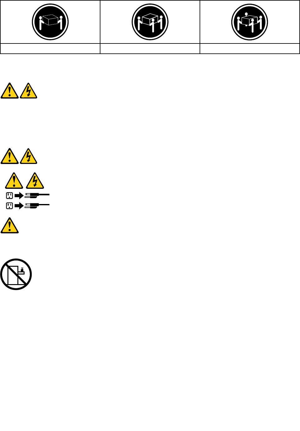
≥18kg(37lbs)≥32kg(70.5lbs)≥55kg(121.2lbs)
CAUTION:
Usesafepracticeswhenlifting.
CAUTION:
Thepowercontrolbuttononthedeviceandthepowerswitchonthepowersupplydonotturnoff
theelectricalcurrentsuppliedtothedevice.Thedevicealsomighthavemorethanonepower
cord.Toremoveallelectricalcurrentfromthedevice,ensurethatallpowercordsaredisconnected
fromthepowersource.
1
2
CAUTION:
Donotplaceanyobjectweighingmorethan82kg(180lbs.)ontopofrack-mounteddevices.
8LenovoC340/440SeriesHardwareMaintenanceManual

Chapter3.Generalinformation
Thischapterprovidesgeneralinformationthatappliestoallcomputermodelscoveredbythismanual.
Specifications
Thissectionliststhephysicalspecificationsforyourcomputer.
Thissectionliststhephysicalspecificationsforyourcomputer.
TypeLenovoC340/C440
Thissectionliststhephysicalspecifications.
Environment
Airtemperature:
Operating:10°to35°C
Transit:-20°to55°C
Humidity:
Operating:35%to80%
Transit:20%to90%(40°C)
Altitude:86KPato106KPa
Electricalinput:
Inputvoltage:90V-264V(AC)
Inputfrequency:47Hz-63Hz
©CopyrightLenovo20139

10LenovoC340/440SeriesHardwareMaintenanceManual

Chapter4.GeneralCheckout
Attention:Thedrivesinthecomputeryouareservicingmighthavebeenrearrangedorthedrivestartup
sequencemayhavebeenchanged.Beextremelycarefulduringwriteoperationssuchascopying,saving,or
formatting.Dataorprogramscanbeoverwrittenifyouselectanincorrectdrive.
Generalerrormessagesappearifaproblemorconflictisfoundbyanapplication,theoperatingsystem,or
both.Foranexplanationofthesemessages,refertotheinformationsuppliedwiththatsoftwarepackage.
Usethefollowingproceduretohelpdeterminethecauseoftheproblem:
1.Power-offthecomputerandallexternaldevices.
2.Checkallcablesandpowercords.
3.Setalldisplaycontrolstothemiddleposition.
4.Power-onallexternaldevices.
5.Power-onthecomputer.
•Lookfordisplayederrorcodes.
•Lookforreadableinstructionsoramainmenuonthedisplay.
Ifyoudidnotreceivethecorrectresponse,proceedtostep6.
Ifyoudidreceivethecorrectresponse,proceedtostep7.
6.Ifoneofthefollowinghappens,followtheinstructiongiven:
•IfthecomputerdisplaysaPOSTerror,goto“POSTerrorcodes” .
•Ifthecomputerhangsandnoerrorisdisplayed,continueatstep7.
7.Iftheteststopsandyoucannotcontinue,replacethelastdevicetested.
©CopyrightLenovo201311

12LenovoC340/440SeriesHardwareMaintenanceManual

Chapter5.UsingtheSetupUtility
TheSetupUtilityprogramisusedtoviewandchangetheconfigurationsettingsofyourcomputer,regardless
ofwhichoperatingsystemyouareusing.However,theoperatingsystemsettingsmightoverrideanysimilar
settingsintheSetupUtilityprogram.
StartingtheLenovoBIOSSetupUtilityprogram
TostarttheLenovoBIOSSetupUtilityprogram,dothefollowing:
1.Ifyourcomputerisalreadyonwhenyoustartthisprocedure,shutdowntheoperatingsystemand
turnoffthecomputer.
2.PressandholdtheF1keythenturnonthecomputer.WhentheLenovoBIOSSetupUtilityprogramis
displayed,releasetheF1key.
Note:IfaPower-OnPasswordoranAdministratorPasswordhasbeenset,theSetupUtilityprogrammenu
willnotbedisplayeduntilyoutypeyourpassword.Formoreinformation,see“Usingpasswords.”
Viewingandchangingsettings
SystemconfigurationoptionsarelistedintheLenovoBIOSSetupUtilityprogrammenu.Tovieworchange
settings,see“StartingtheSetupUtilityprogram.”
YoumustusethekeyboardwhenusingtheLenovoBIOSSetupUtilitymenu.Thekeysusedtoperform
varioustasksaredisplayedonthebottomofeachscreen.
Usingpasswords
YoucanusetheLenovoBIOSSetupUtilityprogramtosetpasswordstopreventunauthorizedpersons
fromgainingaccesstoyourcomputeranddata.See“StartingtheSetupUtilityprogram.”Thefollowing
typesofpasswordsareavailable:
•AdministratorPassword
•Power-OnPassword
Youdonothavetosetanypasswordstouseyourcomputer.However,ifyoudecidetosetpasswords,read
thefollowingsections.
Passwordconsiderations
Apasswordcanbeanycombinationoflettersandnumbersupto16characters(a-zand0-9).Forsecurity
reasons,itisagoodideatouseastrongpasswordthatcannotbeeasilycompromised.Wesuggestthat
passwordsshouldfollowtheserules:
•Forastrongpassword,use7-16charactersandamixoflettersandnumbers.
•Donotuseyournameoryourusername.
•Donotuseacommonwordoracommonname.
•Usesomethingsignificantlydifferentfromyourpreviouspassword.
Attention:AdministratorandPower-Onpasswordsarenotcasesensitive.
©CopyrightLenovo201313

AdministratorPassword
SettinganAdministratorPassworddetersunauthorizedpersonsfromchangingconfigurationsettings.You
mightwanttosetanAdministratorPasswordifyouareresponsibleformaintainingthesettingsofseveral
computers.
AfteryousetanAdministratorPassword,apasswordpromptisdisplayedeverytimeyouaccesstheLenovo
BIOSSetupUtilityprogram.
IfboththeAdministratorandPower-OnPasswordareset,youcantypeeitherpassword.However,youmust
useyourAdministratorPasswordtochangeanyconfigurationsettings.
Setting,changing,ordeletinganAdministratorpassword
TosetanAdministratorPassword,dothefollowing:
Note:Apasswordcanbeanycombinationoflettersandnumbersupto16characters(a-zand0-9).For
moreinformation,see“Passwordconsiderations”onpage13.
1.StarttheLenovoBIOSSetupUtilityprogram(see“StartingtheLenovoBIOSSetupUtilityprogram”on
page13).
2.FromtheSecuritymenu,selectSetAdministratorPasswordandpresstheEnterkey.
3.Thepassworddialogboxwillbedisplayed.T ypethepasswordthenpresstheEnterkey.
4.Re-typethepasswordtoconfirm,thenpresstheEnterkey.Ifyoutypedthepasswordcorrectly,
thepasswordwillbeinstalled.
TochangeanAdministratorPassword,dothefollowing:
1.StarttheLenovoBIOSSetupUtilityprogram(see“StartingtheLenovoBIOSSetupUtilityprogram”on
page13).
2.FromtheSecuritymenu,selectSetAdministratorPasswordandpresstheEnterkey.
3.Thepassworddialogboxwillbedisplayed.TypethecurrentpasswordthenpresstheEnterkey.
4.Typethenewpassword,thenpresstheEnterkey.Re-typethepasswordtoconfirmthenewpassword.
Ifyoutypedthenewpasswordcorrectly,thenewpasswordwillbeinstalled.ASetupNoticedconfirming
thatchangeshavebeensavedwillbedisplayed.
TodeleteapreviouslysetAdministratorPassword,dothefollowing:
1.FromtheSecuritymenu,selectSetAdministratorPasswordandpresstheEnterkey.
2.Thepassworddialogboxwillbedisplayed.TypethecurrentpasswordandpresstheEnterkey.
3.TodeleteanAdministratorPassword,leaveeachnewpasswordlineitemblank,thenpresstheEnter
key.ASetupNoticeconfirmingthatchangeshavebeensavedwillbedisplayed.
4.ReturntotheLenovoBIOSSetupUtilityprogrammenuandselecttheExitoption.
5.SelectSavechangesandExitfromthemenu.
Power-OnPassword
WhenaPower-OnPasswordisset,youcannotstarttheLenovoBIOSSetupUtilityprogramuntilavalid
passwordistypedfromthekeyboard.
Setting,changing,ordeletingaPower-OnPassword
Note:Apasswordcanbeanycombinationoflettersandnumbersupto16characters(a-zand0-9).
14LenovoC340/440SeriesHardwareMaintenanceManual

TosetaPower-OnPassword,dothefollowing:
1.StarttheLenovoBIOSSetupUtilityprogram(See”StartingtheLenovoBIOSSetupUtilityprogram”on
page13.)
2.FromtheSecuritymenu,selectSetPower-OnPasswordandpresstheEnterkey.
3.Thepassworddialogboxwillbedisplayed.Typethepassword,thenpresstheEnterkey.
4.Re-typethepasswordtoconfirm.Ifyoutypedthepasswordcorrectly,thepasswordwillbeinstalled.
TochangeaPower-OnPassword,dothefollowing:
1.StarttheLenovoBIOSSetupUtilityprogram(See”StartingtheLenovoBIOSSetupUtilityprogram”on
page13.)
2.FromtheSecuritymenu,selectSetPower-OnPasswordandpresstheEnterkey.
3.Thepassworddialogboxwillbedisplayed.TypethecurrentpasswordthenpresstheEnterkey.
4.Typethenewpassword,thenpresstheEnterkey.Re-typethepasswordtoconfirmthenewpassword.
Ifyoutypedthenewpasswordcorrectly,thenewpasswordwillbeinstalled.ASetupNoticedconfirming
thatchangeshavebeensavedwillbedisplayed.
TodeleteapreviouslysetPower-OnPassword,dothefollowing:
1.FromtheSecuritymenu,selectSetPower-OnPasswordandpresstheEnterkey.
2.Thepassworddialogboxwillbedisplayed.TypethecurrentpasswordandpresstheEnterkey.
3.TodeletethePower-OnPassword,leaveeachnewpasswordlineitemblank,thenpressEnter.ASetup
Noticeconfirmingthatchangeshavebeensavedwillbedisplayed.
4.ReturntotheLenovoBIOSSetupUtilityprogrammenuandselecttheExitoption.
5.SelectSavechangesandExitfromthemenu.
Enablingordisablingadevice
TheDevicesoptionsisusedtoenableordisableuseraccesstothefollowingdevices:
USBFunctionsSelectwhethertoenableordisableUSB(UniversalSerial
Bus)functions.Ifthefunctionsaredisabled,noUSB
devicescanbeused.
SATAModeWhenthisfeatureissettoDisabled,alldevices
connectedtotheSATAconnectors(e.g.harddiskdrives
ortheopticaldiskdrive)aredisabledandcannotbe
accessed.
OnboardAudioControllerSelectwhethertoenableordisabletheOnboard
AudioController.WhenthisfeatureissettoDisabled
alldevicesconnectedtotheaudioconnectors(e.g.
headphonesoramicrophone)aredisabledandcannot
beused.
OnboardEthernetControllerorLANBootAgentSelectwhethertoenableordisabletheOnboardEthernet
Controller,orselectwhethertoenableordisableload
onboardPXE(PrebootExecutionEnvironment).
Toenableordisableadevice,dothefollowing:
1.StarttheSetupUtilityprogram(see“StartingtheSetupUtilityprogram”onpage13).
2.FromtheSetupUtilityprogrammenu,selectDevices.
3.Selectanoptionasfollows:
SelectUSBSetup,presstheEnterkey,thenselectUSBFunctions.
Chapter5.UsingtheSetupUtility15

SelectATADeviceSetup,presstheEnterkey,thenselectSATAMode.
SelectAudioSetup,presstheEnterkey,thenselectOnboardAudioController.
SelectNetworkSetup,presstheEnterkey,thenselectOnboardEthernetSupportorLANBoot
Agent.
4.SelectDisabledorEnabledandpresstheEnterkey.
5.ReturntotheLenovoBIOSSetupUtilityprogrammenuandselecttheExitoption.
6.SelectSavechangesandExitfromthemenu.
Notes:
a.Ifyoudonotwanttosavethesettings,selectDiscardchangesandExitfromthemenu.
b.SelectIDE/AHCIMode:DevicedriversupportisrequiredforACHI.Dependingonhowtheharddisk
imagewasinstalled,changingthissettingmaypreventthesystemfrombooting.
Selectingastartupdevice
IfyourcomputerdoesnotbootfromadevicesuchastheCD/DVD-ROMdrivediskorharddiskasexpected,
followoneoftheproceduresbelow.
Selectingatemporarystartupdevice
Usethisproceduretostartupfromanybootdevice.
Note:NotallCDs,DVDsorharddiskdrivesarebootable.
1.Turnoffyourcomputer.
2.PressandholdtheF12keythenturnonthecomputer.WhentheStartupDeviceMenuappears,
releasetheF12key.
Note:IftheStartupDeviceMenudoesnotdisplayusingthesesteps,repeatedlypressandreleasethe
F12keyratherthankeepingitpressedwhenturningonthecomputer.
3.Use↑and↓arrowstoselectthedesiredstartupdevicefromtheStartupDeviceMenuandpress
theEnterkeytobegin.
Note:SelectingastartupdevicefromtheStartupDeviceMenudoesnotpermanentlychangethe
startupsequence.
Selectingorchangingthestartupdevicesequence
Tovieworpermanentlychangetheconfiguredstartupdevicesequence,dothefollowing:
1.StarttheLenovoBIOSSetupUtilityprogram(see“StartingtheLenovoBIOSSetupUtilityprogram”on
page13).
2.FromtheLenovoBIOSSetupUtilityprogrammainmenu,selecttheStartupoption.
3.PresstheEnterkey,andselectthedevicesforthePrimaryBootSequence.Readtheinformation
displayedontherightsideofthescreen.
4.Use↑and↓arrowstoselectadevice.Usethe<+>or<->keystomoveadeviceupordown.Usethe
<×>keytoexcludethedevicefromorincludethedeviceinthebootsequence.
5.ReturntotheLenovoBIOSSetupUtilityprogrammenuandselecttheExitoption.
6.SelectSavechangesandExitfromthemenu.
Notes:
16LenovoC340/440SeriesHardwareMaintenanceManual

a.Ifyoudonotwanttosavethesettings,selectDiscardchangesandExitfromthemenu.
b.Ifyouhavechangedthesesettingsandwanttoreturntothedefaultsettings,selectLoadOptimal
Defaultsfromthemenu.
ExitingtheLenovoBIOSSetupUtilityprogram
Afteryoufinishviewingorchangingsettings,presstheEsckeytoreturntotheLenovoBIOSSetupUtility
programmainmenu.YoumighthavetopresstheEsckeyseveraltimes.Dooneofthefollowing:
•Ifyouwanttosavethenewsettings,selectSavechangesandExitfromthemenu.WhentheSave&
resetwindowshows,selecttheYesbutton,andthenpresstheEnterkeytoexittheLenovoBIOS
SetupUtilityprogram.
•Ifyoudonotwanttosavethesettings,selectDiscardchangesandExitfromthemenu.Whenthe
ResetWithoutSavingwindowshows,selecttheY esbutton,andthenpresstheEnterkeytoexitthe
LenovoBIOSSetupUtilityprogram.
Chapter5.UsingtheSetupUtility17

18LenovoC340/440SeriesHardwareMaintenanceManual

Chapter6.Symptom-to-FRUIndex
TheSymptom-to-FRUindexlistserrorsymptomsandpossiblecauses.Themostlikelycauseislistedfirst.
AlwaysbeginwithChapter4,“GeneralCheckout,”onpage11.Thisindexcanalsobeusedtohelpyou
decidewhichFRUstohaveavailablewhenservicingacomputer.Ifyouareunabletocorrecttheproblem
usingthisindex,goto“Undeterminedproblems”onpage20.
Notes:
•Ifyouhavebothanerrormessageandanincorrectaudioresponse,diagnosetheerrormessagefirst.
•Ifyoucannotrunthediagnostictestsoryougetadiagnosticerrorcodewhenrunningatestbutdid
receiveaPOSTerrormessage,diagnosethePOSTerrormessagefirst.
•Ifyoudidnotreceiveanyerrormessagelookforadescriptionofyourerrorsymptomsinthefirstpartof
thisindex.
Harddiskdrivebooterror
Aharddiskdrivebooterrorcanbecausedbythefollowing.
ErrorFRU/Action
Thestartupdriveisnotincludedinthebootsequence
configuration.
Checktheconfigurationandensurethestartupdriveis
inthebootsequence.
Nooperatingsystemisinstalledonthebootdrive.Installanoperatingsystemonthebootdrive.
Thebootsectoronthestartupdriveiscorrupted.Thedrivemustbeformatted.Dothefollowing:
1.Attempttobackupthedataonthefailingharddisk
drive.
2.Usetheoperatingsystemtoformattheharddisk
drive.
Thedriveisdefective.Replacetheharddiskdrive.
PowerSupplyProblems
Followtheseproceduresifyoususpectthereisapowersupplyproblem.
Check/VerifyFRU/Action
Checkthatthefollowingareproperlyinstalled:
•PowerCord
•On/OffSwitchconnector
•SystemBoardPowerSupplyconnectors
•Microprocessorconnections
Reseatconnectors
Checkthepowercord.PowerCord
Checkthepower-onswitch.Power-onSwitch
©CopyrightLenovo201319

POSTerrorcodes
Eachtimeyouturnthecomputeron,itperformsaseriesofteststocheckthatthesystemisoperating
correctlyandthatcertainoptionsareset.ThisseriesoftestsiscalledthePower-OnSelf-Test,orPOST.
POSTdoesthefollowing:
•Checkssomebasicmotherboardoperations
•Checksthatthememoryisworkingcorrectly
•Startsvideooperations
•Verifiesthatthebootdriveisworking
POSTErrorMessageDescription/Action
KeyboarderrorCannotinitializethekeyboard.Makesurethekeyboard
isproperlyconnectedtothecomputerandthatnokeys
areheldpressedduringPOST.T opurposelyconfigure
thecomputerwithoutakeyboard,selectKeyboardless
operationinStartupandsettheoptiontoEnabled.The
BIOSthenignoresthemissingkeyboardduringPOST.
RebootandSelectproperBootdeviceorInsertBoot
MediainselectedBootdevice
TheBIOSwasunabletofindasuitablebootdevice.Make
surethebootdriveisproperlyconnectedtothecomputer.
Makesureyouhavebootablemediainthebootdevice.
Undeterminedproblems
1.Power-offthecomputer.
2.Removeordisconnectthefollowingcomponents(ifconnectedorinstalled)oneatatime.
a.Externaldevices(modem,printer,ormouse)
b.Extendedvideomemory
c.ExternalCache
d.ExternalCacheRAM
e.Harddiskdrive
f.Diskdrive
3.Power-onthecomputertore-testthesystem.
4.Repeatsteps1through3untilyoufindthefailingdeviceorcomponent.
Ifalldevicesandcomponentshavebeenremovedandtheproblemcontinues,replacethesystemboard.
20LenovoC340/440SeriesHardwareMaintenanceManual
Chapter7.Locatingconnectors,controlsandcomponents
Thissectionprovidesillustrationstohelplocatethevariousconnectors,controlsandcomponentsofthe
computer.
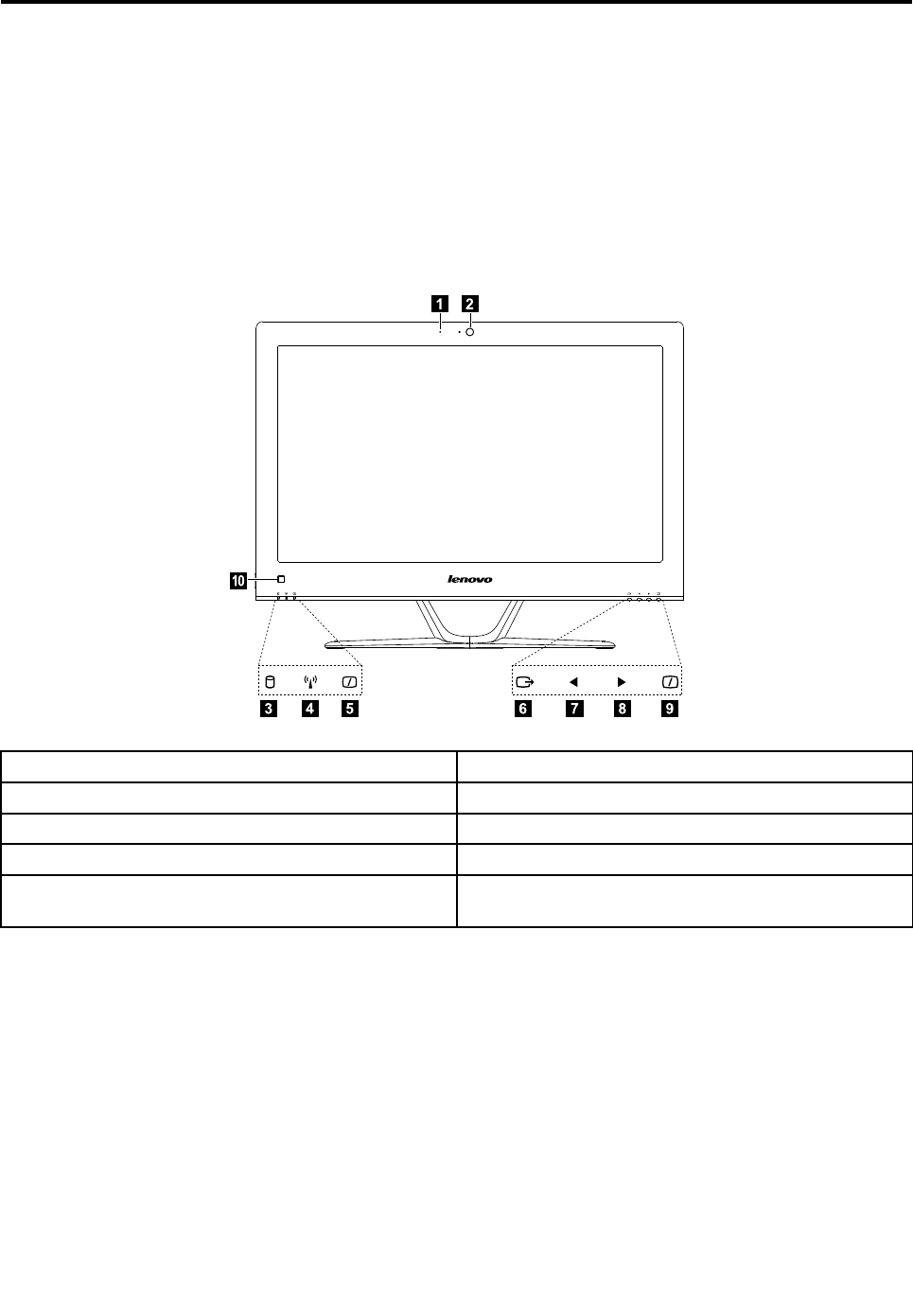
Fontview
Thefollowingillustrationshowsthelocationofcontrolsandcomponentsonthefrontofthecomputer.
Attention:Becarefulnottoblockanyairventsonthecomputer.Blockedairventscancauseoverheating.
12
3765489
10
1.Built-inmicrophone6.Menubutton
2.Built-incamera7.Leftdirectionbutton
3.Harddiskdriveindicator8.Rightdirectionbutton
4.Wi-Fistatusindicator9.MonitorOn/Offbutton
5.MonitorOn/Offindicator10.Built-inIRreceiver(Onlyfunctionalonmodels
equippedwithaIRreceivermodule)
©CopyrightLenovo201321
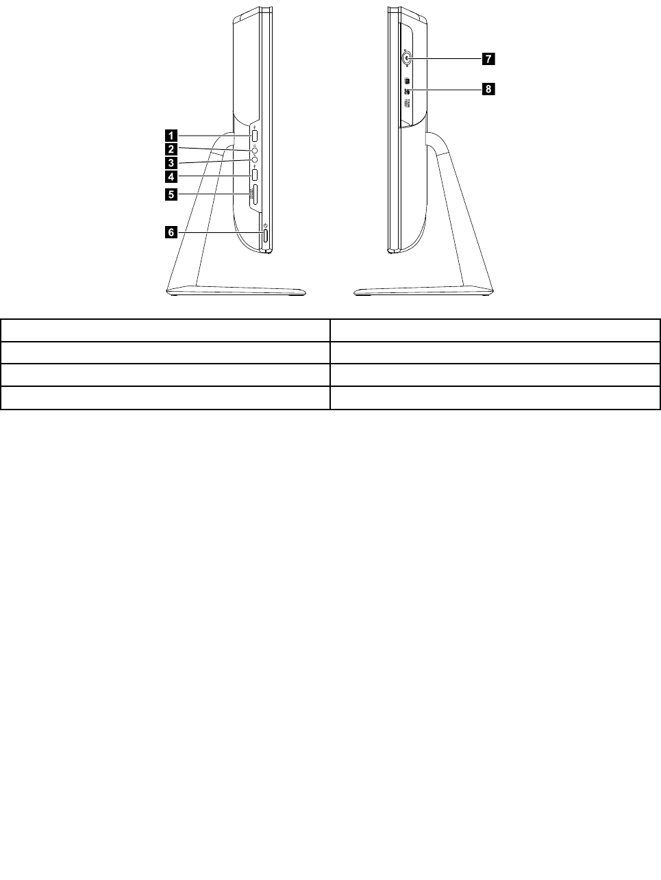
Leftandrightview
Thefollowingillustrationshowsthelocationofconnectors,controlsandcomponentsontheleftandright
sideofthecomputer.
1
2
3
6
5
4
7
8
1.USBconnector5.Memorycardreader
2.Headphoneconnector6.Powerbutton
3.Microphoneconnector7.Opticaldriveejectbutton
4.USBconnector8.Opticaldrive
Attention:Donotinsert3-inchdiscsintotheopticaldrive.
22LenovoC340/440SeriesHardwareMaintenanceManual
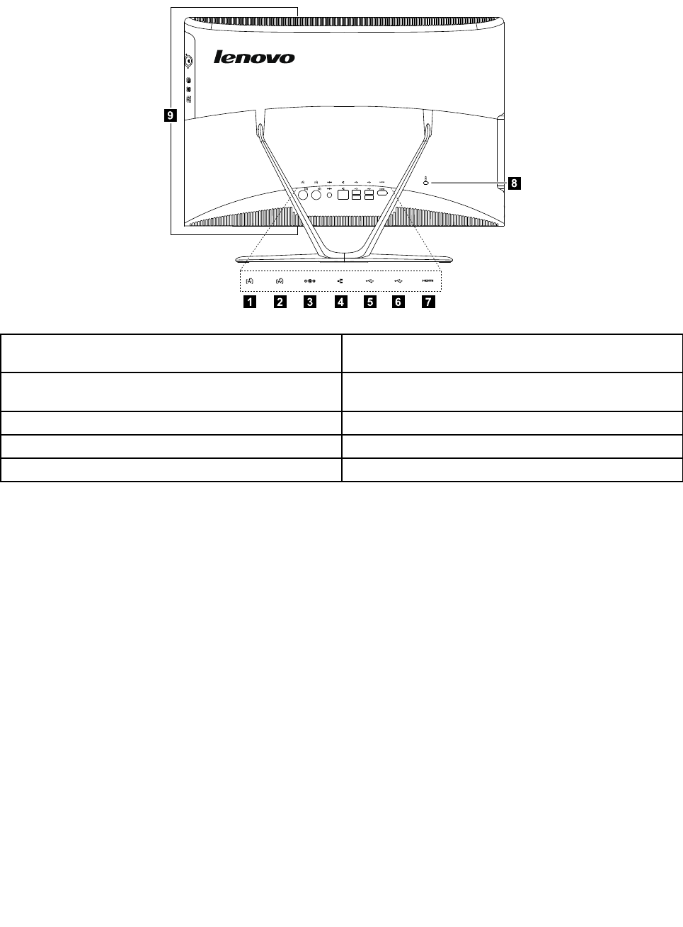
Rearview
Thefollowingillustrationshowsthelocationofconnectorsandcomponentsontherearofthecomputer.
1237654
8
9
1.TVtunerconnector(selectedmodelsonly,2connectors
forJapan)
6.USBconnector
2.TVtunerconnector(selectedmodelsonly,2connectors
forJapan)
7.HDMI-outconnector(selectedmodelsonly)
3.Powerconnector8.Securitycableslot
4.Ethernetconnector9.Airvents
5.USBconnector
Chapter7.Locatingconnectors,controlsandcomponents23
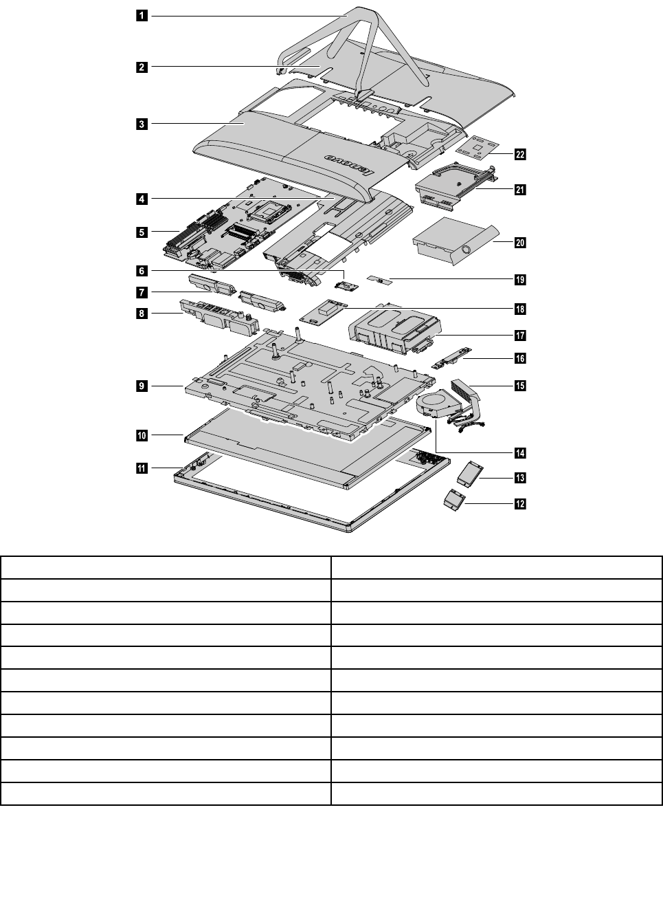
Hardwarecomponents
Thefollowingillustrationshowsthecomponentsthatmakeupyourcomputer.
1
2
3
6
7
8
9
10
11
14
18
16
17
15
19
20
21
22
4
5
12
13
1.Computerstand12.Wi-Ficard
2.Footcover13.TV-Tunercard
3.Middlecover14.Systemfan
4.EMIcover15.Heat-sink
5.Motherboard16.Camera
6.Powerswitchboard17.Harddiskdriveandbay
7.Speakers18.Converterboard
8.RearI/Omodule19.Frontfunctionboard
9.Chassis20.Opticaldrive
10.LEDpanel21.Opticaldrivebracket
11.Frontbezel22.Touchcontrolboard
24LenovoC340/440SeriesHardwareMaintenanceManual
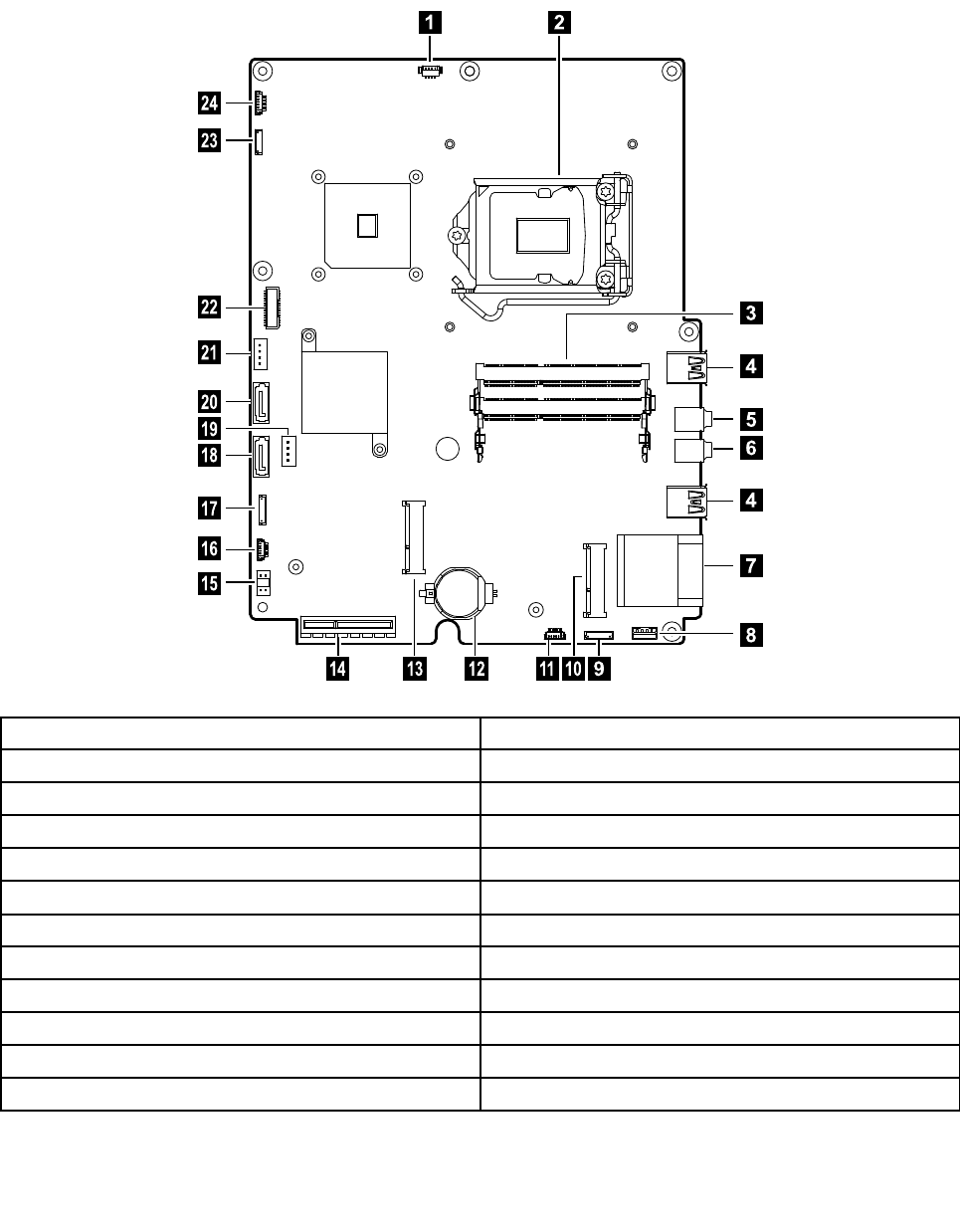
Identifyingpartsonthemotherboard
Themotherboard(sometimescalledtheplanarorsystemboard)isthemaincircuitboardinyourcomputer.
Itprovidesbasiccomputingfunctionsandsupportsavarietyofdevicesthatarefactory-installedorthat
youcaninstalllater.Thefollowingillustrationshowsthelocationofconnectorsandcomponentsonthe
frontofthemotherboard.
12
3
6
7
8
9
1011121314
15
16
17
18
19
20
21
22
23
24
4
4
5
1.Thermalsensorheader13.TV-Tunercardconnector
2.CPUandsocket14.RearI/Omoduleconnector
3.Memoryconnector15.DC-inconnector
4.USBconnectors16.B-Casecardconnector
5.Headphoneconnector17.Converterboardconnector
6.Microphoneconnector18.HarddiskdriveSATAconnector
7.Memorycardconnector19.Harddiskdrivepowerconnector
8.Speakerconnector20.OpticaldriveSATAconnector
9.Powerswitchboardconnector21.Opticaldriverpowerconnector
10.Wi-Ficardconnector22.LVDSconnector
11.Frontcontrolboardconnector23.Cameraconnector
12.Battery24.Systemfanconnector
Chapter7.Locatingconnectors,controlsandcomponents25

26LenovoC340/440SeriesHardwareMaintenanceManual

Chapter8.Replacinghardware
Attention:Donotremovethecomputercoverorattemptanyrepairbeforereadingthe“Importantsafetyinformation”
intheSafetyandWarrantyGuidethatwasincludedwithyourcomputer.ToobtaincopiesoftheSafetyandWarranty
Guide,gototheSupportWebsiteat:http://consumersupport.lenovo.com.
Note:UseonlypartsprovidedbyLenovo.
Generalinformation
Pre-disassemblyinstructions
Beforestartingthedisassemblyprocedure,makesurethatyoudothefollowing:
1.Turnoffthepowertothesystemandallperipherals.
2.Unplugallpowerandsignalcablesfromthecomputer.
3.Placethesystemonaflat,stablesurface.
©CopyrightLenovo201327
Replacingthekeyboardandmouse
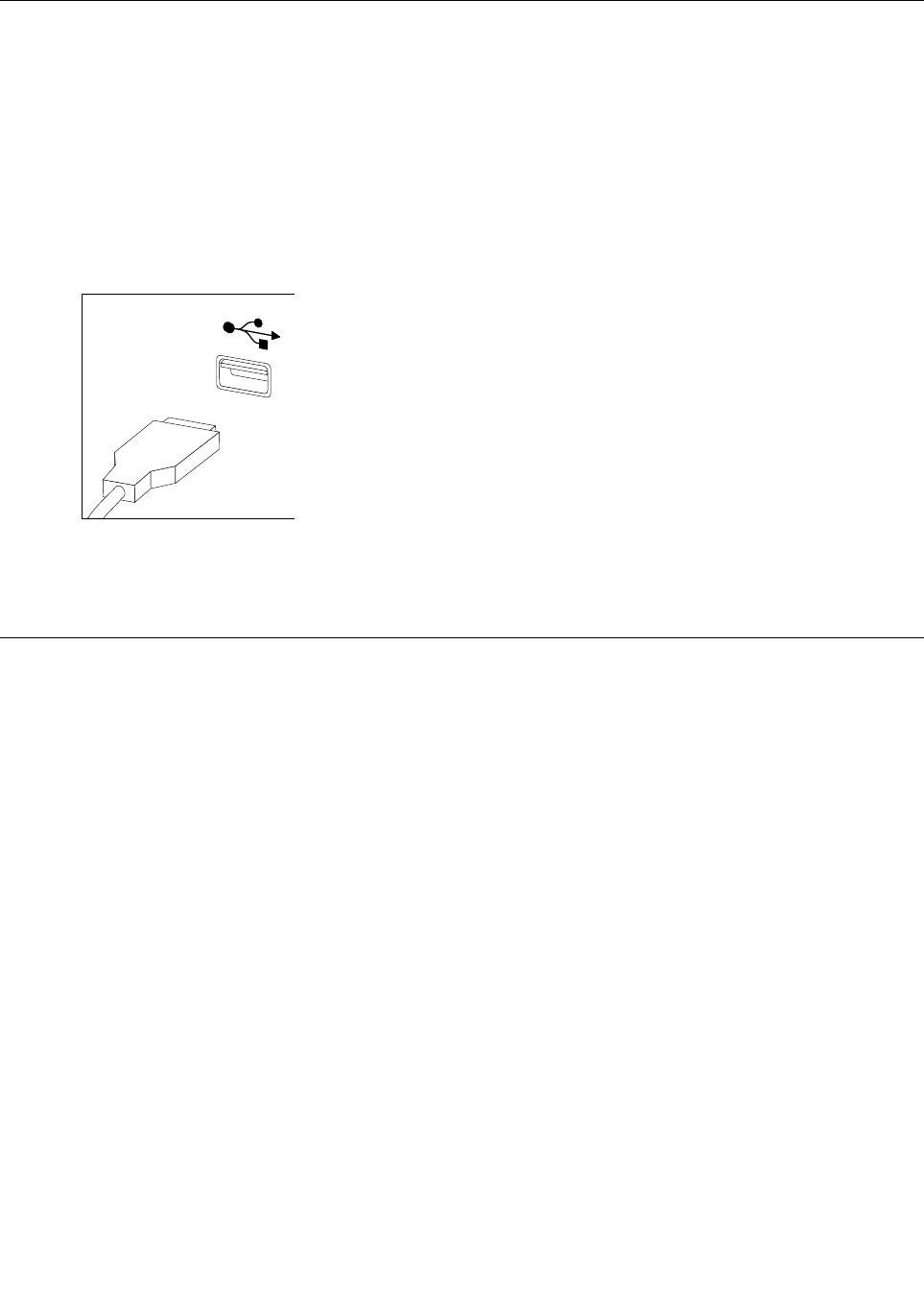
Note:YourkeyboardwillbeconnectedtoaUSBconnectorateithersideorattherearofthecomputer.
Toreplacethekeyboard:
Step1.Removeanymedia(disks,CDs,ormemorycards)fromthedrives,shutdownthecomputer,and
turnoffallattacheddevices.
Step2.Unplugallpowercordsfromelectricaloutlets.
Step3.Locatetheconnectorforthekeyboard.Referto“Sideviewofthecomputer”and“Rearviewof
thecomputer”.
Step4.Disconnectthedefectivekeyboardcablefromthecomputerandconnectthenewkeyboardcable
tothesameconnector.
Step5.Themousecanbereplacedusingthesamemethod.
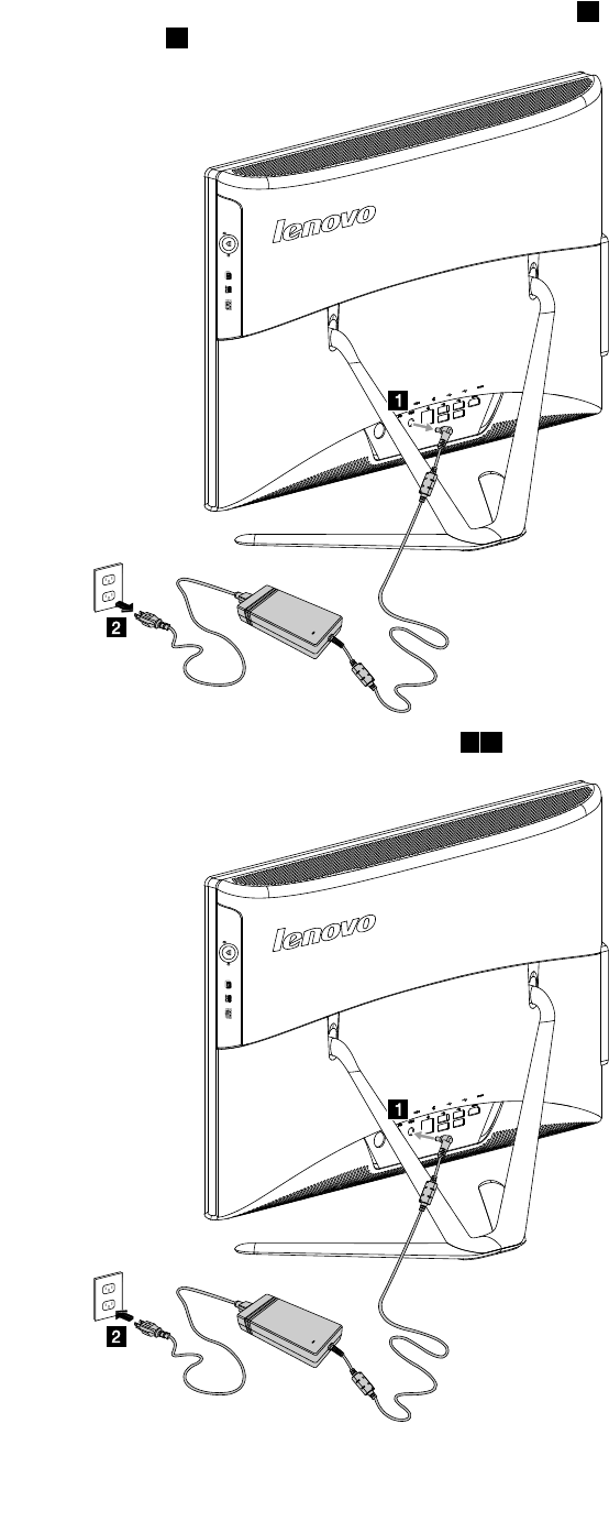
Replacingtheadapter
Attention:Turnoffthecomputerandwait3to5minutestoletitcooldownbeforeremovingthecover.
Step1.Removeanymedia(disks,CDs,ormemorycards)fromthedrives,shutdowntheoperating
system,andturnoffthecomputerandallattacheddevices.
28LenovoC340/440SeriesHardwareMaintenanceManual
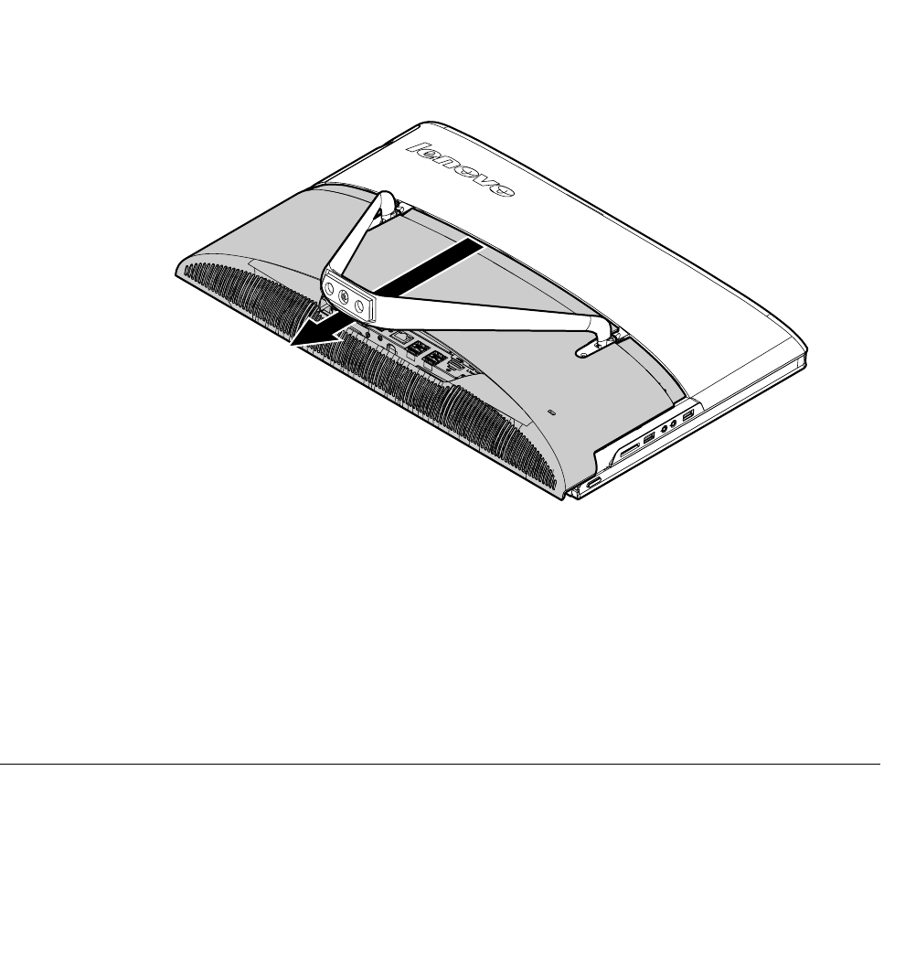
Removingthestandbase
Attention:Turnoffthecomputerandwait3to5minutestoletitcooldownbeforeremovingthecover.
Note:Itmaybehelpfultoplacethecomputerface-downonasoftflatsurfaceforthisprocedure.Lenovo
recommendsthatyouuseablanket,towel,orothersoftclothtoprotectthetouchscreenfromscratches
orotherdamage.
Step1.Removeanymedia(disks,CDs,ormemorycards)fromthedrives,shutdowntheoperating
system,andturnoffthecomputerandallattacheddevices.
Step2.Unplugallpowercordsfromelectricaloutlets.
Step3.Disconnectallcablesattachedtothecomputer.Thisincludespowercords,input/output(I/O)
cables,andanyothercablesthatareconnectedtothecomputer.Referto“Leftandrightviews”
and“Rearview”forhelpwithlocatingthevariousconnectors.
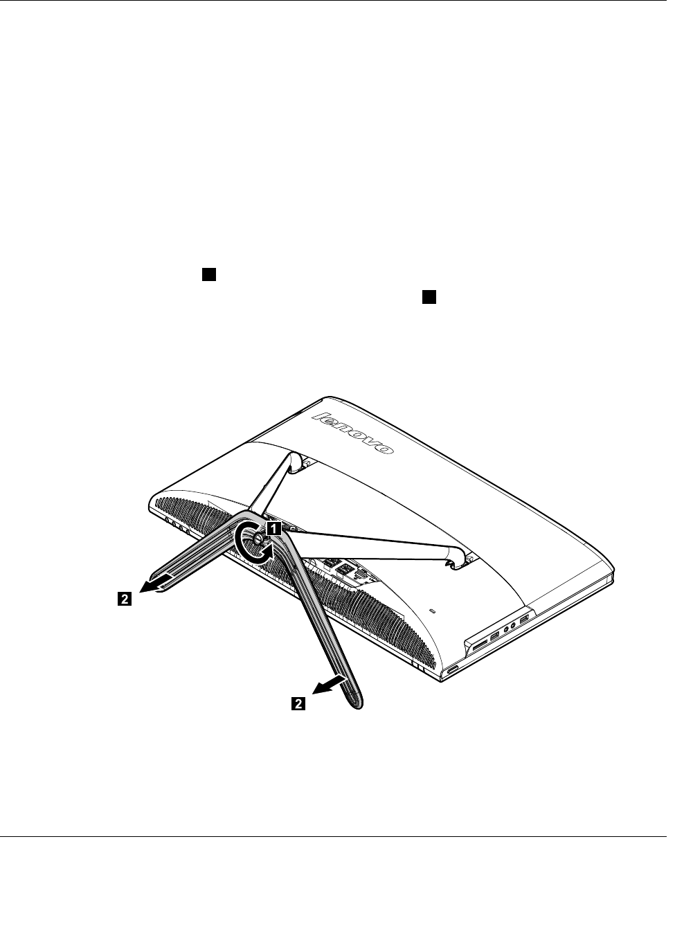
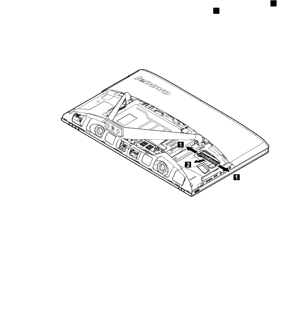
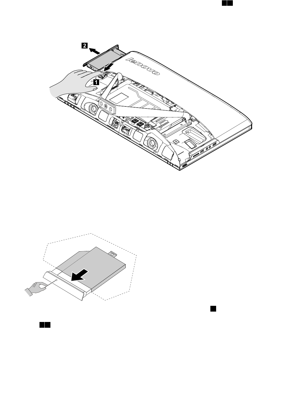
Step4.Twistthehandscrewringcounter-clockwiseuntilthebasecomesloosetoreleasethestandbase
fromthestandholder.1
Step5.Slidethestandbaseoutfromtheholderthenputitaside.2
Step6.Referto“Installingthecomputerstand”toreinstallthestandbase.
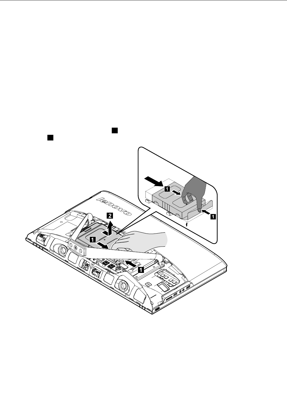
Removingthefootcover
Attention:Turnoffthecomputerandwait3to5minutestoletitcooldownbeforeremovingthecover.
30LenovoC340/440SeriesHardwareMaintenanceManual
Note:Itmaybehelpfultoplacethecomputerface-downonasoftflatsurfaceforthisprocedure.Lenovo
recommendsthatyouuseablanket,towel,orothersoftclothtoprotectthetouchscreenfromscratches
orotherdamage.
Step1.Removeanymedia(disks,CDs,ormemorycards)fromthedrives,shutdowntheoperating
system,andturnoffthecomputerandallattacheddevices.
Step2.Unplugallpowercordsfromelectricaloutlets.
Step3.Disconnectallcablesattachedtothecomputer.Thisincludespowercords,input/output(I/O)
cables,andanyothercablesthatareconnectedtothecomputer.Referto“Leftandrightviews”
and“Rearview”forhelpwithlocatingthevariousconnectors.
Step4.Removethefootbase.Referto“Removingthefootbase” .
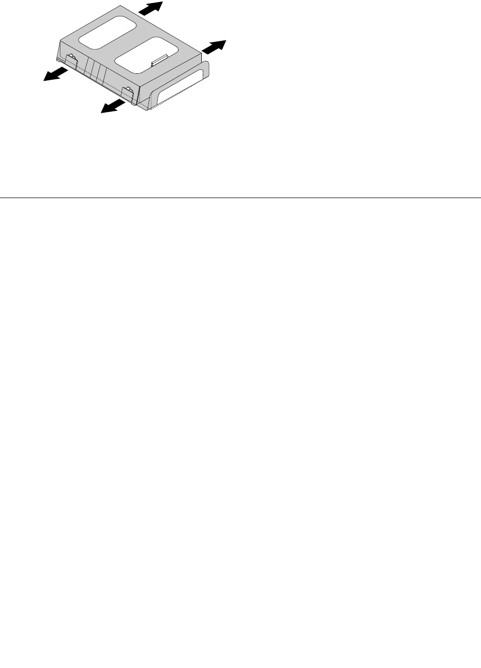
Step5.Liftupthestandholderthenslideoutthefootcoverasshown.
Step6.Toreattachthefootcover:
a.Liftupthestandholder.
b.Lineupthefootcoverwithmountingholesonthebackofthecomputer,thenslideitbackinto
position.
Replacingamemorymodule
Attention:Turnoffthecomputerandwait3to5minutestoletitcooldownbeforeremovingthecover.
Chapter8.Replacinghardware31
Note:Itmaybehelpfultoplacethecomputerface-downonasoftflatsurfaceforthisprocedure.Lenovo
recommendsthatyouuseablanket,towel,orothersoftclothtoprotectthetouchscreenfromscratches
orotherdamage.
Step1.Removeanymedia(disks,CDs,ormemorycards)fromthedrives,shutdowntheoperating
system,andturnoffthecomputerandallattacheddevices.
Step2.Unplugallpowercordsfromelectricaloutlets.
Step3.Disconnectallcablesattachedtothecomputer.Thisincludespowercords,input/output(I/O)
cables,andanyothercablesthatareconnectedtothecomputer.Referto“Leftandrightviews”
and“Rearview”forhelpwithlocatingthevariousconnectors.
Step4.Removethestandbase.Referto“Removingthestandbase” .
Step5.Removethefootcover.Referto“Removingthefootcover” .
Step6.Pushoutthelatchesonbothsidesofthememorysockettoreleasethememorymodule1and
gentlypullthememorymoduleupwardtoremoveitfromitssocket.2Allofthememorymodules
canberemovedusingthesameprocedure.
Step7.Toinstallamemorymodule:
a.Alignthenewmemorymodulewiththememorysocket,theninsertitandpushdownonthe
topedge.Makesurethelatcheslockthememorymoduleinplace.
Step8.Reattachthefootcoverandstandbase.
32LenovoC340/440SeriesHardwareMaintenanceManual
Replacingtheharddiskdrive
Attention:Turnoffthecomputerandwait3to5minutestoletitcooldownbeforeremovingthecover.
Note:Itmaybehelpfultoplacethecomputerface-downonasoftflatsurfaceforthisprocedure.Lenovo
recommendsthatyouuseablanket,towel,orothersoftclothtoprotectthetouchscreenfromscratches
orotherdamage.
Step1.Removeanymedia(disks,CDs,ormemorycards)fromthedrives,shutdowntheoperating
system,andturnoffthecomputerandallattacheddevices.
Step2.Unplugallpowercordsfromelectricaloutlets.
Step3.Disconnectallcablesattachedtothecomputer.Thisincludespowercords,input/output(I/O)
cables,andanyothercablesthatareconnectedtothecomputer.Referto“Leftandrightviews”
and“Rearview”forhelpwithlocatingthevariousconnectors.
Step4.Removethestandbase.Referto“Removingthestandbase” .
Step5.Removethefootcover.Referto“Removingthefootcover” .
Step6.Pushtheharddiskdrivebracket1,thenslidetheharddiskdriveandbracketoutofthechassisas
shown.2
1
1
Chapter8.Replacinghardware33
Step7.Pushthelockpinsoutwardtoreleasetheharddiskdrivefromthebracket.
Step8.Toinstallthenewharddiskdrive:
a.Lineupthenewharddiskdrivewiththebracketandsecureitwiththepins.
b.Slidetheharddiskdriveandbracketbackintoposition.
Step9.Reattachthefootcoverandstandbase.
Replacingtheopticaldrive
Attention:Turnoffthecomputerandwait3to5minutestoletitcooldownbeforeremovingthecover.
Note:Itmaybehelpfultoplacethecomputerface-downonasoftflatsurfaceforthisprocedure.Lenovo
recommendsthatyouuseablanket,towel,orothersoftclothtoprotectthetouchscreenfromscratches
orotherdamage.
Step1.Removeanymedia(disks,CDs,ormemorycards)fromthedrives,shutdowntheoperating
system,andturnoffthecomputerandallattacheddevices.
Step2.Unplugallpowercordsfromelectricaloutlets.
Step3.Disconnectallcablesattachedtothecomputer.Thisincludespowercords,input/output(I/O)
cables,andanyothercablesthatareconnectedtothecomputer.Referto“Leftandrightviews”
and“Rearview”forhelpwithlocatingthevariousconnectors.
Step4.Removethestandbase.Referto“Removingthestandbase” .
Step5.Removethefootcover.Referto“Removingthefootcover” .
34LenovoC340/440SeriesHardwareMaintenanceManual
Step6.Pushtheopticaldrivepindownwardtopushouttheopticaldriveasshown.12
Step7.Pushasmallironstick(paperclip)intothesmallholeontheopticaldrivecoversothatthedisk
springsoutasshown.
Step8.Removethe2screwsthatsecuretheopticaldrivetothemetalbracket.1
Step9.Useasmallflatheadscrewdrivertopressandpushoutthepinsthatsecurethecovertothe
disk.23
Chapter8.Replacinghardware35
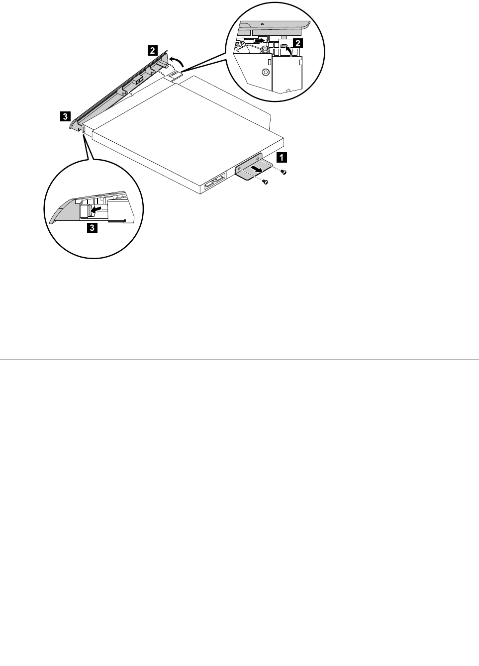
Step10.Separatethecoverfromthedefectiveopticaldrive.
Step11.Toinstallthenewopticaldrive:
a.Alignthenewopticaldrivewiththecover,andthenpushthecoverbackintoposition.
b.Screwthemetalbracketbackontothenewopticaldrive.
c.Slidethenewopticaldriveintothedrivebay.
Step12.Reattachthefootcoverandstandbase.
Removingthestandholder
Note:Turnoffthecomputerandwait3to5minutestoletitcooldownbeforeremovingthecover.
Note:Itmaybehelpfultoplacethecomputerface-downonasoftflatsurfaceforthisprocedure.Lenovo
recommendsthatyouuseablanket,towel,orothersoftclothtoprotectthecomputerscreenfromscratches
orotherdamage.
Toremovethestandholder:
Step1.Removeanymedia(disks,CDs,DVDs,ormemorycards)fromthedrives,shutdowntheoperating
system,andturnoffthecomputerandallattacheddevices.
Step2.Unplugallpowercordsfromelectricaloutlets.
Step3.Disconnectallcablesattachedtothecomputer.Thisincludespowercords,input/output(I/O)
cables,andanyothercablesthatareconnectedtothecomputer.Referto“Leftandrightview”
and“Rearview”forhelpwithlocatingthevariousconnectors.
Step4.Removethestandbase.Referto“Removingthestandbase” .
Step5.Removethefootcover.Referto“Removingthefootcover” .
Step6.Removethefourscrewsthatsecurethestandholdertothechassis,thenliftupthestandholderto
removeit.
36LenovoC340/440SeriesHardwareMaintenanceManual
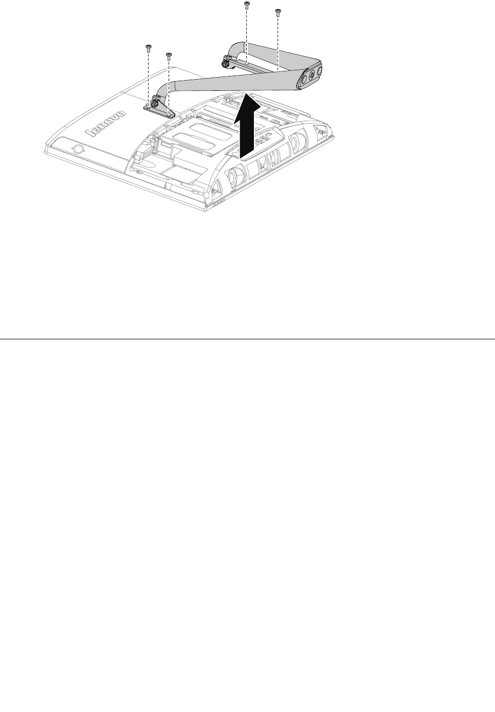
Step7.Toreattachthestandholder:
a.Aligntheholesonthestandholderwithmountingholesonthechassis,placethestand
holderbackintoposition.
b.Securethestandholdertothechassiswiththefourscrews.
Step8.Lineupthefootcoverwithmountingholesonthebackofthecomputer,thenslideitbackinto
position.
Step9.Reattachthestandbase.
Removingthemiddlecover
Note:Turnoffthecomputerandwait3to5minutestoletitcooldownbeforeremovingthecover.
Note:Itmaybehelpfultoplacethecomputerface-downonasoftflatsurfaceforthisprocedure.Lenovo
recommendsthatyouuseablanket,towel,orothersoftclothtoprotectthecomputerscreenfromscratches
orotherdamage.
Toremovethemiddlecover:
Step1.Removeanymedia(disks,CDs,DVDs,ormemorycards)fromthedrives,shutdowntheoperating
system,andturnoffthecomputerandallattacheddevices.
Step2.Unplugallpowercordsfromelectricaloutlets.
Step3.Disconnectallcablesattachedtothecomputer.Thisincludespowercords,input/output(I/O)
cables,andanyothercablesthatareconnectedtothecomputer.Referto“Leftandrightview”
and“Rearview”forhelpwithlocatingthevariousconnectors.
Step4.Removethestandbase.Referto“Removingthestandbase” .
Step5.Removethefootcover.Referto“Removingthefootcover” .
Step6.Removetheopticaldrive.Referto“Replacingtheopticaldrive” .
Step7.Removethestandholder.Referto“Removingthestandholder” .
Step8.Removethesixscrewsthatsecurethemiddlecovertothechassis,thenliftupthemiddlecover
fromtheleftside(opticaldriveside)toremovethemiddlecover.
Chapter8.Replacinghardware37
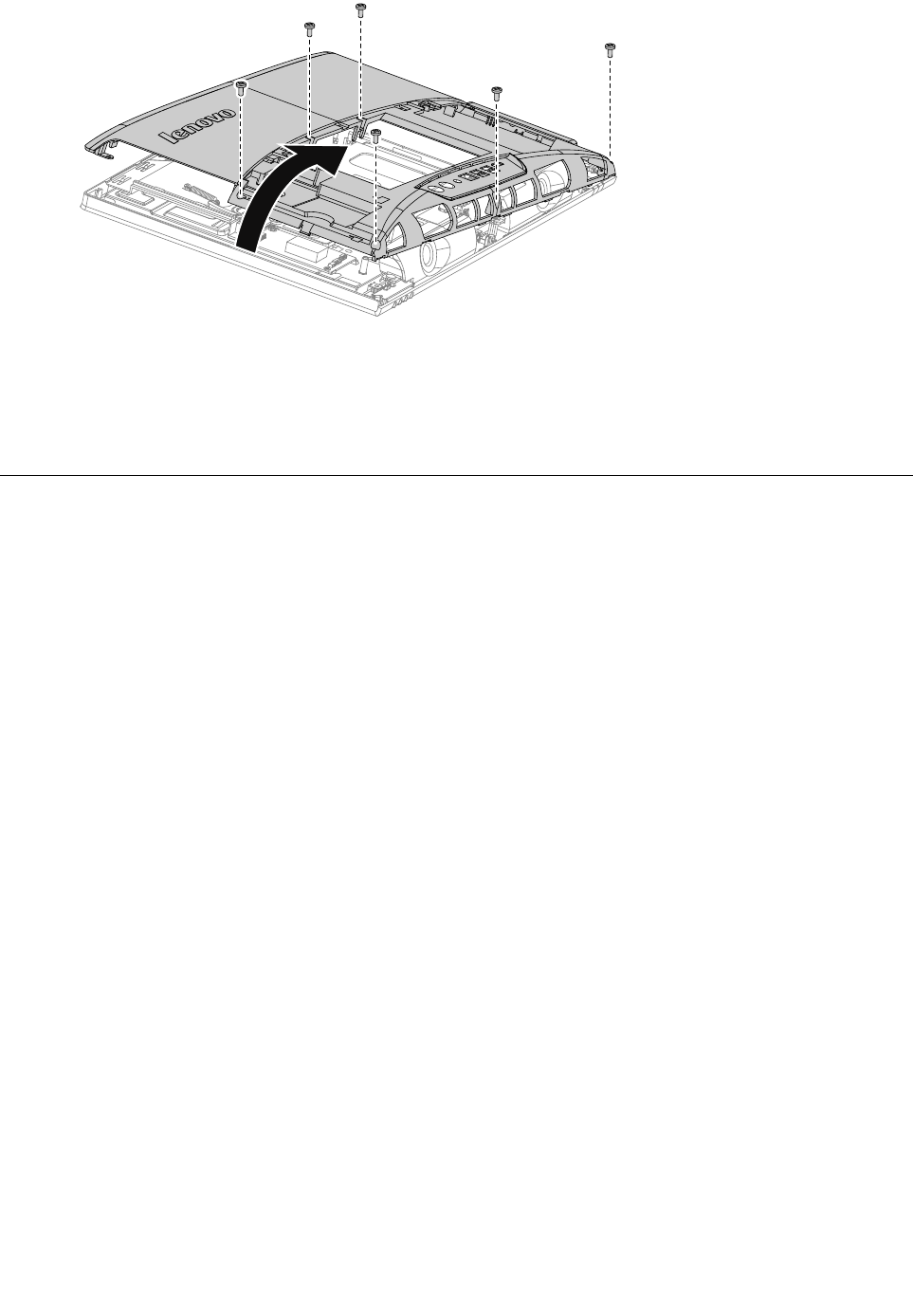
Step9.Toreattachthemiddlecover:
a.Lineupthemiddlecoverwithchassis,thenplacethemiddlecoverback.
b.Securethemiddlecovertothechassiswiththesixscrews.
Step10.Reattachthestandholder,opticaldrive,footcoverandstandbase.
Replacingtheconverterboard
Note:Turnoffthecomputerandwait3to5minutestoletitcooldownbeforeremovingthecover.
Note:Itmaybehelpfultoplacethecomputerface-downonasoftflatsurfaceforthisprocedure.Lenovo
recommendsthatyouuseablanket,towel,orothersoftclothtoprotectthecomputerscreenfromscratches
orotherdamage.
Toreplacetheconverterboard:
Step1.Removeanymedia(disks,CDs,DVDs,ormemorycards)fromthedrives,shutdowntheoperating
system,andturnoffthecomputerandallattacheddevices.
Step2.Unplugallpowercordsfromelectricaloutlets.
Step3.Disconnectallcablesattachedtothecomputer.Thisincludespowercords,input/output(I/O)
cables,andanyothercablesthatareconnectedtothecomputer.Referto“Leftandrightview”
and“Rearview”forhelpwithlocatingthevariousconnectors.
Step4.Removethestandbase.Referto“Removingthestandbase” .
Step5.Removethefootcover.Referto“Removingthefootcover” .
Step6.Removetheopticaldrive.Referto“Replacingtheopticaldrive” .
Step7.Removethestandholder.Referto“Removingthestandholder” .
Step8.Removethemiddlecover.Referto“Removingthemiddlecover” .
38LenovoC340/440SeriesHardwareMaintenanceManual
Step9.Disconnectthetwocablesfromtheconverter,andthenremovethetwoscrewsthatsecurethe
converterboardtothechassis.
Step10.Liftuptheconverterboardtoremoveit.
Step11.Toinstallthenewconverterboard:
a.Lineuptheholesonthenewconverterboardwiththemountingholesonthechassisand
secureitwiththetwoscrews.
b.Connectthetwocablestothenewconverterboard.
Step12.Reattachthemiddlecover,opticaldrive,standholder,footcoverandstandbase.
Replacingthetouchcontrolboard
Note:Turnoffthecomputerandwait3to5minutestoletitcooldownbeforeremovingthecover.
Note:Itmaybehelpfultoplacethecomputerface-downonasoftflatsurfaceforthisprocedure.Lenovo
recommendsthatyouuseablanket,towel,orothersoftclothtoprotectthecomputerscreenfromscratches
orotherdamage.
Toreplacethetouchcontrolboard:
Note:ThefollowinginstructionsareforC440touchmodelsonly.
Step1.Removeanymedia(disks,CDs,DVDs,ormemorycards)fromthedrives,shutdowntheoperating
system,andturnoffthecomputerandallattacheddevices.
Step2.Unplugallpowercordsfromelectricaloutlets.
Step3.Disconnectallcablesattachedtothecomputer.Thisincludespowercords,input/output(I/O)
cables,andanyothercablesthatareconnectedtothecomputer.Referto“Leftandrightview”
and“Rearview”forhelpwithlocatingthevariousconnectors.
Step4.Removethestandbase.Referto“Removingthestandbase” .
Step5.Removethefootcover.Referto“Removingthefootcover” .
Step6.Removetheopticaldrive.Referto“Replacingtheopticaldrive” .
Step7.Removethestandholder.Referto“Removingthestandholder” .
Step8.Removethemiddlecover.Referto“Removingthemiddlecover” .
Chapter8.Replacinghardware39
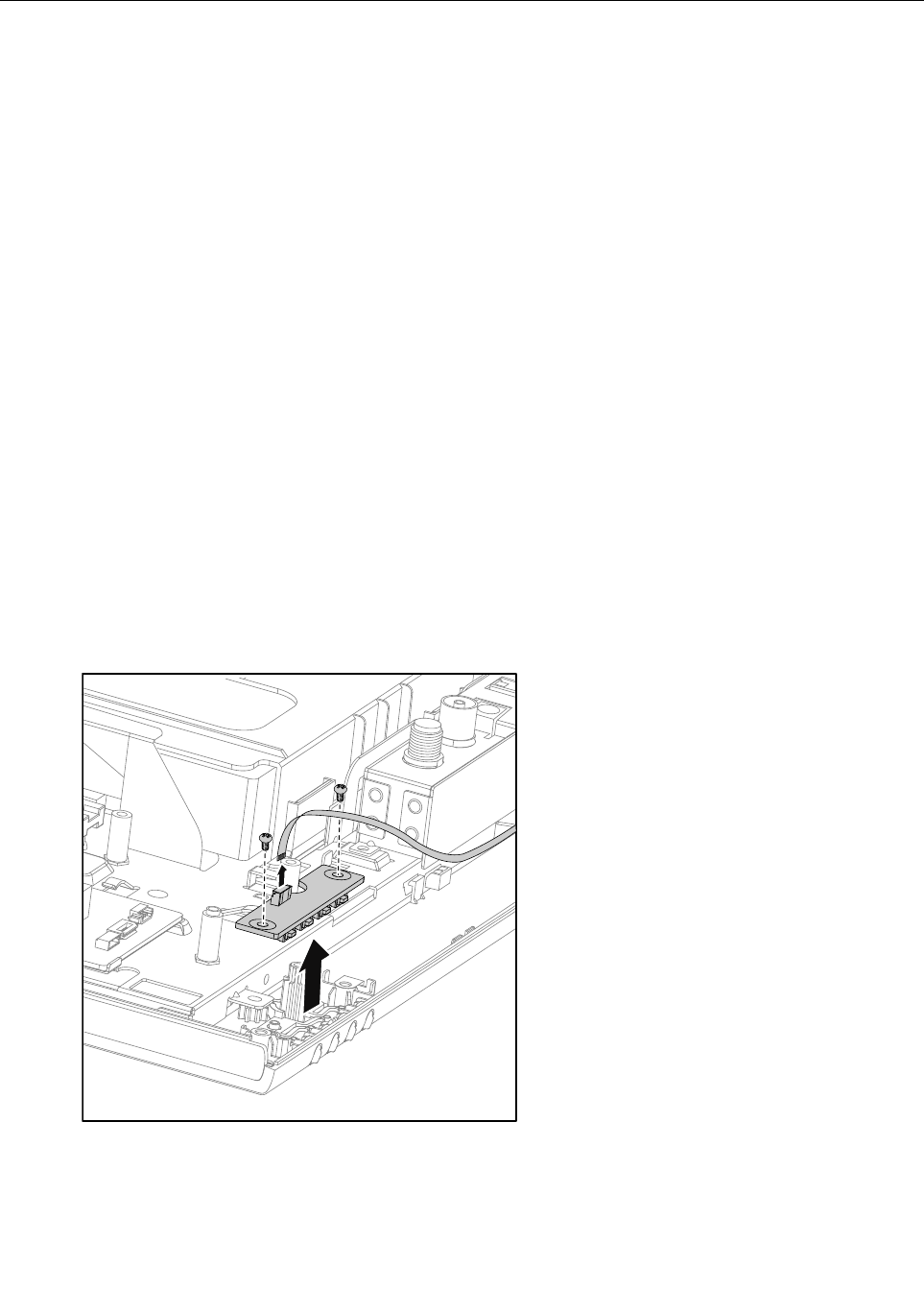
Step9.Disconnectthefourcablesfromtheconverter1234,andthenremovethethreescrewsthat
securethetouchcontrolboardtothechassis.
Step10.Liftupthetouchcontrolboardtoremoveit.
1
2
3
4
Step11.Toinstallthenewtouchcontrolboard:
a.Lineuptheholesonthenewtouchcontrolboardwiththemountingholesonthechassis
andsecureitwiththethreescrews.
b.Connectthefourcablestothenewtouchcontrolboard.
Step12.Reattachthemiddlecover,opticaldrive,standholder,footcoverandstandbase.
RemovingtheEMIcover
Note:Turnoffthecomputerandwait3to5minutestoletitcooldownbeforeremovingthecover.
Note:Itmaybehelpfultoplacethecomputerface-downonasoftflatsurfaceforthisprocedure.Lenovo
recommendsthatyouuseablanket,towel,orothersoftclothtoprotectthecomputerscreenfromscratches
orotherdamage.
ToreplacetheEMIcover
Step1.Removeanymedia(disks,CDs,DVDs,ormemorycards)fromthedrives,shutdowntheoperating
system,andturnoffthecomputerandallattacheddevices.
Step2.Unplugallpowercordsfromelectricaloutlets.
Step3.Disconnectallcablesattachedtothecomputer.Thisincludespowercords,input/output(I/O)
cables,andanyothercablesthatareconnectedtothecomputer.Referto“Leftandrightview”
and“Rearview”forhelpwithlocatingthevariousconnectors.
Step4.Removethestandbase.Referto“Removingthestandbase” .
Step5.Removethefootcover.Referto“Removingthefootcover” .
Step6.Removetheopticaldrive.Referto“Replacingtheopticaldrive” .
Step7.Removethestandholder.Referto“Removingthestandholder” .
Step8.Removethemiddlecover.Referto“Removingthemiddlecover” .
40LenovoC340/440SeriesHardwareMaintenanceManual
Step9.RemovethethreescrewsthatsecuretheEMIcovertothechassis,andthenliftitup.
Step10.ToreattachtheEMIcover:
a.LineuptheholesontheEMIcoverwithmountingholesonthechassis,thenplaceEMIcover
backintoposition.
b.SecuretheEMIcovertothechassiswiththreescrews.
Step11.Reattachthemiddlecover,opticaldrive,standholder,footcoverandstandbase.
ReplacingtherearI/Omodule
Note:Turnoffthecomputerandwait3to5minutestoletitcooldownbeforeremovingthecover.
Note:Itmaybehelpfultoplacethecomputerface-downonasoftflatsurfaceforthisprocedure.Lenovo
recommendsthatyouuseablanket,towel,orothersoftclothtoprotectthecomputerscreenfromscratches
orotherdamage.
ToreplacetherearI/Omodule
Step1.Removeanymedia(disks,CDs,DVDs,ormemorycards)fromthedrives,shutdowntheoperating
system,andturnoffthecomputerandallattacheddevices.
Step2.Unplugallpowercordsfromelectricaloutlets.
Step3.Disconnectallcablesattachedtothecomputer.Thisincludespowercords,input/output(I/O)
cables,andanyothercablesthatareconnectedtothecomputer.Referto“Leftandrightview”
and“Rearview”forhelpwithlocatingthevariousconnectors.
Step4.Removethestandbase.Referto“Removingthestandbase” .
Step5.Removethefootcover.Referto“Removingthefootcover” .
Step6.Removetheopticaldrive.Referto“Replacingtheopticaldrive” .
Step7.Removethestandholder.Referto“Removingthestandholder” .
Step8.Removethemiddlecover.Referto“Removingthemiddlecover” .
Step9.RemovetheEMIcover.Referto“RemovingtheEMIcover” .
Chapter8.Replacinghardware41
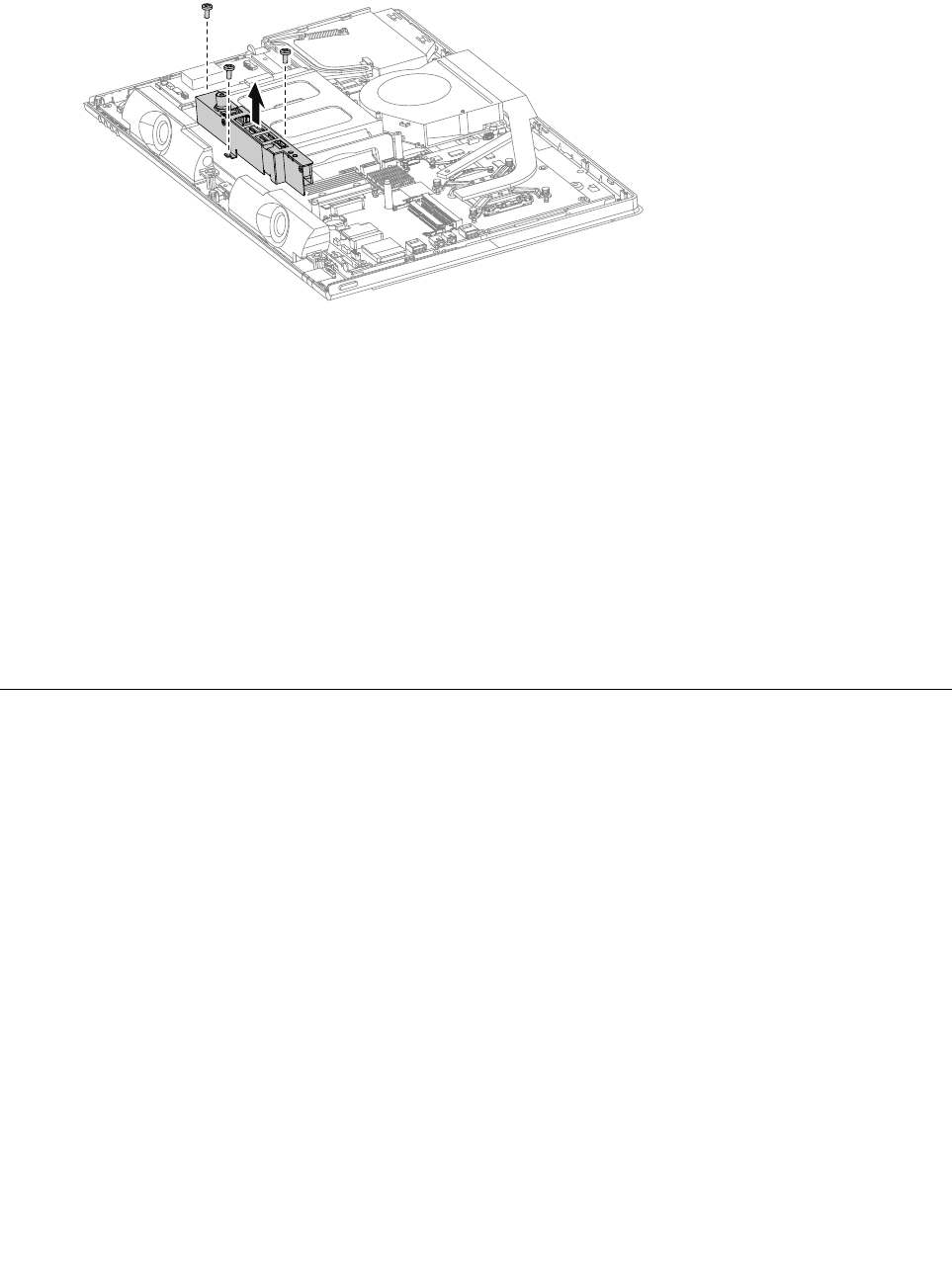
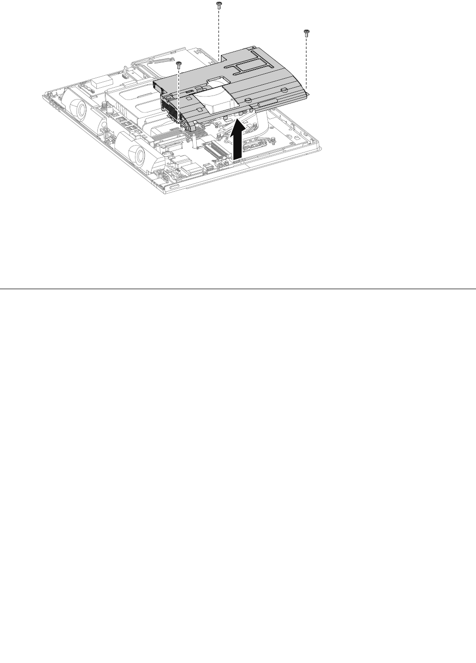
Step10.RemovethethreescrewsthatsecuretherearI/Omoduletothemotherboardandliftitupgently.
Step11.DisconnectthepowercablefromthemotherboardandtheTVantennacable(s)fromtheTVtuner
card.
Step12.RemovethehexagonalnutthatsecuretheTV-TunerantennaconnectortotherearI/Obracket.
ThenslidetheTV-Tunerantennaconnectorout.
Step13.Removetheonescrewthatsecuresthepowerjacktothebracket.Slideoutthepowerjack
fromtherearI/Obracket.
Step14.ToinstallthenewrearI/Omodule:
a.AttachtheTV-TunerantennaconnectorandpowerjacktothenewrearI/Obracket,then
securethemwiththescrewandnut.
b.LineuptherearI/Omodulewiththeconnectorsonthemotherboard,theninserttherearI/O
moduleintoplace.
c.ConnectthepowercabletothemotherboardandtheTVantennacable(s)totheTVtunercard.
d.SecuretherearI/Omodulewiththethreescrews.
Step15.ReattachtheEMIcover,middlecover,opticaldrive,standholder,footcoverandstandbase.
ReplacingtheTVtunercard
Note:Turnoffthecomputerandwait3to5minutestoletitcooldownbeforeremovingthecover.
Note:Itmaybehelpfultoplacethecomputerface-downonasoftflatsurfaceforthisprocedure.Lenovo
recommendsthatyouuseablanket,towel,orothersoftclothtoprotectthecomputerscreenfromscratches
orotherdamage.
ToreplacetheTVtunercard
Step1.Removeanymedia(disks,CDs,DVDs,ormemorycards)fromthedrives,shutdowntheoperating
system,andturnoffthecomputerandallattacheddevices.
Step2.Unplugallpowercordsfromelectricaloutlets.
Step3.Disconnectallcablesattachedtothecomputer.Thisincludespowercords,input/output(I/O)
cables,andanyothercablesthatareconnectedtothecomputer.Referto“Leftandrightview”
and“Rearview”forhelpwithlocatingthevariousconnectors.
Step4.Removethestandbase.Referto“Removingthestandbase” .
Step5.Removethefootcover.Referto“Removingthefootcover” .
Step6.Removetheopticaldrive.Referto“Replacingtheopticaldrive” .
Step7.Removethestandholder.Referto“Removingthestandholder” .
42LenovoC340/440SeriesHardwareMaintenanceManual
Step8.Removethemiddlecover.Referto“Removingthemiddlecover” .
Step9.RemovetheEMIcover.Referto“RemovingtheEMIcover” .
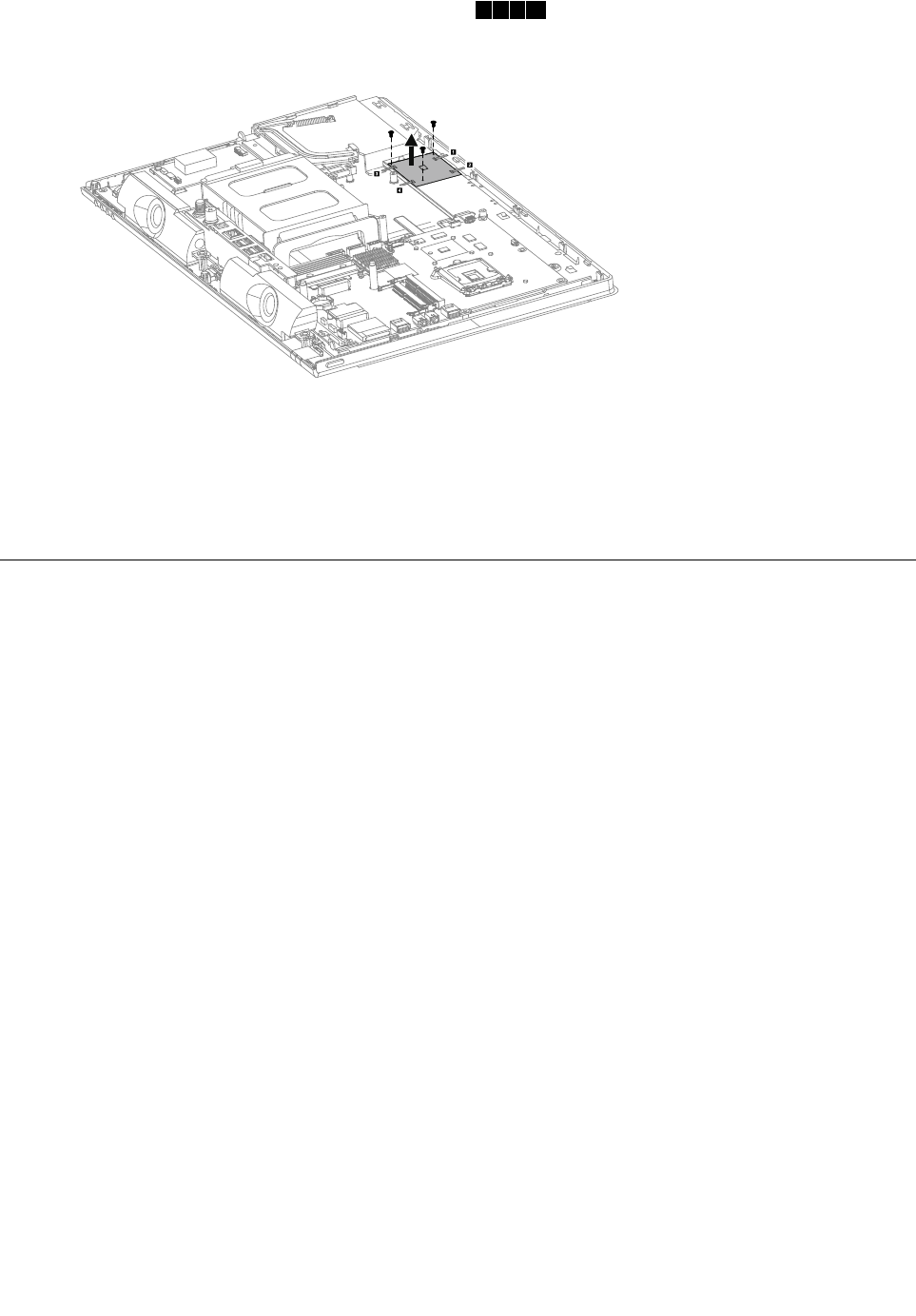
Step10.DisconnecttheantennacablefromtheTV-Tunercard.
Step11.RemovethescrewthatsecurestheTV-Tunercardtothemotherboard.
Step12.PulltheTV-Tunercardupwardtoremoveitfromthecardportonthemotherboard.
Step13.ToinstallthenewTV-Tunercard:
a.InsertthenotchedendoftheTV-Tunercardintothecardportonthemotherboard.
b.SecurenewtheTV-Tunercardtothemotherboardwiththescrew.
c.ConnecttheantennacabletothenewTV-Tunercard.
Step14.ReattachtheEMIcover,middlecover,opticaldrive,standholder,footcoverandstandbase.
ReplacingtheWLANcard
Note:Turnoffthecomputerandwait3to5minutestoletitcooldownbeforeremovingthecover.
Note:Itmaybehelpfultoplacethecomputerface-downonasoftflatsurfaceforthisprocedure.Lenovo
recommendsthatyouuseablanket,towel,orothersoftclothtoprotectthecomputerscreenfromscratches
orotherdamage.
ToreplacetheWLANcard:
Step1.Removeanymedia(disks,CDs,DVDs,ormemorycards)fromthedrives,shutdowntheoperating
system,andturnoffthecomputerandallattacheddevices.
Step2.Unplugallpowercordsfromelectricaloutlets.
Step3.Disconnectallcablesattachedtothecomputer.Thisincludespowercords,input/output(I/O)
cables,andanyothercablesthatareconnectedtothecomputer.Referto“Leftandrightview”
and“Rearview”forhelpwithlocatingthevariousconnectors.
Step4.Removethestandbase.Referto“Removingthestandbase” .
Step5.Removethefootcover.Referto“Removingthefootcover” .
Step6.Removetheopticaldrive.Referto“Replacingtheopticaldrive” .
Step7.Removethestandholder.Referto“Removingthestandholder” .
Step8.Removethemiddlecover.Referto“Removingthemiddlecover” .
Step9.RemovetheEMIcover.Referto“RemovingtheEMIcover” .
Chapter8.Replacinghardware43
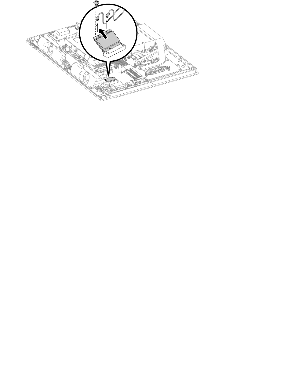
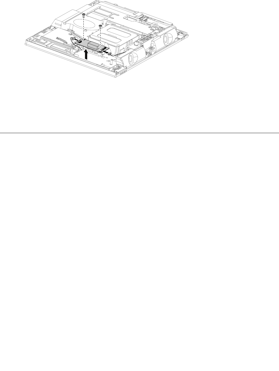
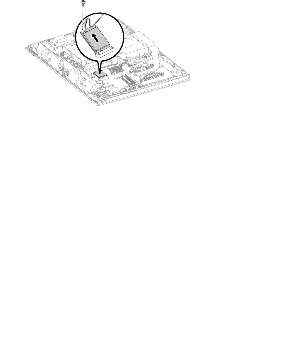
Step10.DisconnecttheantennacablesfromtheWLANcard.
Step11.RemovethescrewthatsecurestheWLANcardtothemotherboard.
Step12.LiftuptheWLANcardtoremoveitfromthesocket.
Step13.ToinstallthenewWLANcard:
a.InsertthenotchedendoftheWLANcardintothecardportonthemotherboard.
b.SecurenewtheWLANcardtothemotherboardwiththescrew.
c.ConnecttheantennacablestothenewWLANcard.
Step14.ReattachtheEMIcover,middlecover,opticaldrive,standholder,footcoverandstandbase.
Replacingthespeakersystem
Note:Turnoffthecomputerandwait3to5minutestoletitcooldownbeforeremovingthecover.
Note:Itmaybehelpfultoplacethecomputerface-downonasoftflatsurfaceforthisprocedure.Lenovo
recommendsthatyouuseablanket,towel,orothersoftclothtoprotectthecomputerscreenfromscratches
orotherdamage.
Toreplacethespeakersystem:
Step1.Removeanymedia(disks,CDs,DVDs,ormemorycards)fromthedrives,shutdowntheoperating
system,andturnoffthecomputerandallattacheddevices.
Step2.Unplugallpowercordsfromelectricaloutlets.
Step3.Disconnectallcablesattachedtothecomputer.Thisincludespowercords,input/output(I/O)
cables,andanyothercablesthatareconnectedtothecomputer.Referto“Leftandrightview”
and“Rearview”forhelpwithlocatingthevariousconnectors.
Step4.Removethestandbase.Referto“Removingthestandbase” .
Step5.Removethefootcover.Referto“Removingthefootcover” .
Step6.Removetheopticaldrive.Referto“Replacingtheopticaldrive” .
Step7.Removethestandholder.Referto“Removingthestandholder” .
Step8.Removethemiddlecover.Referto“Removingthemiddlecover” .
Step9.RemovetheEMIcover.Referto“RemovingtheEMIcover” .
44LenovoC340/440SeriesHardwareMaintenanceManual
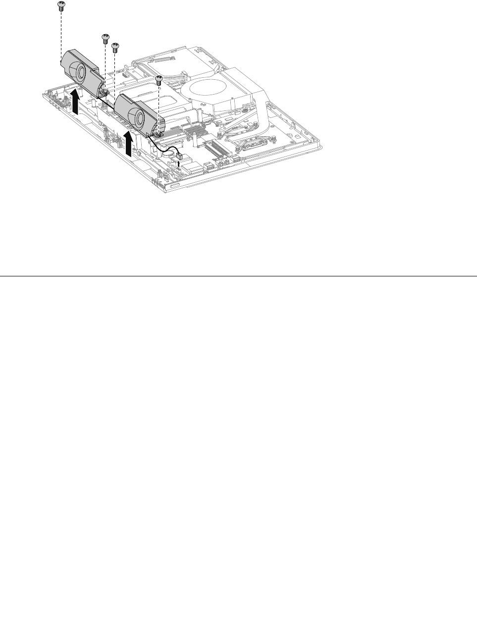
Step10.Disconnectthespeakercablesfromtheconnectoronthemotherboard.
Step11.Removethefourscrewsthatsecurethespeakersystemtothechassis,thenliftupthespeaker
systemtoremoveit.
Step12.Toinstallthenewspeakersystem:
a.Placethenewspeakersystemintoposition,thensecureitwithfourscrews.
b.Connectthenewspeakercablestotheconnectoronthemotherboard.
Step13.ReattachtheEMIcover,middlecover,opticaldrive,standholder,footcoverandstandbase.
Replacingthesystemfan
Note:Turnoffthecomputerandwait3to5minutestoletitcooldownbeforeremovingthecover.
Note:Itmaybehelpfultoplacethecomputerface-downonasoftflatsurfaceforthisprocedure.Lenovo
recommendsthatyouuseablanket,towel,orothersoftclothtoprotectthecomputerscreenfromscratches
orotherdamage.
Toreplacethesystemfan
Step1.Removeanymedia(disks,CDs,DVDs,ormemorycards)fromthedrives,shutdowntheoperating
system,andturnoffthecomputerandallattacheddevices.
Step2.Unplugallpowercordsfromelectricaloutlets.
Step3.Disconnectallcablesattachedtothecomputer.Thisincludespowercords,input/output(I/O)
cables,andanyothercablesthatareconnectedtothecomputer.Referto“Leftandrightview”
and“Rearview”forhelpwithlocatingthevariousconnectors.
Step4.Removethestandbase.Referto“Removingthestandbase” .
Step5.Removethefootcover.Referto“Removingthefootcover” .
Step6.Removetheopticaldrive.Referto“Replacingtheopticaldrive” .
Step7.Removethestandholder.Referto“Removingthestandholder” .
Step8.Removethemiddlecover.Referto“Removingthemiddlecover” .
Step9.RemovetheEMIcover.Referto“RemovingtheEMIcover” .
Step10.Removethesealingtapebetweenthesystemfanandheat-sink.
Chapter8.Replacinghardware45
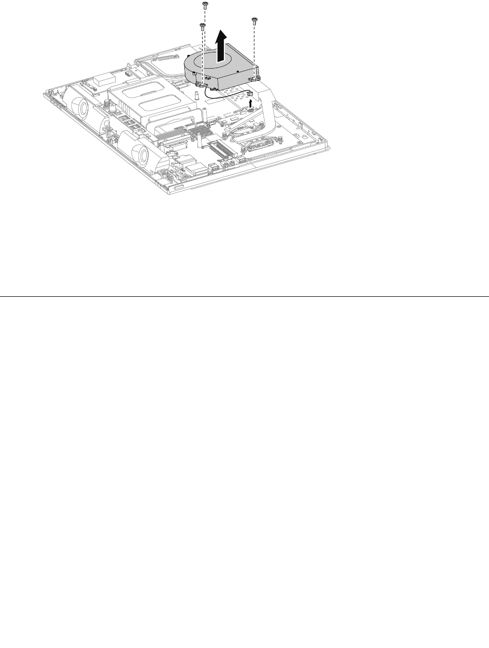
Step11.Removethethreescrewsthatsecurethesystemfantothechassis.
Step12.Disconnectthepowercablefromthemotherboard.
Step13.Liftupthesystemfantoremoveit.
Step14.Toinstallthenewsystemfan:
a.Placethenewsystemfanintoposition,andthensecureittothechassiswiththethreescrews.
b.Connectthesystemfanpowercabletotheconnectoronthemotherboard.
c.Usethesealingtapetosealthegapin-betweenthesystemfanandheat-sink.
Step15.ReattachtheEMIcover,middlecover,opticaldrive,standholder,footcoverandstandbase.
Replacingtheheat-sink
Note:Turnoffthecomputerandwait3to5minutestoletitcooldownbeforeremovingthecover.
Note:Itmaybehelpfultoplacethecomputerface-downonasoftflatsurfaceforthisprocedure.Lenovo
recommendsthatyouuseablanket,towel,orothersoftclothtoprotectthecomputerscreenfromscratches
orotherdamage.
Toreplacetheheat-sink:
Step1.Removeanymedia(disks,CDs,DVDs,ormemorycards)fromthedrives,shutdowntheoperating
system,andturnoffthecomputerandallattacheddevices.
Step2.Unplugallpowercordsfromelectricaloutlets.
Step3.Disconnectallcablesattachedtothecomputer.Thisincludespowercords,input/output(I/O)
cables,andanyothercablesthatareconnectedtothecomputer.Referto“Leftandrightview”
and“Rearview”forhelpwithlocatingthevariousconnectors.
Step4.Removethestandbase.Referto“Removingthestandbase” .
Step5.Removethefootcover.Referto“Removingthefootcover” .
Step6.Removetheopticaldrive.Referto“Replacingtheopticaldrive” .
Step7.Removethestandholder.Referto“Removingthestandholder” .
Step8.Removethemiddlecover.Referto“Removingthemiddlecover” .
Step9.RemovetheEMIcover.Referto“RemovingtheEMIcover” .
Step10.Removethesealingtapebetweenthesystemfanandheat-sink.
46LenovoC340/440SeriesHardwareMaintenanceManual
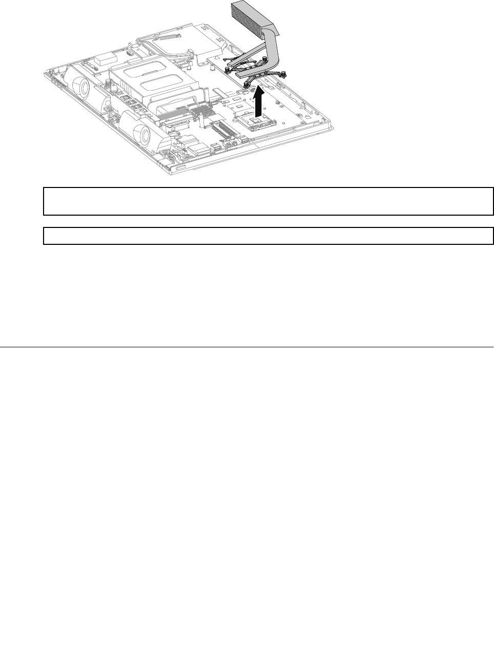
Step11.Removetheeightscrewsthatsecuretheheat-sinktothemotherboardandchassis.
Step12.Removetheheat-sinkbyliftingitup.
Attention:Placetheheat-sinkupsidedownonaflatsurfacetopreventthermalgreasefromcontaminating
othercomponents.
Attention:UseanalcoholpadtowipethethermalgreaseofftheCPU.
Step13.Toinstallthenewheat-sink:
a.Lineupthenewheat-sinkwithmountingholesonthemotherboard,thenplaceitintoposition.
b.Followthenumbersprintedonthenewheat-sinktosecureitinorderusingtheeightscrews.
c.Usethesealingtapetosealthegapin-betweenthesystemfanandheat-sink.
Step14.ReattachtheEMIcover,middlecover,opticaldrive,standholder,footcoverandstandbase.
Replacingthecamera
Note:Turnoffthecomputerandwait3to5minutestoletitcooldownbeforeremovingthecover.
Note:Itmaybehelpfultoplacethecomputerface-downonasoftflatsurfaceforthisprocedure.Lenovo
recommendsthatyouuseablanket,towel,orothersoftclothtoprotectthecomputerscreenfromscratches
orotherdamage.
Toreplacethecamera:
Step1.Removeanymedia(disks,CDs,DVDs,ormemorycards)fromthedrives,shutdowntheoperating
system,andturnoffthecomputerandallattacheddevices.
Step2.Unplugallpowercordsfromelectricaloutlets.
Step3.Disconnectallcablesattachedtothecomputer.Thisincludespowercords,input/output(I/O)
cables,andanyothercablesthatareconnectedtothecomputer.Referto“Leftandrightview”
and“Rearview”forhelpwithlocatingthevariousconnectors.
Step4.Removethestandbase.Referto“Removingthestandbase” .
Step5.Removethefootcover.Referto“Removingthefootcover” .
Step6.Removetheopticaldrive.Referto“Replacingtheopticaldrive” .
Step7.Removethestandholder.Referto“Removingthestandholder” .
Step8.Removethemiddlecover.Referto“Removingthemiddlecover” .
Chapter8.Replacinghardware47
Step9.RemovetheEMIcover.Referto“RemovingtheEMIcover” .
Step10.Removethetwoscrewsthatsecurecameratothefrontbezel.
Step11.Liftupthecameraanddisconnectthedatacablefromthecamera.
Step12.Removethetwoscrewsthatsecurethecameratothebracket,thenputasidethebracket.
Step13.Toinstallthenewcamera:
a.Lineupthenewcamerawiththebracket,thensecurethecameratothebracketwiththe
twoscrews.
b.Connectthedatacabletothenewcamera.
c.Lineuptheholesinthenewcamerawiththemountingholesonthefrontbezelandsecureit
withthetwoscrews.
Step14.ReattachtheEMIcover,middlecover,opticaldrive,standholder,footcoverandstandbase.
ReplacingtheCPU
Note:Turnoffthecomputerandwait3to5minutestoletitcooldownbeforeremovingthecover.
Note:Itmaybehelpfultoplacethecomputerface-downonasoftflatsurfaceforthisprocedure.Lenovo
recommendsthatyouuseablanket,towel,orothersoftclothtoprotectthecomputerscreenfromscratches
orotherdamage.
ToreplacetheCPU
Step1.Removeanymedia(disks,CDs,DVDs,ormemorycards)fromthedrives,shutdowntheoperating
system,andturnoffthecomputerandallattacheddevices.
Step2.Unplugallpowercordsfromelectricaloutlets.
Step3.Disconnectallcablesattachedtothecomputer.Thisincludespowercords,input/output(I/O)
cables,andanyothercablesthatareconnectedtothecomputer.Referto“Leftandrightview”
and“Rearview”forhelpwithlocatingthevariousconnectors.
Step4.Removethestandbase.Referto“Removingthestandbase” .
Step5.Removethefootcover.Referto“Removingthefootcover” .
48LenovoC340/440SeriesHardwareMaintenanceManual
Step6.Removetheopticaldrive.Referto“Replacingtheopticaldrive” .
Step7.Removethestandholder.Referto“Removingthestandholder” .
Step8.Removethemiddlecover.Referto“Removingthemiddlecover” .
Step9.RemovetheEMIcover.Referto“RemovingtheEMIcover” .
Step10.Removetheheat-sink.Referto“Replacingtheheatsink” .
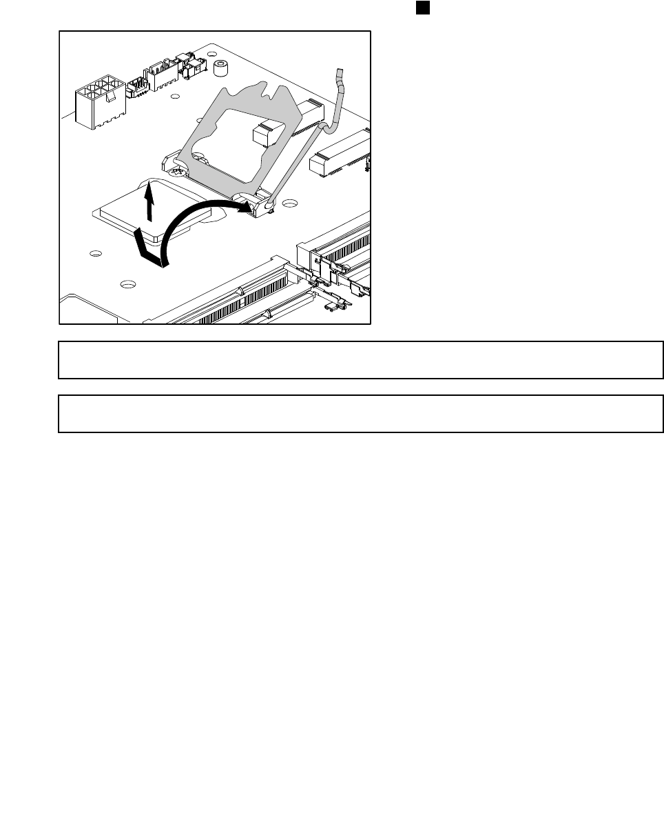
Step11.Liftthesmallhandleandopentheretainer.
Step12.Liftthemicroprocessorstraightupandoutofthesocket.3
Attention:Donottouchthegoldcontactsonthebottomofthemicroprocessor.Whenhandlingthe
microprocessor,touchonlythesides.
Note:Donotdropanythingontothemicroprocessorsocketwhileitisexposed.Thesocketpinsmust
bekeptascleanaspossible.
Chapter8.Replacinghardware49
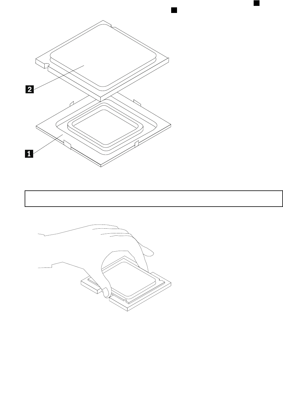
Step13.Holdingthesidesofthemicroprocessorwithyourfingers,removetheprotectivecover1that
protectsthegoldcontactsonthenewmicroprocessor.2
Step14.Holdingthesidesofthemicroprocessorwithyourfingers,positionthemicroprocessorsothatthe
notchesonthemicroprocessorarealignedwiththetabsinthemicroprocessorsocket.
Important:Toavoiddamagingthemicroprocessorcontacts,keepthemicroprocessorcompletelylevel
whileinstallingitintothesocket.
Step15.Lowerthemicroprocessorstraightdownintoitssocketonthemotherboard.
Step16.Tosecurethemicroprocessorinthesocket,closethemicroprocessorretainerandlockitinto
positionwiththesmallhandle.
Step17.Useathermalgreasesyringetoplace5dropsofgreaseonthetopofthemicroprocessor.Each
dropofgreaseshouldbe0.03ml(3tickmarksonthegreasesyringe).
Step18.Reattachtheheat-sink,EMIcover,middlecover,opticaldrive,standholder,footcoverandstand
base.
50LenovoC340/440SeriesHardwareMaintenanceManual
Replacingthefrontcontrolboard
Note:Turnoffthecomputerandwait3to5minutestoletitcooldownbeforeremovingthecover.
Note:Itmaybehelpfultoplacethecomputerface-downonasoftflatsurfaceforthisprocedure.Lenovo
recommendsthatyouuseablanket,towel,orothersoftclothtoprotectthecomputerscreenfromscratches
orotherdamage.
Toreplacethefrontcontrolboard:
Step1.Removeanymedia(disks,CDs,DVDs,ormemorycards)fromthedrives,shutdowntheoperating
system,andturnoffthecomputerandallattacheddevices.
Step2.Unplugallpowercordsfromelectricaloutlets.
Step3.Disconnectallcablesattachedtothecomputer.Thisincludespowercords,input/output(I/O)
cables,andanyothercablesthatareconnectedtothecomputer.Referto“Leftandrightview”
and“Rearview”forhelpwithlocatingthevariousconnectors.
Step4.Removethestandbase.Referto“Removingthestandbase” .
Step5.Removethefootcover.Referto“Removingthefootcover” .
Step6.Removetheopticaldrive.Referto“Replacingtheopticaldrive” .
Step7.Removethestandholder.Referto“Removingthestandholder” .
Step8.Removethemiddlecover.Referto“Removingthemiddlecover” .
Step9.RemovetheEMIcover.Referto“RemovingtheEMIcover” .
Step10.Removethespeakersystem.Referto“Replacingthespeakersystem” .
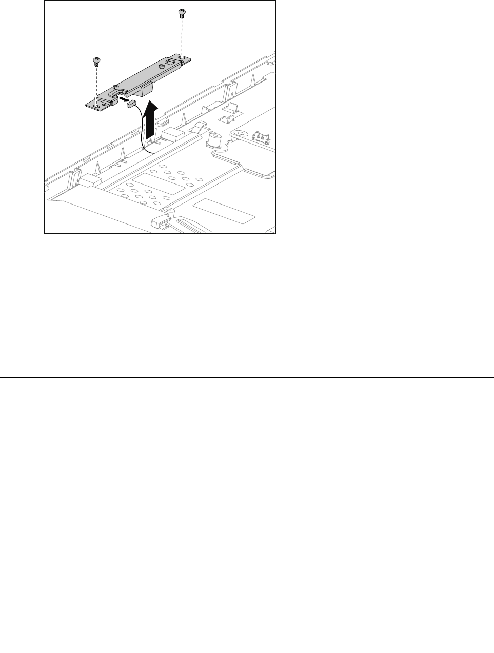
Step11.Removethetwoscrewsthatsecurethefrontcontrolboardtothefrontbezel,
Step12.Disconnectthedatacablefromthefrontcontrolboard,thenliftupthefrontcontrolboard.
Step13.Toinstallthenewfrontcontrolboard:
a.Connectthedatacabletothenewfrontcontrolboard.
b.Lineupthenewfrontcontrolboardwiththefrontbezel,thenplaceitintoposition.
c.Securethefrontcontrolboardwiththetwoscrews.
Chapter8.Replacinghardware51
Step14.Reattachthespeakersystem,EMIcover,middlecover,opticaldrive,standholder,footcover
andstandbase.
Replacingthepowerswitchboard
Note:Turnoffthecomputerandwait3to5minutestoletitcooldownbeforeremovingthecover.
Note:Itmaybehelpfultoplacethecomputerface-downonasoftflatsurfaceforthisprocedure.Lenovo
recommendsthatyouuseablanket,towel,orothersoftclothtoprotectthecomputerscreenfromscratches
orotherdamage.
Toreplacethepowerswitchboard
Step1.Removeanymedia(disks,CDs,DVDs,ormemorycards)fromthedrives,shutdowntheoperating
system,andturnoffthecomputerandallattacheddevices.
Step2.Unplugallpowercordsfromelectricaloutlets.
Step3.Disconnectallcablesattachedtothecomputer.Thisincludespowercords,input/output(I/O)
cables,andanyothercablesthatareconnectedtothecomputer.Referto“Leftandrightview”
and“Rearview”forhelpwithlocatingthevariousconnectors.
Step4.Removethestandbase.Referto“Removingthestandbase” .
Step5.Removethefootcover.Referto“Removingthefootcover” .
Step6.Removetheopticaldrive.Referto“Replacingtheopticaldrive” .
Step7.Removethestandholder.Referto“Removingthestandholder” .
Step8.Removethemiddlecover.Referto“Removingthemiddlecover” .
Step9.RemovetheEMIcover.Referto“RemovingtheEMIcover” .
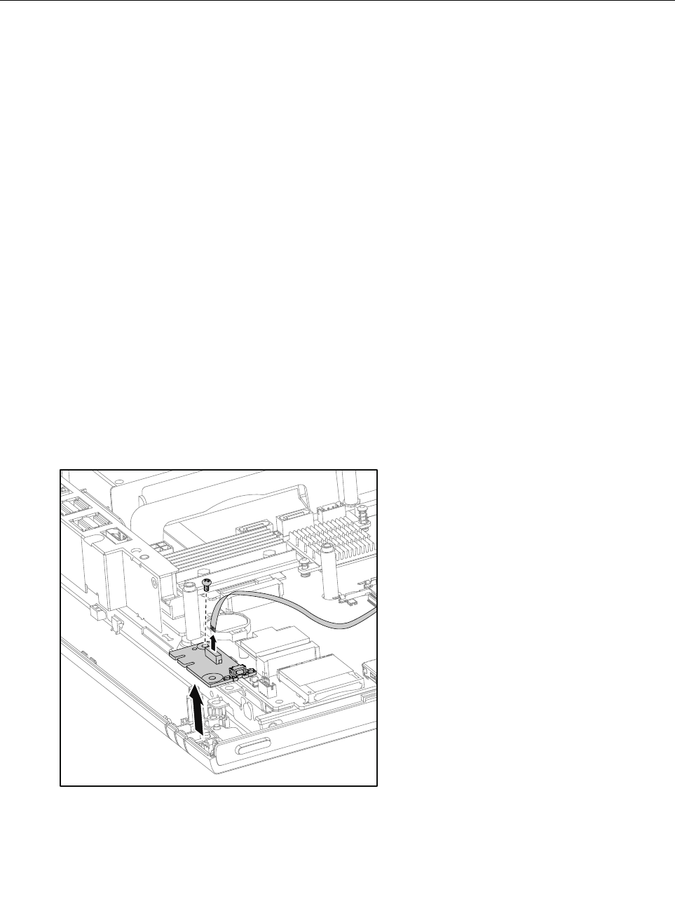
Step10.Removethescrewthatsecurethepowerswitchboardtothefrontbezel.
Step11.Disconnectthedatacablefromthepowerswitchboard,thenliftupthepowerswitchboard.
Step12.Toinstallthepowerswitchboard:
a.Lineuptheholeonthenewpowerswitchboardwiththemountingholeonthefrontbezel,
thenplaceitintoposition.
b.Securethepowerswitchboardwiththescrew.
52LenovoC340/440SeriesHardwareMaintenanceManual

c.Connectthepowercabletothenewpowerswitchboard.
Step13.ReattachtheEMIcover,middlecover,opticaldrive,standholder,footcoverandstandbase.
Replacingthemotherboard
Note:Turnoffthecomputerandwait3to5minutestoletitcooldownbeforeremovingthecover.
Note:Itmaybehelpfultoplacethecomputerface-downonasoftflatsurfaceforthisprocedure.Lenovo
recommendsthatyouuseablanket,towel,orothersoftclothtoprotectthecomputerscreenfromscratches
orotherdamage.
Toreplacethemotherboard:
Step1.Removeanymedia(disks,CDs,DVDs,ormemorycards)fromthedrives,shutdowntheoperating
system,andturnoffthecomputerandallattacheddevices.
Step2.Unplugallpowercordsfromelectricaloutlets.
Step3.Disconnectallcablesattachedtothecomputer.Thisincludespowercords,input/output(I/O)
cables,andanyothercablesthatareconnectedtothecomputer.Referto“Leftandrightview”
and“Rearview”forhelpwithlocatingthevariousconnectors.
Step4.Removethestandbase.Referto“Removingthestandbase” .
Step5.Removethefootcover.Referto“Removingthefootcover” .
Step6.Removethememorymodules.Referto“Replacingamemorymodule” .
Step7.Removetheopticaldrive.Referto“Replacingtheopticaldrive” .
Step8.Removethestandholder.Referto“Removingthestandholder” .
Step9.Removethemiddlecover.Referto“Removingthemiddlecover” .
Step10.RemovetheEMIcover.Referto“RemovingtheEMIcover” .
Step11.RemovetherearI/Omodule.Referto“ReplacingtherearI/Omodule” .
Step12.Removetheheat-sink.Referto“Replacingtheheat-sink” .
Step13.RemovetheCPU.Referto“ReplacingtheCPU” .
Step14.RemovetheTV- Tunercard.Referto“ReplacingtheTVtunercard” .
Step15.RemovetheWLANcard.Referto“ReplacingtheWLANcard” .
Step16.Unplugthefollowingcablesfromconnectorsonthemotherboard:
•Powerswitchboardcable
•Speakersystemcable
•Frontcontrolboardcable
•Convertercable
•Cameracable
•Systemfanpowercable
•Harddiskdrivepowercable
•HarddiskdriveSATAcable(Black)
•OpticaldriveSATAcable(Red)
•Opticaldiskdrivepowercable
•LVDScable
Chapter8.Replacinghardware53
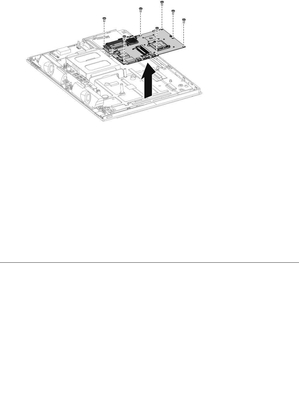
Step17.Removethesevenscrewsthatsecurethemotherboardtothechassisandliftthemotherboard
uptoremoveit.
Step18.Toinstallthenewmotherboard:
a.Lineuptheholesonthenewmotherboardwiththemountingholeschassisandplacethenew
motherboardintoposition.
b.Usethescrewstosecurethenewmotherboardtothechassis.
Step19.Installthefollowingpartstothenewmotherboard:
•WLANcard
•TV-Tunercard
•CPU
•Heat-sink
•RearI/Omodule
•Memorymodule
Step20.Connectallthecablestothenewmotherboard.
Step21.ReattachtheEMIcover,middlecover,opticaldrive,standholder,footcoverandstandbase.
ReplacingtheLEDpanel
Note:Turnoffthecomputerandwait3to5minutestoletitcooldownbeforeremovingthecover.
Note:Itmaybehelpfultoplacethecomputerface-downonasoftflatsurfaceforthisprocedure.Lenovo
recommendsthatyouuseablanket,towel,orothersoftclothtoprotectthecomputerscreenfromscratches
orotherdamage.
ToreplacetheLEDpanel:
Step1.Removeanymedia(disks,CDs,DVDs,ormemorycards)fromthedrives,shutdowntheoperating
system,andturnoffthecomputerandallattacheddevices.
Step2.Unplugallpowercordsfromelectricaloutlets.
Step3.Disconnectallcablesattachedtothecomputer.Thisincludespowercords,input/output(I/O)
cables,andanyothercablesthatareconnectedtothecomputer.Referto“Leftandrightview”
and“Rearview”forhelpwithlocatingthevariousconnectors.
54LenovoC340/440SeriesHardwareMaintenanceManual
Step4.Removethestandbase.Referto“Removingthestandbase” .
Step5.Removethefootcover.Referto“Removingthefootcover” .
Step6.Removetheopticaldrive.Referto“Replacingtheopticaldrive” .
Step7.Removethestandholder.Referto“Removingthestandholder” .
Step8.Removethemiddlecover.Referto“Removingthemiddlecover” .
Step9.RemovetheEMIcover.Referto“RemovingtheEMIcover” .
Step10.Removethespeakersystem.Referto“Replacingthespeakersystem” .
Step11.Removethesystemfan.Referto“Replacingthesystemfan” .
Step12.Disconnectthepowerswitchboardcableandcameracablefromconnectorsonthemotherboard:
Step13.Disconnectthecablefromtheconnectoronthefrontcontrolboard.
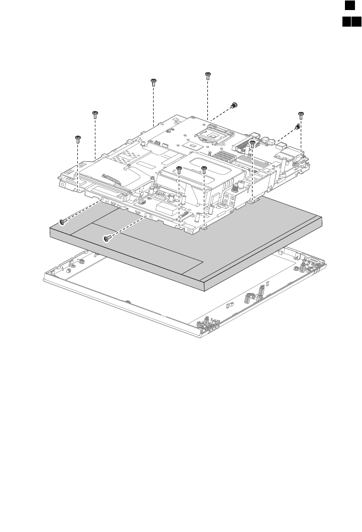
Step14.Removetheninescrewsthatsecurethechassistothefrontbezel.1
Step15.RemovethefourscrewsthatsecuretheLEDpaneltothechassis.23
Step16.DisconnecttheconvertercableandLVDScablefromtheconnectorsontheLEDpanel.
Step17.LiftupthechassistoseparatetheLEDpanelfromthechassis.
Step18.ToinstallthenewtheLEDpanel:
a.LineupthechassiswithnewLEDpanel,andthensecurethenewLEDpaneltothechassis
withthefourscrews.
b.ConnecttheconvertercableandLVDScabletothenewLEDpanel.
c.Lineupthechassiswiththefrontbezel,andthenplacethechassisintoposition.
d.Securethechassistothefrontbezelwiththeninescrews.
e.Reconnectallthecameraandpowerswitchboardcablestotheconnectorsonthe
motherboard.
f.Reconnectthefrontcontrolboardcablebacktotheconnectoronfrontcontrolboard.
Chapter8.Replacinghardware55
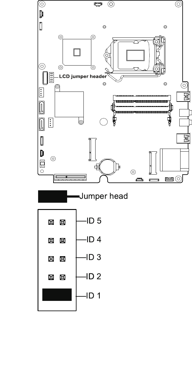
g.Aconverterjumpersettingisrequiredafterreplacingtheoldpanelwithanewpanel.Follow
thebelowdiagramtoinsertthejumperheadstothepinsproperlydependingonthepanel
brands.FollowthebelowdrawingtolocatetheLCDjumperheaderonthemotherboard:
LCD ju mp e r h e ad e r
ID 5
ID 4
ID 3
ID 2
ID
ID 1
Jumper head
56LenovoC340/440SeriesHardwareMaintenanceManual
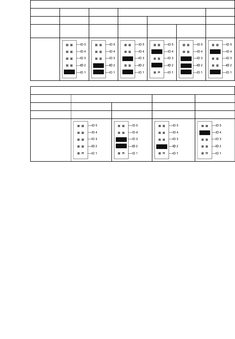
C34020inLCDJumperSetting
PanelAUOLGSECCMI
11S1820041918200171182000791820152718200172
DescriptionM200RW01
V6
LM200WD3
-TLF1
LTM200KT10-
M01,M02
LTM200KT12
-M01
LTM200KT12
-M02
M200FGE
-L20
Heads
Position
ID 5
ID 4
ID 3
ID 2
ID
ID 1
ID 5
ID 4
ID 3
ID 2
ID
ID 1
ID 5
ID 4
ID 3
ID 2
ID
ID 1
ID 5
ID 4
ID 3
ID 2
ID
ID 1
ID 5
ID 4
ID 3
ID 2
ID
ID 1
ID 5
ID 4
ID 3
ID 2
ID
ID 1
C44021.5inLCDJumperSetting
PanelAUOLGCMI
11s18200169182008351820016618200168
DescriptionM215HW03V1M215HTN01.1LM215WF4-TLG1M215HGE-L21
HeadsPosition
ID 5
ID 4
ID 3
ID 2
ID
ID 1
ID 5
ID 4
ID 3
ID 2
ID
ID 1
ID 5
ID 4
ID 3
ID 2
ID
ID 1
ID 5
ID 4
ID 3
ID 2
ID
ID 1
Step19.Reattachthesystemfan,speakersystem,EMIcover,middlecover,standholder,opticaldrive,
footcoverandstandbase.
Chapter8.Replacinghardware57

58LenovoC340/440SeriesHardwareMaintenanceManual
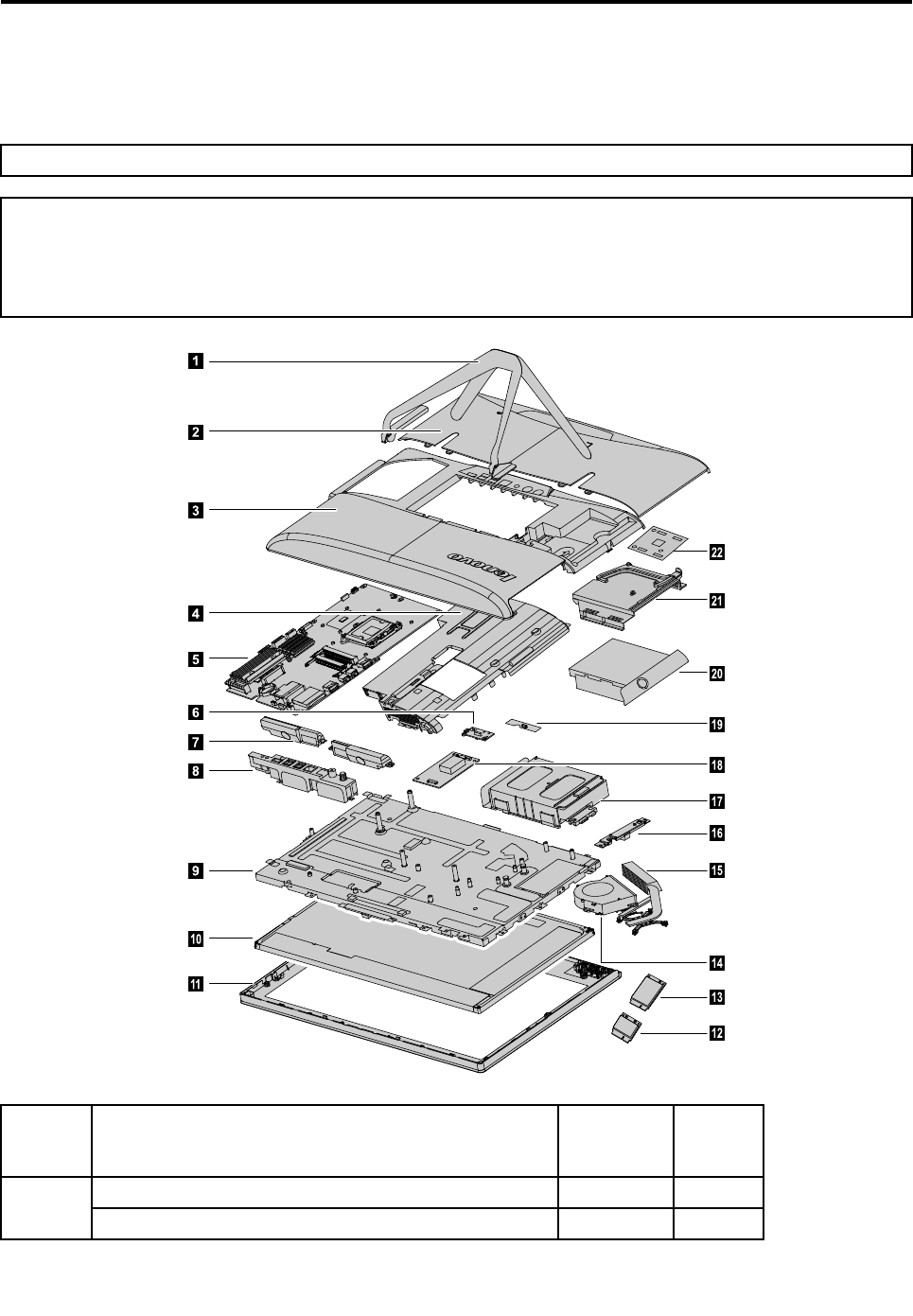
Chapter9.FRUlists
Thischapterliststheinformationonthefieldreplaceableunits(FRUs).
Attention:BesuretoreadandunderstandallthesafetyinformationbeforereplacinganyFRUs.
Notes:FRUsthathavea1or2intheCRUcolumnareCustomerReplaceableUnits(CRUs).
•1–identifiespartsthatarefairlysimpletoreplace,requiringfewornotools.
•2–identifiespartsthatareslightlymoredifficulttoreplace.
•N-identifiespartsthatarenottobereplacedbythecustomer.
1
2
3
6
7
8
9
10
11
14
18
16
17
15
19
20
21
22
4
5
12
13
Item#Description
Service
Part
Number
CRUID
Computerstand
1
????
©CopyrightLenovo201359

Footcover 2
????
Middlecover 3
????
EMIcover
4
????
Motherboard
C340/C440512M_GPUW/OUSB3.0MB90000624N
C340/C4402G_GPUW/OUSB3.0MB90000626N
C340/C440WIN8UMAW/USB3.0MB90000841N
C340/C440WIN8_PROUMAW/USB3.0MB90000842N
C340/C440WIN81G_GPUW/USB3.0MB90000844N
C340/C440WIN8_PRO1G_GPUW/USB3.0MB90000845N
C340/C440WIN8512M_GPUW/USB3.0MB90000847N
C340/C440WIN8_PRO512M_GPUW/USB3.0MB90000848N
C340/C440WIN82G_GPUW/USB3.0MB90000850N
C340/C440WIN8_PRO2G_GPUW/USB3.0MB90000851N
C340/C440WIN8UMAW/OUSB3.0MB90000853N
C340/C440WIN8_PROUMAW/OUSB3.0MB90000854N
C340/C440WIN81G_GPUW/OUSB3.0MB90000856N
C340/C440WIN8_PRO1G_GPUW/OUSB3.0MB90000857N
C340/C440WIN8512M_GPUW/OUSB3.0MB90000859N
C340/C440WIN8_PRO512M_GPUW/OUSB3.0MB90000860N
C340/C440WIN82G_GPUW/OUSB3.0MB90000862N
5
C340/C440WIN8PRO2G_GPUW/OUSB3.0MB90000863N
Powerswitchboard 6
??N
Speakers
C340/C440SpeakerSUMSANGW/HOUSING(*2)90201451N
7
C340/C440SpeakerKuaidaW/HOUSING(*2)90201452N
RearI/Omodule
C440RearIOBoardW/GPUW/HDMIW/OTV90001422N
C440RearIOBoardW/GPUW/OHDMIW/TV90001423N
C440RearIOBoardW/GPUW/OHDMIW/OTV90001424N
C440RearIOBoardW/OGPUW/HDMIW/OTV90001425N
C340RearIOBoardW/GPUW/HDMIW/OTV90001413N
C340RearIOBoardW/GPUW/OHDMIW/TV90001414N
C340RearIOBoardW/GPUW/OHDMIW/OTV90001415N
8
C340RearIOBoardW/OGPUW/HDMIW/OTV90001416N
60LenovoC340/440SeriesHardwareMaintenanceManual

Chassis
9
??N
LEDpanel
LM200WD3-TLF118200171N
M200RW01V618200419N
LTM200KT10-M01,M0218200079N
LM215WF4-TLG118200166N
AUOM215HTN01.118200835N
10
M215HW03V118200169N
Frontbezel
C340FrontBezel(Black)90201405N
C340FrontBezel(White)90201406N
C440FrontBezel(Black)90201458N
11
C440FrontBezel(White)90201459N
Wi-Ficard
CBTAR948511nSBHMCWiFicard(wowl)11200354N
LTNRTL8188CE11nSBHMCWiFicard(wowl)11200352N
12
CBTBCM9431311nHMCWiFicard20002505N
TV- Tunercard
AvermediaH339BBDVB-TMiniTVCard11200290N
13
AvermediaH339BAATSCMiniTVCard11200291N
Systemfan
C340/C440AVCFan90201347N
14
C340/C440DeltaFan90201349N
Heat-sink
C340AVCDISHeatSink90201656N
C440CoolermasterDISHeatSink90201657N
C340AVCUMAHeatSink90201658N
C440CoolermasterUMAHeatSink90201659N
C340AVCUMAHeatSink90201348N
C340CoolermasterUMAHeatSink90201350N
C340AVCDISHeatSink90201351N
15
C340CoolermasterDISHeatSink90201352N
Camera
BisonM720PVCOV9712CAM20200085N
16
CCYM720PVCOV9712CAM20200086N
Chapter9.FRUlists61

Harddiskdriveandbay
WDXL500AWD3200AAKX-08ERMA0320GHDD-LH162002461
SGTPharaoh4KST320DM000320GHDD-LH162001771
WDXL500SM6GWD5000AAKX-083CA1500GHDD-LH162000311
WDXL500AWD5000AAKX-08ERMA0500GHDD-LH162002471
SGTPharaoh4KST500DM002500GHDD-LH162001781
SGTGrenadaST1000DM0031TBHDD-LH162001821
WDXL1000SWD10EZEX-08RKKA01TBHDD-LH162002921
17
SGTGrenadaBPST1000DM0031TBHDD-LH162002931
Converterboard
C340/C440AUOConverter90000633N
C340/C440LGConverter90000634N
18
C340SAMSUNGConverter90000632N
Frontfunctionboard 19
C340/C440FunctionBoard90000631N
Opticaldrive
PLDSDS-8A8SH252014871
SN-208AB252011081
HLDSGT50N252016351
HLDSGT80NSlimRambow/obezel-LH252090151
PLDSDS-8A9SHSlimRambow/obezel-LH252090161
20
TSSTSN-208DBSlimRambow/obezel-LH252090141
Opticaldrivebracket
21
????N
62LenovoC340/440SeriesHardwareMaintenanceManual
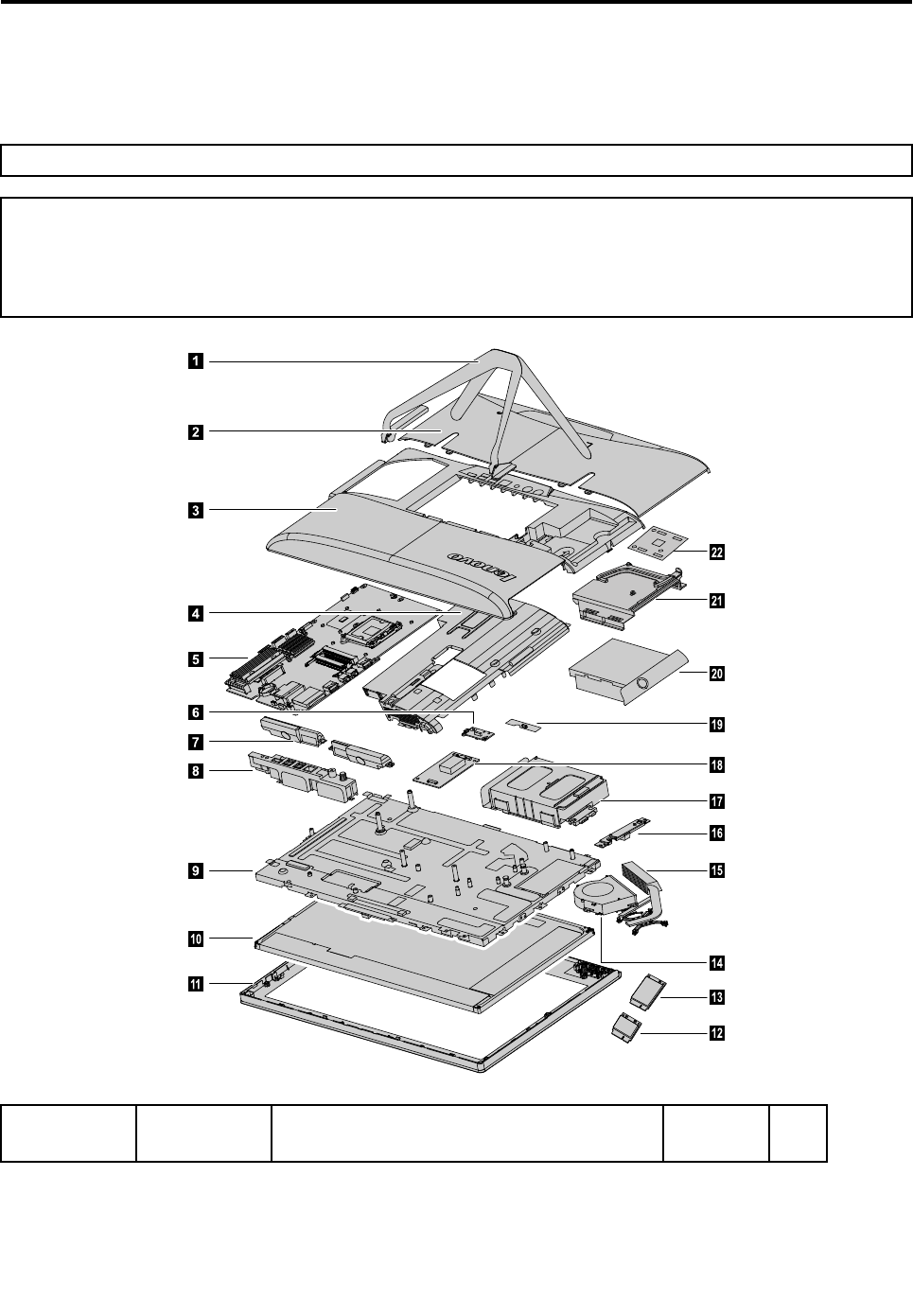
Chapter10.FRUlists-C440Touch
Thischapterliststheinformationonthefieldreplaceableunits(FRUs).
Attention:BesuretoreadandunderstandallthesafetyinformationbeforereplacinganyFRUs.
Notes:FRUsthathavea1or2intheCRUcolumnareCustomerReplaceableUnits(CRUs).
•1–identifiespartsthatarefairlysimpletoreplace,requiringfewornotools.
•2–identifiespartsthatareslightlymoredifficulttoreplace.
•N-identifiespartsthatarenottobereplacedbythecustomer.
1
2
3
6
7
8
9
10
11
14
18
16
17
15
19
20
21
22
4
5
12
13
PartitemNamePartDescription(English)FRUPNCRU
ID
©CopyrightLenovo201363

C440TOUCHNOKUMAW/USB3.0MB90002580N
C440TOUCHNOK2G_GPUW/USB3.0MB90002581N
C440TOUCHW8SUMAW/USB3.0MB90002582N
C440TOUCHW8S2G_GPUW/USB3.0MB90002583N
C440TOUCHW8PUMAW/USB3.0MB90002584N
C440TOUCHW8P2G_GPUW/USB3.0MB90002585N
C440TOUCHNOK1G_GPUW/USB3.0MB90002645N
C440TOUCHNOK512M_GPUW/USB3.0MB90002646N
C440TOUCHNOK2G_GPUW/USB2.0MB90002647N
C440TOUCHNOKUMAW/USB2.0MB90002648N
C440TOUCHNOK512M_GPUW/USB2.0MB90002649N
C440TOUCHNOK1G_GPUW/USB2.0MB90002650N
C440TOUCHW8S1G_GPUW/USB3.0MB90002651N
C440TOUCHW8S512M_GPUW/USB3.0MB90002652N
C440TOUCHW8S2G_GPUW/USB2.0MB90002653N
C440TOUCHW8SUMAW/USB2.0MB90002654N
C440TOUCHW8S512M_GPUW/USB2.0MB90002655N
C440TOUCHW8S1G_GPUW/USB2.0MB90002656N
C440TOUCHW8P1G_GPUW/USB3.0MB90002657N
C440TOUCHW8P512M_GPUW/USB3.0MB90002658N
C440TOUCHW8P2G_GPUW/USB2.0MB90002659N
C440TOUCHW8PUMAW/USB2.0MB90002660N
C440TOUCHW8P512M_GPUW/USB2.0MB90002661N
MainboardMainboard
C440TOUCHW8P1G_GPUW/USB2.0MB90002662N
C340AVCFan90201347N
SystemFanSystemFan
C340DeltaFan90201349N
C340AVCDISHeatSink90201656N
C440CoolermasterDISHeatSink90201657N
C340AVCUMAHeatSink90201658N
HeatsinkHeatsink
C440CoolermasterUMAHeatSink90201659N
C340SpeakerSUMSANGW/HOUSING(*2)90201451N
SpeakerSpeaker
C340SpeakerKuaidaW/HOUSING(*2)90201452N
WLANAntenaWLANAntenaC440TOUCHWlanAntena90202552N
C440TOUCHLCDMODULEFOR2DAUO(GY)90400117N
C440TOUCHLCDMODULEFOR2DLG(GY)90400118N
C440TOUCHLCDMODULEFOR2DAUO(BL)90400165N
LCDModuleLCDModule
C440TOUCHLCDMODULEFOR2DLG(BL)90400166N
64LenovoC340/440SeriesHardwareMaintenanceManual

C440RearIOBoardW/GPUW/HDMIW/OTV90001422N
C440RearIOBoardW/GPUW/OHDMIW/TV90001423N
C440RearIOBoardW/GPUW/OHDMIW/OTV90001424N
C440RearIOBoardW/OGPUW/HDMIW/OTV90001425N
C440RearIOBoardW/GPUW/HDMIW/TV90000641N
RearIOBoardRearIOBoard
C440RearIOBoardW/OGPUW/HDMIW/TV90000642N
C440ConverterForAUOPanel290002680N
Converter
Board
Converter
BoardC340LGConverter90000634N
C440TOUCHPowerLEDBoardW/IR90002586N
OtherBoardsOtherBoards
C440TOUCHFunctionkeyBoard90002587N
C340AUOConvertertoPanelCable90201433N
C340LGConvertertoPanelCable90201435N
Converter
BoardCable
Converter
BoardCable
C340Convertercable90201432N
LVDScableLVDScableC340LVDScable90201426N
TouchControl
BoardCable
TouchControl
BoardCable
C440TOUCHControlBoardtoMBCable90202557N
C440TOUCHBoardFFCTopRight90202558N
C440TOUCHBoardFFCTopLeft90202559N
FFCFFC
C440TOUCHBoardFFCBottom90202560N
C340ODDSATAcable90201428N
C340HDDSATAcable90201429N
C340Functionboardcable90201430N
C340Powerboardcable90201431N
C340TVtunerCableForFtype90201453N
C340TVtunerCableForIECtype90201454N
C340DCincable(120W)90201448N
OtherCableOtherCable
C440TOUCHSigleMicWecamCable90202553N
C340STAND(BOTTOM)902014241
C440TOUCHStand(Top)902025512
B540HDDBracket90200894N
C340DCINBRACKETD6.5MM90201444N
C340SETSHIELDINGFORMB90201450N
C340ODDLATCH90201449N
C440ODDCOVER90201482N
C440TOUCHFrontBezel(Black)90202533N
C440TOUCHFrontBezel(White)90202534N
C440TOUCHRearCoverW/TVW/HDMI(B)902025352
C440TOUCHRearCoverW/TVW/OHDMI(B)902025362
C440TOUCHRearCoverW/OTVW/HDMI(B)902025372
C440TOUCHRearCoverW/OTVW/OHDMI(B)902025382
MechanicalMechanical
Chapter10.FRUlists-C440Touch65

C440TOUCHRearCoverW/TVW/HDMI(W)902025392
C440TOUCHRearCoverW/TVW/OHDMI(W)902025402
C440TOUCHRearCoverW/OTVW/HDMI(W)902025412
C440TOUCHRearCoverW/OTVW/OHDMI(W)902025422
C440TOUCHSlideCoverW/TVW/HDMI(B)902025432
C440TOUCHSlideCoverW/TVW/OHDMI(B)902025442
C440TOUCHSlideCoverW/OTVW/HDMI(B)902025452
C440TOUCHSlideCoverW/OTVW/OHDMI(B)902025462
C440TOUCHSlideCoverW/TVW/HDMI(W)902025472
C440TOUCHSlideCoverW/TVW/OHDMI(W)902025482
C440TOUCHSlideCoverW/OTVW/HDMI(W)902025492
C440TOUCHSlideCoverW/OTVW/OHDMI(W)902025502
C440TOUCHODDBezel(Black)90202554N
C440TOUCHODDBezel(White)90202555N
C440TOUCHMiddleFrame90202556N
IPCG5302.4GHZ65WHDGRAPHICS1100089N
IPCG5402.5GHZ65WHDGRAPHICS1100088N
IICPG5502.6/1066/2/1155/65Q0CPU®1100539N
IG550T2.2/1066/2/115535Q0CPU®1100594N
IICPG540T2.1/1066/2/1155/35Q0CPU®1100538N
IG16102.6/1333/2/115555CPU1100689N
IG1610T2.3/1333/2/115535CPU1100691N
IG6302.7/1333/3/1155/65Q0CPU(R)1100104N
IG6402.8/3/1066/115565Q0CPU1100474N
IG6452.9/1066/3/115565Q0CPU1100578N
IG645T2.5/1066/2.5/115535Q0CPU®1100595N
IG20202.9/1333/3/115555CPU1100688N
IG2020T2.5/1333/3/115535CPU1100690N
IG20303.0/1333/3/115555CPU1100857N
IG2030T2.6/1333/3/115535CPU1100858N
II3-32403.4/1600/3/115555L1CPU®1100454N
II3-32203.3/1600/3/115555L1CPU®1100456N
II3-21303.4/1333/3/115565Q0CPU®1100102N
II3-3240T2.9/1600/3/115535L1CPU®1100485N
II3-3220T2.8/1600/3/115535L1CPU(R)1100484N
CPUCPU
II5-3330S2.7/1600/6/115565E1CPU1100394N
66LenovoC340/440SeriesHardwareMaintenanceManual

M471B5773DH0-CK01100226N
HMT325S6CFR8C-PB1100227N
M471B5773CHS-CK02GBD3-1600SMEMORY1100614N
Mic_SD9PF J2GBD3-1600SMEMORY1100646N
MT8KTF25664HZ-1G6M11100228N
Elp_RJ2108EDBG-GN-F2G
D3L-1600SMEMORY
1100750N
HMT425S6AFR6A-PB2GB
D3L-1600SMemory-HF
1100643N
2GB
Elp_RJ2108BDBG-GN-F2GBD3-1600S
MEMORY(RMT3150ED58E8W-1600)
1100425N
M471B5273DH0-CK01100230N
HMT351S6CFR8C-PB1100231N
MT16KTF51264HZ-1G6M11100232N
Mic_SD9PF J4GBD3-1600SMEMORY1100641N
M471B5273CH0-CK04GBD3-1600SMEMORY1100613N
HMT451S6AFR8A-PB4GB
D3L-1600SMemory-HF
1100638N
M471B5173BH0-YK04GD3L-1600SMEMORY1100856N
Elp_RJ4208EBBG-GN-F4GD3L-1600S
MEMORY(RMT3170EB68F9W-1600)
1100640N
4G
Elp_RJ2108BDBG-GN-F4GBD3-1600S
MEMORY(RMT3160ED58E9W-1600)
1100426N
M471B5773DH0-CK01100226N
HMT325S6CFR8C-PB1100227N
MT8KTF25664HZ-1G6M11100228N
M471B5773CHS-CK02GBD3-1600SMEMORY1100614N
Elp_RJ2108EDBG-GN-F2G
D3L-1600SMEMORY
1100750N
HMT425S6AFR6A-PB2GBD3L-1600S
Memory-HF
1100643N
Mic_SD9PF J2GBD3-1600SMEMORY1100646N
4GB(2*2G)
Elp_RJ2108BDBG-GN-F2GBD3-1600S
MEMORY(RMT3150ED58E8W-1600)
1100425N
M471B5773DH0-CK01100226N
M471B5273DH0-CK01100230N
HMT325S6CFR8C-PB1100227N
HMT351S6CFR8C-PB1100231N
MT8KTF25664HZ-1G6M11100228N
MT16KTF51264HZ-1G6M11100232N
M471B5773CHS-CK02GBD3-1600SMEMORY1100614N
M471B5273CH0-CK04GBD3-1600SMEMORY1100613N
Mic_SD9PF J2GBD3-1600SMEMORY1100646N
6GB(2G+4G)
RAM
Chapter10.FRUlists-C440Touch67

Mic_SD9PF J4GBD3-1600SMEMORY1100641N
HMT451S6AFR8A-PB4GB
D3L-1600SMemory-HF
1100638N
HMT425S6AFR6A-PB2GB
D3L-1600SMemory-HF
1100643N
Elp_RJ2108BDBG-GN-F2GBD3-1600S
MEMORY(RMT3150ED58E8W-1600)
1100425N
Elp_RJ2108BDBG-GN-F4GBD3-1600S
MEMORY(RMT3160ED58E9W-1600)
1100426N
M471B5273DH0-CK01100230N
HMT351S6CFR8C-PB1100231N
Mic_SD9PF J4GBD3-1600SMEMORY1100641N
M471B5273CH0-CK04GBD3-1600SMEMORY1100613N
MT16KTF51264HZ-1G6M11100232N
HMT451S6AFR8A-PB4GB
D3L-1600SMemory-HF
1100638N
M471B5173BH0-YK04GD3L-1600SMEMORY1100856N
Elp_RJ2108BDBG-GN-F4GBD3-1600S
MEMORY(RMT3160ED58E9W-1600)
1100426N
8GB(2*4G)
Elp_RJ4208EBBG-GN-F4GD3L-1600S
MEMORY(RMT3170EB68F9W-1600)
1100640N
WDXL500AWD3200AAKX-08ERMA0320G
HDD-LH
162002462
320G
SGTPharaoh4KST320DM000320GHDD-LH162001772
WDXL500SM6GWD5000AAKX-083CA1
500GHDD-LH
162000312
WDXL500AWD5000AAKX-08ERMA0500G
HDD-LH
162002472
500G
SGTPharaoh4KST500DM002500GHDD-LH162001782
SGTGrenadaST1000DM0031TBHDD-LH162001822
WDXL1000SWD10EZEX-08RKKA01TB
HDD-LH
162002922
1T
SGTGrenadaBPST1000DM0031TBHDD-LH162002932
HDD
2TSGTGrenadaBPST2000DM0012TBHDD-LH162002942
PLDSDS-8A8SH252014872
SN-208AB252011082
HLDSGT50N252016352
HLDSGT80NSlimRambow/obezel-LH252090152
PLDSDS-8A9SHSlimRambow/obezel-LH252090162
ODDODD
TSSTSN-208DBSlimRambow/obezel-LH252090142
68LenovoC340/440SeriesHardwareMaintenanceManual

DeltaADP-120ZBBBGP120WADAPTER(R)360018571 120W
LITEONPA-1121-04LA120WADAPT®362002261
LITEONPA-1151-11VA150WADAPTER360018751
PowerAdapter
150W
FSP150-RAB150WADAPTERADAPT®360018761
CBTAR948511nSBHMCWiFicard(wowl)112003541
LTNRTL8188CE11nSBHMCWiFicard(wowl)112003521
WLANWLAN
CBTBCM9431311nHMCWiFicard200025051
DVB-TcardAvermediaH339BBDVB-TMiniTVCard112002901
ATSCcardAvermediaH339BAATSCMiniTVCard112002911
DVB-TcardAvermediaH334DVB-TMiniTVCard112010711
TVTuner
ATSCcardAvermediaH334ATSCMiniTVCard112010721
IRcontorllerPhilipsWin8IRremotecontroller--Black8889000061 Rempote
controllerIRcontorllerPhilipsWin8IRremotecontroller--White8889000071
BisonM720PVCOV9712CAM202000851
CameraCamera
CCYM720PVCOV9712CAM202000861
SunrexEKB-10YA(US)B-SilkUSBKB-LVT8252091111
PrimaxKB4721(US)B-SilkUSBKB-LVT8252091121
ChiconyKU-1153(US)B-SilkUSBKB-LVT8252091131
SunrexEKB-10YA(TW)B-SilkUSBKB-LVT8252091141
SunrexEKB-10YA(TH)B-SilkUSBKB-LVT8252091151
SunrexEKB-10YA(CZ-SL)B-SUSBKB-LVT8252091161
SunrexEKB-10YA(IN)B-SilkUSBKB-LVT8252091171
SunrexEKB-10YA(RU)B-SilkUSBKB-LVT8252091181
SunrexEKB-10YA(UK)B-SilkUSBKB-LVT8252091191
SunrexEKB-10YA(Nordic)B-SUSBKB-LVT8252091201
SunrexEKB-10YA(LA)B-SilkUSBKB-LVT8252091211
SunrexEKB-10YA(AR)B-SilkUSBKB-LVT8252091221
SunrexEKB-10YA(SW)B-SilkUSBKB-LVT8252091231
SunrexEKB-10YA(GE)B-SilkUSBKB-LVT8252091241
SunrexEKB-10YA(TR)B-SilkUSBKB-LVT8252091251
SunrexEKB-10YA(SP)B-SilkUSBKB-LVT8252091261
SunrexEKB-10YA(SL)B-SilkUSBKB-LVT8252091271
SunrexEKB-10YA(IT)B-SilkUSBKB-LVT8252091281
SunrexEKB-10YA(HB)B-SilkUSBKB-LVT8252091291
SunrexEKB-10YA(FR)B-SilkUSBKB-LVT8252091301
SunrexEKB-10YA(GK)B-SilkUSBKB-LVT8252091311
SunrexEKB-10YA(HG)B-SilkUSBKB-LVT8252091321
SunrexEKB-10YA(BG)B-SilkUSBKB-LVT8252091331
SunrexEKB-10YA(HR)B-SilkUSBKB-LVT8252091341
SunrexEKB-10YA(JP)B-SilkUSBKB-LVT8252091351
USBKeyboard
Keyboard
Chapter10.FRUlists-C440Touch69

SunrexEKB-10YA(EN-FR)B-SUSBKB-LVT8252091361
SunrexEKB-10YA(PT)B-SilkUSBKB-LVT8252091371
SunrexEKB-10YA(BE-EN)B-SUSBKB-LVT8252091381
SunrexEKB-10YA(DU)B-SUSBKB-LVT8252091391
SunrexEKB-10YA(US)W-SilkUSBKB-LVT8252091451
PrimaxKB4721(US)W-SilkUSBKB-LVT8252091461
SunrexEKB-10YA(TW)W-SilkUSBKB-LVT8252091471
SunrexEKB-10YA(TH)W-SilkUSBKB-LVT8252091481
SunrexEKB-10YA(CZ-SL)W-SUSBKB-LVT8252091491
SunrexEKB-10YA(IN)W-SilkUSBKB-LVT8252091501
SunrexEKB-10YA(RU)W-SilkUSBKB-LVT8252091511
SunrexEKB-10YA(UK)W-SilkUSBKB-LVT8252091521
SunrexEKB-10YA(Nordic)W-SUSBKB-LVT8252091531
SunrexEKB-10YA(LA)W-SilkUSBKB-LVT8252091541
SunrexEKB-10YA(AR)W-SilkUSBKB-LVT8252091551
SunrexEKB-10YA(SW)W-SilkUSBKB-LVT8252091561
SunrexEKB-10YA(GE)W-SilkUSBKB-LVT8252091571
SunrexEKB-10YA(TR)W-SilkUSBKB-LVT8252091581
SunrexEKB-10YA(SP)W-SilkUSBKB-LVT8252091591
SunrexEKB-10YA(SL)W-SilkUSBKB-LVT8252091601
SunrexEKB-10YA(IT)W-SilkUSBKB-LVT8252091611
SunrexEKB-10YA(HB)W-SilkUSBKB-LVT8252091621
SunrexEKB-10YA(FR)W-SilkUSBKB-LVT8252091631
SunrexEKB-10YA(GK)W-SilkUSBKB-LVT8252091641
SunrexEKB-10YA(HG)W-SilkUSBKB-LVT8252091651
SunrexEKB-10YA(BG)W-SilkUSBKB-LVT8252091661
SunrexEKB-10YA(HR)W-SilkUSBKB-LVT8252091671
SunrexEKB-10YA(JP)W-SilkUSBKB-LVT8252091681
SunrexEKB-10YA(EN-FR)W-SUSBKB-LVT8252091691
SunrexEKB-10YA(PT)W-SilkUSBKB-LVT8252091701
SunrexEKB-10YA(BE-EN)W-SUSBKB-LVT8252091711
SunrexEKB-10YA(DU)W-SUSBKB-LVT8252091721
LiteonSK-8861(US)2.4GKB-Black8252091752
LiteonSK-8861(US-MY)2.4GKB-Black8252091762
LiteonSK-8861(TW)2.4GKB-Black8252091772
LiteonSK-8861(TH)2.4GKB-Black8252091782
LiteonSK-8861(CS-SK)2.4GKB-Black8252091792
LiteonSK-8861(US-IN)2.4GKB-Black8252091802
LiteonSK-8861(RU)2.4GKB-Black8252091812
LiteonSK-8861(GB)2.4GKB-Black8252091822
Wireless
Keyboard
70LenovoC340/440SeriesHardwareMaintenanceManual

LiteonSK-8861(Nordic)2.4GKB-Black8252091832
LiteonSK-8861(LA)2.4GKB-Black8252091842
LiteonSK-8861(LA-AR)2.4GKB-Black8252091852
LiteonSK-8861(SA)2.4GKB-Black8252091862
LiteonSK-8861(CH)2.4GKB-Black8252091872
LiteonSK-8861(DE)2.4GKB-Black8252091882
LiteonSK-8861(TR)2.4GKB-Black8252091892
LiteonSK-8861(ES)2.4GKB-Black8252091902
LiteonSK-8861(SL)2.4GKB-Black8252091912
LiteonSK-8861(IT)2.4GKB-Black8252091922
LiteonSK-8861(IL)2.4GKB-Black8252091932
LiteonSK-8861(FR)2.4GKB-Black8252091942
LiteonSK-8861(GR)2.4GKB-Black8252091952
LiteonSK-8861(HU)2.4GKB-Black8252091962
LiteonSK-8861(BG)2.4GKB-Black8252091972
LiteonSK-8861(KR)2.4GKB-Black8252091982
LiteonSK-8861(JP)2.4GKB-Black8252091992
LiteonSK-8861(EN-FR)2.4GKB-Black8252092002
LiteonSK-8861(PT)2.4GKB-Black8252092012
LiteonSK-8861(BE-EN)2.4GKB-Black8252092022
LiteonSK-8861(DU)2.4GKB-Black8252092032
LiteonSK-8861(US)2.4GKB-White8252109872
LiteonSK-8861(US-MY)2.4GKB-White8252109882
LiteonSK-8861(TW)2.4GKB-White8252109892
LiteonSK-8861(TH)2.4GKB-White8252109902
LiteonSK-8861(CS-SK)2.4GKB-White8252109912
LiteonSK-8861(US-IN)2.4GKB-White8252109922
LiteonSK-8861(RU)2.4GKB-White8252109932
LiteonSK-8861(GB)2.4GKB-White8252109942
LiteonSK-8861(Nordic)2.4GKB-White8252109952
LiteonSK-8861(LA)2.4GKB-White8252109962
LiteonSK-8861(LA-AR)2.4GKB-White8252109972
LiteonSK-8861(SA)2.4GKB-White8252109982
LiteonSK-8861(CH)2.4GKB-White8252109992
LiteonSK-8861(DE)2.4GKB-White8252110002
LiteonSK-8861(TR)2.4GKB-White8252110012
LiteonSK-8861(ES)2.4GKB-White8252110022
LiteonSK-8861(SL)2.4GKB-White8252110032
LiteonSK-8861(IT)2.4GKB-White8252110042
LiteonSK-8861(IL)2.4GKB-White8252110052
Chapter10.FRUlists-C440Touch71

LiteonSK-8861(FR)2.4GKB-White8252110062
LiteonSK-8861(GR)2.4GKB-White8252110072
LiteonSK-8861(HU)2.4GKB-White8252110082
LiteonSK-8861(BG)2.4GKB-White8252110092
LiteonSK-8861(KR)2.4GKB-White8252110102
LiteonSK-8861(JP)2.4GKB-White8252110112
LiteonSK-8861(EN-FR)2.4GKB-White8252110122
LiteonSK-8861(PT)2.4GKB-White8252110132
LiteonSK-8861(BE-EN)2.4GKB-White8252110142
LiteonSK-8861(US-EU)2.4GKB-White8252110152
LiteonLXH-SM-8825BlackSilkMouse-LVT252005281
ChiconyLXH-MSU-1111BlackSilkMouse-LVT252005291
SunrexLXH-EMS-10ZABlackSilkMouse-LVT252005301
LiteonLXH-SM-8825W-SilkMouse252010681
USBMouse
SunrexLXH-EMS-10ZAW-SilkMouse252013221
LiteonSM-8861(WW)MouseBlack252034642
LiteonSM-8861Mouse(NoBattery)Black252034652
LiteonSM-8861Mouse(MY)Black252034662
LiteonSM-8861(JP)Mouse-Black252057732
LiteonSM-8861(WW)2.4GMouseWhite252110162
LiteonSM-88612.4GMouse(NoBattery)WTE252110172
LiteonSM-88612.4GMouse(MY)White252110182
Mouse
Wireless
Mouse
LiteonSM-88612.4GMouse(JP)White252110192
longwellBlackSingle-end1.0m3wireULCSA
PowerCable
310338571
Volex1mC5USPowerCable310338581
Luxshare1.0mC5USPowerCable310495171
longwellBlackSingle-end1.0mSAAPowerCable310353971
Volex1mC5AustraliaPowerCable310495001
Luxshare1.0mC5AustraliaPowerCable310495201
longwellBlackSingle-end1.0mJapanC5Power
Cable
310388871
Volex1mC5JapanPowerCable310495061
Luxshare1.0mC5JapanPowerCable310495191
LongwellJPN3_2pinconvertACplug®310396551
Luxshare1.0MC52pinJapanpowercord315034251
Longwell1.0MC52pinJapanpowercord315034231
Volex1.0MC52pinJapanpowercord315034241
GrandsunBlackSingle-end1.0m3wireCCC
PowerCable(R)
310329531
Luxshare1.0MC5CCCPowerCable310451471
PowerCordPowerCord
72LenovoC340/440SeriesHardwareMaintenanceManual

Volex1mC5UKPowerCable310494961
Luxshare1.0mC5UKPowerCable315033521
longwellBlackSingle-end1.0mASTAPower
Cable
310353961
longwellBlackSingle-end1.0mVDEPowerCable310353321
Volex1mC5EuropePowerCable310494971
Luxshare1.0mC5EuropePowerCable310495181
longwellBlackSingle-end1.0mIndiaPower
Cable
310353951
Luxshare1.0mC5IndiaPowerCable315033531
LongwellBlackSingle-end1.0mItalyC5Power
Cable®
310391041
Luxshare1.0mC5ItalyPowerCable315033591
Volex1mC5ItalyPowerCable310495041
LongwellBlackSingle-end1.0mBrazilPower
Cable®
310358281
Luxshare1.0mC5BrazilPowerCable315033571
Volex1mC5BrazilPowerCable310495051
LongwellBlackSingle-end1.0mArgentinaC5
PowerCable®
310391001
Luxshare1.0mC5LAUSPowerCable315033561
Volex1mC5LAUSPowerCable310495071
LongwellBlackSingle-end1.0mDenmarkC5
PowerCable®
310391011
Luxshare1.0mC5DenmarlPowerCable315033601
Volex1mC5DenmarlPowerCable310495031
LongwellBlackSingle-end1.0mSwitzerlandC5
PowerCable®
310391031
Luxshare1.0mC5SwitzerlandPowerCable315033611
Volex1mC5SwitzerlandPowerCable310495081
LongwellBlackSingle-end1.0mIsraelC5Power
Cable®
310391071
Luxshare1.0mC5IserealPowerCable315033621
Volex1mC5IsraelPowerCable310495021
LongwellBlackSingle-end1.0mTaiwanC5
PowerCable®
310388851
Luxshare1.0mC5TaiwanPowerCable315033541
Volex1mC5TaiwanPowerCable310494991
LongwellBlackSingle-end1.0mKoreaC5Power
Cable®
310391061
Luxshare1.0mC5KoreaPowerCable315033581
Volex1mC5KoreaPowerCable310494981
Chapter10.FRUlists-C440Touch73

LongwellBlackSingle-end1.0mSAC5Power
Cable®
310391051
Luxshare1.0mC5SAPowerCable315033551
Volex1mC5SAPowerCable310495011
74LenovoC340/440SeriesHardwareMaintenanceManual

Chapter11.Generalinformation
Thischapterprovidesgeneralinformationthatappliestoallcomputermodelscoveredbythismanual.
AdditionalServiceInformation
Thischapterprovidesadditionalinformationthattheservicerepresentativemightfindhelpful.
Powermanagement
Powermanagementreducesthepowerconsumptionofcertaincomponentsofthecomputersuchasthe
systempowersupply,processor,harddiskdrives,andsomemonitors.
Advancedconfigurationandpowerinterface(ACPI)BIOS
AsthiscomputerhasanACPIBIOSsystem,theoperatingsystemisallowedtocontrolthepower
managementfeaturesofthecomputerandthesettingsforAdvancedPowerManagement(APM)BIOSmode
isignored.NotalloperatingsystemssupportACPIBIOSmode.
AutomaticPower-Onfeatures
TheAutomaticPower-OnfeatureswithinthePowerManagementmenuallowyoutoenableanddisable
featuresthatturnonthecomputerautomatically.
•WakeUponAlarm:Y oucanspecifyadateandtimeatwhichthecomputerwillbeturnedonautomatically.
Thiscanbeeitherasingleevent,adailyeventoraweeklyevent.
•WakeUponLAN:ThisfeatureallowsLANadaptercardtowaketheSystem.
©CopyrightLenovo201375
