Lenovo C560 Hmm 20131107 User Manual Hardware Maintenance All In One (Lenovo)
2013-11-17
User Manual: Lenovo Lenovo C560 Hmm 20131107 Lenovo C560 Hardware Maintenance Manual C560 All-in-One (Lenovo) Lenovo C560 All-in-One
Open the PDF directly: View PDF ![]() .
.
Page Count: 55
- Chapter 1. About this manual
- Chapter 2. Safety information
- Chapter 3. General information
- Chapter 4. General Checkout
- Chapter 5. Using the Setup Utility
- Chapter 6. Symptom-to-FRU Index
- Chapter 7. Replacing hardware
- General information
- Replacing the keyboard and mouse
- Replacing the adapter
- Removing the stand base
- Removing the foot cover
- Replacing a memory module
- Replacing the hard disk drive
- Replacing the optical drive
- Removing the stand holder
- Removing the middle cover
- Replacing the converter board
- Replacing the touch control board
- Removing the EMI cover
- Replacing the TV tuner card
- Replacing the WLAN card
- Replacing the speaker system
- Replacing the system fan
- Replacing the heat-sink
- Replacing the camera
- Replacing the CPU
- Replacing the front control board
- Replacing the power switch board
- Replacing the motherboard
- Replacing the LED panel module
- Chapter 8. General information

LenovoC560HardwareMaintenanceManual
ideaideaideaCentreidea
MachineTypes:10150/F0AE[C560]

LenovoC560
HardwareMaintenanceManual
MachineTypes:10150/F0AE[C560]

SecondEdition(October2013)30th
©CopyrightLenovo2013.
LIMITEDANDRESTRICTEDRIGHTSNOTICE:IfdataorsoftwarearedeliveredpursuantaGeneralServices
Administration“GSA”contract,use,reproduction,ordisclosureissubjecttorestrictionssetforthinContractNo.
GS-35F-05925

Contents
Chapter1.Aboutthismanual......1
ImportantSafetyInformation..........1
Chapter2.Safetyinformation......3
Generalsafety................3
Electricalsafety...............3
Safetyinspectionguide............5
Handlingelectrostaticdischarge-sensitive
devices..................5
Groundingrequirements............6
Safetynotices................6
Chapter3.Generalinformation.....9
Specifications................9
Chapter4.GeneralCheckout.....11
Chapter5.UsingtheSetupUtility...13
StartingtheLenovoBIOSSetupUtilityprogram.13
Viewingandchangingsettings........13
Usingpasswords..............13
Enablingordisablingadevice........15
Selectingastartupdevice..........16
ExitingtheLenovoBIOSSetupUtilityprogram..17
Chapter6.Symptom-to-FRUIndex..19
Harddiskdrivebooterror..........19
PowerSupplyProblems...........19
POSTerrorcodes.............20
Undeterminedproblems...........20
Chapter7.Replacinghardware....21
Generalinformation.............21
Replacingthekeyboardandmouse......22
Replacingtheadapter............22
Removingthestandbase..........24
Removingthefootcover...........24
Replacingamemorymodule.........25
Replacingtheharddiskdrive.........27
Replacingtheopticaldrive..........28
Removingthestandholder..........30
Removingthemiddlecover.........31
Replacingtheconverterboard........32
Replacingthetouchcontrolboard.......33
RemovingtheEMIcover...........34
ReplacingtheTVtunercard.........35
ReplacingtheWLANcard..........36
Replacingthespeakersystem........37
Replacingthesystemfan..........38
Replacingtheheat-sink...........39
Replacingthecamera............40
ReplacingtheCPU.............41
Replacingthefrontcontrolboard.......44
Replacingthepowerswitchboard.......45
Replacingthemotherboard..........46
ReplacingtheLEDpanelmodule.......47
Chapter8.Generalinformation....49
AdditionalServiceInformation........49
©CopyrightLenovo2013iii

ivLenovoC560HardwareMaintenanceManual
Chapter1.Aboutthismanual
ThismanualcontainsserviceandreferenceinformationforLenovoC560All-In-Onecomputerslistedonthe
cover.ItisintendedonlyfortrainedservicerswhoarefamiliarwithLenovocomputerproducts.
BeforeservicingaLenovoproduct,besuretoreadtheSafetyInformation.
ThedescriptionoftheTV-tunercardinthismanualappliesonlytocomputerswithaTV-tunercardinstalled.
ItdoesnotapplytocomputerswithoutaTV-tunercard.
ImportantSafetyInformation
BesuretoreadallCAUTIONandDANGERsectionsinthismanualbeforefollowinganyoftheinstructions.
VeuillezliretouteslesconsignesdetypeDANGERetATTENTIONduprésentdocumentavantd’exécuter
lesinstructions.
LesenSieunbedingtalleHinweisevomTyp“ACHTUNG”oder“VORSICHT”indieserDokumentation,bevor
SieirgendwelcheVorgängedurchführen
LeggereleistruzioniintrodottedaATTENZIONEePERICOLOpresentinelmanualeprimadieseguireuna
qualsiasidelleistruzioni
Certifique-sedelertodasasinstruçõesdecuidadoeperigonestemanualantesdeexecutarqualquer
umadasinstruções
Esimportantequeleatodaslasdeclaracionesdeprecauciónydepeligrodeestemanualantesdeseguir
lasinstrucciones.
©CopyrightLenovo20131

2LenovoC560HardwareMaintenanceManual

Chapter2.Safetyinformation
Thischaptercontainsthesafetyinformationthatyouneedtobefamiliarwithbeforeservicingacomputer.
Generalsafety
Followtheserulestoensuregeneralsafety:
•Keeptheareasaroundthecomputerclearandcleanduringandaftermaintenance.
•Whenliftinganyheavyobject:
1.Ensureyoucanstandsafelywithoutslipping.
2.Distributetheweightoftheobjectequallyacrossbothfeet.
3.Liftslowly.Nevermovesuddenlyortwistwhenyouattempttolift.
4.Liftbystandingorbypushingupwithyourlegmuscles;thisactionremovesthestrainfromthe
musclesinyourback.
Donotattempttoliftanyobjectsthatweighmorethan16kg(35lb)orobjectsthatyouthinkare
tooheavyforyou.
•Donotperformanyactionthatwouldcreateahazardforthecustomer,orwouldmakethecomputer
unsafe.
•Beforeyoustartthecomputer,ensurethatotherservicerepresentativesandcustomerpersonnelarenot
inapositionthatwouldcreateahazardforthem.
•Placeremovedcoversandotherpartsinasafeplace,awayfromallpersonnel,whileyouareservicingthe
computer.
•Keepyourtoolcaseawayfromareasthatpeoplemaywalkthroughtoensureno-onetripsoverit.
•Donotwearlooseclothingthatcanbetrappedinthemovingpartsofamachine.Ensurethatyoursleeves
arefastenedorrolledupaboveyourelbows.Ifyourhairislong,tieorfastenitback.
•Inserttheendsofyournecktieorscarfinsideclothingorfastenitwithanon-conductiveclip,
approximately8centimeters(3inches)fromtheend.
•Donotwearjewelry,chains,metal-frameeyeglasses,ormetalfastenersforyourclothing.
Remember:Metalobjectsaregoodelectricalconductors.
•Wearsafetyglasseswhenyouare:hammering,drillingsoldering,cuttingwire,attachingsprings,using
solvents,orworkinginanyotherconditionsthatmightbehazardoustoyoureyes.
•Afterservice,reinstallallsafetyshields,guards,labels,andgroundwires.Replaceanysafetydevice
thatiswornordefective.
•Reattachallcoverscorrectlybeforereturningthecomputertothecustomer.
Electricalsafety
CAUTION:
Electricalcurrentfrompower,telephone,andcommunicationcablescanbehazardous.Toavoid
personalinjuryorequipmentdamage,disconnectanyattachedpowercords,telecommunication
cables,networkcables,andmodemcablesbeforeyouopenthecomputercovers,unlessinstructed
otherwiseintheinstallationandconfigurationprocedures.
©CopyrightLenovo20133

Observethefollowingruleswhenworkingonelectricalequipment.
Important:Useonlyapprovedtoolsandtestequipment.Somehandtoolshavehandlescoveredwithasoft
materialthatdoesnotinsulateyouwhenworkingwithliveelectricalcurrents.Manycustomershaverubber
floormatsneartheirequipmentthatcontainsmallconductivefiberstodecreaseelectrostaticdischarge.
•Findtheroomemergencypower-off(EPO)switch,disconnectingswitch,orelectricaloutlet.Ifanelectrical
accidentoccurs,youcanthenoperatetheswitchorunplugthepowercordquickly.
•Donotworkaloneunderhazardousconditionsornearequipmentthathashazardousvoltages.
•Disconnectallpowerbefore:
–Performingamechanicalinspection
–Workingnearpowersupplies
–RemovingorinstallingFieldReplaceableUnits(FRUs)
•Beforeyoustarttoworkonthecomputer,unplugthepowercord.Ifyoucannotunplugit,askthe
customertopower-offtheelectricaloutletthatsuppliespowertothemachineandtolocktheelectrical
outletintheoffposition.
•Ifyouneedtoworkonacomputerthathasexposedelectricalcircuits,observethefollowingprecautions:
–Ensurethatanotherperson,familiarwiththepower-offcontrols,isnearyou.
Remember:Anotherpersonmustbetheretoswitchoffthepower,ifnecessary.
–Useonlyonehandwhenworkingwithpowered-onelectricalequipment;keeptheotherhandinyour
pocketorbehindyourback.
Remember:Theremustbeacompletecircuittocauseelectricalshock.Byobservingtheaboverule,
youmaypreventacurrentfrompassingthroughyourbody.
–Whenusingatester,setthecontrolscorrectlyandusetheapprovedprobeleadsandaccessoriesfor
thattester.
–Standonsuitablerubbermats(obtainedlocally,ifnecessary)toinsulateyoufromgroundssuchas
metalfloorstripsandmachineframes.
Observethespecialsafetyprecautionswhenyouworkwithveryhighvoltages;theseinstructionsarein
thesafetysectionsofthemaintenanceinformation.Useextremecarewhenmeasuringhighvoltages.
•Regularlyinspectandmaintainyourelectricalhandtoolstoensuretheyaresafetouse.
•Donotusewornorbrokentoolsandtesters.
•Neverassumethatpowerhasbeendisconnectedfromacircuit.First,checkthatithasbeenpoweredoff.
•Alwayslookcarefullyforpossiblehazardsinyourworkarea.Examplesofthesehazardsarewetfloors,
non-groundedpowerextensioncables,conditionsthatmaycauseorallowpowersurges,andmissing
safetygrounds.
•Donottouchliveelectricalcircuitswiththereflectivesurfaceofaplasticdentalmirror.Thissurfaceis
conductive,andtouchingalivecircuitcancausepersonalinjuryanddamagetothecomputer.
•Donotservicethefollowingpartswiththepoweronwhentheyareremovedfromtheirnormaloperating
positionsinacomputer:
–Powersupplyunits
–Pumps
–Blowersandfans
–Motorgenerators
andsimilarunits.(Thispracticeensurescorrectgroundingoftheunits.)
•Ifanelectricalaccidentoccurs:
–Usecaution;donotbecomeavictimyourself.
4LenovoC560HardwareMaintenanceManual

–Switchoffpower.
–Sendanotherpersontogetmedicalaid.
Safetyinspectionguide
Theintentofthisinspectionguideistoassistyouinidentifyingpotentialhazardsposedbytheseproducts.
Eachcomputer,asitwasdesignedandbuilt,hadrequiredsafetyitemsinstalledtoprotectusersand
servicepersonnelfrominjury.Thisguideaddressesonlythoseitems.However,goodjudgmentshouldbe
usedtoidentifypotentialsafetyhazardsduetoattachmentoffeaturesoroptionsnotcoveredbythis
inspectionguide.
Ifanyhazardsarepresent,youmustdeterminehowserioustheapparenthazardcouldbeandwhetheryou
cancontinuewithoutfirstresolvingtheproblem.
Considerthefollowingitemsandthesafetyhazardstheypresent:
•Electricalhazards,especiallyprimarypower(primaryvoltageontheframecancauseseriousorfatal
electricalshock).
•Explosivehazards,suchasadamagedCRTfaceorbulgingcapacitor
•Mechanicalhazards,suchaslooseormissinghardware
Theguideconsistsofaseriesofstepspresentedasachecklist.Beginthecheckswiththepoweroff,and
thepowercorddisconnected.
Checklist:
1.Checkexteriorcoversfordamage(loose,broken,orsharpedges).
2.Power-offthecomputer.Disconnectthepowercord.
3.Checkthepowercordfor:
a.Athird-wiregroundconnectoringoodcondition.Useametertomeasurethird-wireground
continuityfor0.1ohmorlessbetweentheexternalgroundpinandframeground.
b.Thepowercordshouldbetheappropriatetypeasspecifiedinthepartslistings.
c.Insulationmustnotbefrayedorworn.
4.Removethecover.
5.Checkforanyobviousalterations.Usegoodjudgmentastothesafetyofanyalterations.
6.Checkinsidetheunitforanyobvioushazards,suchasmetalfilings,contamination,waterorother
liquids,orsignsoffireorsmokedamage.
7.Checkforworn,frayed,orpinchedcables.
8.Checkthatthepower-supplycoverfasteners(screwsorrivets)havenotbeenremovedortamperedwith.
Handlingelectrostaticdischarge-sensitivedevices
Anycomputerpartcontainingtransistorsorintegratedcircuits(ICs)shouldbeconsideredsensitiveto
electrostaticdischarge(ESD).ESDdamagecanoccurwhenthereisadifferenceinchargebetweenobjects.
ProtectagainstESDdamagebyequalizingthechargesothatthecomputer,thepart,theworkmat,andthe
personhandlingthepartareallatthesamecharge.
Notes:
1.Useproduct-specificESDprocedureswhentheyexceedtherequirementsnotedhere.
2.MakesurethattheESDprotectivedevicesyouusehavebeencertified(ISO9000)asfullyeffective.
WhenhandlingESD-sensitiveparts:
Chapter2.Safetyinformation5
•Keepthepartsinprotectivepackagesuntiltheyareinsertedintotheproduct.
•Avoidcontactwithotherpeoplewhilehandlingthepart.
•Wearagroundedwriststrapagainstyourskintoeliminatestaticonyourbody.
•Preventthepartfromtouchingyourclothing.Mostclothingisinsulativeandretainsachargeeven
whenyouarewearingawriststrap.
•Usetheblacksideofagroundedworkmattoprovideastatic-freeworksurface.Thematisespecially
usefulwhenhandlingESD-sensitivedevices.
•Selectagroundingsystem,suchasthoselistedbelow,toprovideprotectionthatmeetsthespecific
servicerequirement.
Note:TheuseofagroundingsystemisdesirablebutnotrequiredtoprotectagainstESDdamage.
–AttachtheESDgroundcliptoanyframeground,groundbraid,orgreen-wireground.
–UseanESDcommongroundorreferencepointwhenworkingonadouble-insulatedor
battery-operatedsystem.Y oucanusecoaxorconnector-outsideshellsonthesesystems.
–Usetheroundground-prongoftheACplugonAC-operatedcomputers.
Groundingrequirements
Electricalgroundingofthecomputerisrequiredforoperatorsafetyandcorrectsystemfunction.Proper
groundingoftheelectricaloutletcanbeverifiedbyacertifiedelectrician.
Safetynotices
TheCAUTIONandDANGERsafetynoticesinthissectionareprovidedinthelanguageofEnglish.
DANGER
Electricalcurrentfrompower,telephoneandcommunicationcablesishazardous.
Toavoidashockhazard:
•Donotconnectordisconnectanycablesorperforminstallation,maintenance,orreconfiguration
ofthisproductduringanelectricalstorm.
•Connectallpowercordstoaproperlywiredandgroundedelectricaloutlet.
•Connectanyequipmentthatwillbeattachedtothisproducttoaproperlywiredoutlet.
•Whenpossible,useonehandonlytoconnectordisconnectsignalcables.
•Neverturnonanyequipmentwhenthereisevidenceoffire,water,orstructuraldamage.
•Disconnecttheattachedpowercords,telecommunicationscables,networkcables,andmodem
cablesbeforeyouopenthedevicecovers,unlessinstructedotherwiseintheinstallationand
configurationprocedures.
•Connectanddisconnectcablesasdescribedinthefollowingtablewheninstalling,moving,or
openingcoversonthisproductorattacheddevices.
6LenovoC560HardwareMaintenanceManual
ToConnectToDisconnect
1.TurneverythingOFF.
2.First,attachallcablestodevices.
3.Attachsignalcablestoconnectors.
4.Attachpowercordstooutlet.
5.TurndeviceON.
1.TurneverythingOFF.
2.First,removepowercordsfromoutlets.
3.Removesignalcablesfromconnectors.
4.Removeallcablesfromdevices.
CAUTION:
Whenreplacingthelithiumbattery,useonlyPartNumber45C1566oranequivalenttypebattery
recommendedbythemanufacturer.Ifyoursystemhasamodulecontainingalithiumbattery,replace
itonlywiththesamemoduletypemadebythesamemanufacturer.Thebatterycontainslithiumand
canexplodeifnotproperlyused,handled,ordisposedof.
Donot:
•Throwintoorimmerseinwater
•Heattomorethan100°C(212°F)
•Repairordisassemble
Disposeofthebatteryasrequiredbylocalordinancesorregulations.
CAUTION:
Whenlaserproducts(suchasCD-ROMs,DVD-ROMdrives,fiberopticdevices,ortransmitters)are
installed,notethefollowing:
•Donotremovethecovers.Removingthecoversofthelaserproductcouldresultinexposureto
hazardouslaserradiation.Therearenoserviceablepartsinsidethedevice.
•Useofcontrolsoradjustmentsorperformanceofproceduresotherthanthosespecifiedherein
mightresultinhazardousradiationexposure.
DANGER
SomelaserproductscontainanembeddedClass3AorClass3Blaserdiode.Notethefollowing:
Thesediodesemitradiationwhenopen.Donotstareintothebeam,donotviewdirectlywith
opticalinstruments,andavoiddirectexposuretothebeam.
Chapter2.Safetyinformation7
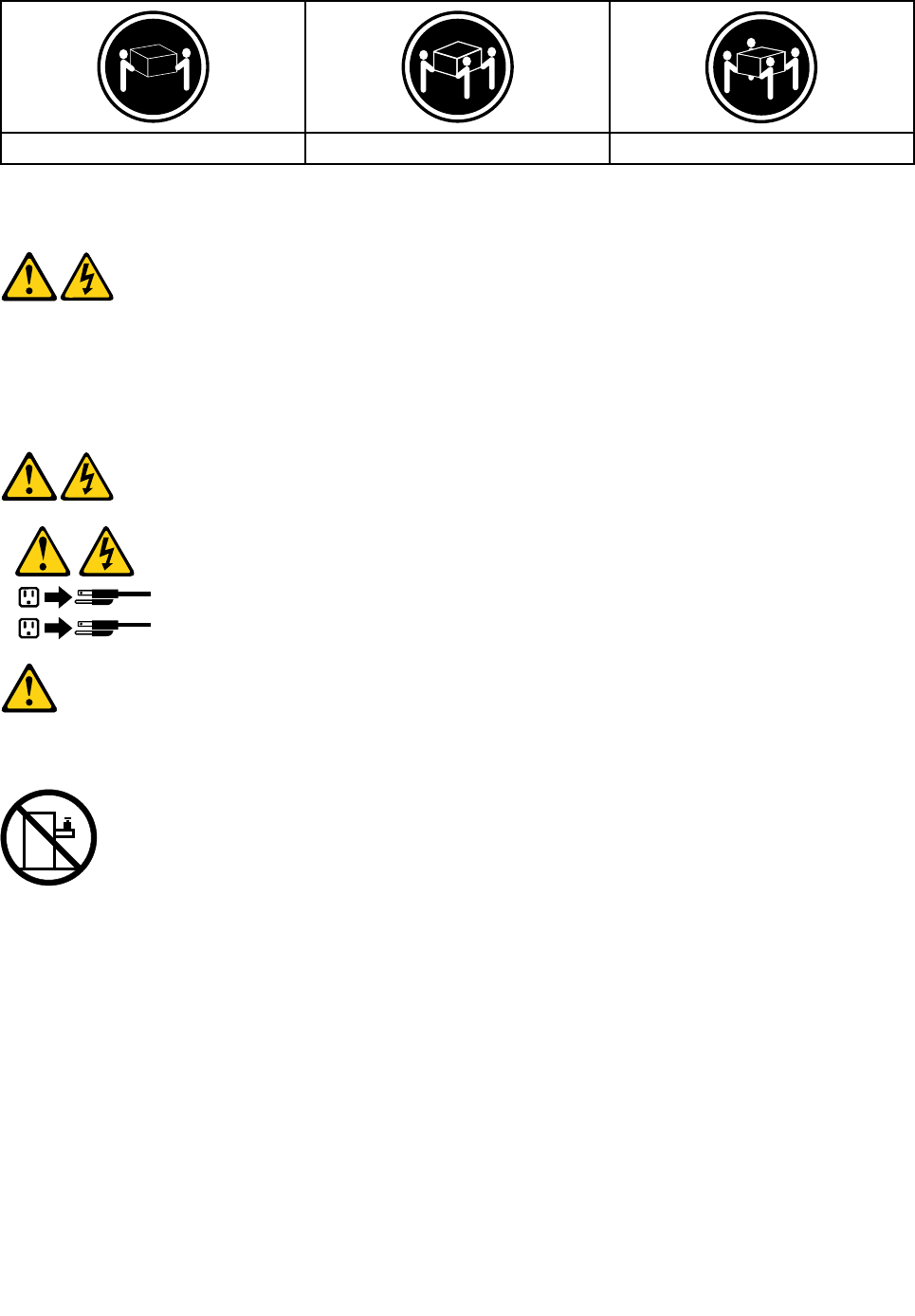
≥18kg(37lbs)≥32kg(70.5lbs)≥55kg(121.2lbs)
CAUTION:
Usesafepracticeswhenlifting.
CAUTION:
Thepowercontrolbuttononthedeviceandthepowerswitchonthepowersupplydonotturnoff
theelectricalcurrentsuppliedtothedevice.Thedevicealsomighthavemorethanonepower
cord.Toremoveallelectricalcurrentfromthedevice,ensurethatallpowercordsaredisconnected
fromthepowersource.
1
2
CAUTION:
Donotplaceanyobjectweighingmorethan82kg(180lbs.)ontopofrack-mounteddevices.
8LenovoC560HardwareMaintenanceManual

Chapter3.Generalinformation
Thischapterprovidesgeneralinformationthatappliestoallcomputermodelscoveredbythismanual.
Specifications
Thissectionliststhephysicalspecificationsforyourcomputer.
Thissectionliststhephysicalspecificationsforyourcomputer.
TypeLenovoC560
Thissectionliststhephysicalspecifications.
Environment
Airtemperature:
Operating:10°to35°C
Transit:-20°to55°C
Humidity:
Operating:35%to80%
Transit:20%to90%(40°C)
Altitude:86KPato106KPa
Electricalinput:
Inputvoltage:90V-264V(AC)
Inputfrequency:47Hz-63Hz
©CopyrightLenovo20139

10LenovoC560HardwareMaintenanceManual

Chapter4.GeneralCheckout
Attention:Thedrivesinthecomputeryouareservicingmighthavebeenrearrangedorthedrivestartup
sequencemayhavebeenchanged.Beextremelycarefulduringwriteoperationssuchascopying,saving,or
formatting.Dataorprogramscanbeoverwrittenifyouselectanincorrectdrive.
Generalerrormessagesappearifaproblemorconflictisfoundbyanapplication,theoperatingsystem,or
both.Foranexplanationofthesemessages,refertotheinformationsuppliedwiththatsoftwarepackage.
Usethefollowingproceduretohelpdeterminethecauseoftheproblem:
1.Power-offthecomputerandallexternaldevices.
2.Checkallcablesandpowercords.
3.Setalldisplaycontrolstothemiddleposition.
4.Power-onallexternaldevices.
5.Power-onthecomputer.
•Lookfordisplayederrorcodes.
•Lookforreadableinstructionsoramainmenuonthedisplay.
Ifyoudidnotreceivethecorrectresponse,proceedtostep6.
Ifyoudidreceivethecorrectresponse,proceedtostep7.
6.Ifoneofthefollowinghappens,followtheinstructiongiven:
•IfthecomputerdisplaysaPOSTerror,goto“POSTerrorcodes” .
•Ifthecomputerhangsandnoerrorisdisplayed,continueatstep7.
7.Iftheteststopsandyoucannotcontinue,replacethelastdevicetested.
©CopyrightLenovo201311

12LenovoC560HardwareMaintenanceManual

Chapter5.UsingtheSetupUtility
TheSetupUtilityprogramisusedtoviewandchangetheconfigurationsettingsofyourcomputer,regardless
ofwhichoperatingsystemyouareusing.However,theoperatingsystemsettingsmightoverrideanysimilar
settingsintheSetupUtilityprogram.
StartingtheLenovoBIOSSetupUtilityprogram
TostarttheLenovoBIOSSetupUtilityprogram,dothefollowing:
1.Ifyourcomputerisalreadyonwhenyoustartthisprocedure,shutdowntheoperatingsystemand
turnoffthecomputer.
2.PressandholdtheF1keythenturnonthecomputer.WhentheLenovoBIOSSetupUtilityprogramis
displayed,releasetheF1key.
Note:IfaPower-OnPasswordoranAdministratorPasswordhasbeenset,theSetupUtilityprogrammenu
willnotbedisplayeduntilyoutypeyourpassword.Formoreinformation,see“Usingpasswords.”
Viewingandchangingsettings
SystemconfigurationoptionsarelistedintheLenovoBIOSSetupUtilityprogrammenu.Tovieworchange
settings,see“StartingtheSetupUtilityprogram.”
YoumustusethekeyboardwhenusingtheLenovoBIOSSetupUtilitymenu.Thekeysusedtoperform
varioustasksaredisplayedonthebottomofeachscreen.
Usingpasswords
YoucanusetheLenovoBIOSSetupUtilityprogramtosetpasswordstopreventunauthorizedpersons
fromgainingaccesstoyourcomputeranddata.See“StartingtheSetupUtilityprogram.”Thefollowing
typesofpasswordsareavailable:
•AdministratorPassword
•Power-OnPassword
Youdonothavetosetanypasswordstouseyourcomputer.However,ifyoudecidetosetpasswords,read
thefollowingsections.
Passwordconsiderations
Apasswordcanbeanycombinationoflettersandnumbersupto16characters(a-zand0-9).Forsecurity
reasons,itisagoodideatouseastrongpasswordthatcannotbeeasilycompromised.Wesuggestthat
passwordsshouldfollowtheserules:
•Forastrongpassword,use7-16charactersandamixoflettersandnumbers.
•Donotuseyournameoryourusername.
•Donotuseacommonwordoracommonname.
•Usesomethingsignificantlydifferentfromyourpreviouspassword.
Attention:AdministratorandPower-Onpasswordsarenotcasesensitive.
©CopyrightLenovo201313

AdministratorPassword
SettinganAdministratorPassworddetersunauthorizedpersonsfromchangingconfigurationsettings.You
mightwanttosetanAdministratorPasswordifyouareresponsibleformaintainingthesettingsofseveral
computers.
AfteryousetanAdministratorPassword,apasswordpromptisdisplayedeverytimeyouaccesstheLenovo
BIOSSetupUtilityprogram.
IfboththeAdministratorandPower-OnPasswordareset,youcantypeeitherpassword.However,youmust
useyourAdministratorPasswordtochangeanyconfigurationsettings.
Setting,changing,ordeletinganAdministratorpassword
TosetanAdministratorPassword,dothefollowing:
Note:Apasswordcanbeanycombinationoflettersandnumbersupto16characters(a-zand0-9).For
moreinformation,see“Passwordconsiderations”onpage13.
1.StarttheLenovoBIOSSetupUtilityprogram(see“StartingtheLenovoBIOSSetupUtilityprogram”on
page13).
2.FromtheSecuritymenu,selectSetAdministratorPasswordandpresstheEnterkey.
3.Thepassworddialogboxwillbedisplayed.TypethepasswordthenpresstheEnterkey.
4.Re-typethepasswordtoconfirm,thenpresstheEnterkey.Ifyoutypedthepasswordcorrectly,
thepasswordwillbeinstalled.
TochangeanAdministratorPassword,dothefollowing:
1.StarttheLenovoBIOSSetupUtilityprogram(see“StartingtheLenovoBIOSSetupUtilityprogram”on
page13).
2.FromtheSecuritymenu,selectSetAdministratorPasswordandpresstheEnterkey.
3.Thepassworddialogboxwillbedisplayed.TypethecurrentpasswordthenpresstheEnterkey.
4.Typethenewpassword,thenpresstheEnterkey.Re-typethepasswordtoconfirmthenewpassword.
Ifyoutypedthenewpasswordcorrectly,thenewpasswordwillbeinstalled.ASetupNoticedconfirming
thatchangeshavebeensavedwillbedisplayed.
TodeleteapreviouslysetAdministratorPassword,dothefollowing:
1.FromtheSecuritymenu,selectSetAdministratorPasswordandpresstheEnterkey.
2.Thepassworddialogboxwillbedisplayed.TypethecurrentpasswordandpresstheEnterkey.
3.TodeleteanAdministratorPassword,leaveeachnewpasswordlineitemblank,thenpresstheEnter
key.ASetupNoticeconfirmingthatchangeshavebeensavedwillbedisplayed.
4.ReturntotheLenovoBIOSSetupUtilityprogrammenuandselecttheExitoption.
5.SelectSavechangesandExitfromthemenu.
Power-OnPassword
WhenaPower-OnPasswordisset,youcannotstarttheLenovoBIOSSetupUtilityprogramuntilavalid
passwordistypedfromthekeyboard.
Setting,changing,ordeletingaPower-OnPassword
Note:Apasswordcanbeanycombinationoflettersandnumbersupto16characters(a-zand0-9).
14LenovoC560HardwareMaintenanceManual
TosetaPower-OnPassword,dothefollowing:
1.StarttheLenovoBIOSSetupUtilityprogram(See”StartingtheLenovoBIOSSetupUtilityprogram”on
page13.)
2.FromtheSecuritymenu,selectSetPower-OnPasswordandpresstheEnterkey.
3.Thepassworddialogboxwillbedisplayed.Typethepassword,thenpresstheEnterkey.
4.Re-typethepasswordtoconfirm.Ifyoutypedthepasswordcorrectly,thepasswordwillbeinstalled.
TochangeaPower-OnPassword,dothefollowing:
1.StarttheLenovoBIOSSetupUtilityprogram(See”StartingtheLenovoBIOSSetupUtilityprogram”on
page13.)
2.FromtheSecuritymenu,selectSetPower-OnPasswordandpresstheEnterkey.
3.Thepassworddialogboxwillbedisplayed.TypethecurrentpasswordthenpresstheEnterkey.
4.Typethenewpassword,thenpresstheEnterkey.Re-typethepasswordtoconfirmthenewpassword.
Ifyoutypedthenewpasswordcorrectly,thenewpasswordwillbeinstalled.ASetupNoticedconfirming
thatchangeshavebeensavedwillbedisplayed.
TodeleteapreviouslysetPower-OnPassword,dothefollowing:
1.FromtheSecuritymenu,selectSetPower-OnPasswordandpresstheEnterkey.
2.Thepassworddialogboxwillbedisplayed.TypethecurrentpasswordandpresstheEnterkey.
3.TodeletethePower-OnPassword,leaveeachnewpasswordlineitemblank,thenpressEnter.ASetup
Noticeconfirmingthatchangeshavebeensavedwillbedisplayed.
4.ReturntotheLenovoBIOSSetupUtilityprogrammenuandselecttheExitoption.
5.SelectSavechangesandExitfromthemenu.
Enablingordisablingadevice
TheDevicesoptionsisusedtoenableordisableuseraccesstothefollowingdevices:
USBFunctionsSelectwhethertoenableordisableUSB(UniversalSerial
Bus)functions.Ifthefunctionsaredisabled,noUSB
devicescanbeused.
SATAModeWhenthisfeatureissettoDisabled,alldevices
connectedtotheSATAconnectors(e.g.harddiskdrives
ortheopticaldiskdrive)aredisabledandcannotbe
accessed.
OnboardAudioControllerSelectwhethertoenableordisabletheOnboard
AudioController.WhenthisfeatureissettoDisabled
alldevicesconnectedtotheaudioconnectors(e.g.
headphonesoramicrophone)aredisabledandcannot
beused.
OnboardEthernetControllerorLANBootAgentSelectwhethertoenableordisabletheOnboardEthernet
Controller,orselectwhethertoenableordisableload
onboardPXE(PrebootExecutionEnvironment).
Toenableordisableadevice,dothefollowing:
1.StarttheSetupUtilityprogram(see“StartingtheSetupUtilityprogram”onpage13).
2.FromtheSetupUtilityprogrammenu,selectDevices.
3.Selectanoptionasfollows:
SelectUSBSetup,presstheEnterkey,thenselectUSBFunctions.
Chapter5.UsingtheSetupUtility15

SelectATADeviceSetup,presstheEnterkey,thenselectSATAMode.
SelectAudioSetup,presstheEnterkey,thenselectOnboardAudioController.
SelectNetworkSetup,presstheEnterkey,thenselectOnboardEthernetSupportorLANBoot
Agent.
4.SelectDisabledorEnabledandpresstheEnterkey.
5.ReturntotheLenovoBIOSSetupUtilityprogrammenuandselecttheExitoption.
6.SelectSavechangesandExitfromthemenu.
Notes:
a.Ifyoudonotwanttosavethesettings,selectDiscardchangesandExitfromthemenu.
b.SelectIDE/AHCIMode:DevicedriversupportisrequiredforACHI.Dependingonhowtheharddisk
imagewasinstalled,changingthissettingmaypreventthesystemfrombooting.
Selectingastartupdevice
IfyourcomputerdoesnotbootfromadevicesuchastheCD/DVD-ROMdrivediskorharddiskasexpected,
followoneoftheproceduresbelow.
Selectingatemporarystartupdevice
Usethisproceduretostartupfromanybootdevice.
Note:NotallCDs,DVDsorharddiskdrivesarebootable.
1.Turnoffyourcomputer.
2.PressandholdtheF12keythenturnonthecomputer.WhentheStartupDeviceMenuappears,
releasetheF12key.
Note:IftheStartupDeviceMenudoesnotdisplayusingthesesteps,repeatedlypressandreleasethe
F12keyratherthankeepingitpressedwhenturningonthecomputer.
3.Use↑and↓arrowstoselectthedesiredstartupdevicefromtheStartupDeviceMenuandpress
theEnterkeytobegin.
Note:SelectingastartupdevicefromtheStartupDeviceMenudoesnotpermanentlychangethe
startupsequence.
Selectingorchangingthestartupdevicesequence
Tovieworpermanentlychangetheconfiguredstartupdevicesequence,dothefollowing:
1.StarttheLenovoBIOSSetupUtilityprogram(see“StartingtheLenovoBIOSSetupUtilityprogram”on
page13).
2.FromtheLenovoBIOSSetupUtilityprogrammainmenu,selecttheStartupoption.
3.PresstheEnterkey,andselectthedevicesforthePrimaryBootSequence.Readtheinformation
displayedontherightsideofthescreen.
4.Use↑and↓arrowstoselectadevice.Usethe<+>or<->keystomoveadeviceupordown.Usethe
<×>keytoexcludethedevicefromorincludethedeviceinthebootsequence.
5.ReturntotheLenovoBIOSSetupUtilityprogrammenuandselecttheExitoption.
6.SelectSavechangesandExitfromthemenu.
Notes:
16LenovoC560HardwareMaintenanceManual

a.Ifyoudonotwanttosavethesettings,selectDiscardchangesandExitfromthemenu.
b.Ifyouhavechangedthesesettingsandwanttoreturntothedefaultsettings,selectLoadOptimal
Defaultsfromthemenu.
ExitingtheLenovoBIOSSetupUtilityprogram
Afteryoufinishviewingorchangingsettings,presstheEsckeytoreturntotheLenovoBIOSSetupUtility
programmainmenu.Y oumighthavetopresstheEsckeyseveraltimes.Dooneofthefollowing:
•Ifyouwanttosavethenewsettings,selectSavechangesandExitfromthemenu.WhentheSave&
resetwindowshows,selecttheYesbutton,andthenpresstheEnterkeytoexittheLenovoBIOS
SetupUtilityprogram.
•Ifyoudonotwanttosavethesettings,selectDiscardchangesandExitfromthemenu.Whenthe
ResetWithoutSavingwindowshows,selecttheYesbutton,andthenpresstheEnterkeytoexitthe
LenovoBIOSSetupUtilityprogram.
Chapter5.UsingtheSetupUtility17

18LenovoC560HardwareMaintenanceManual
Chapter6.Symptom-to-FRUIndex
TheSymptom-to-FRUindexlistserrorsymptomsandpossiblecauses.Themostlikelycauseislistedfirst.
AlwaysbeginwithChapter4,“GeneralCheckout,”onpage11.Thisindexcanalsobeusedtohelpyou
decidewhichFRUstohaveavailablewhenservicingacomputer.Ifyouareunabletocorrecttheproblem
usingthisindex,goto“Undeterminedproblems”onpage20.
Notes:
•Ifyouhavebothanerrormessageandanincorrectaudioresponse,diagnosetheerrormessagefirst.
•Ifyoucannotrunthediagnostictestsoryougetadiagnosticerrorcodewhenrunningatestbutdid
receiveaPOSTerrormessage,diagnosethePOSTerrormessagefirst.
•Ifyoudidnotreceiveanyerrormessagelookforadescriptionofyourerrorsymptomsinthefirstpartof
thisindex.
Harddiskdrivebooterror
Aharddiskdrivebooterrorcanbecausedbythefollowing.
ErrorFRU/Action
Thestartupdriveisnotincludedinthebootsequence
configuration.
Checktheconfigurationandensurethestartupdriveis
inthebootsequence.
Nooperatingsystemisinstalledonthebootdrive.Installanoperatingsystemonthebootdrive.
Thebootsectoronthestartupdriveiscorrupted.Thedrivemustbeformatted.Dothefollowing:
1.Attempttobackupthedataonthefailingharddisk
drive.
2.Usetheoperatingsystemtoformattheharddisk
drive.
Thedriveisdefective.Replacetheharddiskdrive.
PowerSupplyProblems
Followtheseproceduresifyoususpectthereisapowersupplyproblem.
Check/VerifyFRU/Action
Checkthatthefollowingareproperlyinstalled:
•PowerCord
•On/OffSwitchconnector
•SystemBoardPowerSupplyconnectors
•Microprocessorconnections
Reseatconnectors
Checkthepowercord.PowerCord
Checkthepower-onswitch.Power-onSwitch
©CopyrightLenovo201319
POSTerrorcodes
Eachtimeyouturnthecomputeron,itperformsaseriesofteststocheckthatthesystemisoperating
correctlyandthatcertainoptionsareset.ThisseriesoftestsiscalledthePower-OnSelf-Test,orPOST.
POSTdoesthefollowing:
•Checkssomebasicmotherboardoperations
•Checksthatthememoryisworkingcorrectly
•Startsvideooperations
•Verifiesthatthebootdriveisworking
POSTErrorMessageDescription/Action
KeyboarderrorCannotinitializethekeyboard.Makesurethekeyboard
isproperlyconnectedtothecomputerandthatnokeys
areheldpressedduringPOST.Topurposelyconfigure
thecomputerwithoutakeyboard,selectKeyboardless
operationinStartupandsettheoptiontoEnabled.The
BIOSthenignoresthemissingkeyboardduringPOST.
RebootandSelectproperBootdeviceorInsertBoot
MediainselectedBootdevice
TheBIOSwasunabletofindasuitablebootdevice.Make
surethebootdriveisproperlyconnectedtothecomputer.
Makesureyouhavebootablemediainthebootdevice.
Undeterminedproblems
1.Power-offthecomputer.
2.Removeordisconnectthefollowingcomponents(ifconnectedorinstalled)oneatatime.
a.Externaldevices(modem,printer,ormouse)
b.Extendedvideomemory
c.ExternalCache
d.ExternalCacheRAM
e.Harddiskdrive
f.Diskdrive
3.Power-onthecomputertore-testthesystem.
4.Repeatsteps1through3untilyoufindthefailingdeviceorcomponent.
Ifalldevicesandcomponentshavebeenremovedandtheproblemcontinues,replacethesystemboard.
20LenovoC560HardwareMaintenanceManual

Chapter7.Replacinghardware
Attention:Donotremovethecomputercoverorattemptanyrepairbeforereadingthe“Importantsafetyinformation”
intheSafetyandWarrantyGuidethatwasincludedwithyourcomputer.ToobtaincopiesoftheSafetyandWarranty
Guide,gototheSupportWebsiteat:http://consumersupport.lenovo.com.
Note:UseonlypartsprovidedbyLenovo.
Generalinformation
Pre-disassemblyinstructions
Beforestartingthedisassemblyprocedure,makesurethatyoudothefollowing:
1.Turnoffthepowertothesystemandallperipherals.
2.Unplugallpowerandsignalcablesfromthecomputer.
3.Placethesystemonaflat,stablesurface.
©CopyrightLenovo201321
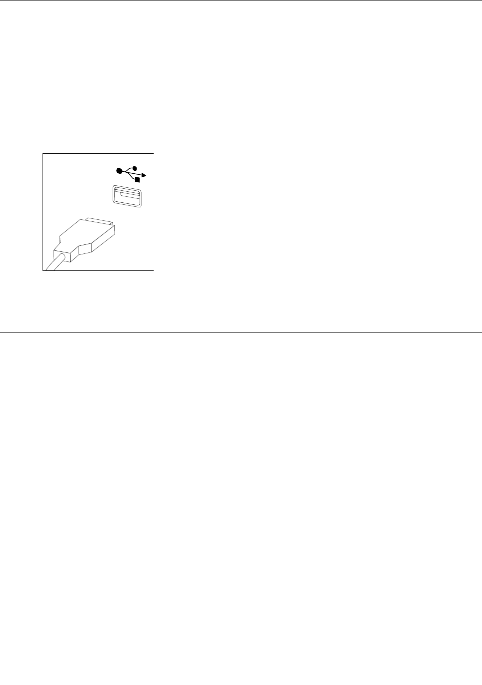
Replacingthekeyboardandmouse
Note:YourkeyboardwillbeconnectedtoaUSBconnectorateithersideorattherearofthecomputer.
Toreplacethekeyboard:
Step1.Removeanymedia(disks,CDs,ormemorycards)fromthedrives,shutdownthecomputer,and
turnoffallattacheddevices.
Step2.Unplugallpowercordsfromelectricaloutlets.
Step3.Locatetheconnectorforthekeyboard.Referto“Sideviewofthecomputer”and“Rearviewof
thecomputer”.
Step4.Disconnectthedefectivekeyboardcablefromthecomputerandconnectthenewkeyboardcable
tothesameconnector.
Step5.Themousecanbereplacedusingthesamemethod.
Replacingtheadapter
Attention:Turnoffthecomputerandwait3to5minutestoletitcooldownbeforeremovingthecover.
Step1.Removeanymedia(disks,CDs,ormemorycards)fromthedrives,shutdowntheoperating
system,andturnoffthecomputerandallattacheddevices.
22LenovoC560HardwareMaintenanceManual
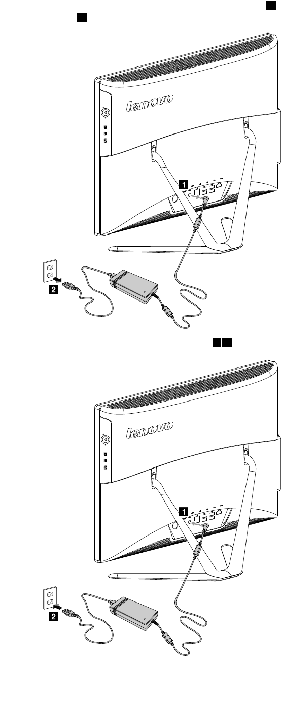
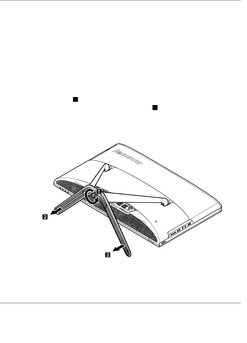
Removingthestandbase
Attention:Turnoffthecomputerandwait3to5minutestoletitcooldownbeforeremovingthecover.
Note:Itmaybehelpfultoplacethecomputerface-downonasoftflatsurfaceforthisprocedure.Lenovo
recommendsthatyouuseablanket,towel,orothersoftclothtoprotectthetouchscreenfromscratches
orotherdamage.
Step1.Removeanymedia(disks,CDs,ormemorycards)fromthedrives,shutdowntheoperating
system,andturnoffthecomputerandallattacheddevices.
Step2.Unplugallpowercordsfromelectricaloutlets.
Step3.Disconnectallcablesattachedtothecomputer.Thisincludespowercords,input/output(I/O)
cables,andanyothercablesthatareconnectedtothecomputer.Referto“Leftandrightviews”
and“Rearview”forhelpwithlocatingthevariousconnectors.
Step4.Twistthehandscrewringcounter-clockwiseuntilthebasecomesloosetoreleasethestandbase
fromthestandholder.1
Step5.Slidethestandbaseoutfromtheholderthenputitaside.2
Step6.Referto“Installingthecomputerstand”toreinstallthestandbase.
Removingthefootcover
Attention:Turnoffthecomputerandwait3to5minutestoletitcooldownbeforeremovingthecover.
24LenovoC560HardwareMaintenanceManual
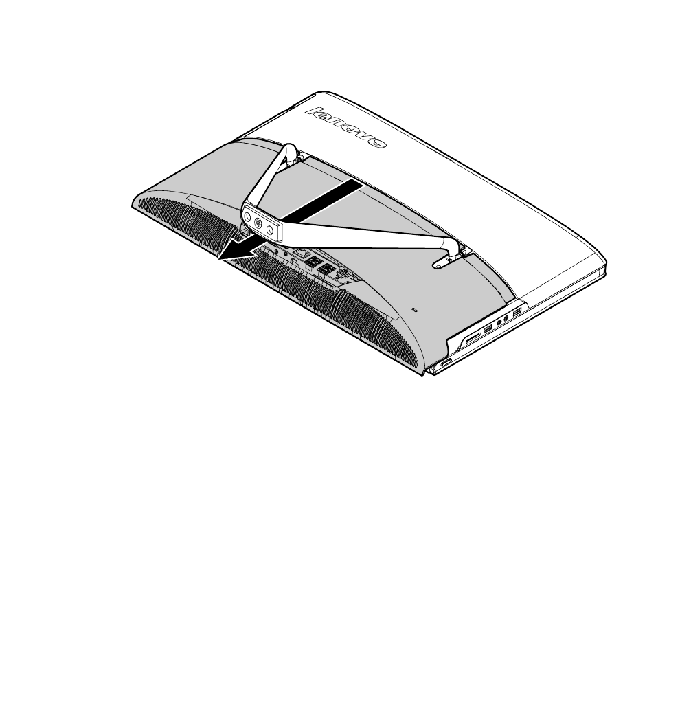
Note:Itmaybehelpfultoplacethecomputerface-downonasoftflatsurfaceforthisprocedure.Lenovo
recommendsthatyouuseablanket,towel,orothersoftclothtoprotectthetouchscreenfromscratches
orotherdamage.
Step1.Removeanymedia(disks,CDs,ormemorycards)fromthedrives,shutdowntheoperating
system,andturnoffthecomputerandallattacheddevices.
Step2.Unplugallpowercordsfromelectricaloutlets.
Step3.Disconnectallcablesattachedtothecomputer.Thisincludespowercords,input/output(I/O)
cables,andanyothercablesthatareconnectedtothecomputer.Referto“Leftandrightviews”
and“Rearview”forhelpwithlocatingthevariousconnectors.
Step4.Removethefootbase.Referto“Removingthefootbase” .
Step5.Liftupthestandholderthenslideoutthefootcoverasshown.
Step6.Toreattachthefootcover:
a.Liftupthestandholder.
b.Lineupthefootcoverwithmountingholesonthebackofthecomputer,thenslideitbackinto
position.
Replacingamemorymodule
Attention:Turnoffthecomputerandwait3to5minutestoletitcooldownbeforeremovingthecover.
Chapter7.Replacinghardware25
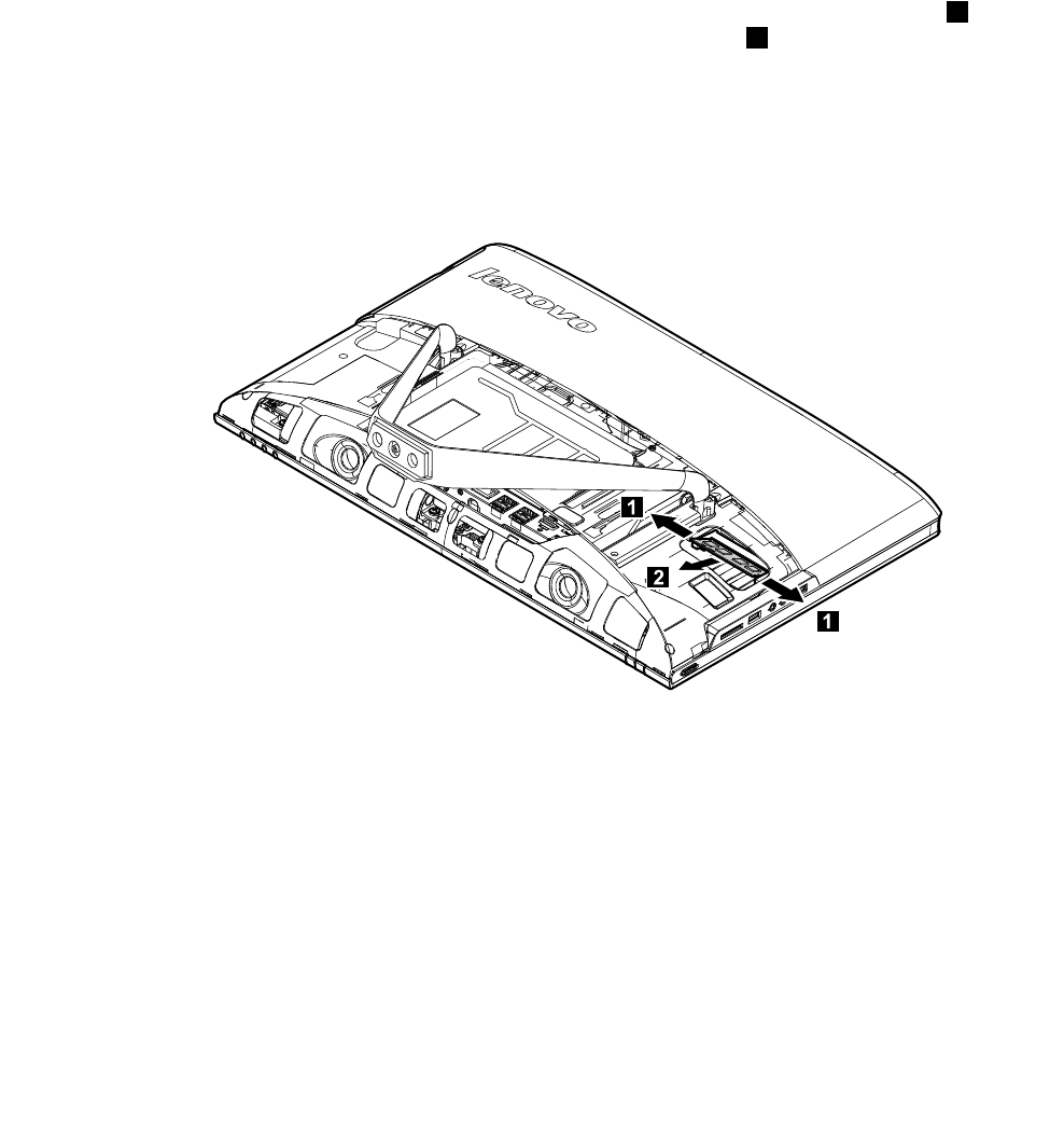
Note:Itmaybehelpfultoplacethecomputerface-downonasoftflatsurfaceforthisprocedure.Lenovo
recommendsthatyouuseablanket,towel,orothersoftclothtoprotectthetouchscreenfromscratches
orotherdamage.
Step1.Removeanymedia(disks,CDs,ormemorycards)fromthedrives,shutdowntheoperating
system,andturnoffthecomputerandallattacheddevices.
Step2.Unplugallpowercordsfromelectricaloutlets.
Step3.Disconnectallcablesattachedtothecomputer.Thisincludespowercords,input/output(I/O)
cables,andanyothercablesthatareconnectedtothecomputer.Referto“Leftandrightviews”
and“Rearview”forhelpwithlocatingthevariousconnectors.
Step4.Removethestandbase.Referto“Removingthestandbase” .
Step5.Removethefootcover.Referto“Removingthefootcover” .
Step6.Pushoutthelatchesonbothsidesofthememorysockettoreleasethememorymodule1and
gentlypullthememorymoduleupwardtoremoveitfromitssocket.2Allofthememorymodules
canberemovedusingthesameprocedure.
Step7.Toinstallamemorymodule:
a.Alignthenewmemorymodulewiththememorysocket,theninsertitandpushdownonthe
topedge.Makesurethelatcheslockthememorymoduleinplace.
Step8.Reattachthefootcoverandstandbase.
26LenovoC560HardwareMaintenanceManual
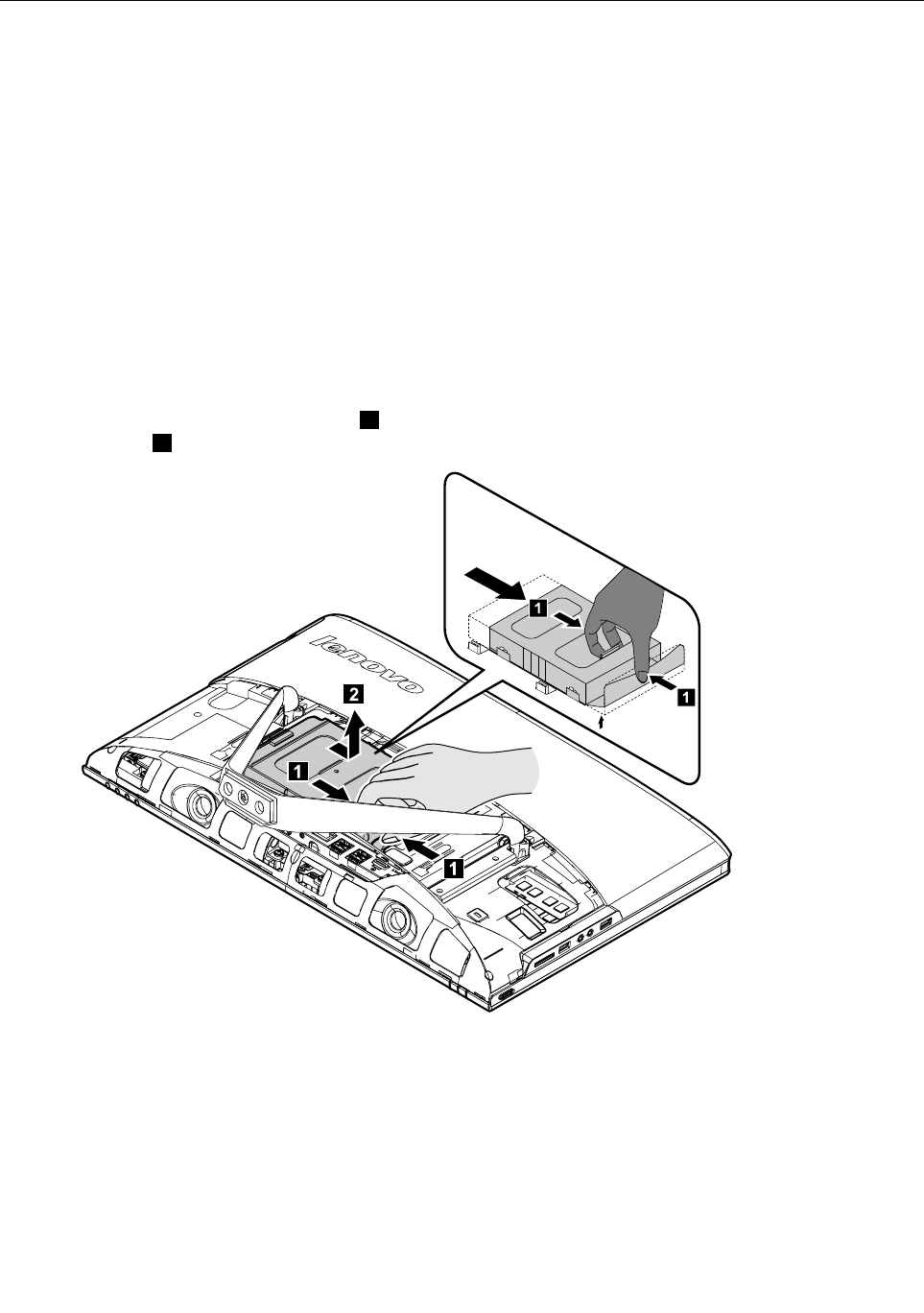
Replacingtheharddiskdrive
Attention:Turnoffthecomputerandwait3to5minutestoletitcooldownbeforeremovingthecover.
Note:Itmaybehelpfultoplacethecomputerface-downonasoftflatsurfaceforthisprocedure.Lenovo
recommendsthatyouuseablanket,towel,orothersoftclothtoprotectthetouchscreenfromscratches
orotherdamage.
Step1.Removeanymedia(disks,CDs,ormemorycards)fromthedrives,shutdowntheoperating
system,andturnoffthecomputerandallattacheddevices.
Step2.Unplugallpowercordsfromelectricaloutlets.
Step3.Disconnectallcablesattachedtothecomputer.Thisincludespowercords,input/output(I/O)
cables,andanyothercablesthatareconnectedtothecomputer.Referto“Leftandrightviews”
and“Rearview”forhelpwithlocatingthevariousconnectors.
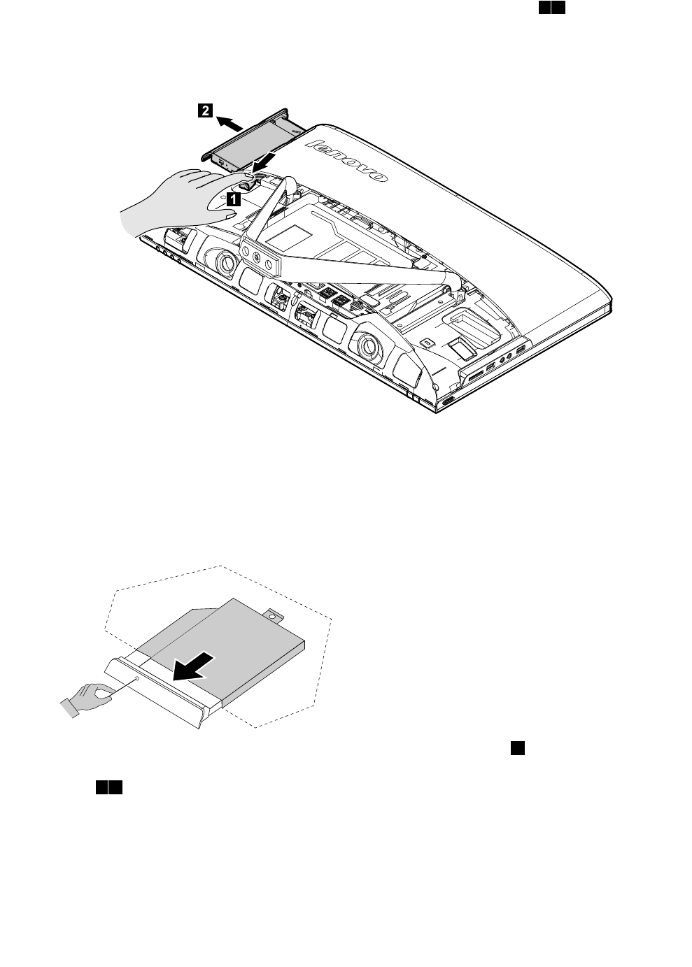
Step4.Removethestandbase.Referto“Removingthestandbase” .
Step5.Removethefootcover.Referto“Removingthefootcover” .
Step6.Pushtheharddiskdrivebracket1,thenslidetheharddiskdriveandbracketoutofthechassisas
shown.2
1
1
Chapter7.Replacinghardware27

Step7.Pushthelockpinsoutwardtoreleasetheharddiskdrivefromthebracket.
Step8.Toinstallthenewharddiskdrive:
a.Lineupthenewharddiskdrivewiththebracketandsecureitwiththepins.
b.Slidetheharddiskdriveandbracketbackintoposition.
Step9.Reattachthefootcoverandstandbase.
Replacingtheopticaldrive
Attention:Turnoffthecomputerandwait3to5minutestoletitcooldownbeforeremovingthecover.
Note:Itmaybehelpfultoplacethecomputerface-downonasoftflatsurfaceforthisprocedure.Lenovo
recommendsthatyouuseablanket,towel,orothersoftclothtoprotectthetouchscreenfromscratches
orotherdamage.
Step1.Removeanymedia(disks,CDs,ormemorycards)fromthedrives,shutdowntheoperating
system,andturnoffthecomputerandallattacheddevices.
Step2.Unplugallpowercordsfromelectricaloutlets.
Step3.Disconnectallcablesattachedtothecomputer.Thisincludespowercords,input/output(I/O)
cables,andanyothercablesthatareconnectedtothecomputer.Referto“Leftandrightviews”
and“Rearview”forhelpwithlocatingthevariousconnectors.
Step4.Removethestandbase.Referto“Removingthestandbase” .
Step5.Removethefootcover.Referto“Removingthefootcover” .
28LenovoC560HardwareMaintenanceManual
Step6.Pushtheopticaldrivepindownwardtopushouttheopticaldriveasshown.12
Step7.Pushasmallironstick(paperclip)intothesmallholeontheopticaldrivecoversothatthedisk
springsoutasshown.
Step8.Removethe2screwsthatsecuretheopticaldrivetothemetalbracket.1
Step9.Useasmallflatheadscrewdrivertopressandpushoutthepinsthatsecurethecovertothe
disk.23
Chapter7.Replacinghardware29
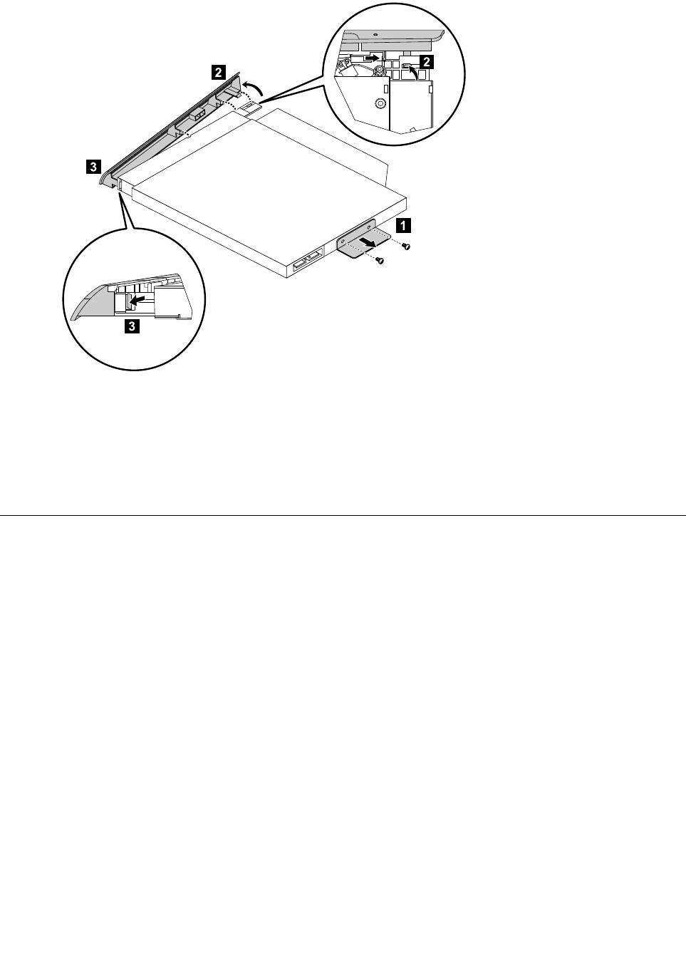
Step10.Separatethecoverfromthedefectiveopticaldrive.
Step11.Toinstallthenewopticaldrive:
a.Alignthenewopticaldrivewiththecover,andthenpushthecoverbackintoposition.
b.Screwthemetalbracketbackontothenewopticaldrive.
c.Slidethenewopticaldriveintothedrivebay.
Step12.Reattachthefootcoverandstandbase.
Removingthestandholder
Note:Turnoffthecomputerandwait3to5minutestoletitcooldownbeforeremovingthecover.
Note:Itmaybehelpfultoplacethecomputerface-downonasoftflatsurfaceforthisprocedure.Lenovo
recommendsthatyouuseablanket,towel,orothersoftclothtoprotectthecomputerscreenfromscratches
orotherdamage.
Toremovethestandholder:
Step1.Removeanymedia(disks,CDs,DVDs,ormemorycards)fromthedrives,shutdowntheoperating
system,andturnoffthecomputerandallattacheddevices.
Step2.Unplugallpowercordsfromelectricaloutlets.
Step3.Disconnectallcablesattachedtothecomputer.Thisincludespowercords,input/output(I/O)
cables,andanyothercablesthatareconnectedtothecomputer.Referto“Leftandrightview”
and“Rearview”forhelpwithlocatingthevariousconnectors.
Step4.Removethestandbase.Referto“Removingthestandbase” .
Step5.Removethefootcover.Referto“Removingthefootcover” .
Step6.Removethefourscrewsthatsecurethestandholdertothechassis,thenliftupthestandholderto
removeit.
30LenovoC560HardwareMaintenanceManual
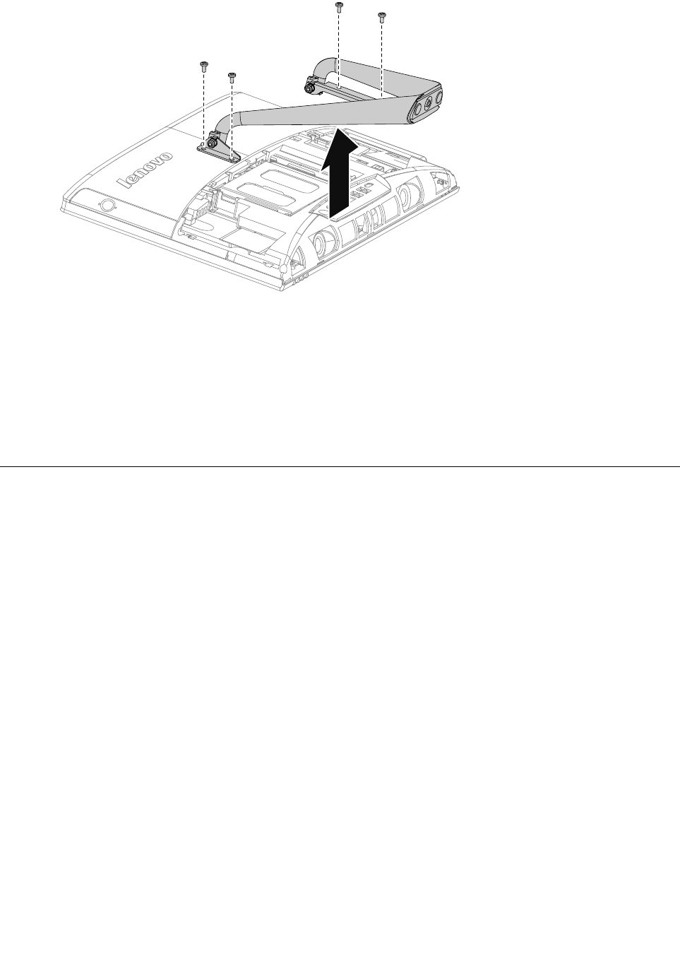
Step7.Toreattachthestandholder:
a.Aligntheholesonthestandholderwithmountingholesonthechassis,placethestand
holderbackintoposition.
b.Securethestandholdertothechassiswiththefourscrews.
Step8.Lineupthefootcoverwithmountingholesonthebackofthecomputer,thenslideitbackinto
position.
Step9.Reattachthestandbase.
Removingthemiddlecover
Note:Turnoffthecomputerandwait3to5minutestoletitcooldownbeforeremovingthecover.
Note:Itmaybehelpfultoplacethecomputerface-downonasoftflatsurfaceforthisprocedure.Lenovo
recommendsthatyouuseablanket,towel,orothersoftclothtoprotectthecomputerscreenfromscratches
orotherdamage.
Toremovethemiddlecover:
Step1.Removeanymedia(disks,CDs,DVDs,ormemorycards)fromthedrives,shutdowntheoperating
system,andturnoffthecomputerandallattacheddevices.
Step2.Unplugallpowercordsfromelectricaloutlets.
Step3.Disconnectallcablesattachedtothecomputer.Thisincludespowercords,input/output(I/O)
cables,andanyothercablesthatareconnectedtothecomputer.Referto“Leftandrightview”
and“Rearview”forhelpwithlocatingthevariousconnectors.
Step4.Removethestandbase.Referto“Removingthestandbase” .
Step5.Removethefootcover.Referto“Removingthefootcover” .
Step6.Removetheopticaldrive.Referto“Replacingtheopticaldrive” .
Step7.Removethestandholder.Referto“Removingthestandholder” .
Step8.Removetheninescrewsthatsecurethemiddlecovertothechassis,thenliftupthemiddlecover
fromtheleftside(opticaldriveside)toremovethemiddlecover.
Chapter7.Replacinghardware31
Step9.Toreattachthemiddlecover:
a.Lineupthemiddlecoverwithchassis,thenplacethemiddlecoverback.
b.Securethemiddlecovertothechassiswiththeninescrews.
Step10.Reattachthestandholder,opticaldrive,footcoverandstandbase.
Replacingtheconverterboard
Note:Turnoffthecomputerandwait3to5minutestoletitcooldownbeforeremovingthecover.
Note:Itmaybehelpfultoplacethecomputerface-downonasoftflatsurfaceforthisprocedure.Lenovo
recommendsthatyouuseablanket,towel,orothersoftclothtoprotectthecomputerscreenfromscratches
orotherdamage.
Toreplacetheconverterboard:
Step1.Removeanymedia(disks,CDs,DVDs,ormemorycards)fromthedrives,shutdowntheoperating
system,andturnoffthecomputerandallattacheddevices.
Step2.Unplugallpowercordsfromelectricaloutlets.
Step3.Disconnectallcablesattachedtothecomputer.Thisincludespowercords,input/output(I/O)
cables,andanyothercablesthatareconnectedtothecomputer.Referto“Leftandrightview”
and“Rearview”forhelpwithlocatingthevariousconnectors.
Step4.Removethestandbase.Referto“Removingthestandbase” .
Step5.Removethefootcover.Referto“Removingthefootcover” .
Step6.Removetheopticaldrive.Referto“Replacingtheopticaldrive” .
Step7.Removethestandholder.Referto“Removingthestandholder” .
Step8.Removethemiddlecover.Referto“Removingthemiddlecover” .
32LenovoC560HardwareMaintenanceManual
Step9.Disconnectthetwocablesfromtheconverter,andthenremovethescrewthatsecuresthe
converterboardtothechassis.
Step10.Liftupthenslideouttheconverterboardtoremoveit.
Step11.Toinstallthenewconverterboard:
a.Lineuptheholesonthenewconverterboardwiththemountingholesonthechassisand
secureitwiththescrew.
b.Connectthetwocablestothenewconverterboard.
Step12.Reattachthemiddlecover,opticaldrive,standholder,footcoverandstandbase.
Replacingthetouchcontrolboard
Note:Turnoffthecomputerandwait3to5minutestoletitcooldownbeforeremovingthecover.
Note:Itmaybehelpfultoplacethecomputerface-downonasoftflatsurfaceforthisprocedure.Lenovo
recommendsthatyouuseablanket,towel,orothersoftclothtoprotectthecomputerscreenfromscratches
orotherdamage.
Toreplacethetouchcontrolboard:
Note:ThefollowinginstructionsareforC560touchmodelsonly.
Step1.Removeanymedia(disks,CDs,DVDs,ormemorycards)fromthedrives,shutdowntheoperating
system,andturnoffthecomputerandallattacheddevices.
Step2.Unplugallpowercordsfromelectricaloutlets.
Step3.Disconnectallcablesattachedtothecomputer.Thisincludespowercords,input/output(I/O)
cables,andanyothercablesthatareconnectedtothecomputer.Referto“Leftandrightview”
and“Rearview”forhelpwithlocatingthevariousconnectors.
Step4.Removethestandbase.Referto“Removingthestandbase” .
Step5.Removethefootcover.Referto“Removingthefootcover” .
Step6.Removetheopticaldrive.Referto“Replacingtheopticaldrive” .
Step7.Removethestandholder.Referto“Removingthestandholder” .
Step8.Removethemiddlecover.Referto“Removingthemiddlecover” .
Chapter7.Replacinghardware33
Step9.Disconnectthecablesfromthetouchcontrolboard1,andthenremovethetwoscrewsthat
securethetouchcontrolboardtothechassis.
Step10.Liftupthetouchcontrolboardtoremoveit.
1
1
Step11.Toinstallthenewtouchcontrolboard:
a.Lineuptheholesonthenewtouchcontrolboardwiththemountingholesonthechassis
andsecureitwiththetwoscrews.
b.Connectthecablestothenewtouchcontrolboard.
Step12.Reattachthemiddlecover,opticaldrive,standholder,footcoverandstandbase.
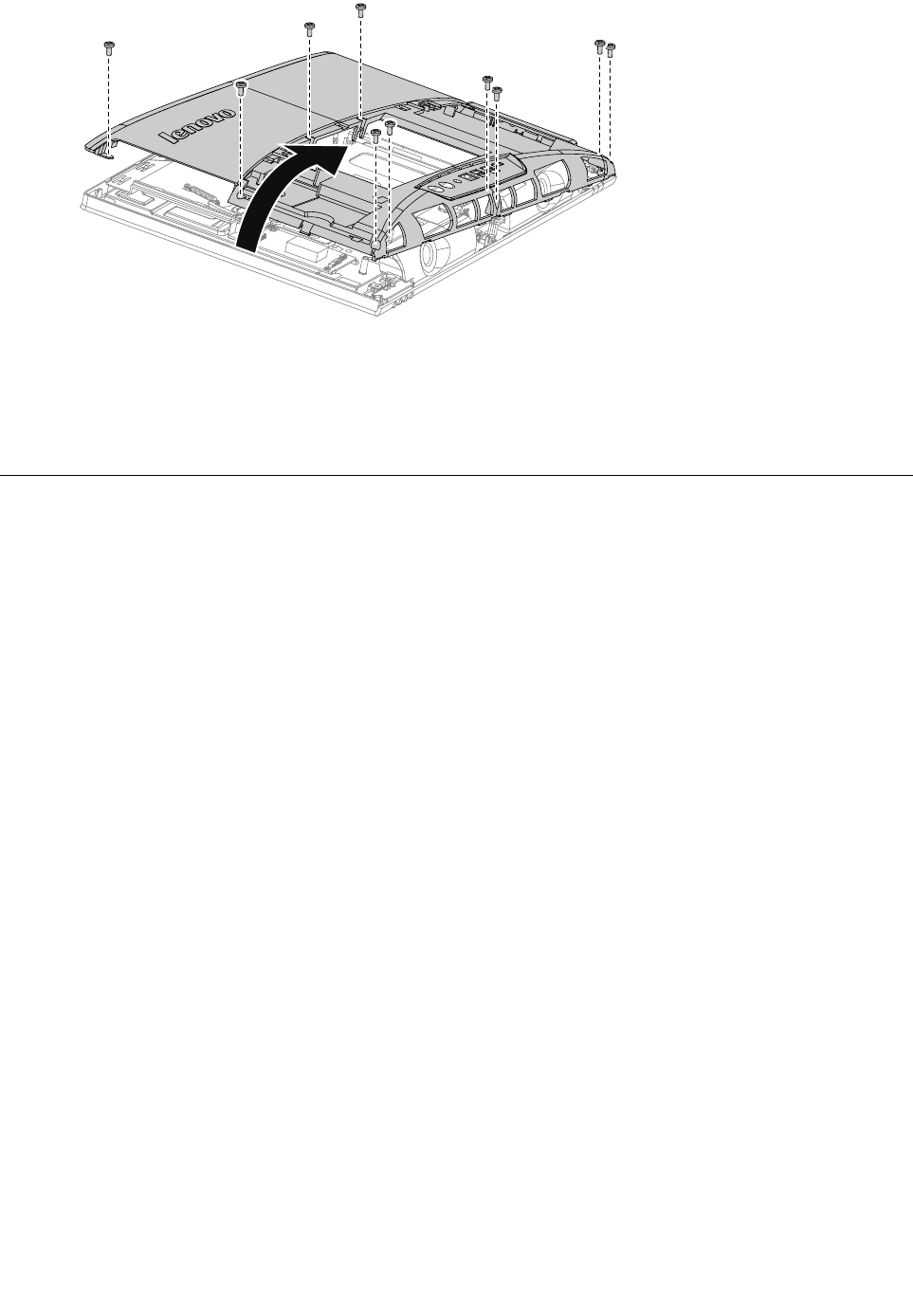
RemovingtheEMIcover
Note:Turnoffthecomputerandwait3to5minutestoletitcooldownbeforeremovingthecover.
Note:Itmaybehelpfultoplacethecomputerface-downonasoftflatsurfaceforthisprocedure.Lenovo
recommendsthatyouuseablanket,towel,orothersoftclothtoprotectthecomputerscreenfromscratches
orotherdamage.
ToreplacetheEMIcover
Step1.Removeanymedia(disks,CDs,DVDs,ormemorycards)fromthedrives,shutdowntheoperating
system,andturnoffthecomputerandallattacheddevices.
Step2.Unplugallpowercordsfromelectricaloutlets.
Step3.Disconnectallcablesattachedtothecomputer.Thisincludespowercords,input/output(I/O)
cables,andanyothercablesthatareconnectedtothecomputer.Referto“Leftandrightview”
and“Rearview”forhelpwithlocatingthevariousconnectors.
Step4.Removethestandbase.Referto“Removingthestandbase” .
Step5.Removethefootcover.Referto“Removingthefootcover” .
Step6.Removetheopticaldrive.Referto“Replacingtheopticaldrive” .
Step7.Removethestandholder.Referto“Removingthestandholder” .
Step8.Removethemiddlecover.Referto“Removingthemiddlecover” .
34LenovoC560HardwareMaintenanceManual
Step9.RemovethesevenscrewsthatsecuretheEMIcovertothechassis,andthenliftitup.
Step10.ToreattachtheEMIcover:
a.LineuptheholesontheEMIcoverwithmountingholesonthechassis,thenplaceEMIcover
backintoposition.
b.SecuretheEMIcovertothechassiswithsevenscrews.
Step11.Reattachthemiddlecover,opticaldrive,standholder,footcoverandstandbase.
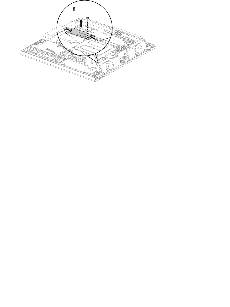
ReplacingtheTVtunercard
Note:Turnoffthecomputerandwait3to5minutestoletitcooldownbeforeremovingthecover.
Note:Itmaybehelpfultoplacethecomputerface-downonasoftflatsurfaceforthisprocedure.Lenovo
recommendsthatyouuseablanket,towel,orothersoftclothtoprotectthecomputerscreenfromscratches
orotherdamage.
ToreplacetheTVtunercard
Step1.Removeanymedia(disks,CDs,DVDs,ormemorycards)fromthedrives,shutdowntheoperating
system,andturnoffthecomputerandallattacheddevices.
Step2.Unplugallpowercordsfromelectricaloutlets.
Step3.Disconnectallcablesattachedtothecomputer.Thisincludespowercords,input/output(I/O)
cables,andanyothercablesthatareconnectedtothecomputer.Referto“Leftandrightview”
and“Rearview”forhelpwithlocatingthevariousconnectors.
Step4.Removethestandbase.Referto“Removingthestandbase” .
Step5.Removethefootcover.Referto“Removingthefootcover” .
Step6.Removetheopticaldrive.Referto“Replacingtheopticaldrive” .
Step7.Removethestandholder.Referto“Removingthestandholder” .
Step8.Removethemiddlecover.Referto“Removingthemiddlecover” .
Step9.RemovetheEMIcover.Referto“RemovingtheEMIcover” .
Chapter7.Replacinghardware35
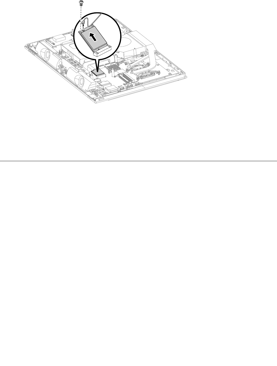
Step10.DisconnecttheantennacablefromtheTV-T unercard.
Step11.RemovethescrewthatsecurestheTV-Tunercardtothemotherboard.
Step12.PulltheTV-Tunercardupwardtoremoveitfromthecardportonthemotherboard.
Step13.ToinstallthenewTV-Tunercard:
a.InsertthenotchedendoftheTV-Tunercardintothecardportonthemotherboard.
b.SecurenewtheTV-Tunercardtothemotherboardwiththescrew.
c.ConnecttheantennacabletothenewTV-Tunercard.
Step14.ReattachtheEMIcover,middlecover,opticaldrive,standholder,footcoverandstandbase.
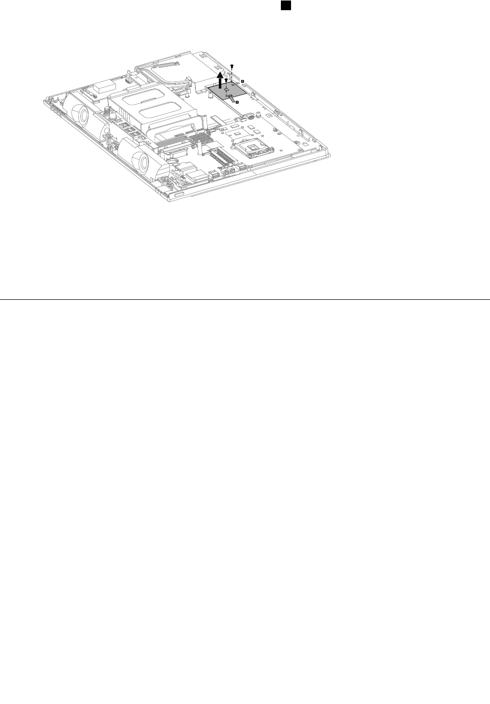
ReplacingtheWLANcard
Note:Turnoffthecomputerandwait3to5minutestoletitcooldownbeforeremovingthecover.
Note:Itmaybehelpfultoplacethecomputerface-downonasoftflatsurfaceforthisprocedure.Lenovo
recommendsthatyouuseablanket,towel,orothersoftclothtoprotectthecomputerscreenfromscratches
orotherdamage.
ToreplacetheWLANcard:
Step1.Removeanymedia(disks,CDs,DVDs,ormemorycards)fromthedrives,shutdowntheoperating
system,andturnoffthecomputerandallattacheddevices.
Step2.Unplugallpowercordsfromelectricaloutlets.
Step3.Disconnectallcablesattachedtothecomputer.Thisincludespowercords,input/output(I/O)
cables,andanyothercablesthatareconnectedtothecomputer.Referto“Leftandrightview”
and“Rearview”forhelpwithlocatingthevariousconnectors.
Step4.Removethestandbase.Referto“Removingthestandbase” .
Step5.Removethefootcover.Referto“Removingthefootcover” .
Step6.Removetheopticaldrive.Referto“Replacingtheopticaldrive” .
Step7.Removethestandholder.Referto“Removingthestandholder” .
Step8.Removethemiddlecover.Referto“Removingthemiddlecover” .
Step9.RemovetheEMIcover.Referto“RemovingtheEMIcover” .
36LenovoC560HardwareMaintenanceManual
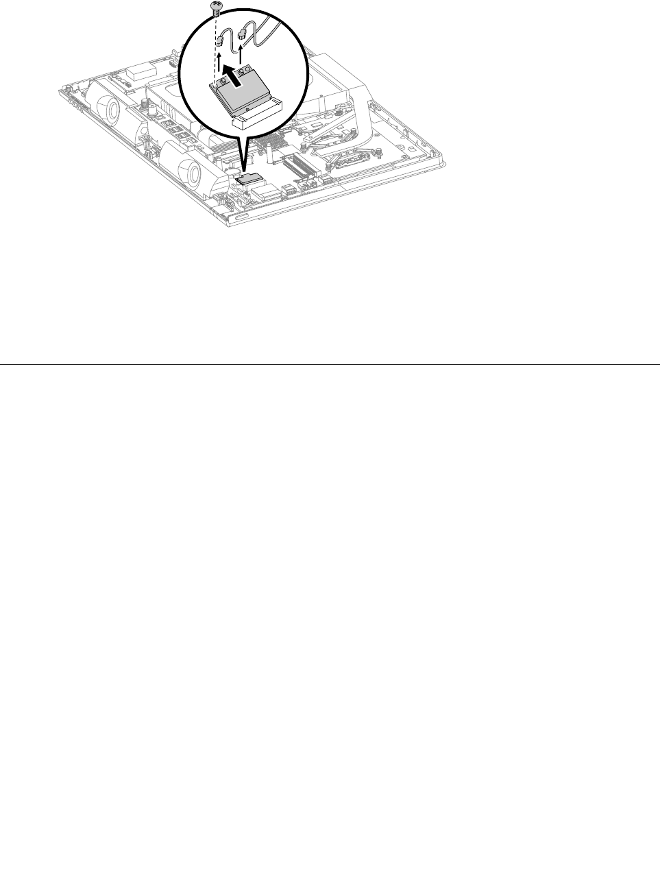
Step10.DisconnecttheantennacablesfromtheWLANcard.
Step11.RemovethescrewthatsecurestheWLANcardtothemotherboard.
Step12.LiftuptheWLANcardtoremoveitfromthesocket.
Step13.ToinstallthenewWLANcard:
a.InsertthenotchedendoftheWLANcardintothecardportonthemotherboard.
b.SecurenewtheWLANcardtothemotherboardwiththescrew.
c.ConnecttheantennacablestothenewWLANcard.
Step14.ReattachtheEMIcover,middlecover,opticaldrive,standholder,footcoverandstandbase.
Replacingthespeakersystem
Note:Turnoffthecomputerandwait3to5minutestoletitcooldownbeforeremovingthecover.
Note:Itmaybehelpfultoplacethecomputerface-downonasoftflatsurfaceforthisprocedure.Lenovo
recommendsthatyouuseablanket,towel,orothersoftclothtoprotectthecomputerscreenfromscratches
orotherdamage.
Toreplacethespeakersystem:
Step1.Removeanymedia(disks,CDs,DVDs,ormemorycards)fromthedrives,shutdowntheoperating
system,andturnoffthecomputerandallattacheddevices.
Step2.Unplugallpowercordsfromelectricaloutlets.
Step3.Disconnectallcablesattachedtothecomputer.Thisincludespowercords,input/output(I/O)
cables,andanyothercablesthatareconnectedtothecomputer.Referto“Leftandrightview”
and“Rearview”forhelpwithlocatingthevariousconnectors.
Step4.Removethestandbase.Referto“Removingthestandbase” .
Step5.Removethefootcover.Referto“Removingthefootcover” .
Step6.Removetheopticaldrive.Referto“Replacingtheopticaldrive” .
Step7.Removethestandholder.Referto“Removingthestandholder” .
Step8.Removethemiddlecover.Referto“Removingthemiddlecover” .
Step9.RemovetheEMIcover.Referto“RemovingtheEMIcover” .
Chapter7.Replacinghardware37
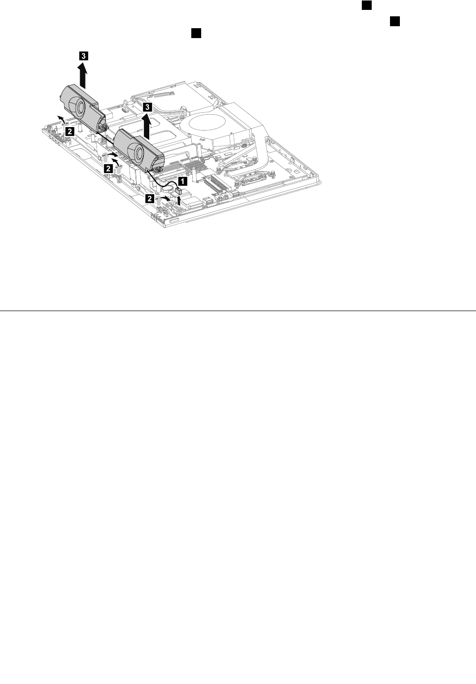
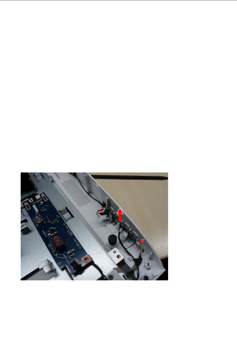
Step10.Disconnectthespeakercablesfromtheconnectoronthemotherboard.1
Step11.Removethefourrubberscrewsthatsecurethespeakersystemtothechassis2,thenliftup
thespeakersystemtoremoveit.3
1
2
2
2
3
3
Step12.Toinstallthenewspeakersystem:
a.Placethenewspeakersystemintoposition,thensecureitwiththerubberscrews.
b.Connectthenewspeakercablestotheconnectoronthemotherboard.
Step13.ReattachtheEMIcover,middlecover,opticaldrive,standholder,footcoverandstandbase.
Replacingthesystemfan
Note:Turnoffthecomputerandwait3to5minutestoletitcooldownbeforeremovingthecover.
Note:Itmaybehelpfultoplacethecomputerface-downonasoftflatsurfaceforthisprocedure.Lenovo
recommendsthatyouuseablanket,towel,orothersoftclothtoprotectthecomputerscreenfromscratches
orotherdamage.
Toreplacethesystemfan
Step1.Removeanymedia(disks,CDs,DVDs,ormemorycards)fromthedrives,shutdowntheoperating
system,andturnoffthecomputerandallattacheddevices.
Step2.Unplugallpowercordsfromelectricaloutlets.
Step3.Disconnectallcablesattachedtothecomputer.Thisincludespowercords,input/output(I/O)
cables,andanyothercablesthatareconnectedtothecomputer.Referto“Leftandrightview”
and“Rearview”forhelpwithlocatingthevariousconnectors.
Step4.Removethestandbase.Referto“Removingthestandbase” .
Step5.Removethefootcover.Referto“Removingthefootcover” .
Step6.Removetheopticaldrive.Referto“Replacingtheopticaldrive” .
Step7.Removethestandholder.Referto“Removingthestandholder” .
Step8.Removethemiddlecover.Referto“Removingthemiddlecover” .
Step9.RemovetheEMIcover.Referto“RemovingtheEMIcover” .
Step10.Removethesealingtapebetweenthesystemfanandheat-sink.
38LenovoC560HardwareMaintenanceManual
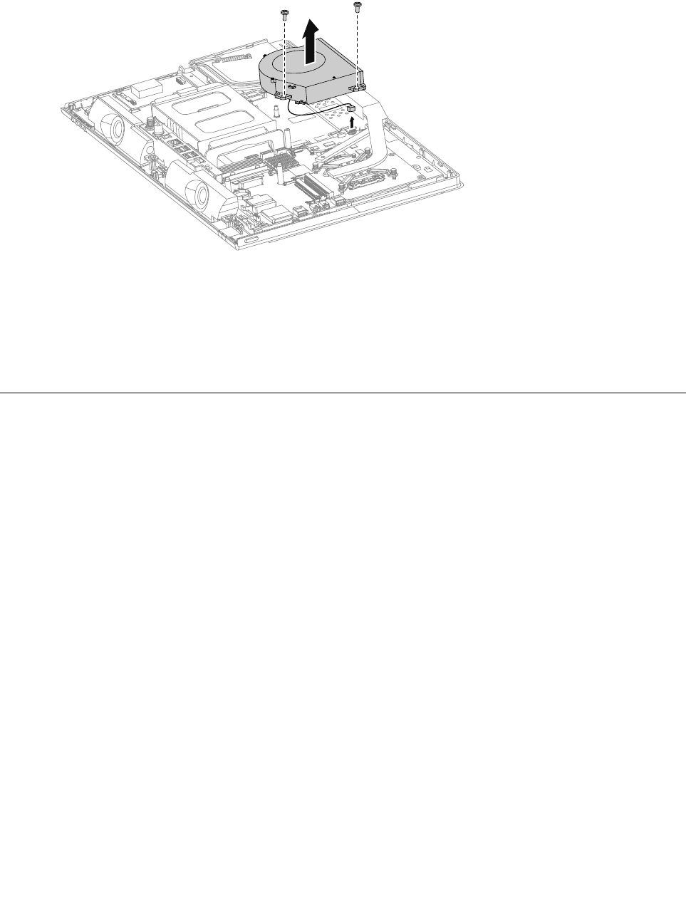
Step11.Removethethreescrewsthatsecurethesystemfantothechassis.
Step12.Disconnectthepowercablefromthemotherboard.
Step13.Liftupthesystemfantoremoveit.
Step14.Toinstallthenewsystemfan:
a.Placethenewsystemfanintoposition,andthensecureittothechassiswiththethreescrews.
b.Connectthesystemfanpowercabletotheconnectoronthemotherboard.
c.Usethesealingtapetosealthegapin-betweenthesystemfanandheat-sink.
Step15.ReattachtheEMIcover,middlecover,opticaldrive,standholder,footcoverandstandbase.
Replacingtheheat-sink
Note:Turnoffthecomputerandwait3to5minutestoletitcooldownbeforeremovingthecover.
Note:Itmaybehelpfultoplacethecomputerface-downonasoftflatsurfaceforthisprocedure.Lenovo
recommendsthatyouuseablanket,towel,orothersoftclothtoprotectthecomputerscreenfromscratches
orotherdamage.
Toreplacetheheat-sink:
Step1.Removeanymedia(disks,CDs,DVDs,ormemorycards)fromthedrives,shutdowntheoperating
system,andturnoffthecomputerandallattacheddevices.
Step2.Unplugallpowercordsfromelectricaloutlets.
Step3.Disconnectallcablesattachedtothecomputer.Thisincludespowercords,input/output(I/O)
cables,andanyothercablesthatareconnectedtothecomputer.Referto“Leftandrightview”
and“Rearview”forhelpwithlocatingthevariousconnectors.
Step4.Removethestandbase.Referto“Removingthestandbase” .
Step5.Removethefootcover.Referto“Removingthefootcover” .
Step6.Removetheopticaldrive.Referto“Replacingtheopticaldrive” .
Step7.Removethestandholder.Referto“Removingthestandholder” .
Step8.Removethemiddlecover.Referto“Removingthemiddlecover” .
Step9.RemovetheEMIcover.Referto“RemovingtheEMIcover” .
Step10.Removethesealingtapebetweenthesystemfanandheat-sink.
Chapter7.Replacinghardware39
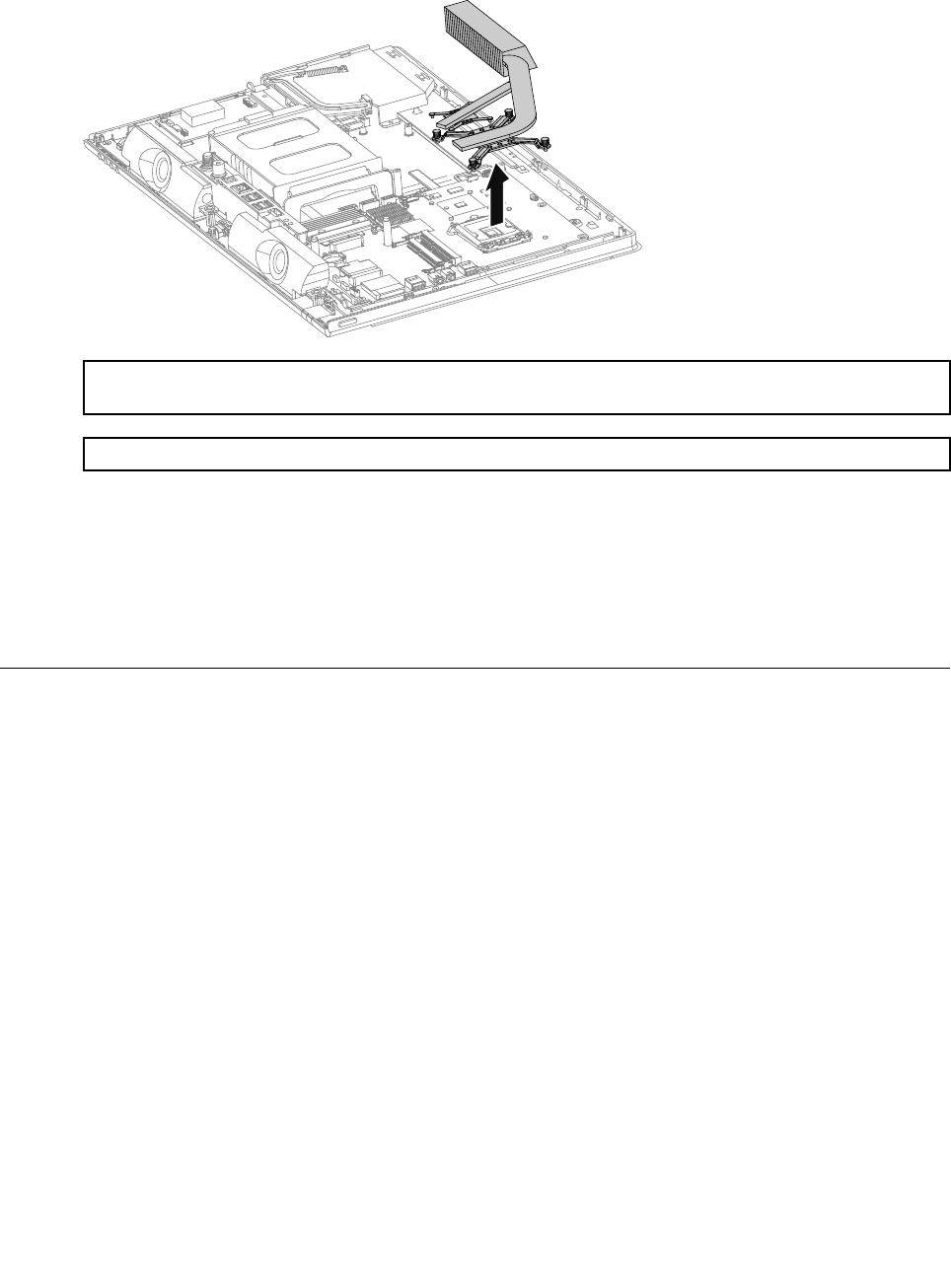
Step11.Removetheeightscrewsthatsecuretheheat-sinktothemotherboardandchassis.
Step12.Removetheheat-sinkbyliftingitup.
Attention:Placetheheat-sinkupsidedownonaflatsurfacetopreventthermalgreasefromcontaminating
othercomponents.
Attention:UseanalcoholpadtowipethethermalgreaseofftheCPU.
Step13.Toinstallthenewheat-sink:
a.Lineupthenewheat-sinkwithmountingholesonthemotherboard,thenplaceitintoposition.
b.Followthenumbersprintedonthenewheat-sinktosecureitinorderusingtheeightscrews.
c.Usethesealingtapetosealthegapin-betweenthesystemfanandheat-sink.
Step14.ReattachtheEMIcover,middlecover,opticaldrive,standholder,footcoverandstandbase.
Replacingthecamera
Note:Turnoffthecomputerandwait3to5minutestoletitcooldownbeforeremovingthecover.
Note:Itmaybehelpfultoplacethecomputerface-downonasoftflatsurfaceforthisprocedure.Lenovo
recommendsthatyouuseablanket,towel,orothersoftclothtoprotectthecomputerscreenfromscratches
orotherdamage.
Toreplacethecamera:
Step1.Removeanymedia(disks,CDs,DVDs,ormemorycards)fromthedrives,shutdowntheoperating
system,andturnoffthecomputerandallattacheddevices.
Step2.Unplugallpowercordsfromelectricaloutlets.
Step3.Disconnectallcablesattachedtothecomputer.Thisincludespowercords,input/output(I/O)
cables,andanyothercablesthatareconnectedtothecomputer.Referto“Leftandrightview”
and“Rearview”forhelpwithlocatingthevariousconnectors.
Step4.Removethestandbase.Referto“Removingthestandbase” .
Step5.Removethefootcover.Referto“Removingthefootcover” .
Step6.Removetheopticaldrive.Referto“Replacingtheopticaldrive” .
Step7.Removethestandholder.Referto“Removingthestandholder” .
Step8.Removethemiddlecover.Referto“Removingthemiddlecover” .
40LenovoC560HardwareMaintenanceManual
Step9.RemovetheEMIcover.Referto“RemovingtheEMIcover” .
Step10.Removetheheat-sink.Referto“Replacingtheheatsink” .
Step11.Removethescrewthatsecurescameratothefrontbezel.
Step12.Liftupthecameraanddisconnectthedatacablefromthecamera.
1
2
Step13.Toinstallthenewcamera:
a.Connectthedatacabletothenewcamera.
b.Lineuptheholesinthenewcamerawiththemountingholesonthefrontbezelandsecureit
withthescrew.
Step14.Reattachtheheat-sink,EMIcover,middlecover,opticaldrive,standholder,footcoverandstand
base.
ReplacingtheCPU
Note:Turnoffthecomputerandwait3to5minutestoletitcooldownbeforeremovingthecover.
Note:Itmaybehelpfultoplacethecomputerface-downonasoftflatsurfaceforthisprocedure.Lenovo
recommendsthatyouuseablanket,towel,orothersoftclothtoprotectthecomputerscreenfromscratches
orotherdamage.
ToreplacetheCPU
Step1.Removeanymedia(disks,CDs,DVDs,ormemorycards)fromthedrives,shutdowntheoperating
system,andturnoffthecomputerandallattacheddevices.
Step2.Unplugallpowercordsfromelectricaloutlets.
Step3.Disconnectallcablesattachedtothecomputer.Thisincludespowercords,input/output(I/O)
cables,andanyothercablesthatareconnectedtothecomputer.Referto“Leftandrightview”
and“Rearview”forhelpwithlocatingthevariousconnectors.
Step4.Removethestandbase.Referto“Removingthestandbase” .
Step5.Removethefootcover.Referto“Removingthefootcover” .
Step6.Removetheopticaldrive.Referto“Replacingtheopticaldrive” .
Chapter7.Replacinghardware41
Step7.Removethestandholder.Referto“Removingthestandholder” .
Step8.Removethemiddlecover.Referto“Removingthemiddlecover” .
Step9.RemovetheEMIcover.Referto“RemovingtheEMIcover” .
Step10.Removetheheat-sink.Referto“Replacingtheheatsink” .
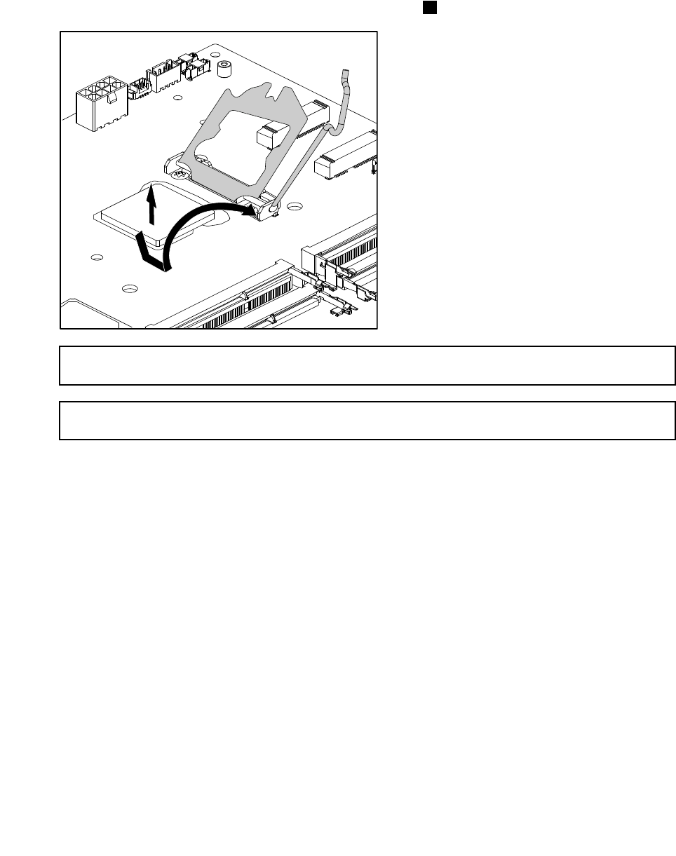
Step11.Liftthesmallhandleandopentheretainer.
Step12.Liftthemicroprocessorstraightupandoutofthesocket.3
Attention:Donottouchthegoldcontactsonthebottomofthemicroprocessor.Whenhandlingthe
microprocessor,touchonlythesides.
Note:Donotdropanythingontothemicroprocessorsocketwhileitisexposed.Thesocketpinsmust
bekeptascleanaspossible.
42LenovoC560HardwareMaintenanceManual
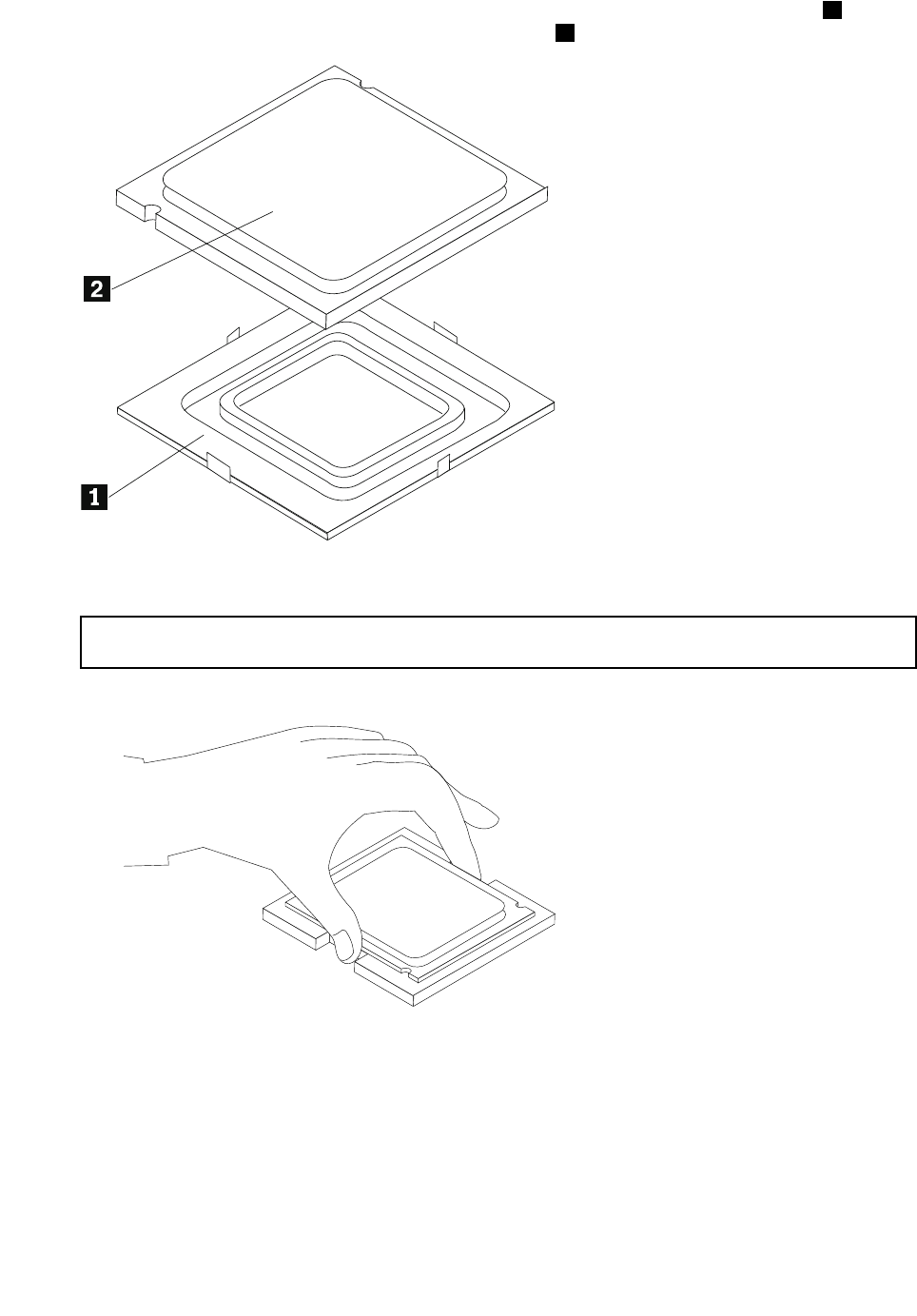
Step13.Holdingthesidesofthemicroprocessorwithyourfingers,removetheprotectivecover1that
protectsthegoldcontactsonthenewmicroprocessor.2
Step14.Holdingthesidesofthemicroprocessorwithyourfingers,positionthemicroprocessorsothatthe
notchesonthemicroprocessorarealignedwiththetabsinthemicroprocessorsocket.
Important:Toavoiddamagingthemicroprocessorcontacts,keepthemicroprocessorcompletelylevel
whileinstallingitintothesocket.
Step15.Lowerthemicroprocessorstraightdownintoitssocketonthemotherboard.
Step16.Tosecurethemicroprocessorinthesocket,closethemicroprocessorretainerandlockitinto
positionwiththesmallhandle.
Step17.Useathermalgreasesyringetoplace5dropsofgreaseonthetopofthemicroprocessor.Each
dropofgreaseshouldbe0.03ml(3tickmarksonthegreasesyringe).
Step18.Reattachtheheat-sink,EMIcover,middlecover,opticaldrive,standholder,footcoverandstand
base.
Chapter7.Replacinghardware43
Replacingthefrontcontrolboard
Note:Turnoffthecomputerandwait3to5minutestoletitcooldownbeforeremovingthecover.
Note:Itmaybehelpfultoplacethecomputerface-downonasoftflatsurfaceforthisprocedure.Lenovo
recommendsthatyouuseablanket,towel,orothersoftclothtoprotectthecomputerscreenfromscratches
orotherdamage.
Toreplacethefrontcontrolboard:
Step1.Removeanymedia(disks,CDs,DVDs,ormemorycards)fromthedrives,shutdowntheoperating
system,andturnoffthecomputerandallattacheddevices.
Step2.Unplugallpowercordsfromelectricaloutlets.
Step3.Disconnectallcablesattachedtothecomputer.Thisincludespowercords,input/output(I/O)
cables,andanyothercablesthatareconnectedtothecomputer.Referto“Leftandrightview”
and“Rearview”forhelpwithlocatingthevariousconnectors.
Step4.Removethestandbase.Referto“Removingthestandbase” .
Step5.Removethefootcover.Referto“Removingthefootcover” .
Step6.Removetheopticaldrive.Referto“Replacingtheopticaldrive” .
Step7.Removethestandholder.Referto“Removingthestandholder” .
Step8.Removethemiddlecover.Referto“Removingthemiddlecover” .
Step9.RemovetheEMIcover.Referto“RemovingtheEMIcover” .
Step10.Removethespeakersystem.Referto“Replacingthespeakersystem” .
Step11.Disconnectthedatacablesfromthefrontcontrolboard.
Step12.Thecontrolboardispinnedtothebezel,pushthetwopinsthenliftuptheboardtoremoveit.
Step13.Toinstallthenewfrontcontrolboard:
a.Connectthedatacabletothenewfrontcontrolboard.
b.Lineupthenewfrontcontrolboardwiththefrontbezel,thenplaceitintoposition.
Step14.Reattachthespeakersystem,EMIcover,middlecover,opticaldrive,standholder,footcover
andstandbase.
44LenovoC560HardwareMaintenanceManual
Replacingthepowerswitchboard
Note:Turnoffthecomputerandwait3to5minutestoletitcooldownbeforeremovingthecover.
Note:Itmaybehelpfultoplacethecomputerface-downonasoftflatsurfaceforthisprocedure.Lenovo
recommendsthatyouuseablanket,towel,orothersoftclothtoprotectthecomputerscreenfromscratches
orotherdamage.
Toreplacethepowerswitchboard
Step1.Removeanymedia(disks,CDs,DVDs,ormemorycards)fromthedrives,shutdowntheoperating
system,andturnoffthecomputerandallattacheddevices.
Step2.Unplugallpowercordsfromelectricaloutlets.
Step3.Disconnectallcablesattachedtothecomputer.Thisincludespowercords,input/output(I/O)
cables,andanyothercablesthatareconnectedtothecomputer.Referto“Leftandrightview”
and“Rearview”forhelpwithlocatingthevariousconnectors.
Step4.Removethestandbase.Referto“Removingthestandbase” .
Step5.Removethefootcover.Referto“Removingthefootcover” .
Step6.Removetheopticaldrive.Referto“Replacingtheopticaldrive” .
Step7.Removethestandholder.Referto“Removingthestandholder” .
Step8.Removethemiddlecover.Referto“Removingthemiddlecover” .
Step9.RemovetheEMIcover.Referto“RemovingtheEMIcover” .
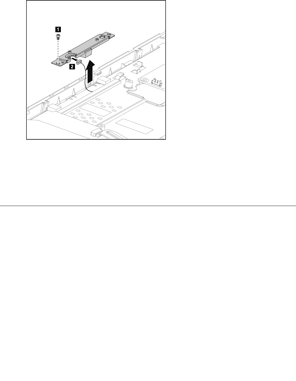
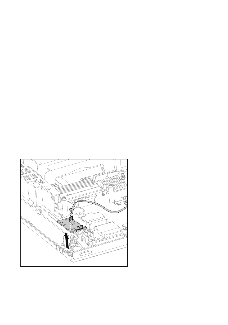
Step10.Removethescrewthatsecurethepowerswitchboardtothefrontbezel.
Step11.Disconnectthedatacablefromthepowerswitchboard,thenliftupthepowerswitchboard.
Step12.Toinstallthepowerswitchboard:
a.Lineuptheholeonthenewpowerswitchboardwiththemountingholeonthefrontbezel,
thenplaceitintoposition.
b.Securethepowerswitchboardwiththescrew.
c.Connectthepowercabletothenewpowerswitchboard.
Chapter7.Replacinghardware45

Step13.ReattachtheEMIcover,middlecover,opticaldrive,standholder,footcoverandstandbase.
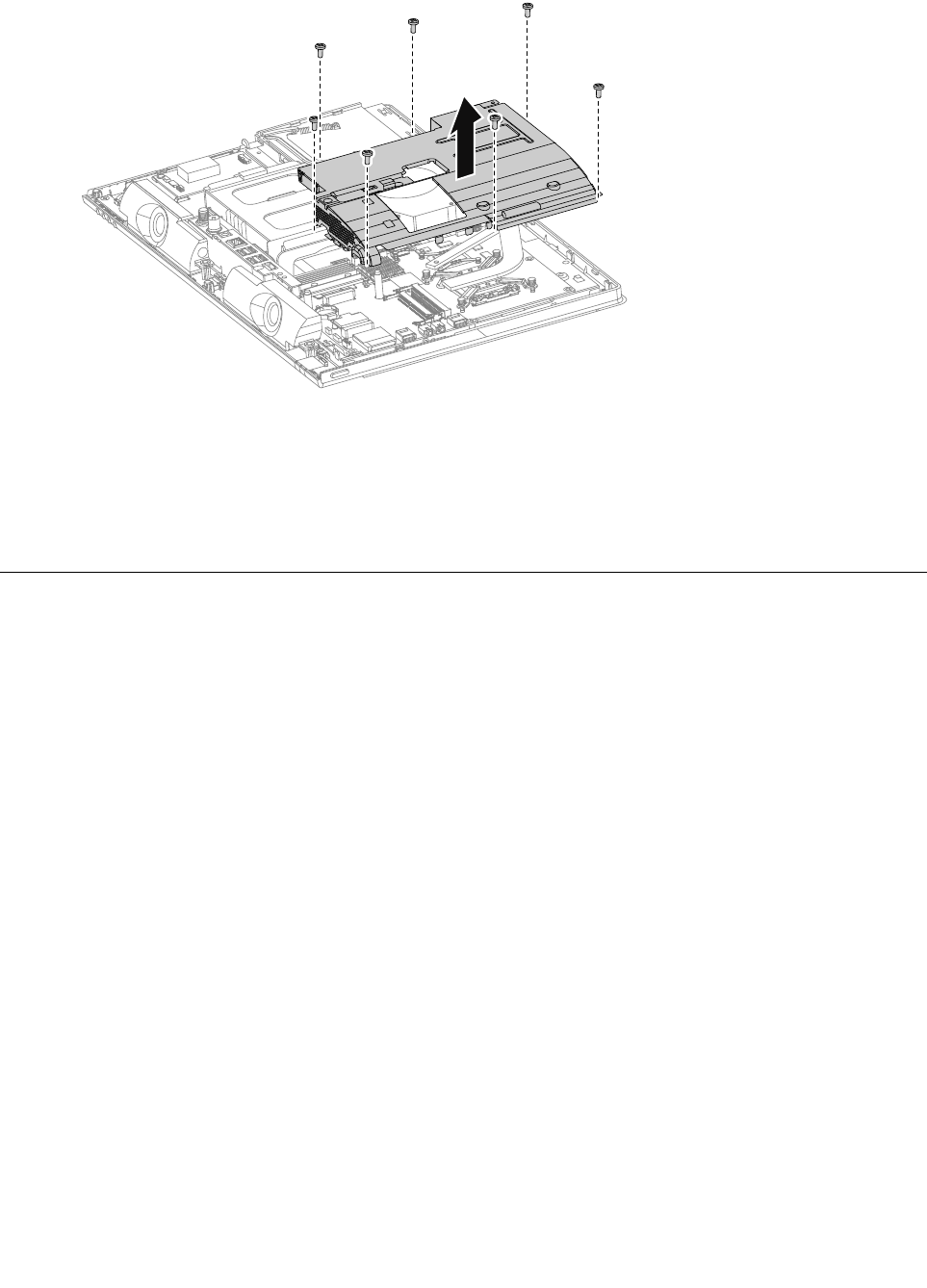
Replacingthemotherboard
Note:Turnoffthecomputerandwait3to5minutestoletitcooldownbeforeremovingthecover.
Note:Itmaybehelpfultoplacethecomputerface-downonasoftflatsurfaceforthisprocedure.Lenovo
recommendsthatyouuseablanket,towel,orothersoftclothtoprotectthecomputerscreenfromscratches
orotherdamage.
Toreplacethemotherboard:
Step1.Removeanymedia(disks,CDs,DVDs,ormemorycards)fromthedrives,shutdowntheoperating
system,andturnoffthecomputerandallattacheddevices.
Step2.Unplugallpowercordsfromelectricaloutlets.
Step3.Disconnectallcablesattachedtothecomputer.Thisincludespowercords,input/output(I/O)
cables,andanyothercablesthatareconnectedtothecomputer.Referto“Leftandrightview”
and“Rearview”forhelpwithlocatingthevariousconnectors.
Step4.Removethestandbase.Referto“Removingthestandbase” .
Step5.Removethefootcover.Referto“Removingthefootcover” .
Step6.Removethememorymodules.Referto“Replacingamemorymodule” .
Step7.Removetheopticaldrive.Referto“Replacingtheopticaldrive” .
Step8.Removethestandholder.Referto“Removingthestandholder” .
Step9.Removethemiddlecover.Referto“Removingthemiddlecover” .
Step10.RemovetheEMIcover.Referto“RemovingtheEMIcover” .
Step11.Removetheheat-sink.Referto“Replacingtheheat-sink” .
Step12.RemovetheCPU.Referto“ReplacingtheCPU” .
Step13.RemovetheTV-T unercard.Referto“ReplacingtheTVtunercard” .
Step14.RemovetheWLANcard.Referto“ReplacingtheWLANcard” .
Step15.Unplugthefollowingcablesfromconnectorsonthemotherboard:
•Powerswitchboardcable
•Speakersystemcable
•Frontcontrolboardcable
•Convertercable
•Cameracable
•Systemfanpowercable
•Harddiskdrivepowercable
•HarddiskdriveSATAcable(Black)
•OpticaldriveSATAcable(Red)
•Opticaldiskdrivepowercable
•LVDScable
46LenovoC560HardwareMaintenanceManual
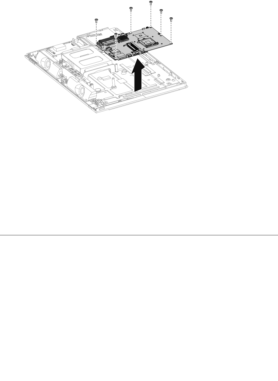
Step16.Removethesixscrewsthatsecurethemotherboardtothechassisandliftthemotherboardupto
removeit.
Step17.Toinstallthenewmotherboard:
a.Lineuptheholesonthenewmotherboardwiththemountingholeschassisandplacethenew
motherboardintoposition.
b.Usethescrewstosecurethenewmotherboardtothechassis.
Step18.Installthefollowingpartstothenewmotherboard:
•WLANcard
•TV-Tunercard
•CPU
•Heat-sink
•Memorymodule
Step19.Connectallthecablestothenewmotherboard.
Step20.ReattachtheEMIcover,middlecover,opticaldrive,standholder,footcoverandstandbase.
ReplacingtheLEDpanelmodule
Note:Turnoffthecomputerandwait3to5minutestoletitcooldownbeforeremovingthecover.
Note:Itmaybehelpfultoplacethecomputerface-downonasoftflatsurfaceforthisprocedure.Lenovo
recommendsthatyouuseablanket,towel,orothersoftclothtoprotectthecomputerscreenfromscratches
orotherdamage.
ToreplacetheLEDpanelmodule:
Step1.Removeanymedia(disks,CDs,DVDs,ormemorycards)fromthedrives,shutdowntheoperating
system,andturnoffthecomputerandallattacheddevices.
Step2.Unplugallpowercordsfromelectricaloutlets.
Step3.Disconnectallcablesattachedtothecomputer.Thisincludespowercords,input/output(I/O)
cables,andanyothercablesthatareconnectedtothecomputer.Referto“Leftandrightview”
and“Rearview”forhelpwithlocatingthevariousconnectors.
Step4.Removethestandbase.Referto“Removingthestandbase” .
Chapter7.Replacinghardware47
Step5.Removethefootcover.Referto“Removingthefootcover” .
Step6.Removetheopticaldrive.Referto“Replacingtheopticaldrive” .
Step7.Removethestandholder.Referto“Removingthestandholder” .
Step8.Removethemiddlecover.Referto“Removingthemiddlecover” .
Step9.RemovetheEMIcover.Referto“RemovingtheEMIcover” .
Step10.Removethespeakersystem.Referto“Replacingthespeakersystem” .
Step11.Removethefrontcontrolboard.Referto“Removingthefrontcontrolboard” .
Step12.Removethepowerswitchboard.Referto“Removingthepowerswitchboard” .
Step13.Removethemotherboard.Referto“Replacingthemotherboard” .
Step14.Disconnectthecablefromtheconnectoronthefrontcontrolboard.
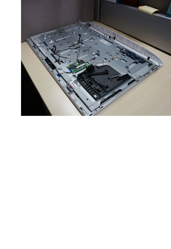
Step15.TheLEDpanelmoduleincluding:LEDpanel,touch,touchcontrolboard,touchcable,middlecase,
chassis,Wi-Ficardantenna,TV-Tunercardantenna,LVDScable,frontbezel.
Step16.ToinstallthenewtheLEDpanelmodule:
a.LineupthemotherboardwiththenewLEDpanelmodule,thensecurethemotherboard
totheLEDpanelmodule.
b.ConnecttheLVDScable,Wi-Ficardantenna,TV-T unercardantenna,touchcontrolboard
cable,converterboardcabletotheconnectorsonthemotherboard.
Step17.Reattachthepowerswitchboard,frontcontrolboard,systemfan,speakersystem,EMIcover,
middlecover,standholder,opticaldrive,footcoverandstandbase.
48LenovoC560HardwareMaintenanceManual

Chapter8.Generalinformation
Thischapterprovidesgeneralinformationthatappliestoallcomputermodelscoveredbythismanual.
AdditionalServiceInformation
Thischapterprovidesadditionalinformationthattheservicerepresentativemightfindhelpful.
Powermanagement
Powermanagementreducesthepowerconsumptionofcertaincomponentsofthecomputersuchasthe
systempowersupply,processor,harddiskdrives,andsomemonitors.
Advancedconfigurationandpowerinterface(ACPI)BIOS
AsthiscomputerhasanACPIBIOSsystem,theoperatingsystemisallowedtocontrolthepower
managementfeaturesofthecomputerandthesettingsforAdvancedPowerManagement(APM)BIOSmode
isignored.NotalloperatingsystemssupportACPIBIOSmode.
AutomaticPower-Onfeatures
TheAutomaticPower-OnfeatureswithinthePowerManagementmenuallowyoutoenableanddisable
featuresthatturnonthecomputerautomatically.
•WakeUponAlarm:Youcanspecifyadateandtimeatwhichthecomputerwillbeturnedonautomatically.
Thiscanbeeitherasingleevent,adailyeventoraweeklyevent.
•WakeUponLAN:ThisfeatureallowsLANadaptercardtowaketheSystem.
©CopyrightLenovo201349
