Lenovo Horizon 2 27 Hmm 20140528 User Manual All In One PC Hardware Maintenance Table (ideacentre) Type 10167
Lenovo-Horizon-2-27-Hardware-Maintenance-Manual-788805 lenovo-horizon-2-27-hardware-maintenance-manual-788805
Horizon 2 27 - Hardware Maintenance Manual horizon_2_27_hmm_en Free User Guide for Lenovo Tablet and eReader, Manual - page1
2014-06-05
User Manual: Lenovo Lenovo Horizon 2 27 Hmm 20140528 Lenovo Horizon 2 27 All-In-One PC Hardware Maintenance Manual Horizon 2 27 Table PC (ideacentre) - Type 10167
Open the PDF directly: View PDF ![]() .
.
Page Count: 49
- Chapter 1. About this manual
- Chapter 2. Safety information
- Chapter 3. General information
- Chapter 4. General Checkout
- Chapter 5. Using the Setup Utility
- Chapter 6. Symptom-to-FRU Index
- Chapter 7. Replacing hardware
- General information
- Replacing the keyboard and mouse
- Removing the rear cover
- Replacing the battery
- Replacing a memory module
- Replacing the Wi-Fi card
- Replacing the hard disk drive
- Replacing the fan module
- Replacing the heat-sink modules
- Replacing the speaker system
- Replacing the I/O board
- Replacing the power switch board
- Replacing the motherboard
- Replacing the camera
- Replacing the LED panel module
- Chapter 8. FRU lists
- Chapter 9. General information

IdeaCentreHorizon227All-In-OnePC
HardwareMaintenanceManual
MachineTypes:F0AQ

IdeaCentreHorizon227All-In-OnePC
HardwareMaintenanceManual
MachineTypes:F0AQ

SecondEdition(May2014)27th
©CopyrightLenovo2014.
LIMITEDANDRESTRICTEDRIGHTSNOTICE:IfdataorsoftwarearedeliveredpursuantaGeneralServices
Administration“GSA”contract,use,reproduction,ordisclosureissubjecttorestrictionssetforthinContractNo.
GS-35F-05925

Contents
Chapter1.Aboutthismanual......1
ImportantSafetyInformation..........1
Chapter2.Safetyinformation......3
Generalsafety................3
Electricalsafety...............3
Safetyinspectionguide............5
Handlingelectrostaticdischarge-sensitive
devices..................5
Groundingrequirements............6
Safetynotices................6
Chapter3.Generalinformation.....9
Specifications................9
Chapter4.GeneralCheckout.....11
Chapter5.UsingtheSetupUtility...13
StartingtheLenovoBIOSSetupUtilityprogram.13
Viewingandchangingsettings........13
Usingpasswords..............13
Enablingordisablingadevice........15
Selectingastartupdevice..........16
ExitingtheLenovoBIOSSetupUtilityprogram..17
Chapter6.Symptom-to-FRUIndex..19
Harddiskdrivebooterror..........19
PowerSupplyProblems...........19
POSTerrorcodes.............20
Undeterminedproblems...........20
Chapter7.Replacinghardware....21
Generalinformation.............21
Replacingthekeyboardandmouse......22
Removingtherearcover...........22
Replacingthebattery............24
Replacingamemorymodule.........25
ReplacingtheWi-Ficard...........26
Replacingtheharddiskdrive.........27
Replacingthefanmodule..........29
Replacingtheheat-sinkmodules.......29
Replacingthespeakersystem........30
ReplacingtheI/Oboard...........31
Replacingthepowerswitchboard.......32
Replacingthemotherboard..........33
Replacingthecamera............34
ReplacingtheLEDpanelmodule.......35
Chapter8.FRUlists..........37
Chapter9.Generalinformation....43
AdditionalServiceInformation........43
©CopyrightLenovo2014iii

ivIdeaCentreHorizon227All-In-OnePCHardwareMaintenanceManual
Chapter1.Aboutthismanual
ThismanualcontainsserviceandreferenceinformationforIdeaCentreHorizon227All-In-Onecomputers
listedonthecover.ItisintendedonlyfortrainedservicerswhoarefamiliarwithLenovocomputerproducts.
BeforeservicingaLenovoproduct,besuretoreadtheSafetyInformation.
ThedescriptionoftheTV-tunercardinthismanualappliesonlytocomputerswithaTV-tunercardinstalled.
ItdoesnotapplytocomputerswithoutaTV-tunercard.
ImportantSafetyInformation
BesuretoreadallCAUTIONandDANGERsectionsinthismanualbeforefollowinganyoftheinstructions.
VeuillezliretouteslesconsignesdetypeDANGERetATTENTIONduprésentdocumentavantd’exécuter
lesinstructions.
LesenSieunbedingtalleHinweisevomTyp“ACHTUNG”oder“VORSICHT”indieserDokumentation,bevor
SieirgendwelcheVorgängedurchführen
LeggereleistruzioniintrodottedaATTENZIONEePERICOLOpresentinelmanualeprimadieseguireuna
qualsiasidelleistruzioni
Certifique-sedelertodasasinstruçõesdecuidadoeperigonestemanualantesdeexecutarqualquer
umadasinstruções
Esimportantequeleatodaslasdeclaracionesdeprecauciónydepeligrodeestemanualantesdeseguir
lasinstrucciones.
©CopyrightLenovo20141

2IdeaCentreHorizon227All-In-OnePCHardwareMaintenanceManual

Chapter2.Safetyinformation
Thischaptercontainsthesafetyinformationthatyouneedtobefamiliarwithbeforeservicingacomputer.
Generalsafety
Followtheserulestoensuregeneralsafety:
•Keeptheareasaroundthecomputerclearandcleanduringandaftermaintenance.
•Whenliftinganyheavyobject:
1.Ensureyoucanstandsafelywithoutslipping.
2.Distributetheweightoftheobjectequallyacrossbothfeet.
3.Liftslowly.Nevermovesuddenlyortwistwhenyouattempttolift.
4.Liftbystandingorbypushingupwithyourlegmuscles;thisactionremovesthestrainfromthe
musclesinyourback.
Donotattempttoliftanyobjectsthatweighmorethan16kg(35lbs.)orobjectsthatyouthink
aretooheavyforyou.
•Donotperformanyactionthatwouldcreateahazardforthecustomer,orwouldmakethecomputer
unsafe.
•Beforeyoustartthecomputer,ensurethatotherservicerepresentativesandcustomerpersonnelarenot
inapositionthatwouldcreateahazardforthem.
•Placeremovedcoversandotherpartsinasafeplace,awayfromallpersonnel,whileyouareservicingthe
computer.
•Keepyourtoolcaseawayfromareasthatpeoplemaywalkthroughtoensureno-onetripsoverit.
•Donotwearlooseclothingthatcanbetrappedinthemovingpartsofamachine.Ensurethatyoursleeves
arefastenedorrolledupaboveyourelbows.Ifyourhairislong,tieorfastenitback.
•Inserttheendsofyournecktieorscarfinsideclothingorfastenitwithanonconductiveclip,approximately
8centimeters(3inches)fromtheend.
•Donotwearjewelry,chains,metal-frameeyeglasses,ormetalfastenersforyourclothing.
Remember:Metalobjectsaregoodelectricalconductors.
•Wearsafetyglasseswhenyouare:hammering,drillingsoldering,cuttingwire,attachingsprings,using
solvents,orworkinginanyotherconditionsthatmightbehazardoustoyoureyes.
•Afterservice,reinstallallsafetyshields,guards,labels,andgroundwires.Replaceanysafetydevice
thatiswornordefective.
•Reattachallcoverscorrectlybeforereturningthecomputertothecustomer.
Electricalsafety
CAUTION:
Electricalcurrentfrompower,telephone,andcommunicationcablescanbehazardous.Toavoid
personalinjuryorequipmentdamage,disconnectanyattachedpowercords,telecommunication
cables,networkcables,andmodemcablesbeforeyouopenthecomputercovers,unlessinstructed
otherwiseintheinstallationandconfigurationprocedures.
©CopyrightLenovo20143

Observethefollowingruleswhenworkingonelectricalequipment.
Important:Useonlyapprovedtoolsandtestequipment.Somehandtoolshavehandlescoveredwithasoft
materialthatdoesnotinsulateyouwhenworkingwithliveelectricalcurrents.Manycustomershaverubber
floormatsneartheirequipmentthatcontainsmallconductivefiberstodecreaseelectrostaticdischarge.
•Findtheroomemergencypower-off(EPO)switch,disconnectingswitch,orelectricaloutlet.Ifanelectrical
accidentoccurs,youcanthenoperatetheswitchorunplugthepowercordquickly.
•Donotworkaloneunderhazardousconditionsornearequipmentthathashazardousvoltages.
•Disconnectallpowerbefore:
–Performingamechanicalinspection
–Workingnearpowersupplies
–RemovingorinstallingFieldReplaceableUnits(FRUs)
•Beforeyoustarttoworkonthecomputer,unplugthepowercord.Ifyoucannotunplugit,askthe
customertopower-offtheelectricaloutletthatsuppliespowertothemachineandtolocktheelectrical
outletintheoffposition.
•Ifyouneedtoworkonacomputerthathasexposedelectricalcircuits,observethefollowingprecautions:
–Ensurethatanotherperson,familiarwiththepower-offcontrols,isnearyou.
Remember:Anotherpersonmustbetheretoswitchoffthepower,ifnecessary.
–Useonlyonehandwhenworkingwithpowered-onelectricalequipment;keeptheotherhandinyour
pocketorbehindyourback.
Remember:Theremustbeacompletecircuittocauseelectricalshock.Byobservingtheaboverule,
youmaypreventacurrentfrompassingthroughyourbody.
–Whenusingatester,setthecontrolscorrectlyandusetheapprovedprobeleadsandaccessoriesfor
thattester.
–Standonsuitablerubbermats(obtainedlocally,ifnecessary)toinsulateyoufromgroundssuchas
metalfloorstripsandmachineframes.
Observethespecialsafetyprecautionswhenyouworkwithveryhighvoltages;theseinstructionsarein
thesafetysectionsofthemaintenanceinformation.Useextremecarewhenmeasuringhighvoltages.
•Regularlyinspectandmaintainyourelectricalhandtoolstoensuretheyaresafetouse.
•Donotusewornorbrokentoolsandtesters.
•Neverassumethatpowerhasbeendisconnectedfromacircuit.First,checkthatithasbeenpoweredoff.
•Alwayslookcarefullyforpossiblehazardsinyourworkarea.Examplesofthesehazardsarewetfloors,
non-groundedpowerextensioncables,conditionsthatmaycauseorallowpowersurges,andmissing
safetygrounds.
•Donottouchliveelectricalcircuitswiththereflectivesurfaceofaplasticdentalmirror.Thissurfaceis
conductive,andtouchingalivecircuitcancausepersonalinjuryanddamagetothecomputer.
•Donotservicethefollowingpartswiththepoweronwhentheyareremovedfromtheirnormaloperating
positionsinacomputer:
–Powersupplyunits
–Pumps
–Blowersandfans
–Motorgenerators
andsimilarunits.(Thispracticeensurescorrectgroundingoftheunits.)
•Ifanelectricalaccidentoccurs:
–Usecaution;donotbecomeavictimyourself.
4IdeaCentreHorizon227All-In-OnePCHardwareMaintenanceManual

–Switchoffpower.
–Sendanotherpersontogetmedicalaid.
Safetyinspectionguide
Theintentofthisinspectionguideistoassistyouinidentifyingpotentialhazardsposedbytheseproducts.
Eachcomputer,asitwasdesignedandbuilt,hadrequiredsafetyitemsinstalledtoprotectusersand
servicepersonnelfrominjury.Thisguideaddressesonlythoseitems.However,goodjudgmentshouldbe
usedtoidentifypotentialsafetyhazardsduetoattachmentoffeaturesoroptionsnotcoveredbythis
inspectionguide.
Ifanyhazardsarepresent,youmustdeterminehowserioustheapparenthazardcouldbeandwhetheryou
cancontinuewithoutfirstresolvingtheproblem.
Considerthefollowingitemsandthesafetyhazardstheypresent:
•Electricalhazards,especiallyprimarypower(primaryvoltageontheframecancauseseriousorfatal
electricalshock).
•Explosivehazards,suchasadamagedCRTfaceorbulgingcapacitor
•Mechanicalhazards,suchaslooseormissinghardware
Theguideconsistsofaseriesofstepspresentedasachecklist.Beginthecheckswiththepoweroff,and
thepowercorddisconnected.
Checklist:
1.Checkexteriorcoversfordamage(loose,broken,orsharpedges).
2.Power-offthecomputer.Disconnectthepowercord.
3.Checkthepowercordfor:
a.Athird-wiregroundconnectoringoodcondition.Useametertomeasurethird-wireground
continuityfor0.1ohmorlessbetweentheexternalgroundpinandframeground.
b.Thepowercordshouldbetheappropriatetypeasspecifiedinthepartslistings.
c.Insulationmustnotbefrayedorworn.
4.Removethecover.
5.Checkforanyobviousalterations.Usegoodjudgmentastothesafetyofanyalterations.
6.Checkinsidetheunitforanyobvioushazards,suchasmetalfilings,contamination,waterorother
liquids,orsignsoffireorsmokedamage.
7.Checkforworn,frayed,orpinchedcables.
8.Checkthatthepower-supplycoverfasteners(screwsorrivets)havenotbeenremovedortamperedwith.
Handlingelectrostaticdischarge-sensitivedevices
Anycomputerpartcontainingtransistorsorintegratedcircuits(ICs)shouldbeconsideredsensitiveto
electrostaticdischarge(ESD).ESDdamagecanoccurwhenthereisadifferenceinchargebetweenobjects.
ProtectagainstESDdamagebyequalizingthechargesothatthecomputer,thepart,theworkmat,andthe
personhandlingthepartareallatthesamecharge.
Notes:
1.Useproduct-specificESDprocedureswhentheyexceedtherequirementsnotedhere.
2.MakesurethattheESDprotectivedevicesyouusehavebeencertified(ISO9000)asfullyeffective.
WhenhandlingESD-sensitiveparts:
Chapter2.Safetyinformation5

•Keepthepartsinprotectivepackagesuntiltheyareinsertedintotheproduct.
•Avoidcontactwithotherpeoplewhilehandlingthepart.
•Wearagroundedwriststrapagainstyourskintoeliminatestaticonyourbody.
•Preventthepartfromtouchingyourclothing.Mostclothingisinsulativeandretainsachargeeven
whenyouarewearingawriststrap.
•Usetheblacksideofagroundedworkmattoprovideastatic-freeworksurface.Thematisespecially
usefulwhenhandlingESD-sensitivedevices.
•Selectagroundingsystem,suchasthoselistedbelow,toprovideprotectionthatmeetsthespecific
servicerequirement.
Note:TheuseofagroundingsystemisdesirablebutnotrequiredtoprotectagainstESDdamage.
–AttachtheESDgroundcliptoanyframeground,groundbraid,orgreen-wireground.
–UseanESDcommongroundorreferencepointwhenworkingonadouble-insulatedor
battery-operatedsystem.Youcanusecoaxorconnector-outsideshellsonthesesystems.
–Usetheroundground-prongoftheACplugonAC-operatedcomputers.
Groundingrequirements
Electricalgroundingofthecomputerisrequiredforoperatorsafetyandcorrectsystemfunction.Proper
groundingoftheelectricaloutletcanbeverifiedbyacertifiedelectrician.
Safetynotices
TheCAUTIONandDANGERsafetynoticesinthissectionareprovidedinthelanguageofEnglish.
DANGER
Electricalcurrentfrompower,telephoneandcommunicationcablesishazardous.
Toavoidashockhazard:
•Donotconnectordisconnectanycablesorperforminstallation,maintenance,orreconfiguration
ofthisproductduringanelectricalstorm.
•Connectallpowercordstoaproperlywiredandgroundedelectricaloutlet.
•Connectanyequipmentthatwillbeattachedtothisproducttoaproperlywiredoutlet.
•Whenpossible,useonehandonlytoconnectordisconnectsignalcables.
•Neverturnonanyequipmentwhenthereisevidenceoffire,water,orstructuraldamage.
•Disconnecttheattachedpowercords,telecommunicationscables,networkcables,andmodem
cablesbeforeyouopenthedevicecovers,unlessinstructedotherwiseintheinstallationand
configurationprocedures.
•Connectanddisconnectcablesasdescribedinthefollowingtablewheninstalling,moving,or
openingcoversonthisproductorattacheddevices.
6IdeaCentreHorizon227All-In-OnePCHardwareMaintenanceManual
ToConnectToDisconnect
1.TurneverythingOFF .
2.First,attachallcablestodevices.
3.Attachsignalcablestoconnectors.
4.Attachpowercordstooutlet.
5.TurndeviceON.
1.TurneverythingOFF .
2.First,removepowercordsfromoutlets.
3.Removesignalcablesfromconnectors.
4.Removeallcablesfromdevices.
CAUTION:
Whenreplacingthelithiumbattery,useonlyPartNumber45C1566oranequivalenttypebattery
recommendedbythemanufacturer.Ifyoursystemhasamodulecontainingalithiumbattery,replace
itonlywiththesamemoduletypemadebythesamemanufacturer.Thebatterycontainslithiumand
canexplodeifnotproperlyused,handled,ordisposedof.
Donot:
•Throwintoorimmerseinwater
•Heattomorethan100°C(212°F)
•Repairordisassemble
Disposeofthebatteryasrequiredbylocalordinancesorregulations.
CAUTION:
Whenlaserproducts(suchasCD-ROMs,DVD-ROMdrives,fiberopticdevices,ortransmitters)are
installed,notethefollowing:
•Donotremovethecovers.Removingthecoversofthelaserproductcouldresultinexposureto
hazardouslaserradiation.Therearenoserviceablepartsinsidethedevice.
•Useofcontrolsoradjustmentsorperformanceofproceduresotherthanthosespecifiedherein
mightresultinhazardousradiationexposure.
DANGER
SomelaserproductscontainanembeddedClass3AorClass3Blaserdiode.Notethefollowing:
Thesediodesemitradiationwhenopen.Donotstareintothebeam,donotviewdirectlywith
opticalinstruments,andavoiddirectexposuretothebeam.
Chapter2.Safetyinformation7
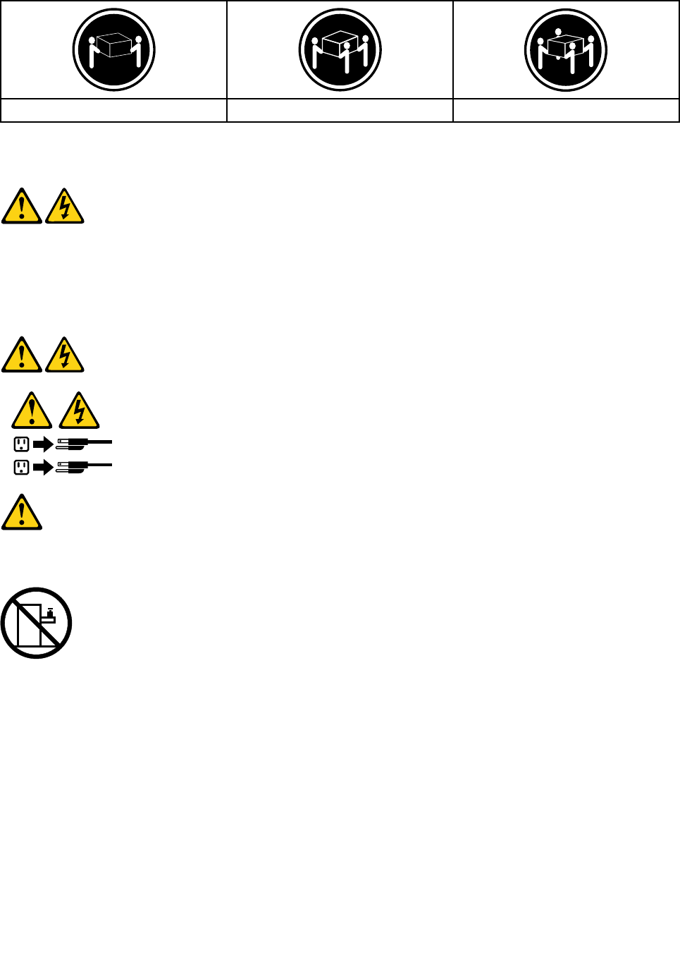
≥18kg(37lbs)≥32kg(70.5lbs)≥55kg(121.2lbs)
CAUTION:
Usesafepracticeswhenlifting.
CAUTION:
Thepowercontrolbuttononthedeviceandthepowerswitchonthepowersupplydonotturnoff
theelectricalcurrentsuppliedtothedevice.Thedevicealsomighthavemorethanonepower
cord.Toremoveallelectricalcurrentfromthedevice,ensurethatallpowercordsaredisconnected
fromthepowersource.
1
2
CAUTION:
Donotplaceanyobjectweighingmorethan82kg(180lbs.)ontopofrack-mounteddevices.
8IdeaCentreHorizon227All-In-OnePCHardwareMaintenanceManual

Chapter3.Generalinformation
Thischapterprovidesgeneralinformationthatappliestoallcomputermodelscoveredbythismanual.
Specifications
Thissectionliststhephysicalspecificationsforyourcomputer.
Thissectionliststhephysicalspecificationsforyourcomputer.
TypeIdeaCentreHorizon227
Thissectionliststhephysicalspecifications.
Environment
Airtemperature:
Operating:10°to35°C
Transit:-20°to55°C
Humidity:
Operating:35%to80%
Transit:20%to90%(40°C)
Altitude:86KPato106KPa
Electricalinput:
Inputvoltage:90V-264V(AC)
Inputfrequency:47Hz-63Hz
©CopyrightLenovo20149

10IdeaCentreHorizon227All-In-OnePCHardwareMaintenanceManual

Chapter4.GeneralCheckout
Attention:Thedrivesinthecomputeryouareservicingmighthavebeenrearrangedorthedrivestartup
sequencemayhavebeenchanged.Beextremelycarefulduringwriteoperationssuchascopying,saving,or
formatting.Dataorprogramscanbeoverwrittenifyouselectanincorrectdrive.
Generalerrormessagesappearifaproblemorconflictisfoundbyanapplication,theoperatingsystem,or
both.Foranexplanationofthesemessages,refertotheinformationsuppliedwiththatsoftwarepackage.
Usethefollowingproceduretohelpdeterminethecauseoftheproblem:
1.Power-offthecomputerandallexternaldevices.
2.Checkallcablesandpowercords.
3.Setalldisplaycontrolstothemiddleposition.
4.Power-onallexternaldevices.
5.Power-onthecomputer.
•Lookfordisplayederrorcodes.
•Lookforreadableinstructionsoramainmenuonthedisplay.
Ifyoudidnotreceivethecorrectresponse,proceedtostep6.
Ifyoudidreceivethecorrectresponse,proceedtostep7.
6.Ifoneofthefollowinghappens,followtheinstructiongiven:
•IfthecomputerdisplaysaPOSTerror,goto“POSTerrorcodes” .
•Ifthecomputerhangsandnoerrorisdisplayed,continueatstep7.
7.Iftheteststopsandyoucannotcontinue,replacethelastdevicetested.
©CopyrightLenovo201411

12IdeaCentreHorizon227All-In-OnePCHardwareMaintenanceManual

Chapter5.UsingtheSetupUtility
TheSetupUtilityprogramisusedtoviewandchangetheconfigurationsettingsofyourcomputer,regardless
ofwhichoperatingsystemyouareusing.However,theoperatingsystemsettingsmightoverrideanysimilar
settingsintheSetupUtilityprogram.
StartingtheLenovoBIOSSetupUtilityprogram
TostarttheLenovoBIOSSetupUtilityprogram,dothefollowing:
1.Ifyourcomputerisalreadyonwhenyoustartthisprocedure,shutdowntheoperatingsystemand
turnoffthecomputer.
2.PressandholdtheF1keythenturnonthecomputer.WhentheLenovoBIOSSetupUtilityprogramis
displayed,releasetheF1key.
Note:IfaPower-OnPasswordoranAdministratorPasswordhasbeenset,theSetupUtilityprogrammenu
willnotbedisplayeduntilyoutypeyourpassword.Formoreinformation,see“Usingpasswords.”
Viewingandchangingsettings
SystemconfigurationoptionsarelistedintheLenovoBIOSSetupUtilityprogrammenu.Tovieworchange
settings,see“StartingtheSetupUtilityprogram.”
YoumustusethekeyboardwhenusingtheLenovoBIOSSetupUtilitymenu.Thekeysusedtoperform
varioustasksaredisplayedonthebottomofeachscreen.
Usingpasswords
YoucanusetheLenovoBIOSSetupUtilityprogramtosetpasswordstopreventunauthorizedpersons
fromgainingaccesstoyourcomputeranddata.See“StartingtheSetupUtilityprogram.”Thefollowing
typesofpasswordsareavailable:
•AdministratorPassword
•Power-OnPassword
Youdonothavetosetanypasswordstouseyourcomputer.However,ifyoudecidetosetpasswords,read
thefollowingsections.
Passwordconsiderations
Apasswordcanbeanycombinationoflettersandnumbersupto16characters(a-zand0-9).Forsecurity
reasons,itisagoodideatouseastrongpasswordthatcannotbeeasilycompromised.Wesuggestthat
passwordsshouldfollowtheserules:
•Forastrongpassword,use7-16charactersandamixoflettersandnumbers.
•Donotuseyournameoryourusername.
•Donotuseacommonwordoracommonname.
•Usesomethingsignificantlydifferentfromyourpreviouspassword.
Attention:AdministratorandPower-Onpasswordsarenotcasesensitive.
©CopyrightLenovo201413

AdministratorPassword
SettinganAdministratorPassworddetersunauthorizedpersonsfromchangingconfigurationsettings.Y ou
mightwanttosetanAdministratorPasswordifyouareresponsibleformaintainingthesettingsofseveral
computers.
AfteryousetanAdministratorPassword,apasswordpromptisdisplayedeverytimeyouaccesstheLenovo
BIOSSetupUtilityprogram.
IfboththeAdministratorandPower-OnPasswordareset,youcantypeeitherpassword.However,youmust
useyourAdministratorPasswordtochangeanyconfigurationsettings.
Setting,changing,ordeletinganAdministratorPassword
TosetanAdministratorPassword,dothefollowing:
Note:Apasswordcanbeanycombinationoflettersandnumbersupto16characters(a-zand0-9).For
moreinformation,see“Passwordconsiderations”onpage13.
1.StarttheLenovoBIOSSetupUtilityprogram(see“StartingtheLenovoBIOSSetupUtilityprogram”on
page13).
2.FromtheSecuritymenu,selectSetAdministratorPasswordandpresstheEnterkey.
3.Thepassworddialogboxwillbedisplayed.TypethepasswordthenpresstheEnterkey.
4.Retypethepasswordtoconfirm,thenpresstheEnterkey.Ifyoutypedthepasswordcorrectly,the
passwordwillbeinstalled.ASetupNoticewillbedisplayedconfirmingthatyourchangeshasbeen
saved.
5.ReturntotheLenovoBIOSSetupUtilityprogrammenuandselecttheExitoption.
6.SelectSaveChangesandExitfromthemenu.
TochangeanAdministratorPassword,dothefollowing:
1.StarttheLenovoBIOSSetupUtilityprogram(see“StartingtheLenovoBIOSSetupUtilityprogram”on
page13).
2.FromtheSecuritymenu,selectSetAdministratorPasswordandpresstheEnterkey.
3.Thepassworddialogboxwillbedisplayed.TypethecurrentpasswordthenpresstheEnterkey.
4.Typethenewpassword,thenpresstheEnterkey.Retypethenewpasswordtoconfirmit.Ifyoutyped
thenewpasswordcorrectly,thenewpasswordwillbeinstalled.ASetupNoticewillbedisplayed
confirmingthatyourchangeshavebeensaved.
5.ReturntotheLenovoBIOSSetupUtilityprogrammenuandselecttheExitoption.
6.SelectSaveChangesandExitfromthemenu.
TodeleteapreviouslysetAdministratorPassword,dothefollowing:
1.StarttheLenovoBIOSSetupUtilityprogram(see“StartingtheLenovoBIOSSetupUtilityprogram”on
page13).
2.FromtheSecuritymenu,selectSetAdministratorPasswordandpresstheEnterkey.
3.Thepassworddialogboxwillbedisplayed.TypethecurrentpasswordandpresstheEnterkey.
4.Leaveeachnewpasswordlineitemblank,thenpresstheEnterkey.ASetupNoticewillbedisplayed
confirmingthatyourchangeshavebeensaved.
5.ReturntotheLenovoBIOSSetupUtilityprogrammenuandselecttheExitoption.
6.SelectSaveChangesandExitfromthemenu.
14IdeaCentreHorizon227All-In-OnePCHardwareMaintenanceManual

Power-OnPassword
WhenaPower-OnPasswordisset,youcannotstarttheLenovoBIOSSetupUtilityprogramuntilavalid
passwordistypedfromthekeyboard.
Setting,changing,ordeletingaPower-OnPassword
Note:Apasswordcanbeanycombinationoflettersandnumbersupto16characters(a-zand0-9).
TosetaPower-OnPassword,dothefollowing:
1.StarttheLenovoBIOSSetupUtilityprogram(see”StartingtheLenovoBIOSSetupUtilityprogram”on
page13).
2.FromtheSecuritymenu,selectSetPower-OnPasswordandpresstheEnterkey.
3.Thepassworddialogboxwillbedisplayed.Typethepassword,thenpresstheEnterkey.
4.Retypethepasswordtoconfirm.Ifyoutypedthepasswordcorrectly,thepasswordwillbeinstalled.
5.ReturntotheLenovoBIOSSetupUtilityprogrammenuandselecttheExitoption.
6.SelectSaveChangesandExitfromthemenu.
TochangeaPower-OnPassword,dothefollowing:
1.StarttheLenovoBIOSSetupUtilityprogram(see”StartingtheLenovoBIOSSetupUtilityprogram”on
page13).
2.FromtheSecuritymenu,selectSetPower-OnPasswordandpresstheEnterkey.
3.Thepassworddialogboxwillbedisplayed.TypethecurrentpasswordthenpresstheEnterkey.
4.Typethenewpassword,thenpresstheEnterkey.Retypethenewpasswordtoconfirmit.Ifyoutyped
thenewpasswordcorrectly,thenewpasswordwillbeinstalled.ASetupNoticewillbedisplayed
confirmingthatyourchangeshavebeensaved.
5.ReturntotheLenovoBIOSSetupUtilityprogrammenuandselecttheExitoption.
6.SelectSaveChangesandExitfromthemenu.
TodeleteapreviouslysetPower-OnPassword,dothefollowing:
1.StarttheLenovoBIOSSetupUtilityprogram(see”StartingtheLenovoBIOSSetupUtilityprogram”on
page13).
2.FromtheSecuritymenu,selectSetPower-OnPasswordandpresstheEnterkey.
3.Thepassworddialogboxwillbedisplayed.TypethecurrentpasswordandpresstheEnterkey.
4.Leaveeachnewpasswordlineitemblank,thenpressEnter.ASetupNoticewillbedisplayedconfirming
thatyourchangeshavebeensaved.
5.ReturntotheLenovoBIOSSetupUtilityprogrammenuandselecttheExitoption.
6.SelectSaveChangesandExitfromthemenu.
Enablingordisablingadevice
TheDevicesoptionsisusedtoenableordisableuseraccesstothefollowing:
USBFunctionsSelectwhethertoenableordisableUSB(UniversalSerial
Bus)functions.Ifthefunctionsaredisabled,noUSB
devicescanbeused.
Chapter5.UsingtheSetupUtility15

SATAModeSelectDisabled/IDE/AHCImode.Devicedriversupport
isrequiredforAHCIorRAID.Dependingonhowthehard
diskdriveimagewasinstalled,changingthissettingmay
preventthesystemfrombooting.
OnboardAudioControllerSelectwhethertoenableordisabletheOnboard
AudioController.WhenthisfeatureissettoDisabled
alldevicesconnectedtotheaudioconnectors(e.g.
headphonesoramicrophone)aredisabledandcannot
beused.
Toenableordisableadevice,dothefollowing:
1.StarttheSetupUtilityprogram(see“StartingtheSetupUtilityprogram”onpage13).
2.FromtheSetupUtilityprogrammenu,selectDevices.
3.Selectanoptionasfollows:
SelectUSBSetup,presstheEnterkey,thenselectUSBFunctions.
SelectATADriversSetup,presstheEnterkey,thenselectSATAMode.
SelectAudioSetup,presstheEnterkey,thenselectOnboardAudioController.
4.SelectDisabledorEnabledandpresstheEnterkey.
5.ReturntotheLenovoBIOSSetupUtilityprogrammenuandselecttheExitoption.
6.SelectSaveChangesandExitfromthemenu.
Notes:
a.Ifyoudonotwanttosavethesettings,selectDiscardChangesandExitfromthemenu.
Selectingastartupdevice
IfyourcomputerdoesnotbootfromadevicesuchastheCD/DVD-ROMdrivediskorharddiskasexpected,
followoneoftheproceduresbelow.
Selectingatemporarystartupdevice
Usethisproceduretostartupfromanybootdevice.
Note:NotallCDs,DVDsorharddiskdrivesarebootable.
1.Turnoffyourcomputer.
2.PressandholdtheF12keythenturnonthecomputer.WhentheStartupDeviceMenuappears,
releasetheF12key.
Note:IftheStartupDeviceMenudoesnotdisplayusingthesesteps,repeatedlypressandreleasethe
F12keyratherthankeepingitpressedwhenturningonthecomputer.
3.Use↑and↓arrowstoselectthedesiredstartupdevicefromtheStartupDeviceMenuandpress
theEnterkeytobegin.
Note:SelectingastartupdevicefromtheStartupDeviceMenudoesnotpermanentlychangethe
startupsequence.
Selectingorchangingthestartupdevicesequence
Tovieworpermanentlychangetheconfiguredstartupdevicesequence,dothefollowing:
16IdeaCentreHorizon227All-In-OnePCHardwareMaintenanceManual

1.StarttheLenovoBIOSSetupUtilityprogram(see“StartingtheLenovoBIOSSetupUtilityprogram”on
page13).
2.FromtheLenovoBIOSSetupUtilityprogrammainmenu,selecttheStartupoption.
3.PresstheEnterkey,andselectthedevicesforthePrimaryBootSequence.Readtheinformation
displayedontherightsideofthescreen.
4.Use↑and↓arrowstoselectadevice.Usethe<+>or<->keystomoveadeviceupordown.Usethe
<×>keytoexcludethedevicefromorincludethedeviceinthebootsequence.
5.ReturntotheLenovoBIOSSetupUtilityprogrammenuandselecttheExitoption.
6.SelectSaveChangesandExitfromthemenu.
Notes:
a.Ifyoudonotwanttosavethesettings,selectDiscardChangesandExitfromthemenu.
b.Ifyouhavechangedthesesettingsandwanttoreturntothedefaultsettings,selectLoadOptimal
Defaultsfromthemenu.
ExitingtheLenovoBIOSSetupUtilityprogram
Afteryoufinishviewingorchangingsettings,presstheEsckeytoreturntotheLenovoBIOSSetupUtility
programmainmenu.YoumighthavetopresstheEsckeyseveraltimes.Dooneofthefollowing:
•Ifyouwanttosavethenewsettings,selectSaveChangesandExitfromthemenu.WhentheSave
&resetwindowshows,selecttheYesbutton,andthenpresstheEnterkeytoexittheLenovoBIOS
SetupUtilityprogram.
•Ifyoudonotwanttosavethesettings,selectDiscardChangesandExitfromthemenu.Whenthe
ResetWithoutSavingwindowshows,selecttheY esbutton,andthenpresstheEnterkeytoexitthe
LenovoBIOSSetupUtilityprogram.
Chapter5.UsingtheSetupUtility17

18IdeaCentreHorizon227All-In-OnePCHardwareMaintenanceManual

Chapter6.Symptom-to-FRUIndex
TheSymptom-to-FRUindexlistserrorsymptomsandpossiblecauses.Themostlikelycauseislistedfirst.
AlwaysbeginwithChapter4,“GeneralCheckout,”onpage11.Thisindexcanalsobeusedtohelpyou
decidewhichFRUstohaveavailablewhenservicingacomputer.Ifyouareunabletocorrecttheproblem
usingthisindex,goto“Undeterminedproblems”onpage20.
Notes:
•Ifyouhavebothanerrormessageandanincorrectaudioresponse,diagnosetheerrormessagefirst.
•Ifyoucannotrunthediagnostictestsoryougetadiagnosticerrorcodewhenrunningatestbutdid
receiveaPOSTerrormessage,diagnosethePOSTerrormessagefirst.
•Ifyoudidnotreceiveanyerrormessagelookforadescriptionofyourerrorsymptomsinthefirstpartof
thisindex.
Harddiskdrivebooterror
Aharddiskdrivebooterrorcanhavethefollowingcauses.
ErrorFRU/Action
Thestartupdriveisnotincludedinthebootsequence
configuration.
Checktheconfigurationandensurethestartupdriveis
inthebootsequence.
Nooperatingsystemisinstalledonthebootdrive.Installanoperatingsystemonthebootdrive.
Thebootsectoronthestartupdriveiscorrupted.Thedrivemustbeformatted.Dothefollowing:
1.Attempttobackupthedataonthefailingharddisk
drive.
2.Usetheoperatingsystemtoformattheharddisk
drive.
Thedriveisdefective.Replacetheharddiskdrive.
PowerSupplyProblems
Followtheseproceduresifyoususpectthereisapowersupplyproblem.
Check/VerifyFRU/Action
Checkthatthefollowingareproperlyinstalled:
•PowerCord
•On/OffSwitchconnector
•SystemBoardPowerSupplyconnectors
•Microprocessorconnections
Reseatconnectors
Checkthepowercord.PowerCord
Checkthepower-onswitch.Power-onSwitch
©CopyrightLenovo201419

POSTerrorcodes
Eachtimeyouturnthecomputeron,itperformsaseriesofteststocheckthatthesystemisoperating
correctlyandthatcertainoptionsareset.ThisseriesoftestsiscalledthePower-OnSelf-Test,orPOST.
POSTdoesthefollowing:
•Checkssomebasicmotherboardoperations
•Checksthatthememoryisworkingcorrectly
•Startsvideooperations
•Verifiesthatthebootdriveisworking
POSTErrorMessageDescription/Action
KeyboarderrorCannotinitializethekeyboard.Makesurethekeyboard
isproperlyconnectedtothecomputerandthatnokeys
areheldpressedduringPOST.Topurposelyconfigure
thecomputerwithoutakeyboard,selectKeyboardless
operationinStartupandsettheoptiontoEnabled.The
BIOSthenignoresthemissingkeyboardduringPOST.
RebootandSelectproperBootdeviceorInsertBoot
MediainselectedBootdevice
TheBIOSwasunabletofindasuitablebootdevice.Make
surethebootdriveisproperlyconnectedtothecomputer.
Makesureyouhavebootablemediainthebootdevice.
Undeterminedproblems
1.Power-offthecomputer.
2.Removeordisconnectthefollowingcomponents(ifconnectedorinstalled)oneatatime.
a.Externaldevices(modem,printer,ormouse)
b.Extendedvideomemory
c.ExternalCache
d.ExternalCacheRAM
e.Harddiskdrive
f.Diskdrive
3.Power-onthecomputertore-testthesystem.
4.Repeatsteps1through3untilyoufindthefailingdeviceorcomponent.
Ifalldevicesandcomponentshavebeenremovedandtheproblemcontinues,replacethesystemboard.
20IdeaCentreHorizon227All-In-OnePCHardwareMaintenanceManual

Chapter7.Replacinghardware
Attention:Donotremovethecomputercoverorattemptanyrepairbeforereadingthe“Importantsafetyinformation”
intheSafetyandWarrantyGuidethatwasincludedwithyourcomputer.ToobtaincopiesoftheSafetyandWarranty
Guide,gototheSupportWebsiteat:http://support.lenovo.com.
Note:UseonlypartsprovidedbyLenovo.
Generalinformation
Pre-disassemblyinstructions
Beforestartingthedisassemblyprocedure,makesurethatyoudothefollowing:
1.Turnoffthepowertothesystemandallperipherals.
2.Unplugallpowerandsignalcablesfromthecomputer.
3.Placethesystemonaflat,stablesurface.
©CopyrightLenovo201421
Replacingthekeyboardandmouse
Toreplacethekeyboardandmouse:
Step1.Removeanymedia(disks,CDs,DVDsormemorycards)fromthedrives,shutdowntheoperating
system,andturnoffthecomputerandallattacheddevices.
Step2.Unplugallpowercordsfromelectricaloutlets.
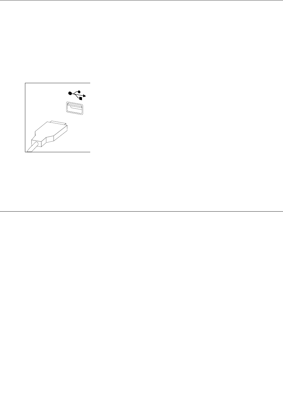
Step3.Disconnectallcablesattachedtothecomputer.Thisincludespowercords,input/output(I/O)
cables,andanyothercablesthatareconnectedtothecomputer.Referto“Leftandrightview”
and“Rearview”forhelpwithlocatingthevariousconnectors.
Note:YourkeyboardwillbeconnectedtoaUSBconnectorononesideorattherearofthe
computer.
Step4.Disconnectthedefectivekeyboardcablefromthecomputerandconnectthenewkeyboardcable
tothesameconnector.
Note:Themousecanbereplacedusingthesamemethod.
Removingtherearcover
Note:Turnoffthecomputerandwait3to5minutestoletitcooldownbeforeremovingthebasecover.
Note:Itmaybehelpfultoplacethecomputerface-downonasoftflatsurfaceforthisprocedure.Lenovo
recommendsthatyouuseablanket,towel,orothersoftclothtoprotectthecomputerscreenfromscratches
orotherdamage.
Toremovethebasecover:
Step1.Removeanymedia(disks,CDs,DVDs,ormemorycards)fromthedrives,shutdowntheoperating
system,andturnoffthecomputerandallattacheddevices.
Step2.Unplugallpowercordsfromelectricaloutlets.
Step3.Disconnectallcablesattachedtothecomputer.Thisincludespowercords,input/output(I/O)
cables,andanyothercablesthatareconnectedtothecomputer.Referto“Leftandrightview”
and“Rearview”forhelpwithlocatingthevariousconnectors.
22IdeaCentreHorizon227All-In-OnePCHardwareMaintenanceManual
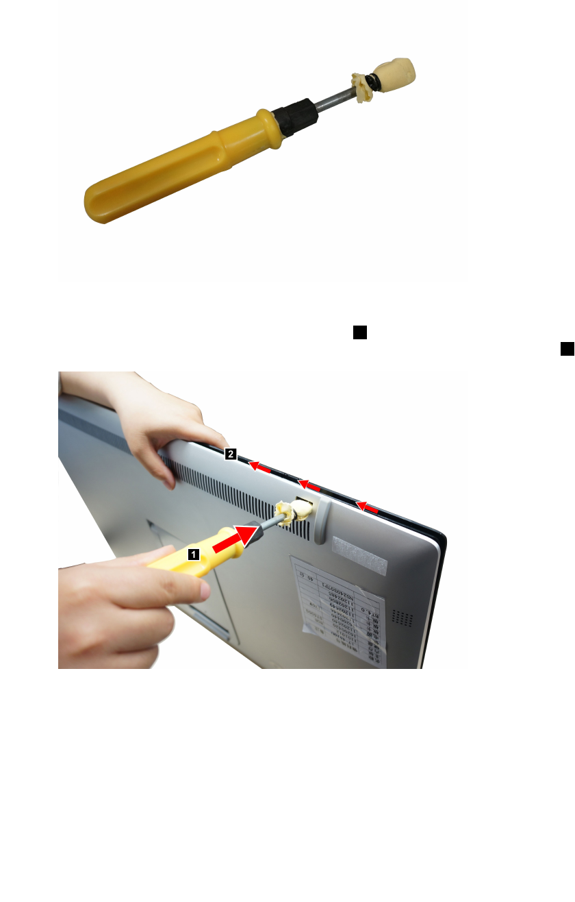
Step4.Forthisprocedureitrequiresusingaflatheadscrewdriver.Useapieceofsoftclothestowrapthe
screwdriverheadbeforeproceeding.
Step5.Thefrontpanelandtherearcoverarepinedtogether,usethewrappedscrewdrivertopushintothe
holeasillustratedtoforcethefrontpanelseparatingfromtherearcover.Forthisprocedureitmight
requiresusingsomestrengthenswhilepushing.1Workingalongthegapopenedin-betweenthe
frontpanelandtherearcovergentlytoseparatingthefrontpanelfromrearcover.2
Chapter7.Replacinghardware23
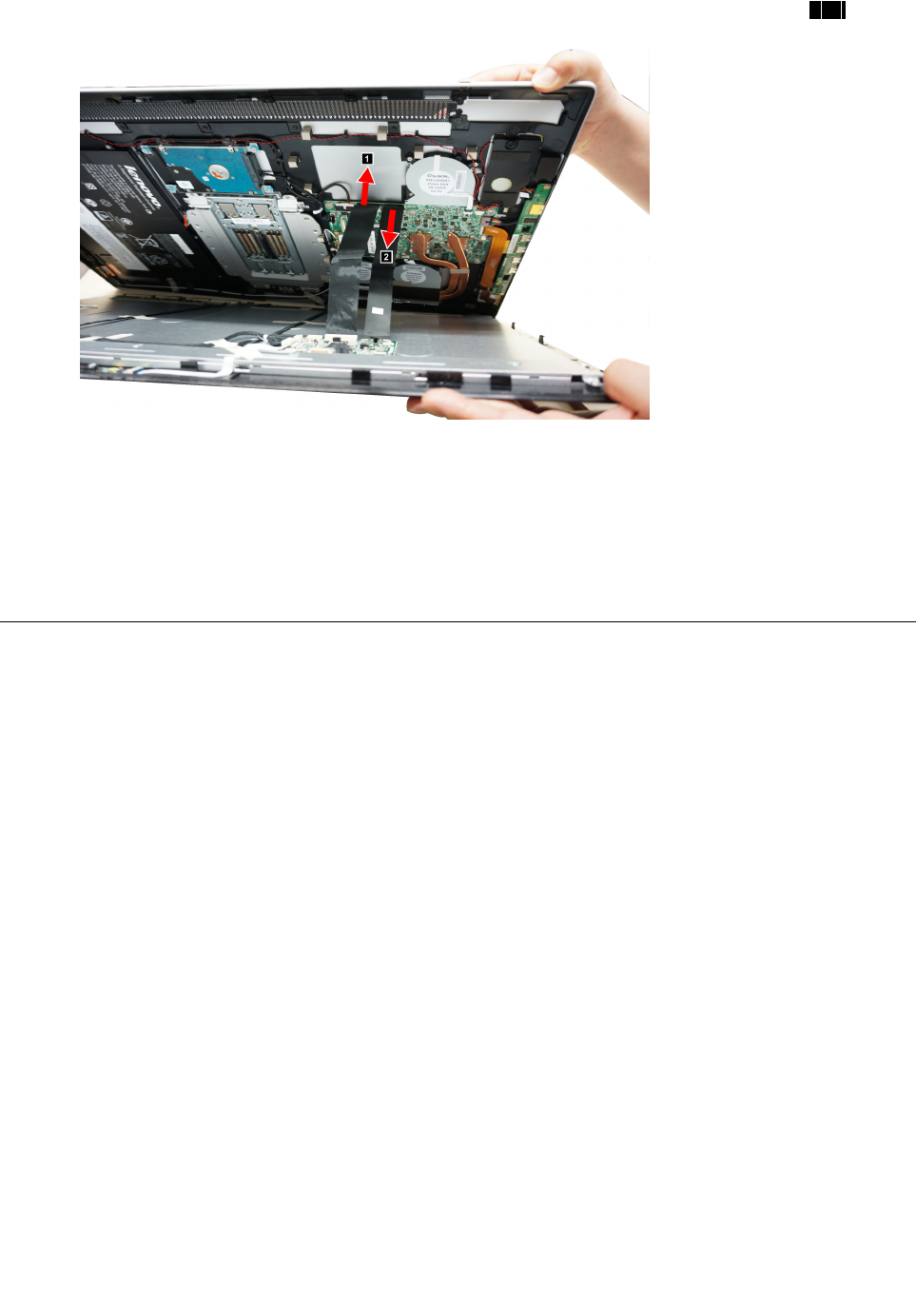
Step6.Disconnectthetwoscalarcablesfromtheconnectorsonthemotherboardasshown.12
Step7.Putthefrontpanelandrearcoveraside.
Step8.Toreattachtherearcover:
a.Lineupthefrontpanelwiththerearcover,andthenreconnectthetwoscalarcablestothe
motherboard.
b.Pressdownalongtheedgeoftherearcoverandsecuretherearcovertothefrontpanelwith
themountingpins.
Replacingthebattery
Note:Turnoffthecomputerandwait3to5minutestoletitcooldownbeforeremovingthebasecover.
Toreplacethebattery:
Step1.Removeanymedia(disks,CDs,DVDs,ormemorycards)fromthedrives,shutdowntheoperating
system,andturnoffthecomputerandallattacheddevices.
Step2.Unplugallpowercordsfromelectricaloutlets.
Step3.Disconnectallcablesattachedtothecomputer.Thisincludespowercords,input/output(I/O)
cables,andanyothercablesthatareconnectedtothecomputer.Referto“Leftandrightview”
and“Rearview”forhelpwithlocatingthevariousconnectors.
Step4.Removetherearcover.Referto“Removingtherearcover” .
24IdeaCentreHorizon227All-In-OnePCHardwareMaintenanceManual
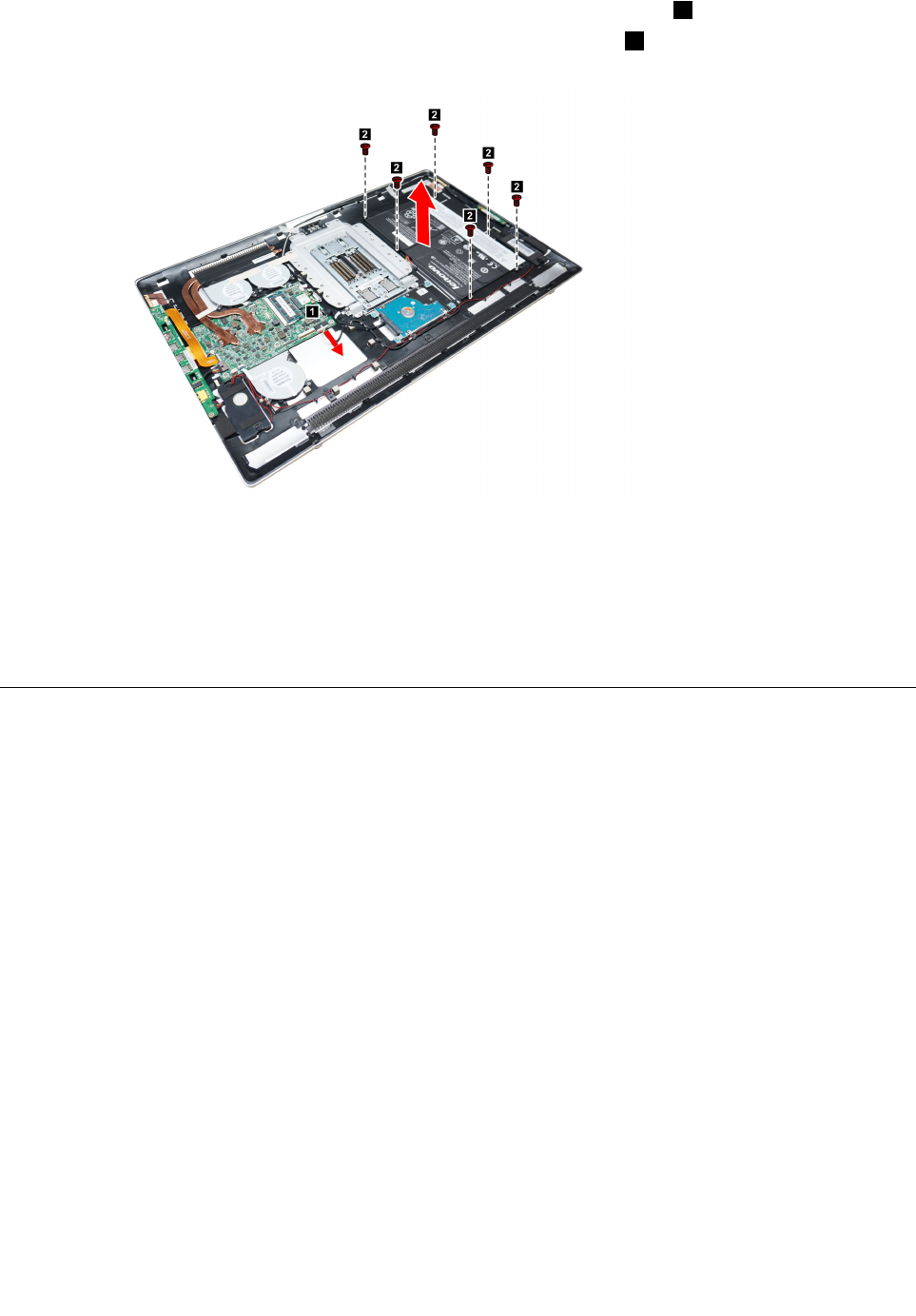
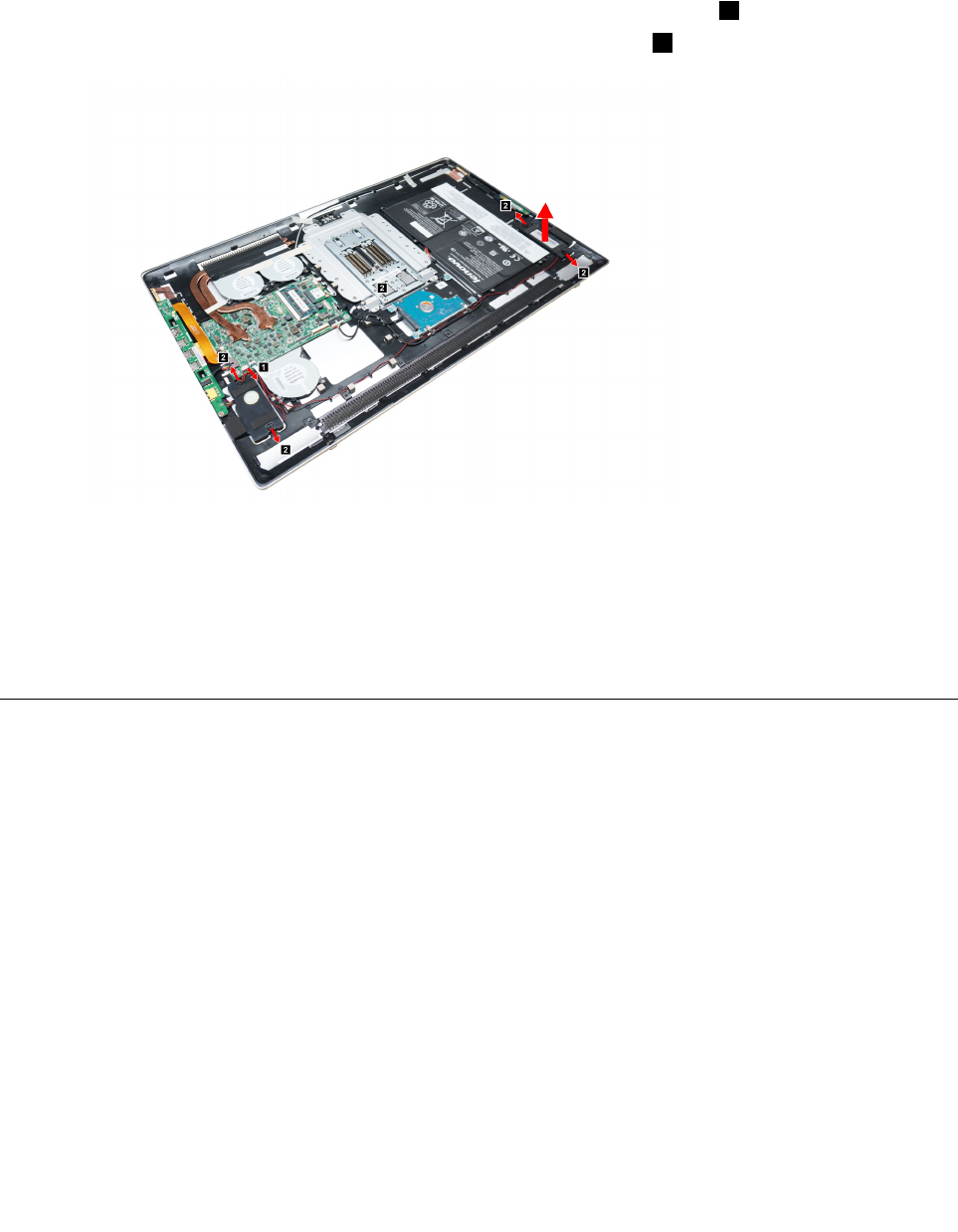
Step5.Disconnectthepowercablefromtheconnectoronthemotherboard.1
Step6.Removethesixscrewsthatsecurethebatterytotherearcover2,thenliftupthebatterypack
asshown.
Step7.Toinstallanewbattery:
a.Lineuptheholeswithmountingholesontherearcover,thenplaceitintoposition.
b.Securethenewbatterytothechassiswiththesixscrews.
c.Connectthepowercabletotheconnectoronthemotherboard.
Step8.Reattachtherearcover.
Replacingamemorymodule
Attention:Turnoffthecomputerandwait3to5minutestoletitcooldownbeforeremovingthebasecover.
Toreplaceamemorymodule:
Step1.Removeanymedia(disks,CDs,DVDs,ormemorycards)fromthedrives,shutdowntheoperating
system,andturnoffthecomputerandallattacheddevices.
Step2.Unplugallpowercordsfromelectricaloutlets.
Step3.Disconnectallcablesattachedtothecomputer.Thisincludespowercords,input/output(I/O)
cables,andanyothercablesthatareconnectedtothecomputer.Referto“Leftandrightview”
and“Rearview”forhelpwithlocatingthevariousconnectors.
Step4.Removetherearcover.Referto“Removingtherearcover” .
Step5.Disconnectthebatterycablefromtheconnectoronmotherboard.Referto“Replacingthebattery” .
Chapter7.Replacinghardware25
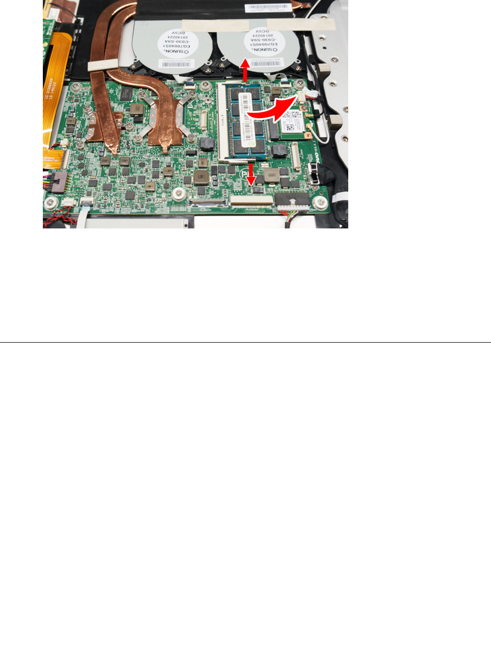
Step6.Pushoutthelatchesonbothsidesofthememorysockettoreleasethememorymodule.Gently
pullthememorymoduleupwardtoremoveitfromitssocket.
Step7.Toinstallthenewmemorymodule:
a.Alignthenewmemorymodulewiththememorysocket,theninsertitandpushdownon
thetopedge.
b.Makesurethelatcheslockthememorymoduleinplace.
c.Reconnectthebatterycabletotheconnectoronthemotherboard.
Step8.Reattachtherearcover.
ReplacingtheWi-Ficard
Note:Turnoffthecomputerandwait3to5minutestoletitcooldownbeforeremovingthebasecover.
ToreplacetheWi-Ficard:
Step1.Removeanymedia(disks,CDs,DVDs,ormemorycards)fromthedrives,shutdowntheoperating
system,andturnoffthecomputerandallattacheddevices.
Step2.Unplugallpowercordsfromelectricaloutlets.
Step3.Disconnectallcablesattachedtothecomputer.Thisincludespowercords,input/output(I/O)
cables,andanyothercablesthatareconnectedtothecomputer.Referto“Leftandrightview”
and“Rearview”forhelpwithlocatingthevariousconnectors.
Step4.Removetherearcover.Referto“Removingtherearcover” .
Step5.RemovetheEMIcover.Referto“RemovingtheEMIcover” .
Step6.Disconnectthebatterycablefromtheconnectoronmotherboard.Referto“Replacingthebattery” .
26IdeaCentreHorizon227All-In-OnePCHardwareMaintenanceManual
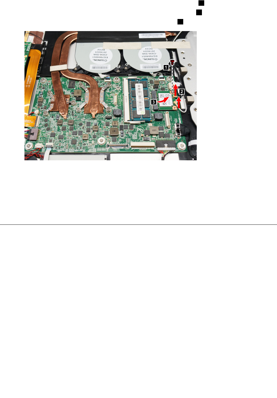
Step7.RemovethescrewthatsecurestheWi-Ficardtothemotherboard.1
Step8.DisconnecttheantennacableanddatacablefromtheWi-Ficard.2
Step9.PulltheWi-Ficardupwardtoremoveitfromthecardport.3
Step10.ToinstallthenewWi-Ficard:
a.LineupthenewWi-Ficardwiththecardport,insertthecardintopositionandsecureit
withthescrew.
b.ReconnecttheantennaanddatacabletothenewWi-Ficard.
c.Reconnectthebatterycabletotheconnectoronthemotherboard.
Step11.Reattachtherearcover.
Replacingtheharddiskdrive
Attention:Turnoffthecomputerandwait3to5minutestoletitcooldownbeforeremovingthebasecover.
Toreplacetheharddiskdrive:
Step1.Removeanymedia(disks,CDs,DVDsormemorycards)fromthedrives,shutdowntheoperating
system,andturnoffthecomputerandallattacheddevices.
Step2.Unplugallpowercordsfromelectricaloutlets.
Step3.Disconnectallcablesattachedtothecomputer.Thisincludespowercords,input/output(I/O)
cables,andanyothercablesthatareconnectedtothecomputer.Referto“Leftandrightview”
and“Rearview”forhelpwithlocatingthevariousconnectors.
Step4.Removetherearcover.Referto“Removingtherearcover” .
Step5.Disconnectthebatterycablefromtheconnectoronmotherboard.Referto“Replacingthebattery” .
Chapter7.Replacinghardware27
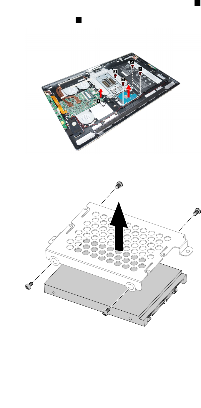
Step6.Disconnectthedataandpowercablesfromtheharddiskdrive.1
Step7.Removethefourscrewsthatsecuretheharddiskdrivetothechassis,thenliftuptheharddisk
drivetoremoveit.2
Step8.Removethefourscrewsthatsecuretheharddiskdrivetothebracket.
Step9.Slidetheharddiskdriveoutofthebracket.
Step10.Installthenewharddiskdriveasfollows:
a.Slidethenewharddiskdriveintothebracket.
b.Securethenewharddiskdrivetothebracketwiththefourscrews.
c.Connectthedataandpowercablestothenewharddiskdrive.
d.Securethenewharddiskdriveandbrackettothechassiswiththefourscrews.
e.Reconnectthebatterycabletotheconnectoronthemotherboard.
28IdeaCentreHorizon227All-In-OnePCHardwareMaintenanceManual
Step11.Reattachtherearcover.
Replacingthefanmodule
Note:Turnoffthecomputerandwait3to5minutestoletitcooldownbeforeremovingthebasecover.
Toreplacethefanmodule:
Step1.Removeanymedia(disks,CDs,DVDsormemorycards)fromthedrives,shutdowntheoperating
system,andturnoffthecomputerandallattacheddevices.
Step2.Unplugallpowercordsfromelectricaloutlets.
Step3.Disconnectallcablesattachedtothecomputer.Thisincludespowercords,input/output(I/O)
cables,andanyothercablesthatareconnectedtothecomputer.Referto“Leftandrightview”
and“Rearview”forhelpwithlocatingthevariousconnectors.
Step4.Removetherearcover.Referto“Removingtherearcover” .
Step5.Disconnectthebatterycablefromtheconnectoronmotherboard.Referto“Replacingthebattery” .
Step6.Removethesixscrewsthatsecurethefanmoduletotherearcover.
Step7.Disconnectthepowercablesfromthemotherboard.
Step8.Liftupthefanmoduletoremoveit.
Step9.Toinstallthenewfanmodule:
a.Lineupthenewfanmodulewiththemountingholesontherearcoverandplaceitintoposition.
b.Securethenewfanmoduletotherearcoverwiththesixscrews.
c.Connectthenewpowercabletotheconnectorsonmotherboard.
d.Reconnectthebatterycabletotheconnectoronthemotherboard.
Step10.Reattachtherearcover.
Replacingtheheat-sinkmodules
Note:Turnoffthecomputerandwait3to5minutestoletitcooldownbeforeremovingthebasecover.
Toreplacetheheat-sinkmodules:
Chapter7.Replacinghardware29
Step1.Removeanymedia(disks,CDs,DVDsormemorycards)fromthedrives,shutdowntheoperating
system,andturnoffthecomputerandallattacheddevices.
Step2.Unplugallpowercordsfromelectricaloutlets.
Step3.Disconnectallcablesattachedtothecomputer.Thisincludespowercords,input/output(I/O)
cables,andanyothercablesthatareconnectedtothecomputer.Referto“Leftandrightview”
and“Rearview”forhelpwithlocatingthevariousconnectors.
Step4.Removetherearcover.Referto“Removingtherearcover” .
Step5.Disconnectthebatterycablefromtheconnectoronmotherboard.Referto“Replacingthebattery” .
Step6.Removetheeightscrewsthatsecuretheheat-sinkmoduletothemotherboard.
Step7.Liftuptheheat-sinkmoduletoremoveit.
Attention:Placetheheat-sinkupsidedownonaflatsurfacetopreventthermalgreasefromcontaminating
othercomponents.
Step8.Toinstallthenewheat-sinkmodule:
a.UseanalcoholpadtowipethethermalgreaseofftheCPU.
b.Lineupthenewheat-sinkwithmountingholesonthemotherboard.
c.Securethenewheat-sinktothemotherboardwiththeeightscrews.
d.Attachthesystemfanstothenewheat-sinkandsecureitwiththescrews.
e.Reconnectthebatterycabletotheconnectoronthemotherboard.
Step9.Reattachtherearcover.
Replacingthespeakersystem
Note:Turnoffthecomputerandwait3to5minutestoletitcooldownbeforeremovingthebasecover.
Toreplacethespeakersystem:
Step1.Removeanymedia(disks,CDs,DVDs,ormemorycards)fromthedrives,shutdowntheoperating
system,andturnoffthecomputerandallattacheddevices.
Step2.Unplugallpowercordsfromelectricaloutlets.
30IdeaCentreHorizon227All-In-OnePCHardwareMaintenanceManual
Step3.Disconnectallcablesattachedtothecomputer.Thisincludespowercords,input/output(I/O)
cables,andanyothercablesthatareconnectedtothecomputer.Referto“Leftandrightview”
and“Rearview”forhelpwithlocatingthevariousconnectors.
Step4.Removetherearcover.Referto“Removingtherearcover” .
Step5.Disconnectthebatterycablefromtheconnectoronmotherboard.Referto“Replacingthebattery” .
Step6.Disconnectthespeakercablefromtheconnectoronthemotherboard.1
Step7.Pushtherubbermountingpinsoutwardtoreleasethespeaker.2
Step8.Toinstallthenewspeakersystem:
a.Attachthenewspeakersystemtothechassis,thensecureitwithmountingrubberpins.
b.Connectthenewspeakercabletotheconnectoronthemotherboard.
c.Reconnectthebatterycabletotheconnectoronthemotherboard.
Step9.Reattachtherearcover.
ReplacingtheI/Oboard
Note:Turnoffthecomputerandwait3to5minutestoletitcooldownbeforeremovingthebasecover.
ToreplacetheI/Oboard:
Step1.Removeanymedia(disks,CDs,DVDs,ormemorycards)fromthedrives,shutdowntheoperating
system,andturnoffthecomputerandallattacheddevices.
Step2.Unplugallpowercordsfromelectricaloutlets.
Step3.Disconnectallcablesattachedtothecomputer.Thisincludespowercords,input/output(I/O)
cables,andanyothercablesthatareconnectedtothecomputer.Referto“Leftandrightview”
and“Rearview”forhelpwithlocatingthevariousconnectors.
Step4.Removetherearcover.Referto“Removingtherearcover” .
Step5.Disconnectthebatterycablefromtheconnectoronmotherboard.Referto“Replacingthebattery” .
Chapter7.Replacinghardware31
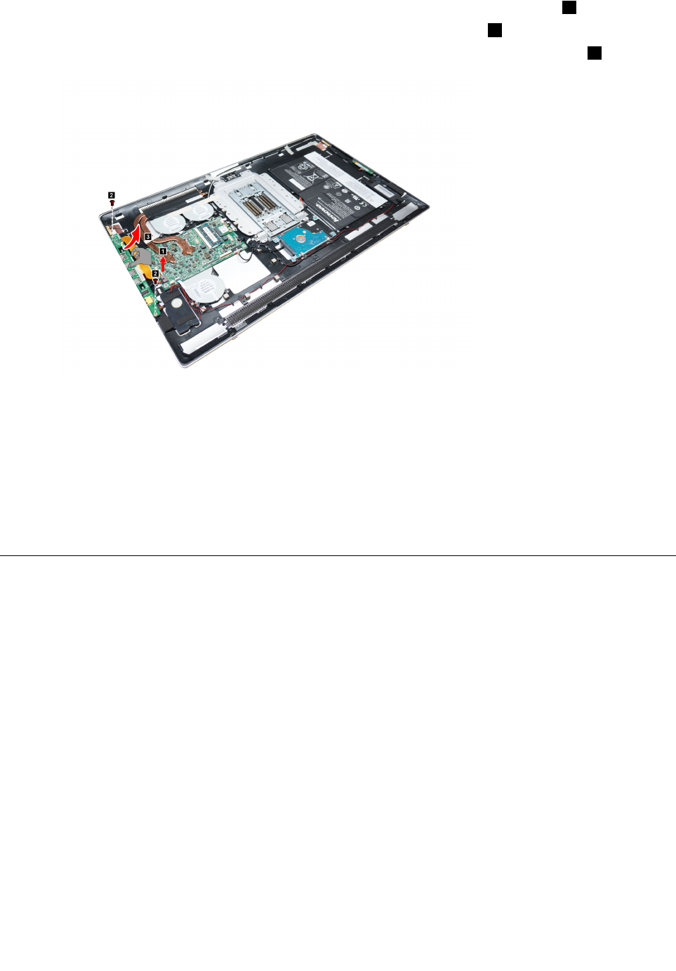
Step6.Disconnectthepowerconnectorcablefromtheconnectoronthemotherboard.1
Step7.RemovethetwoscrewsthatsecuretheI/Oboardtotherearcover.2
Step8.SlideouttheI/OboardasshownanddisconnectthedatacablefromtheI/Oboard.3
Step9.ToinstallthenewI/Oboard:
a.ConnectthedatacabletoconnectoronthenewI/Oboard.
b.LineuptheholesonthenewI/OboardwiththemountingholesontheI/Oboardandsecure
theI/Oboardtotherearcoverwiththetwoscrews.
c.Connectthepowerconnectorcabletotheconnectoronthemotherboard.
d.Reconnectthebatterycabletotheconnectoronthemotherboard.
Step10.Reattachtherearcover.
Replacingthepowerswitchboard
Note:Turnoffthecomputerandwait3to5minutestoletitcooldownbeforeremovingthebasecover.
Toreplacethepowerswitchboard:
Step1.Removeanymedia(disks,CDs,DVDs,ormemorycards)fromthedrives,shutdowntheoperating
system,andturnoffthecomputerandallattacheddevices.
Step2.Unplugallpowercordsfromelectricaloutlets.
Step3.Disconnectallcablesattachedtothecomputer.Thisincludespowercords,input/output(I/O)
cables,andanyothercablesthatareconnectedtothecomputer.Referto“Leftandrightview”
and“Rearview”forhelpwithlocatingthevariousconnectors.
Step4.Removetherearcover.Referto“Removingtherearcover” .
Step5.Disconnectthebatterycablefromtheconnectoronmotherboard.Referto“Replacingthebattery” .
Step6.Disconnectthepowercablefromthepowerswitchboard.
32IdeaCentreHorizon227All-In-OnePCHardwareMaintenanceManual

Step7.Removethetwoscrewsthatsecurethepowerswitchboardtotherearcover1,liftupthepower
switchboard2anddisconnectthecablefromtheswitchboard.3
Step8.Toinstallthepowerswitchboard:
a.Connectthepowercabletothenewpowerswitchboard.
b.Securethepowerswitchboardtotherearcoverwiththetwoscrews.
c.Reconnectthebatterycabletotheconnectoronthemotherboard.
Step9.Reattachtherearcover.
Replacingthemotherboard
Note:Turnoffthecomputerandwait3to5minutestoletitcooldownbeforeremovingthebasecover.
Toreplacethemotherboard:
Step1.Removeanymedia(disks,CDs,DVDs,ormemorycards)fromthedrives,shutdowntheoperating
system,andturnoffthecomputerandallattacheddevices.
Step2.Unplugallpowercordsfromelectricaloutlets.
Step3.Disconnectallcablesattachedtothecomputer.Thisincludespowercords,input/output(I/O)
cables,andanyothercablesthatareconnectedtothecomputer.Referto“Leftandrightview”
and“Rearview”forhelpwithlocatingthevariousconnectors.
Step4.Removetherearcover.Referto“Removingtherearcover” .
Step5.Disconnectthebatterycablefromtheconnectoronmotherboard.Referto“Replacingthebattery” .
Step6.Removethememorymodules.Referto“Replacingamemorymodule” .
Step7.Removetheheat-sinkmodules.Referto“Replacingtheheat-sinkmodules” .
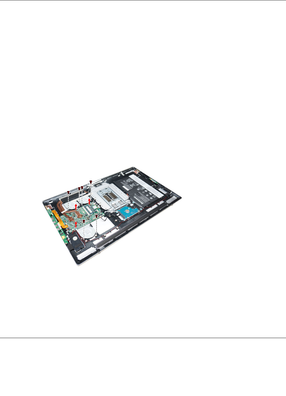
Step8.Removeallthecablesconnectedtothemotherboard.12345678
Chapter7.Replacinghardware33
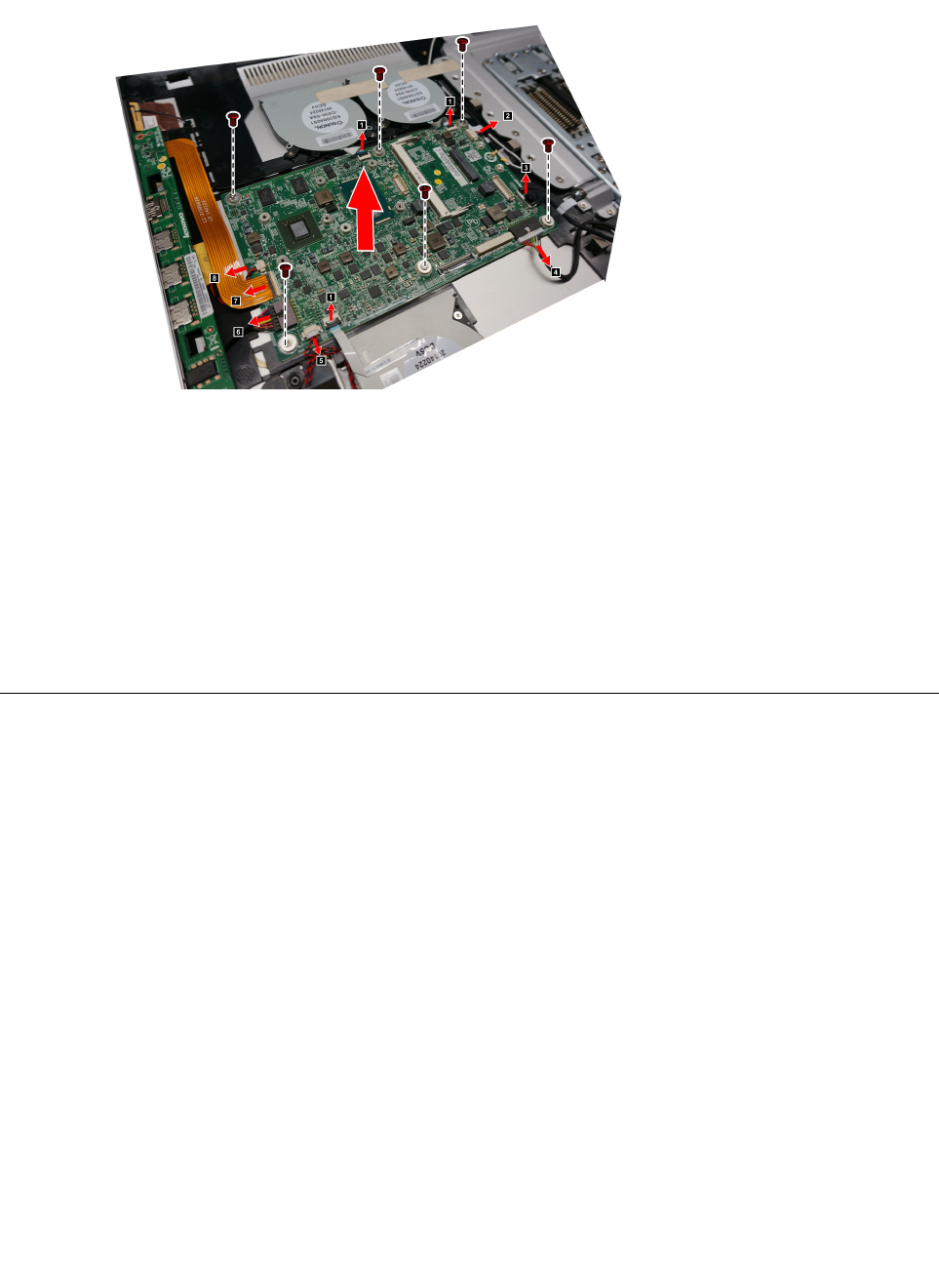
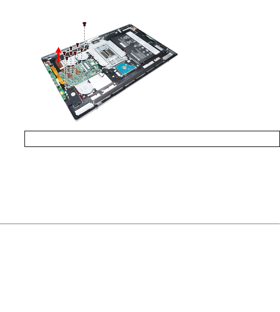
Step9.Removethesixscrewsthatsecurethemotherboardtotherearcoverandliftupthemotherboard
toremoveit.
Step10.Toinstallthenewmotherboard:
a.InsertthenotchedendoftheWi-Ficardintothecardportonthenewmotherboardand
secureitwiththescrew.
b.Connecttheantennacable(s)totheWi-Ficard.
c.Attachtheheat-sinkmodules,andthememorymodulestothemotherboard.
d.Aligntheholesonthenewmotherboardwiththemountingholesontherearcoverandsecure
themotherboardtotherearcoverwiththescrews.
e.Connectallthecablestothenewmotherboard.
Step11.Reattachtherearcover.
Replacingthecamera
Note:Turnoffthecomputerandwait3to5minutestoletitcooldownbeforeremovingthebasecover.
Toreplacethecamera:
Step1.Removeanymedia(disks,CDs,DVDs,ormemorycards)fromthedrives,shutdowntheoperating
system,andturnoffthecomputerandallattacheddevices.
Step2.Unplugallpowercordsfromelectricaloutlets.
Step3.Disconnectallcablesattachedtothecomputer.Thisincludespowercords,input/output(I/O)
cables,andanyothercablesthatareconnectedtothecomputer.Referto“Leftandrightview”
and“Rearview”forhelpwithlocatingthevariousconnectors.
Step4.Removetherearcover.Referto“Removingtherearcover” .
34IdeaCentreHorizon227All-In-OnePCHardwareMaintenanceManual
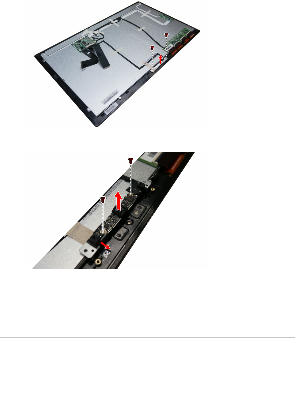
Step5.Removethetwoscrewsthatsecurethecameraandbrackettothefrontbezel.Liftupthecamera
andbrackettoremoveit.
Step6.Removethecamerafrombracketbyremovingthetwoscrewsanddisconnectthedatacable
fromthecamera.
Step7.Toinstallthenewcamera:
a.Connectthedatacabletothenewcamera.
b.Securethenewcameratothebracketwiththetwoscrews.
c.Lineuptheholesinthebracketwiththemountingholesonthefrontbezelandsecurethe
newcamerawiththetwoscrews.
Step8.Reattachtherearcover.
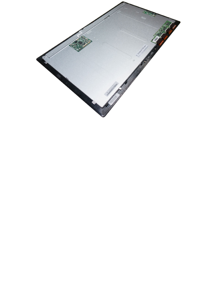
ReplacingtheLEDpanelmodule
Note:Turnoffthecomputerandwait3to5minutestoletitcooldownbeforeremovingthebasecover.
Chapter7.Replacinghardware35
Note:Itmaybehelpfultoplacethecomputerface-downonasoftflatsurfaceforthisprocedure.Lenovo
recommendsthatyouuseablanket,towel,orothersoftclothtoprotectthecomputerscreenfromscratches
orotherdamage.
ToreplacetheLEDpanelmodule:
Step1.Removeanymedia(disks,CDs,DVDs,ormemorycards)fromthedrives,shutdowntheoperating
system,andturnoffthecomputerandallattacheddevices.
Step2.Unplugallpowercordsfromelectricaloutlets.
Step3.Disconnectallcablesattachedtothecomputer.Thisincludespowercords,input/output(I/O)
cables,andanyothercablesthatareconnectedtothecomputer.Referto“Leftandrightview”
and“Rearview”forhelpwithlocatingthevariousconnectors.
Step4.Removetherearcover.Referto“Removingtherearcover” .
Step5.Removethecamera.Referto“Replacingthecamera” .
Step6.Removeallthecablesattachedtothefrontbezel.
Step7.ToinstallthenewtheLEDpanel:
a.ConnectallthecablestotheconnectorsontheLEDpanelmodule.
b.AttachthecameratothenewLEDpanel.
Step8.Reattachtherearcover.
36IdeaCentreHorizon227All-In-OnePCHardwareMaintenanceManual

Chapter8.FRUlists
Thischapterliststheinformationonthefieldreplaceableunits(FRUs).
Attention:BesuretoreadandunderstandallthesafetyinformationbeforereplacinganyFRUs.
Notes:FRUsthathavea1or2intheCRUcolumnareCustomerReplaceableUnits(CRUs).
•1–identifiespartsthatarefairlysimpletoreplace,requiringfewornotools.
•2–identifiespartsthatareslightlymoredifficulttoreplace.
•N-identifiespartsthatarenottobereplacedbythecustomer.
DescriptionLenovoP/NCRU
ID
Motherboard
Description90005883N
W8SMULTi3-4010U2GMB90005884N
W8PMULTi3-4010U2GMB90005885N
W8SMi7-4510U2GMB5B20F66810N
W8PMi5-4210U2GMB5B20F66811N
W8SMi5-4210U2GMB5B20F66812N
NOKMi5-4210U2GMB5B20F66813N
W8PMi7-4510U2GMB5B20F66814N
NOKMi7-4510U2GMB5B20F66815N
NOKMi3-4010U2GSMB90005883N
W8SMi3-4010U2GSMB90005884N
W8PMi3-4010U2GSMB90005885N
NOKMi7-4510U2GSMB5B20F66815N
W8SMi7-4510U2GSMB5B20F66810N
W8PMi7-4510U2GSMB5B20F66814N
NOKMi5-4210U2GSMB5B20F66813N
W8SMi5-4210U2GSMB5B20F66812N
W8PMi5-4210U2GSMB5B20F66811N
NOKMi3-4030U2GSMB5B20G05103N
W8SMi3-4030U2GSMB5B20G05100N
W8PMi3-4030U2GSMB5B20G05099N
LCDTouchModule
AlphaIIFHDLCMforOfilm888016973N
AlphaIIFHDLCMforLGE888016974N
Memory
©CopyrightLenovo201437

MT16KTF1G64HZ-1G6E11100635N
M471B5173DB0-YK04GBD3L-1600S-HF1100942N
M471B1G73DB0-YK08GBD3L-1600S-HF1100943N
MT8KTF51264HZ-1G6E14GBD3L-1600S-HF1100957N
Mic_SD9QBJ4GBD3L-1600S1100959N
Mic_RD9QBJ4GBD3L-1600S-HF1100967N
HMT451S6BFR8A-PB4GBD3L-1600S-HF1100985N
HMT41GS6BFR8A-PB8GBD3L-1600S-HF1100986N
Mic_RD9QBJ8GBD3L-1600S-HF1101012N
HardDrive
HTS545050A7E38016200067N
WD5000LPVX-08V0T16200379N
ST500LM00016200420N
WD10SPCX-24HWST06G7mm1THDD16200554N
ST500L T0126G7mm5.4K500GHDD16200626N
Boards
LTNRTL8821AE1x1ac+BT4.0ComboHMC11202485N
LiteonWB3351x1BGN+BT4.0HMC20200437N
CbtRTL8723BE1x1BGN+BTHMC20200440N
FXNBCM20792MNFCModule11202583N
MSIAlphaIIpowerbuttonboardMP11202641N
MSIAlphaIIIOboardMP11202647N
MSIAlphaIIHomeboardMP11202650N
Camera
AVC1080P2MICWVWBCamAphalII20200611N
Bison1080P2MICWVWBCamAphalII20200612N
Speaker
Alpha2Wabony2.5Wspeaker25216223N
Keyboard&Mouse
LiteonSK-8861(US)2.4GKB-Metal8252160201
LiteonSK-8861(TW)2.4GKB-Metal8252160211
LiteonSK-8861(TH)2.4GKB-Metal8252160221
LiteonSK-8861(CS-SK)2.4GKB-Metal8252160231
LiteonSK-8861(US-IN)2.4GKB-Metal8252160241
LiteonSK-8861(RU)2.4GKB-Metal8252160251
LiteonSK-8861(GB)2.4GKB-Metal8252160261
LiteonSK-8861(Nordic)2.4GKB-Metal8252160271
LiteonSK-8861(LA)2.4GKB-Metal8252160281
LiteonSK-8861(SA)2.4GKB-Metal8252160301
LiteonSK-8861(DE)2.4GKB-Metal8252160311
38IdeaCentreHorizon227All-In-OnePCHardwareMaintenanceManual

LiteonSK-8861(TR)2.4GKB-Metal8252160321
LiteonSK-8861(ES)2.4GKB-Metal8252160331
LiteonSK-8861(IT)2.4GKB-Metal8252160341
LiteonSK-8861(FR)2.4GKB-Metal8252160351
LiteonSK-8861(KR)2.4GKB-Metal8252160361
LiteonSK-8861(JP)2.4GKB-Metal8252160371
LiteonSK-8861(EN-FR)2.4GKB-Metal8252160381
LiteonSK-8861(BE-EN)2.4GKB-Metal8252160391
LiteonSK-8861(US-EU)2.4GKB-Metal8252160401
SK-8861(CH)2.4GKB-Metal8SD50F658161
LiteonZTM6002.4GMouse(WW)Silver252160431
LiteonZTM6002.4GMouse(NoBTY)Silver252160441
PowerCord
US/Canada/Barbados/Belize/Bolivia/CostaRica/Columbia/DominicanRepublic/Ecuador/El
Salvador/Guatemala/Haiti/Honduras/Jamaica/Mexico/NetherlandsAntilles/Nicaragua/
Panama/Philippines/Peru/Venezuela/(Thainland)
310338571
US/Canada/Barbados/Belize/Bolivia/CostaRica/Columbia/DominicanRepublic/Ecuador/El
Salvador/Guatemala/Haiti/Honduras/Jamaica/Mexico/NetherlandsAntilles/Nicaragua/
Panama/Philippines/Peru/Venezuela/(Thainland)
310338581
Albania/Algeria/Angola/Austria/Azerbaijan/Belarus/Belgium/Bosnia/Bulgaria/Croatia//Cambodia/Cote
d'ivoire/Czech/Estonia/Egypt/Finland/France/Georgia/Germany/
Greece/Herzegovina/Hungary/Indonesia/Iceland/Kazakhstan/Kyrgyzstan/Laos/Latvia/
Lebanon/Lithuani
310353321
India/(Bangladesh/SriLanka)310353951
UK/HongKong/Singapore/Malaysia/Bahrain/Bangladesh/Botswana/Burma/Brunei
/Cyprus/Ghana/Ireland/Jordan/Kenya/Kuwait/Malta/Nigeria/Oman/Qatar/UnitedArab
Emirates/TrinidadandTobago/SaudiArabia/SriLanka
310353961
Australia/NewZealand310353971
Brazil310358281
Taiwan310388851
LA(HighVoltage)Argentina,Paraguay,Uruguay310391001
Denmark310391011
Switzerland/Liechtenstein310391031
Italy/Chile/Libya310391041
SouthAfrica/Macao/Namibia/Nepal/Pakistan/Swaziland/Uganda310391051
Korea310391061
Israel310391071
UK/HongKong/Singapore/Malaysia/Bahrain/Bangladesh/Botswana/Burma/Brunei
/Cyprus/Ghana/Ireland/Jordan/Kenya/Kuwait/Malta/Nigeria/Oman/Qatar/UnitedArab
Emirates/TrinidadandTobago/SaudiArabia/SriLanka
310494961
Albania/Algeria/Angola/Austria/Azerbaijan/Belarus/Belgium/Bosnia/Bulgaria/Croatia//Cambodia/Cote
d'ivoire/Czech/Estonia/Egypt/Finland/France/Georgia/Germany/
Greece/Herzegovina/Hungary/Indonesia/Iceland/Kazakhstan/Kyrgyzstan/Laos/Latvia/
Lebanon/Lithuani
310494971
Korea310494981
Chapter8.FRUlists39

Taiwan310494991
Australia/NewZealand310495001
SouthAfrica/Macao/Namibia/Nepal/Pakistan/Swaziland/Uganda310495011
Israel310495021
Denmark310495031
Italy/Chile/Libya310495041
Brazil310495051
LA(HighVoltage)Argentina,Paraguay,Uruguay310495071
Switzerland/Liechtenstein310495081
US/Canada/Barbados/Belize/Bolivia/CostaRica/Columbia/DominicanRepublic/Ecuador/El
Salvador/Guatemala/Haiti/Honduras/Jamaica/Mexico/NetherlandsAntilles/Nicaragua/
Panama/Philippines/Peru/Venezuela/(Thainland)
310495171
Albania/Algeria/Angola/Austria/Azerbaijan/Belarus/Belgium/Bosnia/Bulgaria/Croatia//Cambodia/Cote
d'ivoire/Czech/Estonia/Egypt/Finland/France/Georgia/Germany/
Greece/Herzegovina/Hungary/Indonesia/Iceland/Kazakhstan/Kyrgyzstan/Laos/Latvia/
Lebanon/Lithuani
310495181
Australia/NewZealand310495201
UK/HongKong/Singapore/Malaysia/Bahrain/Bangladesh/Botswana/Burma/Brunei
/Cyprus/Ghana/Ireland/Jordan/Kenya/Kuwait/Malta/Nigeria/Oman/Qatar/UnitedArab
Emirates/TrinidadandTobago/SaudiArabia/SriLanka
315033521
India/(Bangladesh/SriLanka)315033531
Taiwan315033541
SouthAfrica/Macao/Namibia/Nepal/Pakistan/Swaziland/Uganda315033551
LA(HighVoltage)Argentina,Paraguay,Uruguay315033561
Brazil315033571
Korea315033581
Italy/Chile/Libya315033591
Denmark315033601
Switzerland/Liechtenstein315033611
Israel315033621
Japan315034231
Japan315034241
Japan315034251
ThermalModule&Fan
AVCSE42600001AlphaIIHS31506671N
SUNONEG70040S1-C030-S9AAlphaIICPUFAN31506672N
SUNONEG70040S1-C040-S9AAlphaIISYSFAN31506673N
Accessories
Joystick200026561
Striker200026571
AlphaE-dice2nd315046211
AlphaE-dice2nd315046211
40IdeaCentreHorizon227All-In-OnePCHardwareMaintenanceManual

AlphaE-diceChinaUSAUKGermany315047301
AlphaE-diceChinaUSAUKGermany315047301
AlphaE-diceMX,PE,VEN,RU,TL315057561
AlphaE-diceMX,PE,VEN,RU,TL315057561
BetaE-diceUA,JO,KU,OMA,QAT,KSA,UAE315066021
E-diceforAsiaandSouthAmerica315066421
E-diceforAsiaandSouthAmerica315066421
BetaE-diceUA,JO,KU,OMA,QAT,KSA,UAE315066021
Battery
SanyoPolymer3S2P73Wh31506605N
Mechanicals
ASM-ALPHA2_27INCH_BACK_COVER31506851N
ASM_AlphaII_bracket-AforHDD31506853N
ASM_AlphaII_BKT_CAMERA31506854N
RearCoverVictoryAlphaII5CB0G15207N
HingeStronkinAlphaII5H50G15206N
Cables
LSAlphaIIDCINCable31506675N
LSAlphaIIFFCCable_158mm31506676N
LSAlphaIILVDSCABLE(30PIN)_310mm31506677N
LSAlphaIILVDSCABLE(40PIN)_260mm31506678N
LSAlphaIINFCModuleToMBFFCCable31506679N
LSAlphaIIPowerButtonCable_710mm31506680N
LSAlphaIISATAHDDCable_120mm31506681N
LSAlphaIISideIOBoardCable_FPC31506682N
LSAlphaIITO_SCA_BoardCable(Coaxial)31506683N
LSAlphaIITO_SCA_BoardCable(Wire)31506684N
LSAlphaIIWEBCAMCABLE31506687N
LSAlphaIIFFCfortelecontrol31506688N
LSAlpha2WLANantennaL1610mm31506689N
LSAlpha2WLANantennaL2340mm31506690N
LSAlphaIIFHDCVTtopanelFFC_240mm31507030N
LSAlphaIIFHDCVTttoscalarboardFFC31507031N
LSAlphaIILVDSCABLE(30PIN_FHD)_280mm31507032N
DELTAADP-120ZBBBHTcommon120Wadapter36200439N
LiteonPA-1121-04LB120wcommonadapter36200440N
Chapter8.FRUlists41

42IdeaCentreHorizon227All-In-OnePCHardwareMaintenanceManual

Chapter9.Generalinformation
Thischapterprovidesgeneralinformationthatappliestoallcomputermodelscoveredbythismanual.
AdditionalServiceInformation
Thischapterprovidesadditionalinformationthattheservicerepresentativemightfindhelpful.
Powermanagement
Powermanagementreducesthepowerconsumptionofcertaincomponentsofthecomputersuchasthe
systempowersupply,processor,harddiskdrives,andsomemonitors.
Advancedconfigurationandpowerinterface(ACPI)BIOS
AsthiscomputerhasanACPIBIOSsystem,theoperatingsystemisallowedtocontrolthepower
managementfeaturesofthecomputerandthesettingsforAdvancedPowerManagement(APM)BIOSmode
isignored.NotalloperatingsystemssupportACPIBIOSmode.
AutomaticPower-Onfeatures
TheAutomaticPower-OnfeatureswithinthePowerManagementmenuallowyoutoenableanddisable
featuresthatturnonthecomputerautomatically.
•WakeUponAlarm:Youcanspecifyadateandtimeatwhichthecomputerwillbeturnedonautomatically.
Thiscanbeeitherasingleevent,adailyeventoraweeklyevent.
•WakeUponLAN:ThisfeatureallowsLANadaptercardtowaketheSystem.
©CopyrightLenovo201443
