Lenovo U31 70 Hmm 201601 User Manual Hardware Maintenance Laptop (Lenovo) Type 80M6
2016-02-14
User Manual: Lenovo Lenovo U31-70 Hmm 201601 Hardware Maintenance Manual - Lenovo U31-70 U31-70 Laptop (Lenovo) - Type 80M6 80M6
Open the PDF directly: View PDF ![]() .
.
Page Count: 80

Lenovo U31-70
Hardware
Maintenance
Manual

Note:
• Before using this information and the product it supports, be sure to read the general information under
“Notices” on page 75.
First Edition (April 2015)
© Copyright Lenovo 2015. All rights reserved.
LIMITEDANDRESTRICTEDRIGHTSNOTICE:IfdataorsoftwareisdeliveredpursuantaGeneral
ServicesAdministration“GSA”contract,use,reproduction,ordisclosureissubjecttorestrictionsset
forthinContractNo.GS-35F-05925.
©2015Lenovo

iii
Contents
About this manual ....................................... iv
Safety information ........................................ 1
Generalsafety................................................ 2
Electricalsafety.............................................. 3
Safetyinspectionguide.................................. 5
Handlingdevicesthataresensitiveto
electrostaticdischarge.................................... 6
Groundingrequirements................................. 6
Safetynotices:multilingualtranslations.......... 7
Lasercompliancestatement......................... 14
Important service information ................... 16
StrategyforreplacingFRUs......................... 16
Strategyforreplacingaharddiskdrive............17
Importantnoticeforreplacingasystem
board................................................................17
Importantinformationaboutreplacing
RoHScompliantFRUs................................. 18
General checkout ...................................... 19
Whattodorst............................................. 20
Powersystemcheckout................................ 21
CheckingtheACadapter.................................21
Checkingoperationalcharging.........................21
Checkingthebatterypack................................22
Related service information ...................... 23
Restoringthefactorycontentsbyusing
OneKeyRecovery........................................ 23
Restoreoffactorydefault.................................23
Passwords.................................................... 24
Power-onpassword..........................................24
Hard-diskpassword..........................................24
Administratorpassword....................................24
Powermanagement..................................... 25
Screenblankstate............................................25
Puttingthecomputertosleeporshutting
itdown..............................................................25
Puttingyourcomputertosleep.........................25
Shuttingdownthecomputer.............................25
Lenovo U31-70 ............................................ 26
Specications............................................... 26
Statusindicators........................................... 28
Hotkeys......................................................... 29
FRUreplacementnotices............................. 30
Screwnotices..................................................30
RemovingandreplacinganFRU................. 31
1010Basecover...............................................32
1020Batterypack.............................................34
1030PCIExpressMiniCardforwireless
LAN...................................................................36
1040DIMM.......................................................38
1050Speakers.................................................39
1060Harddiskdrive.........................................40
1070FanassemblyandHeatSink
assembly...........................................................42
1080IOboard,DC-incable..............................46
1090
Systemboard............................................ 48
1100Uppercase...............................................51
1110LCDunit...................................................54
1120Integratedcamera,antenna
assemblyandLCDhinges................................57
Locations...................................................... 60
Frontviewandright-sideview..........................60
BottomandLeft-sideview...............................61
Partslist........................................................ 62
Overall..............................................................63
LCDFRUs........................................................69
Miscellaneousparts..........................................71
ACadapters......................................................71
Screws..............................................................71
Powercords......................................................72
Notices......................................................... 75
Trademarks.................................................. 76
iv
About this manual
Thismanualcontainsserviceandreferenceinformationforthefollowing
Lenovoproduct:
Lenovo U31-70
Usethismanualtotroubleshootproblems.
Themanualisdividedintothefollowingsections:
• Thecommonsectionsprovidegeneralinformation,guidelines,andsafety
informationrequiredforservicingcomputers.
• Theproduct-specicsectionincludesservice,reference,andproduct-specic
partsinformation.
Important:
This manual is intended only for trained servicers who are familiar with Lenovo
products. Use this manual to troubleshoot problems effectively.
Before servicing a Lenovo product, make sure to read all the information under
“Safety information” on page 1 and “Important service information” on page 16.

1
Safety information
Safety information
Thischapterpresentsthefollowingsafetyinformationthatyouneedtoget
familiarwithbeforeyouserviceaLenovoU31-70computer:
• “Generalsafety”onpage2
• “Electricalsafety”onpage3
• “Safetyinspectionguide”onpage5
• “Handlingdevicesthataresensitivetoelectrostaticdischarge”onpage6
• “Groundingrequirements”onpage6
• “Safetynotices:multilingualtranslations”onpage7
• “Lasercompliancestatement”onpage14

2
U31-70 Hardware Maintenance Manual
General safety
Followtheserulesbelowtoensuregeneralsafety:
• Observeagoodhousekeeping inthe areawherethemachinesareput
duringandafterthemaintenance.
• Whenliftinganyheavyobject:
1. Makesurethatyoucanstandsafelywithoutslipping.
2. Distributetheweightoftheobjectequallybetweenyourfeet.
3. Useaslowliftingforce.Nevermovesuddenlyortwistwhenyouattempt
toliftit.
4. Liftitbystandingorpushingupwithyourlegmuscles;thisactioncould
avoidthestrainfromthemusclesinyourback.Donotattempttoliftany
objectthatweighsmorethan16kg(35lb)orthatyouthinkistooheavy
foryou.
• Donotperformany actionthatcauseshazardstothecustomer,or that
makesthemachineunsafe.
• Beforeyou startthe machine,makesurethatotherservicerepresentatives
andthecustomerarenotinahazardousposition.
• Pleaseremovecoversand otherparts ina safeplace,awayfromall
personnel,whileyouareservicingthemachine.
• Keepyourtoolcaseawayfromwalkareassothatotherpeoplewillnot trip
overit.
• Donotwearlooseclothingthatcanbetrappedinthemovingparts ofthe
machine.Makesurethatyoursleevesarefastenedorrolledupaboveyour
elbows.Ifyourhairislong,fastenit.
• Inserttheendsofyournecktieorscarfinsideclothingor fastenit withthe
nonconductiveclip,about8centimeters(3inches)fromtheend.
• Donotwearjewelry,chains,metal-frameeyeglasses,ormetalfastenersfor
yourclothing.
Attention:Metalobjectsaregoodelectricalconductors.
• Wearsafetyglasses whenyouarehammering,drilling,soldering,cutting
wire,attachingsprings,usingsolvents,orworkinginanyotherconditions
thatmaybehazardoustoyoureyes.
• Afterservice, reinstallall safetyshields,guards,labels,and groundwires.
Replaceanysafetydevicethatiswornordefective.
• Reinstallallcoverscorrectlybeforereturningthemachinetothecustomer.
• Fanlouversonthemachinehelp toprevent theoverheating ofinternal
components.Donotobstructfanlouvers orcover themwith labelsor
stickers.

3
Safety information
Electrical safety
Observethefollowingruleswhenworkingonelectricalequipments.
Important:
Use only approved tools and test equipments. Some hand tools have handles
covered with a soft material that does not insulate you when working with live
electrical currents.
Many customers have rubber floor mats near their machines that contain small
conductive bers to decrease electrostatic discharges. Do not use such kind of mat
to protect yourself from electrical shock.
• Findtheroomemergency power-off(EPO)switch,disconnectingswitchor
electricaloutlet.Ifanelectricalaccident occurs,you canthen operatethe
switchorunplugthepowercordquickly.
• Donotworkalone underhazardousconditionsornear theequipment that
hashazardousvoltages.
• Disconnectallpowerbefore:
– Performingamechanicalinspection
– Workingnearpowersupplies
– Removingorinstallingmainunits
• Beforeyoustarttoworkonthemachine,unplug thepower cord.Ifyou
cannotunplugit,askthecustomerto power-offthewall boxthatsupplies
powertothemachine,andtolockthewallboxintheoffposition.
• Ifyouneedtoworkonamachinethathasexposedelectricalcircuits,
observethefollowingprecautions:
– Ensurethatanotherperson,familiarwiththepower-offcontrols,isnear
you.
Attention:Anotherperson mustbetheretoswitchoffthepower,if
necessary.
– Useonlyonehandwhenworkingwithpowered-onelectricalequipment;
keeptheotherhandinyourpocketorbehindyourback.
Attention:Anelectricalshockcanoccuronlywhenthereisacomplete
circuit.Byobservingtheaboverule,you maypreventacurrentfrom
passingthroughyourbody.
– Whenusingtesters,setthecontrolscorrectlyandusetheapproved
probeleadsandaccessoriesforthattester.
– Standonsuitablerubbermats(obtainedlocally,ifnecessary)toinsulate
youfromgroundssuchasmetaloorstripsandmachineframes.
Observethespecialsafetyprecautionswhenyouworkwithveryhighvoltages;
instructionsfortheseprecautionsareinthesafetysectionsofmaintenance
information.Beextremelycarefulwhenyoumeasurethehighvoltages.
• Regularlyinspectandmaintainyourelectricalhandtoolsforsafeoperational
condition.
• Donotusewornorbrokentoolsandtesters.
• Neverassumethatpowerhasbeendisconnectedfromacircuit.First,check
ittomakesurethatithasbeenpoweredoff.

4
U31-70 Hardware Maintenance Manual
• Alwayslookcarefullyforpossiblehazardsinyourworkarea.Examplesof
thesehazardsaremoistoors,nongroundedpowerextensioncables,power
surges,andmissingsafetygrounds.
• Donottouchliveelectricalcircuits withthe reflectivesurface ofaplastic
dentalmirror.Thesurfaceisconductive;suchtouchingcancausepersonal
injuryandmachinedamage.
• Donotservicethefollowingpartswiththepoweronwhentheyareremoved
fromtheirnormaloperatingplacesinamachine:
– Powersupplyunits
– Pumps
– Blowersandfans
– Motorgenerators
andsimilarunits.(Thispracticeensurescorrectgroundingoftheunits.)
• Ifanelectricalaccidentoccurs:
– Caution:donotbecomeavictimyourself.
– Switchoffthepower.
– Sendthevictimtogetmedicalaid.

5
Safety information
Safety inspection guide
Thepurpose ofthis inspectionguideistoassistyouinidentifyingpotential
unsafeconditions.Aseachmachine wasdesigned andbuilt, requiredsafety
itemswereinstalledtoprotectusersandservicepersonnelfrominjury.This
guideaddressesonlythoseitems.You shoulduse goodjudgment toidentify
potentialsafetyhazardsaccordingtotheattachmentofnon-Lenovofeaturesor
optionsnotcoveredbythisinspectionguide.
Ifanyunsafeconditionsarepresent,youmustdetermine howserious the
apparenthazardcouldbeandwhetheryoucancontinuewithoutrstcorrecting
theproblem.
Considertheseconditionsandthesafetyhazardstheypresent:
• Electricalhazards,especiallyprimarypower(primaryvoltageontheframe
cancauseseriousorfatalelectricalshock)
• Explosivehazards,suchasadamagedCRTfaceorabulgingcapacitor
• Mechanicalhazards,suchaslooseormissinghardware
Todeterminewhetherthereareanypotentialunsafeconditions, usethe
followingchecklistatthebeginningofeveryservicetask.Beginthecheckswith
thepoweroff,andthepowercorddisconnected.
Checklist:
1. Checkexteriorcoversfordamage(loose,broken,orsharpedges).
2. Turnoffthecomputer.Disconnectthepowercord.
3. Checkthepowercordfor:
a. Athird-wiregroundconnectoringoodcondition.Useametertomeasure
third-wiregroundcontinuityfor0.1ohmorlessbetweentheexternal
groundpinandtheframeground.
b. Thepowercordshouldbethetypespeciedinthepartslist.
c. Insulationmustnotbefrayedorworn.
4. Checkforcrackedorbulgingbatteries.
5. Removethecover.
6. Checkforanyobviousnon-Lenovoalterations.Usegoodjudgmentastothe
safetyofanynon-Lenovoalterations.
7. Check insidethe unitfor anyobviousunsafeconditions,suchasmetal
filings,contamination,waterorotherliquids,orsignsoffireorsmoke
damage.
8. Checkforworn,frayed,orpinchedcables.
9. Checkthatthepower-supplycover fasteners(screwsorrivets)havenot
beenremovedortamperedwith.
6
U31-70 Hardware Maintenance Manual
Handling devices that are sensitive to electrostatic discharge
Anycomputerpartcontainingtransistorsorintegratedcircuits(ICs)shouldbe
consideredsensitivetoelectrostaticdischarge(ESD).ESDdamagecanoccur
whenthere isa differenceinchargebetween objects.Protect againstESD
damagebyequalizingthechargesothatthemachine,thepart,theworkmat,
andthepersonhandlingthepartareallatthesamecharge.
Notes:
1. Use product-specific ESD procedures when they exceed the requirements
noted here.
2. Make sure that the ESD protective devices you use have been certied (ISO
9000) as fully effective.
WhenhandlingESD-sensitiveparts:
• Keepthepartsinprotectivepackagesuntiltheyareinsertedintotheproduct.
• Avoidcontactwithotherpeople.
• Wearagroundedwriststrapagainstyourskintoeliminate staticonyour
body.
• Preventthepartfromtouchingyourclothing.Mostclothingisinsulativeand
retainsachargeevenwhenyouarewearingawriststrap.
• Usetheblacksideofagroundedworkmattoprovideastatic-freework
surface.ThematisespeciallyusefulwhenhandlingESD-sensitivedevices.
• Selectagroundingsystem,suchasthoselistedbelow,toprovideprotection
thatmeetsthespecicservicerequirement.
Note:
The use of a grounding system to guard against ESD damage is desirable but not
necessary.
– AttachtheESDgroundcliptoanyframeground,groundbraid,orgreen-
wireground.
– Whenworkingonadouble-insulatedorbattery-operatedsystem,usean
ESDcommongroundorreferencepoint.Youcanusecoaxorconnector-
outsideshellsonthesesystems.
– Usetheroundgroundprongoftheacplugonac-operatedcomputers.
Grounding requirements
Electricalgroundingofthecomputerisrequiredforoperatorsafetyandcorrect
systemfunction.Propergroundingoftheelectricaloutletcanbeveriedbya
certiedelectrician.
7
Safety information
Safety notices: multilingual translations
Thesafetynoticesin thissection areprovidedinEnglish,French,German,
Hebrew,Italian,Japanese,andSpanish.
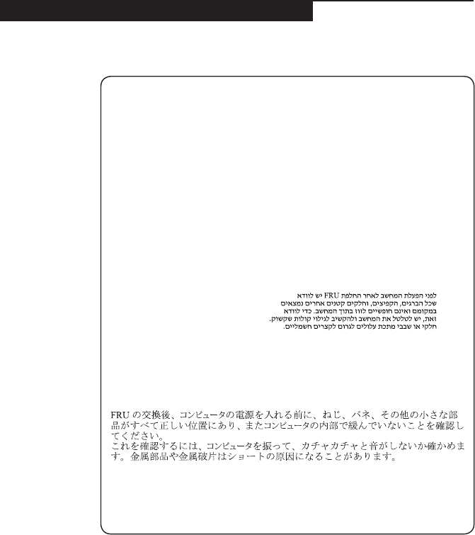
Safety notice 1
Before the computer is powered on after FRU replacement, make sure all screws,
springs, and other small parts are in place and are not left loose inside the
computer. Verify this by shaking the computer and listening for rattling sounds.
Metallic parts or metal akes can cause electrical shorts.
Avant de remettre l’ordinateur sous tension après remplacement d’une unité en
clientèle, vériez que tous les ressorts, vis et autres pièces sont bien en place et
bien xées. Pour ce faire, secouez l’unité et assurez-vous qu’aucun bruit suspect
ne se produit. Des pièces métalliques ou des copeaux de métal pourraient causer
un court-circuit.
Bevor nach einem FRU-Austausch der Computer wieder angeschlossen wird,
muß sichergestellt werden, daß keine Schrauben, Federn oder andere Kleinteile
fehlen oder im Gehäuse vergessen wurden. Der Computer muß geschüttelt und auf
Klappergeräusche geprüft werden. Metallteile oder-splitter können Kurzschlüsse
erzeugen.
Prima di accendere l’elaboratore dopo che é stata effettuata la sostituzione di una
FRU, accertarsi che tutte le viti, le molle e tutte le altri parti di piccole dimensioni
siano nella corretta posizione e non siano sparse all’interno dell’elaboratore.
Vericare ciò scuotendo l’elaboratore e prestando attenzione ad eventuali rumori;
eventuali parti o pezzetti metallici possono provocare cortocircuiti pericolosi.
Antes de encender el sistema despues de sustituir una FRU, compruebe que
todos los tornillos, muelles y demás piezas pequeñas se encuentran en su sitio
y no se encuentran sueltas dentro del sistema. Compruébelo agitando el sistema
y escuchando los posibles ruidos que provocarían. Las piezas metálicas pueden
causar cortocircuitos eléctricos.
8
U31-70 Hardware Maintenance Manual
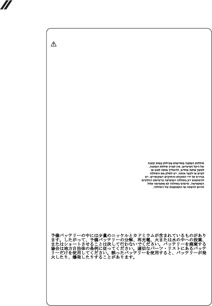
Safety notice 2
DANGER
Some standby batteries contain a small amount of nickel and cadmium. Do not
disassemble a standby battery, recharge it, throw it into fire or water, or short-
circuit it. Dispose of the battery as required by local ordinances or regulations.
Use only the battery in the appropriate parts listing. Use of an incorrect battery can
result in ignition or explosion of the battery.
Certaines batteries de secours contiennent du nickel et du cadmium. Ne les
démontez pas, ne les rechargez pas, ne les exposez ni au feu ni à l’eau. Ne
les mettez pas en court-circuit. Pour les mettre au rebut, conformez-vous à la
réglementation en vigueur. Lorsque vous remplacez la pile de sauvegarde ou celle
de l’horloge temps réel, veillez à n’utiliser que les modèles cités dans la liste de
pièces détachées adéquate. Une batterie ou une pile inappropriée risque de prendre
feu ou d’exploser.
Die Bereitschaftsbatterie, die sich unter dem Diskettenlaufwerk befindet,
kann geringe Mengen Nickel und Cadmium enthalten. Sie darf nicht zerlegt,
wiederaufgeladen, kurzgeschlossen, oder Feuer oder Wasser ausgesetzt werden.
Bei der Entsorgung die örtlichen Bestimmungen für Sondermüll beachten. Beim
Ersetzen der Bereitschafts-oder Systembatterie nur Batterien des Typs verwenden,
der in der Ersatzteilliste aufgeführt ist. Der Einsatz falscher Batterien kann zu
Entzündung oder Explosion führen.
Alcune batterie di riserva contengono una piccola quantità di nichel e cadmio.
Non smontarle, ricaricarle, gettarle nel fuoco o nell’acqua né cortocircuitarle.
Smaltirle secondo la normativa in vigore (DPR 915/82, successive disposizioni e
disposizioni locali). Quando si sostituisce la batteria dell’RTC (real time clock) o
la batteria di supporto, utilizzare soltanto i tipi inseriti nell’appropriato Catalogo
parti. L’impiego di una batteria non adatta potrebbe determinare l’incendio o
l’esplosione della batteria stessa.
Algunas baterías de reserva contienen una pequeña cantidad de níquel y cadmio.
No las desmonte, ni recargue, ni las eche al fuego o al agua ni las cortocircuite.
Deséchelas tal como dispone la normativa local. Utilice sólo baterías que se
encuentren en la lista de piezas. La utilización de una batería no apropiada puede
provocar la ignición o explosión de la misma.
9
Safety information
Safety notice 3
DANGER
The battery pack contains small amounts of nickel. Do not disassemble it, throw
it into re or water, or short-circuit it. Dispose of the battery pack as required by
local ordinances or regulations. Use only the battery in the appropriate parts listing
when replacing the battery pack. Use of an incorrect battery can result in ignition
or explosion of the battery.
La batterie contient du nickel. Ne la démontez pas, ne l’exposez ni au feu ni à l’eau.
Ne la mettez pas en court-circuit. Pour la mettre au rebut, conformez-vous à la
réglementation en vigueur. Lorsque vous remplacez la batterie, veillez à n’utiliser
que les modèles cités dans la liste de pièces détachées adéquate. En effet, une
batterie inappropriée risque de prendre feu ou d’exploser.
Akkus enthalten geringe Mengen von Nickel. Sie dürfen nicht zerlegt,
wiederaufgeladen, kurzgeschlossen, oder Feuer oder Wasser ausgesetzt werden.
Bei der Entsorgung die örtlichen Bestimmungen für Sondermüll beachten. Beim
Ersetzen der Batterie nur Batterien des Typs verwenden, der in der Ersatzteilliste
aufgeführt ist. Der Einsatz falscher Batterien kann zu Entzündung oder Explosion
führen.
La batteria contiene piccole quantità di nichel. Non smontarla, gettarla nel fuoco
o nell’acqua né cortocircuitarla. Smaltirla secondo la normativa in vigore (DPR
915/82, successive disposizioni e disposizioni locali). Quando si sostituisce la
batteria, utilizzare soltanto i tipi inseriti nell’appropriato Catalogo parti. L’impiego
di una batteria non adatta potrebbe determinare l’incendio o l’esplosione della
batteria stessa.
Las baterías contienen pequeñas cantidades de níquel. No las desmonte, ni
recargue, ni las eche al fuego o al agua ni las cortocircuite. Deséchelas tal como
dispone la normativa local. Utilice sólo baterías que se encuentren en la lista de
piezas al sustituir la batería. La utilización de una batería no apropiada puede
provocar la ignición o explosión de la misma.
10
U31-70 Hardware Maintenance Manual
Safety notice 4
DANGER
The lithium battery can cause a fire, an explosion, or a severe burn. Do not
recharge it, remove its polarized connector, disassemble it, heat it above 100°C
(212°F), incinerate it, or expose its cell contents to water. Dispose of the battery as
required by local ordinances or regulations. Use only the battery in the appropriate
parts listing. Use of an incorrect battery can result in ignition or explosion of the
battery.
La pile de sauvegarde contient du lithium. Elle présente des risques d’incendie,
d’explosion ou de brûlures graves. Ne la rechargez pas, ne retirez pas son
connecteur polarisé et ne la démontez pas. Ne l’exposez pas à une temperature
supérieure à 100°C, ne la faites pas brûler et n’en exposez pas le contenu à l’eau.
Mettez la pile au rebut conformément à la réglementation en vigueur. Une pile
inappropriée risque de prendre feu ou d’exploser.
Die Systembatterie ist eine Lithiumbatterie. Sie kann sich entzünden, explodieren
oder schwere Verbrennungen hervorrufen. Batterien dieses Typs dürfen nicht
aufgeladen, zerlegt, über 100 C erhitzt oder verbrannt werden. Auch darf ihr
Inhalt nicht mit Wasser in Verbindung gebracht oder der zur richtigen Polung
angebrachte Verbindungsstecker entfernt werden. Bei der Entsorgung die örtlichen
Bestimmungen für Sondermüll beachten. Beim Ersetzen der Batterie nur Batterien
des Typs verwenden, der in der Ersatzteilliste aufgeführt ist. Der Einsatz falscher
Batterien kann zu Entzündung oder Explosion führen.
La batteria di supporto e una batteria al litio e puo incendiarsi, esplodere o
procurare gravi ustioni. Evitare di ricaricarla, smontarne il connettore polarizzato,
smontarla, riscaldarla ad una temperatura superiore ai 100 gradi centigradi,
incendiarla o gettarla in acqua. Smaltirla secondo la normativa in vigore (DPR
915/82, successive disposizioni e disposizioni locali). L’impiego di una batteria
non adatta potrebbe determinare l’incendio o l’esplosione della batteria stessa.
La batería de repuesto es una batería de litio y puede provocar incendios,
explosiones o quemaduras graves. No la recargue, ni quite el conector polarizado,
ni la desmonte, ni caliente por encima de los 100°C (212°F), ni la incinere ni
exponga el contenido de sus celdas al agua. Deséchela tal como dispone la
normativa local.
11
Safety information
Safety notice 5
If the LCD breaks and the uid from inside the LCD gets into your eyes or on your
hands, immediately wash the affected areas with water at least for 15 minutes.
Seek medical care if any symptoms caused by the uid are present after washing.
Si le panneau d’afchage à cristaux liquides se brise et que vous recevez dans les
yeux ou sur les mains une partie du uide, rincez-les abondamment pendant au
moins quinze minutes. Consultez un médecin si des symptômes persistent après le
lavage.
Die Leuchtstoffröhre im LCD-Bildschirm enthält Quecksilber. Bei der Entsorgung
die örtlichen Bestimmungen für Sondermüll beachten. Der LCD-Bildschirm
besteht aus Glas und kann zerbrechen, wenn er unsachgemäß behandelt wird
oder der Computer auf den Boden fällt. Wenn der Bildschirm beschädigt ist und
die darin befindliche Flüssigkeit in Kontakt mit Haut und Augen gerät, sollten
die betroffenen Stellen mindestens 15 Minuten mit Wasser abgespült und bei
Beschwerden anschließend ein Arzt aufgesucht werden.
Nel caso che caso l’LCD si dovesse rompere ed il liquido in esso contenuto
entrasse in contatto con gli occhi o le mani, lavare immediatamente le parti
interessate con acqua corrente per almeno 15 minuti; poi consultare un medico se i
sintomi dovessero permanere.
Si la LCD se rompe y el uido de su interior entra en contacto con sus ojos o sus
manos, lave inmediatamente las áreas afectadas con agua durante 15 minutos
como mínimo. Obtenga atención medica si se presenta algún síntoma del uido
despues de lavarse.
12
U31-70 Hardware Maintenance Manual
Safety notice 6
DANGER
To avoid shock, do not remove the plastic cover that protects the lower part of the
inverter card.
An d’éviter tout risque de choc électrique, ne retirez pas le cache en plastique
protégeant la partie inférieure de la carte d’alimentation.
Aus Sicherheitsgründen die Kunststoffabdeckung, die den unteren Teil der
Spannungswandlerplatine umgibt, nicht entfernen.
Per evitare scosse elettriche, non rimuovere la copertura in plastica che avvolge la
parte inferiore della scheda invertitore.
Para evitar descargas, no quite la cubierta de plástico que rodea la parte baja de la
tarjeta invertida.
Safety notice 7
DANGER
Though the main batteries have low voltage, a shorted or grounded battery can
produce enough current to burn personnel or combustible materials.
Bien que le voltage des batteries principales soit peu élevé, le court-circuit ou la
mise à la masse d’une batterie peut produire sufsamment de courant pour brûler
des matériaux combustibles ou causer des brûlures corporelles graves.
Obwohl Hauptbatterien eine niedrige Spannung haben, können sie doch bei
Kurzschluß oder Erdung genug Strom abgeben, um brennbare Materialien zu
entzünden oder Verletzungen bei Personen hervorzurufen.
Sebbene le batterie di alimentazione siano a basso voltaggio, una batteria in
corto circuito o a massa può fornire corrente sufficiente da bruciare materiali
combustibili o provocare ustioni ai tecnici di manutenzione.
Aunque las baterías principales tienen un voltaje bajo, una batería cortocircuitada
o con contacto a tierra puede producir la corriente suciente como para quemar
material combustible o provocar quemaduras en el personal.
13
Safety information
Safety notice 8
DANGER
Before removing any FRU, turn off the computer, unplug all power cords from
electrical outlets, remove the battery pack, and then disconnect any interconnecting
cables.
Avant de retirer une unité remplaçable en clientèle, mettez le système hors tension,
débranchez tous les cordons d’alimentation des socles de prise de courant, retirez
la batterie et déconnectez tous les cordons d’interface.
Die Stromzufuhr muß abgeschaltet, alle Stromkabel aus der Steckdose gezogen,
der Akku entfernt und alle Verbindungskabel abgenommen sein, bevor eine FRU
entfernt wird.
Prima di rimuovere qualsiasi FRU, spegnere il sistema, scollegare dalle prese
elettriche tutti i cavi di alimentazione, rimuovere la batteria e poi scollegare i cavi
di interconnessione.
Antes de quitar una FRU, apague el sistema, desenchufe todos los cables de
las tomas de corriente eléctrica, quite la batería y, a continuación, desconecte
cualquier cable de conexión entre dispositivos.
14
U31-70 Hardware Maintenance Manual
Laser compliance statement
SomemodelsofLenovocomputerareequippedfromthefactorywithan
opticalstorage devicesuchasaCD-ROMdriveor aDVD-ROM drive.Such
devicesarealsosoldseparatelyasoptions.Ifoneofthesedrivesisinstalled,
itiscertiedintheU.S.toconformto therequirementsoftheDepartmentof
HealthandHumanServices21CodeofFederalRegulations(DHHS21CFR)
SubchapterJforClass1laserproducts.Elsewhere,the driveis certifiedto
conformtotherequirements ofthe InternationalElectrotechnicalCommission
(IEC)825andCENELECEN60825forClass1laserproducts.
IfaCD-ROMdrive,aDVD-ROMdrive,oranotherlaserdeviceisinstalled,note
thefollowing:
CAUTION
Use of controls or adjustments or performance of procedures other than those
specied herein might result in hazardous radiation exposure.
O uso de controles, ajustes ou desempenho de procedimentos diferentes daqueles
aqui especicados pode resultar em perigosa exposição à radiação.
Pour éviter tout risque d’exposition au rayon laser, respectez les consignes de
réglage et d’utilisation des commandes, ainsi que les procédures décrites.
Werden Steuer- und Einstellelemente anders als hier festgesetzt verwendet, kann
gefährliche Laserstrahlung auftreten.
L’utilizzo di controlli, regolazioni o l’esecuzione di procedure diverse da quelle
specicate possono provocare l’esposizione a.
El uso de controles o ajustes o la ejecución de procedimientos distintos de los aquí
especicados puede provocar la exposición a radiaciones peligrosas.
OpeningtheCD-ROMdrive,theDVD-ROMdrive,oranyotheropticalstorage
devicecouldresultinexposuretohazardouslaser radiation.Thereareno
serviceablepartsinsidethosedrives.Do not open.
15
Safety information
ACD-ROMdrive,aDVD-ROMdrive,oranyotherstoragedeviceinstalledmay
containanembeddedClass3AorClass3Blaserdiode.Notethefollowing:
DANGER
Emits visible and invisible laser radiation when open. Do not stare into the beam,
do not view directly with optical instruments, and avoid direct exposure to the
beam.
Radiação por raio laser ao abrir. Não olhe fixo no feixe de luz, não olhe
diretamente por meio de instrumentos óticos e evite exposição direta com o feixe
de luz.
Rayonnement laser si carter ouvert. Évitez de fixer le faisceau, de le regarder
directement avec des instruments optiques, ou de vous exposer au rayon.
Laserstrahlung bei geöffnetem Gerät. Nicht direkt oder über optische Instrumente
in den Laserstrahl sehen und den Strahlungsbereich meiden.
Kinyitáskor lézersugár ! Ne nézzen bele se szabad szemmel, se optikai
eszközökkel. Kerülje a sugárnyalábbal való érintkezést!
Aprendo l’unità vengono emesse radiazioni laser. Non fissare il fascio, non
guardarlo direttamente con strumenti ottici e evitare l’esposizione diretta al fascio.
Radiación láser al abrir. No mire jamente ni examine con instrumental óptico el
haz de luz. Evite la exposición directa al haz.
16
U31-70 Hardware Maintenance Manual
Important service information
Thischapterpresentsthefollowingimportantserviceinformation:
• “StrategyforreplacingFRUs”onpage16
– “Strategyforreplacingaharddiskdrive”onpage17
– “Importantnoticeforreplacingasystemboard”onpage17
• “ImportantinformationaboutreplacingRoHScompliantFRUs”onpage18
Important:
BIOS and device driver xes are customer-installable. The BIOS and device drivers
are posted on the customer support site:
http://support.lenovo.com.
Strategy for replacing FRUs
Before replacing parts:
Makesurethatall softwarexes, drivers,andBIOSdownloadsareinstalled
beforereplacinganyFRUslistedinthismanual.
Afterasystemboardisreplaced,ensurethatthelatestBIOSisloadedtothe
systemboardbeforecompletingtheserviceaction.
Todownloadsoftwarexes,drivers,andBIOS,followthestepsbelow:
1. Gotohttp://support.lenovo.com.
2. Enterthe serialnumber orselect aproduct oruseLenovosmart
downloading.
3. SelecttheBIOS/Driver/Applicationsanddownload.
4. Followthedirectionsonthescreenandinstallthenecessarysoftware.
17
Important service information
Usethefollowingstrategytopreventunnecessaryexpenseforreplacingand
servicingFRUs:
• IfyouareinstructedtoreplaceanFRU,butthereplacementdoesnotsolve
theproblem,reinstalltheoriginalFRUbeforeyoucontinue.
• Somecomputers havebothaprocessorboardand asystem board.Ifyou
areinstructedtoreplaceeitherofthem,andreplacingoneofthemdoesnot
solvetheproblem,reinstallthatboard,andthenreplacetheotherone.
• IfanadapteroradeviceconsistsofmorethanoneFRU,anyoftheFRUs
maybethecauseofthe error.Beforereplacingtheadapter ordevice,
removetheFRUsonebyonetoseeifthesymptomschange.Replaceonly
theFRUthatchangedthesymptoms.
Attention:Thesetup configurationonthecomputeryouareservicingmay
havebeencustomized.RunningAutomaticConfiguration mayalter the
settings.Notethecurrentcongurationsettings(usingtheViewConguration
option);then,whenservice hasbeen completed,verifythatthosesettings
remainineffect.
Strategy for replacing a hard disk drive
Alwaystrytorun alow-level formatbeforereplacingaharddiskdrive.This
willcauseallcustomerdataontheharddisk tobe lost.Make surethatthe
customerhasacurrentbackupofthedatabeforeperformingthisaction.
Attention:Thedrivestartupsequenceinthecomputeryouareservicingmay
havebeenchanged.Beextremelycareful duringwrite operationssuch as
copying,saving,orformatting.Ifyouselectanincorrectdrive,dataorprograms
canbeoverwritten.
Important notice for replacing a system board
Somecomponentsmountedon asystem boardare verysensitive. Improper
handlingcancausedamagetothosecomponents,andmaycauseasystem
malfunction.
Attention:Whenhandlingasystemboard:
• Donotdropthesystemboardorapplyanyexcessiveforcetoit.
• Avoidroughhandlingofanykind.
• Avoidbendingthe systemboardandhardpushingtopreventcrackingat
eachBGA(BallGridArray)chipset.
18
U31-70 Hardware Maintenance Manual
Important information about replacing RoHS compliant FRUs
RoHS, The Restriction of Hazardous Substances in Electrical and
Electronic Equipment Directive (2002/95/EC) is a European Union legal
requirement affecting the global electronics industry. RoHS requirements
must be implemented on Lenovo products placed on the market after
June 2006. Products on the market before June 2006 are not required to
have RoHS compliant parts. If the original FRU parts are non-compliant,
replacement parts can also be non-compliant. In all cases if the original
FRU parts are RoHS compliant, the replacement part must also be RoHS
compliant.
Note:RoHSandnon-RoHSFRUpartnumberswiththesametandfunction
areidentiedwithuniqueFRUpartnumbers.
Lenovoplans totransit toRoHScompliancewellbefore theimplementation
dateandexpectsits supplierstobereadytosupportLenovo’srequirements
andscheduleintheEU.Productssoldin2005and2006will containsome
RoHScompliantFRUs.Thefollowingstatementpertainstotheseproductsand
anyproductLenovoproducescontainingRoHScompliantFRUs.
RoHScompliant FRUshaveuniqueFRUpartnumbers.Before orafterthe
RoHSimplementationdate,failedRoHScompliantpartsmustalwaysbe
replacedwithRoHScompliantones,soonlytheFRUsidentiedascompliant
inthesystemHMMordirectsubstitutionsforthoseFRUsmaybeused.
Products marketed before June 2006 Products marketed after June 2006
Current or
original part
Replacement FRU Current or
original part
Replacement FRU
Non-RoHS CanbeNon-RoHS
MustbeRoHS MustbeRoHS
Non-RoHS CanbeRoHS
Non-RoHS CansubtoRoHS
RoHS MustbeRoHS
Note:AdirectsubstitutionisapartwithadifferentFRUpartnumberthatis
automaticallyshippedbythedistributioncenteratthetimeoftheorder.
19
General checkout
General checkout
Thischapterpresentsthefollowinginformation:
• “Whattodorst”onpage20
• “Powersystemcheckout”onpage21
Beforeyougotothecheckout,makesuretoreadthefollowingimportantnotes:
Important notes:
• Onlycertiedtrainedpersonnelcanservicethecomputer.
• BeforereplacinganyFRU, readthe entirepageonremovingandreplacing
FRUs.
• CarefullyremovescrewsforreusewhenreplacingFRUs.
• Beextremelycarefulduringsuchwriteoperationsascopying,saving,or
formatting. Drives in the computer that you are servicing sequence might
have been altered. If you select an incorrect drive, data or programs might be
overwritten.
• ReplaceanFRUonlywithanotherFRUofthecorrectmodel. When you
replace an FRU, make sure that the machine model and the FRU part number are
correct by referring to the FRU parts list.
• AnFRUshouldnotbereplacedjustbecauseofasingle,unreproduciblefailure.
Single failures can occur for a variety of reasons that have nothing to do with a
hardware defect, such as cosmic radiation, electrostatic discharge, or software
errors. Consider replacing an FRU only when a problem recurs. If you suspect that
an FRU is defective, clear the error logs and run the test again. If the error does
not recur, do not replace the FRU.
• BecarefulnottoreplaceanondefectiveFRU.

20
U31-70 Hardware Maintenance Manual
What to do rst
WhenyoudoreturnanFRU,youmustincludethefollowinginformationinthe
partsexchangeformorpartsreturnformthatyouattachtoit:
1. Nameandphonenumberofservicer
2. Dateofservice
3. Dateonwhichthemachinefailed
4. Dateofpurchase
5. ProcedureindexandpagenumberinwhichthefailingFRUwasdetected
6. FailingFRUnameandpartnumber
7. Machinetype,modelnumber,andserialnumber
8. Customer’snameandaddress
Note for warranty:During thewarrantyperiod,thecustomer maybe
responsiblefor repaircosts ifthe computerdamagewascausedbymisuse,
accident,modification,unsuitablephysicaloroperatingenvironment,or
impropermaintenancebythecustomer.
Thefollowingisa listof somecommon itemsthatarenotcoveredunder
warrantyandsomesymptoms thatmight indicatethat thesystemwas
subjectedtostressbeyondnormaluse.
Beforecheckingproblemswiththecomputer,determinewhetherthedamageis
coveredunderthewarrantybyreferringtothefollowinglist:
The following are not covered under warranty:
• LCDpanelcrackedfromtheapplicationofexcessive forceor frombeing
dropped
• Scratched(cosmetic)parts
• Distortion,deformation,ordiscolorationofthecosmeticparts
• Plasticparts,latches,pins,orconnectorsthathavebeencrackedorbroken
byexcessiveforce
• Damagecausedbyliquidspilledintothesystem
• DamagecausedbytheimproperinsertionofaPCCardortheinstallationof
anincompatiblecard
• Improperdiskinsertionoruseofanopticaldrive
• Diskettedrivedamagecausedbypressure onthe diskettedrive cover,
foreignmaterialinthedrive,ortheinsertionofadiskettewithmultiplelabels
• Damagedorbentdisketteejectbutton
• Fusesblownbyattachmentofanonsupporteddevice
• Forgottencomputerpassword(makingthecomputerunusable)
• Stickykeyscausedbyspillingaliquidontothekeyboard
• UseofanincorrectACadapteronlaptopproducts
The following symptoms might indicate damage caused by nonwarranted
activities:
• Missingpartsmightbeasymptomofunauthorizedserviceormodication.
• Ifthespindleofaharddiskdrivebecomesnoisy,itmayhavebeensubjected
toexcessiveforce,ordropped.
21
General checkout
Power system checkout
Toverifyasymptom,followthestepsbelow:
1. Turnoffthecomputer.
2. Removethebatterypack.
3. ConnecttheACadapter.
4. Makesurethatpowerissuppliedwhenyouturnonthecomputer.
5. Turnoffthecomputer.
6. DisconnecttheACadapterandinstallthechargedbatterypack.
7. Makesurethatthebatterypacksuppliespowerwhenyouturnonthe
computer.
Ifyoususpectapowerproblem,seetheappropriateoneofthefollowingpower
supplycheckouts:
• “CheckingtheACadapter”onpage21
• “Checkingoperationalcharging”onpage21
• “Checkingthebatterypack”onpage22
Checking the AC adapter
YouareherebecausethecomputerfailsonlywhentheACadapterisused.
• Ifthepower-onindicatordoesnotturnon,checkthepowercordoftheAC
adapterforcorrectcontinuityandinstallation.
• Ifthecomputerdoes notcharge duringoperation,goto“Checking
operationalcharging”.
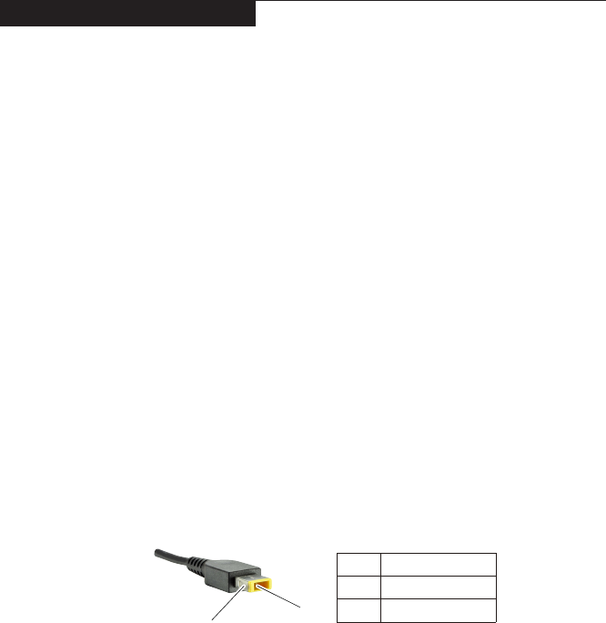
TochecktheACadapter,followthestepsbelow:
1. UnplugtheACadaptercablefromthecomputer.
2. MeasuretheoutputvoltageattheplugoftheACadaptercable.See the
followinggure:
1
2
Voltage (V DC)
+20
0
Pin
1
2
Note:OutputvoltagefortheACadapterpinNo.2maydifferfromtheoneyou
areservicing.
3. Ifthevoltageisnotcorrect,replacetheACadapter.
4. Ifthevoltageisacceptable,dothefollowing:
• Replacethesystemboard.
• Iftheproblempersists,goto“LenovoU31-70”onpage26.
Note:NoisefromtheACadapterdoesnotalwaysindicateadefect.
Checking operational charging
Tocheckwhetherthebatterychargesproperly duringoperation,usea
dischargedbatterypackorabatterypackthathaslessthan50%ofthetotal
powerremainingwheninstalledinthecomputer.

22
U31-70 Hardware Maintenance Manual
Performoperationalcharging.Ifthebatterystatus indicatoror icondoesnot
lighton,removethebatterypackandletitreturntoroomtemperature.Reinstall
thebatterypack.Ifthechargeindicatororicon isstilloff,replacethebattery
pack.
Ifthechargeindicator stilldoesnotlighton,replacethesystemboard.Then
reinstallthebatterypack.Ifitisstillnotcharged,gotothenextsection.
Checking the battery pack
BatterychargingdoesnotstartuntilthePowerMetershowsthatlessthan95%
ofthetotalpowerremains;underthisconditionthebatterypackcanchargeto
100%ofitscapacity.Thisprotectsthebatterypackfrombeingoverchargedor
fromhavingashortenedlife.
Tocheckyourbattery,moveyourcursortothe PowerMeter iconintheicon
trayoftheWindows®taskbarandwaitforamoment(butdonotclickit),andthe
percentageofbatterypowerremainingisdisplayed.Togetdetailedinformation
aboutthebattery,double-clickthePowerMetericon.
Note:Ifthebatterypackbecomeshot,itmaynotbe ableto becharged.
Removeitfromthecomputerandleaveitatroomtemperatureforawhile.After
itcoolsdown,reinstallandrechargeit.
23
Related service information
Related service information
Thischapterpresentsthefollowinginformation:
• “RestoringthefactorycontentsbyusingOneKeyRecovery”onpage23
• “Passwords”onpage24
• “Powermanagement”onpage25
Restoring the factory contents by using OneKey Recovery
Restore of factory default
TheLenovo U31-70computers comewithpre-installed OneKeyRecovery
System.Inordertosaveapplicationfilesandtheinitialbackedupfiles
ofthesystem,theharddiskinaLenovocomputerincludes ahidden
partitionwhenitis shipped.If youneed torestore thesystemtothe
pointofyourfirstbootup,justenterLenovoOneKeyRecoverySystem
andrunSystem Recovery.FordetailsofOneKeyRecoverySystem,
seethe User Guide for Lenovo OneKey Recovery system.
Note: This will delete all the new data on the system partition (C drive), which
is not recoverable. Make sure to back up your critical data before you perform this
action.
Whenyouusetherecoverydiscstobootyourcomputer,thesystemwillenter
theuserinterfaceforsystem recoveryautomatically.Pleasefollowtheprompt
toinsertthebackupdiscstocompletethewholerecoveryprocess.
Note:The recovery process might take up to 2 hours.

24
U31-70 Hardware Maintenance Manual
Passwords
Asmany asthree passwordsmaybeneededforanyLenovo computer:
thepower-onpassword(POP), thehard diskpassword(HDP),andthe
administratorpassword.
Ifanyofthesepasswordshasbeenset,apromptforitappearsonthescreen
wheneverthecomputeristurnedon.Thecomputerdoesnotstartuntilthe
passwordisentered.
Power-on password
Apower-onpassword(POP)protectsthesystemfrombeingpoweredonby
anunauthorized person.Thepasswordmust beenteredbefore anoperating
systemcanbebooted.
Hard-disk password
Therearetwohard-diskpasswords(HDPs):
+UserHDP-fortheuser
+MasterHDP-for thesystemadministrator, whocanuseittogetaccessto
theharddiskdriveeveniftheuserhaschangedtheuserHDP
Attention:IftheuserHDPhasbeen forgotten,check whethera masterHDP
hasbeenset.Ifithas,itcanbeusedforaccesstotheharddiskdrive.If
nomasterHDPisavailable, neitherLenovo norLenovoauthorizedservice
techniciansprovideanyservicestoreseteithertheuserorthemasterHDP,or
torecoverdatafromtheharddiskdrive.Thehard diskdrive canbereplaced
forascheduledfee.
Administrator password
Administratorpasswordcontrolstheaccessofthewholesetuputility.Only
aftertheAdministratorpasswordhasbeensetcantheUserpasswordbeset.If
Administratorpasswordwascleared,theUserpasswordwasclearedtoo.

25
Related service information
Power management
Note:PowermanagementmodesarenotsupportedforAPMoperatingsystem.
Toreduce powerconsumption, thecomputerhasthreepower management
modes:screenblank,sleep(standby),andhibernation.
Screen blank state
Ifthetimesetonthe“Turnoffmonitor”timerinthe operatingsystem expires,
theLCDbacklightturns off.Youcan alsoturnofftheLCDbacklightby
pressing .
Toendscreenblankstateandresumenormaloperation,pressanykeyonthe
keyboard.
Putting the computer to sleep or shutting it down
Whenyouhavenishedworkingwithyourcomputer,youcanputittosleepor
shutitdown.
Putting your computer to sleep
Ifyouwillbeawayfromyourcomputerforonlyashorttime,putthecomputerto
sleep.Whenthecomputerisinsleepmode,youcanquicklywakeittoresume
use,bypassingthestartupprocess.Toputthecomputertosleep,dooneofthe
following:
• Closethedisplaypanel.
• Pressthepowerbutton.
• OpentheCharmsandthenselectSettings → Power → Sleep.
Attention:Waituntilthe powerindicatorlightstartsblinking(indicatingthat
thecomputerisinsleepmode)before youmoveyourcomputer.Movingyour
computerwhile thehard diskisspinningcandamagetheharddisk,causing
lossofdata.
Towakethecomputer,dooneofthefollowing:
• Pressanykeyonthekeyboard.
• Pressthepowerbutton.
Shutting down the computer
Ifyouarenotgoingtouseyourcomputerforalongtime,shutitdown.Toshut
downyourcomputer:
• Openthecharmsbar,thenselectSettings → Power → Shut down.
• Right-clicktheStartbuttoninthelower-leftcornerandselectShut down or
sign out→Shut down.
• Select → Shut downintheupper-rightcorneroftheStartscreen.
Note:TheoperationdependsontheBIOSsetup.Pleaserefertotheactualproduct.
26
U31-70 Hardware Maintenance Manual
Lenovo U31-70
Thischapter presentsthefollowingproduct-specificservice referencesand
product-specicpartsinformation:
• “Specications”onpage26
• “Statusindicators”onpage28
• “Hotkeys”onpage29
• “FRUreplacementnotices”onpage30
• “RemovingandreplacinganFRU”onpage31
• “Locations”onpage60
• “Partslist”onpage62
Specications
ThefollowingtableliststhespecificationsoftheLenovoU31-70:
Table 1. Specications
Feature Description
Processor • Seethesystempropertiesofyourcomputer,youcandothisas
follows:
OpentheControl Panel,andthenselectSystem and
Security→System.
Busarchitecture
• 1600MhzDDR3LSDRAM
• PCIExpressbus2.0
• SerialATA6GB/s
• USB3.0
• USB2.0
• HDMI1.4
• eDP1.3
Graphicmemory
chip
• IntegratedGraphics:GT2,ReservedforGT3
• DiscreteGraphics:Integrated/NvidiaN16v-GM
Display • 13.3-inch16:9,1,366×768pixelsHD/1,920×1,080pixels
FHD
Standard
memory • DDR3L-1600MHz,SODIMM×1(max8GB)
CMOSRAM • 8MByte
Harddiskdrive • 2.5-inch,5mm/7mm,SATAIII
• 256SSD
• 500GB,5400rpm
• HYBRID500GB/1TB5400rpmSSHD(8GB)
I/Oport • Comboaudiojack×1
• RJ-45×1
• HDMIport×1
• USB2.0port×1,USB3.0port×2
• 4in1slot×1(SD/SDHC/SDXC/MMC)
Audio • 1/8"Comboaudiojack
• 1.5Wspeakers×2
• Single/ArrayDigitalMIC

27
Lenovo U31-70
Table 1. Specications (continued)
Feature Description
Ethernet(onthe
systemboard) • 1,000Mbps
Bluetooth
wireless • Combinedincombocard
Keyboard • 6-rowLenovoKeyboard
Touchpad • Multi-touchtype
Integrated
camera • HD
Battery • 2cells,35Wh
ACadapter • 20V,DiscreteGraphics65W,IntegratedGraphics45W
Pre-installed
operating
system
• DOS
• Windows8.1/10(orsimilarupdatein12months)
28
U31-70 Hardware Maintenance Manual
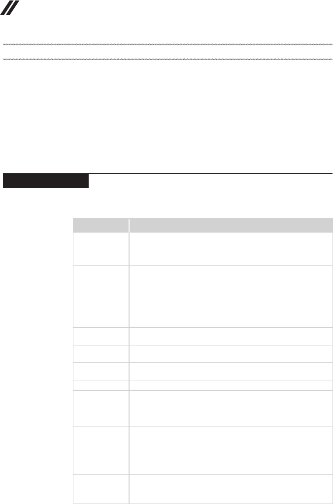
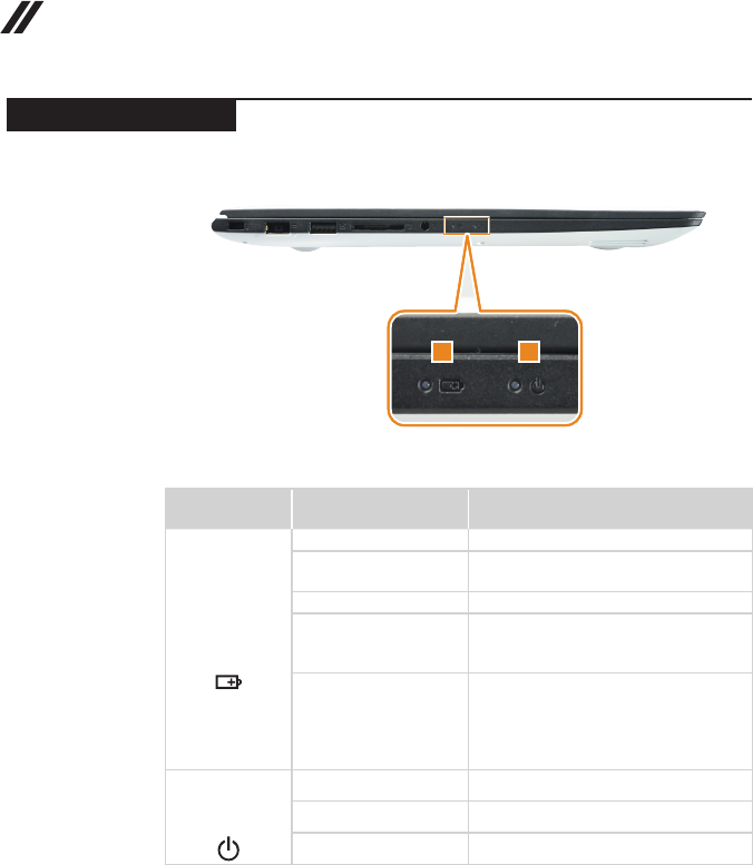
Status indicators
Thesystemstatusindicatorsbelowshowthecomputerstatus:
12
Table 2. Status indicators
Indicator Indicator
status Meaning
1
Batterystatus
indicator
On(solidwhite) Thebatteryhasmorethan20%charge.
On(solidamber) Thebatteryhasbetween5%and20%
charge.
Blinkingquickly(amber) Thebatteryhaslessthan5%charge.
Blinkingslowly(amber)
Thebatteryisbeingcharged.When
thebatterychargereaches20%,the
blinkingcolorwillchangetowhite.
Blinkingslowly(white)
Thebatteryhasbetween20%and80%
chargeandisstillcharging.Whenthe
batteryreaches80%chargethelightwill
stopblinking,butchargingwillcontinue
untilthebatteryisfullycharged.
2
Powerstatus
indicator
On(solidwhite) Thecomputerispoweredon.
Blinking Thecomputerisinsleepmode.
Off Thecomputerispoweredoff.
29
Lenovo U31-70
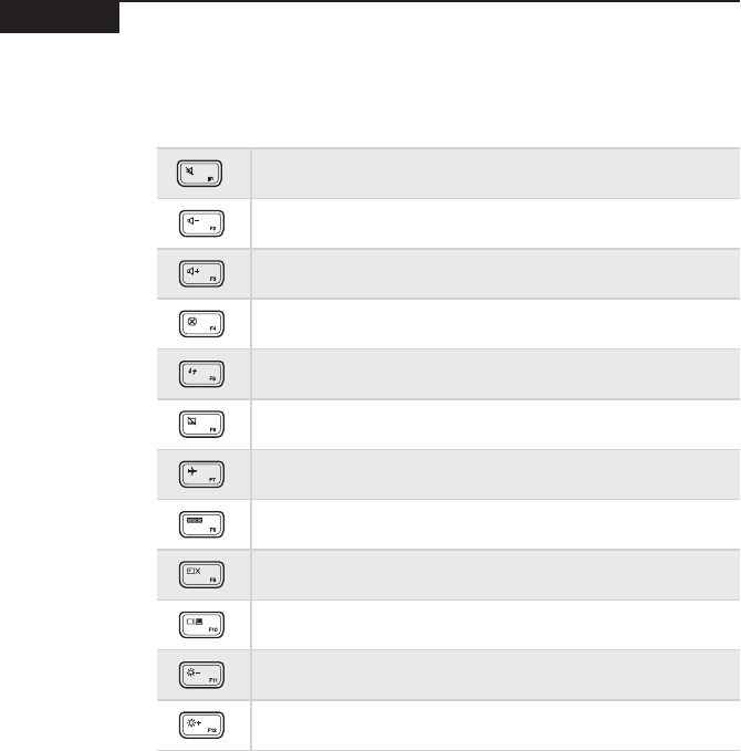
Hotkeys
Youcanaccesscertainsystemsettingsquicklybypressingtheappropriate
hotkeys.
Table 3. Hotkeys
: Mutes/unmutesthesound.
: Decreasesthevolumelevel.
: Increasesthevolumelevel.
: Closesthecurrentlyactivewindow.
: Refreshesthedesktoporthecurrentlyactivewindow.
: Enables/disablesthetouchpad.
: Enables/disablesAirplanemode.
: Displaysallcurrentlyactiveapps.
: Turnson/offthebacklightoftheLCDscreen.
: Togglesthedisplaybetweenthecomputerandanexternaldevice.
: Decreasesthedisplaybrightness.
: Increasesthedisplaybrightness.
30
U31-70 Hardware Maintenance Manual
FRU replacement notices
Thissection presentsnoticesrelatedtoremoving andreplacingparts. Read
thissectioncarefullybeforereplacinganyFRU.
Screw notices
Loosescrewscancause areliability problem.IntheLenovocomputer,this
problemisaddressedwithspecialnylon-coatedscrewsthathavethefollowing
characteristics:
• Theymaintaintightconnections.
• Theydonoteasilycomeloose,evenwithshockorvibration.
• Theyarehardertotighten.
• Eachoneshouldbeusedonlyonce.
Dothefollowingwhenyouservicethismachine:
• Keepthescrewkitinyourtoolbag.
• CarefullyremovescrewsforreusewhenreplacingFRUs.
• Useatorquescrewdriverifyouhaveone.
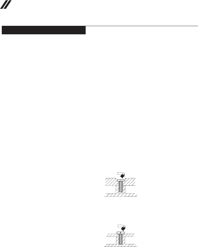
Tightenscrewsasfollows:
• Plastic to plastic
Turnanadditional90° afterthe screwhead touchesthe surfaceof the
plasticpart:
more than 90°
(Cross-section)
• Logic card to plastic
Turnanadditional180°afterthescrewheadtouchesthesurfaceofthe
logiccard:
more than 180°
(Cross-section)
• Torque driver
Ifyouhaveatorquescrewdriver,refertothe“Torque”columnforeachstep.
• Makesurethatyouusethecorrectscrews.Ifyouhaveatorquescrewdriver,
tightenallscrewsrmlytothetorqueshowninthetable.Carefully remove
screws for reuse when replacing FRUs. Make sure that all screws are
tightened rmly.
• Ensuretorque screwdriversarecalibratedcorrectlyfollowing country
specications.
31
Lenovo U31-70
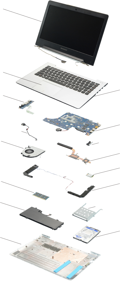
Removing and replacing an FRU
Thissectionpresentsexplodedgures withtheinstructionstoindicatehowto
removeandreplacetheFRU.Makesuretoobservethefollowinggeneralrules:
1. Donotattempttoserviceanycomputerunlessyouhavebeentrainedand
certied.Anuntrainedpersonrunstheriskofdamagingparts.
2. BeforereplacinganyFRU,review“FRUreplacementnotices”onpage30.
3. Beginby removingany FRUsthat haveto beremoved beforethe failing
FRU.AnyofsuchFRUsarelistedatthetopofthepage.Removethemin
theorderinwhichtheyarelisted.
4. FollowthecorrectsequenceinthestepstoremovetheFRU,asgiveninthe
guresbythenumbersinsquarecallouts.
5. WhenturningascrewtoreplaceanFRU,turnitinthedirectionasgivenby
thearrowinthegure.
6. WhenremovingtheFRU,move itinthedirectionasgivenbythearrow in
thegure.
7. Toputthe newFRUinplace,reversetheremovalproceduresandfollow
anyofthenotesthatpertain toreplacement. Forinformation about
connectingandarranginginternalcables,see“Locations”onpage60.
8. WhenreplacinganFRU,usethecorrectscrewasshownintheprocedures.
DANGER
Before removing any FRU, turn off the computer, unplug all power cords from
electrical outlets, remove the battery pack, and then disconnect any of the
interconnecting cables.
Attention:AfterreplacinganFRU,donotturnonthecomputeruntilyouhave
madesurethatallscrews,springs,andothersmallpartsareinplaceandnone
areloose insidethe computer. Verify thisbyshakingthecomputer gentlyand
listeningforrattlingsounds.Metallic partsormetalakescancauseelectrical
shortcircuits.
Attention:Thesystem boardissensitiveto,andcanbe damagedby,
electrostaticdischarge. Beforetouchingit,establishpersonal groundingby
touchingagroundpointwithonehandorusinganelectrostaticdischarge(ESD)
strap(P/N6405959)toremovepotentialshockreasons.
32
U31-70 Hardware Maintenance Manual
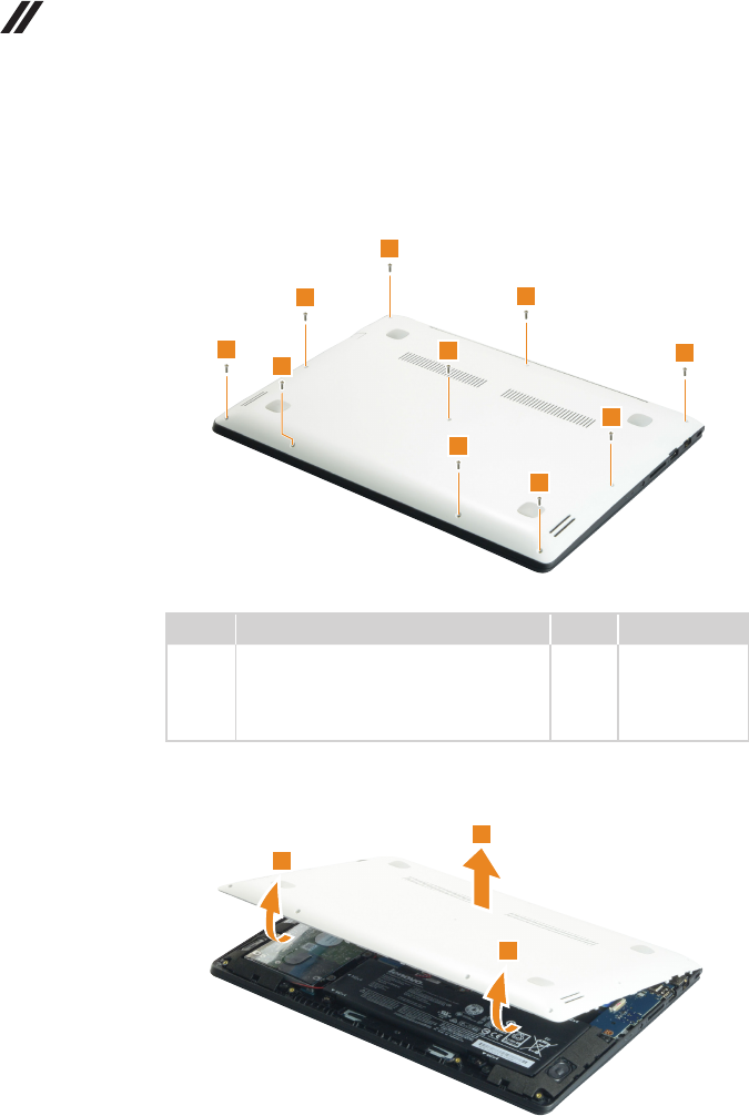
1010 Base cover
Figure 1. Removal steps of base cover
Removethescrews1.
1
1
1
1
1
1
1
1
1
1
Step Screw (quantity) Color Torque
1M2×6mm,Phillips-head,nylok-coated(10)
loglow---logup&loglow---ioboard---logup
&loglow---mb---logup&loglow---rightside
hinge---logup&loglow---leftsidehinge---
klockbracket---logup
Black/
Silver
1.0~1.5kgf*cm
Removethebasecoverinthedirectionsshownbyarrows2and3.
2
2
3
33
Lenovo U31-70
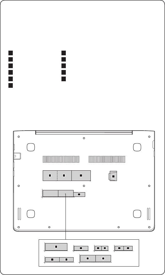
Note: Applying labels to the base cover
ThenewbasecoverFRUis shippedwith akit containinglabels ofseveral
kinds.Whenyoureplace thebase cover, youneed toapply thefollowing
labels:
Thefollowinglabelsneedtobepeeledofffromtheoldbasecoverandputon
thenewbasecover.
a Ratinglabel
b Ratinglabel
c Ratinglabel
d GMLlabel
e KCClabel
f BISlabel
g Wlan/BTlabelforMalaysia/Indonesia
h Wlan/BTlabelforSouthAfrica
i Wlan/BTlabelforIsrael/US/CA/TW
j Wlan/BTlabelforBrazil
k IndonesiaDsidelabel
Forsomemodels,youalsoneedtoapplyoneortwoFCClabels.Checkthe
oldbasecover;ifithasoneortwoFCClabels,ndduplicatesoftheminthe
labelkitandapplythemtothenewbasecover.
Forthelocationofeachlabel,refertothefollowinggures:
ab
h
d
h
g g
c
e
ii
f
jj
k
34
U31-70 Hardware Maintenance Manual
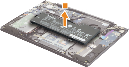
1020 Battery pack
DANGER
Only use the battery specied in the parts list for your computer. Any other battery
could ignite or explode.
Foraccess,removethisFRU:
• “1010Basecover”onpage32
Figure 2. Removal steps of battery pack
Releasethespeakerscables fromthe cableguidesinthedirectionshownby
arrows1.
11
Detachthebatterypackconnectorinthedirectionshownbyarrow2,remove
thescrews3.
3
3
3
32
Step Screw (quantity) Color Torque
3M2×4mm,Phillips-head,nylok-coated(4)
battery---logup
Black 1.0~1.5kgf*cm
35
Lenovo U31-70
Figure 2. Removal steps of battery pack (continued)
Removethebatterypackinthedirectionshownbyarrow4.
4
36
U31-70 Hardware Maintenance Manual
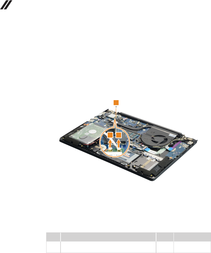
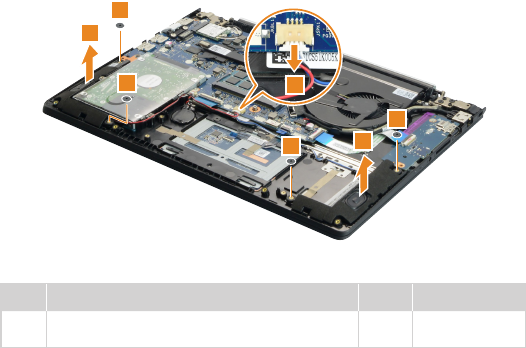
1030 PCI Express Mini Card for wireless LAN
Foraccess,removetheseFRUsinorder:
• “1010Basecover”onpage32
• “1020Batterypack”onpage34
Figure 3. Removal steps of PCI Express Mini Card for wireless LAN
DisconnectthetwowirelessLANcables(black,white)1,andthenremovethe
screw2.
2
11
Instep1,unplugthejacksbyusingthe removaltoolantennaRFconnector
(P/N:08K7159),orpickuptheconnectorswithyourngersandgentlyunplug
theminthedirectionshownbythearrows.
Notes:ThewirelessLANcardhas2cablesinstep1.
ThewirelessLANcardinsomemodelsmighthave3cablesinstep1.
Step Screw (quantity) Color Torque
2M2×2.5mm,Phillips-head,nylok-coated(1)
wirelesscard---logup
Silver 1.0~1.5kgf*cm
37
Lenovo U31-70
Figure 3. Removal steps of PCI Express Mini Card for wireless LAN (continued)
Removethecardinthedirectionshownbyarrow3.
3
When installing:
• Inmodelswitha wirelessLAN cardthathastwoantennaconnectors,plug
theblackcable(1st)(MAIN)intothejacklabeledMAIN,andthegreycable
(2nd)(AUX)intothejacklabeledAUXonthecard.
• InmodelswithawirelessLANcardthathasthreeantennaconnectors,plug
theblackcable(1st)(MAIN)intothejacklabeled1,thegreycable(3rd)into
thejacklabeled3,andthewhitecable(2nd)(AUX)intothejacklabeled2on
thecard.
38
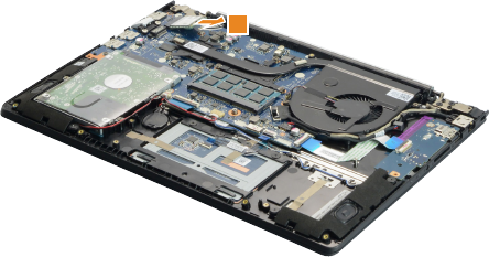
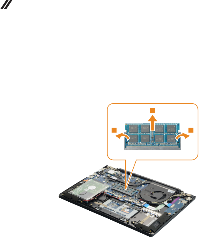
U31-70 Hardware Maintenance Manual
1040 DIMM
Foraccess,removetheseFRUsinorder:
• “1010Basecover”onpage32
• “1020Batterypack”onpage34
Figure 4. Removal steps of DIMM
Releasethe twolatchesonbothedges ofthesocketatthesametime inthe
directionsshown byarrows 1,andthenunplugtheDIMMin thedirection
shownbyarrow2.
1 1
2
When installing:InsertthenotchedendoftheDIMMintothesocket.Pushthe
DIMMrmly,andpivotituntilitsnapsintoplace.Makesurethatitisrmlyxed
intheslotandisdifculttomove.
39
Lenovo U31-70
1050 Speakers
Foraccess,removetheseFRUsinorder:
• “1010Basecover”onpage32
• “1020Batterypack”onpage34
Figure 5. Removal steps of speakers
Detachthespeakersconnectorinthedirectionshownbyarrow1.Removethe
screws2.Thenremovethespeakers3.
2
2
2
21
3
3
Step Screw (quantity) Color Torque
2M2×2mm,Phillips-head,nylok-coated(4)
speaker_l---logup&speaker_r---logup
Black 1.0~1.5kgf*cm
40
U31-70 Hardware Maintenance Manual
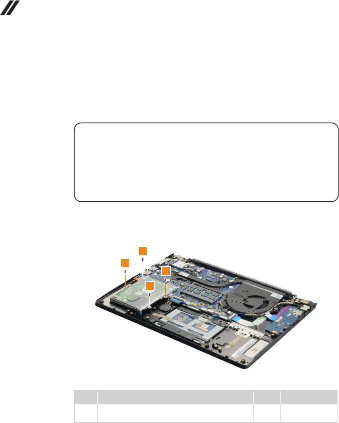
1060 Hard disk drive
Foraccess,removetheseFRUsinorder:
• “1010Basecover”onpage32
• “1020Batterypack”onpage34
• “1050Speakers”onpage39
Attention:
• Donotdropthehard diskdriveorapplyanyphysicalshockto it. The hard
disk drive is sensitive to physical shock. Improper handling can cause damage and
permanent loss of data.
• Before removing the drive, suggest the customer to backup all the information on
it if possible.
• Never remove the drive while the system is operating or in suspend mode.
Figure 6. Removal steps of hard disk drive
Removethescrews1.
1
1
1
1
Step Screw (quantity) Color Torque
1M2×4 mm,Phillips-head,nylok-coated(4)
hddbracket---logup
Black 1.0~1.5kgf*cm
41
Lenovo U31-70
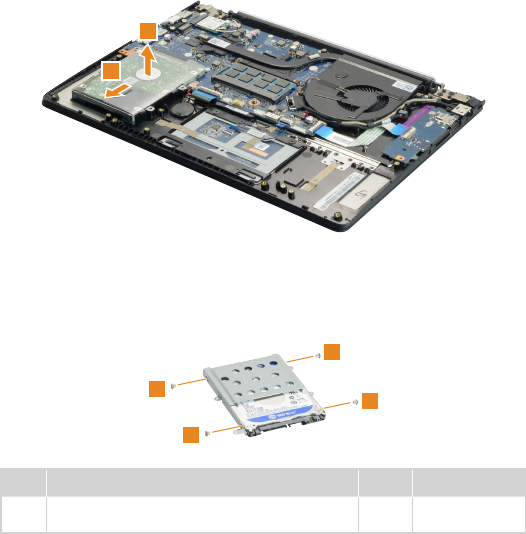
Figure 6. Removal steps of hard disk drive (continued)
DetachtheHDDconnectorinthedirectionshownbyarrow2.Removethe
harddiskdrivefromtheslotinthedirectionshownbyarrow3.
2
3
When installing:MakesurethattheHDDconnectorisattachedrmly.
Removethescrews4anddetachthemetalframefromtheharddiskdrive.
4
4
4
4
Step Screw (quantity) Color Torque
4M3×3mm,Phillips-head,nylok-coated(4)
hddbracket---hddmodule
Silver 1.5~2.0kgf*cm
42
U31-70 Hardware Maintenance Manual
1070 Fan assembly and Heat Sink assembly
Foraccess,removetheseFRUsinorder:
• “1010Basecover”onpage32
• “1020Batterypack”onpage34
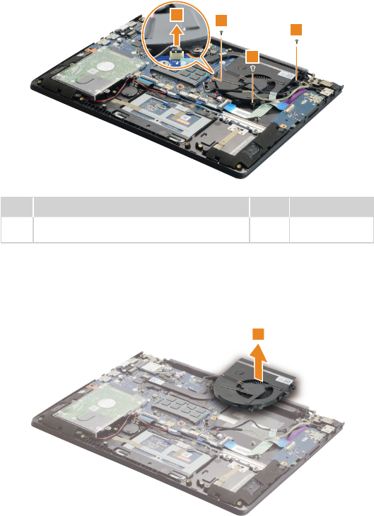
Figure 7. Removal steps of fan assembly and Heat Sink assembly
Releasethecablesfromthecableguidesinthedirectionshownbyarrows1.
1
1
When installing:Route theantenna cablesalongthecableguides.As you
routethecables,makesurethattheyarenotsubjectedtoanytension.Tension
couldcausethecablestobedamagedbythecableguides,orawiretobe
broken.
43
Lenovo U31-70
Figure 7. Removal steps of fan assembly and Heat Sink assembly (continued)
Unplugthefanconnectorinthedirectionshownbyarrow2. Removethe
screws3.
33
3
2
Step Screw (quantity) Color Torque
3M2×4mm,Phillipshead,nylok-coated(3)
fan---mb---logup&fan---logup
Black 1.0~1.5kgf*cm
When installing:Makesurethattheconnectorisattachedrmly.
Removethefaninthedirectionshownbyarrow4.Becarefulnottodamage
theconnector.
4
44
U31-70 Hardware Maintenance Manual
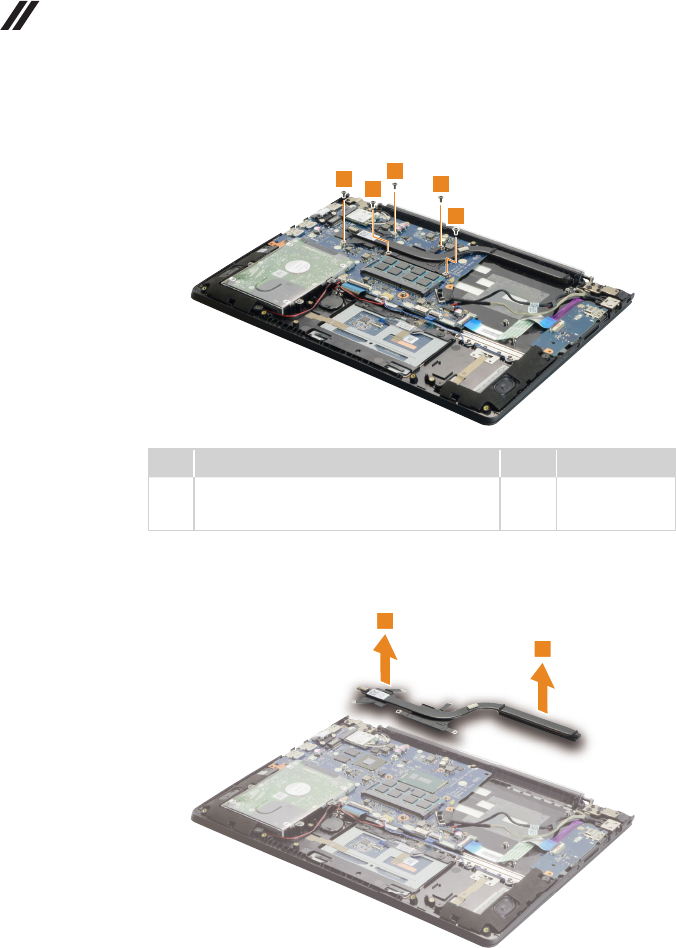
Figure 7. Removal steps of fan assembly and Heat Sink assembly (continued)
Removethescrews5.
555
5
5
Step Screw (quantity) Color Torque
5M2×4mm,Phillipshead,nylok-coated(5)
cputhermalmodule---cpuplate&vgathermal
module---MB
Black 1.0~1.5kgf*cm
Lifttheheatsinkinthedirectionshownbyarrows6.
6
6
45
Lenovo U31-70
Figure 7. Removal steps of fan assembly and Heat Sink assembly (continued)
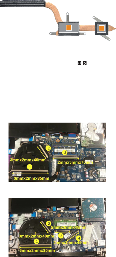
ab
When installing: Before you attach the fan assembly to the computer, apply
thermal grease, at an amount of 0.2 grams, to the part shown in the gure
above. Either too much or too little grease application can cause a thermal
problem due to imperfect contact with a component.
Note:
• A new thermal module FRU is shipped with several gaskets. When you
replace the thermal module, you need to stick these gaskets on it.
• For the gaskets location, please refer to the following gures:
For discrete graphics (with 3 gaskets)
For integrated graphics (with 4 gaskets)
46
U31-70 Hardware Maintenance Manual
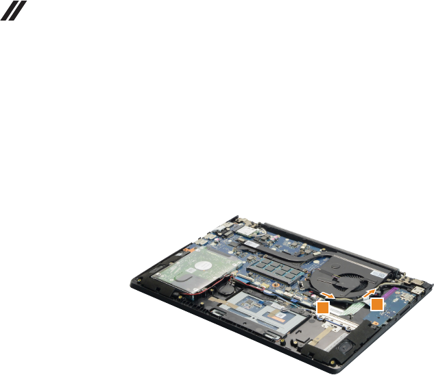
1080 IO board, DC-in cable
Foraccess,removetheseFRUsinorder:
• “1010Basecover”onpage32
• “1020Batterypack”onpage34
• “1070FanassemblyandHeatSinkassembly”onpage42
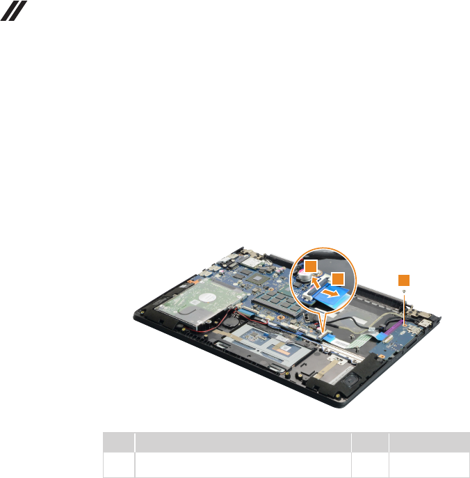
Figure 8. Removal steps of IO board, DC-in cable
DetachtheIOboardconnectorinthedirectionsshownbyarrows1and2.
Removethescrew3.
3
1
2
Step Screw (quantity) Color Torque
3M2×2.5mm,Phillips-head,nylok-coated(1)
ioboard---logup
Silver 1.0~1.5kgf*cm
When installing:Makesurethattheconnectorisattachedrmly.
47
Lenovo U31-70
Figure 8. Removal steps of IO board, DC-in cable (continued)
RemovetheIOboardinthedirectionshownbyarrow4.
4
UnplugtheDC-incable connectorin thedirections shownby arrow5.Then
removetheDC-incableinthedirectionshownbyarrow6.
5
6
When installing:Makesurethattheconnectorisattachedrmly.
48
U31-70 Hardware Maintenance Manual
1090
System board
Important notices for handling the system board:
When handling the system board, bear the following in mind.
• Be careful not to drop the system board on a bench top that has a hard surface,
such as metal, wood, or composite.
• Avoid rough handling of any kind.
• During the whole process, make sure not to drop or stack the system board.
• If you put a system board down, make sure to put it only on a padded surface such
as an ESD mat or conductive corrugated material.
Foraccess,removetheseFRUsinorder:
• “1010Basecover”onpage32
• “1020Batterypack”onpage34
• “1030PCIExpressMiniCardforwirelessLAN”onpage36
• “1050Speakers”onpage39
• “1060Harddiskdrive”onpage40
• “1070FanassemblyandHeatSinkassembly”onpage42
• “1080IOboard,DC-incable”onpage46
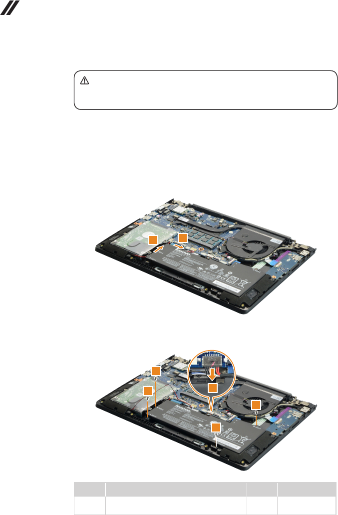
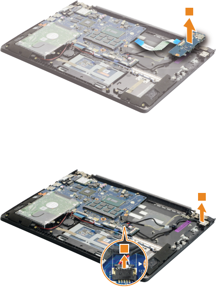
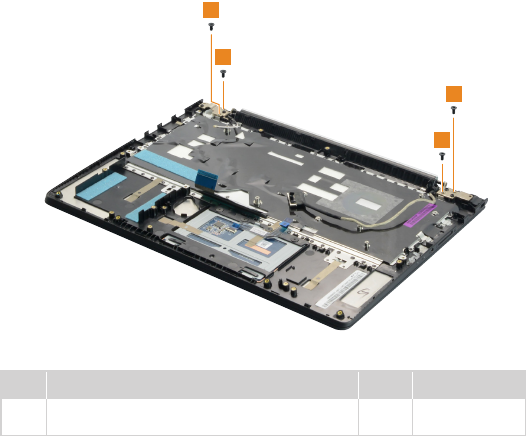
Figure 9. Removal steps of system board
Disconnectthe threeconnectors inthedirectionsshownbyarrows1,2
and3.Thenremovethescrews4and5.
4
5
5
5
1
2
3
2
3
Step Screw (quantity) Color Torque
4M2×4mm,Phillips-head,nylok-coated(1)
M/B---logup
Black 1.0~1.5kgf*cm
5M2×2.5mm,Phillips-head,nylok-coated(3)
M/B---logup
Silver 1.0~1.5kgf*cm
49
Lenovo U31-70
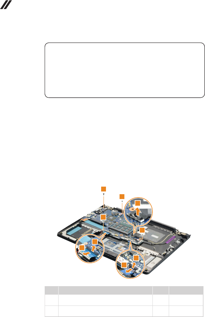
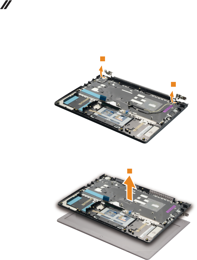
Figure 9. Removal steps of system board (continued)
Removethesystemboardinthedirectionshownbyarrow6.
6
Removethescrews7.
7
7
Step Screw (quantity) Color Torque
7M2×2.5mm,Phillips-head,nylok-coated(2)
RJ45cover---M/B
Silver 1.0~1.5kgf*cm
50
U31-70 Hardware Maintenance Manual
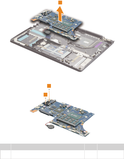
Figure 9. Removal steps of system board (continued)
Remove the RJ-45 door in the direction shown by arrow 8.
8
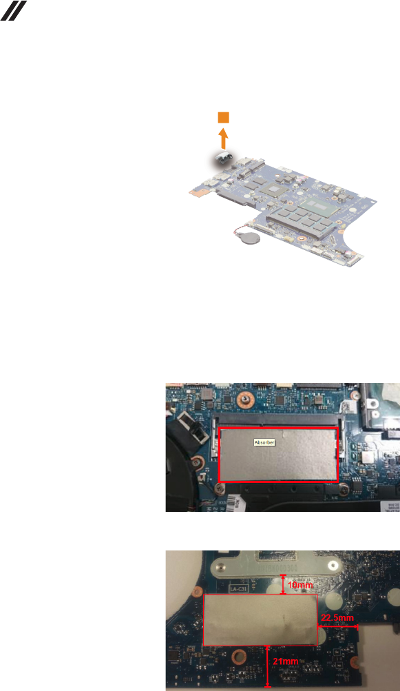
Note:
• A new system board FRU is shipped with two absorbers. When you replace
the system board, you need to stick these absorbers on it.
• Fortheabsorberslocation,pleaserefertothefollowinggures:
Bottom side of system board
Top side of system board
Attention: The absorber may degrade the WLAN signal quality.
51
Lenovo U31-70
1100 Upper case
Foraccess,removetheseFRUsinorder:
• “1010Basecover”onpage32
• “1020Batterypack”onpage34
• “1030PCIExpressMiniCardforwirelessLAN”onpage36
• “1050Speakers”onpage39
• “1060Harddiskdrive”onpage40
• “1070FanassemblyandHeatSinkassembly”onpage42
• “1080IOboard,DC-incable”onpage46
• “1090Systemboard”onpage48
Figure 10. Removal steps of upper case
Removethescrews1.
1
1
1
1
Step Screw (quantity) Color Torque
1M2.5×5mm,Phillips-head,nylok-coated(4)
leftsidehinge---logup&rightsidehinge---logup
Black 1.5~2.0kgf*cm
52
U31-70 Hardware Maintenance Manual
Figure 10. Removal steps of upper case (continued)
Openthehingeinthedirectionshownbyarrows2.
2
2
RemovetheuppercasefromtheLCDmoduleinthedirectionsshownby
arrow3.
3
53
Lenovo U31-70
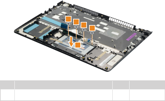
Figure 10. Removal steps of upper case (continued)
Removethescrews4.Thenremovethetouchpadmodule5.
4444
5
Step Screw (quantity) Color Torque
4M2×2mm,Phillips-head,nylok-coated(4)
tpbracket---logup
Black 1.0~1.5kgf*cm
54
U31-70 Hardware Maintenance Manual
1110 LCD unit
Foraccess,removetheseFRUsinorder:
• “1010Basecover”onpage32
• “1020Batterypack”onpage34
• “1030PCIExpressMiniCardforwirelessLAN”onpage36
• “1050Speakers”onpage39
• “1060Harddiskdrive”onpage40
• “1070FanassemblyandHeatSinkassembly”onpage42
• “1080IOboard,DC-incable”onpage46
• “1090Systemboard”onpage48
• “1100Uppercase”onpage51
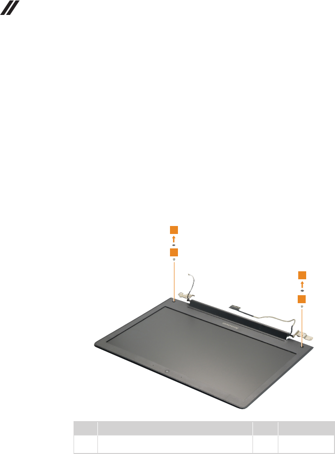
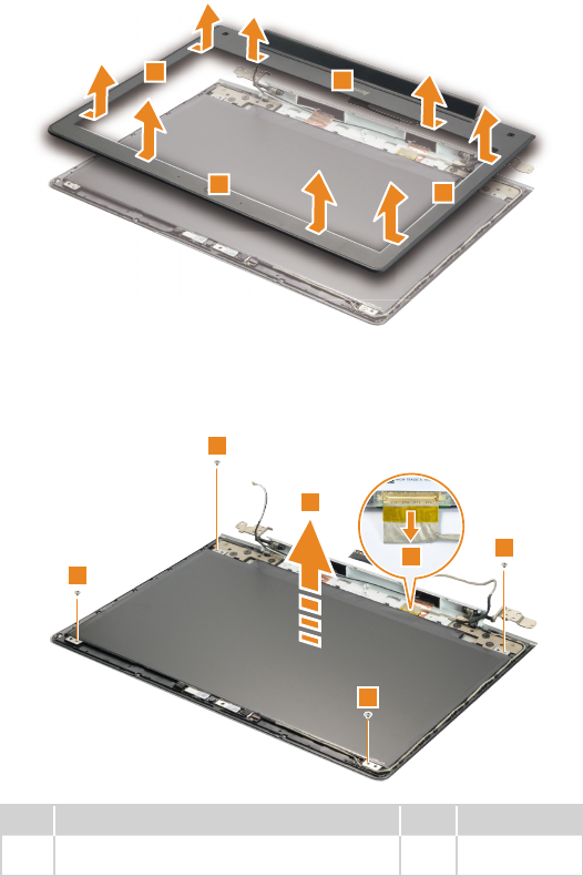
Figure 11. Removal steps of LCD unit
Removethescrewpads1,thenremovethescrews2.
2
1
2
1
Step Screw (quantity) Color Torque
2M2×3mm,Phillips-head,nylok-coated(2)
lcdbezel---lcdbrk---lcdcover
Silver 1.0~1.5kgf*cm
55
Lenovo U31-70
Figure 11. Removal steps of LCD unit (continued)
RemovetheLCDfrontbezelinthedirectionshownbyarrows3.
3
33
3
Removethescrews4.LifttheLCDmoduleslightly5.Disconnecttheconnectorin
thedirectionshownbyarrow6.ThenremovetheLCDmodule.
4
4
4
4
5
6
Step Screw (quantity) Color Torque
4M2×2.5mm,Phillips-head,nylok-coated(4)
lcdpanel---lcdcover
Silver 1.0~1.5kgf*cm
56
U31-70 Hardware Maintenance Manual
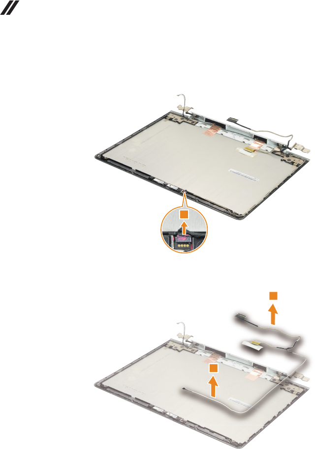
Figure 11. Removal steps of LCD unit (continued)
Detachthecameraconnectorinthedirectionshownbyarrow7.
7
RemovetheLCDcableinthedirectionshownbyarrows8.
8
8
When installing:Makesurethattheconnectorisattachedrmlyandthatyou
donotpinchtheantennacableswhenyouattachtheLCDassembly.Routethe
LCDcablealongthecableguides.
57
Lenovo U31-70
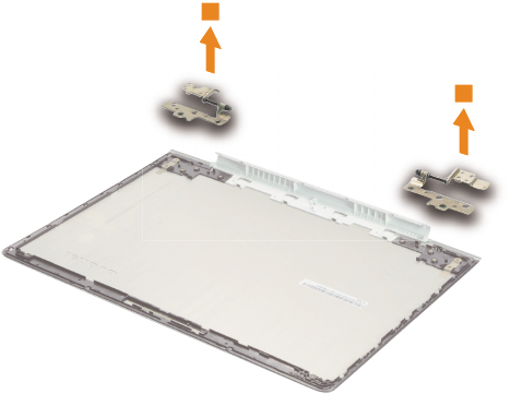
1120 Integrated camera, antenna assembly and LCD hinges
Foraccess,removetheseFRUsinorder:
• “1010Basecover”onpage32
• “1020Batterypack”onpage34
• “1030PCIExpressMiniCardforwirelessLAN”onpage36
• “1050Speakers”onpage39
• “1060Harddiskdrive”onpage40
• “1070FanassemblyandHeatSinkassembly”onpage42
• “1080IOboard,DC-incable”onpage46
• “1090Systemboard”onpage48
• “1100Uppercase”onpage51
• “1110LCDunit”onpage54
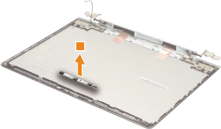
Figure 12. Removal steps of integrated camera, antenna assembly and
LCD hinges
Note:TheintegratedcameraisstuckonthetopcenteroftheLCDcover.
Removetheintegratedcamerainthedirectionshownbyarrow1.
1
When installing:SticktheintegratedcameratothetopcenteroftheLCD
coverandadjustitsplacementtomakesuretheconnectorisattachedrmly.
58
U31-70 Hardware Maintenance Manual
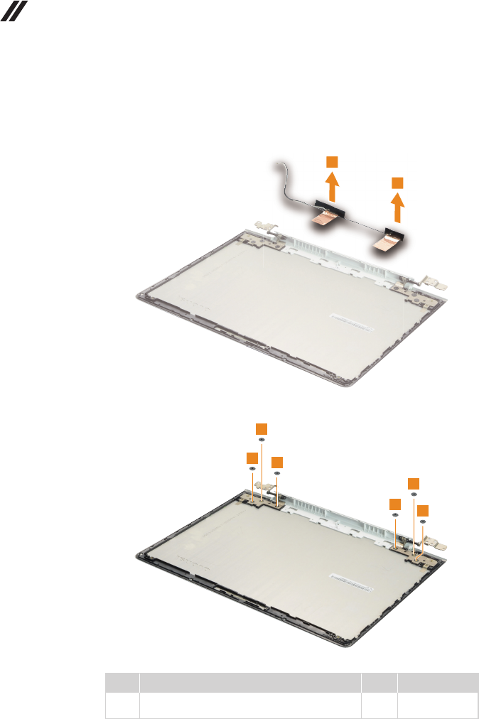
Figure 12. Removal steps of integrated camera, antenna assembly and LCD
hinges (continued)
Peeloffthe adhesivetape securingthe antennaboards, releasethecables
fromthecableguide,andthenremovetheantennaassemblyinthedirection
shownbyarrows2.
2
2
Removethescrews3.
3
3
3
3
3
3
Step Screw (quantity) Color Torque
3M2×6mm,Phillips-head,nylok-coated(6)
lcdbrk---lcdcover
Black 1.0~1.5kgf*cm
59
Lenovo U31-70
Figure 12. Removal steps of integrated camera, antenna assembly and LCD
hinges (continued)
RemovetheLCDhingesinthedirectionshownbyarrows4.
4
4
60
U31-70 Hardware Maintenance Manual
Locations
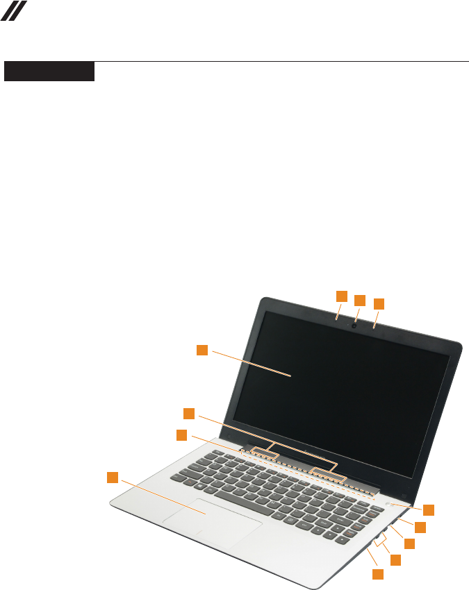
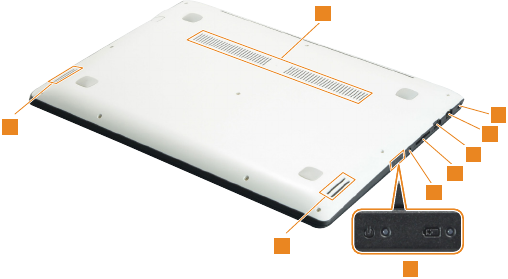
Front view and right-side view
1 Integratedcamera
2 Built-inmicrophone
3 Computerdisplay
4 WirelessLANantennas
5 Ventilationslots
6 Touchpad
7 Novobutton
8 USB3.0port
9 RJ-45port
J HDMIport
K Powerbutton
12
2
3
5
6
4
7
8
9
10
11
62
U31-70 Hardware Maintenance Manual
Parts list
Thissectionpresentsthefollowingserviceparts:
• “Overall”onpage63
• “LCDFRUs”onpage69
• “Miscellaneousparts”onpage71
• “ACadapters”onpage71
• “Screws”onpage71
• “Powercords”onpage72
Note:
Each FRU is available for all types or models, unless specic types or models are
specied.
Attention:
DonotattempttoreplaceanFRUonyourown.IfanFRUisdamaged,contact
aLenovoauthorizedserviceroramarketing representativeforreplacement
orrepair.Onlyqualiedtechnicianscaninspectorrepairthisproduct.
63
Lenovo U31-70
Overall
1
3
4
c
6
10
11
13
2
5
a
b
7
8
9
12

64
U31-70 Hardware Maintenance Manual
Table 4. Parts list—Overall
No. FRU FRU no. CRU
ID.
U31-70
BDW
U31-70
HSW
a-c See“Miscellaneousparts”onpage71.
1 LCDunit(see“LCDFRUs”onpage69).
2 UpperCaseCU31-70BKLWhiteUS 5CB0J30905
N
● ●
2 UpperCaseCU31-70BKLWhiteGK 5CB0J30982 ● ●
2 UpperCaseCU31-70BKLWhiteINT'E 5CB0J30906 ● ●
2 UpperCaseCU31-70BKLWhiteKR 5CB0J30983 ● ●
2 UpperCaseCU31-70BKLWhiteCH 5CB0J30928 ● ●
2 UpperCaseCU31-70BKLWhiteRU 5CB0J31001 ● ●
2 UpperCaseCU31-70BKLWhiteAR 5CB0J30927 ● ●
2 UpperCaseCU31-70BKLWhiteHE 5CB0J31000 ● ●
2 UpperCaseCU31-70BKLWhiteTH 5CB0J30942 ● ●
2 UpperCaseCU31-70BKLWhiteINDIA 5CB0J30871 ● ●
2 UpperCaseCU31-70BKLWhiteUK 5CB0J30944 ● ●
2 UpperCaseCU31-70BKLWhiteIT 5CB0J30898 ● ●
2 UpperCaseCU31-70BKLWhiteSP 5CB0J30976 ● ●
2 UpperCaseCU31-70BKLWhiteTR 5CB0J30900 ● ●
2 UpperCaseCU31-70BKLWhitePO 5CB0J30975 ● ●
2 UpperCaseCU31-70BKLWhiteLA 5CB0J30899 ● ●
2 UpperCaseCU31-70BKLWhiteCF-E 5CB0J30978 ● ●
2 UpperCaseCU31-70BKLWhiteND 5CB0J30902 ● ●
2 UpperCaseCU31-70BKLWhiteFR 5CB0J30977 ● ●
2 UpperCaseCU31-70BKLWhiteGR 5CB0J30901 ● ●
2 UpperCaseCU31-70BKLWhiteBZ 5CB0J30979 ● ●
2 UpperCaseCU31-70BKLWhiteDUTCH 5CB0J30903 ● ●
2 UpperCaseCU31-70BKLWhiteHG 5CB0J30980 ● ●
2 UpperCaseCU31-70BKLWhiteBE 5CB0J30919 ● ●
2 UpperCaseCU31-70BKLWhiteICE 5CB0J30995 ● ●
2 UpperCaseCU31-70BKLWhiteSA 5CB0J30921 ● ●
2 UpperCaseCU31-70BKLWhiteSW 5CB0J30996 ● ●
2 UpperCaseCU31-70BKLWhiteBU 5CB0J30922 ● ●
2 UpperCaseCU31-70BKLWhiteCZ-SK 5CB0J30999 ● ●
2 UpperCaseCU31-70BKLWhiteUSA 5CB0J30971 ● ●
2 UpperCaseCU31-70BKLRedUS 5CB0J30893 ● ●
2 UpperCaseCU31-70BKLRedGK 5CB0J30967 ● ●
2 UpperCaseCU31-70BKLRedINT'E 5CB0J30892 ● ●
2 UpperCaseCU31-70BKLRedKR 5CB0J30968 ● ●
2 UpperCaseCU31-70BKLRedCH 5CB0J30889 ● ●
2 UpperCaseCU31-70BKLRedRU 5CB0J30969 ● ●
2 UpperCaseCU31-70BKLRedAR 5CB0J30890 ● ●
2 UpperCaseCU31-70BKLRedHE 5CB0J30964 ● ●
2 UpperCaseCU31-70BKLRedTH 5CB0J30883 ● ●
2 UpperCaseCU31-70BKLRedINDIA 5CB0J30974 ● ●
2 UpperCaseCU31-70BKLRedUK 5CB0J30896 ● ●
2 UpperCaseCU31-70BKLRedIT 5CB0J30972 ● ●
2 UpperCaseCU31-70BKLRedSP 5CB0J30894 ● ●
2 UpperCaseCU31-70BKLRedTR 5CB0J30973 ● ●
2 UpperCaseCU31-70BKLRedPO 5CB0J30895 ● ●

65
Lenovo U31-70
Table 4. Parts list—Overall (continued)
No. FRU FRU no. CRU
ID.
U31-70
BDW
U31-70
HSW
2 UpperCaseCU31-70BKLRedLA 5CB0J30970
N
● ●
2 UpperCaseCU31-70BKLRedCF-E 5CB0J30891 ● ●
2 UpperCaseCU31-70BKLRedND 5CB0J30966 ● ●
2 UpperCaseCU31-70BKLRedFR 5CB0J30887 ● ●
2 UpperCaseCU31-70BKLRedGR 5CB0J30959 ● ●
2 UpperCaseCU31-70BKLRedBZ 5CB0J30882 ● ●
2 UpperCaseCU31-70BKLRedDUTCH 5CB0J30960 ● ●
2 UpperCaseCU31-70BKLRedHG 5CB0J30884 ● ●
2 UpperCaseCU31-70BKLRedBE 5CB0J30956 ● ●
2 UpperCaseCU31-70BKLRedICE 5CB0J30878 ● ●
2 UpperCaseCU31-70BKLRedSA 5CB0J30958 ● ●
2 UpperCaseCU31-70BKLRedSW 5CB0J30914 ● ●
2 UpperCaseCU31-70BKLRedBU 5CB0J30988 ● ●
2 UpperCaseCU31-70BKLRedCZ-SK 5CB0J30912 ● ●
2 UpperCaseCU31-70BKLRedUSA 5CB0J30989 ● ●
2 UpperCaseCU31-70NBKLWhiteUS 5CB0J30913 ● ●
2 UpperCaseCU31-70NBKLWhiteGK 5CB0J30990 ● ●
2 UpperCaseCU31-70NBKLWhiteINT'E 5CB0J30915 ● ●
2 UpperCaseCU31-70NBKLWhiteKR 5CB0J30991 ● ●
2 UpperCaseCU31-70NBKLWhiteCH 5CB0J30917 ● ●
2 UpperCaseCU31-70NBKLWhiteRU 5CB0J30992 ● ●
2 UpperCaseCU31-70NBKLWhiteAR 5CB0J30929 ● ●
2 UpperCaseCU31-70NBKLWhiteHE 5CB0J31002 ● ●
2 UpperCaseCU31-70NBKLWhiteTH 5CB0J30930 ● ●
2 UpperCaseCU31-70NBKLWhiteINDIA 5CB0J31004 ● ●
2 UpperCaseCU31-70NBKLWhiteUK 5CB0J30943 ● ●
2 UpperCaseCU31-70NBKLWhiteIT 5CB0J30946 ● ●
2 UpperCaseCU31-70NBKLWhiteSP 5CB0J30872 ● ●
2 UpperCaseCU31-70NBKLWhiteTR 5CB0J30945 ● ●
2 UpperCaseCU31-70NBKLWhitePO 5CB0J30873 ● ●
2 UpperCaseCU31-70NBKLWhiteLA 5CB0J30947 ● ●
2 UpperCaseCU31-70NBKLWhiteCF-E 5CB0J30874 ● ●
2 UpperCaseCU31-70NBKLWhiteND 5CB0J30948 ● ●
2 UpperCaseCU31-70NBKLWhiteFR 5CB0J30876 ● ●
2 UpperCaseCU31-70NBKLWhiteGR 5CB0J30949 ● ●
2 UpperCaseCU31-70NBKLWhiteBZ 5CB0J30875 ● ●
2 UpperCaseCU31-70NBKLWhiteDUTCH 5CB0J30950 ● ●
2 UpperCaseCU31-70NBKLWhiteHG 5CB0J30877 ● ●
2 UpperCaseCU31-70NBKLWhiteBE 5CB0J30952 ● ●
2 UpperCaseCU31-70NBKLWhiteICE 5CB0J30880 ● ●
2 UpperCaseCU31-70NBKLWhiteSA 5CB0J30954 ● ●
2 UpperCaseCU31-70NBKLWhiteSW 5CB0J30879 ● ●
2 UpperCaseCU31-70NBKLWhiteBU 5CB0J30953 ● ●
2 UpperCaseCU31-70NBKLWhiteCZ-SK 5CB0J30881 ● ●
2 UpperCaseCU31-70NBKLRedUS 5CB0J30957 ● ●
2 UpperCaseCU31-70NBKLRedGK 5CB0J30886 ● ●
2 UpperCaseCU31-70NBKLRedINT'E 5CB0J30962 ● ●

66
U31-70 Hardware Maintenance Manual
Table 4. Parts list—Overall (continued)
No. FRU FRU no. CRU
ID.
U31-70
BDW
U31-70
HSW
2 UpperCaseCU31-70NBKLRedKR 5CB0J30885
N
● ●
2 UpperCaseCU31-70NBKLRedCH 5CB0J30961 ● ●
2 UpperCaseCU31-70NBKLRedRU 5CB0J30888 ● ●
2 UpperCaseCU31-70NBKLRedAR 5CB0J30965 ● ●
2 UpperCaseCU31-70NBKLRedHE 5CB0J30926 ● ●
2 UpperCaseCU31-70NBKLRedTH 5CB0J31010 ● ●
2 UpperCaseCU31-70NBKLRedINDIA 5CB0J30937 ● ●
2 UpperCaseCU31-70NBKLRedUK 5CB0J31009 ● ●
2 UpperCaseCU31-70NBKLRedIT 5CB0J30936 ● ●
2 UpperCaseCU31-70NBKLRedSP 5CB0J31008 ● ●
2 UpperCaseCU31-70NBKLRedTR 5CB0J30935 ● ●
2 UpperCaseCU31-70NBKLRedPO 5CB0J31007 ● ●
2 UpperCaseCU31-70NBKLRedLA 5CB0J30934 ● ●
2 UpperCaseCU31-70NBKLRedCF-E 5CB0J31006 ● ●
2 UpperCaseCU31-70NBKLRedND 5CB0J30933 ● ●
2 UpperCaseCU31-70NBKLRedFR 5CB0J31005 ● ●
2 UpperCaseCU31-70NBKLRedGR 5CB0J30932 ● ●
2 UpperCaseCU31-70NBKLRedBZ 5CB0J30866 ● ●
2 UpperCaseCU31-70NBKLRedDUTCH 5CB0J30939 ● ●
2 UpperCaseCU31-70NBKLRedHG 5CB0J30865 ● ●
2 UpperCaseCU31-70NBKLRedBE 5CB0J30938 ● ●
2 UpperCaseCU31-70NBKLRedICE 5CB0J30869 ● ●
2 UpperCaseCU31-70NBKLRedSA 5CB0J30941 ● ●
2 UpperCaseCU31-70NBKLRedSW 5CB0J30868 ● ●
2 UpperCaseCU31-70NBKLRedBU 5CB0J30940 ● ●
2 UpperCaseCU31-70NBKLRedCZ-SK 5CB0J30870 ● ●
3 Touchpad,synaTM-02334-00169x104x10.5I2C+ 73042414 ● ●
3 Touchpad,ElanSA469D-22H169x104x10.5I2C+ 73048465 ● ●
3 Touchpad,KGDFF0118A69x04x1.00.5PS 5T60G97154 ● ●
4 IOBoardCU31-70W/Cable 5C50J30997 ● ●
5 MBCU31-70NOK50052GNBKL 5B20J30908 ●
5 MBCU31-70WIN50052GNBKL 5B20J30981 ●
5 MBCU31-70NOKI7-5500DISBKL 5B20J33176 ●
5 MBCU31-70WINI7-5500DISBKL 5B20J33167 ●
5 MBCU31-70NOKI5-5200DISBKL 5B20J33187 ●
5 MBCU31-70WINI5-5200DISBKL 5B20J33182 ●
5 MBCU31-70NOKI5-5200DISNBKL 5B20J33179 ●
5 MBCU31-70WINI5-5200DISNBKL 5B20J33173 ●
5 MBCU31-70NOKI5-5200UMABKL 5B20J33169 ●
5 MBCU31-70WINI5-5200UMABKL 5B20J33163 ●
5 MBCU31-70NOKI5-5200UMANBKL 5B20J33184 ●
5 MBCU31-70WINI5-5200UMANBKL 5B20J33180 ●
5 MBCU31-70NOKI3-5010DISBKL 5B20J33175 ●
5 MBCU31-70WINI3-5010DISBKL 5B20J33171 ●
5 MBCU31-70NOKI3-5010DISNBKL 5B20J33166 ●
5 MBCU31-70WINI3-5010DISNBKL 5B20J33174 ●
5 MBCU31-70NOKI3-5010UMABKL 5B20J33170 ●

67
Lenovo U31-70
No. FRU FRU no. CRU
ID.
U31-70
BDW
U31-70
HSW
5 MBCU31-70WINI3-5010UMABKL 5B20J33164
N
●
5 MBCU31-70NOKI3-5010UMANBKL 5B20J33186 ●
5 MBCU31-70WINI3-5010UMANBKL 5B20J33181 ●
5 MBCU31-70NOKI3-5005DISBKL 5B20J33177 ●
5 MBCU31-70WINI3-5005DISBKL 5B20J33172 ●
5 MBCU31-70NOK5005UMABKLNGC 5B20J33168 ●
5 MBCU31-70WIN5005UMABKLNGC 5B20J33162 ●
5 MBCU31-70NOKI3-5005UMANBKL 5B20J33183 ●
5 MBCU31-70WINI3-5005UMANBKL 5B20J33165 ●
5 MBCU31-70NOK3805UMANNGC 5B20J33185 ●
5 MBCU31-70WIN3805UMANNGC 5B20J33178 ●
5 MBCU31-70NOK40052GBKL 5B20J30925 ●
5 MBCU31-70WIN40052GBKL 5B20J30994 ●
5 MBCU31-704030NOK2GBKL 5B20J33425 ●
5 MBCU31-704030WIN2GBKL 5B20J33424 ●
5 MBCU31-70I3-4030NOKDISNBKL 5B20J33416 ●
5 MBCU31-70I3-4030WINDISNBKL 5B20J33422 ●
5 MBCU31-70I3-4030NOKUMABKL 5B20J33413 ●
5 MBCU31-70I3-4030WINUMABKL 5B20J33419 ●
5 MBCU31-70I3-4030NOKUMANBKL 5B20J33423 ●
5 MBCU31-70I3-4030WINUMANBKL 5B20J33415 ●
5 MBCU31-70I3-4005NOKDISNBKL 5B20J33420 ●
5 MBCU31-70I3-4005WINDISNBKL 5B20J33426 ●
5 MBCU31-704005NOKBKLNGC 5B20J33417 ●
5 MBCU31-704005WINBKLNGC 5B20J33421 ●
5 MBCU31-70I3-4005NOKUMANBKL 5B20J33414 ●
5 MBCU31-70I3-4005WINUMANBKL 5B20J33418 ●
6FanCU31-70 5F10J31003 ● ●
7HeatsinkCU31-70DIS 5H40J30993 ● ●
7HeatsinkCU31-70UMA 5H40J30910 ● ●
8 WLAN,Intel31601x1AC+BTPCIEM.2ROMWLAN SW10A11511 ● ●
8 WLAN,CbtBCM431621x1AC+BT4.0PCIEM.2WLANV2 SW10A11586 ● ●
8 WLAN,LtnNFA3451x1AC+BT4.0PCIEM.2WLANV2 SW10A11628 ● ●
8 WLAN,CbtRTL8821AE1x1AC+BT4.0PCIEM.2WLAN SW10A11648 ● ●
9 SpeakerCU31-70 5SB0J30923 ● ●
10 RAM,M471B5173EB0-YK04GBDDR3L1600 5M30G18425 ● ●
10 RAM,HMT451S6BFR8A-PB/RD4GBDDR3L1600 11202706 ● ●
10 RAM,RMT3170MN68F9F-16004GBDDR3L1600 5M30G75129 ● ●
10 RAM,M471B1G73EB0-YK08GBDDR3L1600 5M30G18424 ● ●
10 RAM,HMT41GS6BFR8A-PB/RD8GBDDR3L1600 11202707 ● ●
10 RAM,RMT3160ME68FAF-16008GBDDR3L1600 11202450 ● ●
11 Battery,U31SP/AL14M2P247.6V35Wh2cell 5B10H13092 ● ●
11 Battery,U31SP/CL14M2P247.6V35Wh2cell 5B10H13096 ● ●
11 Battery,U31SYL14S2P227.6V35Wh2cell 5B10H17229 ● ●
11 Battery,U31LGL14L2P227.6V35Wh2cell 5B10H17230 ● ●
12 Harddiskdrive,ST500LT0126G7mm5.4K500GHDD 16200383 ● ●
Table 4. Parts list—Overall (continued)
68
U31-70 Hardware Maintenance Manual
Table 4. Parts list—Overall (continued)
No. FRU FRU no. CRU
ID.
U31-70
BDW
U31-70
HSW
12 Harddiskdrive,WD5000LPCX-24C6HT06G7mm5.4K
500GHDD 16200395
N
● ●
12 Harddiskdrive,MQ01ABF0506G7mm5.4K500GHDD 16200433 ● ●
12 Harddiskdrive,ST500LM0006G7mm500G+8GSSHD 16200391 ● ●
12 Harddiskdrive,ST500LM0007mm500G+8G(forSIT) 5H20H24608 ● ●
12 Harddiskdrive,WDMN500Mh-2(6G)7mm1TB+(H)8G
5400rpm 16200681 ● ●
13 LowerCaseCU31-70White 5CB0J30951 ● ●
13 LowerCaseCU31-70Red 5CB0J30909 ● ●
— ACadapter(see“ACadapters”onpage71).
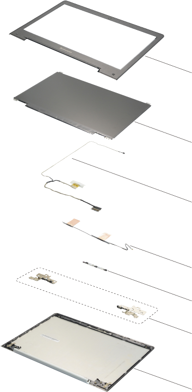
69
Lenovo U31-70
LCD FRUs
InLenovoU31-70,thereisfollowingtypeofLCD.
• “13.3-in.HDLED”
1
2
3
4
5
6
7

70
U31-70 Hardware Maintenance Manual
Table 5. Parts list—LCD FRUs
No. FRU FRU no. CRU
ID.
U31-70
BDW
U31-70
HSW
1 LCDBezelCU31-70Black 5B30J30986
N
● ●
1 LCDBezelCU31-70White 5B30J30920 ● ●
2 Panel,AUOB133XTN01.60AHDAGSNB 5D10H11004 ● ●
2 Panel,IVOM133NWN1R4HDAGSNB 5D10H33278 ● ●
2 Panel,BOEHB133WX1-402HDAGSLED1NBLCD 18201050 ● ●
2 Panel,LGDLP133WF2-SPL1FHDAGSNB 5D10H11579 ● ●
2 Panel,SDCLTN133HL05-401FHDAGSNB 5D10H30488 ● ●
3 EDPCableCU31-70 5C10J30955 ● ●
4 AntennaCU31-70 5A30J30911 ● ●
5 CameraCU31-70 5C20J30907 ● ●
6HingeCU31-70 5H50J30904 ● ●
7LCDCoverCU31-70White 5CB0J30867 ● ●
7LCDCoverCU31-70Red 5CB0J30984 ● ●
71
Lenovo U31-70
Miscellaneous parts
Table 6. Parts list—Miscellaneous parts
FRU FRU no. CRU
ID.
U31-70
BDW
U31-70
HSW
Systemmiscellaneousparts:
N
• (
a
)RJ45DoorCU31-70White 5D30J30998 ● ●
• (
a
)RJ45DoorCU31-70Red 5D30J30924 ● ●
• (
b
)HDDBracketCU31-70 5B40J30985 ● ●
Cablemiscellaneousparts:
• (
c
)DC-INCableCU31-70 5C10J30918 ● ●
Note:Italicized lettersinparenthesesarereferences tothe
explodedviewin“Overall”onpage63.
AC adapters
Table 7. Parts list—3-pin AC adapters
FRU P/N CRU
ID.
U31-70
BDW
U31-70
HSW
ChiconyADLX45NCC3A20V2.25Aadap(CMN) 36200610
*
● ●
LiteonADLX45NLC3A20V2.25Aadap(CMN) 36200606 ● ●
DeltaADLX45NDC3A20V2.25Aadap(CMN) 36200602 ● ●
ChiconyADLX65NCC3A20V3.25Aadapter(CMN) 36200611 ● ●
LiteonADLX65NLC3A20V3.25Aadapter(CMN) 36200607 ● ●
DeltaADLX65NDC3A20V3.25Aadapter 36200249 ● ●
Screws
Table 8. Parts list—screws
FRU P/N CRU
ID.
U31-70
BDW
U31-70
HSW
ScrewPackCU31-70 5S10J30931 N ● ●
72
U31-70 Hardware Maintenance Manual
Power cords
ALenovopowercordforaspeciccountryorregionisusuallyavailableonlyinthatcountryorregion:
Table 9. Parts list—power cords
Region P/N CRU
ID.
U31-70
BDW
U31-70
HSW
UK3PIN
• lux0031+H03VV-F0.75/3C+00111m 145500000
*● ●
Europe3PIN
• lux0033+H03VV-F0.75/3C+00111m 145500001
US3PINlux
• 0014+SPT-260°C18/3C+00161m 145500002
China3PIN
• lux0036+RVV300/3000.75/3C+00021m 145500003
Indian3PIN
• lux0046+IS6940.75/3C+00111m 145500004
Japan3PIN
• lux0018(E)+VCTF0.75/3C+00211m 145500005
Australia3PIN
• lux0038+H03VV-F0.75/3C+00111m 145500006
Taiwan3PIN
• lux0019+VCTF0.75/3C+00211m 145500007
Korea3PIN
• lux0033+H03VV-F0.75/3C+00111m 145500008
Italy3PIN
• lux0029+H03VV-F0.75/3C+00111m 145500009
SouthAfrica3PIN
• lux0044+H03VV-F0.75/3C+00111m 145500010
Brazil3PIN
• lux0034+H03VV-F0.75/3C+00111m 145500011
Israel3PIN
• lux0041+H03VV-F0.75/3C+00111m 145500012
Switzerland3PIN
• lux0027+H03VV-F0.75/3C+00111m 145500013
Denmark3PIN
• lux0048+H03VV-F0.75/3C+00111m 145500014
Argentina3PIN
• lux0040+H03VV-F0.75/3C+00111m 145500015
CCC3PIN
• LongwellLSG-31+RVV300/300+LS-181m 145000568
Argentina3PIN
• LongwellLP-24+H03VV-F+LS-181m 145000567
Danmark3PIN
• LongwellLP-40+H03VV-F+LS-181m 145000566
Switzerland3PIN
• LongwellLP-37+H03VV-F+LS-181m 145000565
Brazil3PIN
• LongwellLP-46+H03VV-F+LS-181m 145000564

73
Lenovo U31-70
Region P/N CRU
ID.
U31-70
BDW
U31-70
HSW
Israel3PIN
• LongwellLP-41+H03VV-F+LS-181m 145000563
*● ●
UL3PIN
• LongwellLP-30B+SPT-218AWG+LS-181m 145000562
UK3PIN
• LongwellLP-61L+H03VV-F+LS-181m 145000561
Indian3PIN
• LongwellLP-67+BIS+LS-181m 145000560
Italy3PIN
• LongwellLP-22+H03VV-F+LS-181m 145000559
Korea3PIN
• LongwellLP-486+KTLH03VV-F+LS-51m 145000558
Australia3PIN
• LongwellLP-23A+LFC-3R+LS-181m 145000557
Taiwan3PIN
• LongwellLP-71+VCTF+LS-331m 145000556
Japan3PIN
• LongwellLP-54+VCTF+LS-181m 145000555
Africa3PIN
• LongwellLP-39+H03VV-F+LS-181m 145000554
CE3PIN
• LongwellLP-34A+H03VV-F+LS-181m 145000553
CCC3PIN
• VOLEXGB10S3+RVV300/500+VAC5S1m 145000538
UL3PIN
• VolexUS15S3+SPT-2+VAC5S1m 145000537
UK3PIN
• VOLEXMP5004+H03VV-F+VAC5S1m 145000605
Switzerland3PIN
• VOLEXMP232+H03VV-F+VAC5S1m 145000524
Italy3PIN
• VOLEXIT10S3+HO3VV-F+VAC5S1m 145000535
Denmark3PIN
• VOLEXMP233D+H03VV-F+VAC5S1m 145000534
Korea3PIN
• VOLEXM2511+KETIIEC+VAC5S1m 145000533
Australia3PIN
• VOLEXAU10S3+H03VV-F+VAC5S1m 145000532
Taiwan3PIN
• VOLEXTW15CS3+VCTF+VAC5S1m 145000531
Japan3PIN
• VOLEXVAC5S+VCTF+M7551m 145000530
Argentina3PIN
• VOLEXVA2073+H03VV-F+VAC5S1m 145000528
Table 9. Parts list—power cords (continued)

74
U31-70 Hardware Maintenance Manual
Region P/N CRU
ID.
U31-70
BDW
U31-70
HSW
Brazil3PIN
• VOLEXCH10S3+H03VV-F+VAC5S1m 145000527
*● ●
Israel3PIN
• VOLEXSI16S3+H03VV-F+VAC5S1m 145000526
CE3PIN
• VOLEXM2511+HO3VV-F+VAC5S1m 145000525
CCC3PIN
• LINETEKPC323+RVV300/300+LS151m 145000600
Argentina3PIN
• LINETEKLS15+H03VV-F+LP391m 145000599
Danmark3PIN
• LINETEKLS15+H03VV-F+LP-381m 145000598
Switzerland3PIN
• LINETEKLS15+H03VV-F+LP-371m 145000597
Brazil3PIN
• LINETEKLS15H03VV-FLP26A1m 145000596
Israel3PIN
• LINETEKLS15+H03VV-F+LP-411m 145000595
UL3PIN
• LINETEKLP-30B+SPT-2+LS151m 145000594
UK3PIN
• LINETEKLP-61L+H03VV-F+LS151m 145000593
Indian3PIN
• LINETEKPE-361+H05VV-F+LS151m 145000592
Italy3PIN
• LINETEKLS15+H03VV-F+PE-3361m 145000591
Korea3PIN
• LINETEKLS15+H05VV-F+LP-E04A1m 145000590
Australia3PIN
• LINETEKLS15+H03VV-F+LP-23A1m 145000589
Taiwan3PIN
• LINETEKLS15+VCTF+LP-531m 145000588
Japan3PIN
• LINETEKLS15+VCTF+LP-541m 145000587
Africa3PIN
• LINETEKLS15+H03VV-F+PE-3641m 145000586
CE3PIN
• LINETEKLP-34+H03VV-F+LS151m 145000585
Table 9. Parts list—power cords (continued)

75
Notices
Notices
Lenovomaynotoffertheproducts,services,orfeaturesdiscussedinthis
documentinallcountries.ConsultyourlocalLenovorepresentativefor
informationontheproducts andservices currentlyavailableinyourarea.Any
referencetoaLenovoproduct,program,orserviceisnot intendedtostateor
implythatonlythatLenovoproduct,program,orservicemaybeused.Any
functionallyequivalent product,program, orservicethatdoesnotinfringe
anyLenovo intellectualpropertyrightmaybeusedinstead. However, itisthe
user’sresponsibilitytoevaluateandverifytheoperationofanyotherproduct,
program,orservice.
Lenovomayhavepatentsorpendingpatentapplicationscoveringsubjectmatter
describedinthisdocument.The furnishingofthisdocumentdoesnotgiveyou
anylicensetothesepatents.
LENOVOGROUPLTD.PROVIDESTHISPUBLICATION“ASIS”
WITHOUTWARRANTY OFANYKIND,EITHEREXPRESSORIMPLIED,
INCLUDING,BUTNOTLIMITEDTO,THEIMPLIEDWARRANTIESOFNON-
INFRINGEMENT,MERCHANTABILITYORFITNESSFORAPARTICULAR
PURPOSE.Somejurisdictionsdonotallowdisclaimerofexpressorimplied
warrantiesincertaintransactions,therefore,thisstatementmaynotapplytoyou.
Thisinformation couldinclude technicalinaccuraciesor typographicalerrors.
Changesareperiodicallymade tothe informationherein; thesechanges
willbeincorporatedin neweditions ofthe publication.Lenovomaymake
improvementsand/or changesin theproduct(s)and/ortheprogram(s)
describedinthispublicationatanytimewithoutnotice.
Theproductsdescribedin thisdocument arenotintendedforusein
implantationorotherlifesupportapplicationswheremalfunctionmay resultin
injuryordeathtopersons.Theinformationcontainedinthisdocumentdoesnot
affectorchange Lenovoproduct specicationsor warranties.Nothinginthis
documentshalloperateasanexpressorimpliedlicenseorindemnityunderthe
intellectualpropertyrightsofLenovoorthird parties.Allinformationcontained
inthisdocumentwasobtainedinspecicenvironmentsandispresentedasan
illustration.Theresultobtainedinotheroperatingenvironmentsmayvary.
Lenovomayuseordistributeanyoftheinformationyousupplyinanywayit
believesappropriatewithoutincurringanyobligationtoyou.
Anyreferencesinthispublicationtonon-LenovoWebsitesareprovidedfor
convenienceonlyanddonotinanymannerserveasanendorsementofthose
Websites.Thematerials atthoseWebsitesarenotpartofthematerials for
thisLenovoproduct,anduseofthoseWebsitesisatyourownrisk.

76
U31-70 Hardware Maintenance Manual
Anyperformance datacontainedherein wasdetermined inacontrolled
environment.Therefore,theresultobtainedin otheroperating environments
mayvarysignificantly.Some measurementsmayhavebeenmadeon
development-levelsystemsandthereisnoguaranteethatthesemeasurements
willbethesameongenerallyavailablesystems.Furthermore,some
measurementsmayhavebeenestimatedthroughextrapolation.Actualresults
mayvary.Usersofthisdocumentshouldverify theapplicable datafor their
specicenvironment.
Trademarks
ThefollowingtermsaretrademarksorregisteredtrademarksofLenovointhe
UnitedStates,othercountries,orboth.
Lenovo
OneKey
MicrosoftandWindowsaretrademarksofMicrosoftCorporationin theUnited
States,othercountries,orboth.
Othercompany,products,or servicenames maybetrademarksorservice
marksofothers.
