Lenovo V110 15Ikb Hmm 201705 15 IKB User Manual Hardware Maintenance Laptop (Lenovo) Type 80TH
2017-05-09
User Manual: Lenovo Lenovo V110-15Ikb Hmm 201705 Hardware Maintenance Manual - Lenovo V110-15IKB V110-15IKB Laptop (Lenovo) - Type 80TH 80TH
Open the PDF directly: View PDF ![]() .
.
Page Count: 82
- About this manual
- Safety information
- Important service information
- General checkout
- Related service information
- Lenovo V110-15IKB
- Specifications
- Status indicators
- Hotkeys
- FRU replacement notices
- Removing and replacing an FRU
- 1010 Optical drive
- 1020 Base cover
- 1030 Battery pack
- 1040 Hard disk drive
- 1050 Speaker
- 1060 IO board
- 1070 PCI Express Mini Card for wireless LAN
- 1080 ODD board
- 1090 DIMM
- 1100 Fan assembly and Heat Sink assembly
- 1110 System board
- 1120 Upper case
- 1130 LCD unit
- 1140 LCD hinges
- 1150 Integrated camera, LCD cable and antenna assembly
- Locations
- Parts list
- Notices

Lenovo V110-15IKB
Hardware
Maintenance
Manual

Note:
• Before using this information and the product it supports, be sure to read the general information under
“Notices” on page 77.
First Edition (April 2017)
© Copyright Lenovo 2017. All rights reserved.
LIMITEDANDRESTRICTEDRIGHTSNOTICE:IfdataorsoftwareisdeliveredpursuantaGeneral
ServicesAdministration“GSA”contract,use,reproduction,ordisclosureissubjecttorestrictionsset
forthinContractNo.GS-35F-05925.
©2017Lenovo

iii
Contents
About this manual ....................................... iv
Safety information ........................................ 1
Generalsafety................................................ 2
Electricalsafety.............................................. 3
Safetyinspectionguide.................................. 5
Handlingdevicesthataresensitiveto
electrostaticdischarge.................................... 6
Groundingrequirements................................. 6
Safetynotices:multilingualtranslations.......... 7
Lasercompliancestatement......................... 14
Important service information ................... 16
StrategyforreplacingFRUs......................... 16
Strategyforreplacingaharddiskdrive............17
Importantnoticeforreplacingasystem
board................................................................17
Importantinformationaboutreplacing
RoHScompliantFRUs................................. 18
General checkout ...................................... 19
Whattodorst............................................. 20
Powersystemcheckout................................ 21
CheckingtheACadapter.................................21
Checkingoperationalcharging.........................22
Checkingthebatterypack................................22
Related service information ...................... 23
Restoringthefactorycontentsbyusing
OneKeyRecovery........................................ 23
Restoreoffactorydefault.................................23
Passwords.................................................... 24
Power-onpassword..........................................24
Hard-diskpassword..........................................24
Administratorpassword....................................24
Powermanagement..................................... 25
Screenblankstate............................................25
Puttingthecomputertosleeporshuttingit
down.................................................................25
Puttingyourcomputertosleep.........................25
Shuttingdownthecomputer.............................26
Lenovo V110-15IKB .................................... 27
Specications............................................... 27
Statusindicators........................................... 29
Hotkeys......................................................... 31
FRUreplacementnotices............................. 32
Screwnotices..................................................32
RemovingandreplacinganFRU................. 33
1010Opticaldrive.............................................34
1020Basecover...............................................35
1030Batterypack.............................................37
1040Harddiskdrive.........................................39
1050Speaker...................................................42
1060IOboard...................................................44
1070PCIExpressMiniCardforwireless
LAN...................................................................45
1080ODDboard..............................................47
1090DIMM.......................................................48
1100FanassemblyandHeatSinkassembly...49
1110
Systemboard............................................ 51
1120Uppercase...............................................53
1130LCDunit...................................................57
1140LCDhinges..............................................59
1150Integratedcamera,LCDcableand
antennaassembly...........................................60
Locations...................................................... 63
Frontviewandright-sideview..........................63
BottomandLeft-sideview...............................64
Partslist........................................................ 65
Overall..............................................................66
LCDFRUs........................................................70
Miscellaneousparts..........................................72
ACadapters......................................................73
Screws..............................................................73
Powercords......................................................74
Notices......................................................... 77
Trademarks.................................................. 78
iv
About this manual
Thismanualcontainsserviceandreferenceinformationforthefollowing
Lenovoproduct:
Lenovo V110-15IKB
Usethismanualtotroubleshootproblems.
Themanualisdividedintothefollowingsections:
• Thecommonsectionsprovidegeneralinformation,guidelines,andsafety
informationrequiredforservicingcomputers.
• Theproduct-specicsectionincludesservice,reference,andproduct-specic
partsinformation.
Important:
This manual is intended only for trained servicers who are familiar with Lenovo
products. Use this manual to troubleshoot problems effectively.
Before servicing a Lenovo product, make sure to read all the information under
“Safety information” on page 1 and “Important service information” on page 16.

1
Safety information
Safety information
Thischapterpresentsthefollowingsafetyinformationthatyouneedtoget
familiarwithbeforeyouserviceaLenovoV110-15IKBcomputer:
• “Generalsafety”onpage2
• “Electricalsafety”onpage3
• “Safetyinspectionguide”onpage5
• “Handlingdevicesthataresensitivetoelectrostaticdischarge”onpage6
• “Groundingrequirements”onpage6
• “Safetynotices:multilingualtranslations”onpage7
• “Lasercompliancestatement”onpage14

2
Lenovo V110-15IKB Hardware Maintenance Manual
General safety
Followtheserulesbelowtoensuregeneralsafety:
• Observeagoodhousekeeping inthe areawherethemachinesareput
duringandafterthemaintenance.
• Whenliftinganyheavyobject:
1. Makesurethatyoucanstandsafelywithoutslipping.
2. Distributetheweightoftheobjectequallybetweenyourfeet.
3. Useaslowliftingforce.Nevermovesuddenlyortwistwhenyouattempt
toliftit.
4. Liftitbystandingorpushingupwithyourlegmuscles;thisactioncould
avoidthestrainfromthemusclesinyourback.Donotattempttoliftany
objectthatweighsmorethan16kg(35lb)orthatyouthinkistooheavy
foryou.
• Donotperformany actionthatcauseshazardstothecustomer,or that
makesthemachineunsafe.
• Beforeyou startthe machine,makesurethatotherservicerepresentatives
andthecustomerarenotinahazardousposition.
• Pleaseremovecoversand otherparts ina safeplace,awayfromall
personnel,whileyouareservicingthemachine.
• Keepyourtoolcaseawayfromwalkareassothatotherpeoplewillnot trip
overit.
• Donotwearlooseclothingthatcanbetrappedinthemovingparts ofthe
machine.Makesurethatyoursleevesarefastenedorrolledupaboveyour
elbows.Ifyourhairislong,fastenit.
• Inserttheendsofyournecktieorscarfinsideclothingor fastenit withthe
nonconductiveclip,about8centimeters(3inches)fromtheend.
• Donotwearjewelry,chains,metal-frameeyeglasses,ormetalfastenersfor
yourclothing.
Attention:Metalobjectsaregoodelectricalconductors.
• Wearsafetyglasses whenyouarehammering,drilling,soldering,cutting
wire,attachingsprings,usingsolvents,orworkinginanyotherconditions
thatmaybehazardoustoyoureyes.
• Afterservice, reinstallall safetyshields,guards,labels,and groundwires.
Replaceanysafetydevicethatiswornordefective.
• Reinstallallcoverscorrectlybeforereturningthemachinetothecustomer.
• Fanlouversonthemachinehelp toprevent theoverheating ofinternal
components.Donotobstructfanlouvers orcover themwith labelsor
stickers.

3
About this manual
Electrical safety
Observethefollowingruleswhenworkingonelectricalequipments.
Important:
Use only approved tools and test equipments. Some hand tools have handles
covered with a soft material that does not insulate you when working with live
electrical currents.
Many customers have rubber floor mats near their machines that contain small
conductive bers to decrease electrostatic discharges. Do not use such kind of mat
to protect yourself from electrical shock.
• Findtheroomemergency power-off(EPO)switch,disconnectingswitchor
electricaloutlet.Ifanelectricalaccident occurs,you canthen operatethe
switchorunplugthepowercordquickly.
• Donotworkalone underhazardousconditionsornear theequipment that
hashazardousvoltages.
• Disconnectallpowerbefore:
– Performingamechanicalinspection
– Workingnearpowersupplies
– Removingorinstallingmainunits
• Beforeyoustarttoworkonthemachine,unplug thepower cord.Ifyou
cannotunplugit,askthecustomerto power-offthewall boxthatsupplies
powertothemachine,andtolockthewallboxintheoffposition.
• Ifyouneedtoworkonamachinethathasexposedelectricalcircuits,
observethefollowingprecautions:
– Ensurethatanotherperson,familiarwiththepower-offcontrols,isnear
you.
Attention:Anotherperson mustbetheretoswitchoffthepower,if
necessary.
– Useonlyonehandwhenworkingwithpowered-onelectricalequipment;
keeptheotherhandinyourpocketorbehindyourback.
Attention:Anelectricalshockcanoccuronlywhenthereisacomplete
circuit.Byobservingtheaboverule,you maypreventacurrentfrom
passingthroughyourbody.
– Whenusingtesters,setthecontrolscorrectlyandusetheapproved
probeleadsandaccessoriesforthattester.
– Standonsuitablerubbermats(obtainedlocally,ifnecessary)toinsulate
youfromgroundssuchasmetaloorstripsandmachineframes.
Observethespecialsafetyprecautionswhenyouworkwithveryhighvoltages;
instructionsfortheseprecautionsareinthesafetysectionsofmaintenance
information.Beextremelycarefulwhenyoumeasurethehighvoltages.
• Regularlyinspectandmaintainyourelectricalhandtoolsforsafeoperational
condition.
• Donotusewornorbrokentoolsandtesters.
• Neverassumethatpowerhasbeendisconnectedfromacircuit.First,check
ittomakesurethatithasbeenpoweredoff.

4
Lenovo V110-15IKB Hardware Maintenance Manual
• Alwayslookcarefullyforpossiblehazardsinyourworkarea.Examplesof
thesehazardsaremoistoors,nongroundedpowerextensioncables,power
surges,andmissingsafetygrounds.
• Donottouchliveelectricalcircuits withthe reflectivesurface ofaplastic
dentalmirror.Thesurfaceisconductive;suchtouchingcancausepersonal
injuryandmachinedamage.
• Donotservicethefollowingpartswiththepoweronwhentheyareremoved
fromtheirnormaloperatingplacesinamachine:
– Powersupplyunits
– Pumps
– Blowersandfans
– Motorgenerators
andsimilarunits.(Thispracticeensurescorrectgroundingoftheunits.)
• Ifanelectricalaccidentoccurs:
– Caution:donotbecomeavictimyourself.
– Switchoffthepower.
– Sendthevictimtogetmedicalaid.

5
About this manual
Safety inspection guide
Thepurpose ofthis inspectionguideistoassistyouinidentifyingpotential
unsafeconditions.Aseachmachine wasdesigned andbuilt, requiredsafety
itemswereinstalledtoprotectusersandservicepersonnelfrominjury.This
guideaddressesonlythoseitems.Youshouldusegoodjudgmenttoidentify
potentialsafetyhazardsaccordingtotheattachmentofnon-Lenovofeaturesor
optionsnotcoveredbythisinspectionguide.
Ifanyunsafeconditionsarepresent,youmustdetermine howserious the
apparenthazardcouldbeandwhetheryoucancontinuewithoutrstcorrecting
theproblem.
Considertheseconditionsandthesafetyhazardstheypresent:
• Electricalhazards,especiallyprimarypower(primaryvoltageontheframe
cancauseseriousorfatalelectricalshock)
• Explosivehazards,suchasadamagedCRTfaceorabulgingcapacitor
• Mechanicalhazards,suchaslooseormissinghardware
Todeterminewhetherthereareanypotentialunsafe conditions,usethe
followingchecklistatthebeginningofeveryservicetask.Beginthecheckswith
thepoweroff,andthepowercorddisconnected.
Checklist:
1. Checkexteriorcoversfordamage(loose,broken,orsharpedges).
2. Turnoffthecomputer.Disconnectthepowercord.
3. Checkthepowercordfor:
a. Athird-wiregroundconnectoringoodcondition.Useametertomeasure
third-wiregroundcontinuityfor0.1ohmorlessbetweentheexternal
groundpinandtheframeground.
b. Thepowercordshouldbethetypespeciedinthepartslist.
c. Insulationmustnotbefrayedorworn.
4. Checkforcrackedorbulgingbatteries.
5. Removethecover.
6. Checkforanyobviousnon-Lenovoalterations.Usegoodjudgmentastothe
safetyofanynon-Lenovoalterations.
7. Checkinsidetheunitforanyobviousunsafeconditions,suchas metal
filings,contamination,waterorotherliquids,orsignsoffireorsmoke
damage.
8. Checkforworn,frayed,orpinchedcables.
9. Checkthatthepower-supplycover fasteners(screwsorrivets)havenot
beenremovedortamperedwith.
6
Lenovo V110-15IKB Hardware Maintenance Manual
Handling devices that are sensitive to electrostatic discharge
Anycomputerpartcontainingtransistorsorintegratedcircuits(ICs)shouldbe
consideredsensitivetoelectrostaticdischarge(ESD).ESDdamagecanoccur
whenthere isa differenceinchargebetween objects.Protect againstESD
damagebyequalizingthechargesothatthemachine,thepart,theworkmat,
andthepersonhandlingthepartareallatthesamecharge.
Notes:
1. Use product-specic ESD procedures when they exceed the requirements noted
here.
2. Make sure that the ESD protective devices you use have been certied (ISO
9000) as fully effective.
WhenhandlingESD-sensitiveparts:
• Keepthepartsinprotectivepackagesuntiltheyareinsertedintotheproduct.
• Avoidcontactwithotherpeople.
• Wearagroundedwriststrapagainstyourskintoeliminate staticonyour
body.
• Preventthepartfromtouchingyourclothing.Mostclothingisinsulativeand
retainsachargeevenwhenyouarewearingawriststrap.
• Usetheblacksideofagroundedworkmattoprovideastatic-freework
surface.ThematisespeciallyusefulwhenhandlingESD-sensitivedevices.
• Selectagroundingsystem,suchasthoselistedbelow,toprovideprotection
thatmeetsthespecicservicerequirement.
Note:
The use of a grounding system to guard against ESD damage is desirable but not
necessary.
– AttachtheESDgroundcliptoanyframeground,groundbraid,orgreen-
wireground.
– Whenworkingonadouble-insulatedorbattery-operatedsystem,usean
ESDcommongroundorreferencepoint.Youcanusecoaxorconnector-
outsideshellsonthesesystems.
– Usetheroundgroundprongoftheacplugonac-operatedcomputers.
Grounding requirements
Electricalgroundingofthecomputerisrequiredforoperatorsafetyandcorrect
systemfunction.Propergroundingoftheelectricaloutletcanbeveriedbya
certiedelectrician.
7
About this manual
Safety notices: multilingual translations
Thesafetynoticesin thissection areprovidedinEnglish,French,German,
Hebrew,Italian,Japanese,andSpanish.
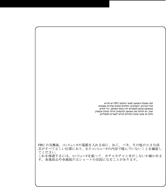
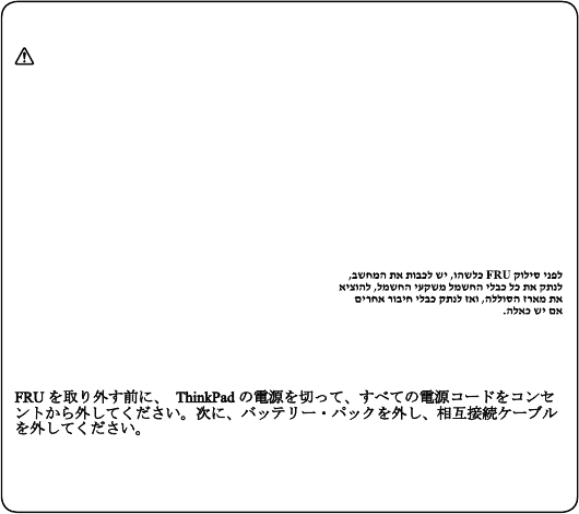
Safety notice 1
Before the computer is powered on after FRU replacement, make sure all screws,
springs, and other small parts are in place and are not left loose inside the computer.
Verify this by shaking the computer and listening for rattling sounds. Metallic parts
or metal akes can cause electrical shorts.
Avant de remettre l’ordinateur sous tension après remplacement d’une unité en
clientèle, vériez que tous les ressorts, vis et autres pièces sont bien en place et
bien xées. Pour ce faire, secouez l’unité et assurez-vous qu’aucun bruit suspect ne
se produit. Des pièces métalliques ou des copeaux de métal pourraient causer un
court-circuit.
Bevor nach einem FRU-Austausch der Computer wieder angeschlossen wird,
muß sichergestellt werden, daß keine Schrauben, Federn oder andere Kleinteile
fehlen oder im Gehäuse vergessen wurden. Der Computer muß geschüttelt und auf
Klappergeräusche geprüft werden. Metallteile oder-splitter können Kurzschlüsse
erzeugen.
Prima di accendere l’elaboratore dopo che é stata effettuata la sostituzione di una
FRU, accertarsi che tutte le viti, le molle e tutte le altri parti di piccole dimensioni
siano nella corretta posizione e non siano sparse all’interno dell’elaboratore.
Vericare ciò scuotendo l’elaboratore e prestando attenzione ad eventuali rumori;
eventuali parti o pezzetti metallici possono provocare cortocircuiti pericolosi.
Antes de encender el sistema despues de sustituir una FRU, compruebe que
todos los tornillos, muelles y demás piezas pequeñas se encuentran en su sitio
y no se encuentran sueltas dentro del sistema. Compruébelo agitando el sistema
y escuchando los posibles ruidos que provocarían. Las piezas metálicas pueden
causar cortocircuitos eléctricos.
8
Lenovo V110-15IKB Hardware Maintenance Manual
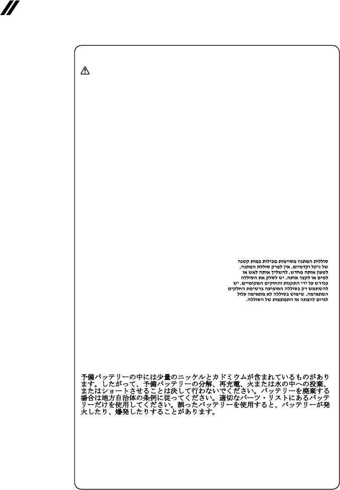
Safety notice 2
DANGER
Some standby batteries contain a small amount of nickel and cadmium. Do not
disassemble a standby battery, recharge it, throw it into fire or water, or short-
circuit it. Dispose of the battery as required by local ordinances or regulations.
Use only the battery in the appropriate parts listing. Use of an incorrect battery can
result in ignition or explosion of the battery.
Certaines batteries de secours contiennent du nickel et du cadmium. Ne les
démontez pas, ne les rechargez pas, ne les exposez ni au feu ni à l’eau. Ne
les mettez pas en court-circuit. Pour les mettre au rebut, conformez-vous à la
réglementation en vigueur. Lorsque vous remplacez la pile de sauvegarde ou celle
de l’horloge temps réel, veillez à n’utiliser que les modèles cités dans la liste de
pièces détachées adéquate. Une batterie ou une pile inappropriée risque de prendre
feu ou d’exploser.
Die Bereitschaftsbatterie, die sich unter dem Diskettenlaufwerk befindet,
kann geringe Mengen Nickel und Cadmium enthalten. Sie darf nicht zerlegt,
wiederaufgeladen, kurzgeschlossen, oder Feuer oder Wasser ausgesetzt werden. Bei
der Entsorgung die örtlichen Bestimmungen für Sondermüll beachten. Beim Ersetzen
der Bereitschafts-oder Systembatterie nur Batterien des Typs verwenden, der in der
Ersatzteilliste aufgeführt ist. Der Einsatz falscher Batterien kann zu Entzündung oder
Explosion führen.
Alcune batterie di riserva contengono una piccola quantità di nichel e cadmio. Non
smontarle, ricaricarle, gettarle nel fuoco o nell’acqua né cortocircuitarle. Smaltirle
secondo la normativa in vigore (DPR 915/82, successive disposizioni e disposizioni
locali). Quando si sostituisce la batteria dell’RTC (real time clock) o la batteria di
supporto, utilizzare soltanto i tipi inseriti nell’appropriato Catalogo parti. L’impiego
di una batteria non adatta potrebbe determinare l’incendio o l’esplosione della
batteria stessa.
Algunas baterías de reserva contienen una pequeña cantidad de níquel y cadmio.
No las desmonte, ni recargue, ni las eche al fuego o al agua ni las cortocircuite.
Deséchelas tal como dispone la normativa local. Utilice sólo baterías que se
encuentren en la lista de piezas. La utilización de una batería no apropiada puede
provocar la ignición o explosión de la misma.
9
About this manual
Safety notice 3
DANGER
The battery pack contains small amounts of nickel. Do not disassemble it, throw
it into re or water, or short-circuit it. Dispose of the battery pack as required by
local ordinances or regulations. Use only the battery in the appropriate parts listing
when replacing the battery pack. Use of an incorrect battery can result in ignition
or explosion of the battery.
La batterie contient du nickel. Ne la démontez pas, ne l’exposez ni au feu ni à l’eau.
Ne la mettez pas en court-circuit. Pour la mettre au rebut, conformez-vous à la
réglementation en vigueur. Lorsque vous remplacez la batterie, veillez à n’utiliser
que les modèles cités dans la liste de pièces détachées adéquate. En effet, une
batterie inappropriée risque de prendre feu ou d’exploser.
Akkus enthalten geringe Mengen von Nickel. Sie dürfen nicht zerlegt,
wiederaufgeladen, kurzgeschlossen, oder Feuer oder Wasser ausgesetzt werden.
Bei der Entsorgung die örtlichen Bestimmungen für Sondermüll beachten. Beim
Ersetzen der Batterie nur Batterien des Typs verwenden, der in der Ersatzteilliste
aufgeführt ist. Der Einsatz falscher Batterien kann zu Entzündung oder Explosion
führen.
La batteria contiene piccole quantità di nichel. Non smontarla, gettarla nel fuoco
o nell’acqua né cortocircuitarla. Smaltirla secondo la normativa in vigore (DPR
915/82, successive disposizioni e disposizioni locali). Quando si sostituisce la
batteria, utilizzare soltanto i tipi inseriti nell’appropriato Catalogo parti. L’impiego
di una batteria non adatta potrebbe determinare l’incendio o l’esplosione della
batteria stessa.
Las baterías contienen pequeñas cantidades de níquel. No las desmonte, ni
recargue, ni las eche al fuego o al agua ni las cortocircuite. Deséchelas tal como
dispone la normativa local. Utilice sólo baterías que se encuentren en la lista de
piezas al sustituir la batería. La utilización de una batería no apropiada puede
provocar la ignición o explosión de la misma.
10
Lenovo V110-15IKB Hardware Maintenance Manual
Safety notice 4
DANGER
The lithium battery can cause a re, an explosion, or a severe burn. Do not recharge
it, remove its polarized connector, disassemble it, heat it above 100°C (212°F),
incinerate it, or expose its cell contents to water. Dispose of the battery as required
by local ordinances or regulations. Use only the battery in the appropriate parts
listing. Use of an incorrect battery can result in ignition or explosion of the battery.
La pile de sauvegarde contient du lithium. Elle présente des risques d’incendie,
d’explosion ou de brûlures graves. Ne la rechargez pas, ne retirez pas son
connecteur polarisé et ne la démontez pas. Ne l’exposez pas à une temperature
supérieure à 100°C, ne la faites pas brûler et n’en exposez pas le contenu à l’eau.
Mettez la pile au rebut conformément à la réglementation en vigueur. Une pile
inappropriée risque de prendre feu ou d’exploser.
Die Systembatterie ist eine Lithiumbatterie. Sie kann sich entzünden, explodieren
oder schwere Verbrennungen hervorrufen. Batterien dieses Typs dürfen nicht
aufgeladen, zerlegt, über 100 C erhitzt oder verbrannt werden. Auch darf ihr Inhalt
nicht mit Wasser in Verbindung gebracht oder der zur richtigen Polung angebrachte
Verbindungsstecker entfernt werden. Bei der Entsorgung die örtlichen Bestimmungen
für Sondermüll beachten. Beim Ersetzen der Batterie nur Batterien des Typs
verwenden, der in der Ersatzteilliste aufgeführt ist. Der Einsatz falscher Batterien
kann zu Entzündung oder Explosion führen.
La batteria di supporto e una batteria al litio e puo incendiarsi, esplodere o
procurare gravi ustioni. Evitare di ricaricarla, smontarne il connettore polarizzato,
smontarla, riscaldarla ad una temperatura superiore ai 100 gradi centigradi,
incendiarla o gettarla in acqua. Smaltirla secondo la normativa in vigore (DPR
915/82, successive disposizioni e disposizioni locali). L’impiego di una batteria
non adatta potrebbe determinare l’incendio o l’esplosione della batteria stessa.
La batería de repuesto es una batería de litio y puede provocar incendios,
explosiones o quemaduras graves. No la recargue, ni quite el conector polarizado,
ni la desmonte, ni caliente por encima de los 100°C (212°F), ni la incinere ni
exponga el contenido de sus celdas al agua. Deséchela tal como dispone la
normativa local.
11
About this manual
Safety notice 5
If the LCD breaks and the uid from inside the LCD gets into your eyes or on your
hands, immediately wash the affected areas with water at least for 15 minutes. Seek
medical care if any symptoms caused by the uid are present after washing.
Si le panneau d’afchage à cristaux liquides se brise et que vous recevez dans les
yeux ou sur les mains une partie du fluide, rincez-les abondamment pendant au
moins quinze minutes. Consultez un médecin si des symptômes persistent après le
lavage.
Die Leuchtstoffröhre im LCD-Bildschirm enthält Quecksilber. Bei der Entsorgung
die örtlichen Bestimmungen für Sondermüll beachten. Der LCD-Bildschirm
besteht aus Glas und kann zerbrechen, wenn er unsachgemäß behandelt wird
oder der Computer auf den Boden fällt. Wenn der Bildschirm beschädigt ist und
die darin befindliche Flüssigkeit in Kontakt mit Haut und Augen gerät, sollten
die betroffenen Stellen mindestens 15 Minuten mit Wasser abgespült und bei
Beschwerden anschließend ein Arzt aufgesucht werden.
Nel caso che caso l’LCD si dovesse rompere ed il liquido in esso contenuto
entrasse in contatto con gli occhi o le mani, lavare immediatamente le parti
interessate con acqua corrente per almeno 15 minuti; poi consultare un medico se i
sintomi dovessero permanere.
Si la LCD se rompe y el uido de su interior entra en contacto con sus ojos o sus
manos, lave inmediatamente las áreas afectadas con agua durante 15 minutos como
mínimo. Obtenga atención medica si se presenta algún síntoma del uido despues
de lavarse.
12
Lenovo V110-15IKB Hardware Maintenance Manual
Safety notice 6
DANGER
To avoid shock, do not remove the plastic cover that protects the lower part of the
inverter card.
An d’éviter tout risque de choc électrique, ne retirez pas le cache en plastique
protégeant la partie inférieure de la carte d’alimentation.
Aus Sicherheitsgründen die Kunststoffabdeckung, die den unteren Teil der
Spannungswandlerplatine umgibt, nicht entfernen.
Per evitare scosse elettriche, non rimuovere la copertura in plastica che avvolge la
parte inferiore della scheda invertitore.
Para evitar descargas, no quite la cubierta de plástico que rodea la parte baja de la
tarjeta invertida.
Safety notice 7
DANGER
Though the main batteries have low voltage, a shorted or grounded battery can
produce enough current to burn personnel or combustible materials.
Bien que le voltage des batteries principales soit peu élevé, le court-circuit ou la
mise à la masse d’une batterie peut produire sufsamment de courant pour brûler
des matériaux combustibles ou causer des brûlures corporelles graves.
Obwohl Hauptbatterien eine niedrige Spannung haben, können sie doch bei
Kurzschluß oder Erdung genug Strom abgeben, um brennbare Materialien zu
entzünden oder Verletzungen bei Personen hervorzurufen.
Sebbene le batterie di alimentazione siano a basso voltaggio, una batteria in
corto circuito o a massa può fornire corrente sufficiente da bruciare materiali
combustibili o provocare ustioni ai tecnici di manutenzione.
Aunque las baterías principales tienen un voltaje bajo, una batería cortocircuitada
o con contacto a tierra puede producir la corriente suciente como para quemar
material combustible o provocar quemaduras en el personal.
13
About this manual
Safety notice 8
DANGER
Before removing any FRU, turn off the computer, unplug all power cords from
electrical outlets, remove the battery pack, and then disconnect any interconnecting
cables.
Avant de retirer une unité remplaçable en clientèle, mettez le système hors tension,
débranchez tous les cordons d’alimentation des socles de prise de courant, retirez la
batterie et déconnectez tous les cordons d’interface.
Die Stromzufuhr muß abgeschaltet, alle Stromkabel aus der Steckdose gezogen,
der Akku entfernt und alle Verbindungskabel abgenommen sein, bevor eine FRU
entfernt wird.
Prima di rimuovere qualsiasi FRU, spegnere il sistema, scollegare dalle prese
elettriche tutti i cavi di alimentazione, rimuovere la batteria e poi scollegare i cavi
di interconnessione.
Antes de quitar una FRU, apague el sistema, desenchufe todos los cables de las
tomas de corriente eléctrica, quite la batería y, a continuación, desconecte cualquier
cable de conexión entre dispositivos.
14
Lenovo V110-15IKB Hardware Maintenance Manual
Laser compliance statement
SomemodelsofLenovocomputerareequippedfromthefactorywithan
opticalstorage devicesuchasaCD-ROMdriveor aDVD-ROM drive.Such
devicesarealsosoldseparatelyasoptions.Ifoneofthesedrivesisinstalled,
itiscertiedintheU.S.toconformto therequirementsoftheDepartmentof
HealthandHumanServices21CodeofFederalRegulations(DHHS21CFR)
SubchapterJforClass1laserproducts.Elsewhere,the driveis certifiedto
conformtotherequirements ofthe InternationalElectrotechnicalCommission
(IEC)825andCENELECEN60825forClass1laserproducts.
IfaCD-ROMdrive,aDVD-ROMdrive,oranotherlaserdeviceisinstalled,note
thefollowing:
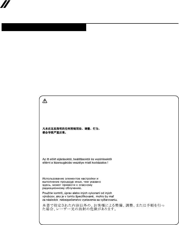
CAUTION
Use of controls or adjustments or performance of procedures other than those
specied herein might result in hazardous radiation exposure.
O uso de controles, ajustes ou desempenho de procedimentos diferentes daqueles
aqui especicados pode resultar em perigosa exposição à radiação.
Pour éviter tout risque d’exposition au rayon laser, respectez les consignes de
réglage et d’utilisation des commandes, ainsi que les procédures décrites.
Werden Steuer- und Einstellelemente anders als hier festgesetzt verwendet, kann
gefährliche Laserstrahlung auftreten.
L’utilizzo di controlli, regolazioni o l’esecuzione di procedure diverse da quelle
specicate possono provocare l’esposizione a.
El uso de controles o ajustes o la ejecución de procedimientos distintos de los aquí
especicados puede provocar la exposición a radiaciones peligrosas.
OpeningtheCD-ROMdrive,theDVD-ROMdrive,oranyotheropticalstorage
devicecouldresultinexposuretohazardouslaser radiation.Thereareno
serviceablepartsinsidethosedrives.Do not open.
15
About this manual
ACD-ROMdrive,aDVD-ROMdrive,oranyotherstoragedeviceinstalledmay
containanembeddedClass3AorClass3Blaserdiode.Notethefollowing:
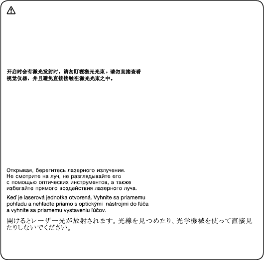
DANGER
Emits visible and invisible laser radiation when open. Do not stare into the beam,
do not view directly with optical instruments, and avoid direct exposure to the
beam.
Radiação por raio laser ao abrir. Não olhe xo no feixe de luz, não olhe diretamente
por meio de instrumentos óticos e evite exposição direta com o feixe de luz.
Rayonnement laser si carter ouvert. Évitez de fixer le faisceau, de le regarder
directement avec des instruments optiques, ou de vous exposer au rayon.
Laserstrahlung bei geöffnetem Gerät. Nicht direkt oder über optische Instrumente
in den Laserstrahl sehen und den Strahlungsbereich meiden.
Kinyitáskor lézersugár ! Ne nézzen bele se szabad szemmel, se optikai
eszközökkel. Kerülje a sugárnyalábbal való érintkezést!
Aprendo l’unità vengono emesse radiazioni laser. Non fissare il fascio, non
guardarlo direttamente con strumenti ottici e evitare l’esposizione diretta al fascio.
Radiación láser al abrir. No mire jamente ni examine con instrumental óptico el
haz de luz. Evite la exposición directa al haz.
16
Lenovo V110-15IKB Hardware Maintenance Manual
Important service information
Thischapterpresentsthefollowingimportantserviceinformation:
• “StrategyforreplacingFRUs”onpage16
– “Strategyforreplacingaharddiskdrive”onpage17
– “Importantnoticeforreplacingasystemboard”onpage17
• “ImportantinformationaboutreplacingRoHScompliantFRUs”onpage18
Important:
BIOS and device driver xes are customer-installable. The BIOS and device
drivers are posted on the customer support site:
http://support.lenovo.com.
Strategy for replacing FRUs
Before replacing parts:
Makesurethatall softwarexes, drivers,andBIOSdownloadsareinstalled
beforereplacinganyFRUslistedinthismanual.
Afterasystemboardisreplaced,ensurethatthelatestBIOSisloadedtothe
systemboardbeforecompletingtheserviceaction.
Todownloadsoftwarexes,drivers,andBIOS,followthestepsbelow:
1. Gotohttp://support.lenovo.com.
2. Entertheserialnumberorselectaproductor useLenovo smart
downloading.
3. SelecttheBIOS/Driver/Applicationsanddownload.
4. Followthedirectionsonthescreenandinstallthenecessarysoftware.
17
Important service information
Usethefollowingstrategytopreventunnecessaryexpenseforreplacingand
servicingFRUs:
• IfyouareinstructedtoreplaceanFRU,butthereplacementdoesnotsolve
theproblem,reinstalltheoriginalFRUbeforeyoucontinue.
• Somecomputers havebothaprocessorboardand asystem board.Ifyou
areinstructedtoreplaceeitherofthem,andreplacingoneofthemdoesnot
solvetheproblem,reinstallthatboard,andthenreplacetheotherone.
• IfanadapteroradeviceconsistsofmorethanoneFRU,anyoftheFRUs
maybethecauseofthe error. Beforereplacing theadapter ordevice,
removetheFRUsonebyonetoseeifthesymptomschange.Replaceonly
theFRUthatchangedthesymptoms.
Attention:Thesetup configurationonthecomputeryouareservicingmay
havebeencustomized.RunningAutomaticConfiguration mayalter the
settings.Notethecurrentcongurationsettings(usingtheViewConguration
option);then,whenservice hasbeen completed,verifythatthosesettings
remainineffect.
Strategy for replacing a hard disk drive
Alwaystrytorun alow-level formatbeforereplacingaharddiskdrive.This
willcauseallcustomerdataontheharddisk tobe lost.Make surethatthe
customerhasacurrentbackupofthedatabeforeperformingthisaction.
Attention:Thedrivestartupsequenceinthecomputeryouareservicingmay
havebeenchanged.Beextremelycareful duringwrite operationssuch as
copying,saving,orformatting.Ifyouselectanincorrectdrive,dataorprograms
canbeoverwritten.
Important notice for replacing a system board
Somecomponentsmountedon asystem boardare verysensitive. Improper
handlingcancausedamagetothosecomponents,andmaycauseasystem
malfunction.
Attention:Whenhandlingasystemboard:
• Donotdropthesystemboardorapplyanyexcessiveforcetoit.
• Avoidroughhandlingofanykind.
• Avoidbendingthe systemboardandhardpushingtopreventcrackingat
eachBGA(BallGridArray)chipset.

18
Lenovo V110-15IKB Hardware Maintenance Manual
Important information about replacing RoHS compliant FRUs
RoHS, The Restriction of Hazardous Substances in Electrical and
Electronic Equipment Directive (2002/95/EC) is a European Union legal
requirement affecting the global electronics industry. RoHS requirements
must be implemented on Lenovo products placed on the market after
June 2006. Products on the market before June 2006 are not required to
have RoHS compliant parts. If the original FRU parts are non-compliant,
replacement parts can also be non-compliant. In all cases if the original
FRU parts are RoHS compliant, the replacement part must also be RoHS
compliant.
Note:RoHS andnon-RoHS FRUpartnumberswiththesametandfunction
areidentiedwithuniqueFRUpartnumbers.
Lenovoplans totransit toRoHScompliancewellbeforetheimplementation
dateandexpectsits suppliersto bereadytosupportLenovo’srequirements
andscheduleintheEU.Productssoldin2005and2006willcontainsome
RoHScompliantFRUs.Thefollowingstatementpertainstotheseproductsand
anyproductLenovoproducescontainingRoHScompliantFRUs.
RoHScompliantFRUshaveuniqueFRUpartnumbers.Before orafter the
RoHSimplementationdate,failed RoHScompliant partsmust alwaysbe
replacedwithRoHScompliantones,so onlythe FRUsidentied ascompliant
inthesystemHMMordirectsubstitutionsforthoseFRUsmaybeused.
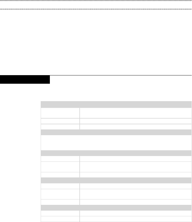
Products marketed before June 2006 Products marketed after June 2006
Current or
original part
Replacement FRU Current or
original part
Replacement FRU
Non-RoHS CanbeNon-RoHS
MustbeRoHS MustbeRoHS
Non-RoHS CanbeRoHS
Non-RoHS CansubtoRoHS
RoHS MustbeRoHS
Note:AdirectsubstitutionisapartwithadifferentFRUpart numberthat is
automaticallyshippedbythedistributioncenteratthetimeoftheorder.

19
General checkout
General checkout
Thischapterpresentsthefollowinginformation:
• “Whattodorst”onpage20
• “Powersystemcheckout”onpage21
Beforeyougotothecheckout,makesuretoreadthefollowingimportantnotes:
Important notes:
• Onlycertiedtrainedpersonnelcanservicethecomputer.
• BeforereplacinganyFRU,readtheentirepageonremovingandreplacing
FRUs.
• CarefullyremovescrewsforreusewhenreplacingFRUs.
• Beextremelycarefulduringsuch writeoperationsas copying,saving,or
formatting. Drives in the computer that you are servicing sequence might
have been altered. If you select an incorrect drive, data or programs might be
overwritten.
• ReplaceanFRUonlywithanotherFRUofthecorrectmodel. When you
replace an FRU, make sure that the machine model and the FRU part number are
correct by referring to the FRU parts list.
• AnFRUshouldnotbereplacedjustbecauseofasingle,unreproduciblefailure.
Single failures can occur for a variety of reasons that have nothing to do with a
hardware defect, such as cosmic radiation, electrostatic discharge, or software
errors. Consider replacing an FRU only when a problem recurs. If you suspect that
an FRU is defective, clear the error logs and run the test again. If the error does
not recur, do not replace the FRU.
• BecarefulnottoreplaceanondefectiveFRU.

20
Lenovo V110-15IKB Hardware Maintenance Manual
What to do rst
WhenyoudoreturnanFRU,youmustincludethefollowinginformationinthe
partsexchangeformorpartsreturnformthatyouattachtoit:
1. Nameandphonenumberofservicer
2. Dateofservice
3. Dateonwhichthemachinefailed
4. Dateofpurchase
5. ProcedureindexandpagenumberinwhichthefailingFRUwasdetected
6. FailingFRUnameandpartnumber
7. Machinetype,modelnumber,andserialnumber
8. Customer’snameandaddress
Note for warranty:During thewarrantyperiod,thecustomer maybe
responsiblefor repaircosts ifthe computerdamagewascausedbymisuse,
accident,modification,unsuitablephysicaloroperatingenvironment,or
impropermaintenancebythecustomer.
Thefollowingisa listof somecommon itemsthatarenotcoveredunder
warrantyandsomesymptoms thatmight indicatethat thesystemwas
subjectedtostressbeyondnormaluse.
Beforecheckingproblemswiththecomputer,determinewhetherthedamageis
coveredunderthewarrantybyreferringtothefollowinglist:
The following are not covered under warranty:
• LCDpanelcrackedfromtheapplicationofexcessive forceor frombeing
dropped
• Scratched(cosmetic)parts
• Distortion,deformation,ordiscolorationofthecosmeticparts
• Plasticparts,latches,pins,orconnectorsthathavebeencrackedorbroken
byexcessiveforce
• Damagecausedbyliquidspilledintothesystem
• DamagecausedbytheimproperinsertionofaPCCardortheinstallationof
anincompatiblecard
• Improperdiskinsertionoruseofanopticaldrive
• Diskettedrivedamagecausedbypressure onthe diskettedrive cover,
foreignmaterialinthedrive,ortheinsertionofadiskettewithmultiplelabels
• Damagedorbentdisketteejectbutton
• Fusesblownbyattachmentofanonsupporteddevice
• Forgottencomputerpassword(makingthecomputerunusable)
• Stickykeyscausedbyspillingaliquidontothekeyboard
• UseofanincorrectACadapteronlaptopproducts
The following symptoms might indicate damage caused by nonwarranted
activities:
• Missingpartsmightbeasymptomofunauthorizedserviceormodication.
• Ifthespindleofaharddiskdrivebecomesnoisy,itmayhavebeensubjected
toexcessiveforce,ordropped.
21
General checkout
Power system checkout
Toverifyasymptom,followthestepsbelow:
1. Turnoffthecomputer.
2. Removethebatterypack.
3. ConnecttheACadapter.
4. Makesurethatpowerissuppliedwhenyouturnonthecomputer.
5. Turnoffthecomputer.
6. DisconnecttheACadapterandinstallthechargedbatterypack.
7. Makesurethatthebatterypacksuppliespowerwhenyouturnonthe
computer.
Ifyoususpectapowerproblem,seetheappropriateoneofthefollowingpower
supplycheckouts:
• “CheckingtheACadapter”onpage21
• “Checkingoperationalcharging”onpage22
• “Checkingthebatterypack”onpage22
Checking the AC adapter
YouareherebecausethecomputerfailsonlywhentheACadapterisused.
• Ifthepower-onindicatordoesnotturnon,checkthepower cordof theAC
adapterforcorrectcontinuityandinstallation.
• Ifthecomputerdoes notcharge duringoperation, goto“Checking
operationalcharging”.
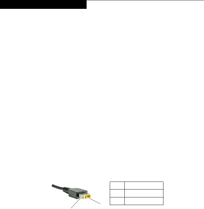
TochecktheACadapter,followthestepsbelow:
1. UnplugtheACadaptercablefromthecomputer.
2. Measuretheoutput voltageattheplugoftheACadapter cable.See the
followinggure:
Voltage (V DC)
+20
0
Pin
1
2
1
2
Note:OutputvoltagefortheACadapterpinNo.2maydifferfromtheoneyou
areservicing.
3. Ifthevoltageisnotcorrect,replacetheACadapter.
4. Ifthevoltageisacceptable,dothefollowing:
• Replacethesystemboard.
• Iftheproblempersists,goto“LenovoV110-15IKB”onpage27.
Note:NoisefromtheACadapterdoesnotalwaysindicateadefect.

22
Lenovo V110-15IKB Hardware Maintenance Manual
Checking operational charging
Tocheckwhether thebatterycharges properlyduringoperation,usea
dischargedbattery packorabatterypackthathas lessthan50%ofthetotal
powerremainingwheninstalledinthecomputer.
Performoperationalcharging.Ifthebatterystatus indicatoror icondoesnot
lighton,removethebatterypackandletitreturntoroomtemperature.Reinstall
thebatterypack.Ifthechargeindicatororicon isstilloff,replacethebattery
pack.
Ifthechargeindicator stilldoesnotlighton,replacethesystemboard.Then
reinstallthebatterypack.Ifitisstillnotcharged,gotothenextsection.
Checking the battery pack
BatterychargingdoesnotstartuntilthePowerMetershowsthatlessthan95%
ofthetotalpowerremains;underthisconditionthebatterypackcanchargeto
100%ofitscapacity.Thisprotectsthebatterypackfrombeingoverchargedor
fromhavingashortenedlife.
Tocheckyourbattery,moveyourcursortothePowerMetericon inthe icon
trayoftheWindows®taskbarandwaitforamoment(butdonotclickit),andthe
percentageofbatterypowerremainingisdisplayed.Togetdetailedinformation
aboutthebattery,double-clickthePowerMetericon.
Note:Ifthebatterypackbecomeshot,itmaynotbe ableto becharged.
Removeitfromthecomputerandleaveitatroomtemperatureforawhile.After
itcoolsdown,reinstallandrechargeit.
23
Related service information
Related service information
Thischapterpresentsthefollowinginformation:
• “RestoringthefactorycontentsbyusingOneKeyRecovery”onpage23
• “Passwords”onpage24
• “Powermanagement”onpage25
Restoring the factory contents by using OneKey Recovery
Restore of factory default
TheLenovoV110-15IKBcomputerscomewithpre-installedOneKeyRecovery
System.Inordertosaveapplicationlesandtheinitialbackeduplesofthe
system,theharddiskinaLenovocomputerincludesahiddenpartitionwhen
itisshipped.Ifyouneedtorestorethesystemtothepointofyourrstboot
up,justenterLenovoOneKeyRecoverySystemandrunSystem Recovery.
FordetailsofOneKeyRecoverySystem,seethe User Guide for Lenovo OneKey
Recovery System.
Note: This will delete all the new data on the system partition (C drive), which
is not recoverable. Make sure to back up your critical data before you perform this
action.

24
Lenovo V110-15IKB Hardware Maintenance Manual
Passwords
Asmany asthree passwordsmaybeneededforanyLenovo computer:
thepower-onpassword(POP), thehard diskpassword(HDP),andthe
administratorpassword.
Ifanyofthesepasswordshasbeenset,apromptforitappearsonthescreen
wheneverthecomputeristurnedon.Thecomputerdoesnotstartuntilthe
passwordisentered.
Power-on password
Apower-onpassword (POP)protects thesystem frombeing poweredon by
anunauthorized person.Thepasswordmust beenteredbefore anoperating
systemcanbebooted.
Hard-disk password
Therearetwohard-diskpasswords(HDPs):
+UserHDP-fortheuser
+MasterHDP-for thesystemadministrator,whocanuse itto getaccess to
theharddiskdriveeveniftheuserhaschangedtheuserHDP
Attention:IftheuserHDPhasbeen forgotten,check whethera masterHDP
hasbeenset.Ifithas,itcanbeusedforaccesstotheharddiskdrive.If
nomasterHDPisavailable, neitherLenovo norLenovoauthorizedservice
techniciansprovideanyservicestoreseteithertheuserorthemasterHDP,or
torecoverdatafromtheharddiskdrive.Thehard diskdrive canbereplaced
forascheduledfee.
Administrator password
Administratorpasswordcontrolstheaccessofthewholesetuputility.Only
AdministratorpasswordwassetthenUserpasswordcanbeset.IfAdministrator
passwordwascleared,theUserpasswordwasclearedtoo.
25
Related service information
Power management
Note:PowermanagementmodesarenotsupportedforAPMoperatingsystem.
Toreducepowerconsumption,thecomputerhastwopower management
modes:sleep(standby),andshutdown.
Putting the computer to sleep or shutting it down
Whenyouhavenishedworkingwithyourcomputer,youcanputittosleepor
shutitdown.
Putting your computer to sleep
Ifyouwillbeawayfromyourcomputerforonlyashorttime,putthecomputer
tosleep.
Whenthecomputerisinsleepmode, youcanquicklywakeittoresumeuse,
bypassingthestartupprocess.
Toputthecomputertosleep,dooneofthefollowing:
• Closethedisplaylid.
• Pressthepowerbutton.
• Preformthefollowingbasedontheoperatingsystem.
For the Windows 7 operating system:
Click Start → Sleep
For the Windows 10 operating system:
Movethe cursorto thelower-leftcorner,and thenselectthe Startbutton.
SelectPower → Sleep.
Note:Put yourcomputer tosleepbeforeyoumoveit.Moving yourcomputer
whiletheharddiskdriveisspinningcandamagetheharddisk,causinglossof
data.
Towakethecomputer,dooneofthefollowing:
• Pressanykeyonthekeyboard.
• Pressthepowerbutton.
26
Lenovo V110-15IKB Hardware Maintenance Manual
Shutting down the computer
Ifyouarenotgoingtouseyourcomputerforalongtime,shutitdown.
Toshutdownyourcomputer,dooneofthefollowing:
• For the Windows 7 operating system:
Click Start → Shut down
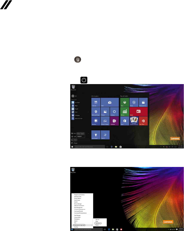
For the Windows 10 operating system:
Movethecursortothelower-leftcorner,andthenselecttheStartbutton.
SelectPower → Shut down.
• Right-clicktheStartbuttoninthelower-leftcornerandselectShut down or
sign out → Shut down.
27
Lenovo V110-15IKB
Lenovo V110-15IKB
Thischapter presentsthefollowingproduct-specificservice referencesand
product-specicpartsinformation:
• “Specications”onpage27
• “Statusindicators”onpage29
• “Hotkeys”onpage31
• “FRUreplacementnotices”onpage32
• “RemovingandreplacinganFRU”onpage33
• “Locations”onpage63
• “Partslist”onpage65
Specications
ThefollowingtableliststhespecicationsoftheLenovoV110-15IKB:
Table 1. Specications
Form Factor
Dimensions Appr.380mm×262mm×
22.9mm
Weight Appr.2.1kgwithbattery
LCDsize 15.6-inch
Processor
Seethesystempropertiesofyourcomputer,youcandothisasfollows:
ClickControl Panel,thenclickHardware and Sound,clickDevice Manager
underDevices and PrintersanddoubleclickProcessors.
Memory
Typeandspeed DDR4-2400MHz
Maximum
supportedcapacity 16GB
Slots SODIMM×1,onboard×1
Hard disk drive
Formfactor 2.5-inch,9.5mm/7mm
Capacity HDD:250GB/500GB/1TB
SSD:128GB/256GB
Interface SATA3
Optical drive
Formfactor 9.0mm
Type Writer
28
Lenovo V110-15IKB Hardware Maintenance Manual
Display
Displayresolution
(LCD) 16:9(1,366×768pixels)
LCDbacklight LED
I/O Ports
USB USB3.0×1,USB2.0×1
Audio Comboaudiojack×1
Communication RJ-45×1
Video/Audio HDMIslot×1
Memorycardslot 4in1slot×1(SD/SDHC/SDXC/MMC)
Battery pack
Type Li-ionbatterypack
Cells/Capacity 3/4cells,24/32Wh
Note:Thecapacitygivenhereisthetypicaloraveragecapacityas
measuredinaspecictestenvironment.Capacitiesmeasuredinother
environmentsmaydifferbutarenolowerthantheratedcapacity(see
productlabel).
AC power adapter
Input 100-240V,50-60Hz
Outputvoltage 20VDC
Power 45/65W
Miscellaneous
Camera 0.3Mega
Security Kensingtonminisecurityslot×1
Table 1. Specications (continued)
29
Lenovo V110-15IKB
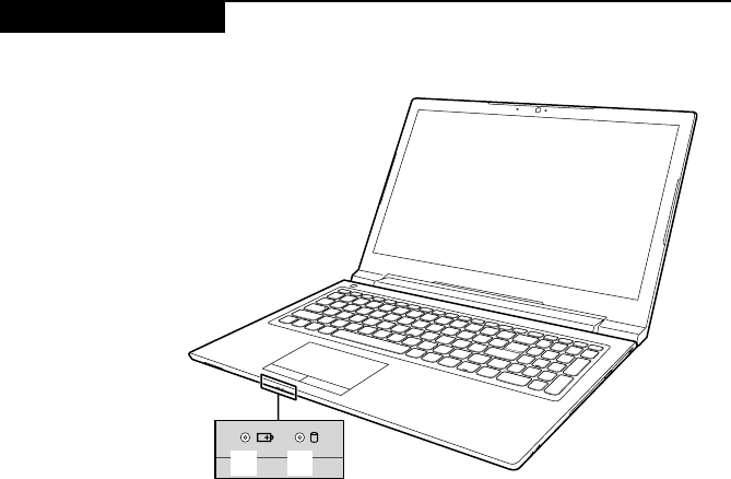
Status indicators
Thesystemstatusindicatorsbelowshowthecomputerstatus:
a b
30
Lenovo V110-15IKB Hardware Maintenance Manual
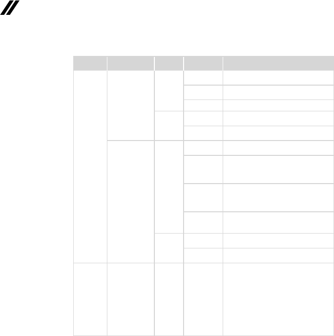
Table 2. Status indicators
Indicator AC power
adapter status
System
status
Indicator
status Meaning
Battery/
Charging
status
indicator
Disconnected
Working
Solidlight
amber
Thebatteryhasbetween1%and
5%charge.
Solidamber Thebatteryhasbetween5%and
20%charge.
Solidgreen
Thebatteryhasmorethan20%charge.
Sleep
Blinking
amber
Thebatteryhasbetween1%and
20%charge.
Blinking
green
Thebatteryhasmorethan20%
charge.
Connected
Working
Solidlight
amber
Thebatteryhasbetween1%and
5%charge.
Fast
blinking
amber
Thebatteryhasbetween5%and
20%charge.Whenbatterycharge
reaches20%,theblinkingcolor
changestogreen.
Slow
blinking
green
Thebatteryhasbetween20%and
80%chargeandisstillcharging.
Whenthebatteryreaches80%
chargethelightwillstopblinking.
Solidgreen
Thebatteryhasmorethan80%
charge,chargingwillcontinueuntil
thebatteryisfullycharged.
Sleep
Blinking
amber
Thebatteryhasbetween1%and
20%charge.
Blinking
green
Thebatteryhasmorethan20%
charge.
Harddisk
drive
indicator
-- -- On
Theharddiskdriveisreadingor
writingdata.
Attention:
• Whentheindicatorison,do
notputthecomputerintosleep
modeorturnoffthecomputer.
• Whentheindicatorison,donot
movethecomputer.Sudden
physicalshockmightcausehard
diskdriveerrors.
31
Lenovo V110-15IKB
Hotkeys
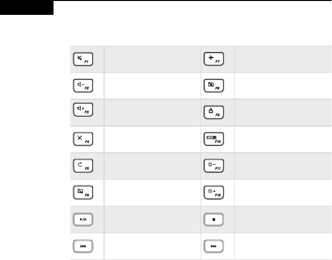
Table 3. Hotkeys
Mutes/unmutesthesound. Enables/disablesairplane
mode.
Decreasesthevolumelevel. Enables/disablescamera.
Increasesthevolumelevel. Locks/unlockstheLCD
screen.
Enables/disables
microphone.
Enablestheexternalprojector
ordanglestheexternal
display.
Refreshespage.
Decreasesthedisplay
brightnessuntiltheLCD
backlightisturnedoff.
Enables/disablesthetouch
pad. Increasesdisplaybrightness.
Play/pausethecurrentvideo
(audio). Stopthecurrentvideo
(audio).
Fastbackwardwhenplaying. Fastforwardwhenplaying.
32
Lenovo V110-15IKB Hardware Maintenance Manual
FRU replacement notices
Thissection presentsnoticesrelatedtoremoving andreplacingparts. Read
thissectioncarefullybeforereplacinganyFRU.
Screw notices
Loosescrewscancause areliability problem.IntheLenovocomputer,this
problemisaddressedwithspecialnylon-coatedscrewsthathavethefollowing
characteristics:
• Theymaintaintightconnections.
• Theydonoteasilycomeloose,evenwithshockorvibration.
• Theyarehardertotighten.
Dothefollowingwhenyouservicethismachine:
• Keepthescrewkitinyourtoolbag.
• CarefullyremovescrewsforreusewhenreplacingFRUs.
• Useatorquescrewdriverifyouhaveone.
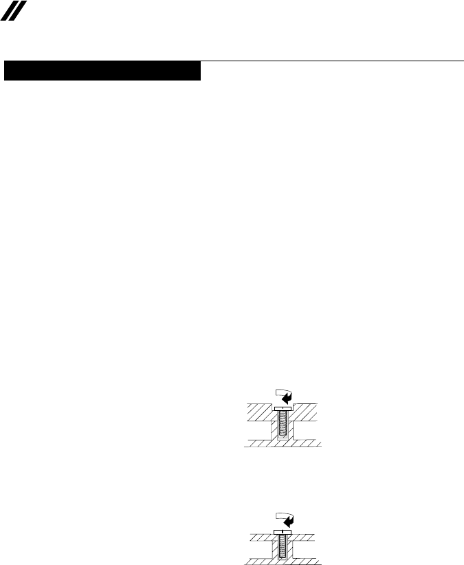
Tightenscrewsasfollows:
• Plastic to plastic
Turnanadditional90° afterthe screwhead touchesthe surfaceof the
plasticpart:
more than 90°
(Cross-section)
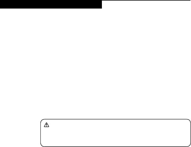
• Logic card to plastic
Turnanadditional180°afterthescrewheadtouchesthesurfaceofthe
logiccard:
more than 180°
(Cross-section)
• Torque driver
Ifyouhaveatorquescrewdriver,refertothe“Torque”columnforeachstep.
• Makesurethatyouusethecorrectscrews.Ifyouhaveatorquescrewdriver,
tightenallscrewsrmlytothetorqueshowninthetable.Carefully remove
screws for reuse when replacing FRUs. Make sure that all screws are
tightened rmly.
• Ensuretorque screwdriversarecalibratedcorrectlyfollowing country
specications.
33
Lenovo V110-15IKB
Removing and replacing an FRU
Thissectionpresentsexplodedgures withtheinstructionstoindicatehowto
removeandreplacetheFRU.Makesuretoobservethefollowinggeneralrules:
1. Donotattempttoserviceanycomputerunlessyouhavebeentrainedand
certied.Anuntrainedpersonrunstheriskofdamagingparts.
2. BeforereplacinganyFRU,review“FRUreplacementnotices”onpage32.
3. Beginby removingany FRUsthat haveto beremoved beforethe failing
FRU.AnyofsuchFRUsarelistedatthetopofthepage.Removethemin
theorderinwhichtheyarelisted.
4. FollowthecorrectsequenceinthestepstoremovetheFRU,asgiveninthe
guresbythenumbersinsquarecallouts.
5. WhenturningascrewtoreplaceanFRU,turnitinthedirectionasgivenby
thearrowinthegure.
6. WhenremovingtheFRU,move itinthedirectionasgivenbythearrow in
thegure.
7. ToputthenewFRUinplace,reversetheremovalproceduresandfollow
anyofthenotesthatpertain toreplacement. Forinformation about
connectingandarranginginternalcables,see“Locations”onpage63.
8. WhenreplacinganFRU,usethecorrectscrewasshownintheprocedures.
DANGER
Before removing any FRU, turn off the computer, unplug all power cords from
electrical outlets, remove the battery pack, and then disconnect any of the
interconnecting cables.
Attention:AfterreplacinganFRU,donotturnonthecomputeruntilyouhave
madesurethatallscrews,springs,andothersmallpartsareinplaceandnone
areloose insidethe computer.Verifythis byshakingthecomputergently and
listeningforrattlingsounds.Metallic partsormetalakescancauseelectrical
shortcircuits.
Attention:Thesystem boardissensitiveto,andcanbe damagedby,
electrostaticdischarge. Beforetouchingit,establishpersonal groundingby
touchingagroundpointwithonehandorusinganelectrostaticdischarge(ESD)
strap(P/N6405959)toremovepotentialshockreasons.
Note:
• The illustrations used in this section are of the Lenovo V110-15IKB, unless
otherwise stated.
34
Lenovo V110-15IKB Hardware Maintenance Manual
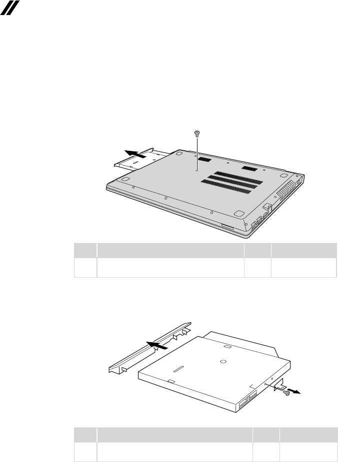
1010 Optical drive
Figure 1. Removal steps of optical drive
Removethescrew1.Thenpulltheopticaldriveoutinthedirectionshownby
arrow2.
a
b
Step Screw (quantity) Color Torque
1M2×3mm,Phillipshead,nylok-coated(1)
LOWTOUPPER Silver 1.85+/-0.15kgf/cm
Removethescrew3,thencarefullyremovetheopticaldrivebracketandbezel
inthedirectionsshownbyarrows4and5.
c
d
e
Step Screw (quantity) Color Torque
3M2×3mm,Phillipshead,nylok-coated(1)
ODDBRKTOODDMODULE Silver
1.85+/-0.15kgf/cm
35
Lenovo V110-15IKB
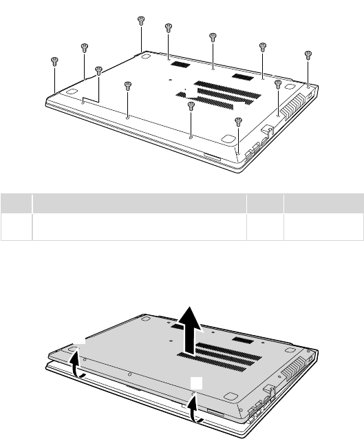
1020 Base cover
Foraccess,removethisFRU:
• “1010Opticaldrive”onpage34
Figure 2. Removal steps of base cover
Removethescrews1.
a
a
aaa
aa
a
a
a
a
a
Step Screw (quantity) Color Torque
1M2×6mm,Phillipshead,nylok-coated(12)
LOWTOUPPER Black
1.85+/-0.15kgf/cm
Removethebasecoverinthedirectionsshownbyarrows2and3.
c
b
b
36
Lenovo V110-15IKB Hardware Maintenance Manual
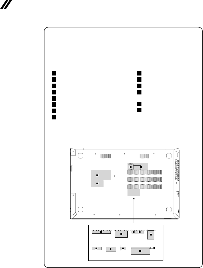
Note: Applying labels to the base cover
ThenewbasecoverFRUis shippedwith akit containinglabels ofseveral
kinds.Whenyoureplace thebase cover, youneedtoapplythefollowing
label:
Thefollowinglabelsneedtobepeeledofffromtheoldbasecover,andneed
tobeputonthenewbasecover.
a Ratinglabel(69.5x34.5mm)
b Ratinglabel(43x24mm)
c GMLlabel
d COAlabel
e Wlan/BTlabelforUS/CA/TW
f KCClabelforKorea
g PostellabelforIndonesia
h DsidelabelforIndonesia
i BISlabelforIndia
j Wlan/BTlabelforIsarel
k Wlan/BTlabelforBrazil
l WlanlabelforSouth
Africa
m CNClabelforArgentina
n Argentinalabel
Forsomemodels,youalsoneedtoapplyoneortwoFCClabels.Checkthe
oldbasecover;ifithasoneortwoFCClabels,ndduplicatesoftheminthe
labelkitandapplythemtothenewbasecover.
Forthelocationofeachlabel,refertothefollowinggures:
b
a
cd
eg
f
h
i
n
m
l
k
j
37
Lenovo V110-15IKB
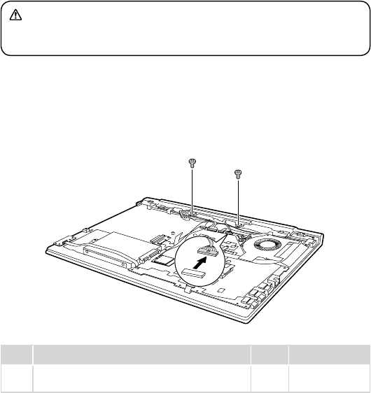
1030 Battery pack
Foraccess,removetheseFRUsinorder:
• “1010Opticaldrive”onpage34
• “1020Basecover”onpage35
DANGER
Only use the battery specied in the parts list for your computer. Any other battery
could ignite or explode.
Figure 3. Removal steps of battery pack
Detachthebatterypackconnectorinthedirectionshownbyarrow1,remove
thescrews2.
b
b
a
Step Screw (quantity) Color Torque
2M2×4mm,Phillipshead,nylok-coated(2)
BATTERYTOUPPER Silver 1.85+/-0.15kgf/cm
38
Lenovo V110-15IKB Hardware Maintenance Manual
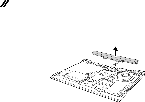
Figure 3. Removal steps of battery pack (continued)
Removethebatterypackinthedirectionshownbyarrow3.
c
When installing:Makesurethebatterypackconnectorisattachedrmly.
39
Lenovo V110-15IKB
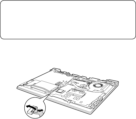
1040 Hard disk drive
Foraccess,removetheseFRUsinorder:
• “1010Opticaldrive”onpage34
• “1020Basecover”onpage35
• “1030Batterypack”onpage37
Attention:
• Donotdroptheharddiskdriveorapplyanyphysicalshocktoit. The hard
disk drive is sensitive to physical shock. Improper handling can cause damages
and permanent loss of data.
• Before removing the drive, suggest the customer to backup all the information on
it if possible.
• Never remove the drive while the system is operating or is in suspend mode.
Figure 4. Removal steps of hard disk drive
DetachtheIOboardcableconnectorinthedirectionsshownbyarrows1and2.
b
a
40
Lenovo V110-15IKB Hardware Maintenance Manual
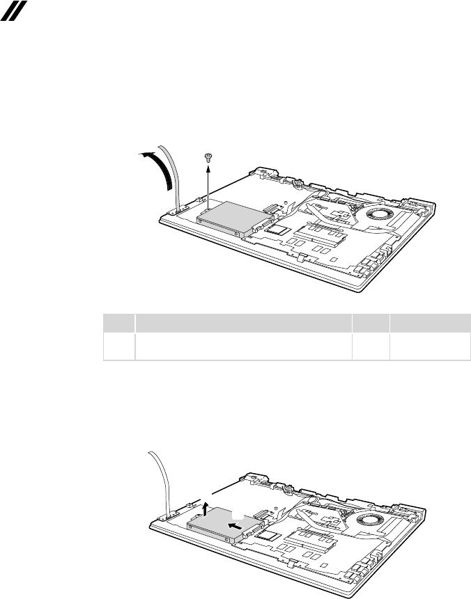
Figure 4. Removal steps of hard disk drive (continued)
LifttheIOboardcableinthedirectionshownbyarrow3.Removethescrew
4.
d
c
Step Screw (quantity) Color Torque
4M2×3mm,Phillipshead,nylok-coated(1)
HDDBRKTOUPPER Silver 1.85+/-0.15kgf/cm
When installing:Makesurethatthecableconnectorisattachedrmly.
DetachtheHDDconnectorinthedirectionshownbyarrow5.Removethe
harddiskdrivefromtheslotinthedirectionshownbyarrow6.
f
e
When installing:MakesurethattheHDDconnectorisattachedrmly.
41
Lenovo V110-15IKB
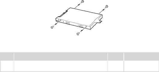
Figure 4. Removal steps of hard disk drive (continued)
Removethescrews7,thentakeoutthemetalframe.
g
g
g
g
Step Screw (quantity) Color Torque
7M3×4mm,Phillipshead,nylok-coated(4)
HDDBRKTOHDD Silver 4+/-0.3kgf/cm
42
Lenovo V110-15IKB Hardware Maintenance Manual
1050 Speaker
Foraccess,removetheseFRUsinorder:
• “1010Opticaldrive”onpage34
• “1020Basecover”onpage35
• “1030Batterypack”onpage37
• “1040Harddiskdrive”onpage39
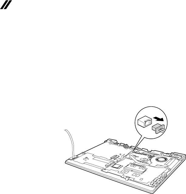
Figure 5. Removal steps of speaker
Unplugthespeakerconnectorinthedirectionshownbyarrow1.
a
43
Lenovo V110-15IKB
Figure 5. Removal steps of speaker (continued)
Removethespeaker2.
b
When installing: Makesurethatthespeakerconnectorisattachedrmly.
44
Lenovo V110-15IKB Hardware Maintenance Manual
1060 IO board
Foraccess,removetheseFRUsinorder:
• “1010Opticaldrive”onpage34
• “1020Basecover”onpage35
• “1030Batterypack”onpage37
• “1040Harddiskdrive”onpage39
• “1050Speaker”onpage42
Figure 6. Removal steps of IO board
Removethescrew1.
a
Step Screw (quantity) Color Torque
1M2×3mm,Phillipshead,nylok-coated(1)
IOBOARDTOUPPER Silver
1.85+/-0.15kgf/cm
RemovetheIOboardinthedirectionshownbyarrow2.
b
When installing: Makesurethattheconnectorisattachedrmly.
45
Lenovo V110-15IKB
1070 PCI Express Mini Card for wireless LAN
Foraccess,removetheseFRUsinorder:
• “1010Opticaldrive”onpage34
• “1020Basecover”onpage35
• “1030Batterypack”onpage37
• “1040Harddiskdrive”onpage39
• “1050Speaker”onpage42
• “1060IOboard”onpage44
Important: Thepreinstalled WLANmodule mayonlybereplacedwitha
Lenovoapprovedmoduleinorderto complywith FCCand ICregulations.
Referto“Overall”onpage66for Lenovopart numbersfortheapproved
modules.
Figure 7. Removal steps of PCI Express Mini Card for wireless LAN
DisconnectthetwowirelessLANcables(white,black)1,andthenremovethe
screw2.
b
a
a
46
Lenovo V110-15IKB Hardware Maintenance Manual
Figure 7. Removal steps of PCI Express Mini Card for wireless LAN (continued)
Instep 1,unplug thejacksbyusingtheremovaltool antennaRFconnector
(P/N:08K7159),orpickuptheconnectorswithyourngersandgentlyunplug
theminthedirectionshownbythearrows.
Notes:ThewirelessLANcardhas2cablesinstep1.
ThewirelessLANcardinsomemodelsmighthave3cablesinstep1.
Step Screw (quantity) Color Torque
2M2×3mm,Phillipshead,nylok-coated(1)
WLANCARDTOMB Silver 1.85+/-0.15kgf/cm
Removethecardinthedirectionshownbyarrow3.
c
When installing:
• Inmodelswitha wirelessLAN cardthathastwoantennaconnectors,plug
theblackcable(1st)(MAIN)intothejacklabeledMAIN,andthewhitecable
(2nd)(AUX)intothejacklabeledAUXonthecard.
• InmodelswithawirelessLANcardthathasthreeantennaconnectors,plug
theblackcable(1st)(MAIN)intothejacklabeled1,thegreycable(3rd)into
thejacklabeled3,andthewhitecable(2nd)(AUX)intothejacklabeled2on
thecard.
47
Lenovo V110-15IKB
1080 ODD board
Foraccess,removetheseFRUsinorder:
• “1010Opticaldrive”onpage34
• “1020Basecover”onpage35
• “1030Batterypack”onpage37
• “1040Harddiskdrive”onpage39
• “1050Speaker”onpage42
• “1060IOboard”onpage44
• “1070PCIExpressMiniCardforwirelessLAN”onpage45
Figure 8. Removal steps of ODD board
DetachtheFPCconnector inthe directionsshown byarrows1and2.
Removethescrew3.
c
ba
Step Screw (quantity) Color Torque
3M2×3mm,Phillipshead,nylok-coated(1)
ODDBOARDTOUPPPER Silver 1.85+/-0.15kgf/cm
RemovetheODDboardinthedirectionshownbyarrow4.
d
When installing: MakesurethattheODDboardconnectorisattachedrmly.
48
Lenovo V110-15IKB Hardware Maintenance Manual
1090 DIMM
Foraccess,removetheseFRUsinorder:
• “1010Opticaldrive”onpage34
• “1020Basecover”onpage35
• “1030Batterypack”onpage37
• “1040Harddiskdrive”onpage39
• “1050Speaker”onpage42
• “1060IOboard”onpage44
• “1070PCIExpressMiniCardforwirelessLAN”onpage45
• “1080ODDboard”onpage47
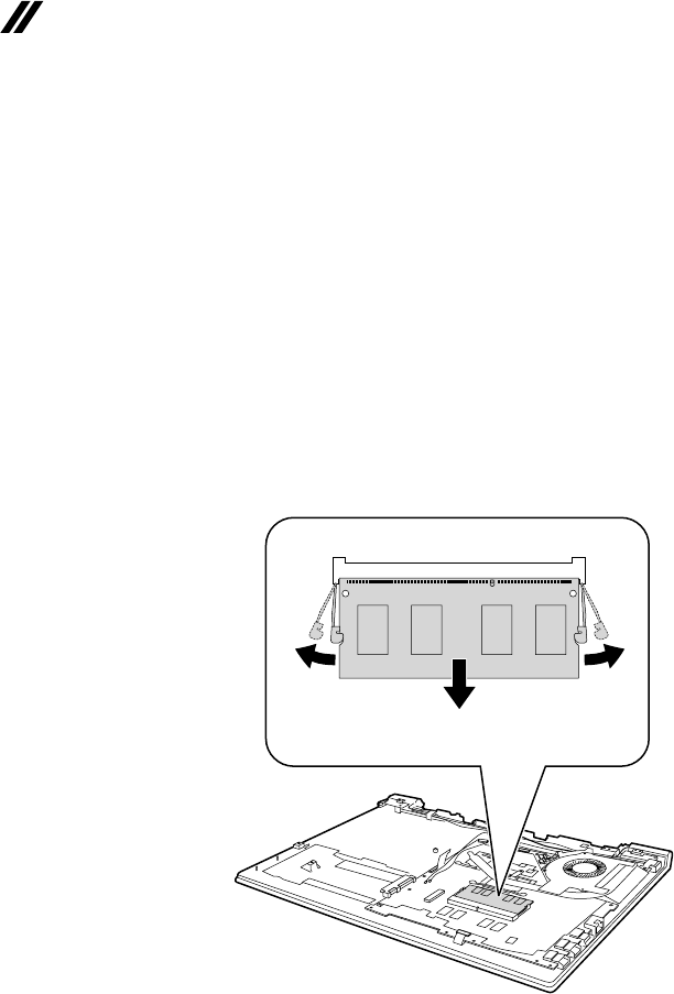
Figure 9. Removal steps of DIMM
Releasethe twolatchesonbothedges ofthesocketatthesametime inthe
directionshownbyarrows1,andthenunplugtheDIMMinthedirectionshown
byarrow2.
aa
b
When installing:InsertthenotchedendoftheDIMMintothesocket.Pushthe
DIMMrmly,andpivotituntilitsnapsintotheplace.Makesurethatitisrmly
xedintheslotanddifculttomove.
49
Lenovo V110-15IKB
1100 Fan assembly and Heat Sink assembly
Foraccess,removetheseFRUsinorder:
• “1010Opticaldrive”onpage34
• “1020Basecover”onpage35
• “1030Batterypack”onpage37
• “1040Harddiskdrive”onpage39
• “1050Speaker”onpage42
• “1060IOboard”onpage44
• “1070PCIExpressMiniCardforwirelessLAN”onpage45
• “1080ODDboard”onpage47
• “1090DIMM”onpage48
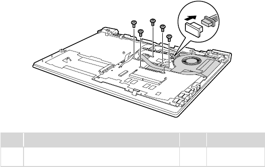
Figure 10. Removal steps of fan assembly and heat sink assembly
Unplugthefanconnectorinthedirectionshownbyarrow1,andthenremove
thescrews2.
b
b
b
b
b
a
Step Screw (quantity) Color Torque
2M2×6mm,Phillipshead,nylok-coated(5)
FANTOUPPER Black 1.85+/-0.15kgf/cm
When installing:Make surethat thefanconnectorisattachedrmlytothe
systemboard.
50
Lenovo V110-15IKB Hardware Maintenance Manual
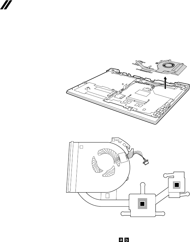
Figure 10. Removal steps of fan assembly and heat sink assembly (continued)
Removethe fanassembly andheatsinkassemblyin thedirectionshown by
arrow3.Becarefulnottodamagetheconnector.
c
a
b
When installing:
Beforeyou attachthe fanassemblytothecomputer,apply thermalgrease,
atanamountof0.2grams,tothe partshowninthegureabove.Either
toomuchortoolittlegrease applicationcan causeathermalproblemdueto
imperfectcontactwithacomponent.
51
Lenovo V110-15IKB
1110
System board
Important notices for handling the system board:
When handling the system board, bear the following in mind.
• Be careful not to drop the system board on a bench top that has a hard surface,
such as metal, wood, or composite.
• Avoid rough handling of any kind.
• In the whole process, make sure not to drop or stack the system board.
• If you put a system board down, make sure to put it only on a padded surface such
as an ESD mat or conductive corrugated material.
Foraccess,removetheseFRUsinorder:
• “1010Opticaldrive”onpage34
• “1020Basecover”onpage35
• “1030Batterypack”onpage37
• “1040Harddiskdrive”onpage39
• “1050Speaker”onpage42
• “1060IOboard”onpage44
• “1070PCIExpressMiniCardforwirelessLAN”onpage45
• “1080ODDboard”onpage47
• “1090DIMM”onpage48
• “1100FanassemblyandHeatSinkassembly”onpage49
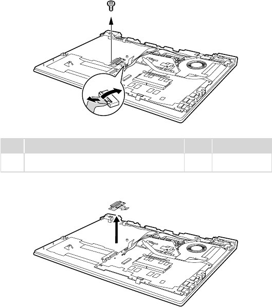
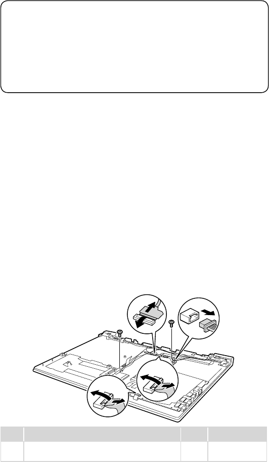
Figure 11. Removal steps of system board
Detachthetouchpadconnectorinthedirectionsshownbyarrows1,2.
UnplugDC-INconnectorinthedirectionshownbyarrow3,detachLCD
connectorinthedirectionsshownbyarrows4and5,detachthepowerboard
inthedirectionsshownbyarrows6,7.Detachkeyboardconnectorunderthe
systemboard.RemovethescrewsH.
h
h
c
e
d
b
a
g
f
Step Screw (quantity) Color Torque
8M2×3mm,Phillipshead,nylok-coated(2)
MBTOUPPER&MBTOKBBRK Silver 1.85+/-0.15kgf/cm
52
Lenovo V110-15IKB Hardware Maintenance Manual
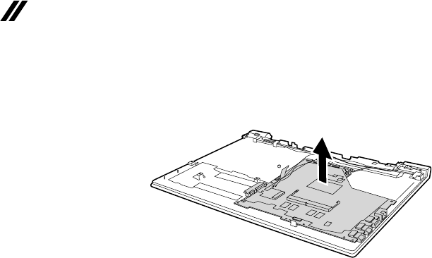
Figure 11. Removal steps of system board (continued)
RemovethesystemboardinthedirectionshownbyarrowI.
i
53
Lenovo V110-15IKB
1120 Upper case
Foraccess,removetheseFRUsinorder:
• “1010Opticaldrive”onpage34
• “1020Basecover”onpage35
• “1030Batterypack”onpage37
• “1040Harddiskdrive”onpage39
• “1050Speaker”onpage42
• “1060IOboard”onpage44
• “1070PCIExpressMiniCardforwirelessLAN”onpage45
• “1080ODDboard”onpage47
• “1090DIMM”onpage48
• “1100FanassemblyandHeatSinkassembly”onpage49
• “1110Systemboard”onpage51
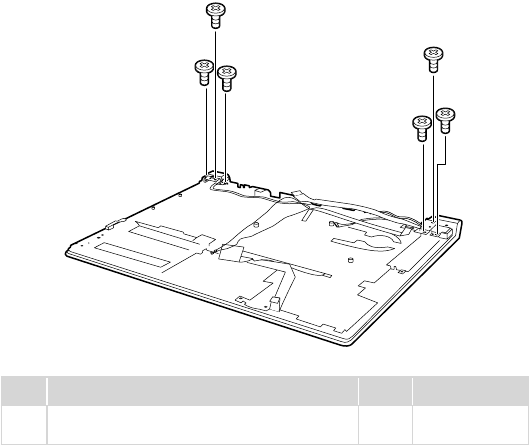
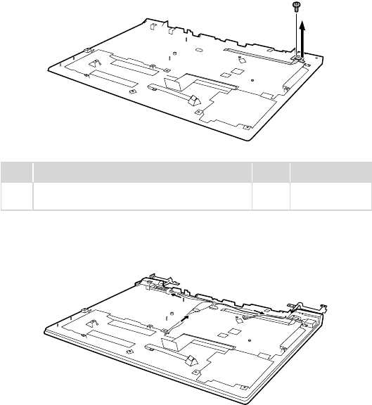
Figure 12. Removal steps of upper case
Removethescrews1.
a
a
a
a
a
a
Step Screw (quantity) Color Torque
1M2×4mm,Phillipshead,nylok-coated(6)
HINGEBRKTOUPPER Silver 1.85+/-0.15kgf/cm
54
Lenovo V110-15IKB Hardware Maintenance Manual
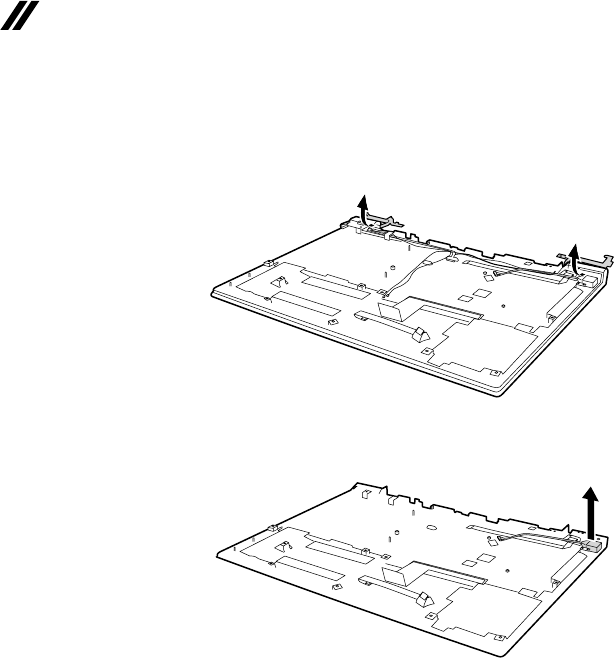
Figure 12. Removal steps of upper case (continued)
Openthehingesinthedirectionshownbyarrows2.
b
b
RemovetheDCincableinthedirectionshownbyarrow3.
c
55
Lenovo V110-15IKB
Figure 12. Removal steps of upper case (continued)
Removethescrew4.Thenremovethepowerboardinthedirectionshownby
arrow5.
e
d
Step Screw (quantity) Color Torque
4M2×3mm,Phillipshead,nylok-coated(1)
POWERBOARDTOUPPER Silver 1.85+/-0.15kgf/cm
Releasetheantennacablesfromthecableguides inthe directionshown by
arrows6.
f
ff
56
Lenovo V110-15IKB Hardware Maintenance Manual
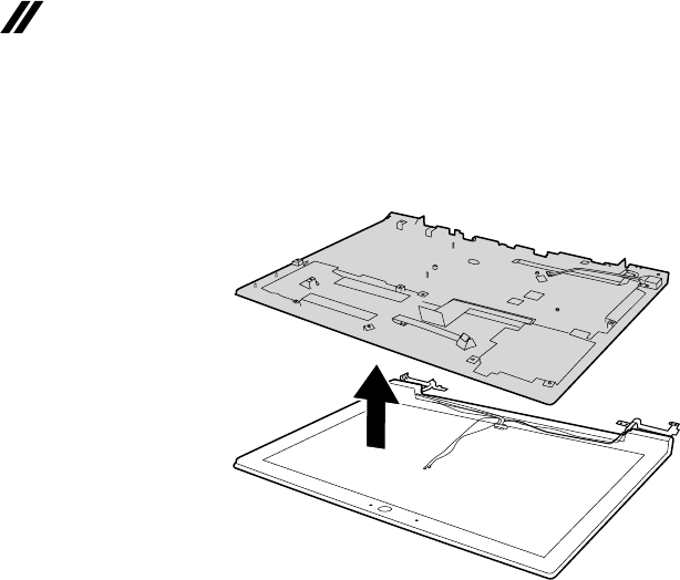
Figure 12. Removal steps of upper case (continued)
RemovetheuppercasefromtheLCDmoduleinthedirectionshownbyarrow
7.
g
57
Lenovo V110-15IKB
1130 LCD unit
Foraccess,removetheseFRUsinorder:
• “1010Opticaldrive”onpage34
• “1020Basecover”onpage35
• “1030Batterypack”onpage37
• “1040Harddiskdrive”onpage39
• “1050Speaker”onpage42
• “1060IOboard”onpage44
• “1070PCIExpressMiniCardforwirelessLAN”onpage45
• “1080ODDboard”onpage47
• “1090DIMM”onpage48
• “1100FanassemblyandHeatSinkassembly”onpage49
• “1110Systemboard”onpage51
• “1120Uppercase”onpage53
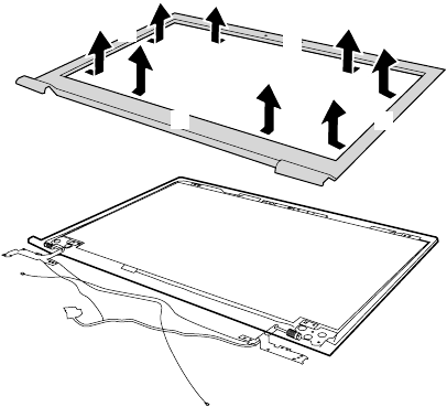
Figure 13. Removal steps of LCD unit
RemovetheLCDfrontbezelinthedirectionbyarrows1.
a
a
a
a
58
Lenovo V110-15IKB Hardware Maintenance Manual
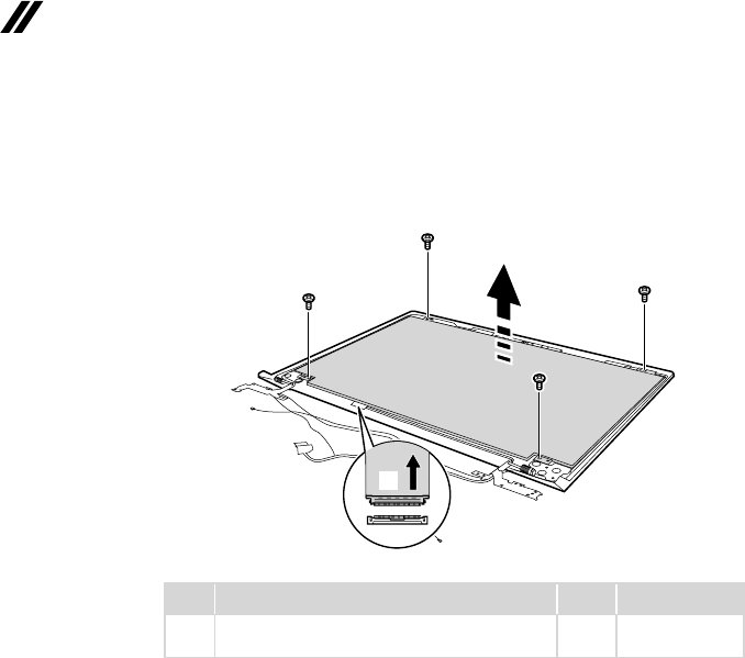
Figure 13. Removal steps of LCD unit (continued)
Removethescrews2.LifttheLCD moduleslightly3.Disconnectthe
connectorinthedirectionshownbyarrow4.ThenremovetheLCDmodule.
b
b
b
b
c
d
Step Screw (quantity) Color Torque
2M2×3mm,Phillipshead,nylok-coated(4)
HINGEBRKTOLCDPANEL Silver 1.85+/-0.15kgf/cm
59
Lenovo V110-15IKB
1140 LCD hinges
Foraccess,removetheseFRUsinorder:
• “1010Opticaldrive”onpage34
• “1020Basecover”onpage35
• “1030Batterypack”onpage37
• “1040Harddiskdrive”onpage39
• “1050Speaker”onpage42
• “1060IOboard”onpage44
• “1070PCIExpressMiniCardforwirelessLAN”onpage45
• “1080ODDboard”onpage47
• “1090DIMM”onpage48
• “1100FanassemblyandHeatSinkassembly”onpage49
• “1110Systemboard”onpage51
• “1120Uppercase”onpage53
• “1130LCDunit”onpage57
Figure 14. Removal steps of LCD hinges
Removethescrews1.Thenreleasethetwohingesinthedirectionshownby
arrows2.
b
b
aa
a
aa
a
Step Screw (quantity) Color Torque
1M2.5×3mm,Phillipshead,nylok-coated(6)
HINGEBRKTOLCDCOVER Silver 3.0+/-0.3kgf/cm
60
Lenovo V110-15IKB Hardware Maintenance Manual
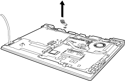
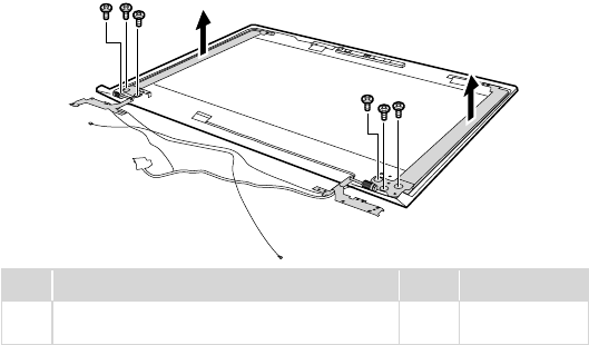
1150 Integrated camera, LCD cable and antenna assembly
Foraccess,removetheseFRUsinorder:
• “1010Opticaldrive”onpage34
• “1020Basecover”onpage35
• “1030Batterypack”onpage37
• “1040Harddiskdrive”onpage39
• “1050Speaker”onpage42
• “1060IOboard”onpage44
• “1070PCIExpressMiniCardforwirelessLAN”onpage45
• “1080ODDboard”onpage47
• “1090DIMM”onpage48
• “1100FanassemblyandHeatSinkassembly”onpage49
• “1110Systemboard”onpage51
• “1120Uppercase”onpage53
• “1130LCDunit”onpage57
• “1140LCDhinges”onpage59
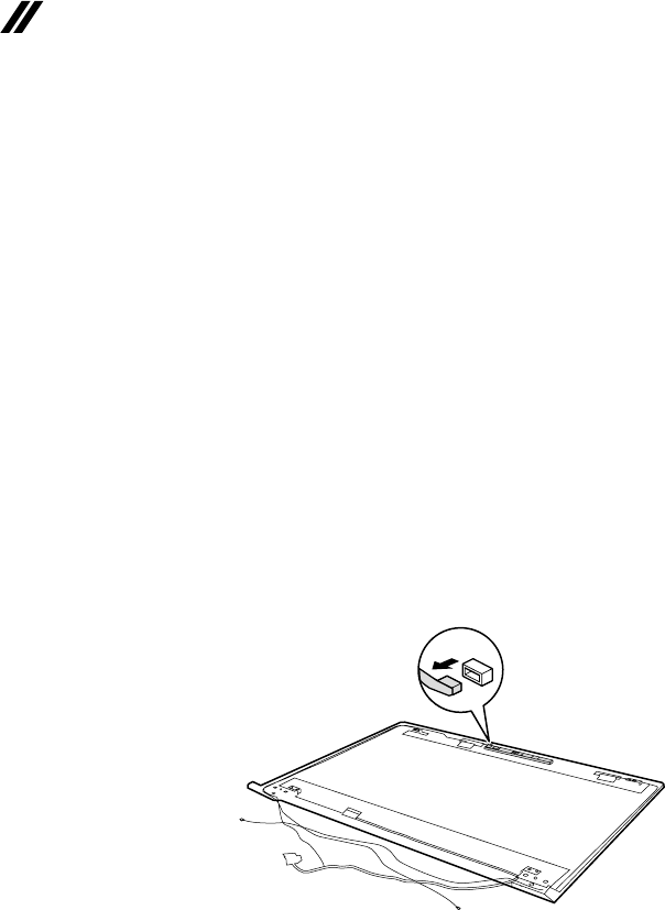
Figure 15. Removal steps of integrated camera, LCD cable and antenna
assembly
Note:TheintegratedcameraisstuckonthetopcenteroftheLCDcover.
Detachtheintegratedcameraconnectorinthedirectionshownbyarrow1.
a
61
Lenovo V110-15IKB
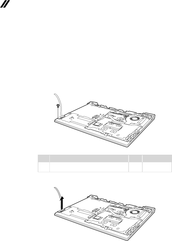
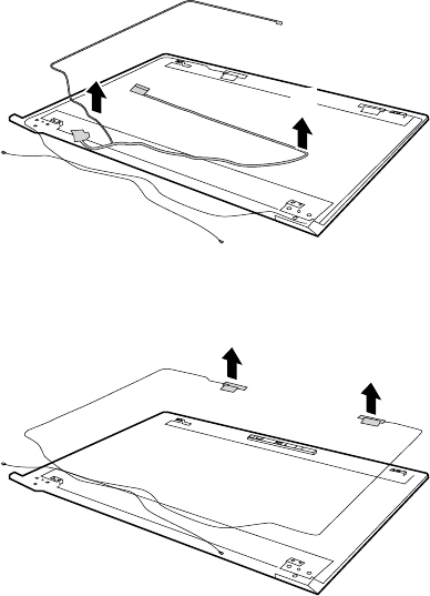
Figure 15. Removal steps of integrated camera, LCD cable and antenna
assembly (continued)
RemovetheLCDcableinthedirectionshownbyarrows2.
b
b
Removetheantennaassemblyinthedirectionshownbyarrows3.
c
c
62
Lenovo V110-15IKB Hardware Maintenance Manual
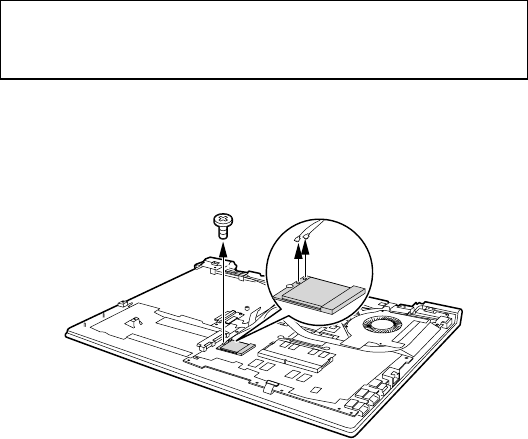
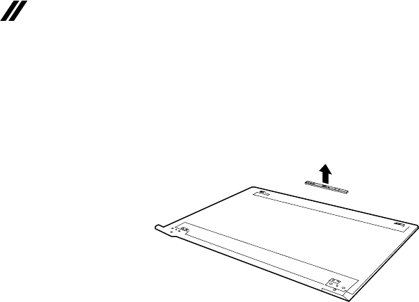
Figure 15. Removal steps of integrated camera, LCD cable and antenna
assembly (continued)
Removethecamerainthedirectionshownbyarrow4.
d
When installing:SticktheintegratedcameratothetopcenteroftheLCD
coverandadjusttheplacementofittomakesurethe connectoris attached
rmly.
63
Lenovo V110-15IKB
Locations
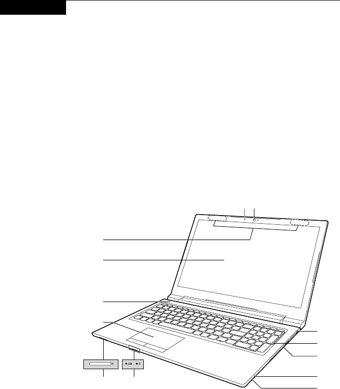
Front view and right-side view
1 Integratedcamera
2 Built-inmicrophone
3 WirelessLANantennas
4 Computerdisplay
5 Powerbutton
6 Touchpad
G Memorycardslot
H Systemstatusindicators
Note:Forthedescriptionofeachindicator,see“Statusindicators”onpage29.
I Novobutton
J Comboaudiojack
K Opticaldiscdrive
L Numerickeypad
M KensingtonMiniSecurityslot
i
j
g
k
m
l
ab
c
d
e
f
h
64
Lenovo V110-15IKB Hardware Maintenance Manual
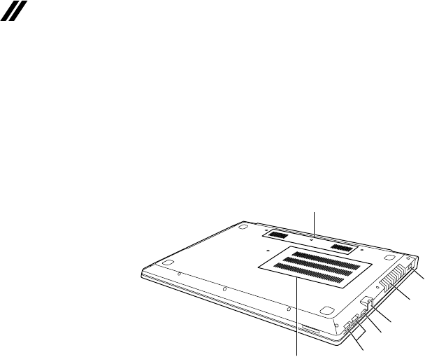
Bottom and Left-side view
1 Speakers
2 Ventilationslots
3 USBport
4 HDMIport
5 RJ-45port
6 Ventilationslots
7 ACpoweradapterjack
a
bc
d
e
f
g
65
Lenovo V110-15IKB
Parts list
Thissectionpresentsthefollowingserviceparts:
• “Overall”onpage66
• “LCDFRUs”onpage70
• “Miscellaneousparts”onpage72
• “ACadapters”onpage73
• “Screws”onpage73
• “Powercords”onpage74
Note:
Each FRU is available for all types or models, unless specic types or models are
specied.
Attention:
DonotattempttoreplaceanFRUonyourown.IfanFRUisdamaged,contact
aLenovoauthorizedserviceroramarketing representativeforreplacement
orrepair.Onlyqualiedtechnicianscaninspectorrepairthisproduct.
66
Lenovo V110-15IKB Hardware Maintenance Manual
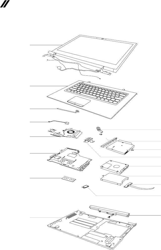
Overall
c
1
a
b
2
3
4
5
6
7
8
9
10
11
12
13
15
14

67
Lenovo V110-15IKB
Table 4. Parts list—Overall
No.
FRU FRU no.
CRU
ID.
a-c See“Miscellaneousparts”onpage72.
1 LCDunit(see“LCDFRUs”onpage70.)
2 UpperCaseW80TLW/KB/TP/CableUS 5CB0L78358
N
2 UpperCaseW80TLW/KB/TP/CableUK 5CB0L78391
2 UpperCaseW80TLW/KB/TP/CableIT 5CB0L78317
2 UpperCaseW80TLW/KB/TP/CableSP 5CB0L78380
2 UpperCaseW80TLW/KB/TP/CableTR 5CB0L78344
2 UpperCaseW80TLW/KB/TP/CableTI 5CB0L78372
2 UpperCaseW80TLW/KB/TP/CablePO 5CB0L78319
2 UpperCaseW80TLW/KB/TP/CableLA 5CB0L78352
2 UpperCaseW80TLW/KB/TP/CableCFE 5CB0L78384
2 UpperCaseW80TLW/KB/TP/CableKO 5CB0L78337
2 UpperCaseW80TLW/KB/TP/CableCH 5CB0L78328
2 UpperCaseW80TLW/KB/TP/CableRU 5CB0L78347
2 UpperCaseW80TLW/KB/TP/CableFR 5CB0L78363
2 UpperCaseW80TLW/KB/TP/CableGR 5CB0L78312
2 UpperCaseW80TLW/KB/TP/CableARE 5CB0L78315
2 UpperCaseW80TLW/KB/TP/CableBZ 5CB0L78371
2 UpperCaseW80TLW/KB/TP/CableJA 5CB0L81944
2 UpperCaseW80TLW/KB/TP/CableNL 5CB0L78360
2 UpperCaseW80TLW/KB/TP/CableGK 5CB0L78367
2 UpperCaseW80TLW/KB/TP/CableHB 5CB0L78378
2 UpperCaseW80TLW/KB/TP/CableHG 5CB0L78359
2 UpperCaseW80TLW/KB/TP/CableND 5CB0L78355
2 UpperCaseW80TLW/KB/TP/CableBE 5CB0L78330
2 UpperCaseW80TLW/KB/TP/CableICE 5CB0L78321
2 UpperCaseW80TLW/KB/TP/CableSA 5CB0L78339
2 UpperCaseW80TLW/KB/TP/CableSW 5CB0L78316
2 UpperCaseW80TLW/KB/TP/CableUSI'E 5CB0L78326
2 UpperCaseW80TLW/KB/TP/CableCZSK 5CB0L78392
2 UpperCaseW80TLW/KB/TP/CableBU 5CB0L78356
2 UpperCaseW80TLW/KB/TP/CableINDIA 5CB0L78389
2 UpperCaseW80TLW/KB/TP/CableFRAR 5CB0L78340
2UpperCaseW80TLW/KB/TP/CableUKR 5CB0L78373
3PowerBoardW80TLW/Cable 5C50L78332
4DC-INCableW80TL 5C10L78342
5ThermalModuleW80TLUMAGT2W/MLR 5H40M09359
5ThermalModuleW80TLDISGT2W/MLR 5H40M09358
6MBW80THNOK3865UDIS4GNFP 5B20P11157
6MBW80THWIN3865UDIS4GNFP 5B20P11158
6MBW80THNOK3865UUMA4GNFP 5B20P11184
6MBW80THWIN3865UUAM4GNFP 5B20P11180
6MBW80THNOK3865UDISNFP 5B20P11176
6MBW80THWIN3865UDISNFP 5B20P11168
6MBW80THNOK3865UUMANFP 5B20P11185
6MBW80THWIN3865UUAMNFP 5B20P11169
6MBW80THNOK4415UDIS4GNFP 5B20P11164

68
Lenovo V110-15IKB Hardware Maintenance Manual
Table 4. Parts list—Overall (continued)
No.
FRU FRU no.
CRU
ID.
6MBW80THWIN4415UDIS4GNFP 5B20P11161
N
6MBW80THNOK4415UUMA4GNFP 5B20P11174
6MBW80THWIN4415UUAM4GNFP 5B20P11165
6MBW80THNOK4415UDISNFP 5B20P11170
6MBW80THWIN4415UDISNFP 5B20P11159
6MBW80THNOK4415UUMANFP 5B20P11182
6MBW80THWIN4415UUAMNFP 5B20P11183
6MBW80THNOKI37100DIS4GNFP 5B20P11181
6MBW80THWINI37100DIS4GNFP 5B20P11166
6MBW80THNOKI37100UMA4GNFP 5B20P11178
6MBW80THWINI37100UAM4GNFP 5B20P11162
6MBW80THNOKI37100DISNFP 5B20P11154
6MBW80THWINI37100DISNFP 5B20P11177
6MBW80THNOKI37100UMANFP 5B20P11179
6MBW80THWINI37100UAMNFP 5B20P11172
6MBW80THNOKI57200DIS4GNFP 5B20P11155
6MBW80THWINI57200DIS4GNFP 5B20P11160
6MBW80THNOKI57200UMA4GNFP 5B20P11173
6MBW80THWINI57200UAM4GNFP 5B20P11167
6MBW80THNOKI57200DISNFP 5B20P11175
6MBW80THWINI57200DISNFP 5B20P11171
6MBW80THNOKI57200UMANFP 5B20P11156
6MBW80THWINI57200UAMNFP 5B20P11163
7 2GBD4SM471A5644EB0-CRC SM30G16500
7 2GBD4SHMA425S6AFR6N-UH SM30G16501
7 2GBD4SRMSA3270MB76H8F-2400 SM30G16503
7 2GBD4SMTA4ATF25664HZ-2G3B1 SM30G16502
7 4GBD4SM471A5244CB0-CRC SM30M49902
7 4GBD4SHMA851S6AFR6N-UH SM30G16505
7 4GBD4SRMSA3270MB86H9F-2400 SM30G16507
7 4GBD4SMTA4ATF51264HZ-2G3B1 SM30G16506
7 8Gbx16D4CPK4A8G165WB-BCRC SM30L08874
7 8Gbx16D4CPMT40A512M16JY-083E:B SM30L08877
7 8Gbx16D4CPH5AN8G6NAFR-UHC SM30L08875
7 ICSDRAMK4A8G165WC-BCRCFBGA96PDDR4 SM30N71798
8 LowerCaseW80TL 5CB0L78394
9 SpeakerW80TL 5SB0L78393
10 HLDSGUE0N9.0mmSlimTrayRamboODD 5DX0J46488 *
10 PLDSDA-8AESH9.0mmSlimTrayRamboODD 5DX0L08424 *
10 DummyODDW80TL 5M20L78336 *
11 ODDBoardW80TLW/Cable 5C50L78362
N
12 ST500LT0126G7mm5.4K500GHDD 16200383
12 MQ01ABF0506G7mm5.4K500GHDD 5H20L34560
12 WDWD5000LPCX-24VHAT07mm5400rpm500GHDD 5H20J35762
12 SeagateST1000LM0351T2.5"7mm5400rpmHDD 5H20L22184
12 TSBMQ01ABD1006G9.5mm5.4K1THDD 5H20L34559
12 WD10JPCX-24UE4T06G9.5mm5.4K1THDD 16200393

69
Lenovo V110-15IKB
Table 4. Parts list—Overall (continued)
No.
FRU FRU no.
CRU
ID.
12 5mm128GB2.5"SATA6Gb/sRTNRB128RFM2KWDLSSD 5SD0M61138
N
12 CV3-DE1282.5"5mm128GSSD 5SD0L02317
12 CV3-DE2562.5"5mm256GSSD 5SD0L02316
12 5mm256GB2.5"SATA6Gb/sRTNRB128RFM2KWDLSSD 5SD0M61139
13 AUOBoardW80TLW/Cable 5C50L78318
14 Intel31651x1AC+BTPCIEM.2WLAN SW10H24486
14 LtnNFA435A1x1AC+BT4.0PCIEM.2WLAN SW10K97461
14 CbtRTL8821AE1x1AC+BT4.0PCIEM.2WLAN SW10A11648
15 V310CP/LL15C4A0214.4V32Wh4cellbty 5B10L04163
15 V310LGL15L4A0214.4V32Wh4cellbty 5B10L04164
15 V310SYL15S4A0214.4V32Wh4cellbty 5B10L04212
— ACadapter(see“ACadapters”onpage73).
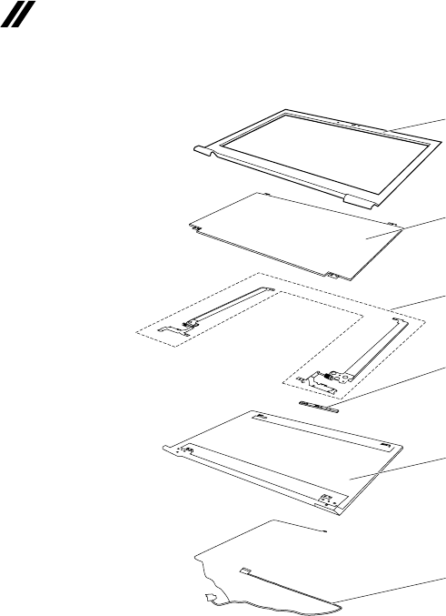
70
Lenovo V110-15IKB Hardware Maintenance Manual
LCD FRUs
1
3
4
2
5
6

71
Lenovo V110-15IKB
Table 5. Parts list—LCD FRUs
No.
FRU FRU no.
CRU
ID.
1 LCDBezelW80TLW/OCamera 5B30L81939
N
1 LCDBezelW80TL 5B30L78388
2 INXN156BGA-EA2HDTAGSNB 5D10K81086
2 AUB156XTN07.13AHDTAGSNB 5D10H52713
2 BONT156WHM-N42V8HDTAGSNB 5D10K81097
2 AUB156HTN03.80CFHDTAGSNB 5D10L08702
2 INN156HGA-EABFHDTAGSNB 5D10K93435
2 BONT156FHM-N41FHDTAGSNB 5D10K93434
3 HingeW80TLL+R 5H50L78350
4 CameraW80TL0.3M 5C20L78343
5 LCDCoverW80TLW/Antenna 5CB0L78341
6LCDCableW80TL 5C10L78348

72
Lenovo V110-15IKB Hardware Maintenance Manual
Miscellaneous parts
Table 6. Parts list—Miscellaneous parts
FRU FRU no.
CRU
ID.
Systemmiscellaneousparts:
N
• (
a
)HDDBracketW80TL 5B40L78313
• (
b
)ODDBracketW80TL 5B40L78379
• (
c
)ODDBezelW80TL 5B30L78311
Note:Italicizedlettersinparenthesesarereferencestotheexplodedviewin
“Overall”onpage66.

73
Lenovo V110-15IKB
AC adapters
Table 7. Parts list—AC adapters
FRU FRU no.
CRU
ID.
AcbelADLX45NAC3A20V2.25ACOO SA10M42789
*
DeltaADLX45NDC3A20V2.25ACOO SA10M42787
LiteonADLX45DLC3A20V2.25ACOO SA10M42529
ChiconyADLX45NCC3A20V2.25ACOO SA10M42722
LiteonADLX65NLC3A20V3.25AADBIS 5A10J75114
DeltaADLX65NDC3A20V3.25ACOO SA10M42728
ChiconyADLX65NCC3A20V3.25ACOO SA10M42777
Screws
Table 8. Parts list—screws
FRU FRU no.
CRU
ID.
ScrewPackW80TL 5S10L78338 N

74
Lenovo V110-15IKB Hardware Maintenance Manual
Power cords
ALenovopowercordforaspeciccountryorregionisusuallyavailableonlyinthatcountryorregion:
Table 9. Parts list—3-pin power cords
Region P/N CRU
ID.
UK3pin
• LINETEKLP-61L+H03VV-F+LS151m
145-000593
*
UK3pin
• LongwellLP-61L+H03VV-F+LS-181m
145-000561
UK3pin
• VOLEXMP5004+H03VV-F+VAC5S1m
145-000605
UK3pin
• lux0031+H03VV-F0.75/3C+00111m
145-500000
Europe3pin
• LINETEKLP-34+H03VV-F+LS151m
145-000585
Europe3pin
• LongwellLP-34A+H03VV-F+LS-181m
145-000553
Europe3pin
• VOLEXM2511+HO3VV-F+VAC5S1m
145-000525
Europe3pin
• lux0033+H03VV-F0.75/3C+00111m
145-500001
US3pin
• LINETEKLP-30B+SPT-2+LS151m
145-000594
US3pin
• LongwellLP-30B+SPT-218AWG+LS-181m
145-000562
US3pin
• VolexUS15S3+SPT-2+VAC5S1m
145-000537
US3pin
• lux0014+SPT-260°C18/3C+00161m
145-500002
China3pin
• LINETEKPC323+RVV300/300+LS151m
145-000600
China3pin
• LongwellLSG-31+RVV300/300+LS-181m
145-000568
China3pin
• VOLEXGB10S3+RVV300/500+VAC5S1m
145-000538
China3pin
• lux0036+RVV300/3000.75/3C+00021m
145-500003
India3pin
• LINETEKPE-361+H05VV-F+LS151m
145-000592
India3pin
• LongwellLP-67+BIS+LS-181m
145-000560
India3pin
• VOLEXIA6A3+IS694+VAC5S1m
145-000536
India3pin
• lux0046+IS6940.75/3C+00111m
145-500004
Japan3pin
• LINETEKLS15+VCTF+LP-541m
145-000587

75
Lenovo V110-15IKB
Table 9. Parts list—3-pin power cords (continued)
Region P/N CRU
ID.
Japan3pin
• LongwellLP-54+VCTF+LS-181m
145-000555
*
Japan3pin
• VOLEXVAC5S+VCTF+M7551m
145-000530
Japan3pin
• lux0018(E)+VCTF0.75/3C+00211m
145-500005
Australia3pin
• LINETEKLS15+H03VV-F+LP-23A1m
145-000589
Australia3pin
• LongwellLP-23A+LFC-3R+LS-181m
145-000557
Australia3pin
• VOLEXAU10S3+H03VV-F+VAC5S1m
145-000532
Australia3pin
• lux0038+H03VV-F0.75/3C+00111m
145-500006
Taiwan3pin
• LINETEKLS15+VCTF+LP-531m
145-000588
Taiwan3pin
• LongwellLP-71+VCTF+LS-331m
145-000556
Taiwan3pin
• VOLEXTW15CS3+VCTF+VAC5S1m
145-000531
Taiwan3pin
• lux0019+VCTF0.75/3C+00211m
145-500007
Korea3pin
• LINETEKLS15+H05VV-F+LP-E04A1m
145-000590
Korea3pin
• LongwellLP-486+KTLH03VV-F+LS-51m
145-000558
Korea3pin
• VOLEXM2511+KETIIEC+VAC5S1m
145-000533
Korea3pin
• lux0033+H03VV-F0.75/3C+00111m
145-500008
Italy3pin
• LINETEKLS15+H03VV-F+PE-3361m
145-000591
Italy3pin
• LongwellLP-22+H03VV-F+LS-181m
145-000559
Italy3pin
• VOLEXIT10S3+HO3VV-F+VAC5S1m
145-000535
Italy3pin
• lux0029+H03VV-F0.75/3C+00111m
145-500009
SouthAfrica3pin
• LINETEKLS15+H03VV-F+PE-3641m
145-000586
SouthAfrica3pin
• LongwellLP-39+H03VV-F+LS-181m
145-000554
SouthAfrica3pin
• lux0044+H03VV-F0.75/3C+00111m
145-500010

76
Lenovo V110-15IKB Hardware Maintenance Manual
Table 9. Parts list—3-pin power cords (continued)
Region P/N CRU
ID.
Brazil3pin
• LINETEKLS15H03VV-FLP26A1m
145-000596
*
Brazil3pin
• LongwellLP-46+H03VV-F+LS-181m
145-000564
Brazil3pin
• VOLEXCH10S3+H03VV-F+VAC5S1m
145-000527
Brazil3pin
• lux0034+H03VV-F0.75/3C+00111m
145-500011
Israel3pin
• LINETEKLS15+H03VV-F+LP-411m
145-000595
Israel3pin
• LongwellLP-41+H03VV-F+LS-181m
145-000563
Israel3pin
• VOLEXSI16S3+H03VV-F+VAC5S1m
145-000526
Israel3pin
• lux0041+H03VV-F0.75/3C+00111m
145-500012
Switzerland3pin
• LINETEKLS15+H03VV-F+LP-371m
145-000597
Switzerland3pin
• LongwellLP-37+H03VV-F+LS-181m
145-000565
Switzerland3pin
• VOLEXMP232+H03VV-F+VAC5S1m
145-000524
Switzerland3pin
• lux0027+H03VV-F0.75/3C+00111m
145-500013
Denmark3pin
• LINETEKLS15+H03VV-F+LP-381m
145-000598
Denmark3pin
• LongwellLP-40+H03VV-F+LS-181m
145-000566
Denmark3pin
• VOLEXMP233D+H03VV-F+VAC5S1m
145-000534
Denmark3pin
• lux0048+H03VV-F0.75/3C+00111m
145-500014
Thailand3pin
• lux0014+H03VV-F0.75/3C+00111m
5L60J33143
Argentina3pin
• LINETEKLS15+H03VV-F+LP391m
145-000599
Argentina3pin
• LongwellLP-24+H03VV-F+LS-181m
145-000567
Argentina3pin
• VOLEXVA2073+H03VV-F+VAC5S1m
145-000528
Argentina3pin
• lux0040+H03VV-F0.75/3C+00111m
145-500015

77
Notices
Notices
Lenovomaynotoffertheproducts,services,orfeaturesdiscussedinthis
documentinallcountries.ConsultyourlocalLenovorepresentativefor
informationontheproducts andservices currentlyavailableinyourarea.Any
referencetoaLenovoproduct,program,orserviceisnot intendedtostateor
implythatonlythatLenovoproduct,program,orservicemaybeused.Any
functionallyequivalent product,program, orservicethatdoesnotinfringe
anyLenovo intellectualpropertyrightmaybeusedinstead. However,itisthe
user’sresponsibilitytoevaluateandverifytheoperationofanyotherproduct,
program,orservice.
Lenovomayhavepatentsorpendingpatentapplicationscoveringsubjectmatter
describedinthisdocument.The furnishingofthisdocumentdoesnotgiveyou
anylicensetothesepatents.
LENOVOGROUPLTD. PROVIDESTHISPUBLICATION“ASIS”
WITHOUTWARRANTYOFANYKIND, EITHEREXPRESS ORIMPLIED,
INCLUDING,BUTNOTLIMITEDTO,THEIMPLIEDWARRANTIESOFNON-
INFRINGEMENT,MERCHANTABILITYORFITNESS FORA PARTICULAR
PURPOSE.Somejurisdictionsdonotallowdisclaimerofexpressorimplied
warrantiesincertaintransactions,therefore,thisstatementmaynotapplytoyou.
Thisinformation couldinclude technicalinaccuraciesor typographicalerrors.
Changesareperiodicallymade tothe informationherein; thesechanges
willbeincorporatedin neweditions ofthe publication.Lenovomaymake
improvementsand/or changesin theproduct(s)and/ortheprogram(s)
describedinthispublicationatanytimewithoutnotice.
Theproductsdescribedin thisdocument arenotintendedforusein
implantationorotherlifesupportapplicationswheremalfunctionmay resultin
injuryordeathtopersons.Theinformationcontainedinthisdocumentdoesnot
affectorchange Lenovoproduct specicationsor warranties.Nothinginthis
documentshalloperateasanexpressorimpliedlicenseorindemnityunderthe
intellectualpropertyrightsofLenovoorthird parties.Allinformationcontained
inthisdocumentwasobtainedinspecicenvironmentsandispresentedasan
illustration.Theresultobtainedinotheroperatingenvironmentsmayvary.
Lenovomayuseordistributeanyoftheinformationyousupplyinanywayit
believesappropriatewithoutincurringanyobligationtoyou.
Anyreferencesinthispublicationtonon-LenovoWebsitesareprovidedfor
convenienceonlyanddonotinanymannerserveasanendorsementofthose
Websites.Thematerials atthoseWebsitesarenotpartofthematerials for
thisLenovoproduct,anduseofthoseWebsitesisatyourownrisk.

78
Lenovo V110-15IKB Hardware Maintenance Manual
Anyperformance datacontainedherein wasdetermined inacontrolled
environment.Therefore,theresultobtainedin otheroperating environments
mayvarysignificantly.Somemeasurementsmayhavebeenmade on
development-levelsystemsandthereisnoguaranteethatthesemeasurements
willbethesameongenerallyavailablesystems.Furthermore,some
measurementsmayhavebeenestimatedthroughextrapolation.Actualresults
mayvary. Usersof thisdocument shouldverifytheapplicabledatafortheir
specicenvironment.
Trademarks
ThefollowingtermsaretrademarksorregisteredtrademarksofLenovointhe
UnitedStates,othercountries,orboth.
Lenovo
OneKey
MicrosoftandWindowsaretrademarksofMicrosoftCorporationin theUnited
States,othercountries,orboth.
Othercompany, products,orservicenamesmaybetrademarksorservice
marksofothers.
