Lenovo M50 Xx Hmm En 70&M50 80 User Manual (English) Hardware Maintenance 70 Laptop (Lenovo)
2014-09-08
User Manual: Lenovo M50-Xx Hmm En (English) Hardware Maintenance Manual M50-70 Laptop (Lenovo) Lenovo M50-70 Notebook
Open the PDF directly: View PDF ![]() .
.
Page Count: 89
- About this manual
- Safety information
- Important service information
- General checkout
- Related service information
- Lenovo M50-70/M50-80
- Specifications
- Status indicators
- Fn key combinations
- FRU replacement notices
- Removing and replacing an FRU
- 1010 Optical drive
- 1020 Keyboard
- 1030 Base cover
- 1040 Battery pack
- 1050 Hard disk drive
- 1060 PCI Express Mini Card for wireless LAN
- 1070 DIMM
- 1080 ODD board
- 1090 Docking board
- 1100 Speakers
- 1110 Thermal module
- 1120 USB board and finger print board
- 1130 System board and touchpad module
- 1140 Upper case and power board
- 1150 LCD unit
- 1160 Antenna assembly
- 1170 LCD cable and integrated camera
- Locations
- Parts list
- Notices

Lenovo M50-70/M50-80
Hardware
Maintenance
Manual

Notes:
• Before using this information and the product it supports, be sure to read the general information under
“Notices” on page 84.
• This manual applies to the following models: Lenovo M50-70/M50-80. The illustrations used in this
manual are for Lenovo M50-70 unless otherwise stated.
First Edition (August. 2014)
© Copyright Lenovo 2014. All rights reserved.
LIMITEDANDRESTRICTEDRIGHTSNOTICE:IfdataorsoftwareisdeliveredpursuantaGeneral
ServicesAdministration“GSA”contract,use,reproduction,ordisclosureissubjecttorestrictionsset
forthinContractNo.GS-35F-05925.
©2014Lenovo

iii
Contents
About this manual ....................................... iv
Safety information ........................................ 1
Generalsafety................................................ 2
Electricalsafety.............................................. 3
Safetyinspectionguide.................................. 5
Handlingdevicesthataresensitiveto
electrostaticdischarge.................................... 6
Groundingrequirements................................. 6
Safetynotices:multilingualtranslations.......... 7
Lasercompliancestatement......................... 14
Important service information ................... 16
StrategyforreplacingFRUs......................... 16
Strategyforreplacingaharddiskdrive............17
Importantnoticeforreplacingasystem
board................................................................17
Importantinformationaboutreplacing
RoHScompliantFRUs................................. 18
General checkout ...................................... 19
Whattodorst............................................. 20
Powersystemcheckout................................ 21
CheckingtheACadapter.................................21
Checkingoperationalcharging.........................21
Checkingthebatterypack................................22
Related service information ...................... 23
Restoringthefactorycontentsbyusing
OneKeyRecovery........................................ 23
Restoreoffactorydefault.................................23
Passwords.................................................... 24
Power-onpassword..........................................24
Hard-diskpassword..........................................24
Administratorpassword....................................24
Powermanagement..................................... 25
Screenblankstate............................................25
Puttingthecomputertosleeporshutting
itdown..............................................................25
Puttingyourcomputertosleep.........................25
Shuttingdownthecomputer.............................26
Lenovo M50-70/M50-80 .............................. 27
Specications............................................... 27
Statusindicators........................................... 29
Fnkeycombinations..................................... 30
FRUreplacementnotices............................. 31
Screwnotices..................................................31
RemovingandreplacinganFRU................. 32
1010Opticaldrive.............................................33
1020Keyboard.................................................35
1030Basecover...............................................37
1040Batterypack.............................................40
1050Harddiskdrive.........................................42
1060PCIExpressMiniCardfor
wirelessLAN.....................................................44
1070DIMM.......................................................46
1080ODDboard..............................................48
1090Dockingboard.........................................49
1100Speakers..................................................51
1110Thermalmodule.......................................52
1120USBboardandngerprintboard............53
1130Systemboardandtouchpadmodule.......56
1140Uppercaseandpowerboard...................59
1150LCDunit...................................................62
1160Antennaassembly....................................66
1170LCDcableandintegratedcamera........... 67
Locations...................................................... 69
Frontviewandright-sideview..........................69
BottomandLeft-sideview...............................70
Partslist........................................................ 71
Overall..............................................................72
LCDFRUs........................................................75
Keyboard..........................................................77
Miscellaneousparts..........................................79
ACadapters......................................................80
Screws..............................................................80
Powercords......................................................81
Notices......................................................... 84
Trademarks.................................................. 85
iv
About this manual
Thismanualcontainsservice andreferenceinformation forthefollowing
Lenovoproduct:
Lenovo M50-70/M50-80
Usethismanualtotroubleshootproblems.
Themanualisdividedintothefollowingsections:
• Thecommonsectionsprovidegeneralinformation,guidelines,and safety
informationrequiredforservicingcomputers.
• Theproduct-specicsectionincludesservice,reference,andproduct-specic
partsinformation.
Important:
This manual is intended only for trained servicers who are familiar with Lenovo
products. Use this manual to troubleshoot problems effectively.
Before servicing a Lenovo product, make sure to read all the information under
“Safety information” on page 1 and “Important service information” on page 16.

1
Safety information
Safety information
Thischapterpresentsthe followingsafetyinformation thatyouneed toget
familiarwithbeforeyouserviceaLenovoM50-70/M50-80computer:
• “Generalsafety”onpage2
• “Electricalsafety”onpage3
• “Safetyinspectionguide”onpage5
• “Handlingdevicesthataresensitivetoelectrostaticdischarge”onpage6
• “Groundingrequirements”onpage6
• “Safetynotices:multilingualtranslations”onpage7
• “Lasercompliancestatement”onpage14

2
M50-70/M50-80 Hardware Maintenance Manual
General safety
Followtheserulesbelowtoensuregeneralsafety:
• Observeagoodhousekeepingin theareawhere themachinesareput
duringandafterthemaintenance.
• Whenliftinganyheavyobject:
1. Makesurethatyoucanstandsafelywithoutslipping.
2. Distributetheweightoftheobjectequallybetweenyourfeet.
3. Useaslowliftingforce.Nevermovesuddenlyortwistwhenyouattempt
toliftit.
4. Liftitbystandingorpushingupwithyourlegmuscles;thisactioncould
avoidthestrainfromthemusclesinyourback.Donotattempttoliftany
objectthatweighsmorethan16kg(35lb)orthatyouthinkistooheavy
foryou.
• Donotperformanyaction thatcauseshazardsto thecustomer, orthat
makesthemachineunsafe.
• Beforeyou startthemachine, makesurethatother servicerepresentatives
andthecustomerarenotinahazardousposition.
• Pleaseremovecoversandother partsina safeplace,away fromall
personnel,whileyouareservicingthemachine.
• Keepyourtoolcaseaway fromwalkareassothat otherpeoplewill nottrip
overit.
• Donotwearloose clothingthatcanbetrapped inthemovingpartsofthe
machine.Makesurethatyoursleevesarefastenedorrolledupaboveyour
elbows.Ifyourhairislong,fastenit.
• Inserttheendsof yournecktieorscarfinside clothingorfastenitwiththe
nonconductiveclip,about8centimeters(3inches)fromtheend.
• Donotwearjewelry,chains,metal-frameeyeglasses,ormetalfastenersfor
yourclothing.
Attention:Metalobjectsaregoodelectricalconductors.
• Wearsafetyglasses whenyouarehammering, drilling,soldering,cutting
wire,attachingsprings,using solvents,orworking inanyother conditions
thatmaybehazardoustoyoureyes.
• Afterservice, reinstallallsafety shields, guards,labels,and groundwires.
Replaceanysafetydevicethatiswornordefective.
• Reinstallallcoverscorrectlybeforereturningthemachinetothecustomer.
• Fanlouversonthemachinehelptoprevent theoverheatingof internal
components.Donotobstructfanlouversorcover themwithlabels or
stickers.

3
Safety information
Electrical safety
Observethefollowingruleswhenworkingonelectricalequipments.
Important:
Use only approved tools and test equipments. Some hand tools have handles
covered with a soft material that does not insulate you when working with live
electrical currents.
Many customers have rubber floor mats near their machines that contain small
conductive bers to decrease electrostatic discharges. Do not use such kind of mat
to protect yourself from electrical shock.
• Findtheroomemergencypower-off(EPO)switch,disconnectingswitchor
electricaloutlet.Ifanelectricalaccidentoccurs,you canthenoperate the
switchorunplugthepowercordquickly.
• Donotworkaloneunder hazardous conditionsornear theequipmentthat
hashazardousvoltages.
• Disconnectallpowerbefore:
– Performingamechanicalinspection
– Workingnearpowersupplies
– Removingorinstallingmainunits
• Beforeyoustarttoworkonthemachine,unplug thepowercord.Ifyou
cannotunplugit,askthecustomer topower-offthewallboxthatsupplies
powertothemachine,andtolockthewallboxintheoffposition.
• Ifyouneedto workona machinethathas exposedelectricalcircuits,
observethefollowingprecautions:
– Ensurethatanotherperson,familiarwiththepower-offcontrols,isnear
you.
Attention:Anotherperson mustbethereto switchoffthepower,if
necessary.
– Useonlyonehandwhenworkingwithpowered-onelectricalequipment;
keeptheotherhandinyourpocketorbehindyourback.
Attention:Anelectricalshockcanoccuronlywhenthereisacomplete
circuit.Byobservingtheaboverule, youmaypreventacurrent from
passingthroughyourbody.
– Whenusingtesters,setthe controlscorrectlyandusetheapproved
probeleadsandaccessoriesforthattester.
– Standonsuitablerubbermats(obtainedlocally,ifnecessary)toinsulate
youfromgroundssuchasmetaloorstripsandmachineframes.
Observethespecialsafetyprecautionswhenyouworkwithveryhighvoltages;
instructionsfortheseprecautionsareinthesafetysections ofmaintenance
information.Beextremelycarefulwhenyoumeasurethehighvoltages.
• Regularlyinspectandmaintainyourelectricalhandtoolsforsafeoperational
condition.
• Donotusewornorbrokentoolsandtesters.
• Neverassumethatpowerhasbeendisconnectedfromacircuit.First,check
ittomakesurethatithasbeenpoweredoff.

4
M50-70/M50-80 Hardware Maintenance Manual
• Alwayslookcarefullyfor possiblehazardsin yourworkarea. Examplesof
thesehazardsaremoistoors,nongroundedpowerextensioncables,power
surges,andmissingsafetygrounds.
• Donottouchliveelectricalcircuitswiththe reflectivesurfaceof aplastic
dentalmirror.Thesurfaceisconductive;suchtouchingcan causepersonal
injuryandmachinedamage.
• Donotservicethefollowingpartswiththepoweronwhentheyareremoved
fromtheirnormaloperatingplacesinamachine:
– Powersupplyunits
– Pumps
– Blowersandfans
– Motorgenerators
andsimilarunits.(Thispracticeensurescorrectgroundingoftheunits.)
• Ifanelectricalaccidentoccurs:
– Caution:donotbecomeavictimyourself.
– Switchoffthepower.
– Sendthevictimtogetmedicalaid.

5
Safety information
Safety inspection guide
Thepurpose ofthisinspection guideistoassistyouinidentifying potential
unsafeconditions.Aseachmachinewas designedandbuilt, requiredsafety
itemswereinstalledtoprotectusersand servicepersonnelfrom injury.This
guideaddressesonlythoseitems.Youshould usegoodjudgmenttoidentify
potentialsafetyhazardsaccordingtotheattachmentofnon-Lenovofeaturesor
optionsnotcoveredbythisinspectionguide.
Ifanyunsafeconditionsarepresent,youmustdetermine howseriousthe
apparenthazardcouldbeandwhetheryoucancontinuewithoutrstcorrecting
theproblem.
Considertheseconditionsandthesafetyhazardstheypresent:
• Electricalhazards,especiallyprimarypower(primaryvoltageontheframe
cancauseseriousorfatalelectricalshock)
• Explosivehazards,suchasadamagedCRTfaceorabulgingcapacitor
• Mechanicalhazards,suchaslooseormissinghardware
Todeterminewhetherthereareanypotentialunsafeconditions,usethe
followingchecklistatthebeginningofeveryservicetask.Beginthecheckswith
thepoweroff,andthepowercorddisconnected.
Checklist:
1. Checkexteriorcoversfordamage(loose,broken,orsharpedges).
2. Turnoffthecomputer.Disconnectthepowercord.
3. Checkthepowercordfor:
a. Athird-wiregroundconnectoringoodcondition.Useametertomeasure
third-wiregroundcontinuityfor 0.1ohmor lessbetweenthe external
groundpinandtheframeground.
b. Thepowercordshouldbethetypespeciedinthepartslist.
c. Insulationmustnotbefrayedorworn.
4. Checkforcrackedorbulgingbatteries.
5. Removethecover.
6. Checkforanyobviousnon-Lenovoalterations.Usegoodjudgmentastothe
safetyofanynon-Lenovoalterations.
7. Check insidetheunit foranyobviousunsafeconditions, suchasmetal
filings,contamination,wateror otherliquids,or signsoffire orsmoke
damage.
8. Checkforworn,frayed,orpinchedcables.
9. Checkthatthepower-supplycoverfasteners (screwsorrivets)have not
beenremovedortamperedwith.
6
M50-70/M50-80 Hardware Maintenance Manual
Handling devices that are sensitive to electrostatic discharge
Anycomputerpartcontaining transistorsorintegrated circuits(ICs)should be
consideredsensitivetoelectrostaticdischarge(ESD).ESDdamagecanoccur
whenthere isadifferenceincharge betweenobjects.Protectagainst ESD
damagebyequalizingthechargesothatthemachine,thepart,theworkmat,
andthepersonhandlingthepartareallatthesamecharge.
Notes:
1. Use product-specific ESD procedures when they exceed the requirements
noted here.
2. Make sure that the ESD protective devices you use have been certied (ISO
9000) as fully effective.
WhenhandlingESD-sensitiveparts:
• Keepthepartsinprotectivepackagesuntiltheyareinsertedintotheproduct.
• Avoidcontactwithotherpeople.
• Wearagroundedwriststrap againstyourskintoeliminatestaticon your
body.
• Preventthepartfromtouchingyourclothing.Mostclothingisinsulativeand
retainsachargeevenwhenyouarewearingawriststrap.
• Usetheblackside ofagroundedworkmattoprovidea static-freework
surface.ThematisespeciallyusefulwhenhandlingESD-sensitivedevices.
• Selectagroundingsystem,suchasthoselistedbelow,toprovideprotection
thatmeetsthespecicservicerequirement.
Note:
The use of a grounding system to guard against ESD damage is desirable but not
necessary.
– AttachtheESDgroundcliptoanyframeground,groundbraid,orgreen-
wireground.
– Whenworkingonadouble-insulatedorbattery-operatedsystem,usean
ESDcommongroundorreferencepoint.Youcanusecoaxorconnector-
outsideshellsonthesesystems.
– Usetheroundgroundprongoftheacplugonac-operatedcomputers.
Grounding requirements
Electricalgroundingofthecomputerisrequiredforoperatorsafetyandcorrect
systemfunction.Propergrounding oftheelectrical outletcanbe veriedbya
certiedelectrician.
7
Safety information
Safety notices: multilingual translations
Thesafetynoticesinthis sectionareprovided inEnglish,French,German,
Hebrew,Italian,Japanese,andSpanish.
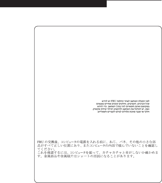
Safety notice 1
Before the computer is powered on after FRU replacement, make sure all screws,
springs, and other small parts are in place and are not left loose inside the
computer. Verify this by shaking the computer and listening for rattling sounds.
Metallic parts or metal akes can cause electrical shorts.
Avant de remettre l’ordinateur sous tension après remplacement d’une unité en
clientèle, vériez que tous les ressorts, vis et autres pièces sont bien en place et
bien xées. Pour ce faire, secouez l’unité et assurez-vous qu’aucun bruit suspect
ne se produit. Des pièces métalliques ou des copeaux de métal pourraient causer
un court-circuit.
Bevor nach einem FRU-Austausch der Computer wieder angeschlossen wird,
muß sichergestellt werden, daß keine Schrauben, Federn oder andere Kleinteile
fehlen oder im Gehäuse vergessen wurden. Der Computer muß geschüttelt und auf
Klappergeräusche geprüft werden. Metallteile oder-splitter können Kurzschlüsse
erzeugen.
Prima di accendere l’elaboratore dopo che é stata effettuata la sostituzione di una
FRU, accertarsi che tutte le viti, le molle e tutte le altri parti di piccole dimensioni
siano nella corretta posizione e non siano sparse all’interno dell’elaboratore.
Vericare ciò scuotendo l’elaboratore e prestando attenzione ad eventuali rumori;
eventuali parti o pezzetti metallici possono provocare cortocircuiti pericolosi.
Antes de encender el sistema despues de sustituir una FRU, compruebe que
todos los tornillos, muelles y demás piezas pequeñas se encuentran en su sitio
y no se encuentran sueltas dentro del sistema. Compruébelo agitando el sistema
y escuchando los posibles ruidos que provocarían. Las piezas metálicas pueden
causar cortocircuitos eléctricos.
8
M50-70/M50-80 Hardware Maintenance Manual
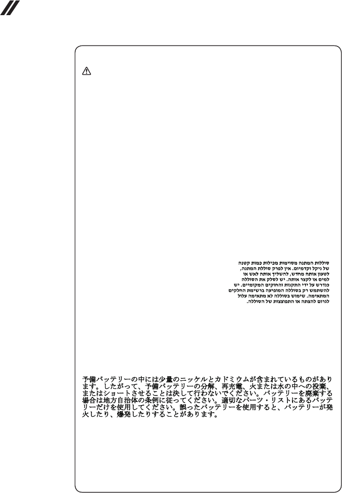
Safety notice 2
DANGER
Some standby batteries contain a small amount of nickel and cadmium. Do not
disassemble a standby battery, recharge it, throw it into fire or water, or short-
circuit it. Dispose of the battery as required by local ordinances or regulations.
Use only the battery in the appropriate parts listing. Use of an incorrect battery can
result in ignition or explosion of the battery.
Certaines batteries de secours contiennent du nickel et du cadmium. Ne les
démontez pas, ne les rechargez pas, ne les exposez ni au feu ni à l’eau. Ne
les mettez pas en court-circuit. Pour les mettre au rebut, conformez-vous à la
réglementation en vigueur. Lorsque vous remplacez la pile de sauvegarde ou celle
de l’horloge temps réel, veillez à n’utiliser que les modèles cités dans la liste de
pièces détachées adéquate. Une batterie ou une pile inappropriée risque de prendre
feu ou d’exploser.
Die Bereitschaftsbatterie, die sich unter dem Diskettenlaufwerk befindet,
kann geringe Mengen Nickel und Cadmium enthalten. Sie darf nicht zerlegt,
wiederaufgeladen, kurzgeschlossen, oder Feuer oder Wasser ausgesetzt werden.
Bei der Entsorgung die örtlichen Bestimmungen für Sondermüll beachten. Beim
Ersetzen der Bereitschafts-oder Systembatterie nur Batterien des Typs verwenden,
der in der Ersatzteilliste aufgeführt ist. Der Einsatz falscher Batterien kann zu
Entzündung oder Explosion führen.
Alcune batterie di riserva contengono una piccola quantità di nichel e cadmio.
Non smontarle, ricaricarle, gettarle nel fuoco o nell’acqua né cortocircuitarle.
Smaltirle secondo la normativa in vigore (DPR 915/82, successive disposizioni e
disposizioni locali). Quando si sostituisce la batteria dell’RTC (real time clock) o
la batteria di supporto, utilizzare soltanto i tipi inseriti nell’appropriato Catalogo
parti. L’impiego di una batteria non adatta potrebbe determinare l’incendio o
l’esplosione della batteria stessa.
Algunas baterías de reserva contienen una pequeña cantidad de níquel y cadmio.
No las desmonte, ni recargue, ni las eche al fuego o al agua ni las cortocircuite.
Deséchelas tal como dispone la normativa local. Utilice sólo baterías que se
encuentren en la lista de piezas. La utilización de una batería no apropiada puede
provocar la ignición o explosión de la misma.
9
Safety information
Safety notice 3
DANGER
The battery pack contains small amounts of nickel. Do not disassemble it, throw
it into re or water, or short-circuit it. Dispose of the battery pack as required by
local ordinances or regulations. Use only the battery in the appropriate parts listing
when replacing the battery pack. Use of an incorrect battery can result in ignition
or explosion of the battery.
La batterie contient du nickel. Ne la démontez pas, ne l’exposez ni au feu ni à l’eau.
Ne la mettez pas en court-circuit. Pour la mettre au rebut, conformez-vous à la
réglementation en vigueur. Lorsque vous remplacez la batterie, veillez à n’utiliser
que les modèles cités dans la liste de pièces détachées adéquate. En effet, une
batterie inappropriée risque de prendre feu ou d’exploser.
Akkus enthalten geringe Mengen von Nickel. Sie dürfen nicht zerlegt,
wiederaufgeladen, kurzgeschlossen, oder Feuer oder Wasser ausgesetzt werden.
Bei der Entsorgung die örtlichen Bestimmungen für Sondermüll beachten. Beim
Ersetzen der Batterie nur Batterien des Typs verwenden, der in der Ersatzteilliste
aufgeführt ist. Der Einsatz falscher Batterien kann zu Entzündung oder Explosion
führen.
La batteria contiene piccole quantità di nichel. Non smontarla, gettarla nel fuoco
o nell’acqua né cortocircuitarla. Smaltirla secondo la normativa in vigore (DPR
915/82, successive disposizioni e disposizioni locali). Quando si sostituisce la
batteria, utilizzare soltanto i tipi inseriti nell’appropriato Catalogo parti. L’impiego
di una batteria non adatta potrebbe determinare l’incendio o l’esplosione della
batteria stessa.
Las baterías contienen pequeñas cantidades de níquel. No las desmonte, ni
recargue, ni las eche al fuego o al agua ni las cortocircuite. Deséchelas tal como
dispone la normativa local. Utilice sólo baterías que se encuentren en la lista de
piezas al sustituir la batería. La utilización de una batería no apropiada puede
provocar la ignición o explosión de la misma.
10
M50-70/M50-80 Hardware Maintenance Manual
Safety notice 4
DANGER
The lithium battery can cause a fire, an explosion, or a severe burn. Do not
recharge it, remove its polarized connector, disassemble it, heat it above 100°C
(212°F), incinerate it, or expose its cell contents to water. Dispose of the battery as
required by local ordinances or regulations. Use only the battery in the appropriate
parts listing. Use of an incorrect battery can result in ignition or explosion of the
battery.
La pile de sauvegarde contient du lithium. Elle présente des risques d’incendie,
d’explosion ou de brûlures graves. Ne la rechargez pas, ne retirez pas son
connecteur polarisé et ne la démontez pas. Ne l’exposez pas à une temperature
supérieure à 100°C, ne la faites pas brûler et n’en exposez pas le contenu à l’eau.
Mettez la pile au rebut conformément à la réglementation en vigueur. Une pile
inappropriée risque de prendre feu ou d’exploser.
Die Systembatterie ist eine Lithiumbatterie. Sie kann sich entzünden, explodieren
oder schwere Verbrennungen hervorrufen. Batterien dieses Typs dürfen nicht
aufgeladen, zerlegt, über 100 C erhitzt oder verbrannt werden. Auch darf ihr
Inhalt nicht mit Wasser in Verbindung gebracht oder der zur richtigen Polung
angebrachte Verbindungsstecker entfernt werden. Bei der Entsorgung die örtlichen
Bestimmungen für Sondermüll beachten. Beim Ersetzen der Batterie nur Batterien
des Typs verwenden, der in der Ersatzteilliste aufgeführt ist. Der Einsatz falscher
Batterien kann zu Entzündung oder Explosion führen.
La batteria di supporto e una batteria al litio e puo incendiarsi, esplodere o
procurare gravi ustioni. Evitare di ricaricarla, smontarne il connettore polarizzato,
smontarla, riscaldarla ad una temperatura superiore ai 100 gradi centigradi,
incendiarla o gettarla in acqua. Smaltirla secondo la normativa in vigore (DPR
915/82, successive disposizioni e disposizioni locali). L’impiego di una batteria
non adatta potrebbe determinare l’incendio o l’esplosione della batteria stessa.
La batería de repuesto es una batería de litio y puede provocar incendios,
explosiones o quemaduras graves. No la recargue, ni quite el conector polarizado,
ni la desmonte, ni caliente por encima de los 100°C (212°F), ni la incinere ni
exponga el contenido de sus celdas al agua. Deséchela tal como dispone la
normativa local.
11
Safety information
Safety notice 5
If the LCD breaks and the uid from inside the LCD gets into your eyes or on your
hands, immediately wash the affected areas with water at least for 15 minutes.
Seek medical care if any symptoms caused by the uid are present after washing.
Si le panneau d’afchage à cristaux liquides se brise et que vous recevez dans les
yeux ou sur les mains une partie du uide, rincez-les abondamment pendant au
moins quinze minutes. Consultez un médecin si des symptômes persistent après le
lavage.
Die Leuchtstoffröhre im LCD-Bildschirm enthält Quecksilber. Bei der Entsorgung
die örtlichen Bestimmungen für Sondermüll beachten. Der LCD-Bildschirm
besteht aus Glas und kann zerbrechen, wenn er unsachgemäß behandelt wird
oder der Computer auf den Boden fällt. Wenn der Bildschirm beschädigt ist und
die darin befindliche Flüssigkeit in Kontakt mit Haut und Augen gerät, sollten
die betroffenen Stellen mindestens 15 Minuten mit Wasser abgespült und bei
Beschwerden anschließend ein Arzt aufgesucht werden.
Nel caso che caso l’LCD si dovesse rompere ed il liquido in esso contenuto
entrasse in contatto con gli occhi o le mani, lavare immediatamente le parti
interessate con acqua corrente per almeno 15 minuti; poi consultare un medico se i
sintomi dovessero permanere.
Si la LCD se rompe y el uido de su interior entra en contacto con sus ojos o sus
manos, lave inmediatamente las áreas afectadas con agua durante 15 minutos
como mínimo. Obtenga atención medica si se presenta algún síntoma del uido
despues de lavarse.
12
M50-70/M50-80 Hardware Maintenance Manual
Safety notice 6
DANGER
To avoid shock, do not remove the plastic cover that protects the lower part of the
inverter card.
An d’éviter tout risque de choc électrique, ne retirez pas le cache en plastique
protégeant la partie inférieure de la carte d’alimentation.
Aus Sicherheitsgründen die Kunststoffabdeckung, die den unteren Teil der
Spannungswandlerplatine umgibt, nicht entfernen.
Per evitare scosse elettriche, non rimuovere la copertura in plastica che avvolge la
parte inferiore della scheda invertitore.
Para evitar descargas, no quite la cubierta de plástico que rodea la parte baja de la
tarjeta invertida.
Safety notice 7
DANGER
Though the main batteries have low voltage, a shorted or grounded battery can
produce enough current to burn personnel or combustible materials.
Bien que le voltage des batteries principales soit peu élevé, le court-circuit ou la
mise à la masse d’une batterie peut produire sufsamment de courant pour brûler
des matériaux combustibles ou causer des brûlures corporelles graves.
Obwohl Hauptbatterien eine niedrige Spannung haben, können sie doch bei
Kurzschluß oder Erdung genug Strom abgeben, um brennbare Materialien zu
entzünden oder Verletzungen bei Personen hervorzurufen.
Sebbene le batterie di alimentazione siano a basso voltaggio, una batteria in
corto circuito o a massa può fornire corrente sufficiente da bruciare materiali
combustibili o provocare ustioni ai tecnici di manutenzione.
Aunque las baterías principales tienen un voltaje bajo, una batería cortocircuitada
o con contacto a tierra puede producir la corriente suciente como para quemar
material combustible o provocar quemaduras en el personal.
13
Safety information
Safety notice 8
DANGER
Before removing any FRU, turn off the computer, unplug all power cords from
electrical outlets, remove the battery pack, and then disconnect any interconnecting
cables.
Avant de retirer une unité remplaçable en clientèle, mettez le système hors tension,
débranchez tous les cordons d’alimentation des socles de prise de courant, retirez
la batterie et déconnectez tous les cordons d’interface.
Die Stromzufuhr muß abgeschaltet, alle Stromkabel aus der Steckdose gezogen,
der Akku entfernt und alle Verbindungskabel abgenommen sein, bevor eine FRU
entfernt wird.
Prima di rimuovere qualsiasi FRU, spegnere il sistema, scollegare dalle prese
elettriche tutti i cavi di alimentazione, rimuovere la batteria e poi scollegare i cavi
di interconnessione.
Antes de quitar una FRU, apague el sistema, desenchufe todos los cables de
las tomas de corriente eléctrica, quite la batería y, a continuación, desconecte
cualquier cable de conexión entre dispositivos.
14
M50-70/M50-80 Hardware Maintenance Manual
Laser compliance statement
SomemodelsofLenovo computerareequippedfromthefactorywithan
opticalstorage devicesuchasa CD-ROMdriveoraDVD-ROMdrive.Such
devicesarealsosoldseparatelyasoptions.Ifoneofthesedrivesisinstalled,
itiscertiedintheU.S.toconformto therequirementsoftheDepartmentof
HealthandHumanServices21CodeofFederalRegulations(DHHS21CFR)
SubchapterJforClass 1laserproducts.Elsewhere,the driveiscertifiedto
conformtotherequirementsof theInternationalElectrotechnical Commission
(IEC)825andCENELECEN60825forClass1laserproducts.
IfaCD-ROMdrive,aDVD-ROMdrive,oranotherlaserdeviceisinstalled,note
thefollowing:
CAUTION
Use of controls or adjustments or performance of procedures other than those
specied herein might result in hazardous radiation exposure.
O uso de controles, ajustes ou desempenho de procedimentos diferentes daqueles
aqui especicados pode resultar em perigosa exposição à radiação.
Pour éviter tout risque d’exposition au rayon laser, respectez les consignes de
réglage et d’utilisation des commandes, ainsi que les procédures décrites.
Werden Steuer- und Einstellelemente anders als hier festgesetzt verwendet, kann
gefährliche Laserstrahlung auftreten.
L’utilizzo di controlli, regolazioni o l’esecuzione di procedure diverse da quelle
specicate possono provocare l’esposizione a.
El uso de controles o ajustes o la ejecución de procedimientos distintos de los aquí
especicados puede provocar la exposición a radiaciones peligrosas.
OpeningtheCD-ROMdrive,theDVD-ROMdrive,oranyotheropticalstorage
devicecouldresultinexposuretohazardouslaserradiation.Thereareno
serviceablepartsinsidethosedrives.Do not open.
15
Safety information
ACD-ROMdrive,aDVD-ROMdrive,oranyotherstoragedeviceinstalledmay
containanembeddedClass3AorClass3Blaserdiode.Notethefollowing:
DANGER
Emits visible and invisible laser radiation when open. Do not stare into the beam,
do not view directly with optical instruments, and avoid direct exposure to the
beam.
Radiação por raio laser ao abrir. Não olhe fixo no feixe de luz, não olhe
diretamente por meio de instrumentos óticos e evite exposição direta com o feixe
de luz.
Rayonnement laser si carter ouvert. Évitez de fixer le faisceau, de le regarder
directement avec des instruments optiques, ou de vous exposer au rayon.
Laserstrahlung bei geöffnetem Gerät. Nicht direkt oder über optische Instrumente
in den Laserstrahl sehen und den Strahlungsbereich meiden.
Kinyitáskor lézersugár ! Ne nézzen bele se szabad szemmel, se optikai
eszközökkel. Kerülje a sugárnyalábbal való érintkezést!
Aprendo l’unità vengono emesse radiazioni laser. Non fissare il fascio, non
guardarlo direttamente con strumenti ottici e evitare l’esposizione diretta al fascio.
Radiación láser al abrir. No mire jamente ni examine con instrumental óptico el
haz de luz. Evite la exposición directa al haz.
16
M50-70/M50-80 Hardware Maintenance Manual
Important service information
Thischapterpresentsthefollowingimportantserviceinformation:
• “StrategyforreplacingFRUs”onpage16
– “Strategyforreplacingaharddiskdrive”onpage17
– “Importantnoticeforreplacingasystemboard”onpage17
• “ImportantinformationaboutreplacingRoHScompliantFRUs”onpage18
Important:
BIOS and device driver xes are customer-installable. The BIOS and device drivers
are posted on the customer support site:
http://support.lenovo.com.
Strategy for replacing FRUs
Before replacing parts:
Makesurethatallsoftware xes,drivers,andBIOSdownloadsareinstalled
beforereplacinganyFRUslistedinthismanual.
Afterasystemboardisreplaced,ensurethatthelatestBIOSisloadedtothe
systemboardbeforecompletingtheserviceaction.
Todownloadsoftwarexes,drivers,andBIOS,followthestepsbelow:
1. Gotohttp://support.lenovo.com.
2. Enterthe serialnumberor selectaproduct oruseLenovo smart
downloading.
3. SelecttheBIOS/Driver/Applicationsanddownload.
4. Followthedirectionsonthescreenandinstallthenecessarysoftware.
17
Important service information
Usethefollowingstrategy topreventunnecessary expenseforreplacing and
servicingFRUs:
• IfyouareinstructedtoreplaceanFRU,butthereplacementdoesnotsolve
theproblem,reinstalltheoriginalFRUbeforeyoucontinue.
• Somecomputers havebothaprocessor boardandasystem board.Ifyou
areinstructedtoreplaceeitherofthem,andreplacingoneofthemdoesnot
solvetheproblem,reinstallthatboard,andthenreplacetheotherone.
• IfanadapteroradeviceconsistsofmorethanoneFRU,anyoftheFRUs
maybethecauseoftheerror.Beforereplacing theadapteror device,
removetheFRUsonebyonetoseeifthesymptomschange.Replaceonly
theFRUthatchangedthesymptoms.
Attention:Thesetup configurationon thecomputeryouareservicingmay
havebeencustomized.RunningAutomaticConfigurationmay alterthe
settings.Notethecurrentcongurationsettings(usingtheViewConguration
option);then,whenservicehas beencompleted,verify thatthosesettings
remainineffect.
Strategy for replacing a hard disk drive
Alwaystrytoruna low-levelformatbefore replacingaharddisk drive.This
willcauseallcustomerdataontheharddisk tobelost.Makesure thatthe
customerhasacurrentbackupofthedatabeforeperformingthisaction.
Attention:Thedrivestartupsequenceinthecomputeryouareservicingmay
havebeenchanged.Beextremelycarefulduringwrite operationssuchas
copying,saving,orformatting.Ifyouselectanincorrectdrive,dataorprograms
canbeoverwritten.
Important notice for replacing a system board
Somecomponentsmountedonasystemboardare verysensitive.Improper
handlingcancausedamage tothosecomponents, andmaycause asystem
malfunction.
Attention:Whenhandlingasystemboard:
• Donotdropthesystemboardorapplyanyexcessiveforcetoit.
• Avoidroughhandlingofanykind.
• Avoidbendingthe systemboardandhard pushingtoprevent crackingat
eachBGA(BallGridArray)chipset.

18
M50-70/M50-80 Hardware Maintenance Manual
Important information about replacing RoHS compliant FRUs
RoHS, The Restriction of Hazardous Substances in Electrical and
Electronic Equipment Directive (2002/95/EC) is a European Union legal
requirement affecting the global electronics industry. RoHS requirements
must be implemented on Lenovo products placed on the market after
June 2006. Products on the market before June 2006 are not required to
have RoHS compliant parts. If the original FRU parts are non-compliant,
replacement parts can also be non-compliant. In all cases if the original
FRU parts are RoHS compliant, the replacement part must also be RoHS
compliant.
Note:RoHSandnon-RoHSFRUpartnumberswiththesametandfunction
areidentiedwithuniqueFRUpartnumbers.
Lenovoplans totransittoRoHScompliancewellbeforethe implementation
dateandexpectsitssuppliers tobereadyto supportLenovo’srequirements
andscheduleinthe EU.Productssold in2005and 2006willcontain some
RoHScompliantFRUs.Thefollowingstatementpertainstotheseproductsand
anyproductLenovoproducescontainingRoHScompliantFRUs.
RoHScompliant FRUshaveuniqueFRU partnumbers.Beforeor afterthe
RoHSimplementationdate,failed RoHScompliantparts mustalwaysbe
replacedwithRoHScompliantones,soonlytheFRUsidentiedascompliant
inthesystemHMMordirectsubstitutionsforthoseFRUsmaybeused.
Products marketed before June 2006 Products marketed after June 2006
Current or
original part
Replacement FRU Current or
original part
Replacement FRU
Non-RoHS CanbeNon-RoHS
MustbeRoHS MustbeRoHS
Non-RoHS CanbeRoHS
Non-RoHS CansubtoRoHS
RoHS MustbeRoHS
Note:Adirectsubstitution isapart withadifferentFRU partnumberthat is
automaticallyshippedbythedistributioncenteratthetimeoftheorder.
19
General checkout
General checkout
Thischapterpresentsthefollowinginformation:
• “Whattodorst”onpage20
• “Powersystemcheckout”onpage21
Beforeyougotothecheckout,makesuretoreadthefollowingimportantnotes:
Important notes:
• Onlycertiedtrainedpersonnelcanservicethecomputer.
• BeforereplacinganyFRU, readtheentirepageonremovingand replacing
FRUs.
• CarefullyremovescrewsforreusewhenreplacingFRUs.
• Beextremelycarefulduringsuchwriteoperationsascopying,saving,or
formatting. Drives in the computer that you are servicing sequence might
have been altered. If you select an incorrect drive, data or programs might be
overwritten.
• ReplaceanFRUonlywithanotherFRUofthecorrectmodel. When you
replace an FRU, make sure that the machine model and the FRU part number are
correct by referring to the FRU parts list.
• AnFRUshouldnotbereplacedjustbecauseofasingle,unreproduciblefailure.
Single failures can occur for a variety of reasons that have nothing to do with a
hardware defect, such as cosmic radiation, electrostatic discharge, or software
errors. Consider replacing an FRU only when a problem recurs. If you suspect that
an FRU is defective, clear the error logs and run the test again. If the error does
not recur, do not replace the FRU.
• BecarefulnottoreplaceanondefectiveFRU.

20
M50-70/M50-80 Hardware Maintenance Manual
What to do rst
WhenyoudoreturnanFRU,youmustincludethefollowinginformationinthe
partsexchangeformorpartsreturnformthatyouattachtoit:
1. Nameandphonenumberofservicer
2. Dateofservice
3. Dateonwhichthemachinefailed
4. Dateofpurchase
5. ProcedureindexandpagenumberinwhichthefailingFRUwasdetected
6. FailingFRUnameandpartnumber
7. Machinetype,modelnumber,andserialnumber
8. Customer’snameandaddress
Note for warranty:During thewarrantyperiod,the customermaybe
responsiblefor repaircostsif thecomputerdamagewas causedbymisuse,
accident,modification,unsuitablephysical oroperatingenvironment, or
impropermaintenancebythecustomer.
Thefollowingisalist ofsomecommon itemsthatare notcoveredunder
warrantyandsomesymptomsthat mightindicatethat thesystemwas
subjectedtostressbeyondnormaluse.
Beforecheckingproblemswiththecomputer,determinewhetherthedamageis
coveredunderthewarrantybyreferringtothefollowinglist:
The following are not covered under warranty:
• LCDpanelcrackedfromtheapplicationofexcessiveforceorfrombeing
dropped
• Scratched(cosmetic)parts
• Distortion,deformation,ordiscolorationofthecosmeticparts
• Plasticparts,latches,pins,orconnectorsthathavebeencrackedorbroken
byexcessiveforce
• Damagecausedbyliquidspilledintothesystem
• DamagecausedbytheimproperinsertionofaPCCardortheinstallationof
anincompatiblecard
• Improperdiskinsertionoruseofanopticaldrive
• Diskettedrivedamagecausedbypressureonthe diskettedrivecover,
foreignmaterialinthedrive,ortheinsertionofadiskettewithmultiplelabels
• Damagedorbentdisketteejectbutton
• Fusesblownbyattachmentofanonsupporteddevice
• Forgottencomputerpassword(makingthecomputerunusable)
• Stickykeyscausedbyspillingaliquidontothekeyboard
• UseofanincorrectACadapteronlaptopproducts
The following symptoms might indicate damage caused by nonwarranted
activities:
• Missingpartsmightbeasymptomofunauthorizedserviceormodication.
• Ifthespindleofaharddiskdrivebecomesnoisy,itmayhavebeensubjected
toexcessiveforce,ordropped.
21
General checkout
Power system checkout
Toverifyasymptom,followthestepsbelow:
1. Turnoffthecomputer.
2. Removethebatterypack.
3. ConnecttheACadapter.
4. Makesurethatpowerissuppliedwhenyouturnonthecomputer.
5. Turnoffthecomputer.
6. DisconnecttheACadapterandinstallthechargedbatterypack.
7. Makesurethat thebatterypack suppliespowerwhen youturnon the
computer.
Ifyoususpectapowerproblem,seetheappropriateoneofthefollowingpower
supplycheckouts:
• “CheckingtheACadapter”onpage21
• “Checkingoperationalcharging”onpage21
• “Checkingthebatterypack”onpage22
Checking the AC adapter
YouareherebecausethecomputerfailsonlywhentheACadapterisused.
• Ifthepower-onindicatordoesnotturnon,checkthepowercordoftheAC
adapterforcorrectcontinuityandinstallation.
• Ifthecomputerdoesnot chargeduringoperation, goto“Checking
operationalcharging”.
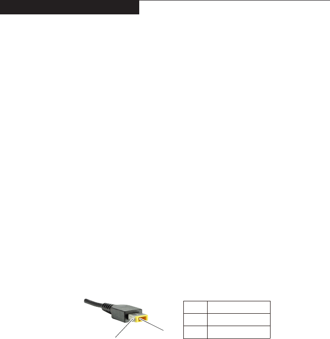
TochecktheACadapter,followthestepsbelow:
1. UnplugtheACadaptercablefromthecomputer.
2. Measuretheoutputvoltageat theplugoftheACadaptercable.Seethe
followinggure:
9ROWDJH9'&
3LQ
Note:OutputvoltagefortheACadapterpinNo.2maydifferfromtheoneyou
areservicing.
3. Ifthevoltageisnotcorrect,replacetheACadapter.
4. Ifthevoltageisacceptable,dothefollowing:
• Replacethesystemboard.
• Iftheproblempersists,goto“LenovoM50-70/M50-80”onpage27.
Note:NoisefromtheACadapterdoesnotalwaysindicateadefect.
Checking operational charging
Tocheckwhetherthe batterychargesproperlyduringoperation,usea
dischargedbatterypackor abatterypack thathasless than50%of thetotal
powerremainingwheninstalledinthecomputer.

22
M50-70/M50-80 Hardware Maintenance Manual
Performoperationalcharging.Ifthebatterystatusindicatororicondoesnotlight
on,removethebatterypackandletitreturntoroomtemperature.Reinstallthe
batterypack.Ifthechargeindicatororiconisstilloff,replacethebatterypack.
Ifthechargeindicatorstill doesnotlighton, replacethesystem board.Then
reinstallthebatterypack.Ifitisstillnotcharged,gotothenextsection.
Checking the battery pack
BatterychargingdoesnotstartuntilthePowerMetershowsthatlessthan95%
ofthetotalpowerremains;underthisconditionthebatterypackcanchargeto
100%ofitscapacity.Thisprotectsthebatterypackfrombeingoverchargedor
fromhavingashortenedlife.
Tocheckyourbattery,moveyourcursortothe PowerMetericoninthe icon
trayoftheWindows®taskbarandwaitforamoment(butdonotclickit),andthe
percentageofbatterypowerremainingisdisplayed.Togetdetailedinformation
aboutthebattery,double-clickthePowerMetericon.
Note:Ifthebattery packbecomeshot,itmay notbeable tobecharged.
Removeitfromthecomputerandleaveitatroomtemperatureforawhile.After
itcoolsdown,reinstallandrechargeit.
23
Related service information
Related service information
Thischapterpresentsthefollowinginformation:
• “RestoringthefactorycontentsbyusingOneKeyRecovery”onpage23
• “Passwords”onpage24
• “Powermanagement”onpage25
Restoring the factory contents by using OneKey Recovery
Restore of factory default
TheLenovoM50-70/M50-80computers comewithpre-installed OneKey
RecoverySystem. Inorderto saveapplicationlesandtheinitialbacked up
filesofthesystem, theharddisk inaLenovo computerincludesa hidden
partitionwhenitis shipped.Ifyou needtorestore thesystemto thepointof
yourrstbootup,justenterLenovoOneKeyRecoverySystemandrunSystem
Recovery.For detailsofOneKeyRecovery System,seethe User Guide for
Lenovo OneKey Recovery System.
Note: This will delete all the new data on the system partition (C drive), which
is not recoverable. Make sure to back up your critical data before you perform this
action.

24
M50-70/M50-80 Hardware Maintenance Manual
Passwords
Asmany asthreepasswords maybeneededfor anyLenovocomputer:
thepower-onpassword(POP),the harddiskpassword (HDP),andthe
administratorpassword.
Ifanyofthesepasswordshasbeenset,apromptforitappearsonthescreen
wheneverthecomputeris turnedon.Thecomputer doesnotstart untilthe
passwordisentered.
Power-on password
Apower-onpassword (POP)protectsthe systemfrombeing poweredonby
anunauthorized person.The passwordmustbeentered beforeanoperating
systemcanbebooted.
Hard-disk password
Therearetwohard-diskpasswords(HDPs):
+UserHDP-fortheuser
+MasterHDP-forthe systemadministrator, whocanuseit togetaccess to
theharddiskdriveeveniftheuserhaschangedtheuserHDP
Attention:Iftheuser HDPhas beenforgotten,check whetheramaster HDP
hasbeenset.If ithas,itcanbeusedforaccess tothehard diskdrive.If
nomasterHDPisavailable,neitherLenovo norLenovauthorized service
techniciansprovideanyservicestoreseteithertheuserorthemasterHDP,or
torecoverdatafromthehard diskdrive.Thehard diskdrivecanbereplaced
forascheduledfee.
Administrator password
Administratorpasswordcontrolsthe accessofthewholesetuputility.Only
AdministratorpasswordwassetthenUserpasswordcanbeset.IfAdministrator
passwordwascleared,theUserpasswordwasclearedtoo.
25
Related service information
Power management
Note:PowermanagementmodesarenotsupportedforAPMoperatingsystem.
Toreduce powerconsumption,thecomputer hasthreepowermanagement
modes:screenblank,sleep(standby),andshutdown.
Screen blank state
Ifthetimesetonthe “Turnoffmonitor”timerinthe operatingsystemexpires,
theLCDbacklightturnsoff.You canalsoturnoffthe LCDbacklightby
pressingF9.
Toendscreenblankstateandresumenormaloperation,pressanykey.
Putting the computer to sleep or shutting it down
Whenyouhavenishedworkingwithyourcomputer,youcanputittosleepor
shutitdown.
Putting your computer to sleep
Ifyouwillbeawayfromyourcomputerforonlyashorttime,putthecomputerto
sleep.Whenthecomputerisinsleepmode,youcanquicklywakeittoresume
use,bypassingthestartupprocess.Toputthecomputertosleep,dooneofthe
following:
• Closethedisplaypanel.
• Pressthepowerbutton.
• Dotheproperoperationsintheoperatingsystem.
Windows 7:
ClickStart →Sleep.
Windows 8.1:
OpentheCharmsandthenselectSettings →Power →Sleep.
Attention:Movingyourcomputerwhiletheharddiskisspinningcandamage
theharddisk,causinglossofdata.
Towakethecomputer,dooneofthefollowing:
• Pressanykeyonthekeyboard.
• Pressthepowerbutton.
26
M50-70/M50-80 Hardware Maintenance Manual
Shutting down the computer
Ifyouarenotgoingtouseyourcomputerforalongtime,shutitdown.Toshut
downyourcomputer:
• Windows 7:
ClickStart →Shut down.
• Windows 8.1:
- Openthecharmsbar,thenselectSettings → Power →
Shut down.
- Right-clicktheStartbuttoninthelower-leftcornerandselectShut down
or sign out→Shut down.
- Select → Shut downintheupper-rightcorneroftheStartscreen.
Note: TheoperationdependsontheBIOSsetup.Pleaserefertotheactual
product.
27
Lenovo M50-70/M50-80
Lenovo M50-70/M50-80
This chapter presents the following product-specific service references and
product-specic parts information:
• “Specications” on page 27
• “Status indicators” on page 29
• “Fn key combinations” on page 30
• “FRU replacement notices” on page 31
• “Removing and replacing an FRU” on page 32
• “Locations” on page 69
• “Parts list” on page 71
Specications
The following table lists the specifications of the Lenovo M50-70/M50-80:
Table 1. Specications
Feature Description
Processor • See the system properties of your computer, you can do this as
follows:
Open the Control Panel, and then select System.
Bus architecture • GPU: PCIe 2.0, 5GT/s
• WLAN: PCIe 1.0, 2.5GT/s
• RAM: DDR3L, 1600MT/s
• DMI x 4, N/A
• FDI x 2, N/A
• LCD: eDP 1.2, 5.4GT/s
• HDMI Port: HDMI 1.4, 1.65GT/s
• HDD: SATA 3.0, 6Gb/s
• ODD: SATA 1.0, 1.5Gb/s
• USB Port: USB 3.0, 5Gb/s
• USB 2.0, 480Mb/s
• BT: USB2.0, 480Mb/s
• Card Reader: SD3.0, 104Mb/s
• SMBus 2.0
• LPC 1.1
• HDA
• SPI
Graphic memory
chip • Disgrete (design ready 25w)
Display • 15.6 16:9, 1,366 x 768 pixels HD / 1,920 × 1,080 pixels FHD
Standard
memory • DDR3L-1,600 MHz SODIMM × 2 (max 16 GB)
CMOS RAM • 256 bytes
Hard disk drive • 2.5-inch, 7 mm / 7.2 mm SATA III
• 320 GB / 500 GB / 1TB 5,400 rpm
28
M50-70/M50-80 Hardware Maintenance Manual
Table 1. Specications (continued)
Feature Description
I/O port • Combo audio jack × 1
• RJ45 × 1
• HDMI port × 1
• S/PDIF jack × 1
• USB 2.0 port × 2, USB 3.0 port × 1
• 2 in 1 slot × 1 (SD/MMC)
Audio • 1/8" Combo audio jack
• 2.0 W speakers × 2
• Array Microphone
Ethernet (on the
system board) • 10/100/1,000 Mbps
Bluetooth
wireless • Combined in combo card
Keyboard • 6 row ISO full size keyboard
Touchpad • Multi-touch type
Integrated
camera • HD (720p) / 0.3 M
Battery • 4 cell, 32 Wh / 41 Wh
AC adapter • 20 V, 45 W / 65 W
Pre-installed
operating
system
• Win8.1/Linpus Lite/DOS
• Win7 Pro(Via Downgrade Program)
29
Lenovo M50-70/M50-80
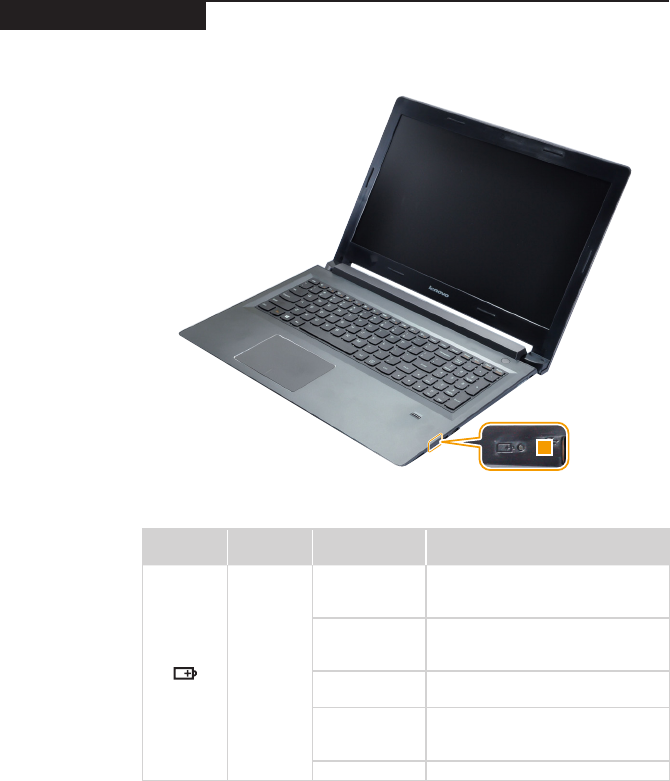
Status indicators
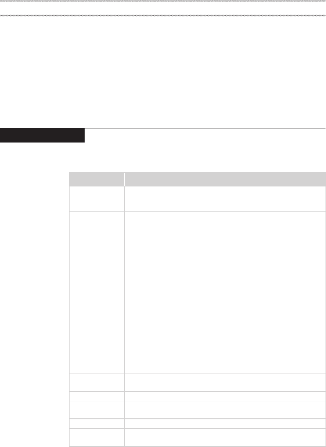
Thesystemstatusindicatorsbelowshowthecomputerstatus:
Table 2. Status indicators
Symbol Indicator Indicator
status Meaning
Battery
Green
Thebatteryhasachargebetween
20%and100%andthecomputeris
poweredon.
Blinkinggreen
Thebatteryhasachargebetween
20%and100%andthecomputeris
insleeporhibernatemode.
Amber Thebatteryhasachargeof20%or
lessandthecomputerispoweredon.
Blinkingamber
Thebatteryhasachargeof20%or
lessandtheACpoweradapteris
connectedtothecomputer.
Off Thecomputerispoweredoff.
30
M50-70/M50-80 Hardware Maintenance Manual
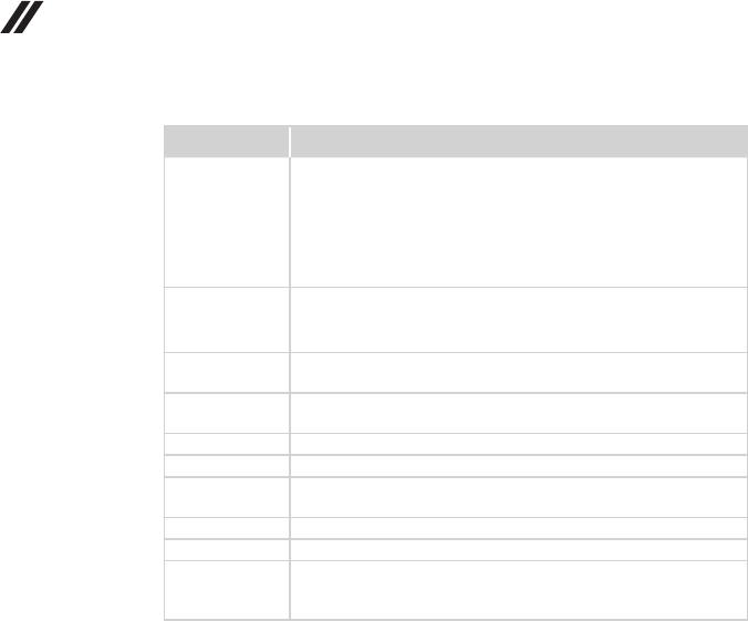
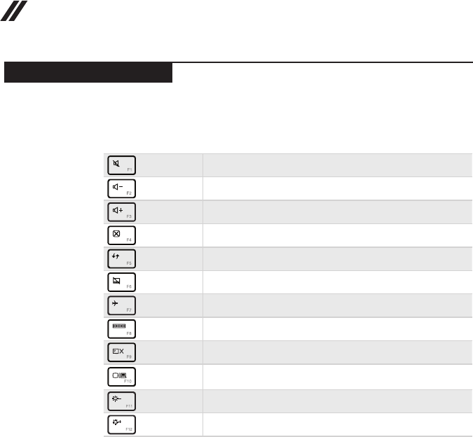
Fn key combinations
Thefollowing tableshowsthe function ofeachcombination of Fnwitha
functionkey.
Table 3. Fn key combinations
: Mutes/unmutesthesound.
: Decreasesthevolumelevel.
: Increasesthevolumelevel.
: Closesthecurrentlyactivewindow.
: Refreshesthedesktoporthecurrentlyactivewindow.
: Enables/disablesthetouchpad.
: Enables/disablesAirplanemode.
: Displaysallcurrentlyactiveapps.
: Turnson/offthebacklightoftheLCDscreen.
: Togglesthedisplaybetweenthecomputerandan
externaldevice.
: Decreasesthedisplaybrightness.
: Increasesthedisplaybrightness.
31
Lenovo M50-70/M50-80
FRU replacement notices
Thissection presentsnoticesrelatedto removingandreplacingparts. Read
thissectioncarefullybeforereplacinganyFRU.
Screw notices
Loosescrewscancausea reliabilityproblem.In theLenovocomputer,this
problemisaddressedwithspecialnylon-coatedscrewsthathavethefollowing
characteristics:
• Theymaintaintightconnections.
• Theydonoteasilycomeloose,evenwithshockorvibration.
• Theyarehardertotighten.
Dothefollowingwhenyouservicethismachine:
• Keepthescrewkitinyourtoolbag.
• CarefullyremovescrewsforreusewhenreplacingFRUs.
• Useatorquescrewdriverifyouhaveone.
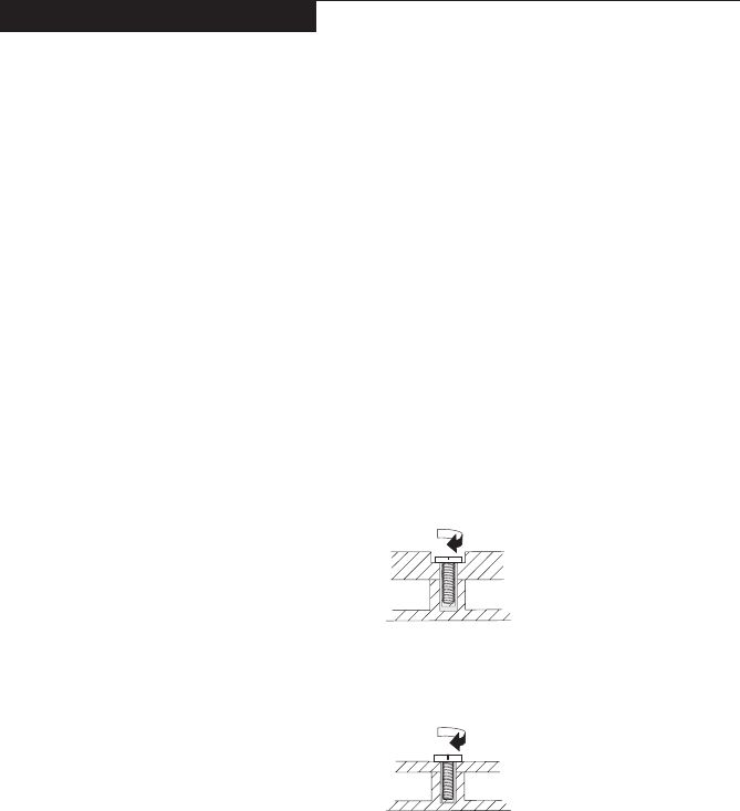
Tightenscrewsasfollows:
• Plastic to plastic
Turnanadditional90°afterthescrewhead touchesthesurface ofthe
plasticpart:
more than 90°
(Cross-section)
• Logic card to plastic
Turnanadditional180° afterthescrewheadtouchesthesurfaceof the
logiccard:
more than 180°
(Cross-section)
• Torque driver
Ifyouhaveatorquescrewdriver,refertothe“Torque”columnforeachstep.
• Makesurethatyouusethecorrectscrews.Ifyouhaveatorquescrewdriver,
tightenallscrewsrmlytothetorqueshowninthetable.Carefully remove
screws for reuse when replacing FRUs. Make sure that all screws are
tightened rmly.
• Ensuretorque screwdriversarecalibratedcorrectly followingcountry
specications.
32
M50-70/M50-80 Hardware Maintenance Manual
Removing and replacing an FRU
Thissectionpresentsexplodedgureswiththeinstructions toindicatehowto
removeandreplacetheFRU.Makesuretoobservethefollowinggeneralrules:
1. Donotattempttoserviceanycomputerunlessyouhavebeentrainedand
certied.Anuntrainedpersonrunstheriskofdamagingparts.
2. BeforereplacinganyFRU,review“FRUreplacementnotices”onpage31.
3. Beginby removinganyFRUs thathavetoberemovedbeforethefailing
FRU.AnyofsuchFRUsarelistedatthetopofthepage.Removethemin
theorderinwhichtheyarelisted.
4. FollowthecorrectsequenceinthestepstoremovetheFRU,asgiveninthe
guresbythenumbersinsquarecallouts.
5. WhenturningascrewtoreplaceanFRU,turnitinthedirectionasgivenby
thearrowinthegure.
6. WhenremovingtheFRU,moveitinthe directionasgivenbythearrowin
thegure.
7. Toputthe newFRUinplace,reverse theremovalproceduresandfollow
anyofthenotesthatpertaintoreplacement. Forinformationabout
connectingandarranginginternalcables,see“Locations”onpage69.
8. WhenreplacinganFRU,usethecorrectscrewasshownintheprocedures.
DANGER
Before removing any FRU, turn off the computer, unplug all power cords from
electrical outlets, remove the battery pack, and then disconnect any of the
interconnecting cables.
Attention:AfterreplacinganFRU,donotturnonthecomputeruntilyouhave
madesurethatallscrews,springs,andothersmallpartsareinplaceandnone
areloose insidethecomputer.Verifythisbyshaking thecomputergentlyand
listeningforrattlingsounds.Metallicpartsormetal akescancauseelectrical
shortcircuits.
Attention:Thesystem boardissensitiveto, andcanbedamaged by,
electrostaticdischarge. Beforetouchingit,establish personal groundingby
touchingagroundpointwithonehandorusinganelectrostaticdischarge(ESD)
strap(P/N6405959)toremovepotentialshockreasons.
Notes:
• The following procedures about removing and replacing FRUs are the same for the
Lenovo M50-70/M50-80.
• The illustrations used in this section are of the Lenovo M50-70, unless otherwise
stated.
33
Lenovo M50-70/M50-80
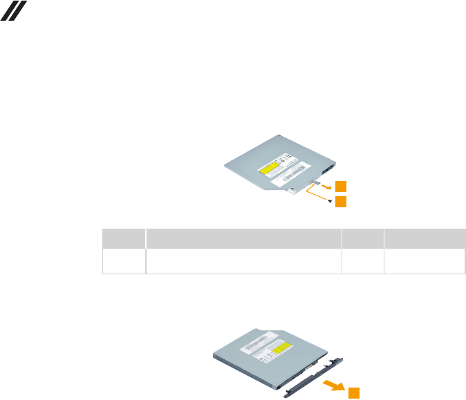
1010 Optical drive
Figure 1. Removal steps of optical drive
Removethescrew1.
Step Screw (quantity) Color Torque
1M2.0×6.0mm,at-head,nylok-coated(1)
Lowtoupontheedge
Black 1.8±0.2kgf*cm
Pulltheopticaldriveoutinthedirectionshownbyarrow2.
34
M50-70/M50-80 Hardware Maintenance Manual
Figure 1. Removal steps of optical drive (continued)
Removethe screw3,then removetheopticaldrive bracketinthedirection
shownbyarrow4.
3
4
Step Screw (quantity) Color Torque
3M2.0×3.0mm,at-head,nylok-coated(1)
oddbrkttooddmodule
Black 1.8±0.2kgf*cm
Carefullyremovetheopticaldrivebezelinthedirectionshownbyarrow5.
35
Lenovo M50-70/M50-80
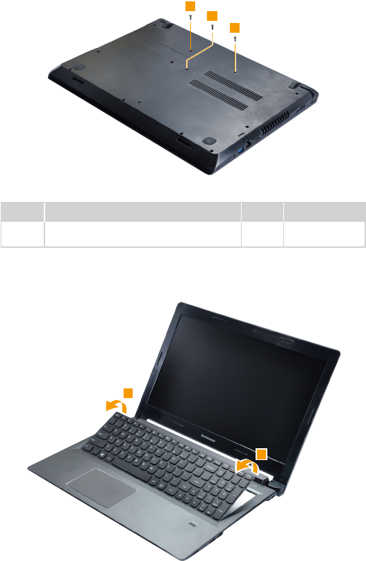
1020 Keyboard
Figure 2. Removal steps of keyboard
Removethescrews1.
Step Screw (quantity) Color Torque
1M2.0×6.0mm,at-head,nylok-coated(3)
Lowtoupontheedge
Black 1.8±0.2kgf*cm
Loosenthekeyboardwithngersinthedirectionshownbyarrows2.
36
M50-70/M50-80 Hardware Maintenance Manual
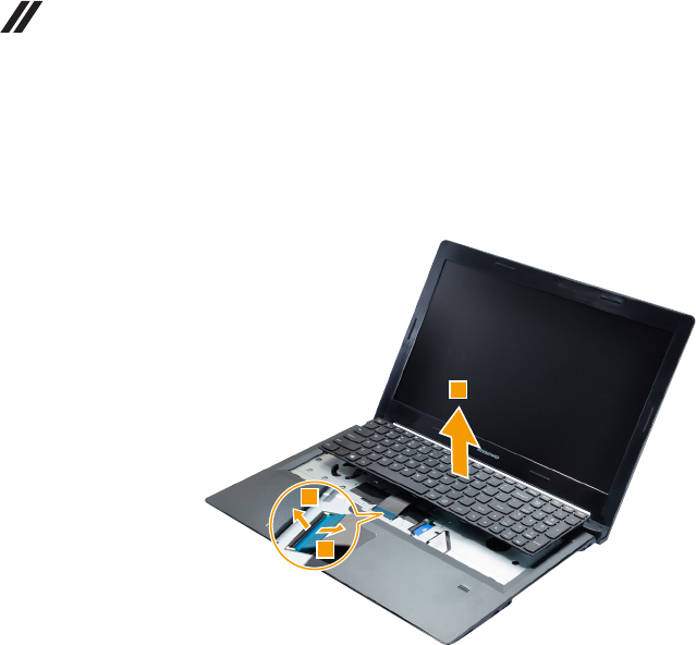
Figure 2. Removal steps of keyboard (continued)
Liftthekeyboardslightly3.Detachtheconnectorinthedirectionsshownby
arrows4and5.Thenremovethekeyboard.
When installing:MakesurethattheFPCconnectorisattachedrmly.
37
Lenovo M50-70/M50-80
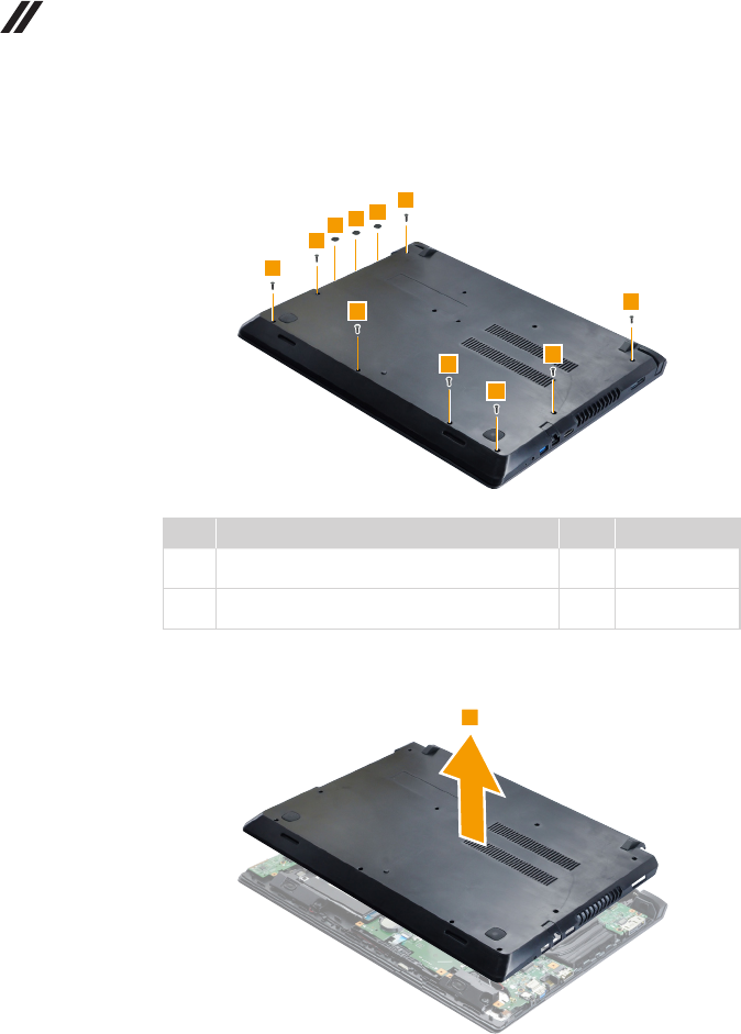
1030 Base cover
Foraccess,removetheseFRUsinorder:
• “1010Opticaldrive”onpage33
• “1020Keyboard”onpage35
Figure 3. Removal steps of base cover
Removethescrews1.
Step Screw (quantity) Color Torque
1M2.0×6.0mm,at-head,nylok-coated(4)
K/BUptoLow
Black 1.8±0.2kgf*cm
38
M50-70/M50-80 Hardware Maintenance Manual
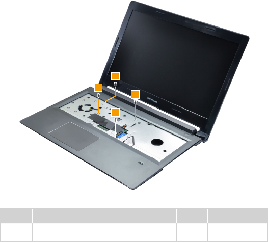
Figure 3. Removal steps of base cover (continued)
Removethescrews2and3.
Step Screw (quantity) Color Torque
2M2.0×6.0mm,at-head,nylok-coated(8)
Lowtoupontheedge
Black 1.8±0.2kgf*cm
3M2.0×2.0mm,at-head,nylok-coated(3)
ODDbridgetoup
Sliver 1.8±0.2kgf*cm
Removethebasecoverinthedirectionshownbyarrow4.
39
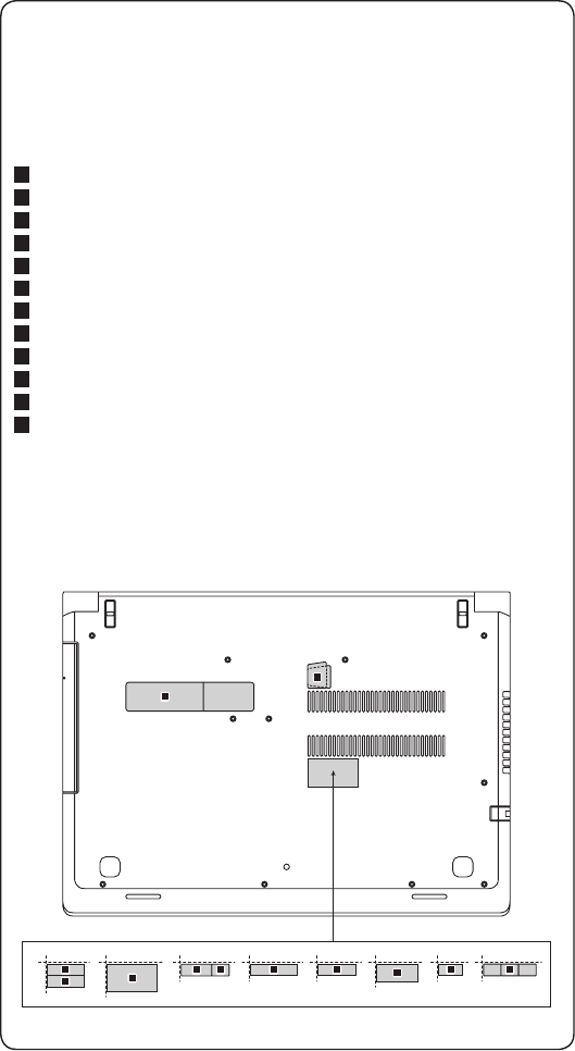
Lenovo M50-70/M50-80
Note: Applying labels to the base cover
The new base cover FRU is shipped with a kit containing labels of several
kinds. When you replace the base cover, you need to apply the following
label:
The following labels need to be peeled off from the old base cover and put on
the new base cover.
a Rating label
b GML label
c BT label for UG/CA/TW
d WL label for UG/CA/TW
e KCC label for Korea
f D Side label for Indonesia
g Postel label for Indonesia
h BIS label for India
i WL/BT label for Israel
j
WL/BT label for Brazil
k WL label for South Africa
l SIRIM label for Malaysia
For some models, you also need to apply one or two FCC labels. Check the
old base cover; if it has one or two FCC labels, nd duplicates of them in the
label kit and apply them to the new base cover.
For the location of each label, refer to the following gure:
k
j
i
h
fg
c
de
l
b
a
40
M50-70/M50-80 Hardware Maintenance Manual
1040 Battery pack
Foraccess,removetheseFRUsinorder:
• “1010Opticaldrive”onpage33
• “1020Keyboard”onpage35
• “1030Basecover”onpage37
DANGER
Only use the battery specied in the parts list for your computer. Any other battery
could ignite or explode.
Figure 4. Removal steps of battery pack
Unplugthebatteryconnectorinthedirectionshownbyarrow1,thenremove
thescrews2.
Step Screw (quantity) Color Torque
2M2.0×3.0mm,at-head,nylok-coated(3)
BATTtoLOGICUPSUB
Black 1.8±0.2kgf*cm
When installing:Makesurethatthebatteryconnectorisattachedrmly.
41
Lenovo M50-70/M50-80
Figure 4. Removal steps of battery pack (continued)
Removethebatterypack3.
42
M50-70/M50-80 Hardware Maintenance Manual
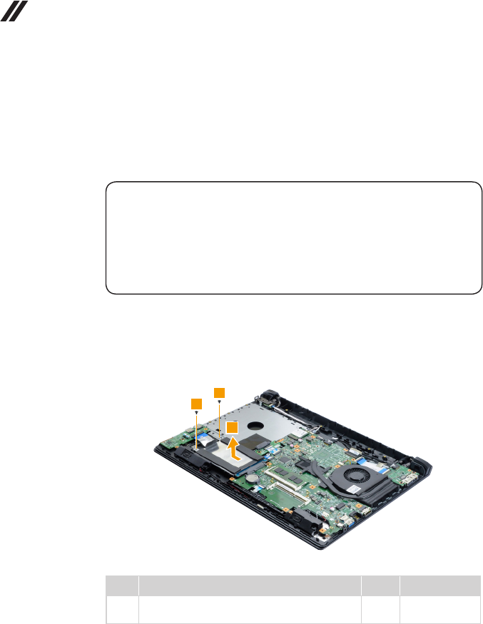
1050 Hard disk drive
Foraccess,removetheseFRUsinorder:
• “1010Opticaldrive”onpage33
• “1020Keyboard”onpage35
• “1030Basecover”onpage37
• “1040Batterypack”onpage40
Attention:
• Donotdropthehard diskdriveorapplyanyphysicalshocktoit. The hard
disk drive is sensitive to physical shock. Improper handling can cause damage and
permanent loss of data.
• Before removing the drive, suggest the customer to backup all the information on
it if possible.
• Never remove the drive while the system is operating or in suspend mode.
Figure 5. Removal steps of hard disk drive
Removethescrews1.Pulltheharddiskdriverinthedirectionshown
byarrow2.
Step Screw (quantity) Color Torque
1M2.0×3.0mm,at-head,nylok-coated(2)
HDDBrkttoUp
Black 1.8±0.2kgf*cm
When installing:MakesurethattheHDDconnectorisattachedrmly.
43
Lenovo M50-70/M50-80
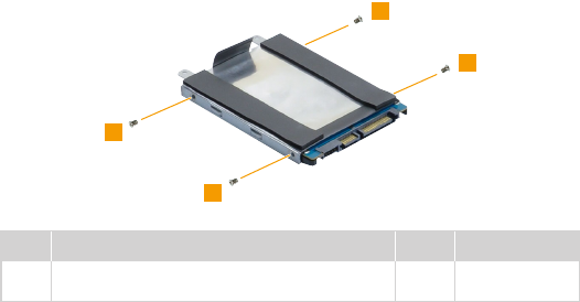
Figure 5. Removal steps of hard disk drive (continued)
Removethescrews3anddetachthemetalframefromtheharddiskdrive.
Step Screw (quantity) Color Torque
3M3.0×4.0mm,at-head,nylok-coated(4)
hddemiboxtohddmodule
Black 3.0±0.2kgf*cm
44
M50-70/M50-80 Hardware Maintenance Manual
1060 PCI Express Mini Card for wireless LAN
Foraccess,removetheseFRUsinorder:
• “1010Opticaldrive”onpage33
• “1020Keyboard”onpage35
• “1030Basecover”onpage37
• “1040Batterypack”onpage40
Figure 6. Removal steps of PCI Express Mini Card for wireless LAN
DisconnectthetwowirelessLANcables(black,white)1,andthenremovethe
screw2.
Instep1,unplugthejacksbyusingthe removaltoolantennaRFconnector
(P/N:08K7159),orpickuptheconnectorswithyourngersandgentlyunplug
theminthedirectionshownbythearrows.
Notes:ThewirelessLANcardhas2cablesinstep1.
ThewirelessLANcardinsomemodelsmighthave3cablesinstep1.
Step Screw (quantity) Color Torque
2M2.0×3.0mm,at-head,nylok-coated(1)
W/Lcardtolow
Black 1.8±0.2kgf*cm
45
Lenovo M50-70/M50-80
Figure 6. Removal steps of PCI Express Mini Card for wireless LAN (continued)
Removethecardinthedirectionshownbyarrow3.
When installing:
• Inmodelswithawireless LANcardthat hastwoantenna connectors,plug
theblackcable(1st)(MAIN)intothejacklabeledMAIN,andthewhitecable
(2nd)(AUX)intothejacklabeledAUXonthecard.
• InmodelswithawirelessLANcardthathasthreeantennaconnectors,plug
theblackcable(1st)(MAIN)intothejacklabeled1,thegreycable(3rd)into
thejacklabeled3,andthewhitecable(2nd)(AUX)intothejacklabeled2on
thecard.
46
M50-70/M50-80 Hardware Maintenance Manual
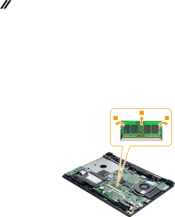
1070 DIMM
Foraccess,removetheseFRUsinorder:
• “1010Opticaldrive”onpage33
• “1020Keyboard”onpage35
• “1030Basecover”onpage37
• “1040Batterypack”onpage40
Figure 7. Removal steps of DIMM
Releasethe twolatchesonbothedgesofthe socketatthesame timeinthe
directionsshown byarrows1,andthenunplugthe DIMMinthedirection
shownbyarrow2.
47
Lenovo M50-70/M50-80
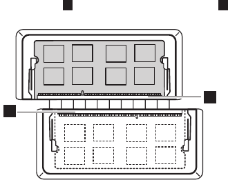
Figure 7. Removal steps of DIMM (continued)
Note:IfonlyoneDIMMisusedonthecomputeryouareservicing,thecardmust
beinstalledinSLOT-0( a:lowerslot),butnotinSLOT-1( b:upperslot).
a
b
When installing:InsertthenotchedendoftheDIMMintothesocket.Pushthe
DIMMrmly,andpivotituntilitsnapsintoplace.Makesurethatitisrmlyxed
intheslotandisdifculttomove.
48
M50-70/M50-80 Hardware Maintenance Manual
1080 ODD board
Foraccess,removetheseFRUsinorder:
• “1010Opticaldrive”onpage33
• “1020Keyboard”onpage35
• “1030Basecover”onpage37
• “1040Batterypack”onpage40
Figure 8. Removal steps of ODD board
DetachtheODDboardconnectorinthedirectionsshownbyarrows1and2.
Removethescrews3.
Step Screw (quantity) Color Torque
3M2.0×2.0mm,at-head,nylok-coated(2)
ODDBDtoUp
Black 1.8±0.2kgf*cm
ThenremovetheODDboardinthedirectionshownbyarrow4.
When installing:Makesurethattheconnectorisattachedrmly.
49
Lenovo M50-70/M50-80
1090 Docking board
Foraccess,removetheseFRUsinorder:
• “1010Opticaldrive”onpage33
• “1020Keyboard”onpage35
• “1030Basecover”onpage37
• “1040Batterypack”onpage40
Figure 9. Removal steps of docking board
Disconnectthetwoconnectorsinthedirectionsshown byarrows1and2.
Thenremovethescrews3.
Step Screw (quantity) Color Torque
3M2.5×5.0mm,at-head,nylok-coated(2)
IOBDtoUp
Black 2.3±0.2kgf*cm
When installing:Makesurethattheconnectorsareattachedrmly.
50
M50-70/M50-80 Hardware Maintenance Manual
Figure 9. Removal steps of docking board (continued)
Removedockingboardinthedirectionshownbyarrow4.
51
Lenovo M50-70/M50-80
1100 Speakers
Foraccess,removetheseFRUsinorder:
• “1010Opticaldrive”onpage33
• “1020Keyboard”onpage35
• “1030Basecover”onpage37
• “1040Batterypack”onpage40
Figure 10. Removal steps of speakers
Unplugthespeakerconnectorinthedirectionshownbyarrow1.Removethe
speakersinthedirectionshownbyarrows2.
52
M50-70/M50-80 Hardware Maintenance Manual
1110 Thermal module
Foraccess,removetheseFRUsinorder:
• “1010Opticaldrive”onpage33
• “1020Keyboard”onpage35
• “1030Basecover”onpage37
• “1040Batterypack”onpage40
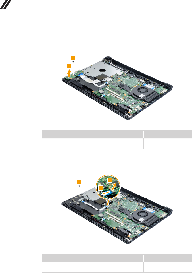
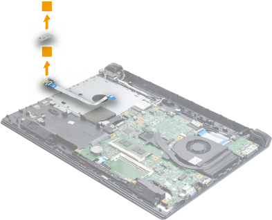
Figure 11. Removal steps of thermal module
Unplugthefanconnectorin thedirectionshown byarrow1. Loosenthe
screws2,thenremovethethermalmoduleinthedirectionshownbyarrow3.
When installing:Makesurethatthefanconnectorisattachedrmly.
53
Lenovo M50-70/M50-80
1120 USB board and nger print board
Foraccess,removetheseFRUsinorder:
• “1010Opticaldrive”onpage33
• “1020Keyboard”onpage35
• “1030Basecover”onpage37
• “1040Batterypack”onpage40
• “1050Harddiskdrive”onpage42
• “1080ODDboard”onpage48
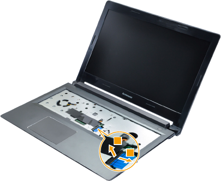
Figure 12. Removal steps of USB board and nger print board
Openthedisplaypanel thendisconnecttheconnectorin thedirections
shownbyarrows1and2.
54
M50-70/M50-80 Hardware Maintenance Manual
Figure 12. Removal steps of USB board and nger print board (continued)
Removethescrew3,thenremovetheUSBboardinthedirectionshownby
arrow4.
Step Screw (quantity) Color Torque
3M2.0×3.0mm,at-head,nylok-coated(1)
IOBDtoUp
Black 1.8±0.2kgf*cm
Disconnectthefingerprintboardconnectorinthedirectionsshownbyarrows5
and6.Removethescrew7.
Step Screw (quantity) Color Torque
7M2.0×3.0mm,at-head,nylok-coated(1)
FPBrkttoUp
Black 1.8±0.2kgf*cm
55
Lenovo M50-70/M50-80
Figure 12. Removal steps of USB board and nger print board (continued)
Removethefingerprintbracketandfingerprintboardinthedirectionshownby
arrows8and9.
56
M50-70/M50-80 Hardware Maintenance Manual
1130 System board and touchpad module
Important notices for handling the system board:
When handling the system board, bear the following in mind.
• Be careful not to drop the system board on a bench top that has a hard surface,
such as metal, wood, or composite.
• Avoid rough handling of any kind.
• During the whole process, make sure not to drop or stack the system board.
• If you put a system board down, make sure to put it only on a padded surface such
as an ESD mat or conductive corrugated material.
Foraccess,removetheseFRUsinorder:
• “1010Opticaldrive”onpage33
• “1020Keyboard”onpage35
• “1030Basecover”onpage37
• “1040Batterypack”onpage40
• “1050Harddiskdrive”onpage42
• “1060PCIExpressMiniCardforwirelessLAN”onpage44
• “1080ODDboard”onpage48
• “1090Dockingboard”onpage49
• “1100Speakers”onpage51
• “1110Thermalmodule”onpage52
• “1120USBboardandngerprintboard”onpage53
57
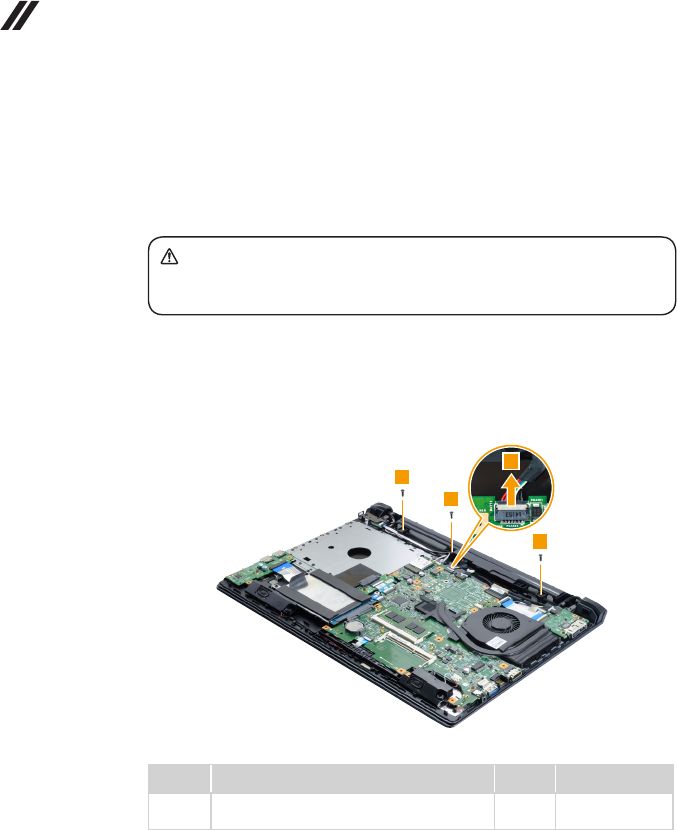
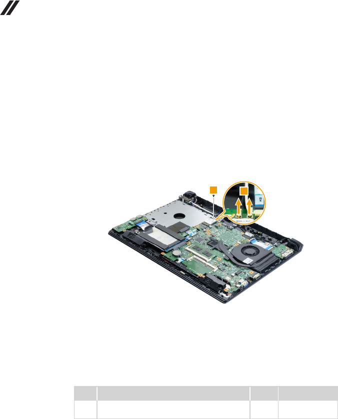
Lenovo M50-70/M50-80
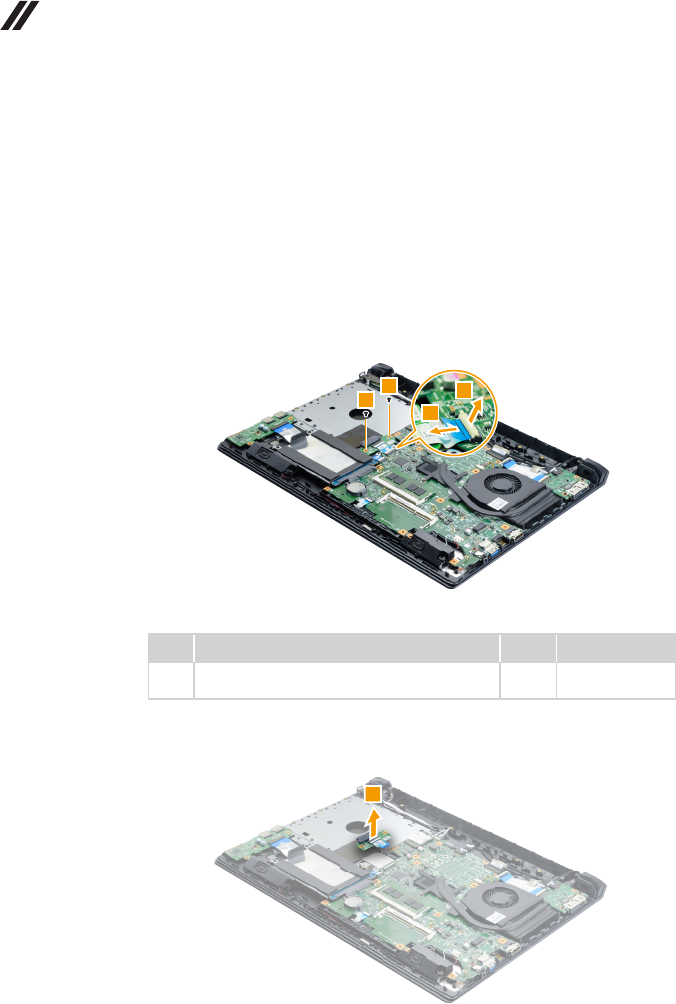
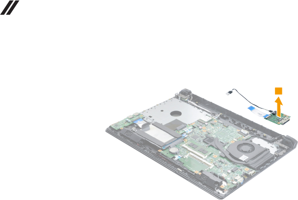
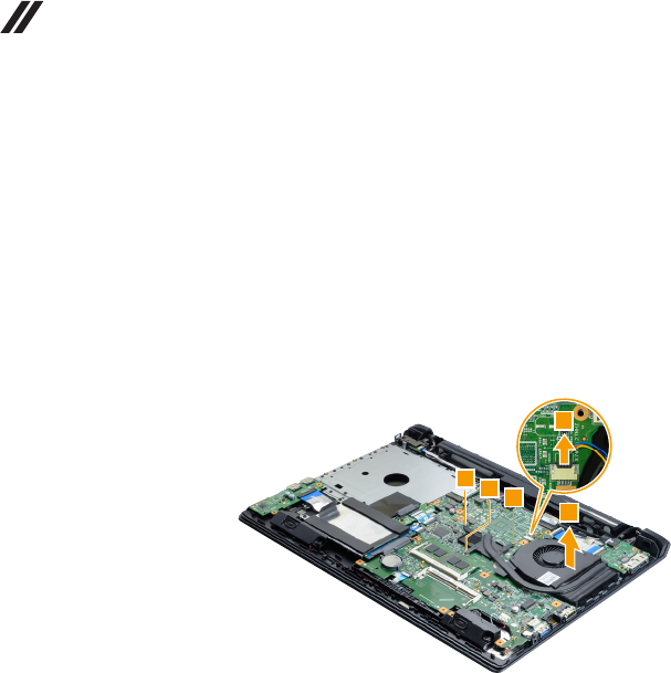
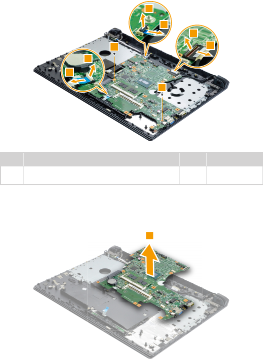
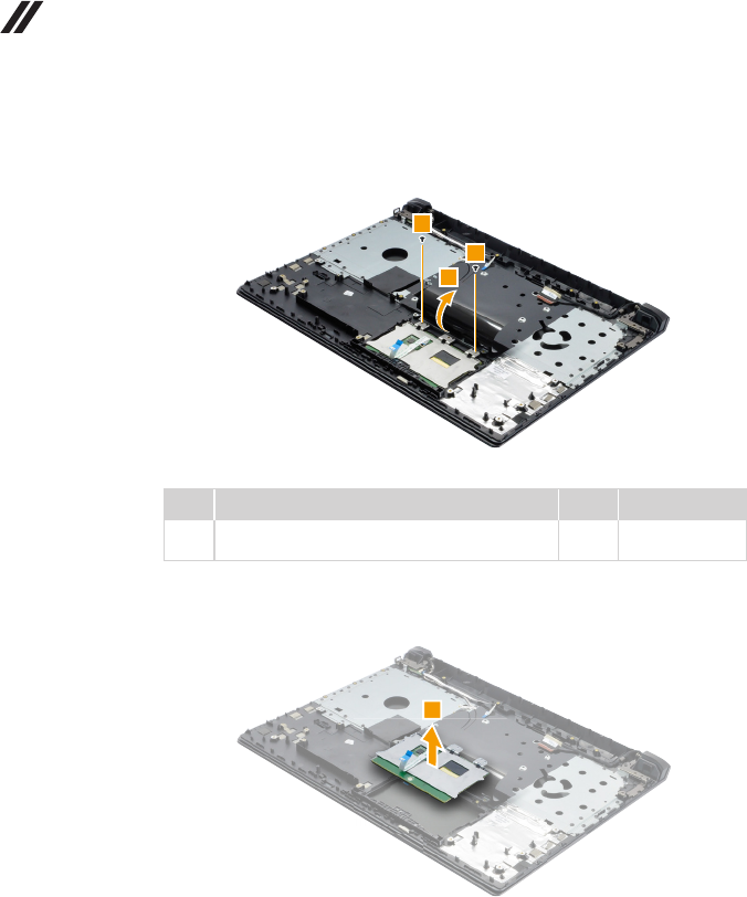
Figure 13. Removal steps of system board and touchpad module (continued)
Disconnecttheconnectorsinthe directionsshownby arrows1and2.
Removethescrews3.
Step Screw (quantity) Color Torque
3M2.0×3.0mm,at-head,nylok-coated(2)
M/BtoUp
Black 1.8±0.2kgf*cm
When installing:Makesurethattheconnectorsareattachedrmly.
Removethesystemboardinthedirectionshownbyarrow4.
58
M50-70/M50-80 Hardware Maintenance Manual
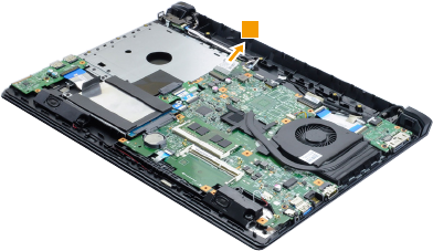
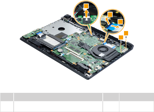
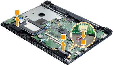
Figure 13. Removal steps of system board and touchpad module (continued)
Openthetabinthedirectionshownbyarrow5.Thenremovethescrews6.
Step Screw (quantity) Color Torque
6M2.0×3.0mm,at-head,nylok-coated(2)
TPmoduletoUP
Black 1.8±0.2kgf*cm
Removethetouchpadmodule7.
59
Lenovo M50-70/M50-80
1140 Upper case and power board
Foraccess,removetheseFRUsinorder:
• “1010Opticaldrive”onpage33
• “1020Keyboard”onpage35
• “1030Basecover”onpage37
• “1040Batterypack”onpage40
• “1050Harddiskdrive”onpage42
• “1060PCIExpressMiniCardforwirelessLAN”onpage44
• “1080ODDboard”onpage48
• “1090Dockingboard”onpage49
• “1100Speakers”onpage51
• “1110Thermalmodule”onpage52
• “1120USBboardandngerprintboard”onpage53
• “1130Systemboardandtouchpadmodule”onpage56
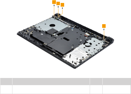
Figure 14. Removal steps of upper case and power board
Removethescrews1.
Step Screw (quantity) Color Torque
1M2.5×5.0mm,at-head,nylok-coated(4)
LCDAssytosystem
Black 2.3±0.2kgf*cm
60
M50-70/M50-80 Hardware Maintenance Manual
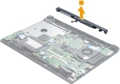
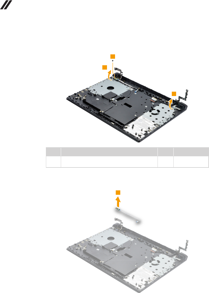
Figure 14. Removal steps of upper case and power board (continued)
Openthehingeinthedirectionshownbyarrows2.Removethescrew3.
Step Screw (quantity) Color Torque
3M2.0×3.0mm,at-head,nylok-coated(1)
PowerBDtoUp
Black 1.8±0.2kgf*cm
Removethepowerboardinthedirectionshownbyarrow4.
61
Lenovo M50-70/M50-80
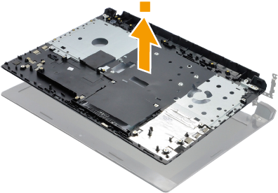
Figure 14. Removal steps of upper case and power board (continued)
Removetheuppercaseinthedirectionshownbyarrow5.
62
M50-70/M50-80 Hardware Maintenance Manual
1150 LCD unit
Foraccess,removetheseFRUsinorder:
• “1010Opticaldrive”onpage33
• “1020Keyboard”onpage35
• “1030Basecover”onpage37
• “1040Batterypack”onpage40
• “1050Harddiskdrive”onpage42
• “1060PCIExpressMiniCardforwirelessLAN”onpage44
• “1080ODDboard”onpage48
• “1090Dockingboard”onpage49
• “1100Speakers”onpage51
• “1110Thermalmodule”onpage52
• “1120USBboardandngerprintboard”onpage53
• “1130Systemboardandtouchpadmodule”onpage56
• “1140Uppercaseandpowerboard”onpage59
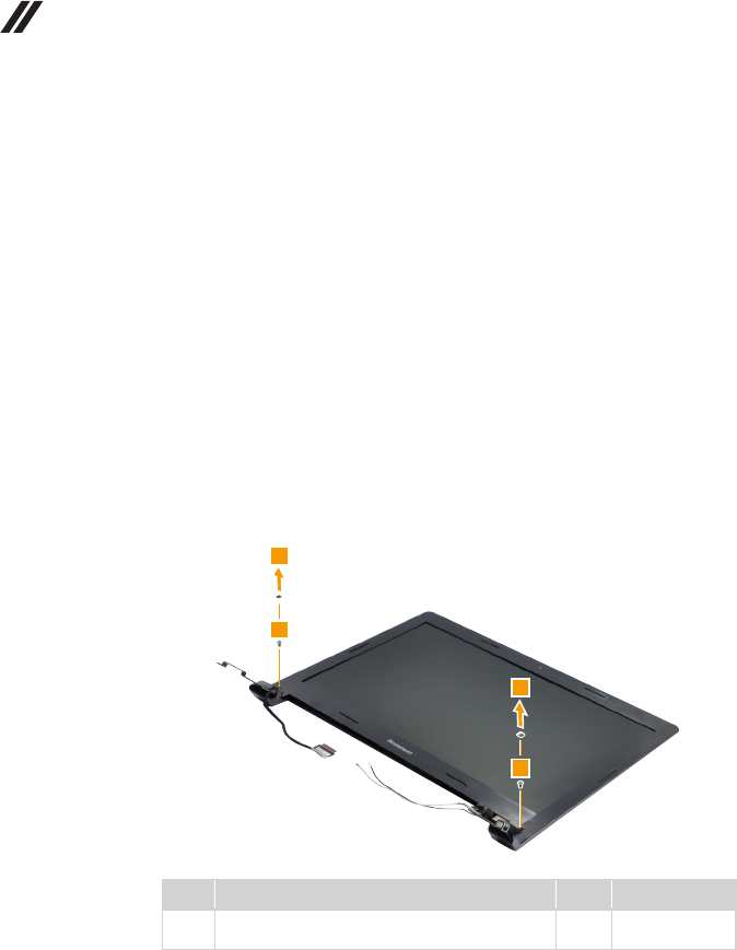
Figure 15. Removal steps of LCD unit
RemoveLCDbezelscrewpads1andthescrews2.
Step Screw (quantity) Color Torque
2M2.5×4.0mm,at-head,nylok-coated(2)
BezeltoLCDPanel
Black 2.3±0.2kgf*cm
63
Lenovo M50-70/M50-80
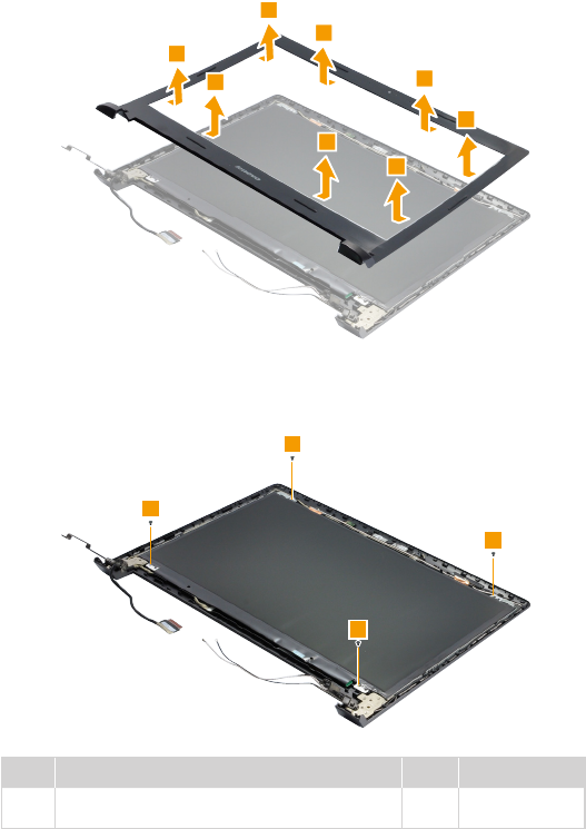
Figure 15. Removal steps of LCD unit (continued)
RemovetheLCDfrontbezelinthedirectionshownbyarrows3.
Removethescrews4.
Step Screw (quantity) Color Torque
4M2.0×3.0mm,at-head,nylok-coated(4)
lcdtolcdcover
Black 1.8±0.2kgf*cm
64
M50-70/M50-80 Hardware Maintenance Manual
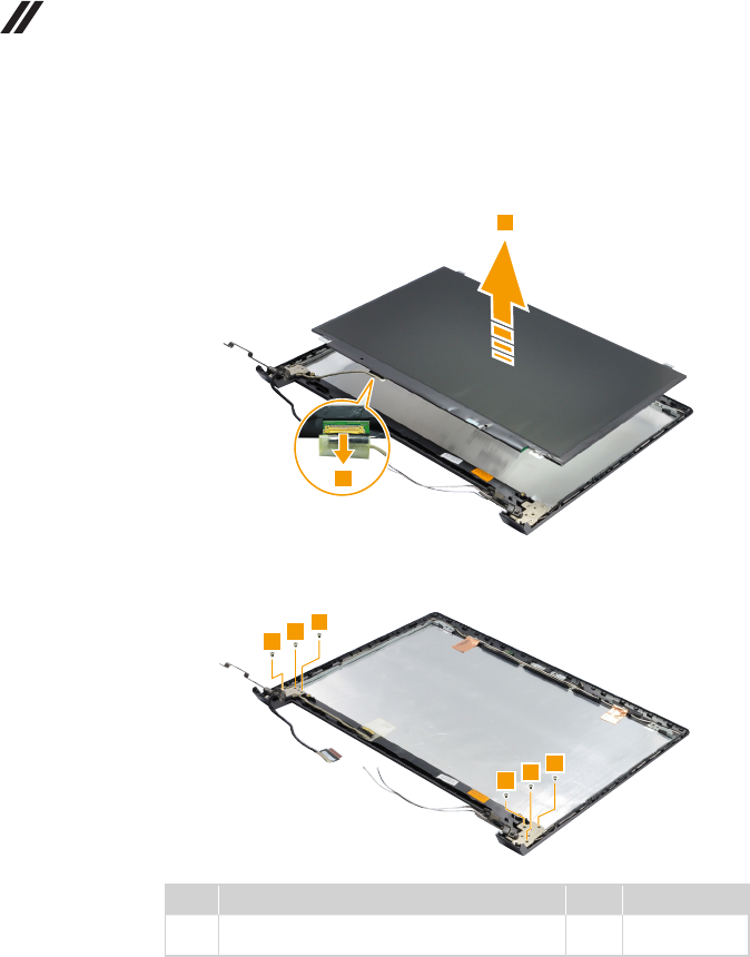
Figure 15. Removal steps of LCD unit (continued)
LifttheLCDpanel slightly5.Peelofftheadhesivetapeanddetachthe
connectorinthedirectionshownbyarrow6.ThenremovetheLCDpanel.
Removethescrews7.
Step Screw (quantity) Color Torque
7M2.5×3.0mm,at-head,nylok-coated(6)
HingetoLCDPanel
Black 2.3±0.2kgf*cm
65
Lenovo M50-70/M50-80
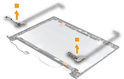
Figure 15. Removal steps of LCD unit (continued)
Thenreleasethehingesinthedirectionshownbyarrows8.
66
M50-70/M50-80 Hardware Maintenance Manual
1160 Antenna assembly
Foraccess,removetheseFRUsinorder:
• “1010Opticaldrive”onpage33
• “1020Keyboard”onpage35
• “1030Basecover”onpage37
• “1040Batterypack”onpage40
• “1050Harddiskdrive”onpage42
• “1060PCIExpressMiniCardforwirelessLAN”onpage44
• “1080ODDboard”onpage48
• “1090Dockingboard”onpage49
• “1100Speakers”onpage51
• “1110Thermalmodule”onpage52
• “1120USBboardandngerprintboard”onpage53
• “1130Systemboardandtouchpadmodule”onpage56
• “1140Uppercaseandpowerboard”onpage59
• “1150LCDunit”onpage62
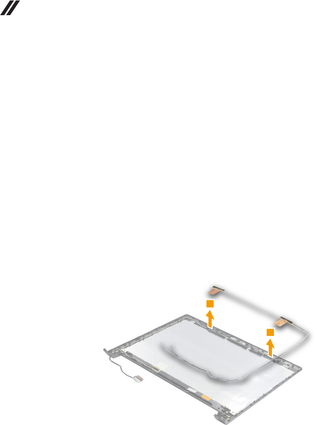
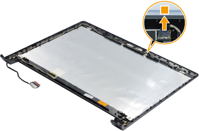
Figure 16. Removal steps of antenna assembly
Peeloffthe adhesivetapesecuring theantennaboards, releasethecables
fromthecableguide, andthenremove theantennaassembly inthedirection
shownbyarrows1.
When installing:Routetheantennacablesalongthecableguidesandsecure
theantenna boardswithadhesivetape.As youroutethecables, makesure
thattheyarenotsubjected toanytension.Tensioncouldcause thecablesto
bedamagedbythecableguides,orawiretobebroken.
67
Lenovo M50-70/M50-80
1170 LCD cable and integrated camera
Foraccess,removetheseFRUsinorder:
• “1010Opticaldrive”onpage33
• “1020Keyboard”onpage35
• “1030Basecover”onpage37
• “1040Batterypack”onpage40
• “1050Harddiskdrive”onpage42
• “1060PCIExpressMiniCardforwirelessLAN”onpage44
• “1080ODDboard”onpage48
• “1090Dockingboard”onpage49
• “1100Speakers”onpage51
• “1110Thermalmodule”onpage52
• “1120USBboardandngerprintboard”onpage53
• “1130Systemboardandtouchpadmodule”onpage56
• “1140Uppercaseandpowerboard”onpage59
• “1150LCDunit”onpage62
• “1160Antennaassembly”onpage66
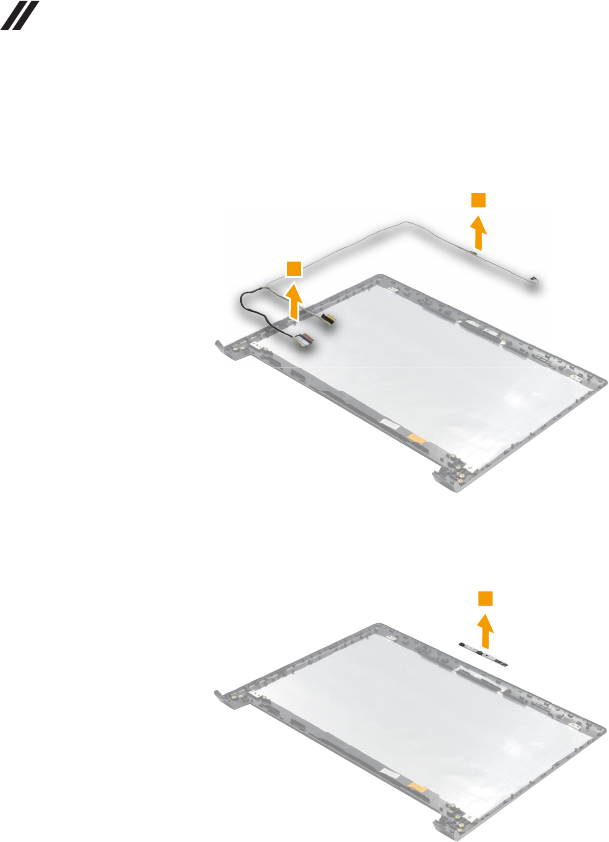
Figure 17. Removal steps of LCD cable and integrated camera
Unplugtheintegratedcameraconnectorinthedirectionshownbyarrow1.
68
M50-70/M50-80 Hardware Maintenance Manual
Figure 17. Removal steps of LCD cable and integrated camera (continued)
ReleasetheLCDcablefromthecableguide,andthenremovethecableinthe
directionshownbyarrows2.
Removetheintegratedcamerainthedirectionshownbyarrow3.
Note:TheintegratedcameraisstucktothetopcenteroftheLCDcover.
When installing:Stick theintegratedcamera tothetopcenter oftheLCD
coverandadjustthe placementofit tomakesure theconnectoris attached
firmly.Whenreplacingthe integratedcamera,route theconnectorcable as
showninthegureabove.
69
Lenovo M50-70/M50-80
Locations
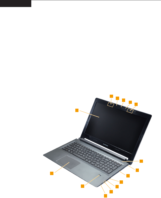
Front view and right-side view
1 Integratedcamera
2 Built-inmicrophone
3 WirelessLANantennas
4 Computerdisplay
5 Touchpad
6 Fingerprintreader
7 Memorycardslot
8 Batterystatusindicator
Note:Forthedescriptionofeachindicator,see“Statusindicators”onpage29.
9 USBport
J Opticaldrive
K Kensingtonlockslot
L Powerbutton
70
M50-70/M50-80 Hardware Maintenance Manual
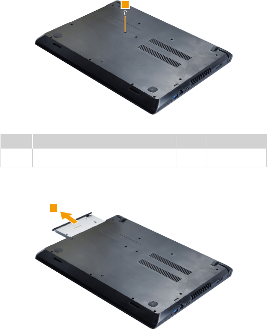
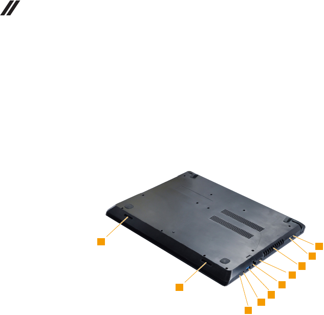
Bottom and Left-side view
1 Novobutton
2 Comboaudiojack
3 USBport
4 RJ-45port
5 HDMIport
6 Fanlouvers
7 LenovoOneLinkconnector
8 ACpoweradapterjack
9 Speaker
71
Lenovo M50-70/M50-80
Parts list
Thissectionpresentsthefollowingserviceparts:
• “Overall”onpage72
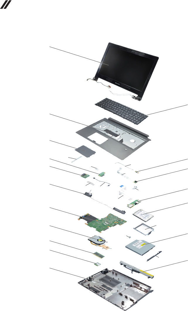
• “LCDFRUs”onpage75
• “Miscellaneousparts”onpage79
• “ACadapters”onpage80
• “Screws”onpage80
• “Powercords”onpage81
Note:
Each FRU is available for all types or models, unless specic types or models are
specied.
Attention:
DonotattempttoreplaceanFRUonyourown.IfanFRUisdamaged,contact
aLenovoauthorizedserviceroramarketing representativeforreplacement
orrepair.Onlyqualiedtechnicianscaninspectorrepairthisproduct.
72
M50-70/M50-80 Hardware Maintenance Manual
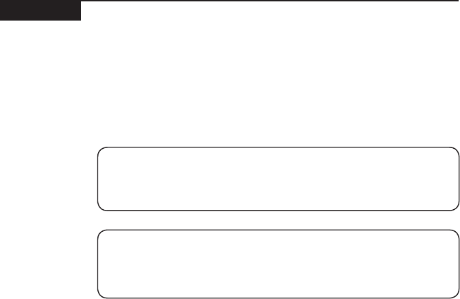
Overall
G
HI
J
D
C
KL
M
E
F

73
Lenovo M50-70/M50-80
Table 4. Parts list—Overall
No. FRU FRU no. CRU ID.
a-k See“Miscellaneousparts”onpage79. N
1LCDunit(see“LCDFRUs”onpage75.) **
2Keyboard(see“Keyboard”onpage77.)
3UpperCoverBlackWM50-70 5CB0G86332 N
4TPButtonBoardWM50-70 5C50G86337 N
5ODDSwitchBoardWM50-70 5C50G86357 N
6DockingBoardWM50-70 5C50G86335 N
7PowerBoardWM50-70 5C50G86326 N
8FingerPrintBoardWM50-70 5F30G86329 N
9IOBoardWM50-70 5C50G86364 N
10 SpeakerWM50-70 5SB0G86327 N
11 MBWM50-70NOKI3-4030UUMA 5B20G86339 N
11 MBWM50-70W8PI3-4030UUMA 5B20G86344 N
11 MBWM50-70W8SI3-4030UUMA 5B20G86345 N
11 MBWM50-70NOKI3-4030U2G 5B20G86347 N
11 MBWM50-70W8PI3-4030U2G 5B20G86351 N
11 MBWM50-70W8SI3-4030U2G 5B20G86356 N
12 HDD,ST320LT0126G7mm5.4K320GHDD 16200384 N
12 HDD,WD3200LPCX-24C6HT06G7mm5.4K
320GHDD
16200551 N
12 HDD,ST500LT0126G7mm5.4K500GHDD 16200383 N
12 HDD,WD5000LPCX-24C6HT06G7mm5.4K
500GHDD
16200395 N
12 HDD,MN500M 16200554 N
12 HDD,HTS541010A7E6307mm5400rpm1THDD 16200658 N
12 HDD,ST750LM0317mm5400rpm1TBHDD 16200660 N
12 HDD,Kahuna8G 16200391 N
12 HDD,Angsana2DH TBD N
12 HDD,WD10S21X-24R1BT07mm5400rpm
1TB+8GSSHD
16200681 N
13 HeatsinkWM50-70W/FANDIS 5H40G86348 N
13 HeatsinkWM50-70W/FANUMA 5H40G86361 N
14 ODD,HLDSGUC0N9.0RamboODD 5DX0F85915 **
14 ODD,PLDSDA-8A6SH9.0RamboODD 5DX0F86404 **
14 ODD,DummyODDM50 SMC0G75069 **
14 DummyODDWM50-70 5CB0G86349
15 RAM,M471B1G73DB0-YK0 11202082 N
15 RAM,HMT41GS6BFR8A-PB 11202707 N
15 RAM,RMT3160ME68FAF-16008GBDDR3L1600 11202450 N
15 RAM,MT16KTF1G64HZ-1G6E18GBDDR3L1600 11201304 N
15 RAM,M471B5674QH0-YK0 11202451 N
15 RAM,HMT425S6AFR6A-PB2GBDDR3L1600 11201299 N
15 RAM,RMT3170MK58F8F-16002GBDDR3L1600 11202301 N
15 RAM,MT4KTF25664HZ-1G6E12GBDDR3L 11201967 N
15 RAM,M471B5173DB0-YK0 11202081 N
15 RAM,HMT451S6BFR8A-PB 11202706 N
15 RAM,RMT3170ME68F9F-16004GBDDR3L1600 11202302 N
15 RAM,MT8KTF51264HZ-1G6E14GBDDR3L1600 11202125 N

74
M50-70/M50-80 Hardware Maintenance Manual
No. FRU FRU no. CRU ID.
16 WirelessLan_Intel,IntelWP131601x1ac+BTM.2
ROWCombo.(BTROMupdate)
SW10A11511 N
16 WirelessLan_Non_Intel,CbtBCM43162
1x1AC+BT4.0PCIEM.2WLAN
20200573 N
16 WirelessLan_Non_Intel,LtnNFA3451x1AC+BT4.0
PCIEM.2WLAN
20200579 N
16 WirelessLan_Non_Intel,CbtBCM43142
1x1BN+BT4.0PCIEM.2WLAN
20200557 N
16 WirelessLan_Non_Intel,LtnNFA3351x1BN+BT4.0
PCIEM.2WLAN
20200558 N
16 WirelessLan_Non_Intel,CbtRTL8723BE
1x1BN+BT4.0PCIEM.2WLAN
20200570 N
16 WirelessLan_Intel,Intel72602x2AC+BTPCIEM.2
WLANV2
20200552 N
17 Battery,MyboSYL13S4E617.2V41.6Wh4cellbty 121500245 N
17 Battery,MyboSP/LL13M4E617.44V41.6Wh4cell
bty
121500246 N
17 Battery,MyboLGL13L4E617.44V41.6Wh4cell
bty
121500247 N
17 Battery,MyboSYL13S4A617.2V32Wh4cellbty 121500260 N
17 Battery,MyboSP/LL13M4A617.2V32Wh4cellbty 121500261 N
17 Battery,MyboLGL13L4A617.2V32Wh4cellbty 121500262 N
18 LowerCoverBlackWM50-70 5CB0G86342 N
18 LowerCoverBlackWM50-70W/DOC 5CB0G86354 N
— ACadapter(see“ACadapters”onpage80).
Table 4. Parts list—Overall (continued)
75
Lenovo M50-70/M50-80
LCD FRUs
InLenovoM50-70/M50-80,therearefollowingtypesofLCDs.
• “15.6-in.TouchHDLED”
76
M50-70/M50-80 Hardware Maintenance Manual
Table 5. Parts list—15.6-in. Touch HD LED
No. FRU FRU no. CRU ID.
1LCDBezelScrewPadPackWM50-70 5R60G90690 N
2LCDBezelBlackWM50-70 5B30G86341 N
3Panel,LP156WHB-TPD1 5D10F76011 N
3Panel,AUOB156XTN04.14AHDAGFLED1NB
LCD
18201588 N
3Panel,CMIN156BGE-EA1C2HDAGSLED1NB
LCD
18201589 N
3Panel,SDCLTN156AT37-401HDAGFNB 5D10G18222 N
3Panel,BOEN156WHM-N22HDAGFNB 5D10G74898 N
3Panel,AUOB156HTN03.6FHDAGSLED1NB
LCD
18201583 N
3Panel,CMIN156HGE-EABFHDAGSLED1NB
LCD
18201584 N
3Panel,BOEHB156FH1-401FHDAGSLED1NB
LCD
18201585 N
4HingeWM50-70R/L 5H50G86330 N
5LCDCableWM50-70W/CAMCable 5C10G86358 N
6AntennaWM50-70Main/AUX 5A30G86336 N
7Camera,LTN13P2SF155HDNBCamera 73048973 N
7Camera,LTN13P2SF153HDNBCamera 73048974 N
7Camera,BISBNC41GYTNHDNBcamera 73048975 N
7Camera,BISBNC4VHTTD0.3MNBcamera 73048976 N
7Camera,BISBNC4VHTK60.3MNBcamera 73048977 N
7Camera,BISBNC7VHTTD0.3MNBcamera 5C20G78838 N
7Camera,AWAAM-VS0690.3MNBcamera 73048978 N
8LCDCoverBlackWM50-703.2MM 5CB0G90691 N
8LCDCoverBlackWM50-703.8MM 5CB0G86331 N
77
Lenovo M50-70/M50-80
Keyboard
Table 6. Parts list—Keyboard
Language P/N CRU ID.
Dafon
English 25214785
**
U.K.English 25214786
Italian 25214787
Spanish 25214788
Turkish 25214789
Thai 25214790
Portuguese 25214791
Latin 25214792
CanadianEnglish&French 25214793
Korean 25214794
TraditionalChinese 25214795
Russian 25214796
French 25214797
German 25214798
Arabic 25214799
Brazilian 25214800
Japanese 25214801
Dutch 25214802
Greek 25214803
Hebrew 25214804
Hungarian 25214805
FourNordiccountries 25214806
Belgian 25214807
Icelandic 25214808
Slovenian 25214809
Swiss 25214810
InternationalEnglish 25214811
Czechoslovakian 25214812
Bulgarian 25214813
Indian 25214814
Sunrex
English 25214755
U.K.English 25214756
Italian 25214757
Spanish 25214758
Turkish 25214759
Thai 25214760
Portuguese 25214761
Latin 25214762
CanadianEnglish&French 25214763
Korean 25214764
TraditionalChinese 25214765
Russian 25214766
French 25214767
German 25214768
78
M50-70/M50-80 Hardware Maintenance Manual
Language P/N CRU ID.
Sunrex
Arabic 25214769
**
Brazilian 25214770
Japanese 25214771
Dutch 25214772
Greek 25214773
Hebrew 25214774
Hungarian 25214775
FourNordiccountries 25214776
Belgian 25214777
Icelandic 25214778
Slovenian 25214779
Swiss 25214780
InternationalEnglish 25214781
Czechoslovakian 25214782
Bulgarian 25214783
Indian 25214784
Chicony
English 25214725
U.K.English 25214726
Italian 25214727
Spanish 25214728
Turkish 25214729
Thai 25214730
Portuguese 25214731
Latin 25214732
CanadianEnglish&French 25214733
Korean 25214734
TraditionalChinese 25214735
Russian 25214736
French 25214737
German 25214738
Arabic 25214739
Brazilian 25214740
Dutch 25214742
Greek 25214743
Hebrew 25214744
Hungarian 25214745
FourNordiccountries 25214746
Belgian 25214747
Icelandic 25214748
Slovenian 25214749
Swiss 25214750
InternationalEnglish 25214751
Czechoslovakian 25214752
Bulgarian 25214753
Indian 25214754
Table 6. Parts list—Keyboard (continued)

79
Lenovo M50-70/M50-80
Miscellaneous parts
Table 7. Parts list—Miscellaneous parts
FRU FRU no. CRU ID.
Systemmiscellaneousparts:
• (
a
)FPBracketWM50-70
• (
b
)HDDBracketWM50-70W/SPG/Foil
• (
c
)ODDBracketWM50-70
• (
d
)ODDBezelBlackWM50-70
5B40G86363
5B40G86359
5B40G86334
5B30G86343
N
Cablemiscellaneousparts:
• (
e
)TPButtonBoardCableWM50-70
• (
f
)ODDSATACableWM50-70
• (
g
)PowerBoardCableWM50-70
• (
h
)FPBoardCableWM50-70
• (
i
)DockingBoardCableWM50-70
• (
j
)DockingDC-INCableWM50-70
• (
k
)IOBoardCableWM50-70
Note:Italicized lettersin parenthesesare referencesto
theexplodedviewin“Overall”onpage72.
5C10G86350
5C10G86328
5C10G86360
5C10G86362
5C10G86352
5C10G86333
5C10G86346
80
M50-70/M50-80 Hardware Maintenance Manual
AC adapters
Table 8. Parts list—3-pin AC adapters
FRU P/N CRU ID.
Adapter,ChiconyADLX45NCC3A20V2.25A 36200610 *
Adapter,ADLX45NDC3A20V2.25Aadapter 36200602 *
Adapter,ADLX45NLC3A20V2.25Aadapter 36200606 *
Adapter,ADP-65FDBB 36200249 *
Adapter,ADLX65NLC3A20V3.25Aadapter 36200607 *
Adapter,ADLX65NCC3A20V3.25Aadapter 36200611 *
Screws
Table 9. Parts list—screws
FRU P/N CRU ID.
ScrewPackWM50-70 5S10G86338 N

81
Lenovo M50-70/M50-80
Power cords
ALenovopowercordforaspeciccountryorregionisusuallyavailableonlyin
thatcountryorregion:
Table 10. Parts list—3-pin power cords
Region P/N CRU ID.
UK3pin
•LINETEKLP-61L+H03VV-F+LS151m
145000593 *
UK3pin
•LongwellLP-61L+H03VV-F+LS-181m
145000561 *
UK3pin
•VOLEXMP5004+H03VV-F+VAC5S1m
145000605 *
UK3pin
•lux0031+H03VV-F0.75/3C+00111m
145500000 *
Europe3pin
•LINETEKLP-34+H03VV-F+LS151m
145000585 *
Europe3pin
•LongwellLP-34A+H03VV-F+LS-181m
145000553 *
Europe3pin
•VOLEXM2511+HO3VV-F+VAC5S1m
145000525 *
Europe3pin
•lux0033+H03VV-F0.75/3C+00111m
145500001 *
US3pin
•LINETEKLP-30B+SPT-2+LS151m
145000594 *
US3pin
•LongwellLP-30B+SPT-218AWG+LS-181m
145000562 *
US3pin
•VolexUS15S3+SPT-2+VAC5S1m
145000537 *
US3pin
•lux0014+SPT-260°C18/3C+00161m
145500002 *
China3pin
•LINETEKPC323+RVV300/300+LS151m
145000600 *
China3pin
•LongwellLSG-31+RVV300/300+LS-181m
145000568 *
China3pin
•VOLEXGB10S3+RVV300/500+VAC5S1m
145000538 *
China3pin
•lux0036+RVV300/3000.75/3C+00021m
145500003 *
India3pin
•LINETEKPE-361+H05VV-F+LS151m
145000592 *
India3pin
•LongwellLP-67+BIS+LS-181m
145000560 *
India3pin
•lux0046+IS6940.75/3C+00111m
145500004 *
Japan3pin
•LINETEKLS15+VCTF+LP-541m
145000587 *
Japan3pin
•LongwellLP-54+VCTF+LS-181m
145000555 *

82
M50-70/M50-80 Hardware Maintenance Manual
Region P/N CRU ID.
Japan3pin
•VOLEXVAC5S+VCTF+M7551m
145000530 *
Japan3pin
•lux0018(E)+VCTF0.75/3C+00211m
145500005 *
Australia3pin
•LINETEKLS15+H03VV-F+LP-23A1m
145000589 *
Australia3pin
•LongwellLP-23A+LFC-3R+LS-181m
145000557 *
Australia3pin
•VOLEXAU10S3+H03VV-F+VAC5S1m
145000532 *
Australia3pin
•lux0038+H03VV-F0.75/3C+00111m
145500006 *
Taiwan3pin
•LINETEKLS15+VCTF+LP-531m
145000588 *
Taiwan3pin
•LongwellLP-71+VCTF+LS-331m
145000556 *
Taiwan3pin
•VOLEXTW15CS3+VCTF+VAC5S1m
145000531 *
Taiwan3pin
•lux0019+VCTF0.75/3C+00211m
145500007 *
Korea3pin
•LINETEKLS15+H05VV-F+LP-E04A1m
145000590 *
Korea3pin
•LongwellLP-486+KTLH03VV-F+LS-51m
145000558 *
Korea3pin
•VOLEXM2511+KETIIEC+VAC5S1m
145000533 *
Korea3pin
•lux0033+H03VV-F0.75/3C+00111m
145500008 *
Italy3pin
•LINETEKLS15+H03VV-F+PE-3361m
145000591 *
Italy3pin
•LongwellLP-22+H03VV-F+LS-181m
145000559 *
Italy3pin
•VOLEXIT10S3+HO3VV-F+VAC5S1m
145000535 *
Italy3pin
•lux0029+H03VV-F0.75/3C+00111m
145500009 *
SouthAfrica3pin
•LINETEKLS15+H03VV-F+PE-3641m
145000586 *
SouthAfrica3pin
•LongwellLP-39+H03VV-F+LS-181m
145000554 *
SouthAfrica3pin
•lux0044+H03VV-F0.75/3C+00111m
145500010 *
Brazil3pin
•LINETEKLS15H03VV-FLP26A1m
145000596 *
Table 10. Parts list—3-pin power cords (continued)

83
Lenovo M50-70/M50-80
Region P/N CRU ID.
Brazil3pin
•LongwellLP-46+H03VV-F+LS-181m
145000564 *
Brazil3pin
•VOLEXCH10S3+H03VV-F+VAC5S1m
145000527 *
Brazil3pin
•lux0034+H03VV-F0.75/3C+00111m
145500011 *
Israel3pin
•LINETEKLS15+H03VV-F+LP-411m
145000595 *
Israel3pin
•LongwellLP-41+H03VV-F+LS-181m
145000563 *
Israel3pin
•VOLEXSI16S3+H03VV-F+VAC5S1m
145000526 *
Israel3pin
•lux0041+H03VV-F0.75/3C+00111m
145500012 *
Switzerland3pin
•LINETEKLS15+H03VV-F+LP-371m
145000597 *
Switzerland3pin
•LongwellLP-37+H03VV-F+LS-181m
145000565 *
Switzerland3pin
•VOLEXMP232+H03VV-F+VAC5S1m
145000524 *
Switzerland3pin
•lux0027+H03VV-F0.75/3C+00111m
145500013 *
Denmark3pin
•LINETEKLS15+H03VV-F+LP-381m
145000598 *
Denmark3pin
•LongwellLP-40+H03VV-F+LS-181m
145000566 *
Denmark3pin
•VOLEXMP233D+H03VV-F+VAC5S1m
145000534 *
Denmark3pin
•lux0048+H03VV-F0.75/3C+00111m
145500014 *
Argentina3pin
•LINETEKLS15+H03VV-F+LP391m
145000599 *
Argentina3pin
•LongwellLP-24+H03VV-F+LS-181m
145000567 *
Argentina3pin
•VOLEXVA2073+H03VV-F+VAC5S1m
145000528 *
Argentina3pin
•lux0040+H03VV-F0.75/3C+00111m
145500015 *
Table 10. Parts list—3-pin power cords (continued)
84
M50-70/M50-80 Hardware Maintenance Manual
Notices
Lenovomaynotoffertheproducts,services,or featuresdiscussedin this
documentinallcountries. Consultyourlocal Lenovorepresentativefor
informationontheproductsand servicescurrentlyavailable inyourarea.Any
referencetoaLenovoproduct,program,orserviceisnotintendedto stateor
implythatonlythat Lenovoproduct,program, orservicemay beused.Any
functionallyequivalent product,program,or servicethatdoesnotinfringe
anyLenovo intellectualpropertyrightmay beusedinstead.However,itisthe
user’sresponsibilitytoevaluateand verifytheoperationofany otherproduct,
program,orservice.
Lenovomayhavepatentsorpendingpatentapplicationscoveringsubjectmatter
describedinthisdocument.Thefurnishing ofthisdocument doesnotgiveyou
anylicensetothesepatents.
LENOVOGROUPLTD.PROVIDESTHISPUBLICATION“ASIS”
WITHOUTWARRANTY OFANYKIND, EITHEREXPRESSORIMPLIED,
INCLUDING,BUTNOTLIMITEDTO,THE IMPLIEDWARRANTIESOFNON-
INFRINGEMENT,MERCHANTABILITYORFITNESSFORAPARTICULAR
PURPOSE.Somejurisdictionsdo notallowdisclaimerofexpressorimplied
warrantiesincertaintransactions,therefore,thisstatementmaynotapplytoyou.
Thisinformation couldincludetechnicalinaccuracies ortypographicalerrors.
Changesareperiodicallymadeto theinformationherein; thesechanges
willbeincorporatedinnew editionsofthe publication.Lenovomaymake
improvementsand/or changesinthe product(s)and/ortheprogram(s)
describedinthispublicationatanytimewithoutnotice.
Theproductsdescribedinthis documentarenot intendedforusein
implantationorotherlife supportapplicationswheremalfunctionmayresultin
injuryordeathtopersons.Theinformationcontainedinthisdocumentdoesnot
affectorchange Lenovoproductspecications orwarranties.Nothing inthis
documentshalloperateasanexpressorimpliedlicenseorindemnityunderthe
intellectualpropertyrightsofLenovoor thirdparties.Allinformationcontained
inthisdocumentwasobtainedinspecicenvironmentsandispresentedasan
illustration.Theresultobtainedinotheroperatingenvironmentsmayvary.
Lenovomayuseor distributeanyof theinformationyou supplyinany wayit
believesappropriatewithoutincurringanyobligationtoyou.
Anyreferencesinthis publicationtonon-LenovoWebsitesare providedfor
convenienceonlyanddonotinanymannerserveasanendorsementofthose
Websites.Thematerials atthoseWebsitesare notpartof thematerialsfor
thisLenovoproduct,anduseofthoseWebsitesisatyourownrisk.

85
Notices
Anyperformance datacontainedhereinwas determinedinacontrolled
environment.Therefore,theresult obtainedinotheroperating environments
mayvarysignificantly.Somemeasurements mayhavebeenmade on
development-levelsystemsandthereisnoguaranteethatthesemeasurements
willbethesame ongenerallyavailablesystems.Furthermore, some
measurementsmayhavebeenestimatedthroughextrapolation.Actualresults
mayvary.Usersofthisdocumentshouldverifytheapplicabledata fortheir
specicenvironment.
Trademarks
ThefollowingtermsaretrademarksorregisteredtrademarksofLenovointhe
UnitedStates,othercountries,orboth.
Lenovo
OneKey
MicrosoftandWindowsare trademarksofMicrosoftCorporationin theUnited
States,othercountries,orboth.
Othercompany,products,orservice namesmaybe trademarksorservice
marksofothers.
