Lenovo M72E Tiny Hmm User Manual Desktop (Think Centre) Type 0896
1970-01-01
User Manual: Lenovo M72E Tiny Hmm M72e Desktop (ThinkCentre) - Type 0896 ThinkCentre M72e, 0896
Open the PDF directly: View PDF ![]() .
.
Page Count: 140 [warning: Documents this large are best viewed by clicking the View PDF Link!]
- Chapter 1. About this manual
- Chapter 2. Safety information
- Chapter 3. General information
- Chapter 4. General checkout
- Chapter 5. Troubleshooting and diagnostics
- Chapter 6. Using the Setup Utility program
- Chapter 7. Symptom-to-FRU index
- Chapter 8. Locations
- Chapter 9. Replacing FRUs
- Handling static-sensitive devices
- Installing or replacing hardware
- Installing or removing the vertical stand
- Installing or removing the VESA mount bracket
- Removing the computer cover
- Installing or replacing a memory module
- Replacing the optical drive
- Replacing the secondary hard disk drive
- Replacing the battery
- Replacing the ac power adapter
- Replacing the ac power adapter bracket
- Replacing the power switch board
- Replacing the heat sink
- Replacing the microprocessor
- Replacing the system board
- Replacing the hard disk drive bracket
- Replacing the hard disk drive
- Replacing the WiFi card module
- Installing or removing the rear WiFi antenna
- Installing or removing two rear WiFi antennas
- Replacing the system fan
- Replacing the internal speaker
- Replacing the keyboard or mouse
- Completing the parts replacement
- Chapter 10. Additional service information
- Appendix A. Notices
- Index

ThinkCentre
HardwareMaintenanceManual
MachineTypes:3261,3263,3264,3267,3273,3856,4004,and4156

Note:Beforeusingthisinformationandtheproductitsupports,besuretoreadandunderstandChapter2
“Safetyinformation”onpage3andAppendixA“Notices”onpage131.
FirstEdition(May2012)
©CopyrightLenovo2012.
LIMITEDANDRESTRICTEDRIGHTSNOTICE:IfdataorsoftwareisdeliveredpursuantaGeneralServicesAdministration
“GSA”contract,use,reproduction,ordisclosureissubjecttorestrictionssetforthinContractNo.GS-35F-05925.

Contents
Chapter1.Aboutthismanual......1
Importantsafetyinformation..........1
Chapter2.Safetyinformation......3
Generalsafety................3
Electricalsafety...............3
Voltage-selectionswitch............5
Safetyinspectionguide............5
Handlingelectrostaticdischarge-sensitive
devices..................6
Groundingrequirements............6
Safetynotices(multi-lingualtranslations).....6
Chapter3.Generalinformation....33
LenovoWelcome..............33
LenovoThinkVantageTools.........33
LenovoSolutionCenter...........33
SimpleTap................33
Additionalinformationresources.......34
Specications...............34
Chapter4.Generalcheckout.....35
Problemdeterminationtips..........35
Chapter5.Troubleshootingand
diagnostics..............37
Basictroubleshooting............37
Troubleshootingprocedure..........38
Troubleshooting..............38
Audioproblems............39
CDproblems.............40
DVDproblems.............41
Intermittentproblems..........42
Harddiskdriveproblems.........43
Keyboard,mouse,orpointingdevice
problems...............43
Monitorproblems............45
Networkingproblems..........47
Optionproblems............49
Performanceandlockupproblems.....50
Printerproblems............52
Serialportproblems...........52
Softwareproblems...........52
USBproblems.............53
Diagnostics................54
LenovoSolutionCenter.........54
Chapter6.UsingtheSetupUtility
program................55
StartingtheSetupUtilityprogram.......55
Viewingandchangingsettings........55
Usingpasswords..............55
Passwordconsiderations.........56
Power-OnPassword..........56
AdministratorPassword.........56
HardDiskPassword...........56
Setting,changing,anddeletingapassword.56
Erasinglostorforgottenpasswords(clearing
CMOS)................57
Enablingordisablingadevice........57
Selectingastartupdevice..........58
Selectingatemporarystartupdevice....58
Selectingorchangingthestartupdevice
sequence...............58
EnablingErPcompliancemode........58
ExitingtheSetupUtilityprogram.......59
Chapter7.Symptom-to-FRUindex..61
Harddiskdrivebooterror..........61
Powersupplyproblems...........61
Beepsymptoms..............61
POSTerrorcodes.............62
Miscellaneouserrormessages........64
Undeterminedproblems...........65
Chapter8.Locations.........67
Locatingconnectors,controls,andindicatorson
thefrontofyourcomputer..........67
Locatingconnectorsontherearofyour
computer.................68
LocatingFRUsandCRUs..........69
LookingupFRUinformation.........71
Locatingpartsonthesystemboard......72
Chapter9.ReplacingFRUs......73
Handlingstatic-sensitivedevices.......73
Installingorreplacinghardware........73
Installingorremovingtheverticalstand...73
InstallingorremovingtheVESAmount
bracket................75
Removingthecomputercover.......77
Installingorreplacingamemorymodule...79
Replacingtheopticaldrive........81
Replacingthesecondaryharddiskdrive...86
Replacingthebattery..........92
©CopyrightLenovo2012i

Replacingtheacpoweradapter......93
Replacingtheacpoweradapterbracket...95
Replacingthepowerswitchboard.....97
Replacingtheheatsink.........99
Replacingthemicroprocessor.......102
Replacingthesystemboard.......104
Replacingtheharddiskdrivebracket....107
Replacingtheharddiskdrive.......111
ReplacingtheWiFicardmodule......112
InstallingorremovingtherearWiFiantenna..114
InstallingorremovingtworearWiFi
antennas...............115
Replacingthesystemfan.........117
Replacingtheinternalspeaker.......120
Replacingthekeyboardormouse.....122
Completingthepartsreplacement.....123
Chapter10.Additionalservice
information.............127
Securityfeatures..............127
Hardware-controlledpasswords......127
Operatingsystempassword.......127
VitalProductData...........127
BIOSlevels................127
Updating(ashing)theBIOSfromadisc....127
Updating(ashing)theBIOSfromyouroperating
system..................128
RecoveringfromaPOST/BIOSupdatefailure..128
Powermanagement............129
AdvancedCongurationandPowerInterface
(ACPI)BIOS..............129
AutomaticPower-Onfeatures.......129
AppendixA.Notices.........131
Televisionoutputnotice...........132
EuropeanconformanceCEmark.......132
Trademarks................132
Index.................133
iiThinkCentreHardwareMaintenanceManual

Chapter1.Aboutthismanual
ThismanualcontainsserviceandreferenceinformationforThinkCentre®computerslistedonthefrontcover.
ItisintendedonlyfortrainedservicerswhoarefamiliarwithLenovo®computerproducts.
BeforeservicingaLenovoproduct,besuretoreadtheSafetyInformationinChapter2“Safetyinformation”
onpage3.
Chapter7“Symptom-to-FRUindex”onpage61andChapter10“Additionalserviceinformation”onpage
127arenotspecictoanymachinetype.ThesechaptersareapplicabletoallThinkCentrecomputers.
FormajorFRUlocationsandCustomerReplaceableUnit(CRU)identication,refertoChapter8“Locations”
onpage67.
ForFRUreplacementinstructions,seeChapter9“ReplacingFRUs”onpage73.
ForFRUpartnumbers,goto:
http:/www.lenovo.com/serviceparts-lookup
Importantsafetyinformation
Besuretoreadallcautionanddangerstatementsinthismanualbeforeperforminganyoftheinstructions.
VeuillezliretouteslesconsignesdetypeDANGERetATTENTIONduprésentdocumentavantd'exécuter
lesinstructions.
LesenSieunbedingtalleHinweisevomTyp"ACHTUNG"oder"VORSICHT"indieserDokumentation,bevor
SieirgendwelcheVorgängedurchführen
LeggereleistruzioniintrodottedaATTENZIONEePERICOLOpresentinelmanualeprimadieseguireuna
qualsiasidelleistruzioni
Certique-sedelertodasasinstruçõesdecuidadoeperigonestemanualantesdeexecutarqualquer
umadasinstruções
Esimportantequeleatodaslasdeclaracionesdeprecauciónydepeligrodeestemanualantesdeseguir
lasinstrucciones.
©CopyrightLenovo20121

2ThinkCentreHardwareMaintenanceManual

Chapter2.Safetyinformation
Thischaptercontainsthesafetyinformationthatyouneedtobefamiliarwithbeforeservicingacomputer.
Generalsafety
Followtheserulestoensuregeneralsafety:
•Observegoodhousekeepingintheareaofthemachinesduringandaftermaintenance.
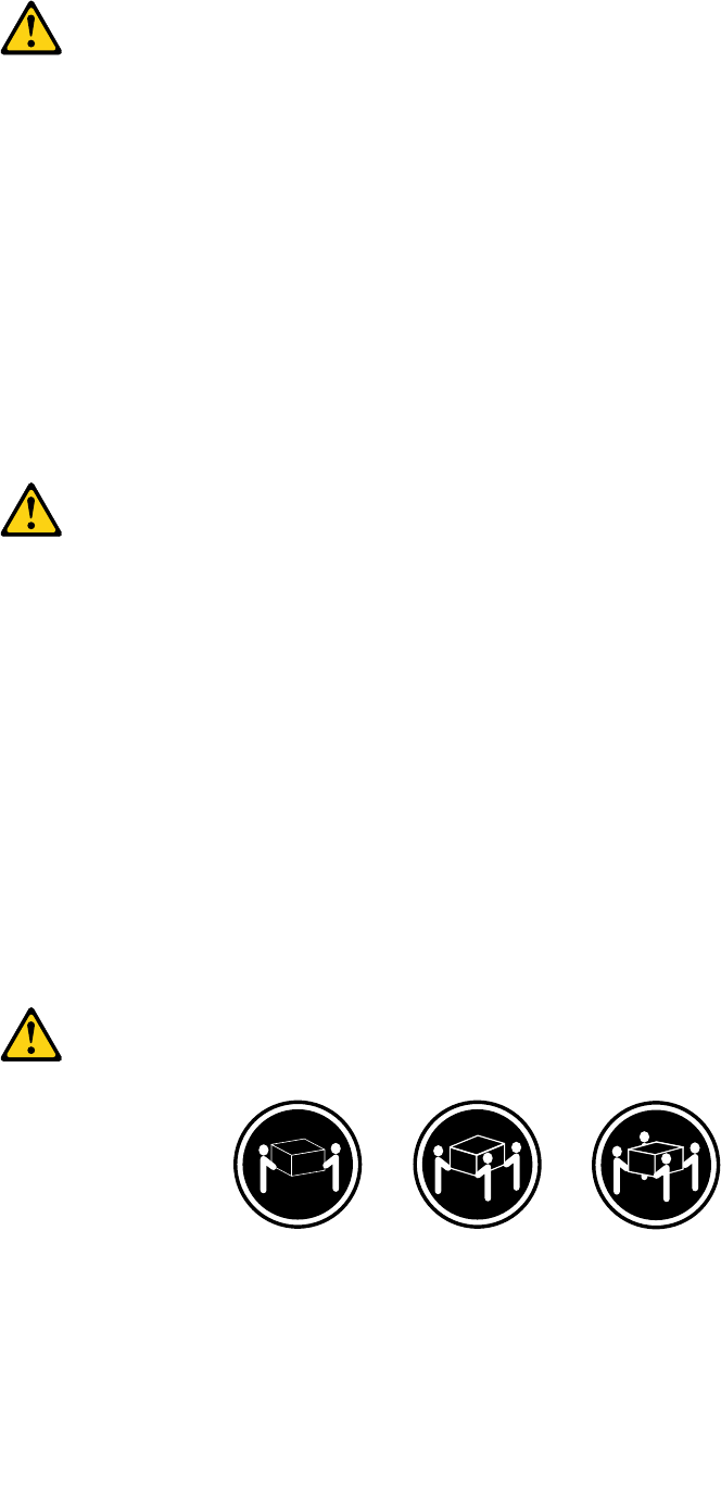
•Whenliftinganyheavyobject:
1.Ensureyoucanstandsafelywithoutslipping.
2.Distributetheweightoftheobjectequallybetweenyourfeet.
3.Useaslowliftingforce.Nevermovesuddenlyortwistwhenyouattempttolift.
4.Liftbystandingorbypushingupwithyourlegmuscles;thisactionremovesthestrainfromthe
musclesinyourback.Donotattempttoliftanyobjectsthatweighmorethan16kg(35lb)orobjects
thatyouthinkaretooheavyforyou.
•Donotperformanyactionthatcauseshazardstothecustomer,orthatmakestheequipmentunsafe.
•Beforeyoustartthemachine,ensurethatotherservicerepresentativesandthecustomer'spersonnelare
notinahazardousposition.
•Placeremovedcoversandotherpartsinasafeplace,awayfromallpersonnel,whileyouareservicing
themachine.
•Keepyourtoolcaseawayfromwalkareassothatotherpeoplewillnottripoverit.
•Donotwearlooseclothingthatcanbetrappedinthemovingpartsofamachine.Ensurethatyoursleeves
arefastenedorrolledupaboveyourelbows.Ifyourhairislong,fastenit.
•Inserttheendsofyournecktieorscarfinsideclothingorfastenitwithanonconductiveclip,approximately
8centimeters(3inches)fromtheend.
•Donotwearjewelry,chains,metal-frameeyeglasses,ormetalfastenersforyourclothing.
Remember:Metalobjectsaregoodelectricalconductors.
•Wearsafetyglasseswhenyouare:hammering,drilling,soldering,cuttingwire,attachingsprings,using
solvents,orworkinginanyotherconditionsthatmightbehazardoustoyoureyes.
•Afterservice,reinstallallsafetyshields,guards,labels,andgroundwires.Replaceanysafetydevice
thatiswornordefective.
•Reinstallallcoverscorrectlybeforereturningthemachinetothecustomer.
Electricalsafety
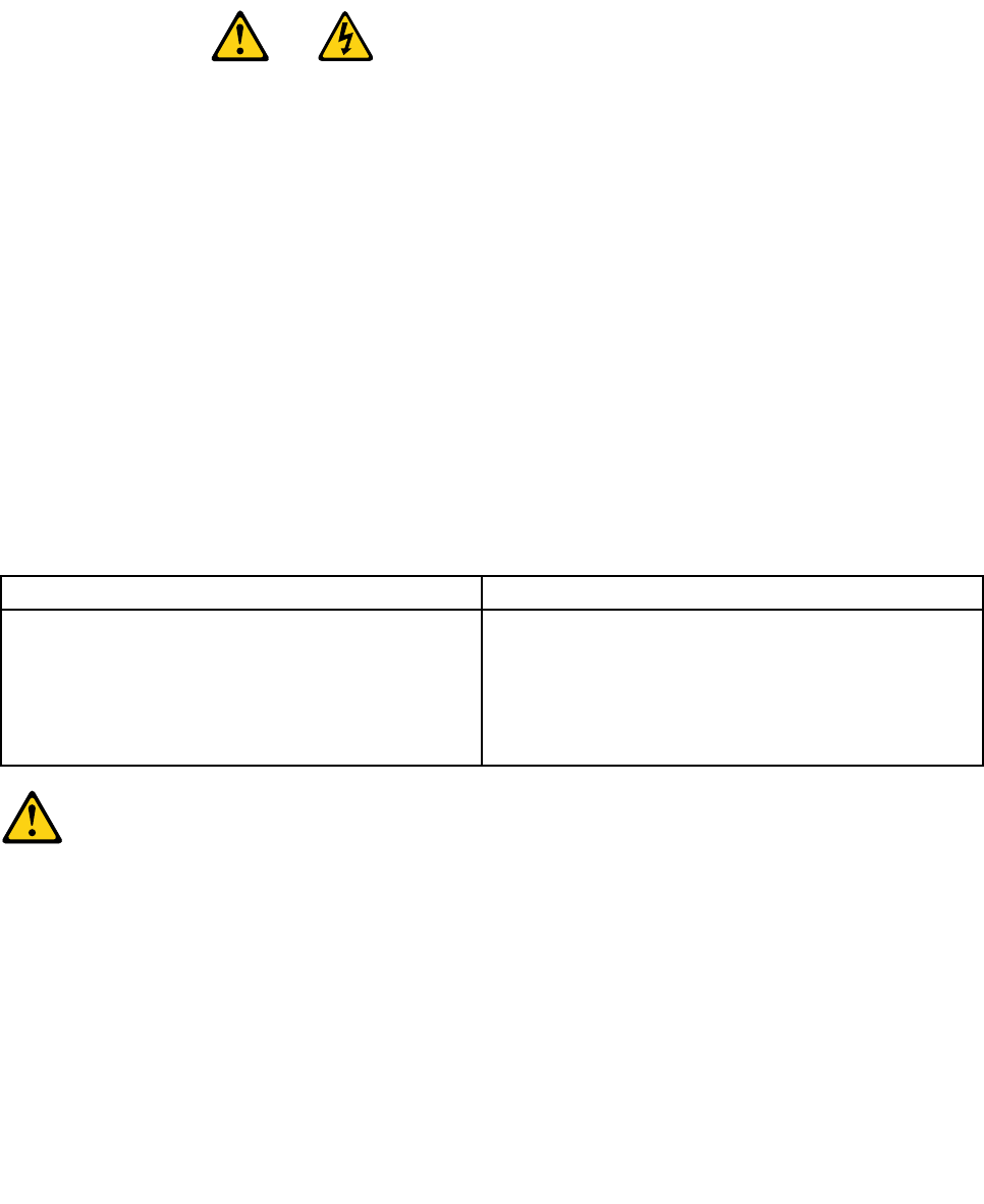
CAUTION:
Electricalcurrentfrompower,telephone,andcommunicationcablescanbehazardous.Toavoid
personalinjuryorequipmentdamage,disconnecttheattachedpowercords,telecommunication
systems,networks,andmodemsbeforeyouopenthecentrecovers,unlessinstructedotherwisein
theinstallationandcongurationprocedures.
Observethefollowingruleswhenworkingonelectricalequipment.
©CopyrightLenovo20123

Important:Useonlyapprovedtoolsandtestequipment.Somehandtoolshavehandlescoveredwithasoft
materialthatdoesnotinsulateyouwhenworkingwithliveelectricalcurrents.Manycustomershave,near
theirequipment,rubberoormatsthatcontainsmallconductiveberstodecreaseelectrostaticdischarges.
Donotusethistypeofmattoprotectyourselffromanelectricshock.
•Findtheroomemergencypower-off(EPO)switch,disconnectingswitch,orelectricaloutlet.Ifanelectrical
accidentoccurs,youcanthenoperatetheswitchorunplugthepowercordquickly.
•Donotworkaloneunderhazardousconditionsornearequipmentthathashazardousvoltages.
•Disconnectallpowerbefore:
–Performingamechanicalinspection
–Workingnearpowersupplies
–RemovingorinstallingFieldReplaceableUnits(FRU)
•Beforeyoustarttoworkonthemachine,unplugthepowercord.Ifyoucannotunplugit,askthecustomer
topower-offthewallboxthatsuppliespowertothemachineandtolockthewallboxintheoffposition.
•Ifyouneedtoworkonamachinethathasexposedelectricalcircuits,observethefollowingprecautions:
–Ensurethatanotherperson,familiarwiththepower-offcontrols,isnearyou.
Remember:Anotherpersonmustbetheretoswitchoffthepower,ifnecessary.
–Useonlyonehandwhenworkingwithpowered-onelectricalequipment;keeptheotherhandinyour
pocketorbehindyourback.
Remember:Theremustbeacompletecircuittocauseanelectricshock.Byobservingtheabove
rule,youmaypreventacurrentfrompassingthroughyourbody.
–Whenusingatester,setthecontrolscorrectlyandusetheapprovedprobeleadsandaccessoriesfor
thattester.
–Standonsuitablerubbermats(obtainedlocally,ifnecessary)toinsulateyoufromgroundssuchas
metaloorstripsandmachineframes.
Observethespecialsafetyprecautionswhenyouworkwithveryhighvoltages;theseinstructionsarein
thesafetysectionsofmaintenanceinformation.Useextremecarewhenmeasuringhighvoltages.
•Regularlyinspectandmaintainyourelectricalhandtoolsforsafeoperationalcondition.
•Donotusewornorbrokentoolsandtesters.
•Neverassumethatpowerhasbeendisconnectedfromacircuit.First,checkthatithasbeenpowered-off.
•Alwayslookcarefullyforpossiblehazardsinyourworkarea.Examplesofthesehazardsaremoistoors,
nongroundedpowerextensioncables,powersurges,andmissingsafetygrounds.
•Donottouchliveelectricalcircuitswiththereectivesurfaceofaplasticdentalmirror.Thesurfaceis
conductive;suchtouchingcancausepersonalinjuryandmachinedamage.
•Donotservicethefollowingpartswiththepoweronwhentheyareremovedfromtheirnormaloperating
placesinamachine:
–Powersupplyunits
–Pumps
–Blowersandfans
–Motorgenerators
andsimilarunits.(Thispracticeensurescorrectgroundingoftheunits.)
•Ifanelectricalaccidentoccurs:
–Usecaution;donotbecomeavictimyourself.
–Switchoffpower.
–Sendanotherpersontogetmedicalaid.
4ThinkCentreHardwareMaintenanceManual

Voltage-selectionswitch
Somecomputersareequippedwithavoltage-selectionswitchlocatednearthepower-cordconnection
pointonthecomputer.Ifyourcomputerhasavoltage-selectionswitch,ensurethatyousettheswitchto
matchthevoltageavailableatyourelectricaloutlet.Settingthevoltage-selectionswitchincorrectlycan
causepermanentdamagetothecomputer.
Ifyourcomputerdoesnothaveavoltage-selectionswitch,yourcomputerisdesignedtooperateonlyatthe
voltageprovidedinthecountryorregionwherethecomputerwasoriginallypurchased.
Ifyourelocateyourcomputertoanothercountry,beawareofthefollowing:
•Ifyourcomputerdoesnothaveavoltage-selectionswitch,donotconnectthecomputertoanelectrical
outletuntilyouhaveveriedthatthevoltageprovidedisthesameasitwasinthecountryorregion
wherethecomputerwasoriginallypurchased.
•Ifyourcomputerhasavoltage-selectionswitch,donotconnectthecomputertoanelectricaloutletuntil
youhaveveriedthatthevoltage-selectionswitchissettomatchthevoltageprovidedinthatcountry
orregion.
Ifyouarenotsureofthevoltageprovidedatyourelectricaloutlet,contactyourlocalelectriccompanyor
refertoofcialWebsitesorotherliteraturefortravelerstothecountryorregionwhereyouarelocated.
Safetyinspectionguide
Theintentofthisinspectionguideistoassistyouinidentifyingpotentiallyunsafeconditionsonthese
products.Eachmachine,asitwasdesignedandbuilt,hadrequiredsafetyitemsinstalledtoprotectusers
andservicepersonnelfrominjury.Thisguideaddressesonlythoseitems.However,goodjudgmentshould
beusedtoidentifypotentialsafetyhazardsduetoattachmentoffeaturesoroptionsnotcoveredbythis
inspectionguide.
Ifanyunsafeconditionsarepresent,youmustdeterminehowserioustheapparenthazardcouldbeand
whetheryoucancontinuewithoutrstcorrectingtheproblem.
Considertheseconditionsandthesafetyhazardstheypresent:
•Electricalhazards,especiallyprimarypower(primaryvoltageontheframecancauseseriousorfatal
electricalshock).
•Explosivehazards,suchasadamagedCRTfaceorbulgingcapacitor
•Mechanicalhazards,suchaslooseormissinghardware
Theguideconsistsofaseriesofstepspresentedinachecklist.Beginthecheckswiththepoweroff,and
thepowercorddisconnected.
Checklist:
1.Checkexteriorcoversfordamage(loose,broken,orsharpedges).
2.Power-offthecomputer.Disconnectthepowercord.
3.Checkthepowercordfor:
a.Athird-wiregroundconnectoringoodcondition.Useametertomeasurethird-wireground
continuityfor0.1ohmorlessbetweentheexternalgroundpinandframeground.
b.Thepowercordshouldbetheappropriatetypeasspeciedinthepartslistings.
c.Insulationmustnotbefrayedorworn.
4.Removethecover.
Chapter2.Safetyinformation5

5.Checkforanyobviousalterations.Usegoodjudgmentastothesafetyofanyalterations.
6.Checkinsidetheunitforanyobviousunsafeconditions,suchasmetallings,contamination,wateror
otherliquids,orsignsofreorsmokedamage.
7.Checkforworn,frayed,orpinchedcables.
8.Checkthatthepower-supplycoverfasteners(screwsorrivets)havenotbeenremovedortamperedwith.
Handlingelectrostaticdischarge-sensitivedevices
Anycomputerpartcontainingtransistorsorintegratedcircuits(ICs)shouldbeconsideredsensitiveto
electrostaticdischarge(ESD).ESDdamagecanoccurwhenthereisadifferenceinchargebetweenobjects.
ProtectagainstESDdamagebyequalizingthechargesothatthemachine,thepart,theworkmat,andthe
personhandlingthepartareallatthesamecharge.
Notes:
1.Useproduct-specicESDprocedureswhentheyexceedtherequirementsnotedhere.
2.MakesurethattheESDprotectivedevicesyouusehavebeencertied(ISO9000)asfullyeffective.
WhenhandlingESD-sensitiveparts:
•Keepthepartsinprotectivepackagesuntiltheyareinsertedintotheproduct.
•Avoidcontactwithotherpeoplewhilehandlingthepart.
•Wearagroundedwriststrapagainstyourskintoeliminatestaticonyourbody.
•Preventthepartfromtouchingyourclothing.Mostclothingisinsulativeandretainsachargeevenwhen
youarewearingawriststrap.
•Usetheblacksideofagroundedworkmattoprovideastatic-freeworksurface.Thematisespecially
usefulwhenhandlingESD-sensitivedevices.
•Selectagroundingsystem,suchasthoselistedbelow,toprovideprotectionthatmeetsthespecic
servicerequirement.
Note:TheuseofagroundingsystemisdesirablebutnotrequiredtoprotectagainstESDdamage.
–AttachtheESDgroundcliptoanyframeground,groundbraid,orgreen-wireground.
–UseanESDcommongroundorreferencepointwhenworkingonadouble-insulatedor
battery-operatedsystem.Youcanusecoaxorconnector-outsideshellsonthesesystems.
–Usetheroundground-prongoftheacplugonac-operatedcomputers.
Groundingrequirements
Electricalgroundingofthecomputerisrequiredforoperatorsafetyandcorrectsystemfunction.Proper
groundingoftheelectricaloutletcanbeveriedbyacertiedelectrician.
Safetynotices(multi-lingualtranslations)
Thecautionanddangersafetynoticesinthissectionareprovidedinthefollowinglanguages:
•English
•Arabic
•Brazilian/Portuguese
•Chinese(simplied)
•Chinese(traditional)
6ThinkCentreHardwareMaintenanceManual
•French
•German
•Hebrew
•Italian
•Korean
•Spanish
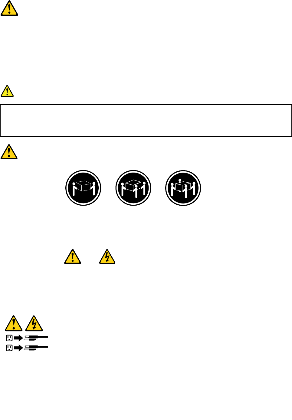
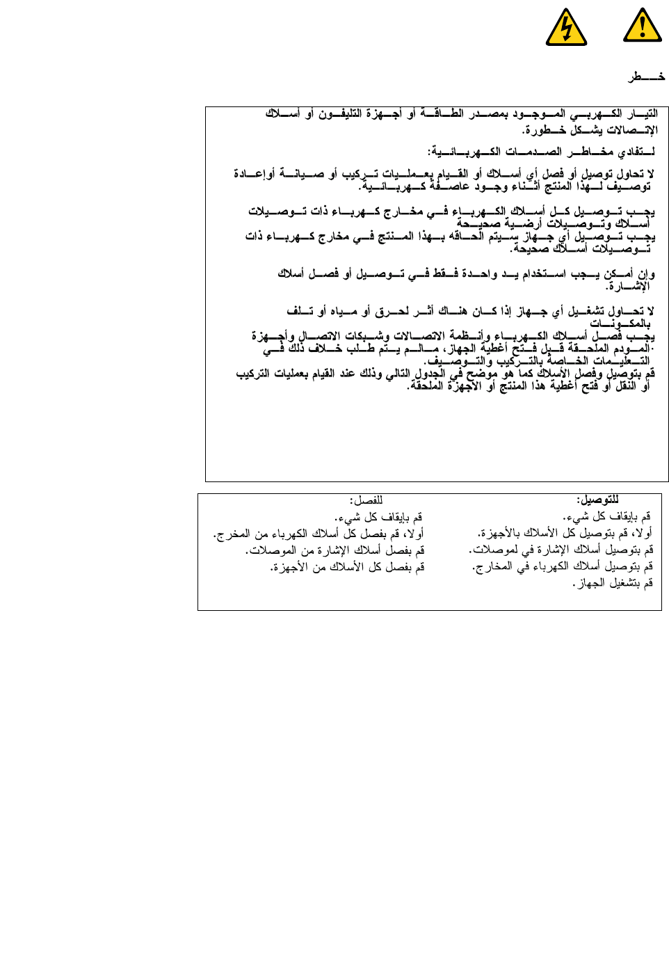
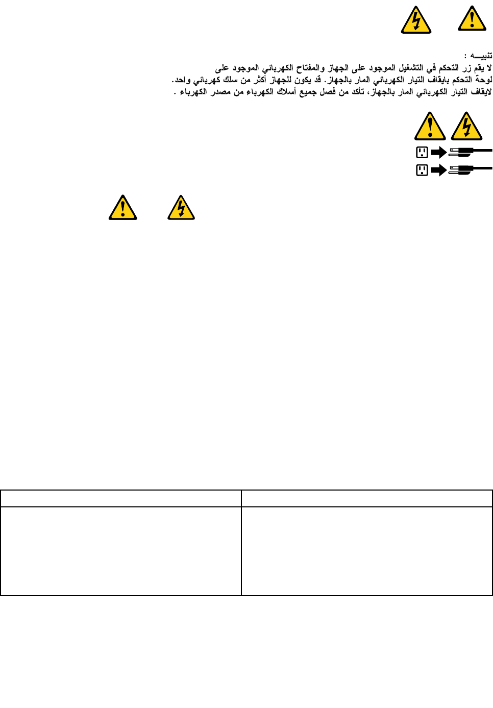
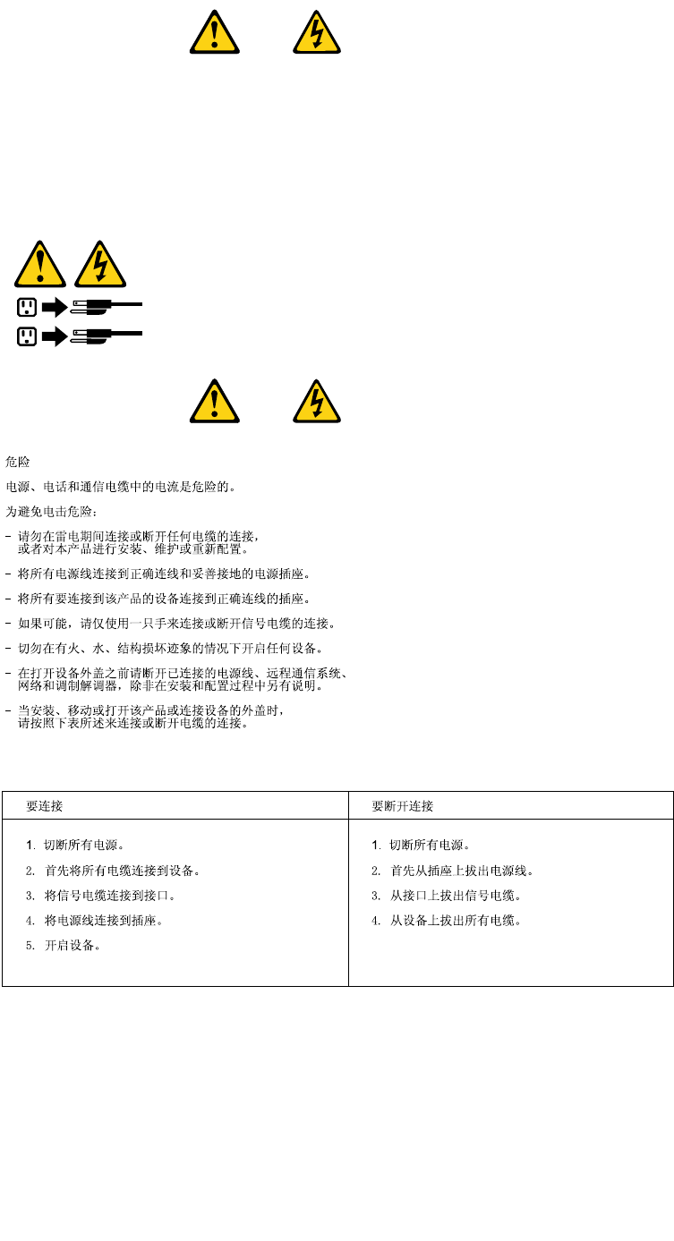
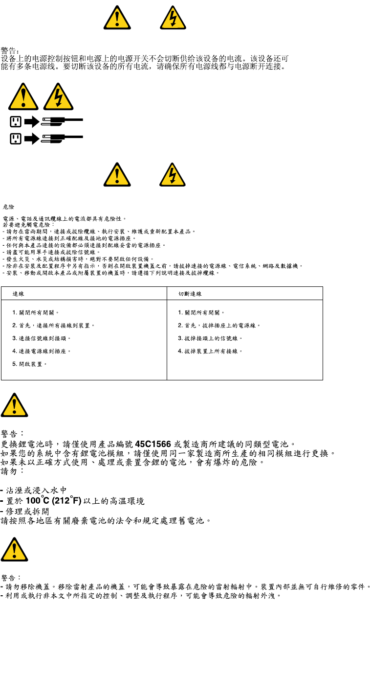
DANGER
Electricalcurrentfrompower,telephoneandcommunicationcablesishazardous.
Toavoidashockhazard:
•Donotconnectordisconnectanycablesorperforminstallation,maintenance,orreconguration
ofthisproductduringanelectricalstorm.
•Connectallpowercordstoaproperlywiredandgroundedelectricaloutlet.
•Connecttoproperlywiredoutletsanyequipmentthatwillbeattachedtothisproduct.
•Whenpossible,useonehandonlytoconnectordisconnectsignalcables.
•Neverturnonanyequipmentwhenthereisevidenceofre,water,orstructuraldamage.
•Disconnecttheattachedpowercords,telecommunicationssystems,networks,andmodems
beforeyouopenthedevicecovers,unlessinstructedotherwiseintheinstallationandconguration
procedures.
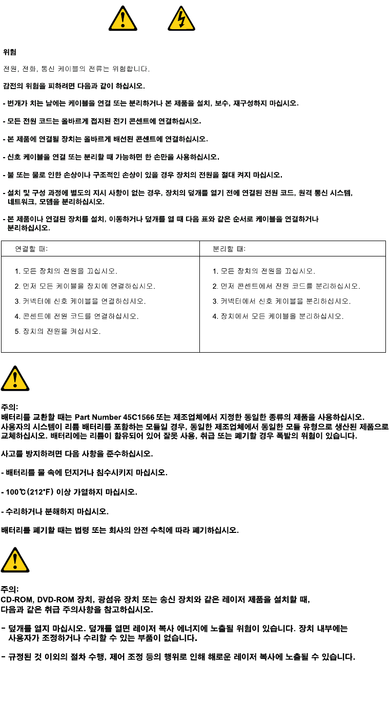
•Connectanddisconnectcablesasdescribedinthefollowingtableswheninstalling,moving,or
openingcoversonthisproductorattacheddevices.
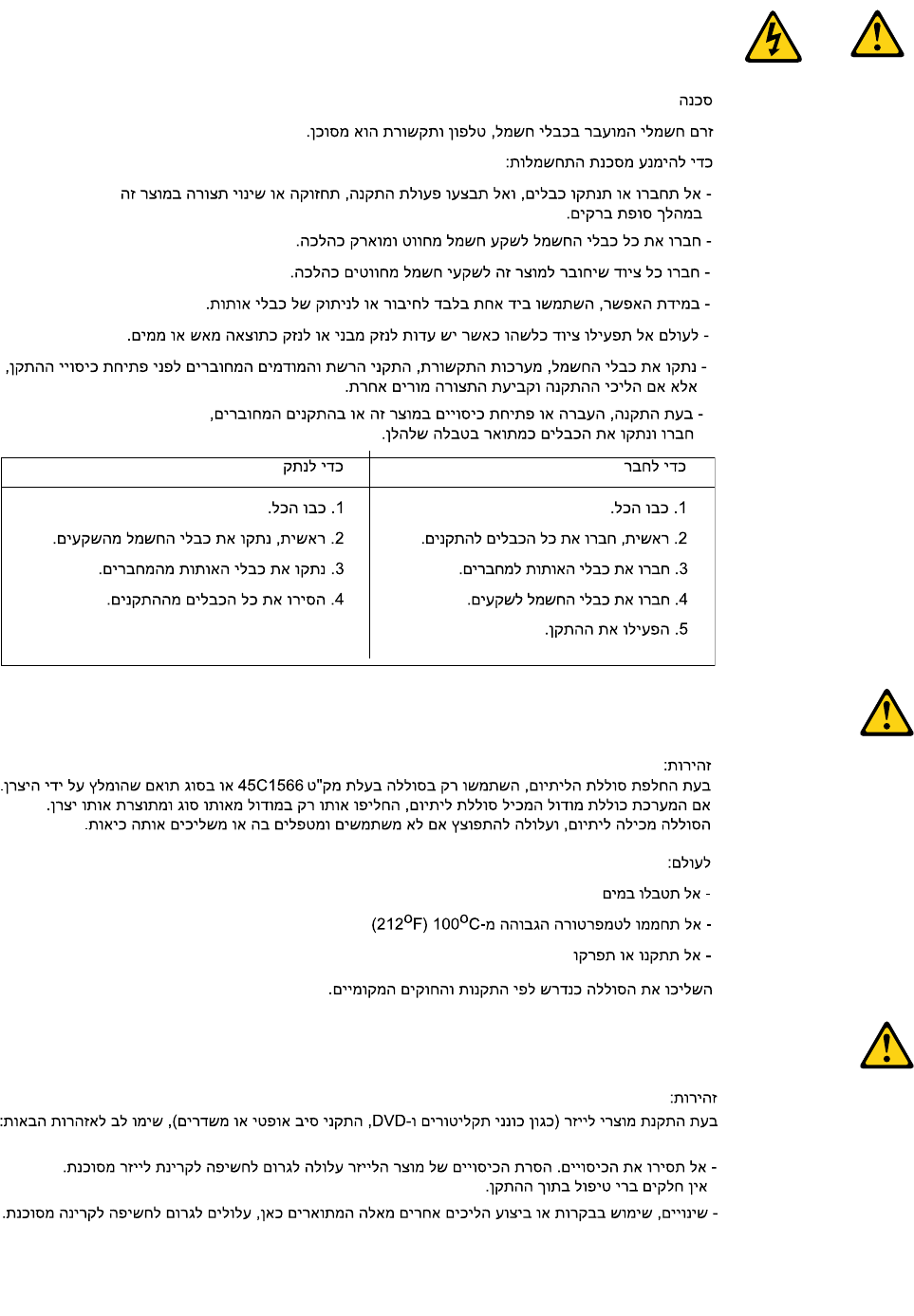
ToConnectToDisconnect
1.TurneverythingOFF.
2.First,attachallcablestodevices.
3.Attachsignalcablestoconnectors.
4.Attachpowercordstooutlet.
5.TurndeviceON.
1.TurneverythingOFF.
2.First,removepowercordsfromoutlet.
3.Removesignalcablesfromconnectors.
4.Removeallcablesfromdevices.
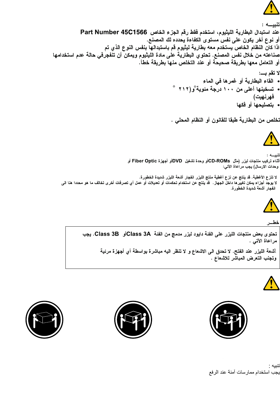
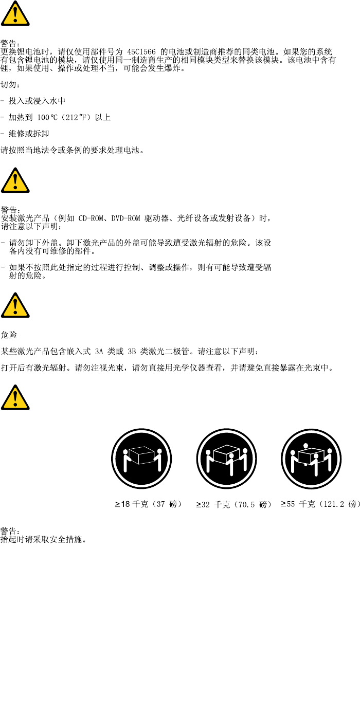
CAUTION:
Whenreplacingthelithiumbattery,useonlyPartNumber45C1566oranequivalenttypebattery
recommendedbythemanufacturer.Ifyoursystemhasamodulecontainingalithiumbattery,replace
itonlywiththesamemoduletypemadebythesamemanufacturer.Thebatterycontainslithiumand
canexplodeifnotproperlyused,handled,ordisposedof.Donot:
•Throworimmerseintowater
•Heattomorethan100°C(212°F)
•Repairordisassemble
Disposeofthebatteryasrequiredbylocalordinancesorregulations.
Chapter2.Safetyinformation7
CAUTION:
Whenlaserproducts(suchasCD-ROMs,DVD-ROMdrives,beropticdevices,ortransmitters)are
installed,notethefollowing:
•Donotremovethecovers.Removingthecoversofthelaserproductcouldresultinexposureto
hazardouslaserradiation.Therearenoserviceablepartsinsidethedevice.
•Useofcontrolsoradjustmentsorperformanceofproceduresotherthanthosespeciedherein
mightresultinhazardousradiationexposure.
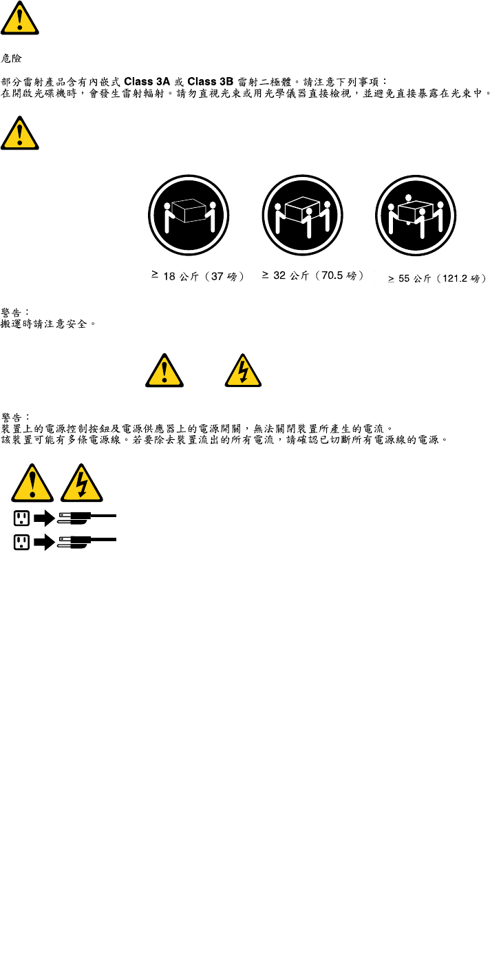
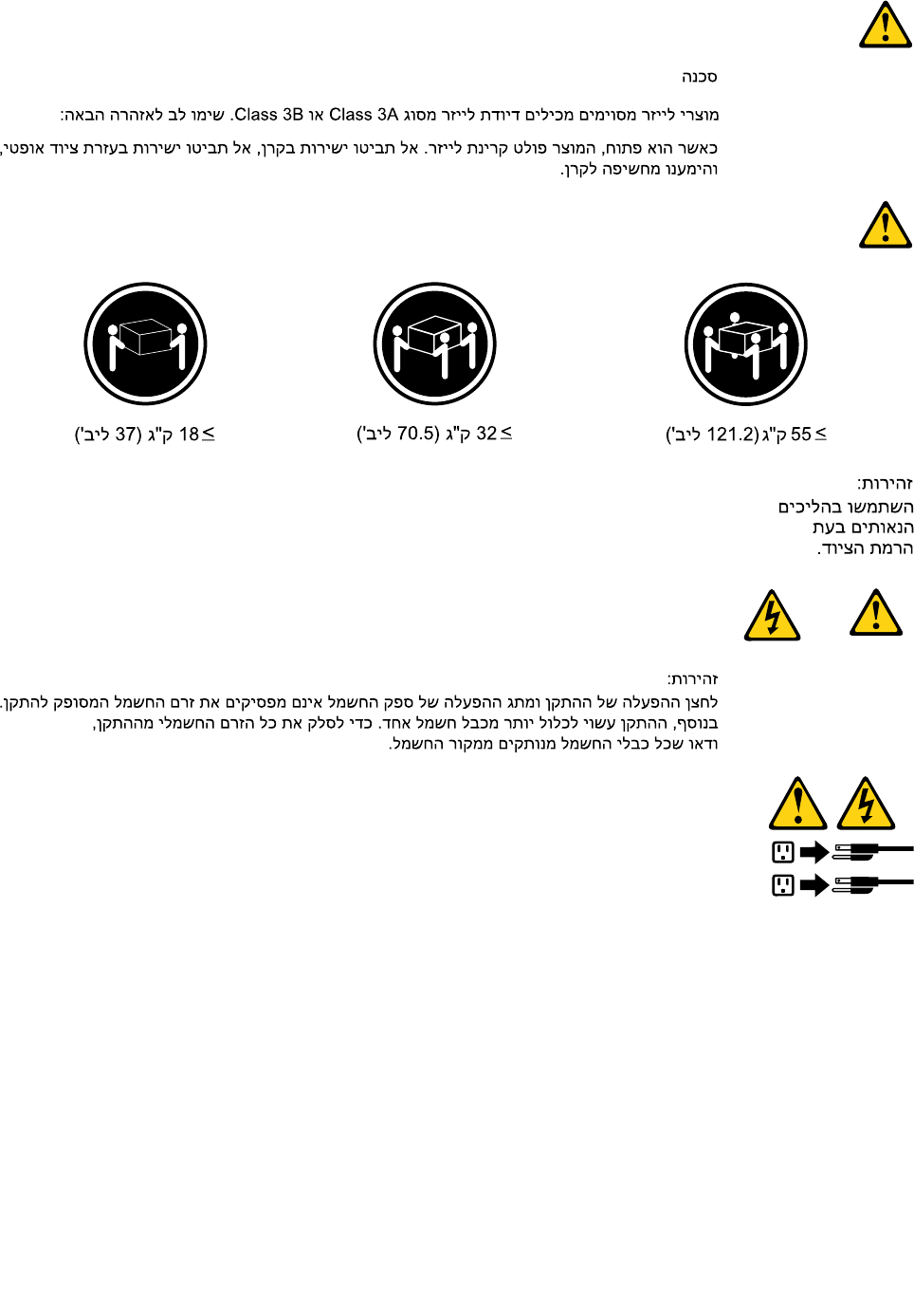
DANGER
SomelaserproductscontainanembeddedClass3AorClass3Blaserdiode.Notethefollowing:
Laserradiationwhenopen.Donotstareintothebeam,donotviewdirectlywithoptical
instruments,andavoiddirectexposuretothebeam.
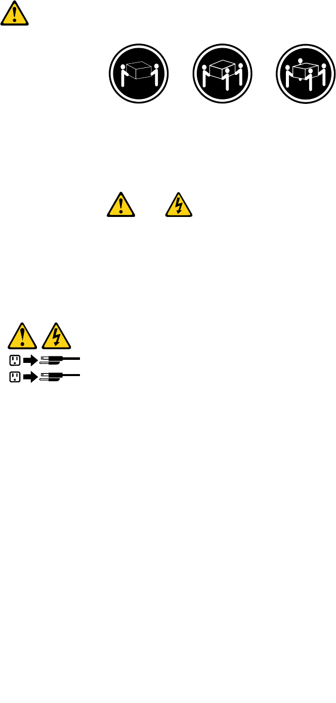
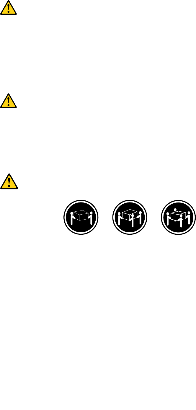
≥18kg(37lb)≥32kg(70.5lb)≥55kg(121.2lb)
CAUTION:
Usesafepracticeswhenlifting.
CAUTION:
Thepowercontrolbuttononthedeviceandthepowerswitchonthepowersupplydonotturnoff
theelectricalcurrentsuppliedtothedevice.Thedevicealsomighthavemorethanonepower
cord.Toremoveallelectricalcurrentfromthedevice,ensurethatallpowercordsaredisconnected
fromthepowersource.
1
2
8ThinkCentreHardwareMaintenanceManual
Chapter2.Safetyinformation9
≥18kg(37lb)≥32kg(70.5lb)≥55kg(121.2lb)
10ThinkCentreHardwareMaintenanceManual
1
2
PERIGO
Acorrenteelétricaprovenientedecabosdealimentação,detelefoneedecomunicaçõeséperigosa.
Paraevitarriscodechoqueelétrico:
•Nãoconectenemdesconectenenhumcaboouexecuteinstalação,manutençãooureconguração
desteprodutoduranteumatempestadecomraios.
•Conectetodososcabosdealimentaçãoatomadaselétricascorretamenteinstaladaseaterradas.
•Todoequipamentoqueforconectadoaesteprodutodeveserconectadoatomadascorretamente
instaladas.
•Quandopossível,utilizeapenasumadasmãosparaconectaroudesconectarcabosdesinal.
•Nuncaliguenenhumequipamentoquandohouverevidênciadefogo,águaoudanosestruturais.
•Antesdeabrirtampasdedispositivos,desconectecabosdealimentação,sistemasdetelecomunicação,
redesemodemsconectados,amenosqueespecicadodemaneiradiferentenosprocedimentosde
instalaçãoeconguração.
•Conecteedesconecteoscabosconformedescritonatabelaapresentadaaseguiraoinstalar,moverou
abrirtampasdesteprodutooudedispositivosconectados.
ParaConectar:ParaDesconectar:
1.DESLIGUETudo.
2.Primeiramente,conectetodososcabosaos
dispositivos.
3.Conecteoscabosdesinalaosconectores.
4.Conecteoscabosdealimentaçãoàstomadas.
5.LIGUEosdispositivos.
1.DESLIGUETudo.
2.Primeiramente,removaoscabosdealimentaçãodas
tomadas.
3.Removaoscabosdesinaldosconectores.
4.Removatodososcabosdosdispositivos.
Chapter2.Safetyinformation11
CUIDADO:
Aosubstituirabateriadelítio,utilizeapenasumabateriacomNúmerodePeça45C1566ouumtipo
debateriaequivalenterecomendadopeloSeoseusistemapossuiummódulocomumabateriade
lítio,substitua-oapenasporummódulodomesmotipoedomesmofabricante.Abateriacontémlítio
epodeexplodirsenãoforutilizada,manuseadaoudescartadademaneiracorreta.
Não:
•Jogueoucoloquenaágua
•Aqueçaamaisde100°C(212°F)
•Consertenemdesmonte
Descarteabateriaconformerequeridopelasleisouregulamentoslocais.
PRECAUCIÓN:
Quandoprodutosalaser(comounidadesdeCD-ROMs,unidadesdeDVD-ROM,dispositivosdebraótica
outransmissores)estivereminstalados,observeoseguinte:
•Nãoremovaastampas.Aremoçãodastampasdeumprodutoalaserpoderesultaremexposição
prejudicialàradiaçãodelaser.Nãoexistempeçasquepodemserconsertadasnointeriordodispositivo.
•Autilizaçãodecontrolesouajustesouaexecuçãodeprocedimentosdiferentesdosespecicadosaqui
poderesultaremexposiçãoprejudicialàradiação.
PERIGO
AlgunsprodutosalasercontêmdiododelaserintegradodaClasse3AoudaClasse3B.Observeoseguinte:
Radiaçãoalaserquandoaberto.Nãoolhediretamenteparaofeixeaolhonuoucominstrumentosópticose
eviteexposiçãodiretaaofeixe.
≥18kg(37lb)≥32kg(70.5lb)≥55kg(121.2lb)
CUIDADO:
Utilizeprocedimentosdesegurançaparalevantarequipamentos.
12ThinkCentreHardwareMaintenanceManual
CUIDADO:
Obotãodecontroledealimentaçãododispositivoeobotãoparaligar/desligardafontedealimentação
nãodesligamacorrenteelétricafornecidaaodispositivo.Odispositivotambémpodetermaisdeumcabo
dealimentação.Pararemovertodaacorrenteelétricadodispositivo,assegurequetodososcabosde
alimentaçãoestejamdesconectadosdafontedealimentação.
1
2
Chapter2.Safetyinformation13
14ThinkCentreHardwareMaintenanceManual
1
2
Chapter2.Safetyinformation15
1
2
16ThinkCentreHardwareMaintenanceManual

DANGER
Lecourantélectriqueprovenantdel'alimentation,dutéléphoneetdescâblesdetransmissionpeutprésenter
undanger.
Pourévitertoutrisquedechocélectrique:
•Nemanipulezaucuncâbleetn'effectuezaucuneopérationd'installation,d'entretienoudereconguration
deceproduitaucoursd'unorage.
•Brancheztouslescordonsd'alimentationsurunsocledeprisedecourantcorrectementcâbléetmisàla
terre.
•Branchezsurdessoclesdeprisedecourantcorrectementcâbléstoutéquipementconnectéàceproduit.
•Lorsquecelaestpossible,n'utilisezqu'uneseulemainpourconnecteroudéconnecterlescâbles
d'interface.
•Nemettezjamaisunéquipementsoustensionencasd'incendieoud'inondation,ouenprésencede
dommagesmatériels.
•Avantderetirerlescartersdel'unité,mettezcelle-cihorstensionetdéconnectezsescordons
d'alimentation,ainsiquelescâblesquilarelientauxréseaux,auxsystèmesdetélécommunicationetaux
modems(saufinstructioncontrairementionnéedanslesprocéduresd'installationetdeconguration).
•Lorsquevousinstallez,quevousdéplacez,ouquevousmanipulezleprésentproduitoudespériphériques
quiluisontraccordés,reportez-vousauxinstructionsci-dessouspourconnecteretdéconnecterles
différentscordons.
ConnexionDéconnexion
1.MettezlesunitésHORSTENSION.
2.Commencezparbranchertouslescordonssurles
unités.
3.Branchezlescâblesd'interfacesurdesconnecteurs.
4.Branchezlescordonsd'alimentationsurdesprises.
5.MettezlesunitésSOUSTENSION.
1.MettezlesunitésHORSTENSION.
2.Débranchezlescordonsd'alimentationdesprises.
3.Débranchezlescâblesd'interfacedesconnecteurs.
4.Débrancheztouslescâblesdesunités.
Chapter2.Safetyinformation17

ATTENTION:
Remplacerlapileaulithiumusagéeparunepilederéférenceidentiqueexclusivement,(référence
45C1566),ousuivrelesinstructionsdufabricantquiendénitleséquivalences.Sivotresystèmeest
dotéd'unmodulecontenantunepileaulithium,vousdevezleremplaceruniquementparunmodule
identique,produitparlemêmefabricant.Lapilecontientdulithiumetpeutexploserencasde
mauvaiseutilisation,demauvaisemanipulationoudemiseaurebutinappropriée.
Nepas:
•lajeteràl'eau,
•l'exposeràdestempératuressupérieuresà100°C,
•chercheràlaréparerouàladémonter.
Nepasmettrelapileàlapoubelle.Pourlamiseaurebut,sereporteràlaréglementationenvigueur.
ATTENTION:
Sidesproduitsàlaser(telsquedesunitésdeCD-ROM,deDVD-ROM,desunitésàbresoptiques,ou
desémetteurs)sontinstallés,prenezconnaissancedesinformationssuivantes:
•Neretirezpaslecarter.Enouvrantl'unitédeCD-ROMoudeDVD-ROM,vousvousexposezau
rayonnementdangereuxdulaser.Aucunepiècedel'unitén'estréparable.
•Pourévitertoutrisqued'expositionaurayonlaser,respectezlesconsignesderéglageet
d'utilisationdescommandes,ainsiquelesprocéduresdécritesdansleprésentmanuel.
DANGER
Certainsproduitsàlasercontiennentunediodeàlaserintégréedeclasse3Aou3B.Prenez
connaissancedesinformationssuivantes:
Rayonnementlaserlorsquelecarterestouvert.Eviteztouteexpositiondirecteaurayonlaser.Evitez
deregarderxementlefaisceauoudel'observeràl'aided'instrumentsoptiques.
18ThinkCentreHardwareMaintenanceManual

≥18kg(37lb)≥32kg(70.5lb)≥55kg(121.2lb)
ATTENTION:
Soulevezlamachineavecprécaution.
ATTENTION:
L'interrupteurdecontrôled'alimentationdel'unitéetl'interrupteurdublocd'alimentationnecoupent
paslecourantélectriquealimentantl'unité.Enoutre,lesystèmepeutêtreéquipédeplusieurs
cordonsd'alimentation.Pourmettrel'unitéhorstension,vousdevezdéconnectertouslescordons
delasourced'alimentation.
1
2
Chapter2.Safetyinformation19
VORSICHT
AnNetz-,Telefon-undDatenleitungenkönnengefährlicheSpannungenanliegen.
AusSicherheitsgründen:
•BeiGewitterandiesemGerätkeineKabelanschließenoderlösen.FernerkeineInstallations-,
Wartungs-oderRekongurationsarbeitendurchführen.
•GerätnuraneineSchutzkontaktsteckdosemitordnungsgemäßgeerdetemSchutzkontakt
anschließen.
•AlleangeschlossenenGeräteebenfallsanSchutzkontaktsteckdosenmitordnungsgemäß
geerdetemSchutzkontaktanschließen.
•DieSignalkabelnachMöglichkeiteinhändiganschließenoderlösen,umeinenStromschlagdurch
BerührenvonOberächenmitunterschiedlichemelektrischemPotenzialzuvermeiden.
•Geräteniemalseinschalten,wennHinweiseaufFeuer,WasseroderGebäudeschädenvorliegen.
•DieVerbindungzudenangeschlossenenNetzkabeln,Telekommunikationssystemen,Netzwerken
undModemsistvordemÖffnendesGehäuseszuunterbrechen,sofernindenInstallations-und
KongurationsprozedurenkeineanderslautendenAnweisungenenthaltensind.
•ZumInstallieren,TransportierenundÖffnenderAbdeckungendesComputersoderder
angeschlossenenEinheitendieKabelgemäßderfolgendenTabelleanschließenundabziehen.
ZumAnschließenderKabelgehenSiewiefolgtvorZumAbziehenderKabelgehenSiewiefolgtvor
1.SchaltenSiealleEinheitenAUS.
2.SchließenSieerstalleKabelandieEinheitenan.
3.SchließenSiedieSignalkabelandieBuchsenan.
4.SchließenSiedieNetzkabelandieSteckdosean.
5.SchaltenSiedieEinheitEIN.
1.SchaltenSiealleEinheitenAUS.
2.ZiehenSiezuerstalleNetzkabelausden
Netzsteckdosen.
3.ZiehenSiedieSignalkabelausdenBuchsen.
4.ZiehenSiealleKabelvondenEinheitenab.
CAUTION:
EineverbrauchteLithiumbatterienurdurcheineBatteriemitderTeilenummer45C1566odereine
gleichwertige,vomHerstellerempfohleneBatterieersetzen.EnthältdasSystemeinModulmiteiner
Lithiumbatterie,diesesnurdurcheinModuldesselbenTypsundvondemselbenHerstellerersetzen.
DieBatterieenthältLithiumundkannbeiunsachgemäßerVerwendung,HandhabungoderEntsorgung
explodieren.
DieBatterienicht:
•mitWasserinBerührungbringen.
•über100Cerhitzen.
•reparierenoderzerlegen.
DieörtlichenBestimmungenfürdieEntsorgungvonSondermüllbeachten.
20ThinkCentreHardwareMaintenanceManual
ACHTUNG:
BeiderInstallationvonLasergeräten(wieCD-ROM-Laufwerken,DVD-aufwerken,Einheitenmit
LichtwellenleitertechnikoderSendern)Folgendesbeachten:
•DieAbdeckungennichtentfernen.DurchEntfernenderAbdeckungendesLasergerätskönnen
gefährlicheLaserstrahlungenfreigesetztwerden.DasGerätenthältkeinezuwartendenTeile.
•WerdenSteuerelemente,EinstellungenoderDurchführungenvonProzedurenandersalshier
angegebenverwendet,kanngefährlicheLaserstrahlungauftreten.
VORSICHT
EinigeLasergeräteenthalteneineLaserdiodederKlasse3Aoder3B.BeachtenSieFolgendes:
LaserstrahlungbeigeöffneterVerkleidung.NichtindenStrahlblicken.KeineLupenoderSpiegel
verwenden.Strahlungsbereichmeiden.
≥18kg(37lb)≥32kg(70.5lb)≥55kg(121.2lb)
ACHTUNG:
ArbeitsschutzrichtlinienbeimAnhebenderMaschinebeachten.
ACHTUNG:
MitdemNetzschalteranderEinheitundamNetzteilwirddieStromversorgungfürdieEinheit
nichtunterbrochen.DieEinheitkannauchmitmehrerenNetzkabelnausgestattetsein.Umdie
StromversorgungfürdieEinheitvollständigzuunterbrechen,müssenallezumGerätführenden
NetzkabelvomNetzgetrenntwerden.
1
2
Chapter2.Safetyinformation21
22ThinkCentreHardwareMaintenanceManual
1
2
Chapter2.Safetyinformation23
PERICOLO
Lacorrenteelettricaprovenientedaicavidialimentazione,deltelefonoedicomunicazionepuòessere
pericolosa.
Perevitareilrischiodiscosseelettriche:
•Noncollegareoscollegarequalsiasicavooppureeffettuarel'installazione,lamanutenzioneola
ricongurazionedelprodottoduranteuntemporale.
•Collegaretuttiilielettriciaunapresadialimentazionecorrettamentecablataedotatadimessaa
terra.
•Collegareallepreseelettricheappropriatetutteleapparecchiaturecheverrannoutilizzateper
questoprodotto.
•Sepossibile,utilizzaresolounamanopercollegareoscollegareicavidisegnale.
•Nonaccendereassolutamenteapparecchiatureinpresenzadiincendi,perdited'acquaodanno
strutturale.
•Scollegareicavidialimentazione,isistemiditelecomunicazione,leretieilmodemprimadi
aprireicoperchideldispositivo,salvoistruzionicontrarierelativealleprocedurediinstallazionee
congurazione.
•Collegareescollegareicavicomedescrittonellaseguentetabellaquandovengonoeffettuate
operazionidiinstallazione,spostamentooaperturadeicoperchidiquestoprodottoodelleunità
collegate.
PercollegarsiPerscollegarsi
1.SPEGNEREleapparecchiature.
2.Innanzitutto,collegaretuttiicavialleunità.
3.Collegareicavidisegnaleaiconnettori.
4.Collegareicavidialimentazioneallapresa.
5.Accenderel'unità.
1.SPEGNEREleapparecchiature.
2.Innanzitutto,rimuovereicavidialimentazionedalla
presa.
3.Rimuovereicavidisegnaledaiconnettori.
4.Rimuoveretuttiicavidalleunità.
24ThinkCentreHardwareMaintenanceManual

ATTENZIONE:
Quandosisostituiscelabatteriaallitio,utilizzaresoloilNumeroparte45C1566ountipodibatteria
equivalenteconsigliatodalproduttore.Sesulsistemaèpresenteunmodulochecontieneunabatteria
allitio,sostituirlosoloconuntipodimodulodellostessotipodellastessacasadiproduzione.La
batteriacontienelitioepuòesplodereseusata,maneggiataosmaltitainmodononcorretto.
Non:
•Gettareoimmergerelabatterianell'acqua
•Riscaldarlaadunatemperaturasuperioreai100gradiC(212gradiF)
•Smontarla,ricaricarlaotentarediripararla
Lebatterieusatevannosmaltiteinaccordoallanormativainvigore(DPR915/82esuccessive
disposizioniedisposizionilocali).
ATTENZIONE:
Quandovengonoinstallatiprodottilaser(qualiCD-ROM,unitàDVD-ROM,unitàabreotticheo
trasmittenti),tenerpresentequantosegue:
•Nonrimuovereglisportelli.L'aperturadiun'unitàlaserpuòdeterminarel'esposizionearadiazioni
laserpericolose.All'internodell'unitànonvisonopartisucuieffettuarel'assistenzatecnica.
•L'utilizzodicontrolli,regolazioniol'esecuzionediprocedurenondescrittinelpresentemanuale
possonoprovocarel'esposizionearadiazionipericolose.
PERICOLO
AlcuneunitàlasercontengonoundiodolaserdiClasse3AoClasse3B.Tenerpresentequantosegue:
Aprendol'unitàvengonoemesseradiazionilaser.Nonssareilfascio,nonguardarlodirettamente
construmentiotticiedevitarel'esposizionealfascio.
Chapter2.Safetyinformation25
≥18kg(37lb)≥32kg(70.5lb)≥55kg(121.2lb)
ATTENZIONE:
Prestareattenzionenelsollevarel'apparecchiatura.
ATTENZIONE:
Ilpulsantedicontrollodell'alimentazionepresentesull'unitàel'interruttoredell'alimentatorenon
disattivanol'alimentazionecorrentefornitaall'unità.E'possibilechel'unitàdispongadipiùcavidi
alimentazione.Perdisattivarel'alimentazionedall'unità,accertarsichetuttiicavidialimentazione
sianoscollegatidallafontedialimentazione.
1
2
26ThinkCentreHardwareMaintenanceManual
Chapter2.Safetyinformation27
1
2
28ThinkCentreHardwareMaintenanceManual
PELIGRO
Lacorrienteeléctricaprocedentedecablesdealimentación,teléfonosycablesdecomunicaciónpuede
serpeligrosa.
Paraevitarelriesgodedescargaeléctrica:
•Noconectenidesconecteloscablesnirealiceningunatareadeinstalación,mantenimientoo
reconguracióndeesteproductoduranteunatormentaeléctrica.
•Conectetodosloscablesdealimentaciónatomasdecorrientedebidamentecableadasy
conectadasatierra.
•Cualquierequipoqueseconecteaesteproductotambiéndebeconectarseatomasdecorriente
debidamentecableadas.
•Siemprequeseaposible,utiliceunasolamanoparaconectarodesconectarloscablesdeseñal.
•Noenciendanuncaunequipocuandohayseñalesdefuego,aguaodañosestructurales.
•Desconecteloscablesdealimentación,lossistemasdetelecomunicaciones,lasredesylos
módemsconectadosantesdeabrirlascubiertasdelosdispositivos,amenosqueseindiquelo
contrarioenlosprocedimientosdeinstalaciónyconguración.
•Conecteydesconecteloscables,comosedescribeenlatablasiguiente,cuandoinstale,muevao
abralascubiertasdeesteproductoodelosdispositivosconectados.
ParaconectarParadesconectar
1.APÁGUELOtodo.
2.Enprimerlugar,conectetodosloscablesalos
dispositivos.
3.Conecteloscablesdeseñalalosconectores.
4.Enchufeloscablesdealimentaciónalastomasde
corriente.
5.Enciendaeldispositivo.
1.APÁGUELOtodo.
2.Enprimerlugar,desenchufeloscablesdealimentación
delastomasdecorriente.
3.Desconecteloscablesdeseñaldelosconectores.
4.Desconectetodosloscablesdelosdispositivos.
PRECAUCIÓN:
Cuandosustituyaunabateríadelitio,utilicesolamenteunabateríanúmerodepieza45C1566uotra
detipoequivalenterecomendadaporelfabricante.Sisusistemadisponedeunmóduloquecontiene
unabateríadelitio,reemplácelosóloconelmismotipodemódulo,delmismofabricante.Labatería
contienelitioypuedeexplotarsinoseutiliza,manipulaodesechacorrectamente.
Nodebe:
•Arrojarlaalaguaosumergirlaenella
•Exponerlaatemperaturassuperioresa100°C(212°F)
•Repararlaodesmontarla
Deshágasedelabateríasegúnespeciquenlasleyesonormaslocales.
Chapter2.Safetyinformation29
PRECAUCIÓN:
Cuandohayaproductosláser(comounidadesdeCD-ROM,unidadesdeDVD,dispositivosdebra
ópticaotransmisores)instalados,tengaencuentalosiguiente:
•Noquitelascubiertas.Siquitalascubiertasdelproductoláser,podríaquedarexpuestoaradiación
láserpeligrosa.Dentrodeldispositivonoexisteningunapiezaquerequieraserviciotécnico.
•Siusacontrolesoajustesorealizaprocedimientosquenoseanlosespecicadosaquí,podría
exponersearadiacionespeligrosas.
PELIGRO
Algunosproductoslásertienenincorporadoundiodoláserdeclase3Aoclase3B.Tengaencuentalo
siguiente:
Cuandoseabre,quedaexpuestoaradiaciónláser.Nomiredirectamentealrayoláser,nisiquieracon
instrumentosópticos,yeviteexponersedirectamentealrayoláser.
≥18kg(37lb)≥32kg(70.5lb)≥55kg(121.2lb)
PRECAUCIÓN:
Adopteprocedimientossegurosallevantarelequipo.
30ThinkCentreHardwareMaintenanceManual
PRECAUCIÓN:
Elbotóndecontroldealimentacióndeldispositivoyelinterruptordealimentacióndelafuentede
alimentaciónnodesconectanlacorrienteeléctricasuministradaaldispositivo.Además,eldispositivo
podríatenermásdeuncabledealimentación.Parasuprimirtodalacorrienteeléctricadeldispositivo,
asegúresedequetodosloscablesdealimentaciónesténdesconectadosdelatomadecorriente.
1
2
Chapter2.Safetyinformation31

32ThinkCentreHardwareMaintenanceManual

Chapter3.Generalinformation
Thischapterprovidesgeneralinformationthatappliestoallmachinetypessupportedbythismanual.
LenovoWelcome
TheLenovoWelcomeprogramintroducessomeinnovativebuilt-infeaturesofLenovotoyouandguidesyou
throughsomeimportantsetuptaskstohelpyoumakethemostofyourcomputer.
LenovoThinkVantageTools
TheLenovoThinkVantage®Toolsprogramguidesyoutoahostofinformationsourcesandprovideseasy
accesstovarioustoolstohelpyouworkmoreeasilyandsecurely.
ToaccesstheLenovoThinkVantageToolsprogram,clickStart➙AllPrograms➙LenovoThinkVantage
Tools.
ThefollowingtableliststheprogramsthatyoucanaccessfromtheLenovoThinkVantageToolsprogram.To
accessaprogram,double-clickthecorrespondingicon.
Table1.ProgramiconnamesinLenovoThinkVantageTools
ProgramnameIconnameinLenovoThinkVantageTools
CreateRecoveryMediaFactoryRecoveryDisks
FingerprintSoftwareFingerprintReader
LenovoThinkVantageToolbox/LenovoSolutionCenterSystemHealthandDiagnostics
SimpleTapSimpleTap
ThinkVantagePasswordManagerPasswordVault
ThinkVantagePowerManagerPowerControls
ThinkVantageRescueandRecovery®EnhancedBackupandRestore
ThinkVantageSystemUpdateUpdateandDrives
LenovoSolutionCenter
TheLenovoSolutionCenterprogramenablesyoutotroubleshootandresolvecomputerproblems.It
combinesdiagnostictests,systeminformationcollection,securitystatus,andsupportinformation,along
withhintsandtipsformaximumsystemperformance.See“LenovoSolutionCenter”onpage54fordetailed
information.
SimpleTap
TheSimpleTapprogramprovidesyouwithaquickwaytocustomizesomebasiccomputersettingssuchas
mutingthespeakers,adjustingthevolume,lockingthecomputeroperatingsystem,launchingaprogram,
openingaWebpage,openingale,andsoon.YoualsocanusetheSimpleTapprogramtoaccessthe
LenovoAppShop,fromwhichyoucandownloadvariousapplicationsandcomputersoftware.
TostarttheSimpleTapprogram,doanyofthefollowing:
•ClickStart➙AllPrograms➙SimpleTap.
©CopyrightLenovo201233

•ClickStart➙AllPrograms➙LenovoThinkVantageTools,anddouble-clickSimpleTap.
•ClicktheredSimpleTaplaunchpointonthedesktop.Theredlaunchpointisavailableonthedesktop
afteryouhavelaunchedtheSimpleTapprogramforthersttime.
•PresstheblueThinkVantagebuttonifyourkeyboardhasone.
Note:TheSimpleTapprogramisonlyavailableoncertainmodelspreinstalledwiththeWindows7operating
system.IfyourWindows7modelisnotpreinstalledwiththeSimpleTapprogram,youcandownloadit
fromhttp://www.lenovo.com/simpletap.
Additionalinformationresources
IfyouhaveInternetaccess,themostup-to-dateinformationforyourcomputerisavailableat:
http://www.lenovo.com/support
Youcanndthefollowinginformation:
•CustomerReplaceableUnit(CRU)installationorreplacementinstructions
•Downloadsanddrivers
•Partsinformation
•Publications
•Troubleshootinginformation
•Linkstootherusefulsourcesofinformation
Specications
Thissectionliststhephysicalspecicationsforyourcomputer.
Dimensions
Width:179mm(7.05inches)
Height:34.5mm(1.36inches)
Depth:182mm(7.17inches)
Weight
Maximumcongurationasshipped:4.86kg(10.71lb)(withpackage)
Maximumcongurationasshipped:4.14kg(9.13lb)(withoutpackage)
Environment
•Airtemperature:
Operating:10°Cto35°C(50°Fto95°F)
Storage:-40°Cto60°C(-40°Fto140°F)inoriginalshippingpackage
Storage:-10°Cto60°C(14°Fto140°F)withoutpackage
•Humidity:
Operating:20%to80%(non-condensing)
Storage:20%to90%(non-condensing)
•Altitude:
Operating:-50to10000ft(-15.2to3048m)
Storage:-50to35000ft(-15.2to10668m)
Electricalinput
Theacpoweradapterinputvoltage:100to240Vac
Inputfrequencyrange:50to60Hz
34ThinkCentreHardwareMaintenanceManual

Chapter4.Generalcheckout
Attention
Thedrivesinthecomputeryouareservicingmighthavebeenrearrangedorthedrivestartupsequencemight
havebeenchanged.Beextremelycarefulduringwriteoperationssuchascopying,saving,orformatting.
Dataorprogramscanbeoverwrittenifyouselectanincorrectdrive.
Generalerrormessagesappearifaproblemorconictisfoundbyanapplicationprogram,theoperating
system,orboth.Fortheexplanationofthesemessages,refertotheinformationsuppliedwiththatsoftware
package.
BeforereplacingaFRU,ensurethatthelatestlevelofBIOSisinstalledonthesystem.Adown-levelBIOS
mightcausefalseerrorsandunnecessaryreplacementofthesystemboard.Formoreinformationonhowto
determineandobtainthelatestlevelBIOS,see“BIOSlevels”onpage127.
Usethefollowingproceduretohelpdeterminethecauseofaproblem:
1.Power-offthecomputerandallexternaldevices.
2.Checkallcablesandpowercords.
3.Setalldisplaycontrolstothemiddleposition.
4.Power-onallexternaldevices.
5.Power-onthecomputer.
•Lookfordisplayederrorcodes
•Listenforbeepcodes
•Lookforreadableinstructionsoramainmenuonthedisplay.
Ifyoudidnotreceivethecorrectresponse,proceedtostep6.
Ifyoudoreceivethecorrectresponse,proceedtostep7.
6.Lookatthefollowingconditionsandfollowtheinstructions:
•IfyouhearbeepcodesduringPOST,goto“Beepsymptoms”onpage61.
•IfthecomputerdisplaysaPOSTerror,goto“POSTerrorcodes”onpage62.
•Ifthecomputerhangsandnoerrorisdisplayed,turnoffthecomputerandthepower.Then,turnthe
powerandthecomputerbackon,continueatstep7.
7.RuntheDiagnosticprograms.See“Diagnostics”onpage54.
•Ifyoureceiveanerror,replacethepartthatthediagnosticprogramcallsout.
•Iftheteststopsandyoucannotcontinue,replacethelastdevicetested.
Problemdeterminationtips
Duetothevarietyofhardwareandsoftwarecombinationsthatcanbeencountered,usethefollowing
informationtoassistyouinproblemdetermination.Ifpossible,havethisinformationavailablewhen
requestingassistancefromServiceSupportandEngineeringfunctions.
•Machinetypeandmodel
•Processororharddiskdriveupgrades
•Failuresymptom
–Dodiagnosticsindicateafailure?
–What,when,where,single,ormultiplesystems?
–Isthefailurerepeatable?
©CopyrightLenovo201235

–Hasthiscongurationeverworked?
–Ifithasbeenworking,whatchangesweremadepriortoitfailing?
–Isthistheoriginalreportedfailure?
•Diagnosticsversion
–Typeandversionlevel
•Hardwareconguration
–Print(printscreen)congurationcurrentlyinuse
–BIOSlevel
•Operatingsystemsoftware
–Typeandversionlevel
Note:Toeliminateconfusion,identicalsystemsareconsideredidenticalonlyifthey:
1.Aretheexactmachinetypeandmodels
2.HavethesameBIOSlevel
3.Havethesameadapters/attachmentsinthesamelocations
4.Havethesameaddressjumpers/terminators/cabling
5.Havethesamesoftwareversionsandlevels
6.Havethesamediagnosticdiskettes(version)
7.Havethesamecongurationoptionssetinthesystem
8.Havethesamesetupforoperating-system-controlledles
Comparingthecongurationandsoftwareset-upbetween“workingandnon-working”systemswilloften
leadtoproblemresolution.
36ThinkCentreHardwareMaintenanceManual

Chapter5.Troubleshootinganddiagnostics
Thischapterdescribessomebasictroubleshootinganddiagnosticprograms.Ifyourcomputerproblemisnot
describedhere,see“Additionalinformationresources”onpage34foradditionaltroubleshootingresources.
Basictroubleshooting
Thefollowingtableprovidesinformationtohelpyoutroubleshootyourcomputerproblems.
Note:Ifyoucannotcorrecttheproblem,havethecomputerserviced.Foralistofserviceandsupport
telephonenumbers,refertotheSafetyandWarrantyGuidethatcomeswithyourcomputerorgotothe
LenovoSupportWebsiteathttp://www.lenovo.com/support/phone.
SymptomAction
Thecomputerdoesnotstart
whenyoupressthepower
switch.
Verifythat:
•Thepowercordiscorrectlyconnectedtotherearofthecomputerandtoa
workingelectricaloutlet.
•Ifyourcomputerhasasecondarypowerswitchontherearofthecomputer,
makesurethatitisswitchedon.
•Thepowerindicatoronthefrontofthecomputerison.
•Thecomputervoltagematchesthevoltageavailableattheelectricaloutletfor
yourcountryorregion.
Themonitorscreenisblank.Verifythat:
•Themonitorsignalcableiscorrectlyconnectedtothemonitorandtothe
appropriatemonitorconnectoronthecomputer.
•Themonitorpowercordiscorrectlyconnectedtothemonitorandtoaworking
electricaloutlet.
•Themonitoristurnedonandthebrightnessandcontrastcontrolsareset
correctly.
•Thecomputervoltagematchesthevoltageavailableattheelectricaloutletfor
yourcountryorregion.
•Ifyourcomputerhastwomonitorconnectors,besuretousetheconnector
onthegraphicscard.
Thekeyboarddoesnotwork.Verifythat:
•Thecomputeristurnedon.
•ThekeyboardissecurelyconnectedtoaUSBconnectoronthecomputer.
•Nokeysarestuck.
Themousedoesnotwork.Verifythat:
•Thecomputeristurnedon.
•ThemouseissecurelyconnectedtoaUSBconnectoronthecomputer.
•Themouseisclean.
©CopyrightLenovo201237

SymptomAction
Theoperatingsystemdoesnot
start.
Verifythat:
•Thestartupsequenceincludesthedevicewheretheoperatingsystemresides.
Usually,theoperatingsystemisontheharddiskdrive.Formoreinformation,
see“Selectingastartupdevice”onpage58.
Thecomputerbeepsmultiple
timesbeforetheoperating
systemstarts.
Verifythatnokeysarestuck.
Troubleshootingprocedure
Usethefollowingprocedureasastartingpointfordiagnosingproblemsyouareexperiencingwithyour
computer:
1.Verifythatthecablesforallattacheddevicesareconnectedcorrectlyandsecurely.
2.Verifythatallattacheddevicesthatrequireacpowerareconnectedtoproperlygrounded,functioning
electricaloutlets.
3.VerifythatallattacheddevicesareenabledintheBIOSsettingsofyourcomputer.Formoreinformation
aboutaccessingandchangingtheBIOSsettings,refertoyourChapter6“UsingtheSetupUtility
program”onpage55.
4.Gotothe“Troubleshooting”onpage38andfollowtheinstructionsforthetypeofproblemyouare
experiencing.IftheTroubleshootinginformationdoesnothelpyouresolveaproblem,continuewiththe
nextstep.
5.Tryusingapreviouslycapturedcongurationtoseeifarecentchangetohardwareorsoftwaresettings
hascausedaproblem.Beforerestoringapreviousconguration,captureyourcurrentcongurationin
casetheoldercongurationsettingsdonotsolvetheproblemorhaveadverseaffects.Torestorea
capturedconguration,clickStart➙ControlPanel➙SystemandSecurity➙System➙System
Protection➙SystemRestore.Ifthisdoesnotcorrecttheproblem,continuewiththenextstep.
6.Runthediagnosticprograms.See“LenovoSolutionCenter”onpage54formoreinformation.
•Ifthediagnosticprogramsdetectahardwarefailure,contacttheLenovoCustomerSupportCenter.
See“Additionalinformationresources”onpage34formoreinformation.
•Ifyouareunabletorunthediagnosticprograms,contacttheLenovoCustomerSupportCenter.See
“Additionalinformationresources”onpage34formoreinformation.
•Ifthediagnosticprogramsdonotdetectahardwarefailure,continuewiththenextstep.
7.Useanantivirusprogramtoseeifyourcomputerhasbeeninfectedbyavirus.Iftheprogramdetectsa
virus,removethevirus.
8.Ifnoneoftheseactionssolvetheproblem,seektechnicalassistance.See“Additionalinformation
resources”onpage34formoreinformation.
Troubleshooting
Usethetroubleshootinginformationtondsolutionstoproblemsthathavedenitesymptoms.
Ifthesymptomyourcomputerisexperiencingoccurredimmediatelyafteryouinstalledanewhardware
optionornewsoftware,dothefollowingbeforereferringtothetroubleshootinginformation:
1.Removethenewhardwareoptionorsoftware.Ifyoumustremovethecomputercovertoremovea
hardwareoption,makesureyoureviewandfollowtheelectricalsafetyinformationprovidedwithyour
computer.Foryoursafety,donotoperatethecomputerwiththecoverremoved.
2.Runthediagnosticprogramstoensureyourcomputerisoperatingcorrectly.
3.Reinstallthenewhardwareoptionorsoftwarefollowingthemanufacturer'sinstructions.
38ThinkCentreHardwareMaintenanceManual

Selecttheproblemyourcomputerisexperiencingfromthefollowinglist:
•“Audioproblems”onpage39
•“CDproblems”onpage40
•“DVDproblems”onpage41
•“Intermittentproblems”onpage42
•“Harddiskdriveproblems”onpage43
•“Keyboard,mouse,orpointingdeviceproblems”onpage43
•“Monitorproblems”onpage45
•“Networkingproblems”onpage47
•“Optionproblems”onpage49
•“Performanceandlockupproblems”onpage50
•“Printerproblems”onpage52
•“Serialportproblems”onpage52
•“Softwareproblems”onpage52
•“USBproblems”onpage53
Audioproblems
Selectyoursymptomfromthefollowinglist:
•“NoaudioinWindows”onpage39
•“AnaudiodiscorAutoPlay-enableddiscdoesnotautomaticallyplaywhenitisinsertedintoadrive”
onpage40
•“Soundcomesfromoneexternalspeakeronly”onpage40
•“NoaudioinDOSapplicationsorgames”onpage40
NoaudioinWindows
Symptom:NoaudioinWindows
Actions:
•IfyouareusingpoweredexternalspeakersthathaveanOn/Offcontrol,verifythattheOn/Offcontrolis
settotheOnpositionandthespeakerpowercableisconnectedtoaproperlygrounded,functionalac
electricaloutlet.
•Ifyourexternalspeakershaveavolumecontrol,verifythatthevolumecontrolisnotsettoolow.
•Double-clickthespeakericonintheWindowsnoticationarea.Amastervolume-controlwindowopens.
VerifythattheMutesettingsarenotcheckedandnoneofthevolumesettingsissettoolow.
•Verifythatyourexternalspeakers(andheadphones,ifused)areconnectedtothecorrectaudioconnector
onthecomputer.Mostspeakercablesarecolor-codedtomatchtheconnector.
Note:Whenexternal-speakerorheadphonecablesareattachedtotheaudioconnector,theinternal
speaker,ifpresent,isdisabled.Inmostcases,ifanaudioadapterisinstalledinoneoftheexpansionslots,
theaudiofunctionbuiltintothesystemboardisdisabled;usetheaudiojacksontheadapter.
•MakesurethattheprogramyouarerunningisdesignedforuseintheMicrosoftWindowsoperating
system.IftheprogramisdesignedtoruninDOS,theprogramdoesnotusetheWindowssoundfeature
andmustbeconguredtouseSoundBlasterProorSoundBlasteremulation.
•Verifythattheaudiodevicedriversarecorrectlyinstalled.SeeMicrosoftWindowshelpsystemformore
information.
Chapter5.Troubleshootinganddiagnostics39

Iftheseactionsdonotcorrecttheproblem,runthediagnosticprograms(see“LenovoSolutionCenter”on
page54forinstructions).Ifyouneedtechnicalassistance,see“Additionalinformationresources”onpage34.
AnaudiodiscorAutoPlay-enableddiscdoesnotautomaticallyplaywhenitis
insertedintoadrive
Symptom:AnaudiodiscorAutoPlay-enableddiscdoesnotautomaticallyplaywhenitisinsertedintoadrive
Action:See“CDproblems”onpage40.
Soundcomesfromoneexternalspeakeronly
Symptom:Soundcomesfromoneexternalspeakeronly.
Actions:
•Ensurethatthespeakercableisinsertedcompletelyintotheconnectoronthecomputer.
•Makesurethecablethatattachestheleftspeakertotherightspeakerissecurelyconnected.
•Double-clickthespeakericonintheWindowsnoticationarea.Amastervolume-controlwindowopens.
VerifythattheBalancesettingsaresetcorrectly.
Iftheseactionsdonotcorrecttheproblem,youmighthaveafailingspeaker.Havethespeakerserviced.If
youneedtechnicalassistance,see“Additionalinformationresources”onpage34.
NoaudioinDOSapplicationsorgames
Symptom:NoaudioinDOSapplicationsorgames
Actions:
•MakesuretheDOSapplicationorgameisconguredtouseSoundBlasterProorSoundBlaster
emulation.Refertothedocumentationthatcomeswiththeapplicationorgameforinstructionson
settingsound-cardsettings.
•Iftheseactionsdonotcorrecttheproblem,runthediagnosticprograms(see“LenovoSolutionCenter”
onpage54forinstructions).Ifyouneedtechnicalassistance,see“Additionalinformationresources”
onpage34.
CDproblems
Selectyoursymptomfromthefollowinglist:
•“AnaudiodiscorAutoPlay-enableddiscdoesnotautomaticallyplaywhenitisinsertedintoaCD
drive”onpage40
•“ACDorDVDdoesnotwork”onpage41
•“Unabletouseastartable(bootable)recoverymedium,suchastheProductRecoveryCD,tostart
yourcomputer”onpage41
AnaudiodiscorAutoPlay-enableddiscdoesnotautomaticallyplaywhenitis
insertedintoaCDdrive
Symptom:AnaudiodiscorAutoPlay-enableddiscdoesnotautomaticallyplaywhenitisinsertedinto
aCDdrive.
Actions:
•IfyouhavemultipleCDorDVDdrivesinstalled(oracombinationofCDandDVDdrives),tryinsertingthe
discintotheotherdrive.Insomecases,onlyoneofthedrivesisconnectedtotheaudiosubsystem.
40ThinkCentreHardwareMaintenanceManual

•IfyouareusingtheWindows7operatingsystem,followtheactionfor“ACDorDVDdoesnotwork”
onpage41.
Ifthisdoesnotcorrecttheproblem,followtheactionfor“ACDorDVDdoesnotwork”onpage41.
ACDorDVDdoesnotwork
Symptom:ACDorDVDdoesnotwork.
Actions:
•Verifythatthediscisinsertedcorrectly,withitslabelup.
•Makesurethatthediscyouareusingisclean.Toremovedustorngerprints,wipethedisccleanwitha
softclothfromthecentertotheoutside.Wipingadiscinacircularmotionmightcauselossofdata.
•Verifythatthediscyouareusingisnotscratchedordamaged.Tryinsertinganotherdiscthatyouknow
isgood.Ifyoucannotreadfromaknown-gooddisc,youmighthaveaproblemwithyourCDorDVD
driveorthecablingtoyourCDorDVDdrive.Makesurethatthepowercableandsignalcableare
securelyconnectedtothedrive.
Unabletouseastartable(bootable)recoverymedium,suchastheProductRecovery
CD,tostartyourcomputer
Symptom:Unabletouseastartable(bootable)recoverymedium,suchastheProductRecoveryCD,
tostartyourcomputer.
Action:MakesurethattheCDorDVDdriveisinthestartupsequencebeforetheharddiskdrive.Refer
toyour“Selectingorchangingthestartupdevicesequence”onpage58forinformationonviewingand
changingthestartupsequence.Notethatonsomemodelsthestartupsequenceispermanentlysetand
cannotbechanged.
Iftheseactionsdonotcorrecttheproblem,runthediagnosticprograms(see“LenovoSolutionCenter”on
page54forinstructions).Ifyouneedtechnicalassistance,see“Additionalinformationresources”onpage34.
DVDproblems
Selectyoursymptomfromthefollowinglist:
•“BlackscreeninsteadofDVDvideo”onpage41
•“DVDmoviewillnotplay”onpage42
•“NoaudioorintermittentaudiowhileplayingDVDmovie”onpage42
•“Playbackisverysloworchoppy”onpage42
•“Invaliddiscornodiscfoundmessage”onpage42
BlackscreeninsteadofDVDvideo
Symptom:BlackscreeninsteadofDVDvideo
Actions:
•RestarttheDVDplayerprogram.
•Closeanyopenles,turnoffthecomputer,andthenrestartthecomputer.
•Tryalowerscreenresolutionorcolordepth.
Iftheseactionsdonotcorrecttheproblem,runthediagnosticprograms(see“LenovoSolutionCenter”on
page54forinstructions).Ifyouneedtechnicalassistance,see“Additionalinformationresources”onpage34.
Chapter5.Troubleshootinganddiagnostics41

DVDmoviewillnotplay
Symptom:DVDmoviewillnotplay.
Actions:
•Makesurethatthediscsurfaceiscleanandnotscratched.
•Checkthediscorpackageforregionalcoding.Youmightneedtopurchaseadiscwithcodingfor
theregionwhereyouareusingyourcomputer.
Iftheseactionsdonotcorrecttheproblem,runthediagnosticprograms(see“LenovoSolutionCenter”on
page54forinstructions).Ifyouneedtechnicalassistance,see“Additionalinformationresources”onpage34.
NoaudioorintermittentaudiowhileplayingDVDmovie
Symptom:NoaudioorintermittentaudiowhileplayingDVDmovie.
Actions:
•Checkthevolumecontrolsettingsonyourcomputerandonyourspeakers.
•Makesurethatthediscsurfaceiscleanandnotscratched.
•Checkallcableconnectionstoandfromthespeakers.
•UsetheDVDmenuforthevideotoselectadifferentaudiotrack.
Iftheseactionsdonotcorrecttheproblem,runthediagnosticprograms(see“LenovoSolutionCenter”on
page54forinstructions).Ifyouneedtechnicalassistance,see“Additionalinformationresources”onpage34.
Playbackisverysloworchoppy
Symptom:Playbackisverysloworchoppy.
Actions:
•Disableanybackgroundprograms,suchasAntiVirusorDesktopThemes.
•Ensurethatvideoresolutionissettolessthan1152x864.
Iftheseactionsdonotcorrecttheproblem,runthediagnosticprograms(see“LenovoSolutionCenter”on
page54forinstructions).Ifyouneedtechnicalassistance,see“Additionalinformationresources”onpage34.
Invaliddiscornodiscfoundmessage
Symptom:Invaliddiscornodiscfoundmessage
Actions:
•EnsurethataDVDdiscisinthedrivewiththeshinysideofthediscfacingdown.
•Ensurethatvideoresolutionissettolessthan1152x864.
•OncomputersthathaveaCD-ROMorCD-RWdriveinadditiontoaDVD-ROMdrive,makesurethatthe
DVDdiscisinthedrivelabeled“DVD”.
Iftheseactionsdonotcorrecttheproblem,runthediagnosticprograms(see“LenovoSolutionCenter”on
page54forinstructions).Ifyouneedtechnicalassistance,see“Additionalinformationresources”onpage34.
Intermittentproblems
Symptom:Aproblemoccursonlyoccasionallyandisdifculttorepeat.
42ThinkCentreHardwareMaintenanceManual

Actions:
•Verifythatallcablesandcordsaresecurelyconnectedtothecomputerandattacheddevices.
•Verifythatwhenthecomputerison,thefangrillisnotblocked(thereisairowaroundthegrill),andthe
fansareworking.Ifairowisblockedorthefansarenotworking,thecomputermightoverheat.
Iftheseactionsdonotcorrecttheproblem,runthediagnosticprograms(see“LenovoSolutionCenter”on
page54forinstructions).Ifyouneedtechnicalassistance,see“Additionalinformationresources”onpage34.
Harddiskdriveproblems
Selectyoursymptomfromthefollowinglist:
•“SomeorallharddiskdrivesmissingfromtheSetupUtilityprogram”onpage43
•“"NoOperatingSystemFound"messageorthesystemnotstartingfromthecorrectharddiskdrive”
onpage43
SomeorallharddiskdrivesmissingfromtheSetupUtilityprogram
Symptom:SomeorallharddiskdrivesmissingfromtheSetupUtilityprogram
Actions:
•Ensurethatallharddiskdrivesignalcablesandpowercablesareconnectedcorrectly.
•Ensurethatyourcomputerisconguredcorrectlytosupporttheharddiskdrives.
–IfyourcomputerisinstalledwithveSATAharddiskdrives,ensurethattheSATAharddiskdrive
enablementmodule(onetoveharddiskdrives)isinstalled.
–IfyourcomputerisinstalledwithSASharddiskdrives,ensurethattheSASharddiskdriveenablement
module(onetoveharddiskdrives)ortheLSIMegaRAIDSASadapterisinstalled.
Iftheseactionsdonotcorrecttheproblem,runthediagnosticprogramLenovoSolutionCenter.See
“LenovoSolutionCenter”onpage54.Ifyouneedtechnicalassistance,see“Additionalinformation
resources”onpage34.
"NoOperatingSystemFound"messageorthesystemnotstartingfromthecorrect
harddiskdrive
Symptom:"NoOperatingSystemFound"messageorthesystemnotstartingfromthecorrectharddiskdrive
Actions:
•Ensurethatallharddiskdrivesignalcablesandpowercablesareconnectedcorrectly.
•EnsurethattheharddiskdriveyourcomputerstartsfromislistedastherststartupdeviceintheSetup
Utilityprogram.Referto“Selectingastartupdevice”onpage58.
Note:Inrarecases,theharddiskdrivewiththeoperatingsystemmightgetcorruptedordamaged.Insuch
cases,youmightneedtoreplacetheharddiskdrive.
Iftheseactionsdonotcorrecttheproblem,runthediagnosticprogramLenovoSolutionCenter.See
“LenovoSolutionCenter”onpage54.Ifyouneedtechnicalassistance,see“Additionalinformation
resources”onpage34.
Keyboard,mouse,orpointingdeviceproblems
Selectyoursymptomfromthefollowinglist:
•“Allorsomekeysonthekeyboarddonotwork”onpage44
Chapter5.Troubleshootinganddiagnostics43

•“Themouseorpointingdevicedoesnotwork”onpage44
•“Thepointeronthescreendoesnotmovesmoothlywiththemouse”onpage44
•“Thewirelesskeyboarddoesnotwork”onpage45
Allorsomekeysonthekeyboarddonotwork
Symptom:Allorsomekeysonthekeyboarddonotwork.
Actions:
•Verifythatthekeyboardcableissecurelyconnectedtothecorrectconnectoronthecomputer.
•IfyouareusinganEnhancedPerformanceUSBkeyboardandoneormoreoftheRapidAccessbuttons
aretheonlykeysthatarenotworking,thesebuttonsmighthavebeendisabledorhavenotbeenassigned
toafunction.UsethehelpsystemintheEnhancedPerformanceCustomizationKeyboardprogramto
helpdiagnoseproblemswiththeRapidAccessbuttons.
•OntheWindows7operatingsystem,dothefollowing:
1.ClickStart➙ControlPanel.
2.ClickHardwareandSound.
3.ClickDevicesandPrinters.
4.Double-clickUSBEnhancedPerformanceKeyboard.TheUSBEnhancedPerformanceKeyboard
Customizationprogramstarts.
Iftheseactionsdonotcorrecttheproblem,havethecomputerandkeyboardserviced.See“Additional
informationresources”onpage34fordetails.
Themouseorpointingdevicedoesnotwork
Symptom:Themouseorpointingdevicedoesnotwork.
Actions:
•Verifythatthemouseorpointing-devicecableissecurelyattachedtothecorrectconnectoronthe
computer.Dependingonthetypeofmouseyouhave,themousecablewillconnecttoeitherthe
mouse,serial,orUSBconnector.SomekeyboardshaveintegratedUSBconnectorsthatcanbeused
foraUSBmouseorpointingdevice.
•Verifythatthedevicedriversforthemouseorpointingdeviceareinstalledcorrectly.
•IfyouareusingaUSBkeyboardormouse,verifythattheUSBconnectorsareenabledintheBIOS
settings.See“Enablingordisablingadevice”onpage57.
Iftheseactionsdonotcorrecttheproblem,runthediagnosticprograms(see“LenovoSolutionCenter”on
page54forinstructions).Ifyouneedtechnicalassistance,see“Additionalinformationresources”onpage34.
Thepointeronthescreendoesnotmovesmoothlywiththemouse
Symptom:Thepointeronthescreendoesnotmovesmoothlywiththemouse.
Action:Erraticmovementofthemousepointerisgenerallycausedbyabuildupofdirt,oils,andother
contaminantsontheballinsidethemouse.Cleanthemouse.
Thengerprintreaderdoesnotwork
Symptom:Thengerprintreaderdoesnotwork.
Action:Thefollowingcouldcausethengerprintreadernottooperateproperly:
•Notenrollingyourngerprintcorrectly.
44ThinkCentreHardwareMaintenanceManual

•Scratchingthesurfaceofthereaderwithahard,pointedobject.
•Scrapingthesurfaceofthereaderwithyournailoranythinghard.
•Usingortouchingthereaderwithadirtynger.
•Thesurfaceofyourngerisverydifferentfromwhenyouenrolledyourngerprint.
Thewirelesskeyboarddoesnotwork
Symptom:Thewirelesskeyboarddoesnotwork.
Action:IftheTransceiverCommunicationsLEDisonandthewirelessKeyboarddoesnotwork,restartyour
computer.Ifrestartingyourcomputerdoesnotsolvetheproblem,verifythatthefollowingconditionsaremet:
•Thebatteriesareproperlyinstalled.
•Thebatteriesstillretaintheircurrent.
•ThewirelessKeyboardislocatedlessthantenmetersawayfromthetransceiver.
•Thetransceiverisfullyinstalled.
Action:IftheTransceiverCommunicationsLEDisnoton,reconnectthetransceiverandthekeyboard.
Monitorproblems
Note:Manymonitorshavestatus-indicatorlightsandbuilt-incontrolsforadjustingbrightness,contrast,
width,height,andotherpictureadjustments.However,thecontrolsvaryfrommonitortypetomonitortype.
Forinformationaboutthestatuslightsandusingthecontrols,refertothedocumentationthatcomes
withyourmonitor.
Selectyoursymptomfromthefollowinglist:
•“Wrongcharactersappearonthescreen”onpage45
•“Themonitorworkswhenyouturnonthecomputer,butgoesblankaftersomeperiodofcomputer
inactivity”onpage45
•“Themonitorworkswhenyouturnonthecomputer,butgoesblankwhenyoustartsomeapplication
programs”onpage46
•“Theimageappearstobeickering”onpage46
•“Theimageisdiscolored”onpage46
Wrongcharactersappearonthescreen
Symptom:Wrongcharactersappearonthescreen.
Action:Havethecomputerserviced.Fordetails,see“Additionalinformationresources”onpage34.
Themonitorworkswhenyouturnonthecomputer,butgoesblankaftersomeperiod
ofcomputerinactivity
Symptom:Themonitorworkswhenyouturnonthecomputer,butgoesblankaftersomeperiodofcomputer
inactivity.
Action:Thecomputerisprobablysetforenergysavingswiththepower-managementfeature.Ifthe
power-managementfeatureisenabled,disablingitorchangingthesettingsmightsolvetheproblem.
Iftheseactionsdonotcorrecttheproblem,runthediagnosticprograms(see“LenovoSolutionCenter”on
page54forinstructions).Ifyouneedtechnicalassistance,see“Additionalinformationresources”onpage34.
Chapter5.Troubleshootinganddiagnostics45

Themonitorworkswhenyouturnonthecomputer,butgoesblankwhenyoustart
someapplicationprograms
Symptom:Themonitorworkswhenyouturnonthecomputer,butgoesblankwhenyoustartsome
applicationprograms.
Actions:
•Makesurethemonitorsignalcableissecurelyconnectedtothemonitorandthemonitorconnectoron
thecomputer.Aloosecablecancauseintermittentproblems.
•Verifythatthenecessarydevicedriversfortheapplicationprogramsareinstalled.Refertothe
documentationfortheaffectedapplicationprogramtoseeifdevicedriversarerequired.
Iftheseactionsdonotcorrecttheproblem,runthediagnosticprograms(see“LenovoSolutionCenter”on
page54forinstructions).Ifyouneedtechnicalassistance,see“Additionalinformationresources”onpage34.
Theimageappearstobeickering
Symptom:Theimageappearstobeickering.
Actions:
•Themonitormightbeoperatinginalow-refreshratedisplaymode.Setthemonitortothehighest,
noninterlacedrefreshratesupportedbyyourmonitorandthevideocontrollerinyourcomputer.
Attention:Usingaresolutionorrefreshratethatisnotsupportedbyyourmonitormightdamageit.Check
thedocumentationthatcomeswithyourmonitortoverifythesupportedrefreshrates.
•Themonitormightbeaffectedbyinterferencefromnearbyequipment.Magneticeldsaroundother
devices,suchastransformers,appliances,uorescentlights,andothermonitorsmightbecausingthe
problem.Moveuorescentdesklightingoranyequipmentthatproducesmagneticeldsfartheraway
fromthemonitor.Ifthisdoesnotcorrecttheproblem,dothefollowing:
1.Turnoffthemonitor.(Movingacolormonitorwhileitisturnedonmightcausescreendiscoloration.)
2.Adjusttheplacementofthemonitorandotherdevicessothattheyareatleast305mm(12inches)
apart.
3.Turnonthemonitor.
•YoucanresettherefreshratethroughyouroperatingsystemControlPanel.
OntheWindows7operatingsystem,clickStart➙ControlPanel➙HardwareandSound➙Adjust
screenresolution➙AdvancedSettings.ThenclicktheMonitortabandselectanewrefreshrate.
•Seeyouroperatingsystemdocumentationorhelpforfurtherinformationonmonitorsettings.
Iftheseactionsdonotcorrecttheproblem,yourmonitormightneedservice.See“Additionalinformation
resources”onpage34fordetails.
Theimageisdiscolored
Symptom:Theimageisdiscolored.
Action:Themonitormightbeaffectedbyinterferencefromnearbyequipment.Magneticeldsaroundother
devices,suchastransformers,appliances,uorescentlights,andothermonitorsmightbecausingthe
problem.Moveuorescentdesklightingoranyequipmentthatproducesmagneticeldsfurtherawayfrom
themonitor.Ifthisdoesnotcorrecttheproblem,dothefollowing:
1.Turnoffthemonitor.(Movingacolormonitorwhileitisturnedonmightcausescreendiscoloration.)
2.Adjusttheplacementofthemonitorandotherdevicessothattheyareatleast305mm(12inches)apart.
3.Turnonthemonitor.
46ThinkCentreHardwareMaintenanceManual

Iftheseactionsdonotcorrecttheproblem,yourmonitormightneedservice.See“Additionalinformation
resources”onpage34fordetails.
Networkingproblems
Thefollowingarethemostcommonnetworkingproblems.Selectyournetworkingproblemfromthe
followinglist:
•“Ethernetproblems”onpage47
Formoreinformation,see“Additionalinformationresources”onpage34.
Ethernetproblems
ForEthernetproblems,selectyoursymptomfromthefollowinglist:
•“Yourcomputercannotconnecttothenetwork”onpage47
•“Theadapterstopsworkingfornoapparentreason”onpage48
•“IfyourcomputerisaGigabitEthernetmodelandyouuseaspeedof1000Mbps,theconnectionfails
orerrorsoccur”onpage48
•“IfyourcomputerisaGigabitEthernetmodel,itcannotconnecttothenetworkat1000Mbps.Instead,
itconnectsat100Mbps”onpage48
Yourcomputercannotconnecttothenetwork
Symptom:Yourcomputercannotconnecttothenetwork.
Actions:Makesurethat:
•Thecableisinstalledproperly.
ThenetworkcablemustbesecurelyconnectedtoboththeEthernetconnectorofyourcomputerand
theRJ45connectorofthehub.Themaximumallowabledistancefromthecomputertohubis100
meters.Ifthecableisconnectedandthedistanceiswithinacceptablelimitsbuttheproblempersists,try
adifferentcable.
•Thecableisinstalledproperly.
•Youareusingthecorrectdevicedriver.
OntheWindows7operatingsystem,dothefollowing:
1.ClickStart➙ControlPanel.
2.ClickHardwareandSound.
3.ClickDeviceManager.Ifyouarepromptedforanadministratorpasswordorconrmation,typethe
passwordorprovideconrmation.
4.IfanexclamationmarkisdisplayednexttoanadapternameunderNetworkadapters,youmightnot
usethecorrectdriverorthedriverisnotenabled.Toupdatethedriver,right-clickthehighlighted
adapter.
5.ClickUpdateDriverSoftware,andthenfollowtheinstructionsonthescreen.
•Theswitchportandtheadapterhavethesameduplexsetting.
Ifyouconguredtheadapterforfullduplex,makesuretheswitchportisalsoconguredforfullduplex.
Settingthewrongduplexmodecandegradeperformance,causedataloss,orresultinlostconnections.
•Youhaveinstalledallnetworkingsoftwarethatisnecessaryforyournetworkenvironment.
CheckwithyourLANadministratorforthenecessarynetworkingsoftware.
Chapter5.Troubleshootinganddiagnostics47

Theadapterstopsworkingfornoapparentreason
Symptom:Theadapterstopsworkingfornoapparentreason.
Action:Thenetworkdriverlesmaybecorruptormissing.Updatethedriverbyreferringtothe“Solution”
descriptionfortheproceduretomakesurethatthecorrectdevicedriverisinstalled.
TheWakeonLANfeatureisnotworking
Symptom:TheWakeonLAN(WOL)featureisnotworking.
Actions:
•MakesurethatWOLisenabledintheBIOSSetupUtilityprogram.
•Ifitis,checkwithyourLANadministratorforthenecessarysettings.
IfyourcomputerisaGigabitEthernetmodelandyouuseaspeedof1000Mbps,theconnection
failsorerrorsoccur
Symptom:IfyourcomputerisaGigabitEthernetmodelandyouuseaspeedof1000Mbps,theconnection
failsorerrorsoccur.
Actions:
•UseCategory5wiringandmakesurethatthenetworkcableissecurelyconnected.
•Connecttoa1000BASE-Thub/switch(not1000BASE-X).
IfyourcomputerisaGigabitEthernetmodel,itcannotconnecttothenetworkat1000Mbps.Instead,
itconnectsat100Mbps
Symptom:IfyourcomputerisaGigabitEthernetmodel,itcannotconnecttothenetworkat1000Mbps.
Instead,itconnectsat100Mbps.
Actions:
•Tryanothercable.
•Makesurethatthelinkpartnerissettoauto-negotiate.
•Makesurethattheswitchis802.3ab-compliant(gigabitovercopper).
AwirelessLANproblem
Symptom:Youcannotconnectusingthebuilt-inwirelessnetworkingcard.
Actions:
•MakesurethatyourwirelessLANdriveristhelatestversion.ChecktheWebsiteandverifythedriver
versionsupportedbyAccessConnectionsisthelatestdocumentedinthereadmele.
•Makesurethatyourcomputeriswithinrangeofawirelessaccesspoint.
•Makesurethatthewirelessradioisenabledbydouble-clickingtheAccessConnectionsiconinthe
Windowsnoticationarea.
Note:OntheWindows7operatingsystem,clickShowhiddeniconsintheWindowsnotication
area.TheAccessConnectionsiconisdisplayed.Formoreinformationabouttheicon,seetheHelpin
AccessConnections.
•CheckNetworkName(SSID),andyourencryptioninformation.UseAccessConnectionstoverifythis
case-sensitiveinformation.
48ThinkCentreHardwareMaintenanceManual

AwirelessWANproblem
Message:UnauthorizedWANcardispluggedin-PoweroffandremovetheWANcard.
Action:TheWANcardisnotsupportedonthiscomputer.Removeit.
Note:SomecomputermodelsdonothaveawirelessWAN.
Bluetoothproblems
ForBluetoothproblems,selectyoursymptomfromthefollowinglist:
•“SounddoesnotcomefromtheBluetoothheadphone”onpage49
•“PIMitemssentfromtheWindows7operatingsystemcannotbereceivedcorrectly”onpage49
SounddoesnotcomefromtheBluetoothheadphone
Symptom:SounddoesnotcomefromtheBluetoothheadset/headphonebutcomesfromthelocalspeaker
eventhoughtheheadset/headphoneisconnectedusingHeadsetproleorAVprole.
Action:Dothefollowing:
1.Exittheapplicationthatusesthesounddevice(forexample,WindowsMediaPlayer).
2.OpentheControlPanelbyclickingStart➙ControlPanel.
3.ClickHardwareandSound➙Sound.
4.SelectthePlaybacktab.
5.IfyouareusingHeadsetprole,selectBluetoothHands-freeAudioandclicktheSetDefaultbutton.If
youareusingAVprole,selectStereoAudioandclicktheSetDefaultbutton.
6.ClickOKtoclosetheSoundwindow.
PIMitemssentfromtheWindows7operatingsystemcannotbereceivedcorrectly
Symptom:PersonalInformationManager(PIM)itemssentfromtheWindows7operatingsystemcannotbe
receivedcorrectlyintotheaddressbookofanyotherBluetooth-enableddevice.
Action:TheWindows7operatingsystemsendsPIMitemsinXMLformat,butmostBluetooth-enabled
deviceshandlePIMitemsinvCardformat.IfanotherBluetooth-enableddevicecanreceivealethrough
Bluetooth,aPIMitemsentfromtheWindows7operatingsystemmightbesavedasalewiththeextension
.contact.
Optionproblems
UsethisinformationtodiagnoseproblemswithLenovohardwareoptionsthatdonothavetheirown
troubleshootinginformation.
Selectyoursymptomfromthefollowinglist:
•“Anoptionthatwasjustinstalleddoesnotwork”onpage49
•“Anoptionthatpreviouslyworkeddoesnotworknow”onpage50
Anoptionthatwasjustinstalleddoesnotwork
Symptom:Anoptionthatwasjustinstalleddoesnotwork.
Action:Verifythat:
•Theoptionisdesignedforyourcomputer.
Chapter5.Troubleshootinganddiagnostics49

•Youfollowedtheinstallationinstructionssuppliedwiththeoptionandtheinstallationinstructionsprovided
withyourcomputer,andalloptionles(suchasdevicedrivers,ifrequired)areinstalledcorrectly.
•Youhavenotloosenedotherinstalledoptionsorcables.
•Iftheoptionisanadapter,youhaveprovidedenoughhardwareresourcesfortheadaptertofunction
correctly.Seethedocumentationsuppliedwiththeadapter(aswellasthedocumentationforanyother
installedadapters)todeterminetheresourcesrequiredforeachadapter.
Iftheseactionsdonotcorrecttheproblem,runthediagnosticprograms(see“LenovoSolutionCenter”on
page54forinstructions).Ifyouneedtechnicalassistance,see“Additionalinformationresources”onpage34.
Anoptionthatpreviouslyworkeddoesnotworknow
Symptom:Anoptionthatpreviouslyworkeddoesnotworknow.
Actions:
•Verifythatalloptionhardwareandcableconnectionsaresecure.
•Iftheoptioncomeswithitsowntestinstructions,usethoseinstructionstotesttheoption.
•IfthefailingoptionisaSCSIoption,verifythat:
–ThecablesforallexternalSCSIoptionsareconnectedcorrectly.
–ThelastoptionineachSCSIchain,ortheendoftheSCSIcable,isterminatedcorrectly.
–AllexternalSCSIoptionsareturnedon.ExternalSCSIoptionsmustbeturnedonbeforethecomputer
isturnedon.Formoreinformation,seeyourSCSIdocumentation.
•Verifythattheoptionandanyrequireddevicedriversareinstalledcorrectly.
Iftheseactionsdonotcorrecttheproblem,runthediagnosticprograms(see“LenovoSolutionCenter”on
page54forinstructions).Ifyouneedtechnicalassistance,see“Additionalinformationresources”onpage34.
Performanceandlockupproblems
Poorperformanceandlockupproblemscanbearesultofanyofthefollowing:
•“Insufcientfreeharddiskdrivespace”onpage50
•“Excessivenumberoffragmentedles”onpage51
•“Insufcientmemory”onpage51
Makeaselectionfromtheabovelisttondoutmoreaboutthecorrectiveactionsyoucantake.
Insufcientfreeharddiskdrivespace
Symptom:Insufcientfreeharddiskdrivespace
TheWindowsoperatingsystemwillslowdownandmightproduceerrorsiftheharddiskdrivegetstoofull.
TochecktheamountoffreespaceontheWindows7operatingsystem,dothefollowing:
1.ClickStart➙Computer.
2.Right-clickyourCdriveentryandthenclickProperties.Theamountoffreediskspaceisdisplayed.
Actionstofreeupdiskspace:
•
1.ClickStart➙Computer.
2.Right-clickyourCdriveentryandthenclickProperties.
50ThinkCentreHardwareMaintenanceManual

3.ClickDiskCleanup.
4.Alistofunnecessarylecategoriesisdisplayed.Selecteachlecategoryyouwanttodelete,
andthenclickOK.
•
1.ClickStart➙ControlPanel.
2.ClickPrograms.
3.ClickTurnWindowsfeaturesonoroff.
4.AlistofoptionalWindowscomponentsisdisplayed.Followtheinstructionsonthescreen.
•
1.ClickStart➙Computer.
2.Right-clickyourCdriveentryandthenclickProperties.
3.ClickDiskCleanup.
4.ClickCleanupsystemles.
5.ClicktheMoreOptionstab.
6.IntheProgramsandFeaturesarea,clicktheCleanupbutton.
7.Alistofinstalledapplicationsisdisplayed.Selecttheapplicationyouwanttoremove.Click
Uninstall/Change.
•CleanoutyourInbox,SentItems,andDeletedItemsfoldersfromyoure-mailapplication.Thefolder
namesandproceduresvarydependingonyoure-mailapplication.Ifyouneedassistance,seethe
helpsystemforyoure-mailapplication.
Excessivenumberoffragmentedles
Symptom:Excessivenumberoffragmentedles
Action:RuntheWindowsDiskDefragmenterprogram.
Note:Dependingonthesizeoftheharddiskdriveandamountofdatacurrentlystoredontheharddisk
drive,thediskdefragmentationprocessmighttakeuptoseveralhourstocomplete.
OntheWindows7operatingsystem,dothefollowing:
1.Closeanyprogramsthatarecurrentlyrunningandcloseanyopenwindows.
2.ClickStart➙Computer.
3.Right-clickyourCdriveentryandthenclickProperties.
4.ClicktheToolstab.
5.ClickDefragmentNow,thenclickContinue.
6.ClickDefragmentNowagaintostartadisk-defragmentationprocess.
Insufcientmemory
Symptom:Insufcientmemory
Ingeneral,themorememorythatisinstalled,thebettertheWindowsoperatingsystemruns.
Action:Installadditionalmemory.Forinformationaboutpurchasingmemory,see“Additionalinformation
resources”onpage34.Forstep-by-stepinstructionsoninstallingmemory,see“Installingorreplacinga
memorymodule”onpage79.
Chapter5.Troubleshootinganddiagnostics51

Iftheseactionsdonotcorrecttheproblem,runthediagnosticprograms(see“LenovoSolutionCenter”on
page54forinstructions).Ifyouneedtechnicalassistance,see“Additionalinformationresources”onpage34.
Printerproblems
Symptom:Theprinterdoesnotwork.
Actions:Verifythat:
1.Theprinteristurnedonandisonline.
2.Paperisloadedcorrectly.
3.Theprintersignalcableissecurelyconnectedtothecorrectparallel,serial,orUSBconnectoronthe
computer.
Note:Non-IEEE-approvedprintersignalcablesmightcauseunpredictableproblems.
1.Anydevicedriversandothersoftwarethatcamewiththeprinterarecorrectlyinstalled.
2.Youhaveassignedtheprinterportcorrectlyinyouroperatingsystem,applicationprogram,orBIOS
settings.FormoreinformationaboutBIOSsettings,seeChapter6“UsingtheSetupUtilityprogram”
onpage55.
Iftheproblempersists,runthetestsdescribedinthedocumentationthatcomeswithyourprinter.Ifyou
cannotcorrecttheproblem,havethecomputerserviced.See“Additionalinformationresources”onpage34.
Serialportproblems
Usethisinformationtotroubleshoottheserialportanddevicesattachedtotheserialport.
Symptom:Serialportcannotbeaccessed.
Actions:
•Makesuretheserialcableissecurelyconnectedtotheserialportonthecomputerandtotheserialdevice.
Iftheserialdevicehasitsownpowercord,makesureitisattachedtoaproperlygroundedelectricaloutlet.
•IftheserialdevicehasitsownOn/Offswitch,makesureitisintheOnposition.
•IftheserialdevicehasanOnlineswitch,makesureitisintheOnlineposition.
•Iftheserialdeviceisaprinter,makesurepaperisloadedcorrectly.
•Verifythatanysoftwaresuppliedwiththeserialdeviceiscorrectlyinstalled.Refertothedocumentation
fortheserial-deviceoption.
•Makesurethattheserial-portadapter,ifyouaddedone,isproperlyinstalledandrmlyseated.
Iftheseactionsdonotcorrecttheproblem,runthediagnosticprograms(see“LenovoSolutionCenter”on
page54forinstructions).Ifyouneedtechnicalassistance,see“Additionalinformationresources”onpage34.
Softwareproblems
Selectyoursymptomfromthefollowinglist:
•“Whenusingasortfeature,datesdonotsortinthecorrectorder”onpage52
•“Softwaredoesnotworkasexpected”onpage53
Whenusingasortfeature,datesdonotsortinthecorrectorder
Symptom:Whenusingasortfeature,datesdonotsortinthecorrectorder.
52ThinkCentreHardwareMaintenanceManual

Action:Somesoftwaredevelopedbeforetheyear2000usedonlythelasttwodigitsofayeartosort
dates,alwaysassumingthersttwodigitswere19.Consequently,theseprogramssortdatesoutoforder.
Checkwithyoursoftwaremanufacturertoseeifanyupdatesareavailable.Manysoftwaremanufacturers
makeupdatesavailablefromtheWorldWideWeb.
Softwaredoesnotworkasexpected
Symptom:Softwaredoesnotworkasexpected.
Actions:
•Mostsoftwareprogramshavebuilt-inhelpsystemsthatprovideinstructionsformosttasks.Ifyouare
havingdifcultyperformingaspecictaskwithinasoftwareprogram,refertothehelpsystemforthat
program.Helpsystemsaretypicallyaccessiblefromamenuorbuttonintheprogram,andfrequently
fromtheF1key.
•IfyouarehavingdifcultywiththeWindowsoperatingsystemoroneofitscomponents,refertothe
Windowshelpsystem.ItisaccessiblefromtheWindowsStartmenu.
•Todetermineifproblemsarecausedbynewlyinstalledsoftware,verifythat:
–Yourcomputerhastheminimummemoryrequirementsneededtousethesoftware.Seethe
informationsuppliedwiththesoftwaretoverifymemoryrequirements.(Ifyoujustinstalledanadapter
ormemory,youmighthaveamemory-addressconict.)
–Thesoftwareisdesignedtooperateonyourcomputer.
–Othersoftwareworksonyourcomputer.
–Thesoftwareyouareusingworkscorrectlyonanothercomputer.
•Ifyoureceivedanyerrormessageswhileusingthesoftwareprogram,seetheprinteddocumentation
suppliedwiththesoftwareorthehelpsystemforthatsoftwareforadescriptionofthemessagesand
solutionstotheproblem.
•Checkwithyoursoftwaremanufacturertoseeifanyupdatesareavailable.Manysoftwaremanufacturers
makeupdatesavailablefromtheWorldWideWeb.
•Ifthesoftwareprogramusedtoworkcorrectly,butdoesnotworkcorrectlynow,clickStart➙Control
Panel➙SystemandSecurity➙System➙SystemProtection➙SystemRestore.
•Ifyouareunabletoresolvetheproblemthroughothermethods,uninstallthesoftwareprogramand
reinstallit.
Iftheseactionsdonotcorrecttheproblem,youmightneedtechnicalassistance.Contactyoursoftware
manufacturerorsee“Additionalinformationresources”onpage34fordetails.
USBproblems
Symptom:TheUSBconnectorscannotbeaccessed.
Actions:
•MakesuretheUSBcableissecurelyconnectedtotheUSBconnectorandtotheUSBdevice.IftheUSB
devicehasitsownpowercord,makesureitisattachedtoaproperlygroundedelectricaloutlet.
•IftheUSBdevicehasitsownOn/Offswitch,makesureitisintheOnposition.
•IftheUSBdevicehasanOnlineswitch,makesureitisintheOnlineposition.
•IftheUSBdeviceisaprinter,makesurepaperisloadedcorrectly.
•MakesureanydevicedriversorothersoftwaresuppliedwiththeUSBdeviceiscorrectlyinstalled.
RefertothedocumentationfortheUSBdevice.
•ResetthedevicebydetachingandreattachingtheUSBconnector.
Chapter5.Troubleshootinganddiagnostics53

Iftheseactionsdonotcorrecttheproblem,runthediagnosticprogramstotesttheUSBconnector(see
“LenovoSolutionCenter”onpage54forinstructions).IftheUSBdevicecamewithitsowndiagnostics,run
thosediagnosticsagainsttheUSBdevice.Ifyouneedtechnicalassistance,see“Additionalinformation
resources”onpage34.
Diagnostics
Thediagnosticprogramisusedtotesthardwarecomponentsofyourcomputer.Thediagnosticprogramcan
alsoreportoperating-system-controlledsettingsthatinterferewiththecorrectoperationofyourcomputer.
Youcanusethepreinstalleddiagnosticprogramtodiagnosecomputerproblems,ifyourcomputeris
runningtheWindowsoperatingsystem.
Notes:
1.YourcomputerispreinstalledwiththeLenovoSolutionCenterprogramfordiagnosticpurposes.For
moreinformationabouttheLenovoSolutionCenterprogram,see“LenovoSolutionCenter”onpage54.
2.Ifyouareunabletoisolateandrepairtheproblemyourselfafterrunningthediagnosticprogram,save
andprinttheloglescreatedbythediagnosticprogram.Youwillneedthelogleswhenyouspeaktoa
Lenovotechnicalsupportrepresentative.
LenovoSolutionCenter
TheLenovoSolutionCenterprogramenablesyoutotroubleshootandresolvecomputerproblems.It
combinesdiagnostictests,systeminformationcollection,securitystatus,andsupportinformation,along
withhintsandtipsformaximumsystemperformance.
Notes:
•TheLenovoSolutionCenterprogramisavailableonlyonmodelspreinstalledwiththeWindows7
operatingsystem.Italsocanbedownloadedfromhttp://www.lenovo.com/diagnose.
•IfyouareusingtheWindowsVista®orWindowsXPoperatingsystem,goto
http://www.lenovo.com/diagnoseforthelatestinformationondiagnosticsforyourcomputer.
ToruntheLenovoSolutionCenterprogramontheWindows7operatingsystem,clickStart➙AllPrograms
➙LenovoThinkVantageTools➙SystemHealthandDiagnostics.Followtheinstructionsonthescreen.
Foradditionalinformation,refertotheLenovoSolutionCenterhelpsystem.
Note:Ifyouareunabletoisolateandrepairtheproblemyourselfafterrunningtheprogram,saveandprint
theloglescreatedbytheprogram.YouwillneedthelogleswhenyouspeaktoaLenovotechnical
supportrepresentative.
54ThinkCentreHardwareMaintenanceManual

Chapter6.UsingtheSetupUtilityprogram
TheSetupUtilityprogramisusedtoviewandchangethecongurationsettingsofyourcomputer,regardless
ofwhichoperatingsystemyouareusing.However,theoperatingsystemsettingsmightoverrideanysimilar
settingsintheSetupUtilityprogram.
StartingtheSetupUtilityprogram
TostarttheSetupUtilityprogram,dothefollowing:
1.Makesureyourcomputeristurnedoff.
2.RepeatedlypressandreleasetheF1keywhenturningonthecomputer.Whenyouhearmultiple
beepsorseealogoscreen,releasetheF1key.
Note:IfaPower-OnPasswordoranAdministratorPasswordhasbeenset,theSetupUtilityprogram
menuwillnotbedisplayeduntilyoutypethecorrectpassword.Formoreinformation,see“Using
passwords”onpage55.
WhenthePOSTdetectsthattheharddiskdrivehasbeenremovedfromyourcomputerorthememory
modulesizehasdecreased,anerrormessagewillbedisplayedwhenyoustartthecomputerandyouwillbe
promptedtodooneofthefollowing:
•PressF1toentertheSetupUtilityprogram.
Note:AfteryouentertheSetupUtilityprogram,pressF10tosavechangesandexittheSetupUtility
program.PressEnterwhenpromptedtoconrmtheexit.Theerrormessagewillnotbedisplayedagain.
•PressF2tobypasstheerrormessageandlogintotheoperatingsystem.
Note:YouhavetoenablethecongurationchangedetectionfeatureforthePOSTtodetecttheremovalof
theharddiskdrive.Toenablethecongurationchangedetectionfeature,dothefollowing:
1.StarttheSetupUtilityprogram.
2.FromtheSetupUtilityprogrammainmenu,selectSecurity➙CongurationChangeDetection,
andpressEnter.
3.SelectEnabledandpressEnter.
4.PressF10tosavechangesandexittheSetupUtilityprogram.PressEnterwhenpromptedtoconrm
theexit.
Viewingandchangingsettings
TheSetupUtilityprogrammenulistsvariousitemsaboutthesystemconguration.Tovieworchange
settings,starttheSetupUtilityprogram.See“StartingtheSetupUtilityprogram”onpage55.Then,follow
theinstructionsonthescreen.
YoucanuseeitherthekeyboardorthemousetonavigatethroughBIOSmenuchoices.Thekeysusedto
performvarioustasksaredisplayedatthebottomofeachscreen.
Usingpasswords
ByusingtheSetupUtilityprogram,youcansetpasswordstopreventunauthorizedaccesstoyourcomputer
anddata.Thefollowingtypesofpasswordsareavailable:
•Power-OnPassword
©CopyrightLenovo201255

•AdministratorPassword
•HardDiskPassword
Youdonothavetosetanypasswordstouseyourcomputer.However,usingpasswordsimproves
computingsecurity.Ifyoudecidetosetanypasswords,readthefollowingsections.
Passwordconsiderations
Apasswordcanbeanycombinationofupto64alphabeticandnumericcharacters.Forsecurityreasons,it
isrecommendedtouseastrongpasswordthatcannotbeeasilycompromised.Tosetastrongpassword,
usethefollowingguidelines:
•Haveatleasteightcharactersinlength
•Containatleastonealphabeticcharacterandonenumericcharacter
•SetupUtilityprogramandharddiskdrivepasswordsarenotcasesensitive
•Notbeyournameoryourusername
•Notbeacommonwordoracommonname
•Besignicantlydifferentfromyourpreviouspasswords
Power-OnPassword
WhenaPower-OnPasswordisset,youarepromptedtotypeavalidpasswordeachtimethecomputeris
turnedon.Thecomputercannotbeuseduntilthevalidpasswordistypedin.
AdministratorPassword
SettinganAdministratorPassworddetersunauthorizedusersfromchangingcongurationsettings.Ifyou
areresponsibleformaintainingthecongurationsettingsofseveralcomputers,youmightwanttosetan
AdministratorPassword.
WhenanAdministratorPasswordisset,youarepromptedtotypeavalidpasswordeachtimeyoutryto
accesstheSetupUtilityprogram.TheSetupUtilityprogramcannotbeaccesseduntilavalidpassword
istypedin.
IfboththePower-OnPasswordandAdministratorPasswordareset,youcantypeeitherpassword.However,
youmustuseyourAdministratorPasswordtochangeanycongurationsettings.
HardDiskPassword
SettingaHardDiskPasswordpreventsunauthorizedaccesstothedataontheharddiskdrive.Whena
HardDiskPasswordisset,youarepromptedtotypeavalidpasswordeachtimeyoutrytoaccessthe
harddiskdrive.
Notes:
•AfteryousetaHardDiskPassword,yourdataontheharddiskdriveisprotectedeveniftheharddisk
driveisremovedfromonecomputerandinstalledinanother.
•IftheHardDiskPasswordisforgotten,thereisnowaytoresetthepasswordorrecoverdatafromthe
harddiskdrive.
Setting,changing,anddeletingapassword
Toset,change,ordeleteapassword,dothefollowing:
1.StarttheSetupUtilityprogram.See“StartingtheSetupUtilityprogram”onpage55.
56ThinkCentreHardwareMaintenanceManual

2.FromtheSetupUtilityprogrammainmenu,selectSecurity.
3.Dependingonthepasswordtype,selectSetPower-OnPassword,SetAdministratorPassword,or
HardDiskPassword.
4.Followtheinstructionsontherightsideofthescreentoset,change,ordeleteapassword.
Note:Apasswordcanbeanycombinationofupto64alphabeticandnumericcharacters.Formore
information,see“Passwordconsiderations”onpage56.
Erasinglostorforgottenpasswords(clearingCMOS)
Thissectionprovidesinstructionsonhowtoeraselostorforgottenpasswords,suchasauserpassword.
Toerasealostorforgottenpassword,dothefollowing:
1.Removeallmediafromthedrivesandturnoffallattacheddevicesandthecomputer.Then,disconnect
allpowercordsfromelectricaloutletsanddisconnectallcablesthatareconnectedtothecomputer.
2.Removethecomputercover.See“Removingthecomputercover”onpage77.
3.LocatetheClearCMOS/Recoveryjumperonthesystemboard.See“Locatingpartsonthesystem
board”onpage72.
4.Movethejumperfromthestandardposition(pin1andpin2)tothemaintenanceposition(pin2and
pin3).
5.Reinstallthecomputercoverandconnectthepowercord.See“Completingthepartsreplacement”on
page123.
6.Turnonthecomputerandleaveitonforapproximately10seconds.Then,turnoffthecomputerby
holdingthepowerswitchforapproximatelyveseconds.
7.Repeatstep1throughstep2.
8.MovetheClearCMOS/Recoveryjumperbacktothestandardposition(pin1andpin2).
9.Reinstallthecomputercoverandconnectthepowercord.See“Completingthepartsreplacement”on
page123.
Enablingordisablingadevice
Thissectionprovidesinformationonhowtoenableordisableuseraccesstothefollowingdevices:
USBSetupUsethisoptiontoenableordisableaUSBconnector.WhenaUSBconnectoris
disabled,thedeviceconnectedtotheUSBconnectorcannotbeused.
SATAControllerWhenthisfeatureissettoDisable,alldevicesconnectedtotheSATAconnectors
(suchasharddiskdrives)aredisabledandcannotbeaccessed.
Toenableordisableadevice,dothefollowing:
1.StarttheSetupUtilityprogram.See“StartingtheSetupUtilityprogram”onpage55.
2.FromtheSetupUtilityprogrammainmenu,selectDevices.
3.Dependingonthedeviceyouwanttoenableordisable,dooneofthefollowing:
•SelectUSBSetuptoenableordisableaUSBdevice.
•SelectATADriveSetuptoenableordisableaSATAdevice.
4.SelectthedesiredsettingsandpressEnter.
5.PressF10tosavechangesandexittheSetupUtilityprogram.See“ExitingtheSetupUtilityprogram”
onpage59.
Chapter6.UsingtheSetupUtilityprogram57

Selectingastartupdevice
Ifyourcomputerdoesnotstartupfromadevicesuchasthediscorharddiskdriveasexpected,dooneof
thefollowingtoselectthestartupdeviceyouwant.
Selectingatemporarystartupdevice
Usethisproceduretoselectatemporarystartupdevice.
Note:Notalldiscsandharddiskdrivesarebootable.
1.Turnoffyourcomputer.
2.RepeatedlypressandreleasetheF12keywhenturningonthecomputer.WhenthePleaseselect
bootdevicewindowdisplays,releasetheF12key.
3.SelectthedesiredstartupdeviceandpressEnter.Thecomputerwillstartupfromthedeviceyou
selected.
Note:SelectingastartupdevicefromthePleaseselectbootdevicewindowdoesnotpermanentlychange
thestartupsequence.
Selectingorchangingthestartupdevicesequence
Tovieworpermanentlychangetheconguredstartupdevicesequence,dothefollowing:
1.StarttheSetupUtilityprogram.See“StartingtheSetupUtilityprogram”onpage55.
2.FromtheSetupUtilityprogrammainmenu,selectStartup.
3.SelectthedevicesforthePrimaryStartupSequence,theAutomaticStartupSequence,andtheError
StartupSequence.Readtheinformationdisplayedontherightsideofthescreen.
4.PressF10tosavechangesandexittheSetupUtilityprogram.See“ExitingtheSetupUtilityprogram”
onpage59.
EnablingErPcompliancemode
Youcanenabletheenergy-relatedproductsdirective(ErP)compliancemodethroughthePowermenuinthe
SetupUtilityprogramtoreducetheconsumptionofelectricitywhenyourcomputerisinstandbyoroffmode.
ToenableErPcompliancemodeintheSetupUtilityprogram,dothefollowing:
1.StarttheSetupUtilityprogram.See“StartingtheSetupUtilityprogram”onpage55.
2.FromtheSetupUtilityprogrammainmenu,selectPower➙EnhancedPowerSavingMode,and
pressEnter.
3.SelectEnabledandpressEnter.
4.FromthePowermenu,selectAutomaticPowerOnandpressEnter.
5.SelectWakeonLanandpressEnter.
6.SelectDisabledandpressEnter.
7.PressF10tosavechangesandexittheSetupUtilityprogram.PressEnterwhenpromptedtoconrm
theexit.
Note:WhenErPcompliancemodeisenabled,youcanwakeupyourcomputerbydoingoneofthefollowing:
•Pressingthepowerswitch
•Enablingthewakeuponalarmfeature
Thewakeuponalarmfeatureenablesyourcomputertowakeupatasettime.Toenablethewake
uponalarmfeature,dothefollowing:
58ThinkCentreHardwareMaintenanceManual

1.StarttheSetupUtilityprogram.
2.FromtheSetupUtilityprogrammainmenu,selectPower➙AutomaticPowerOn,andpressEnter.
3.SelectWakeUponAlarmandpressEnter.Thenfollowtheinstructionsonthescreen.
4.PressF10tosavechangesandexittheSetupUtilityprogram.PressEnterwhenpromptedto
conrmtheexit.
•Enablingtheafterpowerlossfeature
Theafterpowerlossfeatureenablesyourcomputertowakeupwhenthepowersupplyresumesaftera
suddenlossofelectricity.Toenabletheafterpowerlossfeature,dothefollowing:
1.StarttheSetupUtilityprogram.
2.FromtheSetupUtilityprogrammainmenu,selectPower➙AfterPowerLoss,andpressEnter.
3.SelectPowerOnandpressEnter.
4.PressF10tosavechangesandexittheSetupUtilityprogram.PressEnterwhenpromptedto
conrmtheexit.
ExitingtheSetupUtilityprogram
Afteryounishviewingorchangingsettings,pressEsctoreturntotheSetupUtilityprogrammainmenu.
YoumighthavetopressEscseveraltimes.Dooneofthefollowing:
•Ifyouwanttosavethenewsettings,pressF10tosavechangesandexittheSetupUtilityprogram.
•Ifyoudonotwanttosavethesettings,selectExit➙DiscardChangesandExit,andthenpressEnter.
WhentheResetWithoutSavingwindowshows,selectYes,andthenpressEntertoexittheSetup
Utilityprogram.
•Ifyouwanttoreturntothedefaultsettings,pressF9toloadthedefaultsettings,andthenpressF10to
saveandexittheSetupUtilityprogram.
Chapter6.UsingtheSetupUtilityprogram59

60ThinkCentreHardwareMaintenanceManual

Chapter7.Symptom-to-FRUindex
TheSymptom-to-FRUindexlistserrorsymptomsandpossiblecauses.Themostlikelycauseislistedrst.
AlwaysbeginwiththeChapter4“Generalcheckout”onpage35.Youcanusethisindextohelpyoudecide
whichFRUsareneededwhenservicingacomputer.Ifyouareunabletocorrecttheproblemusingthis
index,goto“Undeterminedproblems”onpage65.
Notes:
1.Ifyouhavebothanerrormessageandanincorrectaudioresponse,diagnosetheerrormessagerst.
2.Ifyoucannotrunthediagnostictestsoryougetadiagnosticerrormessagewhenrunningatest,butdidreceivea
POSTerrormessage,diagnosethePOSTerrormessagerst.
3.Ifyoudidnotreceiveanyerrormessage,lookforadescriptionofyourerrorsymptomsintherstpartofthisindex.
Harddiskdrivebooterror
Aharddiskdrivebooterror(errorcodes1962andI999030X)canhavethefollowingcauses.
ErrorFRU/Action
Thestart-updriveisnotinthebootsequencein
conguration.
Checkthecongurationandensurethestart-updriveis
inthebootsequence.
Nooperatingsysteminstalledonthebootdrive.Installanoperatingsystemonthebootdrive.
Thebootsectoronthestart-updriveiscorrupted.Thedrivemustbeformatted.Dothefollowing:
1.Attempttobackupthedataonthefailingharddisk
drive.
2.Usingtheoperatingsystemsprogram,formatthe
harddiskdrive.
Thedriveisdefective.Replacetheharddiskdrive.
Powersupplyproblems
Ifyoususpectapowerproblem,usethefollowingprocedures.
Check/VerifyFRU/Action
Checkthefollowingforproperinstallation:
•Powercord
•On/Offswitchconnector
•On/Offswitchpowersupplyconnector
•Systemboardpowersupplyconnectors
•Microprocessor(s)connection
Reseatconnectors
Checkthepowercordforcontinuity.Powercord
Checkthepower-onswitchforcontinuity.Power-onswitch
Beepsymptoms
Beepsymptomsaretonesoraseriesoftonesseparatedbypauses(intervalswithoutsound)duringPOST.
©CopyrightLenovo201261

Thefollowingtablesdescribesbeepsymptoms.
BeepSymptomFRU/Action
2shortbeepsCMOSsettingerrorPerformthefollowingactionsinorder.
1.StarttheSetupUtilityprogramandpressF10to
Saveandexit.SeeChapter6“UsingtheSetupUtility
program”onpage55.
2.StarttheSetupUtilityprogramandpressF9toload
defaultsandthenpressF10toSaveandexit.
3.PerformaBoot-blockrecovery.See“Recovering
fromaPOST/BIOSupdatefailure”onpage128.
3shortbeepsandthen1longbeepDRAMmemory
error
Performthefollowingactionsinorder.
1.Makesurethememorymodule(s)areproperlyseated
intheconnector(s).
2.Replacethememorymodule(s).
3.Replacethesystemboard.
POSTerrorcodes
Eachtimeyoupower-onthesystem,itperformsaseriesofteststhatchecktheoperationofthesystem
andsomeoptions.ThisseriesoftestsiscalledthePower-OnSelf-Test,orPOST.POSTdoesthefollowing
operations.
•Checkssomebasicsystem-boardoperations
•Checksthememoryoperation
•Startsthevideooperation
•Veriesthatthebootdriveisworking
IfthePOSTdetectsaproblem,anerrormessageappearsonthescreen.Asingleproblemcancauseseveral
errormessagestoappear.Whenyoucorrectthecauseofthersterrormessage,theothererrormessages
probablywillnotappearonthescreenthenexttimeyouturnonthesystem.
POSTErrorcodePOSTErrormessageDescription/Action
00CEMachineTypeorSerialNumberisINVALIDThiserrormessageisdisplayedwhenthemachine
typeortheserialnumberisinvalid.
0211KeyboardnotfoundThiserrormessageisdisplayedwhenthereisno
keyboarddetected.
0135FanfailureThesystemmightbeoverheating.
PressF1toentertheSetupUtilityprogram.
ThenpressF10tosaveandexittheSetupUtility
program.
Note:Iftheproblemiscausedbythe
microprocessorfan,pressingF10willnotsolve
theproblem.
0164MemorysizedecreasedThiserrormessageisdisplayedwhenthememory
sizehasdecreased.
PressF1toentertheSetupUtilityprogram.
ThenpressF10tosaveandexittheSetupUtility
program.
62ThinkCentreHardwareMaintenanceManual

POSTErrorcodePOSTErrormessageDescription/Action
1762CongurationchangehasoccurredThiserrormessageisdisplayedwhenaharddisk
driveoropticaldrivechangehasbeenmade.
PressF1toentertheSetupUtilityprogram.
ThenpressF10tosaveandexittheSetupUtility
program.
1820Morethanoneexternalngerprintreader
isattached.Poweroffandremoveallbut
thereaderthatyousetupwithinyourmain
operatingsystem.
Ifmorethanoneexternalngerprintreaderis
connectedtoacomputer,thiserrormessagewill
bedisplayedtoinformyoutoremoveallofthe
ngerprintkeyboardsexcepttheonecompatible
withthengerprintapplicationonyourcomputer.
1962Nooperatingsystemfound.Pressanykey
torepeatbootsequence.
ThiserroroccursonlyafterthePOSTiscompleted.
Pressanykeytorepeatbootsequence.
0162SetupdataintegritycheckfailurePressF1toentertheSetupUtilityprogram.
ThenpressF10tosaveandexittheSetupUtility
program.
0167NoprocessormicrocodeupdatefoundThiserrormessageindicatesthatthereis
nomicrocodeupdateimageforthecurrent
microprocessor.
0175SystemSecurity-SecuritydatacorruptedPressF1toentertheSetupUtilityprogram.
ThenpressF10tosaveandexittheSetupUtility
program.
0176SystemSecurity-Thesystemhasbeen
tamperedwith
Thiserrormessageisdisplayedwhenthe
computeristurnedonwiththecoveropenor
removed.
PressF1toentertheSetupUtilityprogram.
ThenpressF10tosaveandexittheSetupUtility
program.
0189SystemSecurity-Cannotreadthe
SecurityEEPROM
ThiserrormessageindicatesthattheSecurity
EEPROMmaybebrokenorremoved.
PressF1toentertheSetupUtilityprogram.
ThenpressF10tosaveandexittheSetupUtility
program.
0197SystemSecurity-Unauthorizedsecurity
datachangedetected
PressF1toentertheSetupUtilityprogram.
ThenpressF10tosaveandexittheSetupUtility
program.
0190SystemSecurity-Invalidsecuritychange
requested
PressF1toentertheSetupUtilityprogram.
ThenpressF10tosaveandexittheSetupUtility
program.
0199SystemSecurity-Securitypasswordretry
countexceeded
PressF1toentertheSetupUtilityprogram.
ThenpressF10tosaveandexittheSetupUtility
program.
Chapter7.Symptom-to-FRUindex63

Miscellaneouserrormessages
Message/SymptomFRU/Action
ChangingdisplaycolorsDisplay/Monitor
Computerwillnotpower-off.See“Harddiskdriveboot
error”onpage61.
1.PowerSwitch
2.SystemBoard
3.Risercard,ifinstalled
ComputerwillnotRPLfromserver1.Ensurethatnetworkisinstartupsequenceasrst
deviceorrstdeviceafterdiskette
2.EnsurethatnetworkadapterisenabledforRPL
3.Networkadapter(Advisenetworkadministratorof
newMACaddress)
ComputerwillnotperformaWakeonLAN(ifapplicable)1.Checkpowersupplyandsignalcableconnections
tonetworkadapter
2.Ensurethattheoperatingsystemsettingsaresetto
enableWakeonLAN
3.EnsureWakeonLANfeatureisenabledin
Setup/Conguration(see“StartingtheSetupUtility
program”onpage55)
4.EnsurenetworkadministratorisusingcorrectMAC
address
5.EnsurenointerruptorI/Oaddressconicts
6.Networkadapter(advisenetworkadministratorof
newMACaddress)
Deadcomputer.See“Harddiskdrivebooterror”onpage
61.
1.PowerSupply
2.SystemBoard
Diskettedrivein-uselightremainsonordoesnotlight
whendriveisactive.
1.DisketteDrive
2.SystemBoard
3.DisketteDriveCable
Flashingcursorwithanotherwiseblankdisplay.1.SystemBoard
2.PrimaryHardDiskDrive
3.HardDiskDriveCable
IncorrectmemorysizeduringPOST1.RuntheMemorytests
2.MemoryModule
3.SystemBoard
"InsertaDiskette"iconappearswithaknown-good
diagnosticsdisketteintherst3.5-inchdiskettedrive.
1.SystemBoard
2.DisketteDriveCable
3.NetworkAdapter
Intensityorcolorvariesfromlefttorightofcharacters
andcolorbars
1.Display
2.Videoadapter(ifpresent)
3.SystemBoard
Nopowerorfannotrunning1.See“Harddiskdrivebooterror”onpage61.
64ThinkCentreHardwareMaintenanceManual

Message/SymptomFRU/Action
Non-systemdiskordiskerror-typemessagewitha
known-gooddiagnosticdiskette.
1.DisketteDrive
2.SystemBoard
3.DisketteDriveCable
Otherdisplaysymptomsnotlistedabove(includingblank
orillegibledisplay)
1.Display
2.SystemBoard
Power-onindicatororharddiskdrivein-uselightnoton,
butcomputerworkscorrectly
1.Powerswitch/LEDassembly
2.SystemBoard
Printerproblems1.Printer
2.SystemBoard
Programloadsfromtheharddiskwithaknown-good
diagnosticsdisketteintherst3.5-inchdiskettedrive
1.RunSetupandcheckStartupsequence.
2.DisketteDrive
3.DisketteDriveCable
4.SystemBoard
5.PowerSupply
RPLcomputercannotaccessprogramsfromitsownhard
disk.
1.IfnetworkadministratorisusingLCCMHybridRPL,
checkstartupsequence:
a.Firstdevice-network
b.Seconddevice-harddisk
2.Harddiskdrive
RPLcomputerdoesnotRPLfromserver1.Checkstartupsequence
2.CheckthenetworkadapterLEDstatus
Serialorparallelportdevicefailure(systemboardport)1.ExternalDeviceSelf-TestOK?
2.ExternalDevice
3.Cable
4.SystemBoard
Serialorparallelportdevicefailure(adapterport)1.ExternalDeviceSelf-TestOK?
2.ExternalDevice
3.Cable
4.AlternateAdapter
5.SystemBoard
Someorallkeysonthekeyboarddonotwork1.Keyboard
2.KeyboardCable
3.SystemBoard
Undeterminedproblems
Ifyouencounterundeterminedproblems,dothefollowing:
1.Turnoffthecomputerandthepower.
2.Removeordisconnectthefollowingcomponents(ifinstalled)oneatatime.
a.Externaldevices(modem,printer,ormouse)
b.Anyadaptercards
c.Memorymodules
Chapter7.Symptom-to-FRUindex65

d.Extendedvideomemory
e.ExternalCache
f.ExternalCacheRAM
g.Harddiskdrive
h.Diskettedrive
3.Turnonthepowerandthecomputertore-testthesystem.
4.Repeatsteps1through3untilyoundthefailingdeviceoradaptercards.
Ifalldevicesandadaptercardshavebeenremoved,andtheproblemcontinues,replacethesystemboard.
See“Replacingthesystemboard”onpage104.
66ThinkCentreHardwareMaintenanceManual
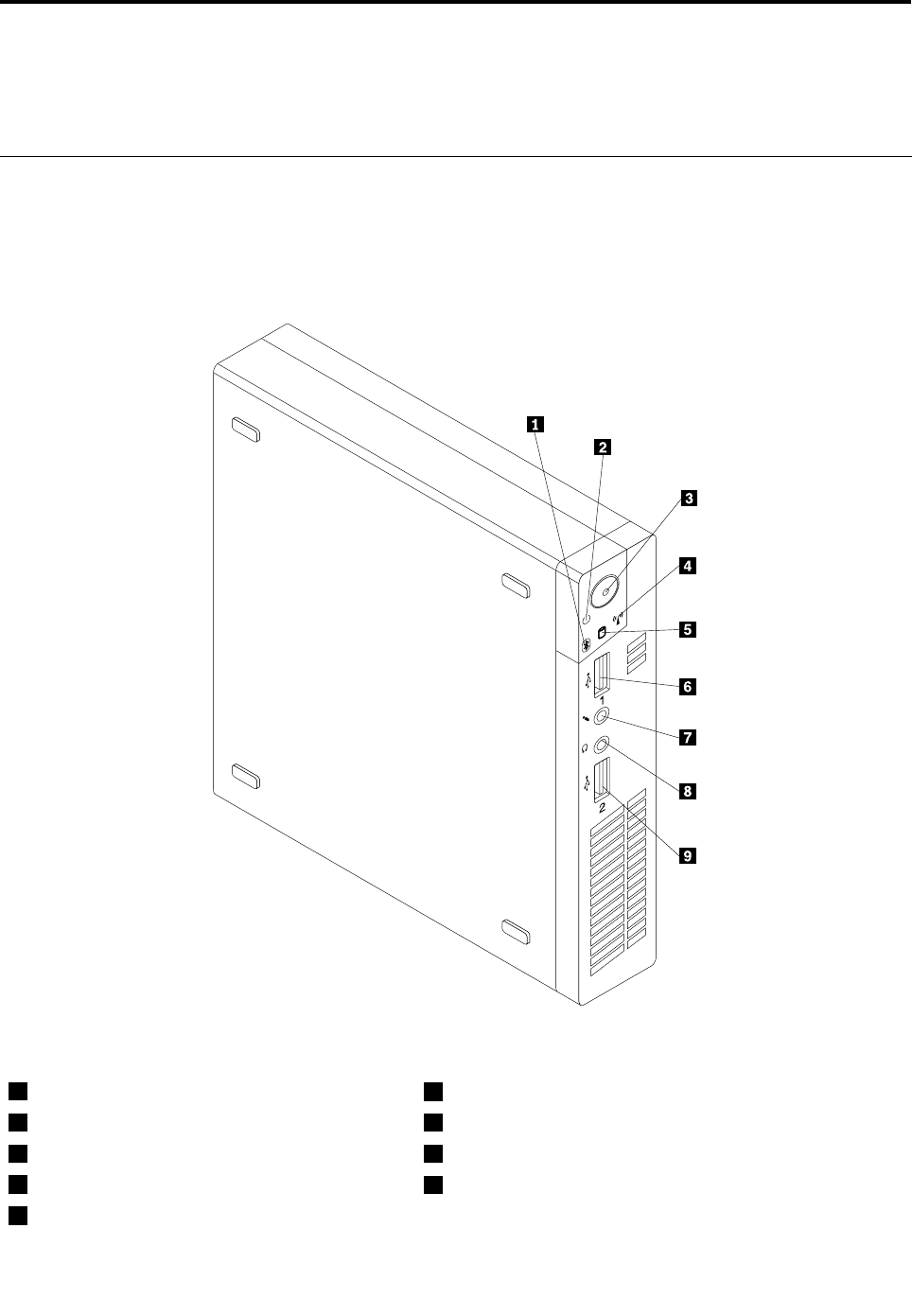
Chapter8.Locations
ThischapterpresentsthelocationsoftheThinkCentrecomputer.
Locatingconnectors,controls,andindicatorsonthefrontofyour
computer
Figure1“Frontconnector,control,andindicatorlocations”onpage67showsthelocationsofthe
connectors,controls,andindicatorsonthefrontofyourcomputer.
Figure1.Frontconnector,control,andindicatorlocations
1Bluetoothactivityindicator6USB2.0connector(USBport1)
2Powerindicator7Microphoneconnector
3Powerswitch8Headphoneconnector
4Wirelessactivityindicator9USB2.0connector(USBport2)
5Harddiskdriveactivityindicator
©CopyrightLenovo201267
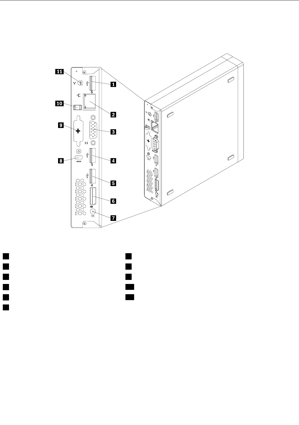
Locatingconnectorsontherearofyourcomputer
Figure2“Rearconnectorlocations”onpage68showsthelocationsoftheconnectorsontherearofyour
computer.Someconnectorsontherearofyourcomputerarecolor-codedtohelpyoudeterminewhereto
connectthecablesonyourcomputer.
Figure2.Rearconnectorlocations
1USB2.0connector(USBport5)7acpoweradapterconnector
2Ethernetconnector8Integratedcablelockslot
3VGAmonitorconnector9Optionalport
4USB2.0connector(USBport3)10acpoweradaptercableloop
5USB2.0connector(USBport4)11WiFicardmoduleantennaslot
6DisplayPortconnector
ConnectorDescription
DisplayPortconnectorUsedtoattachahigh-performancemonitor,adirect-drivemonitor,orotherdevices
thatuseaDisplayPortconnector.
EthernetconnectorUsedtoattachanEthernetcableforalocalareanetwork(LAN).
Note:TooperatethecomputerwithinFCCClassBlimits,useaCategory5Ethernet
cable.
OptionalportUsedtoinstallaserialport,aUSB2.0connector,oranoptionalWiFicardmodule
antenna.
68ThinkCentreHardwareMaintenanceManual

ConnectorDescription
USB2.0connectorUsethisconnectortoattachadevicethatrequiresaUSB2.0connection,suchasa
keyboard,amouse,ascanner,aprinter,orapersonaldigitalassistant(PDA).
VGAmonitorconnectorUsedtoattachaVGAmonitororotherdevicesthatuseaVGAmonitorconnector.
LocatingFRUsandCRUs
Figure3“LocatingFRUsandCRUs”onpage70showsthelocationsofthevariouscomponentsinyour
computer.Toremovethecomputercover,see“Removingthecomputercover”onpage77.
Chapter8.Locations69
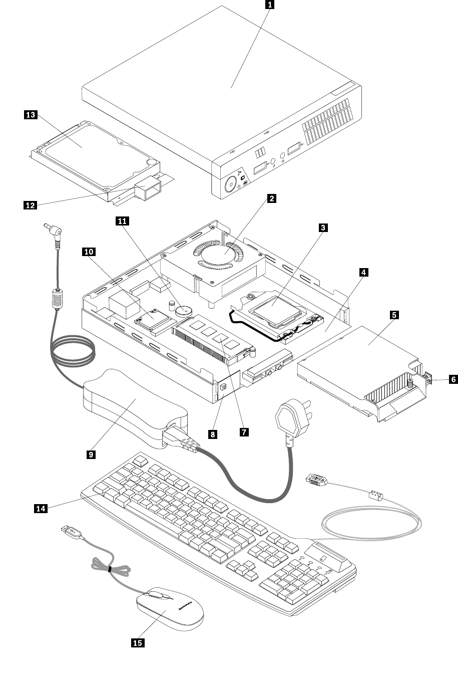
70ThinkCentreHardwareMaintenanceManual
Figure3.LocatingFRUsandCRUs
ThefollowingtableliststhemajorFRUsshowninFigure3“LocatingFRUsandCRUs”onpage70and
identieswhichFRUsalsoareself-serviceCRUsoroptional-serviceCRUs.
Notes:
•Self-serviceCRUs:TheseCRUsunplugoraresecuredbynomorethantwoscrews.Examplesof
thesetypesofCRUsincludethekeyboard,themouse,anyUSBdevice,andthepowercord.Other
Self-serviceCRUsdependingonproductdesignmightincludememorymodules,adaptercards,hard
diskdrives,andopticaldrives.
•Optional-serviceCRUs:TheseCRUsareisolatedpartswithinthecomputerandareconcealedbyan
accesspanelthatistypicallysecuredbymorethantwoscrews.Oncetheaccesspanelisremoved,the
specicCRUisvisible.
•ThelistofFRUsbelowisapartiallist.ForacompletelistingofFRUinformation,suchasFRUpart
numbersandsupportedcomputermodels,goto:
http:/www.lenovo.com/serviceparts-lookup
NumberFRUdescriptionSelf-serviceCRUOptional-serviceCRU
1ComputercoverYesNo
2SystemfanNoYes
3MicroprocessorNoYes
4SystemboardNoNo
5HeatsinkYesNo
6Coverpresenceswitch(Intrusionswitch)YesNo
7MemorymoduleNoYes
8PowerswitchboardNoYes
9acpoweradapterYesNo
10WiFicardmoduleNoYes
11BatteryYesNo
12InternalspeakerNoYes
13HarddiskdriveorsolidstatedriveNoNo
14KeyboardYesNo
15MouseYesNo
LookingupFRUinformation
FordetailedFRUinformation,suchastheFRUpartnumbersandsupportedcomputermodels,goto:
http:/www.lenovo.com/serviceparts-lookup
Chapter8.Locations71
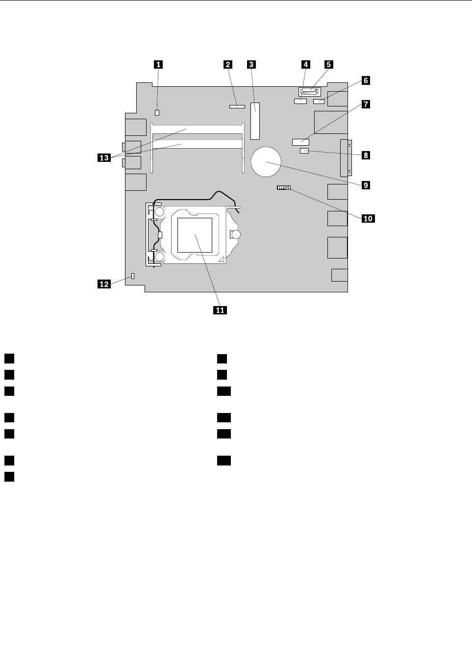
Locatingpartsonthesystemboard
Figure4“Systemboardpartlocations”onpage72showsthelocationsofthepartsonthesystemboard.
Figure4.Systemboardpartlocations
1Internalspeakerconnector8Systemfanconnector
2Powerswitchboardcableconnector9Battery
3MiniPCIExpresscardslot10ClearCMOS(ComplementaryMetalOxideSemiconductor)
/Recoveryjumper
4Harddiskdrivepowerconnector11Microprocessor
5SATAconnector12Coverpresenceswitchconnector(Intrusionswitch
connector)
6OptionalUSBconnector13Memoryslots(2)
7Serial(COM1)connector
72ThinkCentreHardwareMaintenanceManual

Chapter9.ReplacingFRUs
ThischapterprovidesinformationabouttheFRUreplacementinstructions.
Important:BesuretoreadandunderstandChapter2“Safetyinformation”onpage3beforereplacingany
FRU.Theseprecautionsandguidelineswillhelpyouworksafely.
Note:FRUreplacementsaretobedoneonlybytrainedservicetechnicians.
Handlingstatic-sensitivedevices
Donotopenthestatic-protectivepackagecontainingthenewpartuntilthedefectiveparthasbeenremoved
fromthecomputerandyouarereadytoinstallthenewpart.Staticelectricity,althoughharmlesstoyou,can
seriouslydamagecomputercomponentsandparts.
Whenyouhandlecomputerpartsandcomponents,taketheseprecautionstoavoidstatic-electricitydamage:
•Limityourmovement.Movementcancausestaticelectricitytobuilduparoundyou.
•Alwayscarefullyhandlethepartsandothercomputercomponents.HandlePCIcards,memorymodules,
systemboards,andmicroprocessorsbytheedges.Nevertouchexposedcircuitry.
•Preventothersfromtouchingthepartsandothercomputercomponents.
•Beforeyoureplaceanewpart,touchthestatic-protectivepackagecontainingthenewparttoametal
expansion-slotcoverorotherunpaintedmetalsurfaceonthecomputerforatleasttwoseconds.This
reducesstaticelectricityfromthepackageandyourbody.
•Removethenewpartfromthestatic-protectivepackageanddirectlyinstallitinthecomputerwithout
placingitonanyothersurface.Ifitishardforyoutodothisinyourspecicsituation,placethe
static-protectivepackageofthenewpartonasmooth,levelsurface,andthenplacethenewparton
thestatic-protectivepackage.
•Donotplacethepartonthecomputercoverorothermetalsurface.
Installingorreplacinghardware
Thissectionprovidesinstructionsonhowtoinstallorreplacehardwareforyourcomputer.Youcanexpand
thecapabilitiesofyourcomputerandmaintainyourcomputerbyinstallingorreplacinghardware.
Attention:Donotopenyourcomputerorattemptanyrepairbeforereadingandunderstandingthe“Important
safetyinformation”onpage1.
Notes:
1.UseonlycomputerpartsprovidedbyLenovo.
2.Wheninstallingorreplacinganoption,usetheappropriateinstructionsinthissectionalongwiththe
instructionsthatcomewiththeoption.
Installingorremovingtheverticalstand
Attention:Donotopenyourcomputerorattemptanyrepairbeforereadingandunderstandingthe“Important
safetyinformation”onpage1.
Thissectionprovidesinstructionsonhowtoinstallorremovetheverticalstand.
Note:Theverticalstandisonlyavailableonsomemodels.
©CopyrightLenovo201273
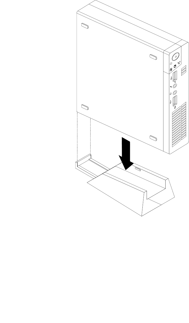
Toinstallorremovetheverticalstand,dothefollowing:
1.Turnoffthecomputer.
2.Aligntherearofthecomputerwiththerearoftheverticalstandandpositionthecomputeronthe
verticalstandasshown.
Figure5.Installingtheverticalstand
74ThinkCentreHardwareMaintenanceManual
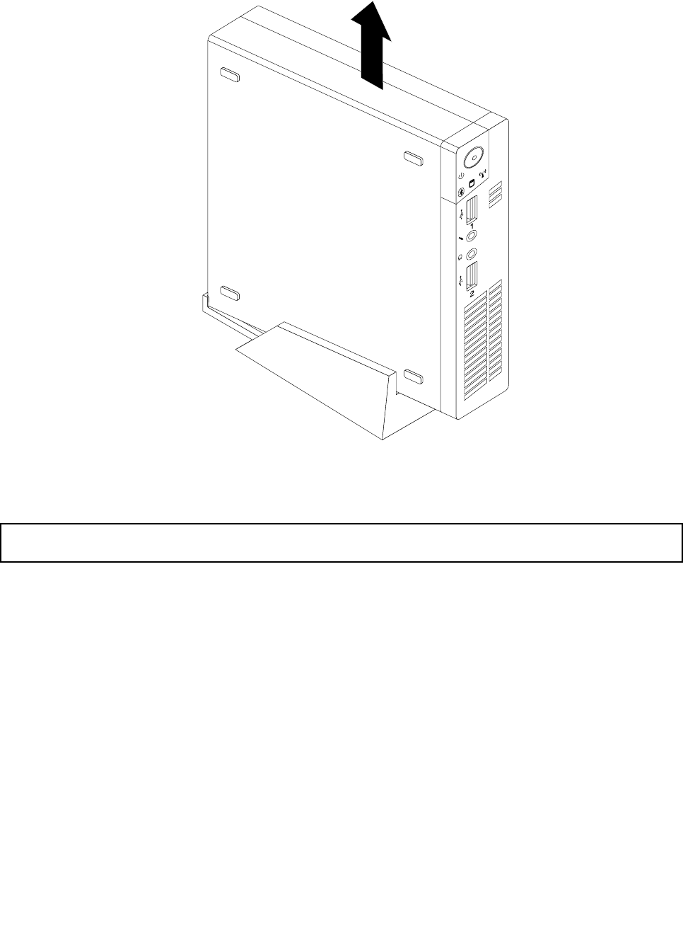
3.Toremovetheverticalstand,liftthecomputertoremoveitfromtheverticalstand.
Figure6.Removingthecomputerfromtheverticalstand
InstallingorremovingtheVESAmountbracket
Attention:Donotopenyourcomputerorattemptanyrepairbeforereadingandunderstandingthe“Important
safetyinformation”onpage1.
ThissectionprovidesinstructionsonhowtoinstallorremovetheVESA(VideoElectronicsStandards
Association)mountbracket.
Note:TheVESAmountbracketisonlyavailableonsomemodels.
ToinstallorremovetheVESAmountbracket,dothefollowing:
1.Turnoffthecomputeranddisconnectallpowercordsfromelectricaloutlets.
Chapter9.ReplacingFRUs75
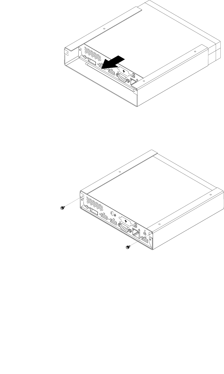
2.ToinstalltheVESAmountbracket,slidethecomputerintotheVESAmountbracket.
Figure7.InstallingtheVESAmountbracket
3.InstallthetwoscrewstosecuretheVESAmountbrackettothecomputer.
Figure8.InstallingthescrewsthatsecuretheVESAmountbracket
76ThinkCentreHardwareMaintenanceManual
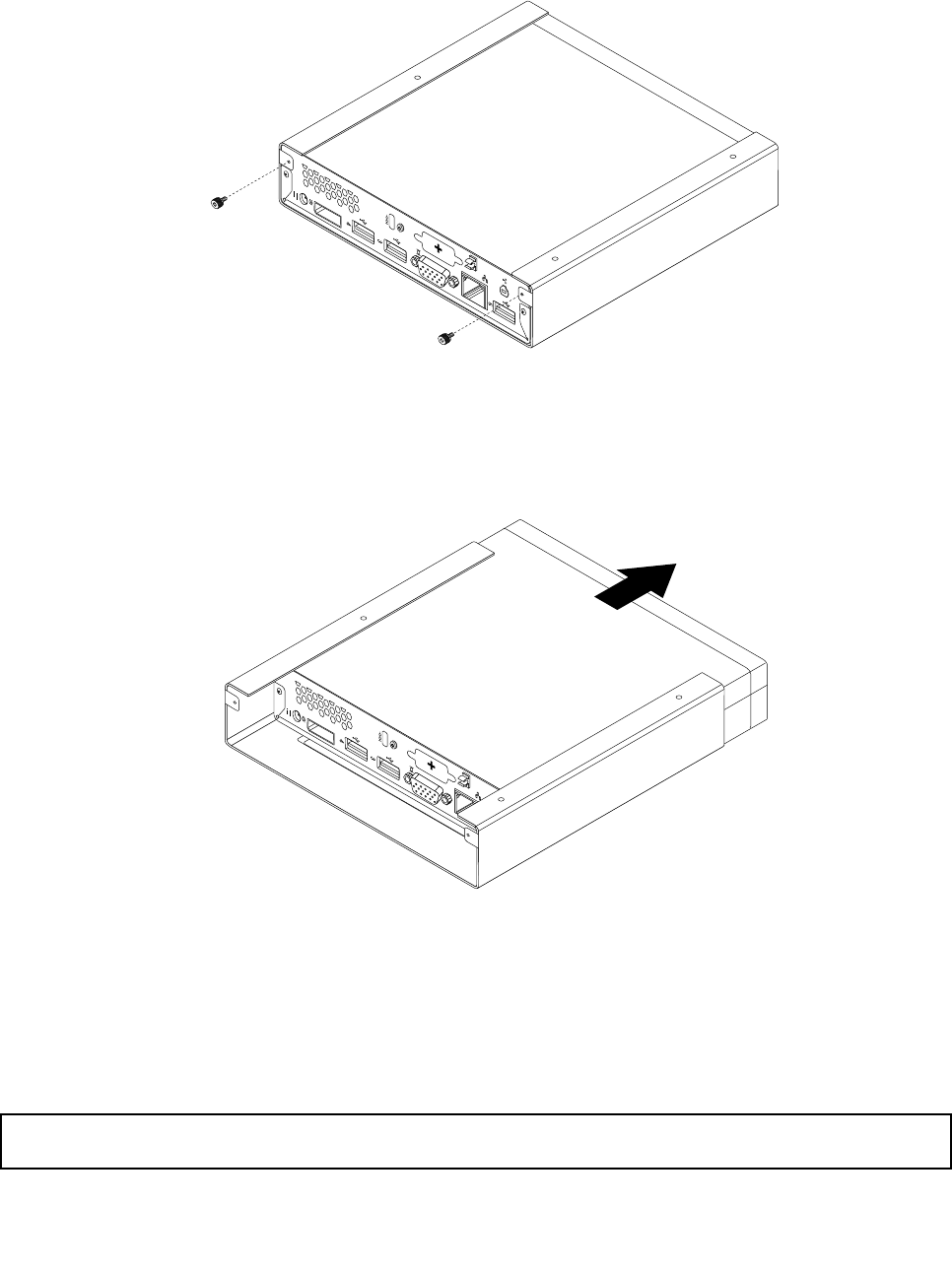
4.ToremovetheVESAmountbracketfromthecomputer,removethetwoscrewsthatsecuretheVESA
mountbrackettothecomputer.
Figure9.RemovingthescrewsthatsecuretheVESAmountbracket
5.SlidethecomputerfromthefrontoftheVESAmountbrackettoremovetheVESAmountbracket
fromthecomputer.
Figure10.RemovingtheVESAmountbracket
Whattodonext:
•Toworkwithanotherpieceofhardware,gototheappropriatesection.
•Tocompletetheinstallationorreplacement,goto“Completingthepartsreplacement”onpage123.
Removingthecomputercover
Attention:Donotopenyourcomputerorattemptanyrepairbeforereadingandunderstandingthe“Important
safetyinformation”onpage1.
Chapter9.ReplacingFRUs77
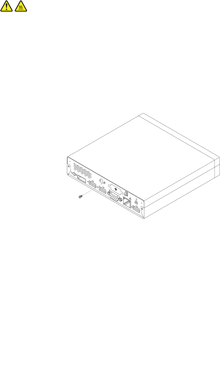
Thissectionprovidesinstructionsonhowtoremovethecomputercover.
CAUTION:
Turnoffthecomputerandwaitthreetoveminutestoletthecomputercoolbeforeremovingthe
computercover.
Toremovethecomputercover,dothefollowing:
1.Removeanymediafromthedrivesandturnoffallattacheddevicesandthecomputer.
2.Disconnectallpowercordsfromelectricaloutlets.
3.Disconnectthepowercords,Input/Outputcables,andanyothercablesthatareconnectedtothe
computer.See“Locatingconnectors,controls,andindicatorsonthefrontofyourcomputer”onpage
67and“Locatingconnectorsontherearofyourcomputer”onpage68.
4.Removeanylockingdevicethatsecuresthecomputercover,suchasanintegratedcablelock.
5.Removethescrewthatsecuresthecomputercover.
Figure11.Removingthecomputercoverscrew
78ThinkCentreHardwareMaintenanceManual
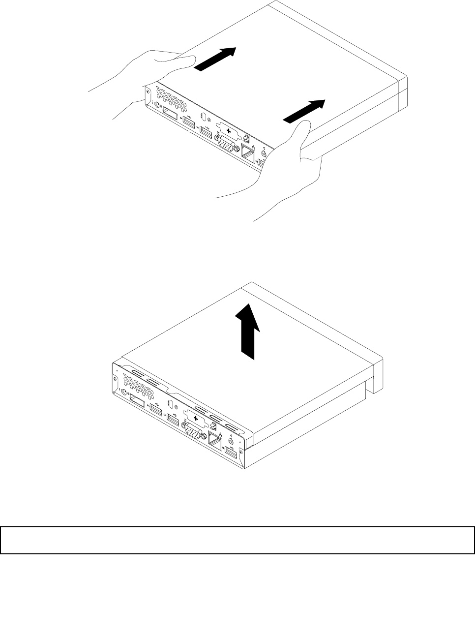
6.Slidethecomputercovertothefrontofthecomputerasmallamount.Liftthecomputercoverto
removeitfromthecomputer.
Figure12.Removingthecomputercover
Installingorreplacingamemorymodule
Attention:Donotopenyourcomputerorattemptanyrepairbeforereadingandunderstandingthe“Important
safetyinformation”onpage1.
Thissectionprovidesinstructionsonhowtoinstallorreplaceamemorymodule.
Chapter9.ReplacingFRUs79
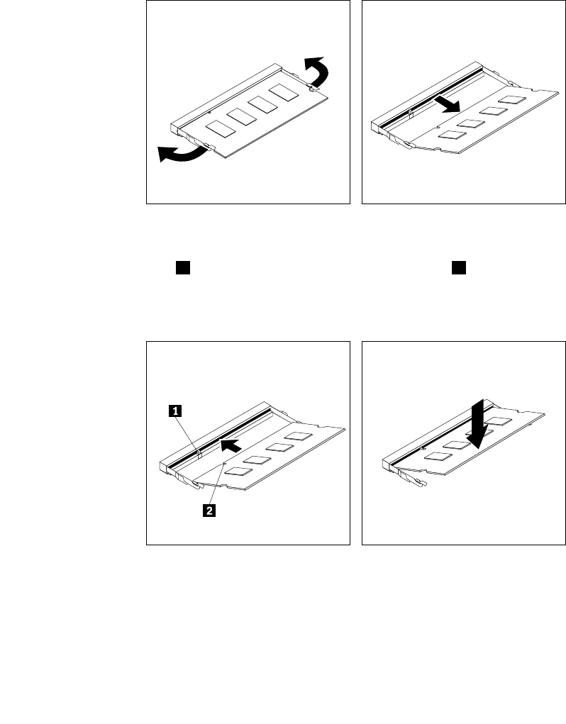
YourcomputerhastwoslotsforinstallingorreplacingDDR3SODIMMsthatprovideuptoamaximumof
16GBsystemmemory.Wheninstallingorreplacingamemorymodule,use2GB,4GB,or8GBDDR3
SODIMMsinanycombinationuptoamaximumof16GB.
Toinstallorreplaceamemorymodule,dothefollowing:
1.Turnoffthecomputeranddisconnectallpowercordsfromelectricaloutlets.
2.Removethecomputercover.See“Removingthecomputercover”onpage77.
3.Locatethememoryslots.See“Locatingpartsonthesystemboard”onpage72.
4.Removetheharddiskdrivebrackettogetyouraccesstothememoryslots.See“Replacingthehard
diskdrivebracket”onpage107.
5.Ifyouarereplacinganoldmemorymodule,opentheretainingclipsandgentlypullthememorymodule
outofthememoryslot.
Figure13.Removingthememorymodule
6.Insertthenotchedend2ofthenewmemorymoduleintotheslot1.Pressthememorymodule
rmlyandpivotthememorymoduleuntilitsnapsintoplace.Makesurethatthememorymoduleis
securedintheslotanddoesnotmoveeasily.
Figure14.Installingamemorymodule
7.Reinstalltheharddiskdrivebracket.See“Replacingtheharddiskdrivebracket”onpage107.
Whattodonext:
•Toworkwithanotherpieceofhardware,gototheappropriatesection.
80ThinkCentreHardwareMaintenanceManual
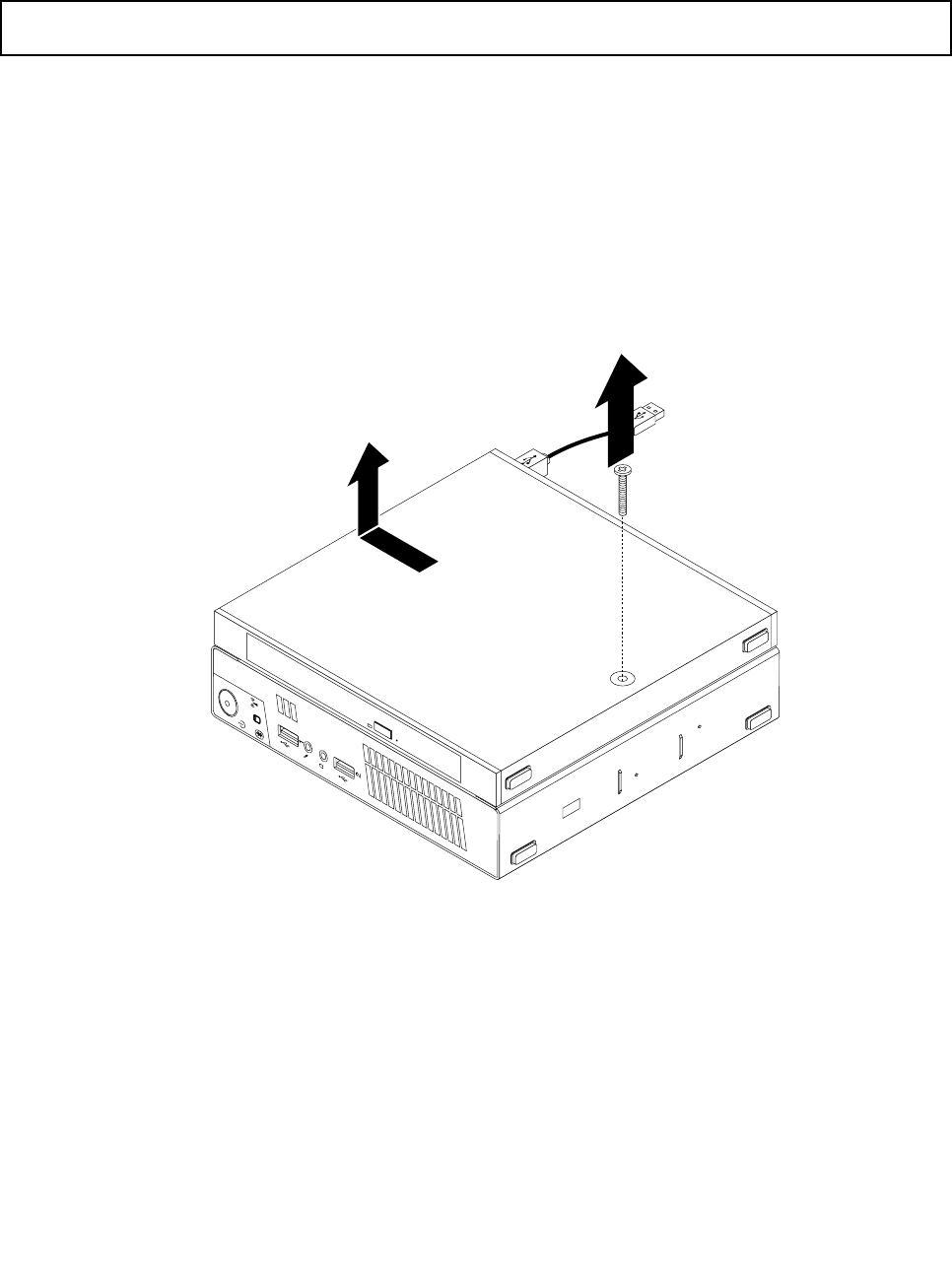
•Tocompletetheinstallationorreplacement,goto“Completingthepartsreplacement”onpage123.
Replacingtheopticaldrive
Attention:Donotopenyourcomputerorattemptanyrepairbeforereadingandunderstandingthe“Important
safetyinformation”onpage1.
Thissectionprovidesinstructionsonhowtoreplacetheopticaldrive.
Note:Theopticaldriveisonlyavailableonsomemodels.
Toreplacetheopticaldrive,dothefollowing:
1.Turnoffthecomputeranddisconnectallpowercordsfromelectricaloutlets.
2.DisconnecttheopticaldrivecablefromtheUSBconnectoronthecomputer.
3.RemovethescrewthatsecurestheopticaldriveboxontheVESAmountbracketandthenslidethe
opticaldriveboxtoremoveitfromtheVESAmountbracket.
Figure15.Removingtheopticaldrivebox
Chapter9.ReplacingFRUs81
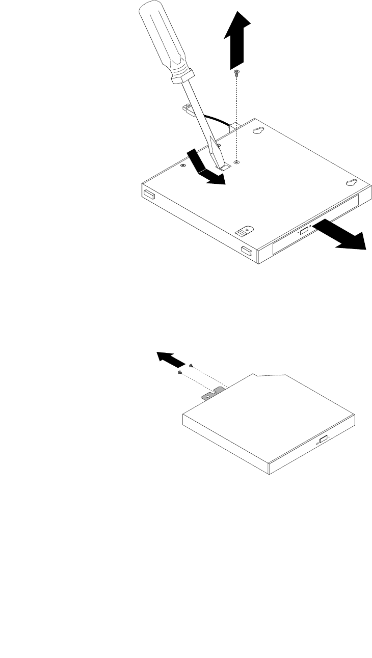
4.Removethescrewthatsecurestheopticaldriveintheopticaldrivebox.Usethescrewdrivertoslide
theopticaldriveforwardandthenremovetheopticaldrivefromtheopticaldrivebox.
Figure16.Removingtheopticaldrivefromtheopticaldrivebox
5.Removethetwoscrewsthatsecuretheopticaldrivemetalplateandthenremovethemetalplate
fromtheopticaldrive.
Figure17.Removingtheopticaldrivemetalplate
82ThinkCentreHardwareMaintenanceManual
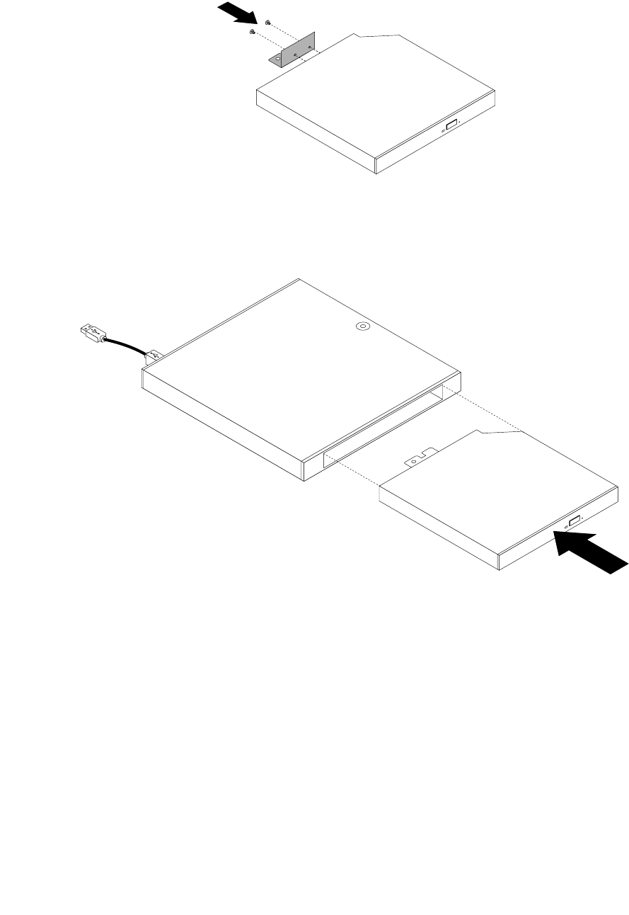
6.Alignthetwoscrewholesintheopticaldrivemetalplatewiththecorrespondingholesinthenewoptical
driveandtheninstallthetwoscrewstosecurethemetalplateonthenewopticaldrive.
Figure18.Installingtheopticaldrivemetalplate
7.Slidethenewopticaldriveintotheopticaldriveboxuntilitsnapsintoposition.
Figure19.Installingtheopticaldriveintotheopticaldrivebox
Chapter9.ReplacingFRUs83
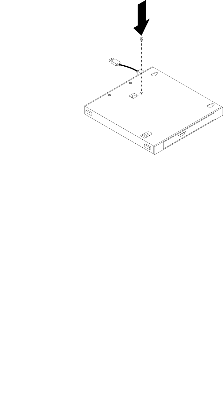
8.Installthescrewthatsecurestheopticaldriveintheopticaldrivebox.
Figure20.Installingthescrewthatsecurestheopticaldrive
84ThinkCentreHardwareMaintenanceManual
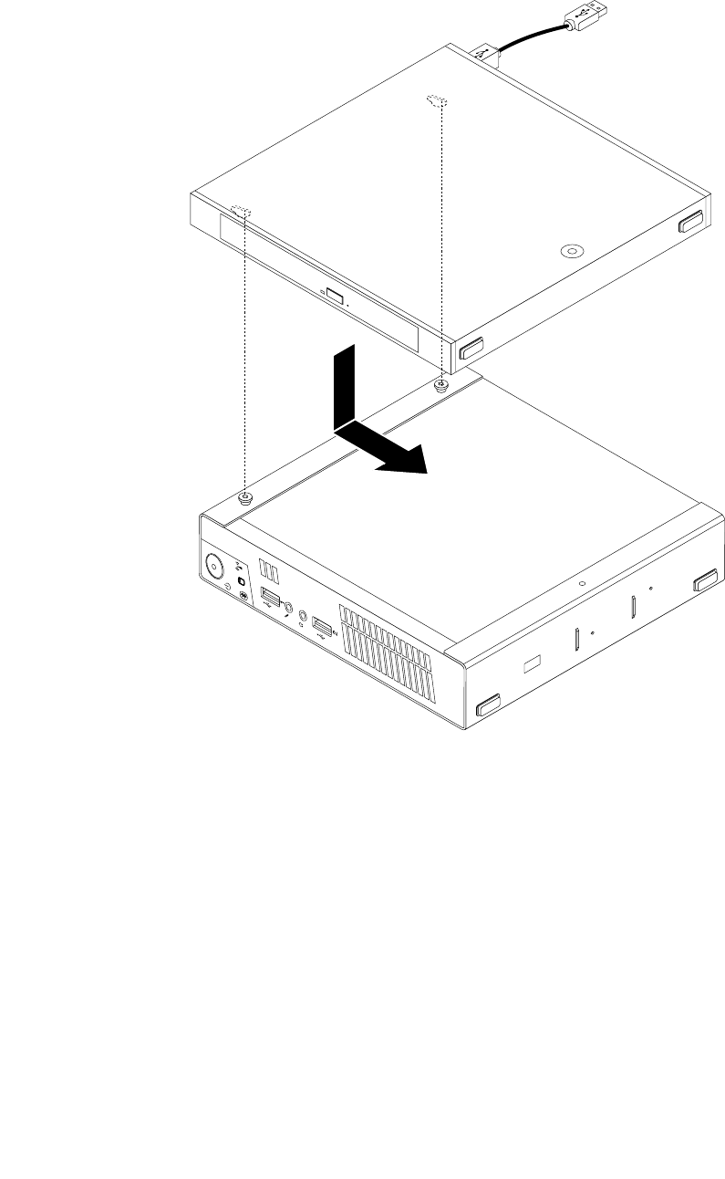
9.AlignthescrewholesintheopticaldriveboxwiththetwoscrewsontheVESAmountbracketandthen
slidetheopticaldriveboxtoinstallitontheVESAmountbracket.
Figure21.Installingtheopticaldrivebox
Chapter9.ReplacingFRUs85
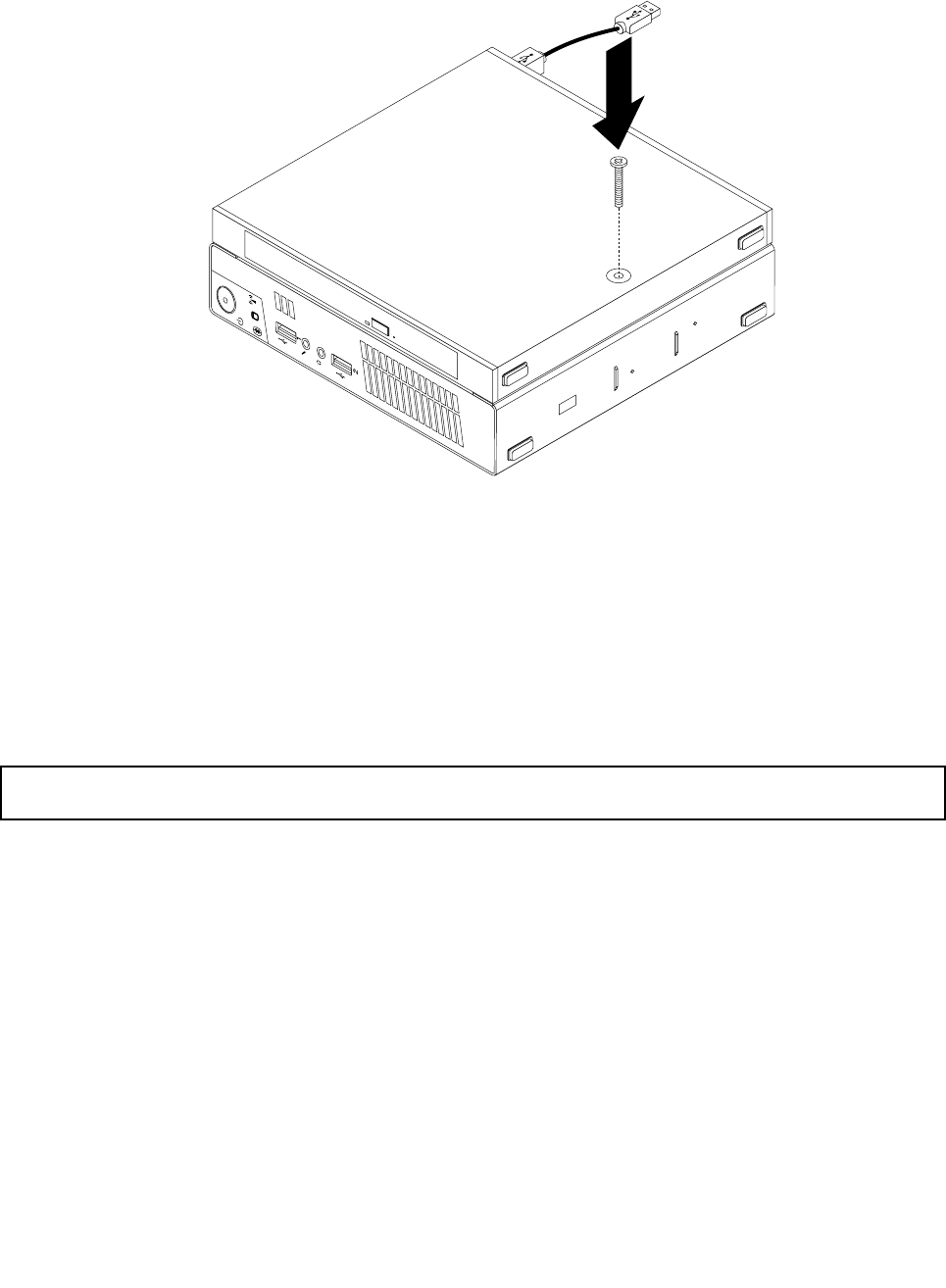
10.InstallthescrewthatsecurestheopticaldriveboxontheVESAmountbracket.
Figure22.Installingthescrewthatsecurestheopticaldrivebox
11.ConnecttheopticaldrivecabletoaUSBconnectoronthecomputer.See“Locatingconnectorsonthe
rearofyourcomputer”onpage68.
Whattodonext:
•Toworkwithanotherpieceofhardware,gototheappropriatesection.
•Tocompletetheinstallationorreplacement,goto“Completingthepartsreplacement”onpage123.
Replacingthesecondaryharddiskdrive
Attention:Donotopenyourcomputerorattemptanyrepairbeforereadingandunderstandingthe“Important
safetyinformation”onpage1.
Thissectionprovidesinstructionsonhowtoreplacethesecondaryharddiskdrive.
Note:Thesecondaryharddiskdriveisonlyavailableonsomemodels.
Toreplacethesecondaryharddiskdrive,dothefollowing:
1.Turnoffthecomputeranddisconnectallpowercordsfromelectricaloutlets.
2.DisconnectthesecondaryharddiskdrivecablefromtheUSBconnectoronthecomputer.
86ThinkCentreHardwareMaintenanceManual
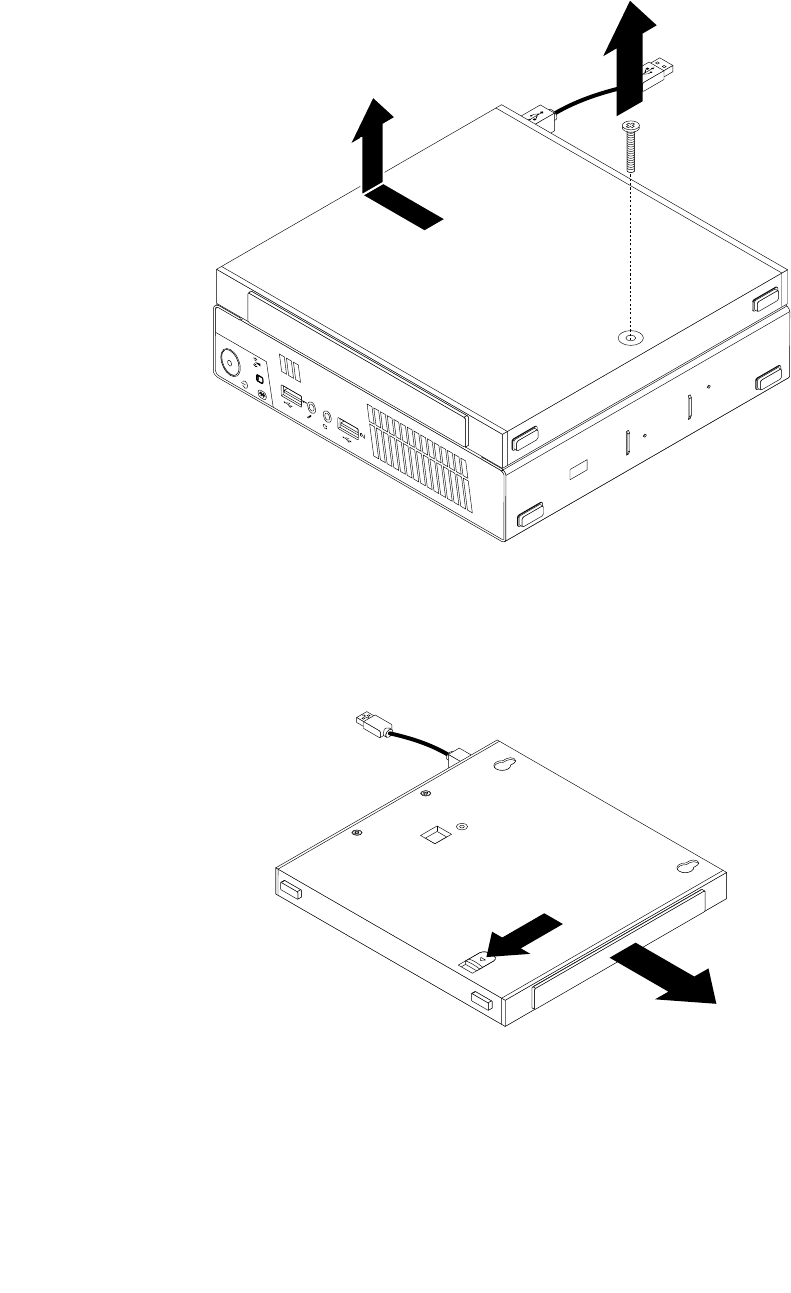
3.RemovethescrewthatsecurestheopticaldriveboxontheVESAmountbracketandthenslidethe
opticaldriveboxtoremoveitfromtheVESAmountbracket.
Figure23.Removingtheopticaldrivebox
4.Slidethereleasebuttonontheopticaldriveboxandthenremovethesecondaryharddiskdriveadapter
fromtheopticaldrivebox.
Figure24.Removingthesecondaryharddiskdriveadapterfromtheopticaldrivebox
Chapter9.ReplacingFRUs87
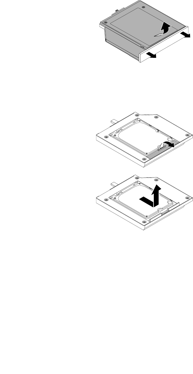
5.Flexthesidesoftheharddiskdriveadapterbracketandthenpivottheharddiskdriveadapterto
removetheadapterfromtheadapterbracket.
Figure25.Removingtheharddiskdriveadapterfromtheadapterbracket
6.Toremovetheharddiskdrivefromtheadapter,lifttheadapterretaininglatch.Slidetheharddiskdrive
towardstheretaininglatchandthenlifttheharddiskdriveoutoftheadapter.
Figure26.Removingthesecondaryharddiskdrivefromtheadapter
88ThinkCentreHardwareMaintenanceManual
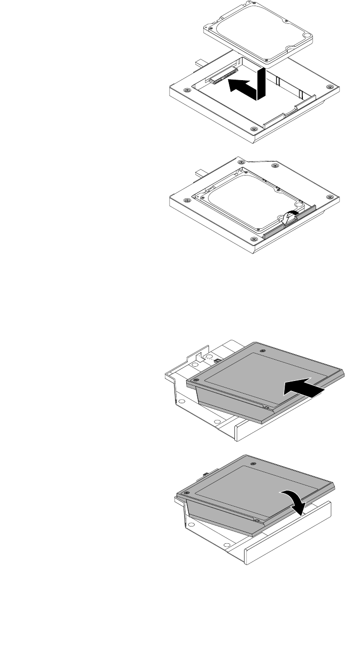
7.Installanewharddiskdriveintotheadapter.Lowertheadapterretaininglatchuntilitsnapsintoposition.
Figure27.Installinganewharddiskdriveintotheadapter
8.Positiontheadapterintotheadapterbracketandthenpivottheadapterdownwarduntilitsnapsinto
position.
Figure28.Installingtheharddiskdriveadapterintotheadapterbracket
Chapter9.ReplacingFRUs89
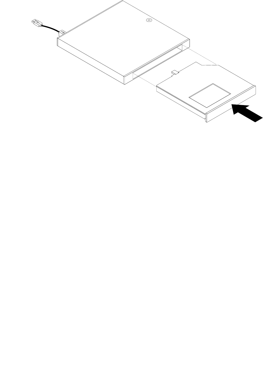
9.Slidetheadapterbracketintotheopticaldriveboxuntilitsnapsintoposition.
Figure29.Installingtheadapterbracketintotheopticaldrivebox
90ThinkCentreHardwareMaintenanceManual
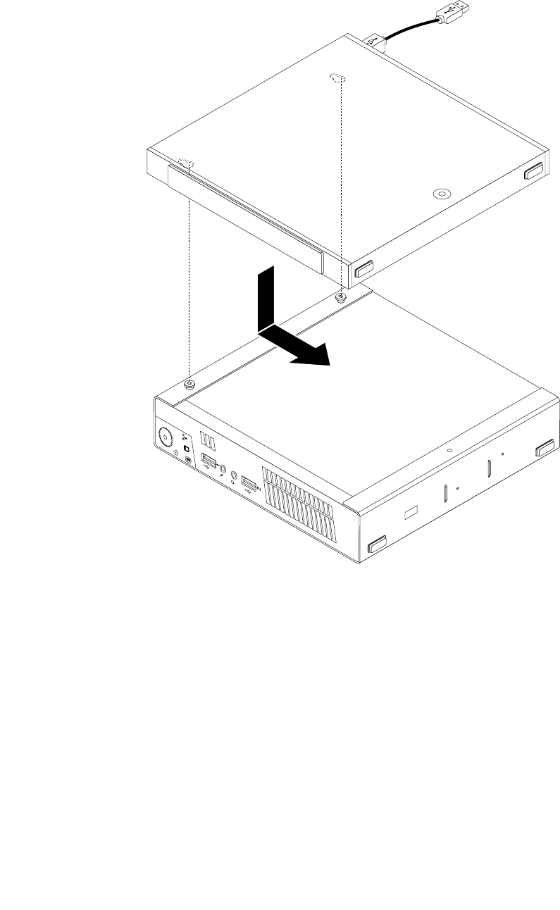
10.AlignthescrewholesintheopticaldriveboxwiththetwoscrewsontheVESAmountbracketandthen
slidetheopticaldriveboxtoinstallitontheVESAmountbracket.
Figure30.Installingtheopticaldrivebox
Chapter9.ReplacingFRUs91
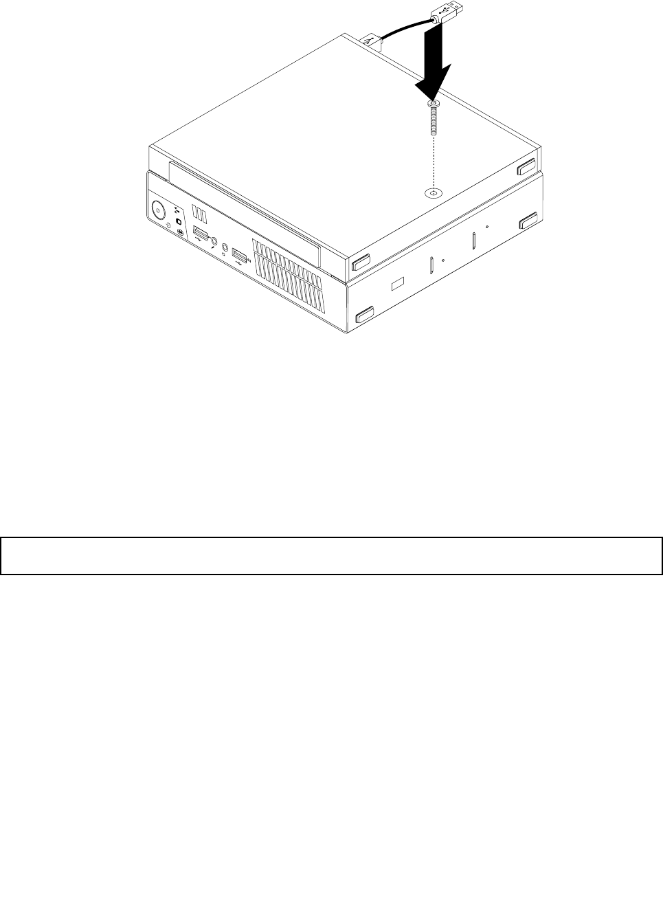
11.InstallthescrewthatsecurestheopticaldriveboxontheVESAmountbracket.
Figure31.Installingthescrewthatsecurestheopticaldrivebox
12.ConnectthesecondaryharddiskdrivecabletoaUSBconnectoronthecomputer.See“Locating
connectorsontherearofyourcomputer”onpage68.
Whattodonext:
•Toworkwithanotherpieceofhardware,gototheappropriatesection.
•Tocompletetheinstallationorreplacement,goto“Completingthepartsreplacement”onpage123.
Replacingthebattery
Attention:Donotopenyourcomputerorattemptanyrepairbeforereadingandunderstandingthe“Important
safetyinformation”onpage1.
Yourcomputerhasaspecialtypeofmemorythatmaintainsthedate,time,andsettingsforbuilt-infeatures,
suchasparallel-portassignments(conguration).Abatterykeepsthisinformationactivewhenyouturn
offthecomputer.
Thebatterynormallyrequiresnochargingormaintenancethroughoutitslife;however,nobatterylasts
forever.Ifthebatteryfails,thedate,time,andcongurationinformation(includingpasswords)arelost.An
errormessageisdisplayedwhenyouturnonthecomputer.
Refertothe“Lithiumbatterynotice”intheSafetyandWarrantyGuideforinformationaboutreplacing
anddisposingofthebattery.
Toreplacethebattery,dothefollowing:
1.Turnoffthecomputeranddisconnectallpowercordsfromelectricaloutlets.
2.Removethecomputercover.See“Removingthecomputercover”onpage77.
3.Locatethebattery.See“Locatingpartsonthesystemboard”onpage72.
92ThinkCentreHardwareMaintenanceManual
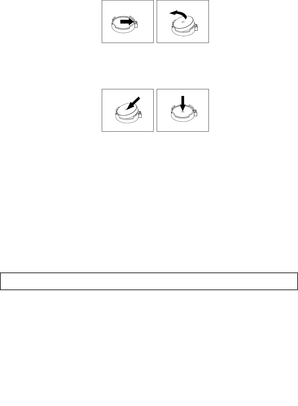
4.Removetheoldbattery.
Figure32.Removingtheoldbattery
5.Installanewbattery.
Figure33.Installinganewbattery
6.Reinstallthecomputercoverandconnectthecables.See“Completingthepartsreplacement”on
page123.
Note:Whenthecomputeristurnedonforthersttimeafterreplacingthebattery,anerrormessage
mightbedisplayed.Thisisnormalafterreplacingthebattery.
7.Turnonthecomputerandallattacheddevices.
8.UsetheSetupUtilityprogramtosetthedate,time,andanypasswords.SeeChapter6“UsingtheSetup
Utilityprogram”onpage55.
Whattodonext:
•Toworkwithanotherpieceofhardware,gototheappropriatesection.
•Tocompletetheinstallationorreplacement,goto“Completingthepartsreplacement”onpage123.
Replacingtheacpoweradapter
Attention:Donotopenyourcomputerorattemptanyrepairbeforereadingandunderstandingthe“Important
safetyinformation”onpage1.
Thissectionprovidesinstructionsonhowtoreplacetheacpoweradapter.
Toreplacetheacpoweradapter,dothefollowing:
1.Turnoffthecomputeranddisconnectallpowercordsfromelectricaloutlets.
Chapter9.ReplacingFRUs93
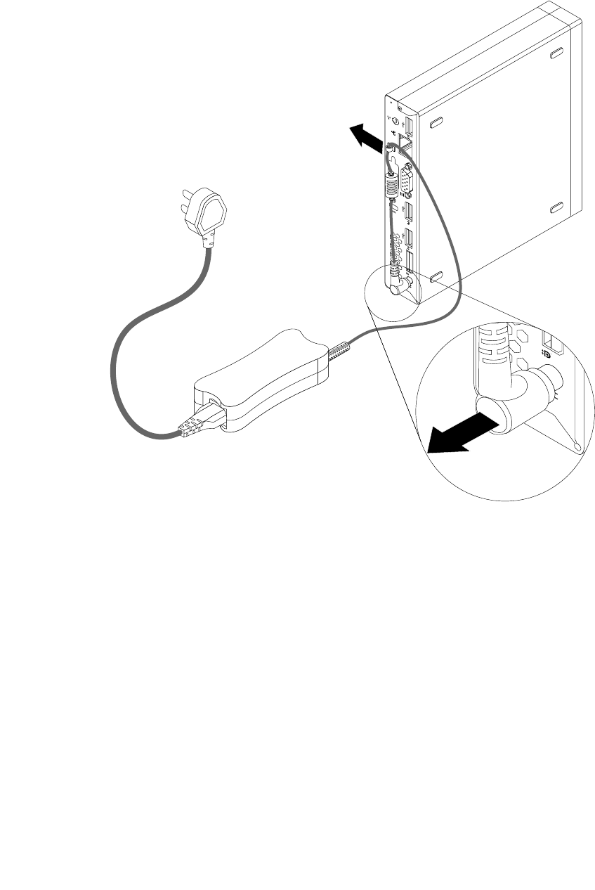
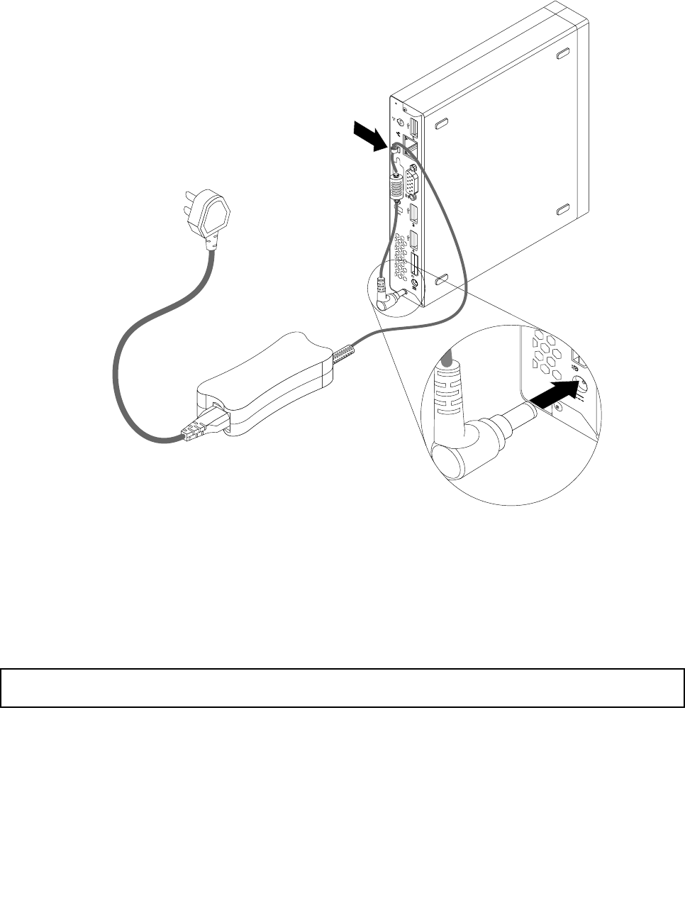
3.Connectthenewacpoweradaptertotheacpoweradapterconnectorattherearofyourcomputer
andanworkableelectricaloutlet.Securethepowercordintothepoweradaptercableloopattherear
ofthecomputerasshown.
Figure35.Connectingthenewacpoweradapter
Whattodonext:
•Toworkwithanotherpieceofhardware,gototheappropriatesection.
•Tocompletetheinstallationorreplacement,goto“Completingthepartsreplacement”onpage123.
Replacingtheacpoweradapterbracket
Attention:Donotopenyourcomputerorattemptanyrepairbeforereadingandunderstandingthe“Important
safetyinformation”onpage1.
Thissectionprovidesinstructionsonhowtoreplacetheacpoweradapterbracket.
Note:Theacpoweradapterbracketisonlyavailableonsomemodels.
Toreplacetheacpoweradapterbracket,dothefollowing:
1.Turnoffthecomputeranddisconnectallpowercordsfromelectricaloutlets.
Chapter9.ReplacingFRUs95
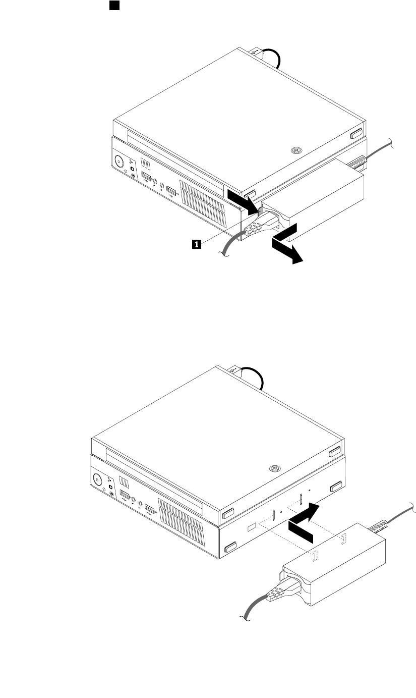
2.Pressthemetaltab1andthenslidetheacpoweradapterbrackettoremoveitfromtheVESAmount
bracket.
Figure36.Removingtheacpoweradapterbracket
3.ToinstalltheacpoweradapterbrackettotheVESAmountbracket,alignthetwotabsontheacpower
adapterbracketwiththeslotsintheVESAmountbracket,andthenslidetheacpoweradapterbracket
toinstallitontheVESAmountbracket.
Figure37.Installingtheacpoweradapterbracket
96ThinkCentreHardwareMaintenanceManual
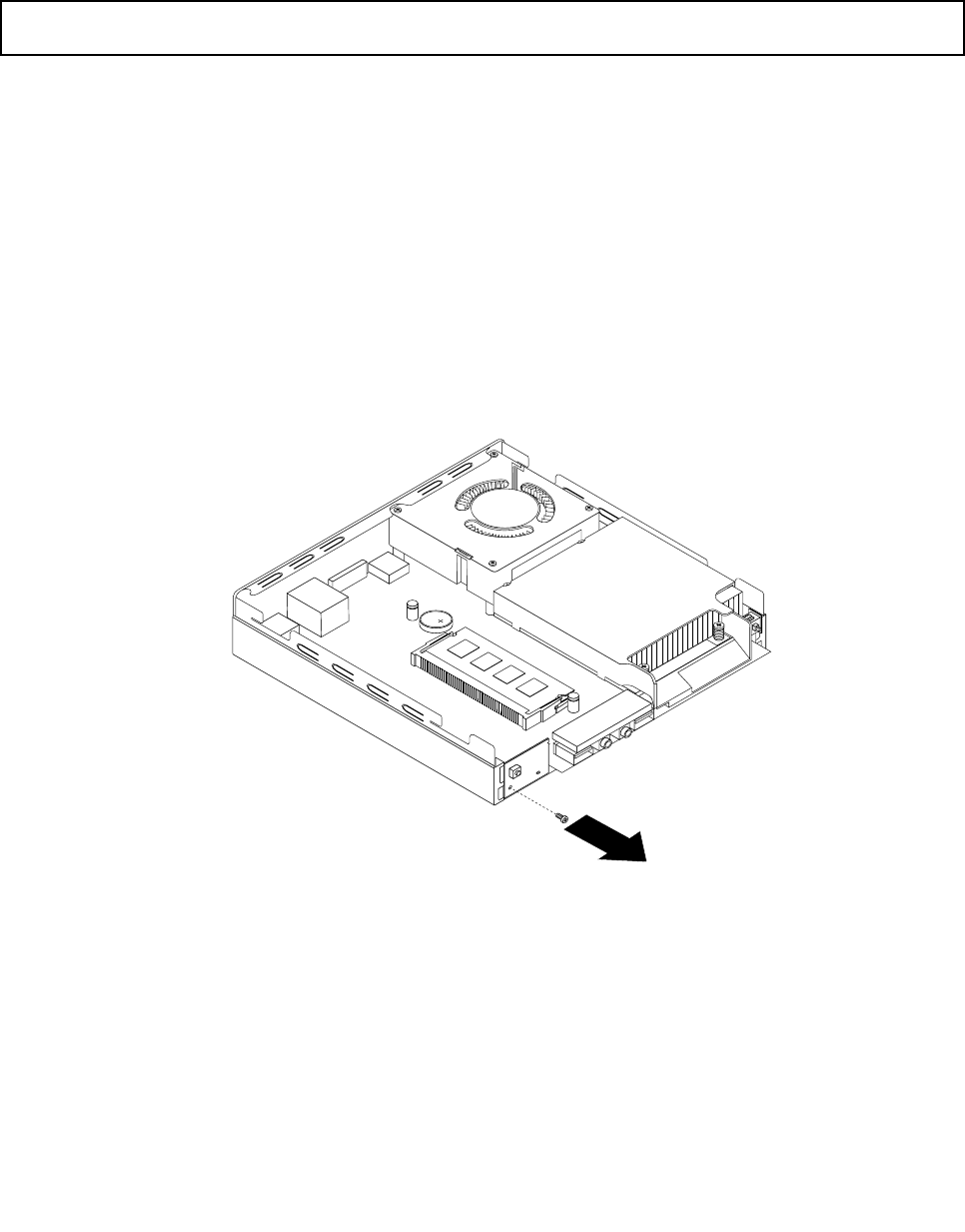
Whattodonext:
•Toworkwithanotherpieceofhardware,gototheappropriatesection.
•Tocompletetheinstallationorreplacement,goto“Completingthepartsreplacement”onpage123.
Replacingthepowerswitchboard
Attention:Donotopenyourcomputerorattemptanyrepairbeforereadingandunderstandingthe“Important
safetyinformation”onpage1.
Thissectionprovidesinstructionsonhowtoreplacethepowerswitchboard.
Toreplacethepowerswitchboard,dothefollowing:
1.Turnoffthecomputeranddisconnectallpowercordsfromelectricaloutlets.
2.Removethecomputercover.See“Removingthecomputercover”onpage77.
3.Locatethepowerswitchboard.See“LocatingFRUsandCRUs”onpage69.
4.Removetheharddiskdrivefromthecomputer.See“Replacingtheharddiskdrivebracket”onpage107.
5.Disconnectthepowerswitchboardcablefromthecorrespondingconnectoronthesystemboard.See
“Locatingpartsonthesystemboard”onpage72.
6.Removethepowerswitchboardcablefromthecabletieinthecomputer.
7.Removethescrewthatsecuresthepowerswitchboardtothecomputer.
Figure38.Removingthescrewthatsecuresthepowerswitchboard
Chapter9.ReplacingFRUs97
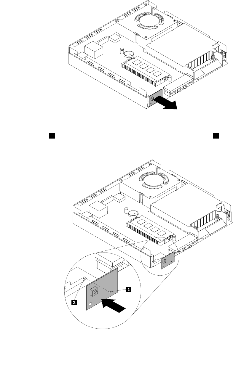
8.Removethepowerswitchboardfromthecomputer.
Figure39.Removingthepowerswitchboard
9.Alignthehole1inthenewpowerswitchboardwiththecorrespondingtab2onthecomputerand
positionthenewpowerswitchboardinthecomputer.
Figure40.Installingthepowerswitchboard
98ThinkCentreHardwareMaintenanceManual
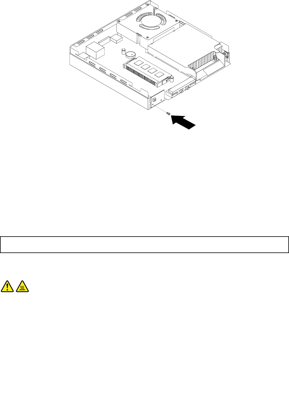
10.Installthescrewtosecurethenewpowerswitchboardinthecomputer.
Figure41.Installingthescrewthatsecuresthepowerswitchboard
11.Connectthepowerswitchboardcabletothepowerswitchboardcableconnectoronthesystemboard.
See“Locatingpartsonthesystemboard”onpage72.
12.Securethenewpowerswitchboardcableintothecabletieinthecomputer.
13.Installtheharddiskdriveintothecomputer.See“Replacingtheharddiskdrivebracket”onpage107.
Whattodonext:
•Toworkwithanotherpieceofhardware,gototheappropriatesection.
•Tocompletetheinstallationorreplacement,goto“Completingthepartsreplacement”onpage123.
Replacingtheheatsink
Attention:Donotopenyourcomputerorattemptanyrepairbeforereadingandunderstandingthe“Important
safetyinformation”onpage1.
Thissectionprovidesinstructionsonhowtoreplacetheheatsink.
CAUTION:
Theheatsinkandfanassemblymightbeveryhot.Turnoffthecomputerandwaitthreetove
minutestoletthecomputercoolbeforeremovingthecomputercover.
Toreplacetheheatsink,dothefollowing:
1.Turnoffthecomputeranddisconnectallpowercordsfromelectricaloutlets.
2.Removethecomputercover.See“Removingthecomputercover”onpage77.
3.Locatetheheatsinkonthesystemboard.See“LocatingFRUsandCRUs”onpage69.
Chapter9.ReplacingFRUs99
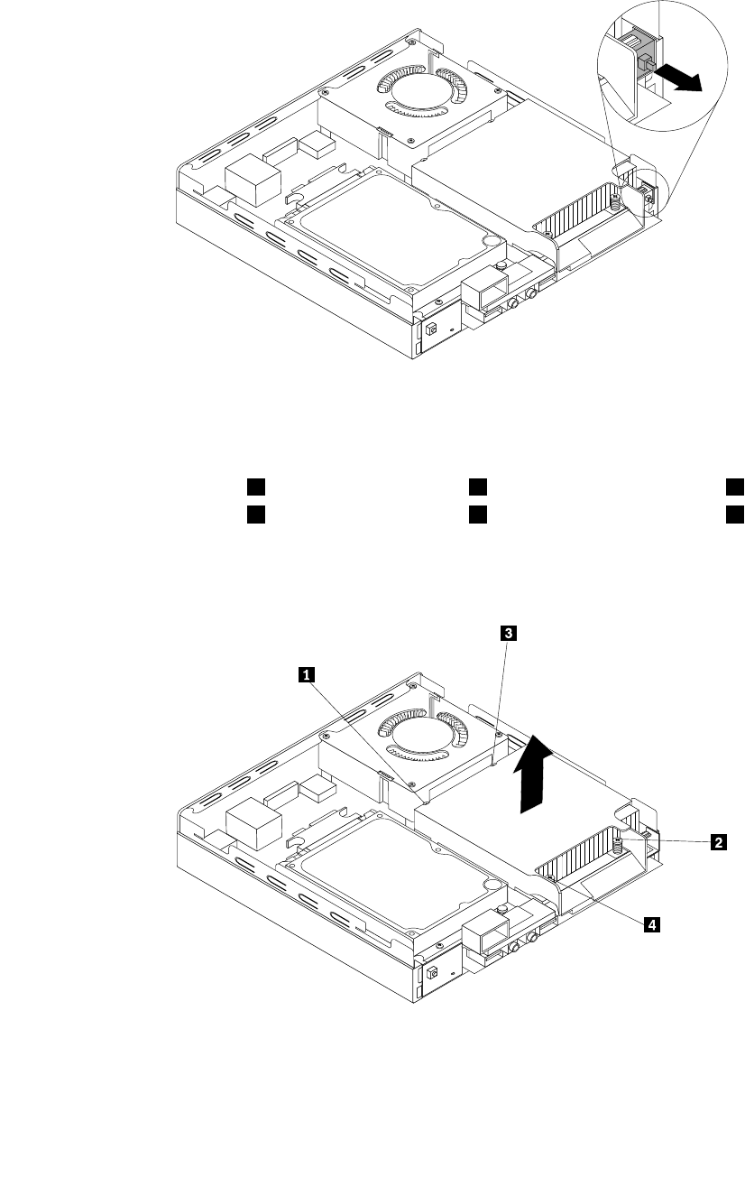
4.Pulltheintrusionswitchtoremoveitfromtheheatsinkbracket.
Figure42.Removingtheintrusionswitch
5.Followthissequencetoremovethefourscrewsthatsecuretheheatsinkandfanassemblytothe
systemboard:
a.Partiallyremovescrew1,thenfullyremovescrew2,andthenfullyremovescrew1.
b.Partiallyremovescrew3,thenfullyremovescrew4,andthenfullyremovescrew3.
Note:Carefullyremovethefourscrewsfromthesystemboardtoavoidanypossibledamagetothe
systemboard.Thefourscrewscannotberemovedfromtheheatsinkandfanassembly.
Figure43.Removingtheheatsink
6.Liftthefailingheatsinkoffthesystemboard.
Notes:
100ThinkCentreHardwareMaintenanceManual
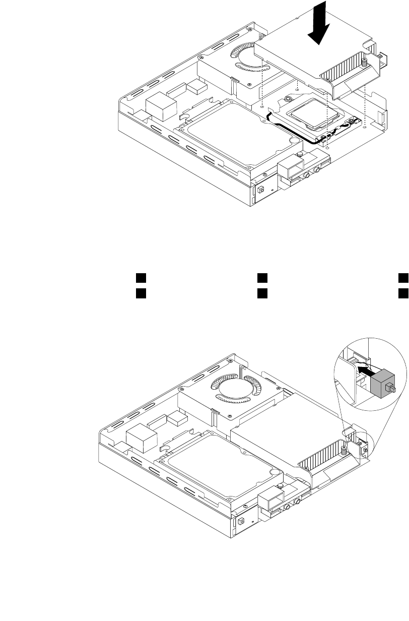
a.Youmighthavetogentlytwisttheheatsinkandfanassemblytofreeitfromthemicroprocessor.
b.Donottouchthethermalgreasewhilehandlingtheheatsinkandfanassembly.
7.Positionthenewheatsinkandfanassemblyonthesystemboardsothatthefourscrewsarealigned
withtheholesinthesystemboard.
Figure44.Installingtheheatsink
8.Followthissequencetoinstallthefourscrewstosecurethenewheatsinkandfanassembly.Do
notover-tightenthescrews.
a.Partiallytightenscrew1,thenfullytightenscrew2,andthenfullytightenscrew1.
b.Partiallytightenscrew3,thenfullytightenscrew4,andthenfullytightenscrew3.
9.Attachtheintrusionswitchtotheheatsinkbracket.
Figure45.Installingtheintrusionswitch
Chapter9.ReplacingFRUs101
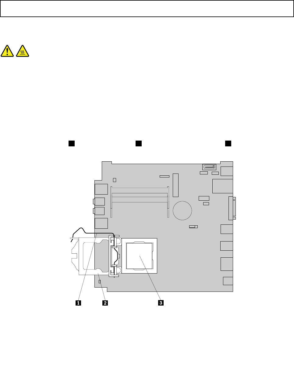
Whattodonext:
•Toworkwithanotherpieceofhardware,gototheappropriatesection.
•Tocompletetheinstallationorreplacement,goto“Completingthepartsreplacement”onpage123.
Replacingthemicroprocessor
Attention:Donotopenyourcomputerorattemptanyrepairbeforereadingandunderstandingthe“Important
safetyinformation”onpage1.
Thissectionprovidesinstructionsonhowtoreplacethemicroprocessor.
CAUTION:
Theheatsinkandmicroprocessormightbeveryhot.Turnoffthecomputerandwaitthreetove
minutestoletthecomputercoolbeforeremovingthecomputercover.
Toreplacethemicroprocessor,dothefollowing:
1.Turnoffthecomputeranddisconnectallpowercordsfromelectricaloutlets.
2.Removethecomputercover.See“Removingthecomputercover”onpage77.
3.Removetheheatsink.See“Replacingtheheatsink”onpage99.
Note:Placetheheatsinkonitssidesothatthethermalgreaseonthebottomofitdoesnotgetin
contactwithanything.
4.Liftthesmallhandle1andopentheretainer2toaccessthemicroprocessor3.
Figure46.Accessingthemicroprocessor
102ThinkCentreHardwareMaintenanceManual
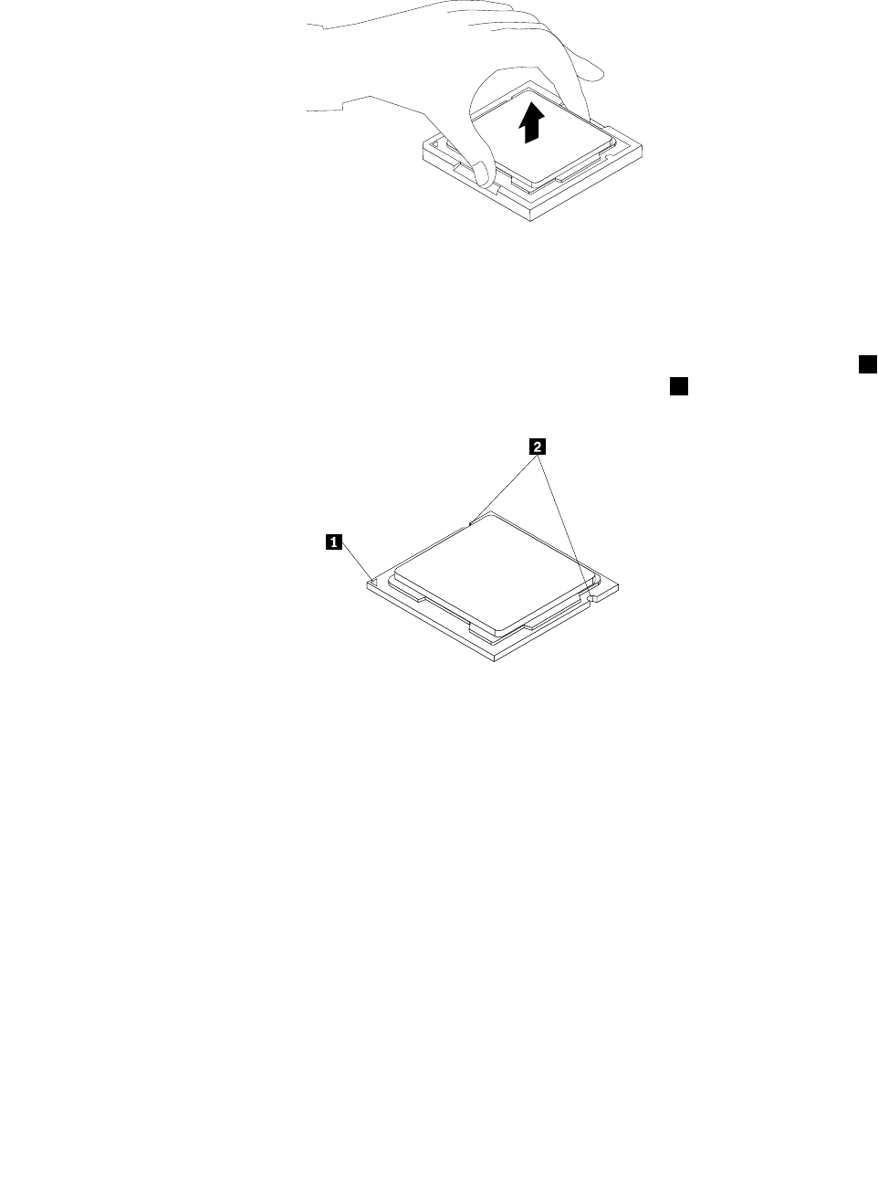
5.Liftthemicroprocessorstraightupandoutofthemicroprocessorsocket.
Figure47.Removingthemicroprocessor
Notes:
a.Yourmicroprocessorandsocketmightlookdifferentfromtheoneillustrated.
b.Notetheorientationofthemicroprocessorinthesocket.Youcaneitherlookforthesmalltriangle1
ononecornerofthemicroprocessorornotetheorientationofthenotches2onthemicroprocessor.
Thisisimportantwheninstallingthenewmicroprocessoronthesystemboard.
c.Touchonlytheedgesofthemicroprocessor.Donottouchthegoldcontactsonthebottom.
d.Donotdropanythingontothemicroprocessorsocketwhileitisexposed.Thesocketpinsmustbe
keptascleanaspossible.
6.Makesurethatthesmallhandleisintheraisedpositionandthemicroprocessorretainerisfullyopen.
7.Removetheprotectivecoverthatprotectsthegoldcontactsofthenewmicroprocessor.
8.Holdthenewmicroprocessorbyitssidesandalignthesmalltriangleononecornerofthenew
microprocessorwiththecorrespondingsmalltriangleononecornerofthemicroprocessorsocket.
Chapter9.ReplacingFRUs103
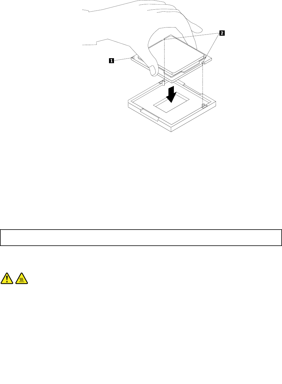
9.Lowerthenewmicroprocessorstraightdownintothemicroprocessorsocketonthesystemboard.
Figure48.Installingthemicroprocessor
10.Closethemicroprocessorretainerandlockitintopositionwiththesmallhandletosecurethenew
microprocessorinthesocket.
11.Reinstalltheheatsink.See“Replacingtheheatsink”onpage99.
Whattodonext:
•Toworkwithanotherpieceofhardware,gototheappropriatesection.
•Tocompletethereplacement,goto“Completingthepartsreplacement”onpage123.
Replacingthesystemboard
Attention:Donotopenyourcomputerorattemptanyrepairbeforereadingandunderstandingthe“Important
safetyinformation”onpage1.
Thissectionprovidesinstructionsonhowtoreplacethesystemboard.
CAUTION:
Theheatsinkandmicroprocessormightbeveryhot.Turnoffthecomputerandwaitthreetove
minutestoletthecomputercoolbeforeremovingthecomputercover.
Toreplacethesystemboard,dothefollowing:
1.Removeallmediafromthedrivesandturnoffallattacheddevicesandthecomputer.Then,disconnect
allpowercordsfromelectricaloutletsanddisconnectallcablesthatareconnectedtothecomputer.
2.Removethecomputercover.See“Removingthecomputercover”onpage77.
3.Removetheheatsink.See“Replacingtheheatsink”onpage99.
104ThinkCentreHardwareMaintenanceManual
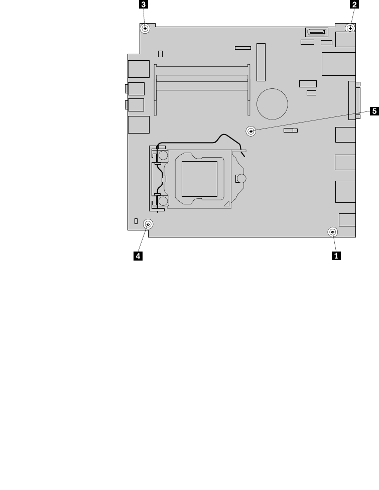
Note:Placetheheatsinkonitssidesothatthethermalgreaseonthebottomofitdoesnotgetin
contactwithanything.
4.Removethesystemfanfromthecomputer.See“Replacingthesystemfan”onpage117.
5.Removetheharddiskdrivebracketfromthecomputer.See“Replacingtheharddiskdrivebracket”on
page107.
6.RemovetheWiFicardmoduleifyourcomputerhasone.See“ReplacingtheWiFicardmodule”on
page112.
7.Removeallmemorymodulesthatarecurrentlyinstalled.See“Installingorreplacingamemorymodule”
onpage79.
8.Carefullytakenoteofthelocationsofallcableconnectionsonthesystemboardanddisconnectall
thecables.See“Locatingpartsonthesystemboard”onpage72.
9.Removethevescrewsthatsecurethesystemboardtothechassisbyfollowingthesequenceshown
inthefollowingillustration.
Figure49.Removingthevescrewsthatsecurethesystemboard
10.Carefullyslidethesystemboardsothatitcanbereleasedfromthemountingstudsthatsecurethe
systemboardinplace.
11.Carefullypivotthefailingsystemboardupwardtoremoveitoutofthechassis.
Chapter9.ReplacingFRUs105
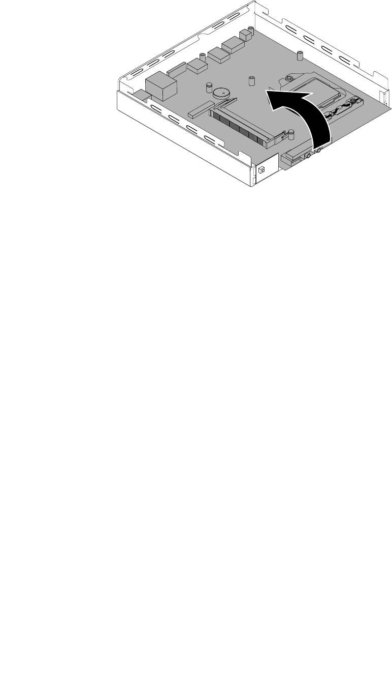
Figure50.Removingthesystemboard
12.Removethemicroprocessorfromthefailingsystemboardandinstallitonthenewsystemboard.See
“Replacingthemicroprocessor”onpage102.
13.Positionthenewsystemboardintothechassissothatthescrewholesinthenewsystemboardare
alignedwiththoseinthechassis.Installthevescrewsthatsecurethesystemboardtothechassisby
installingscrew5toscrew1.
14.Installtheheatsinkonthenewsystemboard.See“Replacingtheheatsink”onpage99.
15.Installtheharddiskdrivebracket.See“Replacingtheharddiskdrivebracket”onpage107.
16.Installthesystemfan.See“Replacingthesystemfan”onpage117.
17.Installallmemorymodulesremovedfromthefailingsystemboardonthenewsystemboard.See
“Installingorreplacingamemorymodule”onpage79.
18.Reconnectallremainingcablestothesystemboard.See“Locatingpartsonthesystemboard”
onpage72.
19.Tocompletethereplacement,goto“Completingthepartsreplacement”onpage123.
Thefailingsystemboardmustbereturnedwithamicroprocessorsocketcovertoprotectthepinsduring
shippingandhandling.
Toinstallthemicroprocessorsocketcover,dothefollowing:
1.Releasetheleversecuringthemicroprocessorretainerandopentheretainertoaccessthe
microprocessor.
2.Graspthemicroprocessoronthesidesandliftitstraightupandoutofthesocket.Donottouchthe
contactsonthemicroprocessorsocket.
3.Lowerthemicroprocessorretainer,andthenlowerthelevertosecuretheretainer.Makesurethe
leverislockedintoposition.
106ThinkCentreHardwareMaintenanceManual
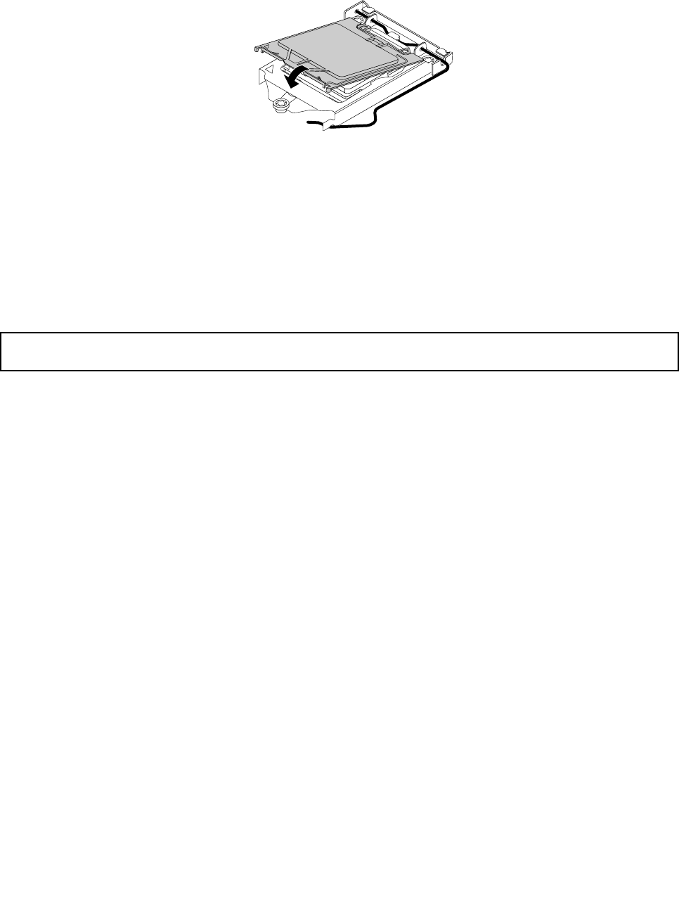
4.Notetheorientationofthesocketcover,andinstallonesideofthesocketcoverintothemicroprocessor
socket.
Figure51.Installingonesideofthesocketcoverintothemicroprocessorsocket
Note:Yourmicroprocessorsocketandcovermightlookslightlydifferentfromtheillustration.
5.Carefullypresstheothersideofthesocketcoverdownwarduntilthesocketcoversnapsintoposition.
6.Carefullycheckthefourcornersofthesocketcovertomakesurethatthecoverissecuredinthe
microprocessorsocket.
7.Followanyadditionalinstructionsincludedwiththereplacementpartyoureceived.
Replacingtheharddiskdrivebracket
Attention:Donotopenyourcomputerorattemptanyrepairbeforereadingandunderstandingthe“Important
safetyinformation”onpage1.
Thissectionprovidesinstructionsonhowtoreplacetheharddiskdrivebracket.
Toreplacetheharddiskdrivebracket,dothefollowing:
1.Turnoffthecomputeranddisconnectallpowercordsfromelectricaloutlets.
2.Removethecomputercover.See“Removingthecomputercover”onpage77.
3.Locatetheharddiskdrive.See“LocatingFRUsandCRUs”onpage69.
4.Disconnectthesignalcableandthepowercablefromtheharddiskdrive.
Chapter9.ReplacingFRUs107
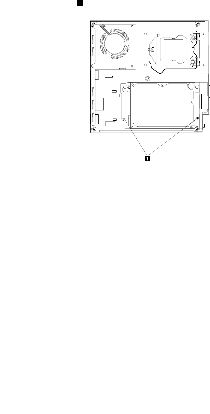
5.Removethetwoscrews1thatsecuretheharddiskdrivebracketonthesystemboard.
Figure52.Removingthescrewsthatsecuretheharddiskdrivebracket
108ThinkCentreHardwareMaintenanceManual
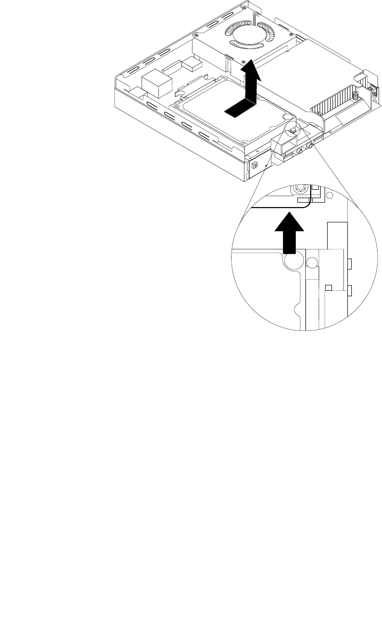
6.Slidetheharddiskdrivebrackettowardtheheatsinkandthenlifttheharddiskdrivebrackettoremove
itfromthecomputer.
Figure53.Removingtheharddiskdrivebracket
Chapter9.ReplacingFRUs109
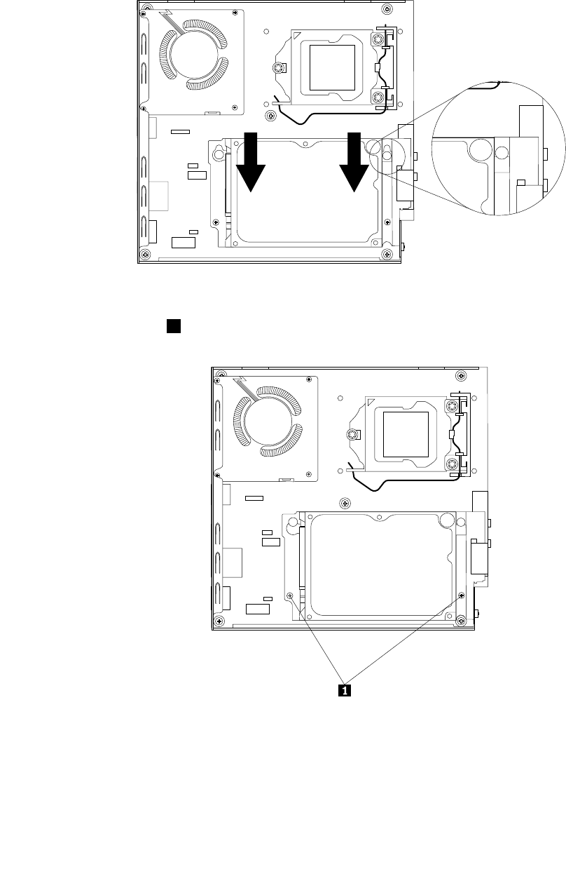
7.Toinstalltheharddiskdrivebracketintothecomputer,positiontheharddiskdrivebracketonthe
systemboardsothatthetwoholesintheharddiskdrivebracketarealignedwiththestandoffsonthe
systemboard.Slidetheharddiskdrivebracketasshownuntilthetwoscrewholesarealignedwiththe
correspondingscrewpostsonthesystemboard.
Figure54.Installingtheharddiskdrivebracket
8.Installthetwoscrews1thatsecuretheharddiskdrivebracket.
Figure55.Installingthetwoscrewsthatsecuretheharddiskdrivebracket
9.Connectthesignalcableandthepowercabletotheharddiskdrive.
Whattodonext:
•Toworkwithanotherpieceofhardware,gototheappropriatesection.
110ThinkCentreHardwareMaintenanceManual
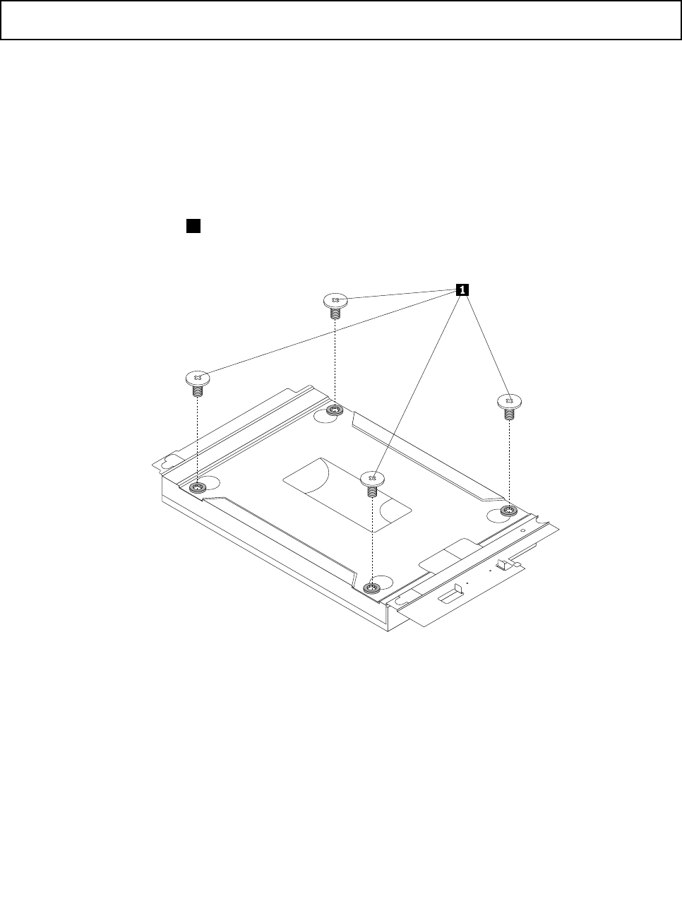
•Tocompletetheinstallationorreplacement,goto“Completingthepartsreplacement”onpage123.
Replacingtheharddiskdrive
Attention:Donotopenyourcomputerorattemptanyrepairbeforereadingandunderstandingthe“Important
safetyinformation”onpage1.
Thissectionprovidesinstructionsonhowtoreplacetheharddiskdrive.
Toreplacetheharddiskdrive,dothefollowing:
1.Turnoffthecomputeranddisconnectallpowercordsfromelectricaloutlets.
2.Removethecomputercover.See“Removingthecomputercover”onpage77.
3.Locatetheharddiskdrive.See“LocatingFRUsandCRUs”onpage69.
4.Removetheharddiskdrivebracketfromthecomputer.See“Replacingtheharddiskdrivebracket”on
page107.
5.Removethefourscrews1thatsecuretheharddiskdriveontheharddiskdrivebracketandthen
completelyremovetheharddiskdrive.
Figure56.Removingthefourscrewsthatsecuretheharddiskdrive
6.Alignthescrewholesinthenewharddiskdrivewiththecorrespondingholesintheharddiskdrive
bracketandtheninstallthefourscrewstosecurethenewharddiskdrive.
7.Reinstalltheharddiskdrivebracketintothecomputer.See“Replacingtheharddiskdrivebracket”on
page107.
Whattodonext:
•Toworkwithanotherpieceofhardware,gototheappropriatesection.
•Tocompletetheinstallationorreplacement,goto“Completingthepartsreplacement”onpage123.
Chapter9.ReplacingFRUs111
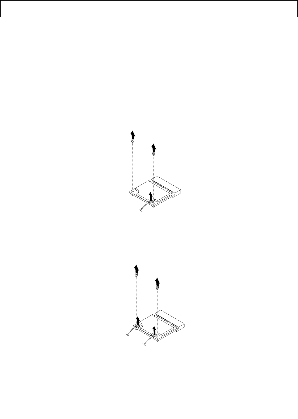
ReplacingtheWiFicardmodule
Attention:Donotopenyourcomputerorattemptanyrepairbeforereadingandunderstandingthe“Important
safetyinformation”onpage1.
ThissectionprovidesinstructionsonhowtoreplacetheWiFicardmodule.
Note:TheWiFicardmoduleisonlyavailableinsomemodels.
ToreplacetheWiFicardmodule,dothefollowing:
1.Turnoffthecomputeranddisconnectallpowercordsfromelectricaloutlets.
2.Removethecomputercover.See“Removingthecomputercover”onpage77.
3.Removetheharddiskdrivebracket.See“Replacingtheharddiskdrivebracket”onpage107.
4.LocatetheWiFicardmoduleonthesystemboard.See“LocatingFRUsandCRUs”onpage69.
5.DisconnecttheWiFiantennacablefromtheWiFicardmoduleandremovethetwoscrewsthatsecure
theWiFicardmoduletothesystemboard.
Figure57.RemovingtheWiFicardmodulecableandscrews
Note:Dependingonyourcomputermodel,theWiFicardmodulethatcomeswithyourcomputer
mighthavetwocables.
Figure58.RemovingtheWiFicardmodulecablesandscrews
112ThinkCentreHardwareMaintenanceManual
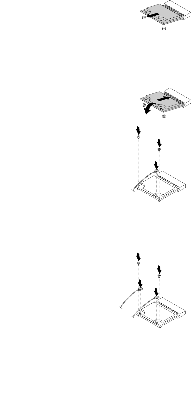
6.PulltheWiFicardmoduletoremoveitoutoftheminiPCIExpressslot.
Figure59.RemovingtheWiFicardmodule
7.InsertthenewWiFicardmoduleintotheminiPCIExpressslot.PivottheWiFicardmoduledownward
andtheninstallthetwoscrewstosecuretheWiFicardmodule.ConnecttheWiFiantennacableto
theWiFicardmodule.
Figure60.InstallingtheWiFicardmodule
Note:Dependingonyourcomputermodel,theWiFicardmodulethatcomeswithyourcomputer
mighthavetwocables.
Figure61.InstallingtheWiFicardmodule
8.Installtheharddiskdrivebracket.See“Replacingtheharddiskdrivebracket”onpage107.
Chapter9.ReplacingFRUs113
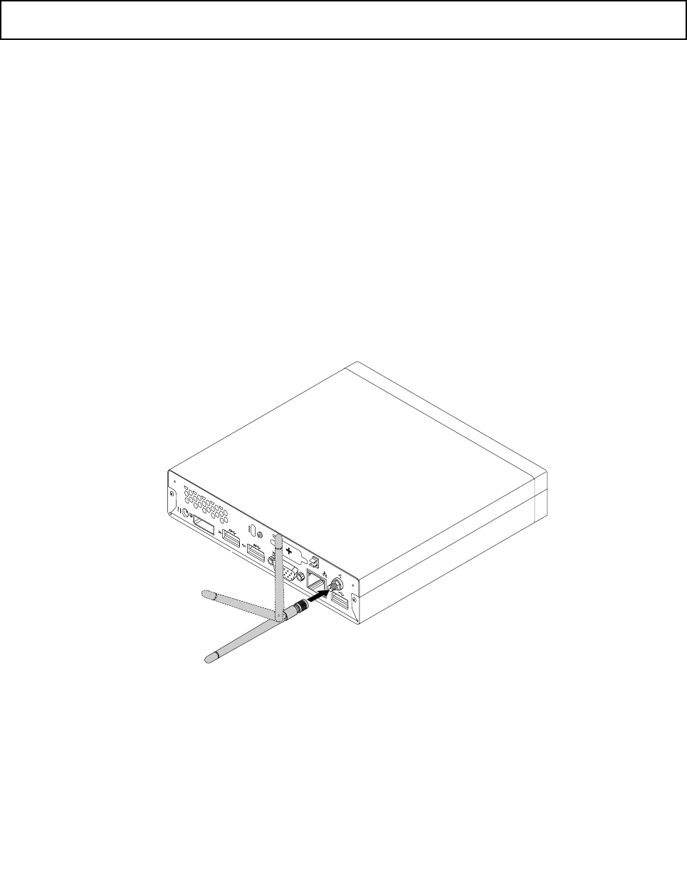
Whattodonext:
•Toworkwithanotherpieceofhardware,gototheappropriatesection.
•Tocompletetheinstallationorreplacement,goto“Completingthepartsreplacement”onpage123.
InstallingorremovingtherearWiFiantenna
Attention:Donotopenyourcomputerorattemptanyrepairbeforereadingandunderstandingthe“Important
safetyinformation”onpage1.
ThissectionprovidesinstructionsonhowtoinstallorremovetherearWiFiantenna.
Notes:
•Therearantennaisonlyavailableonsomemodels.
•Dependingonyourcomputermodel,theWiFicardmodulethatcomeswithyourcomputermightwork
withoneortworearantennas.Formoreinformationabouttworearantennas,see“Installingorremoving
tworearWiFiantennas”onpage115.
InstallingtherearWiFiantenna
ToinstalltherearWiFiantenna,dothefollowing:
1.Turnoffthecomputeranddisconnectallpowercordsfromelectricaloutlets.
2.InstalltherearWiFiantennatotherearWiFiantennacableconnectorattachedontherearofthe
computer.
3.Adjusttheangleoftherearantennatolowertheriskofbreakingtheantennabyaccident.
Figure62.InstallingtherearWiFiantenna
Whattodonext:
•Toworkwithanotherpieceofhardware,gototheappropriatesection.
•Tocompletetheinstallationorreplacement,goto“Completingthepartsreplacement”onpage123.
114ThinkCentreHardwareMaintenanceManual
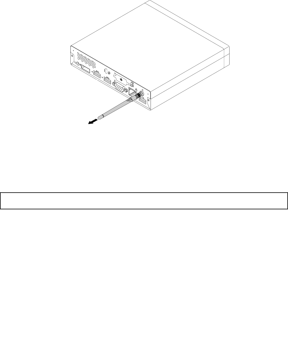
RemovingtherearWiFiantenna
ToremovetherearWiFiantenna,dothefollowing:
1.Turnoffthecomputeranddisconnectallpowercordsfromelectricaloutlets.
2.StraightentherearWiFiantennasothatitcanbemoreeasilytwisted.
3.HoldthethickerendoftherearWiFiantennaandunscrewtheWiFiantennafromtherearofthe
computer.
Figure63.RemovingtherearWiFiantenna
Whattodonext:
•Toworkwithanotherpieceofhardware,gototheappropriatesection.
•Tocompletetheinstallationorreplacement,goto“Completingthepartsreplacement”onpage123.
InstallingorremovingtworearWiFiantennas
Attention:Donotopenyourcomputerorattemptanyrepairbeforereadingandunderstandingthe“Important
safetyinformation”onpage1.
ThissectionprovidesinstructionsonhowtoinstallorremovetworearWiFiantennas.
Notes:
•Therearantennasareonlyavailableonsomemodels.
•Dependingonyourcomputermodel,theWiFicardmodulethatcomeswithyourcomputermightwork
withoneortworearantennas.Formoreinformationaboutonerearantenna,see“Installingorremoving
therearWiFiantenna”onpage114.
InstallingtherearWiFiantennas
Note:Dependingonyourcomputermodel,theWiFicardmodulethatcomeswithyourcomputermight
workwithoneortworearantennas.Ifyoureceivetworearantennas,installbothofthemtotherearofyour
computer.
ToinstalltherearWiFiantennas,dothefollowing:
1.Turnoffthecomputeranddisconnectallpowercordsfromelectricaloutlets.
Chapter9.ReplacingFRUs115
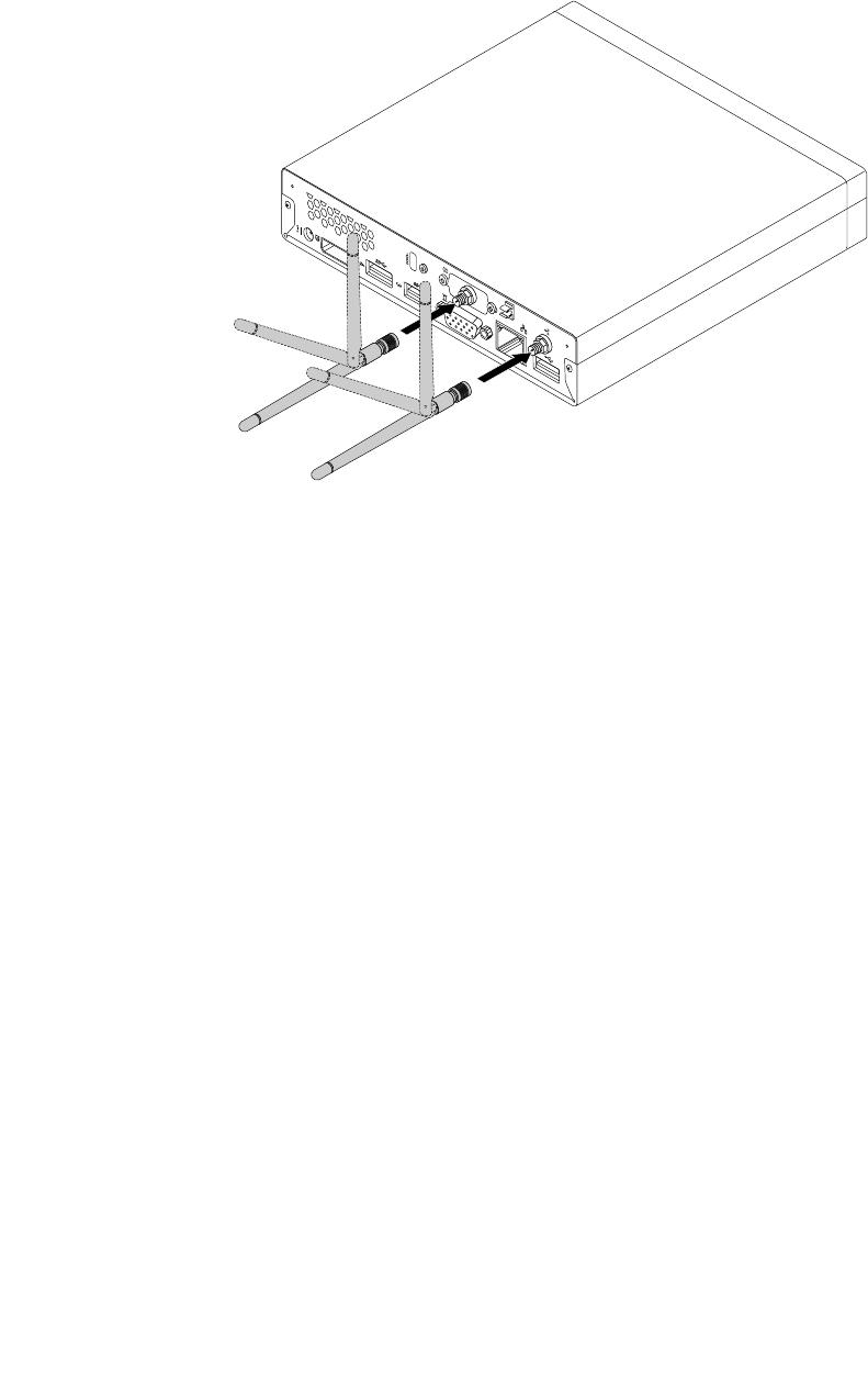
2.InstallthetworearWiFiantennastotherearWiFiantennacableconnectorsattachedontherear
ofthecomputer.
3.Adjusttheangleoftherearantennastolowertheriskofbreakingtheantennabyaccident.
Figure64.InstallingtherearWiFiantennas
Whattodonext:
•Toworkwithanotherpieceofhardware,gototheappropriatesection.
•Tocompletetheinstallationorreplacement,goto“Completingthepartsreplacement”onpage123.
RemovingtherearWiFiantennas
ToremovetherearWiFiantennas,dothefollowing:
1.Turnoffthecomputeranddisconnectallpowercordsfromelectricaloutlets.
2.StraightentherearWiFiantennassothatitcanbemoreeasilytwisted.
116ThinkCentreHardwareMaintenanceManual
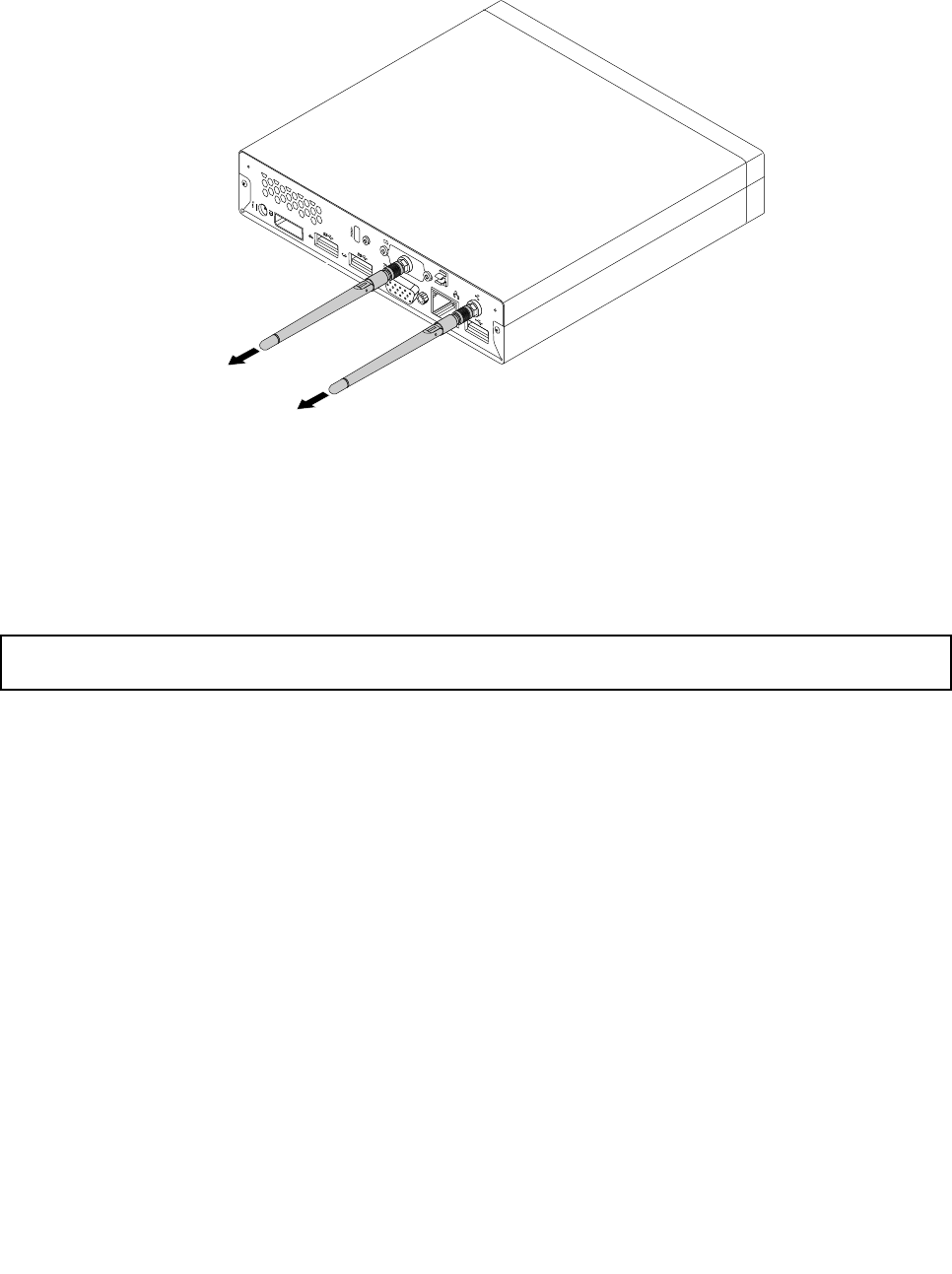
3.HoldthethickerendoftherearWiFiantennasandunscrewtheWiFiantennasfromtherearofthe
computer.
Figure65.RemovingtherearWiFiantennas
Whattodonext:
•Toworkwithanotherpieceofhardware,gototheappropriatesection.
•Tocompletetheinstallationorreplacement,goto“Completingthepartsreplacement”onpage123.
Replacingthesystemfan
Attention:Donotopenyourcomputerorattemptanyrepairbeforereadingandunderstandingthe“Important
safetyinformation”onpage1.
Thissectionprovidesinstructionsonhowtoreplacethesystemfan.
Toreplacethesystemfan,dothefollowing:
1.Turnoffthecomputeranddisconnectallpowercordsfromelectricaloutlets.
2.Removethecomputercover.See“Removingthecomputercover”onpage77.
3.Locatethesystemfaninthecomputer.See“LocatingFRUsandCRUs”onpage69.
4.Removetheheatsinkforeasieraccesstothesystemfan.See“Replacingtheheatsink”onpage99.
5.Disconnectthesystemfancablefromthesystemboard.See“Locatingpartsonthesystemboard”
onpage72.
Chapter9.ReplacingFRUs117
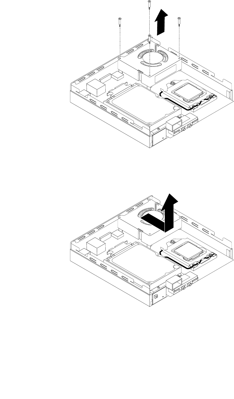
6.Removethefourscrewsthatsecurethesystemfantothesystemboard.
Figure66.Removingthescrewsthatsecurethesystemfan
7.Liftthefailingsystemfanoffthesystemboard.
Figure67.Removingthesystemfan
118ThinkCentreHardwareMaintenanceManual
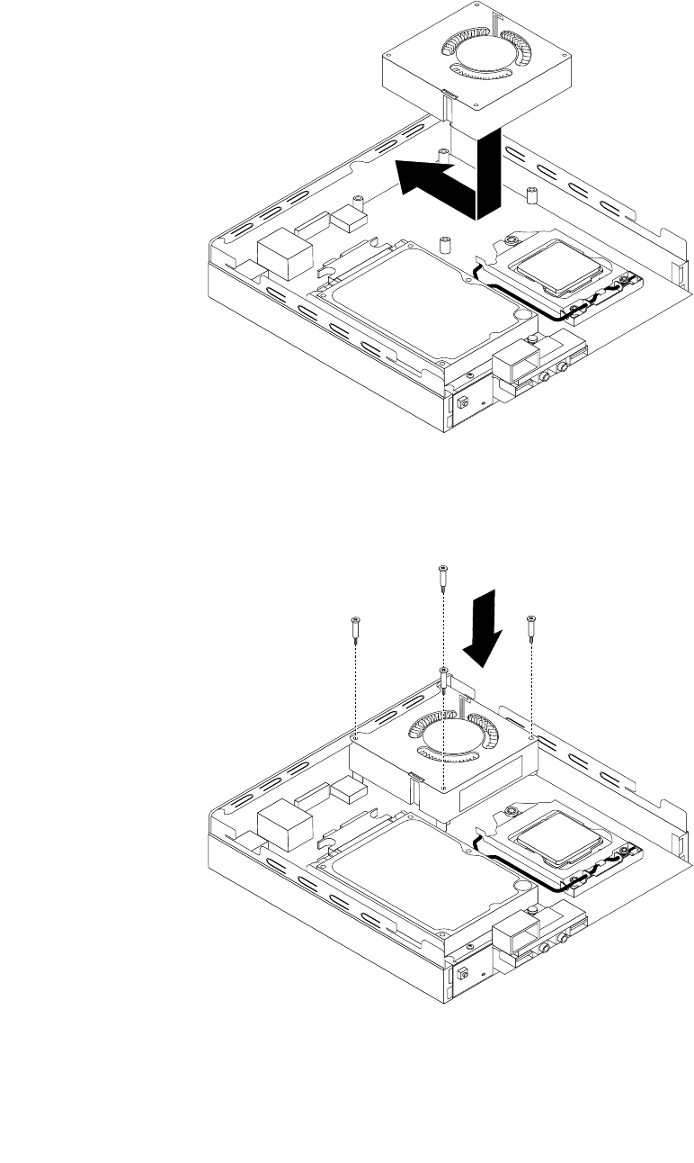
8.Positionthenewsystemfanonthesystemboardsothatthefourscrewsarealignedwiththescrew
postsonthesystemboard.
Figure68.Installingthesystemfan
9.Installthefourscrewsthatsecurethesystemfan.
Figure69.Installingthescrewsthatsecurethesystemfan
Chapter9.ReplacingFRUs119

10.Connectthesystemfancabletothesystemfanconnectoronthesystemboard.See“Locatingpartson
thesystemboard”onpage72.
11.Reinstalltheheatsink.See“Replacingtheheatsink”onpage99.
Whattodonext:
•Toworkwithanotherpieceofhardware,gototheappropriatesection.
•Tocompletetheinstallationorreplacement,goto“Completingthepartsreplacement”onpage123.
Replacingtheinternalspeaker
Attention:Donotopenyourcomputerorattemptanyrepairbeforereadingandunderstandingthe“Important
safetyinformation”onpage1.
Thissectionprovidesinstructionsonhowtoreplacetheinternalspeaker.
Note:Theinternalspeakerisonlyavailableinsomemodels.
Toreplacetheinternalspeaker,dothefollowing:
1.Turnoffthecomputeranddisconnectallpowercordsfromelectricaloutlets.
2.Removethecomputercover.See“Removingthecomputercover”onpage77.
3.Locatetheinternalspeakerinthecomputer.See“Locatingpartsonthesystemboard”onpage72.
4.Removetheharddiskdrivebracket.See“Replacingtheharddiskdrivebracket”onpage107.
5.Disconnecttheinternalspeakercablefromthesystemboard.See“Locatingpartsonthesystem
board”onpage72.
120ThinkCentreHardwareMaintenanceManual
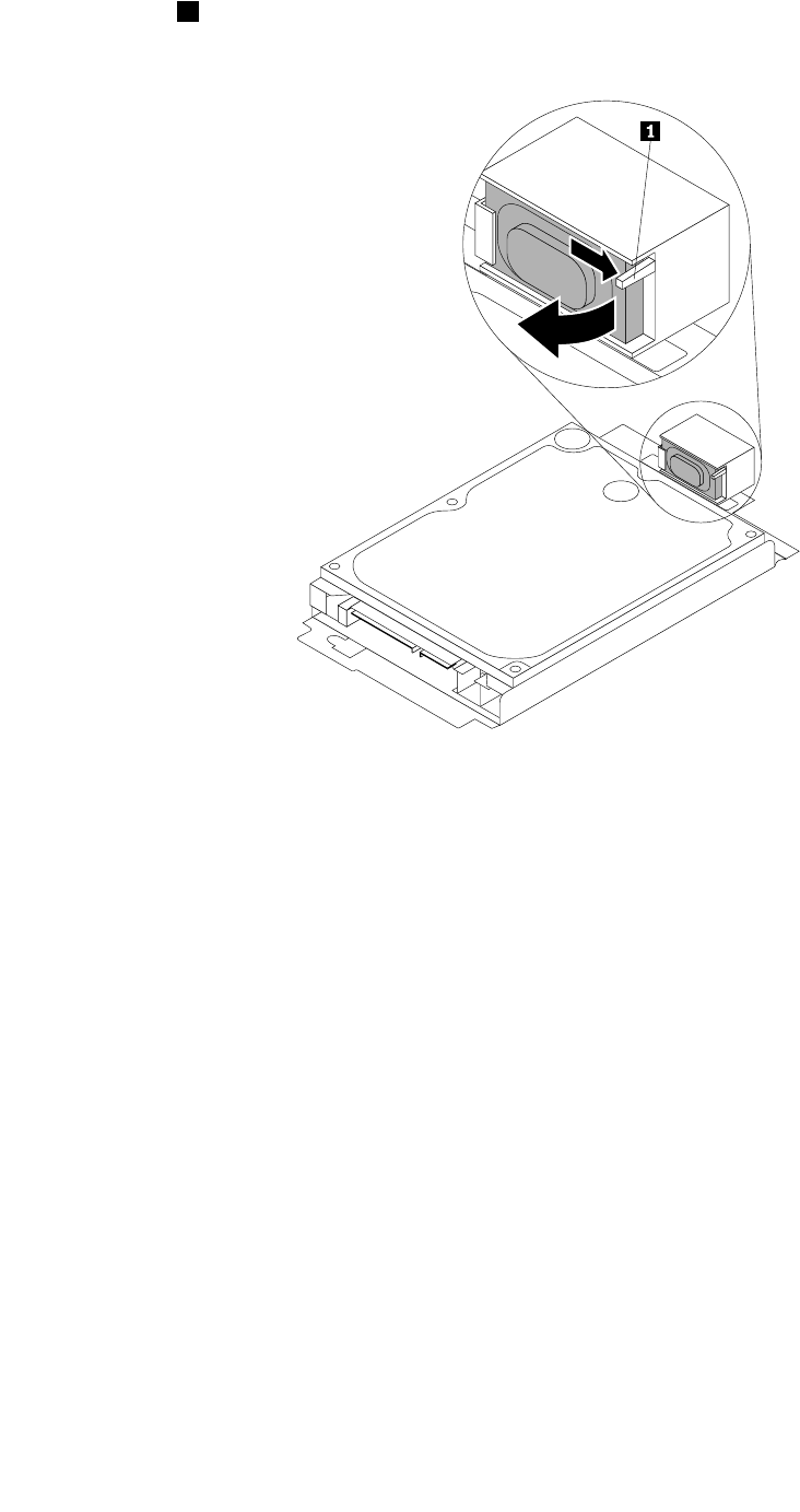
6.Pressthetab1thatsecurestheinternalspeakerandthenpivottheinternalspeakeroutwardasshown
tocompletelyremovetheinternalspeakerfromtheinternalspeakerholder.
Figure70.Removingtheinternalspeaker
Chapter9.ReplacingFRUs121
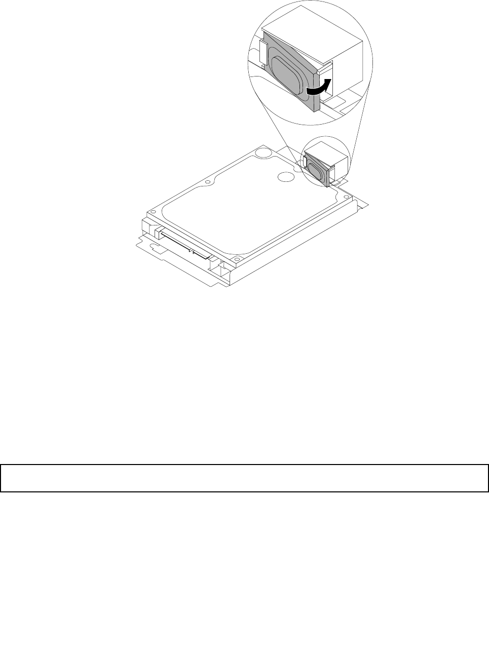
7.Positionthenewinternalspeakerintotheinternalspeakerholderandthenpivottheinternalspeaker
inwarduntilitissecuredinplace.
Figure71.Installinganewinternalspeaker
8.Connecttheinternalspeakercabletothesystemboard.See“Locatingpartsonthesystemboard”
onpage72.
9.Installtheharddiskdrivebracketonthesystemboard.See“Replacingtheharddiskdrivebracket”on
page107.
Whattodonext:
•Toworkwithanotherpieceofhardware,gototheappropriatesection.
•Tocompletetheinstallationorreplacement,goto“Completingthepartsreplacement”onpage123.
Replacingthekeyboardormouse
Attention:Donotopenyourcomputerorattemptanyrepairbeforereadingandunderstandingthe“Important
safetyinformation”onpage1.
Thissectionprovidesinstructionsonhowtoreplacethekeyboardormouse.
Toreplacethekeyboardormouse,dothefollowing:
1.Removeanymediafromthedrives.Then,turnoffallattacheddevicesandthecomputer.
2.Disconnectallpowercordsfromelectricaloutlets.
3.Disconnecttheoldkeyboardcableormousecablefromthecomputer.
122ThinkCentreHardwareMaintenanceManual
4.ConnectanewkeyboardormousetooneoftheUSBconnectorsonthecomputer.Dependingon
whereyouwanttoconnectthenewkeyboardormouse,see“Locatingconnectors,controls,and
indicatorsonthefrontofyourcomputer”onpage67or“Locatingconnectorsontherearofyour
computer”onpage68.
Figure72.ConnectingtheUSBkeyboardormouse
Whattodonext:
•Toworkwithanotherpieceofhardware,gototheappropriatesection.
•Tocompletetheinstallationorreplacement,goto“Completingthepartsreplacement”onpage123.
Completingthepartsreplacement
Aftercompletingtheinstallationorreplacementforallparts,youneedtoreinstallthecomputercoverand
reconnectcables.Dependingonthepartsyouinstalledorreplaced,youmightneedtoconrmtheupdated
informationintheSetupUtilityprogram.RefertoChapter6“UsingtheSetupUtilityprogram”onpage55.
Toreinstallthecomputercoverandreconnectcablestoyourcomputer,dothefollowing:
1.Ensurethatallcomponentshavebeenreassembledcorrectlyandthatnotoolsorloosescrewsare
leftinsideyourcomputer.See“LocatingFRUsandCRUs”onpage69forthelocationsofvarious
componentsinyourcomputer.
2.Beforereinstallingthecomputercover,ensurethatthecablesareroutedcorrectly.Keepcablesclearof
thehingesandsidesofthecomputerchassistoavoidinterferencewithreinstallingthecomputercover.
Chapter9.ReplacingFRUs123
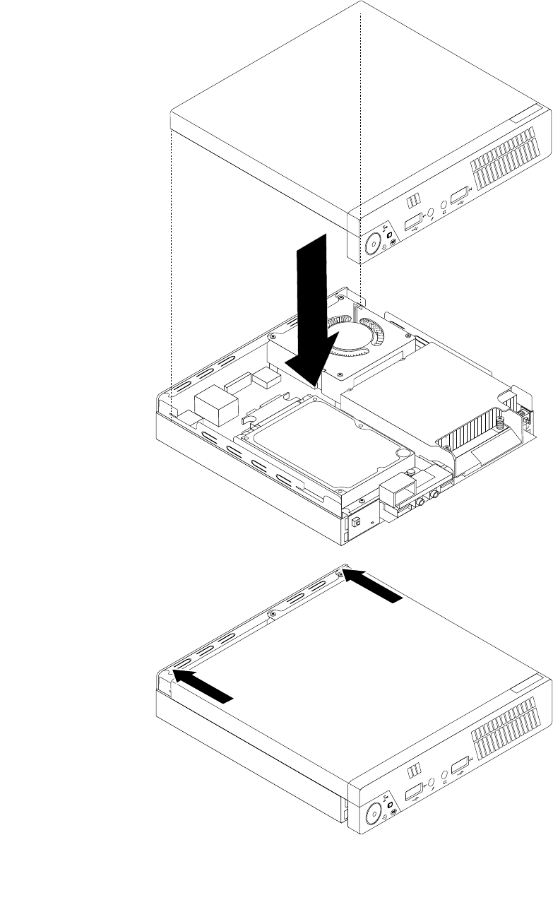
3.Positionthecomputercoveronthechassisandthenpushthecovertotherearofthecomputeruntil
itsnapsintoposition.
Figure73.Installingthecomputercover
124ThinkCentreHardwareMaintenanceManual
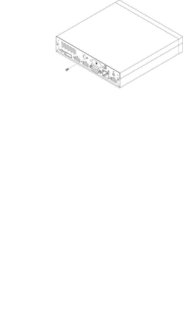
4.Installthescrewtosecurethecomputercover.
Figure74.Installingthecomputercoverscrew
5.Ifthereisanintegratedcablelockavailable,lockthecomputer.
6.Reconnecttheexternalcablesandpowercordstothecomputer.See“Locatingconnectorsonthe
rearofyourcomputer”onpage68.
7.Toupdateyourconguration,refertoChapter6“UsingtheSetupUtilityprogram”onpage55.
Note:Inmostareasoftheworld,LenovorequiresthereturnofthedefectiveCustomerReplaceableUnit
(CRU).InformationaboutthiswillcomewiththeCRUorwillcomeafewdaysaftertheCRUarrives.
Chapter9.ReplacingFRUs125

126ThinkCentreHardwareMaintenanceManual

Chapter10.Additionalserviceinformation
Thischapterprovidesadditionalinformationthattheservicerepresentativemightndhelpful.
Securityfeatures
Securityfeaturesinthissectionincludethefollowing:
•Passwords
•VitalProductData
Hardware-controlledpasswords
UsetheSetupUtilityprogramtosetthehardwarecontrolledpasswords.Formoreinformationabout
passwords,see“Usingpasswords”onpage55.
Operatingsystempassword
Note:ThissectionappliesonlytocomputermodelsthathaveanoperatingsystempreinstalledfromLenovo.
Anoperatingsystempasswordisverysimilartoapower-onpasswordanddeniesaccesstothecomputerby
anunauthorizeduserwhenthepasswordisactivated.Thecomputerisunusableuntilthecorrectpassword
isenteredandrecognizedbythecomputer.
VitalProductData
EachcomputerhasauniqueVitalProductData(VPD)codestoredinthenonvolatilememoryonthesystem
board.Afteryoureplacethesystemboard,theVPDmustbeupdated.ToupdatetheVPD,see“Updating
(ashing)theBIOSfromadisc”onpage127.
BIOSlevels
AnincorrectlevelofBIOScancausefalseerrorsandunnecessaryFRUreplacement.Usethefollowing
informationtodeterminethecurrentlevelofBIOSinstalledinthecomputer,thelatestBIOSavailableforthe
computer,andwheretoobtainthelatestlevelofBIOS.
•TodeterminethecurrentlevelofBIOS:
–StarttheSetupUtilityprogram.
–SeeBIOSRevisionLevelontheMainsetupscreen.
•SourcesforobtainingthelatestlevelBIOSavailable
1.Lenovosupportwebsite:
http://www.lenovo.com/support
2.LenovoCustomerSupportCenter
3.Levels1and2Support
Toupdate(ash)theBIOS,see“Updating(ashing)theBIOSfromadisc”onpage127.
Updating(ashing)theBIOSfromadisc
Thissectionprovidesinstructionsonhowtoupdate(ash)theBIOSfromadisc.
©CopyrightLenovo2012127

Note:Youcandownloadaself-startingbootablediscimage(knownasanISOimage)withthesystem
programupdatestocreateasystem-program-updatedisc.Goto:
http://www.lenovo.com/support
Toupdate(ash)theBIOSfromadisc,dothefollowing:
1.Turnoffyourcomputer.
2.RepeatedlypressandreleasetheF12keywhenturningonthecomputer.WhentheStartupDevice
Menuwindowopens,releasetheF12key.
3.FromtheStartupDeviceMenuwindow,selectthedesiredopticaldriveasthestartupdevice.Then,
insertthediscintothisopticaldriveandpressEnter.Theupdatebegins.
4.Whenpromptedtochangetheserialnumber,itissuggestedthatyoudonotmakethischangeby
pressingN.However,ifyoudowanttochangetheserialnumber,pressY,thentypeintheserialnumber
andpressEnter.
5.Whenpromptedtochangethemachinetypeandmodel,itissuggestedthatyoudonotmakethis
changebypressingN.However,ifyoudowanttochangethemachinetypeandmodel,pressY,then
typeinthemachinetypeandmodelandpressEnter.
6.Followtheinstructionsonthescreentocompletetheupdate.Aftertheupdateiscompleted,removethe
discfromtheopticaldrive.
Updating(ashing)theBIOSfromyouroperatingsystem
Note:BecauseLenovomakesconstantimprovementstoitsWebsites,theWebpagecontentsaresubject
tochangewithoutnotice,includingthecontentsreferencedinthefollowingprocedure.
Toupdate(ash)theBIOSfromyouroperatingsystem,dothefollowing:
1.Gotohttp://www.lenovo.com/support.
2.ClickDownloadDrivers&Software.
3.ClickUseQuickPath.
4.Typethe4-digitmachinetypeforyourcomputerintheQuickPatheldandthenclickFindMyProduct.
5.ClickBIOS.
6.LocatetheBIOSversionthatyouwanttodownload.
7.ClickClickforles.Allavailableleswillbedisplayed.
8.Clickthelinkforthereadmelethatcontainstheinstructionsforupdating(ashing)theBIOSfrom
youroperatingsystem.
9.Printtheseinstructions.Thisisveryimportantbecausetheseinstructionswillnotbedisplayedon
thescreenafterthedownloadbegins.
10.Followtheprintedinstructionstodownload,extract,andinstalltheupdate.
RecoveringfromaPOST/BIOSupdatefailure
IfthepowertoyourcomputerisinterruptedwhilethePOSTandBIOSisbeingupdated,yourcomputer
mightnotrestartcorrectly.Ifthishappens,performthefollowingproceduretorecoverfromthePOSTand
BIOSupdatefailure.ThisprocedureiscommonlycalledBoot-blockRecovery.
1.Removeallmediafromthedrivesandturnoffallattacheddevicesandthecomputer.Then,disconnect
allpowercordsfromelectricaloutletsanddisconnectallcablesthatareconnectedtothecomputer.
2.Removethecomputercover.See“Removingthecomputercover”onpage77.
3.LocatetheClearCMOS/Recoveryjumperonthesystemboard.See“Locatingpartsonthesystem
board”onpage72.
128ThinkCentreHardwareMaintenanceManual

4.RemoveanycablesthatimpedeaccesstotheClearCMOS/Recoveryjumper.
5.Movethejumperfromthestandardposition(pin1andpin2)tothemaintenanceposition(pin2and
pin3).
6.ReconnectanycablesthatweredisconnectedandreinstallthePCIcardifremoved.
7.Reinstallthecomputercoverandreconnectthepowercordsforthecomputerandmonitortoelectrical
outlets.See“Completingthepartsreplacement”onpage123.
8.TurnonthecomputerandtheninsertthePOSTandBIOSupdate(ashupdate)discintotheoptical
drive.Waitafewminutes.Then,therecoverysessionbegins.Therecoverysessionwilltaketwoto
threeminutes.Duringthistime,awarningmessagewillbedisplayedandnoactionisneededfromyou.
9.Aftertherecoverysessioniscompleted,therewillbenovideo,andyourcomputerwillautomatically
turnoff.
10.Repeatstep1throughstep4.
11.MovetheClearCMOS/Recoveryjumperbacktothestandardposition(pin1andpin2).
12.Reconnectanycablesthatweredisconnected.
13.Reinstallthecomputercoverandreconnectanycablesthatweredisconnected.
14.Turnonthecomputertorestarttheoperatingsystem.
Powermanagement
Powermanagementreducesthepowerconsumptionofcertaincomponentsofthecomputersuchasthe
systempowersupply,processor,harddiskdrives,andsomemonitors.
AdvancedCongurationandPowerInterface(ACPI)BIOS
BeinganACPIBIOSsystem,theoperatingsystemisallowedtocontrolthepowermanagementfeatures
ofthecomputerandthesettingforAdvancedPowerManagement(APM)BIOSmodeisignored.Not
alloperatingsystemssupportACPIBIOSmode.
AutomaticPower-Onfeatures
TheAutomaticPower-OnfeatureswithinthePowerManagementmenuallowyoutoenableanddisable
featuresthatturnonthecomputerautomatically.
•RTCresume:Youcanspecifyadateandtimeatwhichthecomputerwillbeturnedonautomatically.
Thiscanbeeitherasingleeventoradailyevent.
•WakeonLAN:Ifthecomputerhasaproperlyconguredtoken-ringorEthernetLANadaptercardthatis
WakeonLAN-enabledandthereisremotenetworkmanagementsoftware,youcanusetheWakeonLAN
feature.WhenyousetWakeonLANtoEnabled,thecomputerwillturnonwhenitreceivesaspecic
signalfromanothercomputeronthelocalareanetwork(LAN).
Chapter10.Additionalserviceinformation129

130ThinkCentreHardwareMaintenanceManual

AppendixA.Notices
Lenovomaynotoffertheproducts,services,orfeaturesdiscussedinthisdocumentinallcountries.Consult
yourlocalLenovorepresentativeforinformationontheproductsandservicescurrentlyavailableinyour
area.AnyreferencetoaLenovoproduct,program,orserviceisnotintendedtostateorimplythatonlythat
Lenovoproduct,program,orservicemaybeused.Anyfunctionallyequivalentproduct,program,orservice
thatdoesnotinfringeanyLenovointellectualpropertyrightmaybeusedinstead.However,itistheuser's
responsibilitytoevaluateandverifytheoperationofanyotherproduct,program,orservice.
Lenovomayhavepatentsorpendingpatentapplicationscoveringsubjectmatterdescribedinthis
document.Thefurnishingofthisdocumentdoesnotgiveyouanylicensetothesepatents.Youcansend
licenseinquiries,inwriting,to:
Lenovo(UnitedStates),Inc.
1009ThinkPlace-BuildingOne
Morrisville,NC27560
U.S.A.
Attention:LenovoDirectorofLicensing
LENOVOPROVIDESTHISPUBLICATION“ASIS”WITHOUTWARRANTYOFANYKIND,EITHEREXPRESS
ORIMPLIED,INCLUDING,BUTNOTLIMITEDTO,THEIMPLIEDWARRANTIESOFNON-INFRINGEMENT,
MERCHANTABILITYORFITNESSFORAPARTICULARPURPOSE.Somejurisdictionsdonotallow
disclaimerofexpressorimpliedwarrantiesincertaintransactions,therefore,thisstatementmaynotapply
toyou.
Thisinformationcouldincludetechnicalinaccuraciesortypographicalerrors.Changesareperiodically
madetotheinformationherein;thesechangeswillbeincorporatedinneweditionsofthepublication.
Lenovomaymakeimprovementsand/orchangesintheproduct(s)and/ortheprogram(s)describedinthis
publicationatanytimewithoutnotice.
Theproductsdescribedinthisdocumentarenotintendedforuseinimplantationorotherlifesupport
applicationswheremalfunctionmayresultininjuryordeathtopersons.Theinformationcontainedinthis
documentdoesnotaffectorchangeLenovoproductspecicationsorwarranties.Nothinginthisdocument
shalloperateasanexpressorimpliedlicenseorindemnityundertheintellectualpropertyrightsofLenovo
orthirdparties.Allinformationcontainedinthisdocumentwasobtainedinspecicenvironmentsandis
presentedasanillustration.Theresultobtainedinotheroperatingenvironmentsmayvary.
Lenovomayuseordistributeanyoftheinformationyousupplyinanywayitbelievesappropriatewithout
incurringanyobligationtoyou.
Anyreferencesinthispublicationtonon-LenovoWebsitesareprovidedforconvenienceonlyanddonotin
anymannerserveasanendorsementofthoseWebsites.ThematerialsatthoseWebsitesarenotpartof
thematerialsforthisLenovoproduct,anduseofthoseWebsitesisatyourownrisk.
Anyperformancedatacontainedhereinwasdeterminedinacontrolledenvironment.Therefore,theresult
obtainedinotheroperatingenvironmentsmayvarysignicantly.Somemeasurementsmayhavebeen
madeondevelopment-levelsystemsandthereisnoguaranteethatthesemeasurementswillbethesame
ongenerallyavailablesystems.Furthermore,somemeasurementsmayhavebeenestimatedthrough
extrapolation.Actualresultsmayvary.Usersofthisdocumentshouldverifytheapplicabledatafortheir
specicenvironment.
©CopyrightLenovo2012131

Televisionoutputnotice
Thefollowingnoticeappliestomodelsthathavethefactory-installedtelevision-outputfeature.
ThisproductincorporatescopyrightprotectiontechnologythatisprotectedbymethodclaimsofcertainU.S.
patentsandotherintellectualpropertyrightsownedbyMacrovisionCorporationandotherrightsowners.
UseofthiscopyrightprotectiontechnologymustbeauthorizedbyMacrovisionCorporation,andisintended
forhomeandotherlimitedviewingusesonlyunlessotherwiseauthorizedbyMacrovisionCorporation.
Reverseengineeringordisassemblyisprohibited.
EuropeanconformanceCEmark
Trademarks
ThefollowingtermsaretrademarksofLenovointheUnitedStates,othercountries,orboth:
Lenovo
TheLenovologo
RescueandRecovery
ThinkCentre
ThinkVantage
Microsoft,Windows,andWindowsVistaaretrademarksoftheMicrosoftgroupofcompanies.
IntelisthetrademarkofIntelCorporationintheUnitedStates,othercountries,orboth.
Othercompany,product,orservicenamesmaybetrademarksorservicemarksofothers.
132ThinkCentreHardwareMaintenanceManual

Index
A
acpoweradapterbracket,replacing95
acpoweradapter,replacing93
Administrator,password56
B
basictroubleshooting37
battery,replacing92
boot-blockrecovery128
C
changing
password56
startupdevicesequence58
CMOS,clearing57
components,internal69
computercover
removing77
computercover,reinstalling123
connector68
connectors
rear68
connectors,controls,indicators
front67
considerations,passwords56
CRU
completingtheinstallation123
CRUs(CustomerReplacableUnits),returningdefective69
D
deletingapassword56
Description68
devices,handlingstatic-sensitive73
diagnostics,troubleshooting37
DisplayPortconnector68
E
environment,operating34
Ethernetconnector68
exiting,SetupUtility59
F
failure,recoveringfromPOST/BIOS128
ashingtheBIOS127
front
connectors,controls,indicators67
FRUlocations69
FRUpartnumbers1,67,71,73
H
harddiskdrivebracket,replacing107
harddiskdrive,replacing111
heatsink,replacing99
I
IdentifyingFRUs69
installingoptions
memorymodule79
installingorremoving
verticalstand73
VESAmountbracket75
internalspeaker,replacing120
K
keyboard,replacing122
L
LenovoSolutionCenter54
locatingcomponents69
lookinguppartnumbers1,67,71,73
M
memorymodule
installing,replacing79
systemboard79
microprocessor
replacing102
mouse,replacing122
O
opticaldrive,replacing81
Optional-serviceCRUs69
P
partnumbers1,67,71,73
partsreplacement,completing123
password
Administrator56
considerations56
Power-OnPassword56
setting,changing,deleting56
passwords
erasing57
lostorforgotten57
passwords,using55
©CopyrightLenovo2012133

powerswitchboard,replacing97
Power-On,Password56
R
rearconnectors68
rearWiFiantenna,installingorremoving114
rearWiFiantennas,installingorremoving115
recovering
fromaPOST/BIOSupdatefailure128
recovery
boot-block128
removingcomputercover77
replacing
battery92
harddiskdrive111
harddiskdrivebracket107
heatsink99
microprocessor102
powerswitchboard97
systemboard104
S
secondaryharddiskdrive,replacing86
security
enablingordisabling57
selecting
startupdevice58
temporarystartupdevice58
Self-serviceCRUs69
serialport68
setting
password56
settings
changing55
viewing55
SetupUtility55
SetupUtilityprogram,starting55
SetupUtility,exiting59
startingtheSetupUtilityprogram55
startupdevice58
sequence,changing58
temporary,selecting58
static-sensitivedevices,handling73
systemboard
connectors72
locatingparts72
locations72
memorymodule79
replacing104
systemfan,replacing117
T
temporarystartupdevice58
theBIOS,updating(ashing)127–128
troubleshooting,basic37
troubleshooting,diagnostics37
U
updating
(ashing)theBIOS127
updating(ashing)theBIOS128
USB2.0connector69
using
passwords55
SetupUtility55
V
verticalstand
installingorremoving73
VESAmountbracket,installingorremoving75
VGAmonitorconnector69
viewingandchangingsettings55
W
WiFicardmodule,replacing112
134ThinkCentreHardwareMaintenanceManual