Lenovo M72Eivy Hmm User Manual Hardware Maintenance (HMM) M72e Desktop (Think Centre) Type 0896
2012-09-24
User Manual: Lenovo M72Eivy Hmm Hardware Maintenance Manual (HMM) M72e Desktop (ThinkCentre) - Type 0896 ThinkCentre M72e, 0896
Open the PDF directly: View PDF ![]() .
.
Page Count: 168 [warning: Documents this large are best viewed by clicking the View PDF Link!]
- Chapter 1. About this manual
- Chapter 2. Safety information
- Chapter 3. General information
- Chapter 4. General checkout
- Chapter 5. Troubleshooting and diagnostics
- Chapter 6. Using the Setup Utility program
- Chapter 7. Symptom-to-FRU index
- Chapter 8. Locations
- Chapter 9. Replacing FRUs (machine types: 0896, 0958, 1112, 2116, 3498, 3593, 3595, 3597, 3617, 3634, 3655, 3662, 3665, and 3675)
- Handling static-sensitive devices
- Installing or replacing hardware
- Installing external options
- Removing the computer cover
- Removing and reinstalling the front bezel
- Installing or replacing a PCI card
- Replacing the battery
- Installing or replacing a memory module
- Installing or replacing the optical drive
- Replacing the heat sink and fan assembly
- Replacing the power supply assembly
- Replacing the microprocessor
- Replacing the system board
- Replacing the primary hard disk drive
- Replacing the rear fan assembly
- Replacing the front audio and USB assembly
- Replacing the WiFi units
- Installing or removing the rear WiFi antenna
- Installing or removing the front WiFi antenna
- Completing the parts replacement
- Chapter 10. Replacing FRUs (machine types: 0900, 0967, 1271, 3578, 3594, 3596, 3598, 3629, 3654, 3660, 3664, 3668, and 3676)
- Handling static-sensitive devices
- Installing or replacing hardware
- Installing external options
- Removing the computer cover
- Removing and reinstalling the front bezel
- Accessing the system board components and drives
- Installing or replacing a memory module
- Installing or replacing a PCI card
- Replacing the battery
- Replacing the hard disk drive
- Installing or replacing the optical drive
- Replacing the heat sink and fan assembly
- Replacing the power supply assembly
- Replacing the microprocessor
- Replacing the system board
- Replacing the front audio and USB assembly
- Replacing the system fan assembly
- Replacing the WiFi units
- Installing or removing the rear WiFi antenna
- Installing or removing the front WiFi antenna
- Completing the parts replacement
- Chapter 11. Additional service information
- Appendix A. Notices
- Index

ThinkCentre
HardwareMaintenanceManual
MachineTypes:0896,0900,0958,0967,1112,1271,2116,3498,
3578,3593,3594,3595,3596,3597,3598,3617,3629,3634,3654,
3655,3660,3662,3664,3665,3668,3675,and3676

Note:Beforeusingthisinformationandtheproductitsupports,besuretoreadandunderstandChapter2
“Safetyinformation”onpage3andAppendixA“Notices”onpage159.
ThirdEdition(September2012)
©CopyrightLenovo2012.
LIMITEDANDRESTRICTEDRIGHTSNOTICE:IfdataorsoftwareisdeliveredpursuantaGeneralServicesAdministration
“GSA”contract,use,reproduction,ordisclosureissubjecttorestrictionssetforthinContractNo.GS-35F-05925.

Contents
Chapter1.Aboutthismanual......1
Importantsafetyinformation..........1
Chapter2.Safetyinformation......3
Generalsafety................3
Electricalsafety...............3
Voltage-selectionswitch............5
Safetyinspectionguide............5
Handlingelectrostaticdischarge-sensitive
devices..................6
Groundingrequirements............6
Safetynotices(multi-lingualtranslations).....6
Chapter3.Generalinformation....29
Specications...............29
Formachinetypes:0896,0958,1112,2116,
3498,3593,3595,3597,3617,3634,3655,
3662,3665,and3675...........29
Formachinetypes:0900,0967,1271,3578,
3594,3596,3598,3629,3654,3660,3664,
3668,and3676.............30
Lenovoprograms.............30
AccessingLenovoprogramsontheWindows
7operatingsystem...........30
AccessingLenovoprogramsontheWindows
8operatingsystem...........32
LenovoSupportWebsite..........32
Chapter4.Generalcheckout.....33
Problemdeterminationtips..........33
Chapter5.Troubleshootingand
diagnostics..............35
Basictroubleshooting............35
AccessingControlPanelontheWindows8
operatingsystem..............36
Troubleshootingprocedure..........36
Troubleshooting..............37
Audioproblems............37
CDproblems.............39
DVDproblems.............40
Intermittentproblems..........41
Harddiskdriveproblems.........41
Keyboard,mouse,orpointingdevice
problems...............42
Monitorproblems............44
Networkingproblems..........45
Optionproblems............48
Performanceandlockupproblems.....49
Printerproblems............51
Serialportproblems...........51
Softwareproblems...........52
USBproblems.............53
Diagnostics................53
LenovoSolutionCenter.........53
Chapter6.UsingtheSetupUtility
program................55
StartingtheSetupUtilityprogram.......55
Viewingandchangingsettings........55
Usingpasswords..............55
Passwordconsiderations.........56
Power-OnPassword..........56
AdministratorPassword.........56
HardDiskPassword...........56
Setting,changing,anddeletingapassword.56
Erasinglostorforgottenpasswords(clearing
CMOS)................57
Enablingordisablingadevice........57
Selectingastartupdevice..........58
Selectingatemporarystartupdevice....58
Selectingorchangingthestartupdevice
sequence...............58
EnablingErPcompliancemode........58
ChangingtheBIOSsettingsbeforeinstallinganew
operatingsystem..............59
ExitingtheSetupUtilityprogram.......59
Chapter7.Symptom-to-FRUindex..61
Harddiskdrivebooterror..........61
Powersupplyproblems...........61
Beepsymptoms..............61
POSTerrorcodes.............62
Miscellaneouserrormessages........64
Undeterminedproblems...........65
Chapter8.Locations.........67
Formachinetypes:0896,0958,1112,2116,3498,
3593,3595,3597,3617,3634,3655,3662,3665,
and3675.................67
Locatingconnectors,controls,andindicators
onthefrontofyourcomputer.......67
Locatingconnectorsontherearofyour
computer...............68
LocatingmajorFRUsandCRUs......69
LookingupFRUinformation.......71
Locatingpartsonthesystemboard....71
©CopyrightLenovo2012i

Locatinginternaldrives.........74
Formachinetypes:0900,0967,1271,3578,3594,
3596,3598,3629,3654,3660,3664,3668,and
3676...................75
Locatingconnectors,controls,andindicators
onthefrontofyourcomputer.......75
Locatingconnectorsontherearofyour
computer...............76
LocatingmajorFRUsandCRUs......76
LookingupFRUinformation.......78
Locatingpartsonthesystemboard....78
Locatinginternaldrives.........80
Chapter9.ReplacingFRUs(machine
types:0896,0958,1112,2116,3498,
3593,3595,3597,3617,3634,3655,
3662,3665,and3675).........81
Handlingstatic-sensitivedevices.......81
Installingorreplacinghardware........81
Installingexternaloptions........81
Removingthecomputercover.......82
Removingandreinstallingthefrontbezel..83
InstallingorreplacingaPCIcard......85
Replacingthebattery..........88
Installingorreplacingamemorymodule...89
Installingorreplacingtheopticaldrive...91
Replacingtheheatsinkandfanassembly..93
Replacingthepowersupplyassembly...95
Replacingthemicroprocessor.......96
Replacingthesystemboard.......99
Replacingtheprimaryharddiskdrive....101
Replacingtherearfanassembly......103
ReplacingthefrontaudioandUSB
assembly...............105
ReplacingtheWiFiunits.........106
InstallingorremovingtherearWiFiantenna..112
InstallingorremovingthefrontWiFi
antenna...............113
Completingthepartsreplacement.....115
Chapter10.ReplacingFRUs(machine
types:0900,0967,1271,3578,3594,
3596,3598,3629,3654,3660,3664,
3668,and3676)...........117
Handlingstatic-sensitivedevices.......117
Installingorreplacinghardware........117
Installingexternaloptions........117
Removingthecomputercover.......118
Removingandreinstallingthefrontbezel..118
Accessingthesystemboardcomponentsand
drives................119
Installingorreplacingamemorymodule...121
InstallingorreplacingaPCIcard......122
Replacingthebattery..........124
Replacingtheharddiskdrive.......125
Installingorreplacingtheopticaldrive...127
Replacingtheheatsinkandfanassembly..130
Replacingthepowersupplyassembly...133
Replacingthemicroprocessor.......137
Replacingthesystemboard.......140
ReplacingthefrontaudioandUSB
assembly...............142
Replacingthesystemfanassembly....143
ReplacingtheWiFiunits.........145
InstallingorremovingtherearWiFiantenna..150
InstallingorremovingthefrontWiFi
antenna...............152
Completingthepartsreplacement.....154
Chapter11.Additionalservice
information.............155
Securityfeatures..............155
Hardware-controlledpasswords......155
Operatingsystempassword.......155
VitalProductData...........155
BIOSlevels................155
Updating(ashing)theBIOSfromadisc....155
Updating(ashing)theBIOSfromyouroperating
system..................156
RecoveringfromaPOSTandBIOSupdate
failure..................157
Powermanagement............158
AdvancedCongurationandPowerInterface
(ACPI)BIOS..............158
AutomaticPower-onfeatures.......158
AppendixA.Notices.........159
Televisionoutputnotice...........160
EuropeanconformanceCEmark.......160
Trademarks................160
Index.................161
iiThinkCentreHardwareMaintenanceManual

Chapter1.Aboutthismanual
ThismanualprovidesserviceandreferenceinformationforThinkCentre®computerslistedonthefrontcover.
ThismanualisintendedonlyfortrainedservicepersonnelwhoarefamiliarwithLenovo®computerproducts.
BeforeservicingaLenovocomputerproduct,besuretoreadChapter2“Safetyinformation”onpage3.
Chapter7“Symptom-to-FRUindex”onpage61andChapter11“Additionalserviceinformation”onpage
155arenotspecictoanymachinetype.ThesechaptersareapplicabletoallThinkCentrecomputers.
FormajorFRUlocationsandCustomerReplaceableUnit(CRU)identication,seeChapter8“Locations”
onpage67.
ForFRUreplacementinstructions,seeChapter9“ReplacingFRUs(machinetypes:0896,0958,1112,
2116,3498,3593,3595,3597,3617,3634,3655,3662,3665,and3675)”onpage81andChapter10
“ReplacingFRUs(machinetypes:0900,0967,1271,3578,3594,3596,3598,3629,3654,3660,3664,
3668,and3676)”onpage117.
ForFRUpartnumbers,goto:
http:/www.lenovo.com/serviceparts-lookup
Importantsafetyinformation
Besuretoreadallcautionanddangerstatementsinthismanualbeforeperforminganyoftheinstructions.
VeuillezliretouteslesconsignesdetypeDANGERetATTENTIONduprésentdocumentavantd'exécuter
lesinstructions.
LesenSieunbedingtalleHinweisevomTyp"ACHTUNG"oder"VORSICHT"indieserDokumentation,bevor
SieirgendwelcheVorgängedurchführen
LeggereleistruzioniintrodottedaATTENZIONEePERICOLOpresentinelmanualeprimadieseguireuna
qualsiasidelleistruzioni
Certique-sedelertodasasinstruçõesdecuidadoeperigonestemanualantesdeexecutarqualquer
umadasinstruções
Esimportantequeleatodaslasdeclaracionesdeprecauciónydepeligrodeestemanualantesdeseguir
lasinstrucciones.
©CopyrightLenovo20121

2ThinkCentreHardwareMaintenanceManual

Chapter2.Safetyinformation
Thischaptercontainsthesafetyinformationthatyouneedtobefamiliarwithbeforeservicingacomputer.
Generalsafety
Followtheserulestoensuregeneralsafety:
•Observegoodhousekeepingintheareaofthemachinesduringandaftermaintenance.
•Whenliftinganyheavyobject:
1.Ensureyoucanstandsafelywithoutslipping.
2.Distributetheweightoftheobjectequallybetweenyourfeet.
3.Useaslowliftingforce.Nevermovesuddenlyortwistwhenyouattempttolift.
4.Liftbystandingorbypushingupwithyourlegmuscles;thisactionremovesthestrainfromthe
musclesinyourback.Donotattempttoliftanyobjectsthatweighmorethan16kg(35lb)orobjects
thatyouthinkaretooheavyforyou.
•Donotperformanyactionthatcauseshazardstothecustomer,orthatmakestheequipmentunsafe.
•Beforeyoustartthemachine,ensurethatotherservicerepresentativesandthecustomer'spersonnelare
notinahazardousposition.
•Placeremovedcoversandotherpartsinasafeplace,awayfromallpersonnel,whileyouareservicing
themachine.
•Keepyourtoolcaseawayfromwalkareassothatotherpeoplewillnottripoverit.
•Donotwearlooseclothingthatcanbetrappedinthemovingpartsofamachine.Ensurethatyoursleeves
arefastenedorrolledupaboveyourelbows.Ifyourhairislong,fastenit.
•Inserttheendsofyournecktieorscarfinsideclothingorfastenitwithanonconductiveclip,approximately
8centimeters(3inches)fromtheend.
•Donotwearjewelry,chains,metal-frameeyeglasses,ormetalfastenersforyourclothing.
Remember:Metalobjectsaregoodelectricalconductors.
•Wearsafetyglasseswhenyouare:hammering,drilling,soldering,cuttingwire,attachingsprings,using
solvents,orworkinginanyotherconditionsthatmightbehazardoustoyoureyes.
•Afterservice,reinstallallsafetyshields,guards,labels,andgroundwires.Replaceanysafetydevice
thatiswornordefective.
•Reinstallallcoverscorrectlybeforereturningthemachinetothecustomer.
Electricalsafety
CAUTION:
Electricalcurrentfrompower,telephone,andcommunicationcablescanbehazardous.Toavoid
personalinjuryorequipmentdamage,disconnecttheattachedpowercords,telecommunication
systems,networks,andmodemsbeforeyouopenthecentrecovers,unlessinstructedotherwisein
theinstallationandcongurationprocedures.
Observethefollowingruleswhenworkingonelectricalequipment.
©CopyrightLenovo20123

Important:Useonlyapprovedtoolsandtestequipment.Somehandtoolshavehandlescoveredwithasoft
materialthatdoesnotinsulateyouwhenworkingwithliveelectricalcurrents.Manycustomershave,near
theirequipment,rubberoormatsthatcontainsmallconductiveberstodecreaseelectrostaticdischarges.
Donotusethistypeofmattoprotectyourselffromanelectricshock.
•Findtheroomemergencypower-off(EPO)switch,disconnectingswitch,orelectricaloutlet.Ifanelectrical
accidentoccurs,youcanthenoperatetheswitchorunplugthepowercordquickly.
•Donotworkaloneunderhazardousconditionsornearequipmentthathashazardousvoltages.
•Disconnectallpowerbefore:
–Performingamechanicalinspection
–Workingnearpowersupplies
–RemovingorinstallingFieldReplaceableUnits(FRU)
•Beforeyoustarttoworkonthemachine,unplugthepowercord.Ifyoucannotunplugit,askthecustomer
topower-offthewallboxthatsuppliespowertothemachineandtolockthewallboxintheoffposition.
•Ifyouneedtoworkonamachinethathasexposedelectricalcircuits,observethefollowingprecautions:
–Ensurethatanotherperson,familiarwiththepower-offcontrols,isnearyou.
Remember:Anotherpersonmustbetheretoswitchoffthepower,ifnecessary.
–Useonlyonehandwhenworkingwithpowered-onelectricalequipment;keeptheotherhandinyour
pocketorbehindyourback.
Remember:Theremustbeacompletecircuittocauseanelectricshock.Byobservingtheabove
rule,youmaypreventacurrentfrompassingthroughyourbody.
–Whenusingatester,setthecontrolscorrectlyandusetheapprovedprobeleadsandaccessoriesfor
thattester.
–Standonsuitablerubbermats(obtainedlocally,ifnecessary)toinsulateyoufromgroundssuchas
metaloorstripsandmachineframes.
Observethespecialsafetyprecautionswhenyouworkwithveryhighvoltages;theseinstructionsarein
thesafetysectionsofmaintenanceinformation.Useextremecarewhenmeasuringhighvoltages.
•Regularlyinspectandmaintainyourelectricalhandtoolsforsafeoperationalcondition.
•Donotusewornorbrokentoolsandtesters.
•Neverassumethatpowerhasbeendisconnectedfromacircuit.First,checkthatithasbeenpowered-off.
•Alwayslookcarefullyforpossiblehazardsinyourworkarea.Examplesofthesehazardsaremoistoors,
nongroundedpowerextensioncables,powersurges,andmissingsafetygrounds.
•Donottouchliveelectricalcircuitswiththereectivesurfaceofaplasticdentalmirror.Thesurfaceis
conductive;suchtouchingcancausepersonalinjuryandmachinedamage.
•Donotservicethefollowingpartswiththepoweronwhentheyareremovedfromtheirnormaloperating
placesinamachine:
–Powersupplyunits
–Pumps
–Blowersandfans
–Motorgenerators
andsimilarunits.(Thispracticeensurescorrectgroundingoftheunits.)
•Ifanelectricalaccidentoccurs:
–Usecaution;donotbecomeavictimyourself.
–Switchoffpower.
–Sendanotherpersontogetmedicalaid.
4ThinkCentreHardwareMaintenanceManual

Voltage-selectionswitch
Somecomputersareequippedwithavoltage-selectionswitchlocatednearthepower-cordconnection
pointonthecomputer.Ifyourcomputerhasavoltage-selectionswitch,ensurethatyousettheswitchto
matchthevoltageavailableatyourelectricaloutlet.Settingthevoltage-selectionswitchincorrectlycan
causepermanentdamagetothecomputer.
Ifyourcomputerdoesnothaveavoltage-selectionswitch,yourcomputerisdesignedtooperateonlyatthe
voltageprovidedinthecountryorregionwherethecomputerwasoriginallypurchased.
Ifyourelocateyourcomputertoanothercountry,beawareofthefollowing:
•Ifyourcomputerdoesnothaveavoltage-selectionswitch,donotconnectthecomputertoanelectrical
outletuntilyouhaveveriedthatthevoltageprovidedisthesameasitwasinthecountryorregion
wherethecomputerwasoriginallypurchased.
•Ifyourcomputerhasavoltage-selectionswitch,donotconnectthecomputertoanelectricaloutletuntil
youhaveveriedthatthevoltage-selectionswitchissettomatchthevoltageprovidedinthatcountry
orregion.
Ifyouarenotsureofthevoltageprovidedatyourelectricaloutlet,contactyourlocalelectriccompanyor
refertoofcialWebsitesorotherliteraturefortravelerstothecountryorregionwhereyouarelocated.
Safetyinspectionguide
Theintentofthisinspectionguideistoassistyouinidentifyingpotentiallyunsafeconditionsonthese
products.Eachmachine,asitwasdesignedandbuilt,hadrequiredsafetyitemsinstalledtoprotectusers
andservicepersonnelfrominjury.Thisguideaddressesonlythoseitems.However,goodjudgmentshould
beusedtoidentifypotentialsafetyhazardsduetoattachmentoffeaturesoroptionsnotcoveredbythis
inspectionguide.
Ifanyunsafeconditionsarepresent,youmustdeterminehowserioustheapparenthazardcouldbeand
whetheryoucancontinuewithoutrstcorrectingtheproblem.
Considertheseconditionsandthesafetyhazardstheypresent:
•Electricalhazards,especiallyprimarypower(primaryvoltageontheframecancauseseriousorfatal
electricalshock).
•Explosivehazards,suchasadamagedCRTfaceorbulgingcapacitor
•Mechanicalhazards,suchaslooseormissinghardware
Theguideconsistsofaseriesofstepspresentedinachecklist.Beginthecheckswiththepoweroff,and
thepowercorddisconnected.
Checklist:
1.Checkexteriorcoversfordamage(loose,broken,orsharpedges).
2.Power-offthecomputer.Disconnectthepowercord.
3.Checkthepowercordfor:
a.Athird-wiregroundconnectoringoodcondition.Useametertomeasurethird-wireground
continuityfor0.1ohmorlessbetweentheexternalgroundpinandframeground.
b.Thepowercordshouldbetheappropriatetypeasspeciedinthepartslistings.
c.Insulationmustnotbefrayedorworn.
4.Removethecover.
Chapter2.Safetyinformation5

5.Checkforanyobviousalterations.Usegoodjudgmentastothesafetyofanyalterations.
6.Checkinsidetheunitforanyobviousunsafeconditions,suchasmetallings,contamination,wateror
otherliquids,orsignsofreorsmokedamage.
7.Checkforworn,frayed,orpinchedcables.
8.Checkthatthepower-supplycoverfasteners(screwsorrivets)havenotbeenremovedortamperedwith.
Handlingelectrostaticdischarge-sensitivedevices
Anycomputerpartcontainingtransistorsorintegratedcircuits(ICs)shouldbeconsideredsensitiveto
electrostaticdischarge(ESD).ESDdamagecanoccurwhenthereisadifferenceinchargebetweenobjects.
ProtectagainstESDdamagebyequalizingthechargesothatthemachine,thepart,theworkmat,andthe
personhandlingthepartareallatthesamecharge.
Notes:
1.Useproduct-specicESDprocedureswhentheyexceedtherequirementsnotedhere.
2.MakesurethattheESDprotectivedevicesyouusehavebeencertied(ISO9000)asfullyeffective.
WhenhandlingESD-sensitiveparts:
•Keepthepartsinprotectivepackagesuntiltheyareinsertedintotheproduct.
•Avoidcontactwithotherpeoplewhilehandlingthepart.
•Wearagroundedwriststrapagainstyourskintoeliminatestaticonyourbody.
•Preventthepartfromtouchingyourclothing.Mostclothingisinsulativeandretainsachargeevenwhen
youarewearingawriststrap.
•Usetheblacksideofagroundedworkmattoprovideastatic-freeworksurface.Thematisespecially
usefulwhenhandlingESD-sensitivedevices.
•Selectagroundingsystem,suchasthoselistedbelow,toprovideprotectionthatmeetsthespecic
servicerequirement.
Note:TheuseofagroundingsystemisdesirablebutnotrequiredtoprotectagainstESDdamage.
–AttachtheESDgroundcliptoanyframeground,groundbraid,orgreen-wireground.
–UseanESDcommongroundorreferencepointwhenworkingonadouble-insulatedor
battery-operatedsystem.Youcanusecoaxorconnector-outsideshellsonthesesystems.
–Usetheroundground-prongoftheacplugonac-operatedcomputers.
Groundingrequirements
Electricalgroundingofthecomputerisrequiredforoperatorsafetyandcorrectsystemfunction.Proper
groundingoftheelectricaloutletcanbeveriedbyacertiedelectrician.
Safetynotices(multi-lingualtranslations)
Thecautionanddangersafetynoticesinthissectionareprovidedinthefollowinglanguages:
•English
•Arabic
•Brazilian/Portuguese
•Chinese(simplied)
•Chinese(traditional)
6ThinkCentreHardwareMaintenanceManual
•French
•German
•Hebrew
•Italian
•Korean
•Spanish
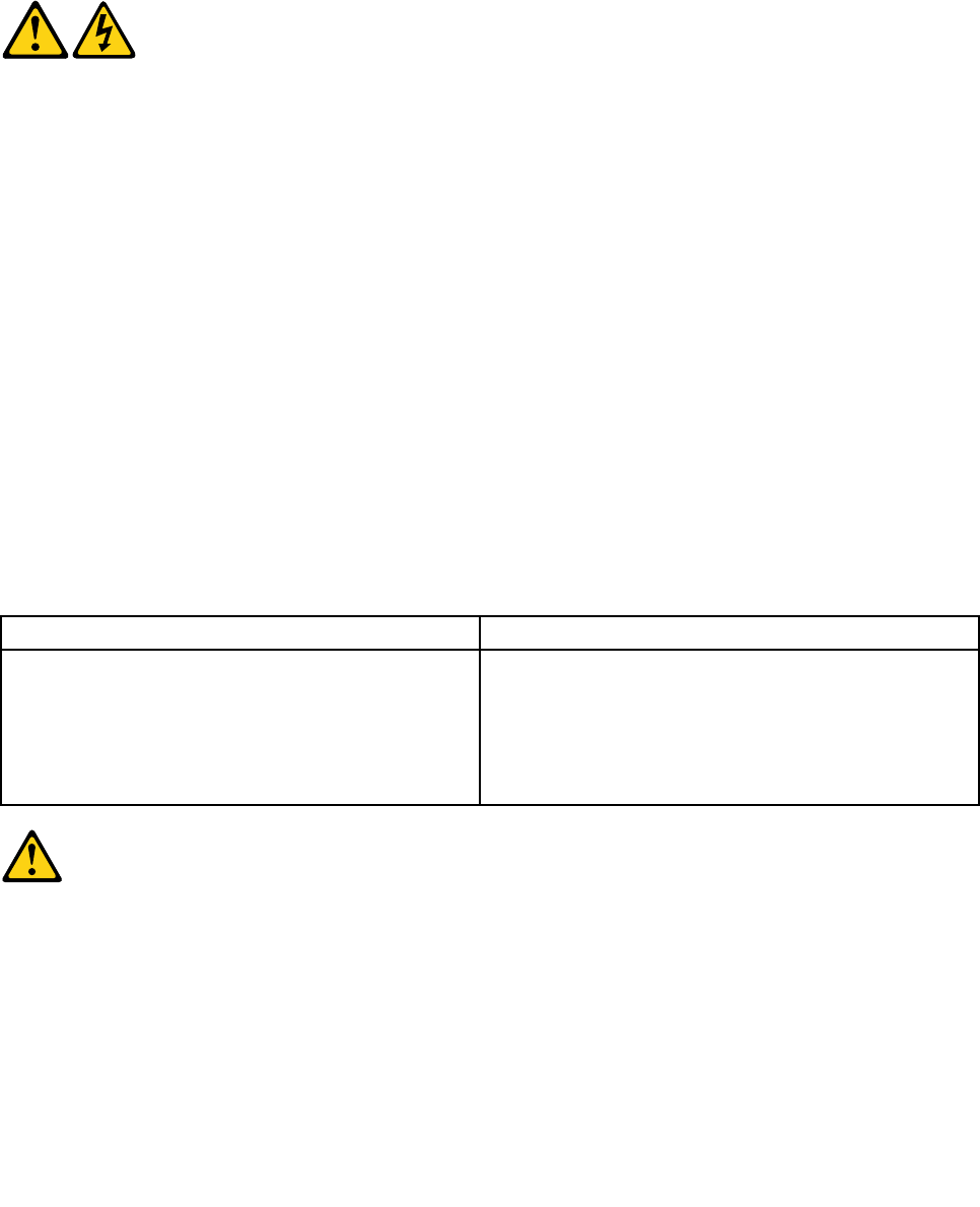
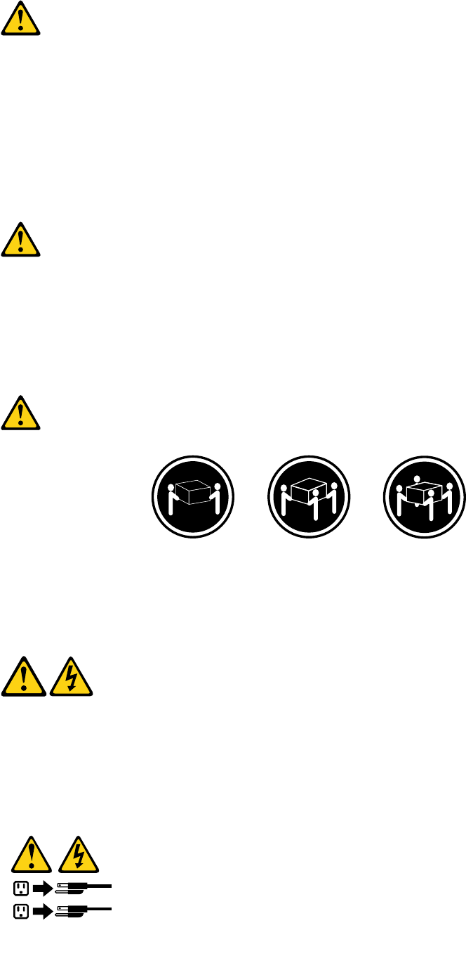
DANGER
Electricalcurrentfrompower,telephoneandcommunicationcablesishazardous.
Toavoidashockhazard:
•Donotconnectordisconnectanycablesorperforminstallation,maintenance,orreconguration
ofthisproductduringanelectricalstorm.
•Connectallpowercordstoaproperlywiredandgroundedelectricaloutlet.
•Connecttoproperlywiredoutletsanyequipmentthatwillbeattachedtothisproduct.
•Whenpossible,useonehandonlytoconnectordisconnectsignalcables.
•Neverturnonanyequipmentwhenthereisevidenceofre,water,orstructuraldamage.
•Disconnecttheattachedpowercords,telecommunicationssystems,networks,andmodems
beforeyouopenthedevicecovers,unlessinstructedotherwiseintheinstallationandconguration
procedures.
•Connectanddisconnectcablesasdescribedinthefollowingtableswheninstalling,moving,or
openingcoversonthisproductorattacheddevices.
ToConnectToDisconnect
1.TurneverythingOFF.
2.First,attachallcablestodevices.
3.Attachsignalcablestoconnectors.
4.Attachpowercordstooutlet.
5.TurndeviceON.
1.TurneverythingOFF.
2.First,removepowercordsfromoutlet.
3.Removesignalcablesfromconnectors.
4.Removeallcablesfromdevices.
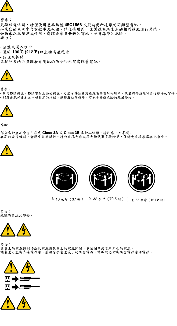
CAUTION:
Whenreplacingthelithiumbattery,useonlyPartNumber45C1566oranequivalenttypebattery
recommendedbythemanufacturer.Ifyoursystemhasamodulecontainingalithiumbattery,replace
itonlywiththesamemoduletypemadebythesamemanufacturer.Thebatterycontainslithiumand
canexplodeifnotproperlyused,handled,ordisposedof.Donot:
•Throworimmerseintowater
•Heattomorethan100°C(212°F)
•Repairordisassemble
Chapter2.Safetyinformation7
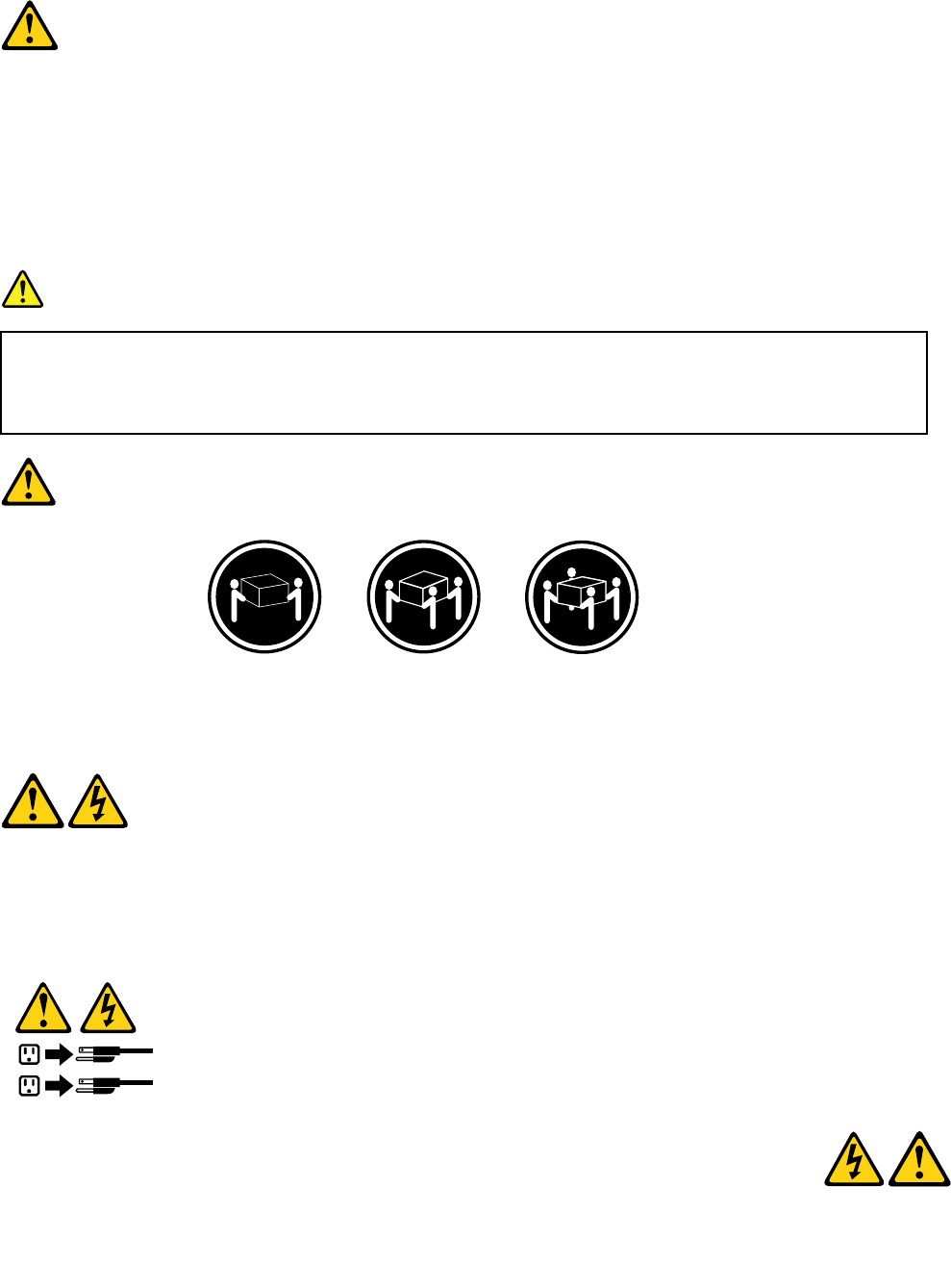
Disposeofthebatteryasrequiredbylocalordinancesorregulations.
CAUTION:
Whenlaserproducts(suchasCD-ROMs,DVD-ROMdrives,beropticdevices,ortransmitters)are
installed,notethefollowing:
•Donotremovethecovers.Removingthecoversofthelaserproductcouldresultinexposureto
hazardouslaserradiation.Therearenoserviceablepartsinsidethedevice.
•Useofcontrolsoradjustmentsorperformanceofproceduresotherthanthosespeciedherein
mightresultinhazardousradiationexposure.
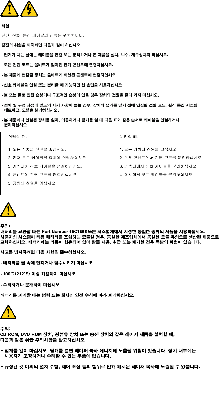
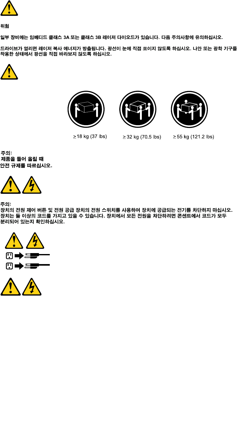
DANGER
SomelaserproductscontainanembeddedClass3AorClass3Blaserdiode.Notethefollowing:
Laserradiationwhenopen.Donotstareintothebeam,donotviewdirectlywithoptical
instruments,andavoiddirectexposuretothebeam.
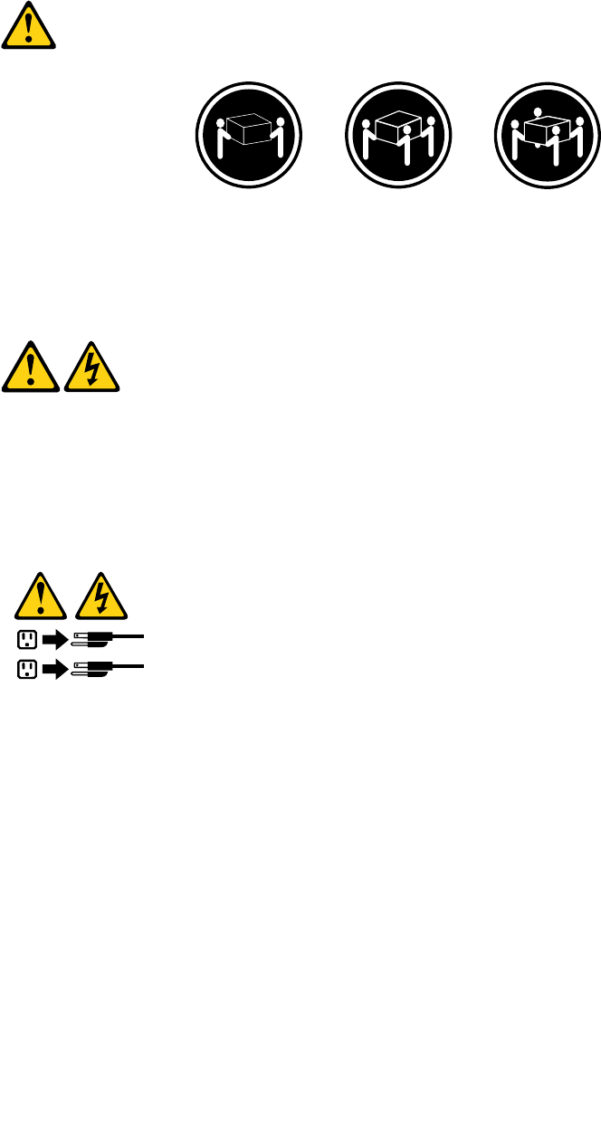
≥18kg(37lbs)≥32kg(70.5lbs)≥55kg(121.2lbs)
CAUTION:
Usesafepracticeswhenlifting.
CAUTION:
Thepowercontrolbuttononthedeviceandthepowerswitchonthepowersupplydonotturnoff
theelectricalcurrentsuppliedtothedevice.Thedevicealsomighthavemorethanonepower
cord.Toremoveallelectricalcurrentfromthedevice,ensurethatallpowercordsaredisconnected
fromthepowersource.
1
2
8ThinkCentreHardwareMaintenanceManual
Chapter2.Safetyinformation9
≥18kg(37lbs)≥32kg(70.5lbs)≥55kg(121.2lbs)
1
2
PERIGO
Acorrenteelétricaprovenientedecabosdealimentação,detelefoneedecomunicaçõeséperigosa.
10ThinkCentreHardwareMaintenanceManual
Paraevitarriscodechoqueelétrico:
•Nãoconectenemdesconectenenhumcaboouexecuteinstalação,manutençãooureconguração
desteprodutoduranteumatempestadecomraios.
•Conectetodososcabosdealimentaçãoatomadaselétricascorretamenteinstaladaseaterradas.
•Todoequipamentoqueforconectadoaesteprodutodeveserconectadoatomadascorretamente
instaladas.
•Quandopossível,utilizeapenasumadasmãosparaconectaroudesconectarcabosdesinal.
•Nuncaliguenenhumequipamentoquandohouverevidênciadefogo,águaoudanosestruturais.
•Antesdeabrirtampasdedispositivos,desconectecabosdealimentação,sistemasdetelecomunicação,
redesemodemsconectados,amenosqueespecicadodemaneiradiferentenosprocedimentosde
instalaçãoeconguração.
•Conecteedesconecteoscabosconformedescritonatabelaapresentadaaseguiraoinstalar,moverou
abrirtampasdesteprodutooudedispositivosconectados.
ParaConectar:ParaDesconectar:
1.DESLIGUETudo.
2.Primeiramente,conectetodososcabosaos
dispositivos.
3.Conecteoscabosdesinalaosconectores.
4.Conecteoscabosdealimentaçãoàstomadas.
5.LIGUEosdispositivos.
1.DESLIGUETudo.
2.Primeiramente,removaoscabosdealimentaçãodas
tomadas.
3.Removaoscabosdesinaldosconectores.
4.Removatodososcabosdosdispositivos.
CUIDADO:
Aosubstituirabateriadelítio,utilizeapenasumabateriacomNúmerodePeça45C1566ouumtipo
debateriaequivalenterecomendadopeloSeoseusistemapossuiummódulocomumabateriade
lítio,substitua-oapenasporummódulodomesmotipoedomesmofabricante.Abateriacontémlítio
epodeexplodirsenãoforutilizada,manuseadaoudescartadademaneiracorreta.
Não:
•Jogueoucoloquenaágua
•Aqueçaamaisde100°C(212°F)
•Consertenemdesmonte
Descarteabateriaconformerequeridopelasleisouregulamentoslocais.
PRECAUCIÓN:
Quandoprodutosalaser(comounidadesdeCD-ROMs,unidadesdeDVD-ROM,dispositivosdebraótica
outransmissores)estivereminstalados,observeoseguinte:
•Nãoremovaastampas.Aremoçãodastampasdeumprodutoalaserpoderesultaremexposição
prejudicialàradiaçãodelaser.Nãoexistempeçasquepodemserconsertadasnointeriordodispositivo.
Chapter2.Safetyinformation11
•Autilizaçãodecontrolesouajustesouaexecuçãodeprocedimentosdiferentesdosespecicadosaqui
poderesultaremexposiçãoprejudicialàradiação.
PERIGO
AlgunsprodutosalasercontêmdiododelaserintegradodaClasse3AoudaClasse3B.Observeoseguinte:
Radiaçãoalaserquandoaberto.Nãoolhediretamenteparaofeixeaolhonuoucominstrumentosópticose
eviteexposiçãodiretaaofeixe.
≥18kg(37lbs)≥32kg(70.5lbs)≥55kg(121.2lbs)
CUIDADO:
Utilizeprocedimentosdesegurançaparalevantarequipamentos.
CUIDADO:
Obotãodecontroledealimentaçãododispositivoeobotãoparaligar/desligardafontedealimentação
nãodesligamacorrenteelétricafornecidaaodispositivo.Odispositivotambémpodetermaisdeumcabo
dealimentação.Pararemovertodaacorrenteelétricadodispositivo,assegurequetodososcabosde
alimentaçãoestejamdesconectadosdafontedealimentação.
1
2
12ThinkCentreHardwareMaintenanceManual
Chapter2.Safetyinformation13
1
2
14ThinkCentreHardwareMaintenanceManual
1
2
Chapter2.Safetyinformation15
DANGER
Lecourantélectriqueprovenantdel'alimentation,dutéléphoneetdescâblesdetransmissionpeutprésenter
undanger.
Pourévitertoutrisquedechocélectrique:
•Nemanipulezaucuncâbleetn'effectuezaucuneopérationd'installation,d'entretienoudereconguration
deceproduitaucoursd'unorage.
•Brancheztouslescordonsd'alimentationsurunsocledeprisedecourantcorrectementcâbléetmisàla
terre.
•Branchezsurdessoclesdeprisedecourantcorrectementcâbléstoutéquipementconnectéàceproduit.
•Lorsquecelaestpossible,n'utilisezqu'uneseulemainpourconnecteroudéconnecterlescâbles
d'interface.
•Nemettezjamaisunéquipementsoustensionencasd'incendieoud'inondation,ouenprésencede
dommagesmatériels.
•Avantderetirerlescartersdel'unité,mettezcelle-cihorstensionetdéconnectezsescordons
d'alimentation,ainsiquelescâblesquilarelientauxréseaux,auxsystèmesdetélécommunicationetaux
modems(saufinstructioncontrairementionnéedanslesprocéduresd'installationetdeconguration).
•Lorsquevousinstallez,quevousdéplacez,ouquevousmanipulezleprésentproduitoudespériphériques
quiluisontraccordés,reportez-vousauxinstructionsci-dessouspourconnecteretdéconnecterles
différentscordons.
ConnexionDéconnexion
1.MettezlesunitésHORSTENSION.
2.Commencezparbranchertouslescordonssurles
unités.
3.Branchezlescâblesd'interfacesurdesconnecteurs.
4.Branchezlescordonsd'alimentationsurdesprises.
5.MettezlesunitésSOUSTENSION.
1.MettezlesunitésHORSTENSION.
2.Débranchezlescordonsd'alimentationdesprises.
3.Débranchezlescâblesd'interfacedesconnecteurs.
4.Débrancheztouslescâblesdesunités.
ATTENTION:
Remplacerlapileaulithiumusagéeparunepilederéférenceidentiqueexclusivement,(référence
45C1566),ousuivrelesinstructionsdufabricantquiendénitleséquivalences.Sivotresystèmeest
dotéd'unmodulecontenantunepileaulithium,vousdevezleremplaceruniquementparunmodule
identique,produitparlemêmefabricant.Lapilecontientdulithiumetpeutexploserencasde
mauvaiseutilisation,demauvaisemanipulationoudemiseaurebutinappropriée.
Nepas:
•lajeteràl'eau,
•l'exposeràdestempératuressupérieuresà100°C,
•chercheràlaréparerouàladémonter.
Nepasmettrelapileàlapoubelle.Pourlamiseaurebut,sereporteràlaréglementationenvigueur.
16ThinkCentreHardwareMaintenanceManual
ATTENTION:
Sidesproduitsàlaser(telsquedesunitésdeCD-ROM,deDVD-ROM,desunitésàbresoptiques,ou
desémetteurs)sontinstallés,prenezconnaissancedesinformationssuivantes:
•Neretirezpaslecarter.Enouvrantl'unitédeCD-ROMoudeDVD-ROM,vousvousexposezau
rayonnementdangereuxdulaser.Aucunepiècedel'unitén'estréparable.
•Pourévitertoutrisqued'expositionaurayonlaser,respectezlesconsignesderéglageet
d'utilisationdescommandes,ainsiquelesprocéduresdécritesdansleprésentmanuel.
DANGER
Certainsproduitsàlasercontiennentunediodeàlaserintégréedeclasse3Aou3B.Prenez
connaissancedesinformationssuivantes:
Rayonnementlaserlorsquelecarterestouvert.Eviteztouteexpositiondirecteaurayonlaser.Evitez
deregarderxementlefaisceauoudel'observeràl'aided'instrumentsoptiques.
≥18kg(37lbs)≥32kg(70.5lbs)≥55kg(121.2lbs)
ATTENTION:
Soulevezlamachineavecprécaution.
ATTENTION:
L'interrupteurdecontrôled'alimentationdel'unitéetl'interrupteurdublocd'alimentationnecoupent
paslecourantélectriquealimentantl'unité.Enoutre,lesystèmepeutêtreéquipédeplusieurs
cordonsd'alimentation.Pourmettrel'unitéhorstension,vousdevezdéconnectertouslescordons
delasourced'alimentation.
Chapter2.Safetyinformation17
1
2
VORSICHT
AnNetz-,Telefon-undDatenleitungenkönnengefährlicheSpannungenanliegen.
AusSicherheitsgründen:
•BeiGewitterandiesemGerätkeineKabelanschließenoderlösen.FernerkeineInstallations-,
Wartungs-oderRekongurationsarbeitendurchführen.
•GerätnuraneineSchutzkontaktsteckdosemitordnungsgemäßgeerdetemSchutzkontakt
anschließen.
•AlleangeschlossenenGeräteebenfallsanSchutzkontaktsteckdosenmitordnungsgemäß
geerdetemSchutzkontaktanschließen.
•DieSignalkabelnachMöglichkeiteinhändiganschließenoderlösen,umeinenStromschlagdurch
BerührenvonOberächenmitunterschiedlichemelektrischemPotenzialzuvermeiden.
•Geräteniemalseinschalten,wennHinweiseaufFeuer,WasseroderGebäudeschädenvorliegen.
•DieVerbindungzudenangeschlossenenNetzkabeln,Telekommunikationssystemen,Netzwerken
undModemsistvordemÖffnendesGehäuseszuunterbrechen,sofernindenInstallations-und
KongurationsprozedurenkeineanderslautendenAnweisungenenthaltensind.
•ZumInstallieren,TransportierenundÖffnenderAbdeckungendesComputersoderder
angeschlossenenEinheitendieKabelgemäßderfolgendenTabelleanschließenundabziehen.
ZumAnschließenderKabelgehenSiewiefolgtvorZumAbziehenderKabelgehenSiewiefolgtvor
1.SchaltenSiealleEinheitenAUS.
2.SchließenSieerstalleKabelandieEinheitenan.
3.SchließenSiedieSignalkabelandieBuchsenan.
4.SchließenSiedieNetzkabelandieSteckdosean.
5.SchaltenSiedieEinheitEIN.
1.SchaltenSiealleEinheitenAUS.
2.ZiehenSiezuerstalleNetzkabelausden
Netzsteckdosen.
3.ZiehenSiedieSignalkabelausdenBuchsen.
4.ZiehenSiealleKabelvondenEinheitenab.
CAUTION:
EineverbrauchteLithiumbatterienurdurcheineBatteriemitderTeilenummer45C1566odereine
gleichwertige,vomHerstellerempfohleneBatterieersetzen.EnthältdasSystemeinModulmiteiner
Lithiumbatterie,diesesnurdurcheinModuldesselbenTypsundvondemselbenHerstellerersetzen.
DieBatterieenthältLithiumundkannbeiunsachgemäßerVerwendung,HandhabungoderEntsorgung
explodieren.
DieBatterienicht:
•mitWasserinBerührungbringen.
18ThinkCentreHardwareMaintenanceManual
•über100Cerhitzen.
•reparierenoderzerlegen.
DieörtlichenBestimmungenfürdieEntsorgungvonSondermüllbeachten.
ACHTUNG:
BeiderInstallationvonLasergeräten(wieCD-ROM-Laufwerken,DVD-aufwerken,Einheitenmit
LichtwellenleitertechnikoderSendern)Folgendesbeachten:
•DieAbdeckungennichtentfernen.DurchEntfernenderAbdeckungendesLasergerätskönnen
gefährlicheLaserstrahlungenfreigesetztwerden.DasGerätenthältkeinezuwartendenTeile.
•WerdenSteuerelemente,EinstellungenoderDurchführungenvonProzedurenandersalshier
angegebenverwendet,kanngefährlicheLaserstrahlungauftreten.
VORSICHT
EinigeLasergeräteenthalteneineLaserdiodederKlasse3Aoder3B.BeachtenSieFolgendes:
LaserstrahlungbeigeöffneterVerkleidung.NichtindenStrahlblicken.KeineLupenoderSpiegel
verwenden.Strahlungsbereichmeiden.
≥18kg≥32kg≥55kg
ACHTUNG:
ArbeitsschutzrichtlinienbeimAnhebenderMaschinebeachten.
ACHTUNG:
MitdemNetzschalteranderEinheitundamNetzteilwirddieStromversorgungfürdieEinheit
nichtunterbrochen.DieEinheitkannauchmitmehrerenNetzkabelnausgestattetsein.Umdie
StromversorgungfürdieEinheitvollständigzuunterbrechen,müssenallezumGerätführenden
NetzkabelvomNetzgetrenntwerden.
Chapter2.Safetyinformation19
1
2
20ThinkCentreHardwareMaintenanceManual
1
2
Chapter2.Safetyinformation21
PERICOLO
Lacorrenteelettricaprovenientedaicavidialimentazione,deltelefonoedicomunicazionepuòessere
pericolosa.
Perevitareilrischiodiscosseelettriche:
•Noncollegareoscollegarequalsiasicavooppureeffettuarel'installazione,lamanutenzioneola
ricongurazionedelprodottoduranteuntemporale.
•Collegaretuttiilielettriciaunapresadialimentazionecorrettamentecablataedotatadimessaa
terra.
•Collegareallepreseelettricheappropriatetutteleapparecchiaturecheverrannoutilizzateper
questoprodotto.
•Sepossibile,utilizzaresolounamanopercollegareoscollegareicavidisegnale.
•Nonaccendereassolutamenteapparecchiatureinpresenzadiincendi,perdited'acquaodanno
strutturale.
•Scollegareicavidialimentazione,isistemiditelecomunicazione,leretieilmodemprimadi
aprireicoperchideldispositivo,salvoistruzionicontrarierelativealleprocedurediinstallazionee
congurazione.
•Collegareescollegareicavicomedescrittonellaseguentetabellaquandovengonoeffettuate
operazionidiinstallazione,spostamentooaperturadeicoperchidiquestoprodottoodelleunità
collegate.
PercollegarsiPerscollegarsi
1.SPEGNEREleapparecchiature.
2.Innanzitutto,collegaretuttiicavialleunità.
3.Collegareicavidisegnaleaiconnettori.
4.Collegareicavidialimentazioneallapresa.
5.Accenderel'unità.
1.SPEGNEREleapparecchiature.
2.Innanzitutto,rimuovereicavidialimentazionedalla
presa.
3.Rimuovereicavidisegnaledaiconnettori.
4.Rimuoveretuttiicavidalleunità.
ATTENZIONE:
Quandosisostituiscelabatteriaallitio,utilizzaresoloilNumeroparte45C1566ountipodibatteria
equivalenteconsigliatodalproduttore.Sesulsistemaèpresenteunmodulochecontieneunabatteria
allitio,sostituirlosoloconuntipodimodulodellostessotipodellastessacasadiproduzione.La
batteriacontienelitioepuòesplodereseusata,maneggiataosmaltitainmodononcorretto.
Non:
•Gettareoimmergerelabatterianell'acqua
•Riscaldarlaadunatemperaturasuperioreai100gradiC(212gradiF)
•Smontarla,ricaricarlaotentarediripararla
Lebatterieusatevannosmaltiteinaccordoallanormativainvigore(DPR915/82esuccessive
disposizioniedisposizionilocali).
22ThinkCentreHardwareMaintenanceManual
ATTENZIONE:
Quandovengonoinstallatiprodottilaser(qualiCD-ROM,unitàDVD-ROM,unitàabreotticheo
trasmittenti),tenerpresentequantosegue:
•Nonrimuovereglisportelli.L'aperturadiun'unitàlaserpuòdeterminarel'esposizionearadiazioni
laserpericolose.All'internodell'unitànonvisonopartisucuieffettuarel'assistenzatecnica.
•L'utilizzodicontrolli,regolazioniol'esecuzionediprocedurenondescrittinelpresentemanuale
possonoprovocarel'esposizionearadiazionipericolose.
PERICOLO
AlcuneunitàlasercontengonoundiodolaserdiClasse3AoClasse3B.Tenerpresentequantosegue:
Aprendol'unitàvengonoemesseradiazionilaser.Nonssareilfascio,nonguardarlodirettamente
construmentiotticiedevitarel'esposizionealfascio.
≥18kg≥32kg≥55kg
ATTENZIONE:
Prestareattenzionenelsollevarel'apparecchiatura.
ATTENZIONE:
Ilpulsantedicontrollodell'alimentazionepresentesull'unitàel'interruttoredell'alimentatorenon
disattivanol'alimentazionecorrentefornitaall'unità.E'possibilechel'unitàdispongadipiùcavidi
alimentazione.Perdisattivarel'alimentazionedall'unità,accertarsichetuttiicavidialimentazione
sianoscollegatidallafontedialimentazione.
1
2
Chapter2.Safetyinformation23
24ThinkCentreHardwareMaintenanceManual
1
2
PELIGRO
Lacorrienteeléctricaprocedentedecablesdealimentación,teléfonosycablesdecomunicaciónpuede
serpeligrosa.
Paraevitarelriesgodedescargaeléctrica:
•Noconectenidesconecteloscablesnirealiceningunatareadeinstalación,mantenimientoo
reconguracióndeesteproductoduranteunatormentaeléctrica.
•Conectetodosloscablesdealimentaciónatomasdecorrientedebidamentecableadasy
conectadasatierra.
•Cualquierequipoqueseconecteaesteproductotambiéndebeconectarseatomasdecorriente
debidamentecableadas.
•Siemprequeseaposible,utiliceunasolamanoparaconectarodesconectarloscablesdeseñal.
Chapter2.Safetyinformation25
•Noenciendanuncaunequipocuandohayseñalesdefuego,aguaodañosestructurales.
•Desconecteloscablesdealimentación,lossistemasdetelecomunicaciones,lasredesylos
módemsconectadosantesdeabrirlascubiertasdelosdispositivos,amenosqueseindiquelo
contrarioenlosprocedimientosdeinstalaciónyconguración.
•Conecteydesconecteloscables,comosedescribeenlatablasiguiente,cuandoinstale,muevao
abralascubiertasdeesteproductoodelosdispositivosconectados.
ParaconectarParadesconectar
1.APÁGUELOtodo.
2.Enprimerlugar,conectetodosloscablesalos
dispositivos.
3.Conecteloscablesdeseñalalosconectores.
4.Enchufeloscablesdealimentaciónalastomasde
corriente.
5.Enciendaeldispositivo.
1.APÁGUELOtodo.
2.Enprimerlugar,desenchufeloscablesdealimentación
delastomasdecorriente.
3.Desconecteloscablesdeseñaldelosconectores.
4.Desconectetodosloscablesdelosdispositivos.
PRECAUCIÓN:
Cuandosustituyaunabateríadelitio,utilicesolamenteunabateríanúmerodepieza45C1566uotra
detipoequivalenterecomendadaporelfabricante.Sisusistemadisponedeunmóduloquecontiene
unabateríadelitio,reemplácelosóloconelmismotipodemódulo,delmismofabricante.Labatería
contienelitioypuedeexplotarsinoseutiliza,manipulaodesechacorrectamente.
Nodebe:
•Arrojarlaalaguaosumergirlaenella
•Exponerlaatemperaturassuperioresa100°C(212°F)
•Repararlaodesmontarla
Deshágasedelabateríasegúnespeciquenlasleyesonormaslocales.
PRECAUCIÓN:
Cuandohayaproductosláser(comounidadesdeCD-ROM,unidadesdeDVD,dispositivosdebra
ópticaotransmisores)instalados,tengaencuentalosiguiente:
•Noquitelascubiertas.Siquitalascubiertasdelproductoláser,podríaquedarexpuestoaradiación
láserpeligrosa.Dentrodeldispositivonoexisteningunapiezaquerequieraserviciotécnico.
•Siusacontrolesoajustesorealizaprocedimientosquenoseanlosespecicadosaquí,podría
exponersearadiacionespeligrosas.
PELIGRO
26ThinkCentreHardwareMaintenanceManual
Algunosproductoslásertienenincorporadoundiodoláserdeclase3Aoclase3B.Tengaencuentalo
siguiente:
Cuandoseabre,quedaexpuestoaradiaciónláser.Nomiredirectamentealrayoláser,nisiquieracon
instrumentosópticos,yeviteexponersedirectamentealrayoláser.
≥18kg≥32kg≥55kg
PRECAUCIÓN:
Adopteprocedimientossegurosallevantarelequipo.
PRECAUCIÓN:
Elbotóndecontroldealimentacióndeldispositivoyelinterruptordealimentacióndelafuentede
alimentaciónnodesconectanlacorrienteeléctricasuministradaaldispositivo.Además,eldispositivo
podríatenermásdeuncabledealimentación.Parasuprimirtodalacorrienteeléctricadeldispositivo,
asegúresedequetodosloscablesdealimentaciónesténdesconectadosdelatomadecorriente.
1
2
Chapter2.Safetyinformation27

28ThinkCentreHardwareMaintenanceManual

Chapter3.Generalinformation
Thischapterprovidesgeneralinformationthatappliestoallmachinetypessupportedbythismanual.
Specications
Thissectionliststhephysicalspecicationsforyourcomputer.
Formachinetypes:0896,0958,1112,2116,3498,3593,3595,3597,3617,
3634,3655,3662,3665,and3675.
Dimensions
Width:160mm(6.3inches)
Height:388mm(15.28inches)
Depth:422mm(16.61inches)
Weight
Maximumcongurationasshipped:8.76kg(19.31lb)(withoutpackage)
Maximumcongurationasshipped:12.26kg(27.03lb)(withpackage)
Environment
•Airtemperature:
Operating:10°Cto35°C(50°Fto95°F)
Non-operating:-40°Cto60°C(-40°Fto140°F)
Non-operating:-10°Cto60°C(14°Fto140°F)(withoutpackage)
•Humidity:
Operating:20%to80%(non-condensing)
Non-operating:20%to90%(non-condensing)
•Altitude:
Operating:-50to10000ft(-15.2to3048m)
Non-operating:-50to35000ft(-15.2to10668m)
Electricalinput
•Inputvoltage:
–Lowrange:
Minimum:100Vac
Maximum:127Vac
Inputfrequencyrange:50to60Hz
Voltage-selectionswitchsetting:115Vac
–Highrange:
Minimum:200Vac
Maximum:240Vac
Inputfrequencyrange:50to60Hz
Voltage-selectionswitchsetting:230Vac
©CopyrightLenovo201229

Formachinetypes:0900,0967,1271,3578,3594,3596,3598,3629,3654,
3660,3664,3668,and3676.
Dimensions
Width:99mm(3.9inches)
Height:335mm(13.19inches)
Depth:382mm(15.04inches)
Weight
Maximumcongurationasshipped:6.86kg(15.12lb)(withoutpackage)
Maximumcongurationasshipped:9.56kg(21.08lb)(withpackage)
Environment
•Airtemperature:
Operating:10°Cto35°C(50°Fto95°F)
Non-operating:-40°Cto60°C(-40°Fto140°F)
Non-operating:-10°Cto60°C(14°Fto140°F)(withoutpackage)
•Humidity:
Operating:20%to80%(non-condensing)
Non-operating:20%to90%(non-condensing)
•Altitude:
Operating:-50to10000ft(-15.2to3048m)
Non-operating:-50to35000ft(-15.2to10668m)
Electricalinput
•Inputvoltage:
–Lowrange:
Minimum:100Vac
Maximum:127Vac
Inputfrequencyrange:50to60Hz
–Highrange:
Minimum:200Vac
Maximum:240Vac
Inputfrequencyrange:50to60Hz
Lenovoprograms
YourcomputercomeswithLenovoprogramstohelpyouworkmoreeasilyandsecurely.Dependingon
theWindowsoperatingsystempreinstalled,theprogramsmightvary.
AccessingLenovoprogramsontheWindows7operatingsystem
OntheWindows7operatingsystem,youcanaccessLenovoprogramsfromeithertheLenovo
ThinkVantage®ToolsprogramorfromControlPanel.
AccessingLenovoprogramsfromtheLenovoThinkVantageToolsprogram
ToaccessLenovoprogramsfromtheLenovoThinkVantageToolsprogram,clickStart➙AllPrograms➙
LenovoThinkVantageTools.Thendouble-clickaprogramicontoaccesstheprogram.
30ThinkCentreHardwareMaintenanceManual

Note:IfaprogramiconintheLenovoThinkVantageToolsprogramnavigationwindowisdimmed,it
indicatesthatyouneedtoinstalltheprogrammanually.Toinstalltheprogrammanually,double-clickthe
programicon.Then,followtheinstructionsonthescreen.Whentheinstallationprocesscompletes,the
programiconwillbeactivated.
Table1.ProgramsintheLenovoThinkVantageToolsprogram
ProgramIconname
CommunicationsUtilityWebConferencing
FingerprintSoftwareFingerprintReader
LenovoSolutionCenterSystemHealthandDiagnostics
PasswordManagerPasswordVault
PowerManagerPowerControls
RecoveryMediaFactoryRecoveryDisks
RescueandRecovery®EnhancedBackupandRestore
SimpleTapSimpleTap
SystemUpdateUpdateandDrivers
ViewManagementUtilityScreenLayout
Note:Dependingonyourcomputermodel,someoftheprogramsmightnotbeavailable.
AccessingLenovoprogramsfromControlPanel
ToaccessLenovoprogramsfromControlPanel,clickStart➙ControlPanel.Thendependingonthe
programyouwanttoaccess,clickthecorrespondingsectionandthenclickthecorrespondinggreentext.
Note:IfyoudonotndtheprogramyouneedinControlPanel,opentheLenovoThinkVantageTools
programnavigationwindowanddouble-clickthedimmedicontoinstalltheprogramyouneed.Then,
followtheinstructionsonthescreen.Whentheinstallationprocesscompletes,theprogramiconwillbe
activated,andyoucanndtheprograminControlPanel.
TheprogramsandthecorrespondingsectionsandgreentextsinControlPanelarelistedinthefollowing
table.
Table2.ProgramsinControlPanel
ProgramControlPanelsectionGreentextinControlPanel
CommunicationsUtilityHardwareandSoundLenovo-WebConferencing
FingerprintSoftwareSystemandSecurity
HardwareandSound
Lenovo-FingerprintReader
LenovoSolutionCenterSystemandSecurityLenovo-SystemHealthand
Diagnostics
PasswordManagerSystemandSecurity
UserAccountsandFamilySafety
Lenovo-PasswordVault
PowerManagerHardwareandSound
SystemandSecurity
Lenovo-PowerControls
RecoveryMediaSystemandSecurityLenovo-FactoryRecoveryDisks
RescueandRecoverySystemandSecurityLenovo-EnhancedBackupand
Restore
Chapter3.Generalinformation31

Table2.ProgramsinControlPanel(continued)
ProgramControlPanelsectionGreentextinControlPanel
SimpleTapProgramsLenovo-SimpleTap
SystemUpdateSystemandSecurityLenovo-UpdateandDrivers
ViewManagementUtilitySystemandSecurityLenovoViewManagementUtility
Note:Dependingonyourcomputermodel,someoftheprogramsmightnotbeavailable.
AccessingLenovoprogramsontheWindows8operatingsystem
IfyourcomputerispreinstalledwiththeWindows8operatingsystem,youcanaccessLenovoprogramsby
doingeitherofthefollowing:
•ClicktheLenovoStarticonfromthetaskbar.Alistofprogramsisdisplayed.Double-clickaLenovo
programtolaunchit.Ifadesiredprogramisnotinthelist,clicktheplusicon+.
•PresstheWindowskeytogototheStartscreen.ClickaLenovoprogramtolaunchit.Ifyoucannotnd
theprogramyouneed,movethepointertothebottom-rightcornerofthescreentodisplaythecharms.
ThenclicktheSearchcharmtosearchforthedesiredprogram.
YourcomputersupportsthefollowingLenovoprograms:
•FingerprintSoftware
•LenovoCompanion
•LenovoExperience
•LenovoSolutionCenter
•LenovoStart
•LenovoSupport
•PasswordManager
•SystemUpdate
LenovoSupportWebsite
TechnicalsupportinformationisavailableontheLenovoSupportWebsiteat:
http://www.lenovo.com/support
ThisWebsiteisupdatedwiththelatestsupportinformationsuchasthefollowing:
•Driversandsoftware
•Diagnosticsolutions
•Productandservicewarranty
•Productandpartsdetails
•Userguidesandmanuals
•Knowledgebaseandfrequentlyaskedquestions
32ThinkCentreHardwareMaintenanceManual

Chapter4.Generalcheckout
Attention
Thedrivesinthecomputeryouareservicingmighthavebeenrearrangedorthedrivestartupsequencemight
havebeenchanged.Beextremelycarefulduringwriteoperationssuchascopying,saving,orformatting.
Dataorprogramscanbeoverwrittenifyouselectanincorrectdrive.
Generalerrormessagesappearifaproblemorconictisfoundbyanapplicationprogram,theoperating
system,orboth.Fortheexplanationofthesemessages,refertotheinformationsuppliedwiththatsoftware
package.
BeforereplacingaFRU,ensurethatthelatestlevelofBIOSisinstalledonthesystem.Adown-levelBIOS
mightcausefalseerrorsandunnecessaryreplacementofthesystemboard.Formoreinformationonhowto
determineandobtainthelatestlevelBIOS,see“BIOSlevels”onpage155.
Usethefollowingproceduretohelpdeterminethecauseofaproblem:
1.Power-offthecomputerandallexternaldevices.
2.Checkallcablesandpowercords.
3.Setalldisplaycontrolstothemiddleposition.
4.Power-onallexternaldevices.
5.Power-onthecomputer.
•Lookfordisplayederrorcodes
•Listenforbeepcodes
•Lookforreadableinstructionsoramainmenuonthedisplay.
Ifyoudidnotreceivethecorrectresponse,proceedtostep6.
Ifyoudoreceivethecorrectresponse,proceedtostep7.
6.Lookatthefollowingconditionsandfollowtheinstructions:
•IfyouhearbeepcodesduringPOST,goto“Beepsymptoms”onpage61.
•IfthecomputerdisplaysaPOSTerror,goto“POSTerrorcodes”onpage62.
•Ifthecomputerhangsandnoerrorisdisplayed,turnoffthecomputerandthepower.Then,turnthe
powerandthecomputerbackon,continueatstep7.
7.RuntheDiagnosticprograms.See“Diagnostics”onpage53.
•Ifyoureceiveanerror,replacethepartthatthediagnosticprogramcallsout.
•Iftheteststopsandyoucannotcontinue,replacethelastdevicetested.
Problemdeterminationtips
Duetothevarietyofhardwareandsoftwarecombinationsthatcanbeencountered,usethefollowing
informationtoassistyouinproblemdetermination.Ifpossible,havethisinformationavailablewhen
requestingassistancefromServiceSupportandEngineeringfunctions.
•Machinetypeandmodel
•Processororharddiskdriveupgrades
•Failuresymptom
–Dodiagnosticsindicateafailure?
–What,when,where,single,ormultiplesystems?
–Isthefailurerepeatable?
©CopyrightLenovo201233

–Hasthiscongurationeverworked?
–Ifithasbeenworking,whatchangesweremadepriortoitfailing?
–Isthistheoriginalreportedfailure?
•Diagnosticsversion
–Typeandversionlevel
•Hardwareconguration
–Print(printscreen)congurationcurrentlyinuse
–BIOSlevel
•Operatingsystemsoftware
–Typeandversionlevel
Note:Toeliminateconfusion,identicalsystemsareconsideredidenticalonlyifthey:
1.Aretheexactmachinetypeandmodels
2.HavethesameBIOSlevel
3.Havethesameadapters/attachmentsinthesamelocations
4.Havethesameaddressjumpers/terminators/cabling
5.Havethesamesoftwareversionsandlevels
6.Havethesamediagnosticdiskettes(version)
7.Havethesamecongurationoptionssetinthesystem
8.Havethesamesetupforoperating-system-controlledles
Comparingthecongurationandsoftwareset-upbetween“workingandnon-working”systemswilloften
leadtoproblemresolution.
34ThinkCentreHardwareMaintenanceManual

Chapter5.Troubleshootinganddiagnostics
Thischapterdescribessomebasictroubleshootinganddiagnosticprograms.Ifyourcomputerproblemis
notdescribedhere,see“LenovoSupportWebsite”onpage32foradditionaltroubleshootingresources.
Basictroubleshooting
Thefollowingtableprovidesinformationtohelpyoutroubleshootyourcomputerproblems.
Note:Ifyoucannotcorrecttheproblem,havethecomputerserviced.Foralistofserviceandsupport
telephonenumbers,refertotheSafetyandWarrantyGuidethatcomeswithyourcomputerorgotothe
LenovoSupportWebsiteathttp://www.lenovo.com/support/phone.
SymptomAction
Thecomputerdoesnotstart
whenyoupressthepower
switch.
Verifythat:
•Thepowercordiscorrectlyconnectedtotherearofthecomputerandtoa
workingelectricaloutlet.
•Ifyourcomputerhasasecondarypowerswitchontherearofthecomputer,
makesurethatitisswitchedon.
•Thepowerindicatoronthefrontofthecomputerison.
•Thecomputervoltagematchesthevoltageavailableattheelectricaloutletfor
yourcountryorregion.
Themonitorscreenisblank.Verifythat:
•Themonitorsignalcableiscorrectlyconnectedtothemonitorandtothe
appropriatemonitorconnectoronthecomputer.
•Themonitorpowercordiscorrectlyconnectedtothemonitorandtoaworking
electricaloutlet.
•Themonitoristurnedonandthebrightnessandcontrastcontrolsareset
correctly.
•Thecomputervoltagematchesthevoltageavailableattheelectricaloutletfor
yourcountryorregion.
•Ifyourcomputerhastwomonitorconnectors,besuretousetheconnector
onthegraphicscard.
Thekeyboarddoesnotwork.Verifythat:
•Thecomputeristurnedon.
•ThekeyboardissecurelyconnectedtoaUSBconnectoronthecomputer.
•Nokeysarestuck.
Themousedoesnotwork.Verifythat:
•Thecomputeristurnedon.
•ThemouseissecurelyconnectedtoaUSBconnectoronthecomputer.
•Themouseisclean.
©CopyrightLenovo201235

SymptomAction
Theoperatingsystemdoesnot
start.
Verifythat:
•Thestartupsequenceincludesthedevicewheretheoperatingsystemresides.
Usually,theoperatingsystemisontheharddiskdrive.Formoreinformation,
see“Selectingastartupdevice”onpage58.
Thecomputerbeepsmultiple
timesbeforetheoperating
systemstarts.
Verifythatnokeysarestuck.
AccessingControlPanelontheWindows8operatingsystem
OntheWindowsoperatingsystem,youcanviewandchangecomputersettingsthroughControlPanel.To
accessControlPanelontheWindows8operatingsystem,dooneofthefollowing:
•Fromthedesktop
1.Movethecursortothetop-rightorbottom-rightcornerofthescreentodisplaythecharms.
2.ClickSettings.
3.ClickControlPanel.
•FromtheStartscreen
1.Movethecursortothetop-rightorbottom-rightcornerofthescreentodisplaythecharms.
2.ClickSearch.
3.OntheAppsscreen,scrolltotherightside,andclickControlPanelintheWindowsSystemsection.
Troubleshootingprocedure
Usethefollowingprocedureasastartingpointfordiagnosingproblemsyouareexperiencingwithyour
computer:
1.Verifythatthecablesforallattacheddevicesareconnectedcorrectlyandsecurely.
2.Verifythatallattacheddevicesthatrequireacpowerareconnectedtoproperlygrounded,functioning
electricaloutlets.
3.VerifythatallattacheddevicesareenabledintheBIOSsettingsofyourcomputer.Formoreinformation
aboutaccessingandchangingtheBIOSsettings,refertoyourChapter6“UsingtheSetupUtility
program”onpage55.
4.Gotothe“Troubleshooting”onpage37andfollowtheinstructionsforthetypeofproblemyouare
experiencing.IftheTroubleshootinginformationdoesnothelpyouresolveaproblem,continuewiththe
nextstep.
5.Tryusingapreviouslycapturedcongurationtoseeifarecentchangetohardwareorsoftwaresettings
hascausedaproblem.Beforerestoringapreviousconguration,captureyourcurrentcongurationin
casetheoldercongurationsettingsdonotsolvetheproblemorhaveadverseaffects.Torestorea
capturedconguration,dothefollowing:
•ForWindows7:ClickStart➙ControlPanel➙SystemandSecurity➙System➙System
Protection➙SystemRestore.
•ForWindows8:OpenControlPanel,andthenclickSystemandSecurity➙System➙System
Protection➙SystemRestore.
Ifthisdoesnotcorrecttheproblem,continuewiththenextstep.
6.Runthediagnosticprogram.See“LenovoSolutionCenter”onpage53formoreinformation.
•Ifthediagnosticprogramdetectsahardwarefailure,contacttheLenovoCustomerSupportCenter.
See“LenovoSupportWebsite”onpage32formoreinformation.
36ThinkCentreHardwareMaintenanceManual

•Ifyouareunabletorunthediagnosticprogram,contacttheLenovoCustomerSupportCenter.See
“LenovoSupportWebsite”onpage32formoreinformation.
•Ifthediagnosticprogramdoesnotdetectahardwarefailure,continuewiththenextstep.
7.Useanantivirusprogramtoseeifyourcomputerhasbeeninfectedbyavirus.Iftheprogramdetectsa
virus,removethevirus.
8.Ifnoneoftheseactionssolvetheproblem,seektechnicalassistance.See“LenovoSupportWeb
site”onpage32formoreinformation.
Troubleshooting
Usethetroubleshootinginformationtondsolutionstoproblemsthathavedenitesymptoms.
Ifthesymptomyourcomputerisexperiencingoccurredimmediatelyafteryouinstalledanewhardware
optionornewsoftware,dothefollowingbeforereferringtothetroubleshootinginformation:
1.Removethenewhardwareoptionorsoftware.Ifyoumustremovethecomputercovertoremovea
hardwareoption,makesureyoureviewandfollowtheelectricalsafetyinformationprovidedwithyour
computer.Foryoursafety,donotoperatethecomputerwiththecoverremoved.
2.Runthediagnosticprogramstoensureyourcomputerisoperatingcorrectly.
3.Reinstallthenewhardwareoptionorsoftwarefollowingthemanufacturer'sinstructions.
Selecttheproblemyourcomputerisexperiencingfromthefollowinglist:
•“Audioproblems”onpage37
•“CDproblems”onpage39
•“DVDproblems”onpage40
•“Intermittentproblems”onpage41
•“Harddiskdriveproblems”onpage41
•“Keyboard,mouse,orpointingdeviceproblems”onpage42
•“Monitorproblems”onpage44
•“Networkingproblems”onpage45
•“Optionproblems”onpage48
•“Performanceandlockupproblems”onpage49
•“Printerproblems”onpage51
•“Serialportproblems”onpage51
•“Softwareproblems”onpage52
•“USBproblems”onpage53
Audioproblems
Selectyoursymptomfromthefollowinglist:
•“NoaudioinWindows”onpage38
•“AnaudiodiscorAutoPlay-enableddiscdoesnotautomaticallyplaywhenitisinsertedintoadrive”
onpage38
•“Soundcomesfromoneexternalspeakeronly”onpage38
•“NoaudioinDOSapplicationsorgames”onpage38
Chapter5.Troubleshootinganddiagnostics37

NoaudioinWindows
Symptom:NoaudioinWindows
Actions:
•IfyouareusingpoweredexternalspeakersthathaveanOn/Offcontrol,verifythattheOn/Offcontrolis
settotheOnpositionandthespeakerpowercableisconnectedtoaproperlygrounded,functionalac
electricaloutlet.
•Ifyourexternalspeakershaveavolumecontrol,verifythatthevolumecontrolisnotsettoolow.
•Double-clickthespeakericonintheWindowsnoticationarea.Amastervolume-controlwindowopens.
VerifythattheMutesettingsarenotcheckedandnoneofthevolumesettingsissettoolow.
•Verifythatyourexternalspeakers(andheadphones,ifused)areconnectedtothecorrectaudioconnector
onthecomputer.Mostspeakercablesarecolor-codedtomatchtheconnector.
Note:Whenexternal-speakerorheadphonecablesareattachedtotheaudioconnector,theinternal
speaker,ifpresent,isdisabled.Inmostcases,ifanaudioadapterisinstalledinoneoftheexpansionslots,
theaudiofunctionbuiltintothesystemboardisdisabled;usetheaudiojacksontheadapter.
•MakesurethattheprogramyouarerunningisdesignedforuseintheMicrosoftWindowsoperating
system.IftheprogramisdesignedtoruninDOS,theprogramdoesnotusetheWindowssoundfeature
andmustbeconguredtouseSoundBlasterProorSoundBlasteremulation.
•Verifythattheaudiodevicedriversarecorrectlyinstalled.SeeMicrosoftWindowshelpsystemformore
information.
Iftheseactionsdonotcorrecttheproblem,runthediagnosticprograms(see“LenovoSolutionCenter”on
page53forinstructions).Ifyouneedtechnicalassistance,see“LenovoSupportWebsite”onpage32.
AnaudiodiscorAutoPlay-enableddiscdoesnotautomaticallyplaywhenitis
insertedintoadrive
Symptom:AnaudiodiscorAutoPlay-enableddiscdoesnotautomaticallyplaywhenitisinsertedintoadrive
Action:See“CDproblems”onpage39.
Soundcomesfromoneexternalspeakeronly
Symptom:Soundcomesfromoneexternalspeakeronly.
Actions:
•Ensurethatthespeakercableisinsertedcompletelyintotheconnectoronthecomputer.
•Makesurethecablethatattachestheleftspeakertotherightspeakerissecurelyconnected.
•Double-clickthespeakericonintheWindowsnoticationarea.Amastervolume-controlwindowopens.
VerifythattheBalancesettingsaresetcorrectly.
Iftheseactionsdonotcorrecttheproblem,youmighthaveafailingspeaker.Havethespeakerserviced.If
youneedtechnicalassistance,see“LenovoSupportWebsite”onpage32.
NoaudioinDOSapplicationsorgames
Symptom:NoaudioinDOSapplicationsorgames
Actions:
•MakesuretheDOSapplicationorgameisconguredtouseSoundBlasterProorSoundBlaster
emulation.Refertothedocumentationthatcomeswiththeapplicationorgameforinstructionson
settingsound-cardsettings.
38ThinkCentreHardwareMaintenanceManual

•Iftheseactionsdonotcorrecttheproblem,runthediagnosticprograms(see“LenovoSolutionCenter”on
page53forinstructions).Ifyouneedtechnicalassistance,see“LenovoSupportWebsite”onpage32.
CDproblems
Selectyoursymptomfromthefollowinglist:
•“AnaudiodiscorAutoPlay-enableddiscdoesnotautomaticallyplaywhenitisinsertedintoaCD
drive”onpage39
•“ACDorDVDdoesnotwork”onpage39
•“Unabletouseastartable(bootable)recoverymedium,suchastheProductRecoveryCD,tostart
yourcomputer”onpage39
AnaudiodiscorAutoPlay-enableddiscdoesnotautomaticallyplaywhenitis
insertedintoaCDdrive
Symptom:AnaudiodiscorAutoPlay-enableddiscdoesnotautomaticallyplaywhenitisinsertedinto
aCDdrive.
Actions:
•IfyouhavemultipleCDorDVDdrivesinstalled(oracombinationofCDandDVDdrives),tryinsertingthe
discintotheotherdrive.Insomecases,onlyoneofthedrivesisconnectedtotheaudiosubsystem.
•IfyouareusingtheWindows7operatingsystem,followtheactionfor“ACDorDVDdoesnotwork”
onpage39.
Ifthisdoesnotcorrecttheproblem,followtheactionfor“ACDorDVDdoesnotwork”onpage39.
ACDorDVDdoesnotwork
Symptom:ACDorDVDdoesnotwork.
Actions:
•Verifythatthediscisinsertedcorrectly,withitslabelup.
•Makesurethatthediscyouareusingisclean.Toremovedustorngerprints,wipethedisccleanwitha
softclothfromthecentertotheoutside.Wipingadiscinacircularmotionmightcauselossofdata.
•Verifythatthediscyouareusingisnotscratchedordamaged.Tryinsertinganotherdiscthatyouknow
isgood.Ifyoucannotreadfromaknown-gooddisc,youmighthaveaproblemwithyourCDorDVD
driveorthecablingtoyourCDorDVDdrive.Makesurethatthepowercableandsignalcableare
securelyconnectedtothedrive.
Unabletouseastartable(bootable)recoverymedium,suchastheProductRecovery
CD,tostartyourcomputer
Symptom:Unabletouseastartable(bootable)recoverymedium,suchastheProductRecoveryCD,
tostartyourcomputer.
Action:MakesurethattheCDorDVDdriveisinthestartupsequencebeforetheharddiskdrive.Refer
toyour“Selectingorchangingthestartupdevicesequence”onpage58forinformationonviewingand
changingthestartupsequence.Notethatonsomemodelsthestartupsequenceispermanentlysetand
cannotbechanged.
Iftheseactionsdonotcorrecttheproblem,runthediagnosticprograms(see“LenovoSolutionCenter”on
page53forinstructions).Ifyouneedtechnicalassistance,see“LenovoSupportWebsite”onpage32.
Chapter5.Troubleshootinganddiagnostics39

DVDproblems
Selectyoursymptomfromthefollowinglist:
•“BlackscreeninsteadofDVDvideo”onpage40
•“DVDmoviewillnotplay”onpage40
•“NoaudioorintermittentaudiowhileplayingDVDmovie”onpage40
•“Playbackisverysloworchoppy”onpage40
•“Invaliddiscornodiscfoundmessage”onpage41
BlackscreeninsteadofDVDvideo
Symptom:BlackscreeninsteadofDVDvideo
Actions:
•RestarttheDVDplayerprogram.
•Closeanyopenles,turnoffthecomputer,andthenrestartthecomputer.
•Tryalowerscreenresolutionorcolordepth.
Iftheseactionsdonotcorrecttheproblem,runthediagnosticprograms(see“LenovoSolutionCenter”on
page53forinstructions).Ifyouneedtechnicalassistance,see“LenovoSupportWebsite”onpage32.
DVDmoviewillnotplay
Symptom:DVDmoviewillnotplay.
Actions:
•Makesurethatthediscsurfaceiscleanandnotscratched.
•Checkthediscorpackageforregionalcoding.Youmightneedtopurchaseadiscwithcodingfor
theregionwhereyouareusingyourcomputer.
Iftheseactionsdonotcorrecttheproblem,runthediagnosticprograms(see“LenovoSolutionCenter”on
page53forinstructions).Ifyouneedtechnicalassistance,see“LenovoSupportWebsite”onpage32.
NoaudioorintermittentaudiowhileplayingDVDmovie
Symptom:NoaudioorintermittentaudiowhileplayingDVDmovie.
Actions:
•Checkthevolumecontrolsettingsonyourcomputerandonyourspeakers.
•Makesurethatthediscsurfaceiscleanandnotscratched.
•Checkallcableconnectionstoandfromthespeakers.
•UsetheDVDmenuforthevideotoselectadifferentaudiotrack.
Iftheseactionsdonotcorrecttheproblem,runthediagnosticprograms(see“LenovoSolutionCenter”on
page53forinstructions).Ifyouneedtechnicalassistance,see“LenovoSupportWebsite”onpage32.
Playbackisverysloworchoppy
Symptom:Playbackisverysloworchoppy.
Actions:
•Disableanybackgroundprograms,suchasAntiVirusorDesktopThemes.
40ThinkCentreHardwareMaintenanceManual

•Ensurethatvideoresolutionissettolessthan1152x864.
Iftheseactionsdonotcorrecttheproblem,runthediagnosticprograms(see“LenovoSolutionCenter”on
page53forinstructions).Ifyouneedtechnicalassistance,see“LenovoSupportWebsite”onpage32.
Invaliddiscornodiscfoundmessage
Symptom:Invaliddiscornodiscfoundmessage
Actions:
•EnsurethataDVDdiscisinthedrivewiththeshinysideofthediscfacingdown.
•Ensurethatvideoresolutionissettolessthan1152x864.
•OncomputersthathaveaCD-ROMorCD-RWdriveinadditiontoaDVD-ROMdrive,makesurethatthe
DVDdiscisinthedrivelabeled“DVD”.
Iftheseactionsdonotcorrecttheproblem,runthediagnosticprograms(see“LenovoSolutionCenter”on
page53forinstructions).Ifyouneedtechnicalassistance,see“LenovoSupportWebsite”onpage32.
Intermittentproblems
Symptom:Aproblemoccursonlyoccasionallyandisdifculttorepeat.
Actions:
•Verifythatallcablesandcordsaresecurelyconnectedtothecomputerandattacheddevices.
•Verifythatwhenthecomputerison,thefangrillisnotblocked(thereisairowaroundthegrill),andthe
fansareworking.Ifairowisblockedorthefansarenotworking,thecomputermightoverheat.
Iftheseactionsdonotcorrecttheproblem,runthediagnosticprograms(see“LenovoSolutionCenter”on
page53forinstructions).Ifyouneedtechnicalassistance,see“LenovoSupportWebsite”onpage32.
Harddiskdriveproblems
Selectyoursymptomfromthefollowinglist:
•“SomeorallharddiskdrivesmissingfromtheSetupUtilityprogram”onpage41
•“"NoOperatingSystemFound"messageorthesystemnotstartingfromthecorrectharddiskdrive”
onpage42
SomeorallharddiskdrivesmissingfromtheSetupUtilityprogram
Symptom:SomeorallharddiskdrivesmissingfromtheSetupUtilityprogram
Actions:
•Ensurethatallharddiskdrivesignalcablesandpowercablesareconnectedcorrectly.
•Ensurethatyourcomputerisconguredcorrectlytosupporttheharddiskdrives.
–IfyourcomputerisinstalledwithveSATAharddiskdrives,ensurethattheSATAharddiskdrive
enablementmodule(onetoveharddiskdrives)isinstalled.
–IfyourcomputerisinstalledwithSASharddiskdrives,ensurethattheSASharddiskdriveenablement
module(onetoveharddiskdrives)ortheLSIMegaRAIDSASadapterisinstalled.
Iftheseactionsdonotcorrecttheproblem,runthediagnosticprogramLenovoSolutionCenter.See“Lenovo
SolutionCenter”onpage53.Ifyouneedtechnicalassistance,see“LenovoSupportWebsite”onpage32.
Chapter5.Troubleshootinganddiagnostics41

"NoOperatingSystemFound"messageorthesystemnotstartingfromthecorrect
harddiskdrive
Symptom:"NoOperatingSystemFound"messageorthesystemnotstartingfromthecorrectharddiskdrive
Actions:
•Ensurethatallharddiskdrivesignalcablesandpowercablesareconnectedcorrectly.
•EnsurethattheharddiskdriveyourcomputerstartsfromislistedastherststartupdeviceintheSetup
Utilityprogram.Referto“Selectingastartupdevice”onpage58.
Note:Inrarecases,theharddiskdrivewiththeoperatingsystemmightgetcorruptedordamaged.Insuch
cases,youmightneedtoreplacetheharddiskdrive.
Iftheseactionsdonotcorrecttheproblem,runthediagnosticprogramLenovoSolutionCenter.See“Lenovo
SolutionCenter”onpage53.Ifyouneedtechnicalassistance,see“LenovoSupportWebsite”onpage32.
Keyboard,mouse,orpointingdeviceproblems
Selectyoursymptomfromthefollowinglist:
•“Allorsomekeysonthekeyboarddonotwork”onpage42
•“Themouseorpointingdevicedoesnotwork”onpage43
•“Thepointeronthescreendoesnotmovesmoothlywiththemouse”onpage43
•“Thewirelesskeyboarddoesnotwork”onpage43
Allorsomekeysonthekeyboarddonotwork
Symptom:Allorsomekeysonthekeyboarddonotwork.
Actions:
•Verifythatthekeyboardcableissecurelyconnectedtothecorrectconnectoronthecomputer.
•IfyouareusinganEnhancedPerformanceUSBkeyboardandoneormoreoftheRapidAccessbuttons
aretheonlykeysthatarenotworking,thesebuttonsmighthavebeendisabledorhavenotbeenassigned
toafunction.UsethehelpsystemintheEnhancedPerformanceCustomizationKeyboardprogramto
helpdiagnoseproblemswiththeRapidAccessbuttons.
ToopentheEnhancedPerformanceCustomizationKeyboardprogram,dooneofthefollowing:
–OntheWindows7operatingsystem,dothefollowing:
1.ClickStart➙ControlPanel.
2.ClickHardwareandSound.
3.ClickDevicesandPrinters.
4.Double-clickUSBEnhancedPerformanceKeyboard.TheUSBEnhancedPerformance
KeyboardCustomizationprogramstarts.
–OntheWindows8operatingsystem,dothefollowing:
1.OpenControlPanel.
2.ClickHardwareandSound.
3.ClickDevicesandPrinters.
4.Double-clickUSBEnhancedPerformanceKeyboard.TheUSBEnhancedPerformance
KeyboardCustomizationprogramstarts.
42ThinkCentreHardwareMaintenanceManual

Iftheseactionsdonotcorrecttheproblem,havethecomputerandkeyboardserviced.See“Lenovo
SupportWebsite”onpage32fordetails.
Themouseorpointingdevicedoesnotwork
Symptom:Themouseorpointingdevicedoesnotwork.
Actions:
•Verifythatthemouseorpointing-devicecableissecurelyattachedtothecorrectconnectoronthe
computer.Dependingonthetypeofmouseyouhave,themousecablewillconnecttoeitherthe
mouse,serial,orUSBconnector.SomekeyboardshaveintegratedUSBconnectorsthatcanbeused
foraUSBmouseorpointingdevice.
•Verifythatthedevicedriversforthemouseorpointingdeviceareinstalledcorrectly.
•IfyouareusingaUSBkeyboardormouse,verifythattheUSBconnectorsareenabledintheBIOS
settings.See“Enablingordisablingadevice”onpage57.
Iftheseactionsdonotcorrecttheproblem,runthediagnosticprograms(see“LenovoSolutionCenter”on
page53forinstructions).Ifyouneedtechnicalassistance,see“LenovoSupportWebsite”onpage32.
Thepointeronthescreendoesnotmovesmoothlywiththemouse
Symptom:Thepointeronthescreendoesnotmovesmoothlywiththemouse.
Action:Erraticmovementofthemousepointerisgenerallycausedbyabuildupofdirt,oils,andother
contaminantsontheballinsidethemouse.Cleanthemouse.
Thengerprintreaderdoesnotwork
Symptom:Thengerprintreaderdoesnotwork.
Action:Thefollowingcouldcausethengerprintreadernottooperateproperly:
•Notenrollingyourngerprintcorrectly.
•Scratchingthesurfaceofthereaderwithahard,pointedobject.
•Scrapingthesurfaceofthereaderwithyournailoranythinghard.
•Usingortouchingthereaderwithadirtynger.
•Thesurfaceofyourngerisverydifferentfromwhenyouenrolledyourngerprint.
Thewirelesskeyboarddoesnotwork
Symptom:Thewirelesskeyboarddoesnotwork.
Action:IftheTransceiverCommunicationsLEDisonandthewirelessKeyboarddoesnotwork,restartyour
computer.Ifrestartingyourcomputerdoesnotsolvetheproblem,verifythatthefollowingconditionsaremet:
•Thebatteriesareproperlyinstalled.
•Thebatteriesstillretaintheircurrent.
•ThewirelessKeyboardislocatedlessthantenmetersawayfromthetransceiver.
•Thetransceiverisfullyinstalled.
Action:IftheTransceiverCommunicationsLEDisnoton,reconnectthetransceiverandthekeyboard.
Chapter5.Troubleshootinganddiagnostics43

Monitorproblems
Note:Manymonitorshavestatus-indicatorlightsandbuilt-incontrolsforadjustingbrightness,contrast,
width,height,andotherpictureadjustments.However,thecontrolsvaryfrommonitortypetomonitortype.
Forinformationaboutthestatuslightsandusingthecontrols,refertothedocumentationthatcomes
withyourmonitor.
Selectyoursymptomfromthefollowinglist:
•“Wrongcharactersappearonthescreen”onpage44
•“Themonitorworkswhenyouturnonthecomputer,butgoesblankaftersomeperiodofcomputer
inactivity”onpage44
•“Themonitorworkswhenyouturnonthecomputer,butgoesblankwhenyoustartsomeapplication
programs”onpage44
•“Theimageappearstobeickering”onpage44
•“Theimageisdiscolored”onpage45
Wrongcharactersappearonthescreen
Symptom:Wrongcharactersappearonthescreen.
Action:Havethecomputerserviced.Fordetails,see“LenovoSupportWebsite”onpage32.
Themonitorworkswhenyouturnonthecomputer,butgoesblankaftersomeperiod
ofcomputerinactivity
Symptom:Themonitorworkswhenyouturnonthecomputer,butgoesblankaftersomeperiodofcomputer
inactivity.
Action:Thecomputerisprobablysetforenergysavingswiththepower-managementfeature.Ifthe
power-managementfeatureisenabled,disablingitorchangingthesettingsmightsolvetheproblem.
Iftheseactionsdonotcorrecttheproblem,runthediagnosticprograms(see“LenovoSolutionCenter”on
page53forinstructions).Ifyouneedtechnicalassistance,see“LenovoSupportWebsite”onpage32.
Themonitorworkswhenyouturnonthecomputer,butgoesblankwhenyoustart
someapplicationprograms
Symptom:Themonitorworkswhenyouturnonthecomputer,butgoesblankwhenyoustartsome
applicationprograms.
Actions:
•Makesurethemonitorsignalcableissecurelyconnectedtothemonitorandthemonitorconnectoron
thecomputer.Aloosecablecancauseintermittentproblems.
•Verifythatthenecessarydevicedriversfortheapplicationprogramsareinstalled.Refertothe
documentationfortheaffectedapplicationprogramtoseeifdevicedriversarerequired.
Iftheseactionsdonotcorrecttheproblem,runthediagnosticprograms(see“LenovoSolutionCenter”on
page53forinstructions).Ifyouneedtechnicalassistance,see“LenovoSupportWebsite”onpage32.
Theimageappearstobeickering
Symptom:Theimageappearstobeickering.
Actions:
44ThinkCentreHardwareMaintenanceManual

•Themonitormightbeoperatinginalow-refreshratedisplaymode.Setthemonitortothehighest,
noninterlacedrefreshratesupportedbyyourmonitorandthevideocontrollerinyourcomputer.
Attention:Usingaresolutionorrefreshratethatisnotsupportedbyyourmonitormightdamageit.Check
thedocumentationthatcomeswithyourmonitortoverifythesupportedrefreshrates.
•Themonitormightbeaffectedbyinterferencefromnearbyequipment.Magneticeldsaroundother
devices,suchastransformers,appliances,uorescentlights,andothermonitorsmightbecausingthe
problem.Moveuorescentdesklightingoranyequipmentthatproducesmagneticeldsfartheraway
fromthemonitor.Ifthisdoesnotcorrecttheproblem,dothefollowing:
1.Turnoffthemonitor.(Movingacolormonitorwhileitisturnedonmightcausescreendiscoloration.)
2.Adjusttheplacementofthemonitorandotherdevicessothattheyareatleast305mm(12inches)
apart.
3.Turnonthemonitor.
•YoucanresettherefreshratethroughyouroperatingsystemControlPanel:
OntheWindows7operatingsystem,clickStart➙ControlPanel➙HardwareandSound➙Adjust
screenresolution➙AdvancedSettings.ThenclicktheMonitortabandselectanewrefreshrate.
OntheWindows8operatingsystem,openControlPanelandclickHardwareandSound➙Adjust
screenresolution➙AdvancedSettings.ThenclicktheMonitortabandselectanewrefreshrate.
•Seeyouroperatingsystemdocumentationorhelpforfurtherinformationonmonitorsettings.
Iftheseactionsdonotcorrecttheproblem,yourmonitormightneedservice.See“LenovoSupportWeb
site”onpage32fordetails.
Theimageisdiscolored
Symptom:Theimageisdiscolored.
Action:Themonitormightbeaffectedbyinterferencefromnearbyequipment.Magneticeldsaroundother
devices,suchastransformers,appliances,uorescentlights,andothermonitorsmightbecausingthe
problem.Moveuorescentdesklightingoranyequipmentthatproducesmagneticeldsfurtherawayfrom
themonitor.Ifthisdoesnotcorrecttheproblem,dothefollowing:
1.Turnoffthemonitor.(Movingacolormonitorwhileitisturnedonmightcausescreendiscoloration.)
2.Adjusttheplacementofthemonitorandotherdevicessothattheyareatleast305mm(12inches)apart.
3.Turnonthemonitor.
Iftheseactionsdonotcorrecttheproblem,yourmonitormightneedservice.See“LenovoSupportWeb
site”onpage32fordetails.
Networkingproblems
Thefollowingarethemostcommonnetworkingproblems.Selectyournetworkingproblemfromthe
followinglist:
•“Ethernetproblems”onpage45
Formoreinformation,see“LenovoSupportWebsite”onpage32.
Ethernetproblems
ForEthernetproblems,selectyoursymptomfromthefollowinglist:
•“Yourcomputercannotconnecttothenetwork”onpage46
•“Theadapterstopsworkingfornoapparentreason”onpage46
Chapter5.Troubleshootinganddiagnostics45

•“IfyourcomputerisaGigabitEthernetmodelandyouuseaspeedof1000Mbps,theconnectionfails
orerrorsoccur”onpage47
•“IfyourcomputerisaGigabitEthernetmodel,itcannotconnecttothenetworkat1000Mbps.Instead,
itconnectsat100Mbps”onpage47
Yourcomputercannotconnecttothenetwork
Symptom:Yourcomputercannotconnecttothenetwork.
Actions:Ensurethat:
•Thecableisinstalledproperly.
ThenetworkcablemustbesecurelyconnectedtoboththeEthernetconnectorofyourcomputerand
theRJ45connectorofthehub.Themaximumallowabledistancefromthecomputertohubis100
meters.Ifthecableisconnectedandthedistanceiswithinacceptablelimitsbuttheproblempersists,try
adifferentcable.
•Thecableisinstalledproperly.
•Youareusingthecorrectdevicedriver.
OntheWindows7operatingsystem,dothefollowing:
1.ClickStart➙ControlPanel.
2.ClickHardwareandSound.
3.ClickDeviceManager.Ifyouarepromptedforanadministratorpasswordorconrmation,typethe
passwordorprovideconrmation.
4.IfanexclamationmarkisdisplayednexttoanadapternameunderNetworkadapters,youmight
notbeusingthecorrectdriverorthedriverisnotenabled.Toupdatethedriver,right-clickthe
highlightedadapter.
5.ClickUpdateDriverSoftware,andthenfollowtheinstructionsonthescreen.
OntheWindows8operatingsystem,dothefollowing:
1.OpenControlPanel.
2.ClickHardwareandSound.
3.ClickDeviceManager.Ifyouarepromptedforanadministratorpasswordorconrmation,typethe
passwordorprovideconrmation.
4.IfanexclamationmarkisdisplayednexttoanadapternameunderNetworkadapters,youmight
notbeusingthecorrectdriverorthedriverisnotenabled.Toupdatethedriver,right-clickthe
highlightedadapter.
5.ClickUpdateDriverSoftware,andthenfollowtheinstructionsonthescreen.
•Theswitchportandtheadapterhavethesameduplexsetting.
Ifyouconguredtheadapterforfullduplex,ensurethattheswitchportisalsoconguredforfullduplex.
Settingthewrongduplexmodecandegradeperformance,causedataloss,orresultinlostconnections.
•Youhaveinstalledallnetworkingsoftwarethatisnecessaryforyournetworkenvironment.
CheckwithyourLANadministratorforthenecessarynetworkingsoftware.
Theadapterstopsworkingfornoapparentreason
Symptom:Theadapterstopsworkingfornoapparentreason.
Action:Thenetworkdriverlesmaybecorruptormissing.Updatethedriverbyreferringtothe“Solution”
descriptionfortheproceduretomakesurethatthecorrectdevicedriverisinstalled.
46ThinkCentreHardwareMaintenanceManual

TheWakeonLANfeatureisnotworking
Symptom:TheWakeonLAN(WOL)featureisnotworking.
Actions:
•MakesurethatWOLisenabledintheBIOSSetupUtilityprogram.
•Ifitis,checkwithyourLANadministratorforthenecessarysettings.
IfyourcomputerisaGigabitEthernetmodelandyouuseaspeedof1000Mbps,theconnection
failsorerrorsoccur
Symptom:IfyourcomputerisaGigabitEthernetmodelandyouuseaspeedof1000Mbps,theconnection
failsorerrorsoccur.
Actions:
•UseCategory5wiringandmakesurethatthenetworkcableissecurelyconnected.
•Connecttoa1000BASE-Thub/switch(not1000BASE-X).
IfyourcomputerisaGigabitEthernetmodel,itcannotconnecttothenetworkat1000Mbps.Instead,
itconnectsat100Mbps
Symptom:IfyourcomputerisaGigabitEthernetmodel,itcannotconnecttothenetworkat1000Mbps.
Instead,itconnectsat100Mbps.
Actions:
•Tryanothercable.
•Makesurethatthelinkpartnerissettoauto-negotiate.
•Makesurethattheswitchis802.3ab-compliant(gigabitovercopper).
AwirelessLANproblem
Symptom:Youcannotconnectusingthebuilt-inwirelessnetworkingcard.
Actions:
•MakesurethatyourwirelessLANdriveristhelatestversion.ChecktheWebsiteandverifythedriver
versionsupportedbyAccessConnectionsisthelatestdocumentedinthereadmele.
•Makesurethatyourcomputeriswithinrangeofawirelessaccesspoint.
•Makesurethatthewirelessradioisenabledbydouble-clickingtheAccessConnectionsiconinthe
Windowsnoticationarea.
Note:OntheWindows7operatingsystem,clickShowhiddeniconsintheWindowsnotication
area.TheAccessConnectionsiconisdisplayed.Formoreinformationabouttheicon,seetheHelpin
AccessConnections.
•CheckNetworkName(SSID),andyourencryptioninformation.UseAccessConnectionstoverifythis
case-sensitiveinformation.
AwirelessWANproblem
Message:UnauthorizedWANcardispluggedin-PoweroffandremovetheWANcard.
Action:TheWANcardisnotsupportedonthiscomputer.Removeit.
Note:SomecomputermodelsdonothaveawirelessWAN.
Chapter5.Troubleshootinganddiagnostics47

Bluetoothproblems
ForBluetoothproblems,selectyoursymptomfromthefollowinglist:
•“SounddoesnotcomefromtheBluetoothheadphone”onpage48
•“PIMitemssentfromtheWindows7operatingsystemcannotbereceivedcorrectly”onpage48
SounddoesnotcomefromtheBluetoothheadphone
Symptom:SounddoesnotcomefromtheBluetoothheadset/headphonebutcomesfromthelocalspeaker
eventhoughtheheadset/headphoneisconnectedusingHeadsetproleorAVprole.
Action:Dothefollowing:
1.Exittheapplicationthatusesthesounddevice(forexample,WindowsMediaPlayer).
2.OpentheControlPanelbyclickingStart➙ControlPanel.
3.ClickHardwareandSound➙Sound.
4.SelectthePlaybacktab.
5.IfyouareusingHeadsetprole,selectBluetoothHands-freeAudioandclicktheSetDefaultbutton.If
youareusingAVprole,selectStereoAudioandclicktheSetDefaultbutton.
6.ClickOKtoclosetheSoundwindow.
PIMitemssentfromtheWindows7operatingsystemcannotbereceivedcorrectly
Symptom:PersonalInformationManager(PIM)itemssentfromtheWindows7operatingsystemcannotbe
receivedcorrectlyintotheaddressbookofanyotherBluetooth-enableddevice.
Action:TheWindows7operatingsystemsendsPIMitemsinXMLformat,butmostBluetooth-enabled
deviceshandlePIMitemsinvCardformat.IfanotherBluetooth-enableddevicecanreceivealethrough
Bluetooth,aPIMitemsentfromtheWindows7operatingsystemmightbesavedasalewiththeextension
.contact.
Optionproblems
UsethisinformationtodiagnoseproblemswithLenovohardwareoptionsthatdonothavetheirown
troubleshootinginformation.
Selectyoursymptomfromthefollowinglist:
•“Anoptionthatwasjustinstalleddoesnotwork”onpage48
•“Anoptionthatpreviouslyworkeddoesnotworknow”onpage49
Anoptionthatwasjustinstalleddoesnotwork
Symptom:Anoptionthatwasjustinstalleddoesnotwork.
Action:Verifythat:
•Theoptionisdesignedforyourcomputer.
•Youfollowedtheinstallationinstructionssuppliedwiththeoptionandtheinstallationinstructionsprovided
withyourcomputer,andalloptionles(suchasdevicedrivers,ifrequired)areinstalledcorrectly.
•Youhavenotloosenedotherinstalledoptionsorcables.
•Iftheoptionisanadapter,youhaveprovidedenoughhardwareresourcesfortheadaptertofunction
correctly.Seethedocumentationsuppliedwiththeadapter(aswellasthedocumentationforanyother
installedadapters)todeterminetheresourcesrequiredforeachadapter.
48ThinkCentreHardwareMaintenanceManual

Iftheseactionsdonotcorrecttheproblem,runthediagnosticprograms(see“LenovoSolutionCenter”on
page53forinstructions).Ifyouneedtechnicalassistance,see“LenovoSupportWebsite”onpage32.
Anoptionthatpreviouslyworkeddoesnotworknow
Symptom:Anoptionthatpreviouslyworkeddoesnotworknow.
Actions:
•Verifythatalloptionhardwareandcableconnectionsaresecure.
•Iftheoptioncomeswithitsowntestinstructions,usethoseinstructionstotesttheoption.
•IfthefailingoptionisaSCSIoption,verifythat:
–ThecablesforallexternalSCSIoptionsareconnectedcorrectly.
–ThelastoptionineachSCSIchain,ortheendoftheSCSIcable,isterminatedcorrectly.
–AllexternalSCSIoptionsareturnedon.ExternalSCSIoptionsmustbeturnedonbeforethecomputer
isturnedon.Formoreinformation,seeyourSCSIdocumentation.
•Verifythattheoptionandanyrequireddevicedriversareinstalledcorrectly.
Iftheseactionsdonotcorrecttheproblem,runthediagnosticprograms(see“LenovoSolutionCenter”on
page53forinstructions).Ifyouneedtechnicalassistance,see“LenovoSupportWebsite”onpage32.
Performanceandlockupproblems
Poorperformanceandlockupproblemscanbearesultofanyofthefollowing:
•“Insufcientfreeharddiskdrivespace”onpage49
•“Excessivenumberoffragmentedles”onpage50
•“Insufcientmemory”onpage51
Makeaselectionfromtheabovelisttondoutmoreaboutthecorrectiveactionsyoucantake.
Insufcientfreeharddiskdrivespace
Symptom:Insufcientfreeharddiskdrivespace
TheWindowsoperatingsystemwillslowdownandmightproduceerrorsiftheharddiskdrivegetstoofull.
TochecktheamountoffreespaceontheWindows7operatingsystem,dothefollowing:
1.ClickStart➙Computer.
2.Right-clickyourCdriveentryandthenclickProperties.Theamountoffreediskspaceisdisplayed.
TochecktheamountoffreespaceontheWindows8operatingsystem,dothefollowing:
1.OpentheWindowsExplorerandclickComputer.
2.Right-clickyourCdriveentryandthenclickProperties.Theamountoffreediskspaceisdisplayed.
Tofreeupdiskspace,doanyofthefollowing:
•Procedure1
1.OntheWindows7operatingsystem,clickStart➙Computer.OntheWindows8operatingsystem,
opentheWindowsExplorerandclickComputer.
2.Right-clickyourCdriveentryandthenclickProperties.
3.ClickDiskCleanup.
Chapter5.Troubleshootinganddiagnostics49

4.Alistofunnecessarylecategoriesisdisplayed.Selecteachlecategoryyouwanttodelete,
andthenclickOK.
•Procedure2
1.OpenControlPanel.
2.ClickPrograms.
3.ClickTurnWindowsfeaturesonoroff.
4.AlistofoptionalWindowscomponentsisdisplayed.Followtheinstructionsonthescreen.
•Procedure3
1.OntheWindows7operatingsystem,clickStart➙Computer.OntheWindows8operatingsystem,
opentheWindowsExplorerandclickComputer.
2.Right-clickyourCdriveentryandthenclickProperties.
3.ClickDiskCleanup.
4.ClickCleanupsystemles.
5.ClicktheMoreOptionstab.
6.IntheProgramsandFeaturesarea,clicktheCleanupbutton.
7.Alistofinstalledprogramsisdisplayed.Selecttheprogramthatyouwanttoremove.Click
Uninstall/Change.
•CleanoutyourInbox,SentItems,andDeletedItemsfoldersfromyoure-mailapplication.Thefolder
namesandproceduresvarydependingonyoure-mailapplication.Ifyouneedassistance,seethe
helpsystemforyoure-mailapplication.
Excessivenumberoffragmentedles
Symptom:Excessivenumberoffragmentedles
Action:RuntheWindowsDiskDefragmenterprogram.
Note:Dependingonthesizeoftheharddiskdriveandamountofdatacurrentlystoredontheharddisk
drive,thedisk-defragmentationprocessmighttakeuptoseveralhourstocomplete.
OntheWindows7operatingsystem,dothefollowing:
1.Closeanyprogramsthatarecurrentlyrunningandcloseanyopenwindows.
2.ClickStart➙Computer.
3.Right-clickyourCdriveentryandthenclickProperties.
4.ClicktheToolstab.
5.ClickDefragmentNow,thenclickContinue.
6.ClickDefragmentNowagaintostartadisk-defragmentationprocess.
OntheWindows8operatingsystem,dothefollowing:
1.Closeanyprogramsthatarecurrentlyrunningandcloseanyopenwindows.
2.OpentheWindowsExplorerandclickComputer.
3.Right-clickyourCdriveentryandthenclickProperties.
4.ClicktheToolstab.
5.ClickOptimize.
6.ClickOptimizeagaintostartadisk-defragmentationprocess.
50ThinkCentreHardwareMaintenanceManual

Insufcientmemory
Symptom:Insufcientmemory
Ingeneral,themorememorythatisinstalled,thebettertheWindowsoperatingsystemruns.
Action:Installadditionalmemory.Forinformationaboutpurchasingmemory,see“LenovoSupportWeb
site”onpage32.Forstep-by-stepinstructionsoninstallingmemory,see“Installingorreplacingamemory
module”onpage89.
Iftheseactionsdonotcorrecttheproblem,runthediagnosticprograms(see“LenovoSolutionCenter”on
page53forinstructions).Ifyouneedtechnicalassistance,see“LenovoSupportWebsite”onpage32.
Printerproblems
Symptom:Theprinterdoesnotwork.
Actions:Verifythat:
1.Theprinteristurnedonandisonline.
2.Paperisloadedcorrectly.
3.Theprintersignalcableissecurelyconnectedtothecorrectparallel,serial,orUSBconnectoronthe
computer.
Note:Non-IEEE-approvedprintersignalcablesmightcauseunpredictableproblems.
1.Anydevicedriversandothersoftwarethatcamewiththeprinterarecorrectlyinstalled.
2.Youhaveassignedtheprinterportcorrectlyinyouroperatingsystem,applicationprogram,orBIOS
settings.FormoreinformationaboutBIOSsettings,seeChapter6“UsingtheSetupUtilityprogram”
onpage55.
Iftheproblempersists,runthetestsdescribedinthedocumentationthatcomeswithyourprinter.Ifyou
cannotcorrecttheproblem,havethecomputerserviced.See“LenovoSupportWebsite”onpage32.
Serialportproblems
Usethisinformationtotroubleshoottheserialportanddevicesattachedtotheserialport.
Symptom:Serialportcannotbeaccessed.
Actions:
•Makesuretheserialcableissecurelyconnectedtotheserialportonthecomputerandtotheserialdevice.
Iftheserialdevicehasitsownpowercord,makesureitisattachedtoaproperlygroundedelectricaloutlet.
•IftheserialdevicehasitsownOn/Offswitch,makesureitisintheOnposition.
•IftheserialdevicehasanOnlineswitch,makesureitisintheOnlineposition.
•Iftheserialdeviceisaprinter,makesurepaperisloadedcorrectly.
•Verifythatanysoftwaresuppliedwiththeserialdeviceiscorrectlyinstalled.Refertothedocumentation
fortheserial-deviceoption.
•Makesurethattheserial-portadapter,ifyouaddedone,isproperlyinstalledandrmlyseated.
Iftheseactionsdonotcorrecttheproblem,runthediagnosticprograms(see“LenovoSolutionCenter”on
page53forinstructions).Ifyouneedtechnicalassistance,see“LenovoSupportWebsite”onpage32.
Chapter5.Troubleshootinganddiagnostics51

Softwareproblems
Selectyoursymptomfromthefollowinglist:
•“Whenusingasortfeature,datesdonotsortinthecorrectorder”onpage52
•“Softwaredoesnotworkasexpected”onpage52
Whenusingasortfeature,datesdonotsortinthecorrectorder
Symptom:Whenusingasortfeature,datesdonotsortinthecorrectorder.
Action:Somesoftwaredevelopedbeforetheyear2000usedonlythelasttwodigitsofayeartosort
dates,alwaysassumingthersttwodigitswere19.Consequently,theseprogramssortdatesoutoforder.
Checkwithyoursoftwaremanufacturertoseeifanyupdatesareavailable.Manysoftwaremanufacturers
makeupdatesavailablefromtheWorldWideWeb.
Softwaredoesnotworkasexpected
Symptom:Softwaredoesnotworkasexpected.
Actions:
•Mostsoftwareprogramshavebuilt-inhelpsystemsthatprovideinstructionsformosttasks.Ifyouare
havingdifcultyperformingaspecictaskwithinasoftwareprogram,refertothehelpsystemforthat
program.Helpsystemsaretypicallyaccessiblefromamenuorbuttonintheprogram,andfrequently
fromtheF1key.
•IfyouarehavingdifcultywiththeWindowsoperatingsystemoroneofitscomponents,refertothe
Windowshelpsystem.ItisaccessiblefromtheWindowsStartmenu.
•Todetermineifproblemsarecausedbynewlyinstalledsoftware,verifythat:
–Yourcomputerhastheminimummemoryrequirementsneededtousethesoftware.Seethe
informationsuppliedwiththesoftwaretoverifymemoryrequirements.(Ifyoujustinstalledanadapter
ormemory,youmighthaveamemory-addressconict.)
–Thesoftwareisdesignedtooperateonyourcomputer.
–Othersoftwareworksonyourcomputer.
–Thesoftwareyouareusingworkscorrectlyonanothercomputer.
•Ifyoureceivedanyerrormessageswhileusingthesoftwareprogram,seetheprinteddocumentation
suppliedwiththesoftwareorthehelpsystemforthatsoftwareforadescriptionofthemessagesand
solutionstotheproblem.
•Checkwithyoursoftwaremanufacturertoseeifanyupdatesareavailable.Manysoftwaremanufacturers
makeupdatesavailablefromtheWorldWideWeb.
•Ifthesoftwareprogramusedtoworkcorrectly,butdoesnotworkcorrectlynow,dothefollowing:
–OntheWindows7operatingsystem,clickStart➙ControlPanel➙SystemandSecurity➙System
➙SystemProtection➙SystemRestore.Then,followtheinstructionsonthescreen.
–OntheWindows8operatingsystem,openControlPanelandclickSystemandSecurity➙System➙
SystemProtection➙SystemRestore.Then,followtheinstructionsonthescreen.
•Ifyouareunabletoresolvetheproblemthroughothermethods,uninstallthesoftwareprogramand
reinstallit.
Iftheseactionsdonotcorrecttheproblem,youmightneedtechnicalassistance.Contactyoursoftware
manufacturerorsee“LenovoSupportWebsite”onpage32fordetails.
52ThinkCentreHardwareMaintenanceManual

USBproblems
Symptom:TheUSBconnectorscannotbeaccessed.
Actions:
•MakesuretheUSBcableissecurelyconnectedtotheUSBconnectorandtotheUSBdevice.IftheUSB
devicehasitsownpowercord,makesureitisattachedtoaproperlygroundedelectricaloutlet.
•IftheUSBdevicehasitsownOn/Offswitch,makesureitisintheOnposition.
•IftheUSBdevicehasanOnlineswitch,makesureitisintheOnlineposition.
•IftheUSBdeviceisaprinter,makesurepaperisloadedcorrectly.
•MakesureanydevicedriversorothersoftwaresuppliedwiththeUSBdeviceiscorrectlyinstalled.
RefertothedocumentationfortheUSBdevice.
•ResetthedevicebydetachingandreattachingtheUSBconnector.
Iftheseactionsdonotcorrecttheproblem,runthediagnosticprogramstotesttheUSBconnector(see
“LenovoSolutionCenter”onpage53forinstructions).IftheUSBdevicecamewithitsowndiagnostics,
runthosediagnosticsagainsttheUSBdevice.Ifyouneedtechnicalassistance,see“LenovoSupport
Website”onpage32.
Diagnostics
Thediagnosticprogramisusedtotesthardwarecomponentsofyourcomputer.Thediagnosticprogramcan
alsoreportoperating-system-controlledsettingsthatinterferewiththecorrectoperationofyourcomputer.
Youcanusethepreinstalleddiagnosticprogramtodiagnosecomputerproblems,ifyourcomputeris
runningtheWindowsoperatingsystem.
Notes:
1.YourcomputerispreinstalledwiththeLenovoSolutionCenterprogramfordiagnosticpurposes.For
moreinformationabouttheLenovoSolutionCenterprogram,see“LenovoSolutionCenter”onpage53.
2.Ifyouareunabletoisolateandrepairtheproblemyourselfafterrunningthediagnosticprogram,save
andprinttheloglescreatedbythediagnosticprogram.Youwillneedthelogleswhenyouspeaktoa
Lenovotechnicalsupportrepresentative.
LenovoSolutionCenter
TheLenovoSolutionCenterprogramenablesyoutotroubleshootandresolvecomputerproblems.It
combinesdiagnostictests,systeminformationcollection,securitystatus,andsupportinformation,along
withhintsandtipsformaximumsystemperformance.
Notes:
•TheLenovoSolutionCenterprogramcanbedownloadedfromhttp://www.lenovo.com/diags.
•IfyouareusingotherWindowsoperatingsystemratherthanWindows7andWindows8,goto
http://www.lenovo.com/diagsforthelatestinformationondiagnosticsforyourcomputer.
ToruntheLenovoSolutionCenterprogram,see“Lenovoprograms”onpage30.
Foradditionalinformation,refertotheLenovoSolutionCenterhelpsystem.
Note:Ifyouareunabletoisolateandrepairtheproblemyourselfafterrunningtheprogram,saveandprint
thelogles.YouwillneedthelogleswhenyouspeaktoaLenovotechnicalsupportrepresentative.
Chapter5.Troubleshootinganddiagnostics53

54ThinkCentreHardwareMaintenanceManual

Chapter6.UsingtheSetupUtilityprogram
TheSetupUtilityprogramisusedtoviewandchangethecongurationsettingsofyourcomputer,regardless
ofwhichoperatingsystemyouareusing.However,theoperatingsystemsettingsmightoverrideanysimilar
settingsintheSetupUtilityprogram.
StartingtheSetupUtilityprogram
TostarttheSetupUtilityprogram,dothefollowing:
1.Makesureyourcomputeristurnedoff.
2.RepeatedlypressandreleasetheF1keywhenturningonthecomputer.Whenyouhearmultiple
beepsorseealogoscreen,releasetheF1key.
Note:IfaPower-OnPasswordoranAdministratorPasswordhasbeenset,theSetupUtilityprogram
menuwillnotbedisplayeduntilyoutypethecorrectpassword.Formoreinformation,see“Using
passwords”onpage55.
WhenthePOSTdetectsthattheharddiskdrivehasbeenremovedfromyourcomputerorthememory
modulesizehasdecreased,anerrormessagewillbedisplayedwhenyoustartthecomputerandyouwillbe
promptedtodooneofthefollowing:
•PressF1toentertheSetupUtilityprogram.
Note:AfteryouentertheSetupUtilityprogram,selectSaveChangesandExitatthebottomofthe
screen.Theerrormessagewillnotbedisplayedagain.
•PressF2tobypasstheerrormessageandlogintotheoperatingsystem.
Viewingandchangingsettings
TheSetupUtilityprogrammenulistsvariousitemsaboutthesystemconguration.Tovieworchange
settings,starttheSetupUtilityprogram.See“StartingtheSetupUtilityprogram”onpage55.Then,follow
theinstructionsonthescreen.
YoucanuseeitherthekeyboardorthemousetonavigatethroughBIOSmenuchoices.Thekeysusedto
performvarioustasksaredisplayedatthebottomofeachscreen.
Usingpasswords
ByusingtheSetupUtilityprogram,youcansetpasswordstopreventunauthorizedaccesstoyourcomputer
anddata.Thefollowingtypesofpasswordsareavailable:
•Power-OnPassword
•AdministratorPassword
•HardDiskPassword
Youdonothavetosetanypasswordstouseyourcomputer.However,usingpasswordsimproves
computingsecurity.Ifyoudecidetosetanypasswords,readthefollowingsections.
©CopyrightLenovo201255

Passwordconsiderations
Apasswordcanbeanycombinationofupto64alphabeticandnumericcharacters.Forsecurityreasons,it
isrecommendedtouseastrongpasswordthatcannotbeeasilycompromised.Tosetastrongpassword,
usethefollowingguidelines:
•Haveatleasteightcharactersinlength
•Containatleastonealphabeticcharacterandonenumericcharacter
•SetupUtilityprogramandharddiskpasswordsarenotcasesensitive
•Notbeyournameoryourusername
•Notbeacommonwordoracommonname
•Besignicantlydifferentfromyourpreviouspasswords
Power-OnPassword
WhenaPower-OnPasswordisset,youarepromptedtotypeavalidpasswordeachtimethecomputeris
turnedon.Thecomputercannotbeuseduntilthevalidpasswordistypedin.
AdministratorPassword
SettinganAdministratorPassworddetersunauthorizedusersfromchangingcongurationsettings.Ifyou
areresponsibleformaintainingthecongurationsettingsofseveralcomputers,youmightwanttosetan
AdministratorPassword.
WhenanAdministratorPasswordisset,youarepromptedtotypeavalidpasswordeachtimeyoutryto
accesstheSetupUtilityprogram.TheSetupUtilityprogramcannotbeaccesseduntilavalidpassword
istypedin.
IfboththePower-OnPasswordandAdministratorPasswordareset,youcantypeeitherpassword.However,
youmustuseyourAdministratorPasswordtochangeanycongurationsettings.
HardDiskPassword
SettingaHardDiskPasswordpreventsunauthorizedaccesstothedataontheharddiskdrive.Whena
HardDiskPasswordisset,youarepromptedtotypeavalidpasswordeachtimeyoutrytoaccessthe
harddiskdrive.
Notes:
•AfteryousetaHardDiskPassword,yourdataontheharddiskdriveisprotectedeveniftheharddisk
driveisremovedfromonecomputerandinstalledinanother.
•IftheHardDiskPasswordisforgotten,thereisnowaytoresetthepasswordorrecoverdatafromthe
harddiskdrive.
Setting,changing,anddeletingapassword
Toset,change,ordeleteapassword,dothefollowing:
1.StarttheSetupUtilityprogram.See“StartingtheSetupUtilityprogram”onpage55.
2.FromtheSetupUtilityprogrammainmenu,selectSecurity.
3.Dependingonthepasswordtype,selectSetPower-OnPassword,SetAdministratorPassword,or
HardDiskPassword.
4.Followtheinstructionsontherightsideofthescreentoset,change,ordeleteapassword.
56ThinkCentreHardwareMaintenanceManual

Note:Apasswordcanbeanycombinationofupto64alphabeticandnumericcharacters.Formore
information,see“Passwordconsiderations”onpage56.
Erasinglostorforgottenpasswords(clearingCMOS)
Thissectionprovidesinstructionsonhowtoeraselostorforgottenpasswords,suchasauserpassword.
Toerasealostorforgottenpassword,dothefollowing:
1.Removeallmediafromthedrivesandturnoffallattacheddevicesandthecomputer.Then,disconnect
allpowercordsfromelectricaloutletsanddisconnectallcablesthatareconnectedtothecomputer.
2.Removethecomputercover.Formachinetypes0896,0958,1112,2116,3498,3593,3595,3597,3617,
3634,3655,3662,3665,and3675,see“Removingthecomputercover”onpage82.Formachinetypes
0900,0967,1271,3578,3594,3596,3598,3629,3654,3660,3664,3668,and3676,see“Removing
thecomputercover”onpage118.
3.LocatetheClearCMOS/Recoveryjumperonthesystemboard.See“Locatingpartsonthesystem
board”onpage71.
4.Movethejumperfromthestandardposition(pin1andpin2)tothemaintenanceposition(pin2and
pin3).
5.Reinstallthecomputercoverandreconnectthepowercordsforthecomputerandmonitor.Formachine
types0896,0958,1112,2116,3498,3593,3595,3597,3617,3634,3655,3662,3665,and3675,see
“Completingthepartsreplacement”onpage115.Formachinetypes0900,0967,1271,3578,3594,
3596,3598,3629,3654,3660,3664,3668,and3676,see“Completingthepartsreplacement”on
page154.
6.Turnonthecomputerandleaveitonforapproximately10seconds.Then,turnoffthecomputerby
holdingthepowerswitchforapproximatelyveseconds.
7.Repeatstep1throughstep3.
8.MovetheClearCMOS/Recoveryjumperbacktothestandardposition(pin1andpin2).
9.Reinstallthecomputercoverandreconnectthepowercordsforthecomputerandmonitor.Formachine
types0896,0958,1112,2116,3498,3593,3595,3597,3617,3634,3655,3662,3665,and3675,see
“Completingthepartsreplacement”onpage115.Formachinetypes0900,0967,1271,3578,3594,
3596,3598,3629,3654,3660,3664,3668,and3676,see“Completingthepartsreplacement”on
page154.
Enablingordisablingadevice
Thissectionprovidesinformationonhowtoenableordisableuseraccesstothefollowingdevices:
USBSetupUsethisoptiontoenableordisableaUSBconnector.WhenaUSBconnectoris
disabled,thedeviceconnectedtotheUSBconnectorcannotbeused.
SATAControllerWhenthisfeatureissettoDisable,alldevicesconnectedtotheSATAconnectors
(suchasharddiskdrivesortheopticaldrive)aredisabledandcannotbeaccessed.
Toenableordisableadevice,dothefollowing:
1.StarttheSetupUtilityprogram.See“StartingtheSetupUtilityprogram”onpage55.
2.FromtheSetupUtilityprogrammainmenu,selectDevices.
3.Dependingonthedeviceyouwanttoenableordisable,dooneofthefollowing:
•SelectUSBSetuptoenableordisableaUSBdevice.
•SelectATADriveSetuptoenableordisableaSATAdevice.
4.SelectthedesiredsettingsandpressEnter.
Chapter6.UsingtheSetupUtilityprogram57

5.PressF10tosavechangesandexittheSetupUtilityprogram.See“ExitingtheSetupUtilityprogram”
onpage59.
Selectingastartupdevice
Ifyourcomputerdoesnotstartupfromadevicesuchasthediscorharddiskdriveasexpected,dooneof
thefollowingtoselectthestartupdeviceyouwant.
Selectingatemporarystartupdevice
Usethisproceduretoselectatemporarystartupdevice.
Note:Notalldiscsandharddiskdrivesarebootable.
1.Turnoffyourcomputer.
2.RepeatedlypressandreleasetheF12keywhenturningonthecomputer.WhenthePleaseselect
bootdevicewindowdisplays,releasetheF12key.
3.SelectthedesiredstartupdeviceandpressEnter.Thecomputerwillstartupfromthedeviceyou
selected.
Note:SelectingastartupdevicefromthePleaseselectbootdevicewindowdoesnotpermanentlychange
thestartupsequence.
Selectingorchangingthestartupdevicesequence
Tovieworpermanentlychangetheconguredstartupdevicesequence,dothefollowing:
1.StarttheSetupUtilityprogram.See“StartingtheSetupUtilityprogram”onpage55.
2.FromtheSetupUtilityprogrammainmenu,selectStartup.
3.SelectthedevicesforthePrimaryStartupSequence,theAutomaticStartupSequence,andtheError
StartupSequence.Readtheinformationdisplayedontherightsideofthescreen.
4.PressF10tosavechangesandexittheSetupUtilityprogram.See“ExitingtheSetupUtilityprogram”
onpage59.
EnablingErPcompliancemode
Youcanenabletheenergy-relatedproductsdirective(ErP)compliancemodethroughthePowermenuinthe
SetupUtilityprogramtoreducetheconsumptionofelectricitywhenyourcomputerisinstandbyoroffmode.
ToenableErPcompliancemodeintheSetupUtilityprogram,dothefollowing:
1.StarttheSetupUtilityprogram.See“StartingtheSetupUtilityprogram”onpage55.
2.FromtheSetupUtilityprogrammainmenu,selectPower➙EnhancedPowerSavingMode,and
pressEnter.
3.SelectEnabledandpressEnter.
4.FromthePowermenu,selectAutomaticPowerOnandpressEnter.
5.SelectWakeonLanandpressEnter.
6.SelectDisabledandpressEnter.
7.PressF10tosavechangesandexittheSetupUtilityprogram.PressEnterwhenpromptedtoconrm
theexit.
Note:WhenErPcompliancemodeisenabled,youcanwakeupyourcomputerbydoingoneofthefollowing:
•Pressingthepowerswitch
•Enablingthewakeuponalarmfeature
58ThinkCentreHardwareMaintenanceManual

Thewakeuponalarmfeatureenablesyourcomputertowakeupatasettime.Toenablethewake
uponalarmfeature,dothefollowing:
1.StarttheSetupUtilityprogram.
2.FromtheSetupUtilityprogrammainmenu,selectPower➙AutomaticPowerOn,andpressEnter.
3.SelectWakeUponAlarmandpressEnter.Thenfollowtheinstructionsonthescreen.
4.PressF10tosavechangesandexittheSetupUtilityprogram.PressEnterwhenpromptedto
conrmtheexit.
•Enablingtheafterpowerlossfeature
Theafterpowerlossfeatureenablesyourcomputertowakeupwhenthepowersupplyresumesaftera
suddenlossofelectricity.Toenabletheafterpowerlossfeature,dothefollowing:
1.StarttheSetupUtilityprogram.
2.FromtheSetupUtilityprogrammainmenu,selectPower➙AfterPowerLoss,andpressEnter.
3.SelectPowerOnandpressEnter.
4.PressF10tosavechangesandexittheSetupUtilityprogram.PressEnterwhenpromptedto
conrmtheexit.
ChangingtheBIOSsettingsbeforeinstallinganewoperatingsystem
BIOSsettingsvarybyoperatingsystem.ChangetheBIOSsettingsbeforeinstallinganewoperatingsystem.
TochangetheBIOSsettings,dothefollowing:
1.StarttheSetupUtilityprogram.See“StartingtheSetupUtilityprogram”onpage55.
2.FromtheSetupUtilityprogrammainmenu,selectExit➙OSOptimizedDefault.
3.Dependingontheoperatingsystemtobeinstalled,dooneofthefollowing:
•ToinstalltheWindows8(64-bit)operatingsystem,selectEnabled.
•ToinstallanoperatingsystemotherthanWindows8(64-bit),selectDisabled.
4.SelectYesinthewindowdisplayedandpressEntertoconrmyourselection.
5.PressF10tosavechangesandexittheSetupUtilityprogram.See“ExitingtheSetupUtilityprogram”
onpage59.
ExitingtheSetupUtilityprogram
Afteryounishviewingorchangingsettings,pressEsctoreturntotheSetupUtilityprogrammainmenu.
YoumighthavetopressEscseveraltimes.Dooneofthefollowing:
•Ifyouwanttosavethenewsettings,pressF10tosavechangesandexittheSetupUtilityprogram.
•Ifyoudonotwanttosavethesettings,selectExit➙DiscardChangesandExit,andthenpressEnter.
WhentheResetWithoutSavingwindowshows,selectYes,andthenpressEntertoexittheSetup
Utilityprogram.
•Ifyouwanttoreturntothedefaultsettings,pressF9toloadthedefaultsettings,andthenpressF10to
saveandexittheSetupUtilityprogram.
Chapter6.UsingtheSetupUtilityprogram59

60ThinkCentreHardwareMaintenanceManual

Chapter7.Symptom-to-FRUindex
TheSymptom-to-FRUindexlistserrorsymptomsandpossiblecauses.Themostlikelycauseislistedrst.
AlwaysbeginwiththeChapter4“Generalcheckout”onpage33.Youcanusethisindextohelpyoudecide
whichFRUsareneededwhenservicingacomputer.Ifyouareunabletocorrecttheproblemusingthis
index,goto“Undeterminedproblems”onpage65.
Notes:
1.Ifyouhavebothanerrormessageandanincorrectaudioresponse,diagnosetheerrormessagerst.
2.Ifyoucannotrunthediagnostictestsoryougetadiagnosticerrormessagewhenrunningatest,butdidreceivea
POSTerrormessage,diagnosethePOSTerrormessagerst.
3.Ifyoudidnotreceiveanyerrormessage,lookforadescriptionofyourerrorsymptomsintherstpartofthisindex.
Harddiskdrivebooterror
Aharddiskdrivebooterror(errorcodes1962andI999030X)canhavethefollowingcauses.
ErrorFRU/Action
Thestart-updriveisnotinthebootsequencein
conguration.
Checkthecongurationandensurethestart-updriveis
inthebootsequence.
Nooperatingsysteminstalledonthebootdrive.Installanoperatingsystemonthebootdrive.
Thebootsectoronthestart-updriveiscorrupted.Thedrivemustbeformatted.Dothefollowing:
1.Attempttobackupthedataonthefailingharddisk
drive.
2.Usingtheoperatingsystemsprogram,formatthe
harddiskdrive.
Thedriveisdefective.Replacetheharddiskdrive.
Powersupplyproblems
Ifyoususpectapowerproblem,usethefollowingprocedures.
Check/VerifyFRU/Action
Checkthefollowingforproperinstallation:
•Powercord
•On/Offswitchconnector
•On/Offswitchpowersupplyconnector
•Systemboardpowersupplyconnectors
•Microprocessor(s)connection
Reseatconnectors
Checkthepowercordforcontinuity.Powercord
Checkthepower-onswitchforcontinuity.Power-onswitch
Beepsymptoms
Beepsymptomsaretonesoraseriesoftonesseparatedbypauses(intervalswithoutsound)duringPOST.
©CopyrightLenovo201261

Thefollowingtablesdescribesbeepsymptoms.
BeepSymptomFRU/Action
2shortbeepsCMOSsettingerrorPerformthefollowingactionsinorder.
1.StarttheSetupUtilityprogramandpressF10to
Saveandexit.SeeChapter6“UsingtheSetupUtility
program”onpage55.
2.StarttheSetupUtilityprogramandpressF9toload
defaultsandthenpressF10toSaveandexit.
3.PerformaBoot-blockrecovery.See“Recovering
fromaPOSTandBIOSupdatefailure”onpage157.
3shortbeepsandthen1longbeepDRAMmemory
error
Performthefollowingactionsinorder.
1.Makesurethememorymodule(s)areproperlyseated
intheconnector(s).
2.Replacethememorymodule(s).
3.Replacethesystemboard.
POSTerrorcodes
Eachtimeyoupower-onthesystem,itperformsaseriesofteststhatchecktheoperationofthesystem
andsomeoptions.ThisseriesoftestsiscalledthePower-OnSelf-Test,orPOST.POSTdoesthefollowing
operations.
•Checkssomebasicsystem-boardoperations
•Checksthememoryoperation
•Startsthevideooperation
•Veriesthatthebootdriveisworking
IfthePOSTdetectsaproblem,anerrormessageappearsonthescreen.Asingleproblemcancauseseveral
errormessagestoappear.Whenyoucorrectthecauseofthersterrormessage,theothererrormessages
probablywillnotappearonthescreenthenexttimeyouturnonthesystem.
POSTErrorcodePOSTErrormessageDescription/Action
00CEMachineTypeorSerialNumberisINVALIDThiserrormessageisdisplayedwhenthemachine
typeortheserialnumberisinvalid.
0211KeyboardnotfoundThiserrormessageisdisplayedwhenthereisno
keyboarddetected.
0135FanfailureThesystemmightbeoverheating.
PressF1toentertheSetupUtilityprogram.
ThenpressF10tosaveandexittheSetupUtility
program.
Note:Iftheproblemiscausedbythe
microprocessorfan,pressingF10willnotsolve
theproblem.
0164MemorysizedecreasedThiserrormessageisdisplayedwhenthememory
sizehasdecreased.
PressF1toentertheSetupUtilityprogram.
ThenpressF10tosaveandexittheSetupUtility
program.
62ThinkCentreHardwareMaintenanceManual

POSTErrorcodePOSTErrormessageDescription/Action
1762CongurationchangehasoccurredThiserrormessageisdisplayedwhenaharddisk
driveoropticaldrivechangehasbeenmade.
PressF1toentertheSetupUtilityprogram.
ThenpressF10tosaveandexittheSetupUtility
program.
1820Morethanoneexternalngerprintreader
isattached.Poweroffandremoveallbut
thereaderthatyousetupwithinyourmain
operatingsystem.
Ifmorethanoneexternalngerprintreaderis
connectedtoacomputer,thiserrormessagewill
bedisplayedtoinformyoutoremoveallofthe
ngerprintkeyboardsexcepttheonecompatible
withthengerprintapplicationonyourcomputer.
1962Nooperatingsystemfound.Pressanykey
torepeatbootsequence.
ThiserroroccursonlyafterthePOSTiscompleted.
Pressanykeytorepeatbootsequence.
0162SetupdataintegritycheckfailurePressF1toentertheSetupUtilityprogram.
ThenpressF10tosaveandexittheSetupUtility
program.
0167NoprocessormicrocodeupdatefoundThiserrormessageindicatesthatthereis
nomicrocodeupdateimageforthecurrent
microprocessor.
0175SystemSecurity-SecuritydatacorruptedPressF1toentertheSetupUtilityprogram.
ThenpressF10tosaveandexittheSetupUtility
program.
0176SystemSecurity-Thesystemhasbeen
tamperedwith
Thiserrormessageisdisplayedwhenthe
computeristurnedonwiththecoveropenor
removed.
PressF1toentertheSetupUtilityprogram.
ThenpressF10tosaveandexittheSetupUtility
program.
0189SystemSecurity-Cannotreadthe
SecurityEEPROM
ThiserrormessageindicatesthattheSecurity
EEPROMmaybebrokenorremoved.
PressF1toentertheSetupUtilityprogram.
ThenpressF10tosaveandexittheSetupUtility
program.
0197SystemSecurity-Unauthorizedsecurity
datachangedetected
PressF1toentertheSetupUtilityprogram.
ThenpressF10tosaveandexittheSetupUtility
program.
0190SystemSecurity-Invalidsecuritychange
requested
PressF1toentertheSetupUtilityprogram.
ThenpressF10tosaveandexittheSetupUtility
program.
0199SystemSecurity-Securitypasswordretry
countexceeded
PressF1toentertheSetupUtilityprogram.
ThenpressF10tosaveandexittheSetupUtility
program.
Chapter7.Symptom-to-FRUindex63

Miscellaneouserrormessages
Message/SymptomFRU/Action
ChangingdisplaycolorsDisplay/Monitor
Computerwillnotpower-off.See“Harddiskdriveboot
error”onpage61.
1.PowerSwitch
2.SystemBoard
3.Risercard,ifinstalled
ComputerwillnotRPLfromserver1.Ensurethatnetworkisinstartupsequenceasrst
deviceorrstdeviceafterdiskette
2.EnsurethatnetworkadapterisenabledforRPL
3.Networkadapter(Advisenetworkadministratorof
newMACaddress)
ComputerwillnotperformaWakeonLAN(ifapplicable)1.Checkpowersupplyandsignalcableconnections
tonetworkadapter
2.Ensurethattheoperatingsystemsettingsaresetto
enableWakeonLAN
3.EnsureWakeonLANfeatureisenabledin
Setup/Conguration(see“StartingtheSetupUtility
program”onpage55)
4.EnsurenetworkadministratorisusingcorrectMAC
address
5.EnsurenointerruptorI/Oaddressconicts
6.Networkadapter(advisenetworkadministratorof
newMACaddress)
Deadcomputer.See“Harddiskdrivebooterror”onpage
61.
1.PowerSupply
2.SystemBoard
Diskettedrivein-uselightremainsonordoesnotlight
whendriveisactive.
1.DisketteDrive
2.SystemBoard
3.DisketteDriveCable
Flashingcursorwithanotherwiseblankdisplay.1.SystemBoard
2.PrimaryHardDiskDrive
3.HardDiskDriveCable
IncorrectmemorysizeduringPOST1.RuntheMemorytests
2.MemoryModule
3.SystemBoard
"InsertaDiskette"iconappearswithaknown-good
diagnosticsdisketteintherst3.5-inchdiskettedrive.
1.SystemBoard
2.DisketteDriveCable
3.NetworkAdapter
Intensityorcolorvariesfromlefttorightofcharacters
andcolorbars
1.Display
2.Videoadapter(ifpresent)
3.SystemBoard
Nopowerorfannotrunning1.See“Harddiskdrivebooterror”onpage61.
64ThinkCentreHardwareMaintenanceManual

Message/SymptomFRU/Action
Non-systemdiskordiskerror-typemessagewitha
known-gooddiagnosticdiskette.
1.DisketteDrive
2.SystemBoard
3.DisketteDriveCable
Otherdisplaysymptomsnotlistedabove(includingblank
orillegibledisplay)
1.Display
2.SystemBoard
Power-onindicatororharddiskdrivein-uselightnoton,
butcomputerworkscorrectly
1.Powerswitch/LEDassembly
2.SystemBoard
Printerproblems1.Printer
2.SystemBoard
Programloadsfromtheharddiskwithaknown-good
diagnosticsdisketteintherst3.5-inchdiskettedrive
1.RunSetupandcheckStartupsequence.
2.DisketteDrive
3.DisketteDriveCable
4.SystemBoard
5.PowerSupply
RPLcomputercannotaccessprogramsfromitsownhard
disk.
1.IfnetworkadministratorisusingLCCMHybridRPL,
checkstartupsequence:
a.Firstdevice-network
b.Seconddevice-harddisk
2.Harddiskdrive
RPLcomputerdoesnotRPLfromserver1.Checkstartupsequence
2.CheckthenetworkadapterLEDstatus
Serialorparallelportdevicefailure(systemboardport)1.ExternalDeviceSelf-TestOK?
2.ExternalDevice
3.Cable
4.SystemBoard
Serialorparallelportdevicefailure(adapterport)1.ExternalDeviceSelf-TestOK?
2.ExternalDevice
3.Cable
4.AlternateAdapter
5.SystemBoard
Someorallkeysonthekeyboarddonotwork1.Keyboard
2.KeyboardCable
3.SystemBoard
Undeterminedproblems
Ifyouencounterundeterminedproblems,dothefollowing:
1.Turnoffthecomputerandthepower.
2.Removeordisconnectthefollowingcomponents(ifinstalled)oneatatime.
a.Externaldevices(modem,printer,ormouse)
b.Anyadaptercards
c.Memorymodules
Chapter7.Symptom-to-FRUindex65

d.Extendedvideomemory
e.ExternalCache
f.ExternalCacheRAM
g.Harddiskdrive
h.Diskettedrive
3.Turnonthepowerandthecomputertore-testthesystem.
4.Repeatsteps1through3untilyoundthefailingdeviceoradaptercards.
Ifalldevicesandadaptercards
havebeenremoved,andtheproblemcontinues,replacethesystemboard.See“Replacingthesystem
board”onpage99or“Replacingthesystemboard”onpage140.
66ThinkCentreHardwareMaintenanceManual
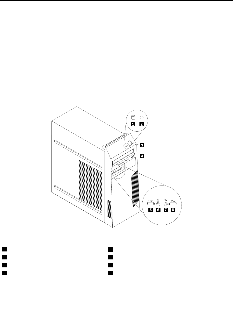
Chapter8.Locations
Thischapterintroducesthelocationsofthecomputerhardwarecomponents.
Formachinetypes:0896,0958,1112,2116,3498,3593,3595,3597,3617,
3634,3655,3662,3665,and3675.
Locatingconnectors,controls,andindicatorsonthefrontofyour
computer
Figure1“Frontconnector,control,andindicatorlocations”onpage67showsthelocationsofthe
connectors,controls,andindicatorsonthefrontofyourcomputer.
Figure1.Frontconnector,control,andindicatorlocations
1Harddiskdriveactivityindicator5USBconnector(USBport1)
2Powerindicator6Headphoneconnector
3Powerswitch7Microphoneconnector
4Opticaldriveeject/closebutton8USBconnector(USBport2)
©CopyrightLenovo201267
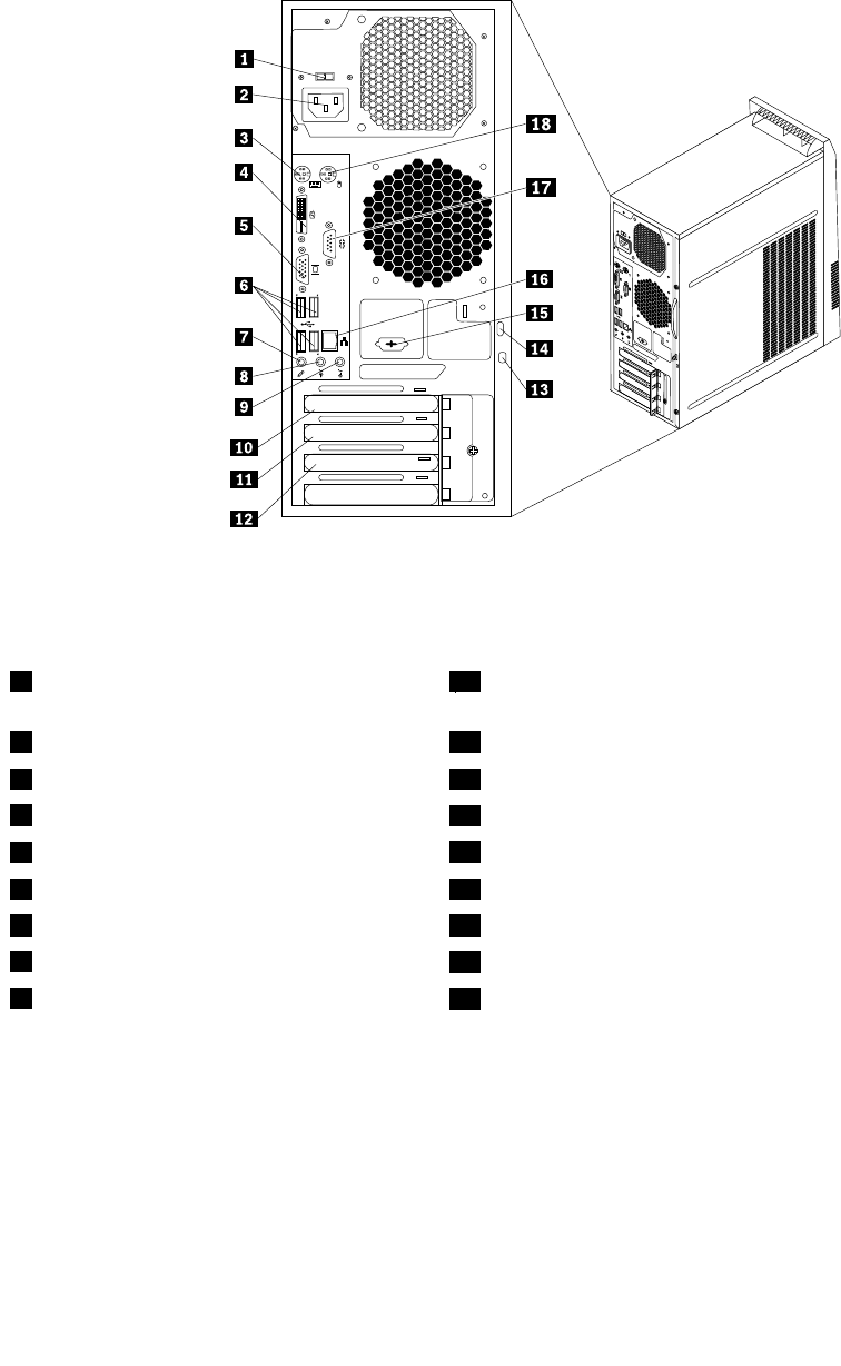
Locatingconnectorsontherearofyourcomputer
Figure2“Rearconnectorlocations”onpage68showsthelocationsoftheconnectorsontherearofyour
computer.Someconnectorsontherearofyourcomputerarecolor-codedtohelpyoudeterminewhereto
connectthecablesonyourcomputer.
Figure2.Rearconnectorlocations
1Voltage-selectionswitch(availableonsome
models)
10PCIExpressx16graphicscardslot
2Powercordconnector11PCIExpressx1cardslot
3PS/2keyboardconnector12PCIExpressx1cardslotorPCIcardslot
4DVImonitorconnector13Integratedcablelock(Kingstonlock)slot
5VGAmonitorconnector14Padlockloop
6USBconnectors(USBports3to6)15Optionalserialport(Serialport2)
7Microphoneconnector16Ethernetconnector
8Audioline-outconnector17Serialport(Serialport1)
9Audioline-inconnector18PS/2mouseconnector
ConnectorDescription
Audioline-inconnectorUsedtoreceiveaudiosignalsfromanexternalaudiodevice,suchasastereo
system.Whenyouattachanexternalaudiodevice,acableisconnectedbetween
theaudioline-outconnectorofthedeviceandtheaudioline-inconnectorofthe
computer.
Audioline-outconnectorUsedtosendaudiosignalsfromthecomputertoexternaldevices,suchaspowered
stereospeakers(speakerswithbuilt-inampliers),headphones,multimedia
keyboards,ortheaudioline-inconnectoronastereosystemorotherexternal
recordingdevice.
68ThinkCentreHardwareMaintenanceManual

ConnectorDescription
DVImonitorconnectorUsedtoattachaDVImonitororotherdevicesthatuseaDVImonitorconnector.
EthernetconnectorUsedtoattachanEthernetcableforalocalareanetwork(LAN).
Note:TooperatethecomputerwithinFCCClassBlimits,useaCategory5Ethernet
cable.
MicrophoneconnectorUsedtoattachamicrophonetoyourcomputerwhenyouwanttorecordsoundorif
youusespeech-recognitionsoftware.
PS/2keyboardconnector
(optional)
UsedtoattachakeyboardthatusesaPS/2keyboardconnector.
PS/2mouseconnector
(optional)
Usedtoattachamouse,atrackball,orotherpointingdevicesthatuseaPS/2
mouseconnector.
SerialportUsedtoattachanexternalmodem,aserialprinter,orotherdevicesthatusea
9-pinserialport.
USBconnectorUsedtoattachadevicethatrequiresaUSBconnector,suchasaUSBkeyboard,a
USBmouse,aUSBscanner,oraUSBprinter.IfyouhavemorethaneightUSB
devices,youcanpurchaseaUSBhub,whichyoucanusetoconnectadditional
USBdevices.
VGAmonitorconnectorUsedtoattachaVGAmonitororotherdevicesthatuseaVGAmonitorconnector.
LocatingmajorFRUsandCRUs
Figure3“LocatingmajorFRUsandCRUs”onpage70showsthelocationsofthevariouscomponentsin
yourcomputer.Toremovethecomputercover,see“Removingthecomputercover”onpage82.
Chapter8.Locations69
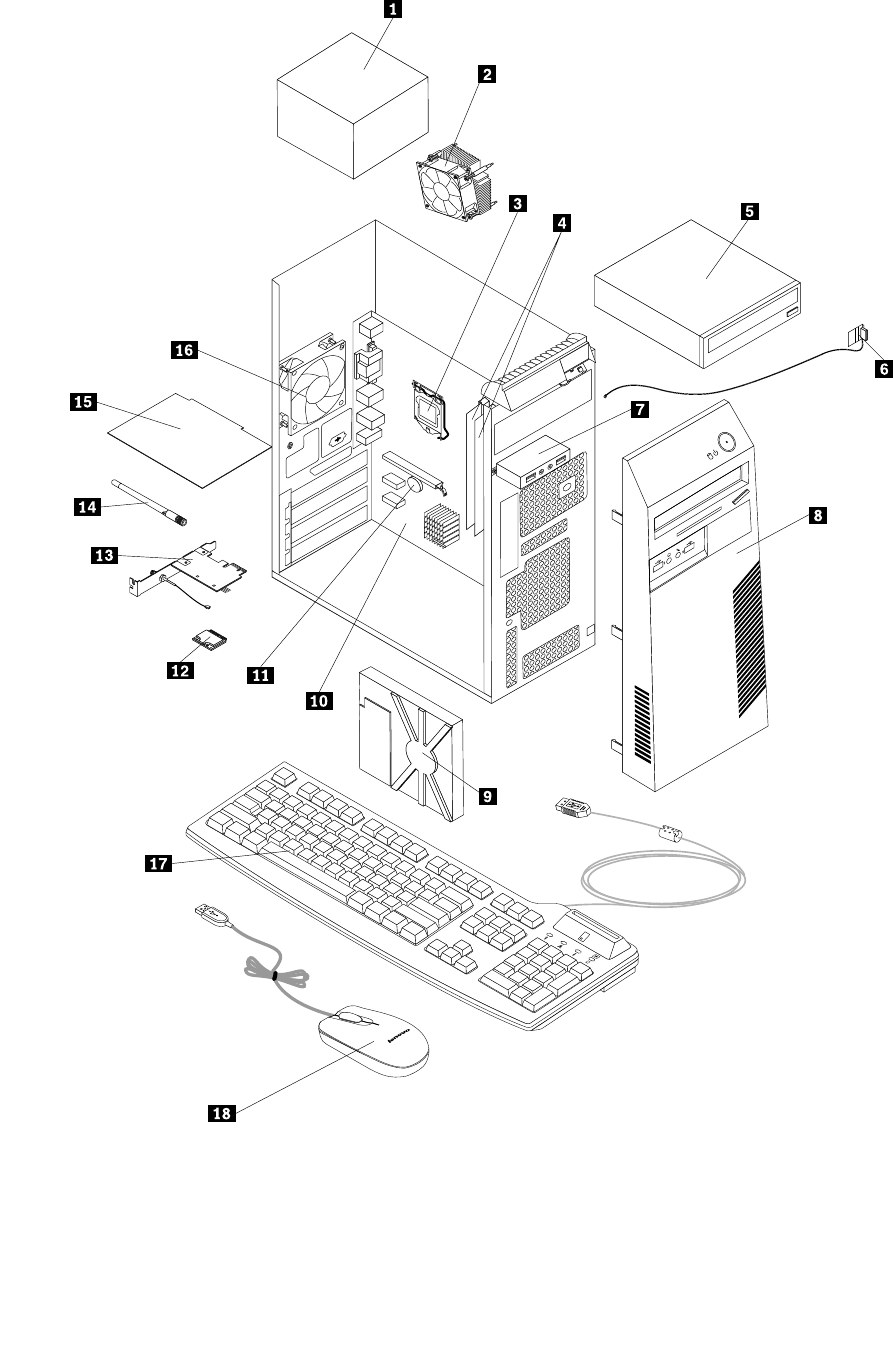

•Self-serviceCRUs:TheseCRUsunplugoraresecuredbynomorethantwoscrews.Examplesof
thesetypesofCRUsincludethekeyboard,themouse,anyUSBdevice,andthepowercord.Other
self-serviceCRUsdependingonproductdesignmightincludememorymodules,adaptercards,hard
diskdrives,andopticaldrives.
•Optional-serviceCRUs:TheseCRUsareisolatedpartswithinthecomputerandareconcealedbyan
accesspanelthatistypicallysecuredbymorethantwoscrews.Oncetheaccesspanelisremoved,the
specicCRUisvisible.
NumberFRUdescriptionSelf-serviceCRUOptional-serviceCRU
1PowersupplyassemblyNoYes
2HeatsinkandfanassemblyNoYes
3MicroprocessorNoYes
4MemorymodulesYesNo
5Opticaldrive(availableinsomemodels)YesNo
6FrontWiFiantennaNoYes
7FrontaudioandUSBassemblyNoYes
8FrontbezelYesNo
9HarddiskdriveNoYes
10SystemboardNoNo
11BatteryYesNo
12WiFicardmoduleNoYes
13WiFiadaptercardNoYes
14RearWiFiantennaYesNo
15PeripheralComponentInterconnect(PCI)cardYesNo
16RearfanNoYes
17KeyboardYesNo
18MouseYesNo
LookingupFRUinformation
FordetailedFRUinformation,suchastheFRUpartnumbersandsupportedcomputermodels,goto:
http:/www.lenovo.com/serviceparts-lookup
Locatingpartsonthesystemboard
Yourcomputercomeswitheitherofthefollowingtypesofsystemboard.
Chapter8.Locations71
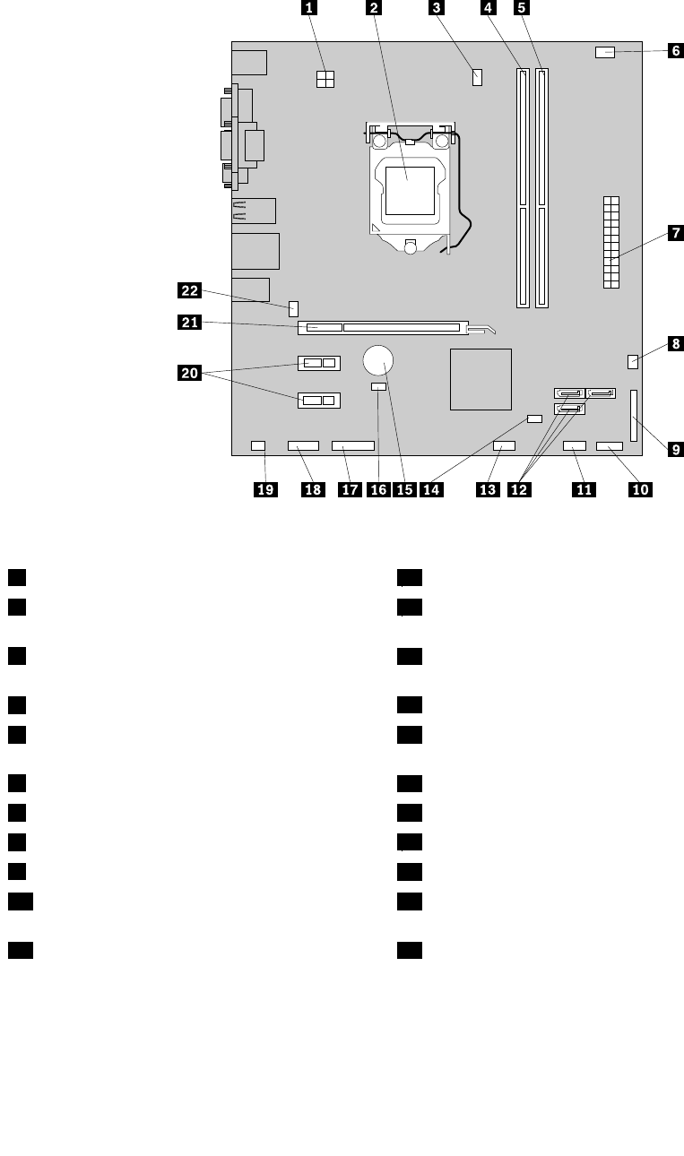
Figure4“Systemboardpartlocations”onpage72showsthelocationsofthepartsononetypeofsystem
board.
Figure4.Systemboardpartlocations
14-pinpowerconnector12SATAconnectors(3)
2Microprocessor13FrontUSBconnector2(forconnectinganadditionalUSB
device)
3Microprocessorfanconnector14ClearCMOS(ComplementaryMetalOxideSemiconductor)
/Recoveryjumper
4Memoryslot1(DIMM1)15Battery
5Memoryslot2(DIMM2)16Coverpresenceswitchconnector(Intrusionswitch
connector)
6Thermalsensorconnector17Serial(COM2)connector
724-pinpowerconnector18Frontaudioconnector
8Powerfanconnector19Internalspeakerconnector
9Parallelconnector20PCIExpressx1cardslots(2)
10Frontpanelconnector(forconnectingLED
indicatorsandthepowerswitch)
21PCIExpressx16graphicscardslot
11FrontUSBconnector1(forconnectingUSB
connectors1and2onthefrontbezel)
22Systemfanconnector
72ThinkCentreHardwareMaintenanceManual
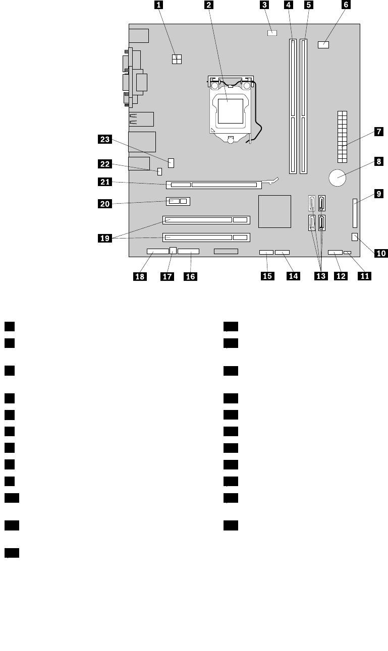
Figure5“Systemboardpartlocations”onpage73showsthelocationsofthepartsontheothertype
ofsystemboard.
Figure5.Systemboardpartlocations
14-pinpowerconnector13SATAconnectors(4)
2Microprocessor14FrontUSBconnector1(forconnectingUSBconnectors1
and2onthefrontbezel)
3Microprocessorfanconnector15FrontUSBconnector2(forconnectinganadditionalUSB
device)
4Memoryslot1(DIMM1)16Serial(COM2)connector
5Memoryslot2(DIMM2)17Internalspeakerconnector
6Thermalsensorconnector18Frontaudioconnector
724-pinpowerconnector19PCIcardslots(2)
8Battery20PCIExpressx1cardslot
9Parallelconnector21PCIExpressx16graphicscardslot
10Powerfanconnector22Coverpresenceswitchconnector(Intrusionswitch
connector)
11ClearCMOS(ComplementaryMetalOxide
Semiconductor)/Recoveryjumper
23Systemfanconnector
12Frontpanelconnector(forconnectingLED
indicatorsandthepowerswitch)
Chapter8.Locations73
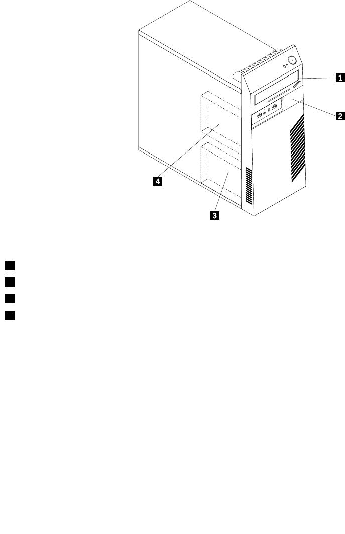
Locatinginternaldrives
Internaldrivesaredevicesthatyourcomputerusestoreadandstoredata.Youcanadddrivestoyour
computertoincreasestoragecapacityandenableyourcomputertoreadothertypesofmedia.Internal
drivesareinstalledinbays.Inthismanual,thebaysarereferredtoasbay1,bay2,andsoon.
Wheninstallingorreplacinganinternaldrive,itisimportanttonotethetypeandsizeofthedrivethatyou
caninstallorreplaceineachbayandcorrectlyconnectthecablestothedriveinstalled.Refertothe
appropriatesectionin“Installingorreplacinghardware”onpage81forinstructionsonhowtoinstallor
replaceinternaldrivesforyourcomputer.
Figure6“Drivebaylocations”onpage74showsthelocationsofthedrivebays.
Figure6.Drivebaylocations
1Bay1-Opticaldrivebay(withanopticaldriveinstalledinsomemodels)
2Bay2-Slimcardreaderdrivebay
3Bay3-PrimarySATAharddiskdrivebay(witha3.5-inchSATAharddiskdriveinstalled)
4Bay4-SecondarySATAharddiskdrivebay
74ThinkCentreHardwareMaintenanceManual
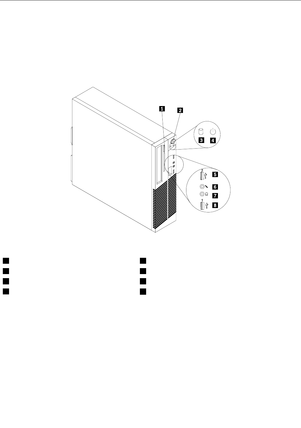
Formachinetypes:0900,0967,1271,3578,3594,3596,3598,3629,3654,
3660,3664,3668,and3676.
Locatingconnectors,controls,andindicatorsonthefrontofyour
computer
Figure7“Frontconnector,control,andindicatorlocations”onpage75showsthelocationsofthe
connectors,controls,andindicatorsonthefrontofyourcomputer.
Figure7.Frontconnector,control,andindicatorlocations
1Opticaldriveeject/closebutton5USBconnector(USBport2)
2Powerswitch6Microphoneconnector
3Harddiskdriveactivityindicator7Headphoneconnector
4Powerindicator8USBconnector(USBport1)
Chapter8.Locations75
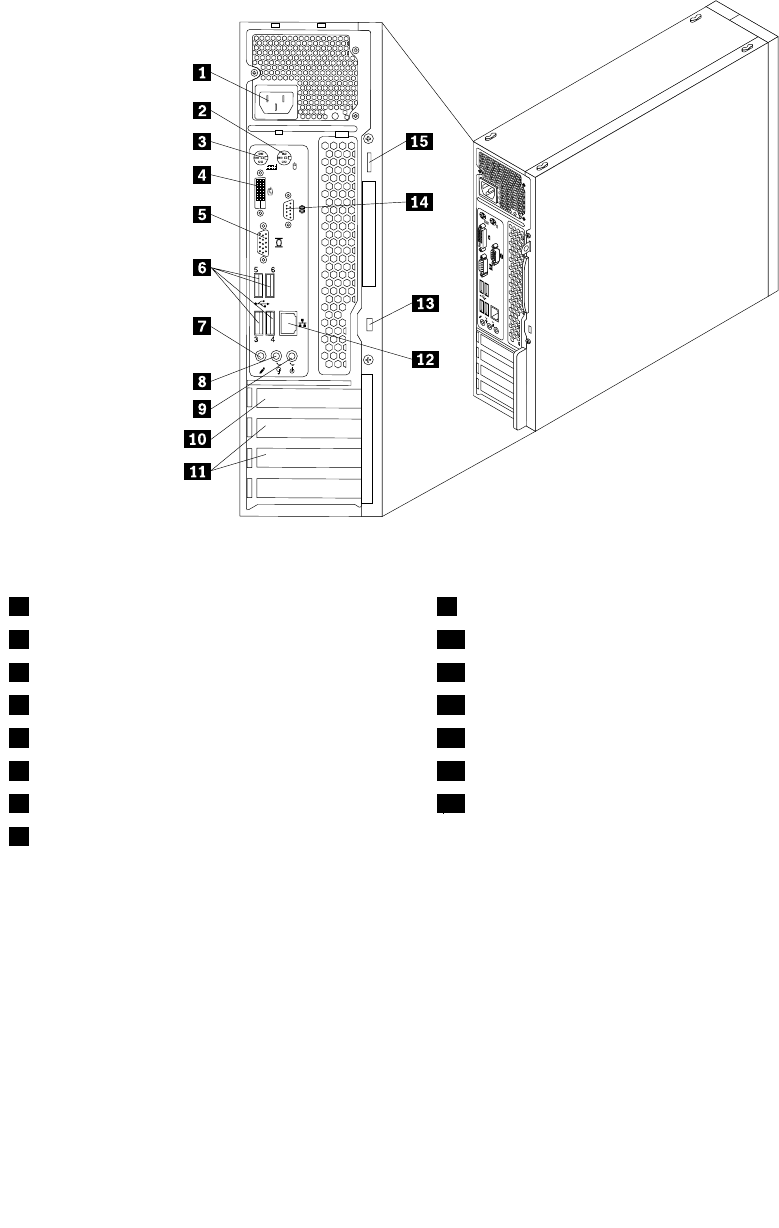
Locatingconnectorsontherearofyourcomputer
Figure8“Rearconnectorlocations”onpage76showsthelocationsoftheconnectorsontherearofyour
computer.Someconnectorsontherearofyourcomputerarecolor-codedtohelpyoudeterminewhereto
connectthecablesonyourcomputer.
Figure8.Rearconnectorlocations
1Powercordconnector9Audioline-inconnector
2PS/2mouseconnector10PCIExpressx16graphicscardslot
3PS/2keyboardconnector11PCIExpressx1cardslots(2)
4DVImonitorconnector12Ethernetconnector
5VGAmonitorconnector13Integratedcablelock(Kingstonlock)slot
6USBconnectors(USBports3to6)14Serialport
7Microphoneconnector15Padlockloop
8Audioline-outconnector
LocatingmajorFRUsandCRUs
Figure9“LocatingmajorFRUsandCRUs”onpage77showsthelocationsofthemajorFRUsandCRUs
inthecomputer.Toremovethecomputercover,see.Toremovethecomputercover,see“Removingthe
computercover”onpage118.
76ThinkCentreHardwareMaintenanceManual
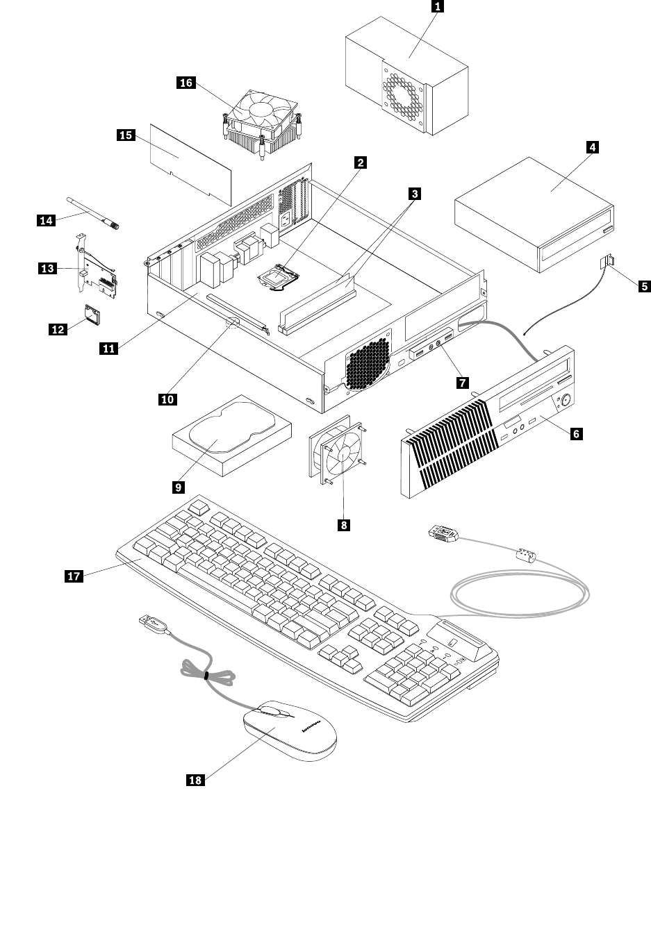

Notes:
•Self-serviceCRUs:TheseCRUsunplugoraresecuredbynomorethantwoscrews.Examplesof
thesetypesofCRUsincludethekeyboard,themouse,anyUSBdevice,andthepowercord.Other
self-serviceCRUsdependingonproductdesignmightincludememorymodules,adaptercards,hard
diskdrives,andopticaldrives.
•Optional-serviceCRUs:TheseCRUsareisolatedpartswithinthecomputerandareconcealedbyan
accesspanelthatistypicallysecuredbymorethantwoscrews.Oncetheaccesspanelisremoved,the
specicCRUisvisible.
NumberFRUdescriptionSelf-serviceCRUOptional-serviceCRU
1PowersupplyassemblyNoYes
2MicroprocessorNoYes
3MemorymodulesYesNo
4Opticaldrive(availableinsomemodels)YesNo
5FrontWiFiantennaNoYes
6FrontbezelYesNo
7FrontaudioandUSBassemblyNoYes
8FrontfanNoYes
9HarddiskdriveNoYes
10BatteryYesNo
11SystemboardNoNo
12WiFicardmoduleNoYes
13WiFiadaptercardNoYes
14RearWiFiantennaYesNo
15PeripheralComponentInterconnect(PCI)cardYesNo
16HeatsinkandfanassemblyNoYes
17KeyboardYesNo
18MouseYesNo
LookingupFRUinformation
FordetailedFRUinformation,suchastheFRUpartnumbersandsupportedcomputermodels,goto:
http:/www.lenovo.com/serviceparts-lookup
Locatingpartsonthesystemboard
Figure10“Systemboardpartlocations”onpage79showsthelocationsofthepartsonthesystemboard.
78ThinkCentreHardwareMaintenanceManual
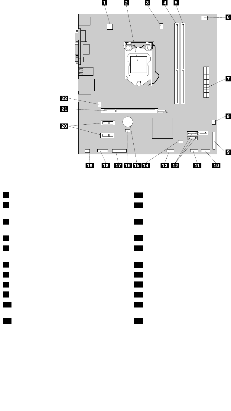
Figure10.Systemboardpartlocations
14-pinpowerconnector12SATAconnectors(4)
2Microprocessor13FrontUSBconnector2(forconnectingadditionalUSB
devices)
3Microprocessorfanconnector14ClearCMOS(ComplementaryMetalOxideSemiconductor)
/Recoveryjumper
4Memoryslot1(DIMM1)15Battery
5Memoryslot2(DIMM2)16Coverpresenceswitchconnector(Intrusionswitch
connector)
6Thermalsensorconnector17Serial(COM2)connector
724-pinpowerconnector18Frontaudioconnector
8Powerfanconnector19Internalspeakerconnector
9Parallelconnector20PCIExpressx1cardslots(2)
10Frontpanelconnector(forconnectingLED
indicatorsandpowerswitch)
21PCIExpressx16graphicscardslot
11FrontUSBconnector1(forconnectingUSB
ports1and2onthefrontbezel)
22Systemfanconnector
Chapter8.Locations79
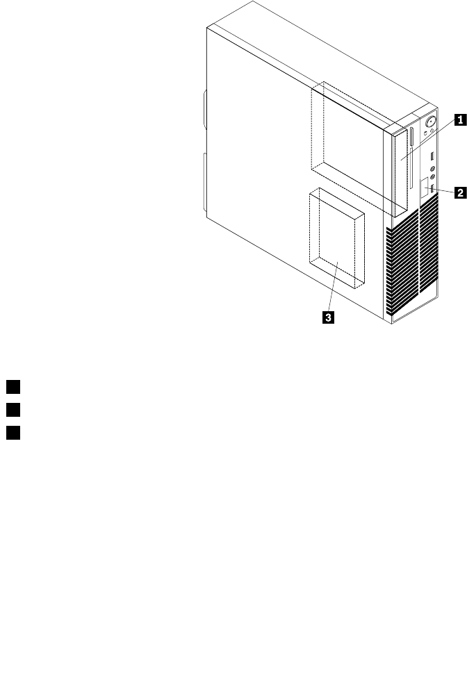
Locatinginternaldrives
Internaldrivesaredevicesthatyourcomputerusestoreadandstoredata.Youcanadddrivestoyour
computertoincreasestoragecapacityandenableyourcomputertoreadothertypesofmedia.Internal
drivesareinstalledinbays.Inthismanual,thebaysarereferredtoasbay1,bay2,andsoon.Your
computercomeswiththefollowingfactory-installeddrives:
•Anopticaldriveinbay1
•A3.5-inchharddiskdriveinbay3
Wheninstallingorreplacinganinternaldrive,itisimportanttonotethetypeandsizeofthedrivethatyou
caninstallorreplaceineachbayandcorrectlyconnectthecablestothedriveinstalled.Refertothe
appropriatesectionin“Installingorreplacinghardware”onpage117forinstructionsonhowtoinstallor
replaceinternaldrivesforyourcomputer.
Figure11“Drivebaylocations”onpage80showsthelocationsofthedrivebays.
Figure11.Drivebaylocations
1Bay1-Opticaldrivebay
2Bay2-Cardreaderdrivebay
2Bay3-SATAharddiskdrivebay(witha3.5-inchharddiskdriveinstalled)
80ThinkCentreHardwareMaintenanceManual

Chapter9.ReplacingFRUs(machinetypes:0896,0958,1112,
2116,3498,3593,3595,3597,3617,3634,3655,3662,3665,and
3675)
ThischapterprovidesinformationabouttheFRUreplacementinstructions.
Important:BesuretoreadandunderstandChapter2“Safetyinformation”onpage3beforereplacingany
FRU.Theseprecautionsandguidelineswillhelpyouworksafely.
Note:FRUreplacementsaretobedoneonlybytrainedservicetechnicians.
Handlingstatic-sensitivedevices
Donotopenthestatic-protectivepackagecontainingthenewpartuntilthedefectiveparthasbeenremoved
fromthecomputerandyouarereadytoinstallthenewpart.Staticelectricity,althoughharmlesstoyou,can
seriouslydamagecomputercomponentsandparts.
Whenyouhandlecomputerpartsandcomponents,taketheseprecautionstoavoidstatic-electricitydamage:
•Limityourmovement.Movementcancausestaticelectricitytobuilduparoundyou.
•Alwayscarefullyhandlethepartsandothercomputercomponents.HandlePCIcards,memorymodules,
systemboards,andmicroprocessorsbytheedges.Nevertouchexposedcircuitry.
•Preventothersfromtouchingthepartsandothercomputercomponents.
•Beforeyoureplaceanewpart,touchthestatic-protectivepackagecontainingthenewparttoametal
expansion-slotcoverorotherunpaintedmetalsurfaceonthecomputerforatleasttwoseconds.This
reducesstaticelectricityfromthepackageandyourbody.
•Removethenewpartfromthestatic-protectivepackageanddirectlyinstallitinthecomputerwithout
placingitonanyothersurface.Ifitishardforyoutodothisinyourspecicsituation,placethe
static-protectivepackageofthenewpartonasmooth,levelsurface,andthenplacethenewparton
thestatic-protectivepackage.
•Donotplacethepartonthecomputercoverorothermetalsurface.
Installingorreplacinghardware
Thissectionprovidesinstructionsonhowtoinstallorreplacehardwareforyourcomputer.Youcanexpand
thecapabilitiesofyourcomputerandmaintainyourcomputerbyinstallingorreplacinghardware.
Attention:
Donotopenyourcomputerorattemptanyrepairbeforereadingandunderstanding“Importantsafetyinformation”
onpage1.
Notes:
1.UseonlycomputerpartsprovidedbyLenovo.
2.Wheninstallingorreplacinganoption,usetheappropriateinstructionsinthissectionalongwiththe
instructionsthatcomewiththeoption.
Installingexternaloptions
Youcanconnectexternaloptionstoyourcomputer,suchasexternalspeakers,aprinter,orascanner.For
someexternaloptions,youmustinstalladditionalsoftwareinadditiontomakingthephysicalconnection.
©CopyrightLenovo201281

Wheninstallinganexternaloption,see“Locatingconnectors,controls,andindicatorsonthefrontofyour
computer”onpage67and“Locatingconnectorsontherearofyourcomputer”onpage68toidentifythe
requiredconnector.Then,usetheinstructionsthatcomewiththeoptiontohelpyoumaketheconnection
andinstallanysoftwareordevicedriversthatarerequiredfortheoption.
Removingthecomputercover
Attention:
Donotopenyourcomputerorattemptanyrepairbeforereadingandunderstandingthe“Importantsafetyinformation”
onpage1.
Thissectionprovidesinstructionsonhowtoremovethecomputercover.
CAUTION:
Turnoffthecomputerandwaitthreetoveminutestoletthecomputercoolbeforeremovingthe
computercover.
Toremovethecomputercover,dothefollowing:
1.Removeanymediafromthedrivesandturnoffallattacheddevicesandthecomputer.
2.Disconnectallpowercordsfromelectricaloutlets.
3.Disconnectthepowercords,Input/Outputcables,andanyothercablesthatareconnectedtothe
computer.See“Locatingconnectors,controls,andindicatorsonthefrontofyourcomputer”onpage
67and“Locatingconnectorsontherearofyourcomputer”onpage68.
4.Removeanylockingdevicethatsecuresthecomputercover,suchasapadlockoranintegrated
cablelock.
82ThinkCentreHardwareMaintenanceManual
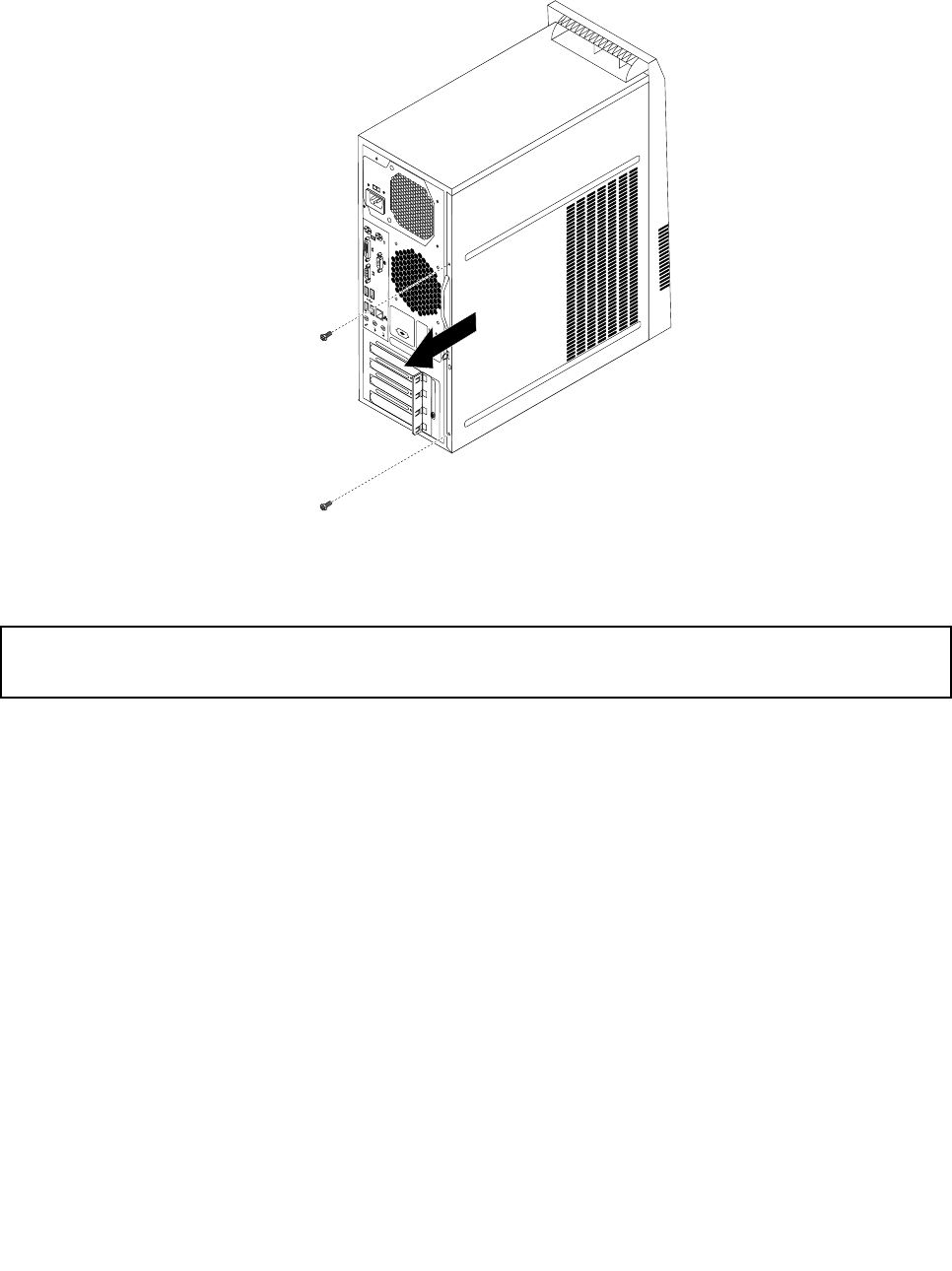
5.Removethetwoscrewsthatsecurethecomputercoverandslidethecomputercovertotherearto
removeit.
Figure12.Removingthecomputercover
Removingandreinstallingthefrontbezel
Attention:
Donotopenyourcomputerorattemptanyrepairbeforereadingandunderstandingthe“Importantsafetyinformation”
onpage1.
Thissectionprovidesinstructionsonhowtoremoveandreinstallthefrontbezel.
Toremoveandreinstallthefrontbezel,dothefollowing:
1.Turnoffthecomputeranddisconnectallpowercordsfromelectricaloutlets.
2.Removethecomputercover.See“Removingthecomputercover”onpage82.
Chapter9.ReplacingFRUs(machinetypes:0896,0958,1112,2116,3498,3593,3595,3597,
3617,3634,3655,3662,3665,and3675)83
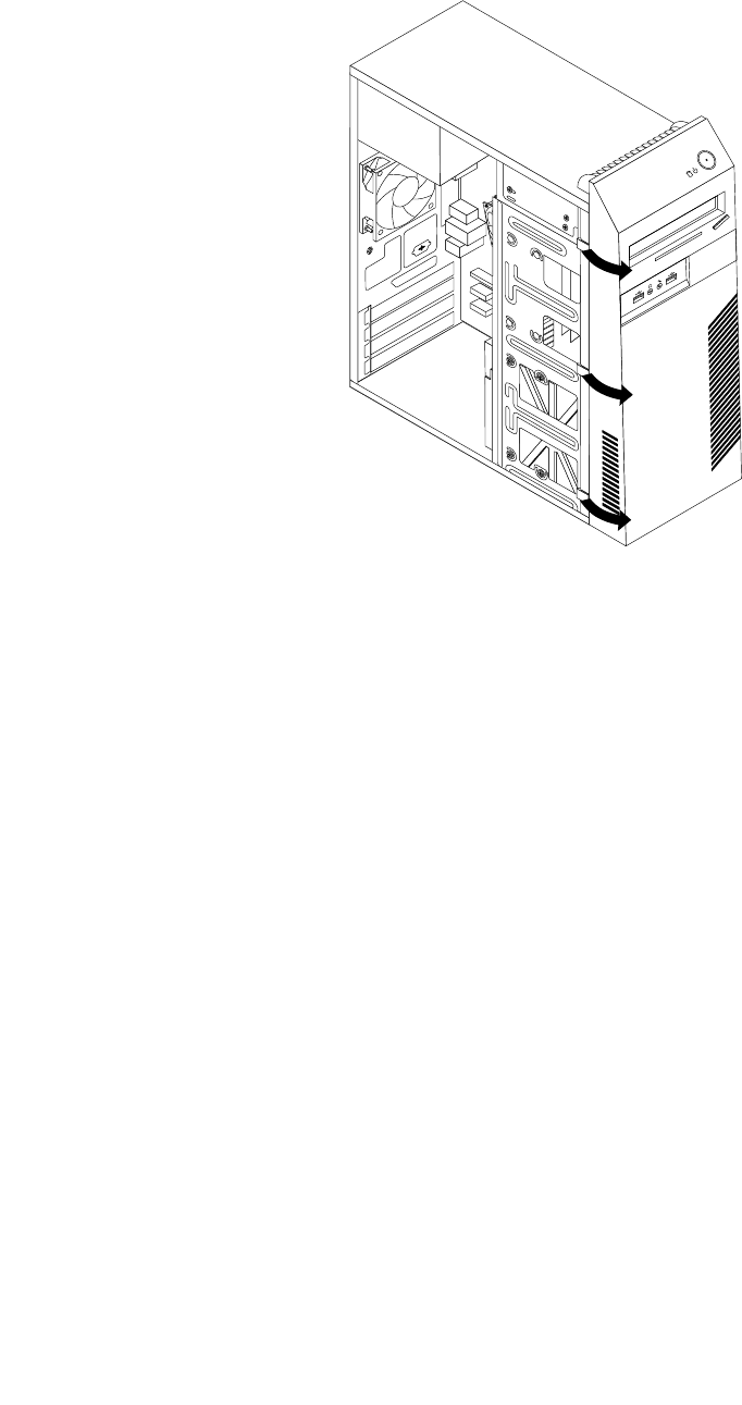
3.Removethefrontbezelbyreleasingthethreeplastictabsontheleftsideandpivotingthefrontbezel
outward.
Figure13.Removingthefrontbezel
84ThinkCentreHardwareMaintenanceManual
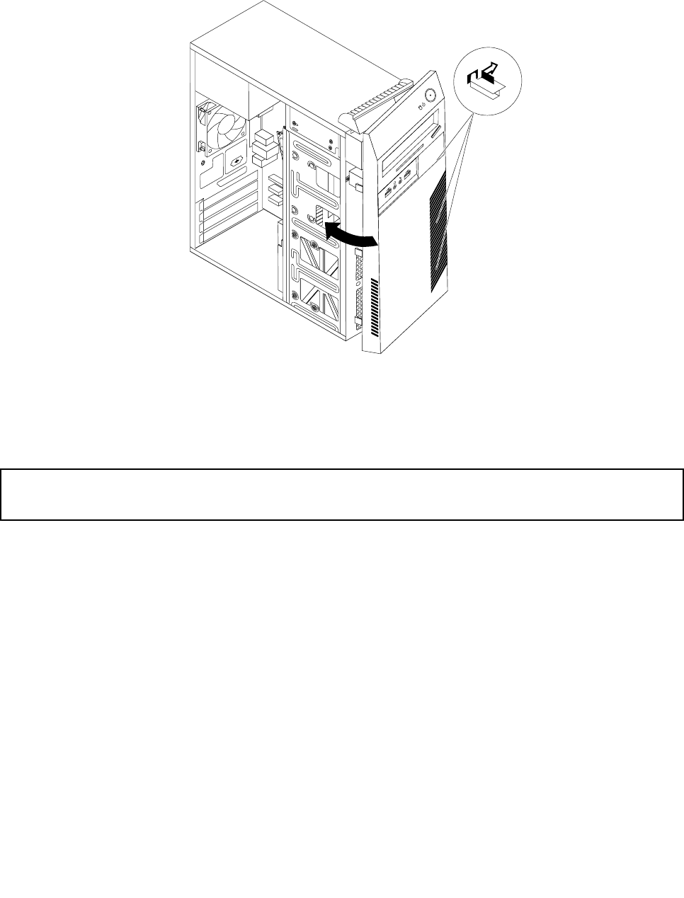
4.Toreinstallthefrontbezel,alignthethreeplastictabsontherightsideofthefrontbezelwiththe
correspondingholesinthechassis,thenpivotthefrontbezelinwardsuntilitsnapsintopositionon
theleftside.
Figure14.Reinstallingthefrontbezel
5.Tocompletetheinstallationorreplacement,goto“Completingthepartsreplacement”onpage115.
InstallingorreplacingaPCIcard
Attention:
Donotopenyourcomputerorattemptanyrepairbeforereadingandunderstandingthe“Importantsafetyinformation”
onpage1.
ThissectionprovidesinstructionsonhowtoinstallorreplaceaPCIcard.
ToinstallorreplaceaPCIcard,dothefollowing:
1.Turnoffthecomputeranddisconnectallpowercordsfromelectricaloutlets.
2.Removethecomputercover.See“Removingthecomputercover”onpage82.
Chapter9.ReplacingFRUs(machinetypes:0896,0958,1112,2116,3498,3593,3595,3597,
3617,3634,3655,3662,3665,and3675)85
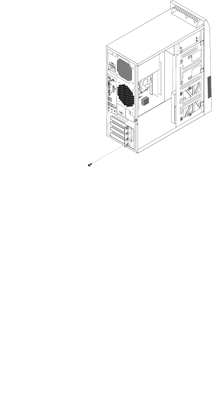
3.Attherearofthecomputer,removethescrewthatsecuresthePCIcardlatch.
Figure15.RemovingthescrewthatsecuresthePCIcardlatch
4.DependingonwhetheryouareinstallingorreplacingaPCIcard,dooneofthefollowing:
•IfyouareinstallingaPCIcard,removetheappropriatemetalslotcover.
•IfyouarereplacinganoldPCIcard,grasptheoldcardthatiscurrentlyinstalledandgentlypullit
outoftheslot.
86ThinkCentreHardwareMaintenanceManual
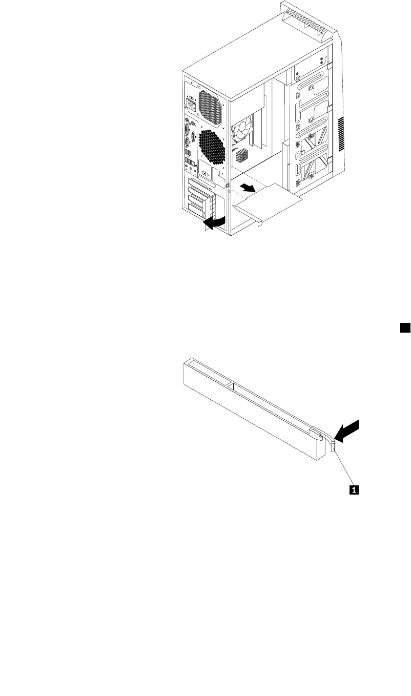
Figure16.RemovingthePCIcard
Notes:
a.Thecardtstightlyintothecardslot.Ifnecessary,alternatemovingeachsideofthecardasmall
amountuntilitisremovedfromthecardslot.
b.Ifthecardisheldinplacebyaretaininglatch,pressthecardretaininglatch1asshownto
disengagethelatch.Graspthecardandgentlypullitoutoftheslot.
5.RemovethenewPCIcardfromitsstatic-protectivepackage.
6.Installthenewcardintotheappropriateslotonthesystemboard.See“Locatingpartsonthesystem
board”onpage71.
Note:IfyouareinstallingaPCIExpressx16graphicscard,makesurethememoryslotretainingclips
areclosedbeforeyouinstallthegraphicscard.
Chapter9.ReplacingFRUs(machinetypes:0896,0958,1112,2116,3498,3593,3595,3597,
3617,3634,3655,3662,3665,and3675)87
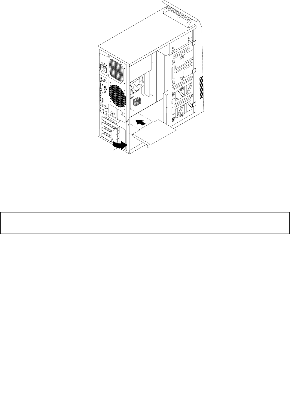
7.PivotthecardlatchtotheclosedpositiontosecurethePCIcard.
Figure17.InstallingaPCIcard
8.ReinstallthescrewtosecurethePCIcardlatchinplace.
9.Tocompletetheinstallationorreplacement,goto“Completingthepartsreplacement”onpage115.
Replacingthebattery
Attention:
Donotopenyourcomputerorattemptanyrepairbeforereadingandunderstandingthe“Importantsafetyinformation”
onpage1.
Yourcomputerhasaspecialtypeofmemorythatmaintainsthedate,time,andsettingsforbuilt-infeatures,
suchasparallel-portassignments(conguration).Abatterykeepsthisinformationactivewhenyouturn
offthecomputer.
Thebatterynormallyrequiresnochargingormaintenancethroughoutitslife;however,nobatterylasts
forever.Ifthebatteryfails,thedate,time,andcongurationinformation(includingpasswords)arelost.An
errormessageisdisplayedwhenyouturnonthecomputer.
Refertothe“Lithiumcoincellbatterynotice”intheSafetyandWarrantyGuideforinformationabout
replacinganddisposingofthebattery.
Toreplacethebattery,dothefollowing:
1.Turnoffthecomputeranddisconnectallpowercordsfromelectricaloutlets.
2.Removethecomputercover.See“Removingthecomputercover”onpage82.
3.Locatethebattery.See“Locatingpartsonthesystemboard”onpage71.
88ThinkCentreHardwareMaintenanceManual
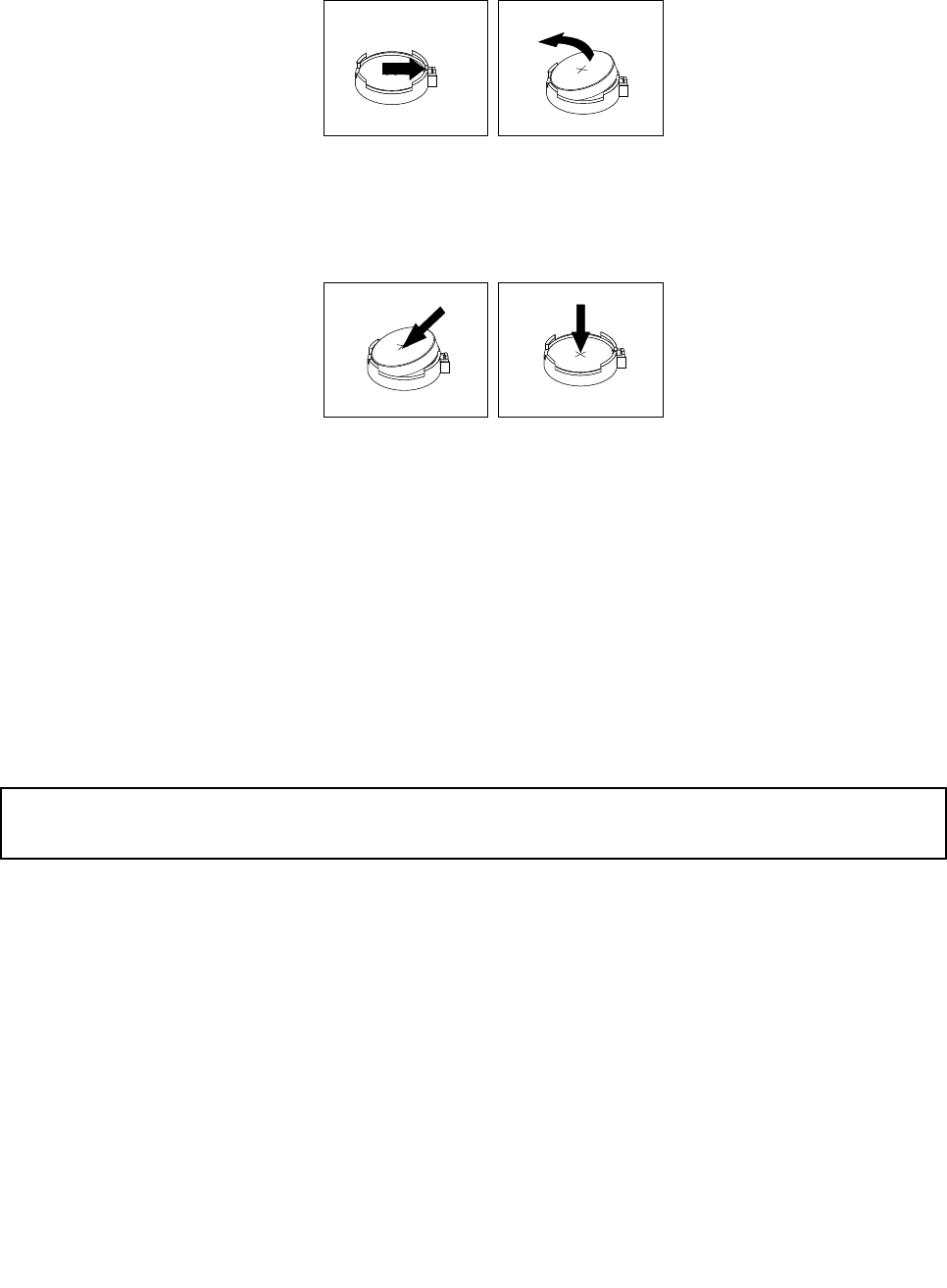
4.Removetheoldbattery.
Figure18.Removingtheoldbattery
5.Installanewbattery.
Figure19.Installinganewbattery
6.Reinstallthecomputercoverandconnectthecables.See“Completingthepartsreplacement”on
page115.
Note:Whenthecomputeristurnedonforthersttimeafterreplacingthebattery,anerrormessage
mightbedisplayed.Thisisnormalafterreplacingthebattery.
7.Turnonthecomputerandallattacheddevices.
8.UsetheSetupUtilityprogramtosetthedate,time,andanypasswords.SeeChapter6“UsingtheSetup
Utilityprogram”onpage55.
9.Tocompletetheinstallationorreplacement,goto“Completingthepartsreplacement”onpage115.
Installingorreplacingamemorymodule
Attention:
Donotopenyourcomputerorattemptanyrepairbeforereadingandunderstandingthe“Importantsafetyinformation”
onpage1.
Thissectionprovidesinstructionsonhowtoinstallorreplaceamemorymodule.
YourcomputerhastwoslotsforinstallingorreplacingDDR3DIMMsthatprovideuptoamaximumof16GB
systemmemory.Wheninstallingorreplacingamemorymodule,use2GB,4GB,or8GBDDR3DIMMs
inanycombinationuptoamaximumof16GB.
Toinstallorreplaceamemorymodule,dothefollowing:
1.Turnoffthecomputeranddisconnectallpowercordsfromelectricaloutlets.
2.Removethecomputercover.See“Removingthecomputercover”onpage82.
3.Laythecomputeronitssideforeasieraccesstothesystemboard.
4.Locatethememoryslots.See“Locatingpartsonthesystemboard”onpage71.
Chapter9.ReplacingFRUs(machinetypes:0896,0958,1112,2116,3498,3593,3595,3597,
3617,3634,3655,3662,3665,and3675)89
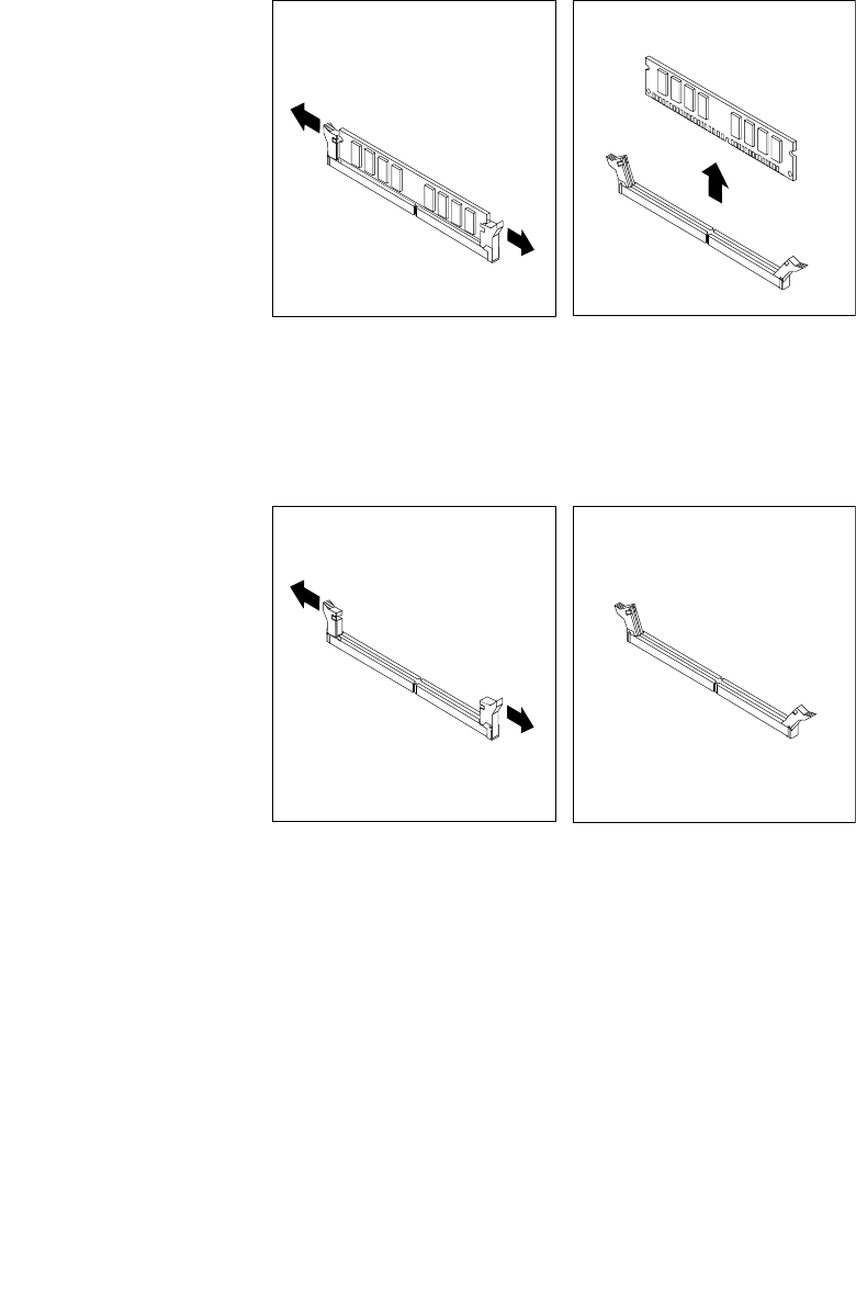
5.Removeanypartsthatmightpreventyouraccesstothememoryslots.Dependingonyourcomputer
model,youmightneedtoremovethePCIExpressx16graphicscardforeasieraccesstothememory
slots.See“InstallingorreplacingaPCIcard”onpage85.
6.Dependingonwhetheryouareinstallingorreplacingamemorymodule,dooneofthefollowing:
•Ifyouarereplacinganoldmemorymodule,opentheretainingclipsandgentlypullthememory
moduleoutofthememoryslot.
Figure20.Removingamemorymodule
•Ifyouareinstallingamemorymodule,opentheretainingclipsofthememoryslotintowhichyou
wanttoinstallthememorymodule.
Figure21.Openingtheretainingclips
90ThinkCentreHardwareMaintenanceManual
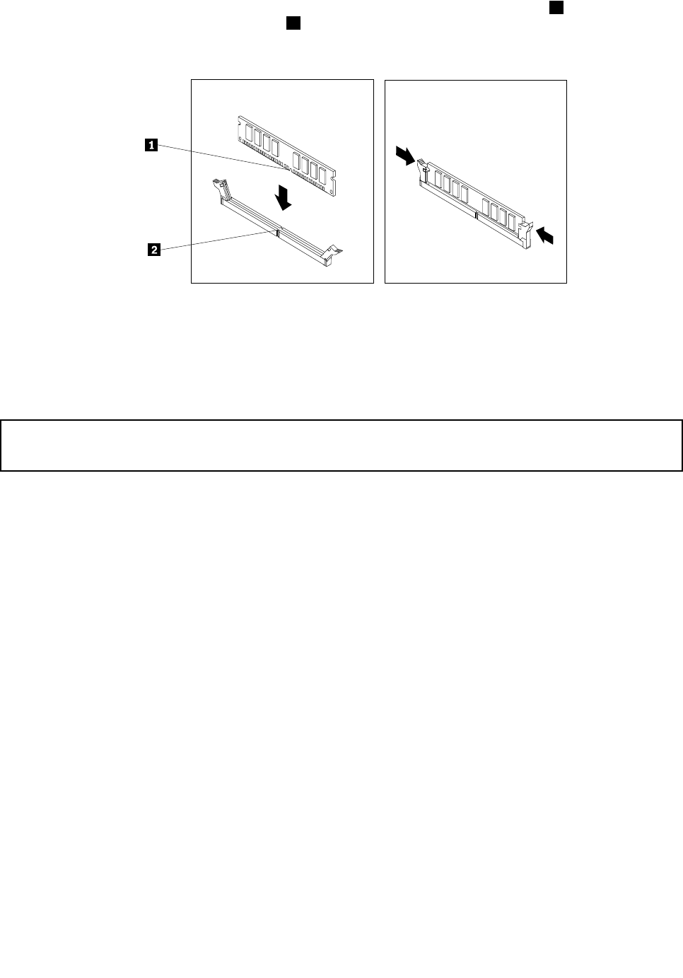
7.Positionthenewmemorymoduleoverthememoryslot.Makesurethatthenotch1onthememory
modulealignscorrectlywiththeslotkey2onthesystemboard.Pushthememorymodulestraight
downintotheslotuntiltheretainingclipsclose.
Figure22.Installingamemorymodule
8.ReinstallthePCIExpressx16graphicscardifyouhaveremovedit.
9.Tocompletetheinstallationorreplacement,goto“Completingthepartsreplacement”onpage115.
Installingorreplacingtheopticaldrive
Attention:
Donotopenyourcomputerorattemptanyrepairbeforereadingandunderstandingthe“Importantsafetyinformation”
onpage1.
Thissectionprovidesinstructionsonhowtoinstallorreplacetheopticaldrive.
Note:Theopticaldriveisonlyavailableinsomemodels.
Toinstallorreplaceanopticaldrive,dothefollowing:
1.Turnoffthecomputeranddisconnectallpowercordsfromelectricaloutlets.
2.Removethecomputercover.See“Removingthecomputercover”onpage82.
3.Removethefrontbezel.See“Removingandreinstallingthefrontbezel”onpage83.
Chapter9.ReplacingFRUs(machinetypes:0896,0958,1112,2116,3498,3593,3595,3597,
3617,3634,3655,3662,3665,and3675)91
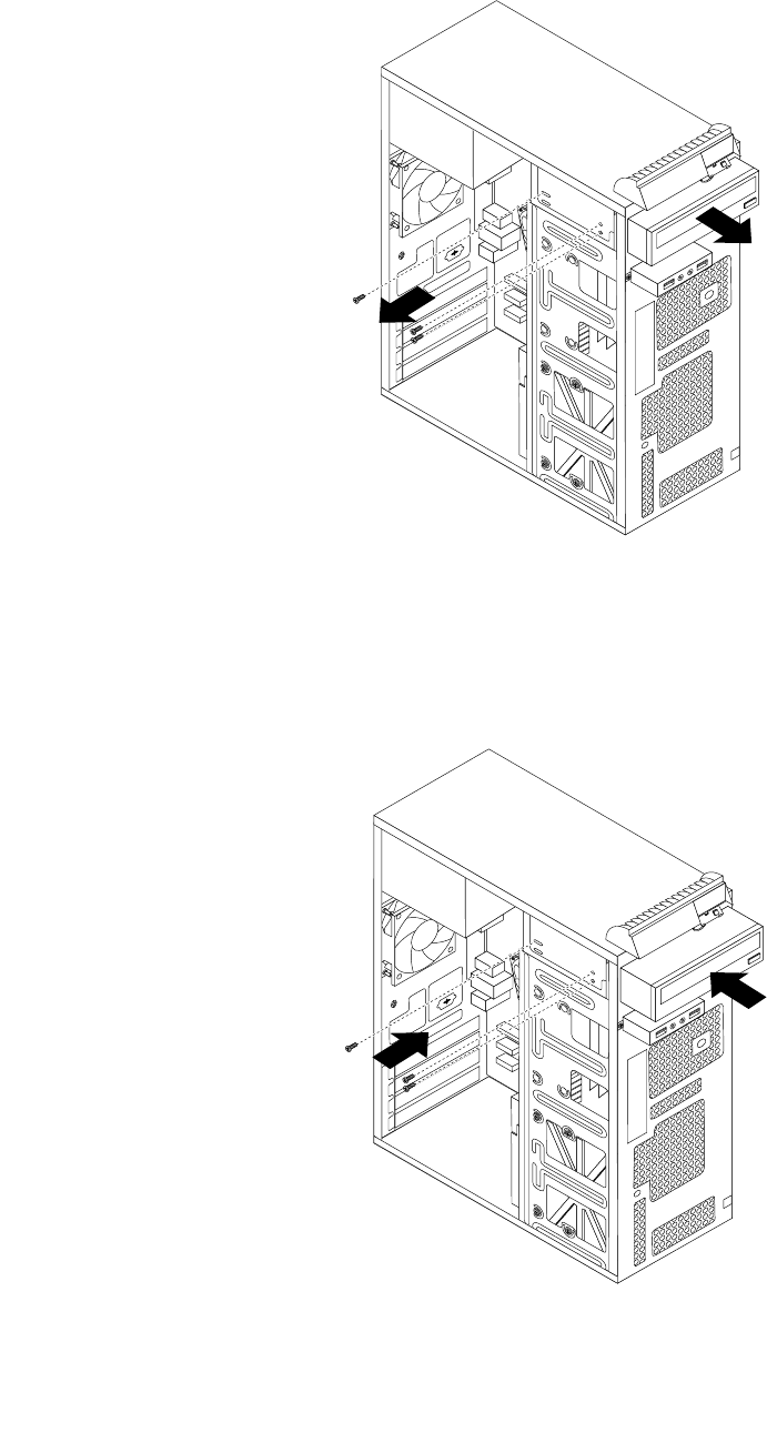
4.Removethethreescrewsthatsecuretheopticaldrive.Then,slidetheopticaldriveoutofthefront
ofthecomputer.
Figure23.Removingtheopticaldrive
5.Slidethenewopticaldriveintothedrivebayfromthefrontandalignthescrewholesinthenewoptical
drivewiththecorrespondingholesinthedrivebay.Then,installthethreescrewstosecurethenew
opticaldriveinplace.
Figure24.Installingtheopticaldrive
92ThinkCentreHardwareMaintenanceManual
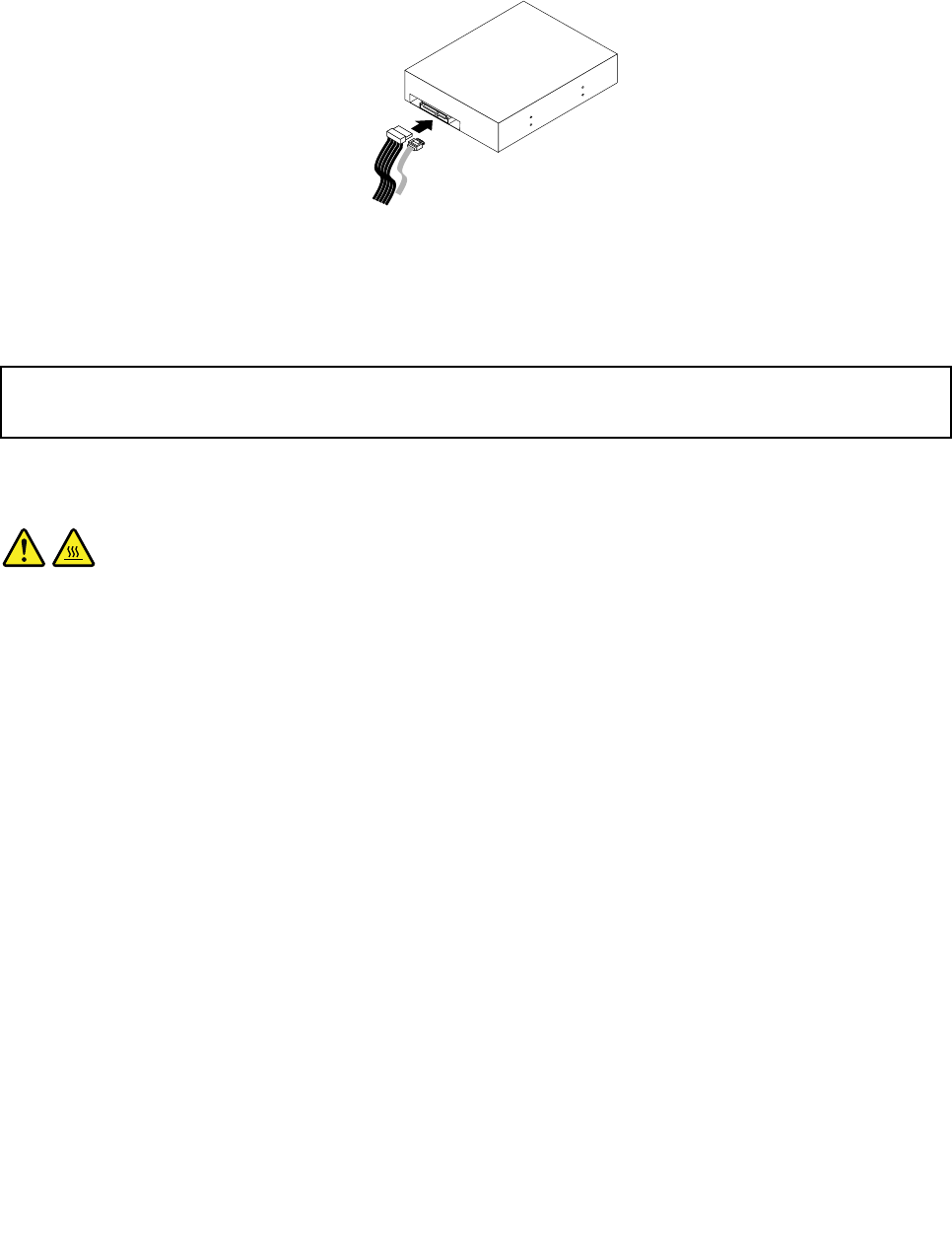
6.Connectoneendofthesignalcabletotherearofthenewopticaldriveandtheotherendtoanavailable
SATAconnectoronthesystemboard.See“Locatingpartsonthesystemboard”onpage71.Then,
locateanavailableve-wirepowerconnectorandconnectittotherearofthenewopticaldrive.
Figure25.ConnectingaSATAopticaldrive
7.Tocompletetheinstallationorreplacement,goto“Completingthepartsreplacement”onpage115.
Replacingtheheatsinkandfanassembly
Attention:
Donotopenyourcomputerorattemptanyrepairbeforereadingandunderstandingthe“Importantsafetyinformation”
onpage1.
Thissectionprovidesinstructionsonhowtoreplacetheheatsinkandfanassembly.
CAUTION:
Theheatsinkandfanassemblymightbeveryhot.Turnoffthecomputerandwaitthreetove
minutestoletthecomputercoolbeforeremovingthecomputercover.
Toreplacetheheatsinkandfanassembly,dothefollowing:
1.Turnoffthecomputeranddisconnectallpowercordsfromelectricaloutlets.
2.Removethecomputercover.See“Removingthecomputercover”onpage82.
3.Laythecomputeronitssideforeasieraccesstothesystemboard.
4.Locatetheheatsinkandfanassembly.See“Locatingpartsonthesystemboard”onpage71.
5.Disconnecttheheatsinkandfanassemblycablefromthemicroprocessorfanconnectoronthesystem
board.See“Locatingpartsonthesystemboard”onpage71.
Chapter9.ReplacingFRUs(machinetypes:0896,0958,1112,2116,3498,3593,3595,3597,
3617,3634,3655,3662,3665,and3675)93
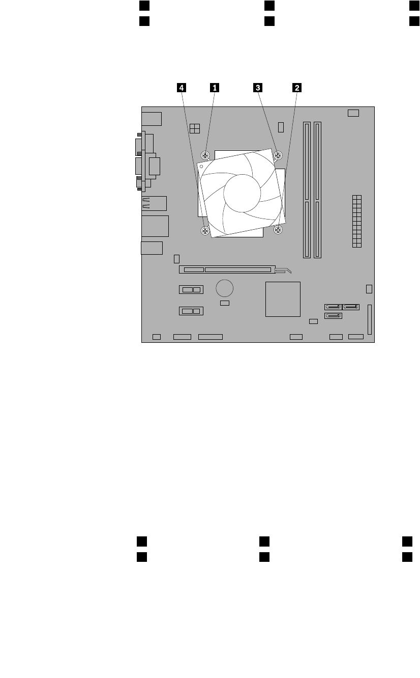
6.Followthissequencetoremovethefourscrewsthatsecuretheheatsinkandfanassemblytothe
systemboard:
a.Partiallyremovescrew1,thenfullyremovescrew2,andthenfullyremovescrew1.
b.Partiallyremovescrew3,thenfullyremovescrew4,andthenfullyremovescrew3.
Note:Carefullyremovethefourscrewsfromthesystemboardtoavoidanypossibledamagetothe
systemboard.Thefourscrewscannotberemovedfromtheheatsinkandfanassembly.
Figure26.Removingtheheatsinkandfanassembly
7.Liftthefailingheatsinkandfanassemblyoffthesystemboard.
Notes:
a.Youmighthavetogentlytwisttheheatsinkandfanassemblytofreeitfromthemicroprocessor.
b.Donottouchthethermalgreasewhilehandlingtheheatsinkandfanassembly.
8.Positionthenewheatsinkandfanassemblyonthesystemboardsothatthefourscrewsarealigned
withtheholesonthesystemboard.
Note:Positionthenewheatsinkandfanassemblysothattheheatsinkandfanassemblycableis
towardthemicroprocessorfanconnectoronthesystemboard.
9.Followthefollowingsequencetoinstallthefourscrewstosecurethenewheatsinkandfanassembly.
Donotover-tightenthescrews.
a.Partiallytightenscrew1,thenfullytightenscrew2,andthenfullytightenscrew1.
b.Partiallytightenscrew3,thenfullytightenscrew4,andthenfullytightenscrew3.
10.Connecttheheatsinkandfanassemblycabletothemicroprocessorfanconnectoronthesystem
board.See“Locatingpartsonthesystemboard”onpage71.
11.Tocompletetheinstallationorreplacement,goto“Completingthepartsreplacement”onpage115.
94ThinkCentreHardwareMaintenanceManual
Replacingthepowersupplyassembly
Attention:
Donotopenyourcomputerorattemptanyrepairbeforereadingandunderstandingthe“Importantsafetyinformation”
onpage1.
Thissectionprovidesinstructionsonhowtoreplacethepowersupplyassembly.
Althoughtherearenomovingpartsinyourcomputerafterthepowercordhasbeendisconnected,the
followingwarningsarerequiredforyoursafetyandproperUnderwritersLaboratories(UL)certication.
CAUTION:
Hazardousmovingparts.Keepngersandotherbodypartsaway.
CAUTION:
Neverremovethecoveronapowersupplyoranypartthathasthefollowinglabelattached.
Hazardousvoltage,current,andenergylevelsarepresentinsideanycomponentthathasthislabel
attached.Therearenoserviceablepartsinsidethesecomponents.Ifyoususpectaproblemwith
oneoftheseparts,contactaservicetechnician.
Toreplacethepowersupplyassembly,dothefollowing:
1.Turnoffthecomputeranddisconnectallpowercordsfromelectricaloutlets.
2.Removethecomputercover.See“Removingthecomputercover”onpage82.
3.Disconnectthepowersupplyassemblycablesfromalldrivesandfromthe24-pinpowerconnectorand
4-pinpowerconnectoronthesystemboard.See“Locatingpartsonthesystemboard”onpage71.
Note:Youmightalsoneedtoreleasethepowersupplyassemblycablesfromsomecableclipsorties
thatsecurethecablestothechassis.
Chapter9.ReplacingFRUs(machinetypes:0896,0958,1112,2116,3498,3593,3595,3597,
3617,3634,3655,3662,3665,and3675)95
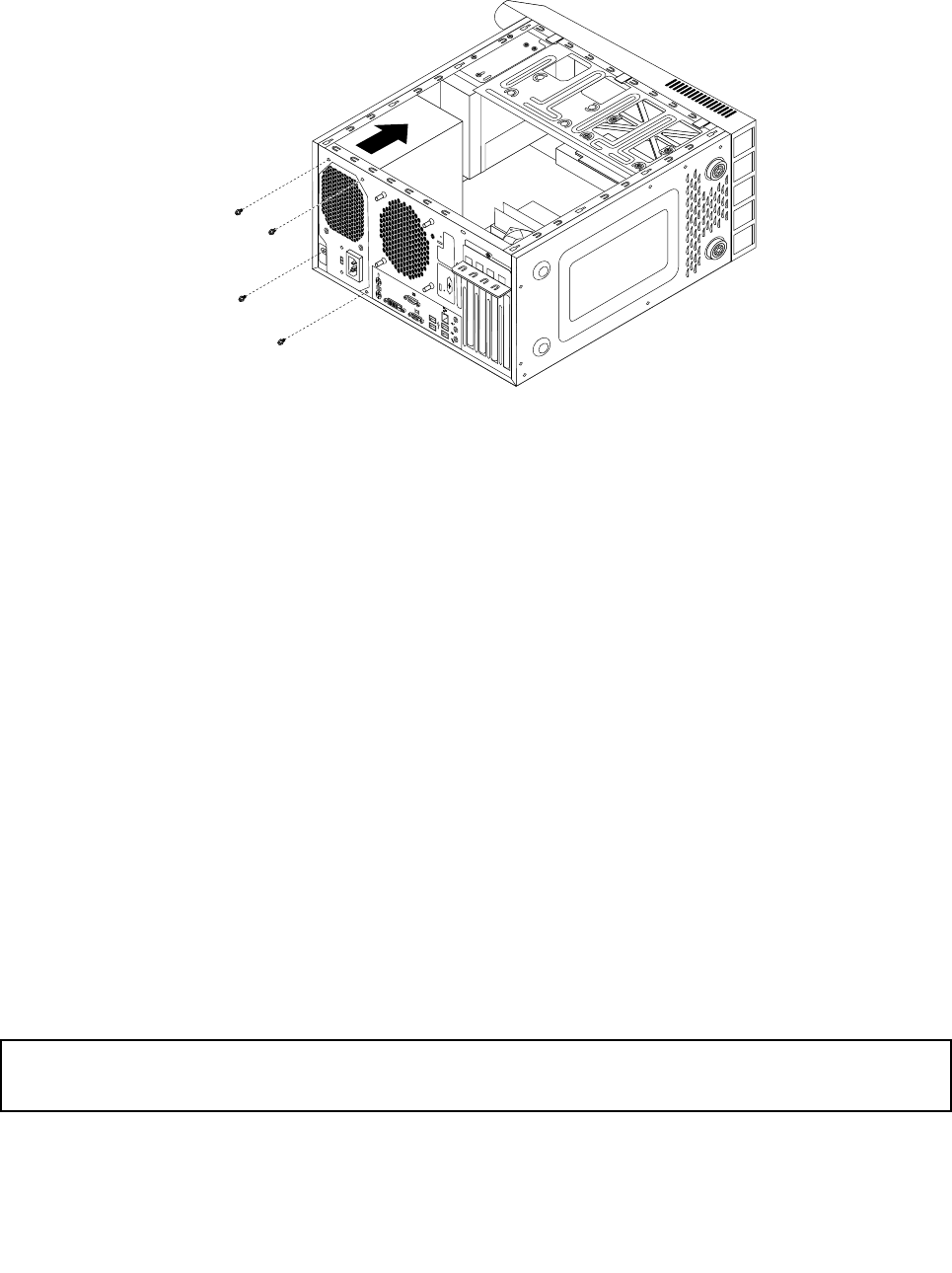
4.Laythecomputeronitssideandremovethefourscrewsattherearofthechassisthatsecurethe
powersupplyassembly.
Figure27.Removingthescrewsforthepowersupplyassembly
5.Slidethepowersupplyassemblytothefrontofthecomputerandthenliftitoutofthechassis.
6.Makesurethatthenewpowersupplyassemblyisthecorrectreplacement.Somepowersupply
assembliesautomaticallysensethevoltage,somepowersupplyassembliesarevoltagespecic,and
somepowersupplyassemblieshaveavoltage-selectionswitch.Ifyourpowersupplyassemblyhas
avoltage-selectionswitch,makesurethatyousetthevoltage-selectionswitchtomatchthevoltage
availableatyourelectricaloutlet.Ifnecessary,useaballpointpentoslidethevoltage-selectionswitch
tothecorrectposition.
•Ifthevoltagesupplyrangeinyourlocalcountryorregionis100–127Vac,setthevoltage-selection
switchto115V.
•Ifthevoltagesupplyrangeinyourlocalcountryorregionis200–240Vac,setthevoltage-selection
switchto230V.
7.Installthenewpowersupplyassemblyintothechassissothatthescrewholesinthepowersupply
assemblyalignwiththoseinthechassis.
8.Installandtightenthefourscrewstosecurethepowersupplyassembly.
Note:UseonlyscrewsprovidedbyLenovo.
9.Reconnectthepowersupplyassemblycablestothesystemboardandeachofthedrives.
10.Securethepowersupplyassemblycableswiththecableclipsandtiesinthechassis.
11.Tocompletetheinstallationorreplacement,goto“Completingthepartsreplacement”onpage115.
Replacingthemicroprocessor
Attention:
Donotopenyourcomputerorattemptanyrepairbeforereadingandunderstandingthe“Importantsafetyinformation”
onpage1.
Thissectionprovidesinstructionsonhowtoreplacethemicroprocessor.
96ThinkCentreHardwareMaintenanceManual
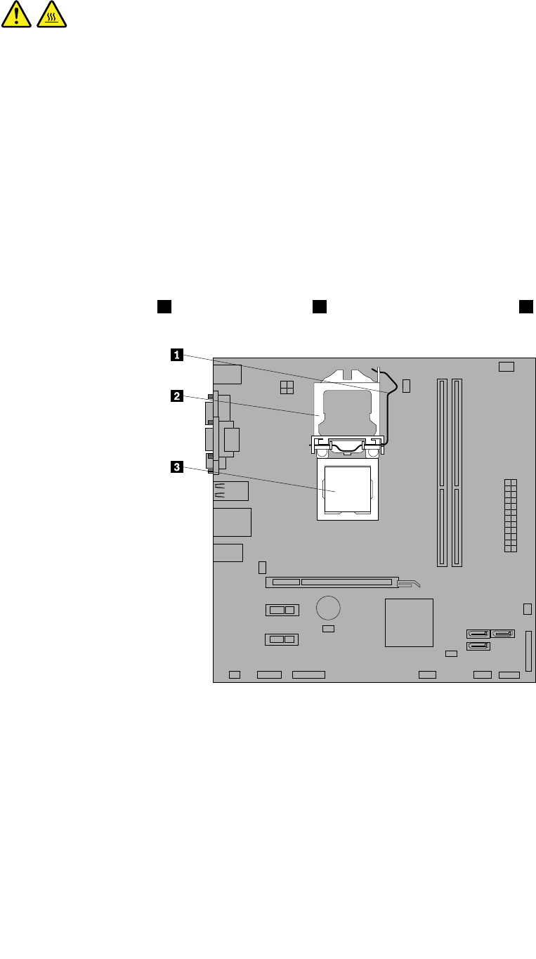
CAUTION:
Theheatsinkandmicroprocessormightbeveryhot.Turnoffthecomputerandwaitthreetove
minutestoletthecomputercoolbeforeremovingthecomputercover.
Toreplacethemicroprocessor,dothefollowing:
1.Removeallmediafromthedrivesandturnoffallattacheddevicesandthecomputer.Then,disconnect
allpowercordsfromelectricaloutletsanddisconnectallcablesthatareconnectedtothecomputer.
2.Removethecomputercover.See“Removingthecomputercover”onpage82.
3.Laythecomputeronitssideforeasieraccesstothesystemboard.
4.Locatethesystemboardanddisconnectallcablesconnectedtothesystemboard.See“Locating
partsonthesystemboard”onpage71.
5.Removetheheatsinkandfanassembly.See“Replacingtheheatsinkandfanassembly”onpage93.
Note:Placetheheatsinkandfanassemblyonitssidesothatthethermalgreaseonthebottomofit
doesnotgetincontactwithanything.
6.Liftthesmallhandle1andopentheretainer2toaccessthemicroprocessor3.
Figure28.Accessingthemicroprocessor
7.Liftthemicroprocessorstraightupandoutofthemicroprocessorsocket.
Chapter9.ReplacingFRUs(machinetypes:0896,0958,1112,2116,3498,3593,3595,3597,
3617,3634,3655,3662,3665,and3675)97
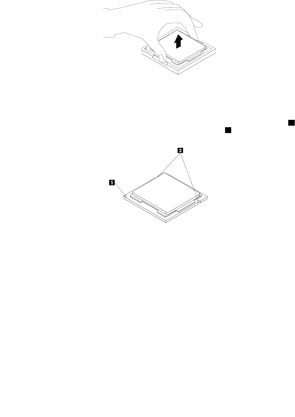
Figure29.Removingthemicroprocessor
Notes:
a.Yourmicroprocessorandsocketmightlookdifferentfromtheoneillustrated.
b.Notetheorientationofthemicroprocessorinthesocket.Youcaneitherlookforthesmalltriangle1
ononecornerofthemicroprocessorornotetheorientationofthenotches2onthemicroprocessor.
Thisisimportantwheninstallingthenewmicroprocessoronthesystemboard.
c.Touchonlytheedgesofthemicroprocessor.Donottouchthegoldcontactsonthebottom.
d.Donotdropanythingontothemicroprocessorsocketwhileitisexposed.Thesocketpinsmustbe
keptascleanaspossible.
8.Makesurethatthesmallhandleisintheraisedpositionandthemicroprocessorretainerisfullyopen.
9.Removetheprotectivecoverthatprotectsthegoldcontactsofthenewmicroprocessor.
10.Holdthenewmicroprocessorbyitssidesandalignthesmalltriangleononecornerofthenew
microprocessorwiththecorrespondingsmalltriangleononecornerofthemicroprocessorsocket.
98ThinkCentreHardwareMaintenanceManual
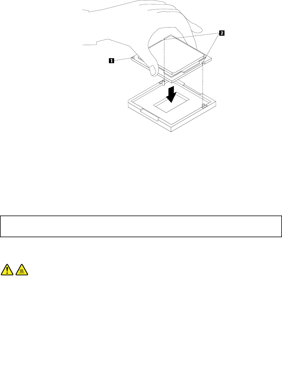
11.Lowerthenewmicroprocessorstraightdownintothemicroprocessorsocketonthesystemboard.
Figure30.Installingthemicroprocessor
12.Closethemicroprocessorretainerandlockitintopositionwiththesmallhandletosecurethenew
microprocessorinthesocket.
13.Reinstalltheheatsinkandfanassembly.See“Replacingtheheatsinkandfanassembly”onpage93.
14.Reconnectallcablesthatweredisconnectedfromthesystemboard.
15.Tocompletethereplacement,goto“Completingthepartsreplacement”onpage115.
Replacingthesystemboard
Attention:
Donotopenyourcomputerorattemptanyrepairbeforereadingandunderstandingthe“Importantsafetyinformation”
onpage1.
Thissectionprovidesinstructionsonhowtoreplacethesystemboard.
CAUTION:
Theheatsinkandmicroprocessormightbeveryhot.Turnoffthecomputerandwaitthreetove
minutestoletthecomputercoolbeforeopeningthecomputercover.
Toreplacethesystemboard,dothefollowing:
1.Removeallmediafromthedrivesandturnoffallattacheddevicesandthecomputer.Then,disconnect
allpowercordsfromelectricaloutletsanddisconnectallcablesthatareconnectedtothecomputer.
2.Removethecomputercover.See“Removingthecomputercover”onpage82.
3.Laythecomputeronitssideforeasieraccesstothesystemboard.
4.RemoveallmemorymodulesandPCIcardsthatarecurrentlyinstalled.See“Installingorreplacinga
memorymodule”onpage89and“InstallingorreplacingaPCIcard”onpage85.
Chapter9.ReplacingFRUs(machinetypes:0896,0958,1112,2116,3498,3593,3595,3597,
3617,3634,3655,3662,3665,and3675)99
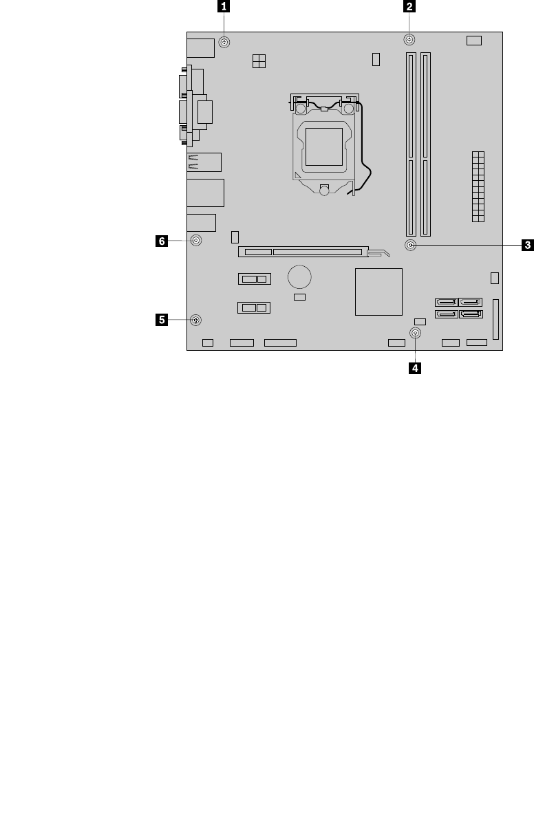
5.Carefullytakenoteofthelocationsofallcableconnectionsonthesystemboardanddisconnectall
thecables.See“Locatingpartsonthesystemboard”onpage71.
6.Removetheheatsinkandfanassemblyfromthefailingsystemboard.See“Replacingtheheatsinkand
fanassembly”onpage93.
7.Removethesixscrewsthatsecurethesystemboard.
Figure31.Removingthesixscrewsthatsecurethesystemboard
8.Carefullyslidethesystemboardsothatitcanbereleasedfromthemountingstudsthatsecurethe
systemboardinplace.
9.Liftthesystemboardoutofthechassis.
10.Removethemicroprocessorfromthefailingsystemboardandinstallitonthenewsystemboard.
See“Replacingthemicroprocessor”onpage96.
11.Installthenewsystemboardintothechassisbyaligningthesixmountingstudsinthechassiswiththe
correspondingholesinthenewsystemboard.Carefullyslidethenewsystemboardintothechassisuntil
itissecuredinplacebythemountingstuds.Then,installthesixscrewstosecurethesystemboard.
12.Installtheheatsinkandfanassemblyandconnecttheheatsinkandfanassemblycabletothenew
systemboard.See“Replacingtheheatsinkandfanassembly”onpage93.
13.InstallallmemorymodulesandPCIcardsremovedfromthefailingsystemboardonthenewsystem
board.See“Installingorreplacingamemorymodule”onpage89and“InstallingorreplacingaPCI
card”onpage85.
14.Reconnectallremainingcablestothesystemboard.See“Locatingpartsonthesystemboard”
onpage71.
15.Tocompletethereplacement,goto“Completingthepartsreplacement”onpage115.
Thefailingsystemboardmustbereturnedwithamicroprocessorsocketcovertoprotectthepinsduring
shippingandhandling.
100ThinkCentreHardwareMaintenanceManual
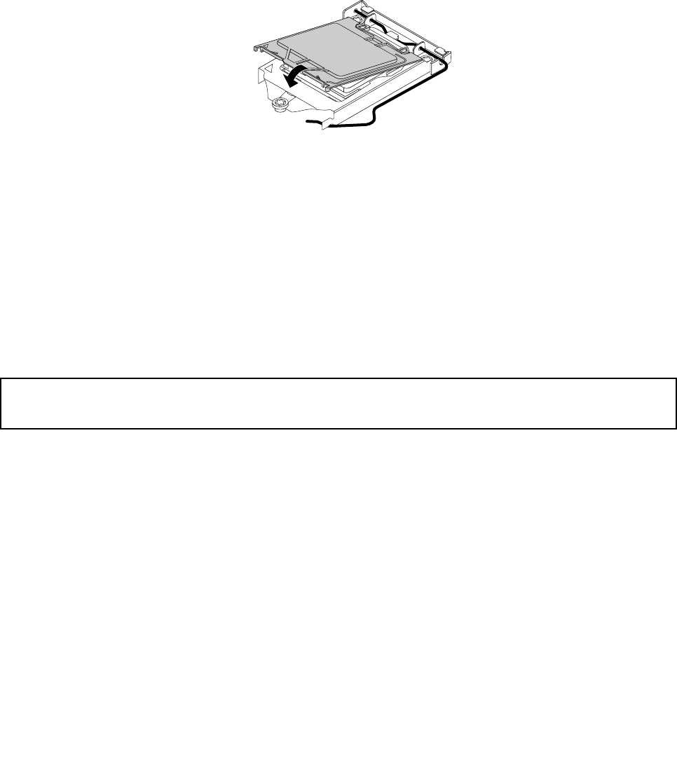
Toinstallthemicroprocessorsocketcover,dothefollowing:
1.Releasetheleversecuringthemicroprocessorretainerandopentheretainertoaccessthe
microprocessor.
2.Graspthemicroprocessoronthesidesandliftitstraightupandoutofthesocket.Donottouchthe
contactsonthemicroprocessorsocket.
3.Lowerthemicroprocessorretainer,andthenlowerthelevertosecuretheretainer.Ensurethatthe
leverislockedintoposition.
4.Notetheorientationofthesocketcover,andinstallonesideofthesocketcoverintothemicroprocessor
socket.
Figure32.Installingonesideofthesocketcoverintothemicroprocessorsocket
Note:Yourmicroprocessorsocketandcovermightlookslightlydifferentfromtheillustration.
5.Carefullypresstheothersideofthesocketcoverdownwarduntilthesocketcoversnapsintoposition.
6.Carefullycheckthefourcornersofthesocketcovertomakesurethatthecoverissecuredinthe
microprocessorsocket.
7.Followanyadditionalinstructionsincludedwiththereplacementpartyoureceived.
Note:Ifyoursystemboardhastwomicroprocessorsockets,besuretoinstallasocketcoverforeach
microprocessorsocket.
Replacingtheprimaryharddiskdrive
Attention:
Donotopenyourcomputerorattemptanyrepairbeforereadingandunderstandingthe“Importantsafetyinformation”
onpage1.
Thissectionprovidesinstructionsonhowtoreplacetheprimaryharddiskdrive.
Toreplacetheprimaryharddiskdrive,dothefollowing:
1.Turnoffthecomputeranddisconnectallpowercordsfromelectricaloutlets.
2.Removethecomputercover.See“Removingthecomputercover”onpage82.
3.Locatetheprimaryharddiskdrive.See“Locatinginternaldrives”onpage74.
Note:Thereisalsoasecondaryharddiskdrivebayforyoutopurchaseandinstallasecondaryhard
diskdrivebyyourself.Ifyouwanttoinstallasecondaryharddiskdrive,usethesamewayofinstalling
theprimaryharddiskdrive.
4.Disconnectthesignalcableandthepowercablefromtheharddiskdrive.
Chapter9.ReplacingFRUs(machinetypes:0896,0958,1112,2116,3498,3593,3595,3597,3617,
3634,3655,3662,3665,and3675)101
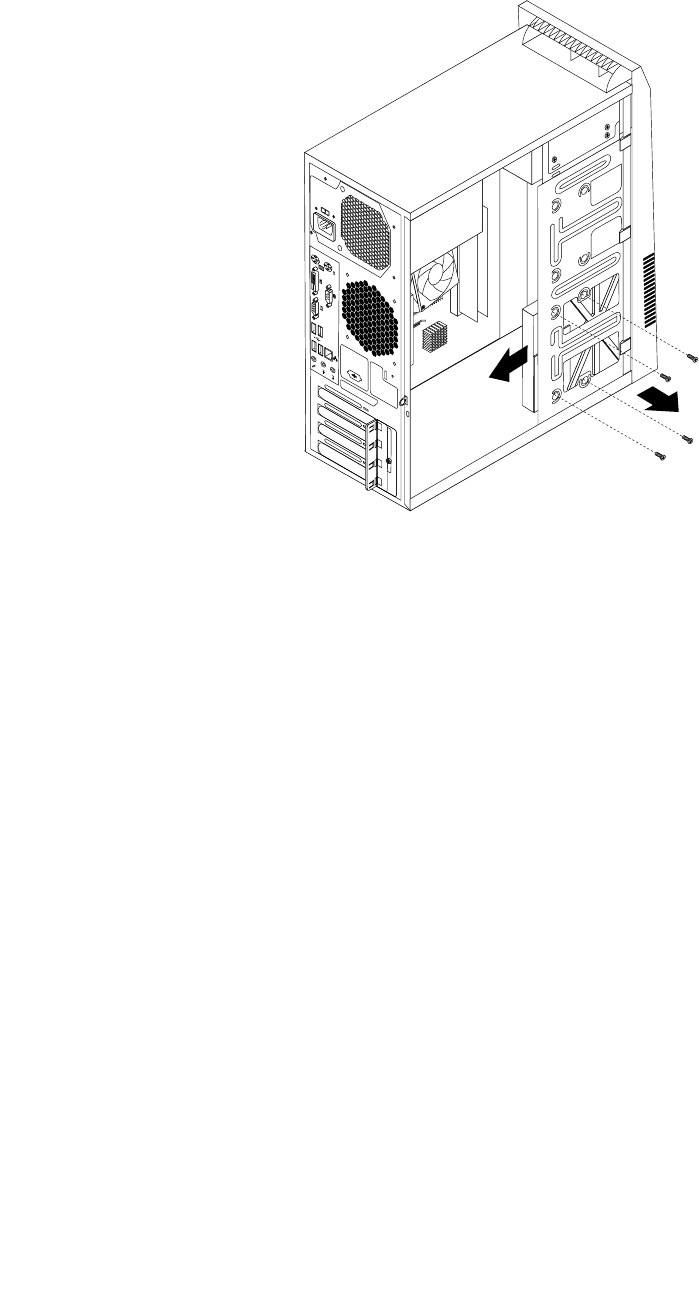
5.Removethefourscrewsthatsecuretheharddiskdrive.Then,slidetheharddiskdriveoutofthechassis.
Figure33.Removingtheharddiskdrive
102ThinkCentreHardwareMaintenanceManual
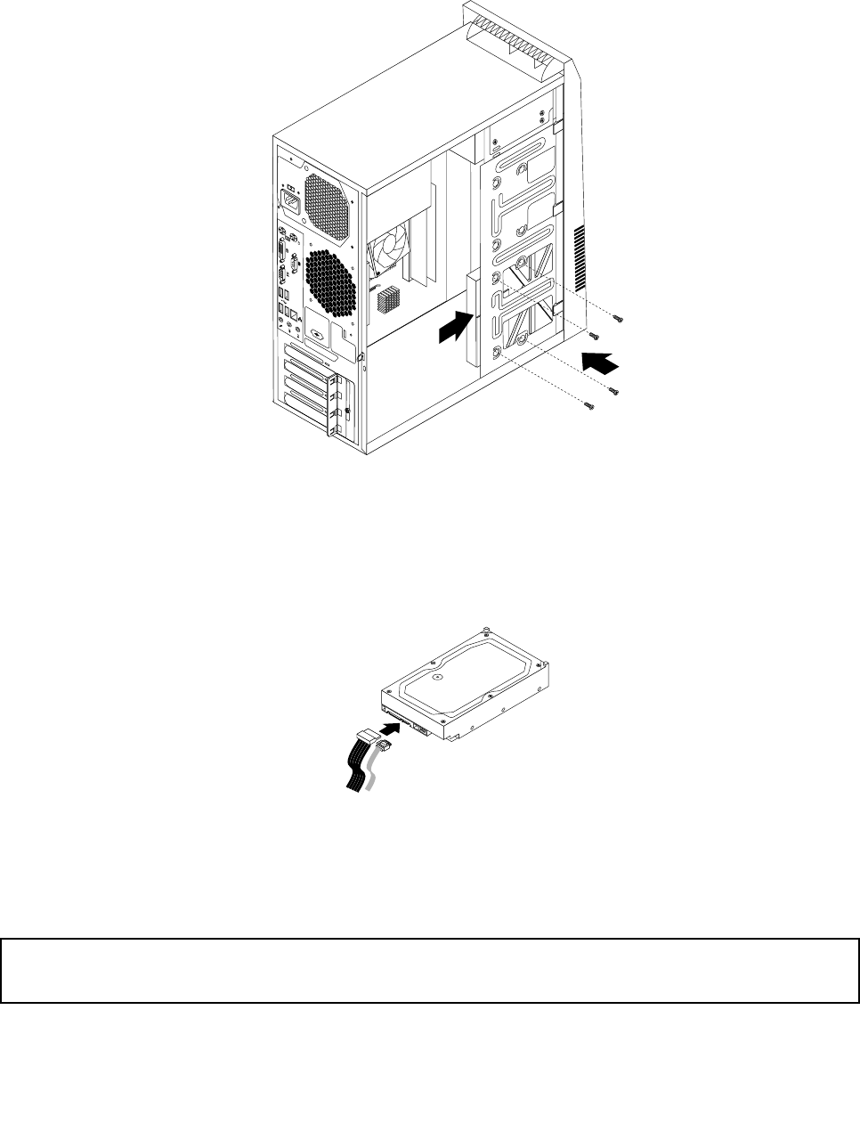
6.Slidethenewharddiskdriveintotheharddiskdrivebayandalignthescrewholesinthenewhard
diskdrivewiththecorrespondingholesinthedrivebay.Then,installthefourscrewstosecurethe
newharddiskdriveinplace.
Figure34.Installingtheharddiskdrive
7.Connectoneendofthesignalcabletotherearofthenewharddiskdriveandtheotherendtoan
availableSATAconnectoronthesystemboard.See“Locatingpartsonthesystemboard”onpage71.
Then,locateanavailableve-wirepowerconnectorandconnectittotherearofthenewharddiskdrive.
Figure35.ConnectingaSATAharddiskdrive
8.Tocompletetheinstallationorreplacement,goto“Completingthepartsreplacement”onpage115.
Replacingtherearfanassembly
Attention:
Donotopenyourcomputerorattemptanyrepairbeforereadingandunderstandingthe“Importantsafetyinformation”
onpage1.
Thissectionprovidesinstructionsonhowtoreplacetherearfanassembly.
Chapter9.ReplacingFRUs(machinetypes:0896,0958,1112,2116,3498,3593,3595,3597,3617,
3634,3655,3662,3665,and3675)103
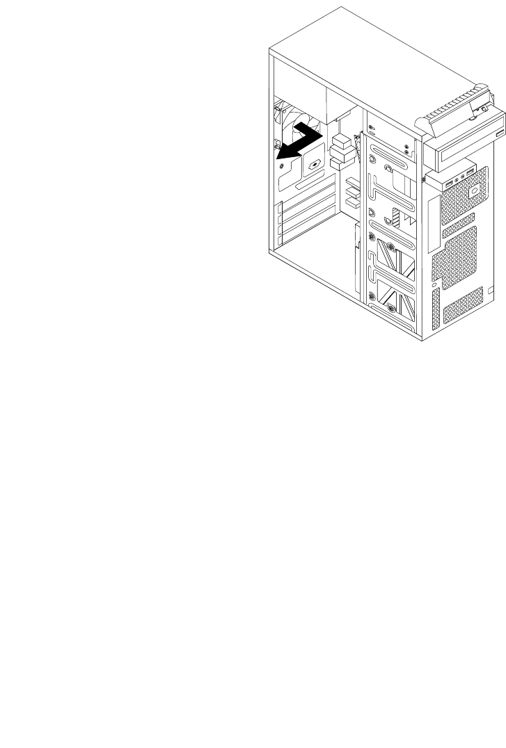
Toreplacetherearfanassembly,dothefollowing:
1.Turnoffthecomputeranddisconnectallpowercordsfromelectricaloutlets.
2.Removethecomputercover.See“Removingthecomputercover”onpage82.
3.Locatetherearfanassembly.See“LocatingmajorFRUsandCRUs”onpage69.
4.Disconnecttherearfanassemblycablefromthesystemfanconnectoronthesystemboard.See
“Locatingpartsonthesystemboard”onpage71.
5.Therearfanassemblyisattachedtothechassisbyfourrubbermounts.Removetherearfanassembly
bybreakingorcuttingtherubbermountsandgentlypullingtherearfanassemblyoutofthechassis.
Note:Thenewrearfanassemblywillhavefournewrubbermountsattached.
Figure36.Removingtherearfanassembly
6.Installthenewrearfanassemblybyaligningthenewrubbermountswiththecorrespondingholesinthe
chassisandpushtherubbermountsthroughtheholes.
104ThinkCentreHardwareMaintenanceManual
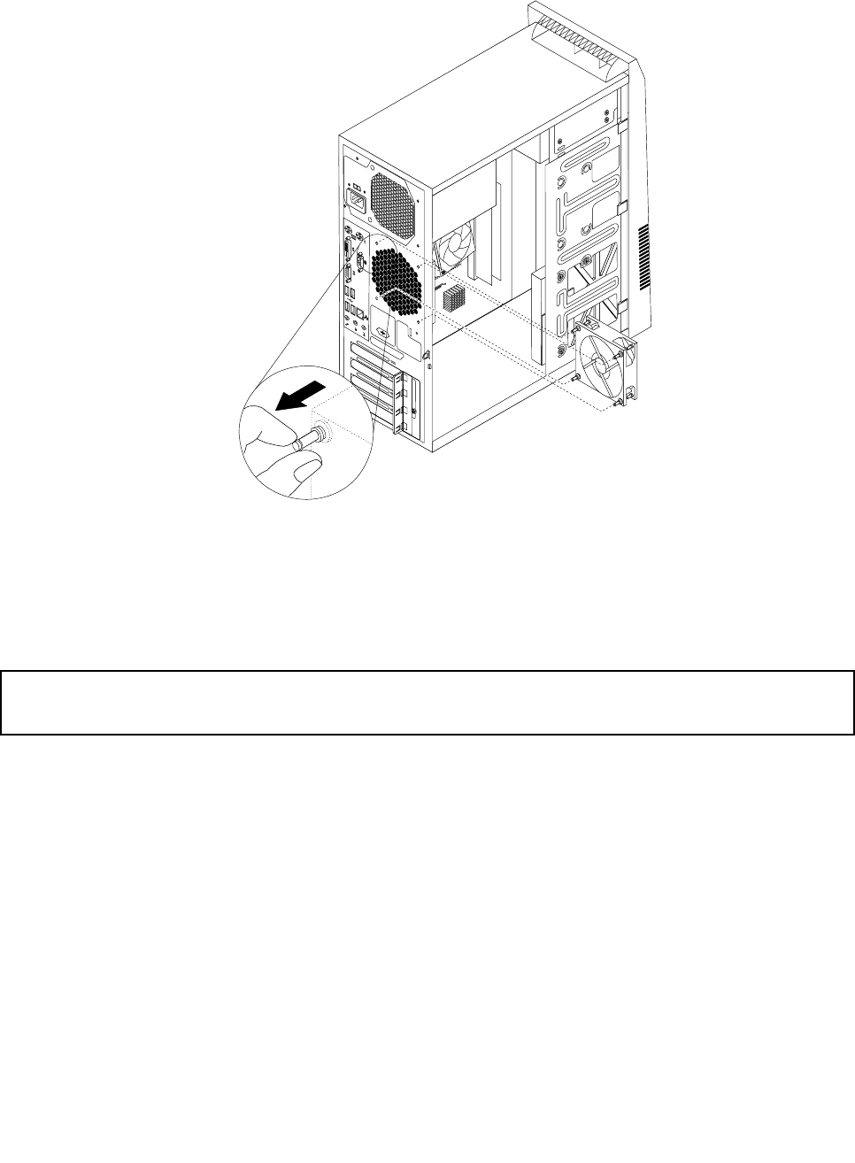
7.Pullonthetipsoftherubbermountsuntiltherearfanassemblyissecuredinplace.
Figure37.Installingtherearfanassembly
8.Connecttherearfanassemblycabletothesystemfanconnectoronthesystemboard.
9.Tocompletetheinstallationorreplacement,goto“Completingthepartsreplacement”onpage115.
ReplacingthefrontaudioandUSBassembly
Attention:
Donotopenyourcomputerorattemptanyrepairbeforereadingandunderstandingthe“Importantsafetyinformation”
onpage1.
ThissectionprovidesinstructionsonhowtoreplacethefrontaudioandUSBassembly.
ToreplacethefrontaudioandUSBassembly,dothefollowing:
1.Turnoffthecomputeranddisconnectallpowercordsfromelectricaloutlets.
2.Removethecomputercover.See“Removingthecomputercover”onpage82.
3.Removethefrontbezel.See“Removingandreinstallingthefrontbezel”onpage83.
4.LocatethefrontaudioandUSBassembly.See“LocatingmajorFRUsandCRUs”onpage69.
5.DisconnectthefrontaudioandUSBassemblycablesfromthesystemboard.See“Locatingpartson
thesystemboard”onpage71.
Note:Makesureyounotethelocationsofthecableswhenyoudisconnectthecablesfromthesystem
board.
Chapter9.ReplacingFRUs(machinetypes:0896,0958,1112,2116,3498,3593,3595,3597,3617,
3634,3655,3662,3665,and3675)105
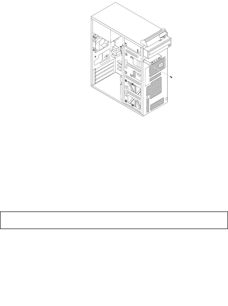
6.RemovethescrewthatsecuresthefrontaudioandUSBassemblybrackettothechassistoremove
thebracketfromthechassis.
Figure38.RemovingthescrewthatsecuresthefrontaudioandUSBassemblytothechassis
7.RemovethetwoscrewsthatsecurethefrontaudioandUSBassemblytoitsbracketandremovethe
failingfrontaudioandUSBassemblyfromthebracket.
8.InstallanewfrontaudioandUSBassemblyintothebracketandinstallthetwoscrewstosecurethe
frontaudioandUSBassemblytothebracket.
9.InstallthefrontaudioandUSBassemblybracketintothechassisandalignthescrewholeinthe
bracketwiththecorrespondingholeinthechassis.
10.Installthescrewtosecurethebrackettothechassis.
11.ReconnectthefrontaudioandUSBassemblycablestothefrontaudioconnectorandthefrontUSB
connectoronthesystemboard.See“Locatingpartsonthesystemboard”onpage71.
12.Tocompletetheinstallationorreplacement,goto“Completingthepartsreplacement”onpage115.
ReplacingtheWiFiunits
Attention:
Donotopenyourcomputerorattemptanyrepairbeforereadingandunderstandingthe“Importantsafetyinformation”
onpage1.
ThissectionprovidesinstructionsonhowtoreplacetheWiFiunits.TheWiFiunitsincludeaWiFiadapter
card,aWiFicardmodule,andarearWiFiantennacable.
ReplacingtheWiFiunitsinvolvesthefollowingoperations:
•“RemovingtheWiFiadaptercard”onpage107
•“RemovingtheWiFicardmodule”onpage108
•“InstallingtheWiFiunits”onpage109
106ThinkCentreHardwareMaintenanceManual
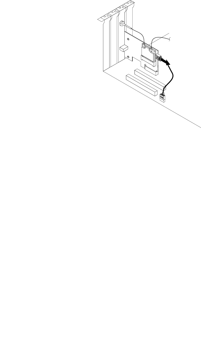
RemovingtheWiFiadaptercard
ToremoveaWiFiadaptercard,dothefollowing:
1.Turnoffthecomputeranddisconnectallpowercordsfromelectricaloutlets.
2.Removethecomputercover.See“Removingthecomputercover”onpage82.
3.IfyourcomputercomeswithaWiFicardmodulethatsupportstheBluetoothfunction,disconnect
theBluetoothcablefromtheWiFiadaptercard.
Figure39.DisconnectingtheBluetoothcable
Note:TheBluetoothcableconnectstheBluetoothconnectorontheWiFiadaptercardtothefrontUSB
connectoronthesystemboardtosupporttheBluetoothfunction.
4.Attherearofthecomputer,removethescrewthatsecuresthePCIcardlatch.
Chapter9.ReplacingFRUs(machinetypes:0896,0958,1112,2116,3498,3593,3595,3597,3617,
3634,3655,3662,3665,and3675)107
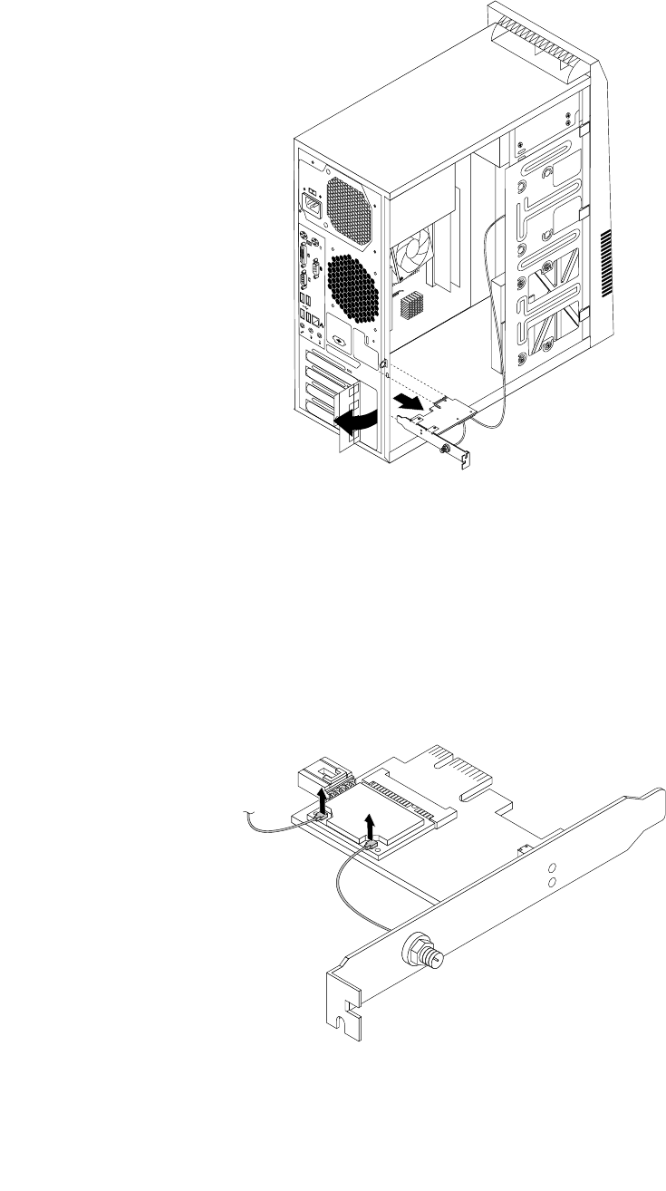
5.GrasptheWiFiadaptercardthatiscurrentlyinstalledandgentlypullitoutoftheslot.
Figure40.RemovingtheWiFiadaptercard
Note:Thecardtstightlyintothecardslot.Ifnecessary,alternatemovingeachsideofthecarda
smallamountuntilitisremovedfromthecardslot.
RemovingtheWiFicardmodule
ToremovetheWiFicardmodule,dothefollowing:
1.RemovetheWiFiadaptercardfromthecomputer,andthendisconnectthefrontandrearWiFiantenna
cablesfromtheWiFicardmodule.
Figure41.RemovingtheWiFiantennacables
108ThinkCentreHardwareMaintenanceManual
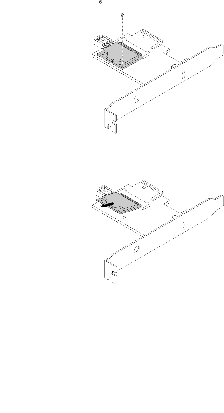
2.RemovethetwoscrewsthatsecuretheWiFicardmoduletotheWiFiadaptercard.
Figure42.RemovingthescrewsthatsecuretheWiFicardmodule
3.PulltheWiFicardmoduleoutoftheminiPCIExpressslottoremoveitfromtheWiFiadaptercard.
Figure43.RemovingtheWiFicardmodule
InstallingtheWiFiunits
ToinstalltheWiFiunits,dothefollowing:
Chapter9.ReplacingFRUs(machinetypes:0896,0958,1112,2116,3498,3593,3595,3597,3617,
3634,3655,3662,3665,and3675)109
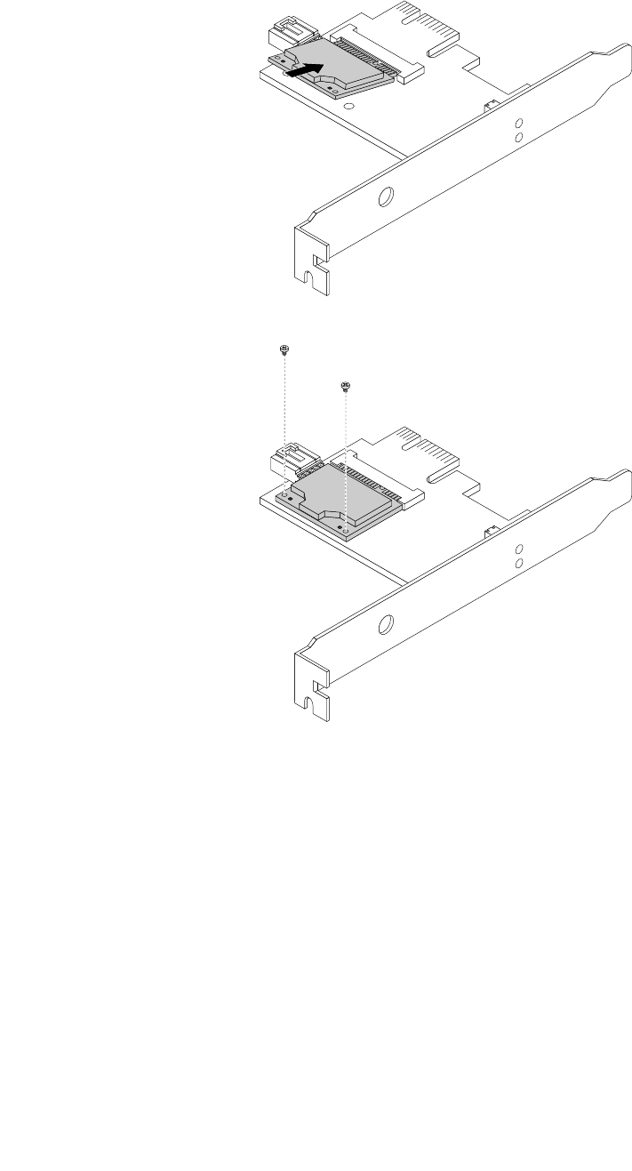
1.InserttheWiFicardmoduleintotheminiPCIExpressslot,andtheninstallthetwoscrewstosecure
theWiFicardmoduletotheWiFiadaptercard.
Figure44.InstallingtheWiFicardmodule
110ThinkCentreHardwareMaintenanceManual
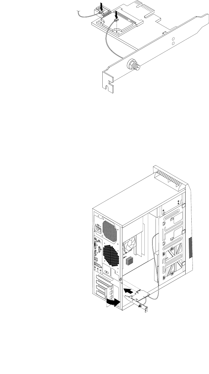
2.ConnectthefrontantennacableandrearantennacabletotheWiFicardmodule.
Figure45.InstallingtheWiFiantennacables
3.InstalltheWiFiadaptercardintothePCIExpressx1slotonthesystemboard.See“Locatingpartson
thesystemboard”onpage71.
4.IftheinstalledWiFicardmodulesupportstheBluetoothfunction,useaBluetoothcabletoconnectthe
BluetoothconnectorontheWiFiadaptercardtothefrontUSBconnectoronthesystemboard.
5.PivotthecardlatchtotheclosedpositiontosecuretheWiFiadaptercard.
Figure46.InstallingtheWiFiadaptercard
6.Tocompletetheinstallationorreplacement,goto“Completingthepartsreplacement”onpage115.
Chapter9.ReplacingFRUs(machinetypes:0896,0958,1112,2116,3498,3593,3595,3597,3617,
3634,3655,3662,3665,and3675)111
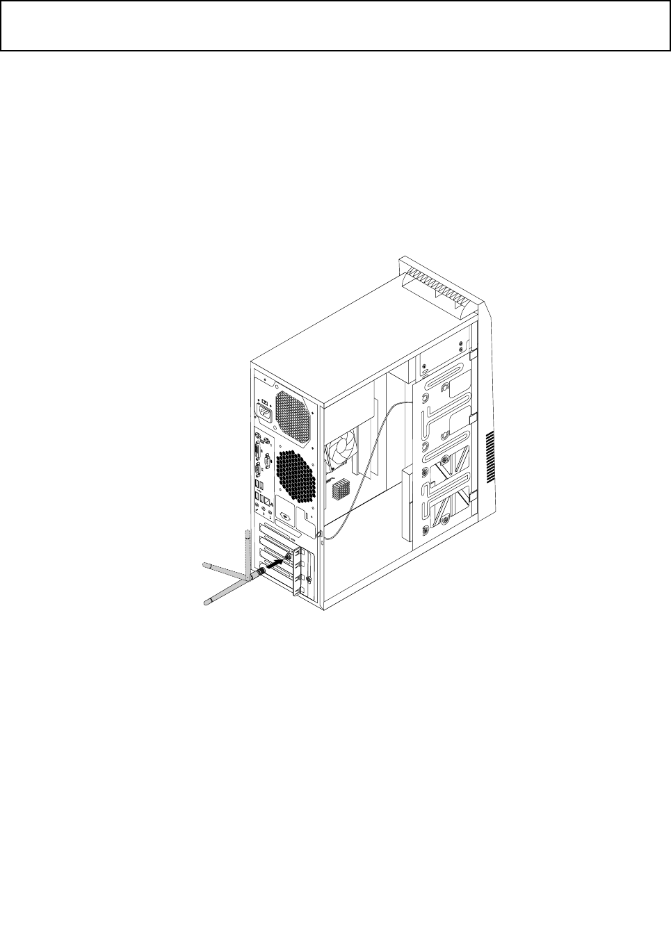
InstallingorremovingtherearWiFiantenna
Attention:
Donotopenyourcomputerorattemptanyrepairbeforereadingandunderstandingthe“Importantsafetyinformation”
onpage1.
ThissectionprovidesinstructionsonhowtoinstallorremovetherearWiFiantenna.
InstallingtherearWiFiantenna
ToinstalltherearWiFiantenna,dothefollowing:
1.Turnoffthecomputeranddisconnectallpowercordsfromelectricaloutlets.
2.InstalltherearWiFiantennatotherearWiFiantennacableconnectorattachedontherearofthe
computer.
3.Adjusttheangleoftherearantennatolowertheriskofbreakingtheantennabyaccident.
Figure47.InstallingtherearWiFiantenna
4.Tocompletetheinstallationorreplacement,goto“Completingthepartsreplacement”onpage115.
RemovingtherearWiFiantenna
ToremovetherearWiFiantenna,dothefollowing:
1.Turnoffthecomputeranddisconnectallpowercordsfromelectricaloutlets.
2.StraightentherearWiFiantennasothatitcanbemoreeasilytwisted.
112ThinkCentreHardwareMaintenanceManual
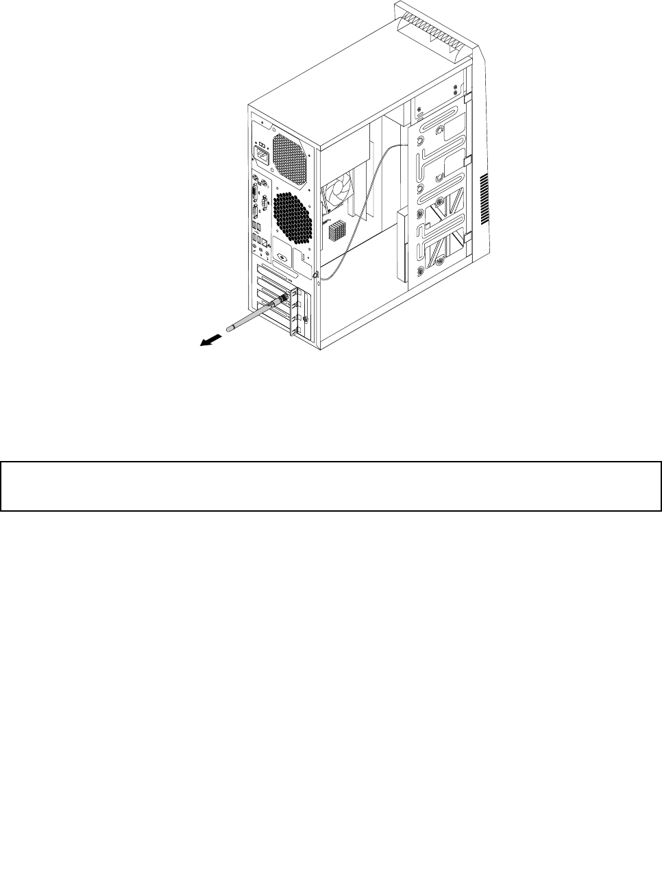
3.HoldthethickerendoftherearWiFiantennaandunscrewtheWiFiantennafromtherearofthe
computer.
Figure48.RemovingtherearWiFiantenna
4.Tocompletetheinstallationorreplacement,goto“Completingthepartsreplacement”onpage115.
InstallingorremovingthefrontWiFiantenna
Attention:
Donotopenyourcomputerorattemptanyrepairbeforereadingandunderstandingthe“Importantsafetyinformation”
onpage1.
ThissectionprovidesinstructionsonhowtoinstallorremovethefrontWiFiantenna.
InstallingthefrontWiFiantenna
ToinstallthefrontWiFiantenna,dothefollowing:
1.Turnoffthecomputeranddisconnectallpowercordsfromelectricaloutlets.
2.Removethecomputercover.See“Removingthecomputercover”onpage82.
3.Removethefrontbezel.See“Removingandreinstallingthefrontbezel”onpage83.
4.Peeloffthepaperthatprotectsthestickersonthefrontantenna.
Chapter9.ReplacingFRUs(machinetypes:0896,0958,1112,2116,3498,3593,3595,3597,3617,
3634,3655,3662,3665,and3675)113
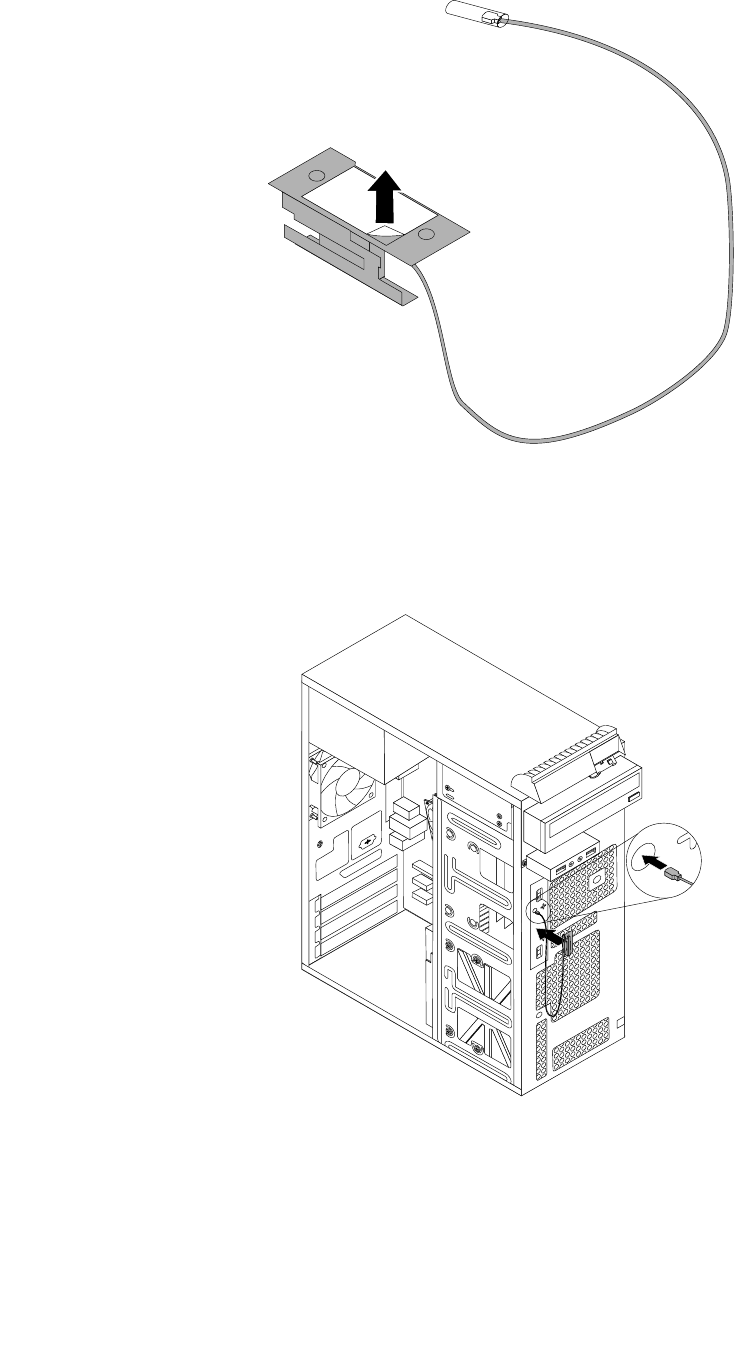
Figure49.Peelingoffthepaperthatprotectsthestickers
5.Stickthefrontantennatothefrontpanelasshown.Theninsertthefrontantennacablethroughthe
holeinthefrontpanel.
Figure50.InstallingthefrontWiFiantenna
6.ConnectthefrontantennacabletotheWiFicardmodule.
7.Tocompletetheinstallationorreplacement,goto“Completingthepartsreplacement”onpage115.
114ThinkCentreHardwareMaintenanceManual
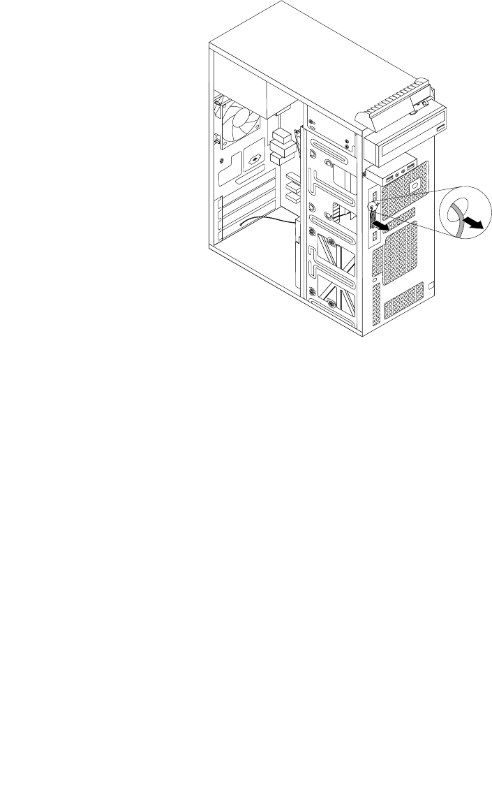
RemovingthefrontWiFiantenna
ToremovethefrontWiFiantenna,dothefollowing:
1.Turnoffthecomputeranddisconnectallpowercordsfromelectricaloutlets.
2.Removethecomputercover.See“Removingthecomputercover”onpage82.
3.Removethefrontbezel.See“Removingandreinstallingthefrontbezel”onpage83.
4.DisconnectthefrontantennacablefromtheWiFicardmodule.
5.Removethefrontantennaandcablefromthefrontofthecomputer.
Figure51.RemovingthefrontWiFiantenna
6.Tocompletetheinstallationorreplacement,goto“Completingthepartsreplacement”onpage115.
Completingthepartsreplacement
Aftercompletingtheinstallationorreplacementforallparts,youneedtoreinstallthecomputercoverand
reconnectcables.Dependingonthepartsyouinstalledorreplaced,youmightneedtoconrmtheupdated
informationintheSetupUtilityprogram.RefertoChapter6“UsingtheSetupUtilityprogram”onpage55.
Toreinstallthecomputercoverandreconnectcablestoyourcomputer,dothefollowing:
1.Makesurethatallcomponentshavebeenreassembledcorrectlyandthatnotoolsorloosescrews
areleftinsideyourcomputer.See“LocatingmajorFRUsandCRUs”onpage69forthelocationsof
variouscomponentsinyourcomputer.
2.Ifyouhaveremovedthefrontbezel,reinstallit.See“Removingandreinstallingthefrontbezel”on
page83.
3.Makesurethatthecablesareroutedcorrectlybeforereinstallingthecomputercover.Keepcablesclear
ofthehingesandsidesofthecomputerchassistoavoidinterferencewithreinstallingthecomputer
cover.
Chapter9.ReplacingFRUs(machinetypes:0896,0958,1112,2116,3498,3593,3595,3597,3617,
3634,3655,3662,3665,and3675)115
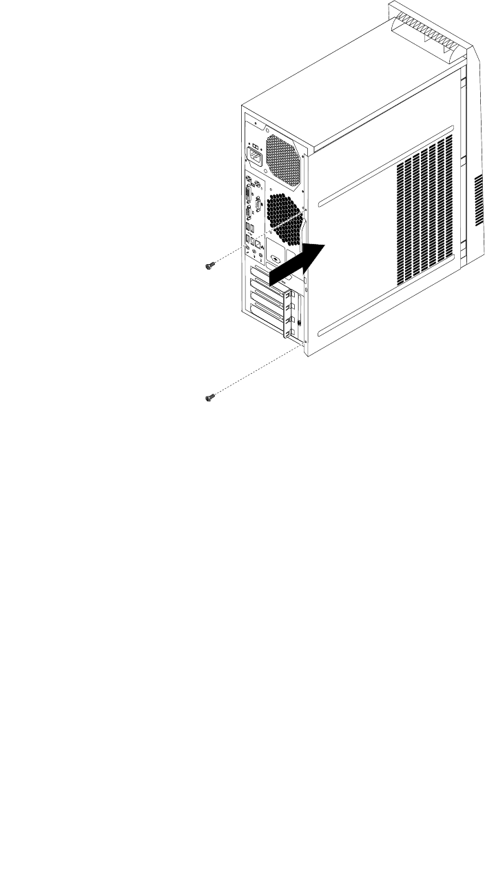
4.Positionthecomputercoveronthechassissothattherailguidesonthebottomofthecomputer
coverengagetherailsonthechassis.Then,pushthecovertothefrontofthecomputeruntilitsnaps
intoposition.
Figure52.Reinstallingthecomputercover
5.Installthescrewstosecurethecomputercover.
6.Ifthereisapadlockavailable,lockthecomputercover.
7.Ifthereisanintegratedcablelockavailable,lockthecomputer.
8.Reconnecttheexternalcablesandpowercordstothecomputer.See“Locatingconnectorsonthe
rearofyourcomputer”onpage68.
9.Toupdateyourconguration,refertoChapter6“UsingtheSetupUtilityprogram”onpage55.
Note:Inmostareasoftheworld,LenovorequiresthereturnofthedefectiveFieldReplaceableUnits(FRUs).
InformationaboutthiswillcomewiththenewFRUsorwillcomeafewdaysafteryoureceivethenewFRUs.
116ThinkCentreHardwareMaintenanceManual

Chapter10.ReplacingFRUs(machinetypes:0900,0967,1271,
3578,3594,3596,3598,3629,3654,3660,3664,3668,and3676)
ThischapterprovidesinformationabouttheFRUreplacementinstructions.
Important:BesuretoreadandunderstandChapter2“Safetyinformation”onpage3beforereplacingany
FRU.Theseprecautionsandguidelineswillhelpyouworksafely.
Note:FRUreplacementsaretobedoneonlybytrainedservicetechnicians.
Handlingstatic-sensitivedevices
Donotopenthestatic-protectivepackagecontainingthenewpartuntilthedefectiveparthasbeenremoved
fromthecomputerandyouarereadytoinstallthenewpart.Staticelectricity,althoughharmlesstoyou,can
seriouslydamagecomputercomponentsandparts.
Whenyouhandlecomputerpartsandcomponents,taketheseprecautionstoavoidstatic-electricitydamage:
•Limityourmovement.Movementcancausestaticelectricitytobuilduparoundyou.
•Alwayscarefullyhandlethepartsandothercomputercomponents.HandlePCIcards,memorymodules,
systemboards,andmicroprocessorsbytheedges.Nevertouchexposedcircuitry.
•Preventothersfromtouchingthepartsandothercomputercomponents.
•Beforeyoureplaceanewpart,touchthestatic-protectivepackagecontainingthenewparttoametal
expansion-slotcoverorotherunpaintedmetalsurfaceonthecomputerforatleasttwoseconds.This
reducesstaticelectricityfromthepackageandyourbody.
•Removethenewpartfromthestatic-protectivepackageanddirectlyinstallitinthecomputerwithout
placingitonanyothersurface.Ifitishardforyoutodothisinyourspecicsituation,placethe
static-protectivepackageofthenewpartonasmooth,levelsurface,andthenplacethenewparton
thestatic-protectivepackage.
•Donotplacethepartonthecomputercoverorothermetalsurface.
Installingorreplacinghardware
Thissectionprovidesinstructionsonhowtoinstallorreplacehardwareforyourcomputer.Youcanexpand
thecapabilitiesofyourcomputerandmaintainyourcomputerbyinstallingorreplacinghardware.
Attention:
Donotopenyourcomputerorattemptanyrepairbeforereadingandunderstandingthe“Importantsafetyinformation”
onpage1.
Notes:
1.UseonlycomputerpartsprovidedbyLenovo.
2.Wheninstallingorreplacinganoption,usetheappropriateinstructionsinthissectionalongwiththe
instructionsthatcomewiththeoption.
Installingexternaloptions
Youcanconnectexternaloptionstoyourcomputer,suchasexternalspeakers,aprinter,orascanner.For
someexternaloptions,youmustinstalladditionalsoftwareinadditiontomakingthephysicalconnection.
Wheninstallinganexternaloption,see“Locatingconnectors,controls,andindicatorsonthefrontofyour
computer”onpage75and“Locatingconnectorsontherearofyourcomputer”onpage76toidentifythe
©CopyrightLenovo2012117
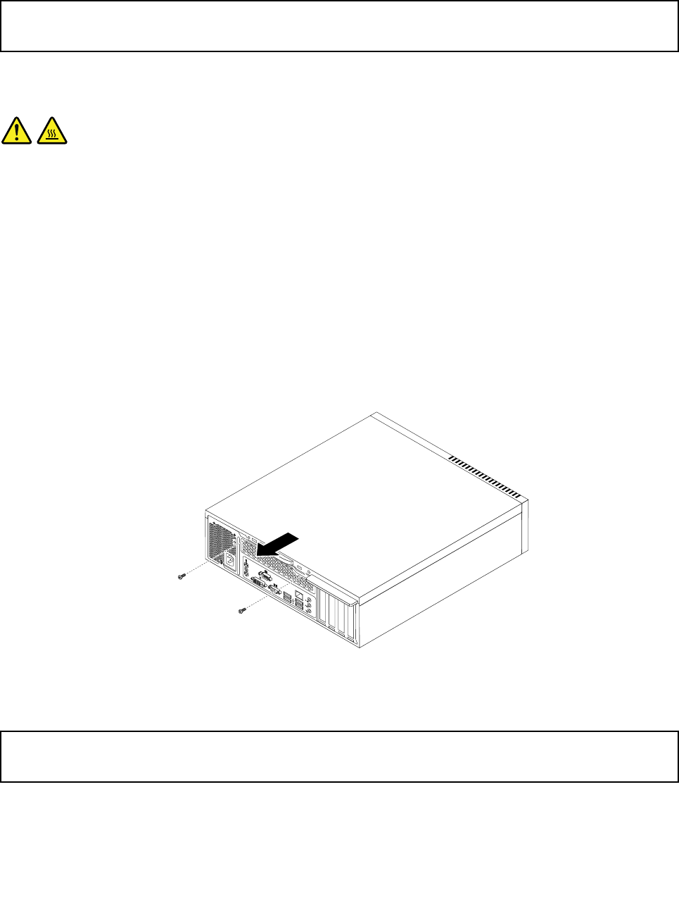
requiredconnector.Then,usetheinstructionsthatcomewiththeoptiontohelpyoumaketheconnection
andinstallanysoftwareordevicedriversthatarerequiredfortheoption.
Removingthecomputercover
Attention:
Donotopenyourcomputerorattemptanyrepairbeforereadingandunderstandingthe“Importantsafetyinformation”
onpage1.
Thissectionprovidesinstructionsonhowtoremovethecomputercover.
CAUTION:
Turnoffthecomputerandwaitthreetoveminutestoletthecomputercoolbeforeopeningthe
computercover.
Toremovethecomputercover,dothefollowing:
1.Removeanymediafromthedrivesandturnoffallattacheddevicesandthecomputer.
2.Disconnectallpowercordsfromelectricaloutlets.
3.Disconnectthepowercords,Input/Outputcables,andanyothercablesthatareconnectedtothe
computer.See“Locatingconnectors,controls,andindicatorsonthefrontofyourcomputer”onpage
75and“Locatingconnectorsontherearofyourcomputer”onpage76.
4.Removeanylockingdevicethatsecuresthecomputercover,suchasanintegratedcablelock.
5.Removethetwoscrewsthatsecurethecomputercoverandslidethecomputercovertotherearto
removeit.
Figure53.Removingthecomputercover
Removingandreinstallingthefrontbezel
Attention:
Donotopenyourcomputerorattemptanyrepairbeforereadingandunderstandingthe“Importantsafetyinformation”
onpage1.
Thissectionprovidesinstructionsonhowtoremoveandreinstallthefrontbezel.
Toremoveandreinstallthefrontbezel,dothefollowing:
118ThinkCentreHardwareMaintenanceManual
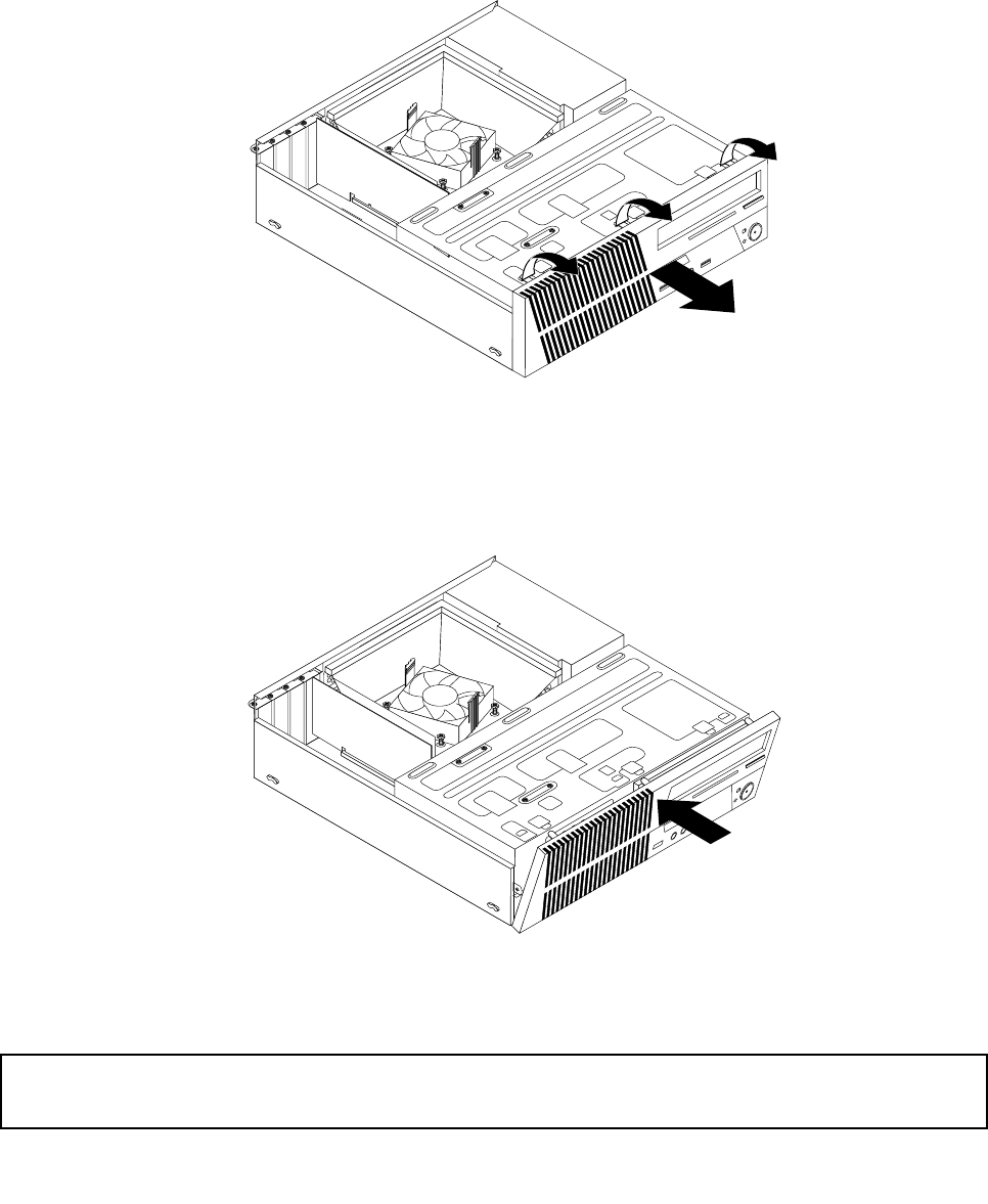
1.Removeallmediafromthedrivesandturnoffallattacheddevicesandthecomputer.Then,disconnect
allpowercordsfromelectricaloutletsanddisconnectallcablesthatareconnectedtothecomputer.
2.Removethecomputercover.See“Removingthecomputercover”onpage118.
3.Removethefrontbezelbyreleasingthethreeplastictabsonthetopofthefrontbezelandpivoting
thefrontbezeloutwardtoremoveitfromthecomputer.Carefullylaythefrontbezelasidewithout
disconnectingthepowerswitchandlight-emittingdiode(LED)assemblycable.
Figure54.Removingthefrontbezel
4.Toreinstallthefrontbezel,aligntheotherthreeplastictabsonthebottomofthefrontbezelwiththe
correspondingholesinthechassis,thenpivotthefrontbezelinwarduntilitsnapsintoposition.
Figure55.Reinstallingthefrontbezel
Accessingthesystemboardcomponentsanddrives
Attention:
Donotopenyourcomputerorattemptanyrepairbeforereadingandunderstandingthe“Importantsafetyinformation”
onpage1.
Chapter10.ReplacingFRUs(machinetypes:0900,0967,1271,3578,3594,3596,3598,3629,
3654,3660,3664,3668,and3676)119
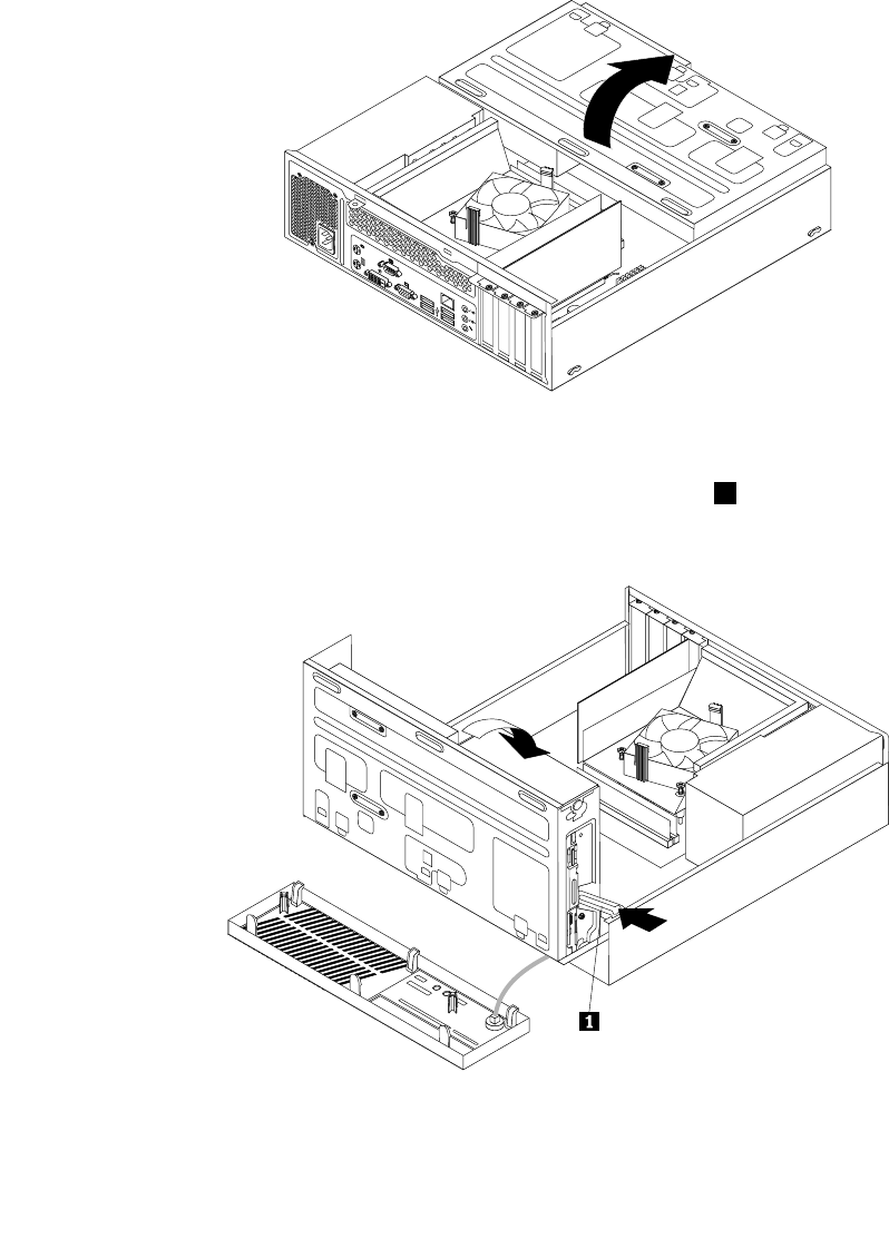
Thissectionprovidesinstructionsonhowtoaccessthesystemboardcomponentsanddrives.
Toaccessthesystemboardcomponentsanddrives,dothefollowing:
1.Removeallmediafromthedrivesandturnoffallattacheddevicesandthecomputer.Then,disconnect
allpowercordsfromelectricaloutletsanddisconnectallcablesthatareconnectedtothecomputer.
2.Removethecomputercover.See“Removingthecomputercover”onpage118.
3.Removethefrontbezel.See“Removingandreinstallingthefrontbezel”onpage118.
4.Pivotthedrivebayassemblyupwardtoaccessalltheinternaldrives,cables,andothercomponents.
Figure56.Pivotingthedrivebayassemblyupward
5.Tolowerthedrivebayassembly,pressthedrivebayassemblyclip1inwardandpivotthedrivebay
assemblydownwardasshown.
Figure57.Loweringthedrivebayassembly
120ThinkCentreHardwareMaintenanceManual
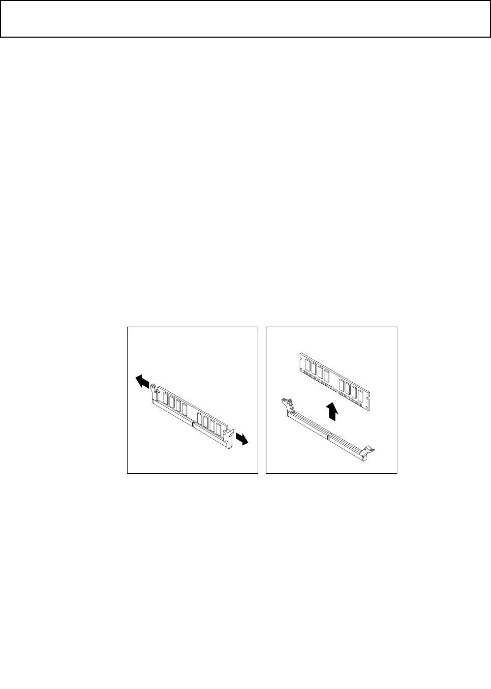
Installingorreplacingamemorymodule
Attention:
Donotopenyourcomputerorattemptanyrepairbeforereadingandunderstandingthe“Importantsafetyinformation”
onpage1.
Thissectionprovidesinstructionsonhowtoinstallorreplaceamemorymodule.
YourcomputerhastwoslotsforinstallingorreplacingDDR3DIMMsthatprovideuptoamaximumof16GB
systemmemory.Wheninstallingorreplacingamemorymodule,use2GB,4GB,or8GBDDR3DIMMs
inanycombinationuptoamaximumof16GB.
Toinstallorreplaceamemorymodule,dothefollowing:
1.Turnoffthecomputeranddisconnectallpowercordsfromelectricaloutlets.
2.Removethecomputercover.See“Removingthecomputercover”onpage118.
3.Removethefrontbezel.See“Removingandreinstallingthefrontbezel”onpage118.
4.Removetheheatsinkfanduct.See“Replacingtheheatsinkandfanassembly”onpage130.
5.Pivottheopticaldrivebayupwardtogainaccesstothememoryslots.See“Installingorreplacingthe
opticaldrive”onpage127.
6.Locatethememoryslots.See“Locatingpartsonthesystemboard”onpage71.
7.Removeanypartsthatmightpreventaccesstothememoryslots.
8.Dependingonwhetheryouareinstallingorreplacingamemorymodule,dooneofthefollowing:
•Ifyouarereplacinganoldmemorymodule,opentheretainingclipsandgentlypullthememory
moduleoutofthememoryslot.
Figure58.Removingamemorymodule
Chapter10.ReplacingFRUs(machinetypes:0900,0967,1271,3578,3594,3596,3598,3629,
3654,3660,3664,3668,and3676)121
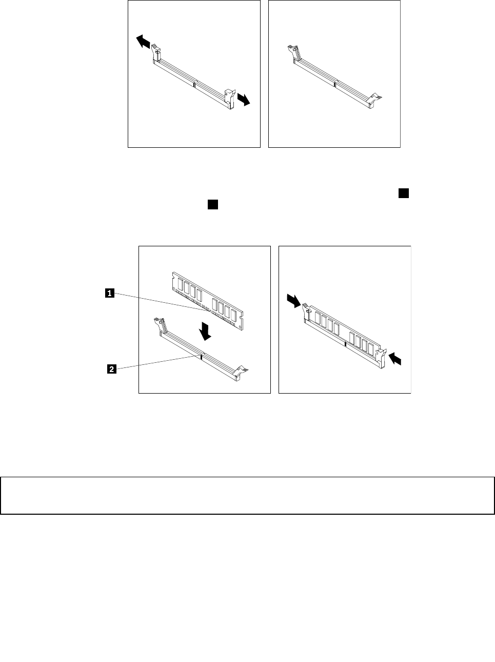
•Ifyouareinstallingamemorymodule,opentheretainingclipsofthememoryslotintowhichyou
wanttoinstallthememorymodule.
Figure59.Openingtheretainingclips
9.Positionthenewmemorymoduleoverthememoryslot.Makesurethatthenotch1onthememory
modulealignscorrectlywiththeslotkey2onthesystemboard.Pushthememorymodulestraight
downintotheslotuntiltheretainingclipsclose.
Figure60.Installingamemorymodule
10.Tocompletetheinstallationorreplacement,goto“Completingthepartsreplacement”onpage154.
InstallingorreplacingaPCIcard
Attention:
Donotopenyourcomputerorattemptanyrepairbeforereadingandunderstandingthe“Importantsafetyinformation”
onpage1.
ThissectionprovidesinstructionsonhowtoinstallorreplaceaPCIcard.YourcomputerhastwoPCI
Expressx1cardslotandonePCIExpressx16graphicscardslot.
ToinstallorreplaceaPCIcard,dothefollowing:
1.Turnoffthecomputeranddisconnectallpowercordsfromelectricaloutlets.
2.Removethecomputercover.See“Removingthecomputercover”onpage118.
3.DependingonwhetheryouareinstallingorreplacingaPCIcard,dooneofthefollowing:
122ThinkCentreHardwareMaintenanceManual
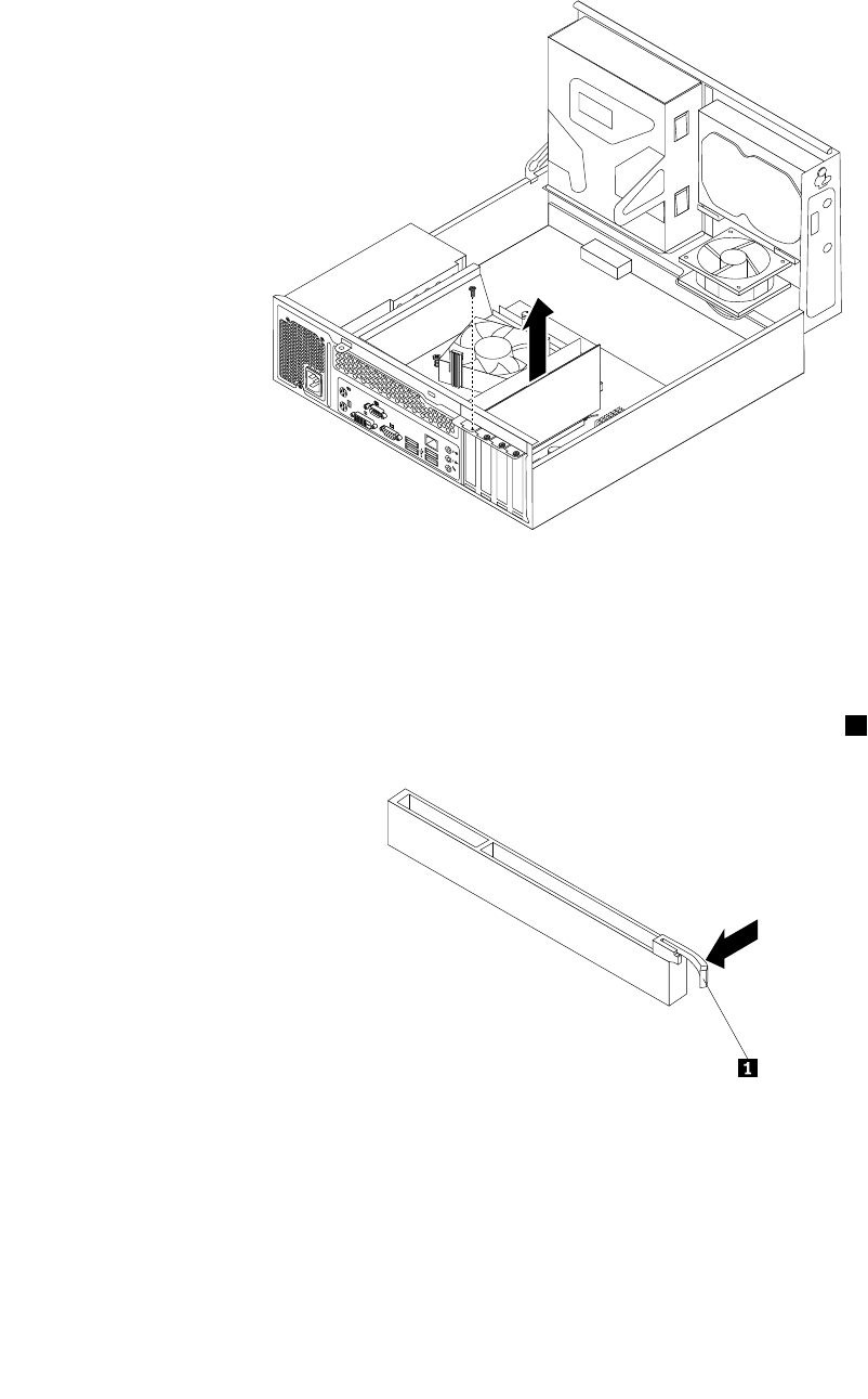
•IfyouarereplacinganoldPCIcard,removethescrewthatsecurestheoldPCIcardandreleasethe
oldPCIcardfromthePCIcardslot.
Figure61.RemovingaPCIcard
Notes:
a.Thecardtstightlyintothecardslot.Ifnecessary,alternatemovingeachsideofthecardasmall
amountuntilitisremovedfromthecardslot.
b.Ifthecardisheldinplacebyaretaininglatch,pressthecardretaininglatch1asshownto
disengagethelatch.Graspthecardandgentlypullitoutoftheslot.
•IfyouareinstallingaPCIcard,removethescrewthatsecurestheappropriatemetalslotcover.
Then,removethemetalslotcover.
4.RemovethenewPCIcardfromitsstatic-protectivepackage.
Chapter10.ReplacingFRUs(machinetypes:0900,0967,1271,3578,3594,3596,3598,3629,
3654,3660,3664,3668,and3676)123
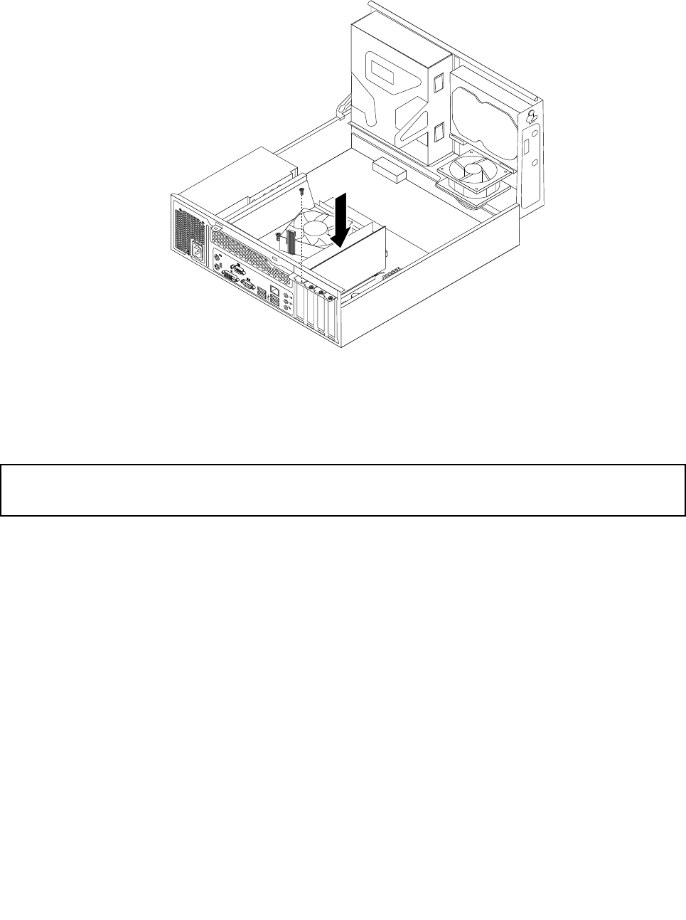
5.Installthenewcardintotheappropriatecardslotonthesystemboard.Then,installthescrewtosecure
thenewPCIcardinplace.See“Locatingpartsonthesystemboard”onpage71.
Figure62.InstallingthePCIcard
6.Tocompletetheinstallationorreplacement,goto“Completingthepartsreplacement”onpage154.
Replacingthebattery
Attention:
Donotopenyourcomputerorattemptanyrepairbeforereadingandunderstandingthe“Importantsafetyinformation”
onpage1.
Yourcomputerhasaspecialtypeofmemorythatmaintainsthedate,time,andsettingsforbuilt-infeatures,
suchasparallel-portassignments(conguration).Abatterykeepsthisinformationactivewhenyouturn
offthecomputer.
Thebatterynormallyrequiresnochargingormaintenancethroughoutitslife;however,nobatterylasts
forever.Ifthebatteryfails,thedate,time,andcongurationinformation(includingpasswords)arelost.An
errormessageisdisplayedwhenyouturnonthecomputer.
Refertothe“Lithiumcoincellbatterynotice”intheSafetyandWarrantyGuideforinformationabout
replacinganddisposingofthebattery.
Toreplacethebattery,dothefollowing:
1.Removeallmediafromthedrivesandturnoffallattacheddevicesandthecomputer.Then,disconnect
allpowercordsfromelectricaloutletsanddisconnectallcablesthatareconnectedtothecomputer.
2.Removethecomputercover.See“Removingthecomputercover”onpage118.
3.Locatethebattery.See“Locatingpartsonthesystemboard”onpage78.
4.Removeanypartsanddisconnectanycablesthatmightpreventyouraccesstothebattery.
5.Removetheoldbattery.
124ThinkCentreHardwareMaintenanceManual
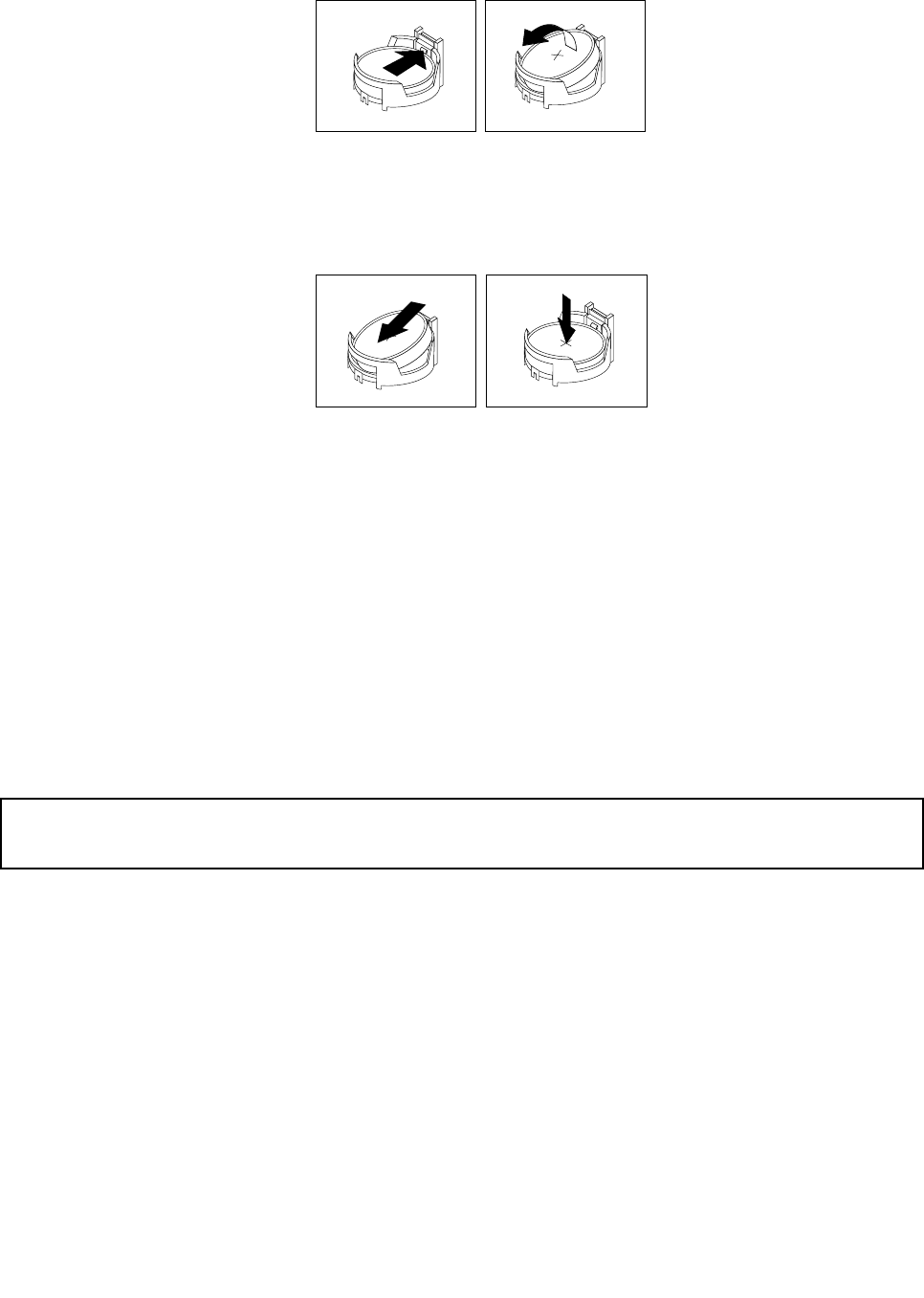
Figure63.Removingtheoldbattery
6.Installthenewbattery.
Figure64.Installingthenewbattery
7.Reinstallanypartsandreconnectanycablesthathavebeenremovedordisconnected.
8.Closethecomputercoverandreconnectallexternalcables.See“Completingthepartsreplacement”
onpage154.
9.Turnonthecomputerandallattacheddevices.
Note:Whenthecomputeristurnedonforthersttimeafterreplacingthebattery,anerrormessage
mightbedisplayed.Thisisnormalafterreplacingthebattery.
10.UsetheSetupUtilityprogramtosetthedate,time,passwords,andanyothercongurationinformation.
SeeChapter6“UsingtheSetupUtilityprogram”onpage55.
11.Tocompletetheinstallationorreplacement,goto“Completingthepartsreplacement”onpage154.
Replacingtheharddiskdrive
Attention:
Donotopenyourcomputerorattemptanyrepairbeforereadingandunderstandingthe“Importantsafetyinformation”
onpage1.
Thissectionprovidesinstructionsonhowtoreplacetheharddiskdrive.
Toreplacetheharddiskdrive,dothefollowing:
1.Turnoffthecomputeranddisconnectallpowercordsfromelectricaloutlets.
2.Removethecomputercover.See“Removingthecomputercover”onpage118.
3.Removethefrontbezel.See“Removingandreinstallingthefrontbezel”onpage118.
Chapter10.ReplacingFRUs(machinetypes:0900,0967,1271,3578,3594,3596,3598,3629,
3654,3660,3664,3668,and3676)125
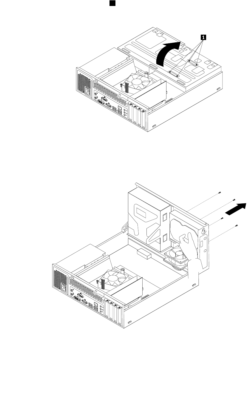
4.Notethelocationofthefourscrews1thatsecuretheharddiskdrive.Then,pivotthedrivebay
assemblyupward.
Figure65.Pivotingthedrivebayassembly
5.Holdtheharddiskdriveandremovethefourscrewsthatsecuretheharddiskdrive.Then,remove
theharddiskdrivefromthedrivebayassembly.
Figure66.Removingtheharddiskdrive
6.Disconnectthesignalcableandthepowercablefromtheharddiskdrivetocompletelyremovethehard
diskdrivefromthechassis.
126ThinkCentreHardwareMaintenanceManual
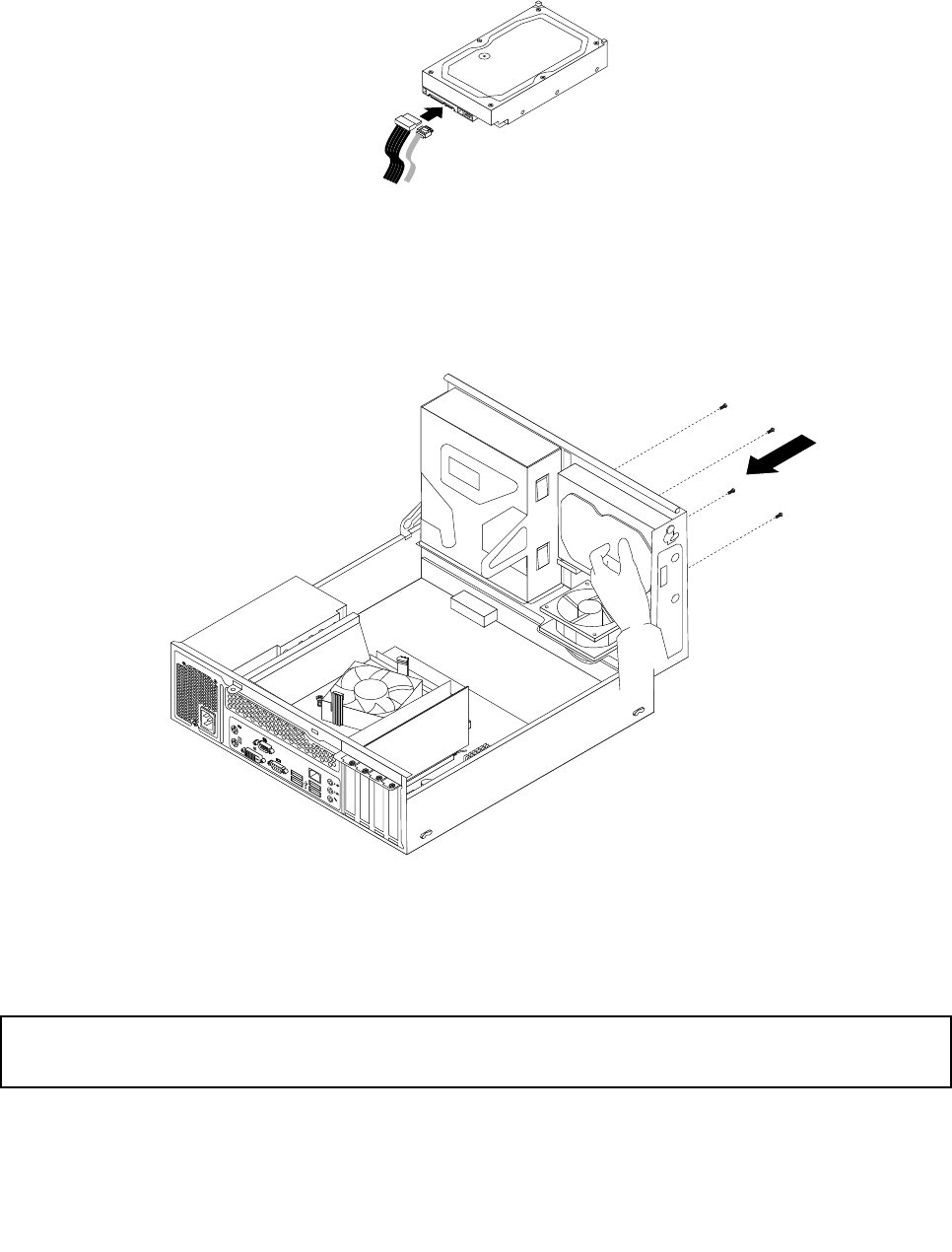
7.Connectoneendofthesignalcabletotherearofthenewharddiskdriveandtheotherendtoan
availableSATAconnectoronthesystemboard.See“Locatingpartsonthesystemboard”onpage71.
Then,locateanavailableve-wirepowerconnectorandconnectittotherearofthenewharddiskdrive.
Figure67.ConnectingaSATAharddiskdrive
8.Positionthenewharddiskdriveintotheharddiskdrivebayandalignthescrewholesinthenewhard
diskdrivewiththecorrespondingholesinthedrivebay.Then,installthefourscrewstosecurethe
newharddiskdriveinplace.
Figure68.Installingtheharddiskdrive
9.Tocompletetheinstallationorreplacement,goto“Completingthepartsreplacement”onpage154.
Installingorreplacingtheopticaldrive
Attention:
Donotopenyourcomputerorattemptanyrepairbeforereadingandunderstandingthe“Importantsafetyinformation”
onpage1.
Thissectionprovidesinstructionsonhowtoreplacetheopticaldrive.
Toreplacetheopticaldrive,dothefollowing:
Chapter10.ReplacingFRUs(machinetypes:0900,0967,1271,3578,3594,3596,3598,3629,
3654,3660,3664,3668,and3676)127
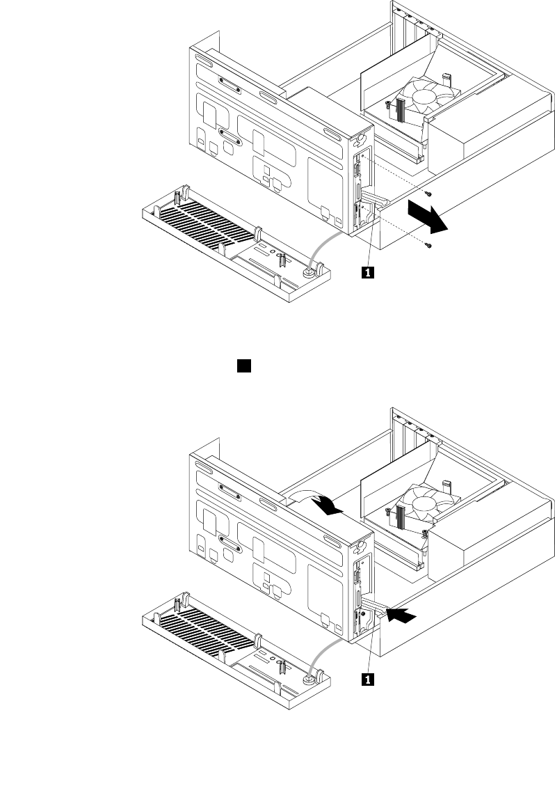
1.Turnoffthecomputeranddisconnectallpowercordsfromelectricaloutlets.
2.Removethecomputercover.See“Removingthecomputercover”onpage118.
3.Removethefrontbezel.See“Removingandreinstallingthefrontbezel”onpage118.
4.Pivotthedrivebayassemblyupward.See“Accessingthesystemboardcomponentsanddrives”on
page119.
5.Disconnectthesignalcableandthepowercablefromtheopticaldrive.
6.Holdtheopticaldriveandremovethetwoscrewsthatsecuretheopticaldrive.
Figure69.Removingtheopticaldrivescrews
7.Pressthedrivebayassemblyclip1inwardandpivotthedrivebayassemblydownwardasshown.
Figure70.Loweringthedrivebayassembly
128ThinkCentreHardwareMaintenanceManual
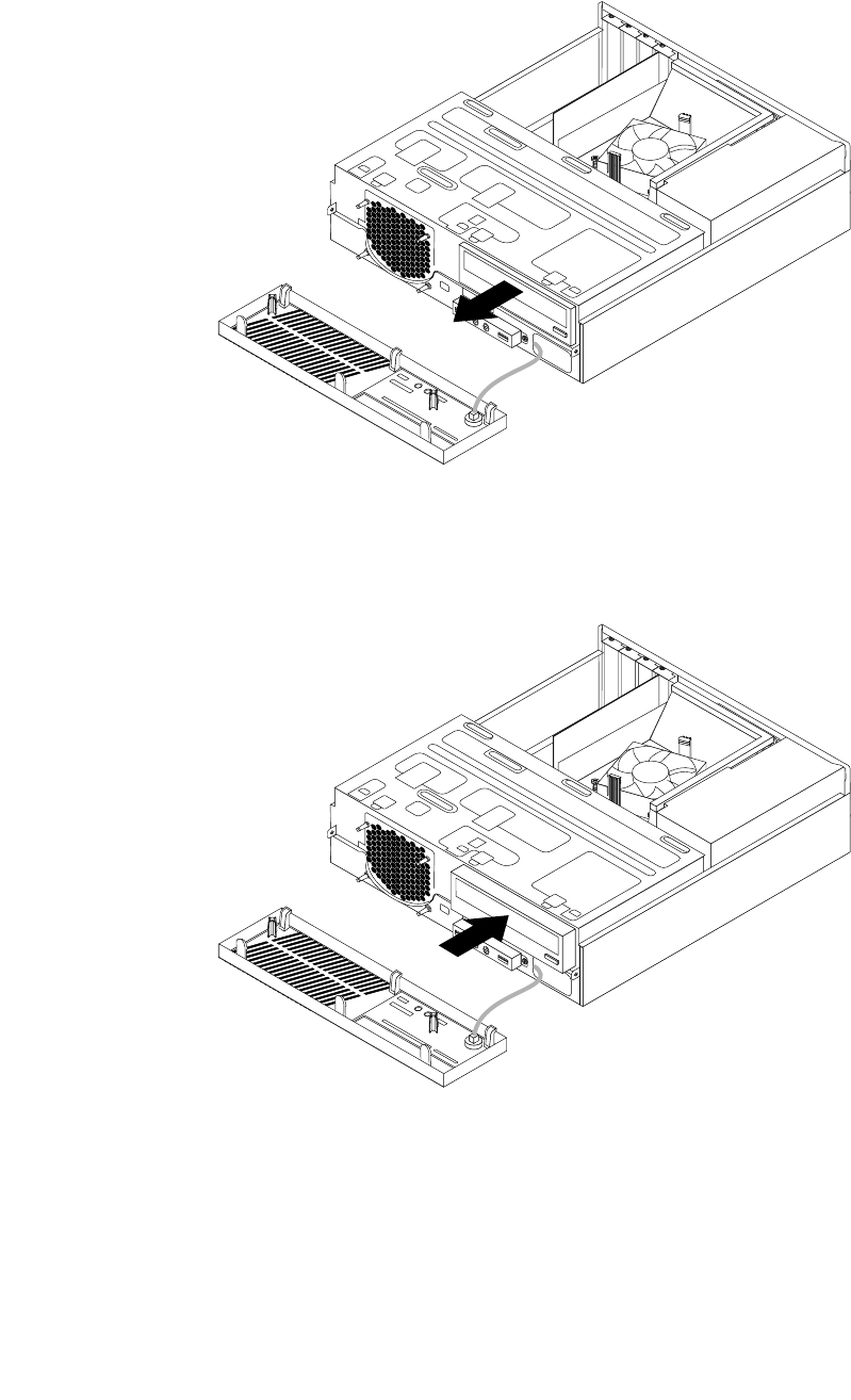
8.Slidetheopticaldriveoutofthefrontofthecomputer.
Figure71.Removingtheopticaldrive
9.Slidethenewopticaldriveintotheopticaldrivebayfromthefrontofthecomputer.
Figure72.Installinganewopticaldrive
Chapter10.ReplacingFRUs(machinetypes:0900,0967,1271,3578,3594,3596,3598,3629,
3654,3660,3664,3668,and3676)129
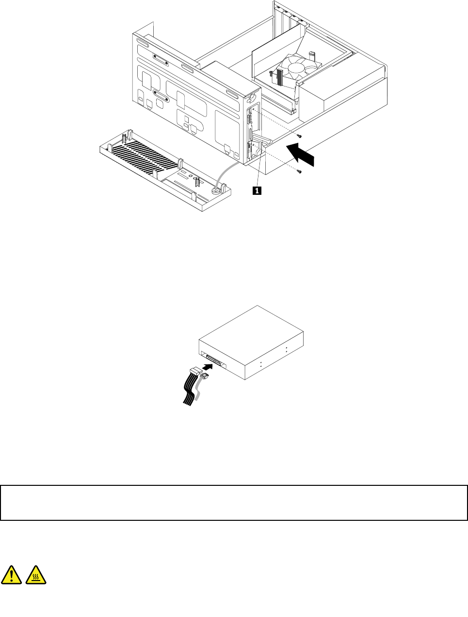
10.Holdthenewopticaldriveandpivotthedrivebayassemblyupward.Alignthescrewholesinthenew
opticaldrivewiththecorrespondingholesinthedrivebay.Then,installthetwoscrewstosecure
thenewopticaldriveinplace.
Figure73.Installingtheopticaldrive
11.Connectoneendofthesignalcabletotherearofthenewopticaldriveandtheotherendtoanavailable
SATAconnectoronthesystemboard.See“Locatingpartsonthesystemboard”onpage71.Then,
locateanavailableve-wirepowerconnectorandconnectittotherearofthenewopticaldrive.
Figure74.ConnectingaSATAopticaldrive
12.Tocompletetheinstallationorreplacement,goto“Completingthepartsreplacement”onpage154.
Replacingtheheatsinkandfanassembly
Attention:
Donotopenyourcomputerorattemptanyrepairbeforereadingandunderstandingthe“Importantsafetyinformation”
onpage1.
Thissectionprovidesinstructionsonhowtoreplacetheheatsinkandfanassembly.
CAUTION:
130ThinkCentreHardwareMaintenanceManual
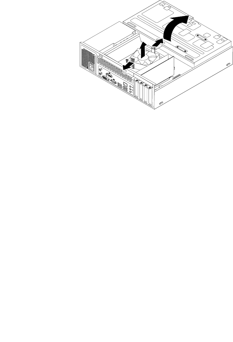
Theheatsinkandfanassemblymightbeveryhot.Turnoffthecomputerandwaitthreetove
minutestoletthecomputercoolbeforeremovingthecomputercover.
Toreplacetheheatsinkandfanassembly,dothefollowing:
1.Removeallmediafromthedrivesandturnoffallattacheddevicesandthecomputer.Then,disconnect
allpowercordsfromelectricaloutletsanddisconnectallcablesthatareconnectedtothecomputer.
2.Removethecomputercover.See“Removingthecomputercover”onpage118.
3.Pivotthedrivebayassemblyupward.Then,pivotthetwoplasticretainingclipsoutwardtoremove
theheatsinkfanductfromthefailingheatsinkandfanassembly.
Figure75.Removingtheheatsinkfanduct
4.Disconnecttheheatsinkandfanassemblycablefromthemicroprocessorfanconnectoronthesystem
board.See“Locatingpartsonthesystemboard”onpage71.
Chapter10.ReplacingFRUs(machinetypes:0900,0967,1271,3578,3594,3596,3598,3629,
3654,3660,3664,3668,and3676)131
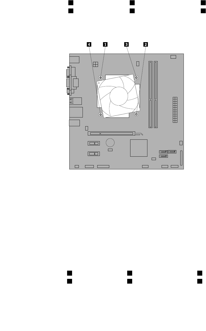
5.Followthissequencetoremovethefourscrewsthatsecuretheheatsinkandfanassemblytothe
systemboard:
a.Partiallyremovescrew1,thenfullyremovescrew2,andthenfullyremovescrew1.
b.Partiallyremovescrew3,thenfullyremovescrew4,andthenfullyremovescrew3.
Note:Carefullyremovethefourscrewsfromthesystemboardtoavoidanypossibledamagetothe
systemboard.Thefourscrewscannotberemovedfromtheheatsinkandfanassembly.
Figure76.Removingtheheatsinkandfanassembly
6.Lifttheheatsinkandfanassemblyoffthesystemboard.
Notes:
a.Youmighthavetogentlytwisttheheatsinkandfanassemblytofreeitfromthemicroprocessor.
b.Whenhandlingtheheatsinkandfanassembly,donottouchthethermalgreaseonthebottom
oftheheatsinkandfanassembly.
7.Placethenewheatsinkandfanassemblyonthesystemboardsothatthefourscrewsarealigned
withthecorrespondingholesinthesystemboard.Makesurethatyouproperlyplacethenewheat
sinkandfanassemblysothatyoucaneasilyconnectthenewheatsinkandfanassemblycabletothe
microprocessorfanconnectoronthesystemboard.
8.Followthissequencetoinstallthefourscrewstosecurethenewheatsinkandfanassembly,asshown
inFigure76“Removingtheheatsinkandfanassembly”onpage132:
a.Partiallytightenscrew1,thenfullytightenscrew2,andthenfullytightenscrew1.
b.Partiallytightenscrew3,thenfullytightenscrew4,andthenfullytightenscrew3.
9.Connectthenewheatsinkandfanassemblycabletothemicroprocessorfanconnectoronthesystem
board.See“Locatingpartsonthesystemboard”onpage71.
132ThinkCentreHardwareMaintenanceManual
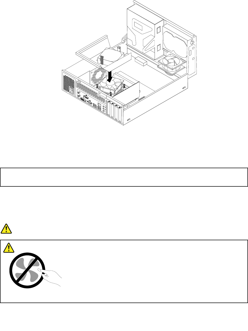
10.Lowerandpositiontheheatsinkfanductonthetopoftheheatsinkandfanassemblyuntilitsnaps
intoposition.
Figure77.Installingtheheatsinkfanduct
11.Tocompletetheinstallationorreplacement,goto“Completingthepartsreplacement”onpage154.
Replacingthepowersupplyassembly
Attention:
Donotopenyourcomputerorattemptanyrepairbeforereadingandunderstandingthe“Importantsafetyinformation”
onpage1.
Thissectionprovidesinstructionsonhowtoreplacethepowersupplyassembly.
Althoughtherearenomovingpartsinyourcomputerafterthepowercordhasbeendisconnected,the
followingwarningsarerequiredforyoursafetyandproperUnderwritersLaboratories(UL)certication.
DANGER
Hazardousmovingparts.Keepngersandotherbodypartsaway.
Chapter10.ReplacingFRUs(machinetypes:0900,0967,1271,3578,3594,3596,3598,3629,
3654,3660,3664,3668,and3676)133
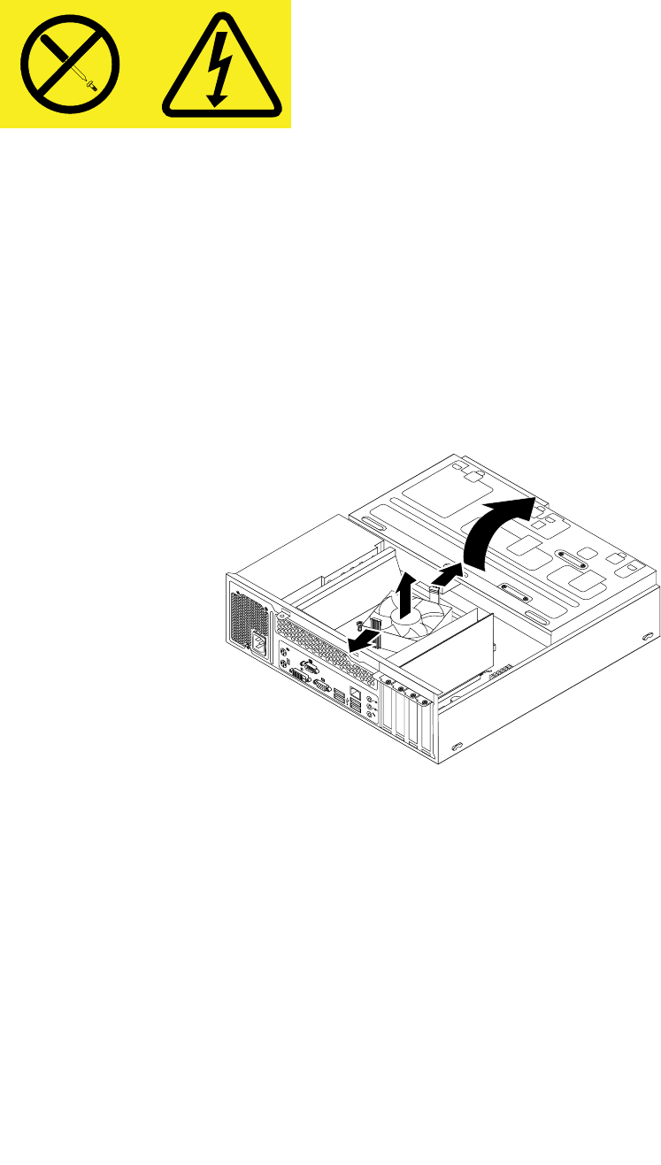
CAUTION:
Neverremovethecoveronapowersupplyoranypartthathasthefollowinglabelattached.
Hazardousvoltage,current,andenergylevelsarepresentinsideanycomponentthathasthislabel
attached.Therearenoserviceablepartsinsidethesecomponents.Ifyoususpectaproblemwith
oneoftheseparts,contactaservicetechnician.
Toreplacethepowersupplyassembly,dothefollowing:
1.Removeallmediafromthedrivesandturnoffallattacheddevicesandthecomputer.Then,disconnect
allpowercordsfromelectricaloutletsanddisconnectallcablesthatareconnectedtothecomputer.
2.Removethecomputercover.See“Removingthecomputercover”onpage118.
3.Removethefrontbezel.See“Removingandreinstallingthefrontbezel”onpage118.
4.Pivotthedrivebayassemblyupward.Then,pivotthetwoplasticretainingclipsoutwardtoremove
theheatsinkfanductfromthefailingheatsinkandfanassembly.
Figure78.Removingtheheatsinkfanduct
5.Disconnectthepowersupplyassemblycablesfromalldrivesandfromthe24-pinpowerconnectorand
4-pinpowerconnectoronthesystemboard.See“Locatingpartsonthesystemboard”onpage71.
Note:Youmightalsoneedtoreleasethepowersupplyassemblycablesfromsomecableclipsorties
thatsecurethecablestothechassis.Makesurethatyounotethecableroutingbeforedisconnecting
thecables.
134ThinkCentreHardwareMaintenanceManual
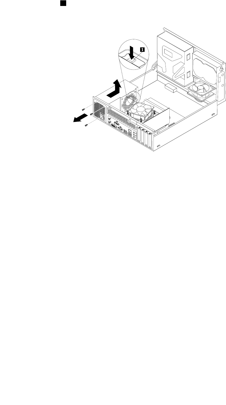
6.Attherearofthecomputer,removethethreescrewsthatsecurethepowersupplyassembly.Pressthe
powersupplyclip1downwardtoreleasethepowersupplyassemblyandthenslidethepowersupply
assemblytothefrontofthecomputer.Liftthepowersupplyassemblyoutofthecomputer.
Figure79.Removingthepowersupplyassembly
7.Makesurethatthenewpowersupplyassemblyisthecorrectreplacement.
Chapter10.ReplacingFRUs(machinetypes:0900,0967,1271,3578,3594,3596,3598,3629,
3654,3660,3664,3668,and3676)135
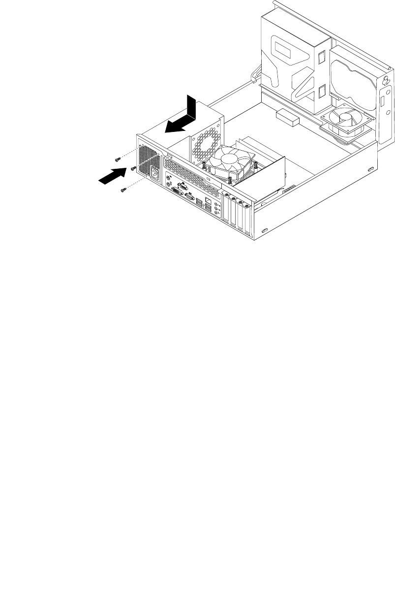
8.Installthenewpowersupplyassemblyintothechassissothatthescrewholesinthenewpowersupply
assemblyarealignedwiththecorrespondingholesintherearofthechassis.Then,installthethree
screwstosecurethenewpowersupplyassemblyinplace.
Note:UseonlyscrewsprovidedbyLenovo.
Figure80.Installingthepowersupplyassembly
9.Connectthenewpowersupplyassemblycablestoalldrivesandthesystemboard.See“Locating
partsonthesystemboard”onpage71.
136ThinkCentreHardwareMaintenanceManual
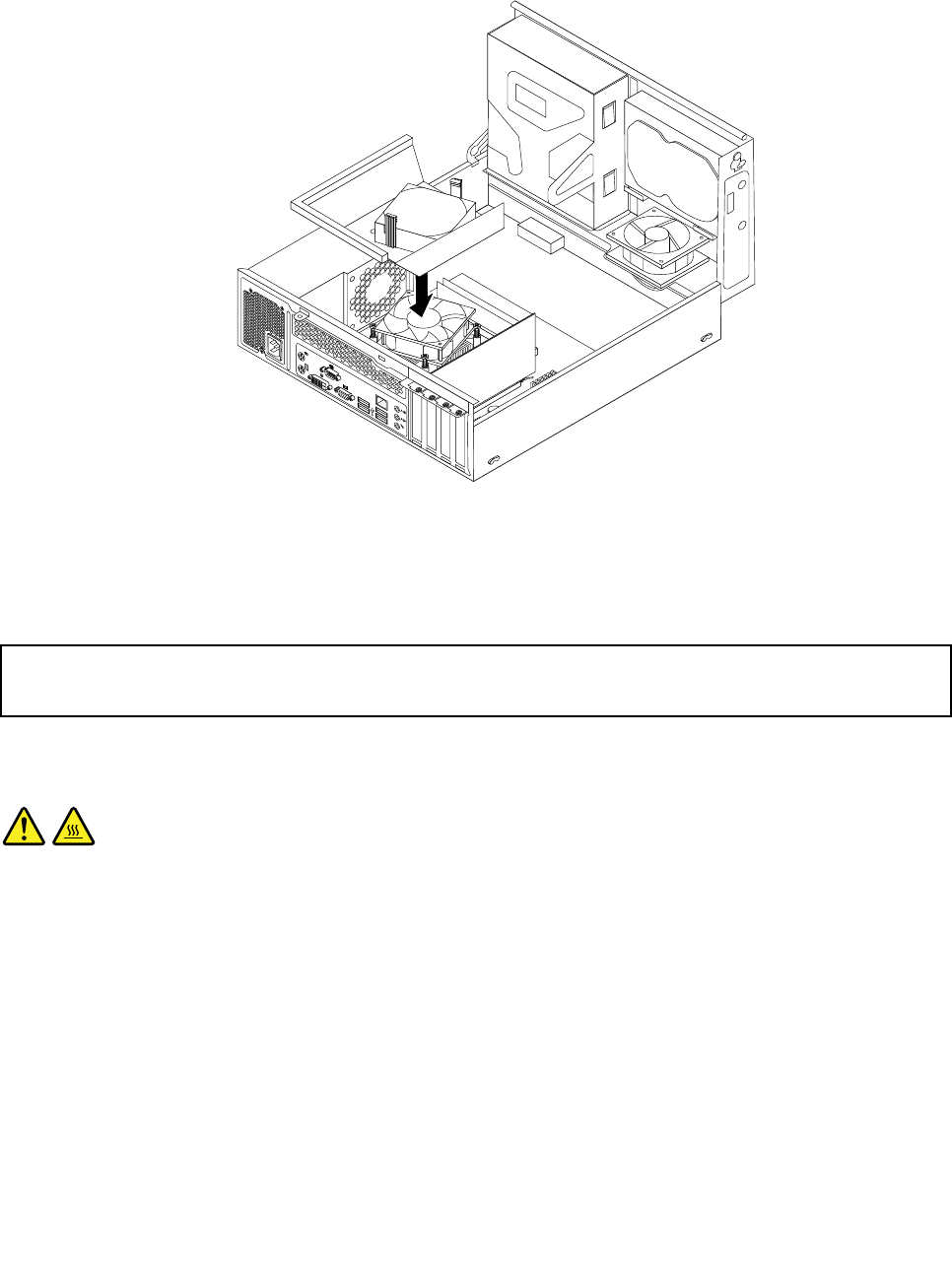
10.Lowerandpositiontheheatsinkfanductonthetopoftheheatsinkandfanassemblyuntilitsnaps
intoposition.
Figure81.Installingtheheatsinkfanduct
11.Tocompletetheinstallationorreplacement,goto“Completingthepartsreplacement”onpage154.
Replacingthemicroprocessor
Attention:
Donotopenyourcomputerorattemptanyrepairbeforereadingandunderstandingthe“Importantsafetyinformation”
onpage1.
Thissectionprovidesinstructionsonhowtoreplacethemicroprocessor.
CAUTION:
Theheatsinkandmicroprocessormightbeveryhot.Turnoffthecomputerandwaitthreetove
minutestoletthecomputercoolbeforeremovingthecomputercover.
Toreplacethemicroprocessor,dothefollowing:
1.Removeallmediafromthedrivesandturnoffallattacheddevicesandthecomputer.Then,disconnect
allpowercordsfromelectricaloutletsanddisconnectallcablesthatareconnectedtothecomputer.
2.Removethecomputercover.See“Removingthecomputercover”onpage118.
3.Locatethesystemboardanddisconnectallcablesconnectedtothesystemboard.See“Locating
partsonthesystemboard”onpage71.
4.Removetheheatsinkandfanassemblywiththefanduct.See“Replacingtheheatsinkandfan
assembly”onpage130.
Note:Donotletthethermalgreaseonthebottomoftheheatsinkandfanassemblygetincontact
withanything.
Chapter10.ReplacingFRUs(machinetypes:0900,0967,1271,3578,3594,3596,3598,3629,
3654,3660,3664,3668,and3676)137
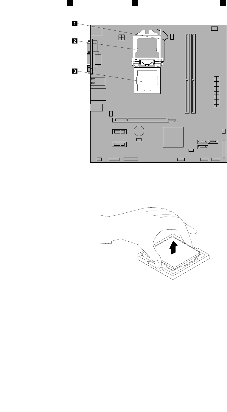
5.Liftthesmallhandle1andopentheretainer2toaccessthemicroprocessor3.
Figure82.Accessingthemicroprocessor
6.Liftthemicroprocessorstraightupandoutofthemicroprocessorsocket.
Figure83.Removingthemicroprocessor
Notes:
a.Yourmicroprocessorandsocketmightlookdifferentfromtheoneillustrated.
138ThinkCentreHardwareMaintenanceManual
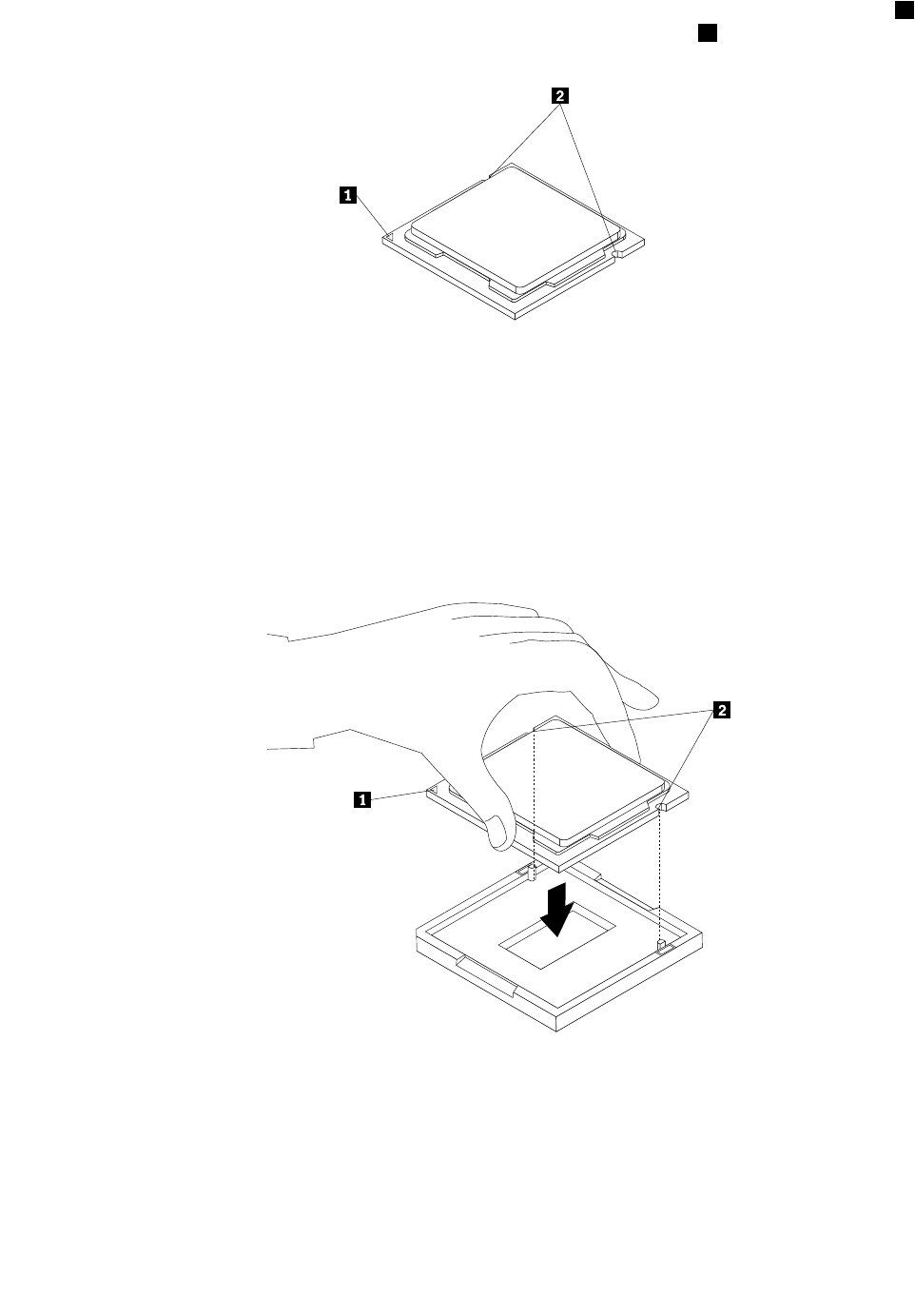
b.Notetheorientationofthemicroprocessorinthesocket.Youcaneitherlookforthesmalltriangle1
ononecornerofthemicroprocessorornotetheorientationofthenotches2onthemicroprocessor.
Thisisimportantwheninstallingthenewmicroprocessoronthesystemboard.
c.Touchonlytheedgesofthemicroprocessor.Donottouchthegoldcontactsonthebottom.
d.Donotdropanythingontothemicroprocessorsocketwhileitisexposed.Thesocketpinsmustbe
keptascleanaspossible.
7.Makesurethatthesmallhandleisintheraisedpositionandthemicroprocessorretainerisfullyopen.
8.Removetheprotectivecoverthatprotectsthegoldcontactsofthenewmicroprocessor.
9.Holdthenewmicroprocessorbyitssidesandalignthesmalltriangleononecornerofthenew
microprocessorwiththecorrespondingsmalltriangleononecornerofthemicroprocessorsocket.
10.Lowerthenewmicroprocessorstraightdownintothemicroprocessorsocketonthesystemboard.
Figure84.Installingthemicroprocessor
11.Closethemicroprocessorretainerandlockitintopositionwiththesmallhandletosecurethenew
microprocessorinthesocket.
12.Reinstalltheheatsinkandfanassemblyandthefanduct.See“Replacingtheheatsinkandfan
assembly”onpage130.
13.Reconnectallcablesthatweredisconnectedfromthesystemboard.
Chapter10.ReplacingFRUs(machinetypes:0900,0967,1271,3578,3594,3596,3598,3629,
3654,3660,3664,3668,and3676)139

14.Tocompletetheinstallationorreplacement,goto“Completingthepartsreplacement”onpage154.
Replacingthesystemboard
Attention:
Donotopenyourcomputerorattemptanyrepairbeforereadingandunderstandingthe“Importantsafetyinformation”
onpage1.
Thissectionprovidesinstructionsonhowtoreplacethesystemboard.
CAUTION:
Theheatsinkandmicroprocessormightbeveryhot.Turnoffthecomputerandwaitthreetove
minutestoletthecomputercoolbeforeopeningthecomputercover.
Toreplacethesystemboard,dothefollowing:
1.Removeallmediafromthedrivesandturnoffallattacheddevicesandthecomputer.Then,disconnect
allpowercordsfromelectricaloutletsanddisconnectallcablesthatareconnectedtothecomputer.
2.Removethecomputercover.See“Removingthecomputercover”onpage118.
3.Removethefrontbezel.See“Removingandreinstallingthefrontbezel”onpage118.
4.Pivottheopticaldrivebayassemblyupwardtogainaccesstothesystemboard.See“Accessingthe
systemboardcomponentsanddrives”onpage119.
5.RemoveallmemorymodulesandPCIcardsthatarecurrentlyinstalled.See“Installingorreplacinga
memorymodule”onpage121and“InstallingorreplacingaPCIcard”onpage122.
6.Removetheheatsinkandfanassemblyfromthefailingsystemboard.See“Replacingtheheatsinkand
fanassembly”onpage130.
7.Carefullytakenoteofthelocationofallcableconnectionsonthesystemboardanddisconnectallthe
cables.See“Locatingpartsonthesystemboard”onpage78.
140ThinkCentreHardwareMaintenanceManual
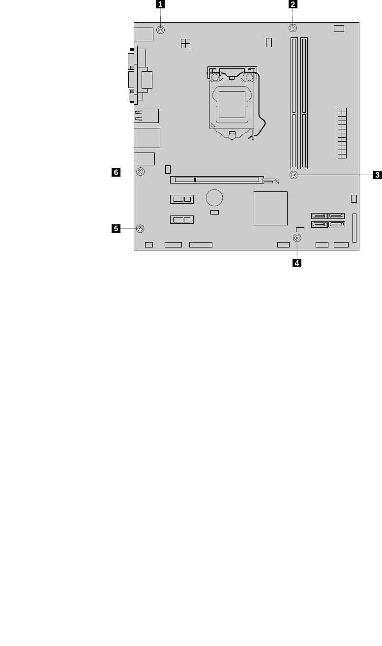
8.Removethesixscrewsthatsecurethesystemboard.
Figure85.Removingthesixscrewsthatsecurethesystemboard
9.Liftthesystemboardoutofthechassis.
10.Removethemicroprocessorfromthefailingsystemboardandinstallitonthenewsystemboard.See
“Replacingthemicroprocessor”onpage137.
11.Installthenewsystemboardintothechassisbyaligningthesixmountingstudsinthechassiswiththe
correspondingholesinthenewsystemboard.Then,installthesixscrewstosecurethesystemboard.
12.Installtheheatsinkandfanassemblyandconnecttheheatsinkandfanassemblycabletothenew
systemboard.See“Replacingtheheatsinkandfanassembly”onpage130.
13.InstallallmemorymodulesandPCIcardsremovedfromthefailingsystemboardonthenewsystem
board.See“Installingorreplacingamemorymodule”onpage121and“InstallingorreplacingaPCI
card”onpage122.
14.Reconnectallremainingcablestothesystemboard.See“Locatingpartsonthesystemboard”
onpage78.
15.Lowertheopticaldrivebayassembly.See“Accessingthesystemboardcomponentsanddrives”on
page119.
16.Tocompletethereplacement,goto“Completingthepartsreplacement”onpage115.
Thefailingsystemboardmustbereturnedwithamicroprocessorsocketcovertoprotectthepinsduring
shippingandhandling.
Toinstallthemicroprocessorsocketcover,dothefollowing:
1.Releasetheleversecuringthemicroprocessorretainerandopentheretainertoaccessthe
microprocessor.
Chapter10.ReplacingFRUs(machinetypes:0900,0967,1271,3578,3594,3596,3598,3629,
3654,3660,3664,3668,and3676)141
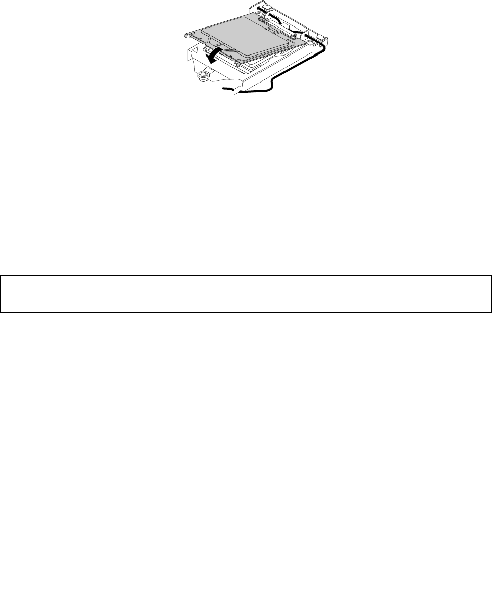
2.Graspthemicroprocessoronthesidesandliftitstraightupandoutofthesocket.Donottouchthe
contactsonthemicroprocessorsocket.
3.Lowerthemicroprocessorretainer,andthenlowerthelevertosecuretheretainer.Ensurethatthe
leverislockedintoposition.
4.Notetheorientationofthesocketcover,andinstallonesideofthesocketcoverintothemicroprocessor
socket.
Figure86.Installingonesideofthesocketcoverintothemicroprocessorsocket
Note:Yourmicroprocessorsocketandcovermightlookslightlydifferentfromtheillustration.
5.Carefullypresstheothersideofthesocketcoverdownwarduntilthesocketcoversnapsintoposition.
6.Carefullycheckthefourcornersofthesocketcovertomakesurethatthecoverissecuredinthe
microprocessorsocket.
7.Followanyadditionalinstructionsincludedwiththereplacementpartyoureceived.
Note:Ifyoursystemboardhastwomicroprocessorsockets,besuretoinstallasocketcoverforeach
microprocessorsocket.
ReplacingthefrontaudioandUSBassembly
Attention:
Donotopenyourcomputerorattemptanyrepairbeforereadingandunderstandingthe“Importantsafetyinformation”
onpage1.
ThissectionprovidesinstructionsonhowtoreplacethefrontaudioandUSBassembly.
ToreplacethefrontaudioandUSBassembly,dothefollowing:
1.Removeallmediafromthedrivesandturnoffallattacheddevicesandthecomputer.Then,disconnect
allpowercordsfromelectricaloutletsanddisconnectallcablesthatareconnectedtothecomputer.
2.Removethecomputercover.See“Removingthecomputercover”onpage118.
3.Removethefrontbezel.See“Removingandreinstallingthefrontbezel”onpage118.
4.PivottheopticaldrivebayupwardanddisconnectthefrontaudioandUSBassemblycablesfromthe
systemboardandnotethecablesrouting.See“Locatingpartsonthesystemboard”onpage71.
142ThinkCentreHardwareMaintenanceManual
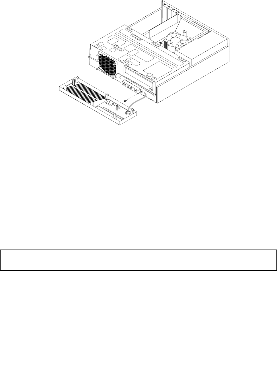
5.RemovethescrewthatsecuresthefrontaudioandUSBassemblybracket.Thenremovethefront
audioandUSBassemblybracketfromthechassis.
Figure87.RemovingthefrontaudioandUSBassembly
6.RemovethetwoscrewsthatsecurethefrontaudioandUSBassemblytoitsbracket.Thenremovethe
failingfrontaudioandUSBassemblyfromthebracket.
7.InstallanewfrontaudioandUSBassemblyintothebracketandinstallthetwoscrewstosecurethe
frontaudioandUSBassemblytothebracket.
8.InstallthefrontaudioandUSBassemblybrackettothechassisandalignthescrewholeinthebracket
withthecorrespondingholeinthechassis.
9.InstallthescrewtosecurethefrontaudioandUSBassemblybrackettothechassis.
10.ReconnectthefrontUSBandfrontaudiocablestothesystemboard.See“Locatingpartsonthe
systemboard”onpage71.
11.Reinstallthefrontbezel.See“Removingandreinstallingthefrontbezel”onpage118.
12.Tocompletetheinstallationorreplacement,goto“Completingthepartsreplacement”onpage154.
Replacingthesystemfanassembly
Attention:
Donotopenyourcomputerorattemptanyrepairbeforereadingandunderstandingthe“Importantsafetyinformation”
onpage1.
Thissectionprovidesinstructionsonhowtoreplacethesystemfanassembly.
Toreplacethesystemfanassembly,dothefollowing:
1.Turnoffthecomputeranddisconnectallpowercordsfromelectricaloutlets.
2.Removethecomputercover.See“Removingthecomputercover”onpage118.
3.Removethefrontbezel.See“Removingandreinstallingthefrontbezel”onpage118.
4.Pivotthedrivebayassemblyupwardtogainaccesstothesystemfanassembly.See“Accessingthe
systemboardcomponentsanddrives”onpage119.
Chapter10.ReplacingFRUs(machinetypes:0900,0967,1271,3578,3594,3596,3598,3629,
3654,3660,3664,3668,and3676)143
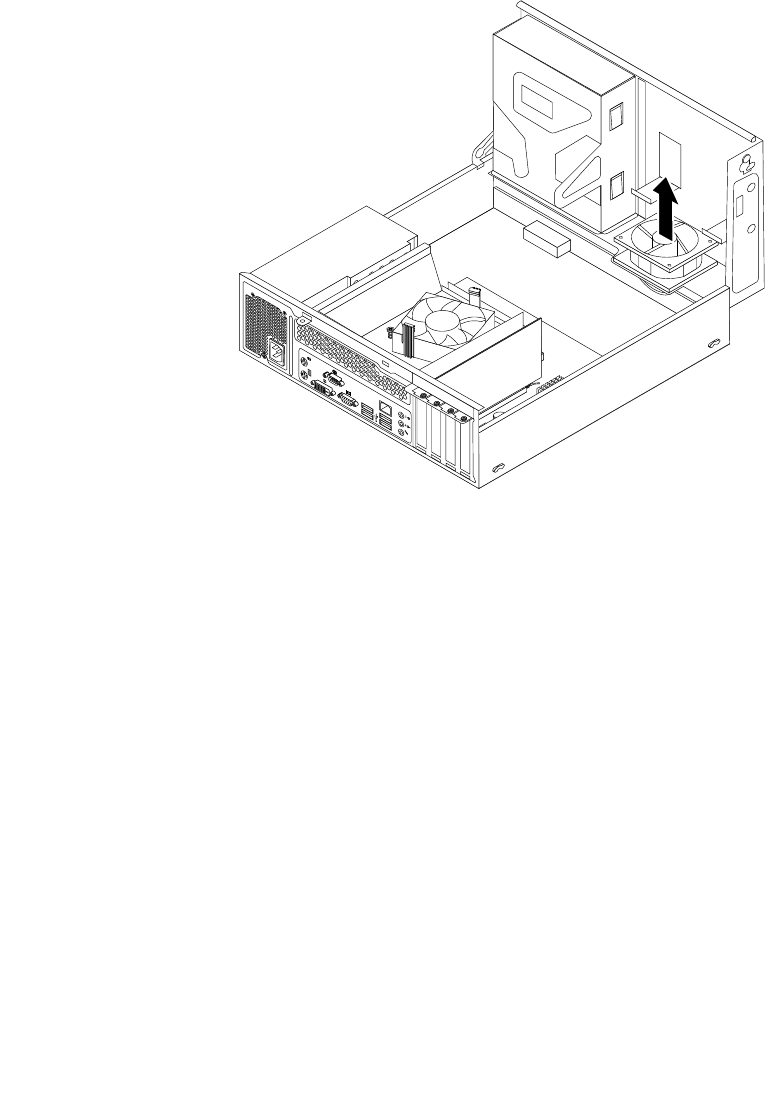
5.Removetheharddiskdriveforeasieraccesstothesystemfanassembly.See“Replacingthehard
diskdrive”onpage125.
6.Removetheheatsinkfanduct.See“Replacingtheheatsinkandfanassembly”onpage130.
7.Disconnectthesystemfanassemblycablefromthesystemfanconnectoronthesystemboard.See
“Locatingpartsonthesystemboard”onpage71.
8.Thesystemfanassemblyisattachedtothechassisbyfourrubbermounts.Removethesystemfan
assemblybycuttingtherubbermountsandliftingthesystemfanassemblyoutofthechassis.
Note:Thenewsystemfanassemblywillhavefournewrubbermountsattached.
Figure88.Removingthesystemfanassembly
144ThinkCentreHardwareMaintenanceManual
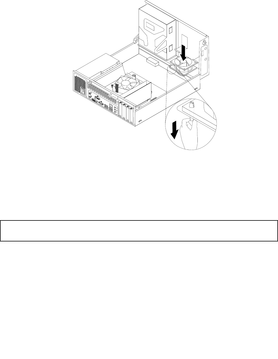
9.Installthenewsystemfanassemblybyaligningthenewrubbermountsthatcamewiththenewsystem
fanassemblywiththecorrespondingholesinthechassis,andthenpushtherubbermountsthroughthe
holes.Then,carefullypullonthetipsoftherubbermountsfromthebottomuntilthenewsystemfan
assemblyissecuredinplace.
Figure89.Installingthesystemfanassembly
10.Connectthenewsystemfanassemblycabletothesystemfanconnectoronthesystemboard.See
“Locatingpartsonthesystemboard”onpage71.
11.Reinstalltheharddiskdrive.See“Replacingtheharddiskdrive”onpage125.
12.Tocompletetheinstallationorreplacement,goto“Completingthepartsreplacement”onpage154.
ReplacingtheWiFiunits
Attention:
Donotopenyourcomputerorattemptanyrepairbeforereadingandunderstandingthe“Importantsafetyinformation”
onpage1.
ThissectionprovidesinstructionsonhowtoreplacetheWiFiunits.TheWiFiunitsincludeaWiFiadapter
card,aWiFicardmodule,andarearWiFiantennacable.
ReplacingtheWiFiunitsinvolvesthefollowingoperations:
•“RemovingtheWiFiadaptercard”onpage145
•“RemovingtheWiFicardmodule”onpage146
•“InstallingtheWiFiunits”onpage148
RemovingtheWiFiadaptercard
ToremovetheWiFiadaptercard,dothefollowing:
1.Turnoffthecomputeranddisconnectallpowercordsfromelectricaloutlets.
Chapter10.ReplacingFRUs(machinetypes:0900,0967,1271,3578,3594,3596,3598,3629,
3654,3660,3664,3668,and3676)145
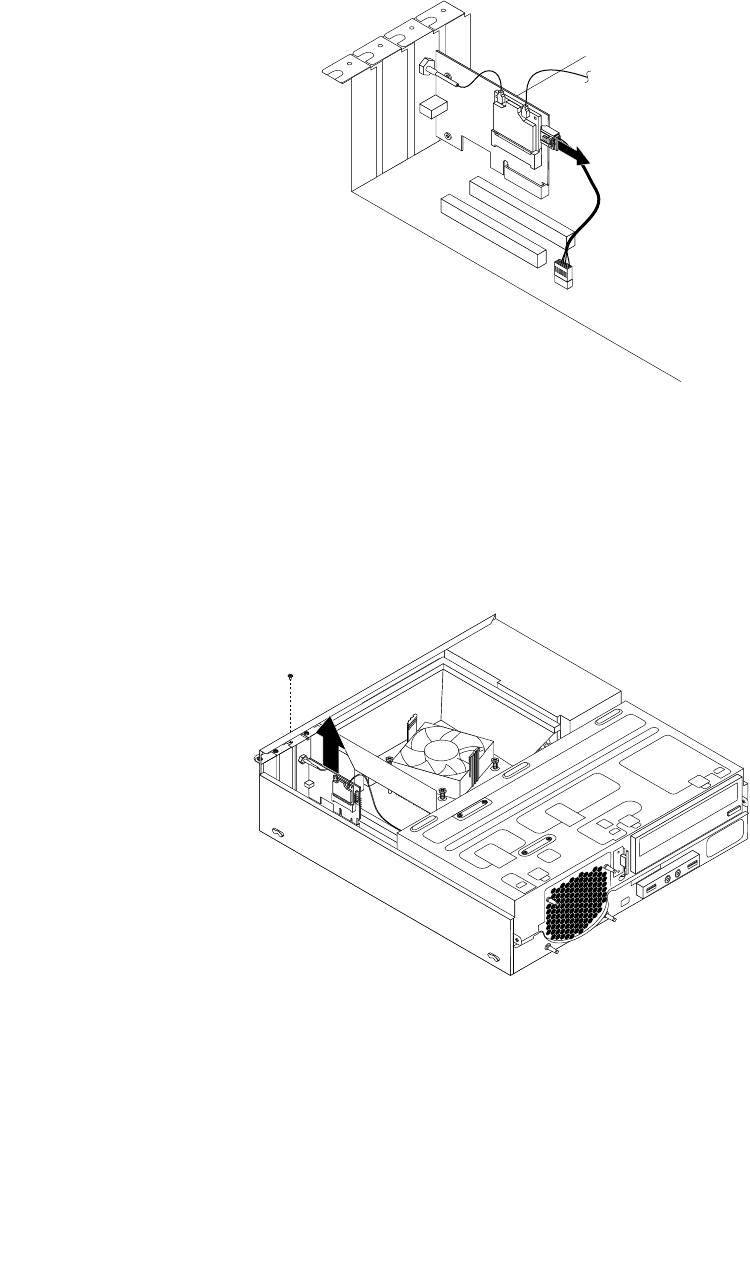
2.Removethecomputercover.See“Removingthecomputercover”onpage118.
3.IfyourcomputercomeswithaWiFicardmodulethatsupportstheBluetoothfunction,disconnect
theBluetoothcablefromtheWiFiadaptercard.
Figure90.DisconnectingtheBluetoothcable
Note:TheBluetoothcableconnectstheBluetoothconnectorontheWiFiadaptercardtothefrontUSB
connectoronthesystemboardtosupporttheBluetoothfunction.
4.RemovethescrewthatsecurestheWiFiadaptercard.
5.GrasptheWiFiadaptercardthatiscurrentlyinstalledandgentlypullitoutoftheslot.
Figure91.RemovingtheWiFiadaptercard
Note:Thecardtstightlyintothecardslot.Ifnecessary,alternatemovingeachsideofthecarda
smallamountuntilitisremovedfromthecardslot.
RemovingtheWiFicardmodule
ToremovetheWiFicardmodule,dothefollowing:
146ThinkCentreHardwareMaintenanceManual
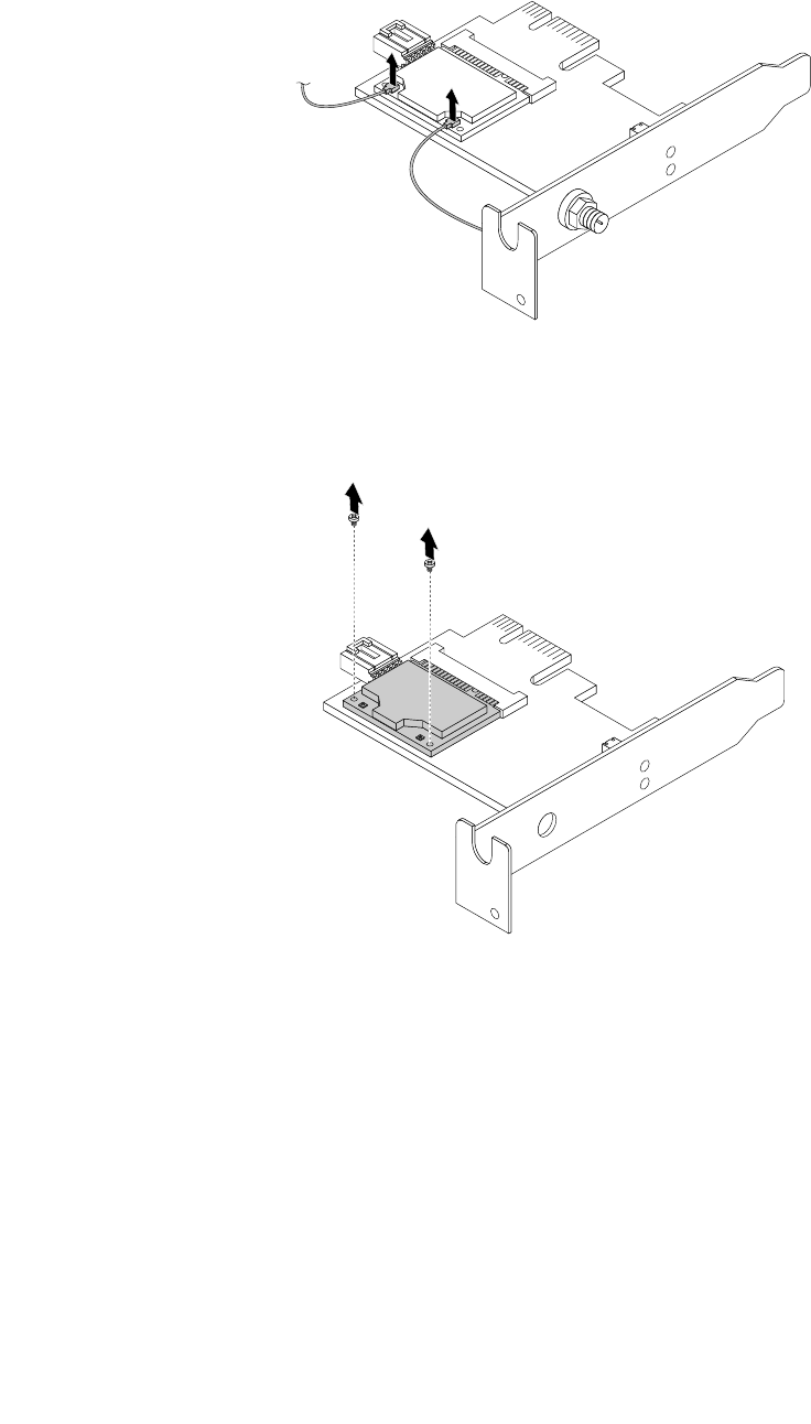
1.RemovetheWiFiadaptercardfromthecomputer,andthendisconnectthefrontandrearWiFiantenna
cablesfromtheWiFicardmodule.
Figure92.RemovingtheWiFiantennacables
2.RemovethetwoscrewsthatsecuretheWiFicardmoduletotheWiFiadaptercard.
Figure93.RemovingthescrewsthatsecuretheWiFicardmodule
Chapter10.ReplacingFRUs(machinetypes:0900,0967,1271,3578,3594,3596,3598,3629,
3654,3660,3664,3668,and3676)147
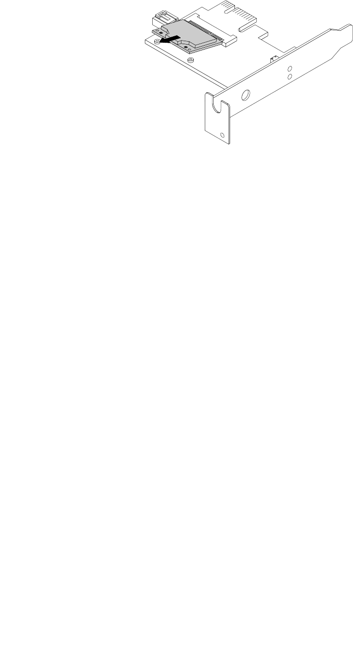
3.PulltheWiFicardmoduleoutoftheminiPCIExpressslottoremoveitfromtheWiFiadaptercard.
Figure94.RemovingtheWiFicardmodule
InstallingtheWiFiunits
ToinstalltheWiFiunits,dothefollowing:
148ThinkCentreHardwareMaintenanceManual
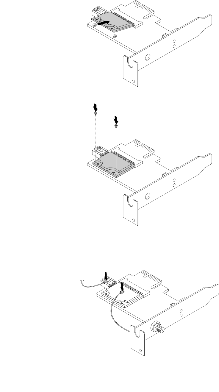
1.InserttheWiFicardmoduleintotheminiPCIExpressslot,andtheninstallthetwoscrewstosecure
theWiFicardmoduletotheWiFiadaptercard.
Figure95.InstallingtheWiFicardmodule
2.ConnectthefrontantennacableandrearantennacabletotheWiFicardmodule.
Figure96.ConnectingtheWiFiantennacables
Chapter10.ReplacingFRUs(machinetypes:0900,0967,1271,3578,3594,3596,3598,3629,
3654,3660,3664,3668,and3676)149
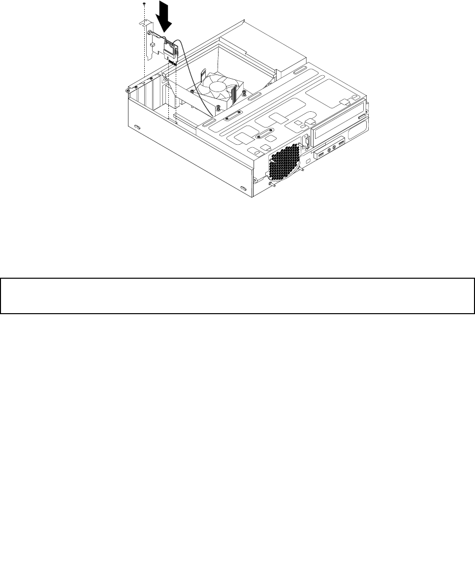
3.LocatethetwoPCIExpressx1slotsonthesystemboard.See“Locatingpartsonthesystemboard”
onpage78.
4.IftheinstalledWiFicardmodulesupportstheBluetoothfunction,useaBluetoothcabletoconnectthe
BluetoothconnectorontheWiFiadaptercardtothefrontUSBconnectoronthesystemboard.
5.InstalltheWiFiadaptercardintooneofthetwoPCIExpressx1slots.Theninstallthescrewtosecure
theWiFiadaptercardinplace.
Figure97.InstallingtheWiFiadaptercard
6.Tocompletetheinstallationorreplacement,goto“Completingthepartsreplacement”onpage154.
InstallingorremovingtherearWiFiantenna
Attention:
Donotopenyourcomputerorattemptanyrepairbeforereadingandunderstandingthe“Importantsafetyinformation”
onpage1.
ThissectionprovidesinstructionsonhowtoinstallorremovetherearWiFiantenna.
InstallingtherearWiFiantenna
ToinstalltherearWiFiantenna,dothefollowing:
1.Turnoffthecomputeranddisconnectallpowercordsfromelectricaloutlets.
2.InstalltherearWiFiantennatotherearWiFiantennacableconnectorattachedontherearofthe
computer.
150ThinkCentreHardwareMaintenanceManual
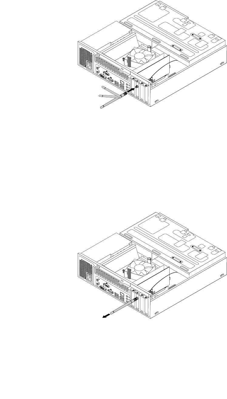
3.Adjusttheangleoftherearantennatolowertheriskofbreakingtheantennabyaccident.
Figure98.InstallingtherearWiFiantenna
4.Tocompletetheinstallationorreplacement,goto“Completingthepartsreplacement”onpage154.
RemovingtherearWiFiantenna
ToremovetherearWiFiantenna,dothefollowing:
1.Turnoffthecomputeranddisconnectallpowercordsfromelectricaloutlets.
2.StraightentherearWiFiantennasothatitcanbemoreeasilytwisted.
3.HoldthethickerendoftherearWiFiantennaandunscrewtheWiFiantennafromtherearofthe
computer.
Figure99.RemovingtherearWiFiantenna
4.Tocompletetheinstallationorreplacement,goto“Completingthepartsreplacement”onpage154.
Chapter10.ReplacingFRUs(machinetypes:0900,0967,1271,3578,3594,3596,3598,3629,
3654,3660,3664,3668,and3676)151
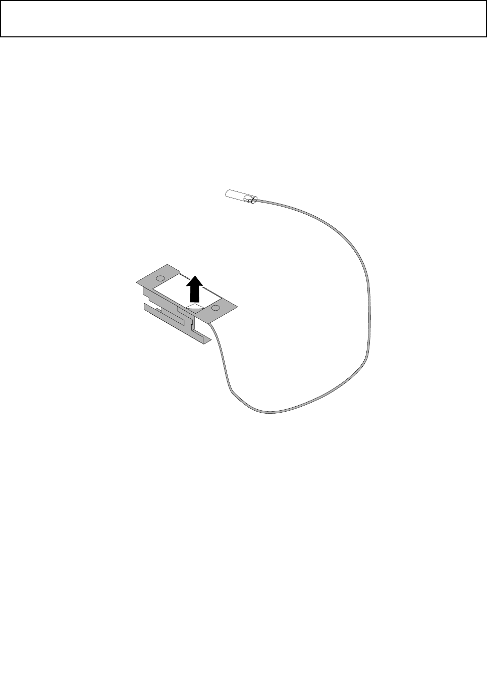
InstallingorremovingthefrontWiFiantenna
Attention:
Donotopenyourcomputerorattemptanyrepairbeforereadingandunderstandingthe“Importantsafetyinformation”
onpage1.
ThissectionprovidesinstructionsonhowtoinstallorremovethefrontWiFiantenna.
InstallingthefrontWiFiantenna
ToinstallthefrontWiFiantenna,dothefollowing:
1.Turnoffthecomputeranddisconnectallpowercordsfromelectricaloutlets.
2.Removethecomputercover.See“Removingthecomputercover”onpage118.
3.Removethefrontbezel.See“Removingandreinstallingthefrontbezel”onpage118.
4.Peeloffthepaperthatprotectsthestickersonthefrontantenna.
Figure100.Peelingoffthepaperthatprotectsthestickers
152ThinkCentreHardwareMaintenanceManual
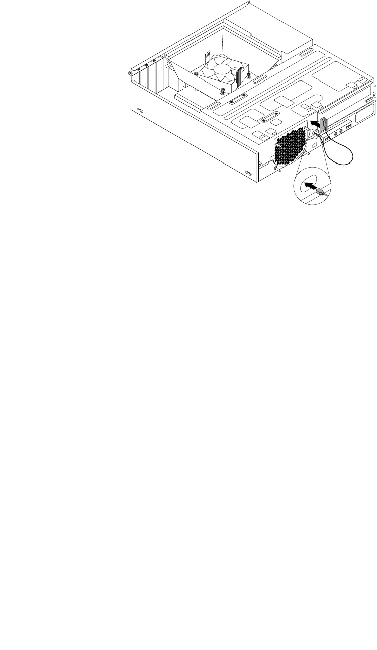
5.Stickthefrontantennatothefrontpanelasshown.Theninsertthefrontantennacablethroughthe
holeinthefrontpanel.
Figure101.InstallingthefrontWiFiantenna
6.ConnectthefrontantennacabletotheWiFicardmodule.
7.Tocompletetheinstallationorreplacement,goto“Completingthepartsreplacement”onpage154.
RemovingthefrontWiFiantenna
ToremovethefrontWiFiantenna,dothefollowing:
1.Turnoffthecomputeranddisconnectallpowercordsfromelectricaloutlets.
2.Removethecomputercover.See“Removingthecomputercover”onpage118.
3.Removethefrontbezel.See“Removingandreinstallingthefrontbezel”onpage118.
4.DisconnectthefrontantennacablefromtheWiFicardmodule.
Chapter10.ReplacingFRUs(machinetypes:0900,0967,1271,3578,3594,3596,3598,3629,
3654,3660,3664,3668,and3676)153
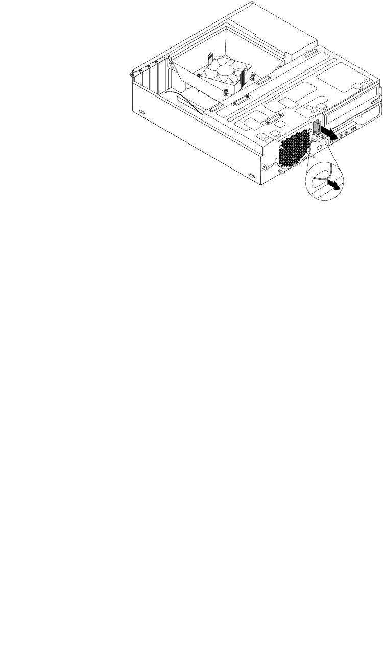
5.Removethefrontantennaandcablefromthefrontofthecomputer.
Figure102.RemovingthefrontWiFiantenna
6.Tocompletetheinstallationorreplacement,goto“Completingthepartsreplacement”onpage154.
Completingthepartsreplacement
Aftercompletingtheinstallationorreplacementforallparts,youneedtoclosethecomputercoverand
reconnectcables.Dependingonthepartsyouinstalledorreplaced,youmightneedtoconrmtheupdated
informationintheSetupUtilityprogram.RefertoChapter6“UsingtheSetupUtilityprogram”onpage55.
Toclosethecomputercoverandreconnectcablestoyourcomputer,dothefollowing:
1.Makesurethatallcomponentshavebeenreassembledcorrectlyandthatnotoolsorloosescrews
areleftinsideyourcomputer.See“LocatingmajorFRUsandCRUs”onpage76forthelocationsof
variouscomponentsinyourcomputer.
2.Ifyouhaveremovedthefrontbezel,reinstallit.Toreinstallthefrontbezel,alignthethreetabson
thefrontbezelwiththecorrespondingholesinthechassisandpivotthefrontbezelinwardsuntil
itsnapsintoposition.
3.Makesurethatthecablesareroutedcorrectly.Keepcablesclearofthehingesandsidesofthe
computerchassistoavoidinterferencewithclosingthecomputercover.
4.Lowertheopticaldrivebay.
5.Reinstallthecomputercover.
6.Ifthereisanintegratedcablelockavailable,lockthecomputer.
7.Reconnecttheexternalcablesandpowercordstothecomputer.See“Locatingconnectorsonthe
rearofyourcomputer”onpage76.
8.Toupdateyourconguration,seeChapter6“UsingtheSetupUtilityprogram”onpage55.
Note:Inmostareasoftheworld,LenovorequiresthereturnofthedefectiveFieldReplaceableUnits(FRUs).
InformationaboutthiswillcomewiththenewFRUsorwillcomeafewdaysafteryoureceivethenewFRUs.
154ThinkCentreHardwareMaintenanceManual

Chapter11.Additionalserviceinformation
Thischapterprovidesadditionalinformationthattheservicerepresentativemightndhelpful.
Securityfeatures
Securityfeaturesinthissectionincludethefollowing:
•Passwords
•VitalProductData
Hardware-controlledpasswords
UsetheSetupUtilityprogramtosetthehardwarecontrolledpasswords.Formoreinformationabout
passwords,see“Usingpasswords”onpage55.
Operatingsystempassword
Note:ThissectionappliesonlytocomputermodelsthathaveanoperatingsystempreinstalledfromLenovo.
Anoperatingsystempasswordisverysimilartoapower-onpasswordanddeniesaccesstothecomputerby
anunauthorizeduserwhenthepasswordisactivated.Thecomputerisunusableuntilthecorrectpassword
isenteredandrecognizedbythecomputer.
VitalProductData
EachcomputerhasauniqueVitalProductData(VPD)codestoredinthenonvolatilememoryonthesystem
board.Afteryoureplacethesystemboard,theVPDmustbeupdated.ToupdatetheVPD,see“Updating
(ashing)theBIOSfromadisc”onpage155.
BIOSlevels
AnincorrectlevelofBIOScancausefalseerrorsandunnecessaryFRUreplacement.Usethefollowing
informationtodeterminethecurrentlevelofBIOSinstalledinthecomputer,thelatestBIOSavailableforthe
computer,andwheretoobtainthelatestlevelofBIOS.
•TodeterminethecurrentLevelofBIOS:
–StarttheSetupUtility.
–SeeBIOSRevisionLevelontheMainsetupscreen.
•SourcesforobtainingthelatestlevelBIOSavailable
1.Lenovosupportwebsite:http://www.lenovo.com/support/
2.LenovoCustomerSupportCenter
3.Levels1and2Support
Toupdate(ash)theBIOS,see“Updating(ashing)theBIOSfromadisc”onpage155.
Note:BIOSsettingsvarybyoperatingsystem.ChangetheBIOSsettingsbeforeinstallinganewoperating
system.See“ChangingtheBIOSsettingsbeforeinstallinganewoperatingsystem”onpage59.
Updating(ashing)theBIOSfromadisc
Thissectionprovidesinstructionsonhowtoupdate(ash)theBIOSfromadiscontheWindows8(64-bit)
operatingsystemandonotheroperatingsystems.
©CopyrightLenovo2012155

Note:Youcandownloadaself-startingbootablediscimage(knownasanISOimage)withthesystem
programupdatestocreateasystem-program-updatedisc.Gotohttp://www.lenovo.com/support.
Toupdate(ash)theBIOSfromadiscontheWindows8(64-bit)operatingsystem,dothefollowing:
1.StarttheSetupUtilityprogram.See“StartingtheSetupUtilityprogram”onpage55.
2.FromtheSetupUtilityprogrammainmenu,selectExit➙OSOptimizedDefault➙Disabled.
3.SelectYesinthewindowdisplayedandpressEntertoconrmyourselection.
4.PressF10tosavechangesandexittheSetupUtilityprogram.See“ExitingtheSetupUtilityprogram”
onpage59.
5.RepeatedlypressandreleaseF12whenturningonthecomputer.WhentheStartupDeviceMenu
windowopens,releaseF12.
6.FromtheStartupDeviceMenuwindow,selectthedesiredopticaldriveasthestartupdevice.Then,
insertthediscintothisopticaldriveandpressEnter.Theupdatebegins.
7.Whenpromptedtochangetheserialnumber,itissuggestedthatyoudonotmakethischangeby
pressingN.However,ifyoudowanttochangetheserialnumber,pressY,andthentypeintheserial
numberandpressEnter.
8.Whenpromptedtochangethemachinetypeandmodel,itissuggestedthatyoudonotmakethis
changebypressingN.However,ifyoudowanttochangethemachinetypeandmodel,pressY,and
thentypeinthemachinetypeandmodelandpressEnter.
9.Followtheinstructionsonthescreentocompletetheupdate.Aftertheupdateiscompleted,removethe
discfromtheopticaldrive.
10.RestartyourcomputerandstarttheSetupUtilityprogram.See“StartingtheSetupUtilityprogram”
onpage55.
11.FromtheSetupUtilityprogrammainmenu,selectExit➙OSOptimizedDefault➙Enabled.
12.SelectYesinthewindowdisplayedandpressEntertoconrmyourselection.
13.PressF10tosavechangesandexittheSetupUtilityprogram.See“ExitingtheSetupUtilityprogram”
onpage59.
Toupdate(ash)theBIOSfromadisconotheroperatingsystems,dothefollowing:
1.Turnoffyourcomputer.
2.RepeatedlypressandreleaseF12whenturningonthecomputer.WhentheStartupDeviceMenu
windowopens,releaseF12.
3.FromtheStartupDeviceMenuwindow,selectthedesiredopticaldriveasthestartupdevice.Then,
insertthediscintothisopticaldriveandpressEnter.Theupdatebegins.
4.Whenpromptedtochangetheserialnumber,itissuggestedthatyoudonotmakethischangeby
pressingN.However,ifyoudowanttochangetheserialnumber,pressY,andthentypeintheserial
numberandpressEnter.
5.Whenpromptedtochangethemachinetypeandmodel,itissuggestedthatyoudonotmakethis
changebypressingN.However,ifyoudowanttochangethemachinetypeandmodel,pressY,and
thentypeinthemachinetypeandmodelandpressEnter.
6.Followtheinstructionsonthescreentocompletetheupdate.Aftertheupdateiscompleted,removethe
discfromtheopticaldrive.
Updating(ashing)theBIOSfromyouroperatingsystem
Note:BecauseLenovomakesconstantimprovementstoitsWebsites,theWebpagecontentsaresubject
tochangewithoutnotice,includingthecontentsreferencedinthefollowingprocedure.
156ThinkCentreHardwareMaintenanceManual

Toupdate(ash)theBIOSfromyouroperatingsystem,dothefollowing:
1.Gotohttp://www.lenovo.com/support.
2.ClickDownloadDrivers&Software.
3.ClickUseQuickPath.
4.Typethe4-digitmachinetypeforyourcomputerintheQuickPatheldandthenclickFindMyProduct.
5.ClickBIOS.
6.LocatetheBIOSversionthatyouwanttodownload.
7.ClickClickforles.Allavailableleswillbedisplayed.
8.Clickthelinkforthereadmelethatcontainstheinstructionsforupdating(ashing)theBIOSfrom
youroperatingsystem.
9.Printtheseinstructions.Thisisveryimportantbecausetheseinstructionswillnotbedisplayedon
thescreenafterthedownloadbegins.
10.Followtheprintedinstructionstodownload,extract,andinstalltheupdate.
RecoveringfromaPOSTandBIOSupdatefailure
IfthepowertoyourcomputerisinterruptedwhilethePOSTandBIOSisbeingupdated,yourcomputer
mightnotrestartcorrectly.Ifthishappens,performthefollowingproceduretorecoverfromthePOSTand
BIOSupdatefailure.ThisprocedureiscommonlycalledBoot-blockRecovery.
1.Removeallmediafromthedrivesandturnoffallattacheddevicesandthecomputer.Then,disconnect
allpowercordsfromelectricaloutletsanddisconnectallcablesthatareconnectedtothecomputer.
2.Removethecomputercover.Formachinetypes0896,0958,1112,2116,3498,3593,3595,3597,3617,
3634,3655,3662,3665,and3675,see“Removingthecomputercover”onpage82.Formachinetypes
0900,0967,1271,3578,3594,3596,3598,3629,3654,3660,3664,3668,and3676,see“Removing
thecomputercover”onpage118.
3.LocatetheClearCMOS/Recoveryjumperonthesystemboard.See“Locatingpartsonthesystem
board”onpage71.
4.RemoveanypartsanddisconnectanycablesthatmightpreventyouraccesstotheClearCMOS
/Recoveryjumper.
5.Movethejumperfromthestandardposition(pin1andpin2)tothemaintenanceposition(pin2and
pin3).
6.Reinstallanypartsandreconnectanycablesthathavebeenremovedordisconnected.
7.Reinstallthecomputercoverandreconnectthepowercordsforthecomputerandmonitor.Formachine
types0896,0958,1112,2116,3498,3593,3595,3597,3617,3634,3655,3662,3665,and3675,see
“Completingthepartsreplacement”onpage115.Formachinetypes0900,0967,1271,3578,3594,
3596,3598,3629,3654,3660,3664,3668,and3676,see“Completingthepartsreplacement”on
page154.
8.TurnonthecomputerandtheninsertthePOSTandBIOSupdate(ashupdate)discintotheoptical
drive.Waitafewminutes.Then,therecoverysessionbegins.Therecoverysessionwilltaketwoto
threeminutes.Duringthistime,awarningmessagewillbedisplayedandnoactionisneededfromyou.
9.Aftertherecoverysessioniscompleted,therewillbenovideo,andyourcomputerwillautomatically
turnoff.
10.Repeatstep1throughstep4.
11.Movethejumperbacktothestandardposition(pin1andpin2).
12.Reinstallanypartsandreconnectanycablesthathavebeenremovedordisconnected.
13.Reinstallthecomputercoverandreconnectpowercordsandallotherexternalcables.Formachine
types0896,0958,1112,2116,3498,3593,3595,3597,3617,3634,3655,3662,3665,and3675,see
“Completingthepartsreplacement”onpage115.Formachinetypes0900,0967,1271,3578,3594,
Chapter11.Additionalserviceinformation157

3596,3598,3629,3654,3660,3664,3668,and3676,see“Completingthepartsreplacement”on
page154.
14.Turnonthecomputertorestarttheoperatingsystem.
Powermanagement
Powermanagementreducesthepowerconsumptionofcertaincomponentsofthecomputersuchasthe
systempowersupply,processor,harddiskdrives,andsomemonitors.
AdvancedCongurationandPowerInterface(ACPI)BIOS
BeinganACPIBIOSsystem,theoperatingsystemisallowedtocontrolthepowermanagementfeatures
ofthecomputerandthesettingforAdvancedPowerManagement(APM)BIOSmodeisignored.Not
alloperatingsystemssupportACPIBIOSmode.
AutomaticPower-onfeatures
TheAutomaticPower-OnfeatureswithinthePowerManagementmenuallowyoutoenableanddisable
featuresthatturnonthecomputerautomatically.
•WakeUponAlarm:Youcanspecifyadateandtimeatwhichthecomputerwillbeturnedon
automatically.Thiscanbeeitherasingleeventoradailyevent.
•WakeonLAN:Ifthecomputerhasaproperlyconguredtoken-ringorEthernetLANadaptercardthatis
WakeonLAN-enabledandthereisremotenetworkmanagementsoftware,youcanusetheWakeonLAN
feature.WhenyousetWakeonLANtoEnabled,thecomputerwillturnonwhenitreceivesaspecic
signalfromanothercomputeronthelocalareanetwork(LAN).
ToenabletheWakeonLANfunctionortheWakeUponAlarmfunctionontheWindows8operatingsystem,
dothefollowing:
1.OpenControlPanel.
2.ClickHardwareandSound➙PowerOptions.
3.Intheleftpanel,clickChoosewhatthepowerbuttonsdo.
4.IntheShutdownsettingsection,clearTurnonfaststartup.
Note:Ifthesettingsareunavailable,clickChangesettingsthatarecurrentlyunavailable.
5.ClickSavechanges.
158ThinkCentreHardwareMaintenanceManual

AppendixA.Notices
Lenovomaynotoffertheproducts,services,orfeaturesdiscussedinthisdocumentinallcountries.Consult
yourlocalLenovorepresentativeforinformationontheproductsandservicescurrentlyavailableinyour
area.AnyreferencetoaLenovoproduct,program,orserviceisnotintendedtostateorimplythatonlythat
Lenovoproduct,program,orservicemaybeused.Anyfunctionallyequivalentproduct,program,orservice
thatdoesnotinfringeanyLenovointellectualpropertyrightmaybeusedinstead.However,itistheuser's
responsibilitytoevaluateandverifytheoperationofanyotherproduct,program,orservice.
Lenovomayhavepatentsorpendingpatentapplicationscoveringsubjectmatterdescribedinthis
document.Thefurnishingofthisdocumentdoesnotgiveyouanylicensetothesepatents.Youcansend
licenseinquiries,inwriting,to:
Lenovo(UnitedStates),Inc.
1009ThinkPlace-BuildingOne
Morrisville,NC27560
U.S.A.
Attention:LenovoDirectorofLicensing
LENOVOPROVIDESTHISPUBLICATION“ASIS”WITHOUTWARRANTYOFANYKIND,EITHEREXPRESS
ORIMPLIED,INCLUDING,BUTNOTLIMITEDTO,THEIMPLIEDWARRANTIESOFNON-INFRINGEMENT,
MERCHANTABILITYORFITNESSFORAPARTICULARPURPOSE.Somejurisdictionsdonotallow
disclaimerofexpressorimpliedwarrantiesincertaintransactions,therefore,thisstatementmaynotapply
toyou.
Thisinformationcouldincludetechnicalinaccuraciesortypographicalerrors.Changesareperiodically
madetotheinformationherein;thesechangeswillbeincorporatedinneweditionsofthepublication.
Lenovomaymakeimprovementsand/orchangesintheproduct(s)and/ortheprogram(s)describedinthis
publicationatanytimewithoutnotice.
Theproductsdescribedinthisdocumentarenotintendedforuseinimplantationorotherlifesupport
applicationswheremalfunctionmayresultininjuryordeathtopersons.Theinformationcontainedinthis
documentdoesnotaffectorchangeLenovoproductspecicationsorwarranties.Nothinginthisdocument
shalloperateasanexpressorimpliedlicenseorindemnityundertheintellectualpropertyrightsofLenovo
orthirdparties.Allinformationcontainedinthisdocumentwasobtainedinspecicenvironmentsandis
presentedasanillustration.Theresultobtainedinotheroperatingenvironmentsmayvary.
Lenovomayuseordistributeanyoftheinformationyousupplyinanywayitbelievesappropriatewithout
incurringanyobligationtoyou.
Anyreferencesinthispublicationtonon-LenovoWebsitesareprovidedforconvenienceonlyanddonotin
anymannerserveasanendorsementofthoseWebsites.ThematerialsatthoseWebsitesarenotpartof
thematerialsforthisLenovoproduct,anduseofthoseWebsitesisatyourownrisk.
Anyperformancedatacontainedhereinwasdeterminedinacontrolledenvironment.Therefore,theresult
obtainedinotheroperatingenvironmentsmayvarysignicantly.Somemeasurementsmayhavebeen
madeondevelopment-levelsystemsandthereisnoguaranteethatthesemeasurementswillbethesame
ongenerallyavailablesystems.Furthermore,somemeasurementsmayhavebeenestimatedthrough
extrapolation.Actualresultsmayvary.Usersofthisdocumentshouldverifytheapplicabledatafortheir
specicenvironment.
©CopyrightLenovo2012159

Televisionoutputnotice
Thefollowingnoticeappliestomodelsthathavethefactory-installedtelevision-outputfeature.
ThisproductincorporatescopyrightprotectiontechnologythatisprotectedbymethodclaimsofcertainU.S.
patentsandotherintellectualpropertyrightsownedbyMacrovisionCorporationandotherrightsowners.
UseofthiscopyrightprotectiontechnologymustbeauthorizedbyMacrovisionCorporation,andisintended
forhomeandotherlimitedviewingusesonlyunlessotherwiseauthorizedbyMacrovisionCorporation.
Reverseengineeringordisassemblyisprohibited.
EuropeanconformanceCEmark
Trademarks
ThefollowingtermsaretrademarksofLenovointheUnitedStates,othercountries,orboth:
Lenovo
TheLenovologo
RescueandRecovery
ThinkCentre
ThinkVantage
Microsoft,Windows,andWindowsVistaaretrademarksoftheMicrosoftgroupofcompanies.
Othercompany,product,orservicenamesmaybetrademarksorservicemarksofothers.
160ThinkCentreHardwareMaintenanceManual

Index
A
accessing
systemboardcomponentsanddrives119
Administrator,password56
audioline-inconnector68
audioline-outconnector68
B
basictroubleshooting35
battery,replacing88,124
BIOSsettings,changing59
Boot-blockRecovery157
C
changing
password56
startupdevicesequence58
CMOS,clearing57
components,internal69,76
computercover
removing82,118
computercover,reinstalling115,154
connector68
connectors
rear68,76
connectors,controls,indicators
front67,75
considerations,passwords56
CRU
completingtheinstallation115,154
completingthereplacement154
CRUs(CustomerReplacableUnits),returning
defective69,76
D
deletingapassword56
Description68
devices,handlingstatic-sensitive81,117
diagnostics,troubleshooting35
DisplayPortconnector69
drives
bays74,80
specications74,80
E
environment,operating29–30
Ethernetconnector69
exiting,SetupUtility59
externaloptions,installing81,117
F
failure,recoveringfromaPOSTandBIOSupdate157
ashingtheBIOS155
front
connectors,controls,indicators67,75
frontaudioandUSBassembly,replacing105,142
frontbezel
frontbezel,removing83
removing,reinstalling118
frontbezel,reinstalling83
frontWiFiantenna,installing,removing113,152
FRUlocations69,76
FRUpartnumbers1,67,71,78,81,117
H
harddiskdrive,replacing101,125
heatsinkandfanassembly
replacing130
heatsinkandfanassembly,replacing93
I
IdentifyingFRUs69,76
installing
operatingsystem59
installingoptions
memorymodule89
PCIcard85
installing,replacing
memorymodule121
PCIcard122
K
keyboardconnector69
L
LenovoSolutionCenter53
locatingcomponents69,76
lookinguppartnumbers1,67,71,78,81,117
M
memorymodule121
installing,replacing89,121
systemboard89
Microphoneconnector69
microprocessor
replacing96,137
mouseconnector69
©CopyrightLenovo2012161

O
opticaldrive,installingorreplacing127
opticaldrive,replacing91
Optional-serviceCRUs69,76
P
partnumbers1,67,71,78,81,117
partsreplacement,completing115,154
password
Administrator56
considerations56
Power-OnPassword56
setting,changing,deleting56
passwords
erasing57
lostorforgotten57
passwords,using55
PCIcard85,122
installing,replacing85,122
slots85
PCIcardlatch86
powersupplyassembly
replacing133
powersupplyassembly,replacing95
Power-On,Password56
R
rearconnectors68,76
rearfanassembly,replacing103
rearWiFiantenna,installing,removing112,150
recovering
fromaPOSTandBIOSupdatefailure157
recovery
Boot-blockRecovery157
removingcomputercover82,118
removing,reinstalling
frontbezel118
replacing
battery88,124
harddiskdrive101,125
heatsinkandfanassembly93,130
microprocessor96,137
powersupplyassembly133
S
security
enablingordisabling57
selecting
startupdevice58
temporarystartupdevice58
Self-serviceCRUs69,76
serialport69
setting
password56
settings
changing55
viewing55
SetupUtility55
SetupUtilityprogram,starting55
SetupUtility,exiting59
startingtheSetupUtilityprogram55
startupdevice58
sequence,changing58
temporary,selecting58
static-sensitivedevices,handling81,117
supportwebsite
support32
support,website32
systemboard
connectors72–73,79
locatingparts71,78
location78
locations72–73
memorymodule89
systemboardcomponentsanddrives
accessing119
systemfanassembly,replacing143
T
temporarystartupdevice58
theBIOS,updating(ashing)155–156
troubleshooting,basic35
troubleshooting,diagnostics35
U
updating
(ashing)theBIOS155
updating(ashing)theBIOS156
USBconnector69
using
passwords55
SetupUtility55
V
VGAmonitorconnector69
viewingandchangingsettings55
W
WiFiunits,WiFiadaptercard,WiFicardmodule,WiFi
antennacable,replacing106
WiFiunits,WiFiadaptercard,WiFicardmodule,WiFi
antennacable,replacing145
162ThinkCentreHardwareMaintenanceManual

PartNumber:
PrintedinUSA
(1P)P/N:
*1P*
