Lenovo M72Z Hmm Us User Manual All In One (Think Centre) Type 3528
1970-01-01
User Manual: Lenovo M72Z Hmm Us M72z All-in-One (ThinkCentre) - Type 3528 ThinkCentre M72z, 3528
Open the PDF directly: View PDF ![]() .
.
Page Count: 126 [warning: Documents this large are best viewed by clicking the View PDF Link!]
- Chapter 1. About this manual
- Chapter 2. Safety information
- Chapter 3. General information
- Chapter 4. General Checkout
- Chapter 5. Troubleshooting and diagnostics
- Chapter 6. Using the Setup Utility program
- Chapter 7. Symptom-to-FRU Index
- Chapter 8. Locations
- Chapter 9. Replacing FRUs
- Removing and reinstalling the system stand hinge cover
- Removing and reinstalling the system stand
- Removing and reinstalling the monitor stand
- Removing and reinstalling the frame stand
- Removing the computer cover
- Replacing the hard disk drive
- Replacing the optical drive
- Removing the VESA mount bracket
- Replacing the rear I/O assembly
- Removing and reinstalling the system board shield
- Replacing the power supply
- Replacing the microprocessor fan
- Replacing the heat sink assembly
- Replacing the microprocessor
- Replacing the card reader
- Opening the system board shield window
- Replacing the battery
- Replacing the inverter
- Installing or replacing a memory module
- Replacing the internal speakers
- Replacing the integrated camera
- Replacing the system board
- Replacing the LCD panel
- Replacing the WI-FI card
- Completing the parts replacement
- Chapter 10. Additional Service Information
- Appendix A. Notices
- Index

ThinkCentre
HardwareMaintenanceManual
MachineTypes:3512,3528,3533,3535,3536,3537,3538,3539,
3543,3548,3549,3553,3554,3556,3558,and3559.

ThinkCentre
HardwareMaintenanceManual
MachineTypes:3512,3528,3533,3535,3536,3537,3538,3539,
3543,3548,3549,3553,3554,3556,3558,and3559.

Note:Beforeusingthisinformationandtheproductitsupports,besuretoreadandunderstandChapter2
“Safetyinformation”onpage3andAppendixA“Notices”onpage115.
FirstEdition(May2012)
©CopyrightLenovo2012.
LIMITEDANDRESTRICTEDRIGHTSNOTICE:IfdataorsoftwarearedeliveredpursuantaGeneralServices
Administration“GSA”contract,use,reproduction,ordisclosureissubjecttorestrictionssetforthinContractNo.
GS-35F-05925.

Contents
Chapter1.Aboutthismanual......1
ImportantSafetyInformation..........1
Chapter2.Safetyinformation......3
Generalsafety................3
Electricalsafety...............3
Safetyinspectionguide............5
Handlingelectrostaticdischarge-sensitive
devices..................5
Groundingrequirements............6
Safetynotices(multi-lingualtranslations).....6
Chapter3.Generalinformation....29
Specications...............29
LenovoThinkVantageTools.........29
LenovoWelcome..............30
LenovoSolutionCenter...........30
SimpleTap................30
Additionalinformationresources.......31
Chapter4.GeneralCheckout.....33
Problemdeterminationtips..........33
Chapter5.Troubleshootingand
diagnostics..............35
Basictroubleshooting............35
Troubleshootingprocedure..........36
Troubleshooting..............37
Audioproblems............37
CDproblems.............38
DVDproblems.............39
Intermittentproblems..........41
Keyboard,mouse,orpointingdevice
problems...............41
Monitorproblems............43
Networkingproblems..........44
Optionproblems............47
Performanceandlockupproblems.....48
Printerproblems............49
Serialportproblems...........49
Softwareproblems...........50
USBproblems.............51
Diagnostics................51
LenovoSolutionCenter.........51
Chapter6.UsingtheSetupUtility
program................53
StartingtheSetupUtilityprogram.......53
Viewingandchangingsettings........53
Usingpasswords..............53
Passwordconsiderations.........54
Power-OnPassword..........54
AdministratorPassword.........54
HardDiskPassword...........54
Setting,changing,anddeletingapassword.54
Enablingordisablingadevice........55
Selectingastartupdevice..........55
Selectingatemporarystartupdevice....55
Selectingorchangingthestartupdevice
sequence...............55
ExitingtheSetupUtilityprogram.......56
Chapter7.Symptom-to-FRUIndex..57
Harddiskdrivebooterror..........57
PowerSupplyProblems...........57
Beepsymptoms..............57
POSTerrorcodes.............58
Miscellaneouserrorconditions........59
Undeterminedproblems...........60
Chapter8.Locations.........63
Locatingconnectors,controls,andindicatorson
thefrontofyourcomputer..........63
Locatingconnectorsontherearofyour
computer.................64
LocatingmajorFRUsandCRUs........66
LookingupFRUinformation.........69
Systemboardpartsandconnectors......70
Chapter9.ReplacingFRUs......71
Removingandreinstallingthesystemstandhinge
cover..................71
Removingandreinstallingthesystemstand...73
Removingandreinstallingthemonitorstand...75
Removingandreinstallingtheframestand....76
Removingthecomputercover........79
Replacingtheharddiskdrive.........79
Replacingtheopticaldrive..........82
RemovingtheVESAmountbracket......83
ReplacingtherearI/Oassembly........84
Removingandreinstallingthesystemboard
shield..................86
Replacingthepowersupply.........87
Replacingthemicroprocessorfan.......88
Replacingtheheatsinkassembly.......89
Replacingthemicroprocessor........91
©CopyrightLenovo2012iii

Replacingthecardreader..........94
Openingthesystemboardshieldwindow....95
Replacingthebattery............96
Replacingtheinverter............97
Installingorreplacingamemorymodule....98
Replacingtheinternalspeakers........100
Replacingtheintegratedcamera.......101
Replacingthesystemboard.........102
ReplacingtheLCDpanel...........104
ReplacingtheWI-FIcard...........108
Completingthepartsreplacement.......109
Chapter10.AdditionalService
Information.............111
Securityfeatures..............111
HardwarecontrolledPasswords......111
Operatingsystempassword.......111
Vitalproductdata............111
BIOSlevels................111
Flashupdateprocedures..........111
Updating(ashing)theBIOSfromadisc....111
Updating(ashing)theBIOSfromyouroperating
system..................112
RecoveringfromaPOST/BIOSupdatefailure..112
Powermanagement............113
Automaticcongurationandpowerinterface
(ACPI)BIOS..............113
AutomaticPower-Onfeatures.......113
AppendixA.Notices.........115
Televisionoutputnotice...........116
EuropeanconformanceCEmark.......116
Trademarks................116
Index.................117
ivThinkCentreHardwareMaintenanceManual

Chapter1.Aboutthismanual
ThismanualprovidesserviceandreferenceinformationforThinkCentre®computerslistedonthecover.This
manualisintendedonlyfortrainedservicepersonnelwhoarefamiliarwithLenovo®computerproducts.
Chapter7“Symptom-to-FRUIndex”onpage57andChapter10“AdditionalServiceInformation”onpage
111arenotspecictoanymachinetype.ThesechaptersareapplicabletoallThinkCentrecomputers.
BeforeservicingaLenovocomputerproduct,besuretoread“ImportantSafetyInformation”onpage1.
TheSymptom-to-FRUIndexandAdditionalServiceInformationchaptersarenotspecictoanymachine
typeandareapplicabletoallThinkCentrecomputers.
FormajorFieldReplaceableUnits(FRU)locationsandCustomerReplaceableUnit(CRU)identication,
seeChapter8“Locations”onpage63.
ForFRUreplacementinstructions,seeChapter9“ReplacingFRUs”onpage71.
ForFRUpartnumbers,goto:
http:/www.lenovo.com/serviceparts-lookup
ImportantSafetyInformation
Besuretoreadallcautionanddangerstatementsinthisbookbeforeperforminganyoftheinstructions.
VeuillezliretouteslesconsignesdetypeDANGERetATTENTIONduprésentdocumentavantd'exécuter
lesinstructions.
LesenSieunbedingtalleHinweisevomTyp"ACHTUNG"oder"VORSICHT"indieserDokumentation,bevor
SieirgendwelcheVorgängedurchführen
LeggereleistruzioniintrodottedaATTENZIONEePERICOLOpresentinelmanualeprimadieseguireuna
qualsiasidelleistruzioni
Certique-sedelertodasasinstruçõesdecuidadoeperigonestemanualantesdeexecutarqualquer
umadasinstruções
Esimportantequeleatodaslasdeclaracionesdeprecauciónydepeligrodeestemanualantesdeseguir
lasinstrucciones.
©CopyrightLenovo20121

2ThinkCentreHardwareMaintenanceManual

Chapter2.Safetyinformation
Thischaptercontainsthesafetyinformationthatyouneedtobefamiliarwithbeforeservicingacomputer.
Generalsafety
Followtheserulestoensuregeneralsafety:
•Observegoodhousekeepingintheareaofthemachinesduringandaftermaintenance.
•Whenliftinganyheavyobject:
1.Ensureyoucanstandsafelywithoutslipping.
2.Distributetheweightoftheobjectequallybetweenyourfeet.
3.Useaslowliftingforce.Nevermovesuddenlyortwistwhenyouattempttolift.
4.Liftbystandingorbypushingupwithyourlegmuscles;thisactionremovesthestrainfromthe
musclesinyourback.
Donotattempttoliftanyobjectsthatweighmorethan16kg(35lb)orobjectsthatyouthinkare
tooheavyforyou.
•Donotperformanyactionthatcauseshazardstothecustomer,orthatmakestheequipmentunsafe.
•Beforeyoustartthemachine,ensurethatotherservicerepresentativesandthecustomer'spersonnelare
notinahazardousposition.
•Placeremovedcoversandotherpartsinasafeplace,awayfromallpersonnel,whileyouareservicing
themachine.
•Keepyourtoolcaseawayfromwalkareassothatotherpeoplewillnottripoverit.
•Donotwearlooseclothingthatcanbetrappedinthemovingpartsofamachine.Ensurethatyoursleeves
arefastenedorrolledupaboveyourelbows.Ifyourhairislong,fastenit.
•Inserttheendsofyournecktieorscarfinsideclothingorfastenitwithanonconductiveclip,approximately
8centimeters(3inches)fromtheend.
•Donotwearjewelry,chains,metal-frameeyeglasses,ormetalfastenersforyourclothing.
Remember:Metalobjectsaregoodelectricalconductors.
•Wearsafetyglasseswhenyouare:hammering,drilling,soldering,cuttingwire,attachingsprings,using
solvents,orworkinginanyotherconditionsthatmightbehazardoustoyoureyes.
•Afterservice,reinstallallsafetyshields,guards,labels,andgroundwires.Replaceanysafetydevice
thatiswornordefective.
•Reinstallallcoverscorrectlybeforereturningthemachinetothecustomer.
Electricalsafety
CAUTION:
Electricalcurrentfrompower,telephone,andcommunicationcablescanbehazardous.Toavoid
personalinjuryorequipmentdamage,disconnecttheattachedpowercords,telecommunication
systems,networks,andmodemsbeforeyouopenthecomputercovers,unlessinstructedotherwise
intheinstallationandcongurationprocedures.
Observethefollowingruleswhenworkingonelectricalequipment.
©CopyrightLenovo20123

Important:Useonlyapprovedtoolsandtestequipment.Somehandtoolshavehandlescoveredwithasoft
materialthatdoesnotinsulateyouwhenworkingwithliveelectricalcurrents.Manycustomershave,near
theirequipment,rubberoormatsthatcontainsmallconductiveberstodecreaseelectrostaticdischarges.
Donotusethistypeofmattoprotectyourselffromelectricalshock.
•Findtheroomemergencypower-off(EPO)switch,disconnectingswitch,orelectricaloutlet.Ifanelectrical
accidentoccurs,youcanthenoperatetheswitchorunplugthepowercordquickly.
•Donotworkaloneunderhazardousconditionsornearequipmentthathashazardousvoltages.
•Disconnectallpowerbefore:
–Performingamechanicalinspection
–Workingnearpowersupplies
–RemovingorinstallingFieldReplaceableUnits(FRUs)
•Beforeyoustarttoworkonthemachine,unplugthepowercord.Ifyoucannotunplugit,askthecustomer
topower-offthewallboxthatsuppliespowertothemachineandtolockthewallboxintheoffposition.
•Ifyouneedtoworkonamachinethathasexposedelectricalcircuits,observethefollowingprecautions:
–Ensurethatanotherperson,familiarwiththepower-offcontrols,isnearyou.
Remember:Anotherpersonmustbetheretoswitchoffthepower,ifnecessary.
–Useonlyonehandwhenworkingwithpowered-onelectricalequipment;keeptheotherhandinyour
pocketorbehindyourback.
Remember:Theremustbeacompletecircuittocauseelectricalshock.Byobservingtheaboverule,
youmaypreventacurrentfrompassingthroughyourbody.
–Whenusingatester,setthecontrolscorrectlyandusetheapprovedprobeleadsandaccessoriesfor
thattester.
–Standonsuitablerubbermats(obtainedlocally,ifnecessary)toinsulateyoufromgroundssuchas
metaloorstripsandmachineframes.
Observethespecialsafetyprecautionswhenyouworkwithveryhighvoltages;theseinstructionsarein
thesafetysectionsofmaintenanceinformation.Useextremecarewhenmeasuringhighvoltages.
•Regularlyinspectandmaintainyourelectricalhandtoolsforsafeoperationalcondition.
•Donotusewornorbrokentoolsandtesters.
•Neverassumethatpowerhasbeendisconnectedfromacircuit.First,checkthatithasbeenpowered-off.
•Alwayslookcarefullyforpossiblehazardsinyourworkarea.Examplesofthesehazardsaremoistoors,
nongroundedpowerextensioncables,powersurges,andmissingsafetygrounds.
•Donottouchliveelectricalcircuitswiththereectivesurfaceofaplasticdentalmirror.Thesurfaceis
conductive;suchtouchingcancausepersonalinjuryandmachinedamage.
•Donotservicethefollowingpartswiththepoweronwhentheyareremovedfromtheirnormaloperating
placesinamachine:
–Powersupplyunits
–Pumps
–Blowersandfans
–Motorgenerators
andsimilarunits.(Thispracticeensurescorrectgroundingoftheunits.)
•Ifanelectricalaccidentoccurs:
–Usecaution;donotbecomeavictimyourself.
–Switchoffpower.
–Sendanotherpersontogetmedicalaid.
4ThinkCentreHardwareMaintenanceManual

Safetyinspectionguide
Theintentofthisinspectionguideistoassistyouinidentifyingpotentiallyunsafeconditionsonthese
products.Eachmachine,asitwasdesignedandbuilt,hadrequiredsafetyitemsinstalledtoprotectusers
andservicepersonnelfrominjury.Thisguideaddressesonlythoseitems.However,goodjudgmentshould
beusedtoidentifypotentialsafetyhazardsduetoattachmentoffeaturesoroptionsnotcoveredbythis
inspectionguide.
Ifanyunsafeconditionsarepresent,youmustdeterminehowserioustheapparenthazardcouldbeand
whetheryoucancontinuewithoutrstcorrectingtheproblem.
Considertheseconditionsandthesafetyhazardstheypresent:
•Electricalhazards,especiallyprimarypower(primaryvoltageontheframecancauseseriousorfatal
electricalshock).
•Explosivehazards,suchasadamagedCRTfaceorbulgingcapacitor
•Mechanicalhazards,suchaslooseormissinghardware
Theguideconsistsofaseriesofstepspresentedinachecklist.Beginthecheckswiththepoweroff,and
thepowercorddisconnected.
Checklist:
1.Checkexteriorcoversfordamage(loose,broken,orsharpedges).
2.Power-offthecomputer.Disconnectthepowercord.
3.Checkthepowercordfor:
a.Athird-wiregroundconnectoringoodcondition.Useametertomeasurethird-wireground
continuityfor0.1ohmorlessbetweentheexternalgroundpinandframeground.
b.Thepowercordshouldbetheappropriatetypeasspeciedinthepartslistings.
c.Insulationmustnotbefrayedorworn.
4.Removethecover.
5.Checkforanyobviousalterations.Usegoodjudgmentastothesafetyofanyalterations.
6.Checkinsidetheunitforanyobviousunsafeconditions,suchasmetallings,contamination,wateror
otherliquids,orsignsofreorsmokedamage.
7.Checkforworn,frayed,orpinchedcables.
8.Checkthatthepower-supplycoverfasteners(screwsorrivets)havenotbeenremovedortamperedwith.
Handlingelectrostaticdischarge-sensitivedevices
Anycomputerpartcontainingtransistorsorintegratedcircuits(ICs)shouldbeconsideredsensitiveto
electrostaticdischarge(ESD).ESDdamagecanoccurwhenthereisadifferenceinchargebetweenobjects.
ProtectagainstESDdamagebyequalizingthechargesothatthemachine,thepart,theworkmat,andthe
personhandlingthepartareallatthesamecharge.
Notes:
1.Useproduct-specicESDprocedureswhentheyexceedtherequirementsnotedhere.
2.MakesurethattheESDprotectivedevicesyouusehavebeencertied(ISO9000)asfullyeffective.
WhenhandlingESD-sensitiveparts:
•Keepthepartsinprotectivepackagesuntiltheyareinsertedintotheproduct.
•Avoidcontactwithotherpeoplewhilehandlingthepart.
Chapter2.Safetyinformation5
•Wearagroundedwriststrapagainstyourskintoeliminatestaticonyourbody.
•Preventthepartfromtouchingyourclothing.Mostclothingisinsulativeandretainsachargeevenwhen
youarewearingawriststrap.
•Usetheblacksideofagroundedworkmattoprovideastatic-freeworksurface.Thematisespecially
usefulwhenhandlingESD-sensitivedevices.
•Selectagroundingsystem,suchasthoselistedbelow,toprovideprotectionthatmeetsthespecic
servicerequirement.
Note:TheuseofagroundingsystemisdesirablebutnotrequiredtoprotectagainstESDdamage.
–AttachtheESDgroundcliptoanyframeground,groundbraid,orgreen-wireground.
–UseanESDcommongroundorreferencepointwhenworkingonadouble-insulatedor
battery-operatedsystem.Youcanusecoaxorconnector-outsideshellsonthesesystems.
–Usetheroundground-prongoftheacplugonac-operatedcomputers.
Groundingrequirements
Electricalgroundingofthecomputerisrequiredforoperatorsafetyandcorrectsystemfunction.Proper
groundingoftheelectricaloutletcanbeveriedbyacertiedelectrician.
Safetynotices(multi-lingualtranslations)
Thecautionanddangersafetynoticesinthissectionareprovidedinthefollowinglanguages:
•English
•Arabic
•Brazilian/Portuguese
•Chinese(simplied)
•Chinese(traditional)
•French
•German
•Hebrew
•Italian
•Korean
•Spanish
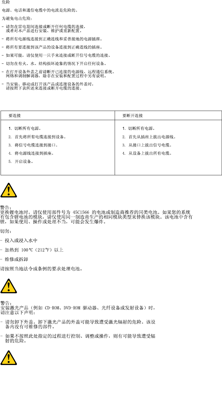
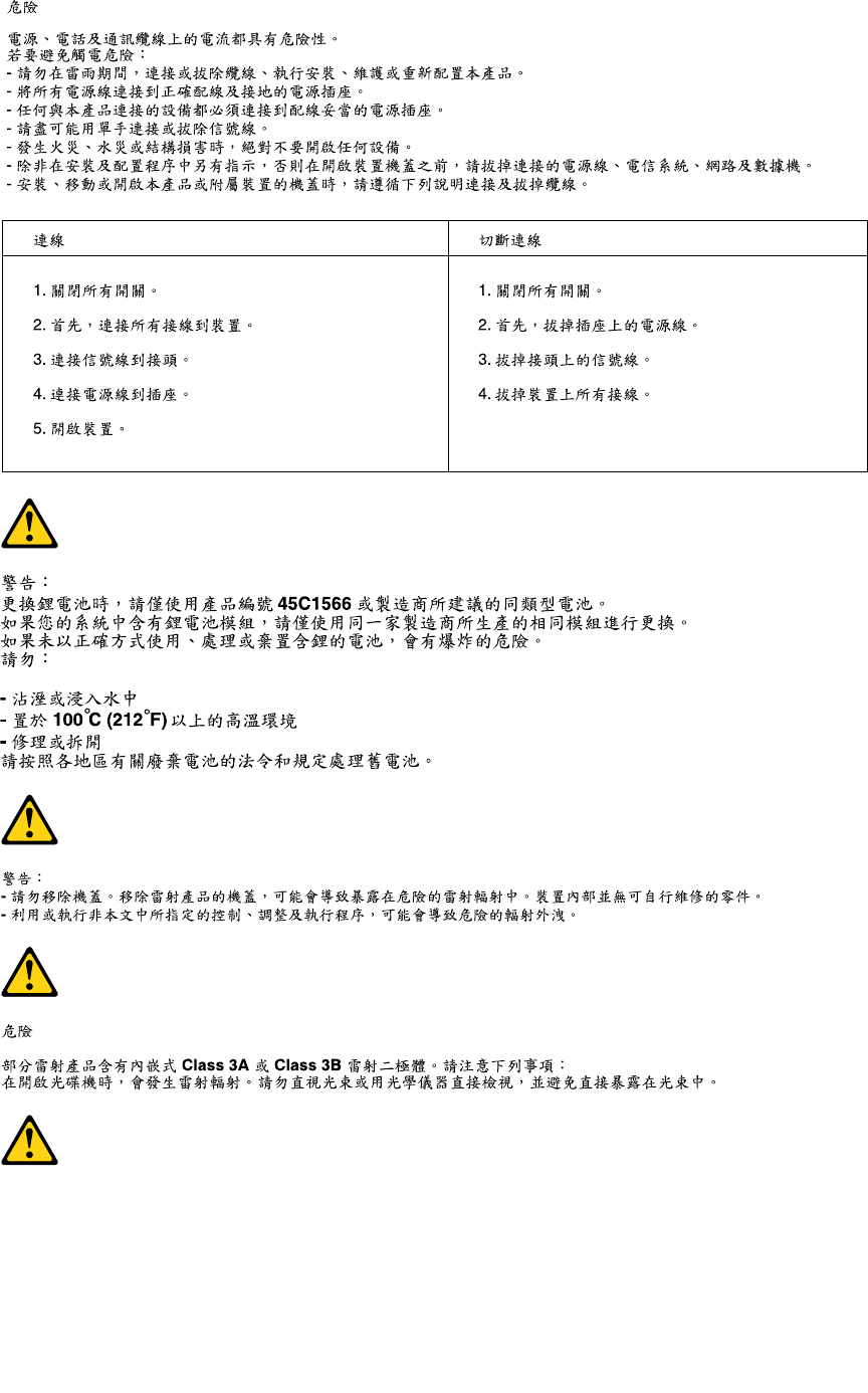
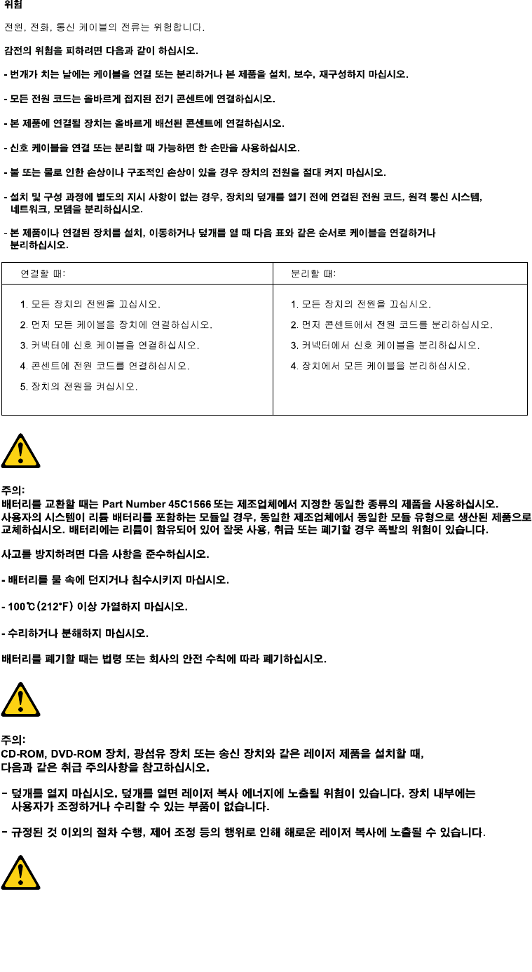
DANGER
Electricalcurrentfrompower,telephoneandcommunicationcablesishazardous.
Toavoidashockhazard:
•Donotconnectordisconnectanycablesorperforminstallation,maintenance,orreconguration
ofthisproductduringanelectricalstorm.
•Connectallpowercordstoaproperlywiredandgroundedelectricaloutlet.
•Connecttoproperlywiredoutletsanyequipmentthatwillbeattachedtothisproduct.
6ThinkCentreHardwareMaintenanceManual
•Whenpossible,useonehandonlytoconnectordisconnectsignalcables.
•Neverturnonanyequipmentwhenthereisevidenceofre,water,orstructuraldamage.
•Disconnecttheattachedpowercords,telecommunicationssystems,networks,andmodems
beforeyouopenthedevicecovers,unlessinstructedotherwiseintheinstallationandconguration
procedures.
•Connectanddisconnectcablesasdescribedinthefollowingtableswheninstalling,moving,or
openingcoversonthisproductorattacheddevices.
ToConnectToDisconnect
1.TurneverythingOFF.
2.First,attachallcablestodevices.
3.Attachsignalcablestoconnectors.
4.Attachpowercordstooutlet.
5.TurndeviceON.
1.TurneverythingOFF.
2.First,removepowercordsfromoutlet.
3.Removesignalcablesfromconnectors.
4.Removeallcablesfromdevices.
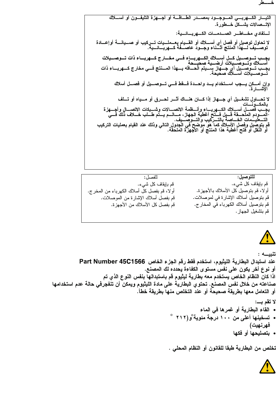
CAUTION:
Whenreplacingthelithiumbattery,useonlyPartNumber45C1566oranequivalenttypebattery
recommendedbythemanufacturer.Ifyoursystemhasamodulecontainingalithiumbattery,replace
itonlywiththesamemoduletypemadebythesamemanufacturer.Thebatterycontainslithiumand
canexplodeifnotproperlyused,handled,ordisposedof.Donot:
•Throworimmerseintowater
•Heattomorethan100°C(212°F)
•Repairordisassemble
Disposeofthebatteryasrequiredbylocalordinancesorregulations.
CAUTION:
Whenlaserproducts(suchasCD-ROMs,DVD-ROMdrives,beropticdevices,ortransmitters)are
installed,notethefollowing:
•Donotremovethecovers.Removingthecoversofthelaserproductcouldresultinexposureto
hazardouslaserradiation.Therearenoserviceablepartsinsidethedevice.
•Useofcontrolsoradjustmentsorperformanceofproceduresotherthanthosespeciedherein
mightresultinhazardousradiationexposure.
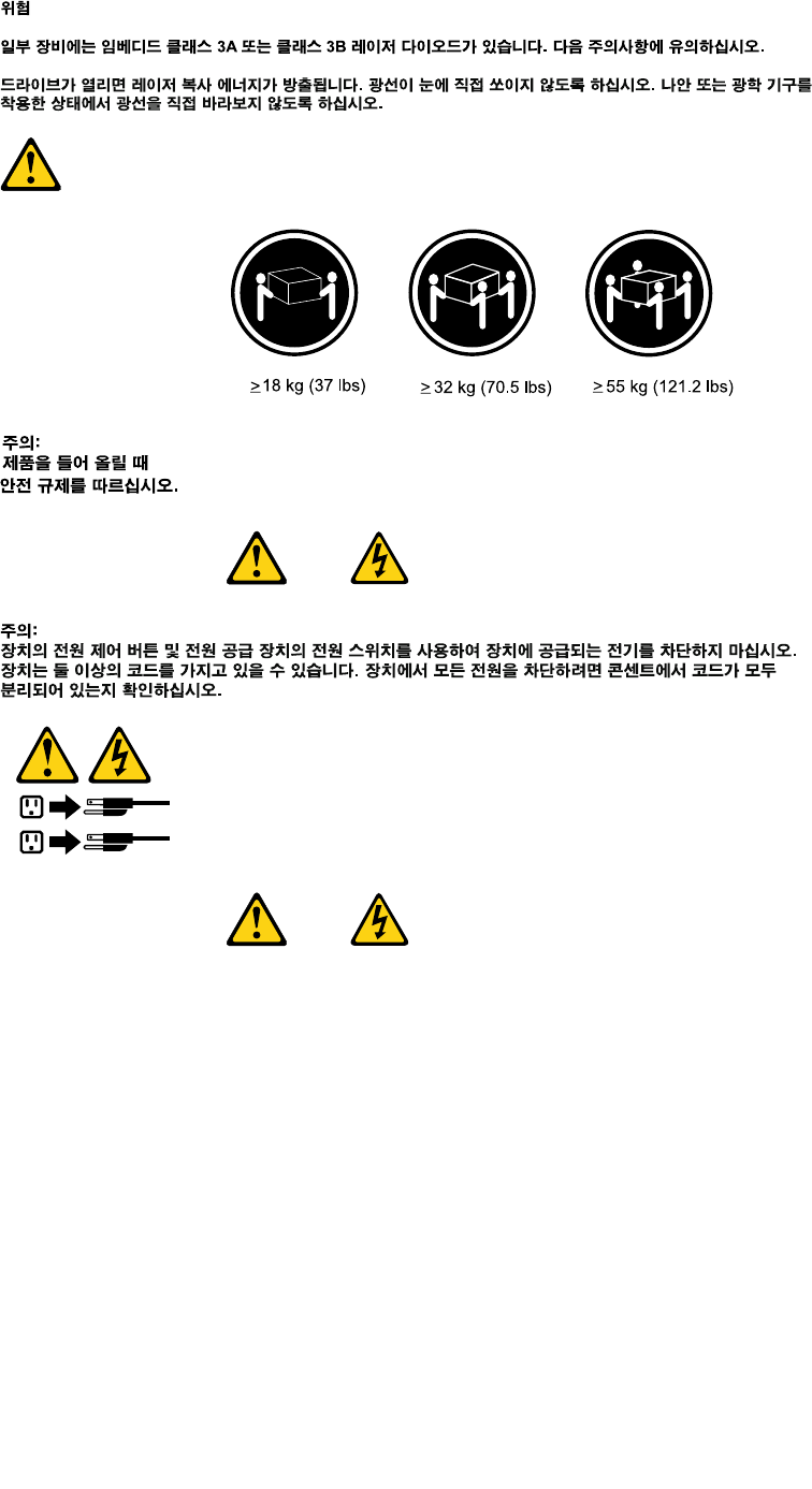
DANGER
SomelaserproductscontainanembeddedClass3AorClass3Blaserdiode.Notethefollowing:
Laserradiationwhenopen.Donotstareintothebeam,donotviewdirectlywithoptical
instruments,andavoiddirectexposuretothebeam.
Chapter2.Safetyinformation7
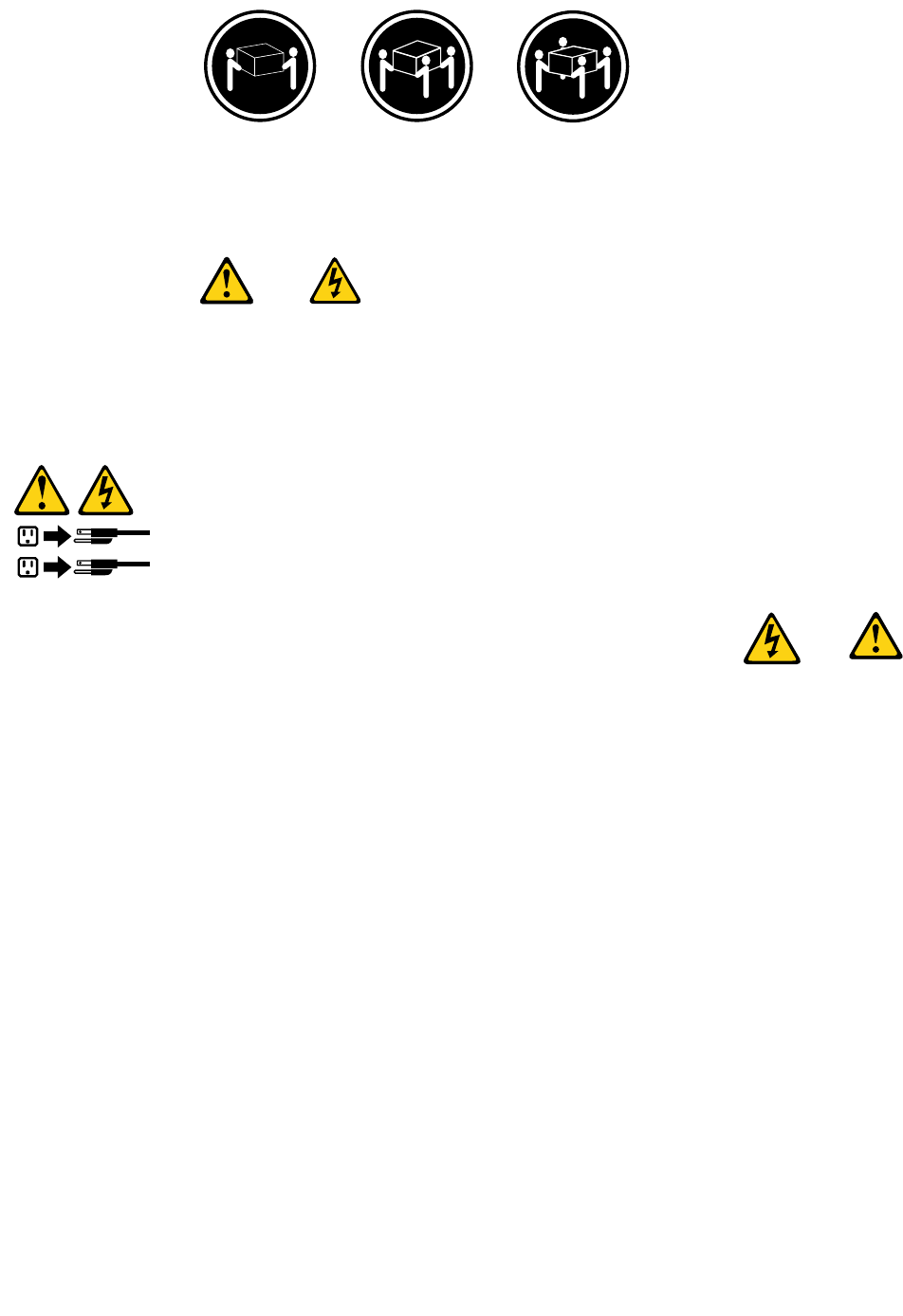
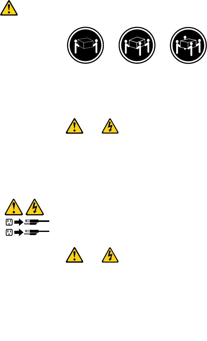
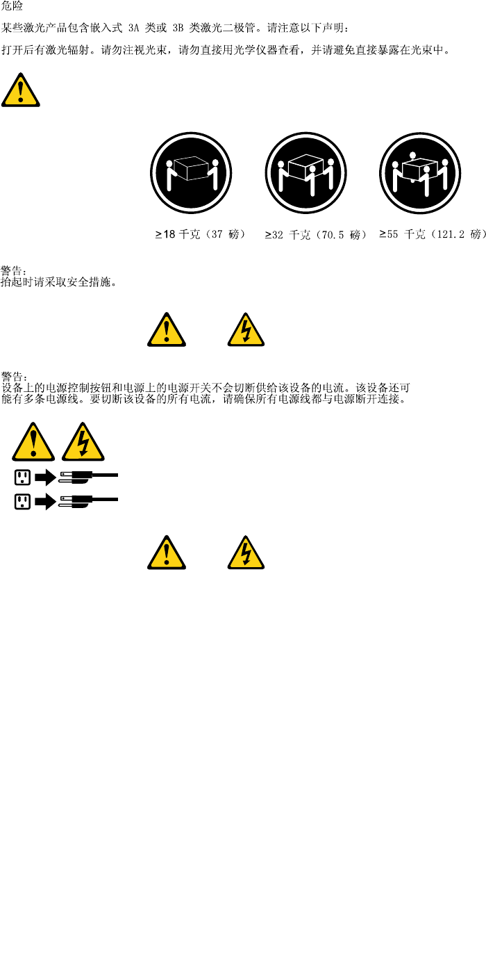
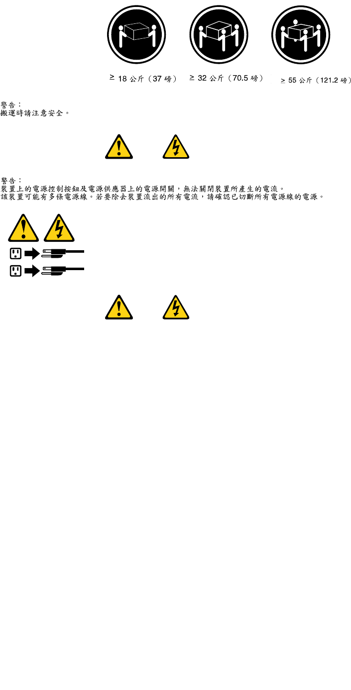
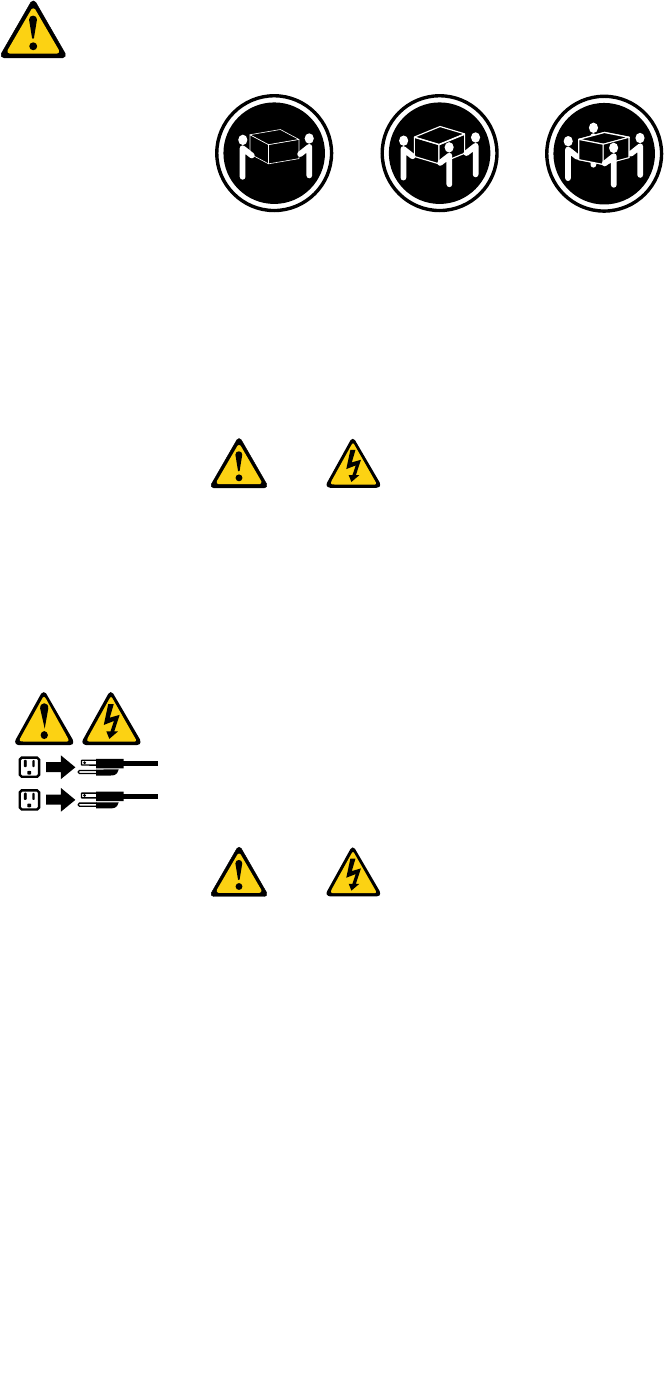
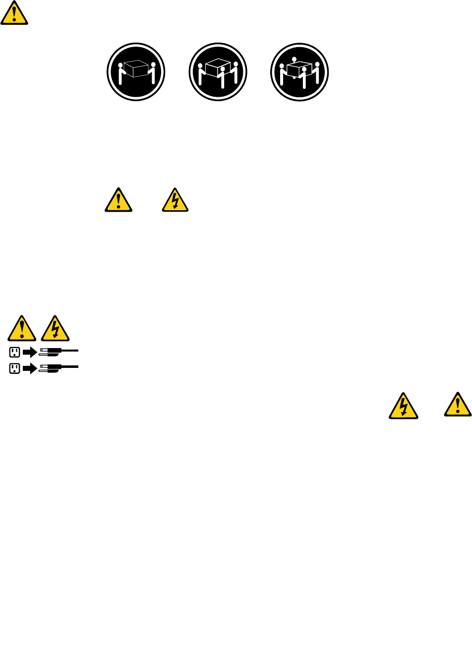
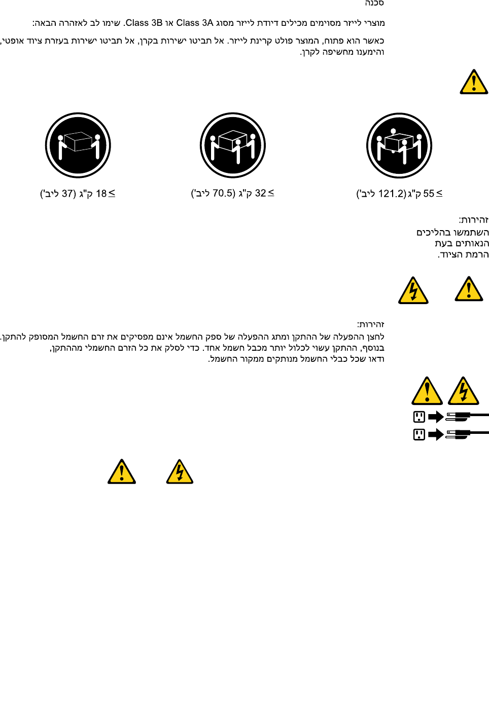
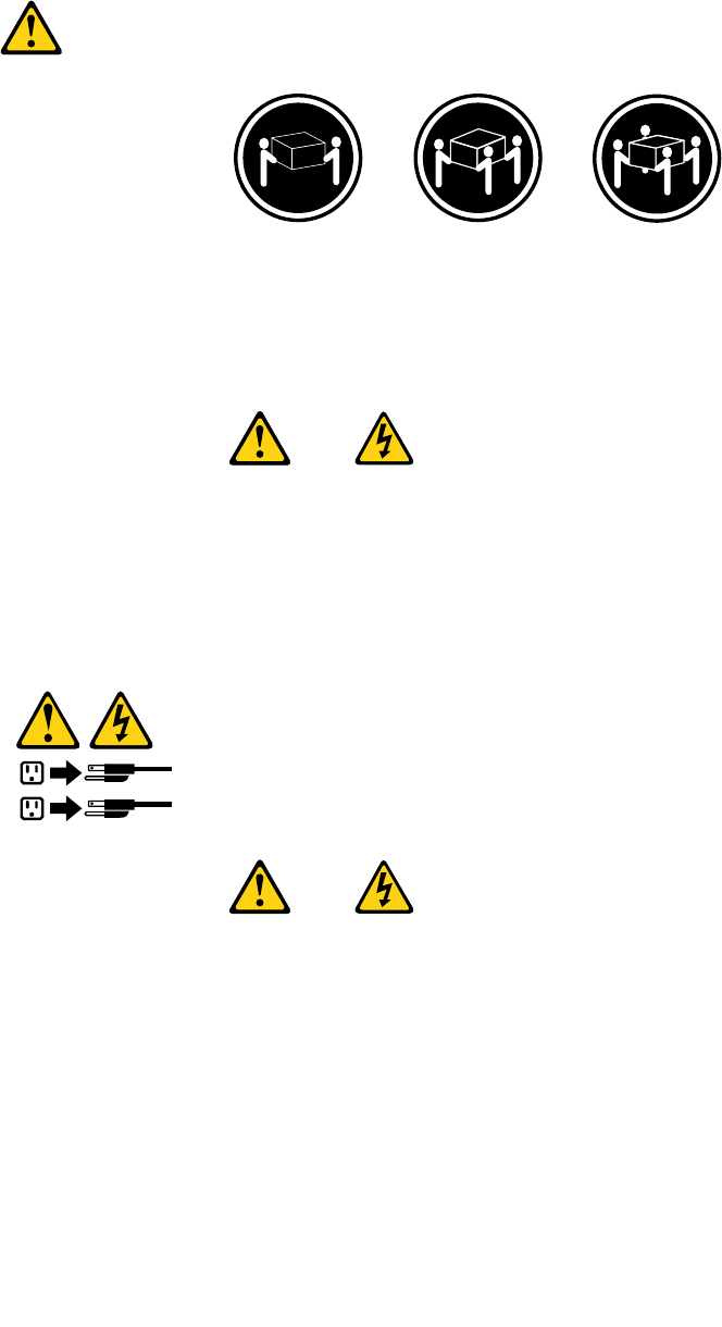
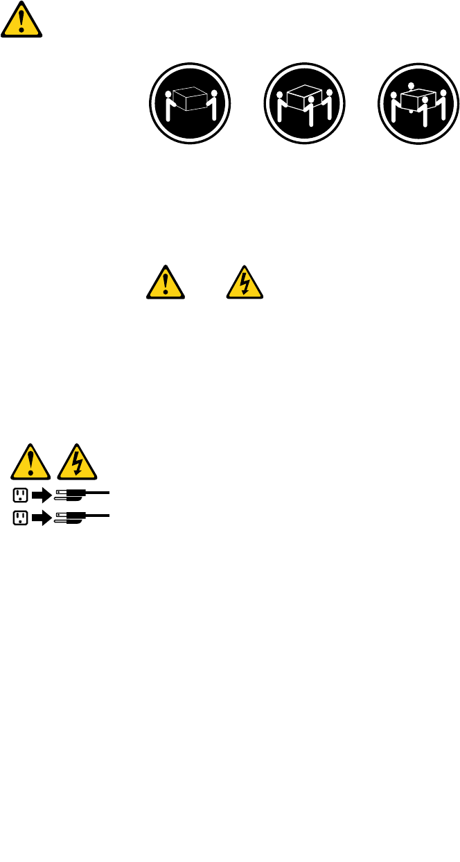
≥18kg(37lbs)≥32kg(70.5lbs)≥55kg(121.2lbs)
CAUTION:
Usesafepracticeswhenlifting.
CAUTION:
Thepowercontrolbuttononthedeviceandthepowerswitchonthepowersupplydonotturnoff
theelectricalcurrentsuppliedtothedevice.Thedevicealsomighthavemorethanonepower
cord.Toremoveallelectricalcurrentfromthedevice,ensurethatallpowercordsaredisconnected
fromthepowersource.
1
2
8ThinkCentreHardwareMaintenanceManual
Chapter2.Safetyinformation9
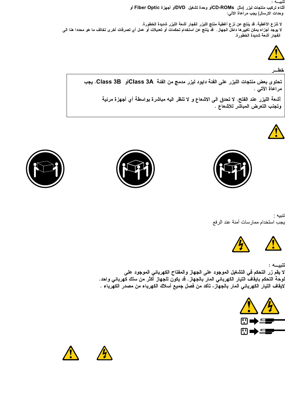
≥18kg(37lbs)≥32kg(70.5lbs)≥55kg(121.2lbs)
1
2
PERIGO
10ThinkCentreHardwareMaintenanceManual
Acorrenteelétricaprovenientedecabosdealimentação,detelefoneedecomunicaçõeséperigosa.
Paraevitarriscodechoqueelétrico:
•Nãoconectenemdesconectenenhumcaboouexecuteinstalação,manutençãooureconguração
desteprodutoduranteumatempestadecomraios.
•Conectetodososcabosdealimentaçãoatomadaselétricascorretamenteinstaladaseaterradas.
•Todoequipamentoqueforconectadoaesteprodutodeveserconectadoatomadascorretamente
instaladas.
•Quandopossível,utilizeapenasumadasmãosparaconectaroudesconectarcabosdesinal.
•Nuncaliguenenhumequipamentoquandohouverevidênciadefogo,águaoudanosestruturais.
•Antesdeabrirtampasdedispositivos,desconectecabosdealimentação,sistemasdetelecomunicação,
redesemodemsconectados,amenosqueespecicadodemaneiradiferentenosprocedimentosde
instalaçãoeconguração.
•Conecteedesconecteoscabosconformedescritonatabelaapresentadaaseguiraoinstalar,moverou
abrirtampasdesteprodutooudedispositivosconectados.
ParaConectar:ParaDesconectar:
1.DESLIGUETudo.
2.Primeiramente,conectetodososcabosaos
dispositivos.
3.Conecteoscabosdesinalaosconectores.
4.Conecteoscabosdealimentaçãoàstomadas.
5.LIGUEosdispositivos.
1.DESLIGUETudo.
2.Primeiramente,removaoscabosdealimentaçãodas
tomadas.
3.Removaoscabosdesinaldosconectores.
4.Removatodososcabosdosdispositivos.
CUIDADO:
Aosubstituirabateriadelítio,utilizeapenasumabateriacomNúmerodePeça45C1566ouumtipo
debateriaequivalenterecomendadopeloSeoseusistemapossuiummódulocomumabateriade
lítio,substitua-oapenasporummódulodomesmotipoedomesmofabricante.Abateriacontémlítio
epodeexplodirsenãoforutilizada,manuseadaoudescartadademaneiracorreta.
Não:
•Jogueoucoloquenaágua
•Aqueçaamaisde100°C(212°F)
•Consertenemdesmonte
Descarteabateriaconformerequeridopelasleisouregulamentoslocais.
PRECAUCIÓN:
Quandoprodutosalaser(comounidadesdeCD-ROMs,unidadesdeDVD-ROM,dispositivosdebraótica
outransmissores)estivereminstalados,observeoseguinte:
Chapter2.Safetyinformation11
•Nãoremovaastampas.Aremoçãodastampasdeumprodutoalaserpoderesultaremexposição
prejudicialàradiaçãodelaser.Nãoexistempeçasquepodemserconsertadasnointeriordodispositivo.
•Autilizaçãodecontrolesouajustesouaexecuçãodeprocedimentosdiferentesdosespecicadosaqui
poderesultaremexposiçãoprejudicialàradiação.
PERIGO
AlgunsprodutosalasercontêmdiododelaserintegradodaClasse3AoudaClasse3B.Observeoseguinte:
Radiaçãoalaserquandoaberto.Nãoolhediretamenteparaofeixeaolhonuoucominstrumentosópticose
eviteexposiçãodiretaaofeixe.
≥18kg(37lbs)≥32kg(70.5lbs)≥55kg(121.2lbs)
CUIDADO:
Utilizeprocedimentosdesegurançaparalevantarequipamentos.
CUIDADO:
Obotãodecontroledealimentaçãododispositivoeobotãoparaligar/desligardafontedealimentação
nãodesligamacorrenteelétricafornecidaaodispositivo.Odispositivotambémpodetermaisdeumcabo
dealimentação.Pararemovertodaacorrenteelétricadodispositivo,assegurequetodososcabosde
alimentaçãoestejamdesconectadosdafontedealimentação.
1
2
12ThinkCentreHardwareMaintenanceManual
Chapter2.Safetyinformation13
1
2
14ThinkCentreHardwareMaintenanceManual
Chapter2.Safetyinformation15
1
2
DANGER
Lecourantélectriqueprovenantdel'alimentation,dutéléphoneetdescâblesdetransmissionpeutprésenter
undanger.
Pourévitertoutrisquedechocélectrique:
•Nemanipulezaucuncâbleetn'effectuezaucuneopérationd'installation,d'entretienoudereconguration
deceproduitaucoursd'unorage.
•Brancheztouslescordonsd'alimentationsurunsocledeprisedecourantcorrectementcâbléetmisàla
terre.
•Branchezsurdessoclesdeprisedecourantcorrectementcâbléstoutéquipementconnectéàceproduit.
•Lorsquecelaestpossible,n'utilisezqu'uneseulemainpourconnecteroudéconnecterlescâbles
d'interface.
•Nemettezjamaisunéquipementsoustensionencasd'incendieoud'inondation,ouenprésencede
dommagesmatériels.
•Avantderetirerlescartersdel'unité,mettezcelle-cihorstensionetdéconnectezsescordons
d'alimentation,ainsiquelescâblesquilarelientauxréseaux,auxsystèmesdetélécommunicationetaux
modems(saufinstructioncontrairementionnéedanslesprocéduresd'installationetdeconguration).
•Lorsquevousinstallez,quevousdéplacez,ouquevousmanipulezleprésentproduitoudespériphériques
quiluisontraccordés,reportez-vousauxinstructionsci-dessouspourconnecteretdéconnecterles
différentscordons.
16ThinkCentreHardwareMaintenanceManual
ConnexionDéconnexion
1.MettezlesunitésHORSTENSION.
2.Commencezparbranchertouslescordonssurles
unités.
3.Branchezlescâblesd'interfacesurdesconnecteurs.
4.Branchezlescordonsd'alimentationsurdesprises.
5.MettezlesunitésSOUSTENSION.
1.MettezlesunitésHORSTENSION.
2.Débranchezlescordonsd'alimentationdesprises.
3.Débranchezlescâblesd'interfacedesconnecteurs.
4.Débrancheztouslescâblesdesunités.
ATTENTION:
Remplacerlapileaulithiumusagéeparunepilederéférenceidentiqueexclusivement,(référence
45C1566),ousuivrelesinstructionsdufabricantquiendénitleséquivalences.Sivotresystèmeest
dotéd'unmodulecontenantunepileaulithium,vousdevezleremplaceruniquementparunmodule
identique,produitparlemêmefabricant.Lapilecontientdulithiumetpeutexploserencasde
mauvaiseutilisation,demauvaisemanipulationoudemiseaurebutinappropriée.
Nepas:
•lajeteràl'eau,
•l'exposeràdestempératuressupérieuresà100°C,
•chercheràlaréparerouàladémonter.
Nepasmettrelapileàlapoubelle.Pourlamiseaurebut,sereporteràlaréglementationenvigueur.
ATTENTION:
Sidesproduitsàlaser(telsquedesunitésdeCD-ROM,deDVD-ROM,desunitésàbresoptiques,ou
desémetteurs)sontinstallés,prenezconnaissancedesinformationssuivantes:
•Neretirezpaslecarter.Enouvrantl'unitédeCD-ROMoudeDVD-ROM,vousvousexposezau
rayonnementdangereuxdulaser.Aucunepiècedel'unitén'estréparable.
•Pourévitertoutrisqued'expositionaurayonlaser,respectezlesconsignesderéglageet
d'utilisationdescommandes,ainsiquelesprocéduresdécritesdansleprésentmanuel.
DANGER
Certainsproduitsàlasercontiennentunediodeàlaserintégréedeclasse3Aou3B.Prenez
connaissancedesinformationssuivantes:
Rayonnementlaserlorsquelecarterestouvert.Eviteztouteexpositiondirecteaurayonlaser.Evitez
deregarderxementlefaisceauoudel'observeràl'aided'instrumentsoptiques.
Chapter2.Safetyinformation17
≥18kg(37lbs)≥32kg(70.5lbs)≥55kg(121.2lbs)
ATTENTION:
Soulevezlamachineavecprécaution.
ATTENTION:
L'interrupteurdecontrôled'alimentationdel'unitéetl'interrupteurdublocd'alimentationnecoupent
paslecourantélectriquealimentantl'unité.Enoutre,lesystèmepeutêtreéquipédeplusieurs
cordonsd'alimentation.Pourmettrel'unitéhorstension,vousdevezdéconnectertouslescordons
delasourced'alimentation.
1
2
VORSICHT
AnNetz-,Telefon-undDatenleitungenkönnengefährlicheSpannungenanliegen.
AusSicherheitsgründen:
•BeiGewitterandiesemGerätkeineKabelanschließenoderlösen.FernerkeineInstallations-,
Wartungs-oderRekongurationsarbeitendurchführen.
•GerätnuraneineSchutzkontaktsteckdosemitordnungsgemäßgeerdetemSchutzkontakt
anschließen.
•AlleangeschlossenenGeräteebenfallsanSchutzkontaktsteckdosenmitordnungsgemäß
geerdetemSchutzkontaktanschließen.
•DieSignalkabelnachMöglichkeiteinhändiganschließenoderlösen,umeinenStromschlagdurch
BerührenvonOberächenmitunterschiedlichemelektrischemPotenzialzuvermeiden.
•Geräteniemalseinschalten,wennHinweiseaufFeuer,WasseroderGebäudeschädenvorliegen.
18ThinkCentreHardwareMaintenanceManual
•DieVerbindungzudenangeschlossenenNetzkabeln,Telekommunikationssystemen,Netzwerken
undModemsistvordemÖffnendesGehäuseszuunterbrechen,sofernindenInstallations-und
KongurationsprozedurenkeineanderslautendenAnweisungenenthaltensind.
•ZumInstallieren,TransportierenundÖffnenderAbdeckungendesComputersoderder
angeschlossenenEinheitendieKabelgemäßderfolgendenTabelleanschließenundabziehen.
ZumAnschließenderKabelgehenSiewiefolgtvorZumAbziehenderKabelgehenSiewiefolgtvor
1.SchaltenSiealleEinheitenAUS.
2.SchließenSieerstalleKabelandieEinheitenan.
3.SchließenSiedieSignalkabelandieBuchsenan.
4.SchließenSiedieNetzkabelandieSteckdosean.
5.SchaltenSiedieEinheitEIN.
1.SchaltenSiealleEinheitenAUS.
2.ZiehenSiezuerstalleNetzkabelausden
Netzsteckdosen.
3.ZiehenSiedieSignalkabelausdenBuchsen.
4.ZiehenSiealleKabelvondenEinheitenab.
CAUTION:
EineverbrauchteLithiumbatterienurdurcheineBatteriemitderTeilenummer45C1566odereine
gleichwertige,vomHerstellerempfohleneBatterieersetzen.EnthältdasSystemeinModulmiteiner
Lithiumbatterie,diesesnurdurcheinModuldesselbenTypsundvondemselbenHerstellerersetzen.
DieBatterieenthältLithiumundkannbeiunsachgemäßerVerwendung,HandhabungoderEntsorgung
explodieren.
DieBatterienicht:
•mitWasserinBerührungbringen.
•über100Cerhitzen.
•reparierenoderzerlegen.
DieörtlichenBestimmungenfürdieEntsorgungvonSondermüllbeachten.
ACHTUNG:
BeiderInstallationvonLasergeräten(wieCD-ROM-Laufwerken,DVD-aufwerken,Einheitenmit
LichtwellenleitertechnikoderSendern)Folgendesbeachten:
•DieAbdeckungennichtentfernen.DurchEntfernenderAbdeckungendesLasergerätskönnen
gefährlicheLaserstrahlungenfreigesetztwerden.DasGerätenthältkeinezuwartendenTeile.
•WerdenSteuerelemente,EinstellungenoderDurchführungenvonProzedurenandersalshier
angegebenverwendet,kanngefährlicheLaserstrahlungauftreten.
VORSICHT
EinigeLasergeräteenthalteneineLaserdiodederKlasse3Aoder3B.BeachtenSieFolgendes:
Chapter2.Safetyinformation19
LaserstrahlungbeigeöffneterVerkleidung.NichtindenStrahlblicken.KeineLupenoderSpiegel
verwenden.Strahlungsbereichmeiden.
≥18kg≥32kg≥55kg
ACHTUNG:
ArbeitsschutzrichtlinienbeimAnhebenderMaschinebeachten.
ACHTUNG:
MitdemNetzschalteranderEinheitundamNetzteilwirddieStromversorgungfürdieEinheit
nichtunterbrochen.DieEinheitkannauchmitmehrerenNetzkabelnausgestattetsein.Umdie
StromversorgungfürdieEinheitvollständigzuunterbrechen,müssenallezumGerätführenden
NetzkabelvomNetzgetrenntwerden.
1
2
20ThinkCentreHardwareMaintenanceManual
Chapter2.Safetyinformation21
1
2
PERICOLO
Lacorrenteelettricaprovenientedaicavidialimentazione,deltelefonoedicomunicazionepuòessere
pericolosa.
Perevitareilrischiodiscosseelettriche:
•Noncollegareoscollegarequalsiasicavooppureeffettuarel'installazione,lamanutenzioneola
ricongurazionedelprodottoduranteuntemporale.
•Collegaretuttiilielettriciaunapresadialimentazionecorrettamentecablataedotatadimessaa
terra.
•Collegareallepreseelettricheappropriatetutteleapparecchiaturecheverrannoutilizzateper
questoprodotto.
22ThinkCentreHardwareMaintenanceManual
•Sepossibile,utilizzaresolounamanopercollegareoscollegareicavidisegnale.
•Nonaccendereassolutamenteapparecchiatureinpresenzadiincendi,perdited'acquaodanno
strutturale.
•Scollegareicavidialimentazione,isistemiditelecomunicazione,leretieilmodemprimadi
aprireicoperchideldispositivo,salvoistruzionicontrarierelativealleprocedurediinstallazionee
congurazione.
•Collegareescollegareicavicomedescrittonellaseguentetabellaquandovengonoeffettuate
operazionidiinstallazione,spostamentooaperturadeicoperchidiquestoprodottoodelleunità
collegate.
PercollegarsiPerscollegarsi
1.SPEGNEREleapparecchiature.
2.Innanzitutto,collegaretuttiicavialleunità.
3.Collegareicavidisegnaleaiconnettori.
4.Collegareicavidialimentazioneallapresa.
5.Accenderel'unità.
1.SPEGNEREleapparecchiature.
2.Innanzitutto,rimuovereicavidialimentazionedalla
presa.
3.Rimuovereicavidisegnaledaiconnettori.
4.Rimuoveretuttiicavidalleunità.
ATTENZIONE:
Quandosisostituiscelabatteriaallitio,utilizzaresoloilNumeroparte45C1566ountipodibatteria
equivalenteconsigliatodalproduttore.Sesulsistemaèpresenteunmodulochecontieneunabatteria
allitio,sostituirlosoloconuntipodimodulodellostessotipodellastessacasadiproduzione.La
batteriacontienelitioepuòesplodereseusata,maneggiataosmaltitainmodononcorretto.
Non:
•Gettareoimmergerelabatterianell'acqua
•Riscaldarlaadunatemperaturasuperioreai100gradiC(212gradiF)
•Smontarla,ricaricarlaotentarediripararla
Lebatterieusatevannosmaltiteinaccordoallanormativainvigore(DPR915/82esuccessive
disposizioniedisposizionilocali).
ATTENZIONE:
Quandovengonoinstallatiprodottilaser(qualiCD-ROM,unitàDVD-ROM,unitàabreotticheo
trasmittenti),tenerpresentequantosegue:
•Nonrimuovereglisportelli.L'aperturadiun'unitàlaserpuòdeterminarel'esposizionearadiazioni
laserpericolose.All'internodell'unitànonvisonopartisucuieffettuarel'assistenzatecnica.
•L'utilizzodicontrolli,regolazioniol'esecuzionediprocedurenondescrittinelpresentemanuale
possonoprovocarel'esposizionearadiazionipericolose.
Chapter2.Safetyinformation23
PERICOLO
AlcuneunitàlasercontengonoundiodolaserdiClasse3AoClasse3B.Tenerpresentequantosegue:
Aprendol'unitàvengonoemesseradiazionilaser.Nonssareilfascio,nonguardarlodirettamente
construmentiotticiedevitarel'esposizionealfascio.
≥18kg≥32kg≥55kg
ATTENZIONE:
Prestareattenzionenelsollevarel'apparecchiatura.
ATTENZIONE:
Ilpulsantedicontrollodell'alimentazionepresentesull'unitàel'interruttoredell'alimentatorenon
disattivanol'alimentazionecorrentefornitaall'unità.E'possibilechel'unitàdispongadipiùcavidi
alimentazione.Perdisattivarel'alimentazionedall'unità,accertarsichetuttiicavidialimentazione
sianoscollegatidallafontedialimentazione.
1
2
24ThinkCentreHardwareMaintenanceManual
Chapter2.Safetyinformation25
1
2
PELIGRO
Lacorrienteeléctricaprocedentedecablesdealimentación,teléfonosycablesdecomunicaciónpuede
serpeligrosa.
Paraevitarelriesgodedescargaeléctrica:
•Noconectenidesconecteloscablesnirealiceningunatareadeinstalación,mantenimientoo
reconguracióndeesteproductoduranteunatormentaeléctrica.
•Conectetodosloscablesdealimentaciónatomasdecorrientedebidamentecableadasy
conectadasatierra.
•Cualquierequipoqueseconecteaesteproductotambiéndebeconectarseatomasdecorriente
debidamentecableadas.
•Siemprequeseaposible,utiliceunasolamanoparaconectarodesconectarloscablesdeseñal.
•Noenciendanuncaunequipocuandohayseñalesdefuego,aguaodañosestructurales.
26ThinkCentreHardwareMaintenanceManual

•Desconecteloscablesdealimentación,lossistemasdetelecomunicaciones,lasredesylos
módemsconectadosantesdeabrirlascubiertasdelosdispositivos,amenosqueseindiquelo
contrarioenlosprocedimientosdeinstalaciónyconguración.
•Conecteydesconecteloscables,comosedescribeenlatablasiguiente,cuandoinstale,muevao
abralascubiertasdeesteproductoodelosdispositivosconectados.
ParaconectarParadesconectar
1.APÁGUELOtodo.
2.Enprimerlugar,conectetodosloscablesalos
dispositivos.
3.Conecteloscablesdeseñalalosconectores.
4.Enchufeloscablesdealimentaciónalastomasde
corriente.
5.Enciendaeldispositivo.
1.APÁGUELOtodo.
2.Enprimerlugar,desenchufeloscablesdealimentación
delastomasdecorriente.
3.Desconecteloscablesdeseñaldelosconectores.
4.Desconectetodosloscablesdelosdispositivos.
PRECAUCIÓN:
Cuandosustituyaunabateríadelitio,utilicesolamenteunabateríanúmerodepieza45C1566uotra
detipoequivalenterecomendadaporelfabricante.Sisusistemadisponedeunmóduloquecontiene
unabateríadelitio,reemplácelosóloconelmismotipodemódulo,delmismofabricante.Labatería
contienelitioypuedeexplotarsinoseutiliza,manipulaodesechacorrectamente.
Nodebe:
•Arrojarlaalaguaosumergirlaenella
•Exponerlaatemperaturassuperioresa100°C(212°F)
•Repararlaodesmontarla
Deshágasedelabateríasegúnespeciquenlasleyesonormaslocales.
PRECAUCIÓN:
Cuandohayaproductosláser(comounidadesdeCD-ROM,unidadesdeDVD,dispositivosdebra
ópticaotransmisores)instalados,tengaencuentalosiguiente:
•Noquitelascubiertas.Siquitalascubiertasdelproductoláser,podríaquedarexpuestoaradiación
láserpeligrosa.Dentrodeldispositivonoexisteningunapiezaquerequieraserviciotécnico.
•Siusacontrolesoajustesorealizaprocedimientosquenoseanlosespecicadosaquí,podría
exponersearadiacionespeligrosas.
PELIGRO
Chapter2.Safetyinformation27
Algunosproductoslásertienenincorporadoundiodoláserdeclase3Aoclase3B.Tengaencuentalo
siguiente:
Cuandoseabre,quedaexpuestoaradiaciónláser.Nomiredirectamentealrayoláser,nisiquieracon
instrumentosópticos,yeviteexponersedirectamentealrayoláser.
≥18kg≥32kg≥55kg
PRECAUCIÓN:
Adopteprocedimientossegurosallevantarelequipo.
PRECAUCIÓN:
Elbotóndecontroldealimentacióndeldispositivoyelinterruptordealimentacióndelafuentede
alimentaciónnodesconectanlacorrienteeléctricasuministradaaldispositivo.Además,eldispositivo
podríatenermásdeuncabledealimentación.Parasuprimirtodalacorrienteeléctricadeldispositivo,
asegúresedequetodosloscablesdealimentaciónesténdesconectadosdelatomadecorriente.
1
2
28ThinkCentreHardwareMaintenanceManual
Chapter3.Generalinformation
Thischapterprovidesgeneralinformationthatappliestoallmachinetypessupportedbythispublication.
Specications
Thissectionliststhephysicalspecicationsforyourcomputer.
Dimensionsandweight
Multi-touchwithframestandNon-touchwithframestandNon-touchwithmonitorstand
Height411.00mm(16.18inches)411.00mm(16.18inches)430.85mm(16.96inches)
Width506.80mm(19.95inches)506.80mm(19.95inches)506.80mm(19.95inches)
Depth107.00mm(4.21inches)100.50mm(4.21inches)227.00mm(8.94inches)
Weight
(maximum)
7.95kg(17.53lbs)6.64kg(14.64lbs)8.40kg(18.52lbs)
Environment
•Airtemperature:
Operating:10°Cto35°C(50°Fto95°F)
Storage:-20°Cto60°C(-4°Fto140°F)
Storage:-10°Cto60°C(14°Fto140°F)withoutpackage
•Humidity:
Operating:20%to80%(non-condensing)
Storage:20%to80%(non-condensing)
•Altitude:
Operating:-50to10000ft(-15.2to3048m)
Storage:-50to35000ft(-15.2to10668m)
Electricalinput
•Inputvoltage:
–Lowrange:
Minimum:100Vac
Maximum:127Vac
Inputfrequencyrange:50to60Hz
–Highrange:
Minimum:200Vac
Maximum:240Vac
Inputfrequencyrange:50to60Hz
LenovoThinkVantageTools
TheLenovoThinkVantage®Toolsprogramguidesyoutoahostofinformationsourcesandprovideseasy
accesstovarioustoolstohelpyouworkmoreeasilyandsecurely.
©CopyrightLenovo201229

ToaccesstheLenovoThinkVantageToolsprogram,clickStart➙AllPrograms➙LenovoThinkVantage
Tools.
ThefollowingtableliststheprogramsthatyoucanaccessfromtheLenovoThinkVantageToolsprogram.To
accessaprogram,double-clickthecorrespondingicon.
Table1.ProgramiconnamesinLenovoThinkVantageTools
ProgramnameIconnameinLenovoThinkVantageTools
CreateRecoveryMediaFactoryRecoveryDisks
FingerprintSoftwareFingerprintReader
LenovoSolutionCenterSystemHealthandDiagnostics
SimpleTapSimpleTap
ThinkVantagePasswordManagerPasswordVault
ThinkVantagePowerManagerPowerControls
ThinkVantageRescueandRecovery®EnhancedBackupandRestore
ThinkVantageSystemUpdateUpdateandDrives
CommunicationsUtilityWebConferencing
ViewManagerScreenLayout
LenovoWelcome
TheLenovoWelcomeprogramintroducesyoutosomeinnovativebuilt-infeaturesofLenovoandguidesyou
throughafewimportantsetuptaskstohelpyoumakethemostofyourcomputer.
LenovoSolutionCenter
TheLenovoSolutionCenterprogramenablesyoutotroubleshootandresolvecomputerproblems.It
combinesdiagnostictests,systeminformationcollection,securitystatus,andsupportinformation,along
withhintsandtipsformaximumsystemperformance.See“LenovoSolutionCenter”onpage51fordetailed
information.
SimpleTap
TheSimpleTapprogramprovidesyouwithaquickwaytocustomizesomebasiccomputersettingssuchas
mutingthespeakers,adjustingthevolume,lockingthecomputeroperatingsystem,launchingaprogram,
openingaWebpage,openingale,andsoon.YoualsocanusetheSimpleTapprogramtoaccessthe
LenovoAppShop,fromwhichyoucandownloadvariousapplicationsandcomputersoftware.
TostarttheSimpleTapprogram,doanyofthefollowing:
•ClickStart➙AllPrograms➙SimpleTap.
•ClickStart➙AllPrograms➙LenovoThinkVantageTools,anddouble-clickSimpleTap.
•ClicktheredSimpleTaplaunchpointonthedesktop.Theredlaunchpointisavailableonthedesktop
afteryouhavelaunchedtheSimpleTapprogramforthersttime.
•PresstheblueThinkVantagebuttonifyourkeyboardhasone.
Note:TheSimpleTapprogramisonlyavailableoncertainmodelspreinstalledwiththeWindows7operating
system.IfyourWindows7modelisnotpreinstalledwiththeSimpleTapprogram,youcandownloadit
fromhttp://www.lenovo.com/simpletap.
30ThinkCentreHardwareMaintenanceManual

Additionalinformationresources
IfyouhaveInternetaccess,themostup-to-dateinformationforyourcomputerisavailablefromtheWorld
WideWeb.
Youcanndthefollowinginformation:
•CRUremovalandinstallationinstructions
•Publications
•Troubleshootinginformation
•Partsinformation
•Downloadsanddrivers
•Linkstootherusefulsourcesofinformation
Toaccessthisinformation,goto:
http://www.lenovo.com/support
Chapter3.Generalinformation31

32ThinkCentreHardwareMaintenanceManual

Chapter4.GeneralCheckout
Attention
Thedrivesinthecomputeryouareservicingmighthavebeenrearrangedorthedrivestartupsequence
changed.Beextremelycarefulduringwriteoperationssuchascopying,saving,orformatting.Dataor
programscanbeoverwrittenifyouselectanincorrectdrive.
Generalerrormessagesappearifaproblemorconictisfoundbyanapplicationprogram,theoperating
system,orboth.Foranexplanationofthesemessages,refertotheinformationsuppliedwiththatsoftware
package.
BeforereplacinganyFRUs,ensurethatthelatestlevelofBIOSisinstalledonthesystem.Adown-levelBIOS
mightcausefalseerrorsandunnecessaryreplacementofthesystemboard.Formoreinformationonhowto
determineandobtainthelatestlevelBIOS,see“BIOSlevels”onpage111.
Usethefollowingproceduretohelpdeterminethecauseoftheproblem:
1.Power-offthecomputerandallexternaldevices.
2.Checkallcablesandpowercords.
3.Setalldisplaycontrolstothemiddleposition.
4.Power-onallexternaldevices.
5.Power-onthecomputer.
•Lookfordisplayederrorcodes
•Listenforbeepcodes
•Lookforreadableinstructionsoramainmenuonthedisplay.
Ifyoudidnotreceivethecorrectresponse,proceedtostep6onpage33.
Ifyoudoreceivethecorrectresponse,proceedtostep7onpage33.
6.Lookatthefollowingconditionsandfollowtheinstructions:
•IfyouhearbeepcodesduringPOST,goto“Beepsymptoms”onpage57.
•IfthecomputerdisplaysaPOSTerror,goto“POSTerrorcodes”onpage58.
•Ifthecomputerhangsandnoerrorisdisplayed,continueatstep7onpage33.
7.RuntheDiagnosticprograms.See“Diagnostics”onpage51.
•Iftheteststopsandyoucannotcontinue,replacethelastdevicetested.
Problemdeterminationtips
Duetothevarietyofhardwareandsoftwarecombinationsthatcanbeencountered,usethefollowing
informationtoassistyouinproblemdetermination.Ifpossible,havethisinformationavailablewhen
requestingassistancefromServiceSupportandEngineeringfunctions.
•Machinetypeandmodel
•Processororharddiskdriveupgrades
•Failuresymptom
–Dodiagnosticsindicateafailure?
–What,when,where,single,ormultiplesystems?
–Isthefailurerepeatable?
–Hasthiscongurationeverworked?
©CopyrightLenovo201233

–Ifithasbeenworking,whatchangesweremadepriortoitfailing?
–Isthistheoriginalreportedfailure?
•Diagnosticsversion
–Typeandversionlevel
•Hardwareconguration
–Print(printscreen)congurationcurrentlyinuse
–BIOSlevel
•Operatingsystemsoftware
–Typeandversionlevel
Notes:Toeliminateconfusion,identicalsystemsareconsideredidenticalonlyifthey:
1.Aretheexactmachinetypeandmodels
2.HavethesameBIOSlevel
3.Havethesameadapters/attachmentsinthesamelocations
4.Havethesameaddressjumpers/terminators/cabling
5.Havethesamesoftwareversionsandlevels
6.HavethesameDiagnosticDiskettes(version)
7.Havethesamecongurationoptionssetinthesystem
8.Havethesamesetupfortheoperatingsystemcontrolles
Comparingthecongurationandsoftwareset-upbetween“workingandnon-working”systemswilloften
leadtoproblemresolution.
34ThinkCentreHardwareMaintenanceManual

Chapter5.Troubleshootinganddiagnostics
Thischapterdescribessomebasictroubleshootinganddiagnosticprograms.Ifyourcomputerproblemis
notdescribedhere,see“Diagnostics”onpage51foradditionaltroubleshootingresources.
Basictroubleshooting
Thefollowingtableprovidesinformationtohelpyoutroubleshootyourcomputerproblems.
Note:Ifyoucannotcorrecttheproblem,havethecomputerserviced.Foralistofserviceandsupport
telephonenumbers,refertotheSafety,Warranty,andSetupGuidethatcomeswithyourcomputerorgoto
theLenovoSupportWebsiteathttp://www.lenovo.com/support/phone.
SymptomAction
Thecomputerdoesnotstart
whenyoupressthepower
switch.
Verifythat:
•Thepowercordiscorrectlyconnectedtotherearofthecomputerandtoa
workingelectricaloutlet.
•Ifyourcomputerhasasecondarypowerswitchontherearofthecomputer,
makesurethatitisswitchedon.
•Thepowerindicatoronthefrontofthecomputerison.
•Thecomputervoltagematchesthevoltageavailableattheelectricaloutletfor
yourcountryorregion.
Themonitorscreenisblank.Verifythat:
•Themonitorpowercordiscorrectlyconnectedtothemonitorandtoaworking
electricaloutlet.
•Themonitoristurnedonandthebrightnessandcontrastcontrolsareset
correctly.
•Thecomputervoltagematchesthevoltageavailableattheelectricaloutletfor
yourcountryorregion.
Thekeyboarddoesnotwork.Verifythat:
•Thecomputeristurnedon.
•ThekeyboardissecurelyconnectedtoaUSBconnectoronthecomputer.
•Nokeysarestuck.
Themousedoesnotwork.Verifythat:
•Thecomputeristurnedon.
•ThemouseissecurelyconnectedtoaUSBconnectoronthecomputer.
•Themouseisclean.
©CopyrightLenovo201235

SymptomAction
Thewirelesskeyboardormouse
doesnotwork.
Verifythat:
•Thecomputeristurnedon.
•Thebatteryorbatteriesinstalledinthewirelesskeyboardormouseareingood
condition.
•Thewirelesscongurationsareallsetcorrectly.Youmightneedtoreferto
thedocumentationthatcomewiththewirelesskeyboardormouse,orrefer
toyourWindowsHelpandSupportinformationsystemforwirelessrelated
instructions.Ifyourwirelessmousehasadongle,makesurethedongleis
correctlyconnectedtooneoftheUSBconnectorsonthecomputer.
•Forthewirelesskeyboard,nokeysarestuck.
•Thewirelessmouseisclean.
Theoperatingsystemdoesnot
start.
Verifythat:
•Thestartupsequenceincludesthedevicewheretheoperatingsystemresides.
Usually,theoperatingsystemisontheharddiskdrive.Formoreinformation,
see“Selectingastartupdevice”onpage55.
Thecomputerbeepsmultiple
timesbeforetheoperating
systemstarts.
Verifythatnokeysarestuck.
Troubleshootingprocedure
Usethefollowingprocedureasastartingpointfordiagnosingproblemsyouareexperiencingwithyour
computer:
1.Verifythatthecablesforallattacheddevicesareconnectedcorrectlyandsecurely.
2.Verifythatallattacheddevicesthatrequireacpowerareconnectedtoproperlygrounded,functioning
electricaloutlets.
3.VerifythatallattacheddevicesareenabledintheBIOSsettingsofyourcomputer.Formoreinformation
aboutaccessingandchangingtheBIOSsettings,refertoyourChapter6“UsingtheSetupUtility
program”onpage53.
4.Gotothe“Troubleshooting”onpage37andfollowtheinstructionsforthetypeofproblemyouare
experiencing.IftheTroubleshootinginformationdoesnothelpyouresolveaproblem,continuewiththe
nextstep.
5.Tryusingapreviouslycapturedcongurationtoseeifarecentchangetohardwareorsoftwaresettings
hascausedaproblem.Beforerestoringapreviousconguration,captureyourcurrentcongurationin
casetheoldercongurationsettingsdonotsolvetheproblemorhaveadverseaffects.Torestorea
capturedconguration,clickStart➙ControlPanel➙SystemandSecurity➙System➙System
Protection➙SystemRestore.Ifthisdoesnotcorrecttheproblem,continuewiththenextstep.
6.Runthediagnosticprograms.See“Diagnostics”onpage51formoreinformation.
•Ifthediagnosticprogramsdetectahardwarefailure,contacttheLenovoCustomerSupportCenter.
See“Additionalinformationresources”onpage31formoreinformation.
•Ifyouareunabletorunthediagnosticprograms,contacttheLenovoCustomerSupportCenter.See
“Additionalinformationresources”onpage31formoreinformation.
•Ifthediagnosticprogramsdonotdetectahardwarefailure,continuewiththenextstep.
7.Useanantivirusprogramtoseeifyourcomputerhasbeeninfectedbyavirus.Iftheprogramdetectsa
virus,removethevirus.
8.Ifnoneoftheseactionssolvetheproblem,seektechnicalassistance.See“Additionalinformation
resources”onpage31formoreinformation.
36ThinkCentreHardwareMaintenanceManual

Troubleshooting
Usethetroubleshootinginformationtondsolutionstoproblemsthathavedenitesymptoms.
Ifthesymptomyourcomputerisexperiencingoccurredimmediatelyafteranewhardwareoptionornew
softwareinstalled,dothefollowingbeforereferringtothetroubleshootinginformation:
1.Removethenewhardwareoptionorsoftware.Ifyoumustremovethecomputercovertoremovea
hardwareoption,havethecomputerserviced.Foryoursafety,donotoperatethecomputerwiththe
coverremoved.
2.Runthediagnosticprogramstoensureyourcomputerisoperatingcorrectly.
3.Reinstallthenewhardwareoptionorsoftware.
Selecttheproblemyourcomputerisexperiencingfromthefollowinglist:
•“Audioproblems”onpage37
•“CDproblems”onpage38
•“DVDproblems”onpage39
•“Intermittentproblems”onpage41
•“Keyboard,mouse,orpointingdeviceproblems”onpage41
•“Monitorproblems”onpage43
•“Networkingproblems”onpage44
•“Optionproblems”onpage47
•“Performanceandlockupproblems”onpage48
•“Printerproblems”onpage49
•“Serialportproblems”onpage49
•“Softwareproblems”onpage50
•“USBproblems”onpage51
Audioproblems
Selectyoursymptomfromthefollowinglist:
•“NoaudioinWindows”onpage37
•“AnaudiodiscorAutoPlay-enableddiscdoesnotautomaticallyplaywhenitisinsertedintoadrive”
onpage38
•“Soundcomesfromoneexternalspeakeronly”onpage38
•“NoaudioinDOSapplicationsorgames”onpage38
NoaudioinWindows
Symptom:NoaudioinWindows
Actions:
•IfyouareusingpoweredexternalspeakersthathaveanOn/Offcontrol,verifythattheOn/Offcontrolis
settotheOnpositionandthespeakerpowercableisconnectedtoaproperlygrounded,functionalac
electricaloutlet.
•Ifyourexternalspeakershaveavolumecontrol,verifythatthevolumecontrolisnotsettoolow.
•Double-clickthespeakericonintheWindowsnoticationarea.Amastervolume-controlwindowopens.
VerifythattheMutesettingsarenotcheckedandnoneofthevolumesettingsissettoolow.
Chapter5.Troubleshootinganddiagnostics37

•Somemodelshaveafrontaudiopanelyoucanusetoadjustvolume.Ifyouhaveafrontaudiopanel,
verifythatthevolumeisnotsettoolow.
•Verifythatyourexternalspeakers(andheadphones,ifused)areconnectedtothecorrectaudioconnector
onthecomputer.Mostspeakercablesarecolor-codedtomatchtheconnector.
Note:Whenexternal-speakerorheadphonecablesareattachedtotheaudioconnector,theinternal
speaker,ifpresent,isdisabled.Inmostcases,ifanaudioadapterisinstalledinoneoftheexpansionslots,
theaudiofunctionbuiltintothesystemboardisdisabled;usetheaudiojacksontheadapter.
•MakesurethattheprogramyouarerunningisdesignedforuseintheMicrosoftWindowsoperating
system.IftheprogramisdesignedtoruninDOS,theprogramdoesnotusetheWindowssoundfeature
andmustbeconguredtouseSoundBlasterProorSoundBlasteremulation.
•Verifythattheaudiodevicedriversarecorrectlyinstalled.SeeMicrosoftWindowshelpsystemformore
information.
Iftheseactionsdonotcorrecttheproblem,runthediagnosticprograms(see“Diagnostics”onpage51for
instructions).Ifyouneedtechnicalassistance,see“Additionalinformationresources”onpage31.
AnaudiodiscorAutoPlay-enableddiscdoesnotautomaticallyplaywhenitis
insertedintoadrive
Symptom:AnaudiodiscorAutoPlay-enableddiscdoesnotautomaticallyplaywhenitisinsertedintoadrive
Action:See“CDproblems”onpage38.
Soundcomesfromoneexternalspeakeronly
Symptom:Soundcomesfromoneexternalspeakeronly.
Actions:
•Ensurethatthespeakercableisinsertedcompletelyintotheconnectoronthecomputer.
•Makesurethecablethatattachestheleftspeakertotherightspeakerissecurelyconnected.
•Double-clickthespeakericonintheWindowsnoticationarea.Amastervolume-controlwindowopens.
VerifythattheBalancesettingsaresetcorrectly.
Iftheseactionsdonotcorrecttheproblem,youmighthaveafailingspeaker.Havethespeakerserviced.If
youneedtechnicalassistance,see“Additionalinformationresources”onpage31.
NoaudioinDOSapplicationsorgames
Symptom:NoaudioinDOSapplicationsorgames
Actions:
•MakesuretheDOSapplicationorgameisconguredtouseSoundBlasterProorSoundBlaster
emulation.Refertothedocumentationthatcomeswiththeapplicationorgameforinstructionson
settingsound-cardsettings.
•Iftheseactionsdonotcorrecttheproblem,runthediagnosticprograms(see“Diagnostics”onpage51
forinstructions).Ifyouneedtechnicalassistance,see“Additionalinformationresources”onpage31.
CDproblems
Selectyoursymptomfromthefollowinglist:
•“AnaudiodiscorAutoPlay-enableddiscdoesnotautomaticallyplaywhenitisinsertedintoaCD
drive”onpage39
38ThinkCentreHardwareMaintenanceManual

•“ACDorDVDdoesnotwork”onpage39
•“Unabletouseastartable(bootable)recoverymedium,suchastheProductRecoveryCD,tostart
yourcomputer”onpage39
AnaudiodiscorAutoPlay-enableddiscdoesnotautomaticallyplaywhenitis
insertedintoaCDdrive
Symptom:AnaudiodiscorAutoPlay-enableddiscdoesnotautomaticallyplaywhenitisinsertedinto
aCDdrive.
Actions:
•IfyouhavemultipleCDorDVDdrivesinstalled(oracombinationofCDandDVDdrives),tryinsertingthe
discintotheotherdrive.Insomecases,onlyoneofthedrivesisconnectedtotheaudiosubsystem.
•IfyouareusingtheWindows7operatingsystem,followtheactionfor“ACDorDVDdoesnotwork”
onpage39.
Ifthisdoesnotcorrecttheproblem,followtheactionfor“ACDorDVDdoesnotwork”onpage39.
ACDorDVDdoesnotwork
Symptom:ACDorDVDdoesnotwork.
Actions:
•Verifythatthediscisinsertedcorrectly,withitslabelup.
•Makesurethatthediscyouareusingisclean.Toremovedustorngerprints,wipethedisccleanwitha
softclothfromthecentertotheoutside.Wipingadiscinacircularmotionmightcauselossofdata.
•Verifythatthediscyouareusingisnotscratchedordamaged.Tryinsertinganotherdiscthatyouknow
isgood.Ifyoucannotreadfromaknown-gooddisc,youmighthaveaproblemwithyourCDorDVD
driveorthecablingtoyourCDorDVDdrive.Makesurethatthepowercableandsignalcableare
securelyconnectedtothedrive.
Unabletouseastartable(bootable)recoverymedium,suchastheProductRecovery
CD,tostartyourcomputer
Symptom:Unabletouseastartable(bootable)recoverymedium,suchastheProductRecoveryCD,
tostartyourcomputer.
Action:MakesurethattheCDorDVDdriveisinthestartupsequencebeforetheharddiskdrive.Refer
toyour“Selectingorchangingthestartupdevicesequence”onpage55forinformationonviewingand
changingthestartupsequence.Notethatonsomemodelsthestartupsequenceispermanentlysetand
cannotbechanged.
Iftheseactionsdonotcorrecttheproblem,runthediagnosticprograms(see“Diagnostics”onpage51for
instructions).Ifyouneedtechnicalassistance,see“Additionalinformationresources”onpage31.
DVDproblems
Selectyoursymptomfromthefollowinglist:
•“BlackscreeninsteadofDVDvideo”onpage40
•“DVDmoviewillnotplay”onpage40
•“NoaudioorintermittentaudiowhileplayingDVDmovie”onpage40
•“Playbackisverysloworchoppy”onpage40
•“Invaliddiscornodiscfoundmessage”onpage40
Chapter5.Troubleshootinganddiagnostics39

BlackscreeninsteadofDVDvideo
Symptom:BlackscreeninsteadofDVDvideo
Actions:
•RestarttheDVDplayerprogram.
•Closeanyopenles,turnoffthecomputer,andthenrestartthecomputer.
•Tryalowerscreenresolutionorcolordepth.
Iftheseactionsdonotcorrecttheproblem,runthediagnosticprograms(see“Diagnostics”onpage51for
instructions).Ifyouneedtechnicalassistance,see“Additionalinformationresources”onpage31.
DVDmoviewillnotplay
Symptom:DVDmoviewillnotplay.
Actions:
•Makesurethatthediscsurfaceiscleanandnotscratched.
•Checkthediscorpackageforregionalcoding.Youmightneedtopurchaseadiscwithcodingfor
theregionwhereyouareusingyourcomputer.
Iftheseactionsdonotcorrecttheproblem,runthediagnosticprograms(see“Diagnostics”onpage51for
instructions).Ifyouneedtechnicalassistance,see“Additionalinformationresources”onpage31.
NoaudioorintermittentaudiowhileplayingDVDmovie
Symptom:NoaudioorintermittentaudiowhileplayingDVDmovie.
Actions:
•Checkthevolumecontrolsettingsonyourcomputerandonyourspeakers.
•Makesurethatthediscsurfaceiscleanandnotscratched.
•Checkallcableconnectionstoandfromthespeakers.
•UsetheDVDmenuforthevideotoselectadifferentaudiotrack.
Iftheseactionsdonotcorrecttheproblem,runthediagnosticprograms(see“Diagnostics”onpage51for
instructions).Ifyouneedtechnicalassistance,see“Additionalinformationresources”onpage31.
Playbackisverysloworchoppy
Symptom:Playbackisverysloworchoppy.
Actions:
•Disableanybackgroundprograms,suchasAntiVirusorDesktopThemes.
•Ensurethatvideoresolutionissettolessthan1152x864.
Iftheseactionsdonotcorrecttheproblem,runthediagnosticprograms(see“Diagnostics”onpage51for
instructions).Ifyouneedtechnicalassistance,see“Additionalinformationresources”onpage31.
Invaliddiscornodiscfoundmessage
Symptom:Invaliddiscornodiscfoundmessage
Actions:
40ThinkCentreHardwareMaintenanceManual

•EnsurethataDVDdiscisinthedrivewiththeshinysideofthediscfacingdown.
•Ensurethatvideoresolutionissettolessthan1152x864.
•OncomputersthathaveaCD-ROMorCD-RWdriveinadditiontoaDVD-ROMdrive,makesurethatthe
DVDdiscisinthedrivelabeled“DVD”.
Iftheseactionsdonotcorrecttheproblem,runthediagnosticprograms(see“Diagnostics”onpage51for
instructions).Ifyouneedtechnicalassistance,see“Additionalinformationresources”onpage31.
Intermittentproblems
Symptom:Aproblemoccursonlyoccasionallyandisdifculttorepeat.
Actions:
•Verifythatallcablesandcordsaresecurelyconnectedtothecomputerandattacheddevices.
•Verifythatwhenthecomputerison,thefanisnotblocked(thereisairowaroundthefan),andthefanis
working.Ifairowisblockedorthefanisnotworking,thecomputermightoverheat.
•IfSCSIdevicesareinstalled,verifythatthelastexternaldeviceineachSCSIchainisterminatedcorrectly.
(SeeyourSCSIdocumentation.)
Iftheseactionsdonotcorrecttheproblem,runthediagnosticprograms(see“Diagnostics”onpage51for
instructions).Ifyouneedtechnicalassistance,see“Additionalinformationresources”onpage31.
Keyboard,mouse,orpointingdeviceproblems
Selectyoursymptomfromthefollowinglist:
•“Allorsomekeysonthekeyboarddonotwork”onpage41
•“Themouseorpointingdevicedoesnotwork”onpage42
•“Thepointeronthescreendoesnotmovesmoothlywiththemouse”onpage42
•“Thengerprintreaderdoesnotwork”onpage42
•“Thewirelesskeyboarddoesnotwork”onpage42
Allorsomekeysonthekeyboarddonotwork
Symptom:Allorsomekeysonthekeyboarddonotwork.
Actions:
•Verifythatthekeyboardcableissecurelyconnectedtothecorrectconnectoronthecomputer.
•IfyouareusinganEnhancedPerformanceUSBkeyboardandoneormoreoftheRapidAccessbuttons
aretheonlykeysthatarenotworking,thesebuttonsmighthavebeendisabledorhavenotbeenassigned
toafunction.UsethehelpsystemintheEnhancedPerformanceCustomizationKeyboardprogramto
helpdiagnoseproblemswiththeRapidAccessbuttons.
•OntheWindows7operatingsystem,dothefollowing:
1.ClickStart➙ControlPanel.
2.ClickHardwareandSound.
3.ClickDevicesandPrinters.
4.Double-clickUSBEnhancedPerformanceKeyboard.TheUSBEnhancedPerformanceKeyboard
Customizationprogramstarts.
Chapter5.Troubleshootinganddiagnostics41

Iftheseactionsdonotcorrecttheproblem,havethecomputerandkeyboardserviced.See“Additional
informationresources”onpage31fordetails.
Themouseorpointingdevicedoesnotwork
Symptom:Themouseorpointingdevicedoesnotwork.
Actions:
•Verifythatthemouseorpointing-devicecableissecurelyattachedtothecorrectconnectoronthe
computer.Dependingonthetypeofmouseyouhave,themousecablewillconnecttoeitherthe
mouse,serial,orUSBconnector.SomekeyboardshaveintegratedUSBconnectorsthatcanbeused
foraUSBmouseorpointingdevice.
•Verifythatthedevicedriversforthemouseorpointingdeviceareinstalledcorrectly.
•IfyouareusingaUSBkeyboardormouse,verifythattheUSBconnectorsareenabledintheBIOS
settings.See“Enablingordisablingadevice”onpage55.
Iftheseactionsdonotcorrecttheproblem,runthediagnosticprograms(see“Diagnostics”onpage51for
instructions).Ifyouneedtechnicalassistance,see“Additionalinformationresources”onpage31.
Thepointeronthescreendoesnotmovesmoothlywiththemouse
Symptom:Thepointeronthescreendoesnotmovesmoothlywiththemouse.
Action:Erraticmovementofthemousepointerisgenerallycausedbyabuildupofdirt,oils,andother
contaminantsontheballinsidethemouse.Cleanthemouse.
Thengerprintreaderdoesnotwork
Symptom:Thengerprintreaderdoesnotwork.
Action:Thefollowingcouldcausethengerprintreadernottooperateproperly:
•Notenrollingyourngerprintcorrectly.
•Scratchingthesurfaceofthereaderwithahard,pointedobject.
•Scrapingthesurfaceofthereaderwithyournailoranythinghard.
•Usingortouchingthereaderwithadirtynger.
•Thesurfaceofyourngerisverydifferentfromwhenyouenrolledyourngerprint.
Thewirelesskeyboarddoesnotwork
Symptom:Thewirelesskeyboarddoesnotwork.
Action:IftheTransceiverCommunicationsLEDisonandthewirelessKeyboarddoesnotwork,restartyour
computer.Ifrestartingyourcomputerdoesnotsolvetheproblem,verifythatthefollowingconditionsaremet:
•Thebatteriesareproperlyinstalled.
•Thebatteriesstillretaintheircurrent.
•Thewirelesskeyboardislocatedlessthantenmetersawayfromthetransceiver.
•Thetransceiverisfullyinstalled.
Action:IfthetransceivercommunicationsLEDisnoton,reconnectthetransceiverandthekeyboard.
42ThinkCentreHardwareMaintenanceManual

Monitorproblems
Note:Manymonitorshavestatus-indicatorlightsandbuilt-incontrolsforadjustingbrightness,contrast,
width,height,andotherpictureadjustments.However,thecontrolsvaryfrommonitortypetomonitortype.
Selectyoursymptomfromthefollowinglist:
•“Wrongcharactersappearonthescreen”onpage43
•“Themonitorworkswhenyouturnonthecomputer,butgoesblankaftersomeperiodofcomputer
inactivity”onpage43
•“Themonitorworkswhenyouturnonthecomputer,butgoesblankwhenyoustartsomeapplication
programs”onpage43
•“Theimageappearstobeickering”onpage43
•“Theimageisdiscolored”onpage44
Wrongcharactersappearonthescreen
Symptom:Wrongcharactersappearonthescreen.
Action:Havethecomputerserviced.Fordetails,see“Additionalinformationresources”onpage31.
Themonitorworkswhenyouturnonthecomputer,butgoesblankaftersomeperiod
ofcomputerinactivity
Symptom:Themonitorworkswhenyouturnonthecomputer,butgoesblankaftersomeperiodofcomputer
inactivity.
Action:Thecomputerisprobablysetforenergysavingswiththepower-managementfeature.Ifthe
power-managementfeatureisenabled,disablingitorchangingthesettingsmightsolvetheproblem.
Iftheseactionsdonotcorrecttheproblem,runthediagnosticprograms(see“Diagnostics”onpage51for
instructions).Ifyouneedtechnicalassistance,see“Additionalinformationresources”onpage31.
Themonitorworkswhenyouturnonthecomputer,butgoesblankwhenyoustart
someapplicationprograms
Symptom:Themonitorworkswhenyouturnonthecomputer,butgoesblankwhenyoustartsome
applicationprograms.
Action:
Verifythatthenecessarydevicedriversfortheapplicationprogramsareinstalled.Refertothedocumentation
fortheaffectedapplicationprogramtoseeifdevicedriversarerequired.
Iftheseactionsdonotcorrecttheproblem,runthediagnosticprograms(see“Diagnostics”onpage51for
instructions).Ifyouneedtechnicalassistance,see“Additionalinformationresources”onpage31.
Theimageappearstobeickering
Symptom:Theimageappearstobeickering.
Actions:
•Themonitormightbeoperatinginalow-refreshratedisplaymode.Setthemonitortothehighest,
noninterlacedrefreshratesupportedbyyourmonitorandthevideocontrollerinyourcomputer.
•Themonitormightbeaffectedbyinterferencefromnearbyequipment.Magneticeldsaroundother
devices,suchastransformers,appliances,uorescentlights,andothermonitorsmightbecausingthe
Chapter5.Troubleshootinganddiagnostics43

problem.Moveuorescentdesklightingoranyequipmentthatproducesmagneticeldsfartheraway
fromthemonitor.Ifthisdoesnotcorrecttheproblem,dothefollowing:
1.Turnoffthemonitor.(Movingacolormonitorwhileitisturnedonmightcausescreendiscoloration.)
2.Adjusttheplacementofthemonitorandotherdevicessothattheyareatleast305mm(12inches)
apart.
3.Turnonthemonitor.
•YoucanresettherefreshratethroughyouroperatingsystemControlPanel:
OntheWindows7operatingsystem,clickStart➙ControlPanel➙HardwareandSound➙Adjust
screenresolution➙AdvancedSettings.ThenclicktheMonitortabandselectanewrefreshrate.
•Seeyouroperatingsystemdocumentationorhelpforfurtherinformationonmonitorsettings.
Iftheseactionsdonotcorrecttheproblem,yourmonitormightneedservice.See“Additionalinformation
resources”onpage31fordetails.
Theimageisdiscolored
Symptom:Theimageisdiscolored.
Action:Themonitormightbeaffectedbyinterferencefromnearbyequipment.Magneticeldsaroundother
devices,suchastransformers,appliances,uorescentlights,andothermonitorsmightbecausingthe
problem.Moveuorescentdesklightingoranyequipmentthatproducesmagneticeldsfurtherawayfrom
themonitor.Ifthisdoesnotcorrecttheproblem,dothefollowing:
1.Turnoffthemonitor.(Movingacolormonitorwhileitisturnedonmightcausescreendiscoloration.)
2.Adjusttheplacementofthemonitorandotherdevicessothattheyareatleast305mm(12inches)apart.
3.Turnonthemonitor.
Iftheseactionsdonotcorrecttheproblem,yourmonitormightneedservice.See“Additionalinformation
resources”onpage31fordetails.
Networkingproblems
Thefollowingarethemostcommonnetworkingproblems.Selectyournetworkingproblemfromthe
followinglist:
•“Ethernetproblems”onpage44
•“AwirelessLANproblem”onpage46
•“AwirelessWANproblem”onpage46
•“Bluetoothproblems”onpage46
Ethernetproblems
ForEthernetproblems,selectyoursymptomfromthefollowinglist:
•“Yourcomputercannotconnecttothenetwork”onpage44
•“Theadapterstopsworkingfornoapparentreason”onpage45
•“IfyourcomputerisaGigabitEthernetmodelandyouuseaspeedof1000Mbps,theconnectionfails
orerrorsoccur”onpage45
•“IfyourcomputerisaGigabitEthernetmodel,itcannotconnecttothenetworkat1000Mbps.Instead,
itconnectsat100Mbps”onpage46
Yourcomputercannotconnecttothenetwork
Symptom:Yourcomputercannotconnecttothenetwork.
44ThinkCentreHardwareMaintenanceManual

Actions:Makesurethat:
•Thecableisinstalledproperly.
ThenetworkcablemustbesecurelyconnectedtoboththeEthernetconnectorofyourcomputerand
theRJ45connectorofthehub.Themaximumallowabledistancefromthecomputertohubis100
meters.Ifthecableisconnectedandthedistanceiswithinacceptablelimitsbuttheproblempersists,try
adifferentcable.
•Thecableisinstalledproperly.
•Youareusingthecorrectdevicedriver.
OntheWindows7operatingsystem,dothefollowing:
1.ClickStart➙ControlPanel.
2.ClickHardwareandSound.
3.ClickDeviceManager.Ifyouarepromptedforanadministratorpasswordorconrmation,typethe
passwordorprovideconrmation.
4.IfanexclamationmarkisdisplayednexttoanadapternameunderNetworkadapters,youmightnot
usethecorrectdriverorthedriverisnotenabled.Toupdatethedriver,right-clickthehighlighted
adapter.
5.ClickUpdateDriverSoftware,andthenfollowtheinstructionsonthescreen.
•Theswitchportandtheadapterhavethesameduplexsetting.
Ifyouconguredtheadapterforfullduplex,makesuretheswitchportisalsoconguredforfullduplex.
Settingthewrongduplexmodecandegradeperformance,causedataloss,orresultinlostconnections.
•Youhaveinstalledallnetworkingsoftwarethatisnecessaryforyournetworkenvironment.
CheckwithyourLANadministratorforthenecessarynetworkingsoftware.
Theadapterstopsworkingfornoapparentreason
Symptom:Theadapterstopsworkingfornoapparentreason.
Action:Thenetworkdriverlesmaybecorruptormissing.Updatethedriverbyreferringtothe“Solution”
descriptionfortheproceduretomakesurethatthecorrectdevicedriverisinstalled.
TheWakeonLANfeatureisnotworking
Symptom:TheWakeonLAN(WOL)featureisnotworking.
Actions:
•MakesurethatWOLisenabledintheBIOSSetupUtilityprogram.
•Ifitis,checkwithyourLANadministratorforthenecessarysettings.
IfyourcomputerisaGigabitEthernetmodelandyouuseaspeedof1000Mbps,theconnection
failsorerrorsoccur
Symptom:IfyourcomputerisaGigabitEthernetmodelandyouuseaspeedof1000Mbps,theconnection
failsorerrorsoccur.
Actions:
•UseCategory5wiringandmakesurethatthenetworkcableissecurelyconnected.
•Connecttoa1000BASE-Thub/switch(not1000BASE-X).
Chapter5.Troubleshootinganddiagnostics45

IfyourcomputerisaGigabitEthernetmodel,itcannotconnecttothenetworkat1000Mbps.Instead,
itconnectsat100Mbps
Symptom:IfyourcomputerisaGigabitEthernetmodel,itcannotconnecttothenetworkat1000Mbps.
Instead,itconnectsat100Mbps.
Actions:
•Tryanothercable.
•Makesurethatthelinkpartnerissettoauto-negotiate.
•Makesurethattheswitchis802.3ab-compliant(gigabitovercopper).
AwirelessLANproblem
Symptom:Youcannotconnectusingthebuilt-inwirelessnetworkingcard.
Actions:
•MakesurethatyourwirelessLANdriveristhelatestversion.ChecktheWebsiteandverifythedriver
versionsupportedbyAccessConnectionsisthelatestdocumentedinthereadmele.
•Makesurethatyourcomputeriswithinrangeofawirelessaccesspoint.
•Makesurethatthewirelessradioisenabledbydouble-clickingtheAccessConnectionsiconinthe
Windowsnoticationarea.
Note:IfyourcomputerispreinstalledwiththeWindows7operatingsystem,clickShowhiddeniconsin
theWindowsnoticationarea.TheAccessConnectionsiconisdisplayed.Formoreinformationabout
theicon,seetheHelpinAccessConnections.
•CheckNetworkName(SSID),andyourencryptioninformation.UseAccessConnectionstoverifythis
case-sensitiveinformation.
AwirelessWANproblem
Message:UnauthorizedWANcardispluggedin-PoweroffandremovetheWANcard.
Action:SeektechnicalassistanceforhelptoremovetheunauthorizedWANcard.See“Additional
informationresources”onpage31formoreinformation.
Note:SomecomputermodelsdonothaveawirelessWAN.
Bluetoothproblems
Bluetoothisavailablewithsomecertaincomputermodels.
ForBluetoothproblems,selectyoursymptomfromthefollowinglist:
•“SounddoesnotcomefromtheBluetoothheadphone”onpage46
•“PIMitemssentfromtheWindows7operatingsystemcannotbereceivedcorrectly”onpage47
SounddoesnotcomefromtheBluetoothheadphone
Symptom:SounddoesnotcomefromtheBluetoothheadset/headphonebutcomesfromthelocalspeaker
eventhoughtheheadset/headphoneisconnectedusingHeadsetproleorAVprole.
Action:Dothefollowing:
1.Exittheapplicationthatusesthesounddevice(forexample,WindowsMediaPlayer).
2.OpentheControlPanelbyclickingStart➙ControlPanel.
3.ClickHardwareandSound➙Sound.
46ThinkCentreHardwareMaintenanceManual

4.SelectthePlaybacktab.
5.IfyouareusingHeadsetprole,selectBluetoothHands-freeAudioandclicktheSetDefaultbutton.If
youareusingAVprole,selectStereoAudioandclicktheSetDefaultbutton.
6.ClickOKtoclosetheSoundwindow.
PIMitemssentfromtheWindows7operatingsystemcannotbereceivedcorrectly
Symptom:PersonalInformationManager(PIM)itemssentfromtheWindows7operatingsystemcannotbe
receivedcorrectlyintotheaddressbookofanyotherBluetooth-enableddevice.
Action:TheWindows7operatingsystemsendsPIMitemsinXMLformat,butmostBluetooth-enabled
deviceshandlePIMitemsinvCardformat.IfanotherBluetooth-enableddevicecanreceivealethrough
Bluetooth,aPIMitemsentfromtheWindows7operatingsystemsystemmightbesavedasalewith
theextensioncontact.
Optionproblems
UsethisinformationtodiagnoseproblemswithLenovohardwareoptionsthatdonothavetheirown
troubleshootinginformation.
Selectyoursymptomfromthefollowinglist:
•“Anoptionthatwasjustinstalleddoesnotwork”onpage47
•“Anoptionthatpreviouslyworkeddoesnotworknow”onpage47
Anoptionthatwasjustinstalleddoesnotwork
Symptom:Anoptionthatwasjustinstalleddoesnotwork.
Action:Verifythat:
•Theoptionisdesignedforyourcomputer.
•Youfollowedtheinstallationinstructionssuppliedwiththeoptionandtheinstallationinstructionsprovided
withyourcomputer,andalloptionles(suchasdevicedrivers,ifrequired)areinstalledcorrectly.
•Youhavenotloosenedotherinstalledoptionsorcables.
•Iftheoptionisanadapter,youhaveprovidedenoughhardwareresourcesfortheadaptertofunction
correctly.Seethedocumentationsuppliedwiththeadapter(aswellasthedocumentationforanyother
installedadapters)todeterminetheresourcesrequiredforeachadapter.
Iftheseactionsdonotcorrecttheproblem,runthediagnosticprograms(see“Diagnostics”onpage51for
instructions).Ifyouneedtechnicalassistance,see“Additionalinformationresources”onpage31.
Anoptionthatpreviouslyworkeddoesnotworknow
Symptom:Anoptionthatpreviouslyworkeddoesnotworknow.
Actions:
•Verifythatalloptionhardwareandcableconnectionsaresecure.
•Iftheoptioncomeswithitsowntestinstructions,usethoseinstructionstotesttheoption.
•IfthefailingoptionisaSCSIoption,verifythat:
–ThecablesforallexternalSCSIoptionsareconnectedcorrectly.
–ThelastoptionineachSCSIchain,ortheendoftheSCSIcable,isterminatedcorrectly.
–AllexternalSCSIoptionsareturnedon.ExternalSCSIoptionsmustbeturnedonbeforethecomputer
isturnedon.Formoreinformation,seeyourSCSIdocumentation.
Chapter5.Troubleshootinganddiagnostics47

•Verifythattheoptionandanyrequireddevicedriversareinstalledcorrectly.
Iftheseactionsdonotcorrecttheproblem,runthediagnosticprograms(see“Diagnostics”onpage51for
instructions).Ifyouneedtechnicalassistance,see“Additionalinformationresources”onpage31.
Performanceandlockupproblems
Poorperformanceandlockupproblemscanbearesultofanyofthefollowing:
•“Insufcientfreeharddiskdrivespace”onpage48
•“Excessivenumberoffragmentedles”onpage49
Makeaselectionfromtheabovelisttondoutmoreaboutthecorrectiveactionsyoucantake.
Insufcientfreeharddiskdrivespace
Symptom:Insufcientfreeharddiskdrivespace
TheWindowsoperatingsystemwillslowdownandmightproduceerrorsiftheharddiskdrivegetstoofull.
TochecktheamountoffreespaceontheWindows7operatingsystem,dothefollowing:
1.ClickStart➙Computer.
2.Right-clickyourCdriveentryandthenclickProperties.Theamountoffreediskspaceisdisplayed.
Actionstofreeupdiskspace:
•OntheWindows7operatingsystem,dooneorallofthefollowing:
–
1.ClickStart➙Computer.
2.Right-clickyourCdriveentryandthenclickProperties.
3.ClickDiskCleanup.
4.Alistofunnecessarylecategoriesisdisplayed.Selecteachlecategoryyouwanttodelete,and
thenclickOK.
–
1.ClickStart➙ControlPanel.
2.ClickPrograms.
3.ClickTurnWindowsfeaturesonoroff.
4.AlistofoptionalWindowscomponentsisdisplayed.Followtheinstructionsonthescreen.
–
1.ClickStart➙Computer.
2.Right-clickyourCdriveentryandthenclickProperties.
3.ClickDiskCleanup.
4.ClickCleanupsystemles.
5.ClicktheMoreOptionstab.
6.IntheProgramsandFeaturesarea,clicktheCleanupbutton.
7.Alistofinstalledapplicationsisdisplayed.Selecttheapplicationyouwanttoremove.Click
Uninstall/Change.
48ThinkCentreHardwareMaintenanceManual

•CleanoutyourInbox,SentItems,andDeletedItemsfoldersfromyoure-mailapplication.Thefolder
namesandproceduresvarydependingonyoure-mailapplication.Ifyouneedassistance,seethe
helpsystemforyoure-mailapplication.
Excessivenumberoffragmentedles
Symptom:Excessivenumberoffragmentedles
Action:RuntheWindowsDiskDefragmenterprogram.
Note:Dependingonthesizeoftheharddiskdriveandamountofdatacurrentlystoredontheharddisk
drive,thediskdefragmentationprocessmighttakeuptoseveralhourstocomplete.
OntheWindows7operatingsystem,dothefollowing:
1.Closeanyprogramsthatarecurrentlyrunningandcloseanyopenwindows.
2.ClickStart➙Computer.
3.Right-clickyourCdriveentryandthenclickProperties.
4.ClicktheToolstab.
5.ClickDefragmentNow,thenclickContinue.
6.ClickDefragmentNowagaintostartadisk-defragmentationprocess.
Printerproblems
Printerissupportedbysomecertaincomputermodels.
Symptom:Theprinterdoesnotwork.
Actions:Verifythat:
1.Theprinteristurnedonandisonline.
2.Paperisloadedcorrectly.
3.Theprintersignalcableissecurelyconnectedtothecorrectparallel,serial,orUSBconnectoronthe
computer.
Note:Non-IEEE-approvedprintersignalcablesmightcauseunpredictableproblems.
1.Anydevicedriversandothersoftwarethatcamewiththeprinterarecorrectlyinstalled.
2.Youhaveassignedtheprinterportcorrectlyinyouroperatingsystem,applicationprogram,orBIOS
settings.FormoreinformationaboutBIOSsettings,seeChapter6“UsingtheSetupUtilityprogram”
onpage53.
Iftheproblempersists,runthetestsdescribedinthedocumentationthatcomeswithyourprinter.Ifyou
cannotcorrecttheproblem,havethecomputerserviced.See“Additionalinformationresources”onpage31.
Serialportproblems
Serialportisavailablewithsomecertaincomputermodels.
Usethisinformationtotroubleshoottheserialportanddevicesattachedtotheserialport.
Symptom:Serialportcannotbeaccessed.
Actions:
•Makesuretheserialcableissecurelyconnectedtotheserialportonthecomputerandtotheserialdevice.
Iftheserialdevicehasitsownpowercord,makesureitisattachedtoaproperlygroundedelectricaloutlet.
Chapter5.Troubleshootinganddiagnostics49

•IftheserialdevicehasitsownOn/Offswitch,makesureitisintheOnposition.
•IftheserialdevicehasanOnlineswitch,makesureitisintheOnlineposition.
•Iftheserialdeviceisaprinter,makesurepaperisloadedcorrectly.
•Verifythatanysoftwaresuppliedwiththeserialdeviceiscorrectlyinstalled.Refertothedocumentation
fortheserial-deviceoption.
•Makesurethattheserial-portadapter,ifyouaddedone,isproperlyinstalledandrmlyseated.
Iftheseactionsdonotcorrecttheproblem,runthediagnosticprograms(see“Diagnostics”onpage51for
instructions).Ifyouneedtechnicalassistance,see“Additionalinformationresources”onpage31.
Softwareproblems
Selectyoursymptomfromthefollowinglist:
•“Whenusingasortfeature,datesdonotsortinthecorrectorder”onpage50
•“Softwaredoesnotworkasexpected”onpage50
Whenusingasortfeature,datesdonotsortinthecorrectorder
Symptom:Whenusingasortfeature,datesdonotsortinthecorrectorder.
Action:Somesoftwaredevelopedbeforetheyear2000usedonlythelasttwodigitsofayeartosort
dates,alwaysassumingthersttwodigitswere19.Consequently,theseprogramssortdatesoutoforder.
Checkwithyoursoftwaremanufacturertoseeifanyupdatesareavailable.Manysoftwaremanufacturers
makeupdatesavailablefromtheWorldWideWeb.
Softwaredoesnotworkasexpected
Symptom:Softwaredoesnotworkasexpected.
Actions:
•Mostsoftwareprogramshavebuilt-inhelpsystemsthatprovideinstructionsformosttasks.Ifyouare
havingdifcultyperformingaspecictaskwithinasoftwareprogram,refertothehelpsystemforthat
program.Helpsystemsaretypicallyaccessiblefromamenuorbuttonintheprogram,andfrequently
fromtheF1key.
•IfyouarehavingdifcultywiththeWindowsoperatingsystemoroneofitscomponents,refertothe
Windowshelpsystem.ItisaccessiblefromtheWindowsStartmenu.
•Todetermineifproblemsarecausedbynewlyinstalledsoftware,verifythat:
–Yourcomputerhastheminimummemoryrequirementsneededtousethesoftware.Seethe
informationsuppliedwiththesoftwaretoverifymemoryrequirements.(Ifyoujustinstalledanadapter
ormemory,youmighthaveamemory-addressconict.)
–Thesoftwareisdesignedtooperateonyourcomputer.
–Othersoftwareworksonyourcomputer.
–Thesoftwareyouareusingworkscorrectlyonanothercomputer.
•Ifyoureceivedanyerrormessageswhileusingthesoftwareprogram,seetheprinteddocumentation
suppliedwiththesoftwareorthehelpsystemforthatsoftwareforadescriptionofthemessagesand
solutionstotheproblem.
•Checkwithyoursoftwaremanufacturertoseeifanyupdatesareavailable.Manysoftwaremanufacturers
makeupdatesavailablefromtheWorldWideWeb.
50ThinkCentreHardwareMaintenanceManual

•Ifthesoftwareprogramusedtoworkcorrectly,butdoesnotworkcorrectlynow,dothefollowing:
OntheWindows7operatingsystem,clickStart➙ControlPanel➙SystemandSecurity➙System➙
SystemProtection➙SystemRestore.
•Ifyouareunabletoresolvetheproblemthroughothermethods,uninstallthesoftwareprogramand
reinstallit.
Iftheseactionsdonotcorrecttheproblem,youmightneedtechnicalassistance.Contactyoursoftware
manufacturerorsee“Additionalinformationresources”onpage31fordetails.
USBproblems
Symptom:TheUSBconnectorscannotbeaccessed.
Actions:
•MakesuretheUSBcableissecurelyconnectedtotheUSBconnectorandtotheUSBdevice.IftheUSB
devicehasitsownpowercord,makesureitisattachedtoaproperlygroundedelectricaloutlet.
•IftheUSBdevicehasitsownOn/Offswitch,makesureitisintheOnposition.
•IftheUSBdevicehasanOnlineswitch,makesureitisintheOnlineposition.
•IftheUSBdeviceisaprinter,makesurepaperisloadedcorrectly.
•MakesureanydevicedriversorothersoftwaresuppliedwiththeUSBdeviceiscorrectlyinstalled.
RefertothedocumentationfortheUSBdevice.
•ResetthedevicebydetachingandreattachingtheUSBconnector.
Iftheseactionsdonotcorrecttheproblem,runthediagnosticprogramstotesttheUSBconnector(see
“Diagnostics”onpage51forinstructions).IftheUSBdevicecamewithitsowndiagnostics,runthose
diagnosticsagainsttheUSBdevice.Ifyouneedtechnicalassistance,see“Additionalinformationresources”
onpage31.
Diagnostics
Diagnosticprogramsareusedtotesthardwarecomponentsofyourcomputer.Diagnosticprogramscan
alsoreportoperating-system-controlledsettingsthatinterferewiththecorrectoperationofyoursystem.
Youcanusethepreinstalleddiagnosticprogramtodiagnosecomputerproblems,ifyourcomputeris
runningintheWindows®operatingsystem.
Notes:
1.YourcomputerispreinstalledwitheithertheLenovoSolutionCenterprogramfordiagnosticpurposes.
FormoreinformationabouttheLenovoSolutionCenterprogram,see“LenovoSolutionCenter”on
page51.
2.Ifyouareunabletoisolateandrepairtheproblemyourselfafterrunningthediagnosticprogram,save
andprinttheloglescreatedbythediagnosticprogram.Youwillneedthelogleswhenyouspeaktoa
Lenovotechnicalsupportrepresentative.
LenovoSolutionCenter
TheLenovoSolutionCenterprogramenablesyoutotroubleshootandresolvecomputerproblems.It
combinesdiagnostictests,systeminformationcollection,securitystatus,andsupportinformation,along
withhintsandtipsformaximumsystemperformance.
Notes:
Chapter5.Troubleshootinganddiagnostics51

•TheLenovoSolutionCenterprogramisavailableonlyonmodelspreinstalledwiththeWindows7
operatingsystem.IfyourWindows7modelisnotpreinstalledwiththeprogram,youcandownloadit
fromhttp://www.lenovo.com/diagnose.
•IfyouareusingtheWindowsVistaorWindowsXPoperatingsystem,goto
http://www.lenovo.com/diagnoseforthelatestinformationondiagnosticsforyour
computer.
ToruntheLenovoSolutionCenterprogramontheWindows7operatingsystem,clickStart➙AllPrograms
➙LenovoThinkVantageTools➙SystemHealthandDiagnostics.Followtheinstructionsonthescreen.
Foradditionalinformation,refertotheLenovoSolutionCenterhelpsystem.
Note:Ifyouareunabletoisolateandrepairtheproblemyourselfafterrunningtheprogram,saveandprint
theloglescreatedbytheprogram.YouwillneedthelogleswhenyouspeaktoaLenovotechnical
supportrepresentative.
52ThinkCentreHardwareMaintenanceManual

Chapter6.UsingtheSetupUtilityprogram
TheSetupUtilityprogramisusedtoviewandchangethecongurationsettingsofyourcomputer,regardless
ofwhichoperatingsystemyouareusing.However,theoperatingsystemsettingsmightoverrideanysimilar
settingsintheSetupUtilityprogram.
StartingtheSetupUtilityprogram
TostarttheSetupUtilityprogram,dothefollowing:
1.Makesureyourcomputeristurnedoff.
2.RepeatedlypressandreleasetheF1keywhenturningonthecomputer.Whenyouhearmultiple
beepsorseealogoscreen,releasetheF1key.
Note:IfaPower-OnPasswordoranAdministratorPasswordhasbeenset,theSetupUtilityprogram
menuwillnotbedisplayeduntilyoutypethecorrectpassword.Formoreinformation,see“Using
passwords”onpage53.
WhenthePOSTdetectsthattheharddiskdrivehasbeenremovedfromyourcomputerorthememory
modulesizehasdecreased,anerrormessagewillbedisplayedwhenyoustartthecomputerandyouwillbe
promptedtodooneofthefollowing:
•PressF1toentertheSetupUtilityprogram.
Note:AfteryouentertheSetupUtilityprogram,selectSaveChangesandExitatthebottomofthe
screen.Theerrormessagewillnotbedisplayedagain.
•PressF2tobypasstheerrormessageandlogintotheoperatingsystem.
Note:YouhavetoenablethecongurationchangedetectionfeatureforthePOSTtodetecttheremovalof
theharddiskdrive.Toenablethecongurationchangedetectionfeature,dothefollowing:
1.StarttheSetupUtilityprogram.
2.FromtheSetupUtilityprogrammainmenu,selectSecurity➙CongurationChangeDetection,
andpressEnter.
3.SelectEnabledandpressEnter.
4.PressF10tosavechangesandexittheSetupUtilityprogram.PressEnterwhenpromptedtoconrm
theexit.
Viewingandchangingsettings
TheSetupUtilityprogrammenulistsvariousitemsaboutthesystemconguration.Tovieworchange
settings,starttheSetupUtilityprogram.See“StartingtheSetupUtilityprogram”onpage53.Then,follow
theinstructionsonthescreen.
YoucanusethekeyboardtonavigatethroughBIOSmenuchoices.Thekeysusedtoperformvarious
tasksaredisplayedatthebottomofeachscreen.
Usingpasswords
ByusingtheSetupUtilityprogram,youcansetpasswordstopreventunauthorizedaccesstoyourcomputer
anddata.Thefollowingtypesofpasswordsareavailable:
•Power-OnPassword
©CopyrightLenovo201253

•AdministratorPassword
•HardDiskPassword
Youdonothavetosetanypasswordstouseyourcomputer.However,usingpasswordsimproves
computingsecurity.Ifyoudecidetosetanypasswords,readthefollowingsections.
Passwordconsiderations
Apasswordcanbeanycombinationofupto64alphabeticandnumericcharacters.Forsecurityreasons,it
isrecommendedtouseastrongpasswordthatcannotbeeasilycompromised.Tosetastrongpassword,
usethefollowingguidelines:
•Haveatleasteightcharactersinlength
•Containatleastonealphabeticcharacterandonenumericcharacter
•SetupUtilityprogramandharddiskdrivepasswordsarenotcasesensitive
•Notbeyournameoryourusername
•Notbeacommonwordoracommonname
•Besignicantlydifferentfromyourpreviouspasswords
Power-OnPassword
WhenaPower-OnPasswordisset,youarepromptedtotypeavalidpasswordeachtimethecomputeris
turnedon.Thecomputercannotbeuseduntilthevalidpasswordistypedin.
AdministratorPassword
SettinganAdministratorPassworddetersunauthorizedusersfromchangingcongurationsettings.Ifyou
areresponsibleformaintainingthecongurationsettingsofseveralcomputers,youmightwanttosetan
AdministratorPassword.
WhenanAdministratorPasswordisset,youarepromptedtotypeavalidpasswordeachtimeyoutryto
accesstheSetupUtilityprogram.TheSetupUtilityprogramcannotbeaccesseduntilavalidpassword
istypedin.
IfboththePower-OnPasswordandAdministratorPasswordareset,youcantypeeitherpassword.However,
youmustuseyourAdministratorPasswordtochangeanycongurationsettings.
HardDiskPassword
SettingaHardDiskPasswordpreventsunauthorizedaccesstothedataontheharddiskdrive.Whena
HardDiskPasswordisset,youarepromptedtotypeavalidpasswordeachtimeyoutrytoaccessthe
harddiskdrive.
Notes:
•AfteryousetaHardDiskPassword,yourdataontheharddiskdriveisprotectedeveniftheharddisk
driveisremovedfromonecomputerandinstalledinanother.
•IftheHardDiskPasswordisforgotten,thereisnowaytoresetthepasswordorrecoverdatafromthe
harddiskdrive.
Setting,changing,anddeletingapassword
Toset,change,ordeleteapassword,dothefollowing:
1.StarttheSetupUtilityprogram.See“StartingtheSetupUtilityprogram”onpage53.
54ThinkCentreHardwareMaintenanceManual

2.FromtheSetupUtilityprogrammainmenu,selectSecurity.
3.Dependingonthepasswordtype,selectSetPower-OnPassword,SetAdministratorPassword,or
HardDiskPassword.
4.Followtheinstructionsontherightsideofthescreentoset,change,ordeleteapassword.
Note:Apasswordcanbeanycombinationofupto64alphabeticandnumericcharacters.Formore
information,see“Passwordconsiderations”onpage54.
Enablingordisablingadevice
Thissectionprovidesinformationonhowtoenableordisableuseraccesstothefollowingdevices:
USBSetupUsethisoptiontoenableordisableaUSBconnector.WhenaUSBconnectoris
disabled,thedeviceconnectedtotheUSBconnectorcannotbeused.
SATAControllerWhenthisfeatureissettoDisable,alldevicesconnectedtotheSATAconnectors
(suchasharddiskdrivesortheopticaldrive)aredisabledandcannotbeaccessed.
Toenableordisableadevice,dothefollowing:
1.StarttheSetupUtilityprogram.See“StartingtheSetupUtilityprogram”onpage53.
2.FromtheSetupUtilityprogrammainmenu,selectDevices.
3.Dependingonthedeviceyouwanttoenableordisable,dooneofthefollowing:
•SelectUSBSetuptoenableordisableaUSBdevice.
•SelectATADriveSetuptoenableordisableaSATAdevice.
4.SelectthedesiredsettingsandpressEnter.
5.PressF10tosaveandexittheSetupUtilityprogram.See“ExitingtheSetupUtilityprogram”onpage56.
Selectingastartupdevice
Ifyourcomputerdoesnotstartupfromadevicesuchasthediscorharddiskdriveasexpected,dooneof
thefollowingtoselectthestartupdeviceyouwant.
Selectingatemporarystartupdevice
Usethisproceduretoselectatemporarystartupdevice.
Note:Notalldiscsandharddiskdrivesarebootable.
1.Turnoffyourcomputer.
2.RepeatedlypressandreleasetheF12keywhenturningonthecomputer.WhentheStartupDevice
Menuwindowdisplays,releasetheF12key.
3.SelectthedesiredstartupdeviceandpressEnter.Thecomputerwillstartupfromthedeviceyou
selected.
Note:SelectingastartupdevicefromtheStartupDeviceMenuwindowdoesnotpermanentlychange
thestartupsequence.
Selectingorchangingthestartupdevicesequence
Tovieworpermanentlychangetheconguredstartupdevicesequence,dothefollowing:
1.StarttheSetupUtilityprogram.See“StartingtheSetupUtilityprogram”onpage53.
2.FromtheSetupUtilityprogrammainmenu,selectStartup.
Chapter6.UsingtheSetupUtilityprogram55

3.SelectthedevicesforthePrimaryBootSequence,theAutomaticBootSequence,andtheErrorBoot
Sequence.Readtheinformationdisplayedontherightsideofthescreen.
4.PressF10tosaveandexittheSetupUtilityprogram.See“ExitingtheSetupUtilityprogram”onpage56.
ExitingtheSetupUtilityprogram
Afteryounishviewingorchangingsettings,pressEsctoreturntotheSetupUtilityprogrammainmenu.
YoumighthavetopressEscseveraltimes.Dooneofthefollowing:
•Ifyouwanttosavethenewsettings,pressF10tosaveandexittheSetupUtilityprogram.
•Ifyoudonotwanttosavethesettings,selectExit➙DiscardChangesandExit,andthenpressEnter.
WhentheResetWithoutSavingwindowshows,selectYes,andthenpressEntertoexittheSetup
Utilityprogram.
•Ifyouwanttoreturntothedefaultsettings,pressF9toloadthedefaultsettings,andthenpressF10to
saveandexittheSetupUtilityprogram.
56ThinkCentreHardwareMaintenanceManual

Chapter7.Symptom-to-FRUIndex
TheSymptom-to-FRUindexlistserrorsymptomsandpossiblecauses.Themostlikelycauseislistedrst.
AlwaysbeginwithChapter4“GeneralCheckout”onpage33.Thisindexcanalsobeusedtohelpyou
decidewhichFRUstohaveavailablewhenservicingacomputer.Ifyouareunabletocorrecttheproblem
usingthisindex,goto“Undeterminedproblems”onpage60.
Notes:
•Ifyouhavebothanerrormessageandanincorrectaudioresponse,diagnosetheerrormessagerst.
•Ifyoucannotrunthediagnostictestsoryougetadiagnosticerrorcodewhenrunningatest,butdidreceivea
POSTerrormessage,diagnosethePOSTerrormessagerst.
•Ifyoudidnotreceiveanyerrormessage,lookforadescriptionofyourerrorsymptomsintherstpartofthisindex.
Harddiskdrivebooterror
Aharddiskdrivebooterrorcanhavethefollowingcauses.
ErrorFRU/Action
Thestart-updriveisnotinthebootsequencein
conguration.
Checkthecongurationandensurethestart-updriveis
inthebootsequence.
Nooperatingsysteminstalledonthebootdrive.Installanoperatingsystemonthebootdrive.
Thebootsectoronthestartupdriveiscorrupted.Thedrivemustbeformatted.Dothefollowing:
1.Attempttobackupthedataonthefailingharddisk
drive.
2.Usingtheoperatingsystemprograms,formatthe
harddiskdrive.
Thedriveisdefective.Replacetheharddiskdrive.
PowerSupplyProblems
Ifyoususpectapowerproblem,usethefollowingprocedures.
Check/VerifyFRU/Action
Checkthefollowingforproperinstallation.
•Powercord
•On/Offswitchconnector
•On/Offswitchpowersupplyconnector
•Systemboardpowersupplyconnectors
•Microprocessor(s)connection
Reseatconnectors
Checkthepowercordforcontinuity.Powercord
Checkthepower-onswitchforcontinuity.Power-onswitch
Beepsymptoms
Beepsymptomsaretonesoraseriesoftonesseparatedbypauses(intervalswithoutsound)duringPOST.
©CopyrightLenovo201257

Thefollowingtablesdescribesbeepsymptoms.
BeepSymptomFRU/Action
2shortbeepsCMOSsettingerrorCommonerrorcode,seethedetailfailureinformationin
“POSTerrorcodes”onpage58.
3shortand1longbeepsDRAMmemoryerrorPerformthefollowingactionsinorder.
1.Makesurethememorymodule(s)areproperlyseated
intheconnector(s).
2.Replacethememorymodule(s).
3.Replacethesystemboard.
POSTerrorcodes
Eachtimeyoupower-onthesystem,itperformsaseriesofteststhatchecktheoperationofthesystem
andsomeoptions.ThisseriesoftestsiscalledthePower-OnSelf-Test,orPOST.POSTdoesthefollowing
operations.
•Checkssomebasicsystem-boardoperations
•Checksthememoryoperation
•Startsthevideooperation
•Veriesthatthebootdriveisworking
IfthePOSTdetectsaproblem,anerrormessageappearsonthescreen.Asingleproblemcancauseseveral
errormessagestoappear.Whenyoucorrectthecauseofthersterrormessage,theothererrormessages
probablywillnotappearonthescreenthenexttimeyouturnonthesystem.
ErrorcodePOSTErrorMessageDescription/Action
0135FanfailureThesystemmightbeoverheating.
PressF1toenterSetup,F2toresume.
Note:Iftheproblemiscausedbythe
microprocessorfan,pressF10will
notsolvetheproblem.
0211KeyboardnotfoundWhenthereisnokeyboarddetected,
theerrormessagewillbedisplayed.
0164MemorysizedecreasedPressF1toenterSetup,F2toresume.
1762CongurationchangehasoccurredThiserrormessageisdisplayedwhen
aharddiskdriveoropticaldrive
changehasbeenmade.
PressF1toenterSetup,F2toresume.
1962Nooperatingsystemfound.Press
anykeytorepeatbootsequence.
ThiserroroccursonlyafterthePOST
iscompleted.
Pressanykeytorepeatboot
sequence.
58ThinkCentreHardwareMaintenanceManual

Miscellaneouserrorconditions
Message/SymptomFRU/Action
ChangingdisplaycolorsDisplay/Monitor
Computerwillnotpower-off.See“Harddiskdriveboot
error”onpage57.
1.PowerSwitch
2.SystemBoard
3.Risercard,ifinstalled.
ComputerwillnotRPLfromserver1.Ensurethatnetworkisinstartupsequenceasrst
deviceorrstdeviceafterdiskette.
2.EnsurethatnetworkadapterisenabledforRPL.
3.Networkadapter(Advisenetworkadministratorof
newMACaddress)
ComputerwillnotperformaWakeOnLAN®(ifapplicable)1.Checkpowersupplyandsignalcableconnections
tonetworkadapter.
2.Ensurethattheoperatingsystemsettingsaresetto
enableWakeonLAN.
3.EnsureWakeOnLANfeatureisenabledin
Setup/Conguration(see“StartingtheSetupUtility
program”onpage53)
4.EnsurenetworkadministratorisusingcorrectMAC
address.
5.EnsurenointerruptorI/Oaddressconicts.
6.Networkadapter(advisenetworkadministratorof
newMACaddress)
Deadcomputer.See“Harddiskdrivebooterror”onpage
57.
1.PowerSupply
2.SystemBoard
Diskettedrivein-uselightremainsonordoesnotlight
whendriveisactive.
1.DisketteDrive
2.SystemBoard
3.DisketteDriveCable
Blankscreenexceptforashingcursor.1.SystemBoard
2.PrimaryHardDiskDrive
3.HardDiskDriveCable
IncorrectmemorysizeduringPOST1.RuntheMemorytests.
2.MemoryModule
3.SystemBoard
"InsertaDiskette"iconappearswithaknown-good
diagnosticsdisketteintherst3.5-inchdiskettedrive.
1.SystemBoard
2.DisketteDriveCable
3.NetworkAdapter
Intensityorcolorvariesfromlefttorightofcharacters
andcolorbars
1.Display
2.Videoadapter(ifpresent)
3.SystemBoard
Nopowerorfannotrunning1.See“Harddiskdrivebooterror”onpage57.
Chapter7.Symptom-to-FRUIndex59

Message/SymptomFRU/Action
Non-systemdiskordiskerror-typemessagewitha
known-gooddiagnosticdiskette.
1.DisketteDrive
2.SystemBoard
3.DisketteDriveCable
Otherdisplaysymptomsnotlistedabove(includingblank
orillegibledisplay)
1.Display
2.SystemBoard
Power-onindicatororharddiskdrivein-uselightnoton,
butcomputerworkscorrectly
1.Powerswitch/LEDassembly
2.SystemBoard
Printerproblems1.Printer
2.SystemBoard
Programloadsfromtheharddiskwithaknown-good
diagnosticsdisketteintherst3.5-inchdiskettedrive
1.RuntheSetupUtilityprogramandcheckStartup
sequence.
2.DisketteDrive
3.DisketteDriveCable
4.SystemBoard
5.PowerSupply
RPLcomputercannotaccessprogramsfromitsownhard
disk.
1.IfnetworkadministratorisusingLCCMHybridRPL,
checkstartupsequence:
a.Firstdevice-network
b.Seconddevice-harddisk
2.Harddiskdrive
RPLcomputerdoesnotRPLfromserver1.Checkstartupsequence.
2.CheckthenetworkadapterLEDstatus.
Serialorparallelportdevicefailure(systemboardport)1.ExternalDeviceSelf-TestOK?
2.ExternalDevice
3.Cable
4.SystemBoard
Serialorparallelportdevicefailure(adapterport)1.ExternalDeviceSelf-TestOK?
2.ExternalDevice
3.Cable
4.AlternateAdapter
5.SystemBoard
Someorallkeysonthekeyboarddonotwork1.Keyboard
2.KeyboardCable
3.SystemBoard
Undeterminedproblems
Thissectionprovidesinstructionsonhowtondoutthefailingdevicesoradapters.
1.Power-offthecomputer.
2.Removeordisconnectthefollowingcomponents(ifinstalled)oneatatime.
a.Externaldevices(modem,printer,ormouse)
b.Anyadapters
c.Memorymodules
60ThinkCentreHardwareMaintenanceManual

d.Extendedvideomemory
e.ExternalCache
f.ExternalCacheRAM
g.Harddiskdrive
h.Diskettedrive
3.Power-onthecomputertore-testthesystem.
4.Repeatsteps1through3untilyoundthefailingdeviceoradapter.
Ifalldevicesandadaptershavebeenremoved,andtheproblemcontinues,replacethesystemboard.
Chapter7.Symptom-to-FRUIndex61

62ThinkCentreHardwareMaintenanceManual
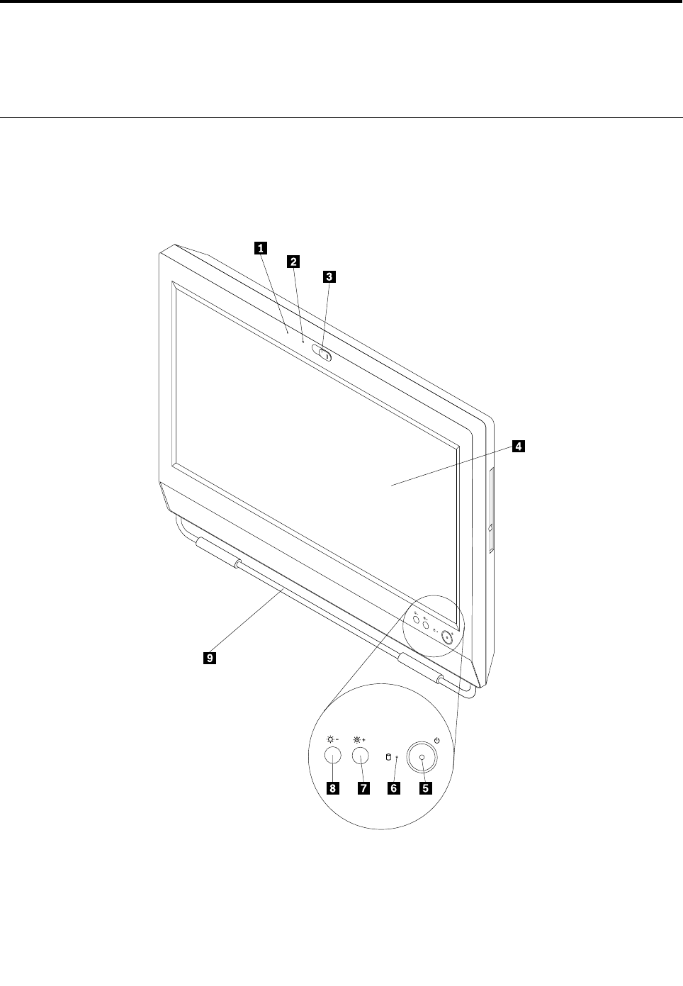
Chapter8.Locations
Thischapterintroducesthelocationsofthecomputerhardwarecomponents.
Locatingconnectors,controls,andindicatorsonthefrontofyour
computer
Figure1“Frontconnector,control,andindicatorlocations”onpage63showsthelocationsofthe
connectors,controls,andindicatorsonthefrontofyourcomputer.
Figure1.Frontconnector,control,andindicatorlocations
©CopyrightLenovo201263
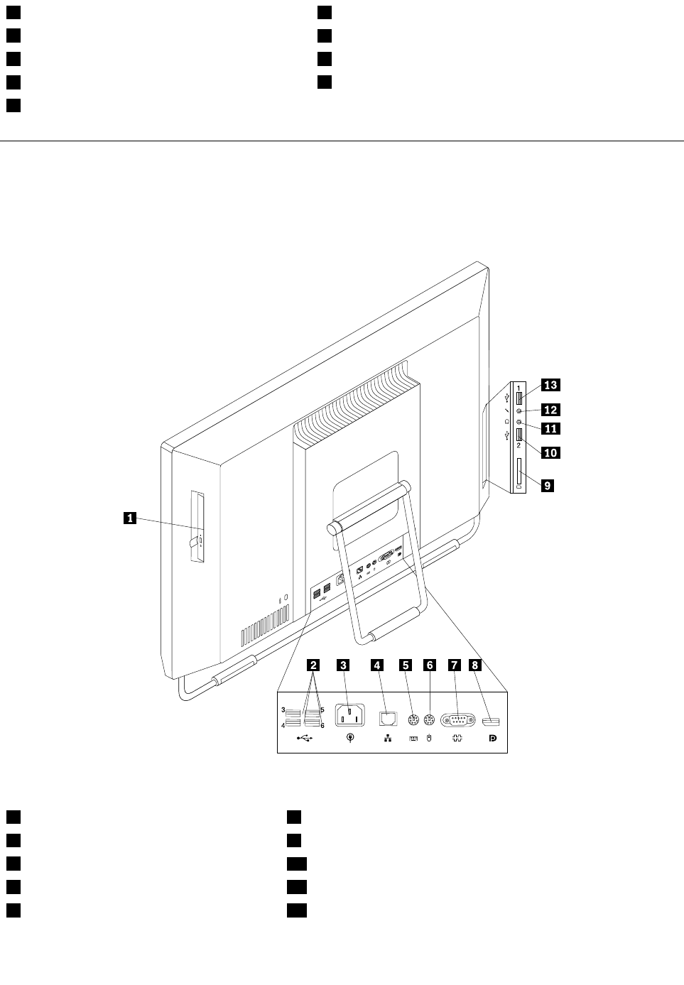
1IntegratedMicrophone6Harddiskdriveactivityindictor
2Integratedcameraindicator7Brightness-up/Auto-adjustingcontrol1
3Integratedcamerablockshield8Brightness-downcontrol
4Liquidcrystaldisplay(LCD)panel9Framestand
5Powerswitch
Locatingconnectorsontherearofyourcomputer
Figure2“Rearconnectorlocations”onpage64showsthelocationsoftheconnectorsontherearofyour
computer.Someconnectorsontherearofyourcomputerarecolor-codedtohelpyoudeterminewhereto
connectthecablesonyourcomputer.
Figure2.Rearconnectorlocations
1Opticaldrive8DisplayPortconnector(optional)
2USBconnectors(USBports3to6)9Cardreader
3Powercordconnector10USBconnector(USBport2)
4Ethernetconnector11Headphoneconnector
5PS/2keyboardconnector(optional)12Microphoneconnector
64ThinkCentreHardwareMaintenanceManual

6PS/2mouseconnector(optional)13USBconnector(USBport1)
7Serialport
Chapter8.Locations65

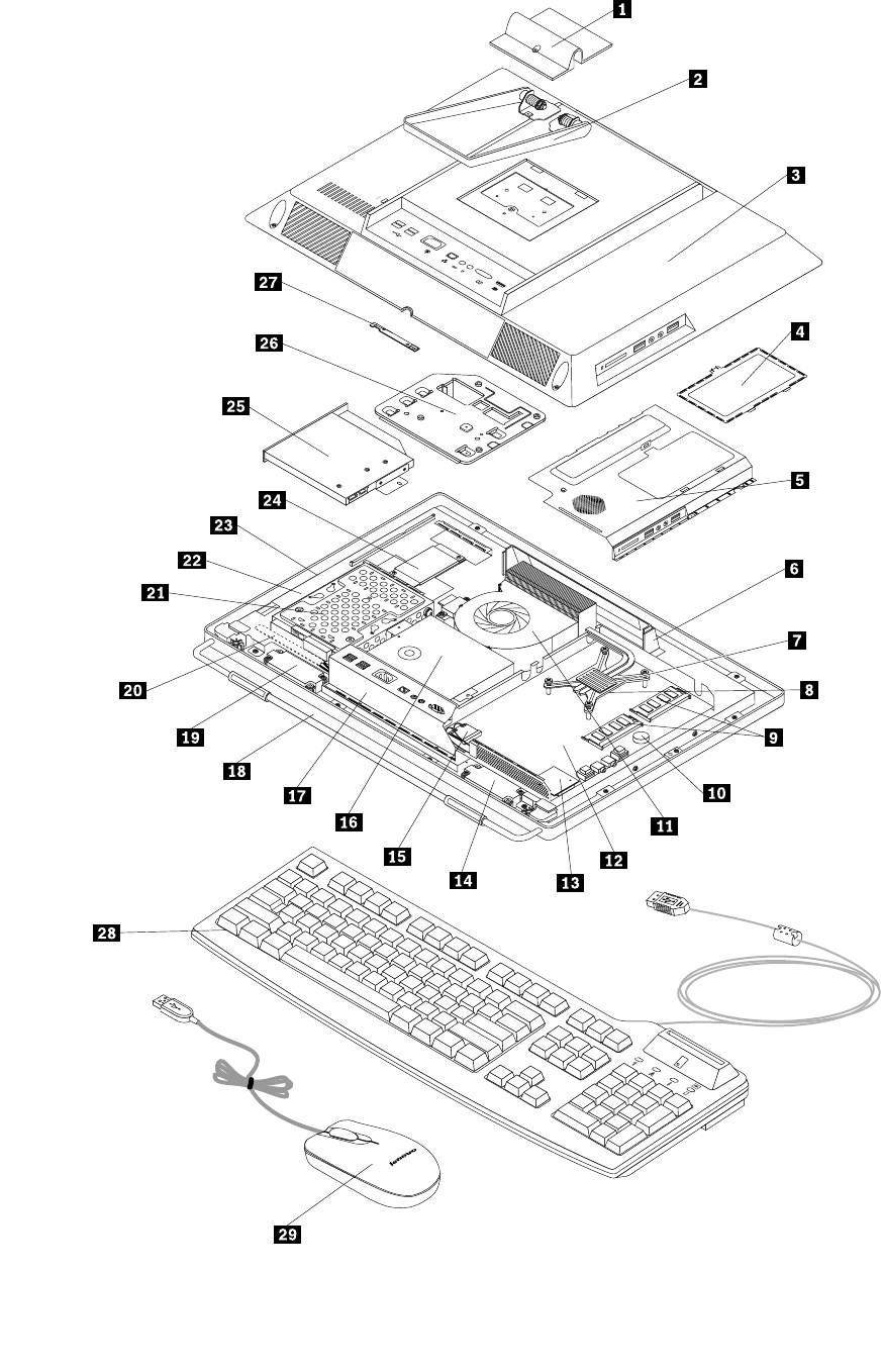
Figure3.LocatingmajorFRUsandCRUs
Chapter8.Locations67

ThefollowingtableliststhemajorFRUsshowninFigure3“LocatingmajorFRUsandCRUs”onpage67and
identieswhichFRUsarealsoself-serviceCRUsoroptional-serviceCRUs.
Notes:
•Self-serviceCRUs:TheseCRUsunplugoraresecuredbynomorethantwoscrews.Examplesof
thesetypesofCRUsincludethekeyboard,themouse,anyUSBdevice,andthepowercord.Other
self-serviceCRUsdependingonproductdesignmightincludememorymodules,adaptercards,hard
diskdrives,andopticaldrives.
•Optional-serviceCRUs:TheseCRUsareisolatedpartswithinthecomputerandareconcealedbyan
accesspanelthatistypicallysecuredbymorethantwoscrews.Oncetheaccesspanelisremoved,the
specicCRUisvisible.
NumberFRUdescriptionSelf-serviceCRUOptional-serviceCRU
1SystemstandhingecoverNoNo
2SystemstandNoNo
3ComputercoverNoNo
4SystemboardshieldwindowNoNo
5SystemboardshieldNoNo
6HandlebarNoNo
7HeatsinkassemblyNoNo
8MicroprocessorNoNo
9MemorymoduleNoNo
10BatteryNoNo
11MicroprocessorfanNoNo
12SystemboardNoNo
13CardreaderNoNo
14InternalspeakerNoNo
15WI-FIconnectorNoNo
16PowersupplyNoNo
17RearI/OconnectorNoNo
18FramestandNoNo
19InternalspeakerNoNo
20ControlbuttonboardNoNo
21HarddiskdriveNoNo
22LCDbracketNoNo
23LCDpanelNoNo
24InverterNoNo
25OpticaldriveNoNo
26VESAmountbracketNoNo
27IntegratedcameraNoNo
28KeyboardYesNo
29MouseYesNo
68ThinkCentreHardwareMaintenanceManual

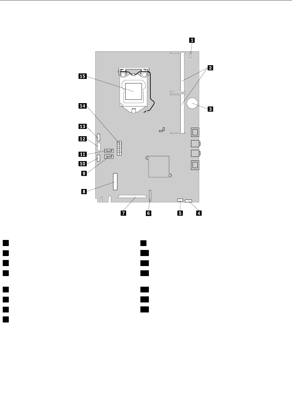
Systemboardpartsandconnectors
Thefollowingillustrationshowsthelocationsofthesystemboardpartsandconnectors.
Figure4.Systemboardpartandconnectorlocations
1Integratedcameracableconnector9SATAconnector
2Memoryslots(2)10Microprocessorfanconnector
3Battery11SATAconnector
4Cardreaderconnector12Opticaldrivepowerconnector/Harddiskdrivepower
connector
5Internalspeakercableconnector13Inverterconnector
6Controlbuttonconnector14Powersupplyconnector
7LCDpanelconnector15Microprocessor
8WI-FIconnector
70ThinkCentreHardwareMaintenanceManual

Chapter9.ReplacingFRUs
ThischapterprovidesremovalorreplacementproceduresformajorFRUs.NotallFRUsaredocumented.
Important
BeforeyoureplaceanyFRU,readChapter2“Safetyinformation”onpage3.Theseprecautionsand
guidelineswillhelpyouworksafely.
FRUreplacementsaretobedonebytrainedservicetechniciansonly.
Removingandreinstallingthesystemstandhingecover
Attention
Donotopenyourcomputerorattemptanyrepairbeforereadingandunderstandingthe“Importantsafety
information”intheSafety,Warranty,andSetupGuidethatcamewithyourcomputer.Toobtainacopyof
theSafety,Warranty,andSetupGuide,goto:
http://www.lenovo.com/support
Thissectionprovidesinstructionsonhowtoremoveandreinstallthesystemstandhingecover.
CAUTION:
Turnoffthecomputerandwaitthreetoveminutestoletthecomputercoolbeforeremovingthe
systemstandhingecover.
Toremoveandreinstallthesystemstandhingecover,dothefollowing:
1.Removeanymediafromthedrivesandturnoffallattacheddevicesandthecomputer.
2.Disconnectallpowercordsfromelectricaloutlets.
3.Disconnectthepowercords,Input/Outputcables,andanyothercablesthatareconnectedtothe
computer.See“Locatingconnectors,controls,andindicatorsonthefrontofyourcomputer”onpage
63and“Locatingconnectorsontherearofyourcomputer”onpage64.
4.Placeasoft,cleantowelorclothonthedeskorsurface.Holdthesidesofyourcomputerandgentlylay
itdownsothatthescreenisagainstthesurfaceandthecoverisfacingup.
5.Removethescrewthatsecuresthesystemstandhingecover,andthenliftthesystemstandhingecover
upandremoveitfromthecomputer.
©CopyrightLenovo201271
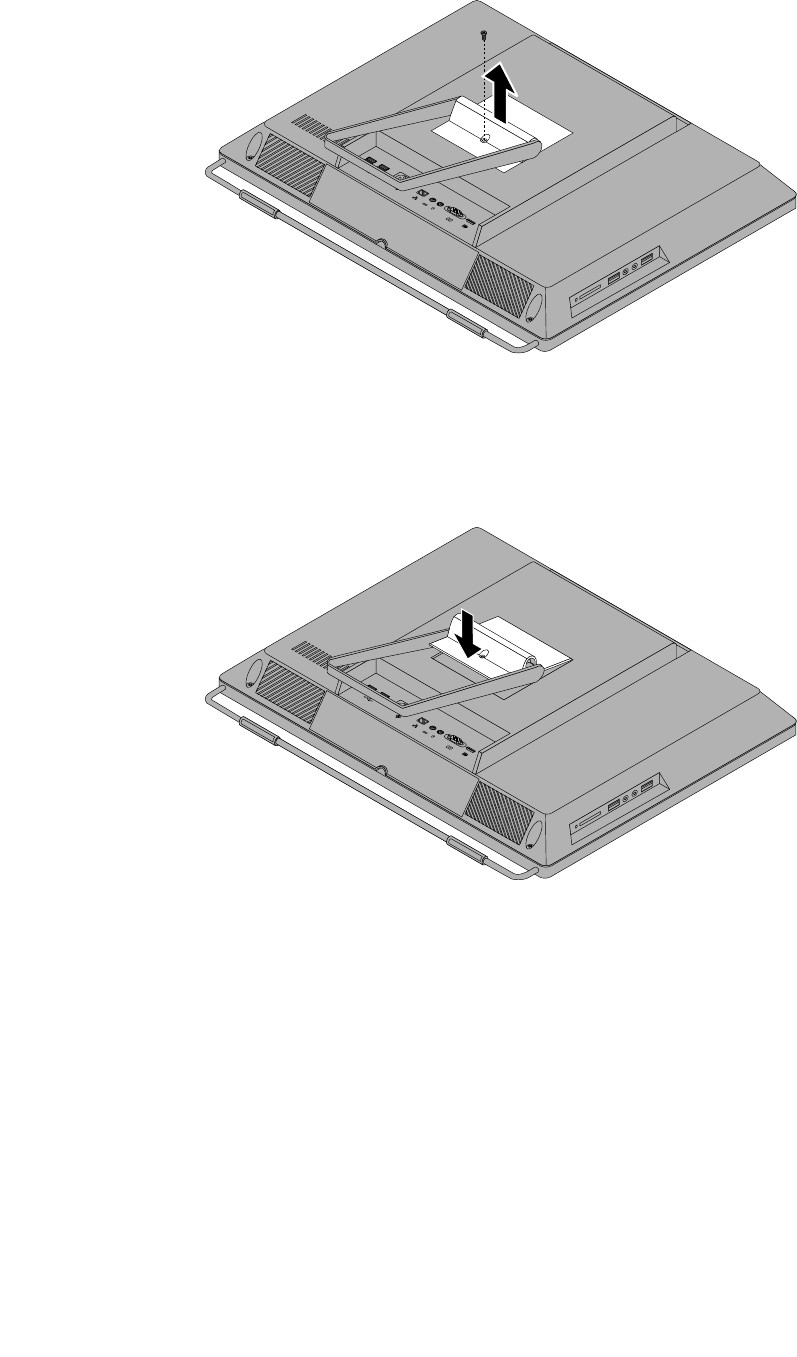
Figure5.Removingthesystemstandhingecover
6.Toreinstallthesystemstandhingecover,placethesystemstandhingecoveronthecomputersothat
thetwoplastictabsonthehingecoveralignwiththecorrespondingholesinthecomputer.
Figure6.Reinstallingthesystemstandhingecover
7.Reinstallthescrewtosecurethesystemstandhingecovertothecomputer.
72ThinkCentreHardwareMaintenanceManual
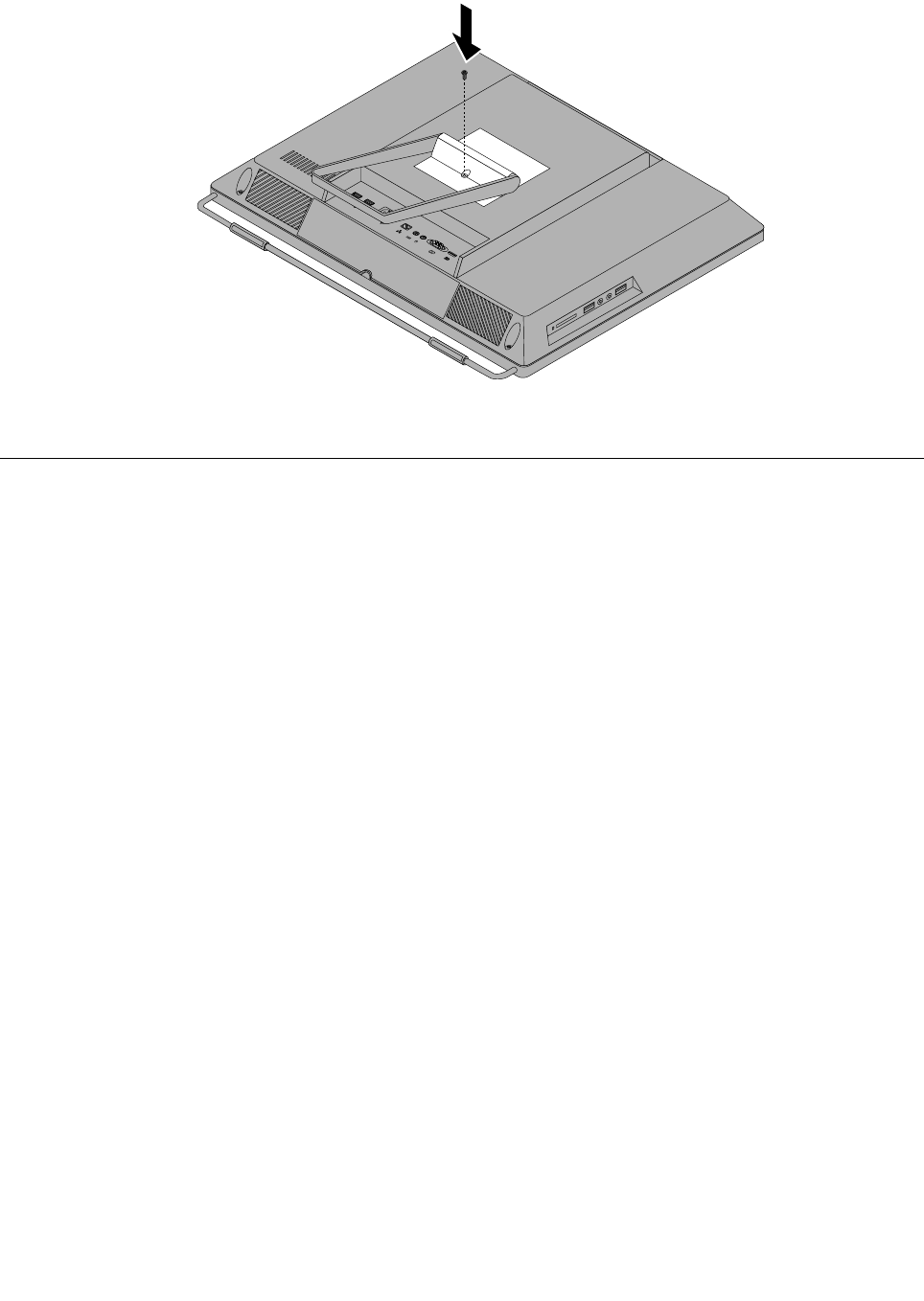
Figure7.Reinstallingthescrewtosecurethesystemstandhingecovertothecomputer
Removingandreinstallingthesystemstand
Attention
Donotopenyourcomputerorattemptanyrepairbeforereadingandunderstandingthe“Importantsafety
information”intheSafety,Warranty,andSetupGuidethatcamewithyourcomputer.Toobtainacopyof
theSafety,Warranty,andSetupGuide,goto:
http://www.lenovo.com/support
Thissectionprovidesinstructionsonhowtoremoveandreinstallthesystemstand.
Toremoveandreinstallthesystemstand,dothefollowing:
1.Turnoffthecomputeranddisconnectallpowercordsfromelectricaloutlets.
2.Removethesystemstandhingecover.See“Removingandreinstallingthesystemstandhingecover”
onpage71.
Chapter9.ReplacingFRUs73
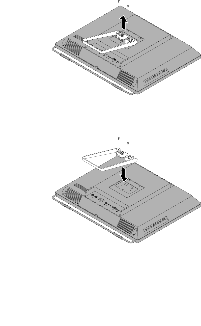
3.Removethetwoscrewsthatsecurethesystemstand,andthenliftthesystemstandupandremove
itfromthecomputer.
Figure8.Removingthesystemstand
4.Toreinstallthesystemstand,alignthetwoscrewholeswiththecorrespondingholesinthechassis,and
theninstallthetwoscrewstosecurethesystemstandtothecomputer.
Figure9.Reinstallingthesystemstand
5.Reinstallthesystemstandhingecover.See“Removingandreinstallingthesystemstandhingecover”
onpage71.
74ThinkCentreHardwareMaintenanceManual
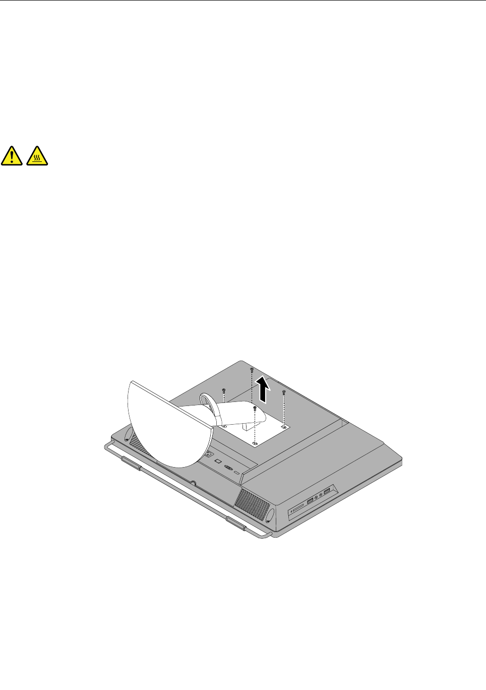
Removingandreinstallingthemonitorstand
Attention
Donotopenyourcomputerorattemptanyrepairbeforereadingandunderstandingthe“Importantsafety
information”intheSafety,Warranty,andSetupGuidethatcamewithyourcomputer.Toobtainacopyof
theSafety,Warranty,andSetupGuide,goto:
http://www.lenovo.com/support
Thissectionprovidesinstructionsonhowtoremoveandreinstallthemonitorstand.
CAUTION:
Turnoffthecomputerandwaitthreetoveminutestoletthecomputercoolbeforeremovingthe
monitorstand.
Toremoveandreinstallthemonitorstand,dothefollowing:
1.Removeanymediafromthedrivesandturnoffallattacheddevicesandthecomputer.
2.Disconnectallpowercordsfromelectricaloutlets.
3.Disconnectthepowercords,Input/Outputcables,andanyothercablesthatareconnectedtothe
computer.See“Locatingconnectors,controls,andindicatorsonthefrontofyourcomputer”onpage
63and“Locatingconnectorsontherearofyourcomputer”onpage64.
4.Placeasoft,cleantowelorclothonthedeskorsurface.Holdthesidesofyourcomputerandgentlylay
itdownsothatthescreenisagainstthesurfaceandthecoverisfacingup.
5.Removethefourscrewsthatsecurethemonitorstand,andthenremovethemonitorstandfromthe
computer.
Figure10.Removingthemonitorstand
Chapter9.ReplacingFRUs75
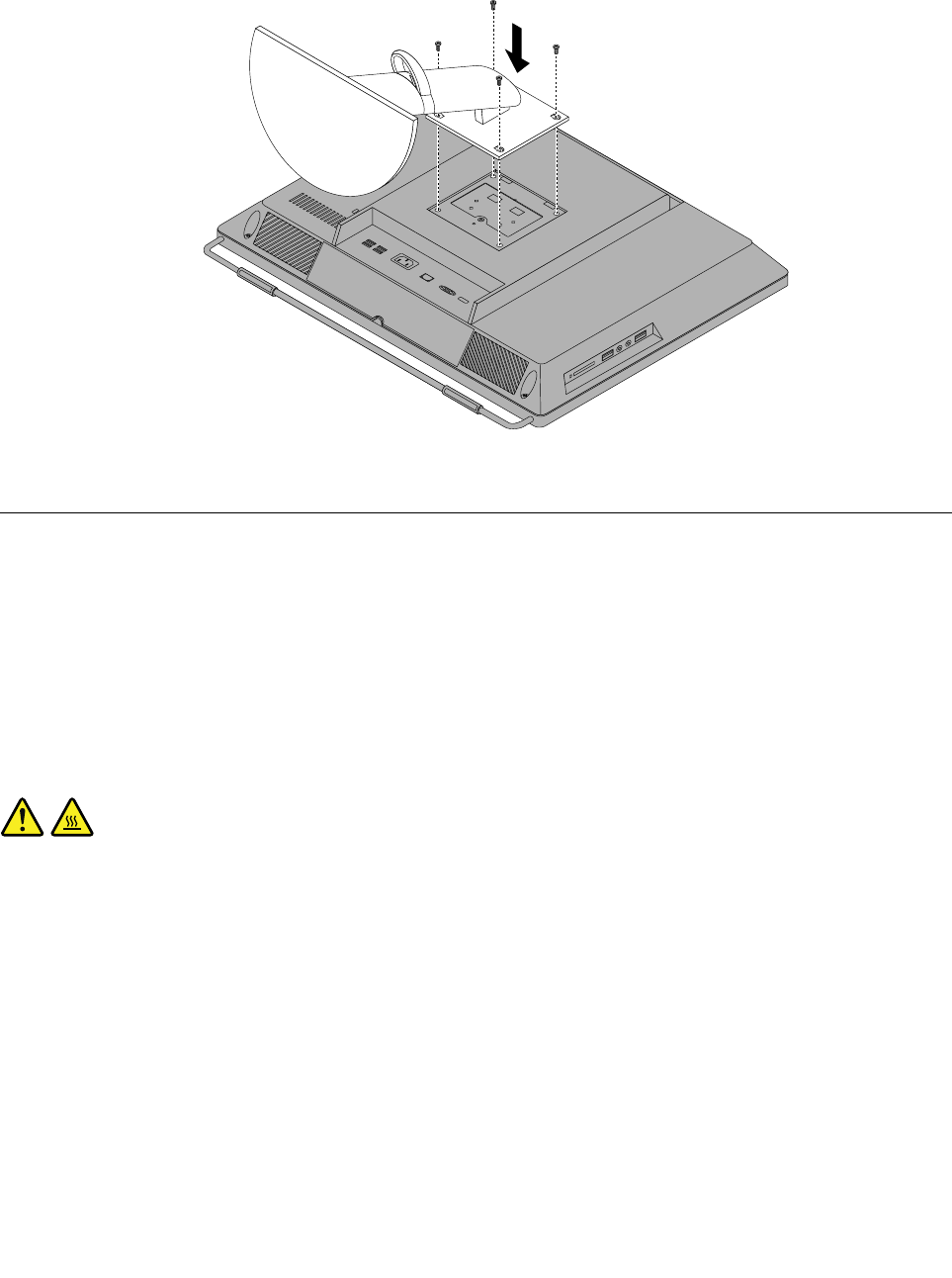
6.Toreinstallthemonitorstand,alignthefourscrewholeswiththecorrespondingholesinthechassis,
andtheninstallthefourscrewstosecurethemonitorstandtothecomputer.
Figure11.Reinstallingthemonitorstand
Removingandreinstallingtheframestand
Attention
Donotopenyourcomputerorattemptanyrepairbeforereadingandunderstandingthe“Importantsafety
information”intheSafety,Warranty,andSetupGuidethatcamewithyourcomputer.Toobtainacopyof
theSafety,Warranty,andSetupGuide,goto:
http://www.lenovo.com/support
Thissectionprovidesinstructionsonhowtoremoveandreinstalltheframestand.
CAUTION:
Turnoffthecomputerandwaitthreetoveminutestoletthecomputercoolbeforeremovingthe
framestand.
Toremoveandreinstalltheframestand,dothefollowing:
1.Removeanymediafromthedrivesandturnoffallattacheddevicesandthecomputer.
2.Disconnectallpowercordsfromelectricaloutlets.
3.Disconnectthepowercords,Input/Outputcables,andanyothercablesthatareconnectedtothe
computer.See“Locatingconnectors,controls,andindicatorsonthefrontofyourcomputer”onpage
63and“Locatingconnectorsontherearofyourcomputer”onpage64.
4.Placeasoft,cleantowelorclothonthedeskorthesurface.Holdthesidesofyourcomputerandgently
layitdownsothatthescreenisagainstthesurfaceandthecoverisfacingup.
5.Removethefourscrewsthatsecuretheframestand,andthenpulltheframestandoutofthecomputer.
76ThinkCentreHardwareMaintenanceManual
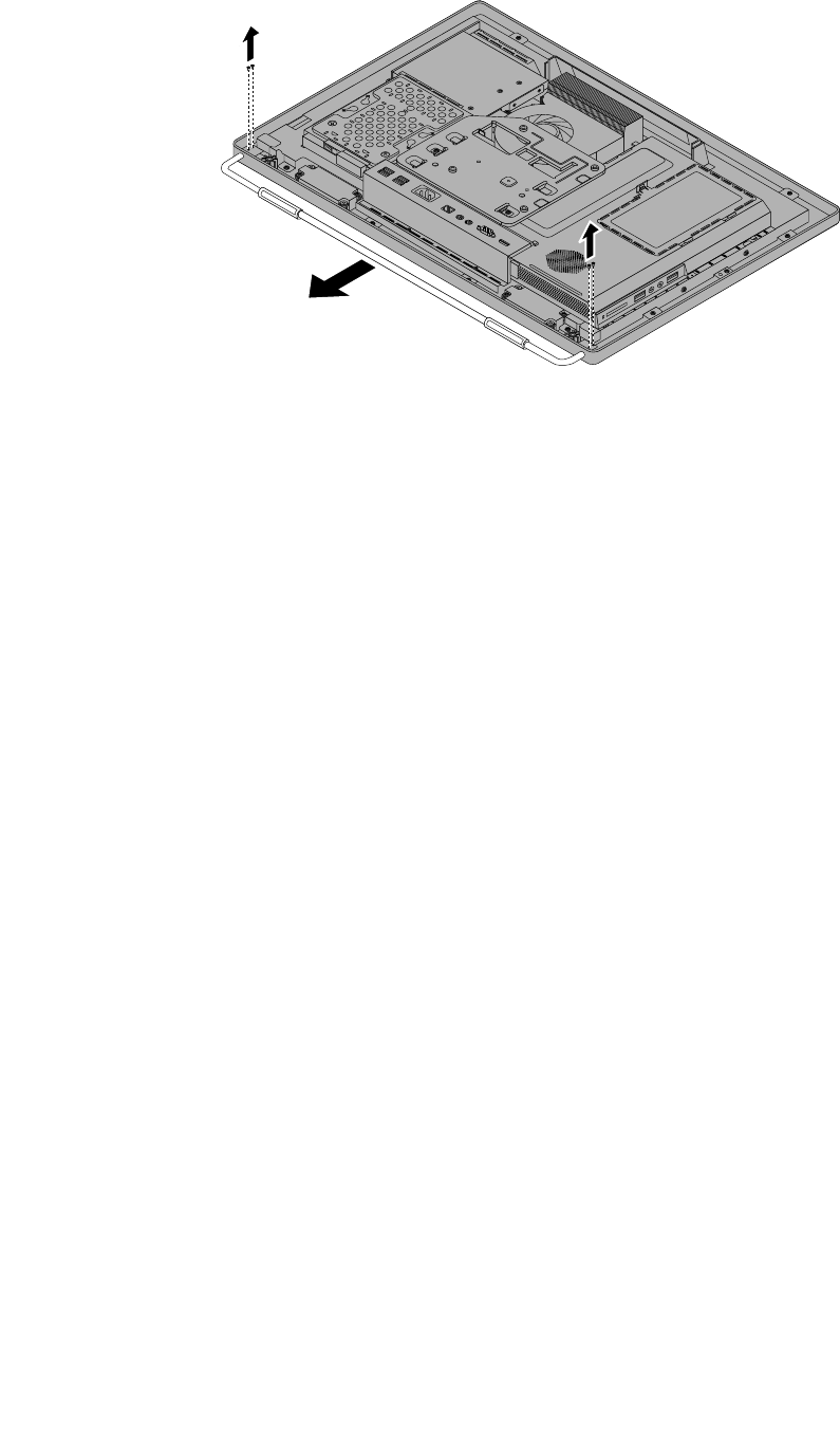
Figure12.Removingtheframestand
Chapter9.ReplacingFRUs77
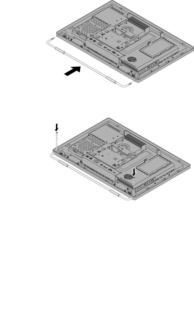
6.Toreinstalltheframestand,placetheframestandonthecomputersothatthescrewholealignswith
thecorrespondingholeinthecomputer.
Figure13.Reinstallingtheframestandtothecomputer
7.Reinstallthefourscrewstosecuretheframestandtothecomputer.
78ThinkCentreHardwareMaintenanceManual
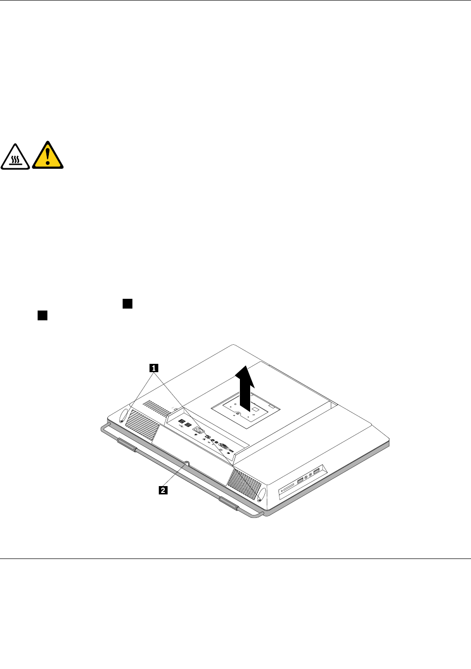
Removingthecomputercover
Attention
Donotopenyourcomputerorattemptanyrepairbeforereadingandunderstandingthe“Importantsafety
information”intheSafety,Warranty,andSetupGuidethatcamewithyourcomputer.Toobtainacopyof
theSafety,Warranty,andSetupGuide,goto:
http://www.lenovo.com/support
Thissectionprovidesinstructionsonhowtoremovethecomputercover.
CAUTION:
Turnoffthecomputerandwaitthreetoveminutestoletthecomputercoolbefore
removingthecomputercover.
Toremovethecomputercover,dothefollowing:
1.Removeallmediafromthedrivesandturnoffallattacheddevicesandthecomputer.Then,disconnect
allpowercordsfromelectricaloutletsanddisconnectallcablesthatareconnectedtothecomputer.
2.Placeasoft,cleantowelorclothonthedeskorotheratsurface.Holdthesidesofyourcomputerand
gentlylayitdownsothatthescreenisagainstthesurfaceandthecoverisfacingup.
3.Removeanylockingdevicethatsecuresthecomputercover,suchasanintegratedcablelock.
4.Removethesystemstand.See“Removingandreinstallingthesystemstand”onpage73.
5.Loosenthetwoscrews1atthebottomofthecomputer.Putyourindexngerorthumbinthenger
slot2,andthenliftthecomputercoveruptoremoveitfromthecomputer.
Figure14.Removingthecomputercover
Replacingtheharddiskdrive
Attention
Donotopenyourcomputerorattemptanyrepairbeforereadingandunderstandingthe“Importantsafety
information”intheSafety,Warranty,andSetupGuidethatcamewithyourcomputer.Toobtainacopyof
Chapter9.ReplacingFRUs79
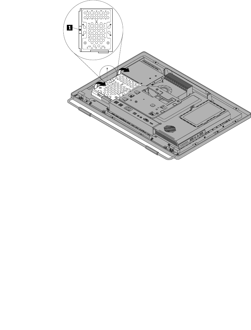
theSafety,Warranty,andSetupGuide,goto:
http://www.lenovo.com/support
Thissectionprovidesinstructionsonhowtoreplacetheharddiskdrive.
Toreplacetheharddiskdrive,dothefollowing:
1.Removeallmediafromthedrivesandturnoffallattacheddevicesandthecomputer.Then,disconnect
allpowercordsfromelectricaloutletsanddisconnectallcablesthatareconnectedtothecomputer.
2.Removethecomputercover.See“Removingthecomputercover”onpage79.
3.Locatetheharddiskdriveinthecomputer.See“LocatingmajorFRUsandCRUs”onpage66.
4.Removethescrewthatsecurestheharddiskdrive.
Figure15.Removingthescrewthatsecurestheharddiskdrive
5.Disconnecttheharddiskdrivecableandslidetheharddiskdriveoutofthechassis.
80ThinkCentreHardwareMaintenanceManual
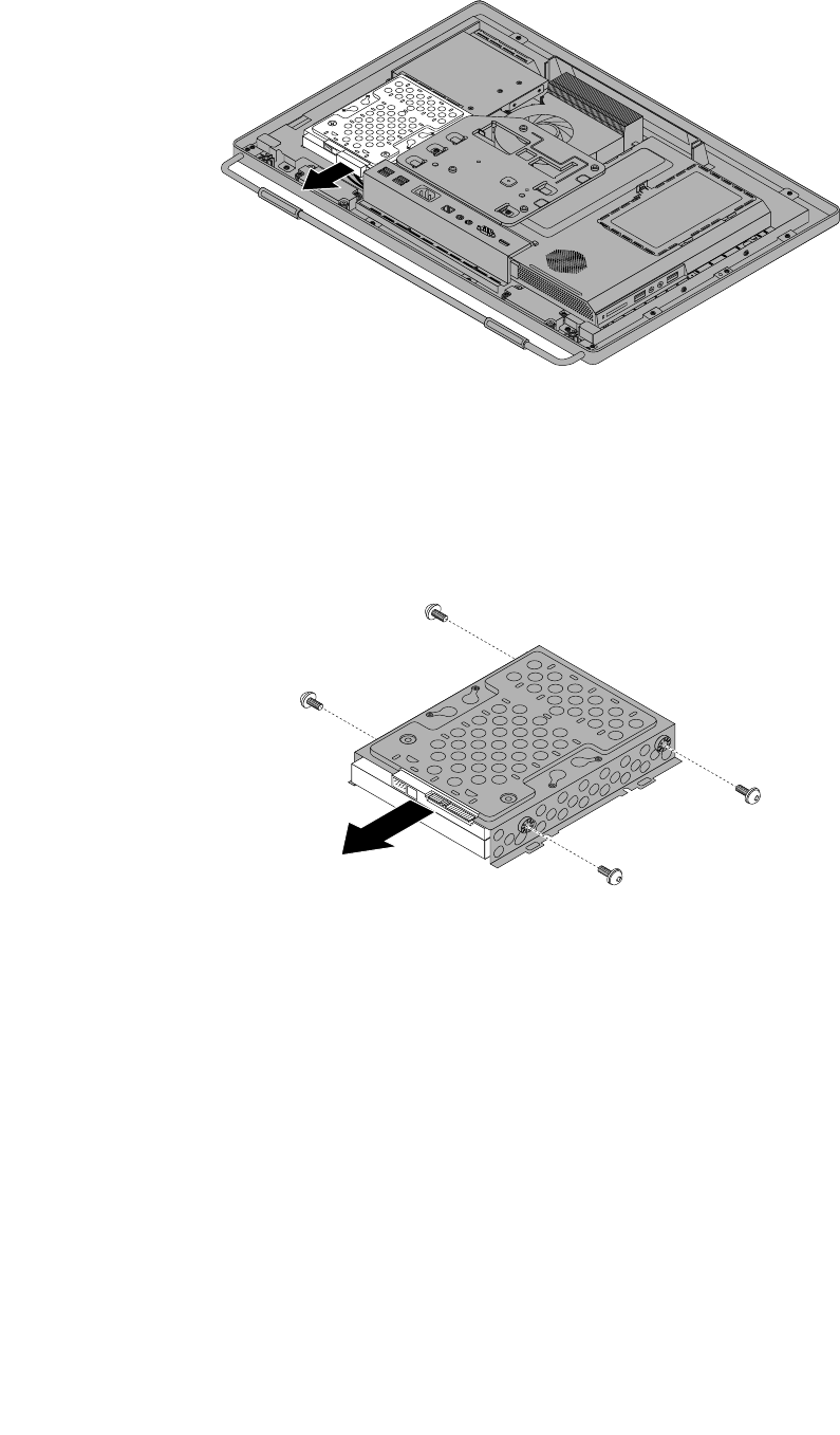
Figure16.Removingtheharddiskdrive
6.Removethefourscrewsontheharddiskdrivebracket,thenremovetheharddiskdriveoutofthe
bracket.Donottouchthecircuitboardonthebottomoftheharddiskdrive.
Figure17.Removingtheharddiskdriveoutofthebracket
7.Toinstallthenewharddiskdriveintothebracket,positiontheharddiskdrivesothatthefourscrew
holesalignwiththoseinthebracket.
8.Installthefourscrewsthatsecuretheharddiskdrivetotheharddiskdrivebracket.
9.Connecttheharddiskdrivecable.
10.Slidethenewharddiskdrivewiththebracketintotheharddiskdrivebay.Alignthescrewholeinthe
harddiskdrivewiththatinthechassis.
11.Installthescrewtosecuretheharddiskdrivebrackettothechassis.
12.Goto“Completingthepartsreplacement”onpage109.
Chapter9.ReplacingFRUs81
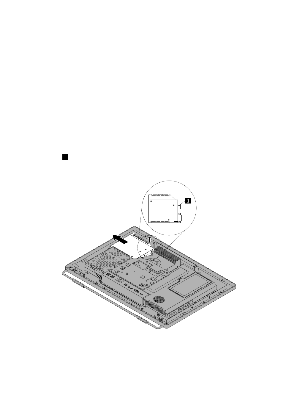
Replacingtheopticaldrive
Attention
Donotopenyourcomputerorattemptanyrepairbeforereadingandunderstandingthe“Importantsafety
information”intheSafety,Warranty,andSetupGuidethatcamewithyourcomputer.Toobtainacopyof
theSafety,Warranty,andSetupGuide,goto:
http://www.lenovo.com/support
Thissectionprovidesinstructionsonhowtoreplacetheopticaldrive.
Note:Theopticaldriveisavailableonlyinsomemodels.
Toreplacetheopticaldrive,dothefollowing:
1.Removeallmediafromthedrivesandturnoffallattacheddevicesandthecomputer.Then,disconnect
allpowercordsfromelectricaloutletsanddisconnectallcablesthatareconnectedtothecomputer.
2.Placeasoft,cleantowelorclothonthedeskorotheratsurface.Holdthesidesofyourcomputerand
gentlylayitdownsothatthescreenisagainstthesurfaceandthecoverisfacingup.
3.Removethecomputercover.See“Removingthecomputercover”onpage79.
4.Locatetheopticaldrive.See“LocatingmajorFRUsandCRUs”onpage66.
5.Removethescrew1thatsecurestheopticaldrive,andthenslidetheopticaldrivetodisconnectthe
opticaldrivefromtheopticaldrivecable.Removetheopticaldriveoutoftheopticaldrivebay.
Figure18.Removingtheopticaldrive
6.Toinstallanewopticaldrive,slidethenewopticaldriveintotheopticaldrivebaytoconnectthecableto
theopticaldrive.
82ThinkCentreHardwareMaintenanceManual
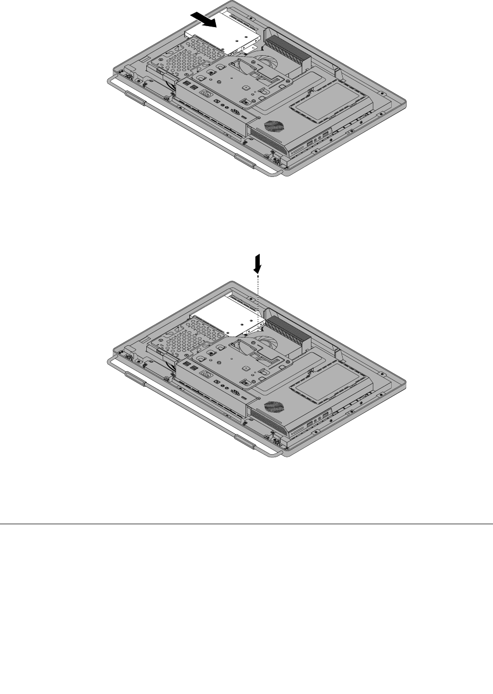
Figure19.Installingtheopticaldrive
7.Installthescrewtosecuretheopticaldrive.
Figure20.Installingthescrewtosecuretheopticaldrive
8.Goto“Completingthepartsreplacement”onpage109.
RemovingtheVESAmountbracket
Attention
Donotopenyourcomputerorattemptanyrepairbeforereadingandunderstandingthe“Importantsafety
information”intheSafety,Warranty,andSetupGuidethatcamewithyourcomputer.Toobtainacopyof
theSafety,Warranty,andSetupGuide,goto:
http://www.lenovo.com/support
ThissectionprovidesinstructionsonhowtoremovetheVESAmountbracket.
Chapter9.ReplacingFRUs83
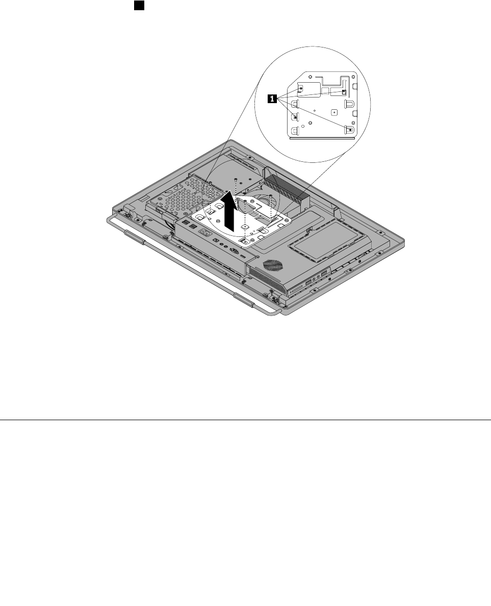
ToremovetheVESAmountbracket,dothefollowing:
1.Removeallmediafromthedrivesandturnoffallattacheddevicesandthecomputer.Then,disconnect
allpowercordsfromelectricaloutletsanddisconnectallcablesthatareconnectedtothecomputer.
2.Placeasoft,cleantowelorclothonthedeskorotheratsurface.Holdthesidesofyourcomputerand
gentlylayitdownsothatthescreenisagainstthesurfaceandthecoverisfacingup.
3.Removethecomputercover.See“Removingthecomputercover”onpage79.
4.LocatetheVESAmountbracket.See“LocatingmajorFRUsandCRUs”onpage66.
5.Removethefourscrews1thatsecuretheVESAmountbracketandlifttheVESAmountbracket
outofthecomputer.
Figure21.RemovingtheVESAmountbracket
6.ToreinstalltheVESAmountbracket,positiontheVESAmountbracketintothecomputersothatthe
screwholesalignwiththoseinthecomputer.ReinstallthefourscrewstosecuretheVESAmount
bracket.
7.Goto“Completingthepartsreplacement”onpage109.
ReplacingtherearI/Oassembly
Attention
Donotopenyourcomputerorattemptanyrepairbeforereadingandunderstandingthe“Importantsafety
information”intheSafety,Warranty,andSetupGuidethatcamewithyourcomputer.Toobtainacopyof
theSafety,Warranty,andSetupGuide,goto:
http://www.lenovo.com/support
ThissectionprovidesinstructionsonhowtoreplacetherearI/Oassembly.
ToreplacetherearI/Oassembly,dothefollowing:
84ThinkCentreHardwareMaintenanceManual
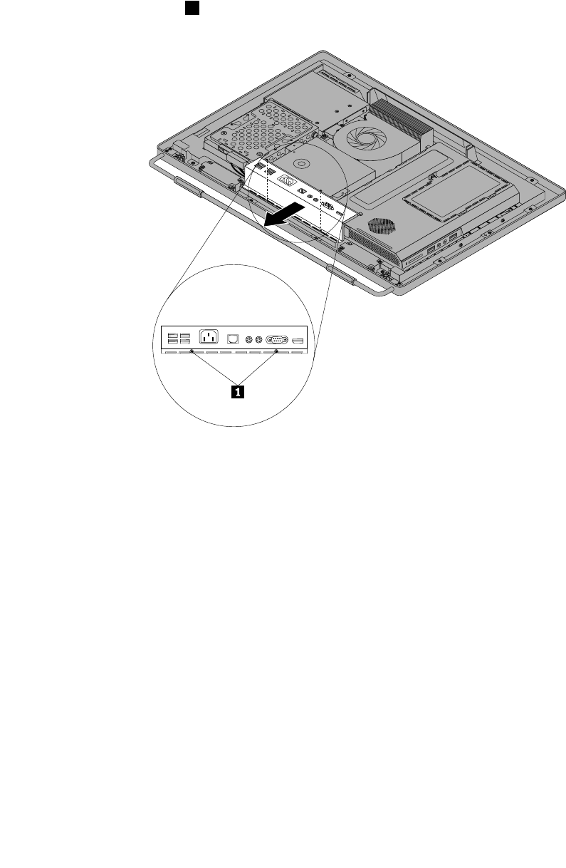
1.Removeallmediafromthedrivesandturnoffallattacheddevicesandthecomputer.Then,disconnect
allpowercordsfromelectricaloutletsanddisconnectallcablesthatareconnectedtothecomputer.
2.Placeasoft,cleantowelorclothonthedeskorotheratsurface.Holdthesidesofyourcomputerand
gentlylayitdownsothatthescreenisagainstthesurfaceandthecoverisfacingup.
3.Removethecomputercover.See“Removingthecomputercover”onpage79.
4.LocatetherearI/Oassembly.See“LocatingmajorFRUsandCRUs”onpage66.
5.Removethetwoscrews1thatsecuretherearI/Oassembly.
Figure22.RemovingthetwoscrewsthatsecuretherearI/Oassembly
Chapter9.ReplacingFRUs85
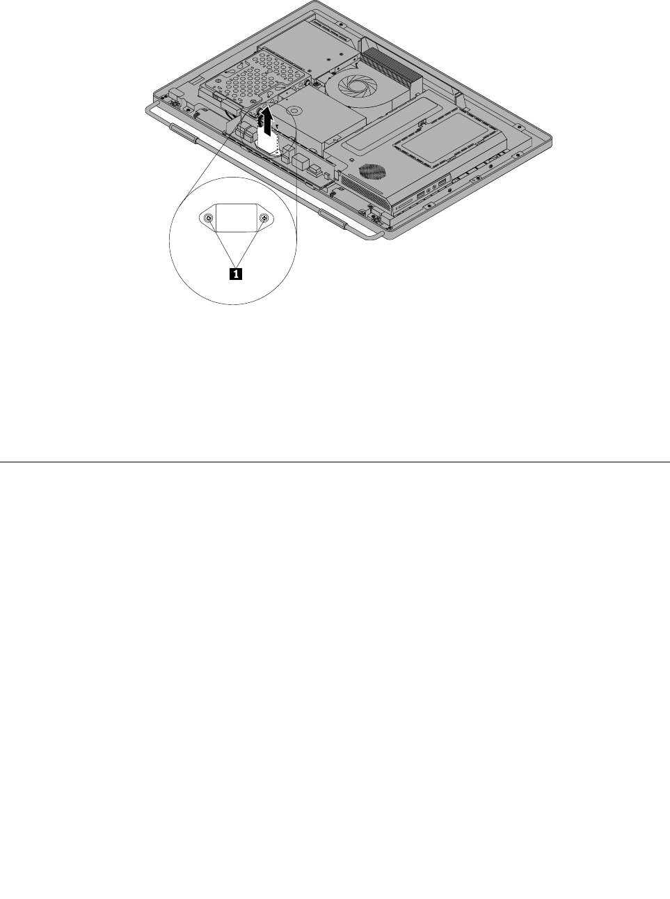
6.TurntherearI/Oassemblyupsidedown,andthenremovethetwoscrewsthatsecurethepowercord
connectortothepowercordconnectorbracket.RemovetherearI/Oassemblyfromthecomputer.
Figure23.Removingthepowercordconnector
7.ToreinstalltherearI/Oassembly,reinstallthetwoscrewsthatsecurethepowercordconnectortothe
powercordconnectorbracket.PositionthenewrearI/Oassemblyintoplace,andthenalignthe
screwholeswiththecorrespondingholesinthecomputermainbracket.Installthetwoscrewsto
securetherearI/Oassembly.
8.Goto“Completingthepartsreplacement”onpage109.
Removingandreinstallingthesystemboardshield
Attention
Donotopenyourcomputerorattemptanyrepairbeforereadingandunderstandingthe“Importantsafety
information”intheSafety,Warranty,andSetupGuidethatcamewithyourcomputer.Toobtainacopyof
theSafety,Warranty,andSetupGuide,goto:
http://www.lenovo.com/support
Thissectionprovidesinstructionsonhowtoremoveandreinstallthesystemboardshield.
Toremoveandreinstallthesystemboardshield,dothefollowing:
1.Removeallmediafromthedrivesandturnoffallattacheddevicesandthecomputer.Then,disconnect
allpowercordsfromelectricaloutletsanddisconnectallcablesthatareconnectedtothecomputer.
2.Placeasoft,cleantowelorclothonthedeskorotheratsurface.Holdthesidesofyourcomputerand
gentlylayitdownsothatthescreenisagainstthesurfaceandthecoverisfacingup.
3.Removethecomputercover.See“Removingthecomputercover”onpage79.
4.Locatethesystemboardshieldinthecomputer.See“LocatingmajorFRUsandCRUs”onpage66.
86ThinkCentreHardwareMaintenanceManual
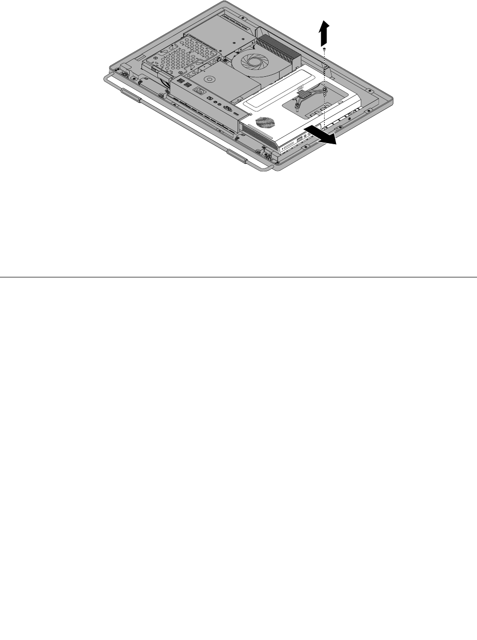
5.Removethescrewthatsecuresthesystemboardshield,andthenslidethesystemboardshieldout
ofthecomputer.
Figure24.Removingthesystemboardshield
6.Toreinstallthesystemboardshield,slidethesystemboardshieldintothesystemboardshieldslotso
thatthescrewholealignswiththatinthecomputer.
7.Reinstallthescrewtosecurethesystemboardshieldtothecomputer.
8.Goto“Completingthepartsreplacement”onpage109.
Replacingthepowersupply
Attention
Donotopenyourcomputerorattemptanyrepairbeforereadingandunderstandingthe“Importantsafety
information”intheSafety,Warranty,andSetupGuidethatcamewithyourcomputer.Toobtainacopyof
theSafety,Warranty,andSetupGuide,goto:
http://www.lenovo.com/support
Thissectionprovidesinstructionsonhowtoreplacethepowersupply.
Toreplacethepowersupply,dothefollowing:
1.Removeallmediafromthedrivesandturnoffallattacheddevicesandthecomputer.Then,disconnect
allpowercordsfromelectricaloutletsanddisconnectallcablesthatareconnectedtothecomputer.
2.Placeasoft,cleantowelorclothonthedeskorotheratsurface.Holdthesidesofyourcomputerand
gentlylayitdownsothatthescreenisagainstthesurfaceandthecoverisfacingup.
3.Removethecomputercover.See“Removingthecomputercover”onpage79.
4.RemovetheVESAmountbracket.See“RemovingtheVESAmountbracket”onpage83.
5.Locatethepowersupply.See“LocatingmajorFRUsandCRUs”onpage66.
6.Removethesystemboardshield.See“Removingandreinstallingthesystemboardshield”onpage86.
7.Disconnectthepowersupplycablesfromthesystemboard.See“Systemboardpartsandconnectors”
onpage70.
8.RemovetherearI/Oassembly,andthenremovethepowercordconnectorfromthepowercord
connectorbracket.See“ReplacingtherearI/Oassembly”onpage84.
Chapter9.ReplacingFRUs87
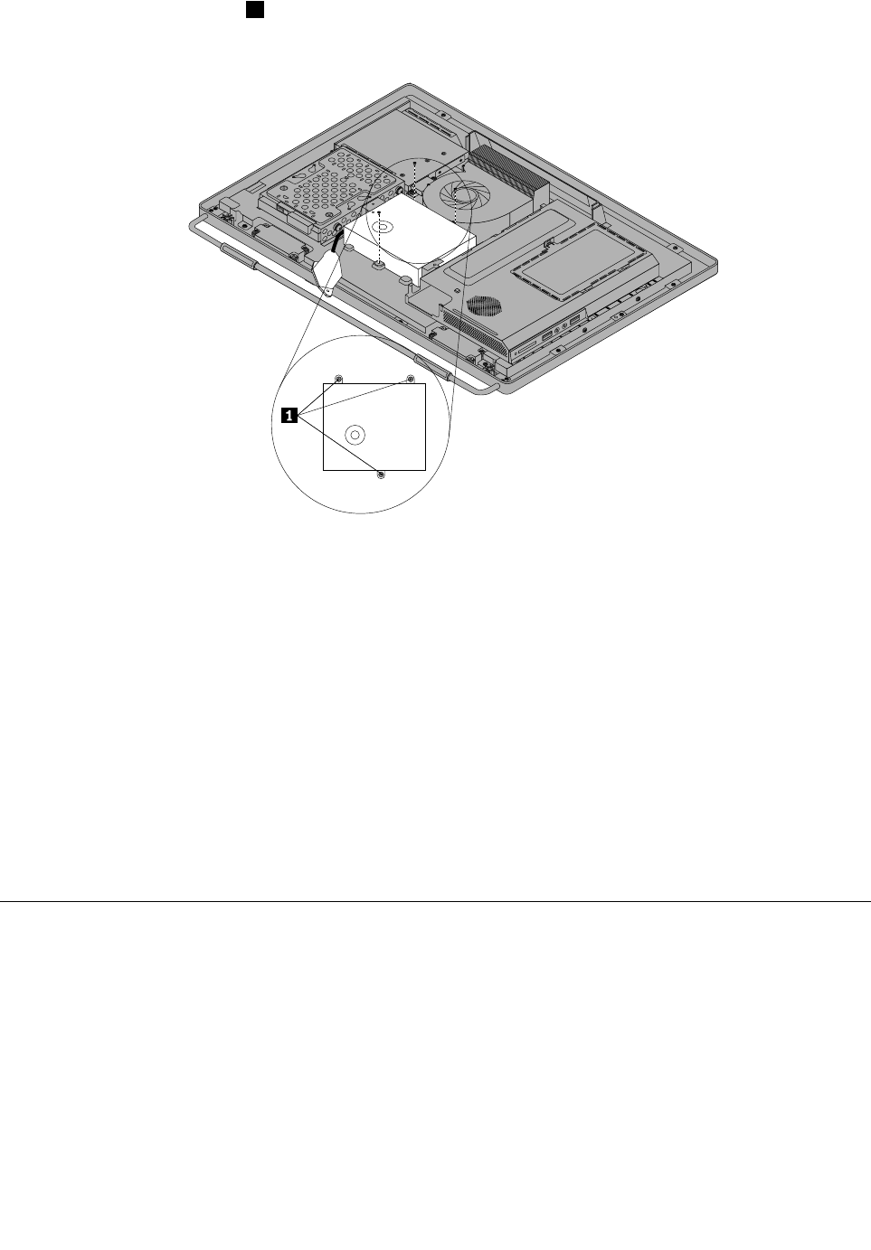
9.Removethethreescrews1thatsecurethepowersupply,andthenremovethepowersupplyout
ofthecomputer.
Figure25.Removingthethreescrewsthatsecurethepowersupply
10.Toreinstallthepowersupply,reinstallthetwoscrewsthatsecurethepowercordconnectortothe
powerconnectorbracket.See“ReplacingtherearI/Oassembly”onpage84.
11.Positionthenewpowersupplyinthecomputerandalignthethreescrewholesinthenewpowersupply
withthoseinthecomputermainbracket.Installthethreescrewstosecurethenewpowersupply.
12.Routethenewpowercordconnectorcable,andthenreinstalltherearI/Oassembly.See“Replacing
therearI/Oassembly”onpage84.
13.Connectthenewpowersupplycablestothepowersupplyconnectorsonthesystemboard.See
“Systemboardpartsandconnectors”onpage70.
14.Reinstallthesystemboardshield.See“Removingandreinstallingthesystemboardshield”onpage86.
15.ReinstalltheVESAmountbracket.See“RemovingtheVESAmountbracket”onpage83.
16.Reinstallthecomputercover.See“Removingthecomputercover”onpage79.
17.Goto“Completingthepartsreplacement”onpage109.
Replacingthemicroprocessorfan
Attention
Donotopenyourcomputerorattemptanyrepairbeforereadingandunderstandingthe“Importantsafety
information”intheSafety,Warranty,andSetupGuidethatcamewithyourcomputer.Toobtainacopyof
theSafety,Warranty,andSetupGuide,goto:
http://www.lenovo.com/support
Thissectionprovidesinstructionsonhowtoreplacethemicroprocessorfan.
Toreplacethemicroprocessorfan,dothefollowing:
88ThinkCentreHardwareMaintenanceManual
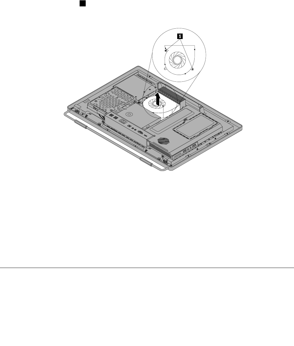
1.Removeallmediafromthedrivesandturnoffallattacheddevicesandthecomputer.Then,disconnect
allpowercordsfromelectricaloutletsanddisconnectallcablesthatareconnectedtothecomputer.
2.Placeasoft,cleantowelorclothonthedeskorotheratsurface.Holdthesidesofyourcomputerand
gentlylayitdownsothatthescreenisagainstthesurfaceandthecoverisfacingup.
3.Removethecomputercover.See“Removingthecomputercover”onpage79.
4.Locatethemicroprocessorfaninthecomputer.See“LocatingmajorFRUsandCRUs”onpage66.
5.Removethesystemboardshield.See“Removingandreinstallingthesystemboardshield”onpage86.
6.Notetheroutingofthemicroprocessorfancable,andthendisconnectthemicroprocessorfancable
fromthesystemboard.See“Systemboardpartsandconnectors”onpage70.
7.Removethetwoscrews1thatsecurethemicroprocessorfantothemainbracket.Then,liftthe
microprocessorfanoffthemainbracket.
Figure26.Removingthemicroprocessorfan
8.Toreinstallthemicroprocessorfan,positionthenewmicroprocessorfanonthemainbracketandalign
thescrewholesinthenewmicroprocessorfanwiththoseinthemainbracket.Reinstallthetwoscrews
thatsecurethemicroprocessorfantothemainbracket.
9.Connectthenewmicroprocessorfancabletothesystemboard.See“Systemboardpartsand
connectors”onpage70.
10.Reinstallthesystemboardshield.See“Removingandreinstallingthesystemboardshield”onpage86.
11.Reinstallthecomputercover.See“Removingthecomputercover”onpage79.
12.Goto“Completingthepartsreplacement”onpage109.
Replacingtheheatsinkassembly
Attention
Donotopenyourcomputerorattemptanyrepairbeforereadingandunderstandingthe“Importantsafety
information”intheSafety,Warranty,andSetupGuidethatcamewithyourcomputer.Toobtainacopyof
Chapter9.ReplacingFRUs89
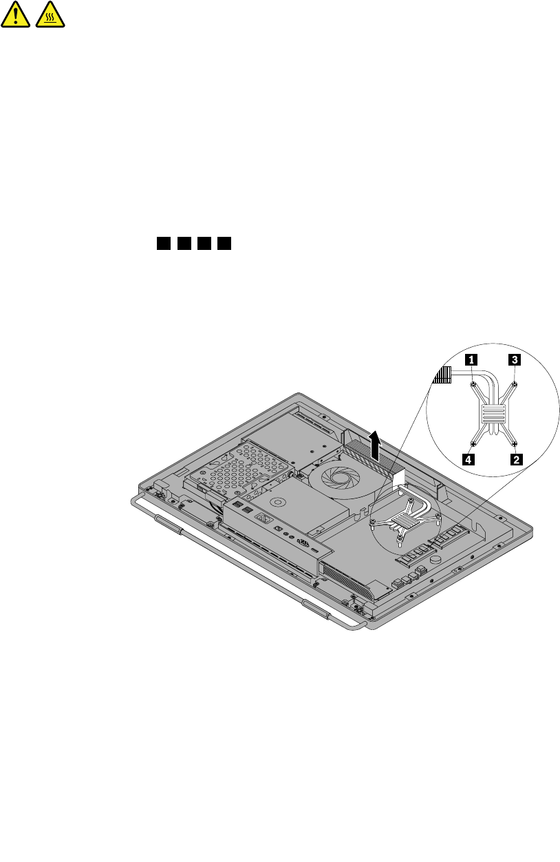
theSafety,Warranty,andSetupGuide,goto:
http://www.lenovo.com/support
Thissectionprovidesinstructionsonhowtoreplacetheheatsinkassembly.
CAUTION:
Theheatsinkandfanassemblymightbeveryhot.Turnoffthecomputerandwaitthreetove
minutestoletthecomputercoolbeforeremovingthecomputercover.
Toreplacetheheatsinkassembly,dothefollowing:
1.Removeallmediafromthedrivesandturnoffallattacheddevicesandthecomputer.Then,disconnect
allpowercordsfromelectricaloutletsanddisconnectallcablesthatareconnectedtothecomputer.
2.Placeasoft,cleantowelorclothonthedeskorotheratsurface.Holdthesidesofyourcomputerand
gentlylayitdownsothatthescreenisagainstthesurfaceandthecoverisfacingup.
3.Removethecomputercover.See“Removingthecomputercover”onpage79.
4.Locatetheheatsinkassemblyonthesystemboard.See“LocatingmajorFRUsandCRUs”onpage66.
5.Removethesystemboardshield.See“Removingandreinstallingthesystemboardshield”onpage86.
6.Followthesequence1,2,3,4ontheheatsinkassemblytoloosethefourscrewsthatsecurethe
heatsinkassemblytothesystemboard.
Note:Carefullyloosethefourscrewsfromthesystemboardtoavoidanypossibledamagetothe
systemboard.Thefourscrewscannotberemovedfromtheheatsinkassembly.
Figure27.Loosingthefourscrewsthatsecuretheheatsinkassemblytothesystemboard
7.Liftthefailingheatsinkassemblyoffthesystemboard.
Notes:
a.Youmighthavetogentlytwisttheheatsinkassemblytofreeitfromthemicroprocessor.
b.Donottouchthethermalgreasewhilehandlingtheheatsinkassembly.
8.Toreinstalltheheatsinkassembly,positionthenewheatsinkassemblyonthesystemboardsothatthe
fourscrewsarealignedwiththecorrespondingholesinthesystemboard.
90ThinkCentreHardwareMaintenanceManual
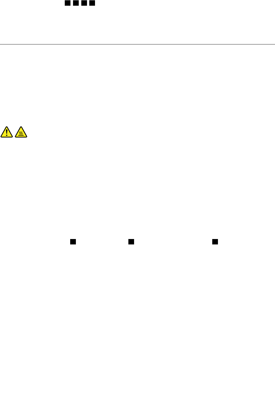
9.Followthesequence1,2,3,4ontheheatsinkassemblytotightenthefourscrewstosecuretheheat
sinkassemblytothesystemboard,asshowninFigure27“Loosingthefourscrewsthatsecuretheheat
sinkassemblytothesystemboard”onpage90.
10.Reinstallthesystemboardshield.See“Removingandreinstallingthesystemboardshield”onpage86.
11.Goto“Completingthepartsreplacement”onpage109.
Replacingthemicroprocessor
Attention
Donotopenyourcomputerorattemptanyrepairbeforereadingandunderstandingthe“Importantsafety
information”intheSafety,Warranty,andSetupGuidethatcamewithyourcomputer.Toobtainacopyof
theSafety,Warranty,andSetupGuide,goto:
http://www.lenovo.com/support
Thissectionprovidesinstructionsonhowtoreplacethemicroprocessor.
CAUTION:
Theheatsinkandfanassemblymightbeveryhot.Turnoffthecomputerandwaitthreetove
minutestoletthecomputercoolbeforeremovingthecomputercover.
Toreplacethemicroprocessor,dothefollowing:
1.Removeallmediafromthedrivesandturnoffallattacheddevicesandthecomputer.Then,disconnect
allpowercordsfromelectricaloutletsanddisconnectallcablesthatareconnectedtothecomputer.
2.Placeasoft,cleantowelorclothonthedeskorotheratsurface.Holdthesidesofyourcomputerand
gentlylayitdownsothatthescreenisagainstthesurfaceandthecoverisfacingup.
3.Removethecomputercover.See“Removingthecomputercover”onpage79.
4.Locatethemicroprocessoronthesystemboard.See“LocatingmajorFRUsandCRUs”onpage66.
5.Removethesystemboardshield.See“Removingandreinstallingthesystemboardshield”onpage86.
6.Removetheheatsinkassemblytogainaccesstothemicroprocessor.See“Replacingtheheatsink
assembly”onpage89.
7.Pressthesmallhandle1toopentheretainer2toaccessthemicroprocessor3.
Chapter9.ReplacingFRUs91
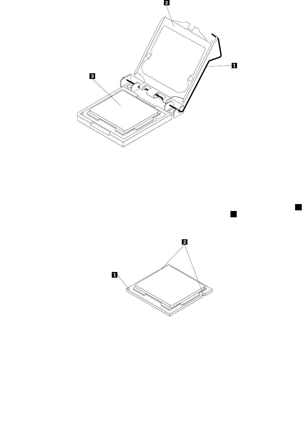
Figure28.Openingtheretainertoaccessthemicroprocessor
8.Liftthemicroprocessorstraightupandoutofthesocket.
Notes:
a.Yourmicroprocessorandsocketmightlookdifferentfromtheoneillustrated.
b.Notetheorientationofthemicroprocessorinthesocket.Youcaneitherlookforthesmalltriangle1
ononecornerofthemicroprocessorornotetheorientationofthenotches2onthemicroprocessor.
Thisisimportantwheninstallinganewmicroprocessoronthesystemboard.
Figure29.Notingtheorientationofthemicroprocessorinthesocket
c.Touchonlythesidesofthemicroprocessor.Donottouchthegoldcontactsonthebottom.
d.Donotdropanythingontothemicroprocessorsocketwhileitisexposed.Thesocketpinsmustbe
keptascleanaspossible.
92ThinkCentreHardwareMaintenanceManual
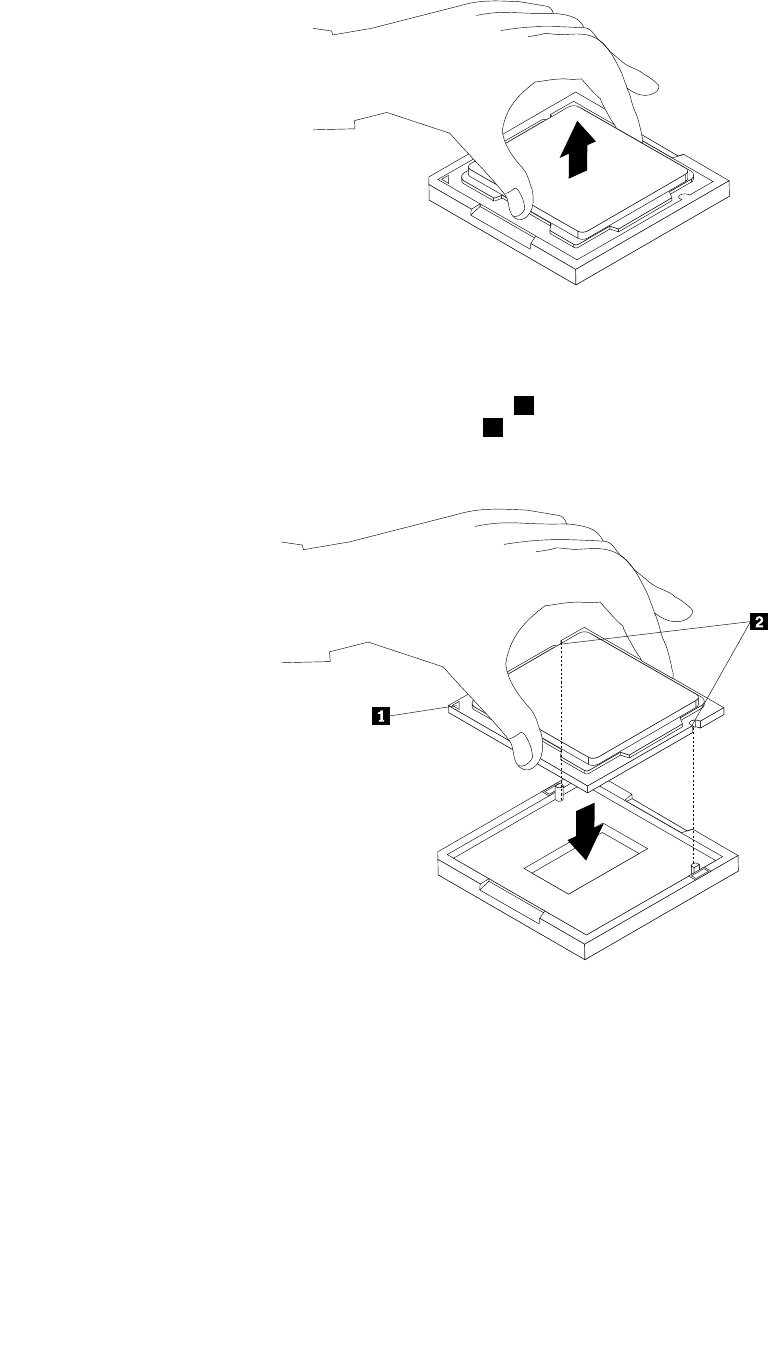
Figure30.Removingthemicroprocessor
9.Makesurethatthesmallhandleisintheraisedpositionandthemicroprocessorretainerisfullyopen.
10.Holdthenewmicroprocessorandalignthenotches2onitwiththealignmentkeysinthe
microprocessorsocket,oralignthesmalltriangle1ononecornerofthenewmicroprocessorwiththe
correspondingbeveledcornerofthemicroprocessorsocket.
Figure31.Installingthemicroprocessor
11.Lowerthenewmicroprocessorstraightdownintothemicroprocessorsocketonthesystemboard.
12.Closethemicroprocessorretainerandlockitintopositionwiththesmallhandletosecurethenew
microprocessorinthesocket.
13.Reinstalltheheatsinkassembly.See“Replacingtheheatsinkassembly”onpage89.
14.Reinstallthesystemboardshield.See“Removingandreinstallingthesystemboardshield”onpage86.
15.Goto“Completingthepartsreplacement”onpage109.
Chapter9.ReplacingFRUs93
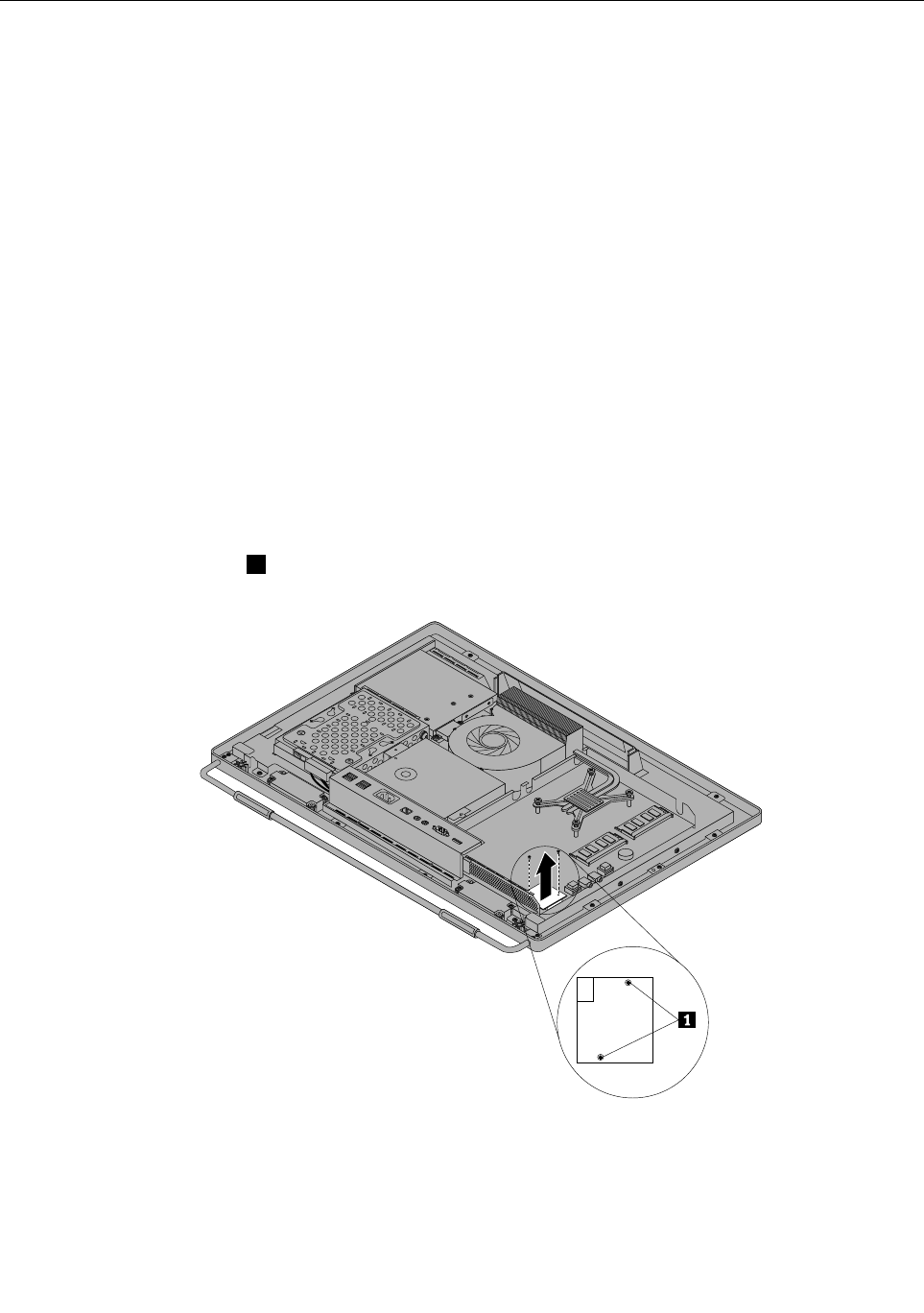
Replacingthecardreader
Attention
Donotopenyourcomputerorattemptanyrepairbeforereadingandunderstandingthe“Importantsafety
information”intheSafety,Warranty,andSetupGuidethatcamewithyourcomputer.Toobtainacopyof
theSafety,Warranty,andSetupGuide,goto:
http://www.lenovo.com/support
Thissectionprovidesinstructionsonhowtoreplacethecardreader.
Note:Thecardreaderisavailableonlyinsomemodels.
Toreplacethecardreader,dothefollowing:
1.Removeallmediafromthedrivesandturnoffallattacheddevicesandthecomputer.Then,disconnect
allpowercordsfromelectricaloutletsanddisconnectallcablesthatareconnectedtothecomputer.
2.Placeasoft,cleantowelorclothonthedeskorotheratsurface.Holdthesidesofyourcomputerand
gentlylayitdownsothatthescreenisagainstthesurfaceandthecoverisfacingup.
3.Removethecomputercover.See“Removingthecomputercover”onpage79.
4.Locatethecardreaderinthecomputer.See“LocatingmajorFRUsandCRUs”onpage66.
5.Removethesystemboardshield.See“Removingandreinstallingthesystemboardshield”onpage86.
6.Disconnectthecardreadercablefromthecardreader.
7.Removethetwoscrews1thatsecurethecardreader,andthenliftthecardreaderoutofthecomputer.
Figure32.Removingthecardreader
8.Toreinstallthecardreader,alignthescrewholesinthenewcardreaderwiththoseinthecomputer,and
theninstallthetwoscrewstosecurethecardreader.
9.Connectthecardreadercabletothenewcardreader.
94ThinkCentreHardwareMaintenanceManual
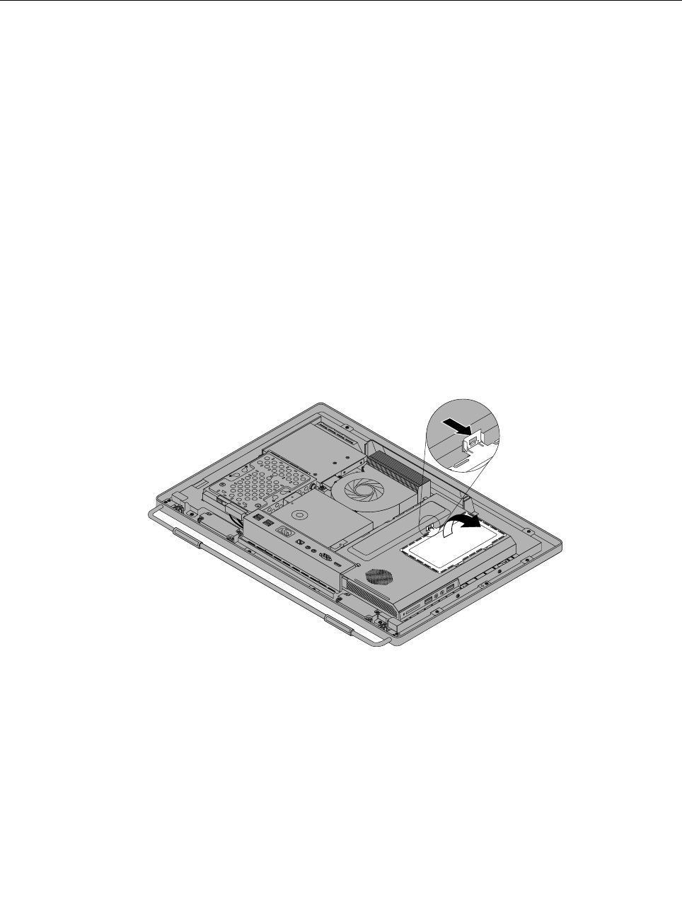
10.Reinstallthesystemboardshield.See“Removingandreinstallingthesystemboardshield”onpage86.
11.Goto“Completingthepartsreplacement”onpage109.
Openingthesystemboardshieldwindow
Attention
Donotopenyourcomputerorattemptanyrepairbeforereadingandunderstandingthe“Importantsafety
information”intheSafety,Warranty,andSetupGuidethatcamewithyourcomputer.Toobtainacopyof
theSafety,Warranty,andSetupGuide,goto:
http://www.lenovo.com/support
Thissectionprovidesinstructionsonhowtoopenandclosethesystemboardshieldwindow.
Toopenandclosethesystemboardshieldwindow,dothefollowing:
1.Removeallmediafromthedrivesandturnoffallattacheddevicesandthecomputer.Then,disconnect
allpowercordsfromelectricaloutletsanddisconnectallcablesthatareconnectedtothecomputer.
2.Placeasoft,cleantowelorclothonthedeskorotheratsurface.Holdthesidesofyourcomputerand
gentlylayitdownsothatthescreenisagainstthesurfaceandthecoverisfacingup.
3.Removethecomputercover.See“Removingthecomputercover”onpage79.
4.Locatethesystemboardshieldwindow.See“LocatingmajorFRUsandCRUs”onpage66.
5.Presstheuppermetaltabofthesystemboardshieldwindow,andthenpivotthesystemboardshield
windowtoopenit.
Figure33.Openingthesystemboardshieldwindow
6.Toclosethesystemboardshieldwindow,placethesystemboardshieldwindowonthesystemboard
shield.Pivotthesystemboardshieldwindowuntilthetwometaltabsalignwitheachother,andthen
presstheuppermetaltabtosnapitintotheposition.
7.Goto“Removingthecomputercover”onpage79.
Chapter9.ReplacingFRUs95
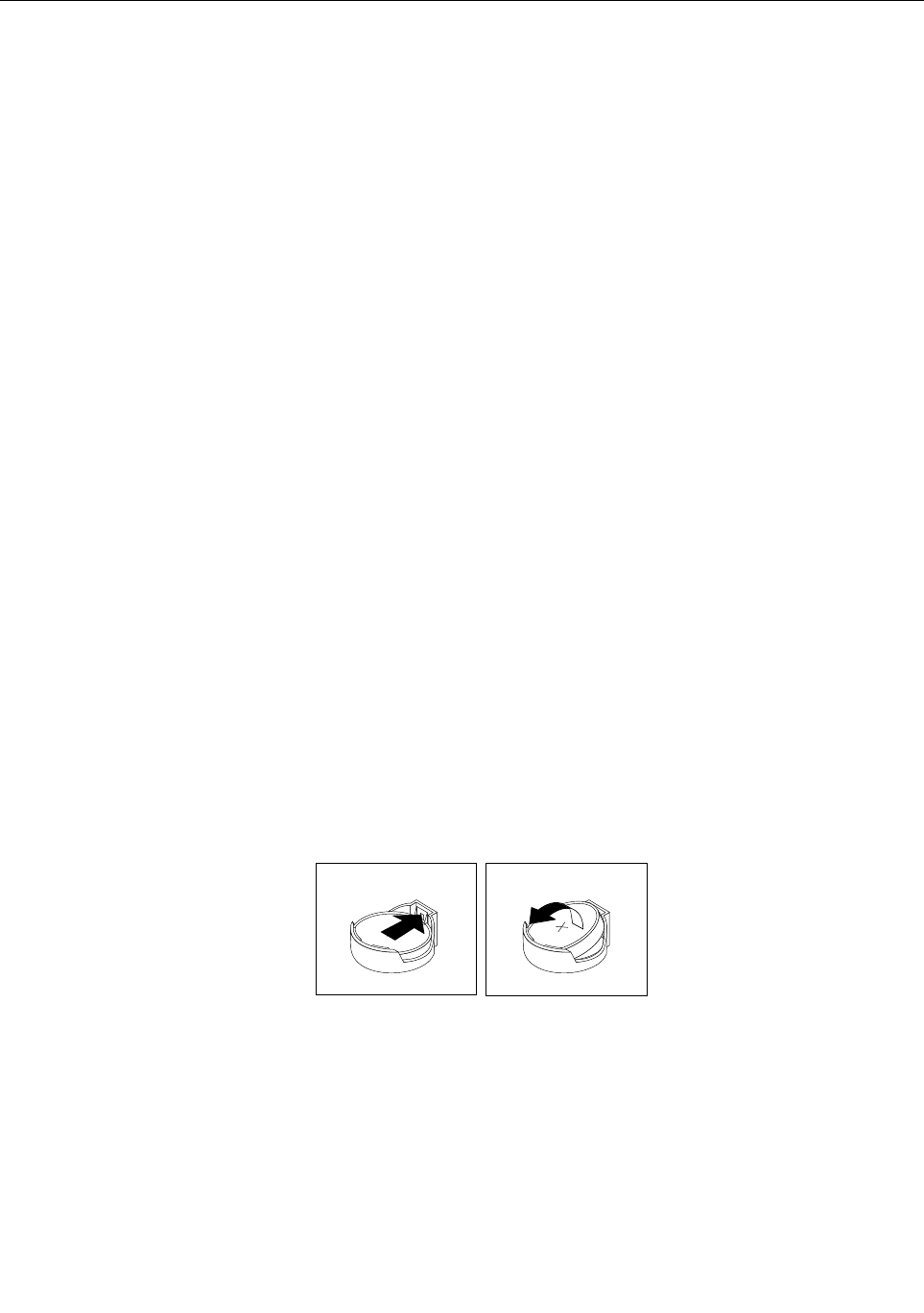
Replacingthebattery
Attention
Donotopenyourcomputerorattemptanyrepairbeforereadingandunderstandingthe“Importantsafety
information”intheSafety,Warranty,andSetupGuidethatcamewithyourcomputer.Toobtainacopyof
theSafety,Warranty,andSetupGuide,goto:
http://www.lenovo.com/support
Thissectionprovidesinstructionsonhowtoreplacethebattery.
Yourcomputerhasaspecialtypeofmemorythatmaintainsthedate,time,andsettingsforbuilt-infeatures,
suchasparallel-portassignments(conguration).Abatterykeepstheinformationactivewhenyouturn
offthecomputer.
Thebatterynormallyrequiresnochargingormaintenancethroughoutitslife.However,ifthebatteryfails,
thedate,time,andcongurationinformation(includingpasswords)arelost.Anerrormessagewillbe
displayedwhenyouturnonthecomputer.
Referto“Lithiumbatterynotice”intheSafety,Warranty,andSetupGuideforinformationaboutreplacing
anddisposingofthebattery.
Toreplacethebattery,dothefollowing:
1.Removeallmediafromthedrivesandturnoffallattacheddevicesandthecomputer.Then,disconnect
allpowercordsfromelectricaloutletsanddisconnectallcablesthatareconnectedtothecomputer.
2.Placeasoft,cleantowelorclothonthedeskorotheratsurface.Holdthesidesofyourcomputerand
gentlylayitdownsothatthescreenisagainstthesurfaceandthecoverisfacingup.
3.Removethecomputercover.See“Removingthecomputercover”onpage79.
4.Locatethebatteryonthesystemboard.See“LocatingmajorFRUsandCRUs”onpage66.
5.Removethesystemboardshieldoropenthesystemboardshieldwindowtogetaccesstothebattery.
See“Removingandreinstallingthesystemboardshield”onpage86or“Openingthesystemboard
shieldwindow”onpage95.
6.Removethebattery.
Figure34.Removingthebattery
7.Installanewbattery.
96ThinkCentreHardwareMaintenanceManual

Figure35.Installinganewbattery
8.Reinstallthesystemboardshieldorclosethesystemboardshieldwindow.See“Removingand
reinstallingthesystemboardshield”onpage86or“Openingthesystemboardshieldwindow”on
page95.
9.Reinstallthecomputercover.See“Completingthepartsreplacement”onpage109.
10.Turnonthecomputerandallattacheddevices.
Note:Whenyouturnthecomputerforthersttimeafterreplacingthebattery,anerrormessagemight
bedisplayed.Thisisnormalafterreplacingthebattery.
11.UsetheSetupUtilityprogramtosetthedate,time,andanypasswords.SeeChapter6“UsingtheSetup
Utilityprogram”onpage53.
Replacingtheinverter
Attention
Donotopenyourcomputerorattemptanyrepairbeforereadingandunderstandingthe“Importantsafety
information”intheSafety,Warranty,andSetupGuidethatcamewithyourcomputer.Toobtainacopyof
theSafety,Warranty,andSetupGuide,goto:
http://www.lenovo.com/support
Thissectionprovidesinstructionsonhowtoreplacetheinverter.
Toreplacetheinverter,dothefollowing:
1.Removeallmediafromthedrivesandturnoffallattacheddevicesandthecomputer.Then,disconnect
allpowercordsfromelectricaloutletsanddisconnectallcablesthatareconnectedtothecomputer.
2.Placeasoft,cleantowelorclothonthedeskorsurface.Holdthesidesofyourcomputerandgentlylay
itdownsothatthescreenisagainstthesurfaceandthecoverisfacingup.
3.Removethecomputercover.See“Removingthecomputercover”onpage79.
4.Removetheopticaldrive.See“Replacingtheopticaldrive”onpage82.
5.Locatetheinverterinthecomputer.See“LocatingmajorFRUsandCRUs”onpage66.
6.Removethetwoscrewsthatsecuretheinvertertothemainbracket.
Chapter9.ReplacingFRUs97
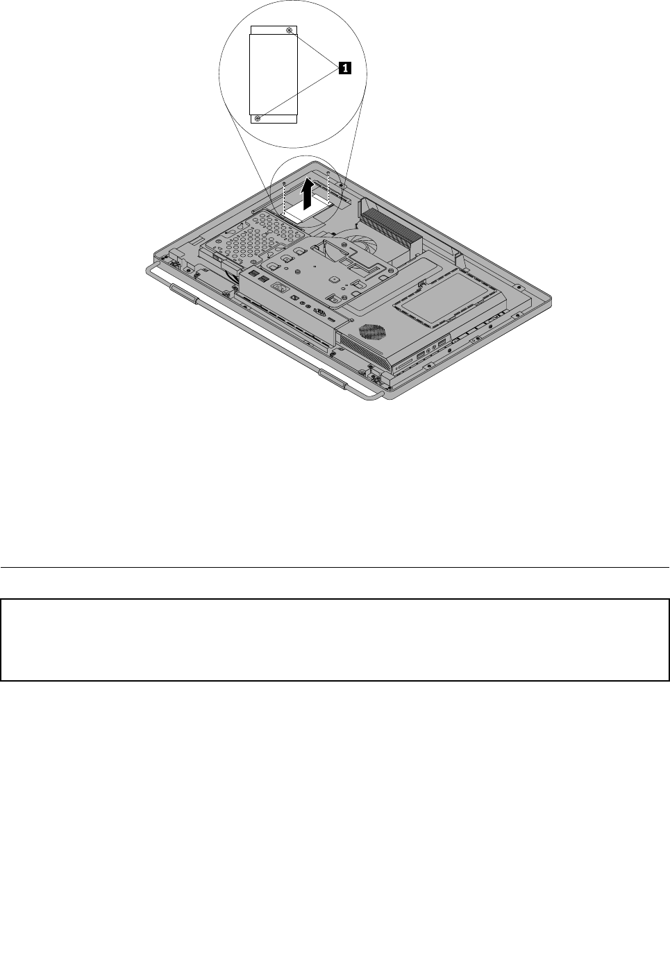
7.Disconnectthethreecablesfromtheinverter.
8.Lifttheinverteroffthecomputer.
9.Toreinstallthenewinverter,connectthethreecablestothenewinverter.Positionthenewinverterand
alignthetwoscrewholesinthenewinverterwiththoseinthecomputer.
10.Installthetwoscrewstosecurethenewinvertertothemainbracket.
11.Reinstalltheopticaldrive.See“Replacingtheopticaldrive”onpage82.
12.Goto“Completingthepartsreplacement”onpage109.
Installingorreplacingamemorymodule
Attention:
Donotopenyourcomputerorattemptanyrepairbeforereadingandunderstandingthe“Importantsafetyinformation”
intheSafety,Warranty,andSetupGuidethatcamewithyourcomputer.ToobtainacopyoftheSafety,Warranty,
andSetupGuide,goto:
http://www.lenovo.com/support
Thissectionprovidesinstructionsonhowtoinstallorreplaceamemorymodule.
YourcomputerhastwomemoryslotsforinstallingorreplacingDDR3SODIMMs(smalloutlinedualinline
memorymodules).Wheninstallingorreplacingamemorymodule,use1GB,2GBor4GBDDR3SODIMMs
inanycombinationuptoamaximumof8GBofsystemmemory.
Toinstallorreplaceamemorymodule,dothefollowing:
1.Removeallmediafromthedrivesandturnoffallattacheddevicesandthecomputer.Then,disconnect
allpowercordsfromelectricaloutletsanddisconnectallcablesthatareconnectedtothecomputer.
2.Placeasoft,cleantowelorclothonthedeskorotheratsurface.Holdthesidesofyourcomputerand
gentlylayitdownsothatthescreenisagainstthesurfaceandthecoverisfacingup.
3.Removethecomputercover.See“Removingthecomputercover”onpage79.
98ThinkCentreHardwareMaintenanceManual
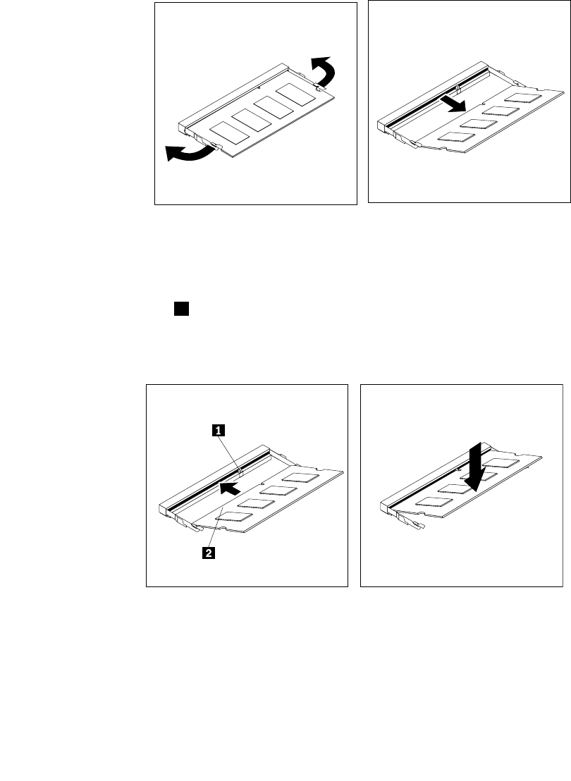
4.Locatethememoryslotsonthesystemboard.See“LocatingmajorFRUsandCRUs”onpage66.
5.Removethesystemboardshieldoropenthesystemboardshieldwindowtogetaccesstothebattery.
See“Removingandreinstallingthesystemboardshield”onpage86or“Openingthesystemboard
shieldwindow”onpage95.
6.Removeanypartsanddisconnectanycablesthatmightpreventyouraccesstothememoryslots.
7.Dooneofthefollowing:
•Ifyouarereplacingamemorymodule,opentheretainingclipsandremovetheoldmemorymodule
thatiscurrentlyinstalled.
Figure36.Removingamemorymodule
•Ifyouareinstallingamemorymodule,opentheretainingclipsofthememoryslotintowhichyou
wanttoinstallthememorymodule.
8.Insertthenotchedend1ofthenewmemorymoduleintotheslot.Pressthememorymodulermly
andpivotthememorymoduleuntilitsnapsintoplace.Makesurethatthememorymoduleissecured
intheslotanddoesnotmoveeasily.
Figure37.Installingamemorymodule
9.Reinstallthesystemboardshieldorclosethesystemboardshieldwindow.See“Removingand
reinstallingthesystemboardshield”onpage86or“Openingthesystemboardshieldwindow”on
page95.
10.Goto“Completingthepartsreplacement”onpage109.
Chapter9.ReplacingFRUs99
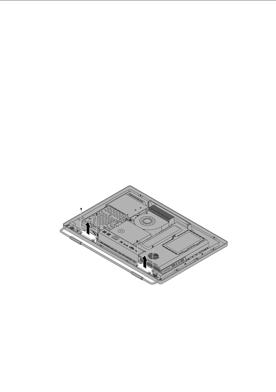
Replacingtheinternalspeakers
Attention
Donotopenyourcomputerorattemptanyrepairbeforereadingandunderstandingthe“Importantsafety
information”intheSafety,Warranty,andSetupGuidethatcamewithyourcomputer.Toobtainacopyof
theSafety,Warranty,andSetupGuide,goto:
http://www.lenovo.com/support
Thissectionprovidesinstructionsonhowtoreplacetheinternalspeakers.
Toreplacetheinternalspeakers,dothefollowing:
1.Removeallmediafromthedrivesandturnoffallattacheddevicesandthecomputer.Then,disconnect
allpowercordsfromelectricaloutletsanddisconnectallcablesthatareconnectedtothecomputer.
2.Placeasoft,cleantowelorclothonthedeskorotheratsurface.Holdthesidesofyourcomputerand
gentlylayitdownsothatthescreenisagainstthesurfaceandthecoverisfacingup.
3.Removethecomputercover.See“Removingthecomputercover”onpage79.
4.Locatetheinternalspeakersinthecomputer.See“LocatingmajorFRUsandCRUs”onpage66.
5.Removethesystemboardshield.See“Removingandreinstallingthesystemboardshield”onpage86.
6.Notethelocationoftheinternalspeakercableconnectionandtheroutingoftheinternalspeakercables.
Disconnecttheinternalspeakercablesfromthesystemboard.
7.Removethetwoscrewsthatsecureeachinternalspeakertothefrontbezel,andthenremovethe
internalspeakersfromthecomputer.
Figure38.Removingtheinternalspeakers
8.Routethenewinternalspeakercables,andthenpositionthenewinternalspeakersonthefrontbezelso
thatthetwoscrewholesineachinternalspeakeralignwiththoseinthefrontbezel.
9.Reinstallthetwoscrewstosecureeachoftheinternalspeakerstothefrontbezel.
10.Connecttheinternalspeakercablestothesystemboard.See“Systemboardpartsandconnectors”
onpage70.
11.Reinstallthesystemboardshield.See“Removingandreinstallingthesystemboardshield”onpage86.
12.Goto“Completingthepartsreplacement”onpage109.
100ThinkCentreHardwareMaintenanceManual
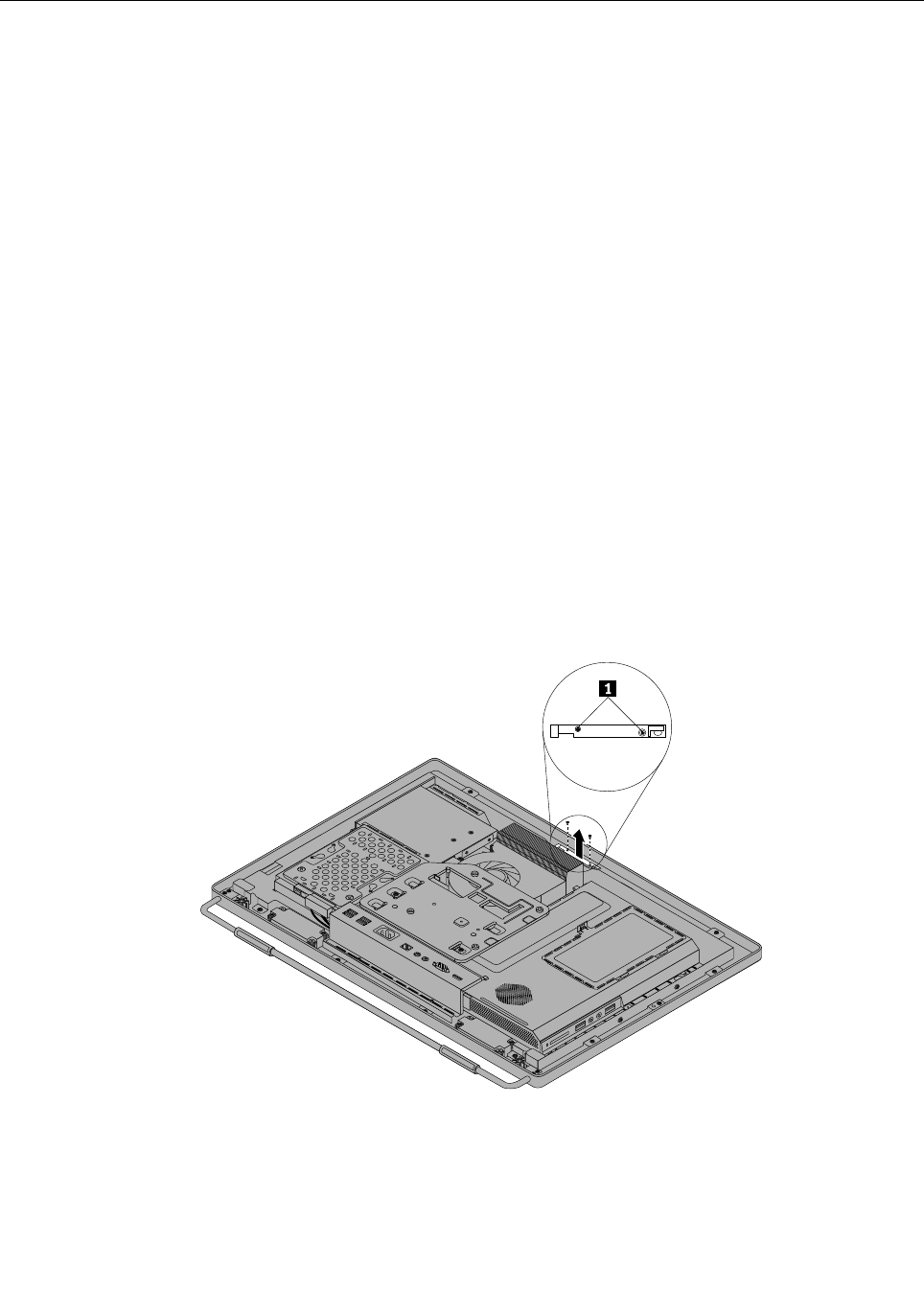
Replacingtheintegratedcamera
Attention
Donotopenyourcomputerorattemptanyrepairbeforereadingandunderstandingthe“Importantsafety
information”intheSafety,Warranty,andSetupGuidethatcamewithyourcomputer.Toobtainacopyof
theSafety,Warranty,andSetupGuide,goto:
http://www.lenovo.com/support
Thissectionprovidesinstructionsonhowtoreplacetheintegratedcamera.
Note:Theintegratedcameraisavailableonlyinsomemodels.
Toreplacetheintegratedcamera,dothefollowing:
1.Removeallmediafromthedrivesandturnoffallattacheddevicesandthecomputer.Then,disconnect
allpowercordsfromelectricaloutletsanddisconnectallcablesthatareconnectedtothecomputer.
2.Placeasoft,cleantowelorclothonthedeskorotheratsurface.Holdthesidesofyourcomputerand
gentlylayitdownsothatthescreenisagainstthesurfaceandthecoverisfacingup.
3.Removethecomputercover.See“Removingthecomputercover”onpage79.
4.Locatetheintegratedcamerainthecomputer.See“LocatingmajorFRUsandCRUs”onpage66.
5.Removethesystemboardshield.See“Removingandreinstallingthesystemboardshield”onpage86.
6.Notetheroutingoftheintegratedcameracable,andthendisconnectthecablefromthesystemboard.
See“Systemboardpartsandconnectors”onpage70.
7.Removethetwoscrewsthatsecuretheintegratedcameratothefrontbezeltoremovetheintegrated
camerafromthecomputer.
Figure39.Removingtheintegratedcamera
8.Toreinstalltheintegratedcamera,positionthenewintegratedcameraandalignthetwoscrewholesin
thenewintegratedcamerawiththoseinthefrontbezel.
9.Installthetwoscrewstosecurethenewintegratedcameratothefrontbezel.
Chapter9.ReplacingFRUs101

10.Routethenewintegratedcameracable,andthenconnecttheintegratedcameracabletothesystem
board.See“Systemboardpartsandconnectors”onpage70.
11.Reinstallthesystemboardshield.See“Removingandreinstallingthesystemboardshield”onpage86.
12.Goto“Completingthepartsreplacement”onpage109.
Replacingthesystemboard
Attention
Donotopenyourcomputerorattemptanyrepairbeforereadingandunderstandingthe“Importantsafety
information”intheSafety,Warranty,andSetupGuidethatcamewithyourcomputer.Toobtainacopyof
theSafety,Warranty,andSetupGuide,goto:
http://www.lenovo.com/support
Thissectionprovidesinstructionsonhowtoreplacethesystemboard.
Toreplacethesystemboard,dothefollowing:
1.Removeallmediafromthedrivesandturnoffallattacheddevicesandthecomputer.Then,disconnect
allpowercordsfromelectricaloutletsanddisconnectallcablesthatareconnectedtothecomputer.
2.Placeasoft,cleantowelorclothonthedeskorotheratsurface.Holdthesidesofyourcomputerand
gentlylayitdownsothatthescreenisagainstthesurfaceandthecoverisfacingup.
3.Removethecomputercover.See“Removingthecomputercover”onpage79.
4.Removethesystemboardshield.See“Removingandreinstallingthesystemboardshield”onpage86.
5.Locatethesystemboardinthecomputer.See“LocatingmajorFRUsandCRUs”onpage66.
6.Removetheheatsinkassembly.See“Replacingtheheatsinkassembly”onpage89.
7.Removethemicroprocessor.See“Replacingthemicroprocessor”onpage91.
8.Removethememorymodules.See“Installingorreplacingamemorymodule”onpage98.
9.Removethebattery.See“Replacingthebattery”onpage96.
10.RemovetherearI/Oassemblytogainaccesstothesystemboard.See“ReplacingtherearI/O
assembly”onpage84.
11.Notethelocationsofallcableconnectionsonthesystemboardanddisconnectallcables.See“System
boardpartsandconnectors”onpage70.
12.Removethesevenscrewsthatsecurethesystemboardtothemainbracket.Carefullyliftthesystem
boardoutofthechassis.
102ThinkCentreHardwareMaintenanceManual
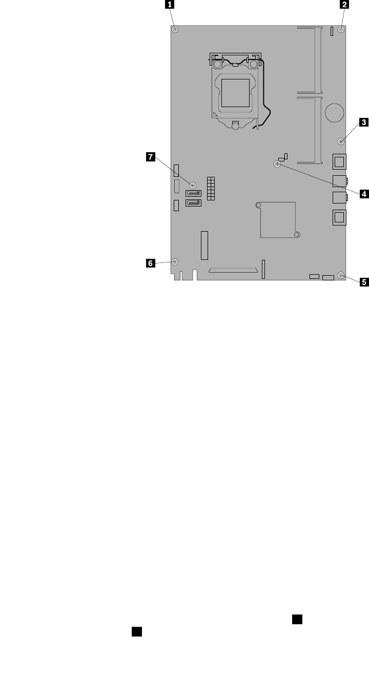
Figure40.Removingthesevenscrewsthatsecurethesystemboardtothemainbracket
13.Placethenewsystemboardintothechassisandalignthescrewholeswiththoseinthechassis.
14.Reinstallthesevenscrewsthatsecurethesystemboardtothemainbracket.
15.ReinstalltherearI/Oassembly.See“ReplacingtherearI/Oassembly”onpage84.
16.Reinstallthebattery.See“Replacingthebattery”onpage96.
17.Reinstallthememorymodules.See“Installingorreplacingamemorymodule”onpage98.
18.Reinstallthemicroprocessor.See“Replacingthemicroprocessor”onpage91.
19.Reinstalltheheatsinkassembly.See“Replacingtheheatsinkassembly”onpage89.
20.Reinstallthesystemboardshield.See“Removingandreinstallingthesystemboardshield”onpage86.
21.Reconnectallcablesthatweredisconnectedfromthesystemboard.See“Systemboardpartsand
connectors”onpage70.
22.Goto“Completingthepartsreplacement”onpage109.
Thefailingsystemboardmustbereturnedwithamicroprocessorsocketcovertoprotectthepinsduring
shippingandhandling.
Toinstallthemicroprocessorsocketcover,dothefollowing:
1.Releasetheleversecuringthemicroprocessorretainerandopentheretainertoaccessthe
microprocessor.
2.Graspthemicroprocessoronthesidesandliftitstraightupandoutofthesocket.Donottouchthe
contactsonthemicroprocessorsocket.
3.Notetheorientationofthesocketcover.Alignthenotches1onthemicroprocessorsocketcover
withthealignmentkeys2onthemicroprocessorsocket.Installonesideofthesocketcoverinto
themicroprocessorsocket.
Chapter9.ReplacingFRUs103

Figure41.Installingonesideofthesocketcoverintothemicroprocessorsocket
Note:Yourmicroprocessorsocketandcovermightlookslightlydifferentfromtheillustration.
4.Carefullypresstheothersideofthesocketcoverdownwardsuntilthesocketcoversnapsintoplace.
5.Carefullycheckthefourcornersofthesocketcovertomakesurethatthecoverissecuredinthe
microprocessorsocket.
6.Lowerthemicroprocessorretainer,andthenlowerthelevertosecuretheretainer.Makesurethe
leverislockedintoposition.
7.Followanyadditionalinstructionsincludedwiththereplacementpartyoureceived.
Note:Ifyoursystemboardhastwomicroprocessorsockets,besuretoinstallasocketcoverforeach
microprocessorsocket.
ReplacingtheLCDpanel
Attention
Donotopenyourcomputerorattemptanyrepairbeforereadingandunderstandingthe“Importantsafety
information”intheSafety,Warranty,andSetupGuidethatcamewithyourcomputer.Toobtainacopyof
theSafety,Warranty,andSetupGuide,goto:
http://www.lenovo.com/support
ThissectionprovidesinstructionsonhowtoreplacetheLCDpanel.
ToreplacetheLCDpanel,dothefollowing:
1.Removeallmediafromthedrivesandturnoffallattacheddevicesandthecomputer.Then,disconnect
allpowercordsfromelectricaloutletsanddisconnectallcablesthatareconnectedtothecomputer.
2.Placeasoft,cleantowelorclothonthedeskorotheratsurface.Holdthesidesofyourcomputerand
gentlylayitdownsothatthescreenisagainstthesurfaceandthecoverisfacingup.
3.Removethecomputercover.See“Removingthecomputercover”onpage79.
4.Removethefootstands.See“Removingandreinstallingtheframestand”onpage76.
104ThinkCentreHardwareMaintenanceManual
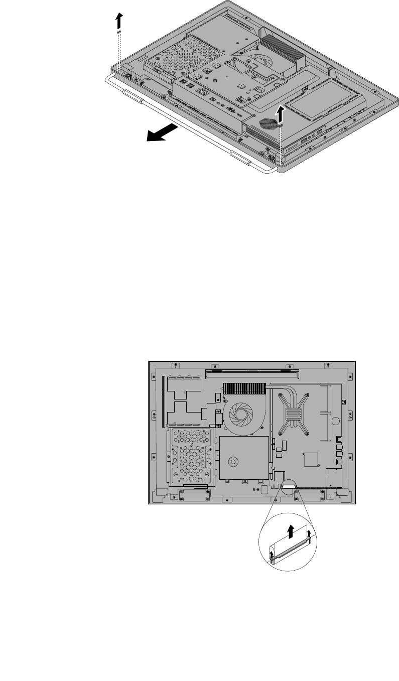
Figure42.Removingtheframestand
5.LocatetheLCDpanelinthecomputer.See“LocatingmajorFRUsandCRUs”onpage66.
6.Removetheopticaldrive.See“Replacingtheopticaldrive”onpage82.
7.Removetheinverter.See“Replacingtheinverter”onpage97.
8.RemovetherearI/Oassembly.See“ReplacingtherearI/Oassembly”onpage84.
9.Removethesystemboardshield.See“Removingandreinstallingthesystemboardshield”onpage86.
10.DisconnecttheLCDpanelcablefromthesystemboard.See“Systemboardpartsandconnectors”
onpage70.
Figure43.DisconnecttheLCDpanelcablefromthesystemboard
Chapter9.ReplacingFRUs105
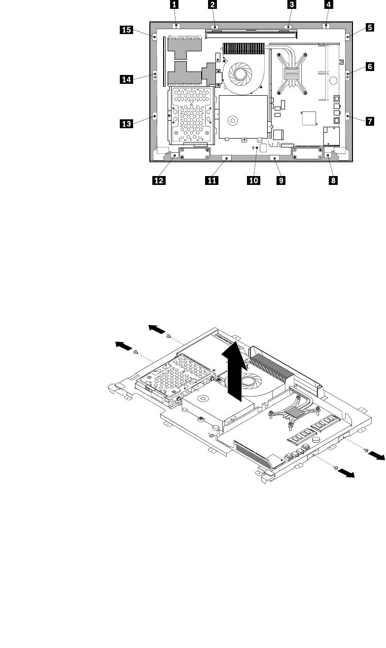
11.Removeallthe15screwsthatsecurethecomputermainbrackettothefrontbezel.
Figure44.Removingallthe15screwsthatsecurethecomputermainbrackettothefrontbezel
12.Notethelocationsofallcableconnectionsthatpreventyoufromliftingthecomputermainbracket,and
disconnectallcables.See“Systemboardpartsandconnectors”onpage70.
13.Removetheintegratedcamera.See“Replacingtheintegratedcamera”onpage101.
14.Liftthecomputermainbracketoffthefrontbezel.
15.RemovethefourscrewsthatsecurethechassistotheLCDpanel,andthenliftthechassisoutof
thecomputertogetassesstotheLCDpanel.
Figure45.RemovingthefourscrewsthatsecuretheLCDpanel
16.PlacethecomputerchassisoverthenewLCDpanelsothatthefourscrewholesalignwiththoseinthe
chassis.ReinstallthefourscrewstosecuretheLCDpaneltothechassis.
17.PositionthecomputermainbracketovertheLCDpanel.Makesurethescrewholesinthecomputer
mainbracketalignwiththoseinthefrontbezel.
18.Reinstallallthe15screwsthatsecurethecomputermainbrackettothefrontbezel.
106ThinkCentreHardwareMaintenanceManual
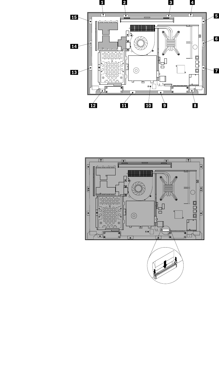
Figure46.Reinstallingallthe15screwsthatsecurethecomputermainbrackettothefrontbezel
19.ReconnecttheLCDpanelcablefromthesystemboard.See“Systemboardpartsandconnectors”
onpage70.
Figure47.ReconnecttheLCDpanelcabletothesystemboard
20.Reinstalltheintegratedcamera.See“Replacingtheintegratedcamera”onpage101.
21.ReinstalltherearI/Oassembly.See“ReplacingtherearI/Oassembly”onpage84.
22.Reinstallthesystemboardshield.See“Removingandreinstallingthesystemboardshield”onpage86.
23.Reinstallthefootstands.See“Removingandreinstallingtheframestand”onpage76.
24.Connectallthecablesthatweredisconnected.See“Systemboardpartsandconnectors”onpage70.
25.Goto“Completingthepartsreplacement”onpage109.
Chapter9.ReplacingFRUs107
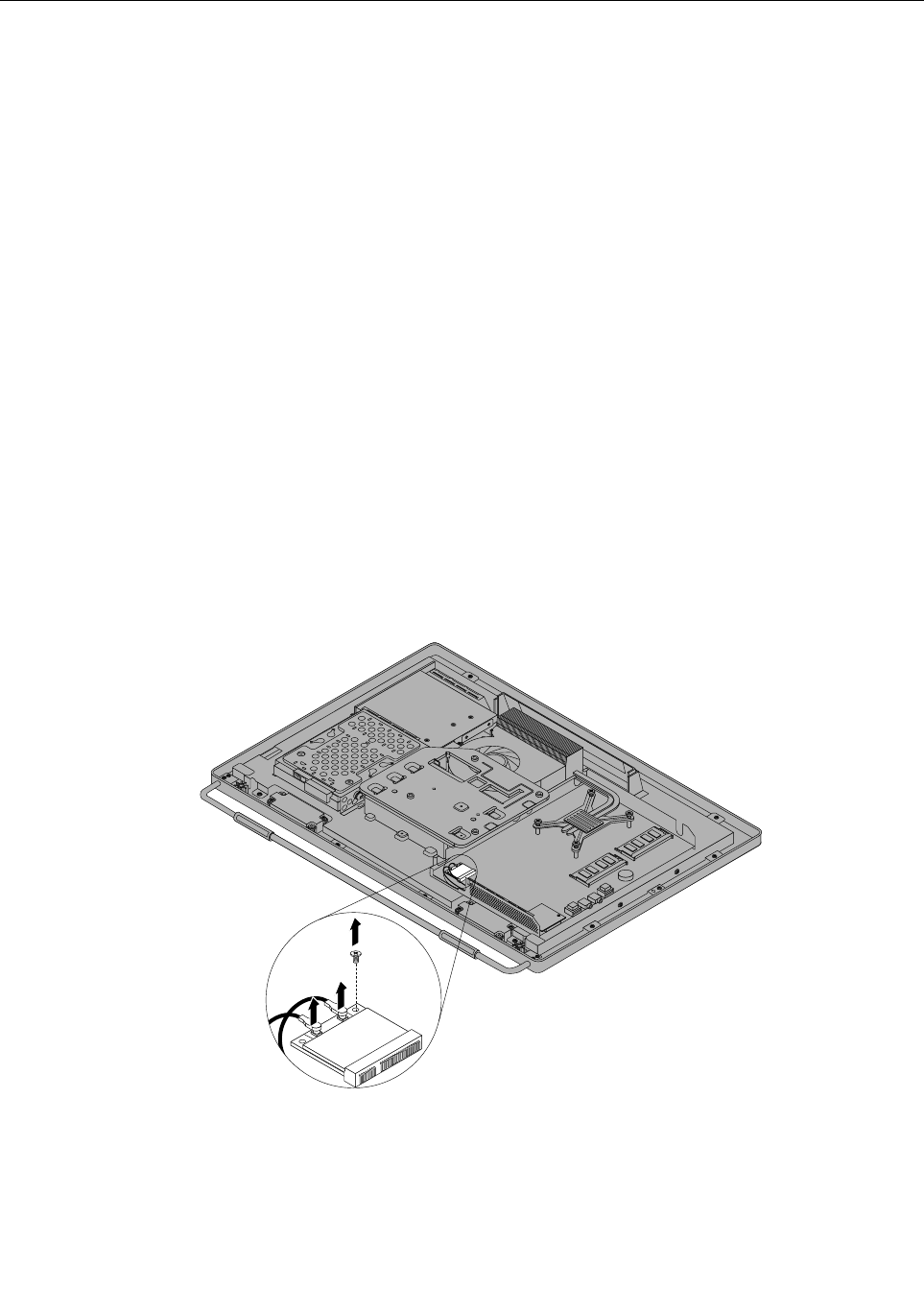
ReplacingtheWI-FIcard
Attention
Donotopenyourcomputerorattemptanyrepairbeforereadingandunderstandingthe“Importantsafety
information”intheSafety,Warranty,andSetupGuidethatcamewithyourcomputer.Toobtainacopyof
theSafety,Warranty,andSetupGuide,goto:
http://www.lenovo.com/support
ThissectionprovidesinstructionsonhowtoreplacetheWI-FIcard.
Note:TheWI-FIcardisavailableonlyinsomemodels.
ToreplacetheWI-FIcard,dothefollowing:
1.Removeallmediafromthedrivesandturnoffallattacheddevicesandthecomputer.Then,disconnect
allpowercordsfromelectricaloutletsanddisconnectallcablesthatareconnectedtothecomputer.
2.Placeasoft,cleantowelorclothonthedeskorotheratsurface.Holdthesidesofyourcomputerand
gentlylayitdownsothatthescreenisagainstthesurfaceandthecoverisfacingup.
3.Removethecomputercover.See“Removingthecomputercover”onpage79.
4.Removethesystemboardshield.See“Removingandreinstallingthesystemboardshield”onpage86.
5.LocatetheWI-FIcardonthesystemboard.See“LocatingmajorFRUsandCRUs”onpage66.
6.RemovetherearI/Oassembly.See“ReplacingtherearI/Oassembly”onpage84.
7.DisconnectthetwocablesfromtheWI-FIcard,andthencarefullyremovethescrewthatsecures
theWI-FIcardtothesystemboard.
Figure48.RemovingthescrewthatsecurestheWI-FIcardtothesystemboard
8.PivottheWI-FIcardupwardandlifttheWI-FIcardoutoftheminiPCIExpressslot.
108ThinkCentreHardwareMaintenanceManual
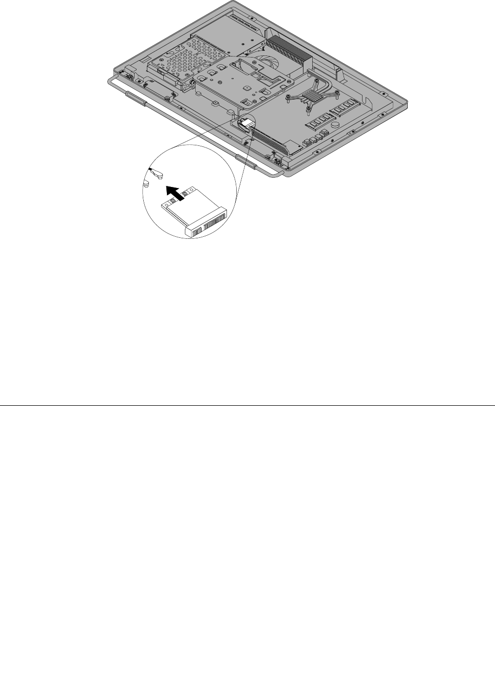
Figure49.RemovingtheWI-FIcard
9.InsertthenotchedendofthenewWI-FIcardintotheminiPCIExpressslot.PressthenewWI-FI
cardrmly,andthenpivottheWI-FIcardtoalignthescrewholeinthenewWI-FIcardwiththat
inthesystemboard.
10.InstallthescrewtosecurethenewWI-FIcardtothesystemboard.
11.ConnectthetwocablestothenewWI-FIcard.
12.ReinstalltherearI/Oassembly.See“ReplacingtherearI/Oassembly”onpage84.
13.Reinstallthesystemboardshield.See“Removingandreinstallingthesystemboardshield”onpage86.
14.Goto“Completingthepartsreplacement”onpage109.
Completingthepartsreplacement
Aftercompletingtheinstallationorreplacementforallparts,youneedtoreinstallthecomputercover
andreconnectcables.
Toreinstallthecomputercoverandreconnectcables,dothefollowing:
1.Makesurethatallcomponentshavebeenreassembledcorrectlyandthatnotoolsorloosescrews
areleftinsideyourcomputer.See“LocatingmajorFRUsandCRUs”onpage66forthelocationsof
variouscomponentsinyourcomputer.
2.Makesurethatthecablesareroutedcorrectlybeforereinstallingthecomputercover.Keepcablesclear
ofthehingesandsidesofthecomputerchassistoavoidinterferencewithreinstallingthecomputer
cover.
Chapter9.ReplacingFRUs109
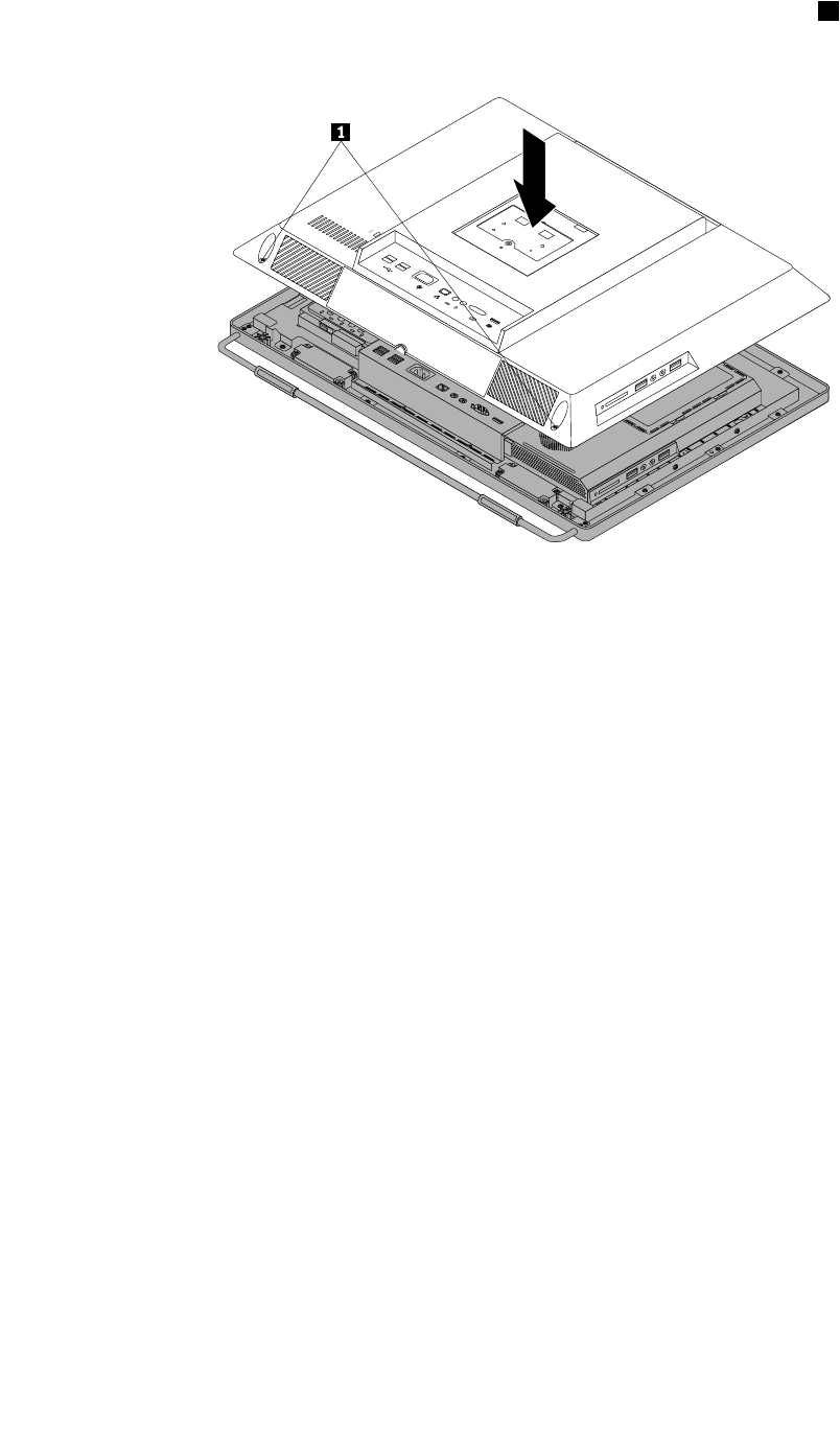
3.Lowerandpositionthecomputercoverintoplaceandthentightenthetwoscrews1tosecurethe
computercover.
Figure50.Installingthecomputercover
4.Reinstallthesystemstandandsystemstandhingecover.See“Removingandreinstallingthesystem
stand”onpage73and“Removingandreinstallingthesystemstandhingecover”onpage71.
5.Lockthecomputercoverifyouhaveanintegratedcablelock.
6.Reconnecttheexternalcablesandpowercordtothecomputer.
7.Dependingonthepartsyouinstalledorreplaced,youmightneedtoconrmtheupdatedinformationin
theSetupUtilityprogram.RefertoChapter6“UsingtheSetupUtilityprogram”onpage53.
Note:Inmostareasoftheworld,LenovorequiresthereturnofthedefectiveCustomerReplaceableUnit
(CRU).InformationaboutthiswillcomewiththeCRUorwillcomeafewdaysaftertheCRUarrives.
110ThinkCentreHardwareMaintenanceManual

Chapter10.AdditionalServiceInformation
Thischapterprovidesadditionalinformationthattheservicerepresentativemightndhelpful.
Securityfeatures
Securityfeaturesinthissectionincludethefollowing:
•Passwords
•VitalProductData
•ManagementInformationFormat(MIF)
HardwarecontrolledPasswords
HardwarecontrolledpasswordsaresetusingtheSetupUtilityprogram.Formoreinformationabout
passwords,see“Usingpasswords”onpage53.
Operatingsystempassword
Anoperatingsystempasswordisverysimilartoapower-onpasswordanddeniesaccesstothecomputer
byanunauthorizeduserwhenthepasswordisactivated.Thecomputerisunusableuntilthepasswordis
enteredandrecognizedbythecomputer.
Vitalproductdata
EachcomputerhasauniqueVitalProductData(VPD)codestoredinthenonvolatilememoryonthesystem
board.Afteryoureplacethesystemboard,theVPDmustbeupdated.ToupdatetheVPD,see“Flash
updateprocedures”onpage111.
BIOSlevels
AnincorrectlevelofBIOScancausefalseerrorsandunnecessaryFRUreplacement.Usethefollowing
informationtodeterminethecurrentlevelofBIOSinstalledinthecomputer,thelatestBIOSavailableforthe
computer,andwheretoobtainthelatestlevelofBIOS.
•TodeterminethecurrentLevelofBIOS:
–StarttheSetupUtility.
–SelectStandardCMOSFeatures.
•SourcesforobtainingthelatestlevelBIOSavailable
1.Lenovosupportwebsite:http://www.lenovo.com/support/
2.LenovoCustomerSupportCenter
3.Levels1and2Support
Toupdate(ash)theBIOS,see“Flashupdateprocedures”onpage111.
Flashupdateprocedures
Thissectiondetailshowtoash(update)theBIOS.
Updating(ashing)theBIOSfromadisc
Thissectionprovidesinstructionsonhowtoupdate(ash)theBIOSfromadisc.
©CopyrightLenovo2012111

Note:Youcandownloadaself-startingbootablediscimage(knownasanISOimage)withthesystem
programupdatestocreateasystem-program-updatedisc.Goto:
http://www.lenovo.com/support
Toupdate(ash)theBIOSfromadisc,dothefollowing:
1.Turnoffyourcomputer.
2.RepeatedlypressandreleasetheF12keywhenturningonthecomputer.WhentheStartupDevice
Menuwindowopens,releasetheF12key.
3.OntheStartupDeviceMenuwindow,selectthedesiredopticaldriveasthestartupdevice.Then,insert
thediscintothisopticaldriveandpressEnter.Theupdatebegins.
4.Whenpromptedtochangetheserialnumber,itissuggestedthatyoudonotmakethischangeby
pressingN.However,ifyoudowanttochangetheserialnumber,pressY,thentypeintheserialnumber
andpressEnter.
5.Whenpromptedtochangethemachinetypeandmodel,itissuggestedthatyoudonotmakethis
changebypressingN.However,ifyoudowanttochangethemachinetypeandmodel,pressY,then
typeinthemachinetypeandmodelandpressEnter.
6.Followtheinstructionsonthescreentocompletetheupdate.Aftertheupdateiscompleted,removethe
discfromtheopticaldrive.
Updating(ashing)theBIOSfromyouroperatingsystem
Note:BecauseLenovomakesconstantimprovementstoitsWebsites,theWebpagecontentsaresubject
tochangewithoutnotice,includingthecontentsreferencedinthefollowingprocedure.
Toupdate(ash)theBIOSfromyouroperatingsystem,dothefollowing:
1.Goto
http://www.lenovo.com/support.
2.Dothefollowingtolocatethedownloadablelesforyourmachinetype:
a.IntheEnteraproductnumbereld,typeyourmachinetypeandclickGo.
b.ClickDownloadsanddrivers.
c.SelectBIOSfromtheReneresultsdrop-downlistboxtoeasilylocatealltheBIOSrelatedlinks.
d.ClicktheBIOSupdatelink.
3.ClicktheTXTlethatcontainstheinstructionsforupdating(ashing)theBIOSfromyouroperating
system.
4.Printtheseinstructions.Thisisveryimportantbecausetheseinstructionswillnotbedisplayedon
thescreenafterthedownloadbegins.
5.Followtheprintedinstructionstodownload,extract,andinstalltheupdate.
RecoveringfromaPOST/BIOSupdatefailure
IfthepowertoyourcomputerisinterruptedwhilethePOST/BIOSisbeingupdated(ashupdate),your
computermightnotrestartcorrectly.Ifthishappens,performthefollowingprocedurecommonlycalled
Boot-blockRecovery.
1.Removeallmediafromthedrivesandturnoffallattacheddevicesandthecomputer.Then,disconnect
allpowercordsfromelectricaloutletsanddisconnectallcablesthatareconnectedtothecomputer.
2.Removethecomputercover.See“Removingthecomputercover”onpage79.
3.LocatetheClearCMOS/Recoveryjumperonthesystemboard.See“Systemboardpartsand
connectors”onpage70.
112ThinkCentreHardwareMaintenanceManual

4.Movethejumperfromthestandardposition(pin1andpin2)tothemaintenanceposition(pin2and
pin3).
5.Installthecomputercoverandreconnectallcablesandpowercordsthatweredisconnected.See
“Completingthepartsreplacement”onpage109.
6.RepeatedlypressandreleasetheF12keywhenturningonthecomputer.WhentheStartupDevice
Menuopens,releasetheF12key.
7.InsertthePOST/BIOSupdate(ash)discintotheopticaldrive.Then,selecttheopticaldriveasthe
startupdeviceandpressEnter.Therecoverysessionbegins.
Note:Therecoverysessionwilltaketwotothreeminutes.Duringthistimeyouwillhearaseries
ofbeeps.
8.Aftertherecoverysessioniscompleted,theseriesofbeepswillend,andthesystemwillautomatically
turnoff.Removethediscfromtheopticaldrivebeforethesystemcompletelyturnsoff.
9.Repeatsteps1through3.
10.MovetheClearCMOS/Recoveryjumperbacktothestandardposition(pin1andpin2).
11.Installthecomputercoverandreconnectallcablesandpowercordsthatweredisconnected.See
“Completingthepartsreplacement”onpage109.
12.Turnonthecomputertorestarttheoperatingsystem.
Powermanagement
Powermanagementreducesthepowerconsumptionofcertaincomponentsofthecomputersuchasthe
systempowersupply,processor,harddiskdrives,andsomemonitors.
Automaticcongurationandpowerinterface(ACPI)BIOS
BeinganACPIBIOSsystem,theoperatingsystemisallowedtocontrolthepowermanagementfeatures
ofthecomputerandthesettingforAdvancedPowerManagement(APM)BIOSmodeisignored.Not
alloperatingsystemssupportACPIBIOSmode.
AutomaticPower-Onfeatures
TheAutomaticPower-OnfeatureswithinthePowerManagementmenuallowyoutoenableanddisable
featuresthatturnonthecomputerautomatically.
•WakeUponAlarm:Youcanspecifyadateandtimeatwhichthecomputerwillbeturnedon
automatically.Thiscanbeeitherasingleeventoradailyevent.
•WakeonLAN:Ifthecomputerhasaproperlyconguredtoken-ringorEthernetLANadaptercardthatis
WakeonLAN-enabledandthereisremotenetworkmanagementsoftware,youcanusetheWakeonLAN
feature.WhenyousetWakeonLANtoEnabled,thecomputerwillturnonwhenitreceivesaspecic
signalfromanothercomputeronthelocalareanetwork(LAN).
Chapter10.AdditionalServiceInformation113

114ThinkCentreHardwareMaintenanceManual

AppendixA.Notices
Lenovomaynotoffertheproducts,services,orfeaturesdiscussedinthisdocumentinallcountries.Consult
yourlocalLenovorepresentativeforinformationontheproductsandservicescurrentlyavailableinyour
area.AnyreferencetoaLenovoproduct,program,orserviceisnotintendedtostateorimplythatonlythat
Lenovoproduct,program,orservicemaybeused.Anyfunctionallyequivalentproduct,program,orservice
thatdoesnotinfringeanyLenovointellectualpropertyrightmaybeusedinstead.However,itistheuser's
responsibilitytoevaluateandverifytheoperationofanyotherproduct,program,orservice.
Lenovomayhavepatentsorpendingpatentapplicationscoveringsubjectmatterdescribedinthis
document.Thefurnishingofthisdocumentdoesnotgiveyouanylicensetothesepatents.Youcansend
licenseinquiries,inwriting,to:
Lenovo(UnitedStates),Inc.
1009ThinkPlace-BuildingOne
Morrisville,NC27560
U.S.A.
Attention:LenovoDirectorofLicensing
LENOVOPROVIDESTHISPUBLICATION“ASIS”WITHOUTWARRANTYOFANYKIND,EITHEREXPRESS
ORIMPLIED,INCLUDING,BUTNOTLIMITEDTO,THEIMPLIEDWARRANTIESOFNON-INFRINGEMENT,
MERCHANTABILITYORFITNESSFORAPARTICULARPURPOSE.Somejurisdictionsdonotallow
disclaimerofexpressorimpliedwarrantiesincertaintransactions,therefore,thisstatementmaynotapply
toyou.
Thisinformationcouldincludetechnicalinaccuraciesortypographicalerrors.Changesareperiodically
madetotheinformationherein;thesechangeswillbeincorporatedinneweditionsofthepublication.
Lenovomaymakeimprovementsand/orchangesintheproduct(s)and/ortheprogram(s)describedinthis
publicationatanytimewithoutnotice.
Theproductsdescribedinthisdocumentarenotintendedforuseinimplantationorotherlifesupport
applicationswheremalfunctionmayresultininjuryordeathtopersons.Theinformationcontainedinthis
documentdoesnotaffectorchangeLenovoproductspecicationsorwarranties.Nothinginthisdocument
shalloperateasanexpressorimpliedlicenseorindemnityundertheintellectualpropertyrightsofLenovo
orthirdparties.Allinformationcontainedinthisdocumentwasobtainedinspecicenvironmentsandis
presentedasanillustration.Theresultobtainedinotheroperatingenvironmentsmayvary.
Lenovomayuseordistributeanyoftheinformationyousupplyinanywayitbelievesappropriatewithout
incurringanyobligationtoyou.
Anyreferencesinthispublicationtonon-LenovoWebsitesareprovidedforconvenienceonlyanddonotin
anymannerserveasanendorsementofthoseWebsites.ThematerialsatthoseWebsitesarenotpartof
thematerialsforthisLenovoproduct,anduseofthoseWebsitesisatyourownrisk.
Anyperformancedatacontainedhereinwasdeterminedinacontrolledenvironment.Therefore,theresult
obtainedinotheroperatingenvironmentsmayvarysignicantly.Somemeasurementsmayhavebeen
madeondevelopment-levelsystemsandthereisnoguaranteethatthesemeasurementswillbethesame
ongenerallyavailablesystems.Furthermore,somemeasurementsmayhavebeenestimatedthrough
extrapolation.Actualresultsmayvary.Usersofthisdocumentshouldverifytheapplicabledatafortheir
specicenvironment.
©CopyrightLenovo2012115

Televisionoutputnotice
Thefollowingnoticeappliestomodelsthathavethefactory-installedtelevision-outputfeature.
ThisproductincorporatescopyrightprotectiontechnologythatisprotectedbymethodclaimsofcertainU.S.
patentsandotherintellectualpropertyrightsownedbyMacrovisionCorporationandotherrightsowners.
UseofthiscopyrightprotectiontechnologymustbeauthorizedbyMacrovisionCorporation,andisintended
forhomeandotherlimitedviewingusesonlyunlessotherwiseauthorizedbyMacrovisionCorporation.
Reverseengineeringordisassemblyisprohibited.
EuropeanconformanceCEmark
Trademarks
ThefollowingtermsaretrademarksofLenovointheUnitedStates,othercountries,orboth:
Lenovo
TheLenovologo
RescueandRecovery
ThinkVantage
MicrosoftandWindowsaretrademarksoftheMicrosoftgroupofcompanies.
IntelisatrademarkofIntelCorporationintheUnitedStates,othercountries,orboth.
LinuxisatrademarkofLinusTorvaldsintheUnitedStates,othercountries,orboth.
Othercompany,product,orservicenamesmaybetrademarksorservicemarksofothers.
116ThinkCentreHardwareMaintenanceManual

Index
A
Administrator,password54
B
basictroubleshooting35
battery,replacing96
boot-blockrecovery112
C
cardreader,replacing94
changing
password54
startupdevicesequence55
components,internal66
computercover
removing79
computercover,reinstalling109
connectors
rear64
connectors,controls,indicators
front63
considerations,passwords54
CRU
completingtheinstallation109
CRUs(CustomerReplacableUnits),returningdefective66
D
deletingapassword54
diagnostics,troubleshooting35
E
environment,operating29
exiting,SetupUtility56
F
ashingtheBIOS111
framestand
reinstalling76
removing76
front
connectors,controls,indicators63
FRUlocations66
FRUpartnumbers63,69
H
harddiskdrive,replacing79
heatsinkassembly,replacing89
I
IdentifyingFRUs66
information
resources31
installing,replacing
memorymodule98
integratedcamera,replacing101
internalspeakers,replacing100
inverter,replacing97
L
LCDpanel,replacing104
LenovoSolutionCenter51
LenovoWelcome30
locatingcomponents66
lookinguppartnumbers63,69
M
memorymodule98
installing,replacing98
microprocessorfan,replacing88
monitorstand
l,removing75
monitorstand,reinstalling75
N
notice,televisionoutput116
notices115
O
opening
systemboardshieldwindow95
opticaldrive,replacing82
Optional-serviceCRUs66
P
partnumbers63,69
partsreplacement,completing109
password
Administrator54
considerations54
Power-OnPassword54
setting,changing,deleting54
passwords,using53
physicalspecications29
powersupply,replacing87
Power-On,Password54
©CopyrightLenovo2012117

R
rearconnectors64
rearI/Oassembly,replacing84
recovering
aPOST/BIOSupdatefailure112
recovery
boot-block112
removing
systemboardshield86
VESAmountbracket83
removingcomputercover79
removingtheframestand76
removingthesystemstandhingecover71
replacing
battery96
cardreader94
harddiskdrive79
heatsinkassembly89
integratedcamera101
internalspeakers100
inverter97
LCDpanel104
microprocessorfan88
powersupply87
rearI/Oassembly84
systemboard102
WI-FIcard108
resources,information31
S
security
enablingordisabling55
selecting
startupdevice55
temporarystartupdevice55
Self-serviceCRUs66
setting
password54
settings
changing53
viewing53
SetupUtility53
SetupUtilityprogram,starting53
SetupUtility,exiting56
startingtheSetupUtilityprogram53
startupdevice55
sequence,changing55
temporary,selecting55
systemboardshieldwindow,Opening95
systemboardshield,removing86
systemboard,replacing102
systemstand
l,removing73
systemstandhingecover
reinstalling71
removing71
systemstand,reinstalling73
T
televisionoutputnotice116
temporarystartupdevice55
theBIOS,updating(ashing)111–112
trademarks116
troubleshooting,basic35
troubleshooting,diagnostics35
U
updating
(ashing)theBIOS111
updating(ashing)theBIOS112
using
passwords53
SetupUtility53
V
VESAmountbracket,removing83
viewingandchangingsettings53
W
WI-FIcard,replacing108
118ThinkCentreHardwareMaintenanceManual