Lenovo P920 Hmm En Hardware Maintenance Manual User (English) (pdf Version) Think Station Workstation (Think Station) Type 30BD
2017-10-09
User Manual: Lenovo P920 Hmm En (English) Hardware Maintenance Manual (pdf version) - ThinkStation P920 P920 Workstation (ThinkStation) - Type 30BD 30BD
Open the PDF directly: View PDF ![]() .
.
Page Count: 246 [warning: Documents this large are best viewed by clicking the View PDF Link!]
- About this manual
- Chapter 1. Read this first: Important safety information
- Chapter 2. Product overview
- Chapter 3. Using your computer
- Chapter 4. You and your computer
- Chapter 5. Security
- Locking your computer
- Viewing and changing security settings in the Setup Utility program
- Using passwords and Windows accounts
- Using fingerprint authentication
- Using the cover presence switch
- Using firewalls
- Protecting data against viruses
- Using the Smart USB Protection function
- Computrace Agent software embedded in firmware
- Trusted Platform Module (TPM)
- Intel BIOS guard
- Chapter 6. Advanced configuration
- Using the Setup Utility program
- Starting the Setup Utility program
- Changing the display mode of the Setup Utility program
- Changing the display language of the Setup Utility program
- Enabling or disabling a device
- Enabling or disabling the automatic power-on of your computer
- Enabling or disabling the ErP LPS compliance mode
- Enabling or disabling the configuration change detection
- Changing the BIOS settings before installing a new operating system
- Using BIOS passwords
- Selecting a startup device
- Changing the fan speed level
- Exiting the Setup Utility program
- BIOS level
- Updating and recovering the BIOS
- Configuring RAID
- Using the Setup Utility program
- Chapter 7. Troubleshooting, diagnostics, and recovery
- Chapter 8. Service checkout and symptom-to-FRU index
- Chapter 9. Hardware removal and installation
- Handling static-sensitive devices
- Preparing your computer and removing the computer cover
- Removing and installing hardware
- External options
- Cover presence switch (intrusion switch)
- Direct cooling air baffle
- Device in a flex bay
- Storage drive in the front-access storage enclosure
- Device in the multi-drive conversion kit
- 3.5-inch storage drive
- 2.5-inch storage drive
- Front fan assembly
- Rear fan assembly
- M.2 solid-state drive
- Power supply assembly
- Memory module
- PCIe card
- Full-length PCIe card
- Super capacitor module
- Multi-function brackets
- Coin-cell battery
- Wi-Fi units
- Device in the 5.25-inch flex module
- VROC upgrade key module
- Blind-connect assembly
- Heat-sink-and-fan assembly
- Microprocessor
- System board
- Completing the parts replacement
- Chapter 10. Getting information, help, and service
- Appendix A. System memory speed
- Appendix B. Supplemental information about the Ubuntu operating system
- Appendix C. Regulatory information
- Appendix D. WEEE and recycling information
- Appendix E. Restriction of Hazardous Substances (RoHS) Directive
- Appendix F. ENERGY STAR model information
- Appendix G. Notices
- Appendix H. Trademarks

P920 Hardware Maintenance Manual
Machine Types: 30BD, 30BV, and 30BC
Note: Before using this information and the product it supports, be sure to read and understand the Chapter
1 “Read this first: Important safety information” on page 1 and Appendix G “Notices” on page 233.
First Edition (October 2017)
© Copyright Lenovo 2017.
LIMITED AND RESTRICTED RIGHTS NOTICE: If data or software is delivered pursuant to a General Services
Administration “GSA” contract, use, reproduction, or disclosure is subject to restrictions set forth in Contract No. GS-
35F-05925.

Contents
About this manual . . . . . . . . . . . . v
Chapter 1. Read this first: Important
safety information . . . . . . . . . . . . 1
Power cords and power adapters . . . . . . . . . 1
General safety . . . . . . . . . . . . . . . . 1
Electrical safety . . . . . . . . . . . . . . . . 2
Safety inspection guide . . . . . . . . . . . . . 3
Handling electrostatic discharge-sensitive
devices . . . . . . . . . . . . . . . . . . . 4
Grounding requirements . . . . . . . . . . . . 5
Safety notices (multi-lingual translations) . . . . . . 5
Chapter 2. Product overview . . . . . 29
Hardware locations . . . . . . . . . . . . . 29
Front view . . . . . . . . . . . . . . . 29
Rear view . . . . . . . . . . . . . . . 30
Computer components . . . . . . . . . . 33
Major FRUs and CRUs . . . . . . . . . . 34
Parts on the system board . . . . . . . . . 38
Internal storage drives . . . . . . . . . . 40
Machine type and model label . . . . . . . 42
Computer features. . . . . . . . . . . . . . 42
Computer specifications . . . . . . . . . . . 46
Programs . . . . . . . . . . . . . . . . . 46
Accessing a program on your computer . . . 46
Installing a program that is ready to be
installed (Windows 7 only) . . . . . . . . . 47
An introduction to Lenovo programs . . . . . 47
Chapter 3. Using your computer . . . 49
Registering your computer . . . . . . . . . . 49
Setting the computer volume . . . . . . . . . 49
Using a disc . . . . . . . . . . . . . . . . 49
Guidelines about using the optical drive . . . 49
Handling and storing a disc . . . . . . . . 49
Playing and removing a disc . . . . . . . . 50
Recording a disc . . . . . . . . . . . . 50
Connecting to a network . . . . . . . . . . . 51
Chapter 4. You and your computer . . 53
Arranging your workspace . . . . . . . . . . 53
Glare and lighting . . . . . . . . . . . . 53
Air circulation . . . . . . . . . . . . . . 53
Electrical outlet locations and cable lengths . . 53
Comfort . . . . . . . . . . . . . . . . 53
Accessibility information . . . . . . . . . . . 54
Cleaning your computer . . . . . . . . . . . 57
Maintenance . . . . . . . . . . . . . . . . 57
Basic maintenance tips . . . . . . . . . . 57
Good maintenance practices . . . . . . . . 58
Keeping your computer current . . . . . . . 58
Moving your computer . . . . . . . . . . . . 59
Chapter 5. Security . . . . . . . . . . 61
Locking your computer . . . . . . . . . . . . 61
Locking the computer cover . . . . . . . . 61
Attaching a Kensington-style cable lock . . . 62
Viewing and changing security settings in the
Setup Utility program . . . . . . . . . . . . 62
Using passwords and Windows accounts . . . . 63
Using fingerprint authentication . . . . . . . . 63
Using the cover presence switch . . . . . . . . 63
Using firewalls . . . . . . . . . . . . . . . 64
Protecting data against viruses . . . . . . . . . 64
Using the Smart USB Protection function . . . . . 64
Computrace Agent software embedded in
firmware. . . . . . . . . . . . . . . . . . 65
Trusted Platform Module (TPM). . . . . . . . . 65
Intel BIOS guard . . . . . . . . . . . . . . 65
Chapter 6. Advanced
configuration. . . . . . . . . . . . . . 67
Using the Setup Utility program . . . . . . . . 67
Starting the Setup Utility program . . . . . . 67
Changing the display mode of the Setup Utility
program . . . . . . . . . . . . . . . . 67
Changing the display language of the Setup
Utility program . . . . . . . . . . . . . 67
Enabling or disabling a device . . . . . . . 68
Enabling or disabling the automatic power-on
of your computer . . . . . . . . . . . . 68
Enabling or disabling the ErP LPS compliance
mode . . . . . . . . . . . . . . . . . 68
Enabling or disabling the configuration change
detection . . . . . . . . . . . . . . . 69
Changing the BIOS settings before installing a
new operating system . . . . . . . . . . 69
Using BIOS passwords . . . . . . . . . . 69
Selecting a startup device . . . . . . . . . 71
Changing the fan speed level . . . . . . . . 72
Exiting the Setup Utility program . . . . . . 72
BIOS level . . . . . . . . . . . . . . . . . 72
Updating and recovering the BIOS . . . . . . . 73
Configuring RAID . . . . . . . . . . . . . . 74
An Introduction to RAID . . . . . . . . . . 74
© Copyright Lenovo 2017 i
Configuring RAID with Intel RSTe . . . . . . 74
Configuring RAID with AVAGO MegaRAID
Configuration Utility . . . . . . . . . . . 76
Configuring RAID with Intel Virtual RAID on
CPU . . . . . . . . . . . . . . . . . 78
Chapter 7. Troubleshooting,
diagnostics, and recovery . . . . . . . 81
Basic procedure for resolving computer
problems . . . . . . . . . . . . . . . . . 81
Troubleshooting . . . . . . . . . . . . . . 81
Startup problems . . . . . . . . . . . . 81
Audio problems . . . . . . . . . . . . . 82
CD or DVD problems . . . . . . . . . . . 83
Intermittent problems. . . . . . . . . . . 84
Storage drive problems . . . . . . . . . . 84
Ethernet LAN problems . . . . . . . . . . 84
Wireless LAN problem . . . . . . . . . . 85
Bluetooth problems . . . . . . . . . . . 86
Performance problems . . . . . . . . . . 87
Serial connector problem . . . . . . . . . 88
USB device problems . . . . . . . . . . 88
Software and driver problems . . . . . . . 89
Diagnosing problems . . . . . . . . . . . . 89
UEFI diagnostic program . . . . . . . . . . . 91
Recovery information . . . . . . . . . . . . 91
Chapter 8. Service checkout and
symptom-to-FRU index . . . . . . . . 95
Service checkout . . . . . . . . . . . . . . 95
Problem determination tips . . . . . . . . 95
Symptom-to-FRU index . . . . . . . . . . . 96
Hard disk drive boot error . . . . . . . . . 96
Power supply problems . . . . . . . . . . 97
Beep symptoms . . . . . . . . . . . . . 97
POST error codes . . . . . . . . . . . . 98
Miscellaneous error conditions . . . . . . . 99
Undetermined problems . . . . . . . . . 101
Chapter 9. Hardware removal and
installation . . . . . . . . . . . . . . . 103
Handling static-sensitive devices . . . . . . . . 103
Preparing your computer and removing the
computer cover . . . . . . . . . . . . . . . 103
Removing and installing hardware . . . . . . . 104
External options . . . . . . . . . . . . . 104
Cover presence switch (intrusion switch) . . . 105
Direct cooling air baffle . . . . . . . . . . 107
Device in a flex bay. . . . . . . . . . . . 109
Storage drive in the front-access storage
enclosure . . . . . . . . . . . . . . . 112
Device in the multi-drive conversion kit . . . . 117
3.5-inch storage drive . . . . . . . . . . 128
2.5-inch storage drive . . . . . . . . . . 131
Front fan assembly. . . . . . . . . . . . 137
Rear fan assembly . . . . . . . . . . . . 138
M.2 solid-state drive . . . . . . . . . . . 140
Power supply assembly . . . . . . . . . . 150
Memory module . . . . . . . . . . . . . 152
PCIe card . . . . . . . . . . . . . . . 155
Full-length PCIe card . . . . . . . . . . . 163
Super capacitor module. . . . . . . . . . 170
Multi-function brackets . . . . . . . . . . 173
Coin-cell battery. . . . . . . . . . . . . 177
Wi-Fi units . . . . . . . . . . . . . . . 179
Device in the 5.25-inch flex module . . . . . 183
VROC upgrade key module . . . . . . . . 194
Blind-connect assembly. . . . . . . . . . 195
Heat-sink-and-fan assembly . . . . . . . . 200
Microprocessor . . . . . . . . . . . . . 204
System board. . . . . . . . . . . . . . 207
Completing the parts replacement . . . . . . . 210
Chapter 10. Getting information,
help, and service . . . . . . . . . . . . 213
Information resources . . . . . . . . . . . . 213
Accessing the user guide in various
languages . . . . . . . . . . . . . . . 213
Windows help system . . . . . . . . . . 213
Safety and warranty . . . . . . . . . . . 213
Lenovo Web site. . . . . . . . . . . . . 213
Lenovo Support Web site . . . . . . . . . 214
Frequently asked questions . . . . . . . . 214
Help and service . . . . . . . . . . . . . . 214
Calling for service . . . . . . . . . . . . 214
Using other services . . . . . . . . . . . 215
Purchasing additional services . . . . . . . 215
Appendix A. System memory
speed. . . . . . . . . . . . . . . . . . 217
Appendix B. Supplemental
information about the Ubuntu operating
system . . . . . . . . . . . . . . . . . 219
Appendix C. Regulatory
information. . . . . . . . . . . . . . . 221
Export classification notice . . . . . . . . . . 221
Electronic emissions notices . . . . . . . . . . 221
Federal Communications Commission
Declaration of Conformity . . . . . . . . . 221
Eurasian compliance mark . . . . . . . . . . 223
Brazil audio notice . . . . . . . . . . . . . . 223
ii P920 Hardware Maintenance Manual

Mexico wireless-radio compliance information. . . 223
Additional regulatory information . . . . . . . . 224
Appendix D. WEEE and recycling
information. . . . . . . . . . . . . . . 225
Important WEEE information. . . . . . . . . . 225
Recycling information for Japan . . . . . . . . 225
Recycling information for Brazil. . . . . . . . . 226
Battery recycling information for Taiwan . . . . . 226
Battery recycling information for the European
Union . . . . . . . . . . . . . . . . . . . 227
Appendix E. Restriction of Hazardous
Substances (RoHS) Directive . . . . . 229
Appendix F. ENERGY STAR model
information. . . . . . . . . . . . . . . 231
Appendix G. Notices. . . . . . . . . . 233
Appendix H. Trademarks . . . . . . . 235
© Copyright Lenovo 2017 iii
iv P920 Hardware Maintenance Manual

About this manual
This manual provides service and reference information for ThinkStation® computers listed on the front
cover.
Use this manual along with the advanced diagnostic tests to troubleshoot problems.
Important: This manual is intended only for trained service technicians who are familiar with ThinkStation
computers. Use this manual along with the advanced diagnostic tests to troubleshoot problems effectively.
Before servicing a ThinkStation computer, be sure to read and understand Chapter 1 “Read this first:
Important safety information” on page 1.
© Copyright Lenovo 2017 v
vi P920 Hardware Maintenance Manual

Chapter 1. Read this first: Important safety information
This chapter contains the safety information that you must be familiar with.
Power cords and power adapters
Use only the power cords and power adapters supplied by the product manufacturer. Do not use the ac
power cord for other devices.
The power cords shall be safety approved. For Germany, it shall be H05VV-F, 3G, 0.75 mm2, or better. For
other countries, the suitable types shall be used accordingly.
Never wrap a power cord around a power adapter or other object. Doing so can stress the cord in ways that
can cause the cord to fray, crack, or crimp. This can present a safety hazard.
Always route power cords so that they will not be walked on, tripped over, or pinched by objects.
Protect power cord and power adapters from liquids. For instance, do not leave your power cord or power
adapter near sinks, tubs, toilets, or on floors that are cleaned with liquid cleansers. Liquids can cause a short
circuit, particularly if the power cord or power adapter has been stressed by misuse. Liquids also can cause
gradual corrosion of power cord terminals and/or the connector terminals on a power adapter, which can
eventually result in overheating.
Ensure that all power cord connectors are securely and completely plugged into receptacles.
Do not use any power adapter that shows corrosion at the ac input pins or shows signs of overheating (such
as deformed plastic) at the ac input or anywhere on the power adapter.
Do not use any power cords where the electrical contacts on either end show signs of corrosion or
overheating or where the power cord appears to have been damaged in any way.
General safety
Follow these rules to ensure general safety:
• Observe good housekeeping in the area of the machines during and after maintenance.
• When lifting any heavy object:
1. Ensure you can stand safely without slipping.
2. Distribute the weight of the object equally between your feet.
3. Use a slow lifting force. Never move suddenly or twist when you attempt to lift.
4. Lift by standing or by pushing up with your leg muscles; this action removes the strain from the
muscles in your back.
Attention: Do not attempt to lift any objects that weigh more than 16 kg (35 lb) or objects that you
think are too heavy for you.
• Do not perform any action that causes hazards to the customer, or that makes the equipment unsafe.
• Before you start the machine, ensure that other service representatives and the customer's personnel are
not in a hazardous position.
• Place removed covers and other parts in a safe place, away from all personnel, while you are servicing the
machine.
© Copyright Lenovo 2017 1

• Keep your tool case away from walk areas so that other people will not trip over it.
• Do not wear loose clothing that can be trapped in the moving parts of a machine. Ensure that your sleeves
are fastened or rolled up above your elbows. If your hair is long, fasten it.
• Insert the ends of your necktie or scarf inside clothing or fasten it with a nonconductive clip, approximately
8 centimeters (3 inches) from the end.
• Do not wear jewelry, chains, metal-frame eyeglasses, or metal fasteners for your clothing.
Remember: Metal objects are good electrical conductors.
• Wear safety glasses when you are: hammering, drilling, soldering, cutting wire, attaching springs, using
solvents, or working in any other conditions that might be hazardous to your eyes.
• After service, reinstall all safety shields, guards, labels, and ground wires. Replace any safety device that
is worn or defective.
• Reinstall all covers correctly before returning the machine to the customer.
CAUTION:
Keep fingers and other parts of your body away from hazardous, moving parts. If you suffer an injury,
seek medical care immediately.
CAUTION:
Avoid contact with hot components inside the computer. During operation, some components
become hot enough to burn the skin. Before you open the computer cover, turn off the computer,
disconnect power, and wait approximately 10 minutes for the components to cool.
Electrical safety
CAUTION:
Electrical current from power, telephone, and communication cables can be hazardous. To avoid
personal injury or equipment damage, disconnect the attached power cords, telecommunication
systems, networks, and modems before you open the computer covers, unless instructed otherwise
in the installation and configuration procedures.
Observe the following rules when working on electrical equipment.
Important: Use only approved tools and test equipment. Some hand tools have handles covered with a soft
material that does not insulate you when working with live electrical currents. Many customers have, near
their equipment, rubber floor mats that contain small conductive fibers to decrease electrostatic discharges.
Do not use this type of mat to protect yourself from electrical shock.
• Find the room emergency power-off (EPO) switch, disconnecting switch, or electrical outlet. If an electrical
accident occurs, you can then operate the switch or unplug the power cord quickly.
• Do not work alone under hazardous conditions or near equipment that has hazardous voltages.
• Disconnect all power before:
– Performing a mechanical inspection
– Working near power supplies
– Removing or installing Field Replaceable Units (FRUs)
2P920 Hardware Maintenance Manual

• Before you start to work on the machine, unplug the power cord. If you cannot unplug it, ask the customer
to power-off the wall box that supplies power to the machine and to lock the wall box in the off position.
• If you need to work on a machine that has exposed electrical circuits, observe the following precautions:
– Ensure that another person, familiar with the power-off controls, is near you.
Remember: Another person must be there to switch off the power, if necessary.
– Use only one hand when working with powered-on electrical equipment; keep the other hand in your
pocket or behind your back.
Remember: There must be a complete circuit to cause electrical shock. By observing the above rule,
you may prevent a current from passing through your body.
– When using a tester, set the controls correctly and use the approved probe leads and accessories for
that tester.
– Stand on suitable rubber mats (obtained locally, if necessary) to insulate you from grounds such as
metal floor strips and machine frames.
Observe the special safety precautions when you work with very high voltages; these instructions are in
the safety sections of maintenance information. Use extreme care when measuring high voltages.
• Regularly inspect and maintain your electrical hand tools for safe operational condition.
• Do not use worn or broken tools and testers.
• Never assume that power has been disconnected from a circuit. First, check that it has been powered-off.
• Always look carefully for possible hazards in your work area. Examples of these hazards are moist floors,
nongrounded power extension cables, power surges, and missing safety grounds.
• Do not touch live electrical circuits with the reflective surface of a plastic dental mirror. The surface is
conductive; such touching can cause personal injury and machine damage.
• Do not service the following parts with the power on when they are removed from their normal operating
places in a machine:
– Power supply units
– Pumps
– Blowers and fans
– Motor generators
and similar units. (This practice ensures correct grounding of the units.)
• If an electrical accident occurs:
– Use caution; do not become a victim yourself.
– Switch off power.
– Send another person to get medical aid.
Safety inspection guide
The intent of this inspection guide is to assist you in identifying potentially unsafe conditions on these
products. Each machine, as it was designed and built, had required safety items installed to protect users
and service personnel from injury. This guide addresses only those items. However, good judgment should
be used to identify potential safety hazards due to attachment of features or options not covered by this
inspection guide.
If any unsafe conditions are present, you must determine how serious the apparent hazard could be and
whether you can continue without first correcting the problem.
Consider these conditions and the safety hazards they present:
Chapter 1.Read this first: Important safety information 3

• Electrical hazards, especially primary power (primary voltage on the frame can cause serious or fatal
electrical shock).
• Explosive hazards, such as a damaged CRT face or bulging capacitor
• Mechanical hazards, such as loose or missing hardware
The guide consists of a series of steps presented in a checklist. Begin the checks with the power off, and the
power cord disconnected.
Checklist:
1. Check exterior covers for damage (loose, broken, or sharp edges).
2. Power-off the computer. Disconnect the power cord.
3. Check the power cord for:
a. A third-wire ground connector in good condition. Use a meter to measure third-wire ground
continuity for 0.1 ohm or less between the external ground pin and frame ground.
b. The power cord should be the appropriate type as specified in the parts listings.
c. Insulation must not be frayed or worn.
4. Remove the cover.
5. Check for any obvious alterations. Use good judgment as to the safety of any alterations.
6. Check inside the unit for any obvious unsafe conditions, such as metal filings, contamination, water or
other liquids, or signs of fire or smoke damage.
7. Check for worn, frayed, or pinched cables.
8. Check that the power-supply cover fasteners (screws or rivets) have not been removed or tampered
with.
Handling electrostatic discharge-sensitive devices
Any computer part containing transistors or integrated circuits (ICs) should be considered sensitive to
electrostatic discharge (ESD). ESD damage can occur when there is a difference in charge between objects.
Protect against ESD damage by equalizing the charge so that the machine, the part, the work mat, and the
person handling the part are all at the same charge.
Notes:
1. Use product-specific ESD procedures when they exceed the requirements noted here.
2. Make sure that the ESD protective devices you use have been certified (ISO 9000) as fully effective.
When handling ESD-sensitive parts:
• Keep the parts in protective packages until they are inserted into the product.
• Avoid contact with other people while handling the part.
• Wear a grounded wrist strap against your skin to eliminate static on your body.
• Prevent the part from touching your clothing. Most clothing is insulative and retains a charge even when
you are wearing a wrist strap.
• Use the black side of a grounded work mat to provide a static-free work surface. The mat is especially
useful when handling ESD-sensitive devices.
• Select a grounding system, such as those listed below, to provide protection that meets the specific
service requirement.
Note: The use of a grounding system is desirable but not required to protect against ESD damage.
4P920 Hardware Maintenance Manual

– Attach the ESD ground clip to any frame ground, ground braid, or green-wire ground.
– Use an ESD common ground or reference point when working on a double-insulated or battery-
operated system. You can use coax or connector-outside shells on these systems.
– Use the round ground-prong of the ac plug on ac-operated computers.
Grounding requirements
Electrical grounding of the computer is required for operator safety and correct system function. Proper
grounding of the electrical outlet can be verified by a certified electrician.
Safety notices (multi-lingual translations)
The caution and danger safety notices in this section are provided in the following languages:
• English
• Arabic
• Brazilian/Portuguese
• Chinese (simplified)
• Chinese (traditional)
• French
• German
• Hebrew
• Italian
• Korean
• Spanish
DANGER
Electrical current from power, telephone and communication cables is hazardous.
To avoid a shock hazard:
• Do not connect or disconnect any cables or perform installation, maintenance, or reconfiguration
of this product during an electrical storm.
• Connect all power cords to a properly wired and grounded electrical outlet.
• Connect to properly wired outlets any equipment that will be attached to this product.
• When possible, use one hand only to connect or disconnect signal cables.
• Never turn on any equipment when there is evidence of fire, water, or structural damage.
• Disconnect the attached power cords, telecommunications systems, networks, and modems
before you open the device covers, unless instructed otherwise in the installation and configuration
procedures.
• Connect and disconnect cables as described in the following tables when installing, moving, or
opening covers on this product or attached devices.
Chapter 1.Read this first: Important safety information 5
To Connect To Disconnect
1. Turn everything OFF.
2. First, attach all cables to devices.
3. Attach signal cables to connectors.
4. Attach power cords to outlet.
5. Turn device ON.
1. Turn everything OFF.
2. First, remove power cords from outlet.
3. Remove signal cables from connectors.
4. Remove all cables from devices.
CAUTION:
When replacing the lithium battery, use only Part Number 45C1566 or an equivalent type battery
recommended by the manufacturer. If your system has a module containing a lithium battery, replace
it only with the same module type made by the same manufacturer. The battery contains lithium and
can explode if not properly used, handled, or disposed of. Do not:
• Throw or immerse into water
• Heat to more than 100°C (212°F)
• Repair or disassemble
Dispose of the battery as required by local ordinances or regulations.
CAUTION:
When laser products (such as CD-ROMs, DVD-ROM drives, fiber optic devices, or transmitters) are
installed, note the following:
• Do not remove the covers. Removing the covers of the laser product could result in exposure to
hazardous laser radiation. There are no serviceable parts inside the device.
• Use of controls or adjustments or performance of procedures other than those specified herein
might result in hazardous radiation exposure.
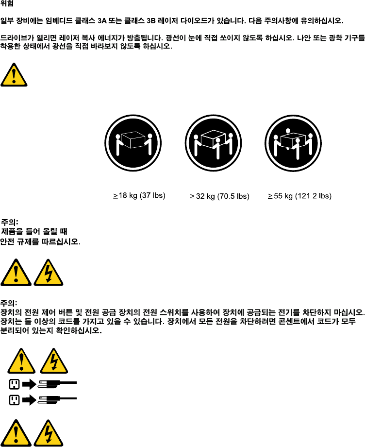
DANGER
Some laser products contain an embedded Class 3A or Class 3B laser diode. Note the following:
Laser radiation when open. Do not stare into the beam, do not view directly with optical
instruments, and avoid direct exposure to the beam.
6P920 Hardware Maintenance Manual
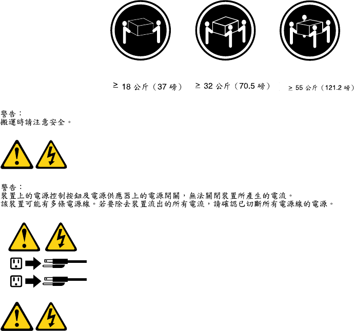
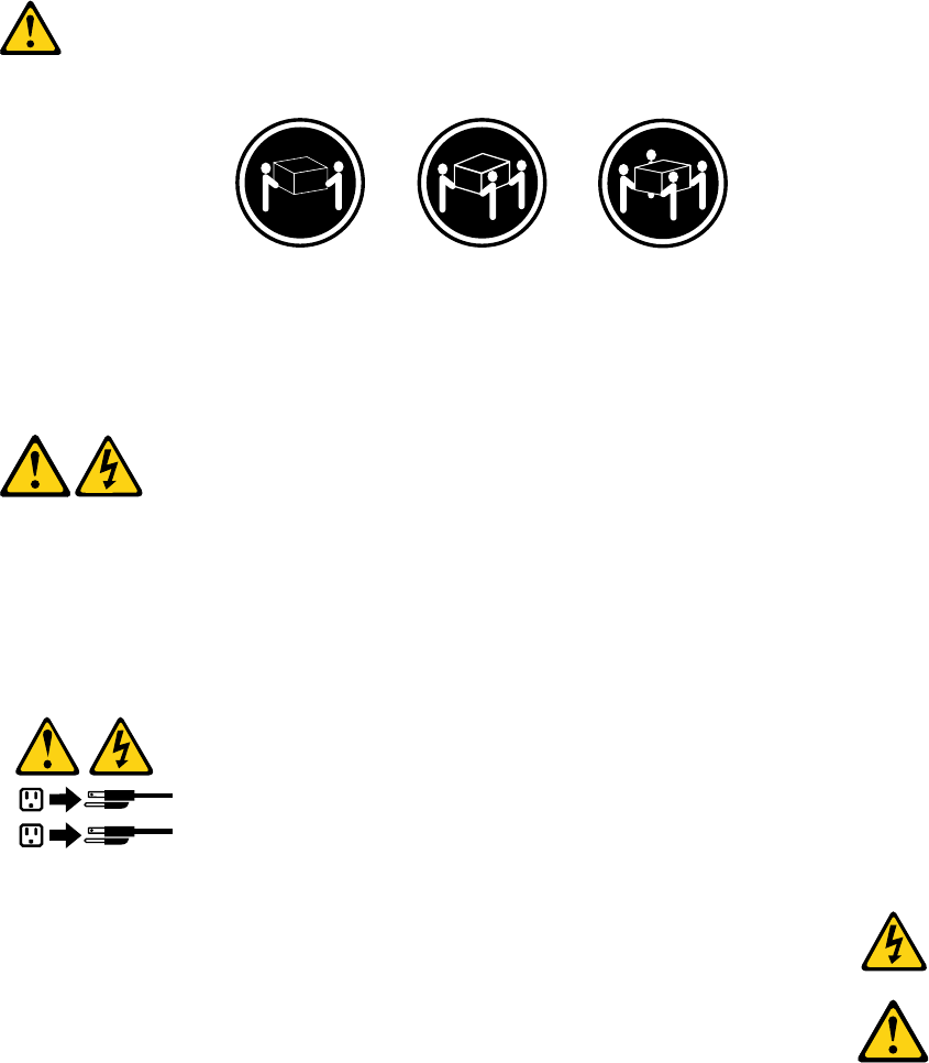
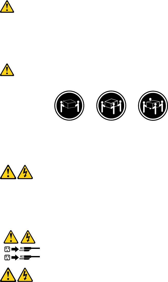
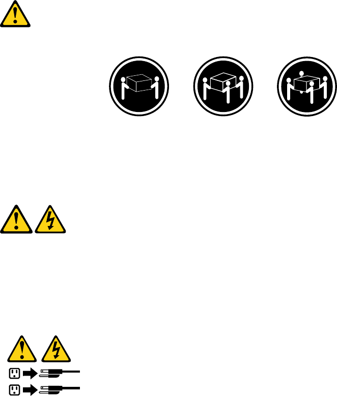
≥18 kg (37 lb) ≥32 kg (70.5 lb) ≥55 kg (121.2 lb)
CAUTION:
Use safe practices when lifting.
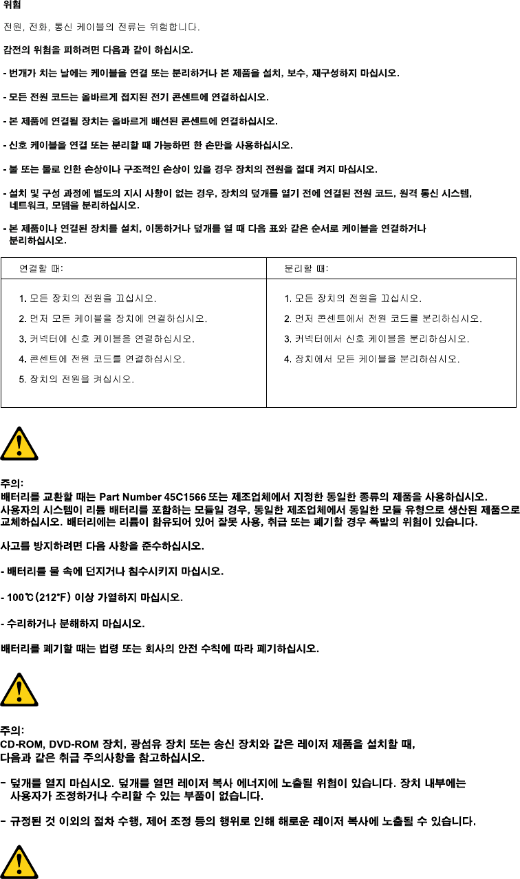
CAUTION:
The power control button on the device and the power switch on the power supply do not turn off the
electrical current supplied to the device. The device also might have more than one power cord. To
remove all electrical current from the device, ensure that all power cords are disconnected from the
power source.
1
2
Chapter 1.Read this first: Important safety information 7
8P920 Hardware Maintenance Manual
PERIGO
A corrente elétrica proveniente de cabos de alimentação, de telefone e de comunicações é perigosa.
Para evitar risco de choque elétrico:
• Não conecte nem desconecte nenhum cabo ou execute instalação, manutenção ou reconfiguração deste
produto durante uma tempestade com raios.
• Conecte todos os cabos de alimentação a tomadas elétricas corretamente instaladas e aterradas.
• Todo equipamento que for conectado a este produto deve ser conectado a tomadas corretamente
instaladas.
• Quando possível, utilize apenas uma das mãos para conectar ou desconectar cabos de sinal.
• Nunca ligue nenhum equipamento quando houver evidência de fogo, água ou danos estruturais.
• Antes de abrir tampas de dispositivos, desconecte cabos de alimentação, sistemas de telecomunicação,
redes e modems conectados, a menos que especificado de maneira diferente nos procedimentos de
instalação e configuração.
• Conecte e desconecte os cabos conforme descrito na tabela apresentada a seguir ao instalar, mover ou
abrir tampas deste produto ou de dispositivos conectados.
Para Conectar: Para Desconectar:
1. DESLIGUE Tudo.
2. Primeiramente, conecte todos os cabos aos
dispositivos.
3. Conecte os cabos de sinal aos conectores.
4. Conecte os cabos de alimentação às tomadas.
5. LIGUE os dispositivos.
1. DESLIGUE Tudo.
2. Primeiramente, remova os cabos de alimentação das
tomadas.
3. Remova os cabos de sinal dos conectores.
4. Remova todos os cabos dos dispositivos.
CUIDADO:
Ao substituir a bateria de lítio, utilize apenas uma bateria com Número de Peça 45C1566 ou um tipo de
bateria equivalente recomendado pelo Se o seu sistema possui um módulo com uma bateria de lítio,
substitua-o apenas por um módulo do mesmo tipo e do mesmo fabricante. A bateria contém lítio e
pode explodir se não for utilizada, manuseada ou descartada de maneira correta.
Não:
• Jogue ou coloque na água
• Aqueça a mais de 100°C (212°F)
• Conserte nem desmonte
Descarte a bateria conforme requerido pelas leis ou regulamentos locais.
PRECAUCIÓN:
10 P920 Hardware Maintenance Manual
Quando produtos a laser (como unidades de CD-ROMs, unidades de DVD-ROM, dispositivos de fibra ótica
ou transmissores) estiverem instalados, observe o seguinte:
• Não remova as tampas. A remoção das tampas de um produto a laser pode resultar em exposição
prejudicial à radiação de laser. Não existem peças que podem ser consertadas no interior do dispositivo.
• A utilização de controles ou ajustes ou a execução de procedimentos diferentes dos especificados aqui
pode resultar em exposição prejudicial à radiação.
PERIGO
Alguns produtos a laser contêm diodo de laser integrado da Classe 3A ou da Classe 3B. Observe o seguinte:
Radiação a laser quando aberto. Não olhe diretamente para o feixe a olho nu ou com instrumentos ópticos e
evite exposição direta ao feixe.
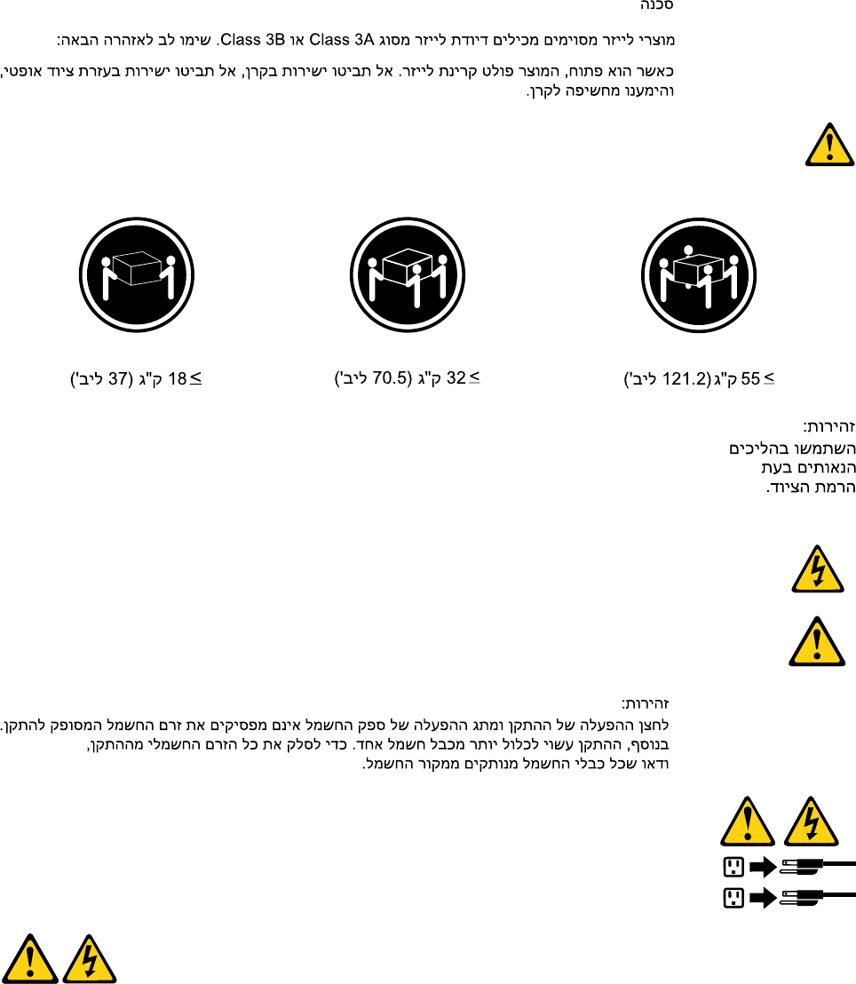
≥18 kg (37 lb) ≥32 kg (70.5 lb) ≥55 kg (121.2 lb)
CUIDADO:
Utilize procedimentos de segurança para levantar equipamentos.
CUIDADO:
O botão de controle de alimentação do dispositivo e o botão para ligar/desligar da fonte de alimentação não
desligam a corrente elétrica fornecida ao dispositivo. O dispositivo também pode ter mais de um cabo de
alimentação. Para remover toda a corrente elétrica do dispositivo, assegure que todos os cabos de
alimentação estejam desconectados da fonte de alimentação.
1
2
Chapter 1.Read this first: Important safety information 11
12 P920 Hardware Maintenance Manual
14 P920 Hardware Maintenance Manual
1
2
DANGER
Le courant électrique provenant de l'alimentation, du téléphone et des câbles de transmission peut présenter
un danger.
Pour éviter tout risque de choc électrique :
• Ne manipulez aucun câble et n'effectuez aucune opération d'installation, d'entretien ou de reconfiguration
de ce produit au cours d'un orage.
• Branchez tous les cordons d'alimentation sur un socle de prise de courant correctement câblé et mis à la
terre.
• Branchez sur des socles de prise de courant correctement câblés tout équipement connecté à ce produit.
• Lorsque cela est possible, n'utilisez qu'une seule main pour connecter ou déconnecter les câbles
d'interface.
• Ne mettez jamais un équipement sous tension en cas d'incendie ou d'inondation, ou en présence de
dommages matériels.
• Avant de retirer les carters de l'unité, mettez celle-ci hors tension et déconnectez ses cordons
d'alimentation, ainsi que les câbles qui la relient aux réseaux, aux systèmes de télécommunication et aux
modems (sauf instruction contraire mentionnée dans les procédures d'installation et de configuration).
• Lorsque vous installez, que vous déplacez, ou que vous manipulez le présent produit ou des
périphériques qui lui sont raccordés, reportez-vous aux instructions ci-dessous pour connecter et
déconnecter les différents cordons.
Chapter 1.Read this first: Important safety information 15
Connexion Déconnexion
1. Mettez les unités HORS TENSION.
2. Commencez par brancher tous les cordons sur les
unités.
3. Branchez les câbles d'interface sur des
connecteurs.
4. Branchez les cordons d'alimentation sur des prises.
5. Mettez les unités SOUS TENSION.
1. Mettez les unités HORS TENSION.
2. Débranchez les cordons d'alimentation des prises.
3. Débranchez les câbles d'interface des connecteurs.
4. Débranchez tous les câbles des unités.
ATTENTION:
Remplacer la pile au lithium usagée par une pile de référence identique exclusivement, (référence
45C1566), ou suivre les instructions du fabricant qui en définit les équivalences. Si votre système est
doté d'un module contenant une pile au lithium, vous devez le remplacer uniquement par un module
identique, produit par le même fabricant. La pile contient du lithium et peut exploser en cas de
mauvaise utilisation, de mauvaise manipulation ou de mise au rebut inappropriée.
Ne pas :
• la jeter à l'eau,
• l'exposer à des températures supérieures à 100°C,
• chercher à la réparer ou à la démonter.
Ne pas mettre la pile à la poubelle. Pour la mise au rebut, se reporter à la réglementation en vigueur.
ATTENTION:
Si des produits à laser (tels que des unités de CD-ROM, de DVD-ROM, des unités à fibres optiques, ou
des émetteurs) sont installés, prenez connaissance des informations suivantes :
• Ne retirez pas le carter. En ouvrant l'unité de CD-ROM ou de DVD-ROM, vous vous exposez au
rayonnement dangereux du laser. Aucune pièce de l'unité n'est réparable.
• Pour éviter tout risque d'exposition au rayon laser, respectez les consignes de réglage et
d'utilisation des commandes, ainsi que les procédures décrites dans le présent manuel.
DANGER
Certains produits à laser contiennent une diode à laser intégrée de classe 3A ou 3B. Prenez
connaissance des informations suivantes:
Rayonnement laser lorsque le carter est ouvert. Evitez toute expositiondirecte au rayon laser. Evitez
de regarder fixement le faisceau ou del'observer à l'aide d'instruments optiques.
16 P920 Hardware Maintenance Manual
≥18 kg (37 lb) ≥32 kg (70.5 lb) ≥55 kg (121.2 lb)
ATTENTION:
Soulevez la machine avec précaution.
ATTENTION:
L'interrupteur de contrôle d'alimentation de l'unité et l'interrupteur dubloc d'alimentation ne coupent
pas le courant électrique alimentantl'unité. En outre, le système peut être équipé de plusieurs
cordonsd'alimentation. Pour mettre l'unité hors tension, vous devez déconnectertous les cordons de
la source d'alimentation.
1
2
VORSICHT
An Netz-, Telefon- und Datenleitungen können gefährliche Spannungen anliegen.
Aus Sicherheitsgründen:
• Bei Gewitter an diesem Gerät keine Kabel anschließen oder lösen. Ferner keine Installations-,
Wartungs- oder Rekonfigurationsarbeiten durchführen.
• Gerät nur an eine Schutzkontaktsteckdose mit ordnungsgemäß geerdetem Schutzkontakt
anschließen.
• Alle angeschlossenen Geräte ebenfalls an Schutzkontaktsteckdosen mit ordnungsgemäß
geerdetem Schutzkontakt anschließen.
• Die Signalkabel nach Möglichkeit einhändig anschließen oder lösen, um einen Stromschlag durch
Berühren von Oberflächen mit unterschiedlichem elektrischem Potenzial zu vermeiden.
• Geräte niemals einschalten, wenn Hinweise auf Feuer, Wasser oder Gebäudeschäden vorliegen.
Chapter 1.Read this first: Important safety information 17
• Die Verbindung zu den angeschlossenen Netzkabeln, Telekommunikationssystemen, Netzwerken
und Modems ist vor dem Öffnen des Gehäuses zu unterbrechen, sofern in den Installations- und
Konfigurationsprozeduren keine anders lautenden Anweisungen enthalten sind.
• Zum Installieren, Transportieren und Öffnen der Abdeckungen des Computers oder der
angeschlossenen Einheiten die Kabel gemäß der folgenden Tabelle anschließen und abziehen.
Zum Anschließen der Kabel gehen Sie wie folgt vor Zum Abziehen der Kabel gehen Sie wie folgt vor
1. Schalten Sie alle Einheiten AUS.
2. Schließen Sie erst alle Kabel an die Einheiten an.
3. Schließen Sie die Signalkabel an die Buchsen an.
4. Schließen Sie die Netzkabel an die Steckdose an.
5. Schalten Sie die Einheit EIN.
1. Schalten Sie alle Einheiten AUS.
2. Ziehen Sie zuerst alle Netzkabel aus den
Netzsteckdosen.
3. Ziehen Sie die Signalkabel aus den Buchsen.
4. Ziehen Sie alle Kabel von den Einheiten ab.
CAUTION:
Eine verbrauchte Lithiumbatterie nur durch eine Batterie mit der Teilenummer 45C1566 oder eine
gleichwertige, vom Hersteller empfohlene Batterie ersetzen. Enthält das System ein Modul mit einer
Lithiumbatterie, dieses nur durch ein Modul desselben Typs und von demselben Hersteller ersetzen. Die
Batterie enthält Lithium und kann bei unsachgemäßer Verwendung, Handhabung oder Entsorgung
explodieren.
Die Batterie nicht:
• mit Wasser in Berührung bringen.
• über 100 C erhitzen.
• reparieren oder zerlegen.
Die örtlichen Bestimmungen für die Entsorgung von Sondermüll beachten.
ACHTUNG:
Bei der Installation von Lasergeräten (wie CD-ROM-Laufwerken, DVD- aufwerken, Einheiten mit
Lichtwellenleitertechnik oder Sendern) Folgendes beachten:
• Die Abdeckungen nicht entfernen. Durch Entfernen der Abdeckungen des Lasergeräts können
gefährliche Laserstrahlungen freigesetzt werden. Das Gerät enthält keine zu wartenden Teile.
• Werden Steuerelemente, Einstellungen oder Durchführungen von Prozeduren anders als hier
angegeben verwendet, kann gefährliche Laserstrahlung auftreten.
VORSICHT
Einige Lasergeräte enthalten eine Laserdiode der Klasse 3A oder 3B. Beachten Sie Folgendes:
18 P920 Hardware Maintenance Manual
Laserstrahlung bei geöffneter Verkleidung. Nicht in den Strahl blicken. Keine Lupen oder Spiegel
verwenden. Strahlungsbereich meiden.
≥18 kg ≥32 kg ≥55 kg
ACHTUNG:
Arbeitsschutzrichtlinien beim Anheben der Maschine beachten.
ACHTUNG:
Mit dem Netzschalter an der Einheit und am Netzteil wird die Stromversorgung für die Einheit nicht
unterbrochen. Die Einheit kann auch mit mehreren Netzkabeln ausgestattet sein. Um die
Stromversorgung für die Einheit vollständig zu unterbrechen, müssen alle zum Gerät führenden
Netzkabel vom Netz getrennt werden.
1
2
Chapter 1.Read this first: Important safety information 19
20 P920 Hardware Maintenance Manual
• Non collegare o scollegare qualsiasi cavo oppure effettuare l'installazione, la manutenzione o la
riconfigurazione del prodotto durante un temporale.
• Collegare tutti i fili elettrici a una presa di alimentazione correttamente cablata e dotata di messa a
terra.
• Collegare alle prese elettriche appropriate tutte le apparecchiature che verranno utilizzate per
questo prodotto.
• Se possibile, utilizzare solo una mano per collegare o scollegare i cavi di segnale.
• Non accendere assolutamente apparecchiature in presenza di incendi, perdite d'acqua o danno
strutturale.
• Scollegare i cavi di alimentazione, i sistemi di telecomunicazione, le reti e il modem prima di aprire i
coperchi del dispositivo, salvo istruzioni contrarie relative alle procedure di installazione e
configurazione.
• Collegare e scollegare i cavi come descritto nella seguente tabella quando vengono effettuate
operazioni di installazione, spostamento o apertura dei coperchi di questo prodotto o delle unità
collegate.
Per collegarsi Per scollegarsi
1. SPEGNERE le apparecchiature.
2. Innanzitutto, collegare tutti i cavi alle unità.
3. Collegare i cavi di segnale ai connettori.
4. Collegare i cavi di alimentazione alla presa.
5. Accendere l'unità.
1. SPEGNERE le apparecchiature.
2. Innanzitutto, rimuovere i cavi di alimentazione dalla
presa.
3. Rimuovere i cavi di segnale dai connettori.
4. Rimuovere tutti i cavi dalle unità.
ATTENZIONE:
Quando si sostituisce la batteria al litio, utilizzare solo il Numero parte 45C1566 o un tipo di batteria
equivalente consigliato dal produttore. Se sul sistema è presente un modulo che contiene una batteria
al litio, sostituirlo solo con un tipo di modulo dello stesso tipo della stessa casa di produzione. La
batteria contiene litio e può esplodere se usata, maneggiata o smaltita in modo non corretto.
Non:
• Gettare o immergere la batteria nell'acqua
• Riscaldarla ad una temperatura superiore ai 100 gradi C (212 gradi F)
• Smontarla, ricaricarla o tentare di ripararla
Le batterie usate vanno smaltite in accordo alla normativa in vigore (DPR 915/82 e successive
disposizioni e disposizioni locali).
ATTENZIONE:
Quando vengono installati prodotti laser (quali CD-ROM, unità DVD-ROM, unità a fibre ottiche o
trasmittenti), tener presente quanto segue:
22 P920 Hardware Maintenance Manual
• Non rimuovere gli sportelli. L'apertura di un'unità laser può determinare l'esposizione a radiazioni
laser pericolose. All'interno dell'unità non vi sono parti su cui effettuare l'assistenza tecnica.
• L'utilizzo di controlli, regolazioni o l'esecuzione di procedure non descritti nel presente manuale
possono provocare l'esposizione a radiazioni pericolose.
PERICOLO
Alcune unità laser contengono un diodo laser di Classe 3A o Classe 3B. Tener presente quanto segue:
Aprendo l'unità vengono emesse radiazioni laser. Non fissare il fascio, non guardarlo direttamente
con strumenti ottici ed evitare l'esposizione al fascio.
≥18 kg ≥32 kg ≥55 kg
ATTENZIONE:
Prestare attenzione nel sollevare l'apparecchiatura.
ATTENZIONE:
Il pulsante di controllo dell'alimentazione presente sull'unità e l'interruttore dell'alimentatore non
disattivano l'alimentazione corrente fornita all'unità. E' possibile che l'unità disponga di più cavi di
alimentazione. Per disattivare l'alimentazione dall'unità, accertarsi che tutti i cavi di alimentazione
siano scollegati dalla fonte di alimentazione.
1
2
Chapter 1.Read this first: Important safety information 23
24 P920 Hardware Maintenance Manual
1
2
PELIGRO
La corriente eléctrica procedente de cables de alimentación, teléfonos y cables de comunicación puede ser
peligrosa.
Para evitar el riesgo de descarga eléctrica:
• No conecte ni desconecte los cables ni realice ninguna tarea de instalación, mantenimiento o
reconfiguración de este producto durante una tormenta eléctrica.
• Conecte todos los cables de alimentación a tomas de corriente debidamente cableadas y
conectadas a tierra.
• Cualquier equipo que se conecte a este producto también debe conectarse a tomas de corriente
debidamente cableadas.
• Siempre que sea posible, utilice una sola mano para conectar o desconectar los cables de señal.
Chapter 1.Read this first: Important safety information 25
• No encienda nunca un equipo cuando hay señales de fuego, agua o daños estructurales.
• Desconecte los cables de alimentación, los sistemas de telecomunicaciones, las redes y los
módems conectados antes de abrir las cubiertas de los dispositivos, a menos que se indique lo
contrario en los procedimientos de instalación y configuración.
• Conecte y desconecte los cables, como se describe en la tabla siguiente, cuando instale, mueva o
abra las cubiertas de este producto o de los dispositivos conectados.
Para conectar Para desconectar
1. APÁGUELO todo.
2. En primer lugar, conecte todos los cables a los
dispositivos.
3. Conecte los cables de señal a los conectores.
4. Enchufe los cables de alimentación a las tomas de
corriente.
5. Encienda el dispositivo.
1. APÁGUELO todo.
2. En primer lugar, desenchufe los cables de
alimentación de las tomas de corriente.
3. Desconecte los cables de señal de los conectores.
4. Desconecte todos los cables de los dispositivos.
PRECAUCIÓN:
Cuando sustituya una batería de litio, utilice solamente una batería número de pieza 45C1566 u otra
de tipo equivalente recomendada por el fabricante. Si su sistema dispone de un módulo que contiene
una batería de litio, reemplácelo sólo con el mismo tipo de módulo, del mismo fabricante. La batería
contiene litio y puede explotar si no se utiliza, manipula o desecha correctamente.
No debe:
• Arrojarla al agua o sumergirla en ella
• Exponerla a temperaturas superiores a 100°C (212°F)
• Repararla o desmontarla
Deshágase de la batería según especifiquen las leyes o normas locales.
PRECAUCIÓN:
Cuando haya productos láser (como unidades de CD-ROM, unidades de DVD, dispositivos de fibra
óptica o transmisores) instalados, tenga en cuenta lo siguiente:
• No quite las cubiertas. Si quita las cubiertas del producto láser, podría quedar expuesto a radiación
láser peligrosa. Dentro del dispositivo no existe ninguna pieza que requiera servicio técnico.
• Si usa controles o ajustes o realiza procedimientos que no sean los especificados aquí, podría
exponerse a radiaciones peligrosas.
PELIGRO
26 P920 Hardware Maintenance Manual
Algunos productos láser tienen incorporado un diodo láser de clase 3A o clase 3B. Tenga en cuenta lo
siguiente:
Cuando se abre, queda expuesto a radiación láser. No mire directamente al rayo láser, ni siquiera con
instrumentos ópticos, y evite exponerse directamente al rayo láser.
≥18 kg ≥32 kg ≥55 kg
PRECAUCIÓN:
Adopte procedimientos seguros al levantar el equipo.
PRECAUCIÓN:
El botón de control de alimentación del dispositivo y el interruptor de alimentación de la fuente de
alimentación no desconectan la corriente eléctrica suministrada al dispositivo. Además, el dispositivo
podría tener más de un cable de alimentación. Para suprimir toda la corriente eléctrica del dispositivo,
asegúrese de que todos los cables de alimentación estén desconectados de la toma de corriente.
1
2
Chapter 1.Read this first: Important safety information 27
28 P920 Hardware Maintenance Manual
Chapter 2. Product overview
This chapter provides basic information to help you get familiar with your computer.
Hardware locations
This section provides information about the locations of your computer hardware.
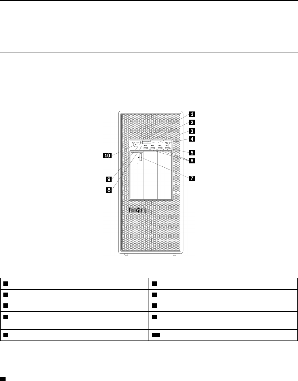
Front view
Note: The computer hardware might look slightly different from the illustration.
Figure 1. Front connectors, controls, and indicators
1 Power button 2 Four-digit diagnostics display
3 SD card slot 4 Headset connector
5 Always On USB 3.0 connector 6 USB 3.0 connectors (3)
7 Optical-drive eject/close button (available on some
models)
8 Photoelectric sensor
9 Storage drive activity indicator 10 Power indicator
Note: The orientation of the ThinkStation® logo plate on the front of your computer is adjustable. When you
lay the computer on its side, you can slightly pull out the logo plate, turn it 90-degree counterclockwise, and
then push it back in.
1 Power button
Press the power button to turn on your computer. If your computer is unresponsive, you can turn off the
computer by pressing and holding the power button for four or more seconds.
© Copyright Lenovo 2017 29

2 Four-digit diagnostics display
The four-digit diagnostics display on the front of the computer displays text and a numerical error code when
the computer detects an issue or error.
3 SD card slot
Insert a secure digital (SD) card into the slot so that the data on the card can be accessed and read.
4 Headset connector
Connect the headset to your computer through the headset connector.
5 Always On USB 3.0 connector
Use this connector to attach a USB-compatible device, such as a USB keyboard, mouse, storage drive, or
printer. With the power cord connected, you can charge the connected USB device even when the computer
is in hibernation mode or turned off. If the Always On USB connector function is not enabled, open the Power
Manager program and enable the function. To open the Power Manager program, see “Accessing a program
on your computer” on page 46. To enable the Always On USB connector, refer to the help system of the
Power Manager program.
6 USB 3.0 connector (3)
Use this connector to attach a USB-compatible device, such as a USB keyboard, mouse, storage drive, or
printer.
7 Optical-drive eject/close button
Press the button to eject or close the tray of the optical drive.
8 Photoelectric sensor
This sensor receives the flash light initiated by the Lenovo PC Diagnostic application installed in the
smartphone. Then, the sensor triggers the computer to send the tune of the current error event to the
smartphone.
9 Storage drive activity indicator
This indicator shows the status of the internal storage drives (such as hard disk drives or solid-state drives).
On: The storage drives are active and data is being transferred.
Off (when the computer is powered on): The storage drives are not in use or no data is being transferred.
10 Power indicator
When the power indicator is on, the computer is turned on.
Rear view
Some connectors on the rear of your computer are color-coded to help you determine where to connect the
cables on your computer.
Note: The computer hardware might look slightly different from the illustration.
30 P920 Hardware Maintenance Manual
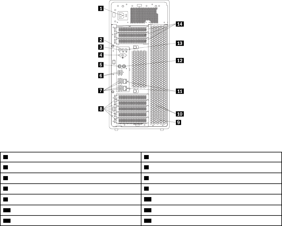
Figure 2. Rear connectors
1 Power cord connector 2 Audio line-out connector
3 Microphone connector 4 Serial connector (available on some models)
5 PS/2 keyboard connector 6 USB 2.0 connectors (2)
7 USB 3.0 connectors (4) 8 PCIe card area*
9 Security-lock slot 10 Key-nest slots
11 Ethernet connectors (2) 12 PS/2 mouse connector
13 Audio line-in connector 14 PCIe card area*
Notes:
• * A discrete graphics card or a network adapter can be installed in the appropriate Peripheral Component
Interconnect Express (PCIe) card slot. If such a card is installed, use the connectors on the card instead of
the corresponding connectors on the computer to optimize the performance.
• Depending on your computer model, the preinstalled cards might vary. One or more graphics cards might
be installed to provide the following connectors:
– DisplayPort® connector
– Digital Visual Interface (DVI) connector
– Mini DisplayPort® connector
DisplayPort connector
Use this connector to attach a high-performance monitor, a direct-drive monitor, or other compatible
devices.
DVI monitor connector
Use this connector to attach a DVI monitor or other compatible devices.
Mini DisplayPort connector
Use this connector to attach a high-performance monitor, a direct-drive monitor, or other compatible
devices. The Mini DisplayPort connector is a miniaturized version of a DisplayPort connector.
Chapter 2.Product overview 31

1 Power cord connector
Connect the power cord to your computer for power supply.
2 Audio line-out connector
The audio line-out connector is used to send audio signals from the computer to external devices, such as
headphones.
3 Microphone connector
Use this connector to attach a microphone to your computer when you want to record sound or if you use
speech-recognition software.
4 Serial connector (available on some models)
Connect an external modem, a serial printer, or other devices that use a 9-pin serial connector to the serial
connector.
5 PS/2 keyboard connector
Use this connector to attach a Personal System/2 (PS/2) keyboard.
6 USB 2.0 connectors (2)
Use this connector to attach a USB-compatible device, such as a USB keyboard, mouse, storage drive, or
printer.
7 USB 3.0 connectors (4)
Use this connector to attach a USB-compatible device, such as a USB keyboard, mouse, storage drive, or
printer.
8 14 PCIe card area
To further improve the computer performance, you can install PCIe cards into this area. Depending on your
computer model, the preinstalled cards might vary.
9 Security-lock slot
Attach a Kensington-style cable lock to the security-lock slot to secure your computer. For more information,
see “Attaching a Kensington-style cable lock” on page 62.
10 Key-nest slots
Install the key holder that comes with the computer cover lock key to the key-nest slots.
11 Ethernet connectors (2)
Connect an Ethernet cable for a local area network (LAN).
Note: To operate the computer within Federal Communications Commission (FCC) Class B limits, use a
Category 5 Ethernet cable.
12 PS/2 mouse connector
Use this connector to attach a PS/2 mouse, a trackball, or other pointing devices.
32 P920 Hardware Maintenance Manual
13 Audio line-in connector
The audio line-in connector is used to receive audio signals from an external audio device, such as a stereo
system. When you attach an external audio device, a cable connection is established between the audio line-
out connector of the device and the audio line-in connector of the computer.
Computer components
Notes:
• Depending on the model, your computer might look slightly different from the illustration.
• To remove the computer cover, see “Preparing your computer and removing the computer cover” on
page 103.
Figure 3. Component locations
1 Power supply assembly 2 M.2 solid-state drive holder
3 M.2 solid-state drive (available on some models) 4 Memory modules*
5 Multi-function bracket in the upper position 6 Front fan assembly
7 Storage drives or a storage-drive-bay cover* 8 Flex bays*
9 Storage drives* 10 Front fan assembly
11 Multi-function bracket in the bottom position 12 Cover presence switch (intrusion switch)
13 Heat-sink-and-fan assembly 1 14 PCIe card*
15 Heat-sink-and-fan assembly 2 (available on some
models)
16 Rear fan assembly
17 Direct cooling air baffle
* Configuration varies by computer models.
Chapter 2.Product overview 33
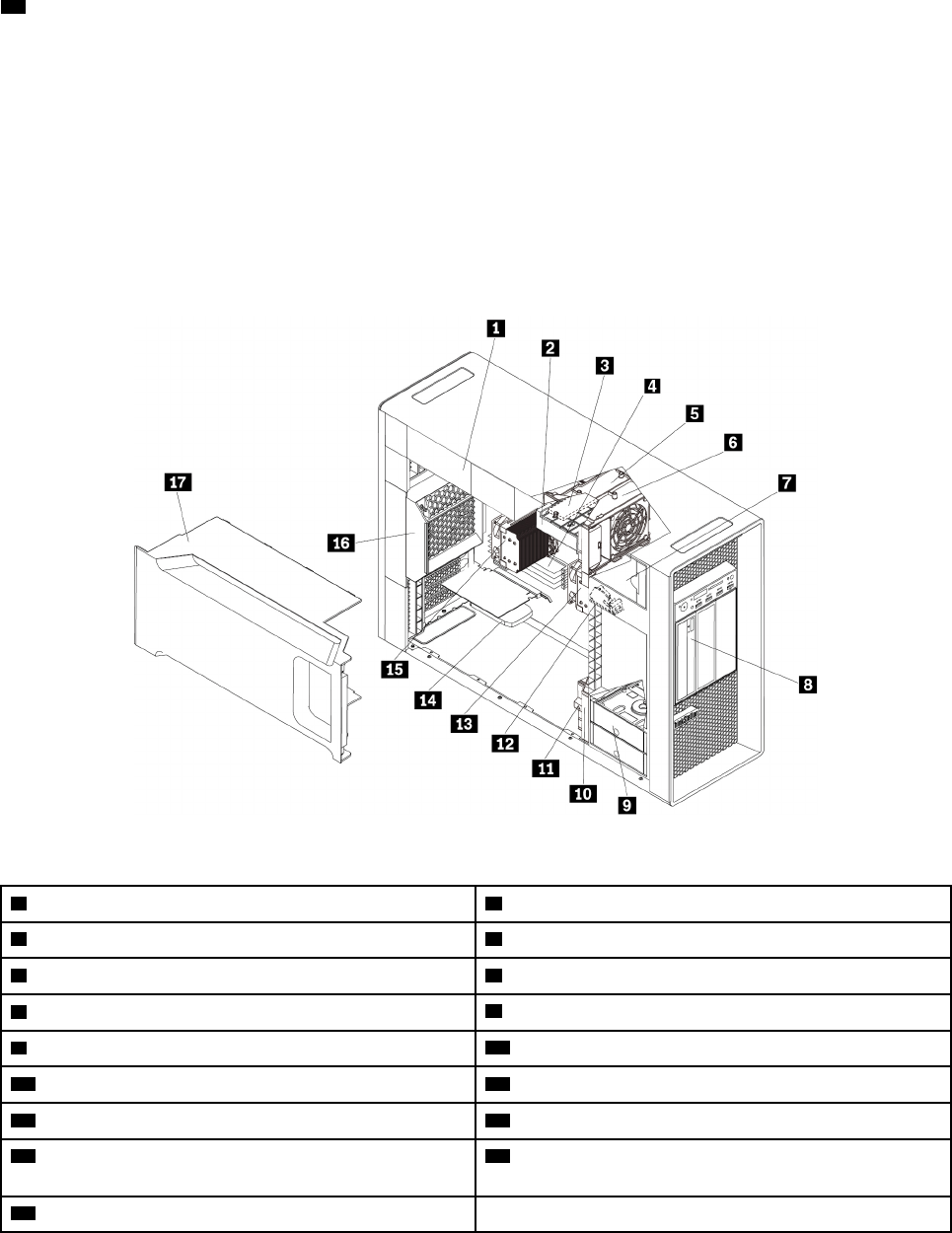
Major FRUs and CRUs
The following illustrations show the locations of the major FRUs and CRUs in the computer. To remove the
computer cover, see “Preparing your computer and removing the computer cover” on page 103.
The following table lists the major FRUs and CRUs shown in Figure 4 “Major FRUs and CRUs” on page 35
and Figure 5 “Accessories” on page 37 and identify which CRUs are self-service CRUs and optional-service
CRUs.
Notes:
• Self-service CRUs: Refer to parts that can be installed or replaced easily by customer themselves or by
trained service technicians at an additional cost.
• Optional-service CRUs: Refer to parts that can be installed or replaced by customers with a greater skill
level. Trained service technicians can also provide service to install or replace the parts under the type of
warranty designated for the customer’s machine.
• FRUs: Refer to parts that must be installed or replaced only by trained service technicians. If customers
choose to replace the FRUs by themselves, the product warranty might be affected.
34 P920 Hardware Maintenance Manual


Number FRU description Self-service CRU Optional-service CRU
1Power supply assembly Yes No
2M.2 solid-state drive holder No Yes
3M.2 solid-state drive (available on some models) No Yes
4M.2 solid-state drive heat sink No Yes
5Multi-function bracket 1 Yes No
6Front fan assembly 1 Yes No
7VROC upgrade key module (available on some
models)
No No
8Microprocessor socket 1 No No
9Memory modules (amount varies by model) No Yes
10 Microprocessor socket 2 No No
11 Coin-cell battery No Yes
12 Slim-optical-drive adapter (available on some
models)
Yes No
13 Multi-drive conversion kit (available on some
models)
Yes No
14 Optical drive (available on some models) Yes No
15 Flex module (available on some models) Yes No
16 Front-access storage enclosure (available on
some models)
Yes No
17 Front fan assembly 2 Yes No
18 Multi-function bracket 2 Yes No
19 Blind-connect assembly No No
20 Hard disk drive or hybrid drive (amount and
combination vary by model)
Yes No
21 Solid-state drive (amount and combination vary
by model)
Yes No
22 Cover presence switch (intrusion switch) Yes No
23 Heat-sink-and-fan assembly 1 No No
24 Heat-sink-and-fan assembly 2 (available on some
models)
No No
25 Computer cover Yes No
26 Direct cooling air baffle Yes No
27 Rear fan assembly Yes No
28 PCIe card (vary by computer model) Yes No
29 Super capacitor module (available on some
models)
Yes No
30 Wi-Fi adapter (available on some models) No Yes
36 P920 Hardware Maintenance Manual
Number FRU description Self-service CRU Optional-service CRU
31 Wi-Fi card (available on some models) No Yes
32 Wi-Fi antenna (available on some models) No Yes
33 System board No No
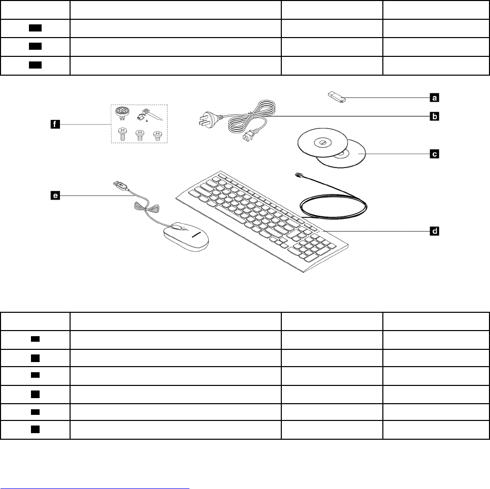
Figure 5. Accessories
Number FRU description Self-service CRU Optional-service CRU
aLenovo factory recovery USB key No No
bPower cord Yes No
cLenovo recovery disc set No No
dKeyboard Yes No
eMouse Yes No
fMiscellaneous parts kits No No
For detailed FRU and CRU information, such as the FRU part numbers and supported computer models, go
to:
http://www.lenovo.com/serviceparts-lookup
Chapter 2.Product overview 37
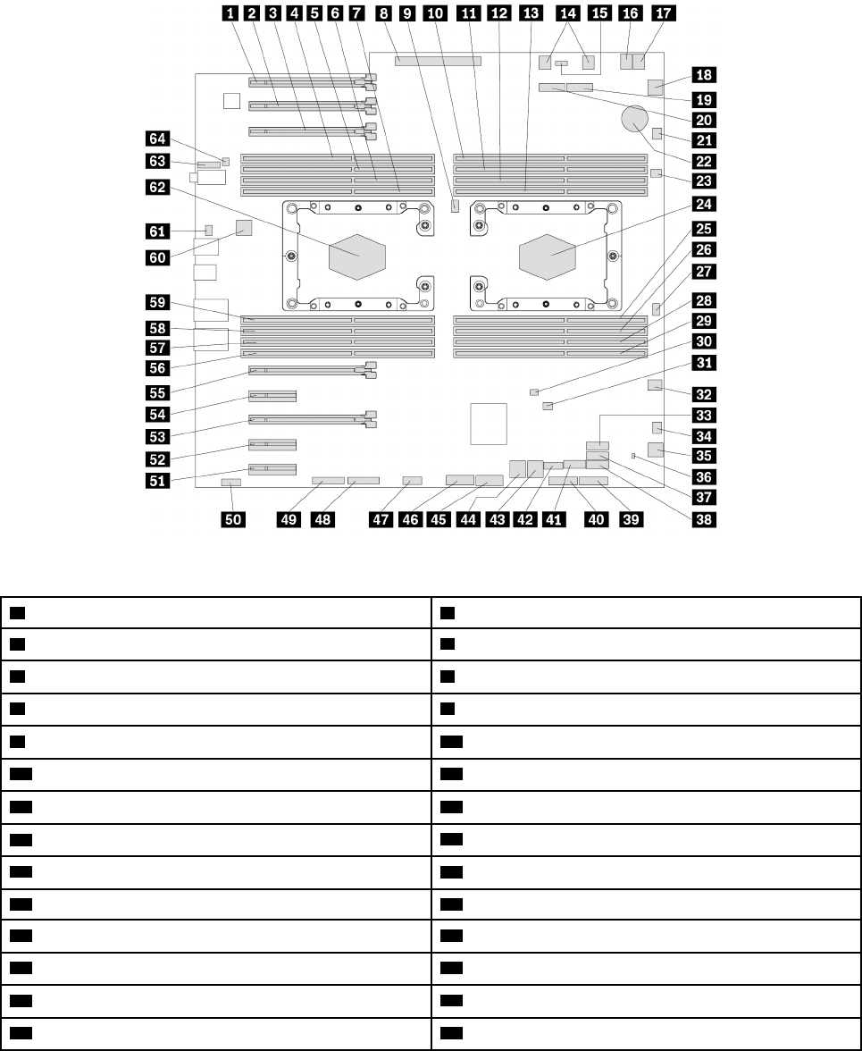
Parts on the system board
The following illustration shows the locations of the parts on the system board.
Note: The system board might look slightly different from the illustration.
Figure 6. Parts on the system board
1 PCIe 3.0 x16 card slot 6 2 PCIe 3.0 x16 card slot 7
3 PCIe 3.0 x16 card slot 8 4 Microprocessor 2 memory slot 2
5 Microprocessor 2 memory slot 6 6 Microprocessor 2 memory slot 4
7 Microprocessor 2 memory slot 8 8 Power supply connector
9 Microprocessor fan connector 2 10 Microprocessor 1 memory slot 1
11 Microprocessor 1 memory slot 5 12 Microprocessor 1 memory slot 3
13 Microprocessor 1 memory slot 7 14 Optical-drive fan connectors
15 VROC connector 16 4-pin power connector
17 4-pin power connector 18 Front-fan-assembly connector
19 M.2 solid-state drive slot 2 20 M.2 solid-state drive slot 1
21 Blind-connect assembly (BCA) 2 connector 22 Coin-cell battery
23 Thermal-sensor connector 24 Microprocessor socket 1
25 Microprocessor 1 memory slot 8 26 Microprocessor 1 memory slot 4
27 Microprocessor fan connector 1 28 Microprocessor 1 memory slot 6
38 P920 Hardware Maintenance Manual

29 Microprocessor 1 memory slot 2 30 Cover presence switch connector (intrusion switch
connector)
31 Clear CMOS /Recovery jumper 32 4-pin power connector
33 SATA 9 connector 34 BCA 1 connector
35 Front-fan-assembly connector 36 Storage-drive activity indicator connector
37 SATA 8 connector 38 SATA 7 connector
39 15-in-1 card reader connector 40 USB 3.0 extension connector
41 eSATA connector 42 Internal USB 2.0 connector
43 Mini-SAS connector (SATA 5–6 connector) 44 Mini-SAS connector (SATA 1–4 connector)
45 Front USB 3.0 connector 46 Front USB 3.0 connector
47 Thunderbolt™ control connector 48 Trusted Cryptography Module (TCM) connector
49 Front panel connector 50 Four-digit-diagnostics-display connector
51 PCIe 3.0 x4 card slot 5 52 PCIe 3.0 x4 card slot 4
53 PCIe 3.0 x16 card slot 3 54 PCIe 3.0 x4 card slot 2
55 PCIe 3.0 x16 card slot 1 56 Microprocessor 2 memory slot 1
57 Microprocessor 2 memory slot 5 58 Microprocessor 2 memory slot 3
59 Microprocessor 2 memory slot 7 60 Rear-fan-assembly connector
61 Serial (COM1) connector 62 Microprocessor socket 2
63 Front-audio connector 64 Internal-speaker connector
Chapter 2.Product overview 39
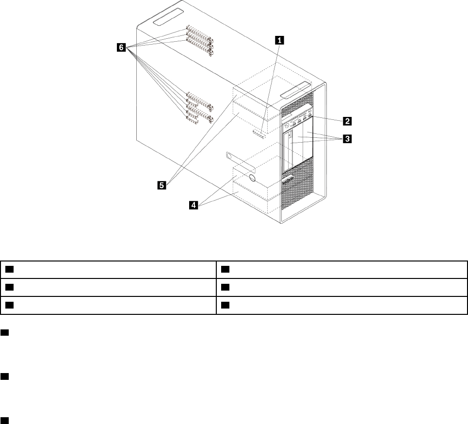
Internal storage drives
Internal storage drives are devices that your computer uses to read and store data. You can add drives to
your computer to increase storage capacity and enable your computer to read other types of media. Internal
storage drives are installed in bays.
When you install or replace an internal storage drive, note the type and size of the drive that each bay
supports and correctly connect the required cables. Refer to the appropriate section in Chapter 9 “Hardware
removal and installation” on page 103 for instructions on how to install or replace internal storage drives for
your computer.
The following illustration shows the locations of the storage drive bays.
Note: The computer hardware might look slightly different from the illustration.
Figure 7. Drive bay locations
1 M.2 solid-state drive slots (2) 2 SD card slot
3 Flex bays (3) 4 Storage drive bays (2)
5 Optional storage drive bays (2) 6 PCIe card slots (8)
1 M.2 solid-state drive slots (2)
One or two M.2 solid state drives are installed in some models.
2 SD card slot
An SD card is installed in some models.
3 Flex bays (3)
Depending on your computer model, the following devices might be installed in the flex bays:
• Flex module
40 P920 Hardware Maintenance Manual

Depending on your computer model, the following parts might be preinstalled in the flex module:
– 15-in-1 card reader
– External Serial Advanced Technology Attachment (eSATA) connector
– Institute of Electrical and Electronics Engineers (IEEE) 1394 connector
– Slim optical drive
– Front Thunderbolt adapter kit
• Front-access storage enclosure
• Multi-drive conversion kit
Depending on your computer model, the following parts might be preinstalled in the multi-drive
conversion kit:
– Hard disk drive
– Slim optical drive
• Optical drive
• Slim-optical-drive adapter
4 Storage drive bays (2)
You can install hard disk drives, solid-state drives, or hybrid drives in the storage drive bays.
5 Optional storage drive bays (2)
If you want to install storage drives into the 5 optional storage drive bays, contact the Lenovo Customer
Support Center for help.
6 PCIe card slots (8)
You can install compatible PCIe cards and PCIe solid-state drives in the PCIe card slots.
Chapter 2.Product overview 41
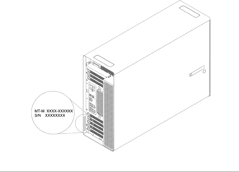
Machine type and model label
The machine type and model label identifies your computer. When you contact Lenovo for help, the machine
type and model information helps support technicians to identify your computer and provide faster service.
The following is a sample of the machine type and model label.
Note: The computer hardware might look slightly different from the illustration.
Figure 8. Machine type and model label
Computer features
For your specific computer model, some features might vary or not apply.
Information about your computer
• To view basic information (such as microprocessor and memory information) about your computer, do the
following:
1. Click the Start button to open the Start menu.
2. Depending on your Microsoft® Windows® operating system version, do one of the following:
– For Windows 7: Right-click Computer, and then click Properties.
– For Windows 10: Click Settings ➙ System ➙ About.
• To view detailed information about the devices (such as the optical drive and network adapters) on your
computer, do the following:
1. Depending on your Windows version, do one of the following:
42 P920 Hardware Maintenance Manual
– For Windows 7: Click the Start button to open the Start menu. Right-click Computer, and then
click Properties.
– For Windows 10: Right-click the Start button to open the Start context menu.
2. Locate and double-click your device in Device Manager to view device properties. Type the
administrator password or provide confirmation if prompted.
Memory
Your computer supports up to 16 double data rate 4 (DDR4) error correction code (ECC) registered dual in-
line memory modules (RDIMMs), DDR4 ECC load reduced DIMMs (LRDIMMs), or DDR4 ECC three-
dimensional stack registered DIMMs (3DS RDIMMs).
For more information, see “Memory module” on page 152.
Internal storage drives
Your computer supports the following storage drives:
• Hard disk drive
• Hybrid drive (available on some models)
• M.2 solid-state drive (available on some models)
• Optical drive (available on some models)
• SD card (available on some models)
• Solid-state drive (available on some models)
To view the amount of storage drive space, do the following:
1. Depending on your Windows version, do one of the following:
• For Windows 7: Click the Start button to open the Start menu. Right-click Computer, and then click
Manage.
• For Windows 10: Right-click the Start button to open the Start context menu.
2. Click Disk Management and follow the instructions on the screen.
Video features
Discrete graphics card installed in one of the PCIe 3.0 x16 card slots (available on some models) (the
connectors vary by graphics card)
Notes: Your computer is installed with one or more graphics cards that vary by computer model. Depending
on your computer model, the graphics cards might provide the following connectors:
• DisplayPort connector
• DVI connector
• Mini DisplayPort connector
Audio features
Integrated audio controller supports the following connectors and devices on your computer:
• Audio line-in connector
• Audio line-out connector
• Headset connector
• Internal speaker
• Microphone connector
Chapter 2.Product overview 43
Input/Output (I/O) features
• 100/1000 Mbps Ethernet connector
• 9-pin serial connectors (available on some models)
• Audio connectors (audio line-in connector, audio line-out connector, headset connector, and microphone
connector)
• Display connectors (DisplayPort connector, DVI connector, and Mini DisplayPort connector) (vary by
graphics card)
• eSATA connector
• IEEE 1394 connector (available on some models)
• Mini-SAS connectors
• PS/2 keyboard connector
• PS/2 mouse connector
• SATA connectors
• USB connectors
Expansion
• Flex bays
• M.2 solid-state drive slots
• Memory slots
• PCIe 3.0 x4 card slots
• PCIe 3.0 x16 card slots
• SD card slot
• Storage drive bays
Power supply
1400-watt automatic voltage-sensing power supply
Wireless features
Depending on your computer model, the following wireless features are supported:
• Wireless LAN
• Bluetooth
System management features
• Ability to store power-on self-test (POST) hardware test results
• Desktop Management Interface (DMI)
Desktop Management Interface provides a common path for users to access information about all
aspects of a computer. The information includes the processor type, installation date, attached printers
and other peripherals, power sources, and maintenance history.
• ErP LPS compliance mode
The energy-related products directive (ErP) lowest power state (LPS) compliance mode reduces the
consumption of electricity when your computer is in sleep or off mode. For more information, see
“Enabling or disabling the ErP LPS compliance mode” on page 68.
44 P920 Hardware Maintenance Manual
• Intel Standard Manageability (ISM)
Intel Standard Manageability builds certain functionalities into computer hardware and firmware.
Therefore, computers are less expensive for businesses and easier to monitor, maintain, update, upgrade,
and repair.
• Intel Active Management Technology (Intel AMT)
With specific Intel platform capabilities and third-party management and security applications, Intel Active
Management Technology enables IT administrators or managed service providers to easily and remotely
discover, repair, and protect their networked computing assets.
• Intel Rapid Storage Technology enterprise (Intel RSTe)
The Intel RSTe configuration utility enables you to configure Redundant Array of Independent Disks (RAID)
for computers with specific Intel chipset system boards. It supports RAID levels 0, 1, 5, and 10 on
computers installed with Serial Advanced Technology Attachment (SATA) storage devices.
• Preboot Execution Environment (PXE)
Preboot Execution Environment enables you to start computers using a network interface. This manner is
independent of starting computers from data storage devices (such as the hard disk drive) or installed
operating systems.
• System Management (SM) basic input/output system (BIOS) and SM software
The SMBIOS specification defines data structures and access methods in a BIOS. Therefore, a user or an
application can store and retrieve information specific about the computer in question.
• Wake on LAN (WOL)
Wake on LAN is an Ethernet computer networking standard that allows a computer to be turned on or
woken up by a network message. The message is usually sent by a program running on another computer
on the same local area network.
• Windows Management Instrumentation (WMI)
Windows Management Instrumentation is a set of extensions to the Windows Driver Model. It provides an
operating system interface through which instrumented components provide information and notification.
Security features
• Ability to enable and disable a device
• Ability to enable and disable USB connectors individually
• Antivirus program
• BIOS passwords and Windows accounts to deter unauthorized use of your computer
• Computrace Agent software embedded in firmware
• Cover presence switch (also called intrusion switch)
• Finger authentication (available on some models)
• Firewalls
• Intel BIOS guard
• Smart USB Protection function
• Startup sequence control
• Startup without keyboard or mouse
• Support for a Kensington-style cable lock
• Support for a key lock on the computer cover (available on some models)
• Trusted Platform Module (TPM)
Chapter 2.Product overview 45

Preinstalled operating system
Your computer is preinstalled with Windows 7 or Windows 10 operating system. Additional operating
systems might be identified by Lenovo as compatible with your computer. To determine if an operating
system has been certified or tested for compatibility, check the Web site of the operating system provider.
Computer specifications
This section lists the physical specifications for your computer.
Dimensions
• Width: 200 mm (7.87 inches)
• Height: 446 mm (17.56 inches)
• Depth: 620 mm (24.41 inches)
Weight
Maximum configuration as shipped: 32.3 kg (71.3 lb)
Environment
• Air temperature:
Operating: From 10°C (50°F) to 35°C (95°F)
Storage in original shipping package: From -40°C (-40°F) to 60°C (140°F)
Storage without package: From -10°C (14°F) to 60°C (140°F)
• Humidity:
Operating: 10%–80% (non-condensing)
Storage: 10%–90% (non-condensing)
• Altitude:
Operating: From -15.2 m (-50 ft) to 3048 m (10 000 ft)
Storage: From -15.2 m (-50 ft) to 10 668 m (35 000 ft)
Electrical input
• Input voltage: From 100 V ac to 240 V ac
• Input frequency: 50/60 Hz
Programs
This section provides information about the programs on your computer.
Accessing a program on your computer
Note: For Windows 7, depending on your computer model, some of the Lenovo programs might be ready to
be installed, so you must install them manually. Then, you can access and use these programs.
To access a program on your computer, do one of the following:
• From Windows Search:
1. Depending on your Windows version, do one of the following:
– For Windows 7: Click the Start button to open the Start menu, and then type the program name
into the search box.
46 P920 Hardware Maintenance Manual
– For Windows 10: Type the program name into the search box next to the Start button.
2. In the search results, click the name of the desired program to launch the program.
• From the Start menu or Control Panel:
1. Depending on your Windows version, do one of the following:
– For Windows 7: Click the Start button to open the Start menu. If the program name is not
displayed, click All Programs to display the program list. Then, click the name of the desired
program to launch the program.
– For Windows 10: Click the Start button to open the Start menu. Then, click the name of the desired
program to launch the program.
2. If the program name is not displayed on the Start menu, access the program from Control Panel.
a. Click the Start button to open the Start menu.
b. Depending on your Windows version, do one of the following:
– For Windows 7: Click Control Panel.
– For Windows 10: Click Windows System ➙ Control Panel.
c. View Control Panel by Large icons or Small icons, and then click the name of the desired program
to launch the program.
Installing a program that is ready to be installed (Windows 7 only)
On the Windows 7 operating system, to install a program that is ready to be installed, do the following:
1. Open the Lenovo ThinkVantage® Tools program. See “Accessing a program on your computer” on page
46.
2. Click View ➙ Tiles to view the program icons.
3. Follow the instructions under grayed-out icons to locate the icon for the desired program. Then, double-
click the icon to install the program.
An introduction to Lenovo programs
This section provides information about the major Lenovo programs available on your operating system.
Note: Depending on your computer model, some of the following programs might not be available.
• Fingerprint Manager Pro or ThinkVantage Fingerprint Software (Windows 7)
The Fingerprint Manager Pro or ThinkVantage Fingerprint Software program enables you to use a
fingerprint reader. The integrated fingerprint reader provided on some keyboards enables you to enroll
your fingerprint and associate it with your power-on password, hard disk password, and Windows
password. As a result, fingerprint authentication can replace passwords and enable simple and secure
user access.
• Lenovo Companion (Windows 10)
Your computer’s best features and capabilities should be easy to access and understand. With Lenovo
Companion, they are. Use Lenovo Companion to do the following:
– Optimize your computer’s performance, monitor your computer’s health, and manage updates.
– Access your user guide, check warranty status, and view accessories customized for your computer.
– Read how-to articles, explore Lenovo forums, and stay up-to-date on technology news with articles
and blogs from trusted sources.
Lenovo Companion is filled with exclusive Lenovo content to help you learn more about what you can do
with your computer.
Chapter 2.Product overview 47
• Lenovo PC Experience (Windows 7)
This program helps you work easily and securely by providing easy access to various programs.
Note: This program cannot be found from the all program list or search box. To access this program, go
to Control Panel. View Control Panel by Category, click Hardware and Sound ➙ Devices and Printers,
and then double-click the device with your computer name.
• Lenovo ID (Windows 10)
The Lenovo ID program enables you to create and manage your Lenovo ID. With a Lenovo ID, you can
connect to everything Lenovo through a single account. Use your Lenovo ID for quick and simple
authentication and then enjoy the various services provided by Lenovo. Such services include online
shopping, app download, personalized device support, special promotional offers, Lenovo forums, and so
on.
• Lenovo PowerENGAGE (Windows 7)
The Lenovo PowerENGAGE program provides power management function.
• Lenovo Solution Center (Windows 7)
The Lenovo Solution Center program enables you to troubleshoot and resolve computer problems. It
combines diagnostic tests, system information collection, security status, and support information, along
with hints and tips for maximum system performance.
• Lenovo ThinkVantage Tools (Windows 7)
The Lenovo ThinkVantage Tools program provides easy access to various tools to help your work more
easily and securely.
• Recovery Media (Windows 7)
The Recovery Media program enables you to restore the contents of the hard disk drive to the factory-
default settings.
• System Update (Windows 7)
The System Update program provides regular access to the system updates for your computer, such as
device driver updates, software updates, and BIOS updates. The program gathers information from the
Lenovo Help Center about new updates for your computer, and then sorts and displays the updates for
download and installation. You have complete control of which updates to download and install.
• ThinkStation Diagnostics (Windows 7 and Windows 10)
The ThinkStation Diagnostics program enables you to troubleshoot and resolve computer problems. The
program notifies you of any issues detected by the real-time hardware diagnostic monitoring function. The
program also provides the details of the issue, analyzes possible causes, and provides solutions.
48 P920 Hardware Maintenance Manual

Chapter 3. Using your computer
This chapter provides information to help you use the various features provided by your computer.
Registering your computer
When you register your computer with Lenovo, you enter required information into a Lenovo database. The
information enables Lenovo to contact you when there is a recall or other severe problem and provide
quicker service when you call Lenovo for help. In addition, some locations offer extended privileges and
services to registered users.
To register your computer with Lenovo, go to http://www.lenovo.com/register and follow the instructions on
the screen.
Setting the computer volume
To set the computer volume, do the following:
1. Click the volume icon in the Windows notification area on the taskbar.
Note: If the volume icon is not displayed in the Windows notification area, add the icon to the
notification area. See the Windows help system.
2. Follow the instructions on the screen and the hover text to adjust the volume, mute the speaker, or
unmute the speaker.
Using a disc
This section provides instructions on how to use a disc and the optical drive.
Guidelines about using the optical drive
When using the optical drive, follow these guidelines:
• Do not place the computer in a location where the drive is exposed to any of the following conditions:
– High temperature
– High humidity
– Excessive dust
– Excessive vibration or sudden shock
– An inclined surface
– Direct sunlight
• Do not insert any object other than a disc into the drive.
• Do not insert damaged discs into the drive. Warped, scratched, or dirty discs can damage the drive.
• Before moving the computer, remove the disc from the drive.
Handling and storing a disc
When handling and storing a disc, follow these guidelines:
• Hold the disc by its edges. Do not touch the surface of the side that is not labeled.
© Copyright Lenovo 2017 49
• To remove dust or fingerprints, wipe the disc with a clean, soft cloth from the center to the outside. Wiping
the disc in a circular direction might cause loss of data.
• Do not write or stick paper on the disc.
• Do not scratch or mark the disc.
• Do not place or store the disc in direct sunlight.
• Do not use benzene, thinners, or other cleaners to clean the disc.
• Do not drop or bend the disc.
Playing and removing a disc
To play a disc, do the following:
1. With the computer on, press the eject/close button on the front of the optical drive. The tray slides out of
the drive.
2. Insert a disc into the tray. Some optical drive has a snap hub in the center of the tray. If your drive has a
snap hub, support the tray with one hand and then push the center of the disc until it snaps into place.
3. Press the eject/close button again or gently push the tray forward to close the tray. The disc player
program starts automatically. For more information, refer to the help system of the disc player program.
To remove a disc from the optical drive, do the following:
1. With the computer on, press the eject/close button on the front of the optical drive. The tray slides out of
the drive.
2. Carefully remove the disc from the tray.
3. Press the eject/close button again or gently push the tray forward to close the tray.
Note: If the tray does not slide out of the drive when you press the eject/close button, turn off your
computer. Then, insert a straightened paper clip into the emergency-eject hole adjacent to the eject/close
button. Use the emergency eject only in an emergency.
Recording a disc
If your optical drive supports recording, you can record a disc.
Recording a disc using Windows tools
To record a disc using Windows tools, do one of the following:
• Burn a disc using the AutoPlay window.
1. Ensure that the disc is played automatically.
a. Click the Start button to open the Start menu.
b. Depending on your Windows version, do one of the following:
– For Windows 7: Click Control Panel. View Control Panel by Large icons or Small icons, and
then click AutoPlay.
– For Windows 10: Click Settings ➙ Devices ➙ AutoPlay.
c. Select or turn on Use AutoPlay for all media and devices.
2. Insert a recordable disc into the optical drive that supports recording. The AutoPlay window opens.
3. Follow the instructions on the screen.
• Burn a disc using Windows Media® Player.
1. Insert a recordable disc into the optical drive that supports recording.
50 P920 Hardware Maintenance Manual
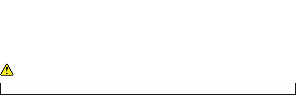
2. Open Windows Media Player. See “Accessing a program on your computer” on page 46.
3. Follow the instructions on the screen.
• Burn a disc from an ISO file.
1. Insert a recordable disc into the optical drive that supports recording.
2. Double-click the ISO file.
3. Follow the instructions on the screen.
Recording a disc using preinstalled programs
To record a disc using preinstalled programs, do the following:
1. Insert a recordable disc into the optical drive that supports recording.
2. Open the PowerDVD Create, PowerProducer, or Power2Go program. See “Accessing a program on
your computer” on page 46.
3. Follow the instructions on the screen.
Connecting to a network
This section provides instructions on how to connect to a network.
Connecting to an Ethernet LAN
You can connect your computer to an Ethernet LAN by connecting an Ethernet cable to the Ethernet
connector.
DANGER
To avoid the risk of electrical shock, do not connect the telephone cable to the Ethernet connector.
Connecting to a wireless LAN
You can connect your computer to a wireless LAN without the use of an Ethernet cable but by means of
radio waves only.
Note: The wireless LAN feature is available only on some models.
To establish a wireless-LAN connection, do the following:
1. Ensure that a wireless LAN is available and the wireless LAN feature on your computer is working.
2. Click the wireless-network-connection-status icon in the Windows notification area to display available
wireless networks.
Note: If the wireless-network-connection-status icon is not displayed in the Windows notification area,
add the icon to the notification area. See the Windows help system.
3. Click a wireless LAN, and then click Connect to connect your computer to it. Provide required
information if needed.
Connecting to a Bluetooth-enabled device
Bluetooth is a short-range wireless communications technology. Use Bluetooth to establish a wireless
connection between your computer and another Bluetooth-enabled device within a distance of about 10 m
(32.8 ft).
Note: The Bluetooth feature is available only on some models.
Chapter 3.Using your computer 51
To connect to a Bluetooth-enabled device, do the following:
1. Turn on the Bluetooth feature of your computer. Ensure that the Bluetooth-enabled device is located
within a distance of about 10 m (32.8 ft) from your computer.
2. Click the Bluetooth icon in the Windows notification area on the taskbar. Then, click Add a Device and
follow the instructions on the screen.
Note: If the Bluetooth icon is not displayed in the Windows notification area, add the icon to the
notification area. See the Windows help system.
52 P920 Hardware Maintenance Manual

Chapter 4. You and your computer
This chapter provides information about accessibility, ergonomic, and cleaning and maintenance.
Arranging your workspace
Arrange your workspace to suit your needs and the kind of work you do. This section provides information
about the factors that affect the way you arrange your workspace.
Glare and lighting
Position the monitor to minimize glare and reflections from overhead lights, windows, and other light
sources. Reflected light from shiny surfaces can cause annoying reflections on your screen. When possible,
place the monitor at right angles to windows and other light sources. If necessary, reduce overhead lighting
by turning off lights or using lower wattage bulbs. If you install the monitor near a window, use curtains or
blinds to block the sunlight. You can adjust the brightness and contrast controls on the monitor as the room
lighting changes throughout the day.
Where it is impossible to avoid reflections or to adjust the lighting, an antiglare filter placed over the screen
might be helpful. However, these filters might affect the clarity of the image on the screen; try them only after
you have exhausted other methods of reducing glare.
Air circulation
Your computer produces heat. The computer has a fan that pulls in fresh air and forces out hot air through
the air vents. Blocking the air vents can cause overheating, which might result in a malfunction or damage.
Position the computer so that nothing blocks the air vents; usually, 51 mm (2 inches) of air space is sufficient.
Ensure that the vented air is not blowing on people.
Electrical outlet locations and cable lengths
The following factors might determine the final placement of your computer:
• Locations of electrical outlets
• Length of power cords or power adapters
• Length of the cables that are connected to other devices
For more information about power cords or power adapters, see “Power cords and power adapters” on page
1.
Comfort
Although no single working position is ideal for everyone, here are a few guidelines to help you find a position
that suits you best. The following figure sets an example for your reference.
© Copyright Lenovo 2017 53

• Screen position: Keep the screen at a comfortable viewing distance, usually 51–61 cm (20–24 inches).
Then, adjust the screen so that the top of the screen is at or slightly below eye level and you can view it
without twisting your body.
• Chair position: Use a chair that gives you good back support and seat height adjustment. Use chair
adjustments to best suit your desired posture.
• Head position: Keep your head and neck in a comfortable and neutral (vertical or upright) position.
• Arm and hand positions: Keep your forearms, wrists, and hands in a relaxed and neutral (horizontal)
position. Type with a soft touch without pounding the keys.
• Leg position: Keep your thighs parallel to the floor and your feet flat on the floor or on a footrest.
Make minor modifications in your working posture to deter the onset of discomfort caused by long periods of
working in the same position. Frequent short breaks from your work also help to prevent minor discomfort
associated with your working posture.
Accessibility information
Lenovo is committed to providing users who have hearing, vision, and mobility limitations with greater
access to information and technology. This section provides information about the ways these users can get
the most out of their computer experience. You also can get the most up-to-date accessibility information
from the following Web site:
http://www.lenovo.com/accessibility
Keyboard shortcuts
The following list contains keyboard shortcuts that can help make your computer easier to use.
Note: Depending on your keyboard, some of the following keyboard shortcuts might not be available.
• Windows logo key + U: Open Ease of Access Center
• Right Shift for eight seconds: Turn on or turn off Filter Keys
• Shift five times: Turn on or turn off Sticky Keys
• Num Lock for five seconds: Turn on or turn off Toggle Keys
• Left Alt+Left Shift+Num Lock: Turn on or turn off Mouse Keys
• Left Alt+Left Shift+PrtScn (or PrtSc): Turn on or turn off High Contrast
For more information, go to https://windows.microsoft.com/, and then search using any of the following
keywords: keyboard shortcuts, key combinations, shortcut keys.
Ease of Access Center
Ease of Access Center on the Windows operating system enables you to configure your computer to suit
your physical and cognitive needs.
54 P920 Hardware Maintenance Manual
To use Ease of Access Center, do the following:
1. Click the Start button to open the Start menu.
2. Depending on your Windows version, do one of the following:
• For Windows 7: Click Control Panel. View Control Panel by Large icons or Small icons, and then
click Ease of Access Center.
• For Windows 10: Click Settings ➙ Ease of Access.
3. Choose the appropriate tool by following the instructions on the screen.
Ease of Access Center mainly includes the following tools:
• Magnifier
Magnifier is a useful utility that enlarges the entire screen or part of the screen so that you can see the
items better.
• Narrator
Narrator is a screen reader that reads aloud what is displayed on the screen and describes events such as
error messages.
• On-Screen Keyboard
To input data into your computer using a mouse, joystick, or other pointing devices instead of a physical
keyboard, you can use On-Screen Keyboard.
• High Contrast
High Contrast is a feature that heightens the color contrast of some text and images on your screen. As a
result, those items are more distinct and easier to identify.
• Personalized keyboard
Adjust keyboard settings to make your keyboard easier to use. For example, you can use your keyboard
to control the pointer and type certain key combinations easier.
• Personalized mouse
Adjust mouse settings to make your mouse easier to use. For example, you can change the pointer
appearance and make it easier to manage windows with the mouse.
Speech Recognition
Speech Recognition enables you to control your computer by voice.
Using only your voice, you can start programs, open menus, click objects on the screen, dictate text into
documents, and write and send e-mails. Everything you do with the keyboard and mouse can be done with
only your voice.
To use Speech Recognition, do the following:
1. Click the Start button to open the Start menu.
2. Depending on your Windows version, do one of the following:
• For Windows 7: Click Control Panel.
• For Windows 10: Click Windows System ➙ Control Panel.
3. View Control Panel by Large icons or Small icons, and then click Speech Recognition.
4. Follow the instructions on the screen.
Screen-reader technologies
Screen-reader technologies are primarily focused on software program interfaces, help information systems,
and various online documents. For additional information about screen readers, see the following:
Chapter 4.You and your computer 55

• Using PDFs with screen readers:
http://www.adobe.com/accessibility.html?promoid=DJGVE
• Using the JAWS screen reader:
http://www.freedomscientific.com/jaws-hq.asp
• Using the NVDA screen reader:
http://www.nvaccess.org/
Screen resolution
You can make the text and images on your screen easier to read by adjusting the screen resolution of your
computer.
To adjust the screen resolution, do the following:
1. Right-click a blank area on the desktop.
2. Depending on your Windows version, do one of the following:
• For Windows 7: Click Screen resolution.
• For Windows 10: Click Display settings ➙ Display.
3. Follow the instructions on the screen.
Note: Setting the resolution too low might prevent some items from fitting on the screen.
Customizable item size
You can make the items on your screen easier to read by changing the item size.
• To change the item size temporarily, use the Magnifier tool in Ease of Access Center.
• To change the item size permanently, do the following:
– Change the size of all the items on your screen.
– For Windows 7:
1. Right-click a blank area on the desktop.
2. Click Screen resolution ➙ Make text and other items larger or smaller.
3. Follow the on-screen instructions to change the item size.
4. Click Apply. This change will take effect the next time you log in to the operating system.
– For Windows 10:
1. Right-click a blank area on the desktop.
2. Click Display settings ➙ Display.
3. Follow the on-screen instructions to change the item size. For some applications, your
configuration might not take effect until you sign out and then sign in again.
– Change the size of the items on a Web page.
Press and hold Ctrl, and then press the plus-sign key (+) to enlarge or the minus-sign key (-) to reduce
the text size.
– Change the size of the items on the desktop or a window.
Note: This function might not work on some windows.
If your mouse has a wheel, press and hold Ctrl, and then scroll the wheel to change the item size.
Industry-standard connectors
Your computer provides industry-standard connectors that enable you to connect assistive devices.
56 P920 Hardware Maintenance Manual

For more information about the location and function of each connector, see “Hardware locations” on page
29.
TTY/TDD conversion modem
Your computer supports the use of a text telephone (TTY) or the telecommunications device for the deaf
(TDD) conversion modem. The modem must be connected between your computer and a TTY/TDD
telephone. Then, you can type a message on your computer and send it to the telephone.
Documentation in accessible formats
Lenovo provides electronic documentation in accessible formats, such as properly tagged PDF files or
HyperText Markup Language (HTML) files. Lenovo electronic documentation is developed to ensure that
visually impaired users can read the documentation through a screen reader. Each image in the
documentation also includes adequate alternative text so that visually impaired users can understand the
image when they use a screen reader.
Cleaning your computer
Attention: Do not open your computer or attempt any repair before reading and understanding the Chapter
1 “Read this first: Important safety information” on page 1. Properly remove or install your computer cover.
See Chapter 9 “Hardware removal and installation” on page 103.
CAUTION:
Remove any media from the drives and turn off all connected devices and the computer. Then,
disconnect all power cords from electrical outlets and disconnect all cables that are connected to the
computer.
It is a good practice to clean your computer periodically to protect the surfaces and ensure trouble-free
operation. Use only mild cleaning solutions and a damp cloth to clean the painted surfaces of the computer.
Dust buildup compounds problems associated with glare, so remember to clean the screen periodically.
Wipe the screen surface gently with a soft, dry cloth, or blow on the screen to remove grit and other loose
particles. Depending on the type of the screen, moisten a soft, lint-free cloth with an LCD cleaner or liquid
glass cleaner and then wipe the screen surface.
Maintenance
With appropriate care and maintenance, your computer will serve you reliably. This section provides
instructions on how to maintain your computer so that it can keep working in better condition.
Basic maintenance tips
Here are some basic points about keeping your computer functioning properly:
• Keep your computer in a clean, dry environment. Ensure that the computer rests on a flat, steady surface.
• Do not cover any of air vents. These air vents provide airflow to keep your computer from overheating.
• Keep food and drinks away from all parts of your computer. Food particles and spills might make the
keyboard and mouse stick and unusable.
• Do not get the power switches or other controls wet. Moisture can damage these parts and cause an
electrical hazard.
• Always disconnect a power cord by grasping the plug instead of the cord.
Chapter 4.You and your computer 57
Good maintenance practices
By performing a few good maintenance practices, you can maintain good computer performance, protect
your data, and be prepared in case of a computer failure.
• Empty your recycle bin on a regular basis.
• Use the disk defragmentation or disk optimization feature of your operating system occasionally to
prevent performance problems caused by an excessive number of fragmented files.
• Clean out your Inbox, Sent Items, and Deleted Items folders in your e-mail application on a regular basis.
• Back up critical data regularly on removable media memory, such as discs and USB storage devices, and
store the removable media in a safe location. The frequency of making backup copies depends on how
critical the data is to you or your business.
• Back up your data on the storage drive regularly. See “Recovery information” on page 91.
• Keep your computer software, device drivers, and operating system up-to-date. See “Keeping your
computer current” on page 58.
• Keep a log book. Entries might include major software or hardware changes, device-driver updates,
intermittent problems and what you did to resolve them, and other issues you might have experienced.
The cause of a problem might be change in hardware, change in software, or any other actions that might
have taken place. A log book can help you or a Lenovo technician determines the cause of a problem.
• Create Product Recovery discs. See “Recovery information” on page 91 for more information about using
Product Recovery discs to restore the hard disk drive to the factory-default settings.
Keeping your computer current
In most cases, it is a good practice to have the most up-to-date operating system update patches, software
programs, and device drivers. This section provides instructions on how to get the latest updates for your
computer.
Getting the latest system updates
To get the latest system updates for your computer, ensure that your computer is connected to the Internet
and do one of the following:
• Use the corresponding Lenovo program to get the system updates, such as device driver updates,
software updates, and BIOS updates:
– For Windows 7: Use the System Update program.
– For Windows 10: Use the Lenovo Companion program.
To open the System Update or Lenovo Companion program, see “Accessing a program on your
computer” on page 46. For more information about using the program, refer to the help system of the
program.
• Use Windows Update to get the system updates, such as security fixes, new versions of Windows
components, and device driver updates.
1. Click the Start button to open the Start menu.
2. Depending on your Windows version, do one of the following:
– For Windows 7: Click Control Panel. View Control Panel by Large icons or Small icons, and then
click Windows Update.
– For Windows 10: Click Settings ➙ Update & Security ➙ Windows Update.
3. Follow the instructions on the screen.
58 P920 Hardware Maintenance Manual

Note: The device drivers provided by Windows Update might not be tested by Lenovo. It is recommended
that you get device drivers by using Lenovo programs or from the Lenovo Web site at http://www.lenovo.com/
support.
Moving your computer
Before moving your computer, take the following precautions:
1. Back up your data on the storage drive. See “Good maintenance practices” on page 58.
2. Remove any media from the drives and turn off all connected devices and the computer. Then,
disconnect all power cords from electrical outlets and disconnect all cables that are connected to the
computer.
3. If you saved the original shipping cartons and packing materials, use them to pack the units. If you are
using different cartons, cushion the units to avoid damage.
Moving your computer to another country or region
When you move your computer to another country or region, you must take local electrical standards into
consideration. If the local electrical outlet style is different from the type you are using, use either an electrical
plug adapter or a new power cord. To purchase such items, contact the Lenovo Customer Support Center.
For a list of Lenovo Support phone numbers, go to http://www.lenovo.com/support/phone. If you cannot find
the support telephone number for your country or region, contact your Lenovo reseller.
Chapter 4.You and your computer 59
60 P920 Hardware Maintenance Manual
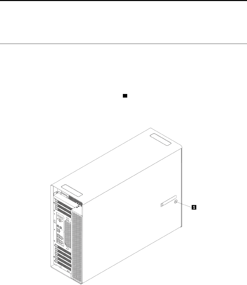
Chapter 5. Security
This chapter provides information about how to protect your computer from unauthorized use.
Locking your computer
This section provides instructions on how to lock your computer with the locking devices to keep your
computer safe.
Locking the computer cover
Locking the computer cover helps prevent unauthorized people from gaining access to the inside of your
computer. Your computer might come with a key lock 1 that is built into the computer cover. The keys for
the key lock are attached to the rear of the machine. For security, store the keys in a secure place when you
are not using them.
Note: The key lock and keys are available only on some models.
Figure 9. Locking the computer cover
© Copyright Lenovo 2017 61
Attaching a Kensington-style cable lock
You can use a Kensington-style cable lock to secure your computer to a desk, table, or other non-permanent
fixture. The cable lock attaches to the security-lock slot at the rear of your computer. Depending on the type
selected, the cable lock can be operated with a key or combination. The cable lock also locks the buttons
used to open the computer cover. This is the same type of lock used with many notebook computers. You
can order such a cable lock directly from Lenovo by searching for Kensington at:
http://www.lenovo.com/support
Figure 10. Kensington-style cable lock
Viewing and changing security settings in the Setup Utility program
To view and change security settings in the Setup Utility program, do the following:
1. Start the Setup Utility program. See “Starting the Setup Utility program” on page 67.
2. Select Security.
3. Follow the instructions on the right side of the screen to view and change security settings. You can refer
to “Using the Setup Utility program” on page 67 to get basic information about some major security
settings.
4. To save settings and exit the Setup Utility program, press F10 or Fn+F10 (depending on the keyboard
settings). Then, select Yes in the window displayed, and press Enter.
62 P920 Hardware Maintenance Manual

Using passwords and Windows accounts
You can use BIOS passwords and Windows accounts to prevent unauthorized access to your computer and
data. To use the BIOS passwords or the Windows accounts, do the following:
• To use BIOS passwords, see “Using BIOS passwords” on page 69.
• To use Windows accounts, do the following:
1. Click the Start button to open the Start menu.
2. Depending on your Windows version, do one of the following:
– For Windows 7: Click Control Panel ➙ User Accounts.
– For Windows 10: Click Settings ➙ Accounts.
3. Follow the instructions on the screen.
Using fingerprint authentication
If your keyboard has a fingerprint reader, you can use fingerprint authentication to replace passwords for
simple and secure user access. To use fingerprint authentication, first enroll your fingerprints and associate
them with your passwords (such as the power-on password, hard disk password, and Windows password).
Use the fingerprint reader and the fingerprint program to complete this procedure.
To use fingerprint authentication, do one of the following:
• For Windows 7: Use the Fingerprint Manager Pro or ThinkVantage Fingerprint Software program provided
by Lenovo. To open the program, see “Accessing a program on your computer” on page 46. For more
information about using the program, refer to the help system of the program.
• For Windows 10: Use the fingerprint tool provided by the Windows operating system. Click the Start
button to open the Start menu, and then click Settings ➙ Accounts ➙ Sign-in options. Follow the
instructions on the screen.
To use the fingerprint reader, refer to the documentation shipped with the fingerprint keyboard or located on
the Lenovo Support Web site at http://www.lenovo.com/support/keyboards.
Using the cover presence switch
The cover presence switch prevents your computer from logging in to the operating system when the
computer cover is not properly installed or closed.
To use the cover presence switch, enable the cover-presence-switch connector on the system board first. To
achieve this, do the following:
1. Start the Setup Utility program. See “Starting the Setup Utility program” on page 67.
2. Select Security ➙ Chassis Intrusion Detection and press Enter.
3. Select Enabled and press Enter.
4. To save settings and exit the Setup Utility program, press F10 or Fn+F10 (depending on the keyboard
settings), select Yes in the window displayed, and press Enter. The cover-presence-switch connector on
the system board is enabled.
The cover presence switch starts functioning. If the switch detects that the computer cover is not correctly
installed or closed, an error message is displayed when you turn on the computer. To fix the error and log in
to the operating system, do the following:
Chapter 5.Security 63

1. Properly remove or install your computer cover. See Chapter 9 “Hardware removal and installation” on
page 103.
2. Start and then exit the Setup Utility program. See “Starting the Setup Utility program” on page 67 and
“Exiting the Setup Utility program” on page 72.
Using firewalls
A firewall can be hardware, software, or a combination of both depending on the level of security required.
Firewalls work on a set of rules to determine which inbound and outbound connections are authorized. If
your computer is preinstalled with a firewall program, it helps protect against computer Internet security
threats, unauthorized access, intrusions, and Internet attacks. It also protects your privacy. For more
information about how to use the firewall program, refer to the help system of your firewall program.
To use Windows Firewall, do the following:
1. Click the Start button to open the Start menu.
2. Depending on your Windows version, do one of the following:
• For Windows 7: Click Control Panel.
• For Windows 10: Click Windows System ➙ Control Panel.
3. View Control Panel by Large icons or Small icons, and then click Windows Defender Firewall.
4. Follow the instructions on the screen.
Protecting data against viruses
Your computer is preinstalled with an antivirus program to help you guard against, detect, and eliminate
viruses.
Lenovo provides a full version of antivirus software on your computer with a free 30-day subscription. After
30 days, you must renew the license to continue receiving the antivirus software updates.
Note: Virus definition files must be kept up-to-date to guard against new viruses.
For more information about how to use your antivirus software, refer to the help system of your antivirus
software.
Using the Smart USB Protection function
The Smart USB Protection function is a security function that helps prevent data from being copied from the
computer to USB storage devices connected to the computer. You can set the Smart USB Protection
function to one of the following modes:
• Disabled (default setting): You can use the USB storage devices without limitation.
• Read Only: You cannot copy data from the computer to the USB storage devices. However, you can
access or modify data on the USB storage devices.
• No Access: You cannot access the USB storage devices from the computer.
To configure the Smart USB Protection function, do the following:
1. Start the Setup Utility program. See “Starting the Setup Utility program” on page 67.
2. Select Security ➙ Smart USB Protection and press Enter.
3. Select the desired setting and press Enter.
64 P920 Hardware Maintenance Manual

4. To save settings and exit the Setup Utility program, press F10 or Fn+F10 (depending on the keyboard
settings). Then, select Yes in the window displayed, and press Enter.
Computrace Agent software embedded in firmware
The Computrace Agent software is an IT asset management and computer theft recovery solution. The
software detects if changes have been made on the computer, such as hardware, software, or the computer
call-in location. You might have to purchase a subscription to activate the Computrace Agent software.
Trusted Platform Module (TPM)
TPM is a secure cryptoprocessor that stores cryptographic keys, which in turn protects information stored in
your computer.
Intel BIOS guard
The BIOS guard module cryptographically verifies all the BIOS updates to the system BIOS flash. Therefore,
the malware is blocked from attacking the BIOS.
Chapter 5.Security 65
66 P920 Hardware Maintenance Manual

Chapter 6. Advanced configuration
This chapter provides information to help you further configure the computer.
Using the Setup Utility program
The Setup Utility program is used to view and change the configuration settings of your computer. This
section provides information about only the major configuration settings available in the program.
Note: The operating system settings might override any similar settings in the Setup Utility program.
Starting the Setup Utility program
To start the Setup Utility program, do the following:
1. Turn on or restart your computer.
2. Before the operating system starts up, repeatedly press and release F1 or Fn+F1 (depending on the
keyboard settings). Based on the Setup Utility display mode setting, one of the following situations
occurs:
• Text mode: The Setup Utility program opens.
• Graphic mode (available on some models): The start screen is displayed. Then, select Setup and
press Enter to open the Setup Utility program.
Note: If a BIOS password has been set, the Setup Utility program will not open until you enter the
correct password. For more information, see “Using BIOS passwords” on page 69.
To view and change the configuration settings, follow the instructions on the screen.
Changing the display mode of the Setup Utility program
You can use the Setup Utility program in the graphic mode or the text mode according to your needs.
• Text mode: The keys on the keyboard used to perform various tasks are displayed at the bottom of the
screen.
Note: The Serial Port Console Redirection item is available only in the text mode.
• Graphic mode (available on some models): In addition to the keyboard, you also can use the mouse to
make selections.
To change the display mode of the Setup Utility program, do the following:
1. Start the Setup Utility program. See “Starting the Setup Utility program” on page 67.
2. From the main interface, select Setup mode select and press Enter.
3. Select Graphic or Text and press Enter.
4. To save settings and exit the Setup Utility program, press F10 or Fn+F10 (depending on the keyboard
settings), select Yes in the window displayed, and press Enter.
Changing the display language of the Setup Utility program
The Setup Utility program supports three display languages: English, French, and simplified Chinese.
To change the display language of the Setup Utility program, do the following:
© Copyright Lenovo 2017 67

1. Start the Setup Utility program. See “Starting the Setup Utility program” on page 67.
2. From the main interface, locate System Language and press Enter.
3. Select the display language according to your needs.
Enabling or disabling a device
This section provides information about how to enable or disable user access to hardware devices (such as
USB connectors or storage drives).
To enable or disable a device, do the following:
1. Start the Setup Utility program. See “Starting the Setup Utility program” on page 67.
2. Select Devices.
3. Select the device you want to enable or disable and press Enter.
4. Select the desired setting and press Enter.
5. To save settings and exit the Setup Utility program, press F10 or Fn+F10 (depending on the keyboard
settings). Then, select Yes in the window displayed, and press Enter.
Enabling or disabling the automatic power-on of your computer
The Automatic Power On item in the Setup Utility program provides various options for you to make your
computer start up automatically.
To enable or disable the Automatic Power On features, do the following:
1. Start the Setup Utility program. See “Starting the Setup Utility program” on page 67.
2. Select Power ➙ Automatic Power On and press Enter.
3. Select the feature you want to enable or disable and press Enter.
4. Select the desired setting and press Enter.
5. To save settings and exit the Setup Utility program, press F10 or Fn+F10 (depending on the keyboard
settings). Then, select Yes in the window displayed, and press Enter.
Enabling or disabling the ErP LPS compliance mode
Lenovo computers meet the eco-design requirements of the ErP Lot 3 regulation. For more information, go
to:
http://www.lenovo.com/ecodeclaration
You can enable the ErP LPS compliance mode in the Setup Utility program to reduce the consumption of
electricity when your computer is off or in sleep mode.
To enable or disable the ErP LPS compliance mode, do the following:
1. Start the Setup Utility program. See “Starting the Setup Utility program” on page 67.
2. Select Power ➙ Enhanced Power Saving Mode and press Enter.
3. Select Enabled or Disabled depending on your needs, and then press Enter. If you select Enabled, you
also need to disable the Wake on LAN feature. See “Enabling or disabling the automatic power-on of
your computer” on page 68.
4. To save settings and exit the Setup Utility program, press F10 or Fn+F10 (depending on the keyboard
settings). Then, select Yes in the window displayed, and press Enter.
When the ErP LPS compliance mode is enabled, you can wake up your computer by doing one of the
following:
68 P920 Hardware Maintenance Manual
• Press the power button.
• Enable the Wake Up on Alarm feature to make your computer wake up at a set time. See “Enabling or
disabling the automatic power-on of your computer” on page 68.
• Enable the After Power Loss feature to make your computer wake up when the power supply resumes
after a sudden loss of electricity.
To enable the After Power Loss feature, do the following:
1. Start the Setup Utility program. See “Starting the Setup Utility program” on page 67.
2. Select Power ➙ After Power Loss and press Enter.
3. Select Power On and press Enter.
4. To save settings and exit the Setup Utility program, press F10 or Fn+F10 (depending on the keyboard
settings). Then, select Yes in the window displayed, and press Enter.
Enabling or disabling the configuration change detection
With the configuration-change detection enabled, if the POST detects configuration changes of some
hardware devices (such as storage drives or memory modules), an error message is displayed.
To enable or disable the configuration change detection, do the following:
1. Start the Setup Utility program. See “Starting the Setup Utility program” on page 67.
2. Select Security ➙ Configuration Change Detection and press Enter.
3. Select the desired setting and press Enter.
4. To save settings and exit the Setup Utility program, press F10 or Fn+F10 (depending on the keyboard
settings). Then, select Yes in the window displayed, and press Enter.
To bypass the error message and log in to the operating system, do one of the following:
• Press F2 or Fn+F2 (depending on the keyboard settings).
• Start and then exit the Setup Utility program. See “Starting the Setup Utility program” on page 67 and
“Exiting the Setup Utility program” on page 72.
Changing the BIOS settings before installing a new operating system
BIOS settings vary by operating system. Change the BIOS settings before installing a new operating system.
To change the BIOS settings, do the following:
1. Start the Setup Utility program. See “Starting the Setup Utility program” on page 67.
2. From the main interface, select Exit ➙ OS Optimized Default and press Enter.
3. Depending on the operating system to be installed, do one of the following:
• To install the Windows 10 (64-bit) operating system, select Enabled and press Enter.
• To install an operating system other than Windows 10 (64-bit), select Disabled and press Enter.
4. Select Yes in the window displayed and press Enter to confirm your selection.
5. To save settings and exit the Setup Utility program, press F10 or Fn+F10 (depending on the keyboard
settings). Then, select Yes in the window displayed, and press Enter.
Using BIOS passwords
By using the Setup Utility program, you can set passwords to prevent unauthorized access to your computer
and data.
Chapter 6.Advanced configuration 69
You do not have to set any passwords to use your computer. However, using passwords improves computer
security. If you decide to set any passwords, read the following topics.
Password types
The following types of passwords are available in the Setup Utility program:
• Power-on password
When a power-on password is set, you are prompted to enter a valid password each time the computer is
turned on. The computer cannot be used until the valid password is entered.
• Administrator password
Setting an administrator password deters unauthorized users from changing configuration settings. If you
are responsible for maintaining the configuration settings of several computers, you might want to set an
administrator password.
When an administrator password is set, you are prompted to enter a valid password each time you try to
access the Setup Utility program. The Setup Utility program cannot be accessed until a valid password is
entered.
If both the power-on password and administrator password are set, you can enter either password.
However, you must use your administrator password to change any configuration settings.
• Hard disk password
Setting a hard disk password prevents unauthorized access to the data on the internal storage drive (such
as a hard disk drive). When a hard disk password is set, you are prompted to enter a valid password each
time you try to access the storage drive.
Notes:
– Even if the storage drive is removed from one computer and installed in another, the hard-disk
password is still valid.
– If the hard disk password is forgotten, there is no way to reset the password or recover data from the
storage drive.
Password considerations
A password can be any combination of up to 64 alphabetic and numeric characters. For security reasons, it
is recommended to use a strong password that cannot be easily compromised.
Note: The Setup Utility program passwords are case-sensitive.
To set a strong password, consider the following guidelines:
• Have at least eight characters in length
• Contain at least one alphabetic character and one numeric character
• Not be your name or your user name
• Not be a common word or a common name
• Be significantly different from your previous passwords
Setting, changing, or deleting a password
To set, change, or delete a password, do the following:
1. Start the Setup Utility program. See “Starting the Setup Utility program” on page 67.
2. Select Security.
3. Depending on the password type, select Set Power-On Password, Set Administrator Password, or
Hard Disk Password and press Enter.
70 P920 Hardware Maintenance Manual
4. Follow the instructions on the right side of the screen to set, change, or delete a password.
Note: A password can be any combination of up to 64 alphabetic and numeric characters. For more
information, see “Password considerations” on page 70.
5. To save settings and exit the Setup Utility program, press F10 or Fn+F10 (depending on the keyboard
settings). Then, select Yes in the window displayed, and press Enter.
Erasing lost or forgotten passwords (clearing CMOS)
This section provides instructions on how to erase lost or forgotten passwords, such as a user password.
Note: The instructions in this section do not apply to the hard disk password.
To erase a lost or forgotten password, do the following:
1. Remove any media from the drives and turn off all connected devices and the computer. Then,
disconnect all power cords from electrical outlets and disconnect all cables that are connected to the
computer.
2. Remove the computer cover. See Chapter 9 “Hardware removal and installation” on page 103.
3. Locate the Clear Complementary Metal Oxide Semiconductor (CMOS) /Recovery jumper on the system
board. See “Hardware locations” on page 29.
4. Move the jumper from the standard position (pin 1 and pin 2) to the maintenance position (pin 2 and pin
3).
5. Reinstall the computer cover and connect the power cord. See Chapter 9 “Hardware removal and
installation” on page 103.
6. Turn on the computer and leave it on for approximately 10 seconds. Then, turn off the computer by
holding the power button for approximately five seconds.
7. Repeat step 1 and step 2.
8. Move the Clear CMOS /Recovery jumper back to the standard position (pin 1 and pin 2).
9. Reinstall the computer cover and connect the power cord.
Selecting a startup device
If your computer does not start up from the expected device, you can either change the startup device
sequence or select a temporary startup device.
Changing the startup device sequence permanently
To change the startup device sequence permanently, do the following:
1. Depending on the type of the storage device, do one of the following:
• If the storage device is internal, go to step 2.
• If the storage device is a disc, ensure that your computer is turned on. Then, insert the disc into the
optical drive.
• If the storage device is an external device other than a disc, connect the storage device to the
computer.
2. Start the Setup Utility program. See “Starting the Setup Utility program” on page 67.
3. Select Startup.
4. Follow the instructions on the right side of the screen to change the startup device sequence.
5. To save settings and exit the Setup Utility program, press F10 or Fn+F10 (depending on the keyboard
settings). Then, select Yes in the window displayed, and press Enter.
Chapter 6.Advanced configuration 71

Selecting a temporary startup device
Note: Not all discs and storage drives are bootable.
To select a temporary startup device, do the following:
1. Depending on the type of the storage device, do one of the following:
• If the storage device is internal, go to step 2.
• If the storage device is a disc, ensure that your computer is turned on. Then, insert the disc into the
optical drive.
• If the storage device is an external device other than a disc, connect the storage device to the
computer.
2. Turn on or restart the computer. Before Windows starts up, repeatedly press and release F12 or Fn+F12
(depending on the keyboard settings) until Startup Device Menu is displayed.
3. Select the desired storage device and press Enter. The computer then starts up from the device you
select.
If you want to select a permanent startup device, select Enter Setup on Startup Device Menu and press
Enter to start the Setup Utility program. For more information about how to select a permanent startup
device, see “Changing the startup device sequence permanently” on page 71.
Changing the fan speed level
The Fan Control Stepping item enables you to adjust the thermal performance of your computer. From level 1
to level 7, a higher fan speed level indicates better thermal performance with more noise.
To change the fan speed level, do the following:
1. Start the Setup Utility program. See “Starting the Setup Utility program” on page 67.
2. Select Power ➙ Fan Control Stepping and press Enter.
3. Select a fan speed level and press Enter.
4. To save settings and exit the Setup Utility program, press F10 or Fn+F10 (depending on the keyboard
settings), select Yes in the window displayed, and press Enter.
Exiting the Setup Utility program
To exit the Setup Utility program, do one of the following:
• If you want to save the new settings, press F10 or Fn+F10 (depending on the keyboard settings). Then,
select Yes in the window displayed and press Enter.
• If you do not want to save the new settings, select Exit ➙ Discard Changes and Exit and press Enter.
Then, select Yes in the window displayed and press Enter.
BIOS level
An incorrect BIOS level can cause false errors and unnecessary FRU replacement. Use the following
information to determine the currently installed BIOS level, the latest BIOS level available, and where to
obtain the latest BIOS level.
• To determine the currently installed BIOS level, start the Setup Utility program and view the BIOS
Revision Level on the Main page.
• Sources for obtaining the latest BIOS level available
– Lenovo support Web site: http://www.lenovo.com/support
– Lenovo Customer Support Center
72 P920 Hardware Maintenance Manual

– Levels 1 and 2 Support
To update the BIOS, see “Updating and recovering the BIOS” on page 73.
Note: BIOS settings vary by operating system. Change the BIOS settings before installing a new operating
system. See “Changing the BIOS settings before installing a new operating system” on page 69.
Updating and recovering the BIOS
The BIOS is the first program that the computer runs when you turn on the computer. The BIOS initializes the
hardware components and loads the operating system and other programs.
Updating the BIOS
When you install a new program, hardware device, or device driver, you might be informed to update the
BIOS. You can update the BIOS from your operating system or a flash update disc (available only on some
models).
To update the BIOS, do the following:
1. Go to http://www.lenovo.com/support.
2. To update the BIOS from your operating system, download the flash BIOS update driver according to
your operating system version. To update the BIOS from a flash update disc, download the ISO image
version (used to create a flash update disc). Then, download the installation instructions for the flash
BIOS update driver.
3. Print the installation instructions you download and follow the instructions to update the BIOS.
Note: If you want to update the BIOS from a flash update disc, the installation instructions might not
provide the instructions on how to record the update disc. See “Recording a disc” on page 50.
Recovering from a BIOS update failure
To recover from a BIOS update failure, do the following:
1. Remove any media from the drives and turn off all connected devices and the computer. Then,
disconnect all power cords from electrical outlets and disconnect all cables that are connected to the
computer.
2. Remove the computer cover. See Chapter 9 “Hardware removal and installation” on page 103.
3. Locate the Clear CMOS /Recovery jumper on the system board. See “Hardware locations” on page 29.
4. Remove any parts and cables that impede your access to the Clear CMOS /Recovery jumper.
5. Move the jumper from the standard position (pin 1 and pin 2) to the maintenance position (pin 2 and pin
3).
6. Reinstall the parts and cables that were removed.
7. Reinstall the computer cover and reconnect any cables that were disconnected. See Chapter 9
“Hardware removal and installation” on page 103.
8. Turn on the computer and insert the BIOS update disc into the optical drive. Wait a few minutes. The
recovery process begins. After the recovery process is completed, your computer will shut down
automatically.
Note: If the computer does not start up from the disc, select the disc as the startup device. See
“Selecting a temporary startup device” on page 72.
9. Repeat steps 1–4.
10. Move the Clear CMOS /Recovery jumper back to the standard position (pin 1 and pin 2).
11. Repeat step 6 and step 7. Then, turn on your computer.
Chapter 6.Advanced configuration 73

Configuring RAID
This section provides information about storage drive requirements for RAID levels, and instructions on how
to configure RAID for your computer. Depending on your computer model and configuration, you can
configure RAID using one of the following utilities:
• Intel Rapid Storage Technology enterprise (RSTe) configuration utility
• AVAGO MegaRAID Configuration Utility
• Intel Virtual RAID on CPU configuration utility
An Introduction to RAID
RAID is a technology that provides increased storage functions and reliability through redundancy.
When a group of independent physical storage drives is set up to use RAID technology, they are in a RAID
array. This array distributes data across multiple storage drives, but the array appears to the host computer
as one single storage unit. Creating and using RAID arrays provides high performance, such as the expedited
I/O performance, because several drives can be accessed simultaneously.
RAID drive groups configured according to certain RAID levels also improve data storage reliability and fault
tolerance compared with single-drive storage systems. Data loss resulting from a drive failure can be
prevented by reconstructing missing data from the remaining drives.
Note: For RAID 0, the missing data resulting from a drive failure cannot be reconstructed.
Configuring RAID with Intel RSTe
If your computer comes with the Intel RSTe configuration utility, you can follow the sections below to
configure RAID with Intel RSTe.
Storage drive requirements for RAID levels
Your computer supports the following RAID levels:
• RAID 0: striped disk array
– Consists of at least two SATA storage drives
– Supported strip size: 4 KB, 8 KB, 16 KB, 32 KB, 64 KB, or 128 KB
– Better performance without fault tolerance
• RAID 1: mirrored disk array
– Consists of two SATA storage drives
– Improved reading performance and 100% redundancy
• RAID 10: striped and mirrored disk array (a combination of RAID 0 and RAID 1)
– Consists of four SATA storage drives
– Supported strip size: 4 KB, 8 KB, 16 KB, 32 KB, or 64 KB
• RAID 5: block-level striped disk array with distributed parity
– Consists of at least three SATA storage drives
– Supported strip size: 16 KB, 32 KB, 64 KB, or 128 KB
– Better performance and fault tolerance
74 P920 Hardware Maintenance Manual
Creating a RAID volume
Attention: All the existing data stored on the selected drives will be erased while the RAID volume is being
created.
To create a RAID volume, do the following:
1. Enable RAID by doing the following:
a. Start the Setup Utility program. See “Starting the Setup Utility program” on page 67.
b. Select Devices ➙ PCH SATA Configuration and press Enter.
c. Select Configure SATA as and press Enter. Then, select RAID and press Enter.
d. To save settings and exit the Setup Utility program, press F10 or Fn+F10 (depending on the
keyboard settings), select Yes in the window displayed, and press Enter.
2. Start the Setup Utility program again. See “Starting the Setup Utility program” on page 67.
3. Select Advanced ➙ Intel RSTe SATA Controller and press Enter.
4. Select Create RAID Volume and press Enter. The Create RAID Volume window is displayed.
5. Select and configure the options one by one.
a. Name: You can use the default name Volume0 or type a preferred name for the RAID volume.
b. RAID Level: You can set the RAID level to one of the following:
• RAID0
• RAID1
• RAID10
• RAID5
Note: Some of the RAID levels might not be displayed because the number of installed SATA
storage drives varies.
c. Select Disks: Select a storage drive and press Enter. Then, select X and press Enter to add it to a
group.
d. Strip Size (if applicable): Select a strip size and press Enter.
e. Capacity: Customize the capacity of the RAID volume. The default RAID volume is the largest value.
6. Select Create Volume and press Enter to create a RAID volume.
7. To save settings and exit the Setup Utility program, press F10 or Fn+F10 (depending on the keyboard
settings), select Yes in the window displayed, and press Enter.
Viewing the information about a RAID volume
To view the information about a RAID volume, do the following:
1. Start the Setup Utility program. See “Starting the Setup Utility program” on page 67.
2. Select Advanced ➙ Intel RSTe SATA Controller and press Enter.
3. Select RAID Volumes and press Enter.
4. Select a RAID volume and press Enter to view the detailed information.
Deleting a RAID volume
Attention: All the existing data stored on the selected drives will be erased after you delete RAID volumes.
To delete a RAID volume, do the following:
1. Start the Setup Utility program. See “Starting the Setup Utility program” on page 67.
2. Select Advanced ➙ Intel RSTe SATA Controller and press Enter.
Chapter 6.Advanced configuration 75
3. Under RAID Volumes, select the RAID volume that you want to delete and press Enter. The RAID
VOLUME INFO window is displayed.
4. Select Delete under Volume Actions and press Enter. When prompted, select Yes and press Enter to
confirm the deletion of the selected RAID volume.
5. To save settings and exit the Setup Utility program, press F10 or Fn+F10 (depending on the keyboard
settings), select Yes in the window displayed, and press Enter.
Configuring RAID with AVAGO MegaRAID Configuration Utility
To configure RAID with AVAGO MegaRAID Configuration Utility, ensure that:
• An AVAGO MegaRAID adapter is installed in your computer.
• The storage drives used for RAID configuration are connected to the installed AVAGO MegaRAID adapter
instead of the system board.
Storage drive requirements for RAID levels
Your computer supports the following RAID levels:
• RAID 0: striped disk array
– Consists of at least two SATA or Serial Attached SCSI (SAS) storage drives
– Supported strip size: 64 KB, 128 KB, 256 KB, 512 KB, or 1 MB
– Better performance without fault tolerance
• RAID 00: spanned storage drive group with a series of RAID 0 storage drive groups
– Consists of two or four SATA or SAS storage drives
– Supported strip size: 64 KB, 128 KB, 256 KB, 512 KB, or 1 MB
– Better performance without fault tolerance
• RAID 1: mirrored disk array
– Consists of two or four SATA or SAS storage drives
– Improved read performance and 100% redundancy
• RAID 10: striped and mirrored disk array (a combination of RAID 0 and RAID 1)
– Consists of four SATA or SAS storage drives
– Data being striped across storage drive groups
– Provides both high data transfer rates and complete data redundancy
• RAID 5: block-level striped disk array with distributed parity
– Consists of at least three SATA or SAS storage drives
– Supported strip size: 64 KB, 128 KB, 256 KB, 512 KB, or 1 MB
– Better performance and fault tolerance
– Available only on some models of AVAGO MegaRAID adapters
• RAID 6: block-level striped disk array with dual distributed parity
– Consists of at least four SATA or SAS storage drives
– Supported strip size: 64 KB, 128 KB, 256 KB, 512 KB, or 1 MB
– Better performance and fault tolerance that can stand up to loss of two storage drives
– Available only on some models of AVAGO MegaRAID adapters
76 P920 Hardware Maintenance Manual
Creating a RAID volume
Attention: All the existing data stored on the selected drives will be erased while the RAID volume is being
created.
To create a RAID volume, do the following:
1. Start the Setup Utility program. See “Starting the Setup Utility program” on page 67.
2. Select Advanced ➙ AVAGO MegaRAID Configuration Utility and press Enter.
3. Select Main Menu and press Enter.
4. Select Configuration Management and press Enter.
5. Select Create Virtual Drive and press Enter.
6. Select and configure the options one by one.
a. Select RAID Level: You can set the RAID level to one of the following:
• RAID0
• RAID1
• RAID5
• RAID6
• RAID00
• RAID10
Note: Some of the RAID levels might not be displayed because the number of installed SATA
storage drives and the model of the AVAGO MegaRAID adapter vary.
b. Select Drives From: Select Unconfigured capacity or Free capacity depending on your needs and
press Enter.
c. Select Drives: Select a storage drive and press Enter. After selecting all storage drives for creating
the RAID volume, select Apply Changes and press Enter. When promoted, select Confirm and
press Enter. Then, select Yes and press Enter to save the storage drive selection. Finally, select OK
and press Enter.
d. Virtual Drive Name: You can type a preferred name for the volume name.
e. Strip Size (if applicable): Select a strip size and press Enter.
7. Select Save Configuration and press Enter. When promoted, select Confirm and press Enter. Then,
select Yes and press Enter to confirm the creation of the RAID volume.
8. To save settings and exit the Setup Utility program, press F10 or Fn+F10 (depending on the keyboard
settings), select Yes in the window displayed, and press Enter.
Viewing the information about a RAID volume
To view the information about a RAID volume, do the following:
1. Start the Setup Utility program. See “Starting the Setup Utility program” on page 67.
2. Select Advanced ➙ AVAGO MegaRAID Configuration Utility and press Enter.
3. Select Main Menu and press Enter.
4. Select Virtual Drive Management and press Enter.
5. Select a RAID volume and press Enter to view the detailed information.
Deleting a RAID volume
Attention: All the existing data stored on the selected drives will be erased after you delete RAID volumes.
Chapter 6.Advanced configuration 77
To delete a RAID volume, do the following:
1. Start the Setup Utility program. See “Starting the Setup Utility program” on page 67.
2. Select Advanced ➙ AVAGO MegaRAID Configuration Utility.
3. Select Main Menu and press Enter.
4. Select Virtual Drive Management and press Enter.
5. Select the RAID volume that is not needed and press Enter.
6. Under Operation, select Delete Virtual Drive and press Enter.
7. Select Go and press Enter. When prompted, select Confirm and press Enter. Then, select Yes and
press Enter to delete the RAID volume.
8. To save settings and exit the Setup Utility program, press F10 or Fn+F10 (depending on the keyboard
settings), select Yes in the window displayed, and press Enter.
Configuring RAID with Intel Virtual RAID on CPU
To configure RAID with the Intel Virtual RAID on CPU configuration utility, ensure that:
• An upgrade key module is connected to the Virtual RAID on CPU (VROC) connector on the system board.
See “Hardware locations” on page 29.
• M.2 solid-state drives are installed in your computer.
Storage drive requirements for RAID levels
Your computer supports the following RAID levels:
• RAID 0: striped disk array
– Consists of at least two M.2 solid-state drives
– Supported strip size: 4 KB, 8 KB, 16 KB, 32 KB, 64 KB, or 128 KB
– Better performance without fault tolerance
• RAID 1: mirrored disk array
– Consists of two M.2 solid-state drives
– Improved reading performance and 100% redundancy
• RAID 10: striped and mirrored disk array (a combination of RAID 0 and RAID 1)
– Consists of four M.2 solid-state drives
– Supported strip size: 4 KB, 8 KB, 16 KB, 32 KB, or 64 KB
• RAID 5: block-level striped disk array with distributed parity
– Consists of at least three M.2 solid-state drives
– Supported strip size: 16 KB, 32 KB, 64 KB, or 128 KB
– Better performance and fault tolerance
– Available only on some models of upgrade key modules
Creating a RAID volume
Attention: All the existing data stored on the selected drives will be erased while the RAID volume is being
created.
To create a RAID volume, do the following:
1. Enable VMD for the selected M.2 solid-state drives by doing the following:
a. Start the Setup Utility program. See “Starting the Setup Utility program” on page 67.
78 P920 Hardware Maintenance Manual
b. Select Advanced ➙ Intel(R) VMD technology and press Enter.
c. Select each menu item and press Enter. Then, select Enabled and press Enter.
d. Select an occupied M.2 solid-state drive slot as you need and press Enter. Then, select VMD and
press Enter.
e. To save settings and exit the Setup Utility program, press F10 or Fn+F10 (depending on the
keyboard settings), select Yes in the window displayed, and press Enter.
2. Start the Setup Utility program again. See “Starting the Setup Utility program” on page 67.
3. Select Advanced ➙ Intel Virtual RAID on CPU and press Enter.
4. Select All Intel VMD Controllers and press Enter.
5. Select Create Volumes and press Enter.
6. Select and configure the options one by one.
a. Name: You can use the default name Volume0 or type a preferred name for the RAID volume.
b. RAID Level: You can set the RAID level to one of the following:
• RAID0
• RAID1
• RAID10
• RAID5
Note: Some of the RAID levels might not be displayed because the number of installed M.2 solid-
state drives and the model of the upgrade key module vary.
c. Select Disks: Select an M.2 solid-state drive and press Enter. Then, select X and press Enter to add
it to a group.
d. Stripe Size (if applicable): Select a stripe size and press Enter.
e. Capacity: Customize the capacity of the RAID volume. The default RAID volume is the largest value.
7. Select Create Volume and press Enter to create a RAID volume.
8. To save settings and exit the Setup Utility program, press F10 or Fn+F10 (depending on the keyboard
settings), select Yes in the window displayed, and press Enter.
Viewing the information about a RAID volume
To view the information about a RAID volume, do the following:
1. Start the Setup Utility program. See “Starting the Setup Utility program” on page 67.
2. Select Advanced ➙ Intel Virtual RAID on CPU and press Enter.
3. Select RAID Volumes and press Enter.
4. Select a RAID volume and press Enter to view the detailed information.
Deleting a RAID volume
Attention: All the existing data stored on the selected drives will be erased after you delete RAID volumes.
To delete a RAID volume, do the following:
1. Start the Setup Utility program. See “Starting the Setup Utility program” on page 67.
2. Select Advanced ➙ Intel Virtual RAID on CPU and press Enter.
3. Select Intel VROC Mananged Volumes and press Enter.
4. Under Volume Actions, select Delete and press Enter.
5. When prompted, select Yes and press Enter to confirm the deletion of the selected RAID volume.
Chapter 6.Advanced configuration 79
6. To save settings and exit the Setup Utility program, press F10 or Fn+F10 (depending on the keyboard
settings), select Yes in the window displayed, and press Enter.
80 P920 Hardware Maintenance Manual

Chapter 7. Troubleshooting, diagnostics, and recovery
This chapter provides solutions to resolve your computer problems. Follow the steps in the basic procedure
for resolving computer problems, which helps you make good use of the troubleshooting, diagnostics, and
recovery information.
Basic procedure for resolving computer problems
It is recommended that you use the following procedure to resolve computer problems you are experiencing:
1. Ensure that:
a. The cables for all connected devices are connected correctly and securely.
b. All connected devices that require ac power are connected to properly grounded, functioning
electrical outlets.
c. All connected devices are enabled in the BIOS settings of your computer. See “Enabling or disabling
a device” on page 68.
If these actions do not resolve your problem, continue with the next step.
2. Use an antivirus program to see if your computer has been infected by a virus. If the program detects a
virus, remove the virus. If the antivirus program does not resolve your problem, continue with the next
step.
3. Go to “Troubleshooting” on page 81 and follow the instructions for the type of problem you are
experiencing. If these troubleshooting instructions do not resolve your problem, continue with the next
step.
4. Run the diagnostic program. See “Diagnosing problems” on page 89. If the diagnostic program does not
resolve your problem, continue with the next step.
5. Recover your operating system. See “Recovery information” on page 91.
6. If none of these actions solve your problem, contact the Lenovo Customer Support Center. For a list of
Lenovo Support phone numbers, go to http://www.lenovo.com/support/phone. For more information
about help, service, and technical assistance, see Chapter 10 “Getting information, help, and service” on
page 213.
Troubleshooting
Attention: Do not open your computer or attempt any repair before reading and understanding the Chapter
1 “Read this first: Important safety information” on page 1.
Use the troubleshooting information to find solutions to problems that have definite symptoms.
Startup problems
The computer does not start up when you press the power button.
Solutions:
Ensure that:
• The power cord is correctly connected to the rear of the computer and to a working electrical outlet.
• If your computer has a secondary power switch on the rear of the computer, ensure that it is switched on.
• The power indicator on the front of the computer is on.
© Copyright Lenovo 2017 81
• The computer voltage matches the voltage available at the electrical outlet for your country or region.
The operating system fails to start up.
Solution:
Ensure that the startup device sequence set in the Setup Utility program includes the device where the
operating system resides. Usually, the operating system is on the internal storage drive. For more
information, see “Changing the startup device sequence permanently” on page 71.
The computer beeps multiple times before the operating system starts up.
Solution:
Ensure that no keys are stuck.
Audio problems
The audio cannot be heard on the Windows operating system.
Solutions:
• If you are using powered external speakers that have an On/Off control, ensure that:
– The On/Off control is set to the On position.
– The speaker power cable is connected to a properly grounded, functional ac electrical outlet.
• If your external speakers have a volume control, ensure that the volume is not set too low.
• Click the volume icon in the Windows notification area on the taskbar. Ensure that the mute speakers
settings are not selected and none of the volume settings is set too low.
Note: If the volume icon is not displayed in the Windows notification area, add the icon to the notification
area. See the Windows help system.
• For some computers that have a front audio panel, ensure that the volume is not set too low.
• Ensure that your external speakers (and headphones, if used) are connected to the correct audio
connectors on the computer. Most speaker cables are color-coded to match the connectors.
Note: When external-speaker or headphone cables are connected to the audio connectors, the internal
speaker, if present, is disabled. In most cases, if an audio adapter is installed in one of the expansion
slots, the audio function built into the system board is disabled. Therefore, you must use the audio
connectors on the audio adapter.
• Ensure that the program you are running is designed for use on the Windows operating system. If the
program is designed to run in DOS, the program does not use the Windows sound feature. The program
must be configured to use Sound Blaster Pro or Sound Blaster emulation.
• Ensure that the audio device drivers are correctly installed.
The sound comes from one of the external speakers.
Solutions:
• Ensure that the speaker cable is inserted completely into the connector on the computer.
• Depending on your Windows version, do one of the following:
– For Windows 7: Click the volume icon in the Windows notification area on the taskbar. Then, click the
speaker icon on top of the volume control.
– For Windows 10: Right-click the volume icon in the Windows notification area on the taskbar. Then,
click Open Volume Mixer and select the desired speaker.
82 P920 Hardware Maintenance Manual
Click the Levels tab and ensure that the Balance settings are set correctly.
Note: If the volume icon is not displayed in the Windows notification area, add the icon to the notification
area. See the Windows help system.
CD or DVD problems
A CD or DVD does not work.
Solutions:
• Ensure that the power cable and signal cable are securely connected to the drive.
• Ensure that the disc is inserted correctly, with its label up.
• Ensure that the disc you are using is clean. To remove dust or fingerprints, wipe the disc clean with a soft
cloth from the center to the outside. Wiping a disc in a circular motion might cause loss of data.
• Ensure that the disc you are using is not scratched or damaged. Try inserting another disc that you know
is good. If you cannot read from a known-good disc, you might have a problem with your optical drive or
the cabling to your optical drive.
• If you have multiple CD or DVD drives installed (or a combination of CD and DVD drives), try inserting the
disc into the other drive. In some cases, only one of the drives is connected to the audio subsystem.
A bootable recovery medium, such as the Product Recovery CD, cannot be used to start your
computer.
Solution:
Ensure that the CD or DVD drive is set as the top priority of the Boot Priority Order in the Setup Utility
program. Refer to “Selecting a temporary startup device” on page 72 for information about viewing and
changing the startup sequence.
Note: On some computer models, the startup sequence is permanently set and cannot be changed.
A black screen is displayed instead of the DVD video.
Solutions:
• Restart the DVD player program.
• Try a lower screen resolution or color depth.
• Close any open files, and then restart the computer.
A DVD movie does not play.
Solutions:
• Ensure that the disc surface is clean and not scratched.
• Check the disc or package for regional coding. You might need to purchase a disc with coding for the
region where you are using your computer.
No audio or only an intermittent audio comes out while a DVD movie is playing.
Solutions:
• Check the volume control settings on your computer and on your speakers.
• Ensure that the disc surface is clean and not scratched.
• Check all cable connections to and from the speakers.
• Use the DVD menu for the video to select a different audio track.
Chapter 7.Troubleshooting, diagnostics, and recovery 83
The playback is slow or choppy.
Solutions:
• Disable any background programs, such as AntiVirus or Desktop Themes.
• Ensure that video resolution is lower than 1152 x 864 pixels.
A message indicating invalid disc or no disc found is displayed.
Solutions:
• Ensure that the disc is in the drive with the shiny side of the disc facing down.
• Ensure that video resolution is lower than 1152 x 864 pixels.
• Ensure that the DVD or CD is inserted into an appropriate optical drive. For example, do not insert a DVD
into a CD-only drive.
Intermittent problems
Intermittent problems refer to the problems occur only occasionally and are difficult to repeat.
Solutions:
• Ensure that all cables and cords are securely connected to the computer and attached devices.
• Ensure that when the computer is on, the fan grill is not blocked (there is air flow around the grill), and the
fans are working. If airflow is blocked or the fans are not working, the computer might overheat.
• If Small Computer System Interface (SCSI) devices are installed, ensure that the last external device in
each SCSI chain is terminated correctly. For more information, see your SCSI documentation.
Storage drive problems
Some or all storage drives are missing from the Setup Utility program.
Solutions:
• Ensure that the signal cables and power cables for all the storage drives are connected correctly.
• If the computer is installed with SAS storage drives, ensure that the AVAGO MegaRAID adapter is
correctly connected.
The computer cannot start up from the correct storage drive or the message “No Operating System
Found” is displayed.
Solutions:
• Ensure that the signal cables and power cables for all the storage drives are connected correctly.
• Ensure that the computer starts up from the correct storage drive. Set the storage drive, on which the
operating system resides, as the first startup device in the Setup Utility program. Refer to “Changing the
startup device sequence permanently” on page 71.
Note: In rare cases, the storage drive with the operating system might get corrupted or damaged. If this
problem occurs, replace the storage drive. Refer to Chapter 9 “Hardware removal and installation” on page
103.
Ethernet LAN problems
The computer cannot connect to an Ethernet LAN.
Solutions:
84 P920 Hardware Maintenance Manual
• Connect the cable from the Ethernet connector to the RJ45 connector of the hub.
• Enable the Ethernet LAN feature in the Setup Utility program. Refer to “Using the Setup Utility program”
on page 67.
• Enable the Ethernet LAN adapter.
1. Click the Start button to open the Start menu.
2. Depending on your Windows version, do one of the following:
– For Windows 7: Click Control Panel.
– For Windows 10: Click Windows System ➙ Control Panel.
3. View Control Panel by Large icons or Small icons, and then click Network and Sharing Center ➙
Change adapter settings.
4. Right-click the Ethernet LAN adapter icon and click Enable.
• Update or reinstall the Ethernet LAN driver. See “Keeping your computer current” on page 58.
• Install all networking software that is necessary for your network environment. Check with your LAN
administrator for the necessary networking software.
• Set the same duplex for the switch port and the adapter. If you configured the adapter for full duplex,
ensure that the switch port is also configured for full duplex. Setting the wrong duplex mode might
degrade performance, cause data loss, or result in lost connections.
When a Gigabit Ethernet model computer is used at a speed of 1000 Mbps, the Ethernet LAN
connection fails or errors occur.
Solution:
Connect the network cable to the Ethernet connector using Category 5 wiring and a 100 BASE-T hub/switch
(not 100 BASE-X).
A Gigabit Ethernet model computer should connect to the network at a speed of 1000 Mbps but at
only a speed of 100 Mbps.
Solutions:
• Try another cable.
• Set the link partner to auto-negotiate.
• Set the switch to be 802.3ab-compliant (gigabit over copper).
The Wake On LAN feature does not work.
Solution:
Enable the Wake On LAN feature in the Setup Utility program. Refer to “Using the Setup Utility program” on
page 67.
Wireless LAN problem
Note: The wireless LAN feature is available only on some models.
The wireless LAN feature does not work.
Solutions:
• Enable the wireless LAN feature in the Setup Utility program. Refer to “Using the Setup Utility program” on
page 67.
• For Windows 10, enable the wireless LAN feature in Windows Settings. Click the Start button to open the
Start menu, and then click Settings ➙ Network & Internet ➙ Wi-Fi. Turn on the Wi-Fi feature.
Chapter 7.Troubleshooting, diagnostics, and recovery 85
• Enable the wireless LAN adapter.
1. Click the Start button to open the Start menu.
2. Depending on your Windows version, do one of the following:
– For Windows 7: Click Control Panel.
– For Windows 10: Click Windows System ➙ Control Panel.
3. View Control Panel by Large icons or Small icons, and then click Network and Sharing Center ➙
Change adapter settings.
4. Right-click the wireless LAN adapter icon and click Enable.
• Update or reinstall the wireless LAN driver. See “Keeping your computer current” on page 58.
Bluetooth problems
Note: The Bluetooth feature is available only on some models.
The Bluetooth feature does not work.
Solutions:
• Enable the Bluetooth feature in the Setup Utility program. Refer to “Using the Setup Utility program” on
page 67.
• Enable the Bluetooth devices. Depending on your Windows version, do one of the following:
– For Windows 7:
1. Click the Start button to open the Start menu. Right-click Computer, and then click Properties.
2. Click Device Manager. Type the administrator password or provide confirmation if prompted.
3. Expand Bluetooth Radios to display the Bluetooth devices. Then, right-click each Bluetooth
device and then Click Enable.
4. Expand Network adapters. Then, right-click each Bluetooth device and then Click Enable.
– For Windows 10:
1. Right-click the Start button to open the Start context menu.
2. Click Device Manager. Type the administrator password or provide confirmation if prompted.
3. Expand Bluetooth to display the Bluetooth devices. Then, right-click each Bluetooth device and
then Click Enable device.
4. Expand Network adapters. Then, right-click each Bluetooth device and then Click Enable device.
• Turn on the Bluetooth radio on Windows 10. Do the following:
1. Click the Start button to open the Start menu.
2. Click Settings ➙ Devices ➙ Bluetooth & other devices.
3. Turn on the Bluetooth switch to enable the Bluetooth feature.
• Update or reinstall the Bluetooth driver. See “Keeping your computer current” on page 58.
No sound comes from the Bluetooth headset or headphones.
Solution:
Set the Bluetooth headset or headphones as the default device.
1. Exit the application that uses the sound device (for example, Windows Media Player).
2. Right-click the volume icon in the Windows notification area on the taskbar.
86 P920 Hardware Maintenance Manual
Note: If the volume icon is not displayed in the Windows notification area, add the icon to the
notification area. See the Windows help system.
3. Click Playback devices.
4. If you are using the Headset profile, select Bluetooth Hands-free Audio, and then click Set Default. If
you are using the AV profile, select Stereo Audio, and then click Set Default.
5. Click OK.
Performance problems
Excessive fragmented files exist on the storage drives.
Solution:
Use the Windows disk defragmentation or disk optimization feature to clean up the files.
Note: Depending on the volume of the storage drives and amount of data stored on the storage drives, the
disk-defragmentation process might take up to several hours.
1. Close any open programs and windows.
2. Click the Start button to open the Start menu.
3. Depending on your Windows version, do one of the following:
• For Windows 7: Click Computer.
• For Windows 10: Click Windows System ➙ File Explorer ➙ This PC.
4. Right-click your C drive and then click Properties.
5. Click the Tools tab.
6. Depending on your Windows version, do one of the following:
• For Windows 7: Click Defragment now.
• For Windows 10: Click Optimize. Select the desired drive and then click Optimize.
7. Follow the instructions on the screen.
The free storage drive space is insufficient.
Solutions:
Free up the storage drive space.
• Clean out your Inbox, Sent Items, and Deleted Items folders from your e-mail application.
• Clean up your C drive.
1. Click the Start button to open the Start menu.
2. Depending on your Windows version, do one of the following:
– For Windows 7: Click Computer.
– For Windows 10: Click Windows System ➙ File Explorer ➙ This PC.
3. Right-click your C drive and then click Properties.
4. Check the amount of free space, and then click Disk Cleanup.
5. A list of unnecessary file categories is displayed. Select each file category you want to delete, and
then click OK.
• Turn some Windows features off or remove some unnecessary programs.
1. Click the Start button to open the Start menu.
Chapter 7.Troubleshooting, diagnostics, and recovery 87

2. Depending on your Windows version, do one of the following:
– For Windows 7: Click Control Panel.
– For Windows 10: Click Windows System ➙ Control Panel.
3. View Control Panel by Large icons or Small icons, and then click Programs and Features.
4. Do one of the following:
– To turn some Windows features off, click Turn Windows features on or off. Follow the
instructions on the screen.
– To remove some unnecessary programs, select the program you want to remove, and then click
Uninstall/Change or Uninstall.
The free memory space is insufficient.
Solutions:
• Right-click a blank area on the taskbar and open Task Manager. Then, end some tasks you are not
performing.
• Install additional memory modules. See Chapter 9 “Hardware removal and installation” on page 103. To
purchase memory modules, go to:
http://www.lenovo.com
Serial connector problem
The serial connector cannot be accessed.
Solutions:
• Connect the serial cable from the serial connector on the computer to the serial device. If the serial device
has its own power cord, connect the power cord to a grounded electrical outlet.
• Turn on the serial device and keep the device online.
• Install any programs supplied with the serial device. Refer to the documentation that comes with the serial
device for more information.
• If you added one serial-connector adapter, ensure that the adapter is installed correctly.
USB device problems
A USB device cannot be accessed.
Solutions:
• Connect the USB cable from the USB connector to the USB device. If the USB device has its own power
cord, connect the power cord to a grounded electrical outlet.
• Turn on the USB device and keep the device online.
• Install any device drivers or programs supplied with the USB device. Refer to the documentation that
comes with the USB device for more information.
• Disconnect and reconnect the USB connector to reset the USB device.
• Ensure that the Smart USB Protection function is disabled. To configure the Smart USB Protection
function, see “Using the Smart USB Protection function” on page 64.
88 P920 Hardware Maintenance Manual

Software and driver problems
For some programs, dates cannot be sorted in correct order.
Solution:
Some programs developed before the year 2000 use only the last two digits of a year to sort dates, assuming
the first two digits are 19. Consequently, dates cannot be sorted in correct order nowadays. Check with your
software manufacturer to see if any updates are available. Many software manufacturers make updates
available from the World Wide Web.
Some programs do not work as expected.
Solutions:
1. Check whether the problem is caused by a program.
a. Ensure that the software is compatible with your computer. Refer to the information supplied with the
software for more information.
b. Verify that other software works properly on your computer.
c. Verify that the software you are using works on another computer.
2. If the problem is caused by a program:
• Refer to the printed documentation that comes with the program or the help system of the program
for troubleshooting information.
• Update the program. See “Keeping your computer current” on page 58.
• Uninstall the program and then reinstall it. To download a program that is preinstalled on your
computer, go to http://www.lenovo.com/support and follow the instructions on the screen.
A device does not work properly due to device driver problems.
Solution:
Update the device driver. See “Keeping your computer current” on page 58.
Diagnosing problems
Many computer problems can be solved without outside assistance. If you experience a problem with your
computer, the first place to start is the troubleshooting information in your computer documentation. If you
suspect a software problem, see the documentation, including readme files and help information systems,
that come with the operating system or program. ThinkStation computers come with a set of diagnostic
programs that you can use to help you identify hardware problems.
Diagnosing problems with Lenovo Solution Center on the Windows 7 operating system
Lenovo Solution Center is preinstalled on your computer and also is available for download at:
http://www.lenovo.com/diags
Notes:
• If you are using another Windows operating system rather than the Windows 7, you can find the latest
information about diagnostics for your computer at:
http://www.lenovo.com/diagnose
• If you are unable to isolate and repair the problem yourself after running Lenovo Solution Center, save and
print the log files created by the program. You need the log files when you speak to a Lenovo technical
support representative.
Chapter 7.Troubleshooting, diagnostics, and recovery 89

Lenovo Solution Center enables you to troubleshoot and resolve computer problems. It combines diagnostic
tests, system information collection, security status, and support information, along with hints and tips for
optimal system performance.
When you are setting up your computer, the Lenovo Solution Center program prompts you to create
recovery media. You can use the recovery media to restore the storage drive to the factory default settings.
For additional information, see the Lenovo Solution Center help system.
Diagnosing problems with Lenovo Companion on the Windows 10 operating system
Lenovo Companion is preinstalled on your computer and also is available for download at:
https://shop.lenovo.com/us/en/accessories/software/apps/lenovo-apps/companion/
Note: If you are unable to isolate and repair the problem yourself after running Lenovo Companion, save and
print the log files created by the program. You need the log files when you speak to a Lenovo technical
support representative.
Lenovo Companion supports the hardware scan function. It combines diagnostic tests, system information
collection, security status, and support information, along with hints and tips for optimal system
performance.
The troubleshooting information or the diagnostic programs might tell you that you need additional or
updated device drivers or other software. You can get the latest technical information and download device
drivers and updates from the Lenovo Support Web site at:
http://www.lenovo.com/support
For additional information, see the Lenovo Companion help system.
Diagnosing problems with ThinkStation Diagnostics on the Windows 7 and Windows 10 operating
systems
ThinkStation Diagnostics is preinstalled on your computer and also is available for download at:
http://www.lenovo.com/diags
Note: If you install Windows 7 by yourself, ensure that ThinkStation Diagnostics is installed after Lenovo
Solution Center if both programs are needed on the same computer.
ThinkStation Diagnostics enables you to troubleshoot and resolve computer problems. The program notifies
you of any issues detected by the real-time hardware diagnostic monitoring function. The program also
provides the details of the issue, analyzes possible causes, and provides solutions.
Hardware diagnostics
The hardware diagnostics function enables your computer to monitor hardware components in real time for
potential issues or errors without impacting the performance. When an issue or error is detected, hardware
diagnostic information is presented in one of the following ways:
• If the ThinkStation Diagnostics application is installed and running on your computer, an issue or error
message is displayed in the Windows notification area. Go to ThinkStation Diagnostics for more
information and suggested solutions.
• If the ThinkStation Diagnostics application is not installed or running on your computer, an error code is
displayed on the four-digit diagnostics display on the front of the computer. For detailed information, do
either of the following:
– Check the error code at:
http://thinkworkstationsoftware.com/diags.html
90 P920 Hardware Maintenance Manual
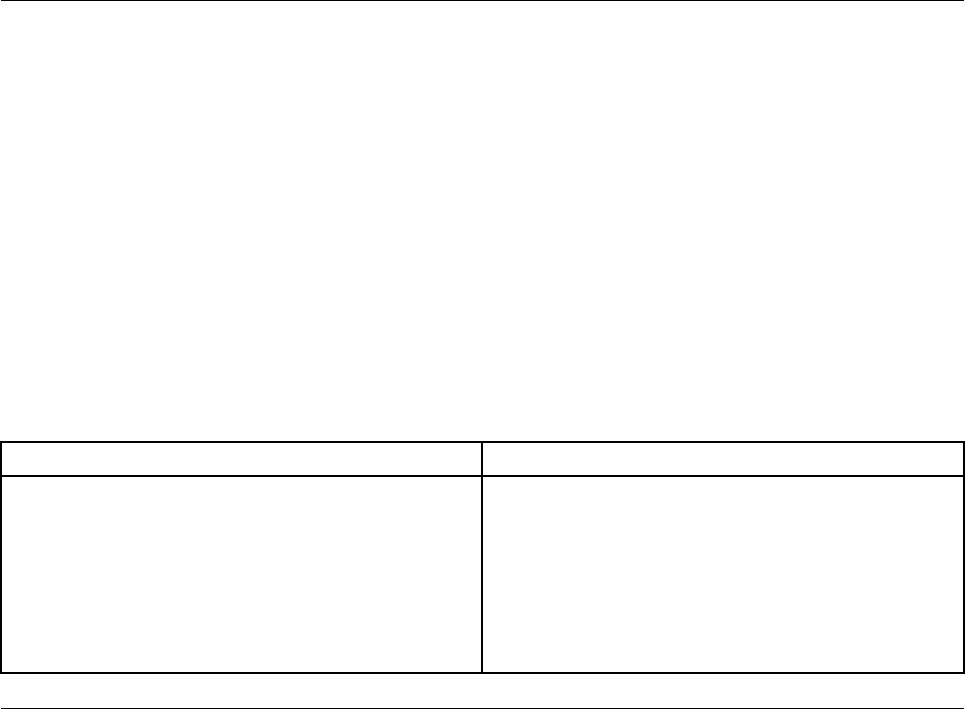
– If the Lenovo PC Diagnostics application is installed in your smartphone, use the application to transfer
the error code from the computer to the smartphone for further analysis. The application is available for
download at both Google Play and iTunes App Store.
The hardware diagnostics function is enabled on your computer by default. If you want to disable the
function, do the following:
1. Start the Setup Utility program. See “Starting the Setup Utility program” on page 67.
2. From the main interface, select Advanced ➙ Diagnostics, and then press Enter.
3. Select Real-time Diagnostics Monitoring and press Enter. Then select Disabled and press Enter.
4. To save settings and exit the Setup Utility program, press F10 or Fn+F10 (depending on the keyboard
settings). Then, select Yes in the window displayed, and press Enter.
UEFI diagnostic program
A UEFI diagnostic program is preinstalled on the computer. It enables you to test memory modules and
internal storage devices, view system information, and check and recover bad sectors on internal storage
devices.
To run the UEFI diagnostic program, do the following:
1. Turn on the computer. If the computer cannot be turned on, go to “Basic procedure for resolving
computer problems” on page 81. If an error code is displayed, go to “Symptom-to-FRU index” on page
96 for error code descriptions and troubleshooting hints.
2. Repeatedly press and release the F10 key when turning on the computer. The main screen of the UEFI
diagnostic program is displayed.
3. Follow the instructions on the screen to use the diagnostic program.
The options on the main screen are as follows:
Table 1. Items on the main screen of the UEFI diagnostic program
DIAGNOSTICS TOOLS
• LCD test
• Memory - Quick test
• Memory - Extended test
• Motherboard test
• PCI-e test
• Storage - Quick test
• System information
• Recover bad sectors tool
• Generate configuration file
• Execute from configuration file
• Exit application
Recovery information
This section provides instructions on how to recover your operating system.
Note: If a device does not work correctly after recovering the operating system, update the device driver.
See “Keeping your computer current” on page 58.
Recovery information for Windows 7
To recover your Windows 7 operating system, use the following solutions:
• Use Windows recovery solutions.
Chapter 7.Troubleshooting, diagnostics, and recovery 91
– Use System Restore to restore system files and settings to an earlier point.
1. Click the Start button to open the Start menu.
2. Click Control Panel. View Control Panel by Large icons or Small icons, and then click Recovery ➙
Open System Restore.
3. Follow the instructions on the screen.
– Use the Windows recovery environment by doing one of the following:
– After several consecutive failed boot attempts, the Windows recovery environment might start
automatically. Follow the instructions on the screen to choose the appropriate recovery solution.
– Turn on or restart your computer. Then, repeatedly press and release F8 or Fn+F8 (depending on the
keyboard settings) until the Advanced Boot Options window opens. Select Repair Your Computer,
press Enter, and follow the instructions on the screen to choose the appropriate recovery solution.
• Use the recovery medium you created earlier with the Recovery Media Creator program to restore only the
C drive or the entire storage drive to the factory-default settings.
1. Select the recovery medium as the startup device. See “Selecting a temporary startup device” on
page 72.
2. Follow the instructions on the screen to choose the appropriate recovery solution.
• Use the recovery disc set provided by Lenovo to restore the entire storage drive to the factory-default
settings.
– If your computer comes with the recovery disc set, follow the instructions shipped with the disc set.
– If your computer does not come with the recovery disc set, contact the Lenovo Customer Support
Center to order a recovery disc set. See “Calling for service” on page 214.
Recovery information for Windows 10
To recover your Windows 10 operating system, use the following solutions:
• Use Windows recovery solutions.
– Use recovery solutions in Windows Settings.
1. Click the Start button to open the Start menu.
2. Click Settings ➙ Update & Security ➙ Recovery.
3. Follow the instructions on the screen to choose the appropriate recovery solution.
– Use System Restore to restore system files and settings to an earlier point.
1. Click the Start button to open the Start menu.
2. Click Windows System ➙ Control Panel.
3. View Control Panel by Large icons or Small icons, and then click Recovery ➙ Open System
Restore.
4. Follow the instructions on the screen.
– Use the File History tool to restore your files from a backup.
Note: If you use the File History tool to restore your files from a backup, ensure that you backed up
your data earlier with the tool.
1. Click the Start button to open the Start menu.
2. Click Windows System ➙ Control Panel.
3. View Control Panel by Large icons or Small icons, and then click File History ➙ Restore personal
files.
4. Follow the instructions on the screen.
92 P920 Hardware Maintenance Manual
– Use the Windows recovery environment by doing one of the following:
– After several consecutive failed boot attempts, the Windows recovery environment might start
automatically. Follow the instructions on the screen to choose the appropriate recovery solution.
– Select the recovery medium you created earlier with the Windows tool as the startup device. See
“Selecting a temporary startup device” on page 72. Then, follow the instructions on the screen to
choose the appropriate recovery solution.
• Use the recovery USB key provided by Lenovo to restore the entire storage drive to the factory-default
settings.
– If your computer comes with the recovery USB key, follow the instructions shipped with the USB key.
– If your computer does not come with the recovery USB key, contact the Lenovo Customer Support
Center to order a recovery USB key. See “Calling for service” on page 214.
Chapter 7.Troubleshooting, diagnostics, and recovery 93
94 P920 Hardware Maintenance Manual

Chapter 8. Service checkout and symptom-to-FRU index
This chapter provides information about general service checkout and symptom-to-FRU index.
Service checkout
Attention: The drives in the computer you are servicing might have been rearranged or the drive startup
sequence changed. Be extremely careful during write operations such as copying, saving, or formatting.
Data or programs can be overwritten if you select an incorrect drive.
General error messages appear if a problem or conflict is found by a program, the operating system, or both.
For an explanation of these messages, refer to the information supplied with that software package.
Before replacing any FRUs, ensure that the latest level of BIOS is installed on the system. A down-level BIOS
might cause false errors and unnecessary replacement of the system board. For more information about how
to determine and obtain the latest level BIOS, see “BIOS level” on page 72.
Use the following procedure to help determine the cause of the problem:
1. Turn off the computer and all external devices.
2. Check all cables and power cords.
3. Set all display controls to the middle position.
4. Turn on all external devices.
5. Turn on the computer.
• Look for displayed error codes.
• Listen for beep codes.
• Look for readable instructions or a main menu on the display.
If you did not receive the correct response, proceed to step 6 on page 95.
If you do receive the correct response, proceed to step 7 on page 95.
6. Look at the following conditions and follow the instructions:
• If you hear beep codes during POST, go to “Beep symptoms” on page 97.
• If the computer displays a POST error, go to “POST error codes” on page 98.
• If the computer hangs and no error is displayed, continue at step 7 on page 95.
7. Run the Diagnostic programs. See “Diagnosing problems” on page 89.
• If you receive an error, replace the part that the diagnostic program calls out.
• If the test stops and you cannot continue, replace the last device tested.
Problem determination tips
Due to the variety of hardware and software combinations that can be encountered, use the following
information to assist you in problem determination. If possible, have this information available when
requesting assistance from Service Support and Engineering functions.
• Machine type and model
• Processor or hard disk drive upgrades
• Failure symptom
– Do diagnostics indicate a failure?
© Copyright Lenovo 2017 95

– What, when, where, single, or multiple systems?
– Is the failure repeatable?
– Has this configuration ever worked?
– If it has been working, what changes were made prior to its failing?
– Is this the original reported failure?
• Diagnostics version
– Type and version level
• Hardware configuration
– Print (print screen) configuration currently in use
– BIOS level
• Operating system software
– Type and version level
Notes: To eliminate confusion, identical systems are considered identical only if they:
1. Are the exact machine type and models
2. Have the same BIOS level
3. Have the same adapters/attachments in the same locations
4. Have the same address jumpers/terminators/cabling
5. Have the same software versions and levels
6. Have the same Diagnostic Diskettes (version)
7. Have the same configuration options set in the system
8. Have the same setup for the operating system control files
Comparing the configuration and software set-up between “working and non-working” systems will often
lead to problem resolution.
Symptom-to-FRU index
The Symptom-to-FRU index lists error symptoms and possible causes. The most likely cause is listed first.
Always begin with “Service checkout” on page 95. This index can also be used to help you decide which
FRUs to have available when servicing a computer. If you are unable to correct the problem using this index,
go to “Undetermined problems” on page 101.
Notes:
• The Symptom-to-FRU index is not specific to any machine type and are applicable to all ThinkStation computers.
• If you have both an error message and an incorrect audio response, diagnose the error message first.
• If you cannot run the diagnostic tests or you get a diagnostic error code when running a test, but did receive a
POST error message, diagnose the POST error message first.
• If you did not receive any error message, look for a description of your error symptoms in the first part of this index.
Hard disk drive boot error
A hard disk drive boot error can have the following causes.
96 P920 Hardware Maintenance Manual

Error FRU/Action
The start-up drive is not in the boot sequence in
configuration.
Check the configuration and ensure that the start-up drive
is in the boot sequence.
No operating system installed on the boot drive. Install an operating system on the boot drive.
The boot sector on the startup drive is corrupted. The drive must be formatted. Do the following:
1. Attempt to back up the data on the failing hard disk
drive.
2. Using the operating system programs, format the
hard disk drive.
The drive is defective. Replace the hard disk drive.
Power supply problems
If you suspect a power problem, use the following procedures.
Check/Verify FRU/Action
Check the following for proper installation.
• Power cord
• On/Off switch connector
• On/Off switch power supply connector
• System board power supply connectors
• Microprocessor connection
Reseat connectors
Check the power cord for continuity. Power cord
Check the power-on switch for continuity. Power-on switch
Beep symptoms
Beep symptoms are tones or a series of tones separated by pauses (intervals without sound) during POST.
The following table describes the beep symptoms.
Beep symptom FRU/Action
2 short beeps: common POST error Common POST error code. See the detailed failure
information in “POST error codes” on page 98.
3 short and 1 long beeps: DRAM memory error Perform the following actions in order:
1. Make sure that the memory modules are properly
seated in the memory slots.
2. Replace the memory modules.
3. Replace the system board (for trained service
personnel only).
Chapter 8.Service checkout and symptom-to-FRU index 97

Beep symptom FRU/Action
4 long beeps: insufficient shadow RAM resources for
option ROM (error code: 8998) or PCIe/PCI MMIO
(memory mapped input/output) resources (error code:
8999)
See the detailed failure information in “POST error codes”
on page 98.
2 long and 3 short beeps: graphics card error Perform the following actions in order:
1. Make sure that the graphics cards are properly
seated in the slots.
2. Replace the graphics cards.
3. Replace the system board (for trained service
personnel only).
POST error codes
Each time you turn on the system, it performs a series of tests that check the operation of the system and
some options. This series of tests are called the Power-On Self-Test, or POST. POST checks the following
operations:
• Some basic system-board operations
• Memory operation
• Video operation
• Whether the boot drive is working
If the POST detects a problem, an error message appears on the screen. A single problem might cause
several error messages to appear. When you correct the cause of the first error message, the other error
messages probably will not appear on the screen the next time.
Error code POST error message Description/Action
0135 CPU fan failure
System fan failure
Power fan failure
Front fan failure
Rear fan failure
Auxiliary fan failure
ODD fan failure
This error message is displayed
when a fan fails and the system
might be overheating.
Press F10 to exit.
0211 Keyboard not found This error message is displayed when
no keyboard is detected.
0164 Memory size decreased This error message is displayed
when the memory size is
decreased.
Press F10 to exit.
1762 SATA device configuration change
has occurred This error message is displayed
when a hard disk drive change or
an optical drive change has been
made.
Press F10 to exit.
98 P920 Hardware Maintenance Manual

Error code POST error message Description/Action
1820 More than one external fingerprint
reader is attached. Turn off and
remove all but the reader that you set
up within your main operating
system.
This error message is displayed
when more than one external
fingerprint reader is connected to
the computer.
Turn off and remove all but the
reader that you set up within your
main operating system.
1962 No operating system found. Boot
sequence will automatically repeat. This error occurs only after the
POST is completed.
Press any key to repeat boot
sequence.
8998 Not enough shadow RAM resources
for OPTION ROM, not all devices
initialized. Suggest to remove some
add-on cards, or change to UEFI
mode in BIOS setup.
This error message is displayed
when the shadow RAM resources
for option ROM are insufficient.
If the legacy option ROM is
insufficient, remove some add-in
cards.
For the system that supports
UEFI, set UEFI as the first priority
or disable CSM in BIOS setup.
8999 Not enough PCIe/PCI MMIO
resources. Currently only one video
card is enabled. Remove some PCIe
cards, or enter BIOS Setup and
enable “Above 4GB Decode”
This error message is displayed
when the PCIe/PCI MMIO
(memory mapped input/output)
resources are insufficient.
For the 32-bit operating system,
remove some add-in cards.
For the 64-bit operating system,
enable Above 4 GB Decode in
BIOS setup.
Miscellaneous error conditions
Message/Symptom FRU/Action
Changing display colors Display/Monitor
Computer will not power-off. See “Hard disk drive boot
error” on page 96. 1. Power Switch
2. System Board
3. Riser card, if installed.
Computer will not RPL from server 1. Ensure that the network is in startup sequence as the
first device or the first device after diskette.
2. Ensure that the network adapter is enabled for RPL.
3. Network adapter (Advise network administrator of
new MAC address)
Chapter 8.Service checkout and symptom-to-FRU index 99

Message/Symptom FRU/Action
Computer will not perform a Wake On LAN® (if applicable) 1. Check the power supply and signal cable
connections to the network adapter.
2. Ensure that the operating system settings are set to
enable Wake on LAN.
3. Ensure that the Wake On LAN feature is enabled in
Setup/Configuration (see “Starting the Setup Utility
program” on page 67)
4. Ensure that the network administrator is using the
correct MAC address.
5. Ensure no interrupt or I/O address conflicts.
6. Network adapter (advise network administrator of
new MAC address)
Dead computer. See “Hard disk drive boot error” on page
96. 1. Power Supply
2. System Board
Diskette drive in-use light remains on or does not light
when drive is active. 1. Diskette Drive
2. System Board
3. Diskette Drive Cable
Blank screen except for flashing cursor. 1. System Board
2. Primary Hard Disk Drive
3. Hard Disk Drive Cable
Incorrect memory size during POST 1. Run the Memory tests.
2. Memory Module
3. System Board
"Insert a Diskette" icon appears with a known-good
diagnostics diskette in the first 3.5-inch diskette drive. 1. System Board
2. Diskette Drive Cable
3. Network Adapter
Intensity or color varies from left to right of characters and
color bars 1. Display
2. Video adapter (if present)
3. System Board
No power or fan not running 1. See “Hard disk drive boot error” on page 96.
Non-system disk or disk error-type message with a
known-good diagnostic diskette. 1. Diskette Drive
2. System Board
3. Diskette Drive Cable
Other display symptoms not listed above (including blank
or illegible display) 1. Display
2. System Board
Power-on indicator or hard disk drive in-use light not on,
but computer works correctly 1. Power switch/LED assembly
2. System Board
Printer problems 1. Printer
2. System Board
100 P920 Hardware Maintenance Manual

Message/Symptom FRU/Action
Program loads from the hard disk with a known-good
diagnostics diskette in the first 3.5-inch diskette drive 1. Run the Setup Utility program and check the Startup
sequence.
2. Diskette Drive
3. Diskette Drive Cable
4. System Board
5. Power Supply
RPL computer cannot access programs from its own hard
disk. 1. If the network administrator is using LCCM Hybrid
RPL, check the startup sequence:
a. First device - network
b. Second device - hard disk
2. Hard disk drive
RPL computer does not RPL from server 1. Check the startup sequence.
2. Check the network adapter LED status.
Serial or parallel connector device failure (system board
connector) 1. External Device Self-Test OK?
2. External Device
3. Cable
4. System Board
Serial or parallel connector device failure (adapter
connector) 1. External Device Self-Test OK?
2. External Device
3. Cable
4. Alternate Adapter
5. System Board
Some or all keys on the keyboard do not work 1. Keyboard
2. Keyboard Cable
3. System Board
Undetermined problems
This section provides instructions on how to find out the failing devices or adapters.
1. Turn off the computer.
2. Remove or disconnect the following components (if installed) one at a time.
a. External devices (modem, printer, or mouse)
b. Any adapters
c. Memory modules
d. Extended video memory
e. External Cache
f. External Cache RAM
g. Hard disk drive
h. Diskette drive
3. Turn on the computer to retest the system.
Chapter 8.Service checkout and symptom-to-FRU index 101

Chapter 9. Hardware removal and installation
This chapter provides instructions on how to remove and install hardware for your computer.
Handling static-sensitive devices
Do not open the static-protective package containing the new part until the defective part has been removed
and you are ready to install the new part. Static electricity, although harmless to you, can seriously damage
computer components and options.
When you handle options and other computer components, take these precautions to avoid static-electricity
damage:
• Limit your movement. Movement can cause static electricity to build up around you.
• Always handle options and other computer components carefully. Handle PCI/PCIe cards, memory
modules, system boards, and microprocessors by the edges. Never touch any exposed circuitry.
• Prevent others from touching the options and other computer components.
• Touch the static-protective package containing the part to a metal expansion-slot cover or other
unpainted metal surface on the computer for at least two seconds. This reduces static electricity from the
package and your body before you install or replace a new part.
• When possible, remove the new part from the static-protective package, and install it directly in the
computer without setting the part down. When this is not possible, place the static-protective package on
a smooth, level surface and place the part on the package.
• Do not place the part on the computer cover or other metal surface.
Preparing your computer and removing the computer cover
Attention: Do not open your computer or attempt any repair before reading and understanding the Chapter
1 “Read this first: Important safety information” on page 1.
CAUTION:
Avoid contact with hot components inside the computer. During operation, some components
become hot enough to burn the skin. Before you open the computer cover, turn off the computer,
disconnect power, and wait approximately 10 minutes for the components to cool.
Before removing or installing any hardware component in your computer, do the following to prepare your
computer and remove the computer cover:
1. Remove any media from the drives and turn off all connected devices and the computer. Then,
disconnect all power cords from electrical outlets and disconnect all cables that are connected to the
computer.
2. Unlock any locking device that secures the computer cover. See “Locking your computer” on page 61.
© Copyright Lenovo 2017 103
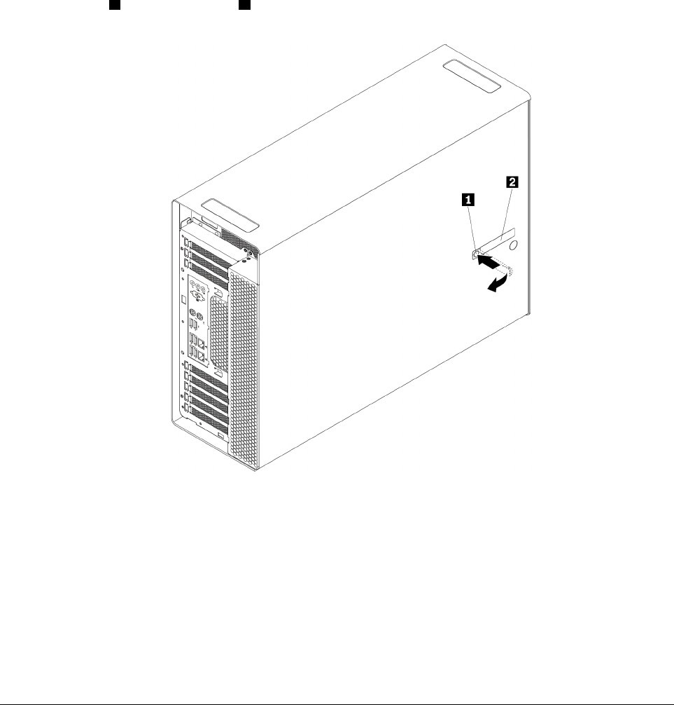
3. Press the pit 1 so that the handle 2 is lifted. Then, pivot the handle as shown and pull the handle to
remove the cover from the chassis.
Figure 11. Removing the computer cover
Notes:
• Depending on your computer model, some of the hardware parts in the removal or installation section
might not be available.
• Use computer parts provided only by Lenovo.
• When removing or installing an option, use the appropriate instructions in this section along with the
instructions that come with the option.
• In most areas of the world, Lenovo requires the return of the defective CRU. Information about this will
come with the CRU or will come a few days after the CRU arrives.
Removing and installing hardware
This section provides instructions on how to remove and install hardware for your computer. You can expand
the capabilities of your computer and maintain your computer by removing or installing hardware.
Attention: Do not open your computer or attempt any repair before reading and understanding the Chapter
1 “Read this first: Important safety information” on page 1.
External options
You can connect external options to your computer, such as external speakers, a printer, or a scanner. For
some external options, you must install additional software in addition to making the physical connection.
When installing an external option, see “Front view” on page 29 and “Rear view” on page 30 to identify the
104 P920 Hardware Maintenance Manual
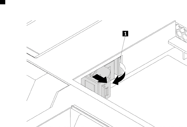
required connector. Then, use the instructions that come with the option to help you make the connection
and install any required software or device drivers.
Cover presence switch (intrusion switch)
Attention: Do not open your computer or attempt any repair before reading and understanding the Chapter
1 “Read this first: Important safety information” on page 1.
To remove or install the cover presence switch (also known as intrusion switch), do the following:
1. Prepare your computer. See “Preparing your computer and removing the computer cover” on page 103.
2. Lay the computer on its side for easier access to the cover presence switch bracket.
3. Locate the cover presence switch bracket. See “Computer components” on page 33.
4. Note the routing of the cover presence switch cable, and then disconnect the cover presence switch
cable from the system board.
5. Pivot the tab 1 on the cover presence switch bracket as shown. Then, remove the bracket together with
the cover presence switch from the chassis.
Figure 12. Removing the cover presence switch bracket
Chapter 9.Hardware removal and installation 105
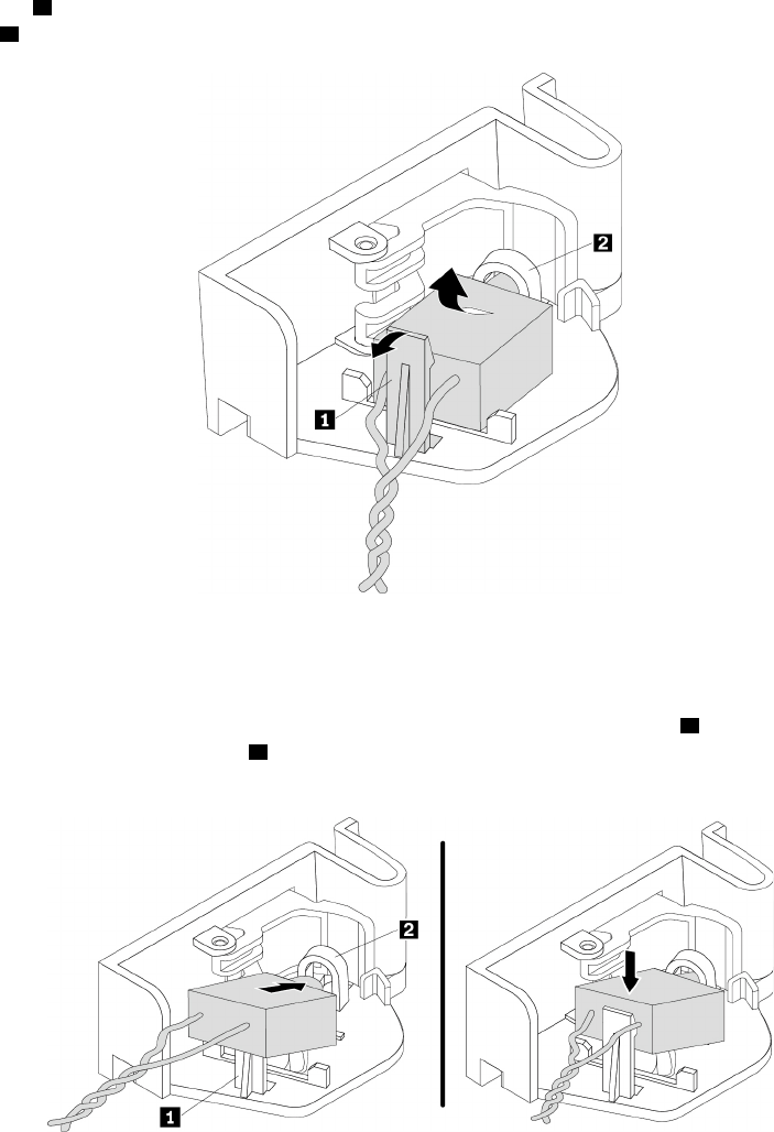
6. To remove the cover presence switch, do the following:
Pivot the clip 1 on the bracket outward, and then disengage the failing cover presence switch from the
circle clip 2 to remove it from the bracket.
Figure 13. Removing the cover presence switch from the bracket
7. To install the cover presence switch, do the following:
Insert the end of the new cover presence switch with the post into the circle clip 2 of the cover presence
switch bracket. Ensure that the clip 1 is placed between the two branched cables of the new cover
presence switch. Then, press the cover presence switch downward until it snaps into position.
Figure 14. Installing the cover presence switch into the bracket
106 P920 Hardware Maintenance Manual
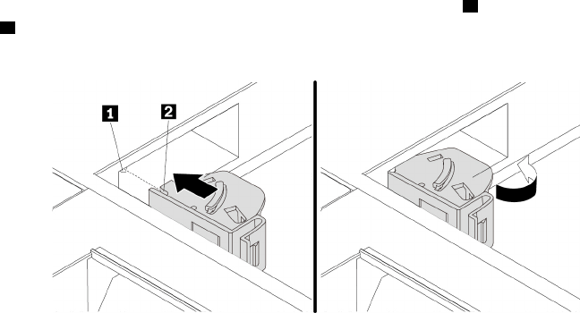
8. Route the cable of the new cover presence switch, and align the notch 2 on the cover presence switch
with the tab 1 in the chassis. Then pivot the cover presence switch bracket as shown until it snaps into
position.
Figure 15. Installing the cover presence switch bracket
9. Connect the cable of the new cover presence switch to the system board. See “Parts on the system
board” on page 38.
What to do next:
• To work with another piece of hardware, go to the appropriate section.
• To complete the installation or replacement, go to “Completing the parts replacement” on page 210.
Direct cooling air baffle
Attention: Do not open your computer or attempt any repair before reading and understanding the Chapter
1 “Read this first: Important safety information” on page 1.
To remove or install the direct cooling air baffle, do the following:
1. Prepare your computer. See “Preparing your computer and removing the computer cover” on page 103.
Chapter 9.Hardware removal and installation 107
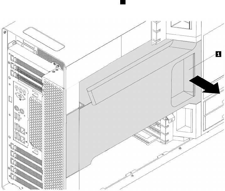
2. To remove the direct cooling air baffle, hold the handle 1 to pull the direct cooling air baffle out of the
chassis.
Figure 16. Removing the direct cooling air baffle
3. To install the direct cooling air baffle, do the following:
108 P920 Hardware Maintenance Manual
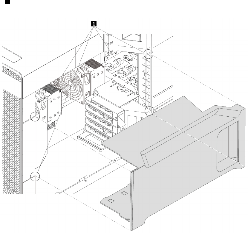
a. Align the plastic boards on the top and bottom sides of the direct cooling air baffle with the small
gaps 1 in the chassis. Ensure that the handle of the direct cooling air baffle faces toward the front of
the chassis.
Figure 17. Aligning the plastic boards with the small gaps
b. Slide the direct cooling air baffle into the chassis until it is secured firmly.
Note: If necessary, adjust the position of the direct cooling air baffle slightly to avoid any interference
with other components in the chassis.
What to do next:
• To work with another piece of hardware, go to the appropriate section.
• To complete the installation or replacement, go to “Completing the parts replacement” on page 210.
Device in a flex bay
Attention: Do not open your computer or attempt any repair before reading and understanding the Chapter
1 “Read this first: Important safety information” on page 1.
Depending on your computer model, the following devices might be installed in the flex bays:
• Flex module
Chapter 9.Hardware removal and installation 109
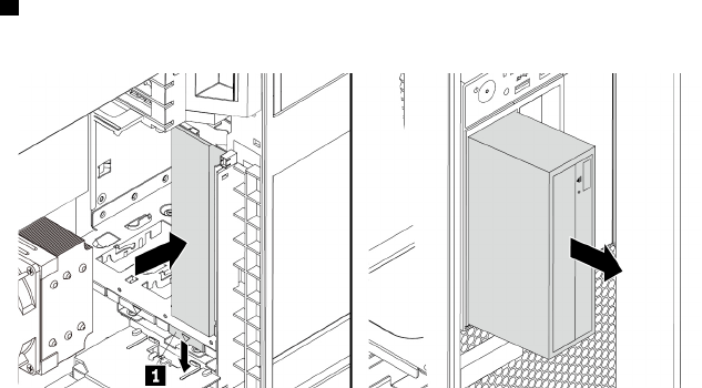
• Front-access storage enclosure
• Multi-drive conversion kit
• Optical drive
• Slim-optical-drive adapter
Note: The following instructions on how to remove or install an optical drive also apply to other supported
devices in the flex bay.
To remove or install an optical drive, do the following:
1. Prepare your computer. See “Preparing your computer and removing the computer cover” on page 103.
2. Remove the direct cooling air baffle. See “Direct cooling air baffle” on page 107.
3. Locate the flex bay. See “Internal storage drives” on page 40.
4. To remove an optical drive, do the following:
a. Disconnect the cables from the optical drive.
Note: If you are removing other supported devices from the flex bay, disconnect any additional
cables.
b. Press the tab 1 downward and push the optical drive to the front of the chassis. Then, remove the
optical drive from the front of the chassis.
Figure 18. Removing the optical drive
5. To install an optical drive, do the following:
110 P920 Hardware Maintenance Manual
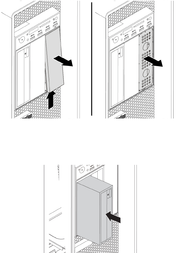
a. If necessary, press the clip underneath the plastic shield until the plastic shield is ejected out of the
bay. Remove the plastic shield from the bay. Then, grasp the metal shield inside the bay and pull it
out of the chassis.
Figure 19. Removing the shields from the flex bay
b. Note the orientation of the new optical drive. Then, slide the optical drive into the flex bay from the
front of the chassis until it snaps into position.
Figure 20. Installing the optical drive
c. Connect the cables to the new optical drive.
Note: If you are installing other supported devices, connect any additional cables. See “Parts on the
system board” on page 38.
6. Reinstall the direct cooling air baffle. See “Direct cooling air baffle” on page 107.
What to do next:
• To work with another piece of hardware, go to the appropriate section.
• To complete the installation or replacement, go to “Completing the parts replacement” on page 210.
Chapter 9.Hardware removal and installation 111
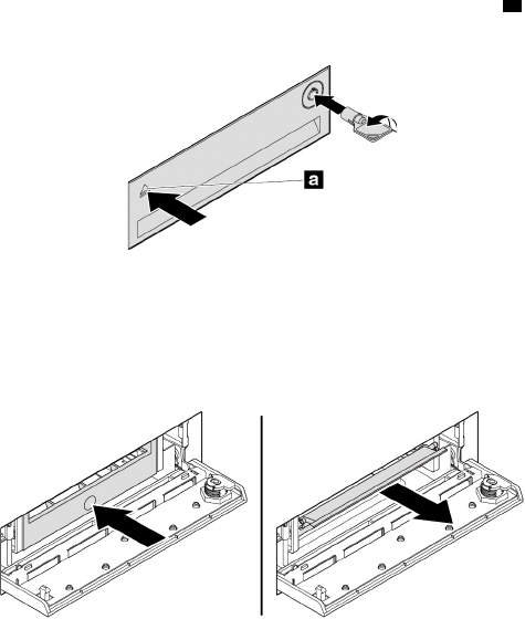
Storage drive in the front-access storage enclosure
Attention: Do not open your computer or attempt any repair before reading and understanding the Chapter
1 “Read this first: Important safety information” on page 1.
The storage drive in the front-access storage drive can be hot-swappable. When both the following
requirements are met, you can remove or install the drive without even turning off your computer.
• The SATA cable of the front-access storage enclosure is connected to the eSATA connector on the
system board. To verify the cable connection, see “Preparing your computer and removing the computer
cover” on page 103 and “Parts on the system board” on page 38 for more information.
• The operating system of your computer does not reside on the storage drive installed in the front-access
storage enclosure.
Attention: If any of the above requirements are not met, do not remove or install the storage drive when the
computer is turned on. Otherwise, data on the storage drive might get damaged.
3.5-inch storage drive
To remove or install a 3.5-inch storage drive, do the following:
1. Before removing an old 3.5-inch storage drive, safely eject the old storage drive from the operating
system first. For more information, see the Windows help system.
2. Unlock the enclosure cover with the provided key as shown. Press the notch a to open the enclosure
cover.
Figure 21. Opening the front-access storage enclosure cover
3. Press the pit on the bracket cover, and then grasp the tilted cover to pull the bracket out of the front-
access storage enclosure.
Figure 22. Removing the bracket from the front-access storage enclosure
112 P920 Hardware Maintenance Manual
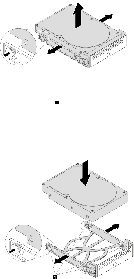
4. To remove the 3.5-inch storage drive, flex both sides of the bracket to remove the 3.5-inch storage drive
from the bracket.
Figure 23. Removing the 3.5-inch storage drive from the bracket
5. To install a new 3.5-inch storage drive into the front-access storage enclosure, do the following:
a. Flex both sides of the bracket and align pins 1 on the bracket with the corresponding holes in the
new 3.5-inch storage drive.
Notes:
• Ensure that the circuit board faces downward and the connectors face toward the rear of the
bracket.
• Do not touch the circuit board on the storage drive.
Figure 24. Installing the 3.5-inch storage drive into the bracket
Chapter 9.Hardware removal and installation 113
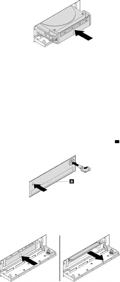
b. Slide the bracket with the new 3.5-inch storage drive into the front-access storage enclosure until it
snaps into position.
Figure 25. Installing the 3.5-inch storage drive into the front-access storage enclosure
c. Press the notch to secure the enclosure cover and lock the enclosure cover with the key.
What to do next:
• To work with another piece of hardware, go to the appropriate section.
• To complete the installation or replacement, go to “Completing the parts replacement” on page 210.
2.5-inch storage drive
To remove or install a 2.5-inch storage drive, do the following:
1. Before removing an old 2.5-inch storage drive, safely eject the old storage drive from the operating
system first. For more information, see the Windows help system.
2. Unlock the enclosure cover with the provided key as shown. Press the notch a to open the enclosure
cover.
Figure 26. Opening the front-access storage enclosure cover
3. Press the pit on the bracket cover, and then grasp the tilted cover to pull the bracket out of the front-
access storage enclosure.
Figure 27. Removing the bracket from the front-access storage enclosure
4. To remove the 2.5-inch storage drive, do the following:
114 P920 Hardware Maintenance Manual
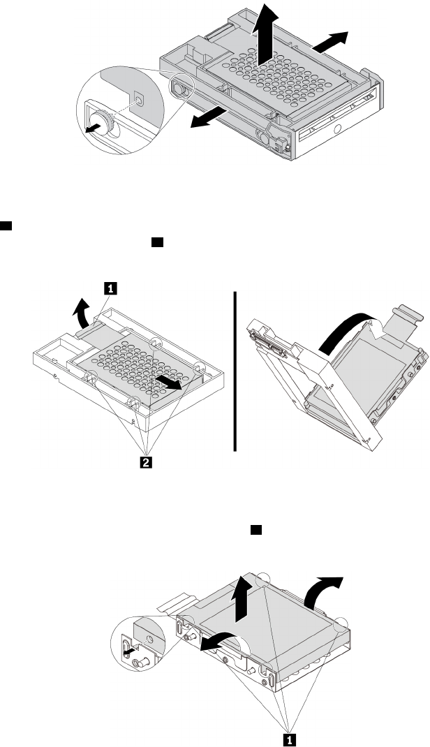
a. Flex both sides of the bracket to remove the 2.5-inch storage drive from the bracket.
Figure 28. Removing the 2.5-inch storage drive from the bracket
b. Pivot the tab 1 of the metal adapter upward. Then, push the adapter as shown until the four tabs on
the adapter are slide into the notches 2. Pivot the adapter as shown to remove it with the storage
drive from the converter.
Figure 29. Removing the adapter from the converter
c. Flex both sides of the adapter to release the four pins 1 from the storage drive. Then, remove the
storage drive from the adapter.
Figure 30. Removing the storage drive from the adapter
5. To install a new 2.5-inch storage drive, do the following:
Chapter 9.Hardware removal and installation 115
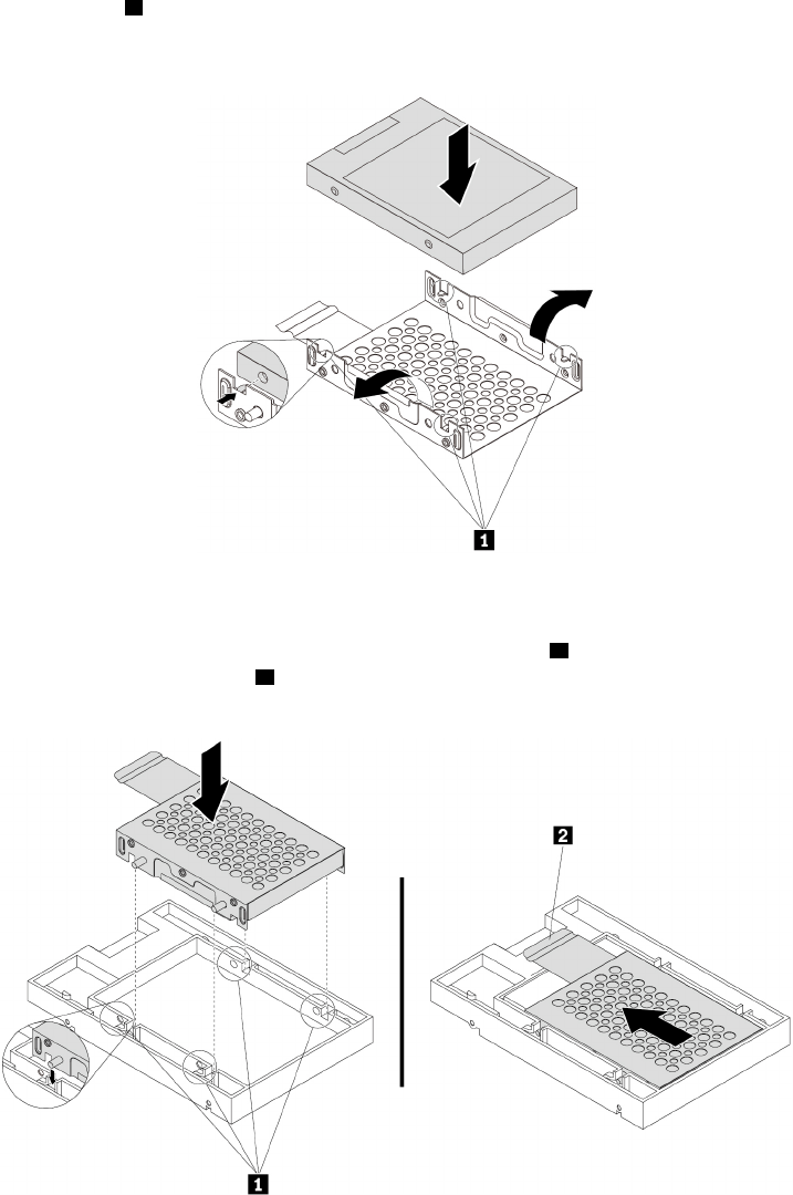
a. Note the orientation of the connector on the new storage drive. Then, flex both sides of the adapter
and align the four pins 1 with the corresponding holes in the storage drive.
Note: Do not touch the circuit board (if accessible) of the 2.5-inch storage drive.
Figure 31. Installing the storage drive into the adapter
b. Align the four tabs on the adapter with the corresponding notches 1 in the converter. Then, slide the
storage drive as shown until the tab 2 snaps into position. The adapter with the storage drive is
installed into the converter.
Figure 32. Installing the adapter into the converter
116 P920 Hardware Maintenance Manual
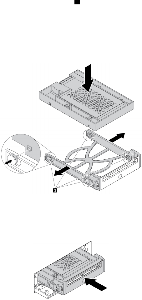
c. Flex both sides of the plastic bracket and align pins 1 on the plastic bracket with the corresponding
holes in the plastic frame of the converter.
Notes:
• Ensure that the circuit board faces downward and the connectors face toward the rear of the
bracket.
• Do not touch the circuit board on the storage drive.
Figure 33. Installing the converter with the 2.5-inch storage drive into the plastic bracket
d. Slide the plastic bracket with the new 2.5-inch storage drive into the front-access storage enclosure
until it snaps into position.
Figure 34. Installing the plastic bracket with the 2.5-inch storage drive into the front-access storage enclosure
e. Press the notch to secure the enclosure cover and lock the enclosure cover with the key.
What to do next:
• To work with another piece of hardware, go to the appropriate section.
• To complete the installation or replacement, go to “Completing the parts replacement” on page 210.
Device in the multi-drive conversion kit
Attention: Do not open your computer or attempt any repair before reading and understanding the Chapter
1 “Read this first: Important safety information” on page 1.
Chapter 9.Hardware removal and installation 117
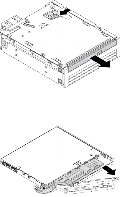
The multi-drive conversion kit (hereafter referred to as kit) might be equipped with either one or both of the
following components:
• Slim optical drive
• Storage drive (such as hard disk drive, solid-state drive, or hybrid drive)
Slim optical drive
Note: The instructions on how to remove or install a slim optical drive in the kit also apply to the slim-optical-
drive adapter.
To remove or install a slim optical drive, do the following:
1. Prepare your computer. See “Preparing your computer and removing the computer cover” on page 103.
2. Ensure that all the cables are disconnected from the kit. Remove the kit from the front of the computer.
See “Device in a flex bay” on page 109.
3. To remove the slim optical drive from the kit, do the following:
a. Press the clip through the hole in the top of the kit as shown and push forward the slim optical drive.
Then, remove the slim optical drive out of the kit.
Figure 35. Removing the slim optical drive from the kit
b. Detach the bracket as shown to remove it from the slim optical drive.
Figure 36. Removing the bracket from the slim optical drive
4. To install a new slim optical drive into the kit, do the following:
118 P920 Hardware Maintenance Manual
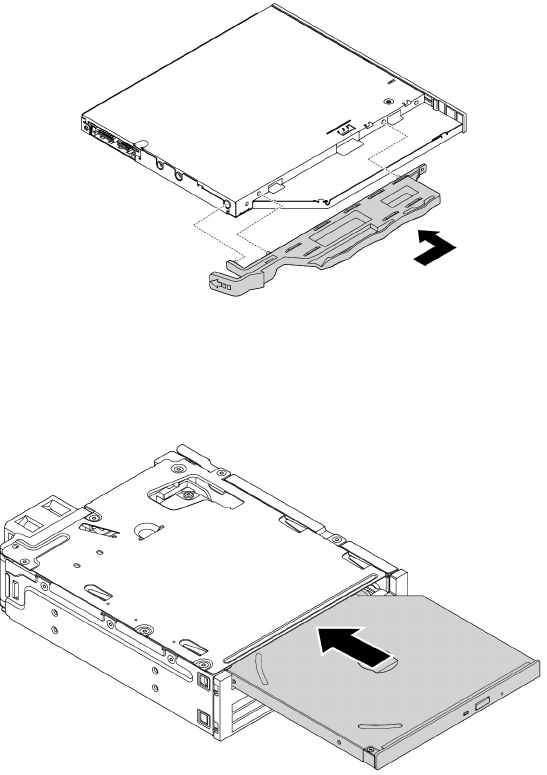
a. Align the three tabs on the bracket with the corresponding holes in the new slim optical drive. Then,
install the bracket to the new slim optical drive.
Figure 37. Installing the bracket to the new slim optical drive
b. Insert the new slim optical drive into the kit until you hear a click. The slim optical drive is secured in
place.
Figure 38. Installing the slim optical drive into the kit
5. Slide the kit into the flex bay and reconnect the cables.
What to do next:
• To work with another piece of hardware, go to the appropriate section.
• To complete the installation or replacement, go to “Completing the parts replacement” on page 210.
3.5-inch storage drive
To remove or install a 3.5-inch storage drive, do the following:
1. Prepare your computer. See “Preparing your computer and removing the computer cover” on page 103.
2. Ensure that all the cables are disconnected from the kit. Remove the kit from the front of the computer.
See “Device in a flex bay” on page 109.
Chapter 9.Hardware removal and installation 119
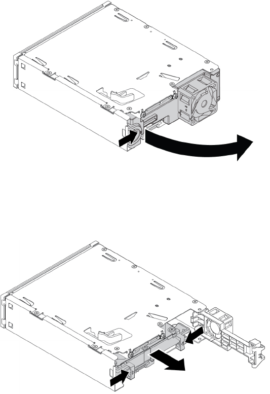
3. Press the clip as shown to open the rear cover of the kit.
Figure 39. Opening the rear cover of the kit
4. Press both clips simultaneously toward each other and pull the conversion bracket out of the rear of the
kit.
Figure 40. Removing the conversion bracket from the kit
120 P920 Hardware Maintenance Manual
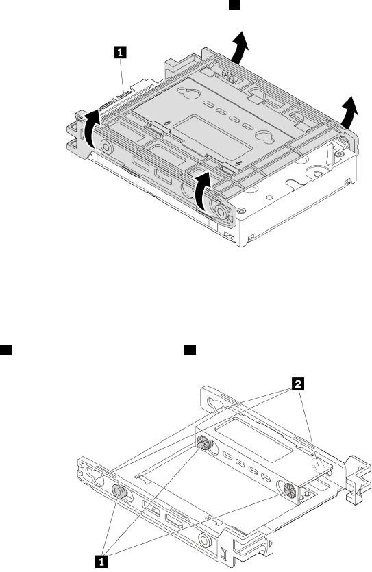
5. To remove the 3.5-inch storage drive, flex both sides of the conversion bracket and then remove the
drive out of the bracket. Do not touch the circuit board 1 on the drive.
Figure 41. Removing the storage drive from the bracket
6. To install a 3.5-inch storage drive, ensure that the conversion bracket is unfolded. To unfold the bracket,
do the following:
a. Remove pins 1 and reinstall them into slots 2.
Figure 42. Removing pins and reinstalling them into slots
Chapter 9.Hardware removal and installation 121
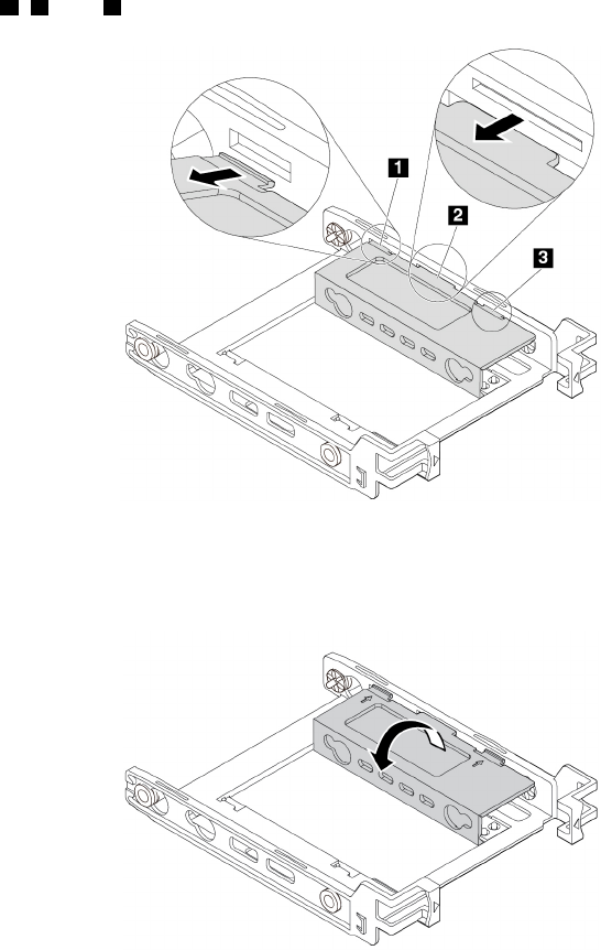
b. Release tabs 1, 2, and 3 from the corresponding slots.
Figure 43. Releasing tabs from the corresponding slots
c. Unfold the bracket as shown.
Figure 44. Unfolding the bracket
122 P920 Hardware Maintenance Manual
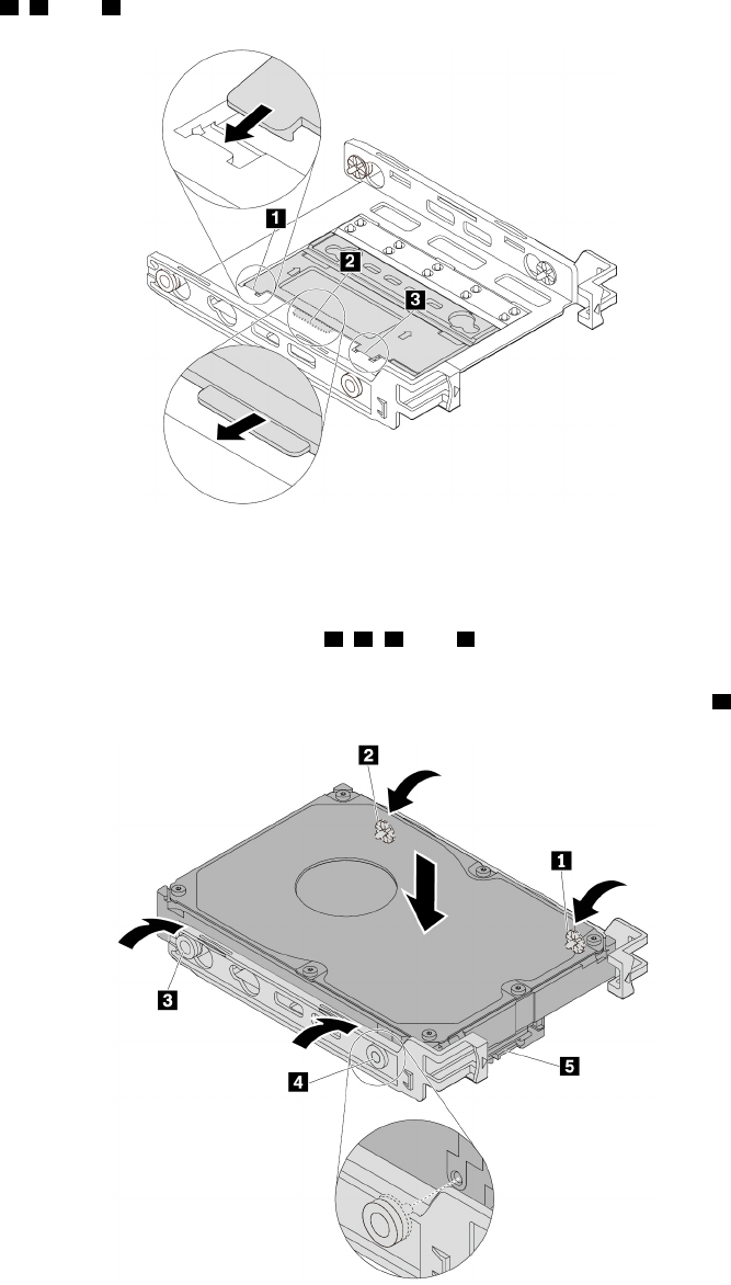
d. Insert tabs 1, 2, and 3 into the corresponding slots. Ensure that the tabs are secured in place.
Figure 45. Inserting tabs into the corresponding slots
7. Install a 3.5-inch storage drive into the bracket by doing the following:
a. Flex both sides of the bracket and align pins 1, 2, 3, and 4 on the bracket with the corresponding
holes in the new 3.5-inch storage drive.
b. Install the new 3.5-inch storage drive into the bracket. Do not touch the circuit board 5 on the drive.
Figure 46. Installing the new 3.5-inch storage drive into the bracket
Chapter 9.Hardware removal and installation 123
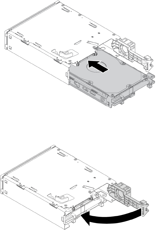
c. Slide the new 3.5-inch storage drive with bracket into the kit from the rear until the drive snaps into
position.
Figure 47. Installing the new 3.5-inch storage drive with bracket into the kit
8. Pivot the rear cover of the kit inward until you hear a click. Ensure that the rear cover is secured in place.
Figure 48. Pivoting the rear cover inward
9. Slide the kit into the flex bay and reconnect the cables.
What to do next:
• To work with another piece of hardware, go to the appropriate section.
• To complete the installation or replacement, go to “Completing the parts replacement” on page 210.
2.5-inch storage drive
To remove or install a 2.5-inch storage drive, do the following:
1. Prepare your computer. See “Preparing your computer and removing the computer cover” on page 103.
2. Ensure that all the cables are disconnected from the kit. Remove the kit from the front of the computer.
See “Device in a flex bay” on page 109.
124 P920 Hardware Maintenance Manual
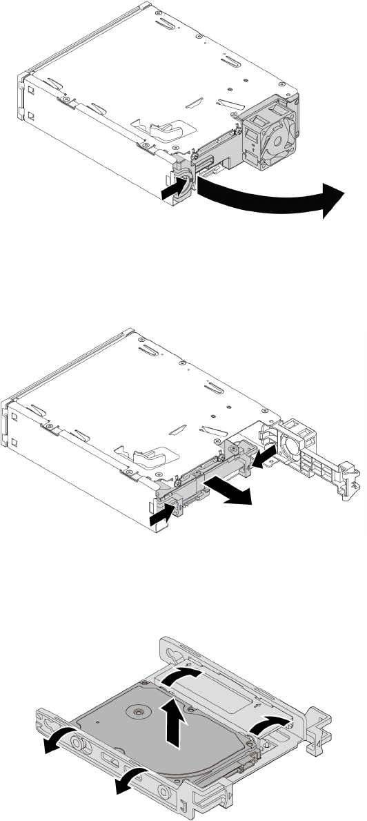
3. Press the clip as shown to open the rear cover of the kit.
Figure 49. Opening the rear cover of the kit
4. Press both clips simultaneously toward each other and pull the conversion bracket out of the rear of the
kit.
Figure 50. Removing the 2.5-inch storage drive from the kit
5. To remove the 2.5-inch storage drive, flex both sides of the conversion bracket and then remove the
drive out of the bracket. Do not touch the circuit board on the drive.
Figure 51. Removing the 2.5-inch storage drive from the bracket
Chapter 9.Hardware removal and installation 125
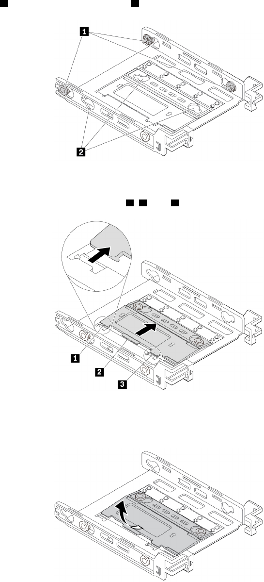
6. To install a 2.5-inch storage drive, ensure that the conversion bracket is folded. To fold the bracket, do
the following:
a. Remove pins 1 and reinstall them into slots 2.
Figure 52. Removing pins and reinstalling them into new slots
b. Pivot the bracket as shown to release tabs 1, 2, and 3 from the slots.
Figure 53. Pivoting the bracket
c. Fold the bracket as shown.
Figure 54. Folding the bracket
126 P920 Hardware Maintenance Manual
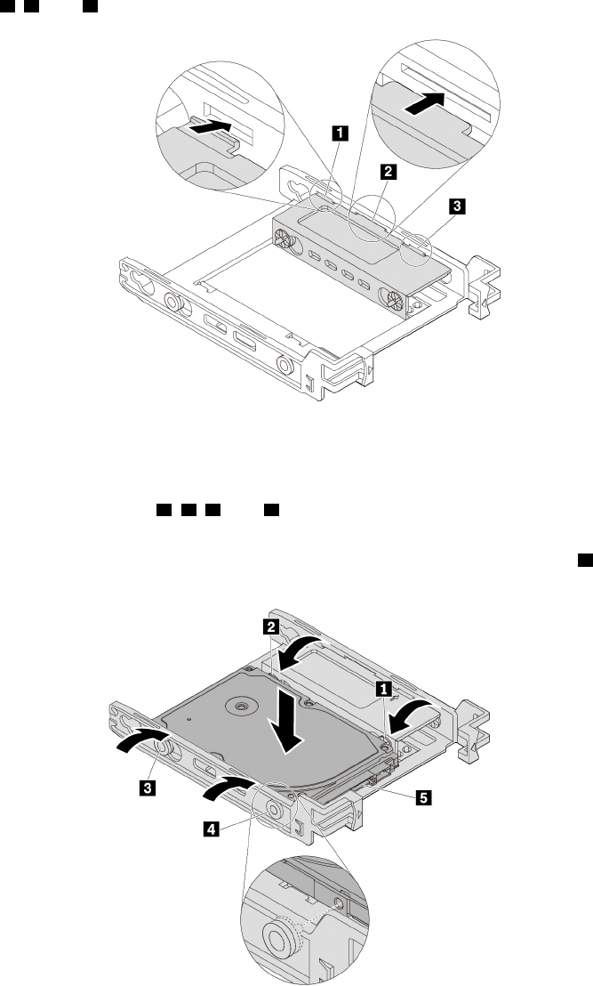
d. Insert tabs 1, 2, and 3 into the corresponding slots. Ensure that the tabs are secured in place.
Figure 55. Inserting the tabs into the corresponding slots
7. To install a 2.5-inch storage drive, do the following:
a. Flex the bracket and align pins 1, 2, 3, and 4 on the bracket with the corresponding holes in the
new 2.5-inch storage drive.
b. Install the new 2.5-inch storage drive into the bracket. Do not touch the circuit board 5 on the drive.
Figure 56. Installing the new 2.5-inch storage drive into the bracket
Chapter 9.Hardware removal and installation 127
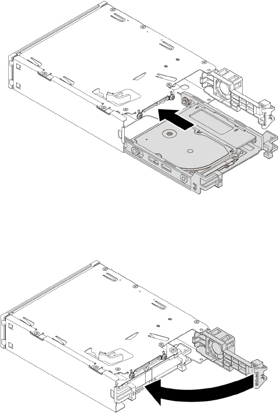
c. Slide the new 2.5-inch storage drive with bracket into the kit from the rear until the drive snaps into
position.
Figure 57. Installing the new 2.5-inch storage drive with bracket into the kit
8. Pivot the rear cover of the kit inward until you hear a click. Ensure that the rear cover is secured in place.
Figure 58. Pivoting the rear cover inward
9. Slide the kit into the flex bay and reconnect the cables.
What to do next:
• To work with another piece of hardware, go to the appropriate section.
• To complete the installation or replacement, go to “Completing the parts replacement” on page 210.
3.5-inch storage drive
Note: Depending on your computer model, a 3.5-inch hard disk drive or a 3.5-inch hybrid drive might come
with your computer.
To remove or install a 3.5-inch storage drive in a storage drive bay, do the following:
1. Prepare your computer. See “Preparing your computer and removing the computer cover” on page 103.
2. Locate the storage drive bay. See “Internal storage drives” on page 40.
128 P920 Hardware Maintenance Manual
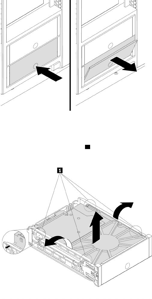
3. Press the pit on the cover of the storage drive bay so that the cover is opened. Then, pull the cover edge
as shown to remove the storage drive bracket from the storage drive bay.
Figure 59. Removing the storage drive bracket
4. To remove a 3.5-inch storage drive, do the following:
a. Flex both sides of the bracket to release the four pins 1 from the storage drive.
b. Remove the storage drive from the bracket.
Figure 60. Removing the 3.5-inch storage drive from the bracket
5. To install a 3.5-inch storage drive, do the following:
Chapter 9.Hardware removal and installation 129
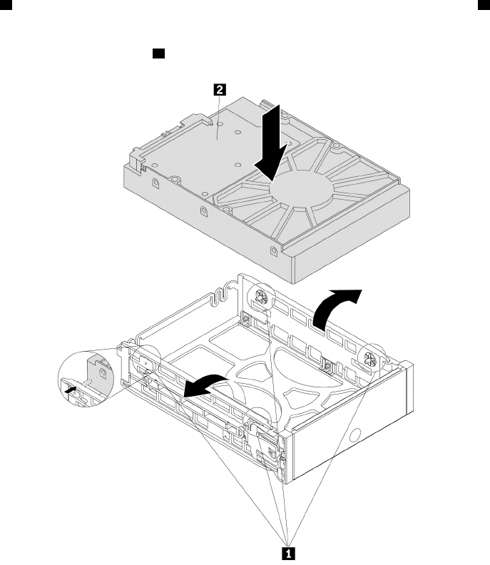
a. Hold the 3.5-inch storage drive so that the connectors face toward the rear of the bracket and the
circuit board 2 faces upward. Then, flex both sides of the bracket and align the four pins 1 on the
bracket with the corresponding holes in the storage drive.
Note: Do not touch the circuit board 2 of the storage drive.
Figure 61. Installing the storage drive into the bracket
130 P920 Hardware Maintenance Manual
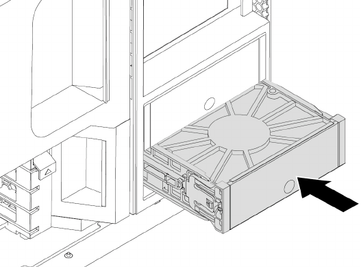
b. Slide the bracket together with the installed storage drive into the storage drive bay until the bracket
snaps into position.
Figure 62. Installing the storage drive bracket
What to do next:
• To work with another piece of hardware, go to the appropriate section.
• To complete the installation or replacement, go to “Completing the parts replacement” on page 210.
2.5-inch storage drive
Note: Depending on your computer model, a 2.5-inch hard disk drive or a 2.5-inch solid-state drive might
come with your computer.
Attention: Do not open your computer or attempt any repair before reading and understanding the Chapter
1 “Read this first: Important safety information” on page 1.
2.5-inch storage drive without a converter
To remove or install a 2.5-inch storage drive without a converter in a storage drive bay, do the following:
1. Prepare your computer. See “Preparing your computer and removing the computer cover” on page 103.
2. Locate the storage drive bay. See “Internal storage drives” on page 40.
Chapter 9.Hardware removal and installation 131
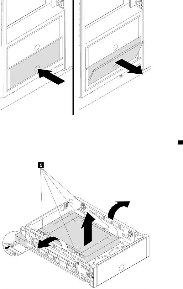
3. Press the pit on the cover of the storage drive bay so that the cover is opened. Then, pull the cover edge
as shown to remove the storage drive bracket from the storage drive bay.
Figure 63. Removing the storage drive bracket
4. To remove a 2.5-inch storage drive, flex both sides of the bracket to release the four pins 1 from the
storage drive. Then, remove the storage drive out of the bracket.
Figure 64. Removing the storage drive from the bracket
5. To install a 2.5-inch storage drive, do the following:
132 P920 Hardware Maintenance Manual
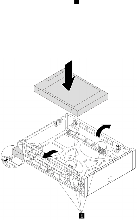
a. Flex both sides of the bracket and align the four pins 1 on the bottom of the bracket with the
corresponding holes in the storage drive.
Notes:
• If you are installing a 2.5-inch hard disk drive, ensure that the circuit board faces downward and
the connectors face toward the rear of the bracket.
• Do not touch the circuit board (if accessible) of the 2.5-inch storage drive.
Figure 65. Installing the storage drive into the bracket
b. Slide the bracket together with the installed storage drive into the storage drive bay until the bracket
snaps into position.
What to do next:
• To work with another piece of hardware, go to the appropriate section.
• To complete the installation or replacement, go to “Completing the parts replacement” on page 210.
2.5-inch storage drive with a converter
To remove or install a 2.5-inch storage drive with a 2.5-inch to 3.5-inch converter in a storage drive bay, do
the following:
1. Prepare your computer. See “Preparing your computer and removing the computer cover” on page 103.
2. Locate the storage drive bay. See “Internal storage drives” on page 40.
Chapter 9.Hardware removal and installation 133
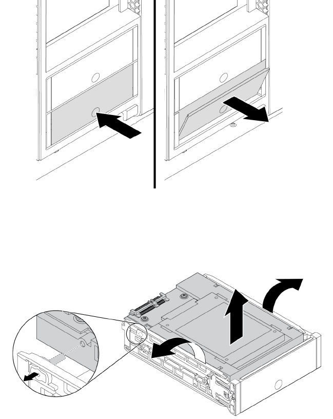
3. Press the pit on the cover of the storage drive bay so that the cover is opened. Then, pull the cover edge
as shown to remove the storage drive bracket from the storage drive bay.
Figure 66. Removing the storage drive bracket
4. To remove a 2.5-inch storage drive with the converter, do the following:
a. Flex both sides of the bracket to remove the converter from the bracket.
Figure 67. Removing the converter from the bracket
134 P920 Hardware Maintenance Manual
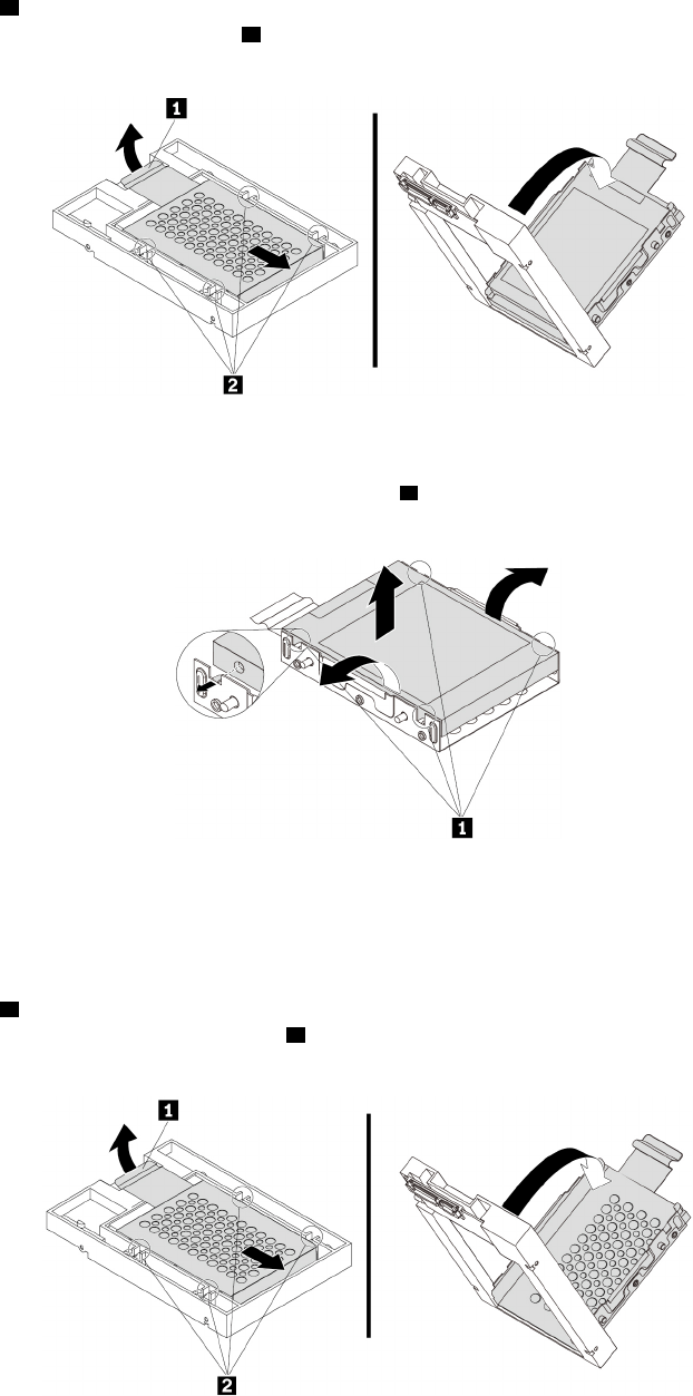
b. Pivot the tab 1 of the metal adapter upward. Then, push the adapter as shown until the four tabs on
the adapter are slide into the notches 2. Pivot the adapter as shown to remove it with the storage
drive from the converter.
Figure 68. Removing the adapter from the converter
c. Flex both sides of the adapter to release the four pins 1 from the storage drive. Then, remove the
storage drive from the adapter.
Figure 69. Removing the storage drive from the adapter
5. To install a 2.5-inch storage drive with the converter, do the following:
a. Flex both sides of the bracket to remove the converter from the bracket.
b. Pivot the tab 1 of the metal adapter upward. Then, push the adapter as shown until the four tabs on
the adapter are slide into the four notches 2. Pivot the adapter as shown to remove it from the
converter.
Figure 70. Removing the adapter from the converter
Chapter 9.Hardware removal and installation 135

c. Note the orientation of the connector on the new storage drive. Then, flex both sides of the adapter
and align the four pins 1 with the corresponding holes in the storage drive.
Note: Do not touch the circuit board (if accessible) of the 2.5-inch storage drive.
Figure 71. Installing the storage drive into the adapter
d. Align the four tabs on the adapter with the corresponding notches 1 in the converter. Then, slide the
storage drive as shown until the tab 2 snaps into position. The adapter with the storage drive is
installed into the converter.
Figure 72. Installing the adapter into the converter
136 P920 Hardware Maintenance Manual
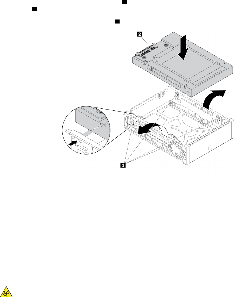
e. Hold the converter with the installed 2.5-inch storage drive so that the connectors face toward the
rear of the bracket and the circuit board 2 faces upward. Then, flex sides of the bracket and align
pins 1 on the bracket with the corresponding holes in the converter.
Note: Do not touch the circuit board 2 of the storage drive.
Figure 73. Installing the converter into the bracket
f. Slide the bracket together with the installed storage drive into the storage drive bay until the bracket
snaps into position.
What to do next:
• To work with another piece of hardware, go to the appropriate section.
• To complete the installation or replacement, go to “Completing the parts replacement” on page 210.
Front fan assembly
Attention: Do not open your computer or attempt any repair before reading and understanding the Chapter
1 “Read this first: Important safety information” on page 1.
CAUTION:
Keep fingers and other parts of your body away from hazardous, moving parts. If you suffer an injury,
seek medical care immediately.
To remove or install a front fan assembly, do the following:
1. Prepare your computer. See “Preparing your computer and removing the computer cover” on page 103.
2. Locate the front fan assembly. See “Computer components” on page 33.
Chapter 9.Hardware removal and installation 137
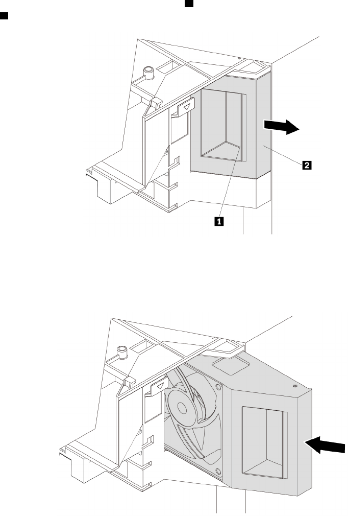
3. To remove the front fan assembly, press the tab 1 and slide the front fan assembly outward by the
handle 2 to remove it from the chassis.
Figure 74. Removing the front fan assembly
4. To install the front fan assembly, slide the front fan assembly into the multi-function bracket until it snaps
into position.
Figure 75. Installing the front fan assembly
What to do next:
• To work with another piece of hardware, go to the appropriate section.
• To complete the installation or replacement, go to “Completing the parts replacement” on page 210.
Rear fan assembly
Attention: Do not open your computer or attempt any repair before reading and understanding the Chapter
1 “Read this first: Important safety information” on page 1.
138 P920 Hardware Maintenance Manual
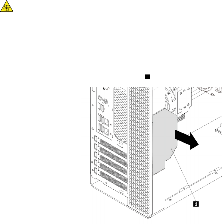
CAUTION:
Keep fingers and other parts of your body away from hazardous, moving parts. If you suffer an injury,
seek medical care immediately.
To remove or install the rear fan assembly, do the following:
1. Prepare your computer. See “Preparing your computer and removing the computer cover” on page 103.
2. Remove the direct cooling air baffle. See “Direct cooling air baffle” on page 107.
3. Locate the rear fan assembly. See “Computer components” on page 33.
4. To remove the rear fan assembly, hold the handle 1 to slide the rear fan assembly out of the chassis.
Figure 76. Removing the rear fan assembly
Chapter 9.Hardware removal and installation 139
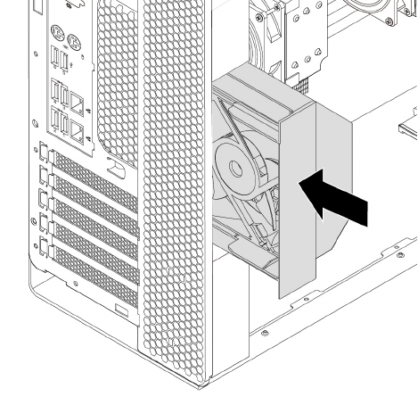
5. To install the rear fan assembly, slide it into the rear fan assembly bay until it snaps into position.
Figure 77. Installing the rear fan assembly
6. Reinstall the direct cooling air baffle. See “Direct cooling air baffle” on page 107.
What to do next:
• To work with another piece of hardware, go to the appropriate section.
• To complete the installation or replacement, go to “Completing the parts replacement” on page 210.
M.2 solid-state drive
Attention: Do not open your computer or attempt any repair before reading and understanding the Chapter
1 “Read this first: Important safety information” on page 1.
An M.2 solid-state drive can be installed in the M.2 solid-state drive holder or an M.2 solid-state drive PCIe
adapter.
M.2 solid-state drive in the M.2 solid-sate drive holder
To remove or install an M.2 solid-state drive in the M.2 solid-sate drive holder, do the following:
1. Prepare your computer. See “Preparing your computer and removing the computer cover” on page 103.
2. Lay the computer on its side for easier access to the M.2 solid-state drive slots.
3. Locate the M.2 solid-state drive slots. See “Parts on the system board” on page 38.
140 P920 Hardware Maintenance Manual
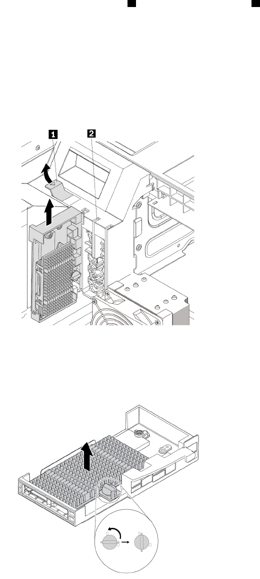
4. To remove the M.2 solid-state drive holder, pivot the tab 1 upward to open the latch 2 inside the multi-
function bracket. Then, grasp the M.2 solid-state drive holder by its edges and gently pull it out of the
M.2 solid-state drive slots.
Notes:
• The M.2 solid-state drive holder might fit tightly into the M.2 solid-state drive slots. If necessary,
alternately move each side of the holder a small amount until it is removed from the slots.
• Depending on the model, the M.2 solid-state drive holder might look slightly different from the
illustration.
Figure 78. Removing the M.2 solid-state drive holder
5. Turn the mounting stud 90-degree counterclockwise to release the heat sink. Then, lift the heat sink off
the M.2 solid-state drive holder.
Figure 79. Removing the heat sink from the M.2 solid-state drive holder
Chapter 9.Hardware removal and installation 141
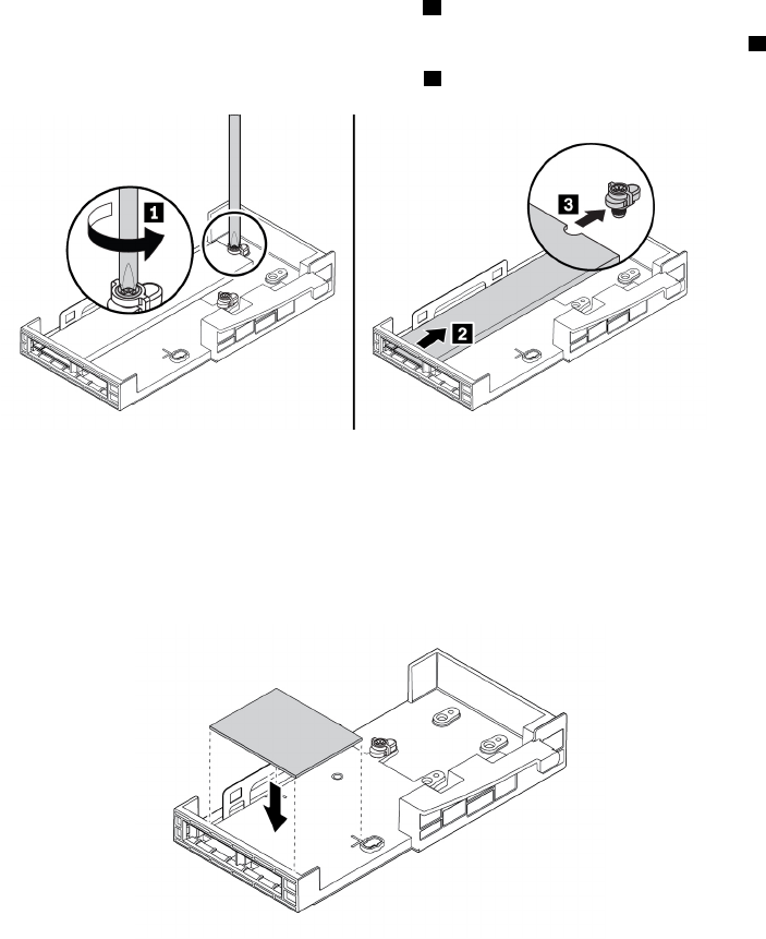
6. To remove an M.2 solid-state drive, do the following:
a. Loosen the screw that secures the M.2 solid-state drive 1.
b. Remove the M.2 solid-state drive with the screw holder from the M.2 solid-state drive slot 2.
c. Remove the screw holder from the M.2 solid-state drive 3.
Figure 80. Removing the M.2 solid-state drive
7. To install an M.2 solid-state drive, do the following:
a. Stick a thermal pad into the position on the M.2 solid-state drive holder as shown. If necessary,
remove the film that protects the thermal pad.
Figure 81. Sticking the thermal pad on the M.2 solid-state drive holder
142 P920 Hardware Maintenance Manual
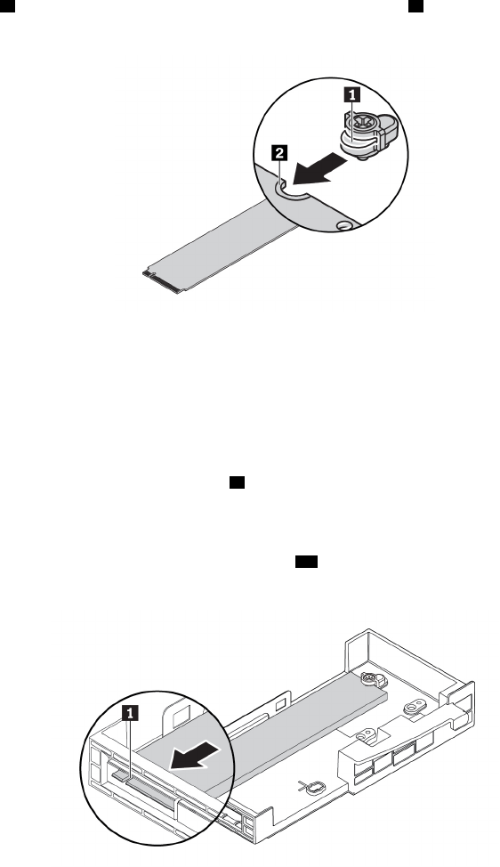
b. Align the notch 1 in the screw holder with the corresponding notch 2 in the M.2 solid-state drive.
Insert the screw holder onto the new M.2 solid-state drive as shown.
Figure 82. Inserting the screw holder onto the M.2 solid-state drive
c. Hold the new M.2 solid-state drive by its edges and ensure that the circuit board side is facing
upward. Insert the drive into the corresponding slot until it is firmly secured.
Notes:
• Pay attention to the direction of the notch 1 in the new drive.
• Do not touch the circuit board of the M.2 solid-state drive.
• If only one M.2 solid-state drive is installed on the M.2 solid-state drive holder, ensure that the
drive is installed in the M.2 solid-state drive slot 1 ( 20 ). See “Parts on the system board” on page
38.
Figure 83. Installing the M.2 solid-state drive
Chapter 9.Hardware removal and installation 143
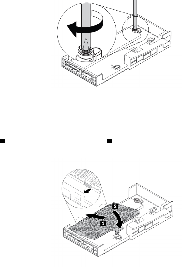
d. Tighten the screw to secure the new M.2 solid-state drive.
Note: Do not overtighten the screw.
Figure 84. Securing the M.2 solid-state drive
8. To install the M.2 solid-state drive heat sink, do the following:
a. If necessary, remove the film that protects the thermal pad on the heat sink.
b. Insert two hooks on the heat sink into the corresponding holes in the M.2 solid-state drive holder as
shown 1. Then, press the heat sink downward 2. Ensure that the mounting stud on the heat sink is
inserted into the hole in the M.2 solid-state drive holder.
Figure 85. Installing the heat sink onto the M.2 solid-state drive holder
144 P920 Hardware Maintenance Manual
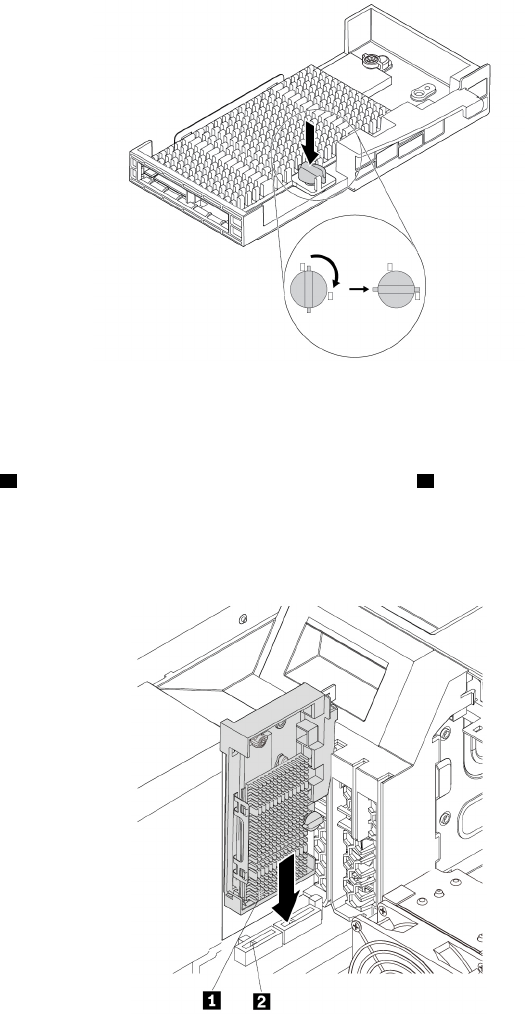
c. Press the mounting stud downward and press the mounting stud downward. Then, turn the
mounting stud 90-degree clockwise to secure the heat sink to the M.2 solid-state drive holder.
Figure 86. Securing the heat sink to the M.2 solid-state drive holder
9. To install the M.2 solid-state drive holder, do the following:
a. Align the notch 1 on the M.2 solid-state drive with the slot key 2 in the M.2 solid-state drive slot.
Then, slide the holder against the multi-function bracket and press the holder downward until the M.2
solid-state drive is securely seated.
Note: Do not touch the circuit board of the M.2 solid-state drive.
Figure 87. Installing the M.2 solid-state drive holder
Chapter 9.Hardware removal and installation 145
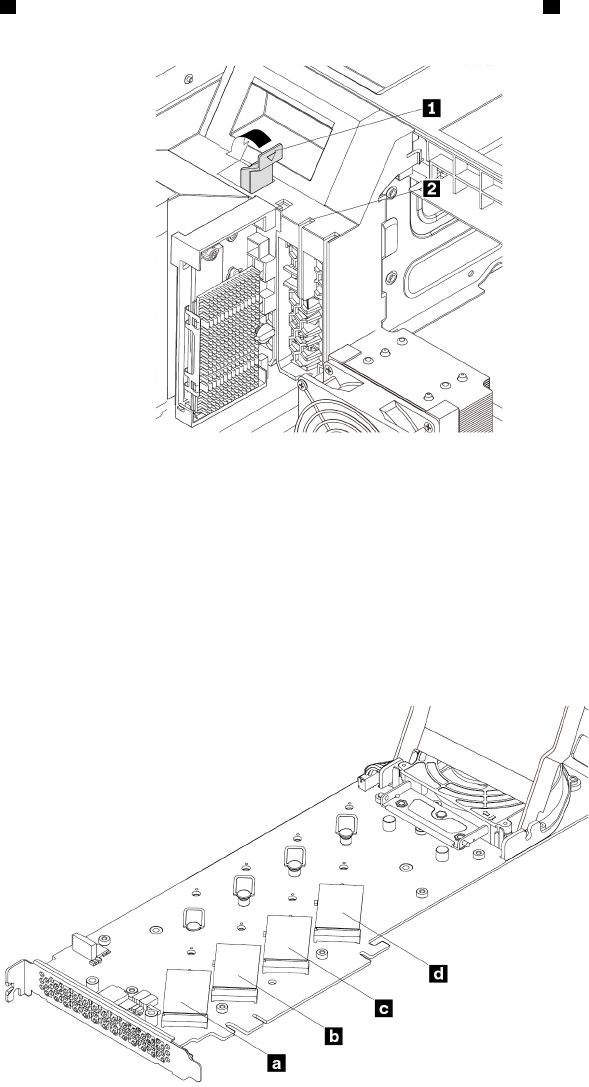
b. Pivot the tab 1 downward until it snaps into position. Ensure that the latch 2 inside the multi-
function bracket is closed.
Figure 88. Closing the card latch
What to do next:
• To work with another piece of hardware, go to the appropriate section.
• To complete the installation or replacement, go to “Completing the parts replacement” on page 210.
M.2 solid-state drive in an M.2 solid-state drive PCIe adapter
Install M.2 solid-state drives in the alphabetic order as shown.
Figure 89. M.2 solid-state drive installation order
To remove or install an M.2 solid-state drive in the M.2 solid-state drive PCIe adapter, do the following:
1. Remove the M.2 solid-state drive PCIe adapter from the PCIe card slot. See “Full-length PCIe card” on
page 163.
146 P920 Hardware Maintenance Manual
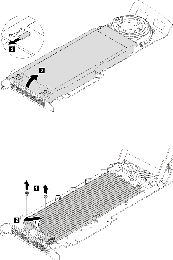
2. Slide the cover latches to the open position. Then, pivot the cover as shown until it stops.
Figure 90. Opening the cover
3. Loosen the screws that secure the M.2 solid-state drive heat sink. Then, remove the heat sink as shown.
Figure 91. Removing the heat sink
Chapter 9.Hardware removal and installation 147
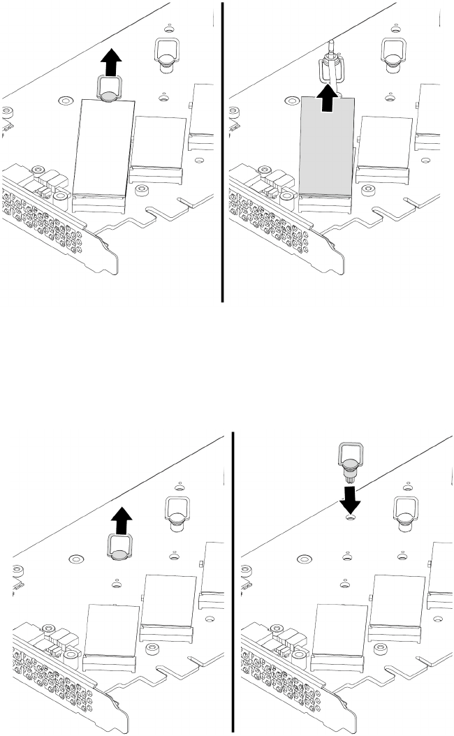
4. To remove the M.2 solid-state drive, pull the handle of the retention latch outward to release the M.2
solid-state drive. Then, remove the M.2 solid-state drive from the PCIe adapter.
Figure 92. Removing the M.2 solid-state drive
5. To install an M.2 solid-state drive, do the following:
a. If necessary, move the retention latch to an appropriate location to suit the length of the new M.2
solid-state drive.
Figure 93. Adjusting the location of the retention latch on the PCIe adapter
b. If necessary, remove the film on the thermal pad on which you want to install the M.2 solid-state
drive.
148 P920 Hardware Maintenance Manual
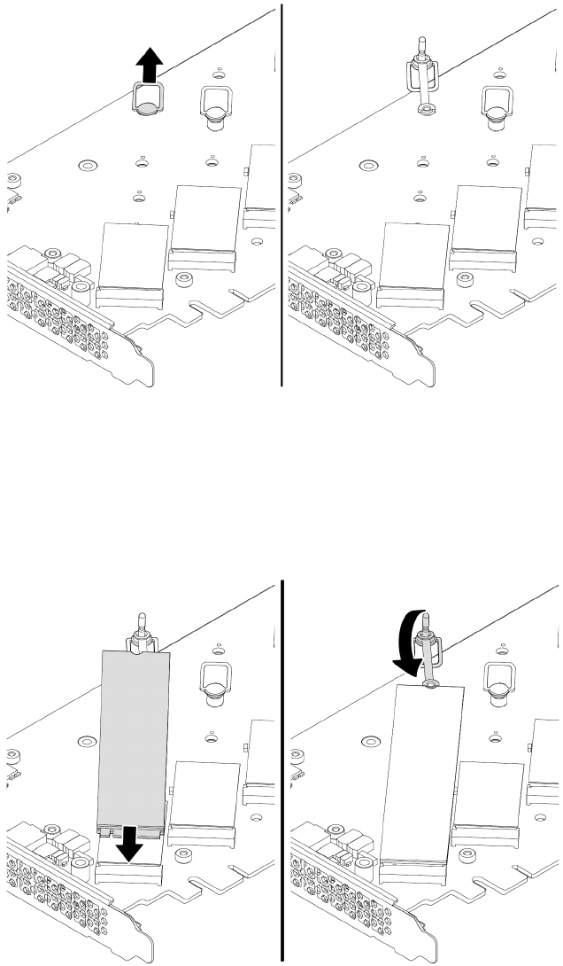
c. Pull the handle of the retention latch outward to the open position.
Figure 94. Opening the retention latch
d. Hold the new M.2 solid-state drive by its edges and ensure that the circuit board side is facing
upward. Insert the drive into the M.2 solid-state drive slot on the PCIe adapter until it is firmly seated.
Then, insert the plug of the retention latch into the hole to secure the new drive.
Note: Do not touch the circuit board of the M.2 solid-state drive.
Figure 95. Installing the M.2 solid-state drive
Chapter 9.Hardware removal and installation 149
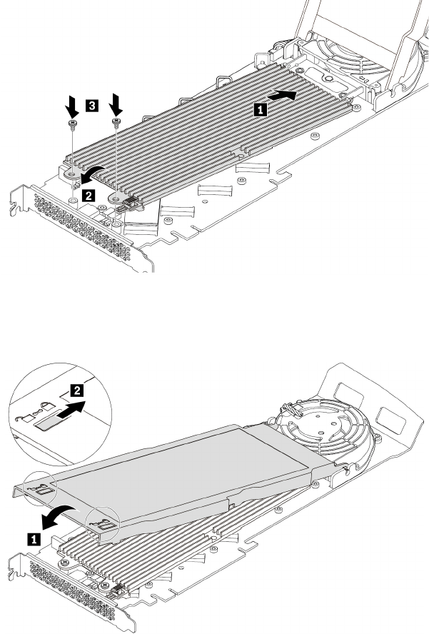
6. Install the heat sink as shown. Then tighten the screws to secure the heat sink.
Figure 96. Installing the heat sink onto the PCIe adapter
7. Install the cover as shown. Then, slide the cover latches to the locked position.
Figure 97. Closing the cover
8. Install the M.2 solid-state drive PCIe adapter in a PCIe x16 card slot. See “Full-length PCIe card” on
page 163.
What to do next:
• To work with another piece of hardware, go to the appropriate section.
• To complete the installation or replacement, go to “Completing the parts replacement” on page 210.
Power supply assembly
Attention: Do not open your computer or attempt any repair before reading and understanding the Chapter
1 “Read this first: Important safety information” on page 1.
150 P920 Hardware Maintenance Manual
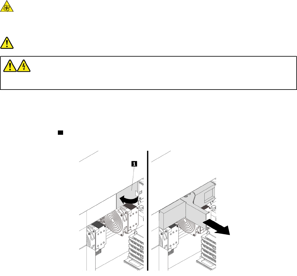
Although there are no moving parts in your computer after the power cord has been disconnected, the
following warnings are required for your safety and proper Underwriters Laboratories (UL) certification.
CAUTION:
Keep fingers and other parts of your body away from hazardous, moving parts. If you suffer an injury,
seek medical care immediately.
DANGER
Disconnect all power cords from electrical outlets before removing the computer cover or any part
that has the above label attached.
To remove and install the power supply assembly, do the following:
1. Prepare your computer. See “Preparing your computer and removing the computer cover” on page 103.
2. Locate the power supply assembly. See “Computer components” on page 33.
3. Pivot the handle 1 at an angle of about 90 degrees as shown. Then, pull the handle as shown to remove
the power supply assembly from the chassis.
Figure 98. Removing the power supply assembly
Chapter 9.Hardware removal and installation 151
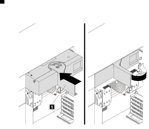
4. With the handle 1 open, slide the power supply assembly into the power supply assembly bay until it
snaps into position. Pivot the handle to the closed position to ensure that the new power supply
assembly is fully installed into position.
Figure 99. Installing the power supply assembly
What to do next:
• To work with another piece of hardware, go to the appropriate section.
• To complete the installation or replacement, go to “Completing the parts replacement” on page 210.
Memory module
Attention: Do not open your computer or attempt any repair before reading and understanding the Chapter
1 “Read this first: Important safety information” on page 1.
Your computer has 16 slots for installing or replacing DDR4 DIMMs that provide up to a maximum of 2048
GB system memory. When installing or replacing a memory module, use the following guidelines:
• Use any of DDR4 ECC RDIMMs, DDR4 ECC LRDIMMs, or DDR4 ECC 3DS RDIMMs for your computer.
Do not install the RDIMMs, LRDIMMs, or 3DS RDIMMs into the same computer.
• Use 8 GB, 16 GB, or 32 GB RDIMMs in any combination up to a maximum of 512 GB.
• Use 64 GB LRDIMMs up to a maximum of 1024 GB.
• Use 128 GB 3DS RDIMM up to a maximum of 2048 GB.
Memory module installation rules
Install memory modules in the alphabetic order as shown.
152 P920 Hardware Maintenance Manual
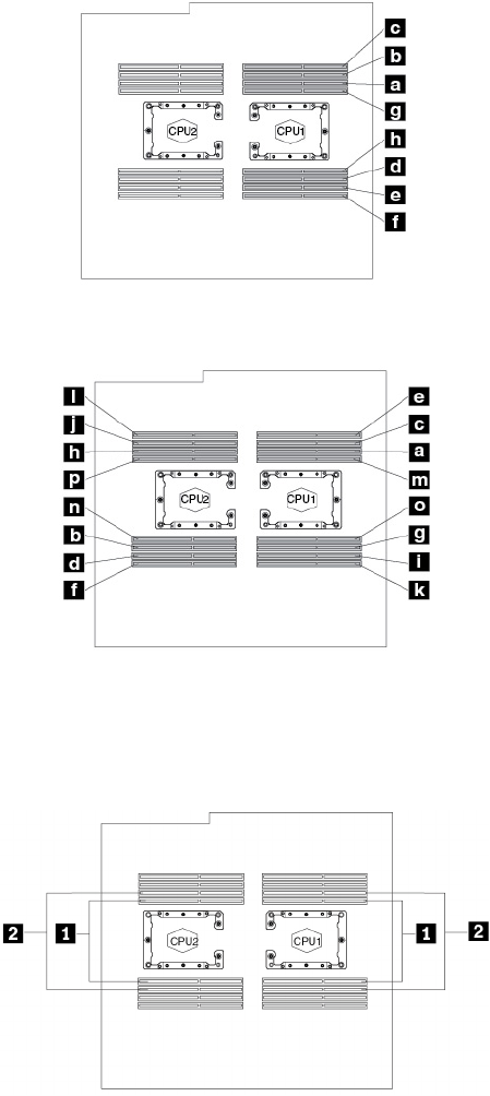
Figure 100. Memory module installation order for computers with one microprocessor
Figure 101. Memory module installation order for computers with two microprocessors
Note: To avoid performance loss, if the memory slots 1 are occupied while the adjacent memory slots 2 are
empty, move the memory modules from slots 1 to the adjacent slots 2 respectively.
Figure 102. Additional notice for removing memory modules
To remove or install a memory module, do the following:
1. Prepare your computer. See “Preparing your computer and removing the computer cover” on page 103.
2. Remove the direct cooling air baffle. See “Direct cooling air baffle” on page 107.
3. Lay the computer on its side for easier access to the memory slots.
4. Locate the memory slot. See Parts on the system board.
Chapter 9.Hardware removal and installation 153
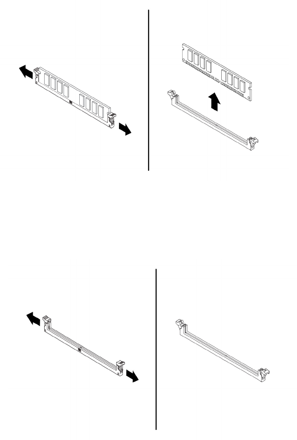
5. To remove a memory module, open the retaining clips and gently pull the memory module out of the
memory slot.
Figure 103. Removing the memory module
6. To install a memory module, do the following:
a. Open the retaining clips of the memory slot into which you want to install the memory module.
Figure 104. Opening retaining clips
154 P920 Hardware Maintenance Manual
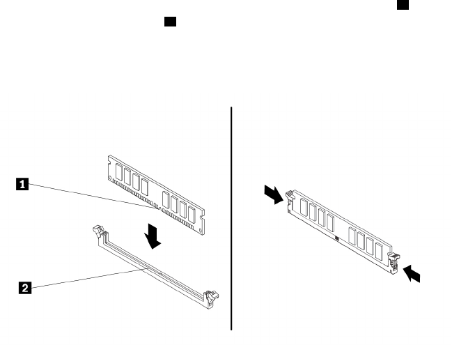
b. Position the new memory module over the memory slot. Ensure that the notch 1 on the memory
module aligns correctly with the slot key 2 on the system board. Push the memory module straight
down into the slot until the retaining clips close.
Note: Do not touch the circuit board of the memory module.
Figure 105. Installing the memory module
c. Reinstall the direct cooling air baffle. See “Direct cooling air baffle” on page 107.
What to do next:
• To work with another piece of hardware, go to the appropriate section.
• To complete the installation or replacement, go to “Completing the parts replacement” on page 210.
PCIe card
Attention: Do not open your computer or attempt any repair before reading and understanding the Chapter
1 “Read this first: Important safety information” on page 1.
Your computer has the following PCIe card slots:
• PCIe 3.0 x4 card slots
• PCIe 3.0 x16 card slots
Notes:
• PCIe cards available vary by computer model.
• To remove or install a full-length PCIe card, see “Full-length PCIe card” on page 163.
• If you want to use an NVIDIA compute card, ensure that your computer also has an NVIDIA graphics card
installed.
PCIe card installation rules
Install PCIe cards in the alphabetic order as shown.
Chapter 9.Hardware removal and installation 155
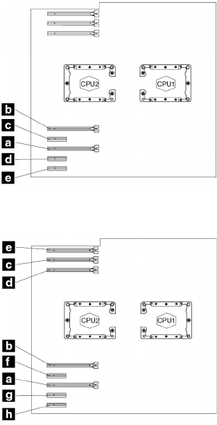
Figure 106. PCIe card installation order for computers with one microprocessor
Figure 107. PCIe card installation order for computers with two microprocessors
To remove or install a PCIe card, do the following:
1. Prepare your computer. See “Preparing your computer and removing the computer cover” on page 103.
2. Lay the computer on its side for easier access to the PCIe card slots.
3. Locate the PCIe card slot. See “Parts on the system board” on page 38.
4. If necessary, remove the direct cooling air baffle for easier operation. See “Direct cooling air baffle” on
page 107.
5. To remove a PCIe card, do the following:
a. For some models, remove the PCIe card retainer first.
156 P920 Hardware Maintenance Manual
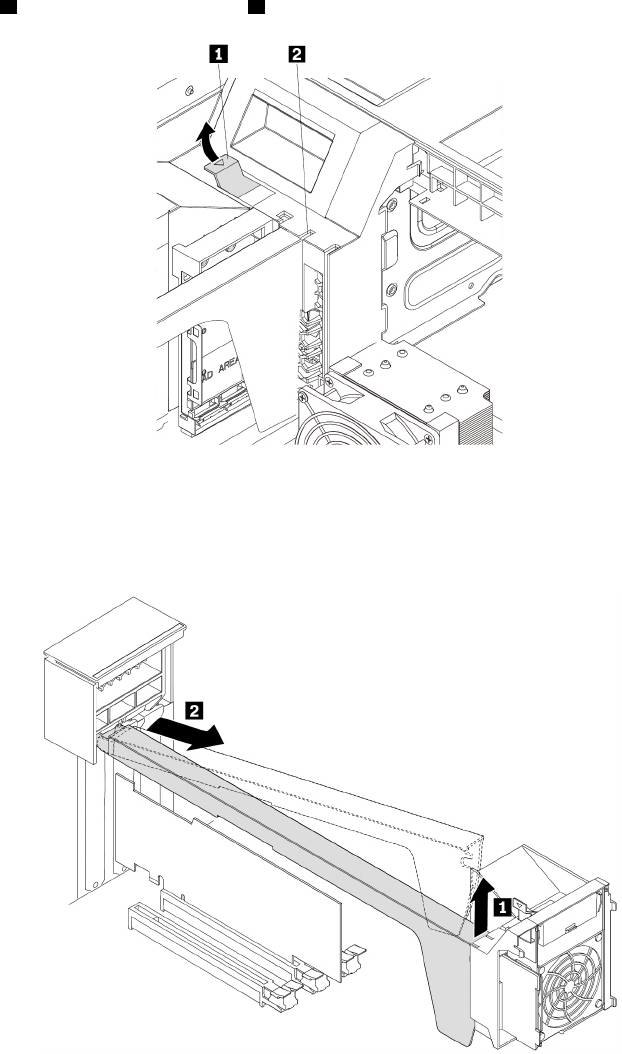
Pivot the tab 1 upward to open the latch 2 inside the multi-function bracket.
Figure 108. Opening the card latch
Grasp the PCIe card retainer by its edges and gently pull it out of the latch. Remove the retainer
completely from the PCIe card latch.
Figure 109. Removing the PCIe card retainer
Chapter 9.Hardware removal and installation 157
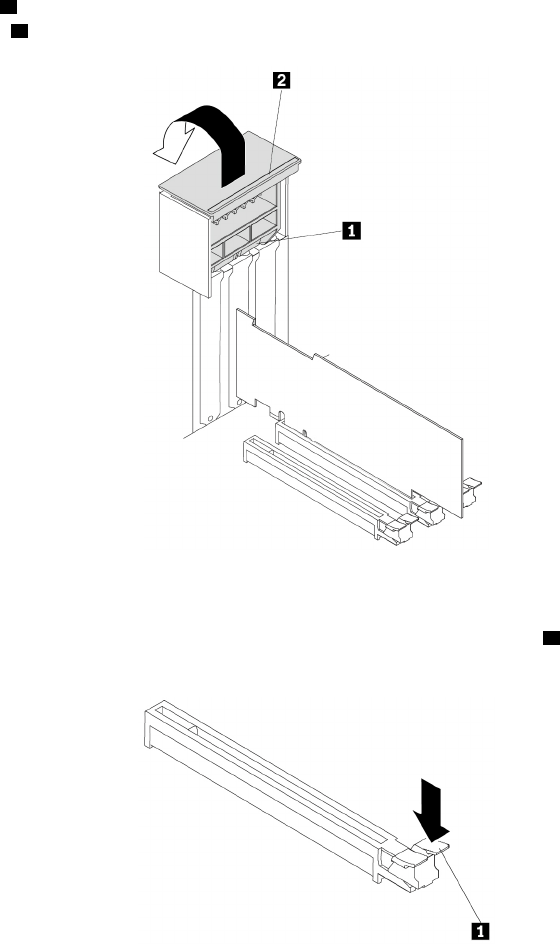
b. Lift the handle 2 on the rear of the chassis until it stops, and then pivot it as shown until it stops. The
PCIe card latch 1 is opened.
Figure 110. Opening the PCIe card latch
c. If the PCIe card is held in place by a retaining latch, press the retaining latch 1 as shown to
disengage the latch.
Figure 111. Disengaging the retaining latch
158 P920 Hardware Maintenance Manual
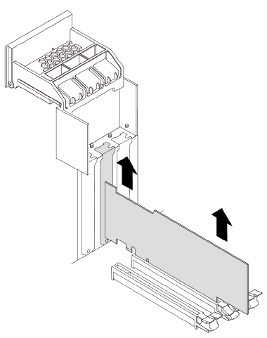
d. Grasp the card and gently pull it out of the slot.
Figure 112. Removing the PCIe card
Notes:
• If the card is connected to other device, disconnect the cables from the card.
• The card might fit tightly into the slot. If necessary, alternately move each side of the card a small
amount until the card is removed from the slot.
6. To install a PCIe card, do the following:
Chapter 9.Hardware removal and installation 159
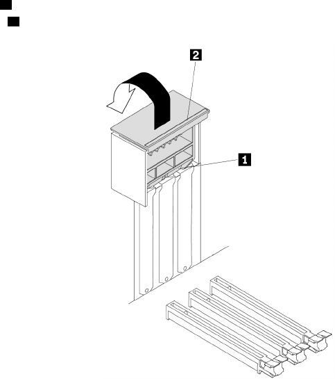
a. Lift the handle 2 on the rear of the chassis until it stops, and then pivot it as shown until it stops. The
PCIe card latch 1 is opened.
Figure 113. Opening the PCIe card latch
b. If needed, remove the appropriate metal slot cover on the rear of the chassis.
c. If the PCIe card slot has a retaining latch, press the card retaining latch downward to disengage the
latch.
160 P920 Hardware Maintenance Manual
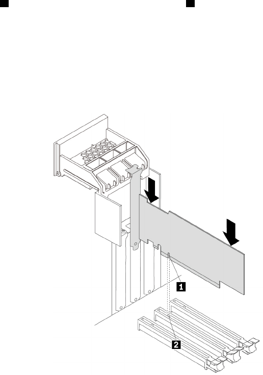
d. Align the notch 1 on the new PCIe card with the slot key 2 in the PCIe card slot. Then, insert the new
PCIe card downward into the card slot until it is securely seated. See “Parts on the system board” on
page 38.
Notes:
• Do not touch the circuit board of the PCIe card.
• If the new PCIe card needs to be connected to another device, connect the cable of the device to
the card.
Figure 114. Installing the PCIe card
Chapter 9.Hardware removal and installation 161
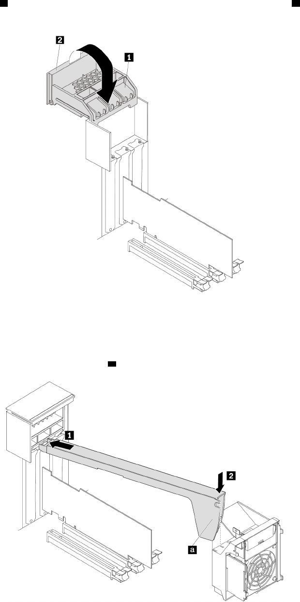
e. Pivot the handle 2 as shown until it stops, and then press it downward until the latch 1 snaps into
position.
Figure 115. Closing the PCIe card latch
f. For some models, install the PCIe card retainer.
Insert the corresponding end of the PCIe card retainer into the gaps in the PCIe card latch as shown.
Pivot the retainer downward to insert part a into the corresponding slot in the multi-function bracket.
Figure 116. Installing the PCIe card retainer
162 P920 Hardware Maintenance Manual
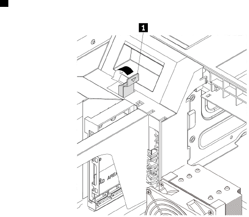
Pivot the tab 1 downward until it snaps into position.
Figure 117. Closing the card latch
7. Reinstall the direct cooling air baffle if you have removed it. See “Direct cooling air baffle” on page 107.
What to do next:
• To work with another piece of hardware, go to the appropriate section.
• To complete the installation or replacement, go to “Completing the parts replacement” on page 210.
Full-length PCIe card
Attention: Do not open your computer or attempt any repair before reading and understanding the Chapter
1 “Read this first: Important safety information” on page 1.
Your computer has the following PCIe card slots:
• PCIe 3.0 x4 card slots
• PCIe 3.0 x16 card slots
Notes:
• The full-length PCIe card is available only on some models.
• If you want to use an NVIDIA compute card, ensure that your computer also has an NVIDIA graphics card
installed.
PCIe card installation rules
Install PCIe cards in the alphabetic order as shown.
Chapter 9.Hardware removal and installation 163

Figure 118. PCIe card installation order for computers with one microprocessor
Figure 119. PCIe card installation order for computers with two microprocessors
To remove or install a full-length PCIe card, do the following:
1. Prepare your computer. See “Preparing your computer and removing the computer cover” on page 103.
2. Lay the computer on its side for easier access to the PCIe card slots.
3. Locate the PCIe card slot. See “Parts on the system board” on page 38.
4. If necessary, remove the direct cooling air baffle for easier operation. See “Direct cooling air baffle” on
page 107.
5. To remove a full-length PCIe card, do the following:
164 P920 Hardware Maintenance Manual
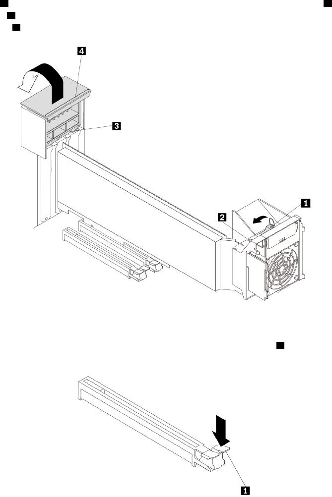
a. Pivot the tab 1 on the multi-function bracket upward until it stops. The PCIe card latch 2 is opened.
Lift the handle 4 on the rear of the chassis until it stops, and then pivot it as shown until it stops. The
PCIe card latch 3 is opened.
Figure 120. Opening PCIe card latches
b. If the PCIe card is held in place by a retaining latch, press the retaining latch 1 as shown to
disengage the latch.
Figure 121. Disengaging the retaining latch
Chapter 9.Hardware removal and installation 165
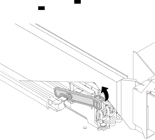
If the card is installed in PCIe 3.0 x16 card slot 1 ( 55 ), pull the tab in the bracket next to
microprocessor 2 memory slot 1 ( 56 ) upward to disengage the retaining latch of the PCIe card slot.
See “Parts on the system board” on page 38.
Figure 122. Disengaging the retaining latch of the PCIe card slot
166 P920 Hardware Maintenance Manual
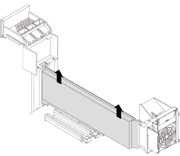
c. Disconnect the power cable from the full-length PCIe card, and then grasp the card and gently pull it
out of the slot.
Figure 123. Removing the full-length PCIe card
Notes:
• If the card is connected to other device, disconnect the cables from the card.
• The card might fit tightly into the slot. If necessary, alternately move each side of the card a small
amount until the card is removed from the slot.
6. To install a full-length PCIe card, do the following:
Chapter 9.Hardware removal and installation 167
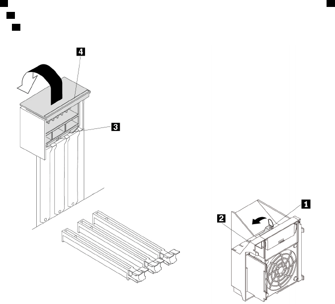
a. Pivot the tab 1 on the multi-function bracket outward until it stops. The PCIe card latch 2 is opened.
Lift the handle 4 on the rear of the chassis until it stops, and then pivot it as shown until it stops. The
PCIe card latch 3 is opened.
Figure 124. Opening PCIe card latches
b. If needed, remove the appropriate metal slot cover on the rear of the chassis.
c. If the PCIe card slot has a retaining latch, press the card retaining latch downward to disengage the
latch.
168 P920 Hardware Maintenance Manual
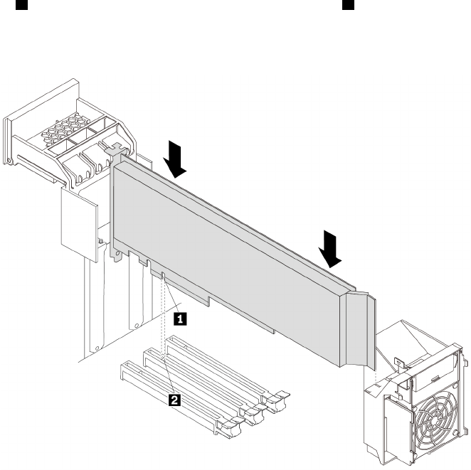
d. Align the notch 1 on the new full-length PCIe card with the slot key 2 in the PCIe card slot. Then,
insert the new card downward into the card slot until it is securely seated.
Note: Do not touch the circuit board of the PCIe card.
Figure 125. Installing the full-length PCIe card
Chapter 9.Hardware removal and installation 169
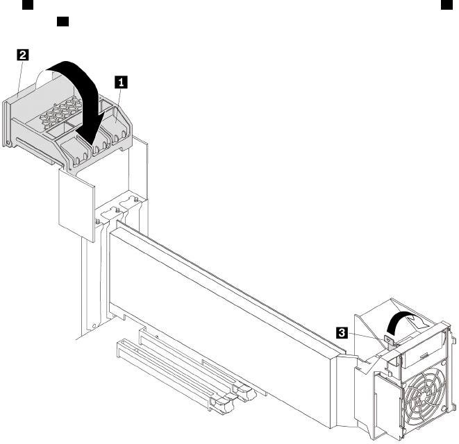
e. Pivot the handle 2 as shown until it stops, and then press it downward until the latch 1 snaps into
position. Pivot the tab 3 downward until it snaps into position.
Figure 126. Closing PCIe card latches
f. Connect the power cable of the full-length PCIe card to the new card. See “Parts on the system
board” on page 38.
7. Reinstall the direct cooling air baffle if you have removed it. See “Direct cooling air baffle” on page 107.
What to do next:
• To work with another piece of hardware, go to the appropriate section.
• To complete the installation or replacement, go to “Completing the parts replacement” on page 210.
Super capacitor module
Attention: Do not open your computer or attempt any repair before reading and understanding the Chapter
1 “Read this first: Important safety information” on page 1.
To remove or install a super capacitor module, do the following:
1. Prepare your computer. See “Preparing your computer and removing the computer cover” on page 103.
2. Lay the computer on its side for easier access to the super capacitor module.
3. If necessary, remove the direct cooling air baffle for easier operation. See “Direct cooling air baffle” on
page 107.
4. Locate the PCIe card slot in which the RAID adapter with the super-capacitor-module holder is installed.
See “Computer components” on page 33.
5. To remove a super capacitor module, do the following:
170 P920 Hardware Maintenance Manual
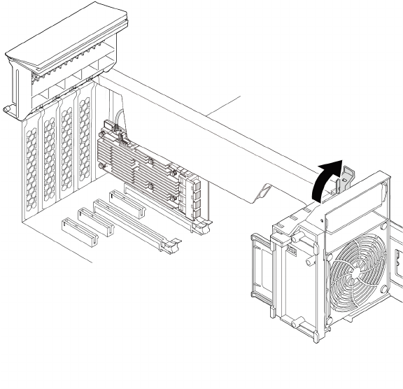
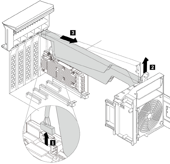
b. Disconnect the super-capacitor-module cable from the RAID adapter. Then remove the holder with
the failing super capacitor module.
Figure 128. Removing the super capacitor module
6. To install a super capacitor module, do the following:
a. Pull and pivot the tab on the multi-function bracket to open the latch inside.
b. Touch the static-protective package that contains the new super capacitor module and its holder to
any unpainted surface on the outside of the computer. Then, remove the new super capacitor
module and its holder from the package.
c. Connect the super-capacitor-module cable to the super-capacitor-module connector on the RAID
adapter.
172 P920 Hardware Maintenance Manual
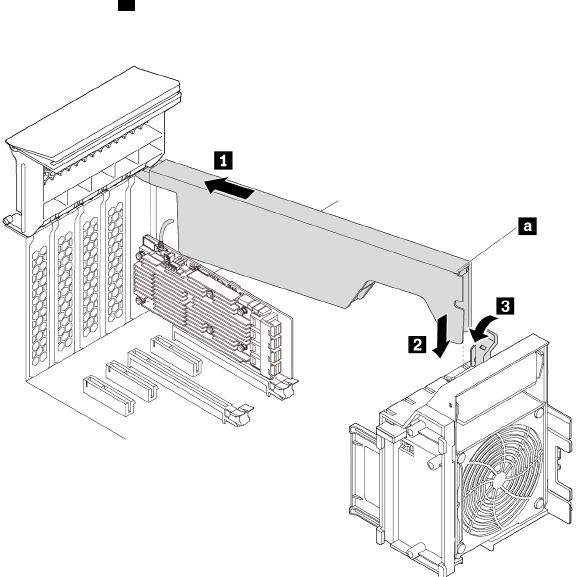
d. Insert the corresponding end of the holder into the gaps in the PCIe card latch as shown. Pivot the
holder downward to insert part a into the corresponding slot in the multi-function bracket. Then,
pivot the tab on the multi-function bracket to secure the holder.
Figure 129. Installing the super capacitor module
7. Reinstall the direct cooling air baffle if you have removed it. See “Direct cooling air baffle” on page 107.
What to do next:
• To work with another piece of hardware, go to the appropriate section.
• To complete the installation or replacement, go to “Completing the parts replacement” on page 210.
Multi-function brackets
Attention: Do not open your computer or attempt any repair before reading and understanding the Chapter
1 “Read this first: Important safety information” on page 1.
Your computer is installed with two multi-function brackets. The brackets are used to secure the front fan
assembly, super capacitor module, PCIe card retainer, and full-length PCIe cards. The bracket installed in
the upper position of the chassis also can be used to secure the M.2 solid-state drive holder and power
supply assembly.
Multi-function bracket in the upper position
To remove and reinstall the multi-function bracket installed in the upper position of the chassis, do the
following:
1. Prepare your computer. See “Preparing your computer and removing the computer cover” on page 103.
2. Locate the multi-function bracket in the upper position of the chassis. See “Computer components” on
page 33.
3. To access the multi-function bracket, remove the following parts:
• “Direct cooling air baffle” on page 107 (if necessary)
Chapter 9.Hardware removal and installation 173
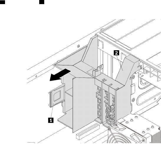
• “Power supply assembly” on page 150
• “Front fan assembly” on page 137
• “M.2 solid-state drive holder” on page 140
• “PCIe card retainer” on page 155 (if necessary)
• “Super capacitor module” on page 170 (if necessary)
• “Full-length PCIe card” on page 163 (if necessary)
4. Hold the handle 1 and the foot 2 at the same time and pull the bracket to the rear of the chassis to
remove the bracket.
Figure 130. Removing the multi-function bracket
174 P920 Hardware Maintenance Manual
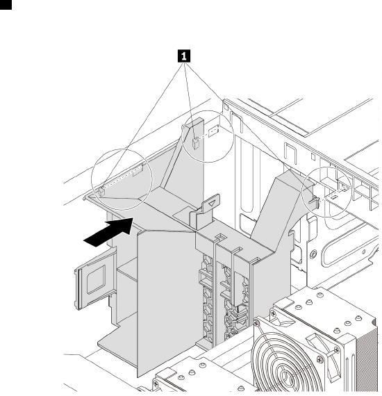
5. Align three tabs 1 on the bracket with the corresponding holes in the chassis. Then, insert the three tabs
into the corresponding holes until the bracket snaps into position.
Figure 131. Reinstalling the multi-function bracket
6. Reinstall the following parts if you have removed them:
• “M.2 solid-state drive holder” on page 140
• “PCIe card retainer” on page 155
• “Super capacitor module” on page 170
• “Full-length PCIe card” on page 163
• “Front fan assembly” on page 137
• “Power supply assembly” on page 150
• “Direct cooling air baffle” on page 107
What to do next:
• To work with another piece of hardware, go to the appropriate section.
• To complete the installation or replacement, go to “Completing the parts replacement” on page 210.
Multi-function bracket in the bottom position
To remove and reinstall the multi-function bracket installed in the bottom position of the chassis, do the
following:
1. Prepare your computer. See “Preparing your computer and removing the computer cover” on page 103.
2. Locate the multi-function bracket in the bottom position of the chassis. See “Computer components” on
page 33.
3. Remove the following parts:
• “Direct cooling air baffle” on page 107 (if necessary)
• “Front fan assembly” on page 137
Chapter 9.Hardware removal and installation 175
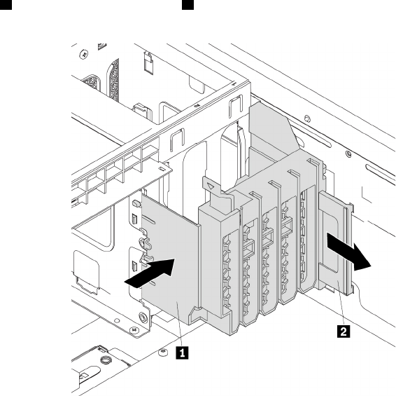
• “PCIe card retainer” on page 155 (if necessary)
• “Super capacitor module” on page 170 (if necessary)
• “Full-length PCIe card” on page 163 (if necessary)
4. Press the foot 1 inward and pull the handle 2 to the rear of the chassis at the same time to remove the
bracket.
Figure 132. Removing the multi-function bracket
176 P920 Hardware Maintenance Manual
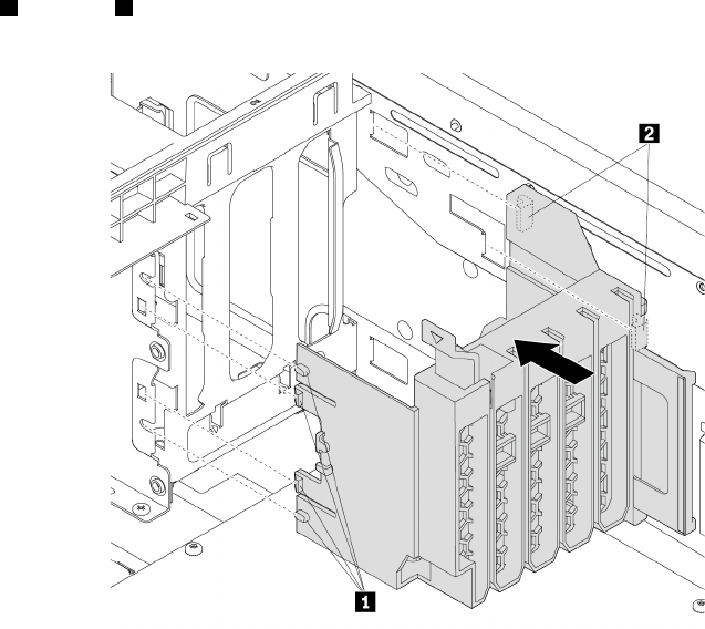
5. Align tabs 1 and tabs 2 on the bracket with the corresponding holes in the chassis. Then, insert the
tabs into the corresponding holes until the bracket snaps into position.
Figure 133. Reinstalling the multi-function bracket
6. Reinstall the following parts if you have removed them:
• “PCIe card retainer” on page 155
• “Super capacitor module” on page 170
• “Full-length PCIe card” on page 163
• “Front fan assembly” on page 137
• “Direct cooling air baffle” on page 107
What to do next:
• To work with another piece of hardware, go to the appropriate section.
• To complete the installation or replacement, go to “Completing the parts replacement” on page 210.
Coin-cell battery
Attention: Do not open your computer or attempt any repair before reading and understanding the Chapter
1 “Read this first: Important safety information” on page 1.
Your computer has a special type of memory that maintains the date, time, and settings for built-in features,
such as parallel-connector assignments (configuration). A coin-cell battery keeps this information active
when you turn off the computer.
The coin-cell battery normally requires no charging or maintenance throughout its life; however, no battery
lasts forever. If the coin-cell battery fails, the date, time, and configuration information (including passwords)
are lost. An error message is displayed when you turn on the computer.
Chapter 9.Hardware removal and installation 177
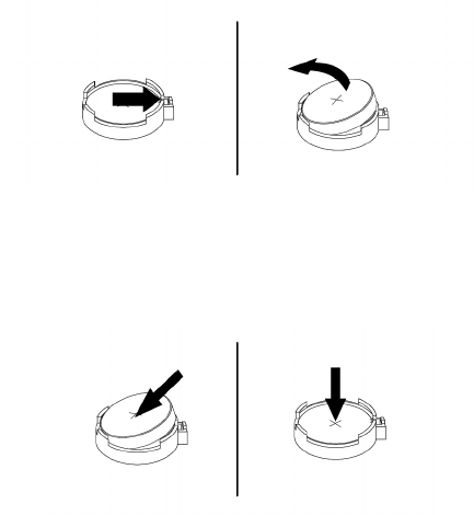
Refer to the “Lithium coin-cell battery notice” in the Safety, Warranty, and Setup Guide for information about
disposing of the coin-cell battery.
To remove and install the coin-cell battery, do the following:
1. Prepare your computer. See “Preparing your computer and removing the computer cover” on page 103.
2. To access the coin-cell battery, remove the following parts:
• “Direct cooling air baffle” on page 107 (if necessary)
• “Power supply assembly” on page 150
• “Front fan assembly” on page 137
• “M.2 solid-state drive holder” on page 140
• “PCIe card retainer” on page 155 (if necessary)
• “Super capacitor module” on page 170 (if necessary)
• “Full-length PCIe card” on page 163 (if necessary)
• “Multi-function bracket in the upper position” on page 173
3. Locate the coin-cell battery. See “Parts on the system board” on page 38.
4. Remove the old coin-cell battery as shown.
Figure 134. Removing the coin-cell battery
5. Install the new coin-cell battery as shown.
Figure 135. Installing the coin-cell battery
6. Reinstall the following parts if you have removed them:
• “Multi-function bracket in the upper position” on page 173
• “Front fan assembly” on page 137
• “Power supply assembly” on page 150
• “M.2 solid-state drive holder” on page 140
• “PCIe card retainer” on page 155
• “Super capacitor module” on page 170
• “Full-length PCIe card” on page 163
178 P920 Hardware Maintenance Manual
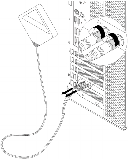
• “Direct cooling air baffle” on page 107
7. Reinstall the computer cover and reconnect the cables. See “Completing the parts replacement” on
page 210.
Note: When the computer is turned on for the first time after the coin-cell battery is replaced, an error
message might be displayed. This is normal after the coin-cell battery is replaced.
8. Turn on the computer and all attached devices.
9. Use the Setup Utility program to set the date, time, and any passwords. See “Using the Setup Utility
program” on page 67.
Wi-Fi units
Attention: Do not open your computer or attempt any repair before reading and understanding the Chapter
1 “Read this first: Important safety information” on page 1.
The Wi-Fi units include a Wi-Fi adapter, a Wi-Fi card, and a Wi-Fi antenna.
To remove or install the Wi-Fi units, do the following:
1. Prepare your computer. See “Preparing your computer and removing the computer cover” on page 103.
2. To remove the Wi-Fi units, do the following:
a. Unscrew the Wi-Fi antenna connectors to remove the Wi-Fi antenna from the rear of the computer.
Figure 136. Removing the Wi-Fi antenna
Chapter 9.Hardware removal and installation 179
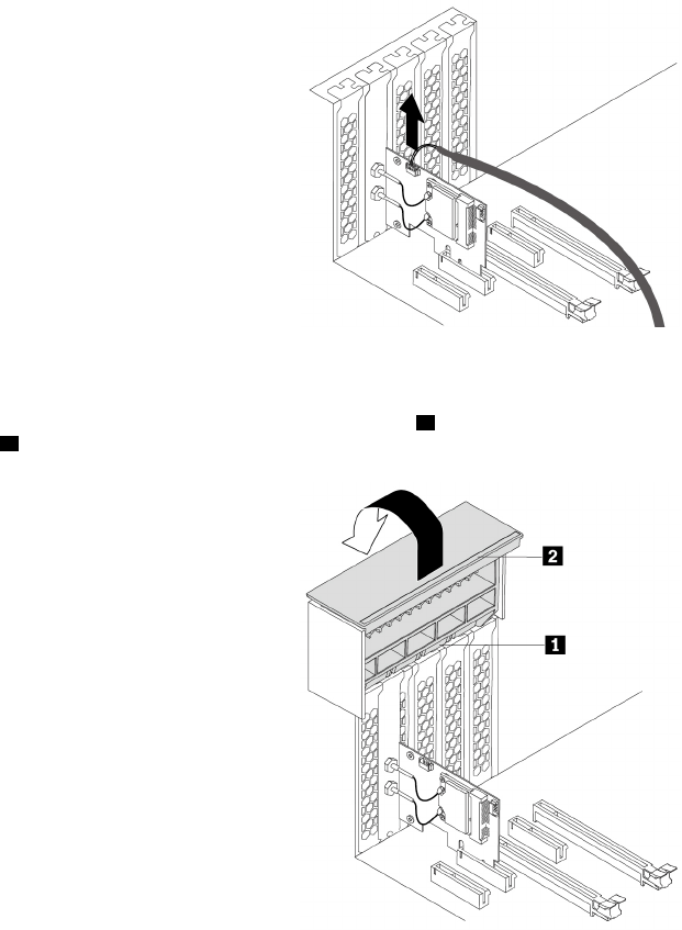
b. If your computer comes with a Wi-Fi card that supports the Bluetooth function, disconnect the
Bluetooth cable from the Wi-Fi adapter.
Figure 137. Disconnecting the Bluetooth cable
c. On the rear of the computer, lift the handle 2 and pivot it as shown until it stops. The PCIe card latch
1 is opened.
Figure 138. Opening the PCIe card latch
180 P920 Hardware Maintenance Manual
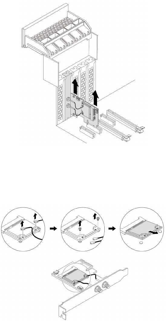
d. Grasp the Wi-Fi adapter and gently pull it out of the slot.
Figure 139. Removing the Wi-Fi adapter
Note: The card might fit tightly into the slot. If necessary, alternately move each side of the card a
small amount until the card is removed from the slot.
e. Disconnect two Wi-Fi antenna cables from the Wi-Fi card. Remove the two screws that secure the
Wi-Fi card to the Wi-Fi adapter. Then, pull the Wi-Fi card out of the mini PCIe slot.
Figure 140. Removing the Wi-Fi card
3. To install the Wi-Fi units, do the following:
Chapter 9.Hardware removal and installation 181
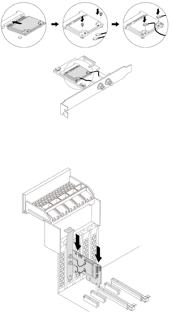
a. Insert the Wi-Fi card into the mini PCIe slot on the Wi-Fi adapter. Install two screws to secure the Wi-
Fi card to the Wi-Fi adapter. Connect two Wi-Fi antenna cables to the Wi-Fi card.
Figure 141. Installing the Wi-Fi card
b. Install the Wi-Fi adapter into the PCIe card slot on the system board. See “Parts on the system
board” on page 38.
Figure 142. Installing the Wi-Fi adapter
c. Pivot the PCIe card latch and push it back in until it snaps into position.
d. If the installed Wi-Fi card supports the Bluetooth function, connect a Bluetooth cable to the Wi-Fi
adapter.
Note: The Bluetooth cable connects the Bluetooth connector on the Wi-Fi adapter to the 15-in-1
card reader connector on the system board. See “Parts on the system board” on page 38.
182 P920 Hardware Maintenance Manual
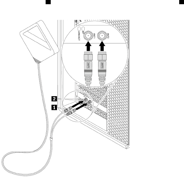
e. Attach the Wi-Fi antenna cable connectors 1 to the corresponding Wi-Fi antenna connectors 2 on
the rear of the computer as shown.
Figure 143. Installing the Wi-Fi antenna
f. Tighten the Wi-Fi antenna cable connectors to secure them to the rear of the computer.
What to do next:
• To work with another piece of hardware, go to the appropriate section.
• To complete the installation or replacement, go to “Completing the parts replacement” on page 210.
Device in the 5.25-inch flex module
Attention: Do not open your computer or attempt any repair before reading and understanding the Chapter
1 “Read this first: Important safety information” on page 1.
This section provides instructions on how to install or replace a device in the 5.25-inch flex module. Installing
and replacing a device in the 5.25-inch flex module involves the following operations:
• “Slim optical drive” on page 183
• “Card reader” on page 186
• “eSATA connector or IEEE 1394 connector” on page 188
• “Front Thunderbolt adapter kit” on page 190
Slim optical drive
To remove or install a slim optical drive in the flex module, do the following:
1. Prepare your computer. See “Preparing your computer and removing the computer cover” on page 103.
2. Record the cable connections and cable routing. Then, disconnect all cables connected to the flex
module from the system board. See “Parts on the system board” on page 38.
Chapter 9.Hardware removal and installation 183
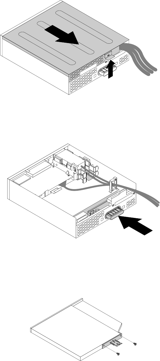
3. Remove the flex module from the front of the computer. See “Device in a flex bay” on page 109.
4. Lift the clip on the rear of the flex module. Then, slide the flex module cover to the rear of the flex module
to remove the cover.
Figure 144. Removing the flex module cover
5. To remove a slim optical drive, do the following:
a. Press the button as shown to remove the slim optical drive from the flex module.
Figure 145. Removing the slim optical drive from the flex module
b. Remove the two screws that secure the clip to remove the plastic clip from the rear of the slim optical
drive.
Note: The plastic clip and the two screws need to be reused to install a new slim optical drive.
Figure 146. Removing the plastic clip from the slim optical drive
184 P920 Hardware Maintenance Manual
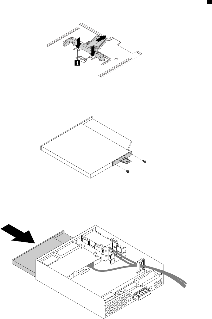
6. To install a slim optical drive, do the following:
a. If no slim optical drive has been installed in the flex module before, press the two metal clips 1 to
remove the plastic clip with the two screws as shown. Remove the two screws.
Figure 147. Removing the plastic clip with the two screws
b. Install the two screws to secure the plastic clip on the rear of the new slim optical drive.
Figure 148. Installing the plastic clip to the slim optical drive
c. Slide the new slim optical drive with the plastic clip into the flex module until the slim optical drive
snaps into position.
Figure 149. Installing the slim optical drive in the flex module
7. Position the flex module cover on the flex module. Ensure that the rail guides on the bottom of the flex
module cover engage the rails on the flex module. Then, push the cover to the front of the flex module
until it snaps into position.
Chapter 9.Hardware removal and installation 185
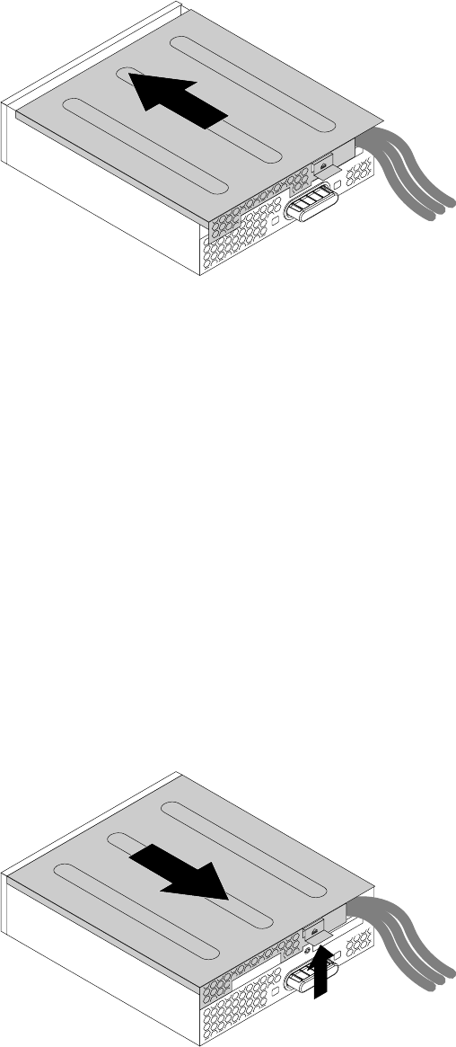
Figure 150. Reinstalling the flex module cover
8. Install the flex module into the flex bay. See “Device in a flex bay” on page 109.
9. Refer to the recorded information about the cable connections and routing. Reconnect all cables
connected to the flex module to the system board. See “Parts on the system board” on page 38.
What to do next:
• To work with another piece of hardware, go to the appropriate section.
• To complete the installation or replacement, go to “Completing the parts replacement” on page 210.
Card reader
To remove or install a card reader in the flex module, do the following:
1. Prepare your computer. See “Preparing your computer and removing the computer cover” on page 103.
2. Record the cable connections and cable routing. Then, disconnect all cables connected to the flex
module from the system board. See “Parts on the system board” on page 38.
3. Remove the flex module from the front of the computer. See “Device in a flex bay” on page 109.
4. Lift the clip on the side of the flex module upward. Then, slide the flex module cover to the rear of the
flex module to remove the cover.
Figure 151. Removing the flex module cover
5. If you are removing a card reader, do the following:
a. Pull the clip as shown to remove the card reader with the card reader retaining bracket out of the flex
module.
186 P920 Hardware Maintenance Manual
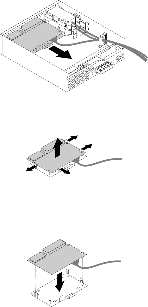
Figure 152. Removing the card reader in the flex module
b. Flex the four clips on the sides of the card reader retaining bracket to remove the card reader from
the bracket.
Figure 153. Removing the card reader from the card reader retaining bracket
6. To install a card reader, do the following:
a. To install a new card reader into the card reader retaining bracket, align the four holes in the card
reader with the corresponding studs on the bracket. Then, press the new card reader downward until
it snaps into position.
Figure 154. Installing the card reader into the card reader retaining bracket
b. Note the orientation of the new card reader and route the card reader cable into the cable clip. Hold
the clip on the card reader retaining bracket. Then, insert the new card reader into the card reader
slot in flex module until it snaps into position.
Chapter 9.Hardware removal and installation 187
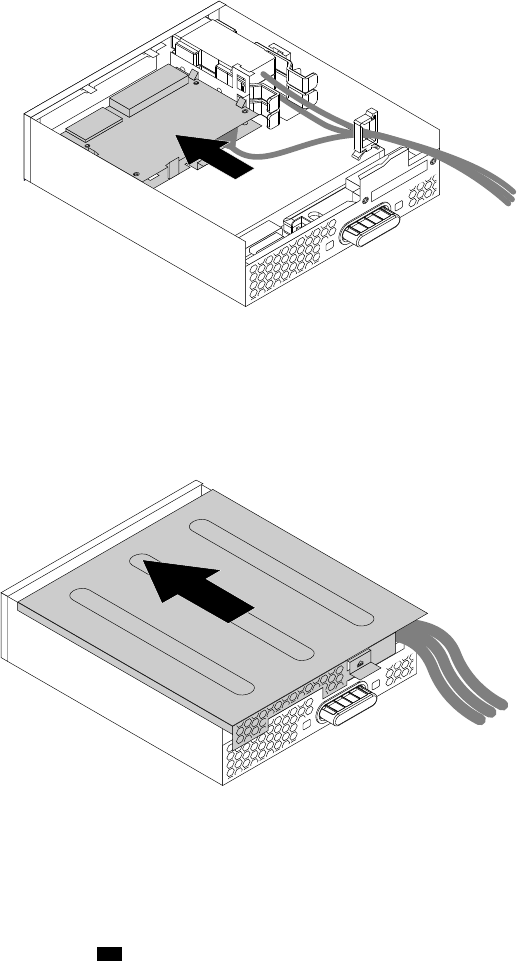
Figure 155. Installing the card reader in the flex module
7. Position the flex module cover on the flex module. Ensure that the rail guides on the bottom of the flex
module cover engage the rails on the flex module. Then, push the cover to the front of the flex module
until it snaps into position.
Figure 156. Reinstalling the flex module cover
8. Install the flex module into the flex bay. See “Device in a flex bay” on page 109.
9. Refer to the recorded information about the cable connections and routing. Reconnect all cables
connected to the flex module to the system board. For the card reader, connect the card reader cable to
the 15-in-1 card reader connector 39 on the system board. See “Parts on the system board” on page
38.
What to do next:
• To work with another piece of hardware, go to the appropriate section.
• To complete the installation or replacement, go to “Completing the parts replacement” on page 210.
eSATA connector or IEEE 1394 connector
To remove or install an eSATA connector or IEEE 1394 connector in the flex module, do the following:
1. Prepare your computer. See “Preparing your computer and removing the computer cover” on page 103.
2. Record the cable connections and cable routing. Then, disconnect all cables connected to the flex
module from the system board. See “Parts on the system board” on page 38.
3. Remove the flex module from the front of the computer. See “Device in a flex bay” on page 109.
188 P920 Hardware Maintenance Manual
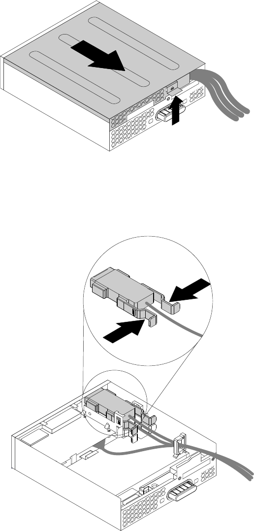
4. Lift the clip on the side of the flex module upward. Then, slide the flex module cover to the rear of the
flex module to remove the cover.
Figure 157. Removing the flex module cover
5. To remove an eSATA connector or IEEE 1394 connector, do the following:
a. Press the two clips toward each other as shown to pull the eSATA connector or IEEE 1394 connector
out of the flex module.
Figure 158. Removing the eSATA connector or IEEE 1394 connector in the flex module
6. To install an eSATA connector or IEEE 1394 connector, do the following:
a. Note the orientation of the eSATA connector or IEEE 1394 connector and route the eSATA connector
or IEEE 1394 connector cable into the cable clip.
Chapter 9.Hardware removal and installation 189
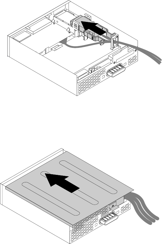
b. Place the eSATA connector or IEEE 1394 connector into the metal retainer. Then, insert the eSATA
connector or IEEE 1394 connector into the corresponding slot in the flex module as shown.
Figure 159. Installing the eSATA connector or IEEE 1394 connector in the flex module
7. Position the flex module cover on the flex module. Ensure that the rail guides on the bottom of the flex
module cover engage the rails on the flex module. Then, push the cover to the front of the flex module
until it snaps into position.
Figure 160. Reinstalling the flex module cover
8. Install the flex module into the flex bay. See “Device in a flex bay” on page 109.
9. Refer to the recorded information about the cable connections and routing, reconnect all cables
connected to the flex module to the system board. See “Parts on the system board” on page 38. For the
eSATA connector or IEEE 1394 connector, connect the cables to the system board as follows:
• Connect the eSATA connector to the eSATA connector on the system board.
• Connect the IEEE 1394 connector cable to the IEEE 1394 adapter.
What to do next:
• To work with another piece of hardware, go to the appropriate section.
• To complete the installation or replacement, go to “Completing the parts replacement” on page 210.
Front Thunderbolt adapter kit
The front Thunderbolt adapter kit includes the following parts:
• A front Thunderbolt I/O adapter
190 P920 Hardware Maintenance Manual
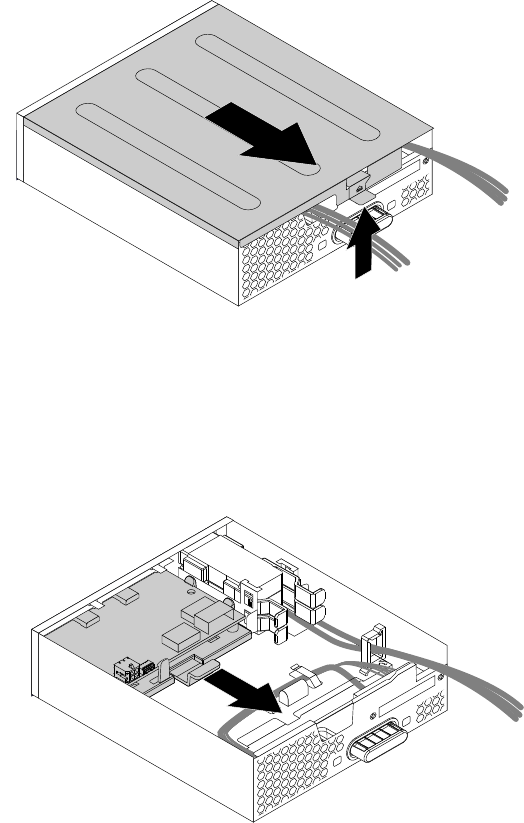
• A front Thunderbolt PCIe x4 card
• A bezel
• A general-purpose input/output (GPIO) cable
• A mini-SAS cable
• An internal DP-to-DP cable
• An external DP-to-DP cable
To remove or install a front Thunderbolt adapter kit, do the following:
1. Prepare your computer. See “Preparing your computer and removing the computer cover” on page 103.
2. Record the cable connections and cable routing. Then, disconnect all cables connected to the flex
module from the system board. See “Parts on the system board” on page 38.
3. Remove the flex module from the front of the computer. See “Device in a flex bay” on page 109.
4. Lift the clip on the rear of the flex module, and then slide the flex module cover to the rear of the flex
module.
Figure 161. Removing the flex module cover
5. To remove a front Thunderbolt I/O adapter, do the following:
a. Remove all the cables connected to the front Thunderbolt I/O adapter.
b. Pull the clip as shown to remove the front Thunderbolt I/O adapter and the retaining bracket out of
the flex module.
Figure 162. Removing the front Thunderbolt adapter and the retaining bracket out of the flex module
Chapter 9.Hardware removal and installation 191
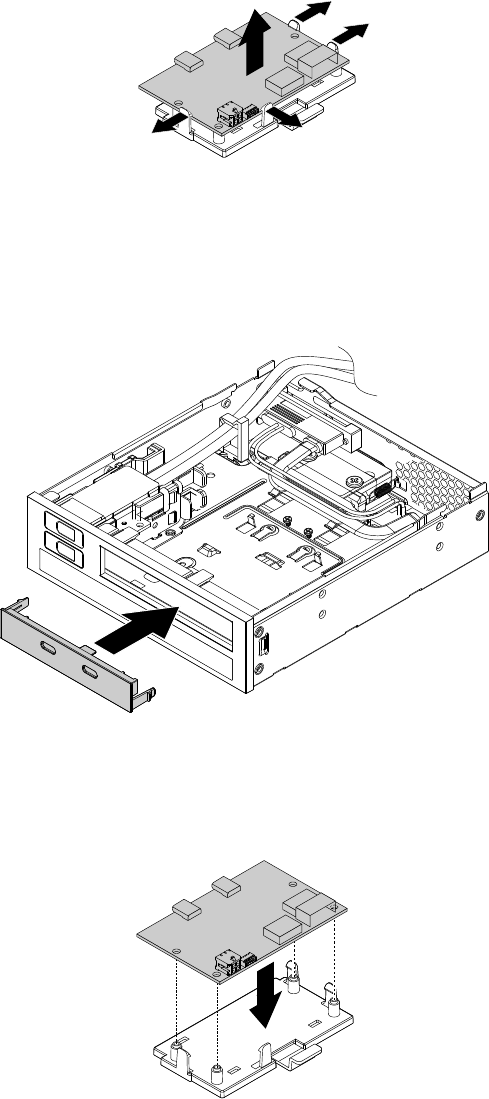
c. Flex the four clips on the sides of the retaining bracket to remove the front Thunderbolt I/O adapter
from the bracket.
Figure 163. Removing the front Thunderbolt I/O adapter from the retaining bracket
6. To install a front Thunderbolt I/O adapter, do the following:
a. If necessary, remove the dummy bezel. Then, install the bezel in the front Thunderbolt adapter kit to
the flex module.
Figure 164. Installing the bezel to the flex module
b. Align the four holes in the front Thunderbolt I/O adapter with the corresponding mounting studs on
the bracket. Then, press the card downward until it snaps into position.
Figure 165. Installing the front Thunderbolt I/O adapter into the retaining bracket
c. Hold the clip on the retaining bracket. Then insert the front Thunderbolt I/O adapter and the retaining
bracket into the flex module as shown until they snap into position.
192 P920 Hardware Maintenance Manual
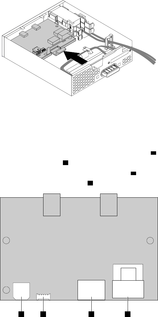
Figure 166. Installing the front Thunderbolt adapter and the retaining bracket into the flex module
d. Install the front Thunderbolt PCIe x4 card into a PCIe 3.0 x4 card slot on the system board. See
“PCIe card” on page 155 and “Parts on the system board” on page 38.
e. Connect the cables to the front Thunderbolt I/O adapter.
• Connect the power cable in the flex module to the 4-pin power connector a.
• Connect the GPIO cable to the connector b.
• Connect the internal DP-to-DP cable to the DisplayPort connector c.
• Connect the mini-SAS cable to the SAS connector d.
abcd
Figure 167. Front Thunderbolt adapter cable connection
f. Route the cables through the two holes in the rear of the flex module.
7. Position the flex module cover on the flex module. Ensure that the rail guides on the bottom of the cover
engage the rails on the flex module. Then, push the cover to the front of the flex module until it snaps
into position.
Chapter 9.Hardware removal and installation 193
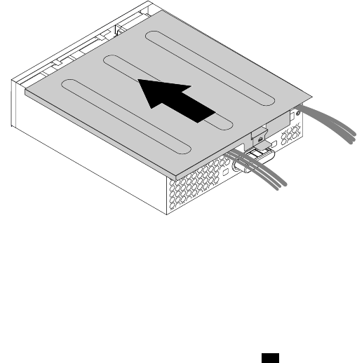
Figure 168. Reinstalling the flex module cover
8. Install the flex module into the flex bay. See “Device in a flex bay” on page 109.
9. Refer to the recorded information about the cable connections and routing. Reconnect all cables
connected to the flex module to the system board. For the front Thunderbolt adapter kit, connect the
cables to the system board and the front Thunderbolt PCIe x4 card as follows:
• Connect the GPIO cable to the Thunderbolt control connector ( 47 ) on the system board. See “Parts
on the system board” on page 38.
• Connect the internal DP-to-DP cable to the DisplayPort connector on the front Thunderbolt PCIe x4
card.
• Connect the mini-SAS cable to the SAS connector on the front Thunderbolt PCIe x4 card.
• Connect the external DP-to-DP cable to the DisplayPort connector on the front Thunderbolt PCIe x4
card and the DisplayPort connector on the graphics card.
What to do next:
• To work with another piece of hardware, go to the appropriate section.
• To complete the installation or replacement, go to “Completing the parts replacement” on page 210.
VROC upgrade key module
Attention: Do not open your computer or attempt any repair before reading and understanding the Chapter
1 “Read this first: Important safety information” on page 1.
To remove or install a VROC upgrade key module, do the following:
1. Prepare your computer. See “Preparing your computer and removing the computer cover” on page 103.
2. Remove the direct cooling air baffle. See “Direct cooling air baffle” on page 107.
3. Lay the computer on its side for easier access to the heat-sink-and-fan assembly.
4. To access the VROC upgrade key module, remove the following parts:
• “Direct cooling air baffle” on page 107
• “Power supply assembly” on page 150
• “Front fan assembly” on page 137
• “M.2 solid-state drive holder” on page 140
• “PCIe card retainer” on page 155 (if necessary)
• “Super capacitor module” on page 170 (if necessary)
194 P920 Hardware Maintenance Manual
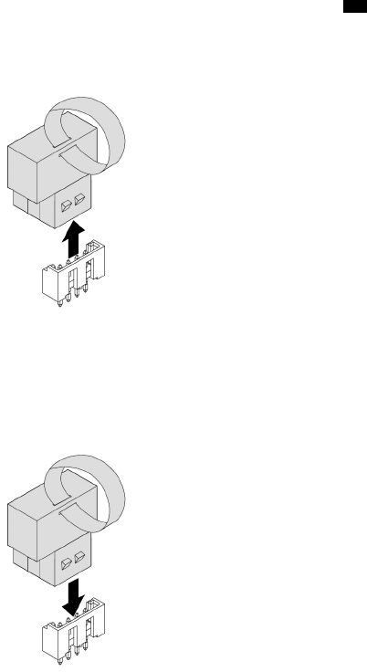
• “Full-length PCIe card” on page 163 (if necessary)
• “Multi-function bracket in the upper position” on page 173
5. Locate the VROC upgrade key module on the system board. See the VROC connector 23 in “Parts on
the system board” on page 38.
6. Remove the VROC upgrade key module as shown.
Figure 169. Removing a VROC upgrade key module
7. Note the orientation of the new VROC upgrade key module. Install the VROC upgrade key module to the
VROC connector on the system board.
Figure 170. Installing a VROC upgrade key module
8. Reinstall all parts that you have removed one by one in the reversed sequence as you remove them.
What to do next:
• To work with another piece of hardware, go to the appropriate section.
• To complete the installation or replacement, go to “Completing the parts replacement” on page 210.
Blind-connect assembly
Attention: Do not open your computer or attempt any repair before reading and understanding the Chapter
1 “Read this first: Important safety information” on page 1.
To remove or install a blind-connect assembly, do the following:
1. Prepare your computer. See “Preparing your computer and removing the computer cover” on page 103.
2. Locate the storage drive bay from which you want to remove or install a blind-connect assembly. See
“Internal storage drives” on page 40.
Chapter 9.Hardware removal and installation 195
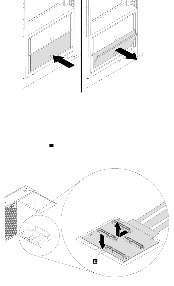
3. Press the pit on the cover of the storage drive bay so that the cover is opened. Then, pull the cover edge
as shown to remove the storage drive bracket from the storage drive bay.
Figure 171. Removing the storage drive bracket
4. Lay the computer on its side for easier access to the blind-connect assembly.
5. To remove a blind-connect assembly, do the following:
a. Record the cable routing and cable connections, and then disconnect the cables of the blind-
connect assembly from the system board or the RAID adapter.
b. Press and hold the metal retainer a, and slide the blind-connect board as shown to release it from
the four tabs.
Figure 172. Removing the blind-connect assembly
c. Pull the blind-connect assembly out of the chassis and remove the cables through the routing holes.
196 P920 Hardware Maintenance Manual
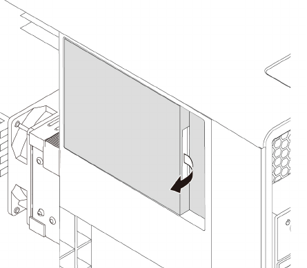
Notes:
• Be careful when you pull the cables through the holes.
• The cable routing varies depending on whether the blind-connect assembly is installed in the
upper storage drive bay or the lower storage drive bay. Record the cable routing method before
pulling out the cables. When you install the new blind-connect assembly afterward, route the
cables in the same way according to your record.
6. To install a blind-connect assembly, do the following:
a. For an optional storage drive bay, remove the storage-drive-bay cover.
Figure 173. Removing the storage-drive-bay cover
Chapter 9.Hardware removal and installation 197
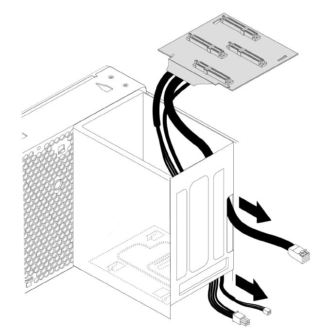
b. Take a new blind-connect assembly. Insert the cables through the routing holes. Refer to the
following figure for cable routing in the lower storage drive bay.
Figure 174. Cable routing for the lower storage drive bay
198 P920 Hardware Maintenance Manual
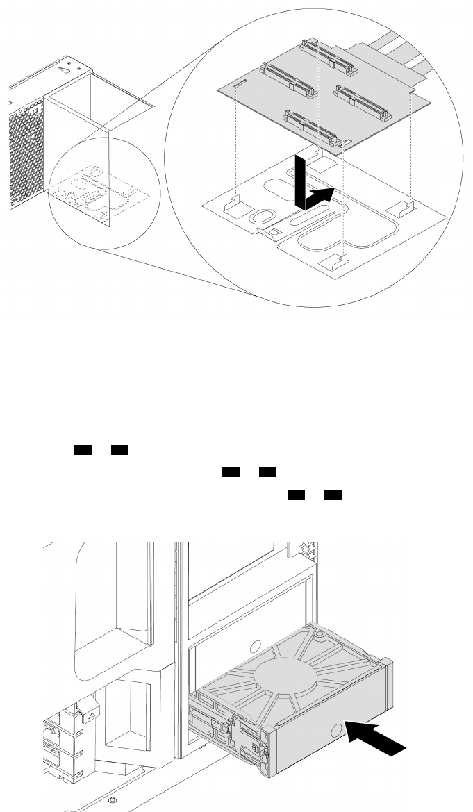
c. Align the four tabs at the bottom of the storage drive bay with the slots on the new blind-connect
board. Then, press down the board and slide it as shown until it snaps into position.
Figure 175. Installing the blind-connect assembly
d. Connect the cables of the blind-connect assembly to the system board or the RAID adapter. See
“Parts on the system board” on page 38.
• If the computer has a RAID adapter installed, connect the cable with the S/X silkscreen to the
mini-SAS connector on the RAID adapter. If no RAID adapter is installed, connect the cable to the
mini-SAS connector ( 44 or 43 ) on the system board.
• Connect the I2C cable to the BCA connector ( 34 or 21 ) on the system board.
• Connect the power cable to the 4-pin power connector ( 17 or 32 ) on the system board.
7. Slide the storage drive bracket back into the storage drive bay until the bracket snaps into position.
Figure 176. Installing the storage drive bracket
Chapter 9.Hardware removal and installation 199
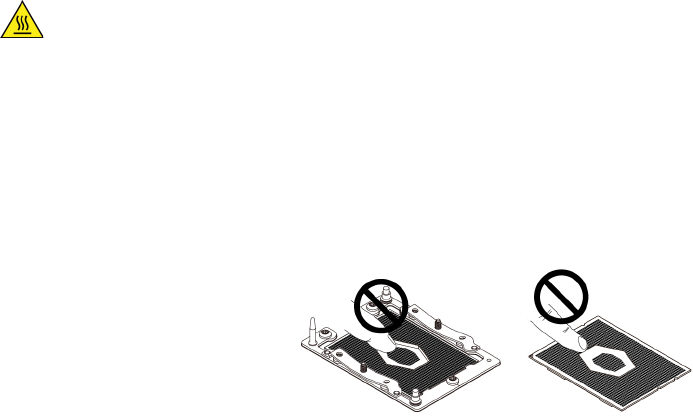
What to do next:
• To work with another piece of hardware, go to the appropriate section.
• To complete the installation or replacement, go to “Completing the parts replacement” on page 210.
Heat-sink-and-fan assembly
Attention: Do not open your computer or attempt any repair before reading and understanding the Chapter
1 “Read this first: Important safety information” on page 1.
CAUTION:
Avoid contact with hot components inside the computer. During operation, some components
become hot enough to burn the skin. Before you open the computer cover, turn off the computer,
disconnect power, and wait approximately 10 minutes for the components to cool.
Notes:
• Depending on your computer model, your computer might be installed with one or two heat-sink-and-fan
assemblies.
• Do not touch the pins on the microprocessor socket or the gold contacts on the microprocessor.
Figure 177. Do not touch the pins or the gold contacts
To remove or install a heat-sink-and-fan assembly, do the following:
1. Prepare your computer. See “Preparing your computer and removing the computer cover” on page 103.
2. Remove the direct cooling air baffle. See “Direct cooling air baffle” on page 107.
3. Lay the computer on its side for easier access to the heat-sink-and-fan assembly.
4. To remove a heat-sink-and-fan assembly from the system board, do the following:
a. Locate the failing heat-sink-and-fan assembly. See “Computer components” on page 33.
b. Disconnect the heat-sink-and-fan-assembly cable from the system board.
200 P920 Hardware Maintenance Manual
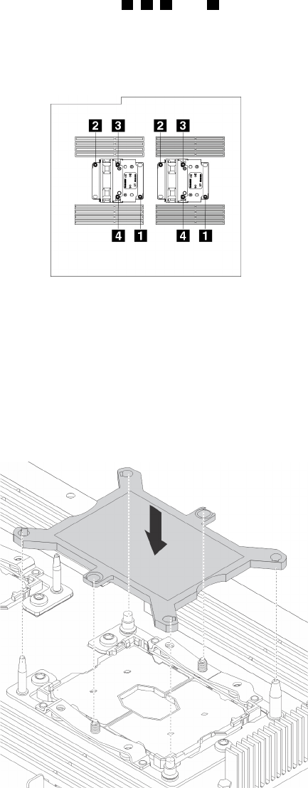
c. Use a T30 Torx® screwdriver to loosen screws 4, 3, 2, and 1 in sequence to release the heat-sink-
and-fan assembly from the system board.
Note: Carefully loosen the four screws to avoid any possible damage to the system board. The four
screws cannot be removed from the heat-sink-and-fan assembly.
Figure 178. Removing the heat-sink-and-fan assembly
d. Lift the failing heat-sink-and-fan assembly from the system board.
Notes:
• You might have to gently twist the heat-sink-and-fan assembly to free it from the microprocessor
socket on the system board.
• Install a microprocessor socket cover to protect the empty microprocessor socket.
Figure 179. Installing the microprocessor socket cover
Chapter 9.Hardware removal and installation 201
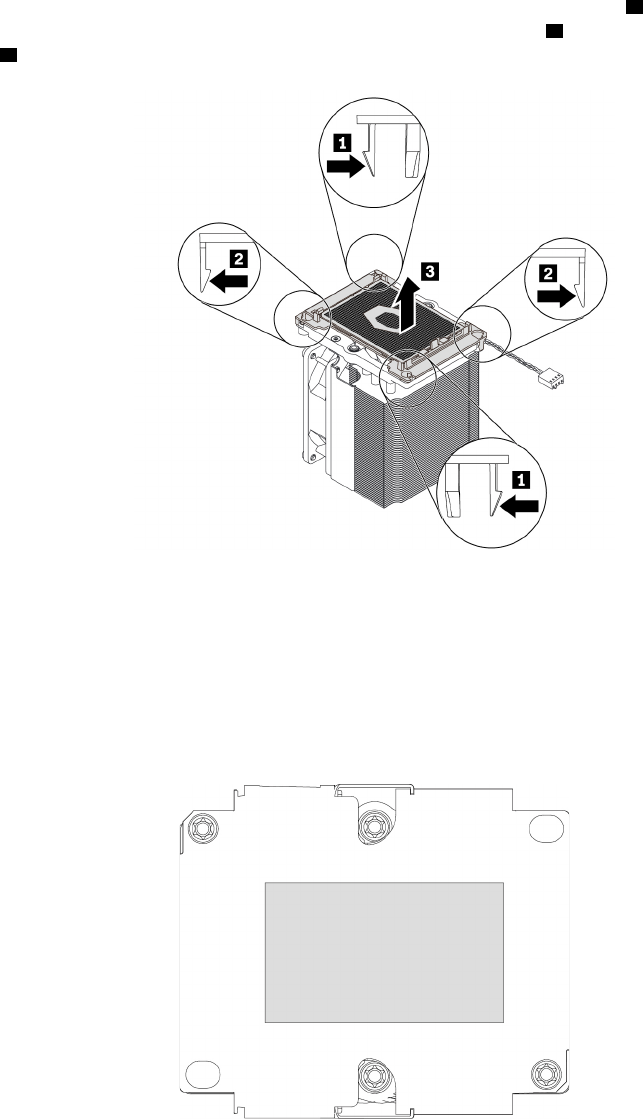
e. Turn the heat-sink-and-fan assembly upside down. Release two retaining clips 1 at the corner of the
microprocessor retainer and then release the other two retaining clips 2 as shown. Then, lift the
retainer 3 with the microprocessor from the heat-sink-and-fan assembly.
Figure 180. Removing the microprocessor retainer from the heat-sink-and-fan assembly
Note: Set aside the microprocessor retainer with the microprocessor. Ensure that the thermal
grease on the bottom of the microprocessor does not get in contact with anything.
5. To install a heat-sink-and-fan assembly on the system board, do the following:
a. If necessary, apply appropriate amount of thermal grease to the bottom of the heat-sink-and-fan
assembly as shown.
Figure 181. Applying thermal grease on the heat-sink-and-fan assembly
202 P920 Hardware Maintenance Manual
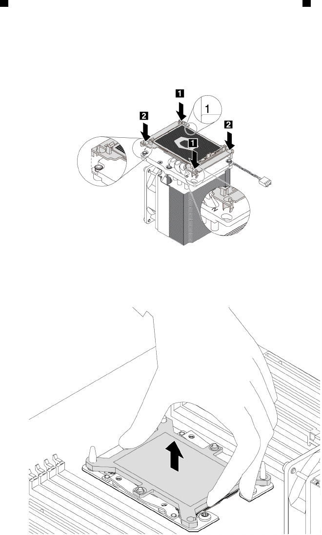
b. Position the microprocessor retainer with the microprocessor on the heat-sink-and-fan assembly.
Insert two retaining clips of the retainer into the corresponding holes in the heat-sink-and-fan
assembly 1. Then, press the other two clips downward until you hear two clicks 2. Ensure that the
retainer with the microprocessor is securely seated on the heat-sink-and-fan assembly.
Note: To install the microprocessor 1 on the heat-sink-and-fan assembly 1, ensure that the
engraved number 1 on the bottom of the heat-sink-and-fan assembly is visible. To install the
microprocessor 2 on the heat-sink-and-fan assembly 2, ensure that the engraved number 2 on the
bottom of the heat-sink-and-fan assembly is visible.
Figure 182. Installing the microprocessor retainer on the heat-sink-and-fan assembly
c. If the microprocessor socket is installed with a microprocessor socket cover, remove the cover.
Figure 183. Removing the microprocessor socket cover
Chapter 9.Hardware removal and installation 203
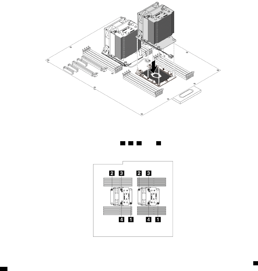
d. Position the heat-sink-and-fan assembly on the system board as shown and align the four screws
with the holes in the system board. Then, lower the heat-sink-and-fan assembly straight down onto
the system board.
Figure 184. Positioning the heat-sink-and-fan assembly on the system board
e. Use a T30 Torx screwdriver to tighten screws 1, 2, 3, and 4 in sequence to secure the heat-sink-
and-fan assembly to the system board.
Figure 185. Securing the heat-sink-and-fan assembly to the system board
f. Connect the cable of the new heat-sink-and-fan assembly to the microprocessor fan connector ( 9 or
27 ) on the system board. See “Parts on the system board” on page 38.
6. Reinstall the direct cooling air baffle. See “Direct cooling air baffle” on page 107.
What to do next:
• To work with another piece of hardware, go to the appropriate section.
• To complete the installation or replacement, go to “Completing the parts replacement” on page 210.
Microprocessor
Attention: Do not open your computer or attempt any repair before reading and understanding the Chapter
1 “Read this first: Important safety information” on page 1.
204 P920 Hardware Maintenance Manual
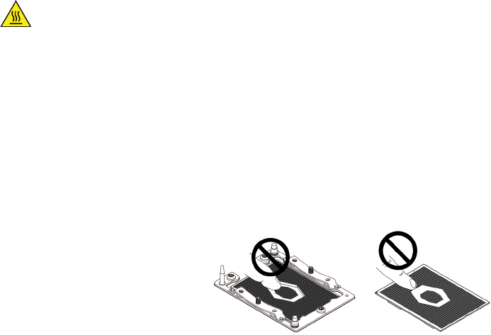
CAUTION:
Avoid contact with hot components inside the computer. During operation, some components
become hot enough to burn the skin. Before you open the computer cover, turn off the computer,
disconnect power, and wait approximately 10 minutes for the components to cool.
Notes:
• Ensure that you install the correct type of microprocessor your computer supports. When two
microprocessors are installed, they must be identical.
• Your microprocessor, socket, and socket cover might look slightly different from the illustrations in this
topic.
• Do not touch the pins on the microprocessor socket or the gold contacts on the microprocessor.
Figure 186. Do not touch the pins or the gold contacts
Depending on your computer model, your computer might be installed with one or two microprocessors.
To remove or install a microprocessor, do the following:
1. Prepare your computer. See “Preparing your computer and removing the computer cover” on page 103.
2. Remove the direct cooling air baffle. See “Direct cooling air baffle” on page 107.
3. Lay the computer on its side for easier access to the heat-sink-and-fan assembly.
4. Locate the correct microprocessor socket on the system board. See “Parts on the system board” on
page 38.
5. To remove a microprocessor, do the following:
a. Remove the heat-sink-and-fan assembly from the system board. Then, remove the microprocessor
retainer with the microprocessor from the heat-sink-and-fan assembly. See “Heat-sink-and-fan
assembly” on page 200.
Chapter 9.Hardware removal and installation 205
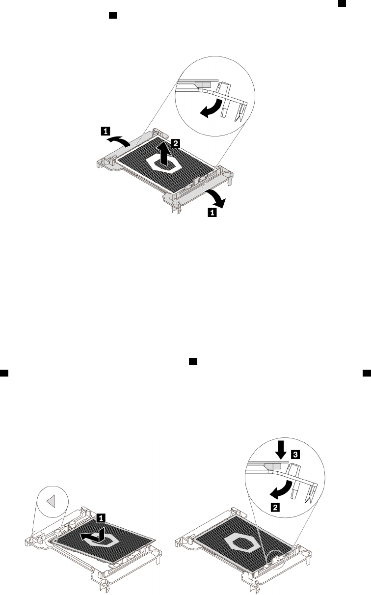
b. Flex two sides of the retainer downward to release the microprocessor from the retainer 1. Then, lift
the microprocessor off the retainer 2.
Note: Touch only the edges of the microprocessor. Do not touch the gold contacts.
Figure 187. Removing the microprocessor from the microprocessor retainer
c. Carefully wipe the thermal grease off the old microprocessor. Place the old microprocessor on a
static-protective surface.
6. To install a microprocessor, do the following:
a. Touch the static-protective package that contains the new microprocessor to any unpainted surface
on the outside of the computer. Then, remove the new microprocessor from the package.
b. Remove the protective cover that protects the gold contacts from the new microprocessor.
c. Note the orientation of the new microprocessor. Hold the new microprocessor by its edges and then
insert one end of the microprocessor into the retainer 1. Then, pivot the opposite side of the retainer
as shown 2 and lower the new microprocessor straight down into the microprocessor socket 3.
Note: The small triangle on one corner of the new microprocessor is the microprocessor orientation
indicator. The new microprocessor is in the correct orientation when this indicator faces the triangle
on the microprocessor retainer.
Figure 188. Installing the microprocessor into the microprocessor
206 P920 Hardware Maintenance Manual
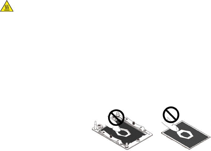
d. Install the microprocessor retainer with the new microprocessor on the heat-sink-and-fan assembly.
Then, install the heat-sink-and-fan assembly on the system board. See “Heat-sink-and-fan
assembly” on page 200.
What to do next:
• To work with another piece of hardware, go to the appropriate section.
• To complete the installation or replacement, go to “Completing the parts replacement” on page 210.
System board
Attention: Do not open your computer or attempt any repair before reading and understanding the Chapter
1 “Read this first: Important safety information” on page 1.
CAUTION:
Avoid contact with hot components inside the computer. During operation, some components
become hot enough to burn the skin. Before you open the computer cover, turn off the computer,
disconnect power, and wait approximately 10 minutes for the components to cool.
Notes:
• Each computer has a unique Vital Product Data (VPD) code stored in the nonvolatile memory on the
system board. After you replace the system board, the VPD must be updated. To update the VPD, see
“Updating and recovering the BIOS” on page 73.
• Your microprocessor sockets and socket covers might look slightly different from the illustrations in this
topic.
• Do not touch the pins on the microprocessor socket or the gold contacts on the microprocessor.
Figure 189. Do not touch the pins or the gold contacts
To remove or install the system board, do the following:
1. Prepare your computer. See “Preparing your computer and removing the computer cover” on page 103.
2. To remove the system board, do the following:
a. To access the system board, remove the following parts:
• “Direct cooling air baffle” on page 107
• “Power supply assembly” on page 150
• “Front fan assembly” on page 137
• “M.2 solid-state drive holder” on page 140
• “PCIe card” on page 155
• “Super capacitor module” on page 170
• “Full-length PCIe card” on page 163
• “Multi-function brackets” on page 173
Chapter 9.Hardware removal and installation 207
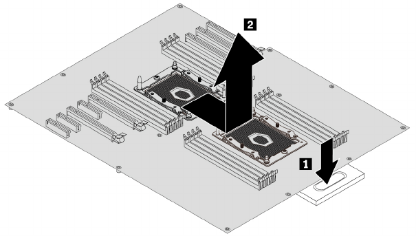
• “Rear fan assembly” on page 138
• “Memory module” on page 152
• “Heat-sink-and-fan assembly” on page 200
• “VROC upgrade key module” on page 194
b. Record the cable routing and cable connections, and then disconnect all cables from the system
board. See “Parts on the system board” on page 38.
c. Press the metal retainer to release the failing system board. Then push the failing system board
toward the metal retainer and carefully lift the system board out of the chassis.
Note: Carefully handle the system board by its edges.
Figure 190. Removing the system board
3. To install the system board, do the following:
208 P920 Hardware Maintenance Manual
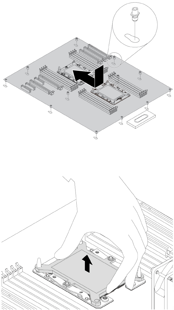
a. Position the new system board in the chassis. Align the 12 mounting studs on the bottom of the
system board with the corresponding holes in the chassis. Then, push the new system board toward
the rear of the computer until it snaps into position. Ensure that the system board is secured by the
metal retainer.
Figure 191. Installing the system board
b. Remove the microprocessor socket covers from the new system board.
Figure 192. Removing the microprocessor socket cover
c. Reinstall all parts that you have removed one by one in the reversed sequence as you remove them.
Refer to the information that you have recorded and the related topics in “Removing and installing
Chapter 9.Hardware removal and installation 209
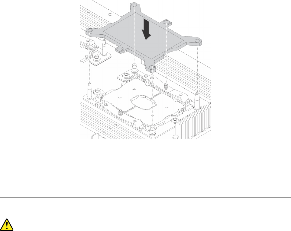
hardware” on page 104. Connect all cables to the new system board. See “Parts on the system
board” on page 38.
d. Connect the external cables and the power cord to the computer.
The failing system board must be returned with microprocessor socket covers to protect the pins during
shipping and handling. Install the microprocessor socket covers removed from the new system board on the
failing system board.
Note: Ensure that each microprocessor socket on the failing system board is installed with a microprocessor
socket cover.
To install the microprocessor socket cover, position the cover on the microprocessor socket as shown and
lower the cover straight down into the socket on the system board.
Figure 193. Installing the microprocessor socket cover
What to do next:
• To work with another piece of hardware, go to the appropriate section.
• To complete the installation or replacement, go to “Completing the parts replacement” on page 210.
Completing the parts replacement
CAUTION:
After replacing a CRU, reinstall all protective covers, including the computer cover, before connecting
power and operating the computer. This action is important to help prevent unexpected electrical
shock and help ensure the containment of an unexpected fire that could happen under extremely rare
conditions.
After completing the removal or installation for all parts, reinstall the computer cover and reconnect cables.
Depending on the parts you removed or installed, you might need to confirm the updated information in the
Setup Utility program. Refer to “Using the Setup Utility program” on page 67.
210 P920 Hardware Maintenance Manual
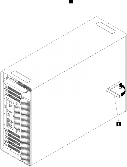
To reinstall the computer cover and reconnect cables to your computer, do the following:
1. Ensure that all components have been reassembled correctly and that no tools or loose screws are left
inside your computer. See “Computer components” on page 33 for the locations of various components
in your computer.
2. Ensure that the cables are routed correctly before reinstalling the computer cover. Keep cables clear of
the hinges and sides of the computer chassis to avoid interference with reinstalling the computer cover.
3. Position the computer cover on the chassis so that the rail guides on the bottom of the computer cover
engage the rails on the chassis. Then, pivot the handle 1 inward until it snaps into position so that the
cover is secured tightly.
Figure 194. Reinstalling the computer cover
4. Place the computer in an upright position.
5. If there is any locking device available, lock the computer cover. See “Locking your computer” on page
61.
6. Reconnect the external cables and power cords to the corresponding connectors on the computer. See
“Hardware locations” on page 29.
7. Update the configuration of your computer if necessary. See “Using the Setup Utility program” on page
67.
8. If a newly installed hardware component does not work correctly, update the device driver. See
“Keeping your computer current” on page 58.
Chapter 9.Hardware removal and installation 211
212 P920 Hardware Maintenance Manual

Chapter 10. Getting information, help, and service
This chapter provides information about getting help and support from Lenovo.
Information resources
You can use the information in this section to access useful resources relating to your computing needs.
Accessing the user guide in various languages
To access the user guide in various languages, go to:
http://www.lenovo.com/support
Windows help system
The Windows help system provides you with detailed information about using the Windows operating
system.
To access the Windows help system, do the following:
1. Click the Start button to open the Start menu.
2. Depending on your Windows version, do one of the following:
• For Windows 7: Click Help and Support. You can choose to use the online or offline help at the
bottom of the screen.
• For Windows 10: Click Get Help.
Note: Using online help for Windows 7 or the help for Windows 10 requires an active Internet connection.
Safety and warranty
The Safety, Warranty, and Setup Guide provided with your computer contains important safety information,
product warranty terms, initial setup procedure, and legal notices. Ensure that you read and understand all
safety information in the Safety, Warranty, and Setup Guide before using your computer.
In addition, read and understand Chapter 1 “Read this first: Important safety information” on page 1 before
using your computer. This preface provides additional safety information that applies to topics and tasks
described in this User Guide.
Lenovo Web site
The Lenovo Web site (http://www.lenovo.com) provides up-to-date information and services to help you buy,
upgrade, and maintain your computer. You also can do the following:
• Shop for desktop and notebook computers, monitors, projectors, upgrades, and accessories for your
computer, and special offers.
• Purchase additional services, such as support for hardware, operating systems, programs, network setup
and configuration, and custom installations.
• Purchase upgrades and extended hardware repair services.
• Access troubleshooting and support information for your computer model and other supported products.
• Find a Service Provider located near you.
© Copyright Lenovo 2017 213

Lenovo Support Web site
Technical support information is available on the Lenovo Support Web site at:
http://www.lenovo.com/support
This Web site is updated with the latest support information such as the following:
• Drivers and software
• Diagnostic solutions
• Product and service warranty
• Product and parts details
• User guides and manuals
• Knowledge base and frequently asked questions
• Lenovo Support phone numbers
Frequently asked questions
For the answers to frequently asked questions about your computer, go to:
http://www.lenovo.com/support/faq
Help and service
This section provides information about obtaining help and service.
Calling for service
During the warranty period, you can get help and information by telephone through the Customer Support
Center. For the warranty period of your computer, go to http://www.lenovo.com/warranty-status. For a list of
Lenovo Support phone numbers, go to http://www.lenovo.com/support/phone.
Note: Phone numbers are subject to change without notice. If the number for your country or region is not
provided, contact your Lenovo reseller or Lenovo marketing representative.
The following services are available during the warranty period:
• Problem determination - Trained service personnel are available to assist you with determining a
hardware problem and deciding what action is necessary to fix the problem.
• Hardware repair - If the problem is caused by hardware under warranty, trained service personnel are
available to provide the applicable level of service.
• Engineering Change management - There might be changes that are required after a product has been
sold. Lenovo or your reseller will make selected Engineering Changes (ECs) that apply to your hardware
available.
These items are not covered by the warranty:
• Replacement or use of parts not manufactured for or by Lenovo or non-warranted Lenovo parts
• Identification of software problem sources
• Configuration of BIOS as part of an installation or upgrade
• Changes, modifications, or upgrades to device drivers
• Installation and maintenance of network operating systems (NOS)
• Installation and maintenance of programs
If possible, be at your computer when you call. Have the following information available:
• Machine type and model
• Serial numbers of your hardware products
214 P920 Hardware Maintenance Manual

• Description of the problem
• Exact wording of any error messages
• Hardware and software configuration information
Using other services
You might travel with your computer or relocate it to a country or region where the machine type for your
desktop or notebook computer is sold. In such a situation, your computer might be eligible for International
Warranty Service, which automatically entitles you to obtain warranty service throughout the warranty period.
Service will be performed by service providers authorized to perform warranty service.
Service methods and procedures vary by country, and some services might not be available in all countries.
International Warranty Service is delivered through the method of service (such as depot, carry-in, or on-site
service) that is provided in the servicing country. Service centers in certain countries might not be able to
service all models of a particular machine type. In some countries, fees and restrictions might apply at the
time of service.
To determine whether your computer is eligible for International Warranty Service and to view a list of the
countries or regions where service is available, go to http://www.lenovo.com/support.
For technical assistance with the installation of or questions related to Service Packs for your preinstalled
Microsoft Windows product, go to http://support.microsoft.com. You also can contact the Lenovo Customer
Support Center for help. Some fees might apply.
Purchasing additional services
During and after the warranty period, you can purchase additional services. Examples of these additional
services include:
• Support for hardware, operating systems, and programs
• Network setup and configuration services
• Upgraded or extended hardware repair services
• Custom installation services
Service availability and service name might vary by country or region. For more information about these
services, go to the Lenovo Web site at:
http://www.lenovo.com
Chapter 10.Getting information, help, and service 215
216 P920 Hardware Maintenance Manual

Appendix A. System memory speed
The Intel Xeon® microprocessor families compatible with this ThinkStation computer feature an integrated
memory controller. The memory controller provides the microprocessor with direct access to the system
memory. Therefore, the system memory speed will be determined by the memory module type, frequency,
size (capacity), the number of memory modules installed, and the microprocessor model.
Notes:
• The actual system memory speed of the memory modules varies depending on the microprocessor
model. For example, your computer comes with 2666 MT/s memory modules, but microprocessor only
supports up to 2400 MT/s memory modules. Then the system memory speed will be no faster than 2400
MT/s.
• The microprocessor models supported in your computer might vary. For a list of supported
microprocessor models, contact the Lenovo Customer Support Center.
Refer to the following information about the system memory speed:
• Memory module types:
– DDR4 RDIMM
– DDR4 LRDIMM
– DDR4 3DS RDIMM
• Memory module operating voltage: 1.2 V
• Memory module frequency: 2666 MT/s
• Microprocessor models:
– Intel Xeon Platinum series
– Intel Xeon Gold series
– Intel Xeon Silver series
– Intel Xeon Bronze series
© Copyright Lenovo 2017 217
218 P920 Hardware Maintenance Manual

Appendix B. Supplemental information about the Ubuntu
operating system
In limited countries or regions, Lenovo offers customers an option to order computers with the preinstalled
Ubuntu® operating system.
If the Ubuntu operating system is available on your computer, read the following information before you use
the computer. Ignore any information related to Windows-based programs, utilities, and Lenovo preinstalled
applications in this documentation.
Accessing the Lenovo Limited Warranty
This product is covered by the terms of the Lenovo Limited Warranty (LLW), version L505-0010-02 08/2011.
You can view the LLW in a number of languages from the following Web site. Read the Lenovo Limited
Warranty at:
http://www.lenovo.com/warranty/llw_02
The LLW also is preinstalled on the computer. To access the LLW, go to the following directory:
/usr/share/doc/lenovo-doc
If you cannot view the LLW either from the Web site or from your computer, contact your local Lenovo office
or reseller to obtain a printed version of the LLW.
Accessing the Ubuntu help system
The Ubuntu help system provides information about how to use the Ubuntu operating system. To access the
help system from the Unity, move your pointer to the Launch bar, and then click the Help icon. If you cannot
find the Help icon from the Launch bar, click the Search icon, and type Help to search it.
To learn more about the Ubuntu operating system, go to:
http://www.ubuntu.com
Getting support information
If you need help, service, technical assistance, or more information about the Ubuntu operating system or
other applications, contact the provider of the Ubuntu operating system or the provider of the application. If
you need the service and support for hardware components shipped with your computer, contact Lenovo.
For more information about how to contact Lenovo, refer to the User Guide and Safety, Warranty, and Setup
Guide.
To access the latest User Guide and Safety, Warranty, and Setup Guide, go to:
http://www.lenovo.com/support
Note: For information about configuring RAID in the Linux® environment, contact your Linux software
provider.
© Copyright Lenovo 2017 219
220 P920 Hardware Maintenance Manual

Appendix C. Regulatory information
The latest compliance information is available at:
http://www.lenovo.com/compliance
Export classification notice
This product is subject to the United States Export Administration Regulations (EAR) and has an Export
Classification Control Number (ECCN) of 5A992.c. It can be re-exported except to any of the embargoed
countries in the EAR E1 country list.
Electronic emissions notices
Federal Communications Commission Declaration of Conformity
The following information refers to Lenovo personal computer machine types 30BD, 30BV, and 30BC.
This equipment has been tested and found to comply with the limits for a Class B digital device, pursuant to
Part 15 of the FCC Rules. These limits are designed to provide reasonable protection against harmful
interference in a residential installation. This equipment generates, uses, and can radiate radio frequency
energy and, if not installed and used in accordance with the instructions, may cause harmful interference to
radio communications. However, there is no guarantee that interference will not occur in a particular
installation. If this equipment does cause harmful interference to radio or television reception, which can be
determined by turning the equipment off and on, the user is encouraged to try to correct the interference by
one or more of the following measures:
• Reorient or relocate the receiving antenna.
• Increase the separation between the equipment and receiver.
• Connect the equipment into an outlet on a circuit different from that to which the receiver is connected.
• Consult an authorized dealer or service representative for help.
Lenovo is not responsible for any radio or television interference caused by using other than specified or
recommended cables and connectors or by unauthorized changes or modifications to this equipment.
Unauthorized changes or modifications could void the user's authority to operate the equipment.
This device complies with Part 15 of the FCC Rules. Operation is subject to the following two conditions: (1)
this device may not cause harmful interference, and (2) this device must accept any interference received,
including interference that may cause undesired operation.
Responsible Party:
Lenovo (United States) Incorporated
1009 Think Place - Building One
Morrisville, NC 27560
Phone Number: 919-294-5900
Industry Canada Class B emission compliance statement
CAN ICES-3(B)/NMB-3(B)
© Copyright Lenovo 2017 221

European Union conformity
EU contact: Lenovo, Einsteinova 21, 851 01 Bratislava, Slovakia
Models without a radio device: This product is in conformity with the protection requirements of EU
Council EMC Directive 2014/30/EU on the approximation of the laws of the Member States relating to
electromagnetic compatibility.
Models with a radio device: This product is in conformity with all the requirements and essential norms that
apply to EU Council Radio Equipment Directive 2014/53/EU on the approximation of the laws of the Member
States relating to radio equipment. The full text of the system EU declaration of conformity and the EU
wireless module declarations are available at the following Internet address: http://www.lenovo.com/eu-doc-
workstations
Lenovo cannot accept responsibility for any failure to satisfy the protection requirements resulting from a
non-recommended modification of the product, including the installation of option cards from other
manufacturers. This product has been tested and found to comply with the limits for Class B equipment
according to European Standards harmonized in the Directives in compliance. The limits for Class B
equipment were derived for typical residential environments to provide reasonable protection against
interference with licensed communication devices.
German Class B compliance statement
Deutschsprachiger EU Hinweis:
Hinweis für Geräte der Klasse B EU-Richtlinie zur Elektromagnetischen Verträglichkeit
Dieses Produkt entspricht den Schutzanforderungen der EU-Richtlinie 2014/30/EU zur Angleichung der
Rechtsvorschriften über die elektromagnetische Verträglichkeit in den EU-Mitgliedsstaaten und hält die
Grenzwerte der Klasse B der Norm gemäß Richtlinie.
Um dieses sicherzustellen, sind die Geräte wie in den Handbüchern beschrieben zu installieren und zu
betreiben. Des Weiteren dürfen auch nur von der Lenovo empfohlene Kabel angeschlossen werden. Lenovo
übernimmt keine Verantwortung für die Einhaltung der Schutzanforderungen, wenn das Produkt ohne
Zustimmung der Lenovo verändert bzw. wenn Erweiterungskomponenten von Fremdherstellern ohne
Empfehlung der Lenovo gesteckt/eingebaut werden.
Deutschland:
Einhaltung des Gesetzes über die elektromagnetische Verträglichkeit von Betriebsmitteln
Dieses Produkt entspricht dem „Gesetz über die elektromagnetische Verträglichkeit von Betriebsmitteln“
EMVG (früher „Gesetz über die elektromagnetische Verträglichkeit von Geräten“). Dies ist die Umsetzung der
EMV EU-Richtlinie 2014/30/EU in der Bundesrepublik Deutschland.
Zulassungsbescheinigung laut dem Deutschen Gesetz über die elektromagnetische Verträglichkeit
von Betriebsmitteln, EMVG vom 20. Juli 2007 (früher Gesetz über die elektromagnetische
Verträglichkeit von Geräten), bzw. der EMV EU Richtlinie 2014/30/EU, für Geräte der Klasse B.
Dieses Gerät ist berechtigt, in Übereinstimmung mit dem Deutschen EMVG das EG-Konformitätszeichen -
CE - zu führen. Verantwortlich für die Konformitätserklärung nach Paragraf 5 des EMVG ist die Lenovo
(Deutschland) GmbH, Meitnerstr. 9, D-70563 Stuttgart.
222 P920 Hardware Maintenance Manual
Informationen in Hinsicht EMVG Paragraf 4 Abs. (1) 4:
Das Gerät erfüllt die Schutzanforderungen nach EN 55024 und EN 55032 Klasse B.
Korean wireless-radio compliance information
Japan VCCI Class B compliance statement
Japan compliance statement for products which connect to the power mains with rated current less
than or equal to 20 A per phase
Japan notice for ac power cord
The ac power cord shipped with your product can be used only for this specific product. Do not use the ac
power cord for other devices.
Lenovo product service information for Taiwan
Keyboard and mouse compliance statement for Taiwan
Eurasian compliance mark
Brazil audio notice
Ouvir sons com mais de 85 decibéis por longos períodos pode provocar danos ao sistema auditivo.
Mexico wireless-radio compliance information
Advertencia: En Mexico la operación de este equipo estásujeta a las siguientes dos condiciones: (1) es
posible que este equipo o dispositivo no cause interferencia perjudicial y (2) este equipo o dispositivo debe
aceptar cualquier interferencia, incluyendo la que pueda causar su operación no deseada.
Appendix C. Regulatory information 223

Additional regulatory information
For additional regulatory information, refer to the Regulatory Notice shipped with your computer. Depending
on the configuration of your computer and the country or region where the computer was purchased, you
might have received additional printed regulatory notices. All regulatory notices are available on the Lenovo
Support Web site in electronic format. To access electronic copies of the documentation, go to http://
www.lenovo.com/support.
224 P920 Hardware Maintenance Manual
Appendix D. WEEE and recycling information
Lenovo encourages owners of information technology (IT) equipment to responsibly recycle their equipment
when it is no longer needed. Lenovo offers various programs and services to assist equipment owners in
recycling their IT products. The latest environmental information is available at:
http://www.lenovo.com/ecodeclaration
Important WEEE information
The WEEE marking on Lenovo products applies to countries with WEEE and e-waste regulations (for
example, the European WEEE Directive, India E-Waste Management Rules). Appliances are labeled in
accordance with local regulations concerning waste electrical and electronic equipment (WEEE). These
regulations determine the framework for the return and recycling of used appliances as applicable within
each geography. This label is applied to various products to indicate that the product is not to be thrown
away, but rather put in the established collection systems for reclaiming these end of life products.
Users of electrical and electronic equipment (EEE) with the WEEE marking must not dispose of end of life
EEE as unsorted municipal waste, but use the collection framework available to them for the return, recycle,
and recovery of WEEE and to minimize any potential effects of EEE on the environment and human health
due to the presence of hazardous substances. Lenovo electrical and electronic equipment (EEE) may contain
parts and components, which at end-of-life might qualify as hazardous waste.
EEE and waste electrical and electronic equipment (WEEE) can be delivered free of charge to the place of
sale or any distributor that sells electrical and electronic equipment of the same nature and function as the
used EEE or WEEE.
For additional WEEE information, go to:
http://www.lenovo.com/recycling
WEEE information for Hungary
Lenovo, as a producer, bears the cost incurred in connection with the fulfillment of Lenovo’s obligations
under Hungary Law No. 197/2014 (VIII.1.) subsections (1)-(5) of section 12.
Recycling information for Japan
Collecting and recycling a disused Lenovo computer or monitor
If you are a company employee and need to dispose of a Lenovo computer or monitor that is the property of
the company, you must do so in accordance with the Law for Promotion of Effective Utilization of Resources.
Computers and monitors are categorized as industrial waste and should be properly disposed of by an
industrial waste disposal contractor certified by a local government. In accordance with the Law for
© Copyright Lenovo 2017 225

Promotion of Effective Utilization of Resources, Lenovo Japan provides, through its PC Collecting and
Recycling Services, for the collecting, reuse, and recycling of disused computers and monitors. For details,
visit the Lenovo Web site at http://www.lenovo.com/recycling/japan. Pursuant to the Law for Promotion of
Effective Utilization of Resources, the collecting and recycling of home-used computers and monitors by the
manufacturer was begun on October 1, 2003. This service is provided free of charge for home-used
computers sold after October 1, 2003. For details, visit the Lenovo Web site at http://www.lenovo.com/
recycling/japan.
Disposing of Lenovo computer components
Some Lenovo computer products sold in Japan may have components that contain heavy metals or other
environmental sensitive substances. To properly dispose of disused components, such as a printed circuit
board or drive, use the methods described above for collecting and recycling a disused computer or monitor.
Disposing of disused lithium batteries from Lenovo computers
A button-shaped lithium battery is installed inside your Lenovo computer to provide power to the computer
clock while the computer is off or disconnected from the main power source. If you need to replace it with a
new one, contact your place of purchase or contact Lenovo for service. If you need to dispose of a disused
lithium battery, insulate it with vinyl tape, contact your place of purchase or an industrial-waste-disposal
operator, and follow their instructions. Disposal of a lithium battery must comply with local ordinances and
regulations.
Recycling information for Brazil
Declarações de Reciclagem no Brasil
Descarte de um Produto Lenovo Fora de Uso
Equipamentos elétricos e eletrônicos não devem ser descartados em lixo comum, mas enviados à pontos de
coleta, autorizados pelo fabricante do produto para que sejam encaminhados e processados por empresas
especializadas no manuseio de resíduos industriais, devidamente certificadas pelos orgãos ambientais, de
acordo com a legislação local.
A Lenovo possui um canal específico para auxiliá-lo no descarte desses produtos. Caso você possua um
produto Lenovo em situação de descarte, ligue para o nosso SAC ou encaminhe um e-mail para:
reciclar@lenovo.com, informando o modelo, número de série e cidade, a fim de enviarmos as instruções
para o correto descarte do seu produto Lenovo.
Battery recycling information for Taiwan
226 P920 Hardware Maintenance Manual
Battery recycling information for the European Union
Notice: This mark applies only to countries within the European Union (EU).
Batteries or packaging for batteries are labeled in accordance with European Directive 2006/66/EC
concerning batteries and accumulators and waste batteries and accumulators. The Directive determines the
framework for the return and recycling of used batteries and accumulators as applicable throughout the
European Union. This label is applied to various batteries to indicate that the battery is not to be thrown
away, but rather reclaimed upon end of life per this Directive.
In accordance with the European Directive 2006/66/EC, batteries and accumulators are labeled to indicate
that they are to be collected separately and recycled at end of life. The label on the battery may also include
a chemical symbol for the metal concerned in the battery (Pb for lead, Hg for mercury, and Cd for cadmium).
Users of batteries and accumulators must not dispose of batteries and accumulators as unsorted municipal
waste, but use the collection framework available to customers for the return, recycling, and treatment of
batteries and accumulators. Customer participation is important to minimize any potential effects of batteries
and accumulators on the environment and human health due to the potential presence of hazardous
substances.
Before placing electrical and electronic equipment (EEE) in the waste collection stream or in waste collection
facilities, the end user of equipment containing batteries and/or accumulators must remove those batteries
and accumulators for separate collection.
Disposing of lithium batteries and battery packs from Lenovo products
A coin-cell type lithium battery might be installed inside your Lenovo product. You can find details about the
battery in the product documentation. If the battery needs to be replaced, contact your place of purchase or
contact Lenovo for service. If you need to dispose of a lithium battery, insulate it with vinyl tape, contact your
place of purchase or a waste-disposal operator, and follow their instructions.
Disposing of battery packs from Lenovo products
Your Lenovo device might contain a lithium-ion battery pack or a nickel metal hydride battery pack. You can
find details on the battery pack in the product documentation. If you need to dispose of a battery pack,
insulate it with vinyl tape, contact Lenovo sales, service, or your place of purchase, or a waste-disposal
operator, and follow their instructions. You also can refer to the instructions provided in the user guide for
your product.
For proper collection and treatment, go to:
http://www.lenovo.com/environment
Appendix D. WEEE and recycling information 227
228 P920 Hardware Maintenance Manual
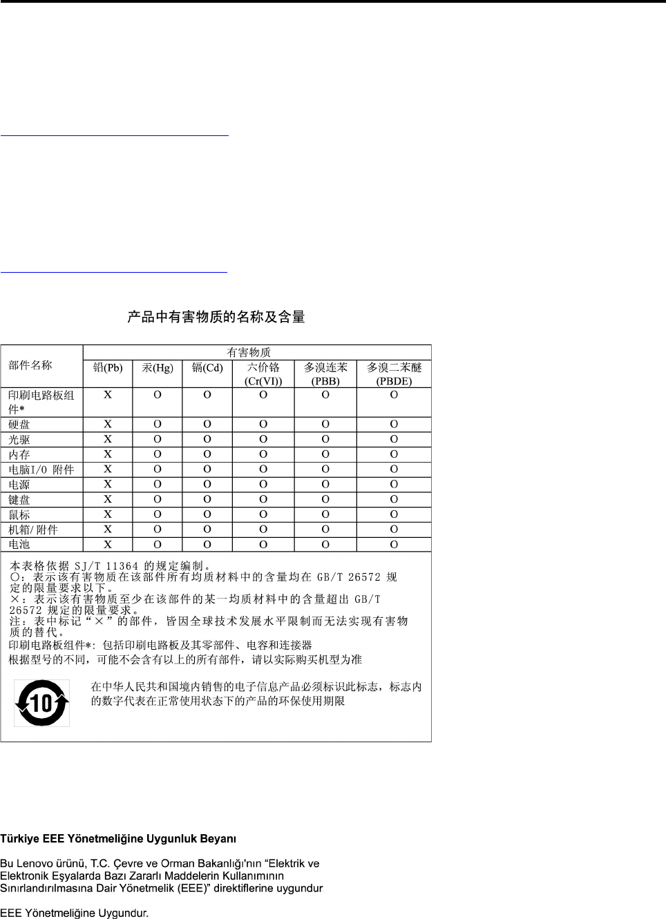
Appendix E. Restriction of Hazardous Substances (RoHS)
Directive
The latest environmental information is available at:
http://www.lenovo.com/ecodeclaration
European Union RoHS
This Lenovo product, with included parts (cables, cords, and so on) meets the requirements of Directive
2011/65/EU on the restriction of the use of certain hazardous substances in electrical and electronic
equipment (“RoHS recast” or “RoHS 2”).
For more information about Lenovo worldwide compliance on RoHS, go to:
www.lenovo.com/rohs-communication
China RoHS
Turkish RoHS
The Lenovo product meets the requirements of the Republic of Turkey Directive on the Restriction of the Use
of Certain Hazardous Substances in Waste Electrical and Electronic Equipment (WEEE).
© Copyright Lenovo 2017 229
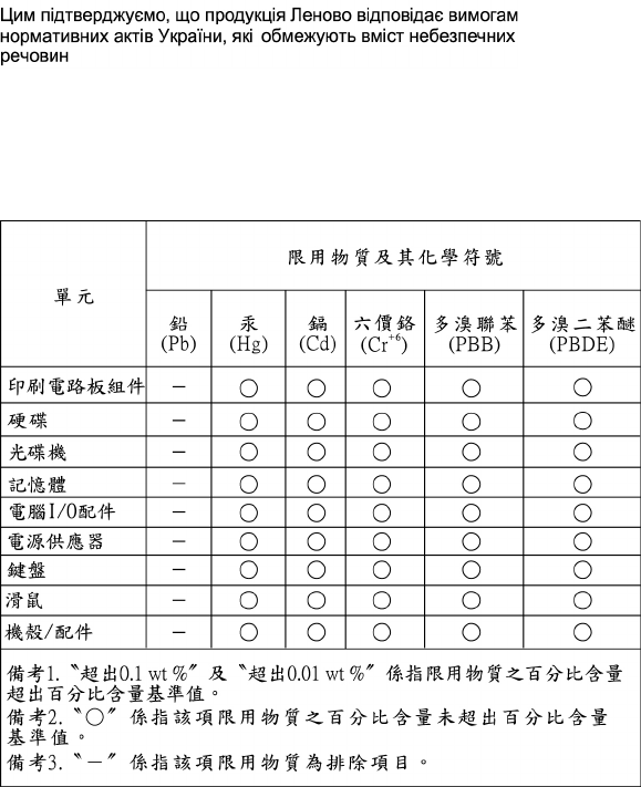
Ukraine RoHS
India RoHS
RoHS compliant as per E-Waste (Management) Rules.
Taiwan RoHS
230 P920 Hardware Maintenance Manual

Appendix F. ENERGY STAR model information
ENERGY STAR® is a joint program of the U.S. Environmental Protection Agency and the U.S. Department of
Energy aimed at saving money and protecting the environment through energy efficient products and
practices.
Lenovo is proud to offer our customers products with an ENERGY STAR compliant designation. Some
models of the following machine types have been designed and tested to conform to the ENERGY STAR
program requirement for computers at the time of manufacture: 30BC0009US and 30BC0008US. For more
information about ENERGY STAR ratings for Lenovo computers, go to:
http://www.lenovo.com
By using ENERGY STAR compliant products and taking advantage of the power-management features of
your computer, you reduce the consumption of electricity. Reduced electrical consumption contributes to
potential financial savings, a cleaner environment, and the reduction of greenhouse gas emissions.
For more information about ENERGY STAR, go to:
http://www.energystar.gov
Lenovo encourages you to make efficient use of energy an integral part of your day-to-day operations. To
help in this endeavor, set the following power-management features to take effect when your computer has
been inactive for a specified duration:
Table 2. ENERGY STAR power-management features
Windows 7 or Windows 10 operating system
Power plan: Default
• Turn off the display: After 10 minutes
• Put the computer to sleep: After 25 minutes
• Advanced power settings:
– Turn off hard disk drives: After 20 minutes
– Hibernate: Never
To awaken your computer from a Sleep mode, press any key on your keyboard.
To change power settings, do the following:
1. Open Control Panel by doing one of the following:
• For Windows 7: Click the Start button to open the Start menu.
• For Windows 10: Right-click the Start button to open the Start context menu.
2. Click Control Panel. View Control Panel by Large icons or Small icons, and then click Power Options.
3. Follow the instructions on the screen.
© Copyright Lenovo 2017 231
232 P920 Hardware Maintenance Manual

Appendix G. Notices
Lenovo may not offer the products, services, or features discussed in this document in all countries. Consult
your local Lenovo representative for information on the products and services currently available in your
area. Any reference to a Lenovo product, program, or service is not intended to state or imply that only that
Lenovo product, program, or service may be used. Any functionally equivalent product, program, or service
that does not infringe any Lenovo intellectual property right may be used instead. However, it is the user's
responsibility to evaluate and verify the operation of any other product, program, or service.
Lenovo may have patents or pending patent applications covering subject matter described in this
document. The furnishing of this document does not give you any license to these patents. You can send
license inquiries, in writing, to:
Lenovo (United States), Inc.
1009 Think Place - Building One
Morrisville, NC 27560
U.S.A.
Attention: Lenovo Director of Licensing
LENOVO PROVIDES THIS PUBLICATION "AS IS" WITHOUT WARRANTY OF ANY KIND, EITHER EXPRESS
OR IMPLIED, INCLUDING, BUT NOT LIMITED TO, THE IMPLIED WARRANTIES OF NON-INFRINGEMENT,
MERCHANTABILITY OR FITNESS FOR A PARTICULAR PURPOSE. Some jurisdictions do not allow
disclaimer of express or implied warranties in certain transactions, therefore, this statement may not apply to
you.
This information could include technical inaccuracies or typographical errors. Changes are periodically made
to the information herein; these changes will be incorporated in new editions of the publication. Lenovo may
make improvements and/or changes in the products and/or the programs described in this publication at any
time without notice.
The products described in this document are not intended for use in implantation or other life support
applications where malfunction may result in injury or death to persons. The information contained in this
document does not affect or change Lenovo product specifications or warranties. Nothing in this document
shall operate as an express or implied license or indemnity under the intellectual property rights of Lenovo or
third parties. All information contained in this document was obtained in specific environments and is
presented as an illustration. The result obtained in other operating environments may vary.
Lenovo may use or distribute any of the information you supply in any way it believes appropriate without
incurring any obligation to you.
Any references in this publication to non-Lenovo Web sites are provided for convenience only and do not in
any manner serve as an endorsement of those Web sites. The materials at those Web sites are not part of the
materials for this Lenovo product, and use of those Web sites is at your own risk.
Any performance data contained herein was determined in a controlled environment. Therefore, the result
obtained in other operating environments may vary significantly. Some measurements may have been made
on development-level systems and there is no guarantee that these measurements will be the same on
generally available systems. Furthermore, some measurements may have been estimated through
extrapolation. Actual results may vary. Users of this document should verify the applicable data for their
specific environment.
© Copyright Lenovo 2017 233
234 P920 Hardware Maintenance Manual

Appendix H. Trademarks
The following terms are trademarks of Lenovo in the United States, other countries, or both:
Lenovo
The Lenovo logo
ThinkStation
The ThinkStation logo
ThinkVantage
Microsoft, Windows, and Windows Media are trademarks of the Microsoft group of companies.
Intel, Thunderbolt, and Xeon are trademarks of Intel Corporation in the U.S. and/or other countries.
Linux is a registered trademark of Linus Torvalds.
DisplayPort and Mini DisplayPort are trademarks of the Video Electronics Standards Association.
Ubuntu is a registered trademark of Canonical Ltd.
Torx is a registered trademark of Acument Intellectual Properties, LLC in the United States or other countries.
Other company, product, or service names may be trademarks or service marks of others.
© Copyright Lenovo 2017 235
236 P920 Hardware Maintenance Manual

