Lenovo T530 T530I W530 Hmm En 0B48474 03 User Manual Hardware Maintenance Laptop (Think Pad) Type 2429
2014-12-18
User Manual: Lenovo T530 T530I W530 Hmm En 0B48474 03 Hardware Maintenance Manual T530i Laptop (ThinkPad) - Type 2429 ThinkPad T530i,2429
Open the PDF directly: View PDF ![]() .
.
Page Count: 126 [warning: Documents this large are best viewed by clicking the View PDF Link!]
- About this manual
- Chapter 1. Safety information
- Chapter 2. Important service information
- Chapter 3. General checkout
- Chapter 4. Related service information
- Chapter 5. Installing and configuring RAID
- Chapter 6. Status indicators
- Chapter 7. Fn key combinations
- Chapter 8. Locations
- Chapter 9. FRU replacement notices
- Chapter 10. Removing or replacing a FRU
- General guidelines
- Before servicing ThinkPad T530, T530i, and W530
- 1010 Battery pack
- 1020 Serial Ultrabay Enhanced device or blank bezel
- 1030 Memory module slot cover
- 1040 Memory module (bottom slot)
- 1050 Hard disk drive or solid state drive
- 1060 Keyboard
- 1070 Memory module (upper slot)
- 1080 PCI Express Mini Card for wireless LAN
- 1090 PCI Express Mini Card for wireless WAN or mSATA solid state drive
- 1100 ExpressCard blank bezel or ExpressCard
- 1110 Keyboard bezel assembly
- 1120 Bluetooth daughter card
- 1130 Backup battery
- 1140 Smart card, dummy smart card and spacer
- 1150 Speaker assembly
- 1160 Thermal fan assembly
- 1170 Microprocessor
- 1180 LCD unit
- 1190 Base cover assembly
- 1200 I/O sub card
- 1210 System board assembly and magnesium structure frame
- 2010 LCD bezel assembly
- 2020 LED sub card
- 2030 Integrated camera
- 2040 LCD cable, camera cable, LCD panel, and hinges
- 2050 Antenna kit and LCD rear cover assembly
- Appendix A. Notices

HardwareMaintenanceManual
ThinkPadT530,T530i,andW530

Note
Beforeusingthisinformationandtheproductitsupports,besuretoreadthegeneralinformationunder
AppendixA“Notices”onpage117.
FourthEdition(December2014)
©CopyrightLenovo2012,2014.
LIMITEDANDRESTRICTEDRIGHTSNOTICE:IfdataorsoftwareisdeliveredpursuantaGeneralServicesAdministration
“GSA”contract,use,reproduction,ordisclosureissubjecttorestrictionssetforthinContractNo.GS-35F-05925.

Contents
Aboutthismanual...........iii
Chapter1.Safetyinformation......1
Generalsafety................1
Electricalsafety...............2
Safetyinspectionguide............3
Handlingdevicesthataresensitivetoelectrostatic
discharge..................3
Groundingrequirements............4
Safetynotices(multilingualtranslations)......4
Lasercompliancestatements(multilingual
translations)................18
Chapter2.Importantservice
information..............27
StrategyforreplacingFRUs.........27
Strategyforreplacingaharddiskdrive,asolid
statedrive,oranmSATAsolidstatedrive..27
Importantnoticeforreplacingasystem
board................28
Howtouseerrorcodes.........28
StrategyforreplacingFRUsforCTO,CMV,and
GAV...................28
Productdefinition............28
FRUidentificationforCTO,CMV,andGAV
products...............29
Chapter3.Generalcheckout.....31
Whattodofirst..............31
Checkoutguide..............32
LenovoSolutionCenter.........32
Quicktestprograms...........32
UEFIdiagnosticprogram.........33
Bootablediagnosticprograms.......33
Powersystemcheckout...........34
Checkingtheacpoweradapter......34
Checkingoperationalcharging......35
Checkingthebatterypack........35
Checkingthebackupbattery.......36
Chapter4.Relatedservice
information..............37
Restoringthefactorycontentsbyusingthe
productRecoveryDiscSet..........37
UsingtheWindowsrecoveryprogramsonthe
Windows8operatingsystem.........38
Passwords................40
Power-onpassword...........41
Harddiskpassword...........41
Supervisorpassword..........41
Howtoremovethepower-onpassword...41
Howtoremovetheharddiskpassword...42
Powermanagement............42
Screenblankmode(fortheWindows7
operatingsystemonly)..........42
Sleepmode..............42
Hibernationmode...........43
Symptom-to-FRUindex...........43
Numericerrorcodes..........44
Errormessages............45
Beepsymptoms............45
No-beepsymptoms...........46
LCD-relatedsymptoms.........46
Intermittentproblems..........47
Undeterminedproblems.........47
Chapter5.Installingandconfiguring
RAID..................49
SupportedRAIDlevels...........49
ConfiguringthesystemUEFIBIOStoenable
embeddedSATARAIDfunctionality......49
CreatingRAIDvolumes...........50
DeletingRAIDvolumes...........50
Chapter6.Statusindicators.....51
Chapter7.Fnkeycombinations...55
Chapter8.Locations.........57
Locatingcomputercontrols,connectors,and
indicators.................57
Frontview...............57
Rearview...............58
Bottomview..............58
LocatingFRUsandCRUs..........58
MajorFRUsandCRUs..........60
LCDFRUsandCRUs..........62
MiscellaneouskitsandotherFRUs.....63
LookingupFRUinformation.........63
Chapter9.FRUreplacement
notices................65
Screwnotices...............65
Retainingserialnumbers...........66
Restoringtheserialnumberofthesystem
unit.................66
RetainingtheUUID...........67
©CopyrightLenovo2012,2014i

ReadingorwritingtheECAinformation...67
Chapter10.Removingorreplacinga
FRU..................69
Generalguidelines.............69
BeforeservicingThinkPadT530,T530i,and
W530..................70
1010Batterypack.............70
1020SerialUltrabayEnhanceddeviceorblank
bezel..................71
1030Memorymoduleslotcover........72
1040Memorymodule(bottomslot)......73
1050Harddiskdriveorsolidstatedrive.....74
1060Keyboard..............76
1070Memorymodule(upperslot).......79
1080PCIExpressMiniCardforwirelessLAN..80
1090PCIExpressMiniCardforwirelessWANor
mSATAsolidstatedrive...........82
1100ExpressCardblankbezelorExpressCard..86
1110Keyboardbezelassembly........87
1120Bluetoothdaughtercard........90
1130Backupbattery............91
1140Smartcard,dummysmartcardandspacer.92
1150Speakerassembly...........93
1160Thermalfanassembly.........94
1170Microprocessor............97
1180LCDunit...............98
1190Basecoverassembly..........101
1200I/Osubcard.............103
1210Systemboardassemblyandmagnesium
structureframe..............104
2010LCDbezelassembly..........108
2020LEDsubcard.............109
2030Integratedcamera...........110
2040LCDcable,cameracable,LCDpanel,and
hinges..................110
2050AntennakitandLCDrearcoverassembly..114
AppendixA.Notices.........117
Electronicemissionnotices..........118
Trademarks................118
iiHardwareMaintenanceManual

Aboutthismanual
ThismanualcontainsserviceandreferenceinformationforthefollowingThinkPad®products.
ThinkPadT530andT530i
Machinetype(MT)2359,2392,2393,2394,2429,2430,and2434
ThinkPadW530
MT2436,2438,2439,2441,2447,2449,and2463
Usethismanualalongwiththeadvanceddiagnosticteststotroubleshootproblems.
Important:ThismanualisintendedonlyfortrainedservicetechnicianswhoarefamiliarwithThinkPad
products.Usethismanualalongwiththeadvanceddiagnosticteststotroubleshootproblemseffectively.
BeforeservicingaThinkPadproduct,besuretoreadalltheinformationunderandChapter2“Important
serviceinformation”onpage27.
©CopyrightLenovo2012,2014iii

ivHardwareMaintenanceManual

Chapter1.Safetyinformation
Thischapterpresentsthefollowingsafetyinformationthatyouneedtobefamiliarwithbeforeyouservicea
ThinkPadnotebookcomputer.
•“Generalsafety”onpage1
•“Electricalsafety”onpage2
•“Safetyinspectionguide”onpage3
•“Handlingdevicesthataresensitivetoelectrostaticdischarge”onpage3
•“Groundingrequirements”onpage4
•“Safetynotices(multilingualtranslations)”onpage4
•“Lasercompliancestatements(multilingualtranslations)”onpage18
Generalsafety
Followtheserulestoensuregeneralsafety:
•Observegoodhousekeepingintheareaofthemachinesduringandaftermaintenance.
•Whenliftinganyheavyobject:
1.Makesurethatyoucanstandsafelywithoutslipping.
2.Distributetheweightoftheobjectequallybetweenyourfeet.
3.Useaslowliftingforce.Nevermovesuddenlyortwistwhenyouattempttolift.
4.Liftbystandingorbypushingupwithyourlegmuscles;thisactionremovesthestrainfromthe
musclesinyourback.Donotattempttoliftanyobjectthatweighsmorethan16kg(35lb)orthatyou
thinkistooheavyforyou.
•Donotperformanyactionthatcauseshazardstothecustomer,orthatmakestheequipmentunsafe.
•Beforeyoustartthemachine,makesurethatotherservicetechniciansandthecustomer'spersonnelare
notinahazardousposition.
•Placeremovedcoversandotherpartsinasafeplace,awayfromallpersonnel,whileyouareservicing
themachine.
•Keepyourtoolcaseawayfromwalkareassothatotherpeoplewillnottripoverit.
•Donotwearlooseclothingthatcanbetrappedinthemovingpartsofamachine.Makesurethatyour
sleevesarefastenedorrolledupaboveyourelbows.Ifyourhairislong,fastenit.
•Inserttheendsofyournecktieorscarfinsideclothingorfastenitwithanonconductiveclip,about8
centimeters(3inches)fromtheend.
•Donotwearjewelry,chains,metal-frameeyeglasses,ormetalfastenersforyourclothing,becausemetal
objectsaregoodelectricalconductors.
•Wearsafetyglasseswhenyouarehammering,drilling,soldering,cuttingwire,attachingsprings,using
solvents,orworkinginanyotherconditionsthatmightbehazardoustoyoureyes.
•Afterservice,reinstallallsafetyshields,guards,labels,andgroundwires.Replaceanysafetydevice
thatiswornordefective.
•Reinstallallcoverscorrectlybeforereturningthemachinetothecustomer.
•Fanlouversonthemachinehelptopreventoverheatingofinternalcomponents.Donotobstructfan
louversorcoverthemwithlabelsorstickers.
©CopyrightLenovo2012,20141

Electricalsafety
Observethefollowingruleswhenworkingonelectricalequipment.
Important:
•Useonlyapprovedtoolsandtestequipment.Somehandtoolshavehandlescoveredwithasoftmaterial
thatdoesnotinsulateyouwhenworkingwithliveelectricalcurrents.
•Manycustomershave,neartheirequipment,rubberfloormatsthatcontainsmallconductivefibersto
decreaseelectrostaticdischarges.Donotusethistypeofmattoprotectyourselffromelectricalshock.
•Findtheroomemergencypower-off(EPO)switch,disconnectingswitch,orelectricaloutlet.Ifanelectrical
accidentoccurs,youcanthenoperatetheswitchorunplugthepowercordquickly.
•Donotworkaloneunderhazardousconditionsornearequipmentthathashazardousvoltages.
•Disconnectallpowerbefore:
–Performingamechanicalinspection
–Workingnearpowersupplies
–Removingorinstallingmainunits
•Beforeyoustarttoworkonthemachine,unplugthepowercord.Ifyoucannotunplugit,askthecustomer
topoweroffthewallboxthatsuppliespowertothemachine,andtolockthewallboxintheoffposition.
•Ifyouneedtoworkonamachinethathasexposedelectricalcircuits,observethefollowingprecautions:
–Ensurethatanotherperson,familiarwiththepower-offcontrols,isnearyou.Thatpersonmustbe
theretoswitchoffthepower,ifnecessary.
–Useonlyonehandwhenworkingwithpowered-onelectricalequipment;keeptheotherhandinyour
pocketorbehindyourback.
CAUTION:
Anelectricalshockcanoccuronlywhenthereisacompletecircuit.Byobservingtheabove
rule,youmaypreventacurrentfrompassingthroughyourbody.
–Whenusingtesters,setthecontrolscorrectlyandusetheapprovedprobeleadsandaccessoriesfor
thattester.
–Standonsuitablerubbermats(obtainedlocally,ifnecessary)toinsulateyoufromgroundssuchas
metalfloorstripsandmachineframes.
Observethespecialsafetyprecautionswhenyouworkwithveryhighvoltages.Instructionsforthese
precautionsareinthesafetysectionsofmaintenanceinformation.Useextremecarewhenmeasuring
highvoltages.
•Regularlyinspectandmaintainyourelectricalhandtoolsforsafeoperationalcondition.
•Donotusewornorbrokentoolsandtesters.
•Neverassumethatpowerhasbeendisconnectedfromacircuit.First,checkthatithasbeenpoweredoff.
•Alwayslookcarefullyforpossiblehazardsinyourworkarea.Examplesofthesehazardsaremoistfloors,
nongroundedpowerextensioncables,powersurges,andmissingsafetygrounds.
•Donottouchliveelectricalcircuitswiththereflectivesurfaceofaplasticdentalmirror.Thesurfaceis
conductive;suchtouchingcancausepersonalinjuryandmachinedamage.
•Donotservicethefollowingpartswiththepoweron:
–Powersupplyunits
–Pumps
–Blowersandfans
–Motorgenerators
–Unitssimilartothoselistedabove
Thispracticeensurescorrectgroundingoftheunits.
2HardwareMaintenanceManual

•Ifanelectricalaccidentoccurs:
–Usecaution;donotbecomeavictimyourself.
–Switchoffpower.
–Sendanotherpersontogetmedicalaid.
Safetyinspectionguide
Thepurposeofthisinspectionguideistoassistyouinidentifyingpotentiallyunsafeconditions.Aseach
machinewasdesignedandbuilt,requiredsafetyitemswereinstalledtoprotectusersandservicetechnicians
frominjury.Thisguideaddressesonlythoseitems.Youshouldusegoodjudgmenttoidentifypotential
safetyhazardsduetoattachmentofnon-ThinkPadfeaturesoroptionsnotcoveredbythisinspectionguide.
Ifanyunsafeconditionsarepresent,youmustdeterminehowserioustheapparenthazardcouldbeand
whetheryoucancontinuewithoutfirstcorrectingtheproblem.
Considertheseconditionsandthesafetyhazardstheypresent:
•Electricalhazards,especiallyprimarypower(primaryvoltageontheframecancauseseriousorfatal
electricalshock)
•Explosivehazards,suchasadamagedCRTfaceorabulgingcapacitor
•Mechanicalhazards,suchaslooseormissinghardware
Todeterminewhetherthereareanypotentiallyunsafeconditions,usethefollowingchecklistatthebeginning
ofeveryservicetask.Beginthecheckswiththepoweroff,andthepowercorddisconnected.
Checklist:
1.Checkexteriorcoversfordamage(loose,broken,orsharpedges).
2.Turnoffthecomputer.Disconnectthepowercord.
3.Checkthepowercordfor:
a.Athird-wiregroundconnectoringoodcondition.Useametertomeasurethird-wireground
continuityfor0.1ohmorlessbetweentheexternalgroundpinandtheframeground.
b.ThepowercordshouldbetheauthorizedtypespecifiedforyourcomputerontheWebpage
http://www.lenovo.com/serviceparts-lookup.
c.Insulationmustnotbefrayedorworn.
4.Checkforcrackedorbulgingbatteries.
5.Removethecover.
6.Checkforanyobviousnon-ThinkPadalterations.Usegoodjudgmentastothesafetyofany
non-ThinkPadalterations.
7.Checkinsidetheunitforanyobviousunsafeconditions,suchasmetalfilings,contamination,wateror
otherliquids,orsignsoffireorsmokedamage.
8.Checkforworn,frayed,orpinchedcables.
9.Checkthatthepower-supplycoverfasteners(screwsorrivets)havenotbeenremovedortamperedwith.
Handlingdevicesthataresensitivetoelectrostaticdischarge
Anycomputerpartcontainingtransistorsorintegratedcircuits(ICs)shouldbeconsideredsensitiveto
electrostaticdischarge(ESD).ESDdamagecanoccurwhenthereisadifferenceinchargebetweenobjects.
ProtectagainstESDdamagebyequalizingthechargesothatthemachine,thepart,theworkmat,andthe
personhandlingthepartareallatthesamecharge.
Chapter1.Safetyinformation3
Notes:
1.Useproduct-specificESDprocedureswhentheyexceedtherequirementsnotedhere.
2.MakesurethattheESDprotectivedevicesyouusehavebeencertified(ISO9000)asfullyeffective.
WhenhandlingESD-sensitiveparts:
•Keepthepartsinprotectivepackagesuntiltheyareinsertedintotheproduct.
•Avoidcontactwithotherpeople.
•Wearagroundedwriststrapagainstyourskintoeliminatestaticonyourbody.
•Preventthepartfromtouchingyourclothing.Mostclothingisinsulativeandretainsachargeeven
whenyouarewearingawriststrap.
•Useagroundedworkmattoprovideastatic-freeworksurface.Thematisespeciallyusefulwhen
handlingESD-sensitivedevices.
•Selectagroundingsystem,suchasthoselistedbelow,toprovideprotectionthatmeetsthespecific
servicerequirement.
Note:TheuseofagroundingsystemtoguardagainstESDdamageisdesirablebutnotnecessary.
–AttachtheESDgroundcliptoanyframeground,groundbraid,orgreen-wireground.
–Whenworkingonadouble-insulatedorbattery-operatedsystem,useanESDcommongroundor
referencepoint.Y oucanusecoaxorconnector-outsideshellsonthesesystems.
–Usetheroundgroundprongoftheacplugonac-operatedcomputers.
Groundingrequirements
Electricalgroundingofthecomputerisrequiredforoperatorsafetyandcorrectsystemfunction.Proper
groundingoftheelectricaloutletcanbeverifiedbyacertifiedelectrician.
Safetynotices(multilingualtranslations)
Thesafetynoticesinthissectionareprovidedinthefollowinglanguages:
•English
•Arabic
•BrazilianPortuguese
•French
•German
•Hebrew
•Japanese
•Korean
•Spanish
•TraditionalChinese
DANGER
4HardwareMaintenanceManual
DANGER
6HardwareMaintenanceManual
PERIGO
PERIGO
PERIGO
PERIGO
PERIGO
PERIGO
8HardwareMaintenanceManual
DANGER
DANGER
DANGER
VORSICHT
VORSICHT
10HardwareMaintenanceManual
VORSICHT
VORSICHT
12HardwareMaintenanceManual
14HardwareMaintenanceManual
16HardwareMaintenanceManual
20HardwareMaintenanceManual
22HardwareMaintenanceManual
24HardwareMaintenanceManual

26HardwareMaintenanceManual

Chapter2.Importantserviceinformation
Thischapterpresentsthefollowingimportantserviceinformationthatappliestoallmachinetypessupported
bythismanual:
•“StrategyforreplacingFRUs”onpage27
–“Strategyforreplacingaharddiskdrive,asolidstatedrive,oranmSATAsolidstatedrive”onpage27
–“Importantnoticeforreplacingasystemboard”onpage28
–“Howtouseerrorcodes”onpage28
•“StrategyforreplacingFRUsforCTO,CMV,andGAV”onpage28
–“Productdefinition”onpage28
–“FRUidentificationforCTO,CMV,andGAVproducts”onpage29
Important:
•AdvisecustomerstocontacttheLenovo®CustomerSupportCenteriftheyneedanyassistancein
obtainingorinstallinganysoftwarefixes,drivers,andUEFIBIOSdownloads.Telephonenumbersfor
LenovoSupportareavailableat:
http://www.lenovo.com/support/phone
•SystemdisassemblyandreassemblyvideosthatshowtheFRUremovalorreplacementproceduresfor
theLenovoauthorizedservicetechniciansareavailableat:
http://www.lenovoservicetraining.com/ion/
StrategyforreplacingFRUs
Beforereplacingparts:
Makesurethatallsoftwarefixes,drivers,andUEFIBIOSdownloadsareinstalledbeforereplacingany
FRUslistedinthismanual.
Afterasystemboardisreplaced,ensurethatthelatestUEFIBIOSisloadedtothesystemboardbefore
completingtheserviceaction.
Todownloadandinstallsoftwarefixes,drivers,andUEFIBIOS,gotohttp://www.lenovo.com/ThinkPadDrivers
andfollowtheinstructionsonthescreen.
UsethefollowingstrategytopreventunnecessaryexpenseforreplacingandservicingFRUs:
•IfyouareinstructedtoreplaceaFRUbutthereplacementdoesnotcorrecttheproblem,reinstallthe
originalFRUbeforeyoucontinue.
•Somecomputershavebothaprocessorboardandasystemboard.Ifyouareinstructedtoreplaceeither
theprocessorboardorthesystemboard,andreplacingoneofthemdoesnotcorrecttheproblem,
reinstallthatboard,andthenreplacetheotherone.
•IfanadapteroradeviceconsistsofmorethanoneFRU,anyoftheFRUsmightbethecauseoftheerror.
Beforereplacingtheadapterordevice,removetheFRUs,onebyone,toseeifthesymptomschange.
ReplaceonlytheFRUthatchangedthesymptoms.
Strategyforreplacingaharddiskdrive,asolidstatedrive,oranmSATA
solidstatedrive
Alwaystrytorunalow-levelformatoperationbeforereplacingaharddiskdriveorasolidstatedrive.This
willcauseallcustomerdataontheharddiskdriveorsolidstatedrivetobelost.Besurethatthecustomer
hasacurrentbackupofthedatabeforeyouperformthistask.
©CopyrightLenovo2012,201427

Attention:Thedrivestartupsequenceinthecomputeryouareservicingmighthavebeenchanged.Be
extremelycarefulduringwriteoperationssuchascopying,saving,orformatting.Ifyouselectanincorrect
drive,dataorprogramscanbeoverwritten.
IfthecomputerisshippedwithbothanmSATAsolidstatedriveandaharddiskdrive,themSATAsolidstate
driveisusedforthe“cache”functionandtosupporttheIntel®RapidStartTechnology.Werecommendthat
usersdonotreplacethemSATAsolid-statedrivebythemselves.Otherwise,the“cache”functionwillnot
workandtheIntelRapidStartTechnologycannotbeusedanymore.
Attention:EnsurethatyoupartitionthemSATAsolid-statedriveafterinstallingitonthecomputeryouare
servicing.Otherwise,themSATAsolid-statedrivewillnotfunctioncorrectly.Forinstructionsonhowto
partitionanmSATAsolid-statedrive,gotohttp://www.lenovo.com/support/msata-fru.
Importantnoticeforreplacingasystemboard
Somecomponentsmountedonasystemboardareverysensitive.Improperhandlingofasystemboardcan
causedamagetothosecomponents,andmaycauseasystemmalfunction.
Attention:Whenhandlingasystemboard:
•Donotdropasystemboardorapplyanyexcessiveforcetoit.
•Avoidroughhandlingofanykind.
•AvoidbendingasystemboardandhardpushingtopreventcrackingateachBGA(BallGridArray)chipset.
Howtouseerrorcodes
Usetheerrorcodesdisplayedonthescreentodiagnosefailures.Ifmorethanoneerrorcodeisdisplayed,
beginthediagnosiswiththefirsterrorcode.Whatevercausesthefirsterrorcodemayalsocausefalseerror
codes.Ifnoerrorcodeisdisplayed,seewhethertheerrorsymptomislistedintheSymptom-to-FRU
Indexforthecomputeryouareservicing.
StrategyforreplacingFRUsforCTO,CMV,andGAV
Productdefinition
DynamicConfigureToOrder(CTO)
ThisprovidestheabilityforacustomertoconfigureaLenovosolutionfromaneSite,andhavethis
configurationsenttofulfillment,whereitisbuiltandshippeddirectlytothecustomer.Themachinelabeland
eSupportwillloadtheseproductsasthe4-digitMTand3-digitmodel,wheremodel=“CTO”(Example:
1829-CTO).
CustomModelVariant(CMV)
ThisisauniqueconfigurationthathasbeennegotiatedbetweenLenovoandthecustomer.Aunique4-digit
MTand3-digitmodelisprovidedtothecustomertoplaceorders(Example:1829-W15).ACMVisaspecial
bidoffering.Therefore,itisNOTgenerallyannounced.
•TheMTMportionofthemachinelabelisthe4-digitMTand3-digitmodel,wheremodel=“CTO”
(Example:1829-CTO).ThePRODUCTIDportionofthemachinelabelisthe4-digitMTand3-digitCMV
model(Example:1829-W15).
•eSupportwillshowboththeCTOandCMVmachinetypemodels(Example:1829-CTOand1829-W15
willbefoundontheeSupportsite.)
28HardwareMaintenanceManual

GeneralAnnounceVariant(GAV)
Thisisastandardmodel(fixedconfiguration).GAVsareannouncedandofferedtoallcustomers.TheMTM
portionofthemachinelabelisa4-digitMTand3-digitmodel,wheremodel=a“fixedpartnumber”,not
“CTO”(Example:1829-F1U).Also,eSupportwilllisttheseproductsunderthesamefixedmodelnumber.
FRUidentificationforCTO,CMV,andGAVproducts
UseLenovoeSupporttoidentifymajorFRUs,FRUpartnumbers,andFRUdescriptionsforCTO,CMV,and
GAVproductsatanMT-serialnumberlevel.ExamplesofmajorFRUsareharddiskdrive,systemboard,
liquidcrystaldisplay(LCD),andmemorymodule.AllCTOandCMVproductsareloadedunderthe4-digit
MTand3-digitmodel,wheremodel=“CTO”(example:1829-CTO).GAVsareloadedunderthe4-digitMT
and3-digitmodel,wheremodel=a“fixedpartnumber”,not“CTO”(example:1829-F1U).
ToidentifythemajorFRUsforaproduct,dothefollowing:
1.Goto:
http://www.lenovo.com/support
2.ClickWarranty&Services.
3.ClickCheckWarrantyStatus.
4.OntheWarrantyStatusLookuppage,clickPartsLookup.
5.Typeyourmachinetypeandserialnumber,andthenclickSubmit.
eSupportalsocanbeusedtoviewthegeneralFRUlistforaproduct.
TogetthegeneralFRUlistforaproduct,dothefollowing:
1.Goto:
http://www.lenovo.com/support
2.ClickParts&Accessories.
3.Followtheinstructionsonthescreentoselectproduct.
4.ClickProductsandPartsDetail.
5.OnthePRODUCTANDPARTSDETAILpage,clickthePartsDetailtabtoviewtheFRUlist.
Note:TheFRUlistisagenerallistofcomponentsanddoesnotcontainspecificmodelinformation.
Chapter2.Importantserviceinformation29

30HardwareMaintenanceManual

Chapter3.Generalcheckout
Thischapterpresentsfollowinginformation:
•“Whattodofirst”onpage31
•“Checkoutguide”onpage32
•“Powersystemcheckout”onpage34
Beforeyougotothecheckoutguide,besuretoreadthefollowingimportantnotes.
Important:
•Onlycertifiedtrainedpersonnelshouldservicethecomputer.
•BeforereplacinganyFRU,readtheentirepageonremovingandreplacingFRUs.
•WhenyoureplaceFRUs,itisrecommendedtousenewnylon-coatedscrews.
•Beextremelycarefulduringsuchwriteoperationsascopying,saving,orformatting.Drivesinthe
computerthatyouareservicingsequencemighthavebeenaltered.Ifyouselectanincorrectdrive,
dataorprogramsmightbeoverwritten.
•ReplaceaFRUonlywithanotherFRUofthecorrectmodel.WhenyoureplaceaFRU,makesurethat
themodelofthemachineandtheFRUpartnumberarecorrectbyreferringtotheFRUpartslistonthe
Webpagehttp://www.lenovo.com/serviceparts-lookup.
•AFRUshouldnotbereplacedbecauseofasingle,unreproduciblefailure.Singlefailurescanoccur
foravarietyofreasonsthathavenothingtodowithahardwaredefect,suchascosmicradiation,
electrostaticdischarge,orsoftwareerrors.ConsiderreplacingaFRUonlywhenaproblemrecurs.Ifyou
suspectthataFRUisdefective,cleartheerrorlogandrunthetestagain.Iftheerrordoesnotrecur,do
notreplacetheFRU.
•BecarefulnottoreplaceanondefectiveFRU.
Whattodofirst
WhenyoureturnaFRU,youmustincludethefollowinginformationinthepartsexchangeformorparts
returnformthatyouattachtoit:
1.Nameandphonenumberofservicetechnician
2.Dateofservice
3.Dateonwhichthemachinefailed
4.Dateofpurchase
5.Failuresymptoms,errorcodesappearingonthedisplay,andbeepsymptoms
6.ProcedureindexandpagenumberinwhichthefailingFRUwasdetected
7.FailingFRUnameandpartnumber
8.Machinetype,modelnumber,andserialnumber
9.Customer'snameandaddress
Note:Duringthewarrantyperiod,thecustomermayberesponsibleforrepaircostsifthecomputerdamage
wascausedbymisuse,accident,modification,unsuitablephysicaloroperatingenvironment,orimproper
maintenancebythecustomer.Followingisalistofsomecommonitemsthatarenotcoveredunderwarranty
andsomesymptomsthatmightindicatethatthesystemwassubjecttostressbeyondnormaluse.
Beforecheckingproblemswiththecomputer,determinewhetherthedamageiscoveredunderthewarranty
byreferringtothefollowinglist:
Thefollowingarenotcoveredunderwarranty:
•LCDpanelcrackedfromtheapplicationofexcessiveforceorfrombeingdropped
•Scratched(cosmetic)parts
©CopyrightLenovo2012,201431

•Distortion,deformation,ordiscolorationofthecosmeticparts
•Plasticparts,latches,pins,orconnectorsthathavebeencrackedorbrokenbyexcessiveforce
•Damagecausedbyliquidspilledintothesystem
•DamagecausedbytheimproperinsertionofaPCCardortheinstallationofanincompatiblecard
•Improperdiscinsertionoruseofanopticaldrive
•Fusesblownbyattachmentofanonsupporteddevice
•Forgottencomputerpassword(makingthecomputerunusable)
•Stickykeyscausedbyspillingaliquidontothekeyboard
•Useofanincorrectacpoweradapteronlaptopproducts
Thefollowingsymptomsmightindicatedamagecausedbynonwarrantedactivities:
•Missingpartsmightbeasymptomofunauthorizedserviceormodification.
•Checkforobviousdamagetoaharddiskdrive.Ifthespindleofaharddiskdrivebecomesnoisy,thehard
diskdrivemighthavebeendroppedorsubjecttoexcessiveforce.
Checkoutguide
UsethefollowingproceduresasaguideinidentifyingandcorrectingproblemswiththeThinkPadnotebook
computer.
Note:ThediagnostictestsareintendedtotestonlyThinkPadproducts.Theuseofnon-ThinkPadproducts,
prototypecards,ormodifiedoptionscanleadtofalseindicationsoferrorsandinvalidsystemresponses.
1.Identifythefailingsymptomsinasmuchdetailaspossible.
2.Verifythesymptoms.Trytore-createthefailurebyrunningthediagnostictestorbyrepeatingthe
operation.
LenovoSolutionCenter
TheLenovoSolutionCenterprogramenablesyoutotroubleshootandresolvecomputerproblems.It
combinesdiagnostictests,systeminformationcollection,securitystatus,andsupportinformation,along
withhintsandtipsformaximumsystemperformance.
TheLenovoSolutionCenterprogramisavailablefordownloadathttp://www.lenovo.com/diags.
ToruntheLenovoSolutionCenterprogram,gotoControlPanelandclickSystemandSecurity➙Lenovo-
SystemHealthandDiagnostics,andthenfollowtheinstructionsonthescreen.
FormoreinformationabouttheLenovoSolutionCenterprogram,refertothehelpinformationsystem
oftheprogram.
Quicktestprograms
Youcanrunquicktestprogramstotroubleshootandresolvecomputerproblems,especiallywhenthe
computerdoesnothavetheLenovoSolutionCenterprograminstalled.
Lenovoprovidesthefollowingquicktestprograms:
•LenovoHardDriveQuickT est:Usethisprogramtotroubleshootandresolveinternalstorageproblems.
•LenovoMemoryQuickT est:Usethisprogramtotroubleshootandresolvememorymoduleproblems.
Thequicktestprogramsareapplicableonthefollowingoperatingsystems:
•Microsoft®Windows®8
•MicrosoftWindows7
•MicrosoftWindowsXP
32HardwareMaintenanceManual

•MicrosoftWindowsServer®2003
•MicrosoftWindowsServer2008
Todownloadandinstallaquicktestprogram,gotohttp://www.lenovo.com/diagsandfollowtheinstructions
ontheWebsite.
Torunatestusingaquicktestprogram,dothefollowing:
1.GototheC:\SWTOOLS\ldiagdirectory.
2.Double-clickthegui_lsc_lite.exefile.
3.WhentheUserAccountControlwindowopens,clickYes.
4.Selectthedeviceclasstobetested.
5.Selectthedevicestobetested.
6.Selectthetesttobeperformed.
7.Followtheinstructionsonthescreentostartthetest.Whenaproblemisdetected,information
messagesaredisplayed.Refertothemessagestotroubleshoottheproblem.
UEFIdiagnosticprogram
AUEFIdiagnosticprogramispreinstalledonthecomputer.Itenablesyoutotestmemorymodulesand
internalstoragedevices,viewsysteminformation,andcheckandrecoverbadsectorsoninternalstorage
devices.
ToruntheUEFIdiagnosticprogram,dothefollowing:
1.Turnonthecomputer.Ifthecomputercannotbeturnedon,goto“Powersystemcheckout”onpage
34,andcheckthepowersources.Ifanerrorcodeisdisplayed,gotoforerrorcodedescriptionsand
troubleshootinghints.
2.WhentheThinkPadlogoisdisplayed,repeatedlypressandreleasetheF10key.Themainscreenofthe
UEFIdiagnosticprogramisdisplayed.
3.Followtheinstructionsonthescreentousetheprogram.
Theoptionsonthemainscreenareasfollows:
Table1.ItemsonthemainscreenoftheUEFIdiagnosticprogram
TestsTools
•QuickMemoryTest
•QuickStorageDeviceTest
•ExitApplication
•SystemInformation
•RecoverBadSectorsTool
Bootablediagnosticprograms
IfthecomputeryouareservicingisnotinstalledwiththeUEFIdiagnosticprogram,youcandownloada
bootablediagnosticprogramfromtheLenovoSupportWebsite.Thebootablediagnosticprogramsenable
youtotestcomputermemoryandinternalstoragedevices,viewsysteminformation,andcheckandrecover
theinternalstoragedevices.Tousethebootablediagnosticprograms,youcancreateabootablediagnostic
mediumonaUSBdeviceorCD.
Tocreateabootablediagnosticmedium,dothefollowing:
1.Gotohttp://www.lenovo.com/diags.
2.ClickLenovoBootableDiagnostics.
Chapter3.Generalcheckout33

3.FollowtheinstructionsontheWebsitetocreateabootablediagnosticmediumonaUSBdeviceorCD.
Tousethediagnosticmediumyouhavecreated,dooneofthefollowing:
•IfyouhavecreatedthebootablediagnosticmediumonaUSBdevice,dothefollowing:
1.AttachtheUSBdevicetothecomputer.
2.Turnonthecomputer.Ifthecomputercannotbeturnedon,goto“Powersystemcheckout”onpage
34,andcheckthepowersources.Ifanerrorcodeisdisplayed,gotoforerrorcodedescriptions
andtroubleshootinghints.
3.WhentheThinkPadlogoisdisplayed,repeatedlypressandreleasetheF12key.WhentheBoot
Menuwindowopens,releasetheF12key.
4.UsethearrowkeystoselectUSBHDDandthenpressEnter.Thediagnosticprogramwillbe
launchedautomatically.
5.Followtheinstructionsonthescreentousethediagnosticprogram.
•IfyouhavecreatedthebootablediagnosticmediumonaCD,dothefollowing:
1.Turnonthecomputer.Ifthecomputercannotbeturnedon,goto“Powersystemcheckout”onpage
34,andcheckthepowersources.Ifanerrorcodeisdisplayed,gotoforerrorcodedescriptions
andtroubleshootinghints.
2.InserttheCDintotheopticaldrive.
3.Restartthecomputer.
4.WhentheThinkPadlogoisdisplayed,repeatedlypressandreleasetheF12key.WhentheBoot
Menuwindowopens,releasetheF12key.
5.UsethearrowkeystoselectATAPICDx(x:0,1,...)andthenpressEnter.Thediagnosticprogram
willbelaunchedautomatically.
6.Followtheinstructionsonthescreentousethediagnosticprogram.
Powersystemcheckout
Toverifyasymptom,dothefollowing:
1.Turnoffthecomputer.
2.Removethebatterypack.
3.Connecttheacadapter.
4.Checkthatpowerissuppliedwhenyouturnonthecomputer.
5.Turnoffthecomputer.
6.Disconnecttheacadapterandinstallthechargedbatterypack.
7.Checkthatthebatterypacksuppliespowerwhenyouturnonthecomputer.
Ifyoususpectapowerproblem,seetheappropriateoneofthefollowingpowersupplycheckouts:
•“Checkingtheacpoweradapter”onpage34
•“Checkingoperationalcharging”onpage35
•“Checkingthebatterypack”onpage35
•“Checkingthebackupbattery”onpage36
Checkingtheacpoweradapter
Ifyoucomputerfailsonlywhentheacpoweradapterisused,usetheinstructionsinthistopic.
•Ifthepowerproblemoccursonlywhenthedockingstationortheportreplicatorisused,replacethe
dockingstationortheportreplicator.
•Ifthepower-onindicatordoesnotturnon,checkthepowercordoftheacpoweradapterforcorrect
continuityandinstallation.
34HardwareMaintenanceManual
•Ifthecomputerdoesnotchargeduringoperation,goto“Checkingoperationalcharging”onpage35.
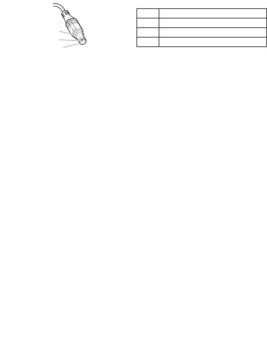
Tochecktheacadapter,dothefollowing:
1.Unplugtheacadaptercablefromthecomputer.
2.Measuretheoutputvoltageattheplugoftheacadaptercable.Seethefollowingillustration:
PinVoltage(Vdc)
1+20
20
3Ground
1
2
3
(20V)
Note:Outputvoltageacrosspin2oftheacpoweradaptermightdifferfromtheoneyouareservicing.
3.Ifthevoltageisnotcorrect,replacetheacadapter.
4.Ifthevoltageisacceptable,replacethesystemboard.
Note:Noisefromtheacadapterdoesnotalwaysindicateadefect.
Checkingoperationalcharging
Tocheckwhetherthebatterychargescorrectlyduringoperation,dothefollowing:
Note:Beforeyoubegin,installadischargedbatterypackorabatterypackthathaslessthan50%ofthe
totalpowerremaininginthecomputer.
1.Ifthebatterystatusindicatordoesnotturnon,removethebatterypackandletitreturntoroom
temperature.
2.Reinstallthebatterypack.
3.Iftheindicatorstilldoesnotturnon,replacethebatterypack.
4.Iftheindicatorstilldoesnotturnon,replacethesystemboard.Otherwise,referto“Checkingthebattery
pack”onpage35tochecktheoriginalbatterypack.
Checkingthebatterypack
ThebatterystatusiconintheWindowsnotificationareadisplaysthepercentageofbatterypowerremaining.
Tocheckfordetailedbatterystatusinformation,dothefollowing:
•ForWindows7:OpenthePowerManagerprogramandclicktheBatterytab.
•ForWindows8:OpentheLenovoSupportprogramandclickBatteryHealth,oropentheLenovo
SettingsprogramandclickPower.
Note:Ifthebatterypackbecomeshot,itmaynotbeabletocharge.Removeitfromthecomputerandleave
itatroomtemperatureforawhile.Afteritcoolsdown,reinstallandrechargeit.
Tocheckthebatterypack,dothefollowing:
1.Turnoffthecomputeranddisconnecttheacpoweradapter.
2.Removethebatterypackandmeasurethevoltagebetweenbatteryterminals1(+)and7(-).The
correctvoltageareshowninthefollowingtable.
Chapter3.Generalcheckout35
TerminalVoltage(Vdc)
1+0to+12.6
7Ground(-)
1(+)2(+)
3456(-)7(-)
3.Measuretheresistancebetweenbatteryterminals5and7.Theresistancemustbe4to30KΩ.Ifthe
resistanceisnotcorrect,replacethebatterypack.
4.Dependingonthevoltagethatyoumeasure,dooneofthefollowing:
•Ifthevoltageislessthan+11.0Vdc,rechargethebatterypack.Ifthevoltageisstilllessthan+11.0V
dcafterrecharging,replacethebatterypack.
•Ifthevoltageismorethan+11.0Vdc,dischargethebatterypackuntilthevoltagebecomesless
than+11.0Vdcandthenrechargethebatterypack.Ifthevoltagestillislessthan+11.0Vdcafter
recharging,replacethebatterypack.
Note:Rechargingwilltakeatleastthreehours,evenifthebatterystatusindicatordoesnotturnon.
5.Replacethesystemboardifthenewbatterypackisnotcharged.
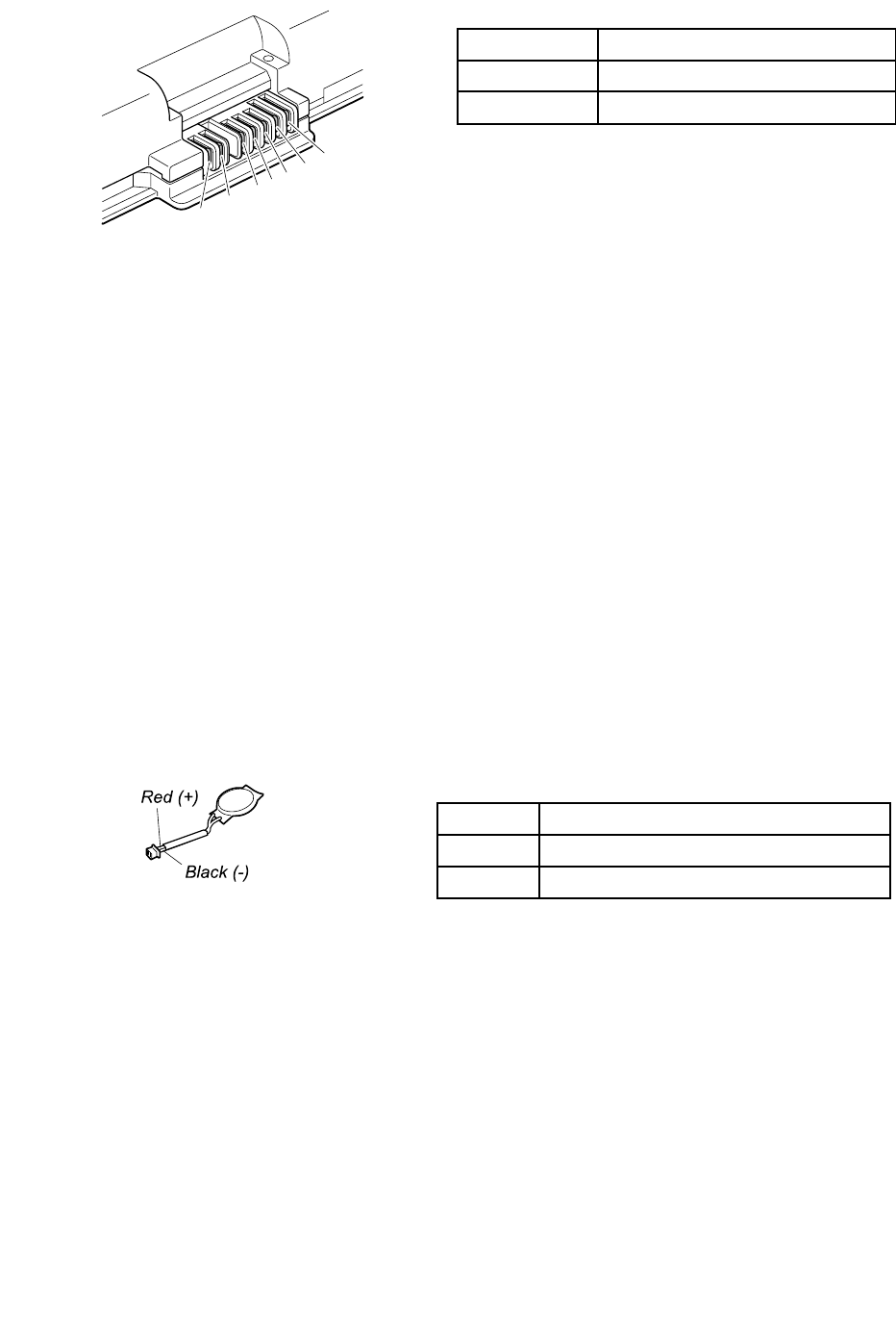
Checkingthebackupbattery
Dothefollowing:
1.Poweroffthecomputer,andunplugtheacadapterfromit.
2.Turnthecomputerupsidedown.
3.Removethebatterypack(see“1010Batterypack”onpage70).
4.Removethebackupbattery(see“1130Backupbattery”onpage91).
5.Measurethevoltageofthebackupbattery.Seethefollowingillustration.
WireVoltage(Vdc)
Red+2.5to+3.2
BlackGround
•Ifthevoltageiscorrect,replacethesystemboard.
•Ifthevoltageisnotcorrect,replacethebackupbattery.
•Ifthebackupbatterydischargesquicklyafterreplacement,replacethesystemboard.
36HardwareMaintenanceManual

Chapter4.Relatedserviceinformation
Thischapterpresentsfollowinginformation:
•“RestoringthefactorycontentsbyusingtheproductRecoveryDiscSet”onpage37
•“Passwords”onpage40
•“Powermanagement”onpage42
•“Symptom-to-FRUindex”onpage43
ServiceWebsite:
Whenthelatestmaintenancedisketteandthesystemprogramservicediskettebecomeavailable,they
willbepostedonhttp://www.lenovo.com/support.
RestoringthefactorycontentsbyusingtheproductRecoveryDiscSet
Whenthemainstoragedeviceisreplacedbecauseofafailure,noproductrecoveryprogramisonthenew
drive.Inthiscase,thecustomermustusetheRecoveryDiscSettorecoverthetablet.OrdertheRecovery
DiscSetandthedriveatthesametimesothatthecustomercanrestorethetablettothefactorydefault
settingsbyusingtheRecoveryDiscSetafterthenewdriveisinstalled.Forinformationaboutwhichdiscsto
order,goto:
http://www.lenovo.com/serviceparts-lookup.
Dependingonthemodel,thenumberofrecoverydiscsincludedintheRecoveryDiscSetdiffers.Torestore
thefactorycontentsbyusingtheproductRecoveryDiscSet,dothefollowing:
Notes:
•Duringtherecoveryprocess,alldataonthedrivewillbedeleted.Ifpossible,copyanyimportantdata
orpersonalfilesthatyouwanttokeepontoremovablemediaoranetworkdrivebeforeyoustartthe
recoveryprocess.
•Therecoveryprocesstakesonetotwohourstocomplete.Thelengthoftimedependsonthemethodyou
use.IfyouuseproductRecoveryDiscSet,therecoveryprocesstakesabouttwohours.
1.ConnectanexternalCD/DVDdrive.
2.MaketheCD/DVDdrivethefirststartupdeviceinthestartupsequenceusingthefollowingprocedure:
a.OpentheThinkPadSetupprogramandselectStartup➙Boot.
b.SelecttheCD/DVDdriveasthe1stBootDevice.
3.InsertthebootablerecoverydiscintotheCD/DVDdrive.
4.StartthecomputerfromtheexternalCD/DVDdrive.
5.Whenpromoted,selectyourlanguageandclickNext.
6.Readthelicenseandacceptthetermsandconditions.Thenfollowtheinstructionsonthescreen.
7.IftheRecoveryDiscSetcontainsaSupplementalRecoveryDisc,insertitwhenpromptedandclickYes.
Note:NotallRecoveryDiscSetscomewithaSupplementalRecoveryDisc.IfthereisaSupplemental
RecoveryDisc,itwillbeclearlymarkedassuch.
8.Whenallofthedatahasbeencopiedfromthelastdiscinthesetandhasbeenprocessed,remove
theexternalCD/DVDdriveandrestartthecomputer.Followtheinstructionsonthescreentofinish
therecovery.
Note:Therestoftherecoveryprocessisfullyautomatedandnoactionfromyouisrequired.The
computerwillrestartintotheMicrosoftWindowsdesktopseveraltimesandyoumightexperience
periodswhennoactivityisapparentonthescreenforseveralminutesatatime.Thisisnormal.
©CopyrightLenovo2012,201437

9.Whentherecoveryprocesscompletes,theWelcometoMicrosoftWindowsscreenisdisplayed.Follow
theinstructionsonthescreentocompletetheWindowssetup.
10.AfteryouhavecompletedtheWindowssetup,youmightwanttorestoretheoriginalstartupsequence.
StarttheThinkPadSetupprogramandthenpressF9torestorethedefaultsettings.PressF10tosave
changesandexittheThinkPadSetupprogram.
Note:Afterrestoringadrivetothefactorydefaultsettings,youmightneedtoreinstallsomedevicedrivers.
UsingtheWindowsrecoveryprogramsontheWindows8operating
system
ThissectionprovidesinformationabouttherecoverysolutionsfortheWindows8operatingsystem.
AWindowsrecoveryimageispreinstalledintherecoverypartitiononyourcomputer.TheWindowsrecovery
imageenablesyoutorefreshyourcomputer,orresetyourcomputertothefactorydefaultsettings.
YoucancreaterecoverymediaasbackupsorreplacementfortheWindowsrecoveryimage.Withthe
recoverymedia,youcantroubleshootandfixtheproblemsonyourcomputerevenifyoucannotstartthe
Windows8operatingsystem.Itisrecommendedthatyoucreaterecoverymediaasearlyaspossible.For
moreinformation,see“Usingrecoverymedia”onpage39.
Refreshingthecomputer
Ifyourcomputerdoesnotperformwellandtheproblemmightbecausedbyarecentlyinstalledprogram,
youcanrefreshyourcomputerwithoutlosingyourpersonalfilesorchangingyoursettings.
Attention:Ifyourefreshyourcomputer,theprogramsthatcamewithyourcomputerandtheprogramsthat
youinstalledfromWindowsStorewillbereinstalled,butallotherprogramswillberemoved.
Torefreshyourcomputer,dothefollowing:
1.Moveyourcursortothetop-rightorbottom-rightcornerofthescreentodisplaythecharms.Click
Settings➙ChangePCsettings➙General.
2.IntheRefreshyourPCwithoutaffectingyourfilessection,clickGetstarted.
3.Followtheinstructionsonthescreentorefreshyourcomputer.
Resettingthecomputertothefactorydefaultsettings
Ifyouwanttorecycleyourcomputerorjuststartover,youcanresetyourcomputertothefactorydefault
settings.Resettingthecomputerwillreinstalltheoperatingsystem,reinstallalltheprogramsthatcamewith
yourcomputer,andresetallthesettingstothefactorydefaultsettings.
Attention:Ifyouresetthecomputertothefactorydefaultsettings,allyourpersonalfilesandsettingswillbe
deleted.Toavoiddataloss,makeabackupcopyofallthedatathatyouwanttokeep.
Toresetyourcomputertothefactorydefaultsettings,dothefollowing:
1.Moveyourcursortothetop-rightorbottom-rightcornerofthescreentodisplaythecharms.Click
Settings➙ChangePCsettings➙General.
2.IntheRemoveeverythingandreinstallWindowssection,clickGetstarted.ThenclickNextto
confirmtheoperation.
3.Dependingonyourneeds,dooneofthefollowing:
•Toperformaquickformat,clickJustremovemyfilestostarttheprocess.Theprocesswilltake
severalminutes.
38HardwareMaintenanceManual

•Toperformacompleteformat,clickFullycleanthedrivetostarttheprocess.Theprocesswill
takeseveralhours.
4.Followtheinstructionsonthescreentoresetyourcomputertothefactorydefaultsettings.
Usingtheadvancedstartupoptions
Withtheadvancedstartupoptions,youcanchangethefirmwaresettingsofthecomputer,changethe
startupsettingsoftheWindowsoperatingsystem,startthecomputerfromanexternaldevice,orrestorethe
Windowsoperatingsystemfromasystemimage.
Tousetheadvancedstartupoptions,dothefollowing:
1.Moveyourcursortothetop-rightorbottom-rightcornerofthescreentodisplaythecharms.Click
Settings➙ChangePCsettings➙General.
2.IntheAdvancedstartupsection,clickRestartnow➙Troubleshoot➙Advancedoptions.
3.Selectadesiredstartupoption,thenfollowtheinstructionsonthescreen.
RecoveringyourcomputerfromtheWindowsrecoveryenvironment
TheWindowsrecoveryenvironmentonyourcomputeroperatesindependentlyfromtheWindows8
operatingsystem.IftheWindows8operatingsystemfailstostart,youstillcanusetheWindowsrecovery
environmenttotroubleshootandfixproblems.
TheWindowsrecoveryenvironmentstartsautomaticallyinthecaseoftwoconsecutivefailedboots.
TomanuallystarttheWindowsrecoveryenvironment,turnonorrestartthecomputer.BeforetheWindows8
operatingsystemstarts,repeatedlypresstheF11key.TheWindowsrecoveryenvironmentstarts.
TousetheWindowsrecoveryenvironment,dothefollowing:
Note:Ensurethatyourcomputerisconnectedtoacpower.
1.Selectapreferredlanguageandthenselectapreferredkeyboardlayout.
2.ClickTroubleshoottodisplaytheoptionalrecoverysolutions.
3.Selectacorrespondingrecoverysolutionaccordingtoyoursituation.Forexample,selectResetyour
PCifyouwanttoresetyourcomputertothefactorydefaultsettings.
Creatingandusingrecoverymedia
YoucancreaterecoverymediaasbackupsfortheWindowsrecoveryenvironmentandtheWindows
recoveryimage.Ifyoucannotstartthecomputer,youcanuserecoverymediatotroubleshootandfixthe
problemsonyourcomputer.
Itisrecommendedthatyoucreaterecoverymediaasearlyaspossible.Onceyoucreaterecoverymedia,
keeptheminasafeplaceanddonotusethemtostoreotherdata.
Creatingrecoverymedia
Tocreaterecoverymedia,youneedaUSBdrivewithatleast8GBofstorage.TherequiredUSBcapacity
dependsonthesizeoftherecoveryimage.
Attention:CreatingrecoverymediawilldeleteanythingstoredontheUSBdrive.T oavoiddataloss,makea
backupcopyofallthedatathatyouwanttokeep.
Tocreaterecoverymedia,dothefollowing:
Note:Ensurethatyourcomputerisconnectedtoacpower.
Chapter4.Relatedserviceinformation39

1.Moveyourcursortothetop-rightorbottom-rightcornerofthescreentodisplaythecharms,and
clickSearch.
2.TyperecoveryintheSearchfieldandclickSettings.ThenclickCreatearecoverydrive.
3.ClickYesintheUserAccountControlwindowtoallowtheRecoveryMediaCreatorprogramtostart.
4.EnsurethatyouselecttheCopytherecoverypartitionfromthePCtotherecoverydrive.option.
ThenclickNext.
Important:IfyoucleartheCopytherecoverypartitionfromthePCtotherecoverydrive.option,
youwillcreaterecoverymediawithouttherecoverypartitioncontent.Youstillcanstartthecomputer
fromtherecoverymedia,butyoumightbeunabletorecoveryourcomputeriftherecoverypartitionon
yourcomputerisdamaged.
5.ConnectaproperUSBdrivethenclickNext.
6.ClickCreateintheRecoveryDrivewindow.Thecreationoftherecoverymediastarts.
7.Whenthecreationoftherecoverymediafinishes,dooneofthefollowing:
•Tokeeptherecoverypartitiononyourcomputer,clickFinish.
•Todeletetherecoverypartitiononyourcomputer,clickDeletetherecoverypartition.
Attention:Ifyoudeletetherecoverypartitiononyourcomputer,dokeeptherecoverymediaina
safeplace.TheWindowsrecoveryimagewillnotbestoredinyourcomputeranymore,andyouwill
needtherecoverymediatorefreshorresetyourcomputer.
8.RemovetheUSBdrive.Therecoverymediaarecreatedsuccessfully.
Usingrecoverymedia
Ifyoucannotstartyourcomputer,orifyoucannotstarttheWindowsrecoveryimageonyourcomputer,use
recoverymediatorecoveryourcomputer.
Touserecoverymedia,dothefollowing:
Note:Ensurethatyourcomputerisconnectedtoacpower.
1.Turnonorrestartthecomputer.BeforetheWindowsoperatingsystemstarts,repeatedlypresstheF12
key.TheBootMenuwindowopens.
2.Selecttherecoverydriveasthebootdevice.
3.Selectapreferredlanguageandthenselectapreferredkeyboardlayout.
4.ClickTroubleshoottodisplaytheoptionalrecoverysolutions.
5.Selectacorrespondingrecoverysolutionaccordingtoyoursituation.Forexample,selectResetyour
PCifyouwanttoresetyourcomputertothefactorydefaultsettings.
FormoreinformationabouttherecoverysolutionsprovidedbytheWindows8operatingsystem,goto:
http://www.lenovo.com/accessories/services/index.html
Passwords
AsmanyasthreepasswordsmightbeneededforaThinkPadnotebookcomputer:thepower-onpassword,
theharddiskpassword,andthesupervisorpassword.
Ifanyofthesepasswordshasbeenset,apromptforitwillbedisplayedonthescreenwheneverthe
computeristurnedon.Thecomputerdoesnotstartuntilthepasswordisentered.
Note:Ifonlyasupervisorpasswordisset,thepasswordpromptwillnotbedisplayedwhentheoperating
systemisstarted.
40HardwareMaintenanceManual

Power-onpassword
Apower-onpassword(POP)protectsthesystemfrombeingpoweredonbyanunauthorizedperson.The
passwordmustbeenteredbeforeanoperatingsystemcanbebooted.ForhowtoremovethePOP ,see
“Howtoremovethepower-onpassword”onpage41.
Harddiskpassword
Therearetwoharddiskpasswords:
•Userharddiskpassword-fortheuser
•Masterharddiskpassword-forthesystemadministrator,whocanuseittogetaccesstotheharddisk
eveniftheuserhaschangedtheuserharddiskpassword.
Note:Therearetwomodesfortheharddiskpassword:UseronlyandMaster+User.TheMaster+User
moderequirestwoharddiskpasswords;thesystemadministratorentersbothinthesameoperation.The
systemadministratorthenprovidestheuserharddiskpasswordtothesystemuser.
Attention:Iftheuserharddiskpasswordhasbeenforgotten,checkwhetheramasterharddiskpassword
hasbeenset.Ifamasterharddiskpasswordhasbeenset,itcanbeusedtoaccesstheharddiskdrive.If
nomasterharddiskpasswordisavailable,neitherLenovonorLenovoauthorizedservicetechniciansprovide
anyservicestoreseteithertheuserharddiskpasswordorthemasterharddiskpassword,ortorecoverdata
fromtheharddiskdrive.Theharddiskdrivecanbereplacedforascheduledfee.
Forinstructionsonhowtoremovetheharddiskpassword,see“Howtoremovetheharddiskpassword”
onpage42.
Supervisorpassword
AsupervisorpasswordprotectsthesysteminformationstoredintheThinkPadSetupprogram.Theuser
mustenterthesupervisorpasswordinordertogetaccesstotheThinkPadSetupprogramandchangethe
systemconfiguration.
Attention:Ifthesupervisorpasswordhasbeenforgottenandcannotbemadeavailabletotheservice
technician,thereisnoserviceproceduretoresetthepassword.Thesystemboardmustbereplacedfor
ascheduledfee.
Howtoremovethepower-onpassword
Toremovethepower-onpasswordthatyouhaveforgotten,dooneofthefollowing:
(A)Ifnosupervisorpasswordhasbeenset,dothefollowingtoremovethepower-onpassword:
1.Turnoffthecomputeranddisconnecttheacpoweradapter.
2.Removethebatterypack.See“1010Batterypack”onpage70.
3.Removethebackupbattery.See“1130Backupbattery”onpage91.
4.Connecttheacpoweradapter.TurnonthecomputerandwaituntilthePOSTends.AfterthePOST
ends,thepasswordpromptdoesnotappear.ThePOPhasbeenremoved.
5.Reinstallthebackupbatteryandthebatterypack.
(B)Ifasupervisorpasswordhasbeensetandisknowntotheservicetechnician,dothefollowingtoremove
thepower-onpassword:
1.Turnonthecomputer.
2.WhentheThinkPadlogoisdisplayed,immediatelypressF1.
3.TypethesupervisorpasswordtoentertheThinkPadSetupprogram.
Chapter4.Relatedserviceinformation41

4.SelectSecurity.
5.SelectPassword.
6.SelectPower-OnPassword.
7.TypethecurrentsupervisorpasswordintheEnterCurrentPasswordfield.ThenleavetheEnter
NewPasswordfieldblank,andpressEntertwice.
8.IntheChangeshavebeensavedwindow,pressEnter.
9.PressF10tosavechangesandexittheThinkPadSetupprogram.
Howtoremovetheharddiskpassword
Attention:IfUseronlymodeisselectedandtheuserharddiskpasswordhasbeenforgottenandcannotbe
madeavailabletotheservicetechnician,neitherLenovonorLenovoauthorizedservicetechniciansprovide
anyservicestoresettheuserharddiskpassword,ortorecoverdatafromtheharddiskdrive.Toputthe
systembacktooperationalstatus,theonlyLenovoandLenovo-authorizedservicesolutionwouldbeto
replacetheharddiskdriveorsolid-statedrivewithascheduledfee.
Toremoveauserharddiskpasswordthathasbeenforgotten,whenthesupervisorpasswordandthemaster
harddiskpasswordareknown,dothefollowing:
1.Turnonthecomputer.
2.WhentheThinkPadlogoisdisplayed,immediatelypressF1toentertheThinkPadSetupprogram.
3.SelectSecurity.
4.SelectPassword.
5.SelectHard-diskxpasswordwherexistheletteroftheharddiskdrive.Apop-upwindowopens.
6.SelectMasterHDP,whereHDPstandsforharddiskpassword.
7.TypethecurrentmasterharddiskpasswordintheEnterCurrentPasswordfield.Then,leavetheEnter
NewPasswordfieldblank,andpressEntertwice.
8.PressF10tosavechangesandexittheThinkPadSetupprogram.Theuserharddiskpasswordandthe
masterharddiskpasswordhavebeenremoved.
Powermanagement
Toreducepowerconsumption,thecomputerhasthreepowermanagementmodes:screenblank,sleep,
andhibernation.
Screenblankmode(fortheWindows7operatingsystemonly)
Ifthetimesetonthe“T urnoffmonitor”timerintheoperatingsystemexpires,theLCDbacklightturnsoff.
Toputthecomputerintoscreenblankmode,right-clickthebatterygaugefromtheWindowsnotification
areaandselectPoweroffdisplay.
Toendscreenblankmodeandresumenormaloperation,pressanykey.
Sleepmode
Whenthecomputerenterssleepmode,thefollowingeventsoccurinadditiontowhatoccursinscreen
blankmode:
•TheLCDispoweredoff.
•Theharddiskdriveispoweredoff.
•Themicroprocessorstops.
Toentersleepmode,pressFn+F4.
42HardwareMaintenanceManual

Incertaincircumstances,thecomputergoesintosleepmodeautomatically:
•Afteraperiodofinactivityspecifiedinpowerplansettings
•Whenthebatteryindicatorblinksorange,indicatingthatthebatterypowerislow
Tocausethecomputertoreturnfromsleepmodeandresumeoperation,dooneofthefollowing:
•PresstheFnkey.
•OpentheLCDcover.
•Turnonthepowerbutton.
Also,ineitherofthefollowingevents,thecomputerautomaticallyreturnsfromsleepmodeandresumes
operation:
•Theringindicator(RI)issignaledbyaserialdeviceoraPCCarddevice.
•Thetimesetontheresumetimerelapses.
Note:Thecomputerdoesnotacceptanyinputimmediatelyafteritenterssleepmode.Waitafew
secondsbeforetakinganyactiontoreenteroperationmode.
Hibernationmode
Inhibernationmode,thefollowingoccurs:
•Thesystemstatus,RAM,VRAM,andsetupdataarestoredontheharddisk.
•Thesystemispoweredoff.
Note:Ifthecomputerentersthehibernationmodewhileitisdockedtothedockingstation,donotundockit
beforeresumingnormaloperation.Ifyoudoundockitandthentrytoresumenormaloperation,youwillget
anerrormessage,andyouwillhavetorestartthesystem.
Toputthecomputerintohibernationmode,usethePowerManagerprogramtodefineoneofthefollowing
actionsastheeventthatcausesthesystemtogointohibernationmode.Thenperformthedefinedaction.
•Closingthelid.
•Pressingthepowerbutton.
•PressingFn+F4.
Also,thecomputergoesintohibernationmodeautomaticallyafteraperiodofinactivityspecifiedinpower
plansettings
Whenthepoweristurnedon,thecomputerreturnsfromhibernationmodeandresumesoperation.The
hibernationfileinthebootrecordontheharddiskdriveisread,andsystemstatusisrestoredfromthe
harddiskdrive.
Symptom-to-FRUindex
Thissectioncontainsfollowinginformation:
•“Numericerrorcodes”onpage44
•“Errormessages”onpage45
•“Beepsymptoms”onpage45
•“No-beepsymptoms”onpage46
•“LCD-relatedsymptoms”onpage46
•“Intermittentproblems”onpage47
•“Undeterminedproblems”onpage47
Thesymptom-to-FRUindexinthissectionlistssymptomsanderrorsandtheirpossiblecauses.Themost
likelycauseislistedfirst,inboldfacetype.
Chapter4.Relatedserviceinformation43

Note:DotheFRUreplacementorotheractionsinthesequenceshowninthecolumnheaded“FRUor
action,insequence.”IfreplacingaFRUdoesnotsolvetheproblem,puttheoriginalpartbackinthe
computer.DonotreplaceanondefectiveFRU.
Thisindexcanalsohelpyoudetermine,duringregularservicing,whatFRUsarelikelytoneedtobe
replacednext.
AnumericerrorisdisplayedforeacherrordetectedinPOSTorsystemoperation.Inthedisplays,ncan
beanynumber.
Ifnonumericcodeisdisplayed,checkthenarrativedescriptionsofsymptoms.Ifthesymptomisnot
describedthere,goto“Intermittentproblems”onpage47.
Note:ForadevicenotsupportedbydiagnosticcodesintheThinkPadnotebookcomputers,seethe
manualforthatdevice.
Numericerrorcodes
Table2.Numericerrorcodes
SymptomorerrorFRUoraction,insequence
0177:BadSVPdata,stopPOSTtask.—Thechecksum
ofthesupervisorpasswordintheEEPROMisnotcorrect.
Systemboard
0183:BadCRCofSecuritySettingsinEFIVariable.
EnterThinkPadSetup.—ThechecksumoftheSecurity
settingsintheEFIVariableisnotcorrect.
EnterThinkPadSetuptocorrectSecuritysettingsin
theEFIVariable.
0187:EAIAdataaccesserror.Systemboard
0188:InvalidRFIDSerializationInformationArea.—The
EEPROMchecksumisnotcorrect(Block#0,1).
Systemboard
0189:InvalidRFIDconfigurationInformationArea.—The
EEPROMchecksumisnotcorrect(Block#4,5).
Systemboard
0190:Criticallow-batteryerror•Chargethebatterypack.
•Batterypack
0191:SystemSecurity-InvalidRemoteChange
requested.
•RunThinkPadSetup,andthensavethecurrent
settingbypressingF10.
•Systemboard
0199:SystemSecurity-Securitypasswordretrycount
exceeded.
•RunThinkPadSetup,andthensavethecurrent
settingbypressingF10.
•Systemboard
0251:SystemCMOSchecksumbad-Default
configurationused
1.Chargethebackupbatteryformorethan8hours
byconnectingtheacadapter.
2.ReplacethebackupbatteryandrunThinkPadSetup
toresetthetimeanddate.
0253:EFIVariableBlockDatawasdestroyed.
0271:Real-TimeClockError.CheckDateandTime
settings.
RunThinkPadSetuptoresetthetimeanddate.
1802:Unauthorizednetworkcardispluggedin-Power
offandremovetheminiPCInetworkcard.
•RemoveMiniPCInetworkcard.
•Systemboard
1820:Morethanoneexternalfingerprintreaderis
attached.Poweroffandremoveallbutthereaderthat
yousetupwithinyourmainoperatingsystem.
Removeallbutthereaderthatyousetupforthe
authentication.
44HardwareMaintenanceManual

Table2.Numericerrorcodes(continued)
SymptomorerrorFRUoraction,insequence
2000:ThinkVantage®ActiveProtectionsensordiagnostics
failed.
Systemboard
2100:DetectionerroronHDD0(MainHDD)1.Reseattheharddiskdrive.
2.Mainharddiskdrive
3.Systemboard
2101:DetectionerroronHDD1(UltrabayHDD)1.Reseattheharddiskdrive.
2.Ultrabay®harddiskdrive
3.Systemboard
2102:DetectionerroronHDD2(MiniSATA)1.ReseattheMiniSATAdevice.
2.MiniSATAdevice
3.Systemboard
2110:ReaderroronHDD0(MainHDD)1.Reseattheharddiskdrive.
2.Mainharddiskdrive
3.Systemboard
2111:ReaderroronHDD1(UltrabayHDD)1.Reseattheharddiskdrive.
2.Ultrabayharddiskdrive
3.Systemboard
2112:ReaderroronHDD2(MiniSATA)1.ReseattheMiniSATAdevice.
2.MiniSATAdevice
3.Systemboard
2200:MachineTypeandSerialNumberareinvalid.Systemboard
2201:MachineUUIDisinvalid.Systemboard
Errormessages
Table3.Errormessages
SymptomorerrorFRUoraction,insequence
Fanerror.1.Fan
2.Thermalgrease
3.Systemboard
Thermalsensingerror.Systemboard
Thebatteryinstalledisnotsupportedbythissystem
andwillnotcharge.Pleasereplacethebatterywiththe
correctLenovobatteryforthissystem.PresstheESC
keytocontinue.
Replacethebattery.
Beepsymptoms
Table4.Beepsymptoms
SymptomorerrorFRUoraction,insequence
FourcyclesoffourshortbeepsSystemboard
Fiveshortbeeps,pause,andfivemoreshortbeepsSystemboard
Oneshortbeep,pause,threeshortbeeps,pause,three
moreshortbeeps,pause,andoneshortbeep
1.Memorymodule
2.Systemboard
Threeshortbeeps,pause,oneshortbeep,pause,one
moreshortbeep,pause,andthreeshortbeeps
RemovetheinstalledPCIdevices.
Chapter4.Relatedserviceinformation45

Table4.Beepsymptoms(continued)
SymptomorerrorFRUoraction,insequence
FiveshortbeepsSystemboard
OnelongandtwoshortbeepsSystemboard
No-beepsymptoms
Table5.No-beepsymptoms
SymptomorerrorFRUoraction,insequence
Nobeep,power-onindicatoron,LCDblank,andno
POST.
1.Makesurethateveryconnectorisconnected
tightlyandcorrectly.
2.Memorymodule
3.Systemboard
Nobeep,power-onindicatoron,andLCDblankduring
POST.
1.Reseatthememorymodule.
2.Systemboard
Thepower-onpasswordpromptappears.Apower-onpasswordorasupervisorpasswordisset.
TypethepasswordandpressEnter.
Thehard-diskpasswordpromptappears.Ahard-diskpasswordisset.Typethepasswordand
pressEnter.
LCD-relatedsymptoms
Important:TheTFTLCDforthenotebookcomputercontainsmanythin-filmtransistors(TFTs).The
presenceofasmallnumberofdotsthataremissing,discolored,oralwayslightedischaracteristicofTFT
LCDtechnology,butexcessivepixelproblemscancauseviewingconcerns.IftheLCDyouareservicinghas
twoorlessvisibledefectivepixels,itshouldnotbeconsideredfaulty.However,iftheLCDhasthreeormore
visibledefectivepixels,itwillbedeemedasdefectivebyLenovoanditshouldbereplaced.
Notes:
•ThispolicyappliestoallThinkPadnotebookcomputerspurchasedon1January,2008orlater.
•LenovowillnotprovidewarrantyreplacementiftheLCDiswithinspecificationsbecausewecannot
guaranteethatanyreplacementLCDwillhavezeropixeldefects.
•OnepixelconsistsofR,G,Bsub-pixels.
Table6.LCD-relatedsymptoms
SymptomorerrorFRUoraction,insequence
Nobeep,power-onindicatoron,andablankLCDduring
POST.
Systemboard
•LCDbacklightnotworking
•LCDtoodark
•LCDbrightnesscannotbeadjusted.
•LCDcontrastcannotbeadjusted.
1.ReseattheLCDconnectors.
2.LCDassembly
3.Systemboard
•LCDscreenunreadable
•Charactersmissingpixels
•Screenabnormal
•Wrongcolordisplayed
1.Seeimportantnotefor“LCD-relatedsymptoms.”
2.ReseatallLCDconnectors.
3.LCDassembly
4.Systemboard
HorizontalorverticallinesdisplayedonLCDLCDassembly
46HardwareMaintenanceManual

Intermittentproblems
Intermittentsystemhangproblemscanbeduetoavarietyofcausesthathavenothingtodowithahardware
defect,suchascosmicradiation,electrostaticdischarge,orsoftwareerrors.FRUreplacementshouldbe
consideredonlywhenaproblemrecurs.
Undeterminedproblems
Ifthediagnostictestsdidnotidentifythedevicethathasfailed,ifwrongdevicesareinstalled,orifthe
systemsimplyisnotoperating,followtheseprocedurestoisolatethefailingFRU(donotisolateFRUs
thathavenodefects).
Verifythatallattacheddevicesaresupportedbythecomputer.
Verifythatthepowersupplybeingusedatthetimeofthefailureisoperatingcorrectly.(See“Powersystem
checkout”onpage34.)
1.Turnoffthecomputer.
2.VisuallycheckeachFRUfordamage.ReplaceanydamagedFRU.
3.Removeordisconnectallofthefollowingdevices:
a.Non-ThinkPaddevices
b.Devicesattachedtothedockingstationortheportreplicator
c.Printer,mouse,andotherexternaldevices
d.Batterypack
e.Harddiskdriveorsolidstatedrive
f.Externaldriveoropticaldrive
g.Memorymodule(Removeallandtheninstallonlyonememorymodule)
h.Opticaldisk
i.PCCards
4.Turnonthecomputer.
5.Determinewhethertheproblemhasbeensolved.
6.Iftheproblemdoesnotrecur,reconnecttheremoveddevicesoneatatimeuntilyoufindthefailingFRU.
7.Iftheproblemremains,replacethefollowingFRUsoneatatime(donotreplaceanondefectiveFRU):
a.Systemboard
b.LCDassembly
Chapter4.Relatedserviceinformation47

48HardwareMaintenanceManual

Chapter5.InstallingandconfiguringRAID
Thischaptercontainsthefollowingtopics:
•“SupportedRAIDlevels”onpage49
•“ConfiguringthesystemUEFIBIOStoenableembeddedSATARAIDfunctionality”onpage49
•“CreatingRAIDvolumes”onpage50
•“DeletingRAIDvolumes”onpage50
Note:WhentheUEFIBIOSwasformattedorthesystemboardwasreplacedintheRAID-supportedmodels,
RAIDisenabledbydefault.
ImportantnoticesforsettingRAID:
BeforeyouinstallandconfigureRAID,checkthecurrentRAIDsettingonthecomputeryouareservicing.
ThisproductsupportseitherRAID0orRAID1.ConfirmtheRAIDsettinginformationprovidedbythe
customeratfirst,thenproceedwiththeinstallation.
TosupportRAID0orRAID1,thecomputersyouareservicingmustbeequippedwithtworives.
SupportedRAIDlevels
ThefollowingRAIDlevelsaresupportedonRAID-supportedmodels:
RAID0-Stripeddiskarray
Betterperformanceandnofaulttolerance.
RAID1-Mirroreddiskarray
Improvedreadperformanceand100%redundancy.
ConfiguringthesystemUEFIBIOStoenableembeddedSATARAID
functionality
Note:ForRAID-supportedmodels,theembeddedSATARAIDfunctionalityisenabledbydefault.
ToconfiguretheUEFIBIOSforRAID,dothefollowing:
1.PressF1toentertheThinkPadSetupprogram.
2.SelectConfig.
3.SelectSerialATA(SATA).
4.SelectSATAControllerModeOption,andthenthefollowingoptionswillbedisplayed:
•Compatibility
•AHCI
•RAID
5.SelectRAID.
6.PressF10tosavechangesandexit.
Attention:AfteryouhaveenabledtheSATARAIDfunctionality,reinstalltheoperatingsystembeforetaking
anyfurtherRAID-relatedaction.
©CopyrightLenovo2012,201449

CreatingRAIDvolumes
ThistopicdescribeshowtousetheIntel®RapidStorageTechnologyoptionROMconfigurationutilityto
createRAIDvolumes.
TocreateRAIDvolumes,dothefollowing:
1.Turnonthecomputer.
2.WhenamessagePress<Ctrl-I>toenterCongurationUtilityisdisplayed,pressCtr+I.
3.OntheIntelRapidStorageTechnologyoptionROMscreen,selectCreateRAIDVolume,andthen
pressEnter.
4.FollowtheinstructionsonthescreentoselecttheRAIDlevelandfillinotherfields.
5.SelectCreateVolume.Whenadialogboxisdisplayed,pressY.
Attention:AlltheexistingdatastoredontheselecteddrivewillbeerasedwhiletheRAIDvolume
isbeingcreated.
6.Exittheconfigurationutility.
DeletingRAIDvolumes
ThistopicdescribeshowtousetheIntelRapidStorageTechnologyoptionROMconfigurationutilityto
deleteRAIDvolumes.
TodeleteaRAIDvolume,dothefollowing:
1.Turnonthecomputer.
2.WhenamessagePress<Ctrl-I>toenterCongurationUtilityisdisplayed,pressCtr+I.
3.OntheIntelRapidStorageTechnologyoptionROMscreen,selecttheRAIDvolumetobedeleted,
andthenpressDelete.
4.Whenadialogboxisdisplayed,pressYtoconfirmthedeletionoftheselectedRAIDvolume.
5.Exittheconfigurationutility.
50HardwareMaintenanceManual
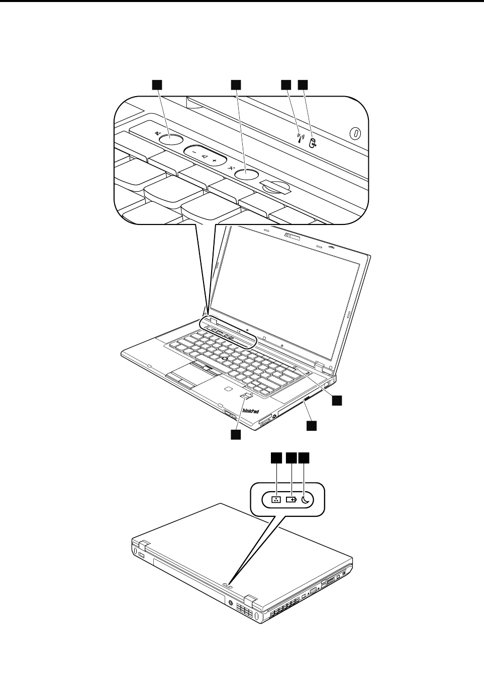
Chapter6.Statusindicators
Thischapterpresentsthesystemstatusindicatorsthatshowthestatusofthecomputer.
1234
5
6
7
9810
©CopyrightLenovo2012,201451
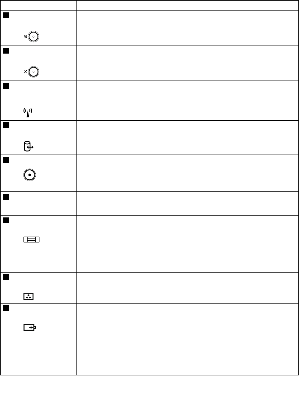
Table7.Statusindicators
IndicatorMeaning
1Speakermute
indicator
Orange:Thespeakerisonmute.Tomuteorunmutethespeakers,pressthe
speakermutebutton.
2Microphonemute
indicator
Orange:Themicrophoneisonmute.Bydefault,whenthemicrophoneisonmute,
noneoftherecordingdevicesisavailable.
3WirelessLAN,WAN,
orBluetoothstatus
indicator
Green:ThewirelessLANfeature(theIEEE802.11b/gstandard,802.11a/b/g,or
802.11n),wirelessWANfeature,orBluetoothfeatureison.
Blinkinggreen:Dataisbeingtransmitted.
4Deviceaccess
statusindicator
Blinkinggreen:Dataisbeingreadfromorwrittentotheharddiskdrive,thesolid
statedrive,orthedeviceintheSerialUltrabay™Enhancedbay.
5Power-onindicatorGreen:Thecomputerisonandreadytouse.Thisindicatorstayslitwheneverthe
computerisonandisnotinsleepmode.
Slowblinkinggreen:Thecomputerisinsleepmode.
Fastblinkinggreen:Thecomputerisenteringsleepmodeorhibernationmode,or
isresumingnormaloperation.
6SerialUltrabay
Enhanceddevice
statusindicator
Green:ASerialUltrabayEnhanceddeviceisinstalledandinuse.
Blinkinggreen:ASerialUltrabayEnhanceddeviceisbeingdetached.
Off:ASerialUltrabayEnhanceddeviceisreadytobeattachedordetached.
7Fingerprintreader
statusindicator
Green:Thefingerprintreaderisreadytotakefingerprint.
Blinkinggreenonce:Thefingerprintisbeingauthenticatedorhasbeen
authenticated.
Blinkinggreen:Thefingerprintreaderisreadytakefingerprintinpower-on
authenticationstate.
Blinkingamber:Thefingerprintcouldnotbeauthenticated.
Steadyamberfor15seconds:Thepower-onauthenticationfeatureisgoingtobe
disabledafterthreebadfingerprintswipes.
8Colorsensorstatus
indicator
Green:Thedisplaycolorcalibrationhascompleted.Whenthecomputerlidopens,
theindicatorturnsoff.
Blinkinggreen:Displaycolorsarebeingcalibrated.
9Batterystatus
indicator
Green:Thebatterychargelevelis80%ormore.
Blinkinggreen:Thebatterychargelevelisbetween20%and80%,andchargingis
continuing.Whenthebatterychargelevelreaches80%,thebatterystatusindicator
stopsblinking,butthechargingmightcontinueuntilthebatteryis100%charged.
Slowblinkingorange:Thebatterychargelevelisbetween5%and20%.
Quickblinkingorange(0.5secondoffevery1.5seconds):Thebatterycharge
levelis5%orless.
Fastblinkingorange(0.25secondoffevery0.5second):Anerrorhasoccurred
withthebattery.
Off:Thebatteryisfullychargedordetached,orthecomputerispoweredoff.
52HardwareMaintenanceManual

Table7.Statusindicators(continued)
IndicatorMeaning
Note:Ifthecomputerisoperatingonbatterypower,thebatterystatusindicatordoes
notworkwhilethecomputeristurnedofforisinsleepmodeorhibernationmode.
10Sleepstatus
indicator
Green:Thecomputerisinsleepmode.
Blinkinggreen:Thecomputerisenteringsleepmodeorhibernationmode,or
isresumingnormaloperation.
Chapter6.Statusindicators53

54HardwareMaintenanceManual

Chapter7.Fnkeycombinations
ThefollowingtabledescribesthefunctionsofFnkeycombinations.
Table8.Fnkeycombinations
KeycombinationDescription
Fn+F3Locksthecomputer.
Fn+F4Putsthecomputerintosleepmode.Toresumenormaloperation,presstheFnkey.
Notes:
•TousetheFn+F4keycombination,youmusthavetheThinkPadPowerManagement
driverinstalledonthecomputer.
•Ifyouwanttousethecombinationtoputthecomputerintohibernationmode,change
thepowerplansettings.
Fn+F5Enablesordisablesthebuilt-inwirelessnetworkingfeaturesandtheBluetoothfeatures.Ifyou
pressFn+F5,alistofwirelessfeaturesisdisplayed.Youcanquicklychangethepowerstate
ofeachfeatureinthelist.
Notes:IfyouwanttouseFn+F5toenableordisablethewirelessfeatures,thefollowing
devicedriversmustbeinstalledonthecomputerbeforehand:
•ThinkPadPowerManagementdriver
•OnScreenDisplayUtility
•Wirelessdevicedrivers
Fn+F6•ForWindows7:OpenstheCommunicationssettingswindow,inwhichyoucanpreview
yourvideoimage,takeasnapshotofyourcurrentimage,andchangethecameraand
audiosettings.
•ForWindows8:StartstheLenovoSettingsprogram,whichenablesyoutochangethe
cameraandaudiosettings.
Fn+F7Switchesbetweenthecomputerdisplayandanexternalmonitor.Thefollowingoptionswill
bedisplayed:
•Computerdisplayonly(LCD)
•Computerdisplayandexternalmonitor(sameimage)
•Computerdisplayandexternalmonitor(extendeddesktop)
•Externalmonitoronly
Note:Y oualsocanusetheWindows+Pcombinationtoswitchbetweenthecomputerdisplay
andanexternalmonitor.
Fn+F8Thecomputerdisplaybecomesdimmer.
Fn+F9Thecomputerdisplaybecomesbrighter.
Fn+F10Previoustrack/scene
Fn+F11Playorpause
Fn+F12Nexttrack/scene
Fn+SpacebarControlsthekeyboardbacklightandtheThinkLight®light.
•Pressonce:Turnonthekeyboardbacklighttolowbrightnesslevel.
•Pressagain:Adjustthekeyboardbacklighttohighbrightnesslevel.
•Pressthethirdtime:T urnoffthekeyboardbacklightandturnontheThinkLightlight.
•Pressthefourthtime:TurnofftheThinkLightlight.
Note:Ifyourcomputerdoesnothaveabacklitkeyboard,theFn+Spacebarcombination
controlsonlytheThinkLightlight.
Fn+BHasthesamefunctionastheBreakkeyonaconventionalkeyboard.
©CopyrightLenovo2012,201455

Table8.Fnkeycombinations(continued)
KeycombinationDescription
Fn+PHasthesamefunctionasthePausekeyonaconventionalkeyboard.
Fn+SHasthesamefunctionastheSysRqkeyonaconventionalkeyboard.
Fn+KHasthesamefunctionastheScrLKkeyonaconventionalkeyboard.
56HardwareMaintenanceManual
Chapter8.Locations
Thischapterintroducesthelocationsofthecomputerhardwarecomponents.
Locatingcomputercontrols,connectors,andindicators
Thistopicintroducesthelocationsofthecomputercontrols,connectors,andindicators.
Frontview
10
3
4
12
2
6
7
8
9
1211
15
16
18
19
17
13
14
8
20
21
5
1Statusindicators(seeChapter6“Statusindicators”
onpage51)
12ExpressCardslot
2Built-inmicrophones13Fingerprintreader(onsomemodels)
3Integratedcamera14Colorsensor(onsomemodels)
4ThinkLightlight15Touchpadbuttons
5Powerbutton16Touchpad
6Securitykeyhole17TrackPointbuttons
7RJ-45Ethernetconnector18TrackPointpointingstick
8Built-instereospeakers19UltraNav®pointingdevice
9SerialUltrabayEnhanceddeviceorblankbezel20Blackbutton
10Comboaudiojack21Volumecontrolbuttons
11Mediacardraderslot
©CopyrightLenovo2012,201457
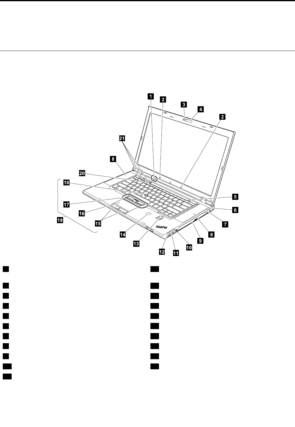
Rearview
1
9
2
3
4
5
7
6
8
10
1Statusindicators(seeChapter6“Statusindicators”
onpage51)
6USB3.0connectors
2Smartcardslot(onsomemodels)7Videographicsarray(VGA)connector
3Wirelessradioswitch8MiniDisplayPortconnector
4IEEE1394connector9acpowerconnector
5USB2.0connector10AlwaysOnUSBconnector
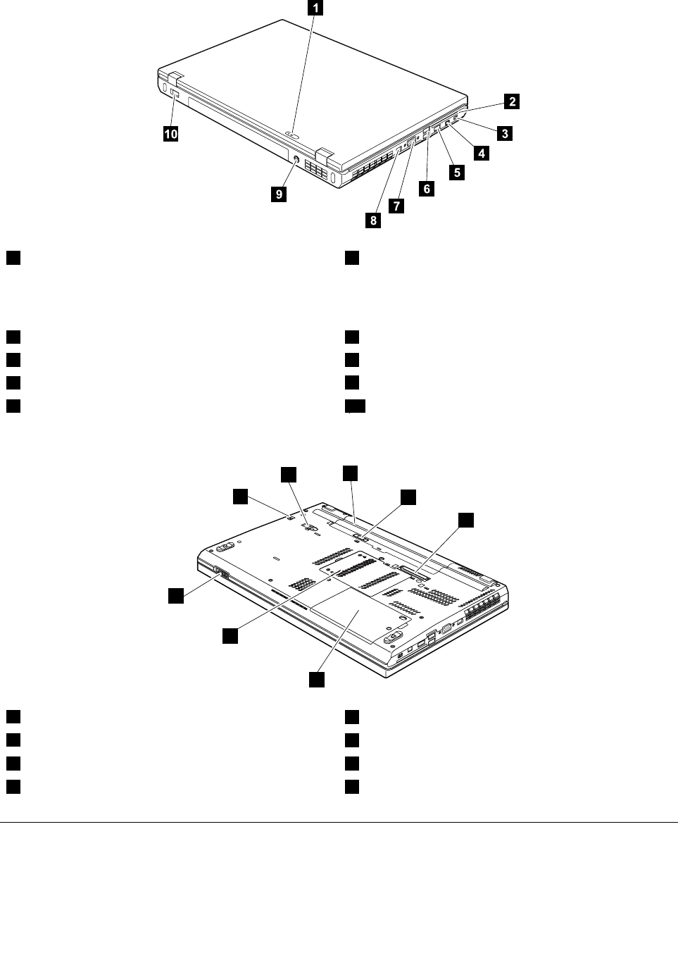
Bottomview
1
2
3
4
6
5
8
7
1Batterypack5Memorymoduleslot(bottom)
2Batterypacklatch6LCDcoverlatch
3Dockingconnector7SerialUltrabayEnhancedlocklatch
4Solidstatedriveorharddiskdriveslot8SerialUltrabayEnhancedejectlatch
LocatingFRUsandCRUs
Thistopicintroducesthefollowingserviceparts:
•“MajorFRUsandCRUs”onpage60
58HardwareMaintenanceManual

•“LCDFRUsandCRUs”onpage62
•“MiscellaneouskitsandotherFRUs”onpage63
Notes:
•EachFRUisavailableforalltypesormodels,unlessotherwisespecified.
•CRUstatementforcustomers:
Youcanresolvesomeproblemswithyourproductwithareplacementpartyoucaninstallyourself,
calleda“CustomerReplaceableUnit”or“CRU.”SomeCRUsaredesignatedasself-serviceCRUsand
othersaredesignatedasoptional-serviceCRUs.Installationofself-serviceCRUsisyourresponsibility.
Foroptional-serviceCRUs,youcaneitherinstalltheCRUyourselforyoucanrequestthataService
ProviderinstallstheCRUaccordingtothewarrantyserviceforyourproduct.Ifyouintendoninstalling
theCRU,LenovowillshiptheCRUtoyou.CRUinformationandreplacementinstructionsareshipped
withyourproductandareavailablefromLenovoatanytimeuponrequest.Y oucanfindalistofCRUs
foryourproductinthisHardwareMaintenanceManual.Anelectronicversionofthismanualcanbe
foundathttp://www.lenovo.com/support.ClickUserGuides&Manualsandthenfollowtheon-screen
instructionstofindthemanualforyourproduct.Youmightberequiredtoreturnthedefectivepart
thatisreplacedbytheCRU.Whenreturnisrequired:(1)returninstructions,aprepaidshippinglabel,
andacontainerwillbeincludedwiththereplacementCRU;and(2)youmightbechargedforthe
replacementCRUifLenovodoesnotreceivethedefectiveCRUwithinthirty(30)daysofyourreceiptof
thereplacementCRU.SeeyourLenovoLimitedWarrantydocumentationforfulldetails.
ThinkPadcomputerscontainthefollowingtypesofCRUs:
–Self-serviceCRUs:TheseCRUsunplugorareheldbynomorethantwoscrews.Examplesof
thesetypesofCRUsincludetheacpoweradapter,powercord,battery,andharddiskdrive.Other
self-serviceCRUsdependingonproductdesignmightincludethememorymodule,wirelesscard,
keyboard,andpalmrestwithfingerprintreaderandtouchpad.
–Optional-serviceCRUs:TheseCRUsareisolatedpartswithinthecomputerthatareconcealedbyan
accesspanelthatistypicallysecuredbymorethantwoscrews.Oncetheaccesspanelisremoved,
thespecificCRUisvisible.
Chapter8.Locations59
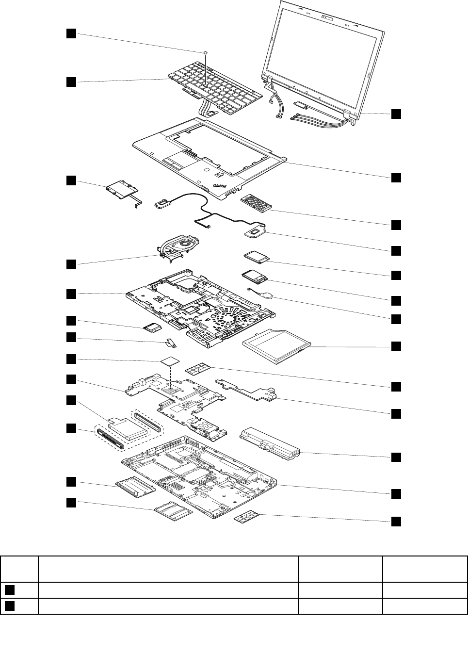

Table9.MajorFRUsandCRUs(continued)
No.FRUdescriptionSelf-serviceCRUOptional-service
CRU
3ExpressCardblankbezelorExpressCardYesNo
4SpeakerassemblyNoNo
5mSATAsolidstatedriveNoNo
6PCIExpressMiniCardforwirelessWANNoY es
7BackupbatteryNoY es
8SerialUltrabayEnhanceddeviceorblankbezelYesNo
9MemorymoduleordummymemorymoduleY esNo
10I/OsubcardNoNo
11BatteryYesNo
12BasecoverassemblyNoNo
13MemorymoduleslotcoverYesNo
14HarddiskdriveslotcoverY esNo
15HarddiskdriverubberrailsorsolidstatedrivespacersYesNo
16HarddiskdriveorsolidstatedriveYesNo
17SystemboardNoNo
18MicroprocessorNoNo
19BluetoothdaughtercardNoNo
20PCIExpressMiniCardforwirelessLANNoY es
21MagnesiumstructureframeNoNo
22ThermalfanassemblyNoNo
23SmartcardordummysmartcardNoNo
24KeyboardNoY es
25TrackPointcapYesNo
Chapter8.Locations61
LCDFRUsandCRUs
1
2
3
4
5
6
7
8
9
10
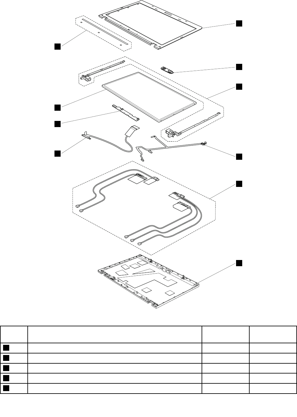
Table10.LCDFRUsandCRUs
No.FRUdescriptionSelf-service
CRU
Optional-service
CRU
1liquidcrystaldisplay(LCD)bezelassemblyNoNo
2IntegratedcameraNoNo
3HingekitNoNo
4LEDcableNoNo
5AntennakitNoNo
62HardwareMaintenanceManual

Table10.LCDFRUsandCRUs(continued)
No.FRUdescriptionSelf-service
CRU
Optional-service
CRU
6LCDrearcoverassemblyNoNo
7LCDcableNoNo
8LEDsubcardNoNo
9LCDpanelNoNo
10ClearplateNoNo
Important:
Forcolorsensormodels,iftheLCDpanelneedsareplacement,orderaspecialLCDpanelFRUkit
fromLenovo.TheFRUkitcontainsaLCDpanel,aCDandaninstructionflyer.ForthecorrectFRUkit
partnumber,checkontheWebsiteathttp://www.lenovo.com/serviceparts-lookup.
MiscellaneouskitsandotherFRUs
Table11.Miscellaneouskits
FRUdescriptionsSelf-service
CRU
Optional
serviceCRU
Systemboardmiscellaneouskit:
•ThermalPad
•CPUbracket
•InsulationSheet
•Spec
NoNo
Basecovermiscellaneouskit:
•BaseCoversubassemblypartswhichcanberemovable
•Spec
NoNo
Systemmiscellaneouskit:
•CableDC-in
•CableSmartCard
•SpacerSmartCard
•SpacerSmartCardReader
•DymmyExpressCard
•DymmyColorSensor
•Spec
NoNo
Screwkit:
•Spec
NoNo
Tapekit:
•Spec
NoNo
Table12.OtherFRUs
FRUdescriptionsSelf-service
CRU
Optional
serviceCRU
acadapterYesNo
PowercordYesNo
LookingupFRUinformation
FordetailedFRUinformation,includingpartnumbers,descriptions,andsubstitutionpartnumbers,goto
http://www.lenovo.com/serviceparts-lookup.
Chapter8.Locations63

64HardwareMaintenanceManual
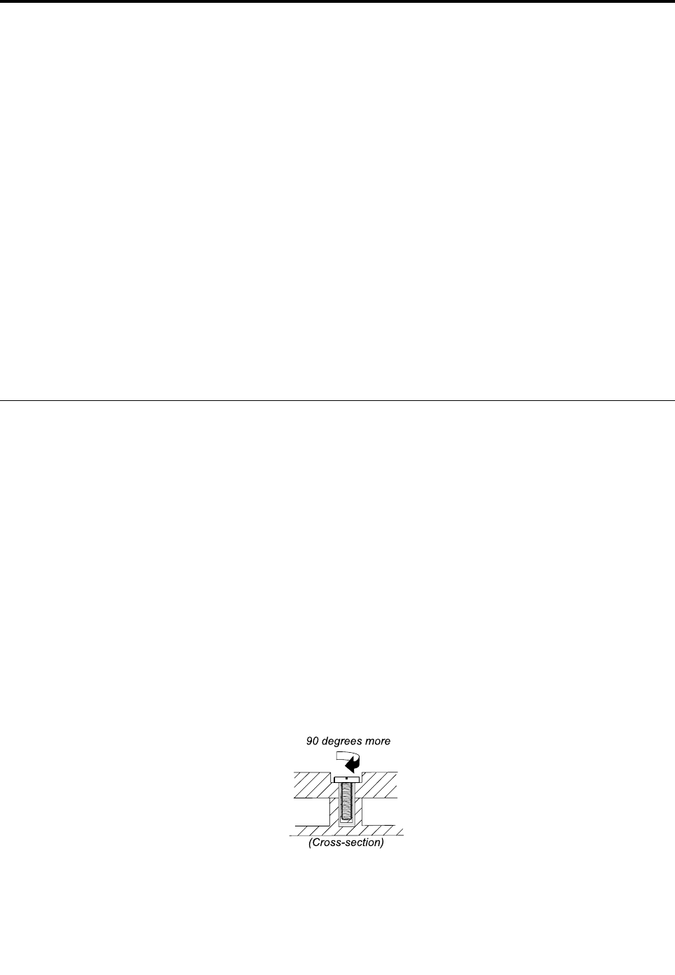
Chapter9.FRUreplacementnotices
Thischapterpresentsnoticesrelatedtoremovingandreplacingparts.Readthischaptercarefullybefore
replacinganyFRU.
CRUstatementforcustomers:
Youcanresolvesomeproblemswithyourproductwithareplacementpartyoucaninstallyourself,called
a“CustomerReplaceableUnit”or“CRU.”SomeCRUsaredesignatedasself-serviceCRUsandothers
aredesignatedasoptional-serviceCRUs.Installationofself-serviceCRUsisyourresponsibility.For
optional-serviceCRUs,youcaneitherinstalltheCRUyourselforyoucanrequestthataServiceProvider
installstheCRUaccordingtothewarrantyserviceforyourproduct.IfyouintendoninstallingtheCRU,
LenovowillshiptheCRUtoyou.CRUinformationandreplacementinstructionsareshippedwithyour
productandareavailablefromLenovoatanytimeuponrequest.YoucanfindalistofCRUsforyour
productinthisHardwareMaintenanceManual.Anelectronicversionofthismanualcanbefoundat
http://www.lenovo.com/support.ClickUserGuides&Manualsandthenfollowtheon-screeninstructions
tofindthemanualforyourproduct.Youmightberequiredtoreturnthedefectivepartthatisreplacedby
theCRU.Whenreturnisrequired:(1)returninstructions,aprepaidshippinglabel,andacontainerwillbe
includedwiththereplacementCRU;and(2)youmightbechargedforthereplacementCRUifLenovodoes
notreceivethedefectiveCRUwithinthirty(30)daysofyourreceiptofthereplacementCRU.Seeyour
LenovoLimitedWarrantydocumentationforfulldetails.
Screwnotices
Loosescrewscancauseareliabilityproblem.IntheThinkPadnotebookcomputer,thisproblemisaddressed
withspecialnylon-coatedscrewsthathavethefollowingcharacteristics:
•Theymaintaintightconnections.
•Theydonoteasilycomeloose,evenwithshockorvibration.
•Theyarehardertotighten.
Dothefollowingwhenyouservicethismachine:
•Keepthescrewkitinyourtoolbag.Forthepartnumberofthescrewkit,goto
http://www.lenovo.com/serviceparts-lookup.
•Itisrecommendedtousenewscrews.
•Itisrecommendedtouseeachscrewonlyonce.
•Useatorquescrewdriverifyouhaveone.
Tightenscrewsasfollows:
•Plastictoplastic
Turnanadditional90degreesafterthescrewheadtouchesthesurfaceoftheplasticpart:
•Logiccardtoplastic
Turnanadditional180degreesafterthescrewheadtouchesthesurfaceofthelogiccard:
©CopyrightLenovo2012,201465
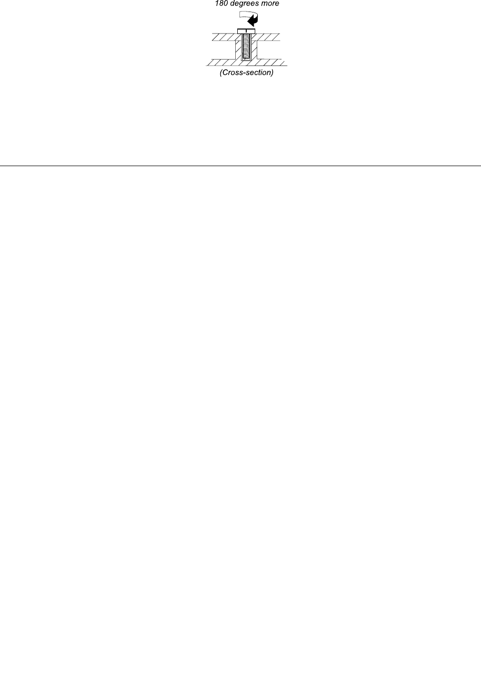
•T orquedriver
Ifyouhaveatorquedriver,refertotheTorquecolumninthescrewinformationtableforeachstep.
–Makesurethatyouusethecorrectscrew.Itisrecommendedtousenewscrewsforreplacements.If
youhaveatorquescrewdriver,tightenallscrewsfirmlytothetorquespecifiedinthescrewinformation
tableforeachstep.
–Ensuretorquescrewdriversarecalibratedcorrectlyfollowingcountryspecifications.
Retainingserialnumbers
Thissectionincludesthefollowingdescriptions:
•“Restoringtheserialnumberofthesystemunit”onpage66
•“RetainingtheUUID”onpage67
•“ReadingorwritingtheECAinformation”onpage67
Restoringtheserialnumberofthesystemunit
Whenthecomputerwasmanufactured,theEEPROMonthesystemboardwasloadedwiththeserial
numbersofthesystemandallmajorcomponents.Thesenumbersneedtoremainthesamethroughout
thelifeofthecomputer.
Ifyoureplacethesystemboard,youmustrestoretheserialnumberofthesystemunittoitsoriginalvalue.
Beforereplacingthesystemboard,savetheoriginalserialnumberbydoingthefollowing:
1.InstallthelatestversionofLENOVOThinkPadHardwareMaintenanceDisketteorMaintenanceKey,
andthenrestartthecomputer.
2.Fromthemainmenu,select1.Setsystemidentification.
3.Turnoffthecomputer,andthenturnonthecomputeragain.
4.WhentheThinkPadlogoisdisplayed,pressEsc.
5.Select2.ReadS/NdatafromEEPROMandfollowtheinstructionsonthescreen.Theserialnumberof
eachdeviceinyourcomputerisdisplayed;theserialnumberofthesystemunitislistedasfollows:
•20Serialnumber
6.Writedownthatnumber.
Note:Theserialnumberofthesystemunitisalsowrittenonthelabelattachedtothebottomofthe
computer.
Afteryouhavereplacedthesystemboard,restoretheserialnumberbydoingthefollowing:
1.InstallthelatestversionofLENOVOThinkPadHardwareMaintenanceDisketteorMaintenanceKey,
andthenrestartthecomputer.
2.Fromthemainmenu,select1.Setsystemidentification.
3.Turnoffthecomputer,andthenturnonthecomputeragain.
4.WhentheThinkPadlogoisdisplayed,pressEsc.
5.Select1.AddS/NdatafromEEPROM.Followtheinstructionsonthescreen.
66HardwareMaintenanceManual

IftheMTMandProductIDnumbersdifferfromeachotherontherearlabel,usewhatisshownforthe
ProductIDfield.Seethefollowingexample:
MTMontherearlabel:
TTTT-CTOS/NSSSSSSS
ProductIDontherearlabel:
TTTT-MMM(UsethisnumberwhensettingSerialNumber.)
Intheexample,theSerialNumbertobeinputis“1STTTTMMMSSSSSSS”.
RetainingtheUUID
TheUniversallyUniqueIdentifier(UUID)isa128-bitnumberuniquelyassignedtoyourcomputerat
productionandstoredintheEEPROMofyoursystemboard.
ThealgorithmthatgeneratesthenumberisdesignedtoprovideuniqueIDsuntiltheyearA.D.3400.Notwo
computersintheworldhavethesamenumber.
Whenyoureplacethesystemboard,followthefollowingstepstocreatenewUUIDforthesystemboardif
thesystemboarddoesnothaveaUUID:
1.InstallthelatestversionofLENOVOThinkPadHardwareMaintenanceDisketteorMaintenanceKey,
andthenrestartthecomputer.
2.Fromthemainmenu,select4.AssignUUID.AnewUUIDiscreatedandwritten.IfavalidUUIDalready
exists,itisnotoverwritten.
ReadingorwritingtheECAinformation
InformationonEngineeringChangeAnnouncements(ECA)arestoredintheEEPROMofthesystemboard.
TheelectronicstorageofthisinformationsimplifiestheproceduretocheckiftheECAhasbeenpreviously
appliedtoamachine.ThemachinedoesnotneedtobedisassembledtocheckfortheECAapplication.
TocheckwhatECAshavebeenpreviouslyappliedtothemachine,usetheECAInformationRead/Write
functionontheLENOVOThinkPadHardwareMaintenanceDisketteorMaintenanceKey.
1.InsertthelatestversionofLENOVOThinkPadHardwareMaintenanceDisketteorMaintenanceKey,
andthenrestartthecomputer.
2.Fromthemainmenu,select6.SetECAInformation.
3.ToreadtheECAinformation,select2.ReadECA/reworknumberfromEEPROMandfollowthe
instructionsonthescreen;Toreadboxbuilddate,select5.ReadboxbuilddatefromEEPROM,and
followtheinstructionsonthescreen.
AfteranECAhasbeenappliedtothemachine,theEEPROMmustbeupdatedtoreflecttheECA's
application.UsethelatestversionofLENOVOThinkPadHardwareMaintenanceDisketteorMaintenance
KeytoupdatetheEEPROM.
Note:OnlytheECAnumberisstoredintheEEPROM.ThemachinetypeoftheECAisassumedtobethe
sameasthemachinetypeofthemachinethathadtheECAappliedtoit.
1.InsertthelatestversionofLENOVOThinkPadHardwareMaintenanceDisketteorMaintenanceKey,
andthenrestartthecomputer.
2.Fromthemainmenu,select6.SetECAInformation.
3.TowritetheECAinformation,select1.WriteECA/reworknumberfromEEPROM,andfollowthe
instruction;Towriteboxbuilddate,select4.WriteboxbuilddatefromEEPROM,andfollowthe
instructiononthescreen.
Chapter9.FRUreplacementnotices67

Ifthesystemboardisbeingreplaced,trytoreadtheECAinformationfromtheoldsystemboardandtransfer
theinformationtothenewsystem.Ifthesystemboardisinoperable,thiswillnotbepossible.
68HardwareMaintenanceManual

Chapter10.RemovingorreplacingaFRU
ThischapterprovidesinstructionsonhowtoremoveorreplaceaFRU.
CRUstatementforcustomers:
Youcanresolvesomeproblemswithyourproductwithareplacementpartyoucaninstallyourself,called
a“CustomerReplaceableUnit”or“CRU.”SomeCRUsaredesignatedasself-serviceCRUsandothers
aredesignatedasoptional-serviceCRUs.Installationofself-serviceCRUsisyourresponsibility.For
optional-serviceCRUs,youcaneitherinstalltheCRUyourselforyoucanrequestthataServiceProvider
installstheCRUaccordingtothewarrantyserviceforyourproduct.IfyouintendoninstallingtheCRU,
LenovowillshiptheCRUtoyou.CRUinformationandreplacementinstructionsareshippedwithyour
productandareavailablefromLenovoatanytimeuponrequest.YoucanfindalistofCRUsforyour
productinthisHardwareMaintenanceManual.Anelectronicversionofthismanualcanbefoundat
http://www.lenovo.com/support.ClickUserGuides&Manualsandthenfollowtheon-screeninstructions
tofindthemanualforyourproduct.Youmightberequiredtoreturnthedefectivepartthatisreplacedby
theCRU.Whenreturnisrequired:(1)returninstructions,aprepaidshippinglabel,andacontainerwillbe
includedwiththereplacementCRU;and(2)youmightbechargedforthereplacementCRUifLenovodoes
notreceivethedefectiveCRUwithinthirty(30)daysofyourreceiptofthereplacementCRU.Seeyour
LenovoLimitedWarrantydocumentationforfulldetails.
Generalguidelines
WhenremovingorreplacingaFRU,besuretoobservethefollowinggeneralguidelines:
1.Donottrytoserviceanycomputerunlessyouhavebeentrainedandcertified.Anuntrainedpersonruns
theriskofdamagingparts.
2.BeforereplacinganyFRU,reviewChapter9“FRUreplacementnotices”onpage65.
3.BeginbyremovinganyFRUsthathavetoberemovedbeforereplacingthefailingFRU.Anysuch
FRUsarelistedatthebeginningofeachFRUreplacementprocedure.Removethemintheorderin
whichtheyarelisted.
4.FollowthecorrectsequenceinthestepsforremovingtheFRU,asgiveninthedrawingsbythe
numbersinsquarecallouts.
5.Whenturningascrew,turnitinthedirectionasgivenbythearrowinthedrawing.
6.WhenremovingtheFRU,moveitinthedirectionasgivenbythearrowinthedrawing.
7.ToputthenewFRUinplace,reversetheremovalprocedureandfollowanynotesthatpertainto
replacement.Forinformationaboutconnectingandarranginginternalcables,seeChapter8“Locations”
onpage57.
8.WhenreplacingaFRU,usethecorrectscrewasshowninthereplacementprocedure.
DANGER
BeforeremovinganyFRU,turnoffthecomputer,unplugallpowercordsfromelectricaloutlets,
removethebatterypack,andthendisconnectanyinterconnectingcables.
Attention:
•AfterreplacingaFRU,donotturnonthecomputeruntilyouhavemadesurethatallscrews,springs,and
othersmallpartsareinplaceandnonearelooseinsidethecomputer.Verifythisbyshakingthecomputer
gentlyandlisteningforrattlingsounds.Metallicpartsormetalflakescancauseelectricalshortcircuits.
©CopyrightLenovo2012,201469
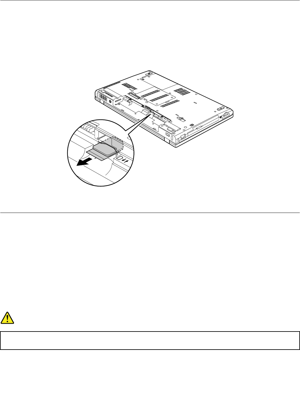
•Thesystemboardissensitiveto,andcanbedamagedby,electrostaticdischarge.Beforetouchingit,
establishpersonalgroundingbytouchingagroundpointwithonehandorbyusinganelectrostatic
discharge(ESD)strap.
BeforeservicingThinkPadT530,T530i,andW530
RemovalstepsofSIMcard
SomemodelsyouareservicingmighthavetheSIMcardthatthecustomerhasinstalled.Ifthecomputeryou
areservicinghastheSIMcardinstalled,removeitbeforeyoustarttheservicing.
ToremovetheSIMcard,youneedtoremovethebatterypackfirst.See“1010Batterypack”onpage70.
Afteryoufinishtheservicing,makesurethatyouinsertthecardbackintotheslotfirmly.
1010Batterypack
Importantnoticeforreplacingabatterypack:
•TheLenovoSolutionCenterprogramprovidesanautomaticbatterydiagnostictestthatdeterminesifthe
batterypackisdefective.AbatterypackFRUshouldnotbereplacedunlessthisdiagnostictestshows
thatthebatteryisdefective.Theonlyexceptiontothisisifthebatterypackisphysicallydamagedor
acustomerisreportingapossiblesafetyissue.
•IftheLenovoSolutionCenterprogramisnotinstalledinthecomputer,thecustomershoulddownloadthis
programbeforeanon-physicallydamagedbatterypackisreplaced.Notethataphysicallydamaged
batterypackisnotcoveredbythewarranty.
Removalstepsofbatterypack
DANGER
Useonlytheauthorizedbatteryspecifiedforyourcomputer.Anyotherbatterycouldigniteor
explode.
Unlockthebatterylatchandholdthebatterylatchintheunlockedposition.Then,removethebatterypack.
70HardwareMaintenanceManual
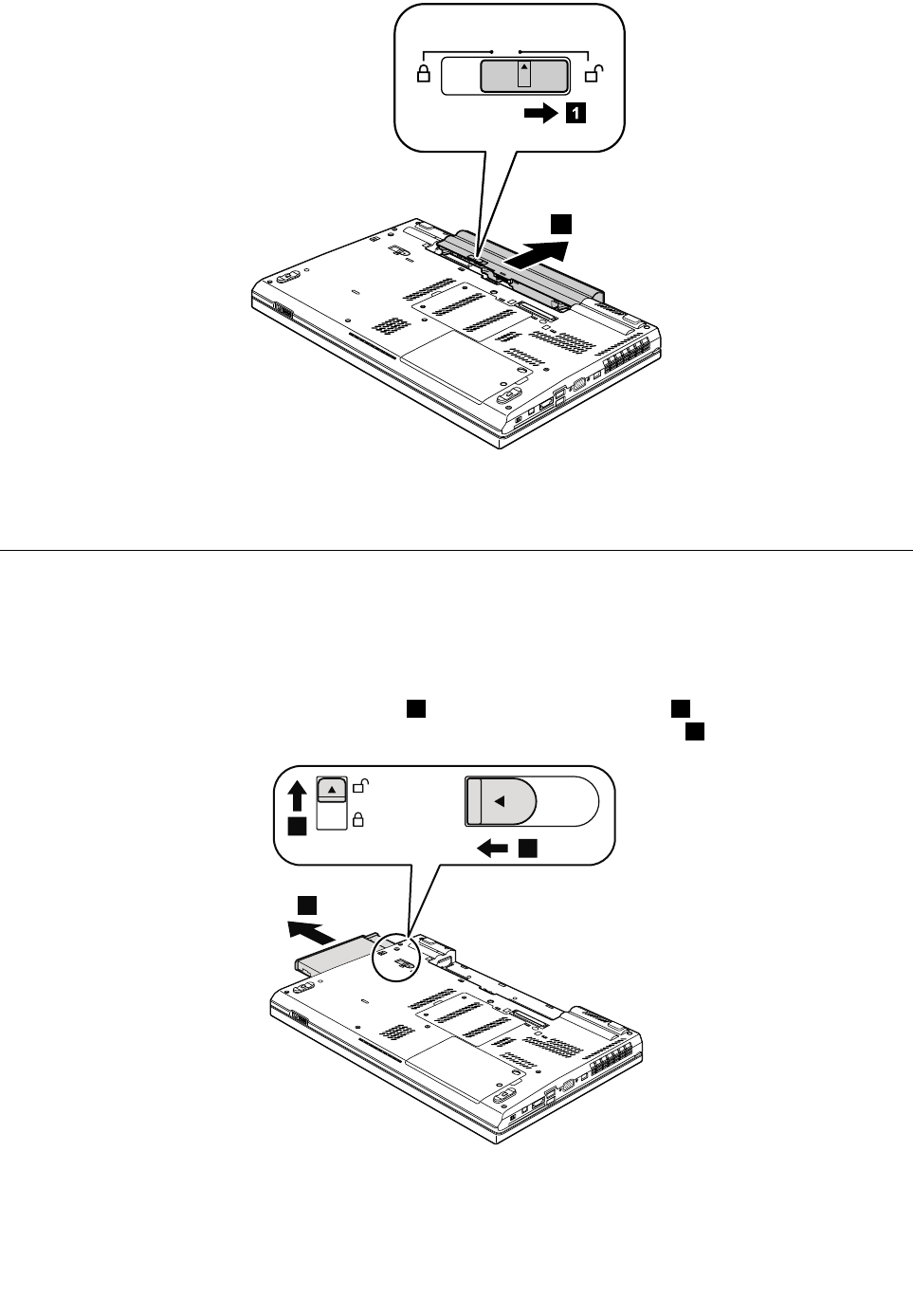
2
1
Wheninstalling:Installthebatterypackintheslot,andthenmakesurethatthebatterylatchisinthe
lockedposition.
1020SerialUltrabayEnhanceddeviceorblankbezel
Foraccess,removethisFRU:
•“1010Batterypack”onpage70
RemovalstepsofSerialUltrabayEnhanceddeviceorblankbezel
Holdthebaylocklatchintheunlockedposition1andslidethebayejectlatch2.Then,pullouttheSerial
UltrabayEnhanceddeviceortheblankbezelinthedirectionshownbythearrow3.
3
2
1
Note:ForRAIDmodels,toremovethesecondharddiskdrive,youneedtoremovethescrewthatsecures
thesecondharddiskdriveadapterfirst.
Chapter10.RemovingorreplacingaFRU71
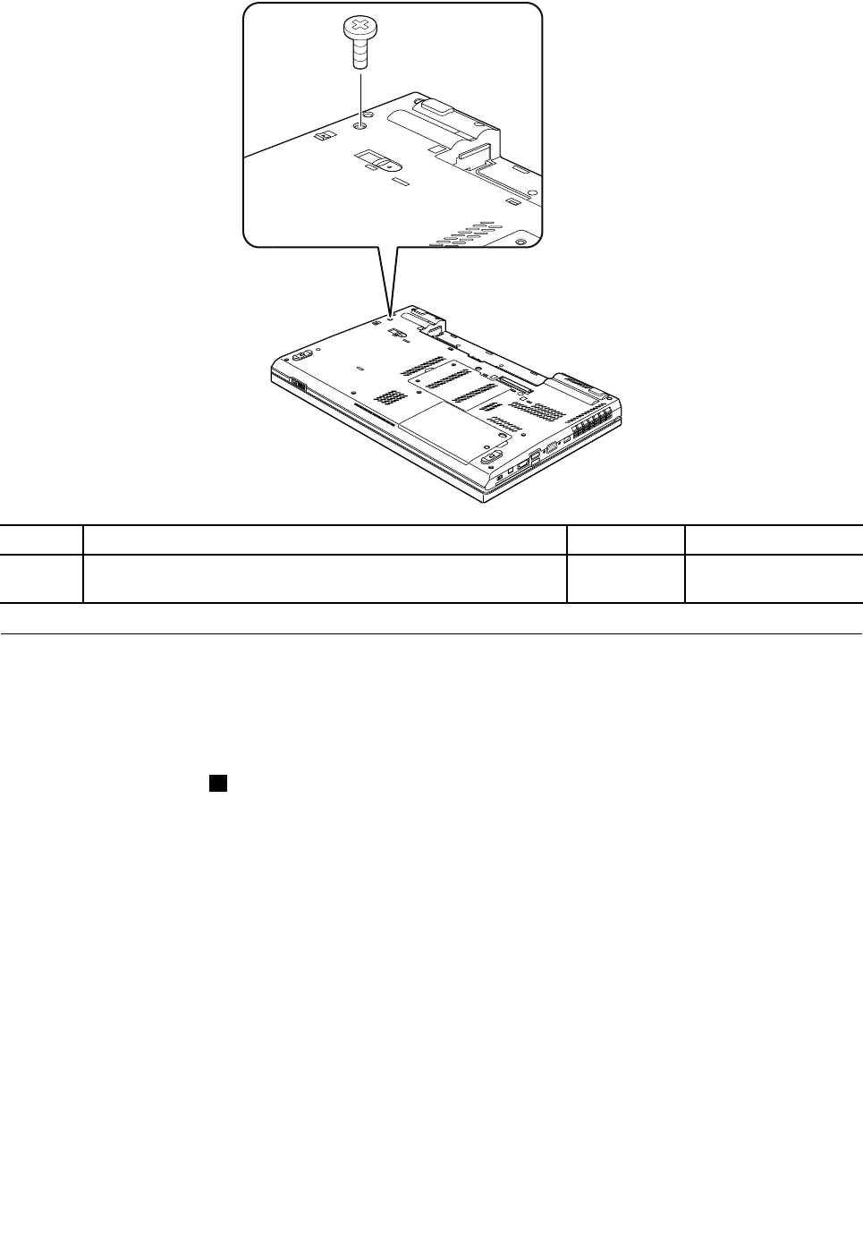
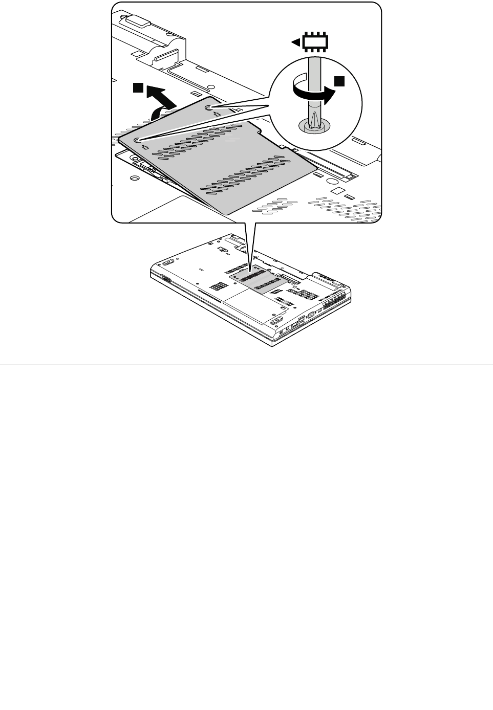
1
2
1040Memorymodule(bottomslot)
Foraccess,removetheseFRUsinorder:
•“1010Batterypack”onpage70
•“1030Memorymoduleslotcover”onpage72
Removalstepsofmemorymodule(bottomslot)
Attention:ForThinkPadW530modelsthatcomewithtwodummycardsinstalled,donotreplacethe
dummycardswithmemorymodules.Otherwise,thesystemmightnotfunctioncorrectly.
Chapter10.RemovingorreplacingaFRU73
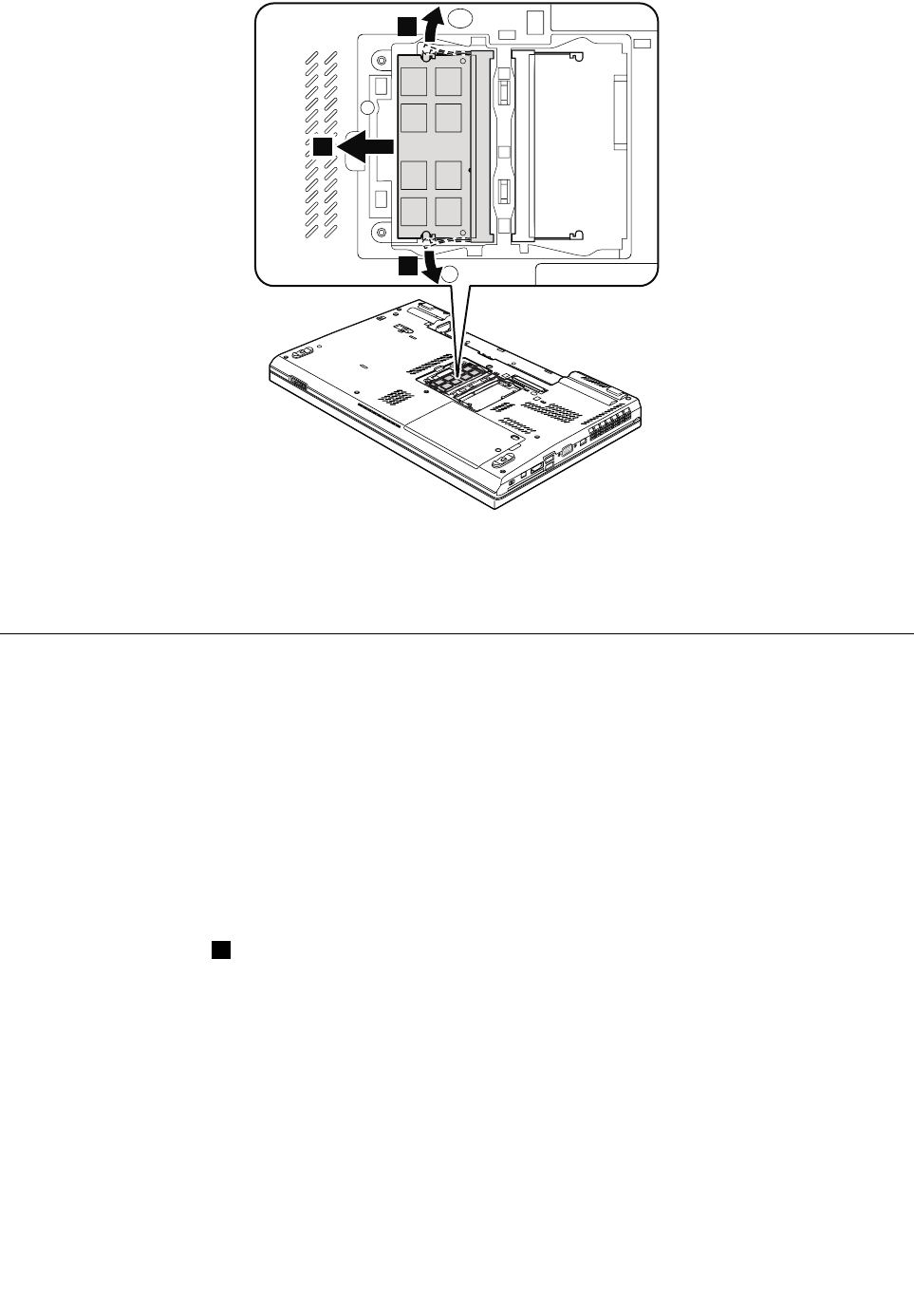
1
1
2
Wheninstalling:Insertthenotchedendofthememorymoduleintotheslot.Pressthememorymodule
firmly,andpivotituntilitsnapsintoplace.Makesurethatitisfirmlyinstalledintheslotanddoesnot
moveeasily.
1050Harddiskdriveorsolidstatedrive
Foraccess,removethisFRU:
•“1010Batterypack”onpage70
Attention:
•Donotdropthedriveorapplyanyphysicalshocktoit.Thedriveissensitivetophysicalshock.Improper
handlingcancausedamageandpermanentlossofdata.
•Beforeremovingthedrive,havetheusermakeabackupcopyofalltheinformationonitifpossible.
•Neverremovethedrivewhilethesystemisoperatingorisinsuspendmode.
Removalstepsofharddiskdriveorsolidstatedrive
Note:Loosenthescrew1,butdonotremoveit.
74HardwareMaintenanceManual
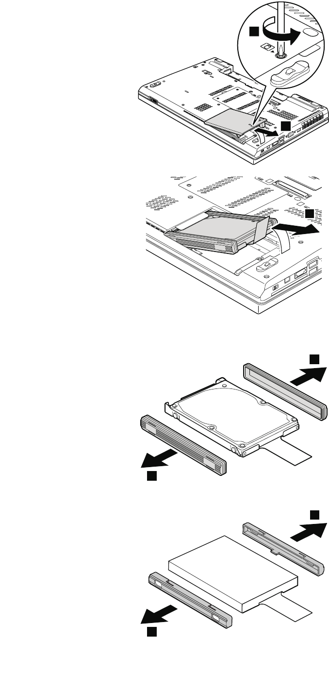
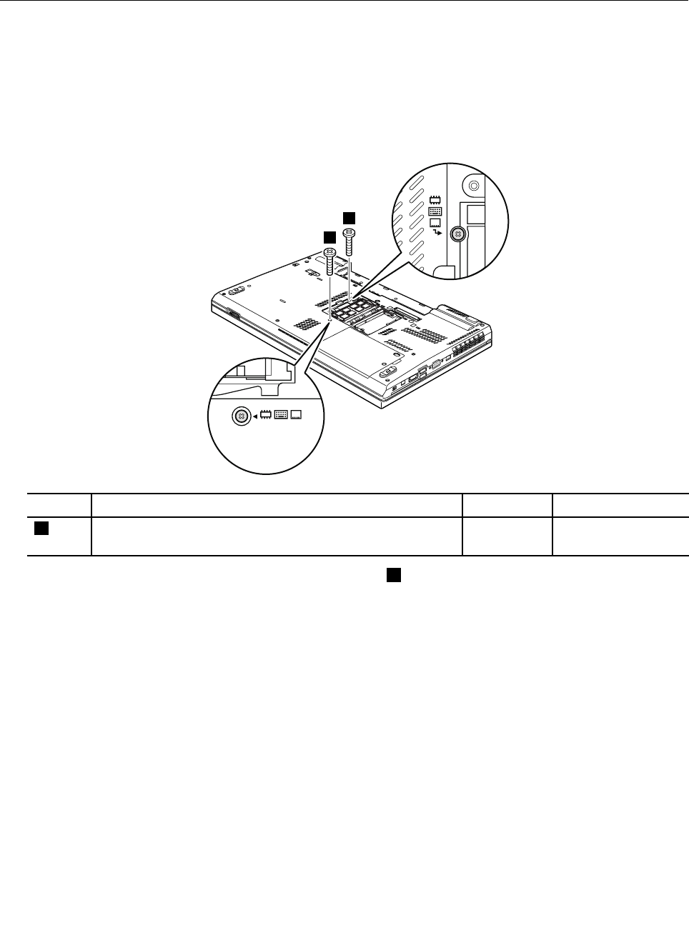
Wheninstalling:Makesurethatthesolidstatedriveconnectororharddiskdriveconnectorisattached
firmly.
1060Keyboard
Foraccess,removetheseFRUsinorder:
•“1010Batterypack”onpage70
•“1030Memorymoduleslotcover”onpage72
Removalstepsofkeyboard
1.Removethescrewsthatsecurethekeyboard.
1
1
StepScrew(quantity)ColorTorque
1M2×14mm,wafer-head,nylon-coated(2)Black0.181Nm
(1.85kgf-cm)
2.Pressthekeyboardinthedirectionshownbythearrow2untilthefrontedgeofthekeyboardis
detachedfromthekeyboardbezel.
76HardwareMaintenanceManual
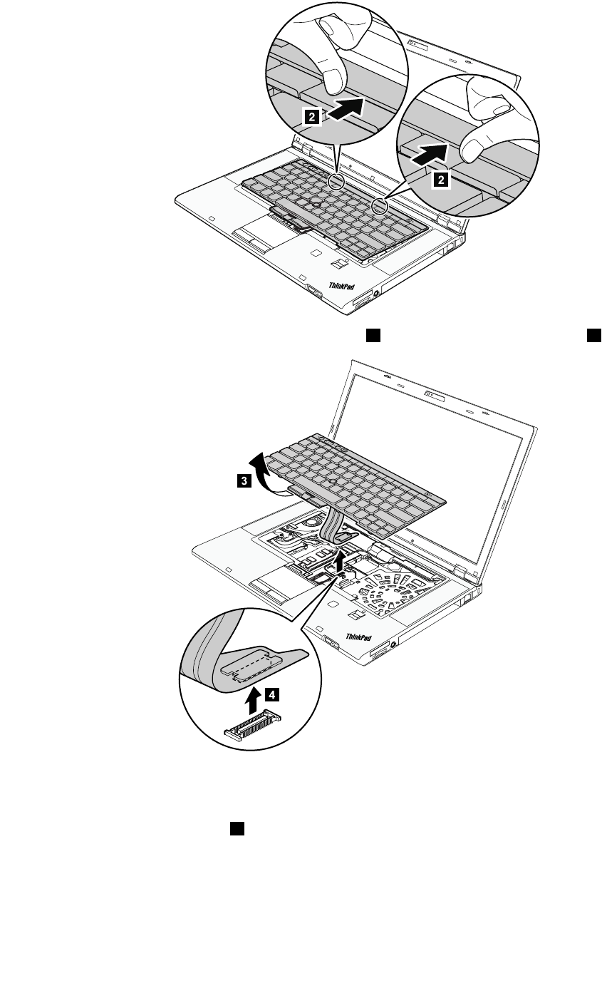
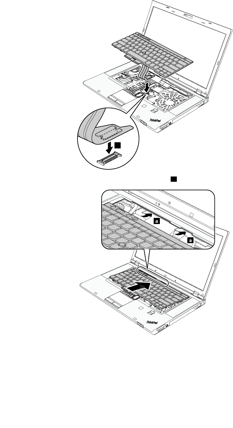
1
2.Attachthekeyboardandensurethatthekeyboardedgesaareundertheframe.
3.Whenthefrontsideofthekeyboardishousedfirmly,gentlypressthekeyswithyourthumbsandslide
thekeyboardtowardyouuntilthekeyboardisinplace.
78HardwareMaintenanceManual
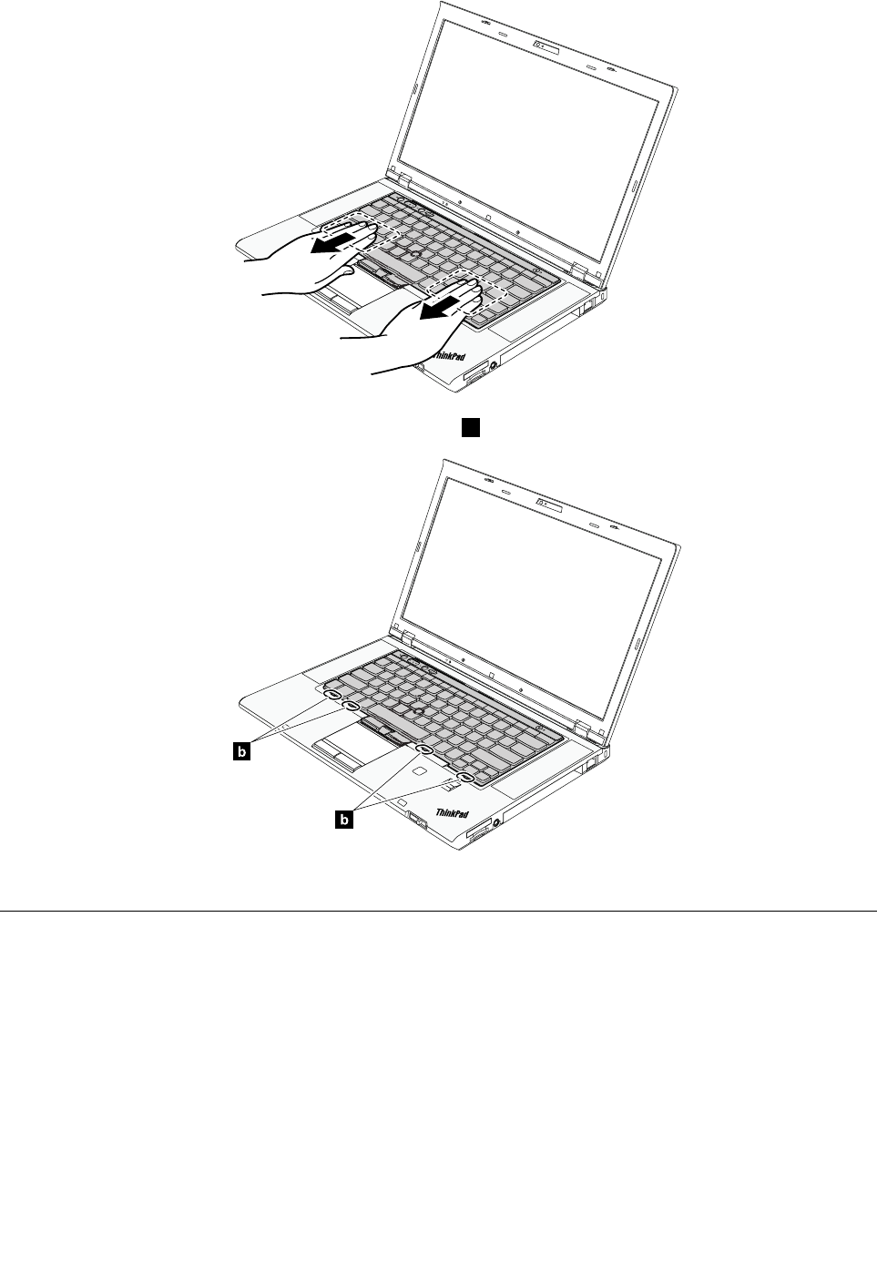
Note:Makesurethatthefrontsideofthekeyboardbishousedfirmly.
b
b
4.Securethekeyboardbytighteningthescrewsfromthebottomsideofthecomputer.
1070Memorymodule(upperslot)
Foraccess,removetheseFRUsinorder:
•“1010Batterypack”onpage70
•“1030Memorymoduleslotcover”onpage72
•“1060Keyboard”onpage76
Removalstepsofmemorymodule(upperslot)
Attention:ForThinkPadW530modelsthatcomewithtwodummycardsinstalled,donotreplacethe
dummycardswithmemorymodule.Otherwise,thesystemmightnotfunctioncorrectly.
Chapter10.RemovingorreplacingaFRU79
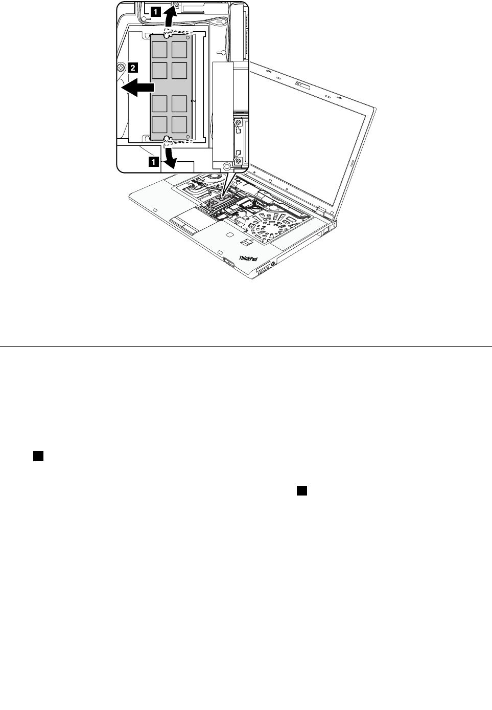
Wheninstalling:Insertthenotchedendofthememorymoduleintothesocket.Pressthememorymodule
firmly,andpivotituntilitsnapsintoplace.Makesurethatitisfirmlyinstalledintheslotanddoesnot
moveeasily.
1080PCIExpressMiniCardforwirelessLAN
Foraccess,removetheseFRUsinorder:
•“1010Batterypack”onpage70
•“1030Memorymoduleslotcover”onpage72
•“1060Keyboard”onpage76
RemovalstepsofPCIExpressMiniCardforwirelessLAN
Instep1,unplugtheconnectorsbyusingtheantennaRFconnectorremovaltoolorpicktheconnectors
withyourfingersandgentlyunplugthemindirectionofthearrow.
Note:Somemodelsmighthaveonlytwoantennacablesinstep1.
80HardwareMaintenanceManual
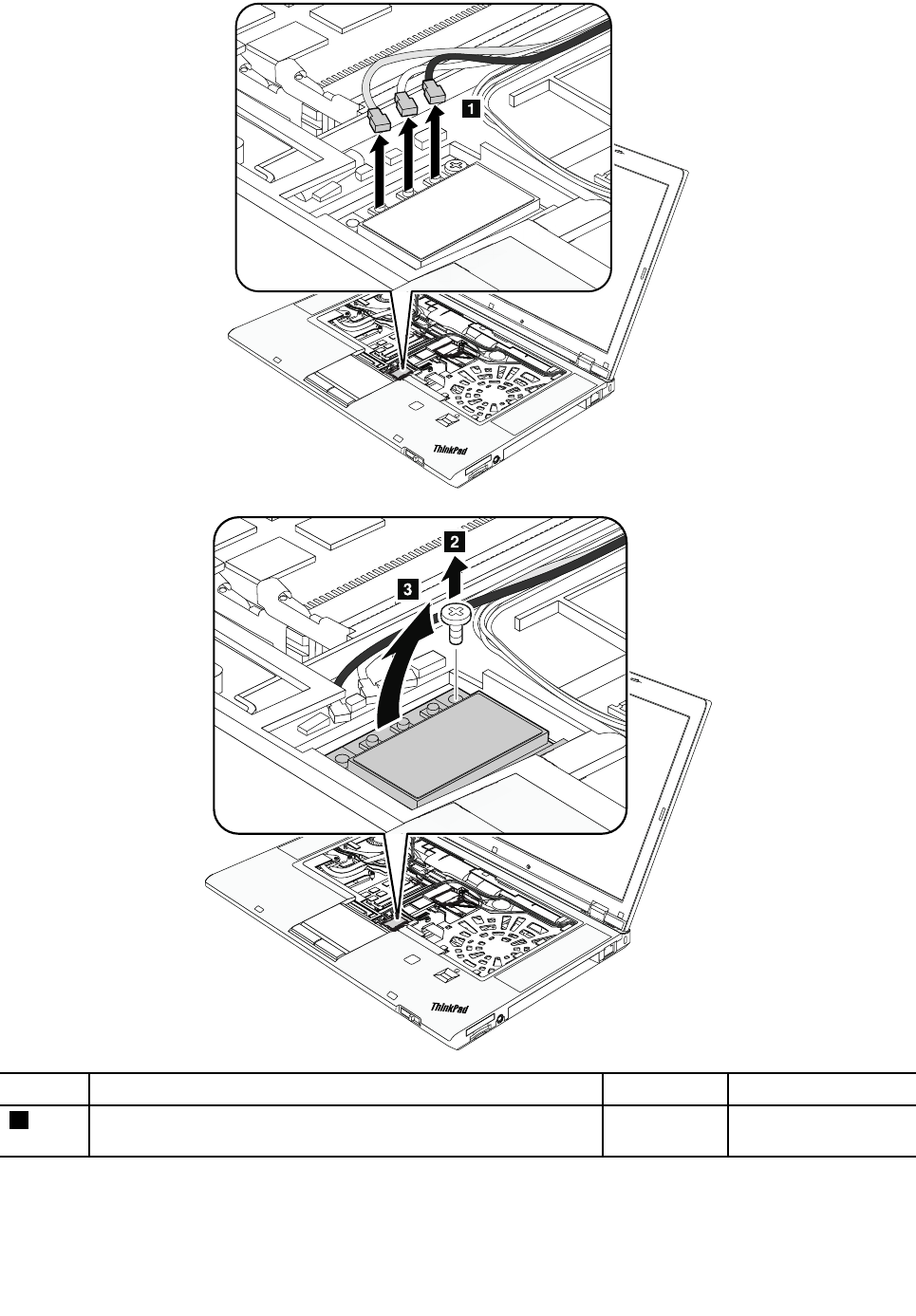
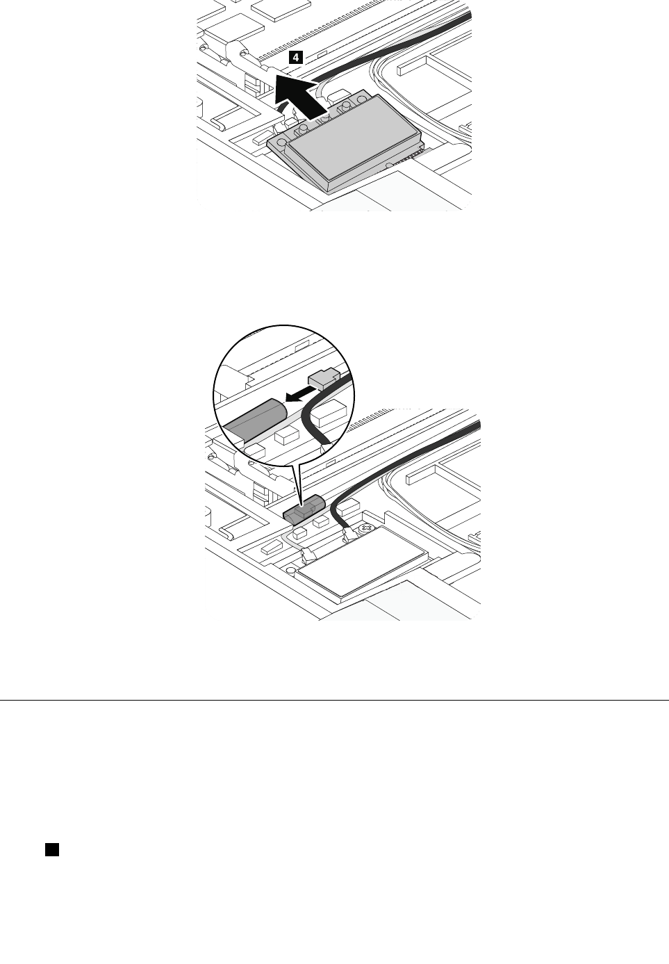
Wheninstalling:
•InmodelswithawirelessLANcardthathastwoantennaconnectors,plugthegraycableintothemain
connector,andtheblackcableintotheauxiliaryconnectoronthecard.Ifthecomputeryouareservicing
hasthreecables,putthewhitecableinthecableprotectiontubeasshowninthefollowingillustration.
•InmodelswithawirelessLANcardthathasthreeantennaconnectors,plugthegraycable(MAIN)
intothemainconnector,theblackcable(AUX)intotheauxiliaryconnector,andthewhitecable(3rd)
intothelastconnector,
1090PCIExpressMiniCardforwirelessWANormSATAsolidstatedrive
Foraccess,removetheseFRUsinorder:
•“1010Batterypack”onpage70
•“1030Memorymoduleslotcover”onpage72
•“1060Keyboard”onpage76
RemovalstepsofPCIExpressMiniCardforwirelessWAN(full-sizeWWANcard)
Instep1,unplugtheconnectorsbyusingtheantennaRFconnectorremovaltoolorpicktheconnectors
withyourfingersandgentlyunplugthemindirectionofthearrow.
82HardwareMaintenanceManual
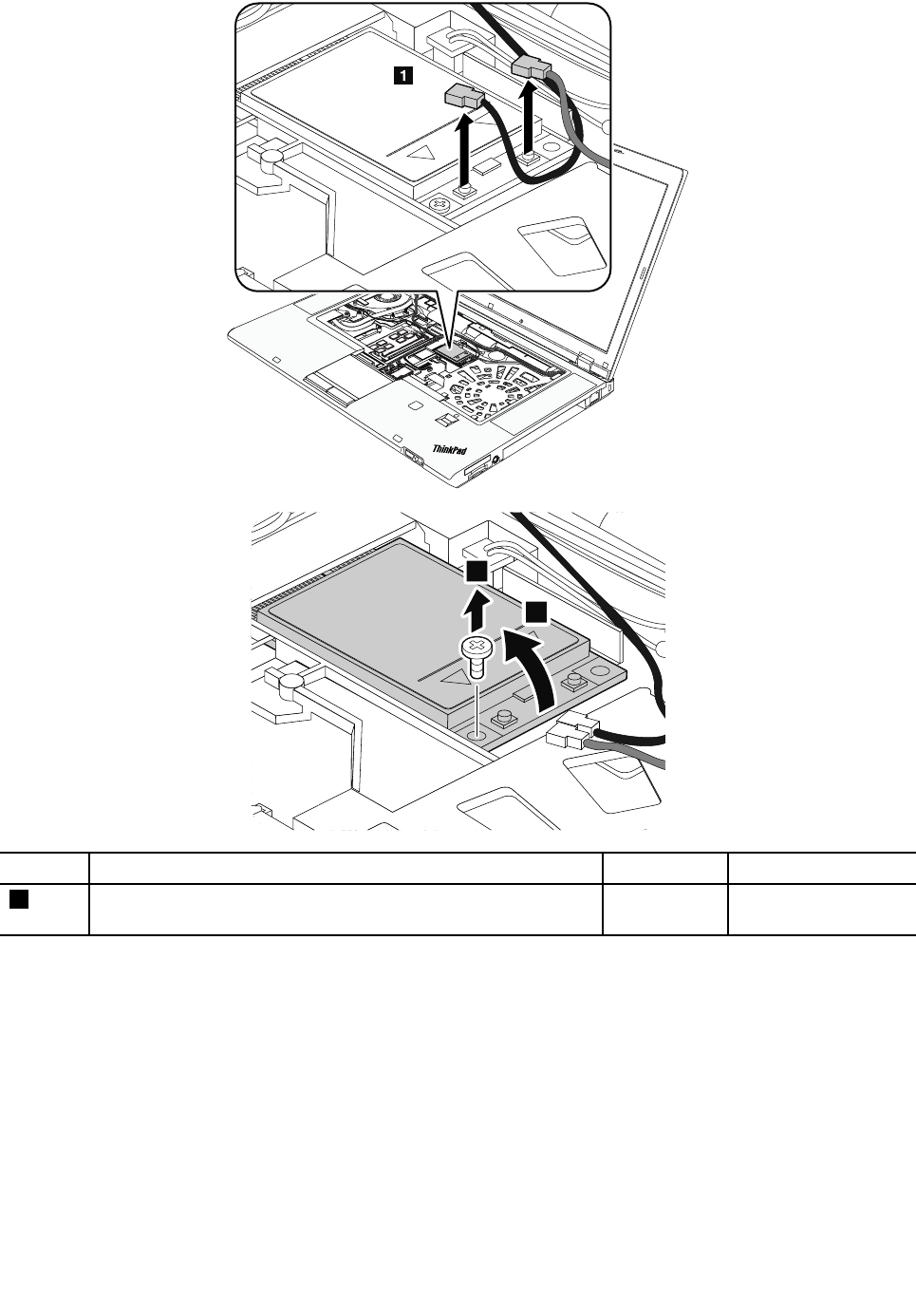
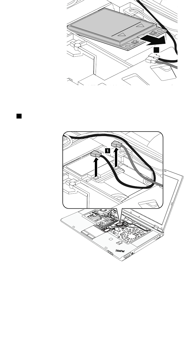
4
Wheninstalling:Plugtheredcableintothemainconnectorandthebluecableintotheauxiliaryconnector.
RemovalstepsofPCIExpressMiniCardforwirelessWAN(half-sizeWWANcard)
Instep1,unplugtheconnectorsbyusingtheantennaRFconnectorremovaltoolorpicktheconnectors
withyourfingersandgentlyunplugthemindirectionofthearrow.
84HardwareMaintenanceManual
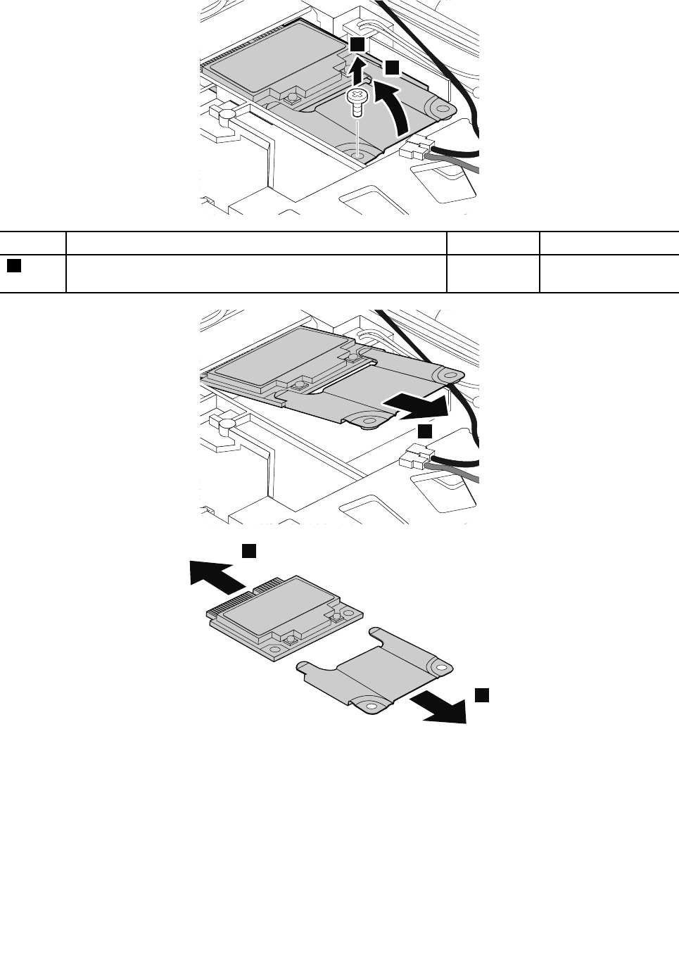
2
3
StepScrew(quantity)ColorTorque
2M2×3mm,wafer-head,nylon-coated(1)Silver0.181Nm
(1.85kgf-cm)
4
5
5
RemovalstepsofmSATAsolidstatedrive
ThecomputercomeswitheitheraPCIExpressMiniCardforwirelessWANoranmSATAsolid-statedrive.If
thecomputerisequippedwithanmSATAsolid-statedrive,itisinstalledinthewirelessWANcardslot.
Attention:
•Donotdropthedriveorapplyanyphysicalshocktoit.Thedriveissensitivetophysicalshock.Improper
handlingcancausedamageandpermanentlossofdata.
•Beforeremovingthedrive,havetheusermakeabackupcopyofalltheinformationonitifpossible.
•Neverremovethedrivewhilethesystemisoperatingorisinsuspendmode.
Chapter10.RemovingorreplacingaFRU85
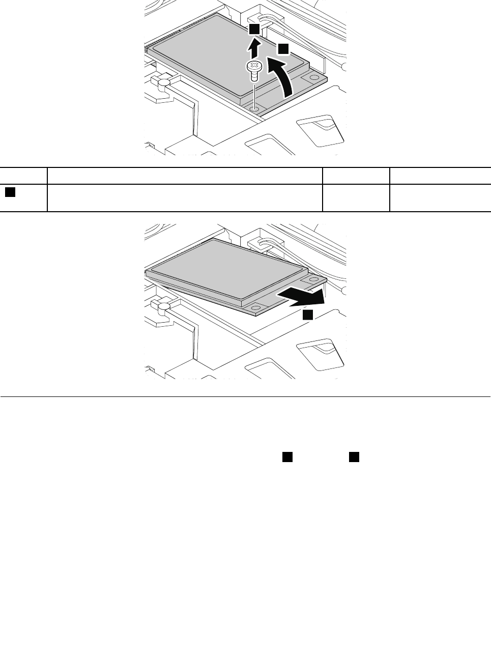
•EnsurethatyoupartitionthemSATAsolid-statedriveafterinstallingitonthecomputeryouareservicing.
Otherwise,themSATAsolid-statedrivewillnotfunctioncorrectly.Forinstructionsononhowtopartition
anmSATAsolid-statedrive,gotohttp://www.lenovo.com/support/msata-fru.
1
2
StepScrew(quantity)ColorTorque
2M2×3mm,wafer-head,nylon-coated(1)Silver0.181Nm
(1.85kgf-cm)
3
1100ExpressCardblankbezelorExpressCard
RemovalstepsofExpressCardblankbezelorExpressCard
WhenyoupresstheExpressCardblankbezelorExpressCard1,itpopsout2.
86HardwareMaintenanceManual
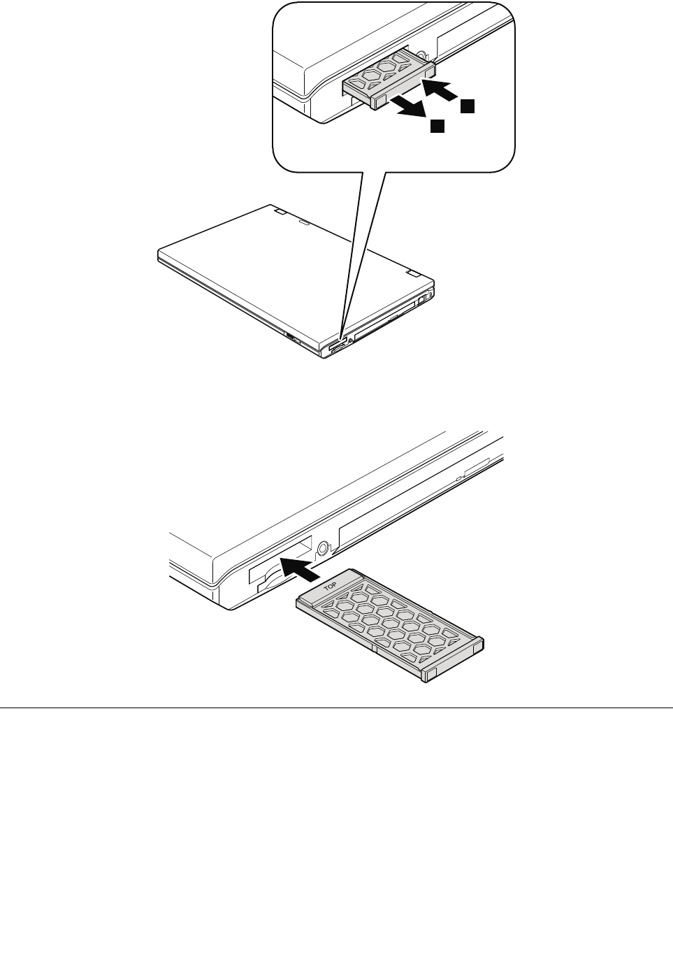
1
2
Wheninstalling:MakesurethattheExpressCardblankbezelorExpressCardiscorrectlyorientedas
showninthefollowingillustration.
1110Keyboardbezelassembly
Foraccess,removetheseFRUsinorder:
•“1010Batterypack”onpage70
•“1030Memorymoduleslotcover”onpage72
•“1060Keyboard”onpage76
•“1100ExpressCardblankbezelorExpressCard”onpage86
Chapter10.RemovingorreplacingaFRU87
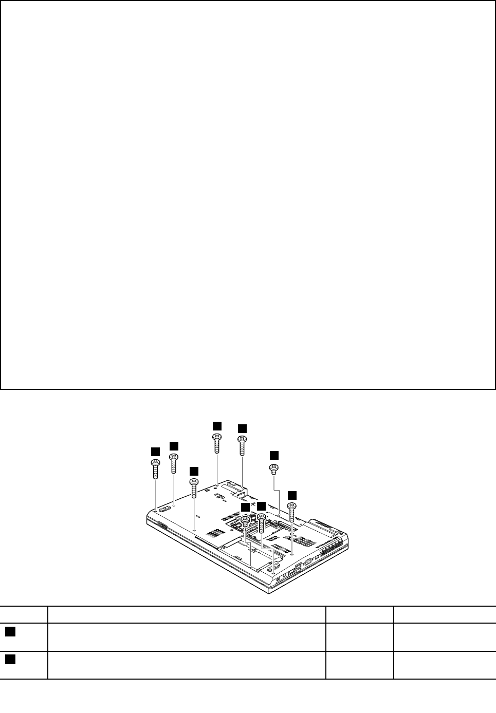
Important:
ReadthefollowinginstructionsfirstbeforereplacingthekeyboardbezelassemblyforThinkPadW530models
withacolorsensor.
•Iftheharddiskdriveisnotdefective,andonlythekeyboardbezelassemblyneedsareplacement:
1.Replacethekeyboardbezelassembly.
2.Afteryoureplacethekeyboardbezelassembly,startthecomputerandruntheSensorReplacementUtility
programbyclickingStart➙AllPrograms➙X-Rite➙PANTONEColorCalibrator➙SensorReplacement
Utility.
3.Ifyoudonothaveaccesstotheharddiskdrive,providethecustomerwithinformationonhowtorunthe
SensorReplacementUtility.
•Ifboththeharddiskdriveandthekeyboardbezelassemblyneedreplacements:
1.Beforeyoureplacethekeyboardbezelassembly,backupthecolorsensorcalibrationprofile
ECCM2SensorData.dattoanexternalmediadevicefromthedirectoryC:\ProgramData\X-Rite\ECCM-2.This
calibrationprofileisgeneratedafteryouusethecolorsensorforthefirsttime.
2.Ifyouareunabletobackupthecolorsensorcalibrationprofile,andifnoproblemwasreportedwiththecolor
sensor,followthestepsattheendofthistopictoremovethecolorsensorfromtheoriginalkeyboardbezel
assembly,andinstallthecolorsensortothenewkeyboardbezelassembly.
3.Replacetheharddiskdrive.See“1050Harddiskdriveorsolidstatedrive”onpage74.Thenreloadthe
operatingsystem.
4.IftheSensorReplacementUtilityprogramcannotbelaunchedsuccessfully,restorethecolor
sensorcalibrationprofileECCM2SensorData.dat,whichyouhavebackedupinstep1,tothedirectory
C:\ProgramData\X-Rite\ECCM-2.
5.Ifyoudidnotbackupthecalibrationprofileandthecustomerdoesnothaveabackupoftheirimage,
youwillalsoneedtoreplacetheLCDpaneleveniftheLCDpanelisnotbroken.See“2040LCDcable,
cameracable,LCDpanel,andhinges”onpage110.
6.RuntheSensorReplacementUtilityprogramagainandfollowtheinstructionsonthescreentoperformthe
initialcolorcalibration,orprovideinstructionstothecustomertorunthisutility.
7.Whentheinitialcalibrationcompletes,adialogboxisdisplayed.ClickOKtoexittheSensorReplacement
Utilityprogram.
Removalstepsofkeyboardbezelassembly
1
1
1
1
2
2
1
1
1
StepScrew(quantity)ColorTorque
1M2×14mm,bind-head,nylon-coated(7)Black0.181Nm
(1.85kgf-cm)
2M2×4mm,bind-head,nylon-coated(2)Black0.181Nm
(1.85kgf-cm)
88HardwareMaintenanceManual
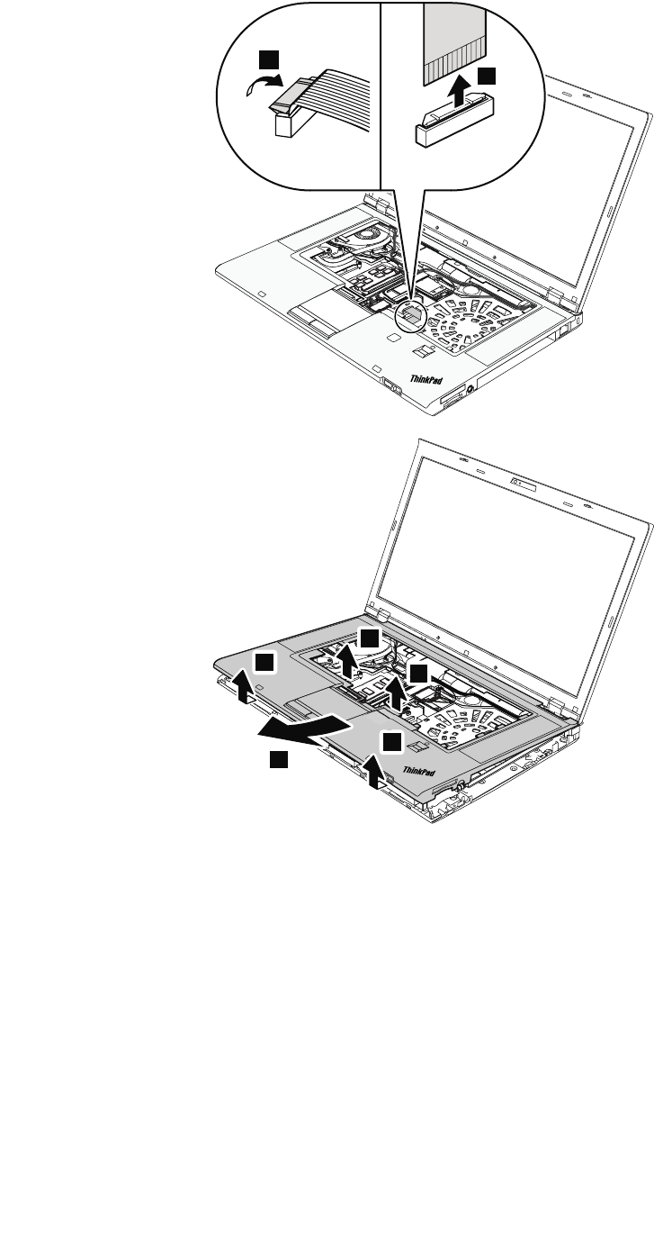
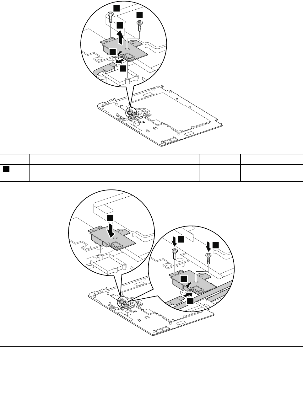
ForThinkPadW530modelswithacolorsensor,ifyouneedtoremovethecolorsensorfromthe
failingkeyboardbezelassemblyandinstallthecolorsensortothenewkeyboardbezelassembly,
dothefollowing:
3
3
1
2
4
StepScrew(quantity)ColorTorque
3M2×L7mm,bind-head,(2)Silver0.181Nm
(1.85kgf-cm)
1
4
4
3
2
1120Bluetoothdaughtercard
Foraccess,removetheseFRUsinorder:
•“1010Batterypack”onpage70
•“1030Memorymoduleslotcover”onpage72
•“1060Keyboard”onpage76
90HardwareMaintenanceManual
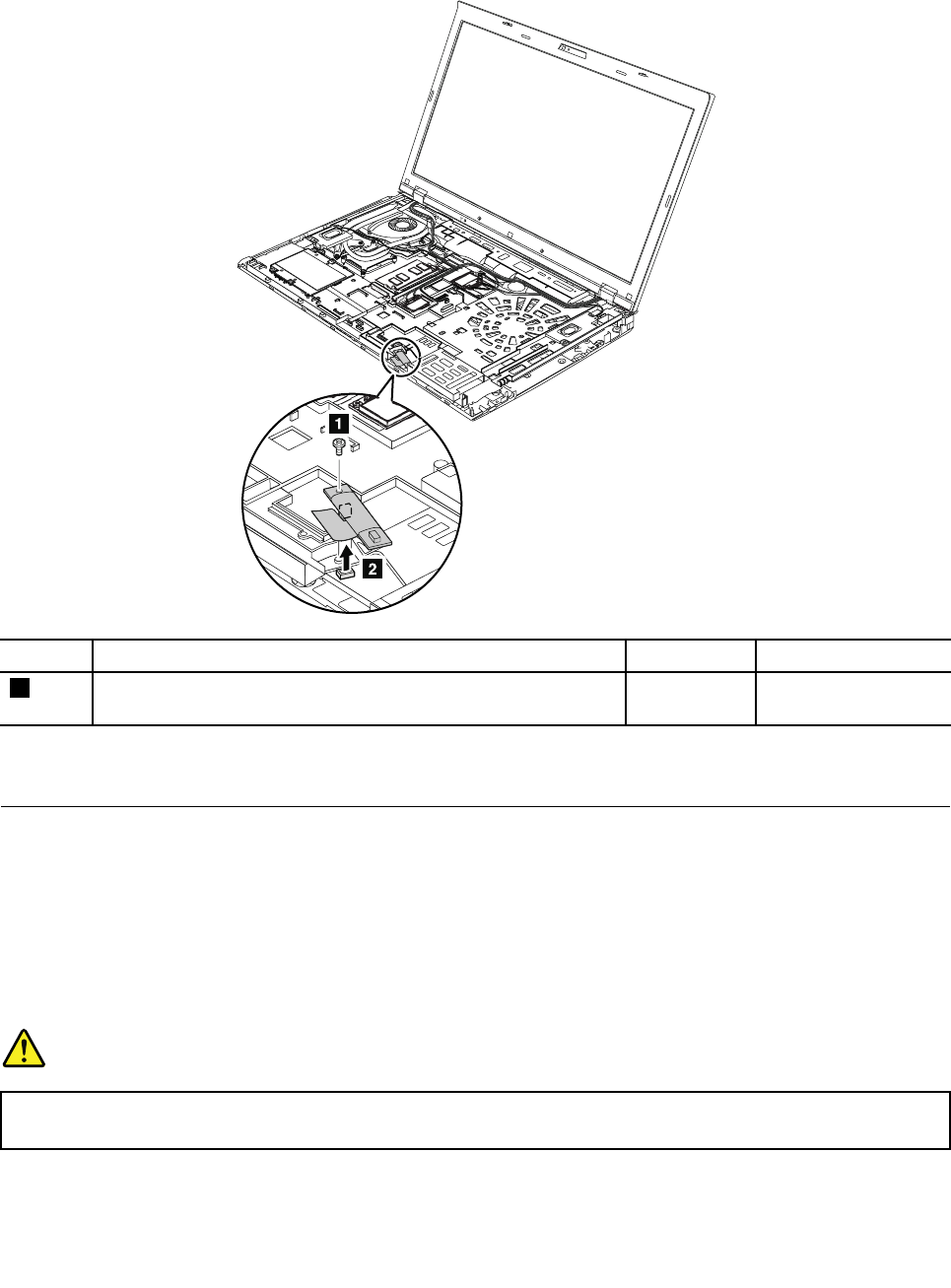
•“1100ExpressCardblankbezelorExpressCard”onpage86
RemovalstepsofBluetoothdaughtercard
StepScrew(quantity)ColorTorque
1M2×3mm,wafer-head,nylon-coated(1)Silver0.181Nm
(1.85kgf-cm)
Wheninstalling:Makesurethattheconnectorisattachedfirmly.
1130Backupbattery
Foraccess,removetheseFRUsinorder:
•“1010Batterypack”onpage70
•“1030Memorymoduleslotcover”onpage72
•“1060Keyboard”onpage76
•“1100ExpressCardblankbezelorExpressCard”onpage86
Removalstepsofbackupbattery
DANGER
Useonlytheauthorizedbatteryspecifiedforyourcomputer.Anyotherbatterycouldigniteor
explode.
Chapter10.RemovingorreplacingaFRU91
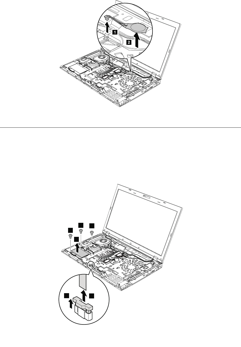
Wheninstalling:Makesurethatthebatteryconnectorisattachedfirmly.
1140Smartcard,dummysmartcardandspacer
Foraccess,removetheseFRUsinorder:
•“1010Batterypack”onpage70
•“1030Memorymoduleslotcover”onpage72
•“1060Keyboard”onpage76
•“1100ExpressCardblankbezelorExpressCard”onpage86
Removalstepsofsmartcard
1
12
3
33
4
92HardwareMaintenanceManual
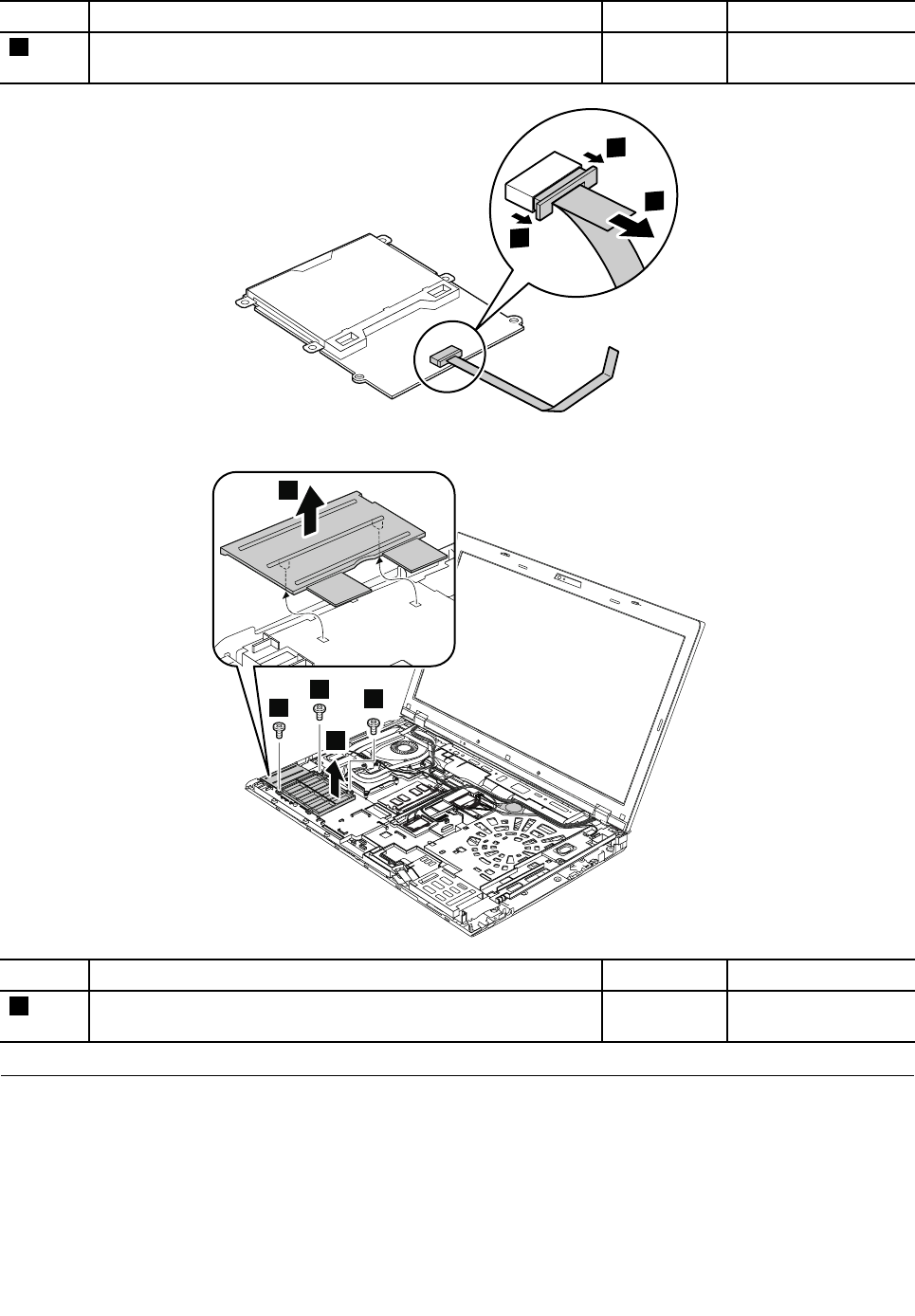
StepScrew(quantity)ColorTorque
3M2×3mm,wafer-head,nylon-coated(3)Silver0.181Nm
(1.85kgf-cm)
6
5
5
Removalstepsofdummysmartcardandspacer
1
11
2
3
StepScrew(quantity)ColorTorque
1M2×3mm,wafer-head,nylon-coated(3)Silver0.181Nm
(1.85kgf-cm)
1150Speakerassembly
Foraccess,removetheseFRUsinorder:
•“1010Batterypack”onpage70
•“1030Memorymoduleslotcover”onpage72
•“1060Keyboard”onpage76
•“1100ExpressCardblankbezelorExpressCard”onpage86
Chapter10.RemovingorreplacingaFRU93
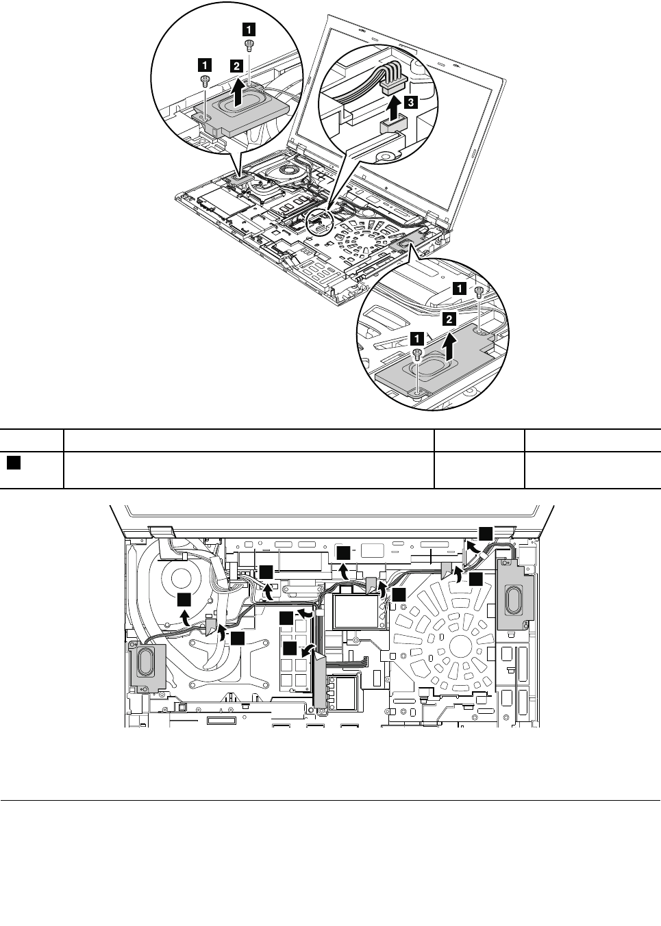
Removalstepsofspeakerassembly
StepScrew(quantity)ColorTorque
1M2×3mm,wafer-head,nylon-coated(4)Silver0.181Nm
(1.85kgf-cm)
4
5
5
5
5
4
5
4
4
Wheninstalling:Makesurethatthespeakerconnectorisattachedfirmly.Thenroutethecablesandsecure
themproperlyasshownintheillustrationabove.
1160Thermalfanassembly
Foraccess,removetheseFRUsinorder:
•“1010Batterypack”onpage70
•“1030Memorymoduleslotcover”onpage72
94HardwareMaintenanceManual
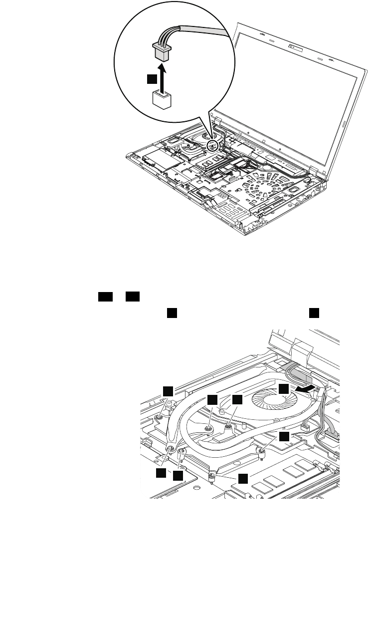
•“1060Keyboard”onpage76
•“1100ExpressCardblankbezelorExpressCard”onpage86
•“1150Speakerassembly”onpage93
Removalstepsofthermalfanassembly
1
Wheninstalling:Makesurethattheconnectorisattachedfirmly.
Notes:
•Loosenthescrews3ato3dinascendingalphabeticorderasillustrated,butdonotremovethem.
•Somemodelsdonothavescrews4.Forthosemodels,skipstep4.
4
43a
43c 3b
3d
2
Chapter10.RemovingorreplacingaFRU95
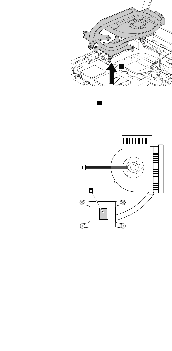
5
Wheninstalling:Beforeyouattachthethermalfanassemblytothecomputer,applythermalgrease,atan
amountof0.2grams,onthepartsmarkedaasinthefollowingillustrations.Eithertoomuchortooless
applicationofgreasecancauseathermalfanproblemduetoimperfectcontactwithacomponent.Forthe
newthermalfanassembly,youneedtopeelthethinfilmofffromtherubbers.
ForIntegratedGraphicsmodels:
a
ForSwitchableGraphicsmodels:
96HardwareMaintenanceManual

a
a
ForWorkstationmodels:
a
a
1170Microprocessor
Foraccess,removetheseFRUsinorder:
•“1010Batterypack”onpage70
•“1030Memorymoduleslotcover”onpage72
•“1060Keyboard”onpage76
•“1100ExpressCardblankbezelorExpressCard”onpage86
•“1150Speakerassembly”onpage93
•“1160Thermalfanassembly”onpage94
Attention:Themicroprocessorisextremelysensitive.Whenyouservicethemicroprocessor,avoidany
kindofroughhandling.
Removalstepsofmicroprocessor
Rotatetheheadofthescrewinthedirectionshownbythearrow1toreleasethelock;thenremovethe
microprocessor2.
Chapter10.RemovingorreplacingaFRU97
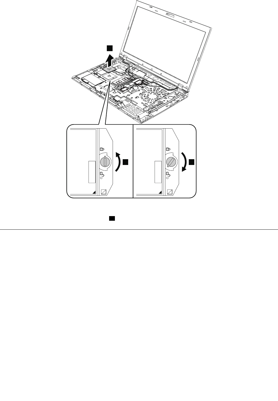
1
a
2
Wheninstalling:Placethemicroprocessorinthemicroprocessorsocket,andthenrotatetheheadofthe
screwinthedirectionshownbythearrowatosecurethemicroprocessor.
1180LCDunit
Foraccess,removetheseFRUsinorder:
•“1010Batterypack”onpage70
•“1030Memorymoduleslotcover”onpage72
•“1050Harddiskdriveorsolidstatedrive”onpage74
•“1060Keyboard”onpage76
•“1080PCIExpressMiniCardforwirelessLAN”onpage80
•“1090PCIExpressMiniCardforwirelessWANormSATAsolidstatedrive”onpage82
•“1100ExpressCardblankbezelorExpressCard”onpage86
98HardwareMaintenanceManual
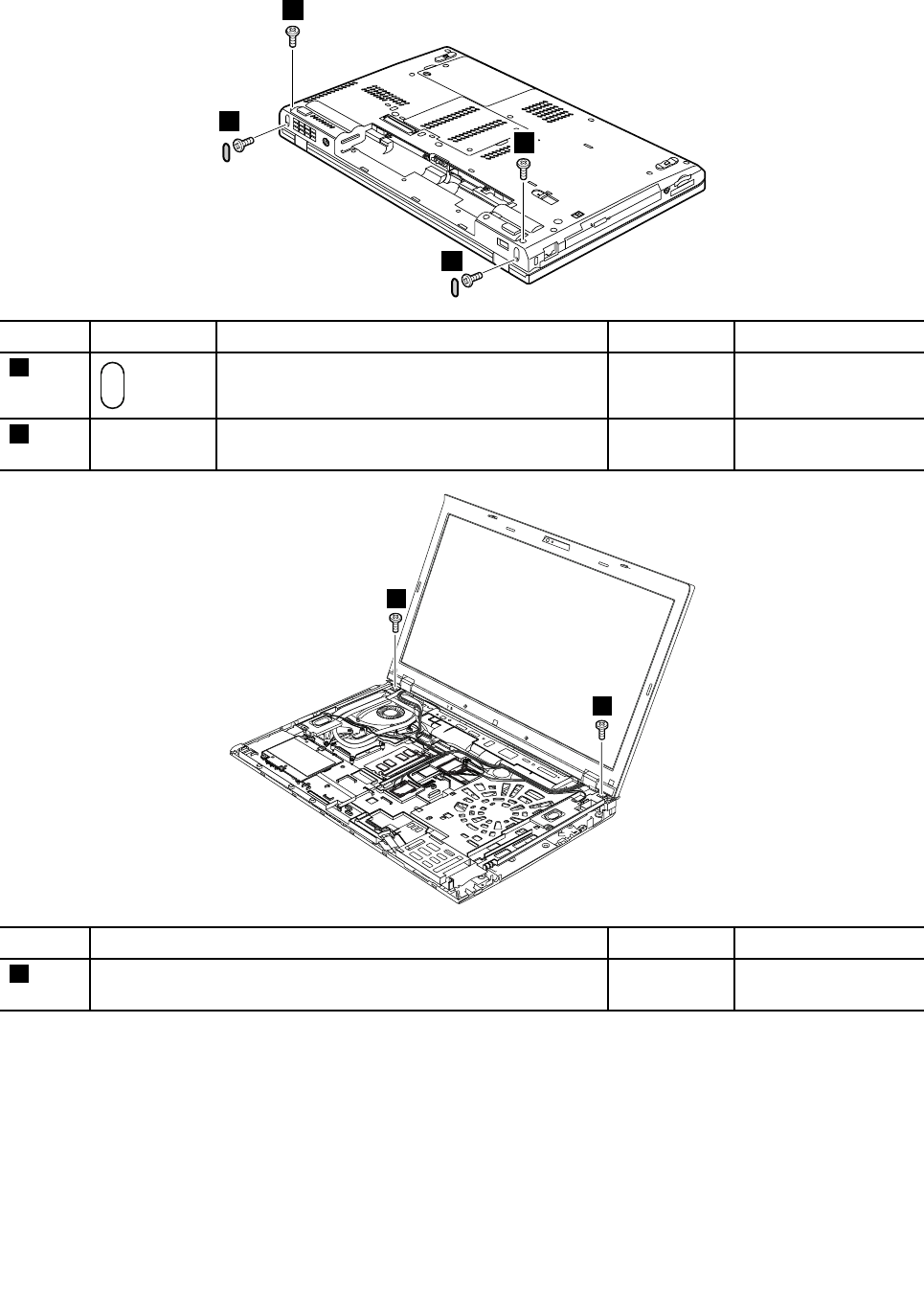
RemovalstepsofLCDunit
2
2
1
1
StepScrewcapScrew(quantity)ColorTorque
1M2.5×6mm,wafer-head,nylon-coated(2)Black0.392Nm
(4.0kgf-cm)
2—M2.5×6mm,wafer-head,nylon-coated(2)Black0.392Nm
(4.0kgf-cm)
3
3
StepScrew(quantity)ColorTorque
3M2.5×6mm,wafer-head,nylon-coated(2)Black0.392Nm
(4.0kgf-cm)
Chapter10.RemovingorreplacingaFRU99
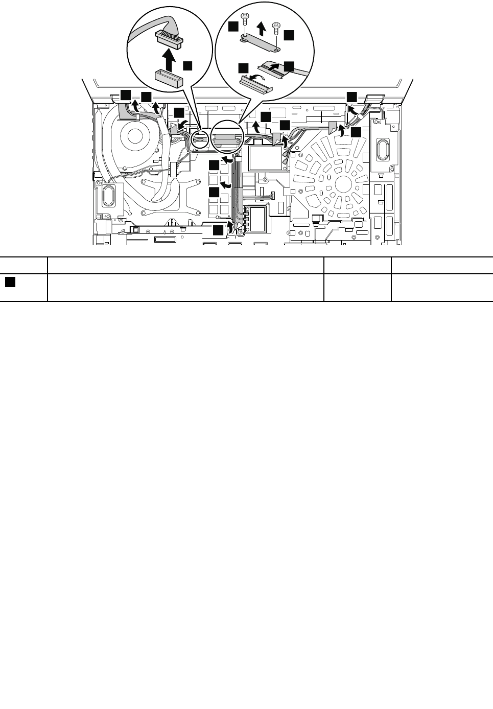
9
9
9
9
9
8
9
8
8
8
5
4
4
6
7
StepScrew(quantity)ColorTorque
4M2×4mm,wafer-head,nylon-coated(2)Black0.181Nm
(1.85kgf-cm)
Wheninstalling:
•MakesurethatyouattachtheLCDconnectorfirmly.
•Makesurethatyouroutethecablesfirmlyandtapeupintheproperpositionsasshowninthefollowing
illustration.
•Whenyouroutethecables,makesurethattheyarenotsubjecttoanytension.Tensioncouldcausethe
cablestobedamagedbythecableguides,orawiretobebroken.
100HardwareMaintenanceManual
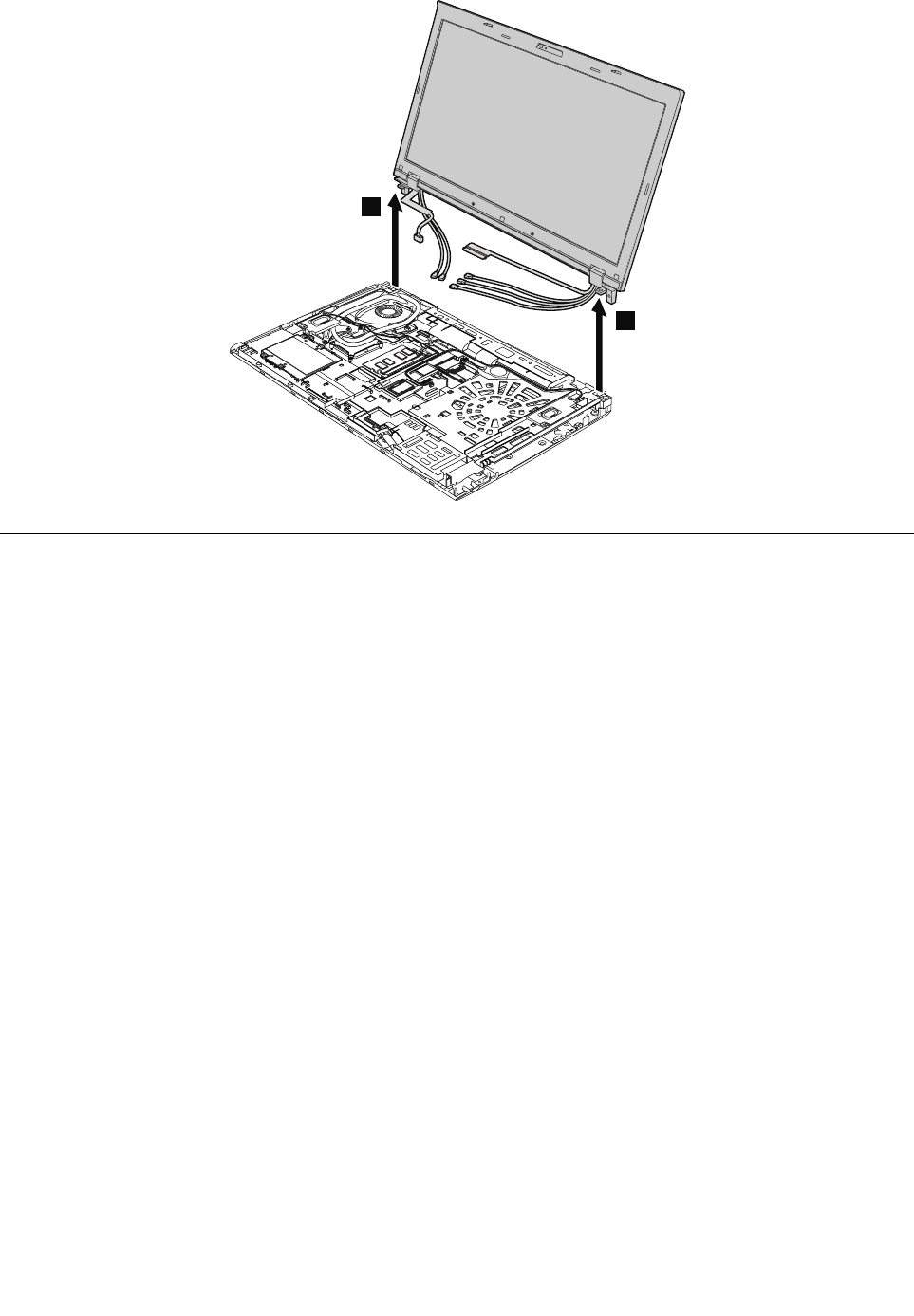
10
10
1190Basecoverassembly
Foraccess,removetheseFRUsinorder:
•“1010Batterypack”onpage70
•“1020SerialUltrabayEnhanceddeviceorblankbezel”onpage71
•“1030Memorymoduleslotcover”onpage72
•“1050Harddiskdriveorsolidstatedrive”onpage74
•“1060Keyboard”onpage76
•“1080PCIExpressMiniCardforwirelessLAN”onpage80
•“1090PCIExpressMiniCardforwirelessWANormSATAsolidstatedrive”onpage82
•“1100ExpressCardblankbezelorExpressCard”onpage86
•“1120Bluetoothdaughtercard”onpage90
•“1130Backupbattery”onpage91
•“1140Smartcard,dummysmartcardandspacer”onpage92
•“1150Speakerassembly”onpage93
•“1160Thermalfanassembly”onpage94
•“1180LCDunit”onpage98
Chapter10.RemovingorreplacingaFRU101
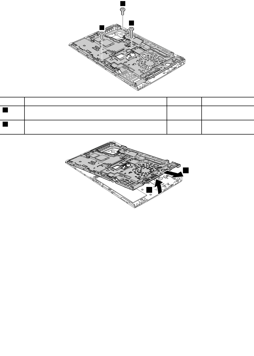
Removalstepsofbasecoverassembly
2
1
1
StepScrew(quantity)ColorTorque
1M2×3mm,wafer-head,nylon-coated(2)Silver0.181Nm
(1.85kgf-cm)
2M2×14mm,wafer-head,nylon-coated(1)Black0.181Nm
(1.85kgf-cm)
3
4
Applyinglabelstothebasecover
ThenewbasecoverFRUisshippedwithakitcontaininglabelsofseveralkinds,includingbutnotlimitedto
thosedescribedinthistopic.
Thefollowingillustrationshowsthecorrectlocationofeachlabel.
102HardwareMaintenanceManual
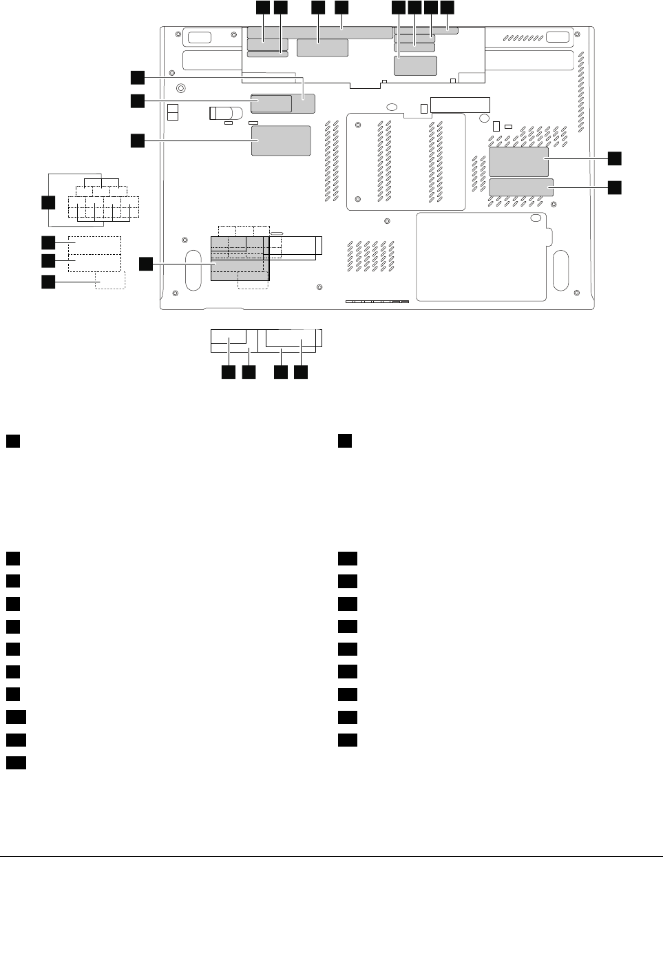
12345678
9
10
14 13 12 11
20
21
9
18
17
16
15
19
Whenyoureplacethebasecover,applythefollowinglabels:
6FCClabel7Machinetypeandserialnumberlabel
Note:IfthebasecoverhastwoFCClabels,applybothtothenewbasecover.
Otherlabelsneedtobepeeledofffromtheoldbasecover,andneedtobeadheredtothenewone.The
labelsincludebutarenotlimitedtothefollowing:
1TaiwanGEOlabel13China3GwirelessWANlabel
2TaiwanwirelessWANlabel14ChinawirelessWANlabel
3CertificateofAuthentication(COA)label15ISRAELlabel
4SystemlabelwithcomplianceID16BrazilwirelessWANlabel
5WirelessWANlabel17BrazilBluetoothlabel
8Informationlabel18Brazilwirelesscardlabel
9Assettag19SIRIMlabelorIndonesiaPOSTELlabel
10Indonesiaratinglabelornon-encryptionlabel20ChinaGEOlabel
11ChinaTELCOMlabel21IBMserverGEOlabel
12China3GlogowirelessWANlabel
Note:IftheCOAlabelisattachedtoapartthatisreplaced,returntheoldpartwiththelabelattachedtothe
customer,orprovidealettertothecustomerstatingwhatthelabelwasoriginallyonthecomputerandwhat
thelabelpartnumber,serialnumber,andproductkeywere.
1200I/Osubcard
Note:TheI/OsubcardcontainsanEthernetconnectorandaUSBconnector.
Chapter10.RemovingorreplacingaFRU103
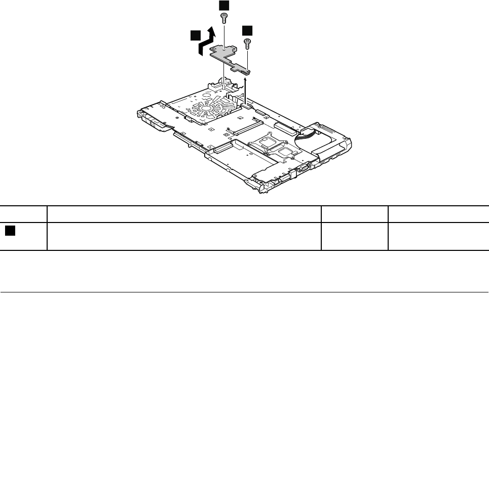
Foraccess,removetheseFRUsinorder:
•“1010Batterypack”onpage70
•“1020SerialUltrabayEnhanceddeviceorblankbezel”onpage71
•“1030Memorymoduleslotcover”onpage72
•“1050Harddiskdriveorsolidstatedrive”onpage74
•“1060Keyboard”onpage76
•“1080PCIExpressMiniCardforwirelessLAN”onpage80
•“1090PCIExpressMiniCardforwirelessWANormSATAsolidstatedrive”onpage82
•“1100ExpressCardblankbezelorExpressCard”onpage86
•“1120Bluetoothdaughtercard”onpage90
•“1130Backupbattery”onpage91
•“1140Smartcard,dummysmartcardandspacer”onpage92
•“1150Speakerassembly”onpage93
•“1160Thermalfanassembly”onpage94
•“1180LCDunit”onpage98
•“1190Basecoverassembly”onpage101
RemovalstepsofI/Osubcard
21
1
StepScrew(quantity)ColorTorque
1M2×7mm,wafer-head,nylon-coated(2)Silver0.181Nm
(1.85kgf-cm)
Wheninstalling:Makesurethattheconnectorisattachedfirmly.
1210Systemboardassemblyandmagnesiumstructureframe
Note:ThesystemboarddoesnotcontaintheEthernetconnectorandtheacpowerconnector.Forthe
Ethernetconnector,see“1200I/Osubcard”onpage103.Theacpowerconnectorisinstalledonthe
magnesiumstructureframe.
Foraccess,removetheseFRUsinorder:
•“1010Batterypack”onpage70
•“1020SerialUltrabayEnhanceddeviceorblankbezel”onpage71
•“1030Memorymoduleslotcover”onpage72
•“1040Memorymodule(bottomslot)”onpage73
•“1050Harddiskdriveorsolidstatedrive”onpage74
•“1060Keyboard”onpage76
104HardwareMaintenanceManual

•“1070Memorymodule(upperslot)”onpage79
•“1080PCIExpressMiniCardforwirelessLAN”onpage80
•“1090PCIExpressMiniCardforwirelessWANormSATAsolidstatedrive”onpage82
•“1100ExpressCardblankbezelorExpressCard”onpage86
•“1120Bluetoothdaughtercard”onpage90
•“1130Backupbattery”onpage91
•“1140Smartcard,dummysmartcardandspacer”onpage92
•“1150Speakerassembly”onpage93
•“1160Thermalfanassembly”onpage94
•“1170Microprocessor”onpage97
•“1180LCDunit”onpage98
•“1190Basecoverassembly”onpage101
•“1200I/Osubcard”onpage103
ImportantnoticesforRAIDsetting:
Beforeyoureplacethesystemboard,ensurethatyouhavereadChapter5“InstallingandconfiguringRAID”
onpage49,andhaveobtainedthenecessaryinformation.Afteryoureplacethesystemboard,RAIDmode
isrecoveredtodefault.ToverifytheRAIDmodesetting,checktheThinkPadSetupsettingbyselecting
Config➙SerialATA(SATA)➙SATAControllerModeOption➙RAID/Compatibility/AHCI.Then,you
willseethattheRAIDoptionisenabled.
Importantnoticesforhandlingthesystemboard:
Whenhandlingthesystemboard,bearthefollowinginmind:
•Thesystemboardhasanaccelerometer,whichcanbebrokenifseveralthousandsofG-forcesareapplied.
Note:Droppingasystemboardfromaheightofaslittleas6inchessothatitfallsflatonahardbenchcansubject
theaccelerometertoasmuchas6,000G'sofshock.
•Becarefulnottodropthesystemboardonabenchtopthathasahardsurface,suchasmetal,wood,orcomposite.
•Ifasystemboardisdropped,besuretodocumentthedropinanyrejectreport,andreplacethesystemboard.
•Avoidroughhandlingofanykind.
•Ateverypointintheprocess,besurenottodroporstackthesystemboard.
•Ifyouputasystemboarddown,besuretoputitonlyonapaddedsurfacesuchasanESDmatorconductive
corrugatedmaterial.
Locationofmajorsensitivecomponentsonthesystemboard
Attention:Thefollowingcomponentssolderedonthetopsideofthesystemboardareextremelysensitive.
Whenyouservicethesystemboard,avoidanykindofroughhandling.
aMicroprocessor
bPlatformControllerHub(PCH)
cAccelerometerchipfortheharddiskdriveActiveProtectionSystem™
dGraphicschip
Note:Thegraphicschipdisonlyfortheswitchablegraphicsmodelsandworkstationmodels.
Thesystemboardinintegratedgraphicsmodelsdoesnothavethischip.
ForIntegratedGraphicsmodels:
Chapter10.RemovingorreplacingaFRU105
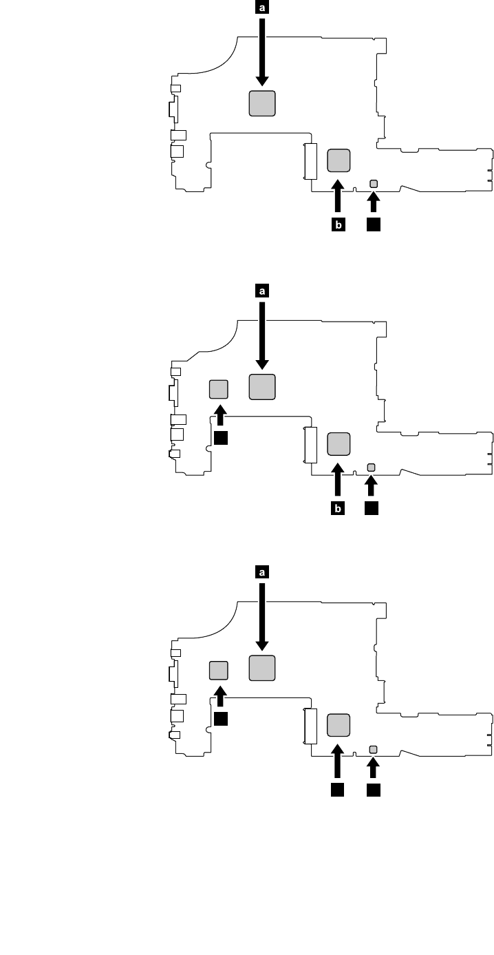
a
b
c
ForSwitchableGraphicsmodels:
a
b
d
c
ForWorkstationmodels:
a
bc
d
106HardwareMaintenanceManual
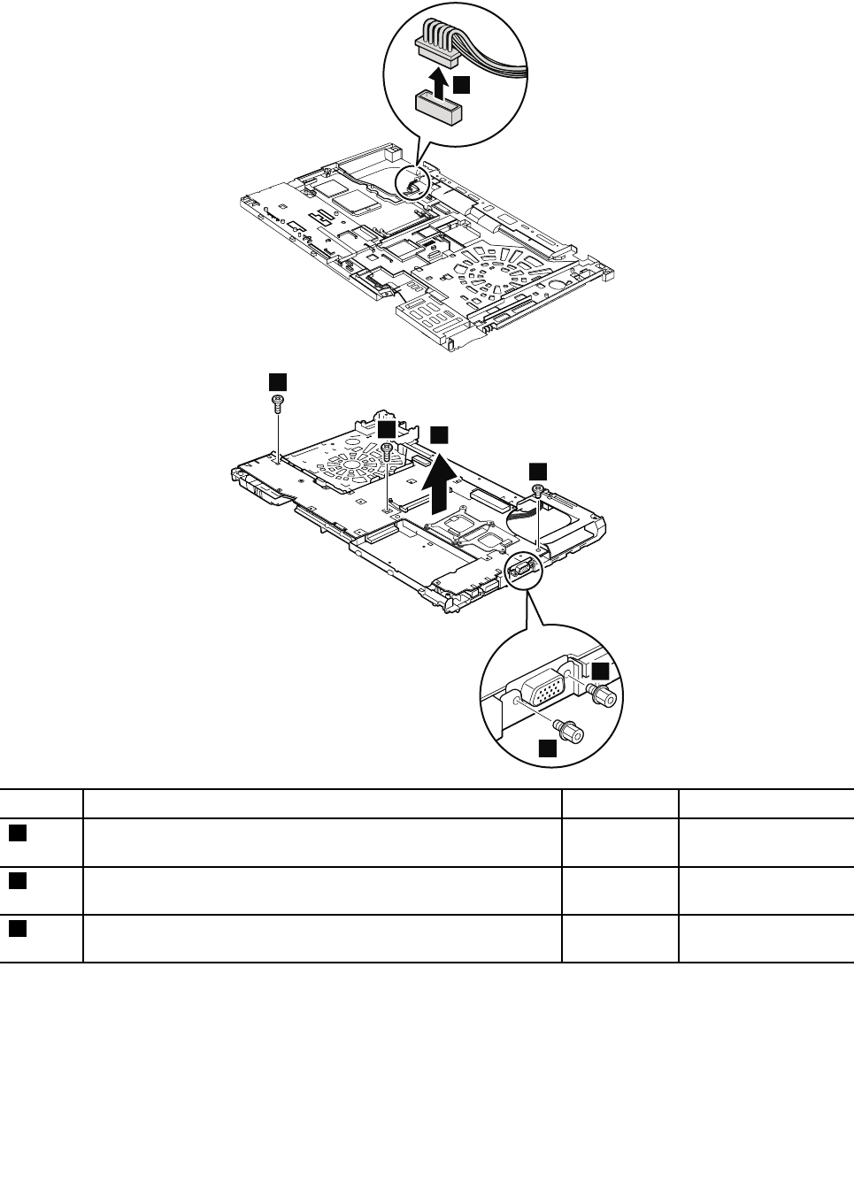
Removalstepsofsystemboardandmagnesiumstructureframe
1
2
2
5
3
4
4
StepScrew(quantity)ColorTorque
2Hexstud,nylon-coated(2)Silver0.392Nm
(4.0kgf-cm)
3M2×3mm,wafer-head,nylon-coated(1)Silver0.181Nm
(1.85kgf-cm)
4M2×7mm,wafer-head,nylon-coated(2)Silver0.181Nm
(1.85kgf-cm)
Wheninstalling:Whenyoureplacethesystemboard,attachthermalrubbersasshowninthefollowing
illustration.Dependingonthemodelsyouareservicing,thenumberofthermalrubbersaredifferent.Check
thethermalrubbersontheoldsystemboard,andfindduplicatesoftheminthenewFRUpackageand
applythemtothenewsystemboard.
Chapter10.RemovingorreplacingaFRU107
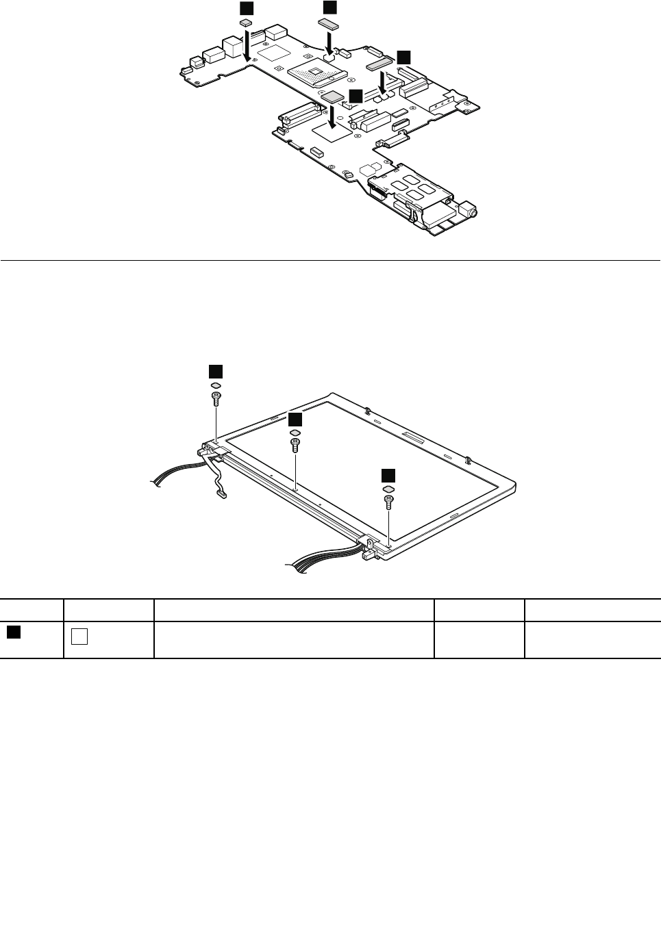
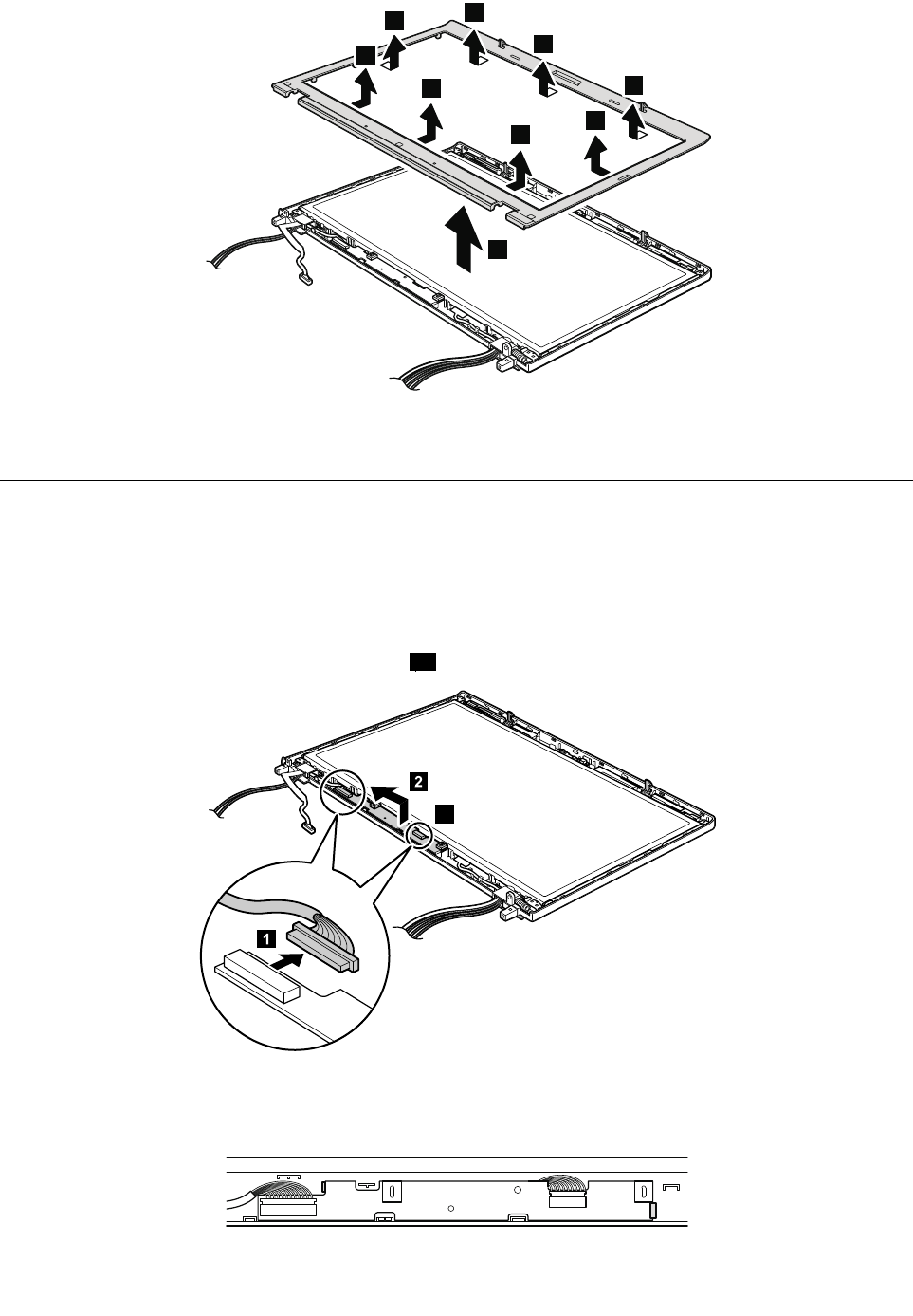
3
2
2
2
2
2
2
2
2
Wheninstalling:Makesurethatallthelatchesareattachedfirmly.
2020LEDsubcard
Foraccess,removetheseFRUsinorder:
•“1010Batterypack”onpage70
•“2010LCDbezelassembly”onpage108
RemovalstepsofLEDsubcard
Note:Somemodelsdonothavetheconnector1a.
2
1a
1
Wheninstalling:Makesurethattheconnectorsareattachedfirmlyandthecardisinstalledasshownin
thefollowingillustration.
Chapter10.RemovingorreplacingaFRU109
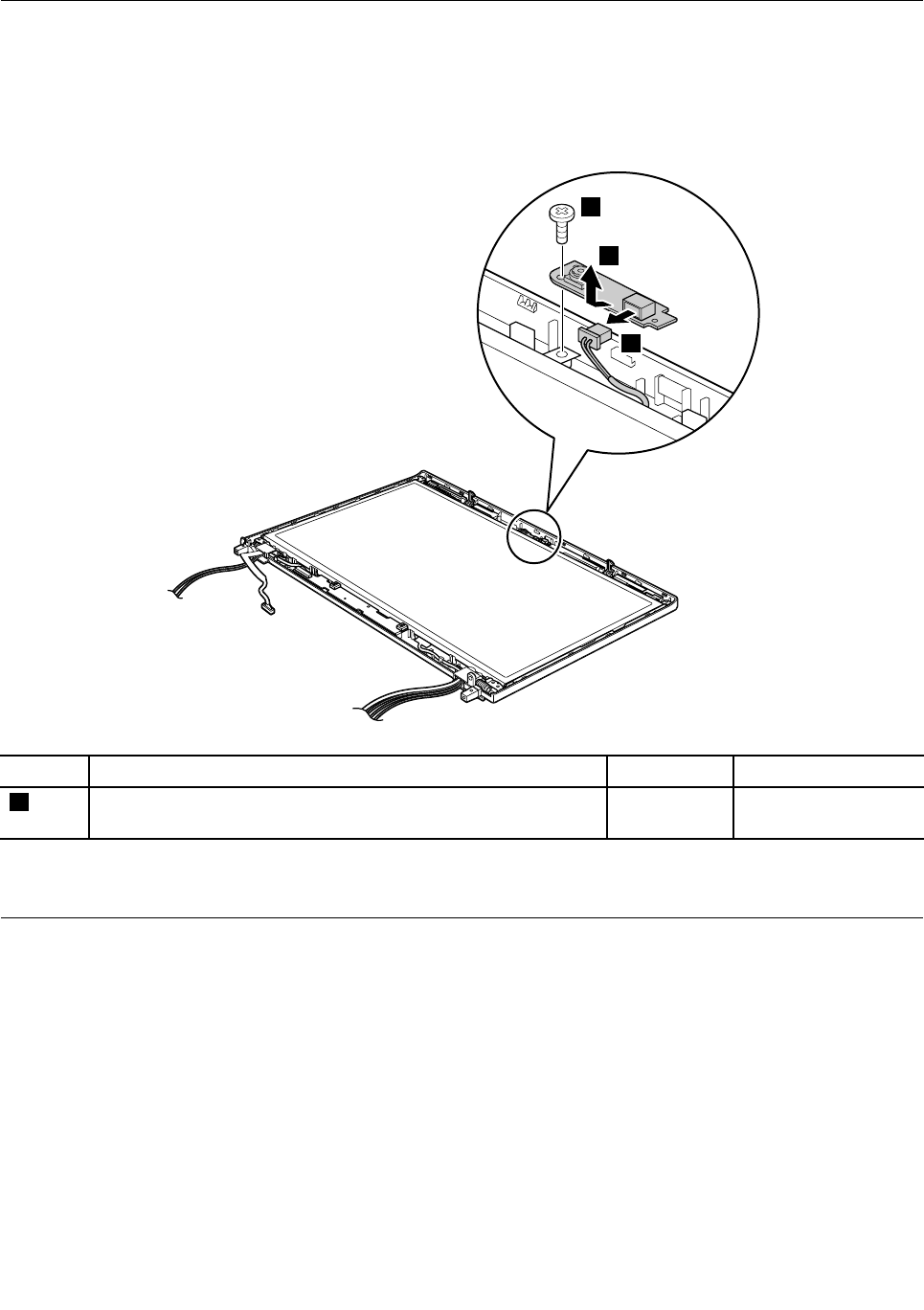
2030Integratedcamera
Foraccess,removetheseFRUsinorder:
•“1010Batterypack”onpage70
•“2010LCDbezelassembly”onpage108
Removalstepsofintegratedcamera
2
1
3
StepScrew(quantity)ColorTorque
1M2×3mm,wafer-head,nylon-coated(1)Silver0.181Nm
(1.85kgf-cm)
Wheninstallling:Makesurethattheconnectoroftheintegratedcameraisattachedfirmly.
2040LCDcable,cameracable,LCDpanel,andhinges
Foraccess,removetheseFRUsinorder:
•“1010Batterypack”onpage70
•“1030Memorymoduleslotcover”onpage72
•“1050Harddiskdriveorsolidstatedrive”onpage74
•“1060Keyboard”onpage76
•“1080PCIExpressMiniCardforwirelessLAN”onpage80
•“1090PCIExpressMiniCardforwirelessWANormSATAsolidstatedrive”onpage82
•“1100ExpressCardblankbezelorExpressCard”onpage86
•“1180LCDunit”onpage98
•“2010LCDbezelassembly”onpage108
110HardwareMaintenanceManual

ReadthisfirstbeforereplacingtheLCDpanel
ForThinkPadW530modelswithacolorsensor:
Important:
IfyourLCDpanelneedsareplacement,orderaspecialLCDpanelFRUkitforcolorsensormodelfromLenovo.
TheFRUkitcontainsaLCDpanel,aCDandaninstructionflyer.ForthecorrectFRUkitpartnumber,checkon
theWebsiteathttp://www.lenovo.com/serviceparts-lookup.
ToreplacetheLCDpanel,besuretofollowthesesteps:
1.BeforeyoureplacetheLCDpanel,locatethelabelontheplasticjacketofthenewLCDpanel.Locate
thenumerickeynumberonthelabelandrecordit.
2.ReplacethefailingLCDpanelwiththenewonethatwasshippedtoyou.Forthedetailedreplacement
procedure,see“RemovalstepsofLCDcable,cameracable,LCDpanel,andhinges”onpage111.
3.StartthecomputerandentertheWindowsoperatingenvironment.
4.InserttheCDthatcamewiththenewLCDpanel.Iftheautorunfunctionisenabled,the
PanelReplacementUtilityprogramstartsautomatically.Iftheprogramdoesnotstartautomatically,run
theprogrammanuallybyexploringtheCDanddouble-clickingPanelReplacementUtility.exe.
5.Followtheinstructionsonthescreentoperformtheinitialcolorcalibration.Whenthekeynumberis
required,typethenumberthatyourecordedinstep1.ThenthePanelReplacementUtilityprogram
startstomeasurethenewLCDpanelandperformtheinitialcolorcalibration.
6.Whentheinitialcalibrationisfinished,adialogboxisdisplayed.ClickOKtoexitthe
PanelReplacementUtilityprogram.
Important:IfthecomputerisprotectedbyaharddiskdrivepasswordoraWindowspassword,doone
ofthefollowing:
•AskthecustomerforthepasswordtorunthePanelReplacementUtilityprogram.
•ProvidetheCDandthenumerickeynumbertothecustomerandguidethecustomertorunthePanel
ReplacementUtilityprogram.
FailingtorunthePanelReplacementUtilityprogramwillrequireanotherLCDpanelreplacement.
RemovalstepsofLCDcable,cameracable,LCDpanel,andhinges
Instep1,releasetheantennacablesfromtheleftandrighthinges.
Chapter10.RemovingorreplacingaFRU111
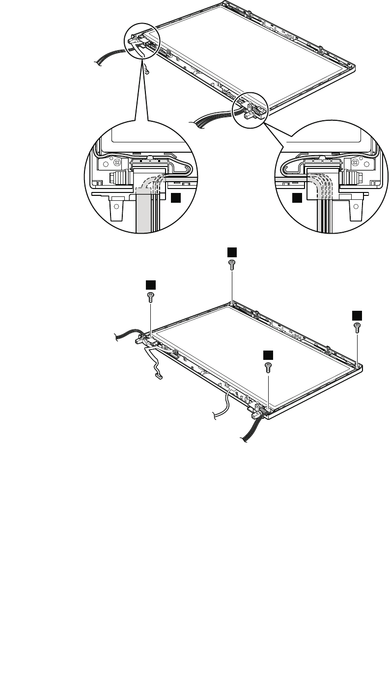
1 1
2
2
2
2
Wheninstalling:WhenattachingtheLCDpaneltothecover,presstheleftandrightedgescoveredwith
metalgentlywithyourfingers.Donotpressthesurfaceofthepanelorapplyanyexcessiveforcetothepanel.
112HardwareMaintenanceManual
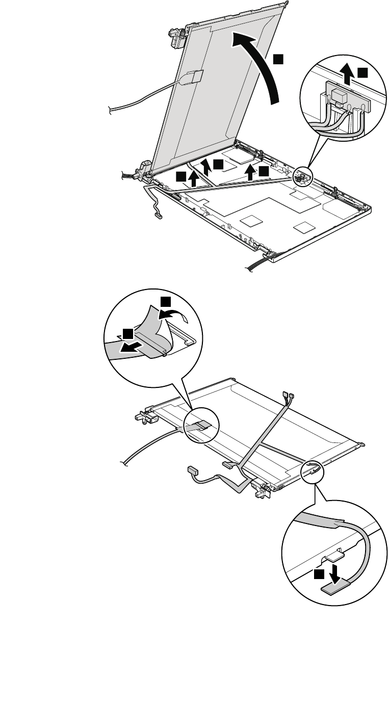
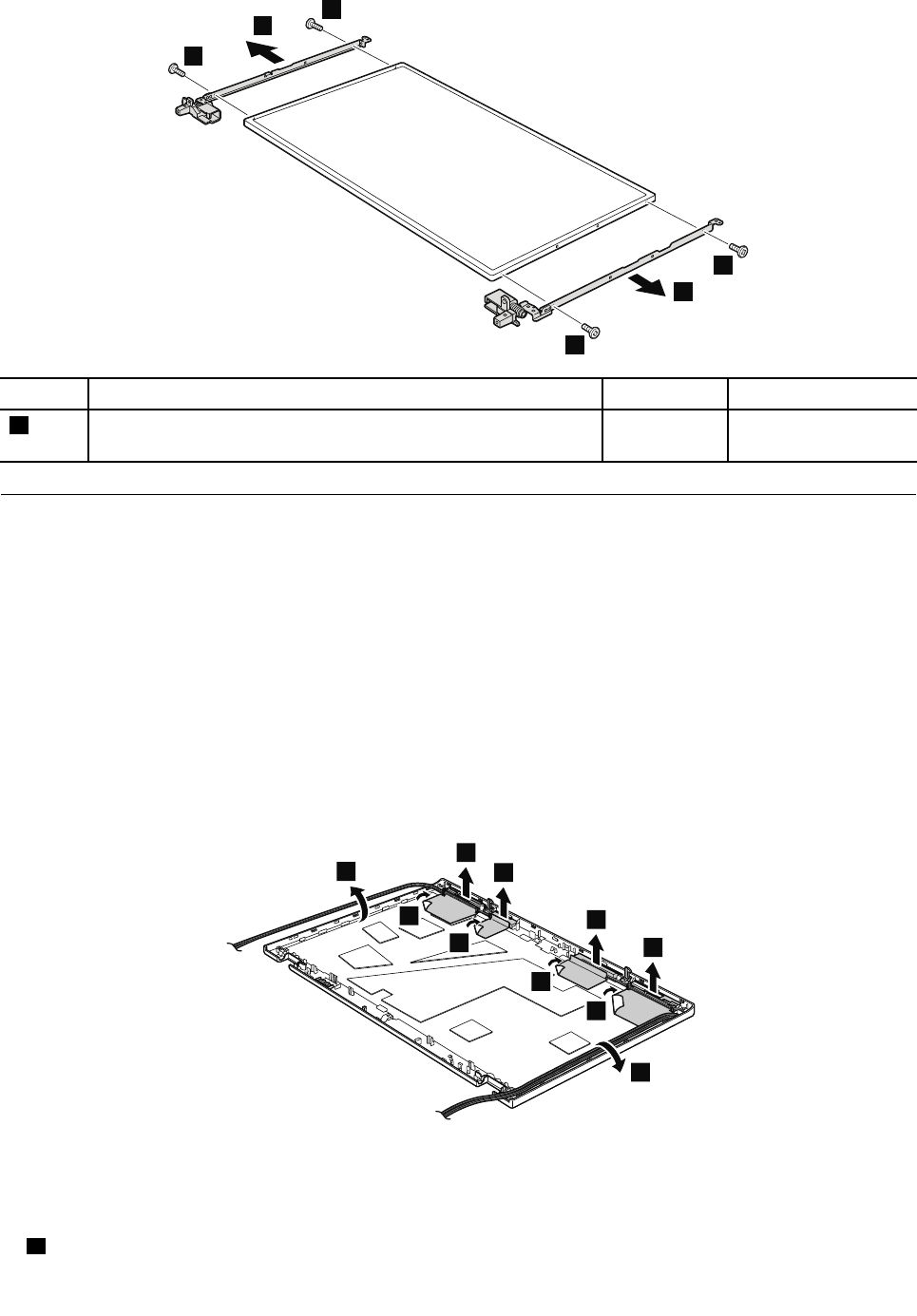
9
9
9
9
10
10
StepScrew(quantity)ColorTorque
9M2×3mm,wafer-head,nylon-coated(4)Silver0.181Nm
(1.85kgf-cm)
2050AntennakitandLCDrearcoverassembly
Foraccess,removetheseFRUsinorder:
•“1010Batterypack”onpage70
•“1030Memorymoduleslotcover”onpage72
•“1050Harddiskdriveorsolidstatedrive”onpage74
•“1060Keyboard”onpage76
•“1080PCIExpressMiniCardforwirelessLAN”onpage80
•“1090PCIExpressMiniCardforwirelessWANormSATAsolidstatedrive”onpage82
•“1100ExpressCardblankbezelorExpressCard”onpage86
•“1180LCDunit”onpage98
•“2010LCDbezelassembly”onpage108
•“2040LCDcable,cameracable,LCDpanel,andhinges”onpage110
RemovalstepsofantennakitandLCDrearcoverassembly
1
1
2
2
2
2
3
3
3
3
Cablerouting:Whenyouinstalltheantennakit,routethecablesasshowninthefollowingillustration.As
youroutethecables,makesurethattheyarenotsubjecttoanytension.Tensioncouldcausethecablesto
bedamagedbythecableguides,orawiretobebroken.
aWirelessWANantenna,AUX(blue)
114HardwareMaintenanceManual
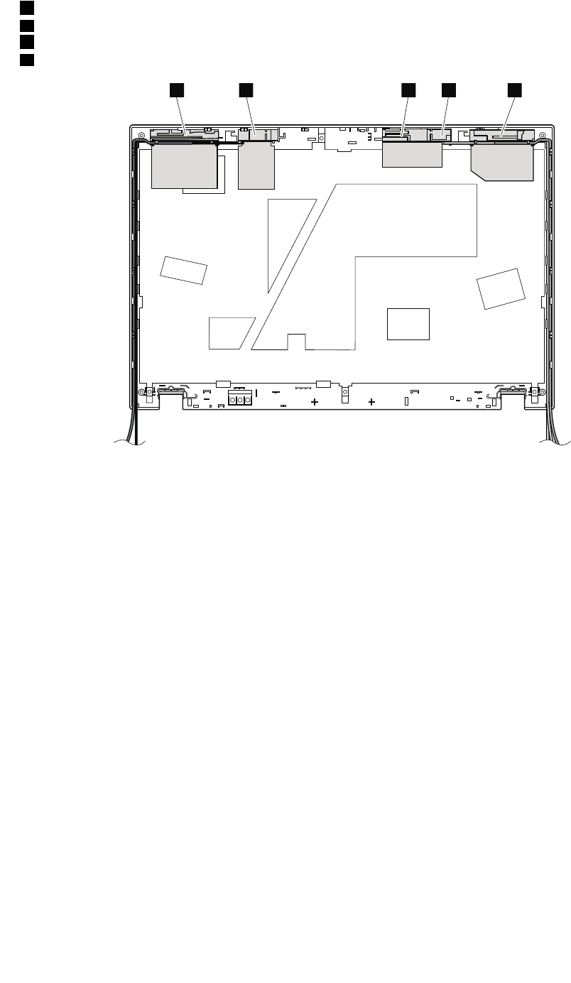

116HardwareMaintenanceManual

AppendixA.Notices
Lenovomaynotoffertheproducts,services,orfeaturesdiscussedinthisdocumentinallcountries.Consult
yourlocalLenovorepresentativeforinformationontheproductsandservicescurrentlyavailableinyour
area.AnyreferencetoaLenovoproduct,program,orserviceisnotintendedtostateorimplythatonlythat
Lenovoproduct,program,orservicemaybeused.Anyfunctionallyequivalentproduct,program,orservice
thatdoesnotinfringeanyLenovointellectualpropertyrightmaybeusedinstead.However,itistheuser’s
responsibilitytoevaluateandverifytheoperationofanyotherproduct,program,orservice.
Lenovomayhavepatentsorpendingpatentapplicationscoveringsubjectmatterdescribedinthis
document.Thefurnishingofthisdocumentdoesnotgiveyouanylicensetothesepatents.Youcansend
licenseinquiries,inwriting,to:
Lenovo(UnitedStates),Inc.
1009ThinkPlace-BuildingOne
Morrisville,NC27560
U.S.A.
Attention:LenovoDirectorofLicensing
LENOVOPROVIDESTHISPUBLICATION“ASIS”WITHOUTWARRANTYOFANYKIND,EITHEREXPRESS
ORIMPLIED,INCLUDING,BUTNOTLIMITEDTO,THEIMPLIEDWARRANTIESOFNON-INFRINGEMENT,
MERCHANTABILITYORFITNESSFORAPARTICULARPURPOSE.Somejurisdictionsdonotallow
disclaimerofexpressorimpliedwarrantiesincertaintransactions,therefore,thisstatementmaynotapply
toyou.
Thisinformationcouldincludetechnicalinaccuraciesortypographicalerrors.Changesareperiodically
madetotheinformationherein;thesechangeswillbeincorporatedinneweditionsofthepublication.
Lenovomaymakeimprovementsand/orchangesintheproduct(s)and/ortheprogram(s)describedinthis
publicationatanytimewithoutnotice.
Theproductsdescribedinthisdocumentarenotintendedforuseinimplantationorotherlifesupport
applicationswheremalfunctionmayresultininjuryordeathtopersons.Theinformationcontainedinthis
documentdoesnotaffectorchangeLenovoproductspecificationsorwarranties.Nothinginthisdocument
shalloperateasanexpressorimpliedlicenseorindemnityundertheintellectualpropertyrightsofLenovo
orthirdparties.Allinformationcontainedinthisdocumentwasobtainedinspecificenvironmentsandis
presentedasanillustration.Theresultobtainedinotheroperatingenvironmentsmayvary.
Lenovomayuseordistributeanyoftheinformationyousupplyinanywayitbelievesappropriatewithout
incurringanyobligationtoyou.
Anyreferencesinthispublicationtonon-LenovoWebsitesareprovidedforconvenienceonlyanddonotin
anymannerserveasanendorsementofthoseWebsites.ThematerialsatthoseWebsitesarenotpartof
thematerialsforthisLenovoproduct,anduseofthoseWebsitesisatyourownrisk.
Anyperformancedatacontainedhereinwasdeterminedinacontrolledenvironment.Therefore,theresult
obtainedinotheroperatingenvironmentsmayvarysignificantly.Somemeasurementsmayhavebeen
madeondevelopment-levelsystemsandthereisnoguaranteethatthesemeasurementswillbethesame
ongenerallyavailablesystems.Furthermore,somemeasurementsmayhavebeenestimatedthrough
extrapolation.Actualresultsmayvary.Usersofthisdocumentshouldverifytheapplicabledatafortheir
specificenvironment.
©CopyrightLenovo2012,2014117

Electronicemissionnotices
ForelectronicemissioninformationonClassBdigitaldevices,refertothecorrespondinginformationin
theUserGuide.
Trademarks
ThefollowingtermsaretrademarksofLenovointheUnitedStates,othercountriesorboth:
ActiveProtectionSystem
Lenovo
ThinkLight
ThinkPad
ThinkVantage
TrackPoint
Ultrabay
UltraNav
Microsoft,Windows,andWindowsServeraretrademarksoftheMicrosoftgroupofcompanies.
IntelisatrademarkofIntelCorporationintheU.S.and/orothercountries.
Othercompany,product,orservicenamesmaybethetrademarksorservicemarksofothers.
118HardwareMaintenanceManual

PartNumber:0B48474_03
Printedin
(1P)P/N:0B48474_03
*1P0B48474_03*
