Lenovo Y520T Series Hmm 20170601 User Manual Legion Y520 Tower Hardware Maintenance 25IKL Desktop (Lenovo) Type 90H8
2017-06-19
User Manual: Lenovo Y520T Series Hmm 20170601 Lenovo Legion Y520 Tower Hardware Maintenance Manual Legion Y520T-25IKL Desktop (Lenovo) - Type 90H8 90H8
Open the PDF directly: View PDF ![]() .
.
Page Count: 55
- Chapter 1. About this manual
- Chapter 2. Safety information
- Chapter 3. General information
- Chapter 4. General Checkout
- Chapter 5. Using the Setup Utility
- Chapter 6. Symptom-to-FRU Index
- Chapter 7. Locating connectors, controls and components
- Chapter 8. Replacing hardware
- General information
- Replacing the keyboard and mouse
- Removing the computer cover
- Removing the top bezel
- Removing the front bezel
- Replacing the power supply assemby
- Replacing an optical drive
- Replacing the M.2 storage drive
- Replacing the 3.5-inch storage drive
- Replacing the graphic card
- Replacing a memory module
- Replacing the Wi-Fi card
- Replacing the Wi-Fi antenna
- Replacing the heat-sink and fan assembly
- Replacing the microprocessor
- Replacing the front fan
- Replacing the rear fan
- Replacing the motherboard
- Chapter 9. FRU lists
- Chapter 10. General information

LenovoLegionY520TowerHardware
MaintenanceManual
MachineTypes:90H7[Y520T-25IKL/EnergyStar]

LenovoLegionY520Tower
HardwareMaintenanceManual
MachineTypes:90H7[Y520T-25IKL/EnergyStar]

FirstEdition(January2017)21st
©CopyrightLenovo2017.
LIMITEDANDRESTRICTEDRIGHTSNOTICE:IfdataorsoftwarearedeliveredpursuantaGeneralServices
Administration“GSA”contract,use,reproduction,ordisclosureissubjecttorestrictionssetforthinContractNo.
GS-35F-05925

Contents
Chapter1.Aboutthismanual.....1
ImportantSafetyInformation.........1
Chapter2.Safetyinformation.....3
Generalsafety...............3
Electricalsafety..............3
Safetyinspectionguide...........5
Handlingelectrostaticdischarge-sensitive
devices.................5
Groundingrequirements...........6
Safetynotices...............6
Chapter3.Generalinformation....9
Specifications...............9
Chapter4.GeneralCheckout.....11
Chapter5.UsingtheSetupUtility...13
StartingtheLenovoBIOSSetupUtilityprogram.13
Viewingandchangingsettings........13
Usingpasswords..............13
Enablingordisablingadevice........15
Selectingastartupdevice..........16
ExitingtheLenovoBIOSSetupUtilityprogram..17
Chapter6.Symptom-to-FRUIndex..19
Harddiskdrivebooterror..........19
PowerSupplyProblems...........19
POSTerrorcodes.............20
Undeterminedproblems...........20
Chapter7.Locatingconnectors,
controlsandcomponents......21
Chapter8.Replacinghardware....25
Generalinformation.............25
Replacingthekeyboardandmouse......26
Removingthecomputercover........26
Removingthetopbezel...........27
Removingthefrontbezel..........28
Replacingthepowersupplyassemby.....29
Replacinganopticaldrive..........30
ReplacingtheM.2storagedrive........31
Replacingthe3.5-inchstoragedrive......32
Replacingthegraphiccard..........33
Replacingamemorymodule.........34
ReplacingtheWi-Ficard...........35
ReplacingtheWi-Fiantenna.........37
Replacingtheheat-sinkandfanassembly....38
Replacingthemicroprocessor........39
Replacingthefrontfan...........40
Replacingtherearfan............41
Replacingthemotherboard..........42
Chapter9.FRUlists..........45
Chapter10.Generalinformation...49
AdditionalServiceInformation........49
©CopyrightLenovo2017iii

ivLenovoLegionY520TowerHardwareMaintenanceManual
Chapter1.Aboutthismanual
ThismanualcontainsserviceandreferenceinformationforLenovoideacentre300seriesdesktopcomputers
listedonthecover.ItisintendedonlyfortrainedservicerswhoarefamiliarwithLenovocomputerproducts.
BeforeservicingaLenovoproduct,besuretoreadtheSafetyInformation.
ThedescriptionoftheTVcardinthismanualisonlyusedforthemachineswhichhavetheTVcard.Itis
invalidforthosemachineswhichdonothaveTVcard.
ImportantSafetyInformation
Besuretoreadallcautionanddangerstatementsinthisbookbeforeperforminganyoftheinstructions.
VeuillezliretouteslesconsignesdetypeDANGERetATTENTIONduprésentdocumentavantd’exécuter
lesinstructions.
LesenSieunbedingtalleHinweisevomT yp“ACHTUNG”oder“VORSICHT”indieserDokumentation,bevor
SieirgendwelcheVorgängedurchführen
LeggereleistruzioniintrodottedaATTENZIONEePERICOLOpresentinelmanualeprimadieseguireuna
qualsiasidelleistruzioni
Certifique-sedelertodasasinstruçõesdecuidadoeperigonestemanualantesdeexecutarqualquer
umadasinstruções
Esimportantequeleatodaslasdeclaracionesdeprecauciónydepeligrodeestemanualantesdeseguir
lasinstrucciones.
©CopyrightLenovo20171

2LenovoLegionY520TowerHardwareMaintenanceManual
Chapter2.Safetyinformation
Thischaptercontainsthesafetyinformationthatyouneedtobefamiliarwithbeforeservicingacomputer.
Generalsafety
Followtheserulestoensuregeneralsafety:
•Observegoodhousekeepingintheareaofthemachinesduringandaftermaintenance.
•Whenliftinganyheavyobject:
1.Ensureyoucanstandsafelywithoutslipping.
2.Distributetheweightoftheobjectequallybetweenyourfeet.
3.Useaslowliftingforce.Nevermovesuddenlyortwistwhenyouattempttolift.
4.Liftbystandingorbypushingupwithyourlegmuscles;thisactionremovesthestrainfromthe
musclesinyourback.
Donotattempttoliftanyobjectsthatweighmorethan16kg(35lb)orobjectsthatyouthinkare
tooheavyforyou.
•Donotperformanyactionthatcauseshazardstothecustomer,orthatmakestheequipmentunsafe.
•Beforeyoustartthemachine,ensurethatotherservicerepresentativesandthecustomer’spersonnelare
notinahazardousposition.
•Placeremovedcoversandotherpartsinasafeplace,awayfromallpersonnel,whileyouareservicing
themachine.
•Keepyourtoolcaseawayfromwalkareassothatotherpeoplewillnottripoverit.
•Donotwearlooseclothingthatcanbetrappedinthemovingpartsofamachine.Ensurethatyoursleeves
arefastenedorrolledupaboveyourelbows.Ifyourhairislong,fastenit.
•Inserttheendsofyournecktieorscarfinsideclothingorfastenitwithanonconductiveclip,approximately
8centimeters(3inches)fromtheend.
•Donotwearjewelry,chains,metal-frameeyeglasses,ormetalfastenersforyourclothing.
Remember:Metalobjectsaregoodelectricalconductors.
•Wearsafetyglasseswhenyouare:hammering,drillingsoldering,cuttingwire,attachingsprings,using
solvents,orworkinginanyotherconditionsthatmightbehazardoustoyoureyes.
•Afterservice,reinstallallsafetyshields,guards,labels,andgroundwires.Replaceanysafetydevice
thatiswornordefective.
•Reinstallallcoverscorrectlybeforereturningthemachinetothecustomer.
Electricalsafety
CAUTION:
Electricalcurrentfrompower,telephone,andcommunicationcablescanbehazardous.T oavoid
personalinjuryorequipmentdamage,disconnecttheattachedpowercords,telecommunication
systems,networks,andmodemsbeforeyouopenthecomputercovers,unlessinstructedotherwise
intheinstallationandconfigurationprocedures.
©CopyrightLenovo20173

Observethefollowingruleswhenworkingonelectricalequipment.
Important:Useonlyapprovedtoolsandtestequipment.Somehandtoolshavehandlescoveredwithasoft
materialthatdoesnotinsulateyouwhenworkingwithliveelectricalcurrents.Manycustomershave,near
theirequipment,rubberfloormatsthatcontainsmallconductivefiberstodecreaseelectrostaticdischarges.
Donotusethistypeofmattoprotectyourselffromelectricalshock.
•Findtheroomemergencypower-off(EPO)switch,disconnectingswitch,orelectricaloutlet.Ifanelectrical
accidentoccurs,youcanthenoperatetheswitchorunplugthepowercordquickly.
•Donotworkaloneunderhazardousconditionsornearequipmentthathashazardousvoltages.
•Disconnectallpowerbefore:
–Performingamechanicalinspection
–Workingnearpowersupplies
–RemovingorinstallingFieldReplaceableUnits(FRUs)
•Beforeyoustarttoworkonthemachine,unplugthepowercord.Ifyoucannotunplugit,askthecustomer
topower-offthewallboxthatsuppliespowertothemachineandtolockthewallboxintheoffposition.
•Ifyouneedtoworkonamachinethathasexposedelectricalcircuits,observethefollowingprecautions:
–Ensurethatanotherperson,familiarwiththepower-offcontrols,isnearyou.
Remember:Anotherpersonmustbetheretoswitchoffthepower,ifnecessary.
–Useonlyonehandwhenworkingwithpowered-onelectricalequipment;keeptheotherhandinyour
pocketorbehindyourback.
Remember:Theremustbeacompletecircuittocauseelectricalshock.Byobservingtheaboverule,
youmaypreventacurrentfrompassingthroughyourbody.
–Whenusingatester,setthecontrolscorrectlyandusetheapprovedprobeleadsandaccessoriesfor
thattester.
–Standonsuitablerubbermats(obtainedlocally,ifnecessary)toinsulateyoufromgroundssuchas
metalfloorstripsandmachineframes.
Observethespecialsafetyprecautionswhenyouworkwithveryhighvoltages;theseinstructionsarein
thesafetysectionsofmaintenanceinformation.Useextremecarewhenmeasuringhighvoltages.
•Regularlyinspectandmaintainyourelectricalhandtoolsforsafeoperationalcondition.
•Donotusewornorbrokentoolsandtesters.
•Neverassumethatpowerhasbeendisconnectedfromacircuit.First,checkthatithasbeenpowered-off.
•Alwayslookcarefullyforpossiblehazardsinyourworkarea.Examplesofthesehazardsaremoistfloors,
nongroundedpowerextensioncables,powersurges,andmissingsafetygrounds.
•Donottouchliveelectricalcircuitswiththereflectivesurfaceofaplasticdentalmirror.Thesurfaceis
conductive;suchtouchingcancausepersonalinjuryandmachinedamage.
•Donotservicethefollowingpartswiththepoweronwhentheyareremovedfromtheirnormaloperating
placesinamachine:
–Powersupplyunits
–Pumps
–Blowersandfans
–Motorgenerators
andsimilarunits.(Thispracticeensurescorrectgroundingoftheunits.)
•Ifanelectricalaccidentoccurs:
–Usecaution;donotbecomeavictimyourself.
–Switchoffpower.
4LenovoLegionY520TowerHardwareMaintenanceManual

–Sendanotherpersontogetmedicalaid.
Safetyinspectionguide
Theintentofthisinspectionguideistoassistyouinidentifyingpotentiallyunsafeconditionsonthese
products.Eachmachine,asitwasdesignedandbuilt,hadrequiredsafetyitemsinstalledtoprotectusers
andservicepersonnelfrominjury.Thisguideaddressesonlythoseitems.However,goodjudgmentshould
beusedtoidentifypotentialsafetyhazardsduetoattachmentoffeaturesoroptionsnotcoveredbythis
inspectionguide.
Ifanyunsafeconditionsarepresent,youmustdeterminehowserioustheapparenthazardcouldbeand
whetheryoucancontinuewithoutfirstcorrectingtheproblem.
Considertheseconditionsandthesafetyhazardstheypresent:
•Electricalhazards,especiallyprimarypower(primaryvoltageontheframecancauseseriousorfatal
electricalshock).
•Explosivehazards,suchasadamagedCRTfaceorbulgingcapacitor
•Mechanicalhazards,suchaslooseormissinghardware
Theguideconsistsofaseriesofstepspresentedinachecklist.Beginthecheckswiththepoweroff,and
thepowercorddisconnected.
Checklist:
1.Checkexteriorcoversfordamage(loose,broken,orsharpedges).
2.Power-offthecomputer.Disconnectthepowercord.
3.Checkthepowercordfor:
a.Athird-wiregroundconnectoringoodcondition.Useametertomeasurethird-wireground
continuityfor0.1ohmorlessbetweentheexternalgroundpinandframeground.
b.Thepowercordshouldbetheappropriatetypeasspecifiedinthepartslistings.
c.Insulationmustnotbefrayedorworn.
4.Removethecover.
5.Checkforanyobviousalterations.Usegoodjudgmentastothesafetyofanyalterations.
6.Checkinsidetheunitforanyobviousunsafeconditions,suchasmetalfilings,contamination,wateror
otherliquids,orsignsoffireorsmokedamage.
7.Checkforworn,frayed,orpinchedcables.
8.Checkthatthepower-supplycoverfasteners(screwsorrivets)havenotbeenremovedortamperedwith.
Handlingelectrostaticdischarge-sensitivedevices
Anycomputerpartcontainingtransistorsorintegratedcircuits(ICs)shouldbeconsideredsensitiveto
electrostaticdischarge(ESD).ESDdamagecanoccurwhenthereisadifferenceinchargebetweenobjects.
ProtectagainstESDdamagebyequalizingthechargesothatthemachine,thepart,theworkmat,andthe
personhandlingthepartareallatthesamecharge.
Notes:
1.Useproduct-specificESDprocedureswhentheyexceedtherequirementsnotedhere.
2.MakesurethattheESDprotectivedevicesyouusehavebeencertified(ISO9000)asfullyeffective.
WhenhandlingESD-sensitiveparts:
•Keepthepartsinprotectivepackagesuntiltheyareinsertedintotheproduct.
Chapter2.Safetyinformation5
•Avoidcontactwithotherpeoplewhilehandlingthepart.
•Wearagroundedwriststrapagainstyourskintoeliminatestaticonyourbody.
•Preventthepartfromtouchingyourclothing.Mostclothingisinsulativeandretainsachargeeven
whenyouarewearingawriststrap.
•Usetheblacksideofagroundedworkmattoprovideastatic-freeworksurface.Thematisespecially
usefulwhenhandlingESD-sensitivedevices.
•Selectagroundingsystem,suchasthoselistedbelow,toprovideprotectionthatmeetsthespecific
servicerequirement.
Note:TheuseofagroundingsystemisdesirablebutnotrequiredtoprotectagainstESDdamage.
–AttachtheESDgroundcliptoanyframeground,groundbraid,orgreen-wireground.
–UseanESDcommongroundorreferencepointwhenworkingonadouble-insulatedor
battery-operatedsystem.Youcanusecoaxorconnector-outsideshellsonthesesystems.
–Usetheroundground-prongoftheacplugonac-operatedcomputers.
Groundingrequirements
Electricalgroundingofthecomputerisrequiredforoperatorsafetyandcorrectsystemfunction.Proper
groundingoftheelectricaloutletcanbeverifiedbyacertifiedelectrician.
Safetynotices
ThecautionanddangersafetynoticesinthissectionareprovidedinthelanguageofEnglish.
DANGER
Electricalcurrentfrompower,telephoneandcommunicationcablesishazardous.
Toavoidashockhazard:
•Donotconnectordisconnectanycablesorperforminstallation,maintenance,orreconfiguration
ofthisproductduringanelectricalstorm.
•Connectallpowercordstoaproperlywiredandgroundedelectricaloutlet.
•Connecttoproperlywiredoutletsanyequipmentthatwillbeattachedtothisproduct.
•Whenpossible,useonehandonlytoconnectordisconnectsignalcables.
•Neverturnonanyequipmentwhenthereisevidenceoffire,water,orstructuraldamage.
•Disconnecttheattachedpowercords,telecommunicationssystems,networks,andmodems
beforeyouopenthedevicecovers,unlessinstructedotherwiseintheinstallationandconfiguration
procedures.
•Connectanddisconnectcablesasdescribedinthefollowingtablewheninstalling,moving,or
openingcoversonthisproductorattacheddevices.
6LenovoLegionY520TowerHardwareMaintenanceManual
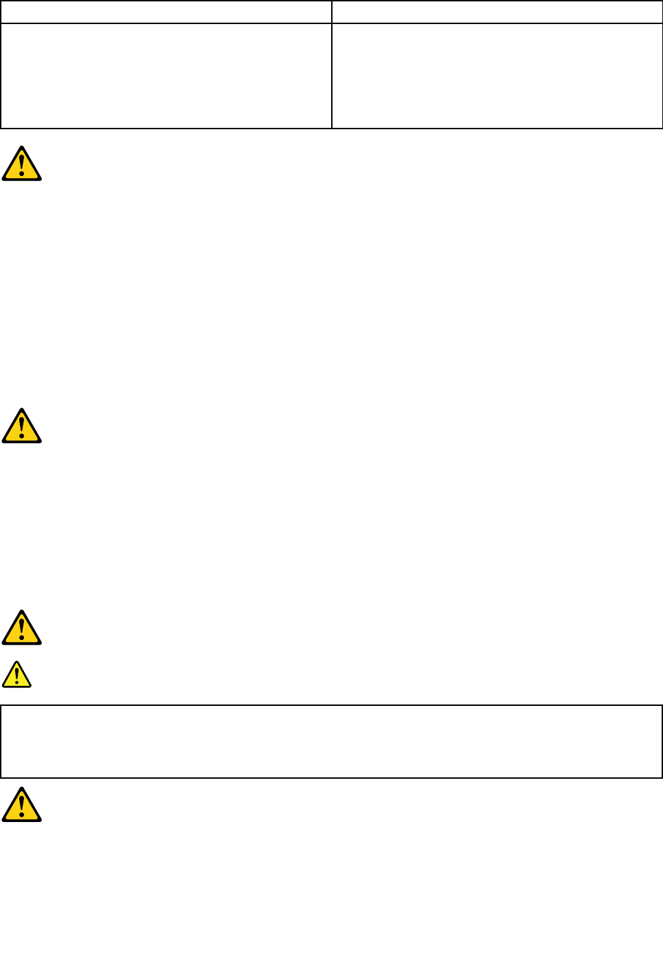
ToConnectToDisconnect
1.T urneverythingOFF .
2.First,attachallcablestodevices.
3.Attachsignalcablestoconnectors.
4.Attachpowercordstooutlet.
5.T urndeviceON.
1.T urneverythingOFF .
2.First,removepowercordsfromoutlet.
3.Removesignalcablesfromconnectors.
4.Removeallcablesfromdevices.
CAUTION:
Whenreplacingthelithiumbattery,useonlyPartNumber45C1566oranequivalenttypebattery
recommendedbythemanufacturer.Ifyoursystemhasamodulecontainingalithiumbattery,replace
itonlywiththesamemoduletypemadebythesamemanufacturer.Thebatterycontainslithiumand
canexplodeifnotproperlyused,handled,ordisposedof.
Donot:
•Throworimmerseintowater
•Heattomorethan100°C(212°F)
•Repairordisassemble
Disposeofthebatteryasrequiredbylocalordinancesorregulations.
CAUTION:
Whenlaserproducts(suchasCD-ROMs,DVD-ROMdrives,fiberopticdevices,ortransmitters)are
installed,notethefollowing:
•Donotremovethecovers.Removingthecoversofthelaserproductcouldresultinexposureto
hazardouslaserradiation.Therearenoserviceablepartsinsidethedevice.
•Useofcontrolsoradjustmentsorperformanceofproceduresotherthanthosespecifiedherein
mightresultinhazardousradiationexposure.
DANGER
SomelaserproductscontainanembeddedClass3AorClass3Blaserdiode.Notethefollowing:
Laserradiationwhenopen.Donotstareintothebeam,donotviewdirectlywithoptical
instruments,andavoiddirectexposuretothebeam.
Chapter2.Safetyinformation7
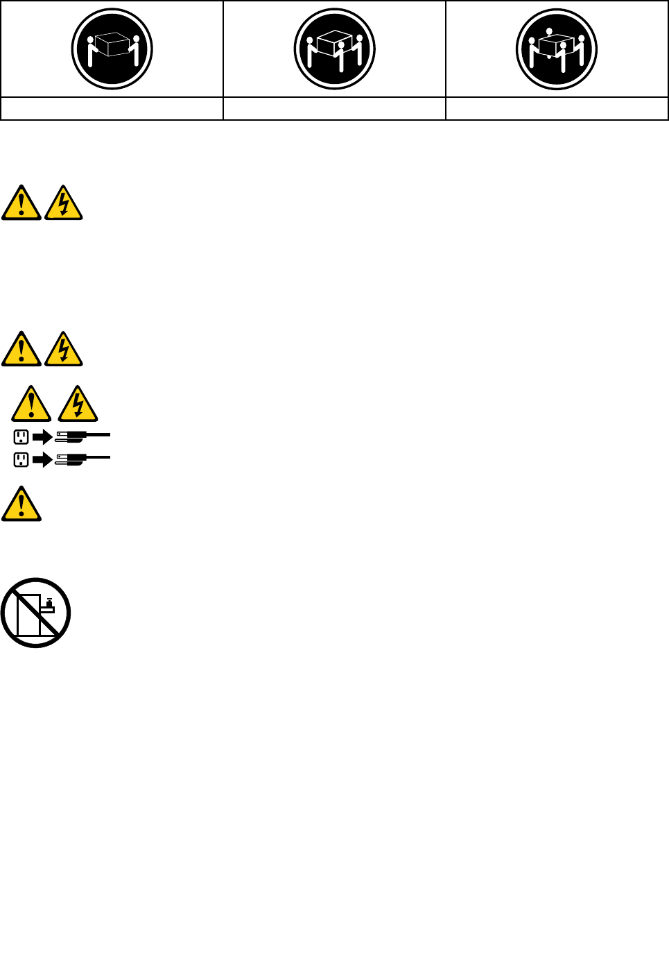
≥18kg(37lbs)≥32kg(70.5lbs)≥55kg(121.2lbs)
CAUTION:
Usesafepracticeswhenlifting.
CAUTION:
Thepowercontrolbuttononthedeviceandthepowerswitchonthepowersupplydonotturnoff
theelectricalcurrentsuppliedtothedevice.Thedevicealsomighthavemorethanonepower
cord.Toremoveallelectricalcurrentfromthedevice,ensurethatallpowercordsaredisconnected
fromthepowersource.
1
2
CAUTION:
Donotplaceanyobjectweighingmorethan82kg(180lbs.)ontopofrack-mounteddevices.
8LenovoLegionY520TowerHardwareMaintenanceManual

Chapter3.Generalinformation
Thischapterprovidesgeneralinformationthatappliestoallmachinetypessupportedbythispublication.
Specifications
Thissectionliststhephysicalspecificationsforyourcomputer.
Thissectionliststhephysicalspecificationsforyourcomputer.
Thissectionliststhephysicalspecifications.
Environment
Airtemperature:
Operating:10°to35°C
Transit:-20°to55°C
Humidity:
Operating:35%to80%
Transit:20%to90%(40°C)
Altitude:86KPato106KPa
Electricalinput:
Inputvoltage:90V-264V(AC)
Inputfrequency:47Hz-63Hz
©CopyrightLenovo20179

10LenovoLegionY520TowerHardwareMaintenanceManual

Chapter4.GeneralCheckout
Attention:Thedrivesinthecomputeryouareservicingmighthavebeenrearrangedorthedrivestartup
sequencechanged.Beextremelycarefulduringwriteoperationssuchascopying,saving,orformatting.
Dataorprogramscanbeoverwrittenifyouselectanincorrectdrive.
Generalerrormessagesappearifaproblemorconflictisfoundbyanapplicationprogram,theoperating
system,orboth.Foranexplanationofthesemessages,refertotheinformationsuppliedwiththatsoftware
package.
Usethefollowingproceduretohelpdeterminethecauseoftheproblem:
1.Power-offthecomputerandallexternaldevices.
2.Checkallcablesandpowercords.
3.Setalldisplaycontrolstothemiddleposition.
4.Power-onallexternaldevices.
5.Power-onthecomputer.
•Lookfordisplayederrorcodes
•Lookforreadableinstructionsoramainmenuonthedisplay.
Ifyoudidnotreceivethecorrectresponse,proceedtostep6.
Ifyoudoreceivethecorrectresponse,proceedtostep7.
6.Lookatthefollowingconditionsandfollowtheinstructions:
•IfthecomputerdisplaysaPOSTerror,goto“POSTerrorcodes” .
•Ifthecomputerhangsandnoerrorisdisplayed,continueatstep7.
7.Iftheteststopsandyoucannotcontinue,replacethelastdevicetested.
©CopyrightLenovo201711

12LenovoLegionY520TowerHardwareMaintenanceManual

Chapter5.UsingtheSetupUtility
TheSetupUtilityprogramisusedtoviewandchangetheconfigurationsettingsofyourcomputer,regardless
ofwhichoperatingsystemyouareusing.However,theoperating-systemsettingsmightoverrideanysimilar
settingsintheSetupUtilityprogram.
StartingtheLenovoBIOSSetupUtilityprogram
TostarttheLenovoBIOSSetupUtilityprogram,dothefollowing:
1.Ifyourcomputerisalreadyonwhenyoustartthisprocedure,shutdowntheoperatingsystemand
turnoffthecomputer.
2.PressandholdtheF1key,andthenturnonthecomputer.WhentheLenovoBIOSSetupUtilityprogram
isdisplayed,releasetheF1key.
Note:IfaPower-OnPasswordoranAdministratorPasswordhasbeenset,theSetupUtilityprogrammenu
isnotdisplayeduntilyoutypeyourpassword.Formoreinformation,see“Usingpasswords.”
Viewingandchangingsettings
SystemconfigurationoptionsarelistedintheLenovoBIOSSetupUtilityprogrammenu.Tovieworchange
settings,see“StartingtheSetupUtilityprogram.”
YoumustusethekeyboardwhenusingtheLenovoBIOSSetupUtilitymenu.Thekeysusedtoperform
varioustasksaredisplayedonthebottomofeachscreen.
Usingpasswords
YoucanusetheLenovoBIOSSetupUtilityprogramtosetpasswordstopreventunauthorizedpersons
fromgainingaccesstoyourcomputeranddata.See“StartingtheSetupUtilityprogram.”Thefollowing
typesofpasswordsareavailable:
•AdministratorPassword
•Power-OnPassword
Youdonothavetosetanypasswordstouseyourcomputer.However,ifyoudecidetosetpasswords,read
thefollowingsections.
Passwordconsiderations
Apasswordcanbeanycombinationoflettersandnumbersupto16character(a-z,and0-9).Forsecurity
reasons,itisagoodideatouseastrongpasswordthatcannotbeeasilycompromised.Wesuggestthat
passwordsshouldfollowtheserules:
•Strongpasswordscontain7-16characters,combinelettersandnumbers.
•Donotuseyournameoryourusername.
•Donotuseacommonwordoracommonname.
•Besignificantlydifferentfromyourpreviouspassword.
Attention:AdministratorandPower-Onpasswordsarenotcasesensitive
©CopyrightLenovo201713

AdministratorPassword
SettinganAdministratorPassworddetersunauthorizedpersonsfromchangingconfigurationsettings.You
mightwanttosetanAdministratorPasswordifyouareresponsibleformaintainingthesettingsofseveral
computers.
AfteryousetanAdministratorPassword,apasswordpromptisdisplayedeverytimeyouaccesstheLenovo
BIOSSetupUtilityprogram.
IfboththeAdministratorandPower-OnPasswordareset,youcantypeeitherpassword.However,youmust
useyourAdministratorPasswordtochangeanyconfigurationsettings.
Setting,changing,ordeletinganAdministratorpassword
TosetanAdministratorPassword,dothefollowing:
Note:Apasswordcanbeanycombinationoflettersandnumbersupto16character(a-z,and0-9).For
moreinformation,see“Passwordconsiderations”onpage13.
1.StarttheLenovoBIOSSetupUtilityprogram(see“StartingtheLenovoBIOSSetupUtilityprogram”on
page13).
2.FromtheSecuritymenu,selectSetAdministratorPasswordandpresstheEnterkey.
3.Thepassworddialogboxwillbedisplayed.Typethepassword,andthenpresstheEnterkey.
4.Re-typethepasswordtoconfirm,andthenpresstheEnterkey.Ifyoutypethepasswordcorrectly,
thepasswordwillbeinstalled.
TochangeanAdministratorPassword,dothefollowing:
1.StarttheLenovoBIOSSetupUtilityprogram(see“StartingtheLenovoBIOSSetupUtilityprogram”on
page13).
2.FromtheSecuritymenu,selectSetAdministratorPasswordandpresstheEnterkey.
3.Thepassworddialogboxwillbedisplayed.Typethecurrentpassword,andthenpressEnterkey.
4.Typethenewpassword,andthenpressEnterkey.Re-typethepasswordtoconfirmthenewpassword,
ifyoutypethenewpasswordcorrectly,thenewpasswordwillbeinstalled.ASetupNoticewilldisplay
thatchangeshavebeensaved.
TodeleteapreviouslysetAdministratorPassword,dothefollowing:
1.FromtheSecuritymenu,selectSetAdministratorPasswordandpresstheEnterkey.
2.Thepassworddialogboxwillbedisplayed.TypethecurrentpasswordandpresstheEnterkey.
3.TodeleteanAdministratorPassword,Enterblankfieldsforeachnewpasswordlineitem.Asetup
noticewilldisplaythatchangeshavebeensaved.
4.ReturntotheLenovoBIOSSetupUtilityprogrammenuandselecttheExitoption.
5.SelectSavechangesandExitfromthemenu.
Power-OnPassword
WhenaPower-OnPasswordisset,youcannotstarttheLenovoBIOSSetupUtilityprogramuntilavalid
passwordistypedfromthekeyboard.
Setting,changing,ordeletingaPower-OnPassword
Note:Apasswordcanbeanycombinationoflettersandnumbersupto16character(a-z,and0-9).
14LenovoLegionY520TowerHardwareMaintenanceManual
TosetaPower-OnPassword,dothefollowing:
1.StarttheLenovoBIOSSetupUtilityprogram(See”StartingtheLenovoBIOSSetupUtilityprogram”on
page13.)
2.FromtheSecuritymenu,selectSetPower-OnPasswordandpresstheEnterkey.
3.Thepassworddialogboxwillbedisplayed.Typethepassword,andpresstheEnterkey.
4.Re-typethepasswordtoconfirm,ifyoutypethepasswordcorrectly,thepasswordwillbeinstalled.
TochangeaPower-OnPassword,dothefollowing:
1.StarttheLenovoBIOSSetupUtilityprogram(See”StartingtheLenovoBIOSSetupUtilityprogram”on
page13.)
2.FromtheSecuritymenu,selectSetPower-OnPasswordandpresstheEnterkey.
3.Thepassworddialogboxwillbedisplayed.Typethecurrentpassword,andthenpresstheEnterkey.
4.Typethenewpassword,andthenpresstheEnterkey.Re-typethepasswordtoconfirmthenew
password,ifyoutypethenewpasswordcorrectly,thenewpasswordwillbeinstalled.Asetupnotice
willdisplaythatchangeshavebeensaved.
TodeleteapreviouslysetPower-OnPassword,dothefollowing:
1.FromtheSecuritymenu,selectSetPower-OnPasswordandpresstheEnterkey.
2.Thepassworddialogboxwillbedisplayed.TypethecurrentpasswordandpresstheEnterkey.
3.TodeletethePower-OnPassword,Enterblankfieldsforeachnewpasswordlineitem.Asetup
noticewilldisplaythatchangeshavebeensaved.
4.ReturntotheLenovoBIOSSetupUtilityprogrammenuandselecttheExitoption.
5.SelectSavechangesandExitfromthemenu.
Enablingordisablingadevice
TheDevicesoptionsisusedtoenableordisableuseraccesstothefollowingdevices:
SerialPortSetupSelectthisoptiontoenableordisableSerialPort(com).
USBFunctionsSelectwhethertoenableordisableUSB(UniversalSerial
Bus)functions.Ifitisdisabled,theUSBkeyboardand/or
USBmousemaybenotabletobeusedwithoutdevice
driversupport.
ATADriveSetupSelectIDE,ACHImodeordisableSATAcontroller.Device
driversupportisrequiredforACHImode.Dependingon
howtheharddiskimagewasinstalled,changingthis
settingmaypreventthesystemfrombooting.
VideoSetupToconfigurevideorelatedfunctions.Thisoptionallows
youtoconfiguresystem'sinitiategraphicadapterfrom
eitherIGD(IntegratedGraphicsDevice)orPEG(PCI
ExpressGraphics).KeepontheIGDenabledbasedon
thesetupoptions.
Chapter5.UsingtheSetupUtility15

OnboardAudioControllerSelectwhethertoenableordisabletheOnboardAudio
Controller,whenfeatureissettoDisabledalldevices
connectedtotheaudioconnectors(e.g.aheadphoneor
amicrophone)aredisabledandcan’tbeused.
OnboardEthernetControllerorLANBootAgentSelectwhethertoenableordisableOnboardEthernet
Controller,orselectwhethertoenableordisableload
onboardPXE(PrebootExecutionEnvironment),or
SMC(SecureManagedClient).Thisfeaturewillallow
thecomputertobootfromaserverimage.
Toenableordisableadevice,dothefollowing:
1.StarttheSetupUtilityprogram(see“StartingtheSetupUtilityprogram”onpage13).
2.FromtheSetupUtilityprogrammenu,selectDevices.
3.Select:
SerialPortSetuppresstheEnterkey,andthenselectSerialPortSetup.
USBSetuppresstheEnterkey,andthenselectUSBFunctions.
ATADeviceSetuppresstheEnterkey.SelectConfigureSATAas,presstheEnterkey,and
thenselectSATAmode.
VideoSetuppresstheEnterkey,andthenselectVideoSetup.
AudioSetuppresstheEnterkey,andthenselectOnboardAudioController.
NetworkSetuppresstheEnterkey,andthenselectOnboardEthernetSupportorLANBoot
Agent.
4.SelectDisabledorEnabledandthenpresstheEnterkey.
5.ReturntotheLenovoBIOSSetupUtilityprogrammenuandselecttheExitoption.
6.SelectSavechangesandExitfromthemenu.
Note:Ifyoudonotwanttosavethesettings,selectDiscardchangesandExitfromthemenu.
Selectingastartupdevice
IfyourcomputerdoesnotbootfromadevicesuchastheCD/DVD-ROMdrivediskorharddiskasexpected,
followoneoftheproceduresbelow.
Selectingatemporarystartupdevice
Usethisproceduretostartupfromanybootdevice.
Note:NotallCDs,DVDsorharddiskdrivesarebootable.
1.Turnoffyourcomputer.
2.PressandholdtheF12key,andthenturnonthecomputer.WhentheStartupDeviceMenuappears,
releasetheF12key.
Note:IftheStartupDeviceMenudoesnotdisplayusingthesesteps,repeatedlypressandreleasethe
F12keyratherthankeepingitpressedwhenturningonthecomputer.
3.Use↑and↓arrowstoselectthedesiredstartupdevicefromtheStartupDeviceMenuandpress
theEnterkeytobegin.
Note:SelectingastartupdevicefromtheStartupDeviceMenudoesnotpermanentlychangethe
startupsequence.
16LenovoLegionY520TowerHardwareMaintenanceManual

Selectingorchangingthestartupdevicesequence
Tovieworpermanentlychangetheconfiguredstartupdevicesequence,dothefollowing:
1.StarttheLenovoBIOSSetupUtilityprogram(see“StartingtheLenovoBIOSSetupUtilityprogram”on
page13).
2.FromtheLenovoBIOSSetupUtilityprogrammainmenu,selecttheStartupoption.
3.PresstheEnterkey,andselectthedevicesforthePrimaryBootSequence.Readtheinformation
displayedontherightsideofthescreen.
4.Use↑and↓arrowstoselectadevice.Usethe<+>or<->keystomoveadeviceupordown.Usethe
<×>keytoexcludethedevicefromorincludethedeviceinthebootsequence.
5.ReturntotheLenovoBIOSSetupUtilityprogrammenuandselecttheExitoption.
6.SelectSavechangesandExitfromthemenu.
Notes:
a.Ifyoudonotwanttosavethesettings,selectDiscardchangesandExitfromthemenu.
b.Ifyouhavechangedthesesettingsandwanttoreturntothedefaultsettings,selectLoadOptimal
Defaultsfromthemenu.
ExitingtheLenovoBIOSSetupUtilityprogram
Afteryoufinishviewingorchangingsettings,presstheEsckeytoreturntotheLenovoBIOSSetupUtility
programmainmenu.YoumighthavetopresstheEsckeyseveraltimes.Dooneofthefollowing:
•Ifyouwanttosavethenewsettings,selectSavechangesandExitfromthemenu.WhentheSave&
resetwindowshows,selecttheYesbutton,andthenpresstheEnterkeytoexittheLenovoBIOS
SetupUtilityprogram.
•Ifyoudonotwanttosavethesettings,selectDiscardchangesandExitfromthemenu.Whenthe
ResetWithoutSavingwindowshows,selecttheYesbutton,andthenpresstheEnterkeytoexitthe
SetupUtilityprogram.
Chapter5.UsingtheSetupUtility17

18LenovoLegionY520TowerHardwareMaintenanceManual
Chapter6.Symptom-to-FRUIndex
TheSymptom-to-FRUindexlistserrorsymptomsandpossiblecauses.Themostlikelycauseislistedfirst.
AlwaysbeginwithChapter4,“GeneralCheckout,”onpage11.Thisindexcanalsobeusedtohelpyou
decidewhichFRUstohaveavailablewhenservicingacomputer.Ifyouareunabletocorrecttheproblem
usingthisindex,goto“Undeterminedproblems”onpage20.
Notes:
•Ifyouhavebothanerrormessageandanincorrectaudioresponse,diagnosetheerrormessagefirst.
•Ifyoucannotrunthediagnostictestsoryougetadiagnosticerrorcodewhenrunningatestbutdid
receiveaPOSTerrormessage,diagnosethePOSTerrormessagefirst.
•Ifyoudidnotreceiveanyerrormessagelookforadescriptionofyourerrorsymptomsinthefirstpartof
thisindex.
Harddiskdrivebooterror
Aharddiskdrivebooterrorcanhavethefollowingcauses.
ErrorFRU/Action
Thestartupdriveisnotincludedinthebootsequence
inconfiguration.
Checktheconfigurationandensurethestartupdriveis
inthebootsequence.
Nooperatingsysteminstalledonthebootdrive.Installanoperatingsystemonthebootdrive.
Thebootsectoronthestartupdriveiscorrupted.Thedrivemustbeformatted.Dothefollowing:
1.Attempttoback-upthedataonthefailingharddisk
drive.
2.Usetheoperatingsystemtoformattheharddisk
drive.
Thedriveisdefective.Replacetheharddiskdrive.
PowerSupplyProblems
Followtheseproceduresifyoususpectthereisapowersupplyproblem.
Check/VerifyFRU/Action
Checkthatthefollowingareproperlyinstalled:
•PowerCord
•On/OffSwitchconnector
•SystemBoardPowerSupplyconnectors
•Microprocessor(s)connection
Reseatconnectors
Checkthepowercord.PowerCord
Checkthepower-onswitch.Power-onSwitch
©CopyrightLenovo201719
POSTerrorcodes
Eachtimeyouturnthecomputeron,itperformsaseriesofteststocheckthatthesystemisoperating
correctlyandthatcertainoptionsareset.ThisseriesoftestsiscalledthePower-OnSelf-Test,orPOST.
POSTdoesthefollowing:
•Checkssomebasicsystem-boardoperations
•Checksthatthememoryisworkingcorrectly
•Startsvideooperations
•Verifiesthatthebootdriveisworking
POSTErrorMessageDescription/Action
KeyboarderrorCannotinitializethekeyboard.Makesurethekeyboard
isproperlyconnectedtothecomputerandthatnokeys
areheldpressedduringPOST.Topurposelyconfigure
thecomputerwithoutakeyboard,selectKeyboardless
operationinStartupoptiontoEnabled.TheBIOSthen
ignoresthemissingkeyboardduringPOST.
RebootandSelectproperBootdeviceorInsertBoot
MediainselectedBootdevice
TheBIOSwasunabletofindasuitablebootdevice.Make
surethebootdriveisproperlyconnectedtothecomputer.
Makesureyouhavebootablemediainthebootdevice.
Undeterminedproblems
1.Power-offthecomputer.
2.Removeordisconnectthefollowingcomponents(ifconnectedorinstalled)oneatatime.
a.Externaldevices(modem,printer,ormouse)
b.Extendedvideomemory
c.ExternalCache
d.ExternalCacheRAM
e.Harddiskdrive
f.Diskdrive
3.Power-onthecomputertore-testthesystem.
4.Repeatsteps1through3untilyoufindthefailingdeviceorcomponent.
Ifalldevicesandcomponentshavebeenremovedandtheproblemcontinues,replacethesystemboard.
20LenovoLegionY520TowerHardwareMaintenanceManual
Chapter7.Locatingconnectors,controlsandcomponents
Thissectionprovidesillustrationstohelplocatethevariousconnectors,controlsandcomponentsofthe
computer.
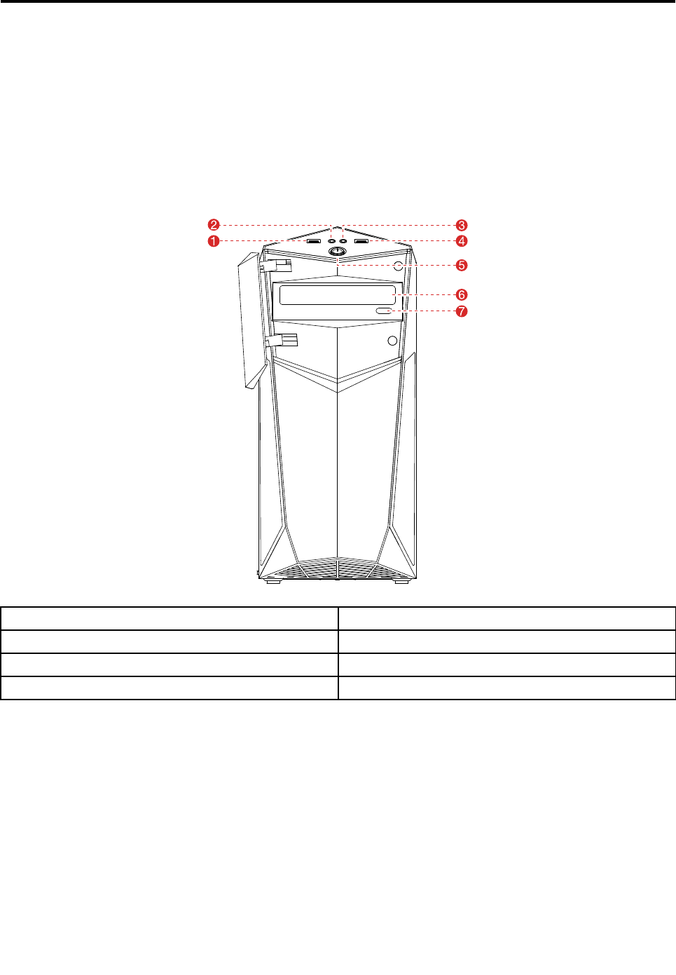
Fontview
Thefollowingillustrationshowsthelocationofcontrolsandcomponentsonthefrontofthecomputer.
Attention:Becarefulnottoblockanyairventsonthecomputer.Blockedairventscancauseoverheating.
1.USB3.0connector5.Powerbutton
2.Headphoneconnector6.Opticaldrive
3.Microphoneconnector7.Opticaldriveejectbutton
4.USB3.0connector
©CopyrightLenovo201721
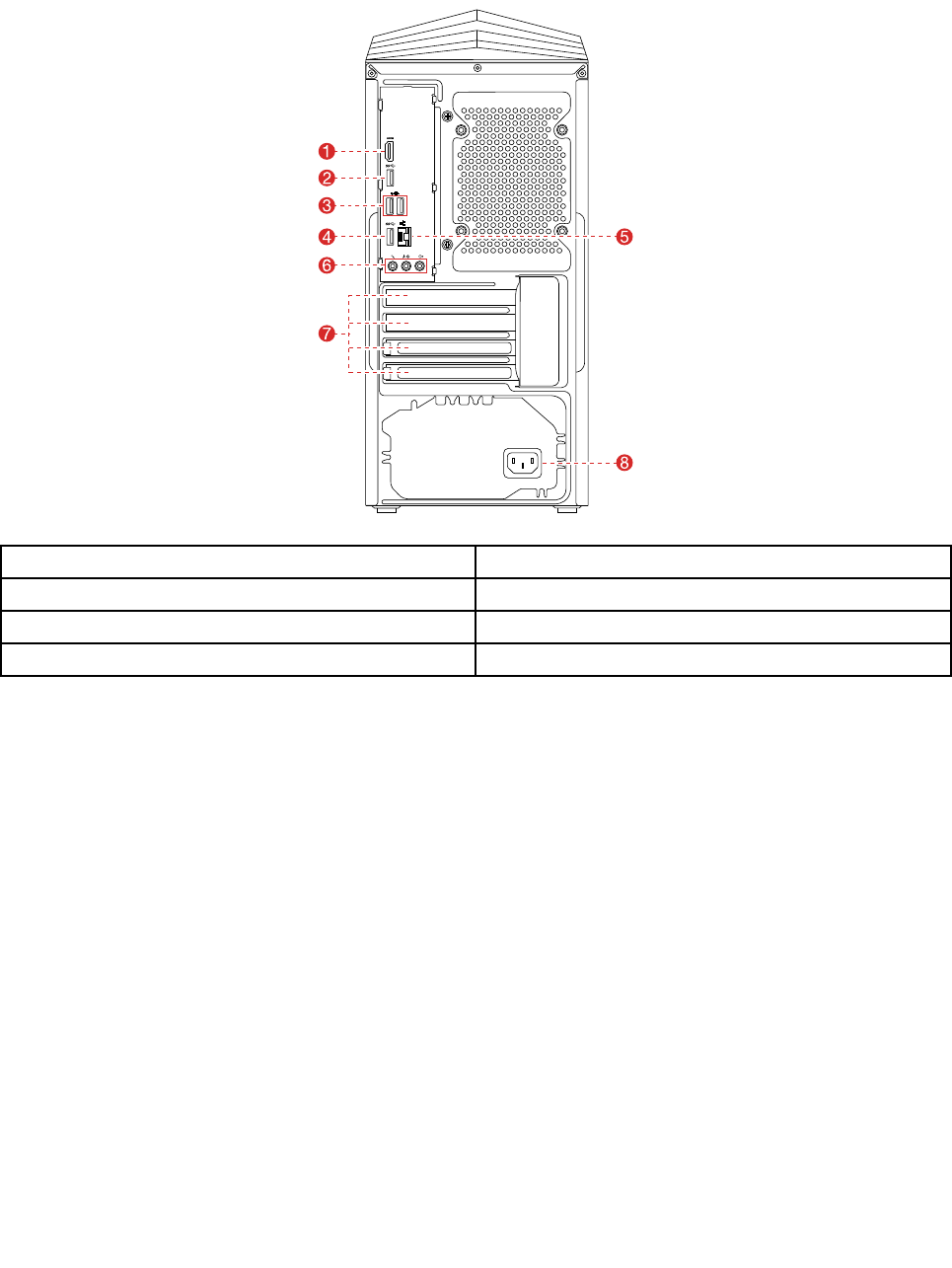
Rearview
Thefollowingillustrationsshowthelocationofconnectorsandcomponentsontherearofthe310series
computers.
1.HDMI-outconnector5.Ethernetconnector
2.USB3.0connector6.Audioconnectors
3.USB2.0connectors(2)7.PCI-Expresscardarea
4.USB3.0connector8.Powerconnector
22LenovoLegionY520TowerHardwareMaintenanceManual
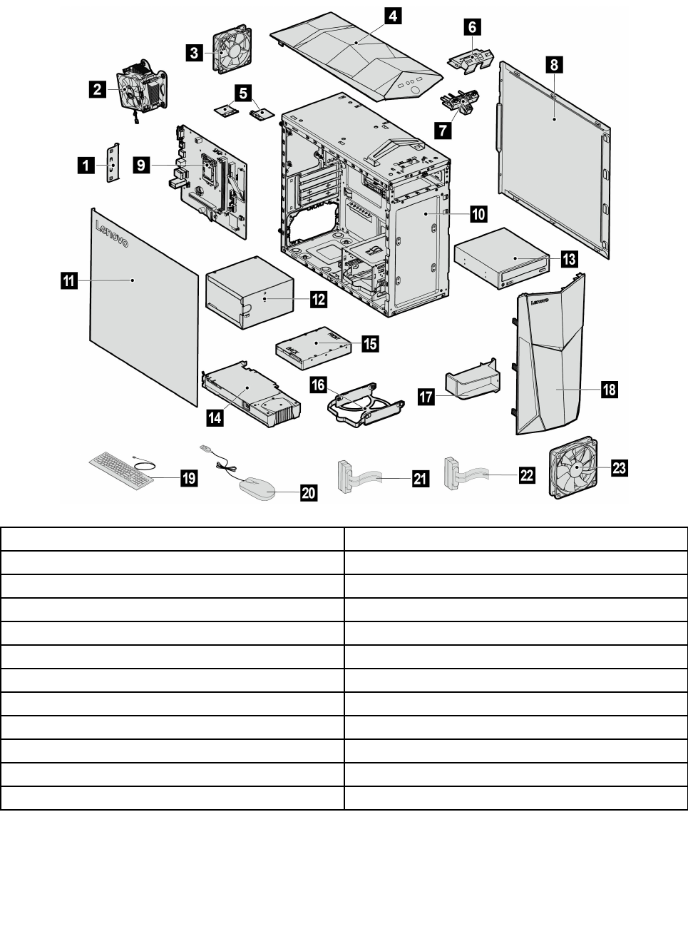
Hardwarecomponents
Thefollowingillustrationshowsthecomponentsthatmakeupyourcomputer.
1.PCIcover13.Opticaldrive
2.Microprocessorassembly14.Graphiccard
3.Rearfan15.Storagedrive
4.Topbezel16.Storagedrivebracket
5.Wi-Fiantennas(2)17.Graphiccardholder
6.FrontI/Obracket18.Topbezel
7.FrontI/Oassembly19.Keyboard
8.Rightcomputercover20.Mouse
9.Motherboard21SATAcable(forconnectingthestoragedrive)
10.Chassis22SATAcable(forconnectingtheopticaldrive)
11Leftcomputercover23Frontfan(optional)
12.Powersupplyunit
Identifyingpartsonthemotherboard
Themotherboard(sometimescalledtheplanarorsystemboard)isthemaincircuitboardinyourcomputer.
Itprovidesbasiccomputingfunctionsandsupportsavarietyofdevicesthatarefactory-installedorthat
Chapter7.Locatingconnectors,controlsandcomponents23
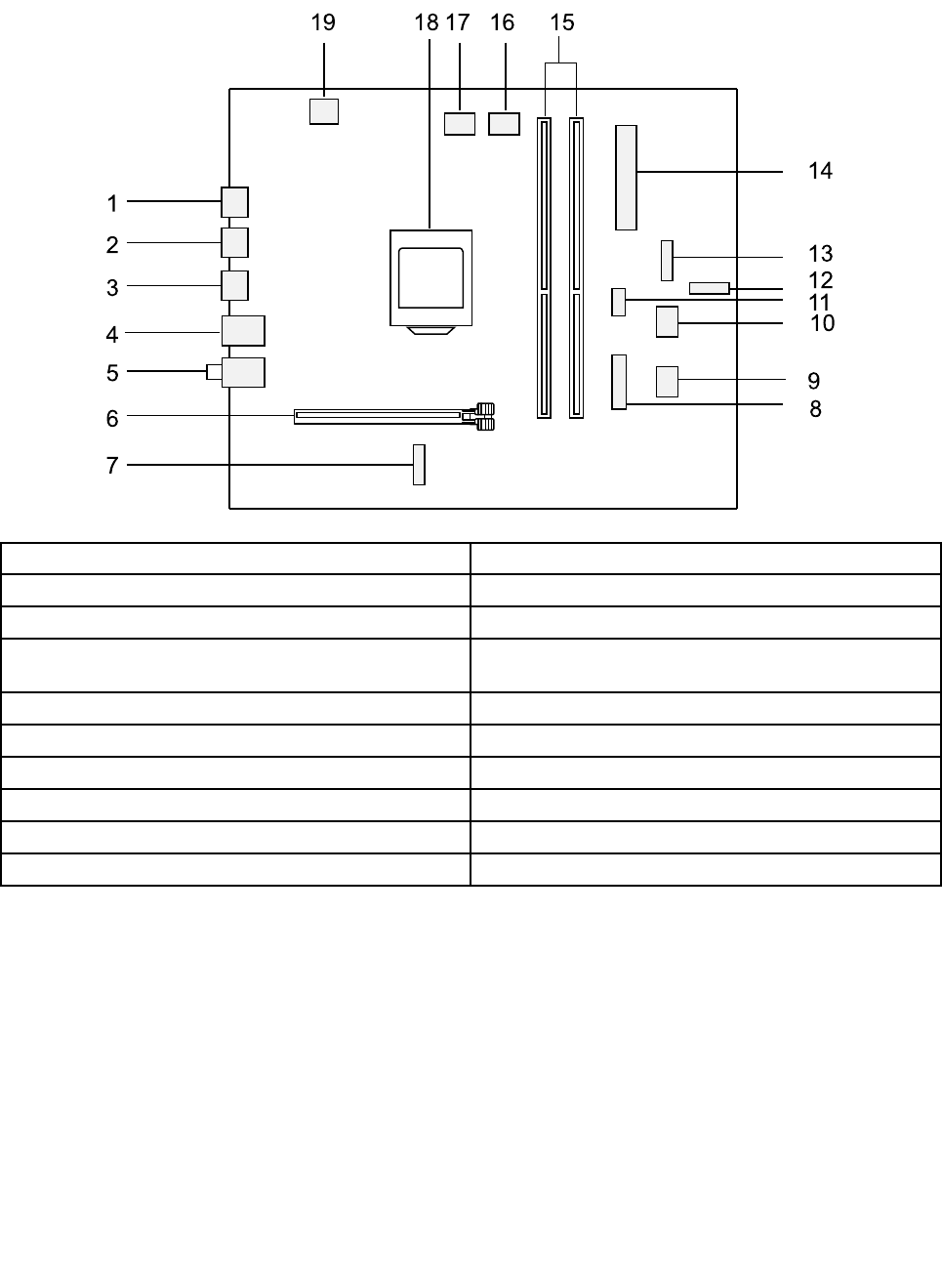
youcaninstalllater.Thefollowingillustrationshowsthelocationofconnectorsandcomponentsonthe
frontofthemotherboard.
1
2
4
5
6
11
9
10
12
13
14
15161719
8
7
3
18
1.HDMI-outconnector11.Frontfanconnector
2.USB3.0connector12.M.2SSDconnector
3.USB2.0connectors(2)13.Frontpanelconnector
4.USB3.0andEthernetconnectors14.24pinpowerconnectortoconnectthepowersupply
unit
5.Audioconnectors15.Memoryslots(2)
6.PCIexpressX16adapterslot16.Microprocessorfanconnector
7.M.2Wi-Ficardslot17.Rearfanconnector
8.FrontUSB3.0connector18.Microprocessorsocket
9.SATAconnector19.4pinconnectortoconnectthemicroprocessor
10.SATAconnector
24LenovoLegionY520TowerHardwareMaintenanceManual

Chapter8.Replacinghardware
Attention:Donotremovethecomputercoverorattemptanyrepairbeforereadingthe“Importantsafetyinformation”
intheSafetyandWarrantyGuidethatwasincludedwithyourcomputer.ToobtaincopiesoftheSafetyandWarranty
Guide,gototheSupportWebsiteat:http://consumersupport.lenovo.com.
Note:UseonlypartsprovidedbyLenovo.
Generalinformation
Pre-disassemblyinstructions
Beforeproceedingwiththedisassemblyprocedure,makesurethatyoudothefollowing:
1.Turnoffthepowertothesystemandallperipherals.
2.Unplugallpowerandsignalcablesfromthecomputer.
3.Placethesystemonaflat,stablesurface.
©CopyrightLenovo201725
Replacingthekeyboardandmouse
Toreplacethekeyboardandmouse
Step1.Removeanymedia(disks,CDs,DVDsormemorycards)fromthedrives,shutdowntheoperating
system,andturnoffthecomputerandallattacheddevices.
Step2.Unplugallpowercordsfromelectricaloutlets.
Step3.Disconnectallcablesattachedtothecomputer.Thisincludespowercords,input/output(I/O)
cables,andanyothercablesthatareconnectedtothecomputer.Referto“Leftandrightview”
and“Rearview”forhelpwithlocatingthevariousconnectors.
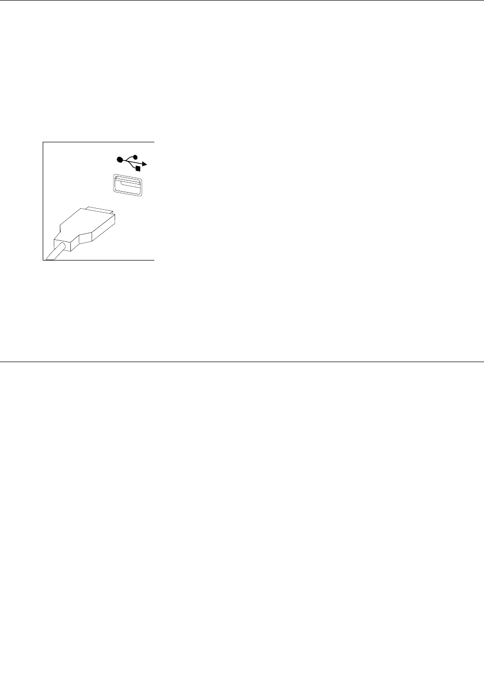
Note:YourkeyboardwillbeconnectedtoaUSBconnectorononesideorattherearofthe
computer.
Step4.Disconnectthedefectivekeyboardcablefromthecomputerandconnectthenewkeyboardcable
tothesameconnector.
Note:Themousecanbereplacedusingthesamemethod.
Removingthecomputercover
Attention:Turnoffthecomputerandwait3to5minutestoletitcooldownbeforeremovingthecover.
Note:Itmaybehelpfultoplacethecomputerface-downonasoftflatsurfaceforthisprocedure.Lenovo
recommendsthatyouuseablanket,towel,orothersoftclothtoprotectthecomputerscreenfromscratches
orotherdamage.
Toremovethecomputercover:
Step1.Removeanymedia(disks,CDs,DVDs,ormemorycards)fromthedrives,shutdowntheoperating
system,andturnoffthecomputerandallattacheddevices.
Step2.Unplugallpowercordsfromelectricaloutlets.
Step3.Disconnectallcablesattachedtothecomputer.Thisincludespowercords,input/output(I/O)
cables,andanyothercablesthatareconnectedtothecomputer.Referto“Leftandrightview”
and“Rearview”forhelpwithlocatingthevariousconnectors.
26LenovoLegionY520TowerHardwareMaintenanceManual
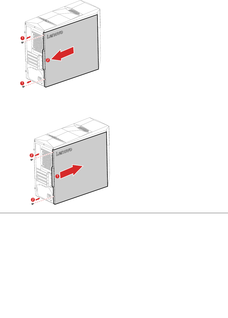
Step4.Removethe2screwsthatsecurethecomputercoverattherearofthechassis.
1
1
2
Step5.Toreinstallthecomputercover:
a.Lineupthecomputercoverwiththechassis,andthenslideitback.
b.Securethecomputercovertothechassiswiththescrews.
1
2
2
Removingthetopbezel
Attention:Turnoffthecomputerandwait3to5minutestoletitcooldownbeforeremovingthecover.
Note:Itmaybehelpfultoplacethecomputerface-downonasoftflatsurfaceforthisprocedure.Lenovo
recommendsthatyouuseablanket,towel,orothersoftclothtoprotectthecomputerscreenfromscratches
orotherdamage.
Toremovethetopbezel:
Step1.Removeanymediafromthedrives,shutdowntheoperatingsystem,andturnoffthecomputer
andallattacheddevices.
Step2.Unplugallpowercordsfromelectricaloutlets.
Chapter8.Replacinghardware27
Step3.Disconnectallcablesattachedtothecomputer.Thisincludespowercords,input/output(I/O)
cables,andanyothercablesthatareconnectedtothecomputer.RefertoLocatingconnectors,
controlsandcomponentstolocatethevariousconnectors.
Step4.Removethecomputercover.RefertoRemovingthecomputercover.
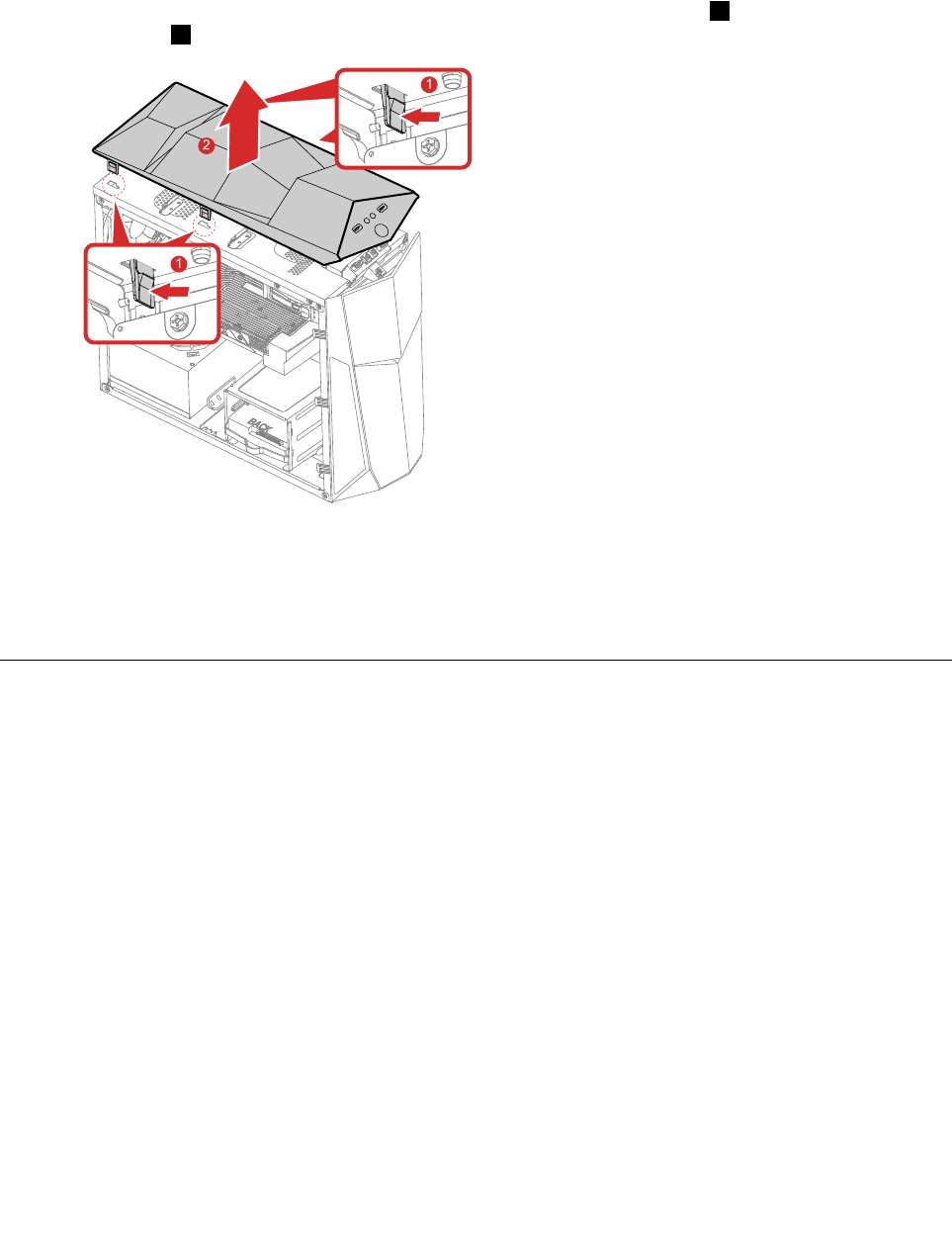
Step5.Pressandpushthefourplastictabsonthetopofthechassisoutward1,andthenremovethe
topbezel2.
1
1
2
Step6.Toreattachthetopbezel:
a.Insertthefourplastictabsintothecorrespondingholesonthetopofthechassisuntilthey
snapintoposition.
Step7.Reinstallalltheremovedparts,andthenreconnectthecables.
Removingthefrontbezel
Attention:Turnoffthecomputerandwait3to5minutestoletitcooldownbeforeremovingthecover.
Note:Itmaybehelpfultoplacethecomputerface-downonasoftflatsurfaceforthisprocedure.Lenovo
recommendsthatyouuseablanket,towel,orothersoftclothtoprotectthecomputerscreenfromscratches
orotherdamage.
Toremovethefrontbezel:
Step1.Removeanymediafromthedrives,shutdowntheoperatingsystem,andturnoffthecomputer
andallattacheddevices.
Step2.Unplugallpowercordsfromelectricaloutlets.
Step3.Disconnectallcablesattachedtothecomputer.Thisincludespowercords,input/output(I/O)
cables,andanyothercablesthatareconnectedtothecomputer.RefertoLocatingconnectors,
controlsandcomponentstolocatethevariousconnectors.
Step4.Removethecomputercover.RefertoRemovingthecomputercover.
28LenovoLegionY520TowerHardwareMaintenanceManual
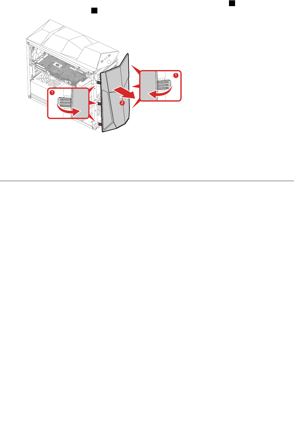
Step5.Releasethethreeplastictabsontheleftandrightsidesofthefrontbezel1,andthenpivot
thefrontbezeloutward2.
1
1
2
Step6.Toreattachthebezel:
a.Alignthethreeplastictabsonbothsidesofthefrontbezelwiththecorrespondingholesinthe
chassis.Then,pivotthefrontbezelinwarduntilitsnapsintoposition.
Step7.Reinstallalltheremovedparts,andthenreconnectthecables.
Replacingthepowersupplyassemby
Note:Forthisprocedure,ithelpstolaythecomputerflat.
Toreplacethepowersupplyassembly:
Step1.Removeanymediafromthedrives,shutdowntheoperatingsystem,andturnoffthecomputer
andallattacheddevices.
Step2.Unplugallpowercordsfromelectricaloutlets.
Step3.Disconnectallcablesattachedtothecomputer.Thisincludespowercords,input/output(I/O)
cables,andanyothercablesthatareconnectedtothecomputer.RefertoLocatingconnectors,
controlsandcomponentstolocatethevariousconnectors.
Step4.Removethecomputercover.RefertoRemovingthecomputercover.
Chapter8.Replacinghardware29
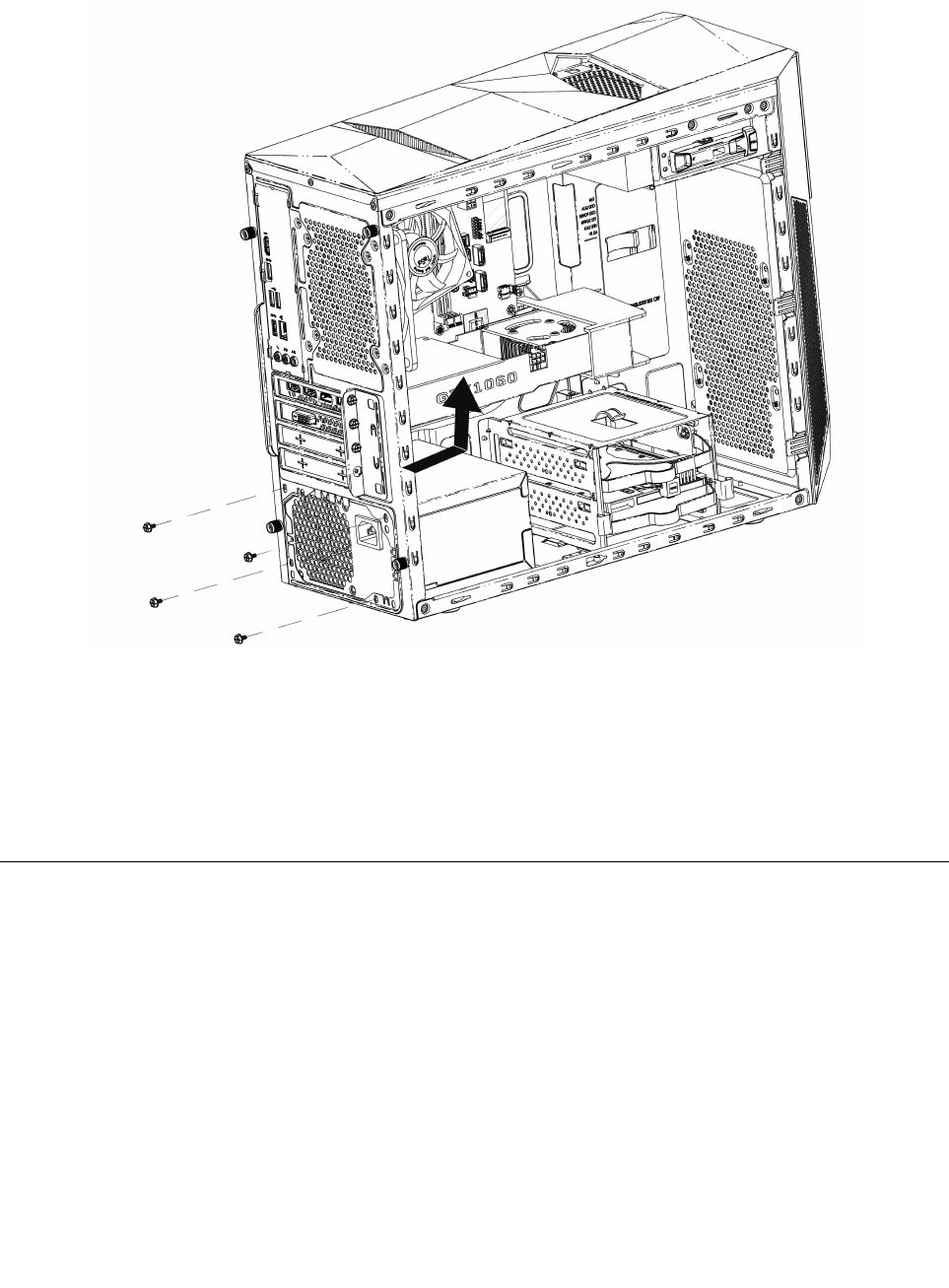
Step5.Removethefivescrewsthatsecurethepowersupplyassembly.
Step6.Slidethenliftthepowersupplyassemblyoutofthechassis.
Step7.Installthenewpowersupplyassembly:
a.Positionthenewpowersupplyassemblyinthechassissothatthefivescrewholesinthe
powersupplyassemblyalignwiththoseinthechassis.Then,installthefivescrewstosecure
thepowersupplyassembly.
b.Connectthepowersupplyassemblycablestotheconnectorsonthemotherboard.
Step8.Reattachthecomputercover.
Replacinganopticaldrive
Note:Forthisprocedure,ithelpstolaythecomputerflat.
Toreplaceanopticaldrive:
Step1.Removeanymediafromthedrives,shutdowntheoperatingsystem,andturnoffthecomputer
andallattacheddevices.
Step2.Unplugallpowercordsfromelectricaloutlets.
Step3.Disconnectallcablesattachedtothecomputer.Thisincludespowercords,input/output(I/O)
cables,andanyothercablesthatareconnectedtothecomputer.RefertoLocatingconnectors,
controlsandcomponentstolocatethevariousconnectors.
Step4.Removethecomputercover.RefertoRemovingthecomputercover.
30LenovoLegionY520TowerHardwareMaintenanceManual
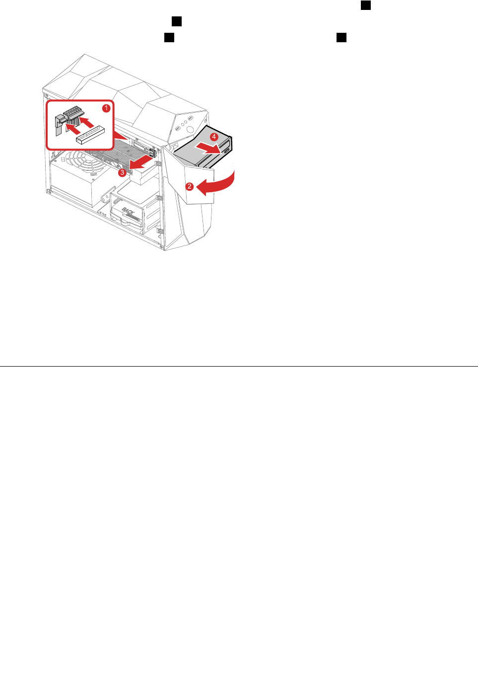
Step5.Disconnectthedataandpowercablesfromtherearoftheopticaldrive1.
Step6.Opentheopticaldrivecover2.
Step7.Opentheopticaldrivelock3,andthenpushtheopticaldriveout4.
1
2
3
4
Step8.Toinstallthenewopticaldrive:
a.Insertthenewopticaldriveintothechassis.
b.Closetheopticaldrivelocktosecurethenewopticaldrivetothechassis.
c.Connectthedataandpowercablestothenewopticaldrive.
d.Closetheopticaldrivecover.
Step9.Reinstallalltheremovedparts.
ReplacingtheM.2storagedrive
Note:Forthisprocedure,ithelpstolaythecomputerflat.
ToreplacetheM.2storagedrive:
Step1.Removeanymediafromthedrives,shutdowntheoperatingsystem,andturnoffthecomputer
andallattacheddevices.
Step2.Unplugallpowercordsfromelectricaloutlets.
Step3.Disconnectallcablesattachedtothecomputer.Thisincludespowercords,input/output(I/O)
cables,andanyothercablesthatareconnectedtothecomputer.RefertoLocatingconnectors,
controlsandcomponentstolocatethevariousconnectors.
Step4.Removethecomputercover.RefertoRemovingthecomputercover.
Chapter8.Replacinghardware31
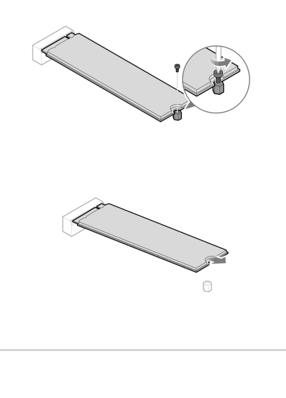
Step5.RemovethescrewthatsecurestheM.2storagedrivetothemotherboard.
Step6.PulltheM.2storagedriveout.
Step7.ToinstallthenewM.2storagedrive:
a.InsertthenewM.2storagedriveintotheM.2slot.
b.SecurethenewM.2storagedrivetothemotherboardwithonescrew.
Step8.Reinstallalltheremovedparts,andthenreconnectthecables.
Replacingthe3.5-inchstoragedrive
Note:Forthisprocedure,ithelpstolaythecomputerflat.
32LenovoLegionY520TowerHardwareMaintenanceManual
Toreplacethe3.5-inchstoragedrive:
Step1.Removeanymediafromthedrives,shutdowntheoperatingsystem,andturnoffthecomputer
andallattacheddevices.
Step2.Unplugallpowercordsfromelectricaloutlets.
Step3.Disconnectallcablesattachedtothecomputer.Thisincludespowercords,input/output(I/O)
cables,andanyothercablesthatareconnectedtothecomputer.RefertoLocatingconnectors,
controlsandcomponentstolocatethevariousconnectors.
Step4.Removethecomputercover.RefertoRemovingthecomputercover.
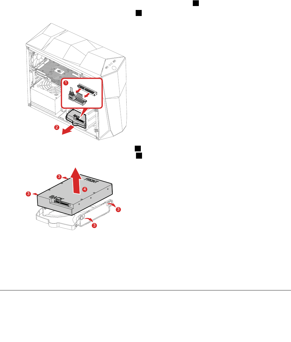
Step5.Disconnectthedataandpowercablesfromthestoragedrive1.
Step6.Pullthestoragedriveassemblyoutward2.
1
2
Step7.Bendthestoragedrivebracketoutward3,andthenliftthe3.5-inchstoragedriveupwardto
removeitfromthestoragedrivebracket4.
3
3
3
3
4
Step8.Toinstallthenew3.5-inchstoragedrive:
a.Putthenew3.5-inchstoragedriveintothestoragedrivebracket.
b.Pushthenew3.5-inchstoragedriveassemblyintothedrivebayuntilitsnapsintoposition.
c.Connectthepoweranddatacablestothe3.5-inchstoragedrive.
Step9.Reinstallalltheremovedparts,andthenreconnectthecables.
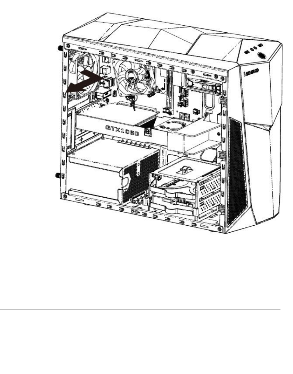
Replacingthegraphiccard
Toreplacethegraphiccard:
Chapter8.Replacinghardware33
Step1.Removeanymediafromthedrives,shutdowntheoperatingsystem,andturnoffthecomputer
andallattacheddevices.
Step2.Unplugallpowercordsfromelectricaloutlets.
Step3.Disconnectallcablesattachedtothecomputer.Thisincludespowercords,input/output(I/O)
cables,andanyothercablesthatareconnectedtothecomputer.RefertoLocatingconnectors,
controlsandcomponentstolocatethevariousconnectors.
Step4.Removethecomputercover.RefertoRemovingthecomputercover.
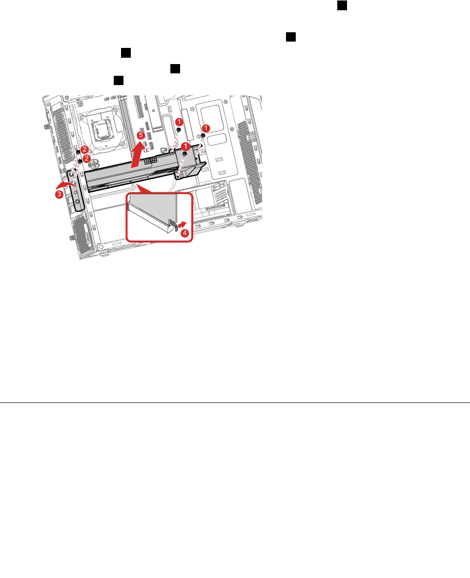
Step5.Removethescrewsthatsecuregraphiccardbrackettothechassis1.
Step6.Removethegraphiccardbracket.
Step7.Removethescrewsthatsecurethelatchtothechassis2.
Step8.Removethelatch3.
Step9.Pressthecardretaininglatch4asshowntodisengagethelatch.Graspthecardandgentlypull
itoutoftheslot5.
1
1
2
2
3
4
5
1
Step10.Toinstallthenewgraphiccard:
a.Insertthenewgraphiccardtothegraphiccardbracket.
b.Insertthenewgraphiccardandbracketassemblyintothegraphiccardslotonthe
motherboard.
c.Pivotthecardretaininglatchtotheclosedposition.
d.Securethegraphiccardbrackettothechassiswithscrews.
e.Installthelatchtotherightpositionandsecureittothechassiswithscrews.
Step11.Reinstallalltheremovedparts,andthenreconnectthecables.
Replacingamemorymodule
Note:Forthisprocedure,ithelpstolaythecomputerflat.
Toreplaceamemorymodule:
Step1.Removeanymediafromthedrives,shutdowntheoperatingsystem,andturnoffthecomputer
andallattacheddevices.
Step2.Unplugallpowercordsfromelectricaloutlets.
34LenovoLegionY520TowerHardwareMaintenanceManual
Step3.Disconnectallcablesattachedtothecomputer.Thisincludespowercords,input/output(I/O)
cables,andanyothercablesthatareconnectedtothecomputer.RefertoLocatingconnectors,
controlsandcomponentstolocatethevariousconnectors.
Step4.Removethecomputercover.RefertoRemovingthecomputercover.
Step5.Locatethememorymoduleconnectors.RefertoLocatingconnectors,controlsandcomponents.
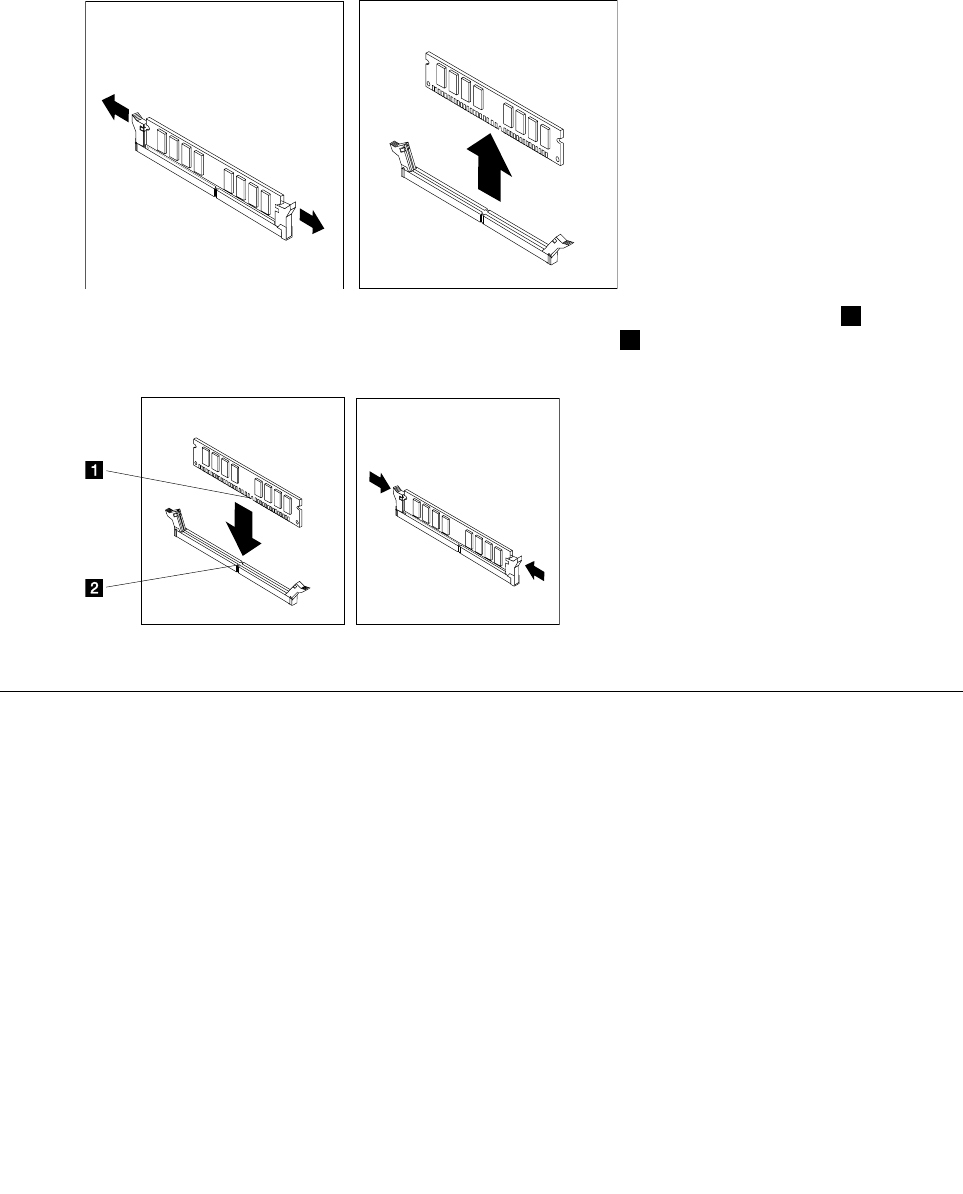
Step6.Removethememorymodulebeingreplacedbyopeningtheretainingclipsasshown.
Step7.Positionthenewmemorymoduleoverthememoryconnector.Makesurethenotch1onthe
memorymoduleiscorrectlyalignedwiththeconnectorkey2onthesystemboard.Pushthe
memorymodulestraightdownintotheconnectoruntiltheretainingclipsclose.
Step8.Reinstallalltheremovedparts,andthenreconnectthecables.
ReplacingtheWi-Ficard
Note:Forthisprocedure,ithelpstolaythecomputerflat.
ToreplacetheWi-Ficard:
Step1.Removeanymediafromthedrives,shutdowntheoperatingsystem,andturnoffthecomputer
andallattacheddevices.
Step2.Unplugallpowercordsfromelectricaloutlets.
Step3.Disconnectallcablesattachedtothecomputer.Thisincludespowercords,input/output(I/O)
cables,andanyothercablesthatareconnectedtothecomputer.RefertoLocatingconnectors,
controlsandcomponentstolocatethevariousconnectors.
Step4.Removethecomputercover.RefertoRemovingthecomputercover.
Chapter8.Replacinghardware35
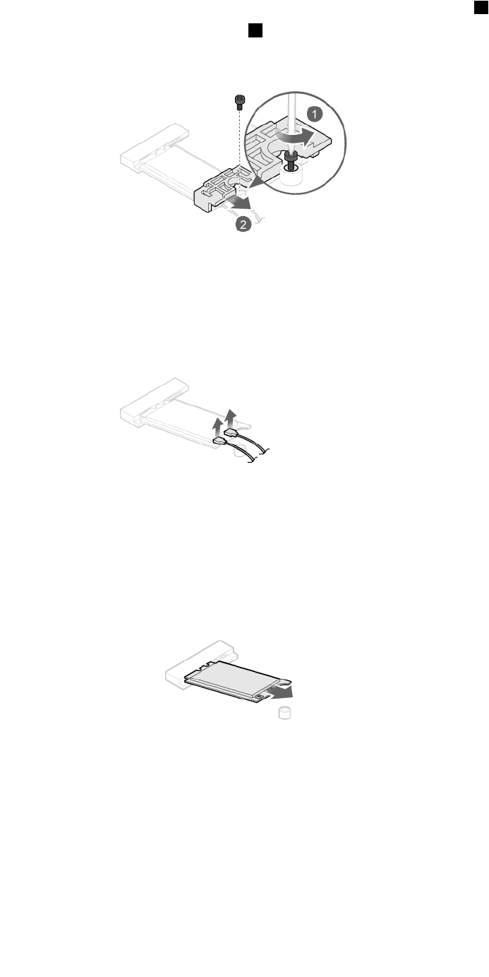
Step5.RemovethescrewthatsecuretheWi-Ficardtothemotherboard1.
Step6.RemovetheWi-Ficardcover2.
Step7.Disconnectthe2antennacablesfromtheWi-Ficard.
Step8.PulltheWi-Ficardoutfromtheslot.
Step9.InstallthenewWi-Ficard:
a.LineupthenewWi-Ficard,andtheninsertitintothesamecardslot.
b.Connectthe2antennacablestothenewWi-Ficard.
c.SecuretheWi-Ficardtothemotherboardwithonescrew.
Step10.Reinstallalltheremovedparts,andthenreconnectthecables.
36LenovoLegionY520TowerHardwareMaintenanceManual
ReplacingtheWi-Fiantenna
Note:Forthisprocedure,ithelpstolaythecomputerflat.
ToreplacetheWi-Fiantenna:
Step1.Removeanymediafromthedrives,shutdowntheoperatingsystem,andturnoffthecomputer
andallattacheddevices.
Step2.Unplugallpowercordsfromelectricaloutlets.
Step3.Disconnectallcablesattachedtothecomputer.Thisincludespowercords,input/output(I/O)
cables,andanyothercablesthatareconnectedtothecomputer.RefertoLocatingconnectors,
controlsandcomponentstolocatethevariousconnectors.
Step4.Removethecomputercover.RefertoRemovingthecomputercover.
Step5.Removethetopbezel.RefertoRemovingthetopbezel.
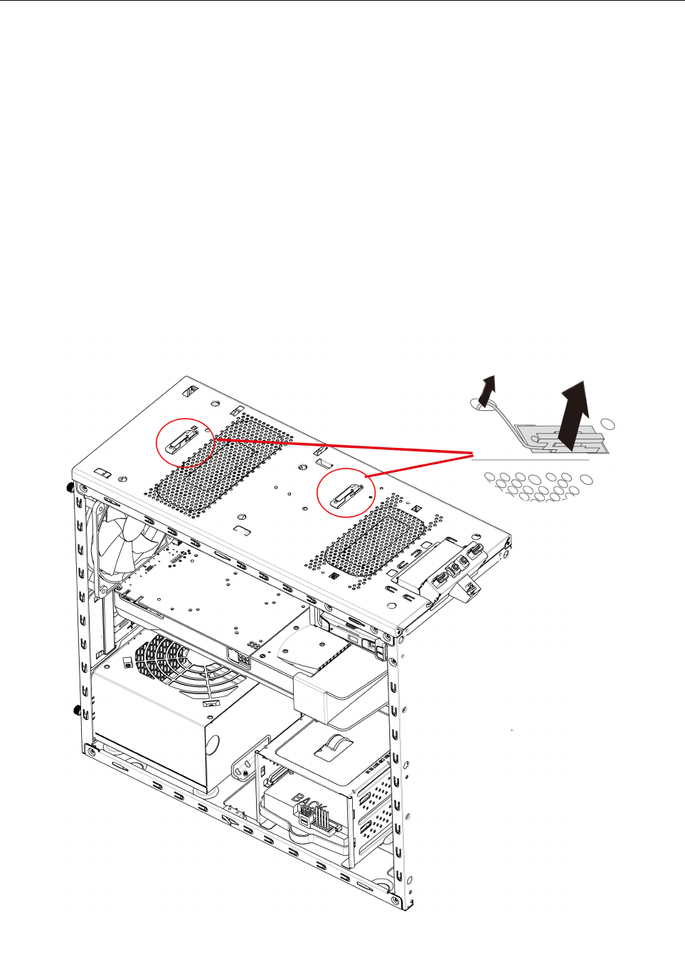
Step6.DisconnecttheWi-FiantennacablesfromtheWi-Ficard.
Step7.PeelofftheWi-Fiantennafromthetoppanel,andthenremoveitfromthechassis.
Chapter8.Replacinghardware37
Step8.InstallthenewWi-Fiantenna:
a.PeeloffthereleasepaperontheadhesivesurfaceofthenewWi-Fiantenna.
b.RoutethenewWi-Fiantennacablethroughthecorrespondinghole,andthenstickthenew
Wi-Fiantennatothetoppanel.
c.ConnectthenewWi-FiantennacablestotheWi-Ficard.
Step9.Reinstallalltheremovedparts,andthenreconnectthecables.
Replacingtheheat-sinkandfanassembly
Note:Forthisprocedure,ithelpstolaythecomputerflat.
Toreplacetheheat-sinkandfanassembly:
Step1.Removeanymediafromthedrives,shutdowntheoperatingsystem,andturnoffthecomputer
andallattacheddevices.
Step2.Unplugallpowercordsfromelectricaloutlets.
Step3.Disconnectallcablesattachedtothecomputer.Thisincludespowercords,input/output(I/O)
cables,andanyothercablesthatareconnectedtothecomputer.RefertoLocatingconnectors,
controlsandcomponentstolocatethevariousconnectors.
Step4.Removethecomputercover.RefertoRemovingthecomputercover.
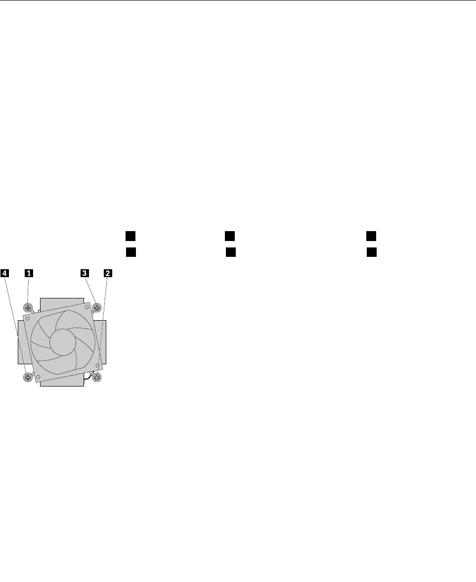
Step5.Disconnecttheheatsinkandfanassemblycablefromthemicroprocessorfanconnectoron
themotherboard.
Loosenthefourscrewsthatsecuretheheatsinkandfanassemblytothemotherboardinthefollowing
sequence:
•a.Partiallyremovescrew1,fullyremovescrew2,andthenfullyremovescrew1.
•b.Partiallyremovescrew3,fullyremovescrew4,andthenfullyremovescrew3.
Step6.Liftthefailingheatsinkandfanassemblyoffthemotherboard.
Note:Donottouchthethermalgreasewhilehandlingtheheatsinkandfanassembly.
Step7.Toinstallthenewheat-sinkassembly:
a.Positionthenewheatsinkandfanassemblyonthemotherboardsothatthefourscrewsare
alignedwiththeholesinthemotherboard.Ensurethattheheatsinkandfanassemblycable
facestowardthemicroprocessorfanconnectoronthemotherboard.
b.Tightenthefourscrewstosecurethenewheatsinkandfanassembly.
c.Connecttheheatsinkandfanassemblycabletothemicroprocessorfanconnectoronthe
motherboard.
38LenovoLegionY520TowerHardwareMaintenanceManual
Step8.Reinstallalltheremovedparts,andthenreconnectthecables.
Replacingthemicroprocessor
Note:Forthisprocedure,ithelpstolaythecomputerflat.
Toreplacethemicroprocessor
Step1.Removeanymediafromthedrives,shutdowntheoperatingsystem,andturnoffthecomputer
andallattacheddevices.
Step2.Unplugallpowercordsfromelectricaloutlets.
Step3.Disconnectallcablesattachedtothecomputer.Thisincludespowercords,input/output(I/O)
cables,andanyothercablesthatareconnectedtothecomputer.RefertoLocatingconnectors,
controlsandcomponentstolocatethevariousconnectors.
Step4.Removethecomputercover.RefertoRemovingthecomputercover.
Step5.Removetheheat-sinkandfanassembly.RefertoReplacingtheheat-sinkandfanassembly.
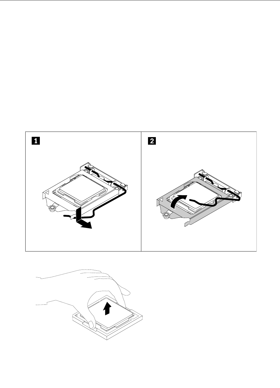
Step6.Pressthesmallhandledownwardtoreleaseitfromtheretainer,andthenopentheretainerto
accessthemicroprocessor.
Step7.Liftthemicroprocessorstraightupandoutofthemicroprocessorsocket.
Note:
a.Yourmicroprocessorandsocketmightlookdifferentfromtheoneillustrated.
Chapter8.Replacinghardware39
b.Touchonlytheedgesofthemicroprocessor.Donottouchthegoldcontactsonthebottom.
c.Donotdropanythingontothemicroprocessorsocketwhileitisexposed.Thesocketpins
mustbekeptascleanaspossible.
Step8.Ensurethatthesmallhandleisintheraisedpositionandthemicroprocessorretainerisfullyopen.
Step9.Removetheprotectivecoverthatprotectsthegoldcontactsofthenewmicroprocessor.
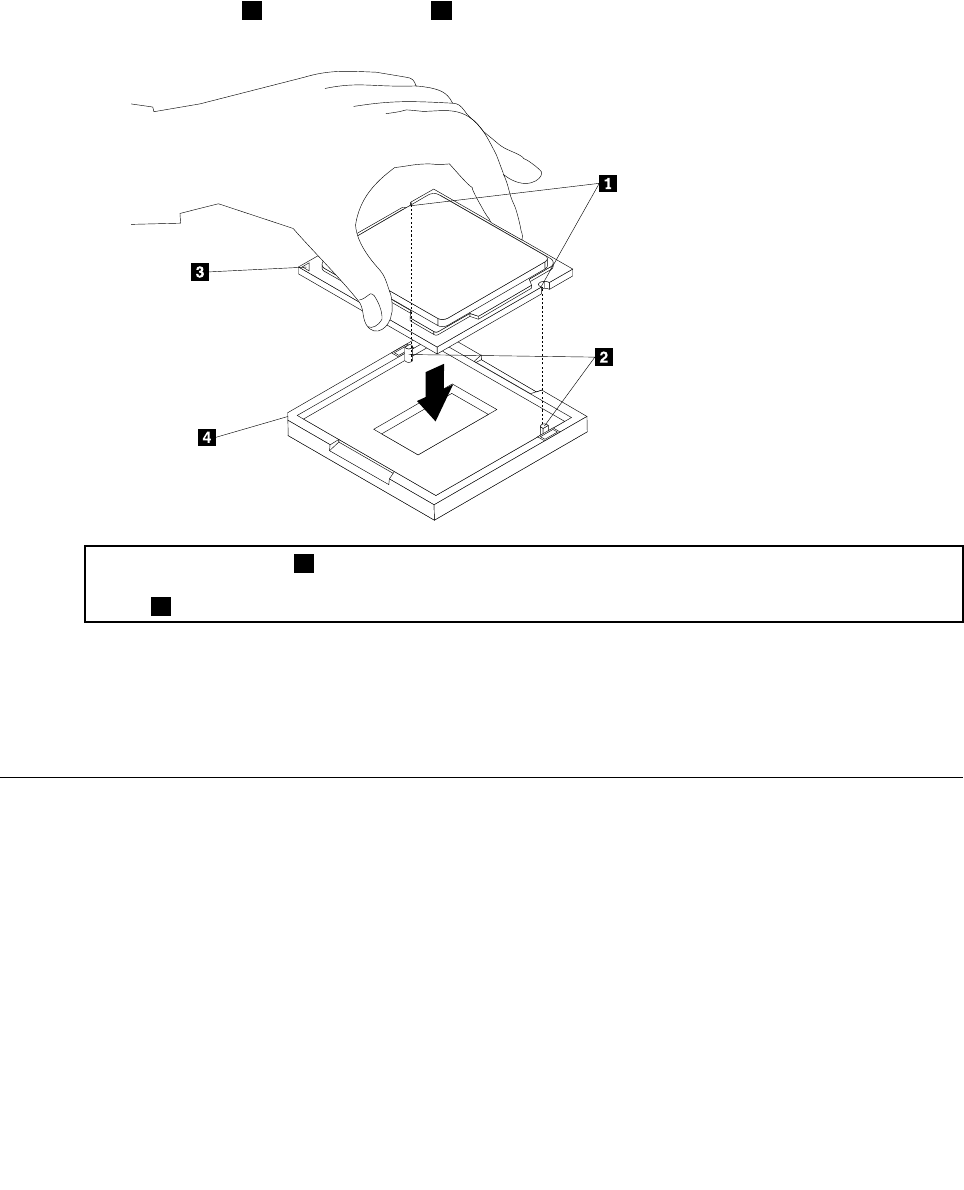
Step10.Notetheorientationofthenewmicroprocessor.Holdthenewmicroprocessorbyitsedgesand
alignthenotches1onitwiththetabs2inthemicroprocessorsocket.Then,carefullylowerthe
newmicroprocessorstraightdownintothemicroprocessorsocket.
Note:Thesmalltriangle3ononecornerofthenewmicroprocessoristhemicroprocessororientation
indicator.Thenewmicroprocessorisinthecorrectorientationwhenthisindicatorpointstothebeveled
corner4ofthemicroprocessorsocket.
Step11.Closethemicroprocessorretainerandlockitintopositionwiththesmallhandletosecurethe
newmicroprocessorinthesocket.
Step12.Reinstalltheheatsinkandfanassembly.
Step13.Reinstallalltheremovedparts,andthenreconnectthecables.
Replacingthefrontfan
Toreplacethefrontfan(optional):
Step1.Removeanymediafromthedrives,shutdowntheoperatingsystem,andturnoffthecomputer
andallattacheddevices.
Step2.Unplugallpowercordsfromelectricaloutlets.
Step3.Disconnectallcablesattachedtothecomputer.Thisincludespowercords,input/output(I/O)
cables,andanyothercablesthatareconnectedtothecomputer.RefertoLocatingconnectors,
controlsandcomponentstolocatethevariousconnectors.
Step4.Removethecomputercover.RefertoRemovingthecomputercover.
Step5.Removethefrontbezel.RefertoRemovingthefrontbezel.
40LenovoLegionY520TowerHardwareMaintenanceManual
Step6.Disconnectthefrontfanpowercablefromthecorrespondingconnectoronthemotherboard.
Step7.Thesystemfanisconnectedtothechassisbyfourrubbermounts.Breakorcuttherubbermounts
andgentlypullthesystemfanoutofthechassis.
Step8.Toinstallthenewsystemfan:
a.Ontheoutsideofthefrontpanel,pushthefourrubbermountsonthenewsystemfanthrough
thecorrespondingholesinthechassis.
b.Ontheinsideofthefrontpanel,pullthetipsoftherubbermountsuntilthesystemfanis
securedinplace.
c.Connectthefanpowercabletothecorrespondingconnectoronthemotherboard.
Step9.Reinstallalltheremovedparts,andthenreconnectthecables.
Replacingtherearfan
Toreplacetherearfan:
Step1.Removeanymediafromthedrives,shutdowntheoperatingsystem,andturnoffthecomputer
andallattacheddevices.
Step2.Unplugallpowercordsfromelectricaloutlets.
Step3.Disconnectallcablesattachedtothecomputer.Thisincludespowercords,input/output(I/O)
cables,andanyothercablesthatareconnectedtothecomputer.RefertoLocatingconnectors,
controlsandcomponentstolocatethevariousconnectors.
Step4.Removethecomputercover.RefertoRemovingthecomputercover.
Chapter8.Replacinghardware41
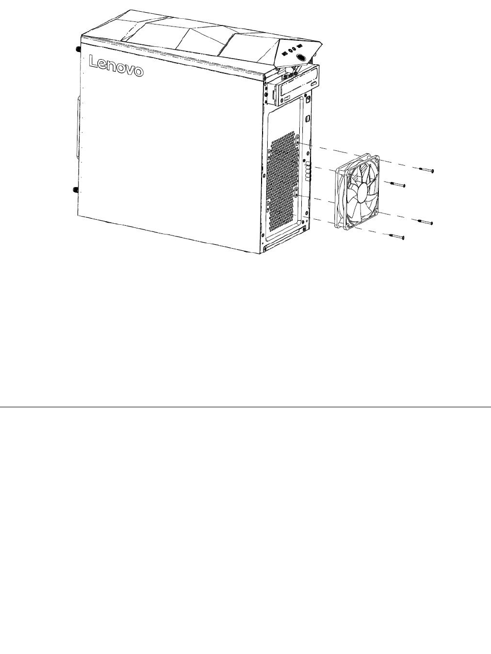
Step5.Disconnecttherearfanpowercablefromthecorrespondingconnectoronthemotherboard.
Step6.Therearfanisconnectedtothechassisbyfourrubbermounts.Breakorcuttherubbermounts
andgentlypullthesystemfanoutofthechassis.
Step7.Toinstallthenewrearfan:
a.Ontheinsideoftherearpanel,pushthefourrubbermountsonthenewrearfanthroughthe
correspondingholesinthechassis.
b.Ontheoutsideoftherearpanel,pullthetipsoftherubbermountsuntiltherearfanissecured
inplace.
c.Connectthefanpowercabletothecorrespondingconnectoronthemotherboard.
Step8.Reinstallalltheremovedparts,andthenreconnectthecables.
Replacingthemotherboard
Note:Forthisprocedure,ithelpstolaythecomputerflat.
Toreplacethemotherboard:
42LenovoLegionY520TowerHardwareMaintenanceManual
Step1.Removeanymediafromthedrives,shutdowntheoperatingsystem,andturnoffthecomputer
andallattacheddevices.
Step2.Unplugallpowercordsfromelectricaloutlets.
Step3.Disconnectallcablesattachedtothecomputer.Thisincludespowercords,input/output(I/O)
cables,andanyothercablesthatareconnectedtothecomputer.RefertoLocatingconnectors,
controlsandcomponentstolocatethevariousconnectors.
Step4.Removethecomputercover.RefertoRemovingthecomputercover.
Step5.Removethefrontbezel.RefertoRemovingthefrontbezel.
Step6.Pivotthedrivebayassemblyupward.
Step7.Removethememorymodule.RefertoReplacingamemorymodule.
Step8.Removetheheat-sinkassembly.RefertoReplacingtheheat-sinkandfanassembly.
Step9.RemovetheCPU.RefertoReplacingthemicroprocessor.
Step10.Removethegraphiccard.RefertoReplacingthegraphiccard.
Step11.RemovetheWi-Ficard.RefertoReplacingtheWi-Ficard.
Step12.Removethefrontfan.RefertoReplacingthefrontfan.
Step13.Removetherearfan.RefertoReplacingtherearfan.
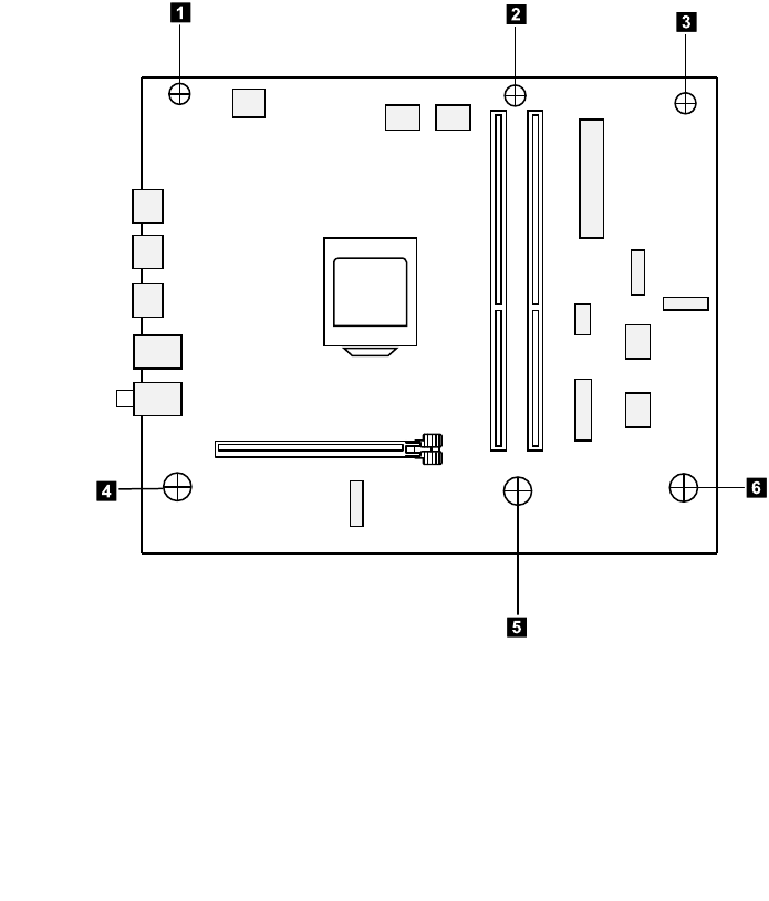
Step14.Disconnecttheallcablesfromtheconnectorsonmotherboard.
Step15.Removethesixscrewsthatsecurethemotherboardtothechassis.
123
4
5
6
Step16.Liftupthemotherboardtoremoveit.
Step17.Installthenewmotherboard:
a.Lineuptheholesonthenewmotherboardwiththemountingholesonthechassisand
secureitwithsixscrews.
Step18.Reinstallalltheremovedparts,andthenreconnectthecables.
Chapter8.Replacinghardware43

44LenovoLegionY520TowerHardwareMaintenanceManual

Chapter9.FRUlists
Thischapterliststheinformationonthefieldreplaceableunits(FRUs)forLenovoLegionY520Tower
seriescomputers.
Attention:BesuretoreadandunderstandallthesafetyinformationbeforereplacinganyFRUs.
FruP/NDescription
ANTENNA
00XJ106DT-Y520ANTENNA
BDPLANAR
00XK269Y520TMBFRUB250TWWINDPK
00XK268Y520TMBFRUB250TWNODPK
CABLE
00XL317FIOCable
00XL320C.A.SATA_HDD_TO_MB_LDF1
00XL319C.A.SATA_ODD_TO_MB_LDF1
DT_KYB
00XH633USBCalliopeKBBKNORDIC
00XH604USBCalliopeKBBKHBW
00XH605USBCalliopeKBBKHUN
00XH607USBCalliopeKBBKITA
00XH598USBCalliopeKBBKFRA
00XH602USBCalliopeKBBKGRE
00XH601USBCalliopeKBBKGER
00XH627USBCalliopeKBBKSLV
00XH626USBCalliopeKBBKEUROENG
00XH610USBCalliopeKBBKKOR
00XH608USBCalliopeKBBKJPN
00XH621USBCalliopeKBBKSWS
00XH622USBCalliopeKBBKTHAI
00XH630USBCalliopeKBBKINDENG
00XH618USBCalliopeKBBKSLK
00XH625USBCalliopeKBBKUKE
00XH619USBCalliopeKBBKSPA
00XH624USBCalliopeKBBKTUR
00XH611USB,Calliope,KB,BK,LASPA
00XH993USBCalliopeKBBKCZE/SLK
00XH594USBCalliopeKBBKTC/ENG
00XH614USBCalliopeKBBKPOR
©CopyrightLenovo201745

00XH595USBCalliopeKBBKCZE
00XH593USBCalliopeKBBKBUL
00XH591USB,Calliope,KB,BK,BELENG
00XH616USBCalliopeKBBKRUS
00XH587USBCalliopeKBBKENG
00XH588USBCalliopeKBBKARA
00XH635USBCalliopeKBBKCANENG/FRA
FAN
01MN067FrontFanWLEDforY520
00XD157FrontSystemFan
HDD_ASM
45K0623HDD,1TB,7200,DT3,SATA3,STD
45K0625HDD,2TB,7200,DT3,SATA3,STD
00PC551HDD,1TB,7200,DT3,SATA3,STD
00PC552HDD,2TB,7200,DT3,SATA3,STD
HEATSINK
01MN069LGA115XCPUCooler
LINECORD
00XL006Fru,US/CA,1.8M,3P ,NON-LH
00XL014Fru,EU/KR,1.8M,3P ,NON-LH
00XL038Fru,LINECORD,ZA,1.8M,3P ,NON-LH
00XL018Fru,LINECORD,TW,1.8M,3P ,NON-LH
00XL000Fru,JP ,Anti- TR,1.8M,3P ,NON-LH
00XL026Fru,LINECORD,IL,1.8M,3P ,NON-LH
00XL049Fru,LINECORD,IT,1.8M,3P ,NON-LH
00XL009Fru,LINECORD,CN,1.8M,3P ,NON-LH
00XL029Fru,LINECORD,CH,1.8M,3P ,NON-LH
00XL028Fru,LINECORD,IL,1.8M,3P ,NON-LH
00XL044Fru,LINECORD,DK,1.8M,3P ,NON-LH
00XL043Fru,LINECORD,AU,1.8M,3P ,NON-LH
00XL041Fru,LINECORD,AU,1.8M,3P ,NON-LH
00XL016Fru,EU/KR,1.8M,3P ,NON-LH
00XL004Fru,US/CA,1.8M,3P ,NON-LH
00XL040Fru,LINECORD,ZA,1.8M,3P ,NON-LH
00XL047Fru,LINECORD,IT,1.8M,3P ,NON-LH
00XL031Fru,LINECORD,CH,1.8M,3P ,NON-LH
00XL050Fru,LINECORD,TH,1.8M,3P ,NON-LH
00XL048Fru,LINECORD,IT,1.8M,3P ,NON-LH
00XL023Fru,LINECORD,GB,1.8M,3P ,NON-LH
00XL019Fru,LINECORD,TW,1.8M,3P ,NON-LH
46LenovoLegionY520TowerHardwareMaintenanceManual

00XL024Fru,LINECORD,GB,1.8M,3P ,NON-LH
00XL025Fru,LINECORD,GB,1.8M,3P ,NON-LH
00XL039Fru,LINECORD,ZA,1.8M,3P ,NON-LH
00XL046Fru,LINECORD,DK,1.8M,3P ,NON-LH
00XL001Fru,JP ,Anti- TR,1.8M,3P ,NON-LH
00XL010Fru,LINECORD,CN,1.8M,3P ,NON-LH
00XL015Fru,EU/KR,1.8M,3P ,NON-LH
00XL030Fru,LINECORD,CH,1.8M,3P ,NON-LH
00XL017Fru,LINECORD,TW,1.8M,3P ,NON-LH
00XL005Fru,US/CA,1.8M,3P ,NON-LH
00XL027Fru,LINECORD,IL,1.8M,3P ,NON-LH
00XL042Fru,LINECORD,AU,1.8M,3P ,NON-LH
00XL045Fru,LINECORD,DK,1.8M,3P ,NON-LH
MECH_ASM
01MN117ASSY_COVER_TOP_IO_LDF1_25L
01MN118ASSY_REAR_IO_SHIELDING_LDF1_25L
00XD328HDMI_COVERKit
01MN119ASSY_3.5HDD_TRAY_LDF1_25L
01MN111ASSY_BRKT_MAIN_LDF1_25L_Chassis
01MN116ASSY_FRONT_BEZEL_LDF1_25L
MECHANICAL
01MN293SCRW_#6_32_L29WZS
01MN140BRKT_SIDE_COVER_L_LDF1_25L
01MN137BRKT_PCI_COVER_LDF1_25L
01MN139BRKT_SIDE_COVER_L_LDF1_25L
01MN260FRUIOshieldMylarw/Oculus
01MN132HLDR_VGA_LDF1_25L
01MN122BRKT_ODD_DUMMY_LDF1_25L
01MN128WIFIlockbracketA5000
01MN123ODDDUMMYCOVER_LDF1_25L
01MN138CABLETIEYJ-295
MEMORY
01AG8058GBDDR42400UDIMM
01AG8158GBDDR42666UDIMM,MICRON
01AG8218GBDDR42666UDIMM,Ramaxel
MOUSE
00PH133USBCalliopeMouseBK
OPT_DRIVE
71Y5545SMD,DT,SATA,H/H,x16
PWR_SUPPLY
Chapter9.FRUlists47

00PC751200-240Vac,multiatx400WPSU
54Y8985100-240Vac,Y710280WESPSU
54Y8930PWR_SUPPLY,100-240Vac,450W
SCREW
01MN134TAPFLATM5*10LNI
01MN164MANUAL-C#6-32L5BLACKZN,WZS
01MN163MANUAL_#6_32_L7.1BLACKZN,WZS
01MN292#6-32UNC_HW_L6.35_NIWZS
01MN133MAHEX#6-325MMBLACK
01MN135M2CAPL4NI
SP
01AG102IntelCorei5-74003.0G4C
01AG106IntelCorei3-71003.9GHZ/2C/3M/2400/
01AG096IntelCorei7-77003.6G4C
SSD
00UP455FRU16GBM.2OptaneMemory
SSD_ASM
00UP468128G,M.2,2280,PCIe3x4,INTEL,STD
00UP436256G,M.2,2280,PCIe3x4,SAM,OPAL
00UP448128G,M.2,2280,PCIe3x4,SAMSG,STD
00UP641256G,M.2,2280,PCIe3x4,TOS,OPAL
VIDEO_CARD
01AJ856MSI@GTX1050Ti@4G/D5/H/DP/DVI
01AJ857GTX1060@3G/D5/H/DP/DVIPCP
01AJ844MSI@GTX1060@6G/D5/H/3-DP/DVI
01AJ874BLD@RX560@4G/D5/H/DP/DVI/HP
WIRELESS
01AX709Wireless,CMB,LTN,NFA435A
48LenovoLegionY520TowerHardwareMaintenanceManual

Chapter10.Generalinformation
Thischapterprovidesgeneralinformationthatappliestoallmachinetypessupportedbythispublication.
AdditionalServiceInformation
Thischapterprovidesadditionalinformationthattheservicerepresentativemightfindhelpful.
Powermanagement
Powermanagementreducesthepowerconsumptionofcertaincomponentsofthecomputersuchasthe
systempowersupply,processor,harddiskdrives,andsomemonitors.
Advancedconfigurationandpowerinterface(ACPI)BIOS
AsthiscomputerhasanACPIBIOSsystem,theoperatingsystemisallowedtocontrolthepower
managementfeaturesofthecomputerandthesettingsforAdvancedPowerManagement(APM)BIOSmode
isignored.NotalloperatingsystemssupportACPIBIOSmode.
AutomaticPower-Onfeatures
TheAutomaticPower-OnfeatureswithinthePowerManagementmenuallowyoutoenableanddisable
featuresthatturnonthecomputerautomatically.
•WakeUponAlarm:Youcanspecifyadateandtimeatwhichthecomputerwillbeturnedonautomatically.
Thiscanbeeitherasingleevent,adailyeventoraweeklyevent.
•WakeUponLAN:ThisfeatureallowsLANadaptercardtowaketheSystem.
©CopyrightLenovo201749
