Lenovo Yoga720 13Ikb 15Ikb Hmm 201702 Yoga 720 1315 IKB User Manual Hardware Maintenance 13IKB, (Type 80X6) Laptop (ideapad)
2017-03-13
User Manual: Lenovo Yoga720-13Ikb Yoga720-15Ikb Hmm 201702 Hardware Maintenance Manual - Yoga 720-13IKB, Yoga 720-15IKB Yoga 720-13IKB (Type 80X6) Laptop (ideapad) Yoga 720-13IKB (Type 80X6)
Open the PDF directly: View PDF ![]() .
.
Page Count: 97
- About this manual
- Safety information
- Important service information
- General checkout
- Related service information
- Lenovo YOGA 720-13IKB/Lenovo YOGA 720-15IKB
- Specifications
- Status indicators
- Keyboard function keys
- FRU replacement notices
- Removing and replacing an FRU
- 1010 Base cover
- 1020 Battery pack
- 1030 Solid state disk
- 1040 PCI Express Mini Card for wireless LAN
- 1050 Speakers
- 1060 DIMM (Lenovo YOGA 720-15IKB)
- 1070 Thermal module
- 1080 System board
- 1090 Fingerprint module (on select models)
- 1100 Touchpad module
- 1110 LCD unit
- 1120 DC-in cable (Lenovo YOGA 720-15IKB)
- 1130 LCD panel
- 1140 EDP cable and camera board
- 1150 LCD hinges
- Locations
- Parts list
- Notices

Lenovo
YOGA 720-13IKB
YOGA 720-15IKB
Hardware
Maintenance
Manual

Notes:
• Beforeusingthisinformationandtheproductitsupports,besuretoreadthegeneralinformationunder
“Notices”onpage92.
• Thismanualappliestothefollowingmodels:LenovoYOGA720-13IKB/LenovoYOGA720-15IKB.
TheillustrationsusedinthismanualareforLenovoYOGA720-15IKBunlessotherwisestated.
First Edition (March 2017)
© Copyright Lenovo 2017. All rights reserved.
LIMITED AND RESTRICTED RIGHTS NOTICE: If data or software is delivered pursuant a General
Services Administration “GSA” contract, use, reproduction, or disclosure is subject to restrictions set
forth in Contract No. GS-35F-05925.
© 2017 Lenovo

iii
Contents
About this manual ....................................... iv
Safety information ........................................ 1
General safety ................................................ 2
Electrical safety .............................................. 3
Safety inspection guide .................................. 5
Handling devices that are sensitive to
electrostatic discharge .................................... 6
Grounding requirements ................................. 6
Safety notices: multilingual translations.......... 7
Laser compliance statement......................... 14
Important service information ................... 16
Strategy for replacing FRUs ......................... 16
Strategy for replacing a hard disk drive ............17
Important notice for replacing a system
board ................................................................17
Important information about replacing
RoHS compliant FRUs ................................. 18
General checkout ...................................... 19
What to do rst ............................................. 20
Power system checkout................................ 21
Checking the AC adapter .................................21
Checking operational charging .........................22
Checking the battery pack ................................22
Related service information ...................... 23
Restoring the factory contents by using
OneKey Recovery ........................................ 23
Restore of factory default .................................23
Passwords .................................................... 24
Power-on password .......................................... 24
Hard-disk password .......................................... 24
Supervisor password ........................................24
Power management ..................................... 25
Putting the computer to sleep or shutting
it down ..............................................................25
Putting your computer to sleep ......................... 25
Shutting down the computer ............................. 25
Lenovo YOGA 720-13IKB/
Lenovo YOGA 720-15IKB ........................... 26
Specications ............................................... 26
Status indicators ........................................... 28
Keyboard function keys ................................ 29
FRU replacement notices ............................. 30
Screw notices ..................................................30
Removing and replacing an FRU ................. 31
1010 Base cover ...............................................32
1020 Battery pack .............................................35
1030 Solid state disk ........................................36
1040 PCI Express Mini Card for
wireless LAN .....................................................38
1050 Speakers .................................................41
1060 DIMM (Lenovo YOGA 720-15IKB) ........... 42
1070 Thermal module .......................................44
1080 System board ..........................................48
1090 Fingerprint module (on select models) ....... 52
1100 Touchpad module .....................................54
1110 LCD unit ................................................... 57
1120
DC-in cable (Lenovo YOGA 720-15IKB)
....... 60
1130 LCD panel ................................................61
1140 EDP cable and camera board .................. 68
1150 LCD hinges ..............................................71
Locations ...................................................... 73
Front and right-side view ..................................73
Bottom and left-side view ................................75
Rear view .........................................................76
Parts list ........................................................ 77
Overall ..............................................................78
LCD FRUs ........................................................85
Miscellaneous parts .......................................... 88
AC adapters ......................................................88
Screws .............................................................. 88
Power cords ......................................................89
Notices......................................................... 92
Trademarks .................................................. 93
iv
About this manual
This manual contains service and reference information for the following
Lenovo products:
Lenovo YOGA 720-13IKB/Lenovo YOGA 720-15IKB
Use this manual to troubleshoot problems.
The manual is divided into the following sections:
• The common sections provide general information, guidelines, and safety
information required for servicing computers.
• The product-specic section includes service, reference, and product-specic
parts information.
Important:
ThismanualisintendedonlyfortrainedservicerswhoarefamiliarwithLenovo
products.Usethismanualtotroubleshootproblemseffectively.
BeforeservicingaLenovoproduct,makesuretoreadalltheinformationunder
“Safetyinformation”onpage1and“Importantserviceinformation”onpage16.

1
Safety information
Safety information
This chapter presents the following safety information that you need to get familiar
with before you service a Lenovo YOGA 720-13IKB/Lenovo YOGA 720-15IKB
computer:
• “General safety” on page 2
• “Electrical safety” on page 3
• “Safety inspection guide” on page 5
• “Handling devices that are sensitive to electrostatic discharge” on page 6
• “Grounding requirements” on page 6
• “Safety notices: multilingual translations” on page 7
• “Laser compliance statement” on page 14

2
Lenovo YOGA 720-13IKB/Lenovo YOGA 720-15IKB
Hardware Maintenance Manual
General safety
Follow these rules below to ensure general safety:
• Observe a good housekeeping in the area where the machines are put
during and after the maintenance.
• When lifting any heavy object:
1. Make sure that you can stand safely without slipping.
2. Distribute the weight of the object equally between your feet.
3. Use a slow lifting force. Never move suddenly or twist when you attempt
to lift it.
4. Lift it by standing or pushing up with your leg muscles; this action could
avoid the strain from the muscles in your back. Do not attempt to lift any
object that weighs more than 16 kg (35 lb) or that you think is too heavy
for you.
• Do not perform any action that causes hazards to the customer, or that
makes the machine unsafe.
• Before you start the machine, make sure that other service representatives
and the customer are not in a hazardous position.
• Please remove covers and other parts in a safe place, away from all
personnel, while you are servicing the machine.
• Keep your toolcase away from walk areas so that other people will not trip
over it.
• Do not wear loose clothing that can be trapped in the moving parts of the
machine. Make sure that your sleeves are fastened or rolled up above your
elbows. If your hair is long, fasten it.
• Insert the ends of your necktie or scarf inside clothing or fasten it with the
nonconductive clip, about 8 centimeters (3 inches) from the end.
• Do not wear jewelry, chains, metal-frame eyeglasses, or metal fasteners for
your clothing.
Attention: Metal objects are good electrical conductors.
• Wear safety glasses when you are hammering, drilling, soldering, cutting
wire, attaching springs, using solvents, or working in any other conditions
that may be hazardous to your eyes.
• After service, reinstall all safety shields, guards, labels, and ground wires.
Replace any safety device that is worn or defective.
• Reinstall all covers correctly before returning the machine to the customer.
• Fan louvers on the machine help to prevent the overheating of internal
components. Do not obstruct fan louvers or cover them with labels or
stickers.

3
Safety information
Electrical safety
Observe the following rules when working on electrical equipments.
Important:
Useonlyapprovedtoolsandtestequipments.Somehandtoolshavehandles
coveredwithasoftmaterialthatdoesnotinsulateyouwhenworkingwithlive
electricalcurrents.
Manycustomershaverubberfloormatsneartheirmachinesthatcontainsmall
conductiveberstodecreaseelectrostaticdischarges.Donotusesuchkindofmat
toprotectyourselffromelectricalshock.
• Find the room emergency power-off (EPO) switch, disconnecting switch or
electrical outlet. If an electrical accident occurs, you can then operate the
switch or unplug the power cord quickly.
• Do not work alone under hazardous conditions or near the equipment that
has hazardous voltages.
• Disconnect all power before:
– Performing a mechanical inspection
– Working near power supplies
– Removing or installing main units
• Before you start to work on the machine, unplug the power cord. If you
cannot unplug it, ask the customer to power-off the wall box that supplies
power to the machine, and to lock the wall box in the off position.
• If you need to work on a machine that has exposed electrical circuits,
observe the following precautions:
– Ensure that another person, familiar with the power-off controls, is near
you.
Attention: Another person must be there to switch off the power, if
necessary.
– Use only one hand when working with powered-on electrical equipment;
keep the other hand in your pocket or behind your back.
Attention: An electrical shock can occur only when there is a complete
circuit. By observing the above rule, you may prevent a current from
passing through your body.
– When using testers, set the controls correctly and use the approved
probe leads and accessories for that tester.
– Stand on suitable rubber mats (obtained locally, if necessary) to insulate
you from grounds such as metal oor strips and machine frames.
Observe the special safety precautions when you work with very high voltages;
instructions for these precautions are in the safety sections of maintenance
information. Be extremely careful when you measure the high voltages.
• Regularly inspect and maintain your electrical hand tools for safe operational
condition.
• Do not use worn or broken tools and testers.
• Never assume that power has been disconnected from a circuit. First, check
it to make sure that it has been powered off.

4
Lenovo YOGA 720-13IKB/Lenovo YOGA 720-15IKB
Hardware Maintenance Manual
• Always look carefully for possible hazards in your work area. Examples of
these hazards are moist oors, nongrounded power extension cables, power
surges, and missing safety grounds.
• Do not touch live electrical circuits with the reflective surface of a plastic
dental mirror. The surface is conductive; such touching can cause personal
injury and machine damage.
• Do not service the following parts with the power on when they are removed
from their normal operating places in a machine:
– Power supply units
– Pumps
– Blowers and fans
– Motor generators
and similar units. (This practice ensures correct grounding of the units.)
• If an electrical accident occurs:
– Caution: do not become a victim yourself.
– Switch off the power.
– Send the victim to get medical aid.

5
Safety information
Safety inspection guide
The purpose of this inspection guide is to assist you in identifying potential
unsafe conditions. As each machine was designed and built, required safety
items were installed to protect users and service personnel from injury. This
guide addresses only those items. You should use good judgment to identify
potential safety hazards according to the attachment of non-Lenovo features or
options not covered by this inspection guide.
If any unsafe conditions are present, you must determine how serious the
apparent hazard could be and whether you can continue without rst correcting
the problem.
Consider these conditions and the safety hazards they present:
• Electrical hazards, especially primary power (primary voltage on the frame
can cause serious or fatal electrical shock)
• Explosive hazards, such as a damaged CRT face or a bulging capacitor
• Mechanical hazards, such as loose or missing hardware
To determine whether there are any potential unsafe conditions, use the
following checklist at the beginning of every service task. Begin the checks with
the power off, and the power cord disconnected.
Checklist:
1. Check exterior covers for damage (loose, broken, or sharp edges).
2. Turn off the computer. Disconnect the power cord.
3. Check the power cord for:
a. A third-wire ground connector in good condition. Use a meter to measure
third-wire ground continuity for 0.1 ohm or less between the external
ground pin and the frame ground.
b. The power cord should be the type specied in the parts list.
c. Insulation must not be frayed or worn.
4. Check for cracked or bulging batteries.
5. Remove the cover.
6. Check for any obvious non-Lenovo alterations. Use good judgment as to the
safety of any non-Lenovo alterations.
7. Check inside the unit for any obvious unsafe conditions, such as metal
filings, contamination, water or other liquids, or signs of fire or smoke
damage.
8. Check for worn, frayed, or pinched cables.
9. Check that the power-supply cover fasteners (screws or rivets) have not
been removed or tampered with.
6
Lenovo YOGA 720-13IKB/Lenovo YOGA 720-15IKB
Hardware Maintenance Manual
Handling devices that are sensitive to electrostatic discharge
Any computer part containing transistors or integrated circuits (ICs) should be
considered sensitive to electrostatic discharge (ESD). ESD damage can occur
when there is a difference in charge between objects. Protect against ESD
damage by equalizing the charge so that the machine, the part, the work mat,
and the person handling the part are all at the same charge.
Notes:
1. Useproduct-specificESDprocedureswhentheyexceedtherequirements
notedhere.
2. MakesurethattheESDprotectivedevicesyouusehavebeencertied(ISO
9000)asfullyeffective.
When handling ESD-sensitive parts:
• Keep the parts in protective packages until they are inserted into the product.
• Avoid contact with other people.
• Wear a grounded wrist strap against your skin to eliminate static on your
body.
• Prevent the part from touching your clothing. Most clothing is insulative and
retains a charge even when you are wearing a wrist strap.
• Use the black side of a grounded work mat to provide a static-free work
surface. The mat is especially useful when handling ESD-sensitive devices.
• Select a grounding system, such as those listed below, to provide protection
that meets the specic service requirement.
Note:
TheuseofagroundingsystemtoguardagainstESDdamageisdesirablebutnot
necessary.
– Attach the ESD ground clip to any frame ground, ground braid, or green-
wire ground.
– When working on a double-insulated or battery-operated system, use an
ESD common ground or reference point. You can use coax or connector-
outside shells on these systems.
– Use the round ground prong of the ac plug on ac-operated computers.
Grounding requirements
Electrical grounding of the computer is required for operator safety and correct
system function. Proper grounding of the electrical outlet can be veried by a
certied electrician.
7
Safety information
Safety notices: multilingual translations
The safety notices in this section are provided in English, French, German,
Hebrew, Italian, Japanese, and Spanish.
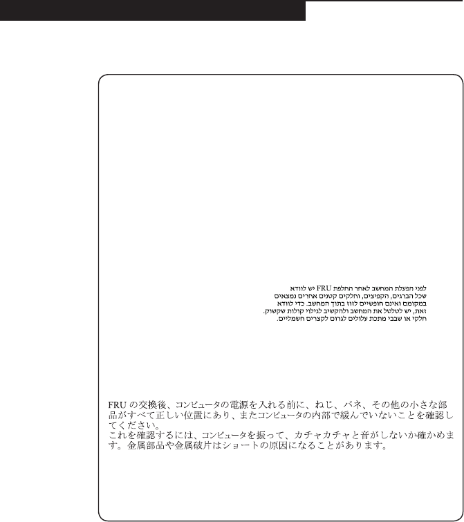
Safety notice 1
BeforethecomputerispoweredonafterFRUreplacement,makesureallscrews,
springs,andothersmallpartsareinplaceandarenotleftlooseinsidethe
computer.Verifythisbyshakingthecomputerandlisteningforrattlingsounds.
Metallicpartsormetalakescancauseelectricalshorts.
Avantderemettrel’ordinateursoustensionaprèsremplacementd’uneunitéen
clientèle,vériezquetouslesressorts,visetautrespiècessontbienenplaceet
bienxées.Pourcefaire,secouezl’unitéetassurez-vousqu’aucunbruitsuspect
neseproduit.Despiècesmétalliquesoudescopeauxdemétalpourraientcauser
uncourt-circuit.
BevornacheinemFRU-AustauschderComputerwiederangeschlossenwird,
mußsichergestelltwerden,daßkeineSchrauben,FedernoderandereKleinteile
fehlenoderimGehäusevergessenwurden.DerComputermußgeschütteltundauf
Klappergeräuschegeprüftwerden.Metallteileoder-splitterkönnenKurzschlüsse
erzeugen.
Primadiaccenderel’elaboratoredopocheéstataeffettuatalasostituzionediuna
FRU,accertarsichetutteleviti,lemolleetuttelealtripartidipiccoledimensioni
sianonellacorrettaposizioneenonsianosparseall’internodell’elaboratore.
Vericareciòscuotendol’elaboratoreeprestandoattenzioneadeventualirumori;
eventualipartiopezzettimetallicipossonoprovocarecortocircuitipericolosi.
AntesdeencenderelsistemadespuesdesustituirunaFRU,compruebeque
todoslostornillos,muellesydemáspiezaspequeñasseencuentranensusitio
ynoseencuentransueltasdentrodelsistema.Compruébeloagitandoelsistema
yescuchandolosposiblesruidosqueprovocarían.Laspiezasmetálicaspueden
causarcortocircuitoseléctricos.
8
Lenovo YOGA 720-13IKB/Lenovo YOGA 720-15IKB
Hardware Maintenance Manual
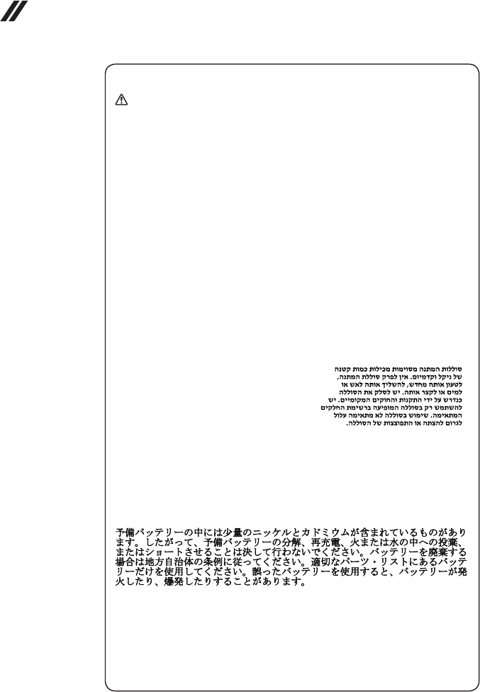
Safety notice 2
DANGER
Somestandbybatteriescontainasmallamountofnickelandcadmium.Donot
disassembleastandbybattery,rechargeit,throwitintofireorwater,orshort-
circuitit.Disposeofthebatteryasrequiredbylocalordinancesorregulations.
Useonlythebatteryintheappropriatepartslisting.Useofanincorrectbatterycan
resultinignitionorexplosionofthebattery.
Certainesbatteriesdesecourscontiennentdunickeletducadmium.Neles
démontezpas,nelesrechargezpas,nelesexposezniaufeuniàl’eau.Ne
lesmettezpasencourt-circuit.Pourlesmettreaurebut,conformez-vousàla
réglementationenvigueur.Lorsquevousremplacezlapiledesauvegardeoucelle
del’horlogetempsréel,veillezàn’utiliserquelesmodèlescitésdanslalistede
piècesdétachéesadéquate.Unebatterieouunepileinappropriéerisquedeprendre
feuoud’exploser.
DieBereitschaftsbatterie,diesichunterdemDiskettenlaufwerkbefindet,
kanngeringeMengenNickelundCadmiumenthalten.Siedarfnichtzerlegt,
wiederaufgeladen,kurzgeschlossen,oderFeueroderWasserausgesetztwerden.
BeiderEntsorgungdieörtlichenBestimmungenfürSondermüllbeachten.Beim
ErsetzenderBereitschafts-oderSystembatterienurBatteriendesTypsverwenden,
derinderErsatzteillisteaufgeführtist.DerEinsatzfalscherBatterienkannzu
EntzündungoderExplosionführen.
Alcunebatteriediriservacontengonounapiccolaquantitàdinichelecadmio.
Nonsmontarle,ricaricarle,gettarlenelfuocoonell’acquanécortocircuitarle.
Smaltirlesecondolanormativainvigore(DPR915/82,successivedisposizionie
disposizionilocali).Quandosisostituiscelabatteriadell’RTC(realtimeclock)o
labatteriadisupporto,utilizzaresoltantoitipiinseritinell’appropriatoCatalogo
parti.L’impiegodiunabatterianonadattapotrebbedeterminarel’incendioo
l’esplosionedellabatteriastessa.
Algunasbateríasdereservacontienenunapequeñacantidaddeníquelycadmio.
Nolasdesmonte,nirecargue,nilasechealfuegooalaguanilascortocircuite.
Deséchelastalcomodisponelanormativalocal.Utilicesólobateríasquese
encuentrenenlalistadepiezas.Lautilizacióndeunabateríanoapropiadapuede
provocarlaigniciónoexplosióndelamisma.
9
Safety information
Safety notice 3
DANGER
Thebatterypackcontainssmallamountsofnickel.Donotdisassembleit,throw
itintoreorwater,orshort-circuitit.Disposeofthebatterypackasrequiredby
localordinancesorregulations.Useonlythebatteryintheappropriatepartslisting
whenreplacingthebatterypack.Useofanincorrectbatterycanresultinignition
orexplosionofthebattery.
Labatteriecontientdunickel.Neladémontezpas,nel’exposezniaufeuniàl’eau.
Nelamettezpasencourt-circuit.Pourlamettreaurebut,conformez-vousàla
réglementationenvigueur.Lorsquevousremplacezlabatterie,veillezàn’utiliser
quelesmodèlescitésdanslalistedepiècesdétachéesadéquate.Eneffet,une
batterieinappropriéerisquedeprendrefeuoud’exploser.
AkkusenthaltengeringeMengenvonNickel.Siedürfennichtzerlegt,
wiederaufgeladen,kurzgeschlossen,oderFeueroderWasserausgesetztwerden.
BeiderEntsorgungdieörtlichenBestimmungenfürSondermüllbeachten.Beim
ErsetzenderBatterienurBatteriendesTypsverwenden,derinderErsatzteilliste
aufgeführtist.DerEinsatzfalscherBatterienkannzuEntzündungoderExplosion
führen.
Labatteriacontienepiccolequantitàdinichel.Nonsmontarla,gettarlanelfuoco
onell’acquanécortocircuitarla.Smaltirlasecondolanormativainvigore(DPR
915/82,successivedisposizioniedisposizionilocali).Quandosisostituiscela
batteria,utilizzaresoltantoitipiinseritinell’appropriatoCatalogoparti.L’impiego
diunabatterianonadattapotrebbedeterminarel’incendiool’esplosionedella
batteriastessa.
Lasbateríascontienenpequeñascantidadesdeníquel.Nolasdesmonte,ni
recargue,nilasechealfuegooalaguanilascortocircuite.Deséchelastalcomo
disponelanormativalocal.Utilicesólobateríasqueseencuentrenenlalistade
piezasalsustituirlabatería.Lautilizacióndeunabateríanoapropiadapuede
provocarlaigniciónoexplosióndelamisma.
10
Lenovo YOGA 720-13IKB/Lenovo YOGA 720-15IKB
Hardware Maintenance Manual
Safety notice 4
DANGER
Thelithiumbatterycancauseafire,anexplosion,orasevereburn.Donot
rechargeit,removeitspolarizedconnector,disassembleit,heatitabove100°C
(212°F),incinerateit,orexposeitscellcontentstowater.Disposeofthebatteryas
requiredbylocalordinancesorregulations.Useonlythebatteryintheappropriate
partslisting.Useofanincorrectbatterycanresultinignitionorexplosionofthe
battery.
Lapiledesauvegardecontientdulithium.Elleprésentedesrisquesd’incendie,
d’explosionoudebrûluresgraves.Nelarechargezpas,neretirezpasson
connecteurpolariséetneladémontezpas.Nel’exposezpasàunetemperature
supérieureà100°C,nelafaitespasbrûleretn’enexposezpaslecontenuàl’eau.
Mettezlapileaurebutconformémentàlaréglementationenvigueur.Unepile
inappropriéerisquedeprendrefeuoud’exploser.
DieSystembatterieisteineLithiumbatterie.Siekannsichentzünden,explodieren
oderschwereVerbrennungenhervorrufen.BatteriendiesesTypsdürfennicht
aufgeladen,zerlegt,über100Cerhitztoderverbranntwerden.Auchdarfihr
InhaltnichtmitWasserinVerbindunggebrachtoderderzurrichtigenPolung
angebrachteVerbindungssteckerentferntwerden.BeiderEntsorgungdieörtlichen
BestimmungenfürSondermüllbeachten.BeimErsetzenderBatterienurBatterien
desTypsverwenden,derinderErsatzteillisteaufgeführtist.DerEinsatzfalscher
BatterienkannzuEntzündungoderExplosionführen.
Labatteriadisupportoeunabatteriaallitioepuoincendiarsi,esplodereo
procuraregraviustioni.Evitarediricaricarla,smontarneilconnettorepolarizzato,
smontarla,riscaldarlaadunatemperaturasuperioreai100gradicentigradi,
incendiarlaogettarlainacqua.Smaltirlasecondolanormativainvigore(DPR
915/82,successivedisposizioniedisposizionilocali).L’impiegodiunabatteria
nonadattapotrebbedeterminarel’incendiool’esplosionedellabatteriastessa.
Labateríaderepuestoesunabateríadelitioypuedeprovocarincendios,
explosionesoquemadurasgraves.Nolarecargue,niquiteelconectorpolarizado,
niladesmonte,nicalienteporencimadelos100°C(212°F),nilaincinereni
expongaelcontenidodesusceldasalagua.Deséchelatalcomodisponela
normativalocal.
11
Safety information
Safety notice 5
IftheLCDbreaksandtheuidfrominsidetheLCDgetsintoyoureyesoronyour
hands,immediatelywashtheaffectedareaswithwateratleastfor15minutes.
Seekmedicalcareifanysymptomscausedbytheuidarepresentafterwashing.
Silepanneaud’afchageàcristauxliquidessebriseetquevousrecevezdansles
yeuxousurlesmainsunepartieduuide,rincez-lesabondammentpendantau
moinsquinzeminutes.Consultezunmédecinsidessymptômespersistentaprèsle
lavage.
DieLeuchtstoffröhreimLCD-BildschirmenthältQuecksilber.BeiderEntsorgung
dieörtlichenBestimmungenfürSondermüllbeachten.DerLCD-Bildschirm
bestehtausGlasundkannzerbrechen,wennerunsachgemäßbehandeltwird
oderderComputeraufdenBodenfällt.WennderBildschirmbeschädigtistund
diedarinbefindlicheFlüssigkeitinKontaktmitHautundAugengerät,sollten
diebetroffenenStellenmindestens15MinutenmitWasserabgespültundbei
BeschwerdenanschließendeinArztaufgesuchtwerden.
Nelcasochecasol’LCDsidovesserompereedilliquidoinessocontenuto
entrasseincontattocongliocchiolemani,lavareimmediatamenteleparti
interessateconacquacorrenteperalmeno15minuti;poiconsultareunmedicosei
sintomidovesseropermanere.
SilaLCDserompeyeluidodesuinteriorentraencontactoconsusojososus
manos,laveinmediatamentelasáreasafectadasconaguadurante15minutos
comomínimo.Obtengaatenciónmedicasisepresentaalgúnsíntomadeluido
despuesdelavarse.
12
Lenovo YOGA 720-13IKB/Lenovo YOGA 720-15IKB
Hardware Maintenance Manual
Safety notice 6
DANGER
Toavoidshock,donotremovetheplasticcoverthatprotectsthelowerpartofthe
invertercard.
And’évitertoutrisquedechocélectrique,neretirezpaslecacheenplastique
protégeantlapartieinférieuredelacarted’alimentation.
AusSicherheitsgründendieKunststoffabdeckung,diedenunterenTeilder
Spannungswandlerplatineumgibt,nichtentfernen.
Perevitarescosseelettriche,nonrimuoverelacoperturainplasticacheavvolgela
parteinferioredellaschedainvertitore.
Paraevitardescargas,noquitelacubiertadeplásticoquerodealapartebajadela
tarjetainvertida.
Safety notice 7
DANGER
Thoughthemainbatterieshavelowvoltage,ashortedorgroundedbatterycan
produceenoughcurrenttoburnpersonnelorcombustiblematerials.
Bienquelevoltagedesbatteriesprincipalessoitpeuélevé,lecourt-circuitoula
miseàlamassed’unebatteriepeutproduiresufsammentdecourantpourbrûler
desmatériauxcombustiblesoucauserdesbrûlurescorporellesgraves.
ObwohlHauptbatterieneineniedrigeSpannunghaben,könnensiedochbei
KurzschlußoderErdunggenugStromabgeben,umbrennbareMaterialienzu
entzündenoderVerletzungenbeiPersonenhervorzurufen.
Sebbenelebatteriedialimentazionesianoabassovoltaggio,unabatteriain
cortocircuitooamassapuòfornirecorrentesufficientedabruciaremateriali
combustibilioprovocareustioniaitecnicidimanutenzione.
Aunquelasbateríasprincipalestienenunvoltajebajo,unabateríacortocircuitada
oconcontactoatierrapuedeproducirlacorrientesucientecomoparaquemar
materialcombustibleoprovocarquemadurasenelpersonal.
13
Safety information
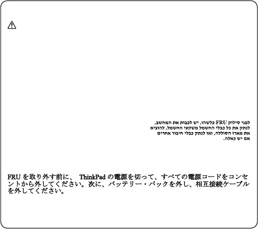
Safety notice 8
DANGER
BeforeremovinganyFRU,turnoffthecomputer,unplugallpowercordsfrom
electricaloutlets,removethebatterypack,andthendisconnectanyinterconnecting
cables.
Avantderetireruneunitéremplaçableenclientèle,mettezlesystèmehorstension,
débrancheztouslescordonsd’alimentationdessoclesdeprisedecourant,retirez
labatterieetdéconnecteztouslescordonsd’interface.
DieStromzufuhrmußabgeschaltet,alleStromkabelausderSteckdosegezogen,
derAkkuentferntundalleVerbindungskabelabgenommensein,bevoreineFRU
entferntwird.
PrimadirimuoverequalsiasiFRU,spegnereilsistema,scollegaredalleprese
elettrichetuttiicavidialimentazione,rimuoverelabatteriaepoiscollegareicavi
diinterconnessione.
AntesdequitarunaFRU,apagueelsistema,desenchufetodosloscablesde
lastomasdecorrienteeléctrica,quitelabateríay,acontinuación,desconecte
cualquiercabledeconexiónentredispositivos.
14
Lenovo YOGA 720-13IKB/Lenovo YOGA 720-15IKB
Hardware Maintenance Manual
Laser compliance statement
Some models of Lenovo computer are equipped from the factory with an
optical storage device such as a CD-ROM drive or a DVD-ROM drive. Such
devices are also sold separately as options. If one of these drives is installed,
it is certied in the U.S. to conform to the requirements of the Department of
Health and Human Services 21 Code of Federal Regulations (DHHS 21 CFR)
Subchapter J for Class 1 laser products. Elsewhere, the drive is certified to
conform to the requirements of the International Electrotechnical Commission
(IEC) 825 and CENELEC EN 60 825 for Class 1 laser products.
If a CD-ROM drive, a DVD-ROM drive, or another laser device is installed, note
the following:
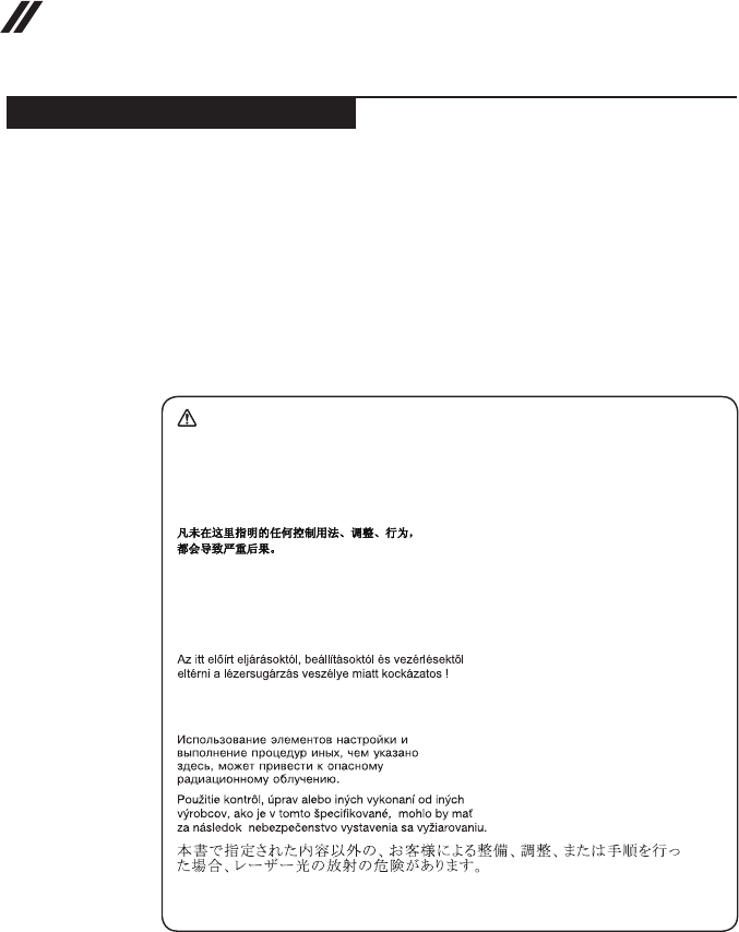
CAUTION
Useofcontrolsoradjustmentsorperformanceofproceduresotherthanthose
speciedhereinmightresultinhazardousradiationexposure.
Ousodecontroles,ajustesoudesempenhodeprocedimentosdiferentesdaqueles
aquiespecicadospoderesultaremperigosaexposiçãoàradiação.
Pourévitertoutrisqued’expositionaurayonlaser,respectezlesconsignesde
réglageetd’utilisationdescommandes,ainsiquelesprocéduresdécrites.
WerdenSteuer-undEinstellelementeandersalshierfestgesetztverwendet,kann
gefährlicheLaserstrahlungauftreten.
L’utilizzodicontrolli,regolazioniol’esecuzionediprocedurediversedaquelle
specicatepossonoprovocarel’esposizionea.
Elusodecontrolesoajustesolaejecucióndeprocedimientosdistintosdelosaquí
especicadospuedeprovocarlaexposiciónaradiacionespeligrosas.
Opening the CD-ROM drive, the DVD-ROM drive, or any other optical storage
device could result in exposure to hazardous laser radiation. There are no
serviceable parts inside those drives. Do not open.
15
Safety information
A CD-ROM drive, a DVD-ROM drive, or any other storage device installed may
contain an embedded Class 3A or Class 3B laser diode. Note the following:
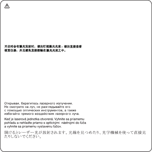
DANGER
Emitsvisibleandinvisiblelaserradiationwhenopen.Donotstareintothebeam,
donotviewdirectlywithopticalinstruments,andavoiddirectexposuretothe
beam.
Radiaçãoporraiolaseraoabrir.Nãoolhefixonofeixedeluz,nãoolhe
diretamentepormeiodeinstrumentosóticoseeviteexposiçãodiretacomofeixe
deluz.
Rayonnementlasersicarterouvert.Évitezdefixerlefaisceau,deleregarder
directementavecdesinstrumentsoptiques,oudevousexposeraurayon.
LaserstrahlungbeigeöffnetemGerät.NichtdirektoderüberoptischeInstrumente
indenLaserstrahlsehenunddenStrahlungsbereichmeiden.
Kinyitáskorlézersugár!Nenézzenbeleseszabadszemmel,seoptikai
eszközökkel.Kerüljeasugárnyalábbalvalóérintkezést!
Aprendol’unitàvengonoemesseradiazionilaser.Nonfissareilfascio,non
guardarlodirettamenteconstrumentiotticieevitarel’esposizionedirettaalfascio.
Radiaciónláseralabrir.Nomirejamenteniexamineconinstrumentalópticoel
hazdeluz.Evitelaexposicióndirectaalhaz.
16
Lenovo YOGA 720-13IKB/Lenovo YOGA 720-15IKB
Hardware Maintenance Manual
Important service information
This chapter presents the following important service information:
• “Strategy for replacing FRUs” on page 16
– “Strategy for replacing a hard disk drive” on page 17
– “Important notice for replacing a system board” on page 17
• “Important information about replacing RoHS compliant FRUs” on page 18
Important:
BIOSanddevicedriverxesarecustomer-installable.TheBIOSanddevicedrivers
arepostedonthecustomersupportsite:
http://support.lenovo.com.
Strategy for replacing FRUs
Before replacing parts:
Make sure that all software xes, drivers, and BIOS downloads are installed
before replacing any FRUs listed in this manual.
After a system board is replaced, ensure that the latest BIOS is loaded to the
system board before completing the service action.
To download software xes, drivers, and BIOS, follow the steps below:
1. Go to http://support.lenovo.com.
2. Enter the serial number or select a product or use Lenovo smart
downloading.
3. Select the BIOS/Driver/Applications and download.
4. Follow the directions on the screen and install the necessary software.
17
Important service information
Use the following strategy to prevent unnecessary expense for replacing and
servicing FRUs:
• If you are instructed to replace an FRU, but the replacement does not solve
the problem, reinstall the original FRU before you continue.
• Some computers have both a processor board and a system board. If you
are instructed to replace either of them, and replacing one of them does not
solve the problem, reinstall that board, and then replace the other one.
• If an adapter or a device consists of more than one FRU, any of the FRUs
may be the cause of the error. Before replacing the adapter or device,
remove the FRUs one by one to see if the symptoms change. Replace only
the FRU that changed the symptoms.
Attention: The setup configuration on the computer you are servicing may
have been customized. Running Automatic Configuration may alter the
settings. Note the current conguration settings (using the View Conguration
option); then, when service has been completed, verify that those settings
remain in effect.
Strategy for replacing a hard disk drive
Always try to run a low-level format before replacing a hard disk drive. This
will cause all customer data on the hard disk to be lost. Make sure that the
customer has a current backup of the data before performing this action.
Attention: The drive startup sequence in the computer you are servicing may
have been changed. Be extremely careful during write operations such as
copying, saving, or formatting. If you select an incorrect drive, data or programs
can be overwritten.
Important notice for replacing a system board
Some components mounted on a system board are very sensitive. Improper
handling can cause damage to those components, and may cause a system
malfunction.
Attention: When handling a system board:
• Do not drop the system board or apply any excessive force to it.
• Avoid rough handling of any kind.
• Avoid bending the system board and hard pushing to prevent cracking at
each BGA (Ball Grid Array) chipset.

18
Lenovo YOGA 720-13IKB/Lenovo YOGA 720-15IKB
Hardware Maintenance Manual
Important information about replacing RoHS compliant FRUs
RoHS, The Restriction of Hazardous Substances in Electrical and
Electronic Equipment Directive (2002/95/EC) is a European Union legal
requirement affecting the global electronics industry. RoHS requirements
must be implemented on Lenovo products placed on the market after
June 2006. Products on the market before June 2006 are not required to
have RoHS compliant parts. If the original FRU parts are non-compliant,
replacement parts can also be non-compliant. In all cases if the original
FRU parts are RoHS compliant, the replacement part must also be RoHS
compliant.
Note: RoHS and non-RoHS FRU part numbers with the same t and function
are identied with unique FRU part numbers.
Lenovo plans to transit to RoHS compliance well before the implementation
date and expects its suppliers to be ready to support Lenovo’s requirements
and schedule in the EU. Products sold in 2005 and 2006 will contain some
RoHS compliant FRUs. The following statement pertains to these products and
any product Lenovo produces containing RoHS compliant FRUs.
RoHS compliant FRUs have unique FRU part numbers. Before or after the
RoHS implementation date, failed RoHS compliant parts must always be
replaced with RoHS compliant ones, so only the FRUs identied as compliant
in the system HMM or direct substitutions for those FRUs may be used.
Products marketed before June 2006 Products marketed after June 2006
Current or
original part
Replacement FRU Current or
original part
Replacement FRU
Non-RoHS Can be Non-RoHS
Must be RoHS Must be RoHS
Non-RoHS Can be RoHS
Non-RoHS Can sub to RoHS
RoHS Must be RoHS
Note: A direct substitution is a part with a different FRU part number that is
automatically shipped by the distribution center at the time of the order.

19
General checkout
General checkout
This chapter presents the following information:
• “What to do rst” on page 20
• “Power system checkout” on page 21
Before you go to the checkout, make sure to read the following important notes:
Important notes:
• Onlycertiedtrainedpersonnelcanservicethecomputer.
• BeforereplacinganyFRU,readtheentirepage onremovingand replacing
FRUs.
• CarefullyremovescrewsforreusewhenreplacingFRUs.
• Beextremelycarefulduringsuchwriteoperationsas copying,saving,or
formatting.Drivesinthecomputerthatyouareservicingsequencemight
havebeenaltered.Ifyouselectanincorrectdrive,dataorprogramsmightbe
overwritten.
• ReplaceanFRUonlywithanotherFRUofthecorrectmodel.Whenyou
replaceanFRU,makesurethatthemachinemodelandtheFRUpartnumberare
correctbyreferringtotheFRUpartslist.
• AnFRUshouldnotbereplacedjustbecauseofasingle,unreproduciblefailure.
Singlefailurescanoccurforavarietyofreasonsthathavenothingtodowitha
hardwaredefect,suchascosmicradiation,electrostaticdischarge,orsoftware
errors.ConsiderreplacinganFRUonlywhenaproblemrecurs.Ifyoususpectthat
anFRUisdefective,cleartheerrorlogsandrunthetestagain.Iftheerrordoes
notrecur,donotreplacetheFRU.
• BecarefulnottoreplaceanondefectiveFRU.

20
Lenovo YOGA 720-13IKB/Lenovo YOGA 720-15IKB
Hardware Maintenance Manual
What to do rst
When you do return an FRU, you must include the following information in the
parts exchange form or parts return form that you attach to it:
1. Name and phone number of servicer
2. Date of service
3. Date on which the machine failed
4. Date of purchase
5. Procedure index and page number in which the failing FRU was detected
6. Failing FRU name and part number
7. Machine type, model number, and serial number
8. Customer’s name and address
Note for warranty: During the warranty period, the customer may be
responsible for repair costs if the computer damage was caused by misuse,
accident, modification, unsuitable physical or operating environment, or
improper maintenance by the customer.
The following is a list of some common items that are not covered under
warranty and some symptoms that might indicate that the system was
subjected to stress beyond normal use.
Before checking problems with the computer, determine whether the damage is
covered under the warranty by referring to the following list:
The following are not covered under warranty:
• LCD panel cracked from the application of excessive force or from being
dropped
• Scratched (cosmetic) parts
• Distortion, deformation, or discoloration of the cosmetic parts
• Plastic parts, latches, pins, or connectors that have been cracked or broken
by excessive force
• Damage caused by liquid spilled into the system
• Damage caused by the improper insertion of a PC Card or the installation of
an incompatible card
• Improper disk insertion or use of an optical drive
• Diskette drive damage caused by pressure on the diskette drive cover,
foreign material in the drive, or the insertion of a diskette with multiple labels
• Damaged or bent diskette eject button
• Fuses blown by attachment of a nonsupported device
• Forgotten computer password (making the computer unusable)
• Sticky keys caused by spilling a liquid onto the keyboard
• Use of an incorrect AC adapter on laptop products
The following symptoms might indicate damage caused by nonwarranted
activities:
• Missing parts might be a symptom of unauthorized service or modication.
• If the spindle of a hard disk drive becomes noisy, it may have been subjected
to excessive force, or dropped.
21
General checkout
Power system checkout
To verify a symptom, follow the steps below:
1. Turn off the computer.
2. Connect the AC adapter.
3. Make sure that power is supplied when you turn on the computer.
4. Turn off the computer.
5. Disconnect the AC adapter.
6. Make sure that the battery pack supplies power when you turn on the
computer.
If you suspect a power problem, see the appropriate power supply checkout:
• “Checking the AC adapter” on page 21
• “Checking operational charging” on page 22
Checking the AC adapter
You are here because the computer fails only when the AC adapter is used.
• If the power-on indicator does not turn on, check the power cord of the AC
adapter for correct continuity and installation.
• If the computer does not charge during operation, go to “Checking
operational charging”.
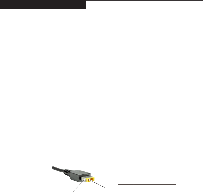
To check the AC adapter, follow the steps below:
1. Unplug the AC adapter cable from the computer.
2. Measure the output voltage at the plug of the AC adapter cable. See the
following gure:
1
2
Voltage (V DC)
+20
0
Pin
1
2
Note: Output voltage for the AC adapter pin No. 2 may differ from the one you
are servicing.
3. If the voltage is not correct, replace the AC adapter.
4. If the voltage is acceptable, do the following:
• Replace the system board.
• If the problem persists, go to “Lenovo YOGA 720-13IKB/Lenovo YOGA 720-
15IKB” on page 26.
Note: Noise from the AC adapter does not always indicate a defect.

22
Lenovo YOGA 720-13IKB/Lenovo YOGA 720-15IKB
Hardware Maintenance Manual
Checking operational charging
To check whether the battery charges properly during operation, use a
discharged battery pack or a battery pack that has less than 50% of the total
power remaining when installed in the computer.
Perform operational charging. If the battery status indicator or icon is not lit,
remove the battery pack and let it return to room temperature. Reinstall the
battery pack. If the charge indicator or icon is still off, replace the battery pack.
If the charge indicator is still not lit, replace the system board.
Checking the battery pack
Battery charging does not start until the Power Meter shows that less than 95%
of the total power remains; under this condition the battery pack can charge to
100% of its capacity. This protects the battery pack from being overcharged or
from having a shortened life.
To check your battery, move your cursor to the Power Meter icon in the icon
tray of the Windows® taskbar and wait for a moment (but do not click it), and
the
percentage of battery power remaining is displayed. To get detailed information
about the battery, double-click the Power Meter icon.
Note: If the battery pack becomes hot, it may not be able to be charged.
Remove it from the computer and leave it at room temperature for a while. After
it cools down, reinstall and recharge it.
23
Related service information
Related service information
This chapter presents the following information:
• “Restoring the factory contents by using OneKey Recovery” on page 23
• “Passwords” on page 24
• “Power management” on page 25
Restoring the factory contents by using OneKey Recovery
Restore of factory default
The Lenovo YOGA 720-13IKB/Lenovo YOGA 720-15IKB Glass computer
comes with pre-installed OneKey Recovery System.In order to save application
files and the initial backed up files of the system, the hard disk in a Lenovo
computer includes a hidden partition when it is shipped. If you need to restore
the system to the point of your rst boot up, just enter the Recovery System.
For details of the Recovery system, see the User Guide for Recovery system.
Note:Thiswilldeleteallthenewdataonthesystempartition(Cdrive),which
isnotrecoverable.Makesuretobackupyourcriticaldatabeforeyouperformthis
action.

24
Lenovo YOGA 720-13IKB/Lenovo YOGA 720-15IKB
Hardware Maintenance Manual
Passwords
As many as three passwords may be needed for any Lenovo computer: the
power-on password (POP), the hard disk password (HDP), and the supervisor
password.
If any of these passwords has been set, a prompt for it appears on the screen
whenever the computer is turned on. The computer does not start until the
password is entered.
Power-on password
A power-on password (POP) protects the system from being powered on by
an unauthorized person. The password must be entered before an operating
system can be booted.
Hard-disk password
There are two hard-disk passwords (HDPs):
+ User HDP - for the user
+ Master HDP - for the system administrator, who can use it to get access to
the hard disk drive even if the user has changed the user HDP
Attention: If the user HDP has been forgotten, check whether a master HDP
has been set. If it has, it can be used for access to the hard disk drive. If
no master HDP is available, neither Lenovo nor Lenov authorized service
technicians provide any services to reset either the user or the master HDP, or
to recover data from the hard disk drive. The hard disk drive can be replaced
for a scheduled fee.
Supervisor password
A supervisor password protects the system information stored in the BIOS. The
user must enter the supervisor password to get access to the BIOS and change
the system conguration.
Attention: If you forget the password, there is no service procedure to reset
the password. The system board must be replaced for a scheduled fee.

25
Related service information
Power management
Note: Power management modes are not supported for an APM operating
system.
Putting the computer to sleep or shutting it down
When you have nished working with your computer, you can put it to sleep or
shut it down.
Putting your computer to sleep
If you will be away from your computer for only a short time, put the computer to
sleep. When the computer is in sleep mode, you can quickly wake it to resume
use, bypassing the startup process.
To put the computer to sleep, do one of the following:
• Close the display lid.
• Press the Power button.
• Open the start menu, and then select Power → Sleep.
Attention: Wait until the power indicator light starts blinking (indicating that
the computer is in sleep mode) before you move your computer. Moving your
computer while the hard disk is spinning can damage the hard disk, causing
loss of data.
To wake the computer, do one of the following:
• Press any key on the keyboard. (Notebook mode only)
• Press the Power button.
Shutting down the computer
If you are not going to use your computer for a long time, shut it down.
To shut down your computer, do one of the following:
• Open the start menu, and then select Power → Shut down.
• Press and hold or right-click the Start button in the lower-left corner and
select Shut down or sign out → Shut down.
26
Lenovo YOGA 720-13IKB/Lenovo YOGA 720-15IKB
Hardware Maintenance Manual
Lenovo YOGA 720-13IKB/Lenovo YOGA 720-15IKB
This chapter presents the following product-specific service references and
product-specic parts information:
• “Specications” on page 26
• “Status indicators” on page 28
• “Keyboard function keys” on page 29
• “FRU replacement notices” on page 30
• “Removing and replacing an FRU” on page 31
• “Locations” on page 73
• “Parts list” on page 77
Specications
The following table lists the specifications of the Lenovo YOGA 720-13IKB/
Lenovo YOGA 720-15IKB:
Table 1. Specications
Feature Description
Processor View the system properties of your computer.
You can do this as follows: Open the Control Panel, and then select
System and Security → System.
Graphic Chipset • Integrated Graphics
• nvidia N17p-G0 (Lenovo YOGA 720-15IKB)
Display • 13.3-inch, 16:9, 1,920 × 1,080 pixels FHD / 3,840 × 2,160 pixels UHD
(Lenovo YOGA 720-13IKB)
• 15.6-inch, 16:9, 1,920 × 1,080 pixels FHD / 3,840 × 2,160 pixels UHD
(Lenovo YOGA 720-15IKB)
Standard
memory • DDR4 (max 16 GB)
SSD • 128 GB, 256 GB, 512 GB or 1 TB, NGFF (PCI-E)
(Lenovo YOGA 720-13IKB)
• 256 GB, 512 GB or 1 TB, NGFF (PCI-E)
(Lenovo YOGA 720-15IKB)
I/O port • Lenovo YOGA 720-13IKB
USB 3.0 × 1
Combo audio jack × 1
Type-C × 1 (compatible with USB 3.0 & PowerDelivery)
Type-C × 1 (compatible with USB 3.1, PowerDelivery,
DisplayPort & Thunderbolt)
• Lenovo YOGA 720-15IKB
USB 3.0 × 2
Combo audio jack × 1
Type-C × 1 (compatible with USB 3.1, DisplayPort &
Thunderbolt)
Audio • 1/8" Combo audio jack
• JBL Branded Speaker
• Built-in microphone × 2

27
Lenovo YOGA 720-13IKB/Lenovo YOGA 720-15IKB
Feature Description
Bluetooth
wireless • Built-in antenna with wireless card module for all Models
Keyboard • 6 Row, Lenovo Keyboard, Back-light
Touch pad • Multi-touch type
Integrated
camera • 720P HD
Battery • 4 cells, 48 Wh (Lenovo YOGA 720-13IKB)
• 6 cells, 72 Wh (Lenovo YOGA 720-15IKB)
AC adapter • 20 V, 45 W (Lenovo YOGA 720-13IKB)
• 20 V, 135 W / 90 W (Lenovo YOGA 720-15IKB)
Pre-installed
operating
system
• Win10
28
Lenovo YOGA 720-13IKB/Lenovo YOGA 720-15IKB
Hardware Maintenance Manual
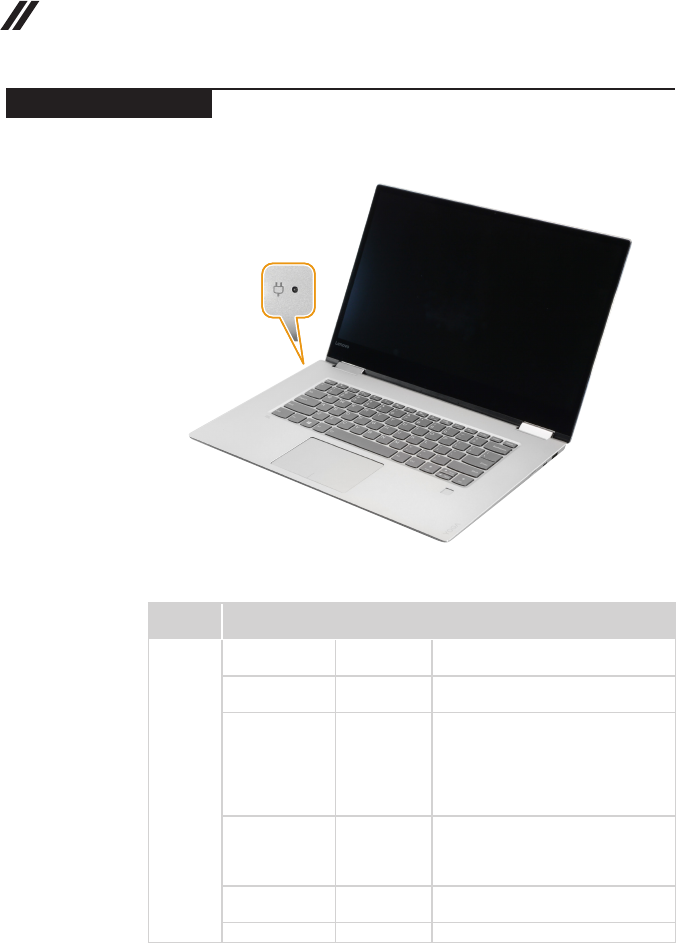
Status indicators
The system status indicators below show the computer status:
Table 2. Status indicators
Indicator Indicator status Charge
status Meaning
Battery
status
indicator
On (solid white) Charging The battery has more than 80%
charge.
On (solid
amber) Discharging The battery has between 5% and
20% charge.
Blinking slowly
(white) Charging
The battery has between 20% and
80% charge. When the battery
reaches 80% charge, the light will
stop blinking. However, charging
will continue until the battery is fully
charged.
Blinking slowly
(amber) Charging
The battery has less than 20%
charge. When the battery charge
reaches 20%, the blinking color will
change to white.
Blinking quickly
(amber) Discharging The battery has less than 5% charge.
Off Discharging The battery has more than 20% charge.
29
Lenovo YOGA 720-13IKB/Lenovo YOGA 720-15IKB
Keyboard function keys
You can access certain system settings quickly by pressing the appropriate
function keys.
Table 3. Fn key combinations
Fn + B: Activates the break function.
Fn + P: Activates the pause function.
Fn + C: Enables/disables the scroll lock.
Fn + S: Activates the system request.
Fn + : Activates the Pgup key function.
Fn + : Activates the Pgdn key function.
Fn + : Activates the home key function.
Fn + : Activates the end key function.
Fn + Space: Adjusts the keyboard backlight (off → dim → bright → off).
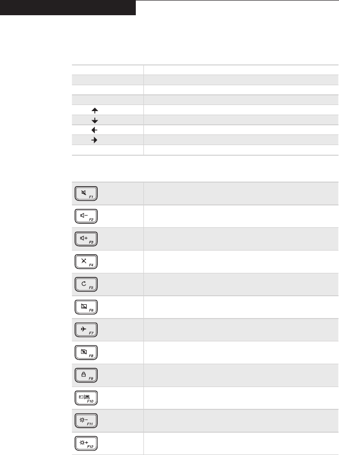
Table 4. Hotkeys
: Mutes/unmutes the sound.
: Decreases the volume level.
: Increases the volume level.
: Enables/disables the microphone.
: Refreshes the desktop or the currently active window.
: Enables/disables the touchpad.
: Enables/disables Airplane mode.
: Enables/disables the integrated camera.
: Locks the screen.
: Toggles the display between the computer and an external
device.
: Decreases display brightness.
: Increases display brightness.
Note: You can use the Lenovo Setting to enable/disable the hotkey function.
30
Lenovo YOGA 720-13IKB/Lenovo YOGA 720-15IKB
Hardware Maintenance Manual
FRU replacement notices
This section presents notices related to removing and replacing parts. Read
this section carefully before replacing any FRU.
Screw notices
Loose screws can cause a reliability problem. In the Lenovo computer, this
problem is addressed with special nylon-coated screws that have the following
characteristics:
• They maintain tight connections.
• They do not easily come loose, even with shock or vibration.
• They are harder to tighten.
Do the following when you service this machine:
• Keep the screw kit in your tool bag.
• Carefully remove screws for reuse when replacing FRUs.
• Use a torque screwdriver if you have one.
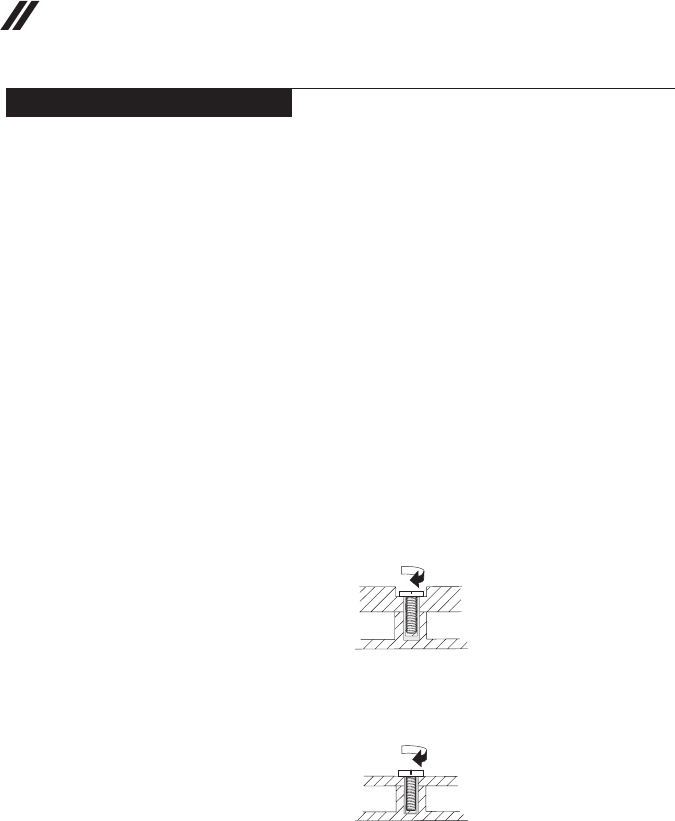
Tighten screws as follows:
• Plastic to plastic
Turn an additional 90° after the screw head touches the surface of the
plastic part:
more than 90°
(Cross-section)
• Logic card to plastic
Turn an additional 180° after the screw head touches the surface of the
logic card:
more than 180°
(Cross-section)
• Torque driver
If you have a torque screwdriver, refer to the “Torque” column for each step.
• Make sure that you use the correct screws. If you have a torque screwdriver,
tighten all screws rmly to the torque shown in the table. Carefully remove
screws for reuse when replacing FRUs. Make sure that all screws are
tightened rmly.
• Ensure torque screwdrivers are calibrated correctly following country
specications.
31
Lenovo YOGA 720-13IKB/Lenovo YOGA 720-15IKB
Removing and replacing an FRU
This section presents exploded gures with the instructions to indicate how to
remove and replace the FRU. Make sure to observe the following general rules:
1. Do not attempt to service any computer unless you have been trained and
certied. An untrained person runs the risk of damaging parts.
2. Before replacing any FRU, review “FRU replacement notices” on page 30.
3. Begin by removing any FRUs that have to be removed before the failing
FRU. Any of such FRUs are listed at the top of the page. Remove them in
the order in which they are listed.
4. Follow the correct sequence in the steps to remove the FRU, as given in the
gures by the numbers in square callouts.
5. When turning a screw to replace an FRU, turn it in the direction as given by
the arrow in the gure.
6. When removing the FRU, move it in the direction as given by the arrow in
the gure.
7. To put the new FRU in place, reverse the removal procedures and follow
any of the notes that pertain to replacement. For information about
connecting and arranging internal cables, see “Locations” on page 73.
8. When replacing an FRU, use the correct screw as shown in the procedures.
DANGER
BeforeremovinganyFRU,turnoffthecomputer,unplugallpowercordsfrom
electricaloutlets,removethebatterypack,andthendisconnectanyofthe
interconnectingcables.
Attention: After replacing an FRU, do not turn on the computer until you have
made sure that all screws, springs, and other small parts are in place and none
are loose inside the computer. Verify this by shaking the computer gently and
listening for rattling sounds. Metallic parts or metal akes can cause electrical
short circuits.
Attention: The system board is sensitive to, and can be damaged by,
electrostatic discharge. Before touching it, establish personal grounding by
touching a ground point with one hand or using an electrostatic discharge (ESD)
strap (P/N 6405959) to remove potential shock reasons.
32
Lenovo YOGA 720-13IKB/Lenovo YOGA 720-15IKB
Hardware Maintenance Manual
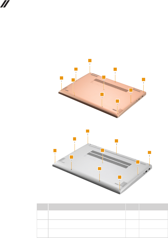
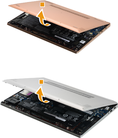
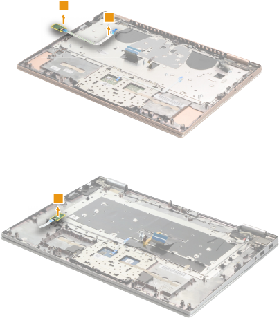
1010 Base cover
Figure 1. Removal steps of base cover
Remove the screws 1 and 2.
Lenovo YOGA 720-13IKB
1
1
1
2
22
2
2
2
2
Lenovo YOGA 720-15IKB
1
2
2
2
2
2
2
2
1
1
Step Screw (quantity) Color Torque
1M2.0 x 7.5 mm, Torx-head, nylok-coated (3)
LOW TO UP (Lenovo YOGA 720-13IKB)
Silver 1.8-2.0 kg_cm
1M2.0 x 9.5 mm, Torx-head, nylok-coated (3)
LOW TO UP (Lenovo YOGA 720-15IKB)
Silver 1.8-2.0 kg_cm
2M2.0 x 5.0 mm, Torx-head, nylok-coated (7)
LOW TO UP
Silver 1.8-2.0 kg_cm
33
Lenovo YOGA 720-13IKB/Lenovo YOGA 720-15IKB
Figure 1. Removal steps of base cover (continued)
Remove the base cover 3.
Lenovo YOGA 720-13IKB
3
Lenovo YOGA 720-15IKB
3
34
Lenovo YOGA 720-13IKB/Lenovo YOGA 720-15IKB
Hardware Maintenance Manual
Note: Applying labels to the base cover
If you see the following labels on base cover, it needs to be peeled off from
the old base cover, and put on the new base cover.
a OS label
b Indonesia label
c WLAN label
d BT label
e China Ofce label
For some models, you also need to apply one or two FCC labels. Check the
old base cover; if it has one or two FCC labels, nd duplicates of them in the
label kit and apply them to the new base cover.
For the location of each label, refer to the following gure:
35
Lenovo YOGA 720-13IKB/Lenovo YOGA 720-15IKB
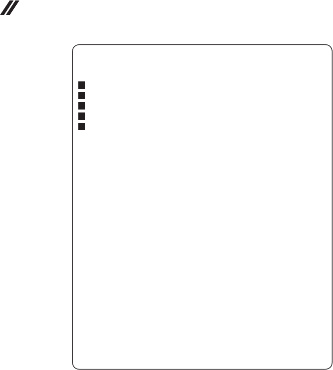
1020 Battery pack
For access, remove this FRU:
• “1010 Base cover” on page 32
DANGER
Onlyusethebatteryspeciedinthepartslistforyourcomputer.Anyotherbattery
couldigniteorexplode.
Figure 2. Removal steps of battery pack
Unplug the battery connector in the direction shown by arrow 1. Remove the
screws 2, then remove the battery pack 3.
Lenovo YOGA 720-13IKB
1
2
2
2
2
3
Lenovo YOGA 720-15IKB
2
2
2
2
1
3
Step Screw (quantity) Color Torque
2M2.0 x 3.5 mm, Phillips-head, nylok-coated (4)
BATTERY TO UP (Lenovo YOGA 720-13IKB)
Silver 1.8-2.0 kg_cm
2M2.0 x 5.0 mm, Phillips-head, nylok-coated (4)
BATTERY TO UP (Lenovo YOGA 720-15IKB)
Black 1.8-2.0 kg_cm
When installing: Make sure that the battery connector is attached rmly.
36
Lenovo YOGA 720-13IKB/Lenovo YOGA 720-15IKB
Hardware Maintenance Manual
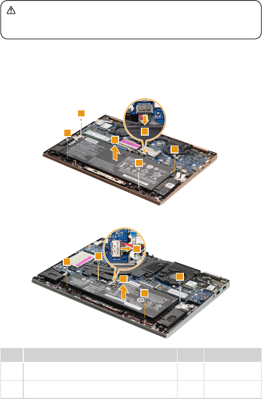
1030 Solid state disk
For access, remove these FRUs in order:
• “1010 Base cover” on page 32
• “1020 Battery pack” on page 35
Figure 3. Removal steps of solid state disk
Remove the screw 1.
Lenovo YOGA 720-13IKB
1
Lenovo YOGA 720-15IKB
1
Step Screw (quantity) Color Torque
1M2.0 x 2.5 mm, Phillips-head, nylok-coated (1)
SSD TO UP
Black 1.8-2.0 kg_cm
37
Lenovo YOGA 720-13IKB/Lenovo YOGA 720-15IKB
Figure 3. Removal steps of solid state disk (continued)
Remove the solid state disk in the direction shown by arrow 2.
Lenovo YOGA 720-13IKB
2
Lenovo YOGA 720-15IKB
2
38
Lenovo YOGA 720-13IKB/Lenovo YOGA 720-15IKB
Hardware Maintenance Manual
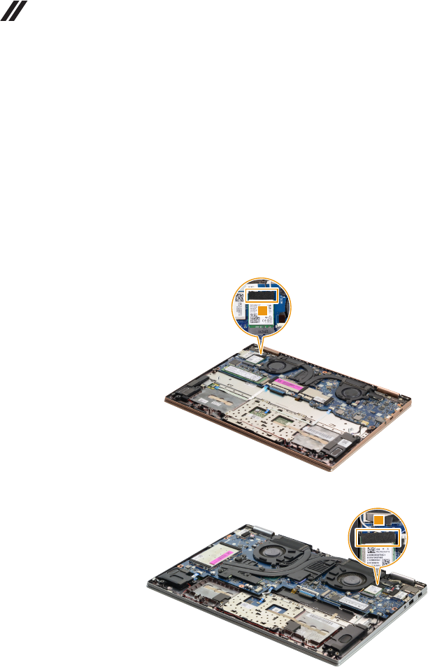
1040 PCI Express Mini Card for wireless LAN
For access, remove these FRUs in order:
• “1010 Base cover” on page 32
• “1020 Battery pack” on page 35
Important: The preinstalled WLAN module may only be replaced with a Lenovo
approved module in order to comply with FCC and IC regulations. Refer to
“Table 5. Parts list—Overall” on page 80 for Lenovo part numbers for the
approved modules.
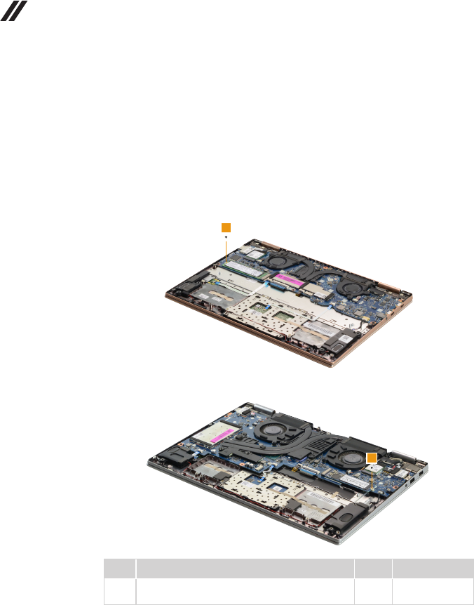
Figure 4. Removal steps of PCI Express Mini Card for wireless LAN
Peel off the sponge on the card 1.
Lenovo YOGA 720-13IKB
1
Lenovo YOGA 720-15IKB
1
39
Lenovo YOGA 720-13IKB/Lenovo YOGA 720-15IKB
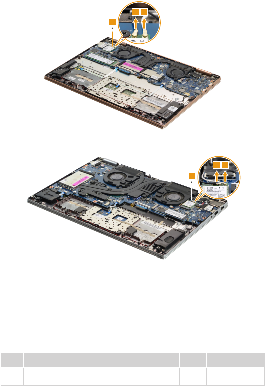
Figure 4. Removal steps of PCI Express Mini Card for wireless LAN (continued)
Disconnect the two wireless LAN cables (black, white) 2, and then remove the
screw 3.
Lenovo YOGA 720-13IKB
22
3
Lenovo YOGA 720-15IKB
3
22
In step 2, unplug the jacks by using the removal tool antenna RF connector
(P/N: 08K7159), or pick up the connectors with your ngers and gently unplug
them in the direction shown by the arrows.
Notes: The wireless LAN card has 2 cables in step 2.
The wireless LAN card in some models might have 3 cables in step 2.
Step Screw (quantity) Color Torque
3M2.0 x 2.5 mm, Phillips-head, nylok-coated (1)
WLAN TO MB
Black 1.8-2.0 kg_cm
40
Lenovo YOGA 720-13IKB/Lenovo YOGA 720-15IKB
Hardware Maintenance Manual
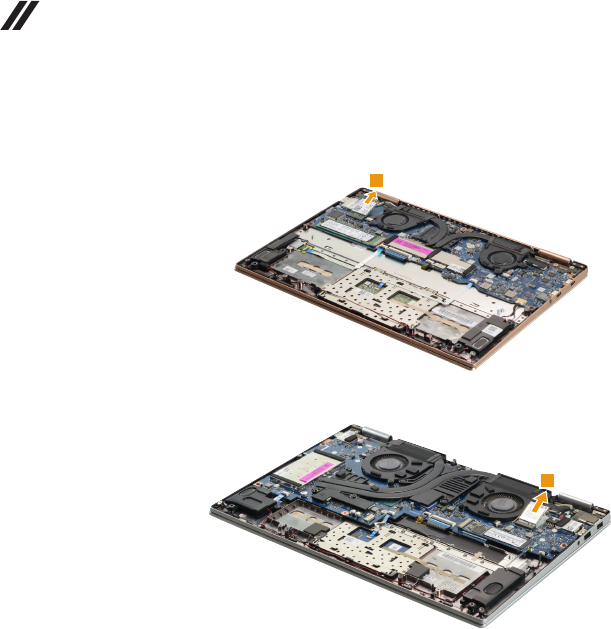
Figure 4. Removal steps of PCI Express Mini Card for wireless LAN (continued)
Remove the card in the direction shown by arrow 4.
Lenovo YOGA 720-13IKB
4
Lenovo YOGA 720-15IKB
4
When installing: When installing the wireless LAN card, plug the black cable
into the jack labeled MAIN and the white cable into the jack labeled AUX.
41
Lenovo YOGA 720-13IKB/Lenovo YOGA 720-15IKB
1050 Speakers
For access, remove these FRUs in order:
• “1010 Base cover” on page 32
• “1020 Battery pack” on page 35
Figure 5. Removal steps of speakers
Unplug the speaker connector in the direction shown by arrow 1. Release
the speaker cable from the cable guides and peel off the tape that secures
the cable. Remove the two speakers 2.
Lenovo YOGA 720-13IKB
1
2
2
Lenovo YOGA 720-15IKB
2
1
2
42
Lenovo YOGA 720-13IKB/Lenovo YOGA 720-15IKB
Hardware Maintenance Manual
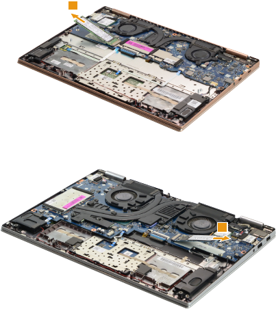
1060 DIMM (Lenovo YOGA 720-15IKB)
For access, remove these FRUs in order:
• “1010 Base cover” on page 32
• “1020 Battery pack” on page 35
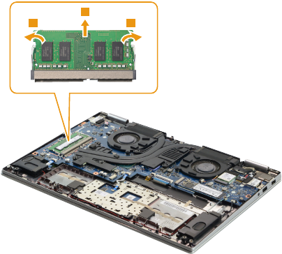
Figure 6. Removal steps of DIMM (Lenovo YOGA 720-15IKB)
Carefully remove the DIMM EMI shielding 1.
1
43
Lenovo YOGA 720-13IKB/Lenovo YOGA 720-15IKB
Figure 6. Removal steps of DIMM (Lenovo YOGA 720-15IKB) (continued)
Release the two latches on both edges of the socket at the same time in the
directions shown by arrows 2, and then unplug the DIMM in the direction shown
by arrow 3.
22
3
When installing: Insert the notched end of the DIMM into the socket. Push the
DIMM rmly, and pivot it until it snaps into place. Make sure that it is rmly xed
in the slot and is difcult to move.
Note: When replacing the memory is completed, you need to restart the
computer after the rst reboot.
44
Lenovo YOGA 720-13IKB/Lenovo YOGA 720-15IKB
Hardware Maintenance Manual
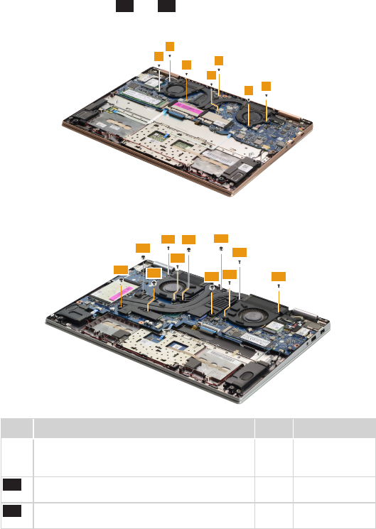
1070 Thermal module
For access, remove these FRUs in order:
• “1010 Base cover” on page 32
• “1020 Battery pack” on page 35
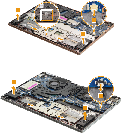
Figure 7. Removal steps of thermal module
Disconnect the two fan connectors in the directions shown by arrows 1 and 2.
Lenovo YOGA 720-13IKB
2
1
2
1
Lenovo YOGA 720-15IKB
1
1
When installing: Make sure that the connectors are attached rmly.
45
Lenovo YOGA 720-13IKB/Lenovo YOGA 720-15IKB
Figure 7. Removal steps of thermal module (continued)
Remove the screws 3, 3-a and 3-b .
Lenovo YOGA 720-13IKB
3
3
3
3
3
33
Lenovo YOGA 720-15IKB
3-a
3-a
3-b
3-b
3-b
3-b
3-a
3-a 3-a
3-b
3-b
Step Screw (quantity) Color Torque
3M2.0 x 2.5 mm, Phillips-head, nylok-coated (7)
THERMAL TO MB (UMA Only) /FAN TO UP
(UMA Only)
Black 1.8-2.0 kg_cm
3-a M2.0 x 5.0 mm, Phillips-head, nylok-coated (5)
FAN TO UP
Black 1.8-2.0 kg_cm
3-b M2.0 x 2.85+2.3 mm, Phillips-head, nylok-
coated (6) THERMAL MODULE TO MB (DIS)
Black 1.8-2.0 kg_cm
46
Lenovo YOGA 720-13IKB/Lenovo YOGA 720-15IKB
Hardware Maintenance Manual
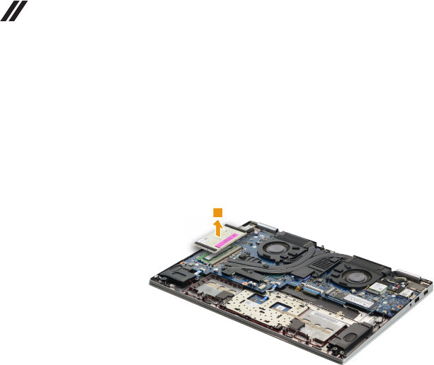
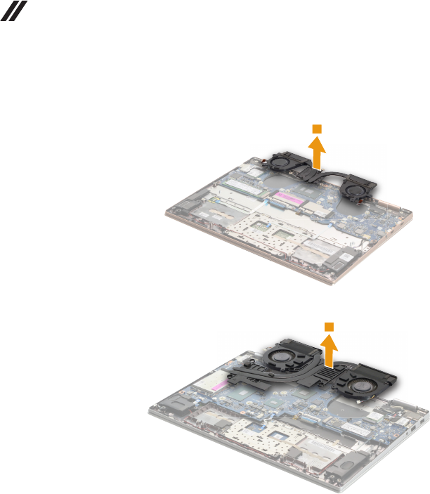
Figure 7. Removal steps of thermal module (continued)
Remove the thermal module in the direction shown by arrow 4.
Lenovo YOGA 720-13IKB
4
Lenovo YOGA 720-15IKB
4
Attention: Do not handle the heat sink assembly roughly. Improper handling
can cause distortion or deformation and imperfect contact with components.
47
Lenovo YOGA 720-13IKB/Lenovo YOGA 720-15IKB
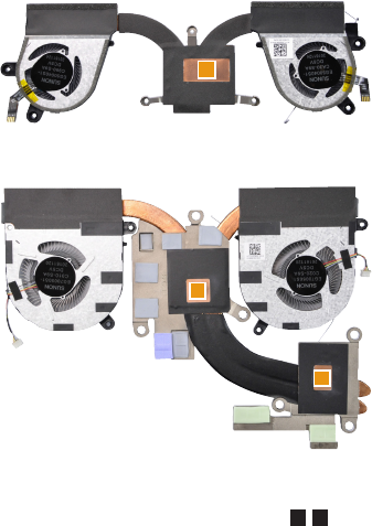
Figure 7. Removal steps of thermal module (continued)
Lenovo YOGA 720-13IKB
a
Lenovo YOGA 720-15IKB
a
b
When installing: Before you attach the fan assembly to the computer, apply
thermal grease, at an amount of 0.2 grams, to parts a b shown in the gure
above. Either too much or too little grease application can cause a thermal
problem due to imperfect contact with a component.
48
Lenovo YOGA 720-13IKB/Lenovo YOGA 720-15IKB
Hardware Maintenance Manual
1080 System board
Important notices for handling the system board:
Whenhandlingthesystemboard,bearthefollowinginmind.
• Becarefulnottodropthesystemboardonabenchtopthathasahardsurface,
suchasmetal,wood,orcomposite.
• Avoidroughhandlingofanykind.
• Duringthewholeprocess,makesurenottodroporstackthesystemboard.
• Ifyouputasystemboarddown,makesuretoputitonlyonapaddedsurface,such
asanESDmatorconductivecorrugatedmaterial.
For access, remove these FRUs in order:
• “1010 Base cover” on page 32
• “1020 Battery pack” on page 35
• “1030 Solid state disk” on page 36
• “1040 PCI Express Mini Card for wireless LAN” on page 38
• “1070 Thermal module” on page 44
49
Lenovo YOGA 720-13IKB/Lenovo YOGA 720-15IKB
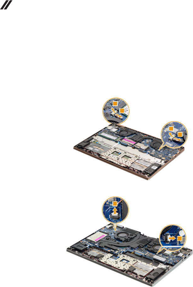
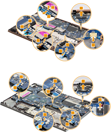
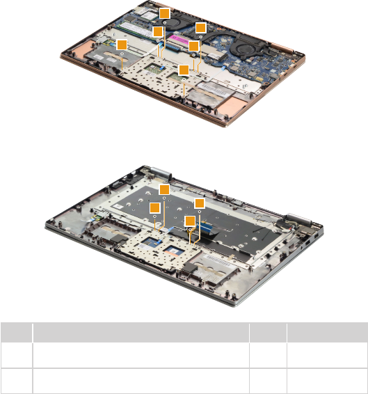
Figure 8. Removal steps of system board (continued)
Detach the connectors in the directions shown by arrows 1, 2 and 3.
Lenovo YOGA 720-13IKB
3
1
2
1
2
1
2
1
2
3
Lenovo YOGA 720-15IKB
1
2
1
2
1
2
1
2
3
3
When installing: Make sure that the connectors are attached rmly.
50
Lenovo YOGA 720-13IKB/Lenovo YOGA 720-15IKB
Hardware Maintenance Manual
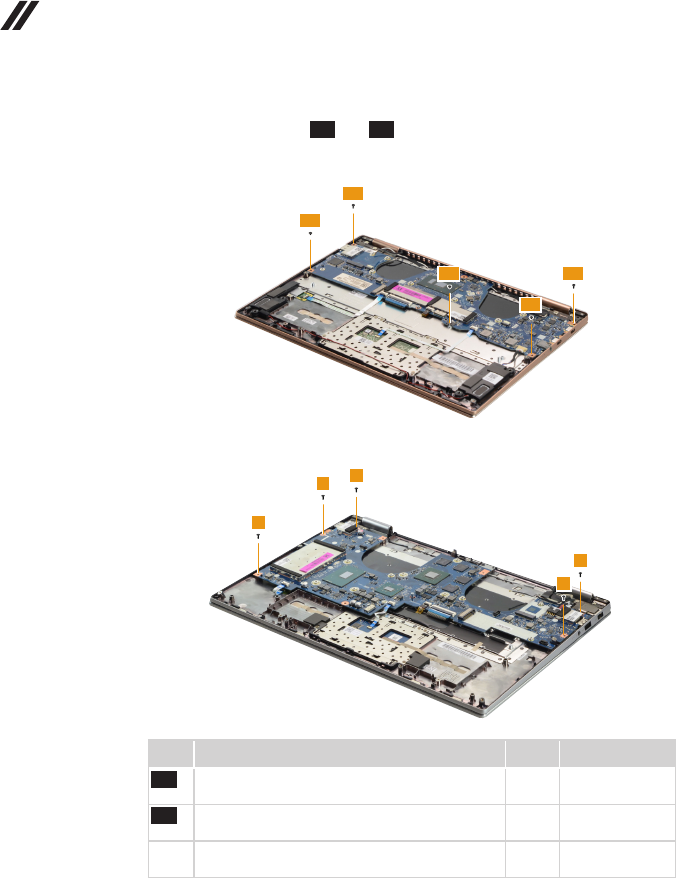
Figure 8. Removal steps of system board (continued)
Remove the screws 4, 4-a and 4-b .
Lenovo YOGA 720-13IKB
4-a
4-a
4-a
4-b
4-b
Lenovo YOGA 720-15IKB
4
4
4
4
4
Step Screw (quantity) Color Torque
4-a M2.0 x 2.5 mm, Phillips-head, nylok-coated (3)
MB TO UP
Black 1.8-2.0 kg_cm
4-b M2.0 x 4.5 mm, Phillips-head, nylok-coated (2)
MB TO HINGE TO UP
Black 1.8-2.0 kg_cm
4M2.0 x 5.0 mm, Phillips-head, nylok-coated (5)
MB TO UPPER
Black 1.8-2.0 kg_cm
51
Lenovo YOGA 720-13IKB/Lenovo YOGA 720-15IKB
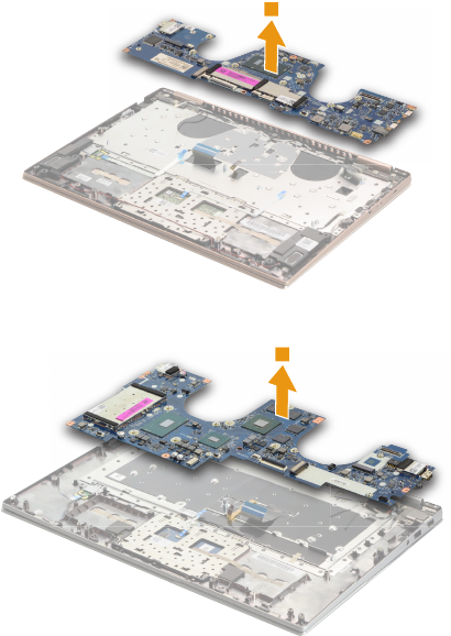
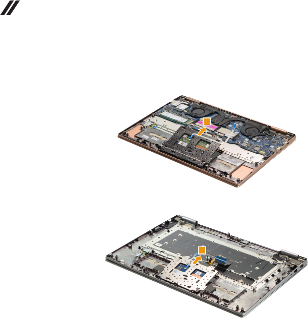
Figure 8. Removal steps of system board (continued)
Remove the system board 5.
Lenovo YOGA 720-13IKB
5
Lenovo YOGA 720-15IKB
5
52
Lenovo YOGA 720-13IKB/Lenovo YOGA 720-15IKB
Hardware Maintenance Manual
1090 Fingerprint module (on select models)
For access, remove these FRUs in order:
• “1010 Base cover” on page 32
• “1020 Battery pack” on page 35
• “1030 Solid state disk” on page 36
• “1040 PCI Express Mini Card for wireless LAN” on page 38
• “1050 Speakers” on page 41
• “1070 Thermal module” on page 44
• “1080 System board” on page 48
Figure 9. Removal steps of ngerprint module
Remove the screw 1, then remove the ngerprint bracket 2.
Lenovo YOGA 720-13IKB
1
2
Lenovo YOGA 720-15IKB
1
2
Step Screw (quantity) Color Torque
1M2.0 x 2.5 mm, Phillips-head, nylok-coated (1)
FP TO UP
Silver 1.8-2.0 kg_cm
53
Lenovo YOGA 720-13IKB/Lenovo YOGA 720-15IKB
Figure 9. Removal steps of ngerprint module (continued)
Remove the ngerprint board 3.
Lenovo YOGA 720-13IKB
3
3
Lenovo YOGA 720-15IKB
3
54
Lenovo YOGA 720-13IKB/Lenovo YOGA 720-15IKB
Hardware Maintenance Manual
1100 Touchpad module
For access, remove these FRUs in order:
• “1010 Base cover” on page 32
• “1020 Battery pack” on page 35
• “1030 Solid state disk” on page 36
• “1040 PCI Express Mini Card for wireless LAN” on page 38
• “1050 Speakers” on page 41
• “1070 Thermal module” on page 44
• “1080 System board” on page 48
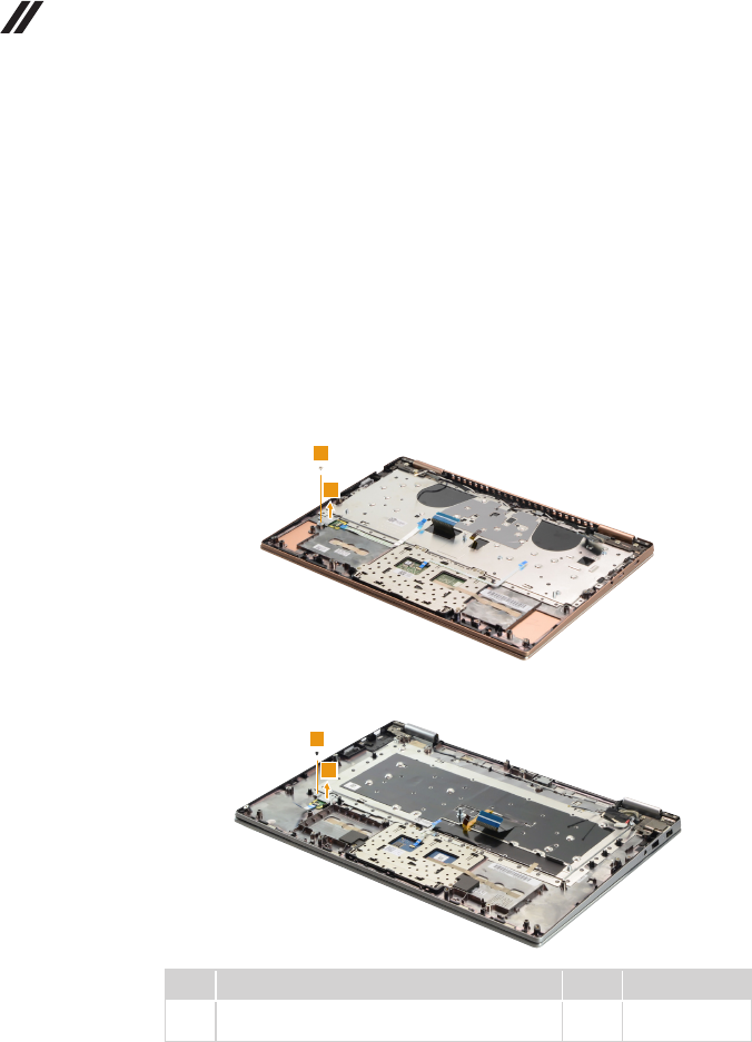
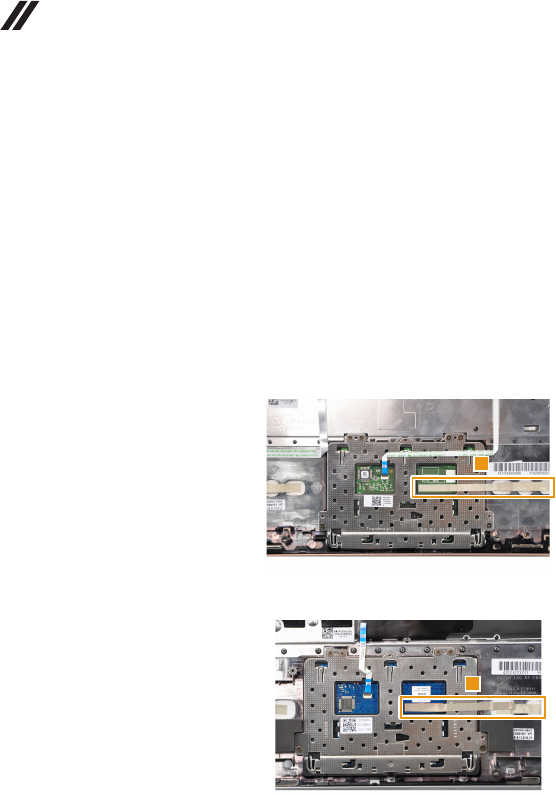
Figure 10. Removal steps of touchpad module
Peel off the tape 1.
Lenovo YOGA 720-13IKB
1
Lenovo YOGA 720-15IKB
1
55
Lenovo YOGA 720-13IKB/Lenovo YOGA 720-15IKB
Figure 10. Removal steps of touchpad module (continued)
Remove the screws 2.
Lenovo YOGA 720-13IKB
2
2
2
2
2
2
Lenovo YOGA 720-15IKB
2
2
2
2
Step Screw (quantity) Color Torque
2M1.6 x 2.0 mm, Phillips-head, nylok-coated (6)
TP BRACKET TO UP (Lenovo YOGA 720-13IKB)
Black 1.8-2.0 kg_cm
2M1.6 x 2.0 mm, Phillips-head, nylok-coated (4)
TP TO UPPER (Lenovo YOGA 720-15IKB)
Black 1.8-2.0 kg_cm
56
Lenovo YOGA 720-13IKB/Lenovo YOGA 720-15IKB
Hardware Maintenance Manual
Figure 10. Removal steps of touchpad module (continued)
Remove the touchpad module in the direction shown by arrow 3.
Lenovo YOGA 720-13IKB
3
Lenovo YOGA 720-15IKB
3
57
Lenovo YOGA 720-13IKB/Lenovo YOGA 720-15IKB
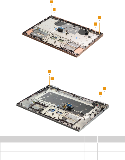
1110 LCD unit
For access, remove these FRUs in order:
• “1010 Base cover” on page 32
• “1020 Battery pack” on page 35
• “1030 Solid state disk” on page 36
• “1040 PCI Express Mini Card for wireless LAN” on page 38
• “1050 Speakers” on page 41
• “1070 Thermal module” on page 44
• “1080 System board” on page 48
Figure 11. Removal steps of LCD unit
Remove the screws 1.
Lenovo YOGA 720-13IKB
1
1
1
1
Lenovo YOGA 720-15IKB
1
1
1
1
Step Screw (quantity) Color Torque
1M2.5 × 4.5 mm, Phillips-head, nylok-coated (4)
HINGE TO UP (Lenovo YOGA 720-13IKB)
Silver 1.8-2.0 kg_cm
1M2.5 × 5.0 mm, Phillips-head, nylok-coated (4)
HINGE TO UPPER (Lenovo YOGA 720-15IKB)
Silver 1.8-2.0 kg_cm
58
Lenovo YOGA 720-13IKB/Lenovo YOGA 720-15IKB
Hardware Maintenance Manual
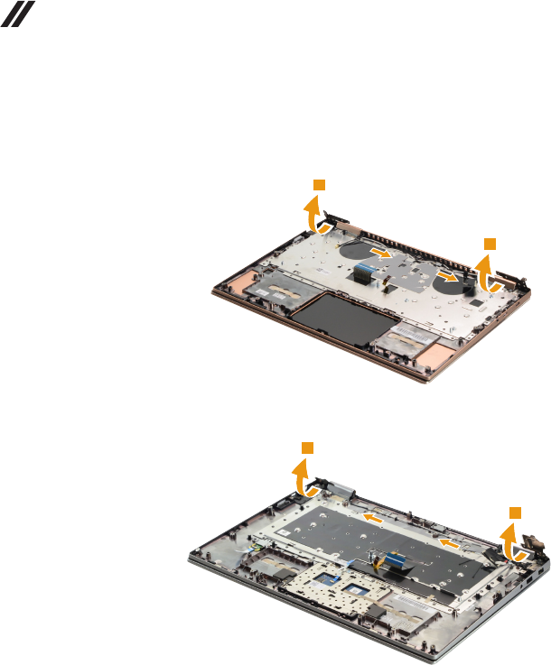
Figure 11. Removal steps of LCD unit (continued)
Open the hinges 2. Release the antenna cables from the cable guides.
Lenovo YOGA 720-13IKB
2
2
Lenovo YOGA 720-15IKB
2
2
59
Lenovo YOGA 720-13IKB/Lenovo YOGA 720-15IKB
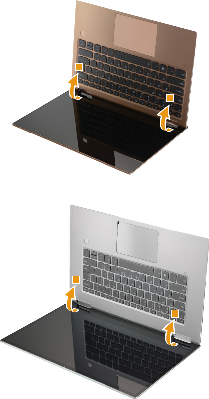
Figure 11. Removal steps of LCD unit (continued)
Rotate the upper case in the direction shown by arrow 3. Then remove the
upper case.
Lenovo YOGA 720-13IKB
3
3
Lenovo YOGA 720-15IKB
3
3
60
Lenovo YOGA 720-13IKB/Lenovo YOGA 720-15IKB
Hardware Maintenance Manual
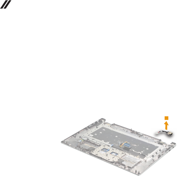
1120 DC-in cable (Lenovo YOGA 720-15IKB)
For access, remove these FRUs in order:
• “1010 Base cover” on page 32
• “1020 Battery pack” on page 35
• “1030 Solid state disk” on page 36
• “1040 PCI Express Mini Card for wireless LAN” on page 38
• “1050 Speakers” on page 41
• “1070 Thermal module” on page 44
• “1080 System board” on page 48
• “1110 LCD unit” on page 57
Figure 12. Removal steps of DC-in cable (Lenovo YOGA 720-15IKB)
Remove the DC-in cable in the direction shown by arrow 1.
1
61
Lenovo YOGA 720-13IKB/Lenovo YOGA 720-15IKB
1130 LCD panel
For access, remove these FRUs in order:
• “1010 Base cover” on page 32
• “1020 Battery pack” on page 35
• “1030 Solid state disk” on page 36
• “1040 PCI Express Mini Card for wireless LAN” on page 38
• “1050 Speakers” on page 41
• “1070 Thermal module” on page 44
• “1080 System board” on page 48
• “1110 LCD unit” on page 57
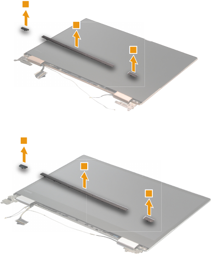
Figure 13. Removal steps of LCD panel
Remove the hinge cover with tweezers 1.
Lenovo YOGA 720-13IKB
1
1
1
Lenovo YOGA 720-15IKB
1
1
1
62
Lenovo YOGA 720-13IKB/Lenovo YOGA 720-15IKB
Hardware Maintenance Manual
Figure 13. Removal steps of LCD panel (continued)
Remove the hinge rubbers 2.
Lenovo YOGA 720-13IKB
2
2
Lenovo YOGA 720-15IKB
2
2
63
Lenovo YOGA 720-13IKB/Lenovo YOGA 720-15IKB
Figure 13. Removal steps of LCD panel (continued)
Remove the screws 3.
Lenovo YOGA 720-13IKB
3
3
Lenovo YOGA 720-15IKB
3
3
Step Screw (quantity) Color Torque
3M1.6 × 2.0 mm, Phillips-head, nylok-coated (2)
PAMEL FRAME TO COVER
(Lenovo YOGA 720-13IKB)
Black 1.8-2.0 kg_cm
3M2.0 × 3.0 mm, Phillips-head, nylok-coated (2)
PAMEL FRAME TO COVER
(Lenovo YOGA 720-15IKB)
Black 1.8-2.0 kg_cm
64
Lenovo YOGA 720-13IKB/Lenovo YOGA 720-15IKB
Hardware Maintenance Manual
Figure 13. Removal steps of LCD panel (continued)
Gently pull out the two pieces of adhesive tape with tweezers in the direction
shown by arrows 4.
Lenovo YOGA 720-13IKB
44
Lenovo YOGA 720-15IKB
44
65
Lenovo YOGA 720-13IKB/Lenovo YOGA 720-15IKB
Figure 13. Removal steps of LCD panel (continued)
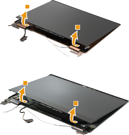
Lift the LCD panel 5.
Lenovo YOGA 720-13IKB
5
5
Lenovo YOGA 720-15IKB
5
5
66
Lenovo YOGA 720-13IKB/Lenovo YOGA 720-15IKB
Hardware Maintenance Manual
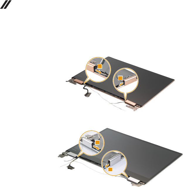
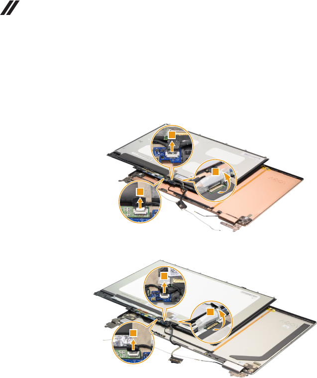
Figure 13. Removal steps of LCD panel (continued)
Gently separate the LCD panel and LCD cover and turn over the LCD panel.
Detach the two connectors in the direction shown by arrows 6. Peel off the
adhesive tape. Lift the EDP cable latch in the direction shown by arrow 7, then
detach the LCD connector.
Lenovo YOGA 720-13IKB
6
6
7
Lenovo YOGA 720-15IKB
6
6
7
When installing: Make sure that the connectors are attached rmly.
67
Lenovo YOGA 720-13IKB/Lenovo YOGA 720-15IKB
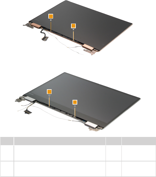
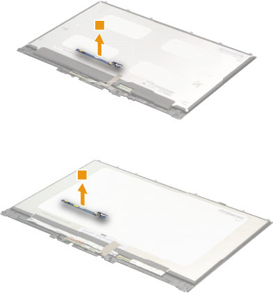
Figure 13. Removal steps of LCD panel (continued)
Remove the microphone board from the LCD module 8.
Lenovo YOGA 720-13IKB
8
Lenovo YOGA 720-15IKB
8
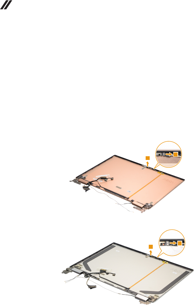
68
Lenovo YOGA 720-13IKB/Lenovo YOGA 720-15IKB
Hardware Maintenance Manual
1140 EDP cable and camera board
For access, remove these FRUs in order:
• “1010 Base cover” on page 32
• “1020 Battery pack” on page 35
• “1030 Solid state disk” on page 36
• “1040 PCI Express Mini Card for wireless LAN” on page 38
• “1050 Speakers” on page 41
• “1070 Thermal module” on page 44
• “1080 System board” on page 48
• “1110 LCD unit” on page 57
• “1130 LCD panel” on page 61
Figure 14. Removal steps of EDP cable and camera board
Unplug the connector in the direction shown by arrow 1. Remove the camera
board 2.
Lenovo YOGA 720-13IKB
2
1
Lenovo YOGA 720-15IKB
1
2
When installing: Make sure that the connector is attached rmly.
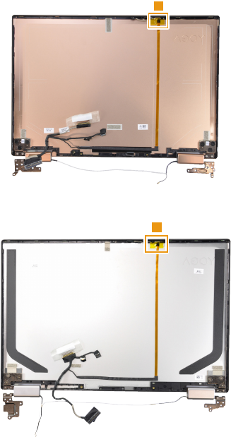
69
Lenovo YOGA 720-13IKB/Lenovo YOGA 720-15IKB
Figure 14. Removal steps of EDP cable and camera board (continued)
Peel off the tape 3.
Lenovo YOGA 720-13IKB
3
Lenovo YOGA 720-15IKB
3
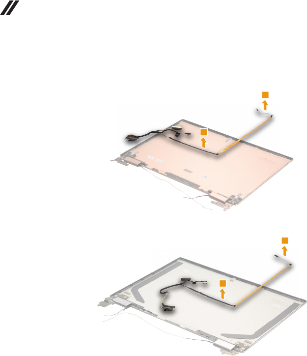
70
Lenovo YOGA 720-13IKB/Lenovo YOGA 720-15IKB
Hardware Maintenance Manual
Figure 14. Removal steps of EDP cable and camera board (continued)
Remove the EDP cable 4.
Lenovo YOGA 720-13IKB
4
4
Lenovo YOGA 720-15IKB
4
4
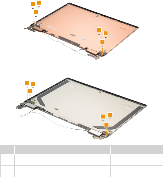
71
Lenovo YOGA 720-13IKB/Lenovo YOGA 720-15IKB
1150 LCD hinges
For access, remove these FRUs in order:
• “1010 Base cover” on page 32
• “1020 Battery pack” on page 35
• “1030 Solid state disk” on page 36
• “1040 PCI Express Mini Card for wireless LAN” on page 38
• “1050 Speakers” on page 41
• “1070 Thermal module” on page 44
• “1080 System board” on page 48
• “1110 LCD unit” on page 57
• “1130 LCD panel” on page 61
• “1140 EDP cable and camera board” on page 68
Figure 15. LCD hinges
Remove the screws 1.
Lenovo YOGA 720-13IKB
1
1
1
1
1
1
Lenovo YOGA 720-15IKB
1
11
1
11
Step Screw (quantity) Color Torque
1M2.0 × 2.0 mm, Phillips-head, nylok-coated (6)
HINGE L/R TO COVER (Lenovo YOGA 720-13IKB)
Black 2.5 ~ 3.0 kgf*cm
1
M2.5 × 2.5 mm, Phillips-head, nylok-coated (6)
HINGE BRK TO LCD COVER (Lenovo YOGA 720-15IKB)
Silver 2.5 ~ 3.0 kgf*cm
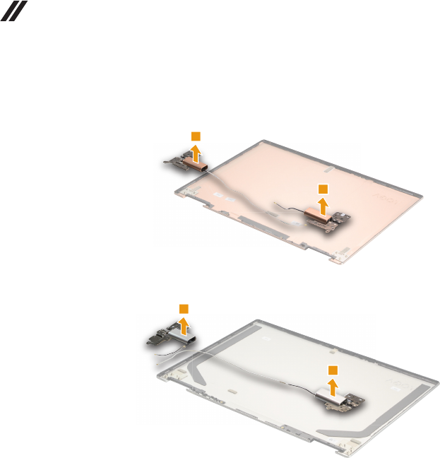
72
Lenovo YOGA 720-13IKB/Lenovo YOGA 720-15IKB
Hardware Maintenance Manual
Figure 15. Removal steps of LCD hinges (continued)
Then release the hinges in the direction shown by arrows 2.
Lenovo YOGA 720-13IKB
2
2
Lenovo YOGA 720-15IKB
2
2
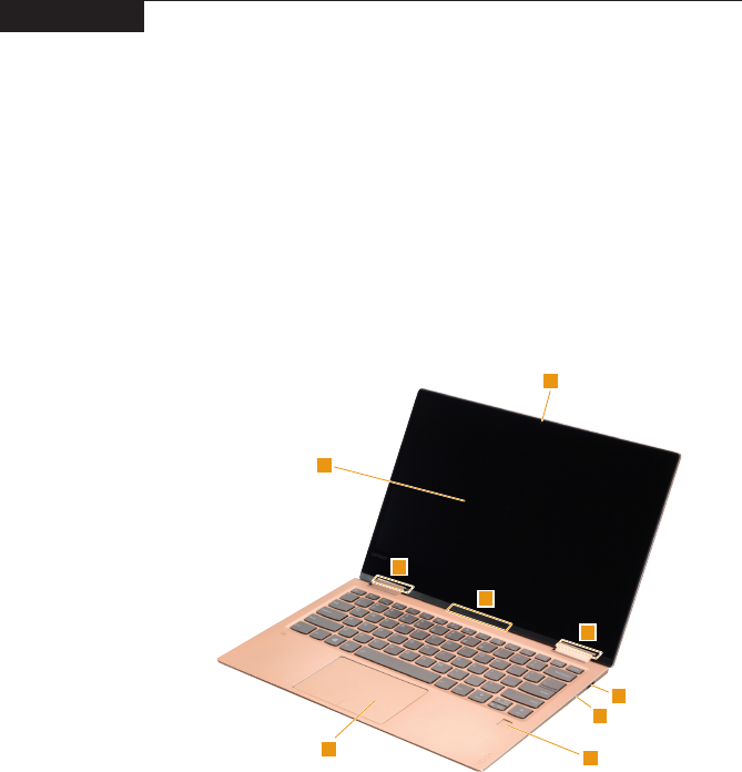
73
Lenovo YOGA 720-13IKB/Lenovo YOGA 720-15IKB
Locations
Front and right-side view
a Integrated camera
b Multi-touch screen
c Wireless LAN antennas
d Built-in microphone
e USB 3.0 port
f Type-C port
g Power button
h Fingerprint reader
i Touchpad
Lenovo YOGA 720-13IKB
1
2
3
3
4
8
9
5
7
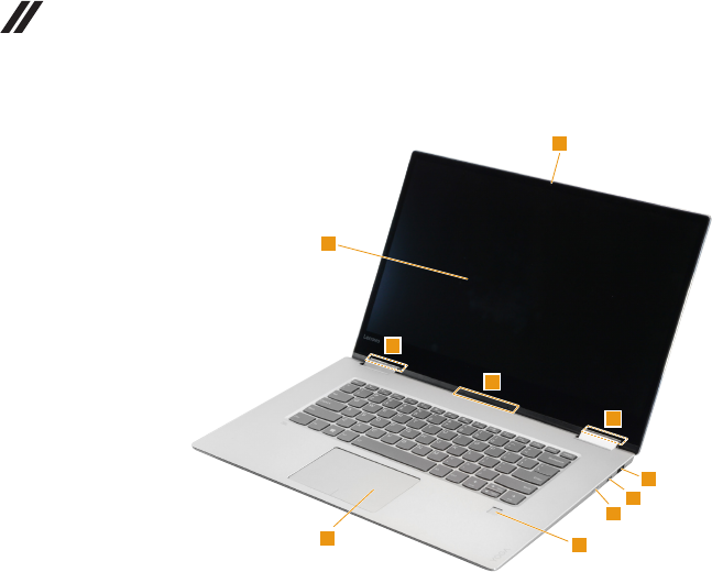
74
Lenovo YOGA 720-13IKB/Lenovo YOGA 720-15IKB
Hardware Maintenance Manual
Lenovo YOGA 720-15IKB
1
2
3
3
4
8
9
7
5
6
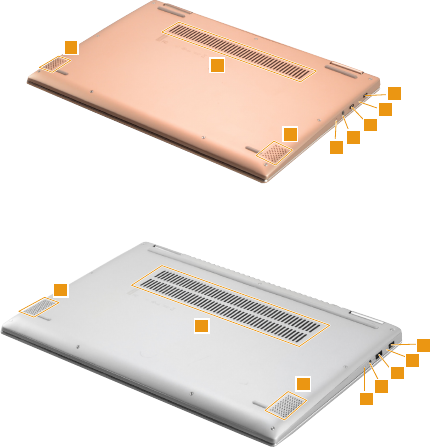
75
Lenovo YOGA 720-13IKB/Lenovo YOGA 720-15IKB
Bottom and left-side view
a Louvers
b Speakers
c AC power adapter jack
d Battery status indicator
Note: For the description of each indicator, see “Status indicators” on page 28.
e USB 3.0 port
f Combo audio jack
g Novo button
h Type-C port
Lenovo YOGA 720-13IKB
3
4
7
2
2
1
6
8
Lenovo YOGA 720-15IKB
3
4
7
2
2
1
6
5
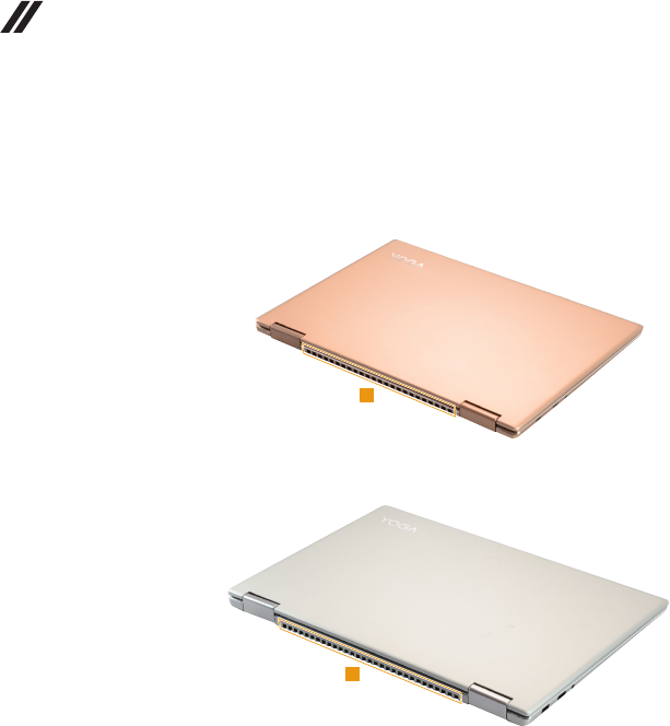
76
Lenovo YOGA 720-13IKB/Lenovo YOGA 720-15IKB
Hardware Maintenance Manual
Rear view
a Ventilation slots
Lenovo YOGA 720-13IKB
1
Lenovo YOGA 720-15IKB
1
77
Lenovo YOGA 720-13IKB/Lenovo YOGA 720-15IKB
Parts list
This section presents the following service parts:
• “Overall” on page 78
• “LCD FRUs” on page 85
• “AC adapters” on page 88
• “Screws” on page 88
Notes:
• EachFRUisavailableforalltypesormodels,unlessspecictypesormodels
arespecied.
Attention:
DonotattempttoreplaceanFRUonyourown.IfanFRUisdamaged,contact
aLenovoauthorizedserviceroramarketingrepresentativeforreplacement
orrepair.Onlyqualiedtechnicianscaninspectorrepairthisproduct.
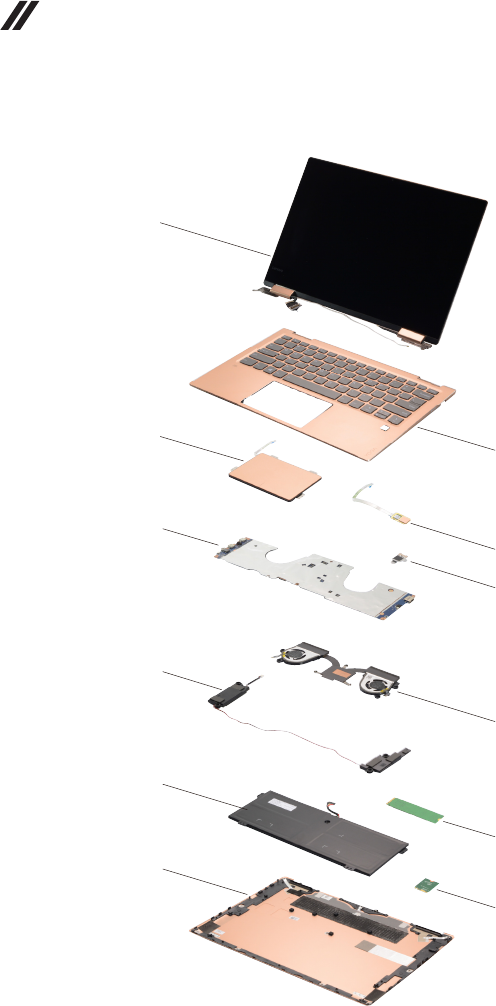
78
Lenovo YOGA 720-13IKB/Lenovo YOGA 720-15IKB
Hardware Maintenance Manual
Overall
Lenovo YOGA 720-13IKB
1
3
5
7
9
11
2
4
a
6
8
10
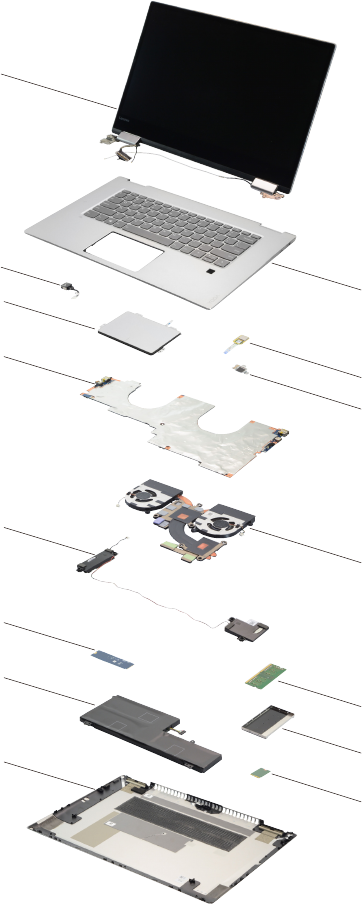
79
Lenovo YOGA 720-13IKB/Lenovo YOGA 720-15IKB
Lenovo YOGA 720-15IKB
1
c
3
5
7
8
9
11
2
4
a
6
12
b
10

80
Lenovo YOGA 720-13IKB/Lenovo YOGA 720-15IKB
Hardware Maintenance Manual
Table 5. Parts list—Overall
No. FRU FRU no. CRU
ID.
Lenovo
YOGA
720-13IKB
Lenovo
YOGA
720-15IKB
a-c see “Miscellaneous parts” on page 88.
1 LCD unit (see “LCD FRUs” on page 85.)
2 Upper Case C 80X6 W/KB Silver US 5CB0N67889 N ●
2 Upper Case C 80X6 W/KB Silver GK 5CB0N67863 N ●
2 UpperCaseC 80X6W/KBSilver US INT'E 5CB0N67850 N ●
2 Upper Case C 80X6 W/KB Silver KO 5CB0N67943 N ●
2 Upper Case C 80X6 W/KB Silver CH 5CB0N67959 N ●
2 Upper Case C 80X6 W/KB Silver RU 5CB0N67881 N ●
2 Upper Case C 80X6 W/KB Silver AR-E 5CB0N67857 N ●
2 Upper Case C 80X6 W/KB Silver HB 5CB0N67989 N ●
2 Upper Case C 80X6 W/KB Silver TI 5CB0N68010 N ●
2 UpperCase C 80X6 W/KB Silver INDIA 5CB0N67910 N ●
2 Upper Case C 80X6 W/KB Silver UK 5CB0N67844 N ●
2 Upper Case C 80X6 W/KB Silver IT 5CB0N67906 N ●
2 Upper Case C 80X6 W/KB Silver SP 5CB0N67912 N ●
2 Upper Case C 80X6 W/KB Silver TR 5CB0N67999 N ●
2 Upper Case C 80X6 W/KB Silver PO 5CB0N67976 N ●
2 Upper Case C 80X6 W/KB Silver LA 5CB0N68042 N ●
2 Upper Case C 80X6 W/KB Silver CF-E 5CB0N67948 N ●
2 Upper Case C 80X6 W/KB Silver ND 5CB0N67826 N ●
2 Upper Case C 80X6 W/KB Silver FR 5CB0N67823 N ●
2 Upper Case C 80X6 W/KB Silver GR 5CB0N67829 N ●
2 Upper Case C 80X6 W/KB Silver BZ 5CB0N67925 N ●
2 Upper Case C 80X6 W/KB Silver NL 5CB0N68028 N ●
2 Upper Case C 80X6 W/KB Silver HG 5CB0N67947 N ●
2 Upper Case C 80X6 W/KB Silver BE 5CB0N67885 N ●
2 Upper Case C 80X6 W/KB Silver ICE 5CB0N67970 N ●
2 Upper Case C 80X6 W/KB Silver SA 5CB0N67980 N ●
2 Upper Case C 80X6 W/KB Silver SW 5CB0N68024 N ●
2 Upper Case C 80X6 W/KB Silver BU 5CB0N67902 N ●
2 UpperCase C 80X6 W/KB Silver CZ-SK 5CB0N67920 N ●
2 UpperCase C 80X6 W/KB Silver AR-FR 5CB0N67934 N ●
2 UpperCase C 80X6 W/KB Silver UKR 5CB0N67891 N ●
2 UpperCase C 80X6 W/KB Silver USA 5CB0N67975 N ●
2 Upper Case C 80X6 W/KB GM US 5CB0N67821 N ●
2 Upper Case C 80X6 W/KB GM GK 5CB0N67838 N ●
2 UpperCaseC 80X6W/KBGM US INT'E 5CB0N67849 N ●
2 Upper Case C 80X6 W/KB GM KO 5CB0N67804 N ●
2 Upper Case C 80X6 W/KB GM CH 5CB0N68036 N ●
2 Upper Case C 80X6 W/KB GM RU 5CB0N68007 N ●
2 Upper Case C 80X6 W/KB GM AR-E 5CB0N68032 N ●
2 Upper Case C 80X6 W/KB GM HB 5CB0N67915 N ●
2 Upper Case C 80X6 W/KB GM TI 5CB0N67963 N ●
2 UpperCase C 80X6 W/KB GM INDIA 5CB0N67922 N ●
2 Upper Case C 80X6 W/KB GM UK 5CB0N67813 N ●
2 Upper Case C 80X6 W/KB GM IT 5CB0N67848 N ●
2 Upper Case C 80X6 W/KB GM SP 5CB0N67973 N ●
2 Upper Case C 80X6 W/KB GM TR 5CB0N67808 N ●

81
Lenovo YOGA 720-13IKB/Lenovo YOGA 720-15IKB
Table 5. Parts list—Overall (continued)
No. FRU FRU no. CRU
ID.
Lenovo
YOGA
720-13IKB
Lenovo
YOGA
720-15IKB
2 Upper Case C 80X6 W/KB GM PO 5CB0N67900 N ●
2 Upper Case C 80X6 W/KB GM LA 5CB0N67972 N ●
2 Upper Case C 80X6 W/KB GM CF-E 5CB0N67905 N ●
2 Upper Case C 80X6 W/KB GM ND 5CB0N68014 N ●
2 Upper Case C 80X6 W/KB GM FR 5CB0N68002 N ●
2 Upper Case C 80X6 W/KB GM GR 5CB0N67887 N ●
2 Upper Case C 80X6 W/KB GM BZ 5CB0N67921 N ●
2 Upper Case C 80X6 W/KB GM NL 5CB0N67923 N ●
2 Upper Case C 80X6 W/KB GM HG 5CB0N67870 N ●
2 Upper Case C 80X6 W/KB GM BE 5CB0N67837 N ●
2 Upper Case C 80X6 W/KB GM ICE 5CB0N67907 N ●
2 Upper Case C 80X6 W/KB GM SA 5CB0N67852 N ●
2 Upper Case C 80X6 W/KB GM SW 5CB0N67871 N ●
2 Upper Case C 80X6 W/KB GM BU 5CB0N68017 N ●
2 UpperCase C 80X6 W/KB GM CZ-SK 5CB0N67895 N ●
2 UpperCase C 80X6 W/KB GM AR-FR 5CB0N67854 N ●
2 UpperCase C 80X6 W/KB GM UKR 5CB0N68034 N ●
2 UpperCase C 80X6 W/KB GM USA 5CB0N67899 N ●
2 Upper Case C 80X6 W/KB Copper US 5CB0N68038 N ●
2 Upper Case C 80X6 W/KB Copper GK 5CB0N68020 N ●
2 UpperCaseC 80X6W/KBCopper US INT'E 5CB0N67961 N ●
2 Upper Case C 80X6 W/KB Copper KO 5CB0N67926 N ●
2 Upper Case C 80X6 W/KB Copper CH 5CB0N68011 N ●
2 Upper Case C 80X6 W/KB Copper RU 5CB0N67918 N ●
2 Upper Case C 80X6 W/KB Copper AR-E 5CB0N67878 N ●
2 Upper Case C 80X6 W/KB Copper HB 5CB0N68012 N ●
2 Upper Case C 80X6 W/KB Copper TI 5CB0N67816 N ●
2 UpperCase C 80X6 W/KB Copper INDIA 5CB0N68018 N ●
2 Upper Case C 80X6 W/KB Copper UK 5CB0N67855 N ●
2 Upper Case C 80X6 W/KB Copper IT 5CB0N67932 N ●
2 Upper Case C 80X6 W/KB Copper SP 5CB0N67851 N ●
2 Upper Case C 80X6 W/KB Copper TR 5CB0N68027 N ●
2 Upper Case C 80X6 W/KB Copper PO 5CB0N67818 N ●
2 Upper Case C 80X6 W/KB Copper LA 5CB0N67982 N ●
2 Upper Case C 80X6 W/KB Copper CF-E 5CB0N67835 N ●
2 Upper Case C 80X6 W/KB Copper ND 5CB0N67935 N ●
2 Upper Case C 80X6 W/KB Copper FR 5CB0N67842 N ●
2 Upper Case C 80X6 W/KB Copper GR 5CB0N67924 N ●
2 Upper Case C 80X6 W/KB Copper BZ 5CB0N67988 N ●
2 Upper Case C 80X6 W/KB Copper NL 5CB0N67830 N ●
2 Upper Case C 80X6 W/KB Copper HG 5CB0N68015 N ●
2 Upper Case C 80X6 W/KB Copper BE 5CB0N67962 N ●
2 Upper Case C 80X6 W/KB Copper ICE 5CB0N68035 N ●
2 Upper Case C 80X6 W/KB Copper SA 5CB0N67955 N ●
2 Upper Case C 80X6 W/KB Copper SW 5CB0N67872 N ●
2 Upper Case C 80X6 W/KB Copper BU 5CB0N67994 N ●
2 UpperCase C 80X6 W/KB Copper CZ-SK 5CB0N68022 N ●

82
Lenovo YOGA 720-13IKB/Lenovo YOGA 720-15IKB
Hardware Maintenance Manual
No. FRU FRU no. CRU
ID.
Lenovo
YOGA
720-13IKB
Lenovo
YOGA
720-15IKB
2 UpperCase C 80X6 W/KB Copper AR-FR 5CB0N67986 N ●
2 UpperCase C 80X6 W/KB Copper UKR 5CB0N68006 N ●
2 UpperCase C 80X6 W/KB Copper USA 5CB0N67831 N ●
2 Upper Case C 80X7 W/KB GM US 5CB0N67978 N ●
2 Upper Case C 80X7 W/KB GM GK 5CB0N67950 N ●
2 UpperCaseC 80X7W/KBGM US INT'E 5CB0N68043 N ●
2 Upper Case C 80X7 W/KB GM KO 5CB0N67942 N ●
2 Upper Case C 80X7 W/KB GM CH 5CB0N67884 N ●
2 Upper Case C 80X7 W/KB GM RU 5CB0N68021 N ●
2 Upper Case C 80X7 W/KB GM AR-E 5CB0N68039 N ●
2 Upper Case C 80X7 W/KB GM HB 5CB0N67938 N ●
2 Upper Case C 80X7 W/KB GM TI 5CB0N67968 N ●
2 UpperCase C 80X7 W/KB GM INDIA 5CB0N67987 N ●
2 Upper Case C 80X7 W/KB GM UK 5CB0N67862 N ●
2 Upper Case C 80X7 W/KB GM IT 5CB0N67866 N ●
2 Upper Case C 80X7 W/KB GM SP 5CB0N67825 N ●
2 Upper Case C 80X7 W/KB GM TR 5CB0N68013 N ●
2 Upper Case C 80X7 W/KB GM PO 5CB0N67811 N ●
2 Upper Case C 80X7 W/KB GM LA 5CB0N67847 N ●
2 Upper Case C 80X7 W/KB GM CF-E 5CB0N67894 N ●
2 Upper Case C 80X7 W/KB GM ND 5CB0N67904 N ●
2 Upper Case C 80X7 W/KB GM FR 5CB0N67927 N ●
2 Upper Case C 80X7 W/KB GM GR 5CB0N67919 N ●
2 Upper Case C 80X7 W/KB GM BZ 5CB0N67956 N ●
2 Upper Case C 80X7 W/KB GM NL 5CB0N67883 N ●
2 Upper Case C 80X7 W/KB GM HG 5CB0N67880 N ●
2 Upper Case C 80X7 W/KB GM BE 5CB0N67958 N ●
2 Upper Case C 80X7 W/KB GM ICE 5CB0N67979 N ●
2 Upper Case C 80X7 W/KB GM SA 5CB0N67802 N ●
2 Upper Case C 80X7 W/KB GM SW 5CB0N68001 N ●
2 Upper Case C 80X7 W/KB GM BU 5CB0N67832 N ●
2 UpperCase C 80X7 W/KB GM CZ-SK 5CB0N67819 N ●
2 UpperCase C 80X7 W/KB GM AR-FR 5CB0N67898 N ●
2 UpperCase C 80X7 W/KB GM UKR 5CB0N67992 N ●
2 UpperCase C 80X7 W/KB GM USA 5CB0N67810 N ●
2 Upper Case C 80X7 W/KB Silver US 5CB0N67945 N ●
2 Upper Case C 80X7 W/KB Silver GK 5CB0N67879 N ●
2 UpperCaseC 80X7W/KBSilver US INT'E 5CB0N67977 N ●
2 Upper Case C 80X7 W/KB Silver KO 5CB0N67964 N ●
2 Upper Case C 80X7 W/KB Silver CH 5CB0N67995 N ●
2 Upper Case C 80X7 W/KB Silver RU 5CB0N67807 N ●
2 Upper Case C 80X7 W/KB Silver AR-E 5CB0N67817 N ●
2 Upper Case C 80X7 W/KB Silver HB 5CB0N67952 N ●
2 Upper Case C 80X7 W/KB Silver TI 5CB0N67911 N ●
2 UpperCase C 80X7 W/KB Silver INDIA 5CB0N67888 N ●
2 Upper Case C 80X7 W/KB Silver UK 5CB0N67983 N ●
2 Upper Case C 80X7 W/KB Silver IT 5CB0N67903 N ●
2 Upper Case C 80X7 W/KB Silver SP 5CB0N68008 N ●
Table 5. Parts list—Overall (continued)

83
Lenovo YOGA 720-13IKB/Lenovo YOGA 720-15IKB
No. FRU FRU no. CRU
ID.
Lenovo
YOGA
720-13IKB
Lenovo
YOGA
720-15IKB
2 Upper Case C 80X7 W/KB Silver TR 5CB0N67960 N ●
2 Upper Case C 80X7 W/KB Silver PO 5CB0N67991 N ●
2 Upper Case C 80X7 W/KB Silver LA 5CB0N67868 N ●
2 Upper Case C 80X7 W/KB Silver CF-E 5CB0N67940 N ●
2 Upper Case C 80X7 W/KB Silver ND 5CB0N67901 N ●
2 Upper Case C 80X7 W/KB Silver FR 5CB0N68009 N ●
2 Upper Case C 80X7 W/KB Silver GR 5CB0N67953 N ●
2 Upper Case C 80X7 W/KB Silver BZ 5CB0N67886 N ●
2 Upper Case C 80X7 W/KB Silver NL 5CB0N67985 N ●
2 Upper Case C 80X7 W/KB Silver HG 5CB0N67949 N ●
2 Upper Case C 80X7 W/KB Silver BE 5CB0N68031 N ●
2 Upper Case C 80X7 W/KB Silver ICE 5CB0N67930 N ●
2 Upper Case C 80X7 W/KB Silver SA 5CB0N68005 N ●
2 Upper Case C 80X7 W/KB Silver SW 5CB0N67858 N ●
2 Upper Case C 80X7 W/KB Silver BU 5CB0N67946 N ●
2 UpperCase C 80X7 W/KB Silver CZ-SK 5CB0N67843 N ●
2 UpperCase C 80X7 W/KB Silver AR-FR 5CB0N67984 N ●
2 UpperCase C 80X7 W/KB Silver UKR 5CB0N67864 N ●
2 UpperCase C 80X7 W/KB Silver USA 5CB0N67833 N ●
3 TP Module C 80X6 W/Cable Silver 5T60N68003 N ●
3 TP ModuleC 80X6 W/CableGunMetal 5T60N67869 N ●
3 TP Module C 80X6 W/Cable Copper 5T60N68037 N ●
3 TP ModuleC 80X7 W/CableGunMetal 5T60N67834 N ●
3 TP Module C 80X7 W/Cable Silver 5T60N67996 N ●
4 FPModuleC 80X6 W/Calbe Silver 5F30N68000 N ●
4 FPModuleC80X6 W/CalbeGunMetal 5F30N67974 N ●
4 FPModule C 80X6 W/CalbeCopper 5F30N67853 N ●
4 FPModuleC80X7 W/CalbeGunMetal 5F30N67939 N ●
4 FPModuleC 80X7 W/Calbe Silver 5F30N67933 N ●
5 MB C 80X6 NOK I77500 UMA 4G 5B20N67990 N ●
5 MB C 80X6 WIN I77500 UMA 4G 5B20N68016 N ●
5 MB C 80X6 NOK I77500 UMA 8G 5B20N67876 N ●
5 MB C 80X6 WIN I77500 UMA 8G 5B20N68033 N ●
5 MB C 80X6 NOK I77500 UMA 16G 5B20N67873 N ●
5 MB C 80X6 WIN I77500 UMA 16G 5B20N67877 N ●
5 MB C 80X6 NOK I57200 UMA 4G 5B20N67998 N ●
5 MB C 80X6 WIN I57200 UMA 4G 5B20N67981 N ●
5 MB C 80X6 NOK I57200 UMA 8G 5B20N67931 N ●
5 MB C 80X6 WIN I57200 UMA 8G 5B20N67805 N ●
5 MB C 80X6 NOK I57200 UMA 16G 5B20N68041 N ●
5 MB C 80X6 WIN I57200 UMA 16G 5B20N67928 N ●
5 MB C 80X6 NOK I77500 UMA 12G 5B20N67875 N ●
5 MB C 80X6 WIN I77500 UMA 12G 5B20N67824 N ●
5 MB C 80X6 NOK I57200 UMA 12G 5B20N67965 N ●
5 MB C 80X6 WIN I57200 UMA 12G 5B20N67969 N ●
5 MB C 80X7 NOK I57300 N17 2G 8G 5B20N67828 N ●
5 MB C 80X7 WIN I57300 N17 2G 8G 5B20N67890 N ●
Table 5. Parts list—Overall (continued)

84
Lenovo YOGA 720-13IKB/Lenovo YOGA 720-15IKB
Hardware Maintenance Manual
Table 5. Parts list—Overall (continued)
No. FRU FRU no. CRU
ID.
Lenovo
YOGA
720-13IKB
Lenovo
YOGA
720-15IKB
5 MB C 80X7 NOK I77700 N17 2G 8G 5B20N67941 N ●
5 MB C 80X7 WIN I77700 N17 2G 8G 5B20N67856 N ●
5 MB C 80X7 NOK I77700 UMA 8G 5B20N67971 N ●
5 MB C 80X7 WIN I77700 UMA 8G 5B20N67814 N ●
5 MB C 80X7 NOK I57300 UMA 8G 5B20N67815 N ●
5 MB C 80X7 WIN I57300 UMA 8G 5B20N67897 N ●
5 MB C 80X7 NOK I57300 N17 4G 8G 5B20N67839 N ●
5 MB C 80X7 WIN I57300 N17 4G 8G 5B20N68025 N ●
5 MB C 80X7 NOK I77700 N17 4G 8G 5B20N68004 N ●
5 MB C 80X7 WIN I77700 N17 4G 8G 5B20N67893 N ●
6 Thermal Module C 80X6 W/Fan 5H40N67860 N ●
6 Thermal Module C 80X7 W/Fan DIS 5H40N67861 N ●
6 Thermal Module C 80X7 W/Fan UMA 5H40N67914 N ●
7 Yoga720-13 RT6-D Speaker 5SB0M65355 N ●
7 Yoga720-15 Blade N-Y Speaker 5SB0M65359 N ●
8 SSD, PM961 MZVLW128HEGR PCIE 128G SSD 5SD0L73445 N ●
8 SSD, TSB XG4 128G M.2 2280 PCIe SSD 5SD0M56301 N ●
8 SSD, PM961 MZVLW256HEHP PCIE 256G SSD 5SD0L73444 N ● ●
8 SSD, TSB XG4 256G M.2 2280 PCIe SSD 5SD0M56299 N ● ●
8 SSD, PM961 MZVLW512HMJP PCIE 512G SSD 5SD0L73443 N ● ●
8 SSD, TSB XG4 512G M.2 2280 PCIe SSD 5SD0M56300 N ● ●
8SSD, MZVLW1T0HMLH-000L2 PCIe M.2 1TB SSD 5SD0L07883 N ● ●
9Battery, Valcan SP/A L16M4PB1 7.68V48Wh4cell bty 5B10M52740 N ●
9Battery, Valcan CP/C L16C4PB1 7.68V48Wh4cell bty 5B10M52739 N●
9 Battery, Valcan LG L16L4PB1 7.72V48Wh4cell bty 5B10M52738 N ●
9Battery,vision LG L16L6PC1 11.58V72Wh6cell bty 5B10M53744 N ●
9Battery,visionSP/C L16M6PC1 11.52V72Wh6cell bty 5B10M53743 N ●
9Battery,vision CP/A L16C6PC1 11.52V72Wh6cell bty 5B10M53745 N ●
10 Intel 8265 2x2AC+BT PCIE M.2 WLAN NV SW10K97453 N ● ●
10 Ltn NFA344A 2x2AC+BT4.x PCIE M.2 WLAN SW10K97465 N ● ●
11 Lower Case C 80X6 Silver 5CB0N68026 N ●
11 Lower Case C 80X6 GunMetal 5CB0N67937 N ●
11 Lower Case C 80X6 Copper 5CB0N68040 N ●
11 Lower Case C 80X7 GunMetal 5CB0N67836 N ●
11 Lower Case C 80X7 Silver 5CB0N67966 N ●
12 Memory, Samsung 4GB DDR4 SODIMM 2400
M471A5244CB0-CRC
SM30M49902 N●
12 Memory, 4GB D4S HMA851S6AFR6N-UH SM30G16505 N ●
12 Memory, 4GB D4S RMSA3270MB86H9F-2400 SM30G16507 N ●
12 Memory, 4GB D4S MTA4ATF51264HZ-2G3B1 SM30G16506 N ●
12 Memory, Samsung 8GB DDR4 SODIMM 2400
M471A1K43CB1-CRC
SM30M49901 N●
12 Memory, HMA81GS6AFR8N-UH SM30G16509 N ●
12 Memory, MTA8ATF1G64HZ-2G3B1 SM30G16510 N ●
12 Memory, RMSA3260MB78HAF-2400 SM30G16511 N ●
— AC adapter (see “AC adapters” on page 88).
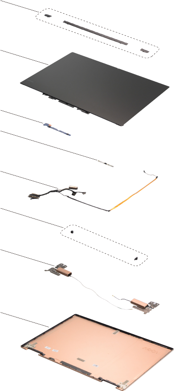
85
Lenovo YOGA 720-13IKB/Lenovo YOGA 720-15IKB
LCD FRUs
In Lenovo YOGA 720-13IKB/Lenovo YOGA 720-15IKB, there are following types
of LCDs.
• “13.3-in. FHD/UHD LED”
Lenovo YOGA 720-13IKB
1
3
2
4
5
8
6
7
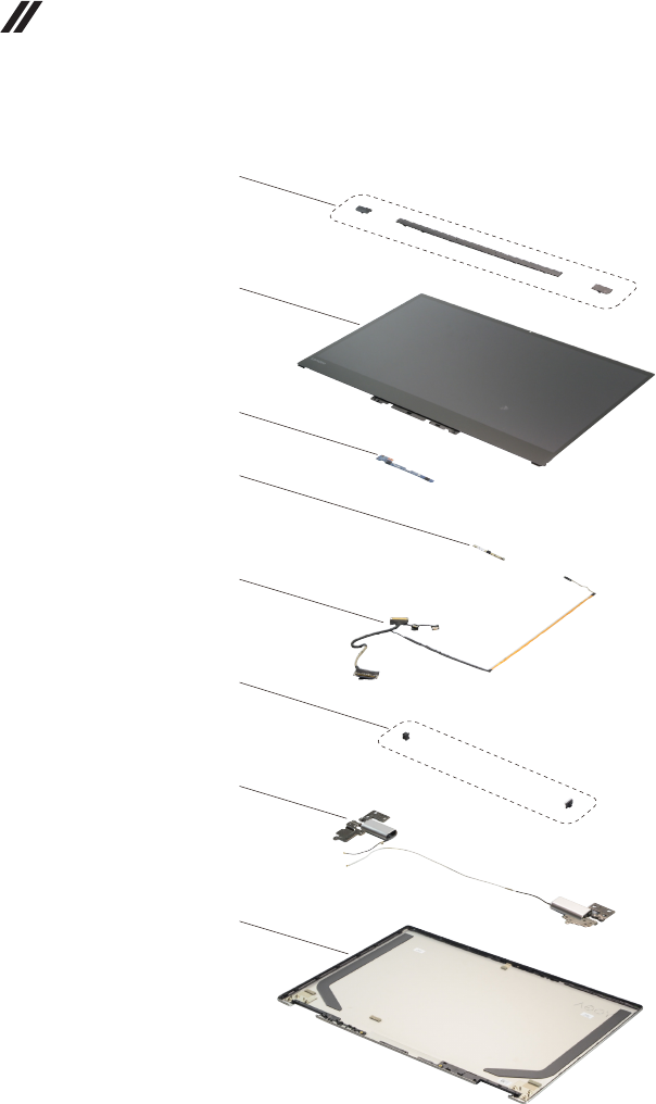
86
Lenovo YOGA 720-13IKB/Lenovo YOGA 720-15IKB
Hardware Maintenance Manual
• “15.6-in. FHD/UHD LED”
Lenovo Yoga 720-15IKB
1
3
2
4
5
8
6
7

87
Lenovo YOGA 720-13IKB/Lenovo YOGA 720-15IKB
Table 6. Parts list—LCD FRUs
No. FRU FRU no. CRU
ID.
Lenovo
YOGA
720-13IKB
Lenovo
YOGA
720-15IKB
1 Hinge Cover C 80X6 MID 5CB0N67892 N ●
1 Hinge Cover C 80X6 R 5CB0N67822 N ●
1 Hinge Cover C 80X6 L 5CB0N67859 N ●
1 Hinge Cover C 80X7 MID 5CB0N68030 N ●
1 Hinge Cover C 80X7 R 5CB0N67896 N ●
1 Hinge Cover C 80X7 L 5CB0N68023 N ●
2
2
3 MIC Board C 80X6 5C50N67840 N ●
3 MIC Board C 80X7 5C50N67997 N ●
4 Camera C 80X6 1M 5C20N68029 N ●
4 Camera C 80X7 1M 5C20N67803 N ●
5 EDP Cable C 80X6 FHD 5C10N67841 N ●
5 EDP Cable C 80X6 UHD 5C10N67944 N ●
5 EDP Cable C 80X7 FHD 5C10N67908 N ●
5 EDP Cable C 80X7 UHD 5C10N67882 N ●
6 Hinge Cap Rubber C 80X6 L 5R60N67967 N ●
6 Hinge Cap Rubber C 80X6 R 5R60N67865 N ●
6 Hinge Cap Rubber C 80X7 L 5R60N67929 N ●
6 Hinge Cap Rubber C 80X7 R 5R60N67806 N ●
7 Hinge C 80X6 W/ANT R+L Silver 5H50N67993 N ●
7 Hinge C 80X6 W/ANT R+L GunMetal 5H50N67951 N ●
7 Hinge C 80X6 W/ANT R+L Copper 5H50N67913 N ●
7 Hinge C 80X7 W/ANT R+L GunMetal 5H50N67845 N ●
7 Hinge C 80X7 W/ANT R+L Silver 5H50N67846 N ●
8 LCD Cover C 80X6 Silver 5CB0N67827 N ●
8 LCD Cover C 80X6 GunMetal 5CB0N67909 N ●
8 LCD Cover C 80X6 Copper 5CB0N68019 N ●
8 LCD Cover C 80X7 GunMetal 5CB0N67820 N ●
8 LCD Cover C 80X7 Silver 5CB0N67812 N ●
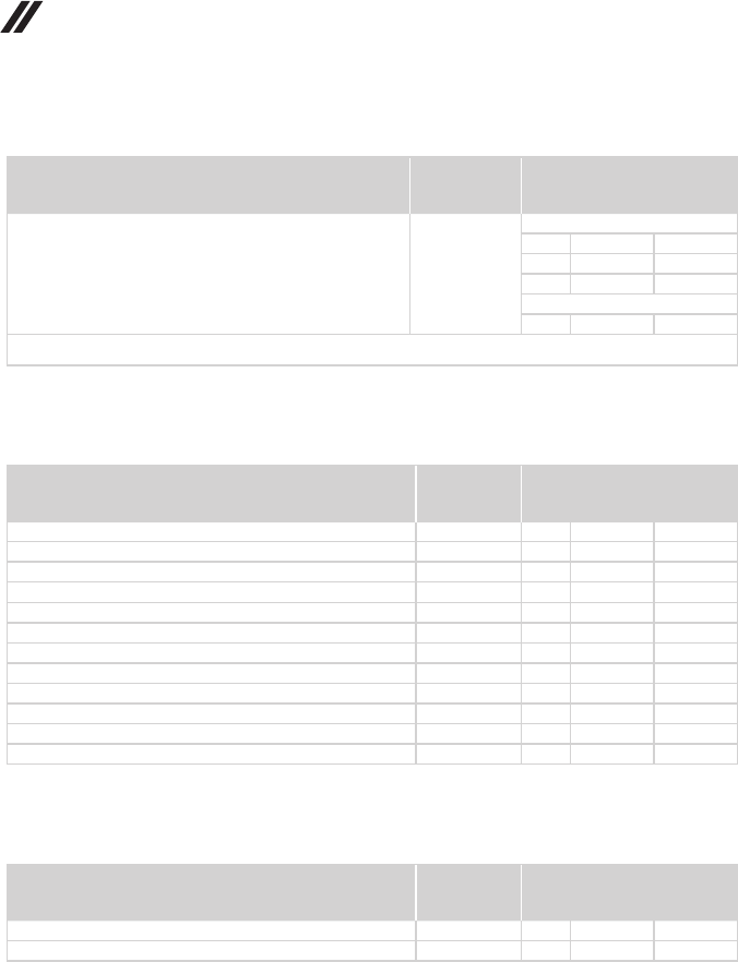
88
Lenovo YOGA 720-13IKB/Lenovo YOGA 720-15IKB
Hardware Maintenance Manual
Miscellaneous parts
Table 7. Parts list—Miscellaneous parts
FRU P/N CRU
ID.
Lenovo
YOGA
720-13IKB
Lenovo
YOGA
720-15IKB
System miscellaneous parts:
• (a) FingerPrint Bracket C 80X6 5B40N67867 N ●
• (a) FingerPrint Bracket C 80X7 5B40N67917 N ●
• (b) Shielding of Memory C 80X7 5S60N67957 N ●
Cable miscellaneous parts:
• (c) DC-IN Cable C 80X7 5C10N67809 N ●
Note: Italicized letters in parentheses are references to the exploded view in “Overall” on page 78.
AC adapters
Table 8. Parts list—AC adapters
FRU P/N CRU
ID.
Lenovo
YOGA
720-13IKB
Lenovo
YOGA
720-15IKB
Chicony PD 3.0 USB-C 45W 3pin SA10E75843 * ●
Liteon PD 3.0 USB-C 45W 3pin SA10E75841 * ●
Delta PD 3.0 USB-C 45W 3pin SA10E75839 * ●
Acbel PD 3.0 USB-C 45W 3pin SA10E75845 * ●
Delta ADLX90NDC3A 20V4.5A BIS 5A10J46686 * ●
Liteon ADLX90NLC3A 20V4.5A AD BIS 5A10J75109 * ●
Chicony ADLX90NCC3A 20V4.5A AD BIS 5A10J75116 * ●
Delta ADLX90NDC3A 20V4.5A COO SA10M42754 * ●
Chicony ADLX90NCC3A 20V4.5A COO SA10M42797 * ●
Liteon ADL135NLC3A 20V6.75A AD BIS 5A10J75112 * ●
Delta ADL135NDC3A 20V6.75A BIS 5A10J46690 * ●
Delta ADL135NDC3A 20V6.75A COO SA10M42761 * ●
Screws
Table 9. Parts list—Screws
FRU P/N CRU
ID.
Lenovo
YOGA
720-13IKB
Lenovo
YOGA
720-15IKB
Screw Pack C 80X6 5S10N67954 N ●
Screw Pack C 80X7 5S10N67936 N ●

89
Lenovo YOGA 720-13IKB/Lenovo YOGA 720-15IKB
Power cords
A Lenovo power cord for a specific country or region is usually available only in that country or
region:
Table 10. Parts list—3-pin power cords
Region P/N CRU
ID.
Lenovo
YOGA
720-13IKB
Lenovo
YOGA
720-15IKB
CCC 3 pin
• LINETEK PC323+RVV300/300+LS15 1m
145000600 *● ●
Argentina 3 pin
• LINETEK LS15+H03VV-F+LP39 1m
145000599 *● ●
Switzerland 3 pin
• LINETEK LS15+H03VV-F+LP-37 1m
145000597 *● ●
Brazil 3 pin
• LINETEK LS15 H03VV-F LP26A 1m
145000596 *● ●
Israel 3 pin
• LINETEK LS15+H03VV-F+LP-41 1m
145000595 *● ●
UL 3 pin
• LINETEK LP-30B + SPT-2 + LS15 1m
145000594 *● ●
UK 3 pin
• LINETEK LP-61L+ H03VV-F+ LS15 1m
145000593 *● ●
India 3 pin
• LINETEK PE-361+ H05VV-F+ LS15 1m
145000592 *● ●
Italy 3 pin
• LINETEK LS15+H03VV-F+PE-336 1m
145000591 *● ●
Korea 3 pin
• LINETEK LS15+H05VV-F+LP-E04A 1m
145000590 *● ●
Australia 3 pin
• LINETEK LS15+H03VV-F+LP-23A 1m
145000589 *● ●
Taiwan 3 pin
• LINETEK LS15+VCTF+LP-53 1m
145000588 *● ●
Japan 3 pin
• LINETEK LS15+VCTF+LP-54 1m
145000587 *● ●
Africa 3 pin
• LINETEK LS15+H03VV-F+PE-364 1m
145000586 *● ●
CE 3 pin
• LINETEK LP-34+H03VV-F + LS15 1m
145000585 *● ●
CCC 3 pin
• Longwell LSG-31+RVV300/300+LS-18 1m
145000568 *● ●
Argentina 3 pin
• Longwell LP-24+H03VV-F+LS-18 1m
145000567 *● ●
Switzerland 3 pin
• Longwell LP-37+H03VV-F+LS-18 1m
145000565 *● ●
Brazil 3 pin
• Longwell LP-46+H03VV-F+LS-18 1m
145000564 *● ●
Israel 3 pin
• Longwell LP-41+H03VV-F+LS-18 1m
145000563 *● ●

90
Lenovo YOGA 720-13IKB/Lenovo YOGA 720-15IKB
Hardware Maintenance Manual
Region P/N CRU
ID.
Lenovo
YOGA
720-13IKB
Lenovo
YOGA
720-15IKB
UL 3 pin
• Longwell LP-30B+SPT-2 18AWG+LS-18 1m
145000562 *● ●
UK 3 pin
• Longwell LP-61L+H03VV-F+LS-18 1m
145000561 *● ●
India 3 pin
• Longwell LP-67+BIS+LS-18 1m
145000560 *● ●
Italy 3 pin
• Longwell LP-22+H03VV-F+LS-18 1m
145000559 *● ●
Korea 3 pin
• Longwell LP-486+KTLH03VV-F+LS-5 1m
145000558 *● ●
Australia 3 pin
• Longwell LP-23A+LFC-3R+LS-18 1m
145000557 *● ●
Taiwan 3 pin
• Longwell LP-71+VCTF+LS-33 1m
145000556 *● ●
Japan 3 pin
• Longwell LP-54+VCTF+LS-18 1m
145000555 *● ●
Africa 3 pin
• Longwell LP-39+H03VV-F+LS-18 1m
145000554 *● ●
CE 3 pin
• Longwell LP-34A+H03VV-F+LS-18 1m
145000553 *● ●
CCC 3 pin
• VOLEX GB10S3+RVV 300/500+VAC5S 1m
145000538 *● ●
Argentina 3 pin
• VOLEX VA2073+H03VV-F+VAC5S 1m
145000528 *● ●
Switzerland 3 pin
• VOLEX MP232+H03VV-F+VAC5S 1m
145000524 *● ●
Brazil 3 pin
• VOLEX CH10S3+H03VV-F+VAC5S 1m
145000527 *● ●
Israel 3 pin
• VOLEX SI16S3+H03VV-F+VAC5S 1m
145000526 *● ●
UL 3 pin
• Volex US15S3+SPT-2 +VAC5S 1m
145000537 *● ●
UK 3 pin
• VOLEX MP5004+H03VV-F+VAC5S 1m
145000605 *● ●
Italy 3 pin
• VOLEX IT10S3+HO3VV-F+VAC5S 1m
145000535 *● ●
Korea 3 pin
• VOLEX M2511+KETI IEC+VAC5S 1m
145000533 *● ●
Australia 3 pin
• VOLEX AU10S3+H03VV-F+VAC5S 1m
145000532 *● ●
Taiwan 3 pin
• VOLEX TW15CS3+VCTF+VAC5S 1m
145000531 *● ●
Japan 3 pin
• VOLEX VAC5S+VCTF+M755 1m
145000530 *● ●
Table 10. Parts list—3-pin power cords (continued)

91
Lenovo YOGA 720-13IKB/Lenovo YOGA 720-15IKB
Region P/N CRU
ID.
Lenovo
YOGA
720-13IKB
Lenovo
YOGA
720-15IKB
CE 3 pin
• VOLEX M2511+HO3VV-F+VAC5S 1m
145000525 *● ●
CCC 3 pin
• lux 0036+RVV 300/300 0.75/3C+0002 1m
145500003 *● ●
Argentina 3 pin
• lux 0040+H03VV-F 0.75/3C+0011 1m
145500015 *● ●
Switzerland 3 pin
• lux 0027+H03VV-F 0.75/3C+0011 1m
145500013 *● ●
Brazil 3 pin
• lux 0034+H03VV-F 0.75/3C+0011 1m
145500011 *● ●
Israel 3 pin
• lux 0041+H03VV-F 0.75/3C+0011 1m
145500012 *● ●
UL 3 pin
• lux 0014+SPT-2 60°C 18/3C+0016 1m
145500002 *● ●
Thailand 3 pin
• lux 0014+H03VV-F 0.75/3C+0011 1m
5L60J33143 *● ●
UK 3 pin
• lux 0031+H03VV-F 0.75/3C+0011 1m
145500000 *● ●
India 3 pin
• lux 0046+IS694 0.75/3C+0011 1m
145500004 *● ●
Italy 3 pin
• lux 0029+H03VV-F 0.75/3C+0011 1m
145500009 *● ●
Korea 3 pin
• lux 0033+H03VV-F 0.75/3C+0011 1m
145500008 *● ●
Australia 3 pin
• lux 0038+H03VV-F 0.75/3C+0011 1m
145500006 *● ●
Taiwan 3 pin
• lux 0019+VCTF 0.75/3C+0021 1m
145500007 *● ●
Japan 3 pin
• lux 0018(E)+VCTF 0.75/3C+0021 1m
145500005 *● ●
Africa 3 pin
• lux 0044+H03VV-F 0.75/3C+0011 1m
145500010 *● ●
CE 3 pin
• lux 0033+H03VV-F 0.75/3C+0011 1m
145500001 *● ●
Table 10. Parts list—3-pin power cords (continued)

92
Lenovo YOGA 720-13IKB/Lenovo YOGA 720-15IKB
Hardware Maintenance Manual
Notices
Lenovo may not offer the products, services, or features discussed in this
document in all countries. Consult your local Lenovo representative for
information on the products and services currently available in your area. Any
reference to a Lenovo product, program, or service is not intended to state or
imply that only that Lenovo product, program, or service may be used. Any
functionally equivalent product, program, or service that does not infringe
any Lenovo intellectual property right may be used instead. However, it is the
user’s responsibility to evaluate and verify the operation of any other product,
program, or service.
Lenovo may have patents or pending patent applications covering subject matter
described in this document. The furnishing of this document does not give you
any license to these patents.
LENOVO GROUP LTD. PROVIDES THIS PUBLICATION “AS IS”
WITHOUT WARRANTY OF ANY KIND, EITHER EXPRESS OR IMPLIED,
INCLUDING, BUT NOT LIMITED TO, THE IMPLIED WARRANTIES OF NON-
INFRINGEMENT, MERCHANTABILITY OR FITNESS FOR A PARTICULAR
PURPOSE. Some jurisdictions do not allow disclaimer of express or implied
warranties in certain transactions, therefore, this statement may not apply to you.
This information could include technical inaccuracies or typographical errors.
Changes are periodically made to the information herein; these changes
will be incorporated in new editions of the publication. Lenovo may make
improvements and/or changes in the product(s) and/or the program(s)
described in this publication at any time without notice.
The products described in this document are not intended for use in
implantation or other life support applications where malfunction may result in
injury or death to persons. The information contained in this document does not
affect or change Lenovo product specications or warranties. Nothing in this
document shall operate as an express or implied license or indemnity under the
intellectual property rights of Lenovo or third parties. All information contained
in this document was obtained in specic environments and is presented as an
illustration. The result obtained in other operating environments may vary.
Lenovo may use or distribute any of the information you supply in any way it
believes appropriate without incurring any obligation to you.
Any references in this publication to non-Lenovo Web sites are provided for
convenience only and do not in any manner serve as an endorsement of those
Web sites. The materials at those Web sites are not part of the materials for
this Lenovo product, and use of those Web sites is at your own risk.
Any performance data contained herein was determined in a controlled
environment. Therefore, the result obtained in other operating environments
may vary significantly. Some measurements may have been made on
development-level systems and there is no guarantee that these measurements
will be the same on generally available systems. Furthermore, some
measurements may have been estimated through extrapolation. Actual results
may vary. Users of this document should verify the applicable data for their
specic environment.

93
Notices
Trademarks
The following terms are either registered trademarks or trademarks of Lenovo
in the United States and/or other countries:
Lenovo®
Lenovo logo®
OneKey
The following term is trademark of Microsoft Corporation in the United States,
other countries, or both:
Windows®
The following term is trademark of Intel Corporation or its subsidiaries in the
United States, other countries, or both:
Intel®
Other company, product, or service names may be the trademarks or service
marks of others.
