Lenovo M920z User Guide And Hardware Maintenance Manual (English) All In One (Think Centre) Type 10S6 Ug Hmm En
2018-07-31
User Manual: Lenovo (English) Hardware Maintenance Manual and User Guide - Lenovo M920z M920z All-in-One (ThinkCentre) - Type 10S6 10S6
Open the PDF directly: View PDF ![]() .
.
Page Count: 70
- Chapter 1. Overview
- Chapter 2. Specifications
- Chapter 3. Computer locks
- Chapter 4. Replacing hardware
- Before replacing hardware
- Knowing FRUs (including CRUs)
- Locating FRUs (including CRUs)
- Replacing the computer stand
- Removing the computer cover
- Replacing the storage drive
- Replacing the optical drive
- Replacing the optical drive and storage drive cables
- Replacing the side I/O bezel
- Replacing the system board shield
- Replacing the VESA mount bracket
- Replacing the power supply assembly
- Replacing the cover presence switch
- Replacing the system fan
- Replacing the heat sink
- Replacing the microprocessor
- Replacing the Wi-Fi card
- Replacing the serial connector module
- Replacing the M.2 solid-state drive
- Replacing a memory module
- Replacing the coin-cell battery
- Replacing the card reader
- Replacing the system board
- Replacing the integrated camera and microphone module
- Replacing the back frame
- Replacing the internal speakers
- Replacing the Wi-Fi antennas
- Replacing the LCD panel
- Completing the parts replacement
- Appendix A. Notices
- Appendix B. Trademarks

M920z User Guide and Hardware
Maintenance Manual
Energy Star Machine Types: 10S6, 10S7, 10Y5, and 10Y6
Note: Before using this information and the product it supports, be sure to read and understand the
Important Product Information Guide and Appendix A “Notices” on page 61.
First Edition (July 2018)
© Copyright Lenovo 2018.
LIMITED AND RESTRICTED RIGHTS NOTICE: If data or software is delivered pursuant to a General Services
Administration “GSA” contract, use, reproduction, or disclosure is subject to restrictions set forth in Contract No. GS-
35F-05925.

Contents
Chapter 1. Overview . . . . . . . . . . . 1
Front view . . . . . . . . . . . . . . . . . . 1
Rear view . . . . . . . . . . . . . . . . . . 3
System board . . . . . . . . . . . . . . . . 4
Machine type and model label . . . . . . . . . . 6
Adjusting the integrated camera and microphone
module . . . . . . . . . . . . . . . . . . . 6
Adjusting the computer stand . . . . . . . . . . 6
Chapter 2. Specifications . . . . . . . . 9
Chapter 3. Computer locks . . . . . . 11
Chapter 4. Replacing hardware . . . . 13
Before replacing hardware . . . . . . . . . . 13
Knowing FRUs (including CRUs) . . . . . . . . 13
Locating FRUs (including CRUs) . . . . . . . . 14
Replacing the computer stand . . . . . . . . . 16
Removing the computer cover . . . . . . . . . 18
Replacing the storage drive . . . . . . . . . . 19
Replacing the optical drive . . . . . . . . . . 21
Replacing the optical drive and storage drive
cables . . . . . . . . . . . . . . . . . . 24
Replacing the side I/O bezel . . . . . . . . . . 24
Replacing the system board shield . . . . . . . 25
Replacing the VESA mount bracket . . . . . . . 26
Replacing the power supply assembly . . . . . . 27
Replacing the cover presence switch . . . . . . 30
Replacing the system fan . . . . . . . . . . . 31
Replacing the heat sink . . . . . . . . . . . . 32
Replacing the microprocessor . . . . . . . . . 33
Replacing the Wi-Fi card . . . . . . . . . . . 38
Replacing the serial connector module . . . . . . 39
Replacing the M.2 solid-state drive . . . . . . . 40
Replacing a memory module. . . . . . . . . . 43
Replacing the coin-cell battery . . . . . . . . . 45
Replacing the card reader . . . . . . . . . . . 47
Replacing the system board . . . . . . . . . . 48
Replacing the integrated camera and microphone
module . . . . . . . . . . . . . . . . . . 49
Replacing the back frame . . . . . . . . . . . 52
Replacing the internal speakers . . . . . . . . 55
Replacing the Wi-Fi antennas . . . . . . . . . 56
Replacing the LCD panel . . . . . . . . . . . 57
Completing the parts replacement . . . . . . . 58
Appendix A. Notices . . . . . . . . . . 61
Appendix B. Trademarks . . . . . . . 63
© Copyright Lenovo 2018 i
ii M920z User Guide and Hardware Maintenance Manual
Chapter 1. Overview
This chapter provides basic information to help you get familiar with your computer.
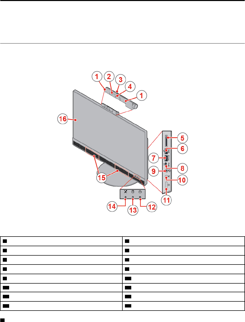
Front view
Note: Your computer model might look slightly different from the illustration.
Figure 1. Front view
1 Integrated microphones (2) (optional) 2 Integrated camera activity indicator (optional)
3 Integrated camera shield control slider (optional) 4 Integrated camera (optional)
5 Card reader slot (optional) 6 USB 3.1 Gen 1 connector
7 Always On USB 3.1 Gen 2 connector (for rapid charge) 8 USB 3.1 Gen 1 Type-C connector
9 Headset connector (also known as combo audio jack) 10 Microphone mute/unmute control (computer mode)
11 Power button 12 Power indicator
13 Storage drive activity indicator 14 Microphone mute/unmute indicator
15 Internal speakers (2) 16 Screen
1 Integrated microphones
Used to record sounds or use speech-recognition software without using a microphone.
© Copyright Lenovo 2018 1

2 Integrated camera activity indicator
When the indicator is on, the camera is in use.
3 Integrated camera shield control slider
Used to cover the camera lens.
4 Integrated camera
Used to take pictures or hold a video conference.
5 Card reader slot
Used to read data from a supported memory card.
6 USB 3.1 Gen 1 connector
Used to connect a USB-compatible device. For optimal data transfer, connect a USB 3.1 Gen 1 device to a
USB 3.1 Gen 2 or USB 3.1 Gen 1 connector instead of a USB 2.0 connector.
7 Always On USB 3.1 Gen 2 connector
Used to connect a USB-compatible device. For optimal data transfer, connect a USB 3.1 Gen 2 device to a
USB 3.1 Gen 2 connector instead of a USB 3.1 Gen 1 or USB 2.0 connector. With the ac power adapter
connected, you can charge the automatically detected device even when the computer is in hibernation
mode or turned off.
8 USB 3.1 Gen 1 Type-C connector
Used to connect a USB Type-C compatible device. For optimal data transfer, connect a USB 3.1 Gen 1
device to a USB 3.1 Gen 2 or USB 3.1 Gen 1 connector instead of a USB 2.0 connector.
9 Headset connector
Used to connect a headset or headphones to your computer.
10 Microphone mute/unmute control
Used to mute or unmute the integrated microphones in the computer mode.
11 Power button
Used to turn on your computer. When you cannot shut down the computer from the operating system, press
and hold the power button for four or more seconds to turn off the computer.
12 Power indicator
This indicator is on when the computer is on.
13 Storage drive activity indicator
This indicator is on when the storage drive is in use.
14 Microphone mute/unmute indicator
This indicator is on when the microphones are muted.
2M920z User Guide and Hardware Maintenance Manual
15 Internal speaker
Used to listen to the sounds from your computer without using a headset or headphones.
16 Screen
Depending on the computer model, your computer screen might support the multi-touch feature. This
feature enables you to use up to ten fingers to interact with the computer.
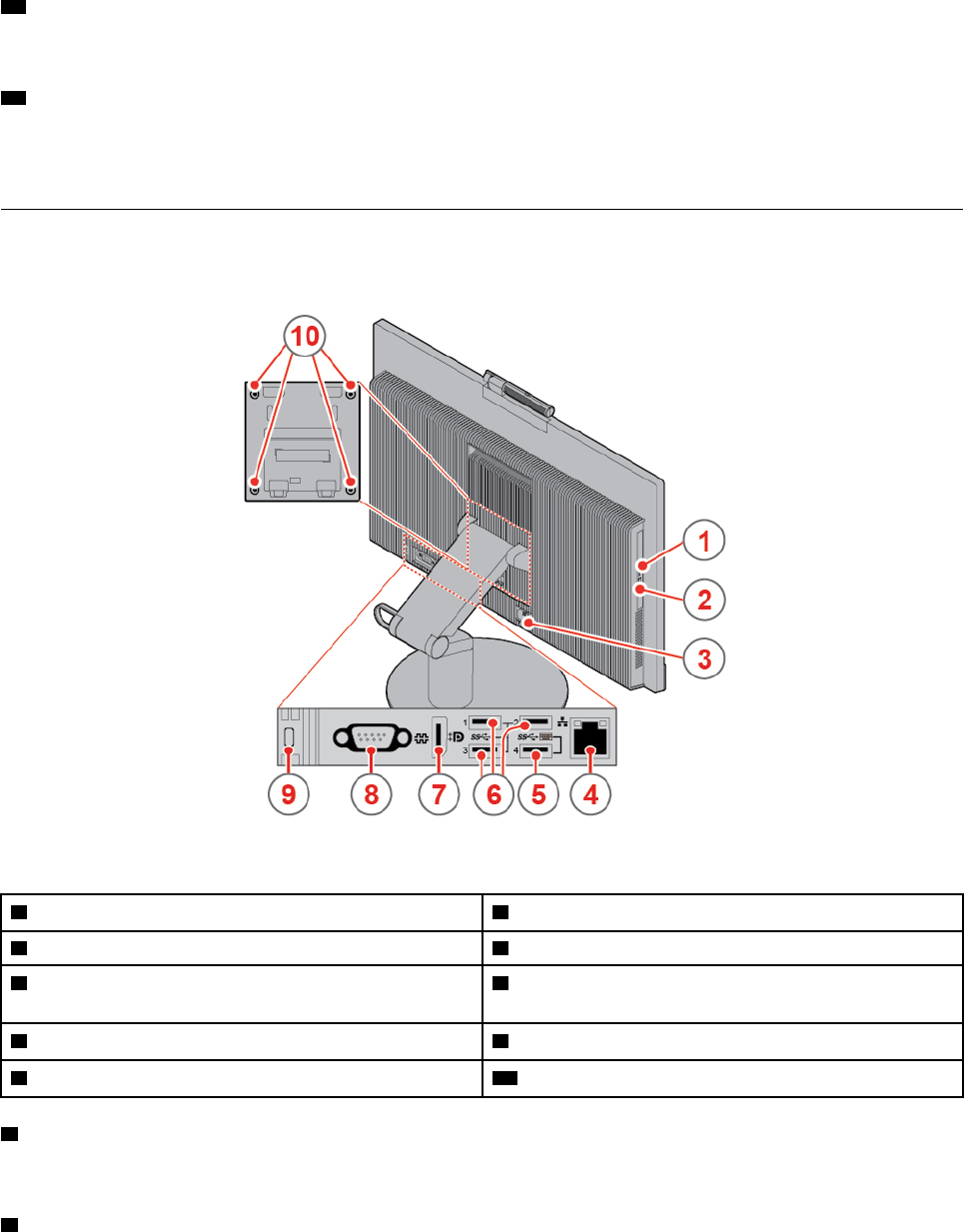
Rear view
Note: Your computer model might look slightly different from the illustration.
Figure 2. Rear view
1 Optical drive activity indicator (optional) 2 Optical drive eject/close button (optional)
3 Power cord connector 4 Ethernet connector
5 USB 3.1 Gen 1 connector (supporting the smart power
on feature)
6 USB 3.1 Gen 1 connectors (3)
7 DisplayPort® 1.2 in/out connector 8 Serial connector (optional)
9 Security-lock slot 10 VESA threaded holes (screws: M4 x 8 mm x 4 pcs)
1 Optical drive activity indicator
This indicator is on when the optical drive is in use.
2 Optical drive eject/close button
Used to eject the tray of the optical drive. After you insert a disc into the tray, press the eject/close button to
close the tray.
Chapter 1.Overview 3

3 Power cord connector
Used to connect the power cord to your computer for power supply.
4 Ethernet connector
Used to connect an Ethernet cable for network access.
5 USB 3.1 Gen 1 connector
Used to connect a USB-compatible device. For optimal data transfer, connect a USB 3.1 Gen 1 device to a
USB 3.1 Gen 2 or USB 3.1 Gen 1 connector instead of a USB 2.0 connector. The connector supports the
smart power on feature that enables you to turn on the computer or wake it up from S4 hibernation mode by
pressing Alt+P on the keyboard. You can enable or disable the smart power on feature from the Setup Utility
program. For detailed information, see Important Product Information Guide.
6 USB 3.1 Gen 1 connector
Used to connect a USB-compatible device. For optimal data transfer, connect a USB 3.1 Gen 1 device to a
USB 3.1 Gen 2 or USB 3.1 Gen 1 connector instead of a USB 2.0 connector.
7 DisplayPort 1.2 in/out connector
Used to send audio and video signals and receive video signals. When a high-performance monitor is
connected to this connector, the computer remains in the computer mode. When another computer in use is
connected to this connector, the computer automatically changes to the monitor mode.
8 Serial connector
Used to connect an external modem, a serial printer, or other devices that use a serial connector.
9 Security-lock slot
Used to secure a Kensington-style cable lock.
10 VESA threaded holes
Used to connect the matched VESA mount with the matched screws when you install the computer on a
wall.
System board
Note: See “Front view” and “Rear view” for additional component descriptions.
4M920z User Guide and Hardware Maintenance Manual
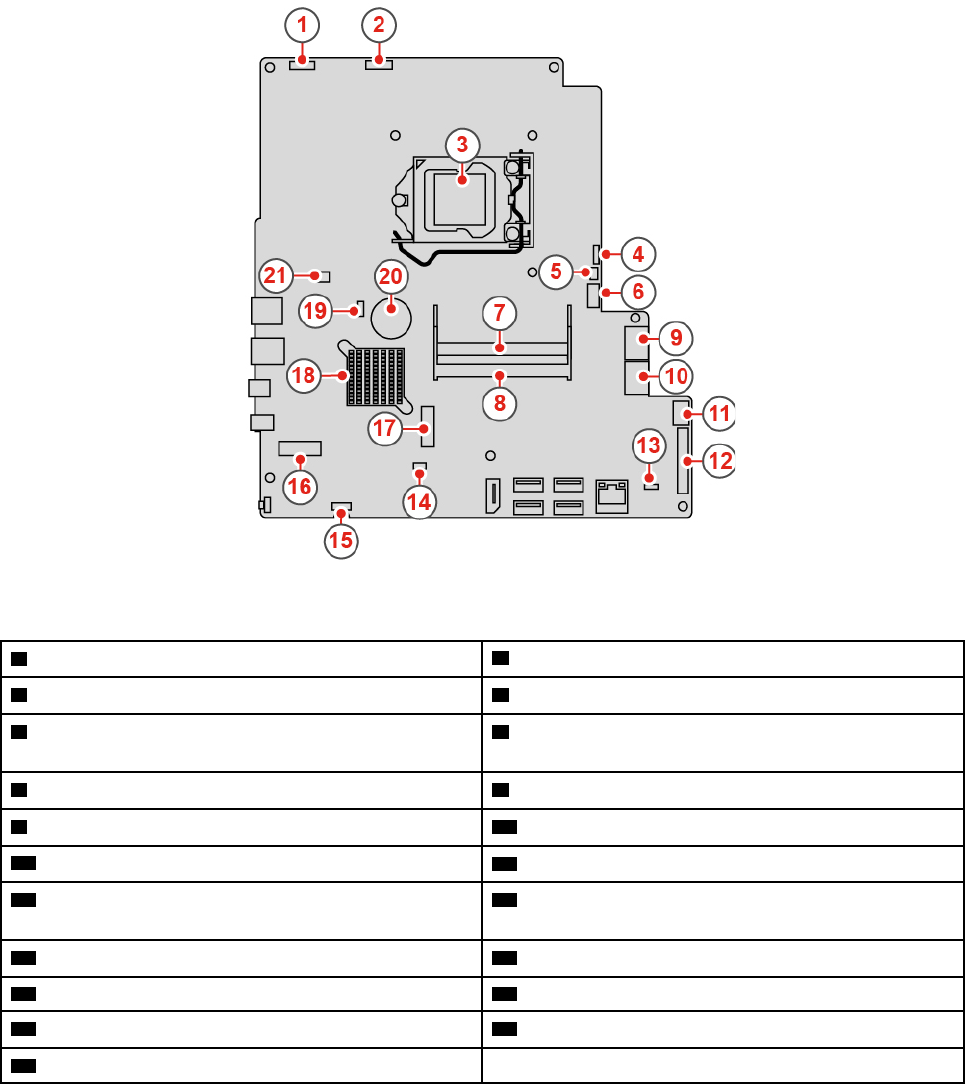
Figure 3. System board
1 LCD power connector 2 Integrated camera and microphone module connector
3 Microprocessor socket 4 System fan connector
5 Touch board connector 6 SATA power connector (connecting to the storage
drive and optical drive)
7 Memory slot (DIMM1) 8 Memory slot (DIMM2)
9 SATA connector (connecting to the optical drive) 10 SATA connector (connecting to the storage drive)
11 Power supply assembly connector 12 LCD LVDS connector
13 Cover presence switch connector (intrusion switch
connector)
14 Serial (COM1) connector
15 Internal speaker connector 16 M.2 Wi-Fi card slot
17 M.2 solid-state drive slot 18 PCH
19 Clear CMOS /Recovery jumper 20 Coin-cell battery
21 Card reader connector
Chapter 1.Overview 5
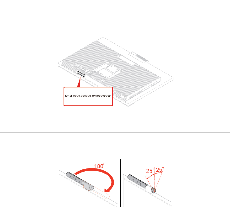
Machine type and model label
The machine type and model label identifies the computer. When you contact Lenovo for help, the machine
type and model information helps support technicians to identify the computer and provide faster service.
The machine type and model label is attached on the computer as shown.
Figure 4. Machine type and model label
Adjusting the integrated camera and microphone module
Note: The integrated camera and microphone module is optional.
Adjusting the computer stand
Note: The computer stand is optional.
6M920z User Guide and Hardware Maintenance Manual
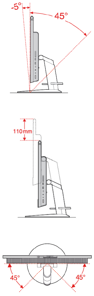
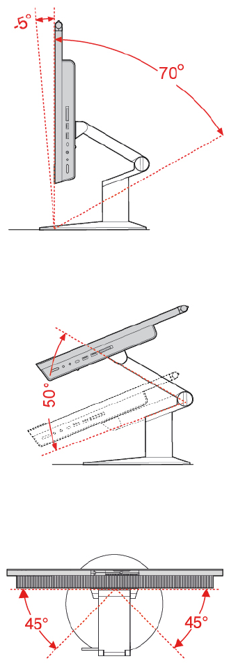
UltraFlex III Stand
Figure 8. Tilting the screen forward and back
Figure 9. Adjusting the height of the screen
Figure 10. Turning the screen to the left and right
8M920z User Guide and Hardware Maintenance Manual

Chapter 2. Specifications
Power supply
150-watt automatic voltage-sensing power supply
Storage drives
• 2.5-inch storage drive (optional)
• M.2 solid-state drive (optional)
Video features
DisplayPort 1.2 in/out connector
Audio features
• Headset connector
• Integrated microphones (optional)
• Internal speakers
Input/Output (I/O) features
• Card reader slot (optional)
• DisplayPort 1.2 in/out connector
• Ethernet connector
• Headset connector
• Serial connector
• USB connectors
Expansion
• Card reader
• Memory slots
• M.2 solid-state drive slot
• Optical drive (optional)
• Storage drive bay
Network features
• Ethernet LAN
• Wireless LAN (optional)
• Bluetooth (optional)
Physical dimensions (without the computer stand)
• Width: 541.6 mm (21.3 inches)
• Height: 370.6 mm (14.6 inches)
• Depth: 46.3 mm (1.8 inches)
Weight (with the computer stand) (without the package)
Maximum configuration as shipped: 8.9 kg (19.6 lb)
© Copyright Lenovo 2018 9
10 M920z User Guide and Hardware Maintenance Manual
Chapter 3. Computer locks
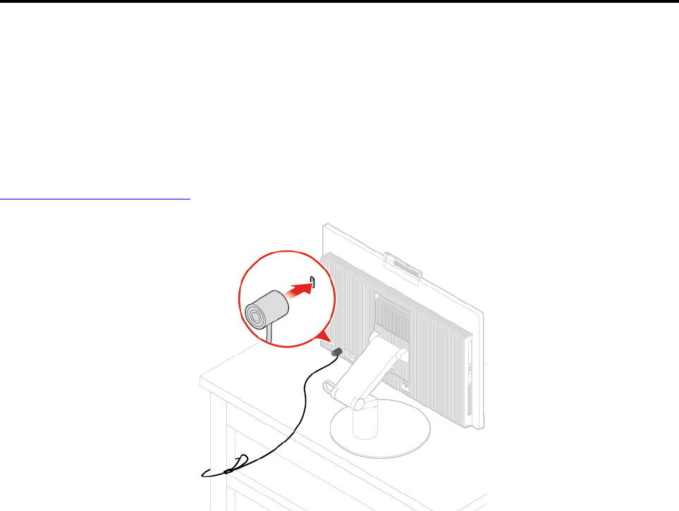
Attaching a Kensington-style cable lock
You can use a Kensington-style cable lock to secure your computer to a desk, table, or another
nonpermanent fixture. The cable lock connects to the security-lock slot at the rear of your computer.
Depending on the type selected, the cable lock can be operated with a key or combination. The cable lock
also locks the buttons used to open the computer cover. This is the same type of lock used with many
notebook computers. You can order such a cable lock directly from Lenovo by searching for Kensington at:
http://www.lenovo.com/support
Figure 11. Attaching a Kensington-style cable lock
© Copyright Lenovo 2018 11
12 M920z User Guide and Hardware Maintenance Manual

Chapter 4. Replacing hardware
This chapter provides instructions on how to replace hardware for your computer.
Before replacing hardware
Attention: Do not open your computer or attempt any repairs before reading this section and the Important
Product Information Guide.
Notes before replacing hardware
• Use computer components provided only by Lenovo.
• When installing or replacing an option, use the appropriate instructions explained in this manual along with
the instructions that come with the option.
• In most areas of the world, Lenovo requires the return of defective CRUs. Information about this will come
with the CRU or will come a few days after the CRU arrives.
Handling static-sensitive devices
Do not open the static-protective package containing the new part until the defective part has been removed
and you are ready to install the new part. Static electricity, although harmless to you, can seriously damage
computer components and options.
When you handle options and other computer components, take these precautions to avoid static-electricity
damage:
• Limit your movement. Movement can cause static electricity to build up around you.
• Always handle options and other computer components carefully. Handle PCI/PCIe cards, memory
modules, system boards, and microprocessors by the edges. Never touch any exposed circuitry.
• Prevent others from touching the options and other computer components.
• Touch the static-protective package containing the part to a metal expansion-slot cover or other
unpainted metal surface on the computer for at least two seconds. This reduces static electricity from the
package and your body before you install or replace a new part.
• When possible, remove the new part from the static-protective package, and install it directly in the
computer without setting the part down. When this is not possible, place the static-protective package on
a smooth, level surface and place the part on the package.
• Do not place the part on the computer cover or other metal surface.
Knowing FRUs (including CRUs)
• Field Replaceable Units (FRUs) are computer parts that a trained technician can upgrade or replace. FRUs
include all CRUs. For detailed FRU information, such as the FRU part numbers and supported computer
models, go to:
http://www.lenovo.com/serviceparts-lookup
• Customer Replaceable Units (CRUs) are computer parts that a user can upgrade or replace.
– Self-service CRUs: You can install self-service CRUs easily. These CRUs might be stand-alone,
latched, or secured by up to two screws. Examples of self-service CRUs include the keyboard, mouse,
and any USB device. You are responsible for replacing all self-service CRUs.
– Optional-service CRUs: Handling optional-service CRUs requires some technical skills and simple tools
(such as a screwdriver). These CRUs are isolated parts within the computer. They are usually
© Copyright Lenovo 2018 13

concealed by an access panel that is secured by more than two screws. You must remove the screws
and panel to access the specific CRU. Optional-service CRUs can be removed and installed by users
or, during the warranty period, by a Lenovo service technician.
Before replacing FRUs
Before replacing any FRU, read the following:
• Only certified and trained personnel can service the computer.
• Before replacing an FRU, read the entire section about replacing the part.
• Be extremely careful during writing operations such as copying, saving, or formatting.
The sequence of the drives in the computer that you are servicing might have been altered. If you select
an incorrect drive, data or programs might be overwritten.
• Replace an FRU only with another FRU of the correct model.
When you replace an FRU, ensure that the model of the machine and the FRU part number are correct.
• An FRU should not be replaced because of a single, unreproducible failure.
Single failures can occur for a variety of reasons that have nothing to do with a hardware defect, such as
cosmic radiation, electrostatic discharge, or software errors. Consider replacing an FRU only when a
problem recurs. If you suspect that an FRU is defective, clear the error log and run the test again. If the
error does not recur, do not replace the FRU.
• Only replace a defective FRU.
Locating FRUs (including CRUs)
Notes:
• Some of the following components are optional.
• To replace a component that is not in the list below, contact a Lenovo service technician. For a list of
Lenovo Support phone numbers, go to:
http://www.lenovo.com/support/phone
14 M920z User Guide and Hardware Maintenance Manual
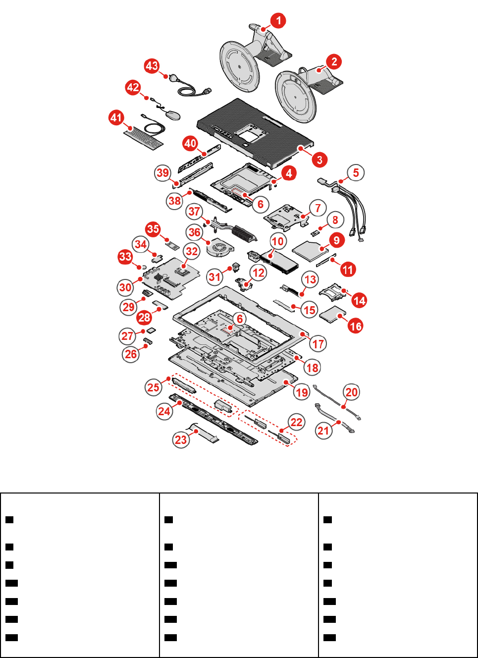
Figure 12. Locating FRUs (including CRUs)
Self-service CRUs Optional-service CRUs Non-CRUs
1 UltraFlex III Stand 4 System board shield 5 Optical drive and storage drive
cables
2 Full-function monitor stand 9 Optical drive 6 Thermal pads (2)
3 Computer cover 11 Optical drive bezel 7 VESA mount bracket
14 Storage drive bracket 28 M.2 solid-state drive 8 Optical drive holder
16 Storage drive 33 Coin-cell battery 10 Power supply assembly
41 Keyboard 35 Memory module 12 Power cord connector bracket
42 Mouse 40 Side I/O bezel 13 Integrated camera and
microphone module
Chapter 4.Replacing hardware 15
Self-service CRUs Optional-service CRUs Non-CRUs
43 Power cord 15 Integrated camera and
microphone module cover
17 Back frame
18 Chassis
19 LCD panel
20 Backlight cable
21 Touch cable
22 Wi-Fi antennas (2)
23 LVDS cable
24 Front decorative cover
25 Internal speakers (2)
26 Wi-Fi card shield
27 Wi-Fi card
29 Serial connector module
30 System board
31 Cover presence switch (intrusion
switch)
32 Microprocessor
34 Card reader
36 System fan
37 Heat sink
38 System board shielding fence
39 Side I/O bracket
Replacing the computer stand
Attention: Do not open your computer or attempt any repairs before reading the Important Product
Information Guide.
1. Remove any media from the drives and turn off all connected devices and the computer.
2. Disconnect all power cords from electrical outlets and disconnect all cables from the computer.
3. Place a soft, clean towel or cloth on the desk or surface. Hold the sides of your computer and gently lay
it down so that the screen is against the surface and the computer cover is facing up.
4. Depending on your computer model, refer to one of the following to replace the computer stand.
• Full-function monitor stand
16 M920z User Guide and Hardware Maintenance Manual
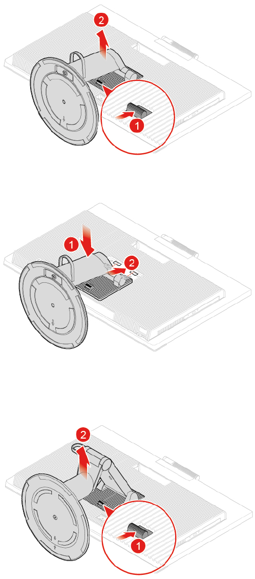
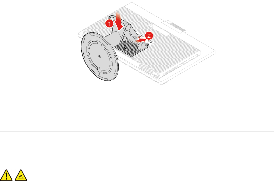
Figure 16. Installing the UltraFlex III Stand
5. Place the computer in an upright position.
6. Reconnect the external cables and power cords to the corresponding connectors on the computer.
Removing the computer cover
Attention: Do not open your computer or attempt any repairs before reading the Important Product
Information Guide.
CAUTION:
Before you open the computer cover, turn off the computer and wait several minutes until the
computer is cool.
1. Remove any media from the drives and turn off all connected devices and the computer.
2. Disconnect all power cords from electrical outlets and disconnect all cables from the computer.
3. Unlock any locking device that secures the computer cover.
4. Place a soft, clean towel or cloth on the desk or surface. Hold the sides of your computer and gently lay
it down so that the screen is against the surface and the computer cover is facing up.
5. Remove the computer stand. See “Replacing the computer stand” on page 16.
18 M920z User Guide and Hardware Maintenance Manual
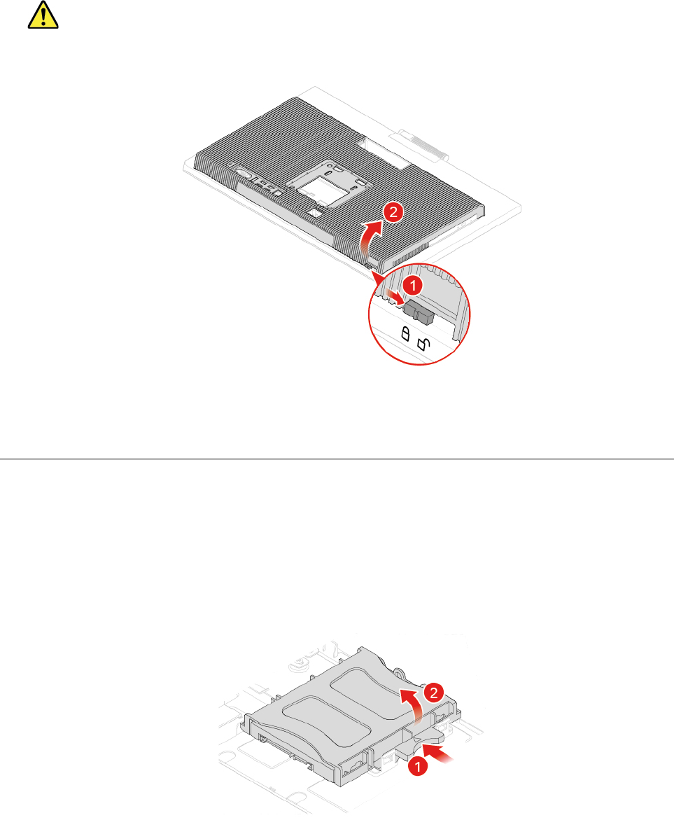
6. Remove the computer cover.
CAUTION:
Do not lift the bottom of the LCD panel so that the integrated camera and microphone module will
not be broken.
Figure 17. Removing the computer cover
7. Complete the replacement. See “Completing the parts replacement” on page 58.
Replacing the storage drive
Attention: Do not open your computer or attempt any repairs before reading the Important Product
Information Guide.
1. Remove the computer stand. See “Replacing the computer stand” on page 16.
2. Remove the computer cover. See “Removing the computer cover” on page 18.
3. Disconnect the signal cable and the power cable from the storage drive.
4. Replace the storage drive.
Figure 18. Removing the storage drive and the bracket
Chapter 4.Replacing hardware 19
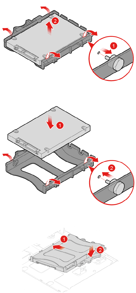
Figure 19. Removing the storage drive from the bracket
Figure 20. Installing the storage drive into the bracket
Figure 21. Installing the storage drive and the bracket
5. Connect the signal cable and the power cable to the new storage drive.
6. Reinstall the removed parts. To complete the replacement, see “Completing the parts replacement” on
page 58.
20 M920z User Guide and Hardware Maintenance Manual
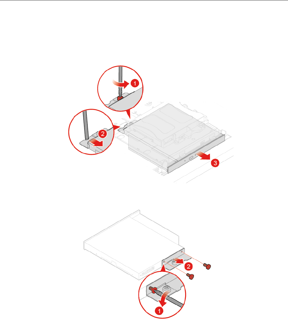
Replacing the optical drive
Attention: Do not open your computer or attempt any repairs before reading the Important Product
Information Guide.
1. Remove the computer stand. See “Replacing the computer stand” on page 16.
2. Remove the computer cover. See “Removing the computer cover” on page 18.
3. Replace the optical drive.
Figure 22. Removing the optical drive
Figure 23. Removing the optical drive holder
Chapter 4.Replacing hardware 21
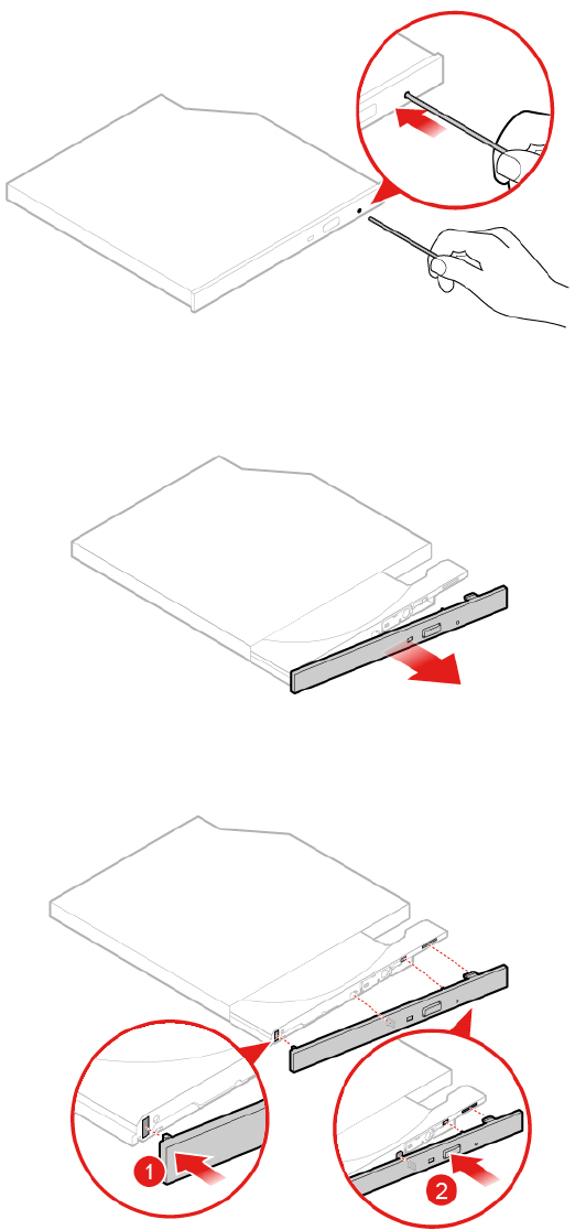
Figure 24. Inserting a straightened paper clip into the emergency-eject hole until the tray slides out
Figure 25. Removing the optical drive bezel
Figure 26. Installing the optical drive bezel
22 M920z User Guide and Hardware Maintenance Manual
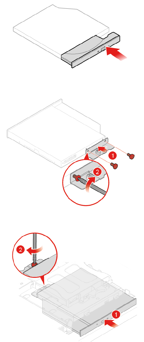
Replacing the optical drive and storage drive cables
Attention: Do not open your computer or attempt any repairs before reading the Important Product
Information Guide.
1. Remove the computer stand. See “Replacing the computer stand” on page 16.
2. Remove the computer cover. See “Removing the computer cover” on page 18.
3. Remove the optical drive. See “Replacing the optical drive” on page 21.
4. Disconnect the optical drive and storage drive cables from the storage drive and the system board.
5. Replace the optical drive and storage drive cables.
Figure 30. Removing the optical drive and storage drive cables
Figure 31. Installing the optical drive and storage drive cables
6. Connect the new optical drive and storage drive cables to the storage drive and the system board.
7. Reinstall the removed parts. To complete the replacement, see “Completing the parts replacement” on
page 58.
Replacing the side I/O bezel
Attention: Do not open your computer or attempt any repairs before reading the Important Product
Information Guide.
1. Remove the computer stand. See “Replacing the computer stand” on page 16.
24 M920z User Guide and Hardware Maintenance Manual
2. Remove the computer cover. See “Removing the computer cover” on page 18.
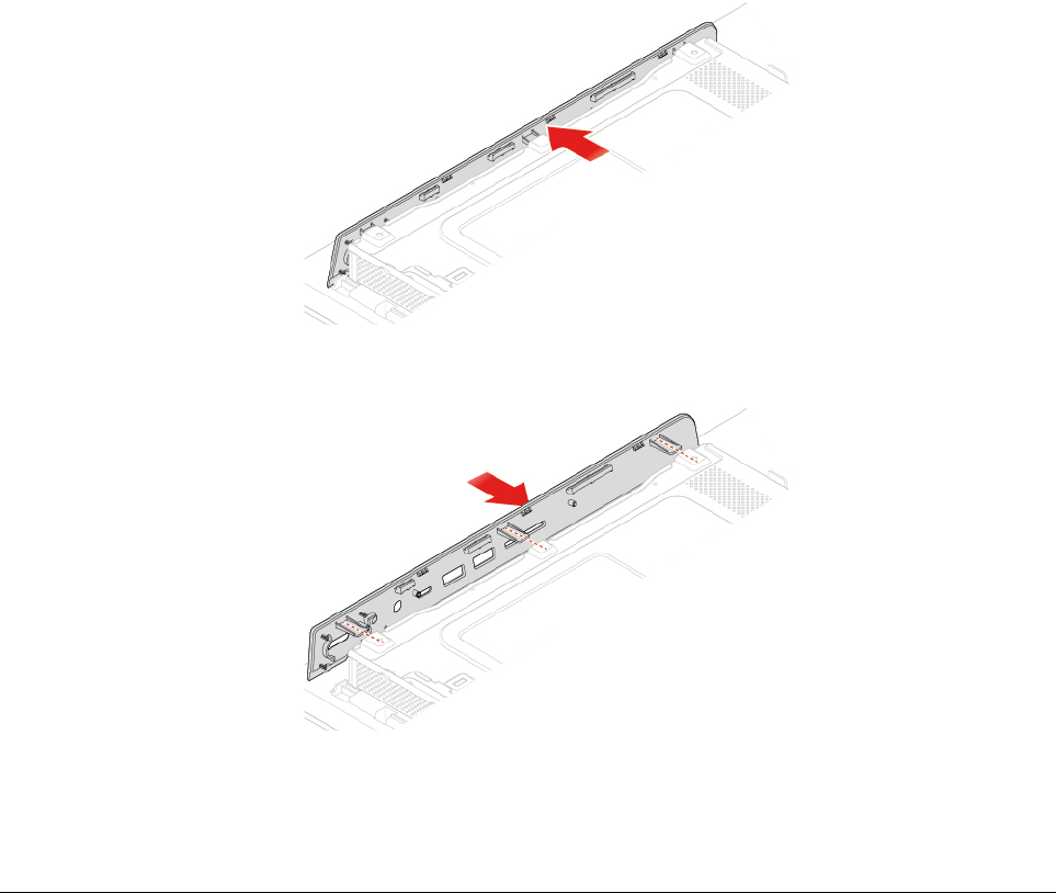
3. Replace the side I/O bezel.
Figure 32. Removing the side I/O bezel
Figure 33. Installing the side I/O bezel
4. Reinstall the removed parts. To complete the replacement, see “Completing the parts replacement” on
page 58.
Replacing the system board shield
Attention: Do not open your computer or attempt any repairs before reading the Important Product
Information Guide.
1. Remove the computer stand. See “Replacing the computer stand” on page 16.
2. Remove the computer cover. See “Removing the computer cover” on page 18.
3. Remove the side I/O bezel. See “Replacing the side I/O bezel” on page 24.
4. Replace the system board shield.
Chapter 4.Replacing hardware 25
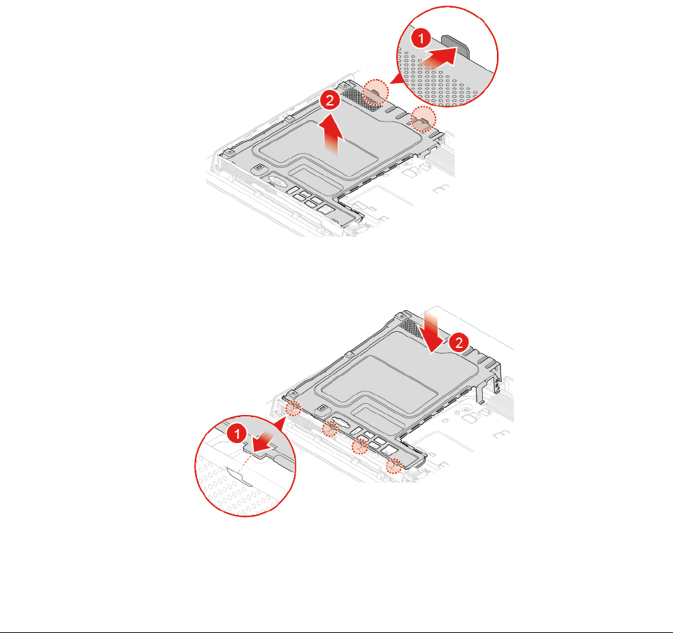
Figure 34. Removing the system board shield
Figure 35. Installing the system board shield
5. Reinstall the removed parts. To complete the replacement, see “Completing the parts replacement” on
page 58.
Replacing the VESA mount bracket
Attention: Do not open your computer or attempt any repairs before reading the Important Product
Information Guide.
1. Remove the computer stand. See “Replacing the computer stand” on page 16.
2. Remove the computer cover. See “Removing the computer cover” on page 18.
3. Remove the side I/O bezel. See “Replacing the side I/O bezel” on page 24.
4. Remove the system board shield. See “Replacing the system board shield” on page 25.
5. Replace the VESA mount bracket.
26 M920z User Guide and Hardware Maintenance Manual
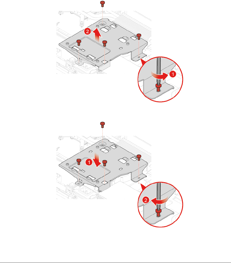
Figure 36. Removing the VESA mount bracket
Figure 37. Installing the VESA mount bracket
6. Reinstall the removed parts. To complete the replacement, see “Completing the parts replacement” on
page 58.
Replacing the power supply assembly
Attention: Do not open your computer or attempt any repairs before reading the Important Product
Information Guide.
Although there are no moving parts in the computer after the power cord has been disconnected, the
following warnings are required for your safety and proper Underwriters Laboratories (UL) certification.
CAUTION:
Chapter 4.Replacing hardware 27
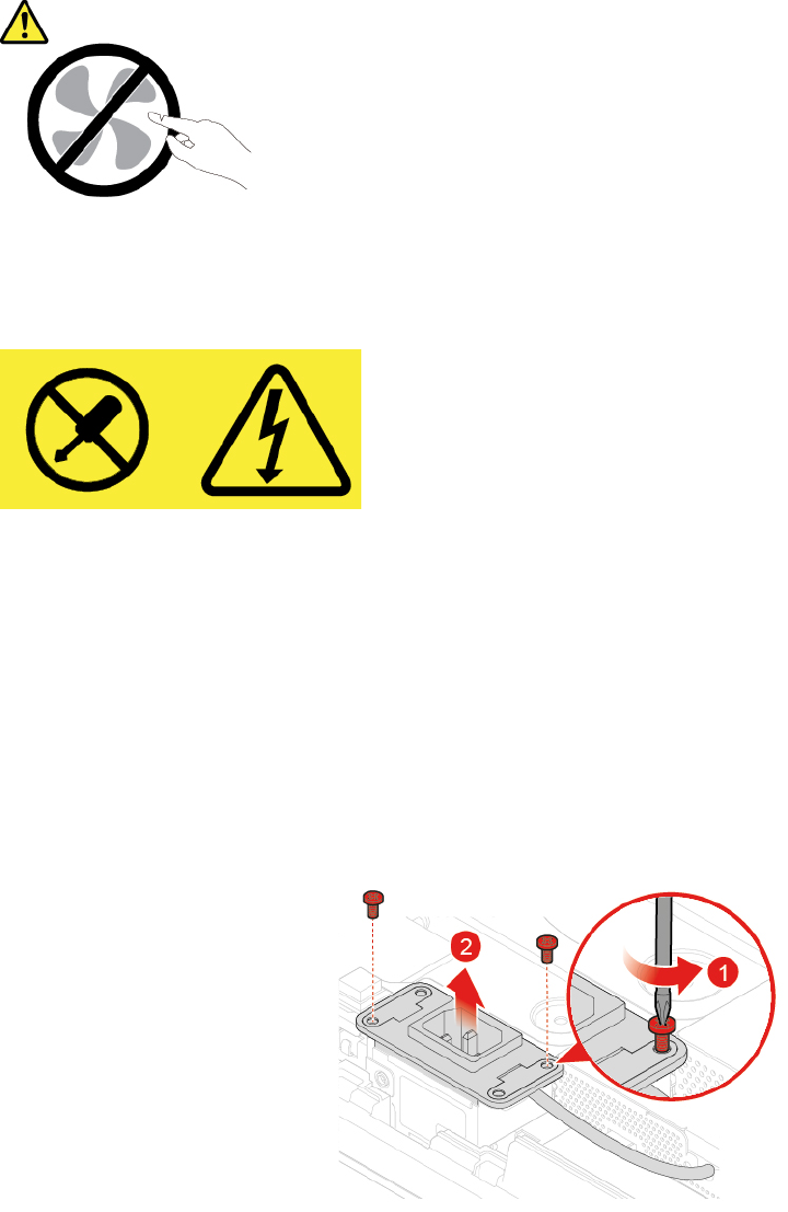
Hazardous moving parts. Keep fingers and other body parts away.
CAUTION:
Never remove the cover on a power supply or any part that has the following label attached.
Hazardous voltage, current, and energy levels are present inside any component that has this label
attached. There are no serviceable parts inside these components. If you suspect a problem with one
of these parts, contact a service technician.
1. Remove the computer stand. See “Replacing the computer stand” on page 16.
2. Remove the computer cover. See “Removing the computer cover” on page 18.
3. Remove the side I/O bezel. See “Replacing the side I/O bezel” on page 24.
4. Remove the system board shield. See “Replacing the system board shield” on page 25.
5. Remove the VESA mount bracket. See “Replacing the VESA mount bracket” on page 26.
6. Disconnect the power supply assembly cable from the system board.
7. Replace the power supply assembly.
Figure 38. Removing the power cord connector
28 M920z User Guide and Hardware Maintenance Manual
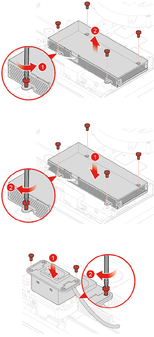
9. Reinstall the removed parts. To complete the replacement, see “Completing the parts replacement” on
page 58.
Replacing the cover presence switch
Attention: Do not open your computer or attempt any repairs before reading the Important Product
Information Guide.
1. Remove the computer stand. See “Replacing the computer stand” on page 16.
2. Remove the computer cover. See “Removing the computer cover” on page 18.
3. Remove the side I/O bezel. See “Replacing the side I/O bezel” on page 24.
4. Remove the system board shield. See “Replacing the system board shield” on page 25.
5. Remove the VESA mount bracket. See “Replacing the VESA mount bracket” on page 26.
6. Remove the power cord connector. See “Replacing the power supply assembly” on page 27.
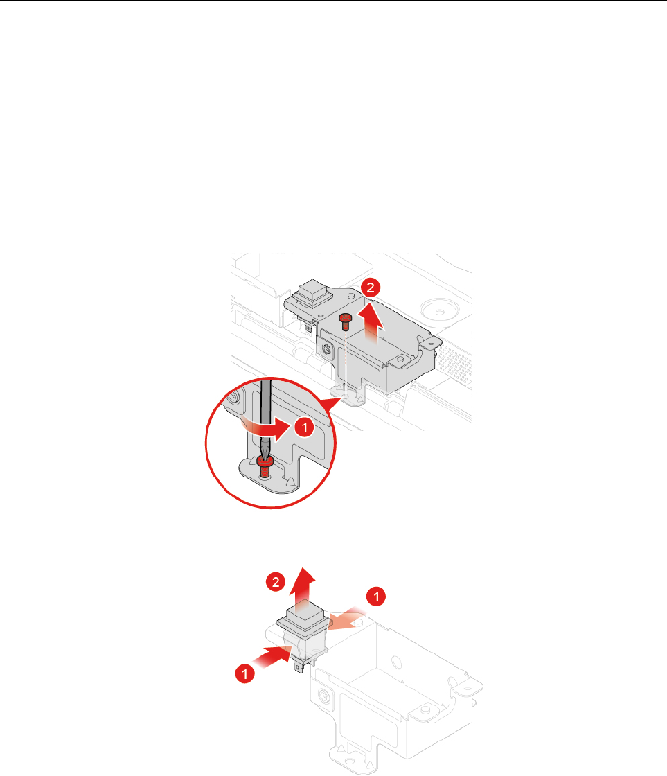
7. Disconnect the cover presence switch cable from the system board.
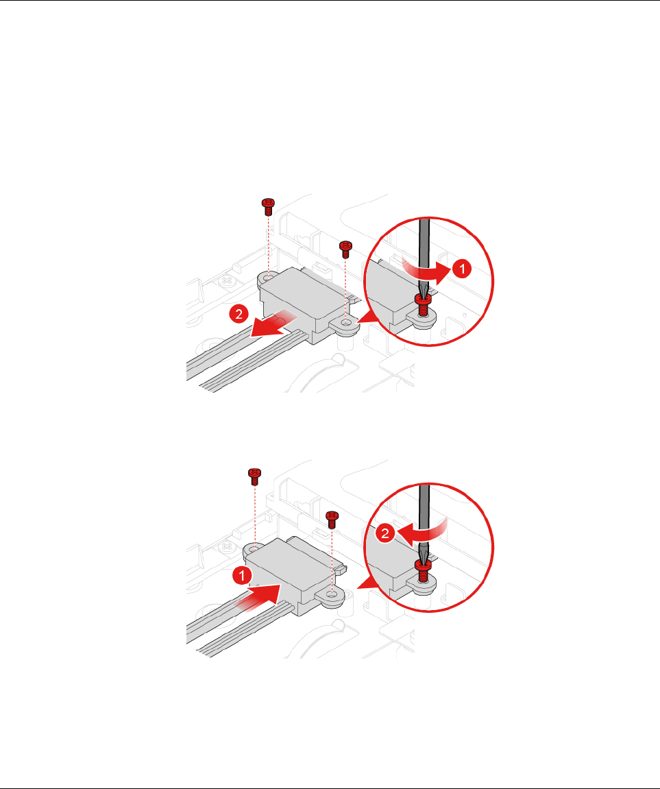
8. Replace the cover presence switch.
Figure 42. Removing the cover presence switch and the bracket
Figure 43. Removing the cover presence switch from the bracket
30 M920z User Guide and Hardware Maintenance Manual
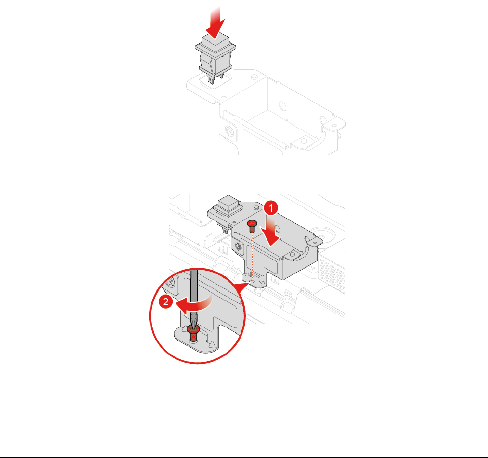
Figure 44. Installing the cover presence switch into the bracket
Figure 45. Installing the cover presence switch and the bracket
9. Connect the new cover presence switch cable to the system board.
10. Reinstall the removed parts. To complete the replacement, see “Completing the parts replacement” on
page 58.
Replacing the system fan
Attention: Do not open your computer or attempt any repairs before reading the Important Product
Information Guide.
1. Remove the computer stand. See “Replacing the computer stand” on page 16.
2. Remove the computer cover. See “Removing the computer cover” on page 18.
3. Remove the side I/O bezel. See “Replacing the side I/O bezel” on page 24.
4. Remove the system board shield. See “Replacing the system board shield” on page 25.
5. Remove the VESA mount bracket. See “Replacing the VESA mount bracket” on page 26.
6. Disconnect the system fan cable from the system board.
7. Replace the system fan.
Chapter 4.Replacing hardware 31
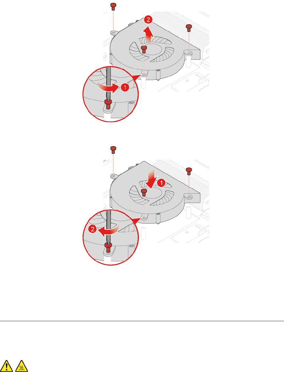
Figure 46. Removing the system fan
Figure 47. Installing the system fan
8. Connect the new system fan cable to the system board.
9. Reinstall the removed parts. To complete the replacement, see “Completing the parts replacement” on
page 58.
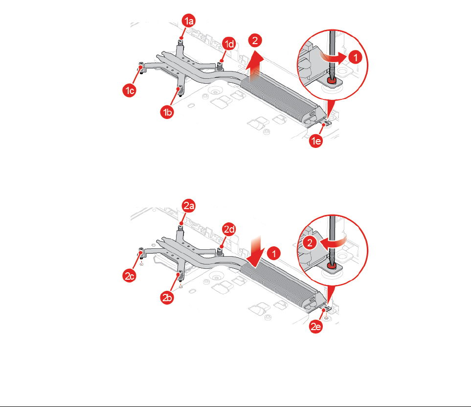
Replacing the heat sink
Attention: Do not open your computer or attempt any repairs before reading the Important Product
Information Guide.
CAUTION:
The heat sink might be very hot. Before you open the computer cover, turn off the computer and wait
several minutes until the computer is cool.
32 M920z User Guide and Hardware Maintenance Manual
1. Remove the computer stand. See “Replacing the computer stand” on page 16.
2. Remove the computer cover. See “Removing the computer cover” on page 18.
3. Remove the side I/O bezel. See “Replacing the side I/O bezel” on page 24.
4. Remove the system board shield. See “Replacing the system board shield” on page 25.
5. Replace the heat sink.
Notes:
• Carefully remove the screws from the system board to avoid any possible damage to the system
board. The screws cannot be removed from the heat sink.
• You might have to gently twist the heat sink to free it from the microprocessor.
• Do not touch the thermal grease while handling the heat sink.
Figure 48. Removing the heat sink
Figure 49. Installing the heat sink
6. Reinstall the removed parts. To complete the replacement, see “Completing the parts replacement” on
page 58.
Replacing the microprocessor
Attention: Do not open your computer or attempt any repairs before reading the Important Product
Information Guide.
CAUTION:
Chapter 4.Replacing hardware 33
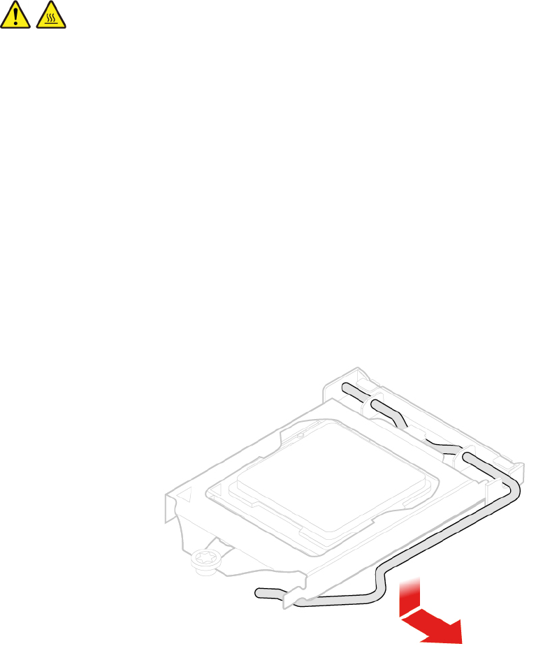
The heat sink might be very hot. Before you open the computer cover, turn off the computer and wait
several minutes until the computer is cool.
1. Remove the computer stand. See “Replacing the computer stand” on page 16.
2. Remove the computer cover. See “Removing the computer cover” on page 18.
3. Remove the side I/O bezel. See “Replacing the side I/O bezel” on page 24.
4. Remove the system board shield. See “Replacing the system board shield” on page 25.
5. Remove the heat sink. See “Replacing the heat sink” on page 32.
6. Record the cable routing and cable connections, and then disconnect all cables from the system board.
See “System board” on page 4.
7. Replace the microprocessor.
Notes:
• Your microprocessor and socket might look different from the one illustrated.
• Touch only the edges of the microprocessor. Do not touch the gold contacts on the bottom.
• Do not drop anything onto the microprocessor socket while it is exposed. The socket pins must be
kept as clean as possible.
Figure 50. Releasing the handle
34 M920z User Guide and Hardware Maintenance Manual
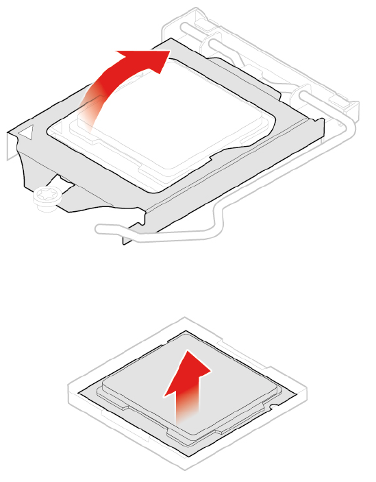
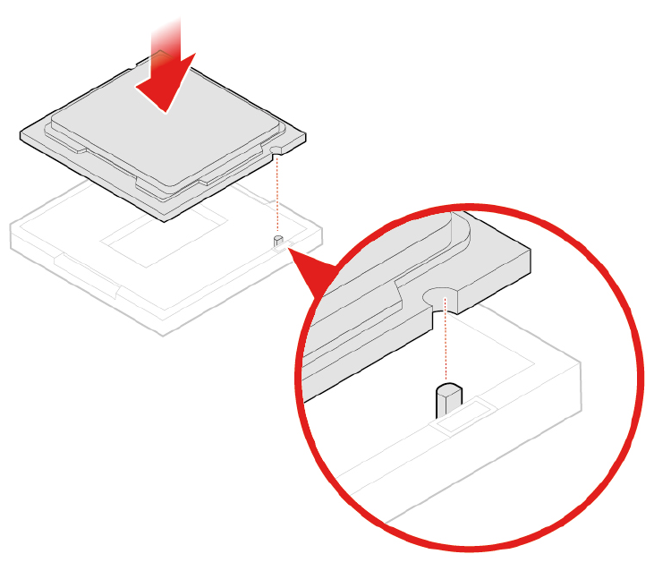
Figure 53. Installing the microprocessor
36 M920z User Guide and Hardware Maintenance Manual
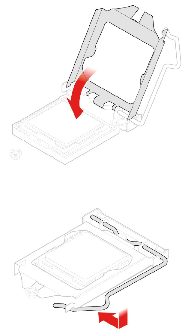
Figure 54. Closing the retainer
8.
Figure 55. Securing the retainer with the handle
9. Route all the cables that you disconnected from the system board, and then reconnect the cables to the
system board.
10. Reinstall the removed parts. To complete the replacement, see “Completing the parts replacement” on
page 58.
Chapter 4.Replacing hardware 37
Replacing the Wi-Fi card
Attention: Do not open your computer or attempt any repairs before reading the Important Product
Information Guide.
1. Remove the computer stand. See “Replacing the computer stand” on page 16.
2. Remove the computer cover. See “Removing the computer cover” on page 18.
3. Remove the side I/O bezel. See “Replacing the side I/O bezel” on page 24.
4. Remove the system board shield. See “Replacing the system board shield” on page 25.
5. Replace the Wi-Fi card.
Figure 56. Removing the Wi-Fi card shield
Figure 57. Disconnecting the Wi-Fi antenna cables
Figure 58. Removing the Wi-Fi card
38 M920z User Guide and Hardware Maintenance Manual
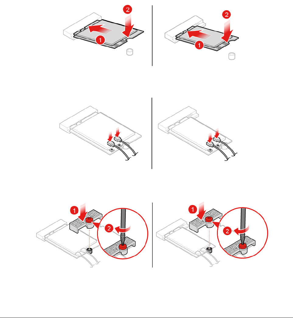
Figure 59. Installing the Wi-Fi card
Figure 60. Connecting the Wi-Fi antenna cables
Figure 61. Installing the Wi-Fi card shield
6. Reinstall the removed parts. To complete the replacement, see “Completing the parts replacement” on
page 58.
Replacing the serial connector module
Attention: Do not open your computer or attempt any repairs before reading the Important Product
Information Guide.
1. Remove the computer stand. See “Replacing the computer stand” on page 16.
2. Remove the computer cover. See “Removing the computer cover” on page 18.
3. Remove the side I/O bezel. See “Replacing the side I/O bezel” on page 24.
4. Remove the system board shield. See “Replacing the system board shield” on page 25.
5. Replace the serial connector module.
Chapter 4.Replacing hardware 39
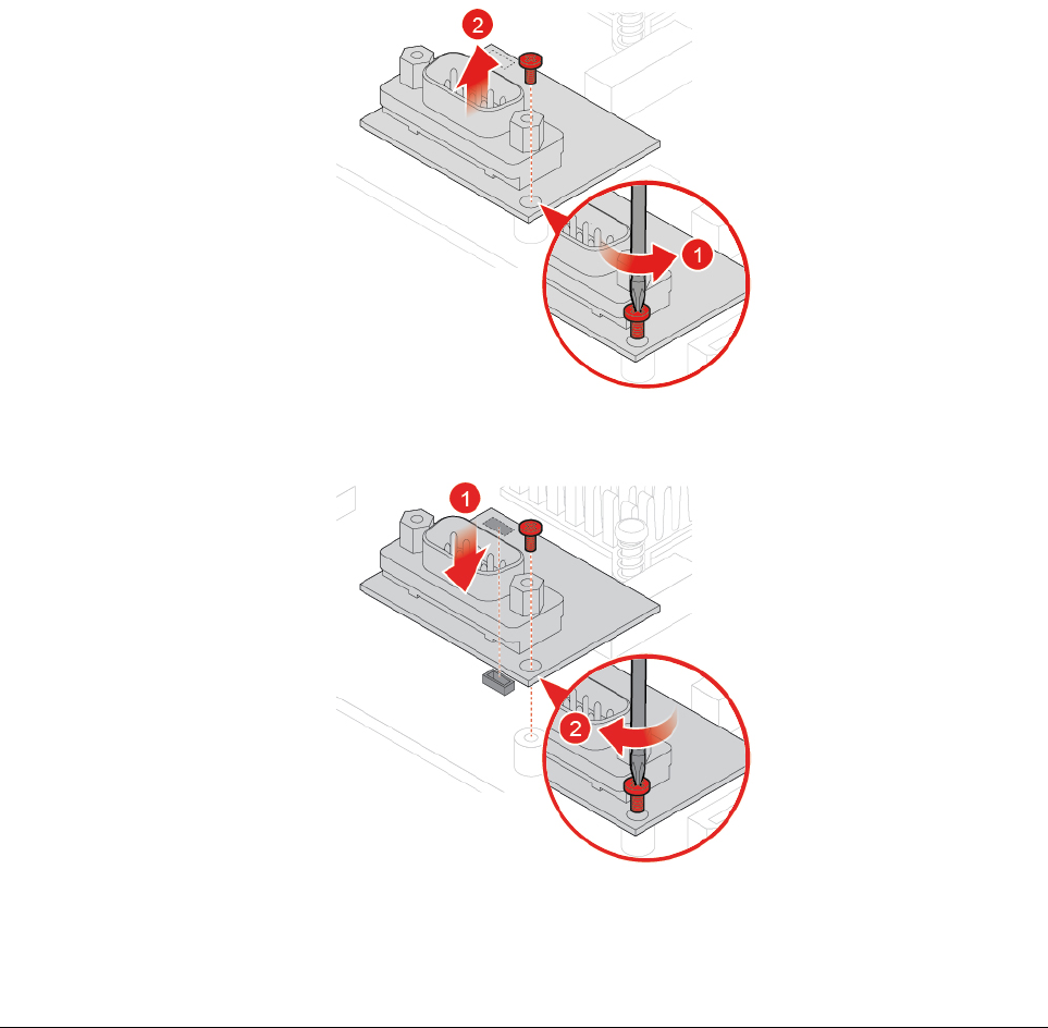
Figure 62. Removing the serial connector module
Figure 63. Installing the serial connector module
6. Reinstall the removed parts. To complete the replacement, see “Completing the parts replacement” on
page 58.
Replacing the M.2 solid-state drive
Attention: Do not open your computer or attempt any repairs before reading the Important Product
Information Guide.
1. Remove the computer stand. See “Replacing the computer stand” on page 16.
2. Remove the computer cover. See “Removing the computer cover” on page 18.
3. Remove the side I/O bezel. See “Replacing the side I/O bezel” on page 24.
4. Remove the system board shield. See “Replacing the system board shield” on page 25.
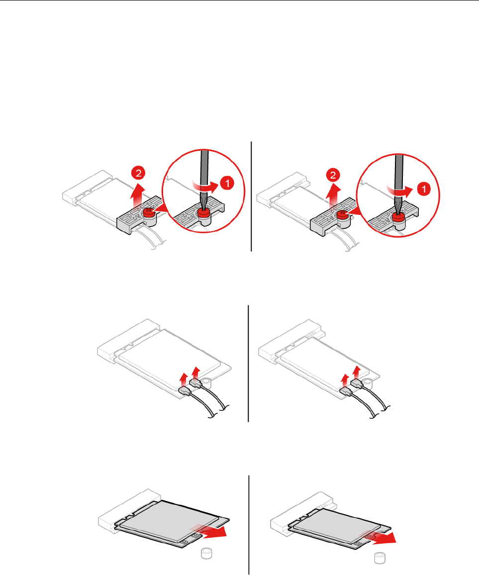
5. Depending on your computer model, refer to one of the following to replace the M.2 solid-state drive.
• Type 1
40 M920z User Guide and Hardware Maintenance Manual
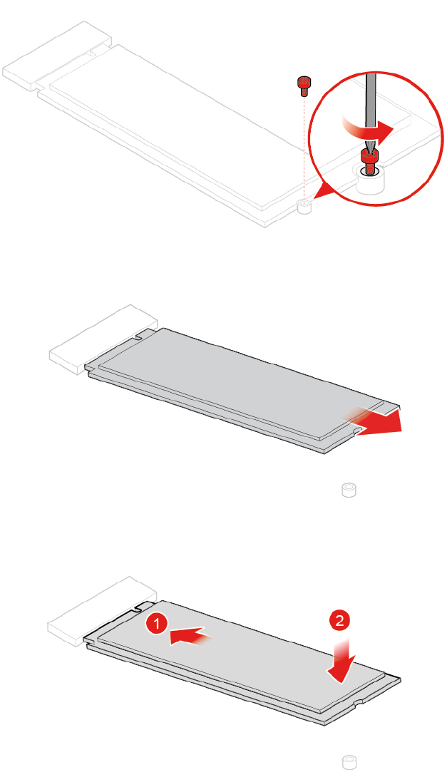
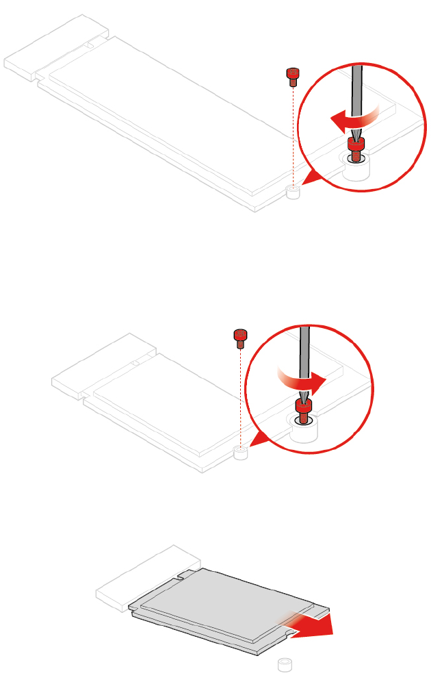
Figure 67. Installing the screw
• Type 2
Figure 68. Removing the screw
Figure 69. Removing the M.2 solid-state drive
42 M920z User Guide and Hardware Maintenance Manual
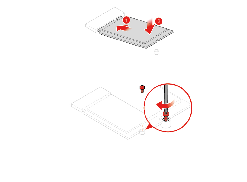
Figure 70. Installing the M.2 solid-state drive
Figure 71. Installing the screw
6. Reinstall the removed parts. To complete the replacement, see “Completing the parts replacement” on
page 58.
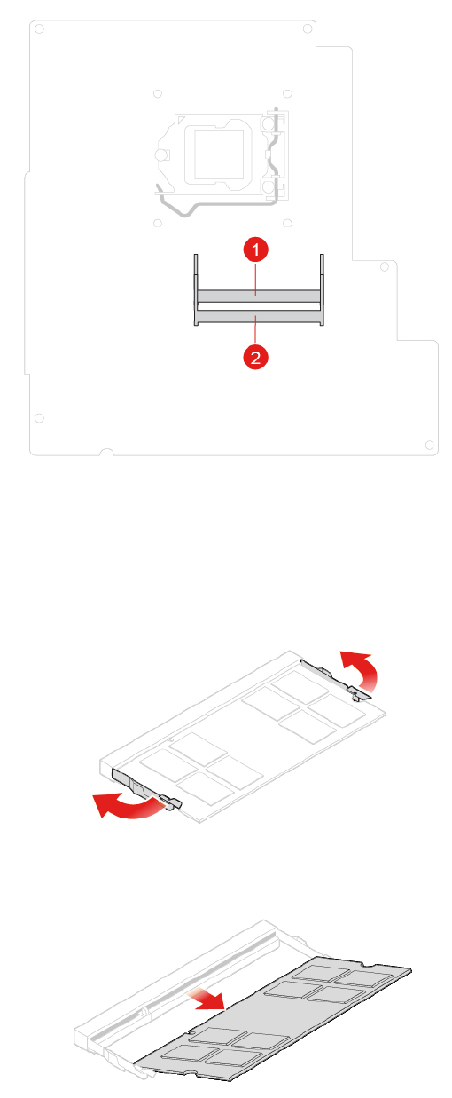
Replacing a memory module
Attention: Do not open your computer or attempt any repairs before reading the Important Product
Information Guide.
Ensure that you follow the installation order for memory modules shown in the following figure.
Chapter 4.Replacing hardware 43
1. Remove the computer stand. See “Replacing the computer stand” on page 16.
2. Remove the computer cover. See “Removing the computer cover” on page 18.
3. Remove the side I/O bezel. See “Replacing the side I/O bezel” on page 24.
4. Remove the system board shield. See “Replacing the system board shield” on page 25.
5. Replace a memory module.
Figure 72. Disengaging the latches
Figure 73. Removing a memory module
44 M920z User Guide and Hardware Maintenance Manual
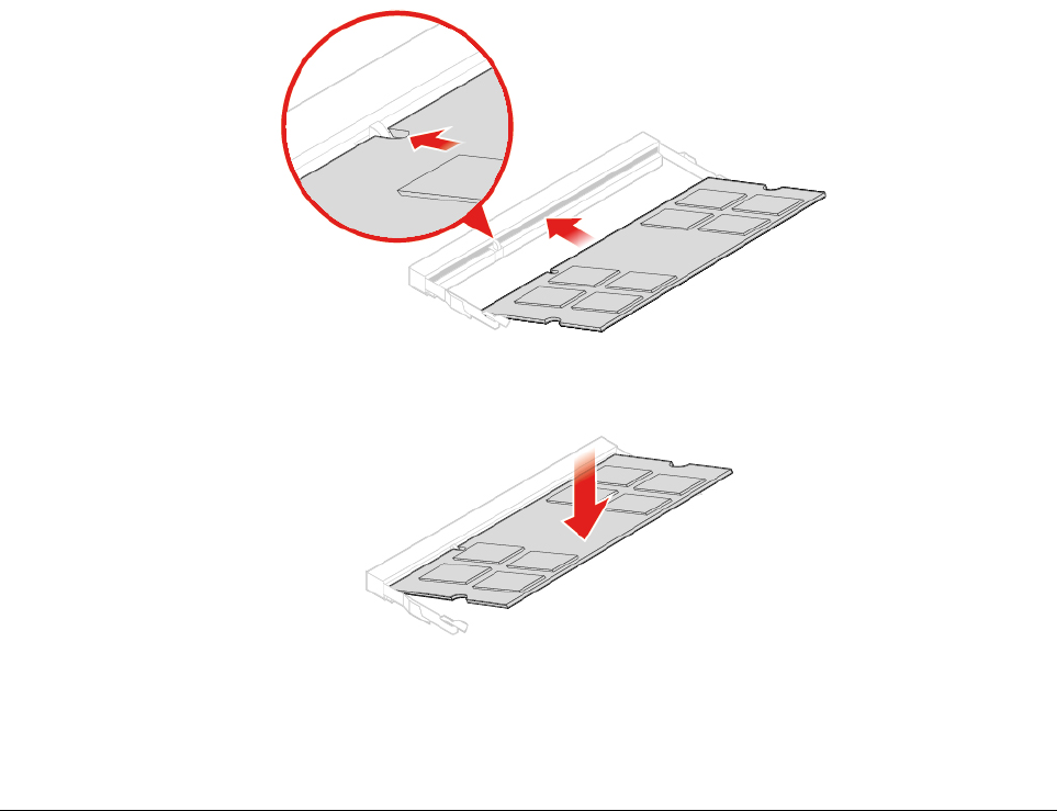
Figure 74. Installing a memory module
Figure 75. Securing a memory module with the latches
6. Reinstall the removed parts. To complete the replacement, see “Completing the parts replacement” on
page 58.
Replacing the coin-cell battery
Attention: Do not open your computer or attempt any repairs before reading the Important Product
Information Guide.
Note: To dispose of the coin-cell battery, refer to “Lithium coin-cell battery notice” in the Safety and
Warranty Guide.
Your computer has a special type of memory that maintains the date, time, and settings for built-in features,
such as parallel connector assignments (configurations). A coin-cell battery keeps this information active
when you turn off the computer.
The coin-cell battery normally requires no charging or maintenance throughout its life; however, no coin-cell
battery lasts forever. If the coin-cell battery fails, the date, time, and configuration information (including
passwords) are lost. An error message is displayed when you turn on the computer.
1. Remove the computer stand. See “Replacing the computer stand” on page 16.
2. Remove the computer cover. See “Removing the computer cover” on page 18.
3. Remove the side I/O bezel. See “Replacing the side I/O bezel” on page 24.
4. Remove the system board shield. See “Replacing the system board shield” on page 25.
5. Replace the coin-cell battery.
Chapter 4.Replacing hardware 45
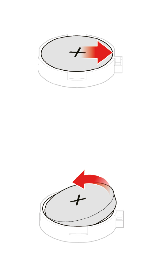
Figure 76. Disengaging the latch
Figure 77. Removing the coin-cell battery
46 M920z User Guide and Hardware Maintenance Manual
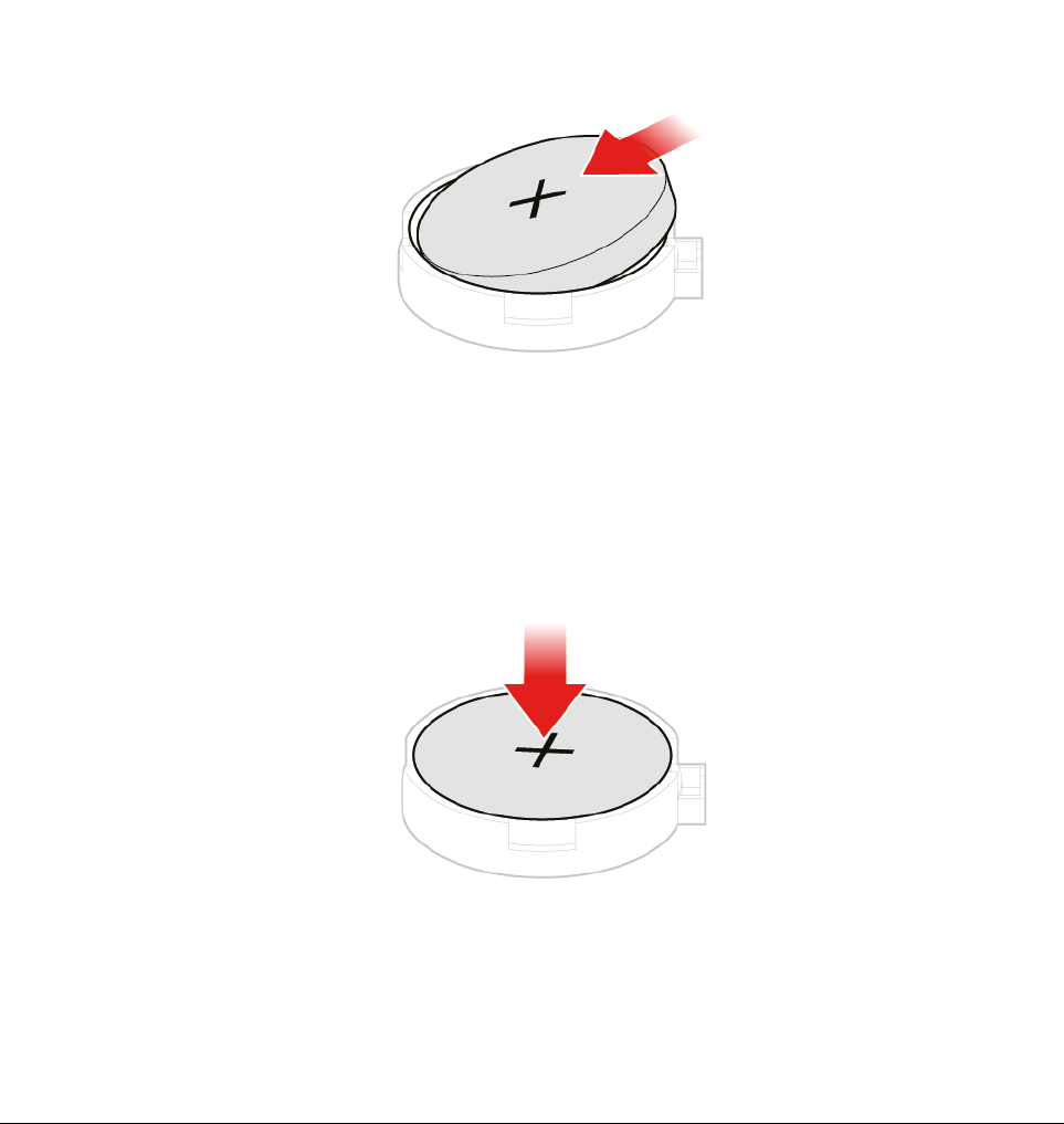
Figure 78. Installing the coin-cell battery
Figure 79. Securing the coin-cell battery with the latch
6. Reinstall the removed parts. To complete the replacement, see “Completing the parts replacement” on
page 58.
Replacing the card reader
Attention: Do not open your computer or attempt any repairs before reading the Important Product
Information Guide.
1. Remove the computer stand. See “Replacing the computer stand” on page 16.
2. Remove the computer cover. See “Removing the computer cover” on page 18.
3. Remove the side I/O bezel. See “Replacing the side I/O bezel” on page 24.
4. Remove the system board shield. See “Replacing the system board shield” on page 25.
5. Disconnect the card reader cable from the system board.
6. Replace the card reader.
Chapter 4.Replacing hardware 47
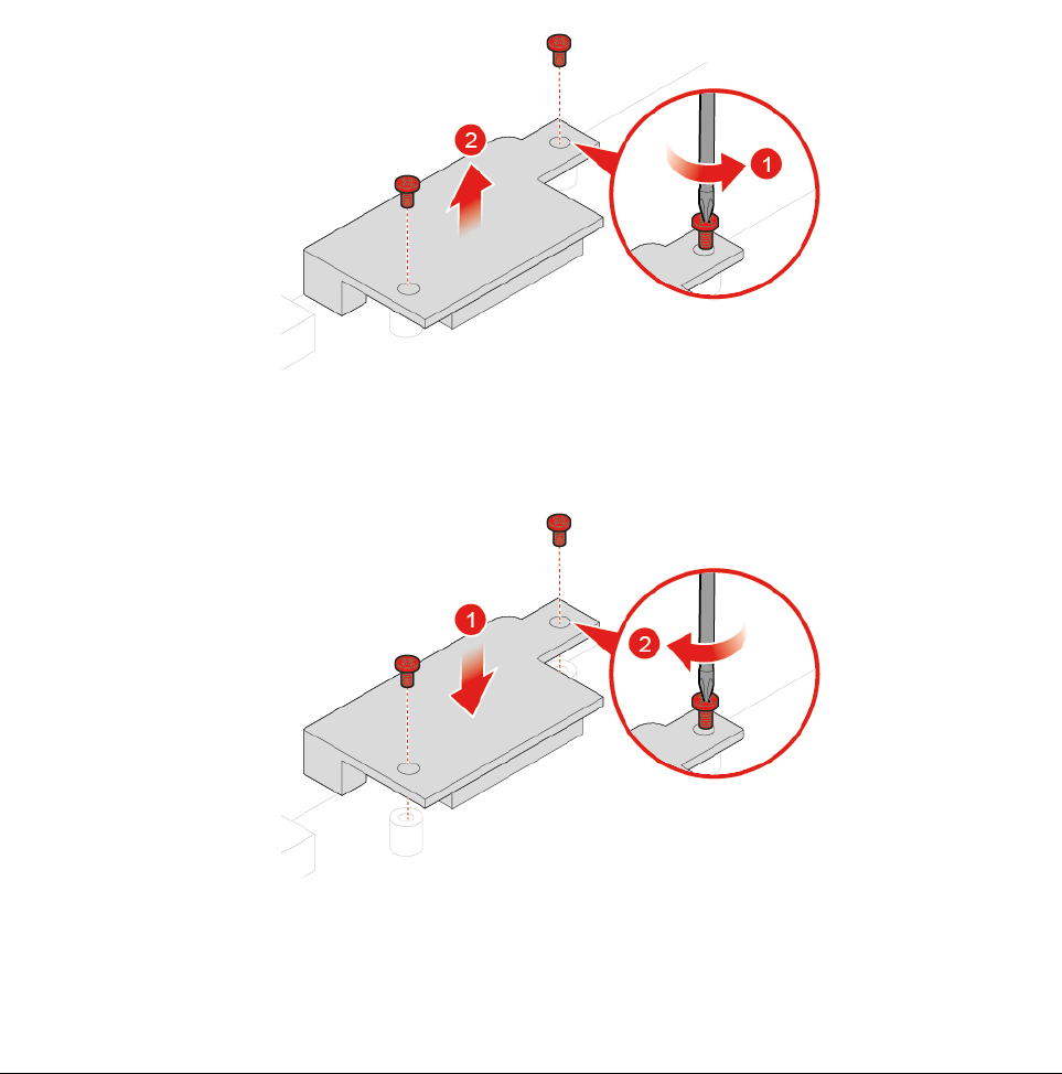
Figure 80. Removing the card reader
Figure 81. Installing the card reader
7. Connect the new card reader cable to the system board.
8. Reinstall the removed parts. To complete the replacement, see “Completing the parts replacement” on
page 58.
Replacing the system board
Attention: Do not open your computer or attempt any repairs before reading the Important Product
Information Guide.
1. Remove the computer stand. See “Replacing the computer stand” on page 16.
2. Remove the computer cover. See “Removing the computer cover” on page 18.
3. Remove the side I/O bezel. See “Replacing the side I/O bezel” on page 24.
4. Remove the system board shield. See “Replacing the system board shield” on page 25.
5. Remove the VESA mount bracket. See “Replacing the VESA mount bracket” on page 26.
6. Remove the heat sink. See “Replacing the heat sink” on page 32.
7. Remove the microprocessor. See “Replacing the microprocessor” on page 33.
8. Remove the Wi-Fi card. See “Replacing the Wi-Fi card” on page 38.
48 M920z User Guide and Hardware Maintenance Manual
9. Remove the serial connector module. See “Replacing the serial connector module” on page 39.
10. Remove the M.2 solid-state drive. See “Replacing the M.2 solid-state drive” on page 40.
11. Remove all memory modules. See “Replacing a memory module” on page 43.
12. Remove the card reader. See “Replacing the card reader” on page 47.
13. Record the cable routing and cable connections, and then disconnect all cables from the system board.
See “System board” on page 4.
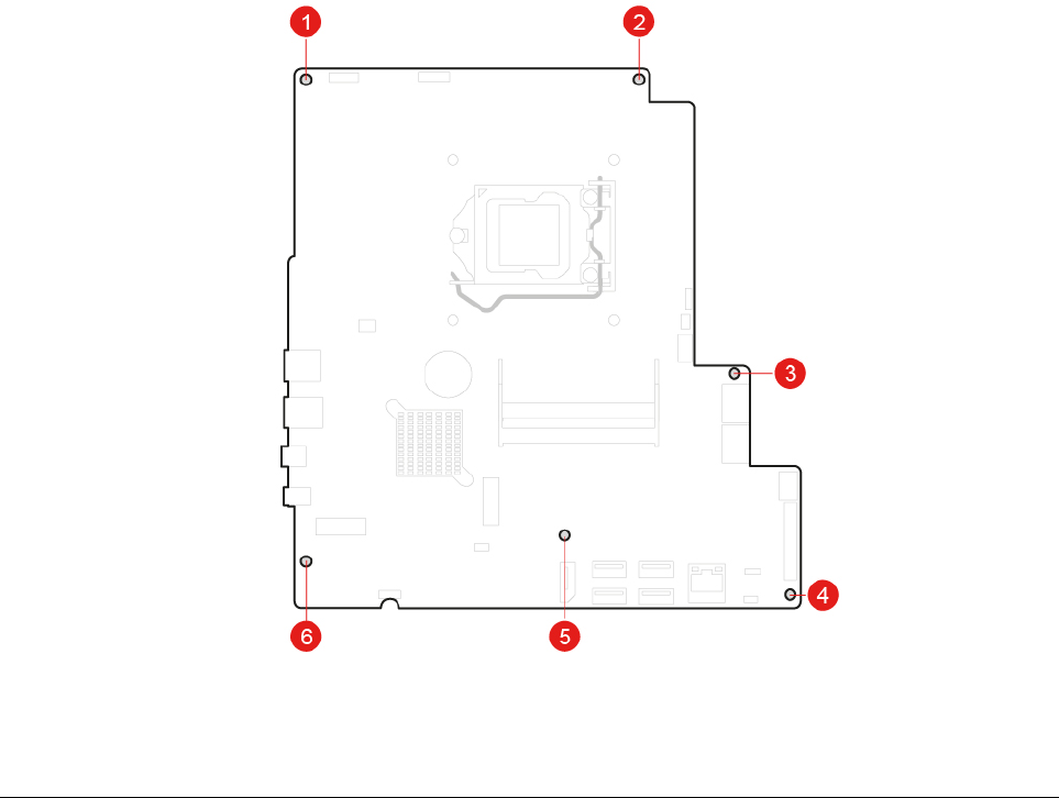
14. Replace the system board.
Notes:
• The numbers in the following figure show the locations of the screws instead of a specific order for
removing and reinstalling the screws.
• Handle the system board carefully by its edges.
• The failing system board must be returned with a microprocessor socket cover to protect the pins
during shipping and handling.
15. Route and connect all the cables to the new system board.
16. Reinstall the removed parts. To complete the replacement, see “Completing the parts replacement” on
page 58.
Replacing the integrated camera and microphone module
Attention: Do not open your computer or attempt any repairs before reading the Important Product
Information Guide.
1. Remove the computer stand. See “Replacing the computer stand” on page 16.
2. Remove the computer cover. See “Removing the computer cover” on page 18.
Chapter 4.Replacing hardware 49
3. Remove the side I/O bezel. See “Replacing the side I/O bezel” on page 24.
4. Remove the system board shield. See “Replacing the system board shield” on page 25.
5. Replace the integrated camera and microphone module.
Figure 82. Turning the integrated camera and microphone module around
Figure 83. Removing the integrated camera and microphone module cover
Figure 84. Removing the integrated camera and microphone module from the back frame
50 M920z User Guide and Hardware Maintenance Manual
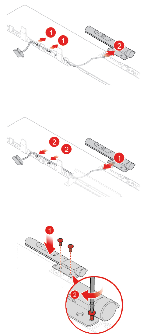
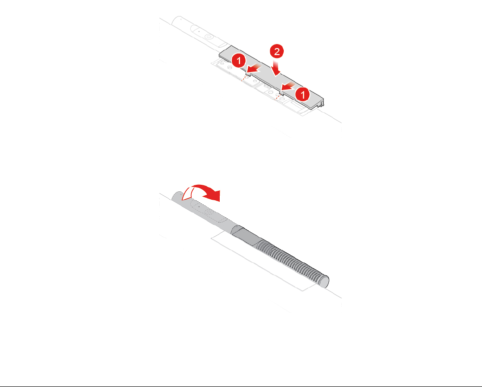
Figure 88. Installing the integrated camera and microphone module cover
Figure 89. Turning the integrated camera and microphone module back
6. Reinstall the removed parts. To complete the replacement, see “Completing the parts replacement” on
page 58.
Replacing the back frame
Attention: Do not open your computer or attempt any repairs before reading the Important Product
Information Guide.
1. Remove the computer stand. See “Replacing the computer stand” on page 16.
2. Remove the computer cover. See “Removing the computer cover” on page 18.
3. Remove the side I/O bezel. See “Replacing the side I/O bezel” on page 24.
4. Remove the system board shield. See “Replacing the system board shield” on page 25.
5. Remove the VESA mount bracket. See “Replacing the VESA mount bracket” on page 26.
6. Remove the system board. See “Replacing the system board” on page 48.
7. Remove the integrated camera and microphone module. See “Replacing the integrated camera and
microphone module” on page 49.
8. Replace the back frame.
52 M920z User Guide and Hardware Maintenance Manual
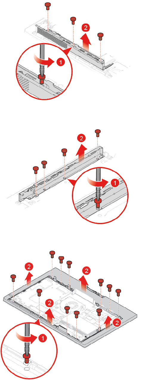
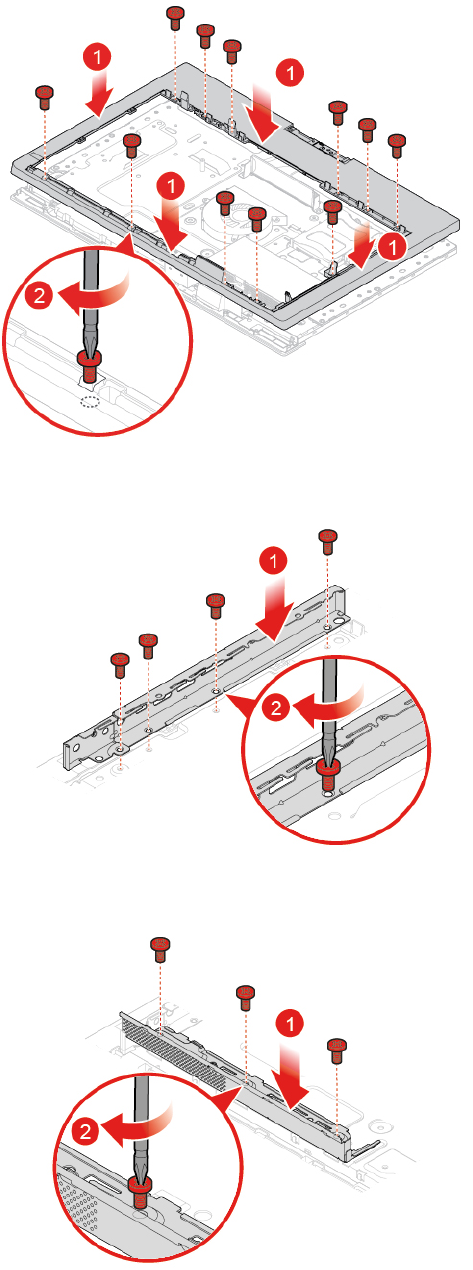
Figure 93. Installing the back frame
Figure 94. Installing the side I/O bracket
Figure 95. Installing the system board shielding fence
54 M920z User Guide and Hardware Maintenance Manual
9. Reinstall the removed parts. To complete the replacement, see “Completing the parts replacement” on
page 58.
Replacing the internal speakers
Attention: Do not open your computer or attempt any repairs before reading the Important Product
Information Guide.
1. Remove the computer stand. See “Replacing the computer stand” on page 16.
2. Remove the computer cover. See “Removing the computer cover” on page 18.
3. Remove the side I/O bezel. See “Replacing the side I/O bezel” on page 24.
4. Remove the system board shield. See “Replacing the system board shield” on page 25.
5. Remove the VESA mount bracket. See “Replacing the VESA mount bracket” on page 26.
6. Remove the power cord connector. See “Replacing the power supply assembly” on page 27.
7. Remove the heat sink. See “Replacing the heat sink” on page 32.
8. Remove the system board. See “Replacing the system board” on page 48.
9. Remove the integrated camera and microphone module. See “Replacing the integrated camera and
microphone module” on page 49.
10. Remove the back frame. See “Replacing the back frame” on page 52.
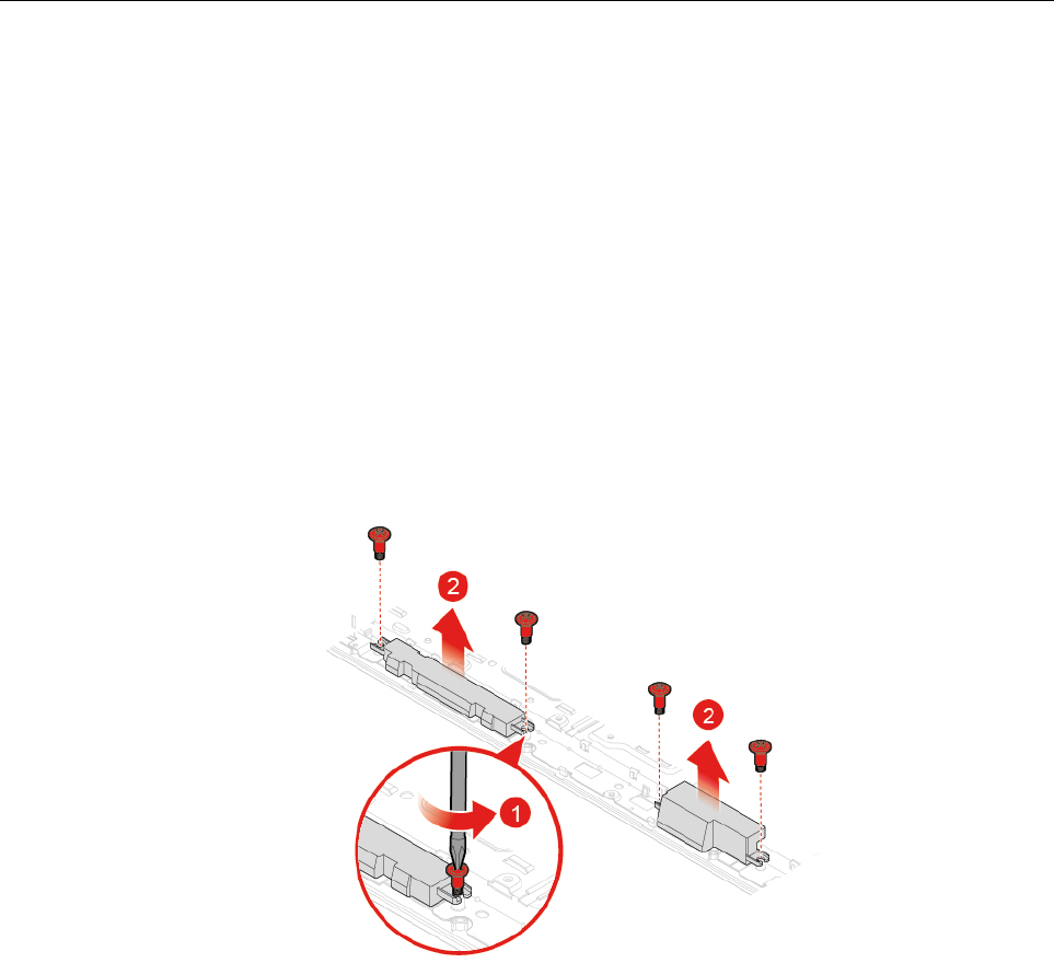
11. Replace the internal speakers.
Figure 96. Removing the internal speakers
Chapter 4.Replacing hardware 55
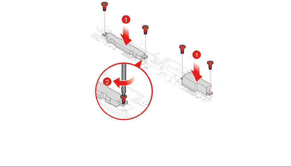
Figure 97. Installing the internal speakers
12. Reinstall the removed parts. To complete the replacement, see “Completing the parts replacement” on
page 58.
Replacing the Wi-Fi antennas
Attention: Do not open your computer or attempt any repairs before reading the Important Product
Information Guide.
1. Remove the computer stand. See “Replacing the computer stand” on page 16.
2. Remove the computer cover. See “Removing the computer cover” on page 18.
3. Remove the side I/O bezel. See “Replacing the side I/O bezel” on page 24.
4. Remove the system board shield. See “Replacing the system board shield” on page 25.
5. Remove the VESA mount bracket. See “Replacing the VESA mount bracket” on page 26.
6. Remove the power cord connector. See “Replacing the power supply assembly” on page 27.
7. Remove the heat sink. See “Replacing the heat sink” on page 32.
8. Remove the system board. See “Replacing the system board” on page 48.
9. Remove the integrated camera and microphone module. See “Replacing the integrated camera and
microphone module” on page 49.
10. Remove the back frame. See “Replacing the back frame” on page 52.
11. Remove the internal speakers. See “Replacing the internal speakers” on page 55.
12. Record the routing of the Wi-Fi antenna cables, and then disconnect the cables from the Wi-Fi card. See
“Replacing the Wi-Fi card” on page 38.
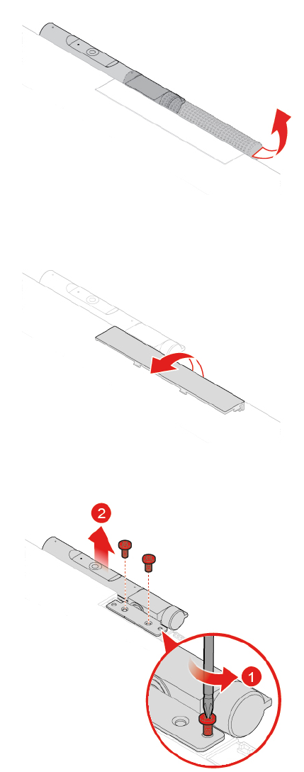
13. Replace the Wi-Fi antennas.
56 M920z User Guide and Hardware Maintenance Manual
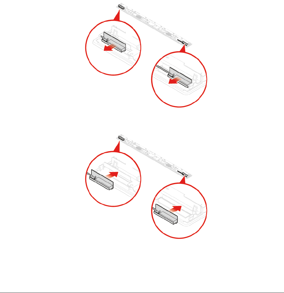
Figure 98. Removing the Wi-Fi antennas
Figure 99. Installing the Wi-Fi antennas
14. Route the new Wi-Fi antenna cables, and then connect the cables to the Wi-Fi card.
15. Reinstall the removed parts. To complete the replacement, see “Completing the parts replacement” on
page 58.
Replacing the LCD panel
Attention: Do not open your computer or attempt any repairs before reading the Important Product
Information Guide.
1. Remove the computer stand. See “Replacing the computer stand” on page 16.
2. Remove the computer cover. See “Removing the computer cover” on page 18.
3. Remove the storage drive. See “Replacing the storage drive” on page 19.
4. Remove the optical drive. See “Replacing the optical drive” on page 21.
5. Remove the optical drive cable. See “Replacing the optical drive and storage drive cables” on page 24.
6. Remove the side I/O bezel. See “Replacing the side I/O bezel” on page 24.
7. Remove the system board shield. See “Replacing the system board shield” on page 25.
Chapter 4.Replacing hardware 57
8. Remove the VESA mount bracket. See “Replacing the VESA mount bracket” on page 26.
9. Remove the power supply assembly. See “Replacing the power supply assembly” on page 27.
10. Remove the cover presence switch. See “Replacing the cover presence switch” on page 30.
11. Remove the system fan. See “Replacing the system fan” on page 31.
12. Remove the heat sink. See “Replacing the heat sink” on page 32.
13. Remove the system board. See “Replacing the system board” on page 48.
14. Remove the integrated camera and microphone module. See “Replacing the integrated camera and
microphone module” on page 49.
15. Remove the back frame. See “Replacing the back frame” on page 52.
16. Remove the internal speakers. See “Replacing the internal speakers” on page 55.
17. Remove the Wi-Fi antennas. See “Replacing the Wi-Fi antennas” on page 56.
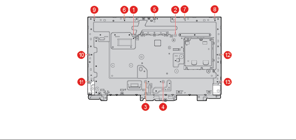
18. Replace the LCD panel.
Note: Ensure that you remove and reinstall the screws in order of the numbers as shown.
19. Reinstall the removed parts. To complete the replacement, see “Completing the parts replacement” on
page 58.
Completing the parts replacement
After completing the installation or replacement for all parts, reinstall the computer cover and reconnect the
cables.
To reinstall the computer cover and reconnect the cables to your computer, do the following:
1. Ensure that all components have been reassembled correctly and that no tools or loose screws are left
inside your computer.
2. Ensure that the cables are routed correctly before reinstalling the computer cover. Keep cables clear of
the hinges and sides of the computer chassis to avoid interference when reinstalling the computer
cover.
58 M920z User Guide and Hardware Maintenance Manual
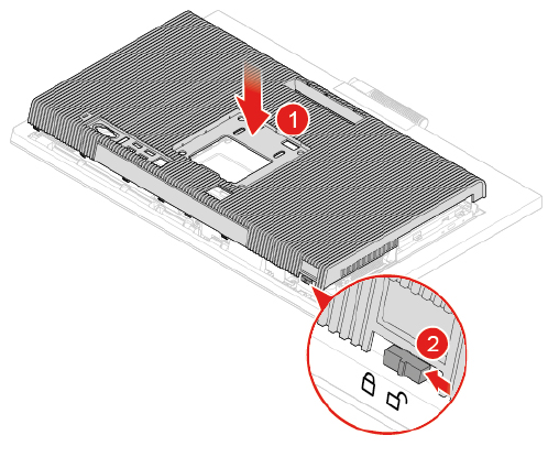
3. Reinstall the computer cover.
Figure 100. Reinstalling the computer cover
4. Reinstall the computer stand. See “Replacing the computer stand” on page 16.
5. Place the computer in an upright position.
6. If a locking device is available, use it to lock the computer.
7. Reconnect the external cables and power cords to the corresponding connectors on the computer.
Chapter 4.Replacing hardware 59
60 M920z User Guide and Hardware Maintenance Manual

Appendix A. Notices
Lenovo may not offer the products, services, or features discussed in this document in all countries. Consult
your local Lenovo representative for information on the products and services currently available in your
area. Any reference to a Lenovo product, program, or service is not intended to state or imply that only that
Lenovo product, program, or service may be used. Any functionally equivalent product, program, or service
that does not infringe any Lenovo intellectual property right may be used instead. However, it is the user's
responsibility to evaluate and verify the operation of any other product, program, or service.
Lenovo may have patents or pending patent applications covering subject matter described in this
document. The furnishing of this document does not give you any license to these patents. You can send
license inquiries, in writing, to:
Lenovo (United States), Inc.
1009 Think Place - Building One
Morrisville, NC 27560
U.S.A.
Attention: Lenovo Director of Licensing
LENOVO PROVIDES THIS PUBLICATION "AS IS" WITHOUT WARRANTY OF ANY KIND, EITHER EXPRESS
OR IMPLIED, INCLUDING, BUT NOT LIMITED TO, THE IMPLIED WARRANTIES OF NON-INFRINGEMENT,
MERCHANTABILITY OR FITNESS FOR A PARTICULAR PURPOSE. Some jurisdictions do not allow
disclaimer of express or implied warranties in certain transactions, therefore, this statement may not apply to
you.
This information could include technical inaccuracies or typographical errors. Changes are periodically made
to the information herein; these changes will be incorporated in new editions of the publication. Lenovo may
make improvements and/or changes in the products and/or the programs described in this publication at any
time without notice.
The products described in this document are not intended for use in implantation or other life support
applications where malfunction may result in injury or death to persons. The information contained in this
document does not affect or change Lenovo product specifications or warranties. Nothing in this document
shall operate as an express or implied license or indemnity under the intellectual property rights of Lenovo or
third parties. All information contained in this document was obtained in specific environments and is
presented as an illustration. The result obtained in other operating environments may vary.
Lenovo may use or distribute any of the information you supply in any way it believes appropriate without
incurring any obligation to you.
Any references in this publication to non-Lenovo Web sites are provided for convenience only and do not in
any manner serve as an endorsement of those Web sites. The materials at those Web sites are not part of the
materials for this Lenovo product, and use of those Web sites is at your own risk.
Any performance data contained herein was determined in a controlled environment. Therefore, the result
obtained in other operating environments may vary significantly. Some measurements may have been made
on development-level systems and there is no guarantee that these measurements will be the same on
generally available systems. Furthermore, some measurements may have been estimated through
extrapolation. Actual results may vary. Users of this document should verify the applicable data for their
specific environment.
© Copyright Lenovo 2018 61
62 M920z User Guide and Hardware Maintenance Manual

Appendix B. Trademarks
The following terms are trademarks of Lenovo in the United States, other countries, or both:
Lenovo
The Lenovo logo
ThinkCentre
The ThinkCentre logo
DisplayPort and Mini DisplayPort are trademarks of the Video Electronics Standards Association.
Other company, product, or service names may be trademarks or service marks of others.
© Copyright Lenovo 2018 63
64 M920z User Guide and Hardware Maintenance Manual