Lenovo Hardware Maintenance Manual V730 13 Laptop (Lenovo) Type 81AV Hmm 201803
2018-03-30
User Manual: Lenovo Hardware Maintenance Manual - V730-13 V730-13 Laptop (Lenovo) - Type 81AV
Open the PDF directly: View PDF ![]() .
.
Page Count: 66
- Chapter 1. Safety information
- Chapter 2. General checkout
- Chapter 3. Idetifying FRUs (CRUs)
- Chapter 4. Removing a FRU or CRU
- General guidelines
- Remove the lower case
- Remove the battery pack
- Remove the solid-state drive
- Remove the wireless module
- Remove the speakers
- Remove the heat sink
- Remove the system board and the dc-in cable
- Remove the touch pad bracket, fingerprint board, and fingerprint bracket
- Disassemble the LCD module
- Appendix A. Lenovo part numbers for replacement FRUs
- Appendix B. Lenovo part numbers for CRUs and miscellaneous parts
- Appendix C. Label locations
- Trademarks

Hardware Maintenance Manual
Lenovo V730–13

Hardware Maintenance Manual
Lenovo V730–13
First Edition (March 2018)
© Copyright Lenovo 2018.

Contents
Chapter 1. Safety information . . . . . . 1
General safety . . . . . . . . . . . . . . . . 1
Electrical safety . . . . . . . . . . . . . . . . 1
Safety inspection guide . . . . . . . . . . . . . 2
Handling devices that are sensitive to electrostatic
discharge . . . . . . . . . . . . . . . . . . 3
Grounding requirements . . . . . . . . . . . . 4
Safety notices (multilingual translations) . . . . . . 4
Chapter 2. General checkout . . . . . 21
What to do first . . . . . . . . . . . . . . . 21
Checking the ac power adapter . . . . . . . . 22
Lenovo V730 – 13 CRU list . . . . . . . . . . 22
Chapter 3. Idetifying FRUs (CRUs) . . 25
All FRUs (CRUs) for Lenovo V730 – 13 . . . . . . 25
Chapter 4. Removing a FRU or
CRU . . . . . . . . . . . . . . . . . . 29
General guidelines. . . . . . . . . . . . . . 29
Remove the lower case . . . . . . . . . . . . 29
Remove the battery pack . . . . . . . . . . . 31
Remove the solid-state drive. . . . . . . . . . 32
Remove the wireless module. . . . . . . . . . 33
Remove the speakers . . . . . . . . . . . . 34
Remove the heat sink . . . . . . . . . . . . 35
Remove the system board and the dc-in cable. . . 36
Remove the touch pad bracket, fingerprint board,
and fingerprint bracket . . . . . . . . . . . . 38
Disassemble the LCD module . . . . . . . . . 39
Remove the LCD bezel . . . . . . . . . . 39
Remove the LCD panel and the LCD cable . . 40
Remove the hinges. . . . . . . . . . . . 41
Remove the adapter, microphone, and
camera boards . . . . . . . . . . . . . 42
Appendix A. Lenovo part numbers
for replacement FRUs . . . . . . . . . 45
Appendix B. Lenovo part numbers
for CRUs and miscellaneous parts . . 51
Appendix C. Label locations . . . . . 55
Trademarks . . . . . . . . . . . . . . . . lvii
© Copyright Lenovo 2018 iii
iv Hardware Maintenance Manual

Chapter 1. Safety information
This chapter presents the following safety information that you need to be familiar with before you service a
Lenovo notebook computer.
General safety
Follow these rules to ensure general safety:
• Observe good housekeeping in the area of the machines during and after maintenance.
• When lifting any heavy object:
1. Make sure that you can stand safely without slipping.
2. Distribute the weight of the object equally between your feet.
3. Use a slow lifting force. Never move suddenly or twist when you attempt to lift.
4. Lift by standing or by pushing up with your leg muscles; this action removes the strain from the
muscles in your back. Do not attempt to lift any object that weighs more than 16 kg (35 lb) or that you
think is too heavy for you.
• Do not perform any action that causes hazards to the customer, or that makes the equipment unsafe.
• Before you start the machine, make sure that other service technicians and the customer's personnel are
not in a hazardous position.
• Place removed covers and other parts in a safe place, away from all personnel, while you are servicing the
machine.
• Keep your tool case away from walk areas so that other people will not trip over it.
• Do not wear loose clothing that can be trapped in the moving parts of a machine. Make sure that your
sleeves are fastened or rolled up above your elbows. If your hair is long, fasten it.
• Insert the ends of your necktie or scarf inside clothing or fasten it with a non-conductive clip, about 8
centimeters (3 inches) from the end.
• Do not wear jewelry, chains, metal-frame eyeglasses, or metal fasteners for your clothing.
Attention: Metal objects are good electrical conductors.
• Wear safety glasses when you are hammering, drilling, soldering, cutting wire, attaching springs, using
solvents, or working in any other conditions that might be hazardous to your eyes.
• After service, reinstall all safety shields, guards, labels, and ground wires. Replace any safety device that
is worn or defective.
• Reinstall all covers correctly before returning the machine to the customer.
• Fan louvers on the machine help to prevent overheating of internal components. Do not obstruct fan
louvers or cover them with labels or stickers.
Electrical safety
Observe the following rules when working on electrical equipment.
Important: Use only approved tools and test equipment. Some hand tools have handles covered with a soft
material that does not insulate you when working with live electrical currents.Many customers have, near
their equipment, rubber floor mats that contain small conductive fibers to decrease electrostatic discharges.
Do not use this type of mat to protect yourself from electrical shock.
• Find the room emergency power-off (EPO) switch, disconnecting switch, or electrical outlet. If an electrical
accident occurs, you can then operate the switch or unplug the power cord quickly.
• Do not work alone under hazardous conditions or near equipment that has hazardous voltages.
• Disconnect all power before:
– Performing a mechanical inspection
– Working near power supplies
© Copyright Lenovo 2018 1

– Removing or installing main units
• Before you start to work on the machine, unplug the power cord. If you cannot unplug it, ask the customer
to power-off the wall box that supplies power to the machine, and to lock the wall box in the off position.
• If you need to work on a machine that has exposed electrical circuits, observe the following precautions:
– Ensure that another person, familiar with the power-off controls, is near you.
Attention: Another person must be there to switch off the power, if necessary.
– Use only one hand when working with powered-on electrical equipment; keep the other hand in your
pocket or behind your back.
Attention: An electrical shock can occur only when there is a complete circuit. By observing the above
rule, you may prevent a current from passing through your body.
– When using testers, set the controls correctly and use the approved probe leads and accessories for
that tester.
– Stand on suitable rubber mats (obtained locally, if necessary) to insulate you from grounds such as
metal floor strips and machine frames.
Observe the special safety precautions when you work with very high voltages; Instructions for these
precautions are in the safety sections of maintenance information. Use extreme care when measuring high
voltages.
• Regularly inspect and maintain your electrical hand tools for safe operational condition.
• Do not use worn or broken tools and testers.
• Never assume that power has been disconnected from a circuit. First, check that it has been powered off.
• Always look carefully for possible hazards in your work area. Examples of these hazards are moist floors,
non-grounded power extension cables, power surges, and missing safety grounds.
• Do not touch live electrical circuits with the reflective surface of a plastic dental mirror. The surface is
conductive; such touching can cause personal injury and machine damage.
• Do not service the following parts with the power on when they are removed from their normal operating
places in a machine:
– Power supply units
– Pumps
– Blowers and fans
– Motor generators
– Similar units as listed above
This practice ensures correct grounding of the units.
• If an electrical accident occurs:
– Use caution; do not become a victim yourself.
– Switch off power.
– Send another person to get medical aid.
Safety inspection guide
The purpose of this inspection guide is to assist you in identifying potentially unsafe conditions. As each
machine was designed and built, required safety items were installed to protect users and service
technicians from injury. This guide addresses only those items. You should use good judgment to identify
potential safety hazards due to attachment of non-Lenovo features or options not covered by this inspection
guide.
If any unsafe conditions are present, you must determine how serious the apparent hazard could be and
whether you can continue without first correcting the problem.
Consider these conditions and the safety hazards they present:
• Electrical hazards, especially primary power (primary voltage on the frame can cause serious or fatal
electrical shock)
• Explosive hazards, such as a damaged cathode ray tube (CRT) face or a bulging capacitor
• Mechanical hazards, such as loose or missing hardware
2Hardware Maintenance Manual

To determine whether there are any potentially unsafe conditions, use the following checklist at the
beginning of every service task. Begin the checks with the power off, and the power cord disconnected.
Checklist:
1. Check exterior covers for damage (loose, broken, or sharp edges).
2. Power off the computer. Disconnect the power cord.
3. Check the power cord for:
a. A third-wire ground connector in good condition. Use a meter to measure third-wire ground
continuity for 0.1 ohm or less between the external ground pin and the frame ground.
b. The power cord should be the authorized type specified for your computer. Go to: http://
www.lenovo.com/serviceparts-lookup
c. Insulation must not be frayed or worn.
4. Check for cracked or bulging batteries.
5. Remove the cover.
6. Check for any obvious non-Lenovo alterations. Use good judgment as to the safety of any non-Lenovo
alterations.
7. Check inside the unit for any obvious unsafe conditions, such as metal filings, contamination, water or
other liquids, or signs of fire or smoke damage.
8. Check for worn, frayed, or pinched cables.
9. Check that the power-supply cover fasteners (screws or rivets) have not been removed or tampered
with.
Handling devices that are sensitive to electrostatic discharge
Any computer part containing transistors or integrated circuits (ICs) should be considered sensitive to
electrostatic discharge (ESD). ESD damage can occur when there is a difference in charge between objects.
Protect against ESD damage by equalizing the charge so that the machine, the part, the work mat, and the
person handling the part are all at the same charge.
Notes:
1. Use product-specific ESD procedures when they exceed the requirements noted here.
2. Make sure that the ESD protective devices you use have been certified (ISO 9000) as fully effective.
When handling ESD-sensitive parts:
• Keep the parts in protective packages until they are inserted into the product.
• Avoid contact with other people.
• Wear a grounded wrist strap against your skin to eliminate static on your body.
• Prevent the part from touching your clothing. Most clothing is insulative and retains a charge even when
you are wearing a wrist strap.
• Use a grounded work mat to provide a static-free work surface. The mat is especially useful when
handling ESD-sensitive devices.
• Select a grounding system, such as those listed below, to provide protection that meets the specific
service requirement.
Note: The use of a grounding system to guard against ESD damage is desirable but not necessary.
– Attach the ESD ground clip to any frame ground, ground braid, or green-wire ground.
– When working on a double-insulated or battery-operated system, use an ESD common ground or
reference point. You can use coax or connector-outside shells on these systems.
– Use the round ground prong of the ac plug on ac-operated computers.
Chapter 1.Safety information 3
Grounding requirements
Electrical grounding of the computer is required for operator safety and correct system function. Proper
grounding of the electrical outlet can be verified by a certified electrician.
Safety notices (multilingual translations)
The safety notices in this section are provided in the following languages:
• English
• Arabic
• Brazilian Portuguese
• French
• German
• Hebrew
• Japanese
• Korean
• Spanish
• Traditional Chinese
DANGER
DANGER
DANGER
4Hardware Maintenance Manual

6Hardware Maintenance Manual

PERIGO
PERIGO
PERIGO
PERIGO
PERIGO
8Hardware Maintenance Manual

DANGER
DANGER
DANGER
DANGER
VORSICHT
10 Hardware Maintenance Manual

VORSICHT
VORSICHT
VORSICHT
12 Hardware Maintenance Manual

14 Hardware Maintenance Manual

16 Hardware Maintenance Manual

18 Hardware Maintenance Manual

20 Hardware Maintenance Manual

Chapter 2. General checkout
This chapter contains the following topics:
Before you go to the checkout instructions, ensure that you read the following important notes.
Important notes:
• Only certified trained personnel should service the computer.
• Before replacing any FRU, read the entire page on removing and replacing FRUs.
• When you replace FRUs, it is recommended to use new nylon-coated screws.
• Be extremely careful during such write operations as copying, saving, or formatting. Drives in the computer
that you are servicing sequence might have been altered. If you select an incorrect drive, data or programs might be
overwritten.
• Replace a FRU only with another FRU of the correct model. When you replace a FRU, make sure that the model
of the machine and the FRU part number are correct by referring to the FRU parts list.
• A FRU should not be replaced because of a single, unreproducible failure. Single failures can occur for a variety
of reasons that have nothing to do with a hardware defect, such as cosmic radiation, electrostatic discharge, or
software errors. Consider replacing a FRU only when a problem recurs. If you suspect that a FRU is defective, clear
the error log and run the test again. If the error does not recur, do not replace the FRU.
• Be careful not to replace a nondefective FRU.
What to do first
When you return a FRU, you must include the following information in the parts exchange form or parts return
form that you attach to it:
1. Name and phone number of service technician
2. Date of service
3. Date on which the machine failed
4. Date of purchase
5. Failure symptoms, error codes appearing on the display, and beep symptoms
6. Procedure index and page number in which the failing FRU was detected
7. Failing FRU name and part number
8. Machine type, model number, and serial number
9. Customer's name and address
Note: During the warranty period, the customer may be responsible for repair costs if the computer damage
was caused by misuse, accident, modification, unsuitable physical or operating environment, or improper
maintenance by the customer. Following is a list of some common items that are not covered under warranty
and some symptoms that might indicate that the system was subjected to stress beyond normal use.
Before checking problems with the computer, determine whether the damage is covered under the warranty
by referring to the following list:
The following are not covered under warranty:
• LCD panel cracked from the application of excessive force or from being dropped
• Scratched (cosmetic) parts
• Distortion, deformation, or discoloration of the cosmetic parts
• Plastic parts, latches, pins, or connectors that have been cracked or broken by excessive force
© Copyright Lenovo 2018 21
• Damage caused by liquid spilled into the system
• Damage caused by the improper insertion of a personal-computer card (PC card) or the installation of an
incompatible card
• Improper disc insertion or use of an external optical drive
• Fuses blown by attachment of a non-supported device
• Forgotten computer password (making the computer unusable)
• Sticky keys caused by spilling a liquid onto the keyboard
• Use of an incorrect ac power adapter on laptop products
The following symptoms might indicate damage caused by non-warranted activities:
• Missing parts might be a symptom of unauthorized service or modification.
• Check for obvious damage to a hard disk drive. If the spindle of a hard disk drive becomes noisy, the hard
disk drive might have been dropped or subject to excessive force.
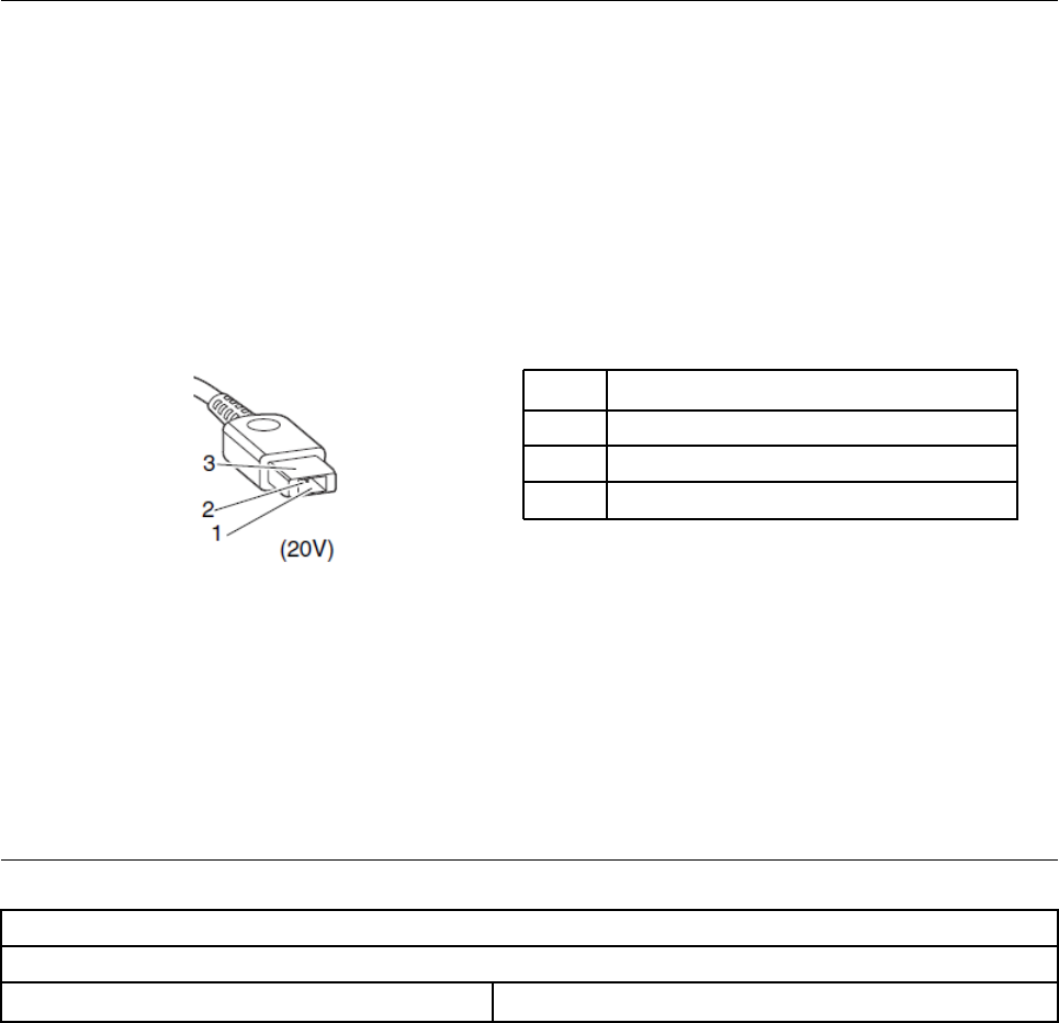
Checking the ac power adapter
If the computer fails only when the ac power adapter is used, refer to the information in this topic to check
the ac power adapter.
If the power-on indicator does not turn on, check the power cord of the ac power adapter for correct
continuity and installation.
To check the ac power adapter, do the following:
1. Unplug the ac power adapter cable from the computer.
2. Measure the output voltage across the plug of the ac power adapter cable. The correct voltages are
shown in the following table.
Pin Voltage (V dc)
1 +20
2 0
3Ground
Note: The output voltage across pin 2 might differ from the voltage that you measure.
3. Depending on the voltage that you measure, do one of the following:
• If the voltage is not correct, replace the ac power adapter.
• If the voltage is acceptable, do the following:
a. Replace the system board.
b. If the problem persists, call the Customer Support Center.
Note: Noise from the ac power adapter does not always indicate a defect.
Lenovo V730 – 13 CRU list
Model: Lenovo V730 – 13
MT: 81AV
CRU Type
22 Hardware Maintenance Manual

24 Hardware Maintenance Manual

Chapter 3. Idetifying FRUs (CRUs)
All FRUs (CRUs) for Lenovo V730 – 13
The exploded illustrations help Lenovo service technicians identify FRUs or CRUs that they may need to
replace when servicing a customer’s computer.
Refer to Appendix A “Lenovo part numbers for replacement FRUs” on page 45 if you need to look up Lenovo
part numbers for a particular FRU or CRU.
1
2
3
10
7
4
6
5
13
14
15
11
12
9
8
Figure 1. Lenovo V730 – 13 exploded view
© Copyright Lenovo 2018 25

Table 1. FRU (CRU) categories
No. FRU (CRU) category
1LCD module
2Upper case (with keyboard)
3Touch pad bracket
4Fingerprint board
5Fingerprint board cable
6Fingerprint bracket
7dc-in cable
8System board
9Heat sink
10 Wireless module
11 Solid state drive
12 Battery pack
13 Speakers
14 Base cover
15 Screw pack
26 Hardware Maintenance Manual


Table 2. FRU categories for the LCD module (continued)
7Adapter board cable
8Adapter board
9eDP cable
10 Hinges
11 LCD base cover
12 Adhesive tape
28 Hardware Maintenance Manual
Chapter 4. Removing a FRU or CRU
General guidelines
When removing or replacing a FRU, ensure that you observe the following general guidelines:
1. Do not try to service any computer unless you have been trained and certified. An untrained person runs
the risk of damaging parts.
2. Begin by removing any FRUs that have to be removed before replacing the failing FRU. Any such FRUs
are listed at the beginning of each FRU replacement procedure. Remove them in the order in which they
are listed.
3. Follow the correct sequence in the steps for removing a FRU, as shown in the illustrations by the
numbers in square callouts.
4. When removing a FRU, move it in the direction as shown by the arrow in the illustration.
5. To install a new FRU in place, perform the removal procedure in reverse and follow any notes that
pertain to replacement.
6. When replacing a FRU, carefully retain and reuse all screws. If screws are missing, look up the Lenovo
parts numbers in Appendix B “Lenovo part numbers for CRUs and miscellaneous parts” on page 51 for
replacement screws and order them through the Lenovo CRM system.
7. When replacing the base cover, reapply all labels that come with the replacement base cover. If some
original labels are not included with the replacement base cover, peal them off from the original base
cover and paste them on the replacement base cover.
DANGER
Before removing any FRU or CRU, shut down the computer and unplug all power cords from
electrical outlets.
Attention: After replacing a FRU, do not turn on the computer until you have ensured that all screws,
springs, and other small parts are in place and none are loose inside the computer. Verify this by shaking the
computer gently and listening for rattling sounds. Metallic parts or metal flakes can cause electrical short
circuits.
Attention: The system board is sensitive to and can be damaged by ESD. Before touching it, establish
personal grounding by touching a ground point with one hand or by using an ESD strap (P/N 6405959).
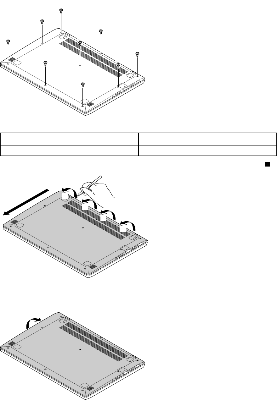
Remove the lower case
Make sure the computer has been shut down before servicing the computer..
Step 1. Place the computer upside down on a flat surface.
Step 2. Remove 9 screws.
© Copyright Lenovo 2018 29
a
a
a
a
a
a
a
a
a
Figure 3. Remove 9 screws
Screw specifications Quantity
M2.0 x 3.5 9
Step 3. Use a pry bar to detach the base cover, starting from the upper edge, then along the left edge. ( 2)
cb
b
b
b
Figure 4. Detach from the upper edge
Step 4. Lift up the cover to detach it.
d
Figure 5. Life up the cover
30 Hardware Maintenance Manual
Refer to Table 3 “Part numbers for FRUs (CRUs)” on page 45 to look up the Lenovo part numbers of the
following replacement parts:
Lower case
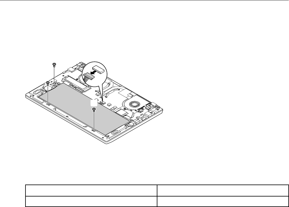
Remove the battery pack
Make sure the following FRUs (or CRUs) have been removed.
“Remove the lower case” on page 29
Step 1. Disconnect the cable from the system board.
b
a
b
b
b
Figure 6. Disconnect cable and remove screws
Attention: Use your fingernail to pull the connector to unplug it. Do not pull the cable.
Step 2. Remove 3 screws.
Screw specifications Quantity
M2.0 x 3 3
Step 3. Remove the battery pack.
Chapter 4.Removing a FRU or CRU 31
c
Figure 7. Remove the battery pack
Refer to Table 3 “Part numbers for FRUs (CRUs)” on page 45 to look up the Lenovo part numbers of the
following replacement parts:
Battery pack
Remove the solid-state drive
Make sure the following FRUs (or CRUs) have been removed.
“Remove the lower case” on page 29
Step 1. Remove 1 screw.
a
Figure 8. Remove 1 screw
Screw specifications Quantity
M2.0 x 3 1
Step 2. Remove the solid-state drive by pulling it away from the slot.
32 Hardware Maintenance Manual
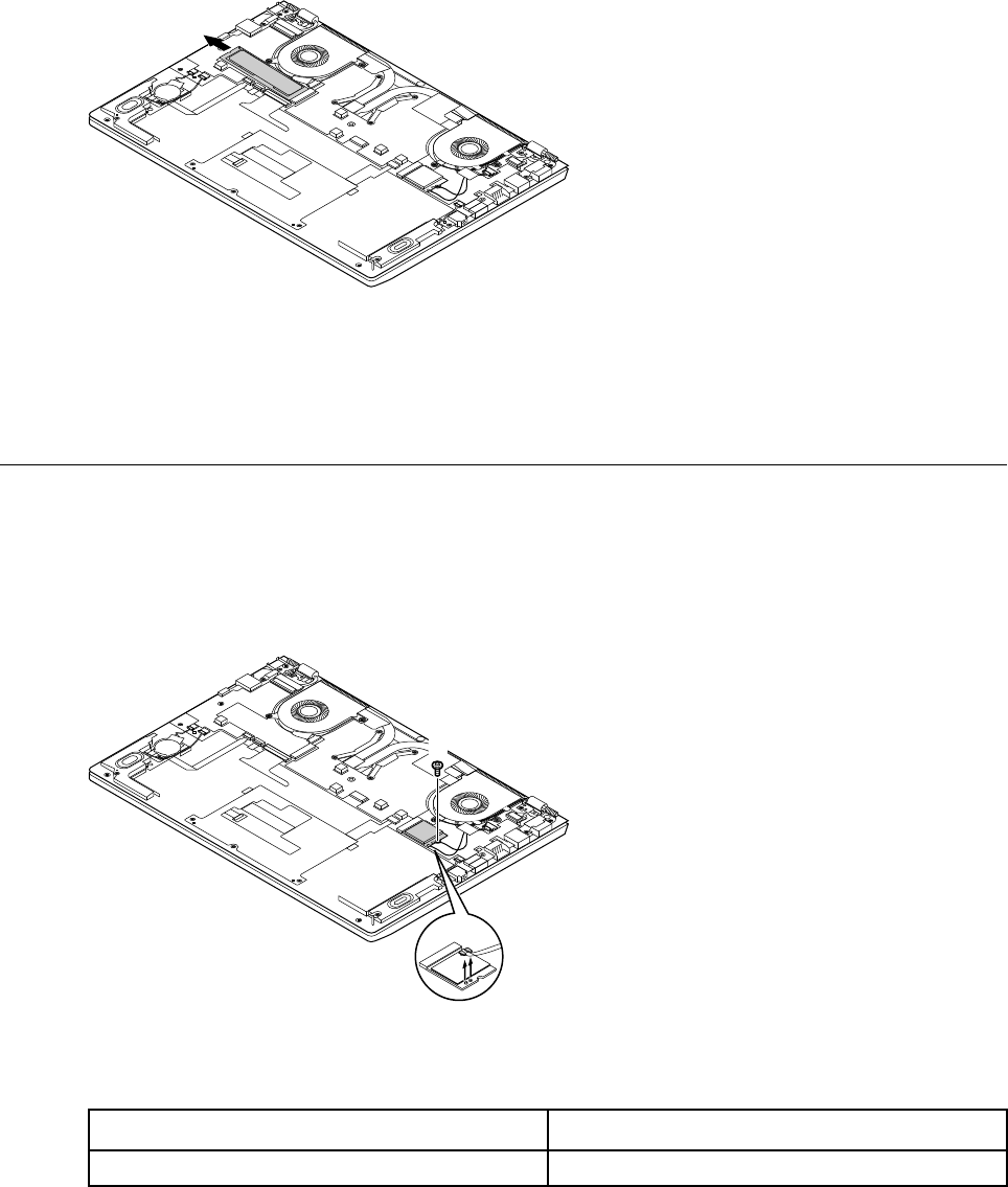
b
Figure 9. Remove by pulling the solid-state drive
Refer to Table 3 “Part numbers for FRUs (CRUs)” on page 45 to look up the Lenovo part numbers of the
following replacement parts:
Solid-state drive
Remove the wireless module
Make sure the following FRUs (or CRUs) have been removed.
“Remove the lower case” on page 29
Step 1. Disconnect the main and auxiliary antenna cables.
a a
b
Figure 10. Disconnect antenna cables
Step 2. Remove 1 screw.
Screw specifications Quantity
M2.0 x 3 1
Step 3. Remove the wireless module by pulling it away from the slot.
Chapter 4.Removing a FRU or CRU 33
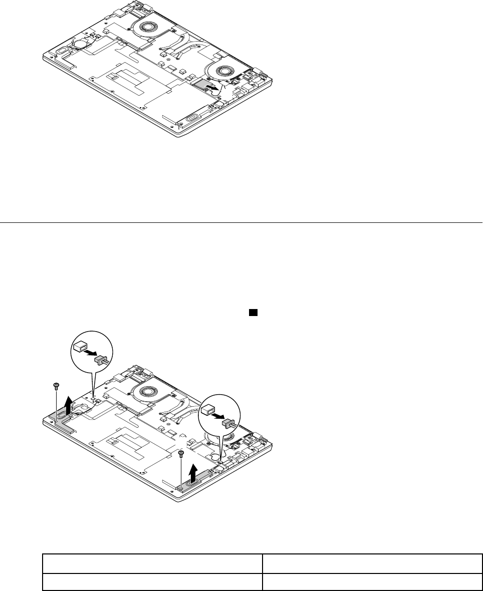
c
Figure 11. Remove the wireless module
Refer to Table 3 “Part numbers for FRUs (CRUs)” on page 45 to look up the Lenovo part numbers of the
following replacement parts:
Wireless module
Remove the speakers
Make sure the following FRUs (CRUs) have been removed.
“Remove the lower case” on page 29
“Remove the battery pack” on page 31
Step 1. Disconnect the cables from the system board. 1
a
a
c
b
c
b
Figure 12. Disconnect the cables
Step 2. Remove 2 screws, then remove the speakers.
Screw specifications Quantity
M2.0 x 3 2
Refer to Table 3 “Part numbers for FRUs (CRUs)” on page 45 to look up the Lenovo part numbers of
replacement speakers.
34 Hardware Maintenance Manual
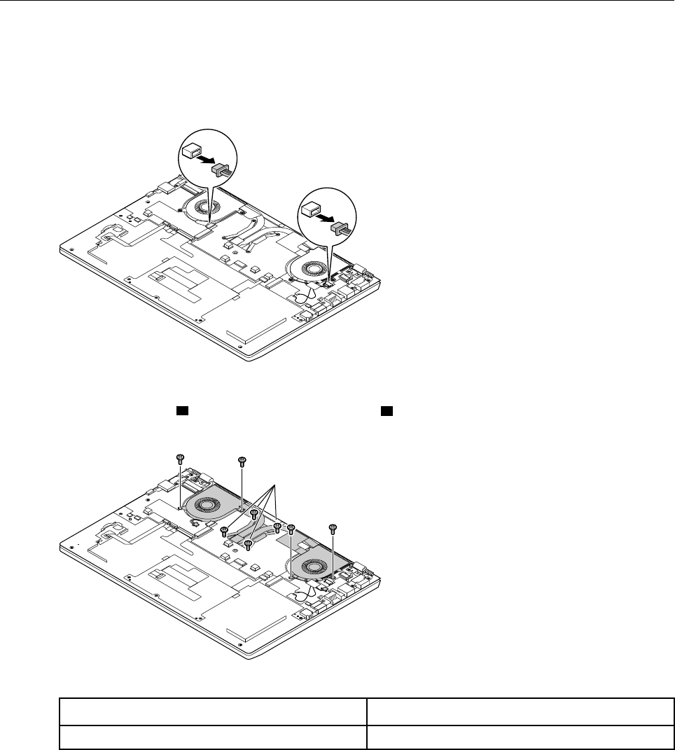
Remove the heat sink
Make sure the following FRUs (or CRUs) have been removed.
“Remove the lower case” on page 29
Step 1. Disconnect two plugs.
a
a
Figure 13. Disconnect two plugs
Step 2. Remove 4 screws ( 2) and loosen another 4 screws ( 3).
bb
c
bb
Figure 14. Remove and loosen screws
Screw specifications Quantity
M2.0 x 3 8
Step 3. Remove the heat sink.
Chapter 4.Removing a FRU or CRU 35
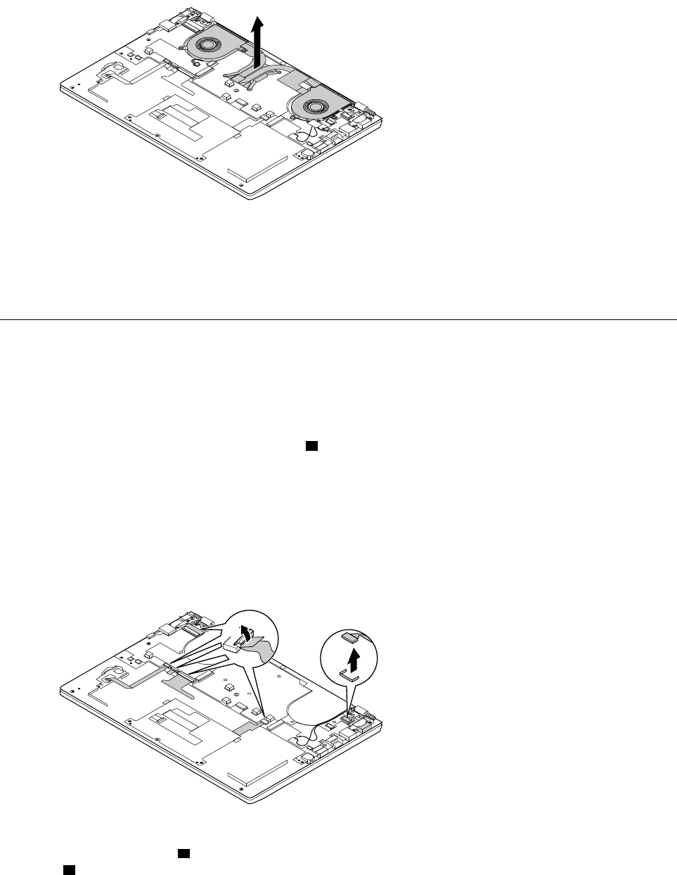
d
Figure 15. Remove the heat sink
Refer to Table 3 “Part numbers for FRUs (CRUs)” on page 45 to look up the Lenovo part numbers of the
following replacement parts:
Heat sink
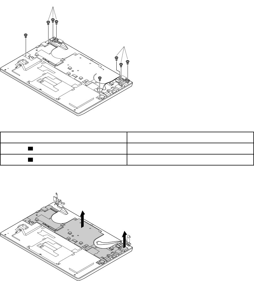
Remove the system board and the dc-in cable
Make sure the following FRUs (or CRUs) have been removed.
“Remove the lower case” on page 29
“Remove the heat sink” on page 35
Step 1. Unplug the dc-in cable from the socket 3 and disconnect all other cables from the system board.
Note: The hardware components that are connected with the system board through cables
include:
Keyboard
Fingerprint reader
dc-in connector
LCD module
b
a
c
Figure 16. Disconnect all cables from the system board
Step 2. Remove 6 screws ( 4) to disconnect the hinges from the base cover, then remove another 2 screws
(5).
36 Hardware Maintenance Manual
d
d
e
e
Figure 17. Remove 8 screws
Screw specifications Number of screws
M2.0 x 4 ( 4) 6
M2.0 x 3 ( 5) 2
Step 3. Remove the dc-in cable.
Step 4. Remove the system board.
g
h
Figure 18. Remove the system board
The LCD module is disconnected from the base cover at step 2.
Note: The LCD module is not a FRU part. Instead, it includes FRU parts as its components. Refer to
“Disassemble the LCD module” on page 39 for instructions on how to disassemble the LCD modules.
Refer to Table 3 “Part numbers for FRUs (CRUs)” on page 45 to look up the Lenovo part numbers of the
following replacement parts:
System board
dc-in cable
Chapter 4.Removing a FRU or CRU 37
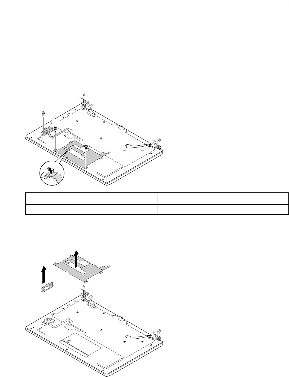
Remove the touch pad bracket, fingerprint board, and fingerprint
bracket
Make sure the following FRUs (or CRUs) have been removed. Also make sure the cable connecting the
fingerprint board to the system board has been disconnected.
Note: Not all Lenovo V730 – 13 SKUs include the fingerprint board.
“Remove the lower case” on page 29
“Remove the battery pack” on page 31
Step 1. Disconnect the cable from the touch pad bracket.
b
a
d
c
c
Screw specifications Number of screws
M2.0 x 3 1
Step 2. Remove the screws that secure the touch pad bracket and the fingerprint board.
Step 3. Remove the touch pad bracket and the fingerprint bracket.
e
f
38 Hardware Maintenance Manual
Step 4. Remove the fingerprint board.
g
Refer to Table 3 “Part numbers for FRUs (CRUs)” on page 45 to look up the Lenovo part numbers of the
following replacement parts:
Touch pad bracket (with two click buttons)
Fingerprint board
Fingerprint bracket
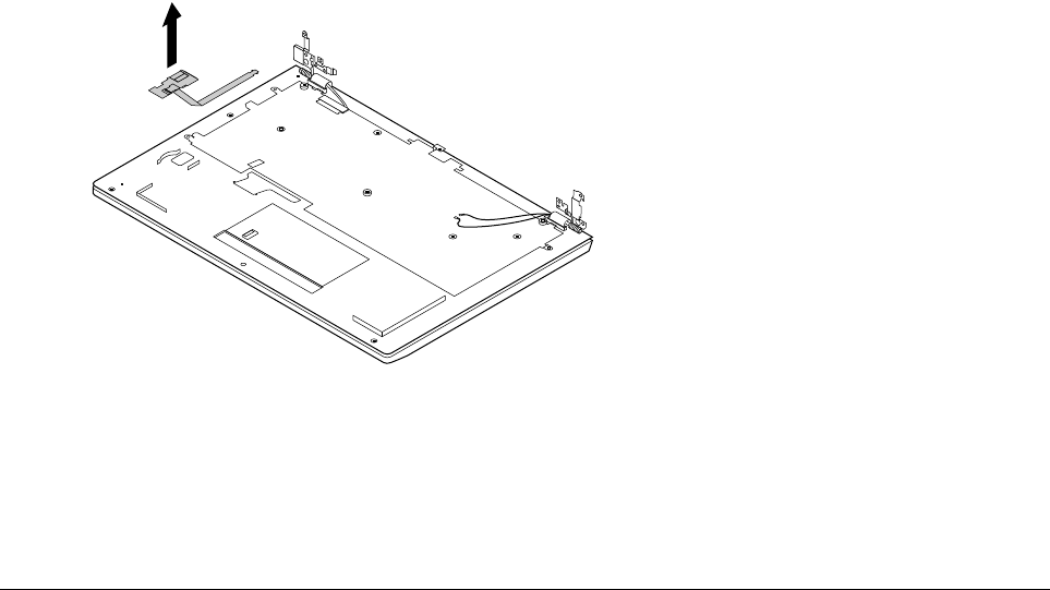
Disassemble the LCD module
The LCD module as a whole is not a FRU. Instead, it contains FRUs as its components. Before
disassembling the LCD module, make sure it has been detached from the base cover. Refer to “Remove the
system board and the dc-in cable” on page 36 for instructions.
Remove the LCD bezel
Step 1. Insert your fingernails under the lower inner side of the LCD bezel and then carefully pull the LCD
bezel outwards. Repeat this action along the inner edges of the LCD bezel until all hooks that
secure the LCD bezel are detached.
Chapter 4.Removing a FRU or CRU 39
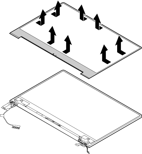
Figure 19. Pull the inner sides of the LCD bezel
Attention: Do not pull the LCD bezel from the outer sides of the LCD bezel, otherwise the hooks
may be damaged. The lower side of the LCD bezel is fixed to the LCD panel with adhesive tape.
Detach with care.
Step 2. Remove the LCD bezel.
Refer to Table 4 “Part numbers for LCD FRUs” on page 49 to look up the Lenovo part numbers for the
replacement LCD bezel.
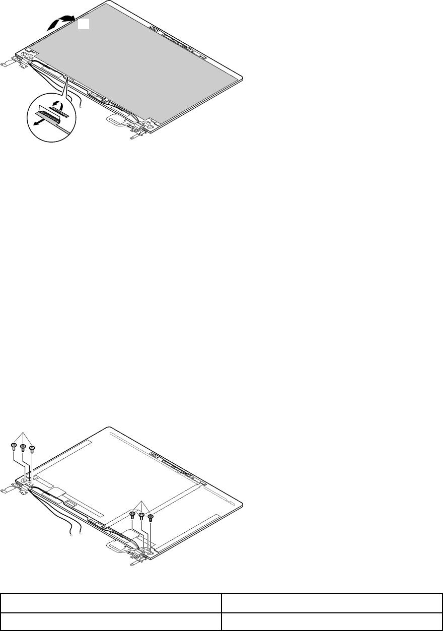
Remove the LCD panel and the LCD cable
Make sure the following FRUs (or CRUs) have been removed.
“Remove the LCD bezel” on page 39
Step 1. Pull the two tapes (located on left and right edges under the LCD panel) downwards steadily; with
the bottom edge as an axis, lift up the top edge of the LCD panel.
Attention: Do not remove the LCD panel at this step. The LCD panel is connected by a cable at
the back side. Detach the cable before removing the LCD panel.
40 Hardware Maintenance Manual
d
c
b
Figure 20. Remove 4 screws and lift up the LCD panel
Step 2. Check the back side of the LCD panel for the LCD connector and then unplug the LCD cable.
Step 3. Remove the LCD panel.
Step 4. Remove the LCD cable.
Refer to Table 3 “Part numbers for FRUs (CRUs)” on page 45 to look up the Lenovo part numbers of the
following replacement parts:
LCD panel
Refer to Appendix B “Lenovo part numbers for CRUs and miscellaneous parts” on page 51 to look up the
Lenovo part numbers of the replacement tape.
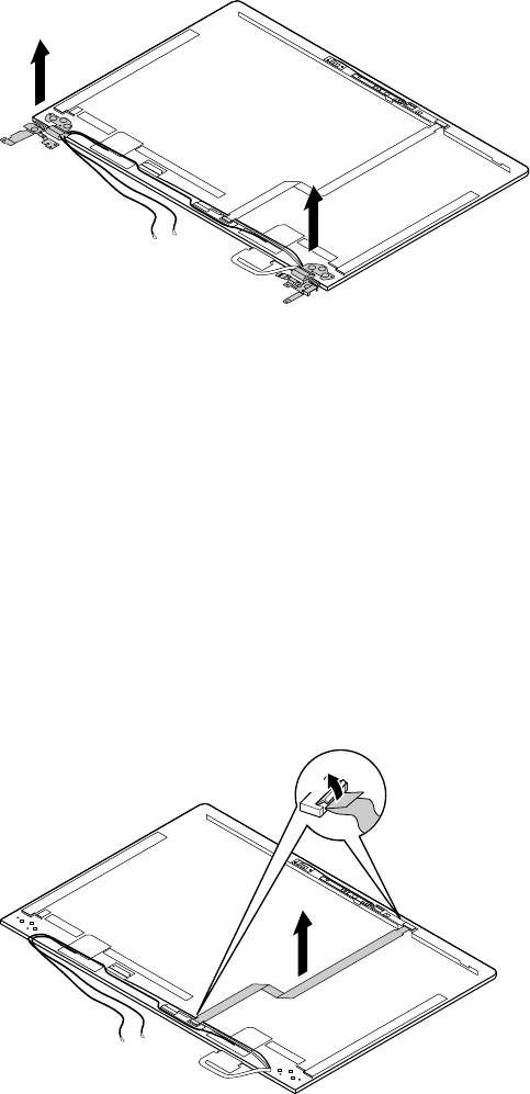
Remove the hinges
Make sure the following FRUs (or CRUs) have been removed.
“Remove the LCD bezel” on page 39
“Remove the LCD panel and the LCD cable” on page 40
Step 1. Remove 6 screws.
f
f
Figure 21. Remove 6 screws
Screw specifications Quantity
M2.5 x 2.5 6
Step 2. Remove the hinges.
Chapter 4.Removing a FRU or CRU 41
g
g
Figure 22. Remove the hinges
Refer to Table 3 “Part numbers for FRUs (CRUs)” on page 45 to look up the Lenovo part numbers of the
following replacement parts:
Hinges
Remove the adapter, microphone, and camera boards
Make sure the following FRUs (or CRUs) have been removed.
“Remove the LCD bezel” on page 39
“Remove the LCD panel and the LCD cable” on page 40
“” on page
Step 1. Unplug the adapter board cable and remove it.
b
a
c
Step 2. Unplug the eDP cable and remove it.
42 Hardware Maintenance Manual


Appendix A. Lenovo part numbers for replacement FRUs
When servicing a customer’s computer, Lenovo service technicians may use part numbers listed in the
following tables to order replacement parts through Lenovo CRM (customer relationship management)
system.
Table 3. Part numbers for FRUs (CRUs)
No. FRU (CRU) category Parts description Lenovo part number
2Upper case (with keyboard)
Upper CaseW 81AV BLK W/TP/KB-US FP 5CB0Q56273
Upper CaseW81AV BLK W/TP/KB-US NFP 5CB0Q56368
Upper CaseW 81AV BLK W/TP/KB-KO FP 5CB0Q98097
Upper CaseW81AV BLK W/TP/KB-KO NFP 5CB0Q98100
Upper CaseW 81AV BLK W/TP/KB-TC FP 5CB0Q98098
Upper CaseW81AV BLK W/TP/KB-TC NFP 5CB0Q98101
Upper CaseW 81AV BLK W/TP/KB-JP FP 5CB0Q98099
Upper CaseW81AV BLK W/TP/KB-JP NFP 5CB0Q98102
3Touch pad bracket
TP button Board W 81AV 5C50Q56346
4Fingerprint board
FP Board W 80VT 5C50N75450
5Fingerprint board cable
FP Cable W 80VT 5C10N75480
6Fingerprint bracket
FP Brackete W 80VT 5B40N75479
7Fingerprint cable
FP Cable W 80VT 5C10N75480
6System board
MBW81AV NOK I36006U UMA 4G NTCM 5B20Q56333
MBW 81AV NOK I36006U UMA 4G TCM 5B20Q56352
MBW81AV NOK I36006U UMA 8G NTCM 5B20Q56371
MBW 81AV NOK I36006U UMA 8G TCM 5B20Q56287
MBW81AVNOK I36006U UMA 16G NTCM 5B20Q56304
MBW81AV NOK I36006U UMA 16G TCM 5B20Q56344
MBW81AV NOK I36100U UMA 4G NTCM 5B20Q56340
MBW 81AV NOK I36100U UMA 4G TCM 5B20Q56373
MBW81AV NOK I36100U UMA 8G NTCM 5B20Q56369
© Copyright Lenovo 2018 45

Table 3. Part numbers for FRUs (CRUs) (continued)
MBW 81AV NOK I36100U UMA 8G TCM 5B20Q56256
MBW81AVNOK I36100U UMA 16G NTCM 5B20Q56305
MBW81AV NOK I36100U UMA 16G TCM 5B20Q56375
MBW81AV NOK I56200U UMA 4G NTCM 5B20Q56320
MBW 81AV NOK I56200U UMA 4G TCM 5B20Q56356
MBW81AV NOK I56200U UMA 8G NTCM 5B20Q56298
MBW 81AV NOK I56200U UMA 8G TCM 5B20Q56283
MBW81AVNOK I56200U UMA 16G NTCM 5B20Q56301
MBW81AV NOK I56200U UMA 16G TCM 5B20Q56290
MBW81AV NOK I56300U UMA 4G NTCM 5B20Q56328
MBW 81AV NOK I56300U UMA 4G TCM 5B20Q56361
MBW81AV NOK I56300U UMA 8G NTCM 5B20Q56327
MBW 81AV NOK I56300U UMA 8G TCM 5B20Q56326
MBW81AVNOK I56300U UMA 16G NTCM 5B20Q56285
MBW81AV NOK I56300U UMA 16G TCM 5B20Q56281
MBW81AV NOK I76500U UMA 4G NTCM 5B20Q56335
MBW 81AV NOK I76500U UMA 4G TCM 5B20Q56254
MBW81AV NOK I76500U UMA 8G NTCM 5B20Q56291
MBW 81AV NOK I76500U UMA 8G TCM 5B20Q56334
MBW81AVNOK I76500U UMA 16G NTCM 5B20Q56275
MBW81AV NOK I76500U UMA 16G TCM 5B20Q56366
MBW81AV NOK I37100U UMA 4G NTCM 5B20Q56311
MBW 81AV NOK I37100U UMA 4G TCM 5B20Q56271
MBW81AV NOK I37100U UMA 8G NTCM 5B20Q56276
MBW 81AV NOK I37100U UMA 8G TCM 5B20Q56282
MBW81AVNOK I37100U UMA 16G NTCM 5B20Q56343
MBW81AV NOK I37100U UMA 16G TCM 5B20Q56300
MBW81AV NOK I57200U UMA 4G NTCM 5B20Q56266
MBW 81AV NOK I57200U UMA 4G TCM 5B20Q56255
MBW81AV NOK I57200U UMA 8G NTCM 5B20Q56325
MBW 81AV NOK I57200U UMA 8G TCM 5B20Q56338
MBW81AVNOK I57200U UMA 16G NTCM 5B20Q56367
MBW81AV NOK I57200U UMA 16G TCM 5B20Q56357
MBW81AV NOK I77500U UMA 4G NTCM 5B20Q56257
MBW 81AV NOK I77500U UMA 4G TCM 5B20Q56355
MBW81AV NOK I77500U UMA 8G NTCM 5B20Q56365
MBW 81AV NOK I77500U UMA 8G TCM 5B20Q56310
46 Hardware Maintenance Manual

Table 3. Part numbers for FRUs (CRUs) (continued)
MBW81AVNOK I77500U UMA 16G NTCM 5B20Q56313
MBW81AV NOK I77500U UMA 16G TCM 5B20Q56322
MBW81AV NOK I37130U UMA 4G NTCM 5B20Q56289
MBW 81AV NOK I37130U UMA 4G TCM 5B20Q56347
MBW81AV NOK I37130U UMA 8G NTCM 5B20Q56359
MBW 81AV NOK I37130U UMA 8G TCM 5B20Q56349
MBW81AVNOK I37130U UMA 16G NTCM 5B20Q56293
MBW81AV NOK I37130U UMA 16G TCM 5B20Q56267
MBW81AV WIN I36006U UMA 4G NTCM 5B20Q56360
MBW 81AV WIN I36006U UMA 4G TCM 5B20Q56350
MBW81AV WIN I36006U UMA 8G NTCM 5B20Q56354
MBW 81AV WIN I36006U UMA 8G TCM 5B20Q56286
MBW81AVWIN I36006U UMA 16G NTCM 5B20Q56262
MBW81AV WIN I36006U UMA 16G TCM 5B20Q56332
MBW81AV WIN I36100U UMA 4G NTCM 5B20Q56345
MBW 81AV WIN I36100U UMA 4G TCM 5B20Q56362
MBW81AV WIN I36100U UMA 8G NTCM 5B20Q56268
MBW 81AV WIN I36100U UMA 8G TCM 5B20Q56316
MBW81AVWIN I36100U UMA 16G NTCM 5B20Q56318
MBW81AV WIN I36100U UMA 16G TCM 5B20Q56277
MBW81AV WIN I56200U UMA 4G NTCM 5B20Q56339
MBW 81AV WIN I56200U UMA 4G TCM 5B20Q56279
MBW81AV WIN I56200U UMA 8G NTCM 5B20Q56294
MBW 81AV WIN I56200U UMA 8G TCM 5B20Q56265
MBW81AVWIN I56200U UMA 16G NTCM 5B20Q56308
MBW81AV WIN I56200U UMA 16G TCM 5B20Q56319
MBW81AV WIN I56300U UMA 4G NTCM 5B20Q56307
MBW 81AV WIN I56300U UMA 4G TCM 5B20Q56370
MBW81AV WIN I56300U UMA 8G NTCM 5B20Q56330
MBW 81AV WIN I56300U UMA 8G TCM 5B20Q56296
MBW81AVWIN I56300U UMA 16G NTCM 5B20Q56364
MBW81AV WIN I56300U UMA 16G TCM 5B20Q56331
MBW81AV WIN I76500U UMA 4G NTCM 5B20Q56258
MBW 81AV WIN I76500U UMA 4G TCM 5B20Q56348
MBW81AV WIN I76500U UMA 8G NTCM 5B20Q56295
MBW 81AV WIN I76500U UMA 8G TCM 5B20Q56337
MBW81AVWIN I76500U UMA 16G NTCM 5B20Q56372
Appendix A. Lenovo part numbers for replacement FRUs 47

Table 3. Part numbers for FRUs (CRUs) (continued)
MBW81AV WIN I76500U UMA 16G TCM 5B20Q56261
MBW81AV WIN I37100U UMA 4G NTCM 5B20Q56351
MBW 81AV WIN I37100U UMA 4G TCM 5B20Q56336
MBW81AV WIN I37100U UMA 8G NTCM 5B20Q56306
MBW 81AV WIN I37100U UMA 8G TCM 5B20Q56292
MBW81AVWIN I37100U UMA 16G NTCM 5B20Q56317
MBW81AV WIN I37100U UMA 16G TCM 5B20Q56269
MBW81AV WIN I57200U UMA 4G NTCM 5B20Q56323
MBW 81AV WIN I57200U UMA 4G TCM 5B20Q56272
MBW81AV WIN I57200U UMA 8G NTCM 5B20Q56324
MBW 81AV WIN I57200U UMA 8G TCM 5B20Q56270
MBW81AVWIN I57200U UMA 16G NTCM 5B20Q56329
MBW81AV WIN I57200U UMA 16G TCM 5B20Q56314
MBW81AV WIN I77500U UMA 4G NTCM 5B20Q56263
MBW 81AV WIN I77500U UMA 4G TCM 5B20Q56321
MBW81AV WIN I77500U UMA 8G NTCM 5B20Q56280
MBW 81AV WIN I77500U UMA 8G TCM 5B20Q56299
MBW81AVWIN I77500U UMA 16G NTCM 5B20Q56363
MBW81AV WIN I77500U UMA 16G TCM 5B20Q56302
MBW81AV WIN I37130U UMA 4G NTCM 5B20Q56264
MBW 81AV WIN I37130U UMA 4G TCM 5B20Q56353
MBW81AV WIN I37130U UMA 8G NTCM 5B20Q56297
MBW 81AV WIN I37130U UMA 8G TCM 5B20Q56253
MBW81AVWIN I37130U UMA 16G NTCM 5B20Q56341
MBW81AV WIN I37130U UMA 16G TCM 5B20Q56260
9Heat sink
Thermal Module W 80VT UMA I3 5H40N75472
10 Wireless module
Intel Windstorm Peak 8265 2*2ac+BT4.x Non-Vpro M.2
Module
SW10K97453
Liteon NFA344A QCA6174A 2*2ac+BT4.x PCIE M.2
WLAN Module
SW10K97465
11 Solid state drive (SSD)
PM961 MZVLW128HEGR PCIE 128G SSD 5SD0L73445
XG4 128GB M.2 2280 PCIe-NVMe THNSN5128GPUK
SSD
5SD0M56301
Intel 600p 256GB M.2 2280 PCIe -NVMe
SSDPEKKW256G7 SSD
5SD0M56358
48 Hardware Maintenance Manual
Table 3. Part numbers for FRUs (CRUs) (continued)
XG4 256GB M.2 2280 PCIe-NVMe THNSN5256GPUK
SSD
5SD0M56299
Lenovo AM6671 M.2 2280 256GB PCIe
LENSN20256GMSP34MEAT2TA SSD
5SD0N26459
Hynix PC401 256G M.2 2280 PCIe HFS256GD9TNG-
62A0A SSD
SSS0Q59628
XG4 512GB M.2 2280 PCIe-NVMe THNSN5512GPUK
SSD
5SD0M56300
Lenovo AM6671 M.2 2280 512GB PCIe
LENSN20512GMSP34MEAT2TA SSD
5SD0N26460
Samsung PM981 512GB M.2 2280 PCIe
MZVLB512HAJQ-000L2 SSD
SSD0P20906
Hynix PC401 512G M.2 2280 PCIe HFS512GD9TNG-
62A0A SSD
SSS0Q59627
12 Battery pack
710S SP/A L15M4PC0 7.5V46Wh4cell bty 5B10K84291
720S SP/A L15M6PC0 7.5V46Wh6cell bty 5B10L55039
710S LG L15L4PC0 7.6V46Wh4cell bty 5B10K85625
13 Speakers
Speaker W 80VT L&R 5SB0N75490
14 Lower case
Lower Case W 80WJ gray 5CB0N75452
15 Screw pack
Screw Pack W 80VT 5S10N75465
Note: Refer to Appendix B “Lenovo part numbers for CRUs and miscellaneous parts” on page 51 to look up
the Lenovo part numbers of ac power adapters and power cords.
Table 4. Part numbers for LCD FRUs
No. FRU (CRU) category Spare parts description Lenovo part number
1LCD bezel
LCD Bezel W 81AV 5B30Q56288
2LCD panel
BO NV133FHM-N61 FHDI AG S NB 5D10M42884
LG LP133WF4 SPB1 FHDI AG S NB 5D10K81089
IV M133NWF4 R0 FHDI AG S NB 5D10M42877
3Microphone board (left)
MIC Board-Left W 81AV 5C50Q56374
4Camera board
Camera W 81AV 1M 5C20Q56312
Appendix A. Lenovo part numbers for replacement FRUs 49

Table 4. Part numbers for LCD FRUs (continued)
5Microphone board (right)
MIC Board-Right W 81AV W/Senor 5C50Q56284
6Microphone board cable
MIC Board-Left Cable W 81AV 5C10Q56303
7Adapter board cable
Change Board Cable W 81AV 5C50Q56358
8Adapter board
Change Board W 81AV 5C50Q56284
9eDP cable
LCD Cable W 81AV HD 5C10Q56309
10 Hinges
Hinge W 80VT L&R 5H50N75463
11 LCD base cover
LCD Cover W 81AV Gray W/ant/tape 5CB0Q56259
12 Adhesive tape
Removable tape W 81AV 5T10Q56342
50 Hardware Maintenance Manual

Appendix B. Lenovo part numbers for CRUs and
miscellaneous parts
The power cords and ac adapters are CRUs.
Table 5. Part numbers for FRUs (CRUs)
Category Parts description Lenovo part number
Screw pack
Screw Pack W 80VT 5S10N75465
Tape
Removable tape W 81AV 5T10Q56342
ac power adapter
Acbel ADLX45NAC3A 20V2.25A COO SA10M42789
Delta ADLX45NDC3A 20V2.25A COO SA10M42787
Liteon ADLX45DLC3A 20V2.25A COO SA10M42529
Chicony ADLX45NCC3A 20V2.25A COO SA10M42722
Power cord
LINETEK PC323+RVV300/300+LS15 1米电源线 145000600
Longwell LSG-31+RVV300/300+LS-18 1米电源线 145000568
VOLEX GB10S3+RVV 300/500+VAC5S 1米电源线 145000538
lux 0036+RVV 300/300 0.75/3C+0002 1米电源线 145500003
LINETEK LP-61L+ H03VV-F+ LS15 1米电源线 145000593
Longwell LP-61L+H03VV-F+LS-18 1米电源线 145000561
VOLEX MP5004+H03VV-F+VAC5S 1米电源线 145000605
lux 0031+H03VV-F 0.75/3C+0011 1米电源线 145500000
LINETEK LP-34+H03VV-F + LS15 1米电源线 145000585
Longwell LP-34A+H03VV-F+LS-18 1米电源线 145000553
VOLEX M2511+HO3VV-F+VAC5S 1米电源线 145000525
lux 0033+H03VV-F 0.75/3C+0011 1米电源线 145500001
LINETEK LP-30B + SPT-2 + LS15 1米电源线 145000594
Longwell LP-30B+SPT-2 18AWG+LS-18 1米电源线 145000562
Volex US15S3+SPT-2 +VAC5S 1米电源线 145000537
lux 0014+SPT-2 60℃ 18/3C+0016 1米电源线 145500002
LINETEK PE-361+ H05VV-F+ LS15 1米电源线 145000592
Longwell LP-67+BIS+LS-18 1米电源线 145000560
lux 0046+IS694 0.75/3C+0011 1米电源线 145500004
LINETEK LS15+VCTF+LP-54 1米电源线 145000587
© Copyright Lenovo 2018 51

Table 5. Part numbers for FRUs (CRUs) (continued)
Longwell LP-54+VCTF+LS-18 1米电源线 145000555
VOLEX VAC5S+VCTF+M755 1米电源线 145000530
lux 0018(E)+VCTF 0.75/3C+0021 1米电源线 145500005
LINETEK LS15+H03VV-F+LP-23A 1米电源线 145000589
Longwell LP-23A+LFC-3R+LS-18 1米电源线 145000557
VOLEX AU10S3+H03VV-F+VAC5S 1米电源线 145000532
lux 0038+H03VV-F 0.75/3C+0011 1米电源线 145500006
LINETEK LS15+VCTF+LP-53 1米电源线 145000588
LINETEK LS15+VCTF+LP-53 1米电源线 SL60M91981
Longwell LP-71+VCTF+LS-33 1米电源线 145000556
Longwell LP-71+VCTF+LS-33 1米电源线 SL60P41024
VOLEX TW15CS3+VCTF+VAC5S 1米电源线 145000531
VOLEX TW15CS3+VCTF+VAC5S 1米电源线 SL60P41028
lux 0019+VCTF 0.75/3C+0021 1米电源线 145500007
lux 0019+VCTF 0.75/3C+0021 1米电源线 SL60P41026
LINETEK LS15+H05VV-F+LP-E04A 1米电源线 145000590
Longwell LP-486+KTLH03VV-F+LS-5 1米电源线 145000558
VOLEX M2511+KETI IEC+VAC5S 1米电源线 145000533
lux 0033+H03VV-F 0.75/3C+0011 1米电源线 145500008
LINETEK LS15+H03VV-F+PE-336 1米电源线 145000591
Longwell LP-22+H03VV-F+LS-18 1米电源线 145000559
VOLEX IT10S3+HO3VV-F+VAC5S 1米电源线 145000535
lux 0029+H03VV-F 0.75/3C+0011 1米电源线 145500009
LINETEK LS15+H03VV-F+PE-364 1米电源线 145000586
Longwell LP-39+H03VV-F+LS-18 1米电源线 145000554
lux 0044+H03VV-F 0.75/3C+0011 1米电源线 145500010
LINETEK LS15 H03VV-F LP26A 1米电源线 145000596
Longwell LP-46+H03VV-F+LS-18 1米电源线 145000564
VOLEX CH10S3+H03VV-F+VAC5S 1米电源线 145000527
lux 0034+H03VV-F 0.75/3C+0011 1米电源线 145500011
LINETEK LS15+H03VV-F+LP-41 1米电源线 145000595
Longwell LP-41+H03VV-F+LS-18 1米电源线 145000563
VOLEX SI16S3+H03VV-F+VAC5S 1米电源线 145000526
lux 0041+H03VV-F 0.75/3C+0011 1米电源线 145500012
LINETEK LS15+H03VV-F+LP-37 1米电源线 145000597
Longwell LP-37+H03VV-F+LS-18 1米电源线 145000565
VOLEX MP232+H03VV-F+VAC5S 1米电源线 145000524
52 Hardware Maintenance Manual

Table 5. Part numbers for FRUs (CRUs) (continued)
lux 0027+H03VV-F 0.75/3C+0011 1米电源线 145500013
lux 0014+H03VV-F 0.75/3C+0011 1米电源线 5L60J33143
LINETEK LS15+H03VV-F+LP39 1米电源线 145000599
Longwell LP-24+H03VV-F+LS-18 1米电源线 145000567
VOLEX VA2073+H03VV-F+VAC5S 1米电源线 145000528
lux 0040+H03VV-F 0.75/3C+0011 1米电源线 145500015
Appendix B. Lenovo part numbers for CRUs and miscellaneous parts 53
54 Hardware Maintenance Manual
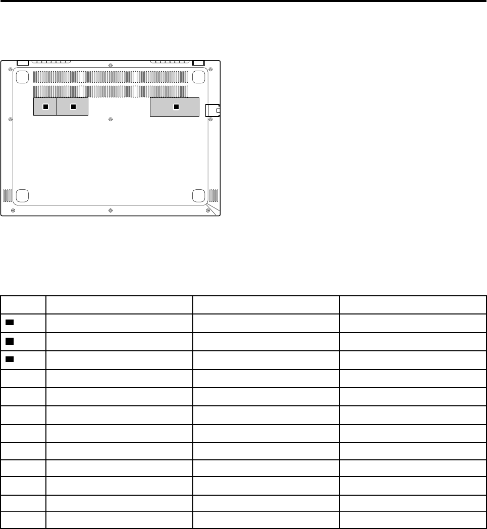
Appendix C. Label locations
abc
Figure 23. Label layout on the back side of the base cover
Labels attached to the base cover are country/region specific. Make sure to apply the appropriate labels to
the replacement base cover.
Table 6. All base cover labels
Label Label description Applied country/region Label dimensions
aRating label all 33 mm x 24 mm
bPrint rating label all 43 mm x 24 mm
cCountry specific label
Taiwan warning label Taiwan 70 mm x 10 mm
US FCC & Canada IC label USA, Canada 32 mm x 10 mm
Argentina CNC label Argentina 68 mm x 6 mm
Argentina label Argentina 65 mm x 20 mm
Korea KCC label Korea 43 mm x 24 mm
Indonesia POSTEL label Indonesia 15 mm x 10 mm
Indonesia rating label Indonesia 26 mm x 10 mm
Brazil Anatel label Brazil 35 mm x 15 mm
South Africa ICASA label South Africa 20 mm x 10 mm
© Copyright Lenovo 2018 55
56 Hardware Maintenance Manual

Trademarks
Lenovo and the “lenovo” logo are trademarks of Lenovo in the United States, other countries or both:
Other company, product, or service names may be trademarks or service marks of others.
