Leonardo S p a TRA100B Part 87 Aircraft Licensed Transmitter operating at 1090MHz User Manual tman 1124 02x
LEONARDO S.p.a. Part 87 Aircraft Licensed Transmitter operating at 1090MHz tman 1124 02x
Contents
- 1. Users manual 1
- 2. Users manual 2
Users manual 1

UNCLASSIFIED MAN-1124/01 T02
___________________________________________________________________________________________________________
______________________________________________________________________________
Page 1
© Copyright Leonardo Finmeccanica S.p.A. – All rights reserved
UNCLASSIFIED
TRA-100B Mode S Transponder (TRA-100B)
Honeywell
Component Maintenance Manual (CMM)
MAN-1124/01 T
Issue No. 02
Date 02-08-2016
Leonardo Finmeccanica S.p.A.
Piazza Montegrappa, 4
00195 - Roma
ITALY

UNCLASSIFIED MAN-1124/01 T02
___________________________________________________________________________________________________________
______________________________________________________________________________
Page 2
© Copyright Leonardo Finmeccanica S.p.A. – All rights reserved
UNCLASSIFIED
Page left intentionally blank
UNCLASSIFIED MAN-1124/01 T02
___________________________________________________________________________________________________________
______________________________________________________________________________
Page 3
© Copyright Leonardo Finmeccanica S.p.A. – All rights reserved
UNCLASSIFIED
Revision List
Date of Issue Issue Number Revision History
18-12-2015 01 First Issue
02-08-2016 02 Updated to include Honeywell comments
This document is composed of 112 pages.

UNCLASSIFIED MAN-1124/01 T02
___________________________________________________________________________________________________________
______________________________________________________________________________
Page 4
© Copyright Leonardo Finmeccanica S.p.A. – All rights reserved
UNCLASSIFIED
TABLE OF CONTENTS
1GENERAL........................................................................................................................................................9
1.1TRA‐100BMODESTRANSPONDER‐LISTOFABBREVIATIONS..........................................................................................9
1.2TRA‐100BMODESTRANSPONDER–CONFIGURATION................................................................................................10
1.3TRA‐100BMODESTRANSPONDER–INTRODUCTION..................................................................................................12
1.4TRA‐100BMODESTRANSPONDER‐SCHEMATICDIAGRAM..........................................................................................13
1.5TRA‐100BMODESTRANSPONDER–GENERALWARNINGSANDCAUTIONSANDRELATEDSAFETYDATA................................14
1.5.1GeneralSafety..........................................................................................................................................14
1.5.2ListofWarningsandCautions..................................................................................................................14
1.6TRA‐100BMODESTRANSPONDER–SUPPORTEQUIPMENTANDTOOLS........................................................................16
1.6.1StandardAGEandTools...........................................................................................................................16
1.6.2Software...................................................................................................................................................16
1.6.3Consumables,MaterialandExpendables................................................................................................16
1.7TRA‐100BMODESTRANSPONDER–PACKAGING,HANDLING,STORAGEANDTRANSPORTATION.......................................17
1.7.1Packaging‐General.................................................................................................................................17
1.7.1.1PackagingProcedure.......................................................................................................................................17
1.7.1.2IdentificationLabel..........................................................................................................................................17
1.7.1.3ReshipmentPackagingProcedure...................................................................................................................17
1.7.1.4OriginalPackaging...........................................................................................................................................18
1.7.1.5InstructionofReshipment...............................................................................................................................18
1.7.2Handling...................................................................................................................................................18
1.7.3Storage.....................................................................................................................................................18
1.7.3.1StorageData....................................................................................................................................................18
1.7.4Transportation.........................................................................................................................................18
1.7.5ESDHandlingProcedure...........................................................................................................................19
1.7.6HazardousMaterials................................................................................................................................19
2DESCRIPTION................................................................................................................................................20
2.1TRA‐100BMODESTRANPONDER–DESCRIPTIONOFHOWITISMADEANDITSFUNCTION..................................................20
3TECHNICALDATA..........................................................................................................................................24
3.1TRA‐100BMODESTRANSPONDER–TECHNICALDATA.............................................................................................24
3.1.1GeneralTechnicalData............................................................................................................................24
3.1.2LabelsData...............................................................................................................................................26

UNCLASSIFIED MAN-1124/01 T02
___________________________________________________________________________________________________________
______________________________________________________________________________
Page 5
© Copyright Leonardo Finmeccanica S.p.A. – All rights reserved
UNCLASSIFIED
3.1.3EnvironmentalCertificationandCharacteristics......................................................................................28
3.1.4ConnectorsData.......................................................................................................................................34
4OPERATION..................................................................................................................................................40
4.1TRA‐100BMODESTRANSPONDER–MODESOPERATION............................................................................................40
4.1.1ATCRBSSystemOperation.......................................................................................................................42
4.1.2ATCRBSTransmissionOverview...............................................................................................................43
4.1.3OVERVIEWOFMODES.............................................................................................................................45
4.1.3.1SignalCharacteristics.......................................................................................................................................45
4.1.3.2InterrogationProcess......................................................................................................................................46
5INSTALLATION..............................................................................................................................................49
5.1TRA‐100BMODESTRANSPONDER–REPLACEPROCEDURES.........................................................................................49
6FAULTISOLATION.........................................................................................................................................51
6.1GENERAL............................................................................................................................................................51
6.2FAILUREDATASTRUCTURE................................................................................................................................51
6.2.1FlightInformationHeader........................................................................................................................51
6.2.2FaultRecordformat.................................................................................................................................53
6.3FAILURELOCATIONONAIRCRAFT......................................................................................................................56
6.3.1ONA/CTroubleshootingprocedure.........................................................................................................57
6.3.2NVMDownloadprocedure.......................................................................................................................60
6.3.2.1TechsatNetLoaderprocedure:.......................................................................................................................60
6.3.3NVMData.................................................................................................................................................64
6.4FAILURELOCATIONOFFAIRCRAFT....................................................................................................................66
6.4.1STTEDescription.......................................................................................................................................66
6.4.2OFFA/CTroubleshootingprocedure........................................................................................................69
6.4.3Connectionprocedure..............................................................................................................................71
6.4.4FaultFinding.............................................................................................................................................71
6.4.5Checkoutprocedure.................................................................................................................................72
6.4.5.1Checkoflightningprotectiondevicespresence..............................................................................................72
6.4.5.2Testofhardware/softwareperformancesinnormaluse................................................................................77
7MAINTENANCE.............................................................................................................................................90
7.1TRA‐100BMODESTRANSPONDER–FIRSTLEVELMAINTENANCE................................................................................90
7.1.1OnAircraftMaintenance(Scheduled)......................................................................................................90

UNCLASSIFIED MAN-1124/01 T02
___________________________________________________________________________________________________________
______________________________________________________________________________
Page 6
© Copyright Leonardo Finmeccanica S.p.A. – All rights reserved
UNCLASSIFIED
7.1.2OnAircraftMaintenance(Unscheduled)..................................................................................................90
7.1.3Servicing...................................................................................................................................................90
7.2TRA‐100BMODESTRANSPONDER–CLEANING........................................................................................................91
7.3TRA‐100BMODESTRANSPONDER–INSPECTION......................................................................................................93
7.4TRA‐100BMODESTRANSPONDER–SECONDLEVELMAINTENANCE..............................................................................95
7.4.1TRA‐100B,DataProcessorandI/O–Replaceprocedure.........................................................................95
7.4.2TRA‐100B,RFSubassembly–Replaceprocedure.....................................................................................99
7.4.3TRA‐100B,ACPowerSupply(ACPS)–Replaceprocedure......................................................................102
7.4.4TRA‐100B,DCPowerSupply(DCPS)–Replaceprocedure.....................................................................106
7.4.5TRA‐100B,WiredChassis(WC)–Replaceprocedure..............................................................................110
8ILLUSTRATEDPARTSDATA..........................................................................................................................112
8.1TRA‐100BMODESTRANSPONDER‐ILLUSTRATEDPARTSDATA....................................................................................112

UNCLASSIFIED MAN-1124/01 T02
___________________________________________________________________________________________________________
______________________________________________________________________________
Page 7
© Copyright Leonardo Finmeccanica S.p.A. – All rights reserved
UNCLASSIFIED
LIST OF ILLUSTRATIONS
FIGURE 1-1 – TRA-100B MODE S TRANSPONDER - CONFIGURATION .................................................................. 11
FIGURE 1-2 – TRA-100B MODE S TRANSPONDER - SCHEMATIC DIAGRAM ........................................................... 13
FIGURE 2-1 – TRA-100B MODE S TRANSPONDER - DESCRIPTION OF HOW IT IS MADE .......................................... 20
FIGURE 2-2 – TRA-100B MODE S TRANSPONDER – FUNCTIONAL DIAGRAM ........................................................ 23
FIGURE 3-1 – TRA-100B MODE S TRANSPONDER – TECHNICAL DATA ............................................................... 25
FIGURE 3-1 – TRA-100B MODE S TRANSPONDER – LABELS LAYOUT .................................................................. 27
FIGURE 3-3 – TRA-100B MODE S TRANSPONDER – CONNECTORS ..................................................................... 34
FIGURE 4-1 – ATCRBS SYSTEM ........................................................................................................................ 42
FIGURE 4-2 – ATCRBS INTERROGATION WITHOUT SIDE LOBE SUPPRESSION (SLS) ............................................ 44
FIGURE 4-3 – ATCRBS INTERROGATION WITH SIDE LOBE SUPPRESSION ............................................................ 44
FIGURE 4-4 – INTERMODE (MODE A/C AND S) INTERROGATION ........................................................................... 47
FIGURE 4-5 – MODE S INTERROGATION PULSE SEQUENCE ................................................................................. 47
FIGURE 4-6 – MODE S REPLY ............................................................................................................................ 48
FIGURE 5-1 – TRA-100B MODE S TRANSPONDER - REPLACE PROCEDURES ....................................................... 50
FIGURE 6-1 – TRA-100B STTE (FRONT AND RIGHT VIEWS) ................................................................................ 67
FIGURE 6-2 – TRA-100B STTE (REAR AND LEFT VIEWS) .................................................................................... 68
FIGURE 6-3 – TRA-100B - FRONT PANEL LED ................................................................................................... 69
FIGURE 6-4 – TRA-100B – OFF A/C TROUBLESHOOTING STTE NVM INTERFACE .............................................. 84
FIGURE 6-5 – TRA-100B – OFF A/C TROUBLESHOOTING – DIAGNOSTIC PROPERTIES (1) ................................... 85
FIGURE 6-6 – TRA-100B – OFF A/C TROUBLESHOOTING – DIAGNOSTIC PROPERTIES (2) ................................... 86
FIGURE 6-4 – TRA-100B – OFF A/C TROUBLESHOOTING .................................................................................. 87
FIGURE 6-5 – TRA-100B – OFF A/C TROUBLESHOOTING – DIAGNOSTIC PROPERTIES (1) ................................... 88
FIGURE 6-6 – TRA-100B – OFF A/C TROUBLESHOOTING – DIAGNOSTIC PROPERTIES (2) ................................... 89
FIGURE 7-1 – TRA-100B, DATA PROCESSOR AND I/O – REPLACE PROCEDURE ................................................... 97
FIGURE 7-2 – TRA-100B, DATA PROCESSOR AND I/O – REPLACE PROCEDURE (POSITION) .................................. 98
FIGURE 7-3 –TRA-100B, RF SUBASSEMBLY – REPLACE PROCEDURE ............................................................... 101
FIGURE 7-4 – TRA-100B, AC POWER SUPPLY (ACPS) – REPLACE PROCEDURE ............................................... 104
FIGURE 7-5 – TRA-100B, ACPS AND DCPS – REPLACE PROCEDURE (POSITION) ............................................. 105
FIGURE 7-6 – TRA-100B, DC POWER SUPPLY (DCPS) – REPLACE PROCEDURE .............................................. 108
FIGURE 7-7 – TRA-100B, ACPS AND DCPS – REPLACE PROCEDURE (POSITION) ............................................. 109

UNCLASSIFIED MAN-1124/01 T02
___________________________________________________________________________________________________________
______________________________________________________________________________
Page 8
© Copyright Leonardo Finmeccanica S.p.A. – All rights reserved
UNCLASSIFIED
LIST OF TABLES
TABLE 1-1 - LIST OF ABBREVIATIONS .................................................................................................................... 9
TABLE 1-2 – TRA-100B - CONFIGURATION DATA ............................................................................................... 10
TABLE 1-3 - TRA-100B – GENERAL WARNINGS, CAUTIONS AND RELATED SAFETY DATA ..................................... 14
TABLE 1-4 - TRA-100B – STANDARD AGE AND TOOLS ....................................................................................... 16
TABLE 1-5 – TRA-100B - SOFTWARE ................................................................................................................. 16
TABLE 1-6 – TRA-100B - CONSUMABLES, MATERIAL AND EXPENDABLES ............................................................ 16
TABLE 3-1 – TRA-100B - TECHNICAL DATA – GENERAL ...................................................................................... 24
TABLE 3-2 – TRA-100B – DO-160G CERTIFICATION CATEGORIES ..................................................................... 28
TABLE 3-3 – TRA-100B – ABD100 1.2 G CERTIFICATION CATEGORIES .............................................................. 29
TABLE 3-4 – TRA-100B – ABD100 1.6 D CERTIFICATION CATEGORIES .............................................................. 31
TABLE 3-5 – TRA-100B – ABD100 1.8 E CERTIFICATION CATEGORIES .............................................................. 31
TABLE 3-6 – TRA-100B – D6-44800-1 CERTIFICATION CATEGORIES .................................................................. 31
TABLE 3-7 – TRA-100B – D6-81926 CERTIFICATION CATEGORIES ..................................................................... 31
TABLE 3-8 – TRA-100B – MIL STD 810F CERTIFICATION CATEGORIES .............................................................. 31
TABLE 3-9 – TRA-100B – ASTM D1149 CERTIFICATION CATEGORIES ............................................................... 32
TABLE 3-10 – TRA-100B – D6/ 16050-4 CERTIFICATION CATEGORIES ............................................................... 32
TABLE 3-11 – TRA-100B – D6-44800-1 CERTIFICATION CATEGORIES ................................................................ 33
TABLE 3-12 – TRA-100B - TECHNICAL DATA – CONNECTORS ............................................................................. 34
TABLE 3-13 – TRA-100B - TECHNICAL DATA – MAIN CONNECTOR PIN MAPPING .................................................. 35
TABLE 6-1 – TRA-100B – INTERNAL FAULTS ..................................................................................................... 54
TABLE 6-2 – TRA-100B – EXTERNAL FAULTS ..................................................................................................... 55
TABLE 6-3 – TRA-100B – MALFUNCTION SYMPTOMS ......................................................................................... 57
TABLE 6-4 - EXTERNAL FAULTS MAINTENANCE PROCEDURE ................................................................................ 64
TABLE 6-5 – TRA-100B STTE COMPOSITION .................................................................................................... 66
TABLE 6-6 – TRA-100B - FRONT PANEL LED INDICATORS .................................................................................. 70
TABLE 6-7 – TRA-100B - TRANSZORB TEST PARAMETERS ................................................................................. 73

UNCLASSIFIED MAN-1124/01 T02
___________________________________________________________________________________________________________
______________________________________________________________________________
Page 9
© Copyright Leonardo Finmeccanica S.p.A. – All rights reserved
UNCLASSIFIED
1 GENERAL
1.1 TRA-100B MODE S TRANSPONDER - LIST OF ABBREVIATIONS
Table 1-1 - List of Abbreviations
Symbol Instruction
AC Alternate Current
AD, A/D Analogue to Digital
BIT Built In Test
BITE Built In Test Equipment
CBIT Continuous Built In Test
DC Direct Current
GND GrouND
HF High Frequency
IBIT Interruptive Built In Test
LRU Line Replaceable Unit
MT Mounting Tray
NSN Nato Stock Number
PBIT Power-on Built In Test
RF Radio Frequency
RX Receiver
TX Transmitter

UNCLASSIFIED MAN-1124/01 T02
___________________________________________________________________________________________________________
______________________________________________________________________________
Page 10
© Copyright Leonardo Finmeccanica S.p.A. – All rights reserved
UNCLASSIFIED
1.2 TRA-100B MODE S TRANSPONDER – CONFIGURATION
This manual is applicable to the following TRA-100B Mode S Transponder Part Numbers (Table
1-2):
Table 1-2 – TRA-100B - Configuration Data
2 Ref.
Figure 1-1
Description Part Number Qty
1
TRA-100B Mode S Transponder
TRA-100B Mode S Transponder
TRA-100B Mode S Transponder
TAC-6001/03
TAC-6003/03
TAC-6004/03
1
2 Wired Chassis (WC) TAE-6001/03 1
3 Data Processor and I/O (DPIO) TAQ-5432/03 1
4 RF – Subassembly (RF) TAG-5501/03 1
5 AC Power Supply (ACPS) TAG-5433/03 1
6 DC Power Supply (DCPS) TAG-5435/03 1
NI TRA-100B Operative SW TBR-6001/01 1
UNCLASSIFIED MAN-1124/01 T02
___________________________________________________________________________________________________________
______________________________________________________________________________
Page 11
© Copyright Leonardo Finmeccanica S.p.A. – All rights reserved
UNCLASSIFIED
Figure 1-1 – TRA-100B Mode S Transponder - Configuration
6
5
2
4
3

UNCLASSIFIED MAN-1124/01 T02
___________________________________________________________________________________________________________
______________________________________________________________________________
Page 12
© Copyright Leonardo Finmeccanica S.p.A. – All rights reserved
UNCLASSIFIED
2.1 TRA-100B Mode S TRANSPONDER – INTRODUCTION
The TRA-100B Mode S Transponder is a remote mounted avionics device which provides the
Mode S Transponder function required by Technical Standard Order (ETSO-C112d).
The XPDR also provides Extended Squitter ADS-B Out function required by ETSO-C166b/.
The TRA-100B Modes S Transponder is designed to be a Level 2 transponder.
It includes the capabilities of a Level 1 Transponder:
• Mode A identity and Mode C pressure-altitude reporting,
• Air Traffic Control Radar Beacon System (ATCRBS)/Mode-S and Mode S all-call
transactions,
• Addressed surveillance altitude and identity transaction,
• Lockout protocols,
• Basic data protocols except data link capability reporting, and
• Air-to-air service and squitter transactions.
The TRA-100B includes the capabilities of a Level 2 Transponder:
• Bi-directional air-to-air information exchange
• Ground-to-air data uplink, Comm-A
• Air-to-ground data downlink, Comm-B
• Multisite message protocol
• Data link capability reporting
• Aircraft identification reporting
• Traffic Alert and Collision Avoidance System (TCAS)/Airborne Collision Avoidance System
(ACAS) crosslink capability
• Overlay Command Capability
In addition, the Transponder contains the following optional additional features:
• TCAS Compatibility (a)
• Antenna Diversity (d)
• Extended Squitter (e)
• Enhanced Surveillance (including Elementary Surveillance) (n)
• Surveillance Identifier Code (s)
UNCLASSIFIED MAN-1124/01 T02
___________________________________________________________________________________________________________
______________________________________________________________________________
Page 13
© Copyright Leonardo Finmeccanica S.p.A. – All rights reserved
UNCLASSIFIED
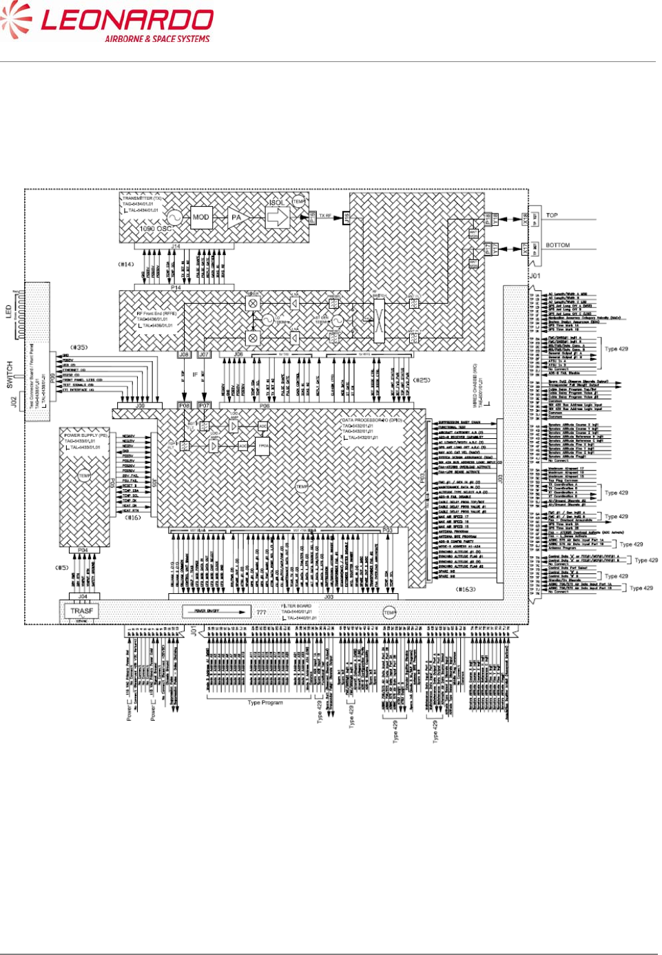
2.2 TRA-100B Mode S TRANSPONDER - SCHEMATIC DIAGRAM
Figure 1-2 – TRA-100B Mode S Transponder - Schematic Diagram
UNCLASSIFIED MAN-1124/01 T02
___________________________________________________________________________________________________________
______________________________________________________________________________
Page 14
© Copyright Leonardo Finmeccanica S.p.A. – All rights reserved
UNCLASSIFIED
2.3 TRA-100B MODE S TRANSPONDER – GENERAL WARNINGS AND
CAUTIONS AND RELATED SAFETY DATA
2.3.1 General Safety
Before you do maintenance procedures on the Unit make sure that you know the
necessary safety data.
Before you work on the Unit, make sure that the electrical power supply is Removed from
the Unit. Energized circuits can cause injury to persons.
Before you work on the Unit, make sure that you have the correct personal safety
equipment. You must use or wear the correct personal safety equipment to prevent
injuries.
Handle all the equipment carefully. This will help to prevent damage to it.
2.3.2 List of Warnings and Cautions
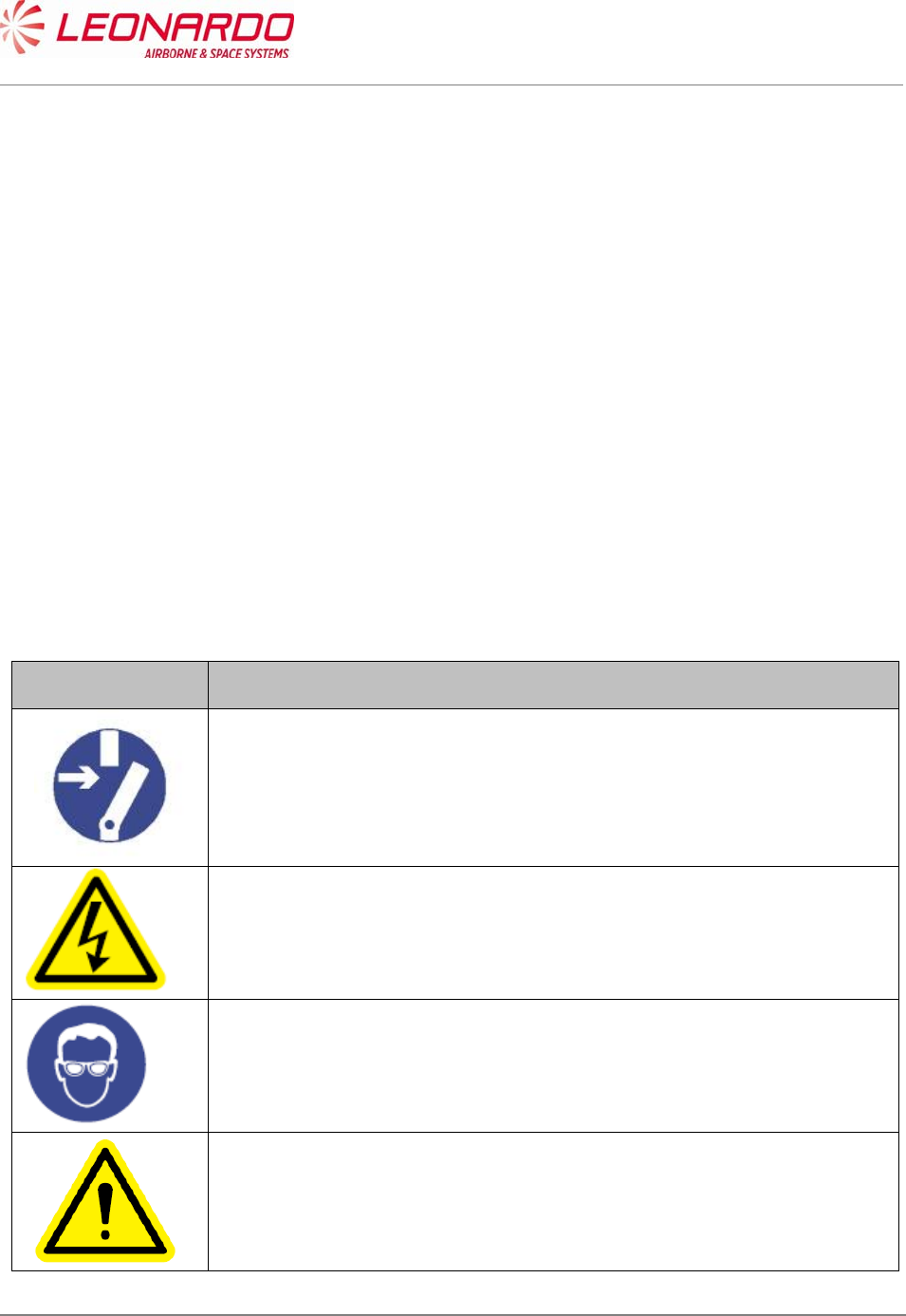
Table 1-3 - TRA-100B – General Warnings, Cautions And Related Safety Data
Symbol Message
WARNING
Make sure that the equipment is disconnected from all electrical power
sources before you do any maintenance work.
WARNING
The internal components use high voltages that can cause injury or
death to personnel.
WARNING
Perform task in ventilated area and use protective clothing.
WARNING
Denatured Alcohol, Electro Contact Cleaner and Conductive Anti-
seizure Compound are dangerous materials. Make sure that you know
the safety precautions and the first aid instructions.
UNCLASSIFIED MAN-1124/01 T02
___________________________________________________________________________________________________________
______________________________________________________________________________
Page 15
© Copyright Leonardo Finmeccanica S.p.A. – All rights reserved
UNCLASSIFIED
CAUTION
The internal components of the equipment are Electro-Static Discharge
(ESD) sensitive devices. Do not touch the pins of the electrical
connectors. Electrostatic discharge can cause damage to these
components.
Install protective caps on all electrical connectors immediately after you
disconnect them to prevent the ingress of dirt.
WARNING
Always handle the equipment with care to prevent damage.
UNCLASSIFIED MAN-1124/01 T02
___________________________________________________________________________________________________________
______________________________________________________________________________
Page 16
© Copyright Leonardo Finmeccanica S.p.A. – All rights reserved
UNCLASSIFIED
2.4 TRA-100B MODE S TRANSPONDER – SUPPORT EQUIPMENT AND
TOOLS
2.4.1 Standard AGE and Tools
Table 1-4 - TRA-100B – Standard AGE and Tools
Nomenclature Identification Qty
Soft Brush Local Supply 1
Torque Screwdriver bit holder Local Supply 1
Bit cross-point sz. 2 Local Supply 1
Bit hex open end 8 mm. Local Supply 1
2.4.2 Software
Table 1-5 – TRA-100B - Software
Nomenclature Identification
TRA-100B_MPC STTE Software TIU-0077/01.01*
*The STTE Software is applicable for the Transponder configurations described in this manual.
2.4.3 Consumables, Material and Expendables
Table 1-6 – TRA-100B - Consumables, Material and Expendables
Nomenclature Specification Commercial
designation Manufacturer Qty Remarks
Denatured Alcohol AA-M-L.422e S-738 D9478 A/R Dangerous
material
Electro Contact
Cleaner QD 02130 1 02344 1 Dangerous
material
Lint free cloth 1 Local supply

UNCLASSIFIED MAN-1124/01 T02
___________________________________________________________________________________________________________
______________________________________________________________________________
Page 17
© Copyright Leonardo Finmeccanica S.p.A. – All rights reserved
UNCLASSIFIED
2.5 TRA-100B MODE S TRANSPONDER – PACKAGING, HANDLING,
STORAGE AND TRANSPORTATION
These procedures are applicable to the Transponder and to all its units.
2.5.1 Packaging - General
Packaging includes all the activities necessary to prepare the units for transportation.
The packaging procedures are mandatory to avoid any damage to the units during transport,
handling and storage.
Each unit is packed separately in its own container.
The packaging procedures are applicable to all the units of the system.
Packaging is carried out according to “Commercial Standard”.
The packaging procedures are applicable to the initial packaging of the units, the return after
repair packaging as well as the reshipment procedure.
2.5.1.1 Packaging Procedure
Insert the unit in a shielding envelope and close it with a warning ESD adhesive label
Wrap the unit in protective ‘bubble wrap’, hold together with adhesive tape.
Put the wrapped item in a commercial cardboard box of suitable dimensions.
Line the box with “Instapak foam” or ‘Pluriball” in a way to prevent the unit from moving inside
the box.
Seal the box with adhesive tape.
Place an identification label on the outside of the IP package describing the contents.
2.5.1.2 Identification Label
The label on the box must include the following data:
Company Name or Logo (Sender)
Quantity of items per pack
Contract Number
Description of part
Part Number
Gross Weight
NSN (if applicable)
Details of receiver.
2.5.1.3 Reshipment Packaging Procedure
Follow the packaging procedures described above.
The units do not require any special preparation for reshipment. Observe general methods and
conditions requested for handling electronic equipment.

UNCLASSIFIED MAN-1124/01 T02
___________________________________________________________________________________________________________
______________________________________________________________________________
Page 18
© Copyright Leonardo Finmeccanica S.p.A. – All rights reserved
UNCLASSIFIED
2.5.1.4 Original Packaging
Commercial Standard packaging is generally considered as not reusable. It is the responsibility of
the packing personnel to decide whether packaging material can be safely reused.
2.5.1.5 Instruction of Reshipment
No special disassembly is required prior to shipping the entire units. Follow the instructions
described in the Initial packaging procedures to pack the units for reshipment.
2.5.2 Handling
The TRA-100B does not require special procedures for unit removal and installation
The gross weight is indicated on the identification label placed on the outside of each box.
The weight of each LRU of the TRA-100B Mode S Transponder is less 7 Kg excluding
packaging.
Special provisions and equipment (forklift etc.) are not required for handling the units.
The containers of the equipment do not have handles or lifting devices.
No lifting requirements are indicated on the containers.
Handle the units with care to avoid damage.
2.5.3 Storage
The conditions listed in this document are relative to storage in a closed depot/warehouse and do
not take into consideration water exposure, salt spray etc.
The equipment must remain in the original shipment containers during storage.
If containers have been opened for shipment acceptance and they are stored in a humid
environment, put dehumidifying bags inside the containers.
The containers must be sealed again by using adhesive tape, this precaution is necessary to avoid
damage from dust and humidity. Commercially available, desiccant (dehumidifying bags) can be
used.
2.5.3.1 Storage Data
The environmental conditions while in storage must respect the following limits:
Maximum Relative Humidity <75%
Storage Temperature: Between -55 °C and +70°C;
Storage Life: 10 years
Store far from magnetic, electrical and electrostatic sources
2.5.4 Transportation
The following transport conditions are applicable to the equipment and its components:
• Temperature: Between -55 °C and +70 °C

UNCLASSIFIED MAN-1124/01 T02
___________________________________________________________________________________________________________
______________________________________________________________________________
Page 19
© Copyright Leonardo Finmeccanica S.p.A. – All rights reserved
UNCLASSIFIED
• Maximum Relative Humidity: <75%
• Thermal shock: 10 °C/min
• Altitude: Max. 15000m (70 000ft)
The equipment must remain within its package during transport.
2.5.5 ESD Handling Procedure
The Unit contains static devices. Be careful when you work on electrostatic discharge sensitive
devices:
Use an approved wrist strap that is connected to a ground point only when no electrical power
is supplied to the system.
Do not touch the electric pins.
Use conductive blanking caps.
Use always an antistatic transport tray to move the equipment.
Install the protective caps on the electrical pins, after their disconnection, to protect them from
electrostatic charge and avoid the entry of dust.
Do not open the Unit except in an approved static-free workshop.
Electrostatic discharge can cause damage to equipment or injury personnel.
2.5.6 Hazardous Materials
None.
UNCLASSIFIED MAN-1124/01 T02
___________________________________________________________________________________________________________
______________________________________________________________________________
Page 20
© Copyright Leonardo Finmeccanica S.p.A. – All rights reserved
UNCLASSIFIED
3 DESCRIPTION
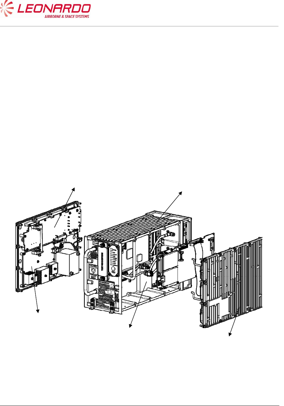
3.1 TRA-100B MODE S TRANPONDER – DESCRIPTION OF HOW IT IS MADE
AND ITS FUNCTION
The TRA-100B Mode S Transponder unit is made up of the modules shown in Figure 3-1 and
listed below:
Wired Chassis (WC)
Data Processor and I/O (DPIO)
RF – Subassembly (RF)
AC Power Supply (ACPS)
DC Power Supply (DCPS)
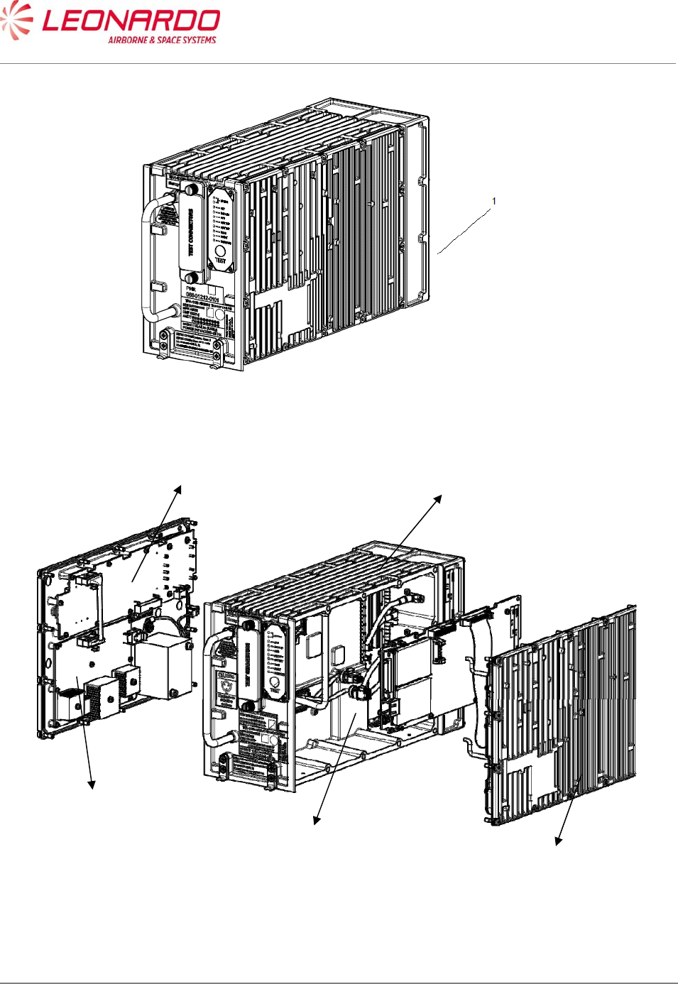
Figure 3-1 – TRA-100B Mode S Transponder - Description of how it is made
DC Power Supply
AC Power Supply
Wired Chassis
RF Module
Data Processor and I/O

UNCLASSIFIED MAN-1124/01 T02
___________________________________________________________________________________________________________
______________________________________________________________________________
Page 21
© Copyright Leonardo Finmeccanica S.p.A. – All rights reserved
UNCLASSIFIED
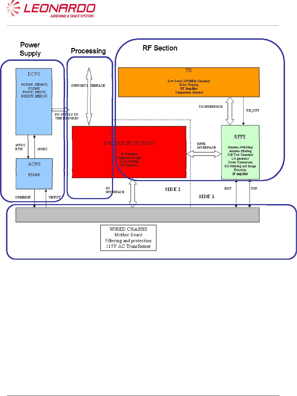
The RFD, TXA and RXA modules combined are referred to as the RF module, and are responsible
for reception and transmission functions. The processing functions are carried out by the Data
Processor as well as the Transponder Software (TS).
The I/O Interface Module together with the Wired Chassis include all the internal and external
interfaces, while the AC and DC Power Supply are responsible for the supply of power to the unit
(see Figure 3-2).
The Wired Chassis (WCH) implements all mechanical functions and electrical interconnections
between modules; it includes:
I/O lines filtering
Power lines filtering
IO lines transient protection
AC input transformer
Front panel LEDs
The ACPS module receives 24 and 48 VAC from WCH transformer and generates internal 28VDC
to DCPS.
It generates AC INPUT FAIL signal to DCPS for BIT purposes
The DCPS module receives 28 VDC from ACPS and generates internal voltages to all modules:
It manages internal ON/OFF state
It manages power interruptions
It manages Power Supply BIT and protections
The DPIO-RX module includes two main sections:
1. DPIO for Processing and I/O
2. RX for RX IF processing
The processing section includes FPGA, Controller and Memories (RAM, FLASH) and manages:
all I/O processing
Interrogation/Reply protocols
TCAS and ADS-B functions
its own board BIT and Equipment BIT by collecting information from all modules
RF modules control (RFFE/TX)
I/O Section includes all I/O circuitry to implement discretes, 429 and other interfaces
The RX Section performs dual channel (TOP/BOT) IF RX processing:
IF Selectivity filtering
Log detection
ADC

UNCLASSIFIED MAN-1124/01 T02
___________________________________________________________________________________________________________
______________________________________________________________________________
Page 22
© Copyright Leonardo Finmeccanica S.p.A. – All rights reserved
UNCLASSIFIED
The RFFE Module performs dual (TOP/BOT) antenna interface implementing the following
functions:
TX/RX selection
TX path antenna switch (TOP/BOT)
TX path harmonic filtering
RX dual channel (TOP/BOT) independent pre-selection and LNA
RX dual channel (TOP/BOT) independent IF down conversion including LO generation
Self test signal generation
Self test Path selection
The TX Module performs all TX functions:
1090 MHz LO generation
Pulse modulation
RF amplification up to required level
It includes Tank capacitor to support fast current delivery to TX devices during reply pulse
trains generation
Tank Capacitor is also used to support hold-up during power interruption between 10ms
and 200ms
UNCLASSIFIED MAN-1124/01 T02
___________________________________________________________________________________________________________
______________________________________________________________________________
Page 23
© Copyright Leonardo Finmeccanica S.p.A. – All rights reserved
UNCLASSIFIED
Figure 3-2 – TRA-100B Mode S Transponder – Functional Diagram

UNCLASSIFIED MAN-1124/01 T02
___________________________________________________________________________________________________________
______________________________________________________________________________
Page 24
© Copyright Leonardo Finmeccanica S.p.A. – All rights reserved
UNCLASSIFIED
4 TECHNICAL DATA
4.1 TRA-100B MODE S TRANSPONDER – TECHNICAL DATA
4.1.1 General Technical Data
Table 4-1 – TRA-100B - Technical data – General
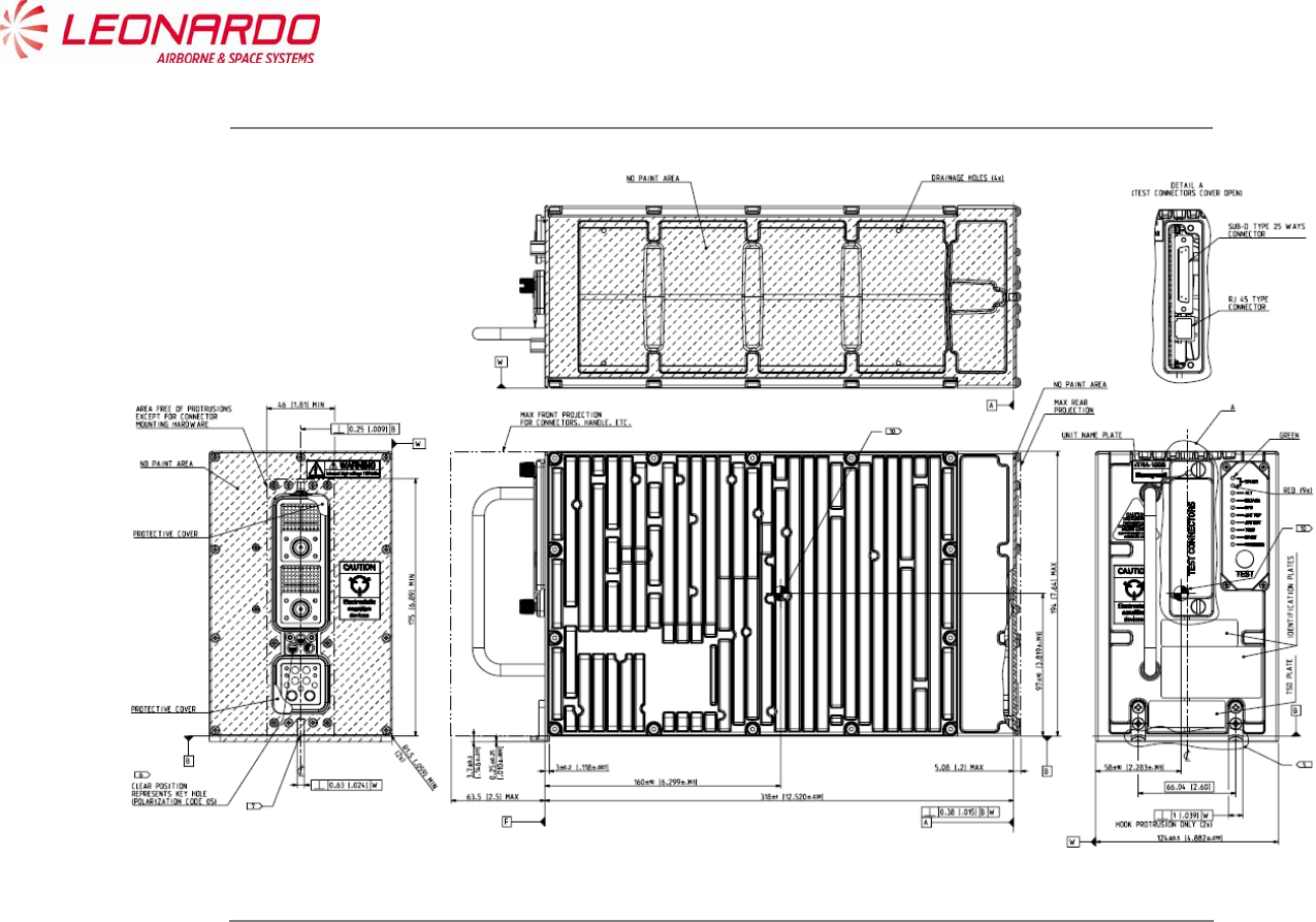
Data Value
Manufacturers Part Numbers
TAC-6001/03
TAC-6003/03
TAC-6004/03
Weight (Total mass) < 7 kg
Dimensions 194 mm x 124 x 318 (Height x Width x Depth)
Output power 400W ± 100 W
Operating temperature -55°C +70°C
Storage Conditions -55°C +70°C
UNCLASSIFIED MAN-1124/01 T02
___________________________________________________________________________________________________________
______________________________________________________________________________
Page 25
© Copyright Leonardo Finmeccanica S.p.A. – All rights reserved
UNCLASSIFIED
Figure 4-1 – TRA-100B Mode S Transponder – Technical Data

UNCLASSIFIED MAN-1124/01 T02
___________________________________________________________________________________________________________
______________________________________________________________________________
Page 26
© Copyright Leonardo Finmeccanica S.p.A. – All rights reserved
UNCLASSIFIED
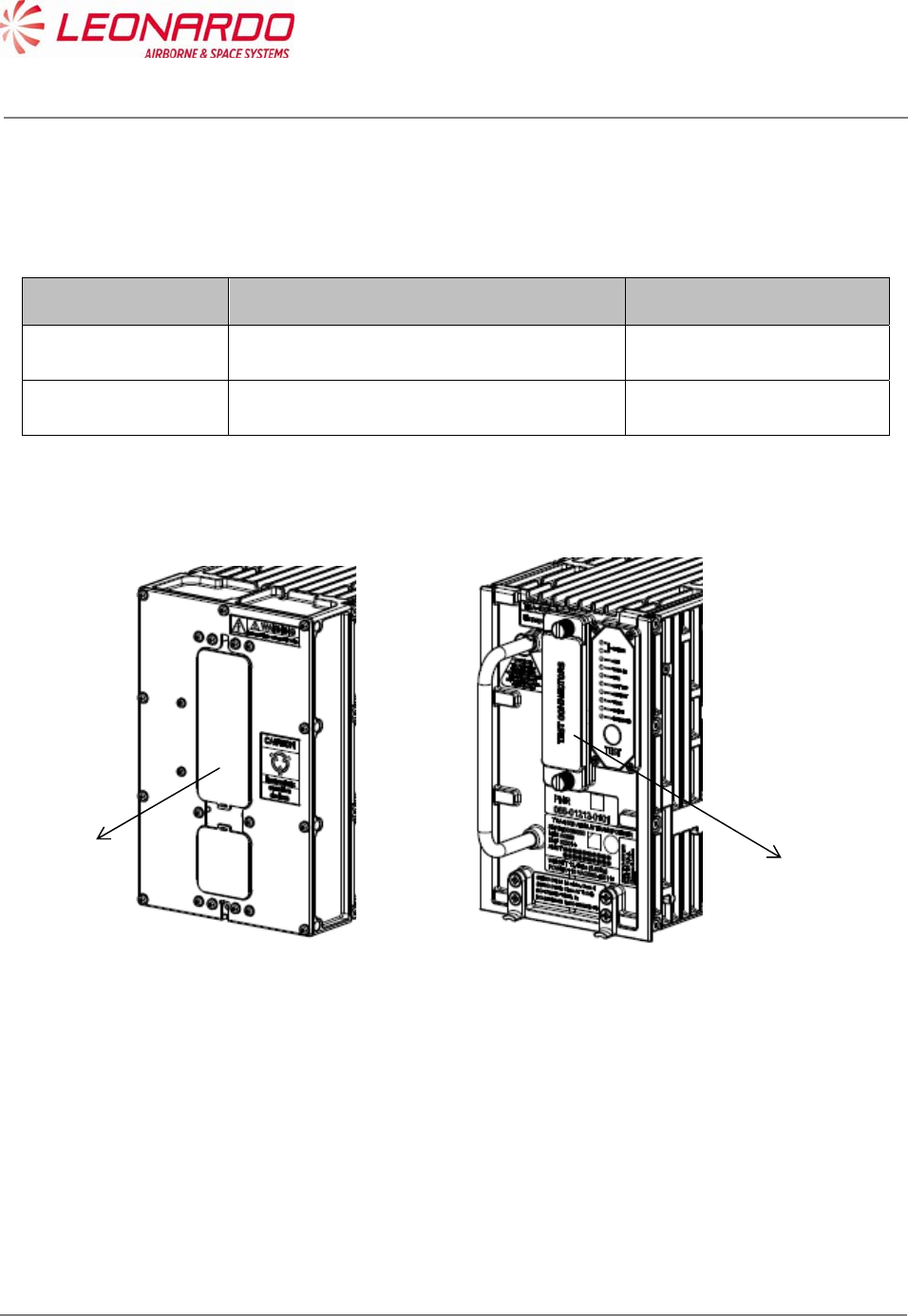
4.1.2 Labels Data
The TRA-100B provides three different labels (ref. 3):
Leonardo Finmeccanica Id. Label (1)
Honeywell Id. Label (2)
Certifications Label (3)
The Leonardo Finmeccanica Id. Label contains the following info:
Data Value
Manufacturers Part Numbers
TAC-6001/03
TAC-6003/03
TAC-6004/03
Manufacturer Leonardo Finmeccanica
Manufacturing Site Montevarchi
Manufacturing Country Italy
SER. Serial Number
MFR. Manufacturer SNS (A0610)
DMF Date of Manufacturing (mmyyy)
AMDT Amendement
Weight (Total mass) 14.5 Lbs. (6,58 Kg)
Power 115 VAC/380-420 Hz.
The Honeywell Id. Label contains the following info:
Data Value
Owner HONEYWELL, International
Owner Part Number
PNR 066-01212-0101
PNR 066-01212-0301
PNR 066-01212-0301
UNCLASSIFIED MAN-1124/01 T02
___________________________________________________________________________________________________________
______________________________________________________________________________
Page 27
© Copyright Leonardo Finmeccanica S.p.A. – All rights reserved
UNCLASSIFIED
Amendement -
The Certification Label contains the following info:
Data Value
ETSO/TSO Certification ETSO C112d: L2 adens, Class 1
ETSO C166b: Class A2 Tx only
DO/ED
178B/12B B: D
254/80 B
160/14G
PNR 066-01212-0101
TSO C112d: xxx C166b: xxx
DO-178B: B,D DO-160G
AMDT 01 02 03 04 05 06 07 08 09 10
11 12 13 14 15 16 17 18 19 20
TRA-100B TRANSPONDER
SER
MFR A0069
DMF
WEIGHT 14,5 Lbs (6,58 Kg)
POWER 115 VAC/380-420 Hz
MFR PNR
TAC-6001/01
Selex ES S.p.A
QA
01
M00000000
01/2013
REMOVE COVER TO ACCESS
SUPPORT TEST CONNECTORS
Figure 4-2 – TRA-100B Mode S Transponder – Labels layout
2
3
1

UNCLASSIFIED MAN-1124/01 T02
___________________________________________________________________________________________________________
______________________________________________________________________________
Page 28
© Copyright Leonardo Finmeccanica S.p.A. – All rights reserved
UNCLASSIFIED
4.1.3 Environmental Certification and Characteristics
The TRA-100B meets the environmental conditions of the Radio Technical Commission for the
Aeronautics (RTCA) document number DO-160G “Environmental Conditions and Test Procedures
for Airline Electronic/Electrical Equipment and Instruments” (Table 4-2).
Additionally to the DO-160G, the following documents have been used to further certification:
ABD100 1.2 G (Table 4-3)
ABD100 1.6 D (Table 4-4)
ABD100 1.8 E (Table 4-5)
D6-44800-1 (Table 4-6)
D6-81926 (Table 4-7)
MIL STD 810F (Table 4-8)
ASTM D1149 (Table 4-9)
D6/ 16050-4 (Table 4-10)
D6-44800-1 (

UNCLASSIFIED MAN-1124/01 T02
___________________________________________________________________________________________________________
______________________________________________________________________________
Page 29
© Copyright Leonardo Finmeccanica S.p.A. – All rights reserved
UNCLASSIFIED
Table 4-11)
Table 4-2 – TRA-100B – DO-160G Certification Categories
DO-160G Title Category
4.5.1 Ground Survival Low Temperature Test A2
4.5.1 Ground Survival Low Temperature Test Short-
Time Operating Low Temperature
F2
4.5.2 Operating Low Temperature Test A2
4.5.2 Operating Low Temperature Test F2
4.5.3 Ground Survival High Temperature Test Short-
Time High Operating
A2F2
4.5.4 Operating High Temperature Test A2F2
4.6.1 Altitude Test A2
4.6.1 Altitude Test F2
4.6.2 Decompression Test A2
4.6.3 Overpressure Test A2
5 Temperature Variation B
6 Humidity A, B
7 Operational Shocks and Crash Safety B, D, A
8 Vibrations S H
9 Explosive Atmosphere E
10 Waterproofness W Y
11 Fluids Susceptibility F
12 Sand and Dust D
13 Fungus Resistance F
15 Magnetic Effect A, Z
16 Power Input A, A(CF)HZPI
17 Voltage Spike A
18 Audio Frequency Conducted Susceptibility -
Power Inputs
R(CF), K
19 Induced Signal Susceptibility ZCX
20 Radio Frequency Susceptibility Radiated R
20 Radio Frequency Susceptibility Conducted R
21 Emission of Radio Frequency Energy M, L

UNCLASSIFIED MAN-1124/01 T02
___________________________________________________________________________________________________________
______________________________________________________________________________
Page 30
© Copyright Leonardo Finmeccanica S.p.A. – All rights reserved
UNCLASSIFIED
DO-160G Title Category
22 Lightning Induced Transient Susceptibility A3J3L3
24 Icing A
25 Electrostatic Discharge (ESD) A
26 Fire Flammability C
Table 4-3 – TRA-100B – ABD100 1.2 G Certification Categories
ABD100
1.2 G
Title Category
1.2.2 Decompression Test A2
1.2.3 Overpressure Test A2
1.6.1 Vibration Operational Vibrations:
random and sinusoidal: a)
Curve 1 b) Curve 2 of the
note " Environmental
directives for new equipment
installed on SA program "
§3.7.1. Operational
Vibrations Vibrations due to
Engine Fan Blade
Loss/WINDMILLING: See
PTS Appendix 1 ( SINE 3-
30Hz SINE, 5.5 G max) and
PTS Appendix 2 (SINE 3-
15.5 Hz SINE, 2.2 Gmax).
The procedures and the
levels given in both these
appendices shall be used.
1.18 Constant Acceleration Functional Test B
3.3.3 Radio Frequency Susceptibility Radiated R
3.3.2 Radio Frequency Susceptibility Conducted Doc ref 483.0156/95 issue 6
or issue 8.1 cat C The test
procedure and set-up i.a.w.
DO- 160 Sect. 20
3.2 Lightning Induced Transient Susceptibility Damage testing
ABD0100.1.2 §3.2 Doc ref
483.0156/95 issue 6 or issue
8.1 cat C The Supplier shall
use the Pin injection test
method. Note: The note
483.0156/95 is applicable for
UNCLASSIFIED MAN-1124/01 T02
___________________________________________________________________________________________________________
______________________________________________________________________________
Page 31
© Copyright Leonardo Finmeccanica S.p.A. – All rights reserved
UNCLASSIFIED
ABD100
1.2 G
Title Category
levels for damage testing
and functional upset
Functional Upset Testing
(Multiple Stroke/Pulse)
ABD0100.1.2 §3.2 Doc ref
483.0156/95 issue 6 or issue
8.1 cat C Note 1: For
Multiple Strokes and Multiple
Burst bundle injection, the
shield of any other shielded
cable of the bundle (except
coaxial cables) shall be
disconnected from any
ground point. Note 2: Wave
form for Multiple Burst shall
be the one defined in DO-
160F with levels and
procedures defined in
483.0156/95
3.5 Electrostatic Discharge (ESD) B
Table 4-4 – TRA-100B – ABD100 1.6 D Certification Categories
ABD0100
1.6 D
Title Category
4.6 Fire/Flammability/Toxicity/Smoke/Gas Emission Pressurized Area
Table 4-5 – TRA-100B – ABD100 1.8 E Certification Categories
ABD100
1.8 E
Title Category
1.3 Dielectric and Insulation Resistance Testing ABD0100.1.8 §1.3
2 Power Input ABD0100.1.8 ADB0100 1.8
§1.2 ABD0100.1.8 §2.0
ABD0100.1.8 Table A
2.4
Voltage Spike ABD0100.1.2 §3.4.2
ABD0100.1.8, tables 3-A
UNCLASSIFIED MAN-1124/01 T02
___________________________________________________________________________________________________________
______________________________________________________________________________
Page 32
© Copyright Leonardo Finmeccanica S.p.A. – All rights reserved
UNCLASSIFIED
Table 4-6 – TRA-100B – D6-44800-1 Certification Categories
D6-
44800-1
Title Category
4.2.5.7 Temperature Variation B
Table 4-7 – TRA-100B – D6-81926 Certification Categories
D6-81926 Title Category
3.1 Bench Handling Shock N/A
8 Random Vibration B2
8 Sinusoidal Vibration Zone 2, Cat. C
4 Constant Acceleration Functional Test Zone 2, Cat. C
3.2
Shipping Container Shock Test Packaged Equipment free
fall from 30in (75cm)
Table 4-8 – TRA-100B – MIL STD 810F Certification Categories
MIL STD
810F
Title Category
516.5 Bench Handling Shock MIL STD 810F Method 516.5
Procedure VI
Table 4-9 – TRA-100B – ASTM D1149 Certification Categories
ASTM
D1149
Title Category
ASTM
D1149
Ozone Testing Ozone environment of 0.25
ppm per volume sea level
equivalent
Table 4-10 – TRA-100B – D6/ 16050-4 Certification Categories
D6/
16050-4
Title Category
7.2.2 Audio Frequency Electric Filed Susceptibility Perform Test as specified in
D6- 16050-4
7.2.3 Audio Frequency Magnetic Field Susceptibility -
Wiring
Perform Test as specified in
D6- 16050-4
7.2.4 Audio Frequency Magnetic Field Susceptibility - Perform Test as specified in

UNCLASSIFIED MAN-1124/01 T02
___________________________________________________________________________________________________________
______________________________________________________________________________
Page 33
© Copyright Leonardo Finmeccanica S.p.A. – All rights reserved
UNCLASSIFIED
D6/
16050-4
Title Category
Equipment D6- 16050-4
7.5.2 Induced Spike Transient Susceptibility Perform Test as specified in
D6- 16050-4
7.5.3 Bus Switching Transient Susceptibility Perform Test as specified in
D6- 16050-4
8.1 Interference Voltage on Signal Lines Perform Test as specified in
D6- 16050-4
8.3.1 AC Capacitive Coupling Perform Test as specified in
D6- 16050-4
8.3.2 AF Inductive Coupling Perform Test as specified in
D6- 16050-4
7.3.1 Radio Frequency Susceptibility Conducted R
8.4.2 RF Radiated Emissions Perform Test as specified in
D6- 16050-4
8.4.1 RF Conducted Emissions Perform Test as specified in
D6- 16050-4
7.4.4 Lightning Induced Transient Susceptibility L2
7.1 Electrostatic Discharge (ESD) Perform test per section 7.1
of D6- 16050-4

UNCLASSIFIED MAN-1124/01 T02
___________________________________________________________________________________________________________
______________________________________________________________________________
Page 34
© Copyright Leonardo Finmeccanica S.p.A. – All rights reserved
UNCLASSIFIED
Table 4-11 – TRA-100B – D6-44800-1 Certification Categories
D6-
44800-1
Section
Title Category
5.19
Loss of Cooling
330 minutes loss of cooling
per Table 2.4 of D6-84901
Rev B. Test is per D6-44800-
1, Table 2b, for Long Term
Loss of Cooling (Class: IIb -
Case cooled, robust
temperature condition). The
test can be perform using an
ambient temperature by
using the procedure in D6-
44800-1, Section 5.19
Procedure B, in lieu of
performing the test via
controlling the sidewall
temperature of the
equipment. Make special
notice to the Flag Notes in
table 2b for how this test is
performed.
UNCLASSIFIED MAN-1124/01 T02
___________________________________________________________________________________________________________
______________________________________________________________________________
Page 35
© Copyright Leonardo Finmeccanica S.p.A. – All rights reserved
UNCLASSIFIED
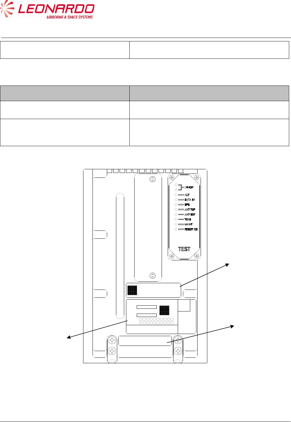
4.1.4 Connectors Data
Table 4-12 – TRA-100B - Technical data – Connectors
Ref. Figure 4-3 Connector Function
1 Main Connector Data and Control I/O
2 Test Connector Maintenance Retrieval
Figure 4-3 – TRA-100B Mode S Transponder – Connectors
1
2

UNCLASSIFIED MAN-1124/01 T02
___________________________________________________________________________________________________________
______________________________________________________________________________
Page 36
© Copyright Leonardo Finmeccanica S.p.A. – All rights reserved
UNCLASSIFIED
Table 4-13 – TRA-100B - Technical data – Main Connector Pin Mapping
TP Section
Pin I/O Type Description
TP 1A Input Program AC Length/Width A MSB
TP 1B Input Program Strobed AC Length/Width B
TP 1C Input Program Strobed AC Length/Width C LSB
TP 1D Input Program Strobed GPS Ant Long Off A (MSB)
TP 1E Input Program Strobed GPS Ant Long Off B
TP 1F Input Program Strobed GPS Ant Long Off C (LSB)
TP 1G Input Program Strobed Navigation Accuracy Category Velocity (NACV)
TP 1H Input Program Strobed System Design Assurance (SDA)
TP 1J Input Differential GPS Time Mark 1A
TP 1K Input Differential GPS Time Mark 1B
TP 2A Input 429 FMC/GNSS #1 In #1 A
TP 2B Input 429 FMC/GNSS #1 In #1 B
TP 2C Input 429 IRS/FMS/Data Conc. A
TP 2D Input 429 IRS/FMS/Data Conc. B
TP 2E Output 429 General Output #1 A
TP 2F Output 429 General Output #1 B
TP 2G Input 429 ATSU In A
TP 2H Input 429 ATSU In B
TP 2J Input Discrete Data Load Enable
TP 2K Input Program ADS-B FAIL Disable
TP 3A Output Discrete ADS-B Fail Disc Out
TP 3B Output Discrete Transponder fail #2 Disc output
TP 3C Input Program Cable Delay Program Top/Bot
TP 3D Input Program Cable Delay Program Value #1
TP 3E Input Program Cable Delay Program Value #2
TP 3F Common Common Common
TP 3G Input Discrete SDI 429 Bus Address Logic Input
TP 3H Input Discrete SDI 429 Bus Address Logic Input
TP 3J Common Common Common
TP 3K Common Common Common
TP 4A N/A N/A No Connect
TP 4B N/A N/A No Connect
TP 4C N/A N/A No Connect
TP 4D N/A N/A No Connect
TP 4E N/A N/A No Connect
TP 4F N/A N/A No Connect
TP 4G N/A N/A No Connect
TP 4H N/A N/A No Connect
TP 4J N/A N/A No Connect
TP 4K N/A N/A No Connect
TP 5A Input Program Maximum Airspeed 17
TP 5B Input Program Maximum Airspeed 16
TP 5C Input Program Maximum Airspeed 15
TP 5D Common Common Top Plug Common
TP 5E Input 429 TX Coordination A
TP 5F Input 429 TX Coordination B
TP 5G Output 429 XT Coordination A

UNCLASSIFIED MAN-1124/01 T02
___________________________________________________________________________________________________________
______________________________________________________________________________
Page 37
© Copyright Leonardo Finmeccanica S.p.A. – All rights reserved
UNCLASSIFIED
TP Section
Pin I/O Type Description
TP 5H Output 429 XT Coordination B
TP 5J Input Discrete Air/Ground Discrete #2
TP 5K Input Discrete Air/Ground Discrete #1
TP 6A Input 429 FMC #1 / Gen In #2 A
TP 6B Input 429 FMC #1 / Gen In #2 B
TP 6C Output Discrete Reserved
TP 6D Input Discrete GPS Time Mark 2A
TP 6E Input Discrete GPS Time Mark 2B
TP 6F Input Discrete Reserved
TP 6G Input Discrete
Reserved (-0101/-0301); FAA - L_Sense
Activate (-0201)
TP 6H N/A N/A No Connect
TP 6J N/A N/A No Connect
TP 6K Input Program Antenna Program
TP 7A Input 429 Control Data 'A' or FCC #1/MCP #1/VHF #1 A
TP 7B Input 429 Control Data 'A' or FCC #1/MCP #1/VHF #1 B
TP 7C N/A N/A No Connect
TP 7D Input Discrete Control Data Port Select
TP 7E Input 429 Control Data 'B' A
TP 7F Input 429 Control Data 'B' B
TP 7G Input Discrete Standby/On Discrete
TP 7H Input 429 ARINC 706/575 Air Data Input Port 1A
TP 7J Input 429 ARINC 706/575 Air Data Input Port 1B
TP 7K N/A N/A No Connect
MP Section
Pin I/O Type Description
MP 1A Input Program Mode S Address A1 (MSB)
MP 1B Input Program Mode S Address A2
MP 1C Input Program Mode S Address A3
MP 1D Input Program Mode S Address A4
MP 1E Input Program Mode S Address A5
MP 1F Input Program Mode S Address A6
MP 1G Input Program Mode S Address A7
MP 1H Input Program Mode S Address A8
MP 1J Input Program Mode S Address A9
MP 1K Input Program Mode S Address A10
MP 2A Input Program Mode S Address A11
MP 2B Input Program Mode S Address A12
MP 2C Input Program Mode S Address A13
MP 2D Input Program Mode S Address A14
MP 2E Input Program Mode S Address A15
MP 2F Input Program Mode S Address A16
MP 2G Input Program Mode S Address A17
MP 2H Input Program Mode S Address A18
MP 2J Input Program Mode S Address A19
MP 2K Input Program Mode S Address A20

UNCLASSIFIED MAN-1124/01 T02
___________________________________________________________________________________________________________
______________________________________________________________________________
Page 38
© Copyright Leonardo Finmeccanica S.p.A. – All rights reserved
UNCLASSIFIED
MP Section
Pin I/O Type Description
MP 3A Input Program Mode S Address A21
MP 3B Input Program Mode S Address A22
MP 3C Input Program Mode S Address A23
MP 3D Input Program Mode S Address A24 (LSB)
MP 3E Common Common Common
MP 3F Input 429 Spare 429 Input 1A
MP 3G Input 429 Spare 429 Input 1B
MP 3H Input Discrete Functional Test
MP 3J Output Discrete Out Spare 1
MP 3K Output Discrete Transponder Fail # 1 discrete output
MP 4A Input Discrete Spare In1
MP 4B Input Discrete Spare In2
MP 4C Input 429 FMC/GNSS #2 In #1 A
MP 4D Input 429 FMC/GNSS #2 In #1 B
MP 4E Input Program Strobed Aircraft Category A (MSB)
MP 4F Input Program Strobed Aircraft Category B (LSB)
MP 4G Input Program ADS-B Configuration Parity
MP 4H Input Program Strobed ADS-B Receive Capability
MP 4J Input Discrete Spare In3
MP 4K Input Discrete Spare In4
MP 5A Input 429 ARINC 706/575 Air Data Input Port 2A
MP 5B Input 429 ARINC 706/575 Air Data Input Port 2B
MP 5C N/A N/A No Connect
MP 5D N/A N/A No Connect
MP 5E Output 429 ATSU Out #1 A
MP 5F Output 429 ATSU Out #1 B
MP 5G Input Discrete Extended Squitter Disable
MP 5H Input Discrete Spare In5 (Mode S DL/DLP Program)
MP 5J Input Program Antenna BITE Program
MP 5K Input Discrete Spare In6
MP 6A Input 429 Maintenance Data Input Port A
MP 6B Input 429 Maintenance Data Input Port B
MP 6C Output 429 Maintenance Data Output Port A
MP 6D Output 429 Maintenance Data Output Port B
MP 6E Input Discrete Alternate Air Data Source Select
MP 6F Input Program Altitude Type Select A Discrete Input
MP 6G Input Program Altitude Type Select B Discrete Input
MP 6H Common Common Middle Plug Common
MP 6J N/A N/A No Connect
MP 6K Common Common Common
MP 7A N/A N/A No Connect
MP 7B N/A N/A No Connect
MP 7C N/A N/A No Connect
MP 7D N/A N/A No Connect
MP 7E N/A N/A No Connect

UNCLASSIFIED MAN-1124/01 T02
___________________________________________________________________________________________________________
______________________________________________________________________________
Page 39
© Copyright Leonardo Finmeccanica S.p.A. – All rights reserved
UNCLASSIFIED
MP Section
Pin I/O Type Description
MP 7F N/A N/A No Connect
MP 7G N/A N/A No Connect
MP 7H N/A N/A No Connect
MP 7J N/A N/A No Connect
MP 7K Input Discrete Acquisition Squitter Inhibit (Honeywell Defined)
BP Section
Pin I/O Type Description
BP 1 Input Power 115 VAC Primary Power Hot
BP 2 N/A N/A No Connect
BP 3 N/A N/A No Connect
BP 4 N/A N/A No Connect
BP 5 N/A N/A No Connect
BP 6 N/A N/A No Connect
BP 7 Input Power 115 VAC Primary Power Cold
BP 8 Input Ground Signal Ground
BP 9 N/A N/A No Connect
BP 10 N/A N/A No Connect
BP 11 Input Ground Chassis Ground
BP 12 Input/Output Suppression Suppression Pulse
BP 13 Input/Output Suppression Suppression Pulse - Daisy Chaining
Test Connector
Pin Signal Name I/O Type Description
1 SWITCH_ETH Discrete In 1 Switch Ethernet
2 TEST_RESET Out Test Point Test Point
3 GND Power GND
4 UP_HRESET Out Test Point Test Point
5 VID_ENV_TOP_TP Out Test Point Test Point
6 TEST_DG18 Internal Purpose Only
7 ST_GATE Out Test Point Test Point
8 TEST_DG19 Internal Purpose Only
9 TEST_DG20 Internal Purpose Only
10 TEST_DG21 Internal Purpose Only
11 TEST_DG22 Internal Purpose Only
12 ACQ_SQ_INH_EN In Discrete In 1 Acquisition Squitter Inhibit Enable
13 PULSE_GATE Out Test Point Test Point
14 OP_MAINT_1 In Discrete In 1 Maintanance Mode Selection
15 OP_MAINT_0 In Discrete In 1 Maintanance Mode Selection
16 VID_ENV_BOT_TP Out Test Point Test Point
17 FPGA _SIN Internal Purpose Only

UNCLASSIFIED MAN-1124/01 T02
___________________________________________________________________________________________________________
______________________________________________________________________________
Page 40
© Copyright Leonardo Finmeccanica S.p.A. – All rights reserved
UNCLASSIFIED
18 FPGA _SOUT Internal Purpose Only
19 DG_INT_PWRFL Out Test Point Test Point
20 SUPP_TP Out Test Point Test Point
21 E2C_SCL_PN In Service I2C
Bus Ctrl/Clk In Service I2C Bus Serial Clock
22 E2C_SDA_PN Bdir Service I2C
Bus Data Service I2C Bus Serial Data
23 WR_UNPROTECT In Service I2C
Bus Ctrl/Clk In Service I2C Bus Control Signal
24 GND_EXT Service I2C
Bus Supply In Service I2C Bus Power Supply Ground
25 5V_EXT In Service I2C
Bus Supply In Power Supply Source for Service I2C Bus

UNCLASSIFIED MAN-1124/01 T02
___________________________________________________________________________________________________________
______________________________________________________________________________
Page 41
© Copyright Leonardo Finmeccanica S.p.A. – All rights reserved
UNCLASSIFIED
5 OPERATION
5.1 TRA-100B MODE S TRANSPONDER – MODES OPERATION
The basic XPDR System consists of a transponder, a control unit, two antennas, and installation
hardware. Communications for the control of the remote transponder are by one-way ARINC 429
bus.
If the transponder is part of a TCAS installation, two-way communications by ARINC 429 data bus
are also utilized between the transponder and the TCAS. The transponder will perform normal Air
Traffic Control (ATC) functions whether it is or is not part of the TCAS system; however the TCAS
system cannot function without the transponder. Antenna diversity operation of the transponder is
a requirement for TCAS installations.
The transponder is capable of accepting altitude (air data) information from a variety of optional
sources. These include the ARINC 575 and ARINC 706 Air Data Computers. Furthermore,
selection between a primary and secondary input for each of these sources is provided.
An input and output ARINC 429 Maintenance Interface is provided that conforms to ARINC 604
and OEM specific requirements.
The transponder may also receive ARINC 429 data from a variety of equipment (i.e. Inertial
Reference System (IRS)/Flight Management System (FMS), Data Concentrator, Flight
Management Computer (FMC)/Global Navigation Satellite System (GNSS), FMC Gen, Flight
Control Computer (FCC)/Maintenance Computer Program (MCP), Control Head, and Air Data
System (ADS)).
This data will be utilized to populate:
Flight Identification required for Elementary Surveillance
Downlink Aircraft Parameters required for Enhanced Surveillance
ADS-B Extended Squitters.
The XPDR performs its intended function and not create a hazard to users of the National
Airspace System (NAS).
The Transponder TRA-100B is a avionics equipment capable to provide the Mode S Transponder
function required by Technical Standard Order (ETSO-C112d/TSO-C112e).
It also provides Extended Squitter ADS-B Out function required by ETSO-C166b/TSO-C166b.

UNCLASSIFIED MAN-1124/01 T02
___________________________________________________________________________________________________________
______________________________________________________________________________
Page 42
© Copyright Leonardo Finmeccanica S.p.A. – All rights reserved
UNCLASSIFIED
The TRA-100B is designed to be a Level 2 transponder.
For Level 1 includes the following capabilities:
Mode A identity and Mode C pressure-altitude reporting,
Air Traffic Control Radar Beacon System (ATCRBS)/Mode-S and Mode S all-call
transactions,
Addressed surveillance altitude and identity transaction,
Lockout protocols,
Basic data protocols except data link capability reporting, and
Air-to-air service and squitter transactions.
For Level 2 includes the following capabilities:
Bi-directional air-to-air information exchange
Ground-to-air data uplink, Comm-A
Air-to-ground data downlink, Comm-B
Multisite message protocol
Data link capability reporting
Aircraft identification reporting
Traffic Alert and Collision Avoidance System (TCAS)/Airborne Collision Avoidance System
(ACAS) crosslink capability
Furthermore the TRA-100B contains the following optional additional features (associated ID code
for transponder marking):
TCAS Compatibility (a)
Antenna Diversity (d)
Extended Squitter (e)
Enhanced Surveillance (including Elementary Surveillance) (n)
Surveillance Identifier Code (s)
Among the above characteristics, the Transponder TRA-100B:
exceeds the minimum output power level of 125 watts required by Class 1 equipment as
defined in RTCA/DO-181E. Therefore, the XPDR transponder marking for TSO-C112e is
Level 2adens, Class 1.
exceeds the minimum output power level of 125 watts required by Class A1 transmit only
equipment as defined in RTCA/DO-260B. Therefore, the XPDR transponder marking for
TSO-C166b is Class A1 transmit only.
UNCLASSIFIED MAN-1124/01 T02
___________________________________________________________________________________________________________
______________________________________________________________________________
Page 43
© Copyright Leonardo Finmeccanica S.p.A. – All rights reserved
UNCLASSIFIED
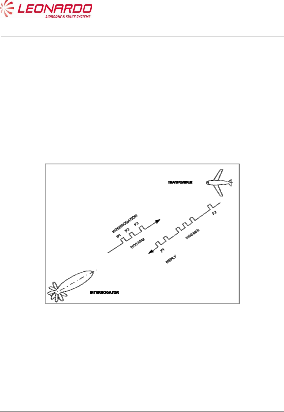
5.1.1 ATCRBS System Operation
The ATCRBS system can be defined as “a secondary surveillance radar system developed for use
within the air traffic control system for more precise position reporting of planes. It is used in
conjunction with the primary radar, which is used to determine the presence of planes in the
airspace. ATCRBS supplements this positional information with positive identification and altitude
information allowing controllers to track each plane more precisely and efficiently .”1
In this scenario the ATC ground based interrogator transmits an interrogation by means of
sequence of pulses at a frequency of 1030 MHz and call all transponders for a response on the
mode being used to reply. The received replies will be displayed on the ATC radar screen.
Analog to the ground based interrogator, an airborne TCAS device may transmits interrogation for
airborne traffic. TCAS can detects direction and altitude of an aircraft equipped with a transponder.
Figure 5-1 – ATCRBS System
1"The Story of Mode S: An Air Traffic Control Data-Link Technology" (Emily Chang, Roger Hu,
Danny Lai, Richard Li, Quincy Scott, Tina Tyan)
UNCLASSIFIED MAN-1124/01 T02
___________________________________________________________________________________________________________
______________________________________________________________________________
Page 44
© Copyright Leonardo Finmeccanica S.p.A. – All rights reserved
UNCLASSIFIED
5.1.2 ATCRBS Transmission Overview
The Air Traffic Control Radar Beacon System (ATCRBS) interrogates aircraft with either Mode A
or Mode C. The Mode A interrogation requests the aircraft identification code. The Mode C
interrogation requests the aircraft altitude. Any aircraft in the beam of the radar replies.
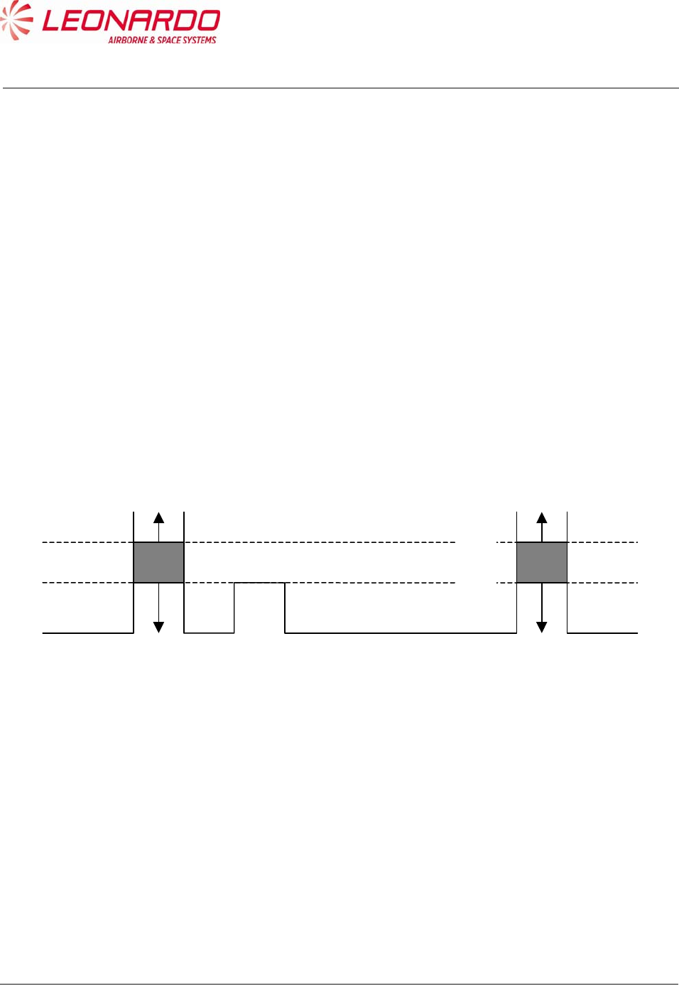
In order to prevent an undesired reply from an aircraft which are not in the main beam the Side
Lobe Suppression (SLS) technique is used.
Looking at the radius antenna diagram, leaking signals (called side lobes), can be identified as
interrogation by aircrafts which are not the desired targets.
The interrogation represented in Figure 5-2 would has multiplies replies from Target 1, 2 and 3.
The interrogation represented in Figure 5-3 will receive a reply from Target 1 according to the
following diagram:
9 dB
0 dB
P1 P2 P3
TRANSPONDER REPLIES
TRANSPONDER MAY
SUPPRESS OR REPLY
TRANSPONDER SUPPRESSES
SLS can also be used to avoid the reflection effects.

UNCLASSIFIED MAN-1124/01 T02
___________________________________________________________________________________________________________
______________________________________________________________________________
Page 45
© Copyright Leonardo Finmeccanica S.p.A. – All rights reserved
UNCLASSIFIED
DIRECTIONAL
Figure 5-2 – ATCRBS Interrogation without Side Lobe Suppression (SLS)
DIRECTIONAL
OMNIDIRECTIONAL
Figure 5-3 – ATCRBS Interrogation with Side Lobe Suppression
Target 1
Target 2
Target 3
Target 1
Target 2
Target 3

UNCLASSIFIED MAN-1124/01 T02
___________________________________________________________________________________________________________
______________________________________________________________________________
Page 46
© Copyright Leonardo Finmeccanica S.p.A. – All rights reserved
UNCLASSIFIED
5.1.3 OVERVIEW OF MODE S
Mode Select (Mode S) is a combined secondary surveillance radar beacon system with ground-
air-ground and air-air data link capability.
It includes a 24-bit aircraft technical address which provides more than 16 million unique
addresses, allowing the interrogator to select then interrogate a specific aircraft of interest.
Each discrete interrogation contains the unique address of the aircraft for which it is intended and
elicits a response dependent upon the level of capability of the corresponding transponder.
Civil aircraft have a permanently assigned technical address.
Implementation of a Mode S interrogation capability improve the existing systems in the following
ways:
Aircraft state (heading, speed, etc.) and aircraft intent information is available via Mode S
selective interrogations.
Adaptive re-interrogation will significantly improve the probability of detecting an aircraft
that is in a marginal signal condition.
The Mode S signal structure will provide improved error detection and correction.
More than sixteen million transponder addresses will allow unique identification of all
aircraft.
Refined range and position accuracy is made possible via Mode S GPS squitter and/or
Mode S datalink.
5.1.3.1 Signal Characteristics
Mode S is fully backwards compatible with the existing Air Traffic Control Radar Beacon System
(ATCRBS).
Mode S transponders respond to Mode S interrogations.
Mode S interrogators can interrogate ATCRBS or Mode S transponders.
Both systems use the same interrogation and reply frequencies (1030 MHz and 1090 MHz,
respectively).

UNCLASSIFIED MAN-1124/01 T02
___________________________________________________________________________________________________________
______________________________________________________________________________
Page 47
© Copyright Leonardo Finmeccanica S.p.A. – All rights reserved
UNCLASSIFIED
Mode S-only interrogations use binary differential phase shift keying modulation (DPSK) at 4
MB/sec and Mode S replies have binary pulse position modulation (PPM) at 1 MB/sec.
The Mode S coding structure provides enhanced error detection and correction (less than 1
undetected error in 108 messages). Mode S is not secure or jam-resistant and is not intended to
replace the encrypted military Mode 4.
Mode S has two basic message lengths: 56 bits and 112 bits.
The 56 bit surveillance formats include a 32 bit command field and a 24 bit address field.
The 112 bits communication formats include a 32 bit command field, a 56 bit data field and a 24 bit
address field.
The 112 bit extended length message formats include an 8 bit command field, an 80 bit data field
and a 24 bit address field.
5.1.3.2 Interrogation Process
Fully operational Mode S interrogators or clusters of interrogators are allocated on interrogator
identification (II) code which, in conjunction with the unique aircraft technical address, enables
linking between the interrogator and the aircraft of interest.
All-call interrogations are sent to all aircraft in a region to obtain the corresponding 24-bit technical
addresses. These addresses are maintained in an internal database and, once the address is
obtained, the all-call acquisition doesn’t need to be repeated for that aircraft.
Upon receiving the technical address, the interrogator sends a lockout message to inhibit the
corresponding transponder form replying to further Mode S all-call interrogations from any sensor
with that interrogator identification code. Lockout is refreshed each antenna scan as part of the
normal surveillance protocol and time-out occurs in 18 seconds if no further lockout commands are
received. The interrogator also has the provision (lockout override”) to command a transponder to
respond regardless of the lockout status effect.
Once it has the unique transponder address, the interrogator can selectively interrogate to obtain
altitude and Mode 3/A codes for Mode S to Mark XII correlation or other useful information.
UNCLASSIFIED MAN-1124/01 T02
___________________________________________________________________________________________________________
______________________________________________________________________________
Page 48
© Copyright Leonardo Finmeccanica S.p.A. – All rights reserved
UNCLASSIFIED
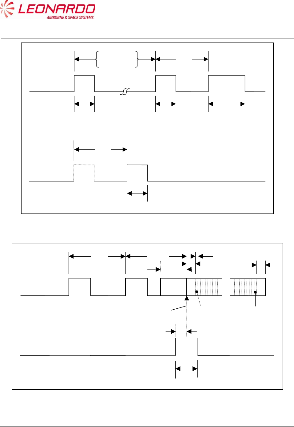
P1 P3 P4
0.8 S0.8
S*
S
Interro
g
ation
Mode A 8.0 S
Mode C 21.0 S2.0 S
* Mode A/C/S all-call: 1.6 S
Mode A/C-only all-call: 0.8 S
P1 P2
0.8 S
SLS Control
Transmission
2.0 S
Figure 5-4 – Intermode (Mode A/C and S) Interrogation Pulse Sequence
P1 P2Interro
g
ation
2.0 S
P3
0.8 S
SLS Control
Transmission
0.4 S
2..75 S
First chi
p
Last chip
P6
1.25 S
0.25 S
0.5 S
Guard interval
0.5
S
S
y
nc
p
hase reversal
Figure 5-5 – Mode S Interrogation Pulse Sequence
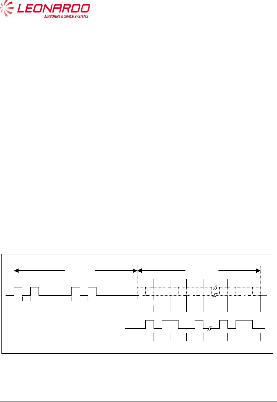
UNCLASSIFIED MAN-1124/01 T02
___________________________________________________________________________________________________________
______________________________________________________________________________
Page 49
© Copyright Leonardo Finmeccanica S.p.A. – All rights reserved
UNCLASSIFIED
The mode S reply consist of a long train of 0.5 s and 1.0 s pulses lasting for up to 130 s. It is
possible that such a train of pulses would give rise to multiple SSR bracket detections which could
overload the plot extractor and effect its proper operation. It is advisable that an SSR plot extractor
design should anticipate the introduction of Mode S and include circuitry to provide protection
against Mode S replies.
In order to detect a Mode S reply it is only necessary to detect the four Mode S preamble pulses.
These pulses are detected as follows:
a second pulse leading edge occurs 7-9 clock periods after detection of the first pulse
leading edge;
a third pulse leading edge occurs 28-30 clock periods after detection of the first pulse
leading edge;
a fourth pulse leading edge occurs 36-38 clock periods after detection of the first pulse
leading edge.
The detection of a Mode S preamble should suppress bracket detection for a period of 120 s
(994 clock periods). After preamble detection the train of pulse leading edges should be monitored
for a gap of at least 22 clock periods. Such a gap would exceed that which is possible in a Mode S
reply and would indicate that the preamble had been spurious, possibly owing to chance
overlapping fruit replies. If a gap of that size is detected, the bracket detection suppression should
be released so that SSR reply processing can resume.
Bit 1 Bit 2 Bit 3 Bit 4
1 0 1 0 1 0 1 0
8.0
9.0
1 0 1 0
Bit
N
-
1
Bit N
0.0 0.5 1.0 3.5 4.5
Time (S)
Preamble
8.0
S
Data block
56 or 112 S
0000011
E
xample. – Reply data block
corresponding to bit
s
e
q
uence 0010…….001
Figure 5-6 – Mode S Reply
UNCLASSIFIED MAN-1124/01 T02
___________________________________________________________________________________________________________
______________________________________________________________________________
Page 50
© Copyright Leonardo Finmeccanica S.p.A. – All rights reserved
UNCLASSIFIED
6 INSTALLATION
6.1 TRA-100B MODE S TRANSPONDER – REPLACE PROCEDURES
Standard Equipment
Description Identification Nr. Qty
None
Materials
Description Identification Nr. Qty
None
Spares
Description Identification Nr. Qty
TRA-100B Mode S Transponder TAC-6001/03 1
Safety Precautions
WARNING
MAKE SURE THAT THE EQUIPMENT IS DISCONNECTED FROM ALL
ELECTRICAL POWER SOURCES BEFORE YOU DO ANY
MAINTENANCE WORK.
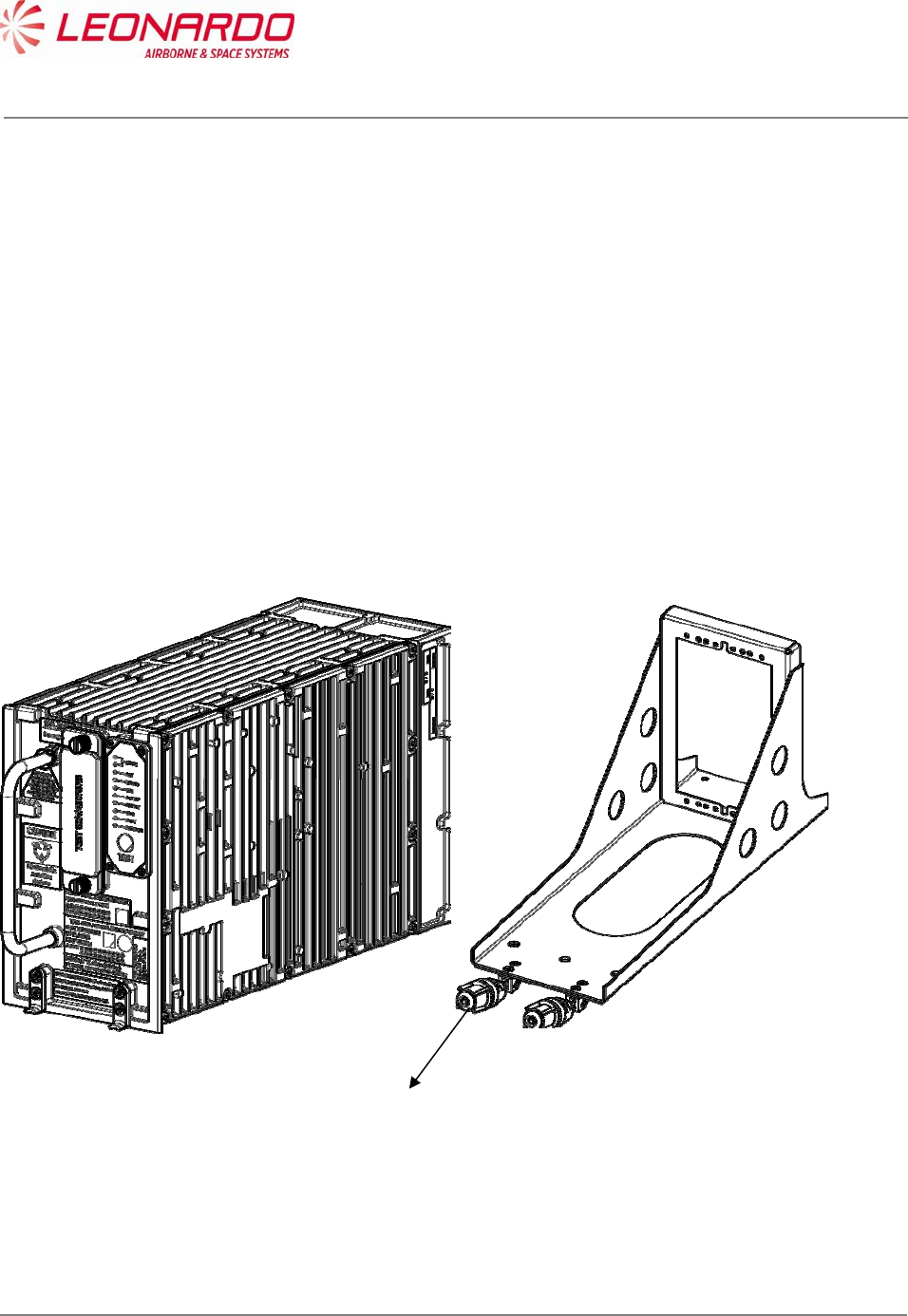
UNCLASSIFIED MAN-1124/01 T02
___________________________________________________________________________________________________________
______________________________________________________________________________
Page 51
© Copyright Leonardo Finmeccanica S.p.A. – All rights reserved
UNCLASSIFIED
Preliminary Operations
1. Make sure the platform is safe for maintenance
Procedure
Removal Procedure
1. Loosen by hand the two hold-down screws on the front of Mounting Tray (1)
2. Pull the Transceiver by the handle
3. Carefully slide the Transponder from the Mounting Tray
Install Procedure
1. Carefully put the TRA-100 B Modes S Transponder into the Mounting Tray, aligning the
TRA-100B connector guide pins with the platform connector.
2. Tighten by hand the two hold-down screws (1) on the front of Mounting Tray
Figure 6-1 – TRA-100B Mode S Transponder - Replace Procedures
Close up
1. Removal all the tools, the materials and the equipment from your work area.
1

UNCLASSIFIED MAN-1124/01 T02
___________________________________________________________________________________________________________
______________________________________________________________________________
Page 52
© Copyright Leonardo Finmeccanica S.p.A. – All rights reserved
UNCLASSIFIED
7 FAULT ISOLATION
7.1 GENERAL
Fault Location procedure allows the maintainer to isolate the failure the source of a failure at the
system level or aircraft wiring level. Furthermore the fault location can be performed even on the
Transponder itself in order to identify the failed module.
The TRA-100B Transponder provides a Built-In-Test function strictly for the purpose of
annunciation to the crew of a faulty Transponder system and for the purpose of providing
maintenance information for the repair function.
The TRA-100B provides several Input/Output interfaces for Built-In-Test capability necessary to
perform a diagnostic process to isolate the failure and provide the information related to its
location.
7.2 FAILURE DATA STRUCTURE
The diagnostic results are stored in a NVM in accordance with the following data::
a) One Hundred (100) Flight legs of storage.
b) Ten (10) subassembly and external faults per flight segment.
c) Three (3) subassembly faults for ground tests.
d) Two Hundred Thirty (230) bytes of storage per Current Flight leg and One Hundred Sixty
Seven (167) bytes for each other Flight leg segment.
7.2.1 Flight Information Header
For each flight leg, currently available flight information is stored in a fixed header.
The flight leg is incremented upon reception from the CFDS of a command label with code of 2,
which occurs during the aircraft take-off.
From one take-off point to the next, faults is stored for the 'current' flight leg.
The flight information header records all the data received on the maintenance port for each flight
leg with the exception of GMT, and flight phase as per the following table:
The flight information header records all the data received on the maintenance port for each flight
leg with the exception of GMT, and flight phase as per the following table:
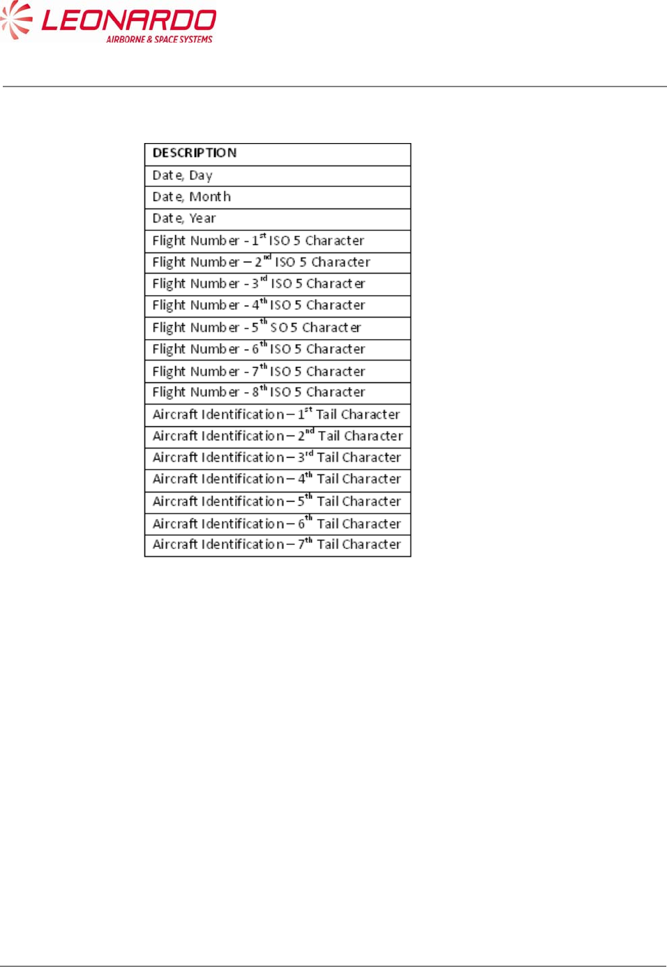
UNCLASSIFIED MAN-1124/01 T02
___________________________________________________________________________________________________________
______________________________________________________________________________
Page 53
© Copyright Leonardo Finmeccanica S.p.A. – All rights reserved
UNCLASSIFIED
The flight information header records all the data received on the maintenance port for each flight
leg with the exception of GMT, and flight phase as per the following table:
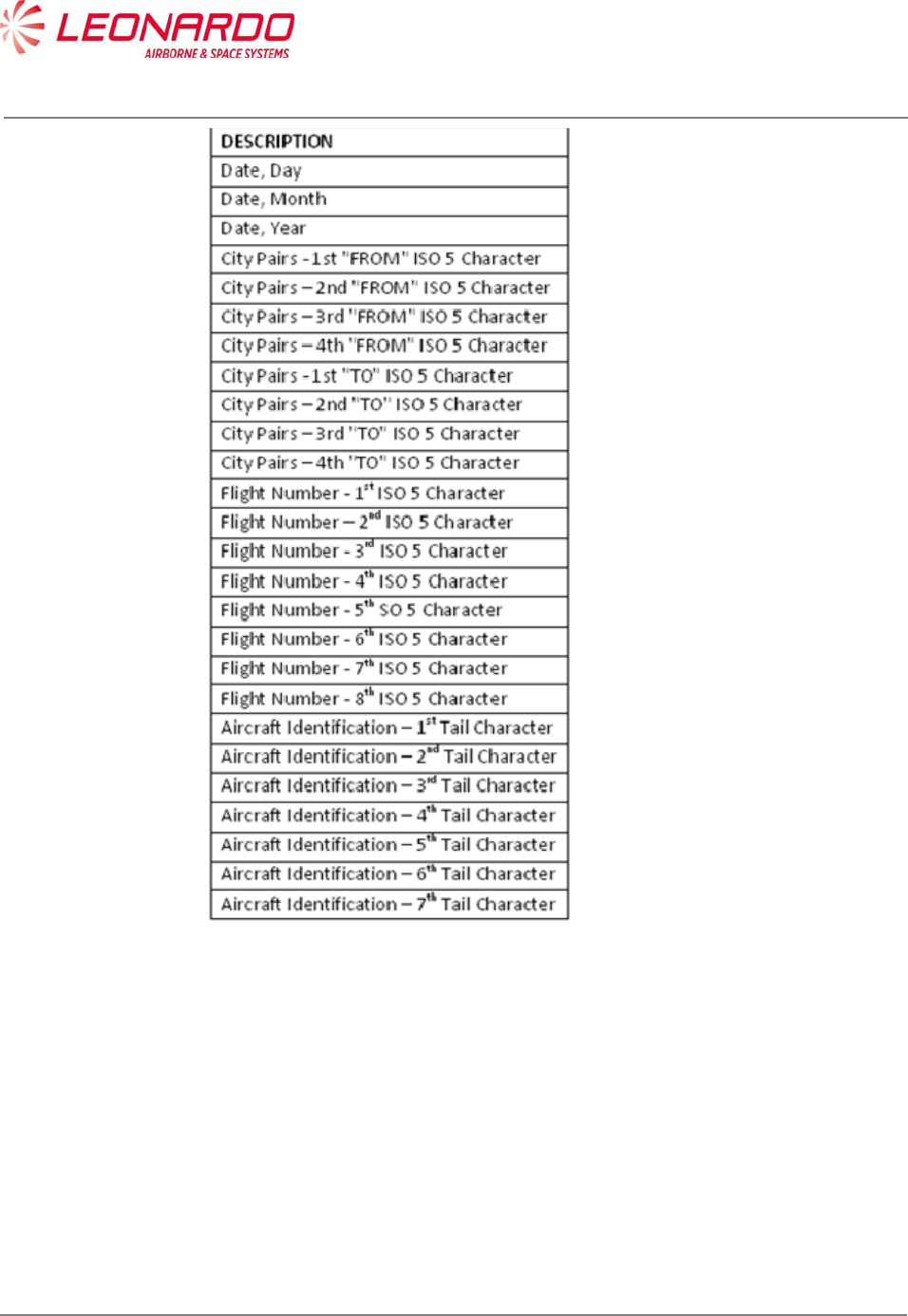
UNCLASSIFIED MAN-1124/01 T02
___________________________________________________________________________________________________________
______________________________________________________________________________
Page 54
© Copyright Leonardo Finmeccanica S.p.A. – All rights reserved
UNCLASSIFIED
7.2.2 Fault Record format
Each fault record contains the time, flight phase, failure code, number of occurrences (up to 4) of
the failure.
The Ground fault records contains the first three faults recorded.
The failure codes are organized as follows:
Log of internal faults
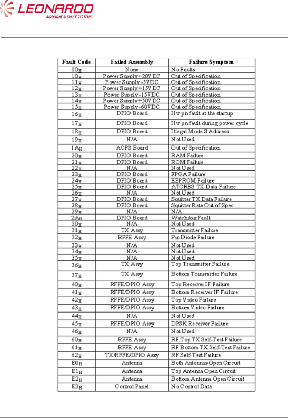
UNCLASSIFIED MAN-1124/01 T02
___________________________________________________________________________________________________________
______________________________________________________________________________
Page 55
© Copyright Leonardo Finmeccanica S.p.A. – All rights reserved
UNCLASSIFIED
Table 7-1 – TRA-100B – Internal Faults
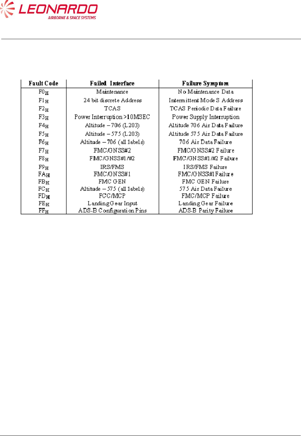
UNCLASSIFIED MAN-1124/01 T02
___________________________________________________________________________________________________________
______________________________________________________________________________
Page 56
© Copyright Leonardo Finmeccanica S.p.A. – All rights reserved
UNCLASSIFIED
Log of external faults
Table 7-2 – TRA-100B – External Faults

UNCLASSIFIED MAN-1124/01 T02
___________________________________________________________________________________________________________
______________________________________________________________________________
Page 57
© Copyright Leonardo Finmeccanica S.p.A. – All rights reserved
UNCLASSIFIED
7.3 FAILURE LOCATION ON AIRCRAFT
The Fault Location procedure permits to find out the origin of a undesired symptoms.
LED on the front panel of the TRA-100B transponder illuminate when TRA-100B system failures
are detected (Figure 7-3).
The TRA-100B transponder's Built-In-Test equipment (BITE) continually monitors the equipment
(both internal and external sources) and if a failure is detected will cause the transponder lamp.
System failure indications displayed on the front of the transponder are detected during
Functional-Self-Test. The Functional-Self-Test is manually initiated from the TEST pushbutton on
the front of the transponder.
Some of the transponder faults, are indicated with red LED's on the transponder front panel. The
following is a list of the transponder fault LED's.
During Power-Up the XPNDR red LED is set and remain set until the equipment is initialized (i.e.
Software and Firmware started up).
The XPNDR red LED is set while the failure discrete output pins are in the active state.
The XPNDR green LED is set to indicate that the equipment is initialized (i.e., Software and
Firmware started up) and the failure discrete output pins are not in the active state.
The front panel LED's provide a real time report of the validity of the Transponder internally and
the external interfaces.
The LED's are activated by the Test Push-button. The tests for the "on-ground" condition are
performed at the time of the activation of the test push-button.
The data from this self-test and the data from the latest passive test sequence is then displayed by
the LED's in the following manner:
Within 1 second from the time the push-button is activated, NOGO (RED) and external
interfaces LED's is turned on for 3 seconds.
NOGO (RED) and external interfaces LED's then go off for 3 seconds.
The appropriate LED then is set on and stays lit until the push-button is released.
The appropriate LED above is green for the Transponder, if no internal faults are identified,
and red for the Transponder, if any internal fault is identified.
The test cycle that is initiated by the push-button re-runs after the 3 second, 3 second, 3 second
sequence described above is completed, if the push-button is still active.

UNCLASSIFIED MAN-1124/01 T02
___________________________________________________________________________________________________________
______________________________________________________________________________
Page 58
© Copyright Leonardo Finmeccanica S.p.A. – All rights reserved
UNCLASSIFIED
However, the LEDs remains in their status annunciation state, and will change in response to any
new array of fault data picked up by the latest test cycle.
7.3.1 ON A/C Troubleshooting procedure
TRA-100B failure indication and associated corrective action procedures are described in Table
7-3
Table 7-3 – TRA-100B – Malfunction Symptoms
Ref. Symptoms Prioritized Corrective Action
1. Primary power is not present on bus
input to the transponder.
1. Check/repair aircraft primary power source
and associated aircraft wiring.
2. Check/replace any external relays that
may be present in the primary power input
lines to transponder.
2. Platform primary power circuit
breaker not remain closed.
1. Check/repair short circuit in aircraft wiring
or system equipment.
3. Fail lamp remains lit on transponder
related control unit.
1. Follow procedure to Ref. 18 if TRA-100B
transponder is selected on control unit or
replace ATCRBS transponder if ATCRBS
transponder is selected from control unit.
4. ATC 1 or ATC 2 annunciation does
not appear on control unit display
window when transponder #1 (ATC
1) is selected from control unit.
1. Replace control unit.
5. Without having pressed the TEST
pushbutton on the front panel of the
TRA-100B, XPNDR red LED failure
indication is lit on the front of
transponder (i.e. red lamp
illuminated on TRA-100B).
1. Replace transponder if a TRA-100B
transponder is being checked. If failure
indication appears on an ATCRBS
transponder please refers to appropriate
maintenance manual
6. When TEST pushbutton on front
panel of transponder is pressed to
initiate functional test, all the lamps
on front of the TRA-100B
transponder do not light for
approximately three seconds and
then extinguish (or, if applicable,
proper initial functional test
1. Replace transponder if a TRA-100B
transponder is being checked. If failure
indication appears on an ATCRBS
transponder please refers to appropriate
maintenance manual

UNCLASSIFIED MAN-1124/01 T02
___________________________________________________________________________________________________________
______________________________________________________________________________
Page 59
© Copyright Leonardo Finmeccanica S.p.A. – All rights reserved
UNCLASSIFIED
Ref. Symptoms Prioritized Corrective Action
indications are not present on an
ATCRBS transponder).
7. Approximately six seconds after the
TEST pushbutton on the front of the
transponder is pressed and held, a
transponder "good" indication is not
present on the transponder or a "fail"
indication is present. For the TRA-
100B, Transponder "good" is
indicated by a LED (green) XPNDR
and a "fail" condition is indicated by
a LED (red) XPNDR.
1. Follow procedure to Ref. 18 if TRA-100B
transponder is selected on control unit or
replace ATCRBS transponder if ATCRBS
transponder is selected from control unit
8. XPNDR Green LED on front of TRA-
100B transponder remains
permanently lit after TEST
pushbutton on transponder has been
released (or, if applicable, a similar
faulty indication appears on an
ATCRBS transponder).
1. Replace transponder if a TRA-100B
transponder is being checked. If failure
indication appears on an ATCRBS
transponder please refers to appropriate
maintenance manual
9. When TEST procedure is initiated
from the control unit, the ATC FAIL
lamp on the control unit itself does
not light for first three seconds or
remains lit.
1. Press and hold TEST pushbutton on front
of transponder selected on the control unit.
Check for fail indication on front of
transponder.
If a lit red fail LED is present on a
TRA-100B transponder follow the procedure
to Ref. 18. If failure indication appears on an
ATCRBS transponder please refers to
appropriate maintenance manual.
2. Replace the control unit.
3. Check/repair Functional Test signal wiring
between the control unit and the transponder.
10. Control unit's ATC IDENT CODE
display window does not indicate
8888 during TEST mode initiated
from control unit.
1. Replace control unit.
11. ATC Code Select switches/controls
on the control unit do not properly
control the ATC Code display on the
control unit.
1. Replace control unit.
12. Mode C ramp tests: proper altitude 1. Follow procedure to Ref. 18 if TRA-100B

UNCLASSIFIED MAN-1124/01 T02
___________________________________________________________________________________________________________
______________________________________________________________________________
Page 60
© Copyright Leonardo Finmeccanica S.p.A. – All rights reserved
UNCLASSIFIED
Ref. Symptoms Prioritized Corrective Action
reports are not displayed on ramp
tester.
transponder is selected on control unit or
replace ATCRBS transponder if ATCRBS
transponder is selected from control unit
2. Check/replace altitude source.
3. Check ramp tester.
13. Mode C ramp tests: the ramp tester
indicates that the transponder's
transmit frequency is not within 1090
MHz ± 1 MHz.
Same as Ref. 12
14. Mode A ramp tests: proper ATC
Code is not displayed on ramp
tester.
Same as Ref. 12
15. Mode A ramp tests: the ramp tester
indicates that the transponder
transmit frequency is not within 1090
MHz ± 1 MHz.
Same as Ref. 12
16. An altitude report display is visible
on ramp tester when the appropriate
control unit switch is set to inhibit
altitude reporting during ramp
testing.
1. Replace control unit.
2. Replace transponder.
3. Check/repair the Altitude Reporting
ON/OFF signal wiring between the control
unit and transponder.
17. a Special Position Identifion (SPI)
pulse indication is not visible on
ramp tester when the ATC IDENT
switch is pressed during ramp
testing.
1. Replace control unit.
2. Replace transponder.
3. Check/repair the IDENT signal wiring
between the control unit and transponder
18. On front panel of TRA-100B
transponder, press and hold the
TEST pushbutton while observing
indicators on front of transponder:
One or more of the red XPNDR,
ALT, DATA IN, TOP, BOT, TCAS,
MAINTENANCE, GPS or
RESERVED LED remain lit.
FAULT LED FAILURE
XPDR green (No other lights on): System
good
XPDR red: XPNDR is defective
ALT: ADC source is defective
DATA IN: Check ATC control unit/wiring
TOP: Top ATC ant/coax is "OPEN"
BOT: Bottom ATC ant/coax is "OPEN"
GPS: GPS source is defective
TCAS: Check TCAS processor/wiring
MAINT Check input from CFDS, if used
RESERVED Not Active
RESERVED Not Active

UNCLASSIFIED MAN-1124/01 T02
___________________________________________________________________________________________________________
______________________________________________________________________________
Page 61
© Copyright Leonardo Finmeccanica S.p.A. – All rights reserved
UNCLASSIFIED
7.3.2 NVM Download procedure
In addition to the above procedures, maintainer can download the NVM contents in order to verify
the status of fault code as per Table 7-1 and Table 7-2.
Following procedure describes step by step actions to be performed in order to download NVM
fault log data from TRA-100B Mode S Transponder.
The procedure is tailored to TechSat Net Loader tool but can be easily translated to any other
A615A compliant tool.
The main goal is to send one of the attached files (HNR-XPDR_1.LNR or HNR-XPDR_1.LNR
depending on XPDR side installation) in order to command the Transponder to download the NVM
fault log data.
7.3.2.1 Techsat Net Loader procedure:
1) Change the PC’s IP Address and Subnet mask (remember current setting).
Control Panel -> Network and Internet -> Network Connections then change Local Area
Connection Properties of the Internet Protocol Version 4 (TCP/IPv4 Properties) to:
IP Address = 10.129.0.1 (for side 1, 10.128.0.1 for side 2)
Subnet mask = 255.255.255.0
2) Standard Ethernet cable connected from PC to the TRA-100B Ethernet port.
3) Maintenance Key plugged into the maintenance port. Note this will tie the Maintenance
Port pins 1, 14 & 15 to Pin 3 (GND).
4) The unit must be configured to be on-ground by grounding TP5K & TP5J.
Note: steps 5-9 can be skipped if the tool has been previously installed
5) Install MediaCreator PartMaker and NetLoader software (see how to install them)
6) The default working directory is : C:\Users\ UserName\DEVSTATION-DATA
(%HOME%/DEVSTATION-DATA)
a. Copy attached files HNR-XPDR_1.LNR and HNR-XPDR_2.LNR in:
%HOME%/DEVSTATION-DATA/loader/download_files
7) Start NetLoader and press “OK” button in Error window
8) Click “Edit Configuration” button
a. Set subnetmask = 255.255.255.0
b. Set ip = 10.129.0.1
c. Set a615a_version = 3
d. Press Commit and then Close
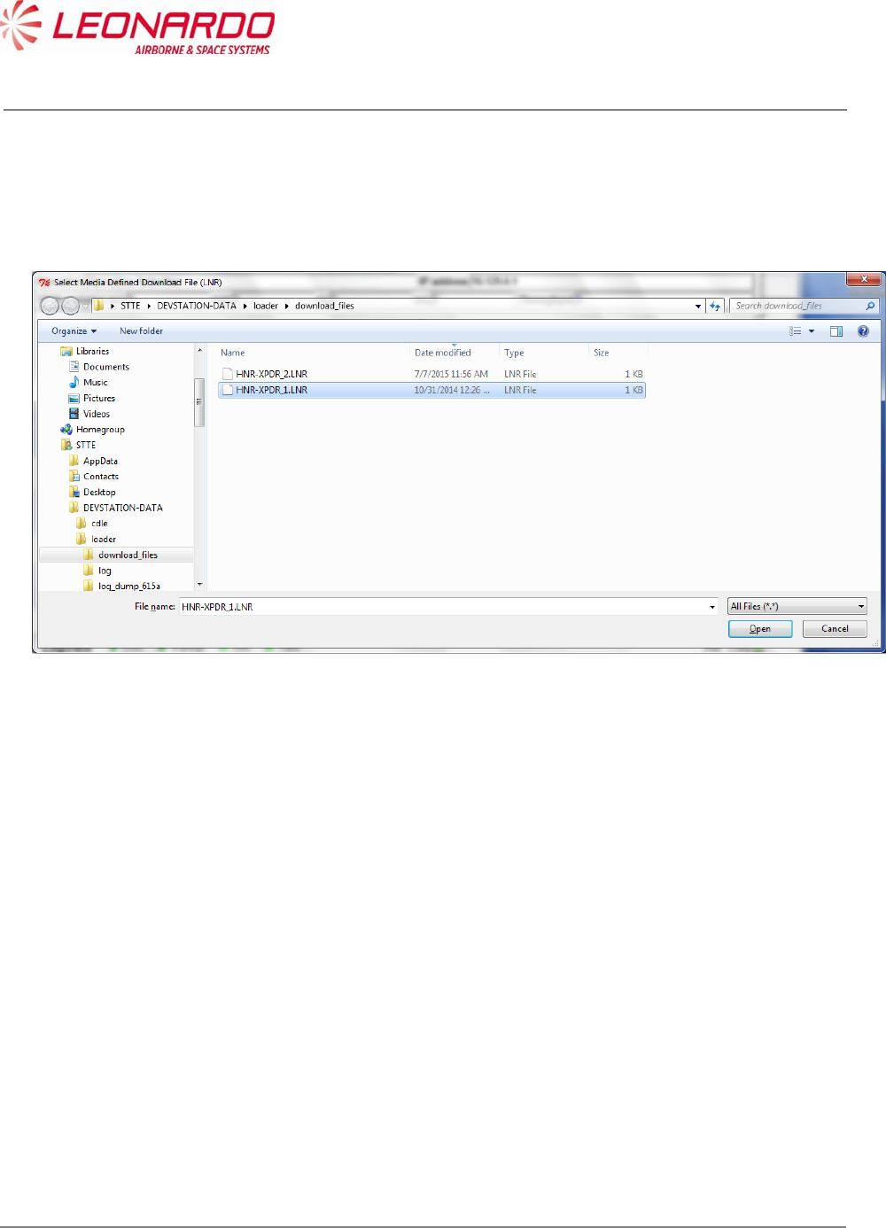
UNCLASSIFIED MAN-1124/01 T02
___________________________________________________________________________________________________________
______________________________________________________________________________
Page 62
© Copyright Leonardo Finmeccanica S.p.A. – All rights reserved
UNCLASSIFIED
9) Press “Shutdown” button
10) Start NetLoader and press “OK” button in Error window
11) Press “Download Media defined” button, following window will appear
12) Click on HNR-XPDR_1.LNR file for side 1 XPDR, HNR-XPDR_2.LNR for side 2 XPDR and
then press “Open” button.
13) If the XPDR is correctly found by the loader the following mask will appear (side 1
example)
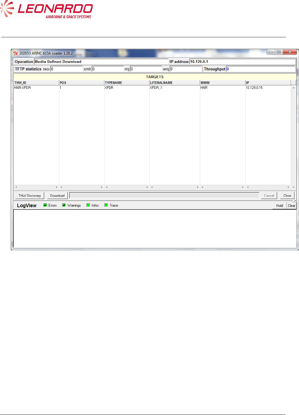
UNCLASSIFIED MAN-1124/01 T02
___________________________________________________________________________________________________________
______________________________________________________________________________
Page 63
© Copyright Leonardo Finmeccanica S.p.A. – All rights reserved
UNCLASSIFIED
14) Select the HNR-XPDR THW_ID row and press “Download” button.
15) NVM download process will start automatically and if successfully the following window will
appear. Binary file “READ_NVM” with NVM fault log content will be stored in
%HOME%/DEVSTATION-DATA/loader/download_files folder.
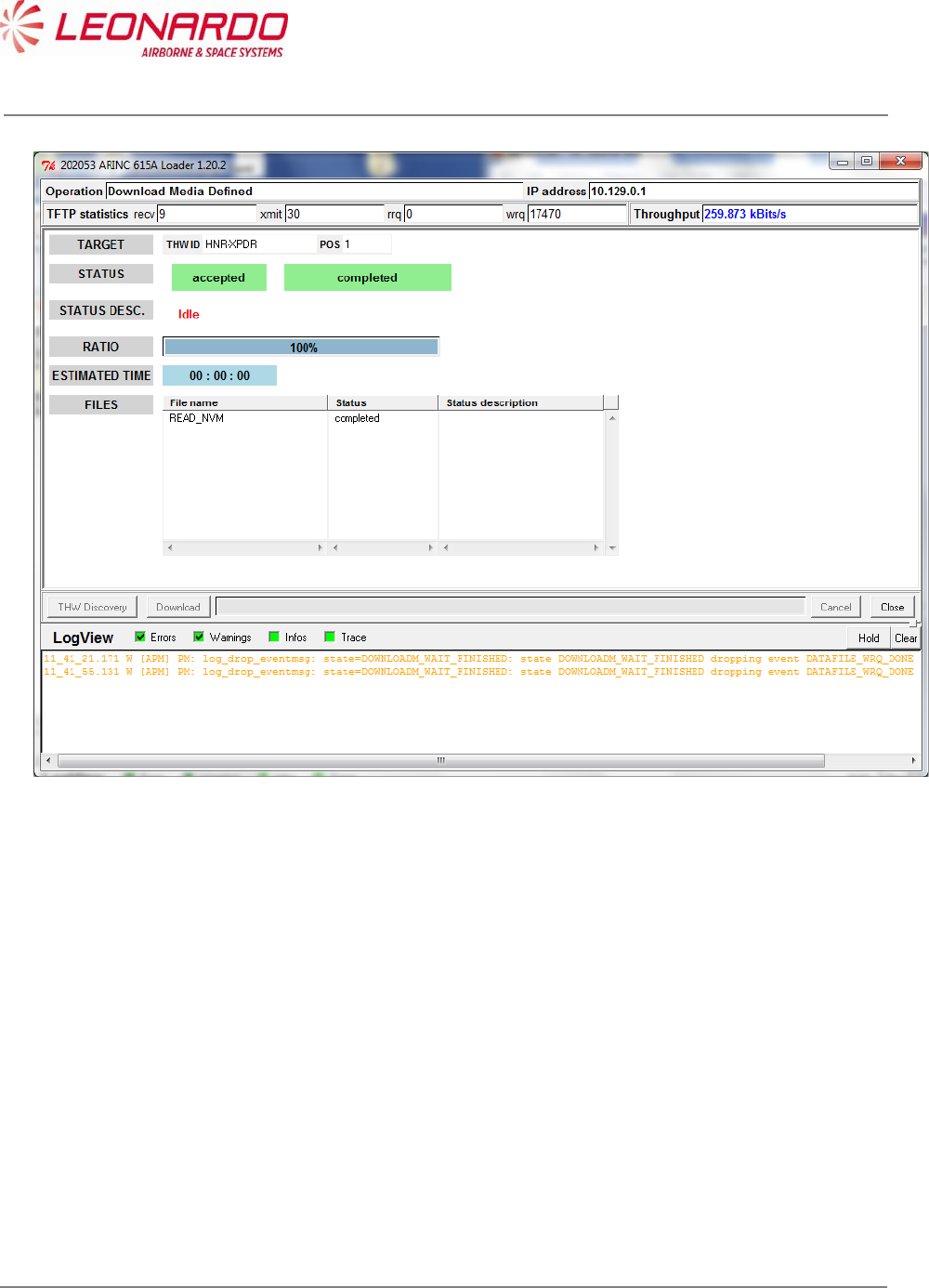
UNCLASSIFIED MAN-1124/01 T02
___________________________________________________________________________________________________________
______________________________________________________________________________
Page 64
© Copyright Leonardo Finmeccanica S.p.A. – All rights reserved
UNCLASSIFIED
16) Press “Close” button
17) Press “Shutdown” button

UNCLASSIFIED MAN-1124/01 T02
___________________________________________________________________________________________________________
______________________________________________________________________________
Page 65
© Copyright Leonardo Finmeccanica S.p.A. – All rights reserved
UNCLASSIFIED
7.3.3 NVM Data
The Table 7-1 – TRA-100B – Internal Faults provides fault log for internal faults and consequently
for off aircraft info, the Table 7-2 – TRA-100B – External Faults provides fault log for failures
detected on external sources. In case of failure indication provided on this area, the first step is
verify the connections between the TRA-100B and related external equipment.
The following table (Table 7-4) reports the troubleshooting procedure to perform against each fault
log.
Table 7-4 - External Faults Maintenance Procedure
Fault
Code
Failed Interface Failure Symptom Maintenance action
F0H Maintenance No Maintenance Data Verify connection with
CFDS if used
F1H 24 bit discrete Address Intermittent Mode S
address
Verify the connection with
Address bus
F2H TCAS TCAS Periodic Data
Failure
Verify connection with
TCAS
F3H Power
Interruption>10MSEC
Power Supply Interruption Verify connection with
primary power from
platform
F4H Altitude – 706 (L203) Altitude 706 Air Data
Failure
Verify connection with
ADC source
F5H Altitude – 575 (L203) Altitude 575 Air Data
Failure
Verify connection with
ADC source
F6H Altitude – 706 (all labels) 706 Air Data Failure Verify connection with
ADC source
F7H FMC/GNSS#2 FMC/GNSS#2 Failure Verify connection with
FMC/GNSS#2
F8H FMC/GNSS#1#2 FMC/GNSS#1#2 Failure Verify connection with
FMC/GNSS#2
F9H IRS/FMS IRS/FMS Failure Verify connection with
IRS/FMS
FAH FMC/GNSS#1 FMC/GNSS#1 Failure Verify connection with
FMC/GNSS#1
FBH FMC GEN FMC GEN Failure Verify connection with
FMC
FCH Altitude – 575 (all labels) 575 Air Data Failure Verify connection with

UNCLASSIFIED MAN-1124/01 T02
___________________________________________________________________________________________________________
______________________________________________________________________________
Page 66
© Copyright Leonardo Finmeccanica S.p.A. – All rights reserved
UNCLASSIFIED
Fault
Code
Failed Interface Failure Symptom Maintenance action
ADC source
FDH FCC/MCP FCC/MCP Failure Verify connection with
FCC/MCP
FEH Landing Gear Input Landing Gear Failure Verify the connection with
platform
FFH ADS-B Configuration
Pins
ADS-B Parity Failure Verify connection with
platform

UNCLASSIFIED MAN-1124/01 T02
___________________________________________________________________________________________________________
______________________________________________________________________________
Page 67
© Copyright Leonardo Finmeccanica S.p.A. – All rights reserved
UNCLASSIFIED
7.4 FAILURE LOCATION OFF AIRCRAFT
7.4.1 STTE Description
As mentioned above the TRA-100B Built-In-Test is capable to perform internal diagnostic and
provide results to the STTE.
The TRA-100B STTE is designed to perform troubleshooting procedure and provides after the
fault isolation the step by step procedure to restore the Transponder in its operating condition.
The TRA-100B STTE is composed as follows
Table 7-5 – TRA-100B STTE Composition
Pos. Item P/N
1 Double Rack 37U 600x800 HPI-1358/01.01
2 Lab Equipment _ (9 KHz - 6 GHZ) 9401151M0019
3 PXI INTERFACE TAD-5055/01.01
4 UUT FRONT PANEL FIXTURE TAG-5486/01.01
5 ANTENNA INTERFACE - MOUNTING TAD-5056/01.01
6 Rack Guide ACCIAIO TELESCOPICA 8100485M0437
7 For Cabinets ACCIAIO 8100081M0419
8 Lab Equipment _ (IFF SIMULATOR) 9401131M0014
9 Lab Equipment _ (AC SOURCE/A 9401163M0015
10 DIGITAL SCOPE TAG-5497/01.01
11 Monitor _ (17" LCD DISPLAY - 9401149M0014
12 PC Periph or Assembly _ (RAC 9401140M0013
13 Ethernet Switch (16 PORT FAS 9300164M0018
14 WORKSTATION 2U RACK HPI-1400/01.01
15 CAVO ICON ITA-ICON ITA L300mm TAN-5358/01.01
16 RF Cable SUCOFLEX 104 PTFE _m 1301783M0015
17 CAVO BNC 90-BNC 90 L2600mm TAN-5361/01.01
18 CAVO BNC 90-BNC 90 L1500mm TAN-5362/01.01
19 CAVO HI-PWR PER ATE MST-TRA TAN-5368/01.01
20 CABLE 37P BREAKOUT PXI - ANTE TAN-5380/01.01
21 TARGHETTA RACK TAK-7180/01.01
22 Cable AWG28 PVC _m**2 _ _ (C 1301273M0012
23 Cable 26/28AWG LSZH _m**2 COP 1301688M0011
26 TRA-100B_MPC STTE Software TIU-0077/01.01
Figure 7-1 and Figure 7-2 show the STTE composition
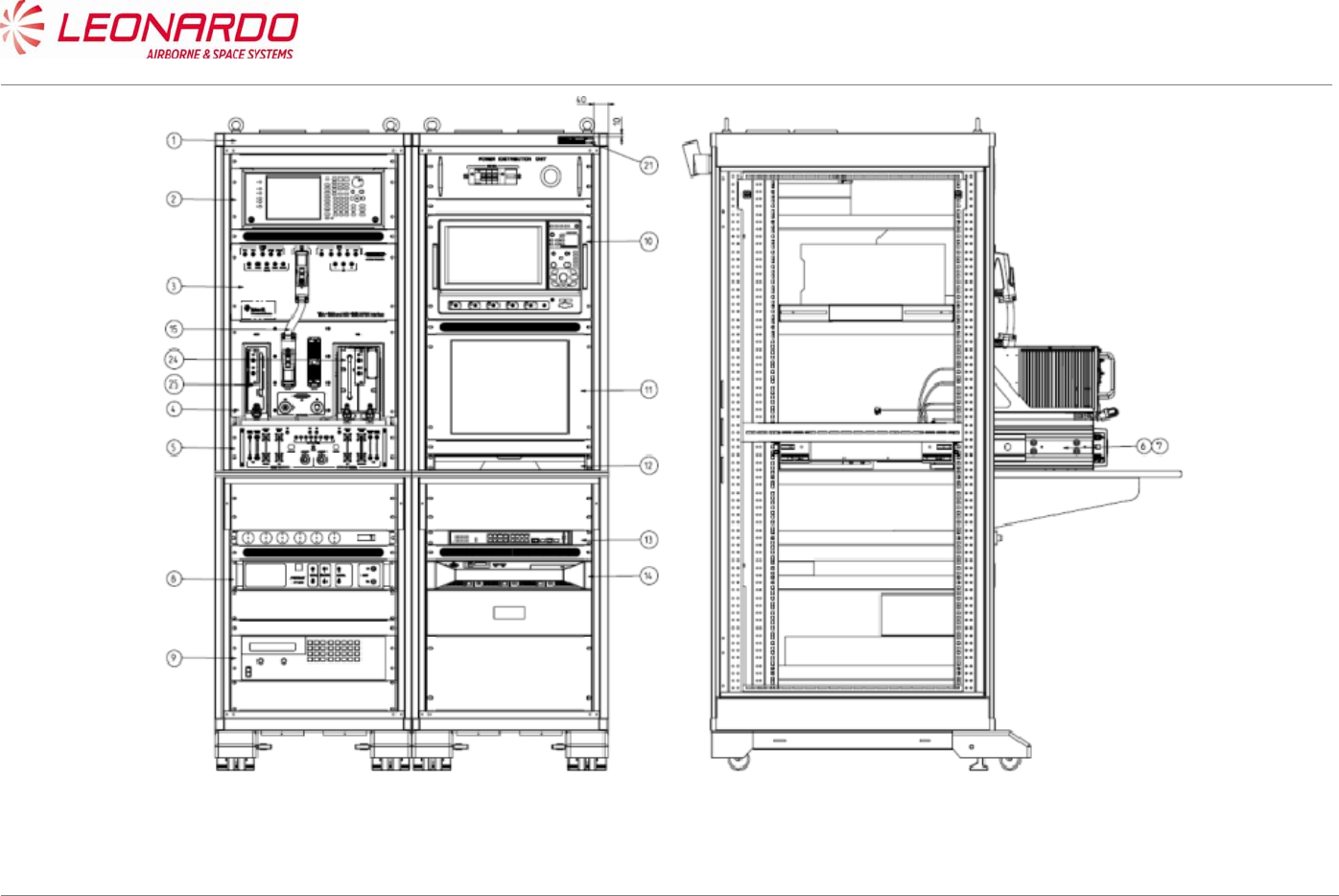
UNCLASSIFIED MAN-1124/01 T02
____________________________________________________________________________________________________________________________________________________________
__________________________________________________________________________________________________________________
Page 68
© Copyright Leonardo Finmeccanica S.p.A. – All rights reserved
UNCLASSIFIED
Figure 7-1 – TRA-100B STTE (Front and right views)
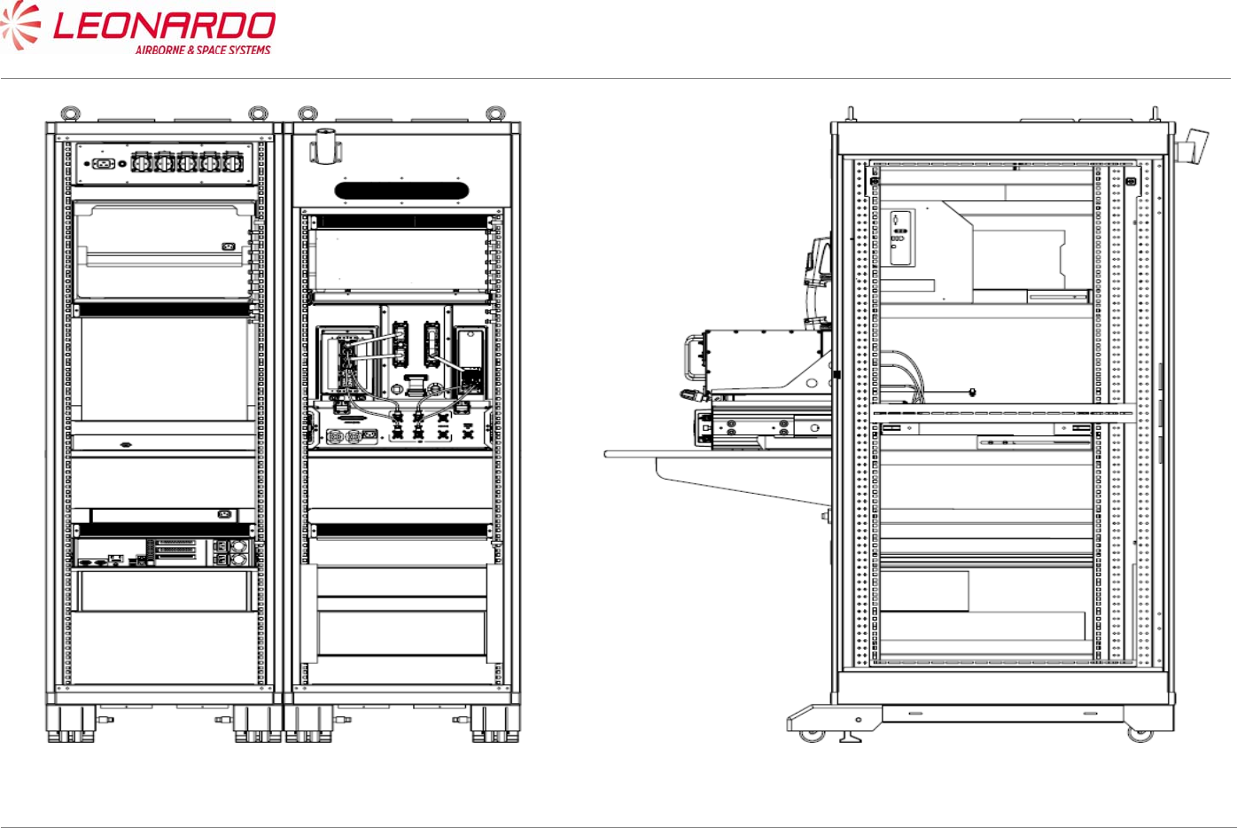
UNCLASSIFIED MAN-1124/01 T02
____________________________________________________________________________________________________________________________________________________________
__________________________________________________________________________________________________________________
Page 69
© Copyright Leonardo Finmeccanica S.p.A. – All rights reserved
UNCLASSIFIED
Figure 7-2 – TRA-100B STTE (Rear and left views)
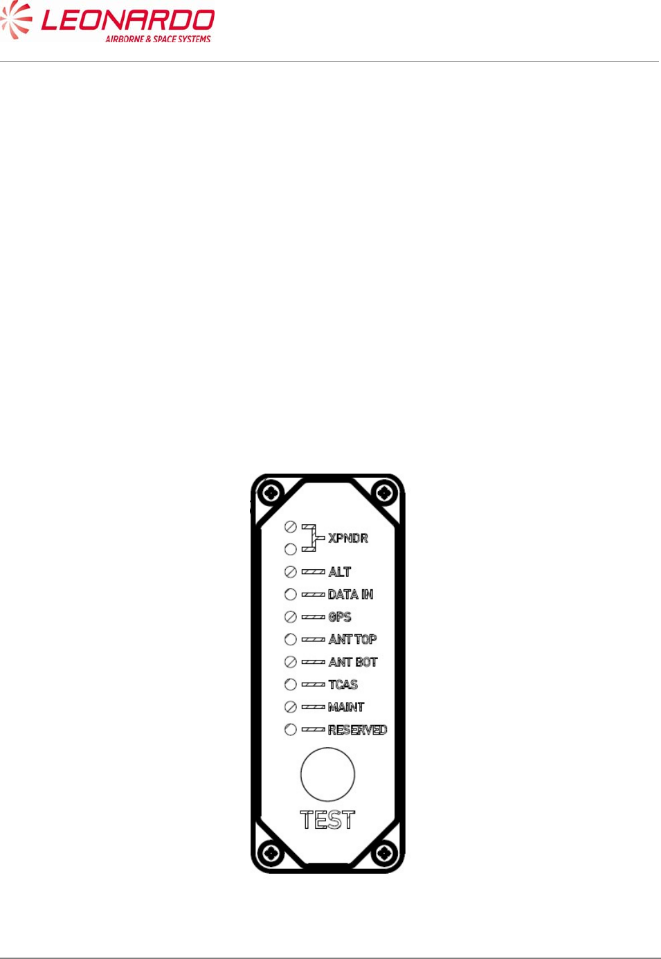
UNCLASSIFIED MAN-1124/01 T02
___________________________________________________________________________________________________________
______________________________________________________________________________
Page 70
© Copyright Leonardo Finmeccanica S.p.A. – All rights reserved
UNCLASSIFIED
7.4.2 OFF A/C Troubleshooting procedure
The OFF A/C troubleshooting procedure is performed in the Repair Station in order to identify or
confirm the failure of received equipment.
It starts with a visual inspection of the Transponder to verify eventual damage that can be occurred
during the handling, packaging and/or transportation.
In case of damage the maintainer has to verify if it is reported on the Failure Report supplied with
the Equipment. In case of missing information the maintainer shall record the damage updating the
Failure Report.
Therefore the equipment shall be connected to the STTE (see Figure 7-1) and shall verify the data
reported in the NVM (see Figure 7-7).
The STTE provides the necessary supplies, command and control signals and maintenance
interface.
The first information on the Transponder health status is provided by the Front Panel. The TRA-
100B is equipped with a set of LED which provide the status of the Transponder itself and the
status of the Transponder interfaces.
Figure 7-3 – TRA-100B - Front Panel LED

UNCLASSIFIED MAN-1124/01 T02
___________________________________________________________________________________________________________
______________________________________________________________________________
Page 71
© Copyright Leonardo Finmeccanica S.p.A. – All rights reserved
UNCLASSIFIED
As showed in Figure 7-3 the following LED are present on the Front Panel with the following
meaning:
Table 7-6 – TRA-100B - Front Panel LED indicators
CONTROL / INDICATOR DESCRIPTION FUNCTION
XPNDR Green Transponder GO. The Transponder is
correctly operating.
XPNDR Red Transponder NOGO. The Transponder is not
operating.
ALT Green/Red This LED provides the status of external
Altitude data. Color green the data are
correct
DATA IN Green/Red This LED provides the status of external
Control data. Color green the data are correct
GPS Green/Red This LED provides the status of external GPS
data. Color green the data are correct
ANT TOP Green/Red This LED provides the status of external
Antenna Top status. Color green the Antenna
Top is correctly operating.
ANT BOT Green/Red This LED provides the status of external
Antenna Bot status. Color green the Antenna
Bot is correctly operating.
TCAS Green/Red This LED provides the status of external
TCAS data. Color green the data are correct
MAINT Green/Red This LED provides the status of Maintenance
interface. Color green the data are correct
RESERVED N/A
During Power-Up the NOGO (RED) LED is set and remain set until the equipment is initialized (i.e.
Software and Firmware started up).
The NOGO (RED) LED is set while the failure discrete output pins are in the active state.
The GO (GREEN) LED is set to indicate that the equipment is initialized (i.e., Software and
Firmware started up) and the failure discrete output pins are not in the active state.
The front panel LED's provide a real time report of the validity of the Transponder internally and
the external interfaces.
The LED's are activated by the Test Push-button. The tests for the "on-ground" condition are
performed at the time of the activation of the test push-button.
The data from this self-test and the data from the latest passive test sequence is then displayed by
the LED's in the following manner:

UNCLASSIFIED MAN-1124/01 T02
___________________________________________________________________________________________________________
______________________________________________________________________________
Page 72
© Copyright Leonardo Finmeccanica S.p.A. – All rights reserved
UNCLASSIFIED
Within 1 second from the time the push-button is activated, NOGO (RED) and external
interfaces LED's is turned on for 3 seconds.
NOGO (RED) and external interfaces LED's then go off for 3 seconds.
The appropriate LED then is set on and stays lit until the push-button is released.
The appropriate LED above is green for the Transponder, if no internal faults are identified,
and red for the Transponder, if any internal fault is identified.
The test cycle that is initiated by the push-button re-runs after the 3 second, 3 second, 3 second
sequence described above is completed, if the push-button is still active.
However, the LEDs remains in their status annunciation state, and will change in response to any
new array of fault data picked up by the latest test cycle.
7.4.3 Connection procedure
The procedure to connect the TRA-100B to the STTE is following reported (ref. Figure 7-1):
1. Install the TRA-100B into the mounting tray (pos. 6 and 7) and push it until the rear
connectors are mated.
2. Securing the TRA-100B to the mounting tray using the two hold down screws
3. Connect the Ethernet connector
4. Connect the Test connector.
7.4.4 Fault Finding
The TRA-100B stores the failures occurred during the operation in the NVM. Nevertheless if a
failure arise in a section of DPIO the Transponder is not operative and the NVM content cannot be
read.
The procedure to perform the fault finding on TRA-100B is following reported:
1. Verify the status of the front panel LED.
2. If the red LED “NO GO” is on the DPIO SRU is failed but no data cannot be written in the
NVM.
Therefore follows the procedure for DPIO Removal (Ref. 8.4.1).
3. If the green LED “GO” is on, the TRA-100B is able to perform the auto test phase.
After 30 sec. the results of test will be reported in the “NVM Maintenance Interface” box (see
Figure 7-7)
4. The data are organized as follows:
a. Current Flight Information data pack: This field contains data related to flight
information such as departure location (From), arrival location (to), flight number
(Flight Nr.), aircraft identification (Aircraft Id.) and date (Date)
b. Failure Localization data pack (flight): This field contains data related Failure code
as per plus time of occurrence (GMT), Flight Phase, Error Repetition Counter (Fail

UNCLASSIFIED MAN-1124/01 T02
___________________________________________________________________________________________________________
______________________________________________________________________________
Page 73
© Copyright Leonardo Finmeccanica S.p.A. – All rights reserved
UNCLASSIFIED
Rep), Check Sum, Temperatures info (Temp 1XX, Temp 2XX, Temp 3XX), ETI
Counter (ETI High, ETI Low).
5. After the completion of test cycle, the operator shall select “Diagnostic Procedure” from
Tool Menu (Figure 7-8)
6. The Diagnostic Procedure screen (Figure 7-9) shows the Fail Code information together
with Module affected and Fail Description. The last column of section “Page” reports the
CMM number of page where the maintenance procedure to be performed in order to
restore the Transponder is recalled.
7. Clicking on the number of page reported in this column, the “Maintenance” section of this
manual will be opened showing the maintenance task to be performed to replace the failed
module.
7.4.5 Checkout procedure
In order to verify if the maintenance procedure restored the TRA-100B to its operating conditions,
a checkout procedure has to be performed.
This checkout consist mainly in running the ATP procedure as described following:
7.4.5.1 Check of lightning protection devices presence
The testing in this section consists of applying an AC voltage through a current-limit resistor to the
UUT rear connector discrete pins.
The voltage level has been selected to provide enough current to activate the transzorbs. With this
AC voltage applied, the Minimum and Maximum DC voltage levels on discrete output pins are
measured to ensure that the transzorbs perform voltage clamping at the device rated values.
Care is taken to apply the AC voltage for less than 15 seconds in order to prevent damage to the
discrete output circuit in case of a transzorb failure.
The following table defines the series resistor value, the external AC voltage to be used for each
single pin and the expected clamping voltage to be verified.

UNCLASSIFIED MAN-1124/01 T02
___________________________________________________________________________________________________________
______________________________________________________________________________
Page 74
© Copyright Leonardo Finmeccanica S.p.A. – All rights reserved
UNCLASSIFIED
Table 7-7 – TRA-100B - Transzorb Test Parameters
Pin I/O Type Description Series
Resistor 1% AC Voltage Clamping Voltage
TP 1A Input Program AC Length/Width A MSB 4.75KΩ
1/2W
80±0.5VAC,
50±0.5Hz ± 72.7 V
TP 1B Input Program
Strobed AC Length/Width B 4.75KΩ
1/2W
80±0.5VAC,
50±0.5Hz ± 72.7 V
TP 1C Input Program
Strobed AC Length/Width C LSB 4.75KΩ
1/2W
80±0.5VAC,
50±0.5Hz ± 72.7 V
TP 1D Input Program
Strobed GPS Ant Long Off A (MSB) 4.75KΩ
1/2W
80±0.5VAC,
50±0.5Hz ± 72.7 V
TP 1E Input Program
Strobed GPS Ant Long Off B 4.75KΩ
1/2W
80±0.5VAC,
50±0.5Hz ± 72.7 V
TP 1F Input Program
Strobed GPS Ant Long Off C (LSB) 4.75KΩ
1/2W
80±0.5VAC,
50±0.5Hz ± 72.7 V
TP 1G Input Program
Strobed
Navigation Accuracy Category
Velocity (NACV)
4.75KΩ
1/2W
80±0.5VAC,
50±0.5Hz ± 72.7 V
TP 1H Input Program
Strobed
System Design Assurance
(SDA)
4.75KΩ
1/2W
80±0.5VAC,
50±0.5Hz ± 72.7 V
TP 1J Input Differential GPS Time Mark 1A 560Ω 1/2W 40±0.5VAC,
50±0.5Hz ± 24.4 V
TP 1K Input Differential GPS Time Mark 1B 560Ω 1/2W 40±0.5VAC,
50±0.5Hz ± 24.4 V
TP 2A Input 429 FMC/GNSS #1 In #1 A 560Ω 1/2W 40±0.5VAC,
50±0.5Hz ± 11.2 V
TP 2B Input 429 FMC/GNSS #1 In #1 B 560Ω 1/2W 40±0.5VAC,
50±0.5Hz ± 11.2 V
TP 2C Input 429 IRS/FMS/Data Conc. A 560Ω 1/2W 40±0.5VAC,
50±0.5Hz ± 11.2 V
TP 2D Input 429 IRS/FMS/Data Conc. B 560Ω 1/2W 40±0.5VAC,
50±0.5Hz ± 11.2 V
TP 2E Output 429 Spare Out 1A 560Ω 1/2W 40±0.5VAC,
50±0.5Hz ± 11.2 V
TP 2F Output 429 Spare Out 1B 560Ω 1/2W 40±0.5VAC,
50±0.5Hz ± 11.2 V
TP 2G Input 429 ATSU In A 560Ω 1/2W 40±0.5VAC,
50±0.5Hz ± 11.2 V
TP 2H Input 429 ATSU In B 560Ω 1/2W 40±0.5VAC,
50±0.5Hz ± 11.2 V
TP 2J Input Discrete Data Load Enable 4.75KΩ
1/2W
80±0.5VAC,
50±0.5Hz ± 72.7 V
TP 2K Input Program ADS-B FAIL Disable 4.75KΩ
1/2W
80±0.5VAC,
50±0.5Hz ± 72.7 V
TP 3A Output Discrete ADS-B FAIL Disc Out 4.75KΩ
1/2W
80±0.5VAC,
50±0.5Hz ± 72.7 V
TP 3B Output Discrete Transponder Fail Disc #2
Output
4.75KΩ
1/2W
80±0.5VAC,
50±0.5Hz ± 72.7 V
TP 3C Input Program Cable Delay Program Top/Bot 4.75KΩ
1/2W
80±0.5VAC,
50±0.5Hz ± 72.7 V
TP 3D Input Program Cable Delay Program Value
#1
4.75KΩ
1/2W
80±0.5VAC,
50±0.5Hz ± 72.7 V
TP 3E Input Program Cable Delay Program Value
#2
4.75KΩ
1/2W
80±0.5VAC,
50±0.5Hz ± 72.7 V
TP 3G Input Discrete SDI 429 Bus Address Logic
Input
4.75KΩ
1/2W
80±0.5VAC,
50±0.5Hz ± 72.7 V
TP 3H Input Discrete SDI 429 Bus Address Logic 4.75KΩ 80±0.5VAC, ± 72.7 V

UNCLASSIFIED MAN-1124/01 T02
___________________________________________________________________________________________________________
______________________________________________________________________________
Page 75
© Copyright Leonardo Finmeccanica S.p.A. – All rights reserved
UNCLASSIFIED
Pin I/O Type Description Series
Resistor 1% AC Voltage Clamping Voltage
Input 1/2W 50±0.5Hz
TP 5A Input Program Maximum Airspeed 17 4.75KΩ
1/2W
80±0.5VAC,
50±0.5Hz ± 72.7 V
TP 5B Input Program Maximum Airspeed 16 4.75KΩ
1/2W
80±0.5VAC,
50±0.5Hz ± 72.7 V
TP 5C Input Program Maximum Airspeed 15 4.75KΩ
1/2W
80±0.5VAC,
50±0.5Hz ± 72.7 V
TP 5E Input 429 TX Coordination A 560Ω 1/2W 40±0.5VAC,
50±0.5Hz ± 11.2 V
TP 5F Input 429 TX Coordination B 560Ω 1/2W 40±0.5VAC,
50±0.5Hz ± 11.2 V
TP 5G Output 429 XT Coordination A 4.75KΩ
1/2W
50±0.5VAC,
50±0.5Hz ± 11.2 V
TP 5H Output 429 XT Coordination B 560Ω 1/2W 40±0.5VAC,
50±0.5Hz ± 11.2 V
TP 5J Input Discrete Air/Ground Discrete #2 4.75KΩ
1/2W
80±0.5VAC,
50±0.5Hz ± 72.7 V
TP 5K Input Discrete Air/Ground Discrete #1 4.75KΩ
1/2W
80±0.5VAC,
50±0.5Hz ± 72.7 V
TP 6A Input 429 FMC #1 / Gen In #2 A 560Ω 1/2W 40±0.5VAC,
50±0.5Hz ± 11.2 V
TP 6B Input 429 FMC #1 / Gen In #2 B 560Ω 1/2W 40±0.5VAC,
50±0.5Hz ± 11.2 V
TP 6D Input Discrete GPS Time Mark 2A 4.75KΩ
1/2W
40±0.5VAC,
50±0.5Hz ± 24.4 V
TP 6E Input Discrete GPS Time Mark 2B 4.75KΩ
1/2W
40±0.5VAC,
50±0.5Hz ± 24.4 V
TP 6F Input Discrete Reserved 4.75KΩ
1/2W
80±0.5VAC,
50±0.5Hz ± 72.7 V
TP 6G Input Discrete Reserved (-0101/-0301); FAA
- L_Sense Activate (-0201)
4.75KΩ
1/2W
80±0.5VAC,
50±0.5Hz ± 72.7 V
TP 6K Input Program Antenna Program 4.75KΩ
1/2W
80±0.5VAC,
50±0.5Hz ± 72.7 V
TP 7A Input 429 Control Data 'A' or FCC
#1/MCP #1/VHF #1 A 560Ω 1/2W 40±0.5VAC,
50±0.5Hz ± 11.2 V
TP 7B Input 429 Control Data 'A' or FCC
#1/MCP #1/VHF #1 B 560Ω 1/2W 40±0.5VAC,
50±0.5Hz ± 11.2 V
TP 7D Input Discrete Control Data Port Select 4.75KΩ
1/2W
80±0.5VAC,
50±0.5Hz ± 72.7 V
TP 7E Input 429 Control Data 'B' A 560Ω 1/2W 40±0.5VAC,
50±0.5Hz ± 11.2 V
TP 7F Input 429 Control Data 'B' B 560Ω 1/2W 40±0.5VAC,
50±0.5Hz ± 11.2 V
TP 7G Input Discrete Standby/On Discrete 4.75KΩ
1/2W
80±0.5VAC,
50±0.5Hz ± 72.7 V
TP 7H Input 429 ARINC 706/575 Air Data Input
Port 1A 560Ω 1/2W 40±0.5VAC,
50±0.5Hz ± 11.2 V
TP 7J Input 429 ARINC 706/575 Air Data Input
Port 1B 560Ω 1/2W 40±0.5VAC,
50±0.5Hz ± 11.2 V
MP 1A Input Program Mode S Address A1 (MSB) 4.75KΩ
1/2W
80±0.5VAC,
50±0.5Hz ± 72.7 V
MP 1B Input Program Mode S Address A2 4.75KΩ
1/2W
80±0.5VAC,
50±0.5Hz ± 72.7 V
MP 1C Input Program Mode S Address A3 4.75KΩ
1/2W
80±0.5VAC,
50±0.5Hz ± 72.7 V
MP 1D Input Program Mode S Address A4 4.75KΩ 80±0.5VAC, ± 72.7 V

UNCLASSIFIED MAN-1124/01 T02
___________________________________________________________________________________________________________
______________________________________________________________________________
Page 76
© Copyright Leonardo Finmeccanica S.p.A. – All rights reserved
UNCLASSIFIED
Pin I/O Type Description Series
Resistor 1% AC Voltage Clamping Voltage
1/2W 50±0.5Hz
MP 1E Input Program Mode S Address A5 4.75KΩ
1/2W
80±0.5VAC,
50±0.5Hz ± 72.7 V
MP 1F Input Program Mode S Address A6 4.75KΩ
1/2W
80±0.5VAC,
50±0.5Hz ± 72.7 V
MP
1G Input Program Mode S Address A7 4.75KΩ
1/2W
80±0.5VAC,
50±0.5Hz ± 72.7 V
MP 1H Input Program Mode S Address A8 4.75KΩ
1/2W
80±0.5VAC,
50±0.5Hz ± 72.7 V
MP 1J Input Program Mode S Address A9 4.75KΩ
1/2W
80±0.5VAC,
50±0.5Hz ± 72.7 V
MP 1K Input Program Mode S Address A10 4.75KΩ
1/2W
80±0.5VAC,
50±0.5Hz ± 72.7 V
MP 2A Input Program Mode S Address A11 4.75KΩ
1/2W
80±0.5VAC,
50±0.5Hz ± 72.7 V
MP 2B Input Program Mode S Address A12 4.75KΩ
1/2W
80±0.5VAC,
50±0.5Hz ± 72.7 V
MP 2C Input Program Mode S Address A13 4.75KΩ
1/2W
80±0.5VAC,
50±0.5Hz ± 72.7 V
MP 2D Input Program Mode S Address A14 4.75KΩ
1/2W
80±0.5VAC,
50±0.5Hz ± 72.7 V
MP 2E Input Program Mode S Address A15 4.75KΩ
1/2W
80±0.5VAC,
50±0.5Hz ± 72.7 V
MP 2F Input Program Mode S Address A16 4.75KΩ
1/2W
80±0.5VAC,
50±0.5Hz ± 72.7 V
MP
2G Input Program Mode S Address A17 4.75KΩ
1/2W
80±0.5VAC,
50±0.5Hz ± 72.7 V
MP 2H Input Program Mode S Address A18 4.75KΩ
1/2W
80±0.5VAC,
50±0.5Hz ± 72.7 V
MP 2J Input Program Mode S Address A19 4.75KΩ
1/2W
80±0.5VAC,
50±0.5Hz ± 72.7 V
MP 2K Input Program Mode S Address A20 4.75KΩ
1/2W
80±0.5VAC,
50±0.5Hz ± 72.7 V
MP 3A Input Program Mode S Address A21 4.75KΩ
1/2W
80±0.5VAC,
50±0.5Hz ± 72.7 V
MP 3B Input Program Mode S Address A22 4.75KΩ
1/2W
80±0.5VAC,
50±0.5Hz ± 72.7 V
MP 3C Input Program Mode S Address A23 4.75KΩ
1/2W
80±0.5VAC,
50±0.5Hz ± 72.7 V
MP 3D Input Program Mode S Address A24 (LSB) 4.75KΩ
1/2W
80±0.5VAC,
50±0.5Hz ± 72.7 V
MP 3F Input 429 Spare 429 Input 1A 560Ω 1/2W 40±0.5VAC,
50±0.5Hz ± 11.2 V
MP
3G Input 429 Spare 429 Input 1B 560Ω 1/2W 40±0.5VAC,
50±0.5Hz ± 11.2 V
MP 3H Input Discrete Functional Test 4.75KΩ
1/2W
80±0.5VAC,
50±0.5Hz ± 72.7 V
MP 3J Output Discrete Spare Out 1 4.75KΩ
1/2W
80±0.5VAC,
50±0.5Hz ± 72.7 V
MP 3K Output Discrete Transponder Fail #1 Discrete
Output
4.75KΩ
1/2W
80±0.5VAC,
50±0.5Hz ± 72.7 V
MP 4A Input Discrete Spare In1 4.75KΩ
1/2W
50±0.5VAC,
50±0.5Hz NA
MP 4B Input Discrete Spare In2 4.75KΩ
1/2W
80±0.5VAC,
50±0.5Hz ± 72.7 V

UNCLASSIFIED MAN-1124/01 T02
___________________________________________________________________________________________________________
______________________________________________________________________________
Page 77
© Copyright Leonardo Finmeccanica S.p.A. – All rights reserved
UNCLASSIFIED
Pin I/O Type Description Series
Resistor 1% AC Voltage Clamping Voltage
MP 4C Input 429 FMC/GNSS #2 In #1 A 560Ω 1/2W 40±0.5VAC,
50±0.5Hz ± 11.2 V
MP 4D Input 429 FMC/GNSS #2 In #1 B 560Ω 1/2W 40±0.5VAC,
50±0.5Hz ± 11.2 V
MP 4E Input Program
Strobed Aircraft Category A (MSB) 4.75KΩ
1/2W
80±0.5VAC,
50±0.5Hz ± 72.7 V
MP 4F Input Program
Strobed Aircraft Category B (LSB) 4.75KΩ
1/2W
80±0.5VAC,
50±0.5Hz ± 72.7 V
MP
4G Input Program ADS-B Configuration Parity 4.75KΩ
1/2W
80±0.5VAC,
50±0.5Hz ± 72.7 V
MP 4H Input Program
Strobed ADS-B Receive Capability 4.75KΩ
1/2W
80±0.5VAC,
50±0.5Hz ± 72.7 V
MP 4J Input Discrete Spare In3 4.75KΩ
1/2W
80±0.5VAC,
50±0.5Hz ± 72.7 V
MP 4K Input Discrete Spare In4 4.75KΩ
1/2W
80±0.5VAC,
50±0.5Hz ± 72.7 V
MP 5A Input 429 ARINC 706/575 Air Data Input
Port 2A 560Ω 1/2W 40±0.5VAC,
50±0.5Hz ± 11.2 V
MP 5B Input 429 ARINC 706/575 Air Data Input
Port 2B 560Ω 1/2W 40±0.5VAC,
50±0.5Hz ± 11.2 V
MP 5E Output 429 ATSU Out A 560Ω 1/2W 40±0.5VAC,
50±0.5Hz ± 11.2 V
MP 5F Output 429 ATSU Out B 560Ω 1/2W 40±0.5VAC,
50±0.5Hz ± 11.2 V
MP
5G Input Discrete Extended Squitter Disable 4.75KΩ
1/2W
80±0.5VAC,
50±0.5Hz ± 72.7 V
MP 5H Input Discrete Spare In5 (Mode S DL/DLP
Program)
4.75KΩ
1/2W
80±0.5VAC,
50±0.5Hz ± 72.7 V
MP 5J Input Program Antenna BITE Program 4.75KΩ
1/2W
80±0.5VAC,
50±0.5Hz ± 72.7 V
MP 5K Input Discrete Spare In6 4.75KΩ
1/2W
80±0.5VAC,
50±0.5Hz ± 72.7 V
MP 6A Input 429 Maintenance Data Input Port A 560Ω 1/2W 40±0.5VAC,
50±0.5Hz ± 11.2 V
MP 6B Input 429 Maintenance Data Input Port B 560Ω 1/2W 40±0.5VAC,
50±0.5Hz ± 11.2 V
MP 6C Output 429 Maintenance Data Output Port
A 560Ω 1/2W 40±0.5VAC,
50±0.5Hz ± 11.2 V
MP 6D Output 429 Maintenance Data Output Port
B 560Ω 1/2W 40±0.5VAC,
50±0.5Hz ± 11.2 V
MP 6E Input Discrete Alternate Air Data Source
Select
4.75KΩ
1/2W
80±0.5VAC,
50±0.5Hz ± 72.7 V
MP 6F Input Program Altitude Type Select A
Discrete Input
4.75KΩ
1/2W
80±0.5VAC,
50±0.5Hz ± 72.7 V
MP
6G Input Program Altitude Type Select B
Discrete Input
4.75KΩ
1/2W
80±0.5VAC,
50±0.5Hz ± 72.7 V
MP 7K Input Discrete Acquisition Squitter Inhibit
(Honeywell Defined)
4.75KΩ
1/2W
80±0.5VAC,
50±0.5Hz ± 72.7 V
BP 1 Input Power 115 VAC Primary Power Hot 4.75KΩ
1/2W
330±0.5VAC,
50±0.5Hz ± 291 V
BP 7 Input Power 115 VAC Primary Power Cold 4.75KΩ
1/2W
330±0.5VAC,
50±0.5Hz ± 291 V
BP 12 Input/Output Suppression Suppression Pulse 4.75KΩ
1/2W
150±0.5VAC,
50±0.5Hz ± 113.0 V
BP 13 Input/Output Suppression Suppression Pulse - Daisy
Chaining
4.75KΩ
1/2W
150±0.5VAC,
50±0.5Hz ± 113.0 V

UNCLASSIFIED MAN-1124/01 T02
___________________________________________________________________________________________________________
______________________________________________________________________________
Page 78
© Copyright Leonardo Finmeccanica S.p.A. – All rights reserved
UNCLASSIFIED
7.4.5.2 Test of hardware/software performances in normal use
7.4.5.2.1 Receiver Characteristics
Step 1 Sensitivity
a. Interrogate the transponder with a standard Mode C ATCRBS/Mode S All-Call interrogation
on Top antenna.
b. Determine the minimum RF signal level required to produce 90% transponder reply
efficiency (MTL).
c. Verify that MTL is in the range -75dBm ± 3dB
d. Repeat steps a,b,c interrogating the transponder on Bottom antenna.
Note: the -78dBm is obtained from best sensitivity (-77dBm) + best cable loss (-1dB), -72dBm is obtained from worst
sensitivity (-69dBm) + worst cable loss (-3dB)
Step 2 Sensitivity @ Low Sensitivity
a. Interrogate the transponder with a standard Mode C ATCRBS/Mode S All-Call interrogation
on Top antenna at MTL+3dB.
b. Verify that the reply ratio is ≥ 99%.
c. Set Low_Sense Activate discrete to GND
d. Verify that the reply ratio is 0%.
e. Increase the level of the interrogation to MTL+9dB
f. Verify that the reply ratio is ≥ 99%.
g. Set Low_Sense Activate discrete to OPEN
Step 3 ATCRBS and ATCRBS/Mode S All-Call Dynamic Range
a. Interrogate the transponder with a standard Mode A interrogation at RF levels at the
following levels: MTL +3 dB, -60dBm, -50dBm, -40dBm, -30dBm, -22dBm
b. For each of the above levels determine reply ratio and verify that it is ≥ 99%.
c. Interrogate the transponder with a standard Mode C ATCRBS/Mode S All-Call interrogation
at RF levels at the following levels: MTL +3 dB, -60dBm, -50dBm, -40dBm, -30dBm, -
22dBm
d. For each of the above levels determine reply ratio and verify that it is ≥ 99%.
Note: -22dBm is obtained from -21dBm considering the best antenna cable attenuation equal to 1dB
Step 4 Mode S Sensitivity
a. Interrogate the transponder with a Mode S Only All-Call interrogation at a standard rate
with PR=0.
b. Determine the minimum RF level to produce 90% proper reply efficiency (MTL).
c. Verify that MTL is in the range -76dBm ± 2dB
Note: the -78dBm is obtained from best sensitivity (-77dBm) + best cable loss (-1dB), -74dBm is obtained from worst
sensitivity (-71dBm) + worst cable loss (-3dB)
Step 5 Mode S Dynamic Range

UNCLASSIFIED MAN-1124/01 T02
___________________________________________________________________________________________________________
______________________________________________________________________________
Page 79
© Copyright Leonardo Finmeccanica S.p.A. – All rights reserved
UNCLASSIFIED
a. Interrogate the transponder with a Mode S Only All-Call interrogation at a standard rate
with PR=0 with RF levels of MTL+3dBm -50dBm and -22dBm.
b. For each of the above levels determine reply ratio and verify that it is ≥ 99%.
Note: -22dBm is obtained from -21dBm considering the best antenna cable attenuation equal to 1dB
7.4.5.2.2 Reply Transmission Frequency
Step 1 Reply Transmission Frequency
a. Modify the label 016 on Control A429 to set all A1,A2,A4,B1,B2,B4,C1,C2,C4,D1,D2,D4 to
‘1’ (setup for 7777 pulse reply)
b. Interrogate the transponder with a standard Mode A interrogation.
c. Verify that reply center frequency is 1090MHz±1Mhz.
d. Interrogate the transponder with a standard Mode A ATCRBS/Mode S All-Call.
e. Verify that reply center frequency is 1090MHz±1Mhz.
7.4.5.2.3 RF Peak Power Output
Step 1 ATCRBS Power Output
a. Modify the label 016 on Control A429 to set all A1,A2,A4,B1,B2,B4,C1,C2,C4,D1,D2,D4 to
‘1’ (setup for 7777 pulse reply)
b. Interrogate the transponder with a standard Mode A interrogation at 1200 interrogations
(maximum available)
c. Measure the power of each single pulse
d. Verify that the lowest value is in the range 24dBW÷28dBW
Note: 24dBW is obtained from minimum required 21dBW at the antenna considering the worst antenna cable attenuation equal to
3dB. 28dBW is obtained is obtained from maximum required 27dBW at the antenna considering the best antenna cable attenuation
equal to 1dB
Step 2 Short Mode S Power Output (§2.2.3.2)
a. Interrogate the transponder with a standard Mode A ATCRBS/Mode S All-Call interrogation
at the standard rate
b. Measure the power of each single pulse
c. Verify that the lowest value is in the range 24dBW÷28dBW
Note: 24dBW is obtained from minimum required 21dBW at the antenna considering the worst antenna cable
attenuation equal to 3dB. 28dBW is obtained is obtained from maximum required 27dBW at the antenna considering
the best antenna cable attenuation equal to 1dB
Step 3 Long Mode S Power Output
a. Interrogate the transponder with a standard Mode S UF4 interrogation requesting for DF20
at 100 interrogations per second (this exceeds the 16 requested by MOPS and include
equivalent extended squitters)
b. Measure the power of each single pulse
c. Verify that the lowest value is in the range 24dBW÷28dBW

UNCLASSIFIED MAN-1124/01 T02
___________________________________________________________________________________________________________
______________________________________________________________________________
Page 80
© Copyright Leonardo Finmeccanica S.p.A. – All rights reserved
UNCLASSIFIED
Note: 24dBW is obtained from minimum required 21dBW at the antenna considering the worst antenna cable
attenuation equal to 3dB. 28dBW is obtained is obtained from maximum required 27dBW at the antenna considering
the best antenna cable attenuation equal to 1dB
7.4.5.2.4 Reply Rate Capability
Step 1 ATCRBS Reply Rate Capability + Continuous Reply Rate Capability
a. Modify the label 016 on Control A429 to set all A1,A2,A4,B1,B2,B4,C1,C2,C4,D1,D2,D4
and SPI to ‘1’ (setup for 15 pulse reply)
b. Interrogate the transponder at a constant rate of 1200 Mode A ATCRBS interrogations per
second plus 100 Mode S UF4 requesting for DF20
c. Measure the output power and frequency and reply ratio for each type of interrogation
d. Verify that the measured power is in the range 24dBW÷28dBW
e. Verify that reply center frequency is 1090MHz±1Mhz.
f. Verify that the reply ratio is ≥ 99% for both Mode A and Mode S
Note: 24dBW is obtained from minimum required 21dBW at the antenna considering the worst antenna cable
attenuation equal to 3dB. 28dBW is obtained is obtained from maximum required 27dBW at the antenna considering
the best antenna cable attenuation equal to 1dB
7.4.5.2.5 Power Consumption
Step 1 Power Consumption at max duty cycle at nominal power supply conditions
a. When running the Reply rate capability test measure:
i. Power consumption in W and verify that is always less than 60W
ii. Power factor, verify that is greater than 0,8
Step 2 Power Consumption at max duty cycle at max voltage and max emergency frequency
a. Set the power supply voltage at 122 Vrms (maximum normal voltage)
b. Set the power supply frequency at 440 Hz (maximum emergency frequency)
c. When running the Reply rate capability test measure:
i. Power consumption in W and verify that is always less than 60W
ii. Power factor, verify that is greater than 0,8
Step 3 Power Consumption at max duty cycle and min voltage and min emergency frequency
a. Set the power supply voltage at 104 Vrms (minimum normal voltage)
b. Set the power supply frequency at 360 Hz (minimum emergency frequency)
c. When running the Reply rate capability test measure:
i. Power consumption in W and verify that is always less than 60W
ii. Power factor, verify that is greater than 0,8
7.4.5.2.6 I/O Discrete Interface
Step 1 Mode S All-Call Addresses
a. Set the ATC test set to generate a Mode-S Only All-Call interrogation with PR, IC and CL
fields set to ZERO.

UNCLASSIFIED MAN-1124/01 T02
___________________________________________________________________________________________________________
______________________________________________________________________________
Page 81
© Copyright Leonardo Finmeccanica S.p.A. – All rights reserved
UNCLASSIFIED
b. Verify that the AA field of the transponder reply is AAAAAAH
c. Verify that XPDR FAIL#1, XPDR FAIL#2 and ADSB FAIL discrete are set in off condition
(No Failure condition)
d. Power off the transponder addresses
e. Set the MS Address discrete at 555555H.
f. Power on the transponder
g. Set the ATC test set to generate a Mode-S Only All-Call interrogation with PR, IC and CL
fields set to ZERO.
h. Verify that the AA field of the transponder reply is 555555H
i. Removal power from the Unit Under Test
Step 2: Address set to ALL ZEROs
a. Set the ICAO 24-Bit Address provided to the UUT to ALL ZEROs.
b. Apply power to the UUT.
c. Verify that XPDR FAIL#1, XPDR FAIL#2 and ADSB FAIL discrete are set in on condition
(Failure condition)
d. Removal power from the Unit Under Test
Step 3: Address set to ALL ONEs
a. Set the ICAO 24-Bit Address provided to the UUT to ALL ONEs.
b. Apply power to the UUT.
c. Verify that XPDR FAIL#1, XPDR FAIL#2 and ADSB FAIL discrete are set in on condition
(Failure condition)
d. Removal power from the Unit Under Test.
Step 4 Pressure Altitude Interface
a. Setup the ATC test set to send standard ATCRBS Mode C interrogation
b. Verify that the replies code is equal to 3329 feet.
c. Set Alternate Air Data Source Select discrete input to OPEN
d. Verify that the replies code is equal to -336 feet.
e. Power off the UUT.
f. Apply default setup
g. Set Alternate Air Data Type Select A (Pin MP 6F) to GND.
h. Apply power to the UUT.
i. Verify that the replies code is equal to 1664 feet.
j. Set the bit 11 of label 016 and 031 of control bus (Control Port B) to ‘1’ to disable altitude
reporting
k. Verify that only the framing pulses are present
l. Set Control Data Port Select (TP-7D) to GND
m. Verify that the replies code is equal to 1664 feet.
n. Set Air/Ground Discrete #2 to GND
o. Verify that no replies are transmitted by the transponder
p. Set Air/Ground Discrete #2 to OPEN

UNCLASSIFIED MAN-1124/01 T02
___________________________________________________________________________________________________________
______________________________________________________________________________
Page 82
© Copyright Leonardo Finmeccanica S.p.A. – All rights reserved
UNCLASSIFIED
q. Set Air/Ground Discrete #1 to GND
r. Verify that no replies are transmitted by the transponder
s. Set Air/Ground Discrete #2 to OPEN
t. Set Air/Ground Discrete #1 to OPEN
u. Verify that the replies code is equal to 1664 feet.
v. Set Standby/On discrete to GND
w. Verify that no replies are transmitted by the transponder
Step 5 Aircraft Identification Data
a. Provide the UUT with an Aircraft Identification Data of “UJUJUJUJ” through FMC/GEN
interface with each char updated at 1 Hz
b. For up to 10.0 seconds after completing Step a, set the ATC test set to generate a Mode S
interrogation with the following GICB Extraction interrogation in order to extract the
Register 2016 - Aircraft Identification.
i. UF=4, PC = 0, RR = 18, DI = 0, IIS = 0
c. Within FIVE (5) seconds of starting the interrogations, verify that the transponder replies
with a DF=20 reply with:
i. DR =4 or 5
ii. MB = 2016 + “UJUJUJUJ” (MB=0x2054A54A54A54A)
d. Provide the UUT with an Aircraft Identification Data of “6 9 6 9 XY” through FMC/GEN
interface (a SPACE is present between 6 and 9, 9 and 6, 6 and 9, 9 and X) with each char
updated at 1 Hz
e. For up to 10.0 seconds after completing Step d, set the ATC test set to generate a Mode S
interrogation with the following GICB Extraction interrogation in order to extract the
Register 2016 - Aircraft Identification.
i. UF=4, PC = 0, RR = 18, DI = 0, IIS = 0
f. Within TEN (10) seconds of completing Step a, verify that the transponder replies with a
DF=20 reply with:
i. MB = 2016 + “6969XY ” (last two characters set to SPACE) ”
(MB=0x20DB9DB9619820)
g. Disable all Aircraft Identification labels on every A429 bus
h. Wait 20 seconds and verify that the transponder replies with a DF=20 reply with:
i. MB = 2016 + “TAIL123 ” (last two characters set to SPACE) ”
Step 6 ADSB Discrete
a. Verify the transmission of acquisition squitter
b. Set the Acquisition Squitter inhibit (MP-7K) to GND
c. Verify that the acquisition squitter is no longer transmitted
d. Set the Acquisition Squitter inhibit (MP-7K) to OPEN
e. Verify the transmission of any of Extended Squitters
f. Set the Extended Squitter Disable (MP-5G) to GND
g. Verify that the Extended Squitters are no longer transmitted
h. Set the Extended Squitter Disable (MP-5G) to OPEN

UNCLASSIFIED MAN-1124/01 T02
___________________________________________________________________________________________________________
______________________________________________________________________________
Page 83
© Copyright Leonardo Finmeccanica S.p.A. – All rights reserved
UNCLASSIFIED
i. Verify that the Squitters are transmitted on both the antennas
j. Verify that Label 353 from Maintenance Bus has the following fields:
i. SDI set to 2d
ii. Max Cruise Air Speed set to 4d
iii. Length/Width set to 10d
iv. GPS Antenna Offset set to 4d
v. Aircraft Category set to 3d
vi. 1090ES IN set to 0
vii. UAT Receiver set to 0
viii. ADSB Conf Parity set to 0
k. Verify that Label 352 from Maintenance Bus has the following fields:
i. SDI set to 2d
ii. Antenna BITE set to 0
iii. NACv set to 1d
iv. SDA set to 2d
v. ADSB Fail Disable set to 0
l. Power off the UUT.
m. Apply default setup
n. Set AC Length/Width A,B,C to Open/Gnd/Open
o. Set GPS Ant Long Off A/B/C to Gnd/Open/Open
p. Set NACv to Open
q. Set SDA to Open
r. Set Aircraft Category A/B to Open/Gnd
s. Set ADSB Receive Capability to GND
t. Set ADSB Config Parity to GND
u. Set SDI to Gnd/Open
v. Set Antenna BITE to Gnd
w. Set ADSB Fail Disable to Gnd
x. Set Antenna Program to Gnd
y. Power on the UUT.
z. Verify that Label 353 from Maintenance Bus has the following fields:
i. SDI set to 1d
ii. Max Cruise Air Speed set to 4d
iii. Length/Width set to 3d
iv. GPS Antenna Offset set to 10d
v. Aircraft Category set to 1d
vi. 1090ES IN set to 1d
vii. UAT Receiver set to 0
viii. ADSB Conf Parity set to 1d
aa. Verify that Label 352 from Maintenance Bus has the following fields:
i. SDI set to 1d
ii. Antenna BITE set to 1d
iii. NACv set to 0d

UNCLASSIFIED MAN-1124/01 T02
___________________________________________________________________________________________________________
______________________________________________________________________________
Page 84
© Copyright Leonardo Finmeccanica S.p.A. – All rights reserved
UNCLASSIFIED
iv. SDA set to 0d
v. ADSB Fail Disable set to 1d
bb. Verify that the squitters are transmitted only on Bottom Antenna.
Step 7 Suppression Out Discrete
a. Verify that for each transmitted squitter a suppression pulse is generated on BP12 output
with the following characteristics:
b. Distance between rising edge of suppression pulse and leading edge of first rf pulse is less
than 10 us
c. Distance between trailing edge of last rf pulse and falling edge of suppression pulse is less
than 10 us
d. Amplitude of suppression pulse is greater than 18V
7.4.5.2.7 A429 Interface Health
a. Verify that Label 351 from Maintenance Bus has the following fields:
i. MCP/FCU Bus set to 0 – Active
ii. ATC Control set to 0 – Active
iii. FMS # 1 Flight ID set to 0 – Active
iv. GNSS #1 Bus set to 0 – Active
v. GNSS #2 Bus set to 0 – Active
vi. IRS #1 Bus set to 0 – Active
vii. IRS #2 Bus set to 0 – Active
viii. FMS Gen. #1 Bus set to 0 – Active
ix. FMS Gen. #2 Bus set to 0 – Active
b. Stop the transmission of all the labels from the MCP, Control, FMS#1, GNSS#1, GNSS#2,
IRS#1, IRS#2, FMS Gen#1, FMS Gen#2 busses:
c. Verify that Label 351 from Maintenance Bus has the following fields:
i. MCP/FCU Bus set to 1= Inactive
ii. ATC Control set to 1= Inactive
iii. FMS # 1 Flight ID set to 1= Inactive
iv. GNSS #1 Bus set to 1= Inactive
v. GNSS #2 Bus set to 1= Inactive
vi. IRS #1 Bus set to 1= Inactive
vii. IRS #2 Bus set to 1= Inactive
viii. FMS Gen. #1 Bus set to 1= Inactive
ix. FMS Gen. #2 Bus set to 1= Inactive
7.4.5.2.8 Front Panel LEDS
a. Verify that the GO led is active
b. Press the Test Button (keep the button pressed)
c. Verify that all others LEDs are active
d. Release the Test Button

UNCLASSIFIED MAN-1124/01 T02
____________________________________________________________________________________________________________________________________________________________
__________________________________________________________________________________________________________________
Page 85
© Copyright Leonardo Finmeccanica S.p.A. – All rights reserved
UNCLASSIFIED
Figure 7-4 – TRA-100B – OFF A/C Troubleshooting STTE NVM Interface

UNCLASSIFIED MAN-1124/01 T02
____________________________________________________________________________________________________________________________________________________________
__________________________________________________________________________________________________________________
Page 86
© Copyright Leonardo Finmeccanica S.p.A. – All rights reserved
UNCLASSIFIED
Figure 7-5 – TRA-100B – OFF A/C Troubleshooting – Diagnostic Properties (1)

UNCLASSIFIED MAN-1124/01 T02
____________________________________________________________________________________________________________________________________________________________
__________________________________________________________________________________________________________________
Page 87
© Copyright Leonardo Finmeccanica S.p.A. – All rights reserved
UNCLASSIFIED
Figure 7-6 – TRA-100B – OFF A/C Troubleshooting – Diagnostic Properties (2)
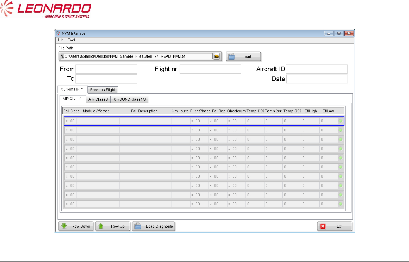
UNCLASSIFIED MAN-1124/01 T02
____________________________________________________________________________________________________________________________________________________________
__________________________________________________________________________________________________________________
Page 88
© Copyright Leonardo Finmeccanica S.p.A. – All rights reserved
UNCLASSIFIED
Figure 7-7 – TRA-100B – OFF A/C Troubleshooting STTE NVM Interface
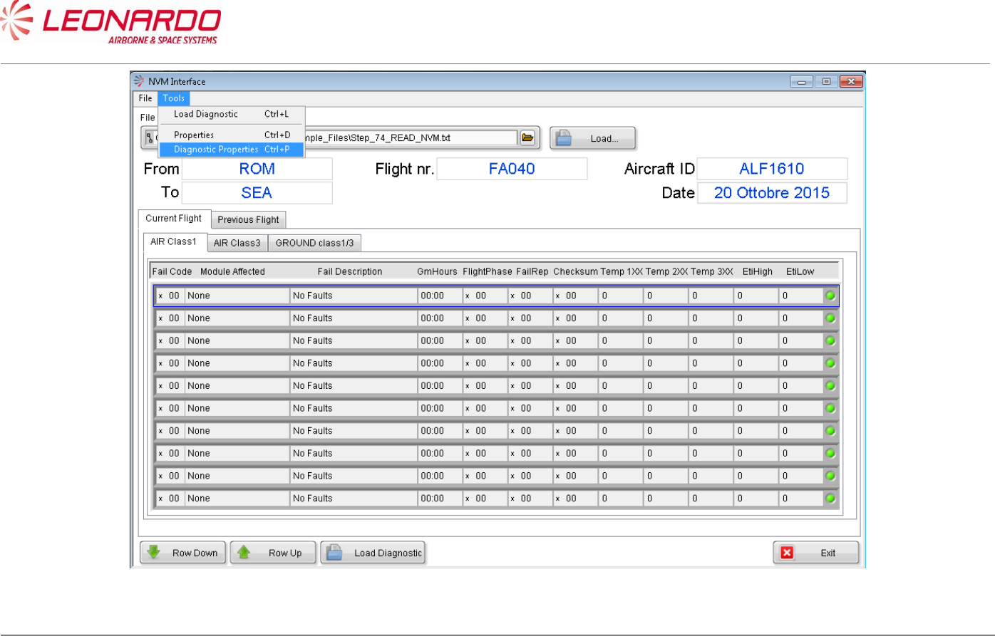
UNCLASSIFIED MAN-1124/01 T02
____________________________________________________________________________________________________________________________________________________________
__________________________________________________________________________________________________________________
Page 89
© Copyright Leonardo Finmeccanica S.p.A. – All rights reserved
UNCLASSIFIED
Figure 7-8 – TRA-100B – OFF A/C Troubleshooting – Diagnostic Properties (1)
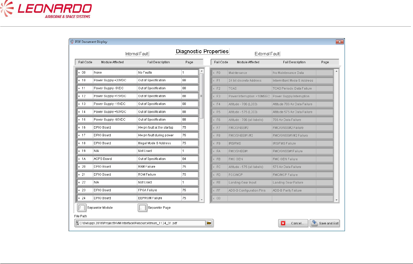
UNCLASSIFIED MAN-1124/01 T02
____________________________________________________________________________________________________________________________________________________________
__________________________________________________________________________________________________________________
Page 90
© Copyright Leonardo Finmeccanica S.p.A. – All rights reserved
UNCLASSIFIED
Figure 7-9 – TRA-100B – OFF A/C Troubleshooting – Diagnostic Properties (2)

UNCLASSIFIED MAN-1124/01 T02
___________________________________________________________________________________________________________
______________________________________________________________________________
Page 91
© Copyright Leonardo Finmeccanica S.p.A. – All rights reserved
UNCLASSIFIED
8 MAINTENANCE
8.1 TRA-100B MODE S TRANSPONDER – FIRST LEVEL MAINTENANCE
8.1.1 On Aircraft Maintenance (Scheduled)
No scheduled maintenance is required; the equipment does not require alignment, calibration,
lubrication or other non-operator adjustments or preventive maintenance.
Nevertheless FAA and EASA procedure require to remove the TRA-100B from platform and
perform an extensive test in the shop every two (2) years independently from failure occurrences.
8.1.2 On Aircraft Maintenance (Unscheduled)
The On Aircraft maintenance is a repair task by replacement of faulty Line Replaceable Unit
(LRU).
LRU Replace Procedure
TRA-100B Modes S Transponder TRA-100B Mode S Transponder – Replace Procedures
This procedure can be performed after the fault isolation procedure as para 7.3.
As preliminary check before starting the fault isolation procedure, perform inspection of the LRU as
per 8.3
Post-installation check is granted by Power Up BIT results provided at the end of start-up.
8.1.3 Servicing
Cleaning
If the equipment requires cleaning, follow the instructions given in the cleaning procedure (ref.
TRA-100B Mode S Transponder – Cleaning).
UNCLASSIFIED MAN-1124/01 T02
___________________________________________________________________________________________________________
______________________________________________________________________________
Page 92
© Copyright Leonardo Finmeccanica S.p.A. – All rights reserved
UNCLASSIFIED
8.2 TRA-100B MODE S TRANSPONDER – CLEANING
Standard Equipment
Description Identification Nr. Qty.
None
Materials
Description Identification Nr.
Qty.
Soft brush Local supply 1
Denatured Alcohol S-738 As Required
Electro Contact Cleaner QD02130 1
Lint-free cloth Local supply 1
Spares
Description Identification Nr. Qty.
None
Safety Precautions
WARNING
MAKE SURE THAT THE EQUIPMENT IS DISCONNECTED FROM ALL
ELECTRICAL POWER SOURCES BEFORE YOU DO ANY
MAINTENANCE WORK.
WARNING
UNCLASSIFIED MAN-1124/01 T02
___________________________________________________________________________________________________________
______________________________________________________________________________
Page 93
© Copyright Leonardo Finmeccanica S.p.A. – All rights reserved
UNCLASSIFIED
PERFORM TASK IN VENTILATED AREA AND USE PROTECTIVE CLOTHING.
WARNING
DENATURED ALCOHOL, ELECTRO CONTACT CLEANER ARE DANGEROUS MATERIALS
MAKE SURE THAT YOU KNOW THE
SAFETY PRECAUTIONS AND THE FIRST AID INSTRUCTIONS.
Preliminary Operations
None
Procedure
1. Clean the equipment with a soft brush moist with the Denatured Alcohol.
2. Wipe the equipment with a dry Lint-free cloth.
3. Inspect all the visible electric components and connections.
4. Clean electrical connectors with an Electro Contact Cleaner.
Close Up
1. Removal all the tools, the materials and the equipment from your work area.
UNCLASSIFIED MAN-1124/01 T02
___________________________________________________________________________________________________________
______________________________________________________________________________
Page 94
© Copyright Leonardo Finmeccanica S.p.A. – All rights reserved
UNCLASSIFIED
8.3 TRA-100B MODE S TRANSPONDER – INSPECTION
Standard Equipment
Description Identification Nr. Qty
None
Materials
Description Identification Nr. Qty
None
Spares
Description Identification Nr. Qty
None
Safety Precautions
WARNING
MAKE SURE THAT YOU REMOVAL THE ELECTRICAL POWER SUPPLY
BEFORE YOU DO THIS PROCEDURE.
Preliminary operations
None

UNCLASSIFIED MAN-1124/01 T02
___________________________________________________________________________________________________________
______________________________________________________________________________
Page 95
© Copyright Leonardo Finmeccanica S.p.A. – All rights reserved
UNCLASSIFIED
Procedure
1. Check for visible damage of equipment.
2. Make sure that connectors are properly installed.
3. Check that ground connections, where existing, are made properly.
4. Switch power off, disconnect cables one at time, and inspect connector pins.
Close up
1. Removal all the tools, the materials and the equipment from your work area.
UNCLASSIFIED MAN-1124/01 T02
___________________________________________________________________________________________________________
______________________________________________________________________________
Page 96
© Copyright Leonardo Finmeccanica S.p.A. – All rights reserved
UNCLASSIFIED
8.4 TRA-100B MODE S TRANSPONDER – SECOND LEVEL MAINTENANCE
8.4.1 TRA-100B, Data Processor and I/O – Replace procedure
Standard Equipment
Description Identification Nr. Qty
Torque Screwdriver bit holder Local Supply 1
Bit cross-point sz. 2 Local Supply 1
Bit hex open end 8 mm. Local Supply 1
Materials
Description Identification Nr. Qty
Spares
Description Identification Nr. Qty
Data Processor and I/O TAQ-5432/03 1
Safety Precautions
WARNING
MAKE SURE THAT THE EQUIPMENT IS DISCONNECTED FROM
ALL ELECTRICAL POWER SOURCES BEFORE YOU DO ANYMAINTENANCE WORK.

UNCLASSIFIED MAN-1124/01 T02
___________________________________________________________________________________________________________
______________________________________________________________________________
Page 97
© Copyright Leonardo Finmeccanica S.p.A. – All rights reserved
UNCLASSIFIED
Preliminary operations
None
Procedure
1. Removal Procedure
1.1) Removal Transponder cover (right side) unscrewing the related M2,5 fourteen
crosshead screws using a torque screwdriver bit holder and appropriate bit (1). (Figure
8-1, Figure 8-2)
1.2) Unscrew two antenna cables using the related tool starting from the upper one and then
the lower one (2)
1.3) Disconnecting supply voltages loosen the clips of connector (3)
1.4) Removal RF cables making an a half turn to the block of related connector (4)
1.5) Extract RFFE module (10)
1.6) Disconnect and Removal the display flat cable (5)
1.7) Unscrew nine crosshead screws using a torque screwdriver bit holder and related bit
avoiding to loose screws and related washers (each screw is supplied with a flat
washer, and spring washer) (6)
1.8) Removal the Data Processor and I/O module
NOTE: To Removal the module keep the antenna cables near the wired chassis using your
thumbs and with the forefingers pull up the board until the un-mating from wired chassis
2. Install Procedure
2.1) Install Data Processor and I/O Module. (Figure 8-1, Figure 8-2)
NOTE: To install the module keep the antenna cables close the wired chassis using your
thumbs and with the forefingers. Furthermore verify that Ethernet and Multipin external
connectors have been correctly entered in related housing placed in the frontal of Wired
Chassis (8).
2.2) In order to connect correctly the Data Processor and I/O module place and tighthen gently
the two corners Phillips screws (7).
NOTE: The spring washer must be installed before the flat washer.
2.3) Carefully press the Data Processor and I/O module on the left side of until the
connectors are mated (9)
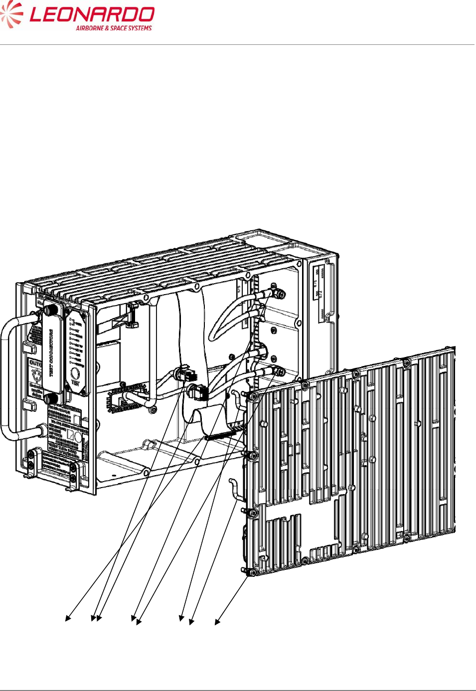
UNCLASSIFIED MAN-1124/01 T02
___________________________________________________________________________________________________________
______________________________________________________________________________
Page 98
© Copyright Leonardo Finmeccanica S.p.A. – All rights reserved
UNCLASSIFIED
2.4) Fixing the two corners cross head screws using a torque screwdriver bit holder and
appropriate bit with a force of 0.45 N/m (7).
2.5) Install and tighten the seven cross head screws using a torque screwdriver bit holder
and appropriate bit with a force of 0.45 N/m (6).
2.6) Carefully insert display flat cable (5)
2.7) Insert RF cable and secure it with half turn (4)
2.8) Carefully insert power supply connector securing it with clips (3)
2.9) Install the antenna cables and tighten it with the torque screwdriver bit holder and
appropriate bit with a force of 0.45 N/m (6).
2.10) Install Transponder cover (right side) fixing the related M2,5 fourteen crosshead screws
using a torque screwdriver bit holder and appropriate bit (1).
Figure 8-1 – TRA-100B, Data Processor and I/O – Replace procedure
12 3 4
5
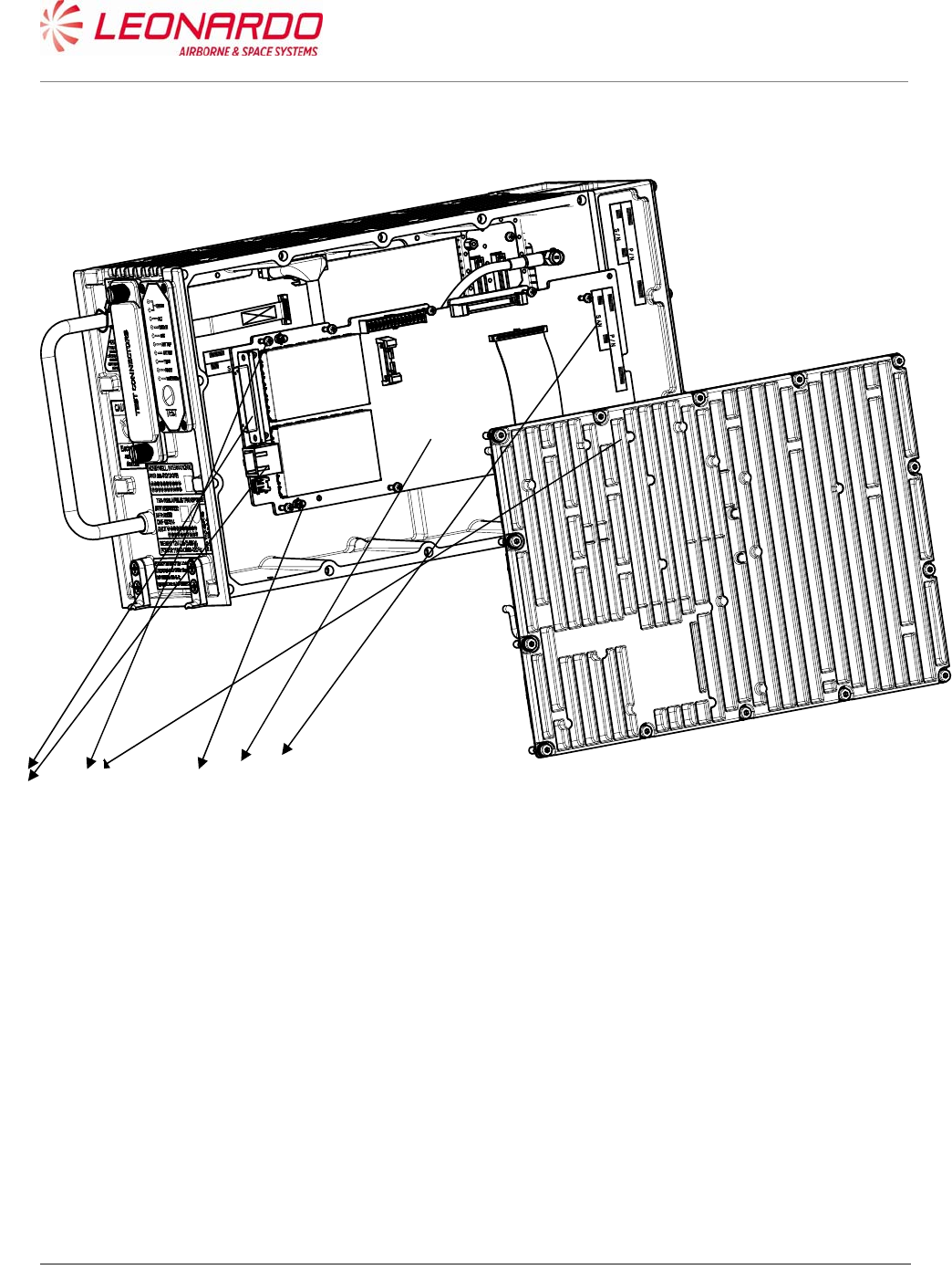
UNCLASSIFIED MAN-1124/01 T02
___________________________________________________________________________________________________________
______________________________________________________________________________
Page 99
© Copyright Leonardo Finmeccanica S.p.A. – All rights reserved
UNCLASSIFIED
Figure 8-2 – TRA-100B, Data Processor and I/O – Replace procedure (position)
Close up
1. Removal all the tools, the materials and the equipment from your work area. Perform the
Check-out procedure as per para. 1.1 to verify the failure removal.
6 7 8 9
10
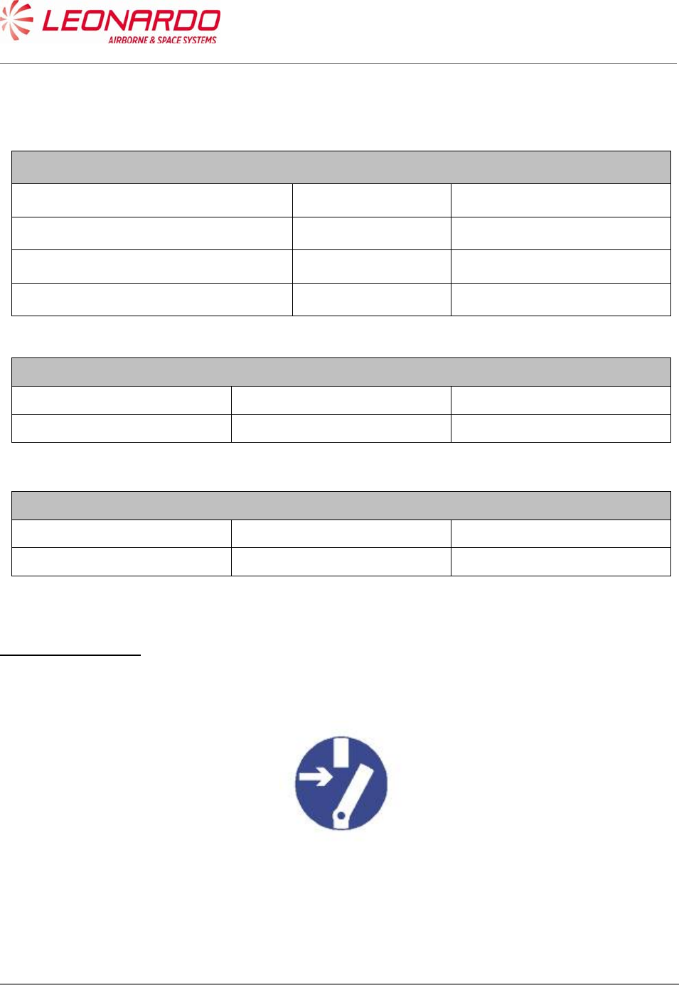
UNCLASSIFIED MAN-1124/01 T02
___________________________________________________________________________________________________________
______________________________________________________________________________
Page 100
© Copyright Leonardo Finmeccanica S.p.A. – All rights reserved
UNCLASSIFIED
8.4.2 TRA-100B, RF Subassembly – Replace procedure
Standard Equipment
Description Identification Nr. Qty
Torque Screwdriver bit holder Local Supply 1
Bit cross-point sz. 2 Local Supply 1
Bit hex open end 8 mm. Local Supply 1
Materials
Description Identification Nr. Qty
Spares
Description Identification Nr. Qty
RF - Subassembly TAG-5501/03 1
Safety Precautions
WARNING
MAKE SURE THAT THE EQUIPMENT IS DISCONNECTED FROM
ALL ELECTRICAL POWER SOURCES BEFORE YOU DO ANYMAINTENANCE WORK.
Preliminary operations

UNCLASSIFIED MAN-1124/01 T02
___________________________________________________________________________________________________________
______________________________________________________________________________
Page 101
© Copyright Leonardo Finmeccanica S.p.A. – All rights reserved
UNCLASSIFIED
None
Procedure
1. Removal Procedure
1.1) Follow the procedure to remove the Data Processor and I/O module (Para. 8.4.1). (Figure
8-3, Figure 8-2)
1.2) Unscrew nine crosshead screws using a torque screwdriver bit holder and related bit
avoiding to loose screws and related washers (each screw is supplied with a flat washer,
and spring washer) (6)
1.3) Removal the RF Subassembly
NOTE: To remove the module keep the antenna cables near the wired chassis using your
thumbs and with the forefingers pull up the board until it is separated from wired chassis
2. Install Procedure
2.1) Install the RF Subassembly. (Figure 8-3, Figure 8-2)
NOTE: To install the module keep the antenna cables close the wired chassis using your
thumbs and with the forefingers. Furthermore verify that Ethernet and Multipin external
connectors have been correctly entered in related housing placed in the frontal of Wired
Chassis (8).
2.2) In order to connect correctly the Data Processor and I/O module place and tighten gently
the two corners Phillips screws (7).
NOTE: The spring washer must be installed before the flat washer.
2.3) Carefully press the Data Processor and I/O module on the left side of until the connectors
are mated (9)
2.4) Tighten the two corners cross head screws using a torque screwdriver bit holder and
appropriate bit with a force of 0.45 N/m (7).
2.5) Install and tighten the seven cross head screws using a torque screwdriver bit holder and
appropriate bit with a force of 0.45 N/m (6).
2.6) Carefully insert display flat cable (5)
2.7) Insert RF cable and secure it with half turn (4)
2.8) Carefully insert power supply connector securing it with clips (3)
2.9) Install the antenna cables and tighten it with the torque screwdriver bit holder and
appropriate bit with a force of 0.45 N/m (6).
2.10) Install Transponder cover (right side) fixing the related M2,5 fourteen crosshead
screws using a torque screwdriver bit holder and appropriate bit (1).
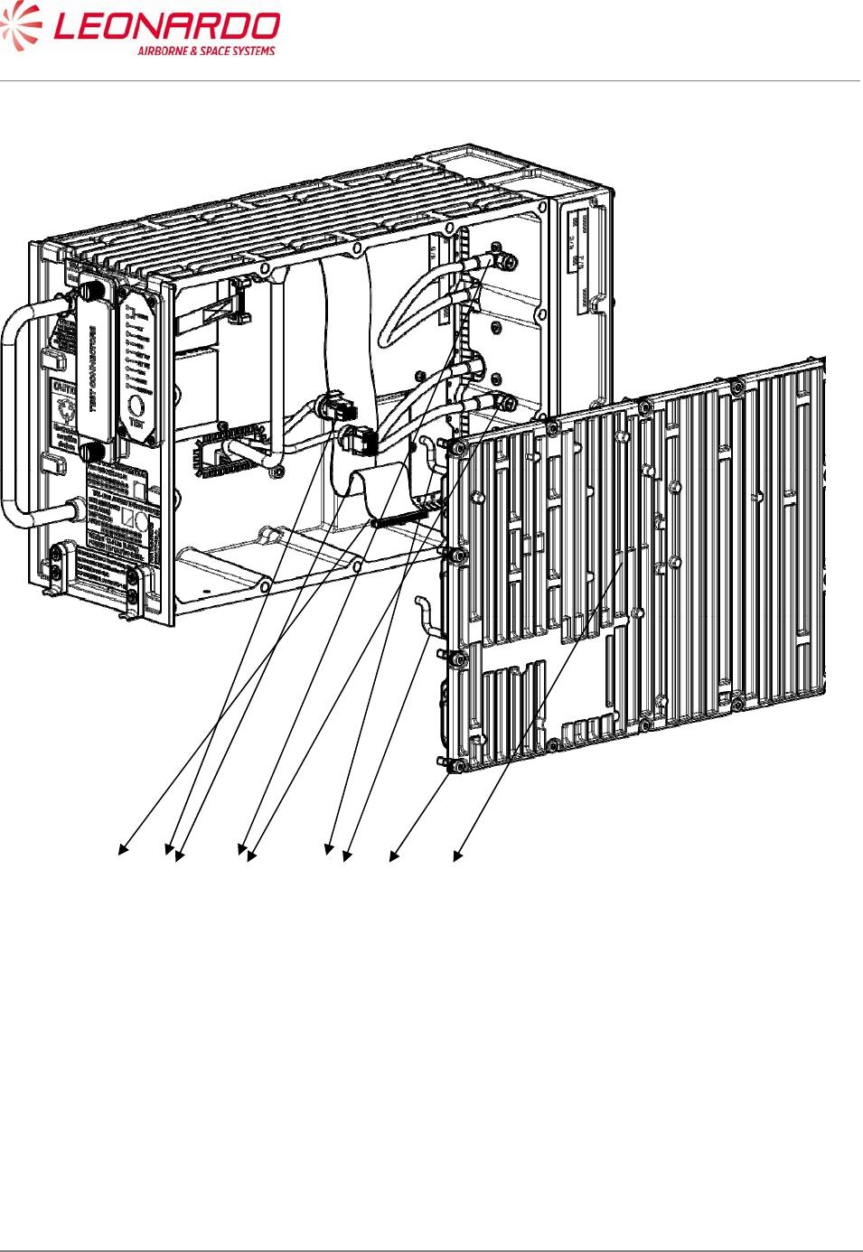
UNCLASSIFIED MAN-1124/01 T02
___________________________________________________________________________________________________________
______________________________________________________________________________
Page 102
© Copyright Leonardo Finmeccanica S.p.A. – All rights reserved
UNCLASSIFIED
Figure 8-3 –TRA-100B, RF Subassembly – Replace procedure
Close up
1. Removal all the tools, the materials and the equipment from your work area.
2. Perform the Check-out procedure as per para. 1.1 to verify the failure removal.
12 3 45 11
UNCLASSIFIED MAN-1124/01 T02
___________________________________________________________________________________________________________
______________________________________________________________________________
Page 103
© Copyright Leonardo Finmeccanica S.p.A. – All rights reserved
UNCLASSIFIED
8.4.3 TRA-100B, AC Power Supply (ACPS) – Replace procedure
Standard Equipment
Description Identification Nr. Qty
Torque Screwdriver bit holder Local Supply 1
Bit cross-point sz. 2 Local Supply 1
Materials
Description Identification Nr. Qty
Spares
Description Identification Nr. Qty
Power Supply (ACPS) TAG-5433/03 1
Safety Precautions
WARNING
MAKE SURE THAT THE EQUIPMENT IS DISCONNECTED FROM
ALL ELECTRICAL POWER SOURCES BEFORE YOU DO ANYMAINTENANCE WORK.
Preliminary operations
None

UNCLASSIFIED MAN-1124/01 T02
___________________________________________________________________________________________________________
______________________________________________________________________________
Page 104
© Copyright Leonardo Finmeccanica S.p.A. – All rights reserved
UNCLASSIFIED
Procedure
1. Removal Procedure
1.1. Removal Transponder cover (left side) unscrewing the M2,5 fourteen crosshead screws
using a torque screwdriver bit holder and related bit (1). (Figure 8-4, Figure 8-5)
1.2. Removal the two cables connecting Wired Chassis to DC Power Supply (2).
1.3. Removal the cable connecting AC Power Supply to DC Power Supply (3)
1.4. Unscrew the four crosshead screws placed on the lower border of DC Power Supply
module using a torque screwdriver bit holder and appropriate bit (4)
1.5. Unscrew the five crosshead screws using a torque screwdriver bit holder and appropriate
bit. (5)
1.6. Removal the DC Power Supply module from the failed AC Power Supply module.
2. Install Procedure
2.1. Insert the DC Power Supply module on a serviceable AC Power Supply module. (Figure
8-4, Figure 8-5)
2.2. Tighten the related five screws using a torque screwdriver bit holder and appropriate bit
with a force of 0.45 N/m (5).
2.3. Tighten the related 4 screws using a torque screwdriver bit holder and appropriate bit with
a force of 0.45 N/m (4).
2.4. Connect the cable connecting AC Power Supply to DC Power Supply (3).
2.5. Connect the two cables connecting Wired Chassis to DC Power Supply. (2)
2.6. Install the Transponder cover (left side) and tighten the related fourteen crosshead screws
using a torque screwdriver bit holder and related bit (1) with a force of 0.95 N/m.
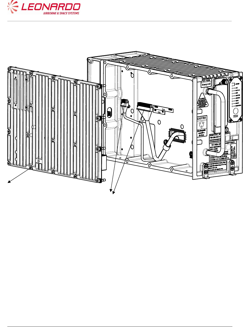
UNCLASSIFIED MAN-1124/01 T02
___________________________________________________________________________________________________________
______________________________________________________________________________
Page 105
© Copyright Leonardo Finmeccanica S.p.A. – All rights reserved
UNCLASSIFIED
Figure 8-4 – TRA-100B, AC Power Supply (ACPS) – Replace procedure
1
2

UNCLASSIFIED MAN-1124/01 T02
___________________________________________________________________________________________________________
______________________________________________________________________________
Page 106
© Copyright Leonardo Finmeccanica S.p.A. – All rights reserved
UNCLASSIFIED
Figure 8-5 – TRA-100B, ACPS and DCPS – Replace procedure (position)
Close up
1. Removal all the tools, the materials and the equipment from your work area.
2. Perform the Check-out procedure as per para. 1.1 to verify the failure removal.
3
4
2
5
UNCLASSIFIED MAN-1124/01 T02
___________________________________________________________________________________________________________
______________________________________________________________________________
Page 107
© Copyright Leonardo Finmeccanica S.p.A. – All rights reserved
UNCLASSIFIED
8.4.4 TRA-100B, DC Power Supply (DCPS) – Replace procedure
Standard Equipment
Description Identification Nr. Qty
Torque Screwdriver bit holder Local Supply 1
Bit cross-point sz. 2 Local Supply 1
Materials
Description Identification Nr. Qty
Spares
Description Identification Nr. Qty
DC Power Supply (DCPS) TAG-5435/03 1
Safety Precautions
WARNING
MAKE SURE THAT THE EQUIPMENT IS DISCONNECTED FROM
ALL ELECTRICAL POWER SOURCES BEFORE YOU DO ANYMAINTENANCE WORK.
Preliminary operations

UNCLASSIFIED MAN-1124/01 T02
___________________________________________________________________________________________________________
______________________________________________________________________________
Page 108
© Copyright Leonardo Finmeccanica S.p.A. – All rights reserved
UNCLASSIFIED
None
Procedure
1. Removal Procedure
1.1. Removal Transponder cover (left side) unscrewing the relative M2,5 fourteen crosshead
screws using a torque screwdriver bit holder and related bit (1). (Figure 8-6, Figure 8-7)
1.2. Removal the two cables connecting Wired Chassis to DC Power Supply (2).
1.3. Removal the cable connecting AC Power Supply to DC Power Supply (3)
1.4. Unscrew the four crosshead screws placed on the lower border of DC Power Supply
module using a torque screwdriver bit holder and appropriate bit (4)
1.5. Unscrew the five crosshead screws using a torque screwdriver bit holder and appropriate
bit. (5)
1.6. Removal the DC Power Supply module.
2. Install Procedure
2.1) Insert the DC Power Supply module. (Figure 8-6, Figure 8-7)
2.2) Fixing it tighten the related five screws using a torque screwdriver bit holder and
appropriate bit with a force of 0.45 N/m (5).
2.3) Tighten the related 4 screws using a torque screwdriver bit holder and appropriate bit with
a force of 0.45 N/m (4).
2.4) Connect the cable connecting AC Power Supply to DC Power Supply (3).
2.5) Connect the two cables connecting Wired Chassis to DC Power Supply. (2)
2.6) Install the Transponder cover (left side) and fix it tightening the related fourteen
crosshead screws using a torque screwdriver bit holder and related bit (1) with a force of
0.95 N/m.
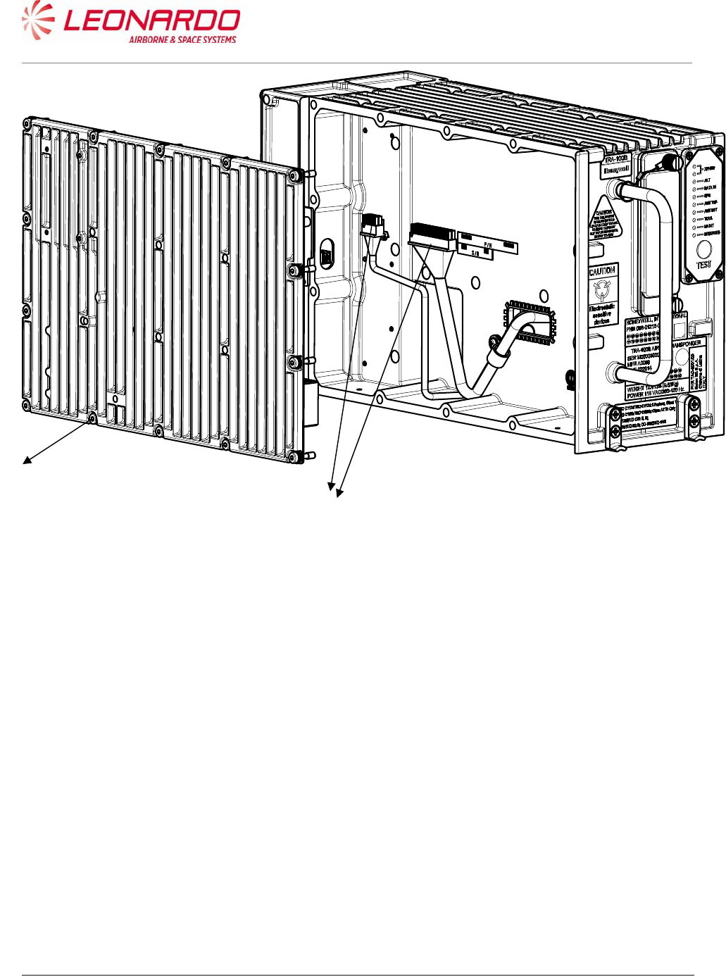
UNCLASSIFIED MAN-1124/01 T02
___________________________________________________________________________________________________________
______________________________________________________________________________
Page 109
© Copyright Leonardo Finmeccanica S.p.A. – All rights reserved
UNCLASSIFIED
Figure 8-6 – TRA-100B, DC Power Supply (DCPS) – Replace procedure
1
2
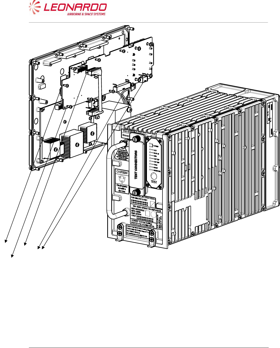
UNCLASSIFIED MAN-1124/01 T02
___________________________________________________________________________________________________________
______________________________________________________________________________
Page 110
© Copyright Leonardo Finmeccanica S.p.A. – All rights reserved
UNCLASSIFIED
Figure 8-7 – TRA-100B, ACPS and DCPS – Replace procedure (position)
Close up
1. Removal all the tools, the materials and the equipment from your work area.
2. Perform the Check-out procedure as per para. 1.1 to verify the failure removal.
3
4
2
5
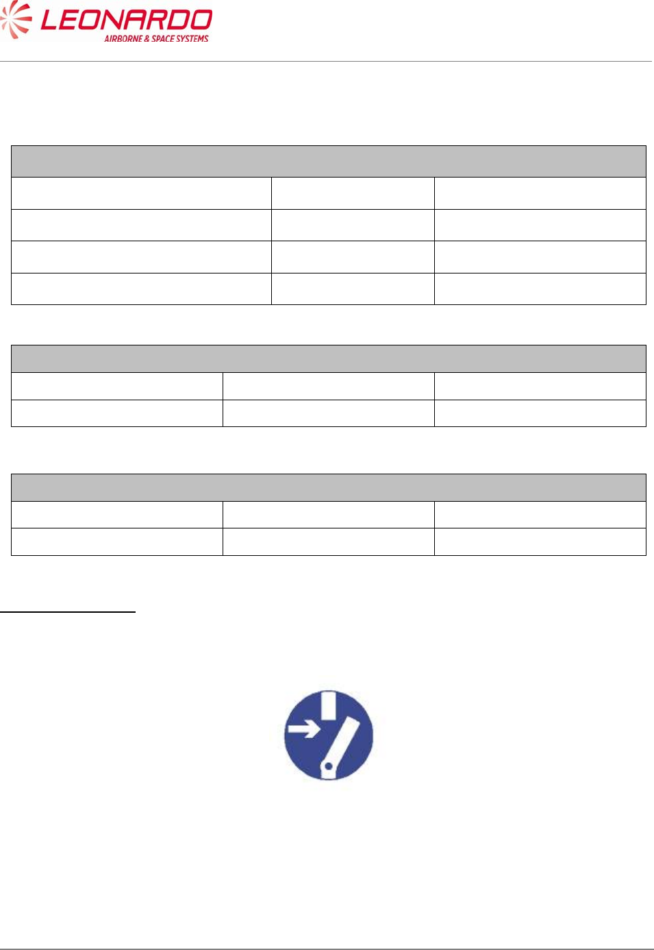
UNCLASSIFIED MAN-1124/01 T02
___________________________________________________________________________________________________________
______________________________________________________________________________
Page 111
© Copyright Leonardo Finmeccanica S.p.A. – All rights reserved
UNCLASSIFIED
8.4.5 TRA-100B, Wired Chassis (WC)– Replace procedure
Standard Equipment
Description Identification Nr. Qty
Torque Screwdriver bit holder Local Supply 1
Bit cross-point sz. 2 Local Supply 1
Bit hex open end 8 mm. Local Supply 1
Materials
Description Identification Nr. Qty
Spares
Description Identification Nr. Qty
Wired Chassis (WC) TAE-6001/03 1
Safety Precautions
WARNING
MAKE SURE THAT THE EQUIPMENT IS DISCONNECTED FROM
ALL ELECTRICAL POWER SOURCES BEFORE YOU DO ANYMAINTENANCE WORK.
Preliminary operations
None

UNCLASSIFIED MAN-1124/01 T02
___________________________________________________________________________________________________________
______________________________________________________________________________
Page 112
© Copyright Leonardo Finmeccanica S.p.A. – All rights reserved
UNCLASSIFIED
Procedure
1. Removal Procedure
1.1. Removal Data Processor and I/O module and RF Sub Assembly module following the
procedures described in Figure 8-1, Figure 8-2 and Figure 8-3.
1.2. Removal the AC Power Supply together with DC Power Supply following the procedure
reported in Figure 8-4 and Figure 8-5
1.3. Removal the Wired Chassis
2. Install Procedure
2.1. Install Data Processor and I/O module and RF Sub Assembly module following the
procedures described in Figure 8-1, Figure 8-2 and Figure 8-3.
2.2. Install the AC Power Supply together with DC Power Supply following the procedure
reported in Figure 8-4 and Figure 8-5.
Close up
1. Removal all the tools, the materials and the equipment from your work area.
2. Perform the Check-out procedure as per para. 1.1 to verify the failure removal.

UNCLASSIFIED MAN-1124/01 T02
___________________________________________________________________________________________________________
______________________________________________________________________________
Page 113
© Copyright Leonardo Finmeccanica S.p.A. – All rights reserved
UNCLASSIFIED
9 ILLUSTRATED PARTS DATA
9.1 TRA-100B MODE S TRANSPONDER - ILLUSTRATED PARTS DATA
Pos Indent CAGE Part Number Description Qty
001 A0069 TAC-6001/03 TRA-100B Mode S Transponder 1
NI A0069 TAD-6001/03 Hardware Equipment TRA-100B
2 A0069 TAE-6001/03 Wired Chassis (WC) 1
2 A0069 TAQ-5432/03 Data Processor and I/O 1
2 A0069 TAG-5501/03 RF - Subassembly 1
2 A0069 TAG-5433/03 AC Power Supply (ACPS) 1
2 A0069 TAG-5435/03 DC Power Supply (DCPS) 1
3 A0069 TAN-7002/01 DPIO-RFFE SIGNAL CABLE 1
3 A0069 TAN-7006/01 DCPS-ACPS CABLE 1
3 A0069 5106876R0012 TWINAX CABLE 2
3 A0069 61170-06/123 WASHER EL INOX M2.5-5.1mm .6T 9
3 A0069 61530-27/006 SCREW INOX TCC/C M2.5x8mm (V 9
3 A0069 61530-27/013 SCREW INOX TCC/C M2.5x22mm ( 4
3 A0069 62380-12/019 Plate ACRYLIC SINGLE 14mm 70m 1
3 A0069 61170-03/127 WASHER PLANE - INOX M2.5-5mm 27
3 A0069 61530-27/005 SCREW INOX TCC/C M2.5x6mm (V 18
3 A0069 61170-01/124 WASHER PLANE INOX M2.5-6.5mm 4