Leonardo S p a TRA100B Part 87 Aircraft Licensed Transmitter operating at 1090MHz User Manual Data Download Equipment DDE
LEONARDO S.p.a. Part 87 Aircraft Licensed Transmitter operating at 1090MHz Data Download Equipment DDE
Contents
- 1. Users manual 1
- 2. Users manual 2
Users manual 2

UNCLASSIFIED MAN-1168/01 T01
___________________________________________________________________________________________________________
______________________________________________________________________________
Page 1
© Copyright Leonardo Finmeccanica S.p.A. – All rights reserved
UNCLASSIFIED
TRA-100B Mode S Transponder (TRA-100B)
Honeywell
Installation Manual (IM)
MAN-1168/01 T
Issue No. 01
Date 04-08-2016
Leonardo Finmeccanica S.p.A.
Piazza Montegrappa, 4
00195 - Roma
ITALY

UNCLASSIFIED MAN-1168/01 T01
___________________________________________________________________________________________________________
______________________________________________________________________________
Page 2
© Copyright Leonardo Finmeccanica S.p.A. – All rights reserved
UNCLASSIFIED
Page left intentionally blank
UNCLASSIFIED MAN-1168/01 T01
___________________________________________________________________________________________________________
______________________________________________________________________________
Page 3
© Copyright Leonardo Finmeccanica S.p.A. – All rights reserved
UNCLASSIFIED
Revision List
Date of Issue
Issue Number
Revision History
04-08-2016
01
First Issue
This document is composed of 22 pages.

UNCLASSIFIED MAN-1168/01 T01
___________________________________________________________________________________________________________
______________________________________________________________________________
Page 4
© Copyright Leonardo Finmeccanica S.p.A. – All rights reserved
UNCLASSIFIED
TABLE OF CONTENTS
1. GENERAL ........................................................................................................................................................... 6
1.1 TRA-100B MODE S TRANSPONDER - LIST OF ABBREVIATIONS .......................................................................................... 6
1.2 TRA-100B MODE S TRANSPONDER – CONFIGURATION .................................................................................................. 7
1.3 TRA-100B MODE S TRANSPONDER – INTRODUCTION .................................................................................................... 8
1.4 TRA-100B MODE S TRANSPONDER - SCHEMATIC DIAGRAM ............................................................................................ 9
1.5 TRA-100B MODE S TRANSPONDER – GENERAL WARNINGS AND CAUTIONS AND RELATED SAFETY DATA ................................ 10
1.5.1 General Safety .......................................................................................................................................... 10
1.5.2 List of Warnings and Cautions .................................................................................................................. 10
2. TECHNICAL DATA ............................................................................................................................................ 12
2.1 TRA-100B MODE S TRANSPONDER – TECHNICAL DATA ............................................................................................. 12
2.1.1 General Technical Data ............................................................................................................................ 12
2.1.2 Labels Data ............................................................................................................................................... 12
3. INSTALLATION................................................................................................................................................. 21
3.1 TRA-100B MODE S TRANSPONDER – REPLACE PROCEDURES......................................................................................... 21

UNCLASSIFIED MAN-1168/01 T01
___________________________________________________________________________________________________________
______________________________________________________________________________
Page 5
© Copyright Leonardo Finmeccanica S.p.A. – All rights reserved
UNCLASSIFIED
LIST OF ILLUSTRATIONS
FIGURE 1-1 – TRA-100B MODE S TRANSPONDER - CONFIGURATION .................................................................... 7
FIGURE 1-2 – TRA-100B MODE S TRANSPONDER - SCHEMATIC DIAGRAM ............................................................. 9
FIGURE 2-1 – TRA-100B MODE S TRANSPONDER – LABELS LAYOUT .................................................................. 14
FIGURE 2-2 – TRA-100B MODE S TRANSPONDER – CONNECTORS ..................................................................... 15
FIGURE 3-1 – TRA-100B MODE S TRANSPONDER - REPLACE PROCEDURES ....................................................... 22
LIST OF TABLES
TABLE 1-1 - LIST OF ABBREVIATIONS .................................................................................................................... 6
TABLE 1-2 – TRA-100B - CONFIGURATION DATA ................................................................................................. 7
TABLE 1-3 - GENERAL WARNINGS, CAUTIONS AND RELATED SAFETY DATA ......................................................... 10
TABLE 2-1 – TRA-100B - TECHNICAL DATA – GENERAL ...................................................................................... 12
TABLE 2-2 – TRA-100B - TECHNICAL DATA – CONNECTORS ............................................................................... 15
TABLE 2-3 – TRA-100B - TECHNICAL DATA – MAIN CONNECTORS PIN MAPPING .................................................. 16
TABLE 2-4 – TRA-100B - TECHNICAL DATA – TEST CONNECTORS PIN MAPPING .................................................. 20

UNCLASSIFIED MAN-1168/01 T01
___________________________________________________________________________________________________________
______________________________________________________________________________
Page 6
© Copyright Leonardo Finmeccanica S.p.A. – All rights reserved
UNCLASSIFIED
1. GENERAL
1.1 TRA-100B MODE S TRANSPONDER - LIST OF ABBREVIATIONS
Table 1-1 - List of Abbreviations
Symbol
Instruction
AC
Alternate Current
AD, A/D
Analogue to Digital
BIT
Built In Test
BITE
Built In Test Equipment
CBIT
Continuous Built In Test
DC
Direct Current
GND
GrouND
HF
High Frequency
IBIT
Interruptive Built In Test
LRU
Line Replaceable Unit
MT
Mounting Tray
NSN
NATO Stock Number
PBIT
Power-on Built In Test
RF
Radio Frequency
RX
Receiver
TX
Transmitter
UNCLASSIFIED MAN-1168/01 T01
___________________________________________________________________________________________________________
______________________________________________________________________________
Page 7
© Copyright Leonardo Finmeccanica S.p.A. – All rights reserved
UNCLASSIFIED
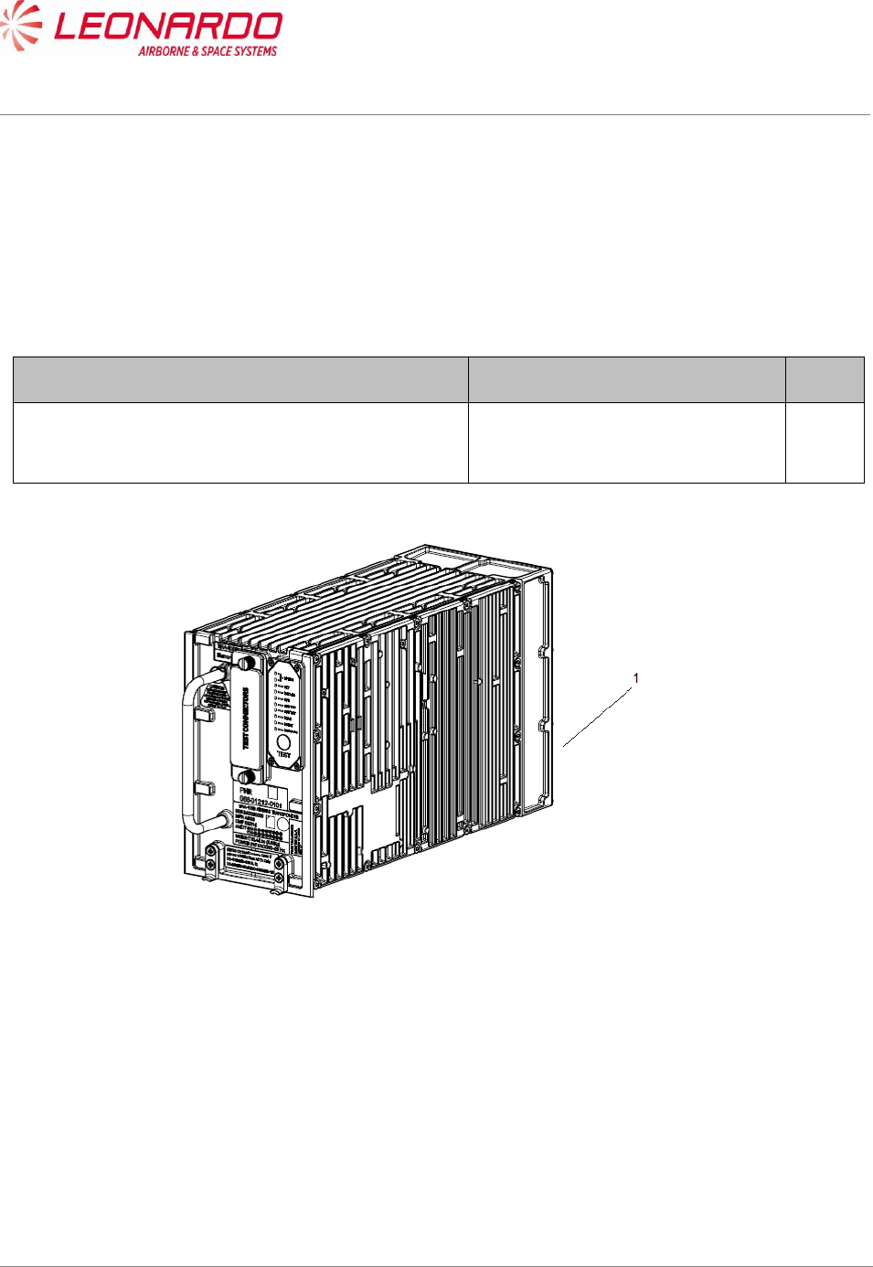
1.2 TRA-100B MODE S TRANSPONDER – CONFIGURATION
This manual is applicable to the following TRA-100B Mode S Transponder Part Numbers (Table 1-
2):
Table 1-2 – TRA-100B - Configuration Data
Description
Part Number
Qty
TRA-100B Mode S Transponder
TAC-6001/03
TAC-6003/03
TAC-6004/03
1
Figure 1-1 – TRA-100B Mode S Transponder - Configuration

UNCLASSIFIED MAN-1168/01 T01
___________________________________________________________________________________________________________
______________________________________________________________________________
Page 8
© Copyright Leonardo Finmeccanica S.p.A. – All rights reserved
UNCLASSIFIED
1.3 TRA-100B Mode S TRANSPONDER – INTRODUCTION
The TRA-100B Mode S Transponder is a remote mounted avionics device which provides the
Mode S Transponder function required by Technical Standard Order (ETSO-C112d).
The XPDR also provides Extended Squitter ADS-B Out function required by ETSO-C166b.
The TRA-100B Modes S Transponder is designed to be a Level 2 transponder.
It includes the capabilities of a Level 1 Transponder:
• Mode A identity and Mode C pressure-altitude reporting,
• Air Traffic Control Radar Beacon System (ATCRBS)/Mode-S and Mode S all-call
transactions,
• Addressed surveillance altitude and identity transaction,
• Lockout protocols,
• Basic data protocols except data link capability reporting, and
• Air-to-air service and squitter transactions.
The TRA-100B includes the capabilities of a Level 2 Transponder:
• Bi-directional air-to-air information exchange
• Ground-to-air data uplink, Comm-A
• Air-to-ground data downlink, Comm-B
• Multisite message protocol
• Data link capability reporting
• Aircraft identification reporting
• Traffic Alert and Collision Avoidance System (TCAS)/Airborne Collision Avoidance System
(ACAS) crosslink capability
• Overlay Command Capability
In addition, the Transponder contains the following optional additional features:
• TCAS Compatibility (a)
• Antenna Diversity (d)
• Extended Squitter (e)
• Enhanced Surveillance (including Elementary Surveillance) (n)
• Surveillance Identifier Code (s)
UNCLASSIFIED MAN-1168/01 T01
___________________________________________________________________________________________________________________________________________________________________________________________________________________________
___________________________________________________________________________________________________________________________________________________________________
Page 9
© Copyright Leonardo Finmeccanica S.p.A. – All rights reserved
UNCLASSIFIED
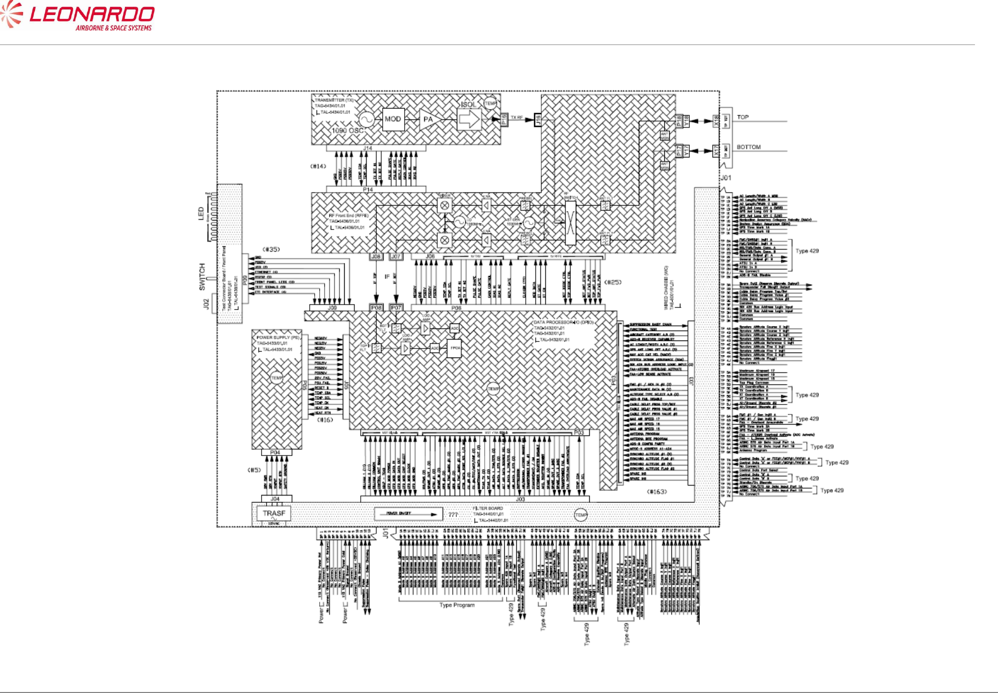
1.4 TRA-100B Mode S TRANSPONDER - SCHEMATIC DIAGRAM
Figure 1-2 – TRA-100B Mode S Transponder - Schematic Diagram
UNCLASSIFIED MAN-1168/01 T01
___________________________________________________________________________________________________________
______________________________________________________________________________
Page 10
© Copyright Leonardo Finmeccanica S.p.A. – All rights reserved
UNCLASSIFIED
1.5 TRA-100B MODE S TRANSPONDER – GENERAL WARNINGS AND
CAUTIONS AND RELATED SAFETY DATA
1.5.1 General Safety
Before you do maintenance procedures on the Unit make sure that you know the
necessary safety data.
Before you work on the Unit, make sure that the electrical power supply is removed from
the Unit. Energized circuits can cause injury to persons.
Before you work on the Unit, make sure that you have the correct personal safety
equipment. You must use or wear the correct personal safety equipment to prevent
injuries.
Handle all the equipment carefully. This will help to prevent damage to it.
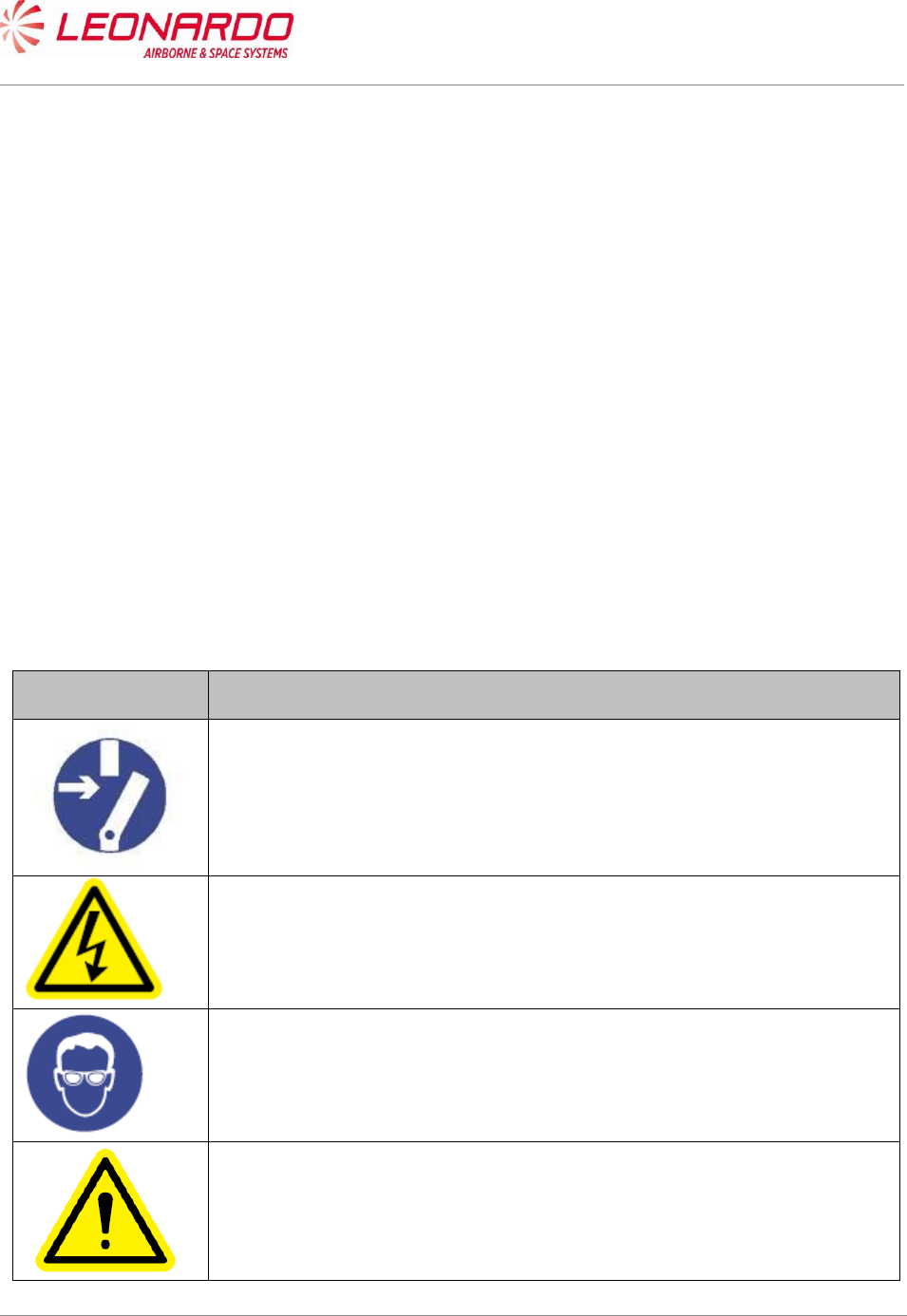
1.5.2 List of Warnings and Cautions
Table 1-3 - General Warnings, Cautions And Related Safety Data
Symbol
Message
WARNING
Make sure that the equipment is disconnected from all electrical power
sources before you do any maintenance work.
WARNING
The internal components use high voltages that can cause injury or
death to personnel.
WARNING
Perform task in ventilated area and use protective clothing.
WARNING
Denatured Alcohol, Electro Contact Cleaner and Conductive Anti-
seizure Compound are dangerous materials. Make sure that you know
the safety precautions and the first aid instructions.
UNCLASSIFIED MAN-1168/01 T01
___________________________________________________________________________________________________________
______________________________________________________________________________
Page 11
© Copyright Leonardo Finmeccanica S.p.A. – All rights reserved
UNCLASSIFIED
CAUTION
The internal components of the equipment are Electro-Static Discharge
(ESD) sensitive devices. Do not touch the pins of the electrical
connectors. Electrostatic discharge can cause damage to these
components.
Install protective caps on all electrical connectors immediately after you
disconnect them to prevent the ingress of dirt.
WARNING
Always handle the equipment with care to prevent damage.

UNCLASSIFIED MAN-1168/01 T01
___________________________________________________________________________________________________________
______________________________________________________________________________
Page 12
© Copyright Leonardo Finmeccanica S.p.A. – All rights reserved
UNCLASSIFIED
2. TECHNICAL DATA
2.1 TRA-100B MODE S TRANSPONDER – TECHNICAL DATA
2.1.1 General Technical Data
Table 2-1 – TRA-100B - Technical data – General
Data
Value
Manufacturers Part Numbers
TAC-6001/03
TAC-6003/03
TAC-6004/03
Weight (Total mass)
< 7 Kg.
Dimensions
194 mm x 124 x 318 (Height x Width x Depth)
Output power
400W ± 100 W
Operating temperature
-55°C +70°C
Storage Conditions
-55°C +70°C
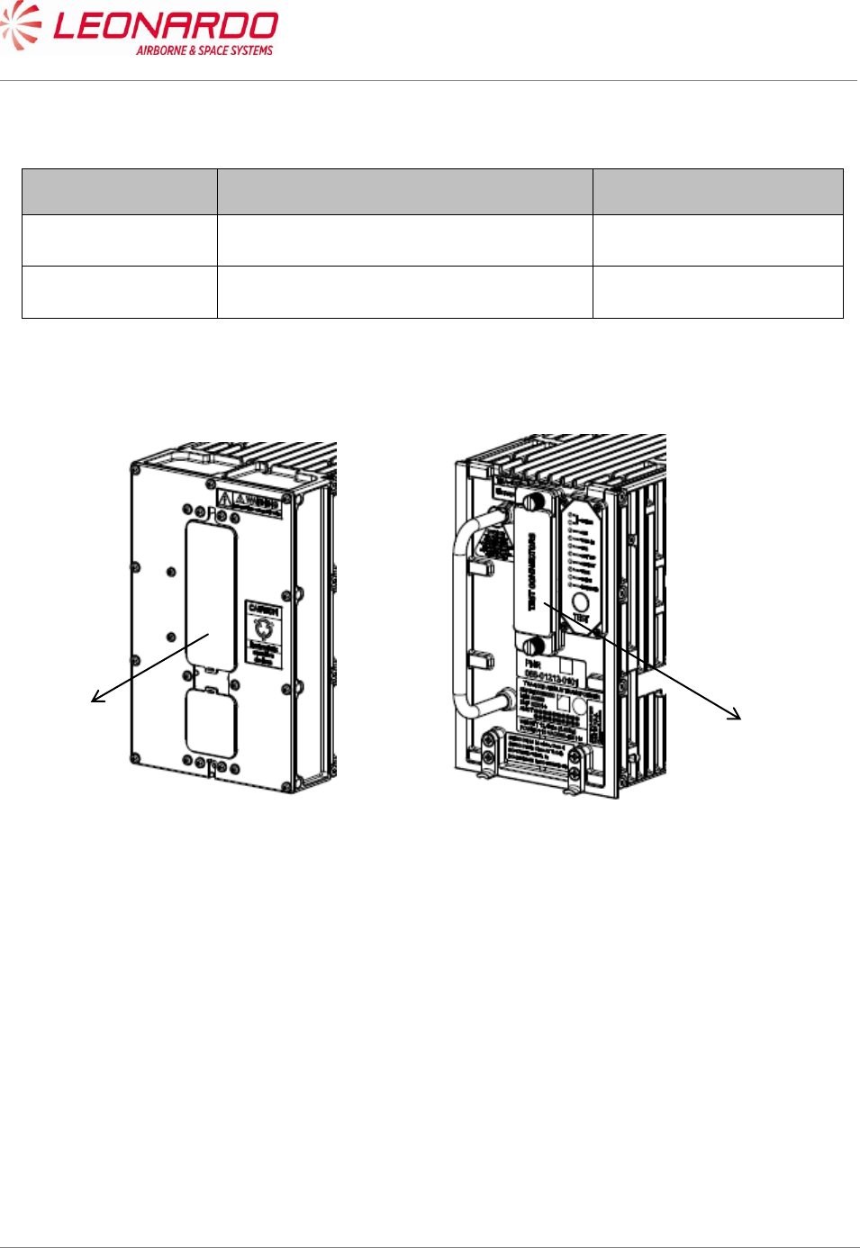
2.1.2 Labels Data
The TRA-100B provide three different labels (ref. Figure 2-1):
Leonardo Finmeccanica Id. Label (1)
Honeywell Id. Label (2)
Certifications Label (3)

UNCLASSIFIED MAN-1168/01 T01
___________________________________________________________________________________________________________
______________________________________________________________________________
Page 13
© Copyright Leonardo Finmeccanica S.p.A. – All rights reserved
UNCLASSIFIED
The Leonardo Finmeccanica Id. Label contains the following info:
Data
Value
Manufacturers Part Numbers
TAC-6001/03
TAC-6003/03
TAC-6004/03
Manufacturer
Leonardo Finmeccanica
Manufacturing Site
Montevarchi
Manufacturing Country
Italy
SER.
Serial Number
MFR.
Manufacturer SNS (A0610)
DMF
Date of Manufacturing (mmyyy)
AMDT
Amendement
Weight (Total mass)
14.5 Lbs. (6.58 Kg)
Power
115 VAC/380-420 Hz.
The Honeywell Id. Label contains the following info:
Data
Value
Owner
HONEYWELL, International
Owner Part Number
PNR 066-01212-0101
PNR 066-01212-0301
PNR 066-01212-0301
Amendement
-
UNCLASSIFIED MAN-1168/01 T01
___________________________________________________________________________________________________________
______________________________________________________________________________
Page 14
© Copyright Leonardo Finmeccanica S.p.A. – All rights reserved
UNCLASSIFIED
The Certification Label contains the following info:
Data
Value
ETSO/TSO Certification
ETSO C112d: L2 adens, Class 1
ETSO C166b: Class A2 Tx only
DO/ED
178B/12B B: D
254/80 B
160/14G
PNR 066-01212-0101
TSO C112d: xxx C166b: xxx
DO-178B: B,D DO-160G
AMDT 01 02 03 04 05 06 07 08 09 10
11 12 13 14 15 16 17 18 19 20
TRA-100B TRANSPONDER
SER
MFR A0069
DMF
WEIGHT 14,5 Lbs (6,58 Kg)
POWER 115 VAC/380-420 Hz
MFR PNR
TAC-6001/01
Selex ES S.p.A
QA
01
M00000000
01/2013
REMOVE COVER TO ACCESS
SUPPORT TEST CONNECTORS
Figure 2-1 – TRA-100B Mode S Transponder – Labels Layout
2
3
1
UNCLASSIFIED MAN-1168/01 T01
___________________________________________________________________________________________________________
______________________________________________________________________________
Page 15
© Copyright Leonardo Finmeccanica S.p.A. – All rights reserved
UNCLASSIFIED
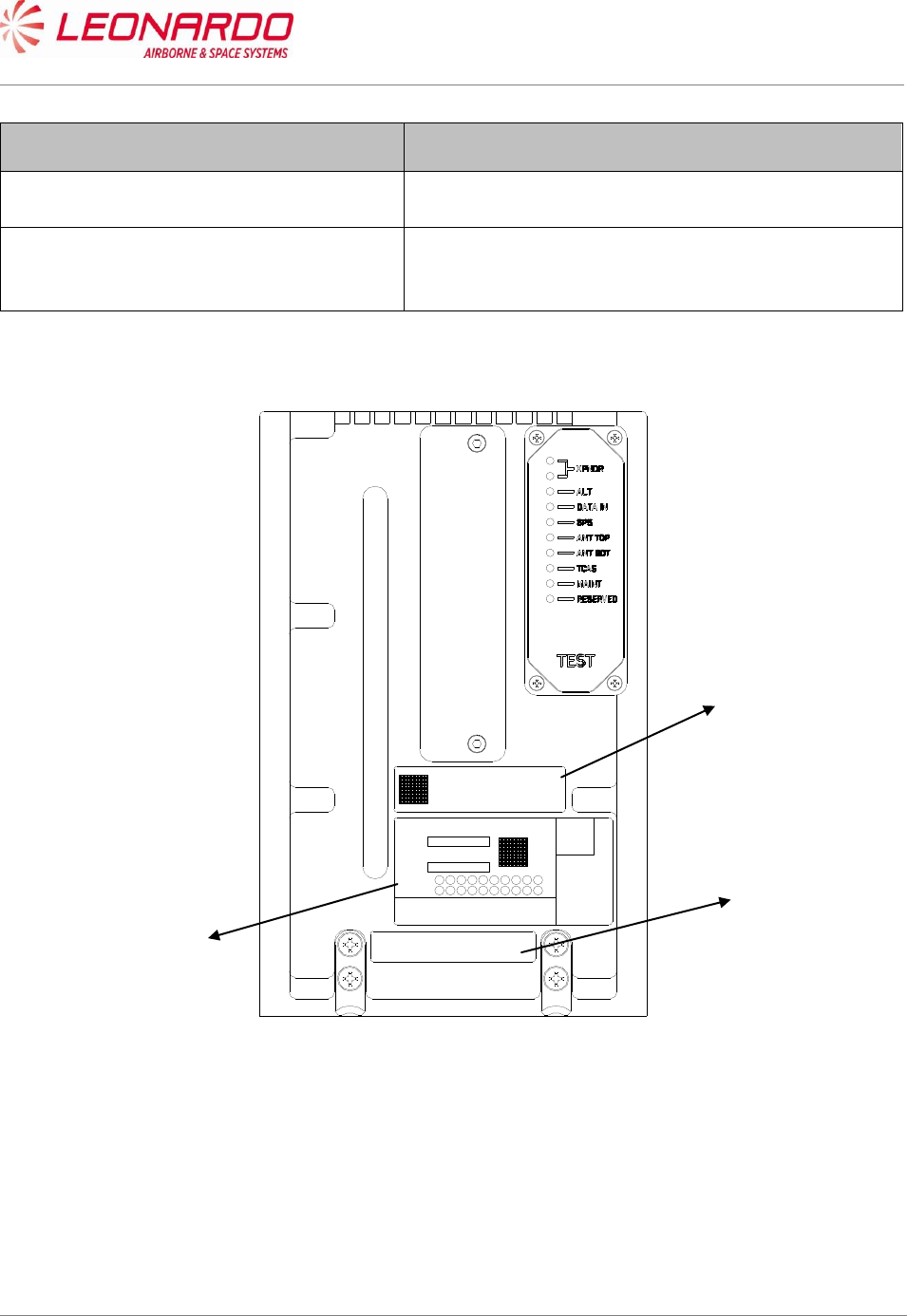
Table 2-2 – TRA-100B - Technical data – Connectors
Ref. Figure 2-2
Connector
Function
1
Main Connector
Data and Control I/O
2
Test Connector
Maintenance Retrieval
Figure 2-2 – TRA-100B Mode S Transponder – Connectors
1
2

UNCLASSIFIED MAN-1168/01 T01
___________________________________________________________________________________________________________
______________________________________________________________________________
Page 16
© Copyright Leonardo Finmeccanica S.p.A. – All rights reserved
UNCLASSIFIED
Table 2-3 – TRA-100B - Technical data – Main Connectors Pin Mapping
TP Section
Pin
I/O
Type
Description
TP 1A
Input
Program
AC Length/Width A MSB
TP 1B
Input
Program Strobed
AC Length/Width B
TP 1C
Input
Program Strobed
AC Length/Width C LSB
TP 1D
Input
Program Strobed
GPS Ant Long Off A (MSB)
TP 1E
Input
Program Strobed
GPS Ant Long Off B
TP 1F
Input
Program Strobed
GPS Ant Long Off C (LSB)
TP 1G
Input
Program Strobed
Navigation Accuracy Category Velocity (NACV)
TP 1H
Input
Program Strobed
System Design Assurance (SDA)
TP 1J
Input
Differential
GPS Time Mark 1A
TP 1K
Input
Differential
GPS Time Mark 1B
TP 2A
Input
429
FMC/GNSS #1 In #1 A
TP 2B
Input
429
FMC/GNSS #1 In #1 B
TP 2C
Input
429
IRS/FMS/Data Conc. A
TP 2D
Input
429
IRS/FMS/Data Conc. B
TP 2E
Output
429
General Output #1 A
TP 2F
Output
429
General Output #1 B
TP 2G
Input
429
ATSU In A
TP 2H
Input
429
ATSU In B
TP 2J
Input
Discrete
Data Load Enable
TP 2K
Input
Program
ADS-B FAIL Disable
TP 3A
Output
Discrete
ADS-B Fail Disc Out
TP 3B
Output
Discrete
Transponder fail #2 Disc output
TP 3C
Input
Program
Cable Delay Program Top/Bot
TP 3D
Input
Program
Cable Delay Program Value #1
TP 3E
Input
Program
Cable Delay Program Value #2
TP 3F
Common
Common
Common
TP 3G
Input
Discrete
SDI 429 Bus Address Logic Input
TP 3H
Input
Discrete
SDI 429 Bus Address Logic Input
TP 3J
Common
Common
Common
TP 3K
Common
Common
Common
TP 4A
N/A
N/A
No Connect
TP 4B
N/A
N/A
No Connect
TP 4C
N/A
N/A
No Connect
TP 4D
N/A
N/A
No Connect
TP 4E
N/A
N/A
No Connect
TP 4F
N/A
N/A
No Connect
TP 4G
N/A
N/A
No Connect
TP 4H
N/A
N/A
No Connect
TP 4J
N/A
N/A
No Connect
TP 4K
N/A
N/A
No Connect
TP 5A
Input
Program
Maximum Airspeed 17
TP 5B
Input
Program
Maximum Airspeed 16
TP 5C
Input
Program
Maximum Airspeed 15
TP 5D
Common
Common
Top Plug Common
TP 5E
Input
429
TX Coordination A

UNCLASSIFIED MAN-1168/01 T01
___________________________________________________________________________________________________________
______________________________________________________________________________
Page 17
© Copyright Leonardo Finmeccanica S.p.A. – All rights reserved
UNCLASSIFIED
TP Section
Pin
I/O
Type
Description
TP 5F
Input
429
TX Coordination B
TP 5G
Output
429
XT Coordination A
TP 5H
Output
429
XT Coordination B
TP 5J
Input
Discrete
Air/Ground Discrete #2
TP 5K
Input
Discrete
Air/Ground Discrete #1
TP 6A
Input
429
FMC #1 / Gen In #2 A
TP 6B
Input
429
FMC #1 / Gen In #2 B
TP 6C
Output
Discrete
Reserved
TP 6D
Input
Discrete
GPS Time Mark 2A
TP 6E
Input
Discrete
GPS Time Mark 2B
TP 6F
Input
Discrete
Reserved
TP 6G
Input
Discrete
Reserved (-0101/-0301); FAA - L_Sense
Activate (-0201)
TP 6H
N/A
N/A
No Connect
TP 6J
N/A
N/A
No Connect
TP 6K
Input
Program
Antenna Program
TP 7A
Input
429
Control Data 'A' or FCC #1/MCP #1/VHF #1 A
TP 7B
Input
429
Control Data 'A' or FCC #1/MCP #1/VHF #1 B
TP 7C
N/A
N/A
No Connect
TP 7D
Input
Discrete
Control Data Port Select
TP 7E
Input
429
Control Data 'B' A
TP 7F
Input
429
Control Data 'B' B
TP 7G
Input
Discrete
Standby/On Discrete
TP 7H
Input
429
ARINC 706/575 Air Data Input Port 1A
TP 7J
Input
429
ARINC 706/575 Air Data Input Port 1B
TP 7K
N/A
N/A
No Connect
MP Section
Pin
I/O
Type
Description
MP 1A
Input
Program
Mode S Address A1 (MSB)
MP 1B
Input
Program
Mode S Address A2
MP 1C
Input
Program
Mode S Address A3
MP 1D
Input
Program
Mode S Address A4
MP 1E
Input
Program
Mode S Address A5
MP 1F
Input
Program
Mode S Address A6
MP 1G
Input
Program
Mode S Address A7
MP 1H
Input
Program
Mode S Address A8
MP 1J
Input
Program
Mode S Address A9
MP 1K
Input
Program
Mode S Address A10
MP 2A
Input
Program
Mode S Address A11
MP 2B
Input
Program
Mode S Address A12
MP 2C
Input
Program
Mode S Address A13
MP 2D
Input
Program
Mode S Address A14
MP 2E
Input
Program
Mode S Address A15
MP 2F
Input
Program
Mode S Address A16
MP 2G
Input
Program
Mode S Address A17
MP 2H
Input
Program
Mode S Address A18
MP 2J
Input
Program
Mode S Address A19
MP 2K
Input
Program
Mode S Address A20

UNCLASSIFIED MAN-1168/01 T01
___________________________________________________________________________________________________________
______________________________________________________________________________
Page 18
© Copyright Leonardo Finmeccanica S.p.A. – All rights reserved
UNCLASSIFIED
MP Section
Pin
I/O
Type
Description
MP 3A
Input
Program
Mode S Address A21
MP 3B
Input
Program
Mode S Address A22
MP 3C
Input
Program
Mode S Address A23
MP 3D
Input
Program
Mode S Address A24 (LSB)
MP 3E
Common
Common
Common
MP 3F
Input
429
Spare 429 Input 1A
MP 3G
Input
429
Spare 429 Input 1B
MP 3H
Input
Discrete
Functional Test
MP 3J
Output
Discrete
Out Spare 1
MP 3K
Output
Discrete
Transponder Fail # 1 discrete output
MP 4A
Input
Discrete
Spare In1
MP 4B
Input
Discrete
Spare In2
MP 4C
Input
429
FMC/GNSS #2 In #1 A
MP 4D
Input
429
FMC/GNSS #2 In #1 B
MP 4E
Input
Program Strobed
Aircraft Category A (MSB)
MP 4F
Input
Program Strobed
Aircraft Category B (LSB)
MP 4G
Input
Program
ADS-B Configuration Parity
MP 4H
Input
Program Strobed
ADS-B Receive Capability
MP 4J
Input
Discrete
Spare In3
MP 4K
Input
Discrete
Spare In4
MP 5A
Input
429
ARINC 706/575 Air Data Input Port 2A
MP 5B
Input
429
ARINC 706/575 Air Data Input Port 2B
MP 5C
N/A
N/A
No Connect
MP 5D
N/A
N/A
No Connect
MP 5E
Output
429
ATSU Out #1 A
MP 5F
Output
429
ATSU Out #1 B
MP 5G
Input
Discrete
Extended Squitter Disable
MP 5H
Input
Discrete
Spare In5 (Mode S DL/DLP Program)
MP 5J
Input
Program
Antenna BITE Program
MP 5K
Input
Discrete
Spare In6
MP 6A
Input
429
Maintenance Data Input Port A
MP 6B
Input
429
Maintenance Data Input Port B
MP 6C
Output
429
Maintenance Data Output Port A
MP 6D
Output
429
Maintenance Data Output Port B
MP 6E
Input
Discrete
Alternate Air Data Source Select
MP 6F
Input
Program
Altitude Type Select A Discrete Input
MP 6G
Input
Program
Altitude Type Select B Discrete Input
MP 6H
Common
Common
Middle Plug Common
MP 6J
N/A
N/A
No Connect
MP 6K
Common
Common
Common
MP 7A
N/A
N/A
No Connect
MP 7B
N/A
N/A
No Connect
MP 7C
N/A
N/A
No Connect
MP 7D
N/A
N/A
No Connect
MP 7E
N/A
N/A
No Connect
MP 7F
N/A
N/A
No Connect
MP 7G
N/A
N/A
No Connect

UNCLASSIFIED MAN-1168/01 T01
___________________________________________________________________________________________________________
______________________________________________________________________________
Page 19
© Copyright Leonardo Finmeccanica S.p.A. – All rights reserved
UNCLASSIFIED
MP Section
Pin
I/O
Type
Description
MP 7H
N/A
N/A
No Connect
MP 7J
N/A
N/A
No Connect
MP 7K
Input
Discrete
Acquisition Squitter Inhibit (Honeywell Defined)
BP Section
Pin
I/O
Type
Description
BP 1
Input
Power
115 VAC Primary Power Hot
BP 2
N/A
N/A
No Connect
BP 3
N/A
N/A
No Connect
BP 4
N/A
N/A
No Connect
BP 5
N/A
N/A
No Connect
BP 6
N/A
N/A
No Connect
BP 7
Input
Power
115 VAC Primary Power Cold
BP 8
Input
Ground
Signal Ground
BP 9
N/A
N/A
No Connect
BP 10
N/A
N/A
No Connect
BP 11
Input
Ground
Chassis Ground
BP 12
Input/Output
Suppression
Suppression Pulse
BP 13
Input/Output
Suppression
Suppression Pulse - Daisy Chaining

UNCLASSIFIED MAN-1168/01 T01
___________________________________________________________________________________________________________
______________________________________________________________________________
Page 20
© Copyright Leonardo Finmeccanica S.p.A. – All rights reserved
UNCLASSIFIED
Table 2-4 – TRA-100B - Technical data – Test Connectors Pin Mapping
Test Connector
Pin
Signal Name
I/O
Type
Description
1
SWITCH_ETH
Discrete In 1
Switch Ethernet
2
TEST_RESET
Out
Test Point
Test Point
3
GND
Power GND
4
UP_HRESET
Out
Test Point
Test Point
5
VID_ENV_TOP_TP
Out
Test Point
Test Point
6
TEST_DG18
Internal Purpose Only
7
ST_GATE
Out
Test Point
Test Point
8
TEST_DG19
Internal Purpose Only
9
TEST_DG20
Internal Purpose Only
10
TEST_DG21
Internal Purpose Only
11
TEST_DG22
Internal Purpose Only
12
ACQ_SQ_INH_EN
In
Discrete In 1
Acquisition Squitter Inhibit Enable
13
PULSE_GATE
Out
Test Point
Test Point
14
OP_MAINT_1
In
Discrete In 1
Maintanance Mode Selection
15
OP_MAINT_0
In
Discrete In 1
Maintanance Mode Selection
16
VID_ENV_BOT_TP
Out
Test Point
Test Point
17
FPGA _SIN
Internal Purpose Only
18
FPGA _SOUT
Internal Purpose Only
19
DG_INT_PWRFL
Out
Test Point
Test Point
20
SUPP_TP
Out
Test Point
Test Point
21
E2C_SCL_PN
In
Service I2C
Bus Ctrl/Clk In
Service I2C Bus Serial Clock
22
E2C_SDA_PN
Bdir
Service I2C
Bus Data
Service I2C Bus Serial Data
23
WR_UNPROTECT
In
Service I2C
Bus Ctrl/Clk In
Service I2C Bus Control Signal
24
GND_EXT
Service I2C
Bus Supply In
Service I2C Bus Power Supply Ground
25
5V_EXT
In
Service I2C
Bus Supply In
Power Supply Source for Service I2C Bus
UNCLASSIFIED MAN-1168/01 T01
___________________________________________________________________________________________________________
______________________________________________________________________________
Page 21
© Copyright Leonardo Finmeccanica S.p.A. – All rights reserved
UNCLASSIFIED
3. INSTALLATION
3.1 TRA-100B MODE S TRANSPONDER – REPLACE PROCEDURES
Standard Equipment
Description
Identification Nr.
Qty
None
Materials
Description
Identification Nr.
Qty
None
Spares
Description
Identification Nr.
Qty
TRA-100B Mode S Transponder
TAC-6001/03
TAC-6003/03
TAC-6004/03
1
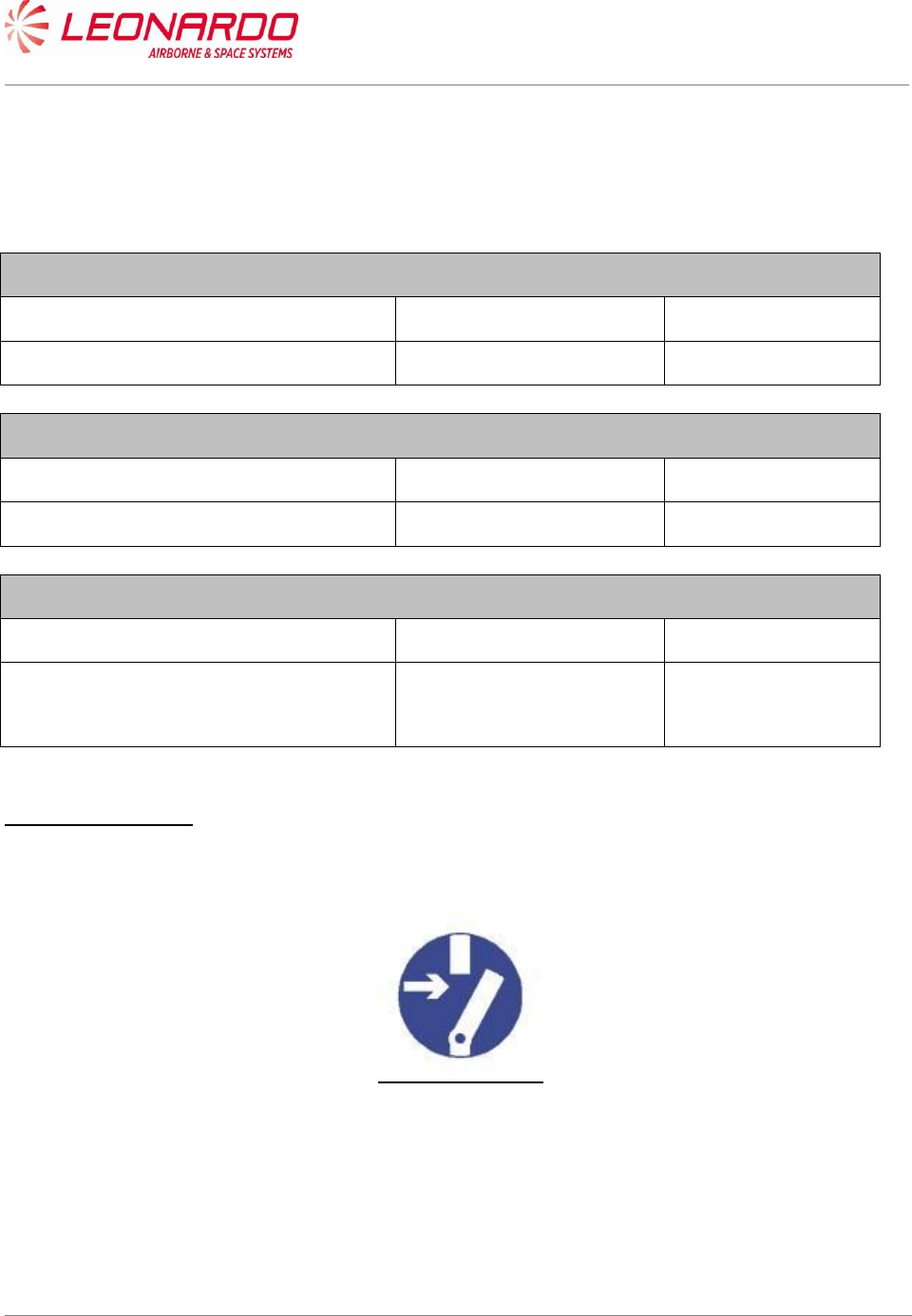
Safety Precautions
WARNING
MAKE SURE THAT THE EQUIPMENT IS DISCONNECTED FROM ALL
ELECTRICAL POWER SOURCES BEFORE YOU DO ANY
MAINTENANCE WORK.
UNCLASSIFIED MAN-1168/01 T01
___________________________________________________________________________________________________________
______________________________________________________________________________
Page 22
© Copyright Leonardo Finmeccanica S.p.A. – All rights reserved
UNCLASSIFIED
Preliminary Operations
1. Make sure the platform is safe for maintenance
Procedure
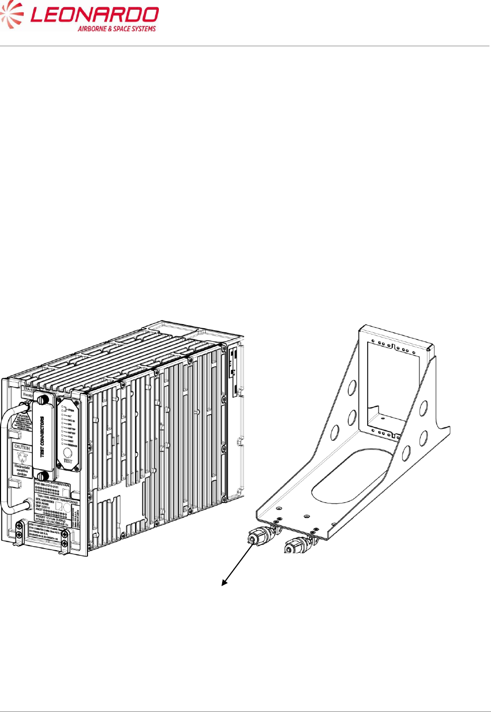
1. Removal Procedure
1.1. Loosen by hand the two hold-down screws on the front of Mounting Tray (1)
1.2. Pull the Transceiver by the handle
1.3. Carefully slide the Transponder from the Mounting Tray
2. Install Procedure
2.1. Carefully put the TRA-100 B Modes S Transponder into the Mounting Tray, aligning the
TRA-100B connector guide pins with the platform connector.
2.2. Tighten by hand the two hold-down screws (1) on the front of Mounting Tray
Figure 3-1 – TRA-100B Mode S Transponder - Replace Procedures
Close up
1) Removal all the tools, the materials and the equipment from your work area.
1