Leviton VRMX1 Light Dimmer User Manual manual
Leviton Manufacturing Co., Inc. Light Dimmer manual
Leviton >
manual

WARNINGS AND CAUTIONS:
To be installed and/or used in accordance with electrical codes and regulations.
• Ifyouareunsureaboutanypartoftheseinstructions,consultanelectrician.
• UseONLYwiththeappropriateAdvanceTransformer120VMark10™Powerline or Lutron Tu-Wire®electronicballastsforcontrollingthespecicuorescentlampsinFluorescentMode.
• Toavoidoverheatingandpossibledamagetothisdeviceandotherequipment,donotinstalltocontrolareceptacle,amotor-oratransformeroperatedappliance.
• Usewithmagneticlowvoltagetransformers,incandescent,or120Vhalogenxturesonly.UseaLevitonelectroniclowvoltagedimmertocontrolelectronic(solidstate)lowvoltagetransformers.
• WhenretrottingMark10™PowerlinedimmingballastsintoxturesthatoriginallyhadInstantStartballasts,thesocketsMUSTbereplacedwithRapidStartsocketstoallowproper
dimmeroperationandpreventdamagetothedimmerballast.Refertotheinstructionsprovidedwiththeballast.
• ViziaRF+
TM
dimmersarenotcompatiblewithstandard3-wayor4-wayswitches.TheymustbeusedwithcompatibleVizia+
TM
or
ViziaRF+
TM
controllersformulti-locationdimming.
WARNINGS AND CAUTIONS:
• Whenmagneticlowvoltagecircuitsareoperatedatadimlevel,withalllampsinoperative,excesscurrentmayowthroughthetransformer.Toavoidpossibletransformerfailuredueto
overcurrent,useatransformerthatincorporatesthermalprotectionorafuseattheprimarywindings.
• Fluorescentlampsmustbeburnedinatfullintensityfor100hourspriortodimmingforproperdimmingperformance.Useonlyone(1)ViziaRF+™Incandescent/MagneticLowVoltage
orFluorescentDimmerinamulti-locationcircuitwithupto9coordinatingremotes(withoutLEDs)orupto4matchingremotes(withLEDs).Theremote(s)willturntheloadon(“atthe
levelselected”fordimmersonly)atthecontrol.
• Totalminimumloadmustexceed40W.
• Dimmermayfeelwarmtothetouchduringnormaloperation.
• Recommendedminimumwallboxdepthis2-1/2".
• Maximumwirelengthfromdimmertoallinstalledremotescannotexceed300ft.
• Usethisdevice.
SinglePole(Onelocation)or3-Way(Multi-location)
Cat.No.VRMX1-1L,1000VA,1000W(Lighted)
120VAC,60Hz
INSTALLATION INSTRUCTIONS
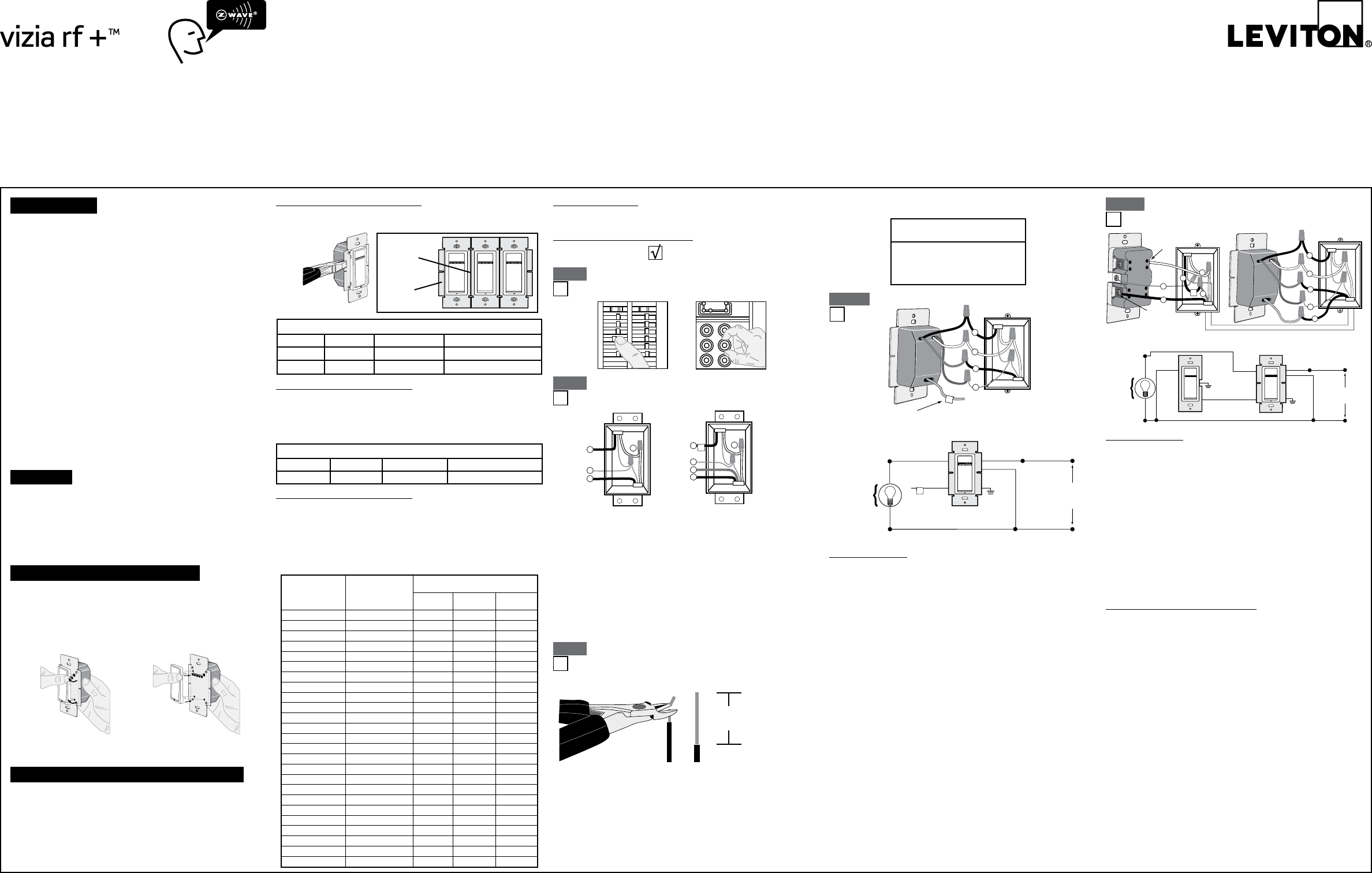
For3-Wayapplications,notethatoneofthescrewterminals
fromtheoldswitchbeingremovedwillusuallybeadifferentcolor(Black)
orlabeledCommon.Tagthatwirewithelectricaltapeandidentifyasthe
common(LineorLoad)inboththedimmerwallboxandremotewallbox.
1-#12w/1to3#14,#16or#18
2-#12w/1or2#16or#18
1-#14w/1to4#16or#18
2-#14w/1to3#16or#18
DI-000-VRMX1-02A
• Pulloffpre-cutinsulationfromdimmerleads.
• Makesurethattheendsofthewiresfromthewallboxare
.
• Removeinsulationfromeachwireinthewallboxasshown.
Coordinating Remote Dimmer
BK
RD
YL/RD
3
2
1
4
Terminal Screw
marked White (WH)
Terminal
Screw marked
Yellow/Red
(YL/RD)
5
1
4
2
Black
White
Green
Red
3
5
Yellow/
Red
Hot (Black)
Neutral (White)
(PRIMARY SIDE
OF MAGNETIC
LOW-VOLTAGE
TRANSFORMER)
Dimmer
Coordinating Remote (no LEDs)
YL/RD Yellow/
Red
RD
White
Red Black
Black BKWH
White
Line
120VAC, 60Hz
(unused)
(unused)
Green
Ground
Green
Ground
Slotted/PhillipsScrewdriver ElectricalTape Pliers
Pencil Cutters Ruler
Inmulti-dimmerinstallations,thereductionofthedimmer’scapacityis
required.Refertothechartformaximumloadperdimmer.
IfinstallingDimmerinasingledeviceapplication,proceedwiththe
section.IfinstallingDimmerina
multi-deviceapplication,proceedasfollows:
Yourdevicemayincludecoloroptions.Tochangecoloroftheface
proceedasfollows:
UsecheckboxeswhenStepsarecompleted.
ONOFF
ONOFF
ONOFF
ONOFF
ONOFF
ONOFF
ONOFFONOFF
ONOFF
ONOFF
ONOFF
ONOFF
atcircuitbreakerorfuseandtestthatpower
isoffbeforewiring!
Step 1
Step 2
Ifthewiringinyourwallboxdoesnotresembleany
ofthesecongurations,consultanelectrician.
2
4
3
1
Line(Hot)
Neutral
Ground
Load
Line or Load
Neutral
Ground
FirstTraveler–notecolor
SecondTraveler–notecolor
2
4
1
5
3
5/8"
Pulloffpre-cutinsulationfromdimmerleads.Makesurethat
theendsofthewiresfromthewallboxare
.Removeinsulationfromeachwireinthewallbox
as shown:
(PRIMARY SIDE
OF BALLAST)
Dimmer
Insulating
Label
Black
Hot (Black)Black
Line
120 VAC,
60Hz
Neutral (White)
Red
Yellow/Red
White
White
Green
Ground
Insulating label:
This wire is used in 3-way installations only.
For single pole installations, do not remove this insulating label.
Yellow/Red
1
4
2
Black
White
Green
Red
3
Low-voltagedimmersareratedinVolt-Amps(VA).Themaximumbulbwattage
isdeterminedbytheefciencyofthetransformerinthelow-voltagelighting
system.Transformerefciencieswillvaryfromdifferentmanufacturers;
consider80%efcientasaverage.Usethecharttodeterminemaximumbulb
wattagefortypicaltransformerefciencyratings.
Mark10™PowerlinedimmersareratedinVolt-Amps(VA).Themaximum
bulbwattageisdeterminedbytheefciencyoftheMark10™Powerline
ballast.Thefollowingtableshowsthemaximumnumberofballaststhatcan
beconnectedtoasingledimmerfordifferentMark10™Powerline ballasts.
Alsonotethatthetableshowsmaximumballastsformulti-ganginstallations.
Todeterminetotalballastload,addthelinecurrentfoundontheballastlabel
forallballastsinthecircuit.Thiswillindicatethetotalloadforthecontrol.
sections
Do not
sections
side section
650W
650VA
800W
800VA
Single
1000W
1000VA
Load
Incand
MagLV
520W
Rating
1000VA
Single
800W
Two Gang
640W
INTRODUCTION
Leviton’sViziaRF+TMcomponentsaredesignedtocommunicatewith
eachotherviaRadioFrequency(RF)toprovideremotecontrolofyour
lighting.UsingRFtechnologyallowsLevitontoprovidethegreatest
signalintegritypossible.EachmoduleinLeviton’s
ViziaRF+TMcomponentlineisaZ-Wave®enableddevice.Ina
Z-Wave®network,eachdeviceisdesignedtoactasarouter.These
routerswillre-transmittheRFsignalfromonedevicetoanotheruntil
theintendeddeviceisreached.Thisensuresthatthesignalisreceived
byitsintendeddevicebyroutingthesignalaroundobstaclesandradio
deadspots.TheSceneCapableIncandescent/MagneticLowVoltage
orFluorescentDimmeriscompatiblewithanyZ-Wave® enabled
network,regardlessofthemanufacturerandcanalsobeusedwith
otherdevicesdisplayingtheZ-Wave® logo.
RemembertoexercisegoodcommonsensewhenusingtheTimer
featuresofyourremote,especiallywhenschedulingunattended
devices.Therecanbesomeunexpectedconsequencesifnotused
withcare.Forexample,anemptycoffeepotcanberemotelyturned
on.Ifthatshouldhappen,yourcoffeepotcouldbedamagedfrom
overheating.Ifanelectricheateristurnedonbyremotecontrolwhile
clothingisdrapedoverit,arecouldresult.theremote
forthecontrolofhighpowerheatingappliancessuchasportable
heaters.Thisdevicewillnotcontrollightingthatisusedwithelectronic
low-voltageandhighfrequencypowersupplytransformers,norhigh
pressuredischargelamps(HIDlighting).Thisincludesmercury-vapor,
sodiumvaporandmetalhalidelamps.
• SoftfadeON/OFF
• Scenecapable
• ON/OFFLEDandBrightnesslevelLED
• Twowaycommunication
• RFreliability
• Easeofinstallation–Nonewwiring
• CompatiblewithotherZ-Wave®enableddevices
FORMAGNETICLOW-VOLTAGEAPPLICATIONS,
CONNECTDIMMERONLYTOTHEPRIMARY(HIGH-VOLTAGE)
SIDEOFAMAGNETICLOW-VOLTAGETRANSFORMER.
WhenusingthecoordinatingremotewithoutLEDs,thedimmer
canbeinstalledoneithertheLineorLoadsideofthe3-waycircuit.
Maximumwirelengthfromdimmertoallinstalledremotescannot
exceed300ft(90m).
• GreenorbarecopperwireinwallboxtoGreendimmerlead.
• LineHot(common)wallboxwireidentied(tagged)whenremoving
oldswitchtoBlackdimmerlead.
• FirstTravelerwallboxwiretoReddimmerlead.
• RemoveRedinsulatinglabelfromYellow/Reddimmerlead.
• SecondTravelerwallboxwiretoYellow/Reddimmerlead
.Thistravelerfromthedimmermustgotothe
terminalscrewontheremotemarked"YL/RD".
• LineNeutralwallboxwiretoWhitedimmerlead.
"BK"and"RD"terminalsoncoordinatingremoteareunused.
Tighten both screws.
Maximumwirelengthfromdimmertolastremoteis300ft(90m).
• GreenorbarecopperwireinwallboxtoGreenterminalscrew.
• Loadwallboxwireidentied(tagged)whenremovingoldswitchtoFirst
Traveler.
• SecondTravelerwallboxwiretoterminalscrew
marked"YL/RD".Thistravelerfromtheremotemustgotothe
Yellow/Reddimmerlead.
• RemoveWhiteinsulatinglabelfromterminalscrewmarked"WH".
• LineNeutralwallboxwiretoterminalscrewmarked"WH".
•
CONNECTAMAGNETICLOW-VOLTAGEDIMMERONLY
TOTHEPRIMARY(HIGH-VOLTAGE)SIDEOFAMAGNETIC
LOW-VOLTAGETRANSFORMER.
• GreenorbarecopperwireinwallboxtoGreendimmerlead.
• LineHotwallboxwiretoBlackdimmerlead.
• LoadwallboxwiretoReddimmerlead.
• LineNeutralwallboxwiretoWhitedimmerlead.
• Yellow/ReddimmerleadshouldhaveRedinsulationlabelafxed.
IfinsulatinglabelisnotafxedtoYellow/Reddimmerlead,
useelectricaltapetocover.
• .
TM
Powerline
TM
Powerline
Single
Gang
Two
Ganged
2 Gang
REZ-2Q18-M2-LD
REZ-1T32
REZ-2Q26
REZ-1T32
REZ-1T42
REZ-1Q18-M2-BS
REZ-1Q18-M2-LD
REZ-2Q18-M2-BS
REZ-1T32
REZ-1T42-M2-BS
REZ-1T42-M2-LD
REZ-2Q26
REZ-2Q26-M2-BS
REZ-2Q26-M2-LD
REZ-1Q18-M2-BS
REZ-1Q18-M2-LD
REZ-2Q18-M2-BS
REZ-2Q18-M2-LD
REZ-1T42-M2-BS
REZ-1T42-M2-LD
REZ-2Q26-M2-BS
REZ-2Q26-M2-LD
REZ-1T42-M2-BS
REZ-1T42-M2-LD
REZ-2T42-M3-BS CFTR32W/GX24Q 13 10 8
CFTR32W/GX24Q 26 20 16
CFTR32W/GX24Q 26 20 16
CFTR26W/GX24Q 17 13 11
CFTR26W/GX24Q 17 13 11
CFTR26W/GX24Q 32 25 20
CFTR26W/GX24Q 32 25 20
CFTR18W/GX24Q 23 18 15
CFTR18W/GX24Q 23 18 15
CFTR18W/GX24Q 46 37 30
CFTR18W/GX24Q 46 37 30
CFQ26W/G24Q 17 13 11
CFQ26W/G24Q 17 13 11
CFQ26W/G24Q 17 13 11
CFQ26W/G24Q 32 25 20
CFQ26W/G24Q 32 25 20
CFQ26W/G24Q 32 25 20
CFQ18W/G24Q 23 18 15
CFQ18W/G24Q 46 37 30
CFQ18W/G24Q 46 37 30
CFM42W/GX24Q 20 16 13
CFM32W/GX24Q 26 20 16
CFM26W/GX24Q 17 13 11
CFM26W/GX24Q 32 25 20
151823CFM18W/GX24Q

LevitonwarrantstotheoriginalconsumerpurchaserandnotforthebenetofanyoneelsethatthisproductatthetimeofitssalebyLevitonisfreeofdefectsinmaterialsandworkmanshipundernormalandproperuseforveyearsfromthepurchasedate.Leviton’sonlyobligationistocorrectsuchdefectsbyrepairorreplacement,atitsoption,ifwithinsuchveyearperiodtheproductisreturnedprepaid,with
proofofpurchasedate,andadescriptionoftheproblemtoThiswarrantyexcludesandthereisdisclaimedliabilityforlaborforremovalofthisproductorreinstallation.Thiswarrantyisvoidifthisproductisinstalledimproperlyorinanimproperenvironment,overloaded,misused,opened,
abused,oralteredinanymanner,orisnotusedundernormaloperatingconditionsornotinaccordancewithanylabelsorinstructions.,butifanyimpliedwarrantyisrequiredbytheapplicablejurisdiction,thedurationofanysuchimpliedwarranty,includingmerchantabilityandtnessfora
particularpurpose,islimitedtoveyears..Theremediesprovidedhereinaretheexclusiveremediesunderthiswarranty,whetherbasedoncontract,tortorotherwise.
PresstherighthalfoftheDIM/BRIGHTBar–Lights
brightentodesiredlevel.
PressthelefthalfoftheDIM/BRIGHTBar–Lightsdimtodesiredlevel.
Ifyoucontinuetohold,thelightswillDIMto
minimumlevelandthenturnOFF.
WhenlightsareOFFyoucanchangethelightlevelthatthe
lightswillturnONtousingtheDIM/BRIGHTBar.
Ifthereisapoweroutage,whenthepowerisrestored,thelightswill
return to the last setting
beforethepowerinterruption.
Cleanwithadampcloth.DO NOTusechemicalcleaners.
-Lamphasabadconnection.
-Wiresnotsecuredrmlywithwireconnectorsofdimmeror
terminalscrewsofremote.
- IfusinginadimmableuorescentapplicationseeAdvanced
ProgrammingFeatureB-4.
-Circuitbreakerorfusehastripped.
-Lampisburnedout.
-NeutralnotwiredtoDimmer(Whitewire).
-Conrmthatthedeviceisbeingsuppliedfroma120V,60HzAC
sourceONLY.
-Conrmthatunitisprogrammedproperly.Repeat"TOINSTALL"
sectiontoverifythatithasbeenincludedintheZ-Wave® network.
-Minimumloadisunder40W.
-ConrmthattheLoadbeingcontrolleddoesnotexceedthe
1000VAdimmerlimit.
-Ensurethattotalwirelengthdoesnotexceed300ft.
-Ensurewiringiscorrect.
ProtectedunderU.S.PatentNumber6,388,399andpatentspending
andlicensedunderU.S.PatentsNumbers5,905,442,and5,982,103
ItisveryimportanttoaccuratelyExcludedevicesfrom
thenetworkwhenmovingorremovingadevicefromaZ-Wave®
network.Thisensuresthatallinformationhasbeenremovedfromyour
PrimaryProgrammer/Controller'sinformationtableandisnotcountedon
tobepartofthemeshnetwork.
IfusingaLevitonZ-Wave®Programmer/Controller,Cat.No.VRCPG,
presstheMenubuttonandscrolldowntoSystemSetup.Press
thecenterbuttontoselectSystemSetupMenu.ChooseAdvanced
Setting.PressthecenterbuttontoselectNetwork.
Whilestandingclosetothedimmer(approximately1foot),pressthe
centerbuttonto<Exclude>devicefromthenetwork.
WhiletheProgrammer/ControllerisintheExclusionmodeandthe
locatorLEDisONontheDimmer,pressthepushpadtoturnonthe
Dimmer.TheProgrammer/ControllerwillverifyExclusionandthe
locatorLEDwillturnOFF.
IftheDimmerisashingAmberwhileintheExclusionmode,the
Programmer/ControllerisstilltryingtocommunicatewiththeDimmer.
Waituntilthedevicestopsashing,thenpressthepushpad.
Thelocatorlightwillilluminatewhentheload
isintheOFFpositiontofacilitateaccessinthedark.
Ifusingthedimmerina3-wayapplication,the
lightswillturnONatbrightnesssetondimmer’s
DIM/BRIGHTbar.Thelightingcanbecontrolled
fromeitherthedimmerortheremotelocation.
Tap–LightsturnONtopresetlevel.
PressandHold–LightsturnONtofullbright.
Tap–LightsturnOFF.
EnergySave:Setsthemaximumbrightnesslevelforenergysavings.
MinimumBrightnessLevel:Setstheminimumdimminglevel.
PresetONLevel:Setstheturnonbrightnesslevelregardlessofthe
previoussetlightlevel(formerlyDimLock).
ONFadeRate:Setstheamountoftimeinsecondsittakesthe
lightstoturnONtomaximumbrightness.
OFFFadeRate:Setstheamountoftimeinsecondsittakesthe
lightstoturnOFFfrommaximumbrightness.
LEDOptions:SetsthetimeperiodinsecondstheLocatorLEDand
Brightnessdisplaywillstayonbeforeextinguishing.
FluorescentMode:AllowsdimmertocontrolMark10Powerline
dimmingballasts.
PressandholdthePushPadandthenthehalfofthe
DIM/BRIGHTBar
(
^
)
for5secondsuntiltheLocatorLEDandleftmost
LED(LED1)begintoblink.
UponreleasingthePushPadandthehalfoftheDIM/BRIGHT
Bar
(
^
)
,theLocatorLEDwillcontinuetoblinkoncepersecondand
therightmostLEDwillilluminatetodisplaythedeviceisinProgram
Mode.Thedefaultenergysavemodeis100%
i.e.fullbright.Tochangethelevel,usethe
DIM/BRIGHTBartomovethecorrespondingLEDtothedesired
discretepresetlevelaccordingto.BytappingthePushPad
thissettingwillautomaticallybesavedandthedevicewilladvance
tothenextprogrammingmode,.
TheLocatorLEDwillblink2timespersecondtoindicatethedevice
isinProgramMode.Thedefault
MinimumBrightnessLevelisLED1.Tochangethe
from1-50%,usetheDIM/BRIGHTBar.Thelight
outputwillreecttheminimumbrightnesslevelselected.Bytapping
thePushPadthissettingwillautomaticallybesavedandthedevice
willadvancetothenextprogrammingmode,.
TheLocatorLEDwillblink3timespersecondtoindicateProgram
Mode. To change the current
from1-100%,usetheDIM/BRIGHTBar.Ifthisfeatureisnotdesired,
pressandholdthehalfoftheDIM/BRIGHTBar(
v
)
until no
LEDislit(defaultsetting).BytappingthePushPadthissettingwill
automaticallybesavedandthedevicewillexitProgrammingModeA.
PressandholdthePushPadandthenthehalfoftheDIM/BRIGHTBar
(
v
)for5secondsuntiltheLocatorLEDandrightmostLED(LED7)begin
toblink.
UponreleasingthePushPadandthehalfoftheDIM/BRIGHT
Bar(
v
),theLocatorLEDwillcontinuetoblinkoncepersecond
indicatingthedimmerisinProgramMode. To
change the ,usetheDIM/BRIGHTBartomovethe
LEDtothedesiredpresetlevelaccordingto.Bytappingthe
PushPadthissettingwillautomaticallybesavedandthedevicewill
advancetothenextprogrammingmode,.
TheLocatorLEDwillblink2timespersecondtoindicateProgram
Mode. To change the ,use
theDIM/BRIGHTBartomovetheLEDtothedesiredpresetlevel
according to .BytappingthePushPadthissettingwill
automaticallybesavedandthedevicewilladvancetothenext
programmingmode,.
TheLocatorLEDwillblink3timespersecondtoindicateProgram
Mode. To change the settings,use
theDIM/BRIGHTBartomovetheLEDtothedesiredpresetsetting
according to the .BytappingthePushPadthissetting
willautomaticallybesavedandthedevicewilladvancetothenext
ProgrammingModeB-4.
Chart B
LED
LED 1
LED 2 (Default)
LED 3
LED 4
LED 5
LED 6
LED 7
FADE ON
0 seconds (instant)
0.5 seconds
1.5 seconds
3.0 seconds
6.0 seconds
10 seconds
25 seconds
0 seconds (instant)
0.5 seconds
1.5 seconds
3.0 seconds
6.0 seconds
10 seconds
25 seconds
FADE OFF
Chart A
When indicator
light is at LED #
7
6
5
4
3
2
1
Light output is at
100%
97%
95%
90%
85%
80%
75%
Energy consumption
savings amounts to
0%
5%
8%
16%
24%
29%
34%
• Restorepoweratcircuitbreakerorfuse.
• PresspaduntillocatorlightisOFF.Lights
shouldturnON.IflightsdonotturnON,press
therighthalfoftheDIM/BRIGHTBaruntilthe
lights brighten.
Step 5
• Positionallwirestoprovideroominoutlet
wallboxfordevice.
• Ensurethattheword“TOP”isfacingupon
devicestrap.
• Partiallyscrewinmountingscrewsinwallbox
mountingholes.
Dresswireswithabendasshownin
diagraminordertorelievestresswhenmounting
device.
Programmer/Controller
mustbeincloseproximitytodimmer
whenincludinginthenetwork.
IfthedimmerhasbeensuccessfullyIncludedinthenetworkand
theusertriestoIncludeitagainwithoutrstexcludingitfromthenetwork,
thedimmerwillretaintherstnodeIDit
hadreceivedandignorethesecond.
Step 9
Chart B-3
LED
LED 1
LED 2
LED 3
LED 4
LED 5
LED 6
LED 7
LOCATOR LED TIMEOUT
Active
Active
Active
Active
Turns off 5 sec. after use
Turns off 5 sec. after use
Turns off 5 sec. after use
LED BRIGHTNESS DISPLAY OPTIONS
Active
Turns off 5 sec. after use
Active
Turns off 5 sec. after use
LED Bar active
LED Bar turns off 5 sec. after use
LED Bar turns off 5 sec. after use
LED Brightness
Display
1 2 3 4 5 6 7
LeftmostLED=LED1
RightmostLED=LED7
• Thedevicewillexitprogrammingmode
after3minutesofinactivity.
• Pressingthepushpadatanytime
duringprogrammingwilladvancethe
devicetothenextprogrammingmode.
Ifyourdimmerisnotresponding,oryouareunabletocontrolitafter
youhavetriedtoInclude/Excludeitmultipletimes,itmaybenecessary
toresetthedimmertoitsoriginalfactorysettings.Toaccomplishthis,
proceedasfollows:
• Onthedimmer,engagetheair-gapswitch
andwait5seconds.Pressthepushpadbackintotheframe
andholdpushpaduntilthelocatorLEDturnsAmberandthenturns
Red.Thedimmerisnowreset.Oncethedimmerisreset,itwillbe
necessarytoRe-Includeittoanetworkbeforeitcanbeused.
SETTINGADEVICETOAFACTORYDEFAULTDOES
NOTEXCLUDETHATDEVICEFROMANETWORK.THEEXCLUSION
PROCEDUREMUSTSTILLBEFOLLOWEDTOREMOVETHEDEVICE
FROMTHEPRIMARYCONTROLLER’SINFORMATIONTABLE.
FAILURETODOSOMAYRESULTINSYSTEMTHATISSLOWTO
RESPOND,ORMAYFAILTORESPONDTOSOMEDEVICES.
IfusingaLevitonZ-Wave®
Programmer/Controller,Cat.No.VRCPG,
presstheMenubuttonandscrolldowntoSystem
Setup.PressthecenterbuttontoselectSystem
SetupMenu.ChooseAdvancedSetting.Pressthe
centerbuttontoselectNetwork.
While standing close to the
dimmer(approximately1foot),pressthecenter
buttonto<Include>deviceinthenetwork.
Onlyonedevicemaybe
includedatatime.DO NOTputmultiple
devicesintotheInclusionmodeatanytime.
WhiletheProgrammer/ControllerisintheInclusion
modeandtheLocatorLEDisONonthedimmer,
pressthepushpadtoturnonthedimmer.The
Programmer/Controllerwillverifyinclusionandthe
LocatorLEDwillturnOFF.
IfthedimmerisashingAmberwhileintheInclusionmode,the
Programmer/Controllerisstilltryingtocommunicatewiththedimmer.
Waituntilthedevicestopsashing,thenpressthepushpad.
IftheLocatorLEDonthedimmerturnssolidRedwhile
including,therehasbeenacommunicationerror.Referto
Troubleshooting section.
ThePrimaryProgrammer/ControllerwillassignanodeIDnumber
(Name)forthisdevice.
ThisIDnumber(Name)willbestoredinthecontrollertobe
usedforfuturereference.
Youmayeditthedevicenameatthistime.
.
1 ON
2 ON
3 ON
4 ON
OFF
OFF
OFF
OFF
Restorepoweratcircuitbreakerorfuse.
Step 8
• Ifusinganon-LevitonProgrammer/Controller,refertothe
Programmer/ControllerinstructionsheetforIncludingadevice.
• IfusingVRCPG'sinstallchecklistgodirectlytostepB.
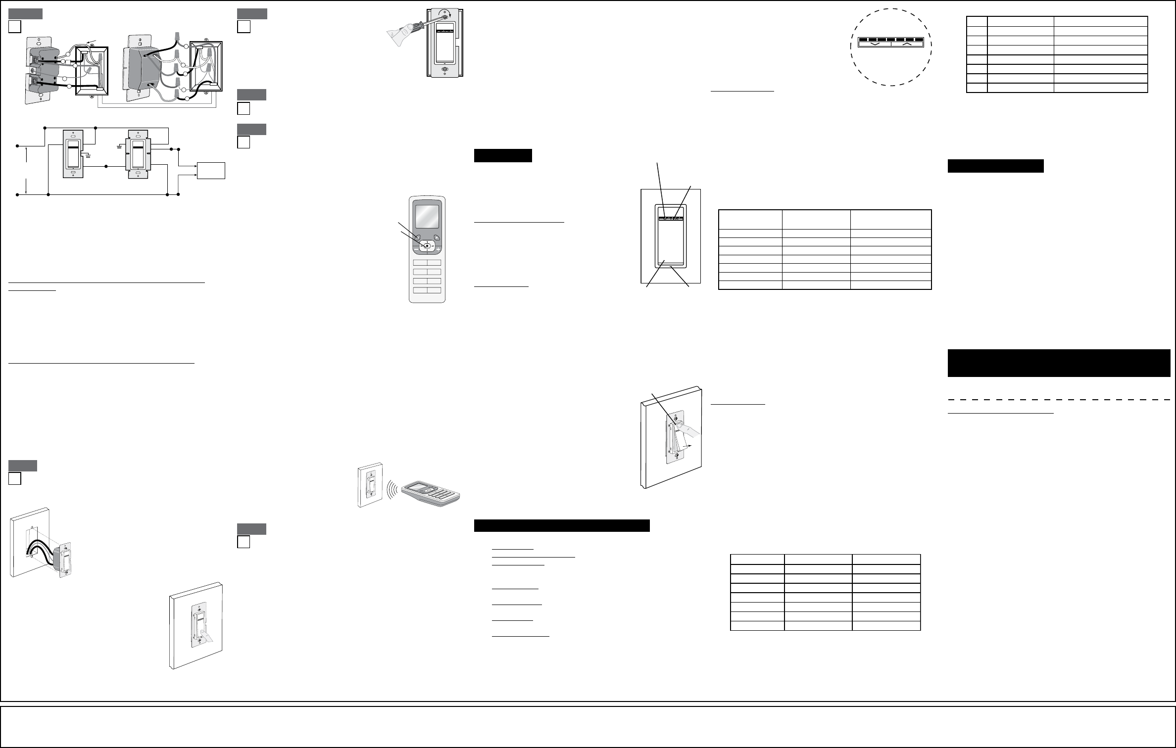
ThedimmerbeinstalledinawallboxthathasaLoad
connection.Thematchingremotemustbeinstalledinawallboxwith
aLineHotconnectionandaNeutralconnection.ANeutralwiretothe
matchingremoteneedstobeaddedasshown.
Ifyouareunsureaboutanypartoftheseinstructions,consultan
electrician.
Maximumwirelengthfromdimmertoallinstalledremotes
cannotexceed300ft(90m).
• GreenorbarecopperwireinwallboxtoGreenterminalscrew.
• LineHot(common)wallboxwireidentied(tagged)whenremoving
oldswitchandFirstTravelertoRemoteterminalmarkedBK.
• SecondTravelerwallboxwirefromdimmertoremoteterminalscrew
marked"YL/RD".Thistravelerfromtheremote
mustgotoYellow/Reddimmerlead.
• LineNeutralwallboxtoremoteterminalscrewmarked"WH".
W
• GreenorbarecopperwireinwallboxtoGreendimmerlead.
• Loadwallboxwireidentied(tagged)whenremovingoldswitchto
Reddimmerlead.
• FirstTravelerLineHottoBlackdimmerlead.
• RemoveRedinsulatinglabelfromYellow/Reddimmerlead.
• SecondTravelerwallboxwire to
Yellow/Reddimmerlead.Thistravelerfromthedimmermustgoto
theterminalscrewontheremotemarked"YL/RD".
• LineneutralwallboxwiretoWhitedimmerlead.
•
Hot (Bla c k )
Neutral (White)
Dimmer
Mat c hing Remote (with LEDs )
YL/RD
Red
Yellow/
Red
WH
BK
Black
Black
White
Ballast
Line
120 V A C , 60H z
Green
Ground
Green
G r oun d
White Primary
Side
Installationmaynowbecompletedbytightening
mountingscrewsintowallbox.Attachwallplate.
Onthedimmeronly,engagethe
air-gapswitchbygentlypressingthetopofthepush
paduntilthebottomliftscompletelyoutoftheframe
andaclickisheard.LED'swillturn
OFF.Thiswillstoppowertothexturetoreplacethe
bulb.Afterservicingiscomplete,pressthepushpad
backintoplacefornormaloperation.
BK
RD
YL/RD
Additional
Neutral Wire
Matching Remote
1
2
3
Dimmer
4
5
1
Yellow/
Red
2
Black
White
Green
Red
3
5
4
DI-000-VRMX1-02A
ThisdevicecomplieswithPart15oftheFCCRules.Operationissubjectto
followingtwoconditions:(1)thisdevicemaynotcauseharmfulinterference,and
(2)thisdevicemustacceptanyinterferencereceived,includinginterferencethat
maycauseundesiredoperationofthedevice.
ThisequipmenthasbeentestedandfoundtocomplywiththelimitsforaClassB
DigitalDevice,pursuanttoPart15oftheFCCRules.Theselimitsaredesigned
toprovidereasonableprotectionagainstharmfulinterferenceinaresidential
installation.Thisequipmentgenerates,uses,andcanradiateradiofrequency
energyand,ifnotinstalledandusedinaccordancewiththeinstructions,may
causeharmfulinterferencetoradiocommunications.However,thereisno
guaranteethatinterferencewillnotoccurinaparticularinstallation.Ifthis
equipmentdoescauseharmfulinterferencetoradioortelevisionreception,which
canbedeterminedbyturningtheequipmentOFFandON,theuserisencouraged
totrytocorrecttheinterferencebyoneormoreofthefollowingmeasures:
• ReorientorrelocatethereceivingAntenna.
• Increasetheseparationbetweentheequipmentandthereceiver.
• Connecttheequipmentintoanoutletonacircuitdifferentfromthattowhich
thereceiverisconnected.
• Consultthedealeroranexperiencedradio/tvtechnicianforhelp.
AnychangesormodicationsnotexpresslyapprovedbyLevitonManufacturing
Co.,Inc.,couldvoidtheuser'sauthoritytooperatetheequipment.
©2011LevitonMfg.Co.,Inc.
TheLocatorLEDwillblink4timespersecondtoindicateProgram
Mode.Defaultoperationmodeis
incandescent/magneticlowvoltagemode.Tochangefromnormal
touorescentmode,usetheDIM/BRIGHTBar.Pressandhold
the halfoftheDIM/BRIGHTBar(
^
)untilLEDislit(default
settingisLEDOFF).BytappingthePushPadthissettingwill
automaticallybesavedanddevicewillexitProgrammingModeB.

ARTWORK PRINT SPECIFICATIONS
FOLD SCHEME / BINDERY DIAGRAM
PART NUMBER REV DESCRIPTION
Line Screen:
Angle:
Resolution:
Offset Flexo
Other
Body Material:
Bindery
Thickness:
Trim
Perfect Bind
Die cut Saddle Stitch
Drill
Fold
The information in this document is the exclusive PROPRIETARY property of LEVITON MANUFACTURING COMPANY, INC. It is disclosed
with the understanding that acceptance or review by the recipient constitues an undertaking by the recipient. (1) to hold this information in strict
confidence, and (2) not to disclose, duplicate, copy, modify or use the information for any purpose other than that for which disclosed.
© 2011 Leviton Mfg. Co., Inc.
Unpublished, All Rights Reserved
PlantApprovals:
PN-ARN: Pilot Rev:ECO Number:
Artwork Release Date:
Artwork Print Specification Sheet Rev A07.eps
PMCQA
Artist:
Notes:
Other
Cust Other
S & A
Mktg Eng
FOR LEVITON USE ONLY
SPECIFICATIONS :
PROCESS :
MANUAL INTERIORS / BINDERY / FOLD SCHEME :
COMMENTS :
For manuals - designates cover specifications
Dimensions:
Material:
Thickness:
Finish:
:
Spot
CMYK
1:
4:
3:
2:
Color(s): over
1:
4:
3:
2:
Fonts:
Spot
CMYK
1:
4:
3:
2:
Color(s): over
1:
4:
3:
2:
Fonts:
Fold Line
Die Cut Punch/Drill Hole
Glue
Kiss Cut Cellophane
Fold Line
Perforate
Die Cut
Die Line Key:
DI-000-VRMX1-02A
Black
1 1
Instruction sheet
Helvetica
H. Sanchez 06/23/11
RS0066-3254
J. Tang08 A. Steele
P. Patel
A. Mancuso
V. LoNigro
11" x 17"
20 lb.
Offset
11"
17"
Part No.
FINAL
2.75"
2.83"
Part No.