Lewmar 34 77 User Manual To The E9bb4393 54a5 4132 B497 Bfa0dfa58845
User Manual: Lewmar 34-77 to the manual
Open the PDF directly: View PDF ![]() .
.
Page Count: 22
GB
www
.
l
e
w
m
a
r.
co
m
GB

3
Ocean Electric Winches 34 -
7
7
GB
C
ontents
I
ntroduction
4
Pro
d
uct support 4
Important information about this manual 4
EMC Recommended
g
uidelines 4
C
E A
pp
rova
l
s 4
S
afety notices
4
Ge
n
e
r
a
l 4
F
i
tt
i
n
g
4
Electrical 4
1
. In
s
tallation 5
1
.1 I
d
entifying manua
l
converti
bl
e winc
h
5
1
.2 Preparing manual winch for conversion 5
1
.3 Fittin
g
a com
p
lete electric winch from new 5
1
.4 Positionin
g
winc
h
a
b
ove
d
ec
k
5
1
.5 Positioning winc
h
anci
ll
aries
b
e
l
ow
d
ec
k
6
1
.6 Fitting a convertible electric winch 34-65 6
1
.7 Fittin
g
a convertible electric winch 66 -77 8
1
.8 Fastenin
g
s 8
1
.9 Winc
h
motor gear
b
ox coup
l
ings 8
2
. Electrical wirin
g
installation
9
2
.1 T
y
pical electrical la
y
out
9
2
.2 Correct main s
p
indle rotation
9
3
. Electrical connections 10
3.
1 E
Se
ri
es
E
lect
ri
c
3
4-4
8
1
0
3.2 ELS Electric Load Sensing 34-48 10
3.3 ELS Electric Load Sensin
g
50-65 11
3.4 ELS E
l
ectric Loa
d
Sensin
g
2
/
3 s
p
ee
d
66-77 11
3.5
EV
C
E
lect
ri
c
V
a
ri
able
Co
n
t
r
ol
3
4-4
8
12
3.6
EV
C
El
ect
ri
c
V
a
ri
ab
l
e
Co
n
t
r
o
l
50
-
65
12
3.7 NEW Electric deck switch 13
4. Per
f
ormance
di
a
g
rams 13
5. Safe workin
g
loads 14
5.1 O
p
timum ro
p
e diameters 14
5.
2 M
a
xim
u
m win
ch
load
v
alues
14
6. Operatin
g
your winch 14
7.
S
ervicin
g
your winch 15
8. Part
s
li
s
t 1
6
8.
1 Win
c
h n
otes
1
6
8
.2 Models 34-65 16
8.3
M
odels
66
-
77
1
7
9. Dimen
s
ion
s
18
10. Total wei
g
ht 19
11. Electric convertible model ran
g
e 19
11.1 Winches 34-77 19
/
2
0
11.2 Circuit breakers 2
0
11.3 NEW Electric deck switch 2
0
12. Fault fi nding 21
13. Lewmar limited warranty 22
B2303 I
ss
ue 6. Ocean electric winche
s
model
s
34-77.
For sizes over 77 please contact Lewmar for details.

4
Ocean Electric Winches 34 -
7
7
I
ntroduction
I
mportant information about this manual
Throughout this manual,
y
ou will see safet
y
and product damage
warnings. You must follow these warnings carefull
y
to avoid
possible in
j
ur
y
or damage
.
The t
y
pe of warnings, what the
y
look like, and how the
y
are used
in this manual are ex
p
lained as follows:
Dear
C
ustomer
,
Thank
y
ou for choosing Lewmar Electric Ocean Winches.
Lewmar products are world renowned for their qualit
y
, technical
innovation and proven performance. With a Lewmar winch
y
ou
will be provided with man
y
y
ears of outstanding service. We wish
y
ou happ
y
sailing
.
P
ro
d
uct support
Lewmar products are supported b
y
a worldwide network of
distributors and Authorised Service Representatives. If
y
ou
encounter an
y
diffi culties with this product, please contact
y
our
nationa
l
d
istri
b
utor, or your
l
oca
l
Lewmar
d
ea
l
er. Detai
l
s are
avai
l
a
bl
e at
:
T
o the best of our knowledge, the information in this manual
w
as correct when it went to
p
ress. However, Lewmar cannot
a
ccept liabilit
y
for an
y
inaccuracies or omissions it ma
y
contain.
I
n addition, our polic
y
of continuous product improvement ma
y
c
han
g
e s
p
ecifi cations without notice. As a result, Lewmar cannot
a
ccept
l
ia
b
i
l
ity for any
d
ifferences
b
etween t
h
e pro
d
uct an
d
t
h
e
m
anua
l
.
www.lewmar.com
A
pp
roval
s
For CE approva
l
certifi cates contact Lewmar.
G
enera
l
Pl
ease ensure t
h
at you t
h
oroug
hl
y un
d
erstan
d
t
h
e operation
a
n
d
safety requirements of t
h
e winc
h
b
efore commencing t
h
e
i
nsta
ll
ation. On
l
y persons w
h
o are comp
l
ete
l
y fami
l
iar wit
h
t
h
e
c
ontrols and those who have been fully made aware of the correct
u
se of the winch should be allowed to use it. If there is an
y
doubt
o
f how to install or o
p
erate this unit
p
lease seek advice from a
s
uitabl
y
qualifi ed engineer.
•
Winches used incorrectl
y
could cause harm to equipment or
cre
w
.
•
Winc
h
es s
h
ou
ld
b
e use
d
wit
h
care an
d
treate
d
wit
h
respect.
•
Sai
l
ing,
l
i
k
e many ot
h
er sports can
b
e
h
azar
d
ous. Even t
h
e
c
orrect se
l
ection, maintenance an
d
use of proper equipment
c
annot e
l
iminate t
h
e potentia
l
for
d
anger, serious injury or
d
eath.
•
Lewmar winches are designed and supplied for line control
i
n marine applications and are to be used in con
j
unction with
app
ro
p
riate clutches, cleats and other manual controls and
s
to
pp
ers.
•
It is the unavoidable responsibilit
y
of the owner or master or
o
t
h
er responsi
bl
e party to assess t
h
e ris
k
of any operation on
th
e vesse
l
.
•
Un
d
er no circumstances s
h
ou
ld
any se
l
f tai
l
ing winc
h
b
e use
d
i
n se
l
f tai
l
ing mo
d
e for any
l
ifting operation; rat
h
er suita
bl
e
a
nd ade
q
uate manual tailin
g
should be arran
g
ed with
p
ro
p
er
m
eans of manuall
y
cleating or stopping the hoist.
•
Ever
y
winch should be installed with adequate means of
m
anuall
y
cleating or stopping the loaded ropes
.
•
Lewmar recommends the use of a
pp
ro
p
riate Personal
P
rotective E
q
ui
p
ment and hands free communication
e
quipment
b
y any person going a
l
oft, an
d
on
l
y t
h
en w
h
ere
th
e person going a
l
oft is proper
l
y traine
d
in t
h
e use of t
h
at
e
quipment an
d
w
h
ere t
h
ere remain suffi cient traine
d
an
d
e
xperience
d
personne
l
on
d
ec
k
to ensure constant o
b
servation
a
n
d
the
co
n
t
in
ued
sa
f
e
co
n
duct
both
o
f
the
v
essel
a
n
d
the
h
oistin
g
o
p
eration.
Fitting
•
T
h
is equipment must
b
e insta
ll
e
d
an
d
operate
d
in accor
d
ance
w
it
h
t
h
e instructions containe
d
in t
h
is manua
l
. Fai
l
ure to
d
o
s
o cou
ld
resu
l
t in poor pro
d
uct performance, persona
l
in
j
ur
y
a
nd/or damage to
y
our boat.
•
Consult the boat manufacturer if
y
ou have an
y
doubt about
t
he strength or suitabilit
y
of the mounting location
.
E
l
ect
ri
ca
l
•
Ma
k
e sure you
h
ave switc
h
e
d
off t
h
e power
b
efore you start
i
nsta
ll
ing t
h
is pro
d
uct.
•
If in
d
ou
b
t a
b
out insta
ll
ing e
l
ectrica
l
equipment p
l
ease see
k
ad
vice from a suita
bly
qua
l
ifi e
d
e
l
ectrica
l
engineer
.
Safety notices
This manual forms
p
art of the
p
roduct and MUST BE RETAINED
alon
g
with, OR incor
p
orated into, the Owner’s Manual for the vessel
to
whi
c
h th
e
win
c
h i
s
fi tt
ed
.
W
arn
i
ng
!
This is a warning against anything which may cause in
j
ury to people
if the warnin
g
is i
g
nored. You are informed about what you must
o
r must not do in order to reduce the risk of in
j
ury to yourself and
o
th
e
r
s.
Safet
y
S
y
mbo
l
When
y
ou see the safet
y
s
y
mbol it means: “Do not...”; “Do not do
t
his”; or “Do not let this ha
pp
en”
.
5
Ocean Electric Winches 34 -
7
7
GB
1
. Installatio
n
Always kee
p
in mind the s
p
ace available below the deck for the
motor
g
earbox.
PRE 1992 1992
AUG 2000 40/44/48 AUGUST 2000
Wavegrip Winch Ocean
Wavespring Manual Convertible
Manual
Convertible Manual
with Power Drive Unit
Complete Electric
Convertible Winch
A
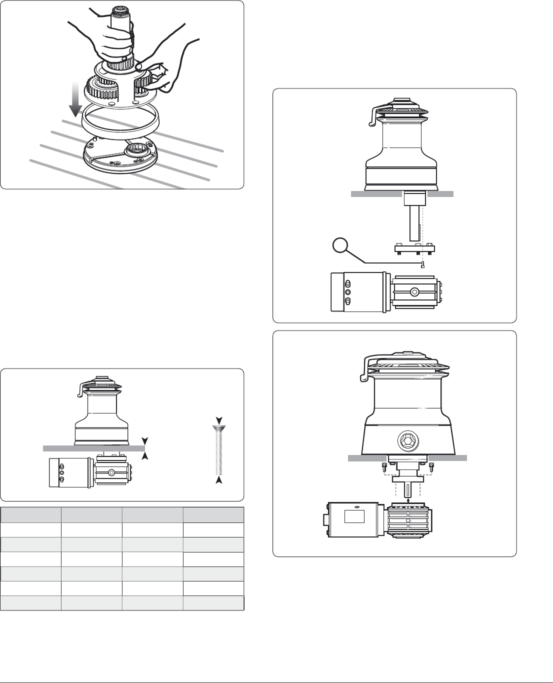
1
.2 Prepar
i
n
g
t
h
e manua
l
w
i
nc
h
f
or convers
i
on to e
l
ectr
i
c
• Remove t
h
e winc
h
from t
h
e
d
ec
k
(
if a
l
rea
d
y insta
ll
e
d)
an
d
r
emove t
h
e Centre P
l
ate, w
h
ic
h
is
l
ocate
d
on t
h
e un
d
ersi
d
e
o
f t
h
e Centre Stem,
b
y using a soft
h
ammer an
d
punc
h
(
Fig.
1
.2.1
)
.
• Remove an
y
sharp edges and clean, to remove all old bedding
/
s
ealin
g
com
p
ounds from the underside of the Centre Stem.
1
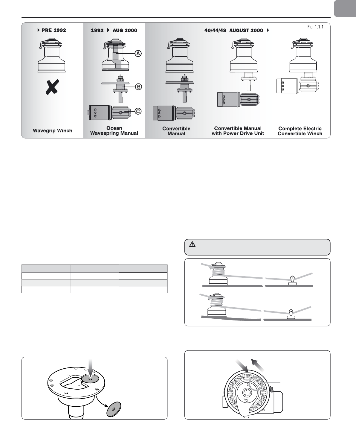
.1 I
d
ent
if
y
i
ng t
h
e manua
l
convert
ibl
e w
i
nc
h
• Fi
g
. 1.1.1
Pre
O
cean w
i
nc
h
es,
i
.e.
fi
xe
d
j
aw Wave
G
r
i
p
wi
nc
h
es, ma
d
e
b
e
f
ore 1992 are N
O
T convert
ibl
e.
Converti
bl
e manua
l
winc
h
es ma
d
e in August 2000 wi
ll
b
e
d
ate
m
ar
k
e
d
H
/
00 on t
h
e centre stem,
(
H = August; 00 = year 2000
)
.
Th
ey a
l
so carry a
bl
ue stic
k
er on t
h
e screw-on top-cap s
h
owing
a
winc
h
h
an
dl
e an
d
a
h
an
d
operating an e
l
ectric
d
ec
k
switc
h
.
T
hese winches can be converted b
y
adding the Power Drive
B
ase (B) unit and the re
q
uired Motor Gearbox (C), Control
B
ox and Switch-
g
ear (12 V or 24 V).
• Ocean Wave S
p
rin
g
manual winches made between 1992 and
A
ugust 2000 are NOT fi tte
d
wit
h
t
h
e necessary centre stem
t
o convert to powere
d
operation. A Centre Stem Kit
(
A
)
is
a
vai
l
a
bl
e to convert t
h
e ear
l
y Ocean Wave Spring winc
h
es
f
rom
(
1992 to Ju
l
y 2000
)
. T
h
e part num
b
ers are
l
iste
d
b
e
l
ow.
P
re Ocean Winches, i.e. fi xed
j
aw Wave Grip winches, made
be
f
o
r
e
1
99
2
a
r
e
N
O
T
co
nv
e
r
t
i
b
l
e.
Win
c
h M
odel
Descri
p
tio
n
P
a
rt N
u
m
be
r
40
C
entre
S
tem Ki
t
480
4
003
7
44
C
entre Stem Ki
t
4
8044037
48
C
entre
S
tem Ki
t
4
80480
3
7
F
ig. 1.
2
.
1
1.3 F
i
tt
i
ng a comp
l
ete e
l
ectr
i
c
win
c
h fr
o
m n
ew
• Test fi t t
h
e winc
h
to t
h
e Power Drive Base an
d
Gear
b
ox to
c
h
ec
k
t
h
e orientation an
d
t
h
e necessary c
l
earence nee
d
e
d
BEF
O
RE DRILLIN
G
ANY H
O
LE
S.
• N
o
w f
o
ll
o
w
sect
i
o
n
s
1
.
4
a
n
d
1
.5.
1.4 Pos
i
t
i
on
i
ng w
i
nc
h
a
b
ove
d
ec
k
• Lewmar recommend that the ro
p
e enters onto the drum at an
ang
l
e of –5° to –10° to t
h
e
b
ase axis of t
h
e winc
h
. To ac
h
ieve
t
h
is ang
l
e it may
b
e necessary to use a
b
ase we
d
ge w
h
en
insta
ll
ing t
h
e winc
h
(
Fig. 1.4.1
)
. T
h
e winc
h
must
b
e mounte
d
on an even sur
f
ace.
-5° to -10°
-5° to -10°
LOAD
OUTPUT GEAR
2 SPEED / 3 SPEED WINCHES
LINE ENTRY
• If practica
l
, for
b
est performance, t
h
e winc
h
s
h
ou
ld
b
e insta
ll
e
d
so t
h
at t
h
e output gear is situate
d
in t
h
e optimum position in
re
l
ation to t
h
e
l
oa
d
(
Fig. 1.4.2
)
.
Fi
g
.
1
.4.
1
Fig. 1.4.
2
6
Ocean Electric Winches 34 -
7
7
• Use t
h
e temp
l
ate provi
d
e
d
as a gui
d
e to position t
h
e winc
h
on
t
h
e
dec
k
.
NOTE: Check the scale of the tem
p
late
matches the winch
(
Fig 1.4.3
).
NOTE: Make
s
ure there i
s
room below
deck for motor and
s
ub box.
Fig.
1
.4.3
1
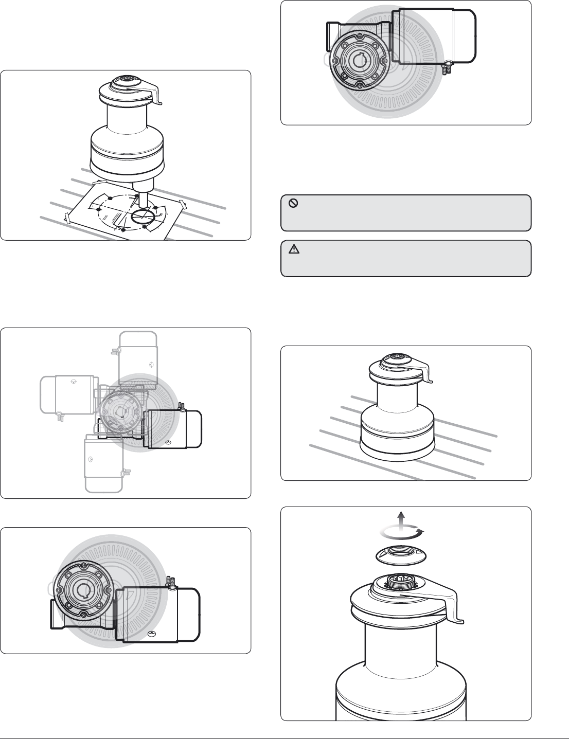
.5 Positionin
g
winch ancillaries below dec
k
N
O
TE: T
h
e pos
i
t
i
on
i
ng o
f
t
h
e motor
gear
b
ox must
b
e c
h
ec
k
e
d
pr
i
or to cutt
i
ng
for deck
/
hull and bulkhead clearance.
• T
h
e motor gear
b
ox can
b
e rotate
d
in 90° steps, Fig. 1.5.1.
• T
h
e motor rotation is factory set for fi tting as Fig. 1.5.2.
Fig. 1.5.1
Fig. 1.5.
2
N
O
TE: T
h
e motor can
b
e
fi
tte
d
as F
i
g. 1.5.3.
•
Contact Lewmar for correct fi tting of e
l
ectrica
l
connections.
If the motor is unitentionally fi tted this way on a single speed
winch it will not o
p
erate and make a clickin
g
noise, on a 2 or
3 speed winch it will dramaticall
y
reduce performance.
•
Check clearance below deck and accessibilit
y
then position the
d
ec
k
switc
h
es near an
d
in view of t
h
e winc
h
. Use t
h
e temp
l
ates
p
rovi
d
e
d
as a gui
d
e to cut
/d
ri
ll
h
o
l
e, fi t switc
h
an
d
sea
l.
NOTE:
A
ir switch tubing must be twist and
ch
a
f
e
f
ree to t
h
e sw
i
tc
h
un
i
t
(
su
b
b
ox
).
F
i
g
. 1.5.
3
1.6 F
i
tt
i
n
g
a convert
ibl
e e
l
ectr
i
c w
i
nc
h
34-65
NOTE: Illu
s
tration
s
are ba
s
ed on a model 50 winch.
•
Place the winch in
p
osition to ensure correct fi t once the holes
h
ave been drilled/cut (Fi
g
. 1.6.1).
F
i
g
. 1.6.
1
F
i
g
. 1.6.
2
•
Unscrew the to
p
ca
p
(Fi
g
. 1.6.2).
DO NOT cover the air bleed hole with sealant as this will sto
p
a
ir esca
p
in
g
and could result in winches self o
p
eratin
g
as the air
ex
p
ands with risin
g
tem
p
eratures in the tube
.
Once you have selected the
p
osition for the winch, motor
g
earbox
a
nd controls, double check everythin
g
and only then drill the holes
i
n th
e
dec
k
.
7
Ocean Electric Winches 34 -
7
7
GB
F
ig.
1
.
6
.
3
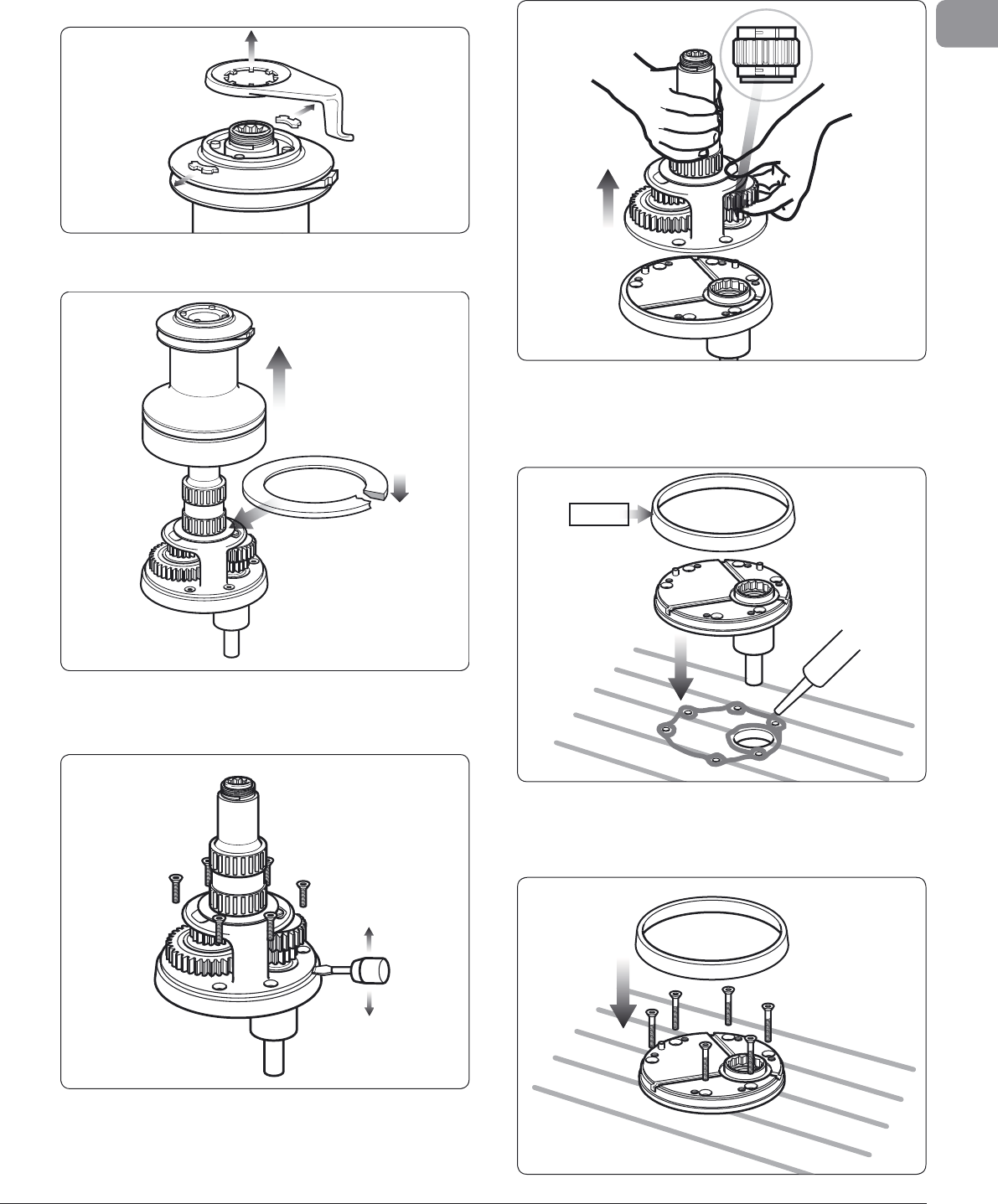
• Remove fee
d
er arm an
d
co
ll
ets
(
Fig. 1.6.3
)
.
• Lift drum off (Fi
g
. 1.6.4). Take care in re-fi ttin
g
the drum
was
h
e
r wi
t
h
be
v
e
l
o
n
u
n
de
r
s
i
de.
F
ig. 1.6.4
F
ig.
1
.
6
.5
• Remove a
ll
screws
h
o
ld
ing centre stem to
b
ase
(
Fig. 1.6.5
)
.
U
sing a fl at
bl
a
d
e
d
screw
d
river in t
h
e
d
rainage s
l
ots,
l
ever off
c
entre stem assembly clear of the two dowel pins.
• Ta
k
e care to
h
o
ld
t
h
e gear stac
k
in position as s
h
own
(
Fig.
1
.6.6
)
.
(
If paw
l
gear fa
ll
s away... note s
h
ou
ld
er face is
d
own
)
.
T
ake care that
p
awls and
p
awl s
p
rin
g
s are ke
p
t in
p
lace, while
r
ebuildin
g
/
p
lacin
g
the centre stem onto the base.
Fi
g
. 1.6.6
• Remove t
h
e
b
ase p
l
ate cover. Lift t
h
e
b
ase an
d
b
e
d
d
own wit
h
a
l
ig
h
t coating of sea
l
ing compoun
d
to prevent
l
ea
k
s
(
Fig
1.6.7)
.
NOTE: Do not u
s
e exce
ss
ive
s
ealant.
44~64
Fi
g
.
1
.
6
.7
• Consu
l
t t
h
e fastening gui
d
e in section 1.8 for
b
o
l
t type an
d
l
engt
h
. Bo
l
t t
h
e
b
ase p
l
ate to t
h
e
d
ec
k
ensuring t
h
at a
ll
fastening
h
ea
d
s are countersun
k
an
d
correct
ly
an
d
rep
l
ace
base
p
late cover (Fi
g
1.6.8).
Fig. 1.6.
8
8
Ocean Electric Winches 34 -
7
7
• Re
p
lace the drum, collets, feeder arm in correct feeder
p
osition
and screw on the to
p
ca
p
.
• Refi t t
h
e centre stem assem
bl
y, ta
k
ing care to
h
o
ld
t
h
e gea
r
stack in
p
osition as before (Fi
g
1.6.9). Rotatin
g
the
g
ears will
facilitate re-en
g
a
g
ement of the
p
awls, and ratchet tracks.
F
i
g
. 1.6.
9
Win
ch
Fastenin
g
X mm
(
min.
)
X
inch
(
min.
)
3
4
/
4
0
5
x M
6
(
1
/
4
”
W
)
3
0
1
1
/
4
4
4/4
8
5
x M
8
(
5
/
5
1
6
”
W
)
33
1
5
/
5
1
6
50/
5
4
6
x M
8
(
5
/
5
1
6
”
W
)
33
1
5
/
5
1
6
58 5 x M10
(
3
/
3
8
” W
)
3
6
1
7
/
1
6
6
4
/
6
5
5 x M10
(
3
/
3
8
” W
)
3
8
1
1
/
2
66/68
& 7
7
6
x M1
0
(
3
/
3
8
” W
)
31
1
1
/
4
1.9 W
i
nc
h
/motor gear
b
ox coup
li
ng
M
ec
h
anica
l
coup
l
ing of t
h
e
h
orizonta
l
d
rive unit an
d
re
d
uction
g
ear
b
ox to t
h
e winc
h
s
h
ou
ld
b
e mounte
d
as Fig 1.9.1
(
34−65
)
an
d
F
ig. 1.9.2
(
66−77
)
wit
h
instructions of previous pages.
•
T
h
e
h
orizonta
l
d
rive unit assem
bl
y s
h
ou
ld
b
e
b
o
l
te
d
from
b
elow decks. Use threadlock on item No.15
(
see Sec. 8.2
)
.
•
If a thick deck or increased motor/
g
earbox distance from
d
eck demands a
g
reater ‘T’ dimension (see Sec. 9). O
p
tional
e
xtension kits are available to special order. Contact
y
our
nea
r
est
L
e
wm
a
r
offi
ce.
+(x)mm/inch=
F
i
g
. 1.8.1
15
Fig.
1
.
9
.
1
F
ig. 1.9.
2
1
.7 F
i
tt
i
ng a convert
ibl
e e
l
ectr
i
c w
i
nc
h
66-7
7
For winc
h
es 66-77, simp
l
y remove t
h
e winc
h
d
rum an
d
access
to mounting
h
o
l
es is avai
l
a
bl
e t
h
roug
h
h
o
l
es in t
h
e
b
ase of t
h
e
cen
t
re s
t
em
.
1
.8 Fastenin
g
s
Fix the winch to the deck usin
g
CSK Head, Stainless Steel
Washers
/
Locknuts
.
• For the correct bolt len
g
th refer to Fi
g
. 1.8.1 and table.
NOTE: Deck fastenin
g
s are not supplied.
9
Ocean Electric Winches 34 -
7
7
GB
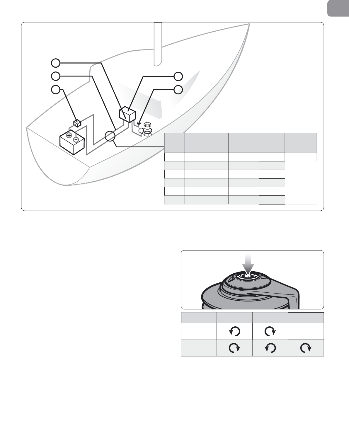
2
. Electrical wirin
g
installatio
n
3
2
15
4
S
ystem
V
o
l
tage
(
V
)
Di
stanc
e
Power suppl
y
to winc
h
C
ross
sect
i
ona
l
a
rea
C
able
si
ze
(
U
S
O
nly
)
B
attery s
i
z
e
1
2
U
p to 10 m (
33
ft) 5
0
mm2
1/
Ø
Up to
3
00
A
mp/hr
s
1
2
10 to 15 m (
33
to 49 ft
)
70
mm2
2/
Ø
1
2
15 to
20
m (4
9
to
66
f
t
)
9
5 mm2
3/
Ø
2
4 Up to 7 m (2
3
ft
)
2
5 mm2
3
2
4 7 to 10 m (2
3
to
33
ft)
35
mm2
2
2
4 10 to 1
3
m (
33
to 4
3
ft
)
50
mm2
1/
Ø
2
.1 Typical electrical layout
NOTE: This is not a wirin
g
dia
g
ram.
1. Position the recommended circuit breaker close to the batter
y
.
S
ee wirin
g
dia
g
rams Sec. 3.
2. Route 2 cables (see size table above) from batter
y
to the
co
n
t
r
ol
bo
x
.
3. Attac
h
motor ca
bl
es to contro
l
b
ox
(
see wiring
d
iagram
)
using
r
ecommen
d
e
d
ca
bl
e sizes.
4. Position t
h
e contro
l
b
ox near t
h
e winc
h
(
±1 metre
)
in a
d
ry
a
rea for watertig
h
t security an
d
accessi
bl
e for maintenance.
5.
P
os
i
t
i
o
n
dec
k
s
wi
tc
h
es
in vi
e
w
o
f win
c
h
.
R
oute
wir
e
a
n
d
attac
h
t
o control box (see wirin
g
dia
g
ram).
2.2 Main spindle rotation
• Check correct main s
p
indle rotation when fitted and
o
p
erated
.
Wi
nc
h
1
st
G
ear
2
nd
G
ear
3
rd
G
ear
2
S
peed
66
−77
3
S
peed
66
−77
Fi
g
. 2.1.1
Fig.
2
.
2
.1
1
0
O
cean Electric Winches 34 - 7
7
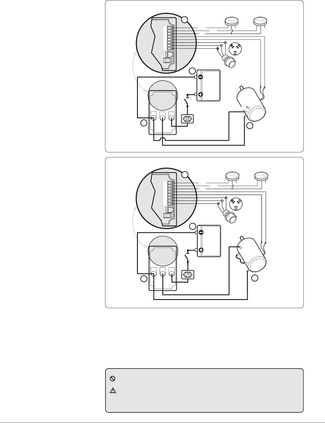
3
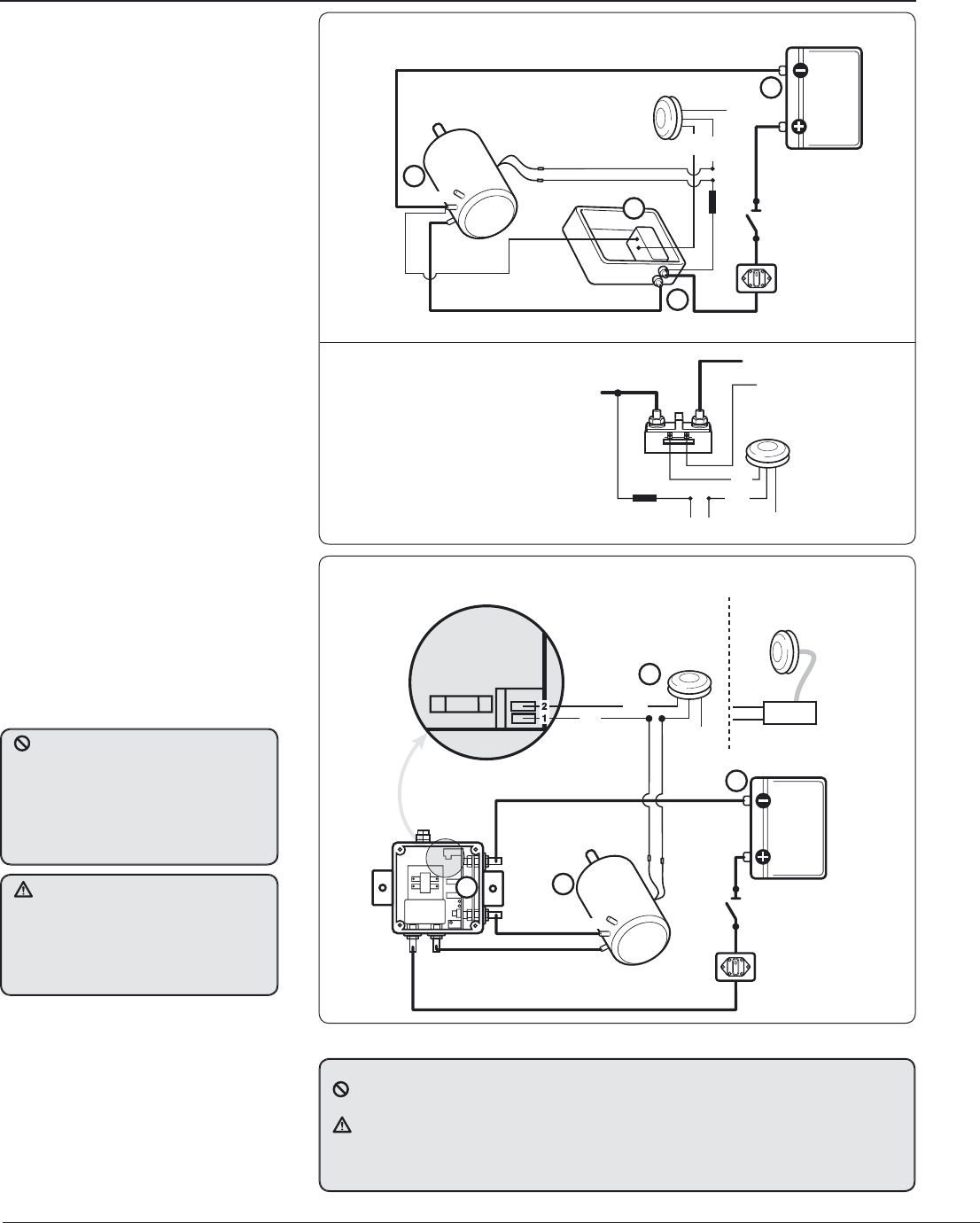
. Electrical connection
s
3 Amp
Slow Blow Fuse
Customer Supplied
Thermal
Cutout
Isolator/Safety
Switch
Circuit
Breaker
Battery
D2
D1
Contactor
12 V - 18000301
24 V - 18000302
Battery +VE
Motor +VE
Grey
Not Used
Electric Switch Kit
69000018
Blue
Black
Battery – VE
A2 2
3
1
4
Fi
g
. 3.1.1 Sin
g
le direction contactor in box with thermal cutout
.
1
2 V (18000301) or 24 V (18000302). Also see
S
ection 3.7
.
3.1 E
S
erie
s
Electric
3
4-4
8
,
12
V or
2
4 V
• T
h
is simp
l
e insta
ll
ation of a power
d
rive
unit, motor an
d
switc
h
gear contro
l
s t
h
e
winc
h
b
y a sing
l
e
d
irection contactor,
w
h
ic
h
can
b
e a Contactor
h
ouse
d
in a
water
p
roof box (Fi
g
3.1.1), or a stand
alone N
y
lon encased unit (Fig 3.1.2).
• The motor thermal tri
p
is connected to
monitor motor tem
p
erature while the
Lewmar safet
y
electric deck switch can
b
e easi
l
y wire
d
.
• Manua
l
overri
d
e faci
l
ity is sti
ll
avai
l
a
bl
e for
b
ac
k
up, or as a means of
experiencing tra
d
itiona
l
sai
l
ing.
• Two p
l
us one spee
d
comes as stan
d
ar
d
contro
l
w
h
ic
h
gives two spee
d
manua
l
drive (handle)
p
lus one s
p
eed electric
d
riv
e.
Fig. 3.1.2
C
ontactor
1
2 V
(
0052505
)
or 24 V
(
0052506
)
D1
PCB
D2
A2
Thermal
Cutout
Isolator/Safety
Switch
Circuit
Breaker
Battery
Control Box
Battery +VE
Motor + VE
Grey
Not Used
Electric Switch Kit
69000016
1
Battery –VE
Motor –VE
2
4
Air Deck
Switch Kit
69000022
Sub Box
Black
Blue
3 A
Fuse
Two-way
Terminal Block
3
F
ig. 3.2.1 12 V or 24 V
C
ontrol box with overload protection. Also see
S
ection 3.7.
3
.
2 EL
S
Electric Loa
d
Sensing 34-48, 12 V or 24
V
• This installation controls the winch b
y
Lewmar’s uni
q
ue Overload Protection
Contro
l
Box
(
Fig 3.2.1
)
, t
h
is a
ll
ows t
h
e
winc
h
to
b
e operate
d
up to t
h
e Safe
Wor
k
ing Loa
d
for winc
h
size.
• Ot
h
er features as Section 3.1
Connect the
p
ower su
pp
ly cables
t
o the batter
y
last when the winch
installation has been com
p
leted
and checked
f
or correct installation.
Incorrect connection o
f
motor cables
may
d
amage t
h
e un
i
t
.
Total voltage drop MU
S
T N
O
T exceed
5%
of supply over completed cabling
installation.
C
heck all connections
f
or water tight security. Lewmar
r
eco
mm
e
n
ds
a
n i
so
l
a
t
o
r t
o
be
fi tt
ed
in
t
he circuit in an accessible
p
osition as
c
lose as
p
ossible to the su
pp
ly
.
NU
MBER KEY F
O
R ALL ELE
C
TRI
C
AL DIA
G
RAM
S
n
Ne
g
ative earth MUST be used
.
o
The deck switch wires MU
S
T be fi tted as shown on wiring diagrams
.
p
C
onnect all low power wiring
(
deck switches, motor cutout etc.
)
before fi tting high power
c
a
bl
es to contro
ll
er.
q
C
able boots are supplied for all high power cable connections, follow guidelines Fig. 2.1.1
for cable sizin
g
.
Battery +VE
Motor +VE
Electric
Switch Kit
69000018
3 Amp
Slow Blow Fuse
Customer Supplied
Grey
Not Used
Blue
Black
Thermal
Cutout
0 V/Motor A2
11
Ocea
n E
lect
ri
c
Win
ches
3
4 -
77
GB
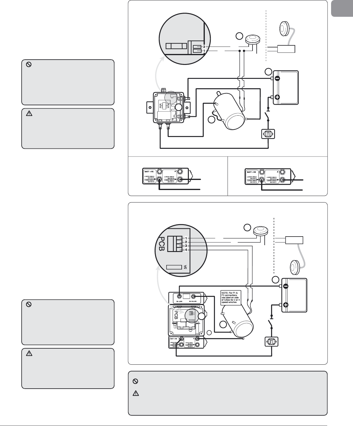
3
.3 ELS Electric Load
S
ensin
g
50-65, 12 V or 24 V
• This installation controls the winch b
y
L
ewmar’s uni
q
ue Overload Protection
C
ontrol Box (Fi
g
3.3.1), this allows the
w
inch to be o
p
erated u
p
to the Safe
W
orkin
g
Load for winch size.
• Ot
h
er features as Section 3.1
PCB
Thermal
Cutout
Isolator/Safety
Switch
Circuit
Breaker
Battery
A2
F1
Control Box
Battery +VE
Motor +VE
Grey
Not Used
Electric Switch Kit
69000016
1
Battery –VE
Motor –VE
A1
F2
2
4
Air Deck
Switch Kit
69000022
Sub Box
Black
Blue
3 A
Fuse
Two-way
Terminal Block
3
F
i
g
. 3.3.1 12 V or 24 V Control box with overload
p
rotection. Also see Section 3.7.
3.
4 EL
S
Electric Loa
d
S
ensing 2/3 speed controlle
r
66
/
68
-77
,
12
V or
2
4
V
• This installation controls the winch b
y
L
ewmar’s uni
q
ue Overload Protection
&
Autoshift Control Box (Fi
g
. 3.4.1).
T
hi
s
a
ll
o
w
s
t
h
e
win
c
h
to
be
sta
r
ted
in
1
st an
d
if reac
h
es t
h
e Safe Wor
k
ing
L
oa
d
, for t
h
e winc
h
size an
d
gear, wi
ll
a
utomatica
ll
y s
h
ift t
h
e winc
h
into 2n
d
g
ear for comp
l
ete
l
oa
d
contro
l
.
In t
h
e case of a 3 spee
d
winc
h
(
Fig.
3
.4.1
b)
t
h
e switc
h
must
b
e re-se
l
ecte
d
t
o achieve 3rd
g
ear.
F
ig. 3.4.1a 2
S
peed winch electrical connection
s
Blue
Black
Grey
Not Used
Electric Switch Kit
69000016
2
Air Deck
Switch Kit
69000022
Sub Box
Isolator/Safety
Switch
Circuit
Breaker
Battery
F1
Control Box
Battery +VE
Motor – VE
1
Battery –VE
Motor –VE
A2
A1
F2
3
4
Thermal
Cutout
8
F
i
g
. 3.4.1 2/3 S
p
eed 12 V or 24 V control box with overload
p
rotection. Also see Section 3.7
.
F
i
g
. 3.4.1b 3 S
p
eed winch electrical connections
C
onnect the power supply cables
to the batter
y
last when the winch
i
nstallation has been com
p
leted
a
n
d
c
h
ec
k
ed
f
o
r
co
rr
ec
t in
s
t
a
ll
a
ti
o
n.
In
co
rr
ec
t
co
nn
ec
ti
o
n
o
f m
o
t
o
r
cab
l
es
m
ay dama
g
e the unit
.
Total volta
g
e dro
p
MUST NOT exceed
5
% of su
pp
ly over com
p
leted cablin
g
i
nstallation.
C
heck all connections
f
or water tight security. Lewmar
r
ecommends an isolator to be
fi
tted in
t
h
e c
i
rcu
i
t
i
n an access
ibl
e pos
i
t
i
on as
close as
p
ossible to the su
pp
ly
.
C
onnect the power supply cables
to t
h
e
b
attery
l
ast w
h
en t
h
e w
i
nc
h
i
nstallation has been com
p
leted
a
n
d
c
h
ec
k
ed
f
o
r
co
rr
ec
t in
s
t
a
ll
a
ti
o
n.
In
co
rr
ec
t
co
nn
ec
ti
o
n
o
f m
o
t
o
r
cab
l
es
m
ay dama
g
e the unit
.
Total volta
g
e dro
p
MUST NOT exceed
5
% of su
pp
ly over com
p
leted cablin
g
i
nstallation.
C
heck all connections
f
or water tight security. Lewmar
r
ecommends an isolator to be
fi
tted in
t
h
e c
i
rcu
i
t
i
n an access
ibl
e pos
i
t
i
on as
c
l
ose as poss
ibl
e to t
h
e supp
l
y
.
N
U
MBER KEY F
O
R ALL ELE
C
TRI
C
AL DIA
G
RAM
S
n
Ne
g
ative earth MUST be used
.
o
The deck switch wires MU
S
T be fi tted as shown on wiring diagrams
.
p
C
onnect all low power wiring
(
deck switches, motor cutout etc.
)
before fi tting high power
ca
bl
es to contro
ll
er
.
q
C
able boots are supplied for all high power cable connections, follow guidelines Fig. 2.1.1
f
or cable sizin
g.
F1
F2
F2
F1
12
O
cean Electric Winches 34 - 7
7
12345678
Black
Black
Grey
Not Used
SW 1
Electric Switch Kit
69000018
3
Grey
Not Used
SW 2
Electric Switch Kit
69000018
Blue
1
2
4
Thermal
Cutout
Isolator/Safety
Switch
Circuit
Breaker
Battery
EVC
Control Box
Battery +VE
Motor – VE
Battery –VE
Motor +VE
D1
D2
(Optional)
Vario Control
Two-way
Terminal Block
3 Amp
Fuse
BAT+
MOT+
BAT–
MOT–
A2
Fi
g
. 3.5.1
A
lso see
S
ection 3.7.
3.5 EV
C
E
l
ectr
i
c Var
i
a
bl
e
Control.
S
tandard controller
si
ng
l
e spee
d
w
i
nc
h
es
34-48, 12 V
&
24 V
• T
h
e EVC winc
h
contro
ll
er is a varia
bl
e
spee
d
motor contro
ll
er w
h
ic
h
can
d
rive
t
h
e winc
h
in 3
d
ifferent ways:
1. SW 1 drives the winch at full speed.
2. SW 2 drives the winch at a set speed
determined b
y
ad
j
ustable dial marked
(SP) on the control box. On suppl
y
the
dial is preset b
y
Lewmar to drive the
winc
h
at 60% of fu
ll
s
p
ee
d
.
3. If optiona
l
Vario Contro
l
is fitte
d
t
h
en t
h
e winc
h
wi
ll
d
rive at a spee
d
d
etermine
d
b
y a
d
justment of t
h
e Vario
Contro
l
w
h
en
d
ec
k
switc
h
(
SW 2
)
is
engage
d.
• Th
e
EV
C
co
n
t
r
o
ll
e
r
uses
cu
rr
e
n
t
sensin
g
to halt the o
p
eration of the
win
c
h wh
e
n
t
h
e
win
c
h h
as
r
eac
h
ed
i
ts
Maximum Safe Workin
g
Load.
• The EVC controller features a Ram
p
/
Soft Start to contro
l
t
h
e winc
h
start
up, a
d
justment of
d
ia
l
RA wi
ll
vary t
h
e
start perio
d
b
etween 0.5 - 5 secon
d
s.
T
h
e
d
ia
l
is preset
b
y Lewmar for a start
p
eriod of 1 second.
• In order to ad
j
ust the speed (SP)
and Ram
p
(RA) dials, unscrew the
p
lu
g
screws, on to
p
of the controller
4 full turns and retract the
p
lu
g
/
screw assem
bl
y. Use an e
l
ectrica
l
s
l
otte
d
(
2.5mm Max.
)
screw
d
river to
a
d
just t
h
e interna
l
d
ia
l
to t
h
e
d
esire
d
sett
i
ng
.
3
.
6 EV
C
E
l
ectr
i
c Var
i
a
bl
e
Control. Standard & high
power controller sin
g
le speed
w
i
nc
h
es 50-65
,
12 V
&
24
V
• Th
e
EV
C
win
c
h
co
n
t
r
o
ll
e
r i
s
a
v
a
ri
ab
l
e
s
p
eed motor controller which can drive
t
h
e winc
h
in 3
d
ifferent ways:
NOTE:
S
tandard EVC used
on 50−65 24 V. H
i
g
h
powe
r
EV
C
use
d
on 50−65 12 V
.
1. SW 1
d
rives t
h
e winc
h
at fu
ll
spee
d
.
2. SW 2
d
rives t
h
e winc
h
at a set spee
d
determined b
y
ad
j
ustable dial marked
(SP) on the control box. On suppl
y
the
dial is preset b
y
Lewmar to drive the
winch at 60% of full s
p
eed.
3. If o
p
tional Vario Control is fitted
t
h
en t
h
e winc
h
wi
ll
d
rive at a spee
d
d
etermine
d
b
y a
d
justment of t
h
e Vario
Contro
l
w
h
en
d
ec
k
switc
h
(
SW 2
)
is
engage
d.
• Th
e
EV
C
co
n
t
r
o
ll
e
r
uses
cu
rr
e
n
t
sensin
g
to halt the o
p
eration of the
win
c
h wh
e
n
t
h
e
win
c
h h
as
r
eac
h
ed
i
ts
Maximum Safe Workin
g
Load.
12345678
Black
Black
Grey
Not Used
SW 1
Electric Switch Kit
69000018
3
Grey
Not Used
SW 2
Electric Switch Kit
69000018
Blue
1
2
4
Isolator/Safety
Switch
Circuit
Breaker
Battery
EVC
Control Box
Battery +VE
Motor – VE
Battery –VE
Motor +VE
(Optional)
Vario Control
Two-way
Terminal Block
3 Amp
Fuse
BAT+
MOT+
BAT–
MOT–
Thermal
Cutout
F1
A2
A1
F2
Fi
g
. 3.6.1
A
lso see
S
ection 3.7.
• The EVC controller features a Ram
p
/
So
f
t
Sta
r
t
to
co
n
t
r
o
l
t
h
e
win
c
h
sta
r
t
up, ad
j
ustment of dial RA will var
y
the
start
p
eriod between 0.5 - 5 seconds.
T
h
e
d
ia
l
is preset
b
y Lewmar for a start
perio
d
of 1 secon
d
.
• In order to ad
j
ust the speed (SP)
and Ram
p
(RA) dials, unscrew the
p
lu
g
screws, on to
p
of the controller
4 full turns and retract the
p
lu
g
/
screw assem
bl
y. Use an e
l
ectrica
l
s
l
otte
d
(
2.5mm Max.
)
screw
d
river to
a
d
just t
h
e interna
l
d
ia
l
to t
h
e
d
esire
d
sett
i
ng
.
N
U
MBER KEY F
O
R ALL ELE
C
TRI
C
AL DIA
G
RAM
S
n
Ne
g
ative earth MUST be used
.
o
The deck switch wires MU
S
T be fi tted as shown on wiring diagrams
.
p
C
onnect all low power wiring
(
deck switches, motor cutout etc.
)
before fi tting high power
ca
bl
es to contro
ll
er
.
q
C
able boots are supplied for all high power cable connections, follow guidelines Fig. 2.1.1
f
or cable sizin
g.
13
Ocean Electric Winches 34 -
7
7
GB
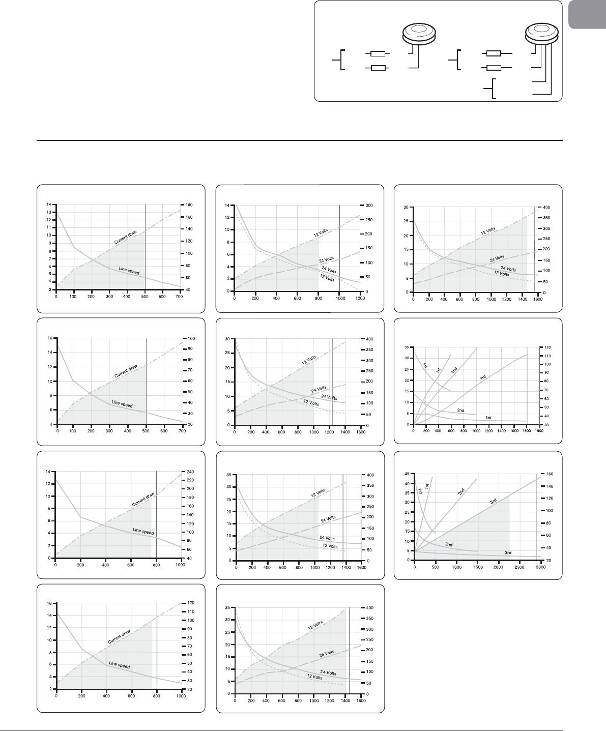
4. Performance
d
iagram
s
The followin
g
g
ra
p
hs show line s
p
eed and am
p
era
g
e draw relative
to t
h
e
l
oa
d
app
l
ie
d
. Eac
h
contro
l
b
ox is set to cut out at t
h
e SWL
w
h
ic
h
is 50% of t
h
e
b
rea
k
ing
l
oa
d
.
Cutout (800 kg)
Line Speed (m/min)
Load (kg)
Current (Amp)
Cutout (500 kg)
Line Speed (m/min)
Load (kg)
Current (Amp)
Cutout (500 kg)
Line Speed (m/min)
Load (kg)
Current (Amp)
M
odel 34-40 Electric 12 Volt
s
M
o
d
e
l
40 E
l
ectr
i
c 24 Vo
l
ts
M
odel 44 Electric 12 Volts
Cutout (1250 kg)
Line Speed (m/min)
Load (kg)
Current (Amp)
Cutout (1000 kg)
Line Speed (m/min)
Load (kg)
Current (Amp)
Cutout (800 kg)
Line Speed (m/min)
Load (kg)
Current (Amp)
M
odel 44 Electric 24 Volt
s
Model 48 Electric 12 & 24 Volt
s
M
odel 50 Electric 12 & 24 Volt
s
Cutout (1814 kg)
Line Speed (m/min)
Load (kg)
Current (Amp)
Cutout (1580 kg)
Line Speed (m/min)
Load (kg)
Current (Amp)
Cutout (1450 kg)
Line Speed (m/min)
Load (kg)
Current (Amp)
Mo
d
e
l
58 E
l
ectr
i
c 12
&
24 Vo
l
t
s
M
odel 64-65 Electric 12 & 24 Volt
s
M
odel 66
/
68-3 Electric 24 Volts
Cutout (1350 kg)
Line Speed (m/min)
Load (kg)
Current (Amp)
Model 54 Electric 12 & 24 Volt
s
Cutout (2721 kg)
Line Speed (m/min)
Load (kg)
Current (Amp)
Model 77-3 Electric 24 Volt
s
3
.7 NEW E
l
ectr
i
c
d
ec
k
sw
i
tc
h
• T
h
e new e
l
ectric
d
ec
k
switc
h
can
b
e or
d
ere
d
un
l
it
(
69000018
)
o
r
l
it
(
69000350
/
48000170
)
.
N
O
TE: In
li
t opt
i
on t
h
e w
i
res s
h
ou
ld
b
e connecte
d
s
eparate to t
h
e e
l
ectr
i
c w
i
nc
h
contro
l
b
ox, to avo
id
a
ny possibility of a si
g
nal upsettin
g
/interferin
g
w
ith the control box circuit. Use a
g
eneral li
g
htin
g
c
ircuit and fused at the shi
p
’s main circuit
p
anel.
Unlit
Electric Switch
69000345
White
White
Red
Black
Lit
Electric Switch
69000350/48000170
White
White
Red
Black
Red +VE
Black –VE
LED
5 A
Max.
5 A
Max.
Fi
g
. 3.7.1
14
Ocean Electric Winches 34 -
7
7
5. Safe wor
k
in
g
l
oa
ds
M
o
d
e
l
R
ope
Ø
(mm) Rope
Ø
(in
)
3
4/4
0
8
t
o
12
5
/
5
1
6
”
t
o
1
/
2
”
4
4
/
4
8
8
t
o
1
4
5
/
5
1
6
”
t
o
9
/
9
1
6
”
50/
54
8
t
o
1
6
5
/
5
1
6
”
t
o
5
/
5
8
”
5
8
&
6
4
/65
8
t
o
1
8
5
/
5
1
6
”
t
o
11
/
1
6
”
66/68
10
to
20
3
/
3
8
” to
3
/
3
4
”
7
7
12
t
o
22
1
/
2
” t
o
7
/
8
”
M
o
d
e
l
Maximum Load
(
kg
)
M
aximum Load
(
lbs
)
3
0
/
40
795
1
75
0
44
1
1
3
6
2
5
00
48
12
47
2
75
0
50
13
6
3
3
00
0
54
1474
3
25
0
58
1
5
8
7
3
50
0
64/65
1
700
3
75
0
66
/
68
2727
6
00
0
77
3
409 750
0
6
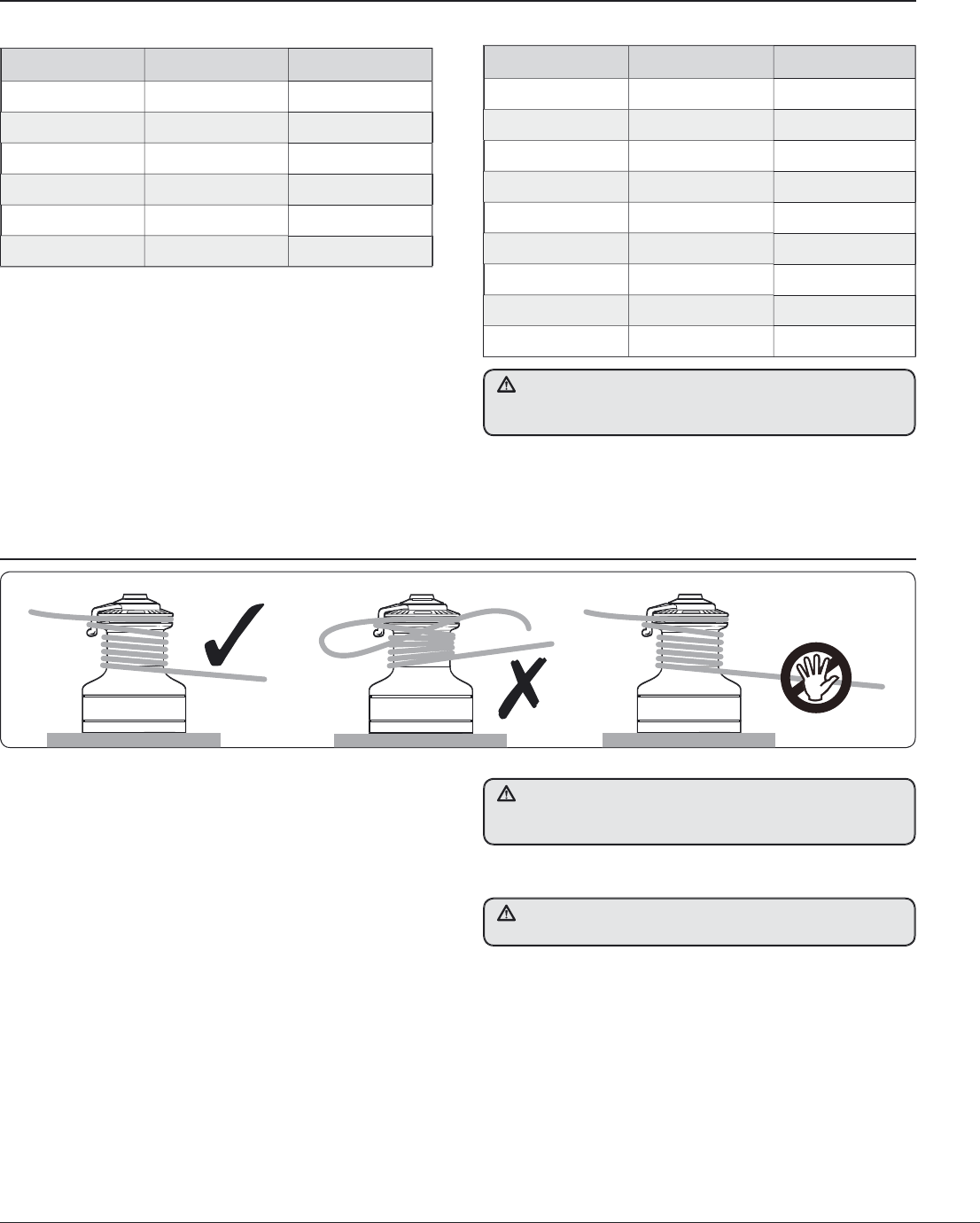
. Operating
y
our winc
h
• Ocean Winc
h
es 34−65 are sing
l
e spee
d
powere
d
winc
h
es &
manual 2 speed, these winches emplo
y
an overide ratchet
gearing for safet
y
when winching manuall
y.
• Ocean Winches 66−77 are 2 or 3 speed powered and manuall
y
operated, the
y
will not drive electricall
y
while the winch lock-in
h
a
n
d
l
e
i
s
in
t
h
e
d
riv
e
soc
k
et.
1. A
d
just t
h
e fee
d
er arm so t
h
at t
h
e rope tai
l
s into a secure are
a
away from t
h
e incoming
l
ine.
2. T
h
ere must
b
e at
l
east 3 turns of rope aroun
d
t
h
e winc
h
b
efore
b
eing passe
d
across t
h
e fee
d
er arm in to t
h
e wavespring se
l
f
tai
l
ing jaws
.
3. Use t
h
e winc
h
h
an
dl
e or e
l
ectric switc
h
to operate t
h
e
win
c
h
.
Fig. 6.0.1
5.1
Op
t
i
mum ro
p
e
di
ameters
5
.2
M
ax
i
mum w
i
nc
h
l
oa
d
va
l
ues
4
. Pa
y
out line as per manual winch.
Maximum safe working loads are recommended to be N
O
T M
O
RE
than the those detailed above. This
p
rovides an acce
p
table safety
m
ar
g
in for dynamic load sur
g
es in extreme sea conditions.
Remove handle a
f
ter use
.
NEVER
h
o
ld
t
h
e
i
ncom
i
ng rope to t
h
e w
i
nc
h
w
hil
e t
h
e w
i
nc
h
i
s
operated.
O
nly control the rope leaving the winch
.
ALWAYS switch off the winch at the circuit breaker
/
isolator after
s
ailin
g
or when leavin
g
the boat to
p
revent accidental o
p
eration
.
15
Ocean Electric Winches 34 -
7
7
GB
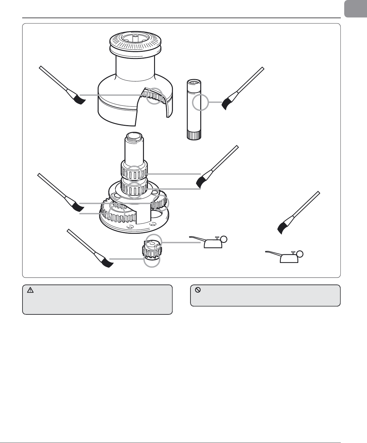
7
. Servicing your winc
h
1. M
O
NTHLY
Hose
d
own wit
h
fres
h
water t
h
en
l
ig
h
t
l
y oi
l
an
d
grease as per
ill
ustration ta
k
ing care not to get any grease in t
h
e paw
l
s as
t
he
y
will stick in operation.
2
.
TW
O
O
R THREE TIME
S
D
U
RIN
G
AC
TIVE
S
AILIN
G
S
EA
SO
N
Stri
p
, clean, check and relubricate.
3
.
END
O
F
S
EA
SO
N
O
R BE
G
INNIN
G
O
F NEW SE
A
SON
Strip, c
l
ean, t
h
oroug
hl
y c
h
ec
k
for
d
amage,
l
u
b
ricate an
d
r
eassem
bl
e as
d
etai
l
e
d
in t
h
e service manua
l
.
C
h
ec
k
con
d
ition of motor gear
b
ox. In t
h
e event of corrosion,
cl
ean an
d
repaint motor wit
h
marine gra
d
e oi
l
b
ase
d
ename
l
p
aint.
F
i
g
. 7.0.
1
• F
o
r m
o
r
e
deta
il
s
as
k f
o
r
t
h
e
fr
ee
boo
kl
et
a
n
d
m
a
n
ua
l “H
o
w
to
Se
rvi
ce
Y
ou
r Win
c
h” B 2
30
4 “Win
c
h P
a
r
ts
M
a
n
ua
l V
o
l
u
m
e
1
0
” B 21
96
a
n
d
“
Custo
m Win
ch
Se
rvi
ce
M
a
n
ual
V
olu
m
e
8
”
B2312
(
77-144
/
2
)
or
d
own
l
oa
d
from
:
www.
l
ewmar.com/w
i
nc
h
serv
i
ce.
O
il
G
reas
e
TURN THE POWER OFF at the circuit breaker
/
isolator before
a
ny maintenance
/
servicing is carried out. Winches need regular
m
aintenance to operate at peak e
ffi
ciency otherwise permanent
d
amage an
d
premature wear can resu
l
t
.
Electric motors become hot during and
f
or some time a
f
ter
use. These units have an oil fi lled gearbox. D
O
N
O
T remove the
mo
t
or.
1
6
Ocean Electric Winches 34 -
7
7
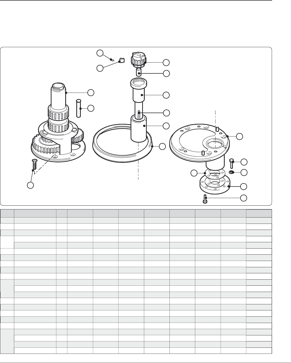
8
. Parts list
8.1 W
i
nc
h
mo
d
e
l
notes
N
O
TE: For w
i
nc
h
es
b
e
f
ore Fe
b
ruar y 1995.
• P
l
ain
b
earing 45000248
h
as rep
l
ace
d
t
h
e
b
earings an
d
spacer,
t
h
ese items ARE NOT interc
h
angea
bl
e. Contact your Lewmar
D
ea
l
e
r
.
I
tem
D
escr
i
pt
i
o
n
Q
t
y
3
4
40
44
4
8
5
0
54
5
8
6
4
/
65
1
C
entre
S
te
m
1
45000265
4
50002
3
7 45000
33
7 450004
3
7 45000560 4500066
0
4500076
0
4500086
0
2
G
ear S
p
indle
1
45000258
4
5000241 45000
3
4
4
4500044
4
4500054
4
4500074
4
4500074
4
4500074
4
3
R
achet Pawl
G
ea
r
1
45000288
4
500024
2
45000
3
4
2
45000
3
4
2
4500054
2
4500064
2
4500074
2
45000842
4
P
awl
4
15
00009
4 15
000094
15
000094
15
000094
15000
3
01 15000
3
01 15000
3
01 15000
3
0
1
Sp
rin
g
4
1
260/7
1
260/
7 1
260/
7 1
260/
7 1
260/
7 1
260/
7 1
260/
7 1
260/
7
5
B
earin
g
3
15000
3
78 15000
3
78 15000
3
98 15000
3
9
8
15
0000
17 15
0000
17 15
0000
17 15
0000
17
6
D
rive Shaft
1
45000
3
5
7
4
5000
3
57 45000
3
57 45000
3
57 4500054
3
4500054
3
4500054
3
4500054
3
7
K
e
y
1
1500
3
28
7
1500
3
287 1500
3
287 1500
3
287 1500
3
287 1500
3
287 1500
3
287 1500
3
287
8
P
lain Bearin
g
1
45000
3
59
4
5000
3
59 45000
3
58 45000
3
5
8
45
0002
4
8
45
0002
4
8
45
0002
4
8
45
0002
4
8
9
B
ase Plate Cover
1
4
5000229
45000229
4
50003
29 4
5000
4
29
4
5000529
4
5000529
4
5000
7
59
4
5000
7
59
1
0
B
ase Plate
1
45
00026
4
4
5
000228
45000
3
28 45
000
4
28
45
000
5
28
45
000
5
28
45
000
75
8
45
000
75
8
Do
w
el
2
4
5000
23
5
45000
23
5
4
5000
23
5
4
5000
23
5
4
500058
1 4
500058
1 4
500058
1 4
5000581
S
h
a
ft
S
e
al
1
B6
234
B6
234
B6
23
4
B6
23
4
B
6
23
5
B
6
23
5
B
6
23
5
B
6
23
5
1
1
I
n
s
ul
a
tion
S
him
1
4
5000257
4500025
7 4
500025
7 4
500025
7 4
500025
7 4
500025
7 4
500025
7 4
500025
7
12
H
EX B
o
lt M
8
x2
5
4
B0
173
B0
173
B0
173
B0
173 B
0
173 B
0
173 B
0
173 B
0
17
3
1
3
W
as
her M8 4
B
12
07
B
12
0
7
B
12
0
7
B
12
0
7 B12
0
7 B12
0
7 B12
0
7 B12
0
7
14
Pla
t
e
1
4
5000
3
50
45000
3
50
4
5000
3
50
4
5000
3
50
4
5000
3
50
4
5000
3
50
4
5000
3
50
4
5000
3
50
15
S
KT HD
s
crew M6 x 1
2
5
B06
7
8
B06
7
8
B06
7
8
B06
7
8
B
06
7
8
B
06
7
8
B
06
7
8
B
06
7
8
1
6
C
S
K HD
s
crew M6 x 1
6
5
B05
24
B05
2
4
-
-
-
-
-
-
CS
K HD
s
crew M8 x 1
6
6
- -
B05
3
6
B05
3
6
CS
K HD
s
crew M8 x 2
5
6
- - - - B
08
1
2
B
08
1
2
-
-
CS
K HD
s
crew M10 x 2
5
5
- - - -
-
-
B
056
7 B
056
7
1
2
16
9
10
11
4
3
6
4
8
14
5
12
13
15
7
Fi
g
. 8.2.1
8.2 Parts list 34-65
•
On winc
h
es 50 to 65 t
h
e 2
l
ower
b
earings
h
ave
b
een rep
l
ace
d
by
item 45003103 (Plain Bearing). These items ARE
i
nterchan
g
eable.
NOTE: Manual winche
s
cannot be converted into
e
lectric versions by addin
g
parts listed here
.
1
7
Ocean Electric Winches 34 -
7
7
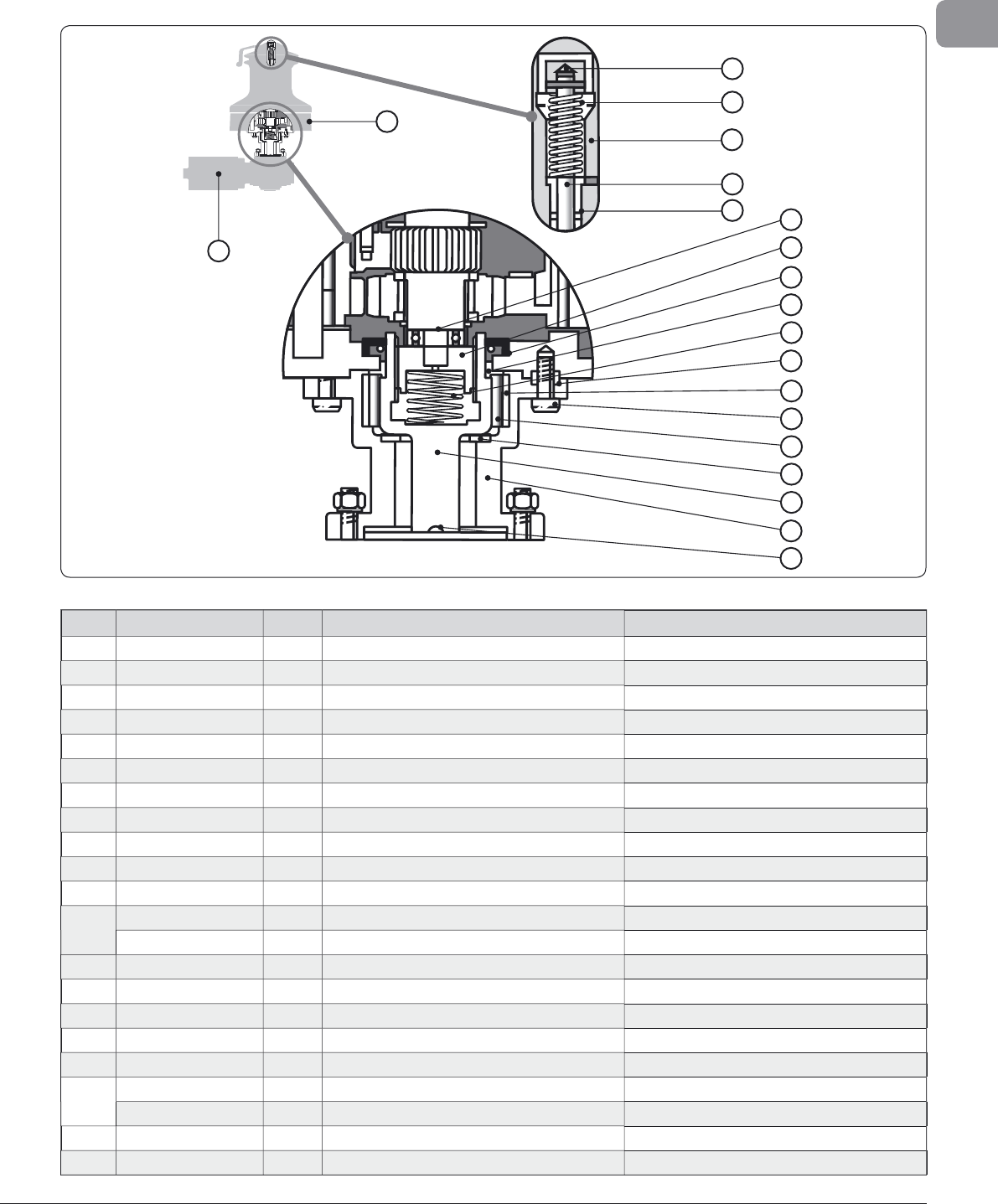
GB
I
te
m
D
escr
i
pt
i
o
n
Q
t
y
6
6
/
68-*
2
7
7-*
2
1
P
us
h
R
o
d
A
ssem
bl
y
1
1
8000
1
8
1
18000
4
88
2
Spring
1
1
50
44
6
13
150
44
6
13
3
‘O’ Ring
1
B
2
5
3
2
B
2
5
3
2
4
B
us
h
1
1
5000
1
8
4
15000
1
8
4
5
Spring Clip
1
B99
41
B99
41
6
D
r
i
ve
D
o
g
1
1
5300688
153005
7
5
7
S
e
al
1
B
2
5
93
B
2
5
93
8
Thru
s
t
S
leev
e
1
4
5002
1
54
45002
1
5
4
9
Spring
1
1
5300
4
8
9
15300
4
8
9
1
0
Hollo
w
Do
w
el
1
4
5002
14
0
45002
14
0
1
1
B
u
sh
1
1
5000569
15000569
1
2
S
cre
w
4
B0686
B0686
Heli
-
coil
4
B
242
3
B
242
3
1
3
R
o
ll
er
B
ear
i
n
g
1
1
50
1
000
7
150
1
0007
14
Th
ru
s
t
Wash
er
1
1
500
32
86
1500
32
86
1
5
Connecting Shaf
t
1
4
5002
1
56
45002
1
56
1
6
Ad
aptor
1
4
50009
44
450009
44
1
7
K
ey
1
1
500
32
8
7
1500
32
87
1
8
M
otor
/
Gearbox 12 V
1
4
80000
77
480000
7
7
M
otor
/
Gearbox 24 V
1
4
80000
7
8
480000
7
8
1
9
P
ower
Base
1
4
50009
4
0
450020
4
0
20
M
ain Spindle - Elec./Hyd
.
1
4
50009
47
45002
1
80
19
18
1
2
20
3
45
6
7
8
9
10
11
12
13
14
15
16
17
F
ig.
8
.3.
1
8
.3 Parts
li
st 66-7
7
*2
S
peed versions shown/detailed
18 Ocean Electric Winches 34 -
7
7
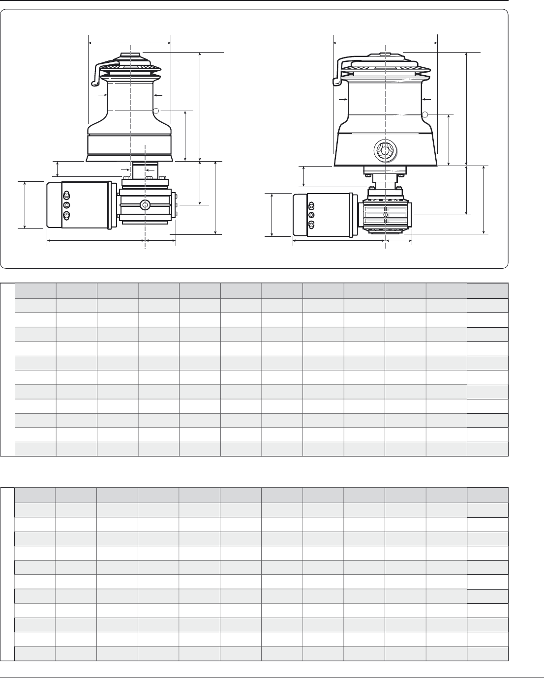
9. Dimensions
D
im
e
n
s
i
o
n
s
in mm
M
o
d
e
l
D
B
H
L
M
N
S
T
*
R
V
X
3
4
/
40 73.
5
1
54
1
89
.4
95
.
4
23
7
38
.1
99
33.
5
1
56
7
0
11
2
44
87
17
4
2
1
5
.
5
1
0
3.
5
23
8
.
5
4
2
13
0
.
5
6
4.4 1
86
72
.
5
11
2
48
93
1
86
228
.
0
1
08
.
5
23
8
.
5
4
4.
5
13
0
.
5
6
4.4 1
86
72
.
5
11
2
50
1
05
209
258
126
290
48
.
5
13
8
.
5
59
.
5
1
82
80
11
2
54
1
05
209
2
7
0
.
8
13
5
.
8
290
48
.
5
13
8
.
5
59
.
5
1
82
80
11
2
58
11
8
234
2
86
.3 13
8
.
8
290
52
.
9
13
8
.
5
59
.
5
1
82
80
11
2
6
4
/6
5 11
8
234
2
9
1.
3
141.
8
290
52
.
9
13
8
.
5
59
.
5
1
82
80
11
2
66/68
14
1
282
3
0
2.
2
14
2
.1
290
-
1
4
4
6
7.
5
188
.
5
80
11
2
66
-3 14
1
294
34
8
1
7
0
290
-
1
4
4
8
7.
5
19
1.
1
80
11
2
77 17
8
29
4 34
8
1
7
4
290
-
1
4
4
8
7.
5
19
1.
1
80
11
2
77-
3
17
8
29
4 34
8
1
7
4
290
-
1
47
8
7.
5
19
1.
1
80
11
2
Di
mens
i
ons
i
n
i
nc
h
es
M
o
d
e
l
D
B
H
L
M
N
S
T
*
R
V
X
3
4 & 40
2
7
/
8
6
1
/
1
6
7
15
/
5
32
3
49
/
9
64
9
5
/
5
1
6
1
1
/
2
3
7
/
8
1
5
/
5
16
6
1
/
8
2
3
/
3
4
4
3
/
3
8
44
3
7
/
1
6
6
55
/
5
6
4
8
3
/
3
8
41
/
16
9
25
/
5
6
41
5
/
5
8
5
9
/
9
6
4
2
1
7
/
32
7
1
/
4
2
55
/
5
6
4
4
3
/
3
8
4
8
3
11
/
1
6
7
21
/
6
4
9
3
/
3
8
41
/
4
9
25
/
5
6
41
1
/
4
5
9
/
9
6
4
2
1
7
/
32
7
1
/
4
2
55
/
5
6
4
4
3
/
3
8
5
0
4
1
/
8
8
1
/
41
0
1
/
8
4
15
/
5
16
1
1
7
/
1
6
1
15
/
5
1
6
5
7
/
1
6
2
5
/
5
16
7
1
/
8
3
1
/
8
4
3
/
3
8
54
4
1
/
8
8
1
/
41
0
5
/
5
8
5
3
/
3
8
1
1
7
/
1
6
1
15
/
5
1
6
5
7
/
1
6
2
5
/
5
16
7
1
/
8
3
1
/
8
4
3
/
3
8
5
8
4
5
/
5
8
9
1
/
411 1
/
451
/
2
1
1
7
/
1
6
2
1
/
1
6
5
7
/
1
6
2
5
/
5
16
7
1
/
8
3
1
/
8
4
3
/
3
8
6
4
/65
4
5
/
5
8
9
1
/
411 1
/
2
5
9
/
9
16
1
1
7
/
1
6
2
1
/
1
6
5
7
/
1
6
2
5
/
5
16
7
1
/
8
3
1
/
8
4
3
/
3
8
66/68
5
9
/
9
1
6
11 1
/
8
11
15
/
5
1
6
5
9
/
9
16
1
1
7
/
1
6
-
5
7
/
1
6
2
11
/
16
7
3
/
3
8
3
1
/
8
4
3
/
3
8
6
6-
3
5
9
/
9
1
6
11 1
/
2
1
3
11
/
1
6
6
1
/
16
1
1
7
/
1
6
-
5
7
/
1
6
3
7
/
16
7
1
/
2
3
1
/
8
4
3
/
3
8
77
7
11 1
/
2
1
3
11
/
1
6
6
7
/
8
1
1
7
/
1
6
-
5
7
/
1
6
3
7
/
16
7
1
/
2
3
1
/
8
4
3
/
3
8
77-
3
7
11 1
/
2
1
3
11
/
1
6
6
7
/
8
1
1
7
/
1
6
-
5
7
/
1
6
3
7
/
16
7
1
/
2
3
1
/
8
4
3
/
3
8
D
B
H
L
T*
S
R
MV
N
M
T*
D
SR
L
H
B
V
X
X
Fi
g
. 9.0.1
*
O
ptional extension kits to increase
‘
T’ are available to special order.
C
ontact
y
our nearest Lewmar offi ce if required.
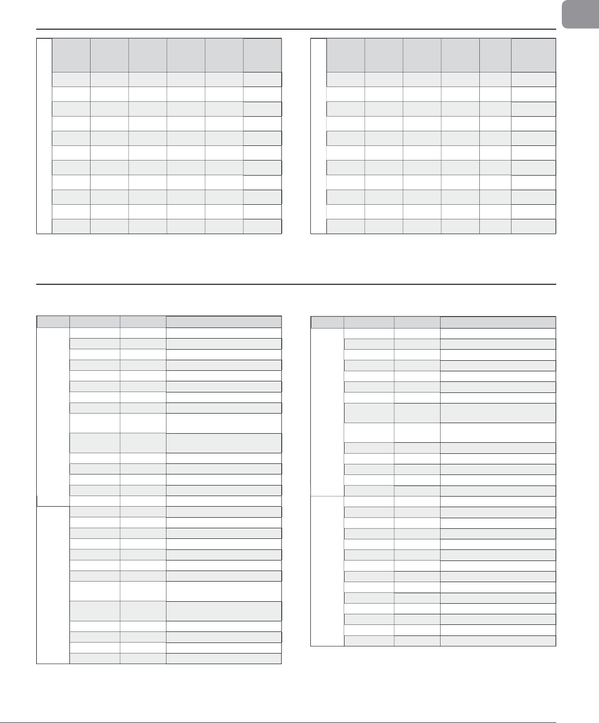
19
Ocean Electric Winches 34 -
7
7
GB
1
0. Total wei
g
ht
W
e
i
g
h
t
i
n
k
g
Mode
l
A
lloy
(
k
g)
All
B
r
o
nz
e
(
k
g)
C
hrome
(
k
g)
S
t.
S
teel
(
k
g)
All
C
hrome
(
k
g)
3
4/4
0
19
21.2
20
.
7
20
.5
21.2
44
23
.
3
2
5.
8
2
5.
8
2
5.5
2
5.
8
4
8
26
3
0.
1
29
.4
28
.
6
3
0.1
5
0
3
0
3
5.
7
3
4.8
3
4.7
3
5.7
54
3
0.
6
3
7.2
3
6.4
3
5.6
3
7.
2
5
8
33
.
4
4
0
.
6
3
9.8
3
8.1
40
.
6
6
4
/65
3
5.7 4
3
.
7
4
2
.
9
40
.1
43
.7
66
/
68
42
4
9
.
7
4
8
.
8
4
6
49
.7
6
6-
3
4
8
-
54.
8
5
2
55
.
7
77
49.
3
-
5
3
.
3
5
3
62.
3
7
7
/3
51.
3
-
57.
3
55
64.
3
W
e
i
g
h
t
i
n
lb
s
M
odel
A
llo
y
(
lbs
)
All
B
r
o
nz
e
(
lbs
)
C
hrome
(
lbs
)
S
t.
S
teel
(
lbs
)
All
C
hrome
(
k
g)
3
4/40 41.
9
4
6
.
7
45.
6
4
5.
2
46
.7
44
51
.
4
5
6
.
8
5
6
.
8
56
.
2
56
.
8
48
57.
3
66
.4
6
4.
8
63
66.
3
50
66
.1
5
78
.
7
76
.
7
7
6
.
5
7
8
.7
54
6
7.4
82
80
.
2
7
8
.
5
82
58
73
.
6
89
.5
80
.
2
8
4
89
.
5
6
4
/6
5
78
.
7
96.
3
9
4.
6
88
.
4
96.
3
66
/
68
92
.4
1
09.
3
1
07.
3
1
0
1.
2
109.
3
66-
3
10
5.
6
-
120
.
6
114.4
1
22
.5
77
108
.
5
-
121.7
11
6
.
6
1
3
7.
7
77
/3
1
1
2
.
9
-
126
.1
121
141
.
5
1
1. Model rang
e
1
1.1 Model range 34-77
M
odel Part No
.
Finis
h
Descri
p
tio
n
34
/
4
0
480
342
55
All
oy
(
Model 34) Deck Unit
480
4
0
2
55
All
oy
(
Model 40
)
Deck Unit
4
8040256
C
hrome Deck Unit
4
8040258
S
t.
S
tee
l
Deck Unit
4
8040259
A
ll
C
hrome Deck Unit
4
8040260 All Bronze Deck Unit
48000
11
6
12 V Motor
/
Gearbox
48000
11
7
2
4 V Motor
/
Gearbox
4
8000
3
0
1
o
r
00
5
2
5
05
12 V
‘
E’
C
ontactor Bo
x
4
8000
3
02
o
r
00
5
2
5
06
24 V ‘E’ Contactor Bo
x
48000081
12 V ‘ELS’ Control Bo
x
48000082
24 V ‘ELS’ Control Bo
x
48000
13
8
12 V ‘EV
C
’
Co
ntr
o
l B
o
x
48000
139 24 V ‘EV
C
’
Co
ntr
o
l B
o
x
480
4
0055
Po
w
e
r
D
r
i
v
e
Ki
t
44
480
442
55
All
oy
Deck
U
n
i
t
480
442
56
C
hr
o
m
e
Deck
U
n
i
t
480
442
58
S
t.
S
tee
l
Deck
U
n
i
t
480
442
5
9
A
ll
C
hr
o
m
e
Deck
U
n
i
t
480
442
60
All
B
r
o
nz
e
Deck
U
n
i
t
4
8000116 12 V Motor/
G
earbox
4
800011
7
2
4 V Motor/
G
earbox
4
800008
1
o
r 005250
5
12 V
‘
E’
C
ontactor Bo
x
4
8000
3
02
o
r 005250
6
24 V
‘
E’
C
ontactor Bo
x
4
800008
3
12 V
‘
EL
S
’
C
ontrol Bo
x
4800008
4 24 V
‘
EL
S
’
C
ontrol Bo
x
48000
14
0
12 V ‘EVC’ Control Box
48000
14
1
24 V
‘
EV
C
’
C
ontrol Box
M
odel
Pa
rt N
o
.
F
ini
s
h
D
escription
4
8
4
80
4
8
2
55
All
o
y
Deck
U
n
it
48048256
C
hrom
e
D
eck Uni
t
4804825
8
S
t.
S
teel
D
eck Uni
t
48048259 All
C
hrom
e
D
eck Uni
t
48048260
A
ll Bronz
e
D
eck Uni
t
4
8000
11
6
12 V Motor
/G
earbo
x
4
8000
117 24 V Motor
/
Gearbo
x
18000
3
01
or
00
5
2
5
0
5
1
2 V
‘
E’
C
ontactor Box
18000
3
0
2
or
00
5
2
5
06
2
4 V ‘E’ Contactor Box
4
8000085
12 V ‘ELS’ Control Box
4
8000086
2
4 V ‘ELS’ Control Box
4
8000
14
2
1
2 V ‘EVC’ Control Box
4
8000
143
2
4 V ‘EV
C
’
Co
ntr
o
l B
o
x
4
80
4
8055
Po
w
e
r
D
r
i
v
e
Ki
t
5
0
4
8050
2
00
All
o
y
Deck
U
n
it
4
8050
2
0
1
C
hr
o
m
e
Deck
U
n
it
4
8050
2
04
S
t.
S
teel
Deck
U
n
it
4
8050
2
0
3 All
C
hr
o
m
e
Deck
U
n
it
4
8050
2
02
All
B
r
o
nz
e
Deck
U
n
it
4
80000
7
5
12 V Motor/
G
earbo
x
48000076 24 V Motor/
G
earbo
x
N
/
A
1
2 V
‘
E’
C
ont
a
ctor Box
N/A
2
4 V
‘
E’
C
ontactor Box
48000087 12 V
‘
EL
S
’
C
ontrol Box
4
8000088
2
4 V
‘
EL
S
’
C
ontrol Box
4
8000
14
4
1
2 V
‘
EV
C
’
C
ontrol Box
4
8000
14
5
2
4 V ‘EVC’ Control Box
4
80
5
00
5
5
Power Drive Kit

2
0
Ocean Electric Winches 34 -
7
7
11.2 Circuit breaker
s
M
o
d
e
l
V
o
l
tag
e
Circui
t
B
rea
k
e
r
Circuit Breake
r
P
art
N
um
b
e
r
3
4
/
40
12
V
90
6
8000
3
4
9
2
4 V
40
68000
54
2
44
12
V 11
0
68000350
2
4 V
50
680003
4
8
4
8
12
V 1
20
68000
23
9
2
4 V
70
680002
4
0
50
12
V 1
50
68000
3
5
1
2
4 V
90
68000
34
9
54
* 12 V 250 FU
SE
58
9
008
2
4 V
90
68000
34
9
5
8
* 12 V 325 FU
SE
58
9
009
2
4 V 11
0
68000
3
50
6
4
/
65 *
12 V
325 FU
SE
58
9
009
24 V
11
0
68000
3
50
6
6
/
68
12 V
11
0
68000
3
50
24 V
50
68000
34
8
77
12 V
11
0
6
800035
0
24 V
5
0
6
800034
8
M
o
d
e
l
P
art
N
o
.
Fi
n
i
s
h
D
escr
i
pt
i
o
n
54
4
805
42
00
All
o
y
Deck
U
n
i
t
4
805
42
0
1
C
hr
o
m
e
Deck
U
n
i
t
4
805
42
0
4
S
t.
S
teel
Deck
U
n
i
t
4
805
42
0
3 All
C
hr
o
m
e
Deck
U
n
i
t
4805420
2
All
B
ronze
D
ec
k
U
n
i
t
48000075
1
2 V Motor/
G
earbox
48000076
2
4 V Motor/
G
earbox
N
/A
12 V
‘
E’
C
ontactor Bo
x
N
/A
24 V
‘
E’
C
ontactor Bo
x
4
8000089
12 V
‘
EL
S
’
C
ontrol Bo
x
4
8000090
24 V ‘ELS’ Control Bo
x
4
8000
14
6
12 V ‘EVC’ Control Bo
x
4
8000
147 24 V ‘EVC’ Control Bo
x
4
80
54
0
55
P
ower Drive Ki
t
58
4
8058200
All
o
y
Deck
U
n
i
t
4
805820
1
C
hr
o
m
e
Deck
U
n
i
t
4
805820
4
S
t.
S
teel
Deck
U
n
i
t
4
8058
2
0
3 All
C
hr
o
m
e
Deck
U
n
i
t
4
8058
2
02
All
B
r
o
nz
e
Deck
U
n
i
t
4
80000
7
5
1
2 V Motor/
G
earbox
4
80000
7
6
2
4 V Motor/
G
earbox
N/A
12 V
‘
E’
C
ont
a
ctor Bo
x
N/
A
24 V
‘
E’
C
ont
a
ctor Bo
x
48000091 12 V
‘
EL
S
’
C
ontrol Bo
x
4800009
2
24 V
‘
EL
S
’
C
ontrol Bo
x
48000148 12 V
‘
EV
C
’
C
ontrol Bo
x
4
8000
14
9
24 V
‘
EV
C
’
C
ontrol Bo
x
4
80
5
80
55
P
ower Drive Ki
t
64
/
6
5
4
8065
2
00
All
o
y
(Model 65) Deck Unit
4
806
42
00
All
o
y
(
Model 64
)
Deck Unit
4
806
42
0
1
C
hr
o
m
e
Deck
U
n
i
t
48064204
S
t.
S
teel Deck Unit
48064203 All
C
hrom
e
Deck Unit
4806420
2
All Bronze Deck Unit
48000075
1
2 V Motor
/G
earbox
4
80000
7
6
2
4 V Motor
/
Gearbox
N
/A
12 V
‘
E’
C
ontactor Bo
x
N
/A
24 V ‘E’ Contactor Bo
x
4800009
3
12 V ‘ELS’ Control Bo
x
4
8000094
24 V ‘ELS’ Control Bo
x
4
8000
15
0
12 V ‘EVC’ Control Bo
x
4
8000
1
5
1 24 V ‘EV
C
’
Co
ntr
o
l B
ox
4
806
4
055
Po
w
e
r
D
r
i
v
e
Kit
66
/
6
8
-2
S
peed
4
8066
2
00
All
o
y
Deck
U
n
i
t
4
8066
2
0
1
C
hr
o
m
e
Deck
U
n
i
t
4
8066
2
0
4
S
t.
S
teel
Deck
U
n
i
t
4
8066
2
0
3 All
C
hr
o
m
e
Deck
U
n
i
t
4
8066
2
02
All
B
r
o
nz
e
Deck
U
n
i
t
4
80000
77
1
2 V Motor/
G
earbox
4
80000
7
8
2
4 V Motor/
G
earbox
N/A
12 V
‘
E’
C
ont
a
ctor Bo
x
N/
A
24 V
‘
E’
C
ont
a
ctor Bo
x
180004
3
0 12 V
‘
EL
S
’
C
ontrol Bo
x
180004
3
1 24 V
‘
EL
S
’
C
ontrol Bo
x
N
/A
12 V
‘
EV
C
’
C
ontrol Bo
x
N
/A
24 V
‘
EV
C
’
C
ontrol Bo
x
66
/
6
8
-3
S
peed
4
806620
5
A
llo
y
Deck Unit
4
8066206
C
hrom
e
Deck Unit
4
8066209
S
t. Steel Deck Unit
4
8066208
All Chrom
e
Deck Unit
M
o
d
e
l
P
art
N
o.
Fi
n
i
s
h
D
escr
i
pt
i
on
77
4
80
77
200
Allo
y
D
eck Uni
t
4
80
77
201
Chrome
D
eck Uni
t
4
80
77
204
St. Stee
l
Dec
k uni
t
4
80
772
03
A
ll
C
hr
o
m
e
Deck
U
n
it
77 -
3
S
pee
d
4
80
77
205
All
oy
Deck
U
n
it
4
80
772
06
C
hr
o
m
e
Deck
U
n
it
4
80
772
09
S
t.
S
tee
l
Deck
U
n
it
4
80
772
08
A
ll
C
hr
o
m
e
Deck
U
n
it
77
&
77 -
3
S
p
ee
d
4
80000
7
8
24 V Motor/
G
earbo
x
4
80000
77 12 V Motor/
G
earbo
x
N/A
1
2 V
‘
E’
C
ont
a
ctor Box
N
/A
2
4 V
‘
E’
C
ont
a
ctor Box
48000022
1
2 V
‘
EL
S
’
C
ontrol Box
4800002
3
2
4 V
‘
EL
S
’
C
ontrol Box
N
/A
1
2 V
‘
EV
C
’
C
ontrol Box
N/
A 24 V
‘
EV
C
’
C
ontrol Box
*
Order fu
s
e holder 589006 with fu
s
e indic
a
ted.
11.3 NEW E
l
ectr
i
c
d
ec
k
s
w
i
tc
h
D
escr
i
pt
i
on
P
art
N
um
b
er
UNLIT - Electric deck switch o
p
en
(
Plastic
)
6
8000
3
45
LIT - Electric deck switch o
p
en
(
Plastic
)
6
9000
3
5
0
LIT - Electric deck switch o
p
en
(
Stainless Steel Lid
)
48000
17
0
Labels -
S
ilver out of black
(S
ailin
g
functions
)
6
9000
3
4
9
Labels - Black out of silver (Sailing functions) use with 4800017
0
6
9000
3
5
6
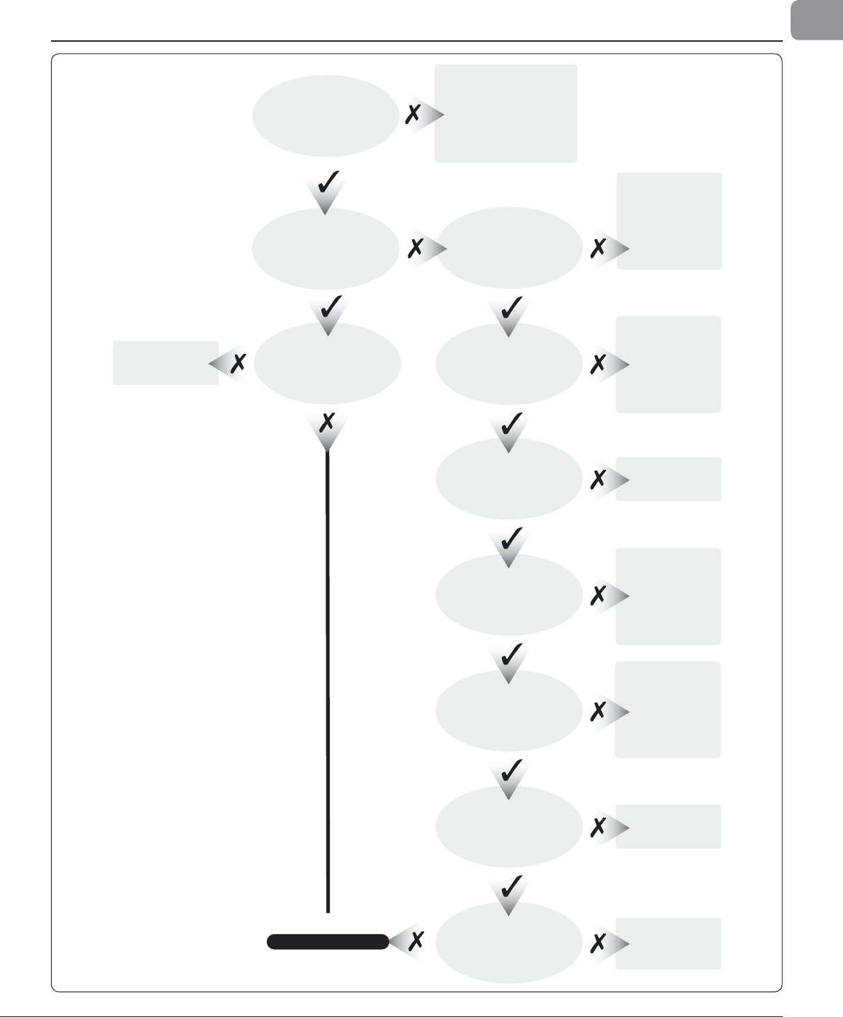
21
Ocean Electric Winches 34 -
7
7
GB
1
2. Fault fi ndin
g
Does the winch operate
manually?
Does the winch operate
electrically?
Check for correct assembly,
over use of grease? pawls
stuck. Clean, check for
broken pawl/springs,
regrease lightly.
Power at the battery?
Winch handle locked in?
(Winches 66–77 only)
Isolator switch/circuit
breaker on?
Check fuse in control box.
Power at winch?
Check switch connection
in control box.
Air hose correctly fitted?
Remove handle.
Check drive dog &
spring (items 6 & 7
parts list)
Ensure free
operation.
Check terminal
connections.
Check battery
voltage.
Adequate reserve
battery capacity?
Switch on.
Check circuit
diagram.
Check
connections.
Clean & check cables
conductivity.
Reconnect.
Check tube is
sealed, no leaks.
Motor runs but winch
does not turn
Check polarity.
www.lewmar.com
Contact Lewmar
Change fuse
(3 Amp).
Check wiring.
NOTE: EVC does NOT
have a fuse.
F
i
g
. 12.0.
1

22
Ocean Electric Winches 34 -
7
7
13. Lewmar
l
imite
d
warrant
y
L
IMITED WARRANTY an
d
K
EY TERMS OF SUPPLY BY LEWM
AR
L
ewmar warrants that in normal usa
g
e and with
p
ro
p
er maintenance its
p
roducts will conform with their specifi cation for a period of three
y
ears
f
rom the date of purchase b
y
the end user, sub
j
ect to the conditions,
limitations and exceptions listed below. An
y
product, which proves to be
d
efective in normal usage during that three-
y
ear period, will be repaired
or, at Lewmar’s option, replaced b
y
Lewmar.
A CONDITIONS AND LIMITATION
S
i
Lewmar’s
l
ia
b
i
l
ity s
h
a
ll
b
e
l
imite
d
to t
h
e repair or rep
l
acement
of any parts of t
h
e pro
d
uct w
h
ic
h
are
d
efective in materia
l
s or
wor
k
mans
h
ip.
i
i Responsibilit
y
for the selection of products appropriate for the use
i
ntended b
y
the Bu
y
er shall rest solel
y
with the Bu
y
er and Lewmar
accepts no responsibilit
y
for an
y
such selection
.
i
ii Lewmar s
h
a
ll
not
b
e
l
ia
bl
e in any way for Pro
d
uct fai
l
ure, or an
y
r
esu
l
ting
l
oss or
d
amage w
h
ic
h
arises from:
a
use of a
p
roduct in an a
pp
lication for which it was not desi
g
ned or
i
ntended;
b
. corrosion, u
l
tra vio
l
et
d
egra
d
ation or wear an
d
tear
;
c. a failure to service or maintain the
p
roduct in accordance with
Lewmar’s recommendations
;
d
. fau
l
ty or
d
efi cient insta
ll
ation of t
h
e pro
d
uct
(
un
l
ess con
d
ucte
d
by
Lewmar
);
e
. an
y
modifi cation or alteration of the product
;
f
. con
d
itions t
h
at excee
d
t
h
e pro
d
uct’s performance specifi cations or
s
afe wor
k
ing
l
oa
d
s.
i
v Product sub
j
ect to a warrant
y
claim must be returned to the Lewmar
outlet which su
pp
lied the
p
roduct for examination unless otherwise
agreed b
y
Lewmar in writing.
v
T
h
is warranty
d
oes not cover any inci
d
enta
l
costs incurre
d
for t
h
e
i
nvestigation, remova
l
, carriage, transport or insta
ll
ation of pro
d
uct
.
v
i Service
b
y anyone ot
h
er t
h
an aut
h
orise
d
Lewmar representatives
sh
a
ll
voi
d
t
h
is warranty un
l
ess it accor
d
s wit
h
Lewmar gui
d
e
l
ines
an
d
stan
d
ar
d
s of wor
k
mans
h
i
p
.
v
ii Lewmar’s products are intended for use onl
y
in the marine
e
nvironment. Bu
y
ers intending to use them for an
y
other purpose
s
hould seek independent professional advice as to their suitabilit
y
.
Lewmar accepts no liabilit
y
arising from such other use.
B EX
C
EPTI
O
N
S
Cover un
d
er t
h
is Warranty is
l
imite
d
to a perio
d
of one year from t
h
e
d
ate
of purc
h
ase
b
y t
h
e en
d
user in t
h
e case of any of t
h
e fo
ll
owing pro
d
ucts
or
p
arts of
p
ro
d
ucts
:
• Electric motors and associated electrical equipment
• E
lect
r
o
ni
c
co
n
t
r
ols
• H
y
draulic pumps, valves and actuator
s
• W
eathe
r
seals
• Products used in “Grand Prix” racing applications
C
LIABILIT
Y
i
Lewmar’s
l
ia
b
i
l
ity un
d
er t
h
is warranty s
h
a
ll
b
e to t
h
e exc
l
usion of
a
ll
ot
h
er warranties or
l
ia
b
i
l
ities
(
to t
h
e extent permitte
d
b
y
l
aw
)
. In
p
articu
l
ar
(b
ut wit
h
out
l
imitation
)
:
a
Lewmar shall not be liable for:
• Any
l
oss of anticipate
d
turnover or profi t or in
d
irect, consequentia
l
or economic
l
oss
;
• Damages, costs or expenses pa
y
able to an
y
third part
y;
• Any
d
amage to yac
h
ts or equipment;
• Death or personal In
j
ur
y
(unless caused b
y
Lewmar’s negligence).
Some states and countries do not allow the exclusion or limitation o
f
incidental or conse
q
uential dama
g
es, so the above limitation or exclusion
ma
y
not appl
y
to
y
ou.
b
Lewmar grants no ot
h
er warranties regar
d
ing t
h
e fi tness for purpose,
use, nature or satisfactory qua
l
ity of t
h
e pro
d
ucts.
ii Where applicable law does not permit a statutory or implied warrant
y
t
o be excluded, then such warranty, if permitted by that state o
r
c
ountry’s law, shall be limited to a period of one year from the date
o
f purchase b
y
the end user. Some states and countries do not allo
w
limitations on how long an implied warrant
y
lasts, so this limitation
ma
y
not appl
y
to
y
ou
.
D PROCEDURE
Notice of a claim for service under this warrant
y
shall be made promptl
y
and in writing b
y
the end user to the Lewmar outlet which supplied the
product or to Lewmar at Southmoor Lane, Havant, Hampshire, England
P
O
9 1
JJ.
E
S
EVERAN
C
E
C
LA
US
E
If any c
l
ause of t
h
is warranty is
h
e
ld
b
y any court or ot
h
er competen
t
aut
h
ority to
b
e inva
l
i
d
or unenforcea
bl
e in w
h
o
l
e or in part, t
h
e va
l
i
d
ity
o
f t
h
e remaining c
l
auses of t
h
is warranty an
d
t
h
e remain
d
er of t
h
e c
l
ause
in
q
uestion s
h
a
ll
not
b
e affecte
d
.
F OTHER RIGHT
S
This warrant
y
gives
y
ou specifi c legal rights, and
y
ou ma
y
also have othe
r
l
egal rights, which var
y
, from state to state and countr
y
to countr
y
.
In t
h
e case of Euro
p
ean States a Consumer customer
(
as
d
efine
d
nationa
ll
y
)
h
as
l
ega
l
rig
h
ts un
d
er t
h
e app
l
ica
bl
e nationa
l
l
aw governing
th
e sa
l
e of Consumer Goo
d
s; t
h
is Warranty
d
oes not affect t
h
ose
r
i
gh
ts.
G L
AW
This warrant
y
shall be governed b
y
and read in accordance with the laws
o
f England or the state or countr
y
in which the fi rst end user is domiciled
at the time of
p
urchase of the
p
roduct.
H
DI
S
P
U
TE
S
Any
d
ispute arising un
d
er t
h
is warranty may, at t
h
e option of t
h
e en
d
-user,
b
e referre
d
to a
l
ternative
d
ispute reso
l
ution un
d
er t
h
e ru
l
es of t
h
e Britis
h
Marine Fe
d
eration or to t
h
e Courts of t
h
e State w
h
ose
l
aw s
h
a
ll
govern
th
e warranty or to t
h
e Courts of Eng
l
an
d
an
d
Wa
l
es.
T
h
e Britis
h
Marine Fe
d
eration may
b
e contacte
d
at Marine House,
T
h
orpe Lea Roa
d
, Eg
h
am, Eng
l
an
d
, TW20 8B
F

Produced by T. Connell UK (+44) 023 9263 9265 Ref:T1712/03/2006
© Copyright 2006 Lewmar Ltd. All rights reserved.
B2303
W
W
W
L
EWMARCO
M
