Lexmark Air Compressor Dd 100 Users Manual
DD-520 to the manual ace6fa8c-c59d-4218-81c6-64ac4408b429
2015-01-23
: Lexmark Lexmark-Lexmark-Air-Compressor-Dd-100-Users-Manual-268433 lexmark-lexmark-air-compressor-dd-100-users-manual-268433 lexmark pdf
Open the PDF directly: View PDF ![]() .
.
Page Count: 5
107 W. Main Street, Worthington, PA 16262
Phone: 724-297-3416 Fax: 724-297-5189
URL:
http://www.airtak.com
e-mail:
airtak@airtak.com
INSTALLATION, OPERATION AND MAINTENANCE INSTRUCTIONS
DELIQUESCENT DRYER
MODELS DD-48 THRU DD-5000
SPECIFICATIONS:
Maximum Working Pressure: 150 PSIG
Maximum Inlet Temperature: 110°F

2
SAFETY INFORMATION
DO NOT REMOVE CAP ON FILL PORT UNTIL ALL PRESSURE IS OUT OF DRYER.
DO NOT REMOVE OR ADJUST ANY EQUIPMENT ON DRYER UNTIL ALL PRESSURE IS OUT OF THE
DRYER.
DO NOT OPERATE DRYER ABOVE MAXIMUM WORKING PRESSURE.
DO NO ALTER VESSEL IN ANY WAY, SUCH AS WELDING OR GRINDING.
LOCATION
For maximum performance, always locate dryer where the inlet compressed air temperature is lowest. Inlet air
temperature to dryer must be no more than 10°F above the lowest temperature in the air system. Outlet dew point
(level of dryness) from dryer depends on inlet temperature of the compressed air.
If temperature of air from the compressor is not within this 10°F range, an aftercooler is required to reduce the air
temperature before it is processed through the dryer. An air-cooled aftercooler sized for a 10°F approach is
recommended for installation before the dryer. The aftercooler compensates for changing atmospheric
temperatures by exchanging heat between the atmospheric and compressed air so that inlet compressed air
temperature to the dryer is within the 10°F range. A separator is then required on the aftercooler outlet to remove
the condensed water.
Where air lines or equipment are located outdoors, install dryer outdoors in coolest location.
In systems where air usage fluctuates or there are sudden demands, protect dryer against air flow surges.
For best efficiency, locate dryer where air pressure is highest in system; more air can be dried at higher pressures.
INSTALLATION
1. Install dryer in an upright (vertical) position on a level surface with fill port on top. On wall-mounted models
DD-12 thru DD-48, provide strapping or additional support to prevent stress on piping to dryer.
2. Install by-pass piping with inlet, outlet and by-pass valves to isolate dryer for adding desiccant.
3. Connect inlet air piping to dryer inlet (lower connection) and outlet piping to dryer outlet (top connection).
Compressed air must flow through dryer from bottom to top of vessel or air will not be sufficiently dried.
WARNING: ALWAYS INSTALL PARTICULATE FILTER AFTER DRYER TO PREVENT ANY ACCIDENTAL
FLOW OF MATERIALS FROM DRYER INTO DOWNSTREAM EQUIPMENT.
4. Connect drain line to coupling on bottom of dryer vessel, and install manual valve at end of line. Note: Install
motorized drain (optional equipment) as indicated on instructions supplied with automatic drain.
5. Install pressure relief valve to conform to OSHA Standard 1910.169; also check local codes.
6. Remove cap from fill port on top of dryer and pour in recommended amount of Deli-Dry desiccant (see chart
below). Check to make sure that vessel is filled to within 1 or 2" of dryer top.
7. Replace cap on fill port, and tighten securely.
8. Close inlet and outlet shutoff valves; also close drain valve.

3
9. Start compressor: then slowly open dryer inlet valve to pressurize dryer gradually.
10. Open outlet valve slowly; close by-pass valve.
CAUTION!!!!!
MAKE SURE THAT DRYER IS NOT SUBJECTED TO AIR SURGES WHILE IT IS BEING PRESSURIZED.
OPERATION
START-UP: Slowly open outlet shutoff valve and then inlet valve. Close by-pass valve.
SHUT-DOWN: Maintain pressure in dryer during shut-down by following this procedure before shutting off air
supply to dryer: Open by-pass valve. Then close dryer inlet and outlet shufoff valves.
MAINTENANCE
*Drain dryer after every 8 hours of operation.
Open manual drain valve and allow all collected drain solution to discharge from dryer. On dryers equipped with an
automatic drain, check periodically by pushing test button to make sure that drain is operating properly.
WARNING
Always drain dryer regularly. If drain solution reaches an abnormally high level, air flow may force
solution into system piping and cause damage to downstream equipment.
*Inspect tablet level through sight window regularly. Add DELI-DRY TABLETS when top of bed is level with
sight window. Use the following procedure:
1. Isolate dryer from air system by closing inlet and outlet valves; open by-pass valve.
2. Open drain valve; depressurize dryer completely.
3. After all pressure is out of dryer, unscrew cap on fill port.
4. Add enough tablets so that vessel is filled.
5. Replace cap on fill port and tighten securely.
6. Slowly open outlet valve and allow air to bleed through drain valve.
7. Close drain valve, and open inlet valve slowly to pressurize dryer graduallly.
8. Close by-pass valve.
4
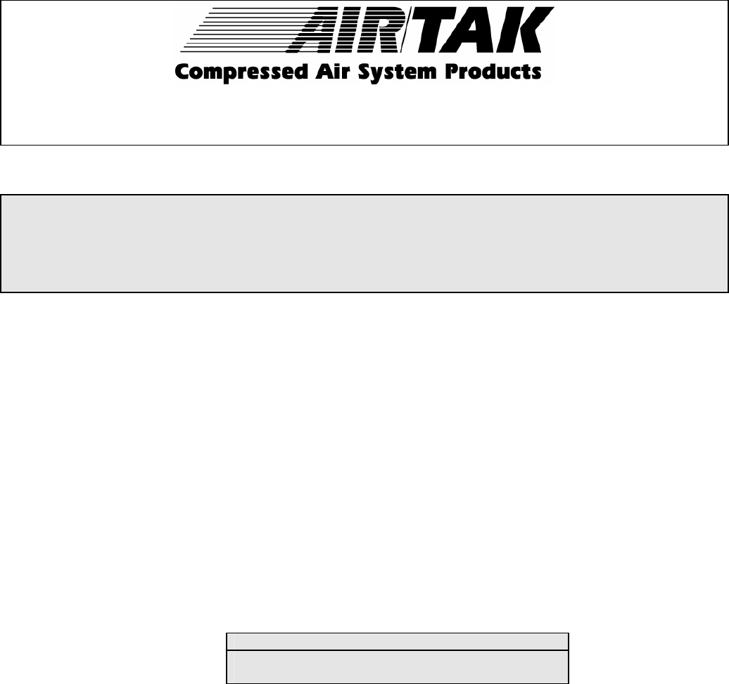
Dimensions & Weights (inches & pounds)
Model No. Heigh
t
Vessel
Diameter
Inlet/Outlet
Connections
Height
to
Inlet
Fill Port
(Diameter)
Deliquescent
Tablets (Initial fill)
Vessel
Weight (LB)
DD-48 37 8 1 5 2 40 85
DD-72 53 14 2 18.5 2 160 210
DD-100 55 14 2 18.5 2 175 220
DD-150 57 14 2 18.5 2 190 230
DD-220 55 20 2 19.5 3 x 4 345 320
DD-370 57 20 2 19.5 3 x 4 370 360
DD-520 67 30 3 22 3 x 4 975 655
DD-740 72 30 3 22 3 x 4 1120 779
DD-970 72 36 4 Flg. 26 4 x 6 1350 985
DD-1250 90 42 4 Flg. 15 11 x 15 1500 1425
DD-1500 102 42 4 Flg. 15 11 x 15 2000 1650
DD-1750 105 48 4 Flg. 15 11 x 15 2450 1800
DD-2000 108 54 6 Flg. 18 11 x 15 2900 2450
DD-2500 110 60 6 Flg. 18 11 x 15 3650 2850
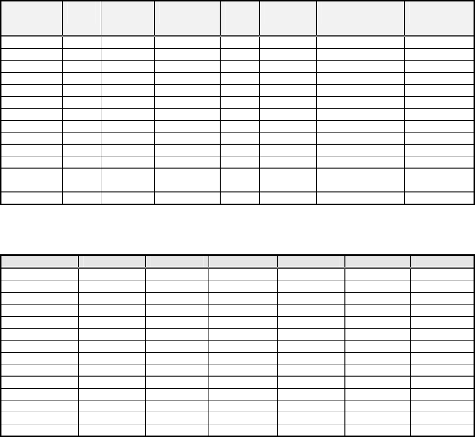
Maximum Capacities (SCFM)
Model No. 70 PSIG 80 PSIG 90 PSIG 100 PSIG 125 PSIG 150 PSIG
DD-48 35 39 43 48 58 68
DD-72 53 59 65 72 87 103
DD-100 73 82 90 100 121 143
DD-150 110 123 135 150 182 215
DD-220 161 180 198 220 267 315
DD-370 270 303 333 370 450 531
DD-520 380 426 468 520 633 746
DD-740 540 607 666 740 901 1062
DD-970 708 795 873 970 1181 1392
DD-1250 925 1032 1141 1250 1522 1794
DD-1500 1107 1238 1369 1500 1826 2153
DD-1750 1292 1444 1597 1750 2131 2512
DD-2000 1477 1651 1825 2000 2435 2871
DD-2500 1846 2064 2282 2500 3044 3589
AIR/TAK WARRANTY POLICY

Air/Tak products will be warranted to be free from defects in materials and workmanship for a period of one
year from date of shipment or up to one year from the verified date of installation not to exceed 15 months.
Date of installation will be verified upon receipt of the completed Warranty Registration Card. All Air/Tak
refrigerated dryers will additionally be warranted on parts only (excluding fan motors and drain valves) for
a period of two years from the date of shipment. Also, deliquescent and regenerative air dryer pressure
vessels and refrigerated air dryer heat exchangers have a 5-year prorated warranty.
All damaged pressure vessels and heat exchangers returned to AIR/TAK for warranty consideration must
be returned freight prepaid. Warranty will be determined after factory inspection. Failure to return a
damaged heat exchanger or pressure vessel will result in warranty denial.
Repairs, adjustments, parts, etc. are limited to actual labor cost provided that such defects are promptly
reported and approved following AIR/TAK's warranty procedures. In no event shall the cost of repairs
exceed the actual cost of materials and labor.
AIR/TAK or its representatives reserve the right to decide which warranty items are authorized. AIR/TAK
shall not be liable for incidental or consequential damages which may result from a breach of the warranty
described above.
For more information on warranty policies and procedures, contact your authorized AIR/TAK Distributor.
AIR/TAK's line of quality compressed air system products includes:
COMPRESSED AIR SYSTEM FILTERS * AIR-COOLED AFTERCOOLERS
REFRIGERATED AIR DRYERS * CAD COMBINATION AFTERCOOLER DRYER SYSTEMS
RAD-PAK REFRIGERATED AIR DRYER/FILTER PACKAGES * HEATLESS REGENERATIVE AIR DRYERS
HLD-PAK HEATLESS REGENERATIVE AIR DRYER/FILTER PACKAGES
BLOWER PURGE REGENERATIVE AIR DRYERS * EXTERNALLY HEATED REGENERATIVE AIR DRYERS
AIR CHILLERS * FLUID CHILLERS
For an authorized distributor near you, contact Air/Tak at: Air/Tak Inc. 107 W. Main Street, Worthington, PA 16262
Phone: 724.297.3416 Fax: 724.297-5189
e-mail: airtak@airtak.com
5
