Lexus OM48C64U
User Manual: Lexus 2012 Lexus RX 450h Owners Manual Pdf | Owner's Manual Pdf
Open the PDF directly: View PDF ![]() .
.
Page Count: 736 [warning: Documents this large are best viewed by clicking the View PDF Link!]

TABLE OF CONTENTS
1
1Before driving
Information on the hybrid system and adjusting and
operating features such as door locks, mirrors, and
steering column.
2When driving Driving, stopping and safe-driving information.
3Interior features Air conditioning and audio systems, as well as other interior
features for a comfortable driving experience.
4Maintenance
and care
Cleaning and protecting your vehicle, performing do-it-your-
self maintenance, and maintenance information.
5When trouble
arises
What to do if the vehicle needs to be towed, gets a flat tire,
or is involved in an accident.
6Vehicle
specifications Detailed vehicle information.
7For owners Reporting safety defects for U.S. owners, and seat belt and
SRS airbag instructions for Canadian owners.
Index Alphabetical listing of information contained in this manual.

TABLE OF CONTENTS Index
2
1-1. Hybrid system
Hybrid system.................................. 30
Hybrid system precautions ......... 34
Energy monitor/
consumption screen ................... 40
Hybrid vehicle driving tips........... 45
1-2. Key information
Keys ...................................................... 47
1-3. Opening, closing and
locking the doors
Smart access system with
push-button start.......................... 52
Wireless remote control.............. 64
Side doors .......................................... 67
Back door........................................... 70
1-4. Adjustable components
(seats, mirrors,
steering wheel)
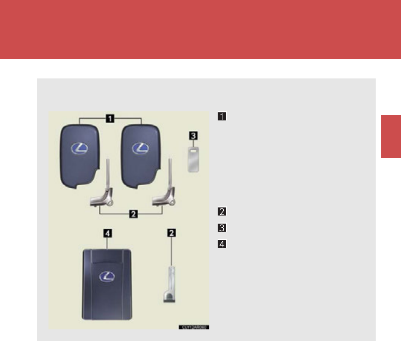
Front seats.......................................... 82
Rear seats........................................... 86
Driving position memory ............. 90
Head restraints................................. 95
Seat belts ............................................ 97
Steering wheel................................ 105
Anti-glare inside rear view
mirror .............................................. 107
Outside rear view mirrors......... 109
1-5. Opening and closing the
windows and moon roof
Power windows................................ 112
Moon roof .......................................... 115
1-6. Refueling
Opening the fuel tank cap........... 119
1-7. Theft deterrent system
Immobilizer system ...................... 124
Alarm.................................................. 126
Theft prevention labels
(for U.S.A.).................................... 129
1Before driving
For vehicles with a navigation system, refer to the “Navigation System Owner’s
Manual” for information regarding the equipment listed below.
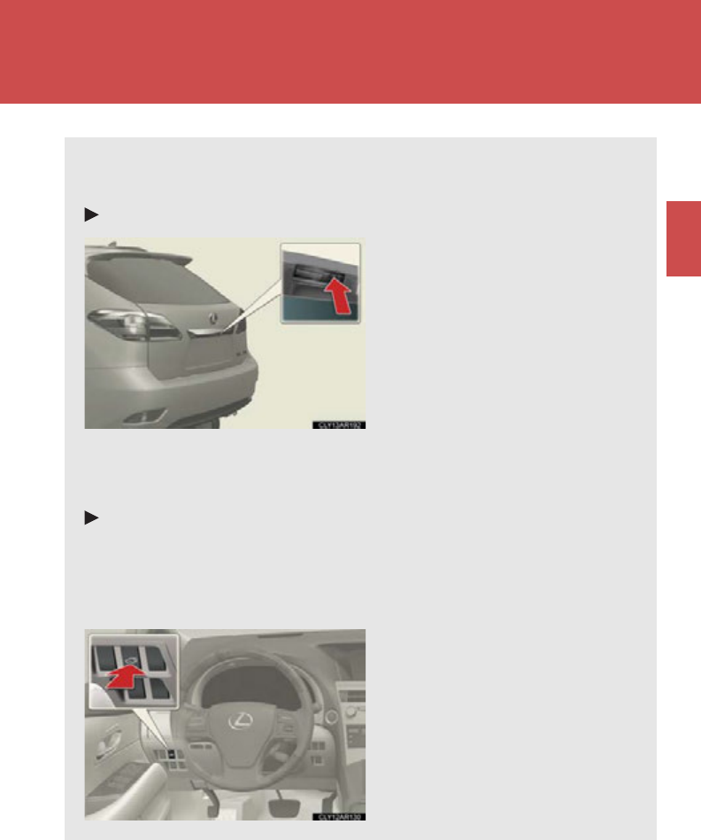
• Navigation system
• Air conditioning controls
• Windshield wiper de-icer
• Rear view monitor system
• Intuitive parking assist
• Audio/video system
• Rear window and outside rear view
mirror defogging

1
2
3
4
5
6
7
3
1-8. Safety information
Correct driving posture ............. 130
SRS airbags ..................................... 132
Front passenger occupant
classification system.................. 144
Child restraint systems ............... 149
Installing child restraints............. 153
2-1. Driving procedures
Driving the vehicle........................ 166
Power (ignition) switch............... 176
Hybrid transmission ..................... 182
Turn signal lever ............................ 190
Parking brake ................................. 192
Horn.................................................... 193
2-2. Instrument cluster
Gauges and meters ..................... 194
Indicators and warning
lights................................................. 198
Multi-information display.......... 202
Head-up display .......................... 208
2-3. Operating the lights and
windshield wipers
Headlight switch............................ 213
Automatic High Beam................ 219
Fog light switch ............................. 226
Windshield wipers and
washer ........................................... 229
Rear window wiper and
washer ........................................... 235
Headlight cleaner switch .......... 237
2-4. Using other driving systems
Cruise control ............................... 238
Dynamic radar cruise
control............................................ 243
Intuitive parking assist................ 257
Electronically modulated
air suspension............................. 264
Rear view monitor system........ 270
Driving assist systems................. 274
Hill-start assist control .............. 280
Pre-Collision System.................. 282
2When driving

TABLE OF CONTENTS Index
4
2-5. Driving information
Utility vehicle precautions....... 286
Cargo and luggage.................... 290
Vehicle load limits........................ 295
Winter driving tips ....................... 296
Trailer towing
(AWD models with
towing package)....................... 300
Trailer towing
(2WD models and AWD
models without towing
package)........................................ 318
Dinghy towing ................................ 319
3-1. Using the air conditioning
system and defogger
Automatic air conditioning
system ............................................ 322
Rear window defogger
switch............................................. 330
Windshield wiper de-icer.......... 331
3-2. Using the audio system
Audio system ................................. 332
Using the radio.............................. 336
Using the CD player................... 346
Playing MP3 and WMA
discs ................................................ 356
Operating an iPod....................... 366
Operating a USB memory....... 374
Optimal use of the audio
system ........................................... 383
Using the AUX port .................. 386
Using the steering wheel
audio switches ........................... 388
3-3. Using the Bluetooth®
audio system
Bluetooth® audio system .......... 391
Using the Bluetooth®
audio system................................ 394
Operating a Bluetooth®
enabled portable player......... 399
Setting up a Bluetooth®
enabled portable player........ 403
Bluetooth® audio system
setup ................................................ 410
3Interior features

1
2
3
4
5
6
7
5
3-4. Using the hands-free phone
system (for mobile phones)
Hands-free system for
mobile phones............................... 411
Using the hands-free system
(for mobile phones)................... 415
Making a phone call.................... 423
Setting a mobile phone.............. 428
Security and system setup........ 434
Using the phone book............... 438
3-5. Using the interior lights
Interior lights list............................ 445
• Interior lights ............................... 446
• Personal lights ............................ 446
3-6. Using the storage features
List of storage features............... 448
• Glove box .................................... 449
• Bottle holders/door
pockets......................................... 450
• Cup holders.................................. 451
• Console box................................ 453
• Auxiliary boxes........................... 455
• Under tray.................................... 456
3-7. Other interior features
Sun visors......................................... 457
Vanity mirrors............................... 458
Clock................................................. 459
Outside temperature
display............................................ 460
Multi-display light control.......... 461
Power outlets................................. 462
Seat heaters and ventilators .... 465
Armrest............................................ 467
Coat hooks ..................................... 468
Floor mat.......................................... 469
Luggage compartment
features.......................................... 470
Garage door opener.................. 474
Compass ........................................ 480
Safety Connect............................. 484

TABLE OF CONTENTS Index
6
4-1. Maintenance and care
Cleaning and protecting
the vehicle exterior................... 492
Cleaning and protecting
the vehicle interior.................... 495
4-2. Maintenance
Maintenance
requirements.............................. 498
General maintenance................. 501
Emission inspection and
maintenance (I/M)
programs ..................................... 505
4-3. Do-it-yourself maintenance
Do-it-yourself service
precautions................................. 506
Hood................................................. 509
Positioning a floor jack................ 510
Engine compartment................... 512
12-volt battery................................ 525
Tires ................................................... 532
Tire inflation pressure.................. 541
Wheels............................................. 545
Air conditioning filter.................. 547
Electronic key battery............... 550
Checking and replacing
fuses................................................ 552
Headlight aim................................ 568
Light bulbs........................................ 571
5-1. Essential information
Emergency flashers.................... 590
If your vehicle needs to
be towed........................................ 591
If you think something is
wrong............................................. 597
5-2. Steps to take in an
emergency
If a warning light turns on
or a warning buzzer
sounds... ....................................... 598
If a warning message is
displayed...................................... 608
If you have a flat tire..................... 629
If the hybrid system will
not start.......................................... 643
If the shift lever cannot
be shifted from P........................ 645
If you lose your keys.................... 646
If the electronic key does
not operate properly ............... 647
If the vehicle 12-volt battery
is discharged .............................. 650
If your vehicle overheats .......... 655
If the vehicle becomes
stuck............................................... 660
If your vehicle has to be
stopped in an emergency....... 661
4Maintenance and care 5When trouble arises

1
2
3
4
5
6
7
7
6-1. Specifications
Maintenance data
(fuel, oil level, etc.)..................... 664
Fuel information............................ 676
Tire information............................ 680
6-2. Customization
Customizable features .............. 693
6-3. Initialization
Items to initialize ........................... 702
Reporting safety defects
for U.S. owners........................... 704
Seat belt instructions
for Canadian owners
(in French).................................... 705
SRS airbag instructions
for Canadian owners
(in French)................................... 708
Abbreviation list .................................. 720
Alphabetical index.............................. 722
What to do if... ...................................... 733
6Vehicle specifications
7For owners
Index

9
Tires
●Rotation
●Replacement
●Inflation pressure
●Information
P. 532
P. 629
P. 673
P. 680
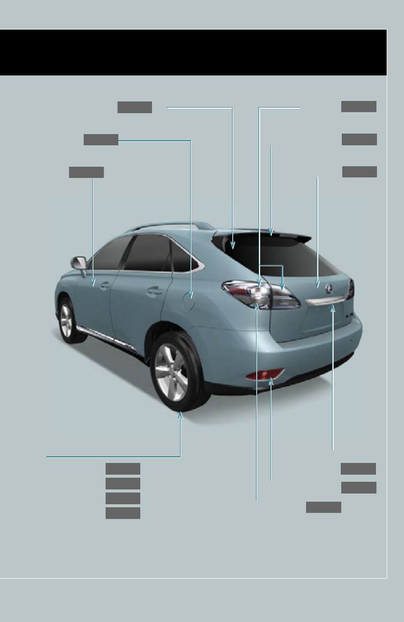
Tail lights
P. 213
Rear window defogger *2
P. 330
Fuel filler door
P. 119
Turn signal lights
P. 190
Back door opener
button
P. 70
Rear window wiper
P. 235
Side marker lights
P. 213
Side doors
P. 67
Back door
P. 70
: If equipped
*2: For vehicles with a navigation system, refer to the “Navigation System Owner’s Manual”.
10
A
Pictorial index Interior
SRS driver airbag
P. 132
SRS knee airbags
P. 132
Front seats
P. 82
SRS front passenger
airbag
P. 132
Power outlet
AUX port
USB port
P. 462
P. 386
P. 374
Door pockets
Bottle holders
P. 450
P. 450
Rear SRS side airbags
P. 132
Power outlet
P. 462
Console box
P. 453
Armrest
Auxiliary boxes
P. 467
P. 448
Power outlet
P. 462
Power window switches
P. 112
Rear seats
P. 86
Head restraints
P. 95
Seat belts
P. 97
Front SRS side airbags
P. 132
Cup holders
P. 451
11
A
Interior light
Personal lights
P. 446
P. 446
SRS curtain shield airbags
P. 132
Interior light
Personal lights
P. 446
P. 446
Auxiliary box
P. 455
Anti-glare inside rear view mirror
Rear view monitor system
Compass
P. 107
P. 270
P. 480
Sun visors
Vanity mirrors
P. 457
P. 458
Coat hooks
P. 468
: If equipped
Without “SOS” button
Moon roof switches
Garage door opener switches
P. 115
P. 474
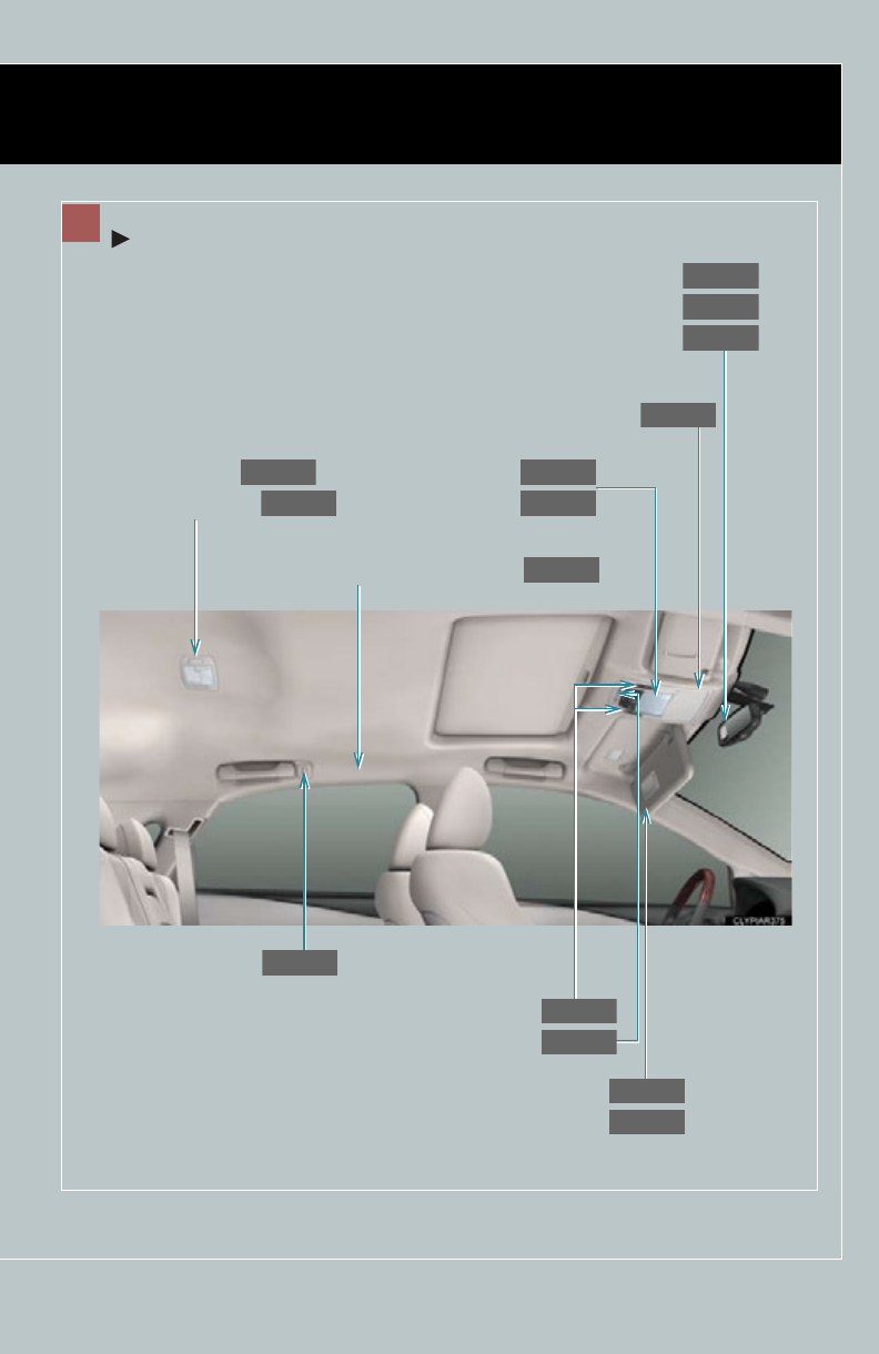
12
Pictorial index Interior
A
Anti-glare inside rear view mirror
P. 107
Personal lights
Interior light
P. 446
P. 446
Sun visors
P. 457
SRS curtain shield airbags
P. 132
Rear view monitor system
P. 270
Interior light
Personal lights
P. 446
P. 446
Coat hooks
P. 468
Moon roof switches
P. 115
Compass
P. 480
Garage door opener switches
P. 474
Vanity mirrors
P. 458
With “SOS” button
“SOS” button
P. 484

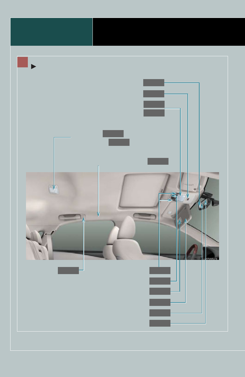
14
C
Cup holders
P. 451
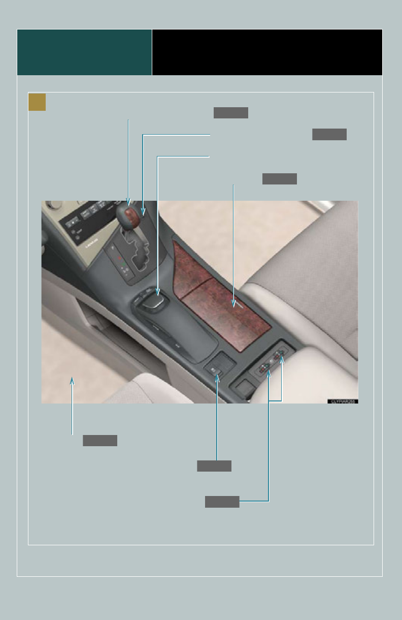
Remote Touch , *1
VSC off switch
P. 274
Seat heater switches /
Seat heater and ventilator switches
P. 465
Floor mat
P. 469
Hybrid transmission shift lever
P. 182
Shift lock override button
P. 645
Pictorial index Interior
: If equipped
*1: Refer to “Navigation System Owner's Manual”.
15
Pictorial index Instrument panel
Headlight switch
Turn signal lever
Fog light switch
P. 213
P. 190
P. 226
Windshield wiper and washer switch
Rear window wiper and washer switch
P. 229
P. 235
Power back door main
switch
P. 70
Tilt and telescopic steering control switch
P. 105
Parking brake pedal
P. 192
Power (ignition) switch
P. 176
Hood lock release
lever
P. 509
Gauges and meters
Multi-information display
P. 194
P. 202
Glove box
P. 449
Horn
P. 193
: If equipped

17
A Without navigation system
Security indicator
P. 124, 126
Audio system
P. 332
Emergency
flasher switch
P. 590
●Display light control
●Outside temperature
display
●Clock
●Air conditioning
display
●Audio display
P. 461
P. 460
P. 459
P. 322
P. 332
Multi display
Air conditioning
system
P. 322
Rear window and outside rear view
mirror defogger switch
P. 330
*1: Refer to “Navigation System Owner's Manual”.
18
B
Telephone switch *2
Talk switch *2
P. 416
P. 416
Cruise control switch
P. 238, 243
Distance switch
P. 243
Multi-information switches
P. 202
Audio remote
control switches *2
P. 388
Side camera switch , *1
C
Head-up display main switch
P. 210
Display position adjustment
switch
P. 210
Display contrast adjustment
switch
P. 210
Pictorial index Instrument panel
19
D
Tire pressure warning
reset switch
P. 534
Height control off switch
P. 264
: If equipped
*1: Refer to “Navigation System Owner's Manual”.
*2: For vehicles with a navigation system, refer to the “Navigation System Owner’s Manual”.
ECup holders
P. 451
Headlight cleaner switch
P. 237
Power back door switch
P. 70
Fuel filler door opener
P. 119
Instrument panel light control
buttons
P. 195
“ODO/TRIP” button
P. 195
Windshield wiper de-icer switch *2
P. 331
Height selector switch
P. 264


22
For your information
Main Owner’s Manual
Please note that this manual applies to all models and explains all equipment, includ-
ing options. Therefore, you may find some explanations for equipment not installed
on your vehicle.
All specifications provided in this manual are current at the time of printing. How-
ever, because of the Lexus policy of continual product improvement, we reserve the
right to make changes at any time without notice.
Depending on specifications, the vehicle shown in the illustrations may differ from
your vehicle in terms of color and equipment.
Noise from under vehicle after turning off the hybrid system
Approximately five hours after the hybrid system is turned off, you may hear sound
coming from under the vehicle for several minutes. This is the sound of a fuel evapo-
ration leakage check and, it does not indicate a malfunction.
Accessories, spare parts and modification of your Lexus
A wide variety of non-genuine spare parts and accessories for Lexus vehicles are
currently available in the market. You should know that Toyota does not warrant
these products and is not responsible for their performance, repair, or replacement,
or for any damage they may cause to, or adverse effect they may have on, your
Lexus vehicle.
This vehicle should not be modified with non-genuine Lexus products. Modification
with non-genuine Lexus products could affect its performance, safety or durability,
and may even violate governmental regulations. In addition, damage or perfor-
mance problems resulting from the modification may not be covered under war-
ranty.

23
Installation of a mobile two-way radio system
The installation of a mobile two-way radio system in your vehicle could affect elec-
tronic systems such as:
●Hybrid system
●Multiport fuel injection system/sequential multiport fuel injection system
●Cruise control system
●Dynamic radar cruise control system
●Anti-lock brake system
●SRS airbag system
●Seat belt pretensioner system
Be sure to check with your Lexus dealer for precautionary measures or special
instructions regarding installation of a mobile two-way radio system.
High voltage parts and cables on the hybrid vehicles emit approximately the same
amount of electromagnetic waves as the conventional gasoline powered vehicles or
home electronic appliances despite of their electromagnetic shielding.
Unwanted noise may occur in the reception of the mobile two-way radio.
Scrapping of your Lexus
The SRS airbag and seat belt pretensioner devices in your Lexus contain explosive
chemicals. If the vehicle is scrapped with the airbags and seat belt pretensioners left
as they are, this may cause an accident such as fire. Be sure to have the systems of
the SRS airbag and seat belt pretensioner removed and disposed of by a qualified
service shop or by your Lexus dealer before you scrap your vehicle.
Perchlorate Material
Special handling may apply, See www.dtsc.ca.gov/hazardouswaste/perchlorate.
Your vehicle has components that may contain perchlorate. These components may
include airbag, seat belt pretensioners, and wireless remote control batteries.

24
Vehicle control and operation data recording
Your Lexus is equipped with sophisticated computers that record certain informa-
tion about your vehicle’s operation, such as:
•Engine speed
• Motor speed
• Accelerator status
•Brake status
• Vehicle speed
•Shift position
The data recorded varies according to the grade level and options the vehicle is
equipped with. The computers do not record conversations, sound or pictures.
●Data usage
Lexus may use the data recorded in these computers to diagnose malfunctions,
conduct research and development, and improve quality.
Lexus will not disclose the recorded data to a third party except:
• With the consent of the vehicle owner or with the consent of the lessee if the
vehicle is leased
• In response to an official request by the police, a court of law or a government
agency
• For research purposes where the data is not tied to a specific vehicle or vehicle
owner
25
●Event data recorder
Your vehicle has computers that monitor and control certain aspects of your vehi-
cle. These computers assist in driving and maintaining optimal vehicle performance.
Besides storing data useful for troubleshooting, there is an event data recorder
(EDR) that records data in a crash or near crash event.
The SRS airbag sensor assembly contains the EDR. In a crash or near crash event,
this device may record the following information:
•Engine speed
• Whether the brake pedal was applied or not
•Vehicle speed
• To what extent the accelerator pedal was depressed
• Position of the transmission shift lever
• Whether the driver and front passenger wore seat belts or not
• Driver’s seat position
• SRS airbag deployment data
• SRS airbag system diagnostic data
• Front passenger’s occupant classification
The information above is intended to be used for the purpose of improving vehicle
safety performance. Unlike general data recorders, the EDR does not record sound
data such as conversation between passengers.
●Disclosure of the EDR data
Lexus will not disclose the data recorded in an EDR to a third party except when:
• An agreement from the vehicle’s owner (or the leasing company for a leased
vehicle) is obtained
• Officially requested to by the police or other authorities
• Necessary, for use as a defense for Lexus in a lawsuit
• Ordered to by a court of law
However, if necessary, Lexus will:
• Use the data for research on Lexus vehicle safety performance
• Disclose the data to a third party for research purposes without disclosing details
of the vehicle owner, and that only when deemed necessary
• Disclose summarized data cleared of vehicle identification information to a non-
Lexus organization for research purposes

26
●Lexus Safety Connect /Lexus Enform (U.S. mainland only)
If your Lexus has Safety Connect or Lexus Enform and if you have subscribed to
those services, please refer to the Safety Connect /Lexus Enform Telematics Sub-
scription Service Agreement for information on data collected and its usage.
CAUTION
■General precautions while driving
Driving under the influence: Never drive your vehicle when under the influence of
alcohol or drugs that have impaired your ability to operate your vehicle. Alcohol
and certain drugs delay reaction time, impair judgment and reduce coordination,
which could lead to an accident that could result in death or serious injury.
Defensive driving: Always drive defensively. Anticipate mistakes that other drivers
or pedestrians might make and be ready to avoid accidents.
Driver distraction: Always give your full attention to driving. Anything that distracts
the driver, such as adjusting controls, talking on a cellular phone or reading can
result in a collision with resulting death or serious injury to you, your occupants or
others.
■General precaution regarding children’s safety
Never leave children unattended in the vehicle, and never allow children to have or
use the key.
Children may be able to start the vehicle or shift the vehicle into neutral. There is
also a danger that children may injure themselves by playing with the windows, the
moon roof, or other features of the vehicle. In addition, heat build-up or extremely
cold temperatures inside the vehicle can be fatal to children.

27
CAUTION
■Disposal of the hybrid battery (traction battery)
If your vehicle is disposed of without the hybrid battery having been removed, there
is a danger of serious electric shock if high voltage parts, cables and their connec-
tors are touched. In the event that your vehicle must be disposed of, the hybrid bat-
tery must be disposed of by your Lexus dealer or a qualified service shop. If the
hybrid battery is not disposed of properly, it may cause electric shock that can result
in death or serious injury.
28
Symbols used throughout this manual
Cautions & Notices
Symbols used in illustrations
CAUTION
This is a warning against something which, if ignored, may cause injury to people. You
are informed about what you must or must not do in order to reduce the risk of injury
to yourself and others.
NOTICE
This is a warning against something which, if ignored, may cause damage to the vehi-
cle or its equipment. You are informed about what you must or must not do in order to
avoid or reduce the risk of damage to your Lexus and its equipment.
Safety symbol
The symbol of a circle with a slash through it means “Do not”,
“Do not do this”, or “Do not let this happen”.
Arrows indicating operations
Indicates the action (pushing, turning, etc.)
used to operate switches and other
devices.
Indicates the outcome of an operation (e.g.
a lid opens).

Before driving 1
29
1-1. Hybrid system
Hybrid system ........................... 30
Hybrid system precautions .... 34
Energy monitor/
consumption screen............. 40
Hybrid vehicle driving tips...... 45
1-2. Key information
Keys............................................... 47
1-3. Opening, closing and
locking the doors
Smart access system with
push-button start .................... 52
Wireless remote control......... 64
Side doors.................................... 67
Back door .................................... 70
1-4. Adjustable components
(seats, mirrors,
steering wheel)
Front seats.................................. 82
Rear seats.................................... 86
Driving position memory....... 90
Head restraints.......................... 95
Seat belts ..................................... 97
Steering wheel......................... 105
Anti-glare inside rear
view mirror............................. 107
Outside rear view
mirrors..................................... 109
1-5. Opening and closing the
windows and moon roof
Power windows......................... 112
Moon roof.................................. 115
1-6. Refueling
Opening the fuel tank cap .... 119
1-7. Theft deterrent system
Immobilizer system................ 124
Alarm.......................................... 126
Theft prevention labels
(for U.S.A.) ............................. 129
1-8. Safety information
Correct driving posture ....... 130
SRS airbags .............................. 132
Front passenger occupant
classification system............ 144
Child restraint systems ......... 149
Installing child restraints....... 153
30
1-1. Hybrid system
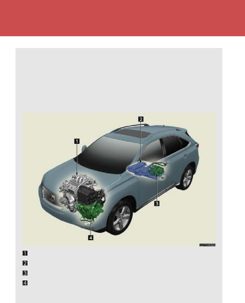
Hybrid system
Your vehicle is a hybrid vehicle. It has characteristics different from con-
ventional vehicles. Be sure you are closely familiar with the characteristics
of your vehicle, and operate with care.
The hybrid system combines the use of a gasoline engine and an electric
motor (traction motor) according to driving conditions, improving fuel effi-
ciency and reducing exhaust emissions.
Gasoline engine
Hybrid battery (traction battery)
Rear electric motor (Traction motor)*
Front electric motor (Traction motor)
*: AWD models only

31
1-1. Hybrid system
1
Before driving
■Charging the hybrid battery (traction battery)
●As the gasoline engine charges the hybrid battery (traction battery), the battery
does not need to be charged from an outside source. However, if the vehicle is
left parked for a long time the hybrid battery will slowly discharge. For this rea-
son, be sure to drive the vehicle at least once every few months for at least 30
minutes. If the hybrid battery becomes fully discharged and you are unable to
jump-start the vehicle with the 12-volt battery, contact your Lexus dealer.
●If the shift lever is in N, the hybrid battery (traction battery) will not be charged.
Always put the shift lever in P when the vehicle is stopped. When driving in
heavy traffic, operate the vehicle with the shift lever in D or S to avoid discharg-
ing the battery.
■When stopped/during start-off
The gasoline engine stops when the vehicle is stopped. During start-
off, the electric motor (traction motor) drives the vehicle. At slow
speeds or when traveling down a gentle slope, the engine is stopped
and the motor is used.
■During normal driving
The gasoline engine is predominantly used. The electric motor
(traction motor) charges the hybrid battery as necessary.
■When accelerating sharply
The power of the hybrid battery (traction battery) is added to that of
the gasoline engine via the electric motor (traction motor).
■When braking (regenerative braking)
The electric motor (traction motor) charges the hybrid battery
(traction battery).

32
1-1. Hybrid system
■Regenerative braking
In the following situations, kinetic energy is converted to electric energy and decel-
eration force can be obtained in conjunction with the recharging of the hybrid bat-
tery (traction battery).
●The accelerator pedal is released.
●The brake pedal is depressed with the shift lever in D or S.
■Conditions in which the gasoline engine may not stop
The gasoline engine starts and stops automatically. However, it may not stop auto-
matically in the following conditions:
●During gasoline engine warm-up
●During hybrid battery (traction battery) charging
●When the temperature of the hybrid battery (traction battery) is high or low
●When the heater is switched on
■Charging the 12-volt battery
P. 652
■After the 12-volt battery has discharged or has been changed or removed
The gasoline engine may not stop even if the vehicle is running on the hybrid battery
(traction battery). If this continues for a few days, contact your Lexus dealer.

33
1-1. Hybrid system
1
Before driving
■Sounds and vibrations specific to a hybrid vehicle
There may be no engine sounds or vibration even though the vehicle is able to
move. Always shift the shift lever to P when parked.
The following sounds or vibrations may occur when the hybrid system is operating,
and are not a malfunction:
●Motor sounds may be heard from the engine compartment.
●Sounds may be heard from the hybrid battery (traction battery) under the rear
seat when the hybrid system starts or stops.
●Sounds from the hybrid system may be heard when the back door is open.
●Sounds may be heard from the hybrid transmission when the engine is started
or stopped, or while the engine is idling.
●Engine sounds may be heard when accelerating sharply.
●Sounds may be heard due to regenerative braking when the brake pedal is
depressed and accelerator is loosened.
●Vibration may be felt when the gasoline engine starts or stops.
●Cooling fan sounds may be heard from the air intake vents under the rear seat.
■Maintenance, repair, recycling, and disposal
Contact your Lexus dealer regarding maintenance, repair, recycling and disposal.
Do not dispose of the vehicle yourself.
34
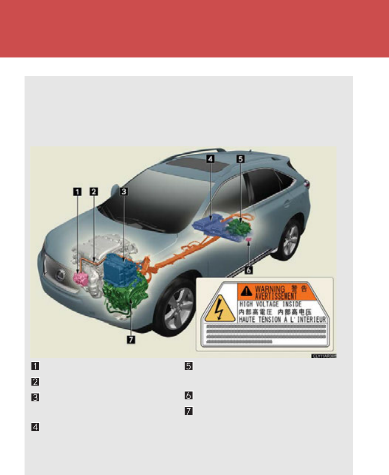
1-1. Hybrid system
Hybrid system precautions
Take care when handling the hybrid system, as it contains a high voltage
system (about 650V at maximum) as well as parts that become extremely
hot when the hybrid system is operating. Obey the caution labels attached
to the vehicle.
*: AWD models only
Air conditioning compressor
High voltage cables (orange)
Power control unit with DC/
DC converter
Hybrid battery (traction bat-
tery)
Rear electric motor (traction
motor)*
Service plug
Front electric motor (traction
motor)
35
1-1. Hybrid system
1
Before driving
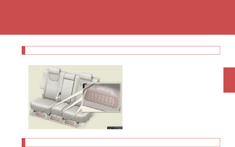
Hybrid battery air vents
There are air intake vents under
the rear seats for the purpose of
cooling the hybrid battery (traction
battery). If the vents become
blocked, it may become the cause
of malfunctions such as the hybrid
battery overheating, a reduction in
battery output power etc.
Emergency shut off system
When the vehicle receives an impact due to an accident, the hybrid sys-
tem automatically stops, blocking off the high voltage current. Also, the
emergency shut off system cuts the fuel supply, minimizing the risk of fuel
leakage. If this occurs, the hybrid system will not be able to be restarted,
therefore contact your Lexus dealer.
36
1-1. Hybrid system
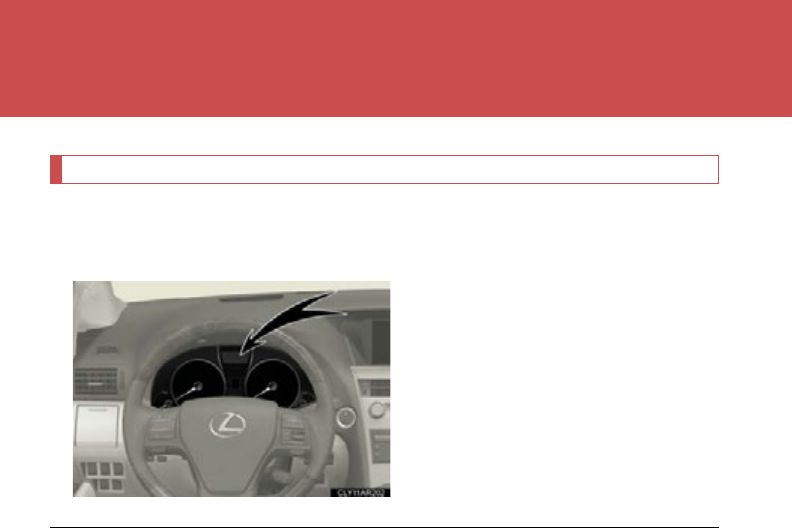
Hybrid warning message
A message is automatically displayed when a malfunction occurs in the
hybrid system or an improper operation is attempted.
If a warning message is shown on
the multi-information display, read
the message and follow the
instructions. (P. 608 )
■If a warning light comes on or, a warning message is displayed
The hybrid system may not start. In that case, try to start the system again. If the
“READY” indicator does not come on, contact your Lexus dealer.
■When the 12-volt battery is reconnected
P. 529
■When refueling, the fuel filler door may take a few moments to open
As part of emission system operation, it may take up to 10 seconds for the fuel filler
door to automatically release after the opener switch is pressed. Before refueling is
possible, a message will be shown on the multi-information display. (P. 11 9 , 620)
■Electromagnetic waves
●High voltage parts and cables on the hybrid vehicles incorporate electromag-
netic shielding, and therefore emit approximately the same amount of electro-
magnetic waves as conventional gasoline powered vehicles or home electronic
appliances.
●Your vehicle may cause sound interference in some third party-produced radio
parts.
37
1-1. Hybrid system
1
Before driving
■Running out of fuel
In order to start the hybrid system, fuel is required. Therefore the hybrid system can-
not be started on electrical energy only.
When the vehicle has run out of fuel and the hybrid system cannot be started, refuel
the vehicle with at least enough gasoline to make the low fuel level warning light
(P. 598) go off. If there is only a small amount of fuel, the hybrid system may not
be able to start. (The minimum amount of fuel to add to make the low fuel level
warning light go out is about 2.7 gal. [10.1 L, 2.2 Imp. gal.] when the vehicle is on a
level surface. This value may vary when the vehicle is on a slope.)
■Hybrid battery (traction battery)
The hybrid battery (traction battery) has a limited service life. The lifespan of the
hybrid battery (traction battery) can change in accordance with driving style and
driving conditions.
CAUTION
■High voltage and high temperature precautions
The vehicle has high voltage DC and AC systems as well as a 12-volt system. DC
and AC high voltage is very dangerous and can cause severe burns and electric
shock that may result in death or serious injury.
●Never touch, disassemble, remove or replace the high voltage parts, cables and
their connectors.
●The hybrid system will become hot after starting as the system uses high voltage.
Be careful of both the high voltage and the high temperature, and always obey
the caution labels attached to the vehicle.
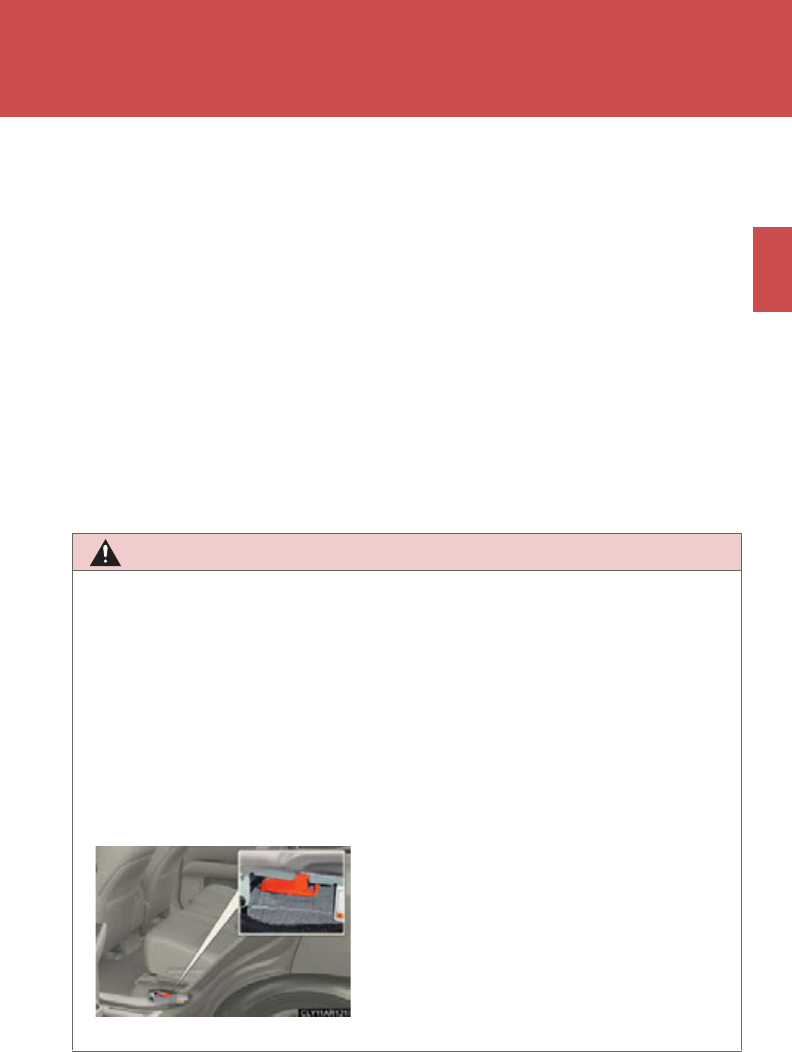
●Never try to open the service plug access
hole located under the rear seat. The ser-
vice plug is used only when the vehicle is
serviced and is subject to high voltage.

38
1-1. Hybrid system
CAUTION
■Road accident cautions
Observe the following precautions to reduce the risk of death or serious injury:
●Pull your vehicle off the road, shift the shift lever to P, apply the parking brake, and
turn the hybrid system off.
●Do not touch the high voltage parts, cables and connectors.
●If electric wires are exposed inside or outside your vehicle, an electric shock may
occur. Never touch exposed electric wires.
●If a fluid leak occurs, do not touch it as it may be strong alkaline electrolyte from
the hybrid battery (traction battery). If it comes into contact with your skin or
eyes, wash it off immediately with a large amount of water or, if possible, boric
acid solution. Seek immediate medical attention.
●If a fire occurs in the hybrid vehicle, leave the vehicle as soon as possible. Never
use a fire extinguisher that is not meant for electric fires. Using even a small
amount of water may be dangerous.
●If your vehicle needs to be towed, do so with all front wheels (for 2WD models) or
four wheels (for AWD models) raised. If the wheels connected to the electric
motor (traction motor) are on the ground when towing, the motor may continue
to generate electricity. This may cause an electricity leakage leading to a fire.
(P. 59 1 )
●Carefully inspect the ground under the vehicle. If you find that liquid has leaked
onto the ground, the fuel system may have been damaged. Leave the vehicle as
soon as possible.
■Nickel-metal hydride battery
Your vehicle contains a sealed nickel-metal hydride battery. If disposed of improp-
erly, it is hazardous to the environment and there is a risk of severe burns and elec-
trical shock that may result in death or serious injury.
■Hybrid battery collection
When disposing of your vehicle, always contact your Lexus dealer. Hybrid batteries
are collected through Lexus dealers, as such we appreciate your cooperation.
■Emergency shut off system
Carefully check to see if there are exposed high voltage parts or cables. Never
touch the parts or cables. (P. 3 4 )

39
1-1. Hybrid system
1
Before driving
NOTICE
■Hybrid battery air vents
●Do not put foreign objects over the air vents. The hybrid battery (traction battery)
may overheat or lose power and be damaged.
●Clean the air vents regularly to prevent the hybrid battery (traction battery) from
overheating.
●Do not wet or allow foreign substances to enter the air vents as this may cause a
short circuit and damage the hybrid battery (traction battery).
●Do not carry large amounts of water such as an aquarium into the vehicle. If water
spills onto the hybrid battery (traction battery), the battery may be damaged.
Have the vehicle inspected by your Lexus dealer.
40
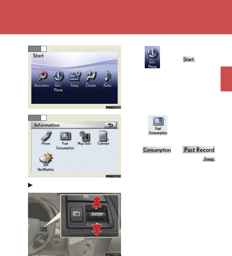
1-1. Hybrid system
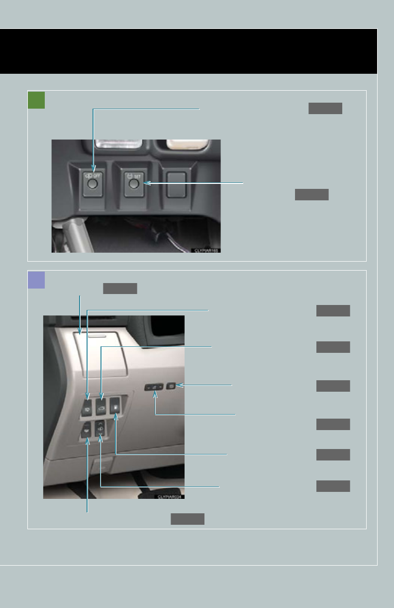
Energy monitor/consumption screen
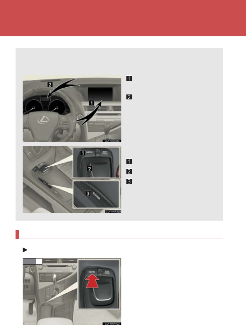
Energy monitor
Navigation system screen (if equipped)
Press the “MENU” button on the
Remote Touch.
You can view the status of your hybrid system on the multi-information dis-
play and the navigation system screen.
Navigation system screen (if
equipped)
Multi-information display
Remote Touch* (if equipped)
“MENU” button
Remote Touch knob
“ENTER” button
*: For use of the Remote Touch,
refer to “Navigation System
Owner's Manual”.
STEP 1
41
1-1. Hybrid system
1
Before driving
Select on the screen
and press the “ENTER” button on
the Remote Touch.
Select and press the
“ENTER” button.
If the or
screen is displayed, select
and press the “ENTER” button.
Multi-information display
Toggle the “ENTER” switch on the
steering wheel upward or down-
ward through several items to
select the energy monitor display.
STEP 2
STEP 3
42
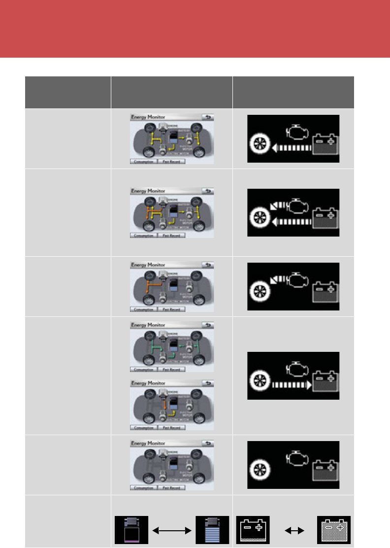
1-1. Hybrid system
These images are examples only, and may vary slightly from actual conditions.
Navigation system screen Multi-information
display
When the vehicle is
powered by the
electric motor
(traction motor)
When the vehicle is
powered by both
the gasoline engine
and the electric
motor (traction
motor)
When the vehicle is
powered by the
gasoline engine
When the vehicle is
charging the hybrid
battery (traction
battery)
When there is no
energy flow
Hybrid battery
(traction battery)
status
Low Full Low Full
43
1-1. Hybrid system
1
Before driving
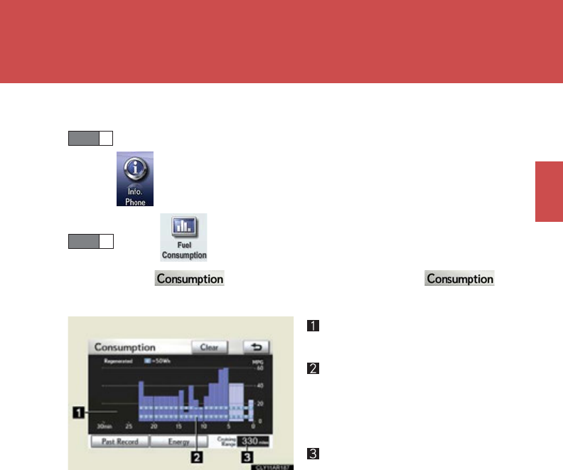
■Consumption (vehicles with a navigation system)
Press the “MENU” button on the “Remote Touch” and select
.
Select and press the “ENTER” button.
If the screen does not appear, select and
press the “ENTER” button.
Fuel consumption in the past 30
minutes
Regenerated energy in the past
30 minutes
One symbol indicates 50 Wh. Up
to 4 symbols are shown.
Cruising range
The image is example only, and may vary slightly from actual conditions.
STEP 1
STEP 2
44
1-1. Hybrid system
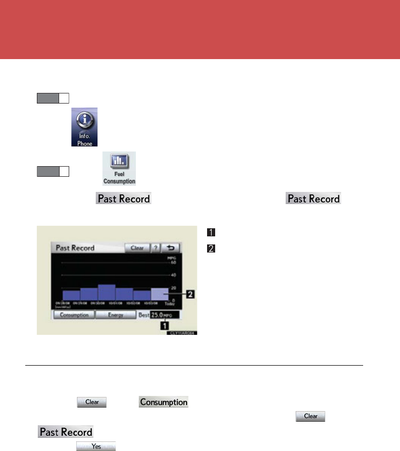
■Past record (vehicles with a navigation system)
Press the “MENU” button on the “Remote Touch” and select
.
Select and push the “ENTER” button.
If the screen does not appear, select and
press the “ENTER” button.
Best past fuel consumption
Average fuel consumption
Displays a maximum of five past
record of the total average fuel
consumption on the multi-informa-
tion display.
The image is example only, and may vary slightly from actual conditions.
STEP 1
STEP 2
■Resetting the consumption data
Selecting on the screen will reset the fuel consumption and
the regenerated energy for the past 30 minutes. Selecting on the
screen will reset the past records and best past fuel consumption.
Selecting on the following screen will confirm resetting of all the data.

45
1
1-1. Hybrid system
Before driving
Hybrid vehicle driving tips
For economical and ecological driving, pay attention to the following
points:
■Use of Hybrid System Indicator
More Eco-friendly driving is possible by keeping the indicate of Hybrid
System Indicator within Eco area.
■When braking the vehicle
Make sure to operate the brakes gently and in good time. A greater
amount of electrical energy can be retained when slowing down.
■Delays
Repeated acceleration and deceleration, as well as long waits at traffic
lights, will lead to bad fuel consumption. Check traffic reports before leav-
ing and avoid delays as much as possible. When encountering a delay,
gently release the brake pedal to allow the vehicle to move forward slightly
while avoiding overuse of the accelerator pedal. Doing so can help control
excessive gasoline consumption.
■Highway driving
Control your speed and keep at a constant speed. Also, before stopping at
a toll booth or similar, allow plenty of time to release the accelerator and
gently apply the brakes. A greater amount of electrical energy can be
retained when slowing down.
■Air conditioning
Use the air conditioning only when necessary. Doing so can help control
excessive gasoline consumption.
In summer: In high temperatures, use the recirculated air mode. Doing so
will help to reduce the burden on the air conditioning and reduce fuel con-
sumption as well.
In winter: Because the gasoline engine will not automatically cut out until
the gasoline engine and the interior of the vehicle are warm, it will con-
sume fuel. Also, fuel consumption can be improved by avoiding overuse of
the heater.

46
1-1. Hybrid system
■Checking tire inflation pressure
Make sure to check the tire inflation pressure frequently. (P. 673 )
Improper tire inflation pressure can cause poor fuel consumption.
Also, as snow tires can cause large amounts of friction, their use on dry
roads can lead to poor fuel consumption. Use a tire that is appropriate for
the season.
■Luggage
Carrying heavy luggage can lead to poor fuel consumption. Avoid carry-
ing unnecessary luggage. Installing a large roof rack can also cause poor
fuel consumption.
■Warming up before driving
Since the gasoline engine starts up and cuts out automatically when cold,
warming up the engine is unnecessary. Moreover, frequently driving short
distances will cause the engine to repeatedly warm up, which can lead to
poor fuel consumption.
47
1
Before driving
1-2. Key information
Keys
The following keys are provided with the vehicle.
Electronic keys
• Operating the smart access
system with push-button start
(P. 52)
• Operating the wireless
remote control function
(P. 6 4)
Mechanical keys
Key number plate
Card key (electronic key) (if
equipped)
Operating the smart access sys-
tem with push-button start
(P. 52)
48
1-2. Key information
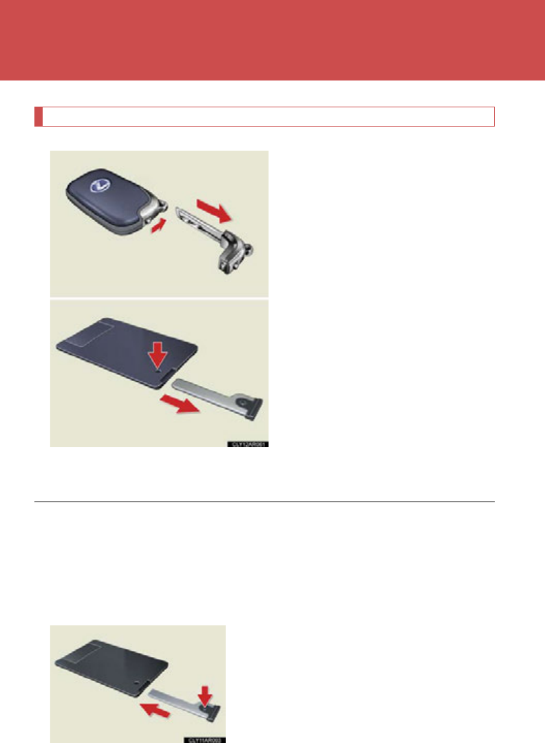
Using the mechanical key
To take out the mechanical key:
Electronic keys: Slide the release
lever and take the key out.
Card key: Press the lock release
button and take the key out.
If the key cannot be inserted in a
lock cylinder, turn it over and re-
attempt to insert it. Mechanical
keys with grooves on one side can
be inserted in one direction only.
After using the mechanical key,
store it in the electronic key. Carry
the mechanical key together with
the electronic key. If the electronic
key battery is depleted or the entry
function does not operate properly,
you will need the mechanical key.
(P. 6 47)
■Card key
●The mechanical key that is stored inside the card key should be used only if a
problem arises, such as when the key does not operate properly.
●If it is difficult to take out the mechanical key, press down the lock release button
using a pen tip etc. If it is still difficult to pull it out, use a coin etc.
●To store the mechanical key in the card
key, insert it while pressing the lock
release button.

49
1-2. Key information
1
Before driving
●The card key is not waterproof.
■When required to leave the vehicle’s key with a parking attendant
Lock the glove box as circumstances demand. (P. 4 49)
Remove the mechanical key for your own use and provide the attendant with the
electronic key only.
■Key number plate
Keep the plate in a safe place such as your wallet, not in the vehicle. In the event that
a mechanical key is lost, a new key can be made at your Lexus dealer using the key
number plate. (P. 646)
■When riding in an aircraft
When bringing an electronic key onto an aircraft, make sure you do not press any
buttons on the electronic key while inside the aircraft cabin. If you are carrying an
electronic key in your bag etc., ensure that the buttons are not likely to be pressed
accidentally. Pressing a button may cause the electronic key to emit radio waves
that could interfere with the operation of the aircraft.
●If the battery cover is not installed and
the battery falls out or if the battery was
removed because the key got wet, rein-
stall the battery with the positive termi-
nal facing the Lexus emblem.

50
1-2. Key information
NOTICE
■To prevent key damage
Observe the following:
●Do not drop the keys, subject them to strong shocks or bend them.
●Do not expose the keys to high temperatures for a long period of time.
●Do not get the keys wet or wash them in an ultrasonic washer etc.
●Do not attach metallic or magnetic materials to the keys or place the keys close to
such materials.
●Do not disassemble the keys.
●Do not attach a sticker or anything else to the surface of the electronic key.
●Do not place the keys near objects that produce magnetic fields, such as TVs,
audio systems, glass top ranges, or medical electrical equipment, such as low-fre-
quency therapy equipment.
■Carrying the electronic key on your person
Carry the electronic key 3.9 in. (10 cm) or more away from electric appliances that
are turned on. Radio waves emitted from electric appliances within 3.9 in. (10 cm)
of the electronic key may interfere with the key, causing the key to not function
properly.
■In case of a smart access system with push-button start malfunction or other key-
related problems
Take your vehicle with all the electronic keys provided with your vehicle, including
the card key, to your Lexus dealer.
■When a vehicle key is lost
If the key remains lost, the risk of vehicle theft increases significantly. Visit your
Lexus dealer immediately with all remaining electronic keys and the card key that
was provided with your vehicle.

51
1-2. Key information
1
Before driving
NOTICE
■Precautions for handling the card key
●Do not apply excess force when inserting the mechanical key into the card key.
Doing so may damage the card key.
●If the battery or card key terminals get wet, the battery may corrode and the card
key may stop working.
If the key is dropped into water, or if drinking water etc. is spilled on the key,
immediately remove the battery cover and wipe the battery and terminals. (To
remove the battery cover, lightly grasp and pull it.) If the battery is corroded, have
your Lexus dealer replace the battery.
●Do not crush the battery cover or use a screwdriver to remove the battery cover.
Forcibly removing the battery cover may bend or damage the key.
●If the battery cover is frequently removed, the battery cover may become loose.
●When installing the battery, make sure to check the direction of the battery.
Installing the battery in the wrong direction may cause the battery to deplete rap-
idly.
●The surface of the card key may be damaged, or its coating may peel off in the
following situations:
• The card key is carried together with hard objects, such as coins and keys.
• The card key is scraped with a sharp object, such as the tip of a mechanical
pencil.
• The surface of the card key is wiped with thinner or benzene.
52
1-3. Opening, closing and locking the doors
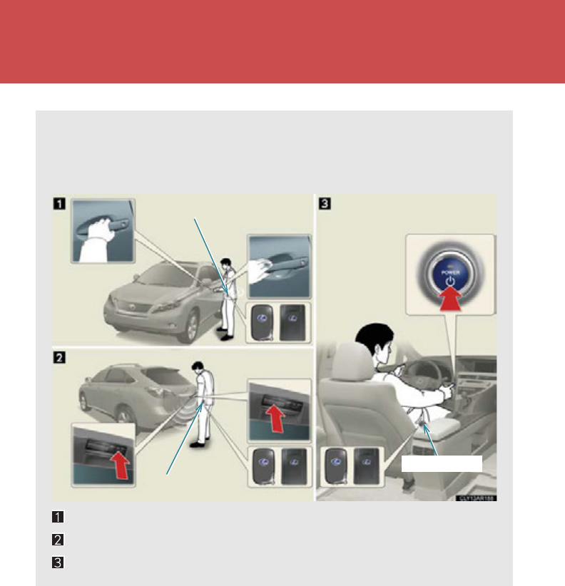
Smart access system with push-button start
By simply carrying the electronic key or card key on your person, for exam-
ple in your pocket, the following operations can be performed without
using a key. The driver should always carry the electronic key.
Locks and unlocks the side doors (P. 53)
Locks and unlocks the back door (P. 53 )
Starts the hybrid system (P. 1 76)
Electronic key
Electronic key
Electronic key
53
1-3. Opening, closing and locking the doors
1
Before driving
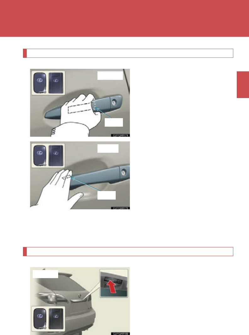
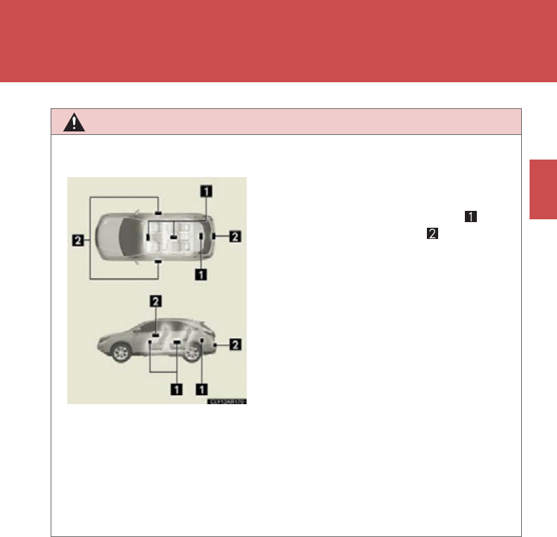
Unlocking and locking the side doors (front door handles only)
Grip the handle to unlock the
door.
Make sure to touch the sensor on
the back of the handle.
The doors cannot be unlocked for
3 seconds after the doors are
locked.
Touch the lock sensor (the inden-
tation on the upper part of the
door handle) to lock the doors.
If locking/unlocking cannot be performed correctly, use the wireless
remote control or mechanical key to perform the operations.
(P. 64, 6 47 )
Unlocking and locking the back door
Press the button to unlock the
door.
The door cannot be unlocked for 3
seconds after the door is locked.
Unlocking
Sensor
Locking
Sensor
Unlocking
54
1-3. Opening, closing and locking the doors
Press the button to lock the door.
If locking/unlocking cannot be performed correctly, use the wireless
remote control to perform the operations. (P. 64)
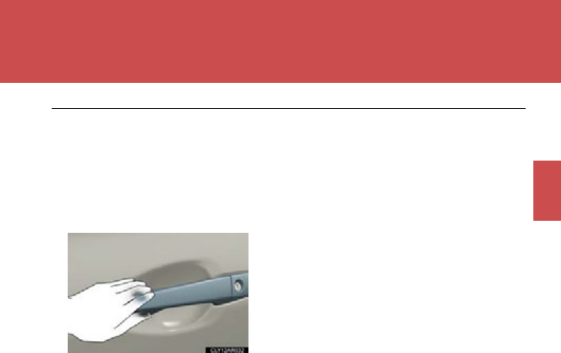
Effective range (areas within which the electronic key is detected)
When locking or unlocking
the doors
The system can be operated
when the electronic key is
within about 2.3 ft. (0.7 m) of
an outside door handle. (Only
the doors detecting the key
can be operated.)
When starting the hybrid
system or changing
“POWER” switch modes
(P. 177)
The system can be operated
when the electronic key is
inside the vehicle.
Locking
55
1-3. Opening, closing and locking the doors
1
Before driving
■Operation signals
A buzzer sounds and the emergency flashers flash to indicate that the doors have
been locked/unlocked. (Locked: Once; Unlocked: Twice)
■When the door cannot be locked by the lock sensor on the upper part of the door
handle
Touch both lock sensors on the upper and
lower part of the door handle simultaneously.

56
1-3. Opening, closing and locking the doors
■Alarms and warning indicators
A combination of exterior and interior alarms as well as warning messages shown
on the multi-information display is used to prevent theft of the vehicle and accidents
resulting from erroneous operation. Take appropriate measures in response to any
warning message on the multi-information display. (P. 6 08 )
The following table describes circumstances and correction procedures when only
alarms are sounded.
*: For “POWER” switch mode explanations: P. 17 7
■If the smart access system with push-button start does not operate properly
The reception conditions may be poor or the battery may have depleted.
●Steps to take in an emergency: P. 647
●Changing the electronic key battery: P. 55 0
Alarm Situation Correction procedure
Exterior alarm
sounds once for 10
seconds.
An attempt was made to lock
the vehicle while a door was
open.
Close all of the doors
and lock the doors
again.
Interior alarm pings
repeatedly
The “POWER” switch was
turned to ACCESSORY
mode while the driver's door
is open. (The driver's door
was opened when the
“POWER” switch is in
ACCESSORY mode.)*
Close the driver's door.
The “POWER” switch was
turned off while the driver's
door is open.*
Close the driver's door.

57
1-3. Opening, closing and locking the doors
1
Before driving
■Conditions affecting operation
The smart access system with push-button start uses weak radio waves. In the fol-
lowing situations, the communication between the electronic key and the vehicle
may be affected, preventing the smart access system with push-button start, wire-
less remote control and immobilizer system from operating properly.
(Ways of coping: P. 647)
●When the electronic key battery is depleted
●When the vehicle is stopped near a TV tower, electric power plant, gas station,
radio station, large display, airport or a similar facility that generates strong
radio waves or electrical noise.
●When carrying a portable radio, cellular phone, cordless phone or other wire-
less communication devices
●When the electronic key is in contact with, or is covered by the following metal-
lic objects
• Cards to which aluminum foil is attached
• Cigarette boxes that have aluminum foil inside
• Metallic wallets or bags
•Coins
• Hand warmers made of metal
• Media such as CDs and DVDs
●When multiple electronic keys are in the vicinity
●When another wireless key (that emits radio waves) is being used nearby
●When carrying the electronic key together with the following devices that emit
radio waves
• Another vehicle's electronic key or a wireless key that emits radio waves
• Personal computers or personal digital assistants (PDAs)
• Digital audio players
• Portable game systems
●If window tint with a metallic content or metallic objects are attached to the rear
window

58
1-3. Opening, closing and locking the doors
■Electronic key battery depletion
●The standard battery life is 1 to 2 years. (The card key battery life is about a year
and a half.)
●If the battery becomes low, an alarm will sound in the cabin when the hybrid sys-
tem stops. (P. 620 )
●As the electronic key always receives radio waves, the battery will become
depleted even if the electronic key is not used. The following symptoms indicate
that the electronic key battery may be depleted. Replace the battery when nec-
essary. (P. 550)
• The smart access system with push-button start or the wireless remote con-
trol does not operate.
• The detection area becomes smaller.
• The LED indicator on the key surface does not turn on.
●To avoid serious deterioration, do not leave the electronic key within 3 ft. (1 m) of
the following electrical appliances that produce a magnetic field:
•TVs
• Personal computers
• Cellular phones, cordless phones and battery chargers
• Recharging cellular phones or cordless phones
•Glass top ranges
• Table lamps
■Security feature
If a door is not opened within approximately 60 seconds after the vehicle is
unlocked, the security feature automatically locks the vehicle again.

59
1-3. Opening, closing and locking the doors
1
Before driving
■Battery-saving function
If the vehicle is parked for a long period of time, the battery-saving function is acti-
vated in order to prevent the vehicle 12-volt battery from being discharged and the
electronic key battery from being depleted.
●In the following circumstances, unlocking the vehicle using the entry function
may take longer than usual:
• When the entry function has not been used for 5 days or more
• When the electronic key has been left within approximately 6 ft. (2 m) of the
vehicle for 10 minutes or more
●If the entry function has not been used for 14 days or more, the vehicle cannot
be unlocked by a door other than the driver's door. To unlock the vehicle, grip
the driver's door handle or use the wireless remote control or the mechanical
key.
The system will resume operation when:
●The vehicle is locked using the lock sensor.
●The vehicle is locked/unlocked using the wireless remote control function.
(P. 6 4)
●The vehicle is locked/unlocked using the mechanical key. (P. 647)
■Points to remember regarding electronic key detection
●If there is a problem with the manner by which the electronic key is held or is
placed as outlined below, the electronic key may not be detected and therefore
may not be able to be operated despite being in the effective range. Also, the
alarm may be triggered accidentally or the door lock prevention function may
not operate.
• Outside the vehicle: When the doors are locked/unlocked with the electronic
key too close to the door window, door handle or rear bumper, or with the
electronic key too close to the ground or in a high location.
• Inside the vehicle: When the electronic key is placed on top of the instrument
panel, on the floor, in a door pocket, inside the glove box etc.

60
1-3. Opening, closing and locking the doors
●Do not leave the electronic key on top of the instrument panel or near the door
pockets when exiting the vehicle. Depending on the radio wave reception con-
ditions, it may be detected by the antenna outside the cabin and the door will
become lockable from the outside, possibly trapping the electronic key inside
the vehicle.
●As long as the electronic key is within the effective range, the doors may be
locked or unlocked by anyone. However, only the doors detecting the elec-
tronic key can be used to unlock the vehicle.
●The doors may lock or unlock if the electronic key is within the effective range
and a large amount of water splashes on the door handle, such as in the rain or
in a car wash. The doors will automatically be locked after approximately 60
seconds if a door is not opened and closed.
●If the key is too close to the vehicle when the button on the wireless
remote control is used for locking and then unlocking is attempted, the smart
access system with push-button start may not operate. If this occurs, perform
unlocking by pressing the button on the wireless remote control.
■Notes for locking the doors
●Touching the door lock sensor while wearing gloves may delay or prevent lock
operation. Remove the gloves and touch the lock sensor again.
●When the lock operation is performed using the lock sensor, recognition signals
will be shown up to two consecutive times. After this, no recognition signals will
be given.
●If the door handle becomes wet while the electronic key is within the effective
range, the door may lock and unlock repeatedly. Place the key in a position 6 ft.
(2 m) or more separate from the vehicle while the vehicle is being washed. (Take
care to ensure that the key is not stolen.)
●If the electronic key is inside the vehicle and a door handle becomes wet during
a car wash, a message may be shown on the multi-information display and a
buzzer will sound outside the vehicle. To turn off the alarm, lock all the doors.
●If ice, snow, mud, etc. is attached to the surface of the lock sensor, the sensor
may not work. If this occurs, operate the sensor again after the ice, snow, mud,
etc. has been cleaned off.
●Fingernails may scrape against the door during operation of the door handle.
Be careful not to injure fingernails or damage the surface of the door.

61
1-3. Opening, closing and locking the doors
1
Before driving
■Notes for the unlocking function
●Gripping the door handle when wearing a glove may not unlock the door.
●A sudden approach to the effective range or door handle may prevent the
doors from being unlocked. In this case, return the door handle to the original
position and check that the doors unlock before pulling the door handle again.
●If there is another electronic key in the detection area, it may take slightly longer
to unlock the doors after the door handle is gripped.
■When the vehicle is not driven for extended periods
●To prevent theft of the vehicle, do not leave the electronic key within 6 ft. (2 m)
of the vehicle.
●The smart access system with push-button start can be deactivated in advance.
(P. 693)
■Customization
Settings (e.g. smart access system with push-button start) can be changed.
(Customizable features P. 693 )
■Certification for the smart access system with push-button start
This system meets the certification requirements of Radio Low.
For vehicles sold in Hawaii, Guam, Saipan and Puerto Rico
FCC ID: NI4TMLF8-6
FCC ID: HYQ14ACX
FCC ID: HYQ14AEB
FCC ID: HYQ13CZF
NOTE:
This device complies with Part 15 of the FCC Rules. Operation is subject to the fol-
lowing two conditions: (1) this device may not cause harmful interference, and (2)
this device must accept any interference received, including interference that may
cause undesired operation.
FCC WARNING:
Changes or modifications not expressly approved by the party responsible for
compliance could void the user's authority to operate the equipment.

62
1-3. Opening, closing and locking the doors
For vehicles sold in the mainland U.S.A.
FCC ID: NI4TMLF8-6
FCC ID: HYQ14ACX
FCC ID: HYQ14AEB
FCC ID: HYQ13CZF
FCC ID: HYQ14ADF
FCC ID: HYQ14AEF
FCC ID: HYQ13CZG
NOTE:
This device complies with Part 15 of the FCC Rules. Operation is subject to the fol-
lowing two conditions: (1) this device may not cause harmful interference, and (2)
this device must accept any interference received, including interference that may
cause undesired operation.
FCC WARNING:
Changes or modifications not expressly approved by the party responsible for
compliance could void the user's authority to operate the equipment.
For vehicles sold in Canada
NOTE:
Operation is subject to the following two conditions: (1) this device may not cause
interference, and (2) this device must accept any interference, including interfer-
ence that may cause undesired operation of the device.
63
1-3. Opening, closing and locking the doors
1
Before driving
CAUTION
■Caution regarding interference with electronic devices
●User of any electrical medical device other than implanted pacemakers and
implanted cardiac defibrillators should consult the manufacturer of the device for
information about its operation under the influence of radio waves.
Radio waves could have unexpected effects on the operation of such medical
devices.
Ask your Lexus dealer for disabling the entry function.
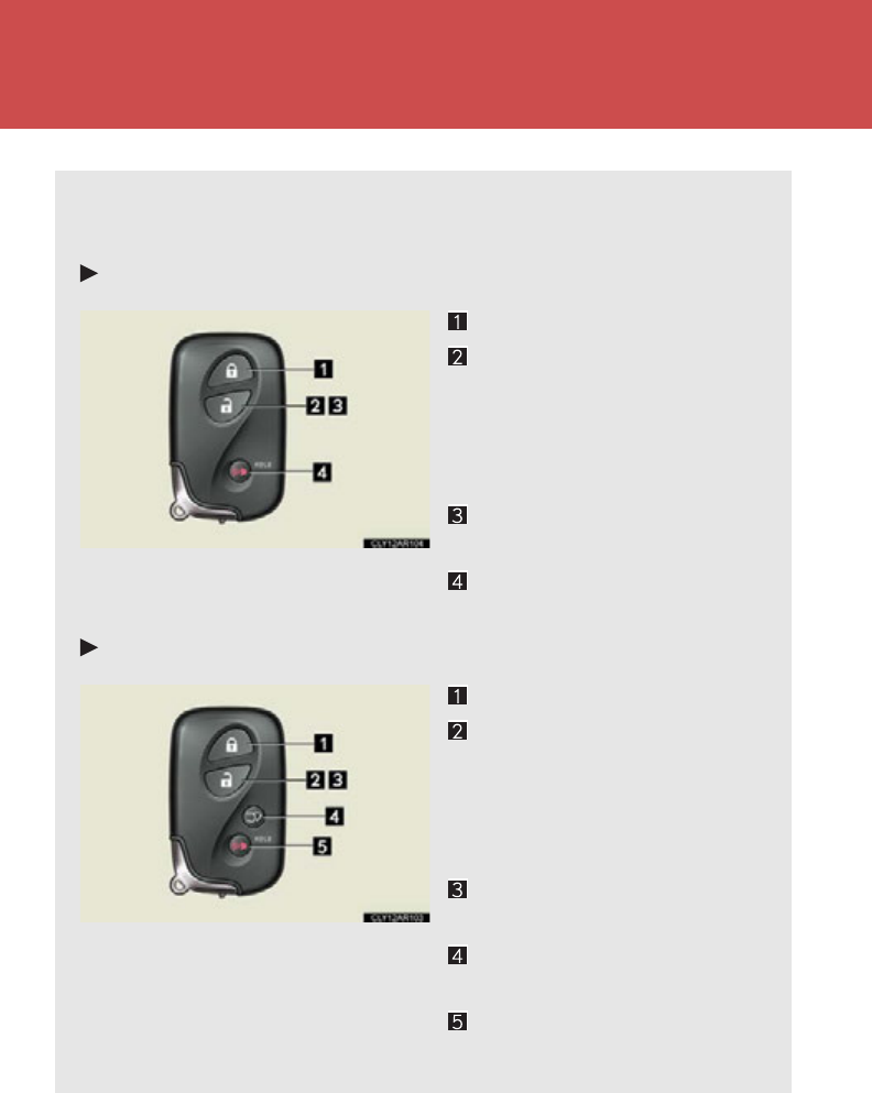
●People with implanted pacemakers or car-
diac defibrillators should keep away from
the antenna inside the cabin ( ) and
antenna outside the cabin ( ).
The radio waves may affect the operation
of such devices. If necessary, the entry
function can be disabled. Ask your Lexus
dealer for details, such as the frequency of
radio waves and timing of emitting the
radio waves. Then, consult your doctor to
see if you should disable the entry function.
64
1-3. Opening, closing and locking the doors
Wireless remote control
The wireless remote control can be used to lock and unlock the vehicle.
It also opens and closes the back door.
Vehicles without a power back door
Locks all the doors
Unlocks all the doors
Pressing the button unlocks the
driver’s door. Pressing the but-
ton again within 3 seconds
unlocks the other doors.
Opens the windows and
moon roof (press and hold)
Sounds the alarm
(press and hold) (P. 126 )
Vehicles with a power back door
Locks all the doors
Unlocks all the doors
Pressing the button unlocks the
driver’s door. Pressing the but-
ton again within 3 seconds
unlocks the other doors.
Opens the windows and
moon roof (press and hold)
Opens and closes the back
door (press and hold)
Sounds the alarm
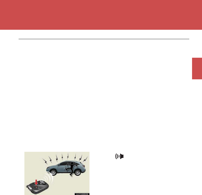
(press and hold) (P. 126 )
65
1-3. Opening, closing and locking the doors
1
Before driving
■Operation signals
Side doors: A buzzer sounds and the emergency flashers flash to indicate that the
doors have been locked/unlocked. (Locked: Once; Unlocked: Twice)
Back door: A buzzer sounds and the emergency flashers flash twice to indicate
that the back door is opening/closing.
Windows and moon roof: A buzzer sounds to indicate that the windows and moon
roof are opening.
■Door lock buzzer
If an attempt to lock the doors is made when a door is not fully closed, a buzzer
sounds continuously. Fully close the door to stop the buzzer, and lock the vehicle
once more.
■Security feature
P. 5 8
■Panic mode
■Back door operation
The back door can be opened even if it is locked. Lock the back door again when
you leave the vehicle. The back door will not lock automatically after it has been
opened and then closed.
■Alarm
Using the wireless remote control to lock the doors will set the alarm system.
(P. 126)
■Reversing the operation of the power back door
Pressing the wireless remote control switch again while the power back door is
operating will cause the operation to reverse.
When is pressed for longer than
about one second, an alarm will sound inter-
mittently and the vehicle lights will flash to
deter any person from trying to break into or
damage your vehicle.
To stop the alarm, press any button on the
electronic key.

66
1-3. Opening, closing and locking the doors
■Conditions affecting operation
P. 57
■If the wireless remote control does not operate properly
Locking and unlocking the doors: Use the mechanical key. (P. 647)
■Electronic key battery depletion
P. 5 8
■When the electronic key battery is fully depleted
P. 55 0
■Customization
Settings (e.g. door unlocking function) can be changed. (Customizable features
P. 693)
67
1
1-3. Opening, closing and locking the doors
Before driving
Side doors
The vehicle can be locked and unlocked using the entry function, wireless
remote control or door lock switches.
■Entry function
P. 53
■Wireless remote control
P. 64
■Door lock switches
Locks all the doors
Unlocks all the doors
■Inside lock buttons
Locks the door
Unlocks the door
The front doors can be opened
by pulling the inside handle even
if the lock buttons are in the lock
position.
68
1-3. Opening, closing and locking the doors
Locking the front doors from the outside without a key
Move the inside lock button to the lock position.
Close the door.
The door cannot be locked if the “POWER” switch is in ACCESSORY or
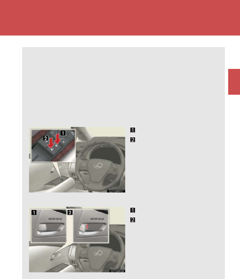
ON mode, or the electronic key is left inside the vehicle.
The key may not be detected correctly and the door may be locked.
Rear door child-protector lock
The door cannot be opened from
inside the vehicle when the lock is
set.
These locks can be set to prevent
children from opening the rear
doors. Push down on each rear
door switch to lock both rear
doors.
STEP 1
STEP 2
■Impact detection door lock release system
In the event that the vehicle is subject to a strong impact, all the doors are unlocked.
Depending on the force of the impact or the type of accident, however, the system
may not operate.
■Using the mechanical key
The doors can also be locked and unlocked with the mechanical key. (P. 647)
■If a wrong key is used
The key cylinder rotates freely to protect the inside mechanism.
■Customization
Settings (e.g. unlocking function using a key) can be changed.
(Customizable features P. 693)

69
1-3. Opening, closing and locking the doors
1
Before driving
CAUTION
■To prevent an accident
Observe the following precautions while driving the vehicle.
Failure to do so may result in a door opening and an occupant falling out, resulting
in death or serious injury.
●Always use a seat belt.
●Always lock all the doors.
●Ensure that all the doors are properly closed.
●Do not pull the inside handle of the doors while driving.
The doors may be opened and the passengers are thrown out of the vehicle and it
may result in serious injury or death.
Be especially careful with the front doors, as the doors may be opened even if the
inside lock buttons are in the locked position.
●Set the rear door child-protector locks when children are seated in the rear seats.
■When opening or closing a door
Check the surroundings of the vehicle such as whether the vehicle is on an incline,
whether there is enough space for a door to open and whether a strong wind is
blowing. When opening or closing the door, hold the door handle tightly to prepare
for any unpredictable movement.
70
1-3. Opening, closing and locking the doors
Back door
The back door can be locked/unlocked and opened/closed by the follow-
ing procedures:
■Locking and unlocking the back door
Door lock switches
P. 67
Entry function
P. 53
Wireless remote control
P. 64
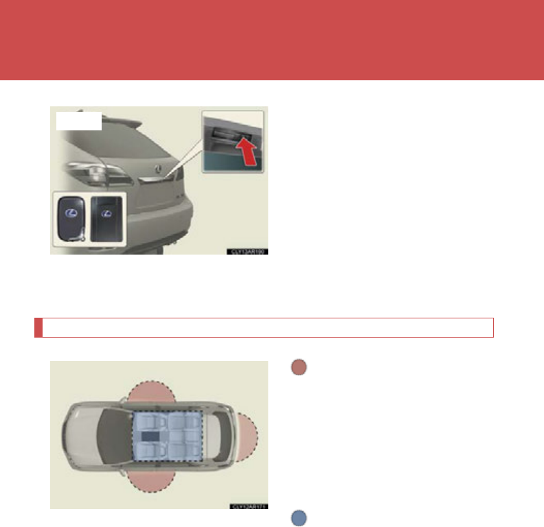
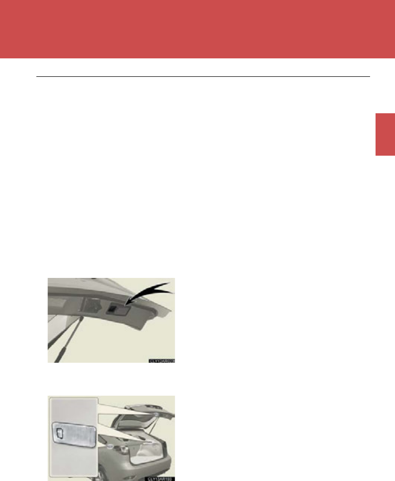
■Opening the back door from outside the vehicle
Raise the back door while push-
ing up the back door opener
button.
71
1-3. Opening, closing and locking the doors
1
Before driving
■Opening the back door from outside the vehicle (vehicles with a
power back door)
Using the back door opener button*
When the back door is
unlocked: Press the back door
opener button.
When the back door is locked:
While carrying the electronic
key on your person, press and
hold the back door opener but-
ton or press it twice.
*: This setting must be customized
at your Lexus dealer.
Using the wireless remote control
P. 64
■Opening the back door from inside the vehicle (vehicles with a
power back door)
Press the switch to open/close.
Pressing the switch again while
the power back door is operat-
ing will cause the operation to
reverse.
72
1-3. Opening, closing and locking the doors
Power back door switch (vehicles with a power back door)
Press the switch to close the back
door.
Pressing the switch again while the
power back door is closing will
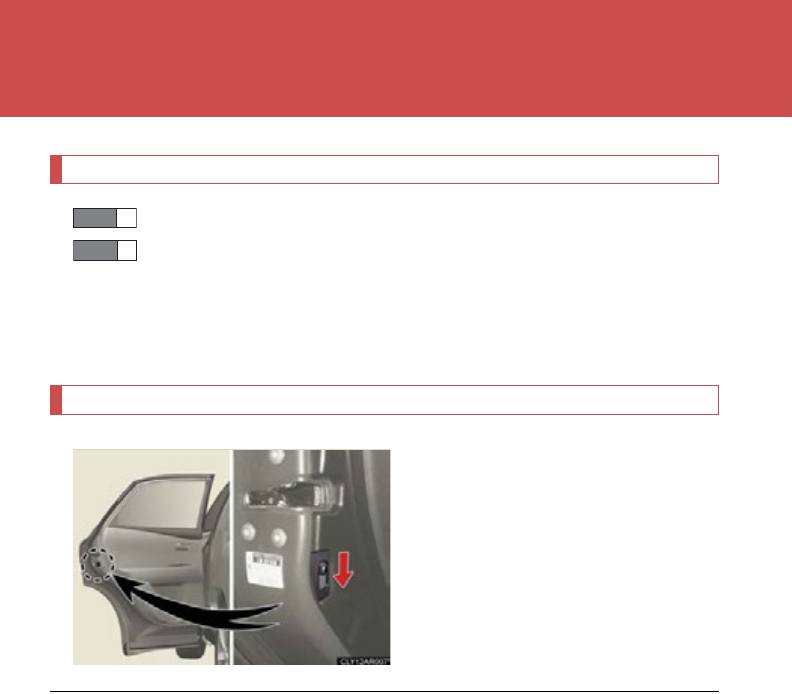
cause it to open again.
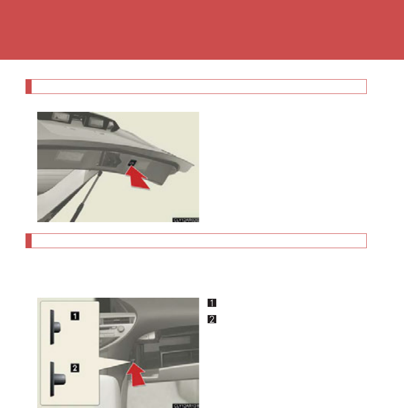
Canceling the power back door system (vehicles with a power back door)
Turn off the main switch in the glove box to disable the power back door
system.
On
Off
The back door cannot be operated
even with the wireless remote con-
trol or power back door switch.
73
1-3. Opening, closing and locking the doors
1
Before driving
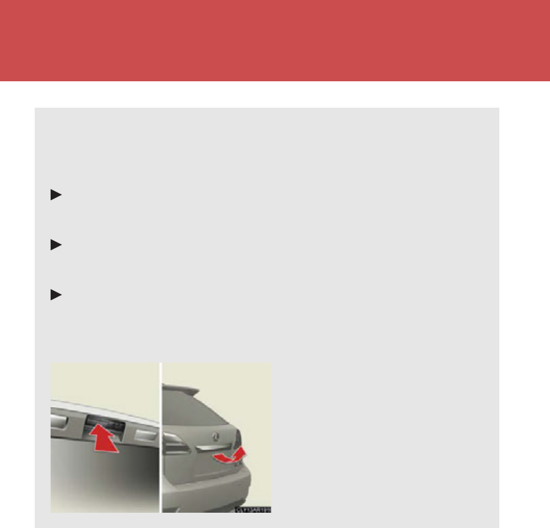
■The power back door can be operated when
●The back door is unlocked. (Except for using the back door opener button* or
wireless remote control, when the power back door can be operated even if it is
locked.)
●The power back door main switch is on.
●To open the power back door when the “POWER” switch is in ON mode, the
power back door main switch must be on, the vehicle speed must be lower than
1 mph (3 km/h) and the shift lever must be in P. (When using the back door
opener button only)
●The “POWER” switch is turned off. (When using the wireless remote control
only)
*: This setting must be customized at your Lexus dealer.
■Back door handle
■Luggage compartment lights
Use the back door handle when lowering the
back door.
Do not close the back door fully while still
holding the door handle as an injury may
result.
The luggage compartment lights turn on
when the back door is opened with the lug-
gage compartment light switch on.
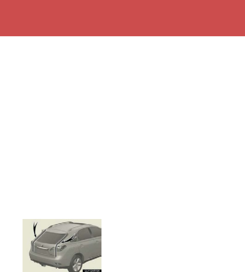
74
1-3. Opening, closing and locking the doors
■Back door closer (vehicles with a power back door)
In the event that the back door is left slightly open, the back door closer will auto-
matically close it to the fully closed position.
●The back door closer will operate regardless of “POWER” switch mode.
●The back door can be opened while the back door closer is operating by press-
ing the back door opener button.
■Power back door operation
●A buzzer sounds and the emergency flashers flash twice to indicate that the
back door is opening/closing.
●The back door can still be opened and closed manually, even when the power
back door main switch is off.
●Pressing the back door opener button while the power back door system is
operating will cause the back door to switch to manual operation.
●If anything obstructs the power back door while it is closing/opening, a buzzer
will sound and the back door will automatically operate in the opposite direc-
tion.
●If two or more successive attempts are made to close the back door, a buzzer
will sound and the back door will switch to manual operation.
■Jam protection function (vehicles with a power back door)
■After the back door has been opened and then closed
Lock the back door as the back door will not lock automatically.
■Luggage mode (vehicles with electronically modulated air suspension)
Pressing the vehicle height selector switch to lower the vehicle height makes load-
ing luggage easier. (P. 265 )
Sensors are attached to the left and right
sides of the power back door. If these sensors
detect an obstruction while the power back
door is closing, the jam protection function
will return the door to the fully open position.
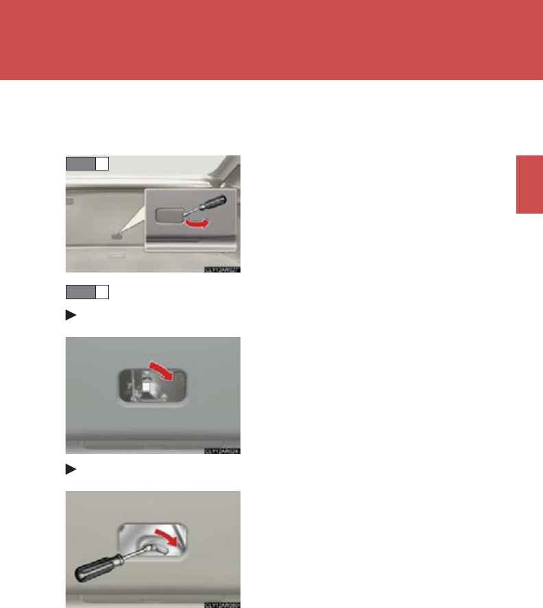
75
1-3. Opening, closing and locking the doors
1
Before driving
■If the back door opener is inoperative
The back door can be opened from the inside.
Move the lever.
Vehicles with a power back door
Vehicles without a power back door
■When reconnecting the 12-volt battery or changing a fuse while the back door is
open:
To enable the power back door to operate properly, initialize the system by com-
pletely closing the back door manually. If the 12-volt battery is reconnected or a
fuse is changed while the back door is closed, initializing the system is not neces-
sary.
Remove the cover.
STEP 1
STEP 2

76
1-3. Opening, closing and locking the doors
CAUTION
■Caution while driving
●Keep the back door closed while driving.
If the back door is left open, it may hit nearby objects while driving or luggage
may be unexpectedly thrown out, causing an accident.
In addition, exhaust gases may enter the vehicle, causing death or a serious
health hazard. Make sure to close the back door before driving.
●Before driving the vehicle, make sure that the back door is fully closed. If the back
door is not fully closed, it may open unexpectedly while driving, causing an acci-
dent.
●Never let anyone sit in the luggage compartment. In the event of sudden braking
or a collision, they are susceptible to death or serious injury.
■When children are in the vehicle
Observe the following precautions.
Failure to do so may result in death or serious injury.
●Do not leave children alone in the luggage compartment.
If a child is accidentally locked in the luggage compartment, they could have heat
exhaustion.
●Do not allow a child to open or close the back door.
Doing so may cause the back door to move unexpectedly, or cause the child’s
hands, head, or neck to be caught by the closing back door, which may result in
death or serious injury of the child.
■Operating the back door
Observe the following precautions.
Failure to do so may cause parts of the body to be caught, resulting in death or seri-
ous injury.
●Remove any heavy loads, such as snow and ice, from the back door before open-
ing it. Failure to do so may cause the back door to fall closed again after it is
opened.
●When opening or closing the back door, thoroughly check to make sure the sur-
rounding area is safe.
●If anyone is in the vicinity, make sure they are safe and let them know that the back
door is about to open or close.
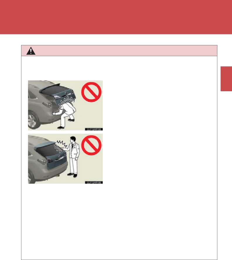
77
1-3. Opening, closing and locking the doors
1
Before driving
CAUTION
●Use caution when opening or closing the back door in windy weather as it may
move abruptly in strong wind.
●Do not pull on the back door damper stay to close the back door, and do not
hang on the back door damper stay.
Doing so may cause hands to be caught or the back door damper stay to break,
causing an accident.
●If a bicycle carrier or similar heavy object is attached to the back door, it may fall
closed again after being opened, causing someone’s hands, head or neck to be
caught and injured. When installing an accessory part to the back door, using a
genuine Lexus part is recommended.
●The back door may fall if it is not opened
fully. It is more difficult to open or close the
back door on an incline than on a level sur-
face, so beware of the back door unexpect-
edly opening or closing by itself. Make sure
that the back door is fully open and secure
before using the luggage compartment.
●When closing the back door, take extra
care to prevent your fingers etc. from being
caught.
●When closing the back door, make sure to
press it lightly on its outer surface. If the
back door handle is used to fully close the
back door, it may result in hands or arms
being caught.
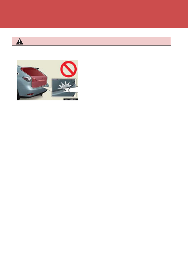
78
1-3. Opening, closing and locking the doors
CAUTION
■Back door closer
●Use caution when using the back door closer as it still operates when the power
back door system is cancelled.
■Power back door
Observe the following precautions when operating the power back door.
Failure to do so may cause death or serious injury.
●Check the safety of the surrounding area to make sure there are no obstacles or
anything that could cause any of your belongings to get caught.
●If anyone is in the vicinity, make sure they are safe and let them know that the back
door is about to open or close.
●If the power back door system is turned off with the main switch while the back
door is operating automatically, the automatic operation is stopped. The back
door then has to be operated manually. Take extra care when on an incline, as the
back door may open or close unexpectedly.
●If the operating conditions of the power back door are no longer met, a buzzer
may sound and the back door may stop opening or closing. The back door then
has to be operated manually. Take extra care when on an incline, as the back door
may open or close abruptly.
●If the power back door main switch is turned off while the power back door is
operating, the back door will change to manual operation. In this case, be careful
as the back door may move suddenly.
●On an incline, the back door may fall after it opens. Make sure the back door is
fully open and secure.
●In the event that the back door is left slightly
open, the back door closer will automati-
cally close it to the fully closed position. It
takes several seconds before the back
door closer begins to operate. Be careful
not to catch fingers or anything else in the
back door, as this may cause bone frac-
tures or other serious injuries.

79
1-3. Opening, closing and locking the doors
1
Before driving
CAUTION
●In the following situations, the power back door may detect an abnormality and
automatic operation may be stopped. In this case, the back door has to be oper-
ated manually. Take extra care when on an incline, as the back door may open or
close abruptly.
• When the back door contacts an obstacle
• When the 12-volt battery voltage suddenly drops, such as when the
“POWER” switch is turned to ON mode or the hybrid system is started dur-
ing automatic operation
●If a bicycle carrier or similar heavy object is attached to the back door, the power
back door may not operate, causing itself to malfunction, or the back door may
fall closed again after being opened, causing someone’s hands, head or neck to
be caught and injured. When installing an accessory part to the back door, using
a genuine Lexus part is recommended.
■Jam protection function
Observe the following precautions.
Failure to do so may cause death or serious injury.
●Be careful while the jam protection function is operating. Being hit by the back
door may result in an injury.
●Although the back door stops closing when the jam protection function detects
an object, take extra care as you may still be injured if part of your body is already
caught.
●If anything obstructs the power back door while it is closing, the jam protection
function will cause the back door to automatically operate in the opposite direc-
tion. However, be careful not to jam body parts in the doorframe, as an injury may
result.
●Never use any part of your body to intentionally activate the jam protection func-
tion.
●The jam protection function may not work if something gets caught just before
the back door fully closes. Be careful not to catch fingers or anything else.
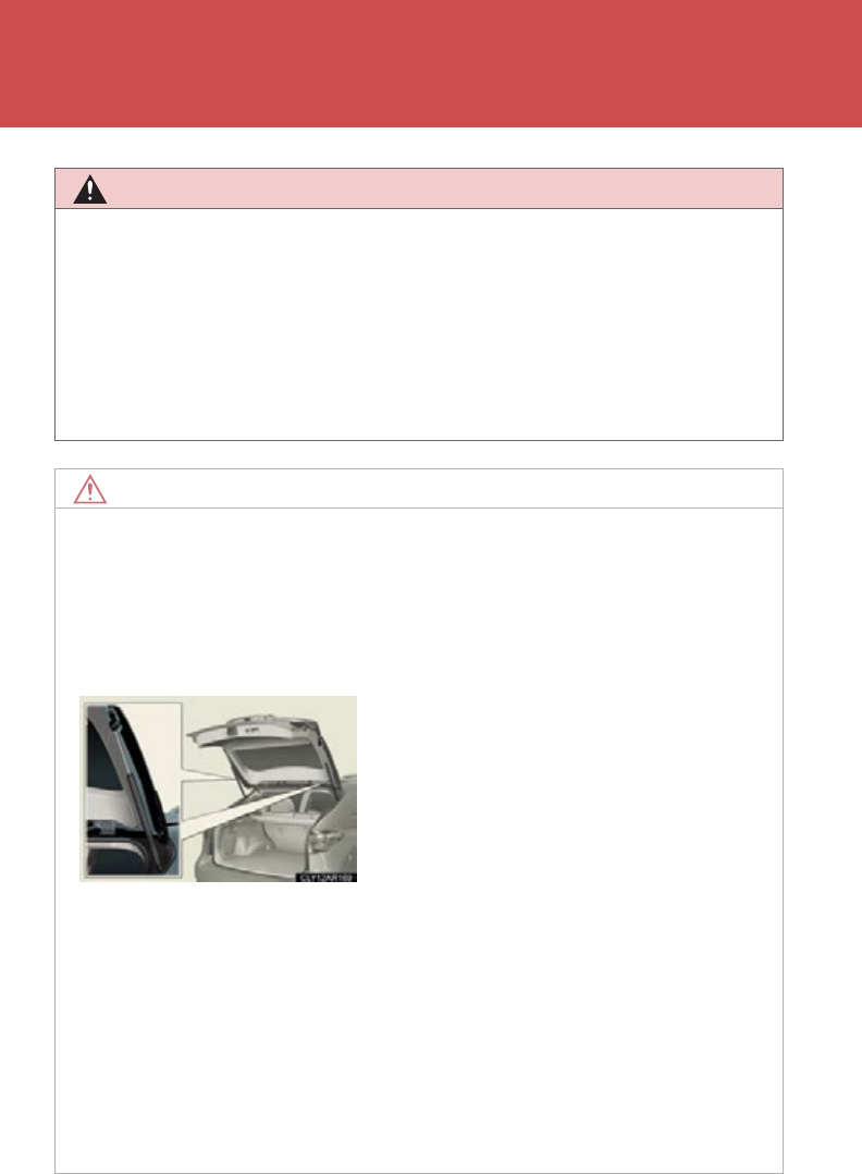
80
1-3. Opening, closing and locking the doors
CAUTION
●The jam protection function may not work depending on the shape of the object
that is caught. Be careful not to catch fingers or anything else.
●The sensors located on the right and left sides of the power back door detect
obstructions and prevent them from becoming jammed in the door. Some objects
may not be detected depending on their shape or how they are jammed. Be care-
ful not to get fingers or other body parts caught in the back door while it is oper-
ating as this may result in a serious injury.
NOTICE
■Back door damper stays
The back door is equipped with damper stays that hold the back door in place.
Observe the following precautions.
Failure to do so may cause damage to the back door damper stay, resulting in mal-
function.
■To prevent back door closer malfunction
●Do not apply excessive force to the back door while the back door closer is oper-
ating.
●If the back door is opened and closed repeatedly in a short amount of time, the
back door closer may stop operating. In this case, manually open the back door
once and wait for a while before attempting to close it again.
●Do not attach any foreign objects, such as
stickers, plastic sheets, or adhesives to the
damper stay rod.
●Do not touch the damper stay rod with
gloves or other fabric items.
●Do not attach any accessories other than
genuine Lexus parts to the back door.
●Do not place your hand on the damper stay
or apply lateral forces to it.

81
1-3. Opening, closing and locking the doors
1
Before driving
NOTICE
■To prevent damage to the power back door
●Make sure that there is no ice between the back door and frame that would pre-
vent movement of the back door. Operating the power back door when exces-
sive load is present on the back door may cause a malfunction.
●Do not apply excessive force to the back door while the power back door is oper-
ating.
●Take care not to damage the sensors (installed on the right and left edges of the
power back door) with a knife or other sharp object. If the sensor is disconnected,
the power back door will not operate in automatic operation.
●When manually closing the back door immediately after the power back door
has been automatically opened fully, some resistance may be felt.
82
1-4. Adjustable components (seats, mirrors, steering wheel)
Front seats
Seat position adjustment switch
Seatback angle adjustment switch
Seat cushion (front) angle adjustment switch
Vertical height adjustment switch
Lumbar support adjustment switch
Seat cushion length adjustment switch (if equipped)
83
1-4. Adjustable components (seats, mirrors, steering wheel)
1
Before driving
Flattening the front seatbacks
■Before flattening the front seatbacks
Slide the rear seats as far back as possible. (P. 86)
■Flattening the front seatbacks
Move the front seat forward, raise
the seat, and remove the head
restraint. (P. 95 )
After returning the seat to its origi-
nal position, make sure to replace
the head restraint.
Move the seatback angle adjust-
ment switch backward to flatten
the seatback.
STEP 1
STEP 2
84
1-4. Adjustable components (seats, mirrors, steering wheel)
Active head restraints
When the occupant’s lower back
presses against the seatback dur-
ing a rear-end collision, the head
restraint moves slightly forward
and upward to help reduce the risk
of whiplash to the seat occupant.
■Active head restraints
Even small forces applied to the seatback may cause the head restraint to move.
Pushing up a locked head restraint forcibly may appear the head restraint inner
structure. These do not indicate problems.
Inner
structure
During
rear-end
collision

85
1-4. Adjustable components (seats, mirrors, steering wheel)
1
Before driving
CAUTION
■Seat adjustment
●To reduce the risk of sliding under the lap belt during a collision, do not recline the
seat more than necessary.
If the seat is too reclined, the lap belt may slide past the hips and apply restraint
forces directly to the abdomen, or your neck may contact the shoulder belt,
increasing the risk of death or serious injury in the event of an accident.
●Adjustments should not be made while driving as the seat may unexpectedly
move and cause the driver to lose control of the vehicle.
■While driving
Do not allow passengers to ride on the flattened seat.
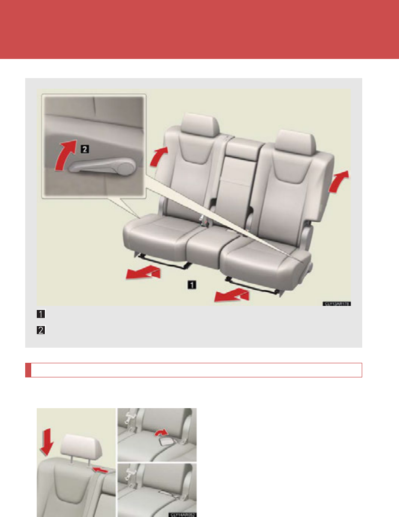
86
1-4. Adjustable components (seats, mirrors, steering wheel)
Rear seats
Folding down the rear seatbacks
■Before folding down the rear seatbacks
Stow all the head restraints and the
rear center seat belt buckle.
Seat position adjustment lever
Seatback angle adjustment lever
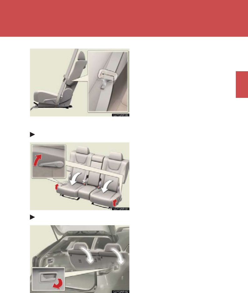
87
1-4. Adjustable components (seats, mirrors, steering wheel)
1
Before driving
Stow the seat belts inside the rear
seat side pockets.
When not in use, the seat belts
should be stored inside the rear
seat side pockets at all times.
■Folding down the rear seatbacks
From inside
Pull the seatback angle adjustment
lever.
To return the rear seatbacks to
their original positions, lift them up
until they lock.
From outside
Pull the levers.
Left side lever: Folds down the
left side rear seat
Right side lever: Folds down the
right side and
center rear seats
To return the rear seatbacks to
their original positions, lift them up
until they lock.
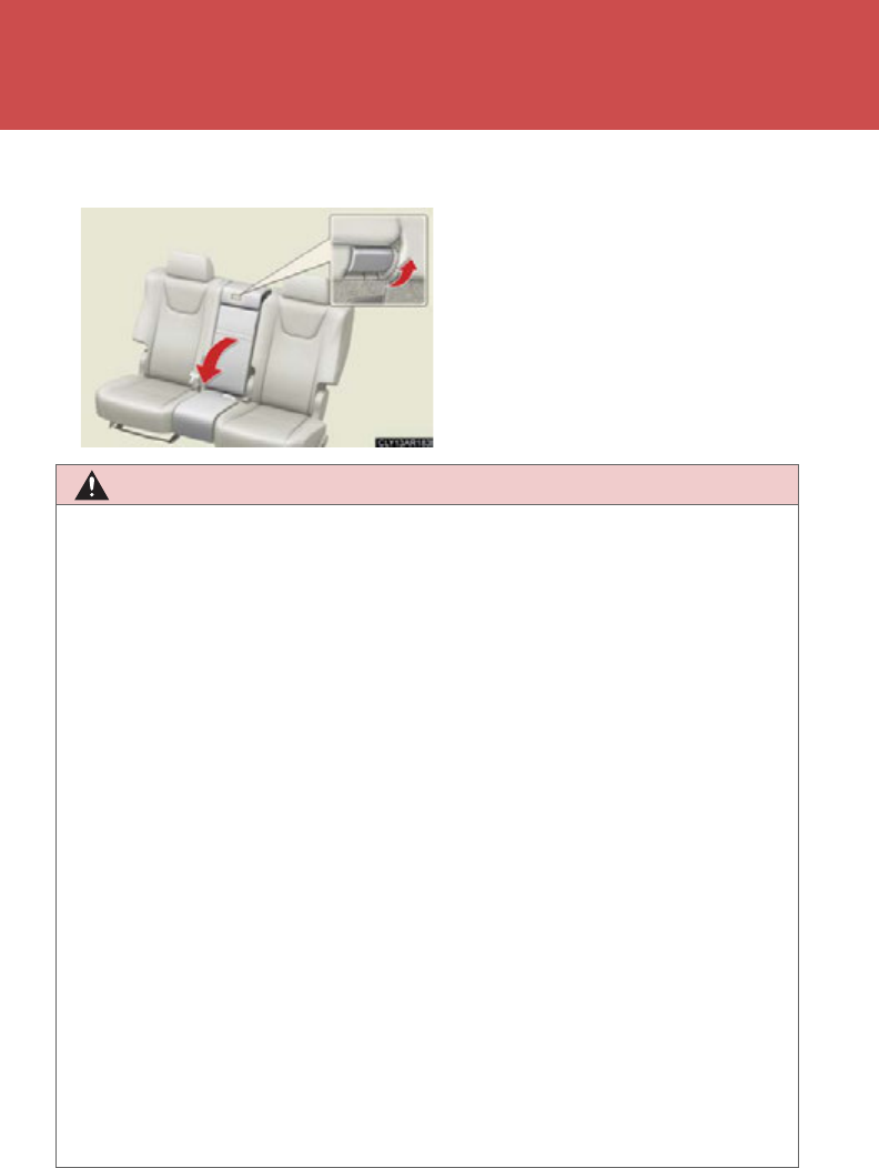
88
1-4. Adjustable components (seats, mirrors, steering wheel)
■Folding down the rear center seatback
Pull the center seatback lever
behind the seatback and fold the
seatback down.
To return the rear center seatback
to its original position, lift it up until
it locks.
CAUTION
■When folding the rear seatbacks down
Observe the following precautions. Failure to do so may result in death or serious
injury.
●Do not fold the seatbacks down while driving.
●Do not fold seatbacks down while passengers are seated or luggage is placed on
the seats.
●Stop the vehicle on level ground, set the parking brake and shift the shift lever to
P.
●After folding the seatback, lightly move the seat back and forth to lock it in place.
●Do not allow anyone to sit on a folded seatback or in the luggage compartment
while driving.
●Do not allow children to enter the luggage compartment.
■Seat adjustment
●To reduce the risk of sliding under the lap belt during a collision, do not recline the
seat more than necessary.
If the seat is too reclined, the lap belt may slide past the hips and apply restraint
forces directly to the abdomen, or your neck may contact the shoulder belt,
increasing the risk of death or serious injury in the event of an accident.
●Adjustments should not be made while driving as the seat may unexpectedly
move and cause the driver to lose control of the vehicle.
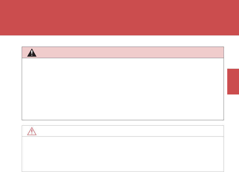
89
1-4. Adjustable components (seats, mirrors, steering wheel)
1
Before driving
CAUTION
■After returning the rear seatback to the upright position
Observe the following precautions. Failure to do so may result in death or serious
injury.
●Make sure the seatback is securely locked by pushing it forward and rearward on
the top.
●Check that the seat belts are not twisted or caught in the seatback.
NOTICE
■Stowing the center seat belt buckle
Before folding down the rear seatbacks, stow the center seat belt buckle to prevent
it from becoming caught in the seatbacks.
90
1-4. Adjustable components (seats, mirrors, steering wheel)
Driving position memory
Your preferred driving position (the position of the driver's seat, steering
wheel and outside rear view mirrors) can be memorized and recalled with
the touch of a button. It is also possible to set this function to activate auto-
matically when the doors are unlocked.
Three different driving positions can be entered into memory.
■Entering a position to memory
Turn the “POWER” switch to ON mode.
Adjust the driver’s seat, steering wheel and outside rear view
mirrors to the desired positions.
Press the “SET” button, then
within 3 seconds press button
“1”, “2” or “3” until the signal
beeps.
If the selected button has
already been preset, the previ-
ously recorded position will be
overwritten.
■Recalling the memorized position
Check that the shift lever is set in P.
Turn the “POWER” switch to ON mode.
Press button “1”, “2” or “3” until
the signal beeps to recall the
desired position.
STEP 1
STEP 2
STEP 3
STEP 1
STEP 2
STEP 3
: If equipped
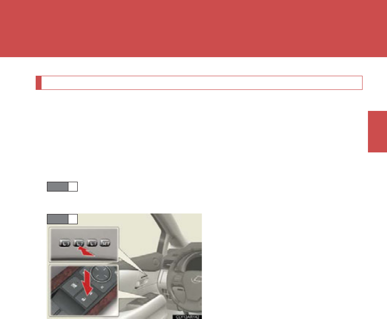
91
1-4. Adjustable components (seats, mirrors, steering wheel)
1
Before driving
Linking driving position memory with door unlock operation
Record your driving position to button “1”, “2” or “3” before performing
the following:
Carry only the key (including the card key) to which you want to link the
driving position. If 2 or more keys are in the vehicle, the driving position
cannot be linked properly.
Shift the shift lever to P and close the driver's door. Turn the
“POWER” switch to ON mode.
Press the desired button (“1”, “2” or
“3”) to recall the position. Then,
while keep pressing the button,
press the driver's door lock
switches (either lock or unlock)
until the signal beeps.
The driving position is recalled
when the driver's door is unlocked
using the entry function or wireless
remote control and the driver's
door is opened.
STEP 1
STEP 2
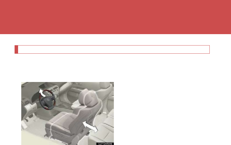
92
1-4. Adjustable components (seats, mirrors, steering wheel)
Power easy access system (driver’s side only)
When the driver enters and exits the vehicle, the driver's seat and steer-
ing wheel will automatically perform the following operations:
Exiting the vehicle: When all of the
following actions have been per-
formed, the steering wheel will
move up and back to the point far-
thest away from the driver and the
seat will move backward (auto
away function):
• The shift lever has been shifted to P
• The “POWER” switch has been
turned off
• The driver seat belt has been
unfastened
Entering the vehicle: When either
of the following actions has been
performed, the steering wheel will
move toward the driver and seat
will move forward (auto return
function):
• The “POWER” switch has been
turned to ACCESSORY mode
• The driver seat belt has been fas-
tened

93
1-4. Adjustable components (seats, mirrors, steering wheel)
1
Before driving
■When driving position memory is linked with door unlock operation
If the driver’s door is opened, the driver’s seat will move toward the memorized
position but stop slightly beforehand to allow easy access to the vehicle.
Turning the “POWER” switch to ACCESSORY mode or fastening the driver’s seat
belt moves the seat fully into the memorized position.
■Canceling the linked door unlock operation
Turn the “POWER” switch to ON mode and close the driver's door.
While pressing the “SET” button, press the driver’s door lock switches
(either lock or unlock) until the signal beeps.
■Operating the driving position memory after turning the “POWER” switch off
Memorized positions (except for the steering wheel position) can be activated up
to 180 seconds after the driver’s door is opened and another 60 seconds after it is
closed again, even after turning the “POWER” switch off.
■Stopping seat position operation part-way through
Perform any of the following operations:
●Press the “SET” button.
●Press button “1”, “2” or “3”.
●Adjust the seat using the switches (only cancels seat position recall).
●Adjust the steering wheel using the tilt and telescopic steering control switch
(only cancels steering wheel position recall).
■Correct seat position
When the seat is in the most forward or most backward position, and the seat is
being moved in those directions, the system may not correctly recognize the cur-
rent position and the memorized position will not be correctly recalled.
■The auto away function for exiting the driver seat
If the seat is already close to the rearmost position, the auto away function may not
operate when the driver exits the vehicle.
■Customization
The distance that the driver’s seat moves backward during the auto away function
can be changed. (Customizable features P. 693)
STEP 1
STEP 2

94
1-4. Adjustable components (seats, mirrors, steering wheel)
CAUTION
■Seat adjustment caution
Take care during seat adjustment so that the seat does not strike the rear passenger
or squeeze your body against the steering wheel.
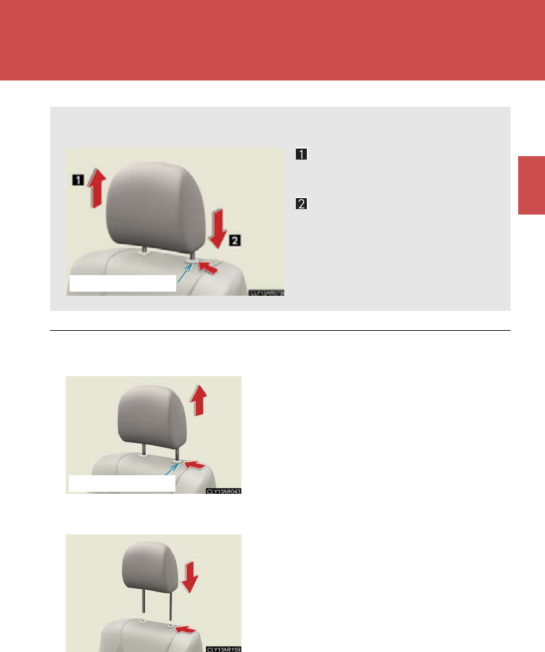
95
1
1-4. Adjustable components (seats, mirrors, steering wheel)
Before driving
Head restraints
■Removing the head restraints
■Installing the head restraints
Head restraints are provided for all seats.
Up
Pull the head restraints up.
Down
Push the head restraint down
while pressing the lock release
button.
Lock release button
Pull the head restraint up while pressing the
lock release button.
Lock release button
Align the head restraint with the installation
holes and push it down to the lock position.
Press and hold the lock release button when
lowering the head restraint.
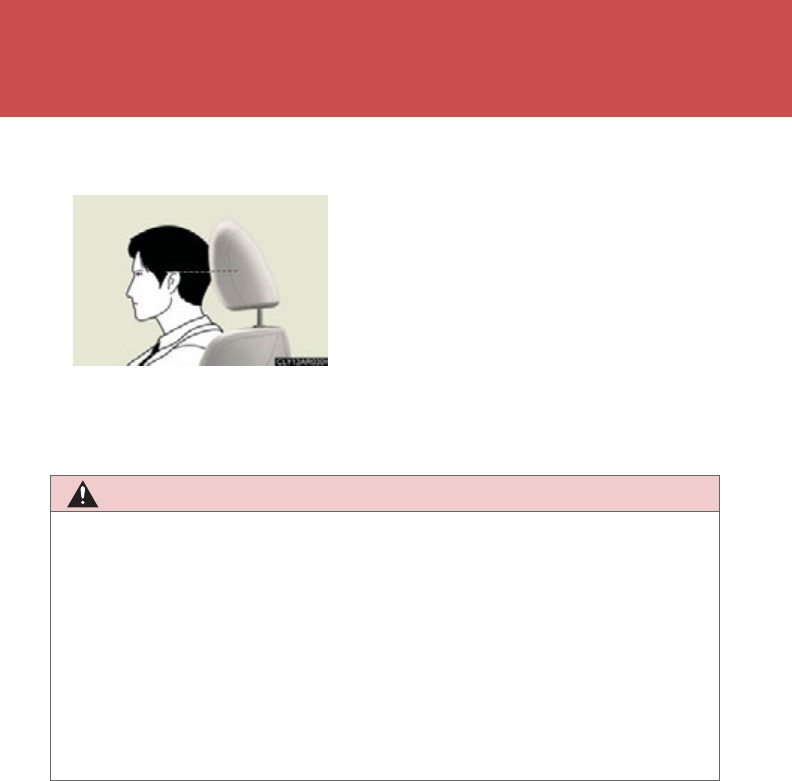
96
1-4. Adjustable components (seats, mirrors, steering wheel)
■Adjusting the height of the head restraints (front seats)
■Adjusting the rear seat head restraints
Always raise the head restraints to the uppermost lock position during use.
CAUTION
■Head restraint precautions
Observe the following precautions regarding the head restraints. Failure to do so
may result in death or serious injury.
●Use the head restraints designed for each respective seat.
●Adjust the head restraints to the correct position at all times.
●After adjusting the head restraints, push down on them and make sure they are
locked in position.
●Do not drive with the head restraints removed.
Make sure that the head restraints are
adjusted so that the center of the head
restraint is closest to the top of your ears.
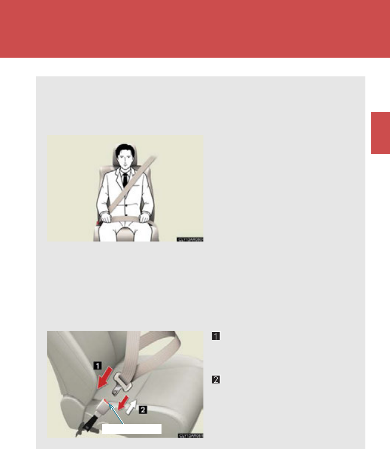
97
1
1-4. Adjustable components (seats, mirrors, steering wheel)
Before driving
Seat belts
Make sure that all occupants are wearing their seat belts before driving the
vehicle.
■Correct use of the seat belts
●Extend the shoulder belt so
that it comes fully over the
shoulder, but does not come
into contact with the neck or
slide off the shoulder.
●Position the lap belt as low as
possible over the hips.
●Adjust the position of the
seatback. Sit up straight and
well back in the seat.
●Do not twist the seat belt.
■Fastening and releasing the seat belt
To fasten the seat belt, push
the plate into the buckle until
a click sound is heard.
To release the seat belt, press
the release button.
Release button
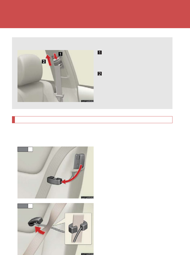
98
1-4. Adjustable components (seats, mirrors, steering wheel)
Seat belt comfort guide (outside rear seats)
If the shoulder belt sits close to a person's neck, use the seat belt comfort
guide.
Pull the comfort guide from the
pocket.
Slide the belt past the slot of the
guide.
The elastic cord must be behind
the seat belt.
■Adjusting the seat belt shoulder anchor height (front seats)
Push the seat belt shoulder
anchor down while pressing
the release button.
Push the seat belt shoulder
anchor up.
Move the height adjuster up and
down as needed until you hear a
click.
STEP 1
STEP 2
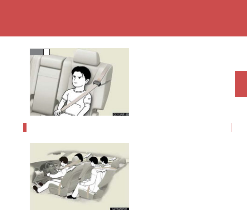
99
1-4. Adjustable components (seats, mirrors, steering wheel)
1
Before driving
Buckle the seat belt and position it
comfortably.
Seat belt pretensioners (front and outside rear seats)
The pretensioner helps the seat
belt to quickly restrain the occu-
pant by retracting the seat belt
when the vehicle is subjected to
certain types of severe frontal colli-
sion.
The pretensioner may not activate
in the event of a minor frontal
impact, a side impact or a rear
impact.
STEP 3
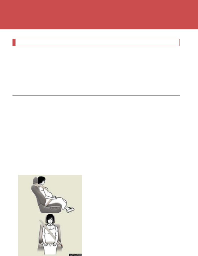
100
1-4. Adjustable components (seats, mirrors, steering wheel)
Pre-collision seat belts (front seats of vehicles with a pre-collision system)
If the pre-collision sensor detects that a collision is unavoidable, the pre-
collision system will retract the seat belt, thus enhancing the effectiveness
of the seat belt pretensioner in a crash.
The same will happen if the driver makes an emergency braking or loses con-
trol of the vehicle. (P. 28 2 )
■Emergency locking retractor (ELR)
The retractor will lock the belt during a sudden stop or on impact. It may also lock if
you lean forward too quickly. To allow the belt to extend, retract the belt and then
pull it slowly.
■Automatic locking retractor (ALR)
When a passenger's shoulder belt is completely extended and then retracted even
slightly, the belt is locked in that position and cannot be extended. This feature is
used to hold the child restraint system (CRS) firmly. To free the belt again, press the
buckle release button and fully retract the seat belt. (P. 1 53 )
■Pregnant women
Obtain medical advice and wear the seat belt
in the proper way. (P. 97)
Women who are pregnant should position
the lap belt as low as possible over the hips in
the same manner as other occupants. Extend
the shoulder belt completely over the shoul-
der and position the belt across the chest.
Avoid belt contact over the round part of the
abdominal area.
If the seat belt is not worn properly, not only
the pregnant woman, but also the fetus could
suffer death or serious injury as a result of
sudden braking or a collision.
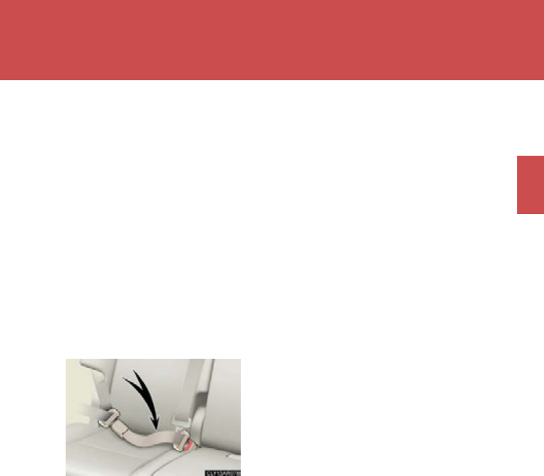
101
1-4. Adjustable components (seats, mirrors, steering wheel)
1
Before driving
■People suffering illness
Obtain medical advice and wear the seat belt in the proper way.
■Child seat belt usage
The seat belts of your vehicle were principally designed for persons of adult size.
●Use a child restraint system appropriate for the child, until the child becomes
large enough to properly wear the vehicle's seat belt. (P. 1 49)
●When the child becomes large enough to properly wear the vehicle's seat belt,
follow the instructions on P. 97 regarding seat belt usage.
■Replacing the belt after the pretensioner has been activated
If the vehicle is involved in multiple collisions, the pretensioner will activate for the
first collision, but will not activate for the second or subsequent collisions.
■Seat belt extender
If your seat belts cannot be fastened securely
because they are not long enough, a person-
alized seat belt extender is available from
your Lexus dealer free of charge.

102
1-4. Adjustable components (seats, mirrors, steering wheel)
CAUTION
Observe the following precautions to reduce the risk of injury in the event of sudden
braking, sudden swerving or an accident.
Failing to do so may cause death or serious injury.
■Wearing a seat belt
●Ensure that all passengers wear a seat belt.
●Always wear a seat belt properly.
●Each seat belt should be used by one person only. Do not use a seat belt for more
than one person at once, including children.
●Lexus recommends that children be seated in the rear seat and always use a seat
belt and/or an appropriate child restraint system.
●To achieve a proper seating position, do not recline the seat more than necessary.
The seat belt is most effective when the occupants are sitting up straight and well
back in the seats.
●Do not wear the shoulder belt under your arm.
●Always wear your seat belt low and snug across your hips.
■When children are in the vehicle
Do not allow children to play with the seat belt. If the seat belt becomes twisted
around a child’s neck, it may lead to choking or other serious injuries that could
result in death.
If this occurs and the buckle cannot be unfastened, scissors should be used to cut
the belt.
■Adjustable shoulder anchor
Always make sure the shoulder belt is positioned across the center of your shoul-
der. The belt should be kept away from your neck, but not falling off your shoulder.
Failure to do so could reduce the amount of protection in an accident and cause
death or serious injuries in the event of a sudden stop, sudden swerve or accident.
(P. 98 )

103
1-4. Adjustable components (seats, mirrors, steering wheel)
1
Before driving
CAUTION
■Seat belt pretensioners
●Do not place anything, such as a cushion, on the front passenger's seat. Doing so
will disperse the passenger's weight, which prevents the sensor from detecting
the passenger's weight properly. As a result, the seat belt pretensioner for the
front passenger's seat may not activate in the event of a collision.
●If the pretensioner has activated, the SRS warning light will come on. In that case,
the seat belt cannot be used again and must be replaced at your Lexus dealer.
■Seat belt damage and wear
●Do not damage the seat belts by allowing the belt, plate, or buckle to be jammed
in the door.
●Inspect the seat belt system periodically. Check for cuts, fraying, and loose parts.
Do not use a damaged seat belt until it is replaced. Damaged seat belts cannot
protect an occupant from death or serious injury.
●Ensure that the belt and tab are locked and the belt is not twisted.
If the seat belt does not function correctly, immediately contact your Lexus
dealer.
●Replace the seat assembly, including the belts, if your vehicle has been involved in
a serious accident, even if there is no obvious damage.
●Do not attempt to install, remove, modify, disassemble or dispose of the seat belts.
Have any necessary repairs carried out by your Lexus dealer. Inappropriate han-
dling of the pretensioner may prevent it from operating properly, resulting in
death or serious injury.
■Using a seat belt comfort guide
Failure to observe the following precautions could reduce the effectiveness of the
seat belt in an accident, causing death or serious injury.
●Make sure the belt is not twisted and that it lies flat. The elastic cord must be
behind the belt and the guide must be on the front.
●To reduce the chance of injury in case of a sudden stop, sudden swerve or acci-
dent while driving, remove and store the comfort guide in its pocket when it is not
in use.
●Always make sure the shoulder belt is positioned across the center of the shoul-
der. The belt should be kept away from the neck, and should not fall off the shoul-
der.

104
1-4. Adjustable components (seats, mirrors, steering wheel)
CAUTION
■Using a seat belt extender
●Do not wear the seat belt extender if you can fasten the seat belt without the
extender.
●Do not use the seat belt extender when installing a child restraint system because
the belt will not securely hold the child restraint system, increasing the risk of
death or serious injury in the event of an accident.
●The personalized extender may not be safe on another vehicle, when used by
another person, or at a different seating position other than the one originally
intended.
NOTICE
■When using a seat belt extender
When releasing the seat belt, press on the buckle release button on the extender,
not on the seat belt.
This helps prevent damage to the vehicle interior and the extender itself.
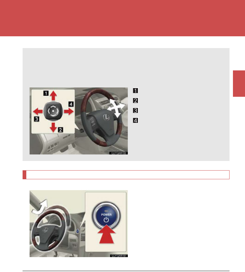
105
1
1-4. Adjustable components (seats, mirrors, steering wheel)
Before driving
Steering wheel
Auto tilt away
When the “POWER” switch is
turned off, the steering wheel
returns to its stowed position by
moving up and away to enable
easier driver entry and exit.
Turning the “POWER” switch to
ACCESSORY or ON mode will
return the steering wheel to the
original position.
The steering wheel can be adjusted to a comfortable position.
Operating the switch moves the steering wheel in the following direc-
tions:
Up
Down
Away from the driver
Toward the driver
■The steering wheel can be adjusted when
The “POWER” switch is in ACCESSORY or ON mode*.
*: Vehicles with driving position memory: If the driver's seat belt is fastened, the
steering wheel can be adjusted regardless of “POWER” switch mode.
■Automatic adjustment of the steering position (vehicles with driving position
memory)
A desired steering position can be entered to memory and recalled automatically
by the driving position memory. (P. 9 0)

106
1-4. Adjustable components (seats, mirrors, steering wheel)
■Notes for the auto tilt away function (vehicles with driving position memory)
The auto tilt away function can only operate when the “POWER” switch has been
turned off, the driver seat belt has been unfastened and the driver’s seat movement
(P. 693) is in a setting other than off.
When the driver fastens the seat belt again, the steering wheel will return to the
original position. (P. 92 )
CAUTION
■Caution while driving
Do not adjust the steering wheel while driving.
Doing so may cause the driver to mishandle the vehicle and cause an accident,
resulting in death or serious injury.
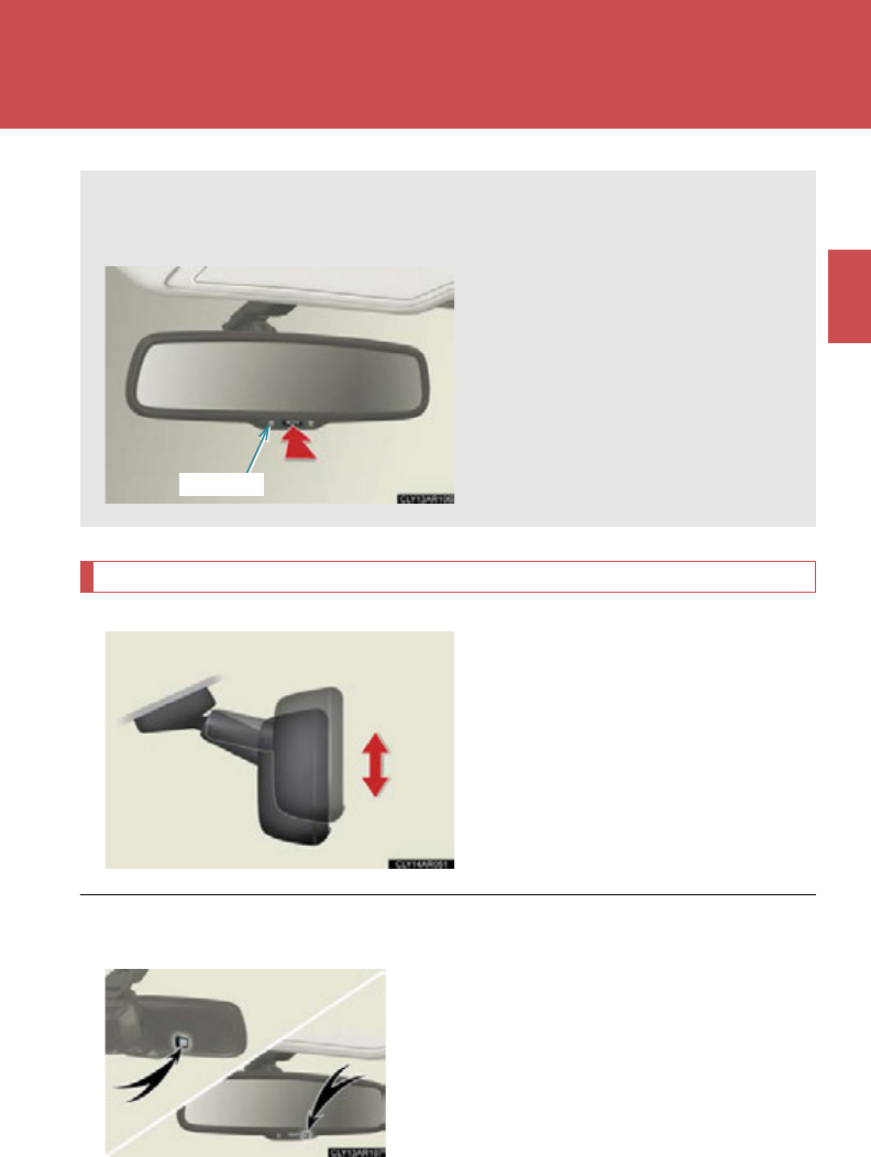
107
1
1-4. Adjustable components (seats, mirrors, steering wheel)
Before driving
Anti-glare inside rear view mirror
Adjusting the height of rear view mirror
Adjust the height of the rear view
mirror by moving it up and down.
In automatic mode, sensors are used to detect the headlights of vehicles
behind and the reflected light is automatically reduced.
Turns automatic mode on/off
The indicator comes on when
automatic mode is turned on.
The mirror will revert to auto-
matic mode each time the
“POWER” switch is turned to
ON mode.
Indicator
■To prevent sensor error
To ensure that the sensors operate properly,
do not touch or cover them.

108
1-4. Adjustable components (seats, mirrors, steering wheel)
CAUTION
■Caution while driving
Do not adjust the position of the mirror while driving.
Doing so may lead to mishandling of the vehicle and cause an accident, resulting in
death or serious injury.
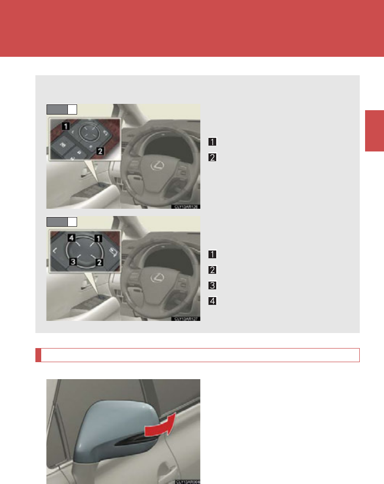
109
1
1-4. Adjustable components (seats, mirrors, steering wheel)
Before driving
Outside rear view mirrors
Manually folding and extending the mirrors
Push the mirror back in the direc-
tion of the vehicle's rear.
Mirror angle can be adjusted using the switch.
To select a mirror to adjust,
press the switch.
Left
Right
Pressing the same switch again
will put the switch in neutral.
To adjust the mirror, press the
switch.
Up
Right
Down
Left
STEP 1
STEP 2
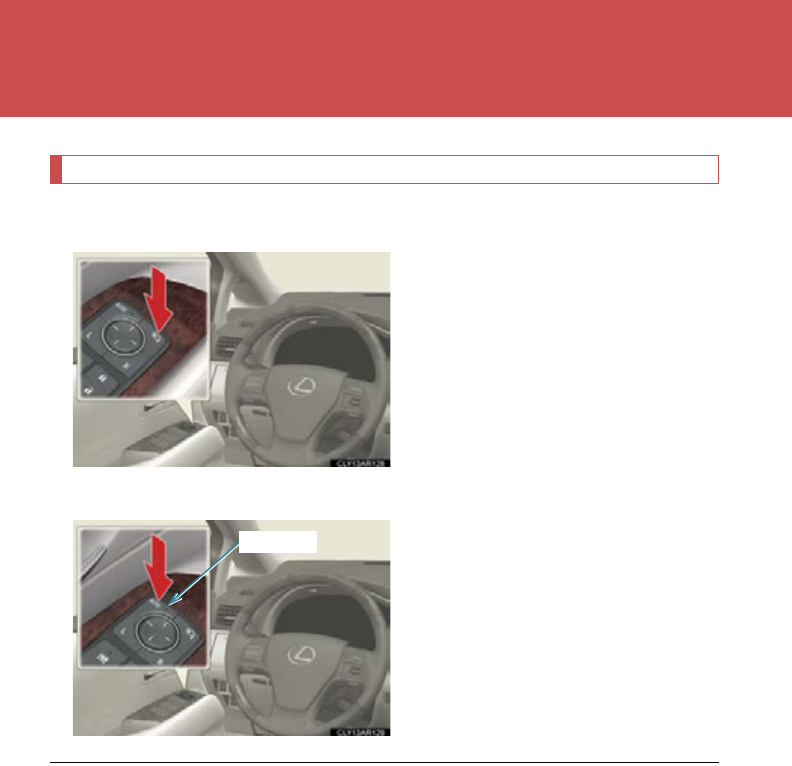
110
1-4. Adjustable components (seats, mirrors, steering wheel)
Automatically folding and extending the mirrors (if equipped)
■Using the switch
Press the switch to fold the mirrors.
Press it again to return them.
■Setting automatic mode
Automatic mode allows the folding
or extending of the mirrors to be
linked to locking/unlocking of the
doors.
Press the “AUTO” switch to set
automatic mode.
The indicator will come on.
Indicator
■Mirror angle can be adjusted when
The “POWER” switch is in ACCESSORY or ON mode.
■Linked mirror function when reversing
The right and left outside rear view mirrors will automatically angle downwards
when the vehicle is reversing in order to give a better view of the ground. This func-
tion only operates when either the “L” or “R” mirror select switch is selected.
■When the mirrors are fogged up
Turn on the mirror defoggers to defog the mirrors. (P. 330)

111
1-4. Adjustable components (seats, mirrors, steering wheel)
1
Before driving
■Automatic adjustment of the mirror angle (vehicles with driving position mem-
ory)
A desired mirror face angle can be entered to memory and recalled automatically
by the driving position memory. (P. 9 0)
■Auto anti-glare function (if equipped)
When the anti-glare inside rear view mirror is set to automatic mode, the outside
rear view mirrors will activate in conjunction with the anti-glare inside rear view mir-
ror to reduce reflected light. (P. 1 07)
CAUTION
■When driving the vehicle
Observe the following precautions while driving.
Failing to do so may result in loss of control of the vehicle and cause an accident,
resulting in death or serious injury.
●Do not adjust the mirrors while driving.
●Do not drive with the mirrors folded.
●Both the driver and passenger side mirrors must be extended and properly
adjusted before driving.
■When a mirror is moving
To avoid personal injury and mirror malfunction, be careful not to get your hand
caught by the moving mirror.
■When the mirror defoggers are operating
Do not touch the rear view mirror surfaces, as they can become very hot and burn
you.
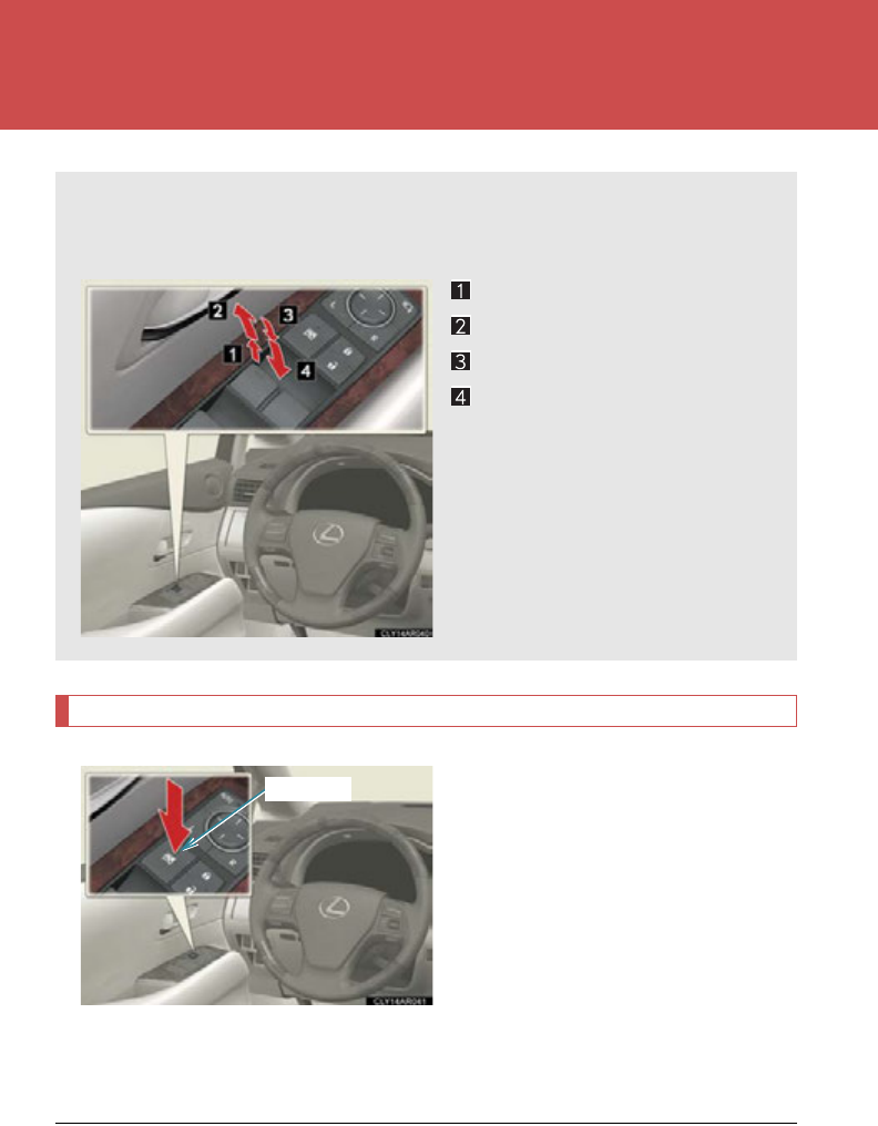
112
1-5. Opening and closing the windows and moon roof
Power windows
Window lock switch
Press the switch to lock the pas-
senger window switches.
The indicator will come on.
Use this switch to prevent children
from accidentally opening or clos-
ing a passenger window.
The passenger windows can still be
opened and closed using the
power window switches on the
driver’s side even if the lock switch
is on.
The power windows can be opened and closed using the switches.
Operating the switch moves the windows as follows:
Closing
One-touch closing*
Opening
One-touch opening*
*: Pushing the switch in the oppo-
site direction will stop window
travel partway.
Indicator
■The power windows can be operated when
The “POWER” switch is in ON mode.

113
1-5. Opening and closing the windows and moon roof
1
Before driving
■Operating the power windows after turning the hybrid system off
The power windows can be operated for approximately 45 seconds even after the
“POWER” switch is turned to ACCESSORY mode or turned off. They cannot,
however, be operated once either front door is opened.
■Jam protection function
If an object becomes caught between the window and the window frame, window
travel is stopped and the window is opened slightly.
■When the power window does not close normally
If the jam protection function is operating abnormally and a window cannot be
closed, perform the following operations using the power window switch on the rel-
evant door.
●After stopping the vehicle, the window can be closed by holding the power win-
dow switch in the one-touch closing position while the “POWER” switch is
turned to ON mode.
●If the window still cannot be closed even by carrying out the operation
explained above, initialize the function by performing the following procedure.
Hold the power window switch in the one-touch closing position. Con-
tinue holding the switch for a further 6 seconds after the window has
closed.
Hold the power window switch in the one-touch opening position. Con-
tinue holding the switch for a further 2 seconds after the window has
opened completely.
Hold the power window switch in the one-touch closing position once
again. Continue holding the switch for a further 2 seconds after the win-
dow has closed.
If you release the switch while the window is moving, start again from the beginning.
If the window continues to close but then re-open slightly even after performing the
above procedure correctly, have the vehicle inspected by your Lexus dealer.
STEP 1
STEP 2
STEP 3

114
1-5. Opening and closing the windows and moon roof
■Door lock linked window operation
●The power windows can be opened and closed using the mechanical key.
(P. 6 47)
●The power windows can be opened using the wireless remote control.
(P. 6 4 )
■When the 12-volt battery is disconnected
The window lock switch is disabled. If necessary, press the window lock switch after
reconnecting the battery.
■Customization
Settings (e.g. linked door lock operation) can be changed.
(Customizable features P. 693)
CAUTION
■Closing the windows
Observe the following precautions.
Failing to do so may result in death or serious injury.
●Check to make sure that all passengers do not have any part of their body in a
position where it could be caught when a window is being operated.
●Do not allow children to operate the power windows.
Closing a power window on someone can cause serious injury, and in some
instances, even death.
■Jam protection function
●Never use any part of your body to intentionally activate the jam protection func-
tion.
●The jam protection function may not work if something gets caught just before
the window fully closes. Also, the jam protection does not operate when the
power window switch is pulled up continually to close the windows.
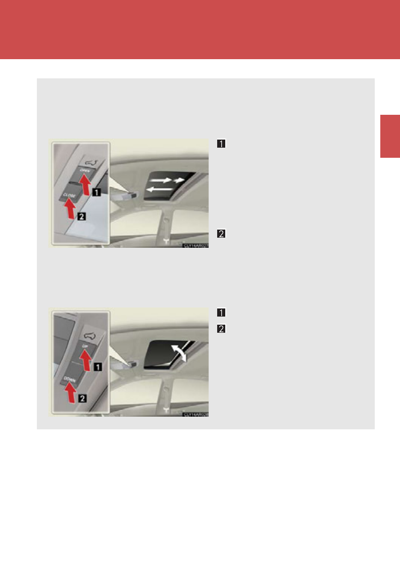
115
1
1-5. Opening and closing the windows and moon roof
Before driving
Moon roof
Use the overhead switches to open and close the moon roof and tilt it up
and down.
■Opening and closing
Opens the moon roof*
The moon roof stops slightly
before the fully open position to
reduce wind noise.
Press the switch again to fully
open the moon roof.
Closes the moon roof*
*: Lightly press either of the moon
roof switches to stop the moon
roof partway.
■Tilting up and down
T
ilts the moon roof up
*
Tilts the moon roof down
*
*: Lightly press either of the moon
roof switches to stop the moon
roof partway.
: If equipped

116
1-5. Opening and closing the windows and moon roof
■The moon roof can be operated when
The “POWER” switch is in ON mode.
■Operating the moon roof after turning the hybrid system off
The moon roof can be operated for approximately 45 seconds even after the
“POWER” switch is turned to ACCESSORY mode or turned off. It cannot, how-
ever, be operated once either front door is opened.
■Jam protection function
If an object is detected between the moon roof and the frame while the moon roof is
closing or tilting down, travel is stopped and the moon roof opens slightly.
■Sunshade
The sunshade can be opened and closed manually. However, the sunshade will
open automatically when the moon roof is opened.
■Door lock linked moon roof operation
●The moon roof can be opened and closed using the mechanical key. (P. 6 47)
●The moon roof can be opened using the wireless remote control. (P. 64 )

117
1-5. Opening and closing the windows and moon roof
1
Before driving
■When the moon roof does not close normally
Perform the following procedure:
●If the moon roof closes but then re-opens slightly
Stop the vehicle.
Press and hold the “CLOSE” switch.*1
The moon roof will close, reopen and pause for approximately 10 sec-
onds.*2 Then it will close again, tilt up and pause for approximately 1 sec-
ond. Finally, it will tilt down, open and close.
Check to make sure that the moon roof is completely closed and then
release the switch.
●If the moon roof tilts down but then tilts back up
Stop the vehicle.
Press and hold the “UP” switch*1 until the moon roof moves into the tilt up
position and stops.
Release the “UP” switch once and then press and hold the “UP” switch
again.*1
The moon roof will pause for approximately 10 seconds in the tilt up posi-
tion.*2 Then it will adjust slightly and pause for approximately 1 second.
Finally, it will tilt down, open and close.
Check to make sure that the moon roof is completely closed and then
release the switch.
*1: If the switch is released at the incorrect time, the procedure will have
to be performed again from the beginning.
*2: If the switch is released after the above mentioned 10 second pause,
automatic operation will be disabled. In that case, press and hold the
“CLOSE” or “UP” switch, and the moon roof will tilt up and pause for
approximately 1 second. Then it will tilt down, open and close. Check
to make sure that the moon roof is completely closed and then release
the switch.
If the moon roof does not fully close even after performing the above procedure
correctly, have the vehicle inspected by your Lexus dealer.
■Customization
Settings (e.g. linked door lock operation) can be changed.
(Customizable features P. 693 )
STEP 1
STEP 2
STEP 3
STEP 1
STEP 2
STEP 3
STEP 4

118
1-5. Opening and closing the windows and moon roof
CAUTION
■Opening the moon roof
Observe the following precautions.
Failing to do so may cause death or serious injury.
●Do not allow any passengers to put their hands or heads outside the vehicle while
it is moving.
●Do not sit on top of the moon roof.
■Closing the moon roof
Observe the following precautions.
Failing to do so may result in death or serious injury.
●Check to make sure that all passengers do not have any part of their body in a
position where it could be caught when the moon roof is being operated.
●Do not allow children to operate the moon roof.
Closing the moon roof on someone can cause death or serious injury.
■Jam protection function
Observe the following precautions.
Failing to do so may result in death or serious injury.
●Never use any part of your body to intentionally activate the jam protection func-
tion.
●The jam protection function may not work if something gets caught just before
the moon roof fully closes. Be careful not to catch fingers or anything else.
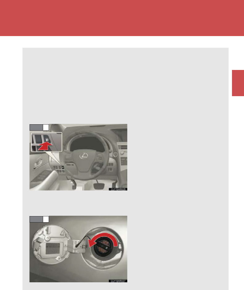
119
1
Before driving
1-6. Refueling
Opening the fuel tank cap
The fuel tank of your vehicle has a special structure, which requires a
reduction in fuel tank pressure before refueling. After the opener switch
has been pressed, it will take several seconds until the vehicle is ready for
refueling.
■Before refueling the vehicle
Turn the “POWER” switch off and close all the doors and windows.
■Opening the fuel tank cap
Press the opener to open the
fuel filler door.
The fuel filler door will open
within about 10 seconds of the
switch being pressed. Before
refueling is possible, a message
will be shown on the multi-infor-
mation display in the instrument
cluster to indicate the progress
of the fuel filler door opener.
(P. 620 )
Turn the fuel tank cap slowly to
open.
STEP 1
STEP 2
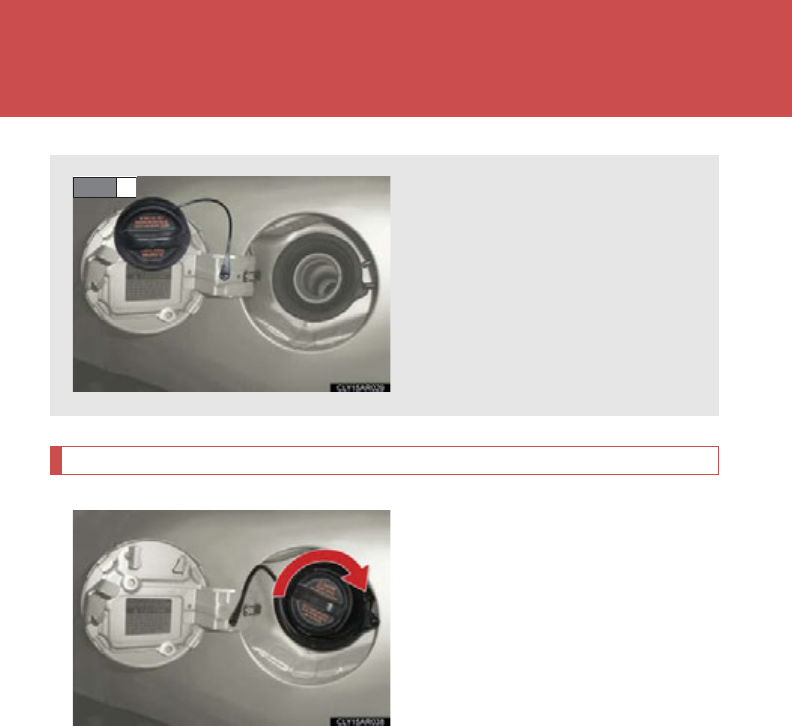
120
1-6. Refueling
Closing the fuel tank cap
After refueling, turn the fuel tank
cap until you hear a click.
Hang the fuel tank cap on the
back of the fuel filler door.
STEP 3
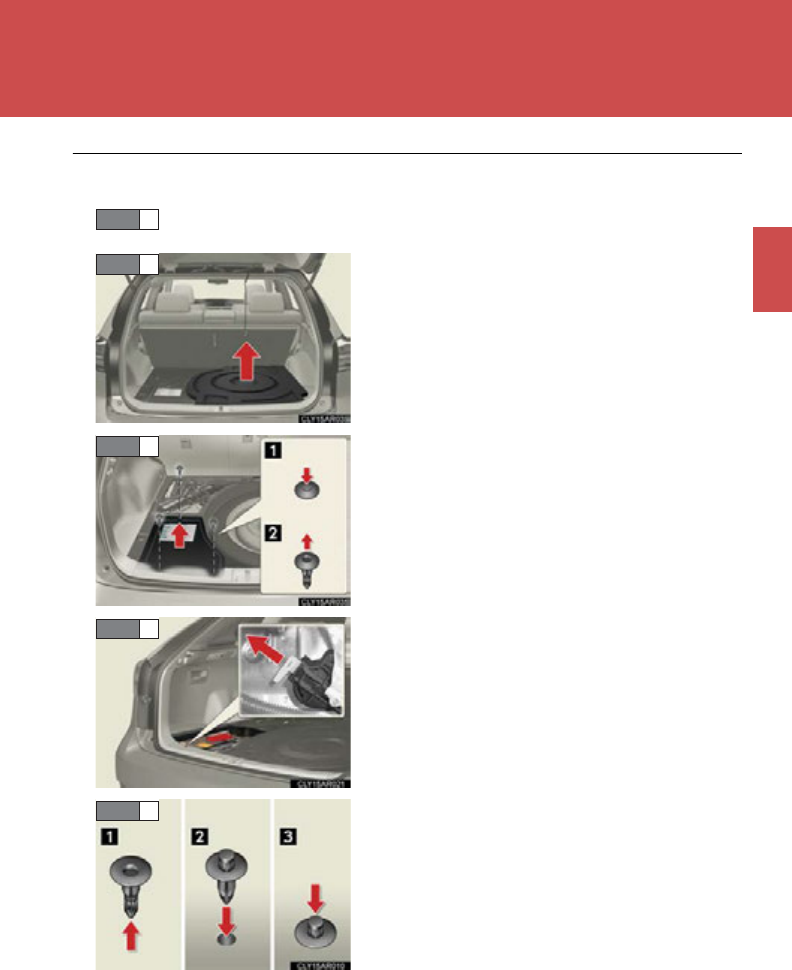
121
1-6. Refueling
1
Before driving
■If the fuel filler door opener is inoperable
Lift the luggage mat up. (P. 52 5)
Using the lever to open the fuel filler door may not allow for an adequate reduction
in fuel tank pressure before refueling. To prevent fuel from spilling out, turn the cap
slowly when removing it.
During refueling, fuel may spill out from the filler opening due to air being dis-
charged from inside the fuel tank. Therefore, fill the fuel tank carefully and slowly.
STEP 1
With a compact spare tire only:
Remove the spare tire cover.
Remove the 12-volt battery cover.
Pull the lever.
If the fuel filler door opener switch cannot be
operated, contact your Lexus dealer to ser-
vice the vehicle. If refueling is urgently neces-
sary, the fuel filler door can be opened using
the lever in the luggage compartment.
Install the clips.
STEP 2
STEP 3
STEP 4
STEP 5

122
1-6. Refueling
CAUTION
■When refueling the vehicle
Observe the following precautions while refueling the vehicle. Failure to do so may
result in death or serious injury.
●After exiting the vehicle and before opening the fuel door, touch an unpainted
metal surface to discharge any static electricity. It is important to discharge static
electricity before refueling because sparks resulting from static electricity can
cause fuel vapors to ignite while refueling.
●Always hold the grips on the fuel tank cap and turn it slowly to remove it.
A whooshing sound may be heard when the fuel tank cap is loosened. Wait until
the sound cannot be heard before fully removing the cap. In hot weather, pressur-
ized fuel may spray out of the filler neck and cause injury.
●Do not allow anyone that has not discharged static electricity from their body to
come close to an open fuel tank.
●Do not inhale vaporized fuel.
Fuel contains substances that are harmful if inhaled.
●Do not smoke while refueling the vehicle.
Doing so may cause the fuel to ignite and cause a fire.
●Do not return to the vehicle or touch any person or object that is statically
charged.
This may cause static electricity to build up, resulting in a possible ignition hazard.
■When refueling
Securely insert the fuel nozzle into the fuel filler neck. If fuel is added with the nozzle
slightly lifted away from the fuel filler neck, the automatic shut off function may not
operate, resulting in fuel overflowing from the tank.
■When replacing the fuel cap
Do not use anything but a genuine Lexus fuel tank cap designed for your vehicle.
Doing so may cause a fire or other incident which may result in death or serious
injury.

123
1-6. Refueling
1
Before driving
NOTICE
■Refueling
●Finish refueling within 30 minutes. If more than 30 minutes passes, the internal
valve closes. In this condition, fuel may overflow during the refueling process.
Press the fuel filler door opener switch again.
●Do not spill fuel during refueling.
Doing so may damage the vehicle, such as causing the emission control system to
operate abnormally or damaging fuel system components or the vehicle's
painted surface.
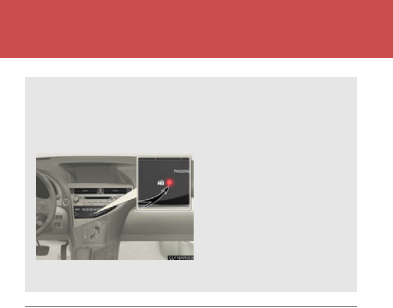
124
1-7. Theft deterrent system
Immobilizer system
■System maintenance
The vehicle has a maintenance-free type immobilizer system.
■Conditions affecting operation
Depending on surrounding environment and conditions, the immobilizer system
may not operate properly. This may prevent the hybrid system from starting.
(P. 57)
The vehicle's keys have built-in transponder chips that prevent the hybrid
system from starting if the key has not been previously registered in the
vehicle's on-board computer.
Never leave the keys inside the vehicle when you leave the vehicle.
The indicator light flashes after
the “POWER” switch has been
turned off to indicate that the
system is operating.
The indicator light stops flashing
after the “POWER” switch has
been turned to ACCESSORY
or ON mode to indicate that the
system has been canceled.
125
1-7. Theft deterrent system
1
Before driving
■Certifications for the immobilizer system
This system meets the certification requirements of Radio Law.
For vehicles sold in the U.S.A.
FCC ID: NI4TMIMB-1
This device complies with Part 15 of the FCC Rules. Operation is subject to the fol-
lowing two conditions: (1) this device may not cause harmful interference, and (2)
this device must accept any interference received, including interference that may
cause undesired operation.
For vehicles sold in Canada
Operation is subject to the following two conditions: (1) this device may not cause
interference, and (2) this device must accept any interference, including interfer-
ence that may cause undesired operation of the device.
CAUTION
■Certifications for the immobilizer system
Changes or modifications not expressly approved by the party responsible for
compliance could void the user’s authority to operate the equipment.
NOTICE
■To ensure the system operates correctly
Do not modify or remove the system. If modified or removed, the proper operation
of the system cannot be guaranteed.
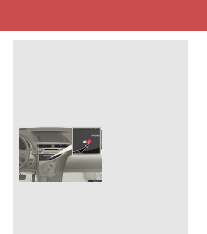
126
1-7. Theft deterrent system
Alarm
The system sounds the alarm and flashes the lights when forcible entry is
detected.
■Triggering of the alarm
The alarm is triggered in the following situations when the alarm is
set:
●A locked door is unlocked or opened in any way other than using
the entry function, wireless remote control or mechanical key.
●The hood is opened.
■Setting the alarm system
Close the doors and hood, and
lock all the doors.
The system will be set automati-
cally after 30 seconds.
The indicator light changes from
being on to flashing when the
system is set.
■Deactivating or stopping the alarm
Do one of the following to deactivate or stop the alarms:
●Unlock the doors.
●Start the hybrid system. (The alarm will be deactivated or stopped
after a few seconds.)

127
1-7. Theft deterrent system
1
Before driving
■System maintenance
The vehicle has a maintenance-free type alarm system.
■Items to check before locking the vehicle
To prevent unexpected triggering of the alarm and vehicle theft, make sure of the
following:
●Nobody is in the vehicle.
●The windows and moon roof are closed before the alarm is set.
●No valuables or other personal items are left in the vehicle.
■Tr ig ge ri n g of th e a l ar m
The alarm may be triggered in the following situations:
(Stopping the alarm deactivates the alarm system.)
■Alarm-operated door lock
●When the alarm is operating, the doors are locked automatically to prevent
intruders.
●Do not leave the key inside the vehicle when the alarm is operating, and make
sure the key is not inside the vehicle when recharging or replacing the 12-volt
battery.
●A person inside the vehicle opens a door
or the hood.
●The 12-volt battery is recharged or
replaced when the vehicle is locked.

128
1-7. Theft deterrent system
NOTICE
■To ensure the system operates correctly
Do not modify or remove the system. If modified or removed, the proper operation
of the system cannot be guaranteed.

129
1
1-7. Theft deterrent system
Before driving
Theft prevention labels (for U.S.A.)
These labels are attached to the
vehicle to reduce vehicle theft
by facilitating the tracing and
recovery of parts from stolen
vehicles. Do not remove under
penalty of law.
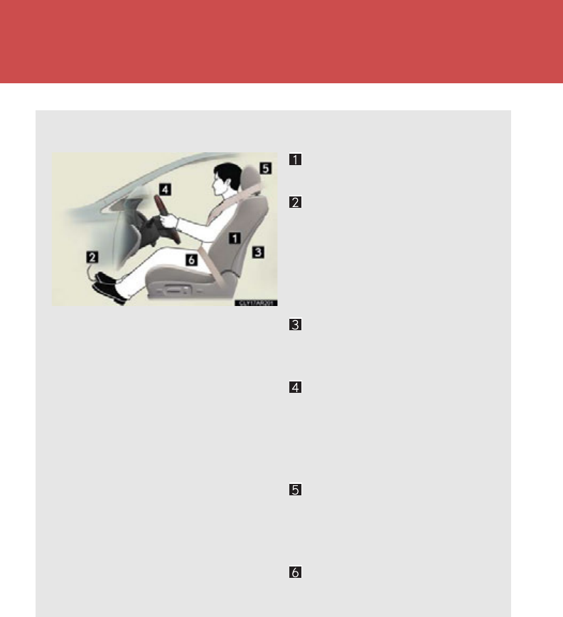
130
1-8. Safety information
Correct driving posture
Drive in a good posture as follows:
Sit upright and well back in
the seat. (P. 82 )
Adjust the position of the seat
forward or backward to
ensure the pedals can be
reached and easily
depressed to the extent
required. (P. 82)
Adjust the seatback so that
the controls are easily opera-
ble. (P. 82 )
Adjust the tilt and telescopic
positions of the steering
wheel downward so the air-
bag is facing your chest.
(P. 105)
Lock the head restraint in
place with the center of the
head restraint closest to the
top of your ears. (P. 95)
Wear the seat belt correctly.
(P. 97)

131
1-8. Safety information
1
Before driving
CAUTION
■While driving
●Do not adjust the position of the driver’s seat.
Doing so could cause the driver to lose control of the vehicle.
●Do not place a cushion between the driver or passenger and the seatback.
A cushion may prevent correct posture from being achieved, and reduce the
effectiveness of the seat belt and head restraint, increasing the risk of death or
serious injury to the driver or passenger.
●Do not place anything under the front seats.
Objects placed under the front seats may become jammed in the seat tracks and
stop the seat from locking in place. This may lead to an accident, resulting in
death or serious injury. The adjustment mechanism may also be damaged.
■Adjusting the seat position
●Take care when adjusting the seat position to ensure that other passengers are
not injured by the moving seat.
●Do not put your hands under the seat or near the moving parts to avoid injury.
Fingers or hands may become jammed in the seat mechanism.
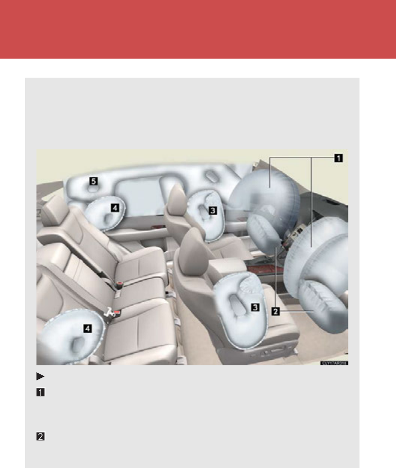
132
1-8. Safety information
SRS airbags
The SRS airbags inflate when the vehicle is subjected to certain types of
severe impacts that may cause significant injury to the occupants. They
work together with the seat belts to help reduce the risk of death or serious
injury.
SRS front airbags
SRS driver airbag/front passenger airbag
Can help protect the head and chest of the driver and front passen-
ger from impact with interior components
SRS knee airbags
Can help provide driver and front passenger protection

133
1-8. Safety information
1
Before driving
SRS side and curtain shield airbags
Front SRS side airbags
Can help protect the torso of the front seat occupants
Rear SRS side airbags
Can help protect the torso of occupants in the rear outer seats
SRS curtain shield airbags
Can help protect primarily the head of occupants in the outer seats
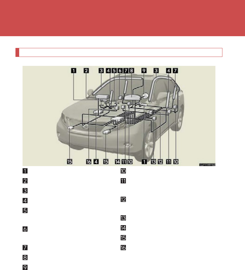
134
1-8. Safety information
SRS airbag system components
Your vehicle is equipped with ADVANCED AIRBAGS designed based
on US motor vehicle safety standards (FMVSS208). The airbag system
controls airbag deployment power for the driver and front passenger. The
driver airbag system consists of the driver’s seat position sensor etc. The
front passenger’s airbag system consists of the front passenger occupant
classification sensor etc.
Knee airbags
Front passenger airbag
Curtain shield airbags
Front side airbags
Occupant detection system
(ECU and sensors)
“AIR BAG ON” and “AIR BAG
OFF” indicator lights
Rear side airbags
SRS warning light
Driver airbag
Curtain shield airbag sensors
Side and curtain shield airbag
sensors
Driver's seat belt buckle
switch
Driver's seat position sensor
Airbag sensor assembly
Front airbag sensors
Front passenger’s seat belt
buckle switch

135
1-8. Safety information
1
Before driving
The main SRS airbag system components are shown above. The SRS air-
bag system is controlled by the airbag sensor assembly. The airbag sen-
sor assembly consists of a safing sensor and an airbag sensor.
In certain types of severe frontal or side impacts, the SRS airbag system
triggers the airbag inflators. A chemical reaction in the inflators quickly
fills the airbags with non-toxic gas to help restrain the motion of the occu-
pants.
■If the SRS airbags deploy (inflate)
●Bruising and slight abrasions may result from contact with a deploying (inflating)
SRS airbag.
●A loud noise and white powder will be emitted.
●Parts of the airbag module (steering wheel hub, airbag cover and inflator) as
well as the seats, parts of the front and rear pillars, and roof side rails, may be hot
for several minutes. The airbag itself may also be hot.
●The windshield may crack.
●For Safety Connect subscribers, if the SRS airbags deploy or in the event of a
severe rear-end collision, the system is designed to send an emergency call to
the response center, notifying them of the vehicle’s location (without needing to
push the “SOS” button) and an agent will attempt to speak with the occupants
to ascertain the level of emergency and assistance required. If the occupants
are unable to communicate, the agent automatically treats the call as an emer-
gency and helps to dispatch the necessary emergency services. (P. 484)
■SRS airbag deployment conditions (SRS front airbags)
●The SRS front airbags will deploy in the event of an impact that exceeds the
set threshold level (the level of force corresponding to an approximately 12 -
18 mph [20 - 30 km/h] frontal collision with a fixed wall that does not move or
deform).
However, this threshold velocity will be considerably higher if the vehicle strikes
an object, such as a parked vehicle or sign pole, which can move or deform on
impact, or if the vehicle is involved in an underride collision (e.g. a collision in
which the front of the vehicle “underrides”, or goes under, the bed of a truck etc.).
●It is possible that in some collisions where the forward deceleration of the vehi-
cle is very close to the designed threshold level, the SRS front airbags and the
seat belt pretensioners may not activate together.
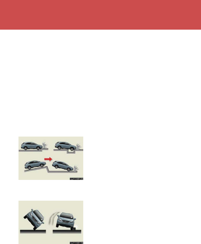
136
1-8. Safety information
●The SRS front passenger airbag will not activate if there is no passenger sitting
in the front passenger seat. However, the SRS front passenger airbag may
deploy if luggage is put in the seat, or the seat belt is fastened, even if the seat is
unoccupied. (P. 97)
■SRS airbag deployment conditions (SRS side airbags and curtain shield airbags)
The SRS side airbags and SRS curtain shield airbags will deploy in the event of an
impact that exceeds the set threshold level (the level of force corresponding to the
impact force produced by an approximately 3300 lb. [1500 kg] vehicle colliding
with the vehicle cabin from a direction perpendicular to the vehicle orientation at an
approximate speed of 12 - 18 mph [20 - 30 km/h]).
■Conditions under which the SRS airbags may deploy (inflate), other than a colli-
sion (SRS front airbags)
The SRS front airbags may also deploy if a serious impact occurs to the underside of
your vehicle. Some examples are shown in the illustration.
The SRS curtain shield airbags may also deploy under the situations shown in the
illustration.
●Hitting a curb, edge of pavement or hard
surface
●Falling into or jumping over a deep hole
●Landing hard or vehicle falling
●The angle of vehicle tip-up is marginal.
●The vehicle skids and hits a curb stone.
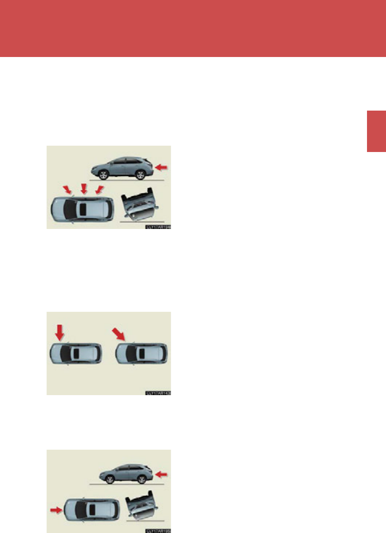
137
1-8. Safety information
1
Before driving
■Types of collisions that may not deploy the SRS airbags (SRS front airbags)
The SRS front airbags are generally not designed to inflate if the vehicle is involved
in a side or rear collision, if it rolls over, or if it is involved in a low-speed frontal colli-
sion. But, whenever a collision of any type causes sufficient forward deceleration of
the vehicle, deployment of the SRS front airbags may occur.
■Types of collisions that may not deploy the SRS airbags
(SRS side airbags and curtain shield airbags)
The SRS side airbag and curtain shield airbag system may not activate if the vehicle
is subjected to a collision from the side at certain angles, or a collision to the side of
the vehicle body other than the passenger compartment.
The SRS side airbags and curtain shield airbags are not generally designed to
inflate if the vehicle is involved in a frontal or rear collision, if it rolls over, or if it is
involved in a low-speed side collision.
●Collision from the side
●Collision from the rear
●Vehicle rollover
●Collision from the side to the vehicle body
other than the passenger compartment
●Collision from the side at an angle
●Collision from the front
●Collision from the rear
●Vehicle rollover
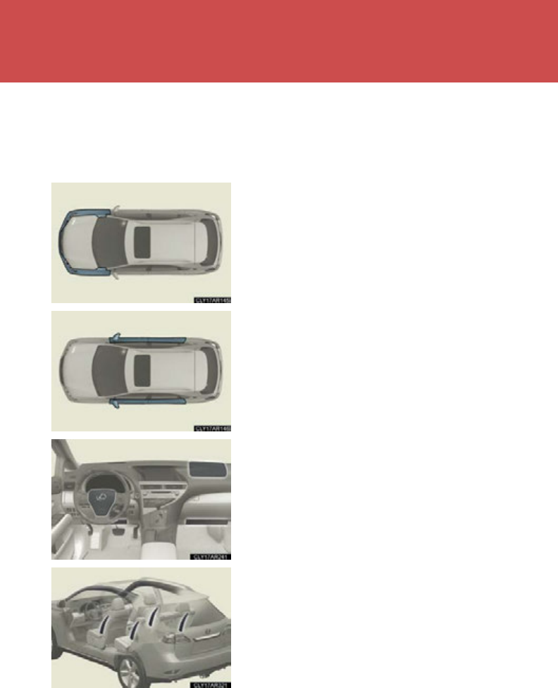
138
1-8. Safety information
■When to contact your Lexus dealer
In the following cases, contact your Lexus dealer as soon as possible.
●Any of the SRS airbags has been inflated.
●The front of the vehicle is damaged or
deformed, or was involved in an accident
that was not severe enough to cause the
SRS airbags to inflate.
●A portion of the doors is damaged or
deformed, or the vehicle was involved in an
accident that was not severe enough to
cause the SRS side airbags and curtain
shield airbags to inflate.
●The pad section of the steering wheel,
dashboard near the front passenger airbag
or lower portion of the instrument panel is
scratched, cracked, or otherwise dam-
aged.
●The surface of the seats with the side air-
bag is scratched, cracked, or otherwise
damaged.
●The portion of the front pillars, rear pillars
or roof side rail garnishes (padding) con-
taining the curtain shield airbags inside is
scratched, cracked, or otherwise dam-
aged.

139
1-8. Safety information
1
Before driving
CAUTION
■SRS airbag precautions
Observe the following precautions regarding the SRS airbags.
Failure to do so may cause death or serious injury.
●The driver and all passengers in the vehicle must wear their seat belts properly.
The SRS airbags are supplemental devices to be used with the seat belts.
●The SRS driver airbag deploys with considerable force, and can cause death or
serious injury especially if the driver is very close to the airbag. The National
Highway Traffic Safety Administration (“NHTSA”) advises:
Since the risk zone for driver’s airbag is the first 2 - 3 in. (50 - 75 mm) of inflation,
placing yourself 10 in. (250 mm) from your driver airbag provides you with a
clear margin of safety. This distance is measured from the center of the steering
wheel to your breastbone. If you sit less than 10 in. (250 mm) away now, you can
change your driving position in several ways:
• Move your seat to the rear as far as you can while still reaching the pedals
comfortably.
• Slightly recline the back of the seat.
Although vehicle designs vary, many drivers can achieve the 10 in. (250 mm)
distance, even with the driver seat all the way forward, simply by reclining the
back of the seat somewhat. If reclining the back of your seat makes it hard to
see the road, raise yourself by using a firm, non-slippery cushion, or raise the
seat if your vehicle has that feature.
• If your steering wheel is adjustable, tilt it downward. This points the airbag
toward your chest instead of your head and neck.
The seat should be adjusted as recommended by NHTSA above, while still main-
taining control of the foot pedals, steering wheel, and your view of the instrument
panel controls.
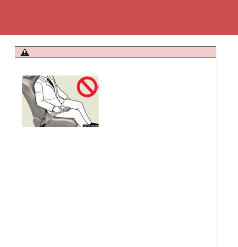
140
1-8. Safety information
CAUTION
■SRS airbag precautions
●The SRS front passenger airbag also deploys with considerable force, and can
cause death or serious injury especially if the front passenger is very close to the
airbag. The front passenger seat should be as far from the airbag as possible with
the seatback adjusted, so the front passenger sits upright.
●Improperly seated and/or restrained infants and children can be killed or seri-
ously injured by a deploying airbag. An infant or child who is too small to use a
seat belt should be properly secured using a child restraint system. Lexus strongly
recommends that all infants and children be placed in the rear seats of the vehicle
and properly restrained. The rear seats are safer for infants and children than the
front passenger seat. (P. 1 49)
●If the seat belt extender has been con-
nected to the driver's seat belt buckle but
the seat belt extender has not also been
fastened to the latch plate of the driver's
seat belt, the SRS driver's airbag system
will judge that the driver is wearing the seat
belt even though the seat belt has not been
connected. In this case, the driver's airbag
may not activate correctly in a collision,
resulting in death or serious injury in the
event of collision. Be sure to wear the seat
belt with the seat belt extender.
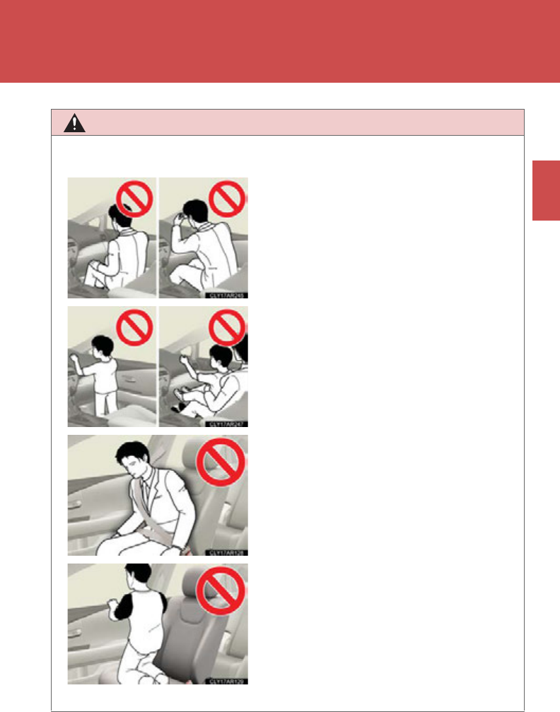
141
1-8. Safety information
1
Before driving
CAUTION
■SRS airbag precautions
●Do not sit on the edge of the seat or lean
against the dashboard.
●Do not allow a child to stand in front of the
SRS front passenger airbag unit or sit on
the knees of a front passenger.
●Do not allow the front seat occupants to
hold items on their knees.
●Do not lean against the door, the roof side
rail or the front, side and rear pillars.
●Do not allow anyone to kneel on the pas-
senger seats toward the door or put their
head or hands outside the vehicle.
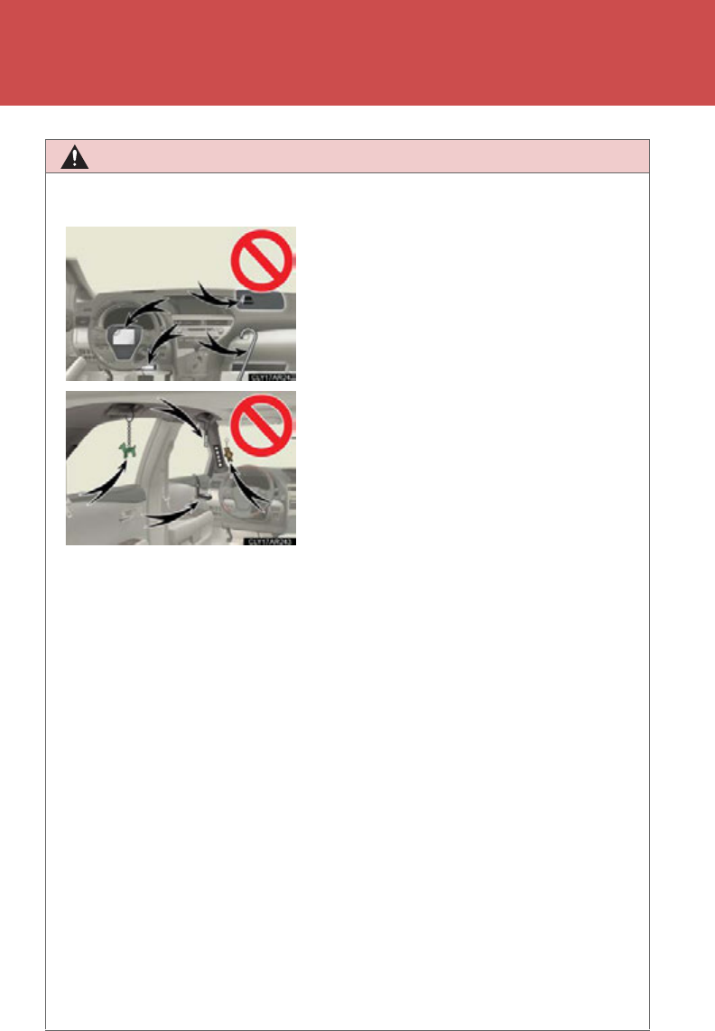
142
1-8. Safety information
CAUTION
■SRS airbag precautions
●If a vinyl cover is put on the area where the SRS knee airbags will deploy, be sure
to remove it.
●Do not use seat accessories which cover the parts where the SRS side airbags
inflate as they may interfere with inflation of the airbags. Such accessories may
prevent the side airbags from activating correctly, disable the system or cause the
side airbags to inflate accidentally, resulting in death or serious injury.
●Do not strike or apply significant levels of force to the area of the SRS airbag
components.
Doing so can cause the SRS airbags to malfunction.
●Do not touch any of the component parts immediately after the SRS airbags have
deployed (inflated) as they may be hot.
●If breathing becomes difficult after the SRS airbags have deployed, open a door
or window to allow fresh air in, or leave the vehicle if it is safe to do so. Wash off
any residue as soon as possible to prevent skin irritation.
●If the areas where the SRS airbags are stored, such as the steering wheel pad and
front and rear pillar garnishes, are damaged or cracked, have them replaced by
your Lexus dealer.
●Do not attach anything to or lean anything
against areas such as the dashboard, steer-
ing wheel pad or lower portion of the
instrument panel.
These items can become projectiles when
SRS driver, front passenger and knee air-
bags deploy.
●Do not attach anything to areas such as the
door, windshield glass, side door glass,
front and rear pillars, roof side rail or assist
grip.
●Do not hang coat hangers or other hard
objects on the coat hooks. All of these
items could become projectiles and may
cause death or serious injury, should the
SRS curtain shield airbags deploy.

143
1-8. Safety information
1
Before driving
CAUTION
■SRS airbag precautions
●Do not place anything, such as a cushion, on the front passenger's seat. Doing so
will disperse the passenger's weight, which prevents the sensor from detecting
the passenger's weight properly. As a result, the SRS front passenger airbag may
not deploy in the event of a collision.
■Modification and disposal of SRS airbag system components
Do not dispose of your vehicle or perform any of the following modifications with-
out consulting your Lexus dealer.
The SRS airbags may malfunction or deploy (inflate) accidentally, causing death or
serious injury.
●Installation, removal, disassembly and repair of the SRS airbags
●Repairs, modifications, removal or replacement of the steering wheel, instrument
panel, dashboard, seats or seat upholstery, front, side and rear pillars or roof side
rails
●Repairs or modifications of the front fender, front bumper, or side of the occupant
compartment
●Installation of snow plows, winches, etc. to the front grille (bull bars or kangaroo
bar etc.)
●Modifications to the vehicle's suspension system
●Installation of electronic devices such as mobile two-way radios or CD players
●Modifications to your vehicle for a person with a physical disability
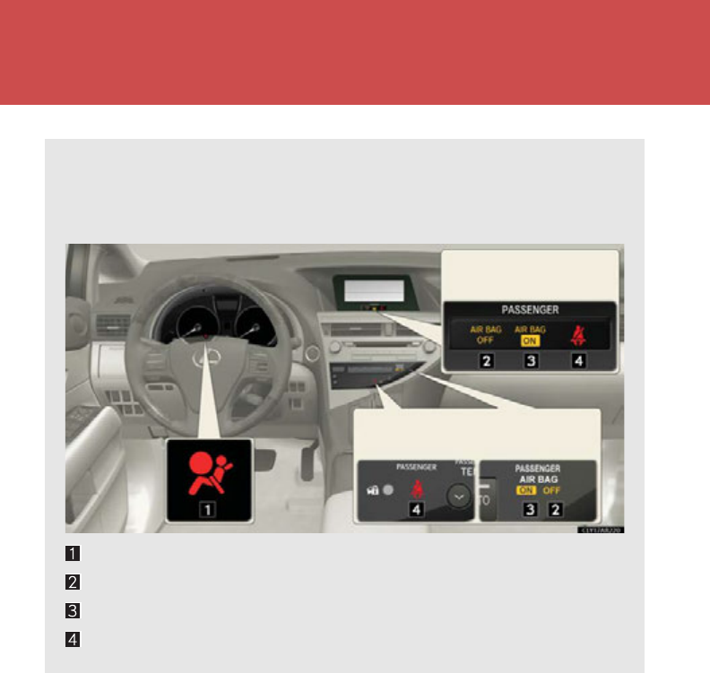
144
1-8. Safety information
Front passenger occupant classification system
Your vehicle is equipped with a front passenger occupant classification sys-
tem. This system detects the condition of the front passenger seat and acti-
vates or deactivates the devices for the front passenger.
SRS warning light
“AIR BAG OFF” indicator light
“AIR BAG ON” indicator light
Front passenger’s seat belt reminder light
Without a
navigation system
With a
navigation system

145
1-8. Safety information
1
Before driving
Condition and operation in the front passenger occupant classification system
■Adult*1
■Child *3 or child restraint system*4
Indicator/
warning light
“AIR BAG ON” and “AIR BAG OFF”
indicator lights
“A I R B AG
ON”
SRS warning light Off
Front passenger’s seat belt reminder light Flashing*2
Devices
Front passenger airbag
Activated
Side airbag on the front
passenger seats
Curtain shield airbag in the front passenger
side
Front passenger knee airbag
Front passenger’s seat belt pretensioner
Indicator/
warning light
“AIR BAG ON” and “AIR BAG OFF”
indicator lights
“A I R B AG
OFF”*5
SRS warning light Off
Front passenger’s seat belt reminder light Flashing*2
Devices
Front passenger airbag Deactivated
Side airbag on the front
passenger seats Activated
Curtain shield airbag in the front passenger
side
Front passenger knee airbag Deactivated
Front passenger’s seat belt pretensioner Activated

146
1-8. Safety information
■Unoccupied
■There is a malfunction in the system
*1: The system judges a person of adult size as an adult. When a smaller
adult sits in the front passenger seat, the system may recognize him/
her as a child depending on his/her physique and posture.
*2: In the event the front passenger does not wear a seat belt.
*3: When a larger child who has outgrown a child restraint system sits in
the front passenger seat, the system may recognize him/her as an
adult depending on his/her physique or posture.
Indicator/
warning light
“AIR BAG ON” and “AIR BAG OFF”
indicator lights
Not illuminated
SRS warning light Off
Front passenger’s seat belt reminder light
Devices
Front passenger airbag Deactivated
Side airbag on the front
passenger seats Activated
Curtain shield airbag in the front passenger
side
Front passenger knee airbag Deactivated
Front passenger’s seat belt pretensioner
Indicator/
warning light
“AIR BAG ON” and “AIR BAG OFF”
indicator lights
“A I R B AG
OFF”
SRS warning light On
Front passenger’s seat belt reminder light Off
Devices
Front passenger airbag Deactivated
Side airbag on the front
passenger seats Activated
Curtain shield airbag in the front passenger
side
Front passenger knee airbag Deactivated
Front passenger’s seat belt pretensioner Activated

147
1-8. Safety information
1
Before driving
*4: Never install a rear-facing child restraint system on the front passen-
ger seat. A forward-facing child restraint system should only be
installed on the front passenger seat when it is unavoidable.
(P. 149)
*5: If the indicator light is not illuminated, consult this manual on how to
install the child restraint system properly. (P. 153)
CAUTION
■Front passenger occupant classification system precautions
Observe the following precautions regarding the front passenger occupant classifi-
cation system.
Failure to do so may cause death or serious injury.
●Wear the seat belt properly.
●Make sure the front passenger’s seat belt tab has not been left inserted into the
buckle before someone sits in the front passenger seat.
●Make sure the “AIR BAG OFF” indicator light is not illuminated when using the
seat belt extender for the front passenger seat. If the “AIR BAG OFF” indicator
light is illuminated, disconnect the extender tongue from the seat belt buckle,
then reconnect the seat belt. Reconnect the seat belt extender after making sure
the “AIR BAG ON” indicator light is illuminated. If you use the seat belt extender
while the “AIR BAG OFF” indicator light is illuminated, the front passenger air-
bag, side airbag on the front passenger side and front passenger knee airbag may
not activate correctly, which could cause death or serious injury in the event of
collision.
●Do not apply a heavy load to the front passenger seat or equipment.
●Do not put weight on the front passenger seat by putting your hands or feet on
the front passenger seat seatback from the rear passenger seat.
●Do not let a rear passenger lift the front passenger seat with their feet or press on
the seatback with their legs.
●Do not put objects under the front passenger seat.

148
1-8. Safety information
CAUTION
■Front passenger occupant classification system precautions
●Do not recline the front passenger seatback so far that it touches a rear seat. This
may cause the “AIR BAG OFF” indicator light to be illuminated, which indicates
that the passenger’s airbags will not deploy in the event of a severe accident. If the
seatback touches the rear seat, return the seatback to a position where it does
not touch the rear seat. Keep the front passenger seatback as upright as possible
when the vehicle is moving. Reclining the seatback excessively may lessen the
effectiveness of the seat belt system.
●If an adult sits in the front passenger seat, the “AIR BAG ON” indicator light is illu-
minated. If the “AIR BAG OFF” indicator is illuminated, ask the passenger to sit
up straight, well back in the seat, feet on the floor, and with the seat belt worn cor-
rectly. If the “AIR BAG OFF” indicator still remains illuminated, either ask the pas-
senger to move to the rear seat, or if that is not possible, move the front passenger
seat fully rearward.
●When it is unavoidable to install the forward-facing child restraint system on the
front passenger seat, install the child restraint system on the front passenger seat
in the proper order. (P. 15 3)
●Do not modify or remove the front seats.
●Do not kick the front passenger seat or subject it to severe impact. Otherwise,
the SRS warning light may come on to indicate a malfunction of the detection sys-
tem. In this case, contact your Lexus dealer immediately.
●Child restraint systems installed on the rear seat should not contact the front seat-
backs.
●Do not use a seat accessory, such as a cushion or seat cover, that covers the seat
cushion surface.
●Do not modify or replace the upholstery of the front seat.
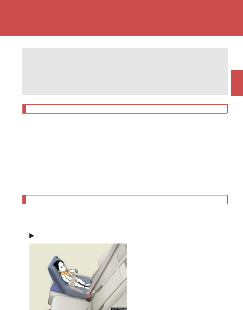
149
1
1-8. Safety information
Before driving
Child restraint systems
Points to remember
Studies have shown that installing a child restraint on a rear seat is much
safer than installing one to the front passenger seat.
●Choose a child restraint system that suits your vehicle and is appropri-
ate to the age and size of the child.
●For installation details, follow the instructions provided with the child
restraint system.
General installation instructions are provided in this manual. (P. 153)
Types of child restraints
Child restraint systems are classified into the following 3 types according
to the age and size of the child.
Rear facing Infant seat/convertible seat
A child restraint system for a small child or baby must itself be properly
restrained on the seat with the lap portion of the lap/shoulder belt.
The laws of all 50 states of the U.S.A. and Canada now require the use of
child restraint systems.
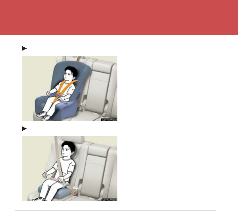
150
1-8. Safety information
Forward facing Convertible seat
Booster seat
■Selecting an appropriate child restraint system
●Use a child restraint system appropriate for the child until the child becomes
large enough to properly wear the vehicle’s seat belt.
●If the child is too large for a child restraint system, sit the child on a rear seat and
use the vehicle's seat belt. (P. 97)

151
1-8. Safety information
1
Before driving
CAUTION
■Child restraint precautions
●For effective protection in automobile accidents and sudden stops, a child must
be properly restrained, using a seat belt or child restraint system depending on
the age and size of the child. Holding a child in your arms is not a substitute for a
child restraint system. In an accident, the child can be crushed against the wind-
shield, or between you and the vehicle's interior. This may cause death or serious
injury to the child in the event of a sudden stop or an accident.
●Lexus strongly urges the use of a proper child restraint system that conforms to
the size of the child, installed on the rear seat. According to accident statistics, the
child is safer when properly restrained in the rear seat than in the front seat.
●Never install a rear-facing child restraint system on the front passenger seat even
if the “AIR BAG OFF” indicator light is illuminated. In the event of an accident, the
force of the rapid inflation of the front passenger airbag can cause death or seri-
ous injury to the child if a rear-facing child restraint system is installed on the front
passenger seat.
●A forward-facing child restraint system may be installed on the front passenger
seat only when it is unavoidable. A child restraint system that requires a top tether
strap should not be used in the front passenger seat since there is no top tether
strap anchor for the front passenger seat. Adjust the seatback as upright as possi-
ble and always move the seat as far back as possible even if the “AIR BAG OFF”
indicator light is illuminated, because the front passenger airbag could inflate with
considerable speed and force. Otherwise, the child may be killed or seriously
injured.
●Do not use the seat belt extender when installing a child restraint system on the
front or rear passenger seat. If installing a child restraint system with the seat belt
extender connected to the seat belt, the seat belt will not securely hold the child
restraint system, which could cause death or serious injury to the child or other
passengers in the event of a sudden stop, sudden swerve or accident.
●Do not allow the child to lean his/her head or any part of his/her body against the
door or the area of the seat, front and rear pillars or roof side rails from which the
SRS side airbags or SRS curtain shield airbags deploy even if the child is seated in
the child restraint system. It is dangerous if the side airbags and curtain shield air-
bags inflate, and the impact could cause death or serious injury to the child.

152
1-8. Safety information
CAUTION
■Child restraint precautions
Make sure you have complied with all installation instructions provided by the child
restraint manufacturer and that the system is properly secured. If it is not secured
properly, it may cause death or serious injury to the child in the event of a sudden
stop, sudden swerve or an accident.
■When children are in the vehicle
Do not allow children to play with the seat belt. If the seat belt becomes twisted
around a child’s neck, it may lead to choking or other serious injuries that could
result in death.
If this occurs and the buckle cannot be unfastened, scissors should be used to cut
the belt.
■When the child restraint system is not in use
●Keep the child restraint system properly secured on the seat even if it is not in use.
Do not store the child restraint system unsecured in the passenger compartment.
●If it is necessary to detach the child restraint system, remove it from the vehicle or
store it securely in the luggage compartment. This will prevent it from injuring
passengers in the event of a sudden stop, sudden swerve or accident.
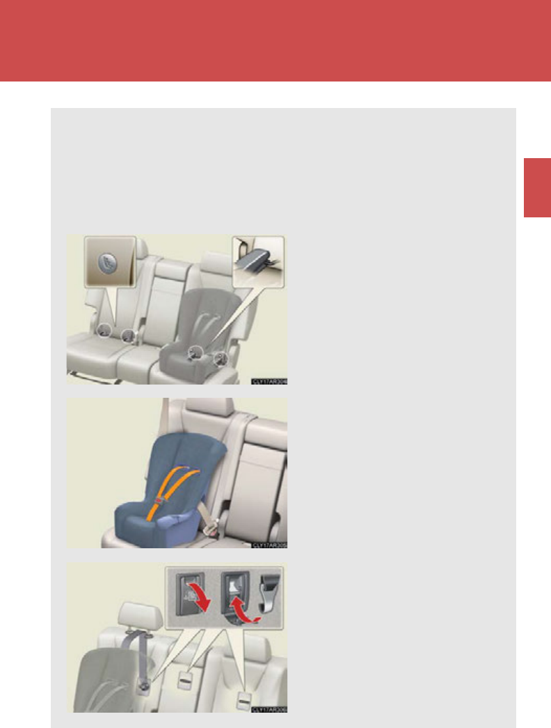
153
1
1-8. Safety information
Before driving
Installing child restraints
Follow the child restraint system manufacturer's instructions. Firmly
secure child restraints to the seats using the LATCH anchors or a seat belt.
Attach the top tether strap when installing a child restraint.
The lap/shoulder belt can be used if your child restraint system is not com-
patible with the LATCH (Lower Anchors and Tethers for Children) system.
Child restraint LATCH anchors
LATCH anchors are provided
for the outer rear seats. (Buttons
displaying the location of the
anchors are attached to the
seats.)
Seat belts equipped with a child
restraint locking mechanism
(ALR/ELR belts except driver’s
seat belt) (P. 97)
Anchor brackets (for top tether
strap)
An anchor bracket is provided
for each rear seat.
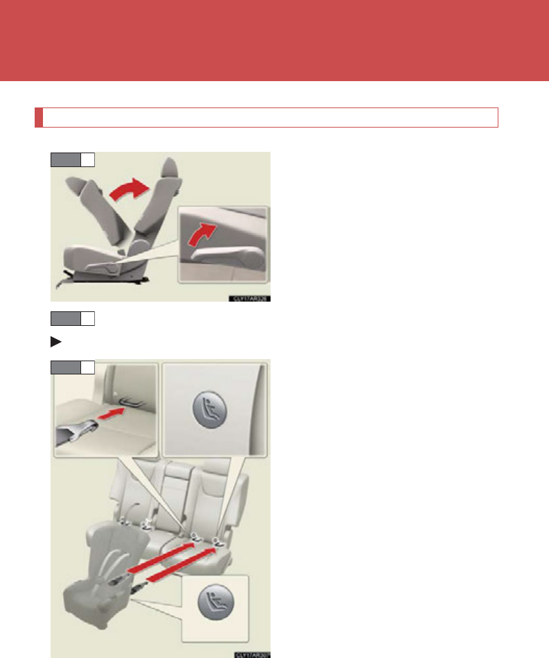
154
1-8. Safety information
Installation with LATCH system
Fold the seatback while pulling the
seatback angle adjustment lever.
Return the seatback and secure it
at the first lock position. (P. 86 )
Widen the gap between the seat cushion and seatback slightly.
Type A
Latch the hooks of the lower straps
onto the LATCH anchors. If the
child restraint has a top tether
strap, the top tether strap should
be latched onto the top tether
strap anchor bracket.
For owners in Canada:
The symbol on a child restraint sys-
tem indicates the presence of a
lower connector system.
STEP 1
STEP 2
Canada only
STEP 3
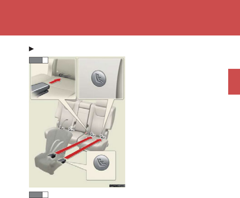
155
1-8. Safety information
1
Before driving
Type B
Latch the buckles onto the LATCH
anchors. If the child restraint has a
top tether strap, the top tether
strap should be latched onto the
top tether strap anchor bracket.
For owners in Canada:
The symbol on a child restraint sys-
tem indicates the presence of a
lower connector system.
If the child restraint has a top tether strap, the top tether strap
should be latched onto the top tether strap anchor. (P. 160)
Canada only
STEP 3
STEP 4
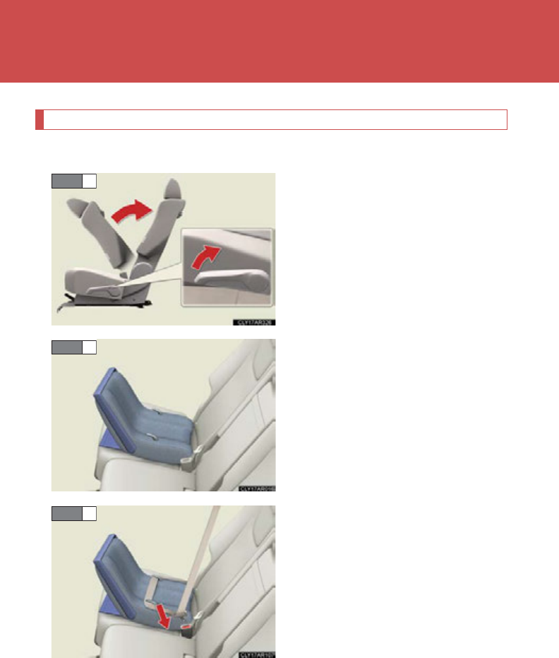
156
1-8. Safety information
Installing child restraints using a seat belt (child restraint lock function belt)
■Rear-facing Infant seat/convertible seat
Fold the seatback while pulling the
seatback angle adjustment lever.
Return the seatback and secure it
at the first lock position. (P. 86 )
Place the child restraint system on
the rear seat facing the rear of the
vehicle.
Run the seat belt through the child
restraint system and insert the
plate into the buckle. Make sure
that the belt is not twisted.
STEP 1
STEP 2
STEP 3
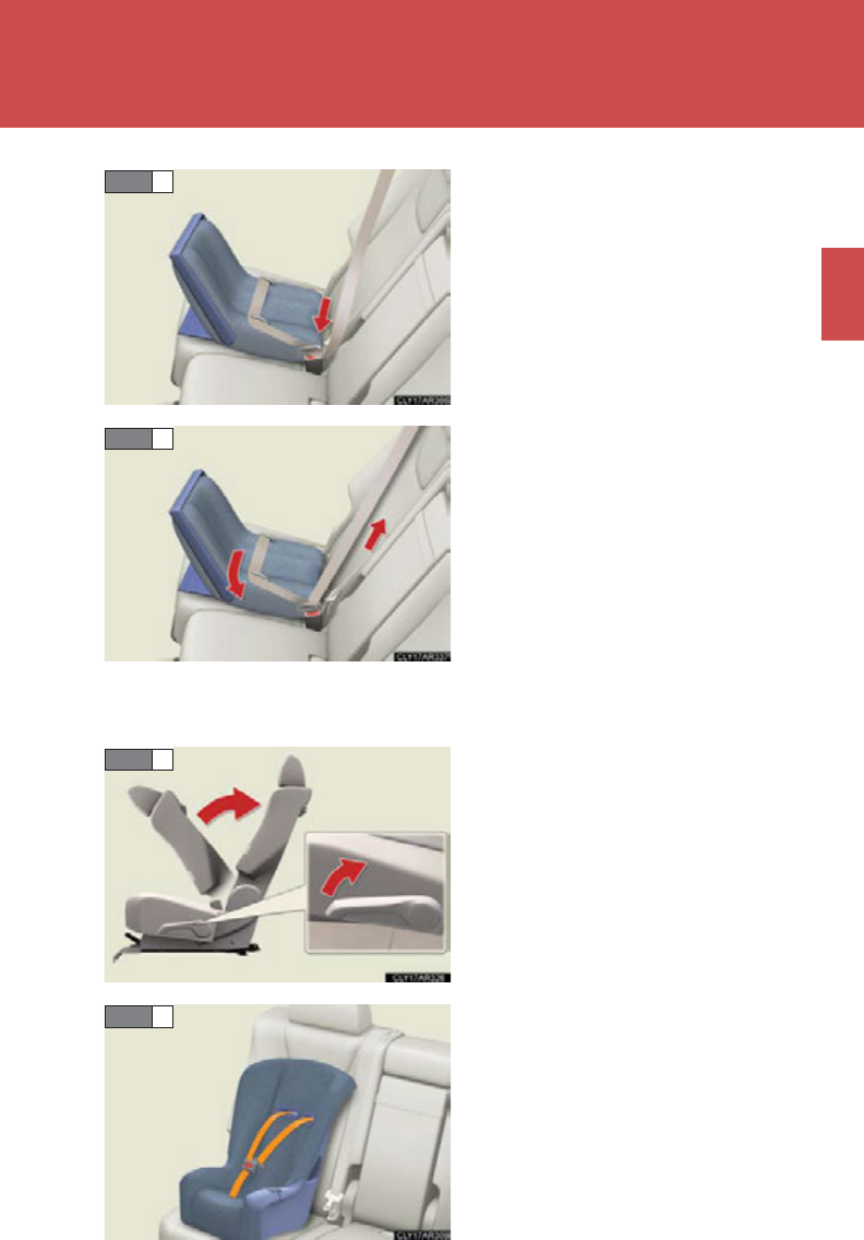
157
1-8. Safety information
1
Before driving
Fully extend the shoulder belt and
allow it to retract to put it in lock
mode. In lock mode, the belt can-
not be extended.
While pushing the child restraint
system down into the rear seat,
allow the shoulder belt to retract
until the child restraint system is
securely in place.
After the shoulder belt has
retracted to a point where there is
no slack in the belt, pull the belt to
check that it cannot be extended.
■Forward-facing Convertible seat
Fold the seatback while pulling the
seatback angle adjustment lever.
Return the seatback and secure it
at the first lock position. (P. 86)
Place the child restraint system on
the seat facing the front of the vehi-
cle.
STEP 4
STEP 5
STEP 1
STEP 2
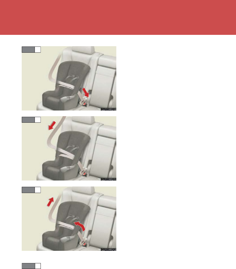
158
1-8. Safety information
Run the seat belt through the child
restraint system and insert the
plate into the buckle. Make sure
that the belt is not twisted.
Fully extend the shoulder belt and
allow it to retract to put it in lock
mode. In lock mode, the belt can-
not be extended.
While pushing the child restraint
system into the rear seat, allow the
shoulder belt to retract until the
child restraint system is securely in
place.
After the shoulder belt has
retracted to a point where there is
no slack in the belt, pull the belt to
check that it cannot be extended.
If the child restraint has a top tether strap, the top tether strap
should be latched onto the top tether strap anchor. (P. 160)
STEP 3
STEP 4
STEP 5
STEP 6
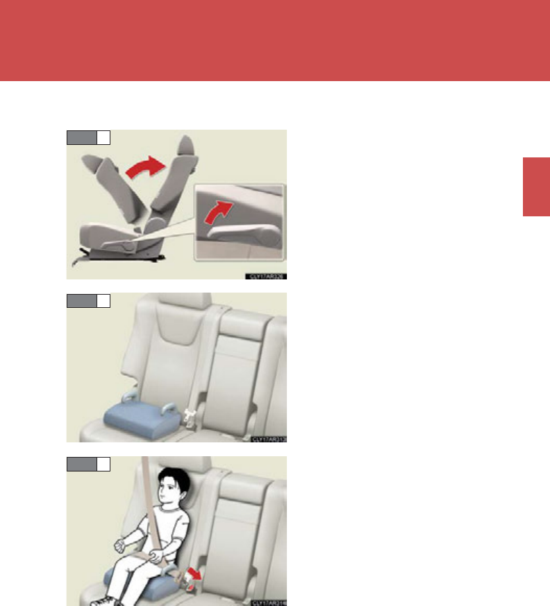
159
1-8. Safety information
1
Before driving
■Booster seat
Fold the seatback while pulling the
seatback angle adjustment lever.
Return the seatback and secure it
at the first lock position. (P. 86)
Place the child restraint system on
the seat facing the front of the vehi-
cle.
Sit the child in the child restraint
system. Fit the seat belt to the child
restraint system according to the
manufacturer's instructions and
insert the plate into the buckle.
Make sure that the belt is not
twisted.
Check that the shoulder belt is cor-
rectly positioned over the child's
shoulder, and that the lap belt is as
low as possible. (P. 97)
STEP 1
STEP 2
STEP 3
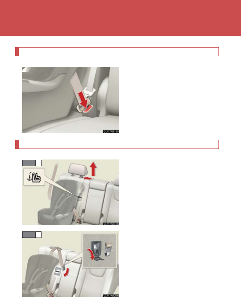
160
1-8. Safety information
Removing a child restraint installed with a seat belt
Press the buckle release button
and fully retract the seat belt.
Child restraint systems with a top tether strap
Secure the child restraint system
using a seat belt or the LATCH
anchors, and remove the head
restraint.
Open the anchor bracket cover,
latch the hook onto the anchor
bracket and tighten the top tether
strap.
Make sure the top tether strap is
securely latched.
STEP 1
STEP 2
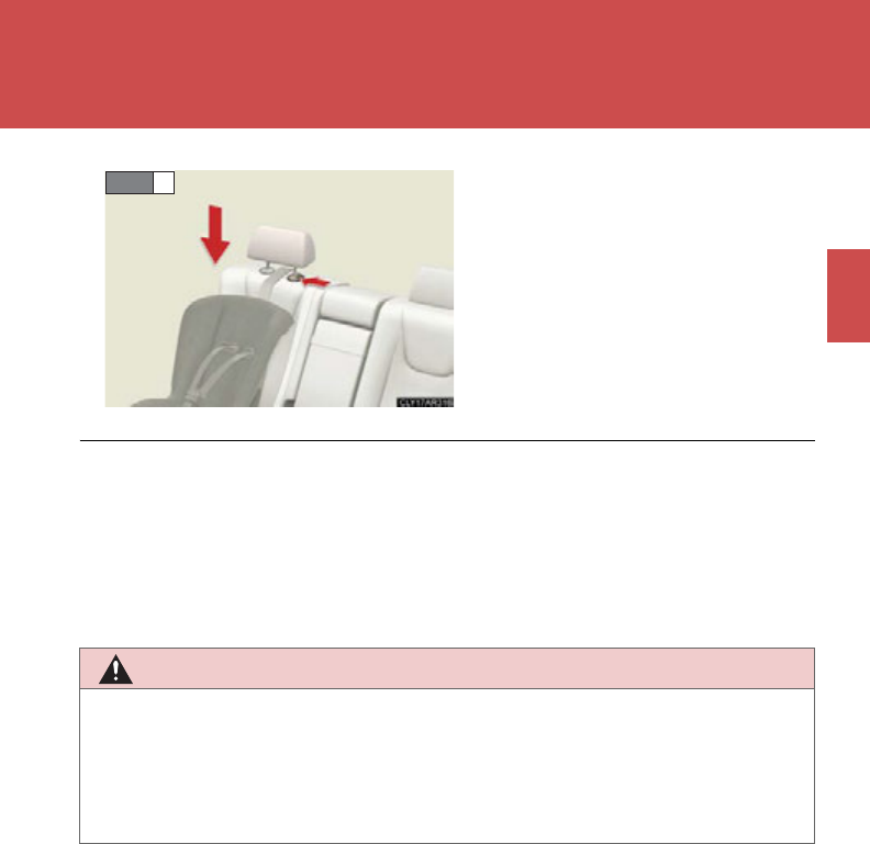
161
1-8. Safety information
1
Before driving
Replace the head restraint and lift
it up to the uppermost lock posi-
tion.
STEP 3
■Laws and regulations pertaining to anchors
The LATCH system conforms to FMVSS225 or CMVSS210.2.
Child restraint systems conforming to FMVSS213 or CMVSS213 specifications
can be used.
This vehicle is designed to conform to the SAE J1819.
CAUTION
■When installing a booster seat
To prevent the belt from going into ALR lock mode, do not fully extend the shoulder
belt. ALR mode causes the belt to tighten only. This could cause injury or discom-
fort to the child. (P. 100)
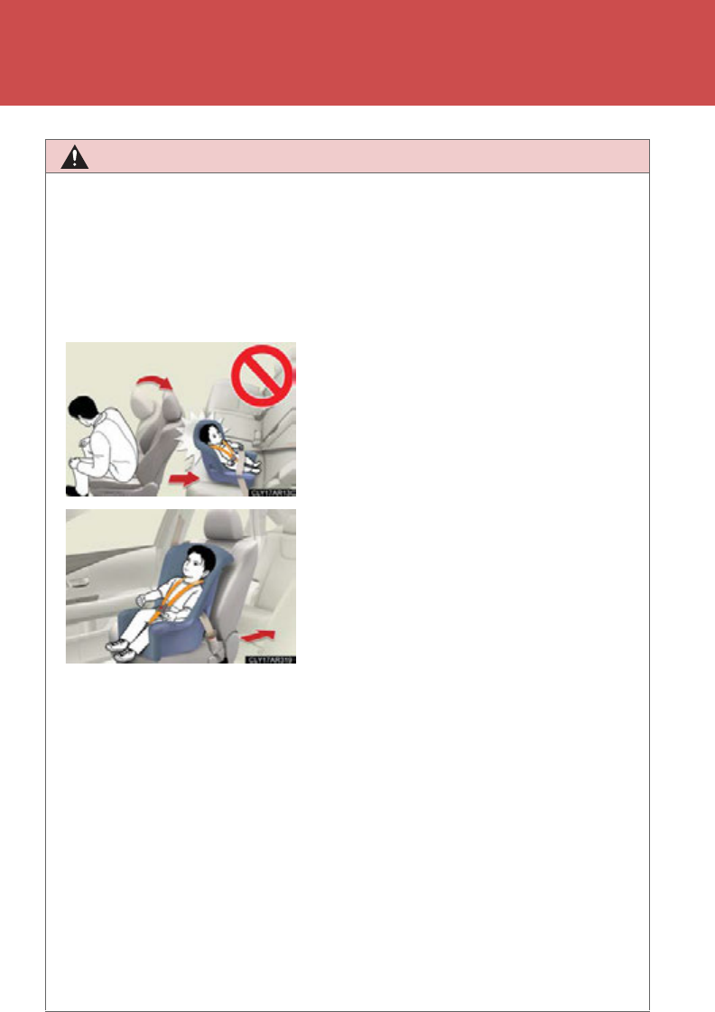
162
1-8. Safety information
CAUTION
■When installing a child restraint system
Follow the directions given in the child restraint system installation manual and fix
the child restraint system securely in place.
If the child restraint system is not correctly fixed in place, the child or other passen-
gers may be injured or even killed in the event of sudden braking, sudden swerving
or an accident.
●When installing a child restraint system in the rear center seat, adjust both seat
cushions to the same position and align both seatbacks at the same angle. The
seatbacks must be adjusted to the same angle. Otherwise, the child restraint sys-
tem cannot be securely restrained and this may cause death or serious injuries in
the event of sudden braking, sudden swerving or an accident.
●When using the LATCH system, move the seat as far back as possible and adjust
the seatback as upright as possible.
●When a booster seat is installed, always ensure that the shoulder belt is posi-
tioned across the center of the child's shoulder. The belt should be kept away
from the child's neck, but not so that it could fall off the child's shoulder. Failing to
do so may result in death or serious injury in the event of sudden braking, sudden
swerving or an accident.
●If the driver’s seat interferes with the child
restraint system and prevents it from being
attached correctly, attach the child restraint
system to the right-hand rear seat.
●Adjust the front passenger seat so that it
does not interfere with the child restraint
system.
●Only put a forward-facing child restraint
system on the front seat when unavoidable.
When installing a forward-facing child
restraint system on the front passenger
seat, move the seat as far back as possible
even if the “AIR BAG OFF” indicator light is
illuminated. Failure to do so may result in
death or serious injury if the airbags deploy
(inflate).

163
1-8. Safety information
1
Before driving
CAUTION
■When installing a child restraint system
●Ensure that the belt and tab are securely locked and the seat belt is not twisted.
●Push and pull the child restraint system from side to side and forward to be sure it
is secure.
●After securing a child restraint system, never adjust the seat.
●Follow all installation instructions provided by the child restraint system manufac-
turer.
■Do not use a seat belt extender
If a seat belt extender is used when installing a child restraint system, the seat belt
will not securely hold the child restraint system, which could cause death or serious
injury to the child or other passengers in the event of sudden braking, sudden
swerving or an accident.
■To correctly attach a child restraint system to the anchors
When using the LATCH anchors, be sure that there are no foreign objects around
the anchors and that the seat belt is not caught behind the child restraint system.
Make sure the child restraint system is securely attached, or it may cause death or
serious injury to the child or other passengers in the event of a sudden stop, sudden
swerve or accident.

164
1-8. Safety information

When driving 2
165
2-1. Driving procedures
Driving the vehicle.................. 166
Power (ignition) switch ........... 176
Hybrid transmission ............... 182
Turn signal lever....................... 190
Parking brake........................... 192
Horn............................................ 193
2-2. Instrument cluster
Gauges and meters................ 194
Indicators and warning
lights ......................................... 198
Multi-information
display.................................... 202
Head-up display .................... 208
2-3. Operating the lights and
windshield wipers
Headlight switch...................... 213
Automatic High Beam........... 219
Fog light switch ....................... 226
Windshield wipers and
washer .................................... 229
Rear window wiper and
washer .................................... 235
Headlight cleaner
switch ...................................... 237
2-4. Using other driving
systems
Cruise control......................... 238
Dynamic radar cruise
control.................................... 243
Intuitive parking assist.......... 257
Electronically modulated
air suspension....................... 264
Rear view monitor
system..................................... 270
Driving assist systems............ 274
Hill-start assist control ......... 280
Pre-Collision System............ 282
2-5. Driving information
Utility vehicle
precautions........................... 286
Cargo and luggage ............... 290
Vehicle load limits.................. 295
Winter driving tips................. 296
Tra il er tow in g
(AWD models with
towing package).................. 300
Tra il er tow in g
(2WD models and
AWD models without
towing package)................... 318
Dinghy towing.......................... 319

166
2-1. Driving procedures
Driving the vehicle
Starting off on a steep uphill
Make sure that the parking brake is set and shift the shift lever to
D.
Gently depress the accelerator pedal.
Release the parking brake.
The following procedures should be observed to ensure safe driving.
■Starting the hybrid system
P. 176
■Driving
With the brake pedal depressed, shift the shift lever to D.
(P. 182 )
Release the parking brake. (P. 1 92 )
Gradually release the brake pedal and gently depress the
accelerator pedal to accelerate the vehicle.
■Stopping
With the shift lever in D, depress the brake pedal.
If necessary, set the parking brake.
If the vehicle is to be stopped for an extended period of time, shift the
shift lever to P. (P. 18 2)
■ Parking the vehicle
With the shift lever in D, depress the brake pedal.
Set the parking brake. (P. 1 92 )
Shift the shift lever to P. (P. 182)
If parking on a hill, block the wheels as needed.
Press the “POWER” switch to stop the hybrid system.
Lock the door, making sure that you have the electronic key on
your person.
STEP 1
STEP 2
STEP 3
STEP 1
STEP 2
STEP 1
STEP 2
STEP 3
STEP 4
STEP 5
STEP 1
STEP 2
STEP 3

167
2-1. Driving procedures
2
When driving
■Driving in the rain
●Drive carefully when it is raining, because visibility will be reduced, the windows
may become fogged-up, and the road will be slippery.
●Drive carefully when it starts to rain, because the road surface will be especially
slippery.
●Refrain from high speeds when driving on an expressway in the rain, because
there may be a layer of water between the tires and the road surface, preventing
the steering and brakes from operating properly.
■Breaking in your new Lexus
To extend the life of the vehicle, observing the following precautions is recom-
mended:
●For the first 200 miles (300 km):
Avoid sudden stops.
●For the first 500 miles (800 km):
Do not tow a trailer.
●For the first 1000 miles (1600 km):
• Do not drive at extremely high speeds.
• Avoid sudden acceleration.
• Do not drive continuously in low gears.
• Do not drive at a constant speed for extended periods.
■Drum-in-disc type parking brake system
Your vehicle has a drum-in-disc type parking brake system. This type of brake sys-
tem needs bedding-down of the brake shoes periodically or whenever the parking
brake shoes and/or drum are replaced. Have your Lexus dealer perform the bed-
ding down operation.
■Operating your vehicle in a foreign country
Comply with the relevant vehicle registration laws and confirm the availability of the
correct fuel. (P. 666)
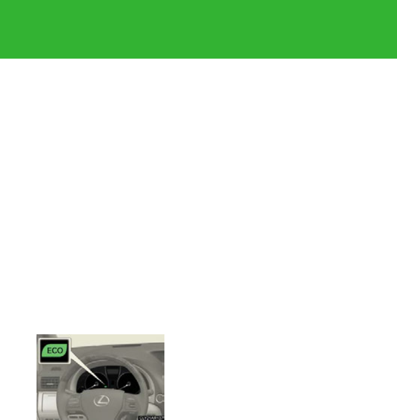
168
2-1. Driving procedures
■For efficient use
●Shift the shift lever to D when driving.
In the N position, the gasoline engine operates but electricity cannot be gener-
ated. The hybrid battery (traction battery) will discharge, requiring unnecessary
engine power to recharge.
●Drive your vehicle smoothly.
Avoid abrupt acceleration and deceleration. Gradual acceleration and decel-
eration will make more effective use of the electric motor (traction motor) with-
out having to use gasoline engine power.
●Avoid repeated acceleration.
Repeated acceleration consumes hybrid battery (traction battery) power,
resulting in poor acceleration. Battery power can be restored by driving with
the accelerator pedal slightly released.
●Shift the shift lever to P when parking.
In the N position, the hybrid battery (traction battery) does not recharge.
Leaving the shift lever in the N position for an extended period of time may dis-
charge the hybrid battery. The vehicle cannot run if the hybrid battery is dis-
charged.
■Eco-friendly driving
■Customization
Setting of Eco Driving Indicator Light can be changed.
(Customizable features P. 693)
During Eco-friendly acceleration (Eco driv-
ing), Eco Driving Indicator Light will turn on. If
the accelerator pedal is depressed more than
necessary, the indicator will turn off.
(P. 1 96)

169
2-1. Driving procedures
2
When driving
CAUTION
■When starting the vehicle
Always keep your foot on the brake pedal while stopped with the hybrid system
operating. This prevents the vehicle from creeping.
■When driving the vehicle
●Do not drive if you are unfamiliar with the location of the brake and accelerator
pedals to avoid depressing the wrong pedal.
• Accidentally depressing the accelerator pedal instead of the brake pedal will
result in sudden acceleration that may lead to an accident that could result in
death or serious injury.
• When backing up, you may twist your body around, leading to a difficulty in
operating the pedals. Make sure to operate the pedals properly.
• Make sure to keep a correct driving posture even when moving the vehicle
only slightly. This allows you to depress the brake and accelerator pedals
properly.
• Depress the brake pedal using your right foot. Depressing the brake pedal
using your left foot may delay response in an emergency, resulting in an acci-
dent.
●The driver should pay extra attention to pedestrians when the vehicle is powered
only by the electric motor (traction motor). Because there is no engine noise, the
pedestrians may misjudge the vehicle’s movement.
●Do not drive the vehicle over or stop the vehicle near flammable materials.
The exhaust system and exhaust gases can be extremely hot. These hot parts may
cause a fire if there is any flammable material nearby.
●Do not let the vehicle roll backward while the shift lever is in a driving position, or
roll forward while the shift lever is in R.
Doing so may result in an accident or damage to the vehicle.
●If the smell of exhaust is noticed inside the vehicle, open the windows and check
that the back door is closed. Large amounts of exhaust in the vehicle can cause
driver drowsiness and an accident, resulting in death or a serious health hazard.
Have the vehicle inspected by your Lexus dealer immediately.

170
2-1. Driving procedures
CAUTION
●Do not shift the shift lever to P while the vehicle is moving.
Doing so can damage the transmission and may result in a loss of vehicle control.
●Do not shift the shift lever to R while the vehicle is moving forward.
Doing so can damage the transmission and may result in a loss of vehicle control.
●Do not shift the shift lever to D while the vehicle is moving backward.
Doing so can damage the transmission and may result in a loss of vehicle control.
●Moving the shift lever to N while the vehicle is moving will disengage the hybrid
system. Engine braking is not available with the hybrid system disengaged.
●During normal driving, do not turn off the hybrid system. Turning the hybrid sys-
tem off while driving will not cause loss of steering or braking control, but the
power assist to these systems will be lost. This will make it more difficult to steer
and brake, so you should pull over and stop the vehicle as soon as it is safe to do
so.
However, in the event of an emergency, such as if it becomes impossible to stop
the vehicle in the normal way: P. 6 61
●Use engine braking (downshift) to maintain a safe speed when driving down a
steep hill.
Using the brakes continuously may cause the brakes to overheat and lose effec-
tiveness. (P. 1 82 )
●When stopped on an incline, use the brake pedal and parking brake to prevent
the vehicle from rolling backward or forward, causing an accident.
●Do not adjust the position of the steering wheel, the seat, or the inside or outside
rear view mirrors while driving.
Doing so may result in a loss of vehicle control that can cause accidents, resulting
in death or serious injury.
●Always check that all passengers' arms, heads or other parts of their body are not
outside the vehicle, as this may result in death or serious injury.

171
2-1. Driving procedures
2
When driving
CAUTION
●Do not drive in excess of the speed limit. Even if the legal speed limit permits it, do
not drive over 85 mph (140 km/h) unless your vehicle has high-speed capability
tires. Driving over 85 mph (140 km/h) may result in tire failure, loss of control and
possible injury. Be sure to consult a tire dealer to determine whether the tires on
your vehicle are high-speed capability tires or not before driving at such speeds.
●On vehicles with an electronically modulated air suspension, if you drive through
water, such as when crossing shallow streams, first check the depth of the water
and the firmness of the river bed. Put the vehicle in “HI” (high) mode with the
height selector switch and then turn off the electronically modulated air suspen-
sion by pressing the height control off switch. Drive your vehicle at 19 mph (30
km/h) or lower.
■When driving on slippery road surfaces
●Sudden braking, acceleration and steering may cause tire slippage and reduce
your ability to control the vehicle, resulting in an accident.
●Sudden changes in engine speed, such as engine braking caused by up-shifting
and down-shifting, may cause the vehicle to skid, resulting in an accident.
●After driving through a puddle, lightly depress the brake pedal to make sure that
the brakes are functioning properly. Wet brake pads may prevent the brakes from
functioning properly. If the brakes on only one side are wet and not functioning
properly, steering control may be affected, resulting in an accident.
■When shifting the shift lever
Be careful not to shift the shift lever with the accelerator pedal depressed.
This may lead to unexpected rapid acceleration of the vehicle that may cause an
accident and result in death or serious injury.
■If you hear a squealing or scraping noise (brake pad wear limit indicators)
Have your Lexus dealer check and replace the brake pads as soon as possible.
The rotor damage can result if the pads are not replaced when needed.
It is dangerous to drive the vehicle when the wear limits of the brake pads and/or
those of the brake discs are exceeded.

172
2-1. Driving procedures
CAUTION
■When the vehicle is stopped
●Do not depress the accelerator pedal unnecessarily.
If the vehicle is in any gear other than P or N, the vehicle may accelerate suddenly
and unexpectedly, causing an accident.
●Do not leave the vehicle with the hybrid system on for a long time.
If such a situation cannot be avoided, park the vehicle in an open space and
check that exhaust fumes do not enter the vehicle interior.
●In order to prevent accidents due to the vehicle rolling away, always keep
depressing the brake pedal while the “READY” indicator is on. Apply the parking
brake as necessary.
●If the vehicle is stopped on an incline, in order to prevent accidents caused by the
vehicle rolling forward or backward, always depress the brake pedal and securely
apply the parking brake as needed.
●Avoid revving or racing the engine.
Running the engine at high speed while the vehicle is stopped may cause the
exhaust system to overheat, which could result in a fire if combustible material is
nearby.
■When the vehicle is parked
●Do not leave glasses, cigarette lighters, spray cans, or soft drink cans in the vehi-
cle when it is in the sun.
Doing so may result in the following:
• Gas may leak from a cigarette lighter or spray can, and may lead to a fire.
• The temperature inside the vehicle may cause the plastic lenses and plastic
material of glasses to deform or crack.
• Soft drink cans may fracture, causing the contents to spray over the interior of
the vehicle, and may also cause a short circuit in the vehicle's electrical com-
ponents.
●Do not leave cigarette lighters in the vehicle. If a cigarette lighter is in a place such
as the glove box or on the floor, it may be lit accidentally when luggage is loaded
or the seat is adjusted, causing a fire.
●Do not attach adhesive discs to the windshield or windows. Do not place contain-
ers such as air fresheners on the instrument panel or dashboard. Adhesive discs
or containers may act as lenses, causing a fire in the vehicle.

173
2-1. Driving procedures
2
When driving
CAUTION
●Do not leave a door or window open if the curved glass is coated with a metal-
lized film such as a silver-colored one. Reflected sunlight may cause the glass to
act as a lens, causing a fire.
●Always apply the parking brake, shift the shift lever to P, stop the hybrid system
and lock the vehicle.
Do not leave the vehicle unattended while the hybrid system is operating.
●Do not touch the exhaust pipes while the hybrid system is operating or immedi-
ately after turning the hybrid system off.
Doing so may cause burns.
●Do not leave the hybrid system operating in an area with snow build-up, or where
it is snowing. If snowbanks build up around the vehicle while the hybrid system is
operating, exhaust gases may collect and enter the vehicle. This may lead to
death or a serious health hazard.
■Exhaust gases
Exhaust gases include harmful carbon monoxide (CO) that is colorless and odor-
less. Inhaling exhaust gases may lead to death or a serious health hazard.
●If the vehicle is in a poorly ventilated area, stop the hybrid system. In a closed
area, such as a garage, exhaust gases may collect and enter the vehicle. This may
lead to death or a serious health hazard.
●The exhaust system should be checked occasionally. If there is a hole or crack
caused by corrosion, damage to a joint or abnormal exhaust noise, be sure to
have the vehicle inspected and repaired by your Lexus dealer. Failure to do so
may allow exhaust gases to enter the vehicle, resulting in death or a serious health
hazard.
■When taking a nap in the vehicle
Always turn the hybrid system off. Otherwise, if you accidentally move the shift
lever or depress the accelerator pedal, this could cause an accident or fire due to
hybrid system overheating. Additionally, if the vehicle is parked in a poorly venti-
lated area, exhaust gases may collect and enter the vehicle, leading to death or a
serious health hazard.

174
2-1. Driving procedures
CAUTION
■When braking the vehicle
●When the brakes are wet, drive more cautiously.
Braking distance increases when the brakes are wet, and this may cause one side
of the vehicle to brake differently than the other side. Also, the parking brake may
not securely hold the vehicle.
●If the power brake assist function does not operate, do not follow other vehicles
closely and avoid hills or sharp turns that require braking.
In this case, braking is still possible, but the brake pedal should be depressed
more firmly than usual. Also, the braking distance will increase.
●The brake system consists of 3 individual hydraulic systems; if one of the systems
fails, the others will still operate. In this case, the brake pedal should be depressed
more firmly than usual and the braking distance will increase. If this happens, do
not continue to drive the vehicle. If the brake system warning light (red indicator)
comes on together with the buzzer sound while driving, immediately stop the
vehicle in a safe place and contact your Lexus dealer.
■If the vehicle becomes stuck
Do not spin the wheels excessively when any of the tires is up in the air, or the vehi-
cle is stuck in sand, mud, etc. This may damage the driveline components or propel
the vehicle forward or backward, causing an accident.
NOTICE
■When driving the vehicle
●Do not depress the accelerator and brake pedals at the same time during driving,
as this may restrain driving torque.
●Do not use the accelerator pedal or depress the accelerator and brake pedals at
the same time to hold the vehicle on a hill.
■When parking the vehicle
Always shift the shift lever to P. Failure to do so may cause the vehicle to move or the
vehicle may accelerate suddenly if the accelerator pedal is accidentally depressed.

175
2-1. Driving procedures
2
When driving
NOTICE
■Avoiding damage to vehicle parts
●Do not turn the steering wheel fully in either direction and hold it there for an
extended period of time.
Doing so may damage the power steering motor.
●When driving over bumps in the road, drive as slowly as possible to avoid damag-
ing the wheels, underside of the vehicle, etc.
■If you get a flat tire while driving
A flat or damaged tire may cause the following situations. Hold the steering wheel
firmly and gradually depress the brake pedal to slow down the vehicle.
●It may be difficult to control your vehicle.
●The vehicle will make abnormal sounds.
●The vehicle will behave abnormally.
Information on what to do in case of a flat tire (P. 629)
■When encountering flooded roads
Do not drive on a road that has flooded after heavy rain etc. Doing so may cause the
following serious damage to the vehicle:
●Engine stalling
●Short in electrical components
●Engine damage caused by water immersion
In the event that you drive on a flooded road and the vehicle is flooded, be sure to
have your Lexus dealer check the following:
●Brake function
●Changes in quantity and quality of oil and fluid used for the engine, hybrid trans-
mission, etc., and, for AWD models, the rear electric motor (traction motor).
●Lubricant condition for the bearings and suspension joints (where possible) and
the function of all joints, bearings, etc.
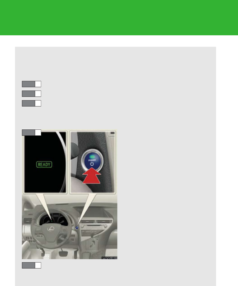
176
2-1. Driving procedures
Power (ignition) switch
Performing the following operations when carrying the electronic key on
your person starts the hybrid system or changes “POWER” switch modes.
■Starting the hybrid system
Check that the parking brake is set.
Check that the shift lever is set in P.
Firmly depress the brake pedal.
The “POWER” switch indicator will turn green. If the indicator does
not turn green, the hybrid system cannot be started.
Press the “POWER” switch.
After a while, the “READY” indi-
cator comes on with a beep
sound.
The vehicle can move when the
“READY” indicator is on even if
the engine is stopped.
Continue depressing the brake
pedal until the hybrid system is
completely started.
The hybrid system can be
started from any “POWER”
switch mode.
Check that the “READY” indicator is on.
The vehicle will not move when the “READY” indicator is off.
STEP 1
STEP 2
STEP 3
STEP 4
STEP 5
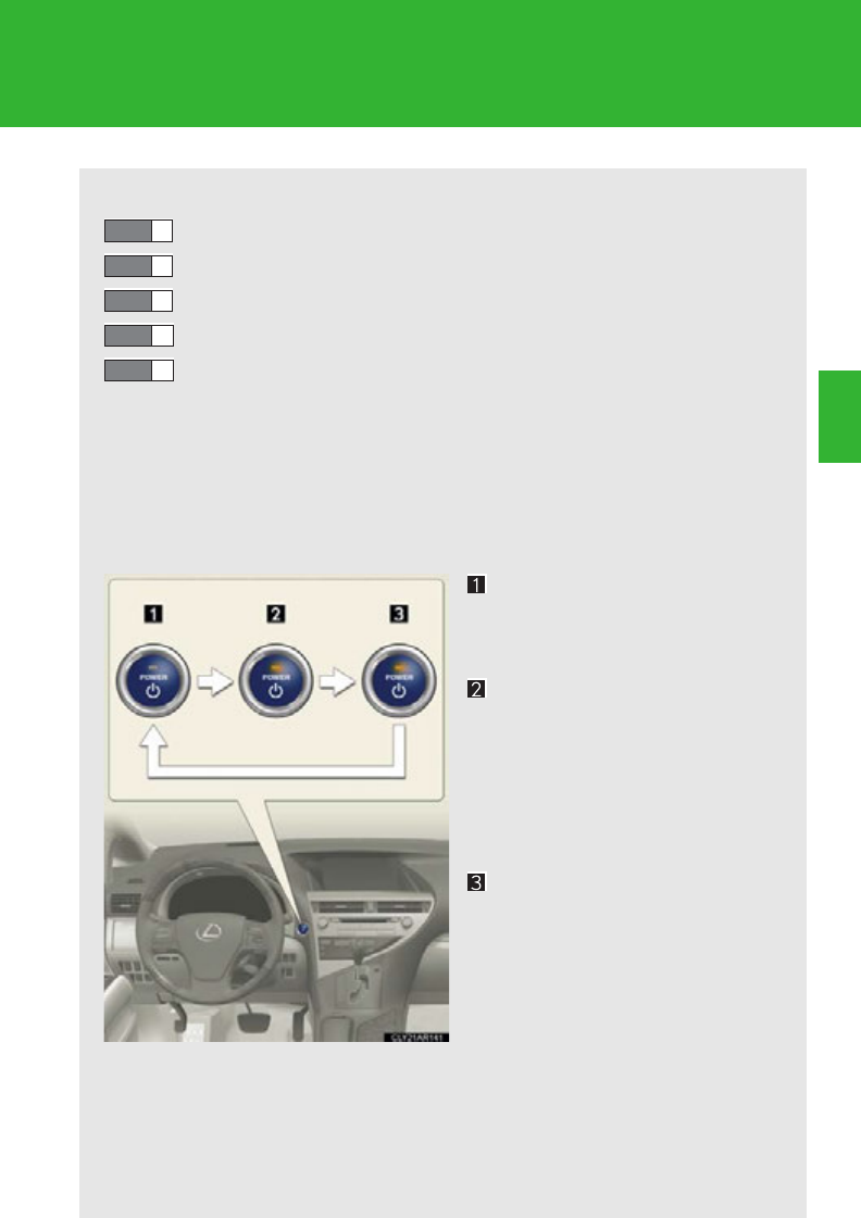
177
2-1. Driving procedures
2
When driving
■Stopping the hybrid system
Stop the vehicle.
Shift the shift lever to P.
Set the parking brake. (P. 1 92 )
Press the “POWER” switch.
Release the brake pedal and check that the indicator on the
“POWER” switch is off.
■Changing “POWER” switch modes
Modes can be changed by pressing the “POWER” switch with the
brake pedal released. (The mode changes each time the switch is
pressed.)
Off*
The emergency flashers can be
used.
ACCESSORY mode
Some electrical components
such as the audio system can be
used.
The “POWER” switch indicator
turns amber.
ON mode
All electrical components can
be used.
The “POWER” switch indicator
turns amber.
*: If the shift lever is in a position
other than P when turning off
the hybrid system, the
“POWER” switch will be turned
to ACCESSORY mode, not to
off.
STEP 1
STEP 2
STEP 3
STEP 4
STEP 5

178
2-1. Driving procedures
When stopping the hybrid system with the shift lever in a position other than P
If the hybrid system is stopped with the shift lever in a position other than
P, the “POWER” switch will not be turned off but instead be turned to
ACCESSORY mode. Perform the following procedure to turn the switch
off:
Check that the parking brake is set.
Shift the shift lever to P.
Check that the indicator on the “POWER” switch is illuminated in
amber and then press the “POWER” switch once.
Check that the indicator on the “POWER” switch is off.
■Auto power off function
When the shift lever is in P, if the vehicle is left in ACCESSORY or ON mode with
the hybrid system not operating for more than 20 minutes (ACCESSORY mode)
or one hour (ON mode), the “POWER” switch will automatically turn off. However,
this function cannot entirely prevent 12-volt battery discharge. Do not leave the
vehicle with the “POWER” switch in ACCESSORY or ON mode for long periods
of time when the hybrid system is not operating.
■Operation of the “POWER” switch
When operating the “POWER” switch, one short, firm press is enough. If the switch
is pressed improperly, the hybrid system may not start or the “POWER” switch
mode may not change. It is not necessary to press and hold the switch.
■Sounds and vibrations specific to a hybrid vehicle
P. 33
■Electronic key battery depletion
P. 5 8
■When the ambient temperature is low, such as during winter driving conditions
It may take time until the “READY” indicator comes on.
■Conditions affecting operation
P. 57
STEP 1
STEP 2
STEP 3
STEP 4
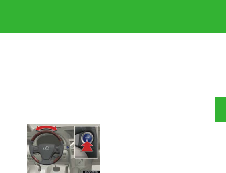
179
2-1. Driving procedures
2
When driving
■Note for the entry function
P. 59
■If the hybrid system does not start
The immobilizer system may not have been deactivated. (P. 124)
■Steering lock
After turning the “POWER” switch off and opening and closing the doors, the
steering wheel will be locked due to the steering lock function. Operating the
“POWER” switch again automatically cancels the steering lock.
■When the steering lock cannot be released
■Steering lock motor overheating prevention
To prevent the steering lock motor from overheating, the motor may be suspended
if the hybrid system is turned on and off repeatedly in a short period of time. In this
case, refrain from operating the hybrid system. After about 2 seconds, the steering
lock motor will resume functioning.
■When the “POWER” switch indicator flashes in amber
The system may be malfunctioning. Have the vehicle inspected by your Lexus
dealer immediately.
■If the “READY” indicator does not come on
If the “READY” indicator does not come on when you press the “POWER” switch
with the shift lever in P and the brake pedal depressed, contact your Lexus dealer
immediately.
■If the hybrid system is malfunctioning
P. 6 09
■If the electronic key battery is depleted
P. 55 0
The green indicator light on the “POWER”
switch will flash and a message will be shown
on the multi-information display. Press the
“POWER” switch again while turning the
steering wheel left and right.

180
2-1. Driving procedures
CAUTION
■When starting the hybrid system
Always start the hybrid system while sitting in the driver’s seat. Do not depress the
accelerator pedal while starting the hybrid system under any circumstances.
Doing so may cause an accident resulting in death or serious injury.
■Caution while driving
If a hybrid system failure occurs while the vehicle is moving, do not lock or open the
doors until the vehicle reaches a safe and complete stop. Activation of the steering
lock in this circumstance may lead to an accident, resulting in death or serious
injury.
■Stopping the hybrid system in an emergency
If you want to stop the hybrid system in an emergency while driving the vehicle,
press and hold the “POWER” switch for more than 3 seconds.
However, do not touch the “POWER” switch while driving except in an emergency.
Turning the hybrid system off while driving will not cause loss of steering or braking
control, but the power assist to these systems will be lost. This will make it more diffi-
cult to steer and brake, so you should pull over and stop the vehicle as soon as it is
safe to do so.
NOTICE
■To prevent 12-volt battery discharge
●Do not leave the “POWER” switch in ACCESSORY or ON mode for long peri-
ods of time without the hybrid system on.
●If the indicator on the “POWER” switch is illuminated, the “POWER” switch is not
off. When exiting the vehicle, always check that the “POWER” switch is off.
●Do not stop the hybrid system when the shift lever is in a position other than P. If
the hybrid system is stopped in another shift lever position, the “POWER” switch
will not be turned off but instead be turned to ACCESSORY mode. If the vehicle
is left in ACCESSORY mode, 12-volt battery discharge may occur.

181
2-1. Driving procedures
2
When driving
NOTICE
■When starting the hybrid system
Do not depress the accelerator pedal unnecessarily.
■Symptoms indicating a malfunction with the “POWER” switch
If the “POWER” switch seems to be operating somewhat differently than usual,
such as the switch sticking slightly, there may be a malfunction. Contact your Lexus
dealer immediately.
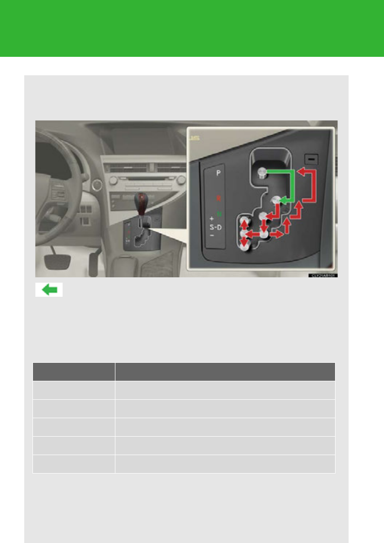
182
2-1. Driving procedures
Hybrid transmission
Select a shift position appropriate for the driving conditions.
■Shifting the shift lever
While the “POWER” switch is in ON mode, depress the brake
pedal and move the shift lever.
When shifting the shift lever between P and D, make sure that the
vehicle is completely stopped.
■Shift position purpose
*1: Shifting to the D position allows the system to select a gear suitable for the
driving conditions. Setting the shift lever to the D position is recommended
for normal driving.
*2: Selecting shift ranges using S mode controls engine braking forces.
Shift position Function
PParking the vehicle/starting the hybrid system
RReversing
NNeutral
DNormal driving*1
SS mode driving*2 (P. 186 )
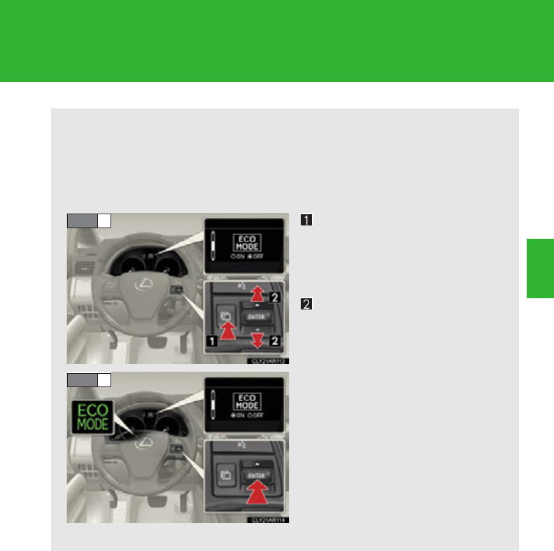
183
2-1. Driving procedures
2
When driving
■Selecting Eco drive mode
When the vehicle is driven in Eco drive mode, vehicle driving force
and operation of the air conditioning system (heating/cooling) is
controlled to improve fuel efficiency.
Press the menu switch.
The multi-information display
will change modes to electronic
features control mode.
Press the “ENTER” switch
upwards or downwards until
“ECO MODE” appears.
Press the “ENTER” switch to
change to “ON”.
The “ECO MODE” indicator
will be displayed.
Each pressing of the switch
turns Eco drive mode on and off.
Press the menu switch to
change to the normal display.
STEP 1
STEP 2
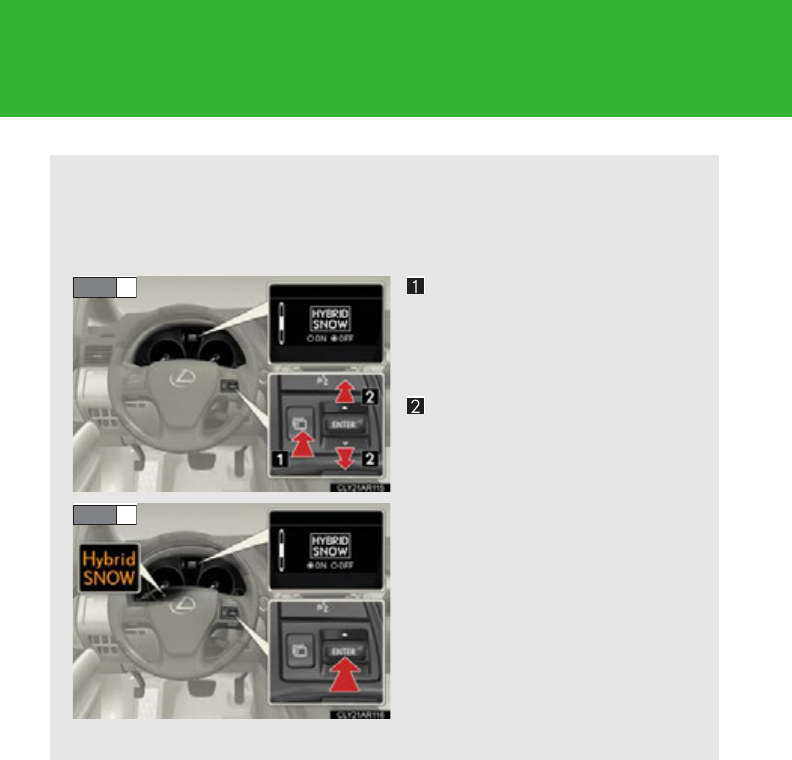
184
2-1. Driving procedures
■Selecting snow mode
Use snow mode for accelerating and driving on slippery road sur-
faces such as snow.
Press the menu switch.
The multi-information display
will change modes to electronic
features control mode.
Press the “ENTER” switch
upwards or downwards until
“HYBRID SNOW” appears.
Press the “ENTER” switch to
change to “ON”.
The “Hybrid SNOW” indicator
will be displayed.
Each pressing of the switch
turns snow mode on and off.
Press the menu switch to
change to the normal display.
STEP 1
STEP 2
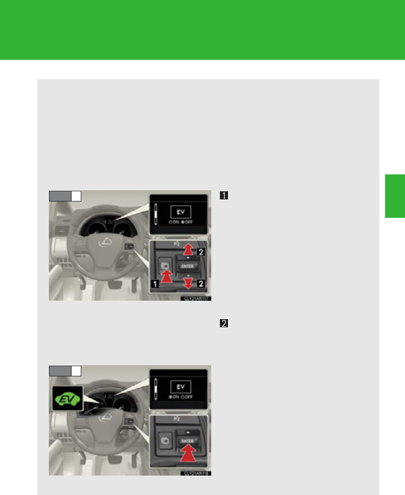
185
2-1. Driving procedures
2
When driving
■Selecting EV drive mode
In EV drive mode, the electric motor (traction motor), powered by
the hybrid battery (traction battery), is used to drive the vehicle.
This mode allows you to drive in residential areas late at night or in
indoor parking lots etc. without concern for noises and exhaust gas
emissions.
Press the menu switch.
The multi-information display
will change modes to electronic
features control mode.
When the menu switch is
pressed within 10 seconds of the
hybrid system being started,
“EV” will be the first mode dis-
played.
Press the “ENTER” switch
upwards or downwards until
“EV” appears.
Press the “ENTER” switch to
change to “ON”.
The EV drive mode indicator
will be displayed.
Each pressing of the switch
turns EV drive mode on and off.
Press the menu switch to
change to the normal display.
STEP 1
STEP 2
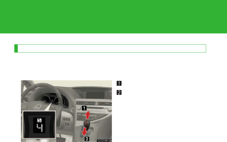
186
2-1. Driving procedures
Changing shift ranges in S mode
When the shift lever is in the S position, the shift lever can be operated as
follows:
For upshifting
For downshifting
The initial shift range in S mode is set automatically to “5” or “4” accord-
ing to vehicle speed.
■Shift ranges and their functions
●You can choose from 6 levels of engine braking force.
●A lower shift range will provide greater engine braking force than a
higher shift range, and the engine speed will also increase.

187
2-1. Driving procedures
2
When driving
■Operation of the air conditioning system in Eco drive mode
Eco drive mode controls the heating/cooling operations and fan speed of the air
conditioning system to enhance fuel efficiency. (P. 322) To improve air condition-
ing performance, adjust the fan speed or turn off Eco drive mode.
■Automatic return to normal driving mode
If snow mode or EV drive mode is selected, the driving mode will automatically
return to normal mode when the hybrid system is turned off.
■S mode
●When the shift range is “5” or lower, holding the shift lever toward “+” sets the
shift range to “6”.
●To prevent the engine from over-revving, upshifting may automatically occur.
■AI-SHIFT
AI-SHIFT automatically selects the optimal gear according to driver performance
and driving conditions.
AI-SHIFT automatically operates when the shift lever is in the D position. (Shifting
the shift lever to the S position cancels the function.)
The engine speed may remain high after releasing the accelerator pedal. This does
not indicate a malfunction.
■When driving with the cruise control or dynamic radar cruise control
Engine braking will not occur in S mode, even when downshifting to “5” or “4”.
(P. 23 8, 24 3)
■If the shift lever cannot be shifted from P
P. 6 45
■If S does not come on even after shifting the shift lever to S
This may indicate a malfunction in the hybrid transmission system. Have the vehicle
inspected by your Lexus dealer immediately.
(In this situation, the hybrid transmission will operate in the same as manner as when
the shift lever is in D.)
■Downshift restriction warning buzzer (S mode)
To help ensure safety and driving performance, downshifting operation may some-
times be restricted. In some circumstances, downshifting may not be possible even
when the shift lever is operated. (The buzzer will sound twice.)

188
2-1. Driving procedures
■Situations in which EV drive mode cannot be turned on
It may not be possible to turn EV drive mode on in the following situations. If it can-
not be turned on, a buzzer will sound and a message will be shown on the multi-
information display.
●The temperature of the hybrid system is high.
The vehicle has been left in the sun, driven on a hill, driven at high speeds, etc.
●The temperature of the hybrid system is low.
The vehicle has been left in extremely low temperatures for a long period of
time etc.
●The gasoline engine is warming up.
●The hybrid battery (traction battery) is low.
●Vehicle speed is about 25 mph (40 km/h) or more.
●The accelerator pedal is depressed firmly or the vehicle is on a hill etc.
●The windshield defogger is in use.
■Automatic cancelation of EV drive mode
When driving in EV drive mode, the gasoline engine may automatically restart in
the following situations. When EV drive mode is canceled, a buzzer will sound and
the EV drive mode indicator will flash and go off.
●The hybrid battery (traction battery) becomes low.
●Vehicle speed becomes more than about 25 mph (40 km/h).
●The accelerator pedal is depressed firmly or the vehicle is on a hill etc.
■Possible driving distance when driving in EV drive mode
In EV drive mode, it is possible to drive up about 0.5 mile (1 km) if driving at a speed of
about 25 mph (40 km/h) or less. (The distance that is possible depends on the hybrid
battery [traction battery] level and driving conditions.)
■Fuel economy
RX450h is designed to achieve the best possible fuel economy during normal driv-
ing (using the gasoline engine and electric motor [traction motor]). Driving in EV
drive mode more than necessary may lower fuel economy.
189
2-1. Driving procedures
2
When driving
CAUTION
■When driving on slippery road surfaces
Do not accelerate or shift gears suddenly.
Sudden changes in engine braking may cause the vehicle to spin or skid, resulting in
an accident.
■Caution while driving
When driving in EV drive mode, pay special attention to the area around the vehi-
cle. Because there is no engine noise, pedestrians, people riding bicycles or other
people and vehicles in the area may not be aware of the vehicle starting off or
approaching them, so take extra care while driving.
NOTICE
■Hybrid battery (traction battery) charge precaution
If the shift lever is in N, the hybrid battery (traction battery) will not be charged even
when the engine is running. Therefore, if the vehicle is left with the shift lever in N for
a long period of time, the hybrid battery (traction battery) will discharge, and this
may result in the vehicle not being able to start.
190
2-1. Driving procedures
Turn signal lever
The turn signal lever can be used to show the following intention of the
driver:
Type A
Right turn
Left turn
Lane change to the right
(push and hold the lever part-
way)
The right hand signals will flash
until you release the lever.
Lane change to the left (push
and hold the lever partway)
The left hand signals will flash
until you release the lever.
191
2-1. Driving procedures
2
When driving
■Turn signals can be operated when
The “POWER” switch is in ON mode.
■If the indicators flash faster than usual
Check that a light bulb in the front or rear turn signal lights has not burned out.
Type B
Right turn
Left turn
Lane change to the right
(push and hold the lever part-
way)
The right hand signals will flash
until you release the lever.
Lane change to the left (push
and hold the lever partway)
The left hand signals will flash
until you release the lever.
192
2-1. Driving procedures
Parking brake
■Usage in winter time
See “Winter driving tips” for parking brake usage in winter time. (P. 296 )
NOTICE
■Before driving
Fully release the parking brake.
Driving the vehicle with the parking brake set will lead to brake components over-
heating, which may affect braking performance and increase brake wear.
To set the parking brake, fully
depress the parking brake pedal
with your left foot while
depressing the brake pedal with
your right foot.
(Depressing the pedal again
releases the parking brake.)
Canada
U.S.A.
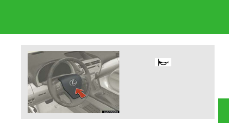
193
2-1. Driving procedures
2
When driving
Horn
To sound the horn, press on or
close to the mark.
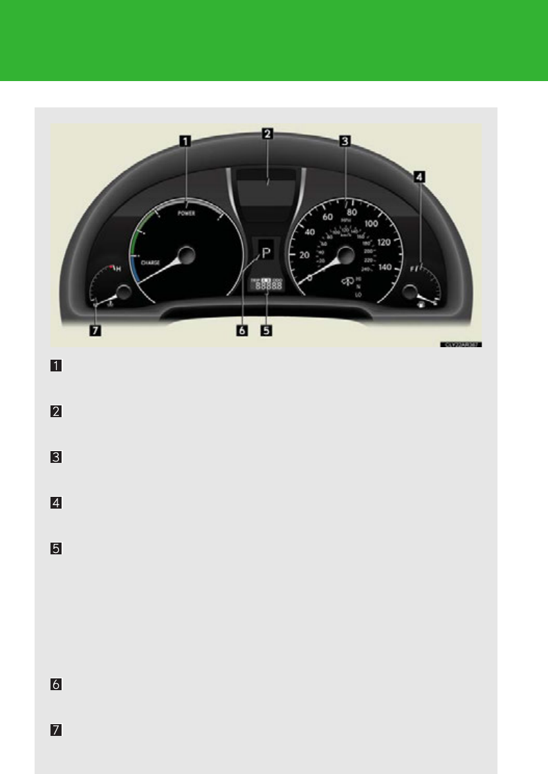
194
2-2. Instrument cluster
Gauges and meters
Hybrid System Indicator
Displays hybrid system power output and regenerative charging level
Multi-information display
P. 2 0 2
Speedometer
Displays the vehicle speed
Fuel gauge
Displays the quantity of fuel remaining in the tank
Odometer and trip meter
Odometer: Displays the total distance the vehicle has been driven
Trip meter: Displays the distance the vehicle has been driven since
the meter was last reset. Trip meters “A” and “B” can be
used to record and display different distances indepen-
dently.
Shift position and shift range display
P. 1 82
Engine coolant temperature gauge
Displays the engine coolant temperature
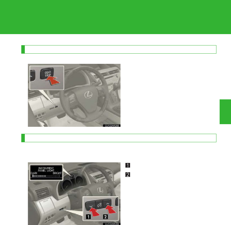
195
2-2. Instrument cluster
2
When driving
Changing the display
Switches between odometer and
trip meter displays. When the trip
meter is displayed, pressing and
holding the button will reset the
trip meter.
Instrument panel light control
The brightness of the instrument panel lights can be adjusted.
Darker
Brighter
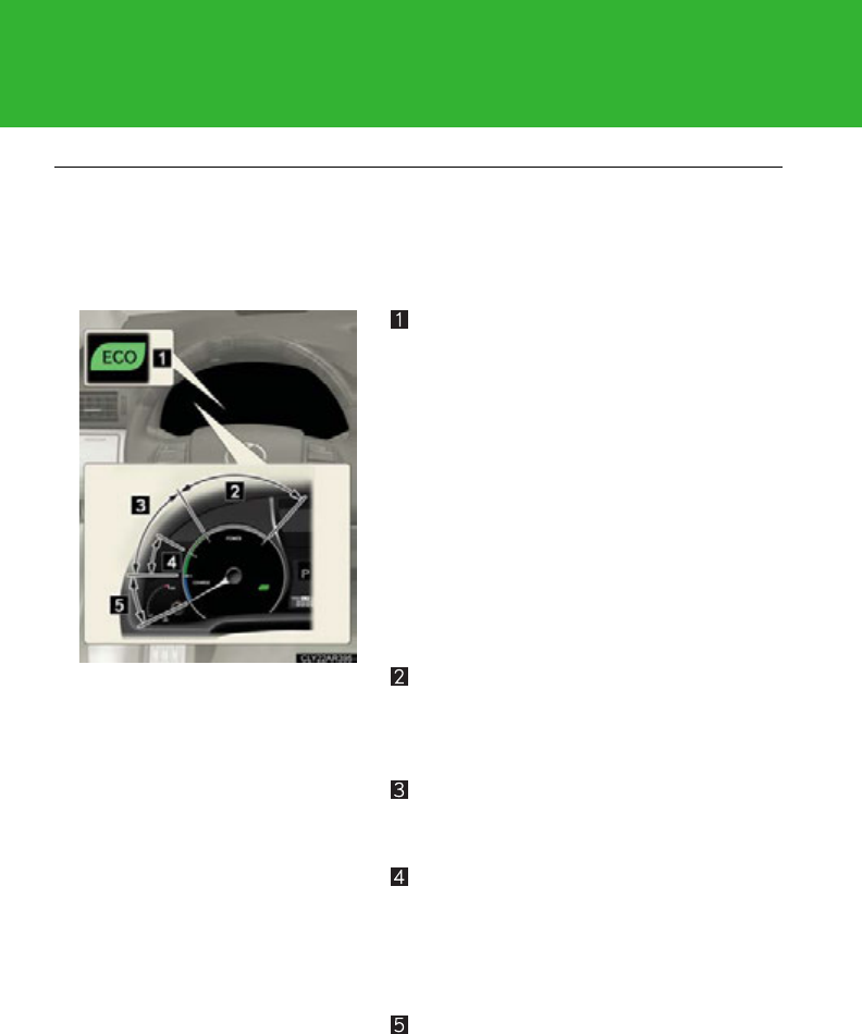
196
2-2. Instrument cluster
■The meters and display illuminate when
The “POWER” switch is in ON mode.
■Hybrid System Indicator
Eco Driving Indicator Light
During Eco-friendly acceleration (Eco
driving), Eco Driving Indicator Light will
turn on.
Eco Driving Indicator Light will not oper-
ate in the following conditions:
●The shift lever is in anything other than
D.
●The driving mode is set to snow mode
or EV drive mode. (P. 184, 185)
●The vehicle speed is approximately 80
mph (130 km/h) or higher.
Power area
Shows that an Eco-friendly driving range is
being exceeded (during full power driving
etc.)
Eco area
Shows that the vehicle is being driven in an
Eco-friendly manner.
Hybrid Eco area
Shows that gasoline engine power is not
being used very often.
The gasoline engine will automatically
stop and restart under various conditions.
Charge area
Shows that energy is being recovered via
regenerative braking.

197
2-2. Instrument cluster
2
When driving
●By keeping the indicator within Eco area, more Eco-friendly driving can be
achieved.
●Charge area indicates regeneration* status. Regenerated energy will be used
to charge the hybrid battery (traction battery).
*: When used in this manual, “regeneration” refers to the conversion of energy cre-
ated by the movement of the vehicle into electrical energy.
NOTICE
■To prevent damage to the engine and its components
The engine may be overheating if the engine coolant temperature gauge is in the
red zone (H). In this case, immediately stop the vehicle in a safe place, and check
the engine after it has cooled completely. (P. 655)
198
2-2. Instrument cluster
Indicators and warning lights
The indicator and warning lights on the instrument cluster and center
panel inform the driver of the status of the vehicle’s various systems.
Instrument cluster
Center panel (without a navigation system)
199
2-2. Instrument cluster
2
When driving
Center panel (with a navigation system)
■Indicators
The indicators inform the driver of the operating state of the vehi-
cle’s various systems.
Turn signal indicator
(P. 1 9 0 )
(if equipped)
Intuitive parking assist
indicator
(P. 2 57)
Headlight high beam indi-
cator (P. 2 1 6 )
(if equipped)
“AFS OFF” indicator
(P. 2 1 6)
(if equipped)
Automatic High Beam
indicator (P. 2 1 9)
Slip indicator
(P. 275, 280)
(U.S.A.)
Headlight indicator
(P. 2 13)
VSC off indicator
(P. 276)
(Canada)
Tail light indicator
(P. 2 13)
“ECO MODE” indicator
(P. 1 83)
*1
*1
*1, 2
*1
200
2-2. Instrument cluster
*1: These lights turn on when the “POWER” switch is turned to the ON
mode to indicate that a system check is being performed. They will turn
off after the hybrid system is on, or after a few seconds. There may be a
malfunction in a system if a light does not come on, or if the lights do not
turn off. Have the vehicle inspected by your Lexus dealer.
*2: The light flashes to indicate that the system is operating.
Front fog light indicator
(P. 2 26)
(if equipped)
Electronically modulated
air suspension indicator
(P. 26 4)
Cruise control indicator
(P. 2 38, 243)
“READY” indicator
(P. 1 76)
(if equipped)
Radar cruise control indi-
cator (P. 243)
“Hybrid SNOW” indica-
tor (P. 1 8 4 )
(without
navigation
system)
SRS airbag on-off indica-
tor (P. 1 4 4 )
(with
navigation
system)
SRS airbag on-off indica-
tor (P. 1 4 4 )
Eco Driving Indicator
Light (P. 1 6 8 )
EV drive mode indicator
(P. 1 85)
*1
*1
*1
*1
201
2-2. Instrument cluster
2
When driving
CAUTION
■If a safety system warning light does not come on
Should a safety system light such as the ABS and SRS warning light not come on
when you start the hybrid system, this could mean that these systems are not avail-
able to help protect you in an accident, which could result in death or serious injury.
Have the vehicle inspected by your Lexus dealer immediately if this occurs.
■Warning lights
Warning lights inform the driver of malfunctions in any of the vehi-
cle’s systems. (P. 598)
*1: These lights turn on when the “POWER” switch is turned to ON mode
to indicate that a system check is being performed. They will turn off
after the hybrid system is on, or after a few seconds. There may be a
malfunction in a system if a light does not come on, or if the lights do
not turn off. Have the vehicle inspected by your Lexus dealer.
*2: The light flashes to indicate a malfunction.
(U.S.A.) (Canada) (U.S.A.) (Canada)
(U.S.A.) (Canada)
(if equipped) (if equipped) (for driver)
(for front
passenger)
*1
*1
*1
*1
*1
*1
*1
*1
*1
*1
*1
*1, 2
*1
*2
*1, 2
*1
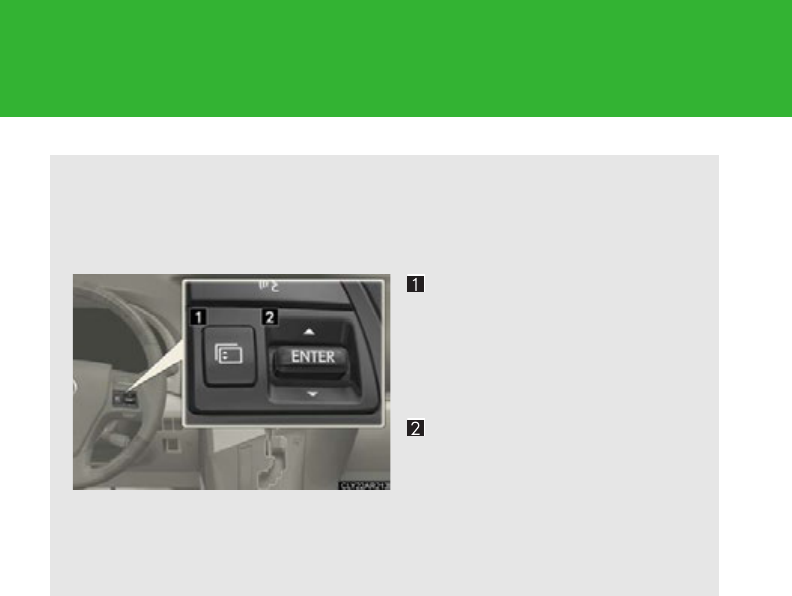
202
2-2. Instrument cluster
Multi-information display
The multi-information display presents the driver with a variety of driving-
related data including the current outside air temperature.
■Multi-information switches
Menu switch
Changes modes to electronic
features control mode, customi-
zation mode or back to normal
display mode
“ENTER” switch
Changes trip information items.
This switch is also used to turn
on/off electronic features con-
trols and to change customiza-
tion settings.
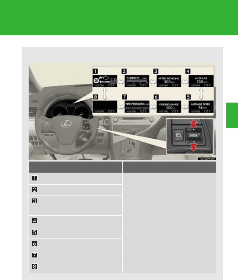
203
2-2. Instrument cluster
2
When driving
■Display contents
Trip information contents Switching display items
Energy monitor
Press the “ENTER” switch upwards
or downwards.
Current fuel consumption
Average fuel consumption after
refueling
Average fuel consumption
Average vehicle speed
Cruising range
Tire inflation pressure
- (off)
204
2-2. Instrument cluster
Display order may vary depending on vehicle condition.
Electronic features control contents Setting electronic features controls
Intuitive parking assist
(if equipped) P. 2 57
Eco drive mode P. 1 83
Snow mode P. 1 84
AFS (if equipped) P. 2 16
EV drive mode P. 1 85
Other contents Details
Outside temperature Displays the outside temperature
Dynamic radar cruise control display
(if equipped) (P. 243)
Automatically displayed when using
dynamic radar cruise control
Customization (P. 693)
Settings of functions such as the
door lock and light illumination time
can be changed
Warning message (P. 608)
Automatically displayed when a mal-
function occurs in one of the vehi-
cle's systems

205
2-2. Instrument cluster
2
When driving
Trip information
■Energy monitor
Displays the status of the hybrid system (P. 4 0)
■Current fuel consumption
Displays the current rate of fuel consumption
■Average fuel consumption after refueling
Displays the average fuel consumption since the vehicle was last refu-
eled
Use the displayed average fuel consumption as a reference.
■Average fuel consumption
Displays the average fuel consumption since the function was reset
• The function can be reset by pushing the “ENTER” switch for longer
than one second when the average fuel consumption is displayed.
• Use the displayed average fuel consumption as a reference.
■Average vehicle speed
Displays the average vehicle speed since the function was reset
The function can be reset by pushing the “ENTER” switch for longer than
one second when the average vehicle speed is displayed.
■Cruising range
Displays the estimated maximum distance that can be driven with the
quantity of fuel remaining
• This distance is computed based on your average fuel consumption. As
a result, the actual distance that can be driven may differ from that dis-
played.
• When only a small amount of fuel is added to the tank, the display may
not be updated.
When refueling, turn the “POWER” switch off. If the vehicle is refueled
without turning the “POWER” switch off, the display may not be
updated.

206
2-2. Instrument cluster
■Tire inflation pressure
Displays inflation pressure of each tire. There is no correlation between
the order of the displayed values and the tire positions.
If the inflation pressure of any tire drops a certain amount below the tire infla-
tion pressure value currently memorized in the system, the displayed values
will be highlighted.
It may take a few minutes to display the tire inflation pressure after the
“POWER” switch is turned to ON mode. It may also take a few minutes to
display the tire inflation pressure after inflation pressure has been adjusted.
If the tire pressure warning light is on or flashing, a message describing the
situation will be displayed.
■Electronic features control can be turned on/off when
The “POWER” switch is in ON mode.
■Conditions for ending electronic features control
In the following situations, the electronic features control will end:
●The menu switch is pressed
●The dynamic radar cruise control is operated
●Intuitive parking assist starts operating
●No action is performed for some time after the electronic features control
screen is displayed
●A warning message appears after the electronic features control screen is dis-
played
■Outside temperature display
In the following situations, the correct outside temperature may not be displayed, or
the display may take longer than normal to change.
●When stopped, or driving at low speeds (less than 15 mph [25 km/h])
●When the outside temperature has changed suddenly (at the entrance/exit of a
garage, tunnel, etc.)
■The multi-information display at low temperatures
Allow the interior of the vehicle to warm up before using the liquid crystal informa-
tion display. At extremely low temperatures, the information display monitor may
respond slowly, and display changes may be delayed.

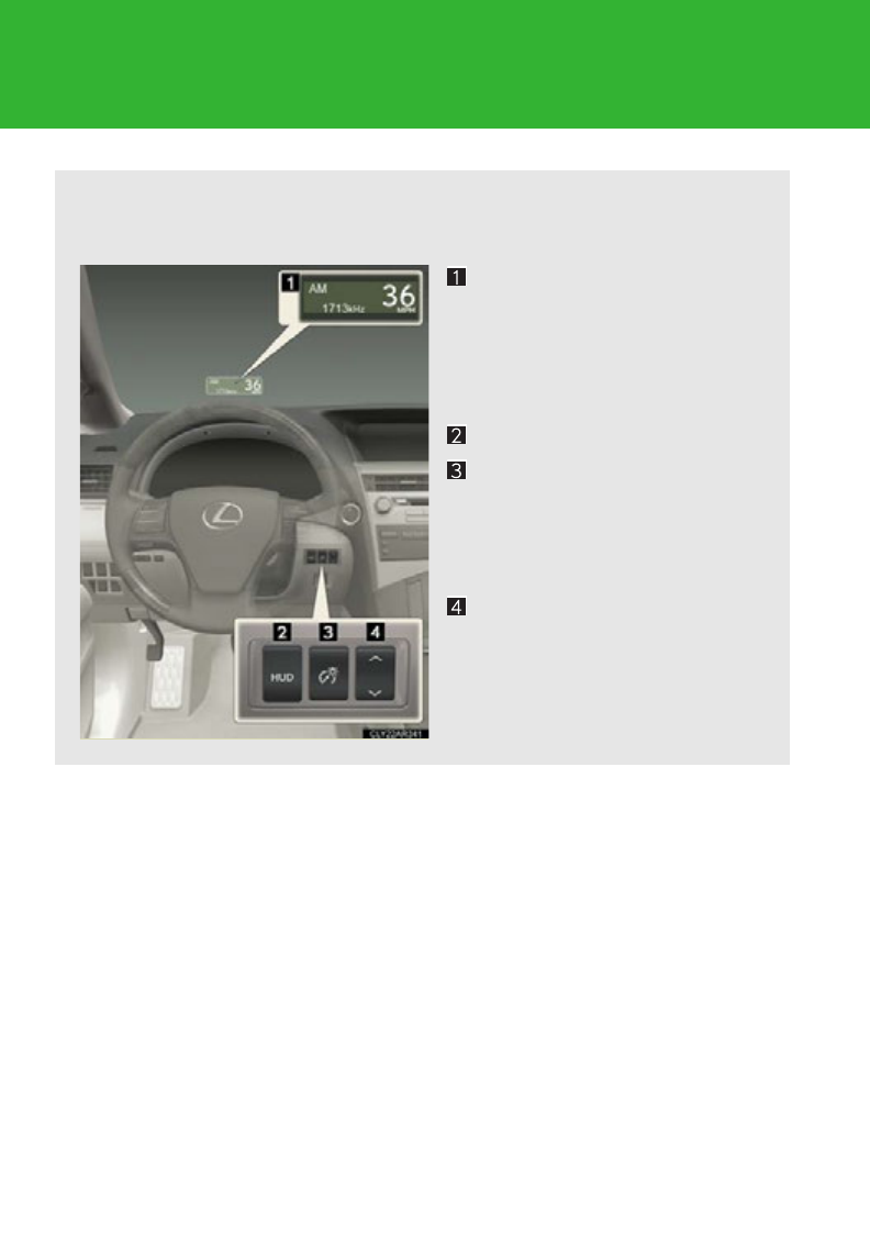
208
2-2. Instrument cluster
Head-up display
The head-up display can be used to project vehicle speed and other infor-
mation onto the windshield.
Head-up display
Display brightness will change
automatically according to the
brightness of the surrounding
area.
Head-up display main switch
Display contrast adjustment
switch
Display brightness can be
adjusted to the desired level.
Display position adjustment
switch
: If equipped
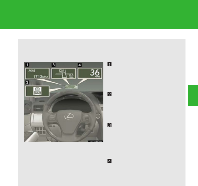
209
2-2. Instrument cluster
2
When driving
■Head-up display contents
In addition to vehicle speed, the following information will be displayed:
Audio display
Displays audio information for
approximately 3 seconds when
the audio system is operated
Dynamic radar cruise con-
trol (if equipped)
Displays the approach warning
message (P. 614)
Turn-by-turn navigation*
Displays a notification of
upcoming intersections during
navigation system route guid-
ance
Vehicle speed display
*: Refer to “Navigation System
Owner’s Manual”.
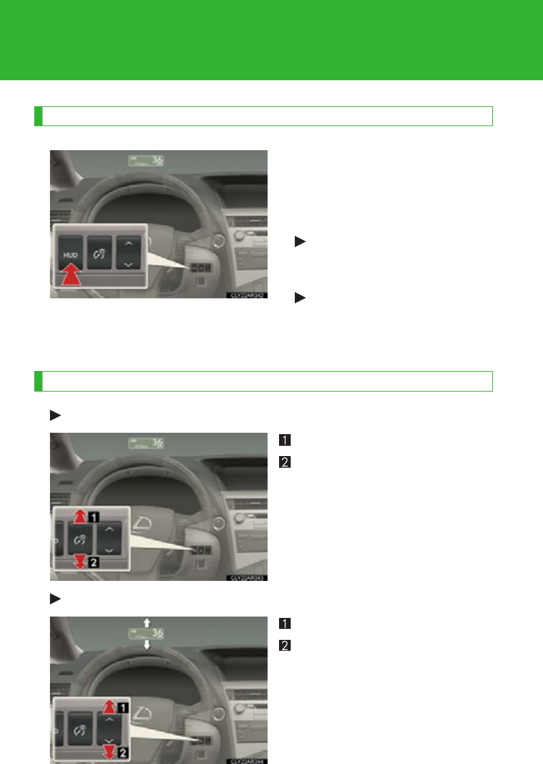
210
2-2. Instrument cluster
Head-up display main switch
Pressing the switch turns the head-
up display on/off and changes the
vehicle speed display units as fol-
lows:
Vehicles sold in the U.S.A.
OFF ON (mph) ON
(km/h) OFF
Except vehicles sold in the
U.S.A.
OFF ON (km/h) ON
(mph) OFF
Display adjustment
Adjusting display contrast
Brighter
Darker
Adjusting display position
Higher
Lower
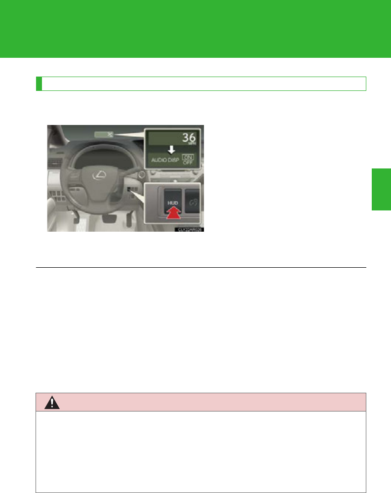
211
2-2. Instrument cluster
2
When driving
Display customization
The audio mode display can be shown or hidden.
Pressing and holding the head-up
display main switch for more than
2 seconds changes the display to
audio display on/off mode. Press
the head-up display main switch to
turn the audio display on/off.
Customization can be performed
when the head-up display is on and
the vehicle is traveling at less than
5 mph (8 km/h).
■Brightness of the head-up display
The headlight control sensor detects the brightness of the area surrounding the
head-up display and adjusts the brightness accordingly. (P. 21 7)
■Head-up display
The head-up display may seem dark and hard to see when viewed through sun-
glasses, especially polarized sunglasses.
Adjust the brightness of the head-up display or remove your sunglasses.
CAUTION
■Before using the head-up display
Check that the position and brightness of the head-up display image does not inter-
fere with safe driving. Incorrect adjustment of the image's position or brightness
may obstruct the driver's view and lead to an accident, resulting in death or serious
injury.
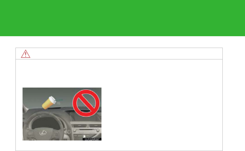
212
2-2. Instrument cluster
NOTICE
■To prevent damage to components
●Do not place anything on the head-up display opening.
●If an object falls into the opening of the
head-up display, remove it immediately.
Also, avoid spilling water or other liquids
near the head-up display opening as this
may cause mechanical damage.
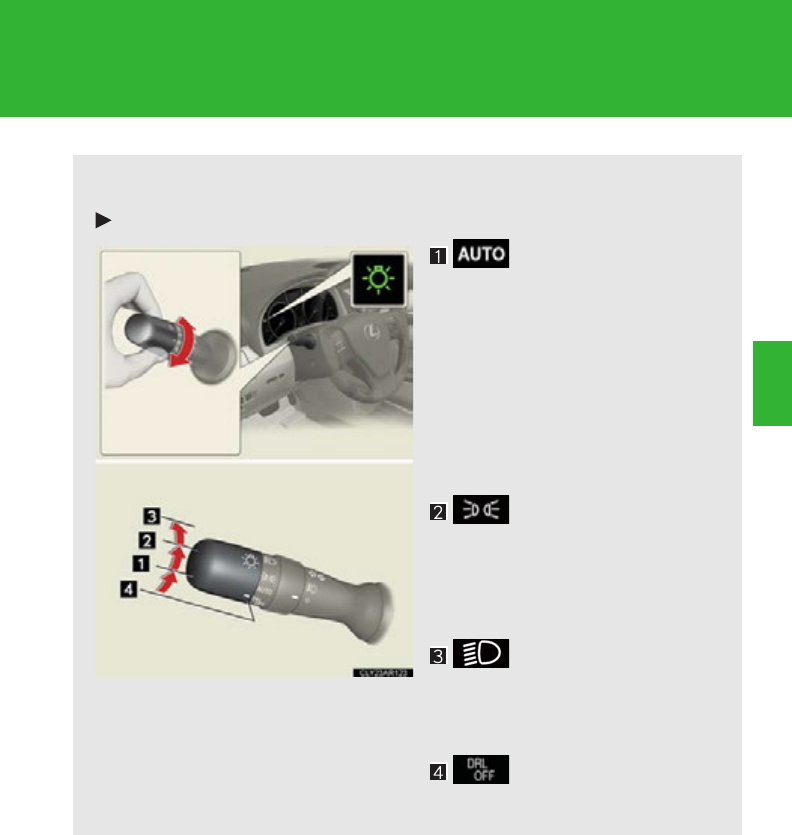
213
2
When driving
2-3. Operating the lights and windshield wipers
Headlight switch
The headlights can be operated manually or automatically.
Type A
The headlights and
side marker, parking,
tail, license plate, day-
time running lights
and instrument panel
lights turn on and off
automatically (when
the “POWER” switch
is in ON mode).
The side marker, park-
ing, tail, license plate,
daytime running lights
and instrument panel
lights turn on.
The headlights and all
the lights listed above
(except daytime run-
ning lights) turn on.
The daytime running
lights turn off.
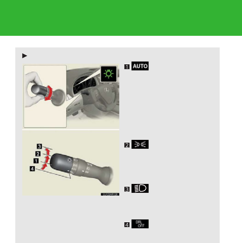
214
2-3. Operating the lights and windshield wipers
Type B
The headlights and
side marker, parking,
tail, license plate, day-
time running lights
and instrument panel
lights turn on and off
automatically (when
the “POWER” switch
is in ON mode).
The side marker, park-
ing, tail, license plate,
daytime running lights
and instrument panel
lights turn on.
The headlights and all
the lights listed above
(except daytime run-
ning lights) turn on.
The daytime running
lights turn off.
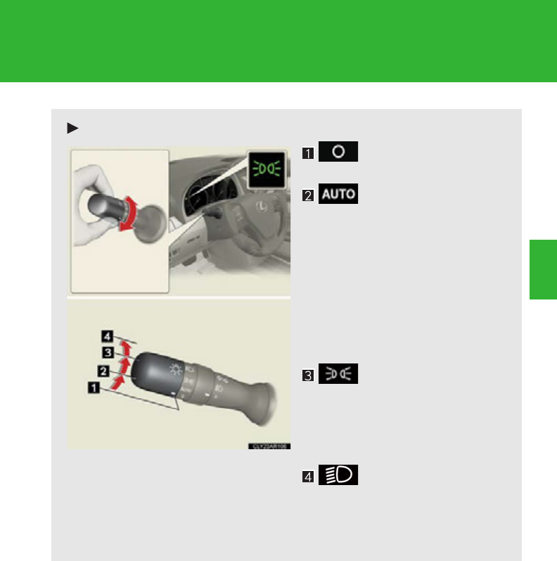
215
2-3. Operating the lights and windshield wipers
2
When driving
Type C
The daytime running
lights turn on.
The headlights and
side marker, parking,
tail, license plate, day-
time running lights
and instrument panel
lights turn on and off
automatically (when
the “POWER” switch
is in ON mode).
The side marker, park-
ing, tail, license plate,
daytime running lights
and instrument panel
lights turn on.
The headlights and all
the lights listed above
(except daytime run-
ning lights) turn on.
216
2-3. Operating the lights and windshield wipers
Turning on the high beam headlights
With the headlights on, push the
lever away from you to turn on
the high beams.
When the light switch is in
position, the Automatic High Beam
system will be activated.
(P. 2 1 9 )
Pull the lever toward you to the
center position to turn the high
beams off.
Pull the lever toward you to turn
on the high beams.
Release the lever to turn them off.
You can flash the high beams with
the headlights on or off.
AFS (Adaptive Front-lighting System) (if equipped)
AFS (Adaptive Front-lighting System) improves visibility at intersections
and on curves by automatically adjusting the direction of the light axis of
the headlights according to vehicle speed and the degree of the tire
angle that are controlled by steering input.
AFS operates at speeds of 6 mph (10 km/h) or higher.
■Deactivating AFS
Press the menu switch.
The multi-information display will
change modes to electronic fea-
tures control mode.
Press the “ENTER” switch
upwards or downwards until
AFS appears.
STEP 1
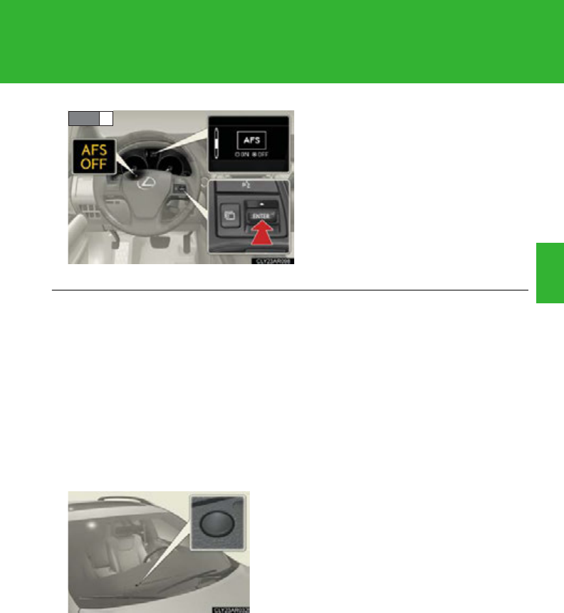
217
2-3. Operating the lights and windshield wipers
2
When driving
Press the “ENTER” switch to
change to “OFF”.
The “AFS OFF” indicator will be
displayed.
Each pressing of the switch turns
“A F S ” o n a n d o f f .
Press the menu switch to change
to the normal display.
STEP 2
■Daytime running light system
●To make your vehicle more visible to other drivers, the daytime running lights
turn on automatically whenever the hybrid system is started and the parking
brake is released. Daytime running lights are not designed for use at night.
For the U.S.A.: Daytime running lights can be turned off by operating the switch.
●Compared to turning on the headlights, the daytime running light system offers
greater durability and consumes less electricity, so it can help improve fuel
economy.
■Headlight control sensor
The sensor may not function properly if an
object is placed on the sensor, or anything
that blocks the sensor is affixed to the wind-
shield.
Doing so interferes with the sensor detecting
the level of ambient light and may cause the
automatic headlight system to malfunction.
218
2-3. Operating the lights and windshield wipers
■Automatic light off system
●When the headlights come on: The headlights and tail lights turn off 30 seconds
after a door is opened and closed if the “POWER” switch is turned to ACCES-
SORY mode or turned off. (The lights turn off immediately if on the key is
pressed after all the doors are locked.)
●When only the tail lights come on: The tail lights turn off automatically if the
“POWER” switch is turned to ACCESSORY mode or turned off and the
driver’s door is opened.
To turn the lights on again, turn the “POWER” switch to ON mode, or turn the light
switch off once and then back to or .
■Automatic headlight leveling system (if equipped)
The level of the headlights is automatically adjusted according to the number of
passengers and the loading condition of the vehicle to ensure that the headlights do
not interfere with other road users.
■If the “AFS OFF” indicator flashes (if equipped)
It may indicate a malfunction in the system. Contact your Lexus dealer.
■Customization
Settings (e.g. light sensor sensitivity) can be changed.
(Customizable features P. 693)
NOTICE
■To prevent 12-volt battery discharge
Do not leave the lights on longer than necessary when the hybrid system is off.
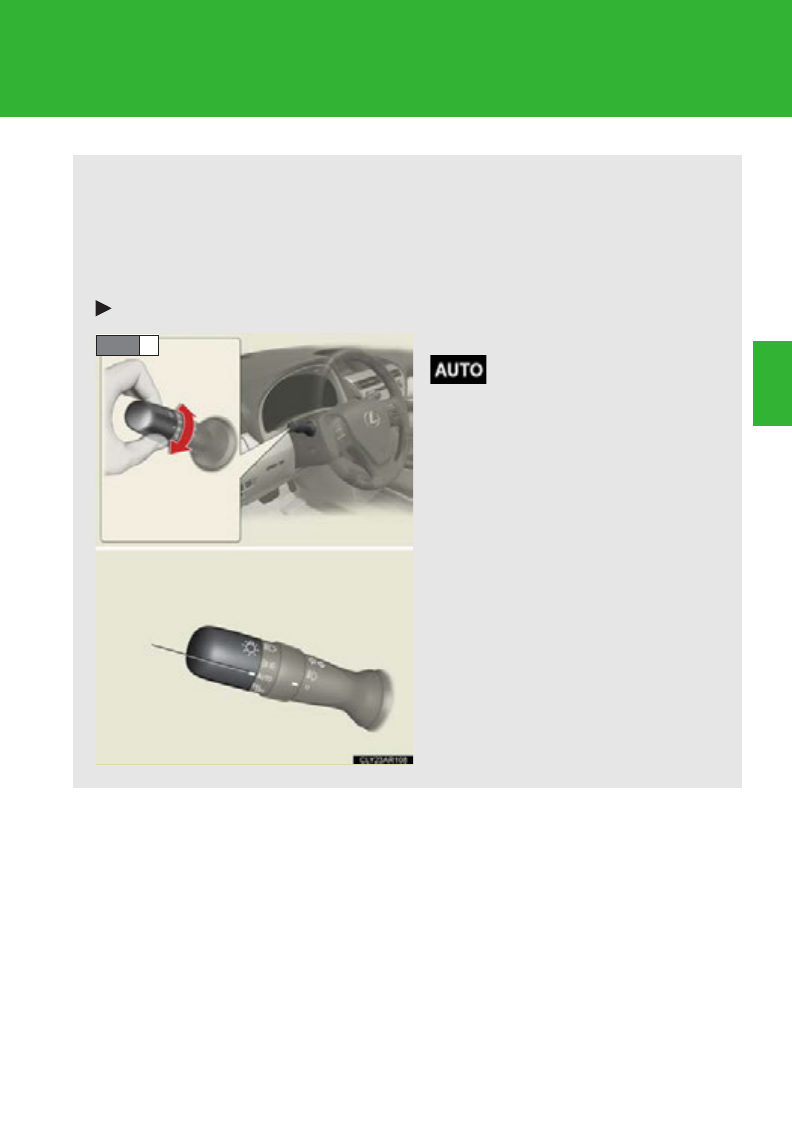
219
2-3. Operating the lights and windshield wipers
2
When driving
Automatic High Beam
: If equipped
The Automatic High Beam uses an in-vehicle camera sensor to assess the
brightness of streetlights, the lights of oncoming and preceding vehicles,
etc., and automatically turns high beam on or off as necessary.
■Activating the Automatic High Beam system
Type A
Turn the headlight switch to the
position.
STEP 1
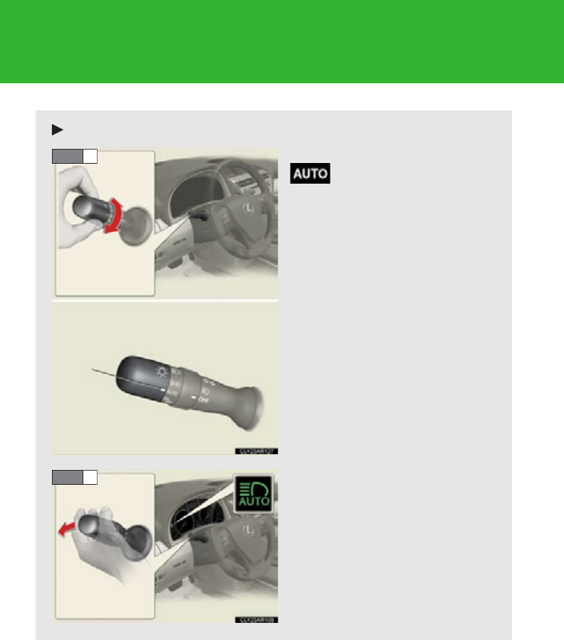
220
2-3. Operating the lights and windshield wipers
Type B
Turn the headlight switch to the
position.
Push the lever away from you.
The Automatic High Beam indi-
cator will come on when the
headlights are turned on auto-
matically to indicate that the sys-
tem is active.
STEP 1
STEP 2
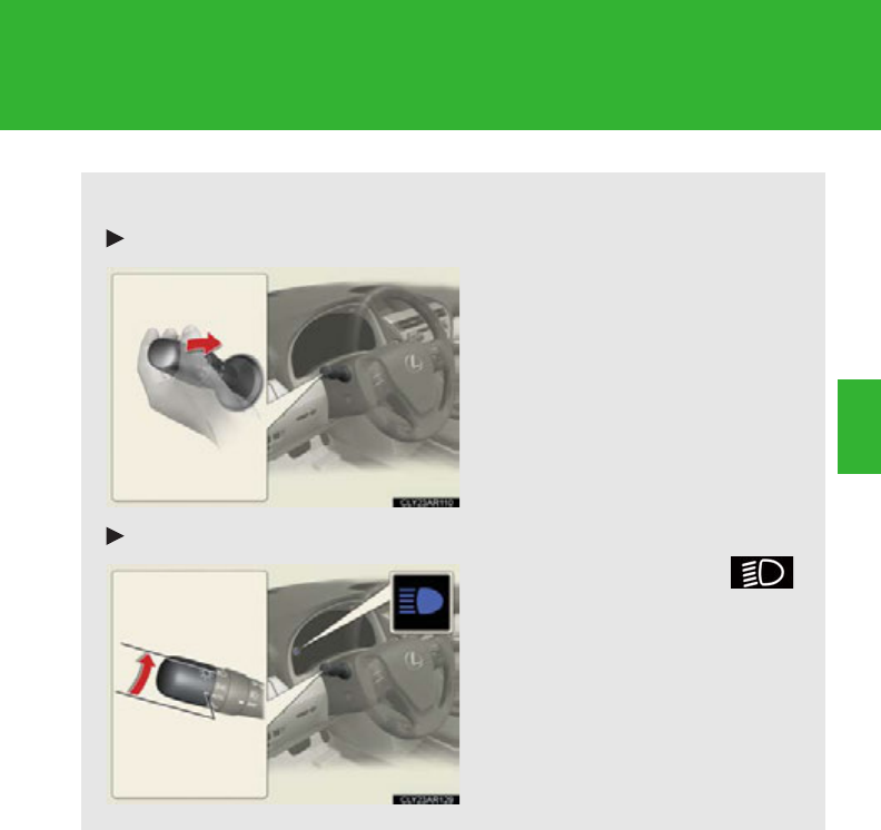
221
2-3. Operating the lights and windshield wipers
2
When driving
■Turning the high beam on/off manually
Switching to low beam
Pull the lever to original posi-
tion.
Switching to high beam
Turn the light switch to
position.

222
2-3. Operating the lights and windshield wipers
■The Automatic High Beam can be operated when
The “POWER” switch is ON mode.
■Limitations of the Automatic High Beam
Do not rely on the Automatic High Beam. Always drive safely, taking care to
observe your surroundings and turning high beam on or off manually if necessary.
■Camera sensor detection information
●High beam may not be automatically turned off in the following situations:
• When oncoming vehicles suddenly appear from a curve.
• When the vehicle is cut in front of by another.
●High beam may be turned off if an oncoming vehicle that is using fog lights with-
out using the headlights is detected.
●House lights, street lights, red traffic signals, and illuminated billboards or signs
may cause the high beam to turn off.
■High beam automatic turning on or off conditions
When all of the following conditions are fulfilled, high beam will be
automatically turned on (after approximately 1 second):
●Vehicle speed is above approximately 20 mph (32 km/h).
●The area ahead of the vehicle is dark.
●There are no oncoming or preceding vehicles with headlights or
tail lights turned on.
If any of the following conditions are fulfilled, high beam will be auto-
matically turned off:
●Vehicle speed drops below approximately 20 mph (32 km/h).
●The area ahead of the vehicle is not dark.
●Oncoming or preceding vehicles have headlights or tail lights
turned on.

223
2-3. Operating the lights and windshield wipers
2
When driving
●The following factors may affect the amount of time taken to turn high beam on
or off:
• The brightness of headlights, fog lights, and tail lights of oncoming and pre-
ceding vehicles
• Road conditions (wetness, ice, snow etc.)
• The number of passengers and amount of baggage
●High beam may be turned on or off when unexpected by the driver.
●In the situations below, the system may not be able to correctly detect the sur-
rounding brightness levels, and may flash or expose nearby pedestrians to the
high beam. Therefore, you should consider turning the high beam on or off
manually rather than relying on the Automatic High Beam system.
• In bad weather (rain, snow, fog, sandstorms etc.)
• The windshield is obscured by fog, mist, ice, dirt etc.
• The windshield is cracked or damaged.
• The inside rear view mirror or camera sensor is deformed or dirty.
• Surrounding brightness levels are equal to those of headlights, tail lights or
fog lights.
• Vehicles ahead have headlights that are either switched off, dirty, are chang-
ing color, or have are not aimed properly.
• When driving through an area of intermittently changing brightness and
darkness
• When frequently and repeatedly driving ascending/descending roads, or
roads with rough, bumpy or uneven surfaces (such as stone-paved roads,
gravel tracks etc.)
• When frequently and repeatedly taking curves or driving on a winding road
• There is a highly reflective object ahead of the vehicle, such as a sign or a mir-
ror.
• The vehicle's headlights are damaged or dirty.
• The vehicle is listing or tilting, due to a flat tire, a trailer being towed etc.
• The Automatic High Beam indicator is flashing.
• The high beam and low beam are repeatedly being switched between in an
abnormal manner.
• The driver believes that the high beam may be causing problems or distress to
other drivers or pedestrians nearby.

224
2-3. Operating the lights and windshield wipers
■If the Automatic High Beam indicator flashes
It may indicate a malfunction in the system. Contact your Lexus dealer.
■Temporary lowering sensor sensitivity
The sensitivity of the sensor can be temporarily lowered.
To lower the sensitivity, push and hold the “AUTO” button on the inside rear view
mirror for 15 to 20 seconds, and release. The indicator light on the inside rear view
mirror will flash to indicate that the sensitivity has been lowered.
When the “POWER” switch is turned off, the sensitivity will be returned to its nor-
mal level.
■Customization
The Automatic High Beam can be turned off.
(Customizable features P. 693)
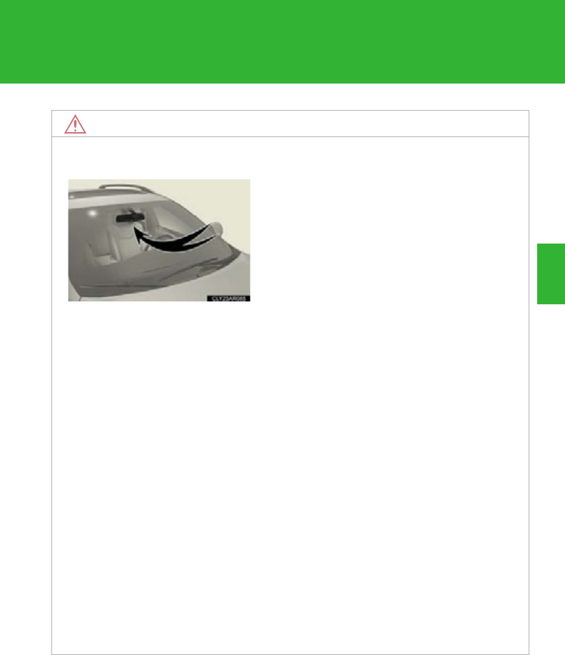
225
2-3. Operating the lights and windshield wipers
2
When driving
NOTICE
■Notes when using the Automatic High Beam system
●Do not touch the camera sensor.
●Do not subject the inside rear view mirror or the camera sensor to a strong
impact.
●Do not disassemble the camera sensor.
●Do not spill liquid onto the inside rear view mirror or the camera sensor.
●Do not apply window tinting or stickers to the camera sensor or the area of wind-
shield near the camera sensor.
●Do not place items on the dashboard. There is a possibility that the camera sensor
will mistake items reflected in the windshield for streetlights, the headlights of
other vehicles, etc.
●Do not install a parking tag or any other accessories near or around the inside
rear view mirror and the camera sensor.
●Do not overload the vehicle.
●Do not modify the vehicle.
●Do not replace windshield with non-genuine windshield.
Contact your Lexus dealer.
Observe the following to ensure that the
Automatic High Beam functions correctly.
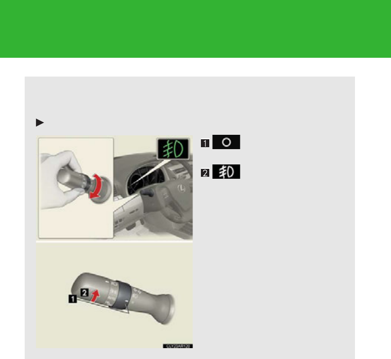
226
2-3. Operating the lights and windshield wipers
Fog light switch
The fog lights improve visibility in difficult driving conditions, such as in rain
and fog.
Type A
Turns the front fog
lights off
Turns the front fog
lights on
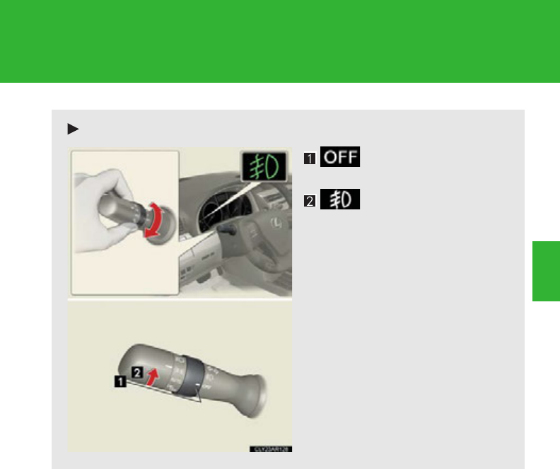
227
2-3. Operating the lights and windshield wipers
2
When driving
Type B
Turns the front fog
lights off
Turns the front fog
lights on
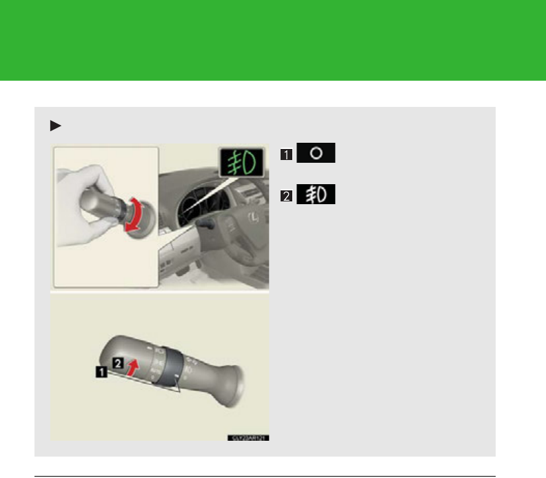
228
2-3. Operating the lights and windshield wipers
■Fog lights can be used when
The headlights are on in low beam.
Type C
Turns the front fog
lights off
Turns the front fog
lights on
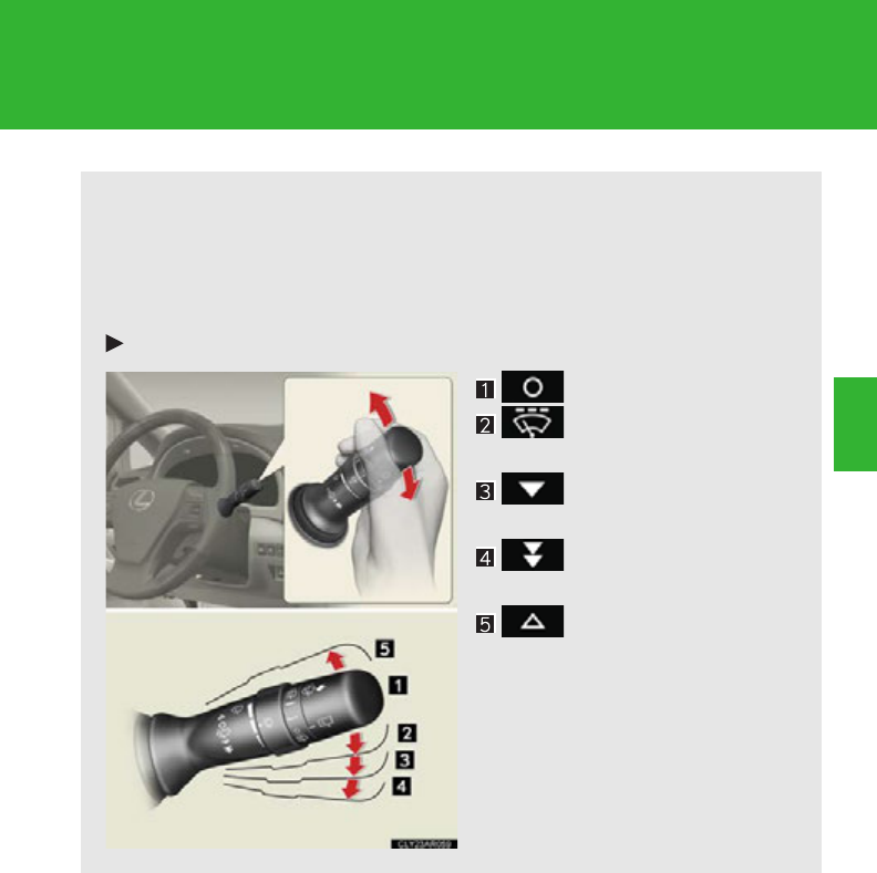
229
2-3. Operating the lights and windshield wipers
2
When driving
Windshield wipers and washer
■Intermittent windshield wipers with interval adjuster (if equipped)
The wiper operation is selected by moving the lever as follows.
When intermittent windshield wiper operation is selected, the wiper
interval can be also adjusted.
Type A
Off
Intermittent wind-
shield wiper operation
Low speed windshield
wiper operation
High speed wind-
shield wiper operation
Temporary operation
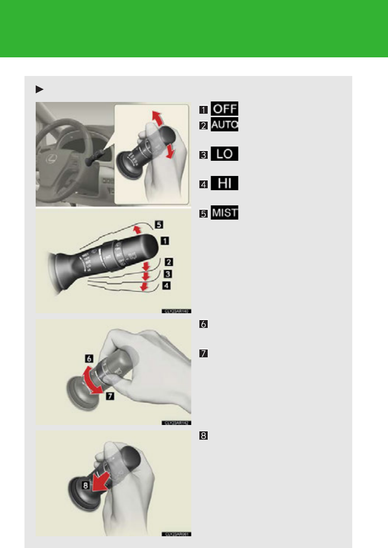
230
2-3. Operating the lights and windshield wipers
Type B
Off
Intermittent wind-
shield wiper operation
Low speed windshield
wiper operation
High speed wind-
shield wiper operation
Temporary operation
Increases the intermittent
windshield wiper frequency
Decreases the intermittent
windshield wiper frequency
Washer/wiper dual operation
The wipers will automatically
operate a couple of times after
the washer squirts.
If the headlights are on, the
headlight cleaners will operate
once.
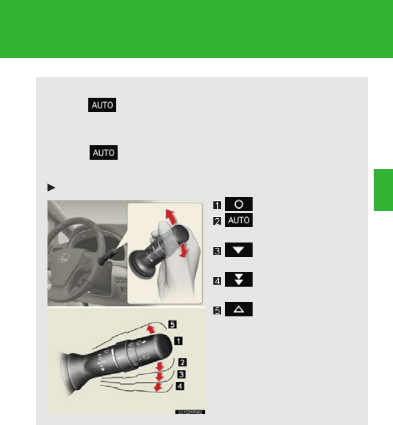
231
2-3. Operating the lights and windshield wipers
2
When driving
■Rain-sensing windshield wipers (if equipped)
When is selected, the wipers will operate automatically when
the sensor detects falling rain. The system automatically adjusts
wiper timing in accordance with rain volume and vehicle speed.
When is selected, the sensor sensitivity can be adjusted as
follows by turning the switch ring:
Type A
Off
Rain-sensing wiper
operation
Low speed wiper
operation
High speed wiper
operation
Temporary operation
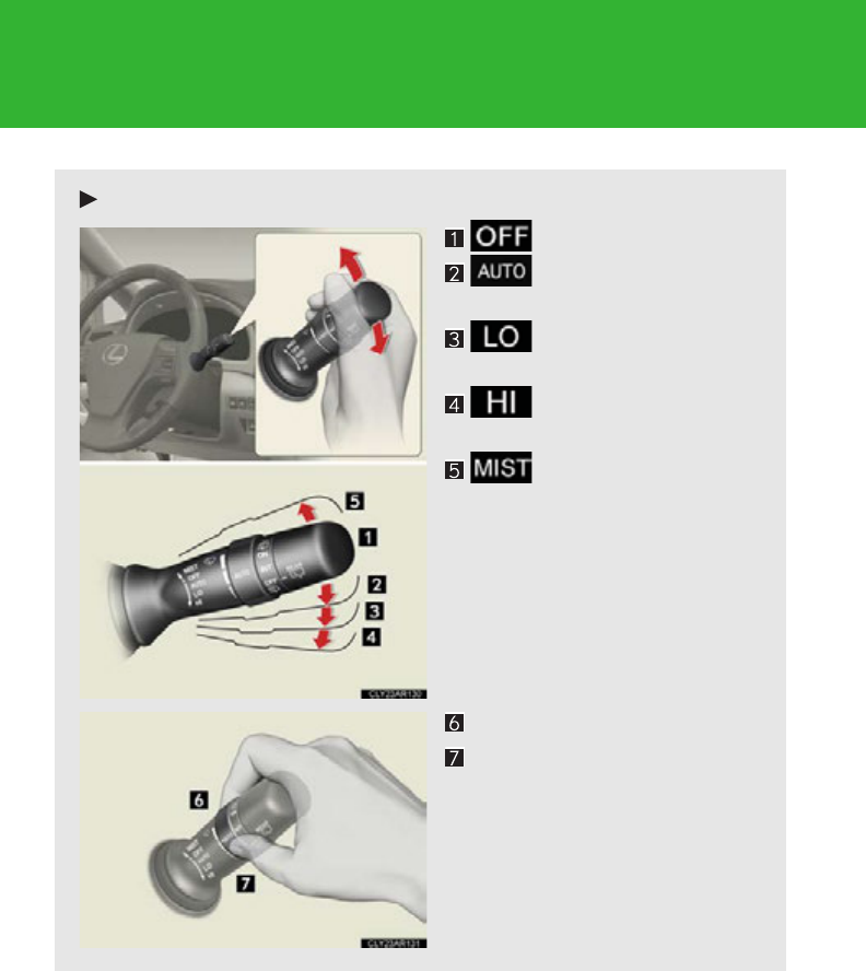
232
2-3. Operating the lights and windshield wipers
Type B
Off
Rain-sensing wiper
operation
Low speed wiper
operation
High speed wiper
operation
Temporary operation
Sensor sensitivity (high)
Sensor sensitivity (low)
233
2-3. Operating the lights and windshield wipers
2
When driving
■The windshield wipers and washer can be operated when
The “POWER” switch is in ON mode.
■Effects of vehicle speed on wiper operation
Vehicle speed affects the following even when the wipers are not in AUTO mode:
●Intermittent wiper interval
●Wiper operation when the washer is being used (delay until drip prevention
wiper sweep occurs)
When low speed wiper operation is selected, wiper operation will be switched from
low speed to intermittent wiper operation only when the vehicle is stationary.
(However, when the sensor sensitivity is adjusted to the highest level, the mode can-
not be switched.)
■Raindrop sensor (vehicles with rain-sensing windshield wipers)
Washer/wiper dual operation
The wipers will automatically
operate a couple of times after
the washer squirts. (After oper-
ating several times, the wipers
operate one more time after a
short delay to prevent dripping.)
If the headlights are on, the
headlight cleaners will operate
once.
●The raindrop sensor judges the amount
of raindrops.
An optical sensor is adopted. It may not
operate properly when sunlight from the
rising or setting of the sun intermittently
strikes the windshield, or if bugs etc. are
present on the windshield.
234
2-3. Operating the lights and windshield wipers
●If the wiper switch is turned to the position while the “POWER” switch is
in ON mode, the wipers will operate once to show that AUTO mode is acti-
vated.
●When the sensor sensitivity ring is turned toward high while in AUTO mode, the
wipers will operate once to indicate that the sensor sensitivity is enhanced.
●If the temperature of the raindrop sensor is 194F (90C) or higher, or 5F
(-15C) or lower, automatic operation may not occur.
In this case, operate the wipers in any mode other than “AUTO”.
■If no windshield washer fluid sprays
Check that the washer nozzles are not blocked if there is washer fluid in the wind-
shield washer fluid reservoir.
CAUTION
■Caution regarding the use of windshield wipers in AUTO mode (vehicles with
rain-sensing windshield wipers)
The windshield wipers may operate unexpectedly if the sensor is touched or the
windshield is subject to vibration in AUTO mode. Take care that your fingers or any-
thing else do not become caught in the windshield wipers.
NOTICE
■When the windshield is dry
Do not use the wipers, as they may damage the windshield.
■When the washer fluid tank is empty
Damage to the washer fluid pump may be caused if the lever is pulled toward you
and held continually.
■When a nozzle becomes blocked
Do not try to clear it with a pin or other object. The nozzle will be damaged.
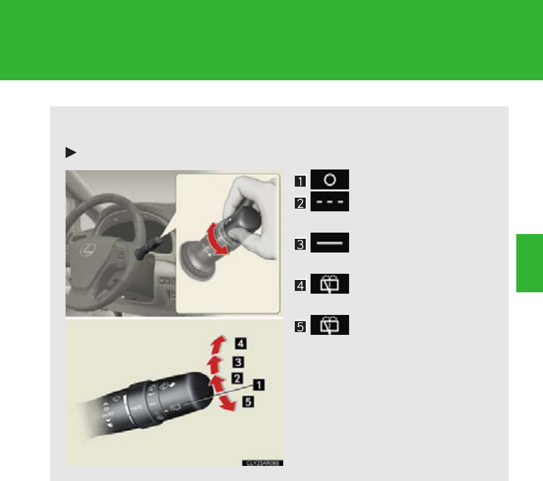
235
2-3. Operating the lights and windshield wipers
2
When driving
Rear window wiper and washer
The wiper operation is selected by moving the lever as follows:
Type A
Off
Intermittent window
wiper operation
Normal window wiper
operation
Washer/wiper dual
operation
Washer/wiper dual
operation
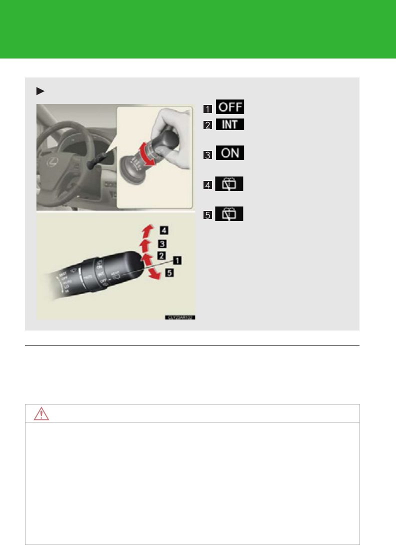
236
2-3. Operating the lights and windshield wipers
■The rear window wiper and washer can be operated when
The “POWER” switch is in ON mode.
NOTICE
■When the rear window is dry
Do not use the wipers, as they may damage the rear window.
■When the washer fluid tank is empty
Damage to the washer fluid pump may be caused if the lever is operated continu-
ally.
■When a nozzle becomes blocked
Do not try to clear it with a pin or other object. The nozzle will be damaged.
Type B
Off
Intermittent window
wiper operation
Normal window wiper
operation
Washer/wiper dual
operation
Washer/wiper dual
operation
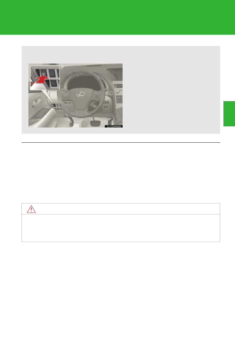
237
2-3. Operating the lights and windshield wipers
2
When driving
Headlight cleaner switch
■The headlight cleaner can be operated when
The “POWER” switch is in ON mode and the headlight switch is turned on.
■Windshield washer linked operation
When the windshield washer is operated with the “POWER” switch in ON mode
and the headlights on, the headlight cleaner will operate once. (P. 22 9)
NOTICE
■When the washer fluid tank is empty
Do not press the switch continually as the washer fluid pump may overheat.
Washer fluid can be sprayed on the headlights.
Press the switch to clean the
headlights.
: If equipped
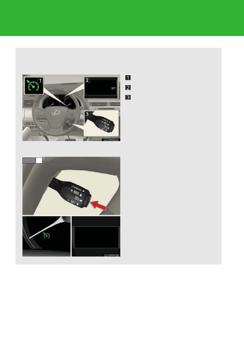
238
2-4. Using other driving systems
Cruise control
: If equipped
Use the cruise control to maintain a set speed without depressing the
accelerator pedal.
Indicator
Display
Cruise control switch
■Setting the vehicle speed
Press the “ON-OFF” button to
activate the cruise control.
Cruise control indicator will
come on.
Press the button again to deacti-
vate the cruise control.
STEP 1
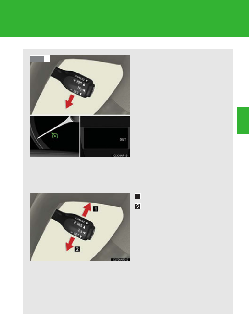
239
2-4. Using other driving systems
2
When driving
Accelerate or decelerate the
vehicle to the desired speed,
and push the lever down to set
the speed.
“SET” will be displayed.
The vehicle speed at the
moment the lever is released
becomes the set speed.
■Adjusting the set speed
To change the set speed, operate the lever until the desired set
speed is obtained.
Increases the speed
Decreases the speed
Fine adjustment: Momentarily
move the lever in the desired
direction.
Large adjustment: Hold the
lever in the desired direction.
The set speed will be increased or decreased as follows:
Fine adjustment: By approximately 1 mph (1.6 km/h) each time the lever is
operated.
Large adjustment: The set speed can be increased or decreased continu-
ally until the lever is released.
STEP 2
240
2-4. Using other driving systems
■Canceling and resuming the constant speed control
Pulling the lever towards you
cancels the constant speed
control.
The speed setting is also can-
celed when the brakes are
applied.
Pushing the lever up resumes
the constant speed control.
Resuming is available when the
vehicle speed is more than
approximately 25 mph (40
km/h).

241
2-4. Using other driving systems
2
When driving
■Cruise control can be set when
●The shift lever is in D or range “4”, “5” or “6” of S has been selected.
●Vehicle speed is above 25 mph (40 km/h).
■Accelerating after setting the vehicle speed
●The vehicle can be accelerated normally. After acceleration, the set speed
resumes.
●Even without canceling the cruise control, the set speed can be increased by
first accelerating the vehicle to the desired speed and then pushing the lever
down to set the new speed.
■Automatic cruise control cancelation
Cruise control will stop maintaining the vehicle speed in any of the following situa-
tions.
●Actual vehicle speed falls more than approximately 10 mph (16 km/h) below the
preset vehicle speed.
At this time, the memorized set speed is not retained.
●Actual vehicle speed is below approximately 25 mph (40km/h).
●VSC is activated.
■If the cruise control indicator light flashes
Press the “ON-OFF” button once to deactivate the system, and then press the but-
ton again to reactivate the system.
If the cruise control speed cannot be set or if the cruise control cancels immediately
after being activated, there may be a malfunction in the cruise control system. Have
the vehicle inspected by your Lexus dealer.

242
2-4. Using other driving systems
CAUTION
■To avoid operating the cruise control by mistake
Switch the cruise control off using the “ON-OFF” button when not in use.
■Situations unsuitable for cruise control
Do not use cruise control in any of the following situations.
Doing so may result in loss of control and could cause an accident resulting in death
or serious injury.
●In heavy traffic
●On roads with sharp bends
●On winding roads
●On slippery roads, such as those covered with rain, ice or snow
●On steep hills
Vehicle speed may exceed the set speed when driving down a steep hill.
●When your vehicle is towing a trailer or during emergency towing
243
2-4. Using other driving systems
2
When driving
Dynamic radar cruise control
Dynamic radar cruise control supplements conventional cruise control
with a vehicle-to-vehicle distance control. In vehicle-to-vehicle distance
control mode, the vehicle automatically accelerates or decelerates in
order to maintain a set following distance from vehicles ahead.
Indicator (vehicle-to-vehicle
distance control mode)
Indicator (constant speed
control mode)
Display
Vehicle-to-vehicle distance
switch
Cruise control switch
■Setting the vehicle speed (vehicle-to-vehicle distance control
mode)
Press the “ON-OFF” button to
activate the cruise control.
Press the button again to deacti-
vate the cruise control.
STEP 1
244
2-4. Using other driving systems
: If equipped
Accelerate or decelerate the
vehicle to the desired speed,
and push the lever down to set
the speed.
“SET” will be displayed.
The vehicle speed at the
moment the lever is released
becomes the set speed.
■Adjusting the speed setting
To change the set speed, operate the lever until the desired set
speed is displayed.
Increases speed
Decreases speed
Fine adjustment: Momentarily
move the lever in the desired
direction.
Large adjustment: Hold the
lever in the desired direction.
In the vehicle-to-vehicle distance control mode, the set speed will be
increased or decreased as follows:
When the set speed is shown in “MPH”
Fine adjustment: By approximately 1 mph (1.6 km/h) each time the lever is
operated
Large adjustment: By approximately 5 mph (8 km/h) for each 0.75 sec-
onds the lever is held
STEP 2
245
2-4. Using other driving systems
2
When driving
When the set speed is shown in “km/h”
Fine adjustment: By approximately 0.6 mph (1 km/h) each time the lever is
operated
Large adjustment: By approximately 3.1 mph (5 km/h) for each 0.75 sec-
onds the lever is held
In the constant speed control mode (P. 249), the set speed will be
increased or decreased as follows:
Fine adjustment: By approximately 1 mph (1.6 km/h) each time the lever is
operated
Large adjustment: The set speed can be increased or decreased continu-
ally until the lever is released.
■Changing the vehicle-to-vehicle distance
Pressing the button changes the
vehicle-to-vehicle distance as
follows:
Long
Medium
Short
The vehicle-to-vehicle distance
is set automatically to long
mode when the “POWER”
switch is turned to ON mode.
If a vehicle is running ahead of
you, the preceding vehicle mark
will also be displayed.
Preceding vehicle mark
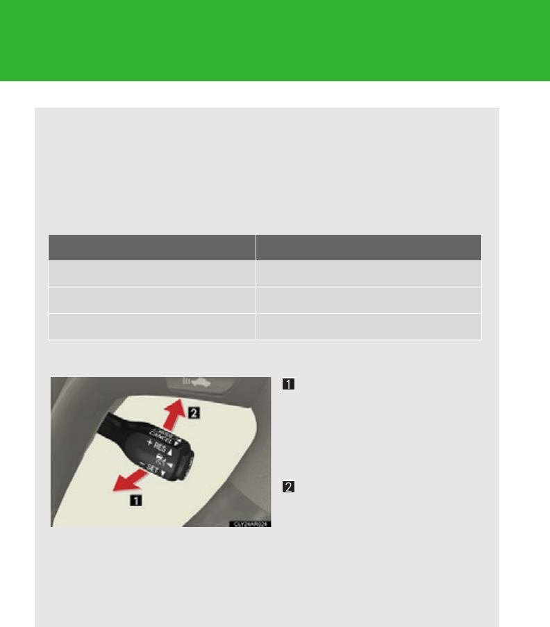
246
2-4. Using other driving systems
■Vehicle-to-vehicle distance settings
Select a distance from the table below. Note that the distances
shown correspond to a vehicle speed of 50 mph (80 km/h). Vehi-
cle-to-vehicle distance increases/decreases in accordance with
vehicle speed.
■Canceling and resuming the speed control
Pulling the lever toward you
cancels the cruise control.
The speed setting is also can-
celed when the brakes are
applied.
Pushing the lever up resumes
the cruise control and returns
vehicle speed to the set
speed.
Resuming is available when the
vehicle speed is more than
approximately 25 mph (40 km/h).
Distance options Vehicle-to-vehicle distance
Long Approximately 164 ft. (50 m)
Medium Approximately 132 ft. (40 m)
Short Approximately 82 ft. (25 m)
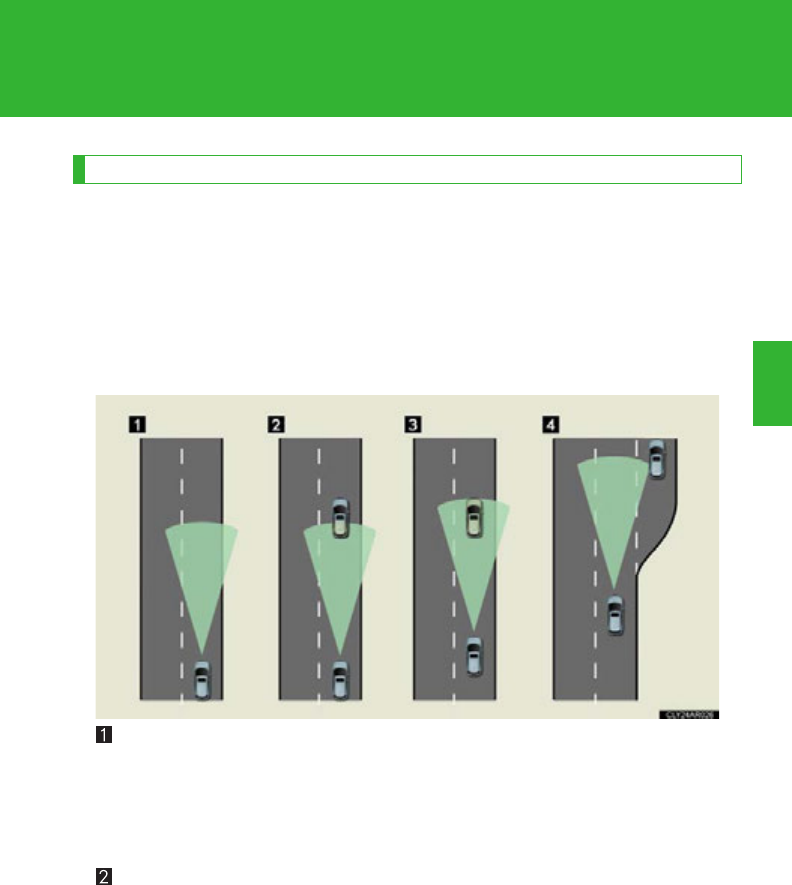
247
2-4. Using other driving systems
2
When driving
Driving in vehicle-to-vehicle distance control mode
This mode employs a radar sensor to detect the presence of vehicles up
to approximately 400ft. (120 m) ahead, determines the current vehicle-
to-vehicle following distance, and operates to maintain a suitable follow-
ing distance from the vehicle ahead.
Note that vehicle-to-vehicle distance will close in when traveling on long
downhill slopes.
Example of constant speed cruising
When there are no vehicles ahead
The vehicle travels at the speed set by the driver. The desired vehicle-to-vehi-
cle distance can also be set by operating the vehicle-to-vehicle distance con-
trol.
Example of deceleration cruising
When the vehicle ahead is driving slower than the set speed
When a vehicle is detected running ahead of you, the system automatically
decelerates your vehicle. When a greater reduction in vehicle speed is nec-
essary, the system applies the brakes. A warning tone warns you when the
system cannot decelerate sufficiently to prevent your vehicle from closing in
on the vehicle ahead.

248
2-4. Using other driving systems
Example of follow-up cruising
When following a vehicle driving slower than the set speed
The system continues follow-up cruising while adjusting for changes in the
speed of the vehicle ahead in order to maintain the vehicle-to-vehicle dis-
tance set by the driver.
Example of acceleration
When there are no longer any vehicles ahead driving slower than the
set speed
The system accelerates until the set speed is reached. The system then
returns to constant speed cruising.
Approach warning
When your vehicle is too close to a vehicle ahead, and sufficient auto-
matic deceleration via the cruise control is not possible, the display will
flash and the buzzer will sound to alert the driver. An example of this
would be if another driver cuts in front of you while you are following a
vehicle. Apply the brakes to ensure an appropriate vehicle-to-vehicle dis-
tance.
■When warning does not occur
In the following instances, there is a possibility that the warnings will not occur:
●When the speed of the vehicle ahead matches or exceeds your vehicle speed
●When the vehicle ahead is traveling at an extremely slow speed
●Immediately after the cruise control speed was set
●At the instant the accelerator is applied
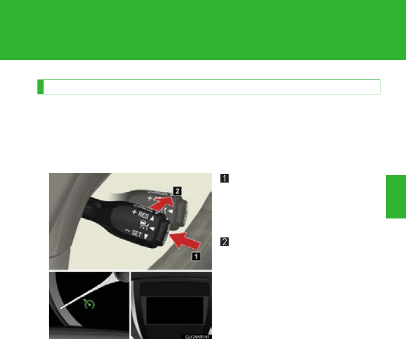
249
2-4. Using other driving systems
2
When driving
Selecting conventional constant speed control mode
Constant speed control mode differs from vehicle-to-vehicle distance
control mode. When constant speed control mode is selected, your vehi-
cle will maintain a set speed regardless of whether or not there are other
vehicles in the lane ahead.
Press the “ON-OFF” button to
activate the cruise control.
Press the button again to deacti-
vate the cruise control.
Switch to constant speed con-
trol mode.
(Push the lever forward and
hold for approximately one sec-
ond.)
Constant speed control mode indi-
cator will come on.
When in constant speed control
mode, to return to vehicle-to-vehi-
cle distance control mode, push
the lever forward again and hold
for approximately 1 second.
After the desired speed has been
set, it is not possible to return to
vehicle-to-vehicle distance control
mode.
If the “ENGINE START STOP”
switch is turned off and then turned
to IGNITION ON mode again, the
vehicle will automatically return to
vehicle-to-vehicle distance control
mode.

250
2-4. Using other driving systems
Adjusting the speed setting:
P. 244
Canceling and resuming the speed
setting: P. 24 6
■Dynamic radar cruise control can be set when
●The shift lever is in the D or range “4”, “5”, or “6” or higher of S has been
selected.
●Vehicle speed is above approximately 30 mph (50 km/h).
■Accelerating after setting the vehicle speed
The vehicle can accelerate normally. After acceleration, the set speed resumes.
However, during vehicle-to-vehicle distance control mode, the vehicle speed may
decrease below the set speed in order to maintain the distance to the vehicle
ahead.
■Automatic cancelation of vehicle-to-vehicle distance control
Vehicle-to-vehicle distance control driving is automatically canceled in the follow-
ing situations:
●Actual vehicle speed falls below approximately 25 mph (40 km/h).
●VSC is activated.
●The sensor cannot operate correctly because it is covered in some way.
●The windshield wipers are operating at high speed (when the wiper switch is set
to the high speed wiper operation position).
●When the snow mode is set.
If vehicle-to-vehicle distance control driving is automatically canceled for any other
reason, there may be a malfunction in the system. Contact your Lexus dealer.
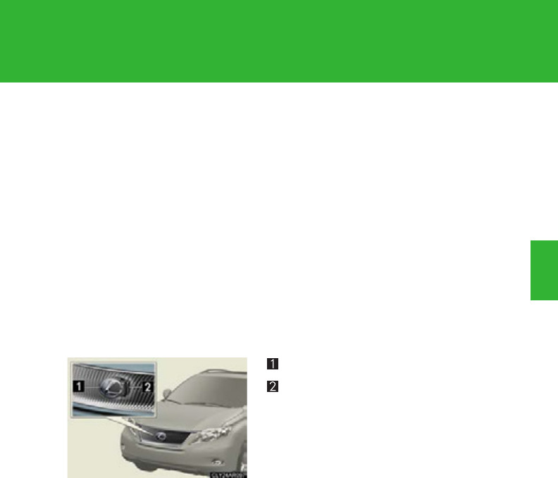
251
2-4. Using other driving systems
2
When driving
■Automatic cancelation of constant speed control
The cruise control will stop maintaining the vehicle speed in the following situations:
●Actual vehicle speed is more than approximately 10 mph (16 km/h) below the
set vehicle speed.
At this time, the memorized set speed is not retained.
●Vehicle speed falls below approximately 25 mph (40 km/h).
●VSC is activated.
■Radar sensor and grille cover
Always keep the sensor and grille cover clean to ensure that the vehicle-to-vehicle
distance control operates properly. (Some obstructions, such as snow, ice and plas-
tic objects, cannot be detected by the obstruction sensor.)
Dynamic radar cruise control is canceled if an obstruction is detected.
■Warning lights, messages and buzzers for dynamic radar cruise control
Warning lights, messages and buzzers are used to indicate a system malfunction or
to inform the driver of the need for caution while driving. (P. 61 4 )
Grille cover
Radar sensor

252
2-4. Using other driving systems
■Certification
For vehicles sold in U.S.A.
FCC ID: HYQDNMWR005
This device complies with Part 15 of the FCC Rules. Operation is subject to the fol-
lowing two conditions: (1) this device may not cause harmful interference, and (2)
this device must accept any interference received, including interference that may
cause undesired operation.
FCC WARNING
Changes or modifications not expressly approved by the party responsible for
compliance could void the user’s authority to operate the equipment.
Radiofrequency radiation exposure Information:
This equipment complies with FCC radiation exposure limits set forth for an uncon-
trolled environment.
This equipment should be installed and operated with minimum distance of 20 cm
between the radiator (antenna) and your body.
This transmitter must not be co-located or operating in conjunction with any other
antenna or transmitter.
For vehicles sold in Canada
Operation is subject to the following two conditions: (1) this device may not cause
interference, and (2) this device must accept any interference, including interfer-
ence that may cause undesired operation of the device.
CAUTION
■Before using dynamic radar cruise control
Do not overly rely on vehicle-to-vehicle distance control.
Be aware of the set speed. If automatic deceleration/acceleration is not appropri-
ate, adjust the vehicle speed, as well as the distance between your vehicle and vehi-
cles ahead by applying the brakes etc.

253
2-4. Using other driving systems
2
When driving
CAUTION
■Cautions regarding the driving assist systems
Observe the following precautions.
Failure to do so may cause an accident resulting in death or serious injury.
●Assisting the driver to measure following distance
The dynamic radar cruise control is only intended to help the driver in determin-
ing the following distance between the driver's own vehicle and a designated
vehicle traveling ahead. It is not a mechanism that allows careless or inattentive
driving, and it is not a system that can assist the driver in low-visibility conditions. It
is still necessary for driver to pay close attention to the vehicle's surroundings.
●Assisting the driver to judge proper following distance
The dynamic radar cruise control determines whether the following distance
between the driver's own vehicle and a designated vehicle traveling ahead is
appropriate or not. It is not capable of making any other type of judgement.
Therefore, it is absolutely necessary for the driver to remain vigilant and to deter-
mine whether or not there is a possibility of danger in any given situation.
●Assisting the driver to operate the vehicle
The dynamic radar cruise control has no capability to prevent or avoid a collision
with a vehicle traveling ahead. Therefore, if there is ever any danger, the driver
must take immediate and direct control of the vehicle and act appropriately in
order to ensure the safety of all involved.
■To avoid inadvertent cruise control activation
Switch the cruise control off using the “ON-OFF” button when not in use.

254
2-4. Using other driving systems
CAUTION
■Situations unsuitable for dynamic radar cruise control
Do not use dynamic radar cruise control in any of the following situations.
Doing so may result in inappropriate speed control and could cause an accident
resulting in death or serious injury.
●In heavy traffic
●On roads with sharp bends
●On winding roads
●On slippery roads, such as those covered with rain, ice and snow
●On steep downhills, or where there are sudden changes between sharp up and
down gradients
●At entrances to expressways
●When weather conditions are bad enough that they may prevent the sensors
from functioning correctly (fog, snow, sandstorm, heavy rain, etc.)
●When a buzzer is heard often
■When the sensor may not be correctly detecting the vehicle ahead
Apply the brakes as necessary when any of the following types of vehicles are in
front of you.
As the sensor may not be able to correctly detect these types of vehicles, the
approach warning (P. 248) will not be activated, and a fatal or serious accident
may result.
●Vehicles that cut in suddenly
●Vehicles traveling at low speeds
●Vehicles that are not moving
●Vehicles with small rear ends (trailers with no load on board etc.)
●Motorcycles traveling in the same lane

255
2-4. Using other driving systems
2
When driving
CAUTION
■Conditions under which the vehicle-to-vehicle distance control may not function
correctly
Apply the brakes as necessary in the following conditions as the radar sensor may
not be able to correctly detect vehicles ahead, and a fatal or serious accident may
result:
●When water or snow thrown up by the surrounding vehicles hinders the function-
ing of the sensor
●When your vehicle is pointing upwards (caused by a heavy load in the luggage
compartment etc.)
●When the road curves or when the lanes are narrow
●When steering wheel operation or your position in the lane is unstable
●When the vehicle ahead of you decelerates suddenly
■To ensure the radar sensor functions correctly
Do not do the following to the sensor or grille as doing so may cause the sensor not
to function correctly and could result in an accident:
●Sticking or attaching anything to them
●Leaving them dirty
●Disassembling or subjecting them to strong shocks
●Modifying or painting them
●Replacing them with non-genuine parts

256
2-4. Using other driving systems
CAUTION
■Handling the radar sensor
Observe the following to ensure the cruise control system can function effectively.
Otherwise, the system may not function correctly and could result in an accident.
●Keep the sensor and front grille cover clean at all times.
Clean the sensor and front grille cover with a soft cloth so you do not mark or
damage them.
●Do not subject the sensor or surrounding area to a strong impact.
If the sensor moves even slightly off position, the system may malfunction. If the
sensor or surrounding area is subject to a strong impact, always have the area
inspected and adjusted by a Lexus dealer.
●Do not disassemble the sensor.
●Do not attach accessories or stickers to the sensor, grille cover or surrounding
area.
●Do not modify or paint the sensor and grille cover.
●Do not replace them with non-genuine parts.
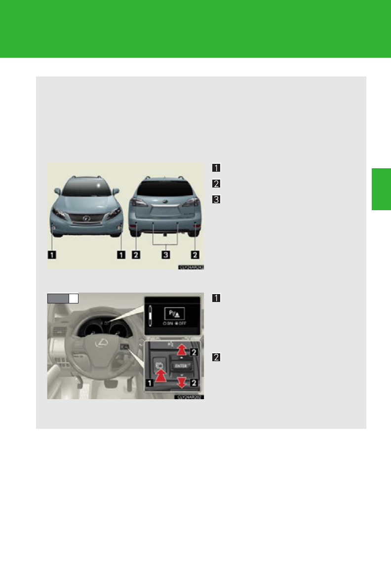
257
2-4. Using other driving systems
2
When driving
Intuitive parking assist
The distance to obstacles measured by the sensors is communicated via
the multi-information display and a buzzer when parallel parking or
maneuvering into a garage is conducted. Always check the surrounding
area when using this system.
■Types of sensors
Front corner sensors
Rear corner sensors
Rear center sensors
■Setting the intuitive parking assist mode
Press the menu switch.
The multi-information display
will change modes to electronic
features control mode.
Press the “ENTER” switch
upwards or downwards until
the intuitive parking assist
mark appears in the multi-
information display.
STEP 1
: If equipped
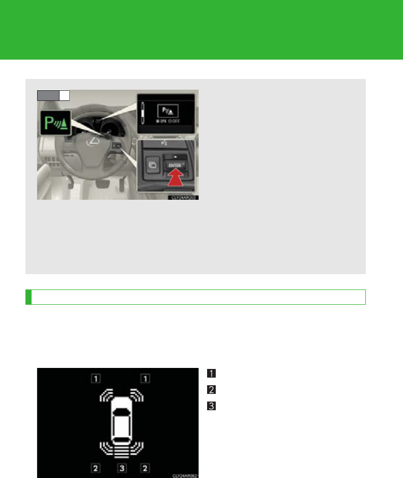
258
2-4. Using other driving systems
Display
When the sensors detect an obstacle, a graphic is shown on the multi-
information display depending on the position and distance to the obsta-
cle.
Front corner sensor operation
Rear corner sensor operation
Rear center sensor operation
Press the “ENTER” switch to
change to “ON”.
The intuitive parking assist indi-
cator will be displayed.
Each pressing of the switch
turns the intuitive parking assist
on and off.
When on, the buzzer sounds to
inform the driver that the system
is operational.
Press the menu switch to
change to the normal display.
STEP 2

259
2-4. Using other driving systems
2
When driving
The distance display and buzzer
When a sensor detects an obstacle, the direction of and the approximate
distance to the obstacle are displayed and the buzzer sounds.
The site of the obstacle will flash (detection level 4 only).
■Front corner sensors
■Rear corner sensors
Detection
level
Multi-information
display
Approximate dis-
tance to obstacle Buzzer
22.0 to 1.6 ft.
(60 to 47.5 cm) Medium
31.6 to 1.2 ft.
(47.5 to 35 cm) Fast
41.2 ft. (35 cm) or
less Continuous
Detection
level
Multi-information
display
Approximate dis-
tance to obstacle Buzzer
21.6 to 1.2 ft.
(50 to 37.5 cm) Medium
31.2 to 0.8 ft.
(37.5 to 25 cm) Fast
40.8 ft. (25 cm) or
less Continuous
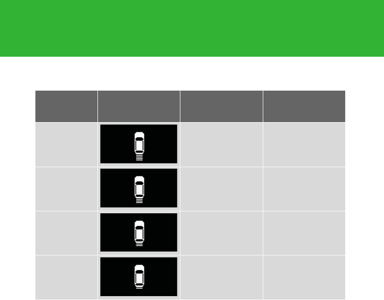
260
2-4. Using other driving systems
■Rear center sensors
Detection
level
Multi-information
display
Approximate dis-
tance to obstacle Buzzer
14.9 to 2.0 ft.
(150 to 60 cm) Slow
22.0 to 1.5 ft.
(60 to 45 cm) Medium
31.5 to 1.2 ft.
(45 to 35 cm) Fast
41.2 ft. (35 cm) or
less Continuous
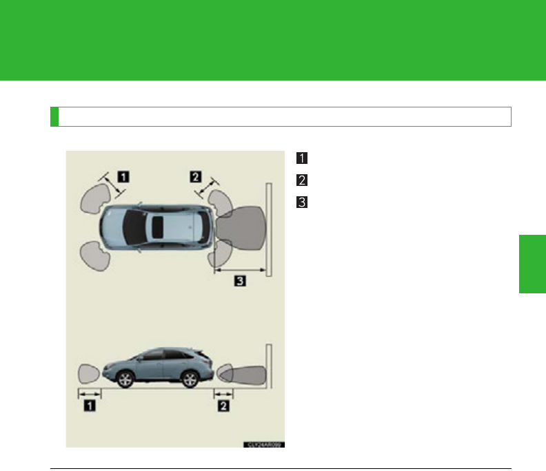
261
2-4. Using other driving systems
2
When driving
Detection range of the sensors
Approximately 2.0 ft. (60 cm)
Approximately 1.6 ft. (50 cm)
Approximately 4.9 ft. (150 cm)
The diagram shows the detection
range of the sensors. Note that the
sensors cannot detect obstacles
that are extremely close to the
vehicle.
The range of the sensors may
change depending on the shape of
the object etc.
■The intuitive parking assist can be operated when
●Front corner sensors:
• The “POWER” switch is in ON mode.
• The shift lever is in a position other than P.
• The vehicle speed is less than about 6 mph (10 km/h).
●Rear corner and center sensors:
• The “POWER” switch is in ON mode.
• The shift lever is in R.

262
2-4. Using other driving systems
■Sensor detection information
●Certain vehicle conditions and the surrounding environment may affect the
ability of a sensor to correctly detect an obstacle. Particular instances where this
may occur are listed below.
• There is dirt, snow or ice on a sensor.
• A sensor is frozen.
• A sensor is covered in any way.
• The vehicle is leaning considerably to one side.
• On an extremely bumpy road, on an incline, on gravel, or on grass
• The vicinity of the vehicle is noisy due to vehicle horns, motorcycle engines,
air brakes of large vehicles, or other loud noises producing ultrasonic waves.
• There is another vehicle equipped with parking assist sensors in the vicinity.
• A sensor is coated with a sheet of spray or heavy rain.
• The vehicle is equipped with a fender pole or radio antenna.
• Towing eyelets are installed.
• A bumper or sensor receives a strong impact.
• The vehicle is approaching a tall or right-angled curb.
• In harsh sunlight or intense cold weather.
• A non-genuine Lexus suspension (lowered suspension, etc.) is installed.
In addition to the examples above, there are instances in which, because of their
shapes, signs and other objects may be judged by a sensor to be closer than they
are.
●The shape of the obstacle may prevent a sensor from detecting it. Pay particular
attention to the following obstacles:
• Wires, fences, ropes, etc.
• Cotton, snow and other materials that absorb sound waves
• Sharply-angled objects
•Low obstacles
• Tall obstacles with upper sections projecting outwards in the direction of your
vehicle
■If a message is displayed
P. 6 08
■Certification (Canada only)
This ISM device complies with Canadian ICES-001.

263
2-4. Using other driving systems
2
When driving
■Customization
Settings (e.g. buzzer volume) can be changed. (Customizable features P. 693)
CAUTION
■Caution when using the intuitive parking assist
Observe the following precautions.
Failing to do so may result in the vehicle being unable to be driven safely and possi-
bly cause an accident.
●Do not use the sensor at speeds in excess of 6 mph (10 km/h).
●Do not attach any accessories within the sensor range.
NOTICE
■Notes when washing the vehicle
Do not apply intensive bursts of water or steam to the sensor area.
Doing so may result in the sensor malfunctioning.
■Conditions possibly indicating system malfunctions
If any of the following occurs, the system may be malfunctioning due to a sensor fail-
ure etc. Have the vehicle inspected by your Lexus dealer.
●The buzzer does not sound when the intuitive parking assist mode is set.
●The sensor operation display flashes and the buzzer sounds even when no obsta-
cle is detected.
●An area of the sensors is hit or subjected to a strong impact.
●Either bumper is hit.
●The sensor operation display remains on even though no buzzer sounds.
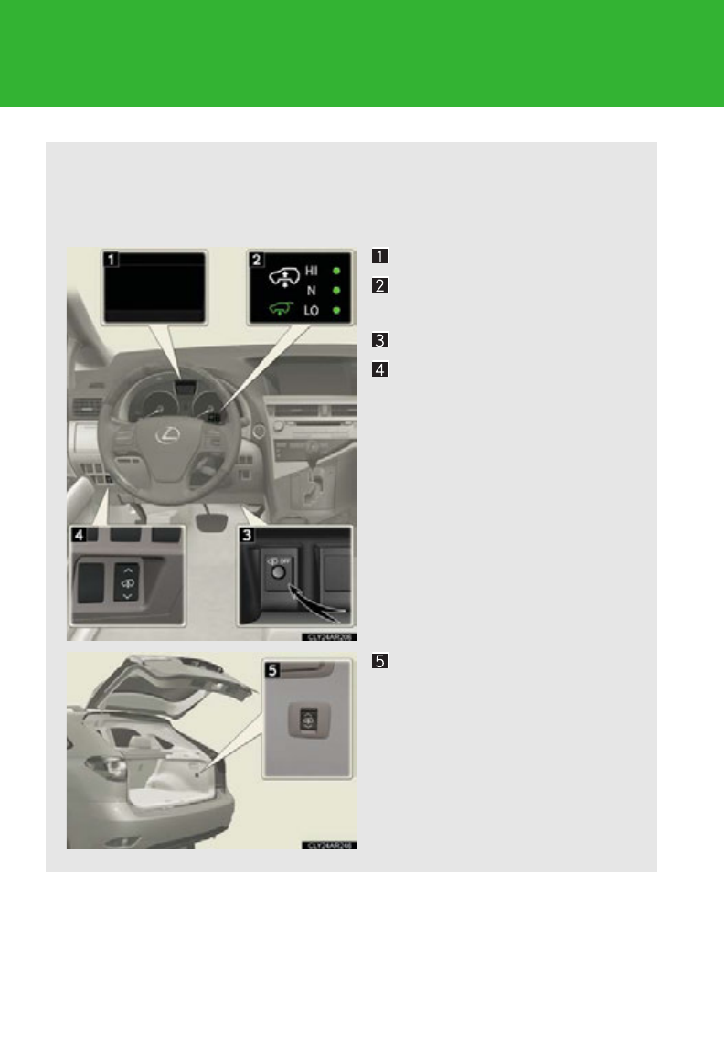
264
2-4. Using other driving systems
Electronically modulated air suspension
The electronically modulated air suspension allows the driver to control
vehicle height in order to adjust driving conditions.
Select the desired height with the height selector switch.
Multi-information display
Electronically modulated air
suspension indicator
Height control off switch
Height selector switch
(driver’s side instrument
panel)
Height selector switch (lug-
gage compartment)
: If equipped

265
2-4. Using other driving systems
2
When driving
Selecting vehicle height
■Height modes
●“HI” mode: For driving on bumpy roads
1.2 in. (30 mm) higher than the normal height
“HI” mode cannot be selected when vehicle speed exceeds 19 mph
(30 km/h).
●“N” mode: For ordinary driving
Normal height
●“LO” mode: For sporty driving
Vehicle front: 0.8 in. (20 mm) lower than the normal height
Vehicle rear: 0.2 in. (5 mm) lower than the normal height
●Luggage mode: For easy entry/exit and easy luggage loading/
unloading
1.2 in. (30 mm) lower than the normal height
■Height selector switch
Press the height selector switch for approximately 1 second.
Driver's side instrument panel
Higher
Pressing this switch while the vehi-
cle is in luggage mode changes the
vehicle height to that of “N” mode.
Lower
Pressing the switch while the vehi-
cle is in “LO” mode changes the
vehicle height to that of luggage
mode.
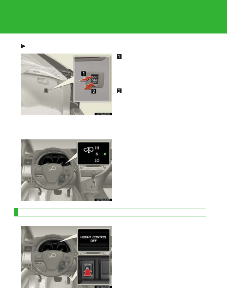
266
2-4. Using other driving systems
Luggage compartment
Higher
Pressing this switch while the vehi-
cle is in luggage mode changes the
vehicle height to that of “N” mode.
Lower
Pressing this switch while the vehi-
cle is in “N” mode changes the
vehicle height to that of luggage
mode, not “LO” mode.
■Electronically modulated air suspension indicator
The indicator for the selected
mode will come on.
The indicator will flash while the
vehicle height is being changed to
the height of the selected mode.
Disabling the height control
Press the height control off switch
while the vehicle is stopped. A
message will appear on the multi-
information display, and vehicle
height will be fixed in the current
mode.
When vehicle speed exceeds 19
mph (30 km/h), the electronically
modulated air suspension is re-
enabled automatically.

267
2-4. Using other driving systems
2
When driving
■Operating conditions
After stopping the hybrid system, the vehicle will remain lowered for a maximum of
60 seconds.
●Height selector switch (driver's side instrument panel)
• While the hybrid system is operating, any vehicle height mode can be
selected.
• Luggage mode can only be selected when the shift lever is in the P position.
●Height selector switch (luggage compartment)
• When the hybrid system is operating and the shift lever is in the P position, any
vehicle height other than “LO” mode can be selected.
• When the “POWER” switch is turned off, the vehicle height can only be low-
ered (only the “” side of the switch can be operated).
This switch can only be operated when the back door is open.
●Height control off switch
When the vehicle is stopped with the “POWER” switch in ON mode, vehicle
height control can be disabled/re-enabled.
■When changing vehicle height modes
Before operating the height selector switch to raise/lower the vehicle height,
ensure that there are no objects in the surrounding area that could damage the
vehicle.
■When “N” mode is selected
During high speed driving, the vehicle height will automatically change to that of
“LO” mode.
■When “HI” mode is selected
The vehicle height will change to that of “N” mode when vehicle speed reaches 31
mph (50 km/h) or when vehicle speed has exceeded 19 mph (30 km/h) for
approximately 10 seconds. Even if vehicle speed is then reduced to under 19 mph
(30 km/h), height will not return to “HI” mode.
■When “LO” mode is selected
The vehicle height will change to that of “N” mode when the hybrid system is
restarted.

268
2-4. Using other driving systems
■When luggage mode is selected
If the vehicle begins to move while still in luggage mode, the vehicle will automati-
cally change to “N” mode once speed exceeds 5 mph (8 km/h). Even if vehicle
speed is reduced below 5 mph (8 km/h), the vehicle height will not automatically
return to luggage mode.
■Operating sound of the air suspension
When the vehicle height is lowered, such as when entering and loading the vehicle,
or when the height selector switch is operated, the sound of the compressor oper-
ating or the mode changing may be heard. This does not indicate a malfunction.
■Automatic leveling function
Regardless of the number of occupants and the luggage load, vehicle height in any
mode is always adjusted to a fixed height by the automatic leveling function.
■Vehicle height mode change time
●If the height control is operated continuously to lower the vehicle, the suspen-
sion air tank may become full, causing operation of the vehicle height lowering
control to become slow.
●To protect the compressor, the system will only raise the vehicle for a total of
100 consecutive seconds. If it takes longer than this to reach the selected
height, operation may be suspended shortly and then restart. However, it may
not be possible to change the vehicle's height mode at this time.
■The electronically modulated air suspension will not operate when
The vehicle height control may not be able to change modes when the vehicle runs
over a high curb or other rugged surfaces where the suspension is stretched.
CAUTION
■The electronically modulated air suspension must be turned off when
The electronically modulated air suspension must be turned off in the following situ-
ations as vehicle height may change, due to the automatic leveling function and you
may catch part of your body in the vehicle, resulting in and cause an accident,
resulting in death or serious injury.
●Any of the wheels is stuck in a ditch.
●It is necessary to jack up the vehicle.

269
2-4. Using other driving systems
2
When driving
CAUTION
●It is necessary to tow the vehicle with part of it lifted.
●When connecting/disconnecting a trailer
For safety, stop the hybrid system if necessary.
■“HI” mode
●“HI” mode should only be used when driving on rough roads, for example when
driving off-road. Because the vehicle's center of gravity will become higher when
in the mode, the vehicle may become unstable when turning abruptly and cause
an accident, resulting in death or serious injury.
●Do not select “HI” mode when loading cargo on the roof luggage carrier.
Because the vehicle's center of gravity will become higher when in the mode, the
vehicle may become unstable when turning abruptly and cause an accident,
resulting in death or serious injury.
NOTICE
■Do not select “LO” mode when driving on bumpy roads.
If the underbody of the vehicle touches a rugged road surface, the vehicle may be
damaged. Also be careful when driving while the vehicle is automatically returning
from luggage or “LO” mode to “N” mode.
■Automatic return to “N” mode
In the following situations, the height of the vehicle will automatically increase. Be
careful in any place where overhead space is limited.
●The vehicle begins to move while still in luggage mode.
●The hybrid system is restarted while the vehicle is in “LO” mode.
■Vehicle height while parked
If the temperature changes or the vehicle is parked for a long time, the vehicle
height may decrease.
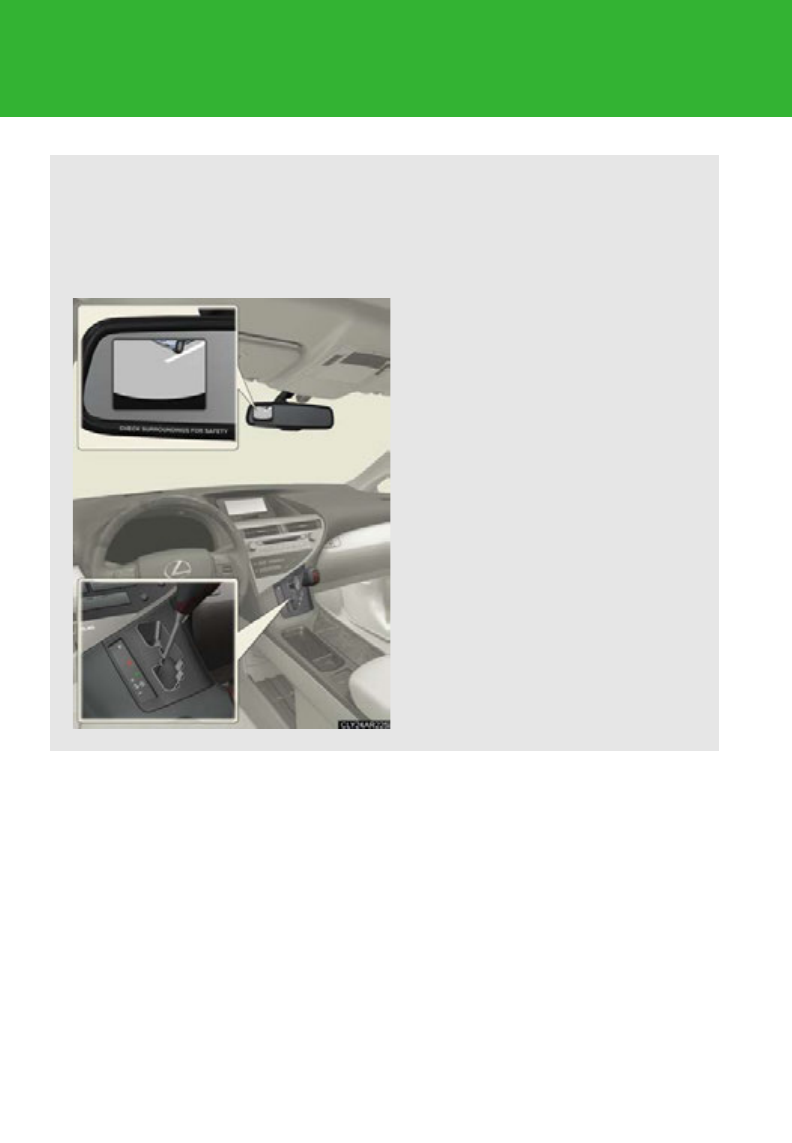
270
2-4. Using other driving systems
Rear view monitor system (rear view mirror-attached type)
The rear view monitor system assists the driver by displaying an image of
the area behind the vehicle. The image is displayed in reverse on the
screen. This reversed image is a similar image to the one on the inside rear
view mirror.
The rear view image is displayed
when the shift lever is in the R
position.
• If the shift lever is shifted out
of R, the screen is turned off.
• The screen remains on for
approximately 5 minutes.
: If equipped
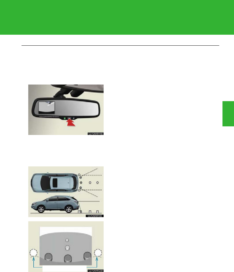
271
2-4. Using other driving systems
2
When driving
■The rear view monitor system can be operated when
The “POWER” switch is in ON mode and the back door is fully closed.
■Switching the screen on/off
■Displayed area
When the screen is displayed, press the
“AUTO” button on the inside rear view mirror
to switch the screen on/off.
Screen on: Green indicator comes on.
Screen off: Orange indicator comes on.
The auto anti-glare inside rear view mirror
will revert to the screen on each time the
“POWER” switch is turned to ON mode.
The area covered by the camera is limited.
Objects that are close to either corner of
the bumper or under the bumper cannot
be seen on the screen.
The area displayed on the screen may vary
according to vehicle orientation or road
conditions.
Corners of bumper

272
2-4. Using other driving systems
■Rear view monitor system camera
■Smear effect
In the following cases, it may become diffi-
cult to see the images on the screen, even
when the system is functioning correctly:
●The vehicle is in a dark area, such as at
night.
●The temperature near the lens is
extremely high or low.
●Water droplets are on the camera lens
or humidity is high, such as when it
rains.
●The camera has scratches or dirt on it.
●Foreign matter, such as snow or mud,
adheres to the camera lens.
●The sun or headlights are shining
directly into the camera lens.
If a bright light, such as sunlight reflected
off the vehicle body, is picked up by the
camera, a smear effect* characteristic to
the camera may occur.
*: Smear effectA phenomenon that
occurs when a bright light is picked up by
the camera; when transmitted by the
camera, the light source appears to have
a vertical streak above and below it.

273
2-4. Using other driving systems
2
When driving
CAUTION
■When using the rear view monitor system, observe the following precautions to
avoid an accident that could result in death or serious injuries:
●Never depend solely on the monitor system when reversing.
●Always check visually and with the mirrors to confirm your intended path is clear.
●Depicted distances between objects and flat surfaces differ from actual dis-
tances.
■Conditions which may affect the rear view monitor system
●If the back of the vehicle has been hit, the camera’s position and mounting angle
may have changed. Have the vehicle inspected by your Lexus dealer.
●Rapid temperature changes, such as when hot water is poured on the vehicle in
cold weather, may cause the system to function abnormally.
●If the camera lens is dirty, it cannot transmit a clear image. Rinse with water and
wipe with a soft cloth. If extremely dirty, wash with a mild cleanser and rinse.
●The displayed image may be darker and moving images may be slightly distorted
when the system is cold.
●As the camera is of water proof construction, do not detach, disassemble or
modify it. This may cause incorrect operation.
●Do not allow organic solvent, car wax, window cleaner or glass coating to adhere
to the camera. If this happens, wipe it off as soon as possible.
●Use your own eyes to confirm the vehicle's surroundings, as the displayed image
may become faint or dark, and moving images will be distorted, or not entirely
visible when the outside temperature is low. When backing up, be sure to check
behind and all around the vehicle with your own eyes and the vehicle's mirrors.

274
2-4. Using other driving systems
Driving assist systems
To help enhance driving safety and performance, the following systems
operate automatically in response to various driving situations. Be aware,
however, that these systems are supplementary and should not be relied
upon too heavily when operating the vehicle.
■ABS (Anti-lock Brake System)
Helps to prevent wheel lock when the brakes are applied suddenly, or if
the brakes are applied while driving on a slippery road surface
■Brake assist
Generates an increased level of braking force after the brake pedal is
depressed, when the system detects a panic stop situation
■VSC (Vehicle Stability Control)
Helps the driver to control skidding when swerving suddenly or turning on
slippery road surfaces
■TRAC (Traction Control)
Helps to maintain drive power and prevent the drive wheels from spinning
when starting the vehicle or accelerating on slippery roads
■Hill-start assist control
P. 28 0
■EPS (Electric Power Steering)
Employs an electric motor to reduce the amount of effort needed to turn
the steering wheel
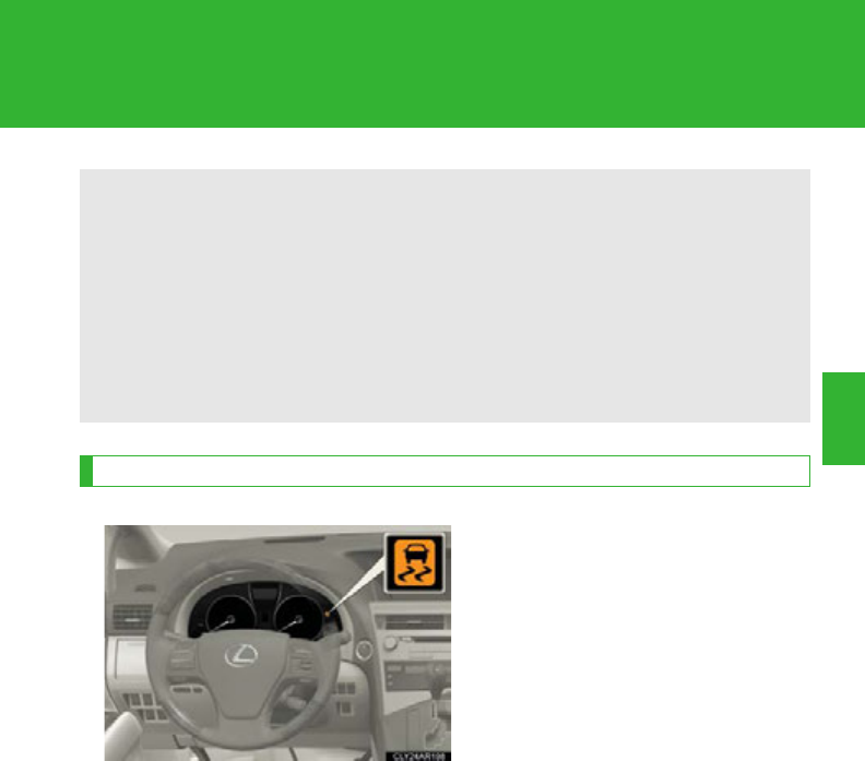
275
2-4. Using other driving systems
2
When driving
When the VSC/TRAC systems are operating
If the vehicle is in danger of slip-
ping or if any of the drive wheels
spins, the slip indicator light flashes
to indicate that the VSC/TRAC
systems are operating.
■VDIM (Vehicle Dynamics Integrated Management)
Provides integrated control of the ABS, brake assist, TRAC, VSC, hill-start
assist control, and EPS systems.
Helps to maintain vehicle stability when swerving on slippery road sur-
faces by controlling the brakes and hybrid system output.
■PCS (Pre-Collision System) (if equipped)
P. 282
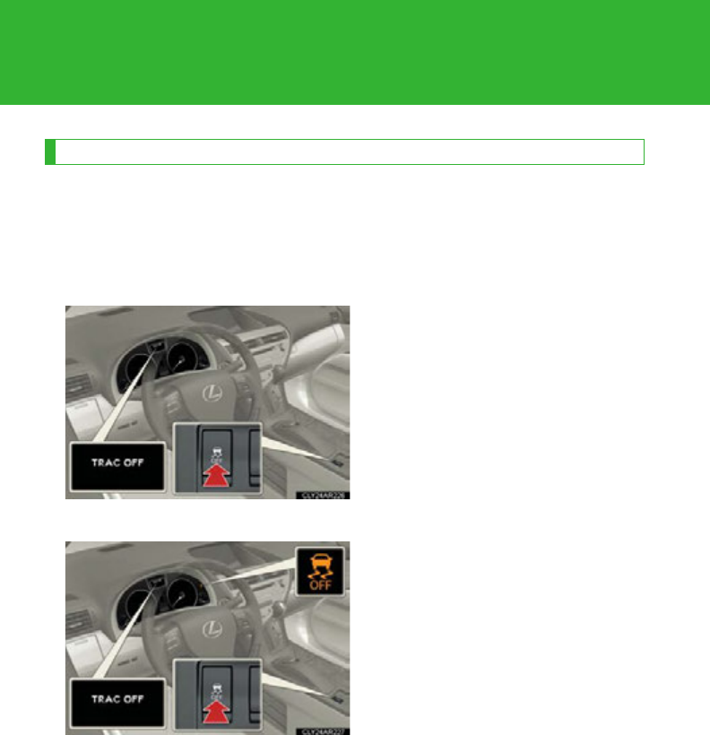
276
2-4. Using other driving systems
Disabling TRAC and/or VSC systems
If the vehicle gets stuck in fresh snow or mud, the TRAC/VSC systems
may reduce power from the hybrid system to the wheels. You may need
to turn the system off to enable you to rock the vehicle in order to free it.
■Turning off the TRAC system only
To turn the TRAC system off,
quickly press and release the
switch.
A message will be shown on the
multi-information display.
Press the switch again to turn the
system back on.
■Turning off both TRAC and VSC systems
To turn the TRAC and VSC sys-
tems off, press and hold the switch
for 3 seconds or more while the
vehicle is stopped.
A message will be shown on the
multi-information display and VSC
off indicator light will come on.
Press the switch again to turn the
systems back on.

277
2-4. Using other driving systems
2
When driving
■When the message is displayed on the multi-information display showing that
TRAC has been disabled even if the VSC off switch has not been pressed
TRAC and hill-start assist control cannot be operated. Contact your Lexus dealer.
■Sounds and vibrations caused by the ABS, VSC, TRAC and brake assist
●A sound may be heard from the engine compartment when the hybrid system is
started or just after the vehicle begins to move. This sound does not indicate that
a malfunction has occurred in any of these systems.
●Any of the following conditions may occur when the above systems are operat-
ing. None of these indicates that a malfunction has occurred.
• Vibrations may be felt through the vehicle body and steering.
• A motor sound may be heard after the vehicle comes to a stop.
• The brake pedal may pulsate slightly after the ABS is activated.
• The brake pedal may move down slightly after the ABS is activated.
■EPS operation sound
When the steering wheel is operated, a motor sound (whirring sound) may be
heard. This does not indicate a malfunction.
■Reactivation of the TRAC /VSC systems
Turning off the hybrid system after turning off the TRAC/VSC systems will automat-
ically reactivate them.
■Reactivation of the TRAC system linked to vehicle speed
When only the TRAC system is turned off, the TRAC system will turn on when vehi-
cle speed increases. However, when both TRAC and VSC systems are turned off,
the systems will not turn on even when vehicle speed increases.
■Reduced effectiveness of the EPS system
The effectiveness of the EPS system is reduced to prevent the system from over-
heating when there is frequent steering input over an extended period of time. The
steering wheel may feel heavy as a result. Should this occur, refrain from excessive
steering input or stop the vehicle and turn the hybrid system off. The EPS system
should return to normal within 10 minutes.
■If the slip indicator comes on
It may indicate a malfunction in the VSC or TRAC function.
Contact your Lexus dealer.

278
2-4. Using other driving systems
CAUTION
■The ABS does not operate effectively when
●Tires with inadequate gripping ability are used (such as excessively worn tires on
a snow covered road).
●The vehicle hydroplanes while driving at high speed on a wet or slick road.
■Stopping distance when the ABS is operating may exceed that of normal condi-
tions
The ABS is not designed to shorten the vehicle’s stopping distance. Always main-
tain a safe distance from the vehicle in front of you in the following situations:
●When driving on dirt, gravel or snow-covered roads
●When driving with tire chains
●When driving over bumps in the road
●When driving over roads with potholes or roads with uneven surfaces
■TRAC may not operate effectively when
Directional control and power may not be achievable while driving on slippery road
surfaces, even if the TRAC system is operating.
Do not drive the vehicle in conditions where stability and power may be lost.

279
2-4. Using other driving systems
2
When driving
CAUTION
■When the VSC is activated
The slip indicator light flashes. Always drive carefully. Reckless driving may cause
an accident, resulting in death or serious injury. Exercise particular care when the
indicator light flashes.
■When the TRAC/VSC systems are turned off
Be especially careful and drive at a speed appropriate to the road conditions. As
these are the systems to help enhance vehicle stability and driving force, do not turn
the TRAC/VSC systems off unless necessary.
■Replacing tires
Make sure that all tires are of the same size, brand, tread pattern and total load
capacity. In addition, make sure that the tires are inflated to the recommended tire
inflation pressure level.
The ABS and VSC systems will not function correctly if different tires are installed
on the vehicle.
Contact your Lexus dealer for further information when replacing tires or wheels.
■Handling of tires and suspension
Using tires with any kind of problem or modifying the suspension will affect the driv-
ing assist systems, and may cause a system malfunction.
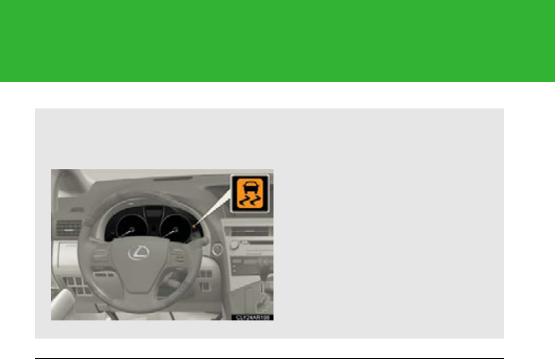
280
2-4. Using other driving systems
Hill-start assist control
■Hill-start assist control can be operated when
●The shift lever is in a position other than P.
●The parking brake is not applied.
●The accelerator pedal is not depressed.
■Hill-start assist control
●While hill-start assist control is operating, the brakes remain automatically
applied after the driver releases the brake pedal. The stop lights and the high
mounted stoplight turn on.
●Hill-start assist control operates for about 2 seconds after the brake pedal is
released.
●If the slip indicator does not flash and the buzzer does not sound when the brake
pedal is further depressed, slightly reduce the pressure on the brake pedal (do
not allow the vehicle to roll backward) and then firmly depress it again. If the sys-
tem still does not operate, check if the operating conditions explained above
have been met.
Hill-start assist control helps to prevent the vehicle from rolling backwards
when starting on an incline or slippery slope.
To engage hill-start assist con-
trol, further depress the brake
pedal when the vehicle is
stopped completely.
A buzzer will sound once to
indicate the system is activated.
The slip indicator will also start
flashing.

281
2-4. Using other driving systems
2
When driving
■Hill-start assist control buzzer
●When hill-start assist control is activated, the buzzer will sound once.
●In the following situations, hill-start assist control will be canceled and the
buzzer will sound twice.
• No attempt is made to drive the vehicle within approximately 2 seconds of
releasing the brake pedal.
• The shift lever is moved to P.
• The parking brake is applied.
• The brake pedal is depressed again.
• The brake pedal has been depressed for more than approximately 3 minutes.
■If the slip indicator comes on
It may indicate a malfunction in the system. Contact your Lexus dealer.
CAUTION
■Hill-start assist control
●Do not overly rely on hill-start assist control. Hill-start assist control may not oper-
ate effectively on extremely steep inclines or roads covered in ice.
●Unlike the parking brake, hill-start assist control is not intended to hold the vehi-
cle stationary for an extended period of time. Do not attempt to use hill-start
assist control to hold the vehicle on an incline for an extended period of time, as
doing so may lead to an accident.
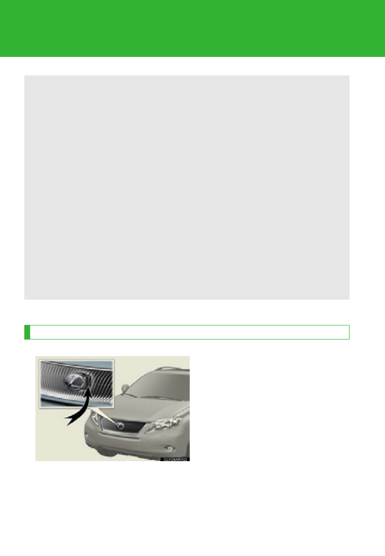
282
2-4. Using other driving systems
Pre-Collision System
Radar sensor
The radar sensor detects vehicles
or other obstacles on or near the
road ahead and determines
whether a collision is imminent
based on the position, speed, and
heading of the obstacles.
When the radar sensor detects the possibility of a frontal collision, safety
systems such as the brake assist and seat belts are automatically engaged
in an attempt to lessen impact and injuries to occupants as well as vehicle
damage.
■Pre-collision seat belts (front seat belts only)
If the pre-collision sensor detects that a collision is unavoidable, the pre-
collision system will retract the seat belt before the collision occurs.
The same will happen if the driver makes an emergency braking or loses
control of the vehicle. (P. 1 0 0)
However, the system will not operate in the event of skidding when the
VSC system is disabled.
■Pre-collision brake assist
When there is a high possibility of a frontal collision, the system applies
greater braking force in relation to how strongly the brake pedal is
depressed.
: If equipped

283
2-4. Using other driving systems
2
When driving
■The pre-collision system is operational when
●Pre-collision seat belts linked to the radar sensor
• Vehicle speed is greater than about 4 mph (5 km/h).
• The speed at which your vehicle is approaching the obstacle or oncoming
vehicle is greater than about 19 mph (30 km/h).
• The front occupants are wearing a seat belt.
●Pre-collision seat belts in the event of sudden braking or skidding
• Vehicle speed is greater than about 19 mph (30 km/h).
• The system detects sudden braking or skidding.
• The front occupants are wearing a seat belt.
●Pre-collision brake assist
• Vehicle speed is greater than about 19 mph (30 km/h).
• The speed at which your vehicle is approaching the obstacle or the vehicle
running ahead of you is greater than about 19 mph (30 km/h).
• The brake pedal is depressed.
■Conditions that may trigger the system even if there is no possibility of collision
●When there is an object by the roadside at the entrance to a curve
●When passing an oncoming vehicle on a curve
●When driving over a narrow iron bridge
●When there is a metal object on the road surface
●When driving on an uneven road surface
●When passing an oncoming vehicle on a left-turn
●When your vehicle rapidly closes on the vehicle in front
●When a grade separation/interchange, sign, billboard, or other structure
appears to be directly in the vehicle's line of travel
●When climbing a steep hill causes an overhead billboard or other metallic struc-
ture to appear directly in the vehicle's line of travel
●When an extreme change in vehicle height occurs
●When the axis of the radar is out of adjustment
●When passing through certain toll gates
●When driving on a bridge

284
2-4. Using other driving systems
When the system is activated in the situations described above, there is also a possi-
bility that the seat belts will retract quickly and the brakes will be applied with a force
greater than normal. When the seat belt is locked in the retracted position, stop the
vehicle in a safe place, release the seat belt and refasten it.
■Obstacles not detected
The sensor cannot detect plastic obstacles such as traffic cones. There may also be
occasions when the sensor cannot detect pedestrians, animals, bicycles, motorcy-
cles, trees, or snowdrifts.
■When there is a malfunction in the system
Warning lights and/or warning messages will turn on or flash. (P. 598, 608)
■Certification
For vehicles sold in U.S.A.
FCC ID: HYQDNMWR005
This device complies with Part 15 of the FCC Rules. Operation is subject to the fol-
lowing two conditions: (1) this device may not cause harmful interference, and (2)
this device must accept any interference received, including interference that may
cause undesired operation.
FCC WARNING
Changes or modifications not expressly approved by the party responsible for
compliance could void the user's authority to operate the equipment.
Radiofrequency radiation exposure Information:
This equipment complies with FCC radiation exposure limits set forth for an uncon-
trolled environment.
This equipment should be installed and operated with minimum distance of 20 cm
between the radiator (antenna) and your body.
This transmitter must not be co-located or operating in conjunction with any other
antenna or transmitter.
For vehicles sold in Canada
Operation is subject to the following two conditions: (1) this device may not cause
interference, and (2) this device must accept any interference, including interfer-
ence that may cause undesired operation of the device.

285
2-4. Using other driving systems
2
When driving
CAUTION
■Limitations of the pre-collision system
Do not overly rely on the pre-collision system. Always drive safely, taking care to
observe your surroundings and checking for any obstacles or other road hazards.
Failure to do so may cause an accident resulting in death or serious injury.
■When the sensor may not be correctly detecting the vehicle ahead
Apply the brakes as necessary in any of the following situations:
●When water or snow thrown up by the surrounding vehicles hinders the function-
ing of the sensor
●When your vehicle is pointing upwards (caused by a heavy load in the luggage
compartment etc.)
●Vehicles that cut in suddenly
●Vehicles with small rear ends (trailers with no load on board etc.)
●Motorcycles traveling in the same lane
■Handling the radar sensor
Observe the following to ensure the pre-collision system can function effectively:
●Keep the sensor and front grille clean at all times.
Clean the sensor and front grille with a soft cloth so you do not mark or damage
them.
●Do not subject the sensor or surrounding area to a strong impact.
If the sensor moves even slightly off position, the system may malfunction. If the
sensor or surrounding area is subject to a strong impact, always have the area
inspected and adjusted by your Lexus dealer.
●Do not disassemble the sensor.
●Do not attach accessories or stickers to the sensor, grille or surrounding area.
●Do not modify or paint the sensor and grille cover.

286
2-5. Driving information
Utility vehicle precautions
Utility vehicle feature
●Specific design characteristics give it a higher center of gravity than
ordinary passenger cars. This vehicle design feature causes this type of
vehicle to be more likely to rollover. And, utility vehicles have a signifi-
cantly higher rollover rate than other types of vehicles.
●It is not designed for cornering at the same speeds as ordinary passen-
ger cars any more than low-slung sports cars designed to perform sat-
isfactorily under off-road conditions. Therefore, sharp turns at
excessive speeds may cause rollover.
CAUTION
■Utility vehicle precautions
Always observe the following precautions to minimize the risk of death or serious
injury or damage to your vehicle:
●In a rollover crash, an unbelted person is significantly more likely to die than a
person wearing a seat belt. Therefore, the driver and all passengers should fasten
their seat belts whenever the vehicle is moving.
●Avoid sharp turns or abrupt maneuvers, if at all possible.
Failure to operate this vehicle correctly may result in loss of control or vehicle roll-
over causing death or serious injury.
●Loading cargo on the roof luggage carrier will make the center of the vehicle
gravity higher. Avoid high speeds, sudden starts, sharp turns, sudden braking or
abrupt maneuvers, otherwise it may result in loss of control or vehicle rollover
due to failure to operate this vehicle correctly.
This vehicle belongs to the utility vehicle class, which has higher ground
clearance and narrower tread in relation to the height of its center of grav-
ity.

287
2-5. Driving information
2
When driving
Off-road driving
Your vehicle is not designed to be driven off-road. However, in the event
that off-road driving cannot be avoided, please observe the following
precautions to help avoid the areas prohibited to vehicles.
●Drive your vehicle only in areas where off-road vehicles are permitted
to travel.
●Respect private property. Get owner’s permission before entering pri-
vate property.
●Do not enter areas that are closed. Honor gates, barriers and signs
that restrict travel.
●Stay on established roads. When conditions are wet, driving tech-
niques should be changed or travel delayed to prevent damage to
roads.
●Avoid driving on very steep, slippery roads and other surfaces, such as
sand, where the tires are liable to lose traction. Your vehicle may not
perform as well as conventional AWD on-road vehicles on these sur-
faces.
CAUTION
●Always slow down in gusty crosswinds. Because of its profile and higher center of
gravity, your vehicle is more sensitive to side winds than an ordinary passenger
car. Slowing down will allow you to have better control.
●Do not drive horizontally across steep slopes. Driving straight up or straight down
is preferred. Your vehicle (or any similar off-road vehicle) can tip over sideways
much more easily than forward or backward.

288
2-5. Driving information
■Additional information for off-road driving
For owners in U.S. mainland, Hawaii and Puerto Rico:
To obtain additional information pertaining to driving your vehicle off-road, consult
the following organizations.
●State and Local Parks and Recreation Departments
●State Motor Vehicle Bureau
●Recreational Vehicle Clubs
●U.S. Forest Service and Bureau of Land Management
CAUTION
■Off-road driving precautions
Always observe the following precautions to minimize the risk of death or serious
injury or damage to your vehicle:
●Drive carefully when off the road. Do not take unnecessary risks by driving in
dangerous places.
●Do not grip the steering wheel spokes when driving off-road. A bad bump could
jerk the wheel and injure your hands. Keep both hands and especially your
thumbs on the outside of the rim.
●Always check your brakes for effectiveness immediately after driving in sand,
mud, water or snow.
●After driving through tall grass, mud, rock, sand, water, etc., check that there is no
grass, bush, paper, rags, stone, sand, etc. adhering or trapped to the underbody.
Clear off any such matter from the underbody. If the vehicle is used with these
materials trapped or adhering to the underbody, a breakdown or fire could occur.
●When driving off-road or in rugged terrain, do not drive at excessive speeds,
jump, make sharp turns, strike objects, etc. This may cause loss of control or vehi-
cle rollover causing death or serious injury. You are also risking expensive dam-
age to your vehicle’s suspension and chassis.

289
2-5. Driving information
2
When driving
NOTICE
■To prevent the water damage
Take all necessary safety measures to ensure that water damage to the hybrid bat-
tery, hybrid system or other components does not occur.
●Water entering the engine compartment may cause severe damage to the hybrid
system. Water entering the interior may cause the hybrid battery stowed under
the rear seats to short circuit.
●Water entering the hybrid transmission will cause deterioration in transmission
quality. The malfunction indicator may come on, and the vehicle may not be driv-
able.
●Water can wash the grease from wheel bearings, causing rusting and premature
failure, and may also enter the hybrid transmission case, reducing the gear oil’s
lubricating qualities.
■When you drive through water
If driving through water, such as when crossing shallow streams, first check the
depth of the water and the bottom of the riverbed for firmness. Drive slowly and
avoid deep water.
■Inspection after off-road driving
●Sand and mud that has accumulated around brake discs may affect braking effi-
ciency and may damage brake system components.
●Always perform a maintenance inspection after each day of off-road driving that
has taken you through rough terrain, sand, mud, or water. For scheduled mainte-
nance information, refer to the “Warranty and Services Guide/Owner’s Manual
Supplement/Scheduled Maintenance”.

290
2-5. Driving information
Cargo and luggage
Capacity and distribution
Cargo capacity depends on the total weight of the occupants.
(Cargo capacity) = (Total load capacity) — (Total weight of occupants)
Steps for Determining Correct Load Limit
(1) Locate the statement “The combined weight of occupants and cargo
should never exceed XXX kg or XXX lbs.” on your vehicle’s placard.
(2)Determine the combined weight of the driver and passengers that will
be riding in your vehicle.
(3)Subtract the combined weight of the driver and passengers from
XXX kg or XXX lbs.
(4)The resulting figure equals the available amount of cargo and luggage
load capacity.
For example, if the “XXX” amount equals 1400 lbs. and there will be
five 150 lb passengers in your vehicle, the amount of available cargo
and luggage load capacity is 650 lbs. (1400 750 (5150) = 650
lbs.)
(5)Determine the combined weight of luggage and cargo being loaded
on the vehicle. That weight may not safely exceed the available cargo
and luggage load capacity calculated in Step 4.
Take notice of the following information about storage precautions, cargo
capacity and load.
●Stow cargo and luggage in the luggage compartment whenever
possible.
●Be sure all items are secured in place.
●Be careful to keep the vehicle level. Placing the weight as far for-
ward as possible helps maintain vehicle balance.
●For better fuel economy, do not carry unnecessary weight.
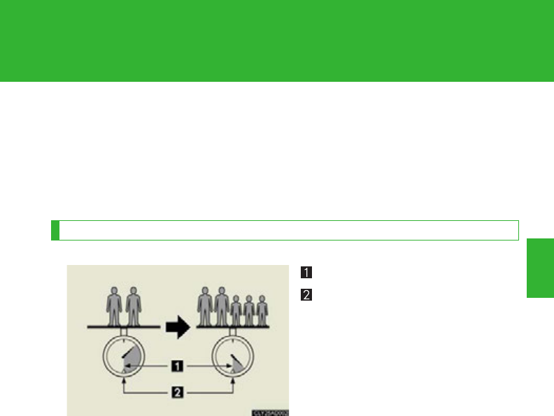
291
2-5. Driving information
2
When driving
(6)If your vehicle will be towing a trailer, load from your trailer will be
transferred to your vehicle. Consult this manual to determine how this
reduces the available cargo and luggage load capacity of your vehi-
cle.
(P. 664)
Example based on your vehicle
Cargo capacity
Total load capacity
When 2 people with the combined weight of 366 lb. (166 kg) are riding
in your vehicle, the available amount of cargo and luggage load capacity
will be as follows:
2WD models
Total load capacity: 825 lb. (370 kg)
825 lb. - 366 lb. = 459 lb. (370 kg - 166 kg = 204 kg)
AWD models
Total load capacity: 885 lb. (400 kg)
885 lb. - 366 lb. = 519 lb. (400 kg - 166 kg = 234 kg)
In this condition, if 3 more passengers with the combined weight of 388 lb.
(176 kg) get on, the available cargo and luggage load will be reduced as fol-
lows:
2WD models
459 lb. - 388 lb. = 71 lb. (204 kg - 176 kg = 28 kg)
AWD models
519 lb. - 388 lb. = 131 lb. (234 kg - 176 kg = 58 kg)

292
2-5. Driving information
As shown in the example above, if the number of occupants increases,
the cargo and luggage load will be reduced by an amount that equals the
increased weight due to the additional occupants. In other words, if an
increase in the number of occupants causes an excess of the total load
capacity (combined weight of occupants plus cargo and luggage load),
you must reduce the cargo and luggage on your vehicle.
CAUTION
■Things that must not be carried in the luggage compartment
The following things may cause a fire if loaded in the luggage compartment:
●Receptacles containing gasoline
●Aerosol cans
■Storage precautions
Observe the following precautions.
Failure to do so may result in death or serious injury.
●Stow cargo and luggage in the luggage compartment whenever possible.
●Do not stack cargo and luggage in the luggage compartment higher than the
seatbacks.
Such items may be thrown about and possibly injure people in the vehicle in the
event of sudden braking or in an accident.
●Do not place cargo or luggage in or on the following locations as the items may
get under the brake or accelerator pedal and prevent the pedals from being
depressed properly, block the driver’s vision, or hit the driver or passengers,
causing an accident:
• At the feet of the driver
• On the front passenger or rear seats (when stacking items)
• On the luggage cover
• On the instrument panel
•On the dashboard
●Secure all items in the occupant compartment, as they may shift and injure some-
one in the event of sudden braking, sudden swerving or an accident.
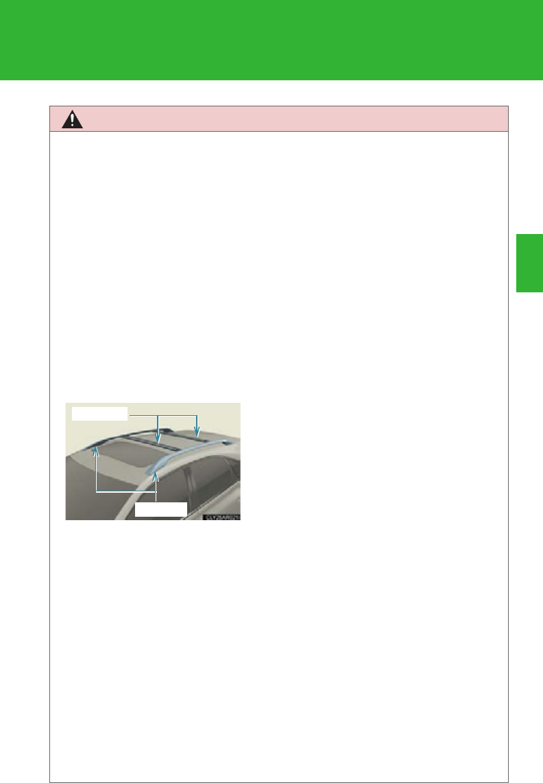
293
2-5. Driving information
2
When driving
CAUTION
●Never allow anyone to ride in the luggage compartment. It is not designed for
passengers. They should ride in their seats with their seat belts properly fastened.
Otherwise, they are much more likely to suffer death or serious bodily injury, in
the event of sudden braking, sudden swerving or an accident.
■Capacity and distribution
●Do not exceed the maximum axle weight rating or the total vehicle weight rating.
●Even if the total load of occupant's weight and the cargo load is less than the total
load capacity, do not apply the load unevenly. Improper loading may cause dete-
rioration of steering or braking control which may cause death or serious injury.
■Roof luggage carrier precautions
To use the roof rails as a roof luggage carrier, you must fit the roof rails with two or
more genuine Lexus cross rails or their equivalent.
When you load cargo on the roof luggage carrier, observe the following:
●Before driving, make sure the cargo is securely fastened on the roof luggage car-
rier.
●Loading cargo on the roof luggage carrier will make the center of gravity of the
vehicle higher. Avoid high speeds, sudden starts, sharp turns, sudden braking or
abrupt maneuvers, otherwise the result may be a loss of control or vehicle roll-
over due to failure to operate this vehicle correctly and result in death or serious
injury.
●If driving for long distances, on rough roads, or at high speeds, stop the vehicle
now and then during the trip to make sure the cargo remains in its place.
●Do not exceed 165 lb. (75 kg) cargo weight on the roof luggage carrier.
●To reduce wind noise when there is no luggage loaded on the roof luggage car-
rier, move the front cross rail to the front-most position and the rear cross rail to
the rearmost position.
●Place the cargo so that its weight is distrib-
uted evenly between the front and rear
axles.
●If loading long or wide cargo, never exceed
the vehicle’s overall length or width.
(P. 664)
Cross rails
Roof rails

294
2-5. Driving information
NOTICE
■When loading cargo
Be careful not to scratch the surface of the moon roof.

295
2-5. Driving information
2
When driving
Vehicle load limits
■Total load capacity and seating capacity
These details are also described on the tire and loading information label.
(P. 541 )
CAUTION
■Overloading the vehicle
Do not overload the vehicle.
It may not only cause damage to the tires, but also degrade steering and braking
ability, resulting in an accident.
Vehicle load limits include total load capacity, seating capacity, TWR
(Trailer Weight Rating) and cargo capacity.
■Total load capacity
2WD models: 825 lb. (370 kg)
AWD models: 885 lb. (400 kg)
Total load capacity means the combined weight of occupants, cargo and
luggage.
■Seating capacity: 5 occupants (Front 2, Rear 3)
Seating capacity means the maximum number of occupants whose esti-
mated average weight is 150 lb. (68 kg) per person.
■TWR (Trailer Weight Rating) (2WD models and AWD models
without towing package)
Lexus does not recommend towing a trailer with your vehicle.
■TWR (Trailer Weight Rating) (AWD models with towing package)
3500 lb. (1588 kg)
TWR means the maximum gross trailer weight (trailer weight plus its
cargo weight) that your vehicle is able to tow.
■Cargo capacity
Cargo capacity may increase or decrease depending on the weight and
the number of occupants.

296
2-5. Driving information
Winter driving tips
Carry out the necessary preparations and inspections before driving the
vehicle in winter. Always drive the vehicle in a manner appropriate to the
prevailing weather conditions.
■Pre-winter preparations
●Use fluids that are appropriate to the prevailing outside tempera-
tures.
• Engine oil
• Engine/power control unit coolant
• Washer fluid
●Have the vehicle fitted with four snow tires or purchase a set of
tire chains for the front tires.
Ensure that all tires are the same size and brand, and that chains match
the size of the tires.
■Before driving the vehicle
Perform the following according to the driving conditions:
●Do not try to forcibly open a window or move a wiper that is fro-
zen. Pour warm water over the frozen area to melt the ice. Wipe
away the water immediately to prevent it from freezing.
●To ensure proper operation of the climate control system fan,
remove any snow that has accumulated on the air inlet vents in
front of the windshield.
●Remove any ice that has accumulated on the vehicle chassis.
●Periodically check for and remove any excess ice or snow that
may have accumulated in the wheel well or on the brakes.
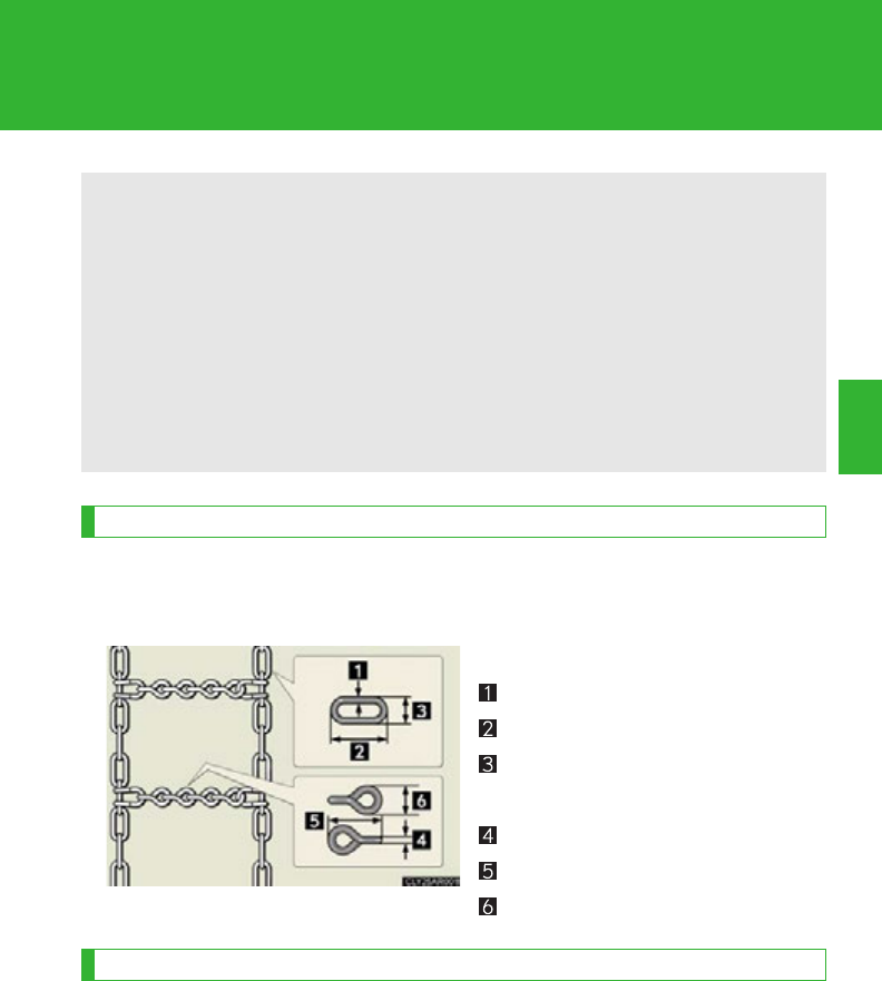
297
2-5. Driving information
2
When driving
Selecting tire chains
Use the correct tire chain size when mounting the tire chains. Chain size
is regulated for each tire size.
Side chain:
0.12 in. (3 mm) in diameter
0.98 in. (25 mm) in length
0.43 in. (10.8 mm) in width
Cross chain:
0.15 in. (3.9 mm) in diameter
1.00 in. (25.3 mm) in length
0.54 in. (13.8 mm) in width
Regulations on the use of tire chains
Regulations regarding the use of tire chains vary depending on location
and type of road. Always check local regulations before installing chains.
■When driving the vehicle
Accelerate the vehicle slowly and drive at a reduced speed suitable to the
road conditions.
■When parking the vehicle
Park the vehicle and move the shift lever to P without setting the
parking brake. The parking brake may freeze up, preventing it from
being released. If necessary, block the wheels to prevent inadvert-
ent sliding or creeping.

298
2-5. Driving information
■Tire chain installation
Observe the following precautions when installing and removing chains:
●Install and remove tire chains in a safe location.
●Install tire chains on the front tires only. Do not install tire chains on the rear tires.
●Install the tire chains on front tires as tightly as possible. Retighten chains after
driving 1/4 1/2 mile (0.5 1.0 km).
●Install tire chains following the instructions provided with the tire chains.
CAUTION
■Driving with snow tires
Observe the following precautions to reduce the risk of accidents.
Failure to do so may result in a loss of vehicle control and cause death or serious
injury.
●Use tires of the size specified for your vehicle.
●Maintain the recommended level of air pressure.
●Do not drive in excess of 75 mph (120 km/h), regardless of the type of snow tires
being used.
●Use snow tires on all, not just some wheels.
■Driving with tire chains
Observe the following precautions to reduce the risk of accidents.
Failure to do so may result in the vehicle being unable to be driven safely, and may
cause death or serious injury.
●Do not drive in excess of the speed limit specified for the tire chains being used,
or 30 mph (50 km/h), whichever is lower.
●Avoid driving on bumpy road surfaces or over potholes.
●Avoid sudden turns and braking, as use of chains may adversely affect vehicle
handling.
●Slow down sufficiently before entering a curve to ensure that vehicle control is
maintained.

299
2-5. Driving information
2
When driving
NOTICE
■Repairing or replacing snow tires
Request repairs or replacement of snow tires from Lexus dealers or legitimate tire
retailers.
This is because the removal and attachment of snow tires affects the operation of
the tire pressure warning valves and transmitters.
■Fitting tire chains
The tire pressure warning valves and transmitters may not function correctly when
tire chains are fitted.

300
2-5. Driving information
Trailer towing (AWD models with towing package)
Towing related terms
■GCWR (Gross Combination Weight Rating)
The maximum allowable gross
combination weight. The gross
combination weight is the sum of
the total vehicle weight (including
the occupants, cargo and any
optional equipment installed on
the vehicle) and the weight of the
trailer being towed (including the
cargo in the trailer).
Your vehicle is designed primarily as a passenger-and-load-carrying vehi-
cle. Towing a trailer can have an adverse impact on handling, performance,
braking, durability, and fuel consumption. For your safety and the safety of
others, you must not overload your vehicle or trailer. You must also ensure
that you are using appropriate towing equipment, that the towing equip-
ment has been installed correctly and used properly, and that you employ
the requisite driving habits.
Vehicle-trailer stability and braking performance are affected by trailer
stability, brake performance and setting, trailer brakes, the hitch and hitch
systems (if equipped).
To tow a trailer safely, use extreme care and drive the vehicle in accor-
dance with your trailer’s characteristics and operating conditions.
Lexus warranties do not apply to damage or malfunction caused by towing
a trailer for commercial purposes.
Contact your Lexus dealer for further information about additional
requirements such as towing kits, etc.
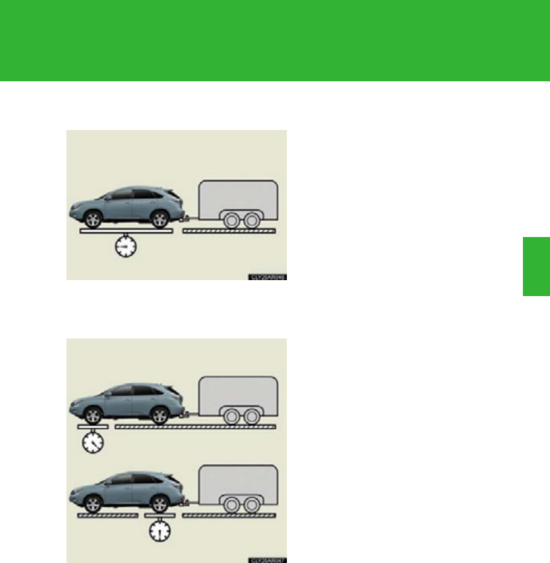
301
2-5. Driving information
2
When driving
■GVWR (Gross Vehicle Weight Rating)
The maximum allowable gross
vehicle weight. The gross vehicle
weight is the total weight of the
vehicle. When towing a trailer, it is
the sum of the vehicle weight
(including the occupants, cargo
and any optional equipment
installed on the vehicle) and the
tongue weight.
■GAWR (Gross Axle Weight Rating)
The maximum allowable gross axle
weight. The gross axle weight is the
load placed on each axle (front
and rear).
Front GAWR
Rear GAWR
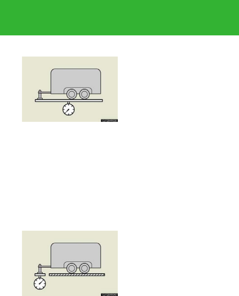
302
2-5. Driving information
■TWR (Trailer Weight Rating)
The maximum allowable gross
trailer weight. The gross trailer
weight is the sum of the trailer
weight and the weight of the cargo
in the trailer.
TWR is calculated assuming base
vehicle with one driver, one front
passenger, towing package (if
available), hitch and hitch systems
(if required).
Additional optional equipment,
passengers and cargo in the vehi-
cle will reduce the trailer weight
rating so as not to exceed GCWR,
GVWR and GAWR.
If the gross trailer weight exceeds
3000 lb. (1360 kg), it is recom-
mended to use a trailer with 2 or
more axles.
■Tongue Weight
The load placed on the trailer hitch
ball. (P. 304)
(With brakes)
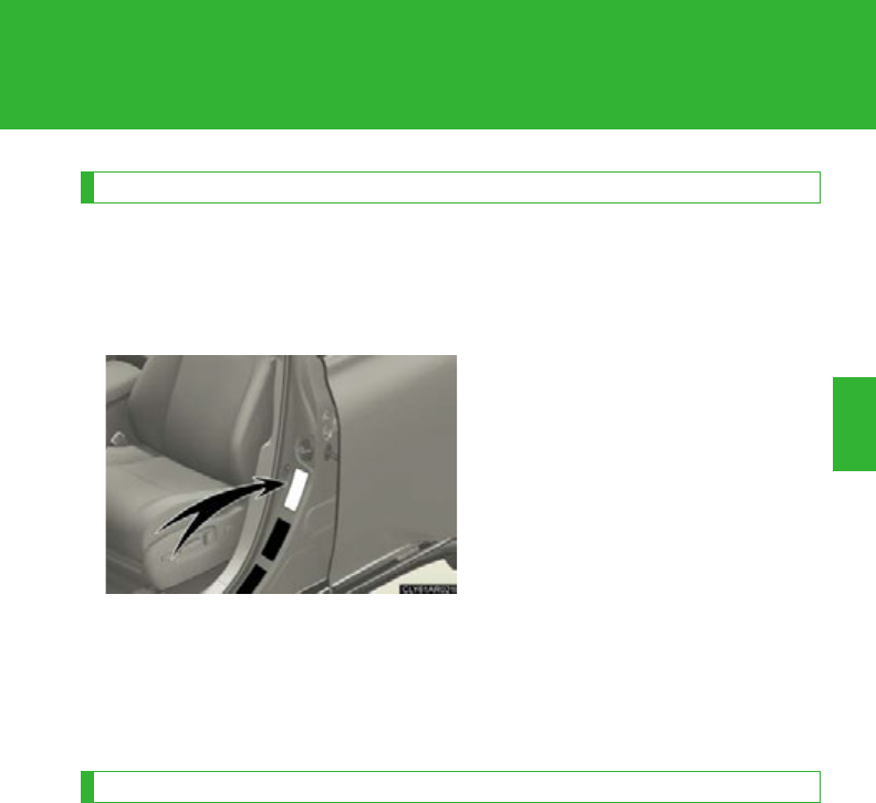
303
2-5. Driving information
2
When driving
Weight limits
●The gross trailer weight must never exceed 3500 lbs (1588 kg).
●The gross combination weight must never exceed 9480 lbs (4297
kg).
●The gross vehicle weight must
never exceed the GVWR indi-
cated on the Certification Label.
●The gross axle weight on each
axle must never exceed the
GAWR indicated on the Certifi-
cation Label.
●If the gross trailer weight is over the unbraked TWR, trailer service
brakes are required.
●If the gross trailer weight is over 2000 lb. (907 kg), a sway control
device with sufficient capacity is required.
GCWR, TWR, Unbraked TWR, Fifth wheel and Gooseneck towing TWR
Confirm that the gross trailer weight, gross combination weight, gross
vehicle weight, gross axle weight and tongue weight are all within the lim-
its.
■GCWR*
9480 lb. (4297 kg)
■TWR*
3500 lb. (1588 kg)
*: These models meet the tow-vehicle trailering requirement of SAE Interna-
tional per SAE J2807.
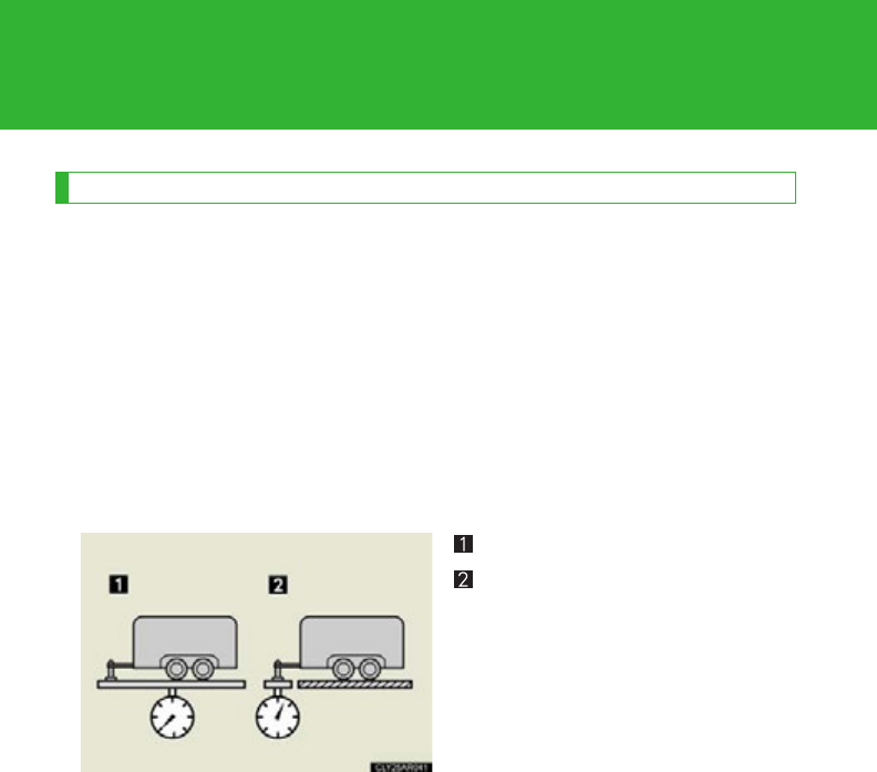
304
2-5. Driving information
Trailer Tongue Weight
●A recommended tongue weight varies in accordance with the types of
trailers or towing as described below.
●To ensure the recommended values shown below, the trailer must be
loaded by referring to the following instructions.
• Tongue Weight
The gross trailer weight should be distributed so that the tongue
weight is 9% to 11%. (Tongue weight /Gross trailer weight x 100 =
9% to 11%)
Gross trailer weight
Ton g u e wei g ht
If using a weight distributing hitch when towing, return the front axle
to the same weight as before the trailer connection.
If front axle weight cannot be measured directly, measure the front
fender height above the front axle before connection. Adjust weight
distributing hitch torque until front fender is returned to the same
height as before connection.
The gross trailer weight, gross axle weight and tongue weight can be
measured with platform scales found at a highway weighing station,
building supply company, trucking company, junk yard, etc.

305
2-5. Driving information
2
When driving
Hitch
Trailer hitch assemblies have different weight capacities. Lexus recom-
mends the use of Lexus hitch/bracket for your vehicle. For details, con-
tact your Lexus dealer.
●If you wish to install a trailer hitch, contact your Lexus dealer.
●Use only a hitch that conforms to the gross trailer weight requirement
of your vehicle.
●Follow the directions supplied by the hitch manufacturer.
●Lubricate the hitch ball with a light coating of grease.
●Remove the trailer hitch whenever you are not towing a trailer. After
removing the hitch, seal any mounting hole in the vehicle body to pre-
vent entry of any substances into the vehicle.
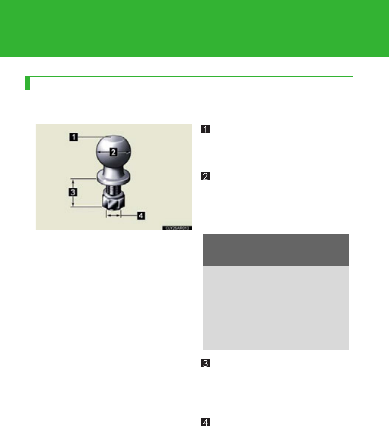
306
2-5. Driving information
Selecting trailer ball
Use the correct trailer ball for your application.
Trailer ball load rating
Matches or exceeds the gross
trailer weight rating of the trailer.
Ball diameter
Matches the size of the trailer cou-
pler. Most couplers are stamped
with the required trailer ball size.
Shank length
Protrudes beyond the bottom of
the lock washer and nut by at least
2 threads.
Shank diameter
Matches the ball mount hole diam-
eter size.
Trailer class Typical trailer ball
size
IV
2 5/16 in.
II and III
2 in.
I
1 7/8 in.
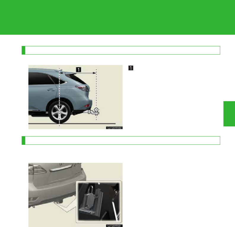
307
2-5. Driving information
2
When driving
Positions for towing hitch receiver and hitch ball
Weight carrying ball position:
45.1 in. (1145 mm)
Connecting trailer lights
4 pin connector
Use the wire harness stored in the
rear end under body.

308
2-5. Driving information
■Auto current cut-off function
In case of over current, the auto cut-off function stops the power flowing to the
trailer lights to prevent damage to the vehicle’s electrical system.
This function is activated when the rated current of any of the following trailer light
circuit components is exceeded:
●Tail lights: maximum 7.8 A
●Stop/turn signal light (right): maximum 4.5 A
●Stop/turn signal light (left): maximum 4.5 A
■When the auto current cut function is activated
If a trailer light does not come on due to the activation of the auto current cut func-
tion, the light system will need to be reset.
Follow the reset procedure shown below.
●If a tail light does not come on, turn off the headlight switch.
●If the right-side stop/turn signal light does not come on, put the turn signal in the
off position or remove foot from the brake pedal.
●If the left-side stop/turn signal light does not come on, put the turn signal in the
off position or remove foot from the brake pedal.
If the emergency flashers do not operate, press the emergency flasher switch to
turn them off.
After the light system is reset, operate the light switches again to see if the lights
operate normally.
If the lights do not operate normally, have the vehicle inspected by your Lexus
dealer.

309
2-5. Driving information
2
When driving
Connecting and disconnecting a trailer (Vehicles with height control system)
If a height control system is installed in your vehicle, you have to connect
and disconnect your trailer more carefully.
●Connecting
Set the electronically modulated air suspension to “LO” mode.
Press the height control off switch to turn off the electronically
modulated air suspension.
Turn off the “POWER” switch.
Connect the trailer.
Turn on the “POWER” switch.
Press the height control off switch again to turn on the electroni-
cally modulated air suspension.
Set the electronically modulated air suspension to “N” mode.
●Disconnecting
Set the electronically modulated air suspension to “LO” mode.
Press the height control off switch to turn off the electronically
modulated air suspension.
Turn off the “POWER” switch.
Set the supporting leg of the trailer on the ground and raise the
hitch by 4 in. (100 mm)
Turn on the “POWER” switch.
Press the height control off switch again to turn on the electroni-
cally modulated air suspension.
Wait until vehicle height is stabilized.
Make sure the hitch is disconnected. If the hitch does not discon-
nect, raise the hitch higher and repeat steps 2 through 7.
Move the vehicle forward in “LO” mode where the hitch does not
touch anything in “N” mode.
Set the height control of electronically modulated air suspension
system to “N” mode.
STEP 1
STEP 2
STEP 3
STEP 4
STEP 5
STEP 6
STEP 7
STEP 1
STEP 2
STEP 3
STEP 4
STEP 5
STEP 6
STEP 7
STEP 8
STEP 7
STEP 9
STEP 7
STEP 10

310
2-5. Driving information
Trailer towing tips
Your vehicle will handle differently when towing a trailer. Help to avoid an
accident, death or serious injury, keep the following in mind when towing:
●Speed limits for towing a trailer vary by state or province. Do not
exceed the posted towing speed limit.
●Lexus recommends that the vehicle-trailer speed limit is 65 mph (104
km/h) on a flat, straight, dry road. Do not exceed this limit, the posted
towing speed limit or the speed limit for your trailer as set forth in your
trailer owner’s manual, whichever is lowest. Instability of the towing
vehicle-trailer combination (trailer sway) increases as speed increases.
Exceeding speed limits may cause loss of control.
●Before starting out, check the trailer lights, tires and the vehicle-trailer
connections. Recheck after driving a short distance.
●Practice turning, stopping and reversing with the trailer attached in an
area away from traffic until you become accustomed to the feel of the
vehicle-trailer combination.
●Reversing with a trailer attached is difficult and requires practice. Grip
the bottom of the steering wheel and move your hand to the left to
move the trailer to the left. Move your hand to the right to move the
trailer to the right. (This is generally opposite to reversing without a
trailer attached.) Avoid sharp or prolonged turning. Have someone
guide you when reversing to reduce the risk of an accident.
●As stopping distance is increased when towing a trailer, vehicle-to-
vehicle distance should be increased. For each 10 mph (16 km/h) of
speed, allow at least one vehicle and trailer length.
●Avoid sudden braking as you may skid, resulting in the trailer jackknif-
ing and a loss of vehicle control. This is especially true on wet or slip-
pery surfaces.
●Avoid jerky starts or sudden acceleration.

311
2-5. Driving information
2
When driving
●Avoid jerky steering and sharp turns, and slow down before making a
turn.
●Note that when making a turn, the trailer wheels will be closer than the
vehicle wheels to the inside of the turn. Compensate by making a
wider than normal turning radius.
●Slow down before making a turn, in cross winds, on wet or slippery sur-
faces, etc.
Increasing vehicle speed can destabilize the trailer.
●Take care when passing other vehicles. Passing requires considerable
distance. After passing a vehicle, do not forget the length of your
trailer, and be sure you have plenty of room before changing lanes.
●To maintain engine braking efficiency and charging system perfor-
mance when using engine braking, do not put the transmission in D.
●Instability happens more frequently when descending steep or long
downhill grades. Before descending, slow down and downshift. Do not
make sudden downshifts while descending steep or long downhill
grades.
●Avoid holding the brake pedal down too long or applying the brakes
too frequently. This could cause the brakes to overheat and result in
reduced braking efficiency.
●Due to the added load of the trailer, your vehicle’s engine may overheat
on hot days (at temperatures over 85°F [30°C]) when driving up a
long or steep grade. If the engine coolant temperature gauge indicates
overheating, immediately turn off the air conditioning (if in use), pull
your vehicle off the road and stop in a safe spot. (P. 655)

312
2-5. Driving information
●Always place wheel blocks under both the vehicle’s and the trailer’s
wheels when parking. Apply the parking brake firmly, and put the
transmission in P. Avoid parking on a slope, but if unavoidable, do so
only after performing the following:
Apply the brakes and keep them applied.
Have someone place wheel blocks under both the vehicle’s and
trailer’s wheels.
When the wheel blocks are in place, release the brakes slowly
until the blocks absorb the load.
Apply the parking brake firmly.
Shift into P and turn off the hybrid system.
●When restarting after parking on a slope:
With the transmission in P, start the hybrid system. Be sure to
keep the brake pedal depressed.
Shift into a forward gear. If reversing, shift into R.
Release the parking brake and brake pedal, and slowly pull or
back away from the wheel blocks. Stop and apply the brakes.
Have someone retrieve the blocks.
STEP 1
STEP 2
STEP 3
STEP 4
STEP 5
STEP 1
STEP 2
STEP 3
STEP 4
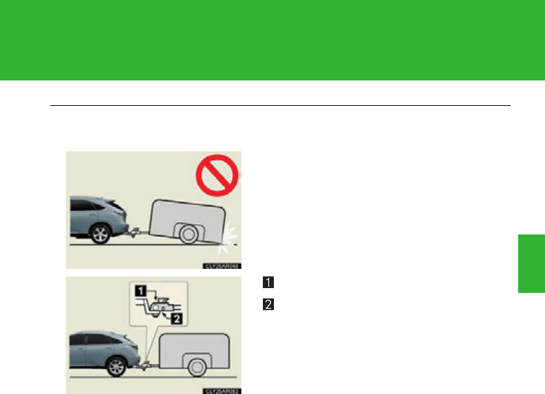
313
2-5. Driving information
2
When driving
■Matching trailer ball height to trailer coupler height
■Before towing
Check that the following conditions are met:
●Ensure that your vehicle’s tires are properly inflated. (P. 673)
●Trailer tires are inflated according to the trailer manufacturer’s recommenda-
tion.
●All trailer lights work as required by law.
●All lights work each time you connect them.
●The trailer ball is set at the proper height for the coupler on the trailer.
●The vehicle remains level when a loaded or unloaded trailer is hitched. Do not
drive if the vehicle is not level, and check for improper tongue weight, overload-
ing, worn suspension, or other possible causes.
●The trailer cargo is securely loaded.
●The rear view mirrors conform to all applicable federal, state/provincial or local
regulations. If they do not, install rear view mirrors appropriate for towing pur-
poses.
No matter which class of tow hitch applies,
for a more safe trailer hookup, the trailer ball
setup must be the proper height for the cou-
pler on the trailer.
Coupler
Trailer ball

314
2-5. Driving information
■Break-in schedule
If your vehicle is new or equipped with any new power train components (such as
an engine, transmission, differential or wheel bearing), Lexus recommends that you
do not tow a trailer until the vehicle has been driven for over 500 miles (800 km).
After the vehicle has been driven for over 500 miles (800 km), you can start tow-
ing. However, for the next 500 miles (800 km), drive the vehicle at a speed of less
than 50 mph (80 km/h) when towing a trailer, and avoid full throttle acceleration.
■Maintenance
●If you tow a trailer, your vehicle will require more frequent maintenance due to
the additional load. (See “Warranty and Services Guide”, “Owner's Manual
Supplement” or “Scheduled Maintenance”.)
●Retighten the fixing bolts of the towing ball and bracket after approximately
600 miles (1000 km) of trailer towing.
■If trailer sway occurs
One or more factors (crosswinds, passing vehicles, rough roads, etc.) can adversely
affect handling of your vehicle and trailer, causing instability.
●If trailer swaying occurs:
• Firmly grip the steering wheel. Steer straight ahead.
Do not try to control trailer swaying by turning the steering wheel.
• Begin releasing the accelerator pedal immediately but very gradually to
reduce speed.
Do not increase speed. Do not apply vehicle brakes.
If you make no extreme correction with the steering or brakes, your vehicle and
trailer should stabilize.
●After the trailer swaying has stopped:
• Stop in a safe place. Get all occupants out of the vehicle.
• Check the tires of the vehicle and the trailer.
• Check the load in the trailer.
Make sure the load has not shifted.
Make sure the tongue weight is appropriate, if possible.
• Check the load in the vehicle.
Make sure the vehicle is not overloaded after occupants get in.
If you cannot find any problems, the speed at which trailer swaying occurred is
beyond the limit of your particular vehicle-trailer combination.
Drive at a lower speed to prevent instability. Remember that swaying of the towing
vehicle-trailer increases as speed increases.

315
2-5. Driving information
2
When driving
CAUTION
■Trailer towing precautions
●To tow a trailer safely, use extreme care and drive the vehicle in accordance with
the trailer’s characteristics and operating conditions. Failure to do so could cause
an accident resulting in death or serious injury. Vehicle stability and braking per-
formance are affected by trailer stability, brake setting and performance, and the
hitch. Your vehicle will handle differently when towing a trailer.
●Vehicles with electronically modulated air suspension (if equipped):
Set the vehicle height to the “LO” mode and turn off the electronically modulated
air suspension when you connect a trailer, otherwise the vehicle height may
change due to the automatic leveling function, and you may catch part of your
body in the vehicle, resulting in an accident.
■To avoid accident or injury
●Do not exceed the TWR, unbraked TWR, GCWR, GVWR or GAWR.
●If the gross trailer weight is over 2000 lb. (907 kg), a sway control device with
sufficient capacity is required.
●Adjust the tongue weight within the appropriate range. Place heavier loads as
close to the trailer axle as possible.
●Do not exceed 65 mph (104 km/h), the posted towing speed limit or the speed
limit for your trailer as set forth in your trailer owner’s manual, whichever is lowest.
Slow down sufficiently before making a turn, in cross winds, on wet or slippery
surface, etc. to help avoid an accident. If you experience a vehicle-trailer instabil-
ity from reducing a certain speed, slow down and make sure you keep your vehi-
cle speed under the speed of which you experience the instability.
●Do not make jerky, abrupt or sharp turns.
●Do not apply the brakes suddenly as you may skid, resulting in jackknifing and
loss of vehicle control. This is especially true on wet or slippery surfaces.
●Do not exceed the trailer hitch assembly weight, gross vehicle weight, gross axle
weight and trailer tongue weight capacities.

316
2-5. Driving information
CAUTION
●Do not use cruise control when towing.
●Slow down and downshift before descending steep or long downhill grades. Do
not make sudden downshifts while descending steep or long downhill grades.
●Vehicle-trailer instability is more likely on steep long downhills. Before descend-
ing steep or long downhill grades, slow down and downshift. Do not make sudden
downshifts when descending steep or long downhill grades. Avoid holding the
brake pedal down too long or applying the brakes too frequently. This could
cause the brakes to overheat and result in reduced braking efficiency.
●Do not tow a trailer when the compact spare tire is installed on your vehicle.
■Hitch
Trailer hitch assemblies have different weight capacities established by the hitch
manufacturer. Even though the vehicle may be physically capable of towing a
higher weight, the operator must determine the maximum weight rating of the par-
ticular hitch assembly and never exceed the maximum weight rating specified for
the trailer-hitch. Exceeding the maximum weight rating set by the trailer-hitch man-
ufacturer can cause an accident resulting in death or serious personal injuries.
■When towing a trailer
Lexus recommends trailers with brakes that conform to any applicable federal and
state/provincial regulations.
●If the gross trailer weight exceeds unbraked TWR, trailer brakes are required.
Lexus recommends trailers with brakes that conform to all applicable federal and
state/provincial regulations.
●Never tap into your vehicle’s hydraulic system, as this will lower the vehicle’s brak-
ing effectiveness.
●Never tow a trailer without using a safety chain securely attached to both the
trailer and the vehicle. If damage occurs to the coupling unit or hitch ball, there is
danger of the trailer wandering into another lane.

317
2-5. Driving information
2
When driving
NOTICE
■When installing a trailer hitch
Use only the position recommended by your Lexus dealer. Do not install the trailer
hitch on the bumper; this may cause body damage.
■Do not directly splice trailer lights
Do not directly splice trailer lights. Directly splicing trailer lights may damage your
vehicle’s electrical system and cause a malfunction.
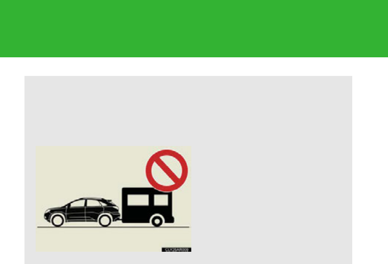
318
2-5. Driving information
Trailer towing (2WD models and AWD models without towing package)
Lexus does not recommend towing a trailer with your vehicle. Lexus also
does not recommend the installation of a tow hitch or the use of a tow hitch
carrier for a wheelchair, scooter, bicycle, etc. Your vehicle is not designed
for trailer towing or for the use of tow hitch mounted carriers.
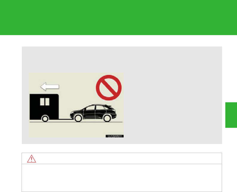
319
2-5. Driving information
2
When driving
Dinghy towing
NOTICE
■To avoid serious damage to your vehicle
Do not tow your vehicle with four wheels on the ground.
Your vehicle is not designed to be dinghy towed (with 4 wheels on the
ground) behind a motor home.

320
3-1. Using the air conditioning
system and defogger
Automatic air
conditioning system........... 322
Rear window defogger
switch ..................................... 330
Windshield wiper de-icer ..... 331
3-2. Using the audio system
Audio system........................... 332
Using the radio ....................... 336
Using the CD player............. 346
Playing MP3 and WMA
discs......................................... 356
Operating an iPod................. 366
Operating a USB
memory................................... 374
Optimal use of the audio
system..................................... 383
Using the AUX port.............. 386
Using the steering wheel
audio switches...................... 388
3-3. Using the Bluetooth®
audio system
Bluetooth® audio system..... 391
Using the Bluetooth®
audio system......................... 394
Operating a Bluetooth®
enabled portable
player...................................... 399
Setting up a Bluetooth®
enabled portable
player...................................... 403
Bluetooth® audio system
setup ........................................ 410
Interior features 3

Interior features 3
321
3-4. Using the hands-free
phone system
(for mobile phones)
Hands-free system
for mobile phones.................. 411
Using the
hands-free system
(for mobile phones).............. 415
Making a phone call .............. 423
Setting a mobile phone......... 428
Security and system
setup........................................ 434
Using the phone book.......... 438
3-5. Using the interior lights
Interior lights list..................... 445
• Interior lights .........................446
• Personal lights.......................446
3-6. Using the storage features
List of storage features........ 448
• Glove box ............................. 449
• Bottle holders/
door pockets......................... 450
• Cup holders ............................451
• Console box.......................... 453
• Auxiliary boxes .................... 455
• Under tray ..............................456
3-7. Other interior features
Sun visors .................................. 457
Vanity mirrors ......................... 458
Clock......................................... 459
Outside temperature
display..................................... 460
Multi-display light control..... 461
Power outlets .......................... 462
Seat heaters and
ventilators ............................. 465
Armrest ..................................... 467
Coat hooks .............................. 468
Floor mat .................................. 469
Luggage compartment
features.................................. 470
Garage door opener ............. 474
Compass .................................. 480
Safety Connect ...................... 484
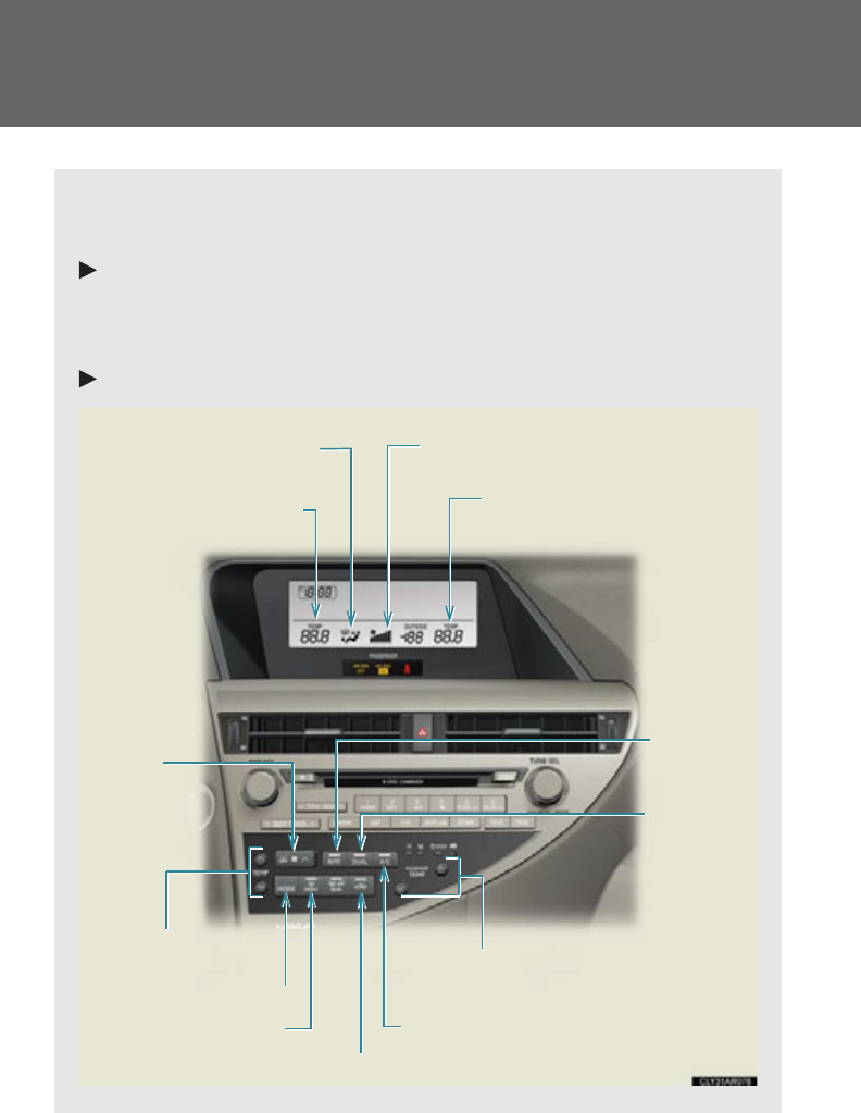
322
3-1. Using the air conditioning system and defogger
Automatic air conditioning system
Air outlets and fan speed are automatically adjusted according to the tem-
perature setting.
Vehicles with a navigation system
Owners of models equipped with a navigation system should refer to
the “Navigation System Owner’s Manual”.
Vehicles without a navigation system
Automatic
mode
button
Driver’s side temperature
display
Air outlet selector button
Fan speed
control
button/
“OFF” button
Air outlet display Fan speed display
Passenger’s side temperature
display
Driver's side temperature
control buttons
Cooling and dehumidification function
on/off button
Outside/recirculated air mode button
Windshield defogger
button
Passenger’s side temperature control buttons
Dual mode
button
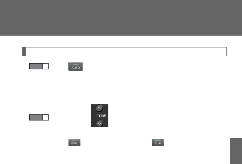
323
3-1. Using the air conditioning system and defogger
3
Interior features
Using the automatic air conditioning system
Press .
The air conditioning system begins to operate. Air outlets and fan
speed are automatically adjusted according to the temperature
setting.
Press “”on to increase the temperature and “” to
decrease the temperature.
When is pressed (the indicator on is on) or the passenger’s
side temperature control button is pressed, the temperature for the
driver and passenger seats can be adjusted separately.
STEP 1
STEP 2
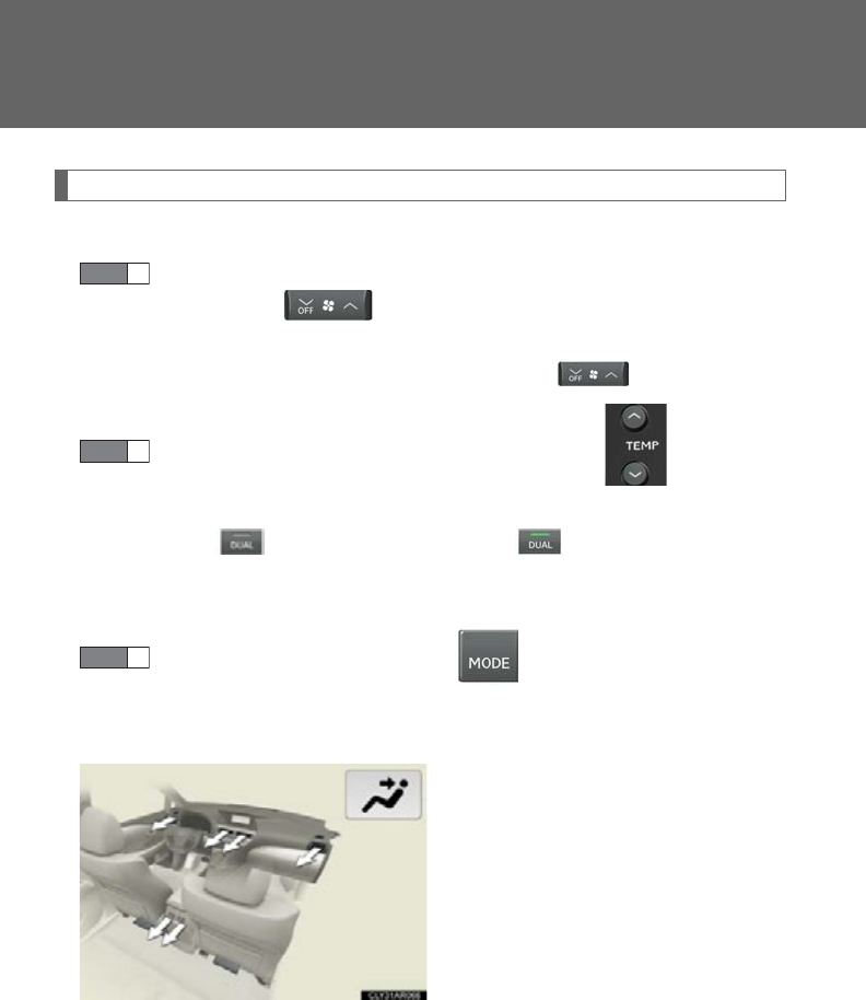
324
3-1. Using the air conditioning system and defogger
Adjusting the settings manually
■Basic setting
To turn on the air conditioning system and adjust the fan speed,
press “” on to increase the fan speed and “OFF ” to
decrease the fan speed.
To turn the fan off, press and hold “OFF ” on .
To adjust the temperature setting, press “” on to increase
the temperature and “” to decrease the temperature.
When is pressed (the indicator on is on) or the passenger’s
side temperature control button is pressed, the temperature for the
driver and passenger seats can be adjusted separately.
To change the air outlets, press .
The air outlets used are switched each time the button is pressed. The
air flow shown on the display indicates the following:
Air flows to the upper body.
STEP 1
STEP 2
STEP 3
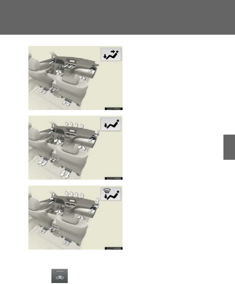
325
3-1. Using the air conditioning system and defogger
3
Interior features
Air flows to the upper body and
feet.
Air flows to the feet.
Air flows to the feet and the wind-
shield defogger operates.
■Switching between outside air and recirculated air modes
Press .
The mode switches between outside air mode (the indicator is off) and
recirculated air mode (the indicator is on) each time the button is pressed.
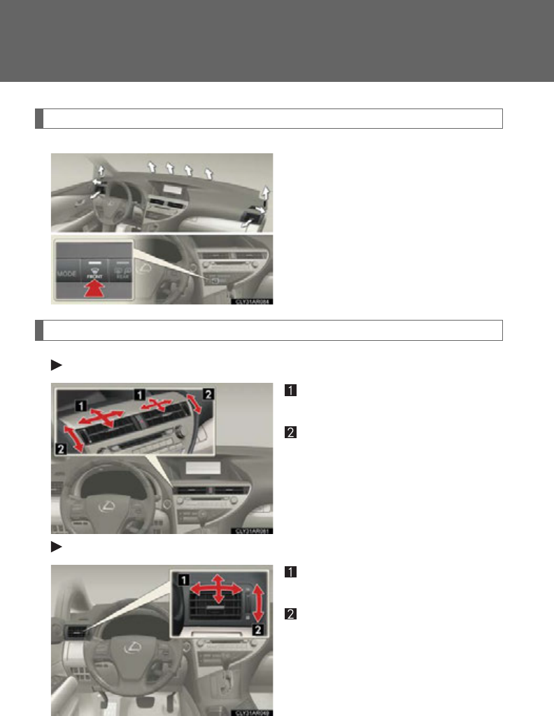
326
3-1. Using the air conditioning system and defogger
Defogging the windshield
Defogging
The air conditioning system oper-
ates automatically.
Recirculated air mode will auto-
matically switch to outside air
mode. It is not possible to return to
recirculated air mode when the
switch is on.
Adjusting the position of and opening and closing the air outlets
Front center outlets
Direct air flow to the left or right,
up or down.
Turn the knob to open or close
the vent.
Front side outlets
Direct air flow to the left or right,
up or down.
Turn the knob to open or close
the vent.
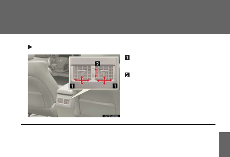
327
3-1. Using the air conditioning system and defogger
3
Interior features
Rear outlets
Direct air flow to the left or right,
up or down.
Turn the knob to open or close
the vent.
■Operation of the air conditioning system in Eco drive mode
In Eco drive mode, the air conditioning system is controlled as follows to prioritize
fuel efficiency:
●Engine speed and compressor operation controlled to restrict heating/cooling
capacity
●Fan speed restricted when automatic mode is selected
To improve air conditioning performance, perform the following operations:
●Adjust the fan speed
●Turn off Eco drive mode
■Customization
The air conditioning control of Eco drive mode can be changed to the same setting
as that used in normal drive mode.
(Customizable features P. 693 )
■Air conditioning system settings
When the “POWER” switch is turned on, the air conditioning system settings will be
set to those that were in use the last time the “POWER” switch was turned off.
●Air conditioning system settings are memorized individually on each electronic
key, so the settings reproduced will be specific to the key that is used.
●This feature is customizable at your Lexus dealer.

328
3-1. Using the air conditioning system and defogger
■Using automatic mode
Fan speed is adjusted automatically according to the temperature setting and ambi-
ent conditions. As a result, the following may occur:
Immediately after the button is pressed, the fan may stop for a while until warm or
cool air is ready to flow.
■Using the system in recirculated air mode
The windows will fog up more easily if recirculated air mode is used for an extended
period.
■Switching between outside air and recirculated air modes
Recirculated air mode or outside air mode may be automatically switched to in
accordance with the temperature setting and the inside temperature.
■Window defogger feature
Recirculated air mode may automatically switch to outside air mode in situations
where the windows need to be defogged.
■When outside air temperature is below 32F (0C)
The cooling and dehumidification function may not operate even when is
pressed.
■When the indicator light on flashes
Press to turn off the cooling and dehumidification function and turn it on
again. There may be a problem in the air conditioning system if the indicator light
continues to flash. Turn the air conditioning system off and have it inspected by your
Lexus dealer.
■Air conditioning odors
●During use, various odors from inside and outside the vehicle may enter into
and accumulate in the air conditioning system. This may then cause odor to be
emitted from the vents.
●To reduce potential odors from occurring:
• It is recommended that the air conditioning system be set to outside air mode
prior to turning the vehicle off.
• The start timing of the blower may be delayed for a short period of time
immediately after the air conditioning system is started in automatic mode.
329
3-1. Using the air conditioning system and defogger
3
Interior features
CAUTION
■To prevent the windshield from fogging up
Do not use during cool air operation in extremely humid weather. The differ-
ence between the temperature of the outside air and that of the windshield can
cause the outer surface of the windshield to fog up, blocking your vision.
NOTICE
■To prevent 12-volt battery discharge
Do not leave the air conditioning system on longer than necessary when the hybrid
system is off.
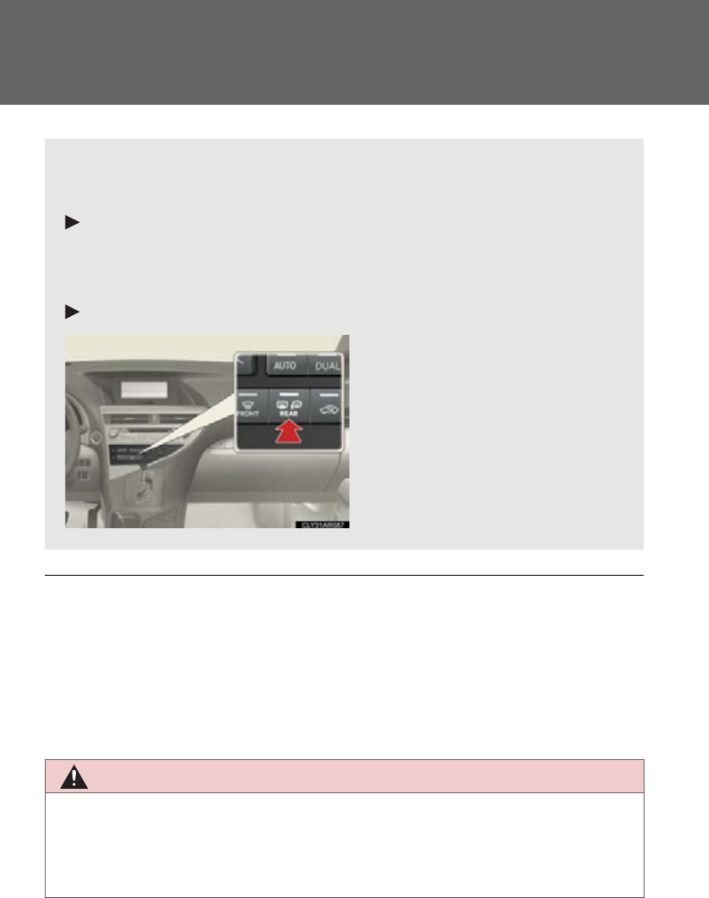
330
3-1. Using the air conditioning system and defogger
Rear window defogger switch
■Operating conditions
The “POWER” switch must be in ON mode.
■The outside rear view mirror defoggers
Turning the rear window defogger on will turn the outside rear view mirror defog-
gers on.
CAUTION
■When the outside rear view mirror defoggers are on
Do not touch the outside surface of the rear view mirrors, as they can become very
hot and burn you.
Defoggers are used to defog the rear window, and to remove raindrops,
dew and frost from the outside rear view mirrors.
Vehicles with a navigation system
Owners of models equipped with a navigation system should refer to
the “Navigation System Owner’s Manual”.
Vehicles without a navigation system
Turns the rear window and out-
side rear view mirror defoggers
on/off
The defoggers will automatically
turn off after 15 to 60 minutes.
The operation time changes
according to the ambient tem-
perature and vehicle speed.
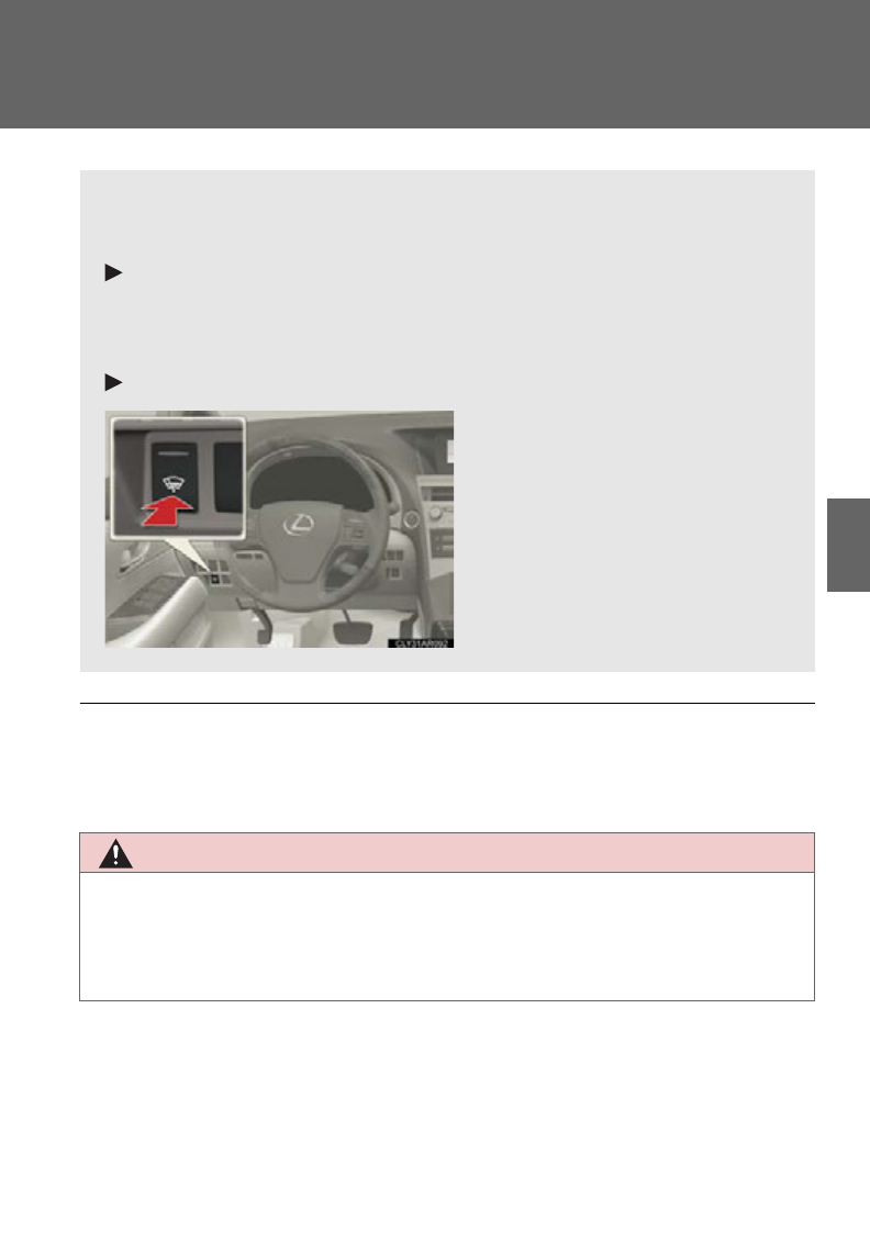
331
3-1. Using the air conditioning system and defogger
3
Interior features
Windshield wiper de-icer
■Operating conditions
The “POWER” switch must be in ON mode.
CAUTION
■When the windshield wiper de-icer is on
Do not touch the lower part of the windshield or the side of the front pillars, as the
surfaces can become very hot and burn you.
This feature is used to prevent ice from building up on the windshield and
wiper blades.
Vehicles with a navigation system
Owners of models equipped with a navigation system should refer to
the “Navigation System Owner’s Manual”.
Vehicles without a navigation system
Turns the windshield wiper de-
icer on/off
The windshield wiper de-icer
will automatically turn off after
approximately 15 minutes.
: If equipped
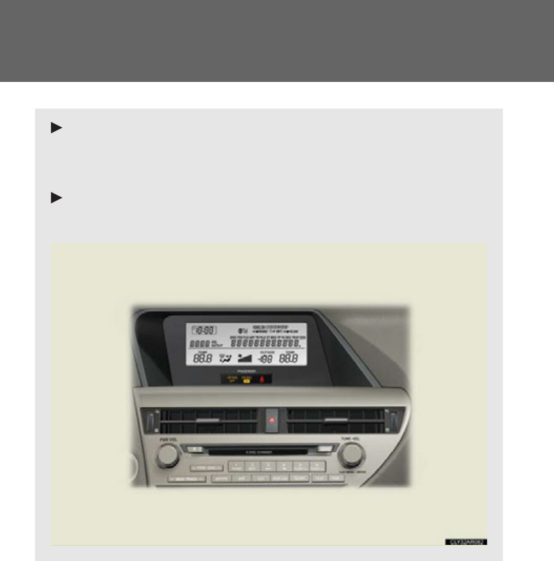
332
3-2. Using the audio system
Audio system
Vehicles with a navigation system
Owners of models equipped with a navigation system should refer to
the “Navigation System Owner’s Manual”.
Vehicles without a navigation system (type A)
CD player with a changer and AM/FM radio
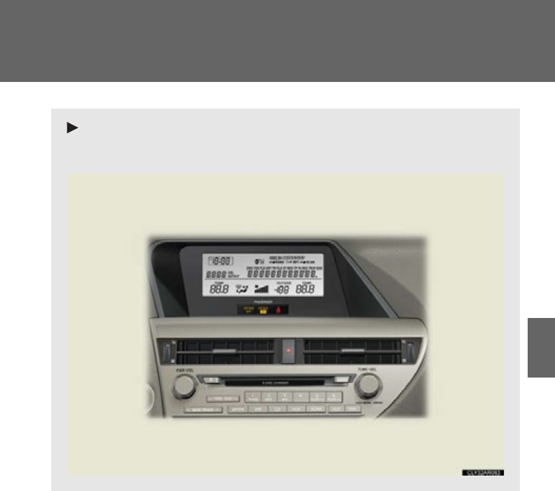
333
3-2. Using the audio system
3
Interior features
Vehicles without a navigation system (type B)
CD player with a changer and AM/FM radio
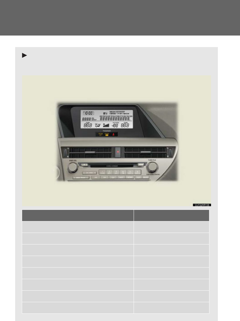
334
3-2. Using the audio system
Vehicles without a navigation system (type C)
CD player with a changer and AM/FM radio
Titl e Page
Using the radio P. 33 6
Using the CD player P. 3 46
Playing MP3 and WMA discs P. 356
Operating an iPod P. 3 66
Operating a USB memory P. 374
Optimal use of the audio system P. 383
Using the AUX port P. 3 86
Using the steering wheel audio switches P. 3 88
335
3-2. Using the audio system
3
Interior features
■Using mobile phones
Interference may be heard through the audio system’s speakers if a mobile phone is
being used inside or close to the vehicle while the audio system is operating.
CAUTION
■Certification
●Part 15 of the FCC Rules
FCC Warning:
Any unauthorized changes or modifications to this equipment will void the user’s
authority to operate this device.
●Laser products
• Do not take this unit apart or attempt to make any changes by yourself.
This is an intricate unit that uses a laser pickup to retrieve information from the
surface of compact discs. The laser is carefully shielded so that its rays remain
inside the cabinet. Therefore, never try to disassemble the player or alter any
of its parts since you may be exposed to laser rays and dangerous voltages.
• This product utilizes a laser.
Use of controls or adjustments or performance of procedures other than
those specified herein may result in hazardous radiation exposure.
NOTICE
■To prevent 12-volt battery discharge
Do not leave the audio system on longer than necessary when the hybrid system is
off.
■To avoid damaging the audio system
Take care not to spill drinks or other fluids over the audio system.
336
3-2. Using the audio system
Using the radio
Type A
Traffic information button
Preset station buttons
Radio text message button
Scan button
Seek button
Channel category button
Frequency adjustment
(AM/FM mode) and
channel (SAT mode)
knob
AM
FM/SAT
mode buttons
“PWR
VOL” knob
Power Volume
337
3-2. Using the audio system
3
Interior features
Type B
Traffic information button
Preset station buttons
Radio text message button
Scan button
Seek button
Channel category button
Frequency adjustment
(AM/FM mode) and
channel (SAT mode)
knob
AM
FM/SAT
mode buttons
“PWR
VOL” knob
Power Volume
338
3-2. Using the audio system
Type C
Preset tuning button
Frequency adjustment
knob
Mute button
“PWR
VOL” knob
Power Volume
Seek button
AM/FM
mode buttons
Preset station buttons
Scan button
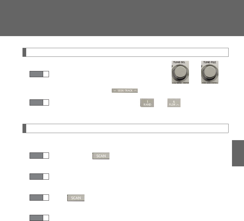
339
3-2. Using the audio system
3
Interior features
Setting station presets (excluding XM® Satellite Radio)
Search for the desired stations by turning or or
pressing “” or “” on .
Press and hold the button (from to ) the station is to
be set to until you hear a beep.
Scanning radio stations (excluding XM® Satellite Radio)
■Scanning the preset radio stations
Press and hold until you hear a beep.
Preset stations will be played for 5 seconds each.
When the desired station is reached, press the button again.
■Scanning all the radio stations within range
Press .
All the stations with reception will be played for 5 seconds each.
When the desired station is reached, press the button again.
STEP 1
STEP 2
STEP 1
STEP 2
STEP 1
STEP 2
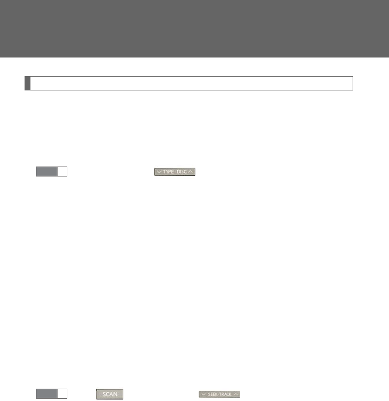
340
3-2. Using the audio system
RDS (Radio Data System) (type A and B)
This feature allows your radio to receive station identification information
and program information (classical, jazz, etc.) from radio stations which
broadcast this information.
■Receiving RDS broadcasts
Press “” or “” on during FM reception.
The type of program changes each time the button is pressed.
●“ROCK”
●“EASYLIS” (Easy listening)
●“CLS/JAZZ” (Classical music and Jazz)
●“R & B” (Rhythm and Blues)
●“INFORM” (Information)
●“RELIGION”
●“MISC” (Miscellaneous)
●“ALERT” (Emergency messages)
If the system receives no RDS stations, “NO PTY” appears on the dis-
play.
Press , or “” or “” on .
The radio seeks or scans for stations of the relevant program type.
STEP 1
STEP 2

341
3-2. Using the audio system
3
Interior features
■Displaying radio station names
Press .
■Displaying radio text messages
Press twice.
A text message is displayed when “MSG” is shown on the screen.
If the text continues past the end of the display, is displayed. Press and
hold until you hear a beep.
XM® Satellite Radio (type A and B)
■Receiving XM® Satellite Radio
Press .
The display changes as follows each time the button is pressed:
“SAT1” “SAT2” “SAT3”
Turn to select the desired channel in all the categories or
press “” or “” on to select the desired channel in the
current category.
■Setting XM® Satellite Radio channel presets
Select the desired channel. Press and hold the button (from to
) the channel is to be set to until you hear a beep.
■Changing the channel category
Press “” or “” on .
STEP 1
STEP 2

342
3-2. Using the audio system
■Scanning the XM® Satellite Radio channels
●Scanning the channels in the current category
Press .
When the desired channel is reached, press the button
again.
●Scanning the preset channels
Press and hold until you hear a beep.
When the desired channel is reached, press the button
again.
■Displaying text information
Press .
The display will show up to 10 characters.
The display changes as follows each time the button is pressed:
●CH NAME
●TITLE (SONG/PROGRAM TITLE)
●NAME (ARTIST NAME/FEATURE)
●CH NUMBER
STEP 1
STEP 2
STEP 1
STEP 2

343
3-2. Using the audio system
3
Interior features
■When the 12-volt battery is disconnected
All preset stations are erased.
■Reception sensitivity
●Cargo loaded on the roof luggage carrier, especially metal objects, may
adversely affect the reception of XM® Satellite Radio.
●It is difficult to maintain perfect radio reception at all times due to the continually
changing position of the antenna, differences in signal strength and surrounding
objects, such as trains and transmitters.
●The radio antenna is mounted inside the rear spoiler and the rear window. To
maintain clear radio reception, do not attach metallic window tinting or other
metallic objects to the antenna wire mounted inside the rear window.
■Receiving XM® Satellite Radio
An XM® Satellite Radio is a tuner designed exclusively to receive broadcasts pro-
vided under a separate subscription. Availability is limited to the 48 contiguous
states and 10 Canadian provinces.
●XM® subscriptions
For detailed information about XM® Satellite Radio or to subscribe:
U.S.A.
Visit on the web at www.siriusxm.com or call 1-877-515-3987.
Canada
Visit on the web at www.xmradio.ca or call 1-877-438-9677.
●Radio ID
You will need the radio ID when activating XM® service or reporting a problem.
Select “CH000” using , and the receiver's 8-character ID number will
appear.
●Satellite tuner
The tuner supports only Audio Services (Music and Talk) and the accompanying
Text Information of XM® Satellite Radio.

344
3-2. Using the audio system
■If the satellite radio does not operate normally
If a problem occurs with the XM® tuner, a message will appear on the display. Refer
to the table below to identify the problem, and take the suggested corrective action.
“ANTENNA”
The XM® antenna is not connected. Check whether
the XM® antenna cable is attached securely.
There is a short-circuit in the antenna or the surround-
ing antenna cable. See a Lexus certified dealer.
“UNAUTH”
You have not subscribed to the XM® Satellite Radio.
The radio is being updated with the latest encryption
code. Contact the XM® Satellite Radio for subscrip-
tion information. When a contract is canceled, you can
choose the “CH000” and all the free-to-air channels.
The premium channel you selected is not authorized.
Wait for about 2 seconds until the radio returns to the
previous channel or “CH001”. If it does not change
automatically, select another channel. If you want to lis-
ten to the premium channel, contact the XM® Satellite
Radio.
“NO SIGNAL”
The XM® signal is too weak at the current location.
Wait until your vehicle reaches a location with a stron-
ger signal.
“LOADING” The unit is acquiring audio or program information.
Wait until the unit has received the information.
“OFF AIR” The channel you selected is not broadcasting any pro-
gramming. Select another channel.

345
3-2. Using the audio system
3
Interior features
Contact the XM® Listener Care Center at 1-877-515-3987 (U.S.A.) or 1-877-
438-9677 (Canada).
■Certifications for the radio tuner
This equipment has been tested and found to comply with the limits for a class B
digital device, pursuant to Part 15 of the FCC Rules. These limits are designed to
provide reasonable protection against harmful interference in a residential installa-
tion. This equipment generates, uses and can radiate radio frequency energy and, if
not installed and used in accordance with the instructions, may cause harmful inter-
ference to radio communications. However, there is no guarantee that interference
will not occur in a particular installation.
If this equipment does cause harmful interference to radio or television reception,
which can be determined by turning the equipment off and on, the user is encour-
aged to try to correct the interference by trying one or more of the following:
●Reorienting or relocate the receiving antenna.
●Increasing the separation between the equipment and receiver.
●Connecting the equipment into an outlet on a circuit different from that to which
the receiver is connected.
●Consulting the dealer or an experienced radio/TV technician for help.
“-----”
There is no song/program title or artist name/feature
associated with the channel at that time. No action
needed.
“CH UNAVL”
The channel you selected is no longer available. Wait
for about 2 seconds until the radio returns to the previ-
ous channel or “CH001”. If it does not change auto-
matically, select another channel.
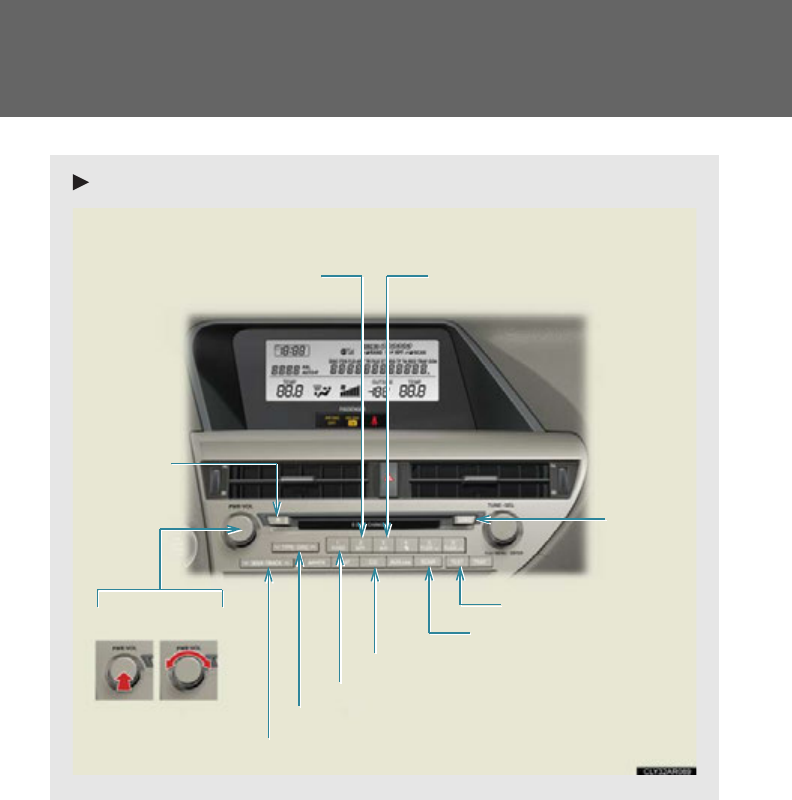
346
3-2. Using the audio system
Using the CD player
Type A
“PWR
VOL” knob
Track selector button
Eject
button
Playback button
Search playback button
Load
button
CD selector button
Random playback button
Repeat play button
Text b ut t o n
Power Volume
Playback/Pause button
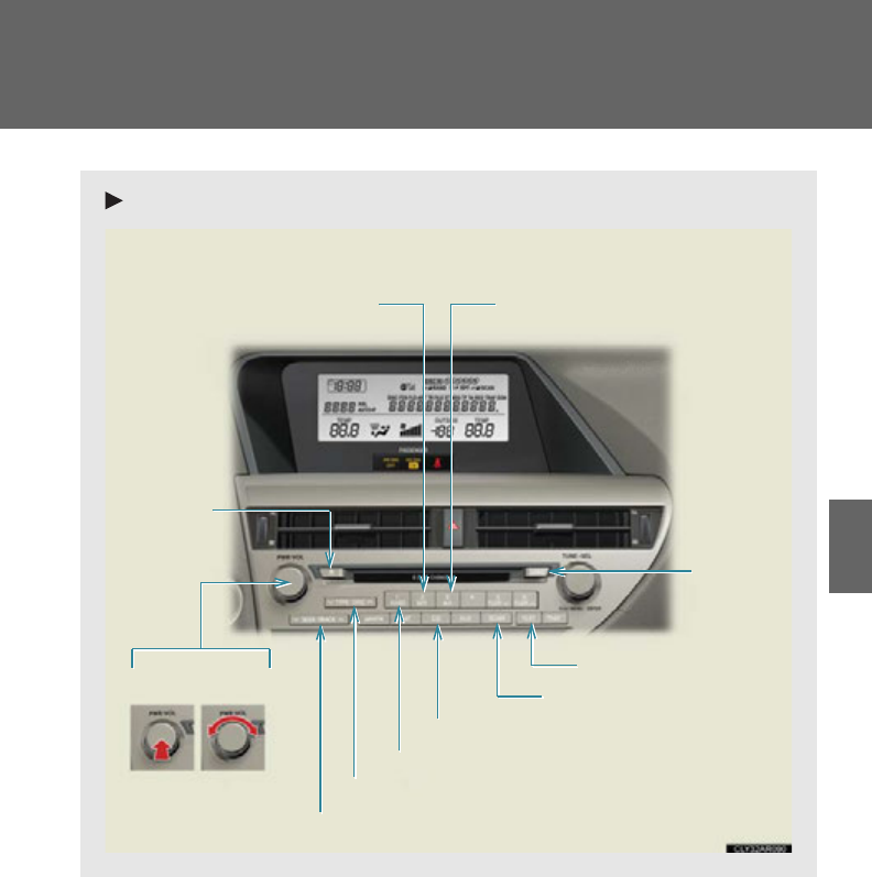
347
3-2. Using the audio system
3
Interior features
Type B
“PWR
VOL” knob
Track selector button
Eject
button
Playback button
Search playback button
Load
button
CD selector button
Random playback button
Repeat play button
Text b ut t o n
Power Volume
Playback/Pause button
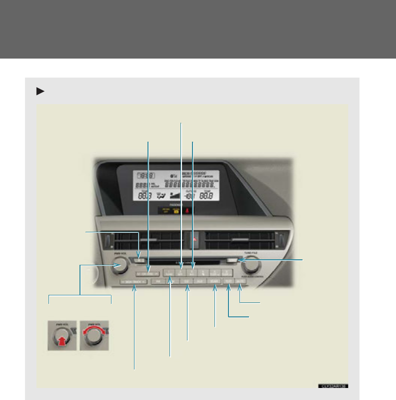
348
3-2. Using the audio system
Type C
Track selector button
Eject
button
Playback button
Load
button
CD selector button
Random playback button
Repeat play button
Text b u t t o n
Search playback button
“PWR
VOL” knob
Power Volume
Mute button
Playback/Pause button
349
3-2. Using the audio system
3
Interior features
Loading a CD
■Loading a CD
Press .
“WAIT” is shown on the display.
When the indicator on the slot turns from amber to green, insert a
CD.
The display changes from “WAIT” to “LOAD”.
■Loading multiple CDs
Press and hold until you hear a beep.
“WAIT” is shown on the display.
When the indicator on the slot turns from amber to green, insert a
CD.
The display changes from “WAIT” to “LOAD”.
The indicator on the slot turns to amber when the CD is being inserted.
When the indicator on the slot turns from amber to green, insert
the next CD.
Repeat the procedure for the remaining CDs.
To cancel the operation, press . If you do not insert a disc within 15
seconds, loading will be canceled automatically.
STEP 1
STEP 2
STEP 1
STEP 2
STEP 3
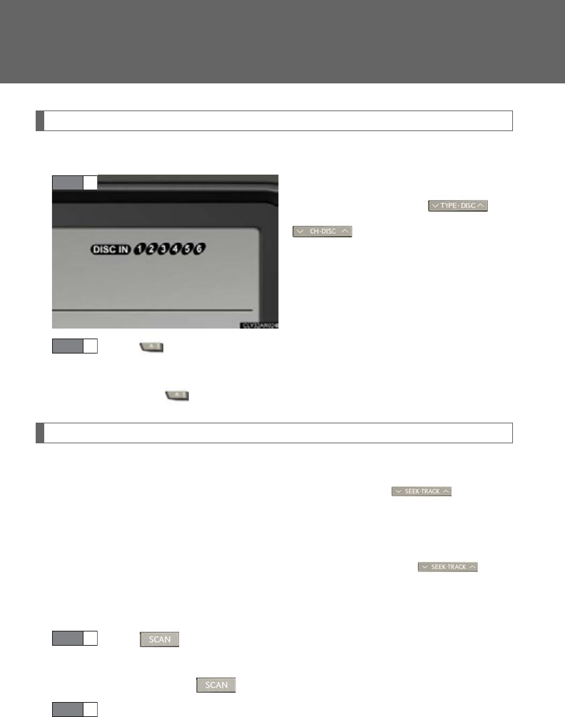
350
3-2. Using the audio system
Ejecting CDs
■Ejecting a CD
To select the CD to be ejected,
press “” or “” on or
.
The selected disc number is shown
on the display.
Press and remove the CD.
■Ejecting all the CDs
Press and hold until you hear a beep, and then remove the CDs.
Selecting, fast-forwarding, reversing and scanning tracks
■Selecting a track
Press “” to move up or “” to move down using until the
desired track number is displayed.
■Fast-forwarding and reversing tracks
To fast-forward or reverse, press and hold “” or “” on until
you hear a beep.
■Scanning tracks
Press .
The first ten seconds of each track will be played.
To cancel, press again.
Press the button again when the desired track is reached.
STEP 1
STEP 2
STEP 1
STEP 2
351
3-2. Using the audio system
3
Interior features
Selecting a CD
■Selecting a CD to play
To select the desired CD, press “” or “” on or .
■Scanning loaded CDs
Press and hold until you hear a beep.
The first ten seconds of the first track on each CD will be played.
To cancel, press again.
Press the button again when the desired CD is reached.
Playing and pausing tracks
To play or pause a track, press .
Random playback
■Current CD
Press .
Songs are played in random order.
To cancel, press again.
■All CDs
Press and hold until you hear a beep.
Tracks on all loaded CDs are played in random order.
To cancel, press again.
STEP 1
STEP 2
352
3-2. Using the audio system
Repeat play
■Repeating a track
Press .
To cancel, press again.
■Repeating all of the tracks on a CD
Press and hold until you hear a beep.
To cancel, press again.
Switching the display
Press .
Each time the button is pressed, the display changes in the following order:
Elapsed time CD title Track title
■CD player protection feature
To protect the internal components, playback is automatically stopped when a
problem is detected.
■Display
Up to 12 characters can be displayed at a time.
If there are 13 or more characters, pressing and holding until you hear a
beep enables to display the remaining characters.
A maximum of 24 characters can be displayed.
If is pressed until you hear a beep again or has not been operated for more
than 6 seconds, the display will return to the first 12 characters.
Depending on the contents recorded, the characters may not be displayed prop-
erly or may not be displayed at all.

353
3-2. Using the audio system
3
Interior features
■When “ERROR” or “WAIT” is shown on the display
“ERROR”: This indicates a trouble either in the CD or inside the player. The CD
may be dirty, damaged, or inserted up-side down.
“WAIT”: This indicates that operation is stopped due to a high temperature inside
the player. Wait for a while and then press . If the CD still cannot
be played back, contact your Lexus dealer.
■Discs that can be used
Discs with the marks shown below can be used.
Playback may not be possible depending on recording format or disc features, or
due to scratches, dirt or deterioration.
CDs with copy-protection features may not be used.
■Lens cleaners
Do not use lens cleaners. Doing so may damage the CD player.
■If discs are left inside the CD player or in the ejected position for extended peri-
ods of time
The discs may be damaged and may not play properly.
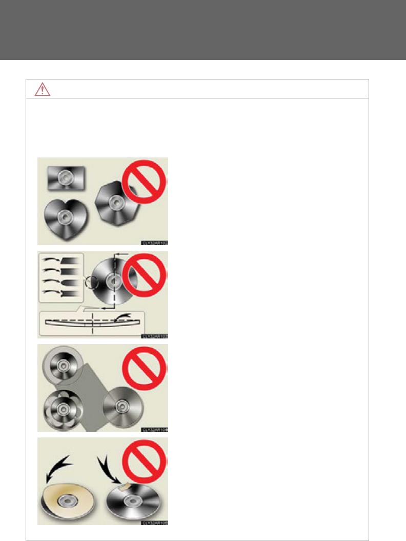
354
3-2. Using the audio system
NOTICE
■CDs and adapters that cannot be used
Do not use the following types of CDs, 3 in. (8 cm) CD adapters or Dual Discs.
Doing so may damage the CD player and/or the CD load/eject function.
●CDs that have a diameter that is not 4.7 in.
(12 cm)
●Low-quality and deformed CDs
●CDs with a transparent or translucent
recording area
●CDs that have had tape, stickers or CD-R
labels attached to them, or that have had
the label peeled off
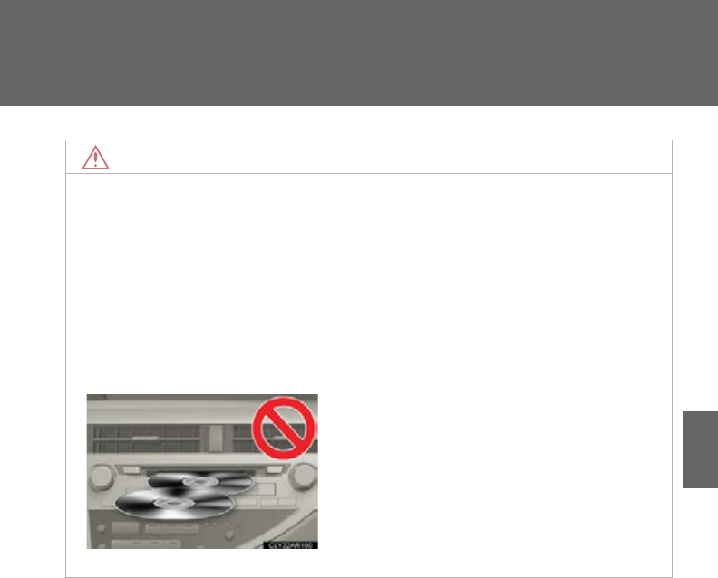
355
3-2. Using the audio system
3
Interior features
NOTICE
■CD player precautions
Failure to follow the precautions below may result in serious damage to the CDs or
the player itself.
●Do not insert anything other than CDs into the CD slot.
●Do not apply oil to the CD player.
●Store CDs away from direct sunlight.
●Never try to disassemble any part of the CD player.
●Do not insert more than one CD at a time.
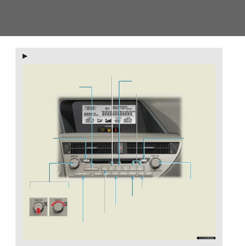
356
3-2. Using the audio system
Playing MP3 and WMA discs
Type A
Eject button
Playback button
Search playback button
Load button
Disc selector button
File selector knob
Random playback button
Repeat play button
Tex t b u t t o n
File selector button
Playback/Pause button
Folder selector buttons
“PWR
VOL” knob
Power Volume
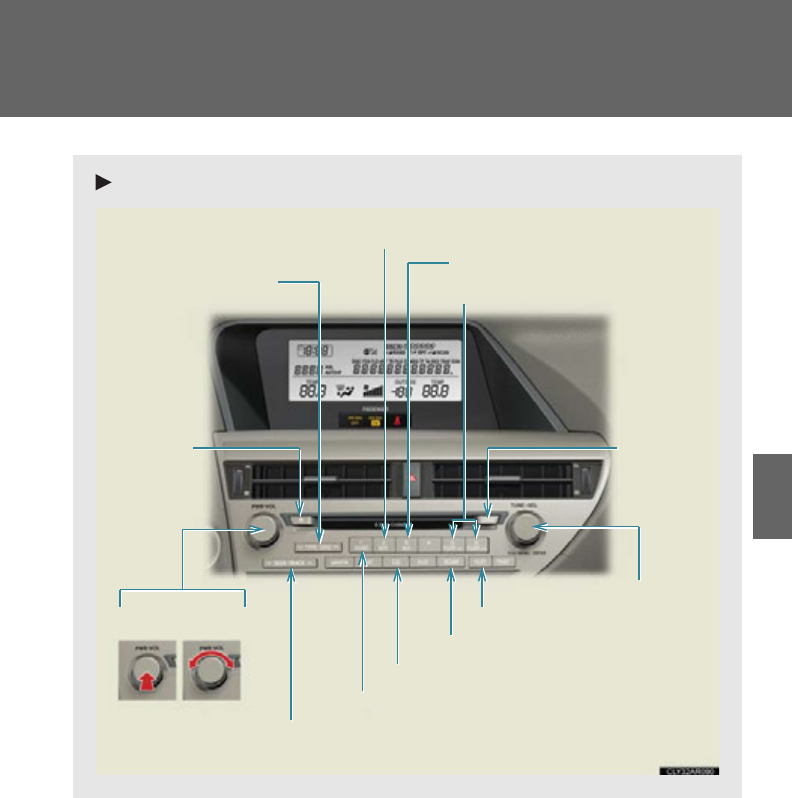
357
3-2. Using the audio system
3
Interior features
Type B
Eject button
Playback button
Search playback button
Load button
Disc selector button
File selector knob
Random playback button
Repeat play button
Tex t b u t t o n
File selector button
Playback/Pause button
Folder selector buttons
“PWR
VOL” knob
Power Volume
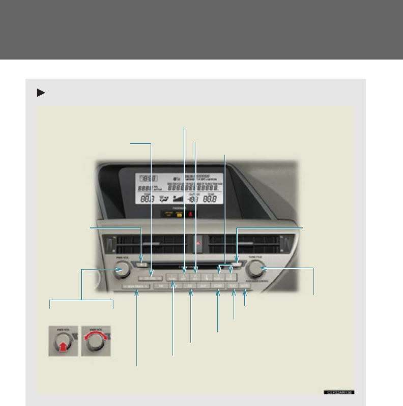
358
3-2. Using the audio system
Type C
Random playback button
Eject button
Playback button
Load button
Disc selector button
File selector knob
Tex t b u t t o n
Folder selector buttons
File selector button
Repeat play button
Search playback button
Mute button
“PWR
VOL” knob
Power Volume
Playback/Pause button
359
3-2. Using the audio system
3
Interior features
Loading and ejecting MP3 and WMA discs
P. 349, 350
Selecting MP3 and WMA discs
P. 351
Selecting and scanning a folder
■Selecting a folder one at a time
Press or to select the desired folder.
■Returning to the first folder
Press and hold until you hear a beep.
■Scanning the first file of all the folders
Press and hold until you hear a beep.
The first ten seconds of the first file in each folder will be played.
When the desired folder is reached, press again.
Fast-forwarding and reversing files
To fast-forward or reverse, press and hold “” or “” on until
you hear a beep.
STEP 1
STEP 2
360
3-2. Using the audio system
Selecting and scanning files
■Selecting a file
Turn or or press “” or “” on to select the
desired file.
■Scanning the files in a folder
Press .
The first ten seconds of each file will be played.
To cancel, press again.
When the desired file is reached, press again.
Playing and pausing files
To play or pause a file, press .
Random playback
■Playing files from a folder in random order
Press .
To cancel, press again.
■Playing all the files from a disc in random order
Press and hold until you hear a beep.
To cancel, press again.
361
3-2. Using the audio system
3
Interior features
Repeat play
■Repeating a file
Press .
To cancel, press again.
■Repeating all the files in a folder
Press and hold until you hear a beep.
To cancel, press again.
Switching the display
Press .
Each time the button is pressed, the display changes in the following order:
Folder no./File no./Elapsed time Folder name File name Album title
(MP3 only) Track title Artist name

362
3-2. Using the audio system
■CD player protection feature
P. 352
■Display
P. 352
■When “ERROR”, “WAIT” or “NO MUSIC” is shown on the display
“ERROR”: This indicates a problem either in the CD or inside the player. The CD
may be dirty, damaged, or inserted up-side down.
“WAIT”: This indicates that operation is stopped due to a high temperature inside
the player. Wait for a while and then press . If the CD still cannot be
played back, contact your Lexus dealer.
“NO MUSIC”: This indicates that an MP3/WMA file is not included in the CD.
■Discs that can be used
P. 353
■Lens cleaners
P. 353
■If discs are left inside the CD player or in the ejected position for extended peri-
ods of time
P. 353

363
3-2. Using the audio system
3
Interior features
■MP3 and WMA files
MP3 (MPEG Audio LAYER 3) is a standard audio compression format.
Files can be compressed to approximately 1/10 of their original size by using MP3
compression.
WMA (Windows Media Audio) is a Microsoft audio compression format.
This format compresses audio data to a size smaller than that of the MP3 format.
There is a limit to the MP3 and WMA file standards that can be used and to the
media/formats on which the files are recorded.
●MP3 file compatibility
• Compatible standards
MP3 (MPEG1 LAYER3, MPEG2 LSF LAYER3)
• Compatible sampling frequencies
MPEG1 LAYER3: 32, 44.1, 48 (kHz)
MPEG2 LSF LAYER3: 16, 22.05, 24 (kHz)
• Compatible bit rates (compatible with VBR)
MPEG1 LAYER3: 64, 80, 96, 112, 128, 160, 192, 224, 256, 320 (kbps)
MPEG2 LSF LAYER3: 64, 80, 96, 112, 128, 144, 160 (kbps)
• Compatible channel modes: stereo, joint stereo, dual channel and monaural
●WMA file compatibility
• Compatible standards
WMA Ver. 7, 8, 9
• Compatible sampling frequencies
32, 44.1, 48 (kHz)
• Compatible bit rates (only compatible with 2-channel playback)
Ver. 7, 8: CBR 48, 64, 80, 96, 128, 160, 192 (kbps)
Ver. 9: CBR 48, 64, 80, 96, 128, 160, 192, 256, 320 (kbps)
●Compatible media
Media that can be used for MP3 and WMA playback are CD-Rs and CD-RWs.
Playback in some instances may not be possible if the CD-R or CD-RW is not
finalized. Playback may not be possible or the audio may jump if the disc is
scratched or marked with fingerprints.

364
3-2. Using the audio system
●Compatible disc formats
The following disc formats can be used:
• Disc formats: CD-ROM Mode 1 and Mode 2
CD-ROM XA Mode 2, Form 1 and Form 2
• File formats: ISO9660 Level 1, Level 2, (Romeo, Joliet)
MP3 and WMA files written in any format other than those listed above may
not play correctly, and their file names and folder names may not be dis-
played correctly.
Items related to standards and limitations are as follows:
• Maximum directory hierarchy: 8 levels (including the root)
• Maximum length of folder names/file names: 32 characters
• Maximum number of folders: 192 (including the root)
• Maximum number of files per disc: 255
●File names
The only files that can be recognized as MP3/WMA and played are those with
the extension .mp3 or .wma.
●Discs containing multi-session recordings
As the audio system is compatible with multi-sessions, it is possible to play discs
that contain MP3 and WMA files. However, only the first session can be played.
●ID3 and WMA tags
ID3 tags can be added to MP3 files, making it possible to record the track title,
artist name, etc.
The system is compatible with ID3 Ver. 1.0, 1.1, and Ver. 2.2, 2.3 ID3 tags. (The
number of characters is based on ID3 Ver. 1.0 and 1.1.)
WMA tags can be added to WMA files, making it possible to record the track
title and artist name in the same way as with ID3 tags.

365
3-2. Using the audio system
3
Interior features
●MP3 and WMA playback
When a disc containing MP3 or WMA files is inserted, all files on the disc are first
checked. Once the file check is finished, the first MP3 or WMA file is played. To
make the file check finish more quickly, we recommend you do not write in any
files other than MP3 or WMA files or create any unnecessary folders.
Discs that contain a mixture of music data and MP3 or WMA format data cannot
be played.
●Extensions
If the file extensions .mp3 and .wma are used for files other than MP3 and WMA
files, they will be mistakenly recognized and played as MP3 and WMA files. This
may result in large amounts of interference and damage to the speakers.
●Playback
• To play MP3 files with steady sound quality, we recommend a fixed bit rate
of at least 128 kbps and a sampling frequency of 44.1 kHz.
• CD-R or CD-RW playback may not be possible in some instances, depend-
ing on the characteristics of the disc.
• There is a wide variety of freeware and other encoding software for MP3
and WMA files on the market, and depending on the status of the encoding
and the file format, poor sound quality or noise at the start of playback may
result. In some cases, playback may not be possible at all.
• When files other than MP3 or WMA files are recorded on a disc, it may take
more time to recognize the disc and in some cases, playback may not be
possible at all.
• Microsoft, Windows, and Windows Media are registered trademarks of
Microsoft Corporation in the U.S.A. and other countries.
NOTICE
■CDs and adapters that cannot be used
P. 35 4
■CD player precautions
P. 355
366
3-2. Using the audio system
Operating an iPod
Connecting an iPod enables you to enjoy music from the vehicle speakers.
■Connecting an iPod
Slide the armrest while pulling
up the lever, and lift the armrest.
Remove the upper tray.
Remove the lower tray.
Open the cover and connect an
iPod using an iPod cable.
Turn on the power of the iPod if it
is not turned on.
Press or .
STEP 1
STEP 2
STEP 3
STEP 4
: If equipped
367
3-2. Using the audio system
3
Interior features
■Control panel
Text b ut t o n
Repeat play button
Playback button
Playback/Pause button
Go back button
Song selector button
Shuffle playback button
iPod menu/
Song selector knob
“PWR
VOL” knob
Power Volume
(type A) (type C)
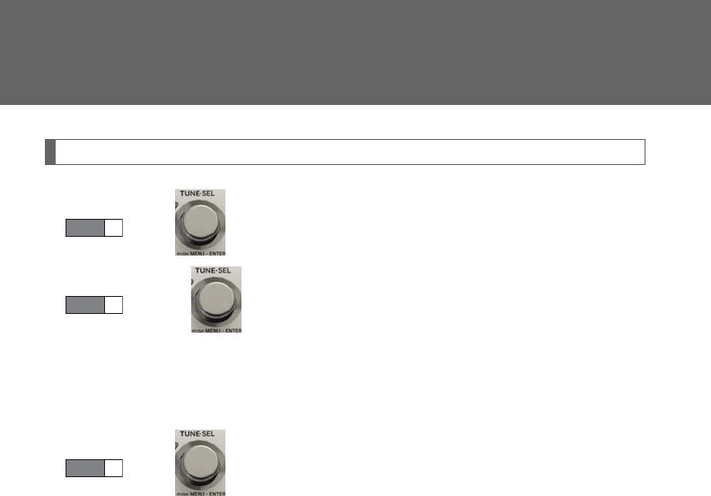
368
3-2. Using the audio system
Selecting a play mode
Press to select iPod menu mode.
Turning changes the play mode in the following order:
“PLAYLISTS”“ARTISTS”“ALBUMS”“SONGS”
“PODCASTS”“GENRES”“COMPOSERS”
“AUDIOBOOKS”
Press to select the desired play mode.
STEP 1
STEP 2
STEP 3
369
3-2. Using the audio system
3
Interior features
■Play mode list
■Selecting a list
Turn to display the first selection list.
Press to select the desired item.
Pressing the knob changes to the second selection list.
Repeat the same procedure to select the desired item.
To return to the previous selection list, select “GO BACK” or press
.
Play mode First
selection
Second
selection
Third
selection
Fourth
selection
“PLAYLISTS” Playlists select Songs select - -
“A R T I S T S ” Artists select Albums select Songs select -
“A L B U M S ” Albums select Songs select - -
“SONGS” Songs select ---
“PODCASTS”
Albums select Songs select - -
“GENRES” Genre select Artists select Albums select Songs select
“COMPOSERS”
Composers
select Albums select Songs select -
“AUDIOBOOKS”
Songs select ---
STEP 1
STEP 2
STEP 3
370
3-2. Using the audio system
Selecting songs
Turn or press “” or “” on to select the desired song.
Playing and pausing songs
To play or pause a song, press .
Fast-forwarding and rewinding songs
To fast-forward or rewind, press and hold “” or “” on until
you hear a beep.
Shuffle playback
■Playing songs from one playlist or album in random order
Press .
To cancel, press again.
■Playing songs from all the playlists or albums in random order
Press and hold until you hear a beep.
To cancel, press again.
Repeat play
Press .
To cancel, press again.
Switching the display
Press .
Each time the button is pressed, the display changes in the following order:
Elapsed time Album title Tra c k t i t l e Artist name
371
3-2. Using the audio system
3
Interior features
Adjusting sound quality and volume balance
Press to enter iPod menu mode.
Pressing changes sound modes. (P. 384)
■About iPod
●Apple is not responsible for the operation of this device or its compliance with
safety and regulatory standards.
●iPod is a trademark of Apple Inc., registered in the U.S. and other countries.
■iPod functions
●When an iPod is connected and the audio source is changed to iPod mode, the
iPod will resume play from the same point in which it was last used.
●Depending on the iPod that is connected to the system, certain functions may
not be available. If a function is unavailable due to a malfunction (as opposed to
a system specification), disconnecting the device and reconnecting it once
again may resolve the problem.
●While connected to the system, the iPod cannot be operated with its own con-
trols. It is necessary to use the controls of the vehicle's audio system instead.
■iPod problems
To resolve most problems encountered when using your iPod, disconnect your iPod
from the vehicle iPod connection and reset it.
For instructions on how to reset your iPod, refer to your iPod Owner's Manual.
■Display
P. 352
STEP 1
STEP 2
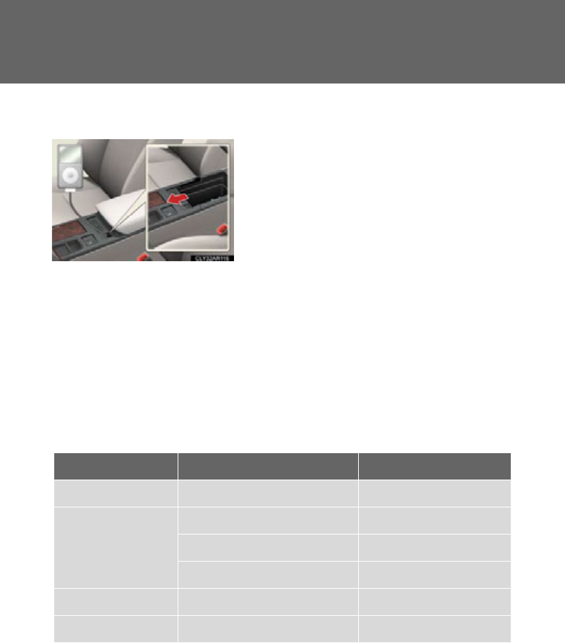
372
3-2. Using the audio system
■Routing portable audio device cables
■Error messages
“ERROR”: This indicates a problem in the iPod or its connection.
“NO MUSIC”: This indicates that there is no music data in the iPod.
“EMPTY”: This indicates that some available songs are not found in a selected
playlist.
“UPDATE”: This indicates that the version of the iPod is not compatible.
Upgrade your iPod software to the latest version.
■Compatible models
Depending on differences between models or software version etc., some models
listed above might be incompatible with this system.
iPod 4th generation and earlier models are not compatible with this system.
iPhone, iPod mini, iPod shuffle and iPod photo are not compatible with this system.
When the cover is slid open, portable audio
device cables can be pulled through the
opening.
Model Generation Software version
iPod 5th generation Ver. 1.2.0 or hig her
iPod nano
1st generation Ver. 1.3.0 or h ig he r
2nd generation Ver. 1.1.2 or higher
3rd generation Ver. 1.0.0 or hi gher
iPod touch 1st generation Ver. 1.1.0 or higher
iPod classic 1st generation Ver. 1 .0.0 or high er
373
3-2. Using the audio system
3
Interior features
Items related to standards and limitations are as follows:
●Maximum number of lists in device: 9999
●Maximum number of songs in device: 65535
●Maximum number of songs per list: 65535
CAUTION
■Caution while driving
Do not connect iPod or operate the controls.
NOTICE
■To prevent damage to iPod
●Do not leave iPod in the vehicle. The temperature inside the vehicle may become
high, resulting in damage to the player.
●Do not push down on or apply unnecessary pressure to the iPod while it is con-
nected as this may damage the iPod or its terminal.
●Do not insert foreign objects into the port as this may damage the iPod or its ter-
minal.
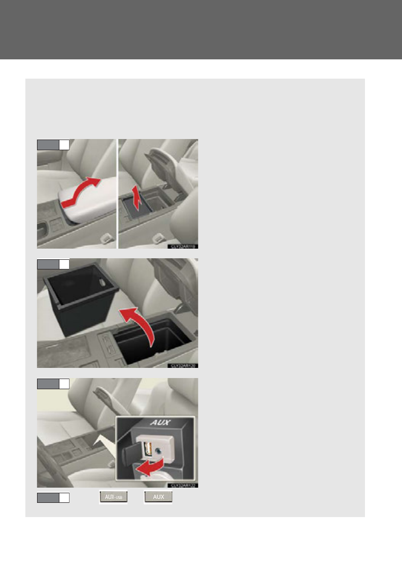
374
3-2. Using the audio system
Operating a USB memory
Connecting a USB memory enables you to enjoy music from the vehicle
speakers.
■Connecting a USB memory
Slide the armrest while pulling
up the lever, and lift the armrest.
Remove the upper tray.
Remove the lower tray.
Open the cover and connect a
USB memory.
Turn on the power of the USB
memory if it is not turned on.
Press or .
STEP 1
STEP 2
STEP 3
STEP 4
: If equipped
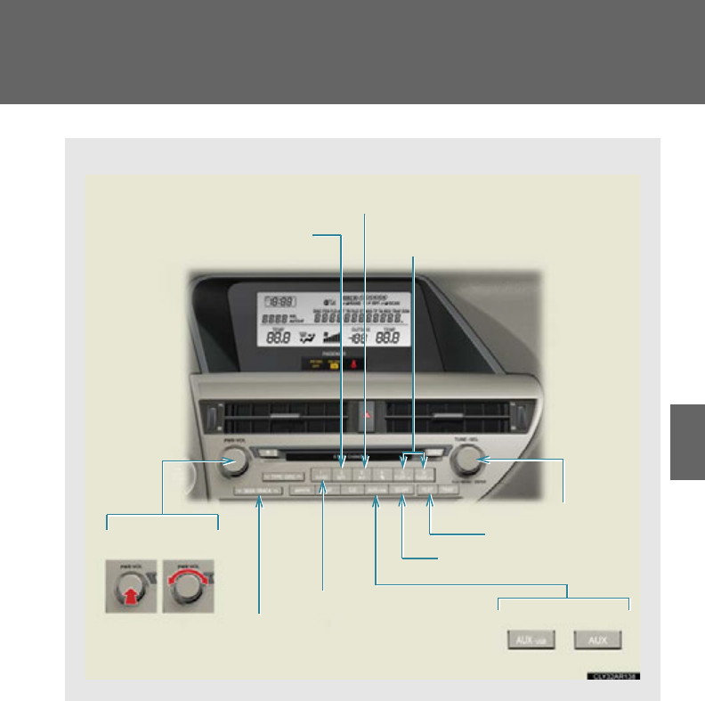
375
3-2. Using the audio system
3
Interior features
■Control panel
Repeat play button Folder selector buttons
Random playback button
File selector button
Search playback button
File selector knob
Playback/Pause button
Text button
“PWR
VOL” knob
Power Volume
Playback button
(type A) (type C)
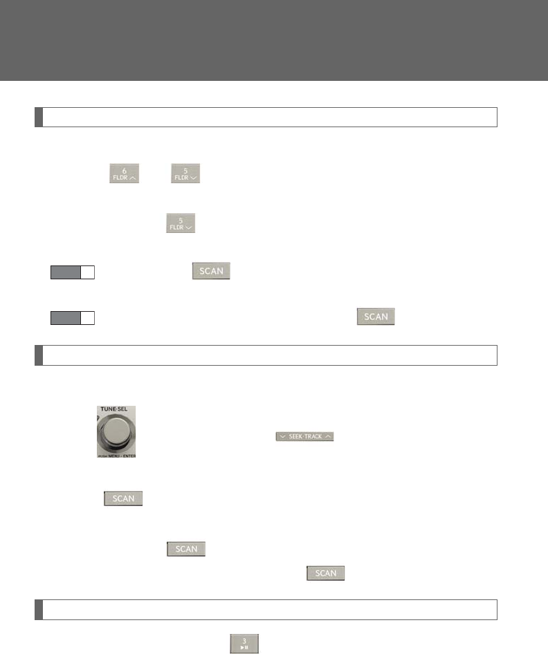
376
3-2. Using the audio system
Selecting and scanning a folder
■Selecting folders one at a time
Press or to select the desired folder.
■Returning to the first folder
Press and hold until you hear a beep.
■Scanning the first file of all the folders
Press and hold until you hear a beep.
The first ten seconds of the first file in each folder will be played.
When the desired folder is reached, press again.
Selecting and scanning files
■Selecting a file
Turn or press “” or “” on to select the desired file.
■Scanning the files in a folder
Press .
The first ten seconds of each file will be played.
To cancel, press again.
When the desired file is reached, press again.
Playing and pausing files
To play or pause a file, press .
STEP 1
STEP 2
377
3-2. Using the audio system
3
Interior features
Fast-forwarding and rewinding files
To fast-forward or rewind, press and hold “” or “” on until
you hear a beep.
Random playback
■Playing files from a folder in random order
Press .
To cancel, press again.
■Playing all the files from a USB memory in random order
Press and hold until you hear a beep.
To cancel, press again.
Repeat play
■Repeating a file
Press .
To cancel, press again.
■Repeating all the files in a folder
Press and hold until you hear a beep.
To cancel, press again.
Switching the display
Press .
Each time the button is pressed, the display changes in the following order:
Elapsed time Folder name File name Album title (MP3 only)
Track title Artist name

378
3-2. Using the audio system
■USB memory functions
●Depending on the USB memory that is connected to the system, the device
itself may not be operable and certain functions may not be available. If the
device is inoperable or a function is unavailable due to a malfunction (as
opposed to a system specification), disconnecting the device and reconnecting
it once again may resolve the problem.
●If the USB memory still does not begin operation after being disconnected and
reconnected, format the memory.
■Display
P. 352
■Routing portable audio device cables
P. 372
■Error messages
“ERROR”: This indicates a problem in the USB memory or its connection.
“NO MUSIC”: This indicates that no MP3/WMA files are included in the USB
memory.

379
3-2. Using the audio system
3
Interior features
■USB memory
●Compatible devices
USB memories that can be used for MP3 and WMA playback
●Compatible device formats
The following device formats can be used:
• USB communication formats: USB2.0 FS (12 Mbps)
• File formats: FAT16/32 (Windows)
• Correspondence class: Mass storage class
MP3 and WMA files written in any format other than those listed above may not
play correctly, and their file names and folder names may not be displayed cor-
rectly.
Items related to standards and limitations are as follows:
• Maximum directory hierarchy: 8 levels
• Maximum number of folders in a device: 999 (including the root)
• Maximum number of files in a device: 65025
• Maximum number of files per folder: 255
●MP3 and WMA files
MP3 (MPEG Audio LAYER 3) is a standard audio compression format.
Files can be compressed to approximately 1/10 of their original size using MP3
compression.
WMA (Windows Media Audio) is a Microsoft audio compression format.
This format compresses audio data to a size smaller than that of the MP3 format.
There is a limit to the MP3 and WMA file standards that can be used and to the
media/formats on which the files are recorded.

380
3-2. Using the audio system
●MP3 file compatibility
• Compatible standards
MP3 (MPEG1 AUDIO LAYERII, III, MPEG2 AUDIO LAYERII, III,
MPEG2.5)
• Compatible sampling frequencies
MPEG1 AUDIO LAYERII, III: 32, 44.1, 48 (kHz)
MPEG2 AUDIO LAYERII, III: 16, 22.05, 24 (kHz)
MPEG2.5: 8, 11.025, 12 (kHz)
• Compatible bit rates (compatible with VBR)
MPEG1 AUDIO LAYERII, III: 32-320 (kbps)
MPEG2 AUDIO LAYERII, III: 32-160 (kbps)
MPEG2.5: 32-160 (kbps)
• Compatible channel modes: stereo, joint stereo, dual channel and monaural
●WMA file compatibility
• Compatible standards
WMA Ver. 9
• Compatible sampling frequencies
HIGH PROFILE 32, 44.1, 48 (kHz)
• Compatible bit rates
HIGH PROFILE 32-320 (kbps, VBR)
●File names
The only files that can be recognized as MP3/WMA and played are those with
the extension .mp3 or .wma.
●ID3 and WMA tags
ID3 tags can be added to MP3 files, making it possible to record the track title,
artist name, etc.
The system is compatible with ID3 Ver. 1.0, 1.1, and Ver. 2.2, 2.3, 2.4 ID3 tags.
(The number of characters is based on ID3 Ver. 1.0 and 1.1.)
WMA tags can be added to WMA files, making it possible to record the track
title and artist name in the same way as with ID3 tags.

381
3-2. Using the audio system
3
Interior features
●MP3 and WMA playback
• When a device containing MP3 or WMA files is connected, all files in the
USB memory device are checked. Once the file check is finished, the first
MP3 or WMA file is played. To make the file check finish more quickly, we
recommend that you do not include any files other than MP3 or WMA files
or create any unnecessary folders.
• When the USB device is connected and the audio source is changed to
USB memory mode, the USB device will start playing the first file in the first
folder. If the same device is removed and reinserted (and the contents have
not been changed), the USB device will resume play from the same point in
which it was last used.
●Extensions
If the file extensions .mp3 and .wma are used for files other than MP3 and WMA
files, they will be skipped (not played).
●Playback
• To play MP3 files with steady sound quality, we recommend a fixed bit rate
of at least 128 kbps and a sampling frequency of 44.1 kHz.
• There is a wide variety of freeware and other encoding software for MP3
and WMA files on the market, and depending on the status of the encoding
and the file format, poor sound quality or noise at the start of playback may
result. In some cases, playback may not be possible at all.
• Microsoft, Windows, and Windows Media are registered trademarks of
Microsoft Corporation in the U.S.A. and other countries.
CAUTION
■Caution while driving
Do not connect USB memories or operate the controls.

382
3-2. Using the audio system
NOTICE
■To prevent damage to USB memories
●Do not leave USB memories in the vehicle. The temperature inside the vehicle
may become high, resulting in damage to the player.
●Do not push down on or apply unnecessary pressure to the USB memory while it
is connected as this may damage the USB memory or its terminal.
●Do not insert foreign objects into the port as this may damage the USB memory
or its terminal.
383
3-2. Using the audio system
3
Interior features
Optimal use of the audio system
Displays the current mode
Changes the following set-
tings:
• Sound quality and volume
balance
P. 384
The sound quality and balance
setting can be changed to pro-
duce the best sound.
• Automatic Sound Levelizer
on/off
P. 385
Type A and B
Type C
384
3-2. Using the audio system
Adjusting sound quality and volume balance
■Changing sound quality modes
Press or .
Pressing the button changes sound modes in the following order:
“BAS”“MID”“TRE”“FAD”“BAL”“A S L”
■Adjusting sound quality
Turning or adjusts the level.
*: The sound quality level is adjusted individually in each audio mode.
Mode
displayed
Sound qual-
ity mode Level Turn counter-
clockwise
Tu r n c l o c k -
wise
“BAS” Bass*-5 to 5
Low High“MID” Mid-range*-5 to 5
“TRE” Tr e b l e *-5 to 5
“FAD”
Front/rear
volume
balance
F7 to R7 Shifts to rear Shifts to front
“BAL”
Left/right
volume
balance
L7 to R7 Shifts to left Shifts to right
385
3-2. Using the audio system
3
Interior features
Turning the Automatic Sound Levelizer (ASL) on/off
Turning or clockwise turns on the ASL, and turning
or counterclockwise turns off the ASL.
ASL automatically adjusts the volume and tone quality according to the noise
level as you drive your vehicle.
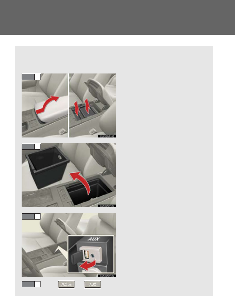
386
3-2. Using the audio system
Using the AUX port
This port can be used to connect a portable audio device and listen to it
through the vehicle’s speakers.
Slide the armrest while pulling
up the lever, and lift the armrest.
Remove the upper trays (if
equipped).
Remove the lower tray.
Open the cover and connect
the portable audio device.
Press or .
STEP 1
STEP 2
STEP 3
STEP 4

387
3-2. Using the audio system
3
Interior features
■Operating portable audio devices connected to the audio system
The volume can be adjusted using the vehicle's audio controls. All other adjust-
ments must be made on the portable audio device itself.
■When using a portable audio device connected to the power outlet
Noise may occur during playback. Use the power source of the portable audio
device.
■Routing portable audio device cables
P. 372
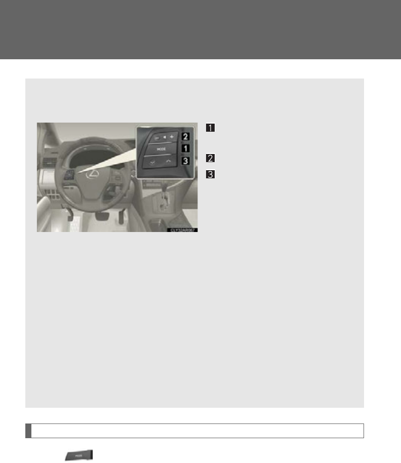
388
3-2. Using the audio system
Using the steering wheel audio switches
Turning the power on
Press when the audio system is turned off.
The audio system can be turned off by holding the switch down until you hear
a beep.
Some audio features can be controlled using the switches on the steering
wheel.
Turns the power on, selects
an audio source
Increases/decreases volume
Radio mode: Selects a radio
station
CD mode: Selects a track,
file (MP3 and
WMA) and disc
Bluetooth® audio mode
(type A and B):
Selects a track and
album
iPod mode (type A and C):
Selects a song
USB memory mode (type A
and C):
Selects a file and folder
389
3-2. Using the audio system
3
Interior features
Changing the audio source
Press when the audio system is turned on. The audio source
changes as follows each time the button is pressed. If no discs are
inserted in the player, that mode will be skipped.
Type A:
FM1FM2SAT1SAT2SAT3CD player
Bluetooth® audioAUXiPod or USB memory
AMFM1
Type B:
FM1FM2SAT1SAT2SAT3CD player
Bluetooth® audioAUXAMFM1
Type C:
FM1FM2CD playerAUXiPod or USB memory
AMFM1
Adjusting the volume
Press “+” on to increase the volume and “-” to decrease the vol-
ume.
Hold down the button to continue increasing or decreasing the volume.
Selecting a radio station
Press to select radio mode.
Press “” or “” on to select a radio station.
To scan for receivable stations, press and hold “” or “” on the button
until you hear a beep.
Selecting a track/file or song
Press to select CD, Bluetooth® audio (type A and B), iPod
(type A and C) or USB memory (type A and C) mode.
Press “” or “” on to select the desired track/file or song.
STEP 1
STEP 2
STEP 1
STEP 2
390
3-2. Using the audio system
Selecting an album (type A and B)
Press to select Bluetooth® audio mode.
Press and hold “” or “” on until you hear a beep.
Selecting a folder (type A and C)
Press to select USB memory mode.
Press and hold “” or “” on until you hear a beep.
Selecting a disc in the CD player
Press to select CD mode.
Press and hold “” or “” on until you hear a beep.
■Canceling automatic selection of a radio station
Press again.
CAUTION
■To reduce the risk of an accident
Exercise care when operating the audio switches on the steering wheel.
STEP 1
STEP 2
STEP 1
STEP 2
STEP 1
STEP 2

391
3
Interior features
3-3. Using the Bluetooth® audio system
Bluetooth® audio system
■Conditions under which the system will not operate
●If using a portable player that does not support Bluetooth®
●If the portable player is switched off
●If the portable player is not connected
●If the portable player’s battery is low
●If the portable player is behind the seat or in the glove box or console box
●If metal is covering or touching the portable player
The Bluetooth® audio system enables you to enjoy music played on a por-
table digital audio player (portable player) from the vehicle speakers via
wireless communication.
This audio system supports Bluetooth®, a wireless data system capable of
playing portable audio music without cables. If your portable player does
not support Bluetooth®, the Bluetooth® audio system will not function.
Vehicles with a navigation system
Owners of models equipped with a navigation system should refer to
the “Navigation System Owner's Manual”.
Vehicles without a navigation system
Title Page
Using the Bluetooth® audio system P. 3 94
Operating a Bluetooth® enabled portable player P. 39 9
Setting up a Bluetooth® enabled portable player P. 4 03
Bluetooth® audio system setup P. 410
: If equipped

392
3-3. Using the Bluetooth® audio system
■When transferring ownership of the vehicle
Be sure to initialize the system to prevent personal data from being improperly
accessed. (P. 4 37)
■About Bluetooth®
■Compatible models
●Bluetooth® specifications:
Ver. 1.1, or higher (Recommended: Ver. 1.2)
●Following profiles:
• A2DP (Advanced Audio Distribution Profile) Ver. 1.0, or higher (Conformed:
Ver. 1.2)
• AVRCP (Audio/Video Remote Control Profile) Ver. 1.0 or higher (Con-
formed: Ver. 1.3)
Portable players must correspond to the above specifications in order to be con-
nected to the Bluetooth® audio system. However, please note that some functions
may be limited depending on the type of portable player.
■Certification for the Bluetooth® audio system
FCC ID: AJDK018
IC ID: 775E-K018
MADE IN JAPAN
This device complies with Part 15 of the FCC Rules and RSS-Gen of IC Rules.
Operation is subject to the following two conditions: (1) This device may not cause
harmful interference, and (2) This device must accept any interference received,
including interference that may cause undesired operation.
Bluetooth is a registered trademark of
Bluetooth SIG. Inc.
393
3-3. Using the Bluetooth® audio system
3
Interior features
CAUTION
■FCC WARNING
Changes or modifications not expressly approved by the party responsible for
compliance could void the user's authority to operate the equipment.
Radio Frequency Radiation Exposure. This equipment complies with FCC radiation
exposure limits set forth for uncontrolled equipment and meets the FCC radio fre-
quency (RF) Exposure Guidelines in Supplement C to OET65. This equipment has
very low levels of RF energy that it deemed to comply without maximum permissive
exposure evaluation (MPE). But it is desirable that it should be installed and oper-
ated with at least 7.9 in. (20 cm) and more between the radiator and person’s body
(excluding extremities: hands, wrists, feet and ankles).
This transmitter must not be co-located or operated in conjunction with any other
antenna or transmitter.
■Caution while driving
Do not connect portable players or operate the controls.
NOTICE
■To prevent damage to portable players
Do not leave portable players in the vehicle. The temperature inside the vehicle
may become high, resulting in damage to the player.
394
3-3. Using the Bluetooth® audio system
Using the Bluetooth® audio system
■Audio unit
Display
A message, name, number,
etc. is displayed.
Lower-case characters and
special characters cannot be
displayed.
Displays information that is
too long to be displayed at
one time on the display (press
and hold)
Selects items such as menu
and number
Turn: Selects an item
Press: Inputs the selected
item
Bluetooth® connection con-
dition
If “BT” is not displayed, the
Bluetooth® audio system
cannot be used.
395
3-3. Using the Bluetooth® audio system
3
Interior features
Operating the system using voice commands
By following voice guidance instructions output from the speaker, voice
commands enable the operation of the Bluetooth® audio system without
the need to check the display or operate .
■Operation procedure when using voice commands
Press the talk switch and follow voice guidance instructions.
■Auxiliary commands when using voice commands
The following auxiliary commands can be used when operating the
system using a voice command:
“Cancel”: Exits the Bluetooth® audio system
“Repeat”: Repeats the previous voice guidance instruction
“Go back”: Returns to the previous procedure
“Help”: Reads aloud the function summary if a help comment is regis-
tered for the selected function
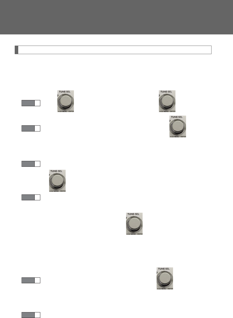
396
3-3. Using the Bluetooth® audio system
Using the Bluetooth® audio system for the first time
Before using the Bluetooth® audio system, it is necessary to register a
Bluetooth® enabled portable player in the system. Follow the procedure
below to register (pair) a portable player:
Press and select “BT•A MENU” using .
Press the talk switch or select “BT•A Setup” using .
The introductory guidance and portable player name registration
instructions are heard.
Select “Pair Audio Player (Pair Audio)” using a voice command
or .
Register a portable player name by either of the following meth-
ods:
a. Select “Record Name” using , and say the name to be
registered.
b. Press the talk switch and say the name to be registered.
A voice guidance instruction to confirm the input is heard.
Select “Confirm” using a voice command or .
A passkey is displayed and heard, and a voice guidance instruction for
inputting the passkey into the portable player is heard.
Input the passkey into the portable player.
Refer to the manual that comes with the portable player for the opera-
tion of the portable player.
STEP 1
STEP 2
STEP 3
STEP 4
STEP 5
STEP 6
397
3-3. Using the Bluetooth® audio system
3
Interior features
Guidance for registration completion is heard.
If the portable player has a Bluetooth® phone, the phone can be regis-
tered at the same time. A voice guidance instruction to register a Blue-
tooth® phone is heard.
Select “Yes” or “No” using a voice command or .
(Bluetooth® phone P. 413)
Menu list of the Bluetooth® audio system
First menu Second
menu Third menu Operation detail
“Setup”
“BT•A
Setup”
“Pair Audio” Registering a portable player
“Connect” Selecting a portable player to
be used
“Change Name” Changing the registered name
of a portable player
“List Audios” Listing the registered portable
players
“Set Passkey” Changing the passkey
“Delete Audio” Deleting a registered portable
player
“System
Setup”
“Guidance Vol” Setting voice guidance volume
“Device Name” Displaying the Bluetooth®
device address and name
“Initialize” Initializing the system
STEP 7

398
3-3. Using the Bluetooth® audio system
■When using a voice command
For numbers, say a combination of single digits from zero to nine.
Say the command correctly and clearly.
■Situations in which the system may not recognize your voice
●When driving on rough roads
●When driving at high speeds
●When air is blowing out of the vents onto the microphone
●When the air conditioning fan emits a loud noise
■Operations that cannot be performed while driving
●Operating the system with
●Registering a portable player to the system
■Changing the passkey
P. 4 08
399
3-3. Using the Bluetooth® audio system
3
Interior features
Operating a Bluetooth® enabled portable player
Type A
“PWR
VOL” knob
Track selector button
Playback button
Search playback button
Random playback button
Repeat play button
Text b ut t o n
Power Volume
Playback/Pause button
Album selector buttons
BT·A menu knob
400
3-3. Using the Bluetooth® audio system
Type B
“PWR
VOL” knob
Track selector button
Playback button
Search playback button
Random playback button
Repeat play button
Text b ut t o n
Power Volume
Playback/Pause button
Album selector buttons
BT·A menu knob
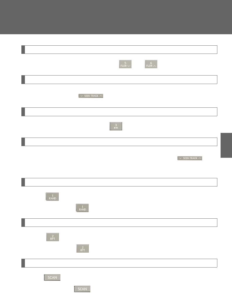
401
3-3. Using the Bluetooth® audio system
3
Interior features
Selecting an album
To select the desired album, press or .
Selecting tracks
Press “” or “” on to select the desired track.
Playing and pausing tracks
To play or pause a track, press .
Fast-forwarding and rewinding tracks
To fast-forward or rewind, press and hold “” or “” on until
you hear a beep.
Random playback
Press .
To cancel, press again.
Repeat play
Press .
To cancel, press again.
Scanning tracks
Press .
To cancel, press again.

402
3-3. Using the Bluetooth® audio system
Switching the display
Press .
Each time the button is pressed, the display changes in the following order:
Elapsed time Album title Tra c k t i t l e Artist name
Using the steering wheel audio switches
P. 388
■Bluetooth® audio system functions
Depending on the portable player that is connected to the system, certain functions
may not be available.
■Display
P. 352
■Error messages
“Memory Error”: This indicates a problem in the system.
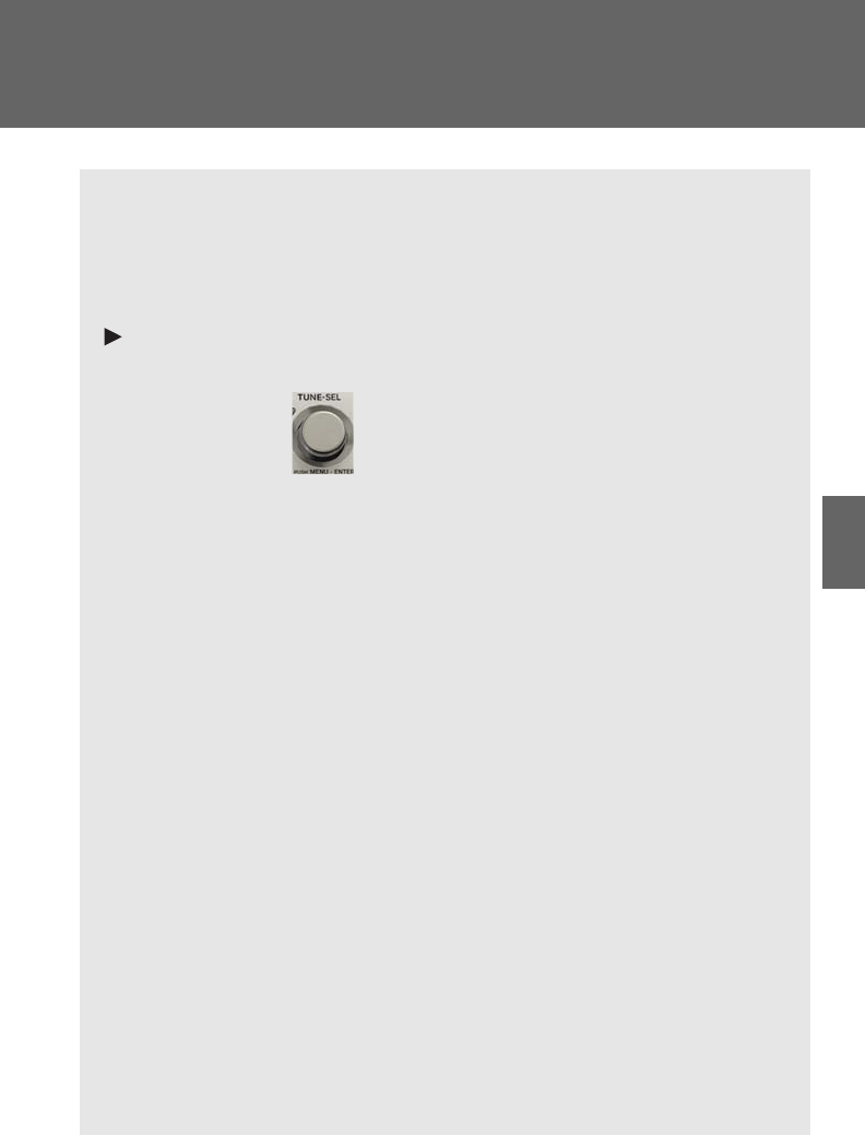
403
3-3. Using the Bluetooth® audio system
3
Interior features
Setting up a Bluetooth® enabled portable player
Registering a portable player in the Bluetooth® audio system allows the
system to function. The following functions can be used for registered por-
table players:
■Functions and operation procedures
Pattern A
To enter the menu for each function, follow the steps below using a
voice command or :
●Registering a portable player
1. “Setup” 2. “Bluetooth Audio Setup (BT•A Setup)”
3. “Pair Audio Player (Pair Audio)”
●Selecting a portable player to be used
1. “Setup” 2. “Bluetooth Audio Setup (BT•A Setup)”
3. “Connect Audio Player (Connect)”
●Changing the registered name of a portable player
1. “Setup” 2. “Bluetooth Audio Setup (BT•A Setup)”
3. “Change Name”
●Listing the registered portable players
1. “Setup” 2. “Bluetooth Audio Setup (BT•A Setup)”
3. “List Audio Players (List Audios)”
●Changing the passkey
1. “Setup” 2. “Bluetooth Audio Setup (BT•A Setup)”
3. “Set Passkey”
●Deleting a registered portable player
1. “Setup” 2. “Bluetooth Audio Setup (BT•A Setup)”
3. “Delete Audio Player (Delete Audio)”
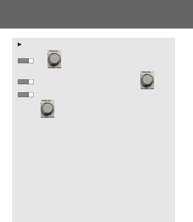
404
3-3. Using the Bluetooth® audio system
Pattern B
Press to select “BT•A MENU”.
Press the talk switch or select “BT•A Setup” using .
Select one of the following functions using a voice command
or .
●Registering a portable player
“Pair Audio Player (Pair Audio)”
●Selecting a portable player to be used
“Connect Audio Player (Connect)”
●Changing the registered name of a portable player
“Change Name”
●Listing the registered portable players
“List Audio Players (List Audios)”
●Changing the passkey
“Set Passkey”
●Deleting a registered portable player
“Delete Audio Player (Delete Audio)”
STEP 1
STEP 2
STEP 3
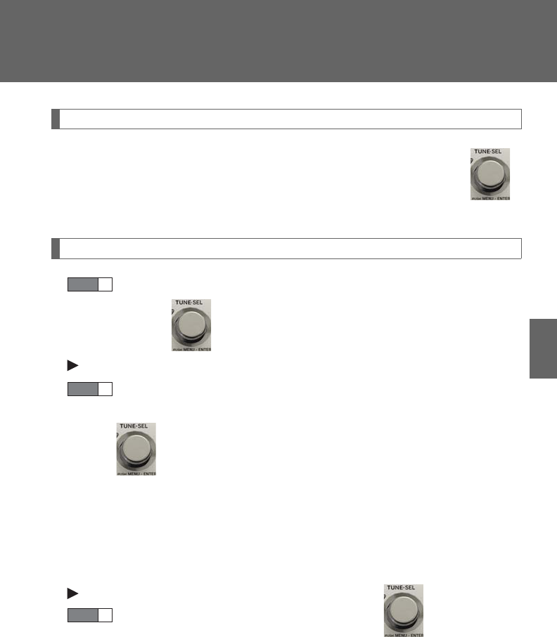
405
3-3. Using the Bluetooth® audio system
3
Interior features
Registering a portable player
Select “Pair Audio Player (Pair Audio)” using a voice command or ,
and perform the procedure for registering a portable player. (P. 396)
Selecting a portable player to be used
Select “Connect Audio Player (Connect)” using a voice com-
mand or .
Pattern A
Select the portable player to be used by either of the following
methods, and select “Confirm” by using a voice command or
:
a. Press the talk switch and say the name of the desired portable
player.
b. Press the talk switch and say “List Audio Players”. When the
name of the desired portable player is read aloud, press the
talk switch.
Pattern B
Select the portable player to be used using .
STEP 1
STEP 2
STEP 2
406
3-3. Using the Bluetooth® audio system
Pattern A
Press the talk switch and say “From Car” or “From Audio player”,
and select “Confirm” by using a voice command or .
Pattern B
Select “From Car” or “From Audio”, using .
If “From Car” is selected, the portable player will be automatically con-
nected whenever the “POWER” switch is in either ACCESSORY or
ON mode.
Changing the registered name of a portable player
Select “Change Name” using a voice command or .
Pattern A
Select the name of the portable player to be changed by either of
the following methods, and select “Confirm” using a voice com-
mand or :
a. Press the talk switch and say the name of desired portable
player.
b. Press the talk switch and say “List Audio Players”. When the
name of the desired portable player is read aloud, press the
talk switch.
STEP 3
STEP 3
STEP 1
STEP 2
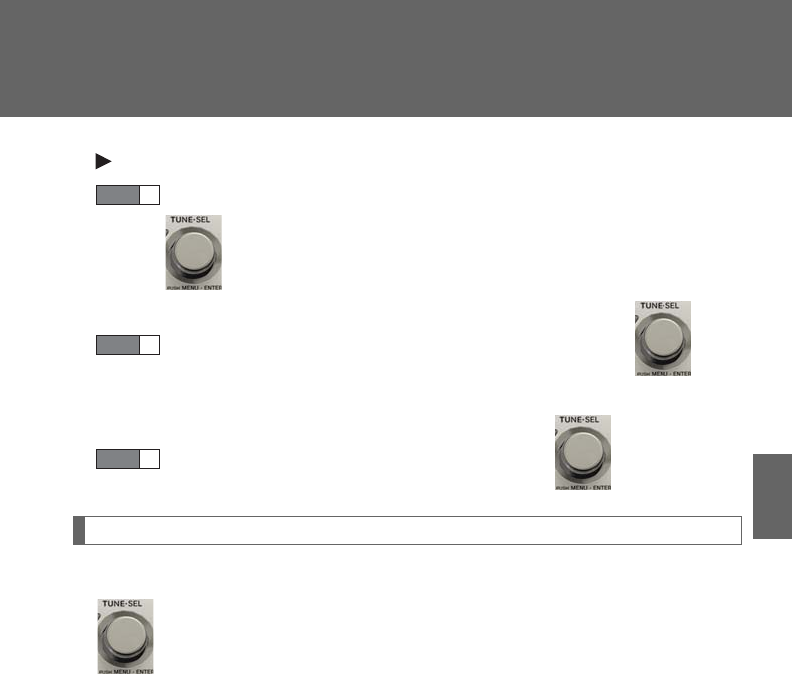
407
3-3. Using the Bluetooth® audio system
3
Interior features
Pattern B
Select the desired portable player name to be changed using
.
Press the talk switch or select “Record Name” using , and
say the new name.
Select “Confirm” using a voice command or .
Listing the registered portable players
Select “List Audio Players (List Audios)” using a voice command or
. The list of registered portable players will be read aloud.
When listing is complete, the system returns to “BT•A Setup”.
Pressing the talk switch while the name of a portable player is being read
aloud selects the portable player, and the following functions will become
available:
●Selecting a portable player: “Connect Audio Player (Connect)”
●Changing a registered name: “Change Name”
●Deleting a portable player: “Delete Audio Player (Delete Audio)”
STEP 2
STEP 3
STEP 4
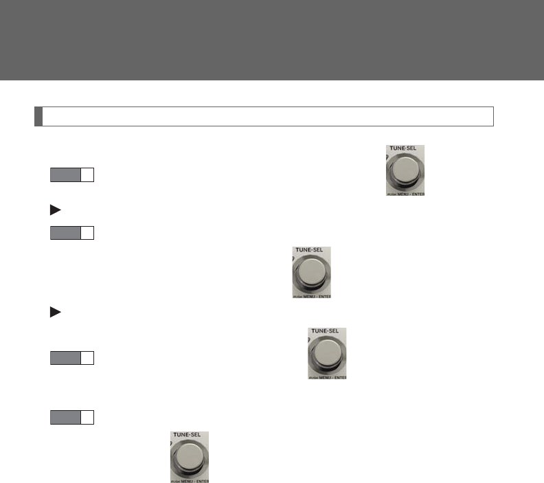
408
3-3. Using the Bluetooth® audio system
Changing the passkey
Select “Set Passkey” using a voice command or .
Pattern A
Press the talk switch, say a 4 to 8-digit number, and select “Con-
firm” using a voice command or .
Pattern B
Select a 4 to 8-digit number using .
The number should be input 1 digit at a time.
When the entire number to be registered as a passkey has been
input, press again.
If the number to be registered has 8 digits, pressing of the knob is not
necessary.
STEP 1
STEP 2
STEP 2
STEP 3
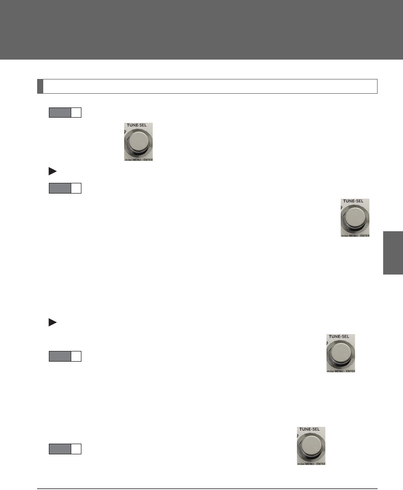
409
3-3. Using the Bluetooth® audio system
3
Interior features
Deleting a registered portable player
Select “Delete Audio Player (Delete Audio)” using a voice com-
mand or .
Pattern A
Select the portable player to be deleted by either of the following
methods and select “Confirm” using a voice command or :
a. Press the talk switch and say the name of the desired portable
player.
b. Press the talk switch and say “List Audio Players”. When the
name of the desired portable player is read aloud, press the
talk switch.
Pattern B
Select the desired portable player to be deleted using .
If the portable player to be deleted is paired as a Bluetooth® phone, the
registration of the mobile phone can be deleted at the same time. A voice
guidance instruction to delete a mobile phone is heard.
Select “Yes” or “No” using a voice command or .
(Bluetooth® phone P. 413)
■The number of portable players that can be registered
Up to 2 portable players can be registered in the system.
STEP 1
STEP 2
STEP 2
STEP 3
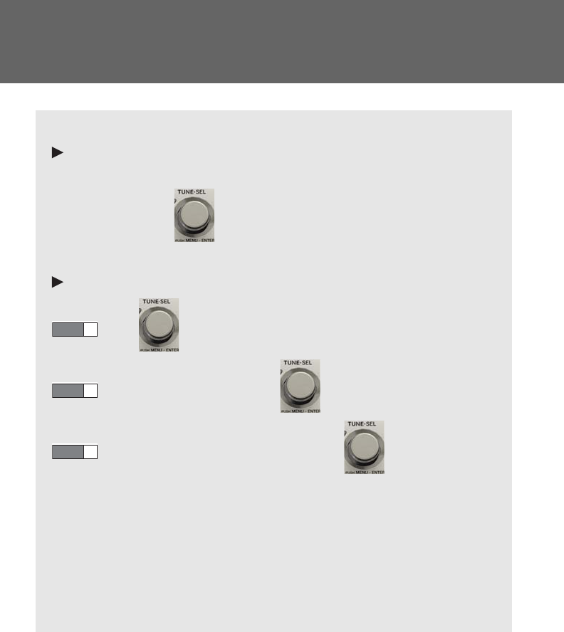
410
3-3. Using the Bluetooth® audio system
Bluetooth® audio system setup
■System setup items and operation procedures
Pattern A
To enter the menu for each function, follow the steps below using a
voice command or :
(P. 43 4)
Pattern B
Press to select “BT•A MENU”.
Select “System Setup” using .
Select one of the following items using :
●Setting voice guidance volume
“Guidance Vol” (
P. 43 6 )
●Displaying the Bluetooth® device address and name
“Device Name” (
P. 43 6 )
●Initializing the system
“Initialize” (
P. 4 37)
STEP 1
STEP 2
STEP 3

411
3
Interior features
3-4. Using the hands-free phone system (for mobile phones)
Hands-free system for mobile phones
The hands-free system is a function that allows you to use your mobile
phone without touching it.
This system supports Bluetooth® mobile phones. Bluetooth® is a wireless
data system that allows the mobile phone to wirelessly connect to the
hands-free system and make/receive calls.
Vehicles with a navigation system
Owners of models equipped with a navigation system should refer to
the “Navigation System Owner's Manual”.
Vehicles without a navigation system
Tit le Page
Using the hands-free system P. 415
Making a phone call P. 42 3
Setting a mobile phone P. 428
Security and system setup P. 43 4
Using the phone book P. 43 8
: If equipped

412
3-4. Using the hands-free phone system (for mobile phones)
■Conditions under which the system will not operate
●If using a mobile phone that does not support Bluetooth®
●If the mobile phone is switched off
●If you are outside service range
●If the mobile phone is not connected
●If the mobile phone's battery is low
●If the mobile phone is behind the seat or in the glove box or console box
●If metal is covering or touching the phone
■When using the hands-free system
●The audio system and voice guidance are muted when making a call.
●If both parties speak at the same time, it may be difficult to hear.
●If the incoming call volume is overly loud, an echo may be heard.
●Try to face toward the microphone as much as possible when speaking.
●In the following circumstances, it may be difficult to hear the other party:
• When driving on unpaved roads
• When driving at high speeds
• When a window is open
• When the air conditioning is blowing directly on the microphone
• When the air conditioning is set to high
■When transferring ownership of the vehicle
Be sure to initialize the system to prevent personal data from being improperly
accessed. (P. 4 37)
■About Bluetooth®
Bluetooth is a registered trademark of
Bluetooth SIG. Inc.

413
3-4. Using the hands-free phone system (for mobile phones)
3
Interior features
■Compatible models
Compatible with HFP (Hands Free Profile) Ver. 1.0 or higher (Conformed: Ver. 1.5)
and OPP (Object Push Profile) Ver. 1.1.
If your mobile phone does not support HFP, you cannot enter the Bluetooth®
phone. If your mobile phone supports OPP alone, you cannot use the Bluetooth®
phone.
■Certification for the hands-free system
FCC ID: AJDK018
IC ID: 775E-K018
MADE IN JAPAN
This device complies with Part 15 of the FCC Rules and RSS-Gen of IC Rules.
Operation is subject to the following two conditions: (1) This device may not cause
harmful interference, and (2) This device must accept any interference received,
including interference that may cause undesired operation.
CAUTION
■FCC WARNING
Changes or modifications not expressly approved by the party responsible for
compliance could void the user's authority to operate the equipment.
Radio Frequency Radiation Exposure. This equipment complies with FCC radiation
exposure limits set forth for uncontrolled equipment and meets the FCC radio fre-
quency (RF) Exposure Guidelines in Supplement C to OET65. This equipment has
very low levels of RF energy that it deemed to comply without maximum permissive
exposure evaluation (MPE). But it is desirable that it should be installed and oper-
ated with at least 7.9 in. (20 cm) and more between the radiator and person’s body
(excluding extremities: hands, wrists, feet and ankles).
This transmitter must not be co-located or operated in conjunction with any other
antenna or transmitter.
■Caution while driving
Do not use a mobile phone or connect the Bluetooth® phone.

414
3-4. Using the hands-free phone system (for mobile phones)
NOTICE
■To prevent damage to mobile phones
Do not leave mobile phones in the vehicle. The temperature inside the vehicle may
become high, resulting in damage to the phone.
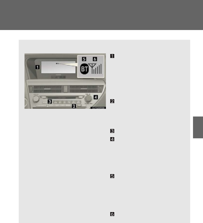
415
3-4. Using the hands-free phone system (for mobile phones)
3
Interior features
Using the hands-free system (for mobile phones)
■Audio unit
Display
A message, name, phone
number, etc. is displayed.
Lower-case characters and
special characters cannot be
displayed.
Displays information that is
too long to be displayed at
one time on the display (press
and hold)
Selects speed dials
Selects items such as menu
and number
Turn: Selects an item
Press: Inputs the selected
item
Bluetooth® connection con-
dition
If “BT” is not displayed, the
hands-free phone system
cannot be used.
Reception level
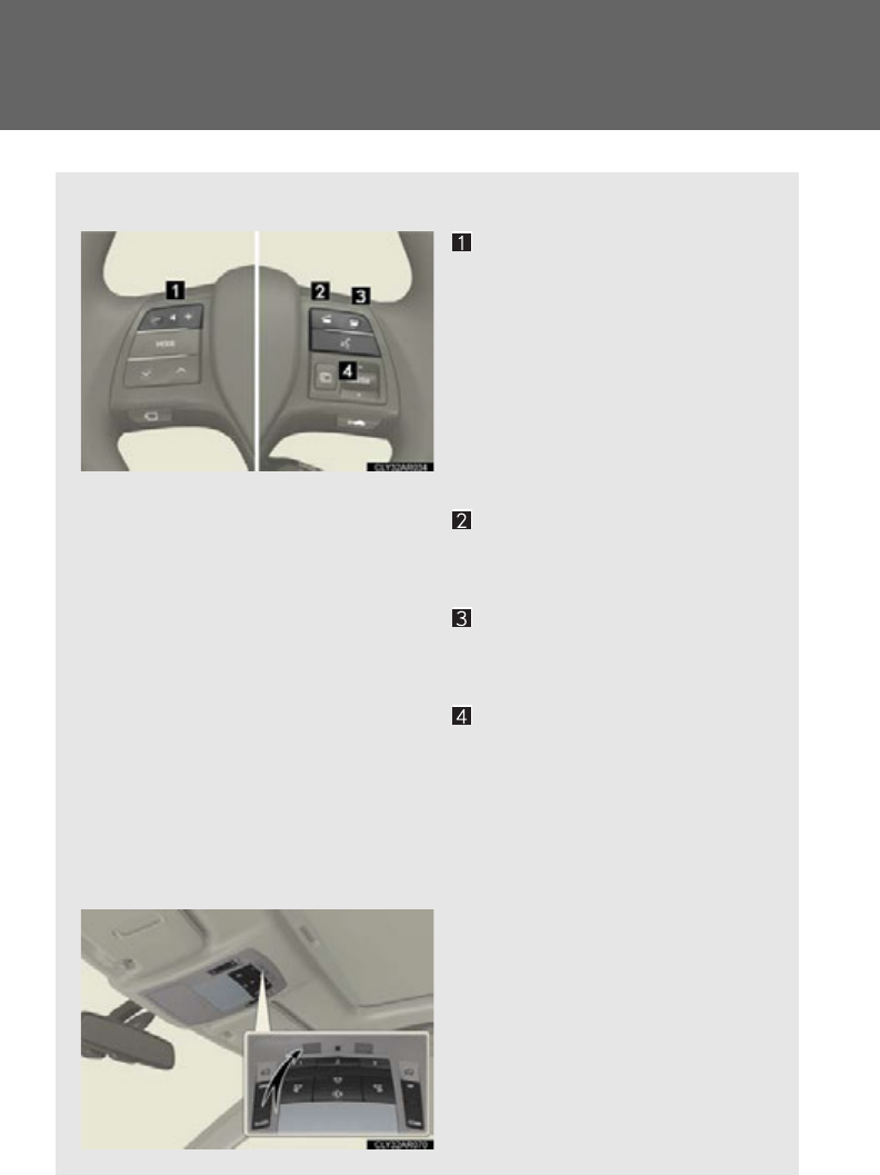
416
3-4. Using the hands-free phone system (for mobile phones)
■Steering wheel switches
Vol ume
During an incoming call:
Adjusts the ring tone volume
During an ongoing call:
Adjusts the receiver volume
The voice guidance volume can-
not be adjusted using this but-
ton.
Off-hook switch
Turns the hands-free system
on/starts a call
On-hook switch
Turns the hands-free system
off/ends a call/refuses a call
Talk switch
Turns the voice command
system on (press)/turns the
voice command system off
(press and hold)
■Microphone
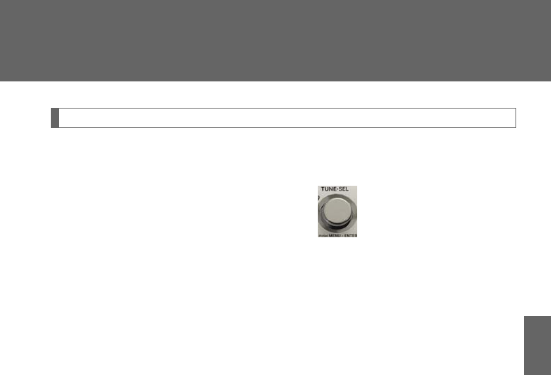
417
3-4. Using the hands-free phone system (for mobile phones)
3
Interior features
Operating the system using voice commands
By following voice guidance instructions output from the speaker, voice
commands enable the operation of the hands-free phone system without
the need to check the display or operate .
■Operation procedure when using voice commands
Press the talk switch and follow voice guidance instructions.
■Auxiliary commands when using voice commands
The following auxiliary commands can be used when operating the
system using a voice command:
“Cancel”: Exits the hands-free phone system
“Repeat”: Repeats the previous voice guidance instruction
“Go back”: Returns to the previous procedure
“Help”: Reads aloud the function summary if a help comment is regis-
tered for the selected function
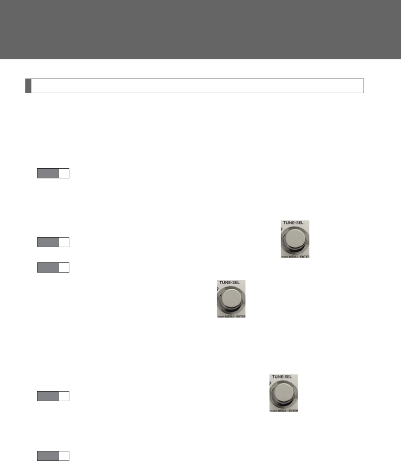
418
3-4. Using the hands-free phone system (for mobile phones)
Using the hands-free phone system for the first time
Before using the hands-free phone system, it is necessary to register a
mobile phone in the system. The system will enter phone registration
mode automatically when starting the system with no mobile phone reg-
istered. Follow the procedure below to register (pair) a mobile phone:
Press the off-hook switch or the talk switch.
The introductory guidance and phone name registration instructions are
heard.
Select “Pair Phone” using a voice command or .
Register a phone name by either of the following methods:
a. Select “Record Name” using , and say the name to be
registered.
b. Press the talk switch and say the name to be registered.
A voice guidance instruction to confirm the input is heard.
Select “Confirm” using a voice command or .
A passkey is displayed and heard, and a voice guidance instruction for
inputting the passkey into the mobile phone is heard.
Input the passkey into the mobile phone.
Refer to the manual that comes with the mobile phone for the operation
of the phone.
Guidance for registration completion is heard.
If the mobile phone has a Bluetooth® audio player, the audio player can
be registered at the same time. A voice guidance instruction to register a
Bluetooth® audio player is heard.
STEP 1
STEP 2
STEP 3
STEP 4
STEP 5
419
3-4. Using the hands-free phone system (for mobile phones)
3
Interior features
Select “Yes” or “No” using a voice command or .
(Bluetooth® audio player P. 392)
Menu list of the hands-free phone system
■Normal operation
First menu Second
menu Third menu Operation detail
“Callback” - - Dialing a number stored in the
incoming call history memory
“Redial” - - Dialing a number stored in the
outgoing call history memory
“Phonebook”
“A d d E n t r y ” -Adding a new phone number
“Change
Name” -Changing the registered name
in the phone book
“Delete
Entry” -Deleting the registered data
“Del Spd
Dial” -Deleting speed dials
“List
Names” -Listing the registered data
“Speed
Dial” -Setting speed dials
STEP 6

420
3-4. Using the hands-free phone system (for mobile phones)
“Setup”
“Security”
“Set PIN” Setting a PIN code
“Phbk Lock” Locking the phone book
“Phbk Unlock” Unlocking the phone book
“Phone
Setup”
“Pair Phone” Registering the mobile phone
to be used
“Connect” Selecting a mobile phone to be
used
“Change Name” Changing the registered name
of a mobile phone
“List Phones” Listing the registered mobile
phones
“Set Passkey” Changing the passkey
“Delete Phone” Deleting a registered mobile
phone
“System
Setup”
“Guidance Vol” Setting voice guidance volume
“Device Name” Displaying the Bluetooth®
device address and name
“Initialize” Initializing the system
First menu Second
menu Third menu Operation detail

421
3-4. Using the hands-free phone system (for mobile phones)
3
Interior features
■Short cut key operation
First menu Second menu Operation detail
“Dial XXX (name)” -Dialing a name registered in the
phone book
“Phone book add
Entry” -Adding a new phone number
“Phone book Change
name” -Changing a registered name in
the phone book
“Phone book Delete
Entry” -Deleting the registered data
“Phone book List
names” -Listing the registered data
“Phone book Set
Speed Dial” -Setting speed dials
“Phone book Delete
Speed Dial” -Deleting speed dials
“Dial XXX (number)” -Dialing by inputting a number
“Phonebook” “Phonebook Unlock” Unlocking the phone book
“Phonebook Lock” Locking the phone book

422
3-4. Using the hands-free phone system (for mobile phones)
■Automatic volume adjustment
When vehicle speed reaches 50 mph (80 km/h) or more, the volume automati-
cally increases. The volume returns to the previous volume setting when vehicle
speed drops to 43 mph (70 km/h) or less.
■When using a voice command
For numbers, say a combination of single digits from zero to nine, # (pound),
(star), and + (plus).
Say the command correctly and clearly.
■Situations in which the system may not recognize your voice
●When driving on rough roads
●When driving at high speeds
●When air is blowing out of the vents onto the microphone
●When the air conditioning fan emits a loud noise
■Operations that cannot be performed while driving
●Operating the system with
●Registering a mobile phone to the system
■Changing the passkey
P. 4 31

423
3-4. Using the hands-free phone system (for mobile phones)
3
Interior features
Making a phone call
■Making a phone call
●Dialing by inputting a number
“Dial by number”
●Dialing by inputting a name
“Dial by name”
●Speed dialing
●Dialing a number stored in the outgoing history memory
“Redial”
●Dialing a number stored in the incoming history memory
“Call back”
■Receiving a phone call
●Answering a phone call
●Refusing a phone call
■Transferring a phone call
■Call waiting
■Using the call history memory
●Dialing
●Storing number in the phone book
●Deleting
424
3-4. Using the hands-free phone system (for mobile phones)
Dialing by inputting a number
Press the talk switch and say “Dial by number”.
Press the talk switch and say the phone number.
Dial by one of the following methods:
a. Press the off-hook switch.
b. Press the talk switch and say “Dial”.
c. Select “Dial” using .
Dialing by inputting a name
Press the talk switch and say “Dial by name”.
Select a registered name to be input by either of the following
methods:
a. Press the talk switch and say a registered name.
b. Press the talk switch and say “List Names”. Press the talk switch
when the desired name is read aloud.
Dial by one of the following methods:
a. Press the off-hook switch.
b. Press the talk switch and say “Dial”.
c. Select “Dial” using .
Speed dialing
Press the off-hook switch.
Press the preset button in which the desired number is registered.
Press the off-hook switch.
STEP 1
STEP 2
STEP 3
STEP 1
STEP 2
STEP 3
STEP 1
STEP 2
STEP 3

425
3-4. Using the hands-free phone system (for mobile phones)
3
Interior features
When receiving a phone call
■Answering a phone call
Press the off-hook switch.
■Refusing a phone call
Press the on-hook switch.
Transferring a phone call
A call can be transferred between the mobile phone and system while
dialing, receiving a call, or during a call. Use one of the following meth-
ods:
a. Operate the mobile phone.
Refer to the manual that comes with the mobile phone for the operation
of the phone.
b. Press the off-hook switch*1.
c. Press the talk switch and say “Call Transfer”*2.
*1: This operation can be performed only when transferring a call
from the mobile phone to the system during a call.
*2: While the vehicle is in motion, calls cannot be transferred from
the system to the mobile phone.
Call waiting
When a call is interrupted by an incoming call from a third party, the fol-
lowing options will become available:
●Answer the incoming call: Press the off-hook switch. (Press the off-
hook switch again as necessary to switch back and forth between
calls.)
●Refuse the incoming call: Press the on-hook switch.
426
3-4. Using the hands-free phone system (for mobile phones)
Using the call history memory
Follow the procedure below to use a number stored in the call history
memory:
Press the talk switch and say “Redial” (when using a number
stored in the outgoing call history memory) or “Call back” (when
using a number stored in the incoming call history memory).
Select the number by either of the following methods:
a. Say “Previous” or “Go back” until the desired number is dis-
played.
b. Select the desired number using .
The following operations can be performed:
Dialing: Press the off-hook switch or select “Dial” using a voice com-
mand or .
Storing the number in the phone book: Select “Store” and then
“Confirm” using a voice command or .
Deleting: Select “Delete” and then “Confirm” using a voice command
or .
STEP 1
STEP 2
STEP 3

427
3-4. Using the hands-free phone system (for mobile phones)
3
Interior features
■Call waiting
●If your phone does not support HFP Ver. 1.5, this function cannot be used.
●Call waiting operation may differ depending on your mobile phone and service
provider.
■Call history
Up to 5 numbers can be stored in each of the outgoing and incoming call history
memories.
■When talking on the phone
●Do not talk at the same time as the other party.
●Keep the volume of the incoming voice down. Otherwise, voice echo will
increase.

428
3-4. Using the hands-free phone system (for mobile phones)
Setting a mobile phone
Registering a mobile phone in the hands-free phone system allows the sys-
tem to function. The following functions can be used for registered mobile
phones:
■Functions and operation procedures
To enter the menu for each function, follow the steps below using a
voice command or :
●Registering a mobile phone
1. “Setup” 2. “Phone Setup” 3. “Pair Phone”
●Selecting a mobile phone to be used
1. “Setup” 2. “Phone Setup” 3. “Connect Phone (Connect)”
●Changing the registered name of a mobile phone
1. “Setup” 2. “Phone Setup” 3. “Change Name”
●Listing the registered mobile phones
1. “Setup” 2. “Phone Setup” 3. “List Phones”
●Changing the passkey
1. “Setup” 2. “Phone Setup” 3. “Set Passkey”
●Deleting a registered mobile phone
1. “Setup” 2. “Phone Setup” 3. “Delete Phone”
429
3-4. Using the hands-free phone system (for mobile phones)
3
Interior features
Registering a mobile phone
Select “Pair Phone” using a voice command or , and perform the
procedure for registering a mobile phone. (P. 41 8 )
Selecting a mobile phone to be used
Select “Connect Phone (Connect)” using a voice command or
.
Pattern A
Select the mobile phone to be used by either of the following
methods, and select “Confirm” by using a voice command or
:
a. Press the talk switch and say the name of the desired mobile
phone.
b. Press the talk switch and say “List Phones”. When the name of
the desired mobile phone is read aloud, press the talk switch.
Pattern B
Select the mobile phone to be used using .
STEP 1
STEP 2
STEP 2

430
3-4. Using the hands-free phone system (for mobile phones)
Changing the registered name of a mobile phone
Select “Change Name” using a voice command or .
Pattern A
Select the name of the mobile phone to be changed by either of
the following methods, and select “Confirm” using a voice com-
mand or :
a. Press the talk switch and say the name of the desired mobile
phone.
b. Press the talk switch and say “List Phones”. When the name of
the desired mobile phone is read aloud, press the talk switch.
Pattern B
Select the desired mobile phone name to be changed using
.
Press the talk switch or select “Record Name” using , and
say the new name.
Select “Confirm” using a voice command or .
STEP 1
STEP 2
STEP 2
STEP 3
STEP 4
431
3-4. Using the hands-free phone system (for mobile phones)
3
Interior features
Listing the registered mobile phones
Select “List Phones” using a voice command or . The list of regis-
tered mobile phones will be read aloud.
When listing is complete, the system returns to “Phone Setup”.
Pressing the talk switch while the name of a mobile phone is being read
aloud selects the mobile phone, and the following functions will become
available:
●Selecting a mobile phone: “Connect Phone (Connect)”
●Changing a registered name: “Change Name”
●Deleting a mobile phone: “Delete Phone”
Changing the passkey
Select “Set Passkey” using a voice command or .
Pattern A
Press the talk switch, say a 4 to 8-digit number, and select “Con-
firm” using a voice command or .
STEP 1
STEP 2
432
3-4. Using the hands-free phone system (for mobile phones)
Pattern B
Select a 4 to 8-digit number using .
The number should be input 1 digit at a time.
When the entire number to be registered as a passkey has been
input, press again.
If the number to be registered has 8 digits, pressing of the knob is not
necessary.
Deleting a registered mobile phone
Select “Delete Phone” using a voice command or .
Pattern A
Select the mobile phone to be deleted by either of the following
methods and select “Confirm” using a voice command or :
a. Press the talk switch and say the name of the desired mobile
phone.
b. Press the talk switch and say “List Phones”. When the name of
the desired mobile phone is read aloud, press the talk switch.
STEP 2
STEP 3
STEP 1
STEP 2
433
3-4. Using the hands-free phone system (for mobile phones)
3
Interior features
Pattern B
Select the desired mobile phone to be deleted using .
If the mobile phone to be deleted is paired as a Bluetooth® audio player,
the registration of the audio player can be deleted at the same time. A
voice guidance instruction to delete a Bluetooth® audio player is heard.
Select “Yes” or “No” using a voice command or .
(Bluetooth® audio player P. 392)
■The number of mobile phones that can be registered
Up to 6 mobile phones can be registered in the system.
STEP 2
STEP 3

434
3-4. Using the hands-free phone system (for mobile phones)
Security and system setup
■Security setting items and operation procedures
To enter the menu for each function, follow the steps below using a
voice command or :
●Setting or changing the PIN (Personal Identification Number)
1. “Setup” 2. “Security” 3. “Set PIN”
●Locking the phone book
1. “Setup” 2. “Security” 3. “Phonebook Lock (Phbk Lock)”
●Unlocking the phone book
1. “Setup” 2. “Security” 3. “Phonebook Unlock (Phbk
Unlock)”
■System setup items and operation procedures
To enter the menu for each function, follow the steps below using
:
●Setting voice guidance volume
1. “Setup” 2. “System Setup” 3. “Guidance Vol”
●Displaying the Bluetooth® device address and name
1. “Setup” 2. “System Setup” 3. “Device Name”
●Initializing the system
1. “Setup” 2. “System Setup” 3. “Initialize”
435
3-4. Using the hands-free phone system (for mobile phones)
3
Interior features
Setting or changing the PIN
■Setting a PIN
Select “Set PIN” using a voice command or .
Enter a PIN using a voice command or .
When using , input the code 1 digit at a time.
■Changing the PIN
Select “Set PIN” using a voice command or .
Enter the registered PIN using a voice command or .
Enter a new PIN using a voice command or .
When using , input the code 1 digit at a time.
Locking or unlocking the phone book
Select “Phonebook Lock (Phbk Lock)” or “Phonebook Unlock
(Phbk Unlock)” using a voice command or .
STEP 1
STEP 2
STEP 1
STEP 2
STEP 3
STEP 1
436
3-4. Using the hands-free phone system (for mobile phones)
Input the PIN by either of the following methods and select “Con-
firm” using a voice command or :
a. Press the talk switch and say the registered PIN.
b. Input a new PIN using .
Setting voice guidance volume
Select “Guidance Vol” using .
Change the voice guidance volume.
To decrease the volume: Turn counterclockwise.
To increase the volume: Turn clockwise.
Displaying the Bluetooth® device address and name
Select “Device Name” using .
Turn to display the Bluetooth® device address and name.
Select “Go Back” using to return to “System Setup”.
STEP 2
STEP 1
STEP 2
STEP 1
STEP 2
STEP 3
437
3-4. Using the hands-free phone system (for mobile phones)
3
Interior features
Initializing the system
Select “Initialize” and then “Confirm” using .
Select “Confirm” again using .
■Initialization
●The following data in the system can be initialized:
•Phone book
• Outgoing and incoming call history
•Speed dials
• Registered mobile phone data
•Security code
• Registered Bluetooth® enabled portable player data
• Passkey for the mobile phones
• Passkey for the Bluetooth® audio players
•Guidance volume
• Receiver volume
• Ring tone volume
●Once the initialization has been completed, the data cannot be restored to its
original state.
■When the phone book is locked
The following functions cannot be used:
●Dialing by inputting a name
●Speed dialing
●Dialing a number stored in the call history memory
●Using the phone book
STEP 1
STEP 2
438
3-4. Using the hands-free phone system (for mobile phones)
Using the phone book
Adding a new phone number
The following methods can be used to add a new phone number:
●Inputting a phone number using a voice command
●Transferring data from the mobile phone
●Inputting a phone number using
●Selecting a phone number from outgoing or incoming call history
To enter the menu for each function, follow the steps below using a
voice command or :
●Adding a new phone number
1. “Phonebook” 2. “Add Entry”
●Changing the registered name in the phone book
1. “Phonebook” 2. “Change Name”
●Listing the registered data
1. “Phonebook” 2. “List Names”
●Setting speed dials
1. “Phonebook” 2. “Set Speed Dial (Speed Dial)”
●Deleting the registered data
1. “Phonebook” 2. “Delete Entry”
●Deleting speed dials
1. “Phonebook” 2. “Delete Speed Dial (Del Spd Dial)”
439
3-4. Using the hands-free phone system (for mobile phones)
3
Interior features
■Adding procedure
Select “Add Entry” using a voice command or .
Use one of the following methods to input a telephone number:
Inputting a telephone number using a voice command:
STEP2-1 Select “By Voice” using a voice command or .
STEP2-2 Press the talk switch, say the desired number, and
select “Confirm” using a voice command.
Transferring data from the mobile phone:
STEP2-1 Select “By Phone” and then “Confirm” using a voice
command or .
STEP2-2 Transfer the data from the mobile phone.
Refer to the manual that comes with the mobile phone for
details on transferring data.
STEP2-3 Select the data to be registered by either of the follow-
ing methods:
a. Say “Previous” or “Next” until the desired data is dis-
played, and select “Confirm” using a voice com-
mand.
b. Select the desired data using .
STEP 1
STEP 2
440
3-4. Using the hands-free phone system (for mobile phones)
Inputting a phone number using :
STEP2-1 Select “Manual Input” using .
STEP2-2 Input a phone number using , and press
again.
Input the phone number 1 digit at a time.
Selecting a phone number from the outgoing or incoming call history:
STEP2-1 Select “Call History” using a voice command or .
STEP2-2 Select “Outgoing” or “Incoming” using a voice com-
mand or .
STEP2-3 Select the data to be registered by either of the follow-
ing methods:
a. Say “Previous” or “Go back” until the desired data is
displayed, and select “Confirm” using a voice com-
mand.
b. Select the desired data using .
441
3-4. Using the hands-free phone system (for mobile phones)
3
Interior features
Select the name to be registered by either of the following meth-
ods, and select “Confirm” using a voice command or :
a. Press the talk switch and say the desired name.
b. Select “Record Name” using and say the desired name.
Select “Confirm” using a voice command or .
In , selecting “Set Speed Dial (Speed Dial)” instead of “Con-
firm” registers the newly added phone number as a speed dial.
Changing the registered name in the phone book
Select “Change Name” using a voice command or .
Pattern A
Select the name to be changed by either of the following meth-
ods, and select “Confirm” using a voice command or :
a. Press the talk switch and say the desired name.
b. Press the talk switch and say “List Names”. When the desired
name is read aloud, press the talk switch.
Pattern B
Select the desired name to be changed using .
STEP 3
STEP 4
STEP 4
STEP 1
STEP 2
STEP 2
442
3-4. Using the hands-free phone system (for mobile phones)
Press the talk switch or select “Record Name” using and
say the new name.
Select “Confirm” using a voice command or .
Listing the registered data
Select “List Names” using a voice command or . The list of the reg-
istered data will be read aloud.
When listing is complete, the system returns to the “Phonebook”.
Pressing the talk switch while the desired data is being read aloud selects
the data, and the following function will become available:
●Dialing: “Dial”
●Changing a registered name: “Change Name”
●Deleting an entry: “Delete Entry”
●Setting a speed dial: “Set Speed Dial (Speed Dial)”
STEP 3
STEP 4
443
3-4. Using the hands-free phone system (for mobile phones)
3
Interior features
Setting speed dials
Select “Set Speed Dial (Speed Dial)” using a voice command or
.
Pattern A
Select the data to be registered as a speed dial by either of the
following methods and select “Confirm” using a voice command
or :
a. Press the talk switch and say the desired name.
b. Press the talk switch and say “List Names”. When the desired
name is read aloud, press the talk switch.
Pattern B
Select the desired data using .
Select the desired preset button and register the data into speed
dial by either of the following methods:
a. Press the desired preset button and select “Confirm” by using a
voice command or .
b. Press and hold the desired preset button.
STEP 1
STEP 2
STEP 2
STEP 3
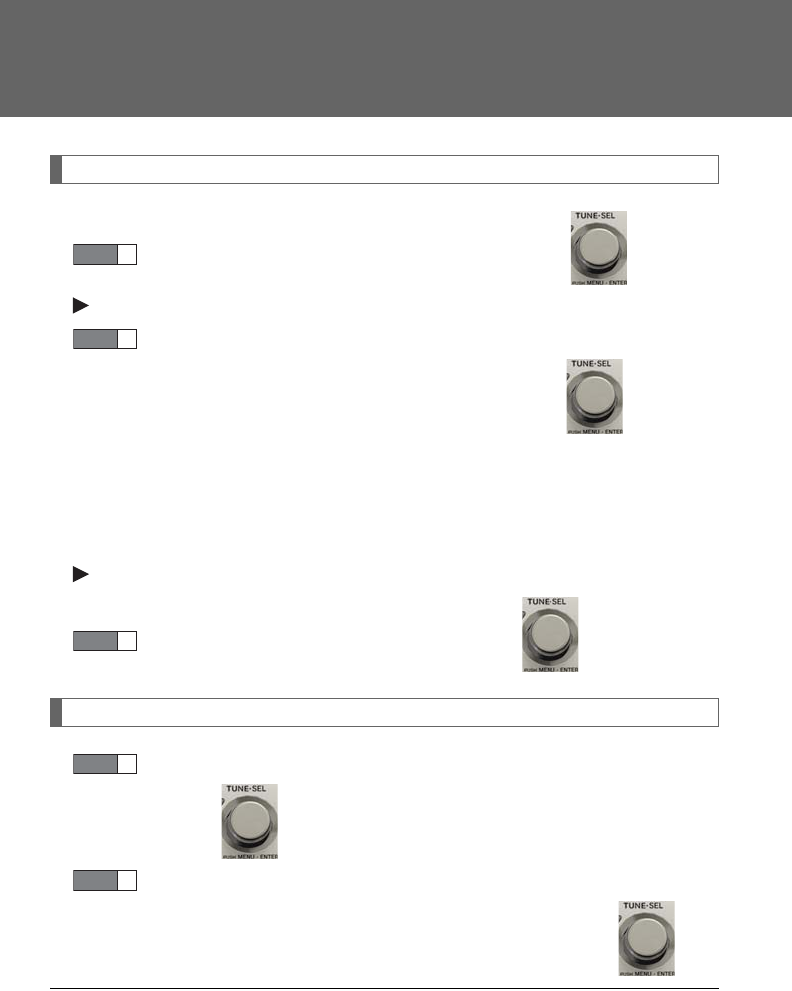
444
3-4. Using the hands-free phone system (for mobile phones)
Deleting the registered data
Select “Delete Entry” using a voice command or .
Pattern A
Select the data to be deleted by either of the following methods
and select “Confirm” using a voice command or :
a. Press the talk switch and say the name of the desired phone
number.
b. Press the talk switch and say “List Names”. When the name of
the desired phone number is read aloud, press the talk switch.
Pattern B
Select the desired data to be deleted using .
Deleting speed dials
Select “Delete Speed Dial (Del Spd Dial)” using a voice com-
mand or .
Press the preset button to which the desired speed dial is regis-
tered and select “Confirm” using a voice command or .
■Limitation of number of digits
A phone number that exceeds 24 digits cannot be registered.
STEP 1
STEP 2
STEP 2
STEP 1
STEP 2

445
3
Interior features
3-5. Using the interior lights
Interior lights list
Front personal lights (P. 446)
Front interior light (P. 446)
Shift lever light (when the “POWER” switch is in ACCESSORY or
ON mode)
Rear personal lights ( P. 446)
Rear interior light
Door courtesy lights
Scuff lights (if equipped)
Footwell lights
Outer foot lights
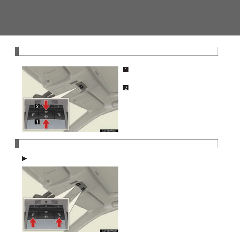
446
3-5. Using the interior lights
Interior lights
Turns the lights on/off linked to
door positions.
Turns the lights on/off
Personal lights
Front
Turns the light on/off
Interior lights and personal lights
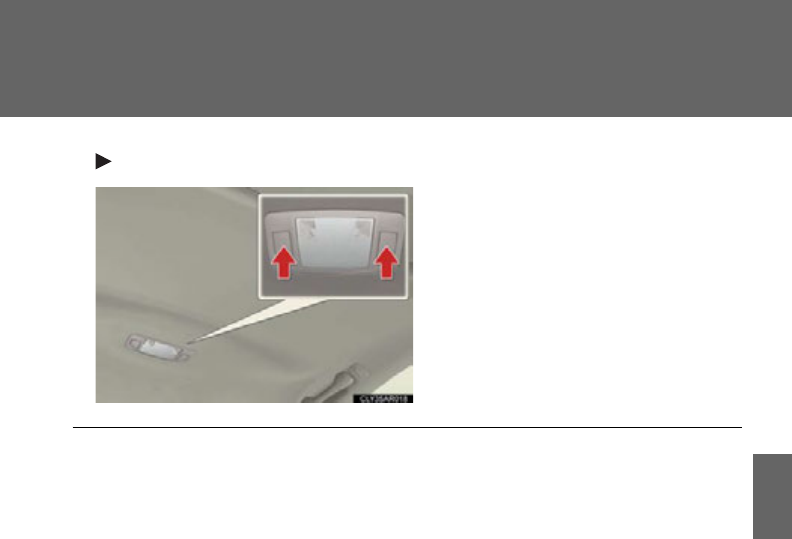
447
3-5. Using the interior lights
3
Interior features
Rear
Turns the light on/off
■Illuminated entry system
The lights automatically turn on/off according to “POWER” switch mode, the pres-
ence of the electronic key, whether the doors are locked/unlocked, and whether
the doors are open/closed.
■To prevent 12-volt battery discharge
If the interior lights remain on when the door is not fully closed and the interior light
switch (door position on/ off) is on, the lights will go off automatically after 20 min-
utes.
■Customization
Settings (e.g. the time elapsed before the lights turn off) can be changed.
(Customizable features P. 693 )
Personal lights

448
3-6. Using the storage features
List of storage features
CAUTION
■Items that should not be left in the storage spaces
Do not leave glasses, lighters or spray cans in the storage spaces, as this may cause
the following when cabin temperature becomes high:
●Glasses may be deformed by heat or cracked if they come into contact with
other stored items.
●Lighters or spray cans may explode. If they come into contact with other stored
items, the lighter may catch fire or the spray can may release gas, causing a fire
hazard.
Glove box
Auxiliary boxes (if equipped)
Bottle holders/door pockets
Cup holders
Console box
Under tray
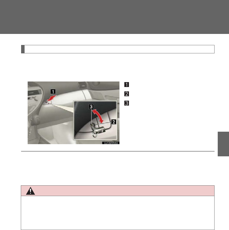
449
3-6. Using the storage features
3
Interior features
Glove box
The glove box can be opened by pressing the lock release button and
locked and unlocked using the mechanical key.
Opens
Locks
Unlocks
■Power back door main switch (if equipped)
The power back door main switch is located in the glove box. (P. 72 )
CAUTION
■Caution while driving
Keep the glove box closed.
Injuries may result in the event of an accident or sudden braking.
Glove box
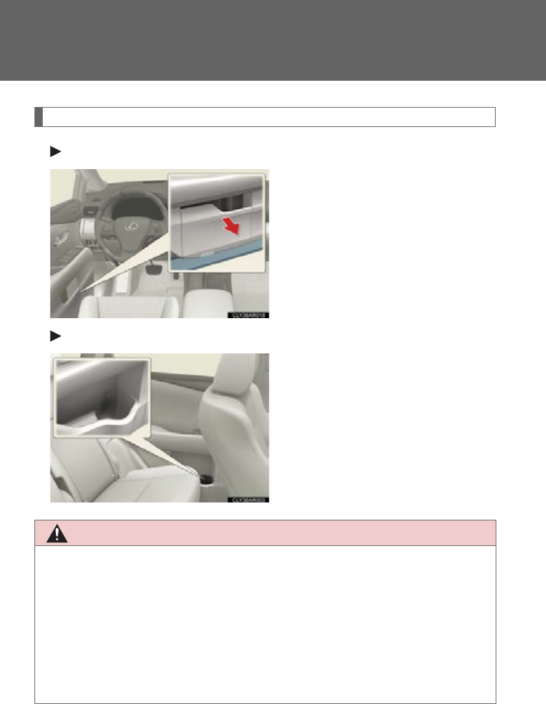
450
3-6. Using the storage features
Bottle holders/door pockets
Front
The front door pockets can be
opened and closed.
Rear
CAUTION
■Caution while driving (front door pockets)
Keep the door pockets closed.
Injuries may result in the event of an accident or sudden braking.
■Items unsuitable for the bottle holders
Do not place anything other than bottles in the bottle holders.
Other items may be thrown out of the holders in the event of an accident or sudden
braking and cause injury.
Bottle holders/door pockets
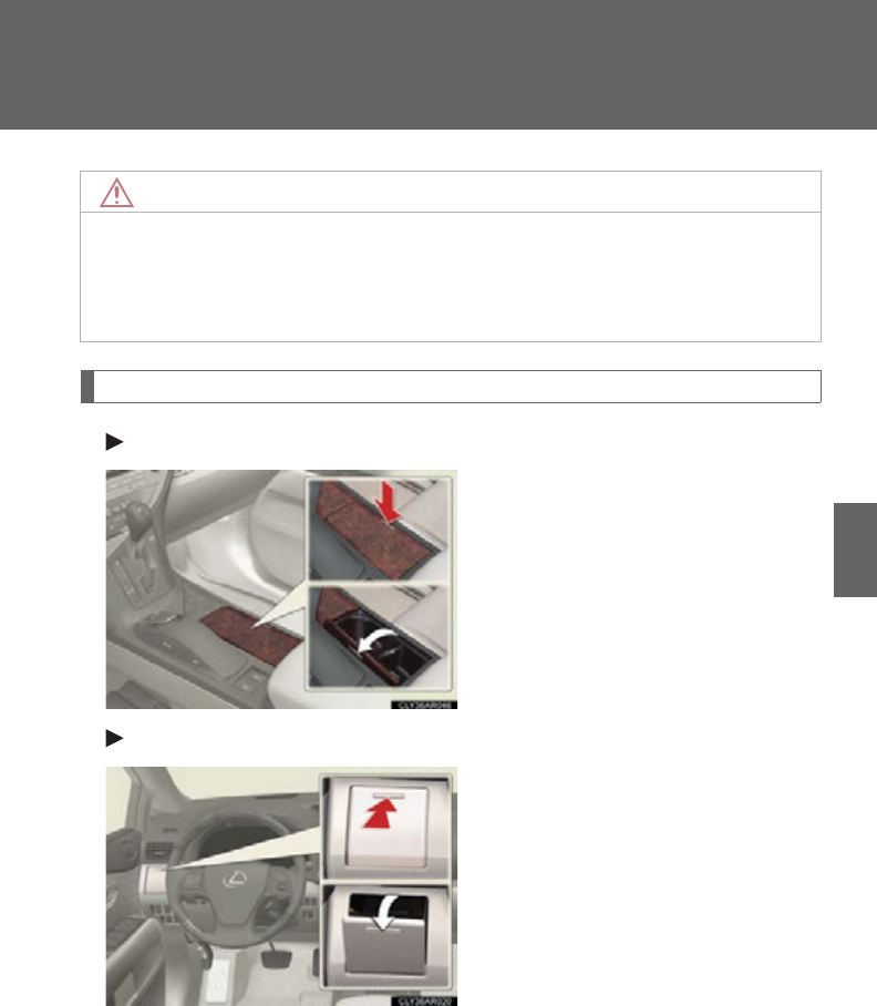
451
3-6. Using the storage features
3
Interior features
Cup holders
Front (type A)
Press down and release the right
side of the cup holder lid.
Front (type B)
Press in and release the cup
holder.
NOTICE
■When stowing a bottle
Put the cap on before stowing the bottle. Do not place open bottles in the bottle
holders. The contents may spill.
Bottle holders/door pockets and cup holders
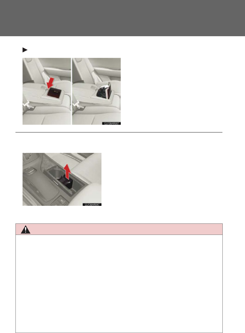
452
3-6. Using the storage features
Rear
Press down the button on the arm-
rest.
■Cup holder insert
CAUTION
■Items unsuitable for the cup holder
Do not place anything other than cups or beverage cans in the cup holders. Even
when the lid is closed, items must not be stored in the cup holders.
Other items may be thrown out of the holders in the event of an accident or sudden
braking and cause injury. If possible, cover hot drinks to prevent burns.
■To prevent burns
Put a lid on containers with hot liquids inside.
■When not in use
Keep the cup holders closed.
Injuries may result in the event of an accident or sudden braking.
The cup holder insert may be removed for
cleaning.
Cup holders
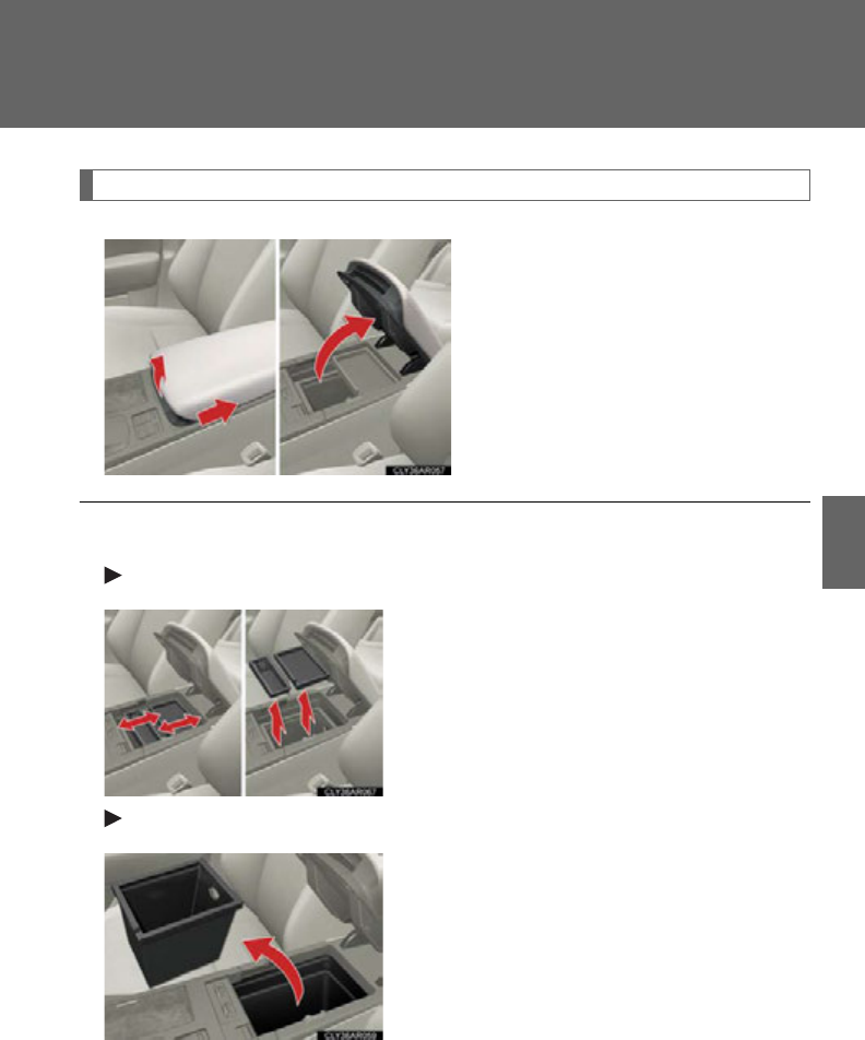
453
3-6. Using the storage features
3
Interior features
Console box
Slide the armrest while pulling up
the lever, and lift the armrest.
■Trays in the console box
Upper tray/upper trays
Lower tray
The tray slides forward/backward and can be
removed.
The tray can be removed.
Console box
454
3-6. Using the storage features
CAUTION
■Caution while driving
Keep the console box closed.
Injuries may result in the event of an accident or sudden braking.
NOTICE
■Tr a ys
Do not insert items exceeding the height of the tray. Doing so may prevent opening
and closing of the lid.
Console box
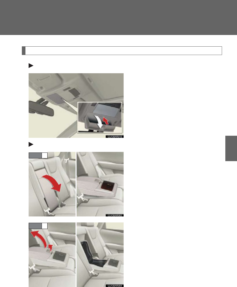
455
3-6. Using the storage features
3
Interior features
Auxiliary boxes
Overhead
Press in the lid.
This box is useful for temporarily
storing sunglasses and similar small
items.
Rear seat (if equipped)
Pull down the armrest.
Pull up the lever to release the lock
and lift the armrest.
STEP 1
STEP 2
Auxiliary boxes
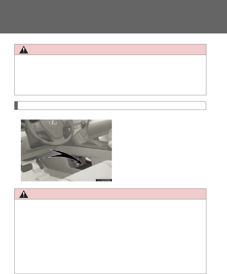
456
3-6. Using the storage features
Under tray
CAUTION
■Caution while driving
Do not leave the auxiliary box open while driving.
Items stored in the auxiliary box may fall out and cause death or serious injury in
case of an accident or sudden stop.
CAUTION
■Items unsuitable for the under tray
Observe the following precautions when putting items in the under tray. Failure to
do so may cause items to be thrown out of the tray in the event of sudden braking or
steering. In these cases, the items may interfere with pedal operation or cause
driver distraction, resulting in an accident.
●Do not store items in the tray that can easily shift or roll out.
●Do not stack items in the tray higher than the tray's edge.
●Do not put items in the tray that may protrude over the tray's edge.
Auxiliary boxes and under tray
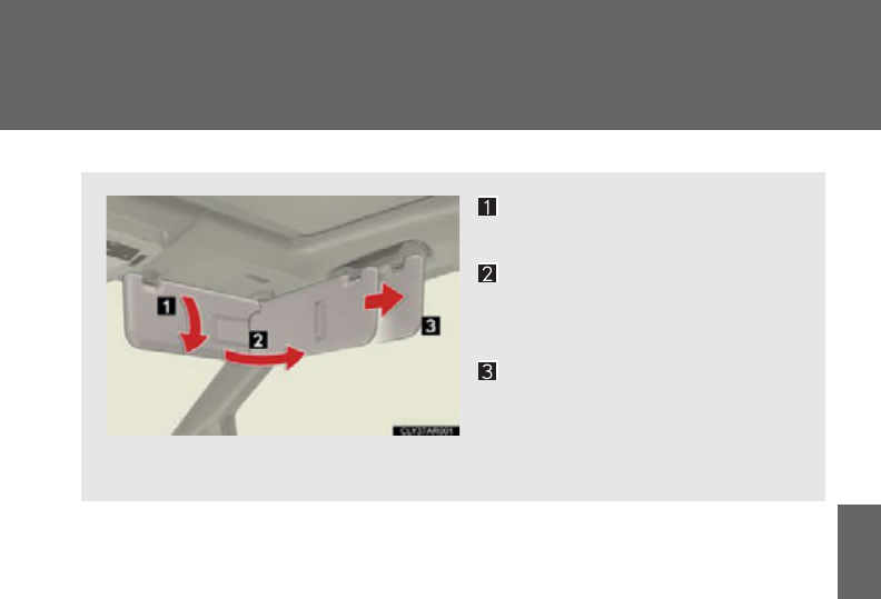
457
3
Interior features
3-7. Other interior features
Sun visors
To set the visor in the forward
position, flip it down.
To set the visor in the side
position, flip down, unhook,
and swing it to the side.
To use the side extender,
place the visor in the side
position, then slide it back-
ward.
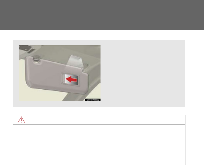
458
3-7. Other interior features
Vanity mirrors
NOTICE
■When not in use
Keep the vanity mirror closed.
■To prevent 12-volt battery discharge
Do not leave the vanity lights on for extended periods while the hybrid system is off.
Slide the cover to open.
The light turns on when the
cover is opened.
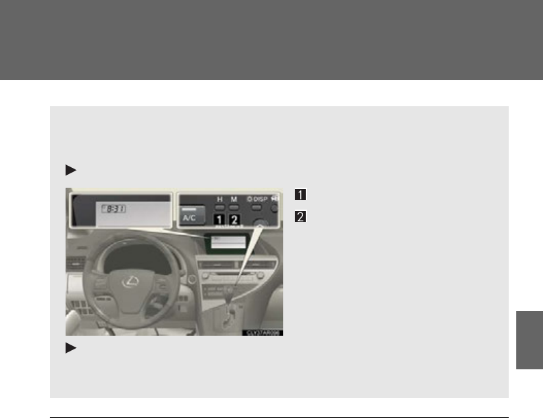
459
3-7. Other interior features
3
Interior features
Clock
■When the 12-volt battery is disconnected
The time display will automatically be set to 1:00.
The clock is displayed when the “POWER” switch is in ACCESSORY or
ON mode. Perform the following steps to adjust the clock.
Without a navigation system
Adjusts the hours
Adjusts the minutes
With a navigation system
Refer to “Navigation System Owner’s Manual”.
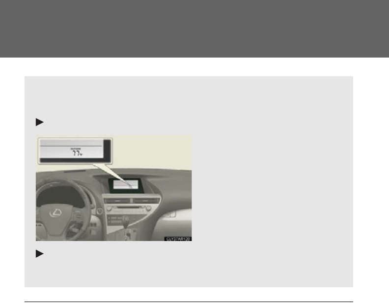
460
3-7. Other interior features
Outside temperature display
■If the temperature does not appear
The system may be malfunctioning. Take your vehicle to your Lexus dealer.
■Display
In the following situations, the correct outside temperature may not be displayed, or
the display may take longer than normal to change:
●When the vehicle is stopped, or moving at low speeds (less than 16 mph [25
km/h])
●When the outside temperature has changed suddenly (at the entrance/exit of a
garage, tunnel, etc.)
The temperature display shows temperatures within the range of -40°F
(-40°C) and 122°F (50°C).
Without a navigation system
With a navigation system
Refer to “Navigation System Owner’s Manual”.
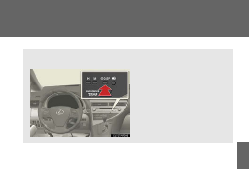
461
3-7. Other interior features
3
Interior features
Multi-display light control (vehicles without a navigation system)
■Instrument panel linked brightness control
When the headlight switch is turned on, the brightness of the multi-display will be
reduced in accordance with the brightness of the instrument panel. (P. 1 95 )
The brightness of the multi-display can be adjusted to four levels.
Press and release the “DISP”
switch until the brightness of the
display is adjusted to the desired
level.
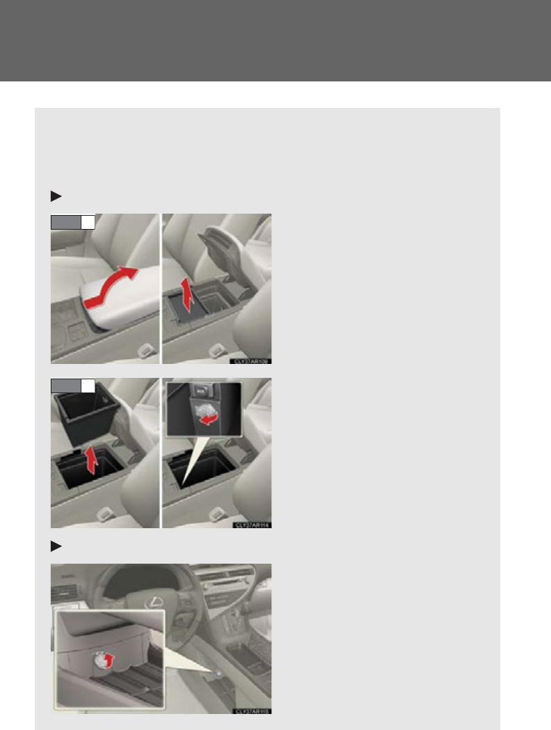
462
3-7. Other interior features
Power outlets
The power outlets can be used for the following components.
12 V: Accessories that run on less than 10 A.
120 VAC: Accessories that use less than 100 W.
Inside the console (12 V)
Slide the armrest while pulling
up the lever, and lift the armrest.
Remove the upper tray.
Remove the lower tray.
Under tray (12V)
STEP 1
STEP 2
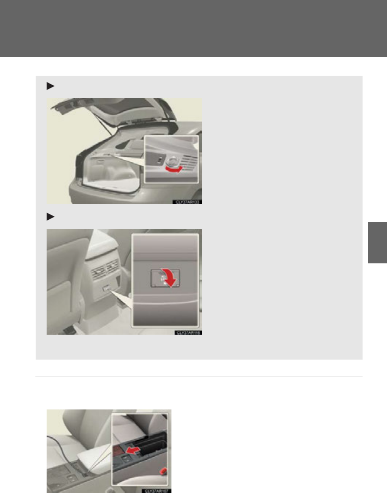
463
3-7. Other interior features
3
Interior features
■Routing accessory device cables
Luggage compartment (12V)
On the back surface of the console (120 VAC*)
*: If equipped
When the cover is slid open, accessory
device cables can be pulled through the
opening.

464
3-7. Other interior features
■The power outlets can be used when
12 V
The “POWER” switch is in ACCESSORY or ON mode.
120 VAC
The “POWER” switch is in ON mode.
NOTICE
■To avoid damaging the power outlets
Close the power outlet lid when the power outlet is not in use.
Foreign objects or liquids that enter the power outlet may cause a short circuit.
■To prevent the fuse from being blown
Close the power outlet lid when the power outlet is not in use.
Foreign objects or liquids that enter the power outlet may cause a short circuit.
12 V: Do not use an accessory that uses more than 12 V 10 A.
120 VAC: Do not use a 120 VAC appliance that requires more than 100 W.
If a 120 VAC appliance that consumes more than 100 W is used, the protection cir-
cuit will cut the power supply.
■To prevent 12-volt battery discharge
Do not use the power outlets longer than necessary when the hybrid system is off.
■Appliances that may not operate properly (120 VAC)
The following 120 VAC appliances may not operate properly even if their power
consumption is under 100 W:
●Appliances with high initial peak wattage
●Measuring devices that process precise data
●Other appliances that require an extremely stable power supply
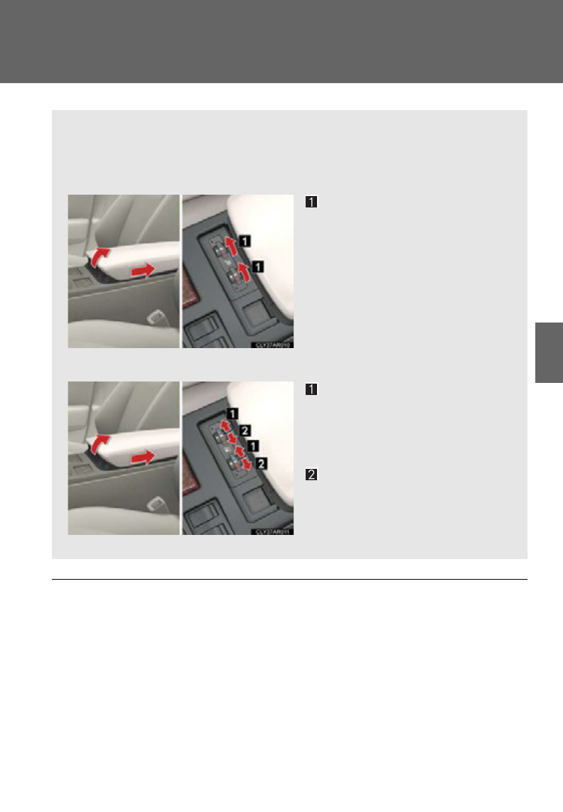
465
3-7. Other interior features
3
Interior features
Seat heaters and ventilators
■Operating condition
The “POWER” switch is in ON mode.
■When not in use
Set the knob at “0”. The indicator light turns off.
: If equipped
The seat heaters and ventilators heat the seats and maintain good airflow
by blowing air from the seats.
■Seat heaters
Turns the seat heater on
The indicator light comes on.
The higher the number is, the
warmer the seat becomes.
■Seat heaters/ventilators
Turns the seat heater on
The indicator light comes on.
The higher the number is, the
warmer the seat becomes.
Blows air from the seat
The indicator light comes on.
The higher the number is, the
stronger the airflow becomes.
466
3-7. Other interior features
CAUTION
■Burns
●Use caution when seating the following persons in a seat with the seat heater on
to avoid the possibility of burns:
• Babies, small children, the elderly, the sick and the physically challenged
• Persons with sensitive skin
• Persons who are fatigued
• Persons who have taken alcohol or drugs that induce sleep (sleeping drugs,
cold remedies, etc.)
●Do not cover the seat with anything when using the seat heater.
Using the seat heater with a blanket or cushion increases the temperature of the
seat and may lead to overheating.
NOTICE
■To prevent damage to the seat heaters/ventilators
Do not put heavy objects that have an uneven surface on the seat and do not stick
sharp objects (needles, nails, etc.) into the seat.
■To prevent 12-volt battery discharge
Do not leave the system on longer than necessary when the hybrid system is off.
467
3-7. Other interior features
3
Interior features
Armrest
NOTICE
■To prevent damage to the armrest
Do not place too much strain on the armrest.
Pull the armrest down for use.
468
3-7. Other interior features
Coat hooks
CAUTION
■Items that must not be hung on the hook
Do not hang a coat hanger or other hard or sharp object on the hook. If the SRS
curtain shield airbags deploy, these items may become projectiles that cause death
or serious injury.
To use the coat hook, push it in.
469
3-7. Other interior features
3
Interior features
Floor mat
CAUTION
Observe the following precautions.
Failure to do so may cause the driver's floor mat to slip, possibly interfering with the
pedals while driving. An unexpectedly high speed may result or it may become diffi-
cult to stop the vehicle, leading to a serious accident.
■When installing the driver's floor mat
●Do not use floor mats designed for other models or different model year vehicles,
even if they are Lexus Genuine floor mats.
●Only use floor mats designed for the driver's seat.
●Always install the floor mat securely using the retaining hooks (clips) provided.
●Do not use two or more floor mats on top of each other.
●Do not place the floor mat bottom-side up or upside-down.
■Before driving
Use only floor mats designed specifically for vehicles of the same model
and model year as your vehicle. Fix them securely in place onto the carpet.
Fix the floor mat in place using
the retaining hooks (clips) pro-
vided.
The shape of the retaining hooks
(clips) and the fixing procedure
of the floor mat for your vehicle
may differ from those shown in
the illustration. For details, refer
to the floor mat retention clip
installation instructions supplied
with the clips.
●Check that the floor mat is securely fixed in
the correct place with all the provided
retaining hooks (clips). Be especially care-
ful to perform this check after cleaning the
floor.
●With the hybrid system stopped and the
shift lever in P, fully depress each pedal to
the floor to make sure it does not interfere
with the floor mat.
470
3-7. Other interior features
Luggage compartment features
■Cargo hooks
Pull the hook to use.
The cargo hooks are provided
for securing loose items.
■Auxiliary boxes
Pull the strap upwards when lift-
ing the cover up.
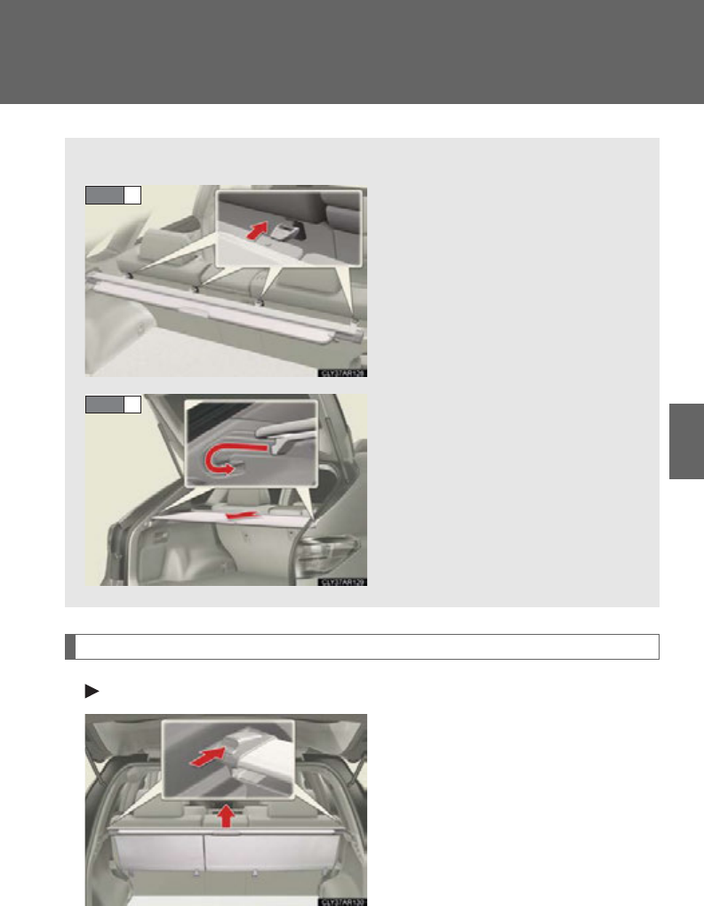
471
3-7. Other interior features
3
Interior features
Removing the luggage covers
Front luggage cover
Press the buttons to remove the
luggage cover.
■Luggage cover
Attach the hooks to the hook
brackets on the rear seat seat-
back.
Pull out the luggage cover and
hook it onto the anchors.
STEP 1
STEP 2
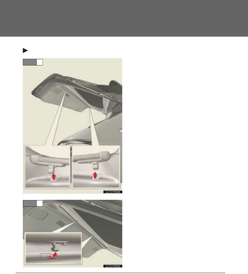
472
3-7. Other interior features
Rear luggage cover
Detach the outer clips of the rear
luggage cover from the back door.
Detach the inner clips of the rear
luggage cover from the back door.
STEP 1
STEP 2
■Installing the rear luggage cover
●Ensure that the luggage cover is in the proper installation position.
Push the clips of the rear luggage cover into the indentions on the back door
until they are locked into place.
●Check that the rear luggage cover is securely attached.

473
3-7. Other interior features
3
Interior features
CAUTION
■When the cargo hooks are not in use
To avoid injury, always return the cargo hooks to their stowed positions.
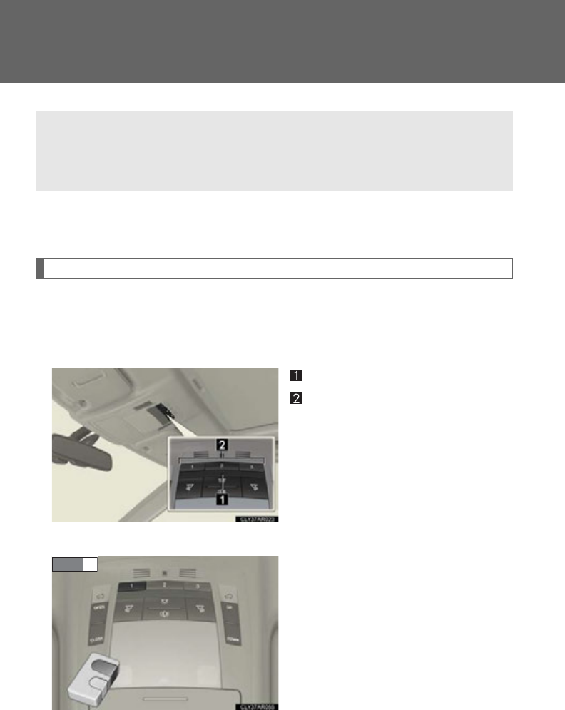
474
3-7. Other interior features
Garage door opener
The garage door opener (HomeLink Universal Transceiver) is manufactured
under license from HomeLink.
Programming the HomeLink (for U.S.A. owners)
The HomeLink compatible transceiver in your vehicle has 3 buttons
which can be programmed to operate 3 different devices. Refer to the
programming method below appropriate for the device.
Indicator
Buttons
■Programming the HomeLink
Point the remote control transmit-
ter for the device 1 to 3 in. (25 to
75 mm) from the HomeLink
control buttons.
Keep the HomeLink indicator
light in view while programming.
The garage door opener can be programmed to operate garage doors,
gates, entry doors, door locks, home lighting systems, security systems, and
other devices.
STEP 1
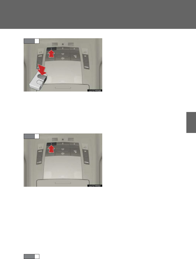
475
3-7. Other interior features
3
Interior features
Press and hold one of the
HomeLink buttons and the trans-
mitter button. When the
HomeLink indicator light
changes from a slow to a rapid
flash, you can release both buttons.
If the HomeLink indicator light
comes on but does not flash, or
flashes rapidly for 2 seconds and
remains lit, the HomeLink button
is already programmed. Use the
other buttons or follow the “Repro-
gramming a HomeLink button”
instructions. (P. 47 7 )
Test the HomeLink operation by
pressing the newly programmed
button.
If a HomeLink button has been
programmed for a garage door,
check to see if the garage door
opens and closes. If the garage
door does not operate, see if your
remote control transmitter is of the
rolling code type. Press and hold
the programmed HomeLink but-
ton. The remote control transmitter
is of the rolling code type if the
HomeLink indicator light flashes
rapidly for 2 seconds and then
remains lit. If your transmitter is of
the rolling code type, proceed to
the heading “Programming a roll-
ing code system”.
Repeat the steps above to program another device for each of
the remaining HomeLink buttons.
STEP 2
STEP 3
STEP 4

476
3-7. Other interior features
■Programming a Rolling Code system (for U.S.A. owners)
If your device is Rolling Code equipped, follow the steps under the
heading “Programming the HomeLink” before proceeding with the
steps listed below.
Locate the learn button on the ceiling mounted garage door
opener motor. The exact location and color of the button may
vary by brand of garage door opener motor.
Refer to the operation manual supplied with the garage door opener
for the location of the learn button.
Press the learn button.
Following this step, you have 30 seconds in which to initiate step 3
below.
Press and hold the vehicle’s programmed HomeLink button for
2 seconds and release it. Repeat this step once again. The garage
door may open.
If the garage door opens, the programming process is complete. If the
door does not open, press and release the button a third time. This third
press and release will complete the programming process by opening
the garage door.
The ceiling mounted garage door opener motor should now recognize
the HomeLink signal and operate the garage door.
Repeat the steps above to program another rolling code system
for any of the remaining HomeLink buttons.
■Programming an entry gate (for U.S.A. owners)/Programming all
devices in the Canadian market
Place your transmitter 1 to 3 in. (25 to 75 mm) away from the sur-
face of the HomeLink.
Keep the HomeLink indicator light in view while programming.
Press and hold the selected HomeLink button.
Repeatedly press and release (cycle) the device’s remote control
button for two seconds each until step 4 is completed.
When the indicator light on the HomeLink compatible trans-
ceiver starts to flash rapidly, release the buttons.
STEP 1
STEP 2
STEP 3
STEP 4
STEP 1
STEP 2
STEP 3
STEP 4
477
3-7. Other interior features
3
Interior features
Test the operation of the HomeLink by pressing the newly pro-
grammed button. Check to see if the gate/device operates cor-
rectly.
Repeat the steps above to program another device for each of
the remaining HomeLink buttons.
■Programming other devices
To program other devices such as home security systems, home door
locks or lighting, contact your authorized Lexus dealer for assistance.
■Reprogramming a button
The individual HomeLink buttons cannot be erased but can be
reprogrammed. To reprogram a button, follow the “Reprogramming a
HomeLink button” instructions.
Operating HomeLink
Press the appropriate HomeLink button. The HomeLink indicator
light should turn on.
The HomeLink compatible transceiver in your vehicle continues to send a
signal for up to 20 seconds as long as the button is pressed.
Reprogramming a HomeLink button
Press and hold the desired HomeLink button. After 20 seconds, the
HomeLink indicator light will start flashing slowly. Next, while still press-
ing and holding the HomeLink button, press and hold the button on the
transmitter until the HomeLink indicator light changes from a slow to a
rapid flash.
STEP 5
STEP 6
478
3-7. Other interior features
Erasing the entire HomeLink memory (all three programs)
Press and hold the 2 outside but-
tons for 10 seconds until the indi-
cator light flashes.
If you sell your vehicle, be sure to
erase the programs stored in the
HomeLink memory.
■Before programming
●Install a new battery in the remote control transmitter.
●The battery side of the remote control transmitter must be pointed away from
the HomeLink button.
■Certification for the garage door opener
For vehicles sold in the U.S.A.
FCC ID: CB2070NHL4
NOTE:
This device complies with Part 15 of the FCC Rules. Operation is subject to the fol-
lowing two conditions: (1) this device may not cause harmful interference, and (2)
this device must accept any interference received, including interference that may
cause undesired operation.
FCC WARNING:
Changes or modifications not expressly approved by the party responsible for
compliance could void the user's authority to operate the equipment.
For vehicles sold in Canada
NOTE:
Operation is subject to the following two conditions: (1) this device may not cause
interference, and (2) this device must accept any interference, including interfer-
ence that may cause undesired operation of the device.
■When support is necessary
Visit on the web at www.homelink.com or call 1-800-355-3515.

479
3-7. Other interior features
3
Interior features
CAUTION
■When programming a garage door or other remote control device
The garage door or other device may operate, so ensure people and objects are
out of danger to prevent potential harm.
■Conforming to federal safety standards
Do not use the HomeLink compatible transceiver with any garage door opener
or device that lacks safety stop and reverse features as required by federal safety
standards.
This includes any garage door that cannot detect an obstruction object. A door or
device without these features increases the risk of death or serious injury.
480
3-7. Other interior features
Compass
: If equipped
The compass on the inside rear view mirror indicates the direction in which
the vehicle is heading.
■Operation
To turn the compass on or off,
press “AUTO” for more than 3
seconds.
■Displays and directions
Display Direction
“N” North
“NE” Northeast
“E” East
“SE” Southeast
“S” South
“SW” Southwest
“W” West
“NW” Northwest
481
3-7. Other interior features
3
Interior features
Calibrating the compass
The direction display deviates from the true direction determined by the
earth’s magnetic field. The amount of deviation varies depending on the
geographic position of the vehicle.
If you cross over one of the map boundaries shown in illustration, the com-
pass will deviate.
To obtain higher precision or perfect calibration, refer to “Deviation calibra-
tion”.
■Deviation calibration
Stop the vehicle.
Press and hold “AUTO”.
A number (1 to 15) appears on the
compass display.
STEP 1
STEP 2
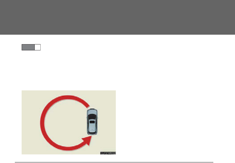
482
3-7. Other interior features
Referring to the map above, press “AUTO” to select the number
of the zone you are in.
If the direction is displayed for several seconds after adjustment, the
calibration is complete.
■Circling calibration
If “C” appears on the display, drive
the vehicle at 5 mph (8 km/h) or
less in a circle until a direction is
displayed.
If there is not enough space to
drive in a circle, drive around the
block until a direction is displayed.
STEP 3
■Conditions unfavorable to correct operation
The compass may not show the correct direction in the following conditions:
●The vehicle is stopped immediately after turning.
●The vehicle is on an inclined surface.
●The vehicle is in a place where the earth's magnetic field is subject to interfer-
ence by artificial magnetic fields (underground car park/parking lot, under a
steel tower, between buildings, roof car park/parking lot, near an intersection,
near a large vehicle, etc.).
●The vehicle has become magnetized. (There is a magnet or metal object near
the inside rear view mirror.)
●The 12-volt battery has been disconnected.
●A door is open.
483
3-7. Other interior features
3
Interior features
CAUTION
■While driving the vehicle
Do not adjust the display. Adjust the display only when the vehicle is stopped.
■When doing the circling calibration
Secure a wide space, and watch out for people and vehicles in the vicinity. Do not
violate any local traffic rules while performing circling calibration.
NOTICE
■To avoid the compass malfunctions
Do not place magnets or any metal objects near the inside rear view mirror.
Doing this may cause the compass sensor to malfunction.
■To ensure normal operation of the compass
●Do not perform a circling calibration of the compass in a place where the earth's
magnetic field is subject to interference by artificial magnetic fields.
●During calibration, do not operate electric systems (moon roof, power windows,
etc.) as they may interfere with the calibration.
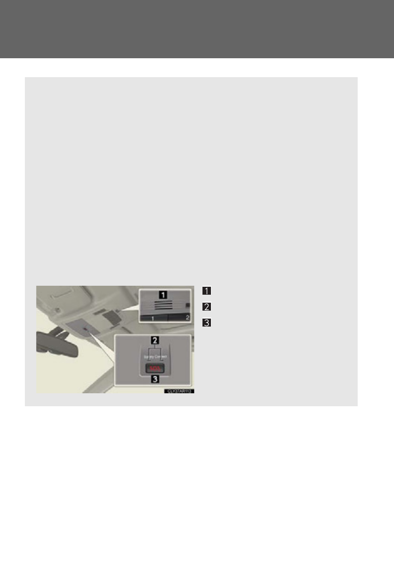
484
3-7. Other interior features
Safety Connect
: If equipped
Safety Connect is a subscription-based telematics service that uses Global
Positioning System (GPS) data and embedded cellular technology to pro-
vide safety and security features to subscribers. Safety Connect is sup-
ported by Lexus’ designated response center, which operates 24 hours per
day, 7 days per week.
Safety Connect service is available by subscription on select, telematics
hardware-equipped vehicles.
By using the Safety Connect service, you are agreeing to be bound by the
Telematics Subscription Service Agreement and its Terms and Conditions,
as in effect and amended from time to time, a current copy of which is avail-
able at Lexus.com. All use of the Safety Connect service is subject to such
then-applicable Terms and Conditions.
■System components
Microphone
LED light indicators
“SOS” button

485
3-7. Other interior features
3
Interior features
■Services
Subscribers have the following Safety Connect services available:
●Automatic Collision Notification*
Helps drivers receive necessary response from emergency ser-
vice providers. (P. 487)
*: U.S. Patent No. 7,508,298 B2
●Stolen Vehicle Location
Helps drivers in the event of vehicle theft. (P. 488)
●Emergency Assistance Button (SOS)
Connects drivers to response-center support. (P. 48 8 )
●Enhanced Roadside Assistance
Provides drivers various on-road assistance. (P. 488 )
■Subscription
After you have signed the Telematics Subscription Service Agree-
ment and are enrolled, you can begin receiving services.
A variety of subscription terms is available for purchase. Contact
your Lexus dealer, call 1-800-25-LEXUS (1-800-255-3987) or
push the “SOS” button in your vehicle for further subscription
details.

486
3-7. Other interior features
■Safety Connect Services Information
●Phone calls using the vehicles Bluetooth® technology will not be possible dur-
ing Safety Connect.
●Safety Connect is available beginning Fall 2009 on select Lexus models. Con-
tact with the Safety Connect response center is dependent upon the telematics
device being in operative condition, cellular connection availability, and GPS
satellite signal reception, which can limit the ability to reach the response center
or receive emergency service support. Enrollment and Telematics Subscription
Service Agreement required. A variety of subscription terms is available;
charges vary by subscription term selected.
●Automatic Collision Notification, Emergency Assistance and Stolen Vehicle
Location will function in the United States, including Hawaii and Alaska, and in
Canada, and Enhanced Roadside Assistance will function in the United States
(except Hawaii) and in Canada. No Safety Connect services will function out-
side of the United States in countries other than Canada.
●Safety Connect services are not subject to section 255 of the Telecommunica-
tions Act and the device is not TTY compatible.
■Languages
The Safety Connect response center will offer support in multiple languages. The
Safety Connect system will offer voice prompts in English and Spanish. Please indi-
cate your language of choice when enrolling.
■When contacting the response center
You may be unable to contact the response center if the network is busy.

487
3-7. Other interior features
3
Interior features
Safety Connect LED light Indicators
When the “POWER” switch is turned to ON mode, the red indicator
light comes on for 2 seconds then turns off. Afterward, the green indica-
tor light comes on, indicating that the service is active.
The following indicator light patterns indicate specific system usage con-
ditions:
●Green indicator light on = Active service
●Green indicator light flashing = Safety Connect call in process
●Red indicator light (except at vehicle start-up) = System malfunction
(contact your Lexus dealer)
●No indicator light (off) = Safety Connect service not active
Safety Connect services
■Automatic Collision Notification
In case of either airbag deployment or severe rear-end collision, the
system is designed to automatically call the response center. The
responding agent receives the vehicle’s location and attempts to speak
with the vehicle occupants to assess the level of emergency. If the
occupants are unable to communicate, the agent automatically treats
the call as an emergency, contacts the nearest emergency services
provider to describe the situation, and requests that assistance be sent
to the location.

488
3-7. Other interior features
■Stolen Vehicle Location
If your vehicle is stolen, Safety Connect can work with local authorities
to assist them in locating and recovering the vehicle. After filing a
police report, call the Safety Connect response center at 1-800-25-
LEXUS (1-800-255-3987) and follow the prompts for Safety Con-
nect to initiate this service.
In addition to assisting law enforcement with recovery of a stolen vehi-
cle, Safety-Connect-equipped vehicle location data may, under cer-
tain circumstances, be shared with third parties to locate your vehicle.
Further information is available at Lexus.com.
■Emergency Assistance Button (“SOS”)
In the event of an emergency on the road, push the “SOS” button to
reach the Safety Connect response center. The answering agent will
determine your vehicle’s location, assess the emergency, and dispatch
the necessary assistance required.
If you accidentally press the “SOS” button, tell the response-center agent
that you are not experiencing an emergency.
■Enhanced Roadside Assistance
Enhanced Roadside Assistance adds GPS data to the already
included warranty-based Lexus roadside service.
Subscribers can press the “SOS” button to reach a Safety Connect
response-center agent, who can help with a wide range of needs, such
as: towing, flat tire, fuel delivery, etc. For a description of the Enhanced
Roadside Assistance services and their limitations, please see the
Safety Connect Terms and Conditions, which are available at
Lexus.com.

489
3-7. Other interior features
3
Interior features
Safety information for Safety Connect
Important! Read this information before using Safety Connect.
■Exposure to radio frequency signals
The Safety Connect system installed in your vehicle is a low-power
radio transmitter and receiver. It receives and also sends out radio fre-
quency (RF) signals.
In August 1996, the Federal Communications Commission (FCC)
adopted RF exposure guidelines with safety levels for mobile wireless
phones. Those guidelines are consistent with the safety standards pre-
viously set by the following U.S. and international standards bodies.
●ANSI (American National Standards Institute) C95.1 [1992]
●NCRP (National Council on Radiation Protection and Measure-
ment) Report 86 [1986]
●ICNIRP (International Commission on Non-Ionizing Radiation Pro-
tection) [1996]
Those standards were based on comprehensive and periodic evalua-
tions of the relevant scientific literature. Over 120 scientists, engineers,
and physicians from universities, and government health agencies and
industries reviewed the available body of research to develop the
ANSI Standard (C95.1).
The design of Safety Connect complies with the FCC guidelines in
addition to those standards.

490
3-7. Other interior features
■License
Licensed by QUALCOMM Incorporated under one or more of the following
United States Patents and/or their counterparts in other nations:
4,901,307 5,490,165 5,056,109 5,504,773 5,101,501
5,506,865 5,109,390 5,511,073 5,228,054 5,535,239
5,267,261 5,544,196 5,267,262 5,568,483 5,337,338
5,600,754 5,414,796 5,657,420 5,416,797 5,659,569
5,710,784 5,778,338
■Certification for Lexus Enform with Safety Connect
FCC ID: O9EGTM1
FCC ID: O6Y-CDMRF101
NOTE:
This device complies with Part 15 of the FCC Rules. Operation is subject to the fol-
lowing two conditions: (1) This device may not cause harmful interference, and (2)
this device must accept any interference received, including interference that may
cause undesired operation.
FCC WARNING:
Changes or modifications not expressly approved by the party responsible for
compliance could void the user's authority to operate the equipment.

Maintenance and care 4
491
4-1. Maintenance and care
Cleaning and protecting
the vehicle exterior............. 492
Cleaning and protecting
the vehicle interior.............. 495
4-2. Maintenance
Maintenance
requirements........................ 498
General maintenance........... 501
Emission inspection and
maintenance (I/M)
programs ............................... 505
4-3. Do-it-yourself
maintenance
Do-it-yourself service
precautions........................... 506
Hood.......................................... 509
Positioning a floor jack.......... 510
Engine compartment ............ 512
12-volt battery ........................ 525
Tires............................................ 532
Tire inflation pressure............ 541
Wheels...................................... 545
Air conditioning filter ........... 547
Electronic key battery.......... 550
Checking and replacing
fuses ........................................ 552
Headlight aim ......................... 568
Light bulbs.................................. 571

492
4-1. Maintenance and care
Cleaning and protecting the vehicle exterior
■Automatic car washes
●Before washing the vehicle:
•Fold the mirrors.
• Turn off the power back door system (if equipped).
●Brushes used in automatic car washes may scratch the vehicle surface and
harm your vehicle’s paint.
■High pressure car washes
●Do not allow the nozzles of the car wash to come within close proximity of the
windows and the air suspension unit (if equipped).
●Before using the car wash, check that the fuel filler door on your vehicle is closed
properly.
Perform the following to protect the vehicle and maintain it in prime condi-
tion:
●Working from top to bottom, liberally apply water to the vehicle
body, wheel wells and underside of the vehicle to remove any dirt
and dust.
●Wash the vehicle body using a sponge or soft cloth, such as a
chamois.
●For hard-to-remove marks, use car wash soap and rinse thor-
oughly with water.
●Wipe away any water.
●Wax the vehicle when the waterproof coating deteriorates.
If water does not bead on a clean surface, apply wax when the vehicle
body is cool.
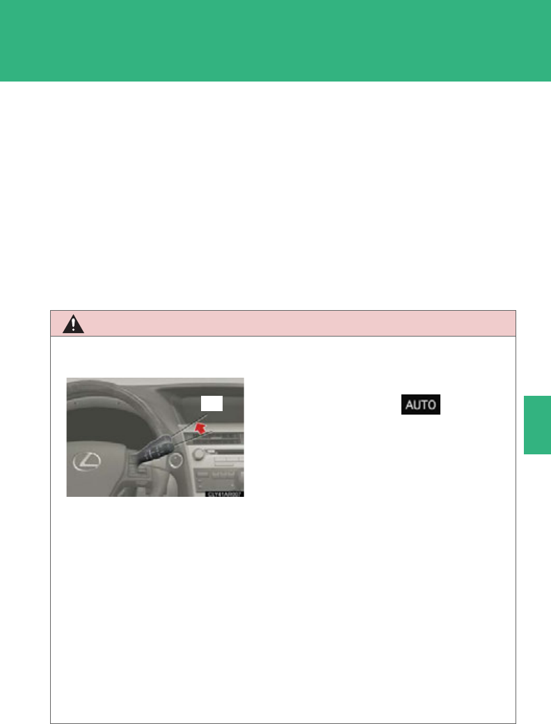
493
4-1. Maintenance and care
4
Maintenance and care
■Aluminum wheels
●Remove any dirt immediately by using a neutral detergent. Do not use hard
brushes or abrasive cleaners. Do not use strong or harsh chemical cleaners.
Use the same mild detergent and wax as used on the paint.
●Do not use detergent on the wheels when they are hot, for example after driving
for long distance in the hot weather.
●Wash detergent from the wheels immediately after use.
■Bumpers
Do not scrub with abrasive cleaners.
CAUTION
■When cleaning the windshield (vehicles with rain-sensing windshield wiper)
●When the upper part of the windshield where the raindrop sensor is located is
touched by hand
●When a wet rag or similar is held close to the raindrop sensor
●If something bumps against the windshield
●If you directly touch the raindrop sensor body or if something bumps into the
raindrop sensor
■Precautions regarding the exhaust pipe
Exhaust gasses cause the exhaust pipe to become quite hot.
When washing the vehicle, be careful not to touch the pipe until it has cooled suffi-
ciently, as touching a hot exhaust pipe can cause burns.
Set the wiper switch to off.
If the wiper switch is in , the wipers
may operate unexpectedly in the following
situations, and may result in hands being
caught or other serious injuries and cause
damage to the wiper blades.
Off

494
4-1. Maintenance and care
NOTICE
■To prevent paint deterioration and corrosion on the body and components (alu-
minum wheels etc.)
●Wash the vehicle immediately in the following cases:
• After driving near the sea coast
• After driving on salted roads
• If you see coal tar or tree sap on the paint surface
• If you see dead insects, insect droppings or bird droppings on the paint
• After driving in an area contaminated with soot, oily smoke, mine dust, iron
powder or chemical substances
• If the vehicle becomes heavily soiled in dust or mud
• If liquids such as benzene and gasoline are spilled on the paint surface
●If the paint is chipped or scratched, have it repaired immediately.
●To prevent the wheels from corroding, remove any dirt and store in a place with
low humidity when storing the wheels.
■Cleaning the exterior lights
●Wash carefully. Do not use organic substances or scrub with a hard brush.
This may damage the surfaces of the lights.
●Do not apply wax on the surfaces of the lights.
Wax may cause damage to the lenses.
■To prevent damage to the windshield wiper arms
When lifting the wiper arms away from the windshield, pull the driver side wiper
arm upward first, and repeat for the passenger side. When returning the wipers to
their original position, do so from the passenger side first.
■When using an automatic car wash (vehicles with rain-sensing windshield wipers)
Set the wiper switch to the off position.
If the wiper switch is in , the wipers may operate and the wiper blades may
be damaged.

495
4-1. Maintenance and care
4
Maintenance and care
Cleaning and protecting the vehicle interior
The following procedures will help protect your vehicle's interior and keep
it in top condition:
■Protecting the vehicle interior
Remove dirt and dust using a vacuum cleaner. Wipe dirty surfaces
with a cloth dampened with lukewarm water.
■Cleaning the leather areas
●Remove dirt and dust using a vacuum cleaner.
●Wipe any excess dirt and dust with a soft cloth dampened with
diluted detergent.
Use a diluted water solution of approximately 5% neutral wool
detergent.
●Wring out any excess water from the cloth and thoroughly wipe
off all remaining traces of detergent.
●Wipe the surface with a dry, soft cloth to remove any remaining
moisture. Allow the leather to dry in a shaded and ventilated area.
■Cleaning the synthetic leather areas
●Remove loose dirt using a vacuum cleaner.
●Apply a mild soap solution to the synthetic leather using a sponge
or soft cloth.
●Allow the solution to soak in for a few minutes. Remove the dirt
and wipe off the solution with a clean, damp cloth.

496
4-1. Maintenance and care
■Caring for leather areas
Lexus recommends cleaning the interior of the vehicle at least twice a year to main-
tain the quality of the vehicle’s interior.
■Shampooing the carpets
There are several commercial foaming-type cleaners available. Use a sponge or
brush to apply the foam. Rub in overlapping circles. Do not apply water. Excellent
results are obtained by keeping the carpet as dry as possible.
■Seat belts
Clean with mild soap and lukewarm water using a cloth or sponge. Also check the
belts periodically for excessive wear, fraying or cuts.
CAUTION
■Water in the vehicle
●Do not splash or spill liquid in the vehicle, such as on the floor and in the hybrid
battery (traction battery) air vents or in the luggage compartment.
Doing so may cause the hybrid battery, electrical components, etc. to malfunc-
tion or catch fire.
●Do not get any of the SRS components or wiring in the vehicle interior wet.
(P. 1 3 4 )
An electrical malfunction may cause the airbags to deploy or not function prop-
erly, resulting in death or severe injury.
■Cleaning the interior (especially instrument panel)
Do not use polish wax or polish cleaner. The instrument panel may reflect off the
windshield, obstructing the driver's view and leading to an accident, resulting in
death or serious injury.

497
4-1. Maintenance and care
4
Maintenance and care
NOTICE
■Cleaning detergents
●Do not use the following types of detergent, as they may discolor the vehicle inte-
rior or cause streaks or damage to painted surfaces:
• Non-seat portions: Organic substances such as benzene or gasoline, alkaline
or acidic solutions, dye, or bleach
• Seats: Acidic solutions, such as thinner, benzene, or alcohol
●Do not use polish wax or polish cleaner. The instrument panel's or other interior
part’s painted surface may be damaged.
■Preventing damage to leather surfaces
Observe the following precautions to avoid damage to and deterioration of leather
surfaces:
●Remove any dust or dirt on leather surfaces immediately.
●Do not expose the vehicle to direct sunlight for extended periods of time. Park
the vehicle in the shade, especially during summer.
●Do not place items made of vinyl, plastic, or that contain wax on the upholstery, as
they may stick to the leather surface if the vehicle interior heats up significantly.
■Water on the floor
Do not wash the vehicle floor with water.
Vehicle systems such as the audio system may be damaged if water comes into
contact with electrical components under the floor of vehicle. Water may also
cause the body to rust.
■Cleaning the inside of the rear window
●Do not use glass cleaner to clean the rear window, as this may cause damage to
the rear window defogger heater wires or antenna. Use a cloth dampened with
lukewarm water to gently wipe the window clean. Wipe the window in strokes
running parallel to the heater wires or antenna.
●Be careful not to scratch or damage the heater wires or antenna.

498
4-2. Maintenance
Maintenance requirements
■Repair and replacement
It is recommended that genuine Lexus parts be used for repair to ensure perfor-
mance of each system. If non-Lexus parts are used in replacement or if a repair
shop other than a Lexus dealer performs repairs, confirm the warranty coverage.
To ensure safe and economical driving, day-to-day care and regular main-
tenance are essential. It is the owner’s responsibility to perform regular
checks. Lexus recommends performing the following maintenance:
■General maintenance
General maintenance should be performed on a daily basis. This
can be done by yourself or by a Lexus dealer.
■Scheduled maintenance
Scheduled maintenance should be performed at specified intervals
according to the maintenance schedule.
For details about maintenance items and schedules, refer to the “War-
ranty and Service Guide”, “Owner’s Manual Supplement” or “Scheduled
Maintenance”.
■Do-it-yourself maintenance
You can perform some maintenance procedures yourself.
Please be aware that do-it-yourself maintenance may affect war-
ranty coverage.
The use of Lexus Repair Manuals is recommended.
For details about warranty coverage, refer to the separate “Owner’s
Guide”, “Warranty and Service Guide”, “Owner’s Manual Supplement”
or “Warranty Booklet”.
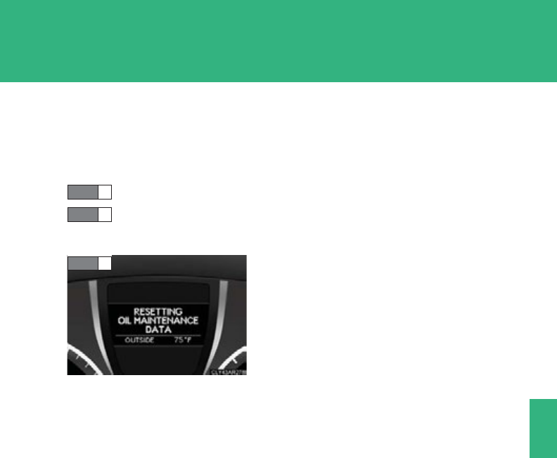
499
4-2. Maintenance
4
Maintenance and care
■Reset the maintenance data (U.S.A. only)
After the required maintenance is performed according to the maintenance sched-
ule, please reset the maintenance data.
To reset the data, follow the procedures described below:
Display the trip meter “A” (P. 195), then turn the “POWER” switch off.
While pressing the “ODO/TRIP” button, turn the “POWER” switch to
ON mode.
■Allow inspection and repairs to be performed by a Lexus dealer
●Lexus technicians are well-trained specialists and are kept up to date with the
latest service information. They are well informed about the operations of all
systems on your vehicle.
●Keep a copy of the repair order. It proves that the maintenance that has been
performed is under warranty coverage. If any problem should arise while your
vehicle is under warranty, your Lexus dealer will promptly take care of it.
STEP 1
STEP 2
Keep the “ODO/TRIP” button pressed for
about 5 seconds. The resetting procedure is
complete when “000000” in the trip meter
flashes once and the message in the multi-
information display disappears.
STEP 3

500
4-2. Maintenance
CAUTION
■If your vehicle is not properly maintained
Improper maintenance could result in serious damage to the vehicle and possible
serious injury or death.
■Handling of the 12-volt battery
●Engine exhaust, some of its constituents, and a wide variety of automobile com-
ponents contain or emit chemicals known to the State of California to cause can-
cer and birth defects and other reproductive harm. Work in a well ventilated area.
●Oils, fuels and fluids contained in vehicles as well as waste produced by compo-
nent wear contain or emit chemicals known to the State of California to cause
cancer and birth defects or other reproductive harm. Avoid exposure and wash
any affected area immediately.
●12-volt battery posts, terminals and related accessories contain lead and lead
compounds which are known to cause brain damage. Wash your hands after
handling. (P. 525)

501
4-2. Maintenance
4
Maintenance and care
General maintenance
Engine compartment
Items Check points
Brake fluid Is the brake fluid at the correct level?
(P. 522 )
Coolant Is the coolant at the correct level?
(P. 51 9 )
Engine oil Is the engine oil at the correct level?
(P. 51 5 )
Exhaust system There should not be any fumes or
strange sounds.
Radiator/condenser/hoses
The radiator and condenser should
be free from foreign objects.
(P. 521 )
Washer fluid Is there sufficient washer fluid?
(P. 523 )
Listed below are the general maintenance items that should be performed
at the intervals specified in the “Warranty and Service Guide” or “Owner’s
Manual Supplement”. It is recommended that any problem you notice
should be brought to the attention of your Lexus dealer or qualified service
shop for advice.

502
4-2. Maintenance
Vehicle interior
Items Check points
12-volt battery Check the indicator and
connections. (P. 525 )
Accelerator pedal
• The accelerator pedal should move
smoothly (without uneven pedal
effort or catching).
Brake pedal
• Does the brake pedal move
smoothly?
• Does the brake pedal have appro-
priate clearance from the floor?
(P. 672)
• Does the brake pedal have the cor-
rect amount of free play?
(P. 672)
Brakes
• The vehicle should not pull to one
side when the brakes are applied.
• The brakes should work effectively.
• The brake pedal should not feel
spongy.
• The brake pedal should not get too
close to the floor when the brakes
are applied.
Head restraints • Do the head restraints move
smoothly and lock securely?
Indicators/buzzers • Do the indicators and buzzers
function properly?
Lights
• Do all the lights come on?
• Are the headlights aimed cor-
rectly? (P. 56 8 )

503
4-2. Maintenance
4
Maintenance and care
Items Check points
Parking brake
• Does the parking brake pedal
move smoothly?
• When parked on a slope and the
parking brake is on, is the vehicle
securely stopped?
Seat belts
• Do the seat belts operate
smoothly?
• The seat belts should not be dam-
aged.
Seats • Do the seat controls operate prop-
erly?
Steering wheel
• Does the steering wheel rotate
smoothly?
• Does the steering wheel have the
correct amount of free play?
• There should not be any strange
sounds coming from the steering
wheel.
Hybrid transmission “Park” mecha-
nism
• When parked on a slope and the
parking brake is on, is the vehicle
securely stopped?
504
4-2. Maintenance
Vehicle exterior
Items Check points
Doors • Do the doors operate smoothly?
Engine hood • Does the engine hood lock system
work properly?
Fluid leaks
• There should not be any signs of
fluid leakage after the vehicle has
been parked.
Tires
• Is the tire inflation pressure cor-
rect?
• The tires should not be damaged or
excessively worn.
• Have the tires been rotated
according to the maintenance
schedule?
• The wheel nuts should not be loose.
CAUTION
■If the hybrid system is operating
Turn the hybrid system off and ensure that there is adequate ventilation before per-
forming maintenance checks.

505
4-2. Maintenance
4
Maintenance and care
Emission inspection and maintenance (I/M) programs
Some states have vehicle emission inspection programs which include
OBD (On Board Diagnostics) checks. The OBD system monitors the oper-
ation of the emission control system.
■If the malfunction indicator lamp comes on
The OBD system determines that a problem exists somewhere in
the emission control system. Your vehicle may not pass the I/M test
and may need to be repaired. Contact your Lexus dealer to service
the vehicle.
■Your vehicle may not pass the I/M test in the following situations:
●When the 12-volt battery is disconnected or discharged
Readiness codes that are set during ordinary driving are erased.
Also, depending on your driving habits, the readiness codes may
not be completely set.
●When the fuel tank cap is loose
The malfunction indicator lamp comes on indicating a temporary
malfunction and your vehicle may not pass the I/M test.
■When the malfunction indicator lamp still remains on after several
driving trips
The error code in the OBD system will not be cleared unless the
vehicle is driven 40 or more times.
■If your vehicle does not pass the I/M test
Contact your Lexus dealer to prepare the vehicle for re-testing.

506
4-3. Do-it-yourself maintenance
Do-it-yourself service precautions
If you perform maintenance by yourself, be sure to follow the correct pro-
cedures as given in these sections.
Items Parts and tools
12-volt battery condition (P. 525)
•Warm water
• Baking soda
•Grease
• Conventional wrench
(for terminal clamp bolts)
Brake fluid level (P. 522)
• FMVSS No.116 DOT 3 or SAE
J1703 brake fluid
•Rag or paper towel
• Funnel (used only for adding brake
fluid)
Engine/power control unit
coolant level (P. 51 9 )
• “Toyota Super Long Life Coolant”
or similar high quality ethylene gly-
col based non-silicate, non-amine,
non-nitrite and non-borate coolant
with long-life hybrid organic acid
technology.
For the U.S.A.:
“Toyota Super Long Life Coolant”
is pre-mixed with 50% coolant and
50% deionized water.
For Canada:
“Toyota Super Long Life Coolant”
is pre-mixed with 55% coolant and
45% deionized water.
• Funnel (used only for adding cool-
ant)

507
4-3. Do-it-yourself maintenance
4
Maintenance and care
Items Parts and tools
Engine oil level (P. 515 )
• “Toyota Genuine Motor Oil” or
equivalent
•Rag or paper towel
• Funnel (used only for adding
engine oil)
Fuses (P. 552) • Fuse with same amperage rating as
original
Tire inflation pressure (P. 5 41 ) • Tire pressure gauge
• Compressed air source
Headlight aim (P. 5 68) • Phillips-head screwdriver
Radiator and condenser (P. 521 )
Washer fluid (P. 523)
• Water or washer fluid containing
antifreeze (for winter use)
• Funnel (used only for adding water
or washer fluid)

508
4-3. Do-it-yourself maintenance
CAUTION
The engine compartment contains many mechanisms and fluids that may move sud-
denly, become hot, or become electrically energized. To avoid death or serious injury,
observe the following precautions:
■When working on the engine compartment
●Make sure that the indicator on the “POWER” switch and the “READY” indicator
are both off.
●Keep hands, clothing and tools away from the moving fans and engine drive belt.
●Be careful not to touch the engine, power control unit, radiator, exhaust manifold,
etc. right after driving as they may be hot. Oil and other fluids may also be hot.
●Do not leave anything that may burn easily, such as paper and rags, in the engine
compartment.
●Do not smoke, cause sparks or expose an open flame to fuel. Fuel fumes are flam-
mable.
■When working near the electric cooling fans or radiator grille
Be sure the “POWER” switch is off.
With the “POWER” switch in ON mode, the electric cooling fans may automati-
cally start to run if the air conditioning is on and/or the coolant temperature is high.
(P. 521)
■Safety glasses
Wear safety glasses to prevent flying or falling material, fluid spray, etc. from getting
in your eyes.
NOTICE
■If you remove the air cleaner filter
Driving with the air cleaner filter removed may cause excessive engine wear due to
dirt in the air. Also, a backfire could cause a fire in the engine compartment.
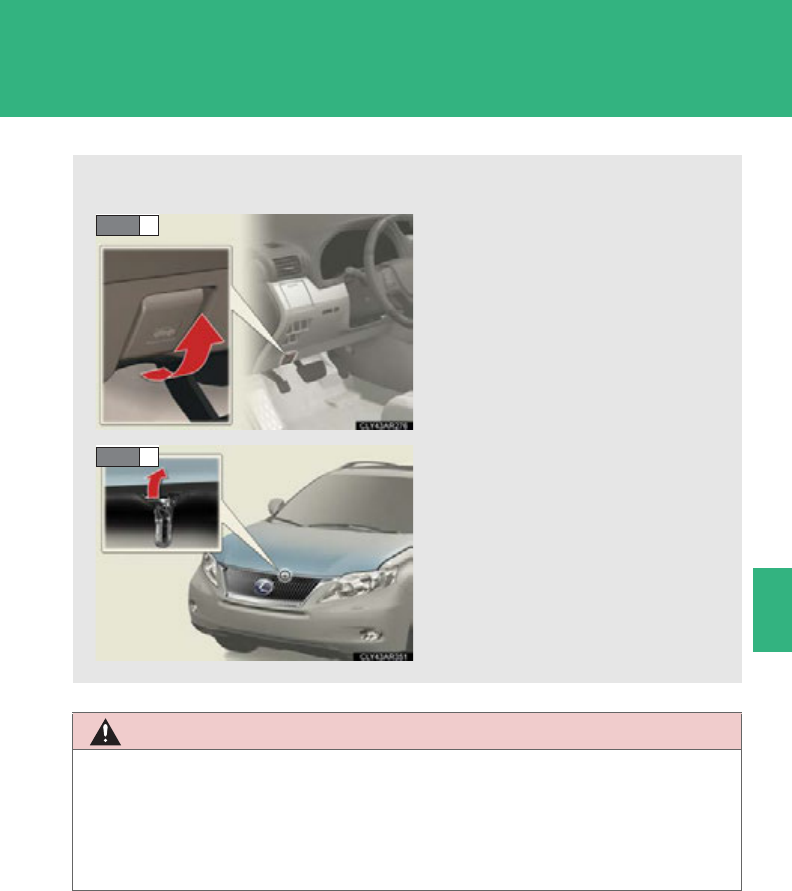
509
4-3. Do-it-yourself maintenance
4
Maintenance and care
Hood
CAUTION
■Pre-driving check
Check that the hood is fully closed and locked.
If the hood is not locked properly, it may open while the vehicle is in motion and
cause an accident, which may result in death or serious injury.
Release the lock from the inside of the vehicle to open the hood.
Pull the hood lock release lever.
The hood will pop up slightly.
Pull up the hood catch and lift
the hood.
STEP 1
STEP 2
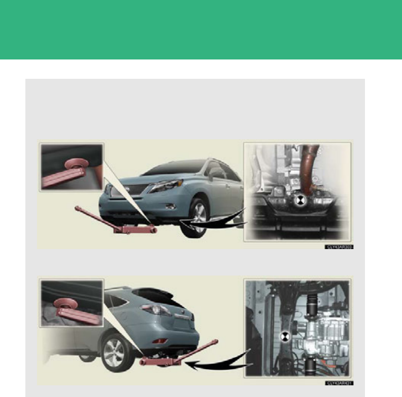
510
4-3. Do-it-yourself maintenance
Positioning a floor jack
When raising your vehicle with a floor jack, position the jack correctly.
Improper placement may damage your vehicle or cause injury.
■Front
■Rear
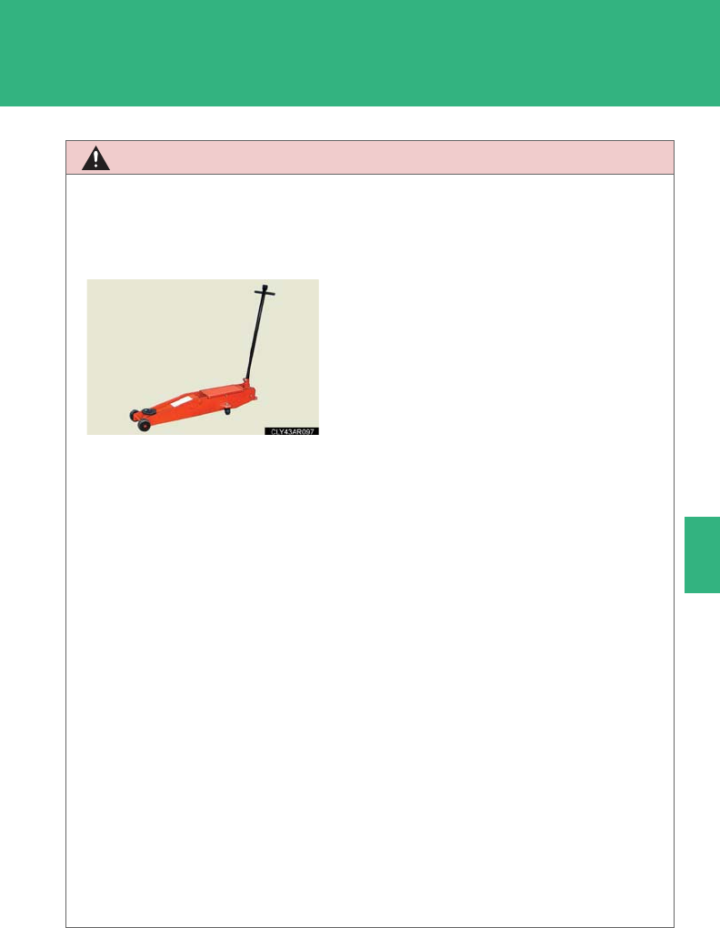
511
4-3. Do-it-yourself maintenance
4
Maintenance and care
CAUTION
■When raising your vehicle
Make sure to observe the following precautions to reduce the possibility of death or
serious injury:
●When using a floor jack, follow the instructions of the manual provided with the
jack.
●Do not use the jack that was supplied with your vehicle.
●Do not put any part of your body underneath the vehicle when it is supported
only by the floor jack.
●Always use floor jack and/or automotive jack stands on a solid, flat, level surface.
●Do not start the hybrid system while the vehicle is supported by the floor jack.
●Stop the vehicle on level, firm ground, firmly set the parking brake and shift the
shift lever to P.
●Make sure to set the floor jack properly at the jack point.
Raising the vehicle with an improperly positioned floor jack will damage the vehi-
cle and may cause the vehicle to fall off the floor jack.
●Do not raise the vehicle while someone is in the vehicle.
●When raising the vehicle, do not place any objects on top of or underneath the
floor jack.
●Vehicles with electronically modulated air suspension (if equipped):
Be sure to turn off the height control and stop the hybrid system. Otherwise, the
vehicle height may change in the automatic leveling function. (P. 26 4)
●Lift up the vehicle using a floor jack such as
the one shown in the illustration.

512
4-3. Do-it-yourself maintenance
Engine compartment
Brake fluid reservoir
(P. 522)
Engine oil filler cap
(P. 515)
Engine oil level dipstick
(P. 515)
Power control unit coolant
reservoir (P. 51 9 )
Fuse boxes (P. 552 )
Engine coolant reservoir
(P. 51 9)
Radiator (P. 521)
Condenser (P. 521)
Electric cooling fans
Power control unit coolant
radiator (P. 521)
Washer fluid tank
(P. 523)
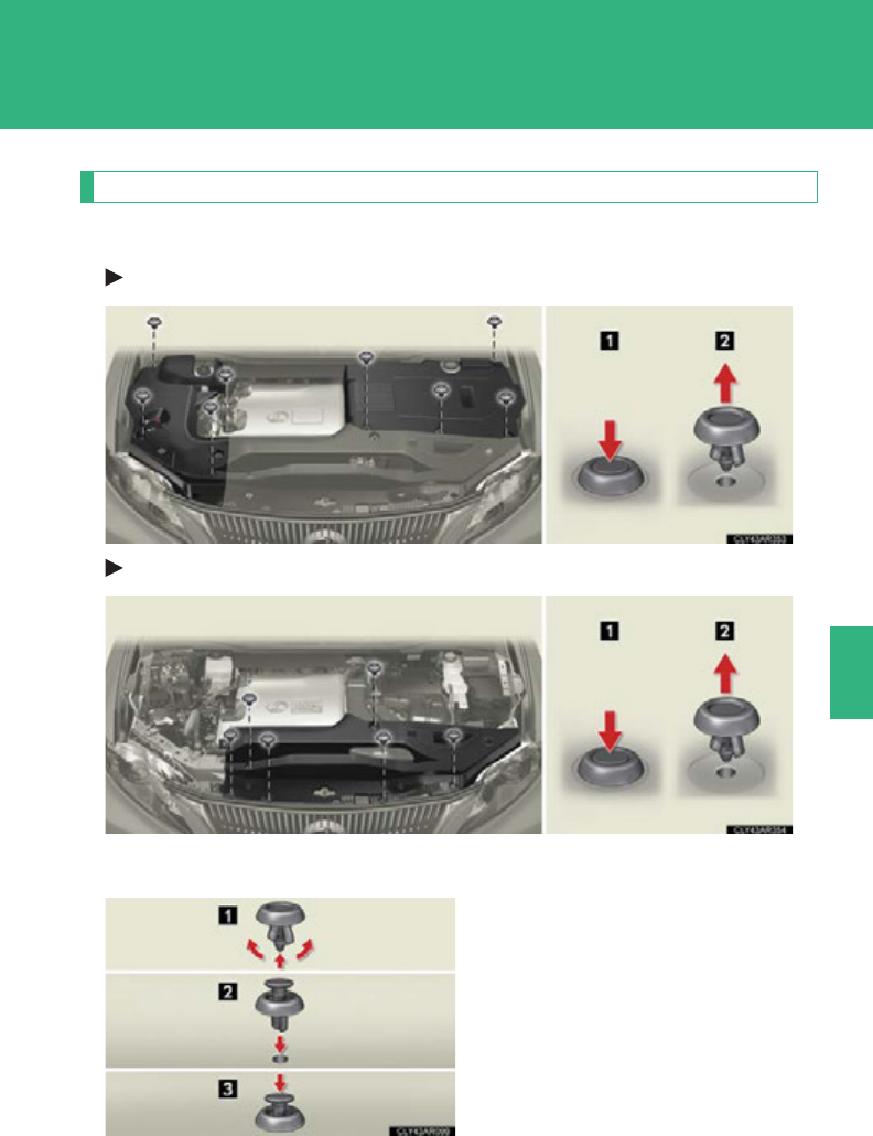
513
4-3. Do-it-yourself maintenance
4
Maintenance and care
Engine compartment cover
■Removing the engine compartment covers
Outside
Front
■Installing the clips

514
4-3. Do-it-yourself maintenance
NOTICE
■After installing an engine compartment cover
Make sure that the cover is securely installed in its original position.
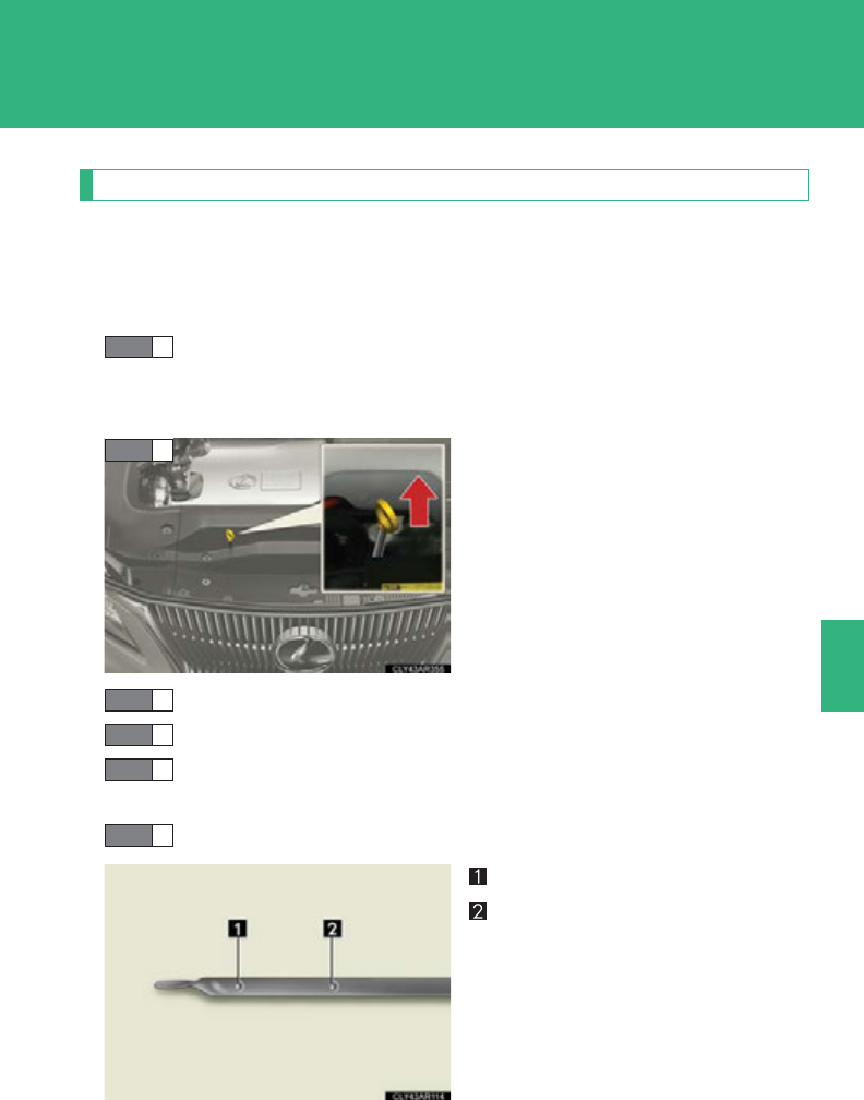
515
4-3. Do-it-yourself maintenance
4
Maintenance and care
Engine oil
With the engine at operating temperature and turned off, check the oil
level on the dipstick.
■Checking the engine oil
Park the vehicle on level ground. After warming up the engine
and turning off the hybrid system, wait more than 5 minutes for
the oil to drain back into the bottom of the engine.
Hold a rag under the end and pull
the dipstick out.
Wipe the dipstick clean.
Reinsert the dipstick fully.
Holding a rag under the end, pull the dipstick out and check the
oil level.
Wipe the dipstick and reinsert it fully.
Low
Full
STEP 1
STEP 2
STEP 3
STEP 4
STEP 5
STEP 6
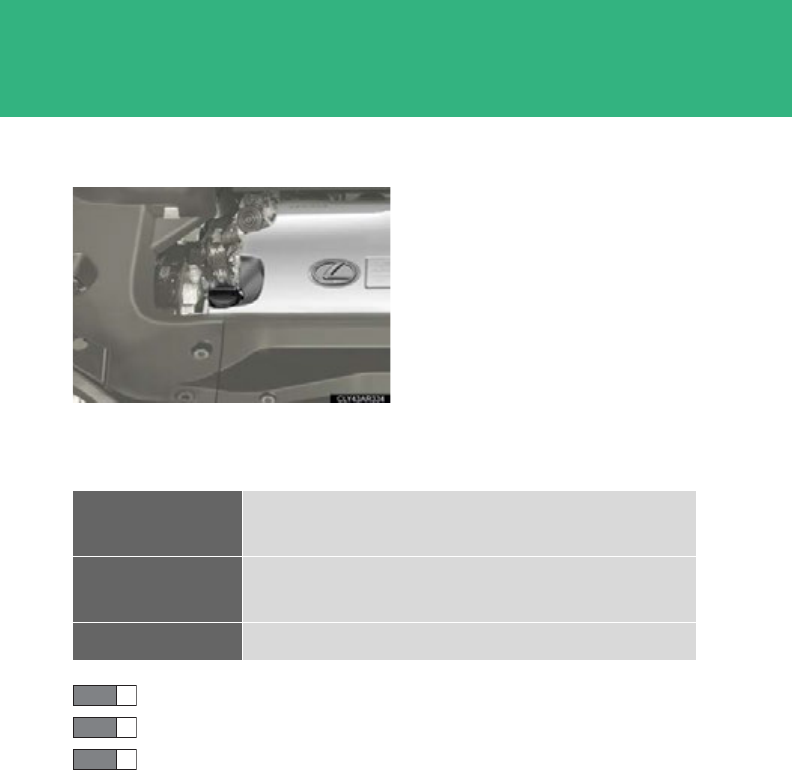
516
4-3. Do-it-yourself maintenance
■Adding engine oil
If the oil level is below or near the
low level mark, add engine oil of
the same type as that already in the
engine.
Make sure to check the oil type and prepare the items needed before
adding oil.
Remove the oil filler cap by turning it counterclockwise.
Add engine oil slowly, checking the dipstick.
Install the oil filler cap by turning it clockwise.
Engine oil
selection P. 66 8
Oil quantity
(Low Full) 1.6 qt. (1.5 L, 1.3 Imp. qt.)
Items Clean funnel
STEP 1
STEP 2
STEP 3

517
4-3. Do-it-yourself maintenance
4
Maintenance and care
■Engine oil consumption
●The amount of engine oil consumed depends on the oil viscosity, the quality of
the oil and the way the vehicle is driven.
●More oil is consumed under driving conditions such as high speeds and fre-
quent acceleration and deceleration.
●A new engine consumes more oil.
●When judging the amount of oil consumption, keep in mind that the oil may
have become diluted, making it difficult to judge the true level accurately.
●Oil consumption: Max. 1.1 qt./600 miles (0.9 Imp. qt./600 miles, 1.0 L/1000
km)
●If your vehicle consumes more than 1.1 qt. (1.0 L, 0.9 Imp. qt.) every 600 miles
(1000 km), contact your Lexus dealer.
CAUTION
■Used engine oil
●Used engine oil contains potentially harmful contaminants which may cause skin
disorders such as inflammation or skin cancer, so care should be taken to avoid
prolonged and repeated contact. To remove used engine oil from your skin, wash
thoroughly with soap and water.
●Dispose of used oil and filters only in a safe and acceptable manner. Do not dis-
pose of used oil and filters in household trash, in sewers or onto the ground.
Call your Lexus dealer, service station or auto parts store for information con-
cerning recycling or disposal.
●Do not leave used engine oil within the reach of children.

518
4-3. Do-it-yourself maintenance
NOTICE
■To prevent serious engine damage
Check the oil level on a regular basis.
■When replacing the engine oil
●Be careful not to spill engine oil on the vehicle components.
●Avoid overfilling, or the engine could be damaged.
●Check the oil level on the dipstick every time you refill the vehicle.
●Be sure the engine oil filler cap is properly tightened.
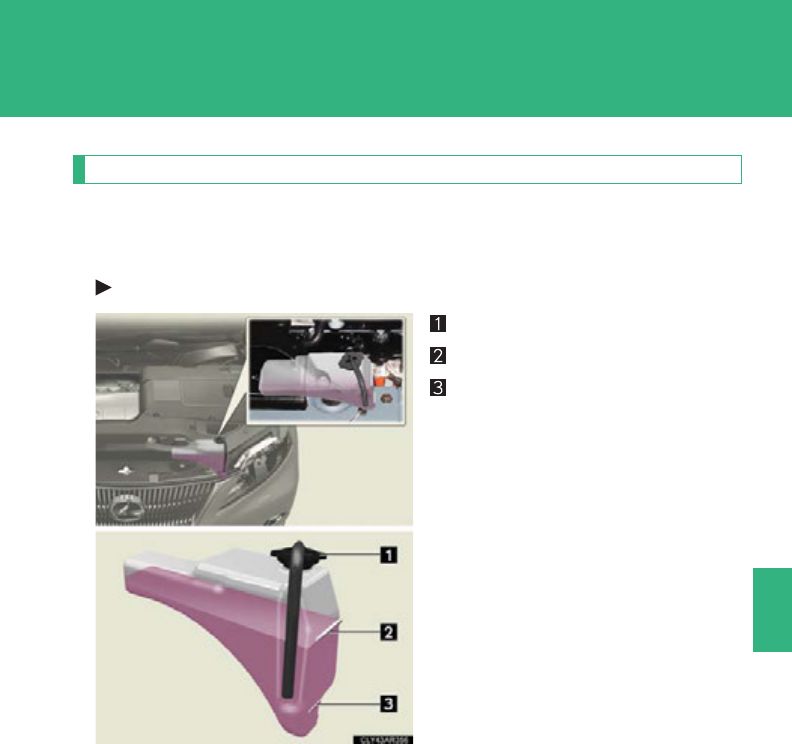
519
4-3. Do-it-yourself maintenance
4
Maintenance and care
Coolant
The coolant level is satisfactory if it is between the “FULL” and “LOW”
lines on the reservoir when the engine and hybrid system are cold.
Engine coolant reservoir
Reservoir cap
“FULL” line
“LOW” line
If the level is on or below the
“LOW” line, add coolant up to the
“FULL” line. (P. 670 )
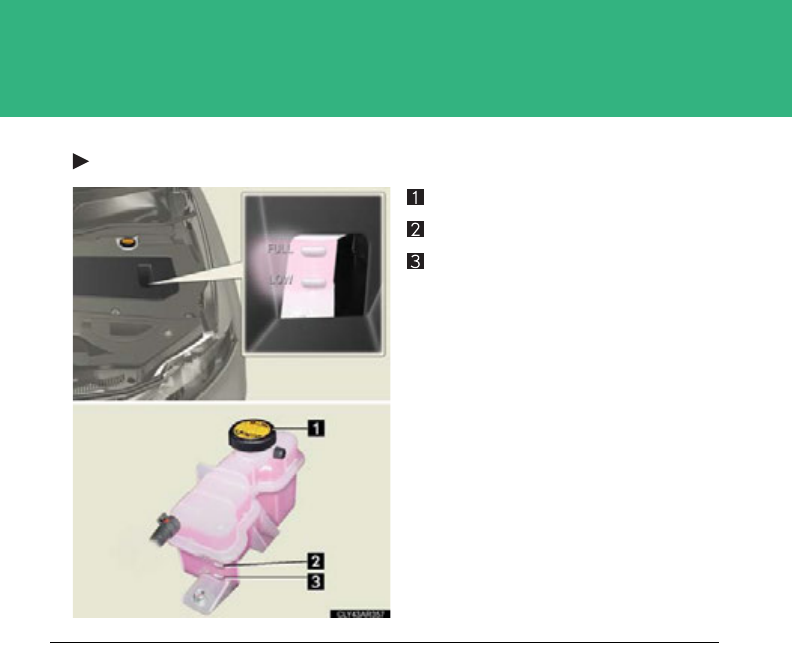
520
4-3. Do-it-yourself maintenance
Power control unit coolant reservoir
Reservoir cap
“FULL” line
“LOW” line
If the level is on or below the
“LOW” line, add coolant up to the
“FULL” line. (P. 670 )
■Coolant selection
Only use “Toyota Super Long Life Coolant” or similar high quality ethylene glycol
based non-silicate, non-amine, non-nitrite, and non-borate coolant with long-life
hybrid organic acid technology.
U.S.A.: “Toyota Super Long Life Coolant” is a mixture of 50% coolant and
50% deionized water. (Minimum temperature: -31F [-35C])
Canada: “Toyota Super Long Life Coolant” is a mixture of 55% coolant and 45%
deionized water. (Minimum temperature: -44F [-42C])
For more details about coolant, contact your Lexus dealer.
■If the coolant level drops within a short time of replenishing
Visually check the radiators, hoses, engine/power control unit coolant reservoir
caps, drain cock and water pump.
If you cannot find a leak, have your Lexus dealer test the cap and check for leaks in
the cooling systems.

521
4-3. Do-it-yourself maintenance
4
Maintenance and care
Radiator and condenser
Check the radiator and condenser and clear any foreign objects.
If either of the above parts are extremely dirty or you are not sure of their
condition, have your vehicle checked by your Lexus dealer.
CAUTION
■When the engine and hybrid system are hot
Do not remove the coolant reservoir cap.
The cooling system may be under pressure and may spray hot coolant if the cap is
removed, causing serious injuries, such as burns.
NOTICE
■When adding coolant
Coolant is neither plain water nor straight antifreeze. The correct mixture of water
and antifreeze must be used to provide proper lubrication, corrosion protection
and cooling. Be sure to read the antifreeze or coolant label.
■If you spill coolant
Be sure to wash it off with water to prevent damaging to parts or paint.
CAUTION
■The radiators and condenser may be hot after driving
Do not touch the radiator or condenser as they may be hot and cause serious inju-
ries, such as burns.
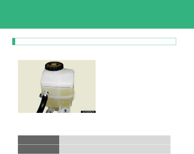
522
4-3. Do-it-yourself maintenance
Brake fluid
■Checking fluid level
The brake fluid level should be
between the “MAX” and “MIN”
lines on the tank.
■Adding fluid
Make sure to check the fluid type and prepare the necessary item.
Fluid type FMVSS No.116 DOT 3 or SAE J1703
Items Clean funnel
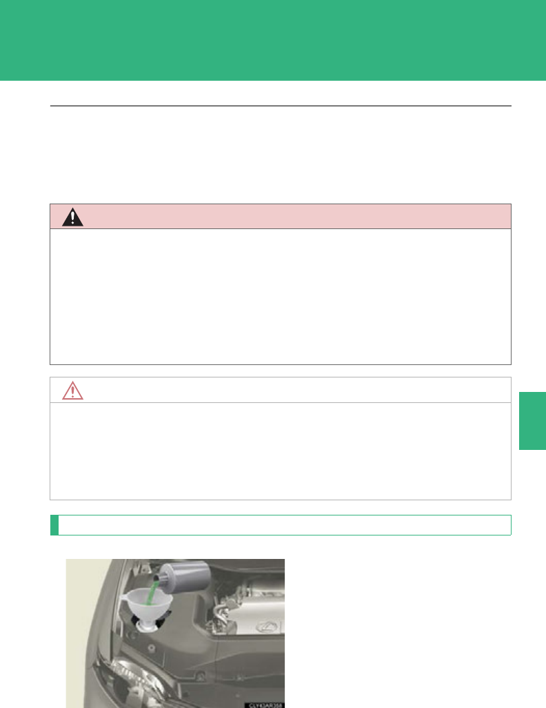
523
4-3. Do-it-yourself maintenance
4
Maintenance and care
Washer fluid
If any washer does not work or the
warning message appears on the
multi-information display, the
washer tank may be empty. Add
washer fluid.
■Brake fluid can absorb moisture from the air
Excess moisture in the brake fluid can cause a dangerous loss of braking efficiency.
Use only newly opened brake fluid.
CAUTION
■When filling the reservoir
Take care because brake fluid can harm your hands or eyes and damage painted
surfaces.
If fluid gets on your hands or in your eyes, flush the affected area with clean water
immediately.
If you still experience discomfort, see a doctor.
NOTICE
■If the fluid level is low or high
It is normal for the brake fluid level to go down slightly as the brake pads wear out or
when the fluid level in the accumulator is high.
If the reservoir needs frequent refilling, may be a serious problem.

524
4-3. Do-it-yourself maintenance
CAUTION
■When adding washer fluid
Do not add washer fluid when the hybrid system is hot or operating as washer fluid
contains alcohol and may catch fire if spilled on the hybrid system etc.
NOTICE
■Do not use any fluid other than washer fluid
Do not use soapy water or engine antifreeze instead of washer fluid.
Doing so may cause streaking on the vehicle’s painted surfaces.
■Diluting washer fluid
Dilute washer fluid with water as necessary.
Refer to the freezing temperatures listed on the label of the washer fluid bottle.

525
4-3. Do-it-yourself maintenance
4
Maintenance and care
12-volt battery
■Location
The 12-volt battery is located on
the left-hand side of the luggage
compartment.
■Removing the 12-volt battery cover
Vehicles with a compact spare tire
Pull the lever upward to fold
back the front part of the deck
board.
Pull the folded deck board
upright.
STEP 1
STEP 2
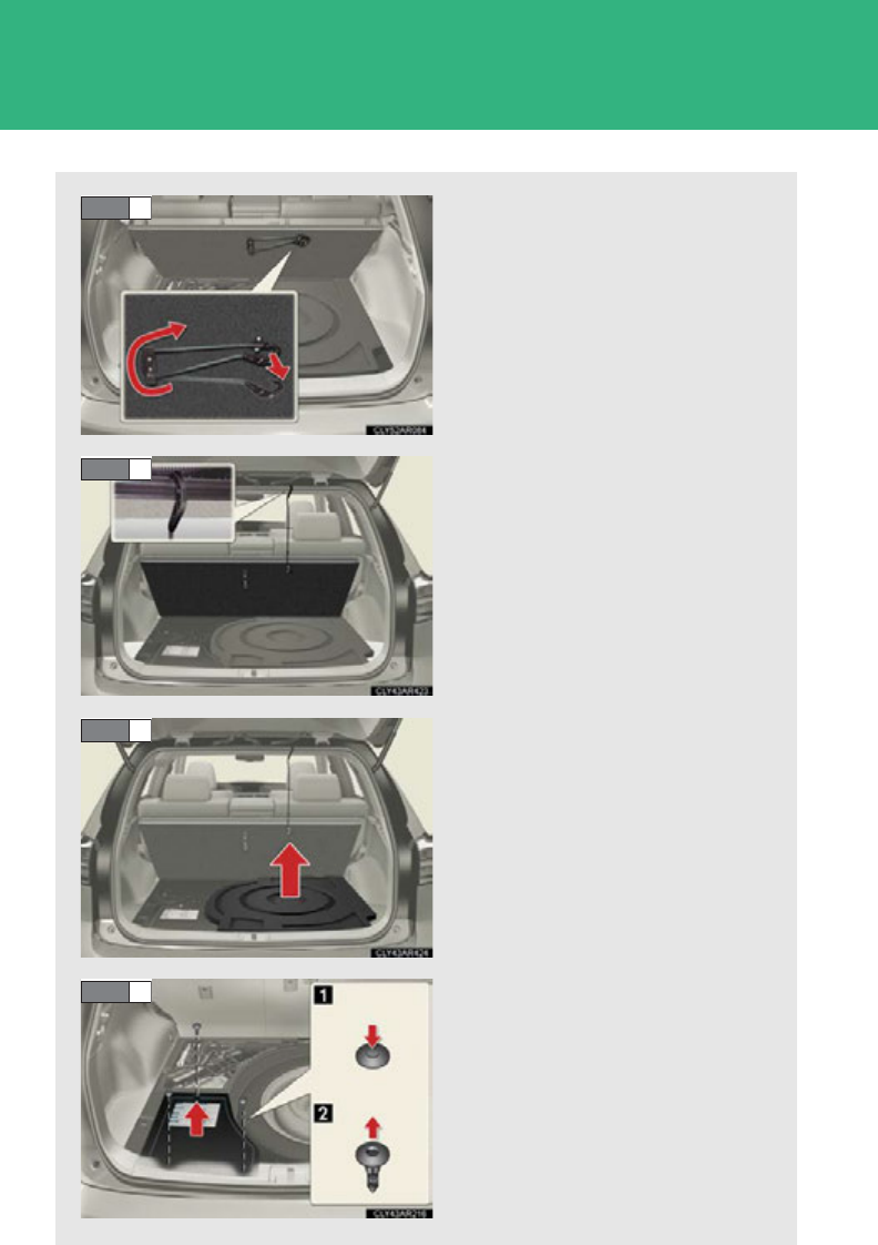
526
4-3. Do-it-yourself maintenance
Pull on the attached hook to
extend the string.
Use the hook to secure the deck
board as shown in the illustra-
tion.
Remove the spare tire cover.
After removing the clips,
remove the 12-volt battery
cover.
STEP 3
STEP 4
STEP 5
STEP 6
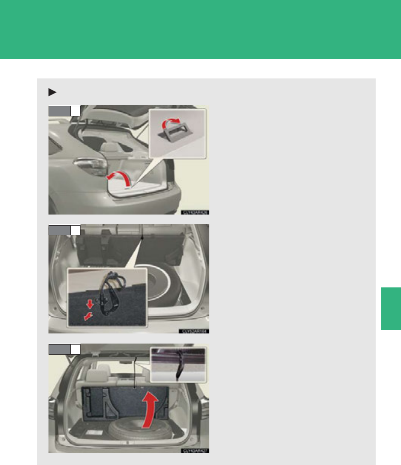
527
4-3. Do-it-yourself maintenance
4
Maintenance and care
Vehicles with a full-size spare tire
Pull the lever upward to fold
back the front part of the deck
board.
Pull on the attached hook to
extend the string.
Use the hook to secure the deck
board as shown in the illustra-
tion.
STEP 1
STEP 2
STEP 3
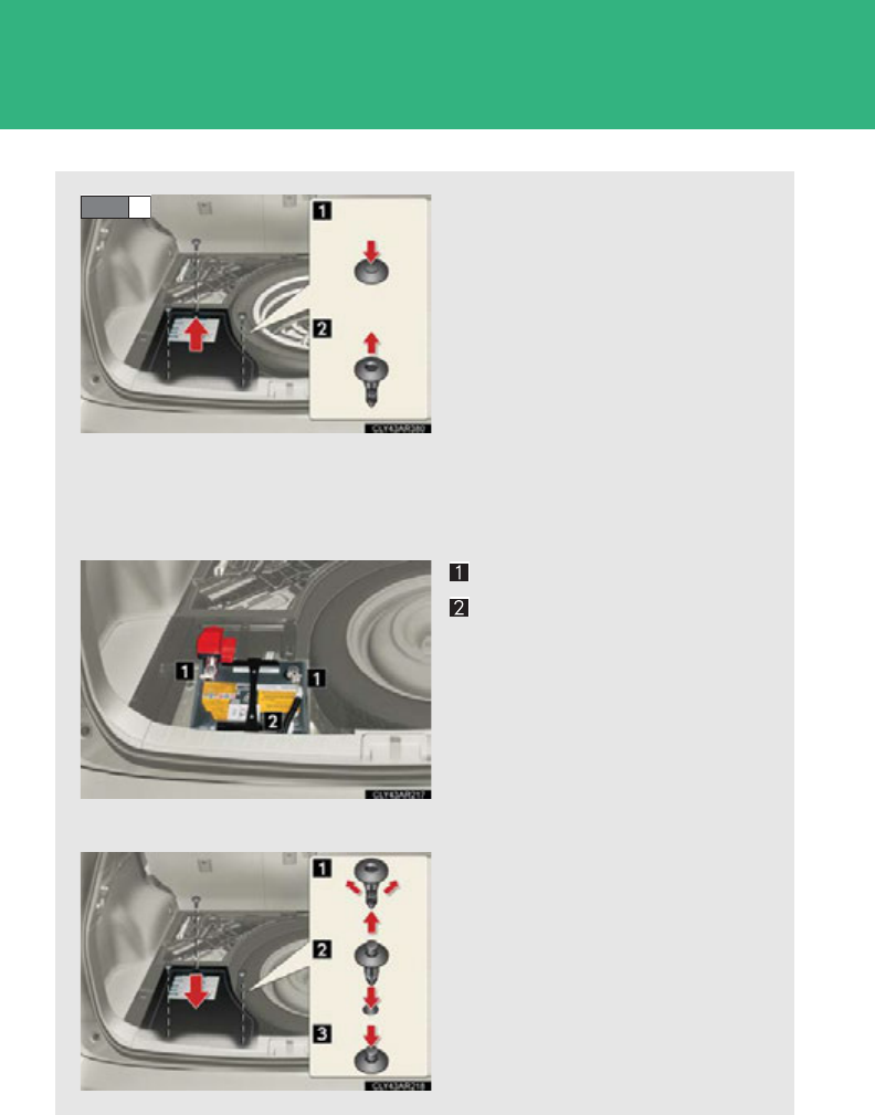
528
4-3. Do-it-yourself maintenance
After removing the clips,
remove the 12-volt battery
cover.
■Exterior
Make sure that the 12-volt battery terminals are not corroded and
that there are no loose connections, cracks or loose clamps.
Terminals
Hold-down clamp
■Installing the 12-volt battery cover
Install the 12-volt battery cover
with the clips.
STEP 4

529
4-3. Do-it-yourself maintenance
4
Maintenance and care
■Before recharging
When recharging, the 12-volt battery produces hydrogen gas which is flammable
and explosive. Therefore, observe the following precautions before recharging:
●If recharging with the 12-volt battery installed on the vehicle, be sure to discon-
nect the ground cable.
●Make sure the power switch on the charger is off when connecting and discon-
necting the charger cables to the 12-volt battery.
■After recharging/reconnecting the 12-volt battery
The hybrid system may not start. Follow one or both of the following procedures:
●After opening and closing the driver’s door, wait 10 seconds and then attempt to
start the hybrid system. (If the system does not start the first time, repeat the pro-
cedure.)
●With the shift lever in P and the “POWER” switch off, open and close any door
and then attempt to start the hybrid system.
If the system will not start even after multiple attempts at both methods, contact
your Lexus dealer.

530
4-3. Do-it-yourself maintenance
CAUTION
■Chemicals in the 12-volt battery
The 12-volt battery contain poisonous and corrosive sulfuric acid and may produce
hydrogen gas which is flammable and explosive. To reduce the risk of death or seri-
ous injury, take the following precautions while working on or near the 12-volt bat-
tery:
●Do not cause sparks by touching the 12-volt battery terminals with tools.
●Do not smoke or light a match near the 12-volt battery.
●Avoid contact with eyes, skin and clothes.
●Never inhale or swallow electrolyte.
●Wear protective safety glasses when working near the 12-volt battery.
●Keep children away from the 12-volt battery.
■Where to safely charge the 12-volt battery
Always charge the 12-volt battery in an open area. Do not charge the 12-volt bat-
tery in a garage or closed room where there is insufficient ventilation.
■How to recharge the 12-volt battery
Only perform a slow charge (5 A or less). The 12-volt battery may explode if
charged at a quicker rate.
■Emergency measures regarding electrolyte
●If electrolyte gets in your eyes
Flush your eyes with clean water for at least 15 minutes and get immediate medi-
cal attention. If possible, continue to apply water with a sponge or cloth while
traveling to the nearest medical facility.
●If electrolyte gets on your skin
Wash the affected area thoroughly. If you feel pain or burning, get medical atten-
tion immediately.
●If electrolyte gets on your clothes
It can soak through clothing on to your skin. Immediately take off the clothing and
follow the procedure above if necessary.
●If you accidentally swallow electrolyte
Drink a large quantity of water or milk. Follow with milk of magnesia, beaten raw
egg or vegetable oil. Get emergency medical attention immediately.

531
4-3. Do-it-yourself maintenance
4
Maintenance and care
CAUTION
■When replacing the 12-volt battery
Use a 12-volt battery designed for the RX450h. Failure to do so may cause gas
(hydrogen) to enter the passenger compartment, causing a fire or explosion.
For replacement of the 12-volt battery, contact your Lexus dealer.
NOTICE
■When recharging the 12-volt battery
Never recharge the 12-volt battery while the hybrid system is operating. Also, be
sure all accessories are turned off.
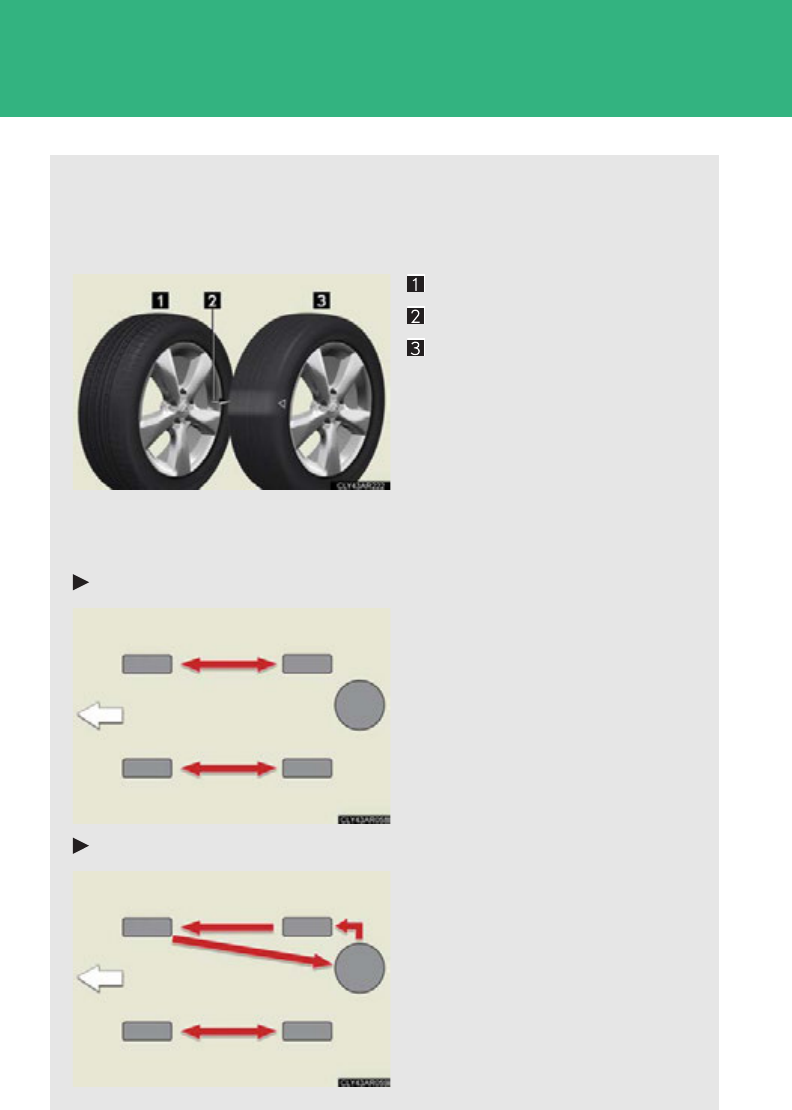
532
4-3. Do-it-yourself maintenance
Tires
Replace or rotate tires in accordance with maintenance schedules and
treadwear.
■Checking tires
New tread
Treadwear indicator
Worn tread
The location of treadwear indi-
cators is shown by the “TWI” or
“” marks, etc., molded on the
sidewall of each tire.
Check spare tire condition and
pressure if not rotated.
■Tire rotation
Vehicles with a compact spare tire
Rotate the tires in the order
shown.
To equalize tire wear and extend
tire life, Lexus recommends that
tire rotation is carried out at the
same interval as tire inspection.
Vehicles with a full-size spare tire
Rotate the tires in the order
shown.
To equalize tire wear and extend
tire life, Lexus recommends that
tire rotation is carried out at the
same interval as tire inspection.
Front
Front

533
4-3. Do-it-yourself maintenance
4
Maintenance and care
Installing tire pressure warning valves and transmitters
When replacing tires or wheels, tire pressure warning valves and trans-
mitters must also be installed.
When new tire pressure warning valves and transmitters are installed,
new tire pressure warning valve and transmitter ID codes must be regis-
tered in the tire pressure warning computer and the tire pressure warning
system must be initialized. Have tire pressure warning valve and transmit-
ter ID codes registered by your Lexus dealer. (P. 535)
Initializing the tire pressure warning system
■The tire pressure warning system must be initialized in the following
circumstances:
●When tire inflation pressure is changed such as when changing trav-
elling speed or load weight
●When changing the tire size
When the tire pressure warning system is initialized, the current tire
inflation pressure is set as the benchmark pressure.
■The tire pressure warning system
Your Lexus is equipped with a tire pressure warning system that uses
tire pressure warning valves and transmitters to detect low tire infla-
tion pressure before serious problems arise. (P. 6 0 1 )
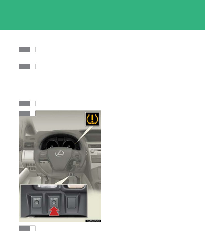
534
4-3. Do-it-yourself maintenance
■How to initialize the tire pressure warning system
Park the vehicle in safe place and turn the “POWER” switch off.
Initialization cannot be performed while the vehicle is moving.
Adjust the tire inflation pressure to the specified cold tire inflation
pressure level. (P. 673)
Make sure to adjust the tire pressure to the specified cold tire inflation
pressure level. The tire pressure warning system will operate based on
this pressure level.
Turn the “POWER” switch to ON mode.
Press and hold the tire pressure
warning reset switch until the tire
pressure warning light blinks
slowly 3 times.
Wait for a few minutes with the “POWER” switch on and then
turn the “POWER” switch off.
STEP 1
STEP 2
STEP 3
STEP 4
STEP 5

535
4-3. Do-it-yourself maintenance
4
Maintenance and care
Registering ID codes
The tire pressure warning valve and transmitter is equipped with a unique
ID code. When replacing a tire pressure warning valve and transmitter, it
is necessary to register the ID code. Have the ID code registered by your
Lexus dealer.
■When to replace your vehicle’s tires
Tires should be replaced if:
●You have tire damage such as cuts, splits, cracks deep enough to expose the
fabric, and bulges indicating internal damage.
●A tire goes flat repeatedly or cannot be properly repaired due to the size or
location of a cut or other damage.
If you are not sure, consult with your Lexus dealer.
■Replacing tires and wheels
If the ID code of the tire pressure warning valve and transmitter is not registered,
the tire pressure warning system will not work properly. After driving for about 20
minutes, the tire pressure warning light blinks for 1 minute and stays on to indicate a
system malfunction.
■Tire life
Any tire over 6 years old must be checked by a qualified technician even if it has sel-
dom or never been used or damage is not obvious.
■If the tread on snow tires wears down below 0.16 in. (4 mm)
The effectiveness of the tires as snow tires is lost.

536
4-3. Do-it-yourself maintenance
■Maximum load of tire
Check that the number given by dividing the maximum load by 1.10 of the replace-
ment tire is greater than 1/2 of the Gross Axle Weight Ratings (GAWR) of either
the front axle or the rear axle, whichever is greater.
■Tire types
1 Summer tires
Summer tires are high-speed performance tires best suited to highway driving
under dry conditions. Since summer tires do not have the same traction perfor-
mance as snow tires, summer tires are inadequate for driving on snow-covered
or icy roads. For driving on snow-covered roads or icy roads, the use of snow tires
is recommended. When installing snow tires, be sure to replace all four tires.
2 All season tires
All season tires are designed to provide better traction in snow and to be ade-
quate for driving in most winter conditions, as well as for use year round. All sea-
son tires, however, do not have adequate traction performance compared with
snow tires in heavy or loose snow. Also, all season tires fall short in acceleration
and handling performance compared with summer tires in highway driving.
3Snow tires
For driving on snow-covered roads or icy roads, we recommend using snow tires.
If you need snow tires, select tires of the same size, construction and load capac-
ity as the originally installed tires. Since your vehicle has radial tires as original
equipment, make sure your snow tires also have radial construction. Do not install
studded tires without first checking local regulations for possible restrictions.
Snow tires should be installed on all wheels. (P. 296 )
For the GAWR, see the Certification Label.
For the maximum load of the tire, see the load
limit at maximum cold tire inflation pressure
mentioned on the sidewall of the tire.
(P. 6 80 )

537
4-3. Do-it-yourself maintenance
4
Maintenance and care
■Initializing the tire pressure warning system
Initialize the tire pressure warning system with the tire inflation pressure adjusted to
the specified level.
■If you push the tire pressure warning reset switch accidentally
If initialization is performed, adjust the tire inflation pressure to the specified level
and initialize the tire pressure warning system again.
■When the initialization of the tire pressure warning system has failed
Initialization can be completed in a few minutes. However, in the following cases,
the settings have not been recorded and the system will not operate properly. If
repeated attempts to record tire inflation pressure settings are unsuccessful, have
the vehicle inspected by your Lexus dealer.
●When operating the tire pressure warning reset button, the tire pressure warn-
ing light does not blink 3 times.
●After carrying out the initialization procedure, the tire pressure warning light
blinks for 1 minute then stays on after driving for 20 minutes.
■Routine tire inflation pressure checks
The tire pressure warning system does not replace routine tire inflation pressure
checks. Make sure to check tire inflation pressure as part of your routine of daily
vehicle checks.

538
4-3. Do-it-yourself maintenance
■Tire pressure warning system certification
TPMS Transmitter FCC ID: PAXPMV107J
IC ID: 3729A-PMV107J
TPMS Receiver FCC ID: HYQ13BCX
IC ID: 1551A-13BCX
For vehicles sold in the U.S.A.
This device complies with part 15 of the FCC Rules. Operation is subject to the fol-
lowing two conditions: (1) This device may not cause harmful interference, and (2)
this device must accept any interference received, including interference that may
cause undesired operation.
FCC WARNING:
Changes or modifications not expressly approved by the party responsible for
compliance could void the user’s authority to operate the equipment.
For vehicles sold in Canada
Operation is subject to the following two conditions: (1) this device may not cause
interference, and (2) this device must accept any interference, including interfer-
ence that may cause undesired operation of the device.
L’utilisation de ce dispositif est autorisée seulement aux deux conditions suivantes:
(1) il ne doit pas produire de brouillage, et (2) l’utilisateur du dispositif doit être prêt
à accepter tout brouillage radioélectrique reçu, même si ce brouillage est
susceptible de compromettre le fonctionnement du dispositif.

539
4-3. Do-it-yourself maintenance
4
Maintenance and care
CAUTION
■Tire pressure warning system operation
The tire pressure warning system may not provide warning immediately if a tire
bursts or if sudden air leakage occurs.
■When inspecting or replacing tires
Observe the following precautions to prevent accidents. Failure to do so may cause
damage to parts of the drive train, as well as dangerous handling characteristics,
which may lead to an accident resulting in death or serious injury.
●Do not mix tires of different makes, models or tread patterns. Also, do not mix
tires of remarkably different treadwear.
●Do not use tire sizes other than those recommended by Lexus.
●Do not mix differently constructed tires (radial, bias-belted or bias-ply tires).
●Do not mix summer, all season and snow tires.
●Do not use tires that have been used on another vehicle.
Do not use tires if you do not know how they were used previously.
■When initializing the tire pressure warning system
Do not push the tire pressure warning reset switch without first adjusting the tire
inflation pressure to the specified level. Otherwise, the tire pressure warning light
may not come on even if the tire inflation pressure is low, or it may come on when
the tire inflation pressure is actually normal.

540
4-3. Do-it-yourself maintenance
NOTICE
■Repairing or replacing tires, wheels, tire pressure warning valves and transmit-
ters and tire valve caps
●When removing or fitting the wheels, tires or the tire pressure warning valves and
transmitter, contact your Lexus dealer as the tire pressure warning valves and
transmitters may be damaged if not handled correctly.
●When replacing tire valve caps, do not use tire valve caps other than those speci-
fied. The cap may become stuck.
■To avoid damage to the tire pressure warning valves and transmitters
When a tire is repaired with liquid sealants, the tire pressure warning valve and
transmitter may not operate properly. If a liquid sealant is used, contact your Lexus
dealer or other qualified service shop as soon as possible. Make sure to replace the
tire pressure warning valve and transmitter when replacing the tire. (P. 533 )
■Driving on rough roads
Take particular care when driving on roads with loose surfaces or potholes.
These conditions may cause losses in tire inflation pressure, reducing the cushion-
ing ability of the tires. In addition, driving on rough roads may cause damage to the
tires themselves, as well as the vehicle’s wheels and body.
■If tire inflation pressure of each tire becomes low while driving
Do not continue driving, or your tires and/or wheels may be ruined.

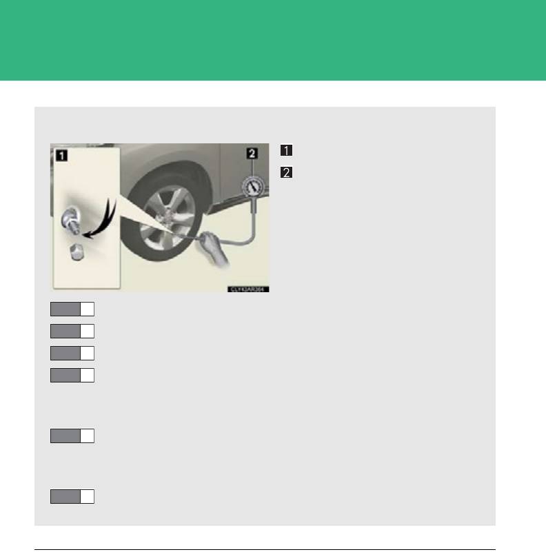
542
4-3. Do-it-yourself maintenance
■Tire inflation pressure check interval
You should check tire inflation pressure every two weeks, or at least once a month.
Do not forget to check the spare.
■Inspection and adjustment procedure
Tire valve
Tire pressure gauge
Remove the tire valve cap.
Press the tip of the tire pressure gauge onto the tire valve.
Read the pressure using the gauge graduations.
If the tire inflation pressure is not at the recommended level,
adjust the pressure.
If you add too much air, press the center of the valve to deflate.
After completing the tire inflation pressure measurement and
adjustment, apply soapy water to the valve and check for leak-
age.
Put the tire valve cap back on.
STEP 1
STEP 2
STEP 3
STEP 4
STEP 5
STEP 6

543
4-3. Do-it-yourself maintenance
4
Maintenance and care
■Effects of incorrect tire inflation pressure
Driving with incorrect tire inflation pressure may result in the following:
●Reduced fuel efficiency
●Reduced driving comfort and tire life
●Reduced safety
●Damage to the drive train
If a tire needs frequent inflating, have it checked by your Lexus dealer.
■Instructions for checking tire pressure
When checking tire inflation pressure, observe the following:
●Check only when the tires are cold.
If your vehicle has been parked for at least 3 hours or has not been driven for
more than 1 mile or 1.5 km, you will get an accurate cold tire inflation pressure
reading.
●Always use a tire pressure gauge.
The appearance of the tire can be misleading. In addition, tire inflation pressure
that is even just a few pounds off can degrade ride and handling.
●Do not reduce tire inflation pressure after driving. It is normal for tire inflation
pressure to be higher after driving.
●Never exceed the vehicle capacity weight.
Passengers and luggage weight should be placed so that the vehicle is bal-
anced.

544
4-3. Do-it-yourself maintenance
CAUTION
■Proper inflation is critical to save tire performance
Keep your tires properly inflated. Otherwise, the following conditions may occur
and result in an accident causing death or serious injury:
●Excessive wear
●Uneven wear
●Poor handling
●Possibility of blowouts resulting from overheated tires
●Poor sealing of the tire bead
●Wheel deformation and/or tire separation
●A greater possibility of tire damage from road hazards
NOTICE
■When inspecting and adjusting tire inflation pressure
Be sure to put the tire valve caps back on.
Without the valve caps, dirt or moisture could get into the valve and cause air leak-
age, which could result in an accident. If the caps are lost, replace them as soon as
possible.

545
4-3. Do-it-yourself maintenance
4
Maintenance and care
Wheels
■When replacing wheels
The wheels of your vehicle are equipped with tire pressure warning valves and
transmitters that allow the tire pressure warning system to provide advanced warn-
ing in the event of a loss in tire inflation pressure. Whenever wheels are replaced,
tire pressure warning valves and transmitters must be installed. (P. 533 )
If a wheel is bent, cracked or heavily corroded, it should be replaced.
Otherwise, the tire may separate from the wheel or cause a loss of han-
dling control.
■Wheel selection
When replacing wheels, care should be taken to ensure that they
are equivalent to those removed in load capacity, diameter, rim
width, and inset*.
Replacement wheels are available at your Lexus dealer.
*: Conventionally referred to as “offset”.
Lexus does not recommend using the following:
●Wheels of different sizes or types
●Used wheels
●Bent wheels that have been straightened
■Aluminum wheel precautions
●Use only Lexus wheel nuts and wrenches designed for use with
your aluminum wheels.
●When rotating, repairing or changing your tires, check that the
wheel nuts are still tight after driving 1000 miles (1600 km).
●Be careful not to damage the aluminum wheels when using tire
chains.
●Use only Lexus genuine balance weights or equivalent and a
plastic or rubber hammer when balancing your wheels.

546
4-3. Do-it-yourself maintenance
CAUTION
■When replacing wheels
●Do not use wheels that are a different size from those recommended in the
Owner’s Manual, as this may result in loss of handling control.
●Never use an inner tube in a leaking wheel which is designed for a tubeless tire.
Doing so may result in an accident, causing death or serious injury.
NOTICE
■Replacing tire pressure warning valves and transmitters
●Because tire repair or replacement may affect the tire pressure warning valves
and transmitters, make sure to have tires serviced by your Lexus dealer or other
qualified service shop. In addition, make sure to purchase your tire pressure
warning valves and transmitters at your Lexus dealer.
●Ensure that only genuine Lexus wheels are used on your vehicle.
Tire pressure warning valves and transmitters may not work properly with non-
genuine wheels.
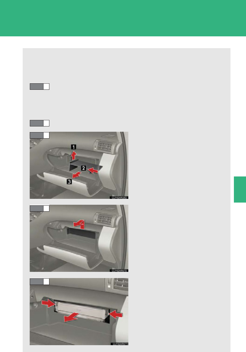
547
4-3. Do-it-yourself maintenance
4
Maintenance and care
Air conditioning filter
The air conditioning filter must be cleaned or changed regularly to main-
tain air conditioning efficiency.
■Removal method
Set the air conditioning system to recirculated mode.
(P. 325)
The air conditioning filter case cannot be removed with the system in
the outside air mode.
Turn the “POWER” switch off.
Open the glove box. Lift and
remove the partition.
Remove the glove box cover.
Remove the filter cover.
STEP 1
STEP 2
STEP 3
STEP 4
STEP 5
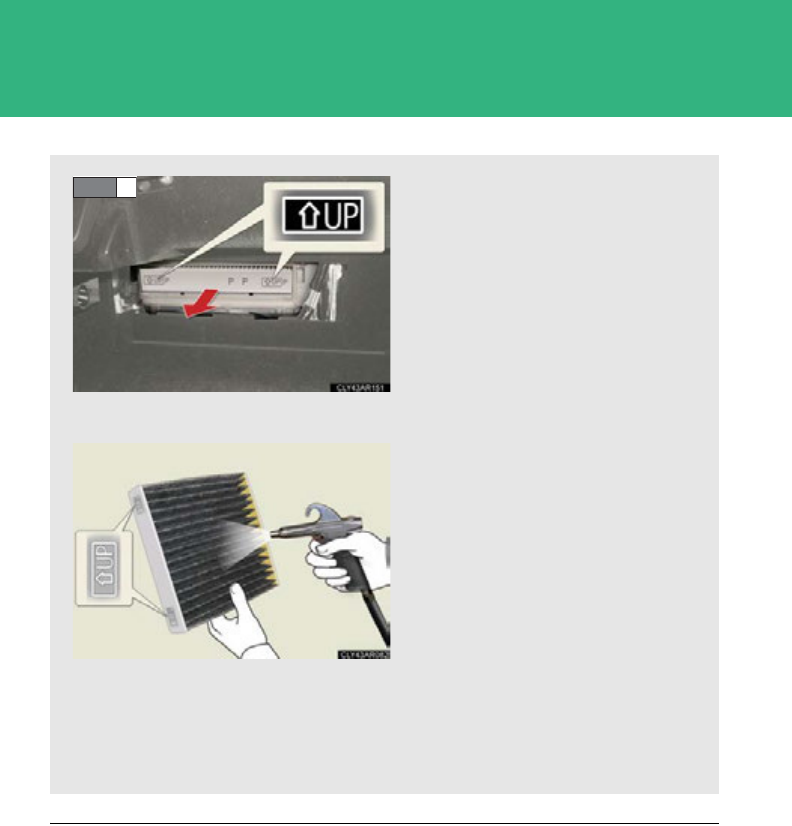
548
4-3. Do-it-yourself maintenance
■Checking interval
Inspect, clean and replace the air conditioning filter according to the maintenance
schedule. In dusty areas or areas with heavy traffic flow, early replacement may be
required. (For scheduled maintenance information, please refer to the “Owner's
Manual Supplement” or “Scheduled Maintenance”.)
■If air flow from the vents decreases dramatically
The filter may be clogged. Check the filter and replace if necessary.
Remove the air conditioning fil-
ter and replace it with a new
one.
The “UP” mark shown on the
filter should be pointing up.
■Cleaning method
If the filter is dirty, clean by blow-
ing compressed air through the
filter from the underside.
Hold the air gun 2 in. (5 cm)
from the filter and blow for
approximately 2 minutes at
72 psi (500 kPa, 5.0 kgf/cm2
or bar).
If an air gun is not available,
have the filter cleaned by
your Lexus dealer.
STEP 6

549
4-3. Do-it-yourself maintenance
4
Maintenance and care
NOTICE
■To prevent damage to the system
●When using the air conditioning system, make sure that a filter is always installed.
●When cleaning the filter, do not clean with water.
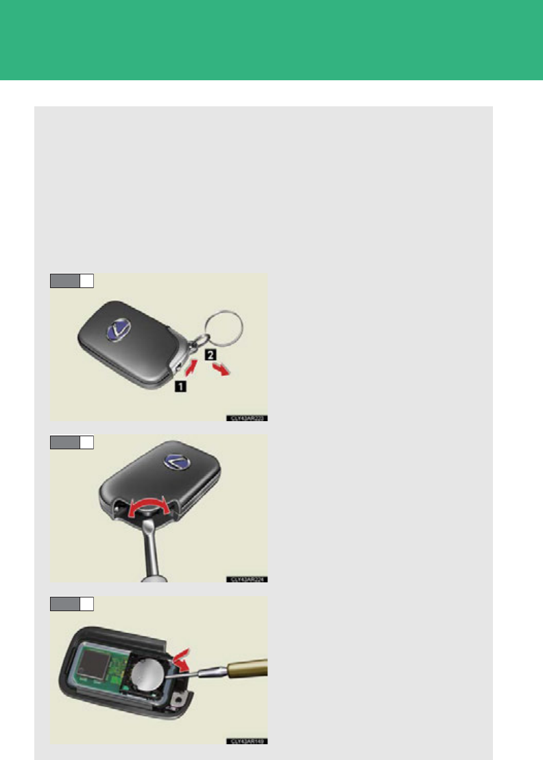
550
4-3. Do-it-yourself maintenance
Electronic key battery
Replace the battery with a new one if it is discharged.
■You will need the following items:
●Flathead screwdriver
●Small Phillips-head screwdriver
●Lithium battery (CR1632)
■Replacing the battery
Take out the mechanical key.
Remove the cover.
Remove the depleted battery.
Insert a new battery with the “+”
terminal facing up.
STEP 1
STEP 2
STEP 3

551
4-3. Do-it-yourself maintenance
4
Maintenance and care
■Use a CR1632 lithium battery
●Batteries can be purchased at your Lexus dealer, local electrical appliance
shops or camera stores.
●Replace only with the same or equivalent type recommended by the manufac-
turer.
●Dispose of used batteries according to the local laws.
■If the electronic key battery is discharged
The following symptoms may occur:
●The smart access system with push-button start and wireless remote control will
not function properly.
●The operational range is reduced.
■When the card key battery needs to be replaced (if equipped)
The battery for the card key is available only at Lexus dealers. Your Lexus dealer
can replace the battery for you.
CAUTION
■Removed battery and other parts
Keep away from children. These parts are small and if swallowed by a child, they can
cause choking. Failure to do so could result in death or serious injury.
NOTICE
■For normal operation after replacing the battery
Observe the following precautions to prevent accidents:
●Always work with dry hands.
Moisture may cause the battery to rust.
●Do not touch or move any other components inside the remote control.
●Do not bend either of the battery terminals.
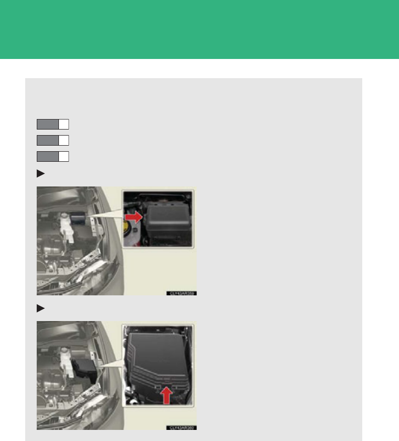
552
4-3. Do-it-yourself maintenance
Checking and replacing fuses
If any of the electrical components do not operate, a fuse may have blown.
If this happens, check and replace the fuses as necessary.
Turn the “POWER” switch off.
Remove the engine compartment cover. (P. 513)
Open the fuse box cover.
Engine compartment (type A fuse box)
Push the tab in and lift the lid off.
Engine compartment (type B fuse box)
Push the tab in and lift the lid off.
STEP 1
STEP 2
STEP 3
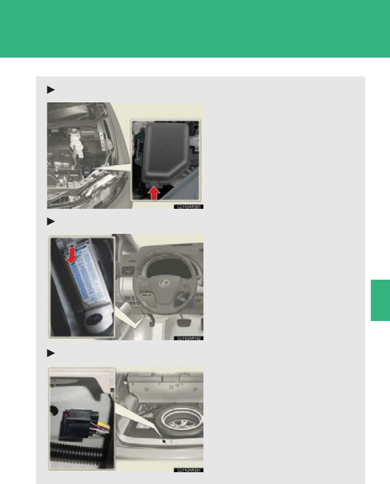
553
4-3. Do-it-yourself maintenance
4
Maintenance and care
Engine compartment (type C fuse box)
Push the tab in and lift the lid off.
Driver's side instrument panel
Remove the lid.
Luggage compartment (type A fuse box)
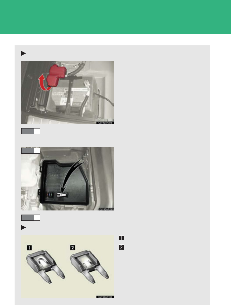
554
4-3. Do-it-yourself maintenance
Luggage compartment (type B fuse box)
Remove the terminal cover.
After a system failure, see “Fuse layout and amperage ratings”
for details about which fuse to check. (P. 557 )
Remove the fuse with the pull-
out tool.
Check if the fuse has blown.
Type A
Normal fuse
Blown fuse
Replace the blown fuse with a
new fuse of an appropriate
amperage rating. The amperage
rating can be found on the fuse
box lid.
STEP 4
STEP 5
STEP 6
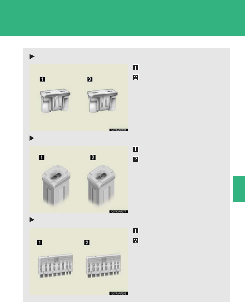
555
4-3. Do-it-yourself maintenance
4
Maintenance and care
Type B
Normal fuse
Blown fuse
Replace the blown fuse with a
new fuse of an appropriate
amperage rating. The amperage
rating can be found on the fuse
box lid.
Type C
Normal fuse
Blown fuse
Replace the blown fuse with a
new fuse of an appropriate
amperage rating. The amperage
rating can be found on the fuse
box lid.
Type D
Normal fuse
Blown fuse
Replace the blown fuse with a
new fuse of an appropriate
amperage rating. The amperage
rating can be found on the fuse
box lid.
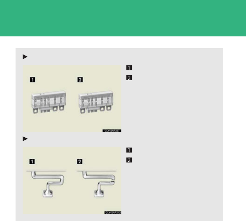
556
4-3. Do-it-yourself maintenance
Type E
Normal fuse
Blown fuse
Replace the blown fuse with a
new fuse of an appropriate
amperage rating. The amperage
rating can be found on the fuse
box lid.
Type F
Normal fuse
Blown fuse
Contact your Lexus dealer.
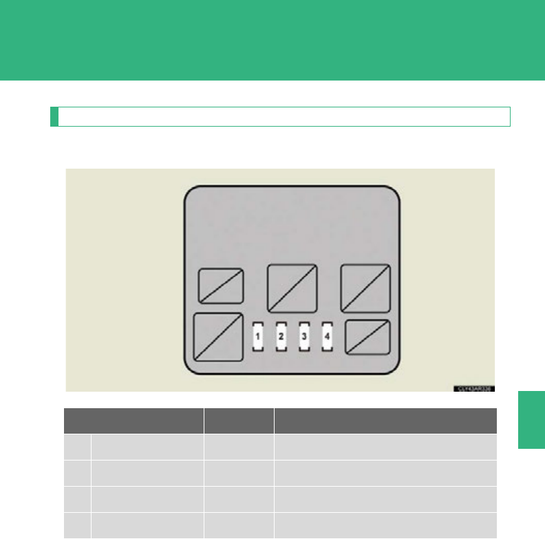
557
4-3. Do-it-yourself maintenance
4
Maintenance and care
Fuse layout and amperage ratings
■Engine compartment (type A fuse box)
Fuse Ampere Circuit
1PCU 15 A Hybrid system
2IGCT NO. 2 10 A Hybrid system
3IGCT NO. 3 10 A Hybrid system
4INV W/P 10 A Hybrid system
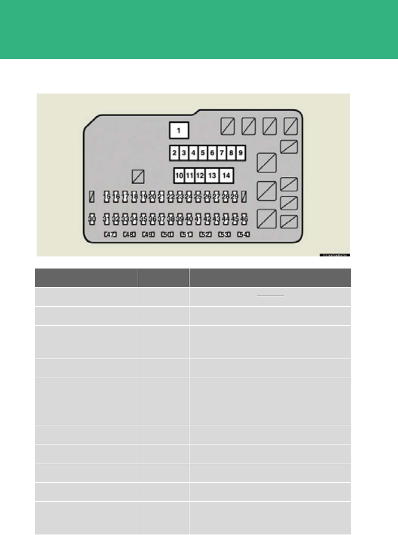
558
4-3. Do-it-yourself maintenance
■Engine compartment (type B fuse box)
Fuse Ampere Circuit
1SPARE 120 A
2RR DEF 50 A Rear window defogger
3AIR SUS 50 A Electronically modulated air suspen-
sion system
4HTR 50 A Air conditioning system
5ECB NO. 1 50 A
Brake system, vehicle stability control,
vehicle dynamics integrated manage-
ment, meters and gauges
6RDI FAN NO. 1 40 A Electric cooling fans
7RDI FAN NO. 2 40 A Electric cooling fans
8H-LP CLN 30 A Headlight cleaner
9PBD 30 A Power back door system
10 HV R/B NO. 1 30 A PCU, IGCT NO. 2, IGCT NO. 3,
INV W/P

559
4-3. Do-it-yourself maintenance
4
Maintenance and care
11 PD 50 A
Daytime running light system, A/F,
H-LP RH HI, H-LP LH LO, H-LP RH
LO, H-LP LH HI, HORN, S-HORN,
multiplex communication system,
multiport fuel injection system/
sequential multiport fuel injection sys-
tem
12 ECB NO. 2 50 A Brake system
13 HV R/B NO. 2 80 A ECB MAIN 1, ECB MAIN 2,
A/C W/P, BATT FAN, OIL PMP
14 DCDC 150 A
FUEL OPN, DR LOCK, OBD, RR
FOG, S/ROOF, INVERTER, ECU-
IG1 NO. 1, ECU-IG1 NO. 2, PANEL,
GAUGE NO. 1
15 AMP1 30 A Audio system
16 EFI MAIN 30 A
Multiport fuel injection system/
sequential multiport fuel injection sys-
tem, EFI NO. 2
17 AMP2 30 A Audio system
18 IG2 MAIN 30 A
Starter system, IGN, GAUGE NO. 2,
ECU IG2
19 IP JB 25 A Power door lock system
20 STR LOCK 20 A Starter system
21 RAD NO. 3 15 A Meters and gauges, instrument panel
lights, navigation system, audio system
22 HAZ 15 A Emergency flashers
23 ETCS 10 A
Multiport fuel injection system/
sequential multiport fuel injection sys-
tem
Fuse Ampere Circuit

560
4-3. Do-it-yourself maintenance
24 RAD NO. 1 10 A Audio system
25 AM2 7.5 A Starter system
26 ECU-B NO. 2 7.5 A
Air conditioning system, front passen-
ger occupant classification system,
starter system, electric power steering
system
27 MAYDAY/TEL 7. 5 A MAYDAY/TEL
28 IMMOBI 7.5 A
29 ECB MAIN
NO. 3 15 A Brake system
30 IGN 10 A
Multiport fuel injection system/
sequential multiport fuel injection sys-
tem, brake system, SRS airbag system
31 DOME 10 A
Vanity mirror lights, luggage compart-
ment lights, interior lights, personal
lights
32 ECU-B NO. 1 10 A
Interior lights, personal lights, tilt and
telescopic steering, multiplex commu-
nication system, meters and gauges,
power windows, driving position
memory system, power seats, power
back door, head-up display, starter
system, air conditioning system,
power door lock system
33 EFI NO. 1 10 A
Multiport fuel injection system/
sequential multiport fuel injection sys-
tem
34 WIP-S 7.5 A Windshield wipers and washer
35 AFS 7.5 A Adaptive front-lighting system
Fuse Ampere Circuit

561
4-3. Do-it-yourself maintenance
4
Maintenance and care
36 BK/UP LP 7.5 A Back-up lights
37 HEATER NO. 2 7.5 A Air conditioning system, AWD system
38 ECU IG1 10 A
Adaptive front-lighting system,
headlight cleaner, cooling fan, cruise
control, electronically modulated air
suspension system, vehicle stability
control, vehicle dynamics integrated
management, brake system
39 EFI NO. 2 10 A
Multiport fuel injection system/
sequential multiport fuel injection sys-
tem
40 F/PMP 15 A
Multiport fuel injection system/
sequential multiport fuel injection sys-
tem
41 DEICER 25 A Windshield wipers and washer
42 STOP 7.5 A
Vehicle stability control, vehicle
dynamics integrated management,
high mounted stoplight
43 TOWING BATT 20 A Trailer battery
44 TOWING 30 A Trailer lights
45 FILTER 10 A Condenser
46 IG1 MAIN 30 A ECU IG1, BK/UP LP,
HEATER NO. 2, AFS
47 H-LP RH HI 15 A Right-hand headlight (high beam)
48 H-LP LH HI 15 A Left-hand headlight (high beam)
49 BIXENON 10 A Discharge headlight
50 H-LP RH LO 15 A Right-hand headlight (low beam)
51 H-LP LH LO 15 A Left-hand headlight (low beam)
Fuse Ampere Circuit
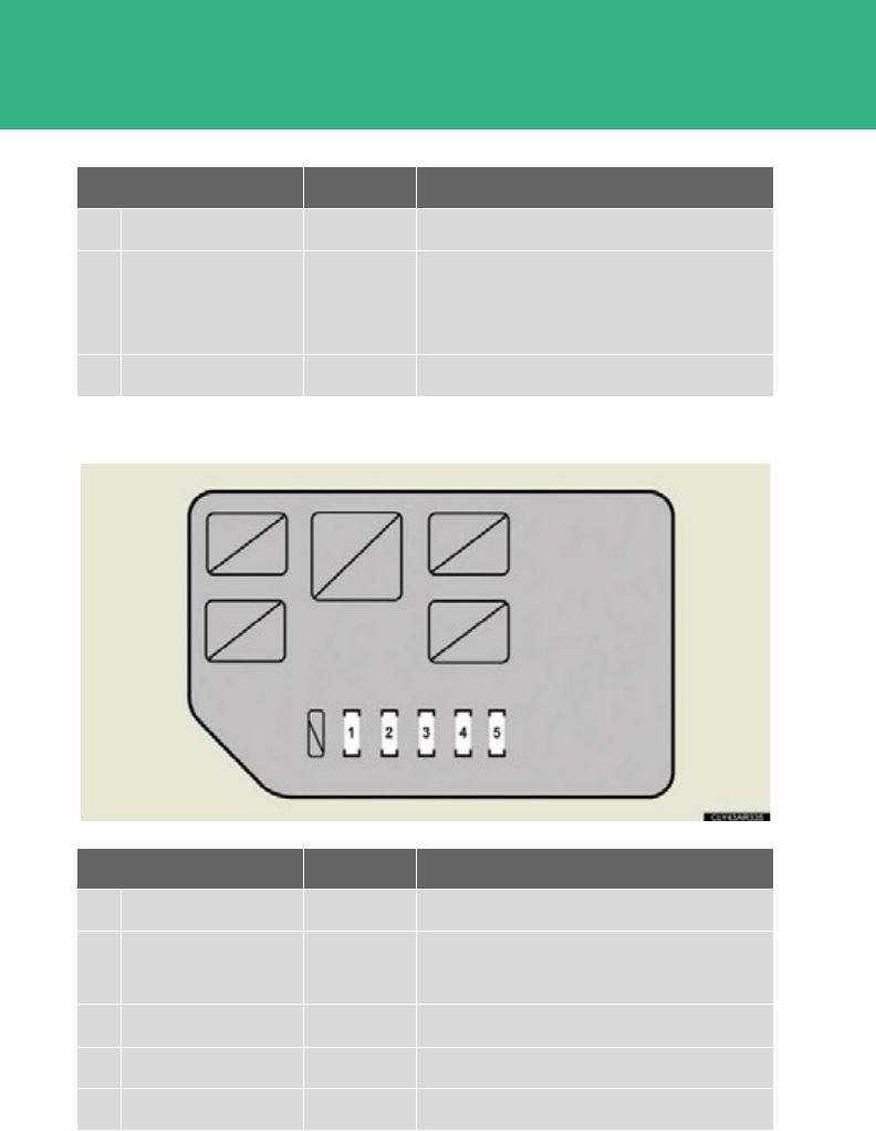
562
4-3. Do-it-yourself maintenance
■Engine compartment (type C fuse box)
52 HORN 10 A Horn
53 A/F 20 A
Multiport fuel injection system/
sequential multiport fuel injection sys-
tem
54 S-HORN 7.5 A S-HORN
Fuse Ampere Circuit
1ECB MAIN NO. 1 10 A Brake system
2ECB MAIN
NO. 2 10 A Brake system
3BATT FAN 15 A Battery cooling fan
4OIL PMP 10 A Hybrid system
5A/C W/P 10 A Air conditioning system
Fuse Ampere Circuit
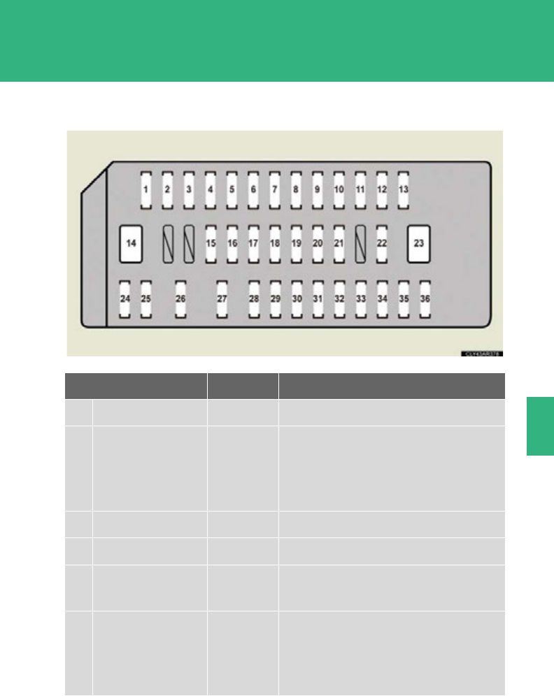
563
4-3. Do-it-yourself maintenance
4
Maintenance and care
■Driver’s side instrument panel
Fuse Ampere Circuit
1P/POINT 15 A Power outlet
2ECU-ACC 10 A
Navigation system, outside rear view
mirror, multiplex communication sys-
tem, multi-information display, head-
up display
3CIG 15 A Power outlet
4RADIO NO. 2 7.5 A Audio system, power outlet
5GAUGE NO. 1 10 A Emergency flashers, navigation sys-
tem, head-up display
6ECU-IG1 NO. 3 10 A
Outside rear view mirror, windshield
wipers and washer, seat heaters,
starter system, power outlet, moon
roof

564
4-3. Do-it-yourself maintenance
7ECU-IG1 NO. 1 10 A
Multiplex communication system,
electric power steering system, shift
lock control system, tilt and telescopic
steering, starter system, hybrid trans-
mission system, power back door,
hybrid system, tire pressure warning
system
8S/ROOF 30 A Moon roof
9FUEL OPN 7.5 A Fuel filler door opener
10 PSB 30 A Pre-collision seat belt
11 TI & TE 30 A Tilt and telescopic steering system
12 DR LOCK 10 A Power door lock system
13 FR FOG 15 A
14 P-SEAT LH 30 A Power seat (left-side)
15 INVERTER 20 A
16 RR FOG 7.5 A
17 D/L ALT B 25 A Multiplex communication system
18 HEATER 10 A Air conditioning system
19 ECU-IG1 NO. 2 10 A
Air conditioning system, multiport fuel
injection system/sequential multiport
fuel injection system, SRS airbag sys-
tem, multi-information display, capaci-
tor
20 PANEL 10 A
Switch illumination, navigation system,
height control system, headlight
cleaner, windshield wiper de-icer, seat
heater, power back door, audio sys-
tem, multi-information display, air con-
ditioning system
Fuse Ampere Circuit

565
4-3. Do-it-yourself maintenance
4
Maintenance and care
21 TAIL 10 A Position lights, tail lights, license plate
lights, towing converter
22 AIR SUS 20 A Electronically modulated air suspen-
sion system
23 P-SEAT RH 30 A Power seat (right-side)
24 OBD 7.5 A On-board diagnosis
25 FR DOOR 25 A Front power window (right-side)
26 RR DOOR 25 A Rear power window (right-side)
27 FL DOOR 25 A Front power window (left-side)
28 RL DOOR 25 A Rear power window (left-side)
29 FR WASH 25 A Windshield wipers and washer
30 RR WIP 15 A Windshield wipers and washer
31 RR WASH 20 A Windshield wipers and washer
32 FR WIP 30 A Windshield wipers and washer
33 ECU IG2 10 A Starter system, intuitive parking assist,
AWD system
34 GAUGE NO. 2 7.5 A Starter system
35 RH S-HTR 15 A Seat heater (right-side)
36 LH S-HTR 15 A Seat heater (left-side)
Fuse Ampere Circuit
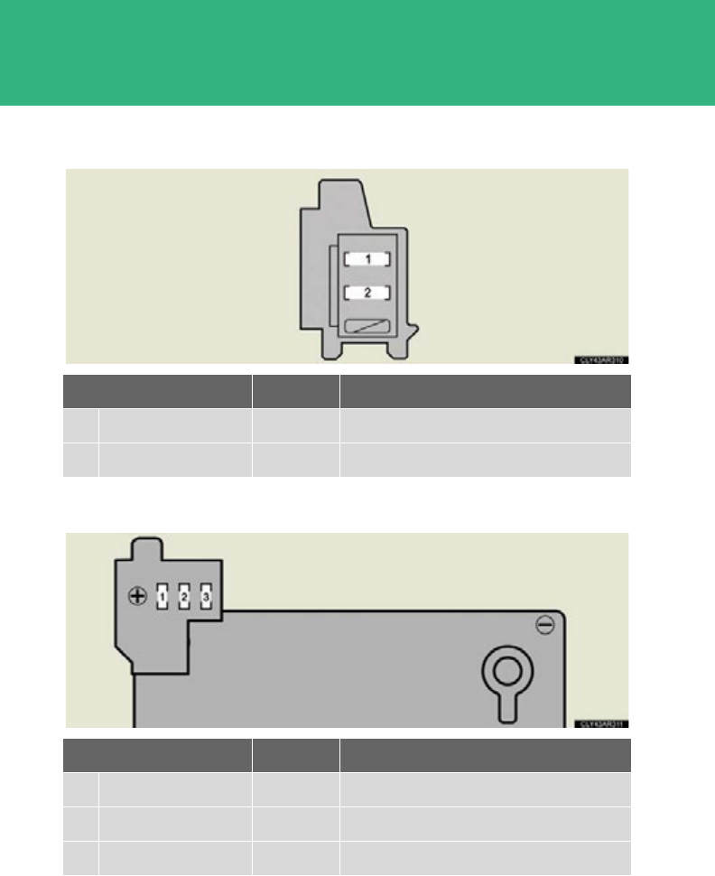
566
4-3. Do-it-yourself maintenance
■Luggage compartment (type A fuse box)
■Luggage compartment (type B fuse box)
Fuse Ampere Circuit
1DCDC-S 7.5 A Hybrid system
2CAPACITOR 10 A Hybrid system
Fuse Ampere Circuit
1MAIN 180 A All electrical components
2RR-B 50 A CAPACITOR, DCDC-S
3EPS 80 A Electric power steering system

567
4-3. Do-it-yourself maintenance
4
Maintenance and care
■After a fuse is replaced
●If the lights do not turn on even after the fuse has been replaced, a bulb may
need replacement. (P. 571)
●If the replaced fuse blows again, have the vehicle inspected by your Lexus
dealer.
■If there is an overload in the circuit
The fuses are designed to blow, protecting the wiring harness from damage.
CAUTION
■To prevent system breakdowns and vehicle fire
Observe the following precautions.
Failure to do so may cause damage, and possibly a fire or injury.
●Never use a fuse of a higher amperage rating than that indicated, or use any
other object in place of a fuse.
●Always use a genuine Lexus fuse or equivalent.
Never replace a fuse with a wire, even as a temporary fix.
This can cause extensive damage or even fire.
●Do not modify the fuses or fuse boxes.
NOTICE
■Before replacing fuses
Have the cause of electrical overload determined and repaired by your Lexus
dealer as soon as possible.
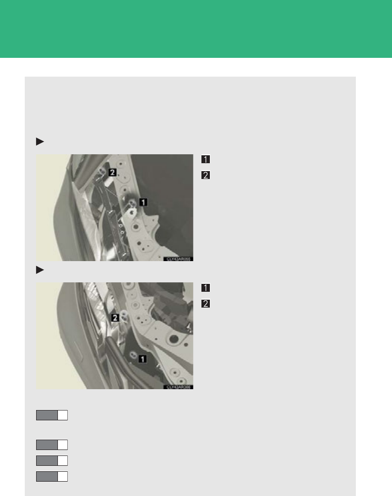
568
4-3. Do-it-yourself maintenance
Headlight aim
■Removing the engine compartment cover
P. 51 3
■Vertical movement adjusting bolts
Vehicles with discharge headlights
Adjustment bolt A
Adjustment bolt B
Vehicles with LED headlights
Adjustment bolt A
Adjustment bolt B
■Before checking the headlight aim
Make sure the vehicle has a full tank of gas and the area around
the headlight is not deformed.
Park the vehicle on level ground.
Sit in the driver’s seat.
Bounce the vehicle several times.
STEP 1
STEP 2
STEP 3
STEP 4
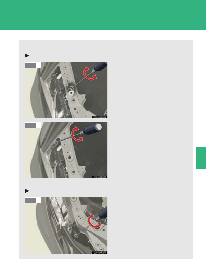
569
4-3. Do-it-yourself maintenance
4
Maintenance and care
■Adjusting the headlight aim
Vehicles with discharge headlights
Turn bolt A in either direction
using a Phillips-head screw-
driver.
Remember the turning direction
and the number of turns in mind.
Turn bolt B the same number of
turns and in the same direction
as step 1 using a Phillips-head
screwdriver.
If the headlight cannot be
adjusted using this procedure,
take the vehicle to your Lexus
dealer to adjust the headlight
aim.
Vehicles with LED headlights
Turn bolt A in either direction
using a Phillips-head screw-
driver.
Remember the turning direction
and the number of turns.
STEP 1
STEP 2
STEP 1
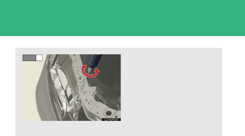
570
4-3. Do-it-yourself maintenance
Turn bolt B the same number of
turns and in the same direction
as step 1 using a Phillips-head
screwdriver.
If the headlight cannot be
adjusted using this procedure,
take the vehicle to your Lexus
dealer to adjust the headlight
aim.
STEP 2
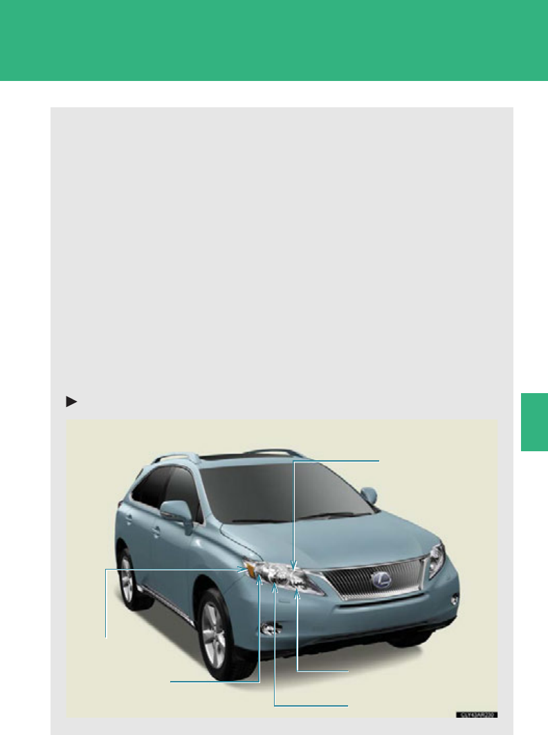
571
4-3. Do-it-yourself maintenance
4
Maintenance and care
Light bulbs
You may replace the following bulbs by yourself. The difficulty level of
replacement varies depending on the bulb. If necessary bulb replacement
seems difficult to perform, contact your Lexus dealer.
For more information about replacing other light bulbs, contact your Lexus
dealer.
■Preparing for light bulb replacement
Check the wattage of the light bulb to be replaced. (P. 675)
■Removing the engine compartment covers
P. 51 3
■Turning off the power back door main switch (if equipped)
P. 72
■Front bulb locations
Halogen headlights
Parking light
Front side marker
light
Front turn
signal light
Headlight high beam and
daytime running light
Headlight low beam
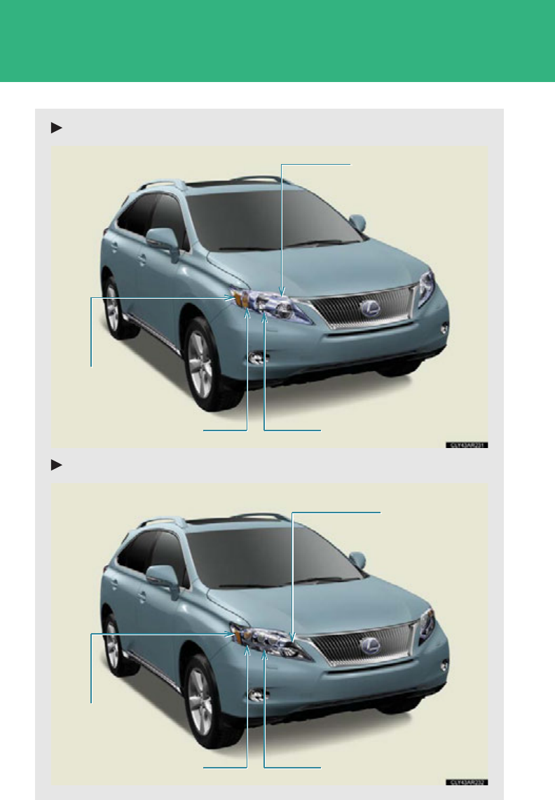
572
4-3. Do-it-yourself maintenance
Discharge headlights
LED headlights
Front turn signal light
Parking light
Daytime running light
Front side marker
light
Front turn signal light Parking light
Headlight high
beam and daytime
running light
Front side marker
light
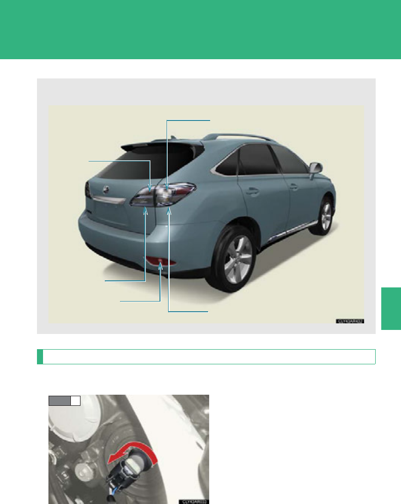
573
4-3. Do-it-yourself maintenance
4
Maintenance and care
Replacing light bulbs
■Daytime running lights (discharge headlights)
Turn the bulb base counterclock-
wise.
■Rear bulb locations
Rear turn signal light
Back-up light
Rear side marker
light
Tail light
Tail light
STEP 1
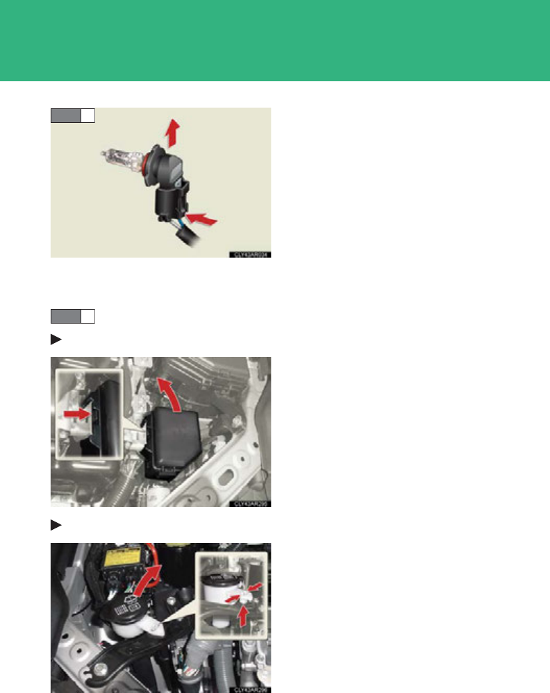
574
4-3. Do-it-yourself maintenance
Unplug the connector while
depressing the lock release.
■Headlight high beams and daytime running lights (halogen head-
lights)
Before replacing the bulbs:
Left side
Move the fuse box.
Right side
Move the washer fluid filler open-
ing.
STEP 2
STEP 1
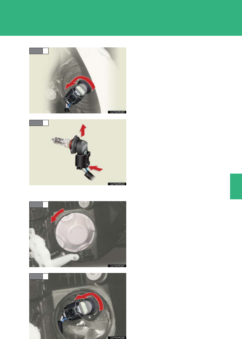
575
4-3. Do-it-yourself maintenance
4
Maintenance and care
Turn the bulb base counterclock-
wise.
Unplug the connector while
depressing the lock release.
■Headlight high beams and daytime running lights (LED headlights)
Turn the cover counterclockwise
and remove it.
Turn the bulb base counterclock-
wise.
STEP 2
STEP 3
STEP 1
STEP 2
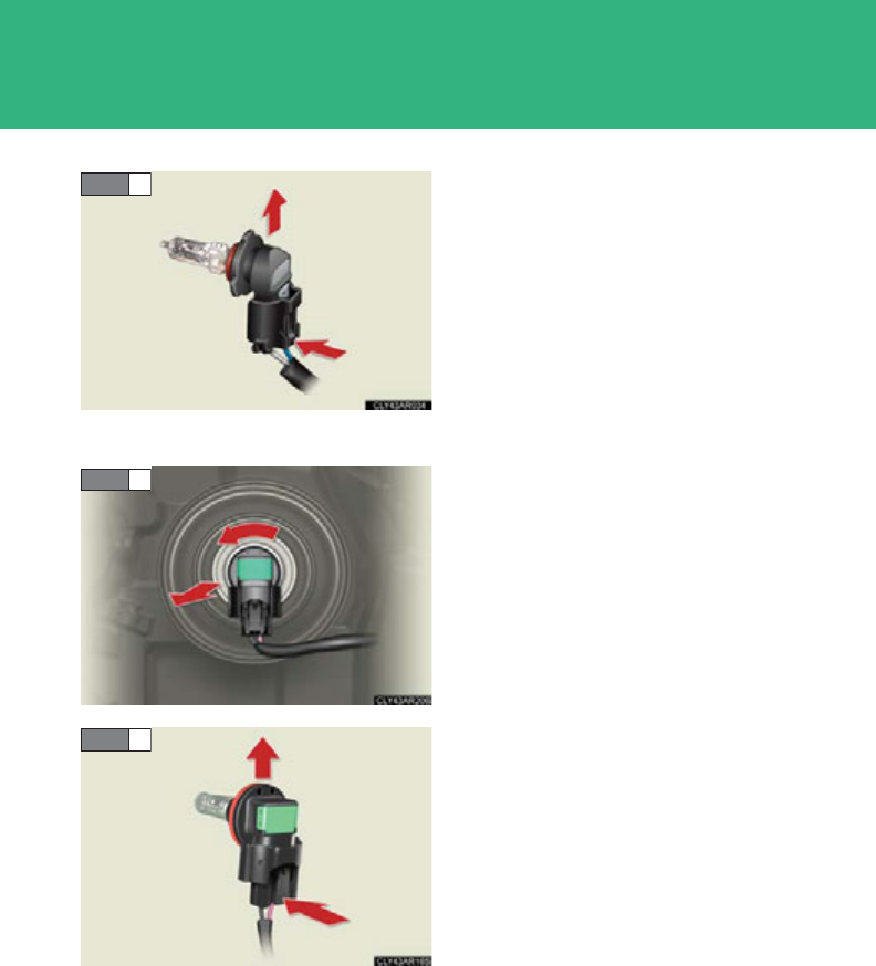
576
4-3. Do-it-yourself maintenance
Unplug the connector while
depressing the lock release.
■Headlight low beams (halogen headlights)
Turn the bulb base counterclock-
wise.
Unplug the connector while press-
ing the lock release.
STEP 3
STEP 1
STEP 2
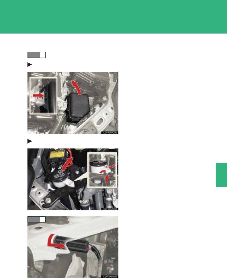
577
4-3. Do-it-yourself maintenance
4
Maintenance and care
■Parking lights (vehicles without LED headlights)
Before replacing the bulbs:
Left side
Move the fuse box.
Right side
Move the washer fluid filler open-
ing.
Turn the bulb base counterclock-
wise.
STEP 1
STEP 2
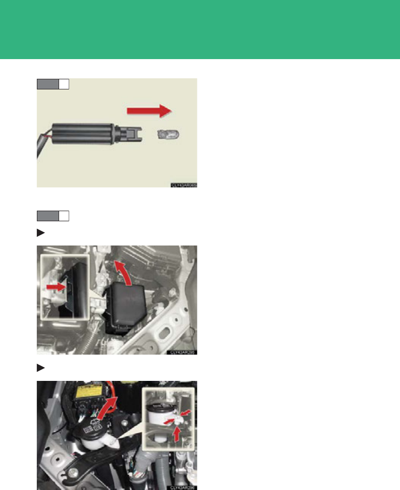
578
4-3. Do-it-yourself maintenance
Remove the light bulb.
■Parking lights (vehicles with LED headlights)
Before replacing the bulbs:
Left side
Move the fuse box.
Right side
Move the washer fluid filler open-
ing.
STEP 3
STEP 1
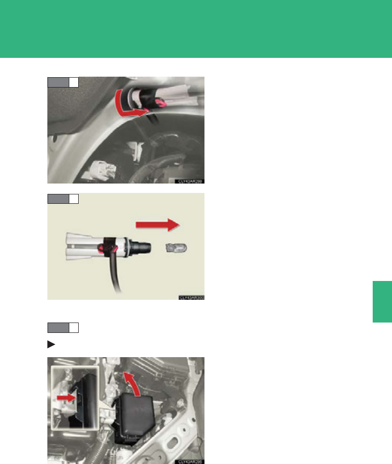
579
4-3. Do-it-yourself maintenance
4
Maintenance and care
Turn the bulb base counterclock-
wise.
Remove the light bulb.
■Front turn signal lights
Before replacing the bulbs:
Left side
Move the fuse box.
STEP 2
STEP 3
STEP 1
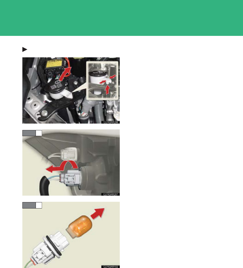
580
4-3. Do-it-yourself maintenance
Right side
Move the washer fluid filler open-
ing.
Turn the bulb base counterclock-
wise.
Remove the light bulb.
STEP 2
STEP 3
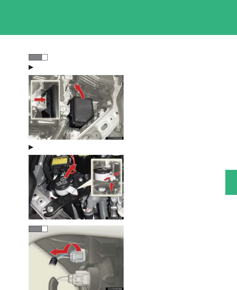
581
4-3. Do-it-yourself maintenance
4
Maintenance and care
■Front side marker lights (vehicles without LED headlights)
Before replacing the bulbs:
Left side
Move the fuse box.
Right side
Move the washer fluid filler open-
ing.
Turn the bulb base counterclock-
wise.
STEP 1
STEP 2
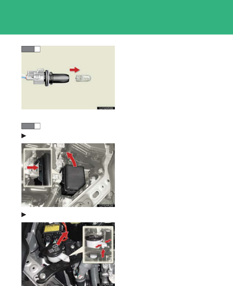
582
4-3. Do-it-yourself maintenance
Remove the light bulb.
■Front side marker lights (vehicles with LED headlights)
Before replacing the bulbs:
Left side
Move the fuse box.
Right side
Move the washer fluid filler open-
ing.
STEP 3
STEP 1
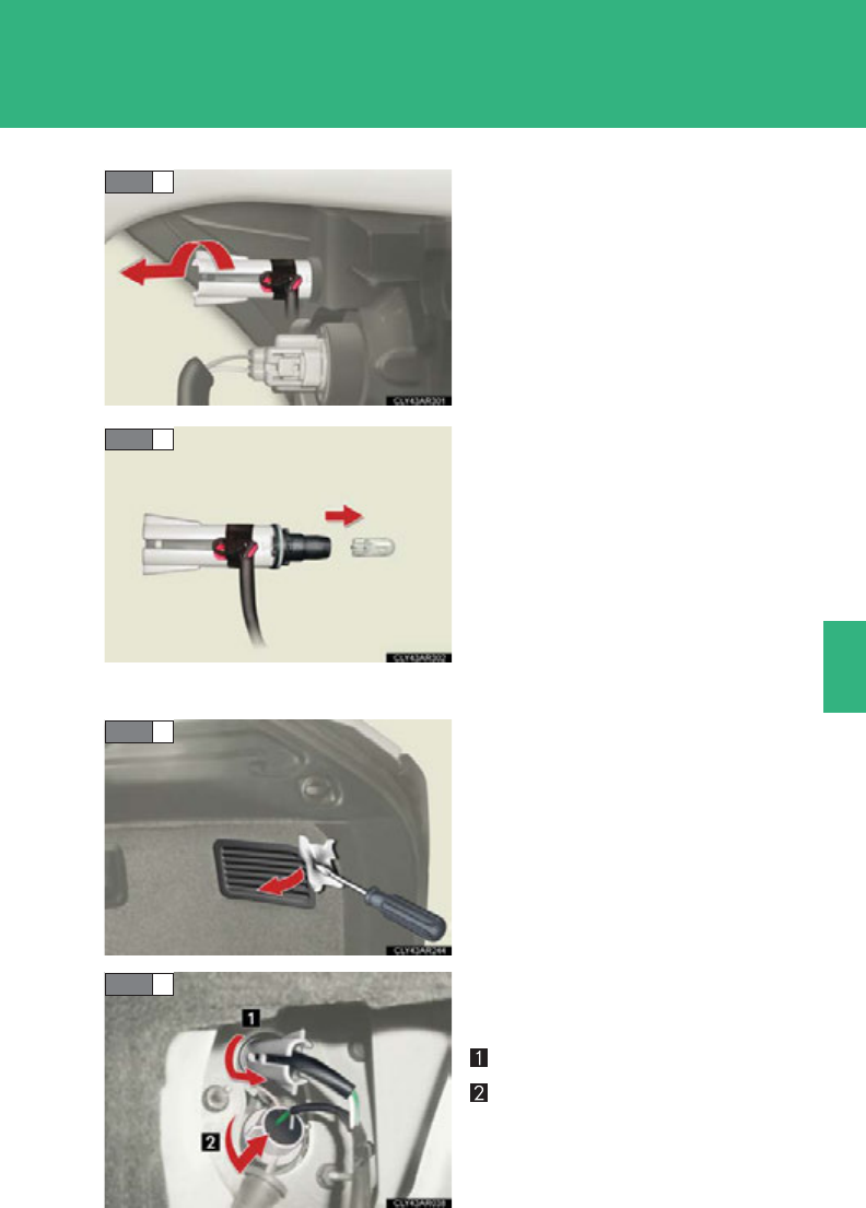
583
4-3. Do-it-yourself maintenance
4
Maintenance and care
Turn the bulb base counterclock-
wise.
Remove the light bulb.
■Rear turn signal and tail lights
Remove the access hole cover.
Use a flathead screwdriver
wrapped in a cloth.
Turn the bulb base counterclock-
wise.
Tail light
Rear turn signal light
STEP 2
STEP 3
STEP 1
STEP 2
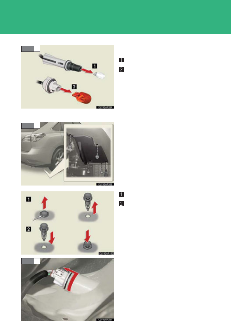
584
4-3. Do-it-yourself maintenance
Remove the light bulb.
Tail light
Rear turn signal light
■Rear side marker lights (right side)
Remove the bolts using a Phillips-
head screwdriver and remove the
clip.
Removing the clip
Installing the clip
Turn the bulb base counterclock-
wise.
STEP 3
STEP 1
STEP 2
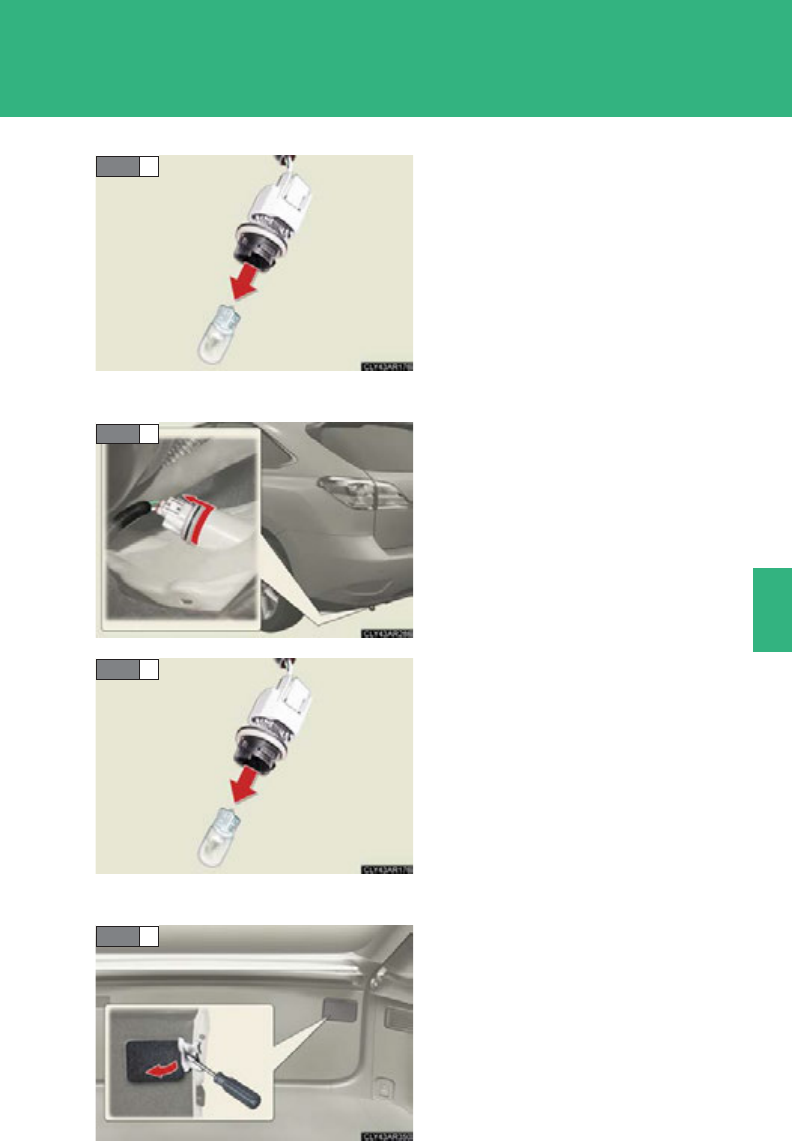
585
4-3. Do-it-yourself maintenance
4
Maintenance and care
Remove the light bulb.
■Rear side marker lights (left side)
Turn the bulb base counterclock-
wise.
Remove the light bulb.
■Tail and back-up lights
Remove the access hole cover.
Use a flathead screwdriver
wrapped in a cloth.
STEP 3
STEP 1
STEP 2
STEP 1
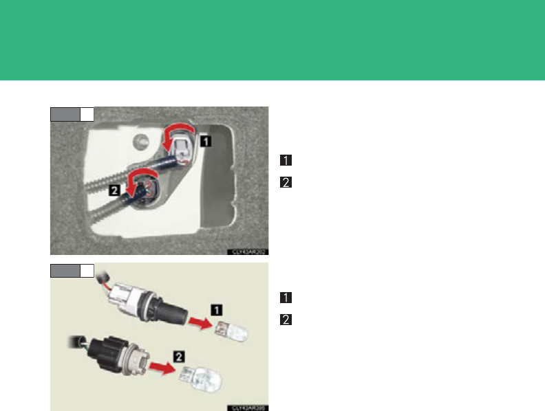
586
4-3. Do-it-yourself maintenance
Turn the bulb base counterclock-
wise.
Tail light
Back-up light
Remove the light bulb.
Tail light
Back-up light
■Lights other than the above
If any of the lights listed below has burnt out, have it replaced by your
Lexus dealer.
●Headlight low beams (discharge bulbs)
●Front fog lights
●Side turn signal lights
●Stop lights
●High mounted stoplight
●License plate lights
STEP 2
STEP 3

587
4-3. Do-it-yourself maintenance
4
Maintenance and care
■Discharge headlights
If voltage to the discharge bulbs is insufficient, the bulbs may not come on, or may
go out temporarily. The discharge bulbs will come on when normal power is
restored.
■LED light bulbs
The headlight low beams (if equipped), side turn signal lights, stop lights, licence
plate lights and high mounted stoplight consist of a number of LEDs. If any of the
LEDs burn out, take your vehicle to your Lexus dealer to have the light replaced.
■Condensation build-up on the inside of the lens
Contact your Lexus dealer for more information in the following situations. Tempo-
rary condensation build-up on the inside of the headlight lens does not indicate a
malfunction.
●Large drops of water are built up on the inside of the lens.
●Water has built up inside the headlight.

588
4-3. Do-it-yourself maintenance
CAUTION
■Replacing light bulbs
●Turn off the lights. Do not attempt to replace the bulb immediately after turning
off the lights.
The bulbs become very hot and may cause burns.
●Do not touch the glass portion of the light bulb with bare hands. Hold the bulb by
the plastic or metal portion.
If the bulb is scratched or dropped it may blow out or crack.
●Fully install light bulbs and any parts used to secure them. Failure to do so may
result in heat damage, fire, or water entering the headlight unit. This may damage
the headlights or cause condensation to build up on the lens.
■Discharge headlights (if equipped)
●Contact your Lexus dealer before replacing discharge headlights (including light
bulbs).
●Do not touch the discharge headlight’s high voltage socket when the headlights
are turned on.
An extremely high voltage of 20000 V will be discharged and could result in
serious injury or death by electric shock.
●Do not attempt to take apart or repair the low beam discharge headlight bulbs,
connectors, power supply circuits, or related components.
Doing so could result in electric shock and serious injury or death.
■To prevent damage or fire
Make sure bulbs are fully seated and locked.

When trouble arises 5
589
5-1. Essential information
Emergency flashers............... 590
If your vehicle needs to
be towed.................................. 591
If you think something is
wrong...................................... 597
5-2. Steps to take in an
emergency
If a warning light turns
on or a warning buzzer
sounds... ................................. 598
If a warning message is
displayed................................ 608
If you have a flat tire............... 629
If the hybrid system will
not start.................................. 643
If the shift lever cannot
be shifted from P ................. 645
If you lose your keys .............. 646
If the electronic key
does not operate
properly .................................. 647
If the vehicle 12-volt
battery is discharged ......... 650
If your vehicle overheats ..... 655
If the vehicle becomes
stuck........................................ 660
If your vehicle has to
be stopped in an
emergency.............................. 661
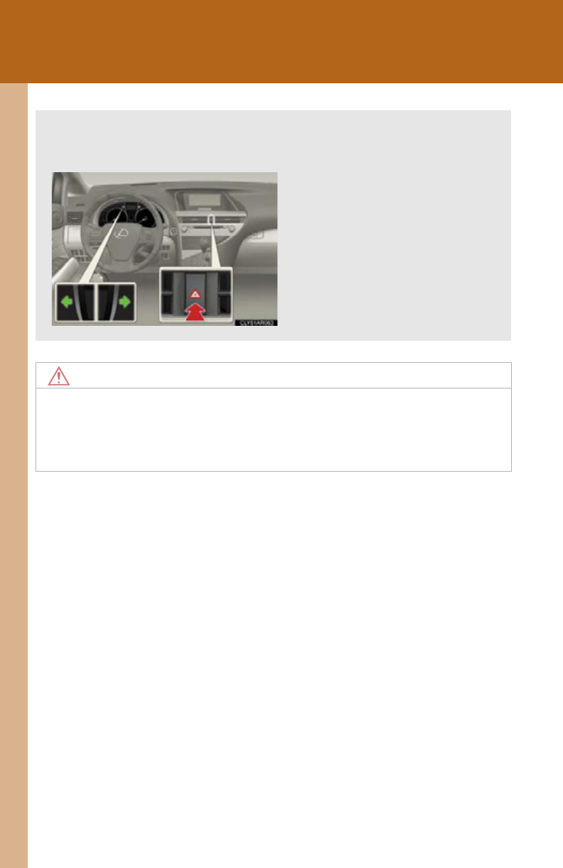
590
5-1. Essential information
Emergency flashers
NOTICE
■To prevent 12-volt battery discharge
Do not leave the emergency flashers on longer than necessary when the hybrid sys-
tem is not operating.
Use the emergency flashers if the vehicle malfunctions or is involved in an
accident.
Press the switch to flash all the
turn signal lights. To turn them
off, press the switch once again.
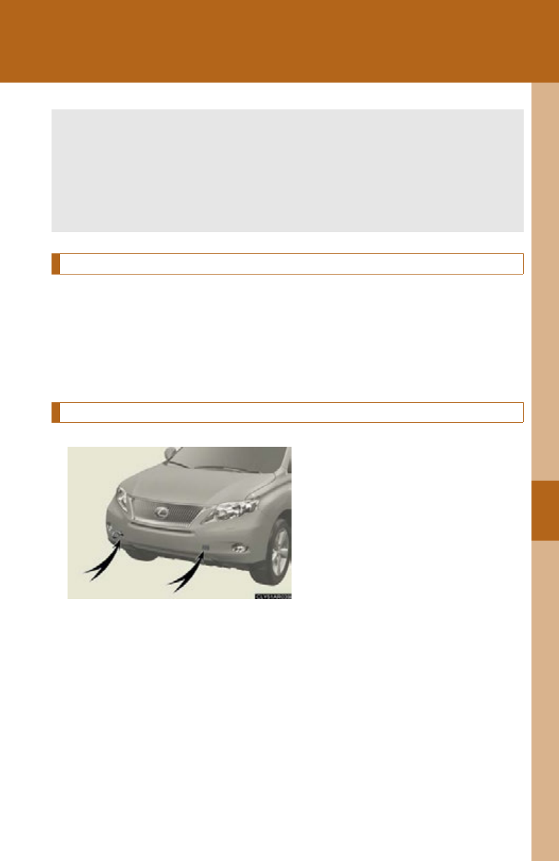
5
When trouble arises
591
5-1. Essential information
If your vehicle needs to be towed
Before towing
The following may indicate a problem with your hybrid transmission.
Contact your Lexus dealer before towing.
●The hybrid system is operating but the vehicle will not move.
●The vehicle makes an abnormal sound.
Emergency towing
If a tow truck is not available in an
emergency, your vehicle may be
temporarily towed using a cable or
chain secured to the emergency
towing eyelet(s). This should only
be attempted on hard surfaced
roads for short distances at under
18 mph (30 km/h).
A driver must be in the vehicle to
steer and operate the brakes. The
vehicle’s wheels, drive train, axles,
steering and brakes must be in
good condition.
If towing is necessary, we recommend having your vehicle towed by your
Lexus dealer or a commercial towing service, using a lift-type truck or a
flatbed truck.
Use a safety chain system for all towing, and abide by all state/provincial
and local laws.
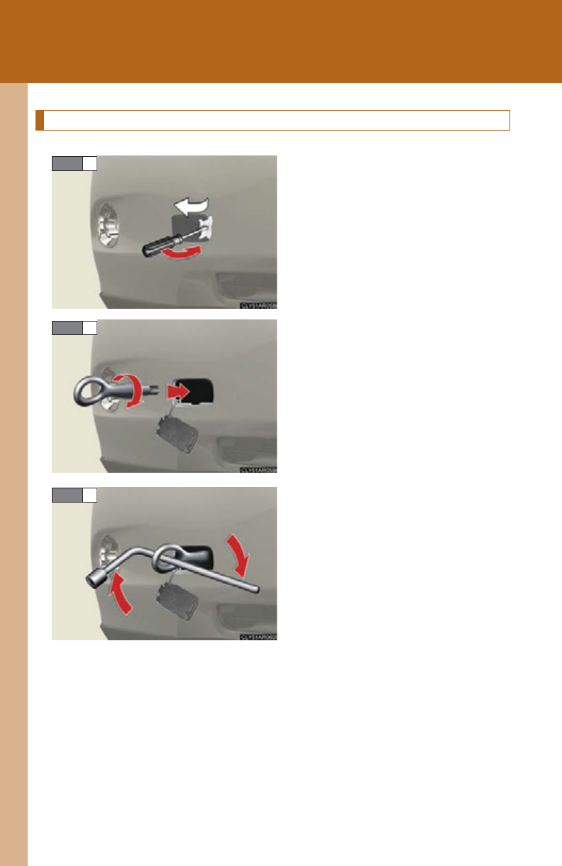
592
5-1. Essential information
Installing towing eyelets
Remove the eyelet cover using a
flathead screwdriver.
To protect the bodywork, place a
rag between the screwdriver and
the vehicle body, as shown in the
illustration.
Insert the towing eyelet into the
hole and tighten partially by hand.
Tighten down the towing eyelet
securely using a wheel nut wrench.
STEP 1
STEP 2
STEP 3
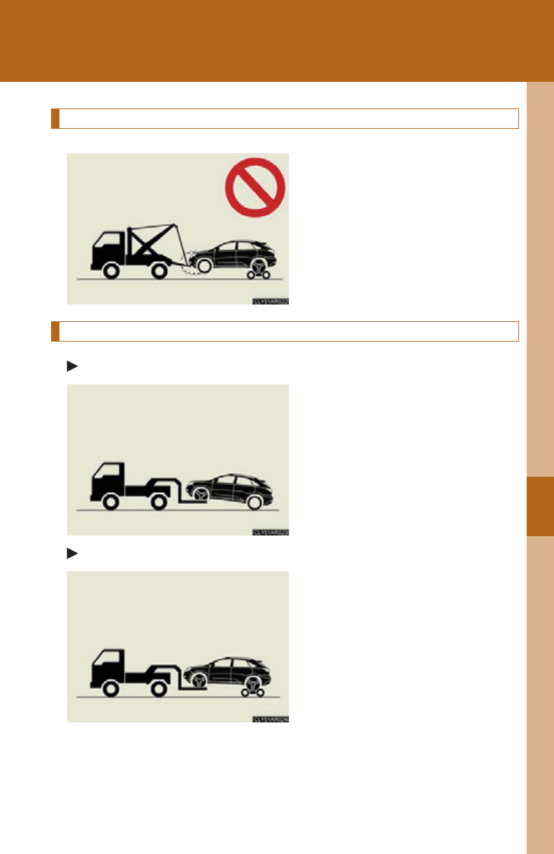
5
When trouble arises
593
5-1. Essential information
Towing with a sling-type truck
Do not tow with a sling-type truck
to prevent body damage.
Towing with a wheel-lift type truck
From the front (2WD models)
Release the parking brake.
From the front (AWD models)
Use a towing dolly under the rear
wheels.
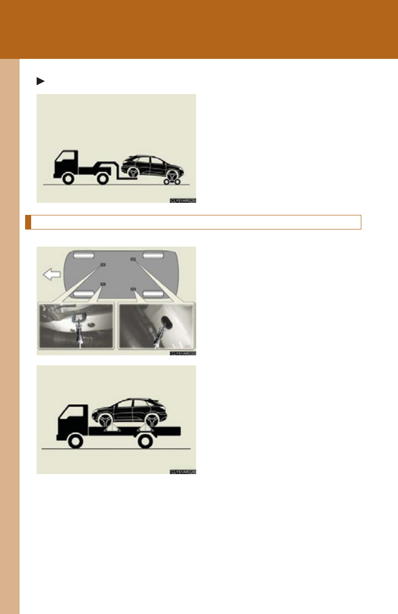
594
5-1. Essential information
From the rear
Use a towing dolly under the front
wheels.
Using a flatbed truck
If your Lexus is transported by a
flatbed truck, it should be tied
down at the locations shown in the
illustration.
If you use chains or cables to tie
down your vehicle, the angles
shaded in black must be 45.
Do not overly tighten the tie downs
or the vehicle may be damaged.

5
When trouble arises
595
5-1. Essential information
■Before emergency towing
Release the parking brake.
Shift the shift lever to N.
Turn the “POWER” switch to ACCESSORY (hybrid system off) or ON
(hybrid system operating) mode.
■Emergency towing eyelet location
P. 6 30
CAUTION
■Caution while towing
●Use extreme caution when towing the vehicle.
Avoid sudden starts or erratic driving maneuvers which place excessive stress on
the emergency towing eyelets and the cables or chains. Always be cautious of the
surroundings and other vehicles while towing.
●If the hybrid system is off, the power assist for the brakes and steering will not
function, making steering and braking more difficult.
■Installing towing eyelets to the vehicle
Make sure that towing eyelets are installed securely.
If not securely installed, towing eyelets may come loose during towing. This may
lead to accidents that cause serious injury or even death.
STEP 1
STEP 2
STEP 3

596
5-1. Essential information
NOTICE
■To prevent causing serious damage to the hybrid transmission when towing using
a wheel-lift type truck
2WD models: Never tow this vehicle from the rear with the front wheels on the
ground.
AWD models: Never tow this vehicle with any of the wheels in contact with the
ground.
■To prevent damaging the vehicle when towing using a wheel-lift type truck
When raising the vehicle, ensure adequate ground clearance for towing at the
opposite end of the raised vehicle. Without adequate clearance, the vehicle could
be damaged while being towed.
■To prevent body damage when towing using a sling-type truck
Do not tow with a sling-type truck, either from the front or rear.

5
When trouble arises
597
5-1. Essential information
If you think something is wrong
If you notice any of the following symptoms, your vehicle probably needs
adjustment or repair. Contact your Lexus dealer as soon as possible.
■Visible symptoms
●Fluid leaks under the vehicle.
(Water dripping from the air conditioning after use is normal.)
●Flat-looking tires or uneven tire wear
●Engine coolant temperature gauge needle continually points
higher than normal.
■Audible symptoms
●Changes in exhaust sound
●Excessive tire squeal when cornering
●Strange noises related to the suspension system
●Pinging or other noises related to the hybrid system
■Operational symptoms
●Engine missing, stumbling or running rough
●Appreciable loss of power
●Vehicle pulls heavily to one side when braking.
●Vehicle pulls heavily to one side when driving on a level road.
●Loss of brake effectiveness, spongy feeling, pedal almost touches
the floor
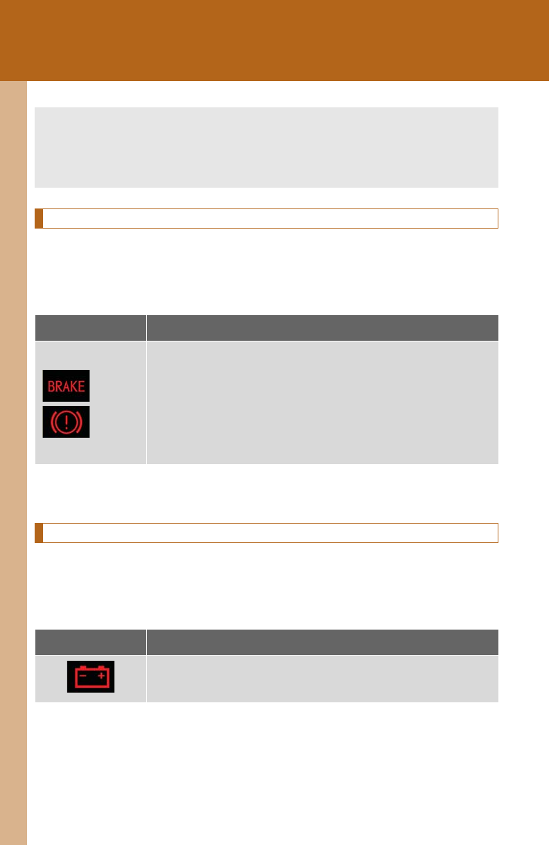
598
5-2. Steps to take in an emergency
If a warning light turns on or a warning buzzer sounds...
Stop the vehicle immediately. Continuing to drive the vehicle may be dangerous.
The following warning indicates a possible problem in the brake system.
Immediately stop the vehicle in a safe place and contact your Lexus
dealer.
*
: Parking brake engaged warning buzzer
P. 61 4
Stop the vehicle immediately.
The following warning indicates the possibility of damage to the vehicle
that may lead to an accident. Immediately stop the vehicle in a safe place
and contact your Lexus dealer.
Warning light Warning light/Details
(U.S.A.)
(Canada)
Brake system warning light (warning buzzer)*
•Low brake fluid
• Malfunction in the brake system
This light also comes on when the parking brake is not
released. If the light turns off after the parking brake is fully
released the system is operating normally.
Warning light Warning light/Details
Charging system warning light
Indicates a malfunction in the vehicle’s charging system
Calmly perform the following actions if any of the warning lights comes on
or flashes. However, if any of the warning lights continue to come on, have
the vehicle inspected by your Lexus dealer.
5
When trouble arises
599
5-2. Steps to take in an emergency
Have the vehicle inspected by your Lexus dealer immediately.
Failing to investigate the cause of the following warnings may lead to the
system operating abnormally and possibly cause an accident. Have the
vehicle inspected by your Lexus dealer immediately.
Warning light Warning light/Details
(U.S.A.)
(Canada)
Malfunction indicator lamp
Indicates a malfunction in:
• The hybrid system;
• The electronic engine control system;
• The electronic throttle control system; or
• The emission control system
SRS warning light
Indicates a malfunction in:
• The SRS airbag system;
• The front passenger occupant classification system; or
• The seat belt pretensioner system
(U.S.A.)
(Canada)
ABS warning light
Indicates a malfunction in:
•The ABS; or
• The brake assist system
Brake system warning light
Indicates a malfunction in:
• The regenerative brake system; or
• The electronically controlled brake system
Electric power steering system warning light
Indicates a malfunction in the EPS (Electric Power Steering)
system
600
5-2. Steps to take in an emergency
(Flashing)
Pre-collision system warning light (if equipped)
Indicates a malfunction in the pre-collision system
The warning light will operate as follows, even when the sys-
tem is not malfunctioning:
• The light will flash quickly when the system is operating.
• The light will turn on when the system cannot temporarily
be used. (P. 61 4)
Slip indicator
Indicates a malfunction in:
• The VSC system;
•The TRAC system; or
• The hill-start assist control system
(Flashes)
“A F S O F F ” i n d i c a t o r
Indicates a malfunction in the adaptive front-lighting system
(Flashes)
Automatic High Beam indicator light
Indicates a malfunction in the automatic high beam system.
Warning light Warning light/Details
5
When trouble arises
601
5-2. Steps to take in an emergency
Follow the correction procedures.
After taking the specified steps to correct the suspected problem, check
that the warning light goes off.
Warning light Warning light/Details Correction procedure
Open door warning light
(warning buzzer)*1
Indicates that one or more of
the doors is not fully closed.
Check that all the doors are
closed.
Low fuel level warning light
Indicates remaining fuel is
approximately 2.7 gal. (10.1 L,
2.2 Imp. gal.) or less
Refuel the vehicle.
(On the instru-
ment panel)
Driver’s seat belt reminder
light (warning buzzer)*2
Warns the driver to fasten
his/her seat belt.
Fasten the seat belt.
(On the center
panel)
Front passenger’s seat belt
reminder light
(warning buzzer)*2
Warns the front passenger to
fasten his/her seat belt.
Fasten the seat belt.
Master warning light
A buzzer sounds and the
warning light comes on and
flashes to indicate that the
master warning system has
detected a malfunction.
P. 6 08

602
5-2. Steps to take in an emergency
*1: Open door warning buzzer:
The open door warning buzzer sounds to alert one or more of the doors is not
fully closed (with the vehicle having reached a speed of 3 mph [5 km/h]).
(P. 614)
*2: Driver's and front passenger’s seat belt buzzer:
The driver’s and front passenger’s seat belt buzzer sounds to alert the driver and
front passenger that his or her seat belt is not fastened. The buzzer sounds inter-
mittently for 10 seconds after the vehicle reaches a speed of 12 mph (20 km/h).
Then, if the seat belt is still unfastened, the buzzer will sound in a different tone
for 20 more seconds.
Tire pressure warning light
When the light comes on:
Low tire inflation pressure
such as
• Natural causes (P. 603)
• Flat tire (P. 629)
Adjust the tire inflation pres-
sure (including the full-size
spare tire) to the specified
level.
The light will turn off after a
few minutes. In case the light
does not turn off even if the
tire inflation pressure is
adjusted, have the system
checked by your Lexus
dealer.
When the light comes on after
blinking for 1 minute:
Malfunction in the tire pres-
sure warning system
(P. 6 04)
Have the system checked by
your Lexus dealer.
Warning light Warning light/Details Correction procedure

5
When trouble arises
603
5-2. Steps to take in an emergency
■SRS warning light
This warning light system monitors the airbag sensor assembly, front airbag sensors,
side and curtain shield airbag sensors, curtain shield airbag sensors, driver's seat
position sensor, driver's seat belt buckle switch, front passenger occupant classifi-
cation system, “AIR BAG ON” indicator light, “AIR BAG OFF” indicator light, front
passenger's seat belt buckle switch, seat belt pretensioner assemblies, inflators,
interconnecting wiring and power sources. (P. 13 2)
■Front passenger detection sensor, passenger seat belt reminder and warning
buzzer
●If luggage is placed on the front passenger seat, the front passenger detection
sensor may cause the warning light to flash and the warning buzzer to sound
even if a passenger is not sitting in the seat.
●If a cushion is placed on the seat, the sensor may not detect a passenger, and the
warning light may not operate properly.
■Electric power steering system warning light
When the 12-volt battery charge becomes insufficient or the voltage temporarily
drops, the electric power steering system warning light may come on.
■If the malfunction indicator lamp comes on while driving
Check that the fuel tank cap is not loose. If it is, tighten the cap securely.
The lamp will go off after several driving trips.
If the light does not go off even after several trips, contact your Lexus dealer as soon
as possible.
■When the tire pressure warning light comes on
Check the tire inflation pressure and adjust to the appropriate level. Pushing the tire
pressure warning reset switch will not turn off the tire pressure warning light.
■The tire pressure warning light may come on due to natural causes
The tire pressure warning light may come on due to natural causes such as natural
air leaks and tire inflation pressure changes caused by temperature. In this case,
adjusting the tire inflation pressure will turn off the warning light (after a few min-
utes).

604
5-2. Steps to take in an emergency
■When a tire is replaced with a spare tire
The compact spare tire is not equipped with a tire pressure warning valve and trans-
mitter. If a tire goes flat, the tire pressure warning light will not turn off even though
the flat tire has been replaced with the spare tire. Replace the spare tire with the
repaired tire and adjust the tire inflation pressure. The tire pressure warning light
will go off after a few minutes.
■If the tire pressure warning system is not functioning
The tire pressure warning system will be disabled in the following conditions:
(When the condition becomes normal, the system will work properly.)
●If tires not equipped with tire pressure warning valves and transmitters are used
●If the ID code on the tire pressure warning valves and transmitters is not regis-
tered in the tire pressure warning computer
●If the tire pressure warning select switch is set to a different tire setting
●If the tire inflation pressure is 73 psi (500 kPa, 5.1 kgf/cm2 or bar) or higher
The tire pressure warning system may be disabled in the following conditions:
(When the condition becomes normal, the system will work properly.)
●If electronic devices or facilities using similar radio wave frequencies are nearby
●If a radio set at similar frequencies is in use in the vehicle
●If a window tint that affects the radio wave signals is installed
●If there is a lot of snow or ice on the vehicle, in particular around the wheels or
wheel housings
●If non-genuine Lexus wheels are used (Even if you use Lexus wheels, the tire
pressure warning system may not work properly with some types of tires.)
●If tire chains are used
●Vehicles with a full-size spare tire: If the spare tire is in a location subject to poor
radio wave signal reception
●Vehicles with a full-size spare tire: If a large metallic object which can interfere
with signal reception is put in the luggage compartment
■If the tire pressure warning light frequently comes on after blinking for 1 minute
If the tire pressure warning light frequently comes on after blinking for 1 minute
when the “POWER” switch is turned to ON mode, have it checked by your Lexus
dealer.

5
When trouble arises
605
5-2. Steps to take in an emergency
■Customization
The vehicle speed linked seat belt reminder buzzer can be disabled.
(Customizable features P. 693 )
CAUTION
■If the electric power steering system warning light comes on
The steering wheel may become extremely heavy.
If the steering wheel becomes heavier than usual when operating, hold it firmly and
operate it using more force than usual. If the electric power steering system warn-
ing light comes on, have the vehicle inspected by your Lexus dealer immediately.
■If the tire pressure warning light comes on
Be sure to observe the following precautions. Failure to do so could cause loss of
vehicle control and result in death or serious injury.
●Stop your vehicle in a safe place as soon as possible. Adjust the tire inflation pres-
sure immediately.
●If the tire pressure warning light comes on even after tire inflation pressure adjust-
ment, it is probable that you have a flat tire. Check the tires. If a tire is flat, change
it with the spare tire and have the flat tire repaired by the nearest Lexus dealer.
●Avoid abrupt maneuvering and braking. If the vehicle tires deteriorate, you could
lose control of the steering wheel or the brakes.
■If a blowout or sudden air leakage should occur
The tire pressure warning system may not activate immediately.

606
5-2. Steps to take in an emergency
CAUTION
■Maintenance of the tires
Each tire, including the spare (if provided), should be checked monthly when cold
and inflated to the inflation pressure recommended by the vehicle manufacturer on
the vehicle placard or tire inflation pressure label (tire and load information label).
(If your vehicle has tires of a different size than the size indicated on the vehicle
placard or tire inflation pressure label [tire and load information label], you should
determine the proper tire inflation pressure for those tires.)
As an added safety feature, your vehicle has been equipped with a tire pressure
monitoring system (TPMS-tire pressure warning system) that illuminates a low tire
pressure telltale (tire pressure warning light) when one or more of your tires is sig-
nificantly under-inflated. Accordingly, when the low tire pressure telltale (tire pres-
sure warning light) illuminates, you should stop and check your tires as soon as
possible, and inflate them to the proper pressure. Driving on a significantly under-
inflated tire causes the tire to overheat and can lead to tire failure. Under-inflation
also reduces fuel efficiency and tire tread life, and may affect the vehicle's handling
and stopping ability.
Please note that the TPMS (tire pressure warning system) is not a substitute for
proper tire maintenance, and it is the driver's responsibility to maintain correct tire
pressure, even if under-inflation has not reached the level to trigger illumination of
the TPMS low tire pressure telltale (tire pressure warning light).
Your vehicle has also been equipped with a TPMS (tire pressure warning system)
malfunction indicator to indicate when the system is not operating properly. The
TPMS (tire pressure warning system) malfunction indicator is combined with the
low tire pressure telltale (tire pressure warning light). When the system detects a
malfunction, the telltale will flash for approximately one minute and then remain
continuously illuminated. This sequence will continue upon subsequent vehicle
start-ups as long as the malfunction exists. When the malfunction indicator is illumi-
nated, the system may not be able to detect or signal low tire pressure as intended.
TPMS (tire pressure warning system) malfunctions may occur for a variety of rea-
sons, including the installation of replacement or alternate tires or wheels on the
vehicle that prevent the TPMS (tire pressure warning system) from functioning
properly. Always check the TPMS (tire pressure warning system) malfunction tell-
tale after replacing one or more tires or wheels on your vehicle to ensure that the
replacement or alternate tires and wheels allow the TPMS (tire pressure warning
system) to continue to function properly.

5
When trouble arises
607
5-2. Steps to take in an emergency
NOTICE
■Precaution when installing a different tire
When a tire of a different specification or maker is installed, the tire pressure warn-
ing system may not operate properly.
608
5-2. Steps to take in an emergency
If a warning message is displayed
Stop the vehicle immediately. Continuing to drive the vehicle may be dangerous.
The following warning indicates a possible problem in the brake system.
Immediately stop the vehicle in a safe place and contact your Lexus
dealer.
Warning message Details
Indicates the following:
• The brake fluid level is low; or,
• The brake system is malfunctioning.
A buzzer also sounds.
Indicates a malfunction in:
• The regenerative brake system; or,
• The electronically controlled brake system
If a warning is shown on the multi-information display, stay calm and per-
form the following actions:
Multi-information display
A warning message is displayed.
Master warning light
The master warning light also
comes on or flashes in order to
indicate that a message is cur-
rently being displayed on the
multi-information display.
If any of the warning lights comes on again after the following actions
have been performed, contact your Lexus dealer.
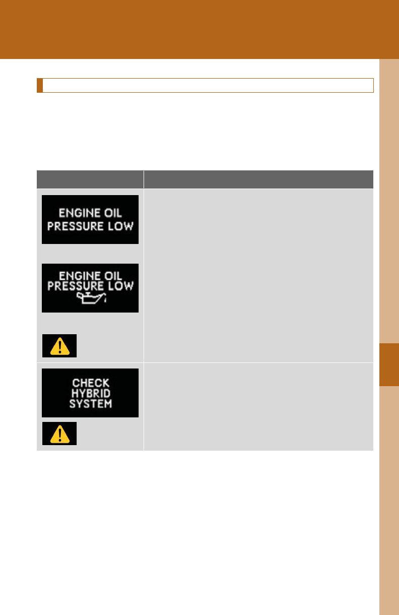
5
When trouble arises
609
5-2. Steps to take in an emergency
Stop the vehicle immediately.
A buzzer sounds and a warning message is shown on the multi-informa-
tion display. The following warning indicates the possibility of damage to
the vehicle that may lead to an accident. Immediately stop the vehicle in a
safe place and contact your Lexus dealer.
Warning message Details
(U.S.A.)
(Canada)
Indicates abnormal engine oil pressure
Indicates a malfunction in the hybrid system
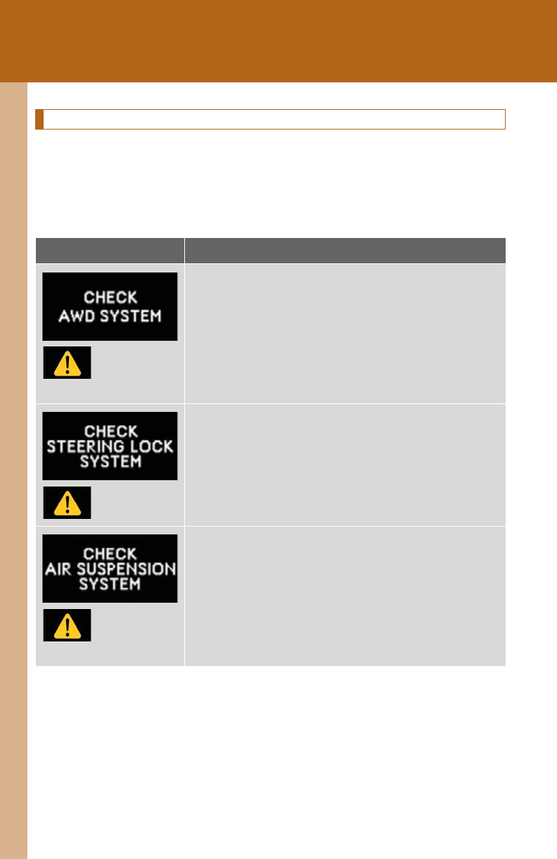
610
5-2. Steps to take in an emergency
Have the vehicle inspected by your Lexus dealer immediately.
A buzzer sounds and a warning message is shown on the multi-informa-
tion display. Failure to investigate the cause of the following warnings may
lead to the system operating abnormally and possibly cause an accident.
Have the vehicle inspected by your Lexus dealer immediately.
Warning message Details
(AWD models)
Indicates a malfunction in the AWD system
Indicates a malfunction in the steering lock system
(If equipped)
Indicates a malfunction in the electronically modu-
lated air suspension system
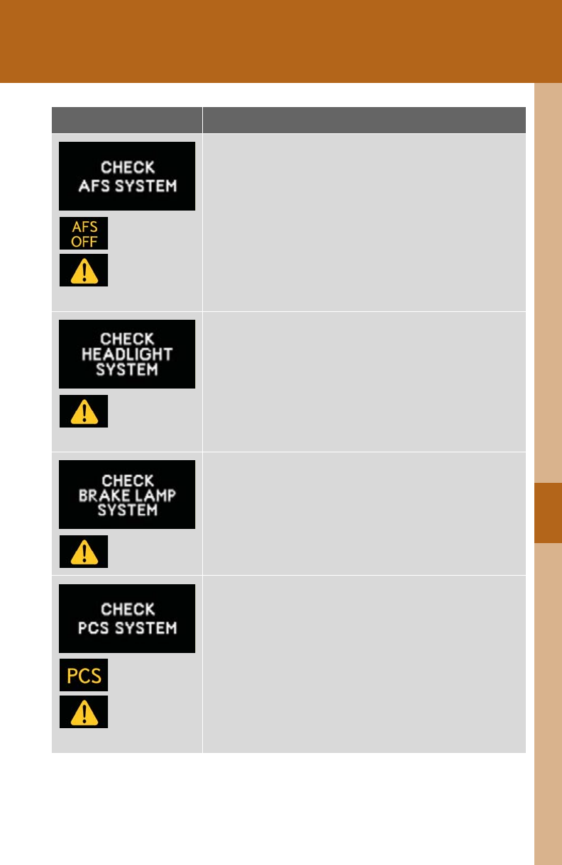
5
When trouble arises
611
5-2. Steps to take in an emergency
(Flashes)
(If equipped)
Indicates a malfunction in the adaptive front lighting
system
(Flashes)
(If equipped)
Indicates a malfunction in the LED headlight system
Indicates a malfunction in the brake light system
(Flashes)
(If equipped)
Indicates a malfunction in the pre-collision system
Warning message Details
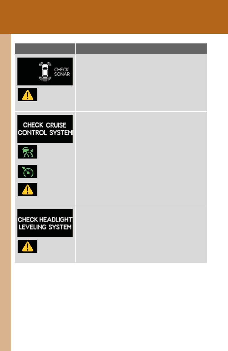
612
5-2. Steps to take in an emergency
(If equipped)
Indicates a malfunction in the intuitive parking assist
The malfunctioning assist-sensor is flashing.
(Flashes)
or
(Flashes)
(If equipped)
Indicates a malfunction in the radar cruise control
system
Press the “ON-OFF” button once to deactivate the
system, and then press the button again to reactivate
the system.
(If equipped)
Indicates a malfunction in the automatic headlight
leveling system
Warning message Details
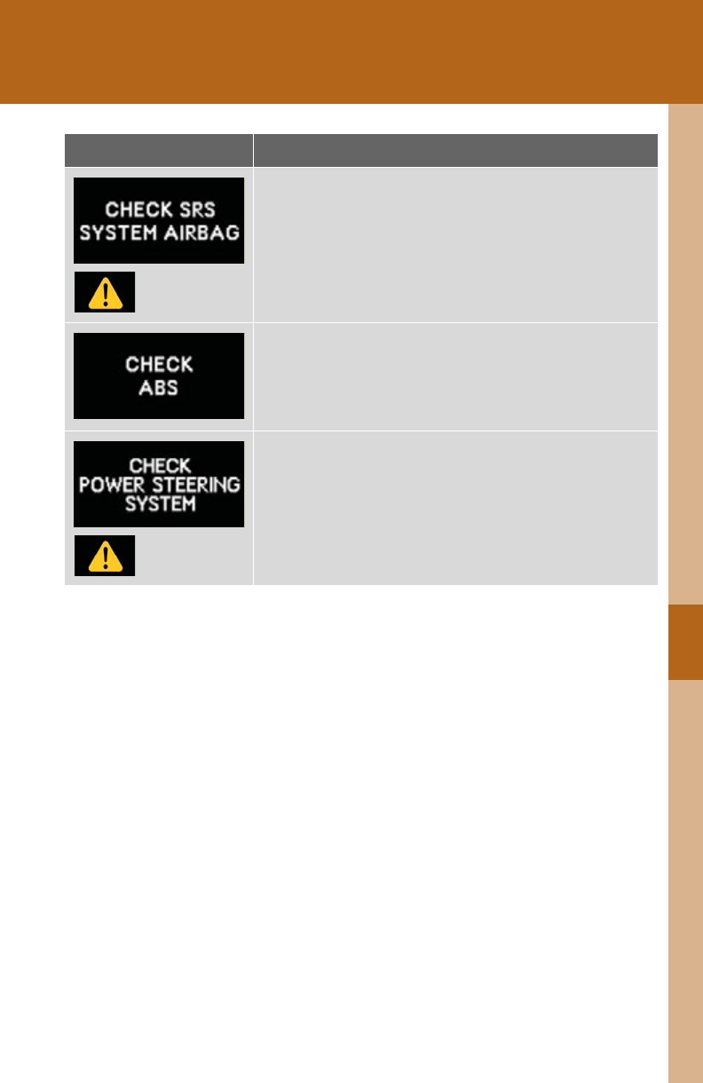
5
When trouble arises
613
5-2. Steps to take in an emergency
Indicates a malfunction in:
• The SRS airbag system;
• The front passenger occupant classification system;
or,
• The seat belt pretensioner system
Indicates a malfunction in:
• The ABS; or,
• The brake assist system
Indicates a malfunction in the EPS (Electric Power
Steering) system
Warning message Details
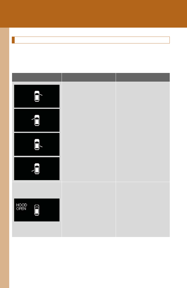
614
5-2. Steps to take in an emergency
Follow the correction procedures.
A buzzer sounds and a warning message is shown on the multi-informa-
tion display. After taking the specified steps to correct the suspected
problem, check that the warning message goes off.
Warning message Details Correction procedure
Indicates that one or
more of the doors is not
fully closed
The system also indi-
cates which doors are
not fully closed.
If the vehicle reaches a
speed of 3 mph
(5 km/h), a buzzer
sounds to indicate that
the door(s) are not yet
fully closed.
Make sure that all the
doors are closed.
Indicates that the hood is
not fully closed
If the vehicle reaches a
speed of 3 mph
(5 km/h), a buzzer
sounds to indicate that
the hood is not yet fully
closed.
Close the hood.
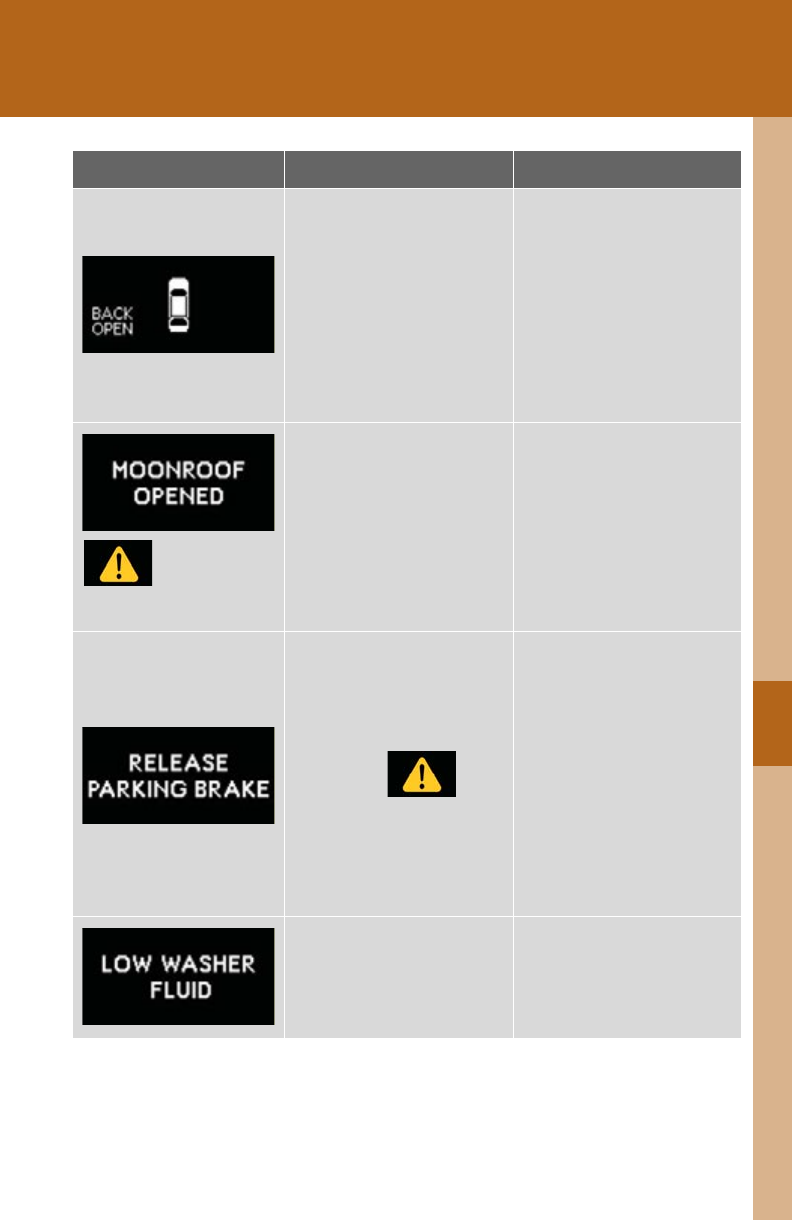
5
When trouble arises
615
5-2. Steps to take in an emergency
Indicates that the back
door is not fully closed
If the vehicle reaches a
speed of 3 mph
(5 km/h), a buzzer
sounds to indicate that
the back door is not yet
fully closed.
Close the back door.
(Flashes)
(If equipped)
Indicates that the moon
roof is not fully closed
(with the “POWER”
switch off, and the driver's
door open)
Close the moon roof.
Indicates that the parking
brake is still engaged
If the vehicle reaches a
speed of 3 mph
(5 km/h),
flashes and a buzzer
sounds to indicate that
the parking brake is still
engaged.
Release the parking
brake.
Indicates that the washer
fluid level is low Add washer fluid.
Warning message Details Correction procedure

616
5-2. Steps to take in an emergency
(U.S.A. only)
Indicates that all mainte-
nance according to the
driven distance on the
maintenance schedule*
should be performed
soon.
If necessary, perform
maintenance.
Comes on approximately
4500 miles (7200 km)
after the maintenance
data has been reset.
(U.S.A. only)
Indicates that all mainte-
nance is required to cor-
respond to the driven
distance on the mainte-
nance schedule*.
Perform the necessary
maintenance. Please reset
the maintenance data
after the maintenance is
performed. (P. 499)
(If equipped)
Indicates that the pre-
collision safety system is
not currently functional
because the grille or the
sensor is dirty.
This message also
appears when the pre-
collision system is not
functional due to over-
heating.
• Check the grille and the
sensor (P. 282) and
clean them if they are
dirty.
• In case of overheating,
the system will become
functional once the sys-
tem cools down.
Warning message Details Correction procedure
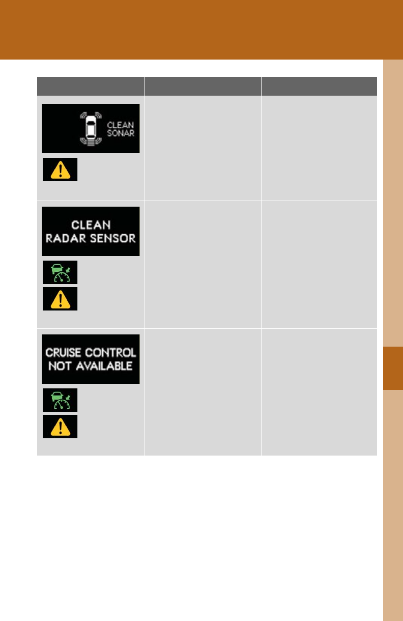
5
When trouble arises
617
5-2. Steps to take in an emergency
(If equipped)
Indicates that intuitive
parking assist is dirty or
covered with ice
A buzzer also sounds.
The site of the malfunc-
tion and the vehicle
image are flashing.
Clean the sensor.
(Flashes)
(If equipped)
Indicates that the radar
cruise control sensor is
dirty or covered with ice
A buzzer also sounds.
Clean the sensor.
(Flashes)
(If equipped)
Indicates that the radar
cruise control system is
unable to judge vehicle-
to-vehicle distance
A buzzer also sounds.
• Switch driving mode to
normal.
• If the windshield wipers
are on, turn them off or
set them to a mode other
than AUTO or high
speed wiper operation.
Warning message Details Correction procedure
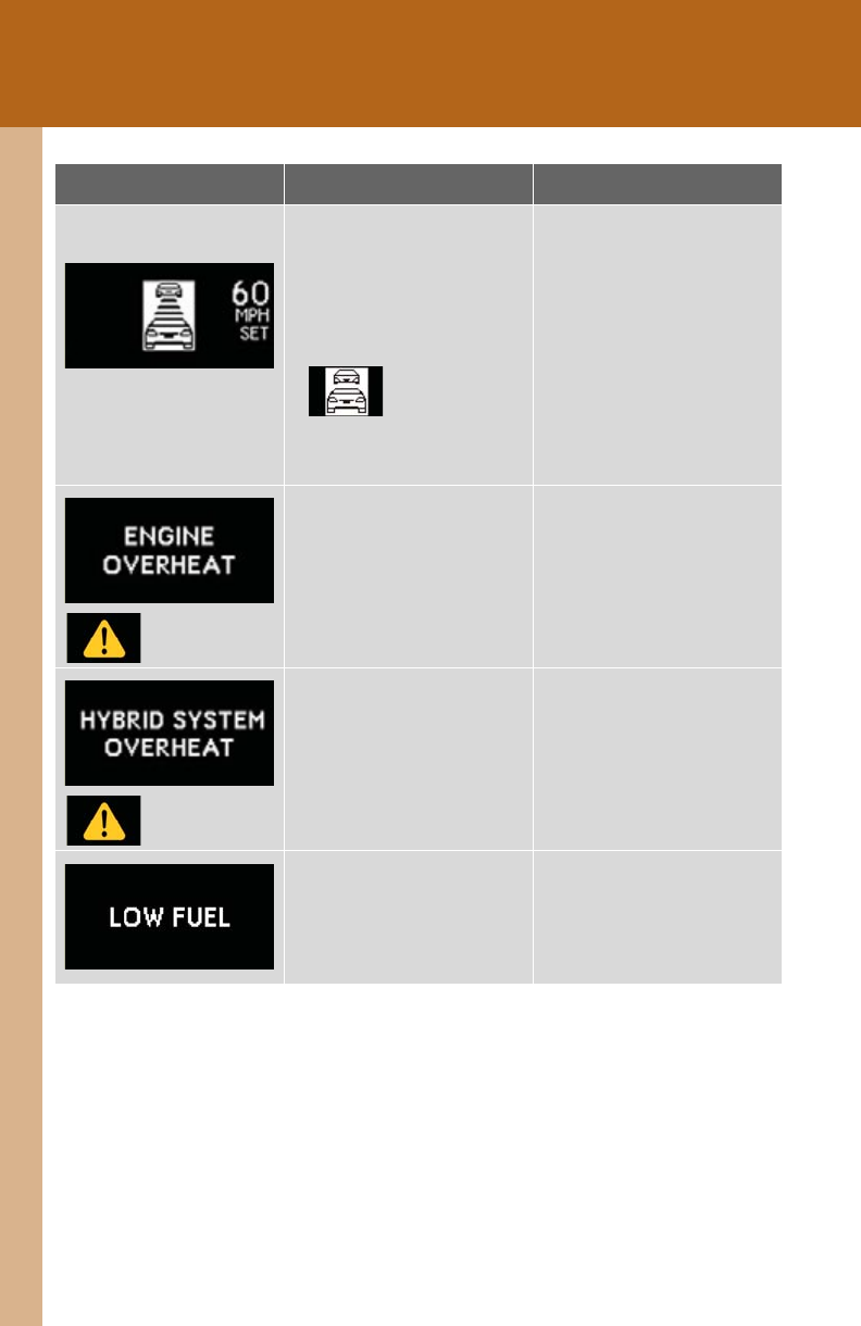
618
5-2. Steps to take in an emergency
(Flashes)
(If equipped)
Indicates that your vehi-
cle is nearing the vehicle
ahead (in radar cruise
mode)
At the same time,
will appear on
the head-up display (the
image flashes).
Slow the vehicle by apply-
ing the brakes.
Indicates that the engine
has overheated
A buzzer also sounds.
Stop and check.
(P. 655 )
Indicates that the hybrid
system has overheated
A buzzer also sounds.
Stop and check.
(P. 655 )
Indicates that remaining
fuel is approximately 2.7
gal. (10.1 L, 2.2 Imp. gal.)
or less
Refuel the vehicle.
Warning message Details Correction procedure
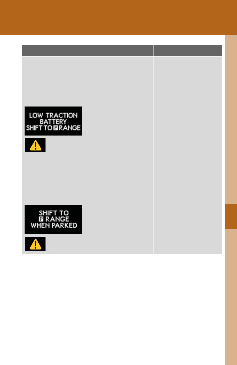
5
When trouble arises
619
5-2. Steps to take in an emergency
*: Refer to the separate “Scheduled Maintenance” or “Owner's Manual Supple-
ment” for the maintenance interval applicable to your vehicle.
(Flashes)
Indicates that the hybrid
battery (traction battery)
is low.
• If a buzzer sounds inter-
mittently, stop the vehicle
in a safe place and shift
the shift lever to P to
charge the hybrid bat-
tery (traction battery).
• If a buzzer sounds con-
tinuously, immediately
stop the vehicle in a safe
place. Turn the
“POWER” switch off and
then to ON mode to
restart the hybrid system.
Ensuring the shift lever is
in P, charge the hybrid
battery (traction bat-
tery).
(Flashes)
Indicates that the driver’s
door is opened when the
hybrid transmission is out
of P with the hybrid sys-
tem on.
Shift the shift lever to P.
Warning message Details Correction procedure
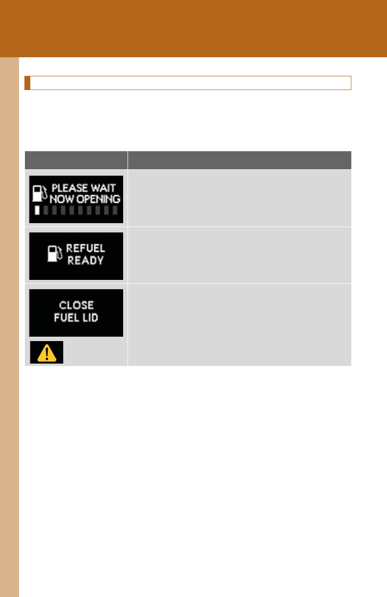
620
5-2. Steps to take in an emergency
Messages displayed when refueling
The following messages are displayed after the fuel filler door opener is
pressed. If the messages do not change or are displayed continuously,
have the vehicle checked by your Lexus dealer.
Message Details
Preparing the vehicle for refueling.
Wait a moment.
You may commence refueling.
Finish refueling within 30 minutes.
Close the fuel filler door.
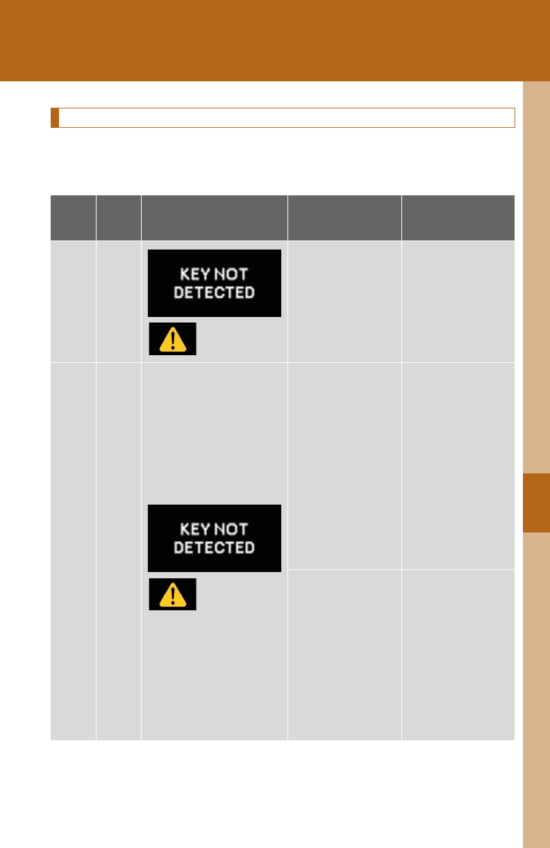
5
When trouble arises
621
5-2. Steps to take in an emergency
Have the malfunction repaired immediately
After taking the specified steps to correct the suspected problem, check
that the warning message and light go off.
Interior
buzzer
Exterior
buzzer
Warning message Details Correction
procedure
Sounds
once
(Flashes)
The electronic key
is not detected
when an attempt
is made to start
the hybrid system.
Confirm the loca-
tion of the elec-
tronic key.
Sounds
once
Sounds
3 times
(Flashes)
The electronic key
was carried out-
side the vehicle
and a door other
than the driver's
door was opened
and closed while
the “POWER”
switch was in a
mode other than
off.
Bring the elec-
tronic key back
into the vehicle.
The driver's door
was opened and
closed while the
electronic key was
not in the vehicle,
the shift lever was
in P and the
“POWER” switch
was not turned off.
Tu r n t h e
“POWER” switch
off or bring the
electronic key
back into the vehi-
cle.
622
5-2. Steps to take in an emergency
Sounds
once
Sounds
once
(Displayed alternately)
(Flashes)
An attempt was
made to exit the
vehicle with the
electronic key and
lock the doors
without first turn-
ing the “POWER”
switch off.
Tu r n t h e
“POWER” switch
off and lock the
doors again.
Sounds
once
(Flashes)
An attempt was
made to start the
hybrid system
without the elec-
tronic key being
present, or the
electronic key was
not functioning
normally.
An attempt was
made to drive
when the regular
key was not inside
the vehicle.
Confirm that the
electronic key is
inside the vehicle.
Con-
tinuous
(Flashes)
The driver’s door
was opened when
the shift lever was
not in P and the
“POWER” switch
was not turned off.
Shift the shift lever
to P.
Interior
buzzer
Exterior
buzzer
Warning message Details Correction
procedure
5
When trouble arises
623
5-2. Steps to take in an emergency
Con-
tinuous
Con-
tinuous
(Displayed alternately)
(Flashes)
The driver's door
was opened and
closed while the
electronic key was
not in the vehicle,
the shift lever was
not in P and the
“POWER” switch
was not turned off.
• Shift the shift
lever to P.
• Bring the elec-
tronic key back
into the vehicle.
Interior
buzzer
Exterior
buzzer
Warning message Details Correction
procedure
624
5-2. Steps to take in an emergency
Sounds
once
Con-
tinuous
(Flashes)
An attempt was
made to lock the
doors using the
smart access sys-
tem with push-
button start while
the electronic key
was still inside the
vehicle.
Retrieve the elec-
tronic key from
the vehicle and
lock the doors
again.
An attempt was
made to lock
either front door
by opening a door
and putting the
inside lock button
into the lock posi-
tion, then closing
the door by pull-
ing on the outside
door handle with
the electronic key
still inside the
vehicle.
Interior
buzzer
Exterior
buzzer
Warning message Details Correction
procedure
5
When trouble arises
625
5-2. Steps to take in an emergency
Sounds
once
(Flashes)
•When the doors
were unlocked
with the
mechanical key
and then the
“POWER”
switch was
pressed, the
electronic key
could not be
detected in the
vehicle.
• The electronic
key could not be
detected in the
vehicle even
after the
“POWER”
switch was
pressed two
consecutive
times.
Touch the elec-
tronic key to the
“POWER” switch
while depressing
the brake pedal.
Sounds
once
(Flashes)
An attempt was
made to start the
hybrid system
with the shift lever
in an incorrect
position.
Shift the shift lever
to P and start the
hybrid system.
Interior
buzzer
Exterior
buzzer
Warning message Details Correction
procedure
626
5-2. Steps to take in an emergency
Sounds
once
(Flashes)
An attempt was
made to turn the
“POWER” switch
off when the shift
lever was not in P.
To turn off the
hybrid system,
first shift the shift
lever to P and
then turn the
“POWER” switch
off.
Power was turned
off due to the
automatic power
off function.
Next time when
starting the hybrid
system, increase
the hybrid system
speed slightly and
maintain that level
for approximately
5 minutes to
recharge the 12-
volt battery.
Sounds
once
The electronic key
has a low battery.
Replace the elec-
tronic key battery.
(P. 55 0)
Interior
buzzer
Exterior
buzzer
Warning message Details Correction
procedure
5
When trouble arises
627
5-2. Steps to take in an emergency
Sounds
once
(Flashes)
The driver's door
was opened and
closed with the
“POWER” switch
turned off and
then the
“POWER” switch
was put in
ACCESSORY
mode twice with-
out the hybrid sys-
tem being started.
Press the
“POWER” switch
while depressing
the brake pedal.
During an hybrid
system starting
procedure in the
event that the
electronic key was
not functioning
properly
(P. 647 ) , t h e
“POWER” switch
was touched with
the electronic key.
Press the
“POWER” switch
within 10 seconds
of the buzzer
sounding.
Sounds
once
(Flashes)
The steering lock
could not be
released within 3
seconds of the
“POWER” switch
being pressed.
Press the
“POWER” switch
while depressing
the brake pedal
and moving the
steering wheel left
and right.
Interior
buzzer
Exterior
buzzer
Warning message Details Correction
procedure

628
5-2. Steps to take in an emergency
■Warning light display in radar cruise mode
In the following cases, the warning light may not be displayed even if vehicle-to-
vehicle distance decreases:
●When your vehicle and the vehicle ahead are traveling at the same speed or the
vehicle ahead is traveling more quickly than your vehicle
●When the vehicle ahead is traveling at a very low speed
●Immediately after cruise control speed is set
●At the instant the accelerator pedal is depressed
■After changing the engine oil (U.S.A. only)
Make sure to reset the oil maintenance data. (P. 515)

5
When trouble arises
629
5-2. Steps to take in an emergency
If you have a flat tire
Remove the flat tire and replace it with the spare provided.
■Before jacking up the vehicle
●Stop the vehicle on a hard, flat surface.
●Set the parking brake.
●Shift the shift lever to P.
●Vehicles with electronically modulated air suspension:
Turn off the height control. (P. 264)
●Stop the hybrid system.
●Turn on the emergency flashers.
630
5-2. Steps to take in an emergency
■Location of the spare tire, jack and tools
Vehicles with a compact spare tire
Vehicles with a full-size spare tire
Towing eyelet
Tool bag
Wheel nut
wrench
Spare tire
cover
Jack Spare tire
Jack handle
Towing eyelet
To o l ba g
Wheel nut
wrench
Spare tire
cover
Jack Spare tire
Jack handle
5
When trouble arises
631
5-2. Steps to take in an emergency
Taking out the jack
Vehicles with a compact spare tire
Pull the lever upward to fold back
the front part of the deck board.
Pull the folded deck board upright.
Pull on the attached hook to
extend the string.
STEP 1
STEP 2
STEP 3
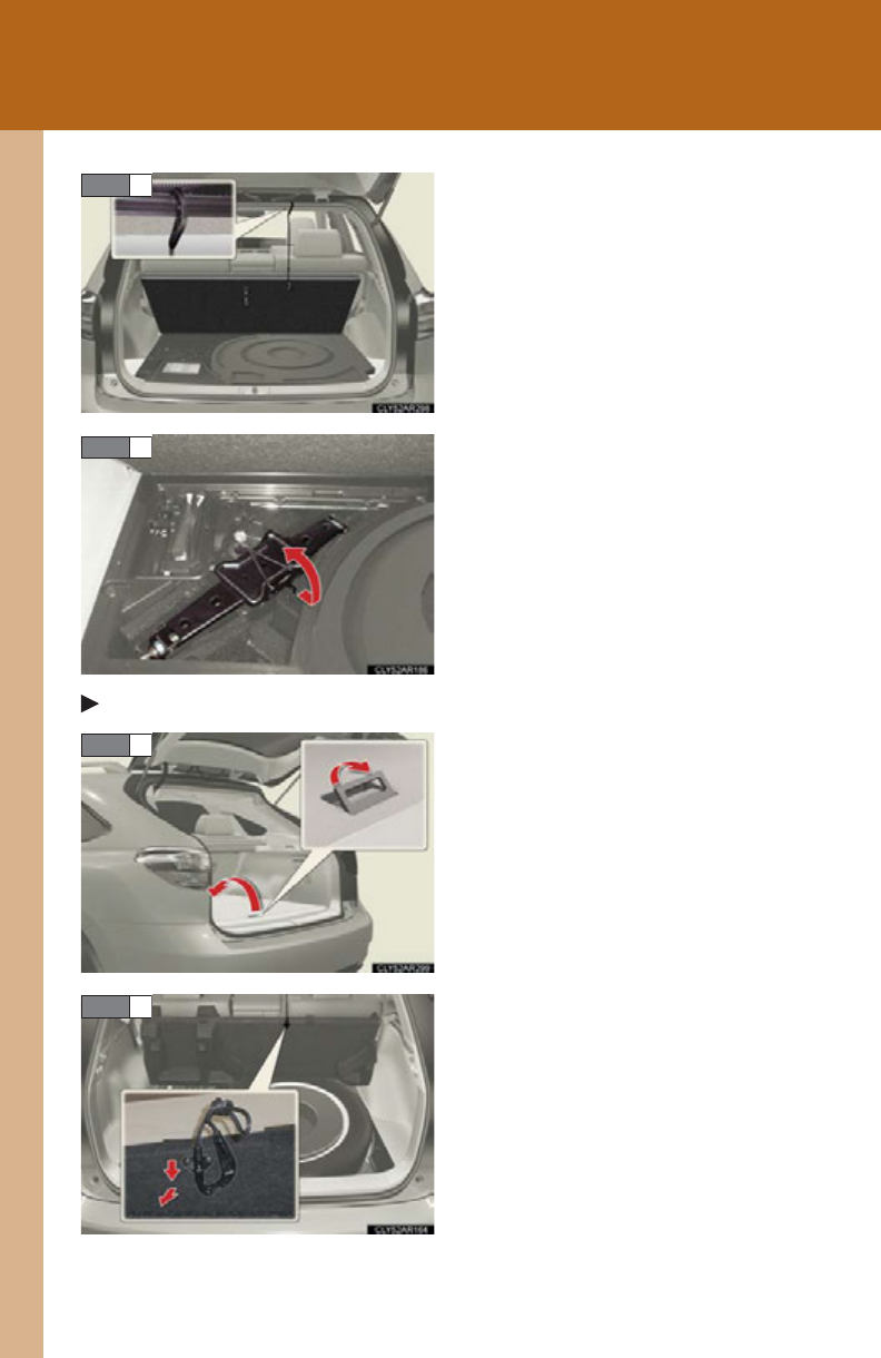
632
5-2. Steps to take in an emergency
Use the hook to secure the deck
board as shown in the illustration.
Remove the jack after removing
the hook.
Vehicles with a full-size spare tire
Pull the lever upward to fold back
the front part of the deck board.
Pull on the attached hook to
extend the string.
STEP 4
STEP 5
STEP 1
STEP 2
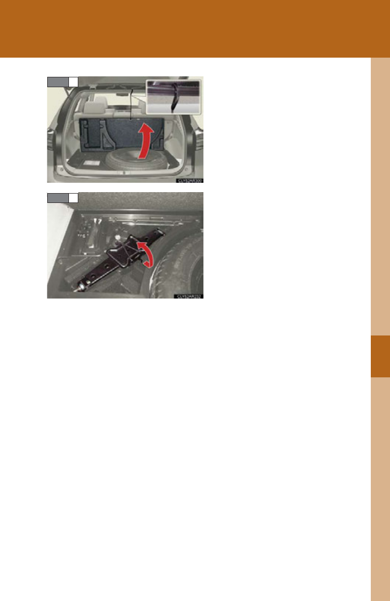
5
When trouble arises
633
5-2. Steps to take in an emergency
Use the hook to secure the deck
board as shown in the illustration.
Remove the jack after removing
the hook.
STEP 3
STEP 4
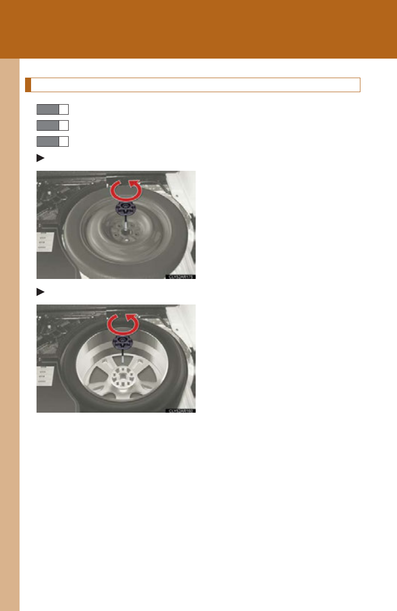
634
5-2. Steps to take in an emergency
Taking out the spare tire
Lift up the deck board. (See “Taking out the jack” for details.)
Remove the spare tire cover.
Loosen the center fastener that secures the spare tire.
Vehicles with a compact spare tire
Vehicles with a full-size spare tire
STEP 1
STEP 2
STEP 3
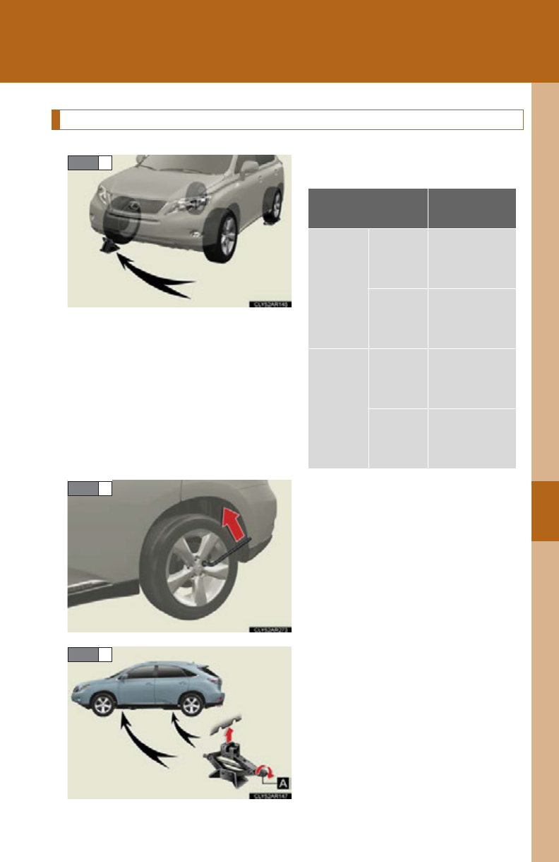
5
When trouble arises
635
5-2. Steps to take in an emergency
Replacing a flat tire
Chock the tires.
Slightly loosen the wheel nuts (one
turn).
Turn the tire jack portion “A” by
hand until the notch of the jack is in
contact with the jack point.
STEP 1
Flat tire Wheel chock
positions
Front
Left-
hand side
Behind the
rear right-
hand side tire
Right-
hand side
Behind the
rear left-
hand side tire
Rear
Left-
hand side
In front of the
front right-
hand side tire
Right-
hand side
In front of the
front left-
hand side tire
STEP 2
STEP 3
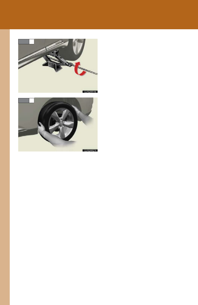
636
5-2. Steps to take in an emergency
Raise the vehicle until the tire is
slightly raised off the ground.
Remove all the wheel nuts and the
tire.
When resting the tire on the
ground, place the tire so that the
wheel design faces up to avoid
scratching the wheel surface.
STEP 4
STEP 5
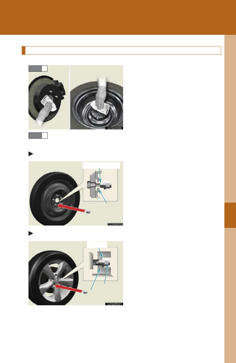
5
When trouble arises
637
5-2. Steps to take in an emergency
Installing the spare tire
Remove any dirt or foreign matter
from the wheel contact surface.
If foreign matter is on the wheel
contact surface, the wheel nuts
may loosen while the vehicle is in
motion, causing the tire to come
off.
Install the spare tire and loosely tighten each wheel nut by hand
by approximately the same amount.
Vehicles with a compact spare tire
Tighten the nuts until the tapered
portion comes into loose contact
with the disc wheel seat.
Vehicles with a full-size spare tire
Turn the nuts until the washers
come into contact with the wheel.
STEP 1
STEP 2
Disc wheel
seat
Tapered portion
Wheel nut
Disc wheel
Washer
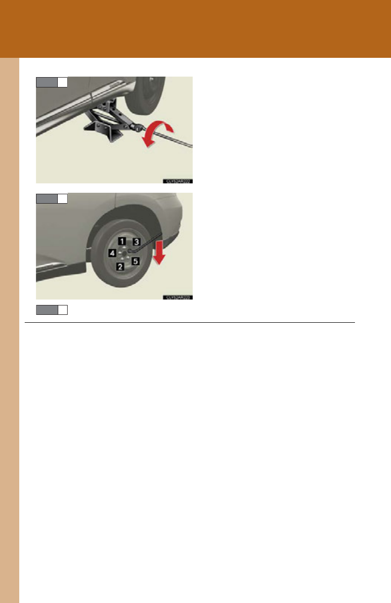
638
5-2. Steps to take in an emergency
Lower the vehicle.
Firmly tighten each wheel nut two
or three times in the order shown
in the illustration.
Tightening torque:
76 ft•lbf (103 N•m, 10.5 kgf•m)
Stow the flat tire, tire jack and all tools.
STEP 3
STEP 4
■The compact spare tire
●The compact spare tire is identified by the label “TEMPORARY USE ONLY”
on the tire sidewall.
Use the compact spare tire temporarily, and only in an emergency.
●Make sure to check the tire inflation pressure of the compact spare tire.
(P. 673)
■When using the compact spare tire
As the compact spare tire is not equipped with a tire pressure warning valve and
transmitter, low inflation pressure of the spare tire will not be indicated by the tire
pressure warning system. Also, if you replace the compact spare tire after the tire
pressure warning light comes on, the light remains on.
STEP 5

5
When trouble arises
639
5-2. Steps to take in an emergency
■If you have a flat front tire on a road covered with snow or ice
Install the compact spare tire on one of the rear wheels of the vehicle. Perform the
following steps and fit tire chains to the front tires:
Replace a rear tire with the compact spare tire.
Replace the flat front tire with the tire removed from the rear of the vehi-
cle.
Fit tire chains to the front tires.
■After completing the tire change
The tire pressure warning system (if equipped) must be reset. (P. 533 )
CAUTION
■Using the tire jack
Improper use of the tire jack may cause the vehicle to suddenly fall off the jack,
leading to death or serious injury.
●Do not use the tire jack for any purpose other than replacing tires or installing and
removing tire chains.
●Only use the tire jack that comes with this vehicle for replacing a flat tire.
Do not use it on other vehicles, and do not use other tire jacks for replacing tires
on this vehicle.
●Always check that the tire jack is securely set to the jack point.
●Do not put any part of your body under the vehicle while it is supported by the
jack.
●Do not start or run the hybrid system while your vehicle is supported by the jack.
●Do not raise the vehicle while someone is inside.
●When raising the vehicle, do not put an object on or under the jack.
●Do not raise the vehicle to a height greater than that required to replace the tire.
●Use a jack stand if it is necessary to get under the vehicle.
●Vehicles with electronically modulated air suspension: Be sure to turn off the
height control and stop the hybrid system.
Take particular care when lowering the vehicle to ensure that no one working on or
near the vehicle may be injured.
STEP 1
STEP 2
STEP 3

640
5-2. Steps to take in an emergency
CAUTION
■Replacing a flat tire
Observe the following precautions to reduce the risk of death or serious injury:
●Do not touch the disc wheels or the area around the brakes immediately after the
vehicle has been driven.
After the vehicle has been driven the disc wheels and the area around the brakes
will be extremely hot. Touching these areas with hands, feet or other body parts
while changing a tire, etc. may result in burns.
●Failure to follow these precautions could cause the wheel nuts to loosen and the
tire to fall off, resulting in death or serious injury.
• Never use oil or grease on the wheel bolts or wheel nuts.
Oil and grease may cause the wheel nuts to be excessively tightened, leading
to bolt or disc wheel damage. In addition, the oil or grease can cause the
wheel nuts to loosen and the wheel may fall off, causing a serious accident.
Remove any oil or grease from the wheel bolts or wheel nuts.
• Have the wheel nuts tightened with a torque wrench to 76 ft•lbf (103 N•m,
10.5 kgf•m) as soon as possible after changing wheels.
• When installing a tire, only use wheel nuts that have been specifically
designed for that wheel.
• If there are any cracks or deformations in the bolt screws, nut threads or bolt
holes of the wheel, have the vehicle inspected by your Lexus dealer.
Failure to follow these precautions could cause the wheel nuts to loosen and the tire
to fall off, resulting in death or serious injury.
■Replacing a flat tire for vehicles with power back door
In cases such as when replacing tires, make sure to turn off the power back door
main switch (P. 72). Failure to do so may cause the back door to operate uninten-
tionally if the power back door switch is accidentally touched, resulting in hands and
fingers being caught and injured.
■When using the compact spare tire
●Remember that the compact spare tire provided is specifically designed for use
with your vehicle. Do not use your compact spare tire on another vehicle.
●Do not use more than one compact spare tire simultaneously.
●Replace the compact spare tire with a standard tire as soon as possible.
●Avoid sudden acceleration, deceleration and braking, as well as sharp cornering.

5
When trouble arises
641
5-2. Steps to take in an emergency
CAUTION
■When the compact spare tire is attached
The vehicle speed may not be correctly detected, and the following systems may
not operate correctly:
●ABS & Brake assist
●VSC
●TRAC
●VDIM
●Intuitive parking assist (if equipped)
●Navigation system (if equipped)
●Cruise control (if equipped)
●Dynamic radar cruise control (if equipped)
●Electronically modulated air suspension (if equipped)
●Pre-Collision System (if equipped)
Also, not only can the following system not be utilized fully, but it may even nega-
tively affect the drive-train components:
●AWD system (if equipped)
■Speed limit when using the compact spare tire
Do not drive at speeds in excess of 50 mph (80 km/h) when a compact spare tire is
installed on the vehicle.
The compact spare tire is not designed for driving at high speeds. Failure to observe
this precaution may lead to an accident causing death or serious injury.

642
5-2. Steps to take in an emergency
NOTICE
■Do not drive the vehicle with a flat tire
Do not continue driving with a flat tire.
Driving even a short distance with a flat tire can damage the tire and the wheel
beyond repair.
■Be careful when driving over bumps with the compact spare tire installed on the
vehicle.
The vehicle becomes lower when driving with the compact spare tire compared to
when driving with standard tires. Be careful when driving over uneven road sur-
faces.
■Driving with tire chains and the compact spare tire
Do not fit tire chains to the compact spare tire.
Tire chains may damage the vehicle body and adversely affect driving performance.
■When replacing the tires
When removing or fitting the wheels, tires or the tire pressure warning valve and
transmitter, contact your Lexus dealer as the tire pressure warning valve and trans-
mitter may be damaged if not handled correctly.
■To avoid damage to the tire pressure warning valves and transmitters
When a tire is repaired with liquid sealants, the tire pressure warning valve and
transmitter may not operate properly. If a liquid sealant is used, contact your Lexus
dealer or other qualified service shop as soon as possible. Make sure to replace the
tire pressure warning valve and transmitter when replacing the tire. (P. 533 )

5
When trouble arises
643
5-2. Steps to take in an emergency
If the hybrid system will not start
Reasons for the hybrid system not starting vary depending on the situation.
Check the following and perform the appropriate procedure:
■The hybrid system will not start even though the correct starting
procedure is being followed. (P. 1 76)
One of the following may be the cause of the problem:
●The electronic key may not be functioning properly. (P. 6 4 8)
●There may be a malfunction in the immobilizer system. (P. 124)
●There may be a malfunction in the steering lock system.
●The hybrid system may be malfunctioning due to an electrical
problem such as an open circuit or a blown fuse. However,
depending on the type of malfunction, an interim measure is avail-
able to start the hybrid system. (P. 644)
■The interior lights and headlights are dim, or the horn does not
sound or sounds at a low volume.
One of the following may be the cause of the problem:
●The 12-volt battery may be discharged. (P. 650)
●The 12-volt battery terminal connections may be loose or cor-
roded.
■The interior lights and headlights do not turn on, or the horn does
not sound.
One of the following may be the cause of the problem:
●One or both of the 12-volt battery terminals may be discon-
nected.
●The 12-volt battery may be discharged. (P. 650)
Contact your Lexus dealer if the problem cannot be repaired, or if
repair procedures are unknown.

644
5-2. Steps to take in an emergency
Emergency start function
When the hybrid system does not start, the following steps can be used as
an interim measure to start the hybrid system if the “POWER” switch is
functioning normally:
Set the parking brake.
Shift the shift lever to P.
Turn the “POWER” switch to ACCESSORY mode.
Press and hold the “POWER” switch for about 15 seconds while
depressing the brake pedal firmly.
Even if the hybrid system can be started using the above steps, the system
may be malfunctioning. Have the vehicle inspected by your Lexus dealer.
STEP 1
STEP 2
STEP 3
STEP 4
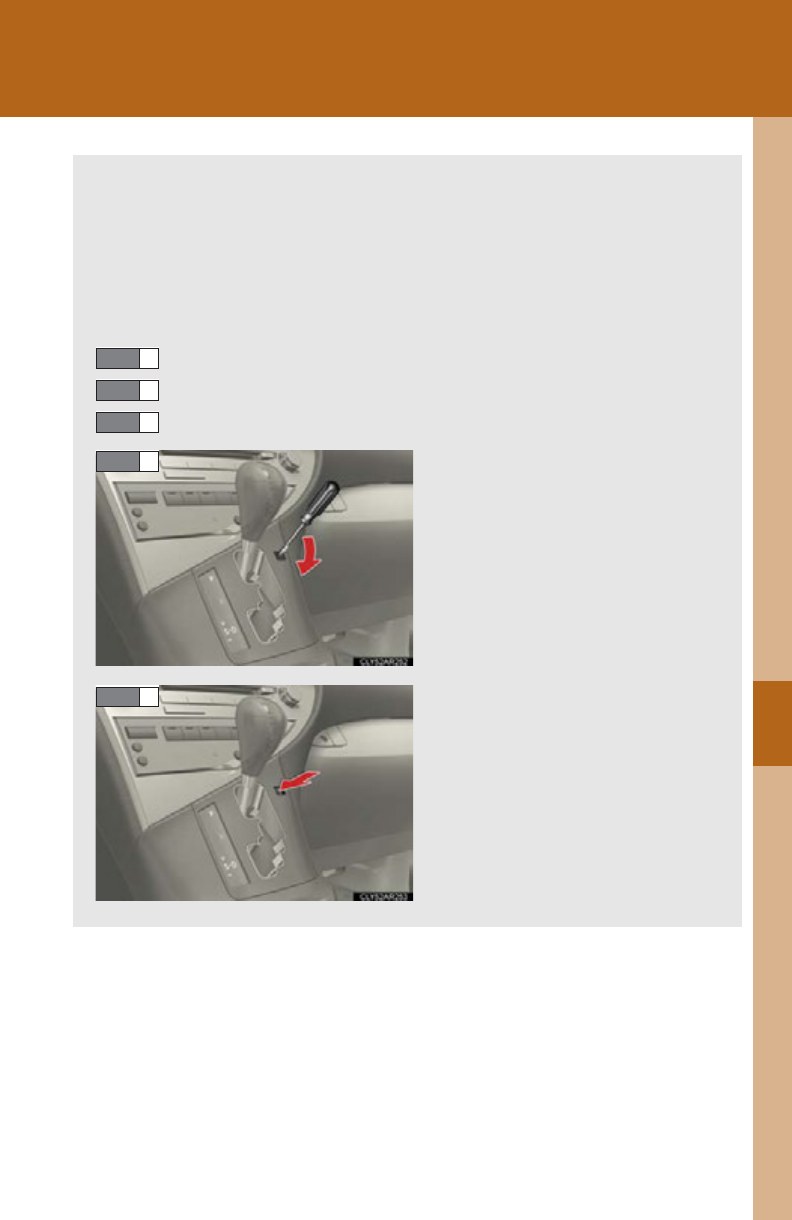
5
When trouble arises
645
5-2. Steps to take in an emergency
If the shift lever cannot be shifted from P
If the shift lever cannot be shifted with your foot on the brake pedal, there
may be a problem with the shift lock system (a system to prevent accidental
operation of the shift lever). Have the vehicle inspected by your Lexus
dealer immediately.
The following steps may be used as an emergency measure to ensure that
the shift lever can be shifted:
Set the parking brake.
Turn the “POWER” switch to ACCESSORY mode.
Depress the brake pedal.
Pry the cover up with a flathead
screwdriver or equivalent.
Press the shift lock override but-
ton.
The shift lever can be shifted
while the button is pressed.
STEP 1
STEP 2
STEP 3
STEP 4
STEP 5

646
5-2. Steps to take in an emergency
If you lose your keys
New genuine Lexus keys can be made by your Lexus dealer using the other
keys and the key number stamped on your key number plate.
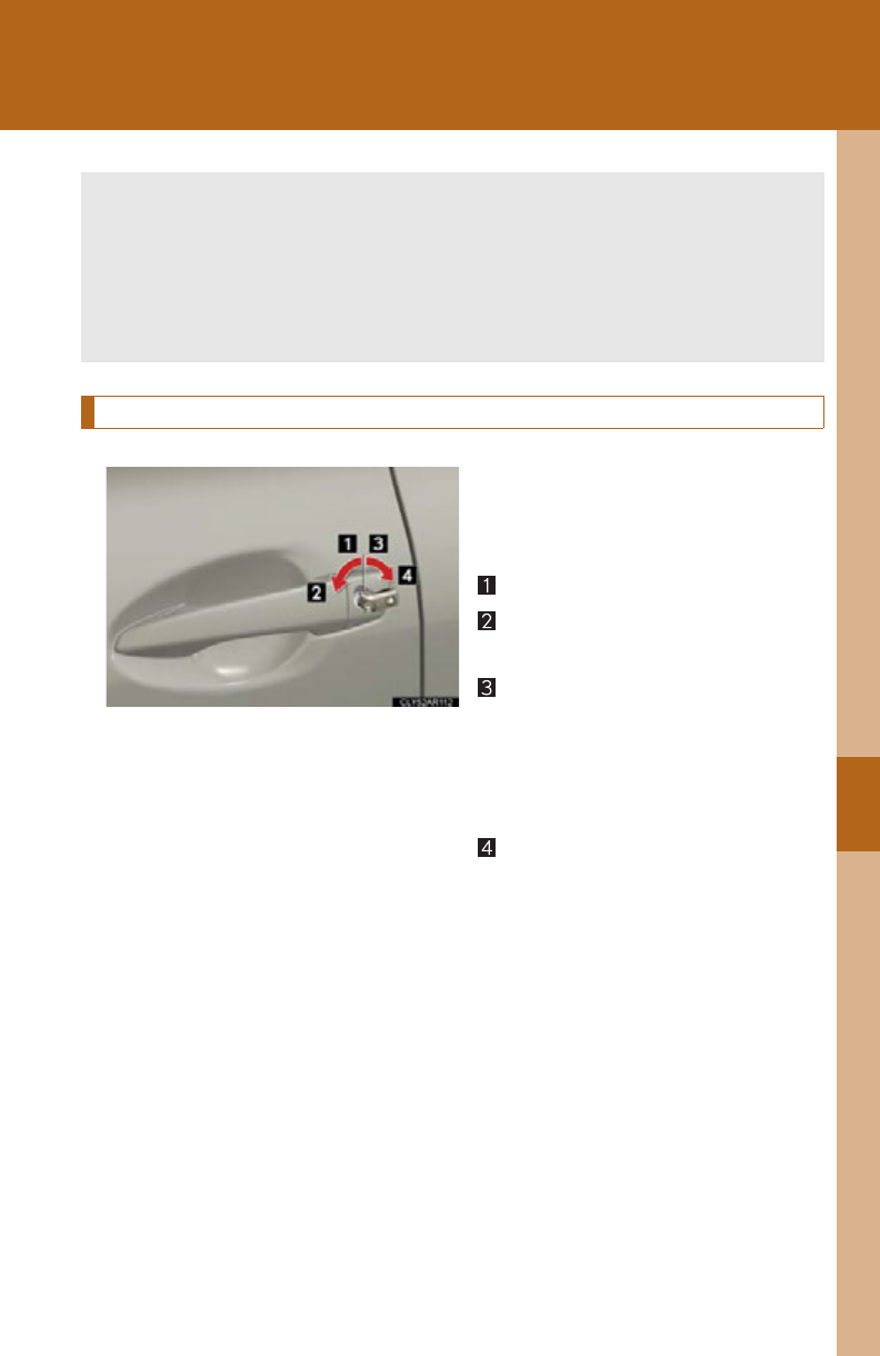
5
When trouble arises
647
5-2. Steps to take in an emergency
If the electronic key does not operate properly
Locking and unlocking the side doors and key linked functions
Use the mechanical key (P. 48)
in order to perform the following
operations (driver’s door only):
Locks all the doors
Closes the windows and moon
roof (turn and hold)
Unlocks the door
Turning the key rearward unlocks
the driver's door. Turning the key
once again unlocks the other
doors.
Opens the windows and moon
roof (turn and hold)
If communication between the electronic key and vehicle is interrupted
(P. 57) or the electronic key cannot be used because the battery is
depleted, the smart access system with push-button start and wireless
remote control cannot be used. In such cases, the doors can be opened and
the hybrid system can be started by following the procedure below.
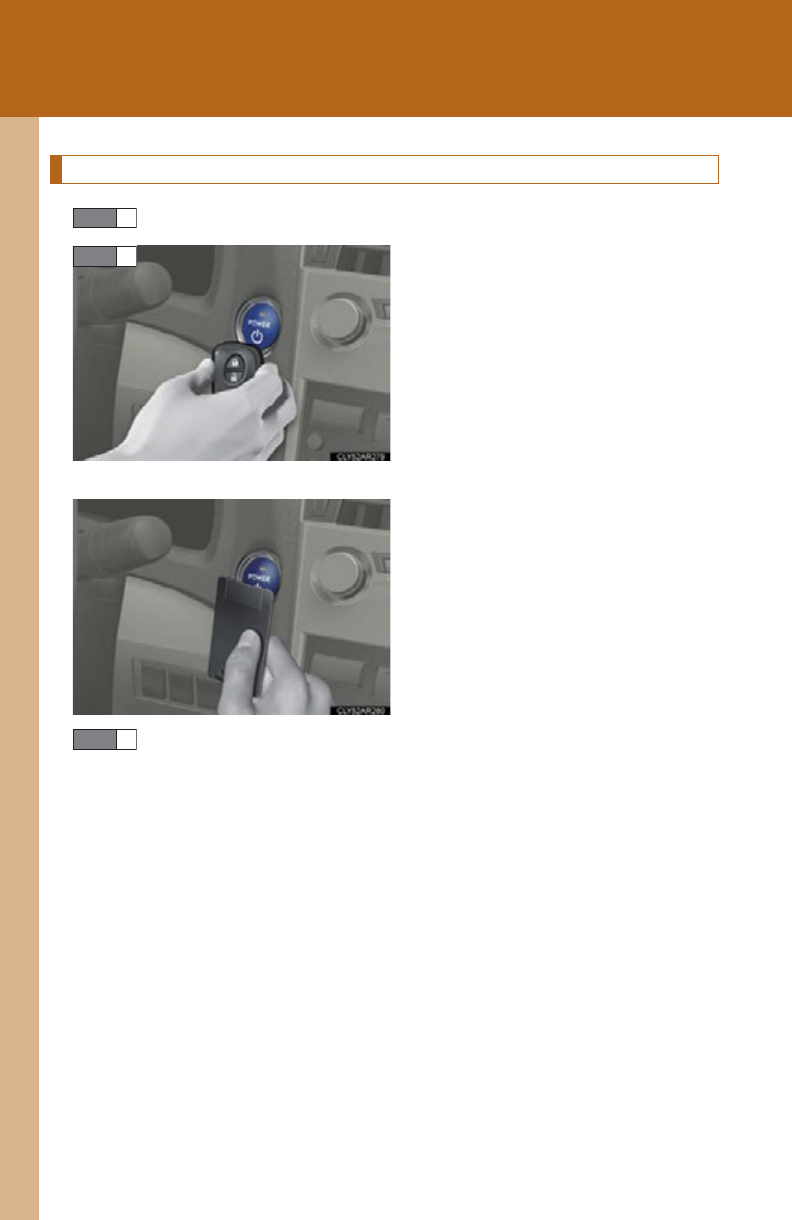
648
5-2. Steps to take in an emergency
Changing “POWER” switch modes and starting the hybrid system
Ensure that the shift lever is in P and depress the brake pedal.
Touch the Lexus emblem side of
the electronic key to the
“POWER” switch.
If any of the doors is opened or
closed while the key is being
touched to the switch, an alarm will
sound to indicate that the start
function cannot detect the elec-
tronic key.
To change “POWER” switch modes: Within 10 seconds of the
buzzer sounding, release the brake pedal and press the
“POWER” switch. Modes can be changed each time the switch is
pressed. (P. 177)
To start the hybrid system: Press the “POWER” switch within 10
seconds of the buzzer sounding, keeping the brake pedal
depressed.
In the event that the hybrid system still cannot be operated, contact your
Lexus dealer.
STEP 1
STEP 2
STEP 3

5
When trouble arises
649
5-2. Steps to take in an emergency
■Stopping the hybrid system
Shift the shift lever to P and press the “POWER” switch as you normally do when
stopping the hybrid system.
■Replacing the key battery
As the above procedure is a temporary measure, it is recommended that the elec-
tronic key battery be replaced immediately when the battery is depleted.
(P. 550)
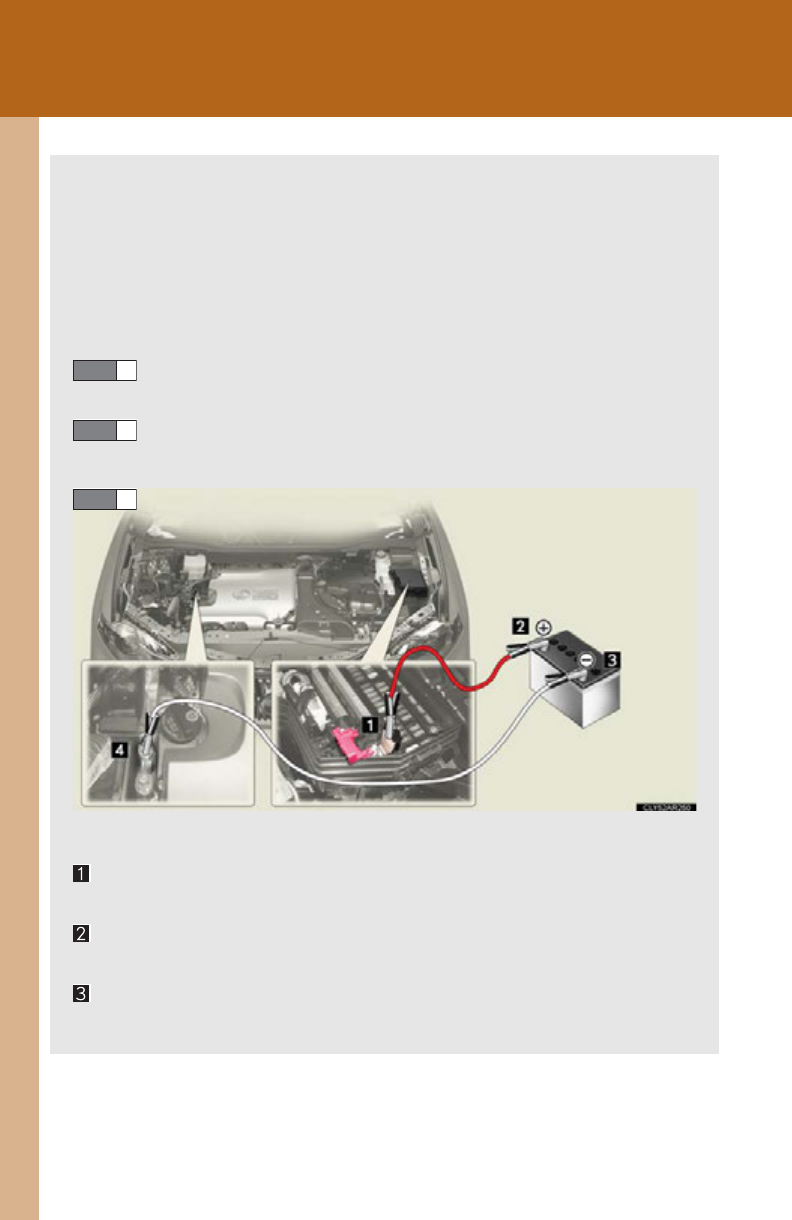
650
5-2. Steps to take in an emergency
If the vehicle 12-volt battery is discharged
The following procedures may be used to start the hybrid system if the vehi-
cle’s 12-volt battery is discharged.
You can also call your Lexus dealer or a qualified repair shop.
If you have a set of jumper (or booster) cables and a second vehicle
with a 12-volt battery, you can jump start your vehicle by following the
steps below.
Open the hood and remove the engine compartment covers.
(P. 513 )
Remove the fuse box cover and open the exclusive jump start-
ing terminal cover.
Connect the jumper cables according to the following procedure:
Connect a positive jumper cable clamp to the exclusive jump start-
ing terminal on your vehicle
Connect a positive jumper cable clamp to the positive (+) battery
terminal on the second vehicle
Connect a negative cable clamp to the negative (-) battery terminal
on the second vehicle
STEP 1
STEP 2
STEP 3

5
When trouble arises
651
5-2. Steps to take in an emergency
Connect the clamp at the other end of the negative cable to a solid,
stationary, unpainted metallic point away from the exclusive jump
starting terminal and any moving parts, as shown in the illustration.
Start the engine of the second vehicle. Increase the engine
speed slightly and maintain that level for approximately 5 min-
utes to recharge the 12-volt battery of your vehicle.
Open and close any of the doors of your vehicle with the
“POWER” switch off.
Maintain the engine speed of the second vehicle and start the
hybrid system of your vehicle by turning the “POWER” switch
to ON mode.
Make sure the “READY” indicator comes on. If the indicator
does not come on, contact your Lexus dealer.
Once the hybrid system has started, remove the jumper cables
in the exact reverse order from which they were connected.
Once the hybrid system starts, have the vehicle inspected at your
Lexus dealer as soon as possible.
STEP 4
STEP 5
STEP 6
STEP 7
STEP 8

652
5-2. Steps to take in an emergency
■Starting the hybrid system when the 12-volt battery is discharged
The hybrid system cannot be started by push-starting.
■To prevent 12-volt battery discharge
●Turn off the headlights and the audio system while the hybrid system is off.
●Turn off any unnecessary electrical components when the vehicle is running at a
low speed for an extended period, such as in heavy traffic.
■When the 12-volt battery is removed or discharged
●The power back door must be initialized. (P. 702 )
●The hybrid system may not start. (P. 529)
■Charging the 12-volt battery
The electricity stored in the 12-volt battery will discharge gradually even when the
vehicle is not in use, due to natural discharge and the draining effects of certain
electrical appliances. If the vehicle is left for a long time, the 12-volt battery may dis-
charge, and the hybrid system may be unable to start. (The 12-volt battery
recharges automatically while the hybrid system is operating.)
CAUTION
■Avoiding 12-volt battery fires or explosions
Observe the following precautions to prevent accidentally igniting the flammable
gas that may be emitted from the 12-volt battery:
●Make sure each jumper cable is connected to the correct terminal and that it is
not unintentionally in contact with any other than the intended terminal.
●Do not allow the other end of the jumper cable connected to the “+” terminal to
come into contact with any other parts or metal surfaces in the area, such as
brackets or unpainted metal.
●Do not allow the + and - clamps of the jumper cables to come into contact with
each other.
●Do not smoke, use matches, cigarette lighters or allow open flame near the 12-
volt battery.

5
When trouble arises
653
5-2. Steps to take in an emergency
CAUTION
■12-volt battery precautions
The 12-volt battery contains poisonous and corrosive acidic electrolyte, while
related parts contain lead and lead compounds. Observe the following precautions
when handling the 12-volt battery:
●When working with the 12-volt battery, always wear safety glasses and take care
not to allow any battery fluids (acid) to come into contact with skin, clothing or the
vehicle body.
●Do not lean over the 12-volt battery.
●In the event that battery fluid comes into contact with the skin or eyes, immedi-
ately wash the affected area with water and seek medical attention.
Place a wet sponge or cloth over the affected area until medical attention can be
received.
●Always wash your hands after handling the battery support, terminals, and other
battery-related parts.
●Do not allow children near the 12-volt battery.
■After recharging the 12-volt battery
Have the 12-volt battery inspected at your Lexus dealer as soon as possible.
If the 12-volt battery is deteriorating, continued use may cause the 12-volt battery to
emit a malodorous gas, which may be detrimental to the health of passengers.
■When replacing the 12-volt battery
P. 53 1

654
5-2. Steps to take in an emergency
NOTICE
■When handling jumper cables
When connecting the jumper cables, ensure that they do not become entangled in
the cooling fans or belt.
■Avoiding accidental short-circuits
When connecting jumper cables, observe the following precautions:
●Make sure each jumper cable is connected to the correct terminal.
●Do not allow the ends of the jumper cable used for the “+” terminals to come into
contact with any other parts or metal surfaces in the area, such as brackets or
unpainted metal.
●Do not allow the “+” and “-” terminals of the jumper cables to come into contact
with each other.
■Exclusive jump starting terminal precaution
The exclusive jump starting terminal is to be used when charging the 12-volt battery
from another vehicle in an emergency. It cannot be used to jump start another vehi-
cle.

5
When trouble arises
655
5-2. Steps to take in an emergency
If your vehicle overheats
Correction procedures
■If “ENGINE OVERHEAT” is shown on the multi-information display
Stop the vehicle in a safe place and turn off the air conditioning
system.
Check to see if steam is coming out from the engine area.
If you see steam:
Stop the hybrid system. Carefully lift the hood after the steam
subsides and then restart the hybrid system.
If you do not see steam:
Leave the hybrid system operating and carefully lift the hood.
Check to see if the cooling fans are operating.
If the fans are operating:
Wait until the “ENGINE OVERHEAT” message disappears and
then stop the hybrid system.
If the fans are not operating:
Stop the hybrid system immediately and call your Lexus dealer.
The following may indicate that your vehicle is overheating:
●“ENGINE OVERHEAT” is shown on the multi-information display:
The engine may be overheating.
●“HYBRID SYSTEM OVERHEAT” is shown on the multi-information
display:
A hybrid system component such as the power control unit or an
electric motor (traction motor) may be overheating.
Follow the correction procedure as described below.
STEP 1
STEP 2
STEP 3
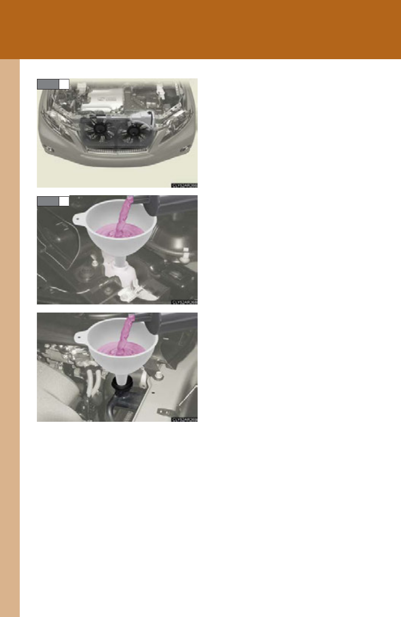
656
5-2. Steps to take in an emergency
After the hybrid system has cooled
down sufficiently, check the engine
coolant level and inspect the cool-
ing system for leaks.
If the engine compartment cover
needs to be removed. (P. 51 3 )
Add engine coolant if necessary.
Water can be used in an emer-
gency if engine coolant is unavail-
able. (P. 670 )
Have the vehicle inspected at the nearest Lexus dealer as soon as possi-
ble.
STEP 4
STEP 5
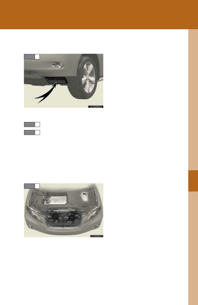
5
When trouble arises
657
5-2. Steps to take in an emergency
■If “HYBRID SYSTEM OVERHEAT” is shown on the multi-informa-
tion display
Stop the vehicle in a safe place and
turn off the air conditioning sys-
tem.
Ensure that the opening for the oil
cooler is not blocked by dirt or any
other foreign substance. If the
opening is not blocked or if the
message does not disappear after
some time the opening has been
cleaned, proceed to STEP 2.
Leave the hybrid system operating and carefully lift the hood.
Check if the cooling fans are operating.
If the fans are operating:
Wait until the “HYBRID SYSTEM OVERHEAT” message disap-
pears and then stop the hybrid system.
If the message does not disappear, call your Lexus dealer.
If the fans are not operating:
Stop the hybrid system immediately and call your Lexus dealer.
After the hybrid system has cooled
down, check the power control
unit coolant level and inspect the
cooling system for leaks.
If the engine compartment cover
needs to be removed. (P. 51 3 )
STEP 1
STEP 2
STEP 3
STEP 4
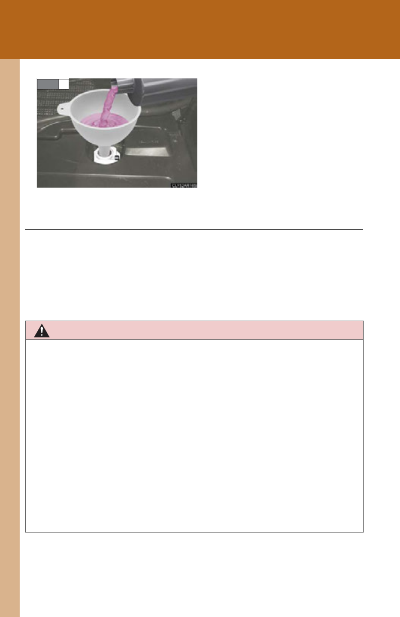
658
5-2. Steps to take in an emergency
Add power control unit coolant if
necessary.
Water can be used in an emer-
gency if power control unit coolant
is unavailable. (P. 670)
Have the vehicle inspected at the nearest Lexus dealer as soon as possi-
ble.
STEP 5
■Overheating
The following symptoms may occur when your vehicle is overheating:
●Hybrid system output decreases.
●Steam comes out from the engine area.
CAUTION
■To prevent an accident or injury when inspecting under the hood of your vehicle
●If steam is seen coming from under the hood, do not open the hood until the
steam has subsided. The engine compartment may be very hot, causing serious
injuries such as burns.
●Check that the indicator on the “POWER” switch and the “READY” indicator are
off.
●For vehicles with a hybrid system, there are times when the gasoline engine auto-
matically starts to run or the cooling fans suddenly start to operate. Do not touch
or approach the rotating parts of the belt or fans. Doing so may lead to fingers,
clothes or tools getting caught, resulting in injury.
●Do not loosen the radiator cap while the hybrid system and radiator are hot.
Serious injuries, such as burns, may result from hot coolant and steam released
under pressure.

5
When trouble arises
659
5-2. Steps to take in an emergency
NOTICE
■When adding engine/power control unit coolant
Wait until the hybrid system has cooled down before adding engine/power control
unit coolant.
When adding coolant, do so slowly. Adding cool coolant to a hot hybrid system too
quickly can cause damage to the hybrid system.
■To prevent damage to the cooling system
Observe the following precautions:
●Avoid contaminating the coolant with foreign matter (such as sand or dust etc.).
●Do not use commercially available coolant additives.
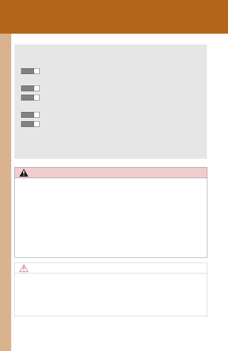
660
5-2. Steps to take in an emergency
If the vehicle becomes stuck
CAUTION
■When attempting to free a stuck vehicle
If you choose to push the vehicle back and forth to free it, make sure the surround-
ing area is clear to avoid striking other vehicles, objects or people. The vehicle may
also lunge forward or lunge back suddenly as it becomes free. Use extreme cau-
tion.
■When shifting the shift lever
Be careful not to shift the shift lever with the accelerator pedal depressed.
This may lead to unexpected rapid acceleration of the vehicle that may cause an
accident resulting in death or serious injury.
NOTICE
■To avoid damage to the hybrid transmission and other components
●Avoid spinning the wheels.
●If the vehicle remains stuck even after these procedures are performed, the vehi-
cle may require towing to be freed.
Carry out the following procedures if the tires spin or the vehicle becomes
stuck in mud, dirt or snow:
Stop the hybrid system. Set the parking brake and shift the shift
lever to P.
Remove the mud, snow or sand from around the stuck tire.
Place wood, stones or some other material under the tires to
help provide traction.
Restart the hybrid system.
Shift the shift lever to the D or R position and carefully apply
the accelerator to free the vehicle.
Turn off the TRAC and VSC systems if these functions are hamper-
ing your attempts to free the vehicle. (P. 276)
STEP 1
STEP 2
STEP 3
STEP 4
STEP 5
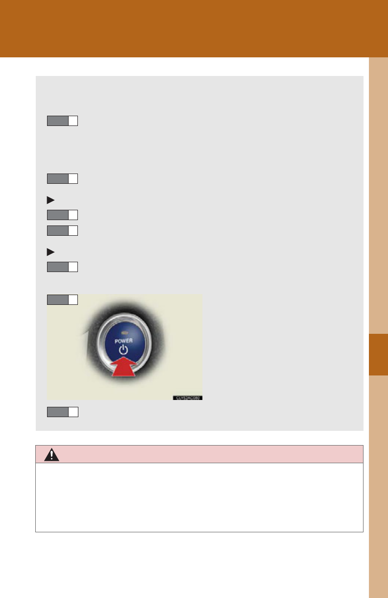
5
When trouble arises
661
5-2. Steps to take in an emergency
If your vehicle has to be stopped in an emergency
CAUTION
■If the hybrid system has to be turned off while driving
Power assist for the brakes and steering wheel will be lost, making the brake pedal
harder to depress and the steering wheel heavier to turn. Decelerate as much as
possible before turning off the hybrid system.
Only in an emergency, such as if it becomes impossible to stop the vehicle
in the normal way, stop the vehicle using the following procedure:
Steadily step on the brake pedal with both feet and firmly
depress it.
Do not pump the brake pedal repeatedly as this will increase the
effort required to slow the vehicle.
Shift the shift lever to N.
If the shift lever is shifted to N
After slowing down, stop the vehicle in a safe place by the road.
Stop the hybrid system.
If the shift lever cannot be shifted to N
Keep depressing the brake pedal with both feet to reduce vehi-
cle speed as much as possible.
Stop the hybrid system by press-
ing and holding the “POWER”
switch for 3 consecutive sec-
onds or more.
Stop the vehicle in a safe place by the road.
STEP 1
STEP 2
STEP 3
STEP 4
STEP 3
Press and hold for 3 seconds or more
STEP 4
STEP 5

662
5-2. Steps to take in an emergency

Vehicle specifications 6
663
6-1. Specifications
Maintenance data
(fuel, oil level, etc.) .............. 664
Fuel information...................... 676
Tire information...................... 680
6-2. Customization
Customizable features ........ 693
6-3. Initialization
Items to initialize.................... 702

664
6-1. Specifications
Maintenance data (fuel, oil level, etc.)
Dimensions and weight
*1: Unladen vehicles
*2: Vehicles without roof antenna and roof rails
*3: Vehicles with roof antenna but without electronically modulated air suspension
*4: Vehicles with roof rails but without electronically modulated air suspension
*5: Vehicles with roof antenna and electronically modulated air suspension
*6: Vehicles with roof rails and electronically modulated air suspension
*7: AWD models with towing package
Overall length 187.8 in. (4770 mm)
Overall width 74.2 in. (1885 mm)
Overall height*1
66.3 in. (1685 mm)*2
66.7 in. (1695 mm)*3
67.7 in. (1720 mm)*4
66.5 in. (1690 mm)*5
67.9 in. (1725 mm)*6
Wheelbase 107.9 in. (2740 mm)
Tr e a d Front 64.2 in. (1630 mm)
Rear 63.8 in. (1620 mm)
Vehicle capacity weight
(Occupants + luggage)
2WD 825 lb. (370 kg)
AWD 885 lb. (400 kg)
Trailer Weight Rating*7
(Trailer weight + cargo) 3500 lb. (1588 kg)
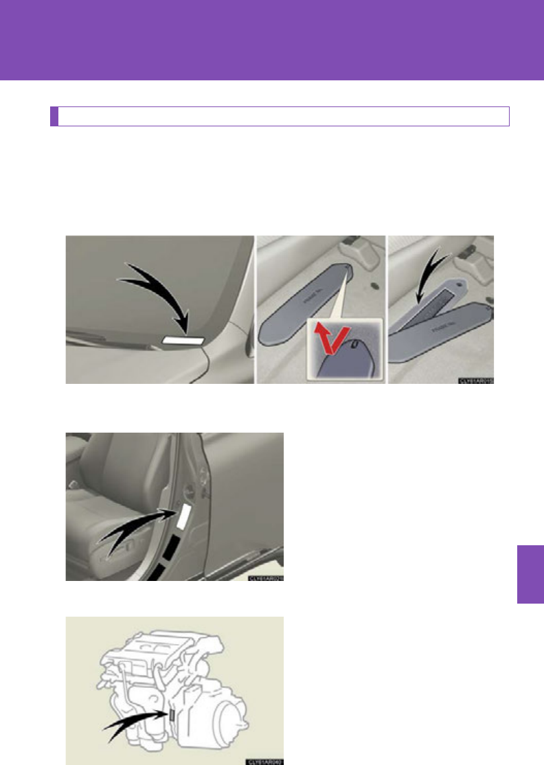
665
6-1. Specifications
6
Vehicle specifications
Vehicle identification
■Vehicle identification number
The vehicle identification number (VIN) is the legal identifier for your
vehicle. This is the primary identification number for your Lexus. It is used
in registering the ownership of your vehicle.
This number is stamped on the top left of the instrument panel. On some mod-
els, this number is also stamped under the front passenger seat.
This number is also on the Certifi-
cation Label.
■Engine number
The engine number is stamped on
the engine block as shown.

666
6-1. Specifications
Engine
Fuel
Electric motor (Traction motor)
Front
Rear (AWD models)
Model 2GR-FXE
Type 6-cylinder V type, 4-cycle, gasoline
Bore and stroke 3.70 3.27 in. (94.0 83.0 mm)
Displacement 210.9 cu.in. (3456 cm3)
Drive belt tension Automatic adjustment
Fuel type Unleaded gasoline only
Octane rating 91 (Research octane number 96) or higher
Fuel tank capacity
(Reference) 17.1 gal. (65 L, 14.2 Imp. gal.)
Type Permanent magnet synchronous motor
Maximum output 123 kW
Maximum torque 247 ft•lbf (335 N•m, 34.2 kgf•m)
Type Permanent magnet synchronous motor
Maximum output 50 kW
Maximum torque 103 ft•lbf (139 N•m, 14.2 kgf•m)

667
6-1. Specifications
6
Vehicle specifications
Hybrid battery (Traction battery)
Type Nickel-metal hydride battery
Volt ag e 9.6 V/module
Capacity 6.5 Ah (3HR)
Quantity 30 modules
Overall voltage 288 V
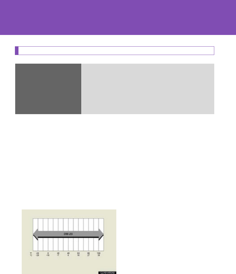
668
6-1. Specifications
Lubrication system
*: The engine oil capacity is a reference quantity to be used when exchang-
ing. Warm up the engine and turn off the hybrid system, wait more than 5
minutes, and check the oil level on the dipstick.
■Engine oil selection
“Toyota Genuine Motor Oil” is used in your Lexus vehicle. Use Lexus
approved “Toyota Genuine Motor Oil” or equivalent to satisfy the follow-
ing grade and viscosity.
Oil grade: ILSAC multigrade engine oil
Recommended viscosity: SAE 0W-20
SAE 0W-20 is the best choice for
good fuel economy and good
starting in cold weather.
If SAE 0W-20 is not available,
SAE 5W-20 oil may be used.
However, it must be replaced with
SAE 0W-20 at the next oil
change.
Oil capacity
(Drain and refill
reference*)
With filter 6.4 qt. (6.1 L, 5.3 Imp. qt.)
Without filter 6.0 qt. (5.7 L, 5.0 Imp. qt.)
Outside temperature

669
6-1. Specifications
6
Vehicle specifications
Oil viscosity (0W-20 is explained here as an example):
●The 0W in 0W-20 indicates the characteristic of the oil which allows cold
startability. Oils with a lower value before the W allow for easier starting of
the engine in cold weather.
●The 20 in 0W-20 indicates the viscosity characteristic of the oil when the
oil is at high temperature. An oil with a higher viscosity (one with a higher
value) may be better suited if the vehicle is operated at high speeds, or
under extreme load conditions.
How to read oil container label:
The ILSAC (International Lubricant Standardization and Approval
Committee) Certification Mark is added to some oil containers to help
you select the oil you should use.

670
6-1. Specifications
Cooling system
*: With towing package
Ignition system
Capacity
Gasoline engine
Power control unit
12.0 qt. (11.4 L, 10.0 Imp. qt.)
12.3 qt. (11.7 L, 10.3 Imp. qt.)*
2.0 qt. (1.9 L, 1.7 Imp. qt.)
Coolant type
Use either of the following:
• “Toyota Super Long Life Coolant”
• Similar high-quality ethylene glycol-based non-sili-
cate, non-amine, non-nitrite, and non-borate cool-
ant with long-life hybrid organic acid technology
Do not use plain water alone.
Spark plug
Make
Gap
DENSO FK20HR11
0.043 in. (1.1 mm)
NOTICE
■Iridium-tipped spark plugs
Use only iridium-tipped spark plugs. Do not adjust the spark plug gap.

671
6-1. Specifications
6
Vehicle specifications
Electrical system
Hybrid Transaxle
*: The fluid capacity is a reference quantity. If replacement is necessary, contact
your Lexus dealer.
12-volt battery
Open voltage* at
68F (20C):
12.6 12.8 V Fully charged
12.2 12.4 V Half charged
11.8 12.0 V Discharged
(*: Voltage checked 20 minutes after the hybrid sys-
tem and all the lights are turned off)
Charging rates 5 A max.
Fluid capacity* Front
4.9 qt. (4.6 L, 4.0 Imp. qt.)
Rear (AWD models)
1.9 qt. (1.8 L, 1.6 Imp. qt.)
Fluid type Toyota Genuine ATF WS
NOTICE
■Transmission fluid type
Using transmission fluid other than “Toyota Genuine ATF WS” may ultimately dam-
age the transmission of your vehicle.

672
6-1. Specifications
Brakes
*1: Minimum pedal clearance when depressed with a force of 112 lbf (500 N, 51
kgf) while the hybrid system is operating
*2: Parking brake pedal travel when depressed with a force of 67.4 lbf (300 N,
30.6 kgf)
Steering
Pedal clearance *13.9 in. (99 mm) Min.
Pedal free play 0.04 0.08 in. (1 2 mm)
Brake pad wear limit 0.04 in. (1.0 mm)
Parking brake lining wear limit 0.04 in. (1.0 mm)
Parking brake pedal travel *25 8 clicks
Fluid type SAE J1703 or FMVSS No.116 DOT 3
Free play Less than 1.2 in. (30 mm)

673
6-1. Specifications
6
Vehicle specifications
Tires and wheels
Type A
Type B
Tire size P235/60R18 102V, T165/90D18 107M (spare)
Tire inflation pressure
(recommended cold tire
inflation pressure)
Front: 33 psi (230 kPa, 2.3 kgf/cm2 or bar)
Rear: 33 psi (230 kPa, 2.3 kgf/cm2 or bar)
Spare: 60 psi (420 kPa, 4.2 kgf/cm2 or bar)
Wheel size 18 7 1/2J, 18 4T (spare)
Wheel nut torque 76 ft•lbf (103 N•m, 10.5 kgf•m)
Tire size P235/60R18 102V
Tire inflation pressure
(recommended cold tire
inflation pressure)
Front: 33 psi (230 kPa, 2.3 kgf/cm2 or bar)
Rear: 33 psi (230 kPa, 2.3 kgf/cm2 or bar)
Spare: 33 psi (230 kPa, 2.3 kgf/cm2 or bar)
Wheel size 18 7 1/2J
Wheel nut torque 76 ft•lbf (103 N•m, 10.5 kgf•m)

674
6-1. Specifications
Typ e C
Typ e D
Tire size P235/55R19 101V, T165/90D18 107M (spare)
Front and rear tire infla-
tion pressure
(recommended cold tire
inflation pressure)
Driving under normal conditions
Front: 33 psi (230 kPa, 2.3 kgf/cm2 or bar)*
Rear: 33 psi (230 kPa, 2.3 kgf/cm2 or bar)*
Spare: 60 psi (420 kPa, 4.2 kgf/cm2 or bar)
*: When driving at high speeds above 100 mph (160
km/h), in countries where such speeds are permitted by
law, add 3 psi (20 kPa, 0.2 kgf/cm2 or bar) to the tires.
Never exceed the maximum cold tire inflation pressure
indicated on the tire sidewall.
Wheel size 19 7 1/2J, 18 4T (spare)
Wheel nut torque 76 ft•lbf (103 N•m, 10.5 kgf•m)
Tire size P235/55R19 101V
Tire inflation pressure
(recommended cold tire
inflation pressure)
Driving under normal conditions
Front: 33 psi (230 kPa, 2.3 kgf/cm2 or bar)
Rear: 33 psi (230 kPa, 2.3 kgf/cm2 or bar)
Spare: 33 psi (230 kPa, 2.3 kgf/cm2 or bar)
When driving at high speeds above 100 mph (160 km/h),
in countries where such speeds are permitted by law,
add 3 psi (20 kPa, 0.2 kgf/cm2 or bar) to the front tires
and rear tires. Never exceed the maximum cold tire
inflation pressure indicated on the tire sidewall.
Wheel size 19 7 1/2J
Wheel nut torque 76 ft•lbf (103 N•m, 10.5 kgf•m)

675
6-1. Specifications
6
Vehicle specifications
Light bulbs
A: HB3 halogen bulbs
B: D4S discharge bulbs
C: Wedge base bulbs (clear)
D: Wedge base bulbs (amber)
E: H11 halogen bulbs
Light Bulbs Bulb No. WTyp e
Exterior
Headlights
High beam (halogen bulbs)
Low beam (halogen bulbs)
Low/High beam (discharge bulbs)
Daytime running lights
9005
H11
D4S
9005
60
55
35
60
A
E
B
A
Front side marker lights W5W 5 C
Front turn signal lights
3457NAK
28 D
Parking lights W5W 5 C
Tail lights W5W 5 C
Front fog lights H11 55 E
Rear turn signal lights
WY21W
21 D
Back-up lights 921 16 C
Outer foot lights 5 C
Interior
Vanity lights 8 C
Front interior lights 5 C
Rear interior lights 8 C
Luggage compartment lights 5 C
Door courtesy lights 5 C
Footwell lights 3.8 C

676
6-1. Specifications
Fuel information
■Fuel tank opening for unleaded gasoline
To help prevent incorrect fueling, your Lexus has a fuel tank opening that only
accommodates the special nozzle on unleaded fuel pumps.
■If your engine knocks
●Consult your Lexus dealer.
●You may occasionally notice light knocking for a short time while accelerating
or driving uphill. This is normal and there is no need for concern.
■Gasoline quality
In very few cases, driveability problems may be caused by the brand of gasoline you
are using. If driveability problems persist, try changing the brand of gasoline. If this
does not correct the problem, consult your Lexus dealer.
Your vehicle must use only unleaded gasoline.
Premium unleaded gasoline with an octane rating of 91 (Research Octane
Number 96) or higher required for optimum engine performance. If 91
octane cannot be obtained, you may use unleaded gasoline with an octane
rating as low as 87 (Research Octane Number 91). Use of unleaded gaso-
line with an octane rating lower than 91 may result in engine knocking. Per-
sistent knocking can lead to engine damage and should be corrected by
refueling with higher octane unleaded gasoline.
At minimum, the gasoline you use should meet the specifications of
ASTM D4814 in the U.S.A. and CGSB3.5-M93 in Canada.

677
6-1. Specifications
6
Vehicle specifications
■Gasoline quality standards
●Automotive manufacturers in the US, Europe and Japan have developed a
specification for fuel quality called the World-Wide Fuel Charter (WWFC) that
is expected to be applied worldwide.
●The WWFC consists of four categories that are based on required emission
levels. In the US, category 4 has been adopted.
●The WWFC improves air quality by lowering emissions in vehicle fleets, and
customer satisfaction through better performance.
■Lexus recommends the use of gasoline containing detergent additives
●Lexus recommends the use of gasoline that contains detergent additives to
avoid build-up of engine deposits.
●All gasoline sold in the US contains detergent additives to clean and/or keep
clean intake systems.
■Lexus recommends the use of cleaner burning gasoline
Cleaner burning gasoline, including reformulated gasoline that contains oxygen-
ates such as ethanol or MTBE (Methyl Tertiary Butyl Ether) is available in many
areas.
Lexus recommends the use of cleaner burning gasoline and appropriately blended
reformulated gasoline. These types of gasoline provide excellent vehicle perfor-
mance, reduce vehicle emissions and improve air quality.
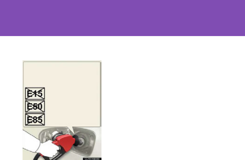
678
6-1. Specifications
■Lexus does not recommend blended gasoline
●If you use gasohol in your Lexus, be sure that it has an octane rating no lower
than 87.
●Lexus DOES NOT recommend the use of gasoline containing methanol.
■Lexus does not recommend gasoline containing MMT
Some gasoline contains octane enhancing additive called MMT (Methylcyclopen-
tadienyl Manganese Tricarbonyl).
Lexus DOES NOT recommend the use of gasoline that contains MMT. If fuel con-
taining MMT is used, your emission control system may be adversely affected.
The malfunction indicator lamp on the instrument cluster may come on. If this hap-
pens, contact your Lexus dealer for service.
●Use only gasoline containing a maxi-
mum of 10% ethanol.
DO NOT use any flex-fuel or gasoline
that could contain more than 10% etha-
nol, including from any pump labeled
E15, E30, E50, E85 (which are only
some examples of fuel containing more
than 10% ethanol).
DO NOT use gasoline contain-
ing more than 10% ethanol.
(15% ethanol)
(50% ethanol)
(85% ethanol)

679
6-1. Specifications
6
Vehicle specifications
NOTICE
■Notice on fuel quality
●Do not use improper fuels. If improper fuels are used the engine will be damaged.
●Do not use leaded gasoline.
Leaded gasoline can cause damage to your vehicle’s three-way catalytic convert-
ers causing the emission control system to malfunction.
●Do not use gasohol other than that stated here.
Other gasohol may cause fuel system damage or vehicle performance problems.
●Using unleaded gasoline with an octane number or rating lower than that stated
here will cause persistent heavy knocking.
At worst, this will lead to engine damage.
■Fuel-related poor driveability
If after using a different type of fuel, poor driveability is encountered (poor hot start-
ing, vaporization, engine knocking, etc.), discontinue the use of that type of fuel.
■When refueling with gasohol
Take care not to spill gasohol. It can damage your vehicle's paint.


681
6-1. Specifications
6
Vehicle specifications
Tire ply composition and materials
Plies are layers of rubber-coated parallel cords. Cords are the strands
which form the plies in a tire.
Radial tires or bias-ply tires
A radial tire has “RADIAL” on the sidewall. A tire not marked “RADIAL” is
a bias-ply tire.
TUBELESS or TUBE TYPE
A tubeless tire does not have a tube and air is directly put into the tire. A
tube type tire has a tube inside the tire and the tube maintains the air pres-
sure.
Load limit at maximum cold tire inflation pressure (P. 536)
Maximum cold tire inflation pressure (P. 673)
This means the pressure to which a tire may be inflated.
Uniform tire quality grading
For details, see “Uniform tire quality grading” that follows.
Summer tire or all season tire (P. 53 6 )
An all season tire has “M+S” on the sidewall. A tire not marked “M+S” is a
summer tire.
“TEMPORARY USE ONLY” (P. 638)
A compact spare tire is identified by the phrase “TEMPORARY USE
ONLY” molded on its sidewall. This tire is designed for temporary emer-
gency use only.
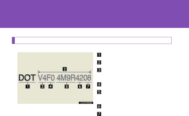
682
6-1. Specifications
Typical DOT and tire identification number (TIN)
DOT symbol*
Tire Identification Number (TIN)
Tire manufacturer's identifica-
tion mark
Tire size code
Manufacturer's optional tire
type code (3 or 4 letters)
Manufacturing week
Manufacturing year
*: The DOT symbol certifies that
the tire conforms to applicable
Federal Motor Vehicle Safety
Standards.
683
6-1. Specifications
6
Vehicle specifications
Tire size
■Typical tire size information
The illustration indicates typical
tire size.
Tire use
(P = Passenger car,
T = Temporary use)
Section width (millimeters)
Aspect ratio
(tire height to section width)
Tire construction code
(R = Radial, D = Diagonal)
Wheel diameter (inches)
Load index (2 digits or 3 digits)
Speed symbol
(alphabet with one letter)
■Tire dimensions
Section width
Tire height
Wheel diameter
684
6-1. Specifications
Tire section names
Bead
Sidewall
Shoulder
Tread
Belt
Inner liner
Reinforcing rubber
Carcass
Rim lines
Bead wires
Chafer
Uniform Tire Quality Grading
This information has been prepared in accordance with regulations
issued by the National Highway Traffic Safety Administration of the U.S.
Department of Transportation.
It provides the purchasers and/or prospective purchasers of Lexus vehi-
cles with information on uniform tire quality grading.
Your Lexus dealer will help answer any questions you may have as you read
this information.
■DOT quality grades
All passenger vehicle tires must conform to Federal Safety Require-
ments in addition to these grades. Quality grades can be found where
applicable on the tire sidewall between tread shoulder and maximum
section width.
For example: Treadwear 200 Traction AA Temperature A

685
6-1. Specifications
6
Vehicle specifications
■Treadwear
The treadwear grade is a comparative rating based on the wear rate of
the tire when tested under controlled conditions on a specified gov-
ernment test course.
For example, a tire graded 150 would wear one and a half (1 - 1/2) times as
well on the government course as a tire graded 100.
The relative performance of tires depends upon the actual conditions of
their use, however, and may depart significantly from the norm due to varia-
tions in driving habits, service practices and differences in road characteris-
tics and climate.
■Traction AA, A, B, C
The traction grades, from highest to lowest, are AA, A, B and C, and
they represent the tire's ability to stop on wet pavement as measured
under controlled conditions on specified government test surfaces of
asphalt and concrete.
A tire marked C may have poor traction performance.
Warning: The traction grade assigned to this tire is based on braking
(straight ahead) traction tests and does not include cornering (turning) trac-
tion.

686
6-1. Specifications
■Temperature A, B, C
The temperature grades are A (the highest), B, and C, representing
the tire's resistance to the generation of heat and its ability to dissipate
heat when tested under controlled conditions on a specified indoor
laboratory test wheel.
Sustained high temperature can cause the material of the tire to degenerate
and reduce tire life, and excessive temperature can lead to sudden tire fail-
ure.
The grade C corresponds to a level of performance which all passenger car
tires must meet under the Federal Motor Vehicle Safety Standard No. 109.
Grades B and A represent higher levels of performance on the laboratory
test wheel than the minimum required by law.
Warning: The temperature grades for this tire are established for a tire that
is properly inflated and not overloaded.
Excessive speed, underinflation, or excessive loading, either separately or in
combination, can cause heat buildup and possible tire failure.

687
6-1. Specifications
6
Vehicle specifications
Glossary of tire terminology
Tire related term Meaning
Cold tire inflation pres-
sure
Tire pressure when the vehicle has been parked for
three hours or more, or has not been driven more
than 1 mile or 1.5 km under that condition
Maximum inflation pres-
sure
The maximum cold inflated pressure to which a tire
may be inflated, shown on the sidewall of the tire
Recommended inflation
pressure
Cold tire inflation pressure recommended by a man-
ufacturer
Accessory weight
The combined weight (in excess of those standard
items which may be replaced) of automatic transmis-
sion, power steering, power brakes, power windows,
power seats, radio and heater, to the extent that these
items are available as factory-installed equipment
(whether installed or not)
Curb weight
The weight of a motor vehicle with standard equip-
ment, including the maximum capacity of fuel, oil and
coolant, and if so equipped, air conditioning and
additional weight optional engine
Maximum loaded vehicle
weight
The sum of:
(a) Curb weight
(b) Accessory weight
(c) Vehicle capacity weight
(d) Production options weight
Normal occupant weight 150 lb. (68 kg) times the number of occupants speci-
fied in the second column of Table 1* that follows

688
6-1. Specifications
Tire related term Meaning
Occupant distribution Distribution of occupants in a vehicle as specified in
the third column of Table 1* below
Production options
weight
The combined weight of installed regular production
options weighing over 5 lb. (2.3 kg) in excess of the
standard items which they replace, not previously
considered in curb weight or accessory weight,
including heavy duty brakes, ride levelers, roof rack,
heavy duty 12-volt battery, and special trim
Rim A metal support for a tire or a tire and tube assembly
upon which the tire beads are seated
Rim diameter
(Wheel diameter) Nominal diameter of the bead seat
Rim size designation Rim diameter and width
Rim type designation The industry manufacturer's designation for a rim by
style or code
Rim width Nominal distance between rim flanges
Vehicle capacity weight
(Total load capacity)
The rated cargo and luggage load plus 150 lb. (68
kg) times the vehicle's designated seating capacity
Vehicle maximum load on
the tire
The load on an individual tire that is determined by
distributing to each axle its share of the maximum
loaded vehicle weight, and dividing by two
Vehicle normal load on
the tire
The load on an individual tire that is determined by
distributing to each axle its share of curb weight,
accessory weight, and normal occupant weight (dis-
tributed in accordance with Table 1* below), and
dividing by two
Weather side The surface area of the rim not covered by the
inflated tire

689
6-1. Specifications
6
Vehicle specifications
Tire related term Meaning
Bead
The part of the tire that is made of steel wires,
wrapped or reinforced by ply cords and that is
shaped to fit the rim
Bead separation A breakdown of the bond between components in
the bead
Bias ply tire
A pneumatic tire in which the ply cords that extend to
the beads are laid at alternate angles substantially
less than 90 degrees to the centerline of the tread
Carcass The tire structure, except tread and sidewall rubber
which, when inflated, bears the load
Chunking The breaking away of pieces of the tread or sidewall
Cord The strands forming the plies in the tire
Cord separation The parting of cords from adjacent rubber com-
pounds
Cracking Any parting within the tread, sidewall, or innerliner of
the tire extending to cord material
CT
A pneumatic tire with an inverted flange tire and rim
system in which the rim is designed with rim flanges
pointed radially inward and the tire is designed to fit
on the underside of the rim in a manner that encloses
the rim flanges inside the air cavity of the tire
Extra load tire
A tire designed to operate at higher loads and at
higher inflation pressures than the corresponding
standard tire
Groove The space between two adjacent tread ribs
Innerliner The layer(s) forming the inside surface of a tubeless
tire that contains the inflating medium within the tire
Innerliner separation The parting of the innerliner from cord material in the
carcass

690
6-1. Specifications
Tire related term Meaning
Intended outboard side-
wall
(a) The sidewall that contains a whitewall, bears
white lettering, or bears manufacturer, brand,
and/or model name molding that is higher or
deeper than the same molding on the other side-
wall of the tire, or
(b) The outward facing sidewall of an asymmetrical
tire that has a particular side that must always
face outward when mounted on a vehicle
Light truck (LT) tire
A tire designated by its manufacturer as primarily
intended for use on lightweight trucks or multipur-
pose passenger vehicles
Load rating The maximum load that a tire is rated to carry for a
given inflation pressure
Maximum load rating The load rating for a tire at the maximum permissible
inflation pressure for that tire
Maximum permissible
inflation pressure
The maximum cold inflation pressure to which a tire
may be inflated
Measuring rim The rim on which a tire is fitted for physical dimension
requirements
Open splice Any parting at any junction of tread, sidewall, or
innerliner that extends to cord material
Outer diameter The overall diameter of an inflated new tire
Overall width
The linear distance between the exteriors of the side-
walls of an inflated tire, including elevations due to
labeling, decorations, or protective bands or ribs
Passenger car tire
A tire intended for use on passenger cars, multipur-
pose passenger vehicles, and trucks, that have a
gross vehicle weight rating (GVWR) of 10,000 lb. or
less.
Ply A layer of rubber-coated parallel cords

691
6-1. Specifications
6
Vehicle specifications
Tire related term Meaning
Ply separation A parting of rubber compound between adjacent
plies
Pneumatic tire
A mechanical device made of rubber, chemicals, fab-
ric and steel or other materials, that, when mounted
on an automotive wheel, provides the traction and
contains the gas or fluid that sustains the load
Radial ply tire
A pneumatic tire in which the ply cords that extend to
the beads are laid at substantially 90 degrees to the
centerline of the tread
Reinforced tire
A tire designed to operate at higher loads and at
higher inflation pressures than the corresponding
standard tire
Section width
The linear distance between the exteriors of the side-
walls of an inflated tire, excluding elevations due to
labeling, decoration, or protective bands
Sidewall That portion of a tire between the tread and bead
Sidewall separation The parting of the rubber compound from the cord
material in the sidewall
Snow tire
A tire that attains a traction index equal to or greater
than 110, compared to the ASTM E-1136 Standard
Reference Test Tire, when using the snow traction test
as described in ASTM F-1805-00, Standard Test
Method for Single Wheel Driving Traction in a
Straight Line on Snow-and Ice-Covered Surfaces,
and which is marked with an Alpine Symbol ( )
on at least one sidewall
Te s t r i m The rim on which a tire is fitted for testing, and may be
any rim listed as appropriate for use with that tire

692
6-1. Specifications
*:Table 1 Occupant loading and distribution for vehicle normal load for
various designated seating capacities
Tire related term Meaning
Tr e a d That portion of a tire that comes into contact with the
road
Tre a d r i b A tread section running circumferentially around a
tire
Tre a d s e p a r a t i o n Pulling away of the tread from the tire carcass
Treadwear indicators
(TWI)
The projections within the principal grooves
designed to give a visual indication of the degrees of
wear of the tread
Wheel-holding fixture The fixture used to hold the wheel and tire assembly
securely during testing
Designated seating
capacity,
Number of occupants
Vehicle normal load,
Number of occupants
Occupant distribution in
a normally loaded vehicle
2 through 4 22 in front
5 through 10 32 in front, 1 in second seat
11 through 15 5
2 in front, 1 in second
seat, 1 in third seat, 1 in
fourth seat
16 through 20 7
2 in front, 2 in second
seat, 2 in third seat, 1 in
fourth seat
693
6
Vehicle specifications
6-2. Customization
Customizable features
Customizing vehicle features
It is possible to customize certain vehicle features using the multi-infor-
mation switches. *
*: For instructions on customizing vehicle features using the navigation
system screen, refer to the “Navigation System Owner’s Manual”.
When customizing vehicle features, ensure that the vehicle is parked in a
safe place with the shift lever in P and the parking brake set.
Press and hold the menu switch of
the multi-information switches to
display customize mode.
Your vehicle includes a variety of electronic features that can be personal-
ized to suit your preferences. Programming of these preferences can be
performed by your Lexus dealer.
It is also possible to customize certain vehicle features yourself using the
multi-information switches and the navigation system screen.
Some function settings are changed simultaneously with other functions
being customized. Contact your Lexus dealer for further details.
STEP 1
694
6-2. Customization
Press the “ENTER” switch
upwards or downwards to
select the item to be custom-
ized.
Press the “ENTER” switch to
confirm.
Press the “ENTER” switch
upwards or downwards to
select the desired setting for the
item being customized.
Press the “ENTER” switch to
confirm.
When customization is completed, press the menu switch to clear the
customization screen.
STEP 2
STEP 3

695
6-2. Customization
6
Vehicle specifications
Customizable Features
Vehicles with a navigation system: Settings that can be changed using
the screen of the navigation system
Vehicles with a navigation system: Settings that can be changed using
the multi-information switches
Vehicles without a navigation system: Settings that can be changed
using the multi-information switches
Settings that can be changed by your Lexus dealer
Definition of symbols: O = Available, — = Not available
Item Function Default
setting
Custom-
ized
setting
Door lock
(P. 67,
647)
Unlocking using
a key
Driver's
door
unlocked
in one step,
all doors
unlocked
in two
steps
All doors
unlocked
in one step
O— — O
Speed-detect-
ing automatic
door lock func-
tion
Off On O—O O
Shifting gears to
position other
than P locks all
doors
On Off O—O O

696
6-2. Customization
Door lock
(P. 67,
647)
Shifting gears to
P unlocks all
doors
On Off O—O O
Opening
driver's door
unlocks all doors
Off On O—O O
Smart
access sys-
tem with
push-button
start and
wireless
remote con-
trol
(P. 52,
64)
Operation sig-
nal (buzzer) 7Off O—O O
1 to 6
Operation signal
(emergency
flashers)
On Off O—O O
Tim e el apsed
before the auto-
matic door lock
function is acti-
vated if a door is
not opened after
being unlocked
60 sec-
onds
Off
O—O O
30 sec-
onds
120 sec-
onds
Smart
access sys-
tem with
push-button
start
(P. 52)
Smart door
unlocking
Driver’s
door
All the
doors O—O O
Smart access
system with
push-button
start
On Off O—O O
Item Function Default
setting
Custom-
ized
setting

697
6-2. Customization
6
Vehicle specifications
Power back
door
(P. 7 1)
Power back
door opening
operation using
the back door
opener button
Off On ———O
Wireless
remote con-
trol
(P. 6 4)
Unlocking oper-
ation
Driver's
door
unlocked
in one step,
all doors
unlocked
in two
steps
All doors
unlocked
in one step
O—O O
Automatic
light control
system
(P. 2 13)
Tim e el apsed
before the head-
lights turn off
30 sec-
onds
Off
O—O O
60 sec-
onds
90 sec-
onds
Light sensor
sensitivity Standard -2 to 2 O—O O
Daytime run-
ning light system On Off O—O O
Automatic high
beam system On Off ———O
Item Function Default
setting
Custom-
ized
setting

698
6-2. Customization
Illumination
(P. 4 45)
Tim e el apsed
before the inte-
rior lights turn off
15 seconds
Off
O—O O
7.5 s ec-
onds
30 sec-
onds
Tim e el apsed
before the exte-
rior lights turn off
15 seconds
Off
O—O O
7.5 s ec-
onds
30 sec-
onds
Sensitivity of the
ambient light
sensor used for
dimming the
meter lights etc.
Standard -2 to 2 O— — O
Sensitivity of the
ambient light
sensor used for
brightening the
meter lights etc.
Standard -2 to 2 O— — O
Footwell lights On Off ———O
Outer foot lights On Off ———O
Item Function Default
setting
Custom-
ized
setting

699
6-2. Customization
6
Vehicle specifications
Automatic
air condi-
tioning sys-
tem
(P. 322)
Switching
between outside
air and recircu-
lated air mode
linked to
“AUTO” switch
operation
Auto Manual O— — O
A/C auto switch
operation Auto Manual O— — O
Exhaust gas sen-
sor sensitivity Standard -3 to 3 O— — O
Air conditioning
control of Eco
drive mode
On Off ———O
Power easy
access sys-
tem
(P. 9 0)
Driver’s seat
movement when
exiting the vehi-
cle (on some
models)
Full
Off
O—O O
Partial
Eco Driving
Indicator
Light
(P. 1 68)
Eco Driving Indi-
cator Light On Off —O—O
Power win-
dows
(P. 1 12)
Mechanical key
linked operation On Off ———O
Wireless remote
control linked
operation
On Off ———O
Item Function Default
setting
Custom-
ized
setting

700
6-2. Customization
Moon roof
(P. 1 15)
Mechanical key
linked operation On Off ———O
Wireless remote
control linked
operation
On Off ———O
Intuitive
parking
assist
(P. 2 57)
Buzzer volume 31 to 5 O— — O
Detection dis-
tance of the rear
center sensor
Far Near O— — O
Display setting
(when intuitive
parking assist is
operating)
All sensors
displayed
No sensors
displayed O— — O
Item Function Default
setting
Custom-
ized
setting

701
6-2. Customization
6
Vehicle specifications
Multi-information display (P. 202)
Settings that can be changed using the multi-information switches
Available languages English, French and Spanish
Available units miles (MPG), km (km/L), km (L/100 km)
■In the following situations, customize mode will automatically be turned off.
●A warning message appears after the customize mode screen is displayed.
●The “POWER” switch is turned off.
●The vehicle begins to move while the customize mode screen is displayed.
CAUTION
■Cautions during customization
As the hybrid system needs to be operating during customization, ensure that the
vehicle is parked in a place with adequate ventilation. In a closed area such as a
garage, exhaust gases including harmful carbon monoxide (CO) may collect and
enter the vehicle. This may lead to death or a serious health hazard.
NOTICE
■During customization
To prevent 12-volt battery discharge, ensure that the hybrid system is operating
while customizing features.

702
6-3. Initialization
Items to initialize
Item When to initialize Reference
Power back door
(if equipped)
• After reconnecting or changing the
12-volt battery
• After changing a fuse
P. 70
Maintenance data
(U.S.A. only) After the maintenance is performed P. 5 0 1
Tire pressure warning
system
• When changing tire pressure (such
as when changing traveling speed,
load weight, etc.)
• When changing the tire size
P. 533
The following items must be initialized for normal system operation in cases
such as after the 12-volt battery is reconnected, or maintenance is per-
formed on the vehicle.


704
Reporting safety defects for U.S. owners
If you believe that your vehicle has a defect which could cause a crash
or could cause injury or death, you should immediately inform the
National Highway Traffic Safety Administration (NHTSA) in addition
to notifying the Lexus Division of Toyota Motor Sales, U.S.A., Inc. (Toll-
free: 1-800-25-LEXUS).
If NHTSA receives similar complaints, it may open an investigation,
and if it finds that a safety defect exists in a group of vehicles, it may
order a recall and remedy campaign. However, NHTSA cannot
become involved in individual problems between you, your dealer, or
Lexus Division of Toyota Motor Sales, U.S.A., Inc.
To contact NHTSA, you may call the Vehicle Safety Hotline toll-free at
1-888-327-4236 (TTY: 1-800-424-9153); go to
http://
www.safercar.gov
; or write to: Administrator, NHTSA, 1200 New
Jersey Ave, S.E., Washington, DC 20590. You can also obtain other
information about motor vehicle safety from
http://www.safercar.gov
.
705
7
For owners
Seat belt instructions for Canadian owners (in French)
The following is a French explanation of seat belt instructions extracted
from the seat belt section in this manual.
See the seat belt section for more detailed seat belt instructions in
English.
Utilisation correcte des ceintures de sécurité
●Déroulez la sangle diagonale de
telle sorte qu'elle passe bien sur
l'épaule, sans pour autant être
en contact avec votre cou ou
glisser de votre épaule.
●Placez la sangle abdominale le
plus bas possible sur les
hanches.
●Réglez la position du dossier de
siège. Asseyez-vous le dos le
plus droit possible et calez-vous
bien dans le siège.
●Ne vrillez pas la ceinture de
sécurité.
706
Guide confort de ceinture de sécurité (sièges arrière extérieurs)
Si la sangle diagonale gêne la personne au niveau du cou, utilisez le guide
confort de la ceinture de sécurité.
Sortez le guide confort de sa
poche.
Engagez la ceinture dans le guide.
Le cordon élastique doit passer
sous la ceinture de sécurité.
Bouclez la ceinture de sécurité,
puis positionnez-la et lâchez-la.
ÉTAPE 1
2
ÉTAPE
3
ÉTAPE

707
7
For owners
Entretien et soin
■Ceintures de sécurité
Nettoyez avec un chiffon ou une éponge humectée d'eau savonneuse tiède.
Profitez de l'occasion pour vérifier régulièrement que les ceintures ne sont pas
effilochées, entaillées, ou ne paraissent pas exagérément usées.
ATTENTION
■Détérioration et usure des ceintures de sécurité
Inspectez les ceintures de sécurité périodiquement. Contrôlez qu'elles ne sont pas
entaillées, effilochées, et que leurs ancrages ne sont pas desserrés. N'utilisez pas
une ceinture de sécurité défectueuse avant qu'elle ne soit remplacée. Une ceinture
de sécurité défectueuse n'apporte aucune garantie de protection de l'occupant en
cas d'accident.
708
SRS airbag instructions for Canadian owners (in French)
The following is a French explanation of SRS airbag instructions extracted
from the SRS airbag section in this manual.
See the SRS airbag section for more detailed SRS airbag instructions
in English.
Sacs de sécurité gonflables SRS frontaux
Sac de sécurité gonflable conducteur/sac de sécurité gonflable
passager avant SRS
Participent à la protection de la tête et du thorax du conducteur et
du passager avant contre les chocs avec les éléments de l'habitacle
Sacs de sécurité gonflables SRS de genoux
Participent à la protection du conducteur et du passager avant

709
7
For owners
Sacs de sécurité gonflables SRS latéraux et rideau
Sacs de sécurité gonflables SRS latéraux avant
Participent à la protection du haut du corps des occupants aux
places avant
Sacs de sécurité gonflables SRS latéraux arrière
Participent à la protection du thorax des occupants assis aux places
arrière extérieures
Sacs de sécurité gonflables SRS rideau
Participent principalement à la protection de la tête des occupants
assis aux places extérieures
710
Composition du système de sacs de sécurité gonflables SRS
Sacs de sécurité gonflables de
genoux
Sac de sécurité gonflable
passager avant
Sacs de sécurité gonflables
rideau
Sacs de sécurité gonflables
latéraux avant
Système de détection des
occupants
(calculateur électronique et
capteurs)
Témoins indicateurs “AIR BAG
ON” et “AIR BAG OFF”
Sacs de sécurité gonflables
latéraux arrière
Témoin d'alerte SRS
Sac de sécurité gonflable
conducteur
Capteurs de sacs de sécurité
gonflables rideau
Capteurs de sacs de sécurité
gonflables latéraux et rideau
Contacteur de boucle de
ceinture de sécurité
conducteur
Capteur de position du siège
conducteur
Boîtier électronique de sacs
de sécurité gonflables
Capteurs de sacs de sécurité
gonflables frontaux
Contacteur de boucle de
ceinture de sécurité passager
avant

711
7
For owners
Votre véhicule est équipé de SACS DE SÉCURITÉ GONFLABLES
INTELLIGENTS (ADVANCED AIRBAGS) conçus selon les normes de
sécurité américaines applicables aux véhicules à moteur (FMVSS208).
Le système de sacs de sécurité gonflables régule la puissance de
déploiement des sacs de sécurité gonflables conducteur et passager
avant. Le système de sac de sécurité gonflable conducteur comprend le
capteur de position du siège conducteur, etc. Le système de sac de
sécurité gonflable passager avant comprend le capteur de classification
des occupants du siège passager avant, etc.
Les principaux éléments du système de sacs de sécurité gonflables SRS
sont illustrés ci-dessus. Le système des sacs de sécurité gonflables SRS
est commandé par un boîtier électronique. Ce boîtier intègre un capteur
de sécurité et un capteur de sac de sécurité gonflable.
Lorsque la violence du choc frontal ou latéral l'exige, le système de sacs
de sécurité gonflables SRS déclenche les dispositifs pyrotechniques de
gonflage (générateurs de gaz). Le déploiement rapide des sacs de
sécurité gonflables est obtenu au moyen d'une réaction chimique dans
les dispositifs pyrotechniques, qui produit un gaz inoffensif permettant
d'amortir le mouvement des occupants.

712
ATTENTION
■
Précautions avec les sacs de sécurité gonflables SRS
Respectez les précautions suivantes concernant les sacs de sécurité gonflables
SRS.
À défaut, des blessures graves, voire mortelles, pourraient s'ensuivre.
●
Le conducteur et tous les passagers à bord du véhicule doivent porter leur
ceinture de sécurité correctement.
Les sacs de sécurité gonflables SRS sont des dispositifs de protection
complémentaires aux ceintures de sécurité.
●
Le sac de sécurité gonflable SRS conducteur se déploie avec une violence
considérable, qui peut être très dangereuse voire mortelle si le conducteur se
trouve très près du sac de sécurité gonflable. L'autorité fédérale chargée de la
sécurité routière aux États-Unis, la “NHTSA” (National Highway Traffic Safety
Administration) conseille:
La zone à risque du sac de sécurité gonflable conducteur se situant dans les
premiers 2 à 3 in. (50 - 75 mm) de déploiement, vous disposez d'une marge de
sécurité confortable en vous plaçant à 10 in. (250 mm) de votre sac de sécurité
gonflable conducteur. Cette distance est à mesurer entre le moyeu du volant de
direction et le sternum. Si vous êtes assis à moins de 10 in. (250 mm), vous
pouvez changer votre position de conduite de plusieurs façons:
• Reculez votre siège le plus possible, tout en continuant à pouvoir atteindre
confortablement les pédales.
• Inclinez légèrement le dossier du siège.
Bien que les véhicules puissent être différents les uns des autres, la plupart
des conducteurs peuvent s'asseoir à une distance de 10 in. (250 mm), même
avec le siège conducteur complètement avancé, simplement en inclinant un
peu le dossier de siège. Si vous avez des difficultés à voir la route après avoir
incliné votre siège, utilisez un coussin ferme et antidérapant pour vous
rehausser ou, si votre véhicule est équipé du réglage en hauteur du siège,
remontez-le.
• Si votre volant de direction est réglable, inclinez-le vers le bas. Cela a pour
effet d'orienter le sac de sécurité gonflable en direction de votre poitrine
plutôt que de votre tête et de votre cou.
Réglez votre siège selon ces recommandations de la NHTSA, tout en conservant le
contrôle des pédales, du volant de direction et la vue des commandes du tableau
de bord.
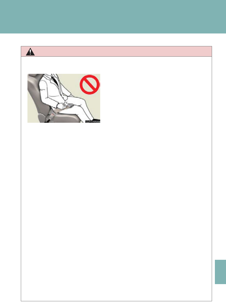
713
7
For owners
ATTENTION
■
Précautions avec les sacs de sécurité gonflables SRS
●
Le sac de sécurité gonflable SRS passager avant se déploie également avec une
violence considérable, qui peut être très dangereuse voire mortelle si le passager
avant se trouve très près du sac de sécurité gonflable. Éloignez le siège passager
avant au maximum du sac de sécurité gonflable, et réglez le dossier de siège de
sorte à être assis bien droit dans le siège.
●
Les nourrissons et les enfants qui ne sont pas correctement assis et/ou protégés
peuvent être grièvement blessés ou tués par le déploiement d'un sac de sécurité
gonflable. Installez dans un siège de sécurité enfant les enfants trop jeunes pour
pouvoir utiliser la ceinture de sécurité. Lexus recommande vivement d'installer
tous les nourrissons et jeunes enfants aux places arrière du véhicule et de prévoir
pour eux des systèmes de retenue adaptés. Les sièges arrière sont plus sûrs pour
les nourrissons et les enfants que le siège passager avant.
●
N'installez jamais un siège de sécurité enfant type dos à la route sur le siège
passager avant, même si le témoin “AIR BAG OFF” est allumé. En cas d'accident,
la force de déploiement rapide du sac de sécurité gonflable passager avant peut
grièvement, voire mortellement blesser l'enfant si le siège de sécurité enfant type
dos à la route est installé sur le siège passager avant.
●
Si vous attachez une rallonge de ceinture
de sécurité à la boucle du siège
conducteur, mais pas à la ceinture de
sécurité proprement dite, le système de
sac de sécurité gonflable SRS conducteur
pense que vous avez attaché votre ceinture
de sécurité, alors qu'en fait c'est faux. Dans
ce cas, il se peut que le sac de sécurité
gonflable conducteur ne se déploie pas
correctement en cas d'accident, et vous
risquez d'être tué ou grièvement blessé.
Veillez donc à porter la ceinture de
sécurité avec la rallonge de ceinture de
sécurité.
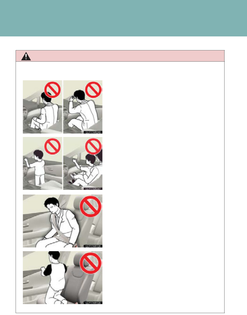
714
ATTENTION
■
Précautions avec les sacs de sécurité gonflables SRS
●Ne pas s'asseoir sur le bord du siège et ne
pas s'appuyer contre la planche de bord.
●Ne laissez pas un enfant rester debout
devant le sac de sécurité gonflable SRS
passager avant ou bien s'asseoir sur les
genoux du passager avant.
●Ne laissez pas les occupants des sièges
avant voyager avec un objet sur les
genoux.
●Ne vous appuyez pas contre la porte,
contre le rail latéral de toit ou contre les
montants avant, latéraux et arrière.
●Interdisez à quiconque de s'agenouiller sur
les sièges passagers en appui contre la
porte ou de sortir la tête ou les mains à
l'extérieur du véhicule.
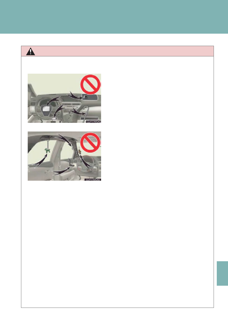
715
7
For owners
ATTENTION
■
Précautions avec les sacs de sécurité gonflables SRS
●
Si un cache en vinyle est mis dans la zone où les sacs de sécurité gonflable SRS
de genoux se déploie, assurez-vous de l'enlever.
●
N'utilisez aucun accessoire de siège venant recouvrir les zones de déploiement
des sacs de sécurité gonflables SRS latéraux, car il risquerait d'en gêner le
déploiement. De tels accessoires peuvent empêcher les sacs de sécurité
gonflables latéraux de fonctionner correctement, désactiver le dispositif ou
entraîner le déploiement accidentel des sacs de sécurité latéraux, entraînant la
mort ou des blessures graves.
●
Évitez de faire subir des chocs ou des pressions excessives aux zones renfermant
les composants des sacs de sécurité gonflables SRS.
En effet, cela pourrait entraîner un fonctionnement anormal des sacs de sécurité
gonflables SRS.
●
Ne rien fixer ou appuyer contre la planche
de bord, la garniture centrale du moyeu de
volant de direction ou la partie inférieure
du tableau de bord.
Au déploiement des sacs de sécurité
gonflables SRS conducteur, passager avant
et genoux, tout objet risque de se
transformer en projectile.
●
Ne rien fixer aux portes, à la vitre de pare-
brise, aux vitres latérales, aux montants
avant et arrière, au rail latéral de toit ou à la
poignée de maintien.
●
Ne suspendez aux crochets à vêtements
aucun cintre nu ni aucun objet dur. En cas
de déploiement des sacs de sécurité
gonflables rideau SRS, tous ces objets
pourraient se transformer en projectiles et
causer des blessures graves, voire
mortelles.

716
ATTENTION
■
Précautions avec les sacs de sécurité gonflables SRS
●
Ne touchez aucun composant du système immédiatement après le
déclenchement (déploiement) des sacs de sécurité gonflables SRS, car ils sont
alors encore très chauds.
●
Si vous avez des difficultés à respirer après le déploiement des sacs de sécurité
gonflables SRS, ouvrez une porte ou une vitre pour faire entrer de l'air frais, ou
bien descendez du véhicule si cela ne présente pas de danger. Essuyez tout
résidu dès que possible afin d'éviter d'éventuelles irritations de la peau.
●
Si les parties renfermant les sacs de sécurité gonflables SRS, telles que la
garniture du moyeu de volant et les garnitures de montants avant et arrière,
apparaissent abîmées ou craquelées, faites-les remplacer par votre
concessionnaire Lexus.
●
Ne rien placer sur le siège du passager avant, comme un coussin par exemple.
Cela a pour conséquence de répartir le poids du passager sur toute la surface du
siège, ce qui empêche le capteur de détecter normalement le poids du passager.
En conséquence, le sac de sécurité gonflable SRS passager avant risque de ne
pas se déployer en cas de choc.

717
7
For owners
ATTENTION
■Modification et mise au rebut des éléments du système de sacs de sécurité
gonflables SRS
Consultez impérativement votre concessionnaire Lexus si vous avez besoin
d'intervenir sur votre véhicule ou de procéder à l'une des modifications suivantes.
Les sacs de sécurité gonflables SRS risquent de ne pas fonctionner correctement
ou de se déployer (gonfler) accidentellement, provoquant ainsi des blessures
graves, voire mortelles.
●Installation, dépose, démontage et réparations des sacs de sécurité gonflables
SRS
●Réparations, modifications, démontage ou remplacement du volant, du tableau
de bord, de la planche de bord, des sièges ou de leur garnissage, des montants
avant, latéraux et arrière ou des rails latéraux de toit
●Réparation ou modification des ailes avant, du bouclier avant, ou des flancs de
l'habitacle
●Installation de chasse-neige, de treuils, etc., sur la calandre (pare-buffle ou pare-
kangourou, etc.)
●Modification des suspensions du véhicule
●Installation d'appareils électroniques tels que radio-émetteurs/récepteurs ou
lecteurs CD
●Aménagements du véhicule visant à permettre sa conduite par une personne
atteinte d'un handicap physique

718

Index
719
Abbreviation list .................... 720
Alphabetical index................. 722
What to do if... ....................... 733
For vehicles with a navigation system, refer to the “Naviga-
tion System Owner's Manual” for information regarding
the equipment listed below.
• Navigation system
• Air conditioning controls
• Windshield wiper de-icer
• Rear view monitor system
• Intuitive parking assist
• Audio/video system
• Rear window and outside rear view mirror defogging

720
Abbreviation list
Abbreviation/Acronym list
ABBREVIATIONS MEANING
2WD 2 Wheel Drive
A/C Air Conditioning
ABS Anti-lock Brake System
AFS Adaptive Front-lighting System
AI-SHIFT Artificial Intelligence Shift control
ALR Automatic Locking Retractor
AWD All Wheel Drive
CAL Calibration
CRS Child Restraint System
ECO Economy/Ecology
ECU Electronic Control Unit
EDR Event Data Recorder
ELR Emergency Locking Retractor
EPS Electric Power Steering
GAWR Gross Axle Weight Ratings
GCWR Gross Combination Weight Rating
GVWR Gross Vehicle Weight Rating
I/M Emission Inspection and Maintenance
LATCH Lower Anchors and Tethers for Children
LED Light Emitting Diode
MMT Methylcyclopentadienyl Manganese Tricarbonyl
M + S Mud and Snow
MTBE Methyl Tertiary Butyl Ether
OBD On Board Diagnostics

721
Abbreviation list
PCS Pre-Collision System
RF Radio Frequency
SRS Supplemental Restraint System
TIN Tire Identification Number
TPMS Tire Pressure Warning System
TRAC Traction Control
TWR Trailer Weight Rating
VDIM Vehicle Dynamics Integrated Management
VIN Vehicle Identification Number
VSC Vehicle Stability Control
ABBREVIATIONS MEANING

722
Alphabetical index
Alphabetical index
A/C*
Air conditioning filter .......................547
Automatic air conditioning
system*................................................ 322
ABS............................................................. 274
ACCESSORY mode ...........................176
Active stabilizer suspension
system..................................................... 274
Adaptive front lighting system ......... 216
AFS.............................................................. 216
Air conditioning system*...................322
Air conditioning filter .......................547
Automatic air conditioning
system*................................................ 322
Airbags
Airbag operating conditions..........135
Airbag precautions for your
child.........................................................139
Airbag warning light ........................599
Curtain shield airbag operating
conditions.............................................136
Curtain shield airbag
precautions .........................................139
Front passenger occupant
classification system........................144
General airbag precautions ..........139
Locations of airbags...........................132
Modification and disposal of
airbags...................................................143
Proper driving posture ..........130, 139
Side airbag operating
conditions.............................................136
Side airbag precautions ...................139
SRS airbags ............................................132
Alarm...........................................................126
Antenna....................................................343
Anti-lock brake system.......................274
Armrest .................................................... 467
Audio input..............................................386
Audio system*
Antenna.................................................. 343
Audio input...........................................386
AUX port..............................................386
CD player/changer......................... 346
iPod.......................................................... 366
MP3/WMA disc...............................356
Optimal use .........................................383
Portable audio device.....................386
Radio ....................................................... 336
Steering wheel audio switch........388
USB memory.......................................379
USB port ................................... 366, 374
Automatic air conditioning system*
Air conditioning filter........................547
Automatic air conditioning
system...................................................322
Automatic headlight leveling
system ..................................................... 218
Automatic high beam system............219
Automatic light control system.........213
AUX port.................................................386
A

723
Alphabetical index
Back door
Back door ................................................ 70
Wireless remote control....................64
Back-up lights
Replacing light bulbs .........................571
Wattage ................................................. 675
Battery
Checking...............................................525
Hybrid battery
(traction battery) ................................34
If the vehicle has a discharged
12-volt battery..................................650
Preparing and checking
before winter.................................... 296
Bluetooth® audio* .............................. 399
Bluetooth® phone*.................................411
Brake
Fluid...........................................................672
Parking brake........................................192
Brake assist..............................................274
Break-in tips ............................................. 167
Card key......................................................47
Care
Exterior................................................... 492
Interior.....................................................495
Seat belts ...............................................496
Cargo capacity ..................................... 295
Cargo hooks...........................................470
CD changer*
CD............................................................ 346
MP3 .........................................................356
WMA disc ............................................356
CD player* ............................................. 346
Chains........................................................296
Child restraint system
Booster seats, definition .................. 149
Booster seats, installation ............... 153
Convertible seats, definition.......... 149
Convertible seats, installation....... 153
Front passenger occupant
classification system........................144
Infant seats, definition........................ 149
Infant seats, installation..................... 153
Installing CRS with LATCH
system ................................................... 154
Installing CRS with seat belts........ 156
Installing CRS with top tether
straps .....................................................160
Child safety
Airbag precautions............................ 139
Back door precautions...................... 76
Child restraint system....................... 149
Child-protectors ...................................68
How your child should wear
the seat belt ..........................................101
Installing child restraints................... 153
Moon roof precautions......................118
Power window lock switch.............. 112
Power window precautions ............114
Removed electronic key battery
precautions.........................................551
Seat belt comfort guide .....................98
Seat belt extender precautions.... 104
Seat belt precautions ........................ 102
Seat heater precautions................. 466
12-volt battery
precautions..........................500, 530
B
C
*: For vehicles with a navigation system, refer to “Navigation System Owner’s Manual”.

724
Alphabetical index
Child-protectors......................................68
Cleaning
Exterior ...................................................492
Interior.....................................................495
Seat belts................................................496
Clock* .......................................................459
Coat hooks..............................................468
Compass ................................................. 480
Condenser ............................................... 521
Console box ...........................................453
Cooling system
Hybrid system overheating..........655
Cornering assist sensors ...................257
Cruise control
Cruise control .....................................238
Dynamic radar cruise control..... 243
Cup holders ............................................. 451
Curtain shield airbags.......................... 132
Customizable features .......................693
Daytime running light system ............217
Defogger*
Rear window........................................330
Side mirrors........................................... 109
Dimensions..............................................664
Dinghy towing......................................... 319
Display
Energy flow..............................................40
Multi-information display...............202
Trip information..................................205
Warning message............................608
Do-it-yourself maintenance ............ 506
Door courtesy lights
Door courtesy lights.........................445
Wattage..................................................675
Door lock
Back door.................................................70
Side door...................................................67
Wireless remote control ...................64
Door pockets .........................................450
Doors
Back door.................................................70
Door lock................................52, 64, 67
Door windows........................................112
Power back door..................................70
Side door...................................................67
Side mirrors............................................109
Driver's seat belt reminder light...... 601
Driving
Break-in tips........................................... 167
Correct posture...................................130
Procedures.............................................166
Utility vehicle precautions............. 286
Winter driving tips............................ 296
Driving position memory......................90
Electric power steering.......................274
Electronic features control...............202
Electronic key
If the electronic key does not
operate properly.............................647
Electronically modulated air
suspension............................................ 264
Emergency flashers
Switch......................................................590
D
E

725
Alphabetical index
Emergency, in case of
If a warning buzzer sounds..........598
If a warning light turns on..............598
If a warning message is
displayed........................................... 608
If the back door opener is
inoperative.............................................75
If the electronic key does not
operate properly............................ 647
If the hybrid system will
not start ............................................... 643
If the shift lever cannot be
shifted from P...................................645
If the vehicle has a discharged
12-volt battery..................................650
If you have a flat tire ........................629
If you lose your keys ........................646
If you think something is
wrong................................................... 597
If your vehicle becomes stuck ....660
If your vehicle has to be
stopped in an emergency ...........661
If your vehicle needs to be
towed.....................................................591
If your vehicle overheats................655
Engine
Accessory mode.................................176
Compartment.......................................512
Hood .......................................................509
How to start the hybrid system....176
Identification number.......................665
If the hybrid system will
not start ............................................... 643
Ignition switch........................................ 176
Overheating.........................................655
“POWER” switch.................................176
Engine compartment cover ..............513
Engine/power control unit coolant
Capacity ................................................ 670
Checking ................................................519
Preparing and checking
before winter ....................................296
Engine oil
Capacity ................................................ 668
Checking ................................................515
Preparing and checking
before winter ....................................296
EPS ............................................................. 274
EV drive mode........................................185
Event data recorder ............................... 24
Floor mat ..................................................469
Fluid
Brake........................................................672
Washer ...................................................523
Fog lights
Replacing light bulbs..........................571
Switch.......................................................226
Wattage..................................................675
Footwell light ..........................................445
Front fog lights
Replacing light bulbs..........................571
Switch.......................................................226
Wattage..................................................675
Front passenger occupant
classification system.......................... 144
Front passenger's seat belt
reminder light....................................... 601
*: For vehicles with a navigation system, refer to “Navigation System Owner’s Manual”.
F

726
Alphabetical index
Front seats
Adjustment............................................... 82
Driving position memory..................90
Flattening seatbacks............................83
Front side marker light
Replacing light bulbs..........................571
Wattage..................................................675
Front turn signal lights
Replacing light bulbs..........................571
Wattage..................................................675
Fuel
Capacity.................................................666
Fuel gauge ..............................................194
Information............................................676
Refueling ................................................... 119
Type..........................................................676
Fuel door .....................................................119
Fuel filler door ...........................................119
Fuses ..........................................................552
Garage door opener ..........................474
Gauges ...................................................... 194
Glove box ................................................449
Hands-free system for
mobile phone* .......................................411
Hazard lights
Switch .................................................... 590
Head restraints
Adjustment .............................................95
Head-up display................................... 208
Headlight aim.........................................569
Headlight cleaner.................................237
Headlights
Discharge headlight
precautions.......................................588
Replacing light bulbs......................... 571
Switch........................................................ 213
Wattage................................................. 675
Heaters
Seat heaters .........................................465
Side mirrors*.......................................330
Height control
Electronically modulated air
suspension .........................................264
Hill-start assist control.........................274
Hood..........................................................509
Hooks
Cargo...................................................... 470
Coat.........................................................468
Horn.............................................................193
HUD ..........................................................208
Hybrid system
Emergency shut off system..............35
Energy monitor/consumption
screen..................................................... 40
High voltage components................34
Hybrid system indicator ..................198
“POWER” switch................................ 176
I/M test .....................................................505
Identification
Electric motor .....................................665
Engine.....................................................665
Vehicle....................................................665
Ignition switch ..........................................176
Illuminated entry system....................445
Immobilizer system................................124
Indicator lights ........................................ 198
G
H
I

727
Alphabetical index
Initialization
Items to initialize................................. 702
Inside rear view mirror.........................107
Interior lights
Interior lights ........................................ 445
Switch...................................................... 446
Wattage ................................................. 675
Jack
Positioning a floor jack .................... 510
Vehicle-equipped jack................... 629
Jack handle..............................................629
Keyless entry..............................................64
Keys
Electronic key..........................................47
If the electronic key does not
operate properly............................ 647
If you lose your keys ........................646
Key number..............................................47
Keyless entry............................................64
Keys..............................................................47
Mechanical key ..................................... 48
“POWER” switch................................176
Wireless remote control key...........64
Light bulbs
Replacing.................................................571
Wattage ................................................. 675
Lights
Door courtesy lights.........................445
Emergency flasher switch ............590
Fog light switch...................................226
Hazard light switch ..........................590
Headlight switch...................................213
Interior light switch............................446
Luggage compartment light ........... 73
Outer foot lights .................................445
Overhead courtesy light................445
Personal light switch.........................446
Replacing light bulbs..........................571
Scuff lights..............................................445
Shift lever light......................................445
Turn signal lever ..................................190
Vanity lights .........................................458
Wattage..................................................675
Load capacity.........................................295
Lock steering column ...........................179
Luggage compartment lights
Switch..........................................................73
Wattage..................................................675
Luggage cover.........................................471
Maintenance
Do-it-yourself maintenance.........506
General maintenance ......................501
Maintenance data............................. 664
Maintenance requirements .........498
Maintenance data.................................499
Meter
Instrument panel light control.......195
Meters....................................................... 194
Mirrors
Inside rear view mirror..................... 107
J
K
L
M
*: For vehicles with a navigation system, refer to “Navigation System Owner’s Manual”.

728
Alphabetical index
Side mirror heaters...........................330
Side mirrors*......................................... 109
Vanity mirrors......................................458
Moon roof...................................................115
MP3 disc ..................................................356
Multi-information display
Electronic features control............202
Trip information..................................205
Noise from under vehicle..................... 22
Odometer.................................................195
Oil
Engine oil................................................ 515
Opener
Back door................................................. 70
Fuel filler door......................................... 119
Hood....................................................... 509
Outer foot lights
Outer foot lights.................................445
Wattage..................................................675
Outside rear view mirrors
Adjusting and folding ....................... 109
Mirror position memory ...................90
Outside temperature display* ........460
Overhead console ...............................455
Overhead courtesy lights
Overhead courtesy lights .............445
Wattage..................................................675
Overheating, Hybrid system ...........655
Parking assist sensors .........................257
Parking brake.......................................... 192
Parking lights
Replacing light bulbs..........................571
Switch ........................................................213
Wattage................................................. 675
PCS............................................................282
Personal lights
Switch...................................................... 446
Power back door..................................... 70
Power easy access system .................. 92
Power outlet ........................................... 462
“POWER” switch ...................................176
Power windows........................................ 112
Pre-collision system ............................282
Radar cruise control............................ 243
Radiator......................................................521
Radio......................................................... 336
Rear seat
Folding down ......................................... 86
Seat adjustment..................................... 86
Rear seat entertainment system*
Rear turn signal lights
Replacing light bulbs........................573
Wattage................................................. 675
Rear view mirror
Compass...............................................480
Rear view monitor system ................ 270
Rear window defogger ......................330
Rear window wiper..............................235
Remote Touch*
Replacing
Electronic key battery.....................550
Fuses........................................................ 552
Light bulbs.............................................. 571
Tires.......................................................... 629
Wireless remote control
battery .................................................550
Reporting safety defects for
U.S. owners.......................................... 704
N
O
P
R

729
Alphabetical index
Roof luggage carrier .......................... 290
Safety Connect..................................... 484
Scuff lights ............................................... 445
Seat belts
Adjusting the seat belt .......................98
Automatic locking retractor.......... 100
Child restraint system
installation............................................153
Cleaning and maintaining
the seat belts.....................................496
Emergency locking retractor ...... 100
How to wear your seat belt..............97
How your child should wear
the seat belt.......................................... 101
Pregnant women,
proper seat belt use....................... 100
Reminder light.......................................601
Seat belt extender................................ 101
Seat belt pretensioners...................... 99
Seat heaters............................................ 465
Seat position memory ........................... 90
Seat ventilators...................................... 465
Seating capacity ................................... 295
Seats
Adjustment .................................... 82, 86
Adjustment
precautions.................................85, 88
Child seats/child restraint
system installation............................153
Cleaning ................................................495
Flatting seat backs................................ 83
Head restraint ........................................ 95
Power easy access system...............92
Properly sitting in the seat...............130
Seat heaters ......................................... 465
Seat position memory ........................90
Seat ventilators................................... 465
Service reminder indicators .............198
Shift lever
If the shift lever cannot be
shifted from P .................................. 645
Transmission.......................................... 182
Shift lever light........................................445
Shift lock system....................................645
Side airbags.............................................. 132
Side marker lights
Switch.........................................................213
Side mirror
Adjusting and folding........................109
Mirror position memory....................90
Smart access system with
push-button start
Entry function..........................................52
Starting the hybrid system...............176
“SOS” button..........................................484
Spare tire
Inflation pressure................................673
Storage location .................................629
Spark plug................................................670
Specifications .........................................664
Speedometer .......................................... 194
Steering
Column lock release..........................179
Steering wheel
Adjustment.............................................105
Audio switches* ................................388
Power easy access system ..............92
Steering wheel position
memory..................................................90
S
*: For vehicles with a navigation system, refer to “Navigation System Owner’s Manual”.

730
Alphabetical index
Storage feature......................................448
Stuck vehicle
If your vehicle becomes stuck.... 660
Sun visors .................................................457
Sunshades...................................................116
Switch
Display contrast adjustment
switch ...................................................208
Display position adjustment
switch ...................................................208
Driving mode selector switch ...... 184
Emergency flasher switch............ 590
ENTER switch.....................................202
Fog light switch................................... 226
Hazard light switch.......................... 590
Head-up display main switch......208
Ignition switch........................................176
Light switches........................................213
Menu switch.........................................202
Power back door switch................... 70
Power door lock switch.................... 67
“POWER” switch ................................176
Power window switch.....................235
Rear window wiper and
washer switch ..................................235
Window lock switch ............................112
Wiper and washer switch ............. 229
Tail lights
Replacing light bulbs......................... 571
Switch........................................................ 213
Wattage................................................. 675
Talk switch.................................................416
Telephone switch....................................416
Theft deterrent system
Alarm......................................................... 126
Immobilizer system ............................ 124
Theft prevention labels.........................129
Tire inflation pressure ...........................541
Tire information
Glossary ................................................ 687
Size...........................................................683
Tire identification number.............682
Uniform tire quality grading.........684
Tires
Chains..................................................... 296
Checking............................................... 532
If you have a flat tire ......................... 629
Inflation pressure.................................541
Inflation pressure sensor ...............533
Information ...........................................680
Replacing .............................................. 629
Rotating tires........................................ 532
Size............................................................673
Snow tires.............................................. 296
Spare tire...............................................630
Tire pressure warning
system........................................532, 601
Tools........................................................... 629
Total load capacity............................... 295
T

731
Alphabetical index
Towing
Dinghy towing.......................................319
Emergency towing.............................591
Trailer towing.......................................300
TRAC.........................................................274
Traction control .....................................274
Trailer towing...............................300, 318
Transmission
Hybrid transmission...........................182
If the shift lever cannot be
shifted from P...................................645
S mode .....................................................186
Trip information display..................... 202
Trip meter..................................................194
Turn signal lights
Replacing light bulbs .........................571
Switch........................................................190
Wattage ................................................. 675
Vanity lights
Vanity lights..........................................458
Wattage ................................................. 675
Vanity mirrors........................................458
VDIM .........................................................274
Vehicle dynamics integrated
management........................................274
Vehicle identification number ........ 665
Vehicle stability control......................274
Voice command switch.......................416
VSC............................................................274
USB port*..................................... 366, 374
Warning buzzers
Brake system.......................................598
Open door ............................................601
Seat belt reminder..............................601
Warning lights
Anti-lock brake system..................599
Brake assist system.......................... 599
Brake system.......................................598
Charging system...............................598
Electric power steering.................. 599
Electronic engine control
system ................................................. 599
Low fuel level ........................................601
Low tire pressure................................601
Malfunction indicator lamp.......... 599
Master warning light..........................601
Open door.............................................601
Pre-collision system......................... 599
Pretensioners...................................... 599
Seat belt reminder light....................601
SRS airbags.......................................... 599
Tire pressure .........................................601
Warning messages ............................. 608
Washer
Checking ...............................................523
Preparing and checking
before winter ....................................296
Switch.......................................................229
Washing and waxing...........................492
V
U
W
*: For vehicles with a navigation system, refer to “Navigation System Owner’s Manual”.

732
Alphabetical index
Weight
Cargo capacity...................................295
Load limits.............................................295
Weight ....................................................664
Wheels ......................................................545
Window glasses ......................................112
Window lock switch ...............................112
Windows
Power windows......................................112
Rear window defogger*................330
Washer................................................... 229
Windshield wiper de-icer................... 331
Windshield wipers................................229
Wireless remote control.......................64
Wireless remote control key
Replacing the battery ..................... 550
WMA disc ...............................................356
*: For vehicles with a navigation system, refer to “Navigation System Owner’s Manual”.
733
What to do if...
What to do if...
A tire punctures
P. 629 If you have a flat tire
The hybrid system does not start
P. 6 4 3 If the hybrid system will not start
P. 124 Immobilizer system
P. 65 0
If the vehicle 12-volt battery is discharged
The shift lever cannot be
moved out
P. 645
If the shift lever cannot be shifted
from P
The engine coolant temperature
gauge enters the red zone
Steam can be seen coming
from under the hood
P. 655 If your vehicle overheats
The key is lost
P. 646 If you lose your keys
The 12-volt battery runs out
P. 65 0 If the vehicle 12-volt battery is dis-
charged
The doors cannot be locked
P. 67 Side doors
P. 70 Back door
The horn begins to sound
P. 1 26 Alarm
The vehicle is stuck in mud or
sand
P. 66 0 If the vehicle becomes stuck
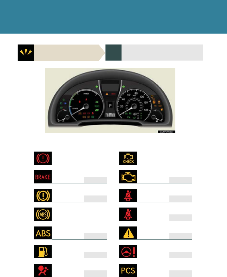
734
What to do if...
A warning light or indicator
light comes on
P. 59 8 If a warning light turns on or a warning
buzzer sounds...
■Warning lights
or or
P. 59 8 P. 599
P. 59 9 P. 601
P. 601
or
P. 59 9 P. 601
P. 60 1 P. 599
P. 59 9 P. 59 9
Brake system warning light
Malfunction indicator lamp
Brake system warning light
Driver’s seat belt
reminder light
“ABS” warning light
Front passenger’s seat belt
reminder light
Master warning light
Low fuel level warning light
Electric power steering system
warning light
SRS warning light
Pre-collision system
warning light*

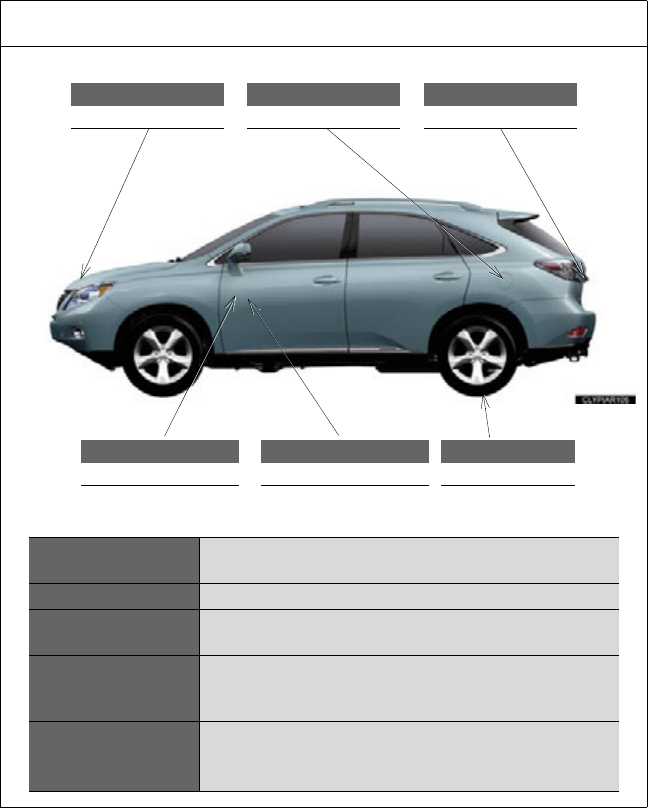
736
GAS STATION INFORMATION
Auxiliary catch lever
P. 5 09
Back door opener
P. 70
Fuel filler door
P. 119
Hood lock release lever
P. 5 09
Fuel filler door opener
P. 11 9
Tire inflation pressure
P. 673
Fuel tank capacity
(Reference) 17.1 gal. (65 L, 14.2 Imp. gal.)
Fuel type Unleaded gasoline only P. 666
Cold tire inflation
pressure P. 673
Engine oil capacity
(Drain and refill
reference)
qt. (L, Imp. qt.)
With filter 6.4 (6,1, 5,3)
Without filter 6.0 (5,7, 5.0)
Engine oil type
Toyota Genuine Motor Oil or equivalent
Oil grade: ILSAC multigrade engine oil P. 668
Recommended oil viscosity: SAE 0W-20
