Li Seng Technology SH-GWAYL10A IOT Gateway User Manual Microsoft PowerPoint Ppt0000012
Li Seng Technology Limited IOT Gateway Microsoft PowerPoint Ppt0000012
user manual

LightPRO System Setup Procedure
Greater China Regional Marketing
NXP Semiconductors
Feb 18, 2014

July 25, 2014
2
Contents
Setting up the Network
1. LightPRO dev kit overview
2. Setting up the LightPRO Network
- IP network side setup
- Jennet-IP network formation
- Group configuration
- Scene configuration
3. How to use the remote (to do On/OFF, Grouping, Dimming)
Hardware – how to make a LightPRO SSL Driver
4. How to connect a LightPRO module
LightPRO – hardware reference design
How to connect LightPRO (PWM 3.3V, 12V, and Analog 0-10V)
LightPRO module pinouts
General guidelines for connecting LightPRO
Testing your SSL Driver with LightPRO module
5. Where to buy LightPRO module and the other parts

Setting up the LightPRO Network
July 25, 2014Subject / Department / Author -
3
July 25, 2014
4
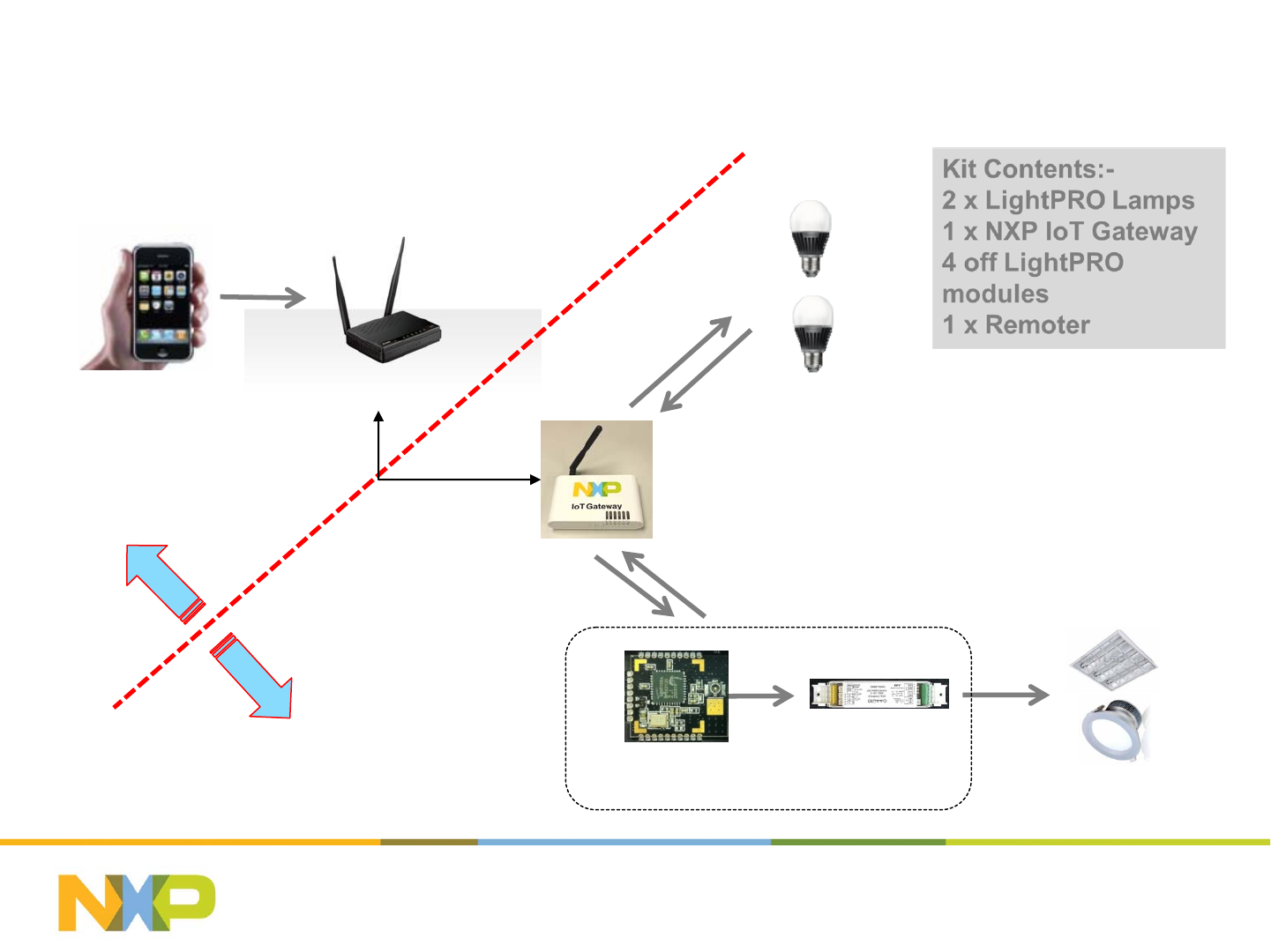
LightPRO dev kit Overview
Wifi Router
IoT Gateway
Smart Bulbs
LightPRO Module SSL Driver
WiFi
Network
Side
Jennet-IP
Network Side
Lan Cable
Setting up the LightPRO network (1)
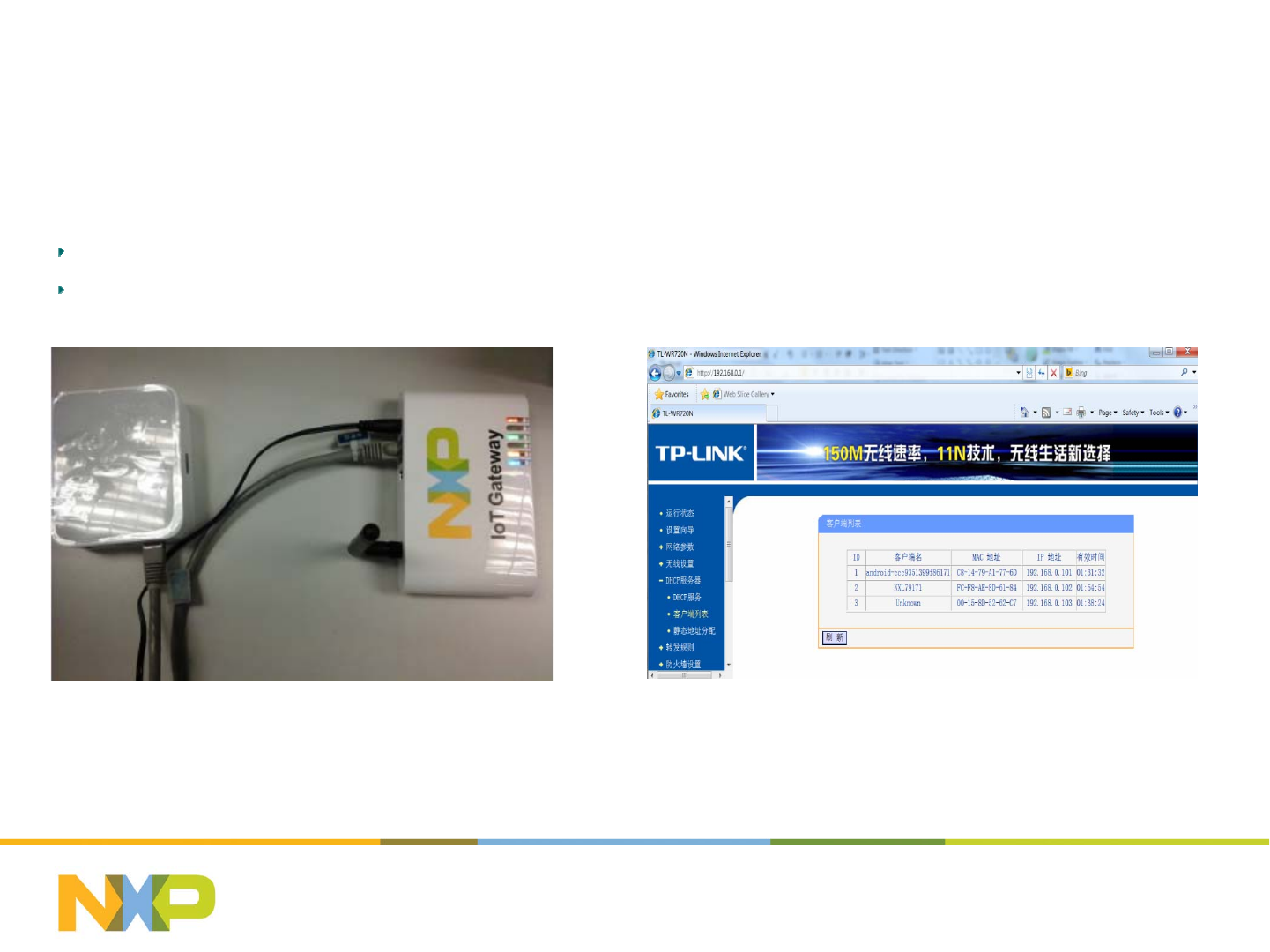
-IP network side setup
Step 1 Connect IoT Gateway to IPv4 network
ConnecttheIoTgatewaywithaLANRouter.ThenfindtheIPaddressofIoTgatewayintheclientlistofDHCPServer.
ThiswillallowPCwebtoaccesstotheIoTGatewayandJennet‐IPnetworkusingtheIPaddress.
July 25, 2014Subject / Department / Author -
5
Setting up the LightPRO network (2)
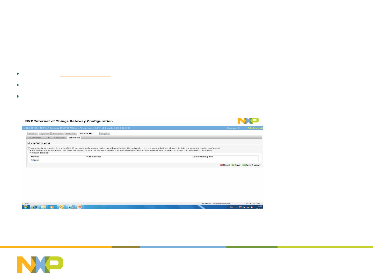
-Jennet-IP network formation
Step 2 Enter Jennet-IP Network formation
OpenBrowser:http://192.168.0.xx.(IPaddressisdynamicallyassignedbytheDHCPserver)
Goto“GatewayConfigurationInterface”,typethepassword“snap”
Goto“Jennet‐IP”‐>“Whitelist” tab,waitforthelamps/remotetojointheJennet‐IPnetwork
July 25, 2014Subject / Department / Author -
6
Setting up the LightPRO network (2)
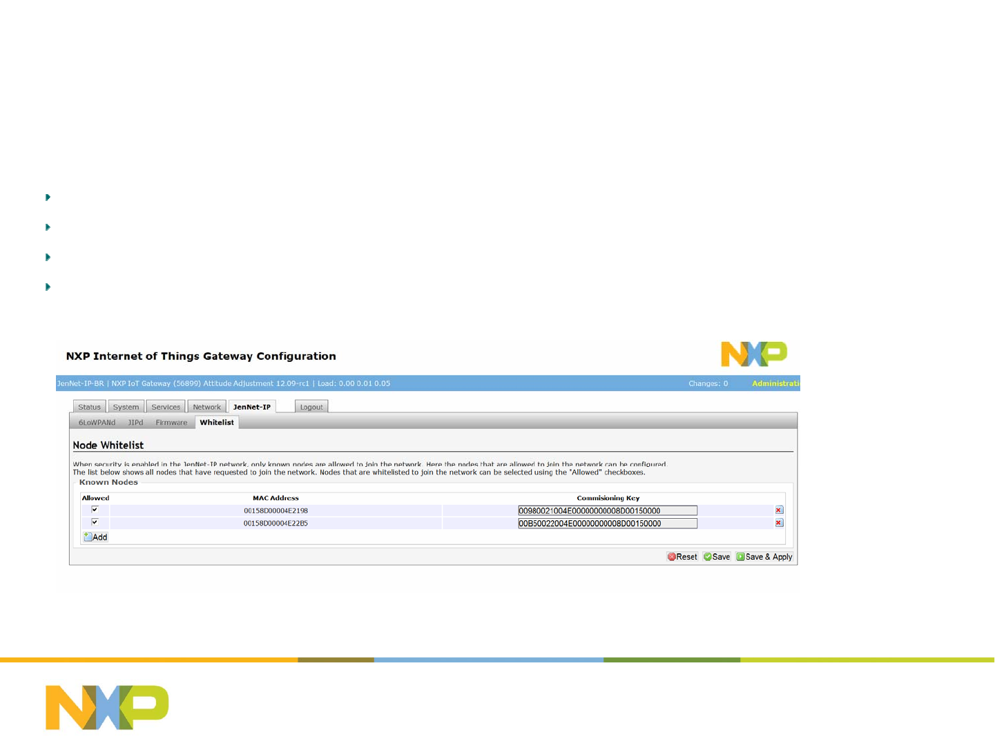
-Jennet-IP network formation
Step 3 Add lamp to Jennet-IP network
Powerupthelamp,whichentersabreathmodetoindicateajoiningstate.
Refreshthepageof“Jennet‐IP”‐>“Whitelist” tabuntilthelampshowsup
Ticktocheckboxofthelampandclick“Save&Apply”
RepeatStep3toaddmorelamps
July 25, 2014Subject / Department / Author -
7
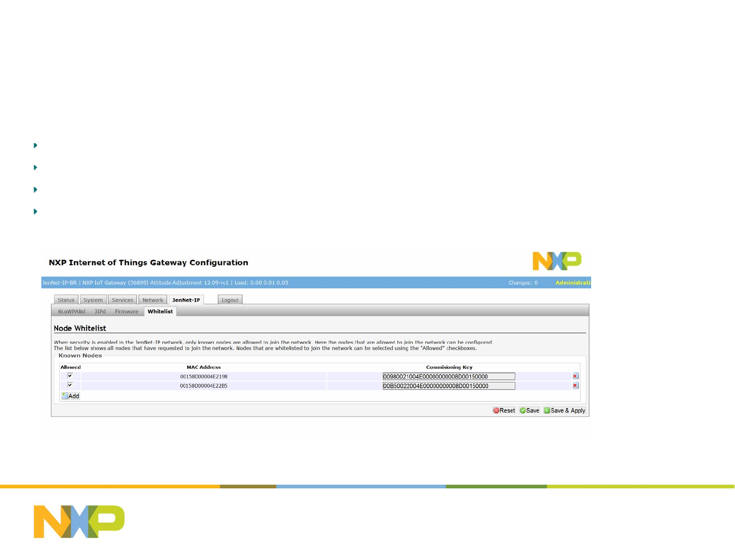
Setting up the LightPRO network (2)
-Jennet-IP network formation
Step 4 Add Remote to Jennet-IP network
Initiatetheactivemodeoftheremotebypressing“PRGbutton‐>Upbutton‐>Downbutton‐>Upbutton”.
Refreshthepageof“Jennet‐IP”‐>“Whitelist” tabuntiltheremoteshowsup
Ticktocheckboxoftheremoteandclick“Save&Apply”
RepeatStep4toaddmoreremotes
July 25, 2014Subject / Department / Author -
8
Setting up the LightPRO network (3)
-Group Configuration
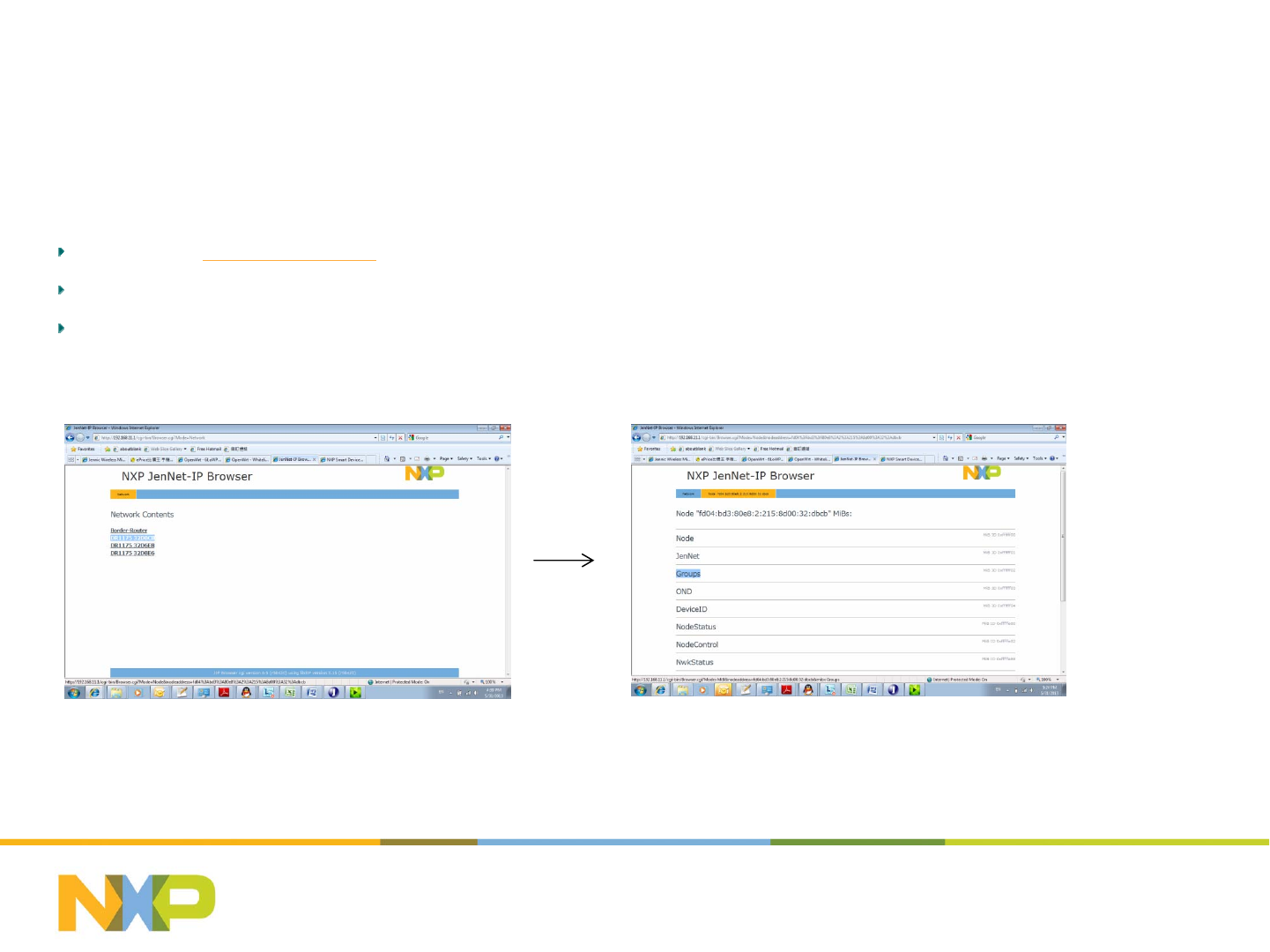
Step 5 Enter Group Configuration
OpenBrowser:http://192.168.0.xx.(IPaddressisdynamicallyassignedbytheDHCPserver)
Goto“JIPBrowser‐>..‐>NetworkContents”,alljoinedlampswillshowout;
SelecttargetlampandthenChoose“Groups” MIBforgroupconfiguration
July 25, 2014Subject / Department / Author -
9
Setting up the LightPRO network (3)
-Group Configuration
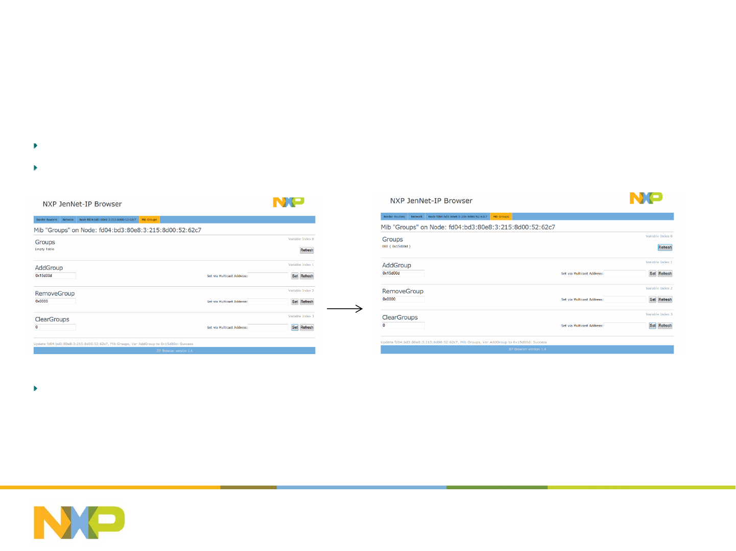
Step 6 Create a Group Entry to a lamp
Fillin“AddGroup” boxwithsupportedGroupIDandthen“Set”;
Whenthebottomlineshows“Success”,Refreshthe“Groups” table.
Notes1:TheGroupIDssupportedbytheAndroidSmartLightingAppare“0x15a00a”,“0x15b00b”,“0x15c00c”,“0x15d00d” and
“0x15f00f”.TheGroupIDssupportedbythePCwebare“0x15c00c”,“0x15d00d” and“0x15f00f”.
July 25, 2014Subject / Department / Author -
10
Setting up the LightPRO network (3)
-Group Configuration
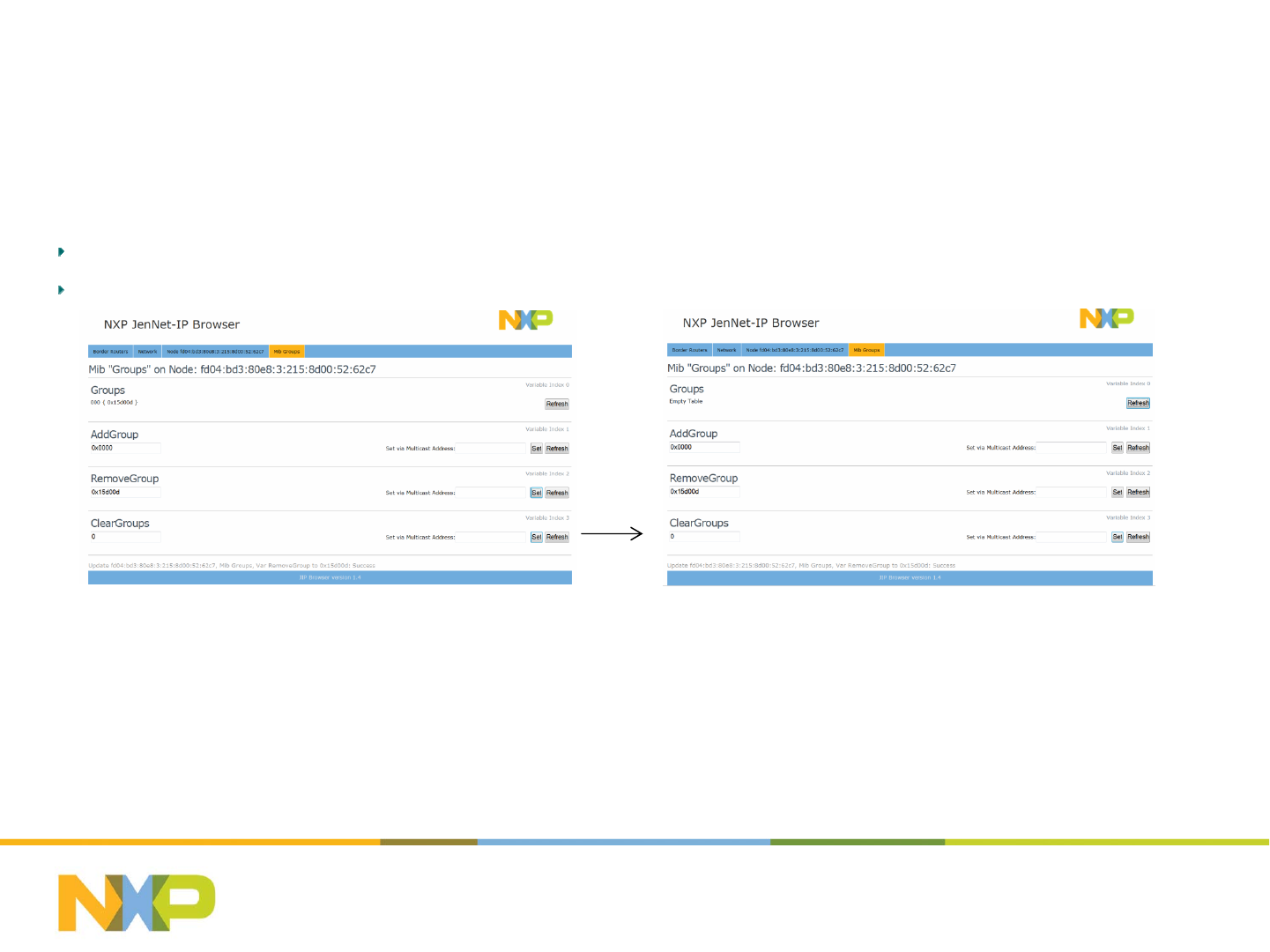
Step 7 Delete a Group Entry from a lamp
Fillin“RemoveGroup” boxwithaGroupIDthatisalreadyintheGrouptable,andthen“Set”;
Whenthebottomlineshows“Success”,Refreshthe“Groups” table.
July 25, 2014Subject / Department / Author -
11

Setting up the LightPRO network (4)
-Scene Configuration
Step 8 Adjust Group Status for Scenes
Basedongroupcontrol,adjustthestatusoflampstotheexpectedscenevalue.
July 25, 2014Subject / Department / Author -
12
Setting up the LightPRO network (4)
-Scene Configuration
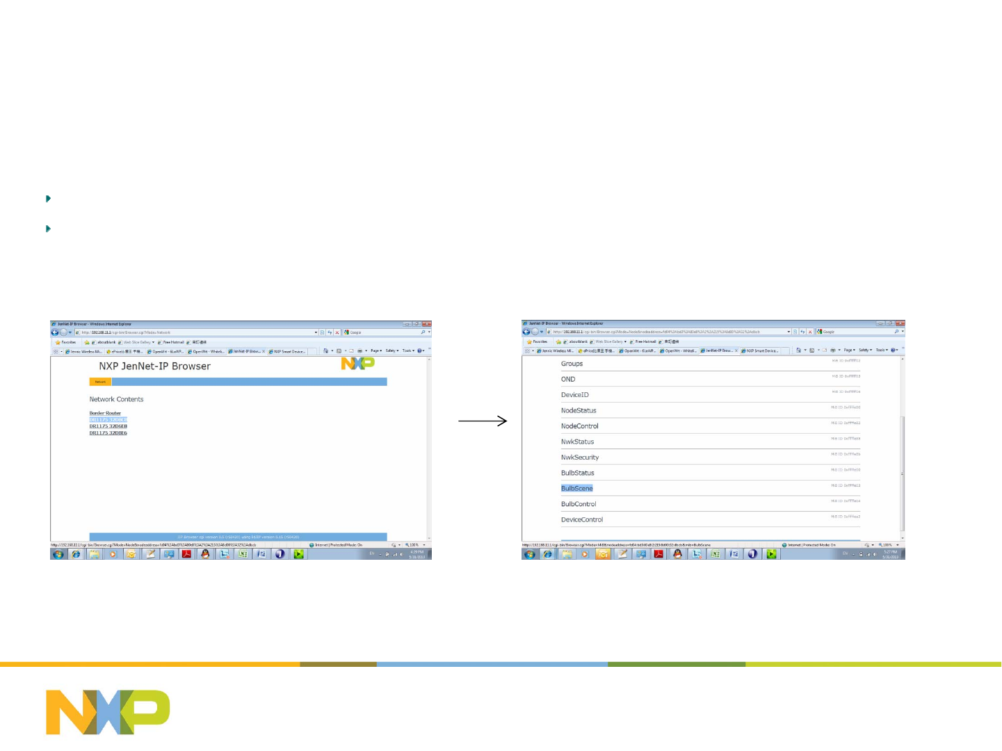
Step 9 Enter Scene Configuration
Goto“JIPBrowser‐>..‐>NetworkContents”,alljoinedlampswillshowout;
Selecttargetlampthenchoose“BulbScene” MIBforsceneconfiguration.
July 25, 2014Subject / Department / Author -
13
Setting up the LightPRO network (4)
-Scene Configuration
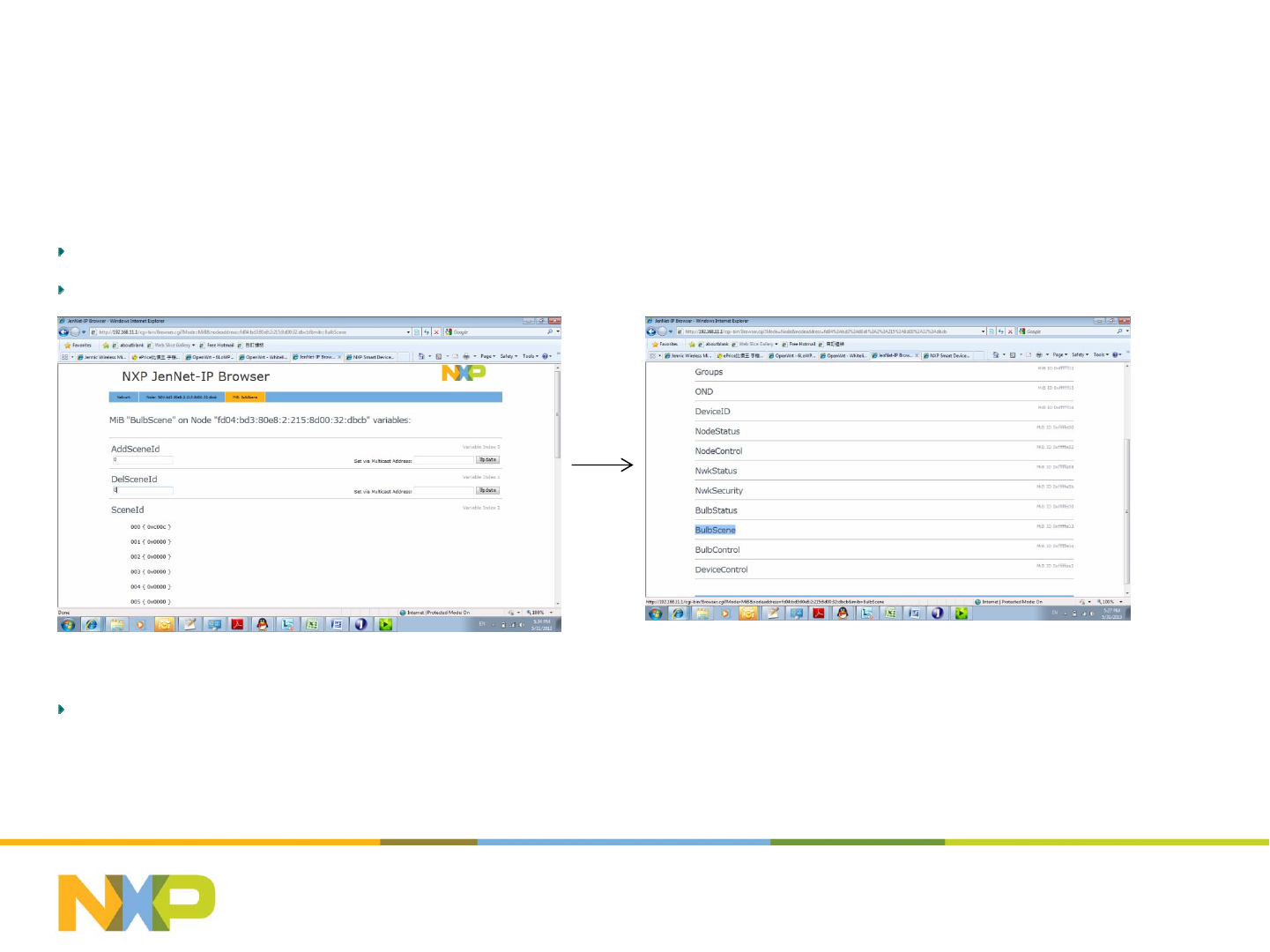
Step 10 Save Scene Configuration
SavethestatusofthebulbintoascenebyeditingoneofsupportedsceneIDinto“AddSceneID” andthen“Set”;
Gobacktothestep9,savethestatusforthesceneonebyoneuntilallbulbinthescenehasbeenaddressed.
Notes:ThevalidsceneIDsare0xA00A(Home),0xB00B(Away),0xC00C(Movie),0xD00D(Reading).
July 25, 2014Subject / Department / Author -
14

Hardware – how to make a
LightPRO SSL Driver
July 25, 2014Subject / Department / Author -
15
IoT Box Reference Design
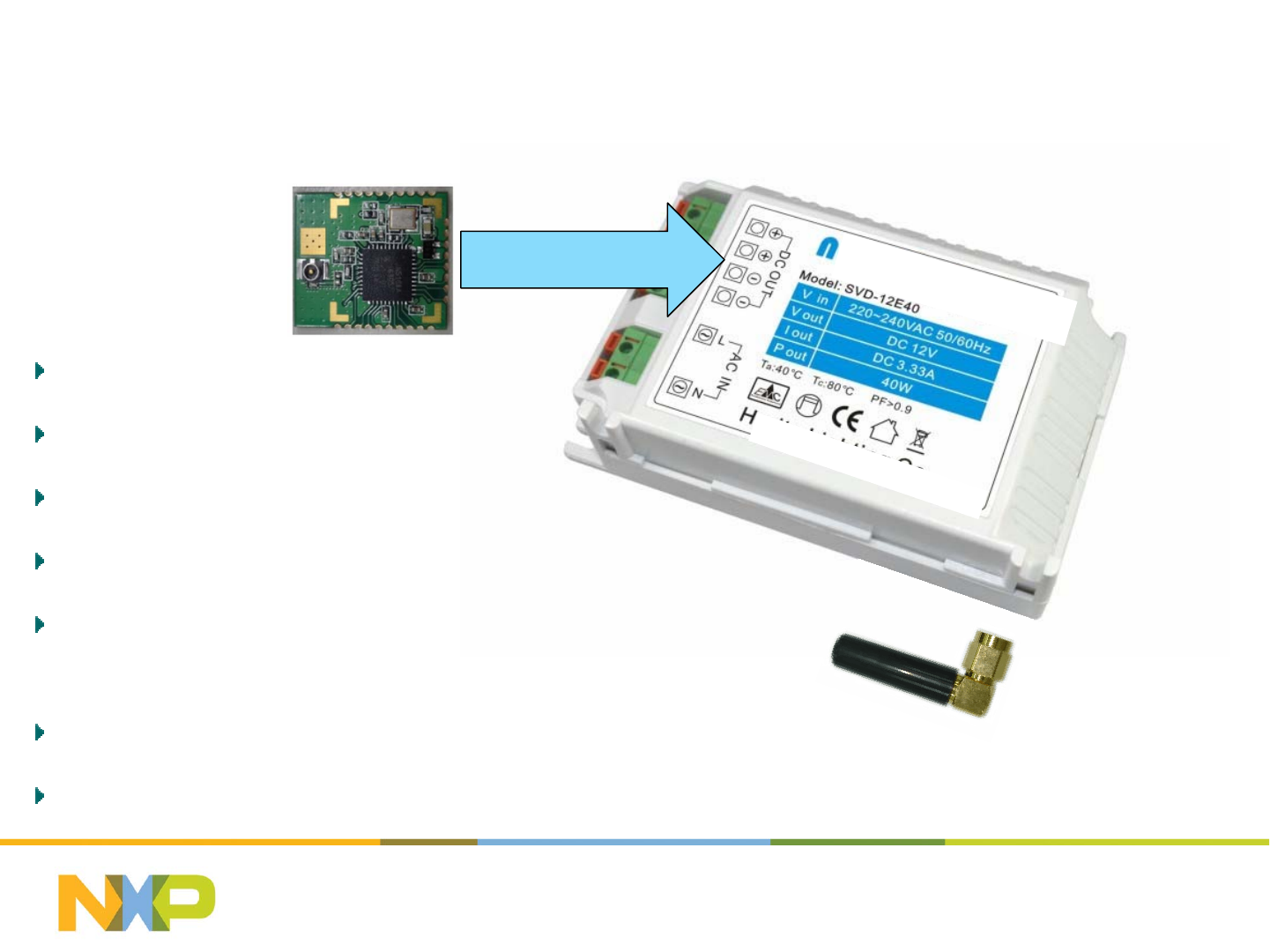
Power Supply
PWM or 0-10V analog
Antenna mounting
LightPRO Module Pin
Connections
Testing
Q&A
July 25, 2014Subject / Department / Author -
16
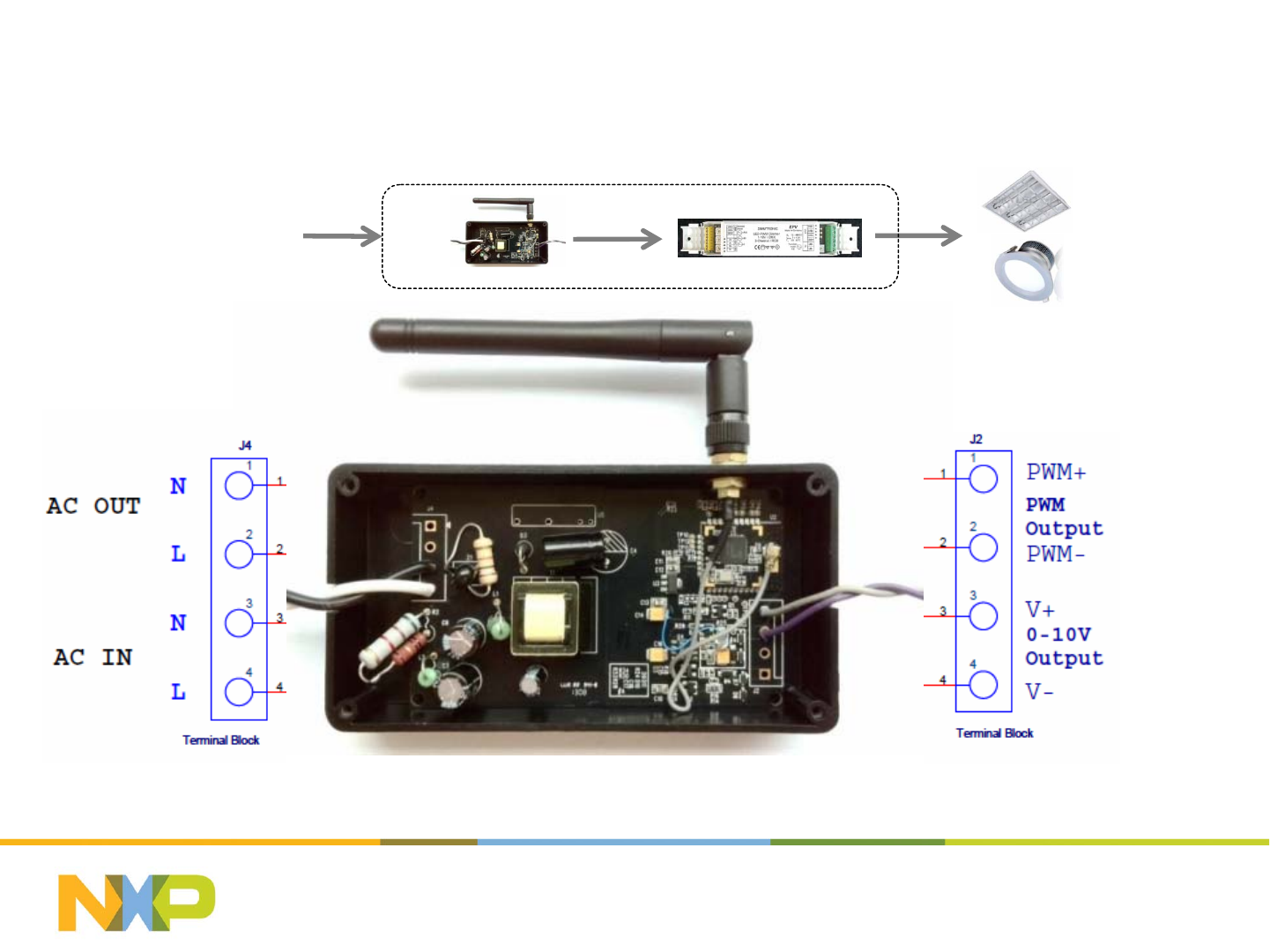
HowtoconnectaLightPROmodule(toan
SSL driver box)
July 25, 2014
17
LightPRO - reference design
AC Power Input Outputs 0~10V or
PWM (500Hz)
90-275VAC
Universal AC
July 25, 2014
18
How to connect LightPRO (1)
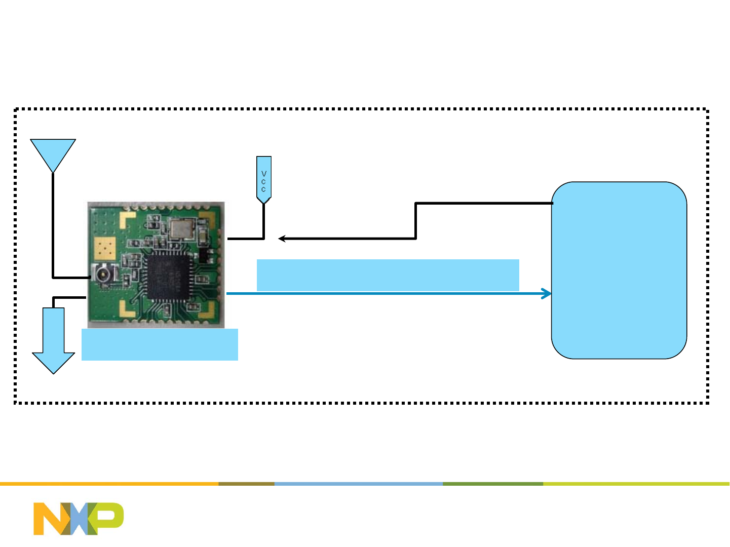
- Inside your IOT SSL Driver – simple 3.3V PWM case
In this example, we show how to interface to a SSL
Driver that accepts 0 to 3.3V PWM signal
NXP LightPRO
G
N
D
(2~3.6v)
3.3V PWM (Pin 14, 500Hz)
SSL DRIVER
3.3V DC output
PWM
dimming
control
input
ANT
+3.3V +-10%
July 25, 2014Subject / Department / Author -
19
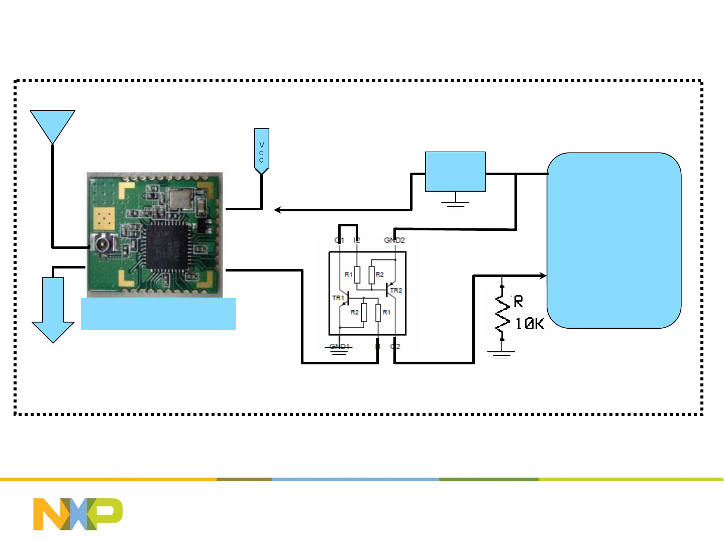
NXP PIMD3 or Equivalent (all R’s are 10k)
NXP LightPRO
G
N
D
(2~3.6v)
SSL DRIVER
12V DC output
PWM
dimming
control
input
LDO
~12V
PWM 500Hz
ANT
Pin 14 3.3V
PWM 500Hz
In this example, we show how to interface to a SSL
Driver that accepts 0 to ~12V PWM signal
How to connect LightPRO (2)
- Inside your IOT SSL Driver – simple 12V PWM case
~12-15V
+3.3V +-10%
July 25, 2014Subject / Department / Author -
20
NXP Light Pro
G
N
D
(2~3.6v)
SSL DRIVER
15V DC output
0~10V
Analog
Control
Signal
LDO
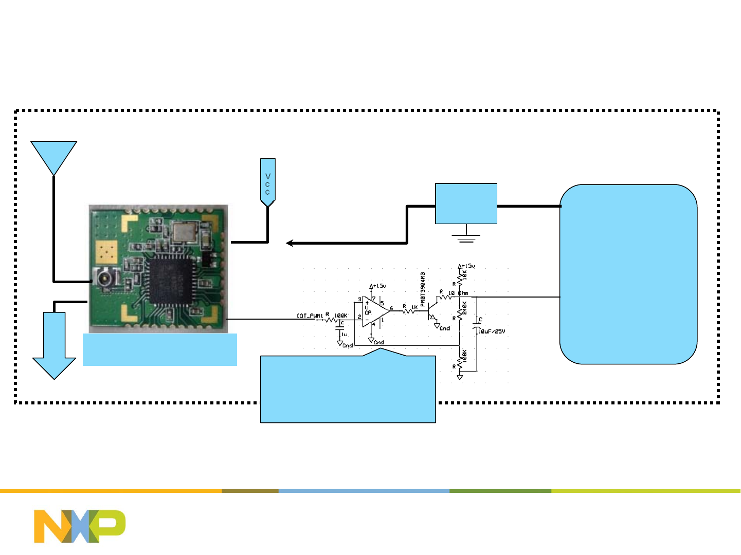
How to connect LightPRO (3)
- Inside your IOT SSL Driver: 0-10V analog control case
ANT
Pin 15 3.3V
PWM 100kHz
+3.3V +-10%
~12-15V
In this example, we show how to interface to a SSL
Driver that accepts 0 to 10V analog control signal
0-10V Analog
Control
Use low power rail to rail input
and output opamp e.g. LT1006
or similar. Ensure opamp supply
is decoupled with 1uF cap close
to supply pins
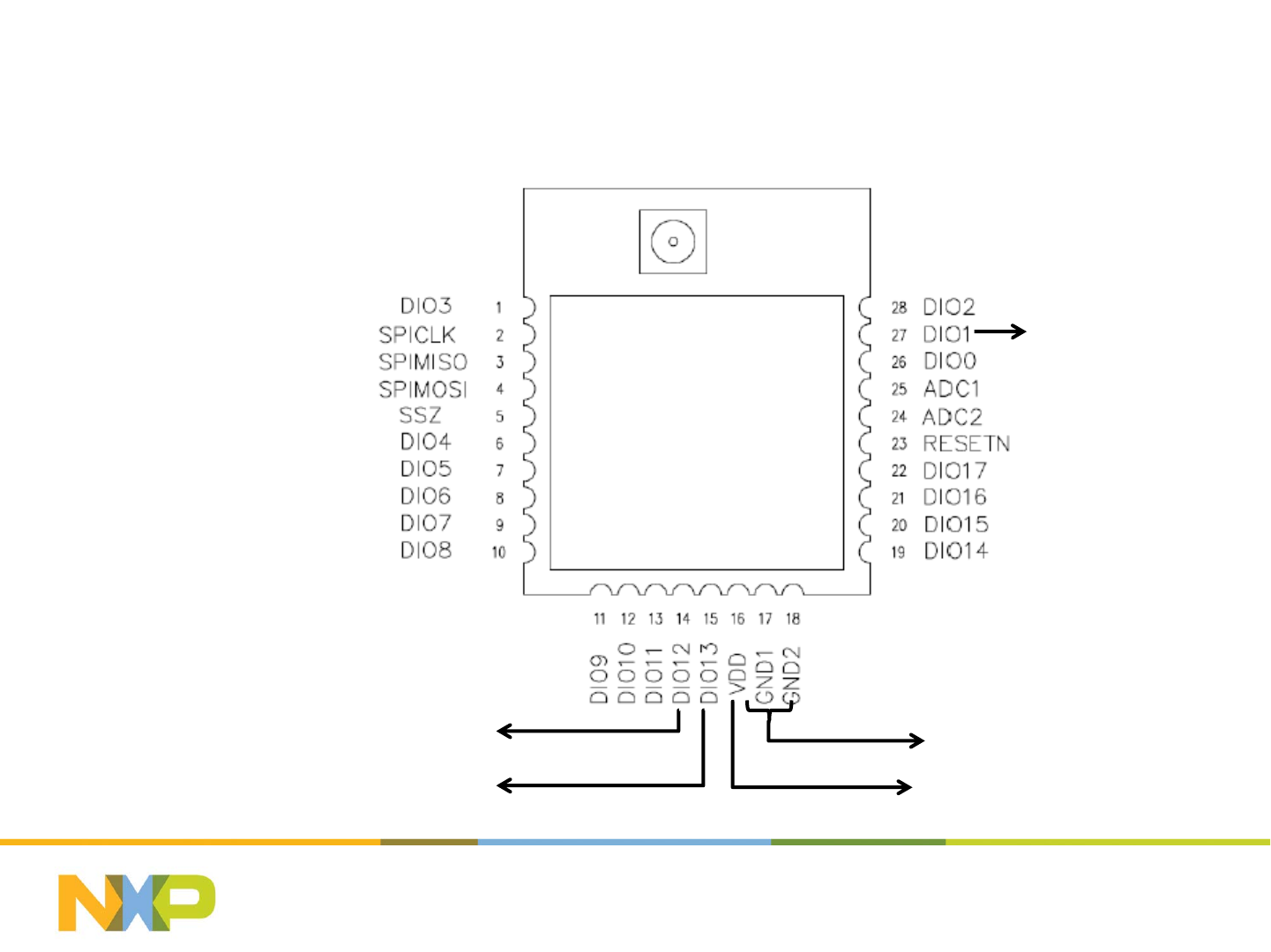
LightPRO module Pins – Top View
July 25, 2014Subject / Department / Author -
21
16 = +3.3V
Monitor
100kHz PWM
500Hz PWM 0V
LightPRO
module is FCC
Approved
Note that the PWM output signals are 0 to +3.3V. If your SSL driver requires
higher PWM voltages, you will need to buffer and amplify these signals
The ‘monitor’ output provides a separate indication of the LED output status
(ON/OFF and dim level) and can be used to drive an external monitor LED
through a transistor buffer. This is useful for testing SSL drivers on the ground
before installation. You do not have to use this feature for correct operation.
Typical current consumption: Rx = 17.5mA Tx = 15mA and operating
temperature range is -40 dec C to +85 deg C
See the link to the reference circuits for circuit details and ideas to interface the
module to your SSL Driver
July 25, 2014Subject / Department / Author -
22
Function PinNumber Comments
0V 17
0V 18
+3.3V 16 +‐10%at25mA
100kHzPWM 15 0to+3.3VPWMusedtodevelop0‐10Vanalogdimingsignal
500HzPWM 14 0to+3.3VlowfrequencyPWMsignal
Monitor 27 Monitorsignal‐interfacetoLEDviatransistorbuffer
Bothpins17and18mustbeconnectedto0V
LightPROModuleElectricalConnections

LightPRO module – General Guidelines
Ensure the power supply entering the module is clean and stable. If
there are long traces between the +3.3V supply and the module,
decouple the power supply close to the LightPRO Module
Ensure there is no physical contact between the module and any other
components in your SSL Driver
Do not attempt to operate the module without an antenna, or with just a
piece of wire – the module performance and network performance will
be severely degraded
Do not pour potting compound over the LightPRO module – this may
affect the RF performance adversely
Ensure that the antenna socket mounted externally on your SSL driver
module is secure and does not rotate – if it does, this can result in a
broken connection inside your SSL driver module during installation
July 25, 2014Subject / Department / Author -
23

Testing your SSL driver with LightPRO
module
Use the small reference network provided in the LightPRO Developers
Kit (2 lamps, 1 x gateway and 1 x remoter) plus an Android Smart
Phone or an Android Tablet
Get your module to join the network – this verifies that the RF section of
the system is operational
Check that the module functions all operate – this verifies that
hardware interface and application software layer is operating correctly
July 25, 2014Subject / Department / Author -
24

Where to buy LightPRO module and the
other parts?
LightPRO Module: From distributors SAC, Zenitron, EDOM, Future,
Arrow, WPI, ZLG
Gateway: Liseng
Remote Control: NXP (more suppliers in Q2)
Sensors: Coming in Q2 (light and occupancy)
July 25, 2014Subject / Department / Author -
25
FCC Statement:
This device complies with part 15 of the FCC Rules. Operation is subject to the following
two conditions: (1) This device may not cause harmful interference, and (2) this device
must accept any interference received, including interference that may cause undesired
operation.
This equipment has been tested and found to comply with the limits for a Class B digital
device, pursuant to part 15 of the FCC Rules. These limits are designed to provide
reasonable protection against harmful interference in a residential installation. This
equipment generates, uses and can radiate radio frequency energy and, if not installed
and used in accordance with the instructions, may cause harmful interference to radio
communications. However, there is no guarantee that interference will not occur in a
particular installation. If this equipment does cause harmful interference to radio or
television reception, which can be determined by turning the equipment off and on, the
user is encouraged to try to correct the interference by one or more of the following
measures:
—Reorient or relocate the receiving antenna.
—Increase the separation between the equipment and receiver.
—Connect the equipment into an outlet on a circuit different from that to which the
receiver is connected.
—Consult the dealer or an experienced radio/TV technician for help.
Caution: Any changes or modifications not expressly approved by the party responsible
for compliance could void the user's authority to operate the equipment.
