Liebert Emerson Nx Ups System Users Manual
NX UPS System to the manual 8fd40408-e337-466a-ad67-390c4cd64ffc
2015-02-09
: Liebert Liebert-Emerson-Nx-Ups-System-Users-Manual-571371 liebert-emerson-nx-ups-system-users-manual-571371 liebert pdf
Open the PDF directly: View PDF ![]() .
.
Page Count: 88
- Safety Precautions
- 1.0 Single Module UPS Installation
- 1.1 Introduction
- 1.2 Preliminary Checks
- 1.3 Location
- 1.4 Positioning
- 1.5 External Protective Devices
- 1.6 Power Cables
- 1.7 Control Cables and Communication
- 1.8 Dry Contacts
- 2.0 Battery Installation
- 2.1 Introduction
- 2.2 Safety
- 2.3 Battery Cabinet
- 2.4 Battery Power Cables
- 2.5 Battery Control
- 3.0 UPS Multi-Module Installation
- 3.1 General
- 3.2 Paralleled UPS Modules
- 3.3 Hot-Standby UPS Modules
- 3.4 Dual Bus System
- 4.0 Installation Drawings
- Figure 20 Electrical connections
- Figure 21 General arrangement-10-30kVA UPS module
- Figure 22 10-30kVA NX front view with doors open
- Figure 23 Location of parallel logic board M3
- Figure 24 Internal battery layout and connecting-GP12120 F2 (12AH/12V)
- Figure 25 Internal battery layout and connecting-LC-R127R2PG1 (7.2AH/12V)
- Figure 26 Internal battery layout
- 5.0 Operation
- 6.0 Operating Procedures
- 6.1 Introduction
- 6.2 UPS Startup
- 6.3 Switching the UPS from Normal to Maintenance Bypass
- 6.4 Powering Down the UPS
- 6.5 Powering Down the UPS and Maintaining Power to Load
- 6.6 Emergency Shutdown With EPO
- 6.7 Auto Restart
- 6.8 Reset After Shutdown for Emergency Stop (EPO Action) or Other Conditions
- 6.9 Language Selection
- 6.10 Changing the Current Date and Time
- 6.11 Command Password
- 6.12 Isolating One Module in a Multi-Module System
- 6.13 Inserting One Module into a Multi-Module System
- 7.0 Operator Control Panel and Display
- 7.1 Introduction
- 7.2 All Status and Event Messages Displayed on the UPS Front Panel
- 7.3 Prompt (Pop-Up) Windows
- 7.4 Dynamic Energy Flow Chart and UPS Help Screen
- 7.5 Default Screen Saver
- 8.0 Options-For Assembly Inside the UPS Cabinet
- 9.0 Technical Specifications
- 9.1 Conformity and Standards
- Table 29 Compliance with European, international standards
- Table 30 Environmental characteristics
- Table 31 Overall efficiency, heat losses and air exchange
- Table 32 Mechanical characteristics
- Table 33 Rectifier AC input (mains)
- Table 34 Battery
- Table 35 Inverter output to critical load
- Table 36 Bypass mains input
- 9.1 Conformity and Standards
AC Power
For Business-Critical Continuity
Liebert NX UPS
User Manual–10-30kVA, 400V, 50/60Hz

i
TABLE OF CONTENTS
1.0 SINGLE MODULE UPS INSTALLATION . . . . . . . . . . . . . . . . . . . . . . . . . . . . . . . . . . . . . . . . .3
1.1 Introduction . . . . . . . . . . . . . . . . . . . . . . . . . . . . . . . . . . . . . . . . . . . . . . . . . . . . . . . . . . . . . . . . 3
1.2 Preliminary Checks . . . . . . . . . . . . . . . . . . . . . . . . . . . . . . . . . . . . . . . . . . . . . . . . . . . . . . . . . . 3
1.3 Location. . . . . . . . . . . . . . . . . . . . . . . . . . . . . . . . . . . . . . . . . . . . . . . . . . . . . . . . . . . . . . . . . . . . 4
1.3.1 UPS Room . . . . . . . . . . . . . . . . . . . . . . . . . . . . . . . . . . . . . . . . . . . . . . . . . . . . . . . . . . . . . . . . . . . 4
1.3.2 External Battery Room . . . . . . . . . . . . . . . . . . . . . . . . . . . . . . . . . . . . . . . . . . . . . . . . . . . . . . . . 4
1.3.3 Storage . . . . . . . . . . . . . . . . . . . . . . . . . . . . . . . . . . . . . . . . . . . . . . . . . . . . . . . . . . . . . . . . . . . . . 4
1.4 Positioning . . . . . . . . . . . . . . . . . . . . . . . . . . . . . . . . . . . . . . . . . . . . . . . . . . . . . . . . . . . . . . . . . 5
1.4.1 System Cabinets . . . . . . . . . . . . . . . . . . . . . . . . . . . . . . . . . . . . . . . . . . . . . . . . . . . . . . . . . . . . . . 5
1.4.2 10 to 30kVA UPS . . . . . . . . . . . . . . . . . . . . . . . . . . . . . . . . . . . . . . . . . . . . . . . . . . . . . . . . . . . . . 5
1.4.3 Moving the Cabinets. . . . . . . . . . . . . . . . . . . . . . . . . . . . . . . . . . . . . . . . . . . . . . . . . . . . . . . . . . . 5
1.4.4 Clearances. . . . . . . . . . . . . . . . . . . . . . . . . . . . . . . . . . . . . . . . . . . . . . . . . . . . . . . . . . . . . . . . . . . 6
1.4.5 Access . . . . . . . . . . . . . . . . . . . . . . . . . . . . . . . . . . . . . . . . . . . . . . . . . . . . . . . . . . . . . . . . . . . . . . 6
1.4.6 Final Positioning. . . . . . . . . . . . . . . . . . . . . . . . . . . . . . . . . . . . . . . . . . . . . . . . . . . . . . . . . . . . . . 6
1.4.7 Floor Anchoring . . . . . . . . . . . . . . . . . . . . . . . . . . . . . . . . . . . . . . . . . . . . . . . . . . . . . . . . . . . . . . 6
1.4.8 Cable Entry . . . . . . . . . . . . . . . . . . . . . . . . . . . . . . . . . . . . . . . . . . . . . . . . . . . . . . . . . . . . . . . . . . 6
1.5 External Protective Devices. . . . . . . . . . . . . . . . . . . . . . . . . . . . . . . . . . . . . . . . . . . . . . . . . . . . 6
1.5.1 Rectifier and Bypass Input . . . . . . . . . . . . . . . . . . . . . . . . . . . . . . . . . . . . . . . . . . . . . . . . . . . . . 6
1.5.2 External Battery. . . . . . . . . . . . . . . . . . . . . . . . . . . . . . . . . . . . . . . . . . . . . . . . . . . . . . . . . . . . . . 7
1.5.3 UPS Output . . . . . . . . . . . . . . . . . . . . . . . . . . . . . . . . . . . . . . . . . . . . . . . . . . . . . . . . . . . . . . . . . 7
1.6 Power Cables . . . . . . . . . . . . . . . . . . . . . . . . . . . . . . . . . . . . . . . . . . . . . . . . . . . . . . . . . . . . . . . 8
1.6.1 Cable Termination . . . . . . . . . . . . . . . . . . . . . . . . . . . . . . . . . . . . . . . . . . . . . . . . . . . . . . . . . . . . 9
1.7 Control Cables and Communication . . . . . . . . . . . . . . . . . . . . . . . . . . . . . . . . . . . . . . . . . . . . 11
1.7.1 Monitor Board Features . . . . . . . . . . . . . . . . . . . . . . . . . . . . . . . . . . . . . . . . . . . . . . . . . . . . . . . 11
1.8 Dry Contacts . . . . . . . . . . . . . . . . . . . . . . . . . . . . . . . . . . . . . . . . . . . . . . . . . . . . . . . . . . . . . . . 12
1.8.1 Input Dry Contacts. . . . . . . . . . . . . . . . . . . . . . . . . . . . . . . . . . . . . . . . . . . . . . . . . . . . . . . . . . . 12
1.8.2 Maintenance Bypass Cabinet Interface . . . . . . . . . . . . . . . . . . . . . . . . . . . . . . . . . . . . . . . . . . 12
1.8.3 External Circuit-Breaker Interface . . . . . . . . . . . . . . . . . . . . . . . . . . . . . . . . . . . . . . . . . . . . . . 13
1.8.4 Output Dry Contacts . . . . . . . . . . . . . . . . . . . . . . . . . . . . . . . . . . . . . . . . . . . . . . . . . . . . . . . . . 14
1.8.5 Emergency Power Off Input. . . . . . . . . . . . . . . . . . . . . . . . . . . . . . . . . . . . . . . . . . . . . . . . . . . . 15
1.8.6 External Bypass Switch Interlock . . . . . . . . . . . . . . . . . . . . . . . . . . . . . . . . . . . . . . . . . . . . . . . 16
1.8.7 Battery Start Facility . . . . . . . . . . . . . . . . . . . . . . . . . . . . . . . . . . . . . . . . . . . . . . . . . . . . . . . . . 16
2.0 BATTERY INSTALLATION . . . . . . . . . . . . . . . . . . . . . . . . . . . . . . . . . . . . . . . . . . . . . . . . . .17
2.1 Introduction . . . . . . . . . . . . . . . . . . . . . . . . . . . . . . . . . . . . . . . . . . . . . . . . . . . . . . . . . . . . . . . 17
2.2 Safety . . . . . . . . . . . . . . . . . . . . . . . . . . . . . . . . . . . . . . . . . . . . . . . . . . . . . . . . . . . . . . . . . . . . 18
2.3 Battery Cabinet . . . . . . . . . . . . . . . . . . . . . . . . . . . . . . . . . . . . . . . . . . . . . . . . . . . . . . . . . . . . 19
2.3.1 Introduction . . . . . . . . . . . . . . . . . . . . . . . . . . . . . . . . . . . . . . . . . . . . . . . . . . . . . . . . . . . . . . . . 19
2.3.2 Temperature Considerations . . . . . . . . . . . . . . . . . . . . . . . . . . . . . . . . . . . . . . . . . . . . . . . . . . . 19
2.3.3 Dimensions . . . . . . . . . . . . . . . . . . . . . . . . . . . . . . . . . . . . . . . . . . . . . . . . . . . . . . . . . . . . . . . . . 19
2.3.4 Weight . . . . . . . . . . . . . . . . . . . . . . . . . . . . . . . . . . . . . . . . . . . . . . . . . . . . . . . . . . . . . . . . . . . . 19
2.3.5 Circuit Isolator Features . . . . . . . . . . . . . . . . . . . . . . . . . . . . . . . . . . . . . . . . . . . . . . . . . . . . . . 19
2.3.6 Battery Temperature Sensor (Optional) . . . . . . . . . . . . . . . . . . . . . . . . . . . . . . . . . . . . . . . . . . 20
2.3.7 Moving the Battery Cabinets. . . . . . . . . . . . . . . . . . . . . . . . . . . . . . . . . . . . . . . . . . . . . . . . . . . 20
2.3.8 Cable Entry . . . . . . . . . . . . . . . . . . . . . . . . . . . . . . . . . . . . . . . . . . . . . . . . . . . . . . . . . . . . . . . . . 20
2.3.9 General Arrangement Drawings . . . . . . . . . . . . . . . . . . . . . . . . . . . . . . . . . . . . . . . . . . . . . . . . 21

ii
2.4 Battery Power Cables. . . . . . . . . . . . . . . . . . . . . . . . . . . . . . . . . . . . . . . . . . . . . . . . . . . . . . . . 24
2.4.1 Connection Principles. . . . . . . . . . . . . . . . . . . . . . . . . . . . . . . . . . . . . . . . . . . . . . . . . . . . . . . . . 24
2.4.2 Fitting the Batteries. . . . . . . . . . . . . . . . . . . . . . . . . . . . . . . . . . . . . . . . . . . . . . . . . . . . . . . . . . 25
2.4.3 Connecting the Battery . . . . . . . . . . . . . . . . . . . . . . . . . . . . . . . . . . . . . . . . . . . . . . . . . . . . . . . 25
2.4.4 Battery Room Design . . . . . . . . . . . . . . . . . . . . . . . . . . . . . . . . . . . . . . . . . . . . . . . . . . . . . . . . . 25
2.5 Battery Control. . . . . . . . . . . . . . . . . . . . . . . . . . . . . . . . . . . . . . . . . . . . . . . . . . . . . . . . . . . . . 25
3.0 UPS MULTI-MODULE INSTALLATION . . . . . . . . . . . . . . . . . . . . . . . . . . . . . . . . . . . . . . . . .26
3.1 General . . . . . . . . . . . . . . . . . . . . . . . . . . . . . . . . . . . . . . . . . . . . . . . . . . . . . . . . . . . . . . . . . . . 26
3.2 Paralleled UPS Modules . . . . . . . . . . . . . . . . . . . . . . . . . . . . . . . . . . . . . . . . . . . . . . . . . . . . . 27
3.2.1 Cabinet Installation . . . . . . . . . . . . . . . . . . . . . . . . . . . . . . . . . . . . . . . . . . . . . . . . . . . . . . . . . . 27
3.2.2 External Protective Devices . . . . . . . . . . . . . . . . . . . . . . . . . . . . . . . . . . . . . . . . . . . . . . . . . . . . 28
3.2.3 Power Cables. . . . . . . . . . . . . . . . . . . . . . . . . . . . . . . . . . . . . . . . . . . . . . . . . . . . . . . . . . . . . . . . 28
3.2.4 Control Cables . . . . . . . . . . . . . . . . . . . . . . . . . . . . . . . . . . . . . . . . . . . . . . . . . . . . . . . . . . . . . . 29
3.3 Hot-Standby UPS Modules . . . . . . . . . . . . . . . . . . . . . . . . . . . . . . . . . . . . . . . . . . . . . . . . . . . 29
3.3.1 Cabinet Installation . . . . . . . . . . . . . . . . . . . . . . . . . . . . . . . . . . . . . . . . . . . . . . . . . . . . . . . . . . 29
3.3.2 External Protective Devices . . . . . . . . . . . . . . . . . . . . . . . . . . . . . . . . . . . . . . . . . . . . . . . . . . . . 29
3.3.3 Power Cables. . . . . . . . . . . . . . . . . . . . . . . . . . . . . . . . . . . . . . . . . . . . . . . . . . . . . . . . . . . . . . . . 30
3.4 Dual Bus System . . . . . . . . . . . . . . . . . . . . . . . . . . . . . . . . . . . . . . . . . . . . . . . . . . . . . . . . . . . 31
3.4.1 Cabinet Installation . . . . . . . . . . . . . . . . . . . . . . . . . . . . . . . . . . . . . . . . . . . . . . . . . . . . . . . . . . 31
3.4.2 External Protective Devices . . . . . . . . . . . . . . . . . . . . . . . . . . . . . . . . . . . . . . . . . . . . . . . . . . . . 31
3.4.3 Power Cables. . . . . . . . . . . . . . . . . . . . . . . . . . . . . . . . . . . . . . . . . . . . . . . . . . . . . . . . . . . . . . . . 31
3.4.4 Control Wires . . . . . . . . . . . . . . . . . . . . . . . . . . . . . . . . . . . . . . . . . . . . . . . . . . . . . . . . . . . . . . . 32
3.4.5 Extended Dual Bus Synchronization Option (DBS Interface Box) . . . . . . . . . . . . . . . . . . . . . 32
4.0 INSTALLATION DRAWINGS . . . . . . . . . . . . . . . . . . . . . . . . . . . . . . . . . . . . . . . . . . . . . . . . .33
5.0 OPERATION . . . . . . . . . . . . . . . . . . . . . . . . . . . . . . . . . . . . . . . . . . . . . . . . . . . . . . . . . . .39
5.1 Introduction . . . . . . . . . . . . . . . . . . . . . . . . . . . . . . . . . . . . . . . . . . . . . . . . . . . . . . . . . . . . . . . 39
5.1.1 Split-Bypass Input . . . . . . . . . . . . . . . . . . . . . . . . . . . . . . . . . . . . . . . . . . . . . . . . . . . . . . . . . . . 39
5.1.2 Static Transfer Switch . . . . . . . . . . . . . . . . . . . . . . . . . . . . . . . . . . . . . . . . . . . . . . . . . . . . . . . . 40
5.1.3 Battery Temperature Compensation. . . . . . . . . . . . . . . . . . . . . . . . . . . . . . . . . . . . . . . . . . . . . 40
5.1.4 Redundant Control Power Supply Board . . . . . . . . . . . . . . . . . . . . . . . . . . . . . . . . . . . . . . . . . 41
5.1.5 Socket Outlet . . . . . . . . . . . . . . . . . . . . . . . . . . . . . . . . . . . . . . . . . . . . . . . . . . . . . . . . . . . . . . . 41
5.2 Multi Module UPS—1+N . . . . . . . . . . . . . . . . . . . . . . . . . . . . . . . . . . . . . . . . . . . . . . . . . . . . . 41
5.2.1 Features of NX Multi-Module UPS Configurations . . . . . . . . . . . . . . . . . . . . . . . . . . . . . . . . . 42
5.2.2 Requirements for Paralleling of UPS Modules . . . . . . . . . . . . . . . . . . . . . . . . . . . . . . . . . . . . . 42
5.3 Modes of Operation. . . . . . . . . . . . . . . . . . . . . . . . . . . . . . . . . . . . . . . . . . . . . . . . . . . . . . . . . . 42
5.3.1 Normal Mode . . . . . . . . . . . . . . . . . . . . . . . . . . . . . . . . . . . . . . . . . . . . . . . . . . . . . . . . . . . . . . . 42
5.3.2 Battery Mode (Stored Energy Mode) . . . . . . . . . . . . . . . . . . . . . . . . . . . . . . . . . . . . . . . . . . . . . 42
5.3.3 Auto-Restart Mode . . . . . . . . . . . . . . . . . . . . . . . . . . . . . . . . . . . . . . . . . . . . . . . . . . . . . . . . . . . 42
5.3.4 Bypass Mode . . . . . . . . . . . . . . . . . . . . . . . . . . . . . . . . . . . . . . . . . . . . . . . . . . . . . . . . . . . . . . . . 43
5.3.5 Maintenance Mode (Manual Bypass) . . . . . . . . . . . . . . . . . . . . . . . . . . . . . . . . . . . . . . . . . . . . 43
5.3.6 ECO Mode (Single UPS Only) . . . . . . . . . . . . . . . . . . . . . . . . . . . . . . . . . . . . . . . . . . . . . . . . . . 43
5.3.7 Parallel Redundancy Mode (System Expansion) . . . . . . . . . . . . . . . . . . . . . . . . . . . . . . . . . . . 43
5.3.8 Hot-Standby Mode . . . . . . . . . . . . . . . . . . . . . . . . . . . . . . . . . . . . . . . . . . . . . . . . . . . . . . . . . . . 43
5.3.9 Frequency Converter Mode . . . . . . . . . . . . . . . . . . . . . . . . . . . . . . . . . . . . . . . . . . . . . . . . . . . . 43
5.4 Battery Management—Set During Commissioning. . . . . . . . . . . . . . . . . . . . . . . . . . . . . . . . 44
5.4.1 Normal Function. . . . . . . . . . . . . . . . . . . . . . . . . . . . . . . . . . . . . . . . . . . . . . . . . . . . . . . . . . . . . 44
5.4.2 Advanced Functions (Software Settings Performed by the Commissioning Engineer) . . . . . 44

iii
5.5 Battery Protection (settings by commissioning engineer) . . . . . . . . . . . . . . . . . . . . . . . . . . . 44
6.0 OPERATING PROCEDURES . . . . . . . . . . . . . . . . . . . . . . . . . . . . . . . . . . . . . . . . . . . . . . . .45
6.1 Introduction . . . . . . . . . . . . . . . . . . . . . . . . . . . . . . . . . . . . . . . . . . . . . . . . . . . . . . . . . . . . . . . 45
6.1.1 Power Switches . . . . . . . . . . . . . . . . . . . . . . . . . . . . . . . . . . . . . . . . . . . . . . . . . . . . . . . . . . . . . . 45
6.2 UPS Startup . . . . . . . . . . . . . . . . . . . . . . . . . . . . . . . . . . . . . . . . . . . . . . . . . . . . . . . . . . . . . . . 46
6.2.1 Start-Up Procedure . . . . . . . . . . . . . . . . . . . . . . . . . . . . . . . . . . . . . . . . . . . . . . . . . . . . . . . . . . 46
6.2.2 Verify Switching Between Operation Modes . . . . . . . . . . . . . . . . . . . . . . . . . . . . . . . . . . . . . . 47
6.3 Switching the UPS from Normal to Maintenance Bypass . . . . . . . . . . . . . . . . . . . . . . . . . . . 48
6.4 Powering Down the UPS . . . . . . . . . . . . . . . . . . . . . . . . . . . . . . . . . . . . . . . . . . . . . . . . . . . . . 48
6.5 Powering Down the UPS and Maintaining Power to Load . . . . . . . . . . . . . . . . . . . . . . . . . . 49
6.6 Emergency Shutdown With EPO . . . . . . . . . . . . . . . . . . . . . . . . . . . . . . . . . . . . . . . . . . . . . . 50
6.7 Auto Restart . . . . . . . . . . . . . . . . . . . . . . . . . . . . . . . . . . . . . . . . . . . . . . . . . . . . . . . . . . . . . . . 50
6.8 Reset After Shutdown for Emergency Stop (EPO Action) or Other Conditions . . . . . . . . . . 50
6.9 Language Selection . . . . . . . . . . . . . . . . . . . . . . . . . . . . . . . . . . . . . . . . . . . . . . . . . . . . . . . . . 51
6.10 Changing the Current Date and Time . . . . . . . . . . . . . . . . . . . . . . . . . . . . . . . . . . . . . . . . . . 51
6.11 Command Password . . . . . . . . . . . . . . . . . . . . . . . . . . . . . . . . . . . . . . . . . . . . . . . . . . . . . . . . . 51
6.12 Isolating One Module in a Multi-Module System. . . . . . . . . . . . . . . . . . . . . . . . . . . . . . . . . . 52
6.13 Inserting One Module into a Multi-Module System. . . . . . . . . . . . . . . . . . . . . . . . . . . . . . . . 53
7.0 OPERATOR CONTROL PANEL AND DISPLAY . . . . . . . . . . . . . . . . . . . . . . . . . . . . . . . . . . .54
7.1 Introduction . . . . . . . . . . . . . . . . . . . . . . . . . . . . . . . . . . . . . . . . . . . . . . . . . . . . . . . . . . . . . . . 54
7.1.1 Mimic Power Flow . . . . . . . . . . . . . . . . . . . . . . . . . . . . . . . . . . . . . . . . . . . . . . . . . . . . . . . . . . . 55
7.1.2 Audible Alarm (Buzzer) . . . . . . . . . . . . . . . . . . . . . . . . . . . . . . . . . . . . . . . . . . . . . . . . . . . . . . . 55
7.1.3 Direct Access Push Buttons (Keys) . . . . . . . . . . . . . . . . . . . . . . . . . . . . . . . . . . . . . . . . . . . . . . 56
7.1.4 LCD Monitor and Menu keys. . . . . . . . . . . . . . . . . . . . . . . . . . . . . . . . . . . . . . . . . . . . . . . . . . . 56
7.1.5 Detailed Description of Menu Items . . . . . . . . . . . . . . . . . . . . . . . . . . . . . . . . . . . . . . . . . . . . . 58
7.2 All Status and Event Messages Displayed on the UPS Front Panel. . . . . . . . . . . . . . . . . . . 60
7.3 Prompt (Pop-Up) Windows. . . . . . . . . . . . . . . . . . . . . . . . . . . . . . . . . . . . . . . . . . . . . . . . . . . . 64
7.4 Dynamic Energy Flow Chart and UPS Help Screen . . . . . . . . . . . . . . . . . . . . . . . . . . . . . . . 64
7.5 Default Screen Saver . . . . . . . . . . . . . . . . . . . . . . . . . . . . . . . . . . . . . . . . . . . . . . . . . . . . . . . . 65
8.0 OPTIONS—FOR ASSEMBLY INSIDE THE UPS CABINET . . . . . . . . . . . . . . . . . . . . . . . . . . .66
8.1 Protection . . . . . . . . . . . . . . . . . . . . . . . . . . . . . . . . . . . . . . . . . . . . . . . . . . . . . . . . . . . . . . . . . 66
8.1.1 Battery Ground Fault Detection . . . . . . . . . . . . . . . . . . . . . . . . . . . . . . . . . . . . . . . . . . . . . . . . 66
8.1.2 Redundant Fan for Power Module. . . . . . . . . . . . . . . . . . . . . . . . . . . . . . . . . . . . . . . . . . . . . . . 67
8.1.3 OC Web Card - SNMP/HTTP Network Interface Card . . . . . . . . . . . . . . . . . . . . . . . . . . . . . . 68
8.1.4 Relay Card . . . . . . . . . . . . . . . . . . . . . . . . . . . . . . . . . . . . . . . . . . . . . . . . . . . . . . . . . . . . . . . . . 69
8.1.5 Multiport-4 Card. . . . . . . . . . . . . . . . . . . . . . . . . . . . . . . . . . . . . . . . . . . . . . . . . . . . . . . . . . . . . 69
8.2 OC485 Web Card – Modbus, Jbus, IGM Net . . . . . . . . . . . . . . . . . . . . . . . . . . . . . . . . . . . . . 71
8.2.1 Remote Alarm Monitor. . . . . . . . . . . . . . . . . . . . . . . . . . . . . . . . . . . . . . . . . . . . . . . . . . . . . . . . 71
8.2.2 Dust Filter for 10-30kVA . . . . . . . . . . . . . . . . . . . . . . . . . . . . . . . . . . . . . . . . . . . . . . . . . . . . . . 72
9.0 TECHNICAL SPECIFICATIONS . . . . . . . . . . . . . . . . . . . . . . . . . . . . . . . . . . . . . . . . . . . . . . .73
9.1 Conformity and Standards. . . . . . . . . . . . . . . . . . . . . . . . . . . . . . . . . . . . . . . . . . . . . . . . . . . . 73

iv
FIGURES
Figure i Model number nomenclature . . . . . . . . . . . . . . . . . . . . . . . . . . . . . . . . . . . . . . . . . . . . . . . . . . . . . . . vi
Figure 1 Residual current circuit breakers (RCCB) symbols . . . . . . . . . . . . . . . . . . . . . . . . . . . . . . . . . . . . . 7
Figure 2 Auxiliary terminal block detail monitoring board (U2) . . . . . . . . . . . . . . . . . . . . . . . . . . . . . . . . . 11
Figure 3 Input dry contacts . . . . . . . . . . . . . . . . . . . . . . . . . . . . . . . . . . . . . . . . . . . . . . . . . . . . . . . . . . . . . . . 12
Figure 4 Jumper connection for BCB interface . . . . . . . . . . . . . . . . . . . . . . . . . . . . . . . . . . . . . . . . . . . . . . . 13
Figure 5 Output dry contacts and EPO wiring . . . . . . . . . . . . . . . . . . . . . . . . . . . . . . . . . . . . . . . . . . . . . . . 14
Figure 6 Battery start for UPS . . . . . . . . . . . . . . . . . . . . . . . . . . . . . . . . . . . . . . . . . . . . . . . . . . . . . . . . . . . . 16
Figure 7 Single temperature sensor and monitor board-U2 . . . . . . . . . . . . . . . . . . . . . . . . . . . . . . . . . . . . . 20
Figure 8 Battery cabinet bottom cable entry location . . . . . . . . . . . . . . . . . . . . . . . . . . . . . . . . . . . . . . . . . . 21
Figure 9 Battery cabinet with fuse or optional circuit breaker locations . . . . . . . . . . . . . . . . . . . . . . . . . . . 22
Figure 10 Battery cabinet internal layout . . . . . . . . . . . . . . . . . . . . . . . . . . . . . . . . . . . . . . . . . . . . . . . . . . . . 23
Figure 11 Battery cabinet, bottom entry . . . . . . . . . . . . . . . . . . . . . . . . . . . . . . . . . . . . . . . . . . . . . . . . . . . . . 24
Figure 12 Battery room design . . . . . . . . . . . . . . . . . . . . . . . . . . . . . . . . . . . . . . . . . . . . . . . . . . . . . . . . . . . . . 25
Figure 13 Emergency power off connections . . . . . . . . . . . . . . . . . . . . . . . . . . . . . . . . . . . . . . . . . . . . . . . . . . 26
Figure 14 Typical 1+N system block diagram with common input supply, with separate batteries
and optional output / bypass distribution panel . . . . . . . . . . . . . . . . . . . . . . . . . . . . . . . . . . . . . . . 27
Figure 15 Dry contacts, multiple UPS modules with distribution panel . . . . . . . . . . . . . . . . . . . . . . . . . . . . 28
Figure 16 Connection of 1+N system parallel control cables. . . . . . . . . . . . . . . . . . . . . . . . . . . . . . . . . . . . . . 29
Figure 17 Hot standby configuration . . . . . . . . . . . . . . . . . . . . . . . . . . . . . . . . . . . . . . . . . . . . . . . . . . . . . . . . 30
Figure 18 Typical dual bus system configuration with static transfer switch and Load Bus Synch . . . . . . 31
Figure 19 Connections of a typical dual bus system utilising Load Bus Synch . . . . . . . . . . . . . . . . . . . . . . . 32
Figure 20 Electrical connections . . . . . . . . . . . . . . . . . . . . . . . . . . . . . . . . . . . . . . . . . . . . . . . . . . . . . . . . . . . . 33
Figure 21 General arrangement—10-30kVA UPS module . . . . . . . . . . . . . . . . . . . . . . . . . . . . . . . . . . . . . . . 34
Figure 22 10-30kVA NX front view with doors open . . . . . . . . . . . . . . . . . . . . . . . . . . . . . . . . . . . . . . . . . . . . 35
Figure 23 Location of parallel logic board M3 . . . . . . . . . . . . . . . . . . . . . . . . . . . . . . . . . . . . . . . . . . . . . . . . . 36
Figure 24 Internal battery layout and connecting—GP12120 F2 (12AH/12V) . . . . . . . . . . . . . . . . . . . . . . . 37
Figure 25 Internal battery layout and connecting—LC-R127R2PG1 (7.2AH/12V) . . . . . . . . . . . . . . . . . . . . 37
Figure 26 Internal battery layout . . . . . . . . . . . . . . . . . . . . . . . . . . . . . . . . . . . . . . . . . . . . . . . . . . . . . . . . . . . 38
Figure 27 Single unit block diagram with split-bypass input . . . . . . . . . . . . . . . . . . . . . . . . . . . . . . . . . . . . . 39
Figure 28 Multiple battery temperature sensors . . . . . . . . . . . . . . . . . . . . . . . . . . . . . . . . . . . . . . . . . . . . . . . 40
Figure 29 1+N multi-module UPS with external maintenance bypass switch . . . . . . . . . . . . . . . . . . . . . . . 41
Figure 30 Example of configuration for single UPS with external maintenance bypass cabinet. . . . . . . . . 49
Figure 31 UPS control and display panel . . . . . . . . . . . . . . . . . . . . . . . . . . . . . . . . . . . . . . . . . . . . . . . . . . . . . 54
Figure 32 Graphic LCD monitor windows and keypad . . . . . . . . . . . . . . . . . . . . . . . . . . . . . . . . . . . . . . . . . . 56
Figure 33 Menu tree . . . . . . . . . . . . . . . . . . . . . . . . . . . . . . . . . . . . . . . . . . . . . . . . . . . . . . . . . . . . . . . . . . . . . 57
Figure 34 Help screen . . . . . . . . . . . . . . . . . . . . . . . . . . . . . . . . . . . . . . . . . . . . . . . . . . . . . . . . . . . . . . . . . . . . 64
Figure 35 Default screen . . . . . . . . . . . . . . . . . . . . . . . . . . . . . . . . . . . . . . . . . . . . . . . . . . . . . . . . . . . . . . . . . . 65
Figure 36 Battery ground fault detection set connections. . . . . . . . . . . . . . . . . . . . . . . . . . . . . . . . . . . . . . . . 66
Figure 37 Redundant power module fan set. . . . . . . . . . . . . . . . . . . . . . . . . . . . . . . . . . . . . . . . . . . . . . . . . . . 67
Figure 38 Communication bays and cable location . . . . . . . . . . . . . . . . . . . . . . . . . . . . . . . . . . . . . . . . . . . . . 67
Figure 39 OC Web Card data summary window . . . . . . . . . . . . . . . . . . . . . . . . . . . . . . . . . . . . . . . . . . . . . . . 68
Figure 40 OC Web Card battery data summary . . . . . . . . . . . . . . . . . . . . . . . . . . . . . . . . . . . . . . . . . . . . . . . 68
Figure 41 SiteNet MultiPort4 Intellislot pin configuration. . . . . . . . . . . . . . . . . . . . . . . . . . . . . . . . . . . . . . . 70
Figure 42 OC485 Web card . . . . . . . . . . . . . . . . . . . . . . . . . . . . . . . . . . . . . . . . . . . . . . . . . . . . . . . . . . . . . . . . 71
Figure 43 Dust filter replacement. . . . . . . . . . . . . . . . . . . . . . . . . . . . . . . . . . . . . . . . . . . . . . . . . . . . . . . . . . . 72

v
TABLES
Table 1 Maximum steady state AC and DC currents. . . . . . . . . . . . . . . . . . . . . . . . . . . . . . . . . . . . . . . . . . . 8
Table 2 Distance from floor to connection point on the equipment . . . . . . . . . . . . . . . . . . . . . . . . . . . . . . . . 8
Table 3 Input dry contacts at X3 . . . . . . . . . . . . . . . . . . . . . . . . . . . . . . . . . . . . . . . . . . . . . . . . . . . . . . . . . . 12
Table 4 Maintenance bypass cabinet interface. . . . . . . . . . . . . . . . . . . . . . . . . . . . . . . . . . . . . . . . . . . . . . . 12
Table 5 External circuit-breaker interface . . . . . . . . . . . . . . . . . . . . . . . . . . . . . . . . . . . . . . . . . . . . . . . . . . 13
Table 6 Output dry contact relays . . . . . . . . . . . . . . . . . . . . . . . . . . . . . . . . . . . . . . . . . . . . . . . . . . . . . . . . . 14
Table 7 EPO input contact relays . . . . . . . . . . . . . . . . . . . . . . . . . . . . . . . . . . . . . . . . . . . . . . . . . . . . . . . . . 15
Table 8 Dimensions and weight. . . . . . . . . . . . . . . . . . . . . . . . . . . . . . . . . . . . . . . . . . . . . . . . . . . . . . . . . . . 19
Table 9 UPS operating modes . . . . . . . . . . . . . . . . . . . . . . . . . . . . . . . . . . . . . . . . . . . . . . . . . . . . . . . . . . . . 45
Table 10 Rotary switch configurations. . . . . . . . . . . . . . . . . . . . . . . . . . . . . . . . . . . . . . . . . . . . . . . . . . . . . . 45
Table 11 UPS control and display panel components . . . . . . . . . . . . . . . . . . . . . . . . . . . . . . . . . . . . . . . . . . 54
Table 12 Rectifier indicator—1 . . . . . . . . . . . . . . . . . . . . . . . . . . . . . . . . . . . . . . . . . . . . . . . . . . . . . . . . . . . . 55
Table 13 Battery indicator—2 . . . . . . . . . . . . . . . . . . . . . . . . . . . . . . . . . . . . . . . . . . . . . . . . . . . . . . . . . . . . . 55
Table 14 Bypass indicator—3 . . . . . . . . . . . . . . . . . . . . . . . . . . . . . . . . . . . . . . . . . . . . . . . . . . . . . . . . . . . . . 55
Table 15 Inverter indicator—4 . . . . . . . . . . . . . . . . . . . . . . . . . . . . . . . . . . . . . . . . . . . . . . . . . . . . . . . . . . . . 55
Table 16 Load indicator—5 . . . . . . . . . . . . . . . . . . . . . . . . . . . . . . . . . . . . . . . . . . . . . . . . . . . . . . . . . . . . . . . 55
Table 17 Status (Alarm) indicator—6 . . . . . . . . . . . . . . . . . . . . . . . . . . . . . . . . . . . . . . . . . . . . . . . . . . . . . . . 55
Table 18 Audible alarm key . . . . . . . . . . . . . . . . . . . . . . . . . . . . . . . . . . . . . . . . . . . . . . . . . . . . . . . . . . . . . . . 55
Table 19 Menu key Icons and their meaning . . . . . . . . . . . . . . . . . . . . . . . . . . . . . . . . . . . . . . . . . . . . . . . . . 56
Table 20 UPS system window . . . . . . . . . . . . . . . . . . . . . . . . . . . . . . . . . . . . . . . . . . . . . . . . . . . . . . . . . . . . . 58
Table 21 Descriptions of UPS menus and data window items . . . . . . . . . . . . . . . . . . . . . . . . . . . . . . . . . . . 58
Table 22 UPS messages . . . . . . . . . . . . . . . . . . . . . . . . . . . . . . . . . . . . . . . . . . . . . . . . . . . . . . . . . . . . . . . . . 60
Table 23 Prompt windows, meanings . . . . . . . . . . . . . . . . . . . . . . . . . . . . . . . . . . . . . . . . . . . . . . . . . . . . . . . 64
Table 24 Dry contact fault alarm signal is available for remote monitoring . . . . . . . . . . . . . . . . . . . . . . . . 66
Table 25 Relay Card pin configuration . . . . . . . . . . . . . . . . . . . . . . . . . . . . . . . . . . . . . . . . . . . . . . . . . . . . . . 69
Table 26 Relay card jumpers . . . . . . . . . . . . . . . . . . . . . . . . . . . . . . . . . . . . . . . . . . . . . . . . . . . . . . . . . . . . . . 69
Table 27 SiteNet MultiPort4 Intellislot pin assignment . . . . . . . . . . . . . . . . . . . . . . . . . . . . . . . . . . . . . . . . 70
Table 28 NX communication options. . . . . . . . . . . . . . . . . . . . . . . . . . . . . . . . . . . . . . . . . . . . . . . . . . . . . . . . 71
Table 29 Compliance with European, international standards. . . . . . . . . . . . . . . . . . . . . . . . . . . . . . . . . . . 73
Table 30 Environmental characteristics . . . . . . . . . . . . . . . . . . . . . . . . . . . . . . . . . . . . . . . . . . . . . . . . . . . . . 73
Table 31 Overall efficiency, heat losses and air exchange . . . . . . . . . . . . . . . . . . . . . . . . . . . . . . . . . . . . . . . 73
Table 32 Mechanical characteristics . . . . . . . . . . . . . . . . . . . . . . . . . . . . . . . . . . . . . . . . . . . . . . . . . . . . . . . . 74
Table 33 Rectifier AC input (mains) . . . . . . . . . . . . . . . . . . . . . . . . . . . . . . . . . . . . . . . . . . . . . . . . . . . . . . . . 74
Table 34 Battery . . . . . . . . . . . . . . . . . . . . . . . . . . . . . . . . . . . . . . . . . . . . . . . . . . . . . . . . . . . . . . . . . . . . . . . . 75
Table 35 Inverter output to critical load . . . . . . . . . . . . . . . . . . . . . . . . . . . . . . . . . . . . . . . . . . . . . . . . . . . . . 75
Table 36 Bypass mains input. . . . . . . . . . . . . . . . . . . . . . . . . . . . . . . . . . . . . . . . . . . . . . . . . . . . . . . . . . . . . . 76
vi
Figure i Model number nomenclature
UPS Single Module
Liebert NXe UPS module ratings:
10, 15, 20, 30kVA (with internal battery)
Example: NXE0A0010U =
10kVA module for Europe and Middle East, 400V/230V
output
Options Model
Identification Note
Battery cabinet NXE0NBCS
Battery Ground Fault detection kit NXA0UFXBGF
Battery temperature probe (for external battery) NXA0UFXBTS
Maintenance bypass cabinet (separate bypass input) NXE0NMBX Specify total system kVA
Fan Redundancy kit NXE0UFXRF Specify UPS kVA rating
Seismic Anchor kit NXA0UFXSAN
Dual bus control cable 05-10-15 metres NXA0UFXD Specify length in metres
Parallel control cable kit 05-10-15 metres NXA0UFXP
Relay Card (On Bat, Bat Low, On Byp, Sum, UPS Fail)
MultiPort4 (4 sets On Bat, bat Low)
Web browser/TCPIP/SNMP Card
Jbus/Modbus Card
RELAYCARD-INT
MULTIPORT 4
OCWEB-LB
OC485CARD
These are Intellislot plug-in cards (3 slots
available).
RAM - Remote Alarm Monitor NXA0CFXRAM Requires RELAYCARD-INT
Modem card NXA0CFXMOD
Extended LBS box NXA0UFXLBS
Air Filter NXA0UFXARF One filter
Dual Bus Extension Kit 50-150 Meters NXXXXMLBSKIT
(XXX: 050 or 150) - Specify length in
meters. Used for extension in length or
dual bus arrangement between Nx and
non-Nx sources'
Individual Battery Monitoring BDS 40 or
BDS 256
Specify number of blocks. Consult
Emerson Network Power representatives
for complete configuration
NXe U
NX Product Line
Revision
to Base
Unit
Feature Set for Region
A0 - EMEA
B0 - Aust/NZ
C0 - Japan
D0 - China
E0 - Latin Amer
F0 - Other
Input &
Output
Voltage
50/60Hz
Voltage Code
220/380 F
230/400 U
240/415 G
0A0 010
Output kVA
010
015
020

1
SAFETY PRECAUTIONS
This manual contains information concerning the installation and operation of this Emerson Network
Power Liebert NX™ Uninterruptible Power System (UPS).
This manual should be read before commencing installation.
The UPS must be commissioned and serviced by an engineer approved by the manufacturer (or
agent).
Failure to do so could result in personnel safety risk, equipment malfunction and invalidation of war-
ranty.
The Liebert NX has been designed for Commercial/Industrial use only, and is not recommended for
use in life support applications.
This is a low emission CLASS A Uninterruptible Power System (UPS) product. In a residential envi-
ronment, this product may nevertheless cause radio interference, in which case, the user may be
required to take additional measures.
Conformity and Standards
This equipment complies with CE directives 73/23 & 93/68 (LV Safety) and 89/336 (EMC), with Aus-
tralia and New Zealand EMC Framework (C-Tick) and with the following product standards for Unin-
terruptible Power System (UPS).
• EN / IEC / AS 62040-1-1—General and safety requirements for use in operator access area
• EN / IEC / AS 62040-2—EMC requirements; Class A compliant
• EN / IEC / AS 62040-3—Performance requirements and test methods
For more details, see 9.0 - Technical Specifications
Continued compliance requires installation in accordance with these instructions and the use of man-
ufacturer approved accessories only.
!WARNING
High Leakage Current
EARTH CONNECTION IS ESSENTIAL BEFORE CONNECTING THE INPUT SUPPLY.
Earth leakage current exceeds 3.5 mA and is less than 860 mA.
Transient and steady-state earth leakage currents, which may occur when starting the
equipment, should be taken into account when selecting instantaneous RCCB or RCD devices.
Residual Current Circuit Breakers (RCCBs) must be selected sensitive to DC unidirectional
pulses (class A) and insensitive to transient current pulses.
Note also that the earth leakage currents of the load will be carried by this RCCB or RCD.
This equipment must be earthed in accordance with the local electrical code of practice.
!WARNING
Back-Feed Protection Notice
This UPS is fitted with a voltage-free contact closure signal for use with an external
automatic disconnect device (supplied by others) to protect against back-feeding voltage into
the bypass input. If this signal is not used by the installer, a label must be added at the
external bypass input disconnect device to warn service personnel that the circuit is
connected to a UPS.
The text to use is the following or equivalent:
ISOLATE THE UNINTERRUPTIBLE POWER SYSTEM BEFORE WORKING ON THIS
CIRCUIT.

2
User-Serviceable Parts
All equipment maintenance and servicing procedures involving internal access requires the use of a
tool and should be carried out only by trained personnel. There are no user-serviceable parts behind
covers requiring a tool for removal.
This UPS is fully compliant with safety regulations for equipment located in an operator accessible
area. Hazardous voltage is present within the UPS and battery enclosure but out of reach of non-ser-
vice personnel. Contact with hazardous voltage is minimized by housing live parts behind safety pan-
els that require a tool for their removal. No risk exists to any personnel when operating the
equipment in the normal manner, following the recommended operating procedures.
Battery Voltage Exceeds 400VDC
All physical battery maintenance and servicing requires the use of a tool or a key and should be car-
ried out only by trained personnel.
Battery manufacturers supply details of the necessary precautions to be observed when working on,
or in the vicinity of, a large bank of battery cells. These precautions should be followed implicitly at all
times.
Attention should be paid to the recommendations concerning local environmental conditions and the
provision of protective clothing, first aid and fire-fighting facilities.
!WARNING
Special care should be taken when working with the batteries associated with this equipment.
When connected together, the battery terminal voltage will exceed 400VDC and is potentially
lethal.

Single Module UPS Installation
3
1.0 SINGLE MODULE UPS INSTALLATION
1.1 Introduction
This following section describes the requirements that must be taken into account when planning the
positioning and cabling of the Liebert NX uninterruptible power supply and related equipment.
This chapter is a guide as to general procedures and practices that should be observed by the install-
ing engineer. The particular conditions of each site will determine the applicability of such proce-
dures.
1.2 Preliminary Checks
Before installing the UPS, please carry out the following preliminary checks:
1. Visually examine the UPS and battery equipment for transit damage, both internally and
externally. Report any damage to the shipper immediately.
2. Verify that the correct equipment is being installed. The equipment supplied has an identification
tag on the back of the main door reporting: the type, size and main calibration parameters of the
UPS.
! WARNING
Professional Installation Required
Do not apply electrical power to the UPS equipment before being authorised to do so by the
commissioning engineer.
The UPS equipment shall be installed by a qualified electrical tradesperson in accordance
with the information contained in this manual. All equipment not referred to this manual is
shipped with details of its own mechanical and electrical installation.
NOTE
Three-phase, 4-wire input supply required.
The standard Liebert NX UPS is suitable for connection to 3-phase, 4-wire (+ Earth) TN, TT
and IT AC power distribution systems (IEC60364-3). Optional 3-wire to 4-wire conversion
transformers are available. If it is used in IT AC power distribution systems, a 4-pole circuit
breaker must be used on the input and refer to the relative IT Systems’ standard
!WARNING
Battery Hazards
Special care should be taken when working with the batteries associated with this equipment.
When connected together, the battery terminal voltage will exceed 400VDC and is hazardous.
Eye protection should be worn to prevent injury from accidental electrical arcs.
Remove rings, watches and all other metal objects.
Use only tools with insulated handles.
Wear rubber gloves.
If a battery leaks electrolyte or is otherwise physically damaged, it must be replaced, stored in
a container resistant to sulfuric acid and disposed of in accordance with local regulations.
If electrolyte comes into contact with the skin, the affected area should be washed
immediately with water.

Single Module UPS Installation
4
1.3 Location
1.3.1 UPS Room
The UPS and its internal battery is intended for indoor installation and should be located in an envi-
ronment with clean air and with adequate ventilation to keep the ambient temperature within the
specified operating range (see Table 30).
All models in the Liebert NX UPS range are air-cooled with the aid of internal fans. Cold air enters
through ventilation grilles at the front of the cabinet and hot air is released through the grilles at the
back. Do not cover the ventilation openings.
If necessary to avoid room temperature build-up, install a system of room extractor fans. Optional air
filters are available if the UPS is to operate in a dusty environment.
The UPS heat dissipation detailed in Table 31 can be used as a guide for air conditioning sizing,
depending on the selected mode of operation:
• Normal Mode (VFI SS 111 Double Conversion UPS)
• ECO Mode (VFD SS 311 Stand By UPS)
If in doubt use Normal Mode figures.
1.3.2 External Battery Room
Batteries should be mounted in an environment where the temperature is consistent and even over
the whole battery. Temperature is a major factor in determining the battery life and capacity. Typical
battery manufacturer performance data are quoted for an operating temperature between 20 and
25°C (68 and 77°F). Operating above this range will reduce the battery life while operation below this
range will reduce the battery capacity. In a normal installation the battery temperature is main-
tained between 15°C and 25°C (59 and 77°F). Keep batteries away from main heat sources or main air
inlets etc.
Where the batteries are located externally to the main UPS cabinet, a battery protection device
(e.g., fuses or circuit breakers) must be mounted as close as possible to the batteries themselves, and
connected using the most direct route possible.
1.3.3 Storage
Should the equipment not be installed immediately, it must be stored in a room for protection against
excessive humidity and or heat sources (see Table 30).
NOTE
The UPS is suitable for mounting on concrete or other non-combustible surface only.
!CAUTION
An unused battery must be recharged periodically per battery manufacturer
recommendation. Temporarily connecting the UPS to a suitable AC supply mains and
activating it for the time required for recharging the batteries can achieve this.

Single Module UPS Installation
5
1.4 Positioning
The cabinet is mounted on four castor-wheels for ease of positioning and for short distance movement.
Jacking feet are provided to prevent the UPS from moving once it has been wheeled to its final posi-
tion.
For optimal design life, the place chosen must offer:
•Easy connection
• Enough space to easily work on the UPS
• Sufficient air exchange of enough to dispel heat produced by UPS
• Protection against atmospheric agents
• Protection against excessive humidity and very high heat sources
• Protection against dust
• Compliance with the current fire prevention requirements
• Operating environment temperature between 20°C and 25°C (68 and 77°F). The batteries are at
maximum efficiency in this temperature range (see Table 30).
The UPS cabinet is constructed around a steel chassis with removable panels. The top and side panels
are secured to the chassis by screws.
Access to the power terminals, auxiliary terminals blocks and power switches is from the front. Oper-
ational status and alarm information is provided through the front door operator control panel. Mod-
els 30kVA and below house both the power components and an internal battery. Cooling air enters
the front of the NX and is exhausted out the rear.
1.4.1 System Cabinets
A UPS may comprise a number of cabinets, depending on the design requirements (e.g., UPS cabinet,
external battery cabinet, external bypass cabinet). In general, all the Liebert cabinets used in a particu-
lar installation are of the same height and designed to be positioned side-by-side to form a matching
array.
Refer to 4.0 - Installation Drawings for assistance on positioning the cabinets described below.
1.4.2 10 to 30kVA UPS
The UPS consist of a single cabinet, which uses typically forty (40) 12V battery blocks, fitted inter-
nally and connected in series to provide a nominal battery voltage. The UPS may be shipped without
the batteries fitted.
An extended battery option is available. This comprises a separate cabinet containing additional bat-
teries that can be connected to the UPS to increase its battery run time.
1.4.3 Moving the Cabinets
Ensure that the UPS weight is within the designated surface weight loading of any handling equip-
ment. See Table 32.
UPS and optional cabinets (battery cabinets, top cable entry cabinets, etc.) can be handled by means
of a forklift or similar equipment.
The UPS cabinet also can be moved short distances by its casters.
!
WARNING
Ensure that any equipment used to move the UPS cabinet has sufficient lifting capacity.
The UPS is fitted with casters. Take care to prevent the NX from moving when unbolting the
unit from its shipping pallet. Ensure that adequate personnel and lifting aids are available
when removing the shipping pallet.
NOTE
Care must be taken when maneuvering units fitted with batteries. Keep such moves to a
minimum.

Single Module UPS Installation
6
1.4.4 Clearances
The Liebert NX has no ventilation grilles at either side of the UPS. To enable routine tightening of
power terminations within the UPS, in addition to meeting any local regulations, Liebert recom-
mends providing adequate clearance in the front of the equipment for unimpeded passage of person-
nel with the doors fully opened. It is important to leave of 150mm (5.9") clearance behind the UPS to
permit adequate circulation of air coming out of the unit.
1.4.5 Access
The component layout of the UPS supports front and top access while servicing, diagnosing and
repairing the UPS, thus reducing the space requirement for side and rear access.
1.4.6 Final Positioning
The UPS cabinets are fitted with casters on the base to allow ease of movement and positioning.
When the equipment has been finally positioned, ensure the adjustable feet are set so that the UPS
will remain stationary and stable.
1.4.7 Floor Anchoring
Diagrams in 4.0 - Installation Drawings show the location of the holes in the base plate through
which the equipment may be bolted to the floor. If the equipment is to be installed on a raised floor it
should be mounted on a pedestal suitably designed to accept the equipment point loading. Refer to the
base view Figure 21 to design this pedestal.
1.4.8 Cable Entry
Cables can enter the Liebert NX UPS and battery cabinet from below. Cable entry is made possible by
removing a blanking piece fitted at the bottom of equipment to reveal the cable entry hole.
1.5 External Protective Devices
Circuit breakers or other protective devices must be installed in the AC supply, external to the UPS.
This chapter provides guidelines for qualified installers who must have knowledge of local wiring
practices pertaining to the equipment to be installed.
1.5.1 Rectifier and Bypass Input
Overcurrent protection must be installed at the distribution panel of the incoming main supply. The
protection must discriminate with the power cables current capacity and with the overload capacity of
the system (see Table 35). As a guideline, a thermomagnetic circuit breaker, with an IEC 60947-2
trip curve C (normal) for 125% of the current listed in Table 1 is suitable.
Split-Bypass—If a split-bypass is used, install separate protective devices for the rectifier and for
the bypass in the incoming mains distribution panel.
!WARNING
Casters are strong enough for movement across even surfaces only. Caster failure could occur
if they are subjected to shock loading.
NOTE
Rectifier and bypass input sources must be referenced to the same neutral potential.
NOTE
For IT power systems, four-pole protective devices must be used, external to the UPS, both
upstream of the input distribution panel and downstream (toward the load).

Single Module UPS Installation
7
Earth Leakage (RCD):
Any residual current detector (RCD) installed upstream of the UPS input supply must be:
• sensitive to DC unidirectional pulses (Class A)
• insensitive to transient current pulses, and
• must have an average sensitivity, adjustable between 0.3 and 1A.
Figure 1 Residual current circuit breakers (RCCB) symbols
To avoid false alarms, earth leakage monitoring devices when used in systems with split-bypass input
or when used in paralleled UPS configurations, must be located upstream of the common neutral
sinking point. Alternatively, the device must monitor the combined four-wire rectifier and split-
bypass input currents.
The residual earth current introduced by the RFI suppression filter inside the UPS is greater than
3.5mA and less than 860mA. Liebert recommends verifying the selectivity with all other differential
devices both upstream of the input distribution board and downstream (toward the load).
1.5.2 External Battery
The UPS and its associated batteries are protected against overcurrents through a DC compatible dis-
connect device.
1.5.3 UPS Output
Any external distribution board used for load distribution shall be fitted with protective devices that
discriminate with those used at the bypass input to the UPS and with the UPS overload characteris-
tics (see Table 35).

Single Module UPS Installation
8
1.6 Power Cables
The cable design must comply with the voltages and currents provided in this section, follow local wir-
ing practices and take into consideration the environmental conditions (temperature and physical
support media).
For cable entry terminal, refer to Figure 22.
!
WARNING
Before starting the UPS, ensure that you are aware of the location and operation of the
external isolators that connect the ups input/bypass supply to the mains distribution panel.
Check that these supplies are electrically isolated and post any necessary warning signs to
prevent their inadvertent operation.
!WARNING
Failure to follow adequate earthing procedures may result in electromagnetic interference or
in hazards involving electric shock and fire.
Table 1 Maximum steady state AC and DC currents
UPS
Rating
(kVA)
Nominal Current, Amps Busbar Stud Size
Input Mains Current 1,2
With Full Battery
Recharge
3ph + N
Output Current2
at Full Load
3ph + N
Battery at
End of
Discharge
Input/Output/
Bypass
Cables External
battery
Cables
(Bolts)
Torque
Load
(Nm) 380V 400V 415V 380V 400V 415V Bolt
Hole
Dia.
(mm)
10 22 21 20 15 14 13 22
M6 6 M6 5
15 33 32 31 22 21 20 33
20 44 43 42 30 29 28 44
30 63 62 61 45 44 42 66
1. Input mains current listed for common rectifier and bypass AC input. For split input the rectifier current is 94% of the currents
listed.
2. Non-linear loads (switch mode power supplies) affect the design of the output and bypass neutral cables. The current
circulating in the neutral cable may exceed the nominal phase current. A typical value is 1.5 In.
3. Protective earth cable: Connect each cabinet to the main ground system must follow the most direct route possible.
The earth conductor shall be sized in accordance with the AC supply fault rating, cable lengths and type of protection. Typical
cross sectional areas are 2.5mm2 (10kVA), 6mm2 (15kVA), 10mm2 (20kVA), 16mm2 (30kVA), as per AS / IEC 60950-1
4. When sizing battery cables, a maximum volt drop of 4 VDC is permissible at the current ratings given in Table 1. The load
equipment is generally connected to a distribution board containing individually protected busbars rather than connected
directly to the UPS output. The output cables from paralleled units to the parallel distribution bus should be of same length so
as to optimise the sharing of current. Do not form coils, so as to minimise the formation of electromagnetic interference.
5. For terminal location – refer to 4.0 - Installation Drawings)
Table 2 Distance from floor to connection point on the equipment
UPS
Minimum Distance
mm (in.)
Rectifier A.C. Input supply 284 (11-1/5)
Bypass A.C. Input supply 284 (11-1/5)
UPS Output A.C. 369 (14-1/2)
Battery Power 369 (14-1/2)
Auxiliary cables: Monitor board (U2) 1104 (43-1/2)

Single Module UPS Installation
9
1.6.1 Cable Termination
Once the equipment has been finally positioned and secured, connect the power cables as described in
the following procedure.
Refer to the appropriate cable connection drawing in 4.0 - Installation Drawings.
1. Verify that the UPS equipment is isolated from its external power source and all the UPS power
isolators are open. Check that these supplies are electrically isolated and post any necessary
warning signs to prevent their inadvertent operation.
2. Open the door to the UPS cabinet and remove the front protective cover to gain access to the
connections bars.
3. Connect the safety earth and any necessary bonding earth cables to the copper earth busbar
located on the floor of the equipment below the power connections. All cabinets in the UPS must
be connected to the user’s ground connection.
Identify and make power connections for incoming cables according to one of the two procedures
below, depending on the type of installation.
Common Input Connections
4. For common bypass and rectifier inputs, connect the AC input supply cables between the mains
distribution panel and the UPS input (mA-mB-mC-N terminals) and tighten the connections to
5Nm (M6 Bolt). Ensure correct phase rotation.
Split-Bypass Connections
5. If a split-bypass configuration is used, connect the AC input supply cables to the rectifier input
busbars (mA-mB-mC-N terminals) and the AC bypass supply cables to the bypass input
(bA-bB-bC-N terminals) and tighten the connections to 5 Nm (M6 Bolt). Ensure correct phase
rotation.
Frequency Converter Mode
If a frequency converter configuration is used, connect the AC input supply cables to the rectifier
input busbars (U1-V1-W1-N terminals) to 5Nm for M6 bolts, to 13Nm for M8 bolts or to 26Nm (M10
bolt). Ensure correct phase rotation and tighten the connections. There will not be any AC
bypass supply cables to the bypass input (U3-V3-W3-N terminals).
NOTE
The operations described in this section must be performed by authorised electricians or
qualified technical personnel. If you have any difficulties, do not hesitate to contact our
Customer Service and Support Department. See the back page of this manual for contact
information.
NOTE
The earthing and neutral bonding arrangement must be in accordance with local and national
codes of practice.
NOTE
For split-bypass operation, ensure that the linking busbars between bypass and rectifier input
are removed.
The AC input and the AC bypass supplies must be referenced to the same neutral point.
NOTE
For frequency converter operation, ensure that the linking busbars between bypass and rectifier
input are removed.

Single Module UPS Installation
10
Output System Connections
6. Connect the system output cables between the UPS output (oA-oB-oC-N terminals) and the
critical load and tighten the connections to 5 Nm (M6 Bolt). Ensure correct phase rotation.
Internal UPS Battery Connection
7. The battery consists of a series string connection of 5 x 8 (or 10) x 12V 6-cell battery blocks.
a. Ensure that the 8 (or 10) battery blocks in each tier (tray) are interconnected.
b. Connect the positive, neutral and negative cables to the UPS terminals.
c. Plug in the cables between the tiers.
d. Ensure correct polarity battery string series connections (i.e., intertier and
interblock connections are from positive to negative terminals.
8. Refit all protective covers removed for cable installation.
!WARNING
If the load equipment will not be ready to accept power on the arrival of the commissioning
engineer, ensure that the system output cables are safely isolated at their ends.
!WARNING
Hazardous Battery Terminal Voltage 480VDC
Ensure correct polarity of string end connections to the UPS terminals, i.e., positive to
positive, negative to negative and neutral to neutral, but leave these UPS terminal cables
disconnected until connection is authorised by the commissioning engineer.
Ensure correct polarity of string end connections to the battery circuit breaker and from the
battery circuit breaker to the UPS terminals, i.e., positive to positive and negative to negative,
but disconnect one or more battery cell links in each tier.
Do not reconnect these links and do not close the battery circuit breaker before authorised by
the commissioning engineer.
Single Module UPS Installation
11
1.7 Control Cables and Communication
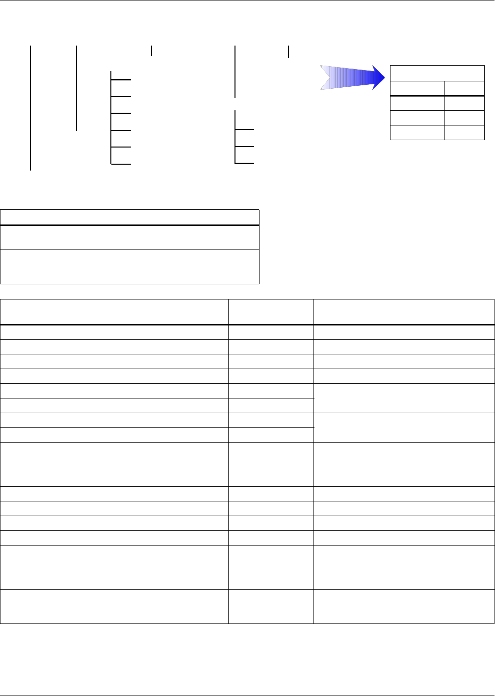
1.7.1 Monitor Board Features
Based on your site’s specific needs, the UPS may require auxiliary connections to manage the battery
system (external battery circuit breaker, battery temperature sensor), communicate with a personal
computer or provide alarm signaling to external devices or for Remote Emergency Power Off (REPO).
The monitor board, arranged for this purpose, is located on the rear of the operator access door. The
main features are:
• Input and Output dry contacts signal (one pair of contacts of relay)
• Emergency Power Off control (EPO)
• Environmental parameter input interface
• User communication (for data setting and user background monitor)
• Intellislot™ interface
• Modem interface
• Temperature detect interface
Figure 2 Auxiliary terminal block detail monitoring board (U2)
Intellislot 2
Intellislot 1
Intellislot 3
J1J3
J22
J23
J12
J9
X4
J15
J16
J17
J24
J10J30J26J4J28J25J21
J13
Dry In MBC BCB
BFP INV ACF EPO
X1 X2 X3
J2
LCD
J8
X7
X6
X5
X4
PWR
Modem
SNMP Card
The black square ( )
on each slot indicates Pin 1.
Single Module UPS Installation
12
1.8 Dry Contacts
The UPS provides input dry contacts and output dry contacts.
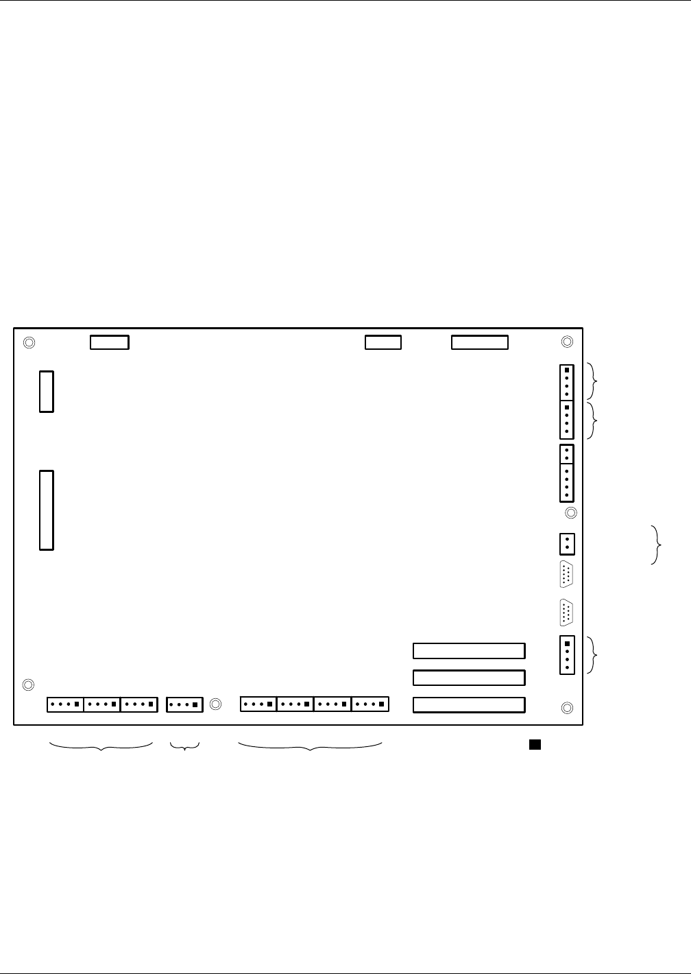
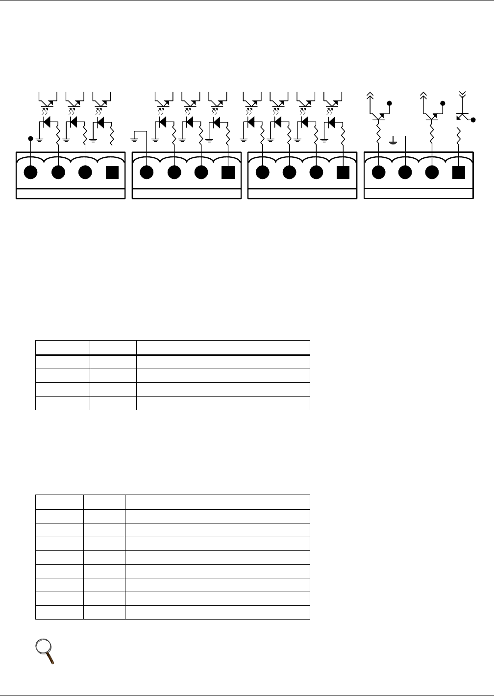
1.8.1 Input Dry Contacts
There are several input dry contacts at the X3 slot.
Figure 3 Input dry contacts
X3 Ancillary Control and Alarms
X3 IN DRY: Environmental, Battery Ground Fault and Generator Contacts
The UPS accepts external signalling from voltage-free (dry) contacts connected to finger-proof, push-in ter-
minal X3 IN DRY. Subject to prior software programming, the signalling is accepted by the UPS when
connection between the relevant terminal and the +12V terminal is altered. Cables connected to X3 IN
DRY must be segregated from power circuits (for screening purposes), double insulated and of a typical 0.5
to 1mm2 cross-section area for maximum runs between 25 and 50 meters (82-164 ft), respectively.
1.8.2 Maintenance Bypass Cabinet Interface
J26 and J30 are the MBC interface.
Table 3 Input dry contacts at X3
Position Name Description
J4.1 ENV3Battery Room Alarm (NC)
J4.2 BtG Battery Ground Fault Detection (NC)
J4.3 GEN1,2 On Generator (NO)
J4.4 +12V +12V Power
1 - Must be configured by configuration software before becoming active.
2 - When activated, the charger current can be limited, via software, to a percentage of the full charger current (0-100%).
3 - Activating this feature turns the battery charger off.
Table 4 Maintenance bypass cabinet interface
Position Name Description
J26.1 T_IT1Input transformer overtemperature (NC)
J26.2 AUX_I Reserved
J26.3 +12V +12V Power
J26.4 GND Power Ground
J30.1 FUSE Reserved
J30.2 F_FAN Fan Fail Alarm (NC)
J30.3 T_OT1Output Transformer Overtemperature (NC)
J30.4 AUX_O Reserved
1 - Must be configured by software before becoming active
NOTE
All auxiliary cables of terminal must be double-insulated. Wire should be 0.5-1.5mm2
(16-20AWG) stranded for maximum runs between 25 and 50 meters (82-164ft.) respectively.
X3
12V
J4 J26 J30 J10
12V
GEN
BtG
ENV
GND
AUX_I
T_IT
FB
GND
F_FAN
FUSE
OL
DRV
12V
AUX_O
T_OT
12V 12V
12V
Single Module UPS Installation
13
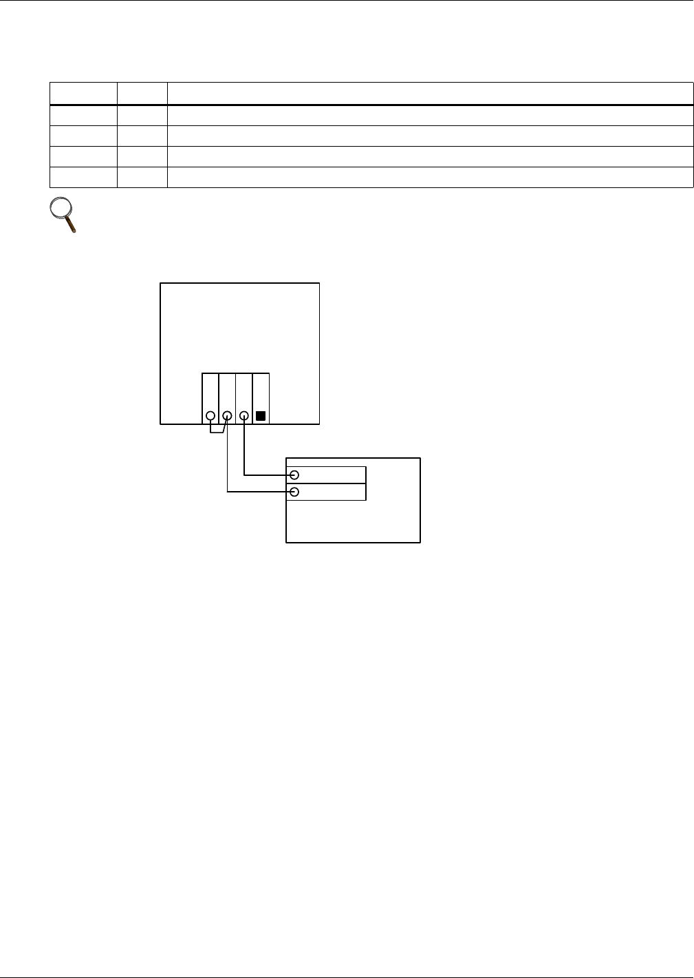
1.8.3 External Circuit-Breaker Interface
J10 is the interface to any external battery circuit breaker (BCB).
Figure 4 Jumper connection for BCB interface
Table 5 External circuit-breaker interface
Position Name Description
J10.1 DRV BCB Driver Signal - (reserved)
J10.2 FB BCB Contact State -(reserved)
J10.3 GND Power Ground
J10.4 OL BCB On-Line - Input - This pin will become active when BCB interface is connected. (N.O.)
NOTE
All auxiliary cables of terminal must be double-insulated. Wire should be 0.5-1.5mm2
(16-20AWG) stranded for maximum runs between 25 and 50 meters (82-164ft.) respectively.
UPS Monitoring Board
J10
OL
DRV
GND
FB
Battery Circuit Breaker
OL
Aux – N.O.
Aux – N.O.
Single Module UPS Installation
14
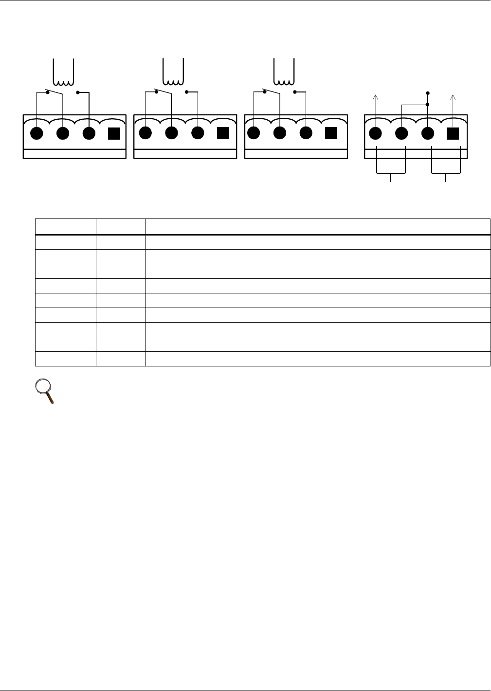
1.8.4 Output Dry Contacts
There are three output dry contact relays at the X1 slot (see Figure 5 and Table 6)
Figure 5 Output dry contacts and EPO wiring
Table 6 Output dry contact relays
Position Name Description
J13.2 BFP_O Bypass feedback protection relay; normally open; closed when bypass SCR is shorted
J13.3 BFP_S Bypass feedback protection relay center
J13.4 BFP_C Bypass feedback protection relay; normally closed; open when bypass SCR is shorted
J21.2 INV_O Inverter mode relay; normally open; closed when UPS is in inverter mode
J21.3 INV_S Inverter mode relay center
J21.4 INV_C Inverter mode relay; normally closed. Opened when UPS is in inverter mode
J25.2 ACF_O Main input fault relay; normally open. Closed when main input is in fault
J25.3 ACF_S Main input fault relay center
J25.4 ACF_C Main input fault relay; normally closed. Open when main input is in fault
NOTE
All auxiliary cables of terminal must be double-insulated. Wire should be 0.5-1.5mm2
(16-20AWG) stranded for maximum runs between 25 and 50 meters (82-164ft.) respectively.
EPO - NCEPO - NO
X2X1
BFP_C
J21 J25 J28
BFP_S
BFP_O
INV_O
INV_S
INV_C
ACF_C
ACF_S
ACF_O
J13
+12V

Single Module UPS Installation
15
1.8.5 Emergency Power Off Input
The UPS has an Emergency Power Off (EPO) function that operates by a button on the control panel
or by a remote contact provided by the user. The EPO button is under a hinged, clear plastic shield.
The X2 slot, shown in Figure 5, is the remote EPO input interface. The EPO has an NO/NC contact
point that becomes active when shorting terminals X2: 3 and 4 or open terminal connection X2: 2 and 1
If an external emergency stop facility is required, it is connected terminals X2: 1&2 or X2: 3&4 of the
auxiliary terminal block (X2). It also is connected to the normally open or normally closed remote stop
switch between these two terminals using shielded cable (see Figure 5 and Table 7). If this function
is not used, terminals X2: 3&4 must be opened and X2: 1&2 must be closed.
X5: Auxiliary DC Power Output
Auxiliary DC power for modem or external SNMP card. The voltage is between 9V to 12V. The maxi-
mum current is 500mA.
X6: Analog Input Interface
Two analog signal channels with an input range is from 0 to +12V. The precision of detection is ÷3%.
• X6 pin 1: Not used
• X6 pin 2: +12V
• X6 pin 3: ENV-T – environment temperature detection
• X6 pin 4: GND
X7: External Battery Temperature Detector Interface
Interface for TMP12Z temperature detector, normally connected to an external battery cabinet (see
Figure 7).
Pin reference:
• X7 pin 1: Not used
• X7 pin 2: +12V (Power supply for Temperature Monitoring Probe)
• X7 pin 3: BAT-T (Battery Temperature signal)
• X7 pin 4: GND
Table 7 EPO input contact relays
Position Name Description
J28.1 EPO_NC EPO activated when opened to J28.2
J28.2 EPO_NC EPO activated when opened to J28.1
J28.3 EPO_NO EPO activated when shorted to J28.4
J28.4 EPO_NO EPO activated when shorted to J28.3
NOTE
The emergency stop action within the UPS shuts down the rectifier, inverter and static bypass.
It does not internally disconnect the input power supply. To disconnect ALL power to the UPS,
open the upstream feeder breaker(s) when the remote EPO is activated.
NOTE
Normally closed EPO – X2: 1,2, these terminals are supplied factory-linked on the monitor
board and must remain installed if using NC contacts.
NOTE
All auxiliary cables of terminal must be double-insulated. Wire should be 0.5-1.5mm2
(16-20AWG) stranded for maximum runs between 25 and 50 meters (82-164ft.) respectively.
Single Module UPS Installation
16
Serial Ports RS232-1 and RS232-2
RS232-1 provides serial data and is intended for direct use with Liebert MultiLink monitoring and
server shutdown software.
RS232-2 provides serial data and is intended for use by authorized commissioning and service person-
nel.
These serial ports are shared with the optional Web browser, SNMP, ModBus and relay cards. Refer
to Table 28 regarding compatibility of simultaneous use.
Intellislot Web Browser, SNMP, ModBus and Relay Cards Interface
There are three interface slots available for optional Web browser, SNMP, ModBus and Relay cards
as illustrated in 8.0 - Options—For Assembly Inside the UPS Cabinet.
1.8.6 External Bypass Switch Interlock
EXT-Maint X3-1&2 on UPS Parallel Board M3 (leave open if no external bypass switch is used)
Provides external maintenance bypass interlock protection for the UPS. Short circuit means external
bypass closed.
EXT-Out (X3-3&4) on UPS Parallel Board (leave shorted if no external output switch is used). Pro-
vides external output interlock protection for paralleled UPS modules. Short circuit means external
output switch closed.
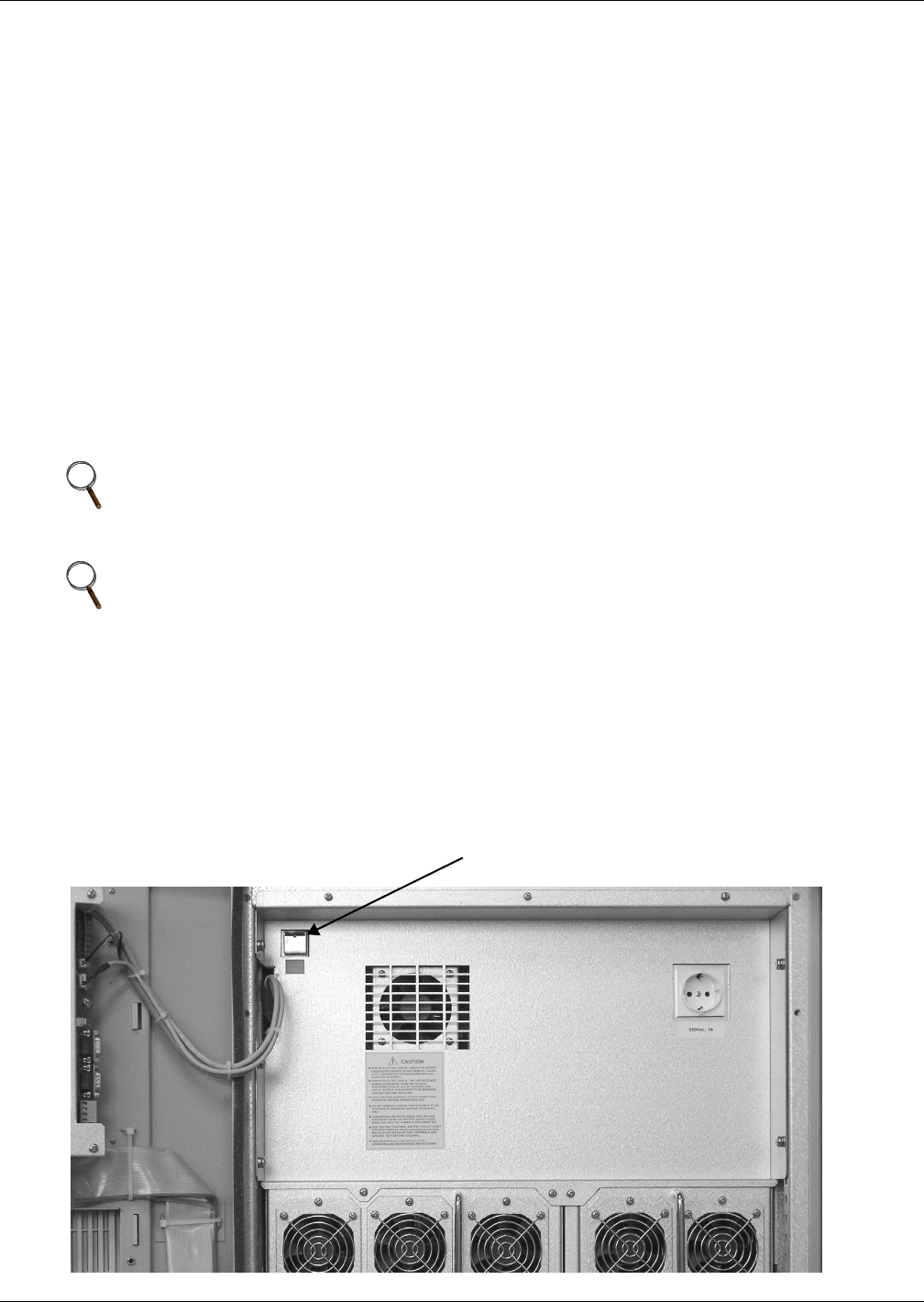
1.8.7 Battery Start Facility
1. Rotate the switch to Normal Mode.
2. Verify that the batteries are connected.
3. Press Battery Start Button.
The LCD begins to show startup screens. The rectifier indicator flashes green while the rectifier is
starting up. It stops flashing and becomes solid green about 30 seconds after the rectifier enters
the normal operation state.
4. After UPS has initialized, press Inverter On
Figure 6 Battery start for UPS
NOTE
UPS Parallel Board M3 is located behind protective covers accessible after opening the UPS
front door – removal of this barrier requires the use of a tool and is restricted to service
personnel.
NOTE
Jumper JP1 (located next to X3) needs to be removed for X3:3&4 to work properly.
Battery Start Button

Battery Installation
17
2.0 BATTERY INSTALLATION
2.1 Introduction
The UPS battery bank consists of battery blocks connected in series to provide a D.C. string voltage as
required by the UPS converter. The 'AUTONOMY TIME' (the time during which the battery can
maintain supply to the load in the event of a mains failure) is limited by the ampere-hour capacity of
the battery blocks and in some cases this results in several strings being connected in parallel.
The NX usually has internal batteries, but longer run time is available by using an external battery
cabinet.
The battery cabinet will be supplied in one of the following forms:
1. Complete installation, comprising the battery cabinet, batteries and protective device.
2. Battery cabinets and protective device only—batteries supplied by others
The battery bank may be disconnected from the UPS for maintenance or service.
NOTE
10kVA to 30kVA UPS models contain an internal battery compartment that can accommodate
up to 44 blocks of batteries for 12Ah/12V; 80 blocks of batteries for 7.2Ah/12V

Battery Installation
18
2.2 Safety
Special care should be taken when working with the batteries associated with the Liebert NX UPS
system. When all the cells are connected together, the battery terminal voltage is potentially hazard-
ous. The battery installation must be segregated from all but appropriately qualified maintenance
personnel by locating the cells in a key-lockable cabinet or in a purpose-designed, dedicated battery
room. When the batteries require maintenance, these precautions must be taken:
• The rotary switch must be turned to Maint. position.
• The input circuit breaker (CB1) must be opened.
• The ANDERSON connector must be disconnected..
NOTE
The fuse on the battery EMI board (UHA241A2-10kkVA, UHK241A2-15/20kVA,
UHS242A2-30kVA) is 600VDC/30A, High Speed Fuse.
NOTE
Full safety instructions concerning the use and maintenance of UPS batteries are provided in
the appropriate battery manufacturers manuals. The battery safety information contained in
this section relates to key considerations that must be taken into account during the
installation design process and might affect the design outcome depending on localised
conditions.
!WARNING
Hazardous battery voltage present behind covers
No user-serviceable parts are located behind covers that require a tool for their removal. Only
qualified service personnel are authorised to remove such covers.
When using internal batteries in 10 to 30kVA units, the batteries are always connected
through power fuses to the UPS and to the segregated terminal bars available for connection
to an external battery.
Isolate any internal battery connections before attempting to access the segregated terminal
bars available for connection to an external battery.
The following general battery safety precautions and warnings should be observed at all
times:
• A battery can present risk of electric shock or burn from high- short-circuit currents.
• The full nominal string voltage, when the battery blocks are interconnected, is 480VDC,
which is hazardous
• Only qualified personnel should install or service batteries.
• Eye protection should be worn to prevent injury from electrical arcs.
• Remove rings, watches, necklaces, bracelets and all other metal objects.
• Use only tools with insulated handles.
• Wear rubber gloves and a rubber apron when handling batteries.
• If a battery leaks electrolyte or is otherwise damaged, it should be placed in a container
resistant to sulfuric acid and disposed of in accordance with local regulations.
• If electrolyte comes into contact with the skin the affected area should be washed immedi-
ately with plenty of clean water.
• Batteries must always be disposed of according to local environmental laws.
• When replacing batteries, use the same number and type that were originally fitted.
• Disconnect charging source before connecting or disconnecting battery terminals.
• Determine whether the battery is inadvertently grounded. If it is inadvertently grounded,
remove the source of the ground. Contact with any part of a grounded battery can result in
electrical shock.

Battery Installation
19
2.3 Battery Cabinet
2.3.1 Introduction
This cabinet can also be used in conjunction additional cabinets, to provide the necessary accommoda-
tion required by the larger cells associated with system’s having a long autonomy time.
Where two (or more) cabinets are used they are positioned alongside each other and secured and
bonded together. If the cabinet(s) is located immediately adjacent to the main UPS equipment the two
units are bolted together.
2.3.2 Temperature Considerations
Valve-regulated, lead acid battery cells are sensitive to ambient temperature and should be operated
between 15°C and 25°C (59-77°F). Battery capacity is increased by 1% for every 1°C (2°F) increase in
temperature up to 25°C (77°F). Battery life is reduced at temperatures above 25°C (77°F).
When batteries are mounted in the same room as the UPS unit, it is the battery that dictates the
designed maximum ambient temperature, not the UPS. — i.e. in the case of valve-regulated cells, the
ambient room temperature should be kept between 15°C and 25°C (59-77°F), and not between 0°C
and 40°C (32-104°F) (which is the specified main equipment operating temperature range). Tempera-
ture deviations are permissible for short periods, provided the average temperature does not exceed
25°C (77°F).
2.3.3 Dimensions
The external dimensions are shown in Table 8. These are the same height and depth as the UPS
module and provide a matching appearance when bolted together. All cabinets are fitted with doors,
which must be fully opened in order to fit or remove the batteries. The door swing must therefore be
taken into consideration when planning the positioning of the cabinets.
2.3.4 Weight
The unladen weight is shown below in Table 8. When designing the battery installation the weight of
the batteries and cables must be added to the unladen weight. This is particularly important when
placing the NX on a raised floor.
2.3.5 Circuit Isolator Features
The UPS is fitted with Anderson connectors and fuses for connection and disconnection of internal
batteries. External battery banks require battery fuses or circuit breaker (with optional status con-
tacts). Refer to 1.8.3 - External Circuit-Breaker Interface for details.
Table 8 Dimensions and weight
Model
Optional
Circuit Breaker
Amperes
Maximum
Discharge Current
(at EOD)
External Cabinet
WxDxH mm (in)
Cabinet Weight
Without Batteries
kg (lb)
Battery Cabinet
50A
10kVA 22A
15kVA 33A
20kVA 44A 820x700x1400
(32-1/4x27-5/8x55) 170 (375)
80A 30kVA 66A
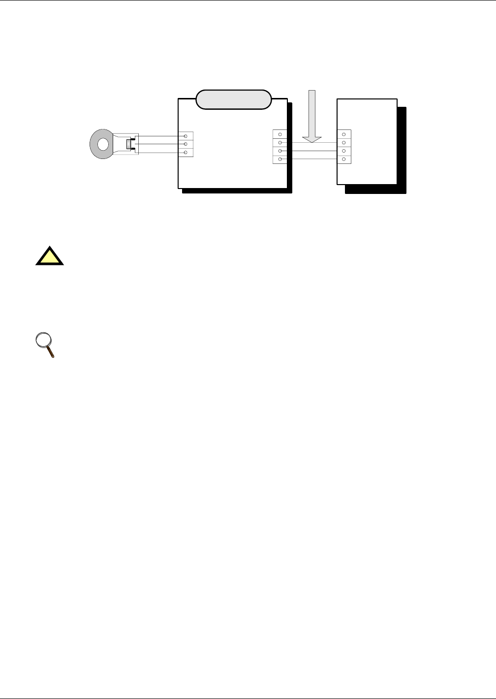
Battery Installation
20
2.3.6 Battery Temperature Sensor (Optional)
The optional external battery temperature sensor kit contains one probe and one temperature trans-
port board as illustrated in Figure 7. It is connected to the UPS Monitor Board.
Figure 7 Single temperature sensor and monitor board-U2
2.3.7 Moving the Battery Cabinets
Ensure that the weight is within the designated surface weight loading of any handling equipment.
See Table 8 for weight details.
Battery cabinets can be handled by means of a fork lift or similar equipment.
Seismic anchors option is available for anchoring the unit to a concrete floor.
2.3.8 Cable Entry
Cables enter the battery cabinet from the bottom. Cable entry is made possible by removing a blank-
ing piece fitted at the bottom to reveal the cable entry hole.
!
WARNING
Ensure any lifting equipment used in moving the cabinet has sufficient lifting capacity.
NOTE
Care must be taken when maneuvering units fitted with batteries. Keep such moves to a
minimum.
When the equipment has been finally positioned ensure the adjustable feet are set so that the
battery cabinet will remain stationary and stable.
Temperature
Sensor
TMP-2
+
IN
-
NC
12V
GND
OUT
UPS
Monitor
Board
– U2
X7
-12V
GND
BAT-T
Cable W2 is packed with the temperature sensor.
Name: W2 L=5m
Name: W1 L=30m
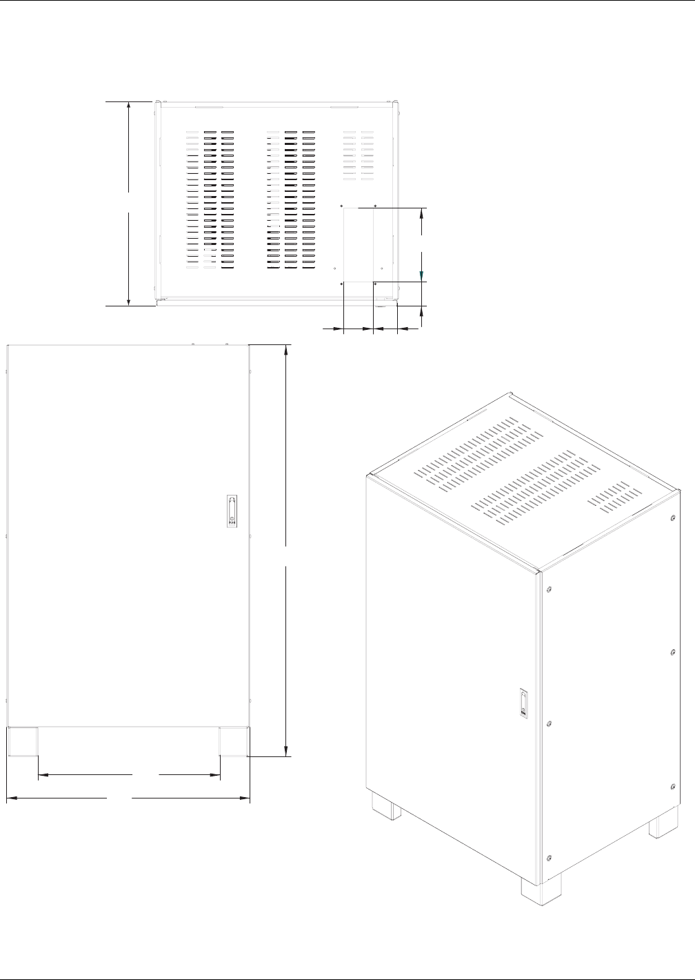
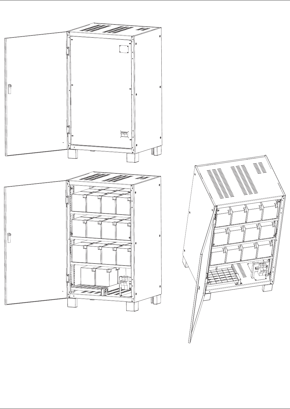
Battery Installation
22
Figure 9 Battery cabinet with fuse or optional circuit breaker locations
Bottom cable entry
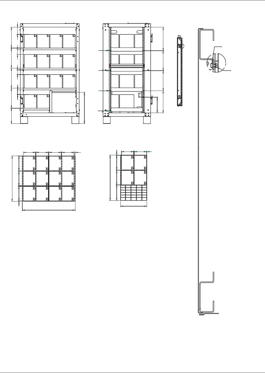
Battery Installation
23
Figure 10 Battery cabinet internal layout
Minimum service space 65mm
3 Layers:
Largest battery dimensions:
201x170x190 (LxWxH)
Positions of captive nuts for grille mounting
1 Layer:
Largest battery dimensions:
201x170x190 (LxWxH)
Captive nut M6
Hex flange
screw M6x16
1.
15
29
43
Detail B
B
215 280 280 280 292
65 65 65 102
201 10 201 10 2017
635
738
15170101701017010170
520110201218
517010170
368
635
308,6 280 280 328,4
437,8
218,5
AMNXE0NBCSL4BT
All measurements are in millimeters.
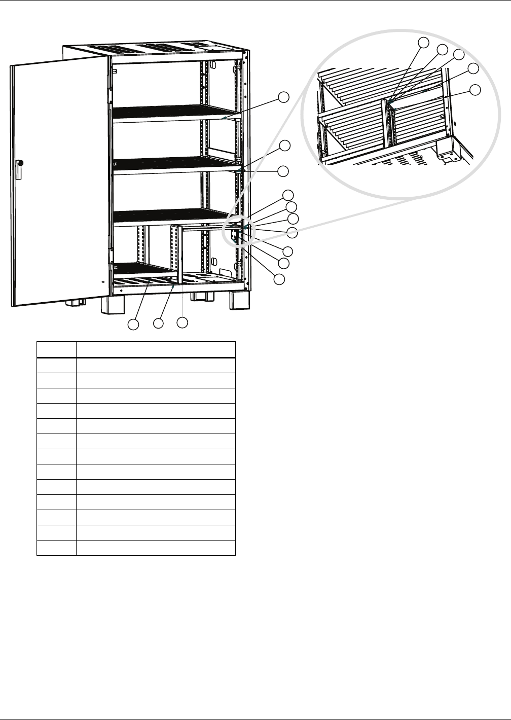
Battery Installation
24
Figure 11 Battery cabinet, bottom entry
2.4 Battery Power Cables
2.4.1 Connection Principles
The following notes, in conjunction with the diagrams, illustrate the broad principles to be followed
when fitting and connecting the majority of battery installations.
Item # Item Name
1 Grille steel
2 Grille steel
3 Middle pillar
4 Cover module BC Small NXe
5 Ground bus
6 Captive nut M4
7 Captive nut M6
8 Screw flange M6x16
9 Nut flange M6
10 Screw M6x16 countersink
11 Spring washer M4
12 Flat washer M4
13 Screw mushroom head cross M4x12
10
8
8
5
1
2 3
4
9
6
13
12
12
11 13
4
6
7
AMNXE0NBCSL4BT
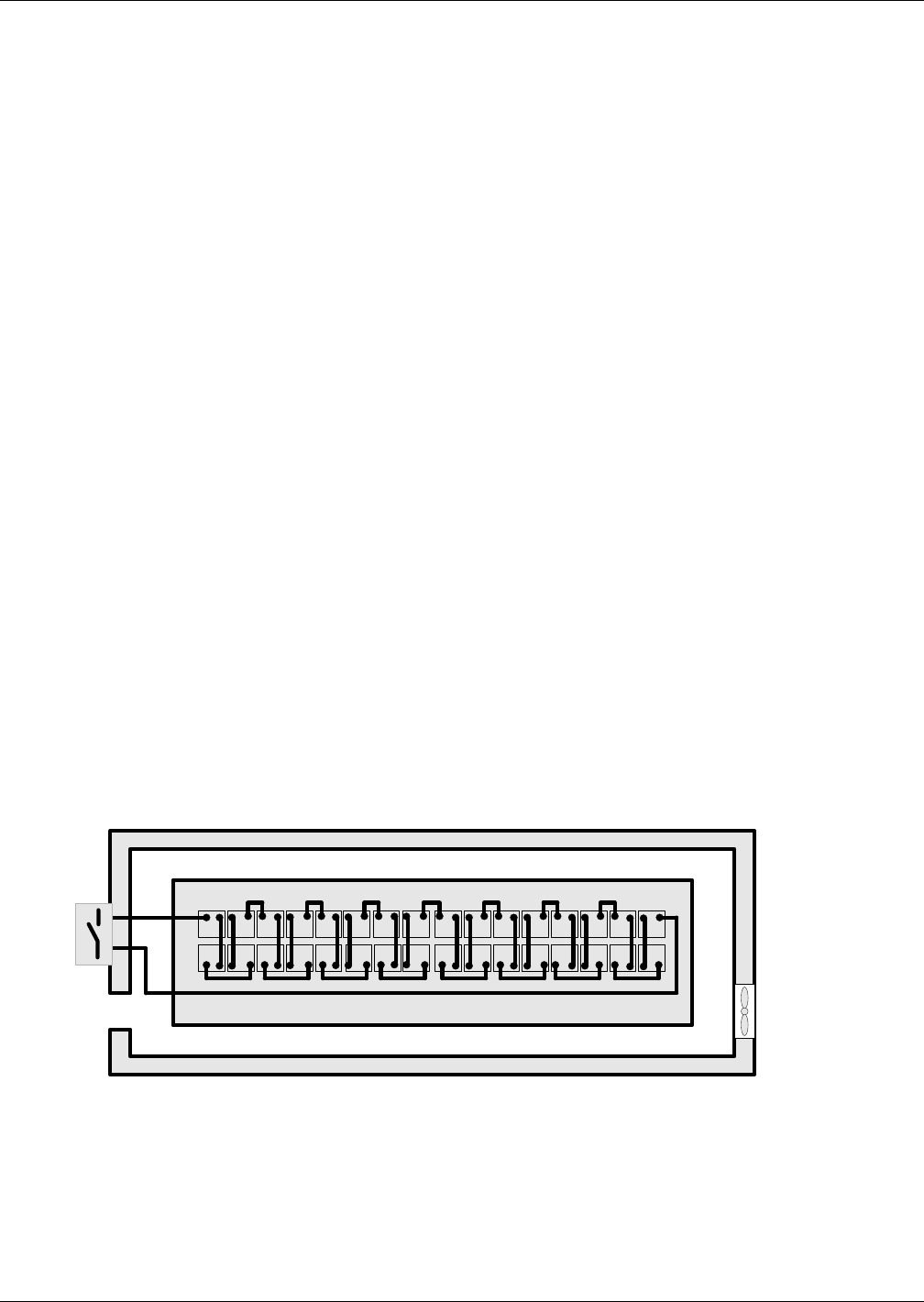
Battery Installation
25
2.4.2 Fitting the Batteries
1. In general, at least 10mm (3/8") must be left unobstructed on all vertical sides of the battery
blocks to permit free air movement around the cells.
2. Clearance should be allowed between the top of the cells and the underside of the shelf above (this
is necessary for monitoring and servicing the cells).
3. When installing the batteries on racks always work from the bottom shelf upwards to prevent
raising the centre of gravity.
2.4.3 Connecting the Battery
1. When the battery cabinet is installed on a raised floor the battery power cables and optional circuit
breaker control cables can be routed to the UPS cabinet via the floor of the cabinet. If the UPS and
battery cabinet are located adjacent to each other and located on a solid floor these cables can be
passed between the cabinets via the lifting apertures located in the lower sides of the cabinets.
2. In general it is recommended that the inter-connecting cables be fitted to the batteries within
their particular level before fitting the inter-level connecting cables, followed finally by the cables
to the circuit breaker.
3. An insulating shroud should be fitted to each terminal after its connection has been made.
4. When connecting the cables between the battery string ends to the optional circuit breaker always
connect the circuit breaker end of the cable first.
2.4.4 Battery Room Design
Whatever the type of mounting system selected, the following conditions should be noted:
• Cell Layout—1
Whichever battery mounting system is used, the batteries should be arranged to prevent the pos-
sibility of simultaneous contact with two exposed live parts having a potential greater an 150V.
Where this is not possible, insulated terminal shields must be installed and insulated cables must
be used for connections.
• Service Platform—2
The service platform (or duckboard) must be slip-proof, insulated from the floor and at least one
metre (39 in.) wide.
• Connections—3
All connections must be as short as possible.
• Battery Protection Fuses/Circuit Breaker—4
The battery circuit breaker is generally installed at the front of the battery room. See 2.5 - Bat-
tery Control for details on connecting the circuit breaker box available for the Liebert NX.
Figure 12 Battery room design
2.5 Battery Control
Battery temperature sensor cables are connected between UPS auxiliary terminal block X3 BCB, the
Battery Temperature sensor and the battery as shown in Figure 7.
Cables connected to X3 BCB must contain a protective earth wire or a shield, be segregated from
power circuits, double insulated and of a typical 0.5 to 1mm2 cross section area for maximum runs
between 25 and 50 meters respectively. The shield should be connected to the protective earth of the
battery cabinet or battery breaker, not at the UPS
1
2
3
4
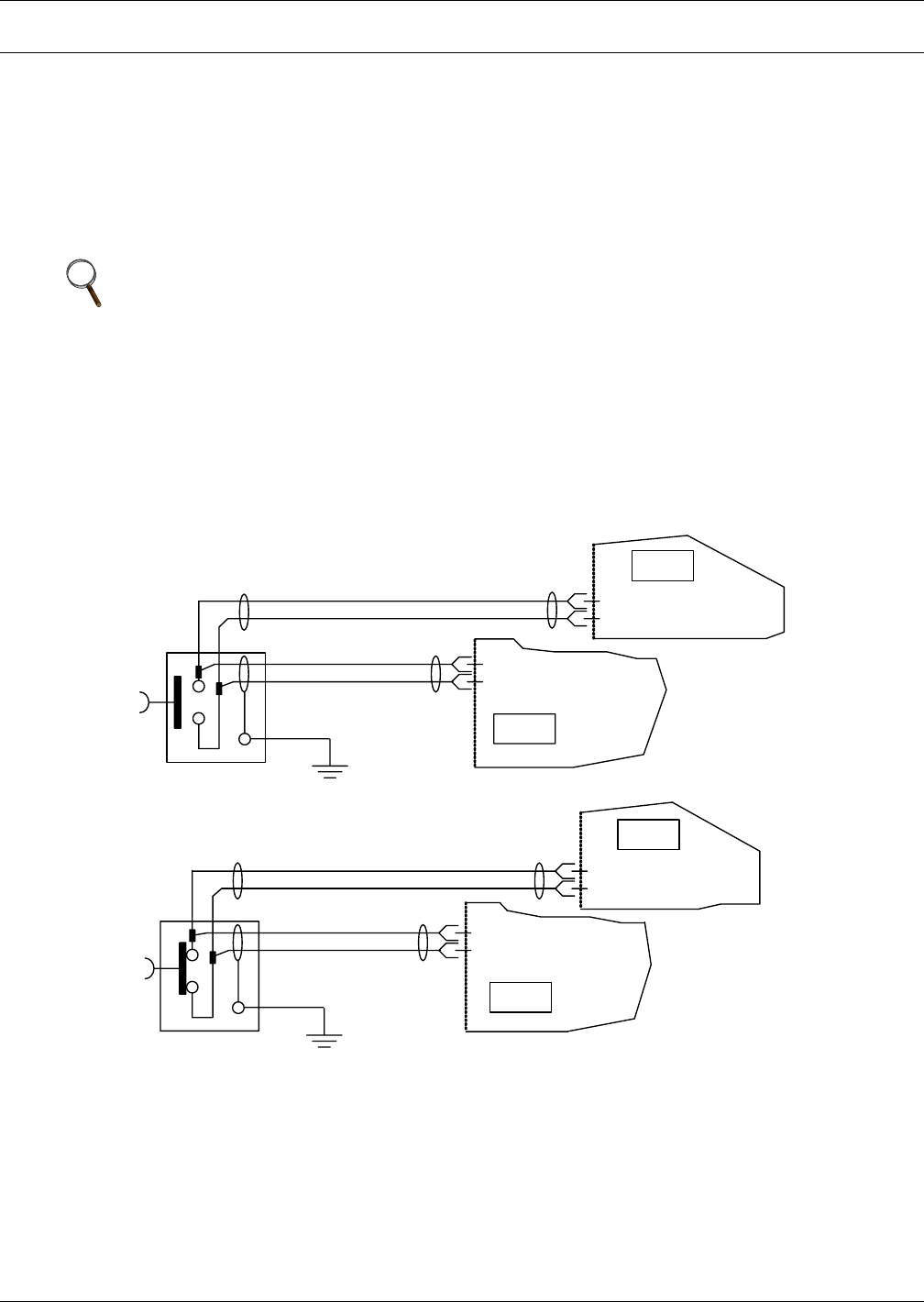
UPS Multi-Module Installation
26
3.0 UPS MULTI-MODULE INSTALLATION
3.1 General
The installation of a multi-module UPS configuration must follow the installation procedure for a sin-
gle UPS module with the additional requirements detailed in this chapter.
In addition to the local EPO push button on the front panel of the UPS module (that stops operation of
that module), the UPS supports also a remote emergency stop to permit simultaneous multi-module
shutdown.
Figure 13 Emergency power off connections
NOTES
1. The remote emergency power off switch must be voltage-free and Normally Open or
Normally Closed.
2. The open voltage supplied is 12VDC, < 20mA
3. This external emergency stop may be supplied with a second set of contacts that can be used
to trip incoming mains or bypass supply circuit breakers supplied by others and fitted with
remote trip units.
4. Normally Closed EPO - X2: 1&2, these terminals are supplied factory-linked on the monitor
board.
UPS2
UPS1
Monitor Board
Monitor Board
X2:1
X2:2
X2:1
X2:2
EPO
UPS1
X2:3
X2:4 Monitor Board
UPS2
X2:3
X2:4 Monitor Board
EPO
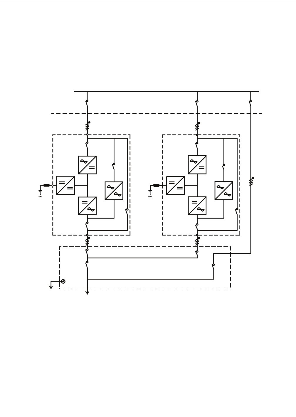
UPS Multi-Module Installation
27
3.2 Paralleled UPS Modules
The basic installation procedure of a parallel system comprising two or more UPS modules is the
same as that of single module system. The following sections only introduce the installation proce-
dures specific to the parallel system.
3.2.1 Cabinet Installation
Place the UPS modules side by side and interconnect as shown in Figure 14. The distribution panel
(external bypass cabinet) is optional but recommended for ease of maintenance and system testing.
Figure 14 Typical 1+N system block diagram with common input supply, with separate batteries and
optional output / bypass distribution panel
Distribution Cabinet
TO LOAD
QUPS
Q1EXT
SW1-A
SW1-D
INVERTER
BATTERY 1
FUSES
CHARGER
UPS1
SUPPLIED BY OTHERS
INPUT MAINS
SUPPLY L1, L2, L3, N
L1, L2, L3, N L1, L2, L3, N
SUPPLY L1, L2, L3, N
CB1
RECTIFER
SW1-C
STATIC
SWITCH
BATTERY 2
FUSES
CHARGER
UPS2
INPUT MAINS
CB1
RECTIFER
SW1-C
STATIC
SWITCH
INVERTER
SW1-A
Q2EXT
QBYP
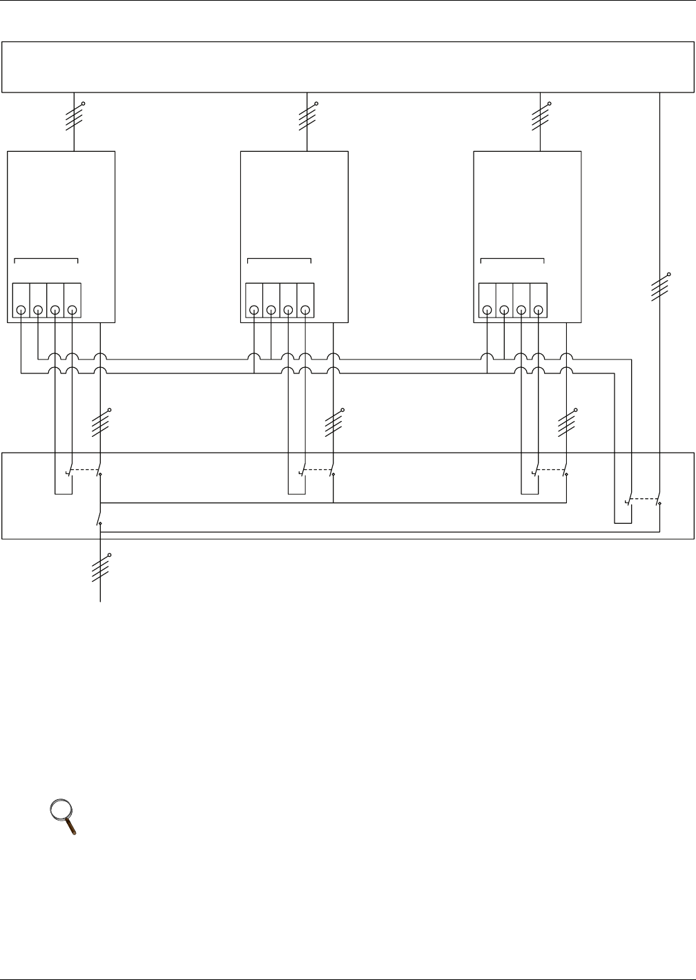
UPS Multi-Module Installation
28
Figure 15 Dry contacts, multiple UPS modules with distribution panel
3.2.2 External Protective Devices
Refer to the instructions in 1.0 - Single Module UPS Installation.
3.2.3 Power Cables
The wiring of power cables is similar to that of single module system. The Bypass and the Main input
sources must be referenced to the same neutral potential and input earth leakage monitoring devices,
if installed, must be located upstream of the common neutral sinking point. Refer to the instructions
in 1.0 - Single Module UPS Installation.
NOTE
The length and specification of power cables including the bypass input cables and UPS output
cables should be the same. This facilitates load sharing when operating in bypass mode.
Input Distribution
Distribution Panel
UPS 1 UPS 2
Q1Ext
To Load
Q2Ext QnExt
QByp
QUPS
UPS N
M3 Board
X3
Ext. Maint. Ext. Out
M3 Board
X3
Ext. Maint. Ext. Out
M3 Board
X3
Ext. Maint. Ext. Out
1234 123 4 1234
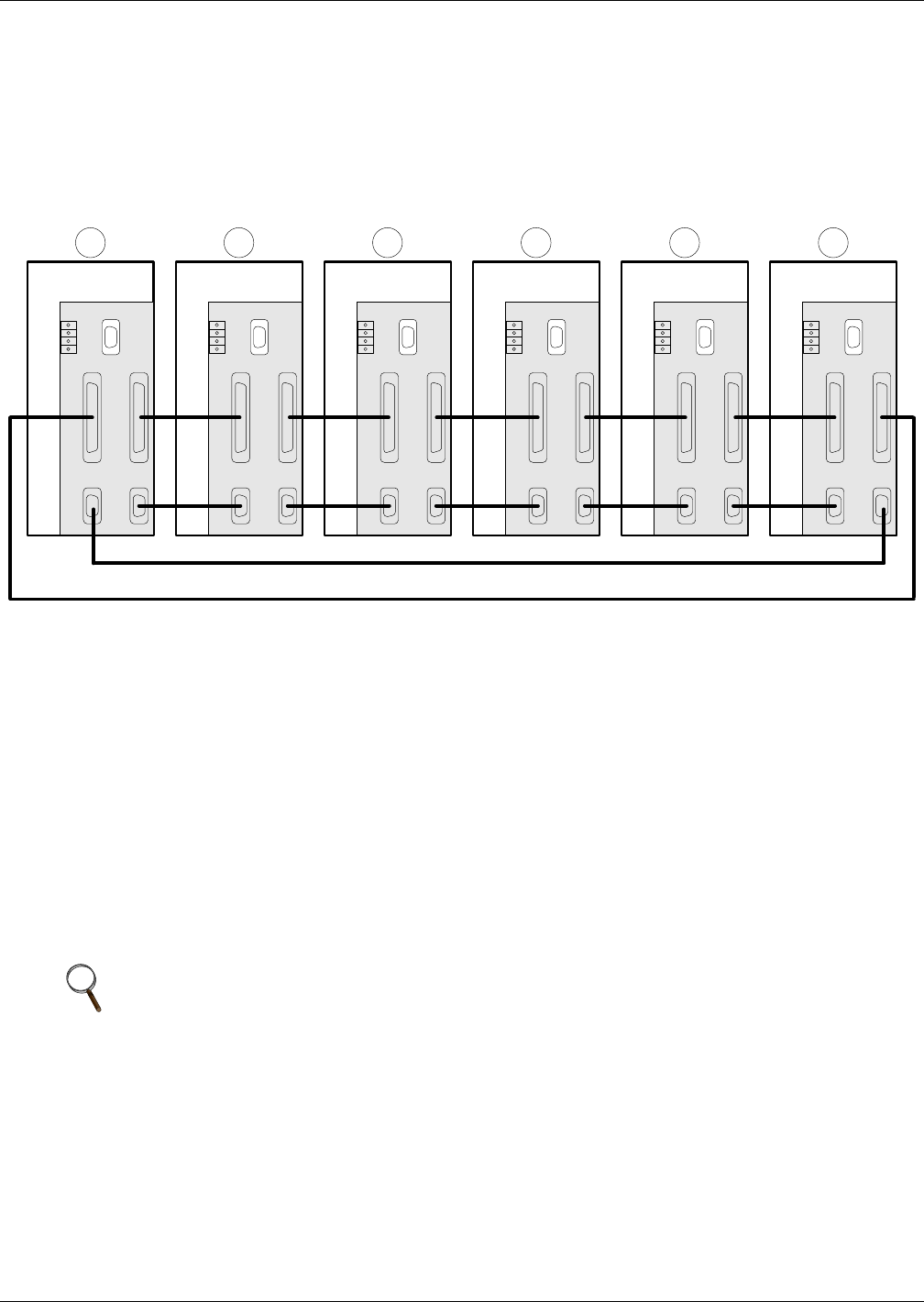
UPS Multi-Module Installation
29
3.2.4 Control Cables
Intermodule Control
Shielded and double insulated control cables available in lengths of 5, 10 and 15 meters must be must
be interconnected in a ring configuration between UPS modules as shown below. The parallel control
board is mounted on the top, behind protective cover of each UPS module (refer to Figure 23). The
ring configuration ensures high reliability of the control. Refer to Figure 16.
Figure 16 Connection of 1+N system parallel control cables
3.3 Hot-Standby UPS Modules
3.3.1 Cabinet Installation
Place the UPS modules side by side and interconnect as shown below.
The hot standby mode comprises two series connected UPS modules of the same rating. One module
is designated as the hot standby master (downstream), and the other module is designated as the hot
standby slave (upstream). Their roles are determined by power connection and configuration soft-
ware. In normal operation, both slave and master operate in normal mode and the output from one
upstream (slave) UPS feeds the bypass input to the other (downstream/master) UPS. The output of
the downstream (master) UPS is connected to the critical load and is always synchronised to the out-
put of the upstream (slave) UPS. If the inverter of the UPS connected to the load fails, the inverter of
the upstream (slave) UPS supplies the load through the downstream (master) UPS bypass circuit.
The system can be programmed to cycle the downstream (master) UPS between normal mode and
bypass mode so that both ups are equally exercised.
3.3.2 External Protective Devices
Refer to the instructions in 1.0 - Single Module UPS Installation.
NOTE
If it is a hot-standby system, the master (downstream) must be turned on first.
X1-1 X1-2
X2-2 X2-1
Parallel Board
X4
X3 P5
P3
P4 P1
P2
X1-1 X1-2
X2-2 X2-1
Parallel Board
X4
X3 P5
P3
P4 P1
P2
X1-1 X1-2
X2-2 X2-1
Parallel Board
X4
X3 P5
P3
P4 P1
P2
X1-1 X1-2
X2-2 X2-1
Parallel Board
X4
X3 P5
P3
P4 P1
P2
X1-1 X1-2
X2-2 X2-1
Parallel Board
X4
X3 P5
P3
P4 P1
P2
X1-1 X1-2
X2-2 X2-1
Parallel Board
X4
X3 P5
P3
P4 P1
P2
1 2 3 4 5 6
UPS
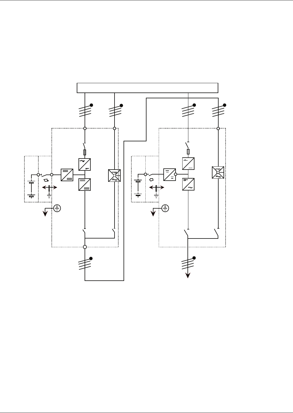
UPS Multi-Module Installation
30
3.3.3 Power Cables
The wiring of power cables is similar to that of single module system except that the output of the
upstream UPS is fed into the bypass input of the downstream UPS, and the load is fed by the down-
stream UPS through its inverter or bypass. The bypass and the main input sources must be refer-
enced to the same neutral potential and input earth leakage monitoring devices, if installed, must be
located upstream of the common neutral sinking point. Refer to the instructions in 1.0 - Single Mod-
ule UPS Installation.
No control wires other than those specified for the single module configuration are required.
Figure 17 Hot standby configuration
INPUT DISTRIBUTION
T
O
L
O
AD
CB1
UPS1
OUTPUT
CB1
DOWNSTREAM UPSTREAM
RECTIFIER
STATIC
SWITCH
INVERTER
Mains L1,
L2, L3, N
L1, L2, L3, N L1, L2, L3, N
Bypass L1,
L2, L3, N
Bypass L1,
L2, L3, N
Mains L1,
L2, L3, N
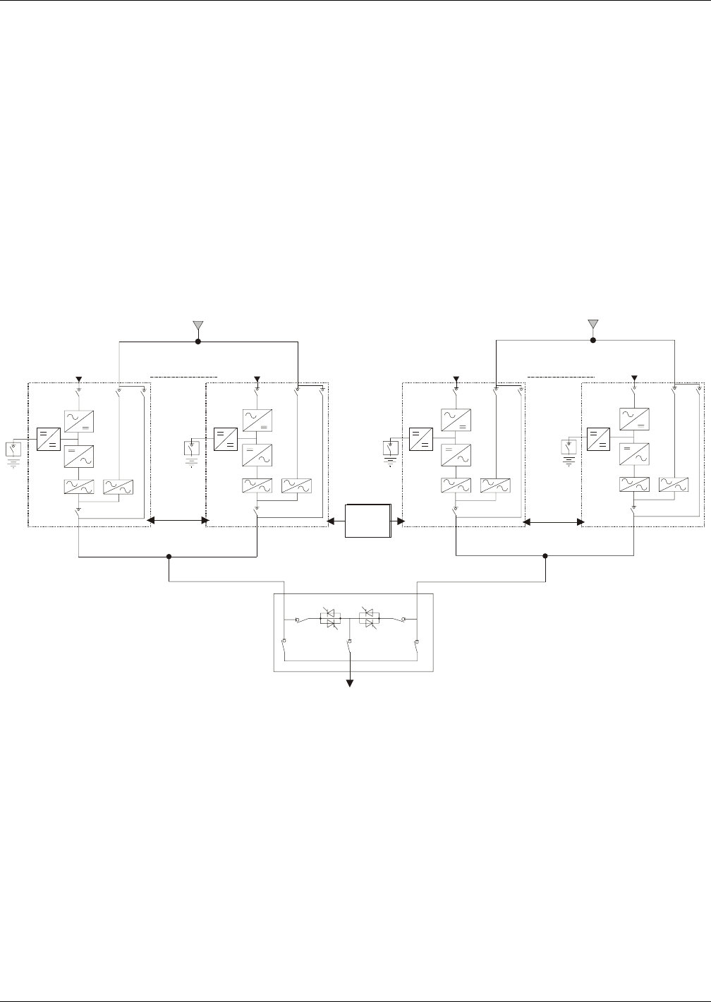
UPS Multi-Module Installation
31
3.4 Dual Bus System
3.4.1 Cabinet Installation
The Dual Bus System consists of two independent UPS configurations each consisting of one or more
UPS modules. Dual Bus Systems are high availability configurations suitable for loads with multiple
input terminals. For single input loads an optional Static Transfer Switch may be added and the stan-
dard Load Bus Synchroniser activated. Depending on the configuration, follow the appropriate instal-
lation instructions for each system.
Place the UPS modules side by side and interconnect as shown below.
The objective of the Dual-bus Synchronizer (DBS) is to keep the output of two independent UPS sys-
tems (or parallel systems) in synchronization. One system is designated as the master; the other is
designated as the slave. The operating modes covered comprise master and or slave operating
inverter or bypass mode.
Figure 18 Typical dual bus system configuration with static transfer switch and Load Bus Synch
3.4.2 External Protective Devices
Refer to the instructions supplied in 1.0 - Single Module UPS Installation.
3.4.3 Power Cables
The wiring of power cables is similar to that of single module system. The Bypass and the Main input
sources must be referenced to the same neutral potential and input earth leakage monitoring devices,
if installed, must be located upstream of the common neutral sinking point. Refer to the instructions
in 1.0 - Single Module UPS Installation
Input
Rectifier
UPS1
Bypass
supply
Input
Rectifier
UPS 6
Intermodule
control cable
STS
LBS
Load
Intermodule
control cable
Bypass
supply
Input
Rectifier
Input
Rectifier
UPS 6UPS1
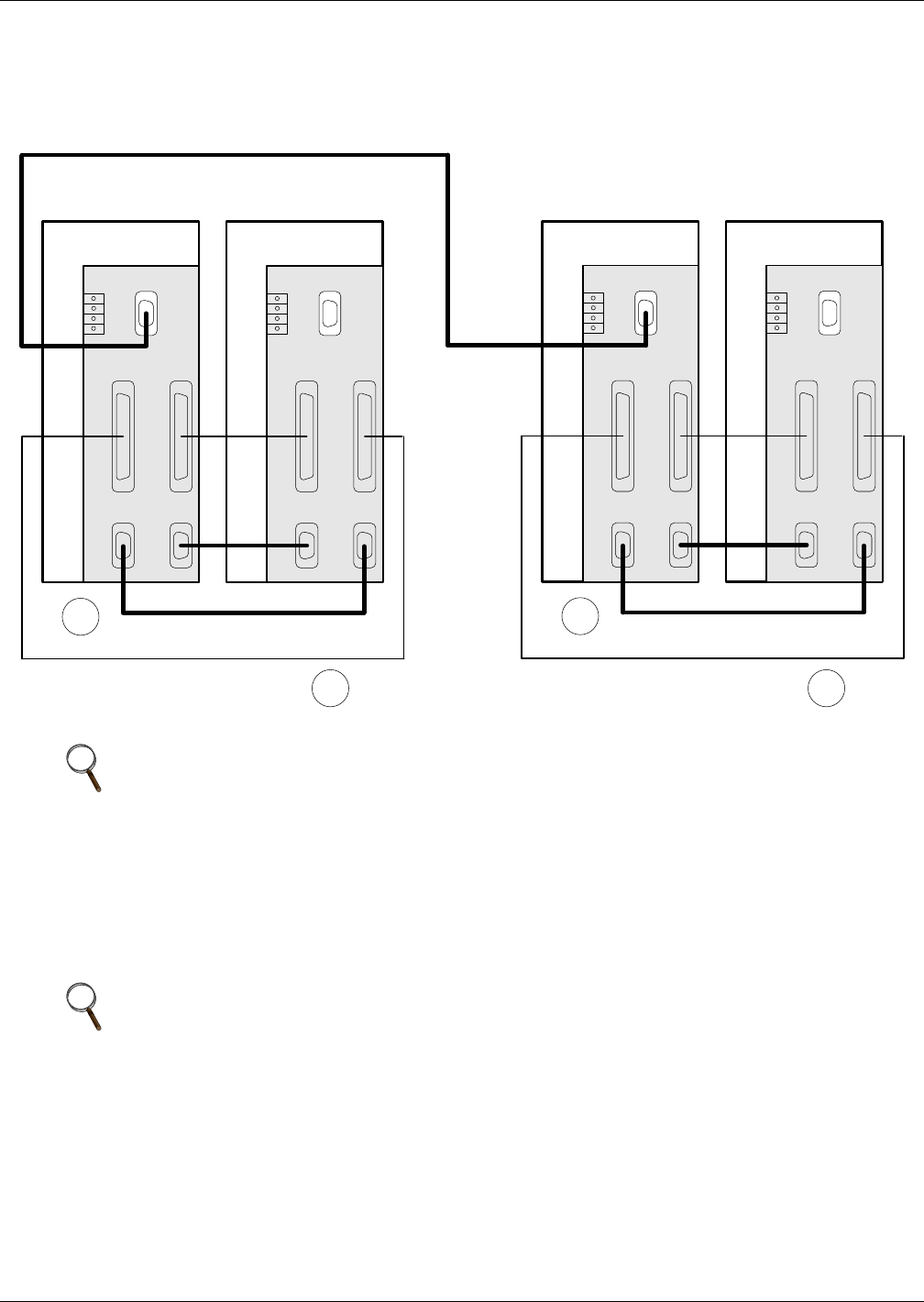
UPS Multi-Module Installation
32
3.4.4 Control Wires
For Liebert NX to NX dual bus configuration, interconnect the optional DBS cable between any DBS
ports of two parallel systems as illustrated in Figure 19.
Figure 19 Connections of a typical dual bus system utilising Load Bus Synch
3.4.5 Extended Dual Bus Synchronization Option (DBS Interface Box)
For Liebert NX to non- NX (whether another Liebert UPS range or not) dual bus configuration, one
DBS interface box shall be mounted on the non- Liebert NX UPS. In this situation, the other UPS sys-
tem is always treated as a master and the following conditions are covered:
• Master and slave are both on inverter
• Master on bypass, slave on inverter
NOTE
Example shown with ring control cables ("8") for DSB applied to two 1+1 paralleled systems.
NOTE
Extended DBS interface box is also used for extending DBS cable length up to
150 meters (490ft) for DBS configuration between two groups of NX UPS systems.
UPS
X1-1 X1-2
X2-2 X2-1
Parallel Board
X4
X3 P5
P3
P4 P1
P2
X1-1 X1-2
X2-2 X2-1
Parallel Board
X4
X3 P5
P3
P4 P1
P2
8
X1-1 X1-2
X2-2 X2-1
Parallel Board
X4
X3 P5
P3
P4 P1
P2
X1-1 X1-2
X2-2 X2-1
Parallel Board
X4
X3 P5
P3
P4 P1
P2
8
UPS
B
Parallel System I Parallel System II
DBS Cable
A
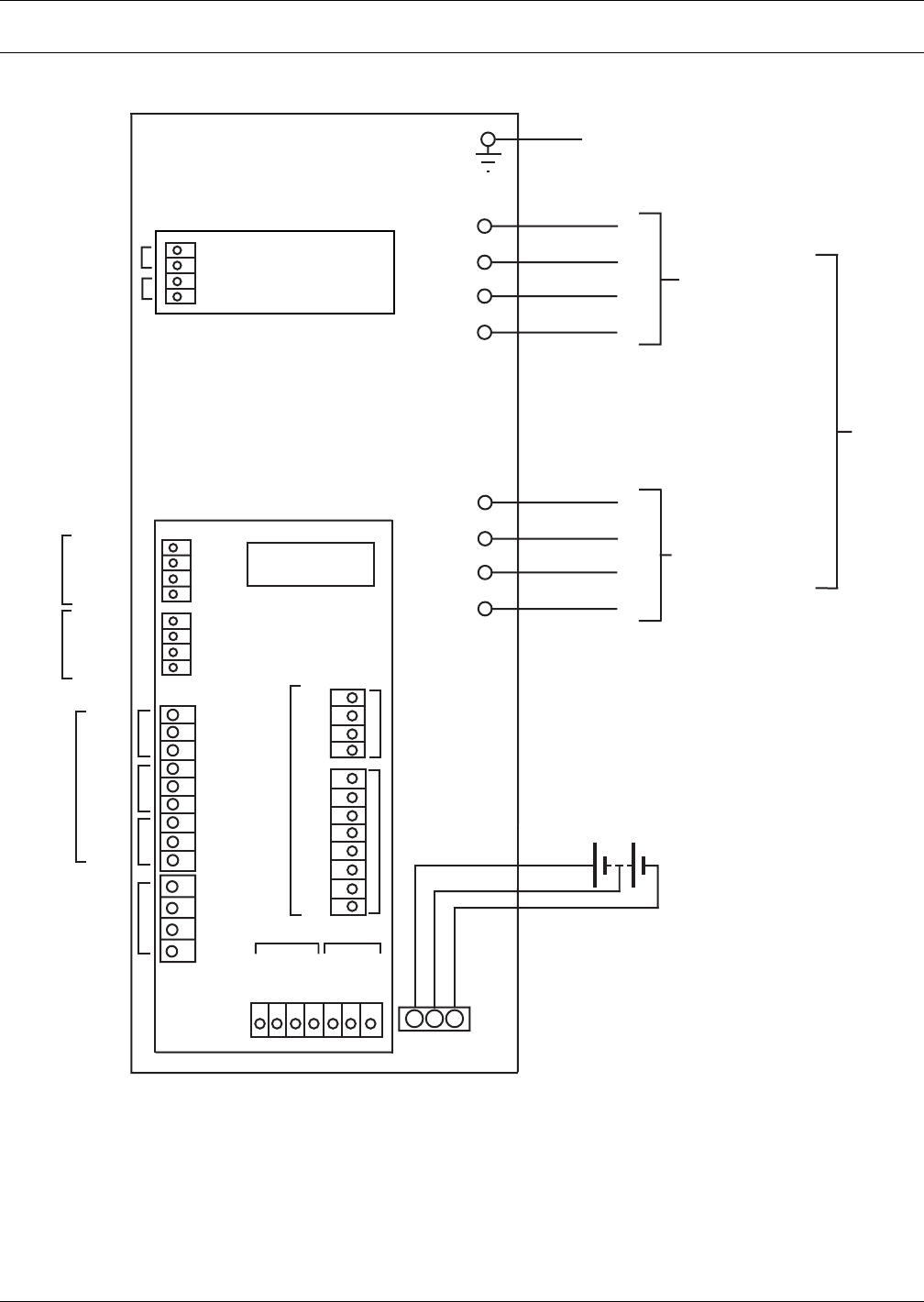
Installation Drawings
33
4.0 INSTALLATION DRAWINGS
Figure 20 Electrical connections
X5
X3
X4
X1
X2 Ext EPO
BCB
Monitor Board
Input
MBC
External Battery
Batt
UPS
Parallel Board
To Customer’s Safety
Earth
Earth
A
B
C
N
A
B
C
N
To Critical Load
Main/Bypass Input
Supply
Power
Cables
+
N
-
J28-1
J28-2
X3 X7
J25
J30
J26
J21
X3
J13
J4
Gen
BPS
AFC
RS-485
Modem-
SNMP
Ext. Maint.
Ext. Out
J28-3
J28-4
J10-1
J10-2
J10-4
J10-3
J22-2
J22-3
J22-4
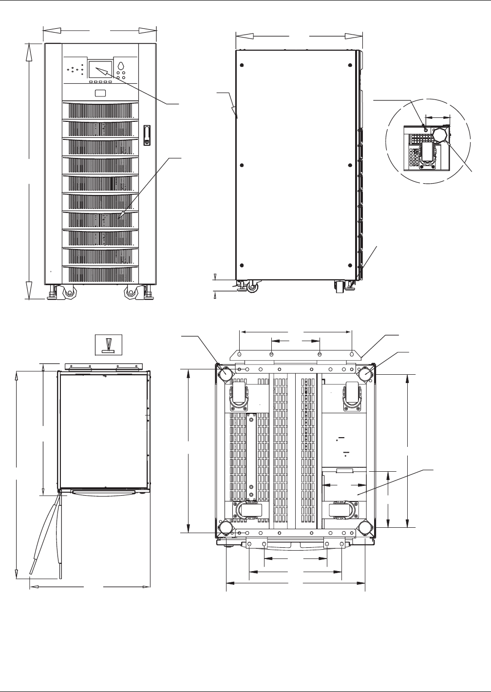
Installation Drawings
34
Figure 21 General arrangement—10-30kVA UPS module
FRONT VIEW LEFT SIDE VIEW
Leveling feet
Detail A, rear of unit
shown without side panel
Lev
e
10mm dia threaded
mounting holes
86.5
7
2
1
700
600
1400
90
867.5
1380
TOP VIEW BOTTOM VIEW
625
420
180
3 5
4
6
572
210
166
236
346
520
708
1) Air inlet grille
2) Air outlet grille
3) Adjustable fixing feet
4) Castors for maneuvering
5) Seismic anchors (option)
6) Cable entry
7) Operator control and display panel
All dimensions are in mm.
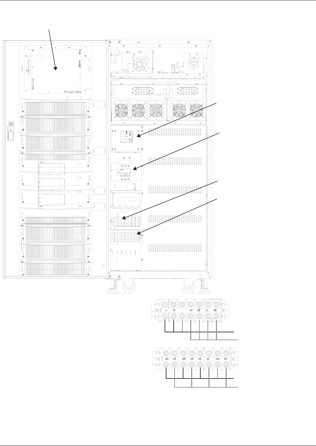
Installation Drawings
35
Figure 22 10-30kVA NX front view with doors open
1
2
3
4
5
External Battery Input
Bypass Input
Main Input
Output
T1
T2
1) Main/Bypass Input terminal (T1)
2) Battery /Output terminal (T2)
3) Input circuit breaker (CB1)
4) Rotary switch (SW1)
5) Monitor board (U2)
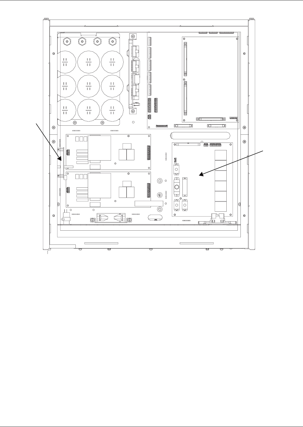
Installation Drawings
36
Figure 23 Location of parallel logic board M3
Battery
Start
Interface
NXe 10-30kVA Top View
Parallel
Logic
Board
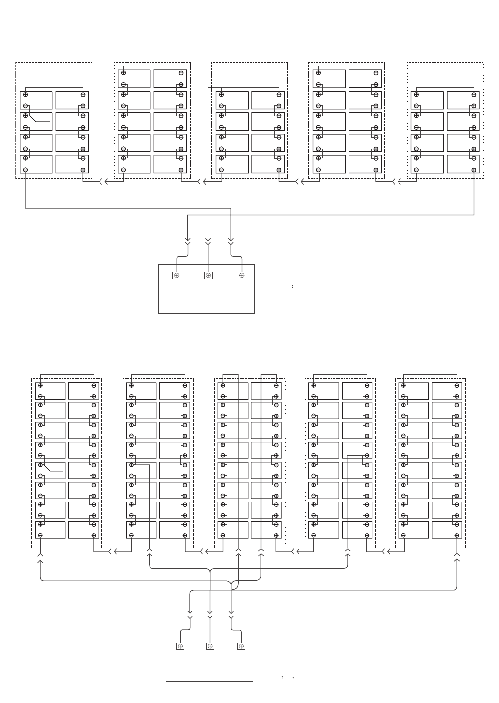
Installation Drawings
37
Figure 24 Internal battery layout and connecting—GP12120 F2 (12AH/12V)
Figure 25 Internal battery layout and connecting—LC-R127R2PG1 (7.2AH/12V)
NOTE 1. TYPICAL USED FOR:GP 12120 F2 (12AH/12V)
BATTERY INTERCONNECT
WIRING DIAGRAM 2. REMOVE 43&44 WHEN 42 JARS ARE USED.
REMOVE 41~44 WHEN 40 JARS ARE USED.
BOTTOM LAYER
W501 4pcs 43 41 44 42
W506 W508
W503
BLK BLK BLK
BLK
W502
75
1
7533
1
W511 W510 W515 W514 W513 W512
TOP LAYER
Layer 5 Layer 4 Layer 3 Layer 2 Layer 1
+BATT IN
A2 BOARD
UPS MODULE
-BATT IN
J2 J6J4
RED
W508
W504
W506
W509 W505 W507
BLK
AA
BLU
NIN
W500
34Pcs
NOTE 1 TYPICAL USED FOR: LC-R127R2PG1 (7.2AH/12V)
BATTERY INTERCONNECT
WIRING DIAGRAM
BOTTOM LAYER
W506
G
BLU
BLK
RED
RED
BLU
BLK
G
C
I
C
I
E
K
M
E
K
M
W508
W503 W502
75 175331
W511
BLK BLK BLK BLK
W510
W515 W514 W513 W512
W521W519
W517
W520
W518W516
TOP LAYER
Layer 4 Layer 3 Layer 2 Layer 1
+BATT IN
A2 BOARD
UPS MODULE
-BATT IN
J2 J6J4
RED
W508
W504
W505
W506
W509 W507
BLK
AA
BLU
NIN
Layer 5
W501 4Pcs
W500
68Pcs
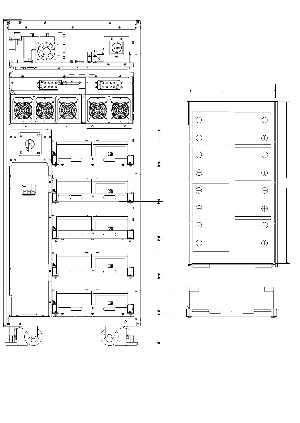
Installation Drawings
38
Figure 26 Internal battery layout
136mm
160mm
160mm
160mm
160mm
151mm
Battery
562mm
347mm
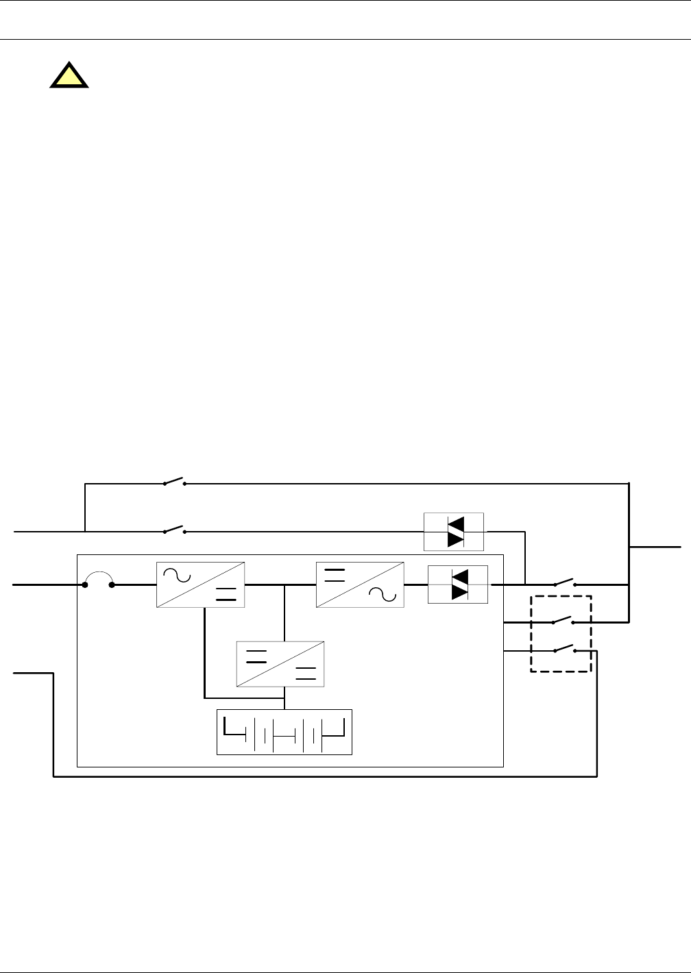
Operation
39
5.0 OPERATION
5.1 Introduction
Liebert’s NX™ Uninterruptible Power System system provides continuous, high-quality AC power to
your business-critical equipment, such as telecommunications and data processing equipment. The
NX UPS supplies power that is free of the disturbances and variations in voltage and frequency com-
mon to utility power, which is subject to brownouts, blackouts, surges and sags.
The NX utilizes the latest in high frequency, double-conversion pulse width modulation (PWM) tech-
nology and fully digital controls to enhance its reliability and increase the ease of use.
The standard NX consists of the UPS and internal batteries in a compact, single cabinet.
As shown in Figure 27, the AC utility source is input at CB1 and the rectifier converts the AC utility
into DC power. The inverter converts that DC power from the utility—or DC power from the batteries
—into AC power for the load. The batteries power the load through the inverter in the event of a
power failure. The utility source can also power the load through the static bypass.
If maintenance or repair of the UPS is necessary, the load can be switched without interruption in
service to the maintenance bypass.
Figure 27 Single unit block diagram with split-bypass input
5.1.1 Split-Bypass Input
Figure 27 illustrates the Liebert NX UPS in what is known as the split-bypass configuration wherein
a separate power switch to a dedicated bypass power source that also feeds the maintenance bypass
line connects the static bypass line. Where a separate power source is not available, the bypass and
rectifier input supply connections are linked.
!WARNING
Hazardous Mains and / or Battery Voltage present behind covers.
No user-serviceable parts are located behind covers that require a tool for their removal. Only
qualified service personnel are authorised to remove such covers.
Bypass
Input
AC Utility
Input
UPS
Output
Neutral
Wire
SW1/D
SW1/C
Rectifier Inverter
Battery
Charger
Discharge
Battery
Static Swich
Static Swich
SW1/A
SW1/B
CB1
Mainten ance Bypass
Neutral
Wire
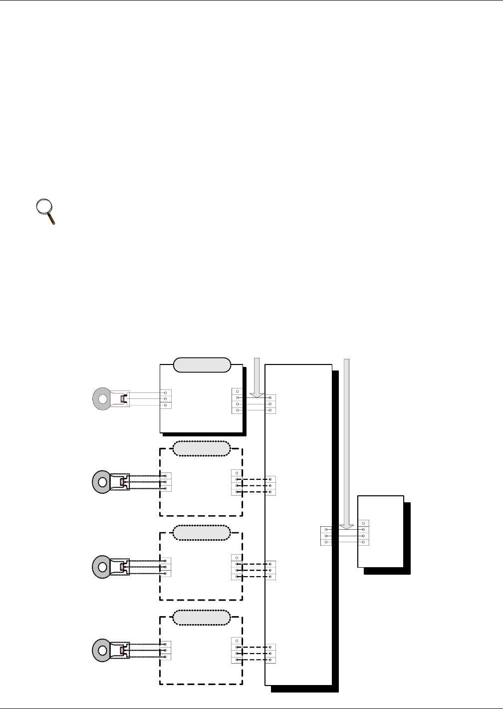
Operation
40
5.1.2 Static Transfer Switch
The circuit blocks labeled Static Switch in Figure 27 contain electronically controlled switching cir-
cuits that enable the critical load to be connected to either the inverter output or to a bypass power
source via the static bypass line. During normal system operation the load is connected to the
inverter; but in the event of a UPS overload or inverter failure, the load is automatically transferred
to the static bypass line.
To provide a clean (no-break) load transfer between the inverter output and static bypass line, the
static switch activates, connecting the load to bypass. To achieve this, the inverter output and bypass
supply must be fully synchronized during normal operating conditions. This is achieved through the
inverter control electronics, which make the inverter frequency track that of the static bypass supply,
provided that the bypass remains within an acceptable frequency window.
A manually controlled, maintenance bypass supply is incorporated into the UPS design. It enables the
critical load to be powered from the utility (bypass) supply while the UPS is shut down for routine
maintenance.
5.1.3 Battery Temperature Compensation
For 10-30kVA UPS with internal batteries, a standard temperature probe is installed to measure the
internal battery temperature to optimize battery management. The measured temperature can be
displayed from the UPS front panel.
For UPS with external batteries, an optional battery temperature interface equally optimises the
external battery management by connecting up to four external temperature sensors from the battery
cabinet(s) to a control unit inside the UPS.
Figure 28 Multiple battery temperature sensors
NOTE
When the UPS is operating in bypass mode or on maintenance bypass, the connected
equipment is not protected from power failures or surges and sags.
Temperature
Sensor
TMP-2
+
IN
-
NC
12V
GND
OUT
BCB Box
BCB Control
Board – C2
+12V
GND
OUT
X103
X105
X104
X106
X108
UPS
Monitor
Board
– U2
X7
-12V
GND
BAT-T
Temperature
Sensor
TMP-2
+
IN
-
NC
12V
GND
OUT
Temperature
Sensor
TMP-2
+
IN
-
NC
12V
GND
OUT
Temperature
Sensor
TMP-2
+
IN
-
NC
12V
GND
OUT
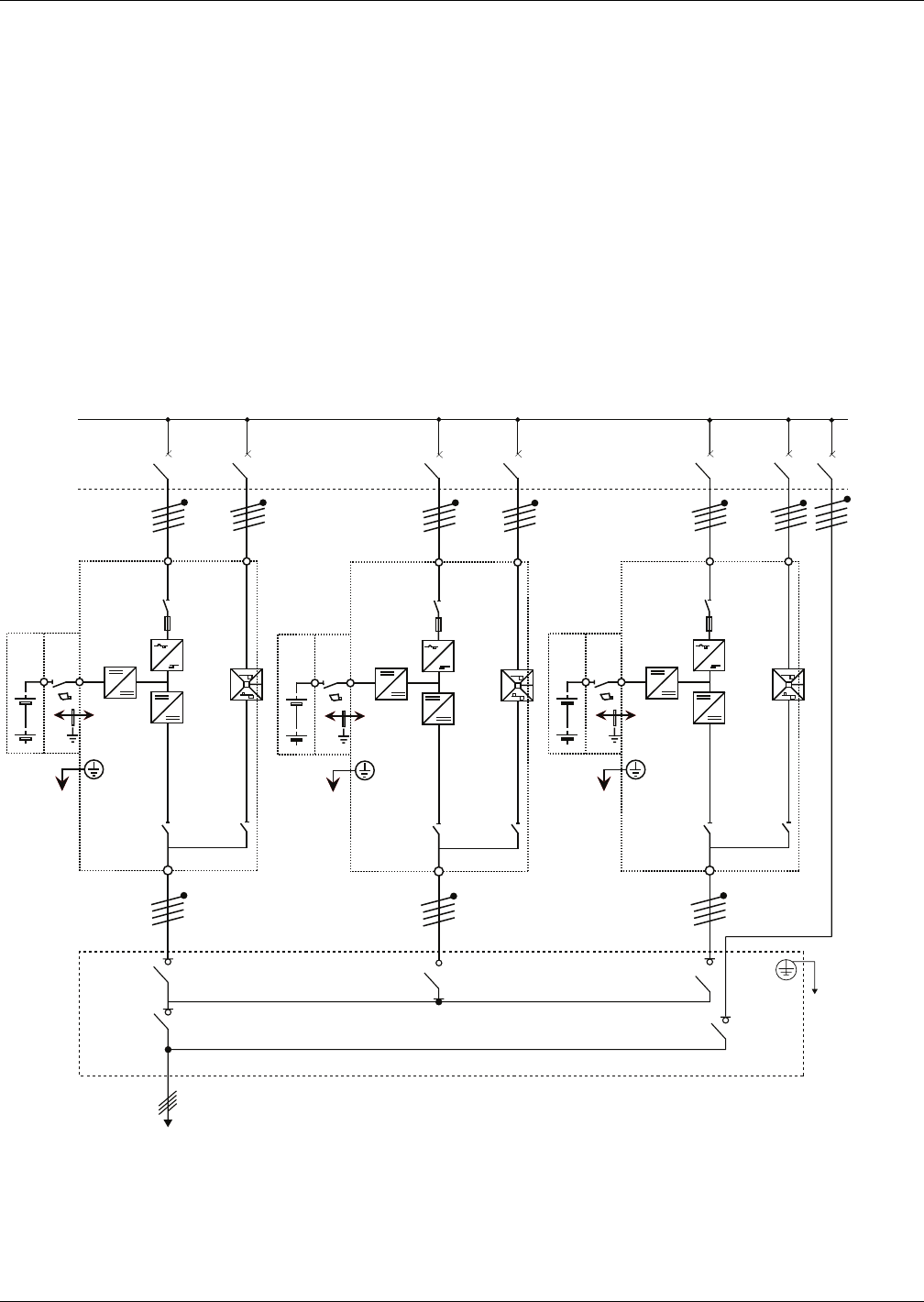
Operation
41
5.1.4 Redundant Control Power Supply Board
The UPS is equipped with two identical and fully redundant control power supply boards. Each of
them takes inputs from the AC and DC sources. When one of the sources or even if one of the control
power boards fails, the UPS system can still operate normally. This feature further enhances the reli-
ability of the system.
5.1.5 Socket Outlet
One single-phase Shuko-type universal outlet of 3A current handling capability provides nominal
UPS output voltage of up to 3A current capacity for the ease of testing, commissioning & servicing of
the UPS.
5.2 Multi Module UPS—1+N
Multi-module UPS are formed by several “single unit” UPS modules to constitute “1+N”system where
groups of one or more, up to six, single units operate together for the purpose of providing additional
power or reliability or both. The load is equally shared between any paralleled UPS.
Figure 29 1+N multi-module UPS with external maintenance bypass switch
Further, single unit or 1+N groups may be configured as “distributed redundant” systems with inde-
pendent outputs that nevertheless are synchronised through a Load Bus Synchroniser (LBS) so that
critical loads can be seamlessly transferred from one system to another. See 5.3 - Modes of Opera-
tion for more information.
CB1
UPS1
OUTPUT
Qout all UPS
Qout UPS1 Qout UPS2
Qout Byp
Qin Ext
Byp
Qin UPS2 Qin UPS3
Qin UPS1
Qout UPS3
RECTIFIER
STATIC
SWITCH
INVERTER
L1,L2,L3,N L1,L2,L3,N L1,L2,L3,N L1,L2,L3,N L1,L2,L3,N L1,L2,L3,N
L1,L2,L3,N
L1,L2,L3,N
L1,L2,L3,N
Supplied by Others
Input Mains Supply Input Mains Supply Input Mains Supply
Bypass Mains Supply
Distribution Cabinet
Bypass Mains Supply
CB1
UPS2
OUTPUT
RECTIFIER
STATIC
SWITCH
INVERTER
CB1
UPS3
OUTPUT
RECTIFIER
STATIC
SWITCH
INVERTER

Operation
42
5.2.1 Features of NX Multi-Module UPS Configurations
1. The hardware and firmware of single module UPS units is completely compatible with the
requirements of a multi-module system. Multi-module configuration is achieved merely through
settings in configuration software.
2. Parallel control cables are connected in a ring, providing both performance and redundancy.
Dual-bus control cables are connected between any two UPS modules of each bus. The intelligent
paralleling logic provides the user with maximum flexibility. For example, shutting down or
starting up UPS modules in a parallel system can be done in any sequence. Transfers between
Normal and Bypass modes of operation are synchronised and self –recovering e.g. following
overloads and their clearance.
3. The total load of the multi-module system can be queried from each module’s LCD display.
5.2.2 Requirements for Paralleling of UPS Modules
A group of paralleled modules behave as if it were one large UPS with the advantage of presenting
higher reliability. In order to assure that all modules are equally utilised and to comply with relevant
wiring rules, the following requirements apply:
1. All UPS modules must be of the same rating and must be connected to the same bypass source.
2. The bypass and the main input sources must be referenced to the same neutral potential.
3. Any RCD, Residual Current monitoring device, if installed, must be of an appropriate setting and
located upstream of the common neutral bonding point. Alternatively, the device must monitor
the combined 4-wire rectifier and split-bypass input currents of the system. Refer to the High
Leakage Current Warning on page 1.
4. The outputs of all UPS modules must be connected to a common output bus.
5.3 Modes of Operation
The NX UPS is an on-line, double-conversion, reverse-transfer UPS that permits operation in these
modes:
•Normal Mode
• Battery Mode (Stored Energy Mode)
• Auto-Restart Mode
• Bypass Mode
• Maintenance Mode (Manual Bypass)
• ECO Mode
• Parallel Redundancy Mode
• Hot-Standby Mode
• Frequency Converter Mode
5.3.1 Normal Mode
The UPS inverter continuously supplies the critical AC load. The rectifier/charger derives power from
the AC mains input source and supplies DC power to the inverter while simultaneously FLOAT or
BOOST charging its associated backup battery.
5.3.2 Battery Mode (Stored Energy Mode)
Upon failure of the AC mains input power; the inverter, which obtains power from the battery, sup-
plies the critical AC load. There is no interruption in power to the critical load upon failure or restora-
tion of the AC mains input power after which the “Normal Mode” operation will continue without the
necessity of user intervention.
5.3.3 Auto-Restart Mode
The battery may become exhausted following an extended AC mains failure. The inverter shuts down
when the battery reaches the End Of Discharge voltage (EOD). The UPS may be programmed to
“Auto Recovery after EOD” after a delay time. This mode and any delay time are programmed by the
commissioning engineer.
NOTE
Optional isolation transformers are available for applications where sources do not share the
same neutral reference or where the neutral is not available.

Operation
43
5.3.4 Bypass Mode
If the inverter overload capacity is exceeded, or if the inverter becomes unavailable for any reason,
the static transfer switch will perform a transfer of the load from the inverter to the bypass source,
with no interruption in power to the critical AC load. Should the inverter be asynchronous with the
bypass, the static switch will perform a transfer of the load from the inverter to the bypass with inter-
ruption in power to critical AC load. This is to avoid paralleling of unsynchronised AC sources. This
interruption is programmable but typically set to be less than 3/4 of an electrical cycle, e.g., less than
15ms (50Hz) or less than 12.5ms (60Hz).
5.3.5 Maintenance Mode (Manual Bypass)
A manual bypass switch is available to ensure continuity of supply to the critical load when the UPS
becomes unavailable e.g. during a maintenance procedure. This manual bypass switch is fitted in all
UPS modules and rated for full load of one module.
5.3.6 ECO Mode (Single UPS Only)
IF ECO mode is selected, the double-conversion UPS operation is inhibited at most times for the pur-
pose of saving energy. In this mode of operation, not unlike UPS of line-interactive or stand-by tech-
nology, the bypass is the preferred source and only when the voltage and / or frequency of the bypass
supply are beyond pre-defined and adjustable limits the critical AC load is transferred to the inverter.
This transfer takes place with an interruption of less than 3/4 of an electrical cycle, e.g., less than
15ms (50Hz) or less than 12.5ms (60Hz).
5.3.7 Parallel Redundancy Mode (System Expansion)
For higher capacity or higher reliability or both, the outputs of up to six UPS modules can pro-
grammed for directly paralleling while a built-in parallel controller in each UPS ensures automatic
load sharing.
5.3.8 Hot-Standby Mode
This is an alternative 1+1 redundancy application that ensures higher availability or better usage
control or both. Two UPS are connected in Hot Stand By mode as follows: UPS 1connects to the criti-
cal load, and UPS 2 connects to the bypass of UPS 1. The remaining AC inputs are connected to the
incoming AC mains supply. UPS 1 synchronises to the output of the UPS 2 ensuring uninterrupted
load transfer from UPS 1 to UPS 2 or vice versa. This ensures that any specified load is supplied by a
UPS while still providing a bypass path to cater for overloads. Further, the system can also be pro-
grammed to reverse UPS1 between Normal and Bypass Modes so that each UPS is equally utilised.
This interval is programmable from 1 to 4,320 hours (180 days).
5.3.9 Frequency Converter Mode
The NX UPS can be programmed into frequency converter mode for either 50Hz or 60Hz stable out-
put frequency. The input frequency may vary from 40Hz to 70Hz. In this mode the static bypass oper-
ation is disabled, and the battery becomes optional depending on any requirement to operate in
battery mode (stored energy mode).

Operation
44
5.4 Battery Management—Set During Commissioning
5.4.1 Normal Function
•Constant charging current—Current can be set up to limit charging power.
•Constant boost voltage boost (if applicable)—Voltage of boost charging can be set as required
by the type of battery.
For Valve Regulated Lead Acid (VRLA) batteries, maximum boost charge voltage should not
exceed 2.4V / cell.
•Float Charge—Voltage of float charging can be set as required by the type of battery.
For VRLA, float charge voltage should be between 2.2V to 2.3V.
•Float Charge Temperature Compensation (optional)—A coefficient of temperature compen-
sation can be as required by the type of battery.
•End of discharge protection (EOD)—If the battery voltage is lower than the EOD, the battery
converter will shut down and the battery is isolated to avoid further battery discharge. EOD is
settable from 1.6V to 1.75V per cell (VRLA) or 0.9 to 1.1 V per cell (NiCd).
•Battery Low Warning Time—Settable between 3 and 60 minutes. The default is 5 minutes.
5.4.2 Advanced Functions (Software Settings Performed by the Commissioning Engineer)
Battery Self-Test and Self-Service
At periodic intervals 20% of the rated capacity of the battery will be discharged automatically. The
minimum amount of load must exceed 20% of the nominal rating of the UPS module. If the load is less
than 20%, auto-discharge cannot be executed. The periodic interval can be set from 30 to 360 days.
The periodic testing can also be inhibited.
•Conditions—Battery float charge for at least 5 hours, load 20~100% of rated UPS capacity
•Trigger—Manually through through the command of Battery Maintenance Test in the LCD
panel or automatically
•Battery Self-Test Interval—30-360 days (default setting is 60 days)
5.5 Battery Protection (settings by commissioning engineer)
Battery Undervoltage Pre-warning
The battery undervoltage pre-warning occurs before the end of discharge. After this pre-warning, the
battery should have the capacity for 3 remaining minutes discharging with full load. The time is user
configured from 3 to 60 minutes.
Battery End of Discharging (EOD) Protection
If the battery voltage is lower than the EOD, the battery converter will be shut down. EOD is settable
from 1.6V to 1.75V per VRLA cell (or 1.0 to 1.1V per NiCd cell).
Battery Isolator Open Warning
If the battery isolator is open, this warning will occur.
The external battery to the UPS through an external battery isolator, which is manually closed and
electronically tripped via the UPS control circuits.
Operating Procedures
45
6.0 OPERATING PROCEDURES
6.1 Introduction
The NX can operate in any of four modes, as shown in Table 9. This section provides instructions on
switching between modes, resetting the UPS, switching the inverter On and Off and performing other
operations.
6.1.1 Power Switches
The UPS unit power switches are CB1 and SW1.
• CB1-Input Current Breaker. Connects the utility supply to the UPS input.
• SW1 - Rotary switch. Has four positions—NORMAL, BYPASS, TEST and MAINT—that corre-
spond to different positions of the SW1-A/B/C/D.
The positions of the rotary switch (SW1) are:
• SW1-A—Output Isolator. Connects the output of the UPS to the load.
• SW1-B—Neutral Isolator. Connects neutral to the UPS.
• SW1-C—Bypass Isolator. Connects the UPS with the bypass supply.
• SW1-D—Maintenance Bypass Isolator. Permits supply of the load directly by the bypass line for
maintenance of the UPS unit.
The functions of the rotary switch are shown in Table 10.
!WARNING
Hazardous mains and / or battery voltage present behind covers.
No user-serviceable parts are located behind covers that require a tool for their removal. Only
qualified service personnel are authorised to remove such covers.
Table 9 UPS operating modes
Operating Mode
Rotary Switch
Position Description
Normal Operation NORMAL The UPS is powering the load.
On Static Bypass BYPASS or
NORMAL
The load power is supplied through the static bypass line. This may be
considered as a temporary mode during load transfers between inverter
and maintenance bypass or supply under abnormal operating conditions.
On Test TEST
No load power is supplied by the UPS. The load is connected to utility
power via the Maintenance Bypass Supply line. NOTE: The load is not
protected against disturbances in AC input power in this mode.
On Maintenance
Bypass MAINT
The UPS is shut down but the load is connected to utility power via the
Maintenance Bypass Supply line. NOTE: The load is not protected
against disturbances in AC input power in this mode.
NOTE
1. The user controls and indicators mentioned in these procedures are identified in 7.0 -
Operator Control Panel and Display.
2. The audible alarm may sound at various points during these procedures. It can be canceled
at any time by pressing the SILENCE ON/OFF push button.
NOTE
This unit refers to some modes and conditions that are set or adjusted using proprietary service
software. To take advantage of all the available features for the NX, the unit must be
commissioned by a Liebert factory-trained service engineer.
Table 10 Rotary switch configurations
Rotary Switch
Position OUTPUT (SW1-A) BYPASS (SW1-C) MAINT
(SW1-D) NEUTRAL (SW1-B)
NORMAL ✔✔ ✔
BYPASS ✔✔ ✔
TEST ✔✔ ✔
MAINT ✔
Operating Procedures
46
6.2 UPS Startup
The NX must be fully installed and commissioned before startup, and external power isolators must
be closed. Once those general conditions are met, the UPS may be started.
6.2.1 Start-Up Procedure
To start the UPS from a fully powered-down condition:
1. Open the UPS door to gain access to the main power switches.
2. Close CB1.
3. Turn the rotary switch to TEST.
The bypass static SCR (M2) closes automatically and the LCD begins to show start-up screens.
The rectifier indicator flashes green while the rectifier is starting up. It stops flashing and
becomes solid green about 30 seconds after the rectifier enters the normal operation state. After
initialization, the bypass static switch closes.
Because output switch SW1-A is still open, the UPS channels power through Maintenance Bypass
Supply line (SW1-D). The bypass indicator extinguishes, provided that the bypass is normal.
The UPS mimic display indicators will be:
4. Turn the rotary switch to BYPASS.
The maintenance switch SW1-D opens and output switch SW1-A closes. The UPS powers from
static bypass instead of from maintenance bypass. The bypass and load indicators turn on. The
design of the rotary switch ensures uninterrupted output.
!WARNING
During this procedure the output terminals will become live.
If any load equipment is connected to the UPS output terminals, please check with the load
user and ascertain whether it is safe to apply power to the load. If the load is not ready to
receive power, then ensure that it is safely isolated from the UPS output terminals.
!CAUTION
Do not operate the rotary switch too fast. Always wait at least 30 seconds when rotating the
switch from one position to another
Indicator State
Rectifier indicator Off
Battery indicator Off
Bypass indicator Off
Inverter indicator Off
Load indicator Off
Status indicator Off
!WARNING
Do NOT turn the rotary switch until the rectifier indicator stops flashing green.
Indicator State
Rectifier indicator Green
Battery indicator Off
Bypass indicator Green
Inverter indicator Off
Load indicator Green
Status indicator Amber

Operating Procedures
47
5. Turn the rotary switch to NORMAL, then press the INVERTER ON control button for 2 seconds.
The inverter will start and the inverter indicator will flash green. After the inverter is ready, the
UPS transfers from bypass to inverter, the bypass indicator turns off and the inverter and load
indicators turn on.
The UPS is operating normally. The UPS mimic display indicators will:
6.2.2 Verify Switching Between Operation Modes
Switch from normal mode to battery mode
• Open CB1 to enter battery mode. This breaks the utility connection to the NX.
To return to normal mode, wait a few seconds and close CB1. The rectifier will restart automati-
cally after 10 seconds and resume feeding power to the inverter.
Switch from Normal Mode to Bypass Mode
• Press INVERTER OFF button to switch to bypass mode.
Switch from Bypass Mode to Normal Mode
• Turn the rotary switch to NORMAL.
• In bypass mode, press the INVERTER ON button. When the inverter is ready, the UPS will
switch to normal mode.
Indicator State
Rectifier indicator Green
Battery indicator Off
Bypass indicator Off
Inverter indicator Green
Output indicator Green
Status indicator Green
NOTE
In bypass mode, the load is being powered by the utility and is not receiving conditioned power
through the inverter.

Operating Procedures
48
6.3 Switching the UPS from Normal to Maintenance Bypass
Follow the procedure below to transfer the load from the inverter output to the Maintenance Bypass
line of the UPS.
This procedure assumes that UPS is operating normally.
1. Press the INVERTER OFF button on the right side of the operator control panel for longer than 2
seconds.
The Inverter indicator will turn off and the status indicator (6) will turn amber and an audible
alarm will sound. The load will transfer to static bypass and the inverter will shut off.
2. Open the UPS door to gain access to the main power switches, SW1 and CB1.
3. Turn the rotary switch to BYPASS position. The UPS Bypass Static Switch still supply power to
load.
4. Turn the rotary switch to TEST. The load is now on maintenance bypass.
5. Turn the rotary switch to MAINT.
6. Open rectifier switch CB1. All operator indicators and messages will turn off as the utility driven
internal power supplies decay. The unit will power down, but the load will continue to be supplied
by the manual maintenance bypass.
6.4 Powering Down the UPS
To power down the UPS completely, follow the procedures in 6.3 - Switching the UPS from Nor-
mal to Maintenance Bypass.
To completely isolate the UPS from the AC supplies, the main external power input isolator (both iso-
lators, where separate supplies are provided for rectifier and bypass) should be opened (see
Figure 30).
!CAUTION
Before performing this operation, read the messages on the LCD to be sure that bypass supply
is regular and the inverter is synchronous with it. If those conditions are not present, there is
a risk of a short interruption in powering the load.
NOTE
Pressing the Alarm Silence Switch cancels the audible alarm, but leaves the warning message
displayed until the appropriate condition is rectified.
!WARNING
Wait 5 minutes for the internal DC busbar capacitors to discharge before attempting to
remove the internal protective barriers.
!WARNING
Even with the UPS rotary switch in maintenance bypass position portions of the unit are still
energized. Service is to be performed by qualified personnel only.
!CAUTION
The load equipment is not protected from normal supply aberrations when operating in the
maintenance bypass mode.
!WARNING
To prevent injury to personnel, lockout or tagout the service supplies.
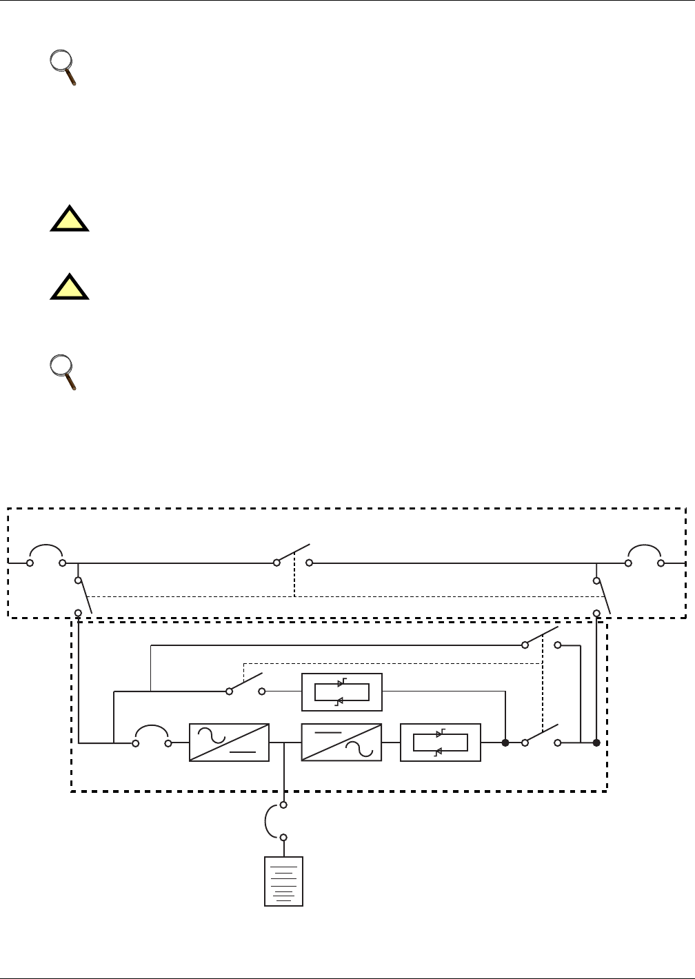
Operating Procedures
49
6.5 Powering Down the UPS and Maintaining Power to Load
If the UPS needs to be shut down completely while maintaining power to the load, follow these steps:
1. Perform Steps 1 through 5 in 6.3 - Switching the UPS from Normal to Maintenance
Bypass.
2. Close the external maintenance bypass rotary switch to Maint position.
The UPS is now completely powered down.
The procedure can be performed only after the installation has been completed (which includes the
maintenance bypass cabinet), after the system has been placed in operation by authorized personnel.
See Figure 30 for more information.
Figure 30 Example of configuration for single UPS with external maintenance bypass cabinet.
NOTE
An external Maintenance Bypass Cabinet must be installed before attempting to perform the
following procedure
!WARNING
On the primary input distribution panel, which is often located distant from the UPS area, a
label should be posted advising service personnel that the UPS circuit is under maintenance.
!WARNING
Wait 5 minutes for the internal DC busbar capacitors to discharge.
NOTE
The maintenance bypass power switch may be operated at any time while the UPS is powered
down to connect the load to the maintenance bypass supply if required
CB1 CB2SW
3P

Operating Procedures
50
6.6 Emergency Shutdown With EPO
This circuit has been designed to switch off the UPS in emergency conditions (i.e., fire, flood, etc.). The
system will turn off the rectifier, inverter and stop powering the load immediately (including the
inverter and bypass), and the battery stops charging or discharging.
If the input utility is present, the UPS’s controls will remain active; however, the output will be
turned off. To remove all power from the UPS, the external feeder breaker should be opened.
6.7 Auto Restart
When the main and bypass sources fail, the UPS draws power from the battery system to supply the
load until the batteries are depleted. When the UPS reaches its end of discharge (EOD) threshold, it
will shut down.
The UPS will automatically restart and enable output power:
• After utility power is restored
• If “Auto Recovery after EOD Enabling” is enabled
• After the “Auto Recovery after EOD Delay Time” expires (the default delay is 10 minutes).
If the “Auto Recovery after EOD Enabling” feature is disabled, the user may restart the system man-
ually by pressing “Fault Clear” button.
6.8 Reset After Shutdown for Emergency Stop (EPO Action) or Other Conditions
Once all appropriate measures have been taken to correct the problem indicated by the alarm mes-
sage appearing on the operator control panel display, carry out this procedure to restore the UPS to
regular operation following an EPO action or for the following reasons: Inverter Overtemperature,
Cut-off Overload, Battery Overvoltage, excessive switching (BYP: XFER COUNT BLOCK), etc.
When the user confirms that the fault is cleared:
1. Press the FAULT CLEAR button to let the system exit the Emergency Off state.
2. Press the INVERTER ON button on the right side of the operator control panel for longer than
2 seconds.
After the EPO button is pressed, if the input utility is removed, the UPS will shut down completely.
When input utility is returned, if the rotary switch (SW1) is in either Bypass or in Normal position,
the UPS will start up on Bypass. There will be power at the output terminals of the UPS.
NOTE
The rectifier will start again, and the bypass will begin to power the load (for units with
internal battery contactor installed, the battery contactor will close). The Rectifier indicator
flashes while the rectifier is starting up. When the rectifier enters the normal operation state
(about 30 seconds), the rectifier indicator turns green.
NOTE
The rectifier will be turned On automatically when the overtemperature fault disappears at
5 minutes after the disappearance of overtemperature signals.
!WARNING
If the rotary switch is in the Maint. position and input utility is present, there will be power at
the output terminals of the UPS.

Operating Procedures
51
6.9 Language Selection
The LCD menus and data display are available in 12 languages: Chinese, Dutch, English, French,
German, Italian, Japanese, Polish, Portuguese, Russian, Spanish and Swedish.To select a different
language than the one being displayed:
1. From the main menu, press the F1 (shift) key to move the cursor to the menu at the top of the
screen.
2. Press F2 and F3 (left and right arrows) as needed to select the Language menu.
3. Press F1 (shift) to move the cursor to the data and settings area of the LCD.
4. Use F2 and F3 (up and down) to select the required language.
5. Press the F4 (enter) key to accept the language selection.
6. Return to the main menu by repeatedly pressing F1 (ESC) as needed; all text on the LCD will now
be displayed in the selected language.
6.10 Changing the Current Date and Time
To change the system date and time:
1. From the main menu, press the F1 (shift) key to move the cursor to the menu at the top of the
screen.
2. Press F2 and F3 (left and right arrows) as needed to select the Settings menu.
3. Press F1 (shift) to move the cursor to the data and settings area of the LCD.
4. Use F2 and F3 (up and down) to select the Date & Time option, then press F4 (enter).
5. Position the cursor on the row in which the date and time are displayed, then press F4 (enter).
6. Using the F2 and F3 (up and down) keys, enter the current time and date information.
7. Press F4 (enter) to save the settings, then press F1 (ESC) to return to the main menu.
6.11 Command Password
Password protection is used to limit the control functions accessible to the operator. The default pass-
word is 12345. This password provides access to UPS and battery test functions.

Operating Procedures
52
6.12 Isolating One Module in a Multi-Module System
1. With all UPS modules in the system in Normal mode, open the external output isolator.
2. Press the UPS EPO to isolate the batteries.
3. Open the UPS door to gain access to the main power switches SW1 and CB1.
4. Turn the rotary switch (SW1) to the Bypass position then continue to rotate to Test.
5. Open rectifier input breaker CB1.
NOTE
The Multi-Module system must have at least one UPS module redundant in the system and
have an external output breaker installed with interlocking cables connected to the UPS
module. The inverter firmware in each UPS in the system must be I140 or greater.
NOTE
Opening the external output isolator under these condtions puts the UPS module into Standby
mode. This is indicated by a flashing inverter LED and the message “Check UPS output.”
An “Inverter asynchronous” alarm is also normal. The remaining UPS modules will remain on
line and “Parallel comm fail” will annunciate.
NOTE
With the UPS external output breaker open and auxiliary switches closed the UPS control will
enable the UPS switch to be rotated through “Bypass” without initiating the remaining on line
UPS modules to transfer to Bypass.
!WARNING
Hazardous Battery Voltage
No operator serviceable parts are located behind covers that require a tool for their removal.
Only qualified service personnel are authorised to remove such covers.
The UPS battery and connecting terminals remains energized at hazardous voltage levels at
all times. The battery is located behind protective covers that require a tool for their removal:
inside the UPS cabinet, inside a free-standing battery cabinet or on open racks inside a
dedicated battery room that may be locked.

Operating Procedures
53
6.13 Inserting One Module into a Multi-Module System
This procedure is indicated to reintegrate a UPS module that has been previously isolated from other
modules of a group of paralleled UPS modules. It is assumed that the installation is complete, the sys-
tem has been commissioned by authorized personnel and the external power isolators are open.
1. Open the UPS door to gain access to the main power switches.
2. Rotate the switch to Test position. The LCD display becomes active.
3. Close the Input breaker CB1
The Rectifier indicator flashes on the UPS mimic panel during the startup of rectifier and
becomes steady green once the rectifier reaches normal operation state after about 30s.
4. Close external battery circuit breaker QF1 (where an external battery is used). This breaker is
located inside the battery cabinet (if used) or is otherwise adjacent to the battery racks
5. Following battery availability being detected by the UPS, the red battery indicator extinguishes
moments after when the battery charger starts operation.
6. Rotate switch to Bypass position
7. Turn the rotary switch to NORMAL.
8. Close external output power isolators.
9. Press the INVERTER ON control button for 2 seconds.
The inverter will startup and the inverter indicator will flash while it synchronizes to the load
voltage and frequency. After the inverter is ready, the UPS connects to the load, the inverter indi-
cator becomes steady green and the output indicator becomes green.
10. Check that no “Warning” message is displayed in the top right corner of the LCD Monitor and the
status of the indicators as follows:
The UPS is now operating in NORMAL mode.
!WARNING
Mains voltage will be applied to UPS output terminals.
No operator serviceable parts are located behind covers that require a tool for their removal.
Only qualified service personnel are authorised to remove such covers.
# LED LED Function Status
1 Rectifier indicator green
2 Battery indicator off
3 Bypass indicator off
4 Inverter indicator green
5 Output indicator green
6 Alarm indicator off
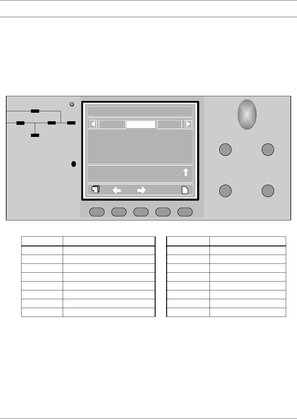
Operator Control Panel and Display
54
7.0 OPERATOR CONTROL PANEL AND DISPLAY
7.1 Introduction
The operator control panel and display is located on the front door of the UPS. The panel is the access
point for operator control and monitoring of all measured parameters, UPS and battery status and of
event and alarm logs.
Figure 31 UPS control and display panel
Table 11 UPS control and display panel components
Component # Function Button Function
1 Rectifier (Input AC to DC) EPO Emergency Power Off button
2 Battery (DC Back-up) Inverter ON Inverter start button
3 Bypass Input Inverter OFF Inverter shutdown button
4 Inverter (DC to AC) Fault Clear Reset button
5 Load (AC Output) Silence On/Off Audible Alarm Mute
6 UPS Status and Alarm indicator — —
7 Audible Alarm (Buzzer)_ F1-F4, Help LCD Menu keys
8 Emergency Power Off Button cover — —
EPO
INVERTER ON
FAULT CLEAR SILENCE ON/OFF
3
1
2
45
Status
?
Rotary SW. normal pos.17:2407-07
Manual turn on
Normal mode
17:29
17:30
07-07
07-07
7
8
6
INVERTER OFF
F2 F3 F4 HELPF1
LoadBypass Output
Liebert NX
020kVA 3X3
2005-10-22
Single
17:32:20
Normal
L1-N/L2
229.5
24.5
49.97
397.5
0.99
L2-N/L3
229.5
24.5
49.97
397.5
1.00
L3-N/L1
229.5
24.5
49.97
397.5
0.99
L1-N/L2 voltage (V)
L-N current (A)
Frequency (Hz)
L-L voltage (V)
Power Factor
The operator control panel is divided into three functional areas
Mimic Power Flow Chart Graphic LCD monitor with menu keys Direct Access keys

Operator Control Panel and Display
55
7.1.1 Mimic Power Flow
The LEDs mounted on the mimic flow chart represent the various power paths and current UPS oper-
ational status.
7.1.2 Audible Alarm (Buzzer)
UPS activity is accompanied by the following sounds
Table 12 Rectifier indicator—1
Green Rectifier in Normal Operation
Flashing
Green
Input AC Normal, but rectifier not operating
Red Rectifier Failed
Off Rectifier Not operating, Input AC Not Available or out of normal range
Table 13 Battery indicator—2
Green Battery Normal, but discharging and powering the load
Flashing
Green
Battery End of Discharge pre-warning
Red
Battery abnormal (Failed, Absent or Polarity Reversed) or Battery
Converter abnormal
(Failed, overcurrent, overtemperature)
Off Battery and Converter Normal, Battery charging.
Table 14 Bypass indicator—3
Green Load on Bypass power
Red Bypass not available, out of normal range or Static bypass switch fault.
Off Bypass Normal, load not on bypass
Table 15 Inverter indicator—4
Green Inverter Normal and powering the load
Flashing
Green
Inverter ON, starting up, synchronising,
or standing by (ECO mode)
Red Inverter failed
Off Inverter not operating
Table 16 Load indicator—5
Green UPS output ON and Normal
Red UPS output ON and Overloaded
Off UPS output OFF.
Table 17 Status (Alarm) indicator—6
Green Normal Operation
Yellow UPS Warning e.g. AC Input Failure
Red UPS fault e.g. Fuse or Hardware failure
Table 18 Audible alarm key
Single beep Direct Access key acknowledgement
One beep
per second
UPS Warning e.g. AC Input Failure
Continuous
beep
Fault e.g. Fuse or Hardware failure
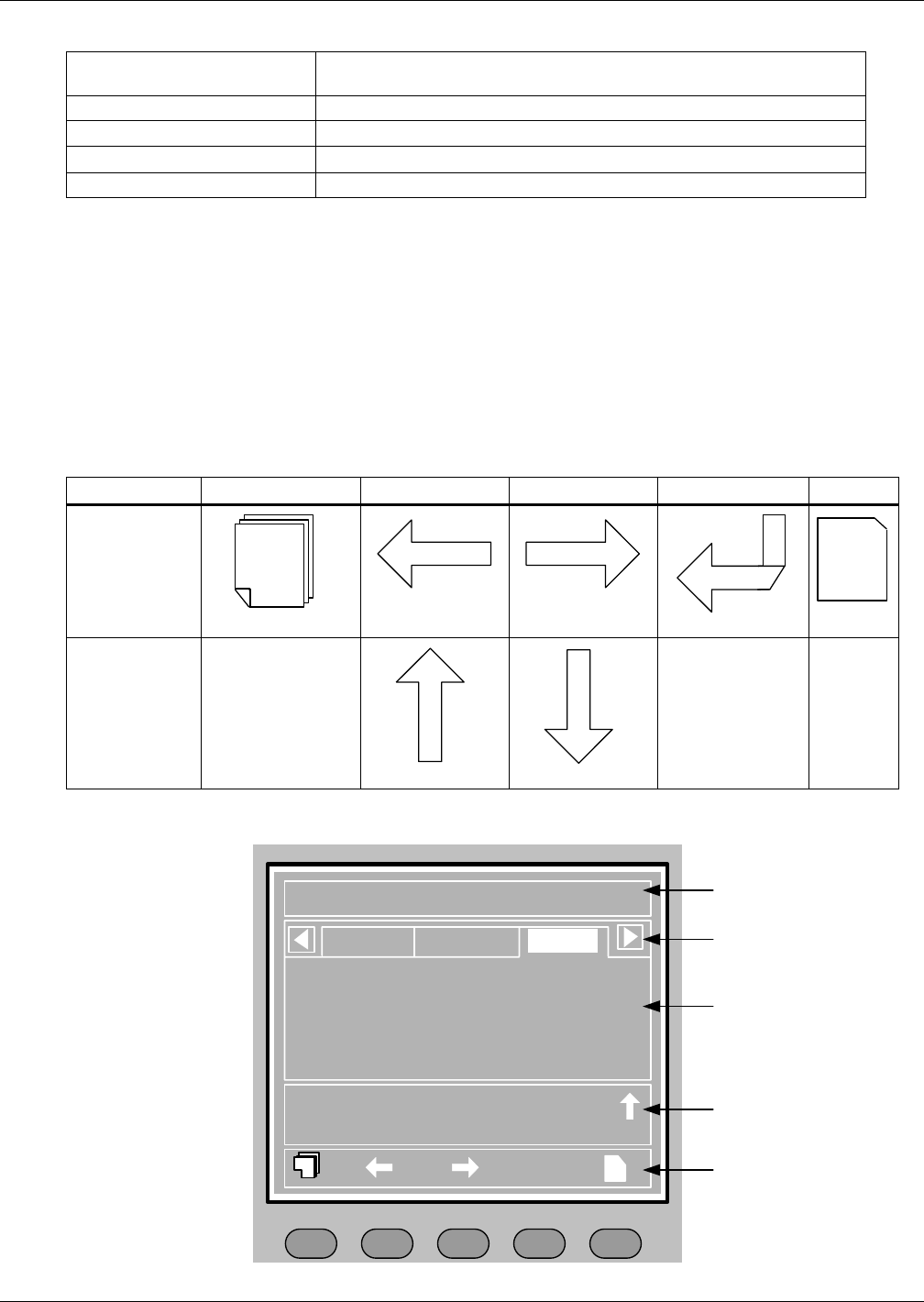
Operator Control Panel and Display
56
7.1.3 Direct Access Push Buttons (Keys)
Press and hold Direct Access key briefly until acknowledged by a single beep.
7.1.4 LCD Monitor and Menu keys
The user-friendly and menu-driven 320 x 240 dot graphic LCD monitor displays real time data and at
the same time stores 512 historical records that can retrieve for reference and diagnosis.
The user can perform commands or easily browse through the input, output, load and battery param-
eters. For quick reference, the UPS status and any warnings are always highlighted without the need
of navigating through the menu. The versions of converter firmware, inverter firmware and internal
monitor firmware can also be displayed on the LCD.
Menu keys F1 to F4 are used to navigate within the graphic LCD monitor windows.
Figure 32 Graphic LCD monitor windows and keypad
Emergency Power Off (EPO) Disconnects Power to the Load. Disables rectifier, inverter, static bypass
and battery operation.
Inverter ON Enables Inverter Operation
Inverter OFF Disables Inverter Operation
Fault clear Resets blocked UPS functions (subject to any fault being cleared)
Silence ON/OFF Toggle type buzzer mute. Any new fault re-enables the buzzer.
Table 19 Menu key Icons and their meaning
Key F1 F2 F3 F4 Help
Window Type 1
Next Data Window
LEFT RIGHT
ENTER HELP
Window Type 2
Escape
UP DOWN
?
ESC
Liebert NX
20kVA 3X3
?
Output
2005-10-22
Unit #1
17:32:20
Normal
F2 F3 F4 HELPF1
Bypass
Main
A(AB) B(BC) C(CA)
Vphase V 220 220 220
Iphase A 20.5 20.5 20.5
Freq. Hz 50.1 50.1 50.1
Vline V 380 380 380
P.F. 0.99 0.99 0.99
Input breaker closed 01-12 12:28:16
Manual turn on 01-12 12:30:06
UPS in normal mode 01-22 12:30:16
4 - Current Record
Window
3 - UPS Data
Window
2 - UPS Menu
Window
1 - UPS System
Window
5 - Keypad Window
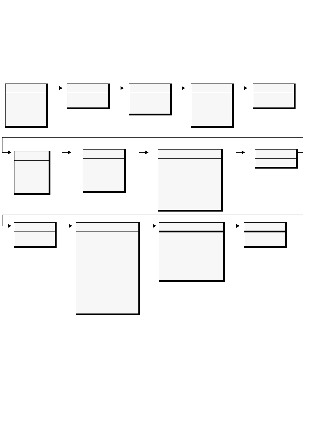
Operator Control Panel and Display
57
The function of keys F1 to F4 is shown by a self-explanatory icon as appropriate for the particular
window. As shown in Figure 32 above, pressing F1 moves the cursor (resting in “OUTPUT”) from the
UPS Menu Window (2) to current record window (4) where it would first rest in “Input breaker closed’.
In a similar manner, pressing F2 would move the cursor from the Output data window to the Bypass
data window.
The summary menu tree is shown below. Refer to 7.2 - All Status and Event Messages Displayed
on the UPS Front Panel for a detailed description of each menu item.
Figure 33 Menu tree
Battery
Battery voltage (V)
Battery current (A)
Battery temperature (°C)
Remain Time Min.
Battery capacity (%)
Battery boost charging
Battery float charging
Battery disconnected
Command
Battery maintenance test
Battery capacity test
System test
Stop testing
Freshening Charge
Stop Freshening
Charge
Version
UPS version
UPS model
Settings
Display contrast
Date format set
Date & time
Comm1 baud rate
Comm2 baud rate
Comm3 baud rate
Communication address
Communication mode
Callback times
Phone No.1
Phone No.2
Phone No.3
Command password
System
Sout (kVA)
Pout (kW)
Qout (kVAR)
Single unit, no
parallel data
Records
(history log)
Language
(Choices for
display)
Mains (input)
L-N voltage (V)
L-N current (A)
Frequency (Hz)
L-L voltage (V)
Power factor
Load
Sout (kVA)
Pout (kW)
Qout (kVAR)
Loadlevel %
Crest factor
Bypass
L-N voltage (V)
Frequency (Hz)
L-L voltage (V)
Output
L-N voltage (V)
L-N current (A)
Frequency (Hz)
L-L voltage (V)
Power factor
TX Input *
L-N voltage (V)
L-L voltage (V)
* When configured, input transformer voltages are
displayed on the front LCD. When not activated, the
values are hidden.
** When configured, output transformer voltages are
displayed on the front LCD. When not activated, the
values are hidden.
TX Output **
L-N voltage (V)
L-L voltage (V)

Operator Control Panel and Display
58
7.1.5 Detailed Description of Menu Items
The description that follows refers to the graphic LCD monitor window shown on Figure 32.
UPS System Window: This fixed-pane window displays current time and date and identifies the UPS,
its configuration and its status.
Menu and Data Window
Use the horizontal arrow keys to navigate between any of the selectable menu and data windows.
Table 20 UPS system window
Description Explanation
Liebert NX UPS family name
2005-10-22 YYYY-MM-DD (see Settings menu for other date formats)
12:30:36 Current Time (24 hr HH:MM:SS format)
30kVA-3x3 30kVA = UPS rated output, 3 x 3 = 3-phase input and output
(Configuration)
Single, ECO, Master, Slave or Unit # 1
Single = single double-conversion unit
ECO = single stand-by unit with double-conversion fall-back
Master = master in a 1+1 Hot Stand By system
Slave = slave in a 1+1 Hot Stand By system
Unit # 1 = of max 6 double-conversion units in a parallel system
(Status)
Normal, Warning or Fault
Normal = UPS operating Normal
Warning = System attention required, e.g. AC Input Failure
Fault = UPS Fuse or Hardware Failure
Table 21 Descriptions of UPS menus and data window items
Menu
Type Item Type Explanation
Mains
(input)
L-N voltage (V) Phase voltage
L-N current (A) Phase current
Frequency (Hz) Input frequency
L-L voltage (v Line-line voltage
Power factor Power factor
TX Input L-N voltage (V) Phase voltage
L-L voltage (V) Line-line voltage
Bypass
L-N voltage (V) Phase voltage
Frequency (Hz) Bypass frequency
L-L voltage (A) Line-line voltage
Output
L-N voltage (V) Phase voltage
L-N current (A) Phase current
Frequency (Hz) Input frequency
L-L voltage (V) Line-line voltage
Power factor Power factor
TX Output L-N voltage (V) Phase voltage
L-L voltage (V) Line-line voltage
Load
Sout (kVA) Sout: Apparent power
Pout (kW) Pout: Active power
Qout (kVAR) Qout: Reactive power
Loadlevel % The percent of the UPS rating load
Crest factor Output current Crest Factor

Operator Control Panel and Display
59
System
Sout (kVA) Sout: Apparent power
Pout (kW) Pout: Active power
Qout (kVAR) Qout: Reactive power
Single unit, no parallel data When configured as a single unit, UPS has only native load, no system
load.
Battery
Battery voltage (V) Battery bus voltage
Battery current (A) Battery bus current
Battery temperature (°C) Internal battery temperature °C
Remain Time Min. Battery run time remaining
Battery boost charging Battery is boost charging
Battery float charging Battery is float charging
Battery disconnected Battery is not connected
Records (history log) Displays all records in the history log
Language (choices for text displayed) User may select any of 12 languages for LCD text.
Settings
Display contrast Adjust the LCD display contrast
Date format set Choose the format for date display: M/D/Y, D/M/Y, M/D/Y, Y/M/D
Date & time Set the date and time
Comm1 baud rate Communication baud rate setting for Intellislot 1
Comm2 baud rate Communication baud rate setting for Intellislot 2
Comm3 baud rate Communication baud rate setting for Intellislot 3
Communication address This setting is applicable to RS485 communication mode
Communication mode Communication Mode Setting
Callback times When Intellislot 1 Communication mode is Modem, this parameter sets
the number of times a number is redialed to send an alarm notification.
Phone No.1 When Intellislot 1 Communication mode is Modem, this is the first phone
number to be dialed (to send an alarm notification).
Phone No.2 When Intellislot 1 Communication mode is Modem, this is the second
phone number to be dialed (to send an alarm notification).
Phone No.3 When Intellislot 1 Communication mode is Modem, this is the third phone
number to be dialed (to send an alarm notification).
Command password User can modify the command password.
Command
(start/stop
battery &
system
tests)
Battery maintenance test This test performs a partial discharge of the battery to obtain a rough
estimate of the battery capacity. Load must be between 20% and 100%.
Battery capacity test This test performs a full discharge of the battery to obtain a precise
measure of the battery capacity. Load must be between 20% and 100%.
System test This is a self-test of the UPS. When the user activates this function, a pop-
up window appears about 5 seconds later to show the results.
Stop testing Manually stops a battery maintenance test, battery capacity test or system
test.
Freshening Charge This command will allow a temporary Equalize charge for the batteries.
This charge is configurable for 1 to 36 hours
Stop Freshening Charge Manually stop a Freshening Charge
Version UPS version Provides UPS firmware version numbers for the inverter, rectifier and
software display board.
UPS model Provides UPS model information—for example, 400V-50Hz.
Table 21 Descriptions of UPS menus and data window items (continued)
Menu
Type Item Type Explanation

Operator Control Panel and Display
60
Current Record Window
Keeps a log the events that resulted in the current mode of operation. Ignores transient conditions
that have been resolved.
Use “page” (F1) and up / down arrow to read the events.
For a complete history log, refer to the Records tab of the Menu and Data Window.
Refer to Table 22 for a complete list of supported status messages.
7.2 All Status and Event Messages Displayed on the UPS Front Panel
This is the complete list of UPS events and status messages supported for display in either the Record
window (Historic data) or in the Current window (Prevailing data) as described in 7.1.4 - LCD Moni-
tor and Menu keys.
Table 22 UPS messages
Message Description / Suggested Action (if any)
Inverter Comm. Fail Internal RS485 communication failure between monitor and inverter
Rectifier Comm. Fail Internal RS485 communication failure between monitor and rectifier
Parallel Comm. Fail
The CAN communication between different UPSs within a parallel system fails.
1.Check if there are some UPSs not powered on in the parallel system. If so, power on these
UPSs and check if the alarm disappears.
2. Press Fault Clear push button.
Battery Overtemp. The Battery temperature is over limit. Check the battery temperature and ventilation
Ambient Overtemp. The Ambient temperature is over limit. Check the ventilation of UPS room.
Battery Fault Battery detected faulty (Reserved)
Replace Battery Battery test failed, Battery should be replaced.
Battery Low Pre-warning
Before the end of discharge, battery undervoltage pre-warning should occur. After this pre-
warning, battery should have the capacity for 3 minutes discharging with full load. The time is
user-configured from 3 to 60 minutes.
Shut down the load in time.
Battery End of Discharge Inverter turned off due to low battery voltage. Check the utility failure and try to recover it.
Mains Volt. Abnormal Mains Voltage exceeds the upper or lower limit and results in rectifier shutdown.
Check the input line-to-neutral voltage amplitude of rectifier.
Mains Undervoltage Mains Voltage is undervoltage with derated load.
Check the input line-to-line voltage amplitude of rectifier
Mains Freq. Abnormal Mains frequency is out of limit range and results in rectifier shutdown.
Check the rectifier’s input voltage frequency
Rectifier Fault Rectifier detected faulty. Rectifier shuts down. Battery discharges.
Rectifier Overtemp. The temperature of heat sink is too high to keep the rectifier running.
The UPS can recover automatically. Check the environment and ventilation.
Batt. Contactor Fail Battery contactor or circuit breaker not responding to control signals.
Batt. Charger Fault The voltage of the battery charger is too high.
Control Power 1 Fail UPS operates but Redundant Control Power is not available.
Mains Phase Reversed AC Input phase sequence is reversed.
Rectifier Overcurrent Rectifier is overloaded.
Soft Start Fail Rectifier could not start due to low DC bus voltage
Bypass Unable to Trace
This alarm is triggered by an inverter software routine when the amplitude or frequency of
bypass voltage is beyond the normal range.
The amplitude threshold is fixed for positive and negative 10% rating.
This alarm automatically resets once the bypass voltage goes normal.
1. First verify that the bypass voltage and frequency displayed on the panel is within the
selected range. Note here the rated voltage and frequency are specified by “Output voltage
level” and “Output frequency level” respectively.
2. If the displayed voltage is believed to be abnormal, then verify the bypass voltage and
frequency presented to the UPS. Check the external supply if it is found to be faulty.

Operator Control Panel and Display
61
Bypass Abnormal
This alarm is triggered by an inverter software routine when the amplitude or frequency of
bypass voltage exceeds the limit.
This alarm automatically resets once the bypass voltage goes normal.
First check if there are some relevant alarms such as “Bypass disconnect open”, “Bypass phase
reverse” and “Mains neutral lost”. If they appear, solve them first.
1. Then verify that the bypass voltage and frequency displayed on the panel is within the bypass
limit. Note here the rated voltage and frequency are specified by “Output voltage level” and
“Output frequency level” respectively.
2. If the displayed voltage is believed to be abnormal, then verify the bypass voltage and
frequency presented to the UPS. Check the external bypass supply if it is found to be faulty. If
the utility is likely to trigger this alarm frequently, the bypass limit can be changed a little larger
through the configuration software according to the customer’s agreement.
Inverter Asynchronous
This alarm is triggered by an inverter software routine when the inverter and bypass waveforms
are misaligned by more than 6 degrees in phase. This alarm resets automatically once the
condition is no longer true.
1. First check if the alarm “Bypass unable to trace” or “Bypass abnormal” occurs. If so, solve it
first.
2. Verify the waveform of the bypass voltage. If it is too distorted, ask the customer to verify and
seek any possible measurements.
Inverter Fault Inverter output voltage beyond limits. Load transfers to bypass.
Inverter Overtemp.
The temperature of the inverter heat sink is too high to keep inverter running.
This alarm is triggered by the signal from a temperature monitoring thermostat on the inverter
bridge heat sink.
The UPS will recover automatically after a 5 minute delay from the disappearance of the
overtemperature signal.
If the overtemperature condition is true, then check for and verify:
1. high ambient air temperature.
2. blocked cooling airway.
3. any fan failure.
4. prolonged inverter overload
Fan Fault At least one of the cooling fans has failed
Inverter STS Fail At least one of the static switches of inverter side is open or short circuit. This fault is locked until
power off.
Bypass STS Fail At least one of the static switches of bypass side is open or short circuit. This fault is locked until
power off
Operation Invalid This record is registered following an incorrect operation:
Output Fuse Fail At least one of the inverter output fuses is blown. Inverter shuts down. Load transfers to bypass.
Control Power 2 Fail UPS operates but Redundant Control Power is not available.
Unit Over load
The UPS is confirmed to be overload when the load arises above 105% nominal rating.
The alarm automatically resets once the overload condition is removed.
1. Confirm that the alarm is true by checking the load percent indicated on the LCD panel to
determine which phase is being overloaded.
2. If the alarm is true, measure the actual output current to verify that the indications are valid.
Disconnect unnecessary load and ensure the safety. In a parallel system, a severe load sharing
error can also leads to the alarm.
System Over load
The UPS parallel system is confirmed to overload when the total load arises above 105%
nominal rating for the set basic number of UPSs. The alarm automatically resets once the
overload condition is removed.
1. Confirm that the alarm is true by checking the system load percent indicated on the LCD
panel to determine which phase is being overloaded.
2. If the alarm is true, measure the actual output current to verify that the indications are valid.
Disconnect unnecessary load and ensure the safety. In a parallel system, a severe load sharing
error can also leads to the alarm.
Table 22 UPS messages (continued)
Message Description / Suggested Action (if any)

Operator Control Panel and Display
62
Unit Over load Timeout
The UPS is confirmed to overload and the overload times out.
Note 1: the highest loaded phase will indicate overload timing-out first.
Note 2: When the timer is active then alarm “unit overload” should also be active as the load is
above nominal.
Note 3: When the timer has expired, the inverter Static Switch is opened and the load
transferred to bypass. The inverter shutdown and will restart after 10 seconds.
Note 4: If the load decreases lower than 95% after 5 minutes, the system will transfer back to
inverter mode.
Confirm that the alarm is genuine by checking the load percent indicated on the LCD. If an
overload is indicated then check the load, and investigate any additional load connected prior to
the alarm (if applicable).
Byp. Abnormal Shutdown Both bypass and inverter voltages unavailable. Load interruption
Inverter Over Current Inverter Pulse Width Modulation module overloaded.
Bypass Phase Reversed
The phase sequence direction of bypass voltage is reversed.
Normally, the phase of phase B lags 120 degrees behind phase A, and the phase of phase C
lags 120 degrees behind phase B.
Verify that the phase rotation of the bypass supply presented to the UPS is correct, and rectify it
if it is found to be in error
Load Impact Transfer A transfer to bypass occurred due to a large step load. The UPS should recover automatically.
Turn on connected equipment in sequential order to reduce the step loading of the inverter.
Transfer Time-out
The load is on bypass power due to excessive number of transfers that occurred within the last
hour.
The UPS will recover automatically and will transfer the load back to inverter power within an
hour.
Load Sharing Fault UPS modules within a parallel system are not sharing the load current equally.
DC Bus Abnormal DC input voltage to inverter beyond limits. Inverter shuts down. Load transfers to bypass.
System Transfer The whole paralleled UPS system transferred to bypass at the same time. This message will
appear on the UPS which passive transfer to bypass
Parallel Board Fault Malfunction of the paralleling control circuits of this UPS module. Can cause “System Transfer”
to bypass.
DC Bus Over Voltage
Rectifier, inverter and battery converter were shutdown because DC bus voltage is too high.
Check whether there is a fault in rectifier side. If no, then check whether overload occurs.
Restart the inverter after resetting the fault
Parallel Connect Fault
The parallel cables are not connected correctly in a parallel system.
Reset the fault by pressing the “fault clear” button, then restart the inverter by pressing the
“inverter on” button.
Bypass Over Current Bypass current is over limit above 135% rating. The UPS just alarms and does nothing.
LBS Active Load Bus Synchronisation is active. The UPS is acting as an LBS master or slave in a dual bus
configuration.
Setting Save Error History records not saved. (Reserved)
Mains Neutral Lost AC Input mains reference neutral not detected.
Protocol version clash Firmware incompatibility between Monitor Board and Digital Signal Processor Board.
Battery ground fault Battery leakage to ground detected (option)
Inv. Turned On Manually Manual Turn On via front panel
Inv. Turned Off Manually Manual Turn Off via front panel
EPO Emergency Power Off direct access key pressed or external command received
Transfer Confirm Prompt to press “enter” key to acknowledge that an interrupted load transfer to bypass will
happen.
Transfer Cancel Prompt to press “ESC” key to avoid that an interrupted load transfer to bypass will happen.
Unit Off Confirm Prompt to press “enter” key to acknowledge that the UPS will be disconnected from other
paralleled UPS modules.
System Off Confirm Prompt to press “enter” key to acknowledge that the all paralleled UPS will be disconnected
from the load.
Table 22 UPS messages (continued)
Message Description / Suggested Action (if any)

Operator Control Panel and Display
63
Fault Reset Fault clear direct access key pressed
Alarm Silence Silence On/Off direct access key pressed
Turn On Fail Inverter failed to turn on when Inverter On direct access key was pressed. This may be as a
result of Invalid Operation (Maintenance bypass on) or DC bus or rectifier not ready.
Alarm Reset Fault clear or Silence On/Off direct access key pressed
Bypass Mode Load supplied from AC input bypass supply.
Normal Mode Load supplied from Inverter output through double conversion of the AC mains input supply.
Battery Mode Load supplied from Inverter output through double conversion of the Battery supply.
Source share mode Load supplied from Inverter output through shared double conversion of the AC mains input
supply and of the Battery supply.
UPS Shutdown UPS Shutdown, output power-down
Check UPS Output Inverter off during normal startup (diagnostics information only)
Generator Connected Generator active signal received. Source share mode may be activated pending UPS settings.
BCB open Battery Circuit Breaker status (open)
BCB closed Battery Circuit Breaker status (closed)
Battery Float Charging Battery status (Float charge mode)
Battery Boost Charging Battery status (Boost charge mode)
Battery Discharging Battery status (discharge mode)
Battery Period Testing Automatic periodic battery maintenance discharge test (20% capacity discharge)
Batt. Capacity Testing User initiated battery capacity discharge test (100% capacity discharge)
Batt. Maint. Testing User initiated maintenance discharge test (20% capacity discharge)
UPS System Testing User initiated UPS self test
Inverter in Setting Inverter starting up and synchronising
Rectifier in Setting Rectifier starting up and synchronising
MBP-T cabinet Fan Fault Maintenance bypass cabinet fans fault.
Ext Input TX Overtemp External Input Isolation Transformer Over Temperature
Ext Output TX Overtemp External Output Isolation Transformer Over Temperature
Battery Room Alarm Environment in Battery Room Needs Attention
Rotary Sw. Test Pos. Rotary switch is in test position.
Rotary Sw. Normal Pos. Rotary switch is in normal position.
Rotary Sw. Bypass Pos. Rotary switch is in bypass position.
Rotary Sw. Maint. Pos. Rotary switch is in maintenance position.
Battery Contactor Open Battery Contactor Open
Battery Contactor Close Battery Contactor Closed
Battery Reverse Connect the battery again and check the wiring of batteries
No Battery Check the battery and the wiring of batteries
Auto start After UPS was shutdown at EOD, inverter auto starts when utility restore
Rec. Flash Update Rectifier firmware is being update
Inv. Flash Update Inverter firmware is being update
Monitor Flash Update Monitor firmware is being update
Input contactor fault Input contactor is in fault
Contactor P.S. 1 fault Contactor Power Supply board 1 Fault
Contactor P.S. 2 fault Contactor Power Supply board 2 Fault
LBS abnormal LBS is abnormal
DSP firmware error The inverter firmware does not match with the rectifier firmware.
Table 22 UPS messages (continued)
Message Description / Suggested Action (if any)
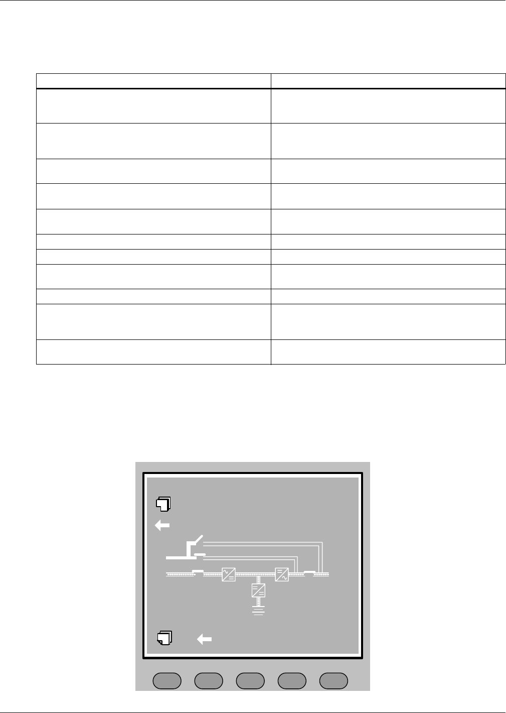
Operator Control Panel and Display
64
7.3 Prompt (Pop-Up) Windows
The prompt window is displayed during the operation of the system to alert the user to certain condi-
tions and / or to require user confirmation of a command.
7.4 Dynamic Energy Flow Chart and UPS Help Screen
This screen displays a mimic diagram of the UPS that includes energy flow and status of isolation and
transfer switches. Press the “Help” key to activate this screen. Press again to toggle between this
screen and the main screen.
Figure 34 Help screen
Table 23 Prompt windows, meanings
Prompt Meaning
Transfer with interrupt, please confirm or cancel
Inverter and Bypass supplies are not synchronised and
any load transfer between the supplies will cause a brief
load interruption.
The load is too high to be transferred with interrupt
The total load must be less than the capacity of one unit
to allow a parallel system to perform an interrupted
transfer from bypass to inverter.
This Operation Leads to Output Shutdown, Confirm or
Cancel
No alternative supply is available and any Inverter Off
operation will cause the load to be de-energised.
This operation leads to inverter overload, confirm or
cancel
The turn-off this inverter will lead to the overload of
remaining inverter(s) in a parallel system.
Turn on more UPS to carry current load The number of paralleled inverters already turned on is
insufficient to carry the existing load.
Battery will be depleted, confirm Battery Capacity test discharges the battery 100%
System self test finished - everything is ok. No action required
System self test finished - Please check the current
warnings. Check “Current Records” window
Enter control password Required for Battery or UPS test (default = 12345)
Battery Self Test aborted, condition not met
Battery self-test condition is not enough. User should
check whether battery state is boost charging and
whether load level is greater than 20 percent.
Battery Refresh Charge aborted, condition not met Boost charging condition is not enough, such as (No
battery, charger has failed, etc.).
F2 F3 F4 HELPF1
Help information
Select the current record window
Press help key back to main menu
Select the previous menu item
Operator Control Panel and Display
65
7.5 Default Screen Saver
This default screen is displayed following at least 2 minutes of operation with no new alarm. After
another delay, the backlight turns off. Press any key (F1-F4 or Help) to reactivate the screen.
Figure 35 Default screen
F2 F3 F4 HELPF1
Liebert NX 2005-05-22 12:30:36
20 kVA-3x3 UNIT #1 NORMAL
Press any key, back to main menu
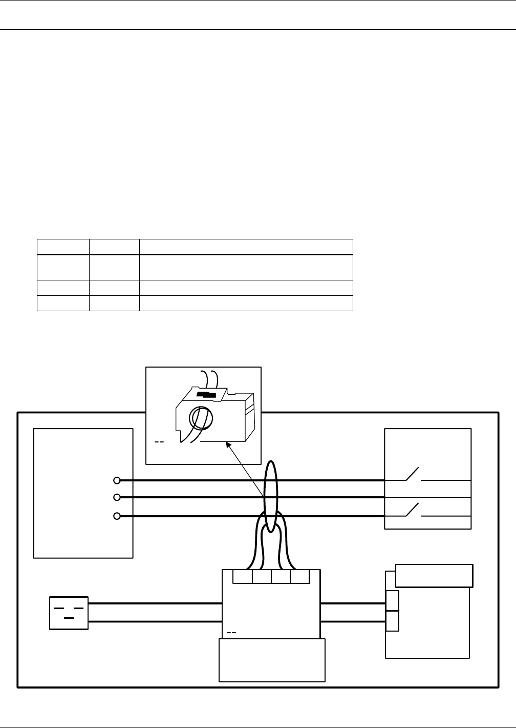
Options—For Assembly Inside the UPS Cabinet
66
8.0 OPTIONS—FOR ASSEMBLY INSIDE THE UPS CABINET
Several items of optional equipment are available for connection to the Liebert NX UPS. These are
described in this section of the manual and should be fitted prior to installation.
8.1 Protection
8.1.1 Battery Ground Fault Detection
In addition to any residual current device mounted externally and upstream the UPS or when
optional isolation transformers are fitted to the UPS, an optional residual battery current device can
be fitted to detect leakage current from the battery into the PE (Protective Earth) Residual current
range monitored: 30~3000mA.
Power supply voltage for the set: AC230V (L-N);
When a battery ground fault is detected, an alarm will appear on the UPS display panel.
An additional Dry contact fault Alarm signal is available for remote monitoring:
The Battery ground fault detection set contains one CT (current transformer) and one DC sensitive
residual current monitor. The connection of this set for UPS is illustrated as follows.
Figure 36 Battery ground fault detection set connections
Table 24 Dry contact fault alarm signal is available for remote monitoring
Terminal Name Definition
21 Common Battery Ground Fault Detection – can be
programmed as Alarm or Pre-Alarm
22 NC
24 NO
BCB or
Contactor
Battery
Socket Output
Phase
Output
Neutral
Current Transformer
W1-A358 (installed
externally only)
Monitor Board
-U2
UPS
IN DRY-X3
+12V
BtG
Battery Ground
Fault Detection
Resys B470
(AC230)
11
14
A1
A2
K1 K2 I2 I2
4
2
Batt +
Batt -
Batt-N
X
X
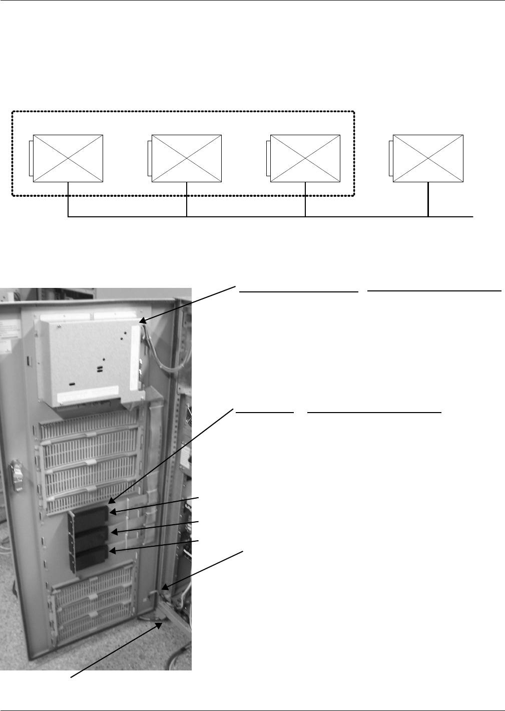
Options—For Assembly Inside the UPS Cabinet
67
8.1.2 Redundant Fan for Power Module
In addition, to ensure sufficient cooling power at various operation modes with 100% rated load, a
redundant power module fan set can be supplied, thus ensuring continuity of UPS operation even
with the failure of some fans. No extra footprint is required.
Figure 37 Redundant power module fan set
Figure 38 Communication bays and cable location
Fan120 Fan120Fan120Fan120
(AC Fan 1-4)(AC Fan 1-3)(AC Fan 1-2)(AC Fan 1-1)
Redundant AC Fan
TOP VIEW
Standard AC Fan
Notes:
a) All Intellislot cards are supported in any bay.
b) Port sharing is:
- PERMITTED between RS232-x DB9 devices and Relay /
Multiport4 Intellislot cards (i.e., Serial Multilink software
will work from RS232-1 DB9 also when relay card is
inserted in the top bay.
- NOT PERMITTED between RS-232-x D-B9 devices and
OCWeb / OC485 cards (i.e., Serial MultiLink software will
not work from RS232-1 DB-9 when OCWeb card is inserted
in the top bay.
RS-232-1 DB-9 (COM Port 1) - Serial MultiLink Software
(Port Setting 2400 Baud)
RS-232-2 DB-9 (COM Port 2 - Service Access Software
(Port Setting 9600 Baud)
Top Bay
Mid Bay
Bottom Bay
Relay Card (no port setting required)
Multiport4 (no port setting required)
OCWeb LB / OC485 (port setting 2400 Baud)
Suggested routing of customer-supplied
communication cables
Gland plate for cable exit
DB-9
Monitor
Board
Top
Mid
Preferred Device This LocationLocation
Bottom
Location Preferred Device This Location
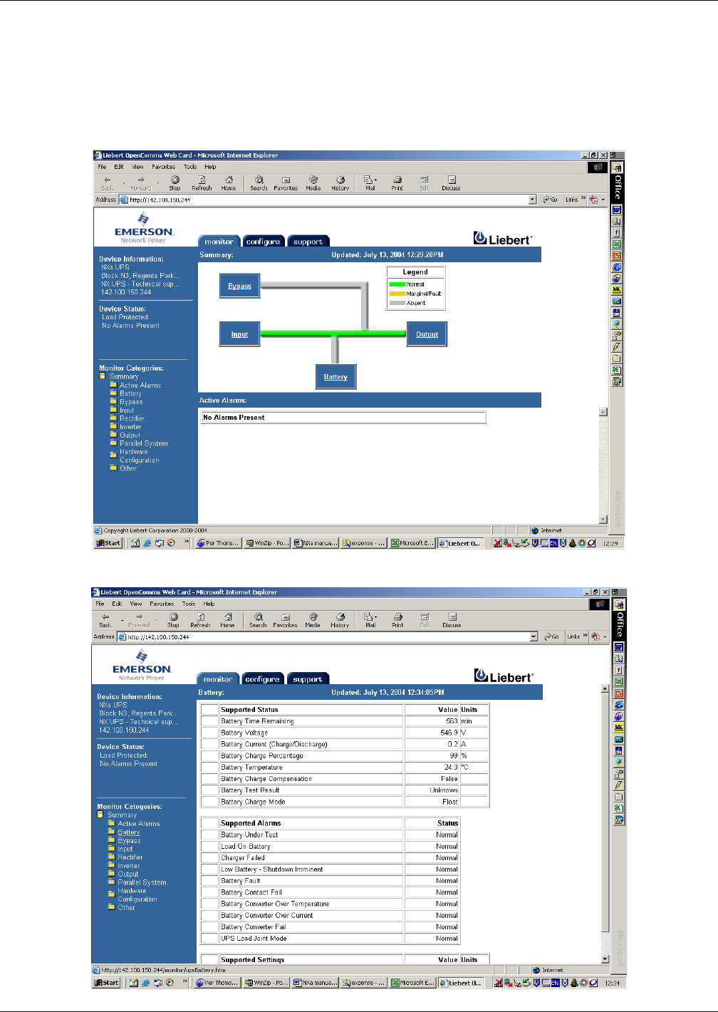
Options—For Assembly Inside the UPS Cabinet
68
8.1.3 OC Web Card - SNMP/HTTP Network Interface Card
This network interface card provides all real-time data and status information as SNMPv1 traps for
connection to a 10/100-baseT Ethernet network and in addition the same card will also transmit the
same status information and all measured parameters for display via a Web browser.
This card is supported in the top, middle and bottom Intellislot bays.
Figure 39 OC Web Card data summary window
Figure 40 OC Web Card battery data summary

Options—For Assembly Inside the UPS Cabinet
69
8.1.4 Relay Card
The Relay card provides voltage-free contact closures for remote monitoring of alarm conditions.
Delivering On Battery, On Bypass, Low Battery, Summary Alarm, UPS Fault and On UPS signals,
the easy-to-install card integrates with AS/400 computers (additional cable required) and other relay
contact monitoring systems.
The Relay card is rated for 24 VAC/VDC at 1A and supported in any of the three NX Intellislot bays.
**A Summary Alarm occurs when any of the following conditions exist:
• Utility power is out of the acceptable range (voltage and/or frequency)
• UPS is in BYPASS MODE (load not on Inverter power)
• UPS Battery is LOW
• UPS fault has occurred
8.1.5 Multiport-4 Card
The Multiport-4 card provides 4 sets of voltage-free contact closures for remote monitoring of alarm
conditions UPS operation On Battery and battery low condition. A typical application is to allows a
maximum of four computer systems to simultaneously monitor the status (e.g., utility power failure /
low battery) of a single UPS.
This card is supported in any of the three NX Intellislot bays.
Table 25 Relay Card pin configuration
Pin Function Operation
1 UPS Fault Closed if no UPS failure
2-3 Not Used
4 UPS Fault Closed if UPS fails
5 Summary Alarm** Closed if SUMMARY ALARM** occurs
6 Summary Alarm** Closed if no alarm conditions are present
7 Any Mode Shutdown return Not Supported– use External EPO terminal
8 Not Used
9 Common - Low Battery
10 Low Battery Closed if battery is OK
11 Low Battery Closed if LOW BATTERY point occurs.
12-13 Not Used
14 UPS Any Mode Shutdown Not supported– use External EPO terminal
15 On UPS Closed if ON UPS (inverter) power
16 On Battery Closed if ON BATTERY power (Utility failure)
17 Common - UPS Fault, Summary Alarm,
On UPS, On Battery, On Bypass
18 On Battery Closed if not ON Battery power (Utility OK)
19 ÷ 23 Not Used
24 On Bypass Closed if ON BYPASS
25 Not Used
Table 26 Relay card jumpers
#Connection Description
JP01 Pin 9 to Pin 17 Allows all relay COMMONS to be tied together.
JP02 Pin 7 to Pin 17 Irrelevant for NX - (Interconnects all relay COMMONS and the (not
supported) ANY MODE SHUTDOWN Return.
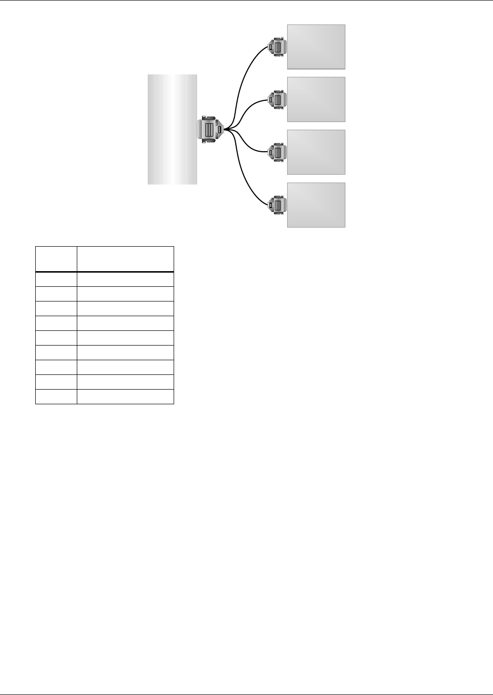
Options—For Assembly Inside the UPS Cabinet
70
Figure 41 SiteNet MultiPort4 Intellislot pin configuration
Table 27 SiteNet MultiPort4 Intellislot pin assignment
Pin
Assignment
Description
1 Low Battery
2 Not Used
3 Not Used
4 Not Used
5 Not Used
6 Not Used
7 Low Battery Common
8 Utility Fail Common
9 Utility Fail
UPS
CPU
CPU
CPU
CPU
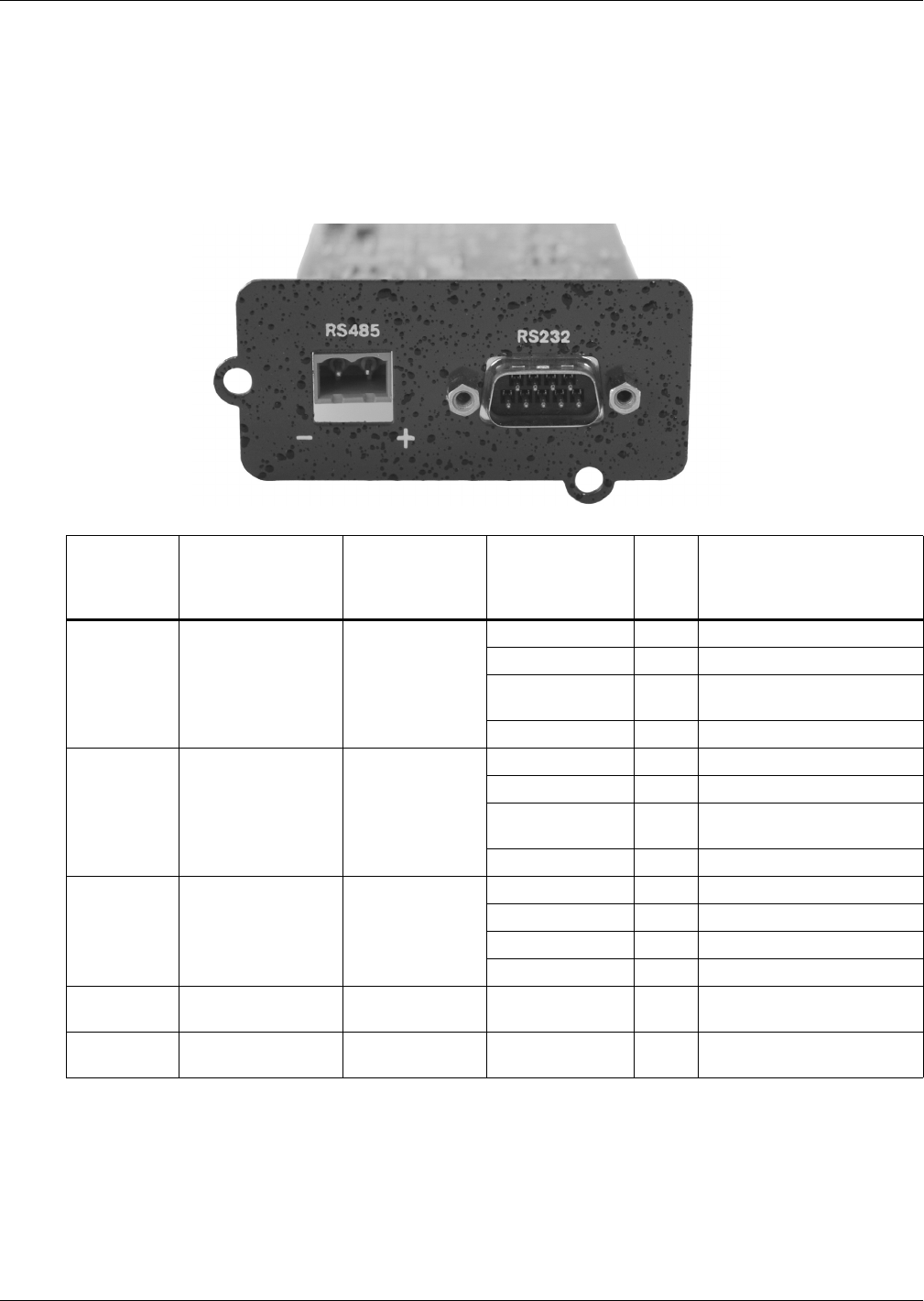
Options—For Assembly Inside the UPS Cabinet
71
8.2 OC485 Web Card – Modbus, Jbus, IGM Net
The OpenComms 485 Card facilitates SiteScan Web or Building Management Systems monitoring.
The RS232 port is used for connection to a personal computer for setting up.
The RS-485 port supports IGM Net and Modbus/JBus protocols and maps the operation of the UPS
including status, alarms and data (voltages, currents, frequency, power, power factor, temperatures
etc.)
Figure 42 OC485 Web card
8.2.1 Remote Alarm Monitor
Status and alarm conditions are available on an optional remote alarm monitor (RAM) panel that is
driven by volt-free alarm status contacts from an optional relay alarm board.
Table 28 NX communication options
Physical
description
of port
Labeled
ID Name
of Port
On the UPS
LCD screen,
under Settings,
controlled by:
Monitoring
Devices
supported
Baud
rate Comments
Top
Intellislot
Intellislot 2
(On Monitor Board) Comm 1
Multiport 4 any
Relaycard-int any
OCWEB-LB 2400 Not simultaneous with
Multilink in RS232-1
Modbus/Jbus 2400
Middle
Intellislot
Intellislot 1
(On Monitor Board) Comm 2
Multiport 4 any
Relaycard-int any
OCWEB-LB 2400 Not simultaneous with
Multilink in RS232-2
Modbus/Jbus 2400
Bottom
Intellislot
Intellislot 3
(On Monitor Board) Comm 3
Multiport 4 any
Relaycard-int any
OCWEB-LB 2400
Modbus/Jbus 2400
Top
DB9 port RS232-1 Comm 1 Multilink Serial 9600 Not simultaneous with Web
card in top Intellislot.
Bottom
DB9 port RS232-2 Comm 2 Service Software
(Reserved) 9600 Not simultaneous with Web
card in middle Intellislot.
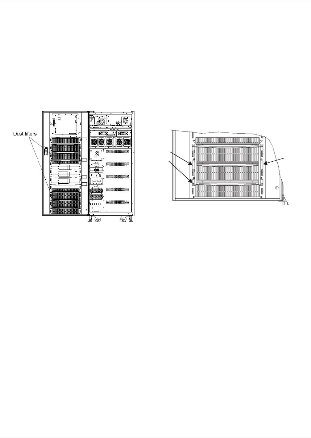
Options—For Assembly Inside the UPS Cabinet
72
8.2.2 Dust Filter for 10-30kVA
Installing the two dust filters in the Liebert NX requires only a Phillips screwdriver. Each filter is
held in place by a bracket on either side of each filter. To install each filter:
1. Open the UPS door and locate the filters (on the back side of the front door; see Figure 43).
2. Remove one bracket and loosen the screw on the second bracket. The second bracket need not be
removed (see Figure 43).
3. Remove the dust filter to be replaced.
4. Insert the clean filter.
5. Reinstall the bracket, tightening the screw securely.
6. Tighten the screw on the second bracket.
Figure 43 Dust filter replacement
Bracket
Sems screw
Bracket

Technical Specifications
73
9.0 TECHNICAL SPECIFICATIONS
9.1 Conformity and Standards
The UPS has been designed to conform to the following European and international standards:
The product standards in Table 29 incorporate relevant compliance clauses with generic IEC and EN
standards for safety (IEC/EN/AS60950), electromagnetic emission and immunity (IEC/EN/AS61000
series) and construction (IEC/EN/AS60146 series and 60529).
Table 29 Compliance with European, international standards
Description Normative reference
General and safety requirements for UPS used in
operator access areas EN 50091-1-1 /IEC 62040-1-1 / AS 62040-1-1
Electromagnetic compatibility (EMC) requirements for
UPS EN 50091-2 / IEC 62040-2 / AS 62040-2 (Class A)
Method of specifying the performance and test
requirements of UPS EN 50091-3 / IEC 62040-3 / AS 62040-3 (VFI SS 111)
Table 30 Environmental characteristics
Rated power, kVA
Unit of
Measurement10152030
Acoustic Noise Level at 1 Meter (39 in) dBa 51.0 51.5 51.6 56
Altitude of Operation m (ft)
≤1000m (3280 ft) above sea level
de-rate power by 1% per 100m(328 ft) between
1000 and 2000 m (3280 and 6560 ft)
Relative Humidity - 0 to 95% non condensing
Operating Temperature °C (°F)
0 to 40 (32-104°)
Battery life is halved for every 10° (18°) increase
above 20° (68°)
Storage-Transport Temperature for UPS °C (°F) -20 to 70 (-4 to 158)
Recommended Battery Storage
Temperature °C (°F) -20 to 30 (-4 to 86)°F)
(20°C [68°F] for optimum battery storage)
Table 31 Overall efficiency, heat losses and air exchange
Rated Power, kVA
Unit of
Measurement 10 15 20 30
Normal Mode (dual conversion) % 90.4 91.2 91.3 91.9
ECO Mode % 93.2 94.2 94.7 96.6
Inverter Efficiency (DC/AC)
(battery at nominal voltage 480VDC and full-rated linear load)
Rated Power, kVA 10152030
Battery Mode % 91.3 91.7 92.0 92.5
Heat Loss & Air Exchange (Ventilation)
Rated Power kVA 10 15 20 30
Normal Mode kW 1.6 1.8 2.2 2.6
ECO Mode kW 1.3 1.4 1.4 1.5
No Load kW 1.3 1.3 1.3 1.3
Maximum Forced Air Cooling (front intake, back exhaust) L/sec (m3/hr) 119
(428) 239 (860)
Input and output voltage 400VAC, battery charged, full rated linear load

Technical Specifications
74
Table 32 Mechanical characteristics
Rated Power, kVA
Unit of
Measurement 10 15 20 30
Dimensions, WxDxH mm (in) 600x700x1400
(23-9/16x27-5/8x55)
Mass
Mass without batteries kg (lb) 180 (397) 204 (450) 204 (450) 210 (463)
Finish N/A Pantone 877 (Silver grey)
equivalent Becker Silver epoxy polyester powder 041-37-2
Protection Degree, IEC (60529) N/A IP20 (finger-proof with front doors open or closed)
Table 33 Rectifier AC input (mains)
Rated Power, kVA
Unit of
Measurement 10 15 20 30
Rated AC Input Voltage 1VAC 380/400/415
(3-phase and sharing neutral with the bypass input)
Input Voltage Tolerance 2VAC 305V to 477V
304V to 208V (output derated below 70%)
Frequency 2Hz 50/60Hz (tolerance 40Hz to 70Hz)
Power Factor
kW/kVA, full
load
(half load)
0.99 (0.98)
Input Power kVA rated 3
(maximum 4)8.9 (11.7) 13.3 (18.9) 17.8 (23.3) 26.6 (35.0)
Input Current A rated 3
(maximum 4)12.9 (16.9) 19.3 (27.4) 25.8 (33.8) 38.6 (50.7)
Harmonic Current Distortion THDI % FL 3 3 3 3
Duration of Progressive
Power Walk-In sec 10 seconds to reach full rated current
(selectable 5 through 30 seconds in 5-second intervals)
1. Rectifier operates at any of the rated supply voltages and frequencies without further adjustment.
2. At 305V input mains the UPS maintains the specified output voltage at rated load without discharging a previously charged
battery
3. IEC 62040-3 / EN 50091-3: at rated load and input voltage 400V, battery charged
4. IEC 62040-3 / EN 50091-3: at rated load and input voltage 400V, battery charging at maximum rated power.

Technical Specifications
75
Table 34 Battery
Intermediate DC Circuit
Rated Power,
kVA
Unit of
Measurement 10 15 20 30
Battery Bus
Voltage VDC Nominal: 480V (VRLA Float charge is 540V)
Range: 400V - 616V
Number of Lead-Acid Cells
Nominal 240 = [40 x 6-cell (12V) blocks]
Maximum 264 = [44 x 6-cell (12V) blocks]
Float Voltage V/cell (VRLA) 2.25 V/cell (selectable from 2.2 –2.3V/cell)
Constant current and constant voltage (IU) charge mode
Temperature
Compensation mV/°C/cl - 3.0 (selectable 0 to – 5.0 around 25°C or 30°C. or inhibit)
Ripple Voltage % V float ≤1
Ripple Current % C10 ≤5
Boost Voltage V/cell (VRLA) 2.35 V/cell (selectable from 2.30-2.40V/cell)
Constant current and constant voltage (IU) charge mode
Boost Control
- float-boost current trigger 0.050 C10 (selectable 0.030-0.070)
- boost-float current trigger 0.010 C10 (selectable 0.005-0.025) with
24 hr safety timeout (selectable 8-30 hr)
- boost mode inhibit also selectable
End Of
Discharge V/cell (VRLA)
1.63 V/cell (selectable from 1.60~1.75 V/cell
Auto Inverse EOD voltage x discharge current mode
(The end of discharge voltage increases at low discharge currents).
Battery Charge V/cell
2.4 V/cell (selectable from 2.3-2.4V/cell)
Constant current and constant voltage (IU) charge mode
Programmable auto trigger or inhibit of boost mode
Battery
Charging Power*
max current
(adjustable) 1
kW 2.5 5 5 7.5
A 3.75 7.5 7.5 12
* At low input voltage the UPS recharge capability increases with load decrease (up to the maximum capacity indicated)
1. Max currents listed are for EOD voltage of 1.67 V/cell for 240 cells.
Table 35 Inverter output to critical load
Rated Power, kVA (kW)
Unit of
Measurement 10 (8) 15 (12) 20 (16) 30 (24)
Rated AC Voltage 1 VAC 380/400/415 V (three-phase, four-wire with neutral
referenced to the bypass neutral)
Frequency 2Hz 50 / 60
Overload % Rated
110% for 60 min
125% for 10 min
150% for 1 min
>150% for 200 msec
Fault Current % Rated 340% current limitation for 200 msec
Non linear load capability 3% Rated 100%
Neutral current capability % Rated 170%
Steady state voltage stability % ±1 (balanced load), ±2 (100% unbalanced load),
Transient voltage response 4%± 5
Total Harmonic Voltage
Distortion (THDV) % < 1 (linear load), < 4 (non linear load 3)
Synchronisation - Window Rated frequency ± 2Hz (selectable ± 0.5 to ± 3Hz)
Slew Rate (Max change rate
of synch frequency) Hz sec
1 Hz/sec
selectable 0.1 to 3Hz/s (single UPS)
0.2Hz/sec (paralleled UPS)
Inverter Voltage Tolerance %V (AC) ±5
1. Factory set to 400V – 380 or 415V selectable by commissioning engineer.
2. Factory set to 50Hz; 60 Hz selectable by commissioning engineer. Frequency converter operation also selectable.
3. EN 50091-3 (1.4.58) crest factor 3:1
4. IEC 62040-3 / EN 50091-3 also for 0-100-0% load transient. Transient recovery time: return to within 5% of steady state
output voltage within half a cycle.

Technical Specifications
76
Table 36 Bypass mains input
Rated power, kVA Unit of
Measurement 10 15 20 30
Rated AC Voltage 1VAC
380/400/415 V
three-phase four-wire, sharing neutral with the rectifier input
and providing neutral reference to the output
Rated Current
380V A 15 23 30 45
400V A 15 22 29 43
415V A 14 21 28 42
Overload Capacity %
135% long term
170% 10 min
1000% 100 ms
Upstream Protection,
Bypass Line (by others) N/A Thermomagnetic circuit breaker, rated up to 125%
of nominal output current. IEC 60947-2 curve C.
Current Rating of Neutral Cable A 1.7 x In
Frequency 2Hz 50 / 60
Transfer Time (between
bypass and inverter) ms
Synchronous transfer: ≤1ms
Asynchronous transfer (default): 15 ms (50 Hz), 13.3 ms (60 Hz)
or 40, 60, 80, 100 ms, selectable
Bypass Voltage Tolerance % VAC
Upper limit: +10, +15 or +20, default +15
Lower limit –10, -20, -30 or -40, default: -20
(delay time to accept steady bypass voltage: 10 sec)
Bypass Frequency Tolerance % ± 2.5 ± 5 ± 10 or ± 20 default ±10
Synchronisation - Window Hz Rated frequency ±2Hz (selectable ± 0.5 to ±3Hz)
1. Factory set to 400V – 380 or 415V selectable by commissioning engineer.
2. Factory set to 50Hz; 60 Hz selectable by commissioning engineer. Bypass condition ignored when UPS set as frequency converter.

Technical Specifications
77
NOTES

Technical Specifications
78

EmersonNetworkPower.com
Ensuring The High Availability
0f Mission-Critical Data And Applications.
Emerson Network Power, the global leader in enabling business-critical
continuity, ensures network resiliency and adaptability through
a family of technologies—including Liebert power and cooling
technologies—that protect and support business-critical systems.
Liebert solutions employ an adaptive architecture that responds
to changes in criticality, density and capacity. Enterprises benefit
from greater IT system availability, operational flexibility and
reduced capital equipment and operating costs.
While every precaution has been taken to ensure the accuracy
and completeness of this literature, Liebert Corporation assumes no
responsibility and disclaims all liability for damages resulting from use of
this information or for any errors or omissions.
© 2006 Liebert Corporation
All rights reserved throughout the world. Specifications subject to change
without notice.
® Liebert and the Liebert logo are registered trademarks of Liebert
Corporation. All names referred to are trademarks
or registered trademarks of their respective owners.
Technical Support / Service
Web Site
www.liebert.com
Monitoring
800-222-5877
monitoring@liebert.com
Outside the US: 614-841-6755
Single-Phase UPS
800-222-5877
upstech@liebert.com
Outside the US: 614-841-6755
Three-Phase UPS
800-543-2378
powertech@liebert.com
Environmental Systems
800-543-2778
Outside the United States
614-888-0246
Locations
United States
1050 Dearborn Drive
P.O. Box 29186
Columbus, OH 43229
Europe
Via Leonardo Da Vinci 8
Zona Industriale Tognana
35028 Piove Di Sacco (PD) Italy
+39 049 9719 111
Fax: +39 049 5841 257
Asia
7/F, Dah Sing Financial Centre
108 Gloucester Road, Wanchai
Hong Kong
852 2572220
Fax: 852 28029250
Emerson Network Power.
The global leader in enabling Business-Critical Continuity™.
Business-Critical Continuity, Emerson Network Power and the Emerson Network Power logo are trademarks and service marks of Emerson Electric Co.
©2006 Emerson Electric Co.
Integrated Cabinet Solutions
AC Power Systems
Connectivity
DC Power Systems
Embedded Computing
Embedded Power Power Switching & Control
Precision Cooling
ServicesOutside Plant
Site Monitoring
Surge Protection
SL-25410_REV2_08-06
