Lifestyler 831287730 User Manual CARDIO FIT 2 Manuals And Guides 99020069
LIFESTYLER Cardiofit Manual 99020069 LIFESTYLER Cardiofit Owner's Manual, LIFESTYLER Cardiofit installation guides
User Manual: Lifestyler 831287730 831287730 LIFESTYLER CARDIO FIT 2 - Manuals and Guides View the owners manual for your LIFESTYLER CARDIO FIT 2 #831287730. Home:Fitness Equipment Parts:Lifestyler Parts:Lifestyler CARDIO FIT 2 Manual
Open the PDF directly: View PDF ![]() .
.
Page Count: 12
6E /,4R8
Model No. 831.287730
Serial No.
Writethe serialnumberinthe space
aboveforfuture reference.
Serial Number Decal
_-x n=="R C i S _:
ECrU I PM ENT
H I='LPLINE!
1-800-736-6879
SEARS, ROEBUCK AND CO.,
HOFFMAN ESTATES, IL 60179
TAIFIGL='I "RESISTANCE_ TIFqtAINIER
USER'S MANUAL
PUSH MODE PULL MODE.

TABLE OF CONTENTS
IMPORTANT PRECAUTIONS •.............. 2
••..,••••.,•,•,, o•,.• .... o..o,•,_,,•*_•, • 11•*•* • •
BEFORE YOU BEGIN .......................................... ............................. 3
ASSEMBLY ............................................................................... 4
HOWTO USE THE CARDIO FIT2 ............................................................. 5
MAINTENANCE AND TROUBLE-SHOOTING .............
• •,o•o°, ,= ,•,.1,,,•••,•,•°o•,°, ,,•• _•, • 8
CONDITIONING GUIDELINES• .... ........................................................... 9
pART LIST, ......
.......... :10
o• o°•,• •e•
EXPLODED DRAWING .............................................................. ....... 11
ORDERING REPLACEMENT PARTS ................................................... Back Cover
Back Cover
WARRANTY ..........,, e o, eooeew o eo •, o = e, ° • , o o*-_ •--o-o.o+J ,• • • J • • O••OQQ •Io•_•Q•e• • ••og•"
2
BEFORE YOU BEGIN
Thank you for selecting the SEARS UFESTYLEFP
CARDIO FIT 2. The CARDIO FIT 2 offers a unique
form of low-impact exercise that uses both the upper
body and the lower body for greater cardiovascular
benefits and increased toning. For a more complete
workout,the CARDIO FIT 2 features both a push mode
and a pull mode, and the adjustable resistance cylinder
lets you exercise at the intensitylevel that's rightfor
you.
For your benefit, read this manual carefully before
using the CARDIO FIT 2. If you have questions after
reading the manual, pleas9 call our toll-free !_IELPLINE
at 1-800-736-6879, Monday through Saturday, 7 a.m.
until7 p.m. Central Time (excluding holidays). To help
us assist you, please note the product model number
and sedal number when calling. The model number is
831287730. The sedal number can be found on a
decal attached to the CARDIO FIT 2 (see the front
cover of this manual for the location of the decal).
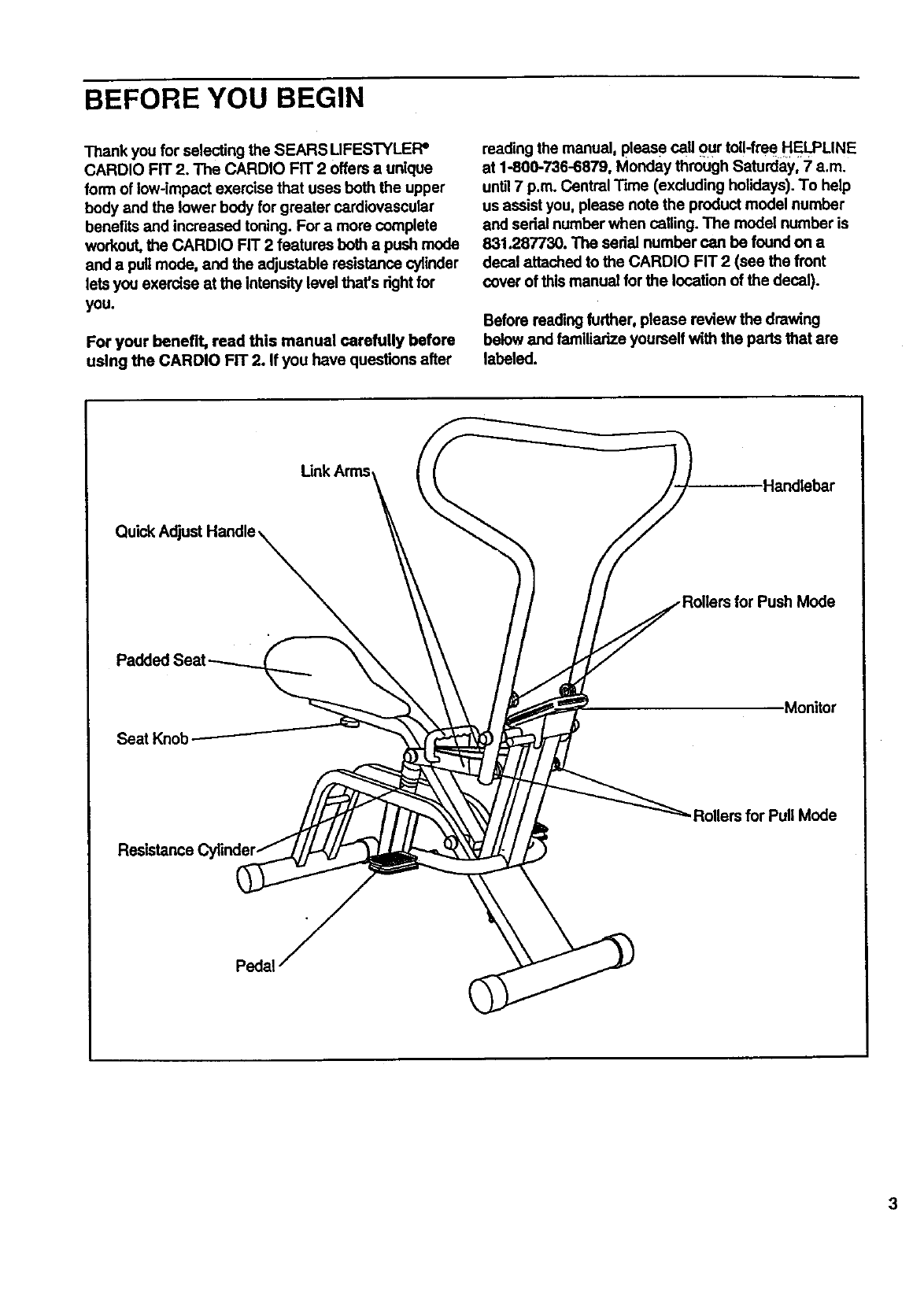
Before reading further, please review the drawing
below and familiarize yourself with the parts that are
labeled.
link Am_ Handlebar
;for Push Mode
Monitor
.Rollers for Pull Mode
ASSEMBLY
Place all parts of the CARDIO FIT 2 in a cleared area and remove the packing matedals. Do not dispose of the
pacldng materials unff assembly is completed. Read each step cemfully before you begin. Assembly requires
the following tools. The Included pedal tool (_ end your own rubber mallet E)_;;:_.
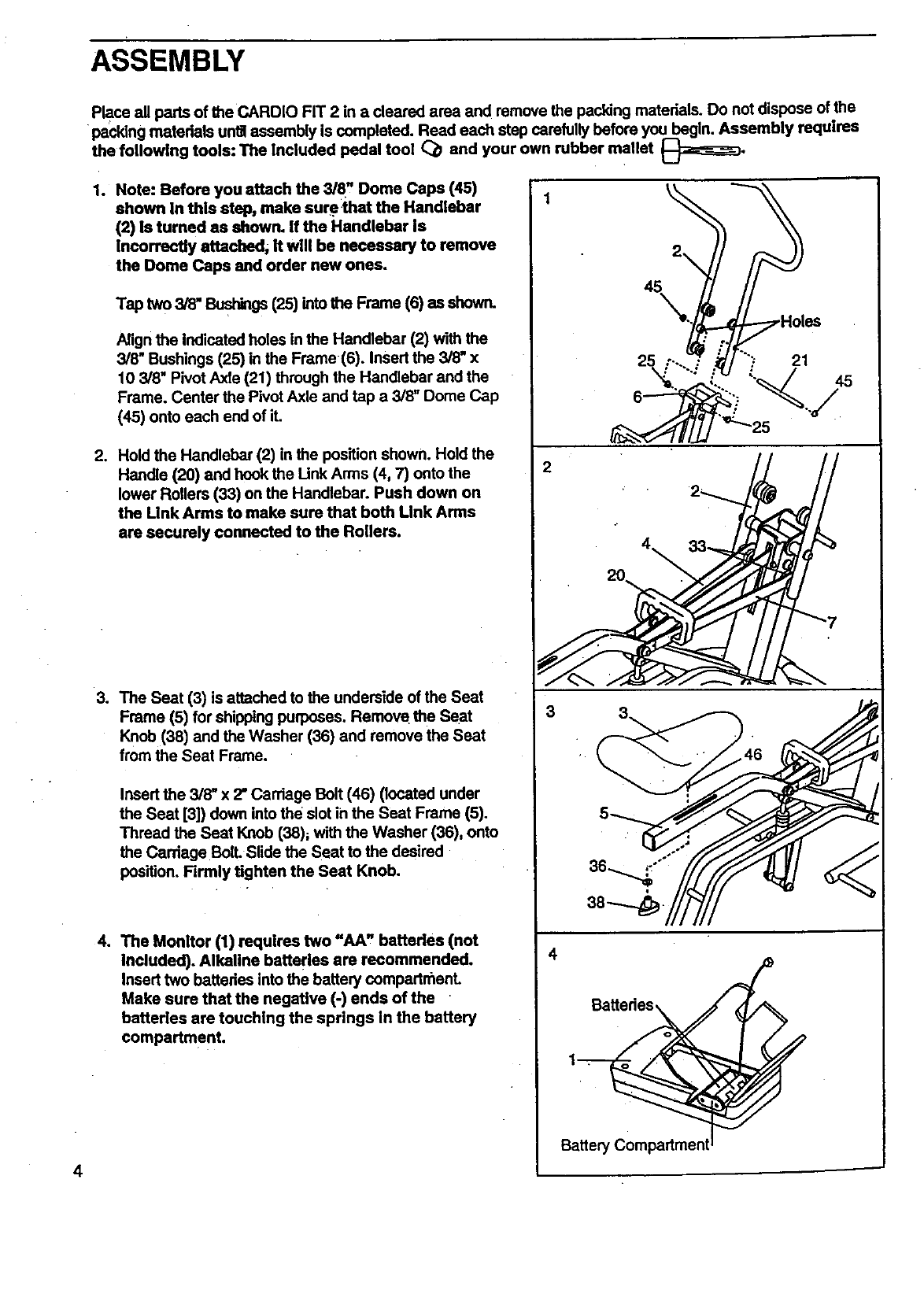
1. Note: Before you attach the 3/8" Dome Caps (45)
shown in this step, make sure that the Handlebar
(2) Is turned as shown. If the Handlebar Is
Incorrectly attached, it will be necessary to remove
the Dome Caps and order new ones.
Tap two 3/8" Bushings(25) intothe Frame (6) as showr_
Align the Indicated holes in the Handlebar (2) with the
3/8" Bushings (25) in the Frame (6). Insert the 3/8" x
10 3/8" Pivot Axle (21) through the Handlebar and the
Frame. Center the Pivot Axle and tap a 3/8" Dome Cap
(45) onto each end of it.
2. Hold the Handlebar (2) in the position shown. Hold the
Handle (20) and hook the Unk Arms (4, 7) onto the
lower Rollers (33) on the Handlebar. Push down on
the Unk Arms to make sure that both Link Arms
are securely connected to the Rollers.
3. The Seat (3) is attached to the underside of the Seat
Frame (5) for shipping purposes. Remove the Seat
Knob (38) and the Washer (36) and remove the Seat
from the Seat Frame.
Insert the 3/8" x 2" Carriage Bolt (46) (located under
the Seat [3]) down into the slot in the Seat Frame (5).
Thread the Seat Knob (38)_ with the Washer (36), onto
the Carriage BoiL Slide the Seat to the desired
position. Firmly tighten the Seat Knob.
4. The Monitor (1) requires two =AA" batteries (not
Included). Alkaline batteries are recommended.
Insert two battedes into the battery compartn_ent.
Make sure that the negative (-) ends of the
batteries are touching the springs in the battery
compartment.
2
3
Battery Compartmer
4
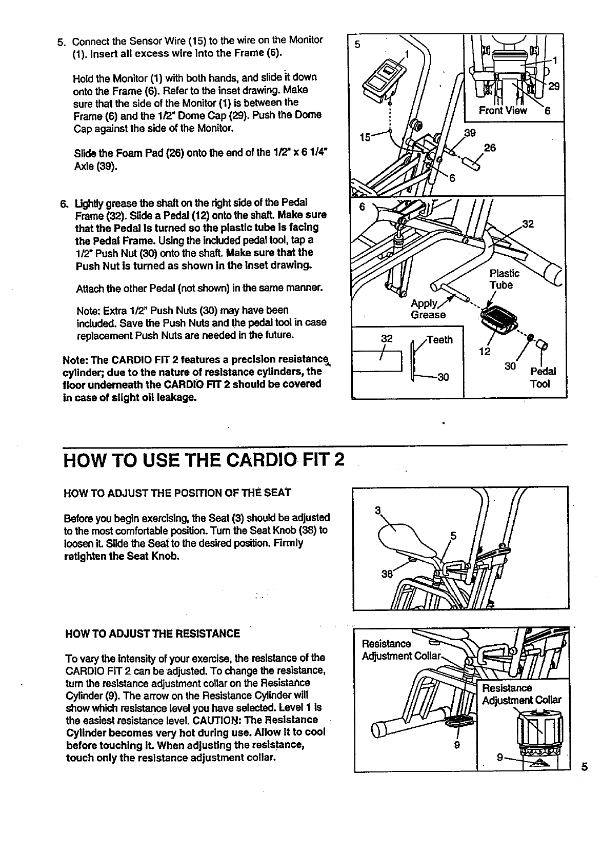
5. Connect the Sensor Wire (15) to the wire on the Monitor
(1). Insert all excess wire into the Frame (6).
Hold the Monitor (1) with both hands, and slide it down
onto the Frame (6). Refer to the inset drawing. Make
sure that the side of the Monitor (1) is between the
Frame (6) and the 1/2" Dome Cap (29). Push the Dome
Cap against the side of the Monitor.
Slide the Foam Pad (26) onto the end of the 1/2" x 6 1/4"
Axle (39),
6. UghUygrease the shaft on the rightside of the Pedal
Frame (32). Slide aPedal (12) onto the shaft. Make sure
that the Pedal is turned so the plastic tube Is facing
the Pedal Frame. Using the included pedal tool, tap a
1/2" Push Nut (30) onto the shaft. Make sure that the
Push Nut Is turned as shown in the inset drawing.
Attachthe other Pedal (not shown) in the same manner.
Note: Extra 1/2" Push Nuts (30) may have been
included. Save the Push Nuts and ",_epedal tool in case
replacement Push Nuts are needed in the future.
Note: The CARDIO FIT 2 features a precision resistance_
cylindeq due to the nature of resistance cylinders, the
floor underneath the CARDIO FIT 2 should be covered
in case of slight oil leakage.
Grease
Front View
26
12
3O
Tool
HOW TO USE THE CARDIO FIT 2
HOW TO ADJUST THE POSITION OF THE SEAT
Before you begin exercising, the Seat (3) should be adjusted
to the most comfortable position.Tum the Seat Knob (38) to
loosen it. Slide the Seat to the desired position. Firmly
retlghten the Seat Knob.
HOW TO ADJUST THE RESISTANCE
To vary the Intensity of your exercise, the resistance of the
CARDIO FIT 2 can be adjusted. To change the resistance,
turn the resistance adjustment collar on the Resistahce
Cylinder (9). The arrow on the Resistance Cylinder will
show which resistance level you have selected. Level I Is
the easiest resistance level. CAUTIO_I: The Resistance
Cylinder becomes very hot during use. Allow it to cool
before touching IL When adjusting the resistance,
touch only the resistance adjustment collar.
Resistance
9
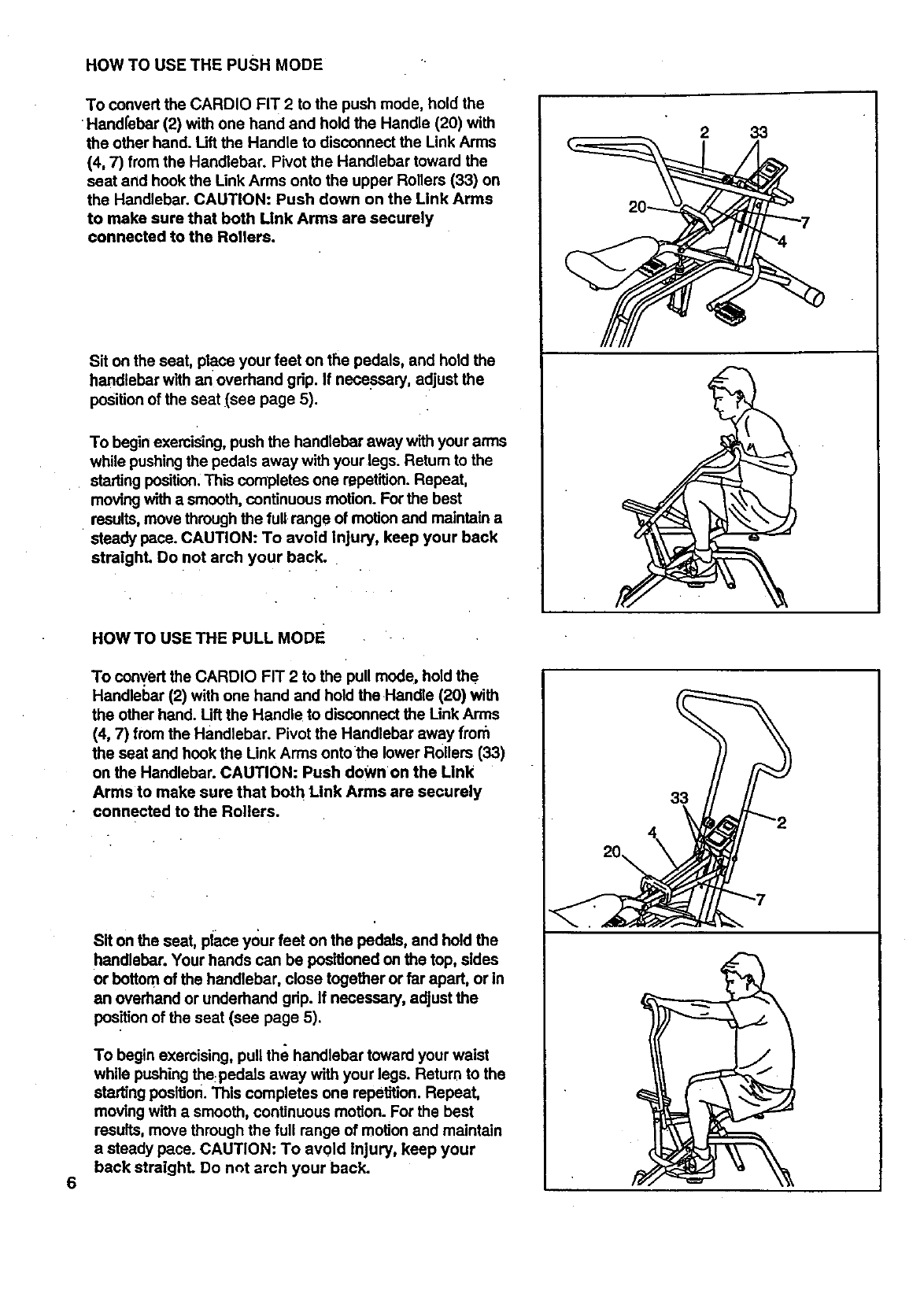
HOW TO USE THE PUSH MODE
To convert the CARDIO FIT 2 to the push mode, hold the
•Handfebar (2) with one hand and hold the Handle (20) with
the other hand. Lift the Handle to disconnect the Link Arms
(4, 7) from the Handlebar. Pivot the Handlebar toward the
seat and honk the Unk Arms onto the upper Rollers (33) on
the Handlebar. CAUTION: Push down on the Link Arms
to make sure that both Link Arms are securely
connected to the Rollers.
Sit on the seat, place your feet on the pedals, and hold the
handlebar with an overhand grip. If necessary, adjust the
positionof the seat (see page 5).
To begin exercising, push the handlebar away with your arms
while pushingthe pedals away with your legs. Return to the
starting position.This completes one repetition. Repeat,
moving with a smooth, continuous motion. For the best
•results, move through the full range of motion and maintain a
steady pace. CAUTION: To avoid Injury, keep your back
straighL Do not arch your back.
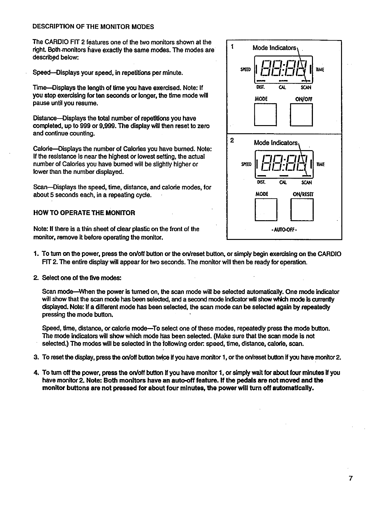
HOW TO USE THE PULL MoDE
To convert the CARDIO FIT 2 to the pull mode, hold the
Handlebar (2) with one hand and hold the Handle (20) with
the other hand. Lift the Handle to disconnect the Unk Arms
(4, 7) from the Handlebar. Pivot the Handlebar away from
the seat and hook the Link Arms ontothe lower Rollers (33)
on the Handlebar. CAUTION: Push down on the Link
Arms to make sure that both Link Arms are securely
connected to the Rollers.
233
6
Sit on the seat, piace your feet on the pedals, and hold the
handlebar. Your hands can be positioned on the top, sides
or bottom of the handlebar, close together or far apart, or in
an overhand or underhand grip. If necessary, adjust the
position of the seat (see page 5).
To begin exercising, pull the handlebar toward your waist
while pushing the:pedals away with your legs. Return to the
starting position. This completes one repetition. Repeat,
moving with a smooth, continuous motion. For the best
results, move through the full range of motion and maintain
asteady pace. CAUTION: To av01d injury, keep your
back straight. Do not arch your back.
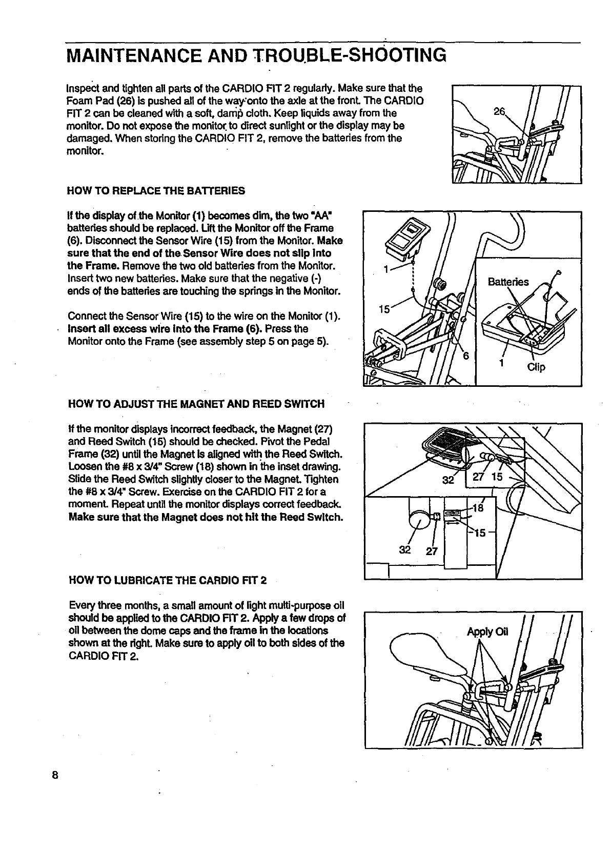
DESCRIPTION OF THE MONITOR MODES
The CARDIO FIT 2 features one of the two monitors shown at the
righL Both.monitors Ilave exactly the same modes. The modes are
described below:
Speed--Displays your speed, in repetitions per minute.
Time--Displays the length of time you have exercised. Note: If
you stop exercising for ten seconds or longer, the time mode will
pause untilyou resume.
Distance--Displays the tota! number of repetitions you have
completed, up to 999 or 9,999. The display will then reset to zero
and continue counting.
Calorie--Displays the number of Calodes you have bumed. Note:
If the resistance is near the highest or lowest setting, the actual
number of Calories you have bumed will be slightlyhigher or
lower than the number displayed.
Scan--Displays the speed, time, distance, and calorie modes, for
about 5 seconds each, in a repeating cycle.
HOW TO OPERATE THE MONITOR
Note: If there is a thin sheet of dear plastic on the front of the
mon'dor,remove it before operating the monitor.
Mode Indicators\.
I,
DIST. CAl. SCAN
TIME
Mode Indicators\ .
-AUTOOR:-
1. To tom on the power, press the on/off buttonor the on/raset button, or simply begin exercising on the CARDIO
FIT 2. The entire display will appear for two seconds. The monitor will then be ready for operation.
2. Select one of the five modes:
Scan mode--When the power is tumed on, the scan mode will be selected automatically. One mode Indicator
will show that the scan mode has been selected,and a second mode indicatorwillshow w_ch mode Is currently
displayed.Note: If a different mode has been selected, the scan mode can be selected again by repeatedly
pressing the mode button.
Speed, time, distance, or calorie mode--To select one of these modes, repeatedly press the mode button.
The mode Indicatorswill show which mode lies been selected. (Make sure that the scan mode is not
selected.) The modes will be selected in the following order:,speed, time, distance, calode, scan.
3. To resetthe display, pressthe on/offbuttontwice if you have mon'dor1, or the on/rssetbuttonif you have monitor2.
4. To turn off the power, prase the on/off buttonIf you have monitor 1, or simply wait for about four minutes If you
have monitor 2. Note: Both monitors have an auto-off feature. If the pedals are not moved and the
monitor buttons are not pressed for about four mlnutss, the power will turn off automatically.
7
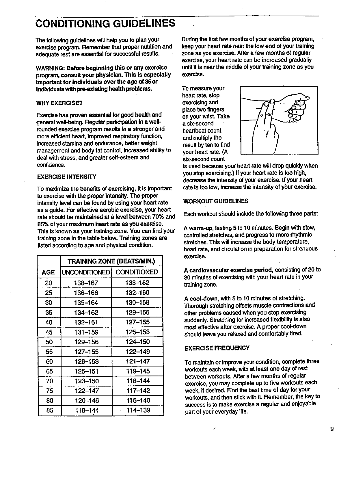
MAINTENANCE AND TROUBLE-SHOOTING
Inspect and tighten all parts of the CARDIO FIT 2 regulady. Make sure that the
Foam Pad (26) Is pushed all of the w.ay-'ontothe axle at the fronL The CARDIO
FIT 2 can be cleaned with a soft, daml_ cloth. Keep liquids away from the
monitor. Do not expose the monitor,to direct sunlight or the display may be
damaged. When storing the CARDIO FIT 2, remove the batteries from the
monitor.
HOW TO REPLACE THE BATrERIES
If the display of the Monitor (1) becomes dim, the two "AA"
batteries should be replaced. Lift the Monitor off the Frame
(6). Disconnect the Sensor Wire (15) from the Monitor. Make
sure that the end of the Sensor Wire does not slip into
the Frame. Remove the two old battedes from the Monitor.
Insert two new batteries. Make sure that the negative (-)
ends of the batteries are touching the springs in the Monitor.
Connect the Sensor Wire (15) to the wire on the Monitor (1).
Insert all excess wire Into the Frame (6). Press the
Monitor onto the Frame (see assembly step 5 on page 5).
Clip
HOW TO ADJUST THE MAGNET AND REED SWITCH
If the monitor displays incorrect feedback, the Magnet (27)
and Reed Switch (1.5)should be checked. Pivot the Pedal
Frame (32) untilthe Magnet is aligned wi_ the Reed Switch.
Loosen the #8 x 3/4" Screw (18) shown in the inset drawing.
Slide the Reed Switch slightly rinser to the MagneL T=ghten
the #8 x 3/4" Screw. Exercise on the CARDIO FIT 2 for a
moment. Repeat until the monitor displays correct feedback.
Make sure that the Magnet does not hit the Reed Switch.
32
HOW TO LUBRICATE THE CARDIO FIT 2
Every three months, asmall amount of light multi-purpose oil
should be applied to the CARDIO FIT 2. Apply a few drops of
oil between the dome caps and the frame in the locations
shown at the dghL Make sure to apply oil to both sides of the
CARDiO FIT 2.
Apply Oil
8
CONDITIONING GUIDELINES
The followingguidelines will help you to plan your
exercise program. Remember that proper nutritionand
adequate rest are essential for successful results.
WARNING: Before beginning this or any exercise
program, consult your physician. This Is especially
important for Individuals over the age of 35 or
Individuals with pre-existing health problems.
WHY EXERCISE?
Exercise has proven essential for good health and
general well-being. Regular padlcipation in a well-
rounded exercise program results in a stronger and
more efficient heart, improved respiratory function,
increased stamina and endurance, better weight
management and body fat control, increased ability to
deal with stress, and greater self-esteem and
confidence.
EXERCISE INTENSITY
To maximize the benefits of exercising, it is Important
to exercise with the proper intensity. The proper
intensitylevel can be found by using your heart rate
as a guide. For effective aerobic exercise, your heart
rate should be maintained at a level between 70% and
85% of your maximum heart rate as you exercise.
This is known as your training zone. You can find your
trainingzone in the table below. Training zones are
listed according to age and physical condition.
TRAINING ZONE (BEATS/MINo)
AGE UNCONDITIONED CONDITIONED
20 138-167 133-162
25 136-166 132-160
30 135-164 130-158
35 134-162 129-156
40 132-161 127-155
45 131-159 125-153
50 129-156 124-150
55 127-155 122-149
60 126-153 121-147
65 125-151 119-145
70 123-150 118-144
75 122-147 117-142
80 120-146 1.15-140
85 118-144 114-139
Duringthe firstfew months of your exemise program,
keep your heart rate near the low end of your training
zone as you exercise. After a few months of regular
exercise, your heart rate can be increased gradually
untilit is near the middle of your training zone as you
exercise.
To measure your
heart rate, stop
exercising and
place two fingers
on your wrist. Take
a six-second
heartbeat count
and multiplythe
result by ten to find
your heart rate. (A
six-second count
is used because your head rate will drop quickly when
you stop exercising.) If your heart rate is too high,
decrease the intensityof your exercise, if your head
rate is too low, increase the intensity of your exercise.
WORKOUT GUIDEUNES
Each workoutshould include the following three pads:
A warm-up, lasting 5 to 10 minutes. Begin with slow,
controlled stretches, and progress to more rhythmic
stretches. This will increase the body temperature,
heart rate, and circulation in preparation for strenuous
exercise.
A cardiovascular exercise pedod, consisting of 20 to
30 minutes of exercising with your heart rate in your
training zone.
A cool-down, with 5 to 10 minutes of stretching.
Thorough stretchingoffsets muscle contractions and
other problems caused when you stop exercising
suddenly. Stretching for incraased flexibility is also
most effective after exercise. A proper cOol-down
should leave you relaxed and comfortably tired.
EXERCISE FREQUENCY
To maintainor improve your condition, complete three
workoutseach week, with at least one day of rest
between workouts. After a few months of regular
exercise, you may complete up to five workouts each
week, if desired. Find the best time of day for your
workouts, and then stickwith it. Remember, the key to
success is to make exercise a regular and enjoyable
part of youi"everyday life.
9
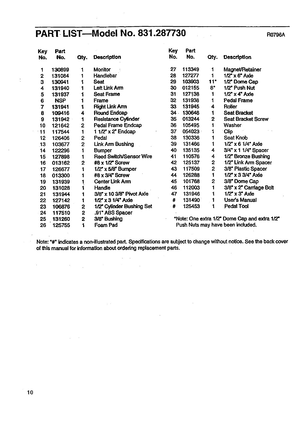
PART LIST--Model No. 831.287730 RO796A
Key Part Key Part
No. No. Qty. Description No. No. Qty. Descflption
1 130899 1 Monitor _ 27 113349 1 Magnet/Retainer
2 131084 1 Handlebar 28 127277 1 1/2_x 6_Axle
3 130941 1 Seat 29 103903 11" 1/2=Dome Cap
4 131940 1 Left Unk Arm 30 012155 8" 1/2" Push Nut
5 131937 1 Seat Frame 31 127138 1 1/2" x 4" Axle
6 NSP 1 Frame 32 131938 1 Pedal Frame
7 131941 1 Right Unk Arm 33 131945 4 Roller
8 109416 4 Round Endcap 34 130648 1 Seat Bracket
9 131942 1 Resistance Cylinder 35 013244 2Seat Bracket Screw
10 121642 2 Pedal Frame Endcap 36 105495 1 Washer
11 117544 1 1 1/2"x2"Endcap 37 054023 1 Clip
12 126406 2 Pedal 38 130336 1 Seat Knob
13 103677 2 LinkArm Bushing 39 131466 1 1/2"x6 1/4"Axle
14 122296 1 Bumper 40 135135 4 3/4" x I 1/4" Spacer
15 127898 1 Reed Switch/Sensor Wire 41 110576 4 1/2" Bronze Bushing
16 013162 2 #8 x 1/2" Screw 42 125137 2 1/2" Link Arm Spacer
17 126677 1 1/2" x 5/8" Bumper 43 117509 2 3/8" Plastic Spacer
18 013300 1 #8 x 3/4" Screw 44 126238 1 1/2" x 3 3/4" Axle
19 131939 "1 Center Unk Arm 45 101768 2 3/8" Dome Cap
20 131028 1 Handle 46 112003 1 3/81 x 2=Carriage Bolt
21 131944 1 3/8" x l0 3/8" Pivot Axle 47 131946 1 1/'Z'x3=Axle
22 127142 1 1/2" x 3 1/4" Axle #131490 1 User's Manual
23 106876 2 1/2" Cylinder Bushing Set # 125453 1 Pedal Tool
24 117510 2 .91" ABS Spacer
25 131260 2 3/8" Bushing *Note: One extra 1/2' Dome Cap and extra 1/'Z'
26 125755 1 Foam Pad Push Nuts may have been included.
Note: =#" indicates a non-illustrated part. Spedfications are subject to change without notice. See the back cover
of this manual for information about ordering replacement parts.
10
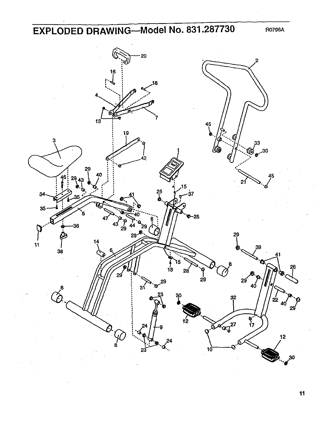
EXPLODED DRAWING---Model No. 831.287730 RO796A
_._20
!' _ .16
4 ::/2 o.--
= o.°
• so -_
13
19
45
2
33
11
29
14
8
18
12
29
29
39
4O
12
11
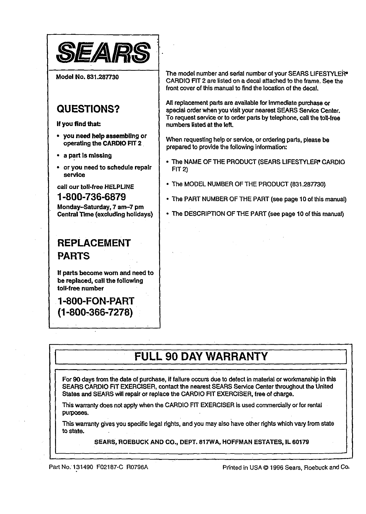
SE /ARS
Model No. 831.287730
QUESTIONS?
If you find that:
• you need help assembling or
operating the CARDIO FIT 2
•a part Is miSSing
•or you need to schedule repair
service
call our toll-free HELPLINE
1-800-736-6879
Monday-Saturday, 7 am-7 pm
Central Time (excluding holidays)
REPLACEMENT
PARTS
If parts become worn and need to
be replaced, call the following
toll-free number
1-800-FON-PART
(1-800-366-7278)
The model number and serial number of your SEARS LIFESTYLEJ:_'
CARDIO FIT 2 are listed on a decal attached to the frame. See the
front cover of this manual to find the location of the decal.
All replacement parts are available for immediate purchase or
special order when you visit your nearest SEARS Service Center.
To request service or to order parts by telephone, call the toll-free
numbers listed at the left.
When requesting help or service, or ordering parts, please be
prepared to provide the following information:
• The NAME OF THE PRODUCT (SEARS LIFESTYLEPP CARDIO
FIT 2)
• The MODEL NUMBER OF THE PRODUCT (831.287730)
•The PART NUMBER OF THE PART (see page 10 of this manual)
• The DESCRIPTION OFTHE PART (see page 10 of this manual)
FULL 90 DAY WARRANTY i
For 90 days from the date of purchase, if failure occurs due to defect in matedai or workmanship in this
SEARS CARDIO FIT EXERCISER, contact the nearest SEARS Service Center throughout the United
States and SEARS will repair or replace the CARDIO FIT EXERCISER, free of charge.
This warranty does not apply when the CARDIO FIT EXERCISER is used commercially or for rental
purposes.
This warranty gives you specific legal rights, and you may also have other rightswhich vary from state
to state.
SEARS, ROEBUCK AND CO., DEPT. 817WA, HOFFMAN ESTATES, IL 60179
Part No. 131490 F02187-C R0796A Printed in USA@ 1996 Sears, Roebuck and C_.
