Lifestyler 831297281 User Manual EXPANSE 2000 TREADMILL Manuals And Guides 99020186
LIFESTYLER Treadmill Manual 99020186 LIFESTYLER Treadmill Owner's Manual, LIFESTYLER Treadmill installation guides
User Manual: Lifestyler 831297281 831297281 LIFESTYLER EXPANSE 2000 TREADMILL - Manuals and Guides View the owners manual for your LIFESTYLER EXPANSE 2000 TREADMILL #831297281. Home:Fitness Equipment Parts:Lifestyler Parts:Lifestyler EXPANSE 2000 TREADMILL Manual
Open the PDF directly: View PDF ![]() .
.
Page Count: 20

EXPANSE
0"10MPHo 2.5liPo PROGRAMMABLESPEEDANDINCLINE• DIRECTPULSEINTERFACE
000
SE_A/ S"
Model No. 831.297281
Serial No.
The serial number can be found in
the location shown below, Write the
serial number in the space above..
Serial
Decal,
F-_U I pM ENT
_o|ln || n lo| _ii-1
H ELPLI N _- I
1-800-736-6879
_CAUTION!:
Reed all safety precautions and
Instructions in thls manual
before using this equipment.
Keep this manual in a safe place
for future reference. OWNER,S MANUAL
SEARS, ROEBUCK AND CO., HOFFMAN ESTATES, IL 60179
2
FULL 90 DAY WARRANTY
For 90 days from the date of purchase, when proper assembly and maintenance procedures detailed in
the Owner's Manual are followed, SEARS will, free of charge, repair or replace and installa replacement
part for any defective part, when this treadmill is used in a normal manner.
This warranty does not apply when this treadmill is used for commercial or rental purposes.
SERVICE IS AVAILABLE SIMPLY BY CONTACTING YOUR NEAREST SEARS SERVICE CEN-
TEPJDEPARTMENT IN THE UNITED STATES.
This warranty gives you specific legal rights,and you may also have other dghts which vary from state
to state.
SEARS, ROEBUCK AND CO., DEPTo 817WA,
HOFFMAN ESTATES, IL 60179

EXPANSE
0"]0MPH* 2.5liP" PROGRAM_BLESPEEDANDINCLINE"DIRECTPULSEINTERFACE
000
i
TABLEOF CONTENTS
IMI_ORTANT SAF_-I-Y PRECAUTIONS ............................................... .......... 4
BEFORE YOU BEGIN ...................................................................... 5
ASSEMBLY .............................................................................. ,6
HOW TO USE THE PULSE SENSOR .......................................................... .7
OPERATION AND ADJUSTMENT .............................................................8
HOW TO MANUALLY CONTROL THE SPEED ............................................. 9
HOW TO MANUALLY CONTROL THE INCLINE ............................................ 9
HOW TO USE THE PULSE DISPLAY ........... 10
*o.oo o*°. o,. o,,.,,.°°, ,.,.o o.o.. , ,...,. .
HOW TO CREATE A CUSTOM PROGRAM ......................................... ... . .10
HOW TO USE A PRESET PROGRAM ................................................... 12
HOW TO USE THE PULSE MODE ................................................. .... 12
TROUBLE-SHOOTING AND STORAGE ......................................................,. 14
CONDITIONING GUIDELINES ............................................................... 16
PART LIST ....................................................................... ....... . 18
EXPLODED DRAWING ............................................................... .. .... 19
ORDERING REPLACEMENT PARTS .......................................................... 20
_,WARNING: Before beginning this or any exercise program, consult your physician. This is
especially Important for persons over the age of 35 or persons with preexisting health problems. Read
all Instructions before using. SEARS assumes no responsibility for personal Injury or property damage
sustained by or through the use of this product. 3
IMPORTANT SAFETY PRECAUTIONS
AWARNING: To reduce the risk of burns, fire, electric shock or injury to persons, read the fol-
lowing important safety precautions a_d information before operating the treadmill.
1. Position the treadmill on a level surface, with 7.
at least 8 feet of clearance behind the tread-
mill. Do not place the treadmill near water,
outdoors or on any surface that blocks an air
opening. Do not operate where aerosol prod-
ucts are used or where oxygen is being 8.
administered.
2. When connecting the power cord (see HOW TO
PLUG IN THE POWER CORD on page 8), plug
the power cord directly into a grounded circuit
capable of carrying 12 or more amp.s. No other
appliance should be on the same circuit. Keep
the power cord away from heated surfaces. If
an extension cord is needed, use only a 14-
gauge general-purpose cord of five feet or less
in length with a three-wire conductor.
3. Never move the walking belt while the power
is turned off. Do not operate the treadmill if
the power cord or plug is damaged, or if the
treadmill is not working properly. (See
BEFORE YOU BEGIN on page 5 if the treadmill
is not working properly.)
4. Wear appropriate exercise clothing when
using the treadmill; do not wear loose clothing
that could become caught in the treadmill.
Always wear afhletic shoes; never use the
treadmill with bare feet, wearing only stock-
ings or in sandals. Athletic support clothes
are recommended for both men and women.
Never allow more than one person on the
treadmill at a time. The treadmill should not be
used by persons weighing more than 250
pounds.
Keep small children away from the treadmill at
all times. Never leave the treadmill unattended
while It is running. Always turn the power off
when the treadmill is not in use.
9. Never drop or insert any object into any open-
ing.
10. To reduce the possibility of overheating, do
not operate the treadmill continuously for
longer than I hour.
11. The treadmill is capable of high speeds.
Adjust the speed slowly to avoid sudden
Jumps in speed.
12. Use the treadmill only as described in this
manual.
13. Always unplug the power cord before perform-
ing the maintenance end adjustment proce-
dures described in this manual. Never remove
the safety cover unless instructed to do so by
an authorized service representative.
Servicing other than the procedures in this
manual should be performed by an authorized
service representative only.
5. The pulse sensor is not a medical device.
Various factors, including the user's move-
ment while exercising, may affect the accura-
cy of heart rate readings. The sensor is
Intended only as an exercise aid in determin-
ing heart rate trends in general.
6. Never start the treadmill while you are stand-
ing on the walking belt. Always hold the
handrail when exercising on the treadmill.
14. When the PULSE mode of the console is
selected, the console will control the speed
and incline of the treadmill to keep your heart
rate at a preset level, if you have heart prob-
lems, or if you are over 60 years of age and
have been inactive, do not use the pulse
mode. If you are taking medication regularly,
consult with your physician to determine
whether the medication will affect your exer-
cise heart rate before using the pulse mode.
SAVE THESE INSTRUCTIONS
4
BEFORE YOU BEGIN
Thank you for selecting the SEARS LIFESTYLEFP
EXPANSE 2000 treadmill. The EXPANSE 2000 tread-
mill blends advanced technology with innovative
design to let you enjoy an excellent form of cardiovas-
cular exemise in the convenience and pdvacy of your
home.
For your safety and benefit, read this manual care-
fully before using the treadmill. If you have addi-
tional questions, please call our Customer Service
Department toll-free at 1-800-736-6879, Monday
through Saturday, 7 a.m. until 7 p.m. Central Time
(excluding holidays). To help us assist you, please
note the product model number and serial number
before calling. The model number of the treadmill is
831.297281. The sedal number can be found on a
decal attached to the treadmill (see the front cover of
this manual for the location).
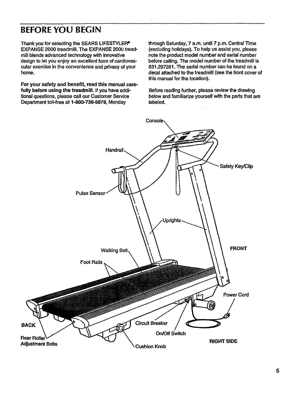
Before reading further, please review the drawing
below and familiarize yourself with the parts that are
labeled.
Console
Handrail
Key/Clip
Pulse Sensor
FRONT
Foot Rails
Power Cord
BACK
Adjustment Bolts
Breaker
On/Off Switch
Cushion Knob RIGHT SIDE
5
ASSEMBLY
Assembly requires the assistance of a second person. Set the treadmill in a cleared area and remove all
packing materials. Do not dispose of the packing materials untilassembly is completed. THE FOLLOWING
TOOLS ARE REQUIRED FOR ASSEMBLY: The 7/32" allen wrench included and your own
adjustable wrench _.
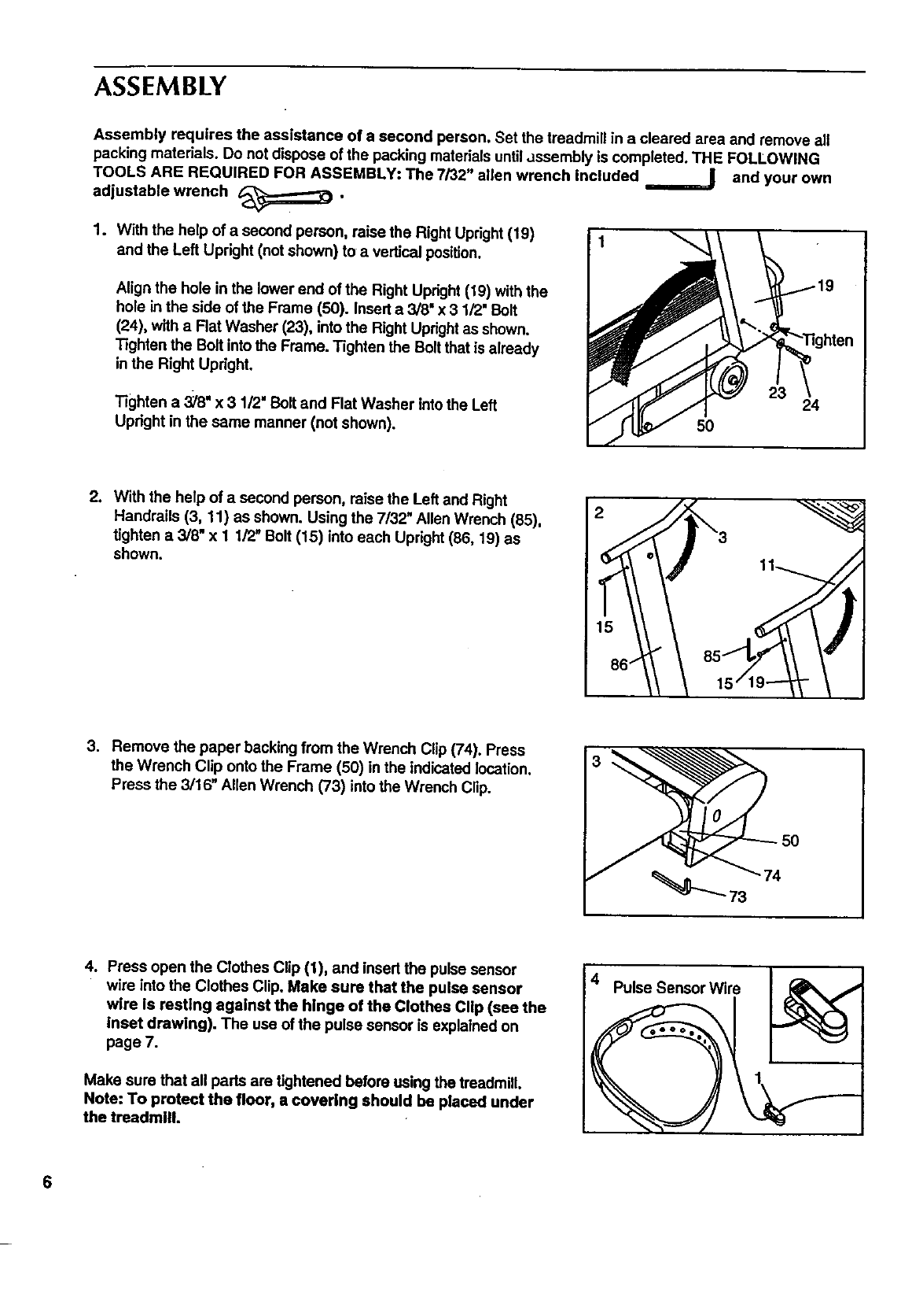
1. With the help of a second person, raise the Right Upright(19)
and the Left Upright (not shown) to a vertical position.
Align the hole in the lower end of the Right Upright(19) with the
hole in the side of the Frame (50). Insert a 3/8" x 3 1/2" Bolt
(24), with a Flat Washer (23), into the Right Uprightas shown.
Tighten the Bolt intothe Frame. Tighten the Bolt that is already
inthe Right Upright.
Tighten a 3;18"x 3 1/2" Bolt and Flat Washer intothe Left
Upright in the same manner (not shown).
24
50
2. With the help of a second person, raise the Left and Right
Handrails (3, 11) as shown. Using the 7/32" Allen Wrench (85),
tighten a 3/8" x 1 1/2" Bolt (15) into each Upright(86, 19) as
shown. 2
15
3. Remove the paper backing from the Wrench Clip (74). Press
the Wrench Clip onto the Frame (50) in the indicated location.
Press the 3/16" Allen Wrench (73) into the Wrench Clip.
4. Press open the Clothes Clip (1), and insert the pulse sensor
wire into the Clothes Clip. Make sure that the pulse sensor
wire is resting against the hinge of the Clothes Clip (see the
inset drawing). The use of the pulse sensor is explained on
page 7.
Make sure that all pads are tightened before using the treadmill.
Note: To protect the floor, a covering should be placed under
the treadmill.
4_Pulse Sensor Wire
6
HOW TO USE THE PULSE SENSOR
The EXPANSE 2000 treadmill features a unique
headband-style pulse sensor. The rubber-armored
pulse sensor and lightweight headband are specially
designed for greater accuracy, comfort and durability.
To get the best performance from the pulse sen-
sor, please read the following Instructions.
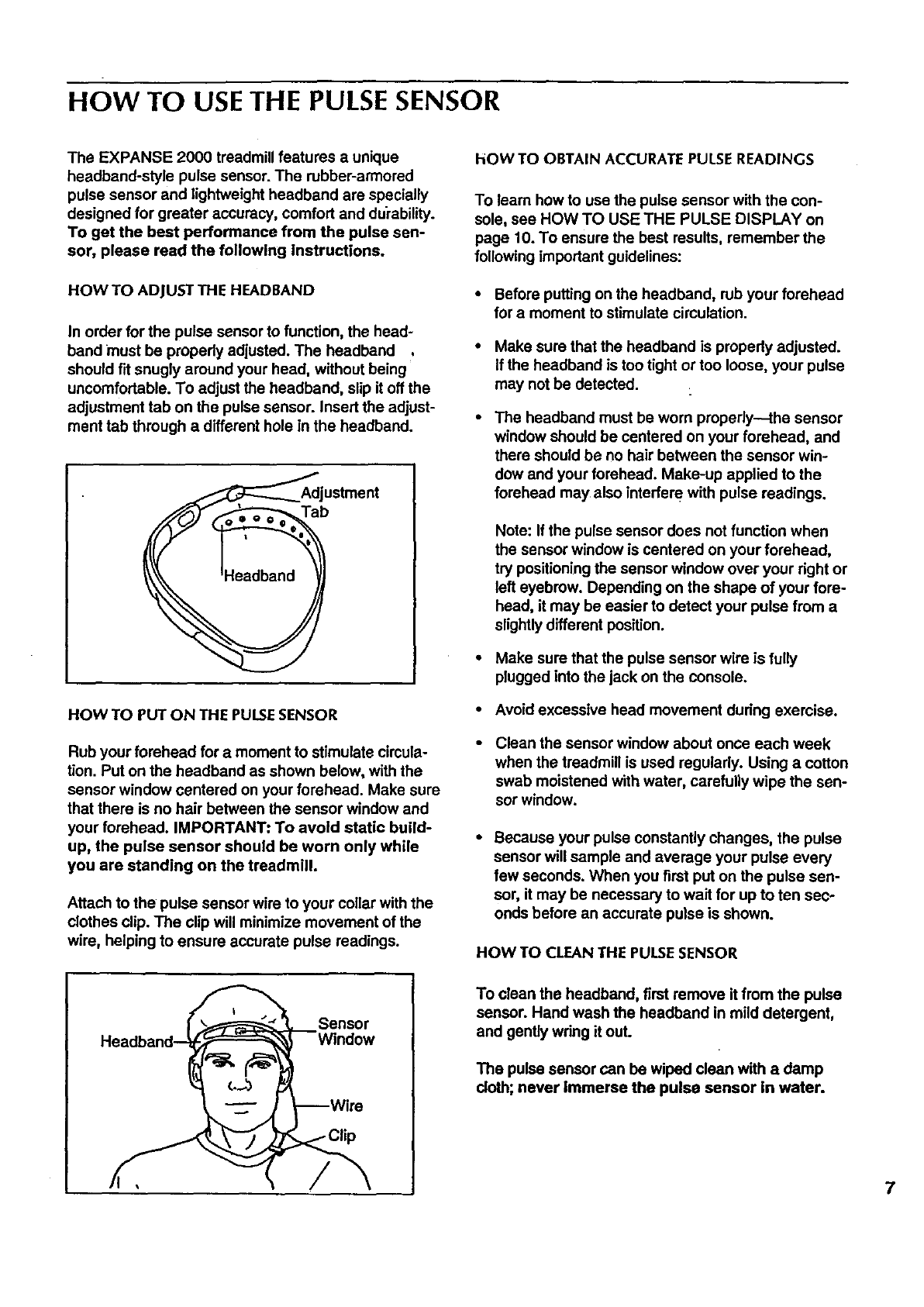
HOW TO ADJUST THE HEADBAND
In order for the pulse sensor to function, the head-
band must be propedy adjusted. The headband ,
should fit snugly around your head, without being
uncomfortable. To adjust the headband, slip it off the
adjustment tab on the pulse sensor. Insert the adjust-
ment tab through a different hole in the headband.
_=<,,-'__AdjlUb stment
HOW TO PUT ON THE PULSESENSOR
Rub your forehead for amoment to stimulate cimula-
tion. Put on the headband as shown below, with the
sensor window centered on your forehead. Make sure
that there is no hair between the sensor window and
your forehead. IMPORTANT: To avoid static build-
up, the pulse sensor should be worn only while
you are standing on the treadmill.
Attach to the pulse sensor wire to your collar with the
clothes clip. The clip will minimize movement of the
wire, helping to ensure accurate pulse readings.
hOW TO OBTAIN ACCURATE PULSE READINGS
To learn how to use the pulse sensor with the con-
sole, see HOW TO USE THE PULSE DISPLAY on
page 10. To ensure the best results, remember the
following important guidelines:
• Before puffing on the headband, rub your forehead
for a moment to stimulate circulation.
Make sure that the headband is propedy adjusted.
If the headband is too tight or too loose, your pulse
may not be detected.
The headband must be worn propedy---the sensor
window should be centered on your forehead, and
there should be no hair between the sensor win-
dow and your forehead. Make-up applied to the
forehead may also interfere with pulse readings.
Note: If the pulse sensor does not function when
the sensor window is centered on your forehead,
try positioning the sensor window over your right or
left eyebrow. Depending on the shape of your fore-
head, it may be easier to detect your pulse from a
slightly different position.
•Make sure that the pulse sensor wire is fully
plugged into the jack on the console.
•Avoid excessive head movement dudng exercise.
Clean the sensor window about once each week
when the treadmill is used regularly. Using a cotton
swab moistened with water, Carefully wipe the sen-
sor window.
Because your pulse constantly changes, the pulse
sensor will sample and average your pulse every
few seconds. When you first put on the pulse sen-
sor, it may be necessary to wait for up to ten sec-
onds before an accurate pulse is shown.
HOW TO CLEAN THE PULSESENSOR
Sensor
To clean the headband, first remove it from the pulse
sensor. Hand wash the headband in mild detergent,
and gently wdng it out.
The pulse sensor can be wiped clean with a damp
cloth; never immerse the pulse sensor in water.
7
OPERATION AND ADJUSTMENT
8
MAINTENANCE-FREE WALKING BELT
This treadmill features a maintenance-free walking
belt. Never apply silicone spray or other sub-
stances to the walking beltor the walking plat-
form; they will deteriorate the walking belt and
cause excessive wear.
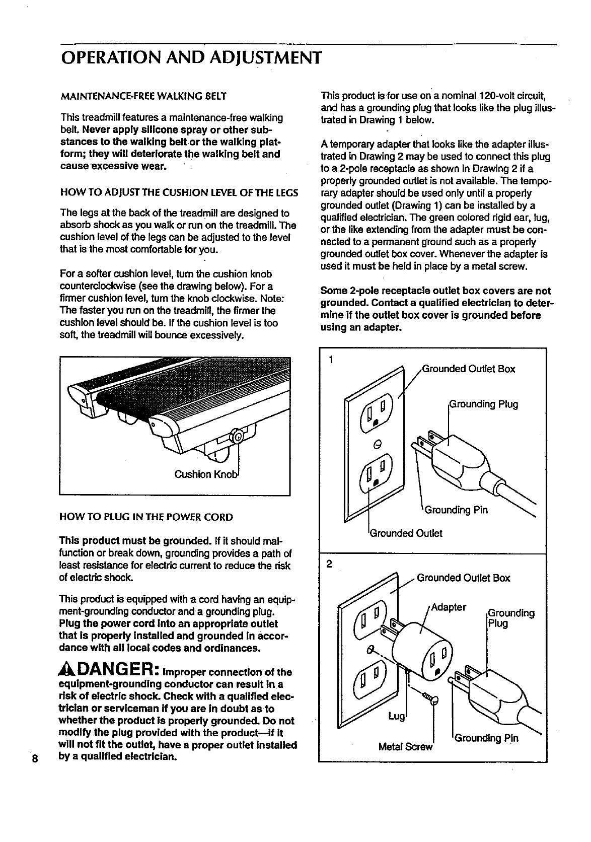
HOW TO ADJUSTTHE CUSHION LEVELOF THE LEGS
The legs at the back of the treadmill are designed to
absorb shock as you walk or run on the treadmill. The
cushion level of the legs can be adjusted to the level
that is the most comfortable for you.
For a softer cushion level, turn the cushion knob
Counterclockwise(see the drawing below). For a
firmer cushion level, tum the knob clockwise. Note:
The faster you run on the treadmill, the firmer the
cushion level should be. If the cushion level is too
soft, the treadmill will bounce excessively.
Cushion
HOW TO PLUG IN THE POWER CORD
This product must be grounded. If it should mal-
function or break down, grounding provides a path of
least resistance for electric current to reduce the risk
of electric shock.
This product is equipped with acord having an equip-
ment-greunding conductor and a grounding plug.
Plug the power cord Into an appropriate outlet
that is properly Installed and grounded In accor-
dance with all local codes and ordinances.
DANGER: Improper connection of the
equipment-grounding conductor can result in a
risk of electric shock. Check with a qualified elec-
trician or serviceman if you are in doubt asto
whether the product is properly grounded. Do not
modify the plug provided with the product--if it
will not fit the outlet, have a proper outlet installed
by a qualified electrician.
This product isfor use on'a nominal 120-volt circuit,
and has a grounding plug that looks like the plug illus-
trated in Drawing 1 below.
A temporary adapter that looks likethe adapter illus-
trated in Drawing 2 may be used to connect this plug
toa 2-pole receptacle as shown in Drawing 2 if a
properly grounded outlet is not available. The tempo-
rary adapter should be used only untilapmpedy
grounded outlet (Drawing 1) can be installed by a
qualified electrician. The green colored rigid ear, lug,
or the like extending from the adapter must be con-
nected to a permanent ground such as a properly
grounded outlet box cover. Whenever the adapter is
used it must be held in place by a metal screw.
Some 2-pole receptacle outlet box covers are not
grounded. Contact a qualified electrician to deter-
mine if the outlet box cover is grounded before
ustng an adapter.
)utlet Box
Plug
2
Grounded Outlet Box
,Adapter
Grounding Pin
Metal Screw
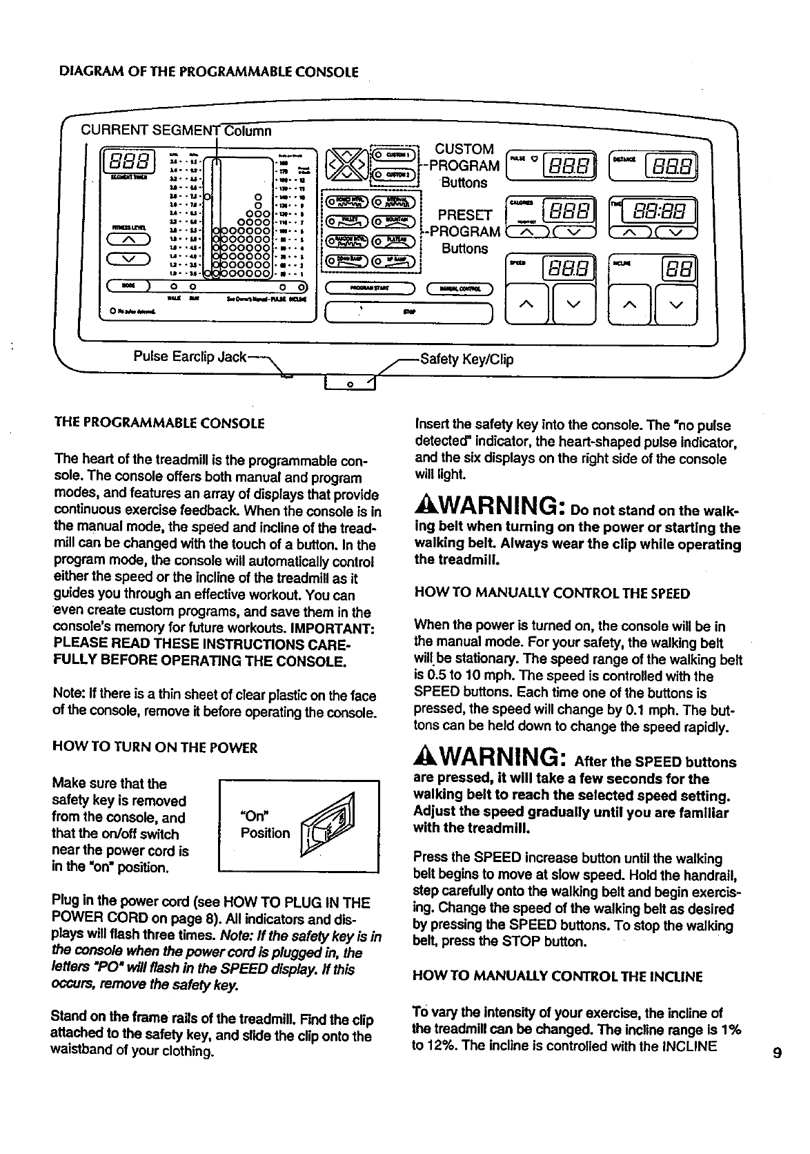
DIAGRAMOFTHEPROGRAMMABLECONSOLE
I
CURRENT SEGMENT Column
Itl_ IlUll .° .
M..U°
U- -1.1. 0
U- -,11. 0
u- -u- 000
u- -_- 0000
.._u_ _ --u-00000
u -•u•
u- ._- 00000
u- -_- 00000
u--_ • 00000
(_,) oo
Oh_
5
.m..
°i,.
°B..
.m°°
.n..
o
r_.,_'_7 CUSTOM
-- -PROGRAM
Su.ons
__i-PROGRAM (A _ v J
_(_) Buttons t;
( m... ) C_)
,( ,' _ )
Pulse Earclip dack---_ _-_Safety Key/Clip
Io-1 J
THE PROGRAMMABLE CONSOLE
The heart of the treadmill is the programmable con-
sole. The console offers both manual and program
modes, and features an array of displays that provide
continuous exercise feedback. When the console is in
the manual mode, the speed and incline of the tread-
mill can be changed with the touch of a button. In the
program mode, the console will automatically control
either the speed or the incline of the treadmill as it
guides you through an effective workout. You can
even create custom programs, and save them in the
console's memory for future workouts. IMPORTANT:
PLEASE READ THESE INSTRUCTIONS CARE-
FULLY BEFORE OPERATING THE CONSOLE.
Note: If there is athin sheet of clear plastic on the face
of the console, remove it before operating the console.
HOW TO TURN ON THE POWER
Make sure that the
safety key is removed
from the console, and
that the on/off switch
near the power cord is
in the =on" position.
Plug in the power cord (see HOW TO PLUG IN THE
POWER CORD on page 8). All indicators and dis-
plays will flash three times. Note: If the safety key is in
the console when the power cord is plugged in, the
letters "PC)"will flash in the SPEED display. If this
occurs, remove the safety key.
Stand on the frame rails of the treadmill. Find the clip
attached to the safety key, and slide the clip onto the
waistband of your clothing.
Insert the safety key into the console. The "no pulse
detected" indicator, the heart-shaped pulse indicator,
and the six displays on the right side of the console
will light.
AWARNING: Do not stand on the walk-
ing belt when turning on the power or starting the
walking bell Always wear the clip while operating
the treadmill.
HOW TO MANUALLY CONTROL THE SPEED
When the power is turned on, the console will be in
the manual mode. For your safety, the walking belt
willbe stationary. The speed range of the walking belt
is 0.5 to 10 mph. The speed is controlled with the
SPEED buttons. Each time one of the buttons is
pressed, the speed will change by 0.1 mph. The but-
tons can be held down to change the speed rapidly.
AWARNING: After the SPEED buttons
are pressed, it will take a few seconds for the
walking belt to reach the selected speed setting.
Adjust the speed gradually until you are familiar
with the treadmill.
Press the SPEED increase button until the walking
belt begins to move at slow speed. Hold the handrail,
step carefully onto the walking belt and begin exercis-
ing. Change the speed of the walking belt as desired
by pressing the SPEED buttons. To stop the walking
belt, press the STOP button.
HOW TO MANUALLY CONTROL THE INCLINE
TO vary the intensity of your exercise, the incline of
the treadmill can be changed. The incline range is 1%
to 12%. The incline is controlled with the INCLINE 9
buttons.Eachtimeoneofthebuttonsispressed,the
inclinewillchangeby0.5%.Thebuttonscanbeheld
downtochangetheinclinerapidly.
When the walking belt is started, the CALORIES dis-
play will show the approximate number of Calories
that you have burned.
10
Note: Because the INCLINE display has two digits,
the display will show 10% when the incline is set at
either 10% or 10.5%, and 11% when the incline is set
at either 11% or 11.5%. After the INCLINE buttons are
pressed, it will take a few seconds for the treadmill to
reach the selected incline setting.
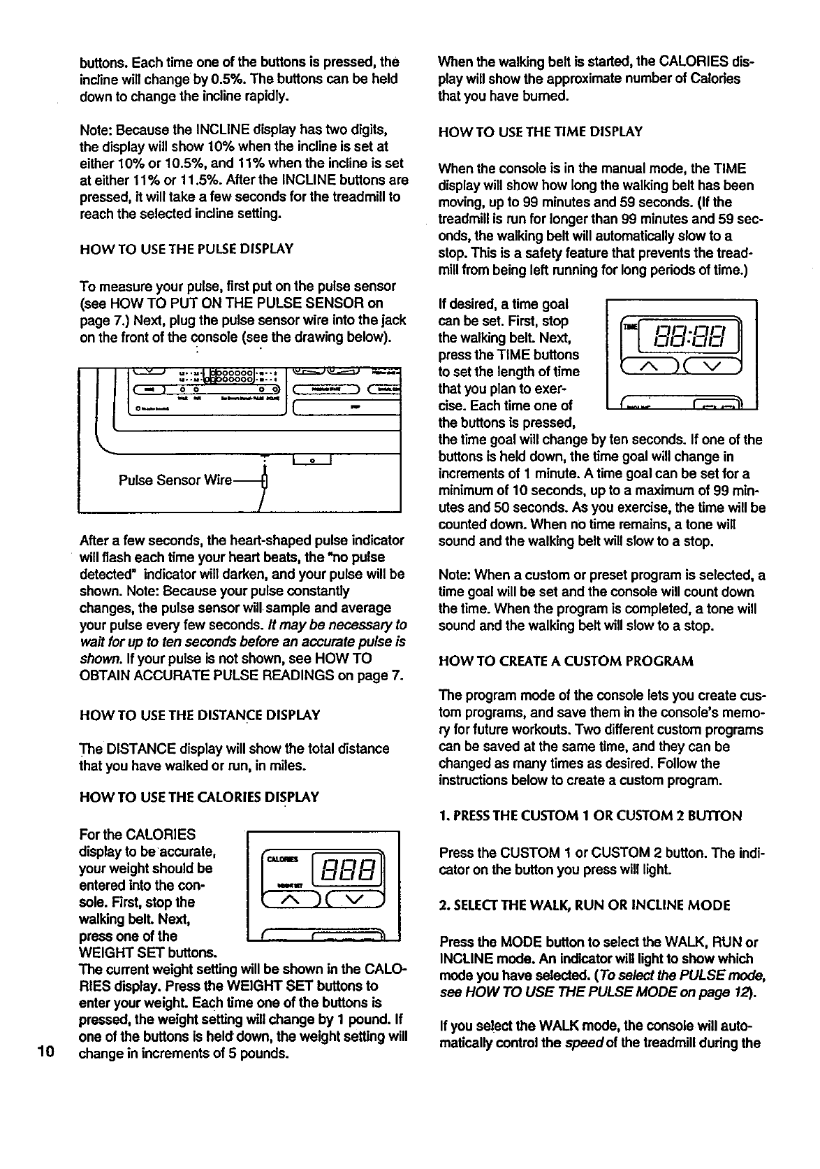
HOW TO USETHE PULSEDISPLAY
To measure your pulse, first put on the pulse sensor
(see HOW TO PUT ON THE PULSE SENSOR on
page 7.) Next, plug the pulse sensor wire into the jack
on the front of the console (see the drawing below).
ll _ u..=,- 0000o .u--* v._::===j u.,_===::_ --,,._,.=
I,-, : ;,Ic D
to-- " ...... JC -
Pulse Sensor Wire-_
After a few seconds, the heart-shaped pulse indicator
will flash each time your heart beats, the *no pulse
detected" indicator will darken, and your pulse will be
shown. Note: Because your pulse constantly
changes, the pulse sensor will sample and average
your pulse every few seconds. It may be necessary to
wait for up to ten seconds before an accurate pulse is
shown. If your pulse is not shown, see HOW TO
OBTAIN ACCURATE PULSE READINGS on page 7.
HOWTO USETHE DISTANCE DISPLAY
_'he DISTANCE display will show the total distance
that you have walked or run, in miles.
HOW TO USE THE CALORIES DISPLAY
For the CALORIES
display to be accurate, {_,,,-- _r--_--_--_-__
your weight should be
entered into the con-
sole. First, stop the
walking bell Next,
press one of the
WEIGHT SET buttons.
The current weight setting will be shown in the CALO-
RIES display. Press the WEIGHT SET buttons to
enter your weighL Each time one of the buttons is
pressed, the weight setting will change by 1 pound. If
one of the buttons is held down, the weight setting will
change in increments of 5 pounds.
HOW TO USETHE TIME DISPLAY
When the console is in the manual mode, the TIME
display will show how longthe walking belt has been
moving, up to 99 minutes and 59 seconds. (If the
treadmill is run for longer than 99 minutes and 59 sec-
onds, the walking belt will automatically slow to a
stop. This is asafety feature that prevents the tread-
millfrom being left running for long periods of time.)
If desired, a time goal
can be set. First, stop
the walking belt. Next,
pressthe TIME buttons
to set the length of time
that you plan to exer-
cise. Each time one of
the buttonsis pressed,
the time goal will change by ten seconds. If one of the
buttonsis held down, the time goal will change in
incrementsof 1 minute. A time goal can be set for a
minimumof 10 seconds, upto a maximum of 99 min-
utes and 50 seconds. As you exemise, the time will be
counted down. When nO time remains, a tone will
sound and the walking belt will slow to a stop.
_=I F=H3.IT_I3
(_..2 _3
Note: When a custom or preset program is selected, a
time goal will be set and the console will count down
the time. When the program is completed, a tone will
sound and the walking belt will slow to astop.
HOW TO CREATEA CUSTOM PROGRAM
The program mode of the console lets you create cus-
tom programs, and save them in the console's memo-
ry for future workouts. Two differentcustom programs
can be saved at the same time, and they can be
changed as many times as desired. Followthe
instructionsbelow to create acustom program.
1. PRESSTHE CUSTOM 1 OR CUSTOM 2 BUTTON
Press the CUSTOM 1 or CUSTOM 2 button. The indi-
cator on the buttonyou press will light.
2. SELECTTHE WALK, RUN OR INCLINE MODE
Press the MODE buttonto select the WALK, RUN or
INCLINE mode. An indicatorwill lightto show which
mode you have selected. (To select the PULSE mode,
see HOW TO USE THE PULSE MODE on page 12).
If you select the WALK mode, the console will auto-
matically control the speedof the treadmill during the
program, and the speed range will be 1.0 to 3.6 mph.
If you select the RUN mode, the console will automati-
cally control the speedof the treadmill, and the speed
range will be 3.0 to 9.5 mph. if you select the
INCLINE mode, the console will automatically control
the incline of the treadmill, and the incline range will
be 1% to 12%. Note: If you select the WALK or RUN
mode, the incline can be manually controlled during .
the program. If you select the INCLINE mode, the
speed can be manually controlled.
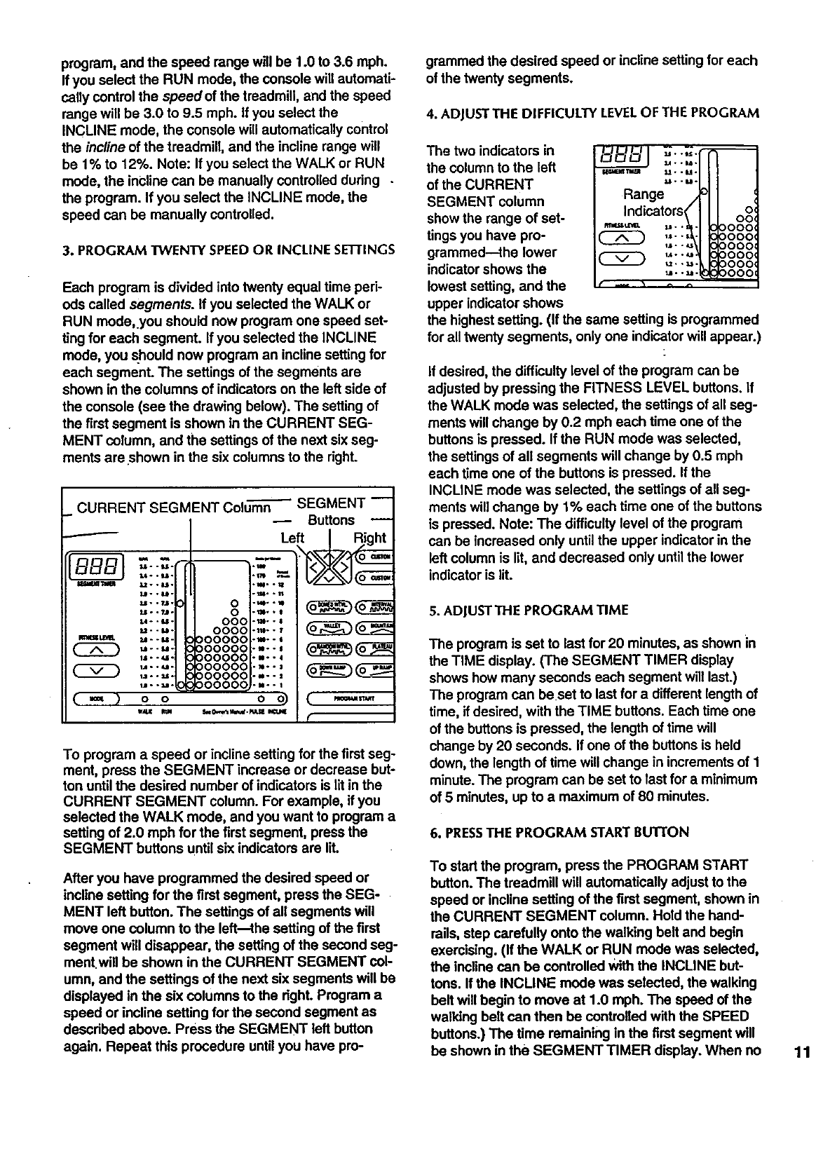
3. PROGRAM TWENTY SPEEDOR INCLINE SIiTFINGS
Each program is divided into twenty equal time perk
eds called segments. If you selected the WALK or
RUN mode,.you should now program one speed set-
ting for each segment. If you selected the INCLINE
mode, you should now program an incline setting for
each segment. The settings of the segments are
shown in the columns of indicators on the left side of
the console (see the drawing below). The setting of
the firstsegment is shown in the CURRENT SEG-
MENT column, and the settings of the next six seg-
ments areshown in the six columns to the right.
CURRENT SEGMENT Colum-_ SEGMENT --
Buttons
f
BB- -I.=.=l --
I_dir_ ";liH Lt. * 8.tl.
W..re.
Uo .?J.
2JL.. ?.ll.
L4 *. U -
U..kl.
Im4_ tL_I_. U- . M-
W--SI-
ll1 •-_I-
U..U.
_..U.
(==) co oo)
w_ WJ4 S_Ow,e_s_.pdLS_ KTJ4E
0
o
coo
coco
)ooooc
)ooooc
3o0o00
3oo00c
30o00c
30000C .u--1
Left / Right
_0_
,..,
...,
,m..l
r
To program a speed or incline setting for the first seg-
ment, press the SEGMENT increase or decrease but-
ton until the desired number of indicators is lit in the
CURRENT SEGMENT column. For example, if you
selected the WALK mode, and you want to program a
setting of 2.0 mph for the firstsegment, press the
SEGMENT buttons until six indicators are lit.
After you have programmed the desired speed or
incline setting for the first segment, press the SEG-
MENT left button. The settings of all segments will
move one column to the left--the setting of the first
segment will disappear, the setting of the second seg-
ment.will be shown in the CURRENT SEGMENT col-
umn, and the settings of the next six segments will be
displayed in the six columns to the right. Program a
speed or incline setting for the second segment as
described above. Press the SEGMENT left button
again. Repeat this procedure until you have pro-
grammed the desired speed or incline setting for each
of the twenty segments.
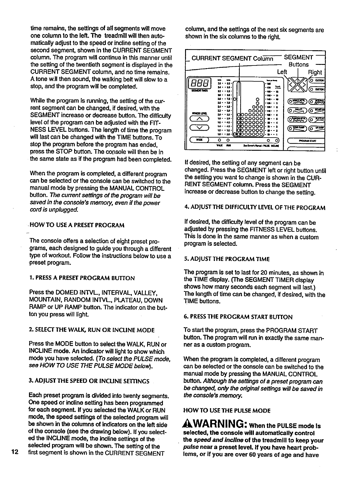
4, ADJUSTTHE DIFFICULTY LEVELOF THE PROGRAM
The two indicators in
the column to the left
of the CURRENT
SEGMENT column
show the range of set-
tings you have pro-
grammed--the lower
indicator shows the
lowest setting, and the
upper indicator shows
u*._.
_..u.
w.,mJ_ u..u.
_.-u.
Range .
Indicators< oo,°'
,_-._ 0000,0000,
-- ,*''_ 0000
_.-u UUUU
f -- • ^ ^
the highestsetting. (If the same setting is programmed
for all twenty segments, only one indicatorwill appear.)
If desired, the difficulty level of the program can be
adjusted by pressing the FITNESS LEVEL buttons. If
the WALK mode was selected, the settings of all seg-
ments will change by 0.2 mph each time one of the
buttons is pressed. If the RUN mode was selected,
the settings of all segments will change by 0.5 mph
each time one of the buttons is pressed. If the
INCLINE mode was selected, the settings of all seg-
ments will change by 1% each time one of the buttons
is pressed. Note: The difficulty level of the program
can be increased only untilthe upper indicator in the
left column is lit, and decreased only until the lower
indicatoris lit.
5. ADJUSTTHE PROGRAM TIME
The program is set to last for 20 minutes, as shown in
the TIME display. (The SEGMENT TIMER display
shows how many seconds each segment will last.)
The program can beset to last for a different length of
time, if desired, with the TIME buttons. Each time one
of the buttons is pressed, the length of time will
change by 20 seconds. If one of the buttons is held
down, the length of time will change in increments of 1
minute. The program can be set to last for a minimum
of 5 minutes, up to a maximum of 80 minutes.
6. PRESSTHE PROGRAM START BUTTON
To start the program, press the PROGRAM START
button. The treadmill will automatically adjust to the
speed or incline setting of the first segment, shown in
the CURRENT SEGMENT column. Hold the hand-
rails, step carefully onto the walking belt and begin
exercising. (If the WALK or RUN mode was selected,
the incline can be controlled With the INCLINE but-
tons. If the INCLINE mode was selected, the walking
belt will begin to move at 1.0 mph. The speed of the
walking belt can then be controlled with the SPEED
buttons.) The time remaining in the first segment will
be shown in the SEGMENT TIMER display. When no 11
time remains, the settings of all segments will move
one column to the left. The treadmill will then auto-
matically adjust to the speed or incline setting of the
second segment, shown in the CURRENT SEGMENT
column. The program will continue in this manner until
the setting of the twentieth segment is displayed in the
CURRENT SEGMENT column, and no time remains.
A tone w_llthen sound, the walking belt will slow to a
stop, and the program will be completed.
While the program is running, the setting of the cur-
rent segment can be changed, if desired, with the
SEGMENT increase or decrease button. The difficulty
level of the program can be adjusted with the FIT-
NESS LEVEL buttons. The length of time the program
will last can be changed with the TIME buttons. To
stop the program before the program has ended,
press the STOP button. The console will then be in
the same state as if the program had been completed.
When the program is completed, a different program
can be selected or the console can be switched to the
manual mode by pressing the MANUAL CONTROL
button. The current settings of the program will be
saved in the console's memory, even if the power
cord is unplugged.
HOW TO USE A PRESETPROGRAM
The console offers a selection of eight preset pro-
grams, each designed to guide you through adifferent
type of workout. Follow the instructions below to use a
preset program.
1. PRESSA PRESETPROGRAM BUTTON
Press the DOMED INTVL, INTERVAL, VALLEY,
MOUNTAIN, RANDOM INTVL, PLATEAU, DOWN
RAMP or UP RAMP button. The indicator on the but-
ton you press will light.
column, and the settings of the next six segments are
shown in the six columns to the right.
_CURRENT SEGMENT Column
/
Ww
( 2D
(.=,)
M, .t_.
&=. °M.
$m.. M .
LI °. 7,1.
u.._.
U..U°
U-.M.
U..LI.
u..LI*
t,I. • _1°
t4° °_t.
t_.. M •
O O
WU m
_SEGMENT--
Buttons --
Left |_ght
o....
0._,.
OOO'm--
O000-m-- _
000000-_--
000000 .... _
000000.--.
oooooo....
O00000-m.-
O0000Q...-
(
If desired, the setting of any segment can be
changed. Press the SEGMENT left or right button until
the setting you want to change is shown in the CUR-
RENT SEGMENT column. Press the SEGMENT
increase or decrease button to change the setting.
4. ADJUSTTHE DIFFICULTY LEVELOF THE PROGRAM
If desired, the difficulty level of the program can be
adjusted by pressing the FITNESS LEVEL buttons.
This is done in the same manner as when a custom
program is selected.
5. ADJUSTTHE PROGRAM TIME
The program is set to last for 20 minutes, as shown in
the TIME display. (The SEGMENT TIMER display
shows how many seconds each segment will last.)
The length of time can be changed, if desired, with the
TIME buttons.
6. PRESSTHE PROGRAM STARTBUTTON
12
2. SELECTTHE WALK, RUN OR INCLINE MODE
Press the MODE button to select the WALK, RUN or
INCLINE mode. An indicator will light to show which
mode you have selected. (To select the PULSE mode,
see HOW TO USE THE PULSE MODE below).
3. ADJUST THE SPEED OR INCLINE SETI'INGS
Each preset program is divided into twenty segments.
One speed or incline setting has been programmed
for each segment. If you selected the WALK or RUN
mode, the speed settings of the selected program will
be shown in the columns of indicatorson the left side
of the console (see the drawing below). If you select-
ed the INCLINE mode, the incline settings of the
selected program will be shown. The setting of the
firstsegment is shown in the CURRENT SEGMENT
To start the program, press the PROGRAM START
button. The program will run in exactly the same man-
ner as a custom program.
When the program is completed, a different program
can be selected or the console can be switched to the
mamJal mode by pressing the MANUAL CONTROL
button. Although the settings of a preset program can
be changed, only the original settings will be saved in
the console's memory.
HOW TO USETHE PULSEMODE
AWA RNING: WhenthePULSEmodeIs
selected, the console will automatically control
, the speed and incline of the treadmill to keep your
pulse near a preset level. If you have heart prob-
lems, or if you are over 60 years of age and have

beeninactive, do not use the PULSE mode.
if you are taking medication regularly, consult
with your physician to determine whether the
medication will affect your exercise heart rate
before using the PULSE mode.
1. PRESSTHE PLATEAU BUI-I'ON
Press the PLATEAU button. The indicatoron the button
will light. Note: If the PULSE mode is selected while a
different program is selected, the PLATEAU program
will automatically he selected.
2. SELECTTHE PULSE MODE
Press the MODE button to select the PULSE mod$.
An indicator will light above the word PULSE.
3. THE PULSE SETTINGS
The program is divided into twenty segments. One
pulse setting is programmed for each segment. The
pulse settings of the program are shown in the
columns of indicators on the left side of the console.
The setting of the first segment is shown in the CUR-
RENT SEGMENT column, and the settings of the next
six segments are shown in the six columns to the
Aght. The settings of the segments cannot be
changed with the SEGMENT buttons.
4. ADJUSTTHE DIFFICULTY LEVELOF THE PROGRAM
If desired, the difficulty level of the program can be
adjusted with the FITNESS LEVEL buttons. Each time
one of the buttons is pressed, the pulse settings of all
segments will change by 10 beats per minute. IMPOR-
TANT: The pulse settings should never exceed
your training zone. See CONDITIONING GUIDE-
LINES on page 16 to find your training zone.
S. ADJUST THE PROGRAM TIME
The PLATEAU program is set to last for 20 minutes,
as shown in the TIME display. (The SEGMENT
TIMER display shows how many seconds each seg-
ment will last.) The length of time can be changed, if
desired, with the TIME buttons. The program can be
set to last for a minimum of 20 minutes, up to amaxi-
mum of 80 minutes.
6. PUT ON THE PULSE SENSOR
Before starting the program, put on the pulse sensor
(see HOWTO USE THE PULSE DISPLAY on page
10). If your pulse is not detected, the PULSE display
will flash and the =no pulse detected" indicator will
light. Wait until your pulse is Shown (see HOW TO
OBTAIN ACCURATE PULSE READINGS on page 7).
7. PRESSTHE PROGRAM START BUTEON
To start the program, press the PROGRAM START
button. When the walking belt begins to move, care-
fully step onto the walking belt and begin exercising.
The console will automatically change the speed or
incline of the treadmill at any time to keep your pulse
near the pulse setting of the first segment, shown in
the CURRENT SEGMENT column. IMPORTANT: Be
alert at all times for speed or incline changes. The
time remaining in the first segment will be shown in
the SEGMENT TIMER display. When no time
remains, the settings of all segments will move one
column to the left. The console will then change the
speed or incline to keep your pulse near the pulse set-
ting of the second segment, shown in the CURRENT
SEGMENT column. The program will continue in this
manner untilthe setting of the twentieth segment is
shown in the CURRENT SEGMENT column, and no
time remains. A tone will then sound, the walking belt
will slow to a stop, and the program will be completed.
While the program is running, the difficultylevel of the
program can be adjusted with the FITNESS LEVEL
buttons. The speed and incline of the treadmill can be
adjusted with the SPEED or INCLINE buttons. How-
ever, if you decrease either setting, the other setting
will automatically increase; if you increase either set-
ting, the other setting will decrease. The console will
always attempt to keep your pulse near the setting of
the current segment. If your pulse is not detected for
one minute, the speed of the treadmill will automati-
cally decrease. If no pulse is detected for two minutes,
the speed will decrease again. If no pulse is detected
for three minutes, the walking belt will slow to a stop.
HOWTO TURN OFF THE POWER
Remove the safety key from the console. Store the
safety key in a secure location.
HOW TO SELECTTHE INFORMATION MODE
The information mode keeps track of tApdistance and
time, and the total distance and time accumulated on
the treadmill. To select this mode, hold down the STOP
button while inserting the safety key into the consore.
The PULSE and DISTANCE displays will show the
tap distance, up to 99,999 miles. The TIME display
will show the tAp time, up to 9,999 hours. The CALO-
RIES display will show the letter _," indicating that
tAp distance and time are displayed. The displays can
be reset to zero, if desired, by pressing the TIME
decrease button. To view the total distance and time,
press the TIME increase button. The PULSE and DIS-
TANCE displays will show the total distance. The
TIME display will show the total time. To exit the infor-
mation mode, remove the safety key. 13
TROUBLE-SHOOTING AND STORAGE
Most treadmill problems can be solved by following the simple steps below. Find the symptom that applies,
and follow the steps listed. If further assistance is needed, call our Customer Service Department toll-free at 1-
800-736-6879, Monday through Saturday, 7 a.m. until7p.m. Central Time (excluding holidays).
1. SYMPTOM: THE POWER DOES NOTTURN ON
a. Make sure that the power cord is plugged into a propedy grounded outlet. (See HOW TO PLUG IN THE
POWER CORD on page 8.) If an extension cord is needed, use only a 14-gauge general-purpose cord of
five feet or less in length.
b. After the power cord has been plugged in, make sure that the safety key is fully inserted into the console.
Various indicatorson the console should light. (See HOW TO TURN ON THE POWER on page 9.)
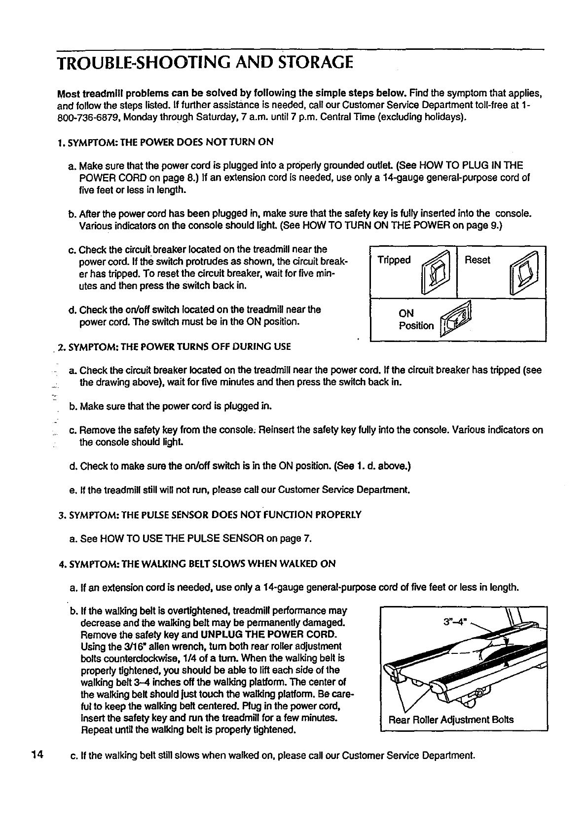
c. Check the circuitbreaker located on the treadmill near the
power cord. If the switch protrudes as shown, the circuitbreak-
er has tripped. To reset the circuit breaker, wait for five min-
utes and then press the switch back in.
d. Check the on/off switch located on the treadmill near the
power cord. The switch must be in the ON position.
•2. SYMPTOM: THE POWER TURNS OFF DURING USE
•
Position
a. Check the circuitbreaker located on the treadmill near the power cord. If the circuit breaker has tripped (see
.... the drawing above), wait for five minutes and then press the switch back in.
b. Make sure that the power cord is plugged in.
:, c. Remove the safety key from the console; Reinsert the safety key fully into the console. Various indicatorson
the console should light.
d. Check to make sure the on/off switch is in the ON position. (See 1. d. above.)
e. If the treadmill stillwill not run, please call our Customer Service Department.
3. SYMPTOM: THE PULSESENSOR DOES NOT FUNCTION PROPERLY
a. See HOW TO USE THE PULSE SENSOR on page 7.
4. SYMPTOM: THE WALKING BELTSLOWS WHEN WALKED ON
a. If an extension cord is needed, use only a 14-gauge general-purpese cord of five feet or less in length.
b. If the walking belt is overtightened, treadmill performance may
decrease and the walking bolt may be permanently damaged.
Remove the safety key and UNPLUG THE POWER CORD.
Using the 3/16" allen wrench, turn both rear roller adjustment
bolts counterclockwise, 114of a turn. When the walking belt is
properly tightened, you should be able to lift each side of the
walking belt 3-4 inches off the walking platform. The center of
the walking belt should just touch the walking platform. Be care-
ful to keep the walking belt centered. Plug in the power cord,
insert the safety key and run the treadmill for a few minutes.
Repeat untilthe walking bolt is propedy tightened. Rear Roller Adjustment Bolts
14 c. If the walking belt still slows when walked on, please call our Customer Service Department.
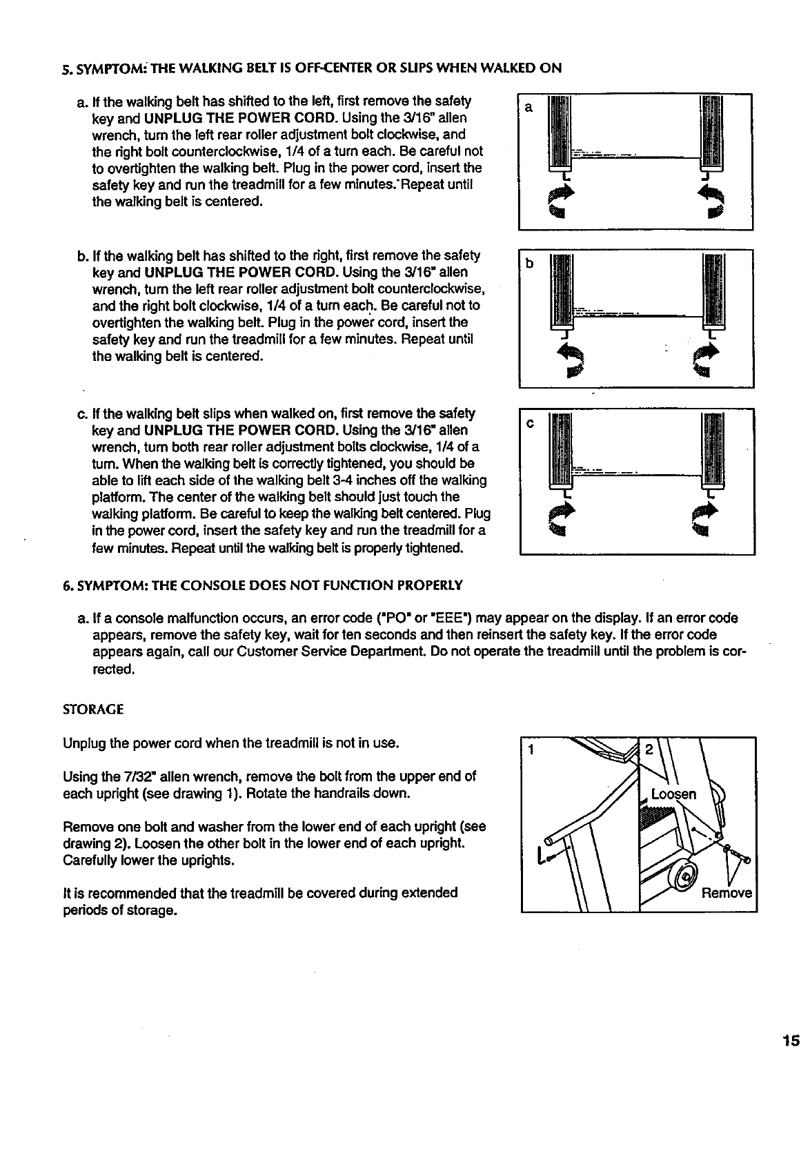
5.SYMPTOM'THEWALKINGBELTISOFF-CENTERORSLIPSWHENWALKEDON
a. Ifthewalkingbelthasshiftedtotheleft,firstremovethesafety
keyandUNPLUGTHEPOWERCORD.Usingthe3/16"allen
wrench, turn the left rear roller adjustment bolt clockwise, and
the right bolt counterclockwise, 114of aturn each. Be careful not
to overtighten the walking belt. Plug in the power cord, insert the
safety key and run the treadmill for a few minutes:Repeat until
the walking belt is centered.
b. If the walking belt has shifted to the right, first remove the safety
key and UNPLUG THE POWER CORD. Using the 3/16" allen
wrench, turn the left rear roller adjustment bolt counterclockwise,
and the right bolt clockwise, 1/4 of a turn each. Be careful not to
overtighten the walking belt. Plug in the power cord, insert the
safety key and run the treadmill for a few minutes. Repeat until
the walking belt is centered.
c. If the walking belt slips when walked on, first remove the safety
key and UNPLUG THE POWER CORD. Using the 3/16" allen
wrench, turn both rear roller adjustment bolts clockwise, 1/4 of a
tum. When the walking belt is correctlytightened, you should be
able to lift each side of the walking belt 3-4 inches off the walking
platform. The center of the walking belt should just touch the
walking platform. Be careful to keep the walking belt centered. Plug
in the power cord, insert the safety key and run the treadmill for a
few minutes. Repeat untilthe walking beltis properlytightened.
b
O
6. SYMPTOM: THE CONSOLE DOES NOT FUNCL'TIONPROPERLY
a. If a console malfunction occurs, an error cede ("PO" or "EEE") may appear on the display. If an error code
appears, remove the safety key, wait for ten seconds and then reinsert the safety key. If the error code
appears again, call our Customer Service Department. Do not operate the treadmill until the problem is cor-
rected.
STORAGE
Unplug the power cord when the treadmill is not in use.
Using the 7/32" allen wrench, remove the bolt from the upper end of
each upright (see drawing 1). Rotate the handrails down.
Remove one bolt and washer from the lower end of each upright (see
drawing 2). Loosen the other bolt in the lower end of each upright.
Carefully lower the uprights.
it is recommended that the treadmill be covered during extended
periods of storage.
Remove
15
CONDITIONING GUIDELINES
The following guidelines will help you to plan your
exemise program. For more information, consultyour
physician or obtain a reputable book about exercise.
Remember that proper nutrition and adequate rest are
essential for successful results.
WARNING: Beforebeginning this or
any exercise program, consult your physician.
This is especially Important for individuals over
the age of 35 or individuals with pre-existing
health problems.
EXERCISEINTENSITY
To maximize the benefits of exercising, it is important
to exercise with the proper intensity. The proper inten-
sit,/level can be found by usingyour heart rate as a
guide. For effective aerobic exercise, your heart rate
should be maintained at a level between 70% and
85% of your maximum heart rate as you exemise.
This is known as your training zone.
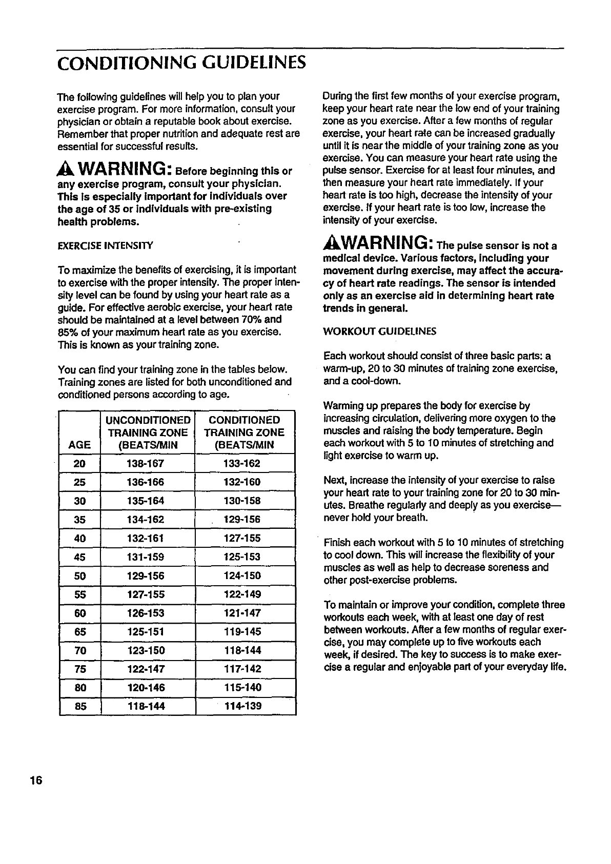
You can find your training zone in the tables below.
Training zones are listed for both unconditioned and
conditioned persons according to age.
UNCONDITIONED CONDITIONED
TRAINING ZONE TRAINING ZONE
AGE (BEATS/MIN (BEATS/MIN
20 138-167 133-162
25 136-166 132-160
30 135-164 130-158
35 134-162 129-156
40 132-161 127-155
46 131-159 125-153
50 129-156 124-150
55 127-155 122-149
60 126-153 121-147
65 125-151 119-145
70 123-150 118-144
75 122-147 117-142
80 120-146 115-140
85 118-144 114-139
Duringthe first few months of your exercise program,
keep your heart rate near the low end of your training
zone as you exercise. After a few months of regular
exercise, your heart rate can be increased gradually
until it is near the middle of your training zone as you
exercise. You can measure your heart rate using the
pulse sensor. Exercise for at least four minutes, and
then measure your heart rate immediately. If your
heart rate is too high, decrease the intensity of your
exercise. If your heart rate is too low, increase the
intensity of your exercise.
kWAR NING: Thepulse sensor isnota
medical device. Various factors, including your
movement during exercise, may affect the accura-
cy of heart rate readings. The sensor is intended
only as an exercise aid in determining heart rate
trends in general.
WORKOUT GUIDELINES
Each workout should consist of three basic pads: a
warm-up, 20 to 30 minutes of training zone exercise,
and a cool-down.
Warming up prepares the body for exercise by
increasing circulation, delivering more oxygen to the
muscles and raising the body temperature. Begin
each workout with 5 to 10 minutes of stretching and
light exercise to warm up.
Next, increase the intensity of your exercise to raise
your heart rate to your training zone for 20 to 30 min-
utes. Breathe regularly and deeply as you exercise--
never hold your breath.
Finish each workout with 5 to 10 minutes of stretching
to cool down. This will increase the flexibilityof your
muscles as well as help to decrease soreness and
other post-exercise problems.
To maintain or improve your condition, complete three
workouts each week, with at least one day of rest
between workouts. After a few months of regular exer-
cise, you may complete up to five workouts each
week, if desired. The key to success is to make exer-
cise aregular and enjoyable part of your everyday life.
16
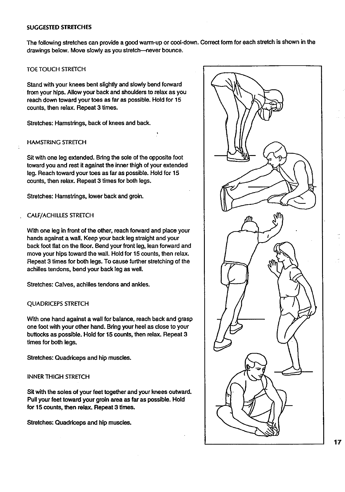
SUGGESTED STRETCHES
The following stretches can provide a good warm-up or cool-down. Correct form for each stretch is shown in the
drawings below. Move slowly as you stretch--never bounce.
TOE TOUCH STRETCH
Stand with your knees bent slightly and slowly bend forward
from your hips. Allow your back and shouldersto relax as you
reach down toward your toes as far as possible. Hold for 15
counts, then relax. Repeat 3 times.
Stretches: Hamstrings, back of knees and back.
HAMSTRING STRETCH
Sit with one leg extended. Bring the sole of the opposite foot
toward you and rest it against the inner thigh of your extended
leg. Reach toward your toes as far as possible. Hold for 15
counts, then relax. Repeat 3 times for both legs.
Stretches: Hamstrings, lower back and groin.
CALF/ACHILLES STRETCH
With one leg in front of the other, reach forward and place your
hands against a wall. Keep your back leg straight and your
back foot flat on the floor. Bend your front leg, lean forward and
move your hips toward the wall. Hold for 15 counts, then relax.
Repeat 3 times for both legs. To cause further stretching of the
achilles tendons, bend your back leg as well.
Stretches: Calves, achilles tendons and ankles.
QUADRICEPS STRETCH
With one hand against a wall for balance, reach back and grasp
one foot with your other hand. Bring your heel as close to your
buttocks as possible. Hold for 15 counts, then relax. Repeat 3
times for both legs.
Stretches: Quadriceps and hip muscles.
INNER THIGH STRETCH
Sit with the soles of your feet together and your knees outward.
Pull your feet toward your groin area as far as possible. Hold
for 15 counts, then relax. Repeat 3 times.
Stretches: Quadriceps and hip muscles.
17
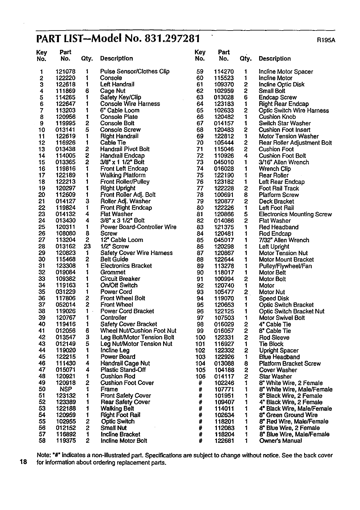
PART LIST--Model No. 831.297281 R195A
Key Part Key Part
No. No. Qty. Description No. No. Qty. Description
1121078 1 Pulse Sensor/Clothes Clip 59 114270 1 Incline Motor Spacer
2 122220 1 Console 60 115523 1 Incline Motor
3122618 1 Left Handrail 61 109370 2 Incline Optic Disk
4 111869 6 Cage Nut 62 102959 2 Small Bolt
5 114265 1 Safety Key/Clip 63 013028 6 Endcap Screw
6 122647 1 Console Wire Harness 64 123183 1Right Rear Endcap
7 113203 1 6" Cable Loom 65 102633 2 Optic Switch Wire Harness
8 120956 1 Console Plate 66 120482 1 Cushion Knob
9 119995 2 Console Bolt 67 014157 1 Switch Star Washer
10 013141 5 Console Screw 68 120483 2 Cushion Foot Insert
11 122619 1 Right Handrail 69 122812 1 Motor Tension Washer
12 116926 1 Cable Tie 70 105444 2 Rear Roller Adjustment Bolt
13 013438 2 Handrail Pivot Bolt 71 115046 2 Cushion Foot
14 114005 2Handrail Endcap 72 110926 4 Cushion Foot Bolt
15 013365 2 3/8" x 1 1/2" Bolt 73 045010 1 3/16" Allen Wrench
16 119816 1 Front Left Endcap 74 016028 1 Wrench Clip
17 122189 1 Walking Platform 75 122190 1 Rear Roller
18 122213 1 Front Roller/Pulley 76 123182 1 Left Rear Endcap
19 120297 1 Right Updght 77 122228 2 Foot Rail Track
20 112609 1 Front Roller Adj. Bolt 78 100691 8 Platform Screw
21 014127 3 Roller Adj. Washer 79 120877 2 Deck Bracket
22 119824 1 Front Right Endcap 80 122226 1 Left Foot Rail
23 014132 4 Flat Washer 81 120866 5 Electronics Mounting Screw
24 013430 4 3/8" x 3 1/2" Bolt 82 014086 2 Flat Washer
25 120311 1 Power Board-Controller Wire 83 121375 1 Red Headband
26 108080 8 Screw 84 120481 1 Rod Endcap
27 113204 2 12" Cable Loom 85 045017 1 7/32" Allen Wrench
28 013162 23 1/2" Screw 86 120298 1 Left Upright
29 120823 1 Safety Cover Wire Harness 87 120867 1 Motor Tension Nut
30 115468 2 Belt Guide 88 122644 1 Motor Mount Bracket
31 123308 1 Electronics Bracket 89 113278 1 Pulley/Flywheel/Fan
32 019084 1 Grommet 90 118017 1 Motor Belt
33 109382 1 Circuit Breaker 91 100994 2 Motor Bolt
34 119163 1 On/Oft Switch 92 120740 1 Motor
35 031229 1 Power Cord 93 105477 2 Motor Nut
36 117806 2 Front Wheel Bolt 94 119070 1 Speed Disk
37 052014 2 Front Wheel 95 120653 1 Optic Switch Bracket
38 119026 1 Power Cord Bracket 96 122125 1 Optic Switch Bracket Nut
39 120767 1 Controller 97 107503 1 Motor Swivel Bolt
40 119416 1 Safety Cover Bracket 98 016029 2 4" Cable Tie
41 012056 6 Wheel Nut/Cushion Foot Nut 99 016057 2 8" Cable Tie
42 013547 3 Leg Bolt/Motor Tension Bolt 100 122331 2 Rod Sleeve
43 012149 5 Leg Nut/Motor Tension Nut 101 116927 1Tie Block
44 119020 1 Incline Leg 102 122332 2 Updght Spacer
45 122215 1 Power Board 103 122926 1 Blue Headband
46 111430 4 Handrail Cage Nut 104 013088 8 Platform Bracket Screw
47 015071 4Plastic Stand-Off 105 104188 2 Cover Washer
48 120921 1 Cushion Rod 106 014117 2 Star Washer
49 120918 2Cushion Foot cover # 102246 18" White Wire, 2 Female
50 NSP 1 Frame # 107771 1 8" White Wire, Male/Female
51 123132 1 Front Safety Cover # 101951 1 8" BlackWire, 2 Female
52 123389 1 Rear Safety Cover # 109407 1 4" BlackWire, 2 Female
53 122188 1 Walking Belt # 114011 1 4" BlackWire, Male/Female
54 120959 1 Right Foot Rail # 102634 1 8" Green Ground Wire
55 102955 2 Optic Switch # 118201 1 8mRed Wire, Male/Female
56 012152 2 Small Nut # 112083 1 8mBlue Wire, 2 Female
57 116892 1 Incline Bracket # 118204 t 8" Blue Wire, Male/Female
58 t 19375 2Incline Motor Bolt # 122681 1 Owner's Manual
Note: "#" indicates anon-illustrated part. Specifications are subject to change without notice. See the back cover
18 for information about ordedng replacement parts.
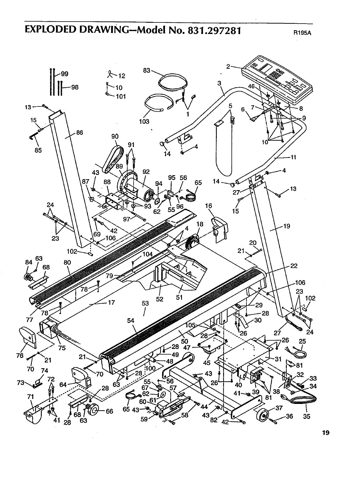
EXPLODED DRAWING--Model No. 831.297281 R195A
15
85
90
103
3
43 92 95 56
94 65
84
24
23
62 16
18
15
20
21.
77
76 21
71
54
53
/
52 51
5O
45
39 81
23 102
24
25
41 63 35
19
ORDERING REPLACEMENT PARTS
Each TREADMILL has its own MODEL NUMBER. Always mention this MODEL NUMBER when requesting ser-
vice or repair parts for your TREADMILL.
All parts listed herein can be ordered through SEARS, ROEBUCK AND CO. SERVICE CENTERS and most-
SEARS RETAIL STORES. If parts you need are not stocked locally, your order will be transmitted to a SEARS
•PARTS DISTRIBUTION CENTER for handling.
WHEN ORDERING REPAIR PARTs, ALWAYS GIVE THE FOLLOWING INFORMATION:
• The MODEL NUMBER of the product (831.297281).
•The NAME of the product (SEARS LIFESTYLEFP EXPANSE 2000).
• The PART NUMBER of the part(s) (see page 18 of th_smanual)."
•The DESCRIPTION of the part(s) (see page 18 of this manual)..
Your SEARS TREADMILL has added value when you consider that SEARS has service units nationwide, staffed
with SEARS trained technicians specifically trained on SEARS products, having the parts, tools and equipment to
ensure that we meet our pledge to you: "We service what we sell."
Should you ever need repair service or parts, call toll free: 1-800-736-6879, Monday through Saturday, 7 a.m.
until7 p.m. Central Time (excluding holidays).
Part No. 122681 R195A Pdnted in USA © 1995 Sears, Roebuck and Co.
